Vortex Shedding Suppression: A Review on Modified Bluff ...
15
Review Vortex Shedding Suppression: A Review on Modified Bluff Bodies Amir Teimourian 1, * and Hanifa Teimourian 2 Citation: Teimourian, A.; Teimourian, H. Vortex Shedding Suppression: A Review on Modified Bluff Bodies. Eng 2021, 2, 325–339. https://doi.org/10.3390/eng2030021 Academic Editors: Antonio Gil Bravo and Rajinder Pal Received: 1 April 2021 Accepted: 18 July 2021 Published: 27 July 2021 Publisher’s Note: MDPI stays neutral with regard to jurisdictional claims in published maps and institutional affil- iations. Copyright: © 2021 by the authors. Licensee MDPI, Basel, Switzerland. This article is an open access article distributed under the terms and conditions of the Creative Commons Attribution (CC BY) license (https:// creativecommons.org/licenses/by/ 4.0/). 1 Department of Aeronautical Engineering, University of Kyrenia, Kyrenia Harbor, Girne 99320, Turkey 2 Faculty of Engineering, Near East University, Near East Boulevard, Nicosia 99138, Turkey; [email protected] * Correspondence: [email protected] Abstract: Vortex shedding phenomenon behind bluff bodies and its destructive unsteady wake can be controlled by employing active and passive flow control methods. In this quest, researchers employed experimental fluid dynamics (EFD), computational fluid dynamics (CFD) and an analytical approach to investigate such phenomena to reach a desired outcome. This study reviews the available literature on the flow control of vortex shedding behind bluff bodies and its destructive wake through the modification of the geometry of the bluff body. Various modifications on the bluff body geometries namely perforated bluff bodies, permeable and porous mesh, corner modification and wavy cylinder have been reviewed. The effectiveness of these methods has been discussed in terms of drag variation, wake structure modifications and Strouhal number alteration. Keywords: vortex shedding suppression; flow control; flow structure; modified bluff bodies 1. Introduction Flow properties and wake structures in the premises of bluff bodies fascinates many researchers for years. As bluff bodies have various applications in engineering, there is a growing interest in understanding this phenomenon in industry. A significant feature of the wake region behind bluff bodies is a formation of vortex street and inciting fluc- tuating forces on the structure, where possible suppression of such a phenomenon is a desired outcome. The periodic phenomenon incurs destructive unsteady loading on the structure and may lead to catastrophic incidents. Therefore, preventing such destructive fluctuating forces requires a better understanding of this phenomenon during design stages of indus- trial systems. Many engineering and industrial applications including the design of skyscrapers, chimneys, offshore structures, bridges and heat exchangers profoundly relies on our understanding of this phenomenon. Wind loading is a key consideration in tall buildings’ design stages and to ensure structural integrity and occupant comfort it is necessary to consider wind-induced stresses and motions. The aerodynamic characteristics and wake flow structure behind bluff bodies, tall buildings for instance, to a great extent depend on the behavior of the separated shear layers from the leading edge. As wind loading can be reduced by controlling the separated flow, a large number of researchers have been investigating the effect of the structural shape modification such as modifying corner shapes on the wind-induced response of structures. Square cross-sectional lighting poles with sharp or round corners, for instance, exhibit large amplitude oscillations with a frequency that is close to the frequency of their first mode. Therefore, the vortex shedding phenomenon’s importance develops a growing in- terest in researchers to dedicate their research on this phenomenon to investigate bluff bodies such as a circular cylinder, square cylinder or flat plate resembling structures in engineering [1–9]. The application of the research varies from wind turbines and the wind energy sector [10–12] to building aerodynamics [13], which provide additional insight to Eng 2021, 2, 325–339. https://doi.org/10.3390/eng2030021 https://www.mdpi.com/journal/eng
-
Upload
khangminh22 -
Category
Documents
-
view
0 -
download
0
Transcript of Vortex Shedding Suppression: A Review on Modified Bluff ...
Review
Vortex Shedding Suppression: A Review on Modified Bluff Bodies
Amir Teimourian 1,* and Hanifa Teimourian 2
�����������������
Citation: Teimourian, A.;
Teimourian, H. Vortex Shedding
Suppression: A Review on Modified
Bluff Bodies. Eng 2021, 2, 325–339.
https://doi.org/10.3390/eng2030021
Academic Editors: Antonio Gil Bravo
and Rajinder Pal
Received: 1 April 2021
Accepted: 18 July 2021
Published: 27 July 2021
Publisher’s Note: MDPI stays neutral
with regard to jurisdictional claims in
published maps and institutional affil-
iations.
Copyright: © 2021 by the authors.
Licensee MDPI, Basel, Switzerland.
This article is an open access article
distributed under the terms and
conditions of the Creative Commons
Attribution (CC BY) license (https://
creativecommons.org/licenses/by/
4.0/).
1 Department of Aeronautical Engineering, University of Kyrenia, Kyrenia Harbor, Girne 99320, Turkey2 Faculty of Engineering, Near East University, Near East Boulevard, Nicosia 99138, Turkey;
[email protected]* Correspondence: [email protected]
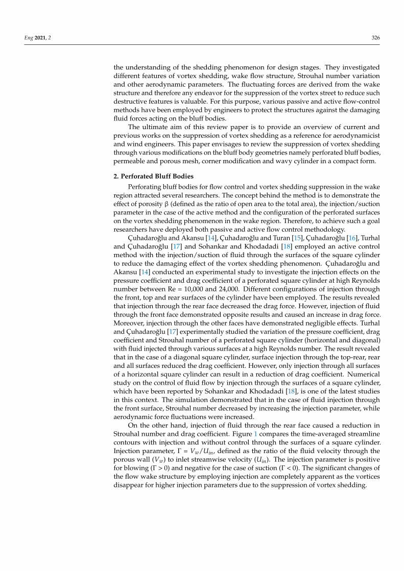
Abstract: Vortex shedding phenomenon behind bluff bodies and its destructive unsteady wake can becontrolled by employing active and passive flow control methods. In this quest, researchers employedexperimental fluid dynamics (EFD), computational fluid dynamics (CFD) and an analytical approachto investigate such phenomena to reach a desired outcome. This study reviews the available literatureon the flow control of vortex shedding behind bluff bodies and its destructive wake through themodification of the geometry of the bluff body. Various modifications on the bluff body geometriesnamely perforated bluff bodies, permeable and porous mesh, corner modification and wavy cylinderhave been reviewed. The effectiveness of these methods has been discussed in terms of drag variation,wake structure modifications and Strouhal number alteration.
Keywords: vortex shedding suppression; flow control; flow structure; modified bluff bodies
1. Introduction
Flow properties and wake structures in the premises of bluff bodies fascinates manyresearchers for years. As bluff bodies have various applications in engineering, there isa growing interest in understanding this phenomenon in industry. A significant featureof the wake region behind bluff bodies is a formation of vortex street and inciting fluc-tuating forces on the structure, where possible suppression of such a phenomenon is adesired outcome.
The periodic phenomenon incurs destructive unsteady loading on the structure andmay lead to catastrophic incidents. Therefore, preventing such destructive fluctuatingforces requires a better understanding of this phenomenon during design stages of indus-trial systems.
Many engineering and industrial applications including the design of skyscrapers,chimneys, offshore structures, bridges and heat exchangers profoundly relies on ourunderstanding of this phenomenon. Wind loading is a key consideration in tall buildings’design stages and to ensure structural integrity and occupant comfort it is necessary toconsider wind-induced stresses and motions. The aerodynamic characteristics and wakeflow structure behind bluff bodies, tall buildings for instance, to a great extent dependon the behavior of the separated shear layers from the leading edge. As wind loadingcan be reduced by controlling the separated flow, a large number of researchers havebeen investigating the effect of the structural shape modification such as modifying cornershapes on the wind-induced response of structures. Square cross-sectional lighting poleswith sharp or round corners, for instance, exhibit large amplitude oscillations with afrequency that is close to the frequency of their first mode.
Therefore, the vortex shedding phenomenon’s importance develops a growing in-terest in researchers to dedicate their research on this phenomenon to investigate bluffbodies such as a circular cylinder, square cylinder or flat plate resembling structures inengineering [1–9]. The application of the research varies from wind turbines and the windenergy sector [10–12] to building aerodynamics [13], which provide additional insight to
Eng 2021, 2, 325–339. https://doi.org/10.3390/eng2030021 https://www.mdpi.com/journal/eng
Eng 2021, 2 326
the understanding of the shedding phenomenon for design stages. They investigateddifferent features of vortex shedding, wake flow structure, Strouhal number variationand other aerodynamic parameters. The fluctuating forces are derived from the wakestructure and therefore any endeavor for the suppression of the vortex street to reduce suchdestructive features is valuable. For this purpose, various passive and active flow-controlmethods have been employed by engineers to protect the structures against the damagingfluid forces acting on the bluff bodies.
The ultimate aim of this review paper is to provide an overview of current andprevious works on the suppression of vortex shedding as a reference for aerodynamicistand wind engineers. This paper envisages to review the suppression of vortex sheddingthrough various modifications on the bluff body geometries namely perforated bluff bodies,permeable and porous mesh, corner modification and wavy cylinder in a compact form.
2. Perforated Bluff Bodies
Perforating bluff bodies for flow control and vortex shedding suppression in the wakeregion attracted several researchers. The concept behind the method is to demonstrate theeffect of porosity β (defined as the ratio of open area to the total area), the injection/suctionparameter in the case of the active method and the configuration of the perforated surfaceson the vortex shedding phenomenon in the wake region. Therefore, to achieve such a goalresearchers have deployed both passive and active flow control methodology.
Çuhadaroglu and Akansu [14], Çuhadaroglu and Turan [15], Çuhadaroglu [16], Turhaland Çuhadaroglu [17] and Sohankar and Khodadadi [18] employed an active controlmethod with the injection/suction of fluid through the surfaces of the square cylinderto reduce the damaging effect of the vortex shedding phenomenon. Çuhadaroglu andAkansu [14] conducted an experimental study to investigate the injection effects on thepressure coefficient and drag coefficient of a perforated square cylinder at high Reynoldsnumber between Re = 10,000 and 24,000. Different configurations of injection throughthe front, top and rear surfaces of the cylinder have been employed. The results revealedthat injection through the rear face decreased the drag force. However, injection of fluidthrough the front face demonstrated opposite results and caused an increase in drag force.Moreover, injection through the other faces have demonstrated negligible effects. Turhaland Çuhadaroglu [17] experimentally studied the variation of the pressure coefficient, dragcoefficient and Strouhal number of a perforated square cylinder (horizontal and diagonal)with fluid injected through various surfaces at a high Reynolds number. The result revealedthat in the case of a diagonal square cylinder, surface injection through the top-rear, rearand all surfaces reduced the drag coefficient. However, only injection through all surfacesof a horizontal square cylinder can result in a reduction of drag coefficient. Numericalstudy on the control of fluid flow by injection through the surfaces of a square cylinder,which have been reported by Sohankar and Khodadadi [18], is one of the latest studiesin this context. The simulation demonstrated that in the case of fluid injection throughthe front surface, Strouhal number decreased by increasing the injection parameter, whileaerodynamic force fluctuations were increased.
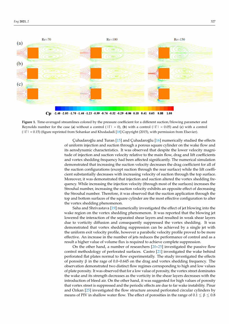
On the other hand, injection of fluid through the rear face caused a reduction inStrouhal number and drag coefficient. Figure 1 compares the time-averaged streamlinecontours with injection and without control through the surfaces of a square cylinder.Injection parameter, Γ = Vw/Uin, defined as the ratio of the fluid velocity through theporous wall (Vw) to inlet streamwise velocity (Uin). The injection parameter is positivefor blowing (Γ > 0) and negative for the case of suction (Γ < 0). The significant changes ofthe flow wake structure by employing injection are completely apparent as the vorticesdisappear for higher injection parameters due to the suppression of vortex shedding.
Eng 2021, 2 327
Eng 2021, 2, FOR PEER REVIEW 3
wake structure by employing injection are completely apparent as the vortices disappear
for higher injection parameters due to the suppression of vortex shedding.
Figure 1. Time-averaged streamlines colored by the pressure coefficient for a different suction/blowing parameter and
Reynolds number for the case (a) without a control (|Γ| = 0), (b) with a control (|Γ| = 0.05) and (c) with a control (|Γ| =
0.15) (figure reprinted from Sohankar and Khodadadi [18] Copyright (2015), with permission from Elsevier).
Çuhadaroğlu and Turan [15] and Çuhadaroğlu [16] numerically studied the effects
of uniform injection and suction through a porous square cylinder on the wake flow and
its aerodynamic characteristics. It was observed that despite the lower velocity magnitude
of injection and suction velocity relative to the main flow, drag and lift coefficients and
vortex shedding frequency had been affected significantly. The numerical simulation
demonstrated that increasing the suction velocity decreases the drag coefficient for all of
the suction configurations (except suction through the rear surface) while the lift coeffi-
cient substantially decreases with increasing velocity of suction through the top surface.
Moreover, it was demonstrated that injection and suction altered the vortex shedding fre-
quency. While increasing the injection velocity (through most of the surfaces) increases
the Strouhal number, increasing the suction velocity exhibits an opposite effect of decreas-
ing the Strouhal number. Therefore, it was observed that the suction application through
the top and bottom surfaces of the square cylinder are the most effective configuration to
alter the vortex shedding phenomenon.
Saha and Shrivastava [19] numerically investigated the effect of jet blowing into the
wake region on the vortex shedding phenomenon. It was reported that the blowing jet
lowered the interaction of the separated shear layers and resulted in weak shear layers
due to vorticity diffusion and consequently suppressed the vortex shedding. It was
demonstrated that vortex shedding suppression can be achieved by a single jet with the
uniform exit velocity profile, however a parabolic velocity profile proved to be more ef-
fective. An increase in the number of jets reduces the performance of control and as a
result a higher value of volume flux is required to achieve complete suppression.
On the other hand, a number of researchers [20–25] investigated the passive flow
control methodology of perforated surfaces. Castro [21] investigated the wake behind per-
forated flat plates normal to flow experimentally. The study investigated the effects of
porosity β in the rage of 0.0–0.645 on the drag and vortex shedding frequency. The obser-
vation demonstrated two distinct flow regimes corresponding to high and low values of
plate porosity. It was observed that for a low value of porosity, the vortex street dominates
the wake and its strength decreases as the vorticity in the shear layers decreases with the
introduction of bleed air. On the other hand, it was suggested for high values of porosity
Figure 1. Time-averaged streamlines colored by the pressure coefficient for a different suction/blowing parameter andReynolds number for the case (a) without a control (|Γ| = 0), (b) with a control (|Γ| = 0.05) and (c) with a control(|Γ| = 0.15) (figure reprinted from Sohankar and Khodadadi [18] Copyright (2015), with permission from Elsevier).
Çuhadaroglu and Turan [15] and Çuhadaroglu [16] numerically studied the effectsof uniform injection and suction through a porous square cylinder on the wake flow andits aerodynamic characteristics. It was observed that despite the lower velocity magni-tude of injection and suction velocity relative to the main flow, drag and lift coefficientsand vortex shedding frequency had been affected significantly. The numerical simulationdemonstrated that increasing the suction velocity decreases the drag coefficient for all ofthe suction configurations (except suction through the rear surface) while the lift coeffi-cient substantially decreases with increasing velocity of suction through the top surface.Moreover, it was demonstrated that injection and suction altered the vortex shedding fre-quency. While increasing the injection velocity (through most of the surfaces) increases theStrouhal number, increasing the suction velocity exhibits an opposite effect of decreasingthe Strouhal number. Therefore, it was observed that the suction application through thetop and bottom surfaces of the square cylinder are the most effective configuration to alterthe vortex shedding phenomenon.
Saha and Shrivastava [19] numerically investigated the effect of jet blowing into thewake region on the vortex shedding phenomenon. It was reported that the blowing jetlowered the interaction of the separated shear layers and resulted in weak shear layersdue to vorticity diffusion and consequently suppressed the vortex shedding. It wasdemonstrated that vortex shedding suppression can be achieved by a single jet withthe uniform exit velocity profile, however a parabolic velocity profile proved to be moreeffective. An increase in the number of jets reduces the performance of control and as aresult a higher value of volume flux is required to achieve complete suppression.
On the other hand, a number of researchers [20–25] investigated the passive flowcontrol methodology of perforated surfaces. Castro [21] investigated the wake behindperforated flat plates normal to flow experimentally. The study investigated the effectsof porosity β in the rage of 0.0–0.645 on the drag and vortex shedding frequency. Theobservation demonstrated two distinct flow regimes corresponding to high and low valuesof plate porosity. It was observed that for a low value of porosity, the vortex street dominatesthe wake and its strength decreases as the vorticity in the shear layers decreases with theintroduction of bleed air. On the other hand, it was suggested for high values of porositythat vortex street is suppressed and the periodic effects are due to far wake instability. Pinarand Ozkan [25] investigated the flow structure around perforated circular cylinders bymeans of PIV in shallow water flow. The effect of porosities in the range of 0.1 ≤ β ≤ 0.8
Eng 2021, 2 328
with an increment of 0.1 were investigated in terms of velocity, vorticity, turbulent kineticenergy, Reynolds shear stress and streamline topologies. It was observed that the unsteadyflow structure and the vortical structures in the wake region downstream of the cylinderaffected significantly by the porosity and result in elongated shear layers. The jet-alike flowthrough the perforated surface of the circular cylinder effectively suppressed the formationof a well-organized Karman vortex street. As the porosity increases, it was observed thatthe formed vortices on the shear layers are elongated along the direction of the flow. Inaddition, a significant reduction in fluctuation in the wake region of a perforated circularcylinder has been observed. Based on the observations, a porosity interval of 0.4 ≤ β ≤ 0.8has been suggested for the most effective suppression of the Karman vortex street. It wasobserved that as the porosity reaches β = 0.4, the flow structure in the wake region of theperforated circular cylinder dramatically changes and the recirculation region disappears.At this porosity value, the flow emanating through the perforated holes takes the shape ofa jet flow and as a result, a significant increase in momentum transfer into the near wakeregion was observed. In a similar research Durhasan and Pinar [23] investigated the effectof perforation on the flow structure in the downstream wake in deep water for Re = 10,000.The flow emanated from the holes because of increments in porosity prevented the shearlayer interaction and consequently elongated the shear layers downstream of the cylinder.Additionally, employing the perforated cylinder results in a significant attenuation of themagnitude of turbulent statistics in comparison with a non-perforated circular cylinder. Inagreement with previous work a porosity range 0.4 ≤ β ≤ 0.8 is reported to suppress theKarman vortex street by employing a perforated cylinder. It was also suggested that such aperforated circular cylinder would result in the prevention of vortex induced vibrations.Firat, Ozkan [22] studied the near wakes of perforated hollow cylinders by means of PIVfor a Reynolds number of Re = 6900. The circular cylinders with two rows of holes wereinvestigated for various combinations of three-hole diameters and hole-to-hole distances.It was reported that increment in the hole diameter, which is in direct relation to the jetmomentum, resulted in increment in the values of time-averaged wake characteristicssuch as the vortex formation length and length of shear layers. It was observed that thevalues of the vortex formation length of the perforated circular cylinder was greater thanthat of the non-perforated cylinder. Hence, by the aid of the jet, the vortex formationphenomena was shifted downstream in the wake region. Teimourian and Hacisevki [20]took a passive flow control approach to investigate perforated surfaces and the effects offluid entrainment on the vortex shedding phenomenon and possible suppression in thewake region of square cylinder. The research investigated the wake region behind thecylinder in terms of the coherent flow structure, time averaged properties and effectivenessof different perforations.
It was observed that these perforated surfaces have significant effects within theinterval of y/D = ±1.0 in the wake behind the square cylinder. The experimental studyrevealed the effects of various perforated surfaces on velocity profiles and the flow structurewhile coherent structures have been diminished significantly. The study reported thata square cylinder with all-faces perforated demonstrated the most significant relativereduction in the coherent turbulent kinetic energy compared with other perforations.
The injection or suction modifies the boundary layer development and the vortexformation region. Researchers employing active flow control methodology on perforatedbluff bodies demonstrated that high injection of fluid through the rear surface altersthe vortex shedding phenomenon. On the other hand, studies on passive flow controlsuggested that even with a low entrainment flow rate in comparison to the active flowcontrol cases, still the shedding phenomenon has been affected significantly. To sum up,the literature suggested that the pressure coefficient distribution, drag coefficient andthe Strouhal number were influenced by the position of the perforated surface and bythe injection rate. While the lift and drag fluctuations for the optimum configurationdecays, a maximum reduction on the drag force of 72% can be achieved. Yet by increasingporosity, β, the flow fluctuations are substantially reduced in the wake region and results

Eng 2021, 2 329
in the suppression of the Karman vortex street due to elongated shear layers and theobservation of a reduction in the magnitudes of vortices. The studies on flow controland the suppression of vortex shedding by employing perforated surfaces have beensummarized in Table 1.
Table 1. Selected studies on flow control and suppression of vortex shedding by employing perforated bluff bodies.
Researchers Flow Control Re TI Technique Measurements BluffBody BR
Castro [21] Passive 2.5 × 10⁴–9.0 × 10⁴ - CTA St, U FP -
Çuhadaroglu, Akansu [14] Active 10,000–24,000 1.2–1.5% PT CP, CD, U SC -
Çuhadaroglu and Turan [15] Active 21,400 - Num St, CD SC -Çuhadaroglu [16] Active - - Num St, CD, CL SC -
Turhal and Çuhadaroglu [17] Active 10,000–24,000 1.2–1.5% PT, CTA St, CP, CD SC 6.5%, 9.2%
Sohankar, Khodadadi [18] Active 70–150 - Num St, CP, CD, CL SC 5%Saha and Shrivastava [19] Active 100 - Num St, U, CD SC 5%
Pinar, Ozkan [25] Passive 10,000 1% PIV U CC 10%Firat, Ozkan [22] Passive 6900 4.5% PIV St, U CC 7.4%
Teimourian, Hacisevki [20] Passive 18,500 0.6% CTA St, U SC 5%Durhasan, Pinar [23] Passive 10,000 - PIV U CC -
Re = Reynolds number; TI, turbulence intensity; CTA = constant temperature anemometry; PT = pressure transducer; PIV = particle imagevelocimetry; St = Strouhal number; CD = drag coefficient; CL = lift coefficient; CP = pressure coefficient; BR, blockage ratio; FP = flat plate;CC = circular cylinder; SC = square cylinder, Num = numerical.
3. Permeable and Porous Mesh
Employing permeable mesh is classified as the passive wake control method to sup-press the vortex shedding in the wake region. Several researchers investigated the effect ofporosity on the wake region for various flow conditions.
Gözmen, Akilli [26], Ozkan and Oruc [27] experimentally investigated suppres-sion of vortex shedding in the wake of a circular cylinder by employing a permeableouter cylinder.
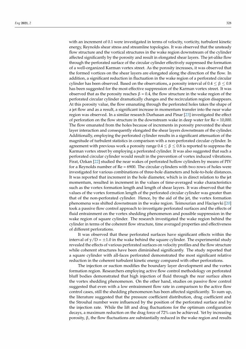
Gözmen and Akilli [26] employed various values of porosity to demonstrate its effecton flow control in the wake of the circular cylinder with the outer permeable cylinder. Itwas observed that vortex shedding has been suppressed significantly downstream thecylinder as porosity increases. In order to control the vortex shedding in the wake, thereport suggested the optimum value of porosity as a value of 0.7. While the previous studyof Gözmen and Akilli [26] conducted the experiments for a single value of the ratio ofthe outer cylinder diameter to the inner cylinder diameter (D/d), Ozkan and Oruc [27]investigated the effects of the variation of both the outer cylinder diameter and porosity. Itwas reported that both parameters have considerable effects on the wake flow behind thecircular cylinder. A significant reduction of turbulent kinetic energy and Reynolds stresseswas observed as a result of employing the outer cylinder. The results demonstrated that avalue of 0.4 ≤ D/d ≤ 0.6 and 1.6 ≤ D/d ≤ 2.0 would achieve a better flow control in thenear wake with a remarkable reduction in the turbulent kinetic energy peak value. Cicolinand Freire [28] investigated a circular cylinder with three different types of permeablemeshes on the suppression of vortex-induced vibrations by means of PIV. It was observedthat the vortex shedding in the wake region has been disrupted and formation lengthhas been increased. Durhasan and Pinar [29] studied the gap between a circular cylinderand a shroud to investigate the effect of shroud porosity and diameter. Therefore, theexperiment was conducted for various porosity and diameter ratios at a Reynolds numberof Re = 5000. Durhasan and Pinar [29] divided the field of view into four flow regions asdemonstrated in Figure 2. These regions are upstream region I (UR I), upstream region II(UR II), downstream region I (DR I) and downstream region II (DR II). Therefore, it waspossible to have a closer look at the effects of shroud on these four flow regions.
Eng 2021, 2 330
Eng 2021, 2, FOR PEER REVIEW 6
(UR II), downstream region I (DR I) and downstream region II (DR II). Therefore, it was
possible to have a closer look at the effects of shroud on these four flow regions.
Figure 2. Schematic representation of flow regions; figure reprinted from Durhasan and Pinar [29]
Copyright (2019), with permission from Elsevier.
Figure 3 demonstrates the time-averaged streamline topology for various porosities
at different diameter ratios. In comparison to the bare cylinder, the recirculation zone of
the cylinder and location of the foci and saddle points are significantly affected for the
case of the perforated cylinders. It was observed at porosity values of β ≤ 0.5, the vortex
formation of the cylinder occurs only in the gap between the cylinder and the shroud. For
β ≥ 0.6 it was observed that in DR I and DR II the formation of the wake flow structures is
affected dominantly by the diameter rather than the porosity. It was also revealed that the
flow structure in the outer region of the shroud exhibited a similar pattern to the wake
region of a single perforated cylinder. In addition, it was reported that employing the
shroud will lead to a significant drag reduction between 21% and 87% depending on the
values of the porosity and the diameter ratio.
Figure 2. Schematic representation of flow regions; figure reprinted from Durhasan and Pinar [29]Copyright (2019), with permission from Elsevier.
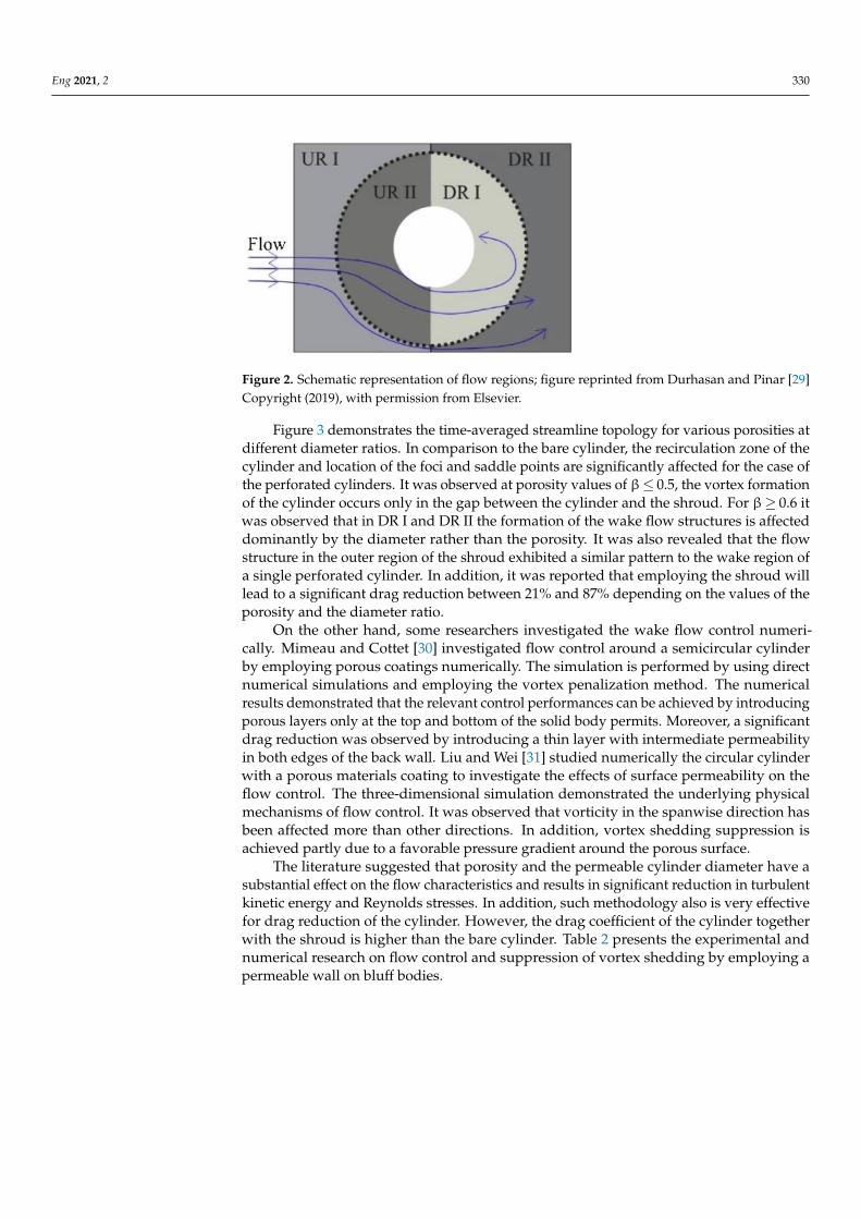
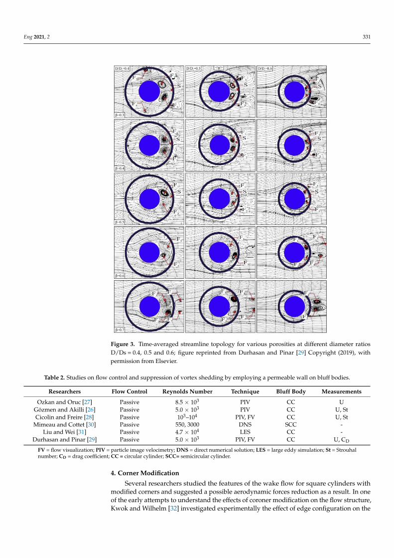
Figure 3 demonstrates the time-averaged streamline topology for various porosities atdifferent diameter ratios. In comparison to the bare cylinder, the recirculation zone of thecylinder and location of the foci and saddle points are significantly affected for the case ofthe perforated cylinders. It was observed at porosity values of β≤ 0.5, the vortex formationof the cylinder occurs only in the gap between the cylinder and the shroud. For β≥ 0.6 itwas observed that in DR I and DR II the formation of the wake flow structures is affecteddominantly by the diameter rather than the porosity. It was also revealed that the flowstructure in the outer region of the shroud exhibited a similar pattern to the wake region ofa single perforated cylinder. In addition, it was reported that employing the shroud willlead to a significant drag reduction between 21% and 87% depending on the values of theporosity and the diameter ratio.
On the other hand, some researchers investigated the wake flow control numeri-cally. Mimeau and Cottet [30] investigated flow control around a semicircular cylinderby employing porous coatings numerically. The simulation is performed by using directnumerical simulations and employing the vortex penalization method. The numericalresults demonstrated that the relevant control performances can be achieved by introducingporous layers only at the top and bottom of the solid body permits. Moreover, a significantdrag reduction was observed by introducing a thin layer with intermediate permeabilityin both edges of the back wall. Liu and Wei [31] studied numerically the circular cylinderwith a porous materials coating to investigate the effects of surface permeability on theflow control. The three-dimensional simulation demonstrated the underlying physicalmechanisms of flow control. It was observed that vorticity in the spanwise direction hasbeen affected more than other directions. In addition, vortex shedding suppression isachieved partly due to a favorable pressure gradient around the porous surface.
The literature suggested that porosity and the permeable cylinder diameter have asubstantial effect on the flow characteristics and results in significant reduction in turbulentkinetic energy and Reynolds stresses. In addition, such methodology also is very effectivefor drag reduction of the cylinder. However, the drag coefficient of the cylinder togetherwith the shroud is higher than the bare cylinder. Table 2 presents the experimental andnumerical research on flow control and suppression of vortex shedding by employing apermeable wall on bluff bodies.
Eng 2021, 2 331Eng 2021, 2, FOR PEER REVIEW 7
Figure 3. Time-averaged streamline topology for various porosities at different diameter ratios
D/Ds=0.4, 0.5 and 0.6; figure reprinted from Durhasan and Pinar [29] Copyright (2019), with per-
mission from Elsevier.
On the other hand, some researchers investigated the wake flow control numerically.
Mimeau and Cottet [30] investigated flow control around a semicircular cylinder by em-
ploying porous coatings numerically. The simulation is performed by using direct numer-
ical simulations and employing the vortex penalization method. The numerical results
demonstrated that the relevant control performances can be achieved by introducing po-
rous layers only at the top and bottom of the solid body permits. Moreover, a significant
drag reduction was observed by introducing a thin layer with intermediate permeability
in both edges of the back wall. Liu and Wei [31] studied numerically the circular cylinder
with a porous materials coating to investigate the effects of surface permeability on the
flow control. The three-dimensional simulation demonstrated the underlying physical
mechanisms of flow control. It was observed that vorticity in the spanwise direction has
been affected more than other directions. In addition, vortex shedding suppression is
achieved partly due to a favorable pressure gradient around the porous surface.
The literature suggested that porosity and the permeable cylinder diameter have a
substantial effect on the flow characteristics and results in significant reduction in turbu-
lent kinetic energy and Reynolds stresses. In addition, such methodology also is very ef-
fective for drag reduction of the cylinder. However, the drag coefficient of the cylinder
Figure 3. Time-averaged streamline topology for various porosities at different diameter ratiosD/Ds = 0.4, 0.5 and 0.6; figure reprinted from Durhasan and Pinar [29] Copyright (2019), withpermission from Elsevier.
Table 2. Studies on flow control and suppression of vortex shedding by employing a permeable wall on bluff bodies.
Researchers Flow Control Reynolds Number Technique Bluff Body Measurements
Ozkan and Oruc [27] Passive 8.5 × 10³ PIV CC UGözmen and Akilli [26] Passive 5.0 × 10³ PIV CC U, StCicolin and Freire [28] Passive 103–104 PIV, FV CC U, St
Mimeau and Cottet [30] Passive 550, 3000 DNS SCC -Liu and Wei [31] Passive 4.7 × 10⁴ LES CC -
Durhasan and Pinar [29] Passive 5.0 × 10³ PIV, FV CC U, CD
FV = flow visualization; PIV = particle image velocimetry; DNS = direct numerical solution; LES = large eddy simulation; St = Strouhalnumber; CD = drag coefficient; CC = circular cylinder; SCC= semicircular cylinder.
4. Corner Modification
Several researchers studied the features of the wake flow for square cylinders withmodified corners and suggested a possible aerodynamic forces reduction as a result. In oneof the early attempts to understand the effects of coroner modification on the flow structure,Kwok and Wilhelm [32] investigated experimentally the effect of edge configuration on the
Eng 2021, 2 332
wind induced response of tall buildings with the rectangular cross section. The experimentdemonstrated that slotted corners and chamfered corners reduce both the along-wind andcross-wind responses significantly. Further investigation on the wake energy spectra andwind force spectra characteristics demonstrated that the excitation processes were alteredfor a chamfered corner. Tamura and Miyagi [33] and Tamura and Miyagi [34] elaboratedthe effect of corner modification of the square cylinder on the wake flow structures andaerodynamics forces. Tamura and Miyagi [33] observed that a slight corner modificationalters the flow structure and result in considerable variation of the aerodynamic char-acteristics up to approximately 60% of the original value. The report suggested cornermodification as a promising passive technique for aerodynamic forces reduction.
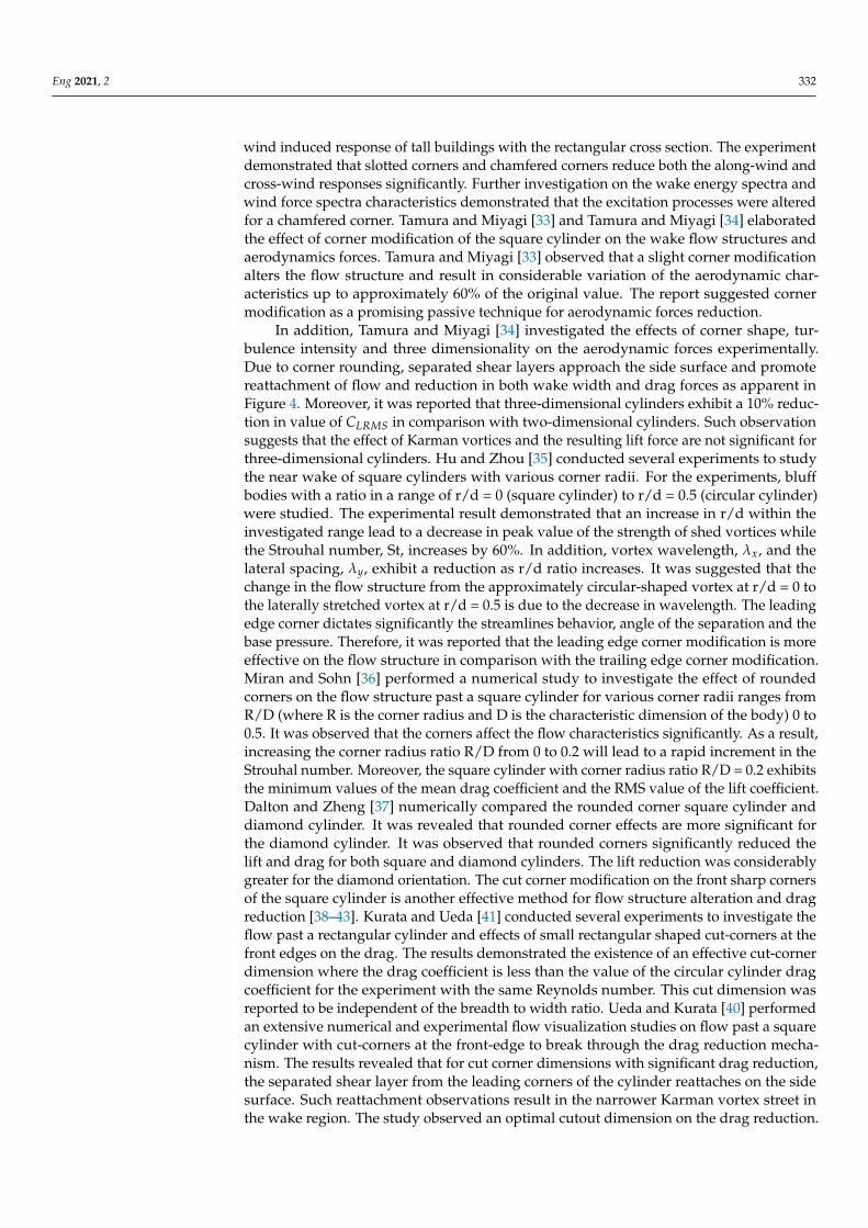
In addition, Tamura and Miyagi [34] investigated the effects of corner shape, tur-bulence intensity and three dimensionality on the aerodynamic forces experimentally.Due to corner rounding, separated shear layers approach the side surface and promotereattachment of flow and reduction in both wake width and drag forces as apparent inFigure 4. Moreover, it was reported that three-dimensional cylinders exhibit a 10% reduc-tion in value of CLRMS in comparison with two-dimensional cylinders. Such observationsuggests that the effect of Karman vortices and the resulting lift force are not significant forthree-dimensional cylinders. Hu and Zhou [35] conducted several experiments to studythe near wake of square cylinders with various corner radii. For the experiments, bluffbodies with a ratio in a range of r/d = 0 (square cylinder) to r/d = 0.5 (circular cylinder)were studied. The experimental result demonstrated that an increase in r/d within theinvestigated range lead to a decrease in peak value of the strength of shed vortices whilethe Strouhal number, St, increases by 60%. In addition, vortex wavelength, λx, and thelateral spacing, λy, exhibit a reduction as r/d ratio increases. It was suggested that thechange in the flow structure from the approximately circular-shaped vortex at r/d = 0 tothe laterally stretched vortex at r/d = 0.5 is due to the decrease in wavelength. The leadingedge corner dictates significantly the streamlines behavior, angle of the separation and thebase pressure. Therefore, it was reported that the leading edge corner modification is moreeffective on the flow structure in comparison with the trailing edge corner modification.Miran and Sohn [36] performed a numerical study to investigate the effect of roundedcorners on the flow structure past a square cylinder for various corner radii ranges fromR/D (where R is the corner radius and D is the characteristic dimension of the body) 0 to0.5. It was observed that the corners affect the flow characteristics significantly. As a result,increasing the corner radius ratio R/D from 0 to 0.2 will lead to a rapid increment in theStrouhal number. Moreover, the square cylinder with corner radius ratio R/D = 0.2 exhibitsthe minimum values of the mean drag coefficient and the RMS value of the lift coefficient.Dalton and Zheng [37] numerically compared the rounded corner square cylinder anddiamond cylinder. It was revealed that rounded corner effects are more significant forthe diamond cylinder. It was observed that rounded corners significantly reduced thelift and drag for both square and diamond cylinders. The lift reduction was considerablygreater for the diamond orientation. The cut corner modification on the front sharp cornersof the square cylinder is another effective method for flow structure alteration and dragreduction [38–43]. Kurata and Ueda [41] conducted several experiments to investigate theflow past a rectangular cylinder and effects of small rectangular shaped cut-corners at thefront edges on the drag. The results demonstrated the existence of an effective cut-cornerdimension where the drag coefficient is less than the value of the circular cylinder dragcoefficient for the experiment with the same Reynolds number. This cut dimension wasreported to be independent of the breadth to width ratio. Ueda and Kurata [40] performedan extensive numerical and experimental flow visualization studies on flow past a squarecylinder with cut-corners at the front-edge to break through the drag reduction mecha-nism. The results revealed that for cut corner dimensions with significant drag reduction,the separated shear layer from the leading corners of the cylinder reattaches on the sidesurface. Such reattachment observations result in the narrower Karman vortex street inthe wake region. The study observed an optimal cutout dimension on the drag reduction.
Eng 2021, 2 333
In addition, optimal drag reduction is achieved when the separated streamline covers thecut-corner and then reattaches along the whole side surfaces. He and Li [39] investigatedflow around square cylinders with cut-corners at the front edges experimentally. Theyobserved that the cut corner modification caused fluctuation intensity of the wake to beweakened with a reduction in the wake width. Cut-corners at the leading corners leadto the suppression of the separation over the side surfaces and result in the reductionof wake width. It was observed that while Strouhal number is inversely proportional tothe minimum wake width parameter, the drag coefficient is directly proportional to theparameter. Further investigation on the flow structure revealed a reduction in the wakevortex size and strength. The wake vortices formed farther downstream of the cylinderswith cut-corners in comparison with unmodified corners. The recirculation flow in thecut-corner facilitates the flow to go around the corner by acting as a virtual shape. On thequest to understand the effects of the corner modification on the flow past square cylinderAmbreen and Kim [38] conducted a more universal study on all proposed modificationsnamely chamfered, rounded and cut corners. Ambreen and Kim [38] investigated cornermodification effects on flow structure and heat transfer in the wake region of the squarecylinder. The numerical study focused on the corner roundedness parameter c/D = 0.125where c and D represent the corner size and cylinder diameter, respectively.
Eng 2021, 2, FOR PEER REVIEW 9
the corner radius and D is the characteristic dimension of the body) 0 to 0.5. It was ob-
served that the corners affect the flow characteristics significantly. As a result, increasing
the corner radius ratio R/D from 0 to 0.2 will lead to a rapid increment in the Strouhal
number. Moreover, the square cylinder with corner radius ratio R/D = 0.2 exhibits the
minimum values of the mean drag coefficient and the RMS value of the lift coefficient.
Dalton and Zheng [37] numerically compared the rounded corner square cylinder and
diamond cylinder. It was revealed that rounded corner effects are more significant for the
diamond cylinder. It was observed that rounded corners significantly reduced the lift and
drag for both square and diamond cylinders. The lift reduction was considerably greater
for the diamond orientation. The cut corner modification on the front sharp corners of the
square cylinder is another effective method for flow structure alteration and drag reduc-
tion [38–43]. Kurata and Ueda [41] conducted several experiments to investigate the flow
past a rectangular cylinder and effects of small rectangular shaped cut-corners at the front
edges on the drag. The results demonstrated the existence of an effective cut-corner di-
mension where the drag coefficient is less than the value of the circular cylinder drag co-
efficient for the experiment with the same Reynolds number. This cut dimension was re-
ported to be independent of the breadth to width ratio. Ueda and Kurata [40] performed
an extensive numerical and experimental flow visualization studies on flow past a square
cylinder with cut-corners at the front-edge to break through the drag reduction mecha-
nism. The results revealed that for cut corner dimensions with significant drag reduction,
the separated shear layer from the leading corners of the cylinder reattaches on the side
surface. Such reattachment observations result in the narrower Karman vortex street in
the wake region. The study observed an optimal cutout dimension on the drag reduction.
In addition, optimal drag reduction is achieved when the separated streamline covers the
cut-corner and then reattaches along the whole side surfaces. He and Li [39] investigated
flow around square cylinders with cut-corners at the front edges experimentally. They
observed that the cut corner modification caused fluctuation intensity of the wake to be
weakened with a reduction in the wake width. Cut-corners at the leading corners lead to
the suppression of the separation over the side surfaces and result in the reduction of wake
width. It was observed that while Strouhal number is inversely proportional to the mini-
mum wake width parameter, the drag coefficient is directly proportional to the parameter.
Further investigation on the flow structure revealed a reduction in the wake vortex size
and strength. The wake vortices formed farther downstream of the cylinders with cut-
corners in comparison with unmodified corners. The recirculation flow in the cut-corner
facilitates the flow to go around the corner by acting as a virtual shape. On the quest to
understand the effects of the corner modification on the flow past square cylinder Am-
breen and Kim [38] conducted a more universal study on all proposed modifications
namely chamfered, rounded and cut corners. Ambreen and Kim [38] investigated corner
modification effects on flow structure and heat transfer in the wake region of the square
cylinder. The numerical study focused on the corner roundedness parameter c/D = 0.125
where c and D represent the corner size and cylinder diameter, respectively.
Figure 4. Instantaneous vorticity contours around a sharp corner square cylinder (Left), chamfered corners cylinder (Mid-
dle) and rounded corners cylinder (Right); figure reprinted from Tamura and Miyagi [33] Copyright (1998), with permis-
sion from Elsevier.
Figure 4. Instantaneous vorticity contours around a sharp corner square cylinder (Left), chamfered corners cylinder(Middle) and rounded corners cylinder (Right); figure reprinted from Tamura and Miyagi [33] Copyright (1998), withpermission from Elsevier.
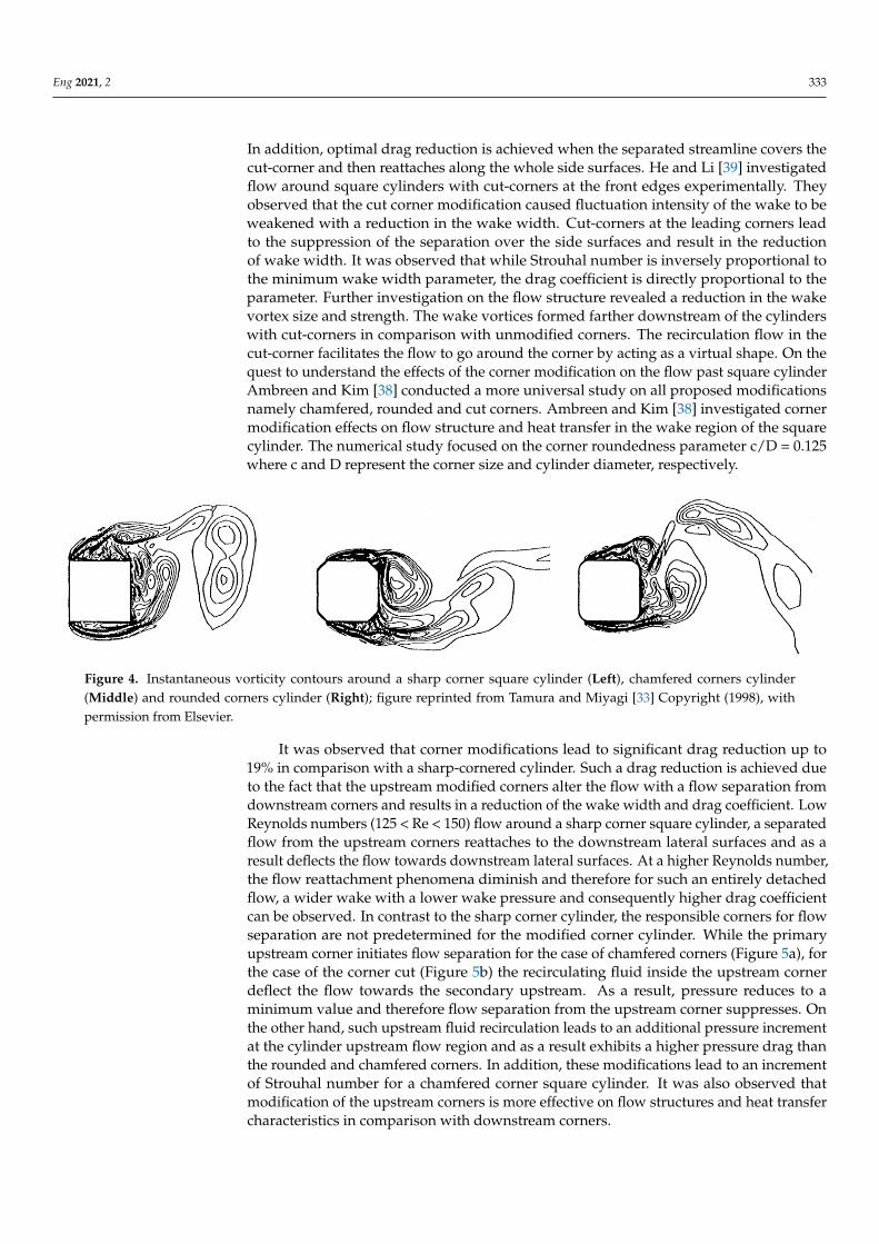
It was observed that corner modifications lead to significant drag reduction up to19% in comparison with a sharp-cornered cylinder. Such a drag reduction is achieved dueto the fact that the upstream modified corners alter the flow with a flow separation fromdownstream corners and results in a reduction of the wake width and drag coefficient. LowReynolds numbers (125 < Re < 150) flow around a sharp corner square cylinder, a separatedflow from the upstream corners reattaches to the downstream lateral surfaces and as aresult deflects the flow towards downstream lateral surfaces. At a higher Reynolds number,the flow reattachment phenomena diminish and therefore for such an entirely detachedflow, a wider wake with a lower wake pressure and consequently higher drag coefficientcan be observed. In contrast to the sharp corner cylinder, the responsible corners for flowseparation are not predetermined for the modified corner cylinder. While the primaryupstream corner initiates flow separation for the case of chamfered corners (Figure 5a), forthe case of the corner cut (Figure 5b) the recirculating fluid inside the upstream cornerdeflect the flow towards the secondary upstream. As a result, pressure reduces to aminimum value and therefore flow separation from the upstream corner suppresses. Onthe other hand, such upstream fluid recirculation leads to an additional pressure incrementat the cylinder upstream flow region and as a result exhibits a higher pressure drag thanthe rounded and chamfered corners. In addition, these modifications lead to an incrementof Strouhal number for a chamfered corner square cylinder. It was also observed thatmodification of the upstream corners is more effective on flow structures and heat transfercharacteristics in comparison with downstream corners.
Eng 2021, 2 334
Eng 2021, 2, FOR PEER REVIEW 10
It was observed that corner modifications lead to significant drag reduction up to
19% in comparison with a sharp-cornered cylinder. Such a drag reduction is achieved due
to the fact that the upstream modified corners alter the flow with a flow separation from
downstream corners and results in a reduction of the wake width and drag coefficient.
Low Reynolds numbers (125 < Re < 150) flow around a sharp corner square cylinder, a
separated flow from the upstream corners reattaches to the downstream lateral surfaces
and as a result deflects the flow towards downstream lateral surfaces. At a higher Reyn-
olds number, the flow reattachment phenomena diminish and therefore for such an en-
tirely detached flow, a wider wake with a lower wake pressure and consequently higher
drag coefficient can be observed. In contrast to the sharp corner cylinder, the responsible
corners for flow separation are not predetermined for the modified corner cylinder. While
the primary upstream corner initiates flow separation for the case of chamfered corners
(Figure 5a), for the case of the corner cut (Figure 5b) the recirculating fluid inside the up-
stream corner deflect the flow towards the secondary upstream. As a result, pressure re-
duces to a minimum value and therefore flow separation from the upstream corner sup-
presses. On the other hand, such upstream fluid recirculation leads to an additional pres-
sure increment at the cylinder upstream flow region and as a result exhibits a higher pres-
sure drag than the rounded and chamfered corners. In addition, these modifications lead
to an increment of Strouhal number for a chamfered corner square cylinder. It was also
observed that modification of the upstream corners is more effective on flow structures
and heat transfer characteristics in comparison with downstream corners.
Figure 5. Streamlines around (a) chamfered and (b) cut corner cylinder at Re = 200; figure reprinted
from Ambreen and Kim [38] Copyright (2018), with permission from Elsevier.
Some researchers combined the effect of corner modification with other parameters
on the wake flow. Mola and Bordonaro [44] numerically studied flows over square cylin-
ders with different aspect ratios and cross-sectional shapes to investigate aerodynamic
forces variations. As flow over finite length cylinders exhibit 3D characteristics close to
the free end region, a low frequency component has been observed. Therefore, mean drag
coefficient varies along the cylinder due to loss of vortex shedding synchronization be-
hind the cylinder. It was reported that in the case of the cylinder with rounded corners
these variations are less significant in comparison with cylinders with sharp corners. [45],
Miran and Sohn [46] and Tong and Sparrow [47] investigated the effect of the angle of
attack or incidence angle on the flow structure of square cylinders with modified corners.
Carassale and Freda [45] investigated the influence of corner modification on the aerody-
Figure 5. Streamlines around (a) chamfered and (b) cut corner cylinder at Re = 200; figure reprintedfrom Ambreen and Kim [38] Copyright (2018), with permission from Elsevier.
Some researchers combined the effect of corner modification with other parameters onthe wake flow. Mola and Bordonaro [44] numerically studied flows over square cylinderswith different aspect ratios and cross-sectional shapes to investigate aerodynamic forcesvariations. As flow over finite length cylinders exhibit 3D characteristics close to thefree end region, a low frequency component has been observed. Therefore, mean dragcoefficient varies along the cylinder due to loss of vortex shedding synchronization behindthe cylinder. It was reported that in the case of the cylinder with rounded corners thesevariations are less significant in comparison with cylinders with sharp corners. [45], Miranand Sohn [46] and Tong and Sparrow [47] investigated the effect of the angle of attack orincidence angle on the flow structure of square cylinders with modified corners. Carassaleand Freda [45] investigated the influence of corner modification on the aerodynamicbehavior of square cylinders at the angles of incidence between 0 and 45◦, experimentally.It was reported that rounded corners promote the reattachment of the flow on the lateralfaces and as a result the critical angle of incidence was reduced. Miran and Sohn [46]observed that the rounded corner cylinder exhibits a lower critical incidence angle incomparison with the sharp corner square cylinder. Therefore, for R/D = 0 (square cylinder)a critical incidence angle of 12◦ was observed whereas for R/D = 0.1–0.4 a value in therange of 5–10◦ was reported. On the other hand, Tong and Sparrow [47] conducted anumerical study on the square cylinder at an angle of attack with various degrees of edgechamfer, which make the shapes of the cylinder range from the square to the octagon. Thework concentrated on heat transfer characteristics and compared the results of the manyinvestigated configurations. It was reported that the more extensive chamfering results ina lowered dependence of the Nusselt number on the Reynolds number.
The experimental and numerical results demonstrated that modified corners of squarecylinder are a promising approach to reduce the drag and lift forces generated behind thecylinder. While in the wake of the square cylinder it was observed that the alternate vorticesare deflecting away from the centerline. The wake region of the rounded corner squareexhibits a different flow structure and a flow reattachment was promoted. Consequently,as the wake width decreases, a reduction in drag and lift coefficients was observed. Otherremarks are that the modification dimension and the location of modified coroners areplaying a significant role on the flow structure alternation. As the corner radius ratio,R/D, increases, the Strouhal number also increases. The leading-edge corner significantlyaffects the streamlines behavior, angle of separation and the base pressure. Therefore, theleading-edge corner modification is more effective on the flow structure in comparison
Eng 2021, 2 335
with trailing edge corners. Table 3 lists the conducted research on corner modification forflow control and drag reduction of square cylinders.
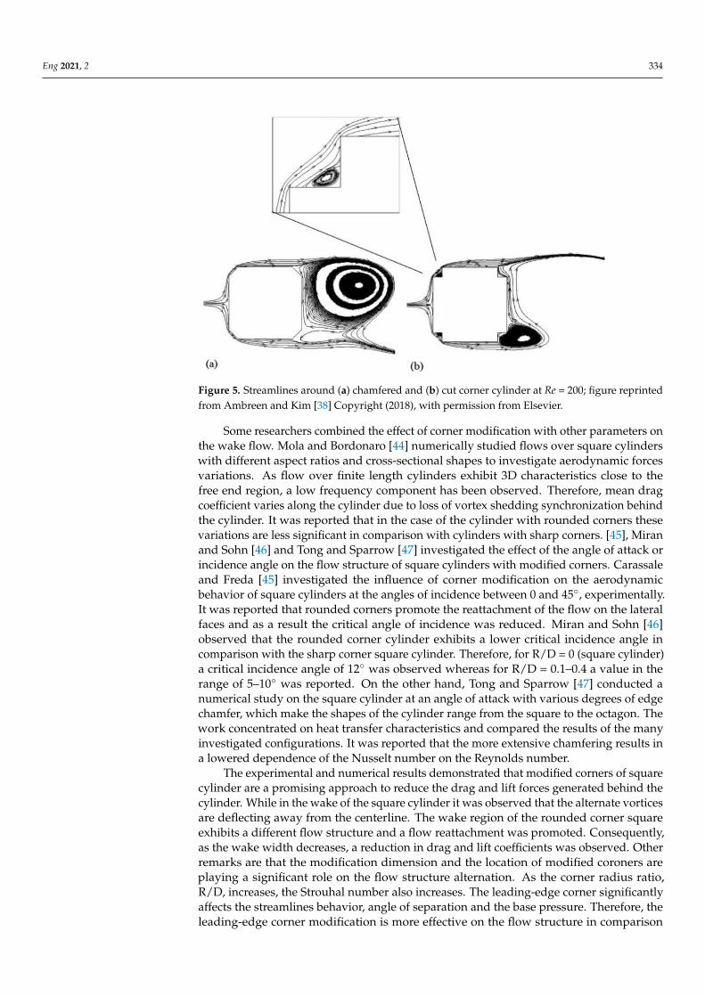
Table 3. Selected studies on flow control and suppression of vortex shedding by employing corner modification.
Researchers Flow Control Reynolds Number TI Technique Measurements
Kwok and Wilhelm [32] CC - - CTA UTamura and Miyagi [33] RC, CC 104–106 0.5% PS, Num CD, CL, CP, StTamura and Miyagi [34] RC, CC 3.0 × 10⁴ 6.5%, 14% CTA, FB CD, CL, StDalton and Zheng [37] RC 250, 1000 - Num CD, CL, CP, St
Hu and Zhou [35] RC 2600, 6000 0.4% PIV, LDA, FV St, UMola and Bordonaro [44] RC 105 1% Num CD, CL, St
Carassale, Freda [45] RC 1.7 × 10⁴, 2.3 × 10⁵ 0.2%, 5% PS, FB CD, CL, CP, StHe and Li [39] RC, CC, CU 1035 8% PIV U, St
Miran and Sohn [36] RC 500 - Num CD, CL, StTong and Sparrow [47] CC 3.0 × 10⁴ –2.3 × 10⁶ - Num Num
Miran and Sohn [46] RC 500 - Num CD, CL, StUeda and Kurata [40] CU 200–10,000 1% FV, Num UKurata and Ueda [41] CU 5.0 × 10⁴ –7.0 × 10⁴ 0.8%, 1.2% CTA, FB CD, St
Ambreen and Kim [38] RC, CC, CU 55–200 - Num CD, CL, CP, St
TI, turbulence intensity; CTA = constant temperature anemometry; FV = flow visualization; PIV = particle image velocimetry; St = Strouhalnumber; CD = drag coefficient; CL = lift coefficient; CP = pressure coefficient; PS = pressure sensor; FB = force balance; RC = roundedcorner; CC = Chamfered corner; CU = cut-corner, Num = numerical.
5. Wavy Cylinder
Employing a wavy surface for bluff bodies is also suggested in the literature for flowcontrol. The concept is to employ a wavy surface, sinusoidal waviness, for instance toinvestigate its effect on the wake flow and vortex shedding phenomenon.
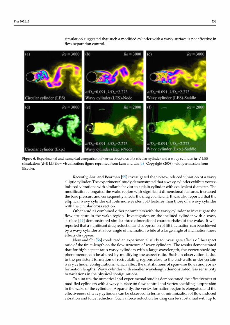
In this context, two sets of extensive numerical investigation [48–51] and combinedexperimental-numerical studies [52–54] have been conducted. Investigations on the wakeflow structure of a wavy circular cylinder demonstrated that the wavy cylinder encountereda lower mean drag coefficient than the corresponding drag coefficient for a circular cylinder.Such an observation was due to the formation of a longer wake vortex generated by thewavy cylinder. On the other hand, a significant reduction of the lift coefficient fluctuationof the wavy cylinder was observed. The employed wavy surface led to the formation of 3-Dfree shear layers, which are more stable than purely 2-D free shear layers. Such free shearlayers only roll up into mature vortices at the further downstream position and significantlyalters the near wake structures and the pressure distributions around the wavy cylinder.The wake flow structure of a circular cylinder and a wavy circular cylinder illustrated inFigure 6 by means of large eddy simulation (LES) and laser-induced fluorescence (LIF).From the figure alteration of the vortex structure behind a way cylinder is apparent.
On the other hand, investigation on the flow structure in the wake region of the modi-fied square cylinder demonstrated that the three-dimensional free shear layers from theleading edge are widened and lengthened. Therefore, vortices formed further downstreamin the wake of modified square cylinder in comparison to the straight square cylinder.Thus, a reduction in the mean drag was observed while the lift fluctuation was suppressedsignificantly. Organized transverse vortices have been observed along the spanwise direc-tion, which make such a flow control achievable. The free shear layers stabilized by thesevortices and therefore forced the roll up process into the vortex at a further downstreamposition. In comparison with a straight square cylinder a significant force reduction isobserved for a wavy square cylinder. The simulation demonstrated more stable three-dimensional free shear layers behind the wavy square cylinder. It was observed that atRe = 100 the free shear layers exhibit a steady flow feature with symmetrical flow patternsbehind the modified cylinder with a wavy surface. In agreement with previous studies areduction in the mean drag coefficient and fluctuating lift coefficient was reported. How-ever, as the aspect ratio and Reynolds number increases such features disappear. The
Eng 2021, 2 336
simulation suggested that such a modified cylinder with a wavy surface is not effective inflow separation control.
Eng 2021, 2, FOR PEER REVIEW 12
flow structure of a wavy circular cylinder demonstrated that the wavy cylinder encoun-
tered a lower mean drag coefficient than the corresponding drag coefficient for a circular
cylinder. Such an observation was due to the formation of a longer wake vortex generated
by the wavy cylinder. On the other hand, a significant reduction of the lift coefficient fluc-
tuation of the wavy cylinder was observed. The employed wavy surface led to the for-
mation of 3-D free shear layers, which are more stable than purely 2-D free shear layers.
Such free shear layers only roll up into mature vortices at the further downstream position
and significantly alters the near wake structures and the pressure distributions around
the wavy cylinder. The wake flow structure of a circular cylinder and a wavy circular
cylinder illustrated in Figure 6 by means of large eddy simulation (LES) and laser-induced
fluorescence (LIF). From the figure alteration of the vortex structure behind a way cylinder
is apparent.
Figure 6. Experimental and numerical comparison of vortex structures of a circular cylinder and a wavy cylinder, a-c LES
simulation; d-f LIF flow visualization; figure reprinted from Lam and Lin [48] Copyright (2008), with permission from
Elsevier .
On the other hand, investigation on the flow structure in the wake region of the mod-
ified square cylinder demonstrated that the three-dimensional free shear layers from the
leading edge are widened and lengthened. Therefore, vortices formed further down-
stream in the wake of modified square cylinder in comparison to the straight square cyl-
inder. Thus, a reduction in the mean drag was observed while the lift fluctuation was
suppressed significantly. Organized transverse vortices have been observed along the
spanwise direction, which make such a flow control achievable. The free shear layers sta-
bilized by these vortices and therefore forced the roll up process into the vortex at a further
downstream position. In comparison with a straight square cylinder a significant force
reduction is observed for a wavy square cylinder. The simulation demonstrated more sta-
ble three-dimensional free shear layers behind the wavy square cylinder. It was observed
that at Re = 100 the free shear layers exhibit a steady flow feature with symmetrical flow
patterns behind the modified cylinder with a wavy surface. In agreement with previous
studies a reduction in the mean drag coefficient and fluctuating lift coefficient was re-
Figure 6. Experimental and numerical comparison of vortex structures of a circular cylinder and a wavy cylinder, (a–c) LESsimulation; (d–f) LIF flow visualization; figure reprinted from Lam and Lin [48] Copyright (2008), with permission fromElsevier.
Recently, Assi and Bearman [55] investigated the vortex-induced vibration of a wavyelliptic cylinder. The experimental study demonstrated that a wavy cylinder exhibits vortex-induced vibrations with similar behavior to a plain cylinder with equivalent diameter. Themodification elongated the wake region with significant dimensional features, increasedthe base pressure and consequently affects the drag coefficient. It was also reported that theelliptical wavy cylinder exhibits more evident 3D features than those of a wavy cylinderwith the circular cross section.
Other studies combined other parameters with the wavy cylinder to investigate theflow structure in the wake region. Investigation on the inclined cylinder with a wavysurface [49] demonstrated similar three dimensional characteristics of the wake. It wasreported that a significant drag reduction and suppression of lift fluctuation can be achievedby a wavy cylinder at a low angle of inclination while at a large angle of inclination theseeffects disappear.
New and Shi [56] conducted an experimental study to investigate effects of the aspectratio of the finite-length on the flow structure of wavy cylinders. The results demonstratedthat for high aspect ratio wavy cylinders with a large wavelength, the vortex sheddingphenomenon can be altered by modifying the aspect ratio. Such an observation is dueto the persistent formation of recirculating regions close to the end-walls under certainwavy cylinder configurations, which affect the distributions of spanwise flows and vortexformation lengths. Wavy cylinder with smaller wavelength demonstrated less sensitivityto variations in the physical configurations.
To sum up, the numerical and experimental studies demonstrated the effectiveness ofmodified cylinders with a wavy surface on flow control and vortex shedding suppressionin the wake of the cylinders. Apparently, the vortex formation region is elongated and theeffectiveness of wavy cylinders can be observed in terms of minimization of flow inducedvibration and force reduction. Such a force reduction for drag can be substantial with up to
Eng 2021, 2 337
a 34% reduction at a higher Reynolds number. Table 4 summarized the conducted researchon modified cylinders with a wavy surface.
Table 4. Selected studies on flow control and suppression of vortex shedding wavy cylinders.
Researchers Technique Reynolds Number TI Bluff Body
Darekar and Sherwin [57] Num 10–500 - SCLee and Nguyen [58] Exp 5.0 × 10³–2.0 × 10⁴ 0.08% CC
Lam and Lin [48] Num 3000 - CCLin and Lin [53] Exp, Num 3000 - CC
Lam and Lin [49] Num 3900 - CCLam and Lin [50] Num 100 - CC
Lam and Wang [59] Exp 200–9000 0.2% CCLam and Wang [60] Exp 1.53 × 10⁴–5.05 × 10⁴ 0.2% CC
Lam and Lin [51] Num 100–5000 - SCNew and Shi [56] Exp 2700 2% CCZou and Hu [54] Exp, Num 600, 5900 - SC
Shen and Miao [52] Exp, Num 100–22,000 - SCTammisola [61] Num 50–100 - CC
Assi and Bearman [55] Exp 1500–15,000 3% EC
CC = circular cylinder; SC = square cylinder; EC = elliptic cylinder; Exp = experimental; Num = numerical.
In conclusion, this paper reviewed different promising methods of vortex sheddingsuppression through geometry modification on the bluff body. The discussed methodsnamely permeable and porous mesh, corner modification and wavy cylinder demonstratepromising results in suppressing vortex shedding. The literature suggests the significanteffectiveness of vortex shedding suppression in terms of the alteration of turbulent kineticenergy, Reynolds stresses and drag coefficient. These methodologies have potential appli-cation in the civil engineering and wind energy sector and their implementation for a moreeffective vortex shedding suppression is essential for engineers.
Author Contributions: Conceptualization, A.T. and H.T.; writing—original draft preparation, A.T.;writing—review and editing, H.T. Both authors have read and agreed to the published version of themanuscript.
Funding: This research received no external funding.
Conflicts of Interest: The authors declare no conflict of interest.
References1. Chashechkin, Y.D.; Zagumennyi, I.V. Formation of waves, vortices and ligaments in 2D stratified flows around obstacles. Phys.
Scr. 2019, 94, 054003. [CrossRef]2. Naumov, I.; Litvinov, I.V.; Mikkelsen, R.F.; Okulov, V.L. Experimental investigation of wake evolution behind a couple of flat
discs in a hydrochannel. Thermophys. Aeromech. 2016, 23, 657–666. [CrossRef]3. Shin, B.; Kondo, M. Effect of Gap Ratio on the Wake behind Two Side-by-Side Flat Plates. J. Appl. Fluid Mech. 2019, 12, 1213–1222.
[CrossRef]4. Gao, S.; Tao, L.; Tian, X.; Yang, J. Flow around an inclined circular disk. J. Fluid Mech. 2018, 851, 687–714. [CrossRef]5. Tian, X.; Hu, Z.; Lu, H.; Yang, J. Direct numerical simulations on the flow past an inclined circular disk. J. Fluids Struct. 2017, 72,
152–168. [CrossRef]6. Hacısevki, H.; Teimourian, A. Interacting wakes of a narrow and a wide flat plate in tandem arrangement. Fluid Dyn. Res. 2016,
48, 015505. [CrossRef]7. Teimourian, A.; Hacisevki, H.; Bahrami, A. Experimental study on flow past two inclined flat plates in tandem arrangement. J.
Wind Eng. Ind. Aerodyn. 2017, 169, 1–11. [CrossRef]8. Schmidt, H.-J.; Woszidlo, R.; Nayeri, C.N.; Paschereit, C.O. The effect of flow control on the wake dynamics of a rectangular bluff
body in ground proximity. Exp. Fluids 2018, 59, 1–16. [CrossRef]9. Li, D.; Yang, Q.; Ma, X.; Dai, G. Free surface characteristics of flow around two side-by-side circular cylinders. J. Mar. Sci. Eng.
2018, 6, 75. [CrossRef]10. Dou, B.; Yang, Z.; Guala, M.; Qu, T.; Lei, L.; Zeng, P. Comparison of Different Driving Modes for the Wind Turbine Wake in Wind
Tunnels. Energies 2020, 13, 1915. [CrossRef]

Eng 2021, 2 338
11. Zou, L.; Wang, K.; Jiang, Y.; Wang, A.; Sun, T. Wind tunnel test on the effect of solidity on near wake instability of vertical-axiswind turbine. J. Mar. Sci. Eng. 2020, 8, 365. [CrossRef]
12. Wang, K.; Zou, L.; Wang, A.; Zhao, P.; Jiang, Y. Wind tunnel study on wake instability of twin H-rotor vertical-axis turbines.Energies 2020, 13, 4310. [CrossRef]
13. Chen, Z.; Kim, B.; Lee, D.-E. Aerodynamic Characteristics and Lateral Displacements of a Set of Two Buildings in a Linked TallBuilding System. Sensors 2021, 21, 4046. [CrossRef] [PubMed]
14. Çuhadaroglu, B.; Akansu, Y.E.; Turhal, A.Ö. An experimental study on the effects of uniform injection through one perforatedsurface of a square cylinder on some aerodynamic parameters. Exp. Therm. Fluid Sci. 2007, 31, 909–915. [CrossRef]
15. Çuhadaroglu, B.; Turan, O. Numerical simulation of turbulent flow around a square cylinder with uniform injection or suctionand heat transfer. Numer. Heat Transf. Part A Appl. 2009, 55, 163–184. [CrossRef]
16. Çuhadaroglu, B. A numerical study on turbulent flow around a square cylinder with uniform injection or suction. Int. J. Numer.Methods Heat Fluid Flow 2009, 19, 708–727. [CrossRef]
17. Turhal, A.Ö.; Çuhadaroglu, B. The effects of surface injection through a perforated square cylinder on some aerodynamicparameters. Exp. Therm. Fluid Sci. 2010, 34, 725–735. [CrossRef]
18. Sohankar, A.; Khodadadi, M.; Rangraz, E. Control of fluid flow and heat transfer around a square cylinder by uniform suctionand blowing at low Reynolds numbers. Comput. Fluids 2015, 109, 155–167. [CrossRef]
19. Saha, A.K.; Shrivastava, A. Suppression of vortex shedding around a square cylinder using blowing. Sadhana 2015, 40, 769–785.[CrossRef]
20. Teimourian, A.; Hacisevki, H.; Bahrami, A. Experimental study on suppression of vortex street behind perforated square cylinder.J. Theor. Appl. Mech. 2017, 55, 1397–1408. [CrossRef]
21. Castro, I. Wake characteristics of two-dimensional perforated plates normal to an air-stream. J. Fluid Mech. 1971, 46, 599–609.[CrossRef]
22. Firat, E.; Ozkan, G.M.; Akilli, H. PIV measurements in the near wakes of hollow cylinders with holes. Exp. Fluids 2017, 58, 39.[CrossRef]
23. Durhasan, T.; Pinar, E.; Ozkan, G.M.; Aksoy, M.M.; Akilli, H.; Sahin, B. PIV measurement downstream of perforated cylinder indeep water. Eur. J. Mech. B Fluids 2018, 72, 225–234. [CrossRef]
24. Molin, B. Hydrodynamic modeling of perforated structures. Appl. Ocean Res. 2011, 33, 1–11. [CrossRef]25. Pinar, E.; Ozkan, G.M.; Durhasan, T.; Aksoy, M.M.; Akilli, H.; Sahin, B. Flow structure around perforated cylinders in shallow
water. J. Fluids Struct. 2015, 55, 52–63. [CrossRef]26. Gözmen, B.; Akilli, H.; Sahin, B. Vortex control of cylinder wake by permeable cylinder. J. Fac. Eng. Archit. 2013, 28, 77–85.27. Ozkan, G.M.; Oruc, V.; Akilli, H.; Sahin, B. Flow around a cylinder surrounded by a permeable cylinder in shallow water. Exp.
Fluids 2012, 53, 1751–1763. [CrossRef]28. Cicolin, M.M.; Freire, C.M.; Assi, G.R. Suppression of the vortex-induced vibration of a circular cylinder with permeable meshes.
In Fluids Engineering Division Summer Meeting; American Society of Mechanical Engineers: Chicago, IL, USA, 2014.29. Durhasan, T.; Pinar, E.; Ozkan, G.M.; Akilli, H.; Sahin, B. The effect of shroud on vortex shedding mechanism of cylinder. Appl.
Ocean Res. 2019, 84, 51–61. [CrossRef]30. Mimeau, C.; Cottet, G.-H.; Mortazavi, I. Passive flow control around a semi-circular cylinder using porous coatings. Int. J. Flow
Control 2014, 6, 43–50.31. Liu, H.; Wei, J. On the role of surface permeability for the control of flow around a circular cylinder. J. Vibroeng. 2016, 18,
5406–5415. [CrossRef]32. Kwok, K.; Wilhelm, P.; Wilkie, B. Effect of edge configuration on wind-induced response of tall buildings. Eng. Struct. 1988, 10,
135–140. [CrossRef]33. Tamura, T.; Miyagi, T.; Kitagishi, T. Numerical prediction of unsteady pressures on a square cylinder with various corner shapes.
J. Wind Eng. Ind. Aerodyn. 1998, 74, 531–542. [CrossRef]34. Tamura, T.; Miyagi, T. The effect of turbulence on aerodynamic forces on a square cylinder with various corner shapes. J. Wind
Eng. Ind. Aerodyn. 1999, 83, 135–145. [CrossRef]35. Hu, J.; Zhou, Y.; Dalton, C. Effects of the corner radius on the near wake of a square prism. Exp. Fluids 2006, 40, 106. [CrossRef]36. Miran, S.; Sohn, C.H. Numerical study of the rounded corners effect on flow past a square cylinder. Int. J. Numer. Methods Heat
Fluid Flow 2015, 25, 686–702. [CrossRef]37. Dalton, C.; Zheng, W. Numerical solutions of a viscous uniform approach flow past square and diamond cylinders. J. Fluids
Struct. 2003, 18, 455–465. [CrossRef]38. Ambreen, T.; Kim, M.-H. Flow and heat transfer characteristics over a square cylinder with corner modifications. Int. J. Heat Mass
Transf. 2018, 117, 50–57. [CrossRef]39. He, G.S.; Li, N.; Wang, J.J. Drag reduction of square cylinders with cut-corners at the front edges. Exp. Fluids 2014, 55, 1745.
[CrossRef]40. Ueda, Y.; Kurata, M.; Kida, T.; Iguchi, M. Visualization of flow past a square prism with cut-corners at the front-edge. J. Vis. 2009,
12, 383–391. [CrossRef]41. Kurata, M.; Ueda, Y.; Kida, T.; Iguchi, M. Drag reduction due to cut-corners at the front-edge of a rectangular cylinder with the
length-to-breadth ratio being less than or equal to unity. J. Fluids Eng. 2009, 131, 064501. [CrossRef]
Eng 2021, 2 339
42. Kurata, M.; Hirakawa, K.; Yasutomi, Z.; Kida, T. Effect of cutout at front edges to drag reduction of square prism. Trans. Jpn.Aeronaut. Space Sci. 1999, 47, 174–181.
43. Igarashi, T. Drag reduction of a rectangular cylinder with small rectangular cutout at its edges normal to air-stream. In Proceedingsof the Annual Meeting, Japan Society of Fluid Mechanics, Tokyo, Japan, 27–29 September 2005.
44. Mola, A.; Bordonaro, G.; Haji, M.R. Low-frequency variations of force coefficients on square cylinders with sharp and roundedcorners. J. Struct. Eng. 2009, 135, 828–835. [CrossRef]
45. Carassale, L.; Freda, A.; Marrè-Brunenghi, M. Experimental investigation on the aerodynamic behavior of square cylinders withrounded corners. J. Fluids Struct. 2014, 44, 195–204. [CrossRef]
46. Miran, S.; Sohn, C.H. Influence of incidence angle on the aerodynamic characteristics of square cylinders with rounded corners.Int. J. Numer. Methods Heat Fluid Flow 2016, 26, 269–283. [CrossRef]
47. Tong, J.C.K.; Sparrow, E.M.; Minkowycz, W.J.; Abraham, J.P. A new archive of heat transfer coefficients from square and chamferedcylinders at angles of attack in crossflow. Int. J. Therm. Sci. 2016, 105, 218–223. [CrossRef]
48. Lam, K.; Lin, Y. Large eddy simulation of flow around wavy cylinders at a subcritical Reynolds number. Int. J. Heat Fluid Flow2008, 29, 1071–1088. [CrossRef]
49. Lam, K.; Lin, Y.F.; Zou, L.; Liu, Y. The effect of wavy surface on vortex shedding from an inclined cylinder in turbulent flow. InProceedings of the Nineteenth International Offshore and Polar Engineering Conference, Osaka, Japan, 21–26 June 2009.
50. Lam, K.; Lin, Y. Effects of wavelength and amplitude of a wavy cylinder in cross-flow at low Reynolds numbers. J. Fluid Mech.2009, 620, 195–220. [CrossRef]
51. Lam, K.; Lin, Y.F.; Zou, L.; Liu, Y. Numerical study of flow patterns and force characteristics for square and rectangular cylinderswith wavy surfaces. J. Fluids Struct. 2012, 28, 359–377. [CrossRef]
52. Shen, S.; Miao, W.; Hong, L.U.; Lin, Z. The numerical and experimental investigations of the near wake behind a modified squarestay-cable. J. Hydrodyn. Ser. B 2016, 28, 897–904. [CrossRef]
53. Lin, Z.; Lin, Y.-F. Force reduction of flow around a sinusoidal wavy cylinder. J. Hydrodyn. Ser. B 2009, 21, 308–315.54. Zou, L.; Hu, Y.; Xu, H.B.; Lu, H.; Wang, M. Characteristics of Flow around a Modified Square Prism. Appl. Mech. Mater. 2015, 723,
190–193. [CrossRef]55. Assi, G.R.; Bearman, P.W. Vortex-induced vibration of a wavy elliptic cylinder. J. Fluids Struct. 2018, 80, 1–21. [CrossRef]56. New, T.; Shi, S.; Liu, Y. Cylinder-wall interference effects on finite-length wavy cylinders at subcritical Reynolds number flows.
Exp. Fluids 2013, 54, 1601. [CrossRef]57. Darekar, R.; Sherwin, S. Flow past a bluff body with a wavy stagnation face. J. Fluids Struct. 2001, 15, 587–596. [CrossRef]58. Lee, S.-J.; Nguyen, A.-T. Experimental investigation on wake behind a wavy cylinder having sinusoidal cross-sectional area
variation. Fluid Dyn. Res. 2007, 39, 292. [CrossRef]59. Lam, K.; Wang, F.; So, R. Three-dimensional nature of vortices in the near wake of a wavy cylinder. J. Fluids Struct. 2004, 19,
815–833. [CrossRef]60. Lam, K.; Wang, F.H.; Li, J.Y.; So, R.M.C. Experimental investigation of the mean and fluctuating forces of wavy (varicose) cylinders
in a cross-flow. J. Fluids Struct. 2004, 19, 321–334. [CrossRef]61. Tammisola, O. Optimal wavy surface to suppress vortex shedding using second-order sensitivity to shape changes. Eur. J. Mech.
B Fluids 2017, 62, 139–148. [CrossRef]