Near-Blowoff Dynamics of a Bluff-Body Stabilized Flame
7
Near-Blowoff Dynamics of a Bluff-Body Stabilized Flame Suraj Nair ∗ Woodward Industrial Controls, Fort Collins, Colorado 80525 and Tim Lieuwen † Georgia Institute of Technology, Atlanta, Georgia 30332-0150 DOI: 10.2514/1.24650 This paper describes an experimental investigation of the dynamics of a near-blowoff, bluff-body stabilized flame. This work is motivated by a number of prior observations showing that near-blowoff flames exhibit enhanced unsteadiness. Laser sheet imaging studies and particle image velocimetry velocity field measurements show that the transient dynamics of these flames occur in two distinct stages before blowoff. The first stage is manifested by the presence of localized “holes” in the flame sheet, at locations where the instantaneous stretch rate exceeds the extinction stretch rate. During this stage, the overall flame and wake dynamics appear essentially unaltered and, moreover, the flame can persist indefinitely, although with enhanced unsteadiness. As the equivalence ratio is further decreased, the size of the flame region affected and the duration of these events increases monotonically. As the blowoff point is approached further, this leads to the second stage, large-scale alterations of the wake dynamics, violent flapping of the flame front, and even larger straining of the flame. In some cases, the flow in this second stage bears striking resemblance to the asymmetric von Kármán type flowfield. I. Introduction F LAMES can only be stabilized in high-velocity reactant streams over a certain range of conditions. As such, determining these conditions, and those for which the flame cannot be stabilized (referred to here as blowout), is an important issue in any practical combustion device; for example, it is a concern in aircraft engines during sudden changes in throttle setting. During rapid decelerations, the fuel flow rate can be reduced very quickly, whereas the slower air flow transient rate is controlled by the rotational inertia of the compressor [1]. In addition, stability limits are narrowed at high- altitude conditions, making blowout a concern in certain flight regimes for aircraft engine main burners or augmenters. Blowout is also an issue in land-based industrial systems, for which the engines are required to operate reliably over long periods with minimal shutdown time [2]. Stringent emissions requirements have motivated these engines to operate premixed and fuel lean [3], in order to minimize combustion temperatures and, therefore, NO x . Such lean operation necessarily requires operating in the vicinity of the blowout point. If it occurs, blowout requires a system shutdown and restart, which increases maintenance costs and reduces part life and availability. Although a variety of approaches are used to stabilize flames, bluff-body stabilization is of particular interest here. Bluff bodies are used for flame stabilization in a variety of propulsion and industrial combustion systems. They are employed for supplementary firing in industrial boilers and heat recovery steam generators and are also used in ramjet and turbojet afterburner systems. In addition, they are often used in fundamental studies of turbulent flame characteristics [4] or as computational test cases [5,6] and have been targeted as one of three stationary laboratory premixed flame configurations for study by the International Workshop on Premixed Flames participants [7]. An extensive literature on the time-average characteristics of such flames exists, such as contained in Vols. 3–5 in the Proceedings of the Combustion Institute by Scurlock [8], Shipman [9], Longwell [10], Zukoski [11], and others. These studies particularly focused upon the processes responsible for flame stabilization and the development of physics-based correlations of flame stability limits. For example, according to Zukoski [12], ignition of the incoming fresh, unburned mixture occurs in the shear layer, where it mixes with combustion products from the recirculation zone behind the bluff body. The reacting mixture flows downstream through the shear layer and ignites the neighboring mixture kernels. When it reaches the end of the wake, it is entrained into the recirculating flow, which conveys it upstream to mix with and ignite the shear layer. The flame remains anchored as long as this feedback process continues. He defines a “critical ignition delay time” that must be less than the time of contact between the incoming reactants and hot wake: t BO: L r =U BO (1) where L r is the recirculation zone length and U BO is the flow velocity. However, due to poor understanding of the recirculation zone entrainment dynamics by vortex shedding and turbulent mixing processes, rational correlations of this very important length scale were never developed in a satisfactory manner. The dynamic characteristics of the flame and flowfield have received significantly less attention and are less well understood. For example, it is well known that the flowfield is substantially altered between the reacting and nonreacting situations, largely due to qualitative differences in the shear layer dynamics. Although vortex dynamics have been extensively investigated in nonreacting flows [13], a number of unanswered questions remain in the reacting flow case; for example, the very fundamental question of whether and when vortex shedding occurs in the reacting case is uncertain [14]. This study is particularly interested in the dynamics of near- blowoff flames. This work is motivated by observations that flames near blowoff exhibit a variety of transient characteristics, as detailed by the authors for bluff body, pilot, and swirl stabilized flames [15,16]. In the specific context of bluff-body flames, this observation was apparently first made by Nicholson and Field [17], who described large-scale pulsations in the bluff-body flame as it was blowing off. In addition, Hertzberg et al. [14] found evidence of vortex shedding in these flames near blowoff, as manifested by the occurrence of discrete peaks in the velocity spectra. Although not treating blowoff explicitly, Soteriou and Mehta [18] and Erickson Received 16 April 2006; revision received 28 July 2006; accepted for publication 28 July 2006. Copyright © 2006 by Suraj Nair and Tim Lieuwen. Published by the American Institute of Aeronautics and Astronautics, Inc., with permission. Copies of this paper may be made for personal or internal use, on condition that the copier pay the $10.00 per-copy fee to the Copyright Clearance Center, Inc., 222 Rosewood Drive, Danvers, MA 01923; include the code 0748-4658/07 $10.00 in correspondence with the CCC. ∗ Mechanical Engineer/Analyst, 1000 East Drake Road. † Associate Professor, 270 Ferst Drive; [email protected]. edu. Senior Member AIAA. JOURNAL OF PROPULSION AND POWER Vol. 23, No. 2, March–April 2007 421
-
Upload
independent -
Category
Documents
-
view
4 -
download
0
Transcript of Near-Blowoff Dynamics of a Bluff-Body Stabilized Flame
Near-Blowoff Dynamics of a Bluff-Body Stabilized Flame
Suraj Nair∗
Woodward Industrial Controls, Fort Collins, Colorado 80525
and
Tim Lieuwen†
Georgia Institute of Technology, Atlanta, Georgia 30332-0150
DOI: 10.2514/1.24650
This paper describes an experimental investigation of the dynamics of a near-blowoff, bluff-body stabilized flame.
This work is motivated by a number of prior observations showing that near-blowoff flames exhibit enhanced
unsteadiness. Laser sheet imaging studies and particle image velocimetry velocity field measurements show that the
transient dynamics of these flames occur in two distinct stages before blowoff. The first stage is manifested by the
presence of localized “holes” in the flame sheet, at locations where the instantaneous stretch rate exceeds the
extinction stretch rate. During this stage, the overall flame and wake dynamics appear essentially unaltered and,
moreover, theflame can persist indefinitely, althoughwith enhanced unsteadiness. As the equivalence ratio is further
decreased, the size of the flame region affected and the duration of these events increases monotonically. As the
blowoff point is approached further, this leads to the second stage, large-scale alterations of the wake dynamics,
violent flapping of the flame front, and even larger straining of the flame. In some cases, the flow in this second stage
bears striking resemblance to the asymmetric von Kármán type flowfield.
I. Introduction
F LAMES can only be stabilized in high-velocity reactant streamsover a certain range of conditions. As such, determining these
conditions, and those for which the flame cannot be stabilized(referred to here as blowout), is an important issue in any practicalcombustion device; for example, it is a concern in aircraft enginesduring sudden changes in throttle setting. During rapid decelerations,the fuel flow rate can be reduced very quickly, whereas the slower airflow transient rate is controlled by the rotational inertia of thecompressor [1]. In addition, stability limits are narrowed at high-altitude conditions, making blowout a concern in certain flightregimes for aircraft engine main burners or augmenters.
Blowout is also an issue in land-based industrial systems, forwhich the engines are required to operate reliably over long periodswith minimal shutdown time [2]. Stringent emissions requirementshave motivated these engines to operate premixed and fuel lean [3],in order to minimize combustion temperatures and, therefore, NOx.Such lean operation necessarily requires operating in the vicinity ofthe blowout point. If it occurs, blowout requires a system shutdownand restart, which increases maintenance costs and reduces part lifeand availability.
Although a variety of approaches are used to stabilize flames,bluff-body stabilization is of particular interest here. Bluff bodies areused for flame stabilization in a variety of propulsion and industrialcombustion systems. They are employed for supplementary firing inindustrial boilers and heat recovery steam generators and are alsoused in ramjet and turbojet afterburner systems. In addition, they areoften used in fundamental studies of turbulent flame characteristics[4] or as computational test cases [5,6] and have been targeted as oneof three stationary laboratory premixed flame configurations forstudy by the International Workshop on Premixed Flamesparticipants [7].
An extensive literature on the time-average characteristics of suchflames exists, such as contained in Vols. 3–5 in the Proceedings ofthe Combustion Institute by Scurlock [8], Shipman [9], Longwell[10], Zukoski [11], and others. These studies particularly focusedupon the processes responsible for flame stabilization and thedevelopment of physics-based correlations of flame stability limits.For example, according to Zukoski [12], ignition of the incomingfresh, unburnedmixture occurs in the shear layer, where itmixeswithcombustion products from the recirculation zone behind the bluffbody. The reacting mixture flows downstream through the shearlayer and ignites the neighboring mixture kernels. When it reachesthe end of the wake, it is entrained into the recirculating flow, whichconveys it upstream tomix with and ignite the shear layer. The flameremains anchored as long as this feedback process continues. Hedefines a “critical ignition delay time” that must be less than the timeof contact between the incoming reactants and hot wake:
tBO: � Lr=UBO (1)
where Lr is the recirculation zone length and UBO is the flowvelocity. However, due to poor understanding of the recirculationzone entrainment dynamics by vortex shedding and turbulent mixingprocesses, rational correlations of this very important length scalewere never developed in a satisfactory manner.
The dynamic characteristics of the flame and flowfield havereceived significantly less attention and are less well understood. Forexample, it is well known that the flowfield is substantially alteredbetween the reacting and nonreacting situations, largely due toqualitative differences in the shear layer dynamics. Although vortexdynamics have been extensively investigated in nonreacting flows[13], a number of unanswered questions remain in the reacting flowcase; for example, the very fundamental question of whether andwhen vortex shedding occurs in the reacting case is uncertain [14].
This study is particularly interested in the dynamics of near-blowoff flames. This work is motivated by observations that flamesnear blowoff exhibit a variety of transient characteristics, as detailedby the authors for bluff body, pilot, and swirl stabilized flames[15,16]. In the specific context of bluff-body flames, this observationwas apparently first made by Nicholson and Field [17], whodescribed large-scale pulsations in the bluff-body flame as it wasblowing off. In addition, Hertzberg et al. [14] found evidence ofvortex shedding in these flames near blowoff, as manifested by theoccurrence of discrete peaks in the velocity spectra. Although nottreating blowoff explicitly, Soteriou and Mehta [18] and Erickson
Received 16 April 2006; revision received 28 July 2006; accepted forpublication 28 July 2006. Copyright © 2006 by Suraj Nair and Tim Lieuwen.Published by the American Institute of Aeronautics and Astronautics, Inc.,with permission. Copies of this paper may be made for personal or internaluse, on condition that the copier pay the $10.00 per-copy fee to the CopyrightClearance Center, Inc., 222 Rosewood Drive, Danvers, MA 01923; includethe code 0748-4658/07 $10.00 in correspondence with the CCC.
∗Mechanical Engineer/Analyst, 1000 East Drake Road.†Associate Professor, 270 Ferst Drive; [email protected].
edu. Senior Member AIAA.
JOURNAL OF PROPULSION AND POWER
Vol. 23, No. 2, March–April 2007
421
et al. [19] considered the factors responsible for the transition fromthe asymmetric von Kármán vortex shedding mode in thenonreacting case to the shear layer dominated vorticity oftenobserved in the reacting case. They show that this transitionphenomenon is highly dependent upon the dilatation ratio across theflame; in particular, that the von Kármán vortex shedding mode doesoccur for low dilatation ratios (Tb=Tu < 1:5–2) flames, and issuppressed at higher dilatation ratios.
The objective of this work is to characterize the dynamics of near-blowoffflames in order to better understand these unsteady processesand also to aid in “smarter” signal processing schemes to detect andpredict blowoff.We next proceed to a discussion of the experimentalapparatus, flow diagnostics, and results.
II. Experimental Facility and Instrumentation
Experiments were carried out with a 9.5 mm cylindrical bluffbody, mounted at the immediate exit of a square section channel(92 � 92 � 914 mm) to stabilize the flame, shown in Fig. 1. Naturalgas and air are mixed in a plenum chamber. It then passes through aflashback arrestor, a series of settling screens and flow straighteners,and finally exhausts into the ambient environment at the burner exit.All measurements were made at atmospheric conditions.
Particle image velocimetry (PIV) was employed to obtaininstantaneous whole flowfield measurements [20]. Because of itsrelatively low sampling rate, they could not be used to visualize thetemporal dynamics of theflame through an extinction event, butwerequite useful for providing snapshots of theflowfield. The air is seededwith 2–3 �m aluminum oxide particles, which were illuminatedusing a laser light sheet produced from the second harmonic output(532 nm) of a dual-head, pulsed Nd:YAG laser. Each laser headprovides 150 mJ=pulse at 10 Hz. The beam is converted into a 2-mm-thin sheet with two cylindrical lenses and passes through themidpoint of the flameholder. The illuminated particles in thecombustor are imaged using a 12-bit MicroMAX Interline CCDcamera (Roper-Scientific, 1300 � 1030 pixels) equipped with a50 mmNikkor lens (f 1=1:8). The laser arrangement used in the PIVmeasurements is also shown in the schematic in Fig. 1. The particledisplacements are obtained by dividing the PIV image into smallerinterrogation windows for which a velocity vector is computed. Theinterrogation window size was 32 � 32 pixels, with a 50% overlap,which resulted in 31 � 39 vectors across the field, corresponding to aspatial size of 80 mm wide � 100 mm high. The delay between thelaser pulses, 100 �s, was chosen such that 25% of the seededparticles remained in the interrogation window between twoconsecutive PIV images.
The temporal dynamics of the flame sheet were visualized by lasersheet scattering from olive oil (3–5 �m) seeded into the inlet airmixture. The oil droplets were generated using a Laskin nozzledesign, with the nozzle immersed in the oil. The light sheet originatesfrom an 8 W Coherent Innova 90 C continuous argon-ion laser ofwavelength 514.3 nm. A cylindrical lens was used to provide a 4-mm-thick light sheet. At each operating condition, 8000 imageswereobtained without any spectral filtering at 1000 frames=s with an
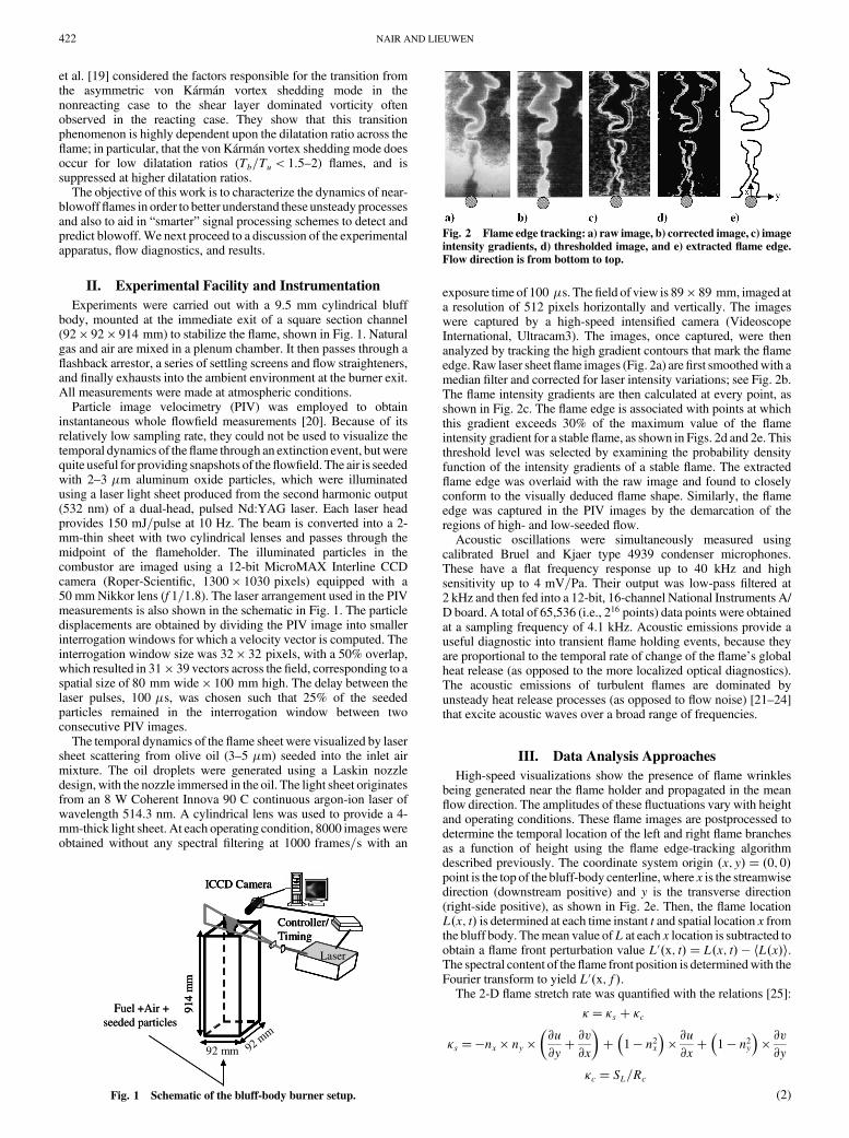
exposure time of 100 �s. Thefield of view is 89 � 89 mm, imaged ata resolution of 512 pixels horizontally and vertically. The imageswere captured by a high-speed intensified camera (VideoscopeInternational, Ultracam3). The images, once captured, were thenanalyzed by tracking the high gradient contours that mark the flameedge. Raw laser sheetflame images (Fig. 2a) arefirst smoothedwith amedian filter and corrected for laser intensity variations; see Fig. 2b.The flame intensity gradients are then calculated at every point, asshown in Fig. 2c. The flame edge is associated with points at whichthis gradient exceeds 30% of the maximum value of the flameintensity gradient for a stable flame, as shown in Figs. 2d and 2e. Thisthreshold level was selected by examining the probability densityfunction of the intensity gradients of a stable flame. The extractedflame edge was overlaid with the raw image and found to closelyconform to the visually deduced flame shape. Similarly, the flameedge was captured in the PIV images by the demarcation of theregions of high- and low-seeded flow.
Acoustic oscillations were simultaneously measured usingcalibrated Bruel and Kjaer type 4939 condenser microphones.These have a flat frequency response up to 40 kHz and highsensitivity up to 4 mV=Pa. Their output was low-pass filtered at2 kHz and then fed into a 12-bit, 16-channel National Instruments A/D board. A total of 65,536 (i.e., 216 points) data points were obtainedat a sampling frequency of 4.1 kHz. Acoustic emissions provide auseful diagnostic into transient flame holding events, because theyare proportional to the temporal rate of change of the flame’s globalheat release (as opposed to the more localized optical diagnostics).The acoustic emissions of turbulent flames are dominated byunsteady heat release processes (as opposed to flow noise) [21–24]that excite acoustic waves over a broad range of frequencies.
III. Data Analysis Approaches
High-speed visualizations show the presence of flame wrinklesbeing generated near the flame holder and propagated in the meanflow direction. The amplitudes of these fluctuations vary with heightand operating conditions. These flame images are postprocessed todetermine the temporal location of the left and right flame branchesas a function of height using the flame edge-tracking algorithmdescribed previously. The coordinate system origin �x; y� � �0; 0�point is the top of the bluff-body centerline, where x is the streamwisedirection (downstream positive) and y is the transverse direction(right-side positive), as shown in Fig. 2e. Then, the flame locationL�x; t� is determined at each time instant t and spatial location x fromthe bluff body. Themean value ofL at each x location is subtracted toobtain a flame front perturbation value L0�x; t� � L�x; t� � hL�x�i.The spectral content of theflame front position is determinedwith theFourier transform to yield L0�x; f�.
The 2-D flame stretch rate was quantified with the relations [25]:
�� �s � �c
�s ��nx � ny ��@u
@y� @v@x
��
�1 � n2x
�� @u@x�
�1 � n2y
�� @v@y
�c � SL=Rc(2)
Fuel +Air +seeded particles
Controller/Timing
ICCD Camera
Laser
92 mm
914
mm
Fuel +Air +seeded particles
Controller/Timing
ICCD Camera
Laser
914
mm
Controller/Timing
ICCD Camera
Laser
92 mm
914
mm
Fig. 1 Schematic of the bluff-body burner setup.
Fig. 2 Flame edge tracking: a) raw image, b) corrected image, c) imageintensity gradients, d) thresholded image, and e) extracted flame edge.Flow direction is from bottom to top.
422 NAIR AND LIEUWEN
The flame speed SL was obtained fromAndrews andBradley [26].The flame normals and curvatures were obtained from the flameedges and used in conjunction with the measured flowfield todetermine the component of � in the 2-D field of view.
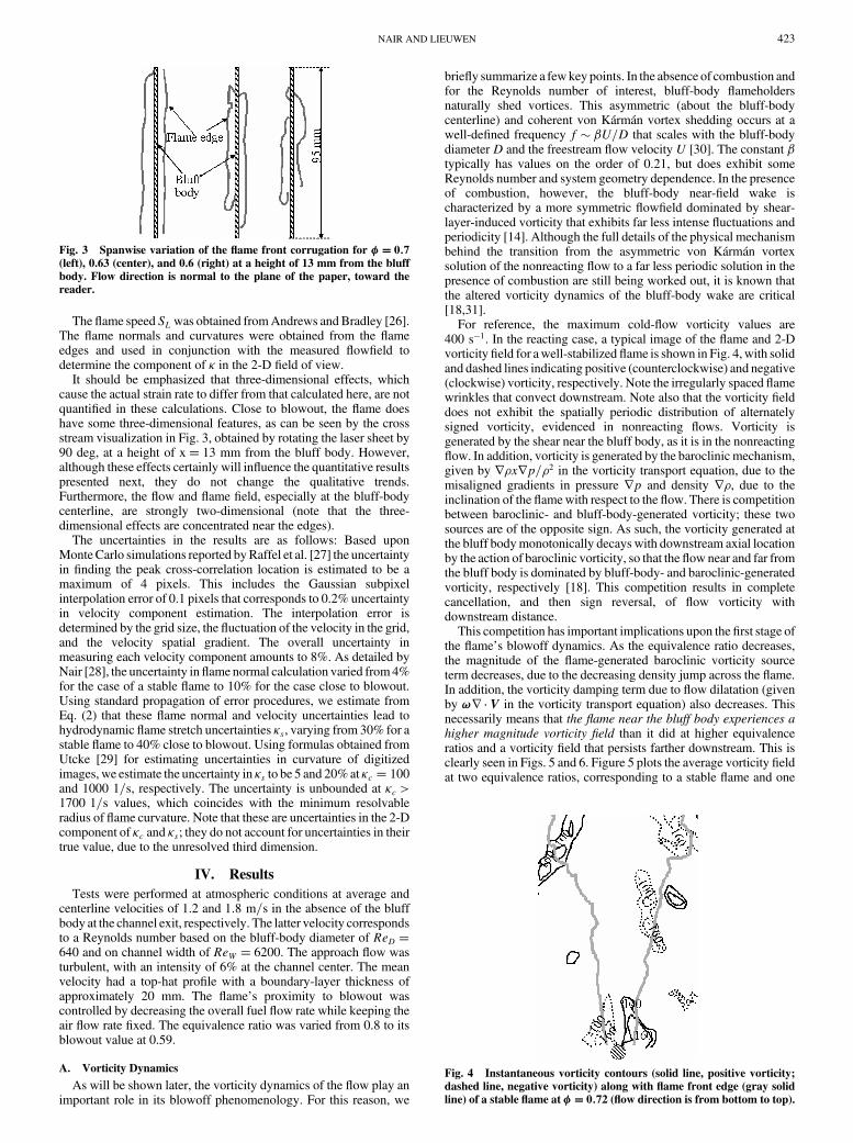
It should be emphasized that three-dimensional effects, whichcause the actual strain rate to differ from that calculated here, are notquantified in these calculations. Close to blowout, the flame doeshave some three-dimensional features, as can be seen by the crossstream visualization in Fig. 3, obtained by rotating the laser sheet by90 deg, at a height of x� 13 mm from the bluff body. However,although these effects certainly will influence the quantitative resultspresented next, they do not change the qualitative trends.Furthermore, the flow and flame field, especially at the bluff-bodycenterline, are strongly two-dimensional (note that the three-dimensional effects are concentrated near the edges).
The uncertainties in the results are as follows: Based uponMonteCarlo simulations reported byRaffel et al. [27] the uncertaintyin finding the peak cross-correlation location is estimated to be amaximum of 4 pixels. This includes the Gaussian subpixelinterpolation error of 0.1 pixels that corresponds to 0.2% uncertaintyin velocity component estimation. The interpolation error isdetermined by the grid size, the fluctuation of the velocity in the grid,and the velocity spatial gradient. The overall uncertainty inmeasuring each velocity component amounts to 8%. As detailed byNair [28], the uncertainty inflame normal calculation varied from4%for the case of a stable flame to 10% for the case close to blowout.Using standard propagation of error procedures, we estimate fromEq. (2) that these flame normal and velocity uncertainties lead tohydrodynamic flame stretch uncertainties �s, varying from 30% for astable flame to 40% close to blowout. Using formulas obtained fromUtcke [29] for estimating uncertainties in curvature of digitizedimages, we estimate the uncertainty in �s to be 5 and 20%at �c � 100and 1000 1=s, respectively. The uncertainty is unbounded at �c >1700 1=s values, which coincides with the minimum resolvableradius of flame curvature. Note that these are uncertainties in the 2-Dcomponent of �c and �s; they do not account for uncertainties in theirtrue value, due to the unresolved third dimension.
IV. Results
Tests were performed at atmospheric conditions at average andcenterline velocities of 1.2 and 1:8 m=s in the absence of the bluffbody at the channel exit, respectively. The latter velocity correspondsto a Reynolds number based on the bluff-body diameter of ReD �640 and on channel width of ReW � 6200. The approach flow wasturbulent, with an intensity of 6% at the channel center. The meanvelocity had a top-hat profile with a boundary-layer thickness ofapproximately 20 mm. The flame’s proximity to blowout wascontrolled by decreasing the overall fuel flow rate while keeping theair flow rate fixed. The equivalence ratio was varied from 0.8 to itsblowout value at 0.59.
A. Vorticity Dynamics
As will be shown later, the vorticity dynamics of the flow play animportant role in its blowoff phenomenology. For this reason, we
briefly summarize a fewkey points. In the absence of combustion andfor the Reynolds number of interest, bluff-body flameholdersnaturally shed vortices. This asymmetric (about the bluff-bodycenterline) and coherent von Kármán vortex shedding occurs at awell-defined frequency f � �U=D that scales with the bluff-bodydiameter D and the freestream flow velocity U [30]. The constant �typically has values on the order of 0.21, but does exhibit someReynolds number and system geometry dependence. In the presenceof combustion, however, the bluff-body near-field wake ischaracterized by a more symmetric flowfield dominated by shear-layer-induced vorticity that exhibits far less intense fluctuations andperiodicity [14]. Although the full details of the physical mechanismbehind the transition from the asymmetric von Kármán vortexsolution of the nonreacting flow to a far less periodic solution in thepresence of combustion are still being worked out, it is known thatthe altered vorticity dynamics of the bluff-body wake are critical[18,31].
For reference, the maximum cold-flow vorticity values are400 s�1. In the reacting case, a typical image of the flame and 2-Dvorticityfield for awell-stabilized flame is shown in Fig. 4,with solidand dashed lines indicating positive (counterclockwise) and negative(clockwise) vorticity, respectively. Note the irregularly spaced flamewrinkles that convect downstream. Note also that the vorticity fielddoes not exhibit the spatially periodic distribution of alternatelysigned vorticity, evidenced in nonreacting flows. Vorticity isgenerated by the shear near the bluff body, as it is in the nonreactingflow. In addition, vorticity is generated by the baroclinic mechanism,given by r�xrp=�2 in the vorticity transport equation, due to themisaligned gradients in pressure rp and density r�, due to theinclination of the flamewith respect to the flow. There is competitionbetween baroclinic- and bluff-body-generated vorticity; these twosources are of the opposite sign. As such, the vorticity generated atthe bluff bodymonotonically decays with downstream axial locationby the action of baroclinic vorticity, so that the flow near and far fromthe bluff body is dominated by bluff-body- and baroclinic-generatedvorticity, respectively [18]. This competition results in completecancellation, and then sign reversal, of flow vorticity withdownstream distance.
This competition has important implications upon the first stage ofthe flame’s blowoff dynamics. As the equivalence ratio decreases,the magnitude of the flame-generated baroclinic vorticity sourceterm decreases, due to the decreasing density jump across the flame.In addition, the vorticity damping term due to flow dilatation (givenby !r � V in the vorticity transport equation) also decreases. Thisnecessarily means that the flame near the bluff body experiences ahigher magnitude vorticity field than it did at higher equivalenceratios and a vorticity field that persists farther downstream. This isclearly seen in Figs. 5 and 6. Figure 5 plots the average vorticity fieldat two equivalence ratios, corresponding to a stable flame and one
Fig. 3 Spanwise variation of the flame front corrugation for �� 0:7(left), 0.63 (center), and 0.6 (right) at a height of 13 mm from the bluffbody. Flow direction is normal to the plane of the paper, toward thereader.
Fig. 4 Instantaneous vorticity contours (solid line, positive vorticity;dashed line, negative vorticity) along with flame front edge (gray solidline) of a stable flame at �� 0:72 (flow direction is from bottom to top).
NAIR AND LIEUWEN 423
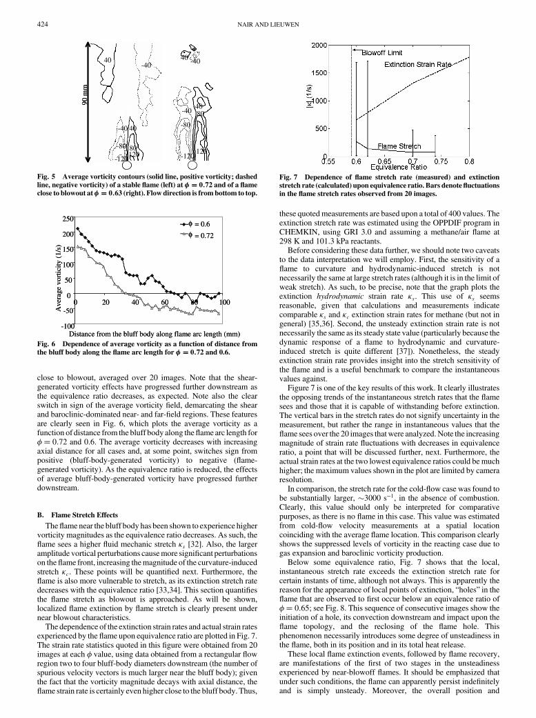
close to blowout, averaged over 20 images. Note that the shear-generated vorticity effects have progressed further downstream asthe equivalence ratio decreases, as expected. Note also the clearswitch in sign of the average vorticity field, demarcating the shearand baroclinic-dominated near- and far-field regions. These featuresare clearly seen in Fig. 6, which plots the average vorticity as afunction of distance from the bluff body along theflame arc length for�� 0:72 and 0.6. The average vorticity decreases with increasingaxial distance for all cases and, at some point, switches sign frompositive (bluff-body-generated vorticity) to negative (flame-generated vorticity). As the equivalence ratio is reduced, the effectsof average bluff-body-generated vorticity have progressed furtherdownstream.
B. Flame Stretch Effects
Theflame near the bluff body has been shown to experience highervorticity magnitudes as the equivalence ratio decreases. As such, theflame sees a higher fluid mechanic stretch �s [32]. Also, the largeramplitude vortical perturbations causemore significant perturbationson theflame front, increasing themagnitude of the curvature-inducedstretch �c. These points will be quantified next. Furthermore, theflame is also more vulnerable to stretch, as its extinction stretch ratedecreases with the equivalence ratio [33,34]. This section quantifiesthe flame stretch as blowout is approached. As will be shown,localized flame extinction by flame stretch is clearly present undernear blowout characteristics.
The dependence of the extinction strain rates and actual strain ratesexperienced by the flame upon equivalence ratio are plotted in Fig. 7.The strain rate statistics quoted in this figure were obtained from 20images at each � value, using data obtained from a rectangular flowregion two to four bluff-body diameters downstream (the number ofspurious velocity vectors is much larger near the bluff body); giventhe fact that the vorticity magnitude decays with axial distance, theflame strain rate is certainly even higher close to the bluff body. Thus,
these quoted measurements are based upon a total of 400 values. Theextinction stretch rate was estimated using the OPPDIF program inCHEMKIN, using GRI 3.0 and assuming a methane/air flame at298 K and 101.3 kPa reactants.
Before considering these data further, we should note two caveatsto the data interpretation we will employ. First, the sensitivity of aflame to curvature and hydrodynamic-induced stretch is notnecessarily the same at large stretch rates (although it is in the limit ofweak stretch). As such, to be precise, note that the graph plots theextinction hydrodynamic strain rate �s. This use of �s seemsreasonable, given that calculations and measurements indicatecomparable �s and �c extinction strain rates for methane (but not ingeneral) [35,36]. Second, the unsteady extinction strain rate is notnecessarily the same as its steady state value (particularly because thedynamic response of a flame to hydrodynamic and curvature-induced stretch is quite different [37]). Nonetheless, the steadyextinction strain rate provides insight into the stretch sensitivity ofthe flame and is a useful benchmark to compare the instantaneousvalues against.
Figure 7 is one of the key results of this work. It clearly illustratesthe opposing trends of the instantaneous stretch rates that the flamesees and those that it is capable of withstanding before extinction.The vertical bars in the stretch rates do not signify uncertainty in themeasurement, but rather the range in instantaneous values that theflame sees over the 20 images thatwere analyzed.Note the increasingmagnitude of strain rate fluctuations with decreases in equivalenceratio, a point that will be discussed further, next. Furthermore, theactual strain rates at the two lowest equivalence ratios could be muchhigher; the maximum values shown in the plot are limited by cameraresolution.
In comparison, the stretch rate for the cold-flow case was found tobe substantially larger, �3000 s�1, in the absence of combustion.Clearly, this value should only be interpreted for comparativepurposes, as there is no flame in this case. This value was estimatedfrom cold-flow velocity measurements at a spatial locationcoinciding with the average flame location. This comparison clearlyshows the suppressed levels of vorticity in the reacting case due togas expansion and baroclinic vorticity production.
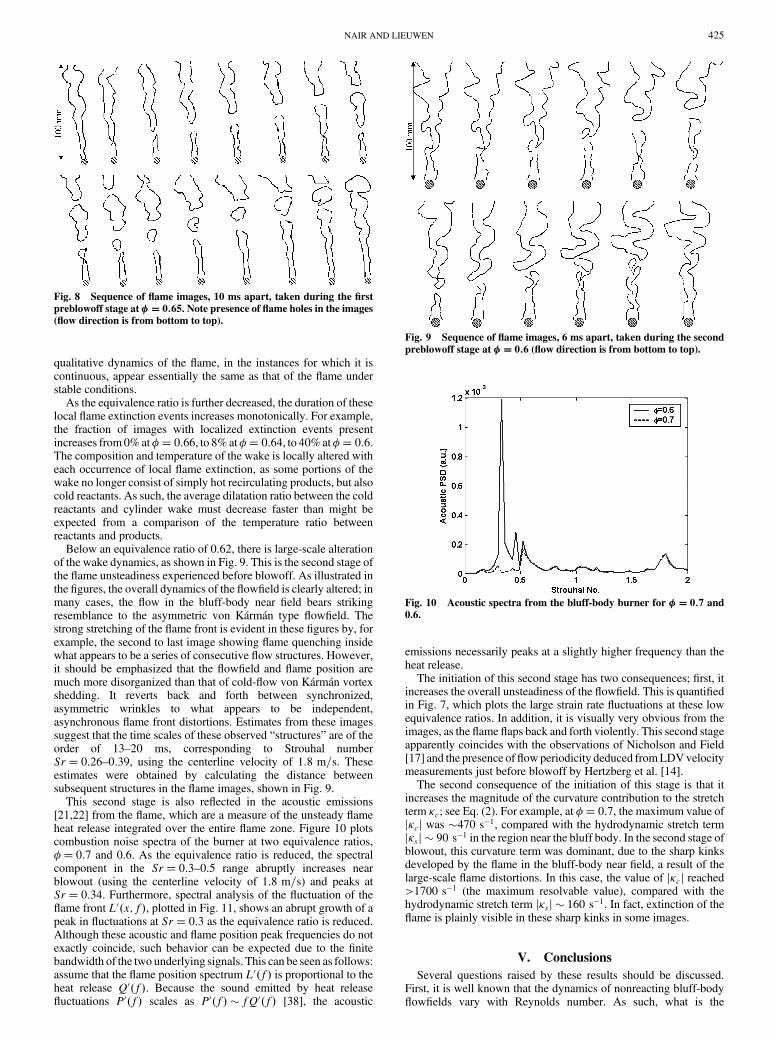
Below some equivalence ratio, Fig. 7 shows that the local,instantaneous stretch rate exceeds the extinction stretch rate forcertain instants of time, although not always. This is apparently thereason for the appearance of local points of extinction, “holes” in theflame that are observed to first occur below an equivalence ratio of�� 0:65; see Fig. 8. This sequence of consecutive images show theinitiation of a hole, its convection downstream and impact upon theflame topology, and the reclosing of the flame hole. Thisphenomenon necessarily introduces some degree of unsteadiness inthe flame, both in its position and in its total heat release.
These local flame extinction events, followed by flame recovery,are manifestations of the first of two stages in the unsteadinessexperienced by near-blowoff flames. It should be emphasized thatunder such conditions, the flame can apparently persist indefinitelyand is simply unsteady. Moreover, the overall position and
120-120
-80
8040
-40
-404040-40
120-120
-80 80
40-40
90 m
m
120-120
-80
8040
-40
-404040-40
120-120
-80 80
40-40
90 m
m
Fig. 5 Average vorticity contours (solid line, positive vorticity; dashedline, negative vorticity) of a stable flame (left) at �� 0:72 and of a flameclose to blowout at�� 0:63 (right). Flow direction is frombottom to top.
φφ
-100
-50
0
50
100
150
200
250
0 20 40 60 80 100
Distance from the bluff body along flame arc length (mm)
Ave
rage
vor
ticity
(1/
s)
= 0.6
= 0.72
φφ
-100
-50
0
50
100
150
200
250
0 20 40 60 80 100
Distance from the bluff body along flame arc length (mm)
Ave
rage
vor
ticity
(1/
s)
= 0.6
= 0.72
Fig. 6 Dependence of average vorticity as a function of distance fromthe bluff body along the flame arc length for �� 0:72 and 0.6.
Fig. 7 Dependence of flame stretch rate (measured) and extinctionstretch rate (calculated) upon equivalence ratio. Bars denote fluctuationsin the flame stretch rates observed from 20 images.
424 NAIR AND LIEUWEN
qualitative dynamics of the flame, in the instances for which it iscontinuous, appear essentially the same as that of the flame understable conditions.
As the equivalence ratio is further decreased, the duration of theselocal flame extinction events increases monotonically. For example,the fraction of images with localized extinction events presentincreases from0%at�� 0:66, to 8%at�� 0:64, to 40%at�� 0:6.The composition and temperature of the wake is locally altered witheach occurrence of local flame extinction, as some portions of thewake no longer consist of simply hot recirculating products, but alsocold reactants. As such, the average dilatation ratio between the coldreactants and cylinder wake must decrease faster than might beexpected from a comparison of the temperature ratio betweenreactants and products.
Below an equivalence ratio of 0.62, there is large-scale alterationof the wake dynamics, as shown in Fig. 9. This is the second stage ofthe flame unsteadiness experienced before blowoff. As illustrated inthe figures, the overall dynamics of the flowfield is clearly altered; inmany cases, the flow in the bluff-body near field bears strikingresemblance to the asymmetric von Kármán type flowfield. Thestrong stretching of the flame front is evident in these figures by, forexample, the second to last image showing flame quenching insidewhat appears to be a series of consecutive flow structures. However,it should be emphasized that the flowfield and flame position aremuch more disorganized than that of cold-flow von Kármán vortexshedding. It reverts back and forth between synchronized,asymmetric wrinkles to what appears to be independent,asynchronous flame front distortions. Estimates from these imagessuggest that the time scales of these observed “structures” are of theorder of 13–20 ms, corresponding to Strouhal numberSr� 0:26–0:39, using the centerline velocity of 1:8 m=s. Theseestimates were obtained by calculating the distance betweensubsequent structures in the flame images, shown in Fig. 9.
This second stage is also reflected in the acoustic emissions[21,22] from the flame, which are a measure of the unsteady flameheat release integrated over the entire flame zone. Figure 10 plotscombustion noise spectra of the burner at two equivalence ratios,�� 0:7 and 0.6. As the equivalence ratio is reduced, the spectralcomponent in the Sr� 0:3–0:5 range abruptly increases nearblowout (using the centerline velocity of 1:8 m=s) and peaks atSr� 0:34. Furthermore, spectral analysis of the fluctuation of theflame front L0�x; f�, plotted in Fig. 11, shows an abrupt growth of apeak in fluctuations at Sr� 0:3 as the equivalence ratio is reduced.Although these acoustic and flame position peak frequencies do notexactly coincide, such behavior can be expected due to the finitebandwidth of the two underlying signals. This can be seen as follows:assume that the flame position spectrum L0�f� is proportional to theheat release Q0�f�. Because the sound emitted by heat releasefluctuations P0�f� scales as P0�f� � fQ0�f� [38], the acoustic
emissions necessarily peaks at a slightly higher frequency than theheat release.
The initiation of this second stage has two consequences; first, itincreases the overall unsteadiness of the flowfield. This is quantifiedin Fig. 7, which plots the large strain rate fluctuations at these lowequivalence ratios. In addition, it is visually very obvious from theimages, as the flame flaps back and forth violently. This second stageapparently coincides with the observations of Nicholson and Field[17] and the presence offlowperiodicity deduced fromLDVvelocitymeasurements just before blowoff by Hertzberg et al. [14].
The second consequence of the initiation of this stage is that itincreases the magnitude of the curvature contribution to the stretchterm �c; see Eq. (2). For example, at �� 0:7, the maximum value ofj�cj was �470 s�1, compared with the hydrodynamic stretch termj�sj � 90 s�1 in the region near the bluff body. In the second stage ofblowout, this curvature term was dominant, due to the sharp kinksdeveloped by the flame in the bluff-body near field, a result of thelarge-scale flame distortions. In this case, the value of j�cj reached>1700 s�1 (the maximum resolvable value), compared with thehydrodynamic stretch term j�sj � 160 s�1. In fact, extinction of theflame is plainly visible in these sharp kinks in some images.
V. Conclusions
Several questions raised by these results should be discussed.First, it is well known that the dynamics of nonreacting bluff-bodyflowfields vary with Reynolds number. As such, what is the
Fig. 8 Sequence of flame images, 10 ms apart, taken during the firstpreblowoff stage at �� 0:65. Note presence of flame holes in the images(flow direction is from bottom to top).
Fig. 9 Sequence of flame images, 6 ms apart, taken during the secondpreblowoff stage at �� 0:6 (flow direction is from bottom to top).
Fig. 10 Acoustic spectra from the bluff-body burner for �� 0:7 and0.6.
NAIR AND LIEUWEN 425

generality of these results to higher Reynolds numbers and otherbluff-body configurations? The basic characteristics of the flowvorticity dynamics upon equivalence ratio noted in Fig. 6 are quitegeneral. These trends can be deduced from basic consideration ofvorticity transport; the fact that baroclinic vorticity is of opposite signto that of the shear-generated vorticity should not change withReynolds number or bluff-body configuration, assuming thepressure gradient remains similar. For example, recent measure-ments in an afterburner combustor simulator with a V-shapedflameholder at ReD � 20; 000 by Bush and Gutmark [39] showsimilar characteristics. Furthermore, the presence of localized flameextinction due to high strain rates is a fundamental combustion issue,which also should not be impacted by variations in Reynoldsnumber.
The structure of the flow and organized vortical structures likelywill change with Reynolds number, but in a manner that is unclear;for example, the presence and/or location of organized vorticalstructures in the near field of the bluff body under near-blowoffconditions. However, other results do suggest that similar flamedynamics appear at higher Reynolds numbers, as very similar imagesof the flame as seen in the second blowout stage reported here havebeen computed by Erickson et al. [19] at Re� 45; 000.
A second issue is the relationship between the two preblowoffstages. In particular, is the presence of the first stage (i.e., localizedflame extinction) a necessary condition for the second stage? Theanswer to this appears to be no, based upon simulation results ofErickson et al. [19], which solve a G equation for the flame positionand do not include flame extinction and temporal flame liftoff. Theyclearly show the presence of large-scale flame corrugation andalteration of the bluff-body wake dynamics, results very similar tothose reported here in Fig. 9. However, this behavior was onlyobserved at very low dilatation ratio values, around Tb=Tu � 1:5. Acommon thread between these two results, however, may be thepresence of a relatively small density ratio between the bluff-bodywake and the unburned reactants. In our experiments, this wasachieved through localized flame extinction, which results in coolingof the bluff-body wake by the recirculation of unburned reactantsinto it; even though the overall dilatation ratio between burnedproducts and reactants has a value of 5–6. In the simulations ofErickson et al. [19], because there is no extinction, the altered wakedynamics occur at low dilatation ratios.
Finally, a word on the actual blowoff event. Figure 7 suggests thatblowoff does not coincide with the point at which the average strainrate equals the extinction strain rate, as the flame blows off muchearlier (however, it is possible that the inclusion of the third,unresolved dimension would alter this conclusion). As such, blowoffmust be precipitated by a time-localized extinction event that is oflarge enough scale to cause irrecoverable blowoff. It is likely thatinitiation of this second stage is ultimately responsible for blowoff, asblowoff occurs at just a slightly lower equivalence ratio (�� 0:59)than the one at which this second stage initiates (�� 0:62). Perhapsone of the flame extinction events occurring in this second stageintroduces a slug of unreacted mixture into the recirculation zone,
which fails to ignite the incoming mixture, resulting in blowoff. Thisexplanation can be seen to have some corollaries to the interpretationof Zukoski [12], according to which, flame extinction occurs whenthe fresh mixture does not spend enough time in the shear layer to beignited by the hot recirculation zone. Although both interpretationsultimately consider a ratio of a chemical time and fluid mechanictime, Zukoski’s interpretation stresses the ratio of their averages. Incontrast, the present study emphasizes the instantaneous value of thisratio and the role of unsteady strain and fluid dynamics.
References
[1] Rosfjord, T. J., and Cohen, J. M., “Evaluation of the TransientOperation of Advanced Gas Turbine Combustors,” Journal of
Propulsion and Power, Vol. 11, No. 3, 1995, pp. 497–504.[2] Schefer, R. W., Wicksall, D. W., and Agrawal, A. K., “Combustion of
Hydrogen-Enriched Methane in a Lean Premixed Swirl-StabilizedBurner,”Proceedings of theCombustion Institute, Vol. 29, CombustionInst., Pittsburgh, PA, 2002, pp. 843–850.
[3] Shih, W. P., Lee, J., and Santavicca, D., “Stability and EmissionsCharacteristics of a Lean Premixed Gas Turbine Combustor,”Proceedings of the Combustion Institute, Vol. 26, Combustion Inst.,Pittsburgh, PA, 1996, pp. 2771–2778.
[4] Knaus, D. A., and Gouldin, F. C., “Measurements of FlameletOrientations in Premixed Flames with Positive and NegativeMarksteinNumbers,” Proceedings of the Combustion Institute, Vol. 28,Combustion Inst., Pittsburgh, PA, 2000, pp. 367–373.
[5] Chakravarthy, V. K., and Menon, S., “Large Eddy Simulations ofConfined Bluff Body Stabilized Highly Turbulent Premixed Flame-s,”American Society of Mechanical Engineers Paper 99-7798, 1999.
[6] Rhee, C., Talbot, L., and Sethian, J., “Dynamic Behavior of PremixedTurbulent V-Flame,” Journal of Fluid Mechanics, Vol. 300, Oct. 1995,pp. 87–115.
[7] Gouldin, F., and Cheng, R. K., “International Workshop on PremixedTurbulent Flames” Premixed Turbulent Flames Database on CMCS
[online database], http://eetd.lbl.gov/aet/combustion/workshop/work-shop.html [cited 16 Jan. 2006].
[8] Williams, G., Hottel, H., and Scurlock, A., “Flame Stabilization andPropagation in High Velocity Gas Streams,” Proceedings of the
Combustion Institute, Vol. 3, Combustion Inst., Pittsburgh, PA, 1951,pp. 21–40.
[9] Williams, G. C., and Shipman, C. W., “Some Properties of RodStabilized Flames of Homogeneous Gas Mixtures,” Proceedings of theCombustion Institute, Vol. 4, Combustion Inst., Pittsburgh, PA, 1953,pp. 733–742.
[10] Longwell, J. P., Chenevey, J., Clark, W., and Frost, E., “FlameStabilization byBaffles in aHighVelocity Gas Stream,”Proceedings ofthe Combustion Institute, Vol. 3, Combustion Inst., Pittsburgh, PA,1951, pp. 40–44.
[11] Zukoski, E. E., “Afterburners,” Aero-Thermodynamics of Gas Turbineand Rocket Propulsion, edited by G. Oates, AIAA, Reston, VA, 1997.
[12] Zukoski, E. E., and Marble, F. E., “The Role of Wake Transition in theProcess of Flame Stabilization in the Bluff Bodies,” AGARD
Combustion Researches and Reviews, Butterworths, London, 1954,pp. 167–180.
[13] Cantwell, B., and Coles, D., “An Experimental Study of Entrainmentand Transport in the Turbulent Near Wake of a Circular Cylinder,”Journal of Fluid Mechanics, Vol. 136, Nov. 1983, pp. 321–374.
[14] Hertzberg, J. R., Shepherd, I. G., and Talbot, L., “Vortex SheddingBehind Rod Stabilized Flames,” Combustion and Flame, Vol. 86,July 1991, pp. 1–11.
[15] Nair, S., “Acoustic Detection of Blowout Phenomenon,” Ph.D. Thesis,Georgia Inst. of Technology, Atlanta, May 2006.
[16] Nair, S., and Lieuwen, T., “Acoustic Detection of Blowout in PremixedFlames,” Journal of Propulsion and Power, Vol. 21, 2005, pp. 32–39.
[17] Nicholson, H., and Field, J., “Some Experimental Techniques for theInvestigation of the Mechanism of Flame Stabilization in the Wake ofBluff Bodies,” Proceedings of the Combustion Institute, Vol. 3,Combustion Inst., Pittsburgh, PA, 1951, pp. 44–68.
[18] Soteriou, M. C., and Mehta, P. G., “Combustion Heat Release Effectson the Dynamics of Bluff Body Stabilized Premixed Reacting Flows,”AIAA Paper 2003-0835, 2003.
[19] Erickson, R., Soteriou, M., and Mehta, P., “The Influence ofTemperature Ratio on the Dynamics of Bluff Body Stabilized Flames,”AIAA Paper 2006-0753, 2006.
[20] Westerweel, J., “Fundamentals of Digital Particle Image Velocimetry,”Measurement Science and Technology, Vol. 8, No. 12, 1997, pp. 1379–1392.
Fig. 11 Typical spectra of flame front fluctuations at a height of 75 mmfrom the bluff body at �� 0:7 and 0.6.
426 NAIR AND LIEUWEN
[21] Hurle, I. R., Price, R. B., Sugden, T. M., and Thomas, A., “SoundEmission from Open Turbulent Premixed Flames,” Proceedings of theRoyal Society of London, Series A, Vol. 303, 1968, pp. 409–427.
[22] Katsuki, M., Mizutani, Y., Chikami, M., and Kittaka, T., “SoundEmission from a Turbulent Flame,” Proceedings of the Combustion
Institute, Vol. 21, Combustion Inst., Pittsburgh, PA, 1986, pp. 1543–1550.
[23] Kotake, S., and Takamoto, K., “Combustion Noise: Effects of theVelocity Turbulence of Unburned Mixture,” Journal of Sound and
Vibration, Vol. 139, May 1990, pp. 9–20.[24] Putnam, A. A., “Combustion Roar of Seven Industrial Burners,”
Journal of the Institute of Fuel, Vol. 49, Sept. 1976, pp. 135–138.[25] Chung, S. H., and Law, C. K., “An Invariant Derivation of Flame
Stretch,” Combustion and Flame, Vol. 55, Aug. 1984, pp. 123–125.[26] Andrews, G. E., and Bradley, D., “Burning Velocity Of Methane-Air
Mixtures,” Combustion and Flame, Vol. 19, Oct. 1972, pp. 275–288.
[27] Raffel, M., Willert, C., and Kompenhans, J., Particle Image
Velocimetry: A Practical Guide, Springer–Verlag, Berlin, 1998.[28] Nair, S., “Acoustic Characterization of Flame Blowout Phenomenon,”
Ph.D. Thesis, Georgia Inst. of Technology, Atlanta, 2006.[29] Utcke, S., “Error Bounds on Curvature Estimation,” in Scale-Space
2003, edited by L. D. Griffin, and M. Lillholm, Springer–Verlag,Heidelberg, Germany, 2003, pp. 657–666.
[30] Williamson, C. H. K., “Vortex Dynamics in the Cylinder Wake,”Annual Review of Fluid Mechanics, Vol. 28, Jan. 1996, pp. 477–539.
[31] Coats, C. M., “Coherent Structure in Combustion,” Progress in Energyand Combustion Science, Vol. 22, No. 5, 1996, pp. 427–509.
[32] Rehm, J. E., and Clemens, N. T., “Relationship Between Vorticity/Strain and Reaction Zone Structure in Turbulent Non-Premixed JetFlames,” Proceedings of the Combustion Institute, Vol. 27,Combustion Inst., Pittsburgh, PA, 1998, pp. 1113–1120.
[33] Poinsot, T., and Veynante, D., Theoretical and Numerical Combustion,R. T. Edwards, Flourtown, PA, 2001.
[34] Sung, C. J., and Law, C. K., “Extinction Mechanisms of Near-LimitPremixed Flames and Extended Limits of Flammability,” Proceedingsof the Combustion Institute, Vol. 26, Combustion Inst., Pittsburgh, PA,1996, pp. 865–873.
[35] Kobayashi, H., and Kitano, M., “Extinction Characteristics of aStretched Cylindrical Premixed Flame,” Combustion and Flame,Vol. 76, Nos. 3–4, 1989, pp. 285–296.
[36] Wang, P., Hu, S., Wehrmeyer, J., and Pitz, R., “Stretch and CurvatureEffects on Flames,” AIAA Paper 2004-148, 2004.
[37] Joulin, G., “On the Response of Premixed Flames to Time DependentStretch and Curvature,” Combustion Science and Technology, Vol. 97,Apr. 1994, pp. 219–229.
[38] Strahle, W. C., “On Combustion Generated Noise,” Journal of FluidMechanics, Vol. 49, No. 2, 1971, pp. 399–414.
[39] Bush, S., and Gutmark, E., “Reacting and Nonreacting Flow Fields of aV-Gutter Stabilized Flame,” AIAA Paper 2006-807, 2006.
J. OefeleinAssociate Editor
NAIR AND LIEUWEN 427