FLAME RETARDANCY, THERMAL CONDUCTIVITY AND ...
78
EFFECTS OF SOME ADDITIVES ON THE PROPERTIES OF RIGID POLYURETHANE FOAMS: FLAME RETARDANCY, THERMAL CONDUCTIVITY AND COMPRESSIVE STRENGTH EMRE AKDOĞAN MSc. Thesis Eskişehir, 2018
-
Upload
khangminh22 -
Category
Documents
-
view
5 -
download
0
Transcript of FLAME RETARDANCY, THERMAL CONDUCTIVITY AND ...
EFFECTS OF SOME ADDITIVES ON THE PROPERTIES OF RIGID POLYURETHANE FOAMS:
FLAME RETARDANCY, THERMAL CONDUCTIVITY AND COMPRESSIVE STRENGTH
EMRE AKDOĞAN
MSc. Thesis
Eskişehir, 2018

TITLE PAGE
EFFECTS OF SOME ADDITIVES ON THE PROPERTIES OF RIGID POLYURETHANE FOAMS: FLAME RETARDANCY, THERMAL
CONDUCTIVITY AND COMPRESSIVE STRENGTH
EMRE AKDOĞAN
MSc. THESIS Chemistry Department
Supervisor: Assoc. Prof. Dr. Murat ERDEM
Eskişehir Anadolu University
Graduate School of Sciences January, 2018
This master thesis was funded within the project number 1606F561 accepted by Anadolu University Scientific Research Project.

FINAL APPROVAL FOR THESIS
This thesis titled “Effects of Some Additives on The Properties of Rigid
Polyurethane Foams: Flame Retardancy, Thermal Conductivity and Compressive
Strength” has been prepared and submitted by Emre Akdoğan in partial fullfillment of
the requirements in “Anadolu University Directive on Graduate Education and
Examination” for the Degree of Master of Science in Chemistry Department has been
examined and approved on …../…../……..
Committee Members Title Name Surname Signature
Member (Supervisor) : Assoc. Prof. Dr. Murat ERDEM .......................
.. Member (Co-Supervisor) : Prof. Dr. Mustafa Erdem ÜREYEN .......................
.. Member : Prof. Dr. Yücel ŞAHİN .......................
.. Member : Prof. Dr. Ender SUVACI .......................
.. Member : Assoc.Prof. Dr. İlhami ÇELİK .......................
..
Prof.Dr. Ersin YÜCEL
Director of Graduate School of Sciences

iii
ABSTRACT
EFFECTS OF SOME ADDITIVES ON THE PROPERTIES OF RIGID POLYURETHANE FOAMS: FLAME RETARDANCY, THERMAL
CONDUCTIVITY AND COMPRESSIVE STRENGTH
Emre AKDOĞAN Chemistry Program
Anadolu University, Graduate School of Science, January 2018
Supervisor: Assoc. Prof. Dr. Murat ERDEM
Co-Supervisor: Prof. Dr. Mustafa Erdem ÜREYEN
In this study, rigid polyurethane foam composites containing aluminum trihydrate
(ATH), zinc borate (ZnB), triphenyl phosphate (TPhP), and their binary blends were
prepared by using one-shot method. Additive amounts were varied from 10% to 50% by
polyol weight percentage, and the weight fractions of the binary blends were also fixed
at 40%. The flame retardancy, thermal insulation, and mechanical properties of the foam
composites were investigated. Limiting oxygen index (LOI), horizontal burning and cone
calorimeter tests were performed for flame retardancy. The surface morphology, closed
cell content, density, thermal conductivity and compressive strength of the foams are
determined. All additives showed increases in the LOI values and decreases in the flame
spread rates. Self-extinguishing was observed for the composites of 40% and 50% by
polyol weight percentage. In most cases, peak heat release rate and total heat release of
composites were less than those of rigid polyurethane foam. Composites with TPhP
exhibited the higher amount of carbon monoxide release while composites incorporated
with ATH diminished the carbon monoxide production. Composites filled with ATH
demonstrated reduced total smoke release and total smoke production. The thermal
conductivity values of composites containing ATH and ZnB showed decreases until the
level of 7.8% compared to the foam without additives. The compressive strength values
of almost all foam composites were observed to be above 120 kPa, which is an acceptable
value for most of the applications. All of the results revealed that composites possessing
both improved flame retardancy and preserved/improved thermal and mechanical
properties can meet the demands from the foam industries.
Keywords: Rigid polyurethane foam, Composite, Flame retardancy, Thermal
conductivity, Compressive strength.

iv
ÖZET
BAZI KATKILARIN SERT POLİÜRETAN KÖPÜKLERİN ÖZELLİKLERİ ÜZERİNE ETKİLERİ: ALEV GECİKTİRİCİLİK, ISIL İLETKENLİK
VE BASMA DAYANIMI
Emre AKDOĞAN Kimya Bölümü
Anadolu Üniversitesi, Fen Bilimleri Enstitüsü, Ocak 2018
Danışman: Doç. Dr. Murat ERDEM
İkinci Danışmanı: Prof. Dr. Mustafa Erdem ÜREYEN Bu tez çalışmasında, alüminyum hidroksit (ATH), çinko borat (ZnB), trifenil fosfat
(TPhP) ve bunların ikili karışımlarını içeren sert poliüretan köpük kompozitler tek atış
yöntemi kullanılarak hazırlanmıştır. Katkı miktarı, poliole göre ağırlıkça %10’dan
%50’ye kadar değiştirilmiştir. İkili karışımlarda ise bu oran poliole göre ağırlıkça %40’a
sabitlenmiştir. Kompozitlerin alev geciktiricilik, ısıl yalıtım ve mekanik özellikleri
incelenmiştir. Alev geciktiricilik için sınırlayıcı oksijen indeksi (LOI), yatay yanma ve
konik kalorimetre testleri yapılmıştır. Köpüklerin yüzey morfolojileri, kapalı hücre
içerikleri, yoğunlukları, ısıl iletkenlik ve basma dayanımları belirlenmiştir. Tüm katkılar
LOI değerlerini arttırırken, alev yayılma hızlarını düşürmüştür. Poliole göre ağırlıkça
%40 ve %50 katkı oranlarında bazı kompozitler için alevin kendiliğinden söndüğü
gözlemlenmiştir. Birçok durumda kompozitlerin pik ısı salınım oranları ve toplam ısı
salınımları sert poliüretan köpükten daha düşüktür. ATH katkılı kompozitlerin yanması
ile toksik karbonmonoksit salınımı azalırken, TPhP içeren kompozitler yüksek miktarda
karbonmonoksit salınımına neden olmuştur. Ayrıca, ATH kullanımı toplam duman
salınımını da azaltmıştır. ATH ve ZnB içeren kompozitlerin ısıl iletkenlik değerleri
katkısız köpüğe göre %7,8’e kadar düşürülmüştür. Neredeyse tüm kompozitlerin basma
mukavemet değerleri birçok uygulama için kabul edilir bir değer olan 120 kPa’ın üstünde
olduğu belirlenmiştir. Tüm sonuçlar birlikte değerlendirildiğinde, iyileştirilmiş yanma
özelliklerinin yanısıra ısıl yalıtım ve mekanik özellikleri de korunmuş/iyileştirilmiş bu
kompozitlerin, sert poliüretan köpük endüstrisinin taleplerini karşılayabileceği ifade
edilebilir.
Anahtar Kelimeler: Sert poliüretan köpük, Kompozit, Alev geciktiricilik, Isıl iletkenlik,
Basma mukavemeti.

v
ACKNOWLEDGEMENTS
I have been working for the completion of this master’s thesis at the Department of
Chemistry, Anadolu University, since February 2015, and this study has been funded by
Anadolu University (Scientific Research Project Code: 1606F561). I am greatly thankful
to a number of very important people for their immense support and help. It is, therefore,
with great pleasure that I express my gratitude to all of them.
First and foremost, I would like to show my appreciation to my supervisor, Assoc.
Prof. Dr. Murat Erdem, for his mentorship, support, technical guidance, and insightful
comments over the years. Besides my advisor, I am sincerely thankful to my co-
supervisor, Prof. Dr. Mustafa Erdem Üreyen, for his help in the direction of this thesis. I
would also like to thank the committee members, Prof. Dr. Yücel Şahin, Prof. Dr. Ender
Suvacı and Assoc. Prof. Dr. İlhami Çelik for their advice and helpful suggestions with
regard to my thesis.
I also owe a thank you to Asst. Prof. Dr. Bilge Erdem and Asst. Prof. Dr. Sultan
Funda Ekti for their monumental support and help on both my research as well as my life.
I would also like to thank Arçelik Inc., Eskişehir for providing me with the materials
necessary for the completion of this thesis. In particular, I would like to acknowledge
Gökşin Sayer, Metin Kaya and Ceren Irmak Karameşe for the numerous fruitful
discussions on rigid polyurethane foams. I would also like to thank the all members of
the PU mixing room and those of the combustion laboratory in Arçelik Inc. for helping
me during my journey with the thesis. Additionally, I would like thank Entekno Materials
for providing me with aluminum trihydrate as much as I need.
I am also grateful to the Civil Aviation Research Center and its member, Feyzullah
Gündoğan, for helping me in the conduction of cone calorimeter and LOI tests.
I would also thank my friends, Yalçın Kılıç, Tuğçe Günay, Kübra Sarper, Tuğba
Alp Arıcı, Serkan Bolat, Burak Berber and Aysun Gençtürk for supporting me no matter
what.
Finally, I want to express my gratitude to my mother, my father, and my sister for
all of the sacrifices that they made on my behalf for the successful completion of the
thesis.
Emre AKDOĞAN
January 2018

vi
..../..../20.... STATEMENT OF COMPLIANCE WITH ETHICAL PRINCIPLES AND RULES
I hereby truthfully declare that this thesis is an original work prepared by me; that
I have behaved in accordance with the scientific ethical principles and rules throughout
the stages of preparation, data collection, analysis and presentation of my work; that I
have cited the sources of all the data and information that could be obtained within the
scope of this study, and included these sources in the references section; and that this
study has been scanned for plagiarism with “scientific plagiarism detection program” used
by Anadolu University, and that “it does not have any plagiarism” whatsoever. I also
declare that, if a case contrary to my declaration is detected in my work at any time, I hereby
express my consent to all the ethical and legal consequences that are involved.
Emre AKDOĞAN

vii
TABLE OF CONTENTS
Page
TITLE PAGE ............................................................................................................... i
FINAL APPROVAL FOR THESIS ........................................................................... ii
ABSTRACT ............................................................................................................... iii
ÖZET.......................................................................................................................... iv
ACKNOWLEDGEMENTS ........................................................................................ v
STATEMENT OF COMPLIANCE WITH ETHICAL PRINCIPLES AND
RULES ...................................................................................................................... vi
TABLE OF CONTENTS .......................................................................................... vii
LIST OF TABLES ..................................................................................................... ix
LIST OF FIGURES .................................................................................................... x
ABBREVIATIONS ................................................................................................... xii
1. INTRODUCTION .................................................................................................. 1
1.1. Research Objective .......................................................................................... 1
1.2. The History and Development of Polyurethane ............................................. 2
1.3. Rigid Polyurethane Foam................................................................................ 4
1.3.1. Polyols .................................................................................................... 5
1.3.2. Isocyanates / Polyisocyanates ................................................................ 6
1.3.3. Blowing agents ....................................................................................... 7
1.3.4. Catalysts ................................................................................................. 9
1.3.5. Surfactants ........................................................................................... 10
1.4. Process of Rigid Polyurethane Foam Preparation ....................................... 10
1.5. Combustion .................................................................................................... 11
1.5.1. Flame retardants ................................................................................. 14
1.6. Thermal Conductivity of Rigid Polyurethane Foams .................................. 16
1.7. Mechanical Properties of Rigid Polyurethane Foams .................................. 18
2. LITERATURE REVIEW .................................................................................... 20
3. EXPERIMENTAL STUDIES .............................................................................. 24

viii
3.1. Raw Materials ................................................................................................ 24
3.2. Foam Preparation .......................................................................................... 24
3.3. Characterization Methods ............................................................................. 26
4. RESULTS and DISCUSSIONS ........................................................................... 31
4.1. Changes in Flame Retardancy Properties .................................................... 31
4.1.1. Effects of ATH, TPhP and ZnB .......................................................... 31
4.1.2. Effect of blends .................................................................................... 38
4.1.3. Flame retardancy mechanism ............................................................. 40
4.2. Changes in Thermal Conductivity of the Composites .................................. 44
4.2.1. Effects of ATH, TPhP and ZnB .......................................................... 44
4.2.2. Effects of blends ................................................................................... 47
4.3. Changes in Compressive Strength ................................................................ 49
4.3.1. Effects of ATH, TPhP and ZnB .......................................................... 49
4.3.2. Effects of blends ................................................................................... 51
5. CONCLUSIONS AND SUGGESTIONS ............................................................. 54
REFERENCES ......................................................................................................... 57
RESUME
ix
LIST OF TABLES
Page
Table 1.1. Physical and environmental properties some important blowing agents ........ 9
Table 3.1. Compositions of RPUFCs’ ......................................................................... 26
Table 4.1. Results of cone calorimeter tests ................................................................ 37
Table 4.2. Theoretical and experimental LOI values of RPUFC .................................. 39
Table 4.3. Results of cone calorimeter tests for blends ................................................ 43
Table 4.4. Closed cell content of the composites......................................................... 46
Table 4.5. Closed cell content of the composites containing blends ............................ 48

x
LIST OF FIGURES
Page
Figure 1.1. Applications of polyurethanes .................................................................. 3
Figure 1.2. Percentage global consumption of plastics in 2012 ................................... 3
Figure 1.3. Fundamental reaction of polyurethane ...................................................... 4
Figure 1.4. Basic of preparation of foam..................................................................... 4
Figure 1.6. Important isocyanates ............................................................................... 6
Figure 1.7. Resonance structures of the isocyanate group ........................................... 7
Figure 1.8. Isocyanates/water reaction ........................................................................ 8
Figure 1.9. Chemical structure of dimethyl polysiloxane .......................................... 10
Figure 1.10. One-shot process .................................................................................... 11
Figure 1.11. Semi-prepolymer process ....................................................................... 11
Figure 1.12. Prepolymer process ................................................................................ 11
Figure 1.13. Fire triangle ............................................................................................ 12
Figure 1.14. Stages of fire .......................................................................................... 13
Figure 1.15. Chemical mechanism of flame retardants................................................ 14
Figure 1.16. Equivalent thicknesses for the same thermal insulation properties of
different materials .................................................................................. 17
Figure 1.17. Thermal heat transfer mechanism of RPUF ............................................ 18
Figure 3.1. Process of RPUFC production ................................................................ 25
Figure 3.2. Heat flow meter system .......................................................................... 27
Figure 3.3. Gas displacement pycnometer system ..................................................... 28
Figure 3.4. Schematic representation of UL 94 HB test ............................................ 29
Figure 3.5. Cone calorimeter .................................................................................... 30
Figure 3.6. Schematization of analysis process ......................................................... 30
Figure 4.1. Effect of FR type and amount on the rate of flame spread ....................... 32
Figure 4.2. Effect of FR type and amount on the LOI ............................................... 33
Figure 4.3. RPUF sample for cone calorimeter test (before and after burning) .......... 35
Figure 4.4. Effect of FR type and amount on the HRR: a) ATH, b) TPhP, c) ZnB .... 36
Figure 4.5. Effect of blend type and composition on the rate of flame spread
UL 94 HB) ............................................................................................. 38
Figure 4.6. Effect of blend type and composition on the LOI .................................... 39

xi
Figure 4.7. Illustration of flame retardancy mechanism of RPUFC containing
ATH/TPhP ............................................................................................. 41
Figure 4.8. Effect of blend type and composition on the HRR: a) ATH-TPhP,
b) ATH-ZnB, c) ZnB-TPhP .................................................................... 42
Figure 4.9. SEM images of the foams a) RPUF, b) 10A, c) 30A, d) 50A, e) 10T,
f) 30T, g) 50T ......................................................................................... 44
Figure 4.10. Effect of FR type and amount on the mean cell size ................................ 45
Figure 4.11. Effect of FR type and amount on the thermal conductivity...................... 46
Figure 4.12. Effect of blend type and composition on the mean cell size .................... 47
Figure 4.13. SEM images of the foams a) RPUF, b) 30A/10T, c) 20A/20T,
d) 10A/30T ............................................................................................. 48
Figure 4.14. Effect of blend type and composition on the thermal conductivity .......... 49
Figure 4.15. Effect of FR type and amount on the density .......................................... 50
Figure 4.16. Effect of FR type and amount on the compressive strength ..................... 51
Figure 4.17. Effect of blend type and composition on the density ............................... 52
Figure 4.18. Effect of blend type and composition on the compressive strength .......... 53

xii
ABBREVIATIONS
AHP : Aluminum hypophosphite
APP : Ammonium polyphosphate
ATH : Aluminum trihydrate
CFC : Chlorofluorocarbon
CFC-11 : Trichlorofluoromethane
DMMP : Dimethyl methylphosphate
DPPM : 2,2-diethyl-1,3propanediol phosphoryl melamine
EG : Expandable graphite
FR : Flame retardant
H-CFC : Hydrogen chlorofluorocarbon
H-FC : Hydrogen fluorocarbon
HFM : Heat Flow Meter
HRR : Heat release rate
LOI : Limiting oxygen index
MARHE : Maximum average rate of heat emission
MDH : Magnesium hydroxide
MDI : Diphenylmethane diisocyanate
OMMT : Organic modified montmorillonite
ONC : Organic modified nanoclay
pEG : Pulverized-EG
php : Per hundred polyol by weight
pHRR : Peak heat release rate
pMDI : Polymethylene polyphenyl diisocynate
PMMA : Poly(methylmethacrylate)
PU : Polyurethane
RIM : Reaction injection molding
RPUF : Rigid polyurethane foam
RPUFC : Rigid polyurethane foam composite
SEM : Scanning Electron Microscope
SNGO : SiO2 nanospheres/GO hybrid
t pHRR : Time peak heat release rate
TDI : Toluen diisocyanate

xiii
TGA : Thermogravimetric analysis
THR : Total heat release rate
TPhP : Triphenyl phosphate
TSP : Total smoke production
TSR : Total smoke release rate
TTI : Time to ignition
UL 94-HB : UL 94 horizontal burning
V : Burning rate
ZnB : Zinc borate

1
1. INTRODUCTION
1.1. Research Objective
Fire constitutes a tremendous destructive force in the physical world. For instance,
at the end of the 2016 in Istanbul, there has been a 12% increase in all fires compared to
2012 (http-1). Fires are extremely challenging to combat and, at times, even impossible
to keep under control. They cause extensive damage to human life and property every
year. Several industries have been working over a long period of time to prevent or at
least to retard the threat fire poses to living beings and livelihood.
Polymeric materials, which are easy to manufacture and employ, are easily
combustible because of their organic structure. As in the case of a majority of polymeric
materials, rigid polyurethane foam (RPUF) is also easily combustible. As a matter of fact,
it is more combustible than other materials as a result of its rigid cellular and organic
structure, additionally it contains flammable, explosive gases in its closed cells. During a
RPUF burn, toxic gases that are extremely harmful to human health and the environment
are released (Levchik and Weil, 2004, p. 1598), thus effectively limiting the use of
RPUFs. To reduce the combustibility of RPUFs, various materials referred to as flame
retardants (FR) are added during the production stages, such as alumina trihydrate (ATH),
expandable graphite (EG), and triphenyl phosphate (TPhP). In such cases, the most
important thing is to possess knowledge of the combustion stages of RPUF and select a
proper FR accordingly. At the same time, it is essential to ensure that the mechanical and
thermal insulation properties are not compromised by the addition of the FR.
The research objective of this project was to investigate, by means of
experimentation, the combustion tendency of the RPUFs and produce rigid polyurethane
foam composites (RPUFCs) with better thermal resistance compared to RPUFs with the
addition of FR blends. One of the best methods toward the reduction of the combustion
tendency of RPUFs is to use synergistic FR blends. Furthermore, the composite materials
must preserve both the mechanical and the thermal insulation performance of RPUFCs
and considerably reduce the production costs. The most effective method to improve
thermal insulation is to decrease the cell size of RPUF. The FR additives may also act as
agents for decreasing the cell size of RPUF, subsequently improving the thermal
insulation and mechanical properties of foam structures.
The obtained composite materials of RPUFs will work to make more time available
for the victims of fire to escape and douse the fire. Thus, it can be said that the materials

2
added as FRs will have the potential to limit the loss of life and property. The composites
of RPUFs used in home refrigerator industries in particular will have better thermal
insulation performances with respect to the neat RPUF, thus reducing the consumption of
energy. The new materials are also aimed at the prevention of the loss of energy by the
enhancement of thermal insulation.
1.2. The History and Development of Polyurethane
Dr. Otto Bayer and his coworkers were researching for a new material in response
to Wallace Carother’s work on polyamides and polyesters, known as nylons. Then,
polyurethane (PU) was developed by Dr. Otto Bayer, recognized as the “father of
polyurethane” in 1937 at the I.G. Farben Laboratories in Leverkusen, Germany (Szycher,
1999, p. 1). After toluene diisocyanate (TDI) was invented in the 1940s, PUs had begun
to be utilized as foams, coatings, and cast elastomers (Fink, 2013, p. 69). The first foams
were also based on TDI, and RPUFs were used as the insulation material to cover a beer
barrel for the first time in 1948. PU elastomers and rigid foams had begun to be used in
adhesives by the 1950s. Steel sandwich building panels were produced with the RPUFs
for the first time in the year 1960. RPUFs had started to be employed as spray building
insulation by 1979. Today, thermal insulation and construction are the biggest markets in
the RPUF industry.
From the day PU was first discovered till today, several different types of PU
materials have been discovered. PU is said to be a unique material for consumers owing
to its performance and durability. The applications of PU have been depicted in Figure
1.1. PUs can be classified in the following seven main groups based on their application:
flexible slab, flexible molded foam, rigid foams, solid elastomers, reaction injection
molding (RIM), carpet backing, and two component formulations.

3
Figure 1.1. Applications of polyurethanes (Szycher, 1999, p. 3)
PU has a gigantic market share in the plastic industry, and the demand for rigid and
flexible foam is increasing significantly day by day. According to marketing research
results, the global market revenue of PU foams was estimated to be worth $40.1 billion
in 2012 and $46.8 billion in 2014, and it is expected to escalate to $72.2 billion by 2020
(Marketandmarkets.com, 2015, p. 37). In 2010, the consumption of polyurethane was
about 5%, but by 2012, the percentage had increased to 6% in all plastic industries. Figure
1.2 presents the percentage of global consumption of plastics in 2012.
Figure 1.2. Percentage global consumption of plastics in 2012 (Sonnenschein, 2014, p.2)
Polyurethane6%Styrenics
7%
Polyethylene terephthalate
7%
Polyvinyl chloride
13%
Polypropylene19%
Polyethylene 29%
All others19%

4
1.3. Rigid Polyurethane Foam
RPUFs manufactured in large amounts are one of the most important thermoset
polymers. PU is essentially a high molecular mass polymer that is produced as a result of
polyaddition, polycondensation, or stepwise polymerization between polyisocyanates
containing N=C=O groups and polyols containing O−H groups, as shown in Figure 1.3.
Figure 1.3. Fundamental reaction of polyurethane
RPUF is formed by the reaction of a polyisocyanate with a polyol in the presence
of a selected catalyst, surfactant, and blowing agent. The basic steps involved in the
preparation of foam are illustrated in Figure 1.4.
Figure 1.4. Basic of preparation of foam (Landrock, 1995, p. 41)
RPUFs are one of the versatile materials that have a wide range of applications,
varying from domestic appliances to the automotive industry. They have several
particular advantages as listed below:
• Excellent thermal insulation properties
• Produced in a wide range of densities
• Great adhesion to many type of materials, such as metal, wood, glass, and ceramics
HOR1
OH +n R2NCOOCNn
OR1
OC
O
NH
R2NH
C
O
n

5
• Ease of applications by spraying or pouring
• Display a broad range of physical properties (Szycher, 1999, p. 258)
1.3.1. Polyols
Polyols consisting of at least two hydroxyl groups are one of the main reaction
partners with diisocyanates for the production of RPUFs. They react with N=C=O groups
of polyisocyanate to form urethane linkages. There are two essential polyols for rigid
foams—polyethers and polyesters. The physical properties of the final product are
considerably affected by the choice of the polyol. The rigidity or the flexibility of the
foam, its brittleness or sturdiness, and the degree of its permeability to gas and moisture
are determined by the polyol used (Szycher, 1999, p. 267).
Figure 1.5. Chemical structure of polyester and polyether (Sonnenschein, 2014, p.4)
There are some points that can be used in the determination of the characteristics of
polyols, such as equivalent weight, functionality, and rigidity or flexibility of the chain
units. For example, if the equivalent weight of the polyol decreases, i.e., if the hydroxyl
number increases, the compressive strength and dimensional stability will show a
subsequent increase. The functionality of polyols also has considerable influence on the
properties of the RPUFs. For instance, if a polyol having higher functionality is used, the
RPUF will possess better heat resistance, dimensional stability, and compressive strength
(Szycher, 1999, p. 268). In the recent years, foam industries have begun to use special
polyols containing either halogen or phosphorous or both of them. These types of polyols
are developed in an attempt to improve FR performances. The first halogenated polyester
based polyol was discovered by Boulet and coworkers. (Boulet et al., 1979, U.S. Patent
No. 4,173,710). For rigid foams, polyether-based polyols, which have ranging hydroxyl
number from 350 to 600 mg KOH/g of polyol, are mostly preferred. In the year 2012, the

6
production of polyether-based polyol was about 75% of the total polyol production
(Sonnenschein, 2014, p. 28).
1.3.2. Isocyanates / Polyisocyanates
The importance of isocyanates, especially of polymeric isocyanates, is clearly seen
in polyurethane chemistry. Toluene diisocyanate (TDI), diphenylmethane diisocyanete
(MDI), and polymethylene polyphenyl diisocyanete (pMDI) are commonly used in rigid
foam production. These isocyanates and their isomers are demonstrated in Figure 1.6.
Isocyanates serve several purposes in RPUF, such as to react with water to form CO2,
which is a suitable gas for foaming, to join polyol molecules, and to obtain urea linkages,
which provide rigidity and thermal resistance to the foam. Isocyanates are characterized
by the NCO percentage content, their functionality, viscosity, and acidity, the acidity
being a significant parameter that has the potential to affect the reactivity (Kapps and
Buschkamp, 2004, p. 6).
Figure 1.6. Important isocyanates
CH3
NCO
NCO
2,4-TDI
CH3
NCOOCN
2,6-TDI
H2C
H2C
H2C
NCOOCN
4,4'-MDI
NCO
OCN
2,4'-MDI 2,2'-MDI
NCO NCO
H2C
H2C
NCO NCO
n
pMDI
NCO

7
The PUs that are produced with the help of aromatic diisocyanates are known to be
more rigid than those produced by aliphatic diisocyanates, the reason behind which is
their reactivity. Polymeric isocyanates (such as pMDI) are extremely stable at the thermal
level, but the oxidative stability of MDI and TDI is lower than that of aliphatic isocyanates
(Chattopadhyay and Webster, 2009, p. 1084). The high reactivity of isocyanates has
always been a matter of intrigue for researchers of organic chemistry. Its reactivity can
be easily comprehended after an analyzation of the electronic structure of the isocyanates,
as has been shown in Figure 1.7. The reactivity of isocyanates towards nucleophilic
reagents is essential owing to the pronounced positive character of the C atom in the
cumulative double bound sequence consisting of N, C, and O, more particularly in
aromatic systems.
Figure 1.7. Resonance structures of the isocyanate group (Wang, 1998, p. 5.)
The positive charge of the C atom is obvious from the resonance structures.
Moreover, the negative charge can be delocalized onto the O atom, N atom, and the R
group, if R is considered to be an aromatic group. It can be clearly understood why an
aromatic isocyanate is more reactive than an aliphatic one. Another important reason why
the substituents are located onto the aromatic ring is because they have the ability to easily
influence the positive character of the NCO group. If there is an electron withdrawing
group in the para or the ortho position of aromatic ring, the reactivity increases, while if
there is an electron donating group, the reactivity reduces (Wang, 1998, p. 6).
1.3.3. Blowing agents
Cellular PUs are produced by means of blowing agents to form gas bubbles in the
polymerizing reaction mixture. Two kinds of blowing agent processes are used in the
preparation of PU foams—chemical and physical blowing agent processes. The oldest
blowing agent is water, which reacts with isocyanates to form CO2 for foaming, and this
is referred to as a chemical agent process (Figure 1.8). The physical agent process is
different from the chemical agent process. Physical blowing agents that have low boiling

8
point vaporize because of the heat of the reaction, and the gas, which is constituted, is
trapped by the cell of the foam.
There are some characteristics of blowing agents that should be paid close attention
to during the choice of a blowing agent. These are its boiling point, molecular weight,
vapor pressure in the temperature range of use, heat of vaporization, solubility in
components and foam, compatibility with materials of construction, and reactivity (Singh,
2001, p. 7). The low thermal conductivity of blowing agents has an extensive effect on
the thermal insulation of RPUFs for the thermal insulation applications (Modesti et al,
2007, p 1351).
Figure 1.8. Isocyanates/water reaction (Landrock, 1995, p. 24)
After the use of chlorofluorocarbons (CFCs) in the late 1950s, specifically
trichlorofluoromethane (CFC-11) as a blowing agent, some advantages were attributed to
the closed cell rigid foams, such as low densities, good mechanical properties, and an
extremely low thermal conductivity. Despite their superior attributes, it was decided by
the Montreal protocol of 1987 that their utilization be discontinued because of the
destruction of stratospheric ozone. In those days, hydrocarbons (n-, cyclo- and iso-
pentanes), hydrogen chlorofluorocarbons (H-CFCs), and hydrogen fluorocarbons (H-
FCs) had begun to be used as blowing agents instead of CFC-11. However, none of those
blowing agents were equivalent to CFC-11.

9
Table 1.1. Physical and environmental properties some important blowing agents (Singh, 2001, p. 10)
CO2 CFC-11 HCFC-141b n-pentane
Chemical formula CO2 CCl3F CH3CCl2F C5H12
Molecular weight (g/mol) 44 137.4 116.9 72
Boiling point (oC) -78.3 23.8 32.9 36.2
Gas phase thermal conductivity (mW/m.K) at 10 oC at 25 oC
15.3 16.4
7.4 7.9
8.8 10
13.7 15
Flammable limit in air (vol %) None None 7.6-17.7 1.3-8.0
Ozone depleting potential (ODP) 0 1 0.11 0
Global warming potential (GWP) 1 4600 700 11
Atmospheric lifetime (years) 120 45 9.2 Few days
1.3.4. Catalysts
Catalysts are also significant for the PU foams, because they accelerate the reaction
rate and strike an appropriate balance between the chain extension and the foaming
reaction. Isocyanate groups react quite slowly with alcohols, water, and themselves in the
absence of the catalysts. If the urethane reaction is too slow, the gas will not be trapped,
and the foam will not be obtained. However, if the urethane reaction takes place too fast,
the PU foam will set up before the gas is formed, so that high densities polymers are
obtained (Szycher, 1999, p. 278). The final properties of the PU foam depend on the
amount of urethane, urea, allophanate, biuret, and isocyanurate bonds along the PU chain.
On the other hand, these bonds depend on the type and the concentration of the catalyst
and their mixtures, thus indicating that catalysts have a great influence on the PU
structures and their final properties.
There are several types of catalysts mentioned in literature. In the case of RPUFs,
the commonly used catalysts are tertiary amines, such as triethylamine and alkali metal
salts such as stannous octoate and dibutyltin dilaurate. Especially when a physical
blowing agent is used to form PU foam, the use of tertiary catalysts becomes necessary
due to their reactivity higher than alkali metal salts. The catalysts are used in the range of
0.1–3% in diversified concentrations of the total reactants (Minogue, 2000, p. 15).

10
1.3.5. Surfactants
Surfactants play a great role in obtaining the required fine cell structures of RPUFs.
If the surfactants are not used, the rigid foam may collapse or have a coarse cell structure.
The surfactants also attribute different functions to RPUFs, such as emulsifying, foam
stabilizing, and cell-size control. Surfactants for RPUF are generally silicone-surfactants.
The most widely used surfactants are copolymers based on dimethyl polysiloxane and
polysiloxane (Szycher, 1999, p. 281). The surfactants are used in the range of 0.1–2.01%
of the total reactants.
Figure 1.9. Chemical structure of dimethyl polysiloxane
1.4. Process of Rigid Polyurethane Foam Preparation
The main processes to prepare urethane foams are one-shot process, semi-
prepolymer process, and prepolymer process. The most preferred process is the one-shot
process (Figure 1.10). The semi-prepolymer process (Figure 1.11) is sometimes preferred
due to the advantages it presents, such as easy processing, stabilized foam rise, and lower
exotherm. In contrast, the prepolymer process (Figure 1.12) is used only for limited
purposes.
The one-shot process can be used for both flexible and rigid foams. As shown in
Figure 1.10, the ingredients are separately supplied to the mixing unit, but polyol, the
blowing agent, the catalyst, and the surfactant are mixed in advance in order to adjust the
viscosity and the mixing accuracy.

11
Figure 1.10. One-shot process (Landrock, 1995, p. 44)
Figure 1.11. Semi-prepolymer process (Landrock, 1995, p. 44)
Figure 1.12. Prepolymer process (Landrock, 1995, p. 44)
1.5. Combustion
Combustion is a chemical reaction in which materials react quickly and
uncontrollably with oxygen at a certain temperature. When the combustion process starts,
it is highly difficult to control or stop, and as a result, unwanted fires take place. Unwanted

12
fires bring about considerable loss of life and property every year. A big majority of
unwanted fires are due to organic polymers which are easily combustible. Additives,
called “flame retardant (FR)”, are incorporated into polymeric materials in an attempt to
reduce bad consequences from the fires. The main purposes of these additives are as
follows:
• To decelerate polymer combustion and degradation
• To lower smoke emission
• To prevent flame spread by dripping of hot or burning material
Fire safety regulations are arranged according to the factors which allows people
the maximum amount of time possible to escape the fire. As seen in Figure 1.13, there
are three required elements to continue combustion, and these elements are fuel, heat, and
oxygen. When one of these elements are limited or removed from the fire, combustion
may be prevented. FRs try to slow down combustion by restricting one or more of these
elements (Xanthos, 2010, p. 310).
Figure 1.13. Fire triangle (Prager and Rosteck, 2006, p. 5)
In general, combustion is examined in terms of temperature development, and this
development consists of the following four stages: ignition, growth, fully developed, and
decay (Figure 1.14).
• Ignition is the first stage of combustion. In this stage, the heat that is present in
the environment initiates the thermal deformation process of the material.
• Growth is completely related to how much oxygen is present in the environment.
If there is enough oxygen in the environment, the flame-spread rate will be faster.

13
• Fully-developed is the stage in which the energy released is at the highest and the
materials start to burn completely. In an addition to these, this stage is the most
dangerous stage in which unburned gases are released into the environment.
• Decay is the last stage where the material is consumed by burning and the energy
release rate is decreased. The heat released to the environment can go on for a
while, but it diminishes later (http-2).
Figure 1.14. Stages of fire (Hull and Baljinder, 2009, p. 3)
The combustion stages of the RPUF should be well-known and FR additives should
be incorporated into it such a way as to be the most effective at these stages. The upper
stability temperatures for different urethane groups are bound with their activation
energy. Thermal studies on RPUF and their composites are complicated by one or more
of the following effects, which are specific intermolecular interactions via hydrogen
bonding, crystallinity, and the presence of chemical crosslinking (Pielichowski, Kulesza
and Pearce, 2003, p. 2319). With respect to thermogravimetric analysis (TGA) performed
in air and nitrogen atmosphere, the thermal degradation process of RPUFs is a three-stage
and a two-stage process respectively, and the oxygen in the air accelerates the process of
thermal degradation. If a physical blowing agent is used for foaming, it is released at the
initial stage. The temperature at which the urethane groups of RPUF (from the polyols
segments of the isocyanates segments) begins to break apart from each other is about
200°C. With increasing temperature, the polyols segments split into some aliphatic ether
alcohols, and the products become more complex after interacting with each other.

14
Between the range of 350–500°C, the dominant products of RPUF are primary amines,
secondary amines, vinyl ethers and CO2 gases (Jiao et al, 2013, p. 2695–2696).
1.5.1. Flame retardants
While selecting FRs, the most important thing is to know the structure of polymer
and its fire stages. Despite the fact that FRs may vary from one another with regards to
chemical structure, the mechanism of FRs can share similarities. They are mostly
separated according to whether they are gas-phase-active and condensed-phase active.
Gas-phase-active FRs can interrupt the radical reactions produced by the flame. The
radical concentration drops below a critical value, and the flame can go out. The
mechanisms of condensed-phase-active FRs greatly outnumber the mechanisms of gas-
phase-active FRs. Charring is the most common known condensed-phase-active
mechanism. FRs which are put out by the cooling effect of water, such as aluminum
hydroxide and magnesium hydroxide, are almost physically active. On the other hand,
there is no FR showing chemical activity alone. Chemical mechanisms are always
accompanied by one or several physical mechanisms. FRs can be classified as explained
below:
Figure 1.15. Chemical mechanism of flame retardants (Xanthos, 2010, p. 318)
Halogen-containing flame retardants: These groups represent the most diversified
class of retardants. These needs to emit halogen in the form of radical or halogen halide
at the same temperature range or below the temperature of decomposition of the polymer

15
in an effort to be effective. Basically, fluorine, chlorine, bromine and iodine can use as
halogenated FRs. Halogen-containing FRs, which are chemically active in the gas phase,
prevent the formation of small molecules required for combustion, form a gas layer on
the flame and thus the flame temperature decreases.
Phosphorus-based flame retardants: These are the second prevalently used class of
FRs. Last research shows that FRs have shifted from halogen-containing FRs toward
phosphorus-based and other halogen-free systems owing to their toxic effects. It is
commonly said that FRs containing phosphorus are notably effective in the polymers
bearing oxygen or nitrogen. Ammonium polyphosphate (APP), TPhP, phosphines,
phosphonium compounds, elemental red phosphorus etc. are all used as phosphorus-
based FRs. The mechanisms of these compounds generally take place in the condensed
phase by enhancing char residue of polymer. But TPhP works only in the gas phase
(Pawlowski and Schartel, 2007, p. 1404). This char residue on the surface of polymer
provide a protective barrier blocking out oxygen entering into combustion zone.
Melamine flame retardants: Melamine is a peerless product with 67 wt% nitrogen
in the molecule and pretty high thermal stability. It also makes up thermally stable salts
with strong acids. It is widely used in flexible PU foams in combination with some
phosphates. It is known that melamine does not melt, but sublimes at about 350°C. Upon
sublimation, significant energy absorbed, which decreases the surface of the polymer.
Inorganic hydroxides flame retardants: These are inorganic compounds that
contain water in their structure, such as ATH and magnesium hydroxide (MDH). These
kind of FRs are usually chemicals that can release water upon heating above 200°C and
this water which is released helps to slow down the combustion. Their biggest
disadvantage of using ATH or MDH is that the mechanical properties of the polymers are
adversely affected due to high loading level of the fillers to be incorporated into polymers
in an attempt to obtain better flame retardancy.
Borate flame retardants: They are composed of two groups as water-soluble and
water-insoluble, and the water-insoluble ones are more thermally stable. For instance,
zinc borate 2ZnO · 3B2O3 · 3.5H2O, known as Firebrake ZB, loses about 13.5 wt% water
at 290 to 450°C. There are several zinc borates which release different amount of water.
When the polymer doped with zinc borate is heated somehow, zinc borate loses water
endothermically, and this water absorbs heat.

16
Intumescent flame retardants: Expandable graphite (EG) can be given as an
example of an intumescent FR system. When the EG is heated it will expand up to 100
times its original thickness, constituting a worm-like structure that covers the whole
burning surface of the material. The expanded graphite constitutes an insulating char layer
over the burning material. This insulative char layer serves as a physical barrier
preventing heat transfer from the flames into the material, also slowing the diffusion of
oxygen into the underlying fuel (Adeosun, 2014, p.23).
Synergism: This concept is usually used in the optimization of flame retardant
formulations; but synergism is sometimes misinterpreted. By definition, synergism means
increased performance of the mixture of two or more components by comparison with
the simple additive performance of the components at the same concentration. The two
mostly used examples of synergism are halogens with antimony and phosphorus with
nitrogen. Except for antimony, halogen-containing FRs are synergistic with other metal
oxides, including Bi2O3, SnO2, Fe2O3 and zinc borates (Morgan and Wilkie, 2007, p. 7–
19).
1.6. Thermal Conductivity of Rigid Polyurethane Foams
Because of increasing energy needs throughout the world, thermal insulation has
become one of the major concerns in the development of heat-transfer technology.
Polymeric foams are more efficient thermal insulation systems than any other
conventional products. The thermal insulation performance of RPUF compares with that
of other materials in Figure 1.16. It is obviously seen in the figure that other materials
need to be used at much higher thickness in order to match the insulation performance of
50 mm RPUF.

17
Figure 1.16. Equivalent thicknesses for the same thermal insulation properties of different materials (Lee and Ramesh, 2004, p. 262)
As seen above, one of the biggest advantage of RPUF is its low thermal
conductivity, which is at 18-28 mW/(m.K). RPUFs predominantly contain closed-cell
structures, and in the closed-cell structures of foams a blowing agent constituting the gas
is trapped during production. The thermal conductivity of RPUF is strongly affected by
this blowing agent. The lower thermal conductivity of the blowing agent, the lower
thermal conductivity of RPUF. In addition to this, the mean cell size has also a great
impact on the RPUFs thermal conductivity. In fact, the total thermal conductivity of
RPUF can be explained as the heat transfer through foams, which includes three
mechanisms: conduction through solid, conduction through cell gas representing at least
50% of heat transferred, and radiation representing about 30-40% of the total, as shown
in Figure 1.17. One main problem about the use of RPUF is their thermal aging which
means the getting worse of insulation properties in time. Conduction through cell gas
changes in time due to outwards diffusion of gases inside the cells and inwards diffusion
of air and radiation is mainly affected by the mean cell size: the lower the cell size, the
lower the contribution. It has also been known that the contribution of gas convection is
insignificant for the typical cell size of RPUF (Glicksman, 1994, p. 105, Modesti,
Lorenzetti and Besco, 2007, p. 1351).
0 250 500 750 1000 1250 1500 1750
Rigid Polyurethane Foam
Polystyrene
Rock Wool
Cork
Glassfibre
Wood
Concrete
Brick
50
80
90
100
130
200
760
1720
Thicknesses (mm)

18
Figure 1.17. Thermal heat transfer mechanism of RPUF
1.7. Mechanical Properties of Rigid Polyurethane Foams
The widespread use of foams in engineering applications, especially in
refrigerators, has forced researchers to improve their mechanical properties. RPUF is the
most important structural element constituting the skeleton of the refrigerators besides
providing high insulation for refrigerators. Thanks to this, refrigerators can stand for
years. The mechanical properties of RPUF are basically influenced by various factors
which are the mechanical properties of the solid material forming the cell edges (struts)
and walls (membranes), cell structure, and gas inside the cells.
Mechanical properties of solid material: The mechanical properties of solid foams
can be described as stiffness, strength, and viscoelasticity. These heavily depend on the
mechanical properties of the solid material in the cell edges and walls. For instance, if the
cell strut and wall material is stiff and strong, the solid foam is stiff and strong too.
Cell structure of foam: The mechanical properties of solid foam are not only
dependent on the mechanical properties of the solid material in the cell edges and walls,
but also cell structure. The deformation of the cell struts and walls influences the overall
mechanical behavior of the foam. When solid foams are loaded by compression or
tension, the struts at the cell edges deform, and they are exposed to bend and compression
or tension. The bending is the primary deformation mechanism, and accordingly, the
foam stiffness is influenced highly by the bending of the cell edges.

19
Gas inside the cells: Solid foams can be divided into two types according to whether
their cells structure is open or closed. Because of the difference in their microstructure,
these two types of foam behave disparately when loaded. Closed cell foams are filled with
a gas. Owing to this, the mechanical properties of the foam are affected by the mechanical
properties of the gas. For example, a gas with low compressibility can strengthen the foam
(Ridha, 2007 p. 9–11).

20
2. LITERATURE REVIEW
The main objectives of the fillers that are incorporated into the production stages of
RPUF are to reduce the production costs, enhance its mechanical and thermal insulation
properties, and reduce combustion inclination. RPUFs are restricted in their application
owing to their high flammability and the poisonous gases released during combustion.
The most commonly used FRs are halogenated, phosphorus, and inorganic hydrates that
are employed in an attempt to reduce combustibility. However, in the event of fire,
halogenated FRs pollute the environment and, most importantly, pose a threat to human
health as they release corrosive and toxic gases. On the grounds of this, there are severe
concerns about their usage, and strict measures have been taken by the governments.
Consequently, it is desirable that FR additives have an efficient flame protection and low
pollution potential. In recent years, attention has largely shifted to the ability of the FRs
to avoid the production of toxic gases and possess good flame protection. Such FRs
include phosphorus, inorganic hydrates, and intumescent systems. At the same time, it is
desirable that FR additives act as an agent for the decrease in the cell size of RPUF,
thereby aiding in the enhancement of thermal insulation and the mechanical properties of
foam structures.
According to Thirumal et al. (2010b, p. 2260), ATH, TPhP and their blends were
incorporated into RPUF, and water was used as a blowing agent. In this study, the amount
of ATH varied from 10 to 100 parts per hundred polyol by weight (php), and TPhP was
used at 50, 75, and 100 php of ATH in a ratio of 1:5 for the development of the processing
during RPUF preparation. The investigations of density, compressive strength,
morphological and thermal conductivity, thermal stability, FR behavior, and smoke
characteristics of RPUFs filled with different ATH concentrations were conducted. The
density and compressive strength of the RPUFs filled with ATH diminished in beginning
and then escalated in direct proportion to ATH content. It was claimed that this was due
to an increase in the cell wall thickness. The thermal stability of the RPUFs did not
manifest a significant change as a result of the increased ATH content. The addition of
ATH with TPhP into RPUF led to a significant reduction in the flame-spread rate and an
increase in the LOI. Thanks to the addition of TPhP, RPUF composites were easy to
process and also led to the progress of FR characteristics of the foam.
As reported by Ye et al. (2009, p. 971), in order to develop not only the mechanical
properties but also the FR performance, pulverized-EG (pEG) was encapsulated with a
21
layer of poly(methylmethacrylate) (PMMA) and marked pEG-PMMA. It was specified
that the average diameter of pEG was 39.8µm. The pEG-PMMA particles were added to
RPUF to obtain uniform dispersion in the polymer matrix without destroying the cell
structure of RPUF composites and, at the same time, preventing the outwards diffusion
of blowing gases. As a result, the mechanical properties and FR performances of pEG-
PMMA/RPUF composites were enhanced. When compared to RPUF composites filled
with pEG-PMMA and solely pEG, pEG-PMMA/RPUF composites were observed to be
superior to pEG/RPUF composites in all respects. It has been observed that this was
possible due to the intense interaction of the PU matrix with the PMMA on the surface of
pEG. As a result, the pEG-PMMA/RPUF composites depicted more advantages with
respect to mechanical properties and FR performances as compared to pEG/RPUF.
In order to improve flame retardancy, Zheng, Wang and Xu (2014, p. 32) studied
the two following systems: one, a phosphorus FR system of APP/TPhP blends, and the
other, a montmorillonite system modified organically (OMMT) by adding into the first
system and blending with increasing OMMT content. The first system, which was
addition of APP/TPhP blends into RPUF, depicted a good thermal stability and the char
yield of RPUF composites according to the thermogravimetric analysis (TGA).
According to the cone calorimeter test, in the second system, one of the RPUF composites
including 5% OMMT/8% APP-4% TPhP showed the longest combustion duration time,
the slowest heat release rate, and the least total smoke production in comparison to the
other RPUF composites. These results could be associated with the synergistic effect
between OMMT and APP-TPhP during the combustion of RPUF composite. The blend
also showed the best compression strength among the competitors.
According to Wang et al. (2017, p. 1), 2,2-diethyl-1,3-propanediol phosphoryl
melamine (DPMM) as a phosphorous-nitrogen intumescent FR was synthesized and
characterized. DPMM, with an increasing php from 5 till 25, was added into RPUFs, and
distilled water was used as a blowing agent. The mechanical properties and the flame
retardancy of DPMM on RPUF were studied. It was observed that DPMM/RPUF
composites showed a small decline with regard to the mechanical properties of composite
foams. In spite of that, the cell structure of the foam, including the 25 php DPMM, was
not destroyed with regard to SEM images. The flame retardancy of DPMM/RPUFs was
examined with the help of LOI, the vertical burning test, and the cone calorimeter. The
LOI of RPUF composite containing 25 php was 29.5%, and UL-94 V-0 rating was

22
obtained. The peak heat release rate of RPUF containing 25 php DPMM decreased from
75.2 kW/m2 (RPUF without DPMM) to 37.3 kW/m2. This led to a subsequent decrease
of 50.4% in pHRR.
According to Wang and Li (2017, p. 1), the combination of SiO2 nanospheres/GO
hybrid (SNGO) and dimethyl methylphosphonate (DMMP) as a phosphorous-containing
FR was incorporated into the RPUFs. The flame retardancy and the mechanical and
thermal insulation properties of RPUF composites were studied. It was observed that the
compressive strengths of RPUF composites containing DMMP declined with the
increasing DMMP content. The reason behind this decline were some acidic substances,
released by the liquid DMMP, that caused the RPUFs to plasticize. The compressive
strengths of RPUF composites containing SNGO/DMMP blends increased with regard to
the RPUF composites containing DMMP without SNGO, the cause of which was the
rigidity of the SNGO. The thermal conductivity results showed that RPUF composites
containing DMMP and SNGO/DMMP did not manifest considerable changes pertaining
to thermal insulation properties. The LOI of pure RPUF was 18%. It was clear that the
LOI of RPUF composites went up with the increasing DMMP. According to the cone
calorimeter results, while the pHRR of RPUF was 344 kW/m2, the foam composites
containing 20 php DMMP and 2 php SNGO/18 php DMMP were decreased to 206 and
190 kW/m2 respectively.
Thirumal et al. (2009, p. 704) reported that organically modified nanoclay (ONC)
in varying quantities from 1 to 10 php was incorporated into the RPUFs, and the RPUFs
were blown by means of distilled water. The mechanical and thermal insulation and the
flame retardant properties of the RPUF nanocomposites were investigated. It was
determined that the compressive strengths of RPUF nanocomposites went up to 3 php of
ONC loading, before depicting a decline. This was associated with the structure of cells
and the hydrogen bonding between ONC and urethane groups. The thermal conductivity
of the RPUF nanocomposites declined to 5 php of ONC loading and then it increased,
owing to the small cell size of RPUF nanocomposites. The LOI of pure RPUF was 22%,
while that of the nanocomposites went up to 3 php of ONC loading before beginning its
decline with increasing ONC content. This improvement of the LOI of the
nanocomposites was due to the formation of a multi-layered carbonaceous silicate
structure of the ONC in the condensed phase, whereas the drop in the LOI after loading
5 php ONC was due to the decrease in density of the nanocomposites.

23
According to Xu et al. (2015, p. 42842) EG, aluminum hypophosphite (AHP) and
their blends were added to RPUFs, and HCFC-141b was used as a blowing agent. The
fire behaviors and the mechanical properties of RPUF composites were studied. While
the LOI of pure RPUF was 19.8%, that of RPUF composites containing 20 php EG, 20
php AHP, 10 php EG/10 php AHP, and 15 php EG/5 php AHP showed a sharp increase
of 36.1%, 25.3%, 36.5%, and 37.8% respectively. This extraordinary increase in the LOI
values of the composites was due to the synergistic effect between EG and AHP additives.
According to the cone calorimeter results, while the pHRR of the pure RPUF was 108,8
kW/m2, the pHRR of RPUF composites containing 20 php EG, 20 php AHP, 10 php
EG/10 php AHP, and 15 php EG/5 php AHP declined to 55.1 kW/m2, 76.4 kW/m2, 51.0
kW/m2, and 48.8 kW/m2 respectively. The cone calorimeter results were parallel to the
LOI results, and they can also be explained with the help of the synergistic effect in FRs.
Due to the incompatibility of FRs with PU matrix, the compressive strengths of RPUFs
filled with only EG or only AHP declined with increasing FRs. When the content of the
total fillers was kept constant at 20%, the compressive strength of RPUF composite
containing 15 php EG/5 php AHP was observed to be higher than that containing 20 php
EG. This was possibly due to the effect of AHP on the mechanical properties of the RPUF
composites.
Based on studies by Lorenzetti et al. (2012, p. 2364), inorganic and organic
phosphinates were used to produce RPUF composites, and these phosphinates were
included in PU foams for the first time in this study. All RPUF composites were filled
with 10 wt% on the total foam mass of phosphinates. The fire behavior of the RPUF
composites was also studied. According to the LOI results, the inorganic phosphinates
were observed to be more effective than the organic phosphinates. When the cone
calorimeter results were taken into account, while the pHRR of pure RPUF was 538
kW/m2, the pHRR of the RPUF composite containing inorganic phosphinate declined
dramatically to 200 kW/m2. The pHRR of the RPUF composites containing organic
phosphinates showed a decline in comparison with pure RPUF by approximately 30%.
However, according to the pure RPUF, no big developments in their total smoke released
(TSR) were observed.

24
3. EXPERIMENTAL STUDIES
3.1. Raw Materials
Polymeric 4,4'-diphenylmethane diisocyanate (pMDI), with NCO content 31%, and
formulized polyether-based polyol, possessing a hydroxyl value of 386 mg KOH/g of
polyol were obtained from Arçelik Refrigerator Plants. The polyether-based polyol
consists of blowing agents, surfactants, and catalysts. Cyclopentane/isopentane blend was
employed as physical blowing agent. Aluminum trihydrate (ATH, with a density of 2.44
g/cm3 and average particle size of 20–25 µm) was provided from Entekno Materials. Zinc
borate (ZnB, with average particle size of 9 µm and 4ZnO.6B2O3.7H2O molecule
formula) and triphenyl phosphate (TPhP) were supplied by Üçgen Pigments & Polymer
Additives in Turkey.
3.2. Foam Preparation
Rigid polyurethane foam (RPUF) was prepared by using one-shot process with
hand mixing. The formulized polyol was put into a 1.0 L polypropylene cup. After adding
pMDI onto the polyol, the mixture was stirred for 8–10 seconds by means of a high-speed
mechanical stirrer (at 2000 rpm). The mixture was immediately poured into a mold (with
the inner dimensions 30 cm × 30 cm × 10 cm (length × width × thickness), preheated at
34±2°C, and allowed to cure for 5 minutes. Rigid polyurethane foam composite (RPUFC)
was also produced in a similar way. An additive was added to polyol and obtained mixture
was mixed with the high-speed mechanical stirrer (2000 rpm) throughout 2 min. pMDI
was added to this dispersion. The mixture was poured into the preheated mold, and
allowed to cure for 5 minutes. After removing the composite from the mold, it was cut
into the desired shapes and sizes in accordance with the testing standards for the purpose
of evaluation of different properties. The production of RPUFCs is schematized in Figure
3.1. The details of compositions for RPUFCs studied in this project are presented in Table
3.1.

25
Figure 3.1. Process of RPUFC production

26
Table 3.1. Compositions of RPUFCs’
Additive type and amount (by polyol weight %)
Foam Code ATH TPhP ZnB
RPUF - - -
10A-50 A 10, 20, 30, 40, 50 - -
10T-50 T - 10, 20, 30, 40, 50
10Z-50 Z - - 10, 20, 30, 40, 50
30A/10T 30 10 -
20A/20T 20 20 -
10A/30T 10 30 -
30A/10Z 30 - 10
20A/20Z 20 - 20
10A/30Z 10 - 30
10T/30Z - 10 30
20T/20Z - 20 20
30T/10Z - 30 10
3.3. Characterization Methods
The measurement of the thermal conductivity of the foams, whose dimensions were
300 mm × 300 mm × 30 mm, was carried out deploying Linseis HFM 300 Heat Flow
Meter (Figure 3.2) with respect to the standard procedure, which is known as ASTM
C518. The temperatures of the upper and the lower plates were set at 38°C and 10°C,
respectively, thus ensuring that the average temperature of foam was maintained at 24°C.
Thermal conductivity measurements were done within 24 hours after demolding.

27
Figure 3.2. Heat flow meter system
After completing the conductivity measurement, the same foam was cut into three
pieces, each with dimensions of 100 mm × 100 mm × 30 mm, from different parts of the
foam to measure the compressive strength. Compressive strength measurements were
done as per ASTM D-1621 by using universal test machine Zwick/Roell mode Proline
instrument at room temperature. Compressive stress at 10% strain was performed to
foams, and the strength values were obtained for this deformation. The compressive
strengths of the three samples per foam were measured, and the average of these values
was reported.
The foams were cut into three pieces with dimensions of 50 mm × 30 mm × 30 mm
in order to determine their closed cell content and density. The final dimensions of each
of the pieces were measured using a caliper without fail, and the pieces were later weighed
for the calculation of the bulk density. Later, the closed cell content and density
measurements of these pieces were carried out using a helium/nitrogen based gas
displacement pycnometer (Micromeritics AccuPyc II 1340) (Figure 3.3) with regard to
ASTM D-6226. The results were considered to be the average values.

28
Figure 3.3. Gas displacement pycnometer system
After the determination of the closed cell content and density measurements, the
same samples were used to examine the morphology of the foams. A sample was cut into
thin slices and coated with gold to obtain an electrically conductive surface. The coated
slices of the foams were studied under a Scanning Electron Microscope (Carl Zeiss Ultra
Plus FESEM) at appropriate accelerating voltage and magnification. The mean cell size
of a foam was determined from SEM images using ImageJ software. Approximately 100
cells were taken into consideration for calculating of the mean cell size.
Horizontal burning tests were performed by means of the UL 94 Horizontal Burning
(UL-94 HB) test according to ASTM D635 (Figure 3.4). The foam was cut into five pieces
with dimensions of 125 mm × 10 mm × 13 mm. A Bunsen burner was used with methane
as a fuel as the ignition source. The gas flow was controlled and maintained at the rate of
105 mL/min with a proper regulator and meter in accordance with ASTM D5207. The
125 mm-long test samples were marked on the 25 mm and 100 mm positions, and the
burning rate was measured between the 25 mm and 100 mm positions. The samples were
then put onto a wire screen and flame was held to the free end of the samples for 30
seconds. The flame was immediately taken away from the samples if it reached the 25
mm position within 30 seconds. Burning rate (V, mm/min) was calculated using the
equation V = 60L/t, where L is the burned length (mm) and t is the time (s), and their
average values were reported.

29
Figure 3.4. Schematic representation of UL 94 HB test (http-3)
Flammability tests were done by using LOI instrument according to ASTM D-
2863-97. The foams were cut into five pieces whose dimensions were 100 mm × 10 mm
× 10 mm, and the average LOI was determined.
The combustion coefficient of the foams was investigated using cone calorimeter
(Figure 3.5) in accordance with ISO 5660-1 standard method. The samples employed in
the strength measurements were also used for calorimetric tests. It was assumed that
compressive stress was not the cause behind the structural deformation that affected the
fire behavior test of the foams. Each sample was wrapped in an aluminum foil and
exposed horizontally to an external heat flux of 35 kW/m2. All computations in cone
calorimeter were associated with the changes in the mass, temperature, smoke production,
and gases (O2, CO, CO2, and NO), and these changes were recorded every second by
means of a special software. The heat release rate (HRR), time to ignition (TTI), peak
heat release rate (pHRR), total smoke release rate (TSR), and so on were calculated from
the computations.
All of the characterization methods have been summarized in Figure 3.6.

30
Figure 3.5. Cone calorimeter
Figure 3.6. Schematization of analysis process

31
4. RESULTS and DISCUSSIONS
Improvement in the properties of RPUF is of significant importance for both the
industry and the academia owing to the increasing interest in the properties of RPUF and
its broad range of applications. In this study, a series of RPUFCs containing ATH, TPhP,
ZnB, and their binary blends were prepared using one-shot method. The flame retardancy,
thermal conductivity, and compressive strength of RPUFCs were investigated.
4.1. Changes in Flame Retardancy Properties
4.1.1. Effects of ATH, TPhP and ZnB
For the evaluation of the flame retardancy of the composites with different loading
of ATH, TPhP, ZnB, and their blends, UL-94 HB, LOI, and cone calorimetric tests were
performed. Figure 4.1 exhibits the effect of the FRs on the rate of flame spread of
composites. The flame spread rate of RPUF is 303.4 mm/min. It is clear from the figure
that the spread rate showed a sharp decrease with the increase in the amount of FRs. Self-
extinguishing properties were observed in the case of composites at the higher loading
level of ATH and TPhP. This phenomena could be attributed to water elimination from
ATH by endothermically decomposing it and also the formation of aluminum oxide char
on the surface of the foam. For TPhP, it may be due to the volatilization of TPhP and the
condensed-phase mechanism of TPhP (Thirumal et al., 2010b, p. 2266–2967). The
observed decrease of ZnB composites was due to the diluting effect of ZnB (Dike, Tayfun
and Dogan, 2017, p. 895).

32
Figure 4.1. Effect of FR type and amount on the rate of flame spread
The LOI is a measure of the percentage of oxygen that is required to be present to
support the combustion of plastic. Air contains approximately 21% oxygen, and therefore,
any material with a LOI value of less than 21% will probably support burning in an open
air. To summarize, the higher the LOI the lower the flammability. Figure 4.2 clarifies the
effect of ATH, TPhP, and ZnB on the LOI of the composites. The LOI of RPUF was
determined as 19.3% in this study. These values for composites containing 50% of ATH,
TPhP, and ZnB increased to 21.9%, 22.2%, and 20.9%, respectively. The LOI showed a
15% increase for the foam of 50T. The increase of the LOI can be associated with the
decrease of the flame spread rate since the cause for both remains the same.
304
265
212
175
102
Not
bur
ning
186
149
76
Not
bur
ning
Not
bur
ning
287
261
229
134
66
0
50
100
150
200
250
300
350
RPUF 10A 20A 30A 40A 50A 10T 20T 30T 40T 50T 10Z 20Z 30Z 40Z 50Z
UL
94 H
B (m
m/m
in)
Foam Code

33
Figure 4.2. Effect of FR type and amount on the LOI (LOI for RPUF: 19.3%)
Cone calorimeter results are significant when it comes to the comparison of
different materials and the expression of the intensity of a fire (Usta, 2012, p. 33).
Parameters including time to ignition (TTI), heat release rate (HRR), peak heat release
rate (pHRR), time to peak heat release rate (t pHRR), total heat release (THR), the mean
CO and mean CO2 yields, total smoke release (TSR), total smoke production (TSP), and
maximum average rate of heat emission (MARHE) were employed to evaluate the
flammability of composites. The curves of HRR are presented in Figure 4.4 and the
corresponding data is compiled in Table 4.1.
Polyurethane foams are materials with short TTI due to their closed cellular
structures and high radiant heat flux (30 kw/m2) (Modesti et al., 2008, p. 2169, Zhang et
al., 2015, p. 432). The obtained results show that while the TTI value of RPUF was 1 s,
TTI values of composites were between 2–4 s. As a result of the addition of 40% ATH,
the TTI increased from 1s to 4s compared to the RPUF.
HRR is known to be one of the important parameters in the evaluation of
combustion tendency. It is associated with fire spread and flashover phenomena in a real
fire situation. (Chung, Kim and Kim, 2009, p. 892, Yang et al., 2015, p. 107). As seen in
Figure 4.4, HRR curves of RPUF indicate that foam manifests a two-step process. RPUF
was observed to burn very quickly after ignition and reached first peak HRR in 10 s which
is lower than almost all foam composites. There is a possibility that this observation is
associated with the release of polyol decomposition products (Gaan et al., 2015, p. 188).
19.9
20.3
20.6
21.1
21.9
19.8
20.5
21.0
21.6
22.2
19.6
20.2
20.520.7
20.9
19,4
19,9
20,4
20,9
21,4
21,9
22,4
10A 20A 30A 40A 50A 10T 20T 30T 40T 50T 10Z 20Z 30Z 40Z 50Z
LOI (
%)
Foam Code

34
An increase in HRR is observed until the formation of a protective char layer.
Additionally, a second peak in the HRR curve may originate from the cracks of the char
layer (Modesti et al., 2008, p 2170). However, with the exception of RPUF, HRR curves
of all composites depicted more than two peaks. This has been, in all likelihood,
originated the effects of simultaneous activated FRs as a result of high radiant heat flux.
It can be seen from Figure 4.4 and Table 4.1 that all FRs could reduce the pHRR
and HRR values of composites, suggesting that FRs (especially ATH and ZnB) promote
to form a protective charred layer during the process of degradation. The pHRR thus
showed a gradual reduction especially for the composites of T series. The pHRR value of
RPUF is 272.9 kW/m2. For 40A, 40T, and 40Z foams, these values are 205.5, 243.6, and
231.6 kW/m2, respectively, showing a respective decrease of 24.7%, 10.7%, and 15.1%
in comparison with RPUF. While peak 2-HRR of composites are relatively higher in
comparison with the peak 2 of RPUF. As compared to RPUF, these peaks of composites
appear much later, thus suggesting the formation of good charred layer. From Figure
4.4(b), it can be observed that the HRR values of RPUFCs containing TPhP decreased
sharply to 0 in about 100s, and the burning stopped. However, other composites and
RPUF were still kept their HRR and continued to burn. The THR value of RPUF was
about 22.9 MJ/m2. As can be seen from Table 4.1, in the case of low level of FR loading,
this value for composites was observed to be lower than that of RPUF. However, with the
increase in the FR loading level, the THR value of composite also increased. The mass of
samples may play a role in the manifestation of the said observations (Xu and Wang,
2015, p. 8).
MARHE is a beneficial parameter for the estimation of the scale of a fire. While
the MARHE value of RPUF was determined to be 233.4 kW/m2, the MARHE value
declined to 174.5 kW/m2 in the case of composites containing 40% of ATH.
Toxic gases and smoke are known to pose as much danger as fire. Therefore, TSR,
TSP, mean CO, and mean CO2 yields are significant parameters in the evaluation of
secondary fire hazards of materials (Li et al, 2018, p.3). Composites doped with ATH
were observed to reduce the TSR and TSP values at all levels of loading. Owing to the
organic structure of TPhP, the TSP and TSR values of the composites with TPhP
increased in direct proportion to the contents of TPhP. Interestingly for the composites
containing TPhP, while the mean CO yield depicted a significant increase, the mean CO2
yield decreased as the content of TPhP increased. This in turn meant that the smoke was
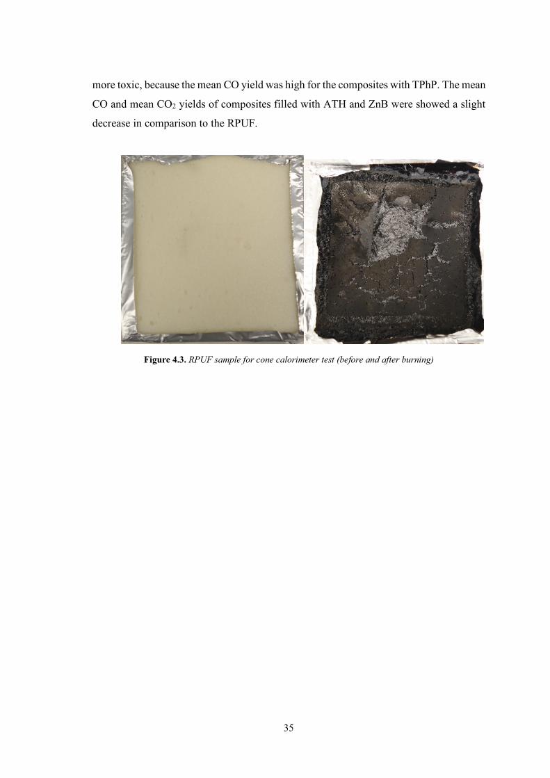
35
more toxic, because the mean CO yield was high for the composites with TPhP. The mean
CO and mean CO2 yields of composites filled with ATH and ZnB were showed a slight
decrease in comparison to the RPUF.
Figure 4.3. RPUF sample for cone calorimeter test (before and after burning)

36
Figure 4.4. Effect of FR type and amount on the HRR: a) ATH, b) TPhP, c) ZnB

Table 4.1. Results of cone calorimeter tests
Parameter RPUF 10A 20A 30A 40A 10T 20T 30T 40T 10Z 20Z 30Z 40Z
TTI (s) 1 4 4 3 4 3 2 2 3 2 4 3 2
t pHRR (s) 10 75 80 85 40 10 15 20 25 10 10 15 15
pHRR (kW/m2) 272.9 258.1 249.8 211.7 205.5 245.8 265.3 261.5 243.5 264.6 264.2 218.7 231.6
THR (MJ/m2) 22.9 20.9 20.8 21.0 23.8 19.0 18.4 20.5 20.4 20.4 24.5 23.2 24.5
Mean COY (kg/kg) 0.068 0.058 0.076 0.065 0.060 0.079 0.086 0.112 0.128 0.065 0.054 0.056 0.060
Mean CO2Y (kg/kg) 1.84 1.60 1.66 1.62 1.75 1.50 1.28 1.18 1.10 1.75 1.85 1.75 1.73
TSR (m2/m2) 786.8 774.5 721.5 743.7 751.5 845.1 991.6 1378.3 1673.1 849.7 917.7 874.6 955.6
TSP (m2) 7.0 6.8 6.4 6.6 6.6 7.5 8.8 12.2 14.8 7.5 8.1 7.7 8.4
MARHE (kW/m2) 233.4 202.0 188.4 194.9 174.5 212.7 222.1 237.4 219.5 220.2 220.2 195.6 204.6
37

38
4.1.2. Effect of blends
Figure 4.5 shows the effect of FR blends on the flame spread rate of RPUF
composites. The rate of flame spread of all composites containing the blend of FRs
decreased in comparison to the composites having the same amount of corresponding FR
only. For example, the rate of 20Z and 20T was 261 and 149.1 mm/min, respectively.
Due to the addition of 20% ZnB and 20% TPPh by polyol weight percentage into RPUF
matrix, the rate of flame spread decreased to 32.9 mm/min. Moreover, the foams of
30A/10T and 20A/20T could not be burned according to the UL94 HB test procedure.
These results were likely due to the synergistic effect among FRs.
Figure 4.5. Effect of blend type and composition on the rate of flame spread (UL 94 HB)
Figure 4.6 shows the effect of blends on the LOI of RPUFCs. The presence of TPhP
to ATH further lowered the LOI according to the composites filled with the same amount
of ATH. While the LOI of 20A and 20T composites were 20.3% and 20.5% respectively,
this value of 20A/20T sample was increased 21.7%. Besides, while the LOI of 30T sample
was 21%, the LOI of 10Z/30T sample was 21.8%.
304
Not b
urni
ng
Not b
urni
ng
30
104 11
3
180
133
33 420
50
100
150
200
250
300
350
RPUF 30A/10T 20A/20T 10A/30T 30A/10Z 20A/20Z 10A/30Z 30Z/10T 20Z/20T 10Z/30T
UL
94 H
B (m
m/m
in)
Foam Code

39
Figure 4.6. Effect of blend type and composition on the LOI (LOI for RPUF 19.3%)
For binary or ternary combination systems, the numerical values of LOI may be
shifted from those the theoretically calculated ones. While the upward shift is known as
synergism, the downward shift is known as antagonism. The theoretical LOI values of
RPUFC with binary blends have been calculated from a knowledge of their experimental
values under identical loadings conditions with the individual additives and without
additive. For example, the LOI values of a polymer filled with binary combinations
(LOIab) could be calculated as (4.1):
LOIab = LOIa + LOIb - LOIRPUF (4.1)
where LOIRPUF is the LOI value without additive, and LOIa, LOIb are LOI values with the
additives a and b, respectively (Varughese, De and De, 1989, p. 120). As shown in Table
4.2, while in some cases the upward shift in LOI values was determined, the downward
shift was observed in some cases. According to the LOI test, the experimental LOI of the
30A/10T, 20A/20T, 30A/10Z and 10Z/30T foams were greater than their theoretical
values of LOI. Therefore, the RPUFCs containing these binary FRs combinations showed
synergistic effect. This could be associated with the combinations of phase mechanism of
FRs.
Table 4.2. Theoretical and experimental LOI values of RPUFC
30A/10T 20A/20T 10A/30T 30A/10Z 20A/20Z 10A/30Z 30Z/10T 20Z/20T 10Z/30T
Experimental 21.5 21.7 21.6 21.1 21.2 20.9 20.9 21.3 21.8
Theoretical 21.1 21.5 21.6 20.9 21.2 21.1 21.0 21.4 21.3
21.5
21.7
21.6
21.1
21.2
20.9 20.9
21.3
21.8
20,6
20,8
21
21,2
21,4
21,6
21,8
22
30A/10T 20A/20T 10A/30T 30A/10Z 20A/20Z 10A/30Z 30Z/10T 20Z/20T 10Z/30T
LOI (
%)
Foam Code

40
The curves of HRR are depicted in Figure 4.7, and the corresponding data is listed
in Table 4.2. When the composites containing blends are compared with ones containing
the same amount of corresponding FRs, generally, the efficient synergistic effect was not
observed with respect to pHRR and THR values. It is most likely that this was due to the
presence of an extremely combustible blowing agent mixture (pentane/cyclopentane) in
the cells of the foam structure. As mentioned above, HRR curves of composites
containing binary blends also depicted more than two peaks. This can be associated with
the effects of simultaneous activated FRs as a result of high radiant heat flux.
While the MARHE values of RPUF and 30Z foam were 233.4 and 195.6 kW/m2
respectively, the value of 30Z/10T composite foam was 153.5 kW/m2. The MARHE
value of 30Z/10T foam was improved by 35% and 21.5%, respectively, according to the
RPUF and 30Z foams.
The TSR and TSP increased with the presence of the blends in the RPUF, the reason
for which could be ascribed to the char promotion effect of the FRs used. These additives
may disturb the sufficient burning of the foam (Xu et al., 2015, p. 8). However, the CO
yield of the composites containing ATH/ZnB blends decreased effectively according to
the other composites, indicating that their toxicity was lesser than the others. The CO2
yields of all composites containing binary blends were lower than that of RPUF. While
the CO yield of 30A sample was 0.065 kg/kg, the CO yield of 30A/10Z sample was 0.046
kg/kg. Almost all composites with ATH/ZnB blends had not higher value of CO yield
than those of composites containing solely ATH or ZnB. This was possibly due to the
smoke suppression feature of ZnB. On the other hand, as expected, the CO emission of
composite increased with the increasing TPhP content of the FR blend.
4.1.3. Flame retardancy mechanism
The flammability of polymeric materials is heavily bound up with the thermal
degradation process which occurs on exposed to heat. For this reason, the thermal
degradation mechanism of polymers is rather significant in understanding the combustion
process and flame retardancy. Generally, the effective FR should possess the degradation
temperature close to that of polymer matrix without FR additives (Thirumal et al, 2010a,
p. 1144). The flame retardancy mechanism of RPUFC containing ATH/TPhP is
illustrated in Figure 4.7. It has been thought that the liquid of TPhP and the particle of
ATH are dispersed on the cell wall and struts. When RPUF heats, it first starts releasing

41
flammable blowing agent gases from the closed cells, and ATH particles absorb heat until
the temperature of RPUF reaches 220℃. After ignition, the release of flammable gases
from the RPUF is started due to its thermal decomposition. For one thing, ATH particles
eliminate the water bonding chemically and this water helps to cool hot polymer matrix,
and form aluminum oxide char on the surface of RPUF then acts as physical barrier for
inhibiting the heat and mass transfer. For another, the thermal decomposition of TPhP
produces phosphoric acid. Phosphoric acid helps the degradation of PU to form the
compact char layer on the surface of RPUF and further decomposes to PO and PO2 with
quenching effect in the gas phase. Therefore, because of the combined physical and
diluting effects of ATH and the catalysis of charring formation and volatilization effects
of TPhP, a good flame retardant effect between ATH and TPhP has been observed in
RPUF (Xi et al, 2015, p. 41, Yang et al, 2014, p. 1042, Thirumal et al, 2010b, p. 2267).
Figure 4.7. Illustration of flame retardancy mechanism of RPUFC containing ATH/TPhP

42
Figure 4.8. Effect of blend type and composition on the HRR: a) ATH-TPhP, b) ATH-ZnB, c) ZnB-TPhP

Table 4.3. Results of cone calorimeter tests for blends
Parameter RPUF 30A/10T 20A/20T 10A/30T 30A/10Z 20A/20Z 10A/30Z 30Z/10T 20Z/20T 10Z/30T
TTI (s) 1 3 4 4 4 3 3 2 2 2
t pHRR (s) 10 70 75 55 55 50 20 10 45 10
pHRR (kW/m2) 272.9 209.4 256.3 240.6 270.2 220.6 244.5 183.1 232.2 211.4
THR (MJ/m2) 22.9 22.4 21.7 21.6 23.4 22.6 23.0 21.0 14.6 14.2
Mean COY (kg/kg) 0.068 0.082 0.112 0.140 0.046 0.048 0.055 0.085 0.102 0.117
Mean CO2Y (kg/kg) 1.84 1.60 1.43 1.42 1.61 1.74 1.66 1.71 1.35 1.24
TSR (m2/m2) 786.8 1010.4 1317.1 1551.8 826.9 836.5 833.1 966.6 1246.9 1404.9
TSP (m2) 7.0 8.9 11.6 13.7 7.3 7.4 7.4 8.5 11.0 12.4
MARHE (kW/m2) 233.4 182.2 213.3 212.9 227.0 195.5 217.9 153.5 204.3 193.7
43

44
4.2. Changes in Thermal Conductivity of the Composites
4.2.1. Effects of ATH, TPhP and ZnB
Thermal conductivity of RPUF depends on several parameters, such as mean cell
size, thermal conductivity of blowing agent gas in the cells, cell orientation, density of
foam, closed cell content, and thermal conductivity of additives (Marrucho, Santos and
Dohrn, 2005, p. 208, Thirumal et al., 2007, p. 255, Zhao et al., 2015. p. 312, Lim, Kim
and Kim, 2010, p. 368, Modesti, Lorenzetti and Besco, 2007, p. 1354, Nikje, 2009, p.
149).
The changes in the cell morphology with the addition of the FRs were demonstrated
with the help of SEM images (Figure 4.8). It is clear from the images that the cell size of
RPUF composites reduced than that of RPUF. Figure 4.9 depicts the changes in the mean
cell size varying with the amount of FRs of composites. Both the thermal insulation
capacity and the mechanical performance of rigid foams are positively affected by the
reduction in the cell size and the protection or enhancement of the close cell content
(Kabakci et al., 2017, p. 8, Danowska et al., 2013 p. 2275, Zhu et al., 2012, p. 4704,
Thirumal et al., 2009, p. 708).
Figure 4.9. SEM images of the foams a) RPUF, b) 10A, c) 30A, d )50A, e) 10T, f) 30T, g) 50T

45
Figure 4.10. Effect of FR type and amount on the mean cell size
The mean cell size of RPUF was observed to be 367 µm. In most cases, composites
had lower mean cell size than RPUF. While the mean cell size of the RPUFCs containing
all FR additives was increased as the content of FRs increased, the mean cell size of the
composites of solely 30T, 40T and 50T was higher than that of RPUF. The RPUFCs filled
with ATH and ZnB, which are solid additives, showed the least mean cell size. However,
the mean cell size of RPUFCs containing TPhP, which is liquid additive, became bigger
than that of RPUF. While the addition of 50% ATH and ZnB caused a reduction of around
30 % both, the addition of 50% of TPhP caused an increase of around 13.5%. The reason
why the mean cell size increased with the increasing FR additives could be the
coalescence of cells during nucleation (Harikrishnan, Patro and Khakhar, 2006, p.7132).
Table 4.3 shows the effects of closed cell content of RPUF composites filled with FRs.
The closed cell content of the RPUF was determined to be 87.1%. In general, by the
addition of FRs, the closed cell content manifested a slight increase. Although the closed
cell content increased also after the addition of TPhP, it depicted a decrease with higher
loadings. It has been speculated that small changes in the closed cell content similar to
those in this study did not have a significant influence on thermal conductivity.
367
220
234
242
252
258
244 27
9
370 39
5 424
193
190 206
208 25
5
0
100
200
300
400
500
600
700
RPUF 10A 20A 30A 40A 50A 10T 20T 30T 40T 50T 10Z 20Z 30Z 40Z 50Z
Mea
n C
ell S
ize
(µm
)
Foam Code

46
Table 4.4. Closed cell content of the composites (Closed cell content of RPUF: 87.1%±2)
Foam Code
Closed Cell Content
(%)
Foam Code
Closed Cell Content
(%)
Foam Code
Closed Cell Content
(%) 10A 91.6 10T 91.8 10Z 93.2
20A 91.3 20T 91.7 20Z 91.4
30A 92.2 30T 91 30Z 91.4
40A 92.3 40T 87.5 40Z 90.8 50A 91.9 50T 87.1 50Z 90.0
Thermal conductivity of rigid foams is a fundamental parameter as an indicator of
thermal insulation properties. The effect of composites with FR additives is illustrated in
Figure 4.10. The thermal conductivity value of RPUF was determined as 22.53 mW/m.K.
It was observed that the thermal conductivities of composites filled with ATH and ZnB
were lower than those of RPUF, even in the case of 50A and 50Z foams. The thermal
conductivity values of 50A and 50Z were 21.99 and 21.76 mW/m.K respectively,
indicating that the thermal conductivity was decreased at the level of 2.4% for 50A and
3.4% for 50Z. This can be primarily attributed to the small mean cell size of RPUF
composites compared with the RPUF (Thirumal et al., 2010b, p. 2264). Although the
thermal conductivity of composites containing TPhP was lower than that of RPUF at
lower loadings, the conductivity values depicted a subsequent increase as the content of
TPhP increased. It is suggested that this can be associated with the increasing mean cell
size.
Figure 4.11. Effect of FR type and amount on the thermal conductivity
22.53
21.19 21.3421.53
21.7521.99
21.5821.98
22.64
23.47
24.92
21.04 20.96 21.1921.35
21.76
19,5
20,5
21,5
22,5
23,5
24,5
25,5
RPUF 10A 20A 30A 40A 50A 10T 20T 30T 40T 50T 10Z 20Z 30Z 40Z 50Z
Ther
mal
Con
duct
ivity
(mW
/m.K
)
Foam Code

47
4.2.2. Effects of blends
Depending on the loading of FR blends composites filled with the blends of FRs,
the mean cell size was demonstrated in Figure 4.11. It was pointed out in the same figure
that the incorporation of the FR blends into foam matrix reduces the mean cell size
according to the RPUF. In the composites containing ATH/TPhP, ATH/ZnB, and
ZnB/TPhP, the mean cell size increased with the increasing content of TPhP, ZnB, and
TPhP respectively, except for 30A/10Z foam. As also seen from Figure 4.12, when the
TPhP content increased, the uniform structure of the cells began to disintegrate. It may
be due to the effect of the immiscibility of TPhP with polyol at the high level of TPhP
content. The SEM images also revealed that cells increased in size with the subsequent
increase of TPhP in the blend. Compared to RPUF, 30A/10Z, 30A/10T, and 30Z/10T
composites displayed 20%, 23%, and 26% reduction in the mean cell size respectively.
Figure 4.12. Effect of blend type and composition on the mean cell size
367
283 30
4 327
294
255
262 27
3
323 34
0
0
50
100
150
200
250
300
350
400
450
500
RPUF 30A/10T 20A/20T 10A/30T 30A/10Z 20A/20Z 10A/30Z 30Z/10T 20Z/20T 10Z/30T
Mea
n C
ell S
ize
(µm
)
Foam Code

48
Figure 4.13. SEM images of the foams a) RPUF, b) 30A/10T, c) 20A/20T, d) 10A/30T
Table 4.4 depicts the effects of blend type and composition on the closed cell
content of foam composites. The closed cell contents of composites containing blends
were observed to be higher than that of RPUF. However, it can be recommended that
these changes in closed cell content could not affect the thermal conductivity and
compressive strength of the foams.
Table 4.5. Closed cell content of the composites containing blends (RPUF: 87.1%±2)
Foam Code
Closed Cell Content
(%)
Foam Code
Closed Cell Content
(%)
Foam Code
Closed Cell Content
(%) 30A/10T 91.7 30A/10Z 91.2 30Z/10T 92.7
20A/20T 92.6 20A/20Z 91.5 20Z/20T 93.4
10A/30T 91.8 10A/30Z 92.0 10Z/30T 92.8

49
The variation of thermal conductivity of composites with blend type and
composition is shown in Figure 4.13. In accordance with mean cell size, thermal
conductivity values of foam composites also increased with increasing TPhP content of
blends, and interestingly, conductivity values of A/Z combinations were observed to be
lower than that of RPUF for all compositions. The foams of 20A/20Z showed the lowest
thermal conductivity value of 20.78 mw/m.K among the composites. The decrease in its
cell size was a factor that contributed to the mentioned results (Thirumal et al., 2010b, p.
2264).
Figure 4.14. Effect of blend type and composition on the thermal conductivity
4.3. Changes in Compressive Strength
4.3.1. Effects of ATH, TPhP and ZnB
Foam density is one of the most significant parameters that affect the mechanical
properties of RPUFs. The density of foams can vary with the changes in the type and
amount of blowing agents and the additives used (Thirumal et al., 2007, p. 249). In this
study, the blowing agent content was fixed and the content of FR additives varied from
10% to 50% by polyol weight percentage. The effect of type and loading level on the
density of the composites is shown in Figure 4.14. The density of RPUF was observed to
be 36.2 kg/m3. The figure indicates that the density marked a linear increase with the
increasing amount of FR additives. The reasons for the increase in density of foam
22.53
21.82
22.36
23.09
21.81
20.78
21.27
21.75
22.6
23.58
20
20,5
21
21,5
22
22,5
23
23,5
24
RPUF 30A/10T 20A/20T 10A/30T 30A/10Z 20A/20Z 10A/30Z 30Z/10T 20Z/20T 10Z/30T
Ther
mal
Con
duct
ivity
(mW
/m.K
)
Foam Code

50
composites can be evaluated as the higher density of FRs (ρATH: 2443.9 kg/m3, ρTPhP:
1205.5 kg/m3, ρZnB: 469.34 kg/m3) than that of RPUF and increasing viscosity that results
into hindering the foaming process in the presence of FRs (Piszczyk et al., 2012, p. 1729,
Thirumal et al., 2010b, p. 2263).
Figure 4.15. Effect of FR type and amount on the density
As known from literature, the presence of additives has a great impact on the
mechanical properties of the RPUF. The compressive strength of the foams is one of the
most important parameters to determine their applications (Kabakci et al, 2017 , p. 11).
Figure 4.15 shows the effect of the increasing loading of ATH, TPhP, and ZnB on the
compressive strength. The red line on the 120 kPa shows an acceptable compressive
strength value for most of the applications. The compressive strength of RPUF was
determined to be 140 kPa. By the addition of ATH until 40%, the compressive strength
first increased and then decreased with the further addition of ATH. Moreover, the
compressive strength at 50% ATH content was even higher than that of RPUF. Similar
results were obtained from the other composites filled with TPhP and ZnB. Almost all
foam composites were in acceptable values of the strength. One of the other important
parameters that affects the compressive strength is the interaction among additive
particles and polymer chains (Lorenzetti et al., 2010, p. 3674, Xu et al., 2007, p. 445, Cao
et al., 2005, p. 781). The contribution of H-bond formation among urethane groups to the
compressive strength is well known. The FRs may interfere with the H-bond formation
36.2
39
41.5
45.1
48.1
52.9
37.639.1
41.8
45
49.5
38.3
40.5
42.7
46.3
50.6
35
37
39
41
43
45
47
49
51
53
55
RPUF 10A 20A 30A 40A 50A 10T 20T 30T 40T 50T 10Z 20Z 30Z 40Z 50Z
Den
sity
(kg/
m3 )
Foam Code

51
in polyurethane foams, which in turn has a negative effect on the mechanical properties.
As a result, the increase in density competes with the hindering of H-bond formation
among urethane groups in order to determine the compressive strength. The reason behind
the decrease in the compressive strength after 40% ATH loadings could be the dominant
effect of interference with the H-bond formation. This explanation is applicable to the
other composites containing TPhP and ZnB.
Figure 4.16. Effect of FR type and amount on the compressive strength
4.3.2. Effects of blends
Figure 4.16 depicts the effect of the blend type and composition on the density of
foams. It is indicated that the addition of blends causes an increase in density as compared
to the foam without additive. This was mainly associated with the higher densities of FR
additives than that of RPUF. The highest density among the foams was specified in the
case of the 30A/10T foam. This was probably due to the higher density of ATH as
compared to that of TPhP and ZnB. Also, the density of 30A/10T foam was higher than
that of 30A foam. While the density of 30A/10T foam was 49.6 kg/m3, the density of 30A
foam was 45.1 kg/m3.
140
150
163
176 17
9
155
162
151
142
111
106
140
126
121
120
112
80
90
100
110
120
130
140
150
160
170
180
190
200
RPUF 10A 20A 30A 40A 50A 10T 20T 30T 40T 50T 10Z 20Z 30Z 40Z 50Z
Com
pres
sive
Stre
ngth
(kP
a)
Foam Code

52
Figure 4.17. Effect of blend type and composition on the density
Figure 4.17 illustrates the effect of the blend type and composition on the
compressive strength of foams. As seen in the figure, all composites were above the 120
kPa, and all RPUF composites containing blends have been observed to contribute to the
rigidity of the composites. While the compressive strength value of 30A, 30T and 30Z
was determined as 176, 142 and 121 kPa, respectively, these values increased for the
composites with blends containing the same amount of corresponding FR (except for
30A/10Z), 149 kPa for 30T/10Z, 195 kPa for 30T/10A, 141 kPa for 30Z/10A, 170 kPa
for 30Z10T, 144 kPa for 30A/10Z and 181 kPa for 30A/10T. The compressive strength
of 20A/20T was lower with respect to that of 20A, the reason behind which was probably
the plasticizing effect of TPhP with ATH, which matched up with the change in density
(Thirumal et al.,2010b, p. 2263).
36.2
49.6
45.846.7
43
44.6
42.7
44.443.6
45.8
35
37
39
41
43
45
47
49
51
RPUF 30A/10T 20A/20T 10A/30T 30A/10Z 20A/20Z 10A/30Z 30Z/10T 20Z/20T 10Z/30T
Den
sity
(kg/
m3 )
Foam Code

53
Figure 4.18. Effect of blend type and composition on the compressive strength
140
181
157
195
144
151
141
170
181
149
80
100
120
140
160
180
200
220
RPUF 30A/10T 20A/20T 10A/30T 30A/10Z 20A/20Z 10A/30Z 30Z/10T 20Z/20T 10Z/30T
Com
pres
sive
Stre
ngth
(kP
a)
Foam Code

54
5. CONCLUSIONS AND SUGGESTIONS
The objective of this research was to produce rigid polyurethane foam composites
possessing improved flame retardant properties besides both thermal insulation (with low
thermal conductivity) and mechanical (with high compression strength) properties. For
that purpose, ATH, ZnB, and TPhP and their binary blends were incorporated into RPUF
at different loadings. Some thermal, microscopic, calorimetric, and physical
techniques/machines were applied/used for the characterization of the foams. LOI, UL 94
HB, and cone calorimeter tests were conducted for flame retardancy, heat flow
measurements for thermal conductivity, and mechanical tests for compressive strength.
The results are summarized below:
• Almost all FRs or blends could improve the FR properties of composites. The
flame spread rates for composites depicted a significant reduction in comparison
to the RPUF. Moreover, self-extinguishing was observed for 50A, 40T, 50T,
30A/10T and 20A/20T.
• The LOI values depicted a linear increase with the addition of FRs to the foam.
The most efficient additive was TPhP, where the LOI of the 50T foam increased
by 15% with respect to the RPUF. This increment ratios for 50A and 50Z were
13.5% and 8.3%, respectively.
• From the cone calorimeter results, two peaks were observed in the HRR curves.
The first peak was seen because the HRR value increased greatly until the
formation of a char layer, following which it started to decrease. A second peak
was observed as soon as the char layer cracked.
• The TTI, t pHRR, and pHRR values marked an improvement with the addition
of FRs for almost all composites. The TTI values for the composites were higher
than the TTI value of RPUF. TTI increased from 1 s to 4 s for in the presence of
some FRs of blends. Morever, due to the presence of good charred layer the peak
of 2-HRR of composites appear much later. HRR values of T series composites
decreased to 0 in about 100s, while the other composites and RPUF continued
heat release. The pHRR value of 30Z/10T was 183.06 kW/m2, and this value
improved by 20% and 33% in comparison with the 30Z composite and the
RPUF, respectively. In addition to this, the MARHE value of the 30Z/10T
sample, which was 153.5 kW/m2, depicted an improvement of 35% and 21.5%
according to the RPUF and 30Z sample respectively.

55
• TSR, TSP, mean CO and mean CO2 yields decreased with the addition of ATH.
Due to the increment mean CO yield, toxicity of released gas increased for the
T series composites. Moreover, the higher loading level of TPhP, the toxicity
was much. Similarly, with increasing the ratio of TPhP in the blend, realeased
gas became more dangerous. However, the mean CO and mean CO2 yields
increased significantly increased with the increase in the content of TPhP.
• In many cases, the presence of FRs had effects of reducing the mean cell size.
The addition of 50% ATH and ZnB caused the reduction of around 30% for both,
and the addition of 50% TPhP caused an increase of 13.5% when compared to
that of RPUF.
• The closed cell content of RPUF was about 87%. With the addition of FRs, this
content of composites rose up to the level of 90–91%. It is acceptable that
considerable changes were not observed in the closed cell content in the presence
FRs/with increasing loading of FRs. • The thermal conductivities of composites doped with ATH and ZnB were lower
than that of RPUF, even at the foams of 50A and 50Z. The thermal conductivity
values decreased at the level of 2.4% for the 50A sample and 3.4% for the 50Z
sample. The lowest thermal conductivity value was obtained as 20.78 mW/m.K
in the foam of 20A/20Z, corresponding to the reduction of 7.8%. • The densities of all composites depicted a linear increase with an increasing
amount of FRs. While the density of RPUF was measured to be 36.2 kg/m3, the
densities of the 50A, 50T, and 50Z samples were 52.9, 49.5, and 50.6 kg/m3
respectively. For composites containing blend, this value changed between 42.7
and 49.6 kg/m3. • Almost all the obtained composites were within the acceptable value. The
compressive strength marked an increase till the addition of ATH till 40%, after
which it decreased. The compressive strength at 50% ATH content was higher
than that of RPUF. Compressive strength gradually decreased for the composites
incorporated TPhP or ZnB with increasing doping amounts. However,
composites possessing low amount of TPhP or ZnB had still better mechanical
properties in comparison to RPUF.
It was proven by means of this study that incorporating ATH, ZnB, TPhP, and their
binary blends into foam enhances the flame retardancy performance. In addition to this,

56
composites that have better thermal insulation properties and mechanical properties were
produced.
The challenges encountered during the analysis of the experimental and numerical
results form the basis for the following recommendations for future works.
Ø All experiments that have been carried out could be conducted again by using
Reaction Injection Molding (RIM) instead of hand molding.
Ø The FR additives and their proportions could be varied.
Ø The effect of FRs on the products that RPUFs released during combustion can
be studied.
Ø The char residue after burning RPUFC with cone calorimeter can be examined
with SEM, and an attempt could be made to relate between FR and its char
residue.
57
REFERENCES
Adeosun, D. (2014). Analysis of fire performance, smoke development and combustion
gases from flame retarded rigid polyurethane foams, Doctoral dissertation,
University of Waterloo, Mechanical Engineering, Ontario, Canada.
Boulet, J. C., Walraevens, R., Bonnety, G., Lolivier, J. and Trouillet, P. (1979).
“Halogenated polyether polyols and polyurethane foams produced therefrom” U.S.
Patent No. 4,173,710. Washington, DC: U.S. Patent and Trademark Office.
Cao, X., Lee, L. J., Widya, T. and Macosko, C. (2005). Polyurethane/clay
nanocomposites foams: Processing, structure and properties. Polymer, 46(3), 775-
783.
Chattopadhyay, D. K. and Webster, D. C. (2009). Thermal stability and flame retardancy
of polyurethanes. Progress in Polymer Science, 34(10), 1068-1133. Chung, Y. J., Kim, Y. and Kim, S. (2009). Flame retardant properties of polyurethane
produced by the addition of phosphorous containing polyurethane oligomers
(II). Journal of Industrial and Engineering Chemistry, 15(6), 888-893. Danowska, M., Piszczyk, Ł., Strankowski, M., Gazda, M. and Haponiuk, J. T. (2013).
Rigid polyurethane foams modified with selected layered silicate
nanofillers. Journal of Applied Polymer Science, 130(4), 2272-2281.
Dike, A. S., Tayfun, U. and Dogan, M. (2017). Influence of zinc borate on flame retardant
and thermal properties of polyurethane elastomer composites containing huntite-
hydromagnesite mineral. Fire and Materials, 41(7), 890-897. Fink, J. K. (2013). Reactive polymers fundamentals and applications: A concise guide to
industrial polymers. William Andrew.
Gaan, S., Liang, S., Mispreuve, H., Perler, H., Naescher, R. and Neisius, M. (2015). Flame
retardant flexible polyurethane foams from novel DOPO-phosphonamidate
additives. Polymer Degradation and Stability, 113, 180-188. Harikrishnan, G., Patro, T.U. and Khakhar, D.V. (2006). Polyurethane foam-clay
nanocomposites: Nanoclays as cell openers. Industrial & Engineering Chemistry
Research, 45, 7126-7134.
Hull, T. Richard, and Baljinder K. Kandola. (2009). Fire retardancy of polymers: New
strategies and mechanisms. Royal Society of Chemistry.

58
Jiao L., Xiao H., Wang Q. and Sun J. (2013). Thermal degradation characteristics of rigid
polyurethane foam and the volatile products analysis with TG-FTIR-MS. Polymer
Degradation and Stability, 98(12), 2687-2696.
Kabakci, E., Sayer, G., Suvaci, E., Uysal, O., Güler, İ., Kaya, M. (2017). Processing-
structure-property relationship in rigid polyurethane foams. Journal of Applied
Polymer Science, 134(21), 1-13. Kapps, M. and Buschkamp, S. (2004). The production of rigid polyurethane foam. Bayer
Materials Science, 20, 3-12.
L.R. Glicksman, (1994). “Heat Transfer in Foams” in Low density Cellular Plastics.
Physical Basis of Behaviour, N.C. Hilyard and A. Cunningham, Eds.,
Chapman&Hall, London, 104.
Landrock, A. H. (1995). Handbook of plastic foams: Types, properties, manufacture and
applications. Elsevier. Lee, S. T. and Ramesh, N. S. (2004). Polymeric foams: Mechanisms and materials. CRC
press. Levchik, S. V. and Weil, E. D. (2004). Thermal decomposition, combustion and fire-
retardancy of polyurethanes-A review of the recent literature. Polymer
International, 53(11), 1585-1610
Li, L., Chen, Y., Qian, L., Xu, B. and Xi, W. (2018). Addition flame-retardant effect of
nonreactive phosphonate and expandable graphite in rigid polyurethane
foams. Journal of Applied Polymer Science, 135(10), 1-8. Lim H., Kim, E. Y. and Kim, B. K. (2010). Polyurethane foams blown with various types
of environmentally friendly blowing agents. Plastics, Rubber and
Composites, 39(8), 364-369. Lorenzetti, A., Hrelja, D., Besco, S., Roso, M. and Modesti, M. (2010). Improvement of
nanoclays dispersion through microwave processing in polyurethane rigid
nanocomposite foams. Journal of Applied Polymer Science, 115(6), 3667-3674.
Lorenzetti, A., Modesti, M., Gallo, E., Schartel, B., Besco, S. and Roso, M. (2012).
Synthesis of phosphinated polyurethane foams with improved fire
behaviour. Polymer degradation and stability, 97(11), 2364-2369. Marketandmarkets.com (2015). Polyurethane Foam Market by Type (Flexible Foam,
Rigid Foam), by End-User Industry (Bedding&Furniture, Building&Construction,

59
Electronics, Automotive, Footwear, Packaging, Others), by Geography–Global
Trends&Forecasts to 2020.
Marrucho, I. M., Santos, F., Oliveira, N. S. and Dohrn, R. (2005). Aging of rigid
polyurethane foams: Thermal conductivity of N2 and cyclopentane gas
mixtures. Journal of Cellular Plastics, 41(3), 207-224. Minogue, E. (2000). An in-situ study of the nucleation process of polyurethane rigid foam
formation (Doctoral dissertation, Dublin City University).
Modesti, M., Lorenzetti, A. and Besco, S. (2007). Influence of nanofillers on thermal
insulating properties of polyurethane nanocomposites foams. Polymer
Engineering&Science, 47(9), 1351-1358.
Modesti, M., Lorenzetti, A., Besco, S., Hrelja, D., Semenzato, S., Bertani, R. and
Michelin, R. A. (2008). Synergism between flame retardant and modified layered
silicate on thermal stability and fire behaviour of polyurethane nanocomposite
foams. Polymer Degradation and Stability, 93(12), 2166-2171. Morgan, A. B. and Wilkie, C. A. (2007). Flame retardant polymer nanocomposites. John
Wiley & Sons.
Nikje, M. A., Garmarudi, A. B., Haghshenas, M. and Mazaheri, Z. (2009). Improving the
performance of heat insulation polyurethane foams by silica nanoparticles.
In Nanotechnology in Construction 3 (pp. 149-154). Springer, Berlin, Heidelberg. Pawlowski, K. H. and Schartel, B. (2007). Flame retardancy mechanisms of triphenyl
phosphate, resorcinol bis (diphenyl phosphate) and bisphenol A bis (diphenyl
phosphate) in polycarbonate/acrylonitrile–butadiene–styrene blends. Polymer
International, 56(11), 1404-1414. Pielichowski, K., Kulesza, K. and Pearce, E. M. (2003). Thermal degradation studies on
rigid polyurethane foams blown with pentane. Journal of Applied Polymer Science,
88(9), 2319-2330.
Piszczyk, Ł., Strankowski, M., Danowska, M., Haponiuk, J. T. and Gazda, M. (2012).
Preparation and characterization of rigid polyurethane–polyglycerol
nanocomposite foams. European Polymer Journal, 48(10), 1726-1733
Prager, F. H. and Rosteck, H. (2006). Polyurethane and fire: Fire performance testing
under real conditions. John Wiley&Sons.

60
Ridha, M. (2007). Mechanical and failure properties of rigid polyurethane foam under
tension, Doctoral dissertation, National University of Singapore, Mechanical
Engineering.
Singh, S. N. (2001). Blowing agents for polyurethane foams (Vol. 12). ISmithers Rapra
Publishing. Sonnenschein, M. F. (2014). Polyurethanes: Science, technology, markets, and trends
(Vol. 11). John Wiley&Sons.
Szycher's Handbook of Polyurethanes Second Edition (1999). Boca Raton, FL, CRC
Press.
Thirumal, M., Khastgir, D., Nando, G. B., Naik, Y. P., & Singha, N. K. (2010a). Halogen-
free flame retardant PUF: Effect of melamine compounds on mechanical, thermal
and flame retardant properties. Polymer Degradation and Stability, 95(6), 1138-
1145. Thirumal, M., Khastgir, D., Singha, N. K., Manjunath, B. S. and Naik, Y. P. (2009). Effect
of a nanoclay on the mechanical, thermal and flame retardant properties of rigid
polyurethane foam. Journal of Macromolecular Science, Part A: Pure and Applied
Chemistry, 46(7), 704-712.
Thirumal, M., Khastgir, D., Singha, N. K., Manjunath, B. S. and Naik, Y. P. (2007).
Mechanical, morphological and thermal properties of rigid polyurethane foam:
effect of the fillers. Cellular Polymers, 26(4), 245.
Thirumal, M., Singha, N. K., Khastgir, D., Manjunath, B. S. and Naik, Y. P. (2010b).
Halogen-free flame-retardant rigid polyurethane foams: Effect of alumina
trihydrate and triphenylphosphate on the properties of polyurethane foams. Journal
of applied polymer science, 116(4), 2260-2268. Usta, N. (2012). Investigation of fire behavior of rigid polyurethane foams containing fly
ash and intumescent flame retardant by using a cone calorimeter. Journal of
Applied Polymer Science, 124(4), 3372-3382.
Varughese, K. T., De, S. K. and De, P. P. (1989). The Effects of Flame Retardant
Combinations in PVC-Epoxidised Natural Rubber Miscible Blends: Antimony
Trioxide in Combination with Halogen and Non-Halogen Based Additives. Journal
of fire sciences, 7(2), 115-130.

61
Wang, C., Wu, Y., Li, Y., Shao, Q., Yan, X., Han, C., Whang Z., Liu Z. and Guo, Z.
(2017). Flame-retardant rigid polyurethane foam with a phosphorus-nitrogen single
intumescent flame retardant. Polymers for Advanced Technologies,1-9.
Wang, F. (1998). Polydimethylsiloxane modification of segmented thermoplastic
polyurethanes and polyureas, Doctoral dissertation, Virginia Polytechnic Institute
and State University, Chemistry.
Wang, Z. and Li, X. (2017). Mechanical properties and flame retardancy of rigid
polyurethane foams containing a SiO2 nanospheres/graphene oxide hybrid and
dimethyl methylphosphonate. Polymer-Plastics Technology and Engineering,
(just-accepted), 1-9.
Xanthos, M. (2010). Functional Fillers for Plastics. 2nd Edit, Wiley-VCH, Germany. Xi, W., Qian, L., Chen, Y., Wang, J. and Liu, X. (2015). Addition flame-retardant
behaviors of expandable graphite and [bis (2-hydroxyethyl) amino]-methyl-
phosphonic acid dimethyl ester in rigid polyurethane foams. Polymer Degradation
and Stability, 122, 36-43. Xu, W. and Wang, G. (2015). Synthesis of polyhydric alcohol/ethanol phosphate flame
retardant and its application in PU rigid foams. Journal of Applied Polymer
Science, 132(30), 1-8.
Xu, W. Z., Liu, L., Wang, S. Q. and Hu, Y. (2015). Synergistic effect of expandable
graphite and aluminum hypophosphite on flame-retardant properties of rigid
polyurethane foam. Journal of Applied Polymer Science, 132(47), 1-9.30T/A Xu, Z., Tang, X., Gu, A. and Fang, Z. (2007). Novel preparation and mechanical
properties of rigid polyurethane foam/organoclay nanocomposites. Journal of
Aapplied Polymer Science, 106(1), 439-447. Yang, H., Wang, X., Song, L., Yu, B., Yuan, Y., Hu, Y. and Yuen, R. K. (2014).
Aluminum hypophosphite in combination with expandable graphite as a novel
flame retardant system for rigid polyurethane foams. Polymers for Advanced
Technologies, 25(9), 1034-1043. Yang, R., Hu, W., Xu, L., Song, Y. and Li, J. (2015). Synthesis, mechanical properties
and fire behaviors of rigid polyurethane foam with a reactive flame retardant
containing phosphazene and phosphate. Polymer Degradation and Stability, 122,
102-109.
62
Ye, L., Meng, X. Y., Ji, X., Li, Z. M. and Tang, J. H. (2009). Synthesis and
characterization of expandable graphite–poly (methyl methacrylate) composite
particles and their application to flame retardation of rigid polyurethane
foams. Polymer Degradation and Stability, 94(6), 971-979.
Zhang, M., Luo, Z., Zhang, J., Chen, S., and Zhou, Y. (2015) Effects of a novel
phosphorus–nitrogen flame retardant on rosin-based rigid polyurethane foams.
Polymer Degradation Stability. 120, 427–434.
Zhao, C., Yan, Y., Hu, Z., Li, L. and Fan, X. (2015). Preparation and characterization of
granular silica aerogel/polyisocyanurate rigid foam composites. Construction and
Building Materials, 93, 309-316. Zheng, X., Wang, G. and Xu, W. (2014). Roles of organically-modified montmorillonite
and phosphorous flame retardant during the combustion of rigid polyurethane
foam. Polymer Degradation and Stability, 101, 32-39.
Zhu, M., Bandyopadhyay-Ghosh, S., Khazabi, M., Cai, H., Correa, C. and Sain, M.
(2012). Reinforcement of soy polyol-based rigid polyurethane foams by cellulose
microfibers and nanoclays. Journal of Applied Polymer Science, 124(6), 4702-
4710.
http-1: http://itfaiye.ibb.gov.tr/img/1139914122017__8231012225.pdf (The date of
access: 10.01.2018)
http-2: Hartin, E. (2015). Fire development and fire behavior indicators, http://cfbt-
us.com/pdfs/FBIandFireDevelopment.pdf (The date accessed: 17.07.2017)
http-3: http://dfmpro.geometricglobal.com/2016/09/22/ul-certification-important-
plastics-part-designers/ (The date of access: 24.10.2017)

63
RESUME
Name Surname : Emre Akdoğan
Foreign Language : English
The birth place and year : BOLU/1990
E-mail : [email protected]
Education Background:
• 2012, Belgin Mineral Oil Company, Summer Internship
• 2013, WAT Program, New York, USA
• 2014, Anadolu University, Faculty of Science, Chemistry Department
• 2015-2016, Nanjing University of Aeronautic and Astronautics
Fall Semester, Mevlana Exchange Program
• 2017, Research Assistant, Anadolu University, Faculty of Science, Chemistry
Department
Awards:
• Graduated as a valedictorian student from Chemistry Department at the end of
2013-2014 academic year.
• Nanjing Government Scholarship (2015-2016)
National / International Presentations / Posters
• Ortaç, K., Erdem, M., Erdem, B. and Akdoğan, E. “Farklı Tip Fonksiyonellik
İçeren Organik/Inorganik Yapılar ile Kil Modifikasyonu Ve Karakterizasyonu”
27. Ulusal Kimya Kongresi, Çanakkale, August 2015
• Akdoğan, E. and Erdem, M. “Öğütülmüş Kabuğunun Sert Poliüretan Köpük
Üzerine Etkilerinin İncelenmesi” 12. Ulusak Kimya Mühendisleri Kongresi
(UKMK), İzmir, August 2016
• Irmak, C., Suvacı, E., Erdem, M., Uysal, O., Sayer, G., Kaya, M. and Akdoğan,
E. “Effect of Phyllosilicate Type Organoclay Addition on The Properties of Rigid
Polyurethane Foam” Polyurethane Technical Conference, Baltimore, Maryland
USA, September 2016
• Akdoğan, E., Erdem, M., Üreyen, M., E., Uysal, O., Irmak, C., Suvacı, E., Sayer,
G. and Kaya, M. “Effects Of Halogen-Free Flame Retardant Additives on The
Flame Retardancy, Thermal İnsulation And Mechanical Properties Of Rigid

64
Polyurethane Foams” Pure and Applied Chemistry International Conference,
Bangkok, Thailand, February 2017
• Akdoğan, E., Erdem, M., Üreyen, M., E., Uysal, O., Suvacı, E. and Kaya, M.
“Several Properties of Rigid Polyurethane Foam Composites Filled with Halogen-
Free Flame Retardant Additives” Polyurethane Technical Conference, New
Orleans, Louisiana, USA, October 2017