PROTEGO® Technology • Flame Arresters • Valves • Tank ...
50
PROTEGO ® Technology • Flame Arresters • Valves • Tank Accessories Volume 1 Edition 2017 for safety and environment
-
Upload
khangminh22 -
Category
Documents
-
view
1 -
download
0
Transcript of PROTEGO® Technology • Flame Arresters • Valves • Tank ...
1for safety and environment
PROTEGO® Technology
• Flame Arresters
• Valves
• Tank Accessories
Volume 1
Edition 2017 for safety and environment

2
How to use this catalogue
The PROTEGO® catalogue has a modular structure.
In Volume 1 the company is introduced and with the “Tech-nical Fundamentals” and the “Safe Systems in Practice” a basic explanation of operation and use of PROTEGO® devices is provided.
In the following Volumes 2 through 8 the devices are described in detail.
KA / 1 / 0514 / GB
Typical Applications
• Storage Tanks and Loading Facilities • Vapour-return at Petrol Stations • Combustion Systems • Chemical and Pharmaceutical Processing Systems • Landfill and Biogas Systems • Wastewater Treatment Systems
Special Applications
• Food Sterilization under Vacuum • Wafer Production in IT Industry • Methane Extraction Fan of Mines • Vitamine Production • Production of Tooth Paste and Mouthwash
Exotic Applications
• Nitrous Oxide Supply in Clinical Applications • Explosionproof Surface Drain at Heliports • Storage of Whisky Barrels • Production of Brandy

3for safety and environment
Contents
KA / 1 / 0316 / GB
PROTEGO® – about us 4
Technical Fundamentals 6 Flame Arresters.................................................................................................................................................................... 6
Pressure and Vacuum Relief Valves...................................................................................................................................11
Pressure and Vacuum Relief Valves with Flame Arresters.................................................................................................16
Venting Requirements of Aboveground Storage Tanks - Sizing and Calculation Formulas............................................... 18
Safe Systems in Practice 26 Storage Tanks in Tank Farms for Refineries and Chemical Processing Plants.................................................................. 27
Chemical and Pharmaceutical Processing Facilities.......................................................................................................... 28
Vapour Combustion Systems and Flares........................................................................................................................... 29
Ship Building and Loading Systems................................................................................................................................... 30
Biogas Systems, Wastewater Treatment, and Landfill Gas Systems................................................................................. 31
Flame Arresters as integrated Equipment Components.....................................................................................................32
Cryogenic Tanks................................................................................................................................................................. 33
Overview of Products and Services 34 Deflagration Flame Arresters, end-of-line and Vent Caps.................................................................................................. 34
Deflagration Flame Arresters.............................................................................................................................................. 34
Detonation Flame Arresters................................................................................................................................................ 34
Pressure and Vacuum Relief Valves, end-of-line................................................................................................................35
Pressure and Vacuum Relief Valves, in-line....................................................................................................................... 35
Pressure and Vacuum Relief Valves with Flame Arrester, end-of-line................................................................................ 35
Tank Accessories and Special Equipment.......................................................................................................................... 35
Appendix 36 Regulations, Laws, Standards and PROTEGO® Publications............................................................................................36
Glossary..............................................................................................................................................................................38
Materials, Units and Conversion Factors........................................................................................................................... 48
Data Sheet for PROTEGO® Devices.................................................................................................................................. 49
Services and Spare Parts................................................................................................................................................... 50
All rights and alterations reserved acc. ISO 16016
Special Applications
4
PROTEGO® - about us
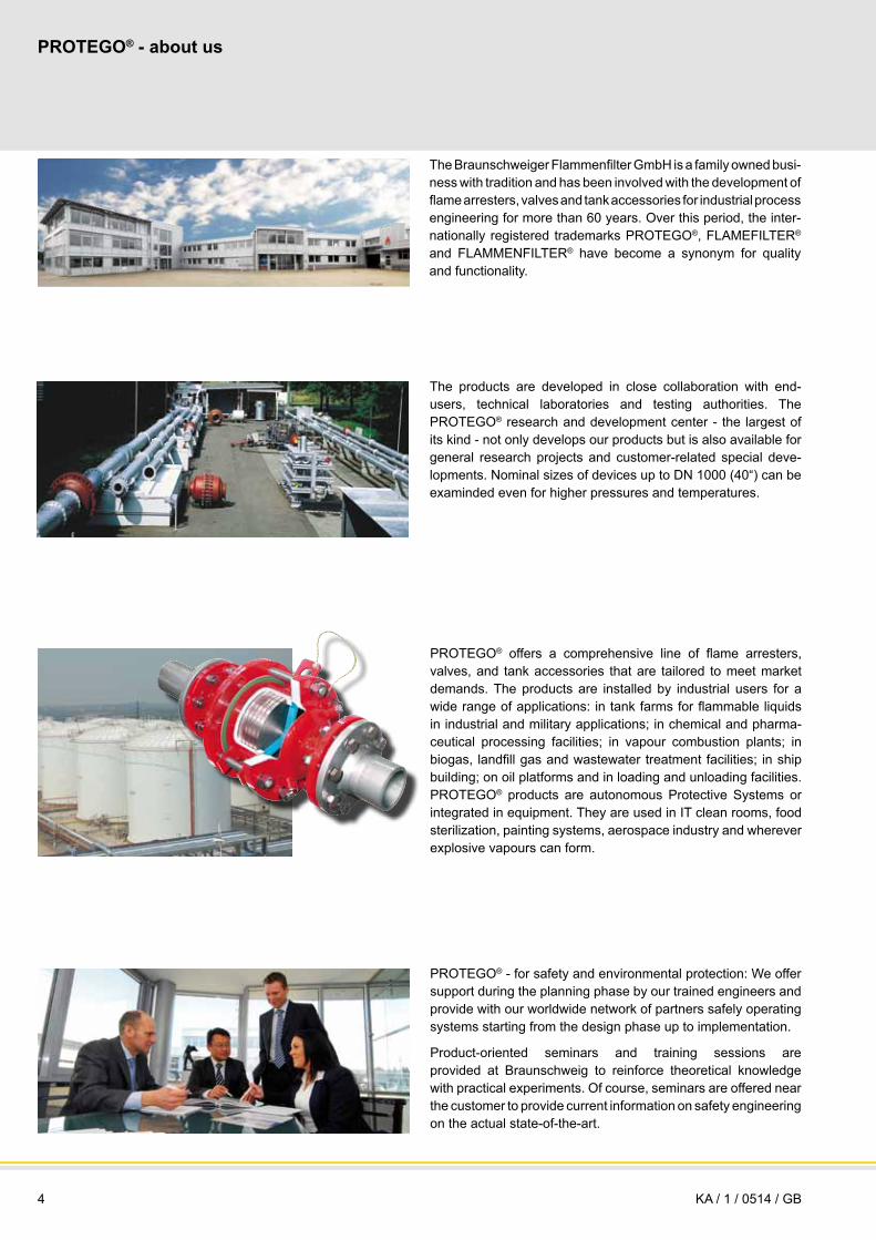
PROTEGO® - for safety and environmental protection: We offer support during the planning phase by our trained engineers and provide with our worldwide network of partners safely operating systems starting from the design phase up to implementation.
Product-oriented seminars and training sessions are provided at Braunschweig to reinforce theoretical knowledge with practical experiments. Of course, seminars are offered near the customer to provide current information on safety engineering on the actual state-of-the-art.
The products are developed in close collaboration with end-users, technical laboratories and testing authorities. The PROTEGO® research and development center - the largest of its kind - not only develops our products but is also available for general research projects and customer-related special deve-lopments. Nominal sizes of devices up to DN 1000 (40“) can be examinded even for higher pressures and temperatures.
The Braunschweiger Flammenfilter GmbH is a family owned busi-ness with tradition and has been involved with the development of flame arresters, valves and tank accessories for industrial process engineering for more than 60 years. Over this period, the inter-nationally registered trademarks PROTEGO®, FLAMEFILTER® and FLAMMENFILTER® have become a synonym for quality and functionality.
PROTEGO® offers a comprehensive line of flame arresters, valves, and tank accessories that are tailored to meet market demands. The products are installed by industrial users for a wide range of applications: in tank farms for flammable liquids in industrial and military applications; in chemical and pharma-ceutical processing facilities; in vapour combustion plants; in biogas, landfill gas and wastewater treatment facilities; in ship building; on oil platforms and in loading and unloading facilities. PROTEGO® products are autonomous Protective Systems or integrated in equipment. They are used in IT clean rooms, food sterilization, painting systems, aerospace industry and wherever explosive vapours can form.
KA / 1 / 0514 / GB

5for safety and environment
Product quality is assured according to international standards. DIN ISO 9001/2008 and DIN ISO 14001 have been implemen-ted for quite a while and have become a part of everydays practice.
The quality derived from producing in accordance with ATEX is the quality seal of reliability. To this we add the steering wheel symbol for supplies to the ship-building industry indicating com-pliance with international requirements. The international testing and approval institutions know us as a competent and reliable partner in their daily dealings with us and have issued over 5000 approvals.
Today, PROTEGO® is considered as the leading company in its field of business and operates worldwide with a network of sub-sidiaries, branches and representatives. The PROTEGO® group includes 12 distribution and service companies and over 120 representatives in the most important markets in every corner of the globe. Customers are promptly supplied with products, replacement parts and services by means of regional support centers.
In the fields of safety and environmental protection, PROTEGO® is well known internationally for: • product innovation
• technological leadership
• technical advice and service
• problem solving
• product quality
• product availability and on-time delivery
• integrity and solidity
PRO safety - PRO tection - PROTEGO®
PROTEGO® WORLD TEAM
PROTEGO®, FLAMEFILTER® and FLAMMENFILTER® are international registered trademarks of Braunschweiger Flammenfilter GmbH.
KA / 1 / 0317 / GB

6
Technical Fundamentals Flame Arresters
DevelopmentFlame arresters protect systems subject to explosion hazards from the effects of explosions. Ever since methane gas explosions were successfully suppressed in the mining industry in the mid-19th century by the development of the mine shaft lamp with a Davy screen, solutions have been found for making systems safer in modern hydrocarbon chemistry, where much more hazardous gases are used.
In addition, filling stations became necessary with the introduc-tion of the automobile. With filling station tanks, the problem of explosive vapours arose, consisting of hydrocarbons and air that form around the tanks and loading equipment, which can ignite. Given the need for safe handling in dangerous atmospheres, the large oil companies advanced the deve-lopment of protective devices for both industrial and military applications.
Initial successes were achieved with gravel pots that were used on fuel tanks. The entrance of an explosion in the atmosphere into the storage tank or into the connected line was stopped by the gravel, and the flame was extinguished. The tank remained protected. The problem with loose gravel, however, is the not reproducible flame arresting capability and the high pressure losses. In 1929, a new development was patented that replaced the loose gravel with wound corrugated strips of metal (Fig. 1a). Together with the patented shock-absorber, a protective device was developed that stopped detonative combustion processes in the pipe at minimum pressure loss. The PROTEGO® deto-nation flame arrester – developed by Robert Leinemann – was born (Fig. 1b). It was given its name many years later in 1954 when Robert Leinemann founded his company Braunschweiger Flammenfilter.
As chemical processes developed, the requirements on protec-tive devices became increasingly complex. To this the require-ments of environmental protection were added. Vapours from processes needed to be disposed in an environmentally friendly manner and supplied to combustion systems according to clean-air regulations. The continuously or only occasionally explosive mixture was sent to an ignition source during operation. These particular hazards had to be countered with special measures. PROTEGO® flame arresters offer reliable protection in plant systems; these flame arresters always correspond to the state-of-the-art as a result of continuous research and development.
Figure 1b: Detonation Flame Arrester with Shock-Absorber
Figure 1a: FlAmeFilter® wound out of corrugated metal strips
KA / 1 / 0909 / GB
7for safety and environment
KA / 1 / 0514 / GB
Figure 2: Atmospheric deflagration
Figure 4: Stabilized burning
Figure 3: Pre-volume deflagration
Combustion Processes
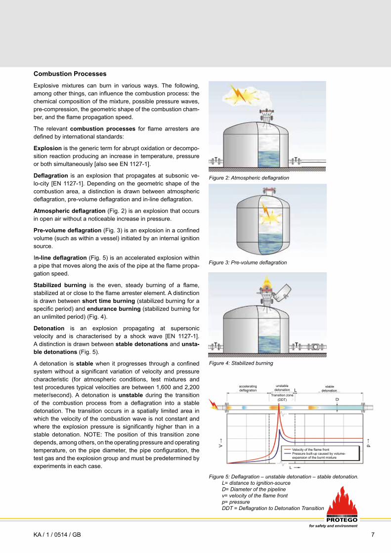
Explosive mixtures can burn in various ways. The following, among other things, can influence the combustion process: the chemical composition of the mixture, possible pressure waves, pre-compression, the geometric shape of the combustion cham-ber, and the flame propagation speed.
The relevant combustion processes for flame arresters are defined by international standards:
Explosion is the generic term for abrupt oxidation or decompo-sition reaction producing an increase in temperature, pressure or both simultaneously [also see EN 1127-1].
Deflagration is an explosion that propagates at subsonic ve-lo-city [EN 1127-1]. Depending on the geometric shape of the combustion area, a distinction is drawn between atmospheric deflagration, pre-volume deflagration and in-line deflagration.
Atmospheric deflagration (Fig. 2) is an explosion that occurs in open air without a noticeable increase in pressure.
Pre-volume deflagration (Fig. 3) is an explosion in a confined volume (such as within a vessel) initiated by an internal ignition source.
In-line deflagration (Fig. 5) is an accelerated explosion within a pipe that moves along the axis of the pipe at the flame propa-gation speed.
Stabilized burning is the even, steady burning of a flame, stabilized at or close to the flame arrester element. A distinction is drawn between short time burning (stabilized burning for a specific period) and endurance burning (stabilized burning for an unlimited period) (Fig. 4).
Detonation is an explosion propagating at supersonic velocity and is characterised by a shock wave [EN 1127-1]. A distinction is drawn between stable detonations and unsta-ble detonations (Fig. 5).
A detonation is stable when it progresses through a confined system without a significant variation of velocity and pressure characteristic (for atmospheric conditions, test mixtures and test procedures typical velocities are between 1,600 and 2,200 meter/second). A detonation is unstable during the transition of the combustion process from a deflagration into a stable detonation. The transition occurs in a spatially limited area in which the velocity of the combustion wave is not constant and where the explosion pressure is significantly higher than in a stable detonation. NOTE: The position of this transition zone depends, among others, on the operating pressure and operating temperature, on the pipe diameter, the pipe configuration, the test gas and the explosion group and must be predetermined by experiments in each case.
V → p →
L
Figure 5: Deflagration – unstable detonation – stable detonation. l= distance to ignition-sourceD= Diameter of the pipelinev= velocity of the flame frontp= pressure DDT = Deflagration to Detonation Transition
Velocity of the flame frontPressure built-up caused by volume-expansion of the burnt mixture
stable detonation
accelerating deflagration
Transition zone (DDT)
unstable detonation

8
Technical Fundamentals Flame Arresters
KA / 1 / 0514 / GB
Energiefluss in die Wand
total energy dissipation
Master TypesFlame arresters are subdivided into different types depending upon the combustion process (Endurance burning, Deflagration, Detonation and the various sub-groups) and in accordance to the installation (in-line, end-of-line, in equipment).
Master types are
a) static dry flame arresters b) static liquid seal flame arresters c) dynamic flame arresters
Working principlea) Static dry flame arresters
Flame arrester elements made of wound corrugated metal strips can be manufactured with consistantly reproducible flame quen-ching gaps. The gap-size can be adjusted in accordance to the flash-back capability of the explosive mixture.
The FLAMEFILTER® is made of wound corrugated metal strips and forms the flame arrester element. The principle of flame quenching in small gaps is applied in PROTEGO® end-of-line flame arresters and PROTEGO® in-line flame arresters (volume 2, 3, 4 and 7).
When a mixture ignites in a gap between two walls, the flame spreads towards the non-combusted mixture. The expansion in volume of the combusted mixture pre-compresses the non-combusted mixture and accelerates the flame.
By heat dissipation in the boundary layer “s”, transferring it to the large surface of the gap-length compared to the gap-width “D” and cooling-down the product below its ignition temperature (Fig. 6) the flame is extinguished.
The gap width and the gap length of the flame arrester element determines its extinguishing ability.
The narrower and longer the gap, the greater the extinguishing effectiveness. The wider and shorter the gap, the lower the pressure loss. The optimum solution between the two conditions is determined by experiments.
Figure 7: FlAmeFilter® (a) with gap widths and gap lengths and PrOteGO® flame arrester unit (b) with FLAMEFILTER®, spacer and FlAmeFilter® cage
7b
To protect against all of the previously mentioned combustion processes, PROTEGO® developed static dry flame arresters and optimized their design and had them undergo national and international certifications in prototype tests (Fig. 7a and b).
All static dry PROTEGO® flame arresters are based on the working principle of FLAMEFILTER®.
Original PROTEGO® technology
7a
Corrugated steel strip
Flat steel strip
Flat steel strip
Gap length
Gap width of the FLAMEFILTER®
Spacer
FLAMEFILTER® cage
Plan view
Figure 6: Extinguishing the flame in the narrow gap (flame quenching) by heat transfer
total energy dissipation
Corrugated steel strip
total energy dissipation
unburnt mixtureburnt mixture flame front
energy dissipation into the
boundary layer
flame front unburnt mixture
flame front unburnt mixtureburnt mixture
energy dissipation into the
boundary layer
energy dissipation into the
boundary layer
breakdown of energy flow
unburnt mixtureburnt mixture
9for safety and environment
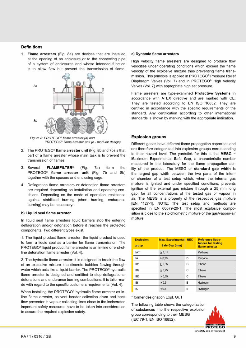
Flame arresters (Fig. 8a) are devices that are installed at the opening of an enclosure or to the connecting pipe of a system of enclosures and whose intended function is to allow flow but prevent the transmission of flame.
The PROTEGO® flame arrester unit (Fig. 8b and 7b) is that part of a flame arrester whose main task is to prevent the transmission of flames.
Several FLAMEFILTER® (Fig. 7a) form the PROTEGO® flame arrester unit (Fig. 7b and 8b) together with the spacers and enclosing cage.
Deflagration flame arresters or detonation flame arresters are required depending on installation and operating con-ditions. Depending on the mode of operation, resistance against stabilized burning (short burning, endurance burning) may be necessary.
Definitions1.
2.
3.
4.
Figure 8: PrOteGO® flame arrester (a) and PrOteGO® flame arrester unit (b - modular design)
8a
8b
b) Liquid seal flame arrester
In liquid seal flame arresters liquid barriers stop the entering deflagration and/or detonation before it reaches the protected components. Two different types exist.
1. The liquid product flame arrester: the liquid product is used to form a liquid seal as a barrier for flame transmission. The PROTEGO® liquid product flame arrester is an in-line or end-of-line detonation flame arrester (Vol. 4).
2. The hydraulic flame arrester: it is designed to break the flow of an explosive mixture into discrete bubbles flowing through water which acts like a liquid barrier. The PROTEGO® hydraulic flame arrester is designed and certified to stop deflagrations, detonations and endurance burning combustions. It is tailor-ma-de with regard to the specific customers requirements (Vol. 4).
When installing the PROTEGO® hydraulic flame arrester as in-line flame arrester, as vent header collection drum and back flow preventer in vapour collecting lines close to the incinerator, important safety measures have to be taken into consideration to assure the required explosion safety.
Explosion groupsDifferent gases have different flame propagation capacities and are therefore categorized into explosion groups corresponding to their hazard level. The yardstick for this is the MESG = Maximum Experimental Safe Gap, a characteristic number measured in the laboratory for the flame propagation abi-lity of the product. The MESG or standard gap width is the largest gap width between the two parts of the interi-or chamber of a test setup which, when the internal gas mixture is ignited and under specified conditions, prevents ignition of the external gas mixture through a 25 mm long gap, for all concentrations of the tested gas or vapour in air. The MESG is a property of the respective gas mixture [EN 1127-1]. NOTE: The test setup and methods are specified in EN 60079-20-1. The most explosive compo- sition is close to the stoichiometric mixture of the gas/vapour-air mixture.
c) Dynamic flame arresters
High velocity flame arresters are designed to produce flow velocities under operating conditions which exceed the flame velocity of the explosive mixture thus preventing flame trans-mission. This principle is applied in PROTEGO® Pressure Relief Diaphragm Valves (Vol. 7) and in PROTEGO® High Velocity Valves (Vol. 7) with appropriate high set pressure.
Flame arresters are type-examined Protective Systems in accordance with ATEX directive and are marked with CE. They are tested according to EN ISO 16852. They are certified in accordance with the specific requirements of the standard. Any certification according to other international standards is shown by marking with the appropriate indication.
KA / 1 / 0316 / GB
Explosion Max. Experimental NEC
group Safe Gap (mm)
IIA1* > 1,14 Methane
IIA > 0,90 D Propane
IIB1 > 0,85 C Ethene
IIB2 > 0,75 C Ethene
IIB3 > 0,65 C Ethene
IIB > 0,5 B Hydrogen
IIC < 0,5 B Hydrogen
* former designation Expl. Gr. I
The following table shows the categorization of substances into the respective explosion group corresponding to their MESG (IEC 79-1, EN ISO 16852).
Reference Subs- tances for testing flame arrester

10
Location of installationDepending on the location of installation, the flame arresters must fulfill various protective tasks:
At the opening of a system part to the atmosphere ▬► End-of-line flame arrester At the opening of an equipment onto a connecting pipe ▬► Pre-volume flame arrester In the pipe ▬► In-line flame arrester
PROTEGO® End-of-line flame arresters protect against at-mospheric deflagrations and stabilised burning — either short time burning or endurance burning. They can only be connected on one side and can not be installed in the pipe. PROTEGO® end-of-line flame arresters can however be combined with val-
PROTEGO® has the right flame arrester for all applications
End-of-line flame arresters for atmospheric deflagrations: PROTEGO® Deflagration Flame Arresters, end-of-line, Volume 2
End-of-line flame arresters for atmospheric deflagrations and short time burning: PROTEGO® Deflagration Flame Arresters, short time burning proof, end-of-line, Volume 2
End-of-line flame arresters for atmospheric deflagrations and short time and endurance burning: PROTEGO® Deflagration Flame Arresters, endurance burning proof, end-of-line, Vol. 2
SelectionThe effectiveness of flame arresters must be tested and approved. Flame arresters are categorized according to the combustion process and the installation site.
The selection criteria are described in the appropriate volumes. The different variations and wide range of types arises from the tailored solutions for different applications. PROTEGO® flame arresters are generally service-friendly due to the modular de-sign of the flame arrester unit. Special details of the design (pa-tented Shock Wave Guide Tube Effect SWGTE or Shock-absor-ber) enable a superior flow due to the minimum pressure loss.
Please refer to more specific literature (especially technical information concerning safety ratings) for the MESG of individual substances, additional ratings and characteristic substance quantities. This information is provided by PROTEGO® upon special request.
As the pressure and temperature increase, the load on the flame arresters generally increases. Flame arresters that have been tested under standard conditions are approved and can be used up to 60°C (140°F) and 1.1 bar (15.9 psi). If the operating temperature and/or the operating pressure is higher, the flame arrester must undergo a special examination for the higher ope-rating parameters.
PROTEGO® offers flame arresters for the above mentioned ex-plosion groups for higher pressures (>1.1bar abs, 15.9 psi) and higher temperatures (>60°C, 140°F) as required by the operating pressure or temperature.
Location of End-of-line On- In-line Installation equipment
Combustion process
Atmospheric deflagration
Atmospheric deflagration and short time burning
Atmospheric deflagration and short time burning and endurance burning
Pre-volume deflagration
In-line deflagration
Stable detonation and in-line deflagration
Unstable and Stable detonation and in-line deflagration
Application example
→ Tank, page 27 → Reactor, page 28
→ Free venting, page 29
→ Blower→ Vacuum
pump (p. 32)
→ For vent header, page 27→ Combustion system, page 28
→ Vapour return, page 29
Products → Volume 2 → Volume 2 → Volume 2 → Volume 3 → Volume 3 → Volume 4 → Volume 4
Technical Fundamentals Flame Arresters
ves (see Volume 7: Pressure and Vacuum Relief Valves with PROTEGO® flame arresters).
PROTEGO® Pre-volume flame arresters are flame arresters which avoid flame transmission from the inside of an explosion-proof vessel to the outside or to a conntected pipe.
PROTEGO® In-line flame arresters protect against deflagrati-on , stable or unstable detonations in pipes. Stable detonation flame arresters avoid an explosion transmission of deflagrations and stable detonations. In-line flame arresters which are tested against unstable detonations protect from deflagrations, stable and unstable detonations.
The flame arresters should be located according to their spe-cified use. In the case of in-line deflagration flame arresters, make sure that the allowable L/D (L = distance between the igni-tion source and the installation location of the flame arrester, D = pipe diameter) is not exceeded and that the in-line defla-gration flame arresters are not installed too far from the ignition source, so that they are not subject to a detonation because the path is too long. The allowable L/D is stated in the manufactu-rers manual of the flame arrester.
Pre-volume flame arresters on equipment: PROTEGO®
Deflagration Flame Arrester units on equipment, Volume 3
In-line flame arresters for deflagrations: PROTEGO® Deflagration Flame Arresters, in-line, Volume 3
In-line flame arresters for deflagrations and stable detonations: PROTEGO® Detonation Flame Arresters, in-line, Volume 4
In-line flame arresters for deflagrations as well as stable and unstable detonations: PROTEGO® Detonation Flame Arresters, in-line, Volume 4
KA / 1 / 0514 / GB

11for safety and environment
Technical FundamentalsPressure and Vacuum Relief Valves
DevelopmentClosed vessels or tanks filled with liquid products must have an opening through which the accumulated pressure can be released so that the vessel does not explode. Along the same lines, a vacuum has to be compensated for when the tank or ves-sel is drained so that it does not implode. Unallowable overpres-sure and negative overpressure will accumulate with loading and unloading procedure, steam cleaning processes, blanketing and thermal effects. Free openings enable a free exchange with the atmosphere or with connected pipe systems that are uncontrol-led and unmonitored. Vent caps are used in this case (Fig. 1).
The vented product vapours can be poisonous, odorous, flammable, or simply represent the loss of product. They pollute the atmosphere.
The local concentration of chemical and processing plants and the associated environmental pollution have increased so much over the last 50 years, that valves are now to be used, especially in industrially developed countries, to keep the free opening cross-sections closed during operation and only permit emergency venting or relief.
The ventilation devices, which are in the form of pressure and vacuum relief valves, should not be shut off (Fig. 2).
These valves need to be simple and robust valves that do not require remote control, are trouble-free and reliably fulfill expected tasks: Maintaining and compensating pressure and vacuum.
Valve TechnologyPROTEGO® pressure and vacuum relief valves have weight-loaded or spring-loaded valve pallets. When there is excess pressure in the tank, the pressure valve pallet guided in the housing lifts and thereby releases the flow into the atmosphere (Fig. 3a) until the pressure falls below the set pressure. The valve then reseats. The vacuum side of the valve is tightly sealed by the additional overpressure load. When there is a vacuum in the tank, the overpressure of the atmosphere lifts the vacuum disc and the tank is vented (Fig. 3b).
Figure 3b: Operation of the valve under vacuum (negative pressure) in the tank
Figure 3a: Operation of the valve under pressure in the tank
In principle, the diaphragm valve, which is loaded with liquid (as a weight), and the pilot-valve, which is self-controlled, operate in the same manner.
The weight-loaded valve pallets have different designs. A distinction is made between the full-lift pallet (Fig. 4 and Fig. 5 a, b) and the normal pallet (Fig. 6).
Figure 4: PrOteGO® full-lift pallet with air cushion seal
Figure 1: Free venting of the storage tank with PrOteGO® eH/0S
Figure 2: Venting of the storage tank with pressure and vacuum relief valve PrOteGO® VD/SV
KA / 1 / 0514 / GB
Location of End-of-line On- In-line Installation equipment
Combustion process
Atmospheric deflagration
Atmospheric deflagration and short time burning
Atmospheric deflagration and short time burning and endurance burning
Pre-volume deflagration
In-line deflagration
Stable detonation and in-line deflagration
Unstable and Stable detonation and in-line deflagration
Application example
→ Tank, page 27 → Reactor, page 28
→ Free venting, page 29
→ Blower→ Vacuum
pump (p. 32)
→ For vent header, page 27→ Combustion system, page 28
→ Vapour return, page 29
Products → Volume 2 → Volume 2 → Volume 2 → Volume 3 → Volume 3 → Volume 4 → Volume 4

12
Technical FundamentalsPressure and Vacuum Relief Valves
The sealing between valve pallet and valve seat is provided by an FEP air cushion seal, a metal to metal sealing, or PTFE flat sealing depending on the set pressure or on the application. The best sealing is obtained with a metal valve disc lapped to be seated on the metal valve seat (metal to metal). When the set pressures are low, an FEP air cushion seal provides a tight seal. The tightness of the PROTEGO® valves is far above the normal standard (API2000 resp. EN ISO 28300) and hence meets the stringent demands of emission control regulations.
PROTEGO® pressure and vacuum relief valves with full-lift pallet discharge the flow within 10% overpressure from the set pressure to a fully opened valve (full-lift).
Figure 5a: Discharge with full-lift pallet and air-cushioned seal
Figure 5b: Discharge with full-lift pallet and metal seal
closed Discharge with full-lift
closed Discharge with full-lift
This is attained by precisely harmonizing the diameter and height of the valve pallet rim with the adapted, machined and lapped valve seat. In addition, the flow-enhancing design reinforces the overall effect on the outflow side. These valve pallets are used in end-of-line and in-line valves.
PROTEGO® pressure and vacuum relief valves with conventional pallets discharge the flow within a 40% pressure.
Figure 6: Discharge with normal pallet (flat with metal seal)
closed Discharge with full lift
After the initial response, the rise in pressure is proportional to the discharged flow up to a full lift. When the back pressure in the connected pipeline is high or the valve is installed in com-bination with a pressure control valve, this method provides greater stability for the overall system. However, the overall flow performance is not as good as that of valves with full-lift valve pallets. These valve pallets (Fig. 6) are primarily used in in-line valves when required by operating conditions.
Depending on the design of the valve and the valve pallets, the design pressure and design vacuum (negative gauge pressure) is achieved with different overpressure (Fig. 7). Unless otherwise agreed, the standard PROTEGO® valve design is for 10% technology.
Advantages of PROTEGO® 10% technology:
Pressure conservation very close to the maximum allowable tank pressure
Minimization of product losses
Reduction of vapour emissions
The PROTEGO® diaphragm valve (Fig. 8) has a liquid load above the diaphragm.
The static liquid column is an indication of the set pressu-re. The flexible liquid-loaded diaphragm adjusts tightly to the metallic valve seat to provide an excellent seal. If the set pressure is exceeded, the diaphragm lifts and releases the cross-section for the flow to discharge. Due to the flexible di-aphragm, these valves are used in weather-related low tem-peratures and in sticky, polymerizing media. PROTEGO® diaphragm valves are the only valves worldwide which are frost-proof down to temperatures of -40°C (-40°F).
KA / 1 / 0514 / GB
Figure 7: Opening characteristics of valves with different overpressure levels
Overpressure 10%: valve is closed up to 18 mbarOverpressure 100%: valve opens at 10 mbar already
↓
tank pressure
Design point
Des
ign
flow
overpressure

13for safety and environment
The self-controlled PROTEGO® pilot operated valve (Fig. 9) discharges the flow without requiring additional overpres-sure. Up to the set pressure until the pilot reacts, the valve remains sealed; it immediately opens in a full-lift after the set pressure is reached without overpressure and releases the cross-section of the valve (set pressure = opening pressure). As the pressure increases, the seal increases up to the set pressure. Once the flow is discharged and the pressure falls below the opening pressure, the valve recloses. PROTEGO® pilot valves are generally used as safety relief valves for low-temperature storage tanks or wherever the valve must be very tightly sealed up to the set pressure.
The operating requirements regarding the amount of outbrea-thing and inbreathing capacity determine whether separate pressure valves and vacuum valves or combined pressure and vacuum relief valves are used.
Pressure and vacuum relief valves for maintaining pressure (vapour conservation)Process-dependent pressure maintenance in systems is ensured by valves that take pressure vessel related para- meters into consideration. Conventional safety valves are used for pressures above 0.5 barg (7.25 psig) according to EN-ISO 4126 and Pressure Equipment Directive (PED), API 526 and ASME VIII, Div.1, or other internatio-nal standards. For pressures below 0.5 barg (7.25 psig), the
Figure 8: Diaphragm Valve PrOteGO® UB/SF-0
pressure can be maintained with safety valves that are not subject to the regulations of Pressure Equipment Directive (PED). They need to meet other criteria however: Provide a good seal, be frostproof, trouble-free and easy to maintain. PROTEGO® pressure and vacuum conservation valves meet these requirements while being highly efficient, operate stable and offer safe function even at very low pressures due to the 10% technology. In addition emissions of the products are reduced.
National and international technical regulations for maintaining clean air serve as the basis for calculating savings (such as VDI 3479: “Emission Control - Marketing Installation Tank Farms”, VOC Directive 1999/13/EC and 94/63/EC or API MPMS Chapter 19.1: “API Manual of Petroleum Measurement Standards - Chapter 19, Evaporative Loss Measurement, Section 1 - Evaporative Loss from Fixed-Roof Tanks, 3rd Edition”). The design of the tank, the paint, the insulation, and pressu-re maintenance via the valves influence - among others - the reduction of emissions.
The effect that pressure maintenance has on the reduction of product (vapour) loss improves as the set pressure of the valve approaches the maximum allowable tank pressure. The flow needs to be reliably discharged without the tank rupturing. A comparison of product loss at different overpressures clearly reveals the advantages of the 10% technology over the 40% overpressure and especially in contrast to a 100% overpressure: The specially developed design yields measurable savings by decreasing the accumulation up to the required performance (Fig. 10).
20 18 14 10
71 65 51 35
80
70
60
50
40
30
20
10
0
% E
mm
issi
on re
duct
ion
0%=71% maximum
theoretical saving
10% PROTEGO® Technology (full-
lift disc, set pressure
18 mbar) = 65% saving
40% Technology (normal disc, set pressure
14 mbar) = 51% saving
100% Technology (set pressure 10
mbar) = 35% saving
Emission reduction at a petrol storage tank with 20 mbar max. allowable tank pressure and different valve technologies
Figure 9: pilot operated pressure relief valve PrOteGO® Pm/DS
KA / 1 / 0316 / GB
Figure 10: Stored product Petrol: Comparison of product savings at different overpressure levels versus the free vented storage tank: example of product loss at 20 mbar allowable tank pressure savings in % at different overpressure 0% = up to 20 mbar (8 inch W.C.) the valve is closed (theoretical): more than 70% saving, 10%= only at a valve set pressure 18 mbar (7.2 inch W.C.) the valve opens, 65% saving, 40%= at a valve set pressure 14 mbar (5.6 inch W.C.) the valve opens, 51% saving,100%=already at a valve set pressure 10 mbar (4 inch W.C.) the valve opens: only 35% saving.

14
d
b ac
Pressure and Vacuum Relief Valves for Pressure Relief and Tank BreathingOutdoor storage tanks and vessels are exposed to weather conditions such as heating up and cooling down (the tank must be able to breath). These influences must be considered in addition to filling and emptying capacities as well as inert-gas supply. They can be calculated with good approximation (see Venting Requirements of Aboveground Storage Tanks - Sizing and Calculation Formulas, Page 18). The valve opening pressure must not exceed the maximum allowable tank pressure which also is called the tank design pressure. The construction and design of the valve determines how this opening pressure is reached. Safety valves with conventional construction designed for pressure vessels with 0.5 bar (7.25 psi) overpressure require an overpressure of 10% above the set pressure to attain the opening pressure. Below 1 bar (14.5 psi) pressure, the maximum overpressure may reach 100 mbar (4 inch W.C.), which is clear-ly above the 10% level. In contrast, PROTEGO® valves with the relevant technology meet the requirements of conventional safety valves with an overpressure of 10% even at low set pressures down to 0.003 bar (1.2 inch W.C.).
Under normal operating conditions, it must be impossible to block off the venting system on the tank. The sizing of the pressure and vacuum relief system must be such, that the design pressure, i.e. the pressure and vacuum (negative pressure) in the tank, can not be exceeded under any operating conditions. The pressure and vacuum relief valve must be designed for maximum flow arising from the pump capacity, thermal and other influences. This valve is frequently called the vent valve.
When extremely high venting rates are required due to fire on the outside surface of the tank or malfunctions in special tank equipment (such as tank blanketing gas systems), additional emergency pressure relief valves must be used, especially when the tank roof does not have a weak seam (Fig. 11).
When a blanket gas system fails, large amounts of gas can flow into the tank. The excess gas must be discharged from the tank through the pressure relief system without exceeding the tank design pressure.
Figure 11: Venting of the storage tank with a pressure and vacuum relief valve PrOteGO® VD/SV-PA (a), piped into the vent header during operation (b), venting during operation via the nitrogen control valve PrOteGO® ZM-R (c), relieving in a fire-case through the emergency pressure relief valve PrOteGO® er/V (d)
PROTEGO® valves fulfill the above metioned functions of maintaining and relieving pressure as pressure relief valves, vacuum relief valves, or combined pressure and va-cuum relief valves.
valves operate trouble-free.
If the flowing products are explosive, in-line valves must have upstream flame arresters to protect the system against acce-lerated combustions. End-of-line valves in this case of ha-zardous application, must be equipped with an end-of-line flame arrester to protect the system against atmospheric deflagration (see also Vol. 7).
Sizing of the ValvesThe maximum possible volumetric flow, the maximum permissible pressures, and the operating data (process para-meters) must be taken into account when sizing pressure/ vacuum relief valves.
Definitions:Set pressure = the valve starts to open = adjusted set pressu-re of the valve at 0 bar back pressure
Opening pressure = set pressure plus overpressure
Reseating Pressure = Closing pressure = the valve recloses and is sealed
Overpressure = pressure increase over the set pressure
Accumulation (ISO) = pressure increase over the maximum allowable tank pressure of the vessel allowed during discharge through the pressure relief valve
Accumulation (EN) = differential pressure between the set pressure of the valve and the tank pressure at which the re-quired flow rate is reached or the set vacuum of the valve and the tank internal negative pressure at which the required flow rate is reached (not used in this catalog)
Pressure loss = decrease in pressure within the valve at a given flow
Pressure loss curve (Flow Chart) = performance curve in the flow chart = the characteristics of the valves as the pressure in mbar (inch W.C.) plotted against the flow in m3/h (CFH)
Back pressure = pressure in the system, that acts against the flow out of the valve and that needs to be included as additio-nal pressure on the valve pallet
The maximum allowable design pressure of an equipment, storage tank or vessel may not be exceeded. The maximum possible flow must be reliably discharged through the valve so that the maximum allowable design pressure of the equipment is not exceeded. Safety factors must be taken into account.
Technical FundamentalsPressure and Vacuum Relief Valves
Location of installationIn general, PROTEGO® end-of-line valves are used for storage tanks, vessels or for ventilation lines. In pipes, PROTEGO® in-line valves are used as overflow valves, for backflow prevention and occasionally as control valves. The great advantages are their simple design and large opening cross-sections. These
KA / 1 / 0514 / GB

15for safety and environment
Operating states of pressure and vacuum relief valves: The valve is optimally sized when the operating point lies on the performance curve, i.e., when the attained maximum flow is discharged with the valve completely open without requiring an additional overpressure (with completely open valve) (full-load operating range A, Fig. 12).
When the design flow is not being reached during discharge the valve does not open completely. The valve pallet only lifts briefly, discharges the volume, and then recloses when the pressure falls below the set pressure. The reseating pressure depends on the design of the valve pallet and the geometry of the valve. There are partial-load operating ranges in which the full-lift is not reached (over-sized valves) and overload ranges in which an additional overpressure is required after a full lift to discharge the flow (under-sized valves). Within the overload range, the valve is stable; in the partial load range, the valve pallet can flutter due to instability. A proper sizing that takes possible operating conditions into consideration is therefore essential.
SelectionThe valves are selected using the above selection criteria depending on the location of installation and whether the valve is to function as a pressure relief valve, vacuum relief valve, or combined pressure and vacuum relief valve.
Figure 12: Design and operating points in the flow chart
PROTEGO® has the right valve for all applications
For venting of storage tanks and vessels ▬► PROTEGO® Pressure and Vacuum Relief Valves, end-of-line (Vol. 5)
As overflow valves or backflow preventers ▬► PROTEGO® Pressure or Vacuum Relief Valves, in-line (Vol. 6)
Location of End-of-line Valves In-line Valves Installation
Function Pressure Relief Valves
Vacuum Relief Valves
Pressure and Vacuum Relief Valves
Pressure Relief and Vacuum Valves, pilot operated
Pressure or Vacuum Relief Valves
Pressure and Vacuum Relief Valves
Blanketing Valves
Example of Use
→ Storage tank, page 27 → Vent header, page 27
Product → Volume 5 → Volume 5 → Volume 5 → Volume 5 → Volume 6 → Volume 6 → Volume 6
Example (Fig. 12): Valve opening pressure Po = 20 mbar Valve set pressure Pset = 18 mbar (20 mbar - 10%)
A design flow design = 3.500 m3/h B over-load > design C partial-load < design
For venting of tanks storing products at low temperatures and storing critical products
▬► PROTEGO® Pressure / Vacuum Relief Diaphragm Valves, end-of-line (Vol. 5)
KA / 1 / 0311 / GB
For sizing of combined single component devices, which have not been flow tested as combined devices (e.g. DR/ES with DV/ZT), a special sizing process needs to be considered. Please contact our sales engineers for specific guidance.
opening pressure resp. tank design pressure overpressure % 100%1 +set pressure =
Ope
ning
pre
ssur
e re
sp. t
ank
pres
sure
(m
bar)
Flow (m3/h)
Partial-load operating range
over-load operating range
Po
16
Technical FundamentalsPressure and Vacuum Relief Valves with Flame Arresters
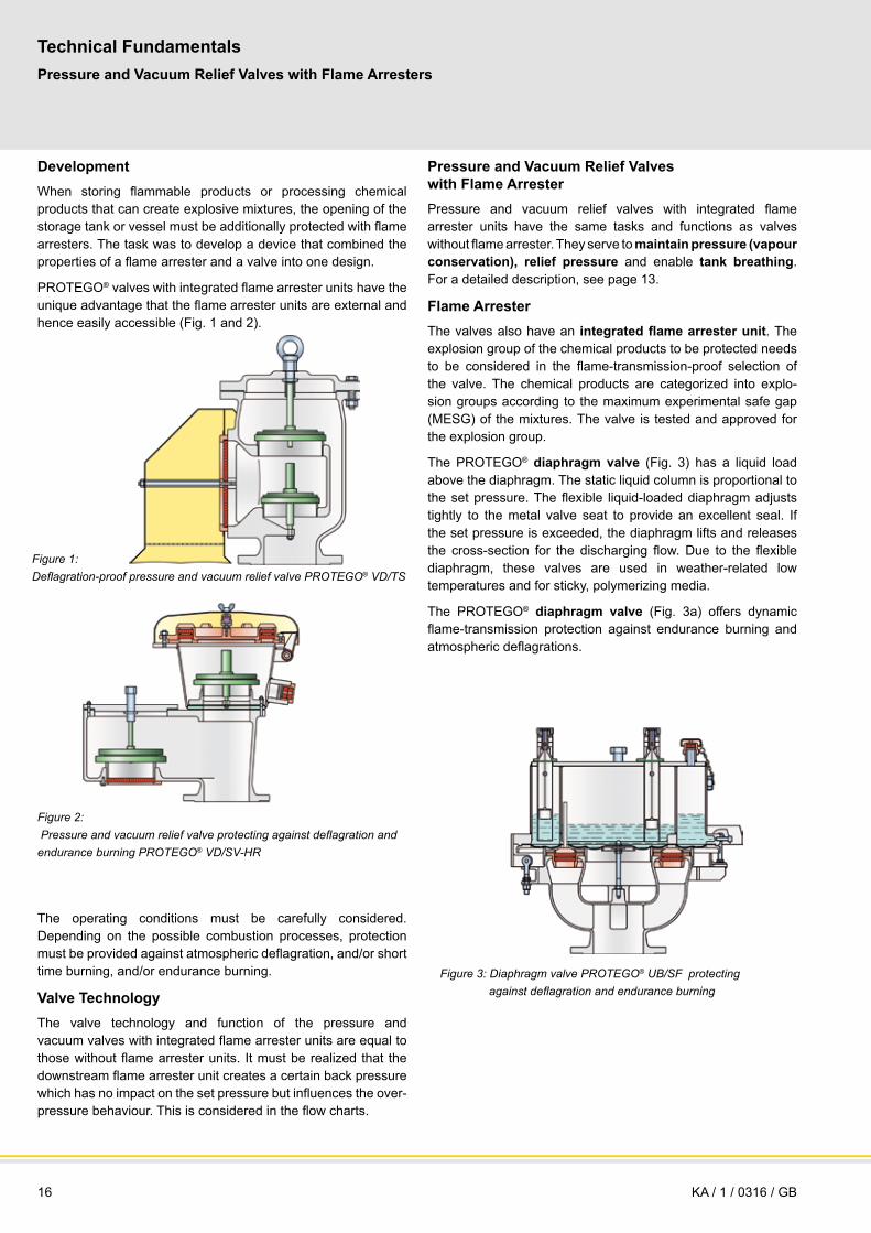
Development
When storing flammable products or processing chemical products that can create explosive mixtures, the opening of the storage tank or vessel must be additionally protected with flame arresters. The task was to develop a device that combined the properties of a flame arrester and a valve into one design.
PROTEGO® valves with integrated flame arrester units have the unique advantage that the flame arrester units are external and hence easily accessible (Fig. 1 and 2).
The operating conditions must be carefully considered. Depending on the possible combustion processes, protection must be provided against atmospheric deflagration, and/or short time burning, and/or endurance burning.
Valve TechnologyThe valve technology and function of the pressure and vacuum valves with integrated flame arrester units are equal to those without flame arrester units. It must be realized that the downstream flame arrester unit creates a certain back pressure which has no impact on the set pressure but influences the over-pressure behaviour. This is considered in the flow charts.
Pressure and Vacuum Relief Valves with Flame ArresterPressure and vacuum relief valves with integrated flame arrester units have the same tasks and functions as valves without flame arrester. They serve to maintain pressure (vapour conservation), relief pressure and enable tank breathing. For a detailed description, see page 13.
Flame ArresterThe valves also have an integrated flame arrester unit. The explosion group of the chemical products to be protected needs to be considered in the flame-transmission-proof selection of the valve. The chemical products are categorized into explo-sion groups according to the maximum experimental safe gap (MESG) of the mixtures. The valve is tested and approved for the explosion group.
The PROTEGO® diaphragm valve (Fig. 3) has a liquid load above the diaphragm. The static liquid column is proportional to the set pressure. The flexible liquid-loaded diaphragm adjusts tightly to the metal valve seat to provide an excellent seal. If the set pressure is exceeded, the diaphragm lifts and releases the cross-section for the discharging flow. Due to the flexible diaphragm, these valves are used in weather-related low temperatures and for sticky, polymerizing media.
The PROTEGO® diaphragm valve (Fig. 3a) offers dynamic flame-transmission protection against endurance burning and atmospheric deflagrations.
Figure 1: Deflagration-proof pressure and vacuum relief valve PROTEGO® VD/tS
Figure 2: Pressure and vacuum relief valve protecting against deflagration and endurance burning PrOteGO® VD/SV-Hr
Figure 3: Diaphragm valve PrOteGO® UB/SF protecting against deflagration and endurance burning
KA / 1 / 0316 / GB
17for safety and environment
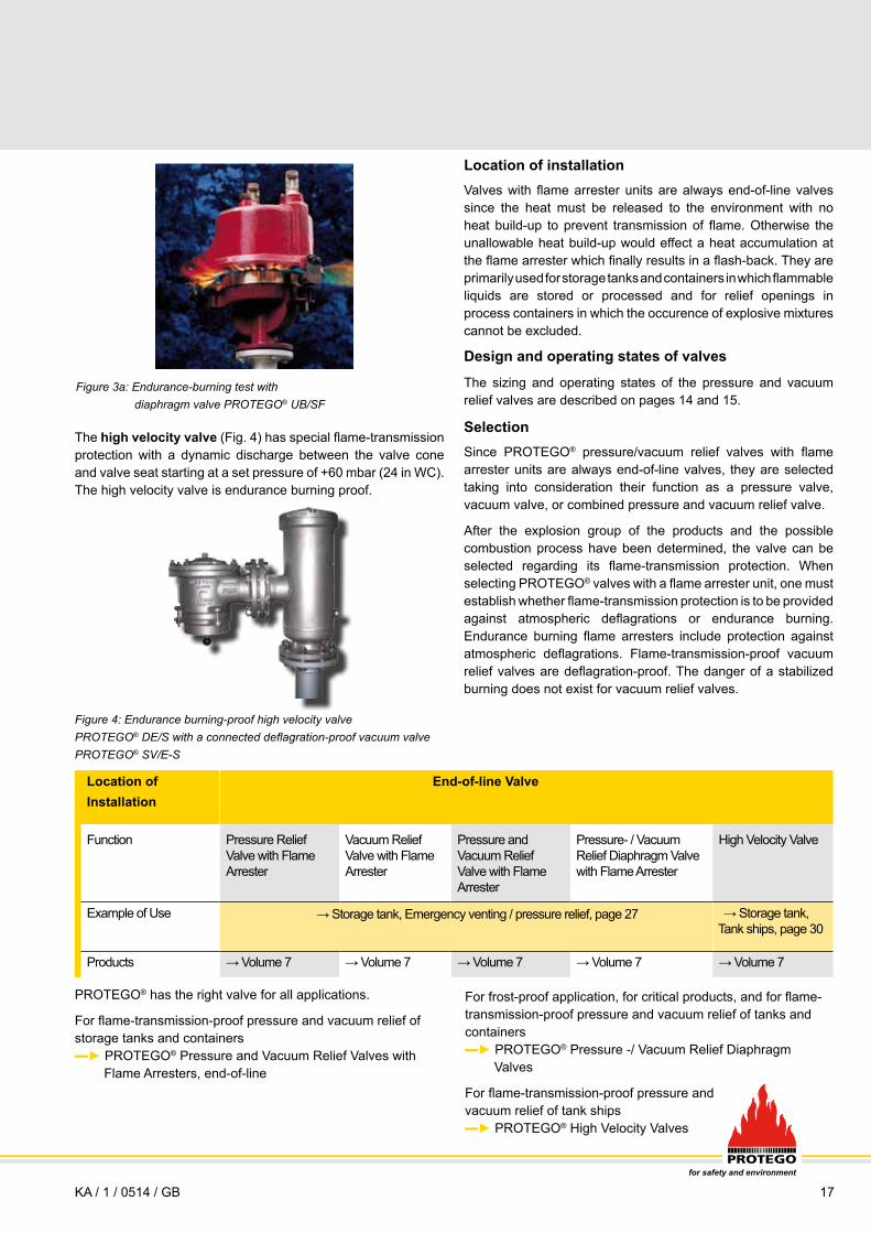
Figure 4: endurance burning-proof high velocity valve PrOteGO® DE/S with a connected deflagration-proof vacuum valve PrOteGO® SV/e-S
Figure 3a: endurance-burning test with diaphragm valve PrOteGO® UB/SF
Location of installationValves with flame arrester units are always end-of-line valves since the heat must be released to the environment with no heat build-up to prevent transmission of flame. Otherwise the unallowable heat build-up would effect a heat accumulation at the flame arrester which finally results in a flash-back. They are primarily used for storage tanks and containers in which flammable liquids are stored or processed and for relief openings in process containers in which the occurence of explosive mixtures cannot be excluded.
Design and operating states of valves
The sizing and operating states of the pressure and vacuum relief valves are described on pages 14 and 15.
SelectionSince PROTEGO® pressure/vacuum relief valves with flame arrester units are always end-of-line valves, they are selected taking into consideration their function as a pressure valve, vacuum valve, or combined pressure and vacuum relief valve.
After the explosion group of the products and the possible combustion process have been determined, the valve can be selected regarding its flame-transmission protection. When selecting PROTEGO® valves with a flame arrester unit, one must establish whether flame-transmission protection is to be provided against atmospheric deflagrations or endurance burning. Endurance burning flame arresters include protection against atmospheric deflagrations. Flame-transmission-proof vacuum relief valves are deflagration-proof. The danger of a stabilized burning does not exist for vacuum relief valves.
PROTEGO® has the right valve for all applications.
For flame-transmission-proof pressure and vacuum relief of storage tanks and containers ▬► PROTEGO® Pressure and Vacuum Relief Valves with Flame Arresters, end-of-line
Location of End-of-line Valve Installation
Function Pressure Relief Valve with Flame Arrester
Vacuum Relief Valve with Flame Arrester
Pressure and Vacuum Relief Valve with Flame Arrester
Pressure- / Vacuum Relief Diaphragm Valve with Flame Arrester
High Velocity Valve
Example of Use → Storage tank, Tank ships, page 30
Products → Volume 7 → Volume 7 → Volume 7 → Volume 7 → Volume 7
The high velocity valve (Fig. 4) has special flame-transmission protection with a dynamic discharge between the valve cone and valve seat starting at a set pressure of +60 mbar (24 in WC). The high velocity valve is endurance burning proof.
For frost-proof application, for critical products, and for flame-transmission-proof pressure and vacuum relief of tanks and containers ▬► PROTEGO® Pressure -/ Vacuum Relief Diaphragm Valves
For flame-transmission-proof pressure and vacuum relief of tank ships ▬► PROTEGO® High Velocity Valves
→ Storage tank, Emergency venting / pressure relief, page 27
KA / 1 / 0514 / GB

18
Technical Fundamentals
Tank Valve
opening pressure
operating pressure (< design pressure)
set pressure
overpressure
blow down
reseating pressure
design pressure = calculated pressure = Maximum Allowab-le Working Pressure (MAWP) to be not exceeded at all ope-rating conditions. For fire and emergency conditions weak roof to shell attachment or emergency relief val-ves to be provided.
opening pressure < design pressure; set pressure = 0,9 x opening pressure for 10% overpressure technology.
% of design pressure = = % of opening pressurep
testpressure for tanks with
p>10mbar
design pressure = test pressure for tanks with
p<10mbar
Figure 1: Comparison of pressure terms for storage tanks and vent valves designed and manufactured in accordance to different standards (e.g. API 620 or API 650 or EN 14015) equipped with pressure relief devices (illustration simplified and based on 10% overpressure technology of the valve).The different definition of the term accumulation is explained on Page 14.
Figure 1A
EN 14015
100
90
110
p
Tank Valve
opening pressure
OPP (< Internal
Design Pressure)
set pressure
overpressure
blow down
reseating pressure
internal design pressure= max. relieving pres-sure under operating condition, fire con-dition or emergency (max. relieving pres-sure for valve and emergency valve).
OPP = Operating Pressure
opening pressure< internal design pressure
set pressure = 0,9 x opening pressure for 10% overpressure technology.
% of MAWP = = % of opening pressurep
Internal Design Pressure
Figure 1B
API 650
100
90
110
p
MAAP= Maximum Allowable Acumulated Pressure = max. relieving pres-sure under operating condition (max. re-lieving pressure for valve). Relief Pres-sure for fire-case or emergency condition relief at 20% excess overpressure.
Max. allowable set pressure= MAWP for 10% overpressure technology.MAWP = Maximum Allowable Working Pressure
% of MAWP = = % of set pressurep
Figure 1C
MAAP (Operating)
MAAP (Fire)
Tank Valve
opening pressure
OPP (< MAWP)
set pressure
accumulation
blow down
reseating pressure
MAWP(Design)
API 620
100
90
110
p
120
Venting Requirements of Aboveground Storage Tanks - Sizing and Calculation Formulas
Pressure Terms and DefinitionsTanks storing flammable and non-flammable liquids are designed and manufactured in accordance to different standards: EN 14015, API 620 or API 650 are the most important standards worldwide. Depending on the standard different maximum tank pressures are allowable to relief the required massflow.
Fig. 1 shows the most common terms for tanks and valves. This comparison clarifies the sizing of end-of-line relief valves featuring the 10% overpressure technology with a set pressure
adjusted only 10% below the opening pressure. In accordance to EN 14015 and API 650 (Fig. 1A and 1B) the design pressure or MAWP = Maximum Allowable Working Pressure of the tank must not be exceeded not even in fire-case or system mal-function. Following API 620 (Fig. 1C) the valve must relief the required regular massflow out of thermal influences and pumping at 10% above the design pressure (in general the MAWP) at the latest. For fire-case or emergency an overpressure of 20% is allowable: after exceeding the MAWP by maximum 20% the required emergency massflow must be
opening pressure for fire
KA / 1 / 0514 / GB

19for safety and environment
relieved. Fig. 2 shows the procedure to determine the set pressure for valves with different overpressure characteristics by considering the specific tank design pressure. These examples are for end-of-line relief valves only without a back-pressure originated by e.g. connected pipe-away-line. If the tank is designed in accordance to EN 14015 or API 650 the opening pressure must not exceed the design pressure (=MAWP) of the tank (Fig. 2A). The set pressure
Tank Valve
set pressure for 10%
overpressure
EN 14015 / API 650
%
100
90
80
70
60
50
40
Pressure relief Valve / Vacuum relief Valve
10% 40% 100%
reseating pressure
set pressure for 40%
overpressure
reseating pressure
max. allowable
overpressure in accordance to
DIN/TRbF
set pressure for 100%
overpressure
reseating pressure
overpressure (conventional vent
valves)
design pressure
opening pressure
PROTEGO 10% Technology
is a result of the opening pressure minus the overpressure of the valve which is a characteristic of the specific valve. If the tank is manufactured in accordance to API 620 the opening pressure may exceed the tank design pressure by 10% for regular breathing and 20% for fire-case (Fig. 2B). The set pressure again is the result of the opening pressure minus the valve-characteristic overpressure.
Figure 2: Selection of the set pressure of the Pressure or Vacuum relief Valve considering the tank design pressure and the valves characteristic overpressure (e.g. 10%, 40% or 100%). API 620 using the 20% over-pressure allowance for fire emergency.
Figure 2A: Design in acc. to EN 14015 or API 650
KA / 1 / 0909 / GB
Valve
set pressure for 10%
overpressure
API 620
%
110
100
90
80
70
60
50
Pressure relief Valve / Vacuum relief Valve
10% 40% 100% 20%
reseating pressure
set pressure for 40%
overpressure
reseating pressure
set pressure for 100%
overpressure
Figure 2B: Design in acc. to API 620
Tankemergencyrelief Valve
120MAAP (Fire)
MAAP (Opera-
tion)
MAWP (Design)
opening pressure
opening pressure
for fire
set pressure
for fire
reseating pressure
40
overpressure (conventional vent
valves)
overpressure (conventional vent
valves)
PROTEGO 10% Technology
accumulation accumulation

20
Technical FundamentalsVenting Requirements of Aboveground Storage Tanks - Sizing and Calculation Formulas
Calculation of the Out- and Inbreathing venting capacity in acc. to ISO 28300/API 2000: The maximum required venting capacity is the total amount of pump capacity and capacity out of thermal influences:
V.out = V.
thermal out + V.pump in
V.in = V.
thermal in + V.pump out
V. = 0,25 •V
0.9 • Rithermal out Tank
V. = C •V
0.7 • Rithermal in Tank
The calculation of the maximum required capacity out of the thermal influences is based on ISO 28300 with regard to above-ground storage tanks with or without insulation.
Thermal capacity for heating up V.thermal out in m3/h
Thermal capacity for cooling down V.thermal in in m3/h
VTank is the volume of the tank in m3
Vtank = 0,7854 • D2 • H
Ri is a reduction factor for insulation (see ISO 28300/API 2000)
V. pump in is the filling rate to calculate the outbreathing capa-
city out of the maximum pump capacity in m³/h for products stored below 40°C and a vapour pressure pvp < 50 mbar. For products stored at a temperature above 40°C or with a vapour pressure pvp > 50 mbar the out-breathing rate must be increased by the evaporation rate.
V. pump out is the emptying rate to calculate the inbreathing ca-
pacity of the pump in m3/h.
C=3 for products with equal vapour pressure as hexane and storage temperature < 25°C
C=5 for products with vapour pressures higher than hexane and/or storage temperature above 25°C (if vapour pressure not known, then C=5)
The mentioned calculation formulas are valid for latitudes 58° to 42°; other latitudes see ISO 28300/API 2000.
Particular influences to be considered are e.g.:
Failure of the nitrogen blanketing valve – Installation of an additional emergency relief valve to vent the non calculated flow which was not foreseen under operation
Filling the empty hot tank with cold liquid product – Considering the additional flow due to the sudden cooling down when calculating the necessary vacuum capacity
Exceeding the maximum given pump out capacity – Considering a safety factor when calculating the required inbreathing capacity
Calculation of the Out- and Inbreathing venting capacity in acc. to TRbF 20:To calculate the out- and inbreathing capacity of storage tanks (e.g. tanks in acc. to DIN 4119 – aboveground storage tanks or DIN 6608 – horizontal underground or buried tanks) the calculation formulas of TRbF (since 1 January 2013 VdTÜV-Merkblatt Tankanlagen 967) are to be applied.
H = Height of the Tank in m; D = Diameter in m
Calculation of Out- and Inbreathing venting capacity in acc. to API 2000 5th edition / ISO 28300 Annex A: The out- and inbreathing capacity of petroleum storage tanks can be calculated in acc. to ISO 28300 Annex A (approximately equivalent to API 2000 5th edition) if specific boundary conditions are fulfilled (see ISO 28300).
If required and when the tanks are specified and designed in accordance to API 650, the venting capacity is to be calculated in accordance to API 2000 for in- and outbreathing as well as for emergency fire cases.
When calculating the required capacities in accordance to API 2000 5th edition / ISO 28300 Annex A, the flammable liquids must be verified with regard to their flashpoint. Different formulas must be applied for liquids with flash-point < 100°F (< 37,8°C) and for liquids with flashpoint > 100°F (> 37,8°C). The maximum required venting capacity is the total amount of pump capacity plus capacity out of ther-mal influences. In contrast, the calculation of the pump capacity must consider a factor for the inbreathing rate and the different flashpoints for the outbreathing rate.
Calculation of the inbreathing capacity:
V. = V
. x 0,94 + V
.thermal inin pump out
Calculation of the required capacity due to thermal influences:
V. = 0,17 x x VTank EHeating up H
D-0,52 0,89
V. = 4,8 x VTank ACooling down 0,71
KA / 1 / 0514 / GB

21for safety and environment
The thermal capacity V.thermal out is rated in API 2000 5th ed. Fig.
2A (English units) and 2B (Metric Units) depending on the tank-volume and the flashpoint. The maximum pumping capacity V
. pump in is rated in accordance to the specified operating rates
for filling.
Simplified formula for estimating calculation:
V. = 208,2 x F x A 0,82 for Metric Units in Nm3/hfire
Insulation is considered with a factor F in API 2000 Fig. 4A (Englisch Units) and 4B (Metric Units).
Inbreathing Outbreathing thermal in thermal Out
Flashpoint Flashpoint
> 37,8°C < 37,8°C
m3 Nm3/h Nm3/h Nm3/h
10 1,69 1,01 1,69
20 3,37 2,02 3,37
100 16,90 10,10 16,90
200 33,70 20,20 33,70
300 50,60 30,30 50,60
500 84,30 50,60 84,30
1.000 169,00 101,00 169,00
2.000 337,00 202,00 337,00
3.000 506,00 303,00 506,00
4.000 647,00 388,00 647,00
5.000 787,00 472,00 787,00
10.000 1.210,00 726,00 1.210,00
20.000 1.877,00 1.126,00 1.877,00
25.000 2.179,00 1.307,00 2.179,00
30.000 2.495,00 1.497,00 2.495,00
Tank Capacity
Requirements of Thermal Venting Capacity (Metric Units)
Excerpt of API 2000 5th ed.
Figure 2A Figure 2B
The thermal capacity thermalIn is rated in API 2000 5th ed. Fig. 2A (English Units) and 2B (Metric Units) depending on the tank-volume. The maximum pumping capacity V
.pump out
is rated in ac-cordance to the specified operating rates for emptying.
Calculation of the outbreathing capacity:
For liquids with flashpoint <100°F (<37,8°C)
V. = V
. x 2,02 + V
.thermal outout pumping in
For liquids with flashpoint >100°F (>37,8°C)
V. = V
. x 1,01 + V
.thermal outout pumping in
V. = 1107 x F x A 0,82 for English Units in SCFHfire
In case there is no weak roof-to-shell attachment, the venting for fire emergency case is to be realized through an emergency pressure relief valve. The required capacity for fire emergency case V
.Fire is rated in accordance to API 2000 Fig. 3A (English
Units) and Fig. 3B (Metric Units) depending on the wetted surface area of the tank.
Inbreathing Outbreathing thermal in thermal Out
Flashpoint Flashpoint
> 100°F < 100°F
Barrels Gallons SCFH Air SCFH Air
100
500
1.000
2.000
4.000
5.000
10.000
20.000
30.000
40.000
50.000
100.000
140.000
160.000
180.000
Tank Capacity
Excerpt of API 2000 5th ed.
4.200
21.000
42.000
84.000
168.000
210.000
420.000
840.000
1.260.000
1.680.000
2.100.000
4.200.000
5.880.000
6.720.000
7.560.000
100
500
1.000
2.000
4.000
5.000
10.000
20.000
28.000
34.000
40.000
60.000
75.000
82.000
90.000
60
300
600
1.200
2.400
3.000
6.000
12.000
17.000
21.000
24.000
36.000
45.000
50.000
54.000
100
500
1.000
2.000
4.000
5.000
10.000
20.000
28.000
34.000
40.000
60.000
75.000
82.000
90.000
SCFH Air
Requirements of Thermal Venting Capacity (English Units)
Tank Capacity
Calcuation of emergency venting capacity according to API 2000 5th edition and ISO 28300
KA / 1 / 0514 / GB

22
=V. *
Technical FundamentalsVenting Requirements of Aboveground Storage Tanks - Sizing and Calculation Formulas
Emergency Venting required for Fire Exposure Versus Wetted Surface Area (Metric Units)
Venting Requirement V.
m2 Nm3/h
2 608
4 1.217
6 1.825
8 2.434
15 4.563
25 6.684
30 7.411
35 8.086
45 9.322
60 10.971
80 12.911
150 16.532
260 19.910
Wetted Area A
Excerpt of API 2000 5th ed.
Environmental Factors for nonrefrigerated Aboveground Tanks (Metric Units)
Tank-configuration Insulation F - Factor Thickness
0 1,0
2,5 0,3
5 0,15
10 0,075
15 0,05
0
0,03
0,5
Excerpt of API 2000 5th ed.
cm
Emergency Venting required for Fire Exposure Versus Wetted Surface Area (English Units)
Venting Requirement V.
square feet SCFH Wetted Area A
Excerpt of API 2000 5th ed.
20
40
60
80
100
140
180
250
350
500
700
1400
2800
21.100
42.100
63.200
84.200
105.000
147.000
190.000
239.000
288.000
354.000
428.000
587.000
742.000
Bare metal tank
insulated tank
insulated tank
insulated tank
insulated tank
underground storage
earth covered storage
impoundment away
from tank
Environmental Factors for nonrefrigerated Aboveground Tanks (English Units)
Tank-configuration Insulation F - Factor Thickness
0 1.0
1 0.3
2 0.15
4 0.075
6 0.05
0
0.03
0.5
Excerpt of API 2000 5th ed.
inch
Bare metal tank
insulated tank
insulated tank
insulated tank
insulated tank
underground storage
earth covered storage
impoundment away
from tank
Figure 4A Figure 4B
Figure 3A Figure 3B
KA / 1 / 0909 / GB

23for safety and environment
Conversion of operational flow into equivalent diagram flow for use of flow chartsTo use the flow charts (pressure vs. flow diagram) by conside-ring the operational and product data, it is necessary to convert the given operational flow V
.B,Gas into the equivalent diagram-
flow V.Dia. This V
.Dia then creates the same pressure loss as the
actual operational flow.
1) Conversion of the operational flow V.B,Gas into the standard
flow V.N,Gas:
2) Conversion of the standard flow V.N,Gas into the equivalent
diagram flow V.Dia:
3) Calculation of the average density pN,Gas of a gas-mixture
Terms
V. = Flow m3/h (CFH)
p = Pressure bar abs (psi abs)
T = Temperature K
p = Specific density kg/m3 (lb / cu ft)
v = Volume fraction
Indices
N = Standard condition (at 1,013 bar abs and 273,15 K)
B = Operational condition (pressure and temperature in acc. to operation)
Gas = Actual product
Dia = Related to the Diagram, when using the flow chart for sizing (pDia=1,189 kg/m3 related density of air at 20 °C and 1 bar abs.)
G = related to the outlet of the device ( pG back pressure) for operating conditions
V. = V
. * = V
. *N, Gas B, Gas
TN * pB
TB * pN
pB * 273,15KTB * 1,013 bar abs.
V. * N, Gas
pp
N, Gas *pN *TB
Dia *pG *TN
pN, Gas = (v1 * pN, Gas 1 + v2 * pN, Gas 2 +...+ vx * pN, Gas x )
B, Gas
ppV
. =Dia
=V. * N, Gas
pp
N, Gas *TB * 1,013 barabs.
G * 1,2 * 273,15 Kkgm3
KA / 1 / 0514 / GB

24
Step 3
Consideration of the operational process parameters of the unburnt mixtures with regard to the impact on the combustion behaviour:
OperatingTemperature < 60°C (< 140°F) Standard, no particular requirements > 60°C (> 140°F) Special approvals necessary
Operating pressure < 1,1 bar abs(< 15.95 psi) Standard, no particular requirements > 1,1 bar abs(> 15.95 psi) Special approvals necessary
Step 4
Assessment of the overall system and classification into hazardous zones in accordance to frequency and duration of explosive atmosphere based on national and international regulations e.g. TRBS, IEC or NFPA/NEC.
Zone 0
A place in which an explosive atmosphere consisting of a mixture of air with flammable substances in the form of gas, vapour or mist is present continuously or for long periods or frequently.
Zone 1
A place in which an explosive atmosphere consisting of a mixture of air with flammable substances in the form of gas, vapour or mist is likely to occur in normal operation occasionally.
Zone 2
A place in which an explosive atmosphere consisting of a mixture of air with flammable substances in the form of gas, vapour or mist is not likely to occur in normal operation but, if it does occur, will persist for a short period only.
To work out a risk assessment, the possible ignition sources must be evaluated under normal operating conditions as well as under special operating conditions like cleaning and mainte-nance work (see EN 1127-1):
effective ignition source:
Steady and continuously under normal operation Solely as a result of malfunctions Solely as a result of rare malfunctions
Effective ignition sources are chemical reactions, flames and hot gases, hot surfaces, mechanical generated sparks, static electricity, lightning, electromagnetic waves, ultrasonics, adiabatic compression, shock waves etc.
Effectiveness of the ignition source is to be compared to the flammability of the flammable substance.
Technical FundamentalsVenting Requirements of Aboveground Storage Tanks - Sizing and Calculation Formulas
Safety Proceeding to Protect Hazardous Explosive Areas in Third-Party-audited processing plants Step 1
Assessment of the possible combustion process based on Standards, e.g. EN 1127-1 General Explosion Protection Methods and EN ISO 16852 respectively EN 12874 Flame Ar-resters
Deflagration in the atmosphere, in a pre-volume or in a pipeline
Detonation in a pipeline, stable or unstable
Endurance burning due to continous flow of vapours/gases in the pipeline or at the opening of a tank Step 2
Classification of the products based on literature and international standards EN ISO 16852, VbF, NFPA, British Standard for liquids, gases, vapours and multiple component mixtures
Liquids: subdividing in flammable, easy flammable and highly flammable due to the flash point of the liquid and verifying the ignition temperature.
The classification is following the VbF (previously) and the Ordinance on Hazardous Substances (Gef. Stoff VO):
Non water soluble previous actual
(A I FP< 21 °C) FP < 0 °C (32°F) Extremely flammable FP < 21 °C (70°F) Highly flammable (A II FP 21–55 °C) FP 21-55°C (70-131°F) Flammable (A III FP 55–100 °C) -
Water soluble previous actual
(B < FP 21 °C) FP < 0 °C (32°F) Extremely flammable FP < 21 °C (70°F) Highly flammable FP 21–55 °C (70-131°F) Flammable
FP = Flashpoint
Products with a flashpoint FP>55°C (>131°F) get flammable when being heated close to the flashpoint (∆T = 5 degree safety margin as a rule of thumb for hydrocarbons as well as 15 de-gree for mixtures).
Vapours: classification of the gas/vapour-air-mixtures in accordance to the MESG of the products or the mixture into the Explosion Groups IIA1, IIA, IIB1, IIB2, IIB3, IIB and IIC (page 9) (NEC Group D, C and B).
KA / 1 / 0316 / GB
25for safety and environment
KA / 1 / 0316 / GB
Step 5
Selection, number and location of the suitable Equipment, Protective System and Component must follow the require-ments of national and international regulations (ATEX Directive).
For equipment (blowers, agitators, containers etc.)
In Zone 0 equipment categorized in group II cat 1
In Zone 1 equipment categorized in group II cat 2
In Zone 2 equipment categorized in group II cat 3
Flame arresters tested accordingly to EN ISO 16852 resp. EN 12874 fullfil the health and safety requirements of current ATEX directive.
Flame arresters are Protective Systems and are not categorized. They must be type examination tested and approved by a Notified Body. They can be installed in all zones (zone 0, 1 or 2) and are marked with CE to state the conformity with all applicable requirements.
The procedure and the results of the risk assessment must be verified in the “Explosion Protection Document“. The plant operator (employer) has to confirm that Equipment, Protective Systems and Components are in accordance with the law and are in compliance with the actual state-of-the-art. Process engineering, plant-layout, substances, zoning, risk assessment etc. are part of the protection concept and are determined in connection with the corresponding responsibilities.

26
6
PROTEGO® devices offer safety and environmental protection
In Storage Tank Farms for Refineries and Chemical Plants
In Processing Systems for Chemical and Pharmaceutical Industries
In Vapour Combustion Systems and Flares
In Ship Building and Loading Systems
In Vapour Recovery Units
As integrated Component of Equipment, Machines and Vessels
1
2
3
4
5
6
PROTEGO® safety devices are used in a wide range of industrial applications. A safe process requires reliable protection for every conceivable operating parameter. Practical examples show how systems can be made safe and how PROTEGO® devices can be incorporated into control loops. Engineers are responsible for properly harmonizing the overall system.
Applications of PROTEGO® devices are used in other areas such as in biogas and landfill gas systems, medical technology, food processing, airplane construction, automobile construction, IT clean-rooms, thin-layer manufacturing, etc.
Safe Systems in PracticeOverview
KA / 1 / 0514 / GB
27for safety and environment
UB/SF
LDA-F
DR/ESDV/ZT
P/EB
SV/E SV/E
LDA-W
SA/S
DR/ES
VD/SV
DR/ES
LDA-F
VD/SVER/V
UB/SFDR/ES
DV/ZTDR/ES
DV/ZW
LDA-WF
VD/SV-HRL
LDA-W
LDA-WF
7
PV/EBR
DR/ES
DA-G
LDAEF/V
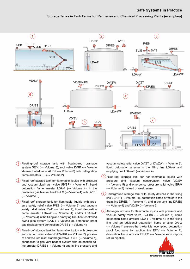
Floating-roof storage tank with floating-roof drainage system SE/K (→ Volume 8), roof valve D/SR (→ Volume stem-actuated valve AL/DK (→ Volume 8) with deflagration flame arresters EB (→ Volume 2)
Fixed-roof storage tank for flammable liquids with pressure and vacuum diaphragm valve UB/SF (→ Volume 7), liquid detonation flame arrester LDA-F (→ Volume 4), in the protective gas blanket line DR/ES (→ Volume 4) with DV/ZT (→ Volume 6)
Fixed-roof storage tank for flammable liquids with pres-sure safety relief valve P/EB (→ Volume 7) and vacuum safety relief valve SV/E (→ Volume 7), liquid detonation flame arrester LDA-W (→ Volume 4) and/or LDA-W-F (→ Volume 4) in the filling and emptying line, float-controlled swing pipe system SA/S (→ Volume 8), detonation-proof gas displacement connection DR/ES (→ Volume 4)
Fixed-roof storage tank for flammable liquids with pressure and vacuum relief valve VD/SV-HRL (→ Volume 7), pressu-re and vacuum relief diaphragm valve UB/SF (→ Volume 7), connection to gas vent header system with detonation fla-me arrester DR/ES (→ Volume 4) and in-line pressure and
1
2
3
5
6
7
Storage Tanks in Tank Farms for Refineries and Chemical Processing Plants (exemplary)
vacuum safety relief valve DV/ZT or DV/ZW (→ Volume 6), liquid detonation arrester in the filling line LDA-W and emptying line LDA-WF (→ Volume 4)
Fixed-roof storage tank for non-flammable liquids with pressure and vacuum conservation valve VD/SV (→ Volume 5) and emergency pressure relief valve ER/V (→ Volume 5) instead of weak seam
Underground storage tank with safety devices in the filling line LDA-F (→ Volume 4), detonation flame arrester in the drain line DR/ES (→ Volume 4), and in the vent line DR/ES (→ Volume 4) and VD/SV (→ Volume 5)
Aboveground tank for flammable liquids with pressure and vacuum safety relief valve PV/EBR (→ Volume 7), liquid detonation flame arrester LDA (→ Volume 4) in the filling line and an additional detonation flame arrester DA-G (→ Volume 4) ensures that the tank is not emptied, detonation proof foot valve for suction line EF/V (→ Volume 4), detonation flame arrester DR/ES (→ Volume 4) in vapour return pipeline.
Safe Systems in Practice
KA / 1 / 0216 / GBfor safety and environment
4
EBD/SR
SE/K
P/EB EBAL/DK
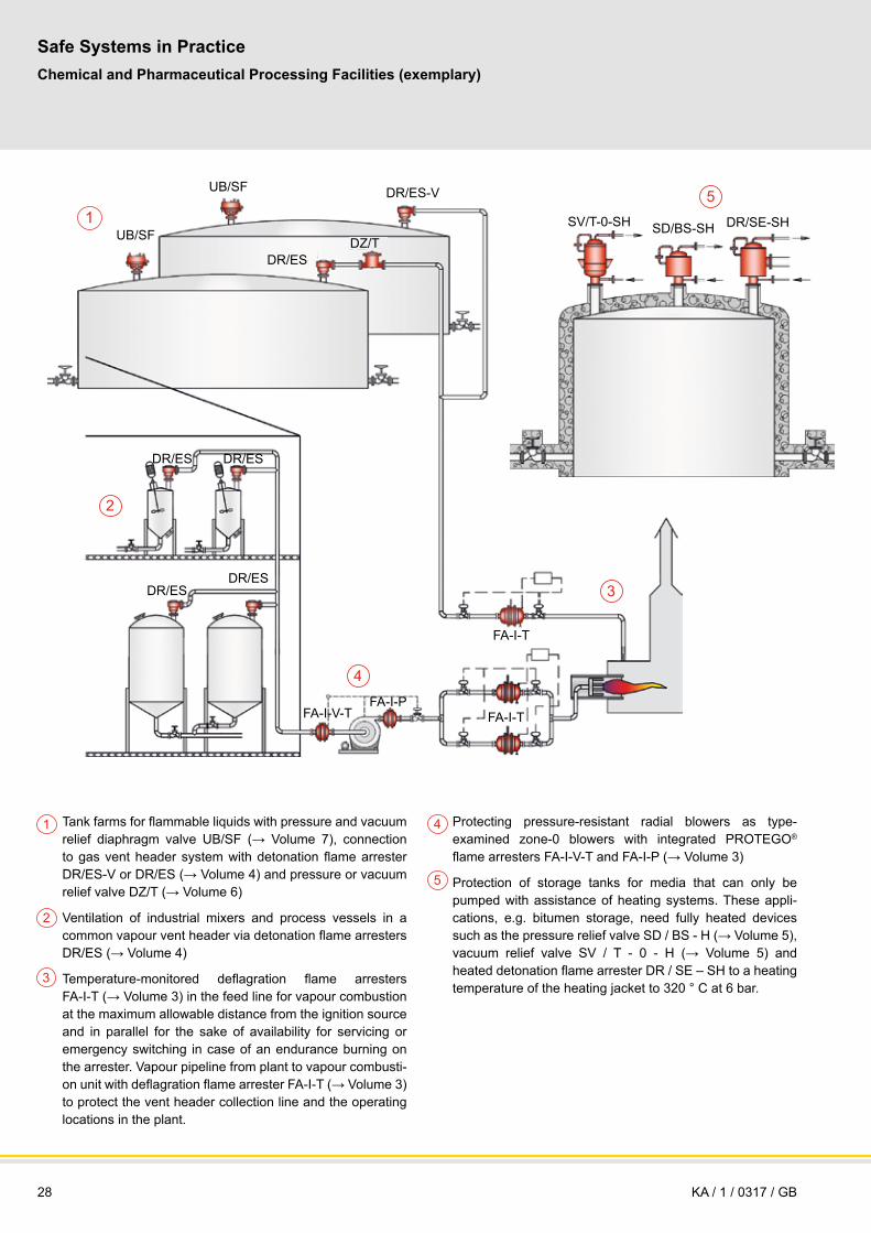
28
Safe Systems in PracticeChemical and Pharmaceutical Processing Facilities (exemplary)
KA / 1 / 0317 / GB
1
2
DR/ES
UB/SF DZ/T
UB/SF DR/ES-V
DR/ES DR/ES
DR/ESDR/ES
FA-I-V-TFA-I-P
FA-I-T
FA-I-T
SV/T-0-SH SD/BS-SH DR/SE-SH
2
3
4
5
Tank farms for flammable liquids with pressure and vacuum relief diaphragm valve UB/SF (→ Volume 7), connection to gas vent header system with detonation flame arrester DR/ES-V or DR/ES (→ Volume 4) and pressure or vacuum relief valve DZ/T (→ Volume 6)
Ventilation of industrial mixers and process vessels in a common vapour vent header via detonation flame arresters DR/ES (→ Volume 4)
Temperature-monitored deflagration flame arresters FA-I-T (→ Volume 3) in the feed line for vapour combustion at the maximum allowable distance from the ignition source and in parallel for the sake of availability for servicing or emergency switching in case of an endurance burning on the arrester. Vapour pipeline from plant to vapour combusti-on unit with deflagration flame arrester FA-I-T (→ Volume 3) to protect the vent header collection line and the operating locations in the plant.
Protecting pressure-resistant radial blowers as type- examined zone-0 blowers with integrated PROTEGO®
flame arresters FA-I-V-T and FA-I-P (→ Volume 3)
Protection of storage tanks for media that can only be pumped with assistance of heating systems. These appli-cations, e.g. bitumen storage, need fully heated devices such as the pressure relief valve SD / BS - H (→ Volume 5), vacuum relief valve SV / T - 0 - H (→ Volume 5) and heated detonation flame arrester DR / SE – SH to a heating temperature of the heating jacket to 320 ° C at 6 bar.
3
4
5
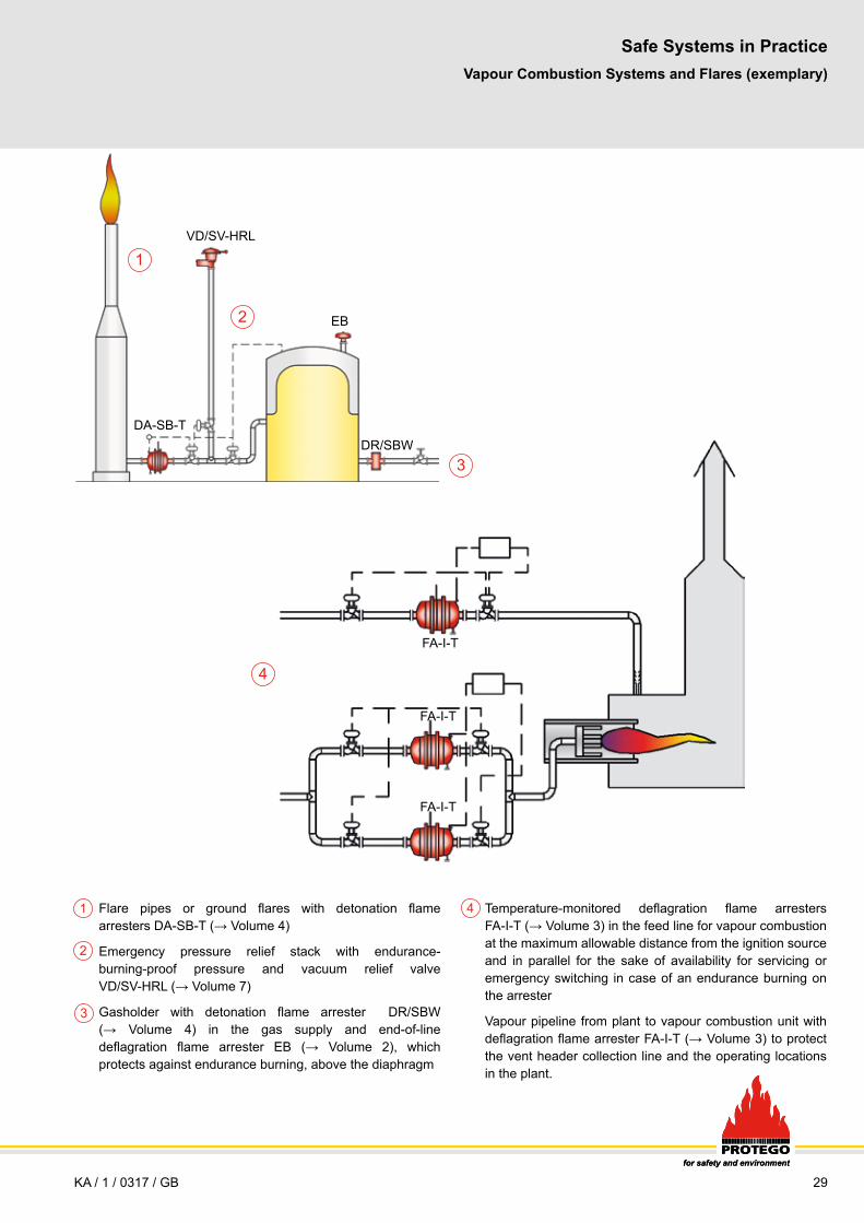
29for safety and environment
1
2
4Flare pipes or ground flares with detonation flame arresters DA-SB-T (→ Volume 4)
Emergency pressure relief stack with endurance-burning-proof pressure and vacuum relief valve VD/SV-HRL (→ Volume 7)
Gasholder with detonation flame arrester DR/SBW (→ Volume 4) in the gas supply and end-of-line deflagration flame arrester EB (→ Volume 2), which protects against endurance burning, above the diaphragm
3
Vapour Combustion Systems and Flares (exemplary)
Temperature-monitored deflagration flame arresters FA-I-T (→ Volume 3) in the feed line for vapour combustion at the maximum allowable distance from the ignition source and in parallel for the sake of availability for servicing or emergency switching in case of an endurance burning on the arrester
Vapour pipeline from plant to vapour combustion unit with deflagration flame arrester FA-I-T (→ Volume 3) to protect the vent header collection line and the operating locations in the plant.
Safe Systems in Practice
KA / 1 / 0317 / GBfor safety and environment
VD/SV-HRL
DR/SBWDA-SB-T
FA-I-T
EB
FA-I-T
FA-I-T

30
1
2
3
Tank ships for flammable products/chemical tankers with detonation flame arresters BR/TS (→ Volume 4) on the individual tank, endurance-burning-proof high-velocity vent valves DE/S (→ Volume 7), and explosion-proof vacuum flame arrester SV/E-S (→ Volume 7)
Detonation-proof connection of the gas return line at the loading terminal for flammable liquids with a detonation flame arrester DA-SB (→ Volume 4)
Detonation flame arresters DA-SB (→ Volume 4) in the gas displacement/gas return line from the loading stations for tank waggons and tank trucks
Safe Systems in PracticeShip Building and Loading Systems (exemplary)
Not shown: Offshore platforms/drilling platforms with detonation flame arresters DA-SB (→ Volume 4) and deflagration flame arresters FA-CN (→ Volume 3), FPSOs (Floating Production Storage and Offloading) with IMO- approved detonation flame arresters DA-SB (→ Volume 4) and pressure and vacuum relief valves VD/TS (→ Volume 7), hydraulic control boxes with deflagration flame arresters BE-AD (→ Volume 2)
KA / 1 / 0216 / GB
BR/TS
DE/SSV/E-S
DA-SB
DA-SB
DA-SB DA-SB
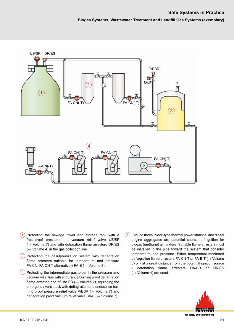
31for safety and environment
1
2
4
3
Protecting the sewage tower and storage tank with a frost-proof pressure and vacuum relief valve UB/SF (→ Volume 7) and with detonation flame arresters DR/ES (→ Volume 4) in the gas collection line
Protecting the desulphurization system with deflagration flame arresters suitable for temperature and pressure FA-CN, FA-CN-T alternatively FA-E (→ Volume 3)
Protecting the intermediate gasholder in the pressure and vacuum relief line with endurance burning proof deflagration flame arrester, end-of-line EB (→ Volume 2), equipping the emergency vent stack with deflagration and endurance bur-ning proof pressure relief valve P/EBR (→ Volume 7) and deflagration proof vacuum relief valve SV/E (→ Volume 7)
Ground flares, block-type thermal power stations, and diesel engine aggregates are potential sources of ignition for biogas (methane) air mixture. Suitable flame arresters must be installed in the pipe toward the system that consider temperature and pressure. Either temperature-monitored deflagration flame arresters FA-CN-T or FA-E-T (→ Volume 3) or - at a great distance from the potential ignition source - detonation flame arresters DA-SB or DR/ES (→ Volume 4) are used.
Biogas Systems, Wastewater Treatment and Landfill Gas Systems (exemplary)
Safe Systems in Practice
for safety and environment
KA / 1 / 0216 / GB
UB/SF DR/ES
P/EBR
EB
FA-CN(-T)FA-CN(-T)
FA-CN(-T)FA-CN(-T)
FA-CN(-T)
FA-CN(-T)
SV/E

32
EV/VD
EV/VS-T
FA-I-V-T
FA-I-P
Safe Systems in PracticeFlame Arresters as integrated Equipment Components (exemplary)
1
2
FLAMEFILTER® or PROTEGO® flame arresters as OEM components are product varieties, that are integrated by equipment manufacturers in their brand-name products.
Protecting pressure-resistant radial blowers as type- examined zone-0 blowers with integrated PROTEGO®
flame arresters FA-I-V-T and FA-I-P (→ Volume 3)
Protecting dry-running vacuum pumps with PROTEGO®
flame arresters EV/VS-T and EV/VD (→ Volume 3) at the inlet and at the outlet, which are tested and certified together with the vacuum pump. Other forms of protection with DR/ES and DR/ES-T (→ Volume 4) are possible.
Not shown: FLAMEFILTER® are used in gas analyzers to protect the explosive environment from explosions arising in the device from the ignition of the gases or vapours to be measured or analyzed. PROTEGO® flame arresters are installed in the pressure and vacuum relief openings of air-plane fuel tanks to protect from external explosions.
Blower
dry running vacuum pump
KA / 1 / 0317 / GB

33for safety and environment
LNG Storage Tank
DA-SB-T
V/SV-XXL
DA-SB
Ethylene Storage Tank
DA-SBV/SV-XL
DA-SB-T
SI/DP
Ammonia Storage Tank
SI/DP
VN-A-PCPF-NV
V/SV
DA-SB
DA-SB-T
VN-A-PCPF-NV
VN-A-PCPF-NVVN-A-PCPF-NV
VN-A-PCPF-NVVN-A-PCPF-NV
VD/SV
PM-HFNB/AP
ER/V
LIN-LOX-LAR Storage Tank
Cryogenic Tanks (exemplary)
Safe Systems in Practice
KA / 1 / 0317 / GB
● Pilot operated valves that solve instability problems during operation such as fluttering and chattering. ● Cleaning for oxygen service available on request.● Cryogenic functional test available on request. ● Low pressure and Vacuum Conservation Vents. - Full lift technology available (fully open with only 10% overpressure/pressure accumulation) - Deadweight or spring loaded● Extremely low leakage rates on breather valves (much lower than ISO 28300 and API 2000 7th ed.)● Low pressure reducing valves
● Pneumatic driven fast In-Tank valves.● Pneumatic and manual driven internal safety valves.
● ATEX approved Flame Arresters - End-of-line applications Deflagration flame arresters Endurance burning proof arresters - In-line applications Deflagration flame arresters Detonation flame arresters
● Sold globally. Serviced locally (PARC). ● Fully ATEX, ISO 9001 and ISO 14001 certified international company.
ProductsPM-HF, VD/SV and ER/V (→ Volume 5), VN-A-PCPF-NV, V/SV, V/SV-XL and V/SV-XXL (→ Volume 5), NB/AP, ITV-S and SI/DP (→ Volume 8), DA-SB and DA-SB-T (→ Volume 4), ZM-R (→ Volume 6)
Propylene Storage Tank
ZM-RER/V V/SV
DA-SB V/SV-XXL
DA-SB-T
VN-A-PCPF-NVVN-A-PCPF-NV
ITV-S

34
Overview of Products and Services
KA / 1 / 0514 / GB
Flame ArrestersDeflagration Flame Arresters, end-of-line and Vent Caps.................................................................Volume 2
Deflagration flame arresters, deflagration proof, short time burning proof, endurance burning proof
Vent caps without flame arresters
Explosion groups: IIA1, IIA, IIB1, IIB2, IIB3, IIB, IIC
Nominal sizes 15 to 800 mm (½“ to 32“)
Materials: carbon steel, stainless steel, Hastelloy, ECTFE-coated
Special designs according to customer specifications
Services and spare parts
Deflagration Flame Arresters............................................................................................................... Volume 3
Deflagration flame arresters, in-line, deflagration flame arrester units on equipment
Explosion groups: IIA1, IIA, IIB1, IIB2, IIB3, IIB, IIC
Nominal sizes 10 to 1000 mm (¼“ to 40“)
Materials: carbon steel, stainless steel, Hastelloy, ECTFE-coated
Special designs according to customer specifications
Services and spare parts
Detonation Flame Arresters................................................................................................................. Volume 4
Detonation flame arresters for stable detonations, for unstable detonations
Explosion groups: IIA1, IIA, IIB1, IIB2, IIB3, IIB, IIC
Nominal sizes 15 to 800 mm (½“ to 32“)
Materials: carbon steel, stainless steel, Hastelloy, ECTFE-coated
Special designs according to customer specifications
Services and spare parts
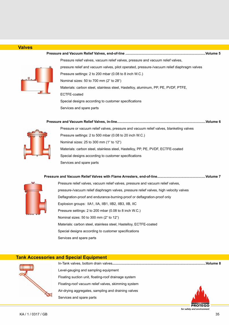
35for safety and environment
ValvesPressure and Vacuum Relief Valves, end-of-line ...................................................................................Volume 5
Pressure relief valves, vacuum relief valves, pressure and vacuum relief valves,
pressure relief and vacuum valves, pilot operated, pressure-/vacuum relief diaphragm valves
Pressure settings: 2 to 200 mbar (0.08 to 8 inch W.C.)
Nominal sizes: 50 to 700 mm (2“ to 28“)
Materials: carbon steel, stainless steel, Hastelloy, aluminum, PP, PE, PVDF, PTFE,
ECTFE-coated
Special designs according to customer specifications
Services and spare parts
Pressure and Vacuum Relief Valves, in-line............................................................................................Volume 6
Pressure or vacuum relief valves, pressure and vacuum relief valves, blanketing valves
Pressure settings: 2 to 500 mbar (0.08 to 20 inch W.C.)
Nominal sizes: 25 to 300 mm (1“ to 12“)
Materials: carbon steel, stainless steel, Hastelloy, PP, PE, PVDF, ECTFE-coated
Special designs according to customer specifications
Services and spare parts
Pressure and Vacuum Relief Valves with Flame Arresters, end-of-line.................................................. Volume 7
Pressure relief valves, vacuum relief valves, pressure and vacuum relief valves,
pressure-/vacuum relief diaphragm valves, pressure relief valves, high velocity valves
Deflagration-proof and endurance-burning-proof or deflagration-proof only
Explosion groups: IIA1, IIA, IIB1, IIB2, IIB3, IIB, IIC
Pressure settings: 2 to 200 mbar (0.08 to 8 inch W.C.)
Nominal sizes: 50 to 300 mm (2“ to 12“)
Materials: carbon steel, stainless steel, Hastelloy, ECTFE-coated
Special designs according to customer specifications
Services and spare parts
Tank Accessories and Special Equipment In-Tank valves, bottom drain valves.................................................................................................Volume 8
Level-gauging and sampling equipment
Floating suction unit, floating-roof drainage system
Floating-roof vacuum relief valves, skimming system
Air-drying aggregates, sampling and draining valves
Services and spare parts
Deflagration Flame Arresters, end-of-line and Vent Caps.................................................................Volume 2
Deflagration flame arresters, deflagration proof, short time burning proof, endurance burning proof
Vent caps without flame arresters
Explosion groups: IIA1, IIA, IIB1, IIB2, IIB3, IIB, IIC
Nominal sizes 15 to 800 mm (½“ to 32“)
Materials: carbon steel, stainless steel, Hastelloy, ECTFE-coated
Special designs according to customer specifications
Services and spare parts
Deflagration Flame Arresters............................................................................................................... Volume 3
Deflagration flame arresters, in-line, deflagration flame arrester units on equipment
Explosion groups: IIA1, IIA, IIB1, IIB2, IIB3, IIB, IIC
Nominal sizes 10 to 1000 mm (¼“ to 40“)
Materials: carbon steel, stainless steel, Hastelloy, ECTFE-coated
Special designs according to customer specifications
Services and spare parts
Detonation Flame Arresters................................................................................................................. Volume 4
Detonation flame arresters for stable detonations, for unstable detonations
Explosion groups: IIA1, IIA, IIB1, IIB2, IIB3, IIB, IIC
Nominal sizes 15 to 800 mm (½“ to 32“)
Materials: carbon steel, stainless steel, Hastelloy, ECTFE-coated
Special designs according to customer specifications
Services and spare parts
KA / 1 / 0317 / GB
36
AppendixRegulations, Laws, Standards and PROTEGO® Publications
KA / 1 / 0116 / GB
Regulations and Laws
2014/34/EU Directive of the European Parliament and the Council of February 21, 2014 on the approximate of the laws of the Member States concerning equipment and Protective Systems intended for use in potential-ly explosive atmospheres (recast, replace 94/9/EC after April, 20 2016)
94/9/EC Directive of the European Parliament and the Council of March 23, 1994 on the approximate of the laws of the Member States concerning equipment and Protective Systems intended for use in potentially explosive atmospheres (replaced by 2014/34/EU)
1999/92/EC Directive of the Council on minimum requirements for improving the safety and health of workers potentially at risk from explosive atmospheres (individual directive according to article 16 of Directive 89/391/EEC)
2006/42/EC Directive on machinery of 17 May 2006
2014/68/EU (PED) Pressure equipment directive of the European Parliament and the European Council replace 97/23/EC from 17.7.2015 shall applied from July 19, 2016
97/23/EC Pressure equipment directive of the European Parliament and theEuropean Council valid until July 18, 2016
1999/13/EC Control of VOC emissions resulting from storage and distribution of petrol
Standards
EN ISO 28300: Petroleum, petrochemical and natural gas industries - Venting of atmospheric and low-pressure storage tanks, 2008
EN ISO 16852: Flame Arresters - Performance requirements, test methods and limits for use, 2010
EN 12874 Flame Arresters: Performance Requirements, Test Methods, andLimits for Use, 2001
EN 1127-1 Explosive Atmospheres. Explosion Prevention and Protection. Part 1: Basic Concepts and Methodology, 2011
EN 1012-2 Compressors and Vacuum Pumps. Part 2: Vacuum pumps, 2011
EN 12255-10 Wastewater Treatment Plants - Part 10: Safety and Construction Principles, 2001
EN 13463-1 Non-Electrical Equipment Intended For Use in Potentially Explosive Atmospheres - Part 1: Basic Methods and Requirements, 2009
EN 13463-5 Non-electrical equipment intended for use in potentially explo- sive atmospheres - Part 5: Protection by constructional safety ‘c’, 2012
EN ISO/IEC 80079-34 Explosive atmospheres - Part 34: Application of quality systems for equipment manufacture, 2012
EN 14015 Specification for the Design and Manufacture of Site-Built, Abo- ve-Ground, Vertical, Cylindrical, and Welded Flat-Bottomed, Steel Tanks for the Storage of Liquids at Ambient Temperature and Above, Appendix L: Requirements for Pressure and Vacuum Relief Systems, 2005
33 CFR Part Facilities Transferring Oil Or Hazardous Material in Bulk (USCG-Rule)
API STD 2000 7th ed. Venting Atmospheric and Low-Pressure Storage Tanks, 2014
API Publ 2210 3rd ed. Flame Arresters for Vents of Tanks Storing Petroleum Products, 2000 (in revision)
API Publ 2028 2nd ed. Flame Arresters in Piping, 1991
API Bulletin 2521, Use of Pressure-Vacuum Vent Valves for Atmospheric Pressure Tanks to Reduce Evaporation Loss,1993
ANSI/UL 525 6th ed. Standard for Flame Arresters, 1994
ASTM F1273-91 Standard Specification for Tank Vent Flame Arresters, Reapproved 2007
NFPA 30 Flammable and Combustible Liquids Code, 2015 ed.
NFPA 36 Standard for Solvent Extraction Plants, 2013 ed.
NFPA 59A Standard for the Production, Storage, and Handling of Liquefied Natural Gas (LNG), 2013 ed.
NFPA 67 Guide on Explosion Protection for Gaseous Mixtures in Pipe Systems, 2016 ed.
NFPA 68, Venting of Deflagrations, 2013 ed.
NFPA 69 Standard on Explosion Prevention Systems, 2014 ed.
NFPA 497 Recommended Practice for the Classification of Flammable Vapors and of Hazardous Locations for Electrical Installations in Chemical Process Areas, 2012 ed.
HSG176 The Storage of Flammable Liquids in Tanks, 2015
IEC 60079-10-1 Explosive atmospheres. Classification ofareas. Explosive gas atmospheres, 2014
EN 60079-20-1 Explosive atmospheres - Part 20-1: Material characteristics for gas and vapour classification - Test methods and data (IEC 60079-20-1), 2010
Technical Regulations
Occupational Safety and Health Protection Rules - Explosion Protection Rules (EX-RL), 2015 - German
TRBS 2152 Hazardous explosive atmosphere, 2016
TRBS 2153 Vermeidung von Zündgefahren infolge elektrostatischer Aufladungen, 2009
TRBS 3151 Vermeidung von Brand-, Explosions- und Druckgefährdungen an Tankstellen und Füllanlagen zur Befüllung von Landfahrzeugen, 2015
TRbF 20 Läger, 2002
VdTÜV-Merkblatt Tankanlagen 967, 2012
VDI 3479, Emission Reduction, Distribution Storage for Mineral Oil Far from Refineries, 2010
GUV-R 127 Regeln für Sicherheit und Gesundheitsschutz, Deponien, 2001
AO 8.06/77 Explosion Protection in the Manufacture and Processing of Fermented Spirits (Alcohol Memorandum), Institution for Statutory Accident Insurance and Prevention in the Food Industry and the Catering Trade - German
Techncal Literature (Selection)
Handbook of Explosion Prevention and Protection (Editor: Steen, H.) Wiley-VCH Verlag,Weinheim (2008)
Lexikon Explosionsschutz, Sammlung definierter Begriffe, Berthold Dyrba, Carl Heymanns Verlag (2006)
37for safety and environment
KA / 1 / 0116 / GB
6. Nachtrag zu Sicherheitstechnischen Kennzahlen brennbarer Gase und Dämpfe (K. Nabert, G. Schön), Deutscher Eichverlag GmbH, Braun- schweig 1990
Brandes, E., Möller W. Safety Characteristic Data Volume 1: Flammable Liquids and Gases, Schünemann Verlag, 2008
Schampel K.: Flammendurchschlagsicherungen, Expert Verlag, 1988
Brandes, E., März, G., Redeker, T., Normspaltweiten von Mehr-Brennstoff- komponenten-Gemischen in Abhängigkeit der Brennstoffzusammen- setzung, PTB-Bericht PTB-W-69, Juni 1997
Steen, H., Schampel, K.: Stoffabhängigkeit der Wirkung flammendurch- schlagsicherer Einrichtungen. Fortschritt-Berichte VDI, Reihe 6, Nr. 122 1983
Schampel, K.: Verhinderung eines Dauerbrandes an Flammendurch- schlagsicherungen in Lüftungsleitungen von Behältern und Apparaturen, 2. Sicherheitstechnische Vortragsveranstaltung über Fragen des Explosi-onsschutzes, PTB-Bericht W-20 (1983) 20-29.
Bartknecht, W.: Explosionsschutz, Grundlagen und Anwendungen, Springer Verlag, Berlin, Heidelberg, 1993
Prof. Dr. Hans Witt, Explosionsschutz bei Ventilatoren, Witt & Sohn GmbH&Co., Pinneberg, 1998
Meidinger, Ventilatoren zur Förderung von Gas/Luft- oder Dampf/ Luftgemischen der Zone 0, 1998
Eberhard Grabs, Anforderungen an explosionsgeschützte Vakuumpumpen - Ergebnisse einer Risikobewertung - Veröff. in PTB Mitteilungen 106 5/96
U. Füssel, Vakuum ohne Abwässer - Trockenläufer setzen sich durch, Chemie Technik, 1998
U. Friedrichsen, Konzept erfolgreich getestet - Trockenlaufende Vakuum- pumpe sichert wirtschaftlichen Prozess, Chemie Technik, 1998
Bjerketvedt, D., Bakke, J.R., van Wingerden, K.: Gas Explosion Handbook,Journal of Hazardous Materials 52 (1997), 1 – 150
Redeker, T.: Sicherheitstechnische Kennzahlen – Basis für den Explosions- schutz, 9. Internationales Kolloquium für die Verhütung von Arbeitsunfällen und Berufskrankheiten in der chemischen Industrie Luzern, 1984
Stanley S. Grossel: Deflagration und Detonation Flame Arresters, 2002
PROTEGO® Publications
Absicherung der Abblaseleitung eines Sicherheitsventils durch eine Defla- grationsendsicherung; Dr. T. Heidermann/H. Kuchta; Technische Überwachung, 2003
In-line Flame Arresters to Prevent Flashback of Thermal Combustion Units; Dr. T. Heidermann/Dr. M. Davies; Wiley InterScience, 2006
Keeping explosion in isolation; Dr. T. Heidermann/Dr. M. Davies/Dr. P. Bosse; HYDROCARBON ENGINEERING, 2008
A Research Study on Safe Application of Flame Arresters for Thermal Com- bustion Units; Dr. M. Davies/Dr. T. Heidermann/D.Long; HYDROCARBON ENGINEERING, 2008
FLAME ARRESTERS FOR PLANTS HANDLING ACETYLENE AND ETHY- LENE OXIDE; D. Long/Dr. T. Heidermann; IChemE, 2009
Leben schützen, Werte erhalten; Hochgeschwindigkeitsventile in der Edel- metallverarbeitung; Dr. T. Heidermann; Verfahrenstechnik, 2009
Flames under arrest; Dr. M. Davies/Dr. T. Heidermann; HYDROCARBON ENGINEERING, 2012
FLAME ARRESTERS; Testing and applying flame arresters; Dr. M. Davies/Dr. T. Heidermann; INDUSTRIALFIRE JOURNAL, 2011
Conservation vents do not substitute arresters; Dr. M. Davies/ Dr. T. Heidermann; Tank Storage Magazine, 2010
New standards for flame arresters and tank venting; Dr. T. Heidermann; 13th International Symposium on Loss Prevention
FLAME TRANSMISSION TESTS WITH P/V VALVES; Dr. M. Davies/ Dr. T. Heidermann; Test Report, 2007
FLAME ARRESTERS; Dr. M. Davies/Dr. T. Heidermann; Perry´s chemical engineers Handbook 8th EDITION Green Perry; 23-92
CFD-Modeling for Optimizing the Function of Low-Pressure Valves; F. Helmsen, T. Kirchner; Process and Plant Safety; 2012 Wiley-VCH Verlag GmbH & Co. KGaA
Sicherheit bei Problemprodukten; Dr. M. Davies/Dr. P. Bosse/ T. Klocke; POWTECH, TECHNOPHARM, EXPLORISK
New ISO standard for flame arresters to increase explosion isolation efficiency; Dr. M. Davies/Dr. T. Heidermann/Dr. P. Bosse; HYDROCARBON ENGINEERING
No safe substitute, FLAME ARRESTERS; HAZARDOUS CARGO BULLETIN, 2008
Schwerpunkt: Lagerung: Flammen filtern; T. Schaper/Dr. P. Bosse; Gefährliche Ladung, 2005
A conservation vents is not a safe substitute for a flame arrester; Dr. T. Heidermann/Dr. M. Davies/D. Preusse; HYDROCARBON ENGINEERING, 2008
Venting Technologies for reducing vapour losses; Dr. P. Bosse/ Dr. M. Da- vies; HYDROCARBON ENGINEERING, 2008
Auslegung, sicherer Betrieb und Instandhaltung von Schutzsystemen in explosionsgefährdeten überwachungsbedürftigen Anlagen; Dr. V. Halstrick; Technische Sicherheit, 2012
Protect Your Process With The Proper Flame Arresters. Dr. M. Davies, Dr. T. Heidermann, CEP, 2013
Alt neben Neu - Konzept für qualifizierte und regelmäßigeWartung; T. Anderssohn; Verfahrenstechnik, 2012
Flammendurchschlagsicherungen - Planung, Betrieb, Wartung; T. Anderssohn; Industriearmaturen, 2013R. Raman, D. Moncalvo, T. Heidermann, S. Kostos; Overfilling Protection for Weak Tanks, CCPS 2015
Influence of Overpressure in Pressure Vacuum Safety Valves on Emission Reduction and Explosion Risk Minimization of Atmospheric Storage Tanks; 11th Global Congress of Process Safety; Dr.-Ing. Davide Moncalvo, Dr.-Ing. Michael Davies, 2015
Overfilling Protection for Weak Tanks, 11th Global Congress of Process Safety; Rahul Raman, Justin Phillips, 2015

38
AppendixGlossary
Term
accumulation
actual flow capacity
adjusted set pressure
ambient air
ambient temperature
annular flame arresting unit
atmospheric conditions
atmospheric discharge
back pressure
bi-directional flame arrester
blow down
bottom drain valve
check valve
coating
combustion air
component
condensate drain screw
conventional pressure-relief valve
deflagration
deflagration flame arrester
design pressure (tank)
Description
pressure increase over the maximum allowable working pressure of the vessel allowed during discharge through the pressure-relief device
actual flow capacity is the flowing capacity determined by measurement
vacuum or gauge pressure at which under test stand conditions (atmospheric back pressure) valves commence to lift
normal atmosphere surrounding the equipment and protection system
temperature of the air or other medium where the equipment is to be used (IEV 826-01-04) (IEC 60204-32:1998) Note: For the application of the Directive 94/9/EC only air is considered
flame arresting unit consisting of annular crimped ribbons
atmospheric conditions are pressures from 80 kPa till 110 kPa and temperatures from -20°C up to +60°C
release of vapors and gases from pressure-relieving and depressurizing devices to the atmosphere
the back pressure is the gauge pressure existing at the outlet side during blowing (pa = pae + paf)
a flame arrester which prevents flame transmission from both sides
difference between set pressure and reseating pressures, normally stated as a percentage of set pressure
emergency valve at the tank bottom to shut immediately in case of downstream piping rupture
valve, that prevents backflow against flow direction
protective painting with defined layer-thickness
air required to combust the flare gases
„component“ means any item essential to the safe functioning of Equipment and Protective System but with no autonomous function
screw to drain the condensate
spring-loaded pressure-relief valve whose operational characteris-tics are directly affected by changes in the back pressure
explosion propagating at subsonic velocity (EN 1127-1:1997)
flame arrester designed to prevent the transmission of a deflagration. It can be an end-of-line flame arrester or an in-line flame arrester
max. permissible pressure of a tank in the space above the stored liquid
Source
ISO 23251 - 3.1
DIN 3320-75
-
EN 13237 - 3.1
EN 13237 - 3.2
-
ISO 16852 - 3.25
ISO 23251 - 3.4
DIN 3320-58
ISO 16852 - 3.13
-
-
-
ISO 23251 - 3.19
EN 1127 - 3.2
-
ISO 23251 - 3.20
EN 13237 - 3.15
ISO 16852 - 3.14
-
KA / 1 / 0909 / GB

39for safety and environment
Glossary
design pressure / design temperature (general design)
design vacuum (negative gauge pressure)
detonation
detonation flame arrester
detonation proof by-pass
diaphragm valve
emergency venting
emergency venting valves
end-of-line flame arrester
endurance burning
endurance burning flame arrester
equipment
equipment category
explosion
explosion limits
explosive atmosphere
flame arrester
flame arrester cage
flame arrester element
pressure, together with the design temperature, used to determine the minimum permissible thickness or physical characteristic of each component, as determined by the design rules of the pressure-design code
max. permissible vacuum (negative gauge pressure) in the space above the stored liquid
explosion propagating at supersonic velocity and characterized by a stock wave (EN 1127-1: 1997)
flame arrester designed to prevent the transmission of a detonation. It can be an end-of-line flame arrester or an in-line flame arrester
dry-type detonation proof by-pass to keep a minimum liquid for safety reasons
valve, where the moving valve part consists of a diaphragm
venting required when an abnormal condition, such as ruptured internal heating coils or an external fire, exists either inside or outside a tank
pressure relief valves for emergency venting
flame arrester that is fitted with one pipe connection only
stabilized burning for an unlimited time
flame arrester that prevents flame transmission during and after endurance burning
„equipment“ means machines, apparatus, fixed or mobile devices, control components and instrumentation thereof and detection and prevention systems which, separately or jointly, are intended for the generation, transfer, storage, measurement, control and conversion of energy, for the processing of material, and which are capable of causing an explosion through their own potential sources of ignition
within an equipment group, a category is the classification according to the required level of protection. The categories are defined as given in A.6.
abrupt oxidation or decomposition reaction producing an increase in temperature, pressure or in both simultaneously
limits of explosion range (EN 1127-1:1997)
mixture with air, under atmospheric conditions, of flammable substances in the form of gases, vapors, mists or dusts, in which, after ignition has occurred, combustion spreads to the entire unburned mixture
a device fitted to the opening of an enclosure or to the connecting pipework of a system of enclosures and whose intended function is to allow flow but prevent the transmission of flame
enclosure for the flame arrester element including spider rings
crimped ribbon element
ISO 23251 - 3.23
-
EN 13237 - 3.18
ISO 16852 3.15
-
-
ISO 28300 - 3.23
-
ISO 16852 - 3.23
ISO 16852 - 3.6
ISO 16852 - 3.16
EN 1127 - 3.5
EN 13237 - 3.26
ISO 16852 - 3.7
EN 13237 - 3.29
EN 1127 - 3.17
ISO 16852 - 3.1
-
-
KA / 1 / 0909 / GB

40
Glossary
Appendix
flame arrester element gap
flame arrester housing
flame arrester set
flame arrester unit
flame transmission proof
FLAMEFILTER®
FLAMEFILTER® cage
FLAMEFILTER® gap
FLAMEFILTER® set
flammable gas or vapor
flammable liquid
flammable material
flammable substances
flashback
flashpoint
floating cover
floating roof
floating suction unit
foot valve flame arrester
free vents
flame arrester elements have profiles, which are more or less triangular. The flame arrester element gap is the triangular height of the flame arrester element
that portion of a flame arrester whose principal function is to provide a suitable enclosure for the flame arrester element and allow mechanical connections to other systems
combination of flame arrester elements with spacers
flame arrester cage with flame arrester elements and spacers
characteristic of a device to avoid flashback
international trademarks by Braunschweiger Flammenfilter GmbH for flame arrester element made of crimped ribbon
enclosure for FLAMEFILTER® including spider rings
flame arrester element gap of a crimped ribbon element type FLAMEFILTER®
combination of FLAMEFILTER® with spacers
gas or vapor which, when mixed with air in certain proportions, will form an explosive gas atmosphere (EN 60079-10:1996)
liquid capable of producing a flammable vapor under any foreseeable operating condition (EN 60079-10:1996)
material which is flammable of itself, or is capable of producing a flammable gas, vapor or mist (EN 60079-10:1996)
substance in the form of gas, vapor, liquid, solid, or mixtures of these, able to undergo an exothermic reaction with air when ignited (EN 1127-1:1997)
phenomenon occurring in a flammable mixture of air and gas when the local velocity of the combustible mixture becomes less than the flame velocity, causing the flame to travel back to the point of mixture
lowest temperature, corrected to a barometric pressure of 101,3 kPa, at which application of a test flame causes the vapor of the test portion to ignite under the specified conditions of test (ISO 13736:1997)
structure which floats on the surface of a liquid inside a fixed roof tank, primarily to reduce vapor loss
metallic structure which floats on the surface of a liquid inside an open top tank shell, and in complete contact with this surface
mechanical device, sometimes articulated, installed in some tanks, which floats on the liquid surface and only permits product to be withdrawn from this point
a flame arrester designed to use the liquid product combined with a non return valve to form a barrier to flame transmission
open vents
-
ISO 16852 - 3.2
-
-
-
-
-
-
-
EN 13237 - 3.44
EN 13237 - 3.45
EN 13237 - 3.46
EN 13237 - 3.48
ISO 23251 - 3.34
EN 13237 - 3.49
EN 14015 - 3.1.22
EN 14015 - 3.1.21
EN 14015 - 3.1.28
ISO 16852 - 3.19.2
EN 14015 - 3.1.40
KA / 1 / 0909 / GB

41for safety and environment
Glossary
fusible link
gauging and sampling device
gauging nozzle
gauging pipe
gauging probe
guide bushing
guide rod
guide spindle
guide pipe
hazardous area
hazardous explosive atmosphere
heat release
heating jacket
high velocity vent valve (dynamic flame arrester)
housing
hydraulic flame arrester
ignition source
ignition temperature (of a combustible gas or of a combustible liquid)
inert gas
inerting
in-line flame arrester
integrated temperature sensor
component which melts at a defined temperature and which actuates another function (opening of hood, closing of valve)
equipment for stating the liquid level within storage tanks as well as for sampling from any height within the stored medium
opening at a storage tank for gauging or sampling
pipe within the storage tank for determining the liquid level and for sampling - in flashback-proof or regular design
device for determining the liquid levels in storage tanks
component for guiding e.g. the guide spindle of a valve pallet
component (rod) for guidance of valve pallet
orthogonal to valve pallet section, central pipe for guiding the valve pallet
pipe for guiding the guide spindle of a valve pallet
area in which an explosive atmosphere is present, or may be expected to be present in quantities such as to require special precautions for the construction, installation and use of equipment
explosive atmosphere which, if it explodes, causes damage
total heat liberated by combustion of the relief gases based on the lower heating value
closed room for heating of a device, which encloses the device fully or partly
pressure relief valve designed to have nominal flow velocities that exceed the flame velocity of the explosive mixture, thus preventing flame transmission
enclosure of a product or component
flame arrester designed to break the flow of an explosive mixture into discrete bubbles in a water column, thus preventing flame transmission
any source with sufficient energy to initiate combustion (EN ISO 13702:1999)
the lowest temperature of a heated wall as determined under specified test conditions, at which the ignition of a combustible substance in the form of gas or vapor mixture with air will occur
non-flammable gas which will not support combustion and does not react to produce a flammable gas
addition of inert substances to prevent explosive atmospheres
flame arrester that is fitted with two pipe connections, one each side of the flame arrester
temperature sensor integrated into the flame arrester, as specified by the manufacturer of the flame arrester, in order to provide a signal suitable to activate counter measures
-
-
-
-
-
-
-
-
-
EN 13237 - 3.55
EN 1127 - 3.19
ISO 23251 - 3.36
-
ISO 16852 - 3.18
-
ISO 16852 - 3.20
EN 13237 - 3.62
EN 1127 - 3.31
EN 13237 - 3.68
EN 1127 - 3.21
ISO 16852 - 3.22
ISO 16852 - 3.24
KA / 1 / 0909 / GB
42
Glossary
Appendix
leak rate
left-hand wound
lift
limiting oxygen concentration (LOC)
lining
liquid product detonation flame arrester
liquid seal (water seal)
lower explosion limit (LEL)
maintenance
malfunction
manifold
maximum allowable explosion pressure
maximum allowable pressure (pressure equipment)
maximum allowable temperature (pressure equipment)
maximum allowable working pressure (MAWP)
maximum experimental safe gap (MESG)
maximum operating temperature
leakage of a device in volume per time (liter per second)
orientation (angle) of gaps of crimped ribbon element
actual travel of the valve disc away from the closed position
maximum oxygen concentration in a mixture of a flammable substance and air and an inert gas, in which an explosion will not occur, determined under specified test conditions (EN 1127-1:1997)
protective cladding with defined minimum/maximum thickness to protect against aggressive mixtures (e.g. acid)
flame arrester in which the liquid product is used to form a liquid seal as a flame arrester medium, in order to prevent flame trans-mission of a detonation. There are two types of liquid product detonation flame arrester for use in liquid product lines: liquid seals and foot valves
device that directs the flow of relief gases through a liquid (normally water) on the path to the flare burner, used to protect the flare header from air infiltration or flashback, to divert flow, or to create back pressure for the flare header
the lower limit of the explosion range
combination of all technical and administrative actions, including supervision actions, intended to retain an item in, or restore it to, a state in which it can perform a required function
the equipment, protective system and components do not perform the intended function
piping system for the collection and/or distribution of a fluid to or from multiple flow paths
calculated maximum explosion pressure which the equipment will withstand
maximum pressure for which the equipment is designed as specified by the manufacturer
maximum temperature for which the equipment is designed as specified by the manufacturer
maximum gauge pressure permissible at the top of a completed vessel in its normal operating position at the designated coincident temperature specified for that pressure
the maximum gap of the joint between the two parts of the interior chamber of the test apparatus which, when the internal gas mixture is ignited and under specified conditions, prevents ignition of the external gas mixture through a 25 mm long joint, for all concentrations of the tested gas or vapor in air. The MESG is a property of the respective gas mixture (EN 1127-1: 1997) Note: IEC 60079-1 A standardizes the test apparatus and the test method
maximum temperature reached when equipment or protective system is operating at its intended operating conditions
-
-
ISO 4126 - 3.3
EN 13237 - 3.64
-
ISO 16852 - 3.19
ISO 23251-3.43
EN 1127 - 3.8
EN 13237 - 3.78
EN 1127 - 3.25
ISO 23251 - 3.45
EN 14460 - 3.7
97/23/EC (PED)
97/23/EC (PED)
ISO 23251 - 3.47
-
-
KA / 1 / 0909 / GB

51for safety and environment
Glossary
measurable type (static flame arrester)
most easily ignitable explosive atmosphere
nominal size, nominal diameter
non-measurable type (static flame arrester)
normal pressure venting
normal vacuum venting
normal venting
opening pressure
operating pressure
operating temperature
overpressure
pallet guidance
pallet type valve (disc valve)
pilot-operated pressure relief valve
pilot-operated valve
pipe away valve
pressure
pressure-relief valve
pressure/vacuum valve (PV valve)
a flame arrester where the quenching gaps of the flame arrester element can be technically drawn, measured and controlled
explosive atmosphere with a concentration of flammable substances which under specified conditions, requires the lowest energy for its ignition
(DN) a numerical size designation used for all components of a piping system, for which the external diameter or the size of thread is not indicated. The figure is rounded and has only an approximate relation to the machined dimensions
a flame arrester where the quenching gaps of the flame arrester element cannot be technically drawn, measured or controlled (e.g. random such knitted mesh, sintered metal and gravel beds)
outbreathing under normal operating conditions (pumping product into the tank and thermal outbreathing)
inbreathing under normal operating conditions (pumping product out of the tank and thermal inbreating)
venting required because of operational requirements or atmosheric changes
the opening pressure is the vacuum resp. gauge pressure at which the lift is sufficient to discharge the predetermined mass flow; it is equal to the set pressure plus overpressure
pressure in the process system experiences during normal operation, including normal variations
temperature reached when the apparatus is operating at its rating
pressure increase over the set pressure, at which the safety valve attains the lift specified by the manufacturer, usually expressed as a percentage of the set pressure
element of valve providing guidance of valve pallet
valve with discoidal seal and axial guide
pressure relief valve in which the major relieving device or main valve is combined with and controlled by a self-actuated auxiliary pressure-relief valve (pilot)
valve actuated by a control device (pilot)
pressure or vacuum valve to which a vent pipe may be connected
pressure unit used in this standard is the bar (1 bar = 10000 Pa), quoted as gauge (relative to atmospheric pressure) or absolute as appropriate
valve designed to open and relieve excess pressure and to reclose and prevent the further flow of fluid after normal conditions have been restored
weight-loaded, pilot-operated, or spring-loaded valve, used to relieve excess pressure and/or vacuum that has developed in a tank
ISO 16852 - 3.17.1
EN 13237 - 3.87
-
ISO 16852 - 3.17.2
EN 14015 - 3.1.35
EN 14015 - 3.1.36
ISO 28300 – 3.7
DIN 3320 - 54
ISO 23251 - 3.49
-
ISO 4126 - 3.2.3
-
-
ISO 23251 - 3.52
-
EN 14015 - 3.1.44
ISO 4126 - 3.2
ISO 23251 - 3.56
ISO 23251 - 3.11
KA / 1 / 0909 / GB

52
Glossary
Appendix
pre-volume flame arrester
product
protective screen
protective system
quenching
relieving pressure
reseating pressure (closing pressure)
right-hand wound
safety shut-off valve
safety valve
sampling and air bleed valve
set pressure
set vacuum
shock absorber
Shock-Wave-Guide-Tube (SWGT)
short time burning
spacer
sparge pipe
stabilized burning
stable detonation
flame arrester that, after ignition by an internal ignition source, prevents flame transmission from inside an explosion-pressure-resistant containment (e.g. a vessel or closed pipe work) to the outside, or into the connecting pipe work
term product covers equipment, protective systems, devices, components and their combinations as well as software as defined in 3.4.2 of EN ISO 9000:2000 (EN 13980.2002)
component, which provides free flow, but prevents entrance of foreign matter, for example animals
„protective system“ means design units which are intended to halt incipient explosions immediately and/or to limit the effective range of explosion flames and explosion pressures. Protective systems may be integrated into equipment or separately placed on the market for use as autonomous systems
cooling of a fluid by mixing it with another fluid of a lower temperature
pressure at the inlet of a relief device when the fluid is flowing at the required relieving capacity
value of the inlet static pressure at which the disc re-establishes contact with the seat or at which the lift becomes zero
orientation (angle) of gaps of crimped ribbon element
a safety shut-off valve is a valve which closes automatically to prevent a predetermined gauge pressure being exceeded
valve which automatically, without the assistance of any energy other than that of the fluid concerned, discharges a quantity of the fluid so as to prevent further flow of fluid after normal pressure conditions of service have been restored
flashbackproof and non flashbackproof taps or valves out- and inbreathing of parts of plant
gauge pressure at the device inlet at which the relief device is set to start opening under service conditions
internal negative gauge pressure at which a vacuum valve first opens
component to reduce the kinetic energy of a detonation
component for decoupling of shock wave and flame front: PROTEGO® patent
stabilized burning for a specific time
component, which lies on and between the crimped ribbon elements of a flame arrester unit
pipe leading into the dip liquid of an hydraulic flame arrester
steady burning of a flame stabilized at, or close to the flame arrester element
a detonation is stable when it progresses through a confined system without significant variation of velocity and pressure characteristics
ISO 16852 - 3.23
EN 13237 - 3.95
-
EN 1127 - 3.36
ISO 23251 - 3.59
ISO 28300 - 3.15
ISO 4126 - 3.2.4
-
DIN 3320-2
ISO 4126 - 3.1
-
ISO 28300 - 3.19
-
-
-
ISO 16852 - 3.5
-
-
ISO 16852 - 3.4
ISO 16852 - 3.10
KA / 1 / 0909 / GB
53for safety and environment
Glossary
static electricity
static flame arrester
stoichiometric air
storage tank storage vessel
swing pipe unit
swivel joint
temperature class
temperature sensor
test pressure
thermal inbreathing
thermal outbreathing
unstable detonation
upper explosion limit (UEL)
valve lift
valve pallet gasket
vent cap
vent header
vent pipes
venting system
venting system with flame arresting capability
build-up of an electrical difference of potential or charge, through friction of dissimilar materials or substances e.g. product flow through a pipe
a flame arrester designed to prevent flame transmission by quenching gaps
chemically correct ratio of fuel to air capable of perfect combustion with no infused fuel or air
fixed tank or vessel that is not part of the processing unit in petrochemical facilities, refineries, gas plants, oil and gas production facilities, and other facilities
flexible pipeline with or without float within a storage tank for filling and emptying
part of a swing pipe system
classification of equipment, protective system or component for explosive atmospheres based on its maximum surface temperature
temperature sensor for monitoring the temperature
pressure to test the mechanical stability of devices and or to test devices for leak
movement of air or blanketing gas into a tank, when vapours in the tank contract or condense as a result of weather changes (e.g. decrease in atmospheric temperature)
movement of air or blanketing gas out of a tank, when vapours in the tank expand and liquid in the tank vapourizes as a result of weather changes (e.g. increase in atmospheric temperature)
detonation during the transition of a combustion process from a deflagration into a stable detonation. The transition occurs in an limited spatial zone where the velocity of the combustion wave is not constant and where the explosion pressure is significantly higher than in a stable detonation
the upper limit of the explosion range
actual travel of the valve pallet away from the closed position, when a valve is relieving
sealing element between valve pallet and valve seat
end-of-line device for free out- and inbreathing of plant components. This device can be flame transmission proof
piping system that collects and delivers the relief gases to the vent stack
pipes connected to pipe away valves
system, which consists of pipeline and devices for free out- and inbreathing of parts of plants
free vents or pressure and/or vacuum valves combined with a flame arrester or with integrated flame arresting elements
EN 14015 - 3.1.18
ISO 16852 - 3.17
ISO 23251 - 3.73
ISO 23251 - 3.74
-
-
EN 13237 - 3.111
-
-
ISO 28300 - 3.20
ISO 28300 - 3.21
ISO 16852 - 3.11
EN 1127 - 3.9
-
-
-
ISO 23251 - 3.78
EN 14015 - 3.1.45
-
DIN EN 14015 - 3.1.42
KA / 1 / 0909 / GB

54
Glossary
Appendix
vessel
zone 0
zone 1
zone 2
zones for gases/vapours
container or structural envelope in which materials are processed, treated or stored
place in which an explosive atmosphere consisting of a mixture with air of flammable substances in the form of gas, vapor or mist is present continuously or for long periods or frequently
place in which an explosive atmosphere consisting of a mixture with air of flammable substances in the form of gas, vapor or mist is likely to occur in normal operation occasionally
place in which an explosive atmosphere consisting of a mixture with air of flammable substances in the form of gas, vapor or mist is not likely to occur in normal operation but, if it does occur, will persist for a short period only
hazardous areas are classified into zones based upon the frequency of the occurrence and the duration of an explosive gas atmosphere, the definitions are only applicable to equipment group II
ISO 23251 - 3.80
EN 13237 - 3.119-1
EN 13237 - 3.119-2
EN 13237 - 3.119-3
EN 13237 - 3.119
KA / 1 / 0909 / GB

55for safety and environment
KA / 1 / 0514 / GB
Notes:
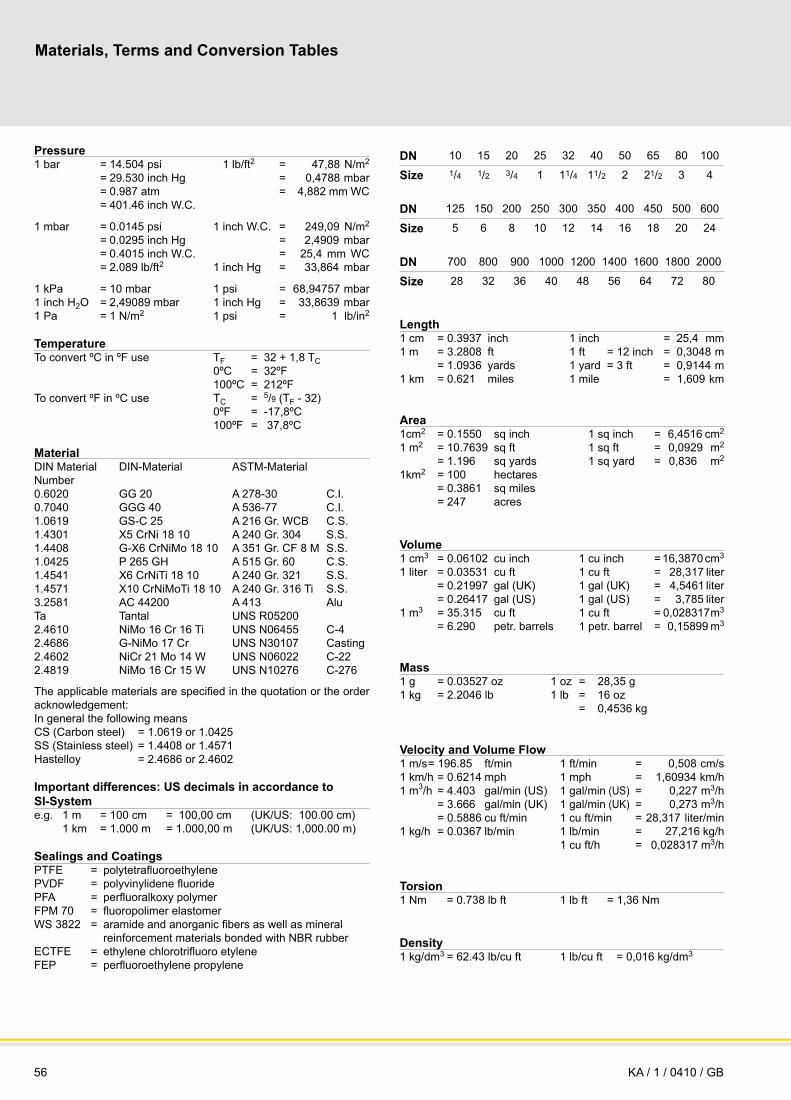
56
Data Sheet for PROTEGO® - Valves and Flame ArrestersMaterials, Terms and Conversion Tables
DN 10 15 20 25 32 40 50 65 80 100
Size 1/4 1/2 3/4 1 11/4 11/2 2 21/2 3 4
DN 125 150 200 250 300 350 400 450 500 600
Size 5 6 8 10 12 14 16 18 20 24
DN 700 800 900 1000 1200 1400 1600 1800 2000
Size 28 32 36 40 48 56 64 72 80
Length1 cm = 0.3937 inch 1 inch = 25,4 mm 1 m = 3.2808 ft 1 ft = 12 inch = 0,3048 m = 1.0936 yards 1 yard = 3 ft = 0,9144 m 1 km = 0.621 miles 1 mile = 1,609 km
Area1cm2 = 0.1550 sq inch 1 sq inch = 6,4516 cm2 1 m2 = 10.7639 sq ft 1 sq ft = 0,0929 m2 = 1.196 sq yards 1 sq yard = 0,836 m2 1km2 = 100 hectares = 0.3861 sq miles = 247 acres
Volume1 cm3 = 0.06102 cu inch 1 cu inch = 16,3870 cm3 1 liter = 0.03531 cu ft 1 cu ft = 28,317 liter = 0.21997 gal (UK) 1 gal (UK) = 4,5461 liter = 0.26417 gal (US) 1 gal (US) = 3,785 liter 1 m3 = 35.315 cu ft 1 cu ft = 0,028317 m3 = 6.290 petr. barrels 1 petr. barrel = 0,15899 m3
Mass1 g = 0.03527 oz 1 oz = 28,35 g1 kg = 2.2046 lb 1 lb = 16 oz = 0,4536 kg
Velocity and Volume Flow1 m/s = 196.85 ft/min 1 ft/min = 0,508 cm/s 1 km/h = 0.6214 mph 1 mph = 1,60934 km/h 1 m3/h = 4.403 gal/min (US) 1 gal/min (US) = 0,227 m3/h = 3.666 gal/min (UK) 1 gal/min (UK) = 0,273 m3/h = 0.5886 cu ft/min 1 cu ft/min = 28,317 liter/min 1 kg/h = 0.0367 lb/min 1 lb/min = 27,216 kg/h 1 cu ft/h = 0,028317 m3/h
Torsion 1 Nm = 0.738 lb ft 1 lb ft = 1,36 Nm
Density1 kg/dm3 = 62.43 lb/cu ft 1 lb/cu ft = 0,016 kg/dm3
Pressure1 bar = 14.504 psi 1 lb/ft2 = 47,88 N/m2 = 29.530 inch Hg = 0,4788 mbar = 0.987 atm = 4,882 mm WC = 401.46 inch W.C.
1 mbar = 0.0145 psi 1 inch W.C. = 249,09 N/m2 = 0.0295 inch Hg = 2,4909 mbar = 0.4015 inch W.C. = 25,4 mm WC = 2.089 lb/ft2 1 inch Hg = 33,864 mbar
1 kPa = 10 mbar 1 psi = 68,94757 mbar 1 inch H2O = 2,49089 mbar 1 inch Hg = 33,8639 mbar 1 Pa = 1 N/m2 1 psi = 1 lb/in2
TemperatureTo convert ºC in ºF use TF = 32 + 1,8 TC 0ºC = 32ºF 100ºC = 212ºFTo convert ºF in ºC use TC = 5/9 (TF - 32) 0ºF = -17,8ºC 100ºF = 37,8ºC
MaterialDIN Material DIN-Material ASTM-MaterialNumber0.6020 GG 20 A 278-30 C.I.0.7040 GGG 40 A 536-77 C.I.1.0619 GS-C 25 A 216 Gr. WCB C.S.1.4301 X5 CrNi 18 10 A 240 Gr. 304 S.S.1.4408 G-X6 CrNiMo 18 10 A 351 Gr. CF 8 M S.S.1.0425 P 265 GH A 515 Gr. 60 C.S.1.4541 X6 CrNiTi 18 10 A 240 Gr. 321 S.S.1.4571 X10 CrNiMoTi 18 10 A 240 Gr. 316 Ti S.S.3.2581 AC 44200 A 413 AluTa Tantal UNS R052002.4610 NiMo 16 Cr 16 Ti UNS N06455 C-42.4686 G-NiMo 17 Cr UNS N30107 Casting2.4602 NiCr 21 Mo 14 W UNS N06022 C-222.4819 NiMo 16 Cr 15 W UNS N10276 C-276
The applicable materials are specified in the quotation or the order acknowledgement:In general the following meansCS (Carbon steel) = 1.0619 or 1.0425SS (Stainless steel) = 1.4408 or 1.4571Hastelloy = 2.4686 or 2.4602
Important differences: US decimals in accordance to SI-Systeme.g. 1 m = 100 cm = 100,00 cm (UK/US: 100.00 cm) 1 km = 1.000 m = 1.000,00 m (UK/US: 1,000.00 m)
Sealings and CoatingsPTFE = polytetrafluoroethylenePVDF = polyvinylidene fluoridePFA = perfluoralkoxy polymerFPM 70 = fluoropolimer elastomerWS 3822 = aramide and anorganic fibers as well as mineral reinforcement materials bonded with NBR rubberECTFE = ethylene chlorotrifluoro etyleneFEP = perfluoroethylene propylene
KA / 1 / 0410 / GB

57for safety and environment
Data Sheet for PROTEGO® - Valves and Flame Arresters
Project Data Sheet
Quotation-No.Project-No.Valve / Flame Arrester Tag No.
Order-No.Project ReferenceTank / Vessel No.
Storage Tank / Vessel aboveground diameter m/ft design pressure mbar/inch W.C.
underground height m/ft design vacuum mbar/inch W.C.
insulated wall height m/ft pumping-in-rate m³/h cu ft/minins. thickness mm / inch blanketing level m/ft pumping-out-rate m³/h cu ft/min
inert gas inert gas blanketing level tank design standard
Stored Product Offgas/Vapour-CompositionComponentsName Formula Vol.%
Flashpoint°C/°F
CAS MESGmm/inch
Ex.-Group
Processing Plantdesign temperature °C/°F design pressure bar/psioperating temperature °C/°F operating pressure bar/psi back pressure mbar/inch W.C.
Installation in-line horizontal distance to source of ignition m/ft
end-of-line vertical
Function pressure endurance burning proof temperature monitored on side
vacuum short-time burning proof temperature monitored both side
pressure/vacuum combined deflagration proof pressure monitored
detonation proof bidirectional flame arrester
Valve and Flame Arrester Datasize nominal DN flow V
. m³/h cu ft/min density kg/m³ lb/cu ft
pressure nominal PN inlet flange DN PN formset pressure mbar/inch W.C. outlet flange DN PN formset vacuum mbar/inch W.C. pressure drop ∆p mbar/inch W.C.
Materialpressure carrying parts internals lining
Inspection/Documentationmaterial certificate works certificate performance certificate
Piping Flow Diagram (excerpt) / Additional Remarks / Miscellaneous → refer to seperate sheet
Fill in and tick off, if applicable, delete unit, if not applicable
signed: date: approved: released:
KA / 1 / 0909 / GB

58 KA / 1 / 0909 / GB
www.protego.com