A PARAMETRIC STUDY ON LATERAL LOAD RESISTANCE ...
18
http://iaeme.com/Home/journal/IJCIET 858 [email protected] International Journal of Civil Engineering and Technology (IJCIET) Volume 8, Issue 7, July 2017, pp. 858–875, Article ID: IJCIET_08_07_093 Available online at http://http://iaeme.com/Home/issue/IJCIET?Volume=8&Issue=7 ISSN Print: 0976-6308 and ISSN Online: 0976-6316 © IAEME Publication Scopus Indexed A PARAMETRIC STUDY ON LATERAL LOAD RESISTANCE OF STEEL CHIMNEYS M. Pavan Kumar Assistant Professor of Civil Engineering, SVP Engineering College, Visakhapatnam, Andhra Pradesh, India P. Markandeya Raju Professor of Civil Engineering, MVGR College of Engineering (A), Vizianagaram, Andhra Pradesh, India N. Victor Babu Professor of Civil Engineering, Baba Institute of Technology and Sciences, Visakhapatnam, Andhra Pradesh, India K. Roopesh Post Graduate Student of Structural Engineering, Baba Institute of Technology and Sciences, Visakhapatnam, Andhra Pradesh, India ABSTRACT This paper presents a computer aided investigation on the seismic and wind effects on chimneys of different heights in the Indian scenario. Self-supporting steel stacks (provided as chimneys) of overall height 90m and 110m subjected to wind and seismic loads are considered in this study. The chimneys are analyzed using STAAD.Pro software for seismic Zones II, III, IV and V and wind loads of basic wind speeds 39m/sec, 44msec, 49m/sec, and 50m/sec. Maximum shear force and bending moments developed in the steel stacks along with lateral displacements and mode shapes are determined and compared to study the structural response of steel stacks. Keywords: Chimney, Wind Speeds, Seismic Loads, Steel, IS 800 2007, STAAD.Pro; Cite this Article:M. Pavan Kumar, P. Markandeya Raju, N. Victor Babu and K. Roopesh, A Parametric Study On Lateral Load Resistance of Steel Chimneys, International Journal of Civil Engineering and Technology, 8(7), 2017, pp. 858–875. http://iaeme.com/Home/issue/IJCIET?Volume=8&Issue=7
-
Upload
khangminh22 -
Category
Documents
-
view
2 -
download
0
Transcript of A PARAMETRIC STUDY ON LATERAL LOAD RESISTANCE ...
http://iaeme.com/Home/journal/IJCIET 858 [email protected]
International Journal of Civil Engineering and Technology (IJCIET)
Volume 8, Issue 7, July 2017, pp. 858–875, Article ID: IJCIET_08_07_093
Available online at http://http://iaeme.com/Home/issue/IJCIET?Volume=8&Issue=7
ISSN Print: 0976-6308 and ISSN Online: 0976-6316
© IAEME Publication Scopus Indexed
A PARAMETRIC STUDY ON LATERAL LOAD
RESISTANCE OF STEEL CHIMNEYS
M. Pavan Kumar
Assistant Professor of Civil Engineering, SVP Engineering College,
Visakhapatnam, Andhra Pradesh, India
P. Markandeya Raju
Professor of Civil Engineering, MVGR College of Engineering (A),
Vizianagaram, Andhra Pradesh, India
N. Victor Babu
Professor of Civil Engineering, Baba Institute of Technology and Sciences,
Visakhapatnam, Andhra Pradesh, India
K. Roopesh
Post Graduate Student of Structural Engineering,
Baba Institute of Technology and Sciences, Visakhapatnam,
Andhra Pradesh, India
ABSTRACT
This paper presents a computer aided investigation on the seismic and wind effects
on chimneys of different heights in the Indian scenario. Self-supporting steel stacks
(provided as chimneys) of overall height 90m and 110m subjected to wind and seismic
loads are considered in this study. The chimneys are analyzed using STAAD.Pro
software for seismic Zones II, III, IV and V and wind loads of basic wind speeds
39m/sec, 44msec, 49m/sec, and 50m/sec. Maximum shear force and bending moments
developed in the steel stacks along with lateral displacements and mode shapes are
determined and compared to study the structural response of steel stacks.
Keywords: Chimney, Wind Speeds, Seismic Loads, Steel, IS 800 2007, STAAD.Pro;
Cite this Article:M. Pavan Kumar, P. Markandeya Raju, N. Victor Babu and K.
Roopesh, A Parametric Study On Lateral Load Resistance of Steel Chimneys,
International Journal of Civil Engineering and Technology, 8(7), 2017, pp. 858–875.
http://iaeme.com/Home/issue/IJCIET?Volume=8&Issue=7
M. Pavan Kumar, P. Markandeya Raju, N. Victor Babu and K. Roopesh
http://iaeme.com/Home/journal/IJCIET 859 [email protected]
1. INTRODUCTION
Chimneys are very important industrial structures adopted for the emission of poisonous gases
or smoke at higher altitudes. They are designed as vertical or nearly vertical structures to
ensure smooth flow of gases. Industrial chimneys are commonly referred to as flue gas stacks.
The height of the chimney is based on the ability required to transfer flue gases to the external
environment through stack effect. Chimneys are constructed at least 5m taller than the tallest
building in surrounding area of 150m radius. Different materials such as steel, concrete and
bricks are used for the construction of chimneys.
Steel chimney can be designed as one of the following two types.
(a) Self-supporting steel chimneys: Lateral forces (wind or seismic forces) are transmitted to
the foundation by the cantilever action of the chimney.
(b) Guyed steel chimneys: The mild steel wire ropes or guys are attached to transmit the
lateral forces to ground to ensure the stability of the guyed steel chimney.
Many researchers studied the performance of chimneys under the action of lateral loads.
Par Tranvik et.al. (2007) [1]studied the structural behavior of the 90 m height VEAB steel
chimney in southern Sweden. The authors observed fatigue cracks before nine months of
service. The authors investigated the cause of failure by regularly observing and collecting
measurements of the chimney. The chimney was found to oscillate in both first and second
mode of natural frequency. Raj Kumar et.al. (2011) [2]design self-supported chimneys of
different heights varying from 150m to 250m in two different earthquake zones, Zone 2 and
5.Hard and soft soils were considered for study while varying wind speeds from 33m/s to
55m/s. It was concluded from the study that that stresses induced in zone 5 are almost equal to
stresses induced at minimum wind speed 33m/s. Murali (2012)[3]dealt with the study of three
chimneys of 55m high above ground level designed as per IS 6533 (Part 2) 1989[4]. Wind
load was calculated as per IS: 875 (Part 3) 1987 [5].Three different wind speeds were
considered for the design of chimneys viz., 47m/s, 50m/s and 55m/s respectively. The results
indicated that the thickness of chimney remains same irrespective of the wind speed
considered. Sivakonda Reddy et. al. (2013) [6]studied the effect of wind on 275m tall
chimneys for I and VI wind zones of India. The results indicate that in shell completed
condition, for zone I (i.e. basic wind speed 33m/s) across winds are governing and for highest
wind zone of VI (i.e. basic wind speed 55m/s), along wind loads are governing. The analysis
is carried out using STAAD.Proand MS EXCEL spread sheets. AnilPradeep et.al, (2014)
[7]has analyzed the 60m reinforced concrete chimney. Comparison has been made for wind
and seismic analysis. Seismic analysis is done as per IS 1893(Part 4) 2005 [8] and wind
analysis as per Draft Code CED38 (7892):2013. It is concluded that as zone factor increases,
the magnitude of shear force and bending moment also increases. Rakshit et. al. (2015)
[9]analyzed a cantilever steel chimney as per Indian standards with an objective to explain the
importance of geometrical limitations in the design of cantilever steel chimney. The authors
summarized the analysis and design concepts of chimneys as per Indian code provisions and
incorporated them through finite element analysis. The effect of inspection manhole on the
behavior of cantilever steel chimney was also studied by considering two chimney models,
one with the manhole and other without manhole.Agar et. al. (2015) [10]conducted an
analytical study on the performance based seismic evaluation of industrial chimneys by static
and dynamic analysis. Linear static and dynamic analysis of RC and steel chimneys having
height 65m were performed using SAP2000. The effect of zone on base shear, maximum
lateral displacement, fundamental time period and frequency was studied by comparing the
results of all the zones. Deflection at the free end of chimney is observed to be within the
permissible limits of 0.003h for the both the RC and steel chimney. It was concluded from
this study that steel chimney is more economical in all aspects compared to RC chimney.

A Parametric Study On Lateral Load Resistance of Steel Chimneys
http://iaeme.com/Home/journal/IJCIET 860 [email protected]
Saran Kumar et.al. (2015) [11]conducted an analytical study on the wind analysis and vortex
shedding effect on steel chimney using computational fluid dynamics. Vortex shedding is
phenomenon that occurs when air or fluid at certain velocity past a cylindrical body forms an
oscillating flow that depends on the size and shape of the body. Reynolds number is used to
predict fluid flow pattern. In this study, five models of chimneys with different heights and
diameters at top and bottom, were designed as per IS 6533 (Part 2) 1989 [4] and wind load are
calculated as per IS: 875 (Part 3) 1987 [5].The study on the vortex shedding effect on
different chimney models reveals that the wind induced vibration in the tall chimneys varies
with respect to height. Chmielewski et. al. (2005) [12]studied the natural frequencies and
natural modes of 250 m high multi-flue industrial RC chimney with the flexibility of soil and
used finite element method for analysis. Also, experimental work to investigate the free
vibration response is carried out by using two geophone sensors and experimental results are
compared with analytical results. The results show that the soil flexibility under the
foundation influences the natural frequency and natural time periods of vibration of the
chimney by considerable margin. Yoganatham et.al. (2013) [13]opined that the analysis and
design of chimneys are normally governed by wind are earthquake load. In this paper modal
analysis of a RCC chimney in a cement factory is carried out using the FEM software package
ANSYS. The effect of changein the dimensions of the chimney on the modal parameters such
as fundamental frequency, displacement etc. are evaluated.
From the review of literature, it is observed that few studies have been conducted on the
wind and seismic performance of Chimneys in the Indian scenario.
2.METHODOLOGY
2.1. General
The basic objective of this study is to investigate the seismic behavior and wind effects on
chimneys in various seismic and wind zones of India. For this study, a hypothetical case of
two Self-supporting steel stack chimneys of height 90m and 110m subjected to wind and
seismic loads are considered as the chimney. The chimneys are considered to be of fixed base
for the purpose of modeling. Methodology of the present study is discussed in the following
sections.
2.2. Geometrical configuration details of steel stack
Two Self-supported steel chimney of heights 90m and 110m are designed as per Indian
Standard codes IS 6533 (Part 1and 2): 1989 [14, 4] in seismic zones II, III, IV, and V for wind
speeds 39m/s, 44m/s, 47m/s, and 50m/s.
The design parameters of the steel stack for 90m height are presented here.
Design Parameters considered
The top diameters of the chimneys are calculated as per IS 6533(Part 1)1989[14]. The
flare heights and the bottom diameters of the chimney are calculated as per IS 6533 (Part 2)
1989[4], Clause 7.2.3and 7.2.4. The relevant calculations are presented below.
Total height of chimney,h = 90m
Flare height of the chimney, hf = (1/3) × 90 = 30m
Top diameter of chimney, D = 3.5m
Flare diameter of chimney, Df = 1.6 × 3.5 = 5.6m
Total height of chimney, h = 110 m
Flare height of the chimney, hf= (1/3) × 110 =40m

M. Pavan Kumar, P. Markandeya Raju, N. Victor Babu and K. Roopesh
http://iaeme.com/Home/journal/IJCIET 861 [email protected]
Top diameter of chimney, D = 4.5 m
Flare diameter of chimney, Df = 1.6 × 4.5 = 7.5m
Figures 1(a) and 1(b)show the geometry of 90m and 110m chimneys adopted for this study.
Figure 1(a) 90 m Chimney Figure 1(b) 110 m Chimney
Total 8 chimneys are considered for this study. The chimneys are lined with stainless steel
whose unit weight is 78.5kN/m3. The chimney shells are categorized into 9 segments of each
10m along the height for calculation purpose.
General geometric details of the chimney are presented here.
Height - 90m
Diameter of the chimney at bottom 5.6 m
Diameter of the chimney at top 3.5 m
Flare height 30 m
Height of stack 60 m
Height – 110m
Diameter of the chimney at bottom 7.5 m
Diameter of the chimney at top 4.5 m
Flare height 40 m
Height of stack 70 m
2.3. Material Properties
The material properties of the material of the chimney are considered for all calculations as
given below.
Density of steel = 78.5kN/m3
Yield stress of steel = 250kN/m3
Poisson’s ratio=0.3
Strain in elastic range = 0.2%
Modulus of Elasticity (E) of steel = 200000×106N/m2
A Parametric Study On Lateral Load Resistance of Steel Chimneys
http://iaeme.com/Home/journal/IJCIET 862 [email protected]
2.4. Loads acting on the steel chimney
Self-supporting steel chimneys experience various loads in both vertical and lateral
displacements. Important loads that a steel chimney often experiences are wind loads, seismic
loads, and temperature loads apart from self-weight, loads from the attachments, and imposed
loads on service platforms.
The loads considered in this study are Self-weight of chimney, Wind loads and Seismic loads.
2.4.1. Self-weight
Self-weight of chimney is calculated as per IS 875(Part 1): 1987.
2.4.2. Wind loads
Wind effect plays an important role on chimneys as they are tall structures. For self-supported
steel chimneys, wind is considered as major load.
Wind loads are designed as per IS 875(Part 3): 2015.
Design wind speed can be calculated as,
Vz=Vb× k1× k2× k3× k4 as per IS code 875(Part3)2015[15]Clause 6.3
Where,
Vz= Design wind speed at any height z in m/s.
Vb = Basic wind speed
k1 = Probability factor (Risk coefficient)
k2 = Terrain height and structure size factor
k3 = Topography factor
k4= Importance factor for cyclonic region
Design wind pressure,
pz= 0.6 × Vz2 as per IS 875 (Part 3) 2015Clause 5.4
Where,
pz= Design wind pressure in N/m2 at height z
Vz= Design wind velocity in m/s at height z
Wind force,
P = K×pz× A as per IS code 875(Part3) 2015
Where,
P = wind force in N
K = shape factor for chimney (0.7)
A = projected area of chimney in m2
2.4.3. Seismic loads
Seismic load is a major consideration for chimney as it is a natural load. This load is normally
dynamic in nature. Seismic force is estimated as cyclic in nature for short period. For
designing earthquake resistant structures, it is necessary to evaluate the structural response to
ground motion and calculate respective shear force and bending moments. A structure may be
considered serviceable if it is able to fulfil its operational functions for which it was designed.
Earthquake loads are designed as per the code IS 1893(Part 4): 2005.
M. Pavan Kumar, P. Markandeya Raju, N. Victor Babu and K. Roopesh
http://iaeme.com/Home/journal/IJCIET 863 [email protected]
The fundamental time period of vibration for stack-like structures is,AgE
hWCT
s
tT=
IS 1893(Part 4): 2005. Clause 14.1
Where,
CT = Coefficient depending on slenderness ratio of the structure
Wt= Total weight of the structure including lining weight,
A = Area of cross-section at the base of the structural shell
h = Total height of the structure
Es= Modulus of elasticity of material of the structural shell
g= Acceleration due to gravity
Horizontal seismic force
By using the fundamental time period T, horizontal seismic force Ahcan be obtained.
Ah = (Z/2) × (Sa/g) × (I/R)as per IS code 1893(Part1)2002 Clause 6.4.2.
Where,
Ah= Horizontal seismic coefficient
Z = Zone factor as given in 1S 1893:2005 (Part 1),
I= Importance factor as given in1893:2005 (Part 2)
R=Response reduction factor as given in 1893:2005 (Part 4)
Sa/ g = Spectral acceleration coefficient.
Design shear force and bending moment
Either the simplified method or Dynamic repose spectrum modal analysis method is
recommended for calculating seismic forces developed on this structure.
The shear force V, and the design bending moment M shall be calculated by the following
formulae.
Shear force,
V = Cv×Ah×Wt×Dv
Bending moment,
M = Ah×Wt×h×D
Where,
Cv = Coefficient of shear force depending on slenderness ratio.
Ah= Horizontal seismic coefficient
W= Total weight of structure including lining weight
H = Height of centre of gravity of structure above base
Dv, Dm= Distribution factors for shear and moment
2.5. Load Combinations
The various load combinations considered while designing the steel chimneys in
STAAD.ProV8i are: as per IS 6533 (Part 2) 1989[4].
1.5× (DL+EQ(X))
1.5× (DL+EQ(-X))
1.5×(DL+EQ(Y))

A Parametric Study On Lateral Load Resistance of Steel Chimneys
http://iaeme.com/Home/journal/IJCIET 864 [email protected]
1.5× (DL+EQ(-Y))
1.5× (DL+WL(X))
1.5× (DL+WL(-X))
1.5× (DL+WL(Y))
1.5× (DL+WL(-Y))
Where,
DL = Dead load
EQ(X) = Earthquake load in horizontal direction
EQ(Y) = Earthquake load in vertical direction
WL(X) = Wind load in horizontal direction
WL(Y) = Wind load in vertical direction
2.6. Response Spectrum Method
In order to perform the seismic analysis and design of a structure to be built at a particular
location, the actual time history record is required. However, it is not possible to have such
records at each and every location. Further, the seismic analysis of structures cannot be
carried out simply based on the peak value of the ground acceleration as the response of the
structure depend upon the frequency content of ground motion and its own dynamic
properties. To overcome the above difficulties, earthquake response spectrum is the most
popular method in the seismic analysis of structures. There are computational advantages in
using the response spectrum method of seismic analysis for prediction of displacements and
member forces in structural systems. The method involves the calculation of only the
maximum values of the displacements and member forces in each mode of vibration using
smooth design spectra that are the average of several earthquake motions. Depending upon
the type of resonance, three types of response spectra are identified namely acceleration,
velocity and displacement. If the response of a single degree of freedom system to earthquake
is studied in detail, the response of a system with multi degrees of freedom can found. Mass
having a comparatively shorter natural period T vibrates rapidly, that of longer natural period
T vibrates slowly. The method that is used for the analysis of chimneys is Response spectrum
method. The nodal points that are considered while designing the chimney in STAAD. Pro are
shown.
3. RESULTS AND DISCUSSION
3.1. General
For modeling, the chimney is considered fixed at the bottom and free on the top. Seismic and
wind loads are applied with different combinations and all the displacements, shear force and
bending moments are recorded from the post-processor of STAAD.Pro software. The
behavior of a self-supporting steel chimney in terms of Nodal displacement at various heights,
shear force and bending moment at each segment of a chimney is observed from the results.
3.2. Lateral Displacements
The nodal displacements due to both seismic loads and wind loads for chimneys of heights
90m and 110m have been analyzed for various earthquake zones and wind speeds and the
values obtained are tabulated and plotted in the graph as shown below. All the displacement
values were taken from the post-processor of STAAD.Pro software.

M. Pavan Kumar, P. Markandeya Raju, N. Victor Babu and K. Roopesh
http://iaeme.com/Home/journal/IJCIET 865 [email protected]
Figure 2 presents the comparison of lateral displacements due to Wind loads for a
chimney of height 90m in 4 wind speeds. From the Figure 2, an increase in percentage of
lateral displacement by 39.87, 60.50 and 72.46 for zones III, IV and V respectively when
compared to zone II are observed. It is also observed that the lateral displacement at the top of
steel stacks for all the seismic zones are in the permissible limit (0.004 × 90=0.36m or
360mm) as per IS 1893(Part 1)2002 Clause 7.11.1.
Figure 2 Lateral displacements due to Seismic loads for a 90 m height chimney in 4 seismic zones
Figure 3 presents the comparison of lateral displacements due to Wind loads for a
chimney of height 90m in 4 wind speeds.
Figure 3 Comparison of lateral displacements due to Wind loads for a chimney of height 90m in 4
basic wind speeds.
79.41
131.98
201.05
288.39
0
50
100
150
200
250
300
0 10 20 30 40 50 60 70 80 90
Dis
pla
cem
ents
(m
m)
Heights of chimney (m)
ZONE II ZONE III ZONE IV ZONE V
387.14
285.484
399.71412.87
345.259
432.94
0
75
150
225
300
375
450
0 10 20 30 40 50 60 70 80 90
Dis
pla
cem
ents
(m
m)
Heights of chimney (m)
39m/s 44m/s 47m/s 50m/s
A Parametric Study On Lateral Load Resistance of Steel Chimneys
http://iaeme.com/Home/journal/IJCIET 866 [email protected]
From the Figure 3, an increase in percentage of lateral displacements by 3.14, 6.23 and
10.58 for basic wind speeds of 44m/sec, 47m/sec, and 50m/sec respectively is observed when
compared to 39m/sec. It is also observed that the lateral displacement at the top of steel stacks
for all the wind speeds are in the permissible limit (h/200=90/200=0.45 or 450mm) as per IS
code IS 6533 (Part 2)1989 Clause 7.4.
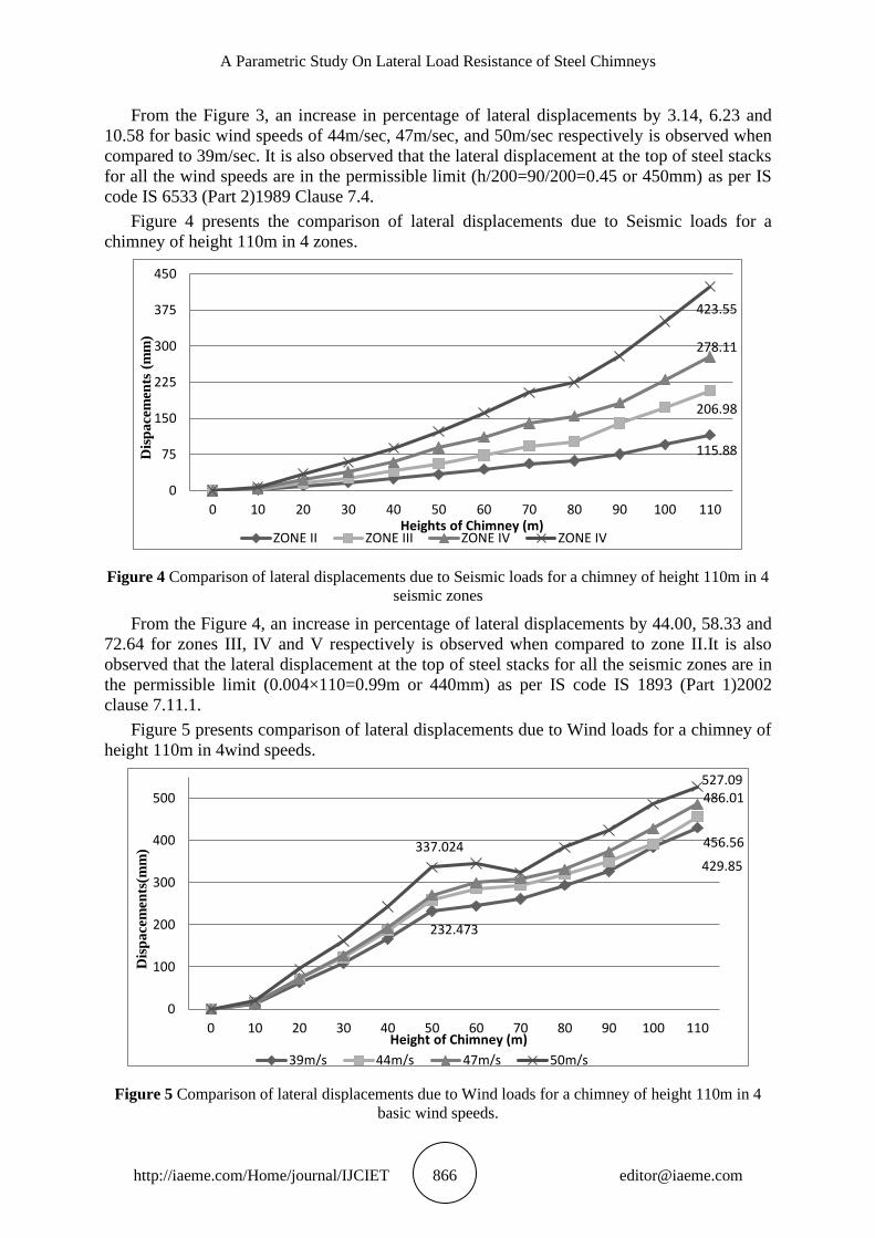
Figure 4 presents the comparison of lateral displacements due to Seismic loads for a
chimney of height 110m in 4 zones.
Figure 4 Comparison of lateral displacements due to Seismic loads for a chimney of height 110m in 4
seismic zones
From the Figure 4, an increase in percentage of lateral displacements by 44.00, 58.33 and
72.64 for zones III, IV and V respectively is observed when compared to zone II.It is also
observed that the lateral displacement at the top of steel stacks for all the seismic zones are in
the permissible limit (0.004×110=0.99m or 440mm) as per IS code IS 1893 (Part 1)2002
clause 7.11.1.
Figure 5 presents comparison of lateral displacements due to Wind loads for a chimney of
height 110m in 4wind speeds.
Figure 5 Comparison of lateral displacements due to Wind loads for a chimney of height 110m in 4
basic wind speeds.
115.88
206.98
278.11
423.55
0
75
150
225
300
375
450
0 10 20 30 40 50 60 70 80 90 100 110
Dis
pa
cem
ents
(m
m)
Heights of Chimney (m)ZONE II ZONE III ZONE IV ZONE IV
232.473
429.85
456.56
486.01
337.024
527.09
0
100
200
300
400
500
0 10 20 30 40 50 60 70 80 90 100 110
Dis
pa
cem
ents
(mm
)
Height of Chimney (m)
39m/s 44m/s 47m/s 50m/s
M. Pavan Kumar, P. Markandeya Raju, N. Victor Babu and K. Roopesh
http://iaeme.com/Home/journal/IJCIET 867 [email protected]
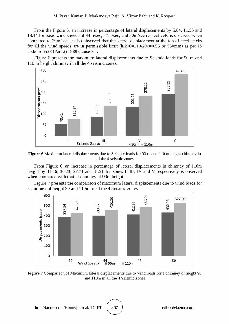
From the Figure 5, an increase in percentage of lateral displacements by 5.84, 11.55 and
18.44 for basic wind speeds of 44m/sec, 47m/sec, and 50m/sec respectively is observed when
compared to 39m/sec. It also observed that the lateral displacement at the top of steel stacks
for all the wind speeds are in permissible limit (h/200=110/200=0.55 or 550mm) as per IS
code IS 6533 (Part 2) 1989 clause 7.4.
Figure 6 presents the maximum lateral displacements due to Seismic loads for 90 m and
110 m height chimney in all the 4 seismic zones.
Figure 6 Maximum lateral displacements due to Seismic loads for 90 m and 110 m height chimney in
all the 4 seismic zones
From Figure 6, an increase in percentage of lateral displacements in chimney of 110m
height by 31.46, 36.23, 27.71 and 31.91 for zones II III, IV and V respectively is observed
when compared with that of chimney of 90m height.
Figure 7 presents the comparison of maximum lateral displacements due to wind loads for
a chimney of height 90 and 110m in all the 4 Seismic zones
Figure 7 Comparison of Maximum lateral displacements due to wind loads for a chimney of height 90
and 110m in all the 4 Seismic zones
79
.41 1
31
.98 2
01
.05
28
8.3
9
11
5.8
7
20
6.9
8 27
8.1
1
423.55
0
75
150
225
300
375
450
II III IV V
Dis
pa
cem
ents
(m
m)
Seismic Zones 90m 110m
38
7.1
4
39
9.7
2
41
2.8
7
43
2.9
5
42
9.8
5
45
6.5
6
48
6.0
1
527.09
0
100
200
300
400
500
600
39 44 47 50
Dis
pa
cem
ents
(m
m)
Wind Speeds 90m 110m
A Parametric Study On Lateral Load Resistance of Steel Chimneys
http://iaeme.com/Home/journal/IJCIET 868 [email protected]
From Figure 7, an increase in percentage of lateral displacements in chimney of 110m
height by 9.93, 12.45, 15.04 and 17.86 for basic wind speeds of 39m/sec, 44m/sec, 47m/sec,
and 50m/sec respectively is observed when compared to chimney of 90m height.
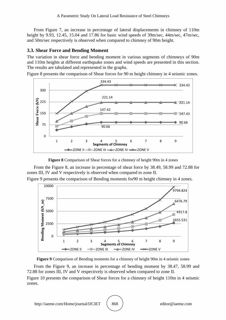
3.3. Shear Force and Bending Moment
The variation in shear force and bending moment in various segments of chimneys of 90m
and 110m heights at different earthquake zones and wind speeds are presented in this section.
The results are tabulated and represented in the graphs.
Figure 8 presents the comparison of Shear forces for 90 m height chimney in 4 seismic zones.
Figure 8 Comparison of Shear forces for a chimney of height 90m in 4 zones
From the Figure 8, an increase in percentage of shear force by 38.49, 58.99 and 72.88 for
zones III, IV and V respectively is observed when compared to zone II.
Figure 9 presents the comparison of Bending moments for90 m height chimney in 4 zones.
Figure 9 Comparison of Bending moments for a chimney of height 90m in 4 seismic zones
From the Figure 9, an increase in percentage of bending moment by 38.47, 58.99 and
72.88 for zones III, IV and V respectively is observed when compared to zone II.
Figure 10 presents the comparison of Shear forces for a chimney of height 110m in 4 seismic
zones.
90.6690.66
147.42147.43
221.14
221.14
334.43334.43
0
75
150
225
300
1 2 3 4 5 6 7 8 9
Sh
ear
Fo
rce
(kN
)
Segments of Chimney
ZONE II ZONE III ZONE IV ZONE V
2655.531
4317.8
6476.79
9794.824
0
2500
5000
7500
10000
1 2 3 4 5 6 7 8 9Ben
din
g M
om
ent
(kN
_m
)
Segments of Chimney
ZONE II ZONE III ZONE IV ZONE V

M. Pavan Kumar, P. Markandeya Raju, N. Victor Babu and K. Roopesh
http://iaeme.com/Home/journal/IJCIET 869 [email protected]
Figure 10 Comparison of Shear forces for a chimney of height 110m in 4 seismic zones
From Figure 10, an increase in percentage of shear force by 31.09, 34.16 and 78.10 for
zones III, IV and V respectively is observed when compared to zone II.
Figure 11 presents the comparison of Bending moments for a chimney of height 110m in
4 seismic zones.
Figure 11 Comparison of Bending moments for a chimney of height 110m in 4 seismic zones
From the Figure 11, an increase in percentage of bending moment by 31.09, 34.16 and
76.44 is observed for zones III, IV and V respectively when compared to zone II.
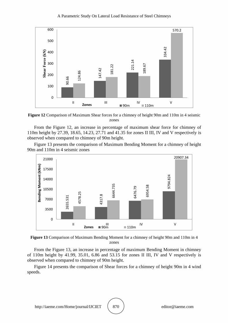
Figure 12 presents the comparison of Maximum Shear forces for a chimney of height 90m
and 110m in 4 seismic zones.
118.61
124.86
181.22180.19
189.67
541.69
570.2
0
100
200
300
400
500
600
1 2 3 4 5 6 7 8 9 10 11
Sh
ear
Fo
rce
(kN
)
Segments of chimneyZONE II ZONE III ZONE IV ZONE V
4578.25
4578.25
6954.58 6954.58
20907.3420907.34
0
5000
10000
15000
20000
1 2 3 4 5 6 7 8 9 10 11
Ben
din
g M
om
ent
(kN
m)
Segments of chimney
ZONE II ZONE III ZONE IV ZONE V
A Parametric Study On Lateral Load Resistance of Steel Chimneys
http://iaeme.com/Home/journal/IJCIET 870 [email protected]
Figure 12 Comparison of Maximum Shear forces for a chimney of height 90m and 110m in 4 seismic
zones
From the Figure 12, an increase in percentage of maximum shear force for chimney of
110m height by 27.39, 18.65, 14.23, 27.71 and 41.35 for zones II III, IV and V respectively is
observed when compared to chimney of 90m height.
Figure 13 presents the comparison of Maximum Bending Moment for a chimney of height
90m and 110m in 4 seismic zones
Figure 13 Comparison of Maximum Bending Moment for a chimney of height 90m and 110m in 4
zones
From the Figure 13, an increase in percentage of maximum Bending Moment in chimney
of 110m height by 41.99, 35.01, 6.86 and 53.15 for zones II III, IV and V respectively is
observed when compared to chimney of 90m height.
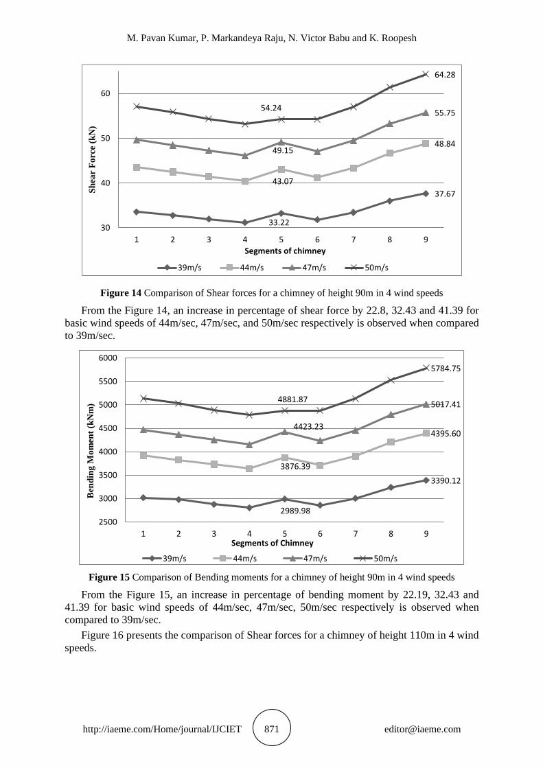
Figure 14 presents the comparison of Shear forces for a chimney of height 90m in 4 wind
speeds.
90
.66 14
7.4
2 22
1.1
4
33
4.4
2
12
4.8
6
18
1.2
2
18
9.6
7
570.2
0
100
200
300
400
500
600
II III IV V
Sh
ear
Fo
rce
(kN
)
Zones 90m 110m
26
55
.53
1
43
17
.8 64
76
.79 97
94
.82
4
45
78
.25
66
44
.73
5
69
54
.58
20907.34
0
3500
7000
10500
14000
17500
21000
II III IV V
Be
nd
ing
Mo
me
nt
(kN
m)
Zones 90m 110m
M. Pavan Kumar, P. Markandeya Raju, N. Victor Babu and K. Roopesh
http://iaeme.com/Home/journal/IJCIET 871 [email protected]
Figure 14 Comparison of Shear forces for a chimney of height 90m in 4 wind speeds
From the Figure 14, an increase in percentage of shear force by 22.8, 32.43 and 41.39 for
basic wind speeds of 44m/sec, 47m/sec, and 50m/sec respectively is observed when compared
to 39m/sec.
Figure 15 Comparison of Bending moments for a chimney of height 90m in 4 wind speeds
From the Figure 15, an increase in percentage of bending moment by 22.19, 32.43 and
41.39 for basic wind speeds of 44m/sec, 47m/sec, 50m/sec respectively is observed when
compared to 39m/sec.
Figure 16 presents the comparison of Shear forces for a chimney of height 110m in 4 wind
speeds.
33.22
37.67
43.07
48.8449.15
55.7554.24
64.28
30
40
50
60
1 2 3 4 5 6 7 8 9
Sh
ear
Fo
rce
(kN
)
Segments of chimney
39m/s 44m/s 47m/s 50m/s
2989.98
3390.12
3876.39
4395.604423.23
5017.414881.87
5784.75
2500
3000
3500
4000
4500
5000
5500
6000
1 2 3 4 5 6 7 8 9
Ben
din
g M
om
ent
(kN
m)
Segments of Chimney
39m/s 44m/s 47m/s 50m/s
A Parametric Study On Lateral Load Resistance of Steel Chimneys
http://iaeme.com/Home/journal/IJCIET 872 [email protected]
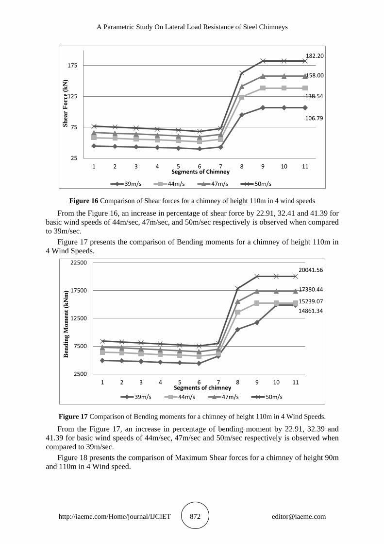
Figure 16 Comparison of Shear forces for a chimney of height 110m in 4 wind speeds
From the Figure 16, an increase in percentage of shear force by 22.91, 32.41 and 41.39 for
basic wind speeds of 44m/sec, 47m/sec, and 50m/sec respectively is observed when compared
to 39m/sec.
Figure 17 presents the comparison of Bending moments for a chimney of height 110m in
4 Wind Speeds.
Figure 17 Comparison of Bending moments for a chimney of height 110m in 4 Wind Speeds.
From the Figure 17, an increase in percentage of bending moment by 22.91, 32.39 and
41.39 for basic wind speeds of 44m/sec, 47m/sec and 50m/sec respectively is observed when
compared to 39m/sec.
Figure 18 presents the comparison of Maximum Shear forces for a chimney of height 90m
and 110m in 4 Wind speed.
106.79
138.54
158.00
182.20
25
75
125
175
1 2 3 4 5 6 7 8 9 10 11
Sh
ear
Fo
rce
(kN
)
Segments of Chimney
39m/s 44m/s 47m/s 50m/s
14861.34
15239.07
17380.44
20041.56
2500
7500
12500
17500
22500
1 2 3 4 5 6 7 8 9 10 11
Ben
din
g M
om
ent
(kN
m)
Segments of chimney
39m/s 44m/s 47m/s 50m/s
M. Pavan Kumar, P. Markandeya Raju, N. Victor Babu and K. Roopesh
http://iaeme.com/Home/journal/IJCIET 873 [email protected]
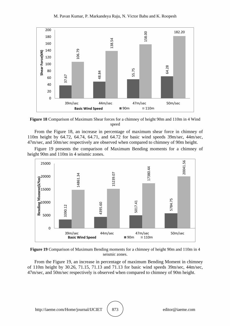
Figure 18 Comparison of Maximum Shear forces for a chimney of height 90m and 110m in 4 Wind
speed
From the Figure 18, an increase in percentage of maximum shear force in chimney of
110m height by 64.72, 64.74, 64.71, and 64.72 for basic wind speeds 39m/sec, 44m/sec,
47m/sec, and 50m/sec respectively are observed when compared to chimney of 90m height.
Figure 19 presents the comparison of Maximum Bending moments for a chimney of
height 90m and 110m in 4 seismic zones.
Figure 19 Comparison of Maximum Bending moments for a chimney of height 90m and 110m in 4
seismic zones.
From the Figure 19, an increase in percentage of maximum Bending Moment in chimney
of 110m height by 30.26, 71.15, 71.13 and 71.13 for basic wind speeds 39m/sec, 44m/sec,
47m/sec, and 50m/sec respectively is observed when compared to chimney of 90m height.
37
.67
48
.84
55
.75
64
.28
10
6.7
9
13
8.5
4
15
8.0
0 182.20
0
20
40
60
80
100
120
140
160
180
200
39m/sec 44m/sec 47m/sec 50m/sec
She
ar F
orc
e(k
N)
Basic Wind Speed 90m 110m
33
90
.12
43
95
.60
50
17
.41
57
84
.75
14
86
1.3
4
15
23
9.0
7
17
38
0.4
4
20
04
1.5
6
0
5000
10000
15000
20000
25000
39m/sec 44m/sec 47m/sec 50m/sec
Ben
din
g M
om
ent(
kN
m)
Basic Wind Speed 90m 110m

A Parametric Study On Lateral Load Resistance of Steel Chimneys
http://iaeme.com/Home/journal/IJCIET 874 [email protected]
3.4. Response Spectrum for Frequency, Time Periods and Spectral Acceleration
of 90m & 110m Height Chimney
The magnitudes of Frequency, Time periods and spectral accelerations from the response
spectrum analysis (using STAAD.Pro) of chimneys of heights 90m and 110m for various
Seismic zones and basic wind speeds are plotted and discussed in this section.
Figure 20 (a) Comparison of
Frequency for a chimney of
height 90m and 110m
Figure 20 (b) Comparison of
Period for a chimney of height
90 and 110m
Figure 20 (c) Comparison of
spectral acceleration for a
chimney of height 90m and
110m.
From the Figure 20 (a), an increase in percentage of maximum frequency in chimney of
110m height of 24.81 respectively is observed when compared to chimney of 90m height.
From the Figure 20 (b), an increase in percentage of maximum Time period in chimney of
90m height of 16.35 respectively is observed when compared to chimney of 110m height.
From the Figure 20 (c), maximum Spectral acceleration in chimney of 90m height is equal to
that of chimney of 110m height.
4. CONCLUSIONS
From the analytical study presented in this paper, the following are some specific and general
conclusions.
The maximum displacements for both the chimneys are observed for earthquake zone
V.The maximum displacements for both the chimneys are found in areas with higher wind
speed i.e., at 50m/s. There is more impact of wind load on the chimney when compared to
seismic load. The value of shear force becomes constant after the 4th segment for both the
chimneys. The value of bending moment increases with increase in height of segments from
bottom to top and also with increase in seismic zones.The maximum values of shear force and
bending moment shows that as the height of chimney increases the intensity of shear force
and bending moment values at the bottom segment also increases at a higher rate.
2.74
2.06
0
1
1
2
2
3
3
90M 110M
Fre
qu
ency
1.33
1.59
1.2
1.25
1.3
1.35
1.4
1.45
1.5
1.55
1.6
1.65
90M 110M
Tim
e P
eroid
(se
c.)
2.50 2.50
0.0
0.5
1.0
1.5
2.0
2.5
3.0
90M 110MS
pec
tra
l A
ccle
rati
on

M. Pavan Kumar, P. Markandeya Raju, N. Victor Babu and K. Roopesh
http://iaeme.com/Home/journal/IJCIET 875 [email protected]
REFERENCES
[1] Par Tranvik, Göran Alpsten “Structural Behaviour under Wind loading of a 90 m Steel
Chimney, Wind and Structures, 8(1), pp. 61-78.
[2] Rajkumar and Vishwanath. B. Patil, “Analysis of Self-Supporting Chimney” International
Journal of Innovative Technology and Exploring Engineering (IJITEE), 3(5), 2013.
[3] G. Murali, B. Mohan, P. Sitara and P. Jayasree, "Response of Mild Steel Chimney Under
Wind Loads. "International Journal of Engineering and Application, 2(2), 2012, pp. 490-
498.
[4] IS 6533 (Part 2): 1989, “Indian standard code for design and construction of steel
chimney” (First Revision), Bureau of Indian Standards, Manak Bhavan, 9 Bahadur Shah
Zafar Marg, New Delhi.
[5] IS 875 (Part 3): 1987, “Indian standard code of practice for criteria for design loads (other
than earthquake) for buildings and structures(Second Revision), Bureau of Indian
Standards, Manak Bhavan, 9 Bahadur Shah Zafar Marg, New Delhi.
[6] B Sivakondareddy and V Rohini Padmavathi, Ch Srikanth, “Study of wind load effects on
tall RC Chimneys”, International journal of advanced engineering technology, 3(2), 2012,
pp. 92-97.
[7] K Anil Pradeep C V Siva Rama Prasad, (2014) “Governing Loads for Design of a 60m
Industrial RCC Chimney”, International Journal of Innovative Research in Science,
Engineering and Technology, 3(8), 2014, pp. 15151-15159.
[8] IS 1893 (Part 4):2005 “Criteria for earthquake resistant design of structures”, Bureau of
Indian Standards, Manak Bhavan, 9 Bahadur Shah Zafar Marg, New Delhi.
[9] B D Rakshith, A Ranjit, J Sanjith, G Chetan, “Analysis of Cantilever Steel Chimney as
per Indian Standards” Journal of Engineering Search and Applications”, 5(5), 2015,
pp.151-162.
[10] S Sagar, Basvaraj Gudadappanavar, “Performance Based Seismic Evaluation of Industrial
Chimney by Static and Dynamic Analysis”, International Research Journal of Engineering
and Technology (IRJET), 2(4), 2015, pp. 1670-1674.
[11] T Saran Kumar, R Nagavinothini, "Wind Analysis and Analytical Study on Vortex
Shedding on Steel Chimney using CFT" IJSETR, 4(4), 2015, pp.715-718.
[12] Chmielewski; P Górski; B Beirow and J Kretzschmar, “Theoretical and experimental free
vibrations of tall industrial chimney with flexibility of soil”. Engineering Structures,27,
2004, pp.25-34.
[13] C Yoganatham, M Helen Santhi, “Modal Analysis of RCC Chimney”, International
Journal of Research in Civil Engineering, Architecture and Design, 1(2), 2013, pp. 20-23.
[14] IS 6533(part1): 1989, “Indian standard code for design and construction of steel
chimney”. (First Revision), Bureau of Indian Standards, Manak Bhavan, 9 Bahadur Shah
Zafar Marg, New Delhi.
[15] Mohd. Mohsin Khan and Dr. Amrit Kumar Roy, CFD Simulation of Wind Effects on
Industrial RCC Chimney. International Journal of Civil Engineering and Technology,
8(1), 2017, pp. 1008–1020.
[16] P.J.Bansod, Dr.S.B.Thakre and Dr.N.A.Wankhade. Expermentational Data Analysis of
Chimney Operated Solar Power Plant, International Journal of Mechanical Engineering
and Technology, 7(1), 2016, pp. 225-231.
[17] IS code 875 (Part3) 2015,” Design loads (other than Earthquake) for Buildings and
Structures” (Third Revision), Bureau of Indian Standards, Manak Bhavan, 9 Bahadur
Shah Zafar Marg, New Delhi.