A Novel Method for Adaptive Control of Manufacturing ...
245
A Novel Method for Adaptive Control of Manufacturing Equipment in Cloud Environments Ph.D Dissertation Göran Adamson This dissertation is submitted in partial fulfilment of the requirements for the degree of Doctor of Philosophy Supported by the University of Skövde, Sweden De Montfort University Leicester – United Kingdom March 2018
-
Upload
khangminh22 -
Category
Documents
-
view
0 -
download
0
Transcript of A Novel Method for Adaptive Control of Manufacturing ...
-Abstract-
Page i
A Novel Method for Adaptive Control of
Manufacturing Equipment in Cloud Environments
Ph.D Dissertation
Göran Adamson
This dissertation is submitted in partial fulfilment of the requirements
for the degree of Doctor of Philosophy
Supported by the University of Skövde, Sweden
De Montfort University
Leicester – United Kingdom
March 2018
-Abstract-
Page i
Abstract
The ability to adaptively control manufacturing equipment, both in local and distributed
environments, is becoming increasingly more important for many manufacturing companies.
One important reason for this is that manufacturing companies are facing increasing levels
of changes, variations and uncertainty, caused by both internal and external factors, which
can negatively impact their performance. Frequently changing consumer requirements and
market demands usually lead to variations in manufacturing quantities, product design and
shorter product life-cycles. Variations in manufacturing capability and functionality, such as
equipment breakdowns, missing/worn/broken tools and delays, also contribute to a high
level of uncertainty. The result is unpredictable manufacturing system performance, with an
increased number of unforeseen events occurring in these systems. Events which are difficult
for traditional planning and control systems to satisfactorily manage.
For manufacturing scenarios such as these, the use of real-time manufacturing information
and intelligence is necessary to enable manufacturing activities to be performed according
to actual manufacturing conditions and requirements, and not according to a pre-
determined process plan. Therefore, there is a need for an event-driven control approach to
facilitate adaptive decision-making and dynamic control capabilities.
Another reason driving the move for adaptive control of manufacturing equipment is the
trend of increasing globalization, which forces manufacturing industry to focus on more cost-
effective manufacturing systems and collaboration within global supply chains and
manufacturing networks. Cloud Manufacturing is evolving as a new manufacturing paradigm
to match this trend, enabling the mutually advantageous sharing of resources, knowledge
and information between distributed companies and manufacturing units. One of the crucial
objectives for Cloud Manufacturing is the coordinated planning, control and execution of
discrete manufacturing operations in collaborative and networked environments. Therefore,
there is also a need that such an event-driven control approach supports the control of
distributed manufacturing equipment.
The aim of this research study is to define and verify a novel and comprehensive method for
adaptive control of manufacturing equipment in cloud environments.
-Abstract-
Page ii
The presented research follows the Design Science Research methodology. From a review of
research literature, problems regarding adaptive manufacturing equipment control have
been identified. A control approach, building on a structure of event-driven Manufacturing
Feature Function Blocks, supported by an Information Framework, has been formulated. The
Function Block structure is constructed to generate real-time control instructions, triggered
by events from the manufacturing environment. The Information Framework uses the
concept of Ontologies and The Semantic Web to enable description and matching of
manufacturing resource capabilities and manufacturing task requests in distributed
environments, e.g. within Cloud Manufacturing. The suggested control approach has been
designed and instantiated, implemented as prototype systems for both local and distributed
manufacturing scenarios, in both real and virtual applications. In these systems, event-driven
Assembly Feature Function Blocks for adaptive control of robotic assembly tasks have been
used to demonstrate the applicability of the control approach. The utility and performance
of these prototype systems have been tested, verified and evaluated for different assembly
scenarios.
The proposed control approach has many promising characteristics for use within both local
and distributed environments, such as cloud environments. The biggest advantage compared
to traditional control is that the required control is created at run-time according to actual
manufacturing conditions.
The biggest obstacle for being applicable to its full extent is manufacturing equipment
controlled by proprietary control systems, with native control languages. To take the full
advantage of the IEC Function Block control approach, controllers which can interface,
interpret and execute these Function Blocks directly, are necessary.
- Acknowledgements - ___________________________________________________________________________
Page iii
Acknowledgements
Returning to University of Skövde 2009, Mats Jägstam almost immediately offered me to
start PhD studies. Thank you Mats for providing me the opportunity to do this journey. I also
want to thank Prof. Philip Moore, my first supervisor, and Prof. Lihui Wang, my second
supervisor, for their support and guidance during my research. My gratitude also goes to Dr.
Seng Chong and the team at De Montfort University.
Many thanks to all of my colleagues at the Division of Production and Automation
Engineering, for providing a cheerful work environment. I would especially like to express my
gratitude to Victor Hedén, Bernard Schmidt and Tehseen Aslam for their support and
encouragement, and valuable discussions. A million thanks to Magnus Holm for his
continuous support and close cooperation during these years. The studies were a challenge,
but we also had a lot of fun.
My gratitude also goes to the University of Skövde for its financial support.
My greatest appreciation of all goes to my family, Gunilla and Linnéa, for their love, support
and encouragement during all these years.
Skövde, March 2018
Göran Adamson

-Declaration-
Page iv
Declaration
I declare that the work described within this dissertation was originally undertaken by me,
Göran Adamson, between the dates of registration for a degree of Doctor of Philosophy at
De Montfort University.
-Table of contents-
Page v
Table of Contents
ABSTRACT ......................................................................................................................................... I
ACKNOWLEDGEMENTS ................................................................................................................... III
DECLARATION ................................................................................................................................. IV
TABLE OF CONTENTS ........................................................................................................................ V
LIST OF FIGURES .............................................................................................................................. IX
LIST OF TABLES ............................................................................................................................... XII
1 INTRODUCTION ....................................................................................................................... 1
1.1 RESEARCH BACKGROUND AND CONTEXT ......................................................................................... 2
1.1.1 Challenges facing the manufacturing industry: (a brief overview)................................... 2
1.1.2 Adaptability and Event-driven Function Blocks ................................................................ 8
1.1.3 Distributed Manufacturing ............................................................................................. 21
1.1.4 Semantic Web and ontology technologies ..................................................................... 23
1.2 MOTIVATION .......................................................................................................................... 24
1.3 AIM AND OBJECTIVES ................................................................................................................ 24
1.3.1 Research Scope and limitations ...................................................................................... 25
1.4 RESEARCH METHODOLOGY ........................................................................................................ 25
1.5 RESEARCH CONTRIBUTIONS ........................................................................................................ 30
1.6 THESIS ORGANISATION .............................................................................................................. 31
1.6.1 Chapter 2: Cloud Manufacturing and cloud environments ............................................ 31
1.6.2 Chapter 3: Event-driven adaptability using IEC 61499 Function Blocks and
Manufacturing Features .............................................................................................................. 31
1.6.3 Chapter 4: Function Block control of a production cell ................................................... 32
1.6.4 Chapter 5: Function Block control of real and virtual assembly cells in distributed
environment ................................................................................................................................ 32
1.6.5 Chapter 6: Robot Control-as-a-Service for Adaptive Robotic Assembly in a Cloud
Environment ................................................................................................................................ 33
1.6.6 Chapter 7: Discussions, conclusions and future work ..................................................... 34
2 CLOUD MANUFACTURING AND CLOUD ENVIRONMENTS ...................................................... 35
2.1 IN THE CLOUD ......................................................................................................................... 35
2.2 CLOUD ENVIRONMENTS ............................................................................................................ 35
-Table of contents-
Page vi
2.3 CLOUD MANUFACTURING ......................................................................................................... 36
2.3.1 Cloud Manufacturing Drivers ......................................................................................... 39
2.3.2 Cloud Manufacturing Definitions ................................................................................... 40
2.3.3 Cloud Manufacturing Participants ................................................................................. 42
2.3.4 Cloud Manufacturing Resources and Services ................................................................ 43
2.3.5 Cloud Manufacturing Architectures ............................................................................... 43
2.3.6 Research Areas and Technologies .................................................................................. 46
2.3.7 Platform Management ................................................................................................... 55
2.3.8 Knowledge and Data Management ............................................................................... 56
2.3.9 Cloud Manufacturing Concepts ...................................................................................... 57
2.3.10 Connotations and Characteristics ................................................................................... 62
2.3.11 Collaborative Work ......................................................................................................... 62
2.3.12 Security ........................................................................................................................... 64
2.3.13 Simulation ....................................................................................................................... 64
2.3.14 Cost and Price Management .......................................................................................... 65
2.3.15 Enabling, Supporting and Application Technologies ...................................................... 65
2.3.16 On-going Research Areas within Cloud Manufacturing ................................................. 66
2.3.17 Cloud Manufacturing Research Initiatives...................................................................... 67
2.3.18 Future Directions and Trends ......................................................................................... 70
2.3.19 Outstanding Cloud Manufacturing Research Issues ....................................................... 74
2.4 SUMMARY .............................................................................................................................. 81
3 ADAPTIVE CONTROL OF MANUFACTURING EQUIPMENT IN CLOUD ENVIRONMENTS ............ 83
3.1 INTRODUCTION ....................................................................................................................... 84
3.2 MANUFACTURING FEATURES FOR PRODUCTS, RESOURCES, PLANNING AND CONTROL ............................ 85
3.2.1 Manufacturing Features ................................................................................................. 86
3.2.2 Assembly Features .......................................................................................................... 87
3.2.3 Feature-based Information framework .......................................................................... 91
3.2.4 Summary ........................................................................................................................ 98
3.3 EVENT-DRIVEN ADAPTABILITY USING IEC 61499 FUNCTION BLOCKS AND MANUFACTURING FEATURES ... 98
3.3.1 Manufacturing Feature-Function Blocks ........................................................................ 99
3.3.2 Assembly Feature-Function Blocks ............................................................................... 101
3.3.3 Combining Assembly Feature-Function Blocks for creating assembly control applications
107
3.3.4 Adaptive Robot Assembly Control using Assembly Feature-Function Blocks ............... 108
3.3.5 Assembly Feature-Function Block Control Advantages ................................................ 110
3.3.6 Summary ...................................................................................................................... 111
3.4 CLOUD MANUFACTURING CONTROL STRUCTURE ......................................................................... 112
-Table of contents-
Page vii
3.4.1 Robot Control-as-a-Service ........................................................................................... 115
3.4.2 Cloud Service Management .......................................................................................... 118
3.4.3 Summary ...................................................................................................................... 121
4 FUNCTION BLOCK CONTROL OF A PRODUCTION CELL .......................................................... 122
4.1 RESEARCH METHOD................................................................................................................ 122
4.2 PRODUCTION CELL DEMONSTRATOR .......................................................................................... 122
4.3 TEST CASE ............................................................................................................................ 125
4.3.1 Products ........................................................................................................................ 125
4.3.2 Manufacturing Feature-Function Blocks ...................................................................... 125
4.3.3 Service Interface-Function Blocks ................................................................................. 130
4.3.4 Demonstrator HMI ....................................................................................................... 131
4.3.5 Demonstrator production sequence ............................................................................. 132
4.3.6 Robotic assembly sequence .......................................................................................... 133
4.3.7 Demonstrator cell control ............................................................................................. 133
4.4 CASE STUDY EVALUATION ........................................................................................................ 134
4.5 SUMMARY ............................................................................................................................ 136
4.5.1 Acknowledgment .......................................................................................................... 137
5 FUNCTION BLOCK CONTROL OF REAL AND VIRTUAL ASSEMBLY CELLS IN A DISTRIBUTED
ENVIRONMENT ............................................................................................................................ 138
5.1 RESEARCH METHOD................................................................................................................ 138
5.2 ROBOTIC ASSEMBLY CELL DEMONSTRATORS ............................................................................... 139
5.3 TEST CASE ............................................................................................................................ 140
5.3.1 Products ........................................................................................................................ 141
5.3.2 Demonstrator cell assembly sequence ......................................................................... 142
5.3.3 Assembly Feature-Function Blocks ............................................................................... 142
5.3.4 Assembly cell control .................................................................................................... 144
5.4 CASE STUDY EVALUATION ........................................................................................................ 149
5.5 SUMMARY ............................................................................................................................ 151
5.5.1 Acknowledgment .......................................................................................................... 152
6 ROBOT CONTROL-AS-A-SERVICE FOR ADAPTIVE ROBOTIC ASSEMBLY IN A CLOUD
ENVIRONMENT ............................................................................................................................ 153
6.1 ASSEMBLY SCENARIO .............................................................................................................. 154
6.2 ENGINE ASSEMBLY COMPONENTS ............................................................................................. 155
6.3 ENGINE ASSEMBLY TASK ......................................................................................................... 159
6.4 ENGINE ASSEMBLY TASK CONTROL ............................................................................................ 160
-Table of contents-
Page viii
6.4.1 Function Block Control Structure .................................................................................. 162
6.4.2 Control Structure Constituents ..................................................................................... 163
6.4.3 Control Structure Functionality..................................................................................... 165
6.5 ASSEMBLY TASK SEQUENCE ..................................................................................................... 166
6.6 ADAPTIVITY SCENARIOS - HANDLING VARIATIONS ......................................................................... 176
6.7 SUMMARY ............................................................................................................................ 177
7 DISCUSSION, CONCLUSIONS AND FUTURE WORK ................................................................ 179
7.1 DISCUSSIONS ........................................................................................................................ 179
7.1.1 Guideline 1 - Design as an Artefact .............................................................................. 180
7.1.2 Guideline 2 - Problem Relevance .................................................................................. 181
7.1.3 Guideline 3 - Design Evaluation .................................................................................... 182
7.1.4 Guideline 4 - Research Contribution ............................................................................. 182
7.1.5 Guideline 5 - Research Rigor ......................................................................................... 183
7.1.6 Guideline 6 - Design as a Search Process ...................................................................... 184
7.1.7 Guideline 7 - Communication of Research .................................................................... 185
7.1.8 Concluding discussion ................................................................................................... 185
7.2 CONCLUSIONS ....................................................................................................................... 186
7.3 FUTURE WORK ...................................................................................................................... 192
REFERENCES ................................................................................................................................. 195
PUBLICATIONS OF GÖRAN ADAMSON ......................................................................................... 207
JOURNAL PUBLICATIONS ....................................................................................................................... 207
CONFERENCE PUBLICATIONS ................................................................................................................. 207
JOURNAL PUBLICATIONS, CO-AUTHOR ..................................................................................................... 208
CONFERENCE ARTICLES, CO-AUTHOR ....................................................................................................... 209
APPENDIX 1 .................................................................................................................................. 211
APPENDIX 2 .................................................................................................................................. 214
APPENDIX 3 .................................................................................................................................. 216
-List of Figures-
Page ix
List of Figures
Figure 1. IEC 61499 System model .................................................................................... 11
(Figure used with the permission from Magnus Holm) ......................................................... 11
Figure 2. IEC 61499 Device model ..................................................................................... 12
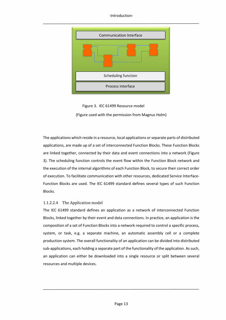
Figure 3. IEC 61499 Resource model ................................................................................ 13
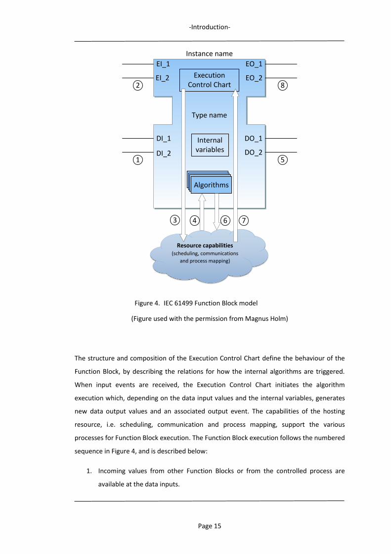
Figure 4. IEC 61499 Function Block model ........................................................................ 15
Figure 5. Execution Control Chart ..................................................................................... 17
Figure 6. Basic Function Block (left) Composite Function Block (right). ...................... 18
Figure 7. The Design Science Research Process Model .................................................... 27
Figure 8. Research process mapped to Dissertation Chapters ......................................... 29
Figure 9. Cloud Manufacturing Concept ........................................................................... 37
Figure 10. Cloud Manufacturing Concept Architecture .................................................. 44
Figure 11. Combined use of Manufacturing Features .................................................... 85
Figure 12. Basic Assembly Features ................................................................................ 89
Figure 13. Assembly task ................................................................................................. 90
Figure 14. Step-wise assembly sequence for Assembly Features “Pick” and “Insert” ... 90
Figure 15. Assembly feature-enriched product data model ........................................... 92
Figure 16. Feature-level assembly resource capability model........................................ 96
Figure 17. Machining Feature-Function Block .............................................................. 100
Figure 18. Graphical definition of an Insert Assembly Feature-Function Block ............ 102
Figure 19. Execution Control Chart for Assembly Feature-FB in Figure 18................... 106
Figure 20. Composite FB Application with dynamic sequence adjustment ................. 107
Figure 21. Event Switch-Function Block ........................................................................ 108
Figure 22. Two-level Function Block-based control structure ...................................... 114
Figure 23. Robot Control-as-a-Service .......................................................................... 115
Figure 24. IDEF0 Model of Robot Control-as-a-Service ................................................ 118
Figure 25. Cloud Service Interaction Flowchart ............................................................ 119
Figure 26. Robot Control-as-a-Service within Cloud Manufacturing Environment ...... 120
Figure 27. Production cell with gantry robot and table-top CNC milling machine ....... 123
Figure 28. Demonstrator Control System ..................................................................... 124
Figure 29. Composite Machining Feature-Function Block “Pocket” ............................. 126

-List of Figures-
Page x
Figure 30. Machining Feature-Function Block “Path_Pocket_Horizontal” ................... 126
Figure 31. Assembly Feature-Function Block PLACE ..................................................... 127
Figure 32. Controller Function Block for Gantry Robot ................................................ 128
Figure 33. Algorithm for Robot Servomotor Control .................................................... 129
Figure 34. Execution Control Chart for Assembly Feature-Function Block “Place” ...... 130
Figure 35. Service Interface-Function Block ................................................................. 131
Figure 36. Production Cell HMI ..................................................................................... 132
Figure 37. Function Block Control for real and virtual assembly cells (MiniCell) .......... 139
Figure 38. MiniCell layout ............................................................................................. 140
Figure 39. Shaft variants and washers .......................................................................... 141
Figure 40. Mounting washer onto shaft in Measuring Station ..................................... 141
Figure 41. Assembly Features PLACE and INSERT ......................................................... 143
Figure 42. Assembly Feature-Function Block PLACE ..................................................... 143
Figure 43. Demonstrator cell HMI ................................................................................ 145
Figure 44. Communication service program ................................................................. 147
Figure 45. MiniCell control system ................................................................................ 148
Figure 46. Engine assembly station ............................................................................... 155
Figure 47. Engine Block ................................................................................................. 156
Figure 48. Engine Block Base Frame ............................................................................. 156
Figure 49. Engine Cylinder Head ................................................................................... 157
Figure 50. Piston, and pistons pre-mounted on piston fixture ..................................... 157
Figure 51. Engine head bolt, and bolts pre-mounted in bolt fixture ............................ 158
Figure 52. Engine components to be assembled .......................................................... 158
Figure 53. Engine assembled on pallet ......................................................................... 159
Figure 54. Engine assembly sequence .......................................................................... 160
Figure 55. Function Block Control Structure ................................................................. 162
Figure 56. Pallet at assembly position .......................................................................... 167
Figure 57. INSERT Assembly Feature operations .......................................................... 167
Figure 58. Robot target location I2 received from Station Data Base .......................... 168
Figure 59. Piston pick location ...................................................................................... 168
Figure 60. Piston safe location ...................................................................................... 169
Figure 61. Target location I7 received from Consumer Cloud Data Base ..................... 170
Figure 62. Piston inserting depth value ........................................................................ 170
Figure 63. PLACE Assembly Feature operations ........................................................... 171

-List of Figures-
Page xi
Figure 64. Engine Cylinder Head pick location .............................................................. 171
Figure 65. Engine Cylinder Head safe location.............................................................. 172
Figure 66. Engine Cylinder Head Place location onto Engine Block .............................. 172
Figure 67. SCREW Assembly Feature operations .......................................................... 173
Figure 68. Bolts pick location ........................................................................................ 173
Figure 69. Bolts safe location above Bolt Fixture.......................................................... 174
Figure 70. Bolts safe location above Engine Cylinder Head .......................................... 174
Figure 71. Bolts inserted location ................................................................................. 175
Figure 72. Pallet exiting as Assembly Station operations are finished ......................... 175
Figure 73. Horisontal pocket ......................................................................................... 214
Figure 74. Vertical pocket ............................................................................................. 214
Figure 75. “HIS” engraved ............................................................................................. 215
-List of Tables-
Page xii
List of Tables
Table 1. Cloud Manufacturing architectures, platforms, frameworks, models and
applications. ........................................................................................................................... 57
Table 2. Cloud Manufacturing Research Areas ................................................................ 67
Table 3. Assembly Feature-Function Block Event and Data Inputs ............................... 104
Table 4. Assembly Feature-Function Block Event and Data Outputs ............................ 105
Table 5. Design Science Research Guidelines (A. R. Hevner et al., 2004) ...................... 179
-Introduction-
Page 1
1 Introduction
This PhD dissertation introduces a novel method for adaptive manufacturing equipment
control in cloud environments, presenting the construct of a control concept which
encompasses the complete manufacturing control structure, from supervisory control on a
cloud level, down to local generation and execution of equipment control at the shop floor
and machine controller levels. In this research, implementations of this method has been
focused on robotic assembly applications for concept validation and evaluation. As such, the
presented method is supported by different implementations and an application scenario.
The study has initially been inspired by a number of initiatives and challenges appearing in
the manufacturing industry. Further on, it has also been driven by new manufacturing
capabilities facilitated by evolving technologies and concepts, such as: Internet of Things,
Cloud Manufacturing, Service architectures, Semantic Web, etc., widening and extending the
research scope, i.e. from local to distributed manufacturing applications, from shop floor to
Cloud perspectives, and from direct equipment control to Equipment Control-as-a-Service.
The major enabling concepts for the presented control method presented are:
- The concept of event-driven Function Blocks, as defined in IEC 61499 (IEC, 2005), an
IEC standard for distributed industrial processes and control systems. These Function
Blocks are used to enable manufacturing system adaptability, as they can make
process plans able to adapt to environmental variations and changes in dynamic shop
floors.
- The concept of Product Manufacturing Features.
- The concept of Cloud Manufacturing and Cloud Manufacturing Services.
- The concept of Ontologies and the Semantic Web.
Both complete system framework and control structure, and enabling technologies are
presented and discussed, as well as two comprehensive case studies with implementations,
and an application scenario also presenting a supporting system information framework.
Prototype control systems have been designed, implemented and evaluated according to the
research problems stated. Together with the study of event-driven Function Blocks and
Product Feature technologies, Cloud Manufacturing, Ontologies and The Semantic Web, this
constitutes the foundation for the performed research on adaptive control of manufacturing
-Introduction-
Page 2
equipment in cloud environments. As such, the research addresses outstanding issues within
the manufacturing domain, indicated in the reviwed research litterature.
In the following sections, the background and motivation of the research study presented in
this dissertation are described. The research aims and objectives, and the applied research
methodology are presented, after which the chapter is concluded by a presentation of the
organisation of the dissertation.
1.1 Research background and context
The background and influences to this research are described in the following sections:
1.1.1 Challenges facing the manufacturing industry: (a brief overview)
To improve and to adopt to new challenges the evolution of manufacturing and its processes
is continuous, iteratively going from concept development to the introduction of new
technologies, tools, methods and standards for the effective, economical, and sustainable
production of products. Contemporary manufacturing is considered to be an integrated
concept at all company levels, from discrete manufacturing resources such as equipment,
machines and personnel, to complete production systems as well as the entire business level
operation.
1.1.1.1 Contemporary Manufacturing
To better understand contemporary manufacturing challenges and influences, a historical
perspective on the recent developments of industrial manufacturing and its paradigms is
informative. Understanding past and present manufacturing and its limitations and
shortcomings will facilitate an understanding and help foreseeing of what is to come. The
prevailing manufacturing paradigm plays a key role for the competitiveness of manufacturing
industries. To exceed the traditional mass production paradigm, the last 40 years have seen
a range of initiatives and implementations in advanced manufacturing, with new paradigms
such as mass customisation as well as intelligent, holonic, reconfigurable, lean, agile,
networked, distributed, grid and sustainable manufacturing (Z. M. Bi & Wang, 2013; Lee,
Baines, Tjahjono, & Greenough, 2006; Nambiar, 2010). These initiatives consider not only the
technical aspects but economic and social factors as well, and lately also environmental
issues play an increasingly important role. Research has progressed in areas ranging from
modelling, analysing, and designing manufacturing systems, to the effective planning,
operation and control of them. Important objectives are optimisation of productivity, system
flexibility, quality, cost, service and environmental considerations. Recently, research

-Introduction-
Page 3
covering the collaboration and resource-sharing in all parts of the product development life-
cycle has shown a growing interest. With new opportunities arising from improvements
within modern information and communication technology, service and information driven
manufacturing has become a focused research topic and already made some progress within
collaborative and distributed manufacturing, e.g. Cloud Manufacturing. Another example of
the developing manufacturing domain is the future-project ”Industry 4.0”, launched by the
German Federal Government (K. Zhou, Taigang, & Lifeng, 2015). It is part of a high-tech
strategy for the upcoming state of networked production, for realising completely
automated production of mainly small batches. The vision is a structured, modular Smart
factory, and the concept postulates that all manufacturing equipment, such as: machine-
tools, robots, handling systems, but also raw materials and products, are equipped with
communication interfaces for a continuous exchange of data, transforming the
manufacturing system to a “Cyber Physical System”. The control of such a networked system
is then possible from a distributed IT infrastructure, e.g. a cloud environment (Griffor, Greer,
Wollman, & Burns, 2017).
There are many reasons and driving factors behind the significant changes in contemporary
manufacturing. Beside the rapid development of advanced manufacturing, computer and
information technologies, intense global competition, as well as economic and resource
globalisation, are now a reality. Historically, the modern manufacturing focus has changed
from enlarging production scale in the 60s, to cost reduction in the 70s, from product quality
in the 80s shifting to rapid market response in the 90s, and lately focusing on service,
information and knowledge. It is particularly the introduction of computer and information
technologies and the rapid development of the Internet technologies that the last years have
sped up the development of manufacturing (B. H. Li, Zhang, & Chai, 2010). This have led to
new and challenging requirements regarding the management and control of distributed and
collaborative resource sharing in cloud environments. The issue of adaptively handling
variations is also a major concern for manufacturing control.
1.1.1.2 Uncertainty in manufacturing systems
Many manufacturing systems are facing the challenge of handling an increasing amount of
uncertainty, which inflict unpredicted events to be dealt with in different manufacturing
scenarios. These events often restrict the systems’ performance and may be caused by
unforeseen conditions and variations of both external and internal system nature.
-Introduction-
Page 4
Many external variations are caused by shorter product life-cycles. In combination with
changing manufacturing requirements due to increasing international competition among
producers, market demands are dynamically changing as a result of continuously more
frequently changing customer requirements. Variations and trends in customer demand may
effect issues like product design, product mix, delivery dates, manufacturing quantities, etc.,
(Monostori et al., 2010; Valilai & Houshmand, 2013). Companies in the job-shop
manufacturing environments are particularly exposed to high levels of uncertainty, as their
production is made up of a large variety of products, often in small batch sizes and big
product mixes. For them, performing effectively and reaching high productivity goals is an
everyday challenge (L. Wang, Holm, & Adamson, 2010). Internally, variations in
manufacturing capability and functionality, caused by equipment breakdowns, job delays,
tools being worn, broken or missing, fixture shortages, express orders, etc., also contribute
to the levels of uncertainty.
Conditions like these result in unpredictable manufacturing system performance, with an
increased number of unforeseen events occurring in these systems. These events are often
not possible to handle efficiently by traditional planning and control systems (X. Xu, Wang, &
Newman, 2011). Most process plans generated using existing CAPP systems are tied to
specific resources such as robots, CNC-machines, tools, etc. (Lihui Wang, Feng, Cai, & Jin,
2007). As such, these plans are inflexible, unportable, and not responsive to unexpected
changes. If a manufacturing resource becomes unavailable, this will require the dedicated
process plan to be revised, as well as the re-programming of manufacturing equipment.
Typical automated manufacturing operations, like machining and robotic assembly
operations, are often time-consuming and tedious to program, involving the creation of
predefined control code for specific machines, robots, tasks and products. If an unforeseen
change occurs, depending on the severity and nature of the cause of the change, the control
code generated often has to be adjusted or totally recreated to generate the correct
equipment behaviour or functionality.
The ability to handle influences of uncertainty requires both flexibility and adaptability to be
competitive (Boutellier, Gassmann, & von Zedtwitz, 2008). Changes in demand and variations
in production capability and functionality, requires adaptive, dynamic and flexible tools and
functions for planning and controlling the manufacturing process, for arriving as closely as
possible at an optimal performance. Successfully handling manufacturing uncertainty
requires both adaptive run-time decision-making and effective execution of these decisions.

-Introduction-
Page 5
1.1.1.3 Globalisation, collaborative working and resource sharing
The growing globalisation in manufacturing is driving a continuously more competitive
market, in which product life-cycles are getting shorter while product variety and
customisation is increasing. Business collaborations and outsourcing of manufacturing
activities and processes also adds to a very dynamic manufacturing environment, making
adaptability an important and necessary property for being competitive. Surviving in an
increasing globalisation, manufacturing companies are focusing on adopting more cost-
effective manufacturing systems to remain competitive (Valilai & Houshmand, 2013). To be
able to be competitive on a global marketplace, meeting and satisfying dynamic customer
demands, collaboration within global supply chains and manufacturing networks for critical
and complex manufacturing activities such as design and manufacturing, is of high interest
for many companies. Sharing resources, knowledge and information between geographically
distributed manufacturing entities can make them more agile and cost-effective, with higher
resource’ utilisation, leading to a competitive edge, in a win-win scenario for all participants.
So there are many strong drivers for collaborative manufacturing and the proliferation of the
many advantages and possibilities of resource sharing (Ding, Yu, & Sun, 2012). The on-going
manufacturing trend of focusing on solely performing core manufacturing activities, relying
on company specific competences, while out-sourcing related and supporting activities, is all
in line with the ideas of the evolving resource sharing paradigm. For some companies, critical
manufacturing resources are limited and too costly, while other companies may possess
spare manufacturing capacity, knowledge and competence. To lower the overall cost for
manufacturing, companies may provide and share their resources to increase the resource
utilization rate, with companies with lack and need of these resources. Globalisation is
therefore a major driver for collaborative work, and there are several recently emerged
information technologies, which combined enable seamless collaboration activities, for all
the phases of product development. Cloud Computing is one of these core technologies,
offering computing resources as services in a convenient pay-as-you-go mode. The concept
of offering computer resources as services can be adopted in manufacturing, with
manufacturing resources being offered as different services, i.e. Design-as-a-Service,
Machining-as-a-Service, Assembly-as-a-Service, etc., (X. Xu, 2012). Examples of other
contributing and enabling technologies are: Internet of Things, Semantic Web, embedded
systems, and virtualisation technologies.
-Introduction-
Page 6
The success of many international manufacturing enterprises relies on the distribution of
their manufacturing capacities over the globe. With a worldwide integration of their
distributed product development processes and manufacturing operations, they are already
realising and taking advantage of the many benefits of resource sharing and collaborative
manufacturing activities (Valilai & Houshmand, 2013). However, the majority of
manufacturing companies are small, and in contrast to SMEs, international enterprises and
bigger companies often have a greater capability of adjusting to evolving manufacturing
conditions and changing requirements due to their in-house competences, knowledge and
resources. So this approach for competitiveness has not been in reach for the majority of
SMEs, mostly due to technological limitations for resource sharing and lack of partner
networks. Some of the major challenges emerging that many SME manufacturing companies
are facing today are (F. Tao, Zhang, & Nee, 2011):
Core Technologies
Many SMEs are in the original equipment manufacturing branch, being labour intensive and
in the low end of the value chain. Staff education levels are also often lower than those in big
enterprises. Without expertise knowledge and competence about, and access to, core
technologies such as; design, product development, manufacturing management,
simulation, etc., their abilities for making higher profits are severely hampered.
Expensive and Complex IT-systems
With digitalisation of manufacturing an array of different software and information systems
have appeared (ERP, PDM, CAD, CAM, CAPP, etc.), which companies need to use for being
effective and competitive. These inflict high costs, and problems concerning integration,
maintenance, education and data sharing.
Complex Product Designs
The process of designing new products has become much more complicated. Considering all
phases of the product life-cycle when developing a new product, requires the use and
cooperation of a variety of highly complex and advanced applications, software, services and
knowledge structures. In-house access to all these resources and capabilities is not available
for many SME companies.
-Introduction-
Page 7
Lack of Follow-up Service
The business scope does not encompass follow-up service, which is a crucial necessity
catalysing in increased trading opportunities and additional value creation. If problems with
products sold cannot be solved, this can decrease customer loyalty and harm the esteem and
reputation of the company.
High Sub-contracting Costs
The development of many SMEs is often hindered by high sub-contracting costs, which often
constitutes a significant part of the total cost for the development of a new product. Sub-
contracting is becoming increasingly necessary for many SMEs, as product development
becomes more advanced and complex.
Matching Manufacturing Orders with Resources’ Capability and Capacity
SMEs often have difficulties in accomplishing manufacturing orders due to the lack of
advanced equipment with certain required properties. Or the opposite, companies that have
this equipment but lack manufacturing missions and orders. This is a resource matching
problem between resource providers and resource consumers.
Lack of Resource and Capability Sharing Mode
Sharing of resources and capabilities is one of the key virtues of collaborative manufacturing.
To be successful in all manufacturing activities, the ability of sharing computing, data and
information resources, applications and services, equipment and application systems is
mandatory. A company-wide sharing approach for full connectivity, remote access, and
interoperability for all resources is then required.
These challenges point to problems and difficulties for SMEs to be competitive while solely
relying on their in-house resources and capabilities. To succeed, they must be able to respond
rapidly to dynamically changing market demands, driven by an increasing international
competition among producers, combined with continuously more frequently changing
customer requirements. A resource sharing manufacturing mechanism, supporting services
for scalable and economical resource sharing and coordinated collaboration, would solve
many of these problems, and give especially SMEs a much more competitive edge.
-Introduction-
Page 8
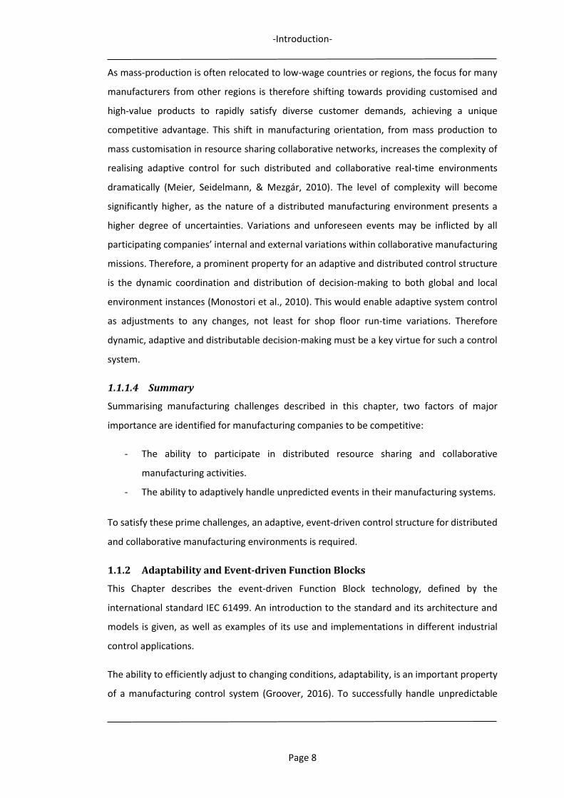
As mass-production is often relocated to low-wage countries or regions, the focus for many
manufacturers from other regions is therefore shifting towards providing customised and
high-value products to rapidly satisfy diverse customer demands, achieving a unique
competitive advantage. This shift in manufacturing orientation, from mass production to
mass customisation in resource sharing collaborative networks, increases the complexity of
realising adaptive control for such distributed and collaborative real-time environments
dramatically (Meier, Seidelmann, & Mezgár, 2010). The level of complexity will become
significantly higher, as the nature of a distributed manufacturing environment presents a
higher degree of uncertainties. Variations and unforeseen events may be inflicted by all
participating companies’ internal and external variations within collaborative manufacturing
missions. Therefore, a prominent property for an adaptive and distributed control structure
is the dynamic coordination and distribution of decision-making to both global and local
environment instances (Monostori et al., 2010). This would enable adaptive system control
as adjustments to any changes, not least for shop floor run-time variations. Therefore
dynamic, adaptive and distributable decision-making must be a key virtue for such a control
system.
1.1.1.4 Summary
Summarising manufacturing challenges described in this chapter, two factors of major
importance are identified for manufacturing companies to be competitive:
- The ability to participate in distributed resource sharing and collaborative
manufacturing activities.
- The ability to adaptively handle unpredicted events in their manufacturing systems.
To satisfy these prime challenges, an adaptive, event-driven control structure for distributed
and collaborative manufacturing environments is required.
1.1.2 Adaptability and Event-driven Function Blocks
This Chapter describes the event-driven Function Block technology, defined by the
international standard IEC 61499. An introduction to the standard and its architecture and
models is given, as well as examples of its use and implementations in different industrial
control applications.
The ability to efficiently adjust to changing conditions, adaptability, is an important property
of a manufacturing control system (Groover, 2016). To successfully handle unpredictable
-Introduction-
Page 9
events negatively affecting the performance of a manufacturing system requires both
adaptive and distributed run-time decision-making, but also effective execution of these
decisions. One approach to limit the negative influence of uncertainty and unpredictable
behaviour on manufacturing performance is to use real-time manufacturing information.
Using real-time system information for both planning and control of a manufacturing system
means that the time span between decision-making and actual execution can be narrowed
down to a minimum, facilitating more correct decisions as well as decreasing possible
negative impact of uncertainty. Using actual events within a distributed control system to
trigger the dynamic generation of the required control activities would make possible
adaptive decision-making and dynamic control capabilities, as an important and valuable
built-in control system property to handle uncertainty.
The concept of event-driven Function Blocks supports this approach, as it enables the use of
online information for dynamic and distributed decision-making, as well as dynamic control
capabilities that are able to handle, in a responsive and adaptive way, different kinds of
uncertainty. Applying such Function Blocks for the control of manufacturing equipment
implies giving the control system more intelligence and autonomy to better handle and adapt
to changes, for a more successful fulfillment of the manufacturing objectives (Monostori et
al., 2010).
1.1.2.1 Introduction to IEC 61499
Event-driven Function Blocks are initially defined in the IEC 61499 standard (IEC, 2005), which
explains the usage, development and implementation of Function Blocks in distributed
industrial process measurement and control systems, in a component-oriented approach.
The standard describes a generic modelling approach for distributed control applications
enabling interoperability, re-configurability and portability for distributed control systems,
facilitated through event-driven Function Blocks. IEC 61499 was developed jointly from the
existing concepts of the Function Block Diagram in the PLC language standard IEC 61131-3,
and standardisation work concerning Fieldbus, after the need for a common model for the
application of software modules called Function Blocks had been raised. Function Block
Diagrams were initially introduced in IEC 61131-3 to solve problems with textual
programming, ladder diagrams and the reuse of common tasks. In contrast to IEC 61131, the
primary purpose of IEC 61499 is not that of a programming methodology, but instead it
describes a system architecture, and provides a set of models to describe distributed control
-Introduction-
Page 10
systems using event-driven Function Blocks in a real-time execution environment (Lewis,
2001; Vyatkin, 2011; Zoitl, 2008).
The standard supports intelligence to be decentralised and wrapped in software
components, which can be distributed in a system control network. An event-driven Function
Block-based control system can therefore be applied to control various industrial systems as
well as be used for high-level process planning. The control approach is flexible and versatile
as it can be designed to handle both execution control, process monitoring and the
scheduling of dynamic resources (Lewis, 2001).
The IEC 61499 Function Block is defined as an event-triggered component with inputs and
outputs for events as well as data, with algorithms, internal variables controlled by the
Execution Control Chart. The execution of its algorithms, triggered by arriving input events,
determines the Function Block behaviour. Function Block algorithms will read data from
incoming input data when executing, and then produce new output data. The completion
and availability of the output data will then be announced by output events. The algorithm
execution and scheduling is controlled by the Execution Control Chart, a finite state machine
with different states, transitions and actions. Function Blocks are intended to encapsulate a
software solution for a dedicated task, using one or several algorithms. As such, they can
encapsulate generic functionality which can be used in different control scenarios. By
combining Function Blocks into networks, complete control applications with an aggregated
higher-level functionality can be realised.
1.1.2.2 IEC 61499 Architecture and Models
The IEC 61499 standard defines models which together support the development of a
Function Block control system architecture for distributed industrial processes. The standard
includes the following five models:
System model
Device model
Resource model
Application model
Function Block model

-Introduction-
Page 11
1.1.2.2.1 The System model
The System model is the top level and constitutes a collection of devices, such as controllers,
sensors, actuators, etc. These devices are connected to the controlled processes or systems,
and communicate with each other to, jointly or alone, execute one or more control
applications. These control applications may be distributed to several cooperating devices or
to a single device, and the system model can include one or several control applications
(Figure 1). Control applications are made up of a network of various Function Blocks and
when these are compiled and downloaded into a control system, the Function Block network
will be distributed to different devices. Dedicated communication Function Blocks then
provide services for information sharing between distributed Function Blocks, and also for
interfacing control system hardware. The level of intelligence or processing capacity that can
be the included in the system devices, determines the level of performance for distributed
control. As the control is split and distributed to several devices, no single one of these
devices can be regarded as the main controller.
Figure 1. IEC 61499 System model
(Figure used with the permission from Magnus Holm)
1.1.2.2.2 The Device model
The Device model describes devices, which can be seen as functional units, i.e. physical
production control system units, such as computers, microcomputers, PLCs, intelligent
sensors or actuators, embedded chips, etc. Each such device may include one or several
computationally independent resources, responsible for executing the applications, which
may be distributed onto one or several resources, in one or several devices. Each device has
-Introduction-
Page 12
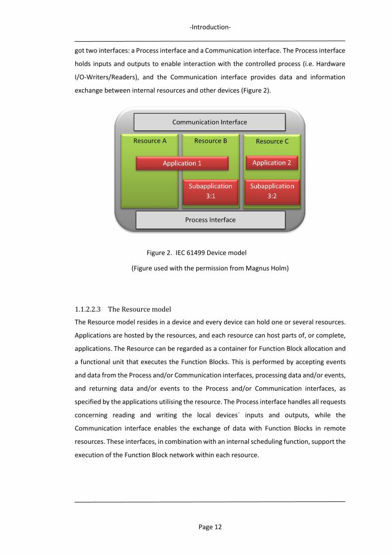
got two interfaces: a Process interface and a Communication interface. The Process interface
holds inputs and outputs to enable interaction with the controlled process (i.e. Hardware
I/O-Writers/Readers), and the Communication interface provides data and information
exchange between internal resources and other devices (Figure 2).
Figure 2. IEC 61499 Device model
(Figure used with the permission from Magnus Holm)
1.1.2.2.3 The Resource model
The Resource model resides in a device and every device can hold one or several resources.
Applications are hosted by the resources, and each resource can host parts of, or complete,
applications. The Resource can be regarded as a container for Function Block allocation and
a functional unit that executes the Function Blocks. This is performed by accepting events
and data from the Process and/or Communication interfaces, processing data and/or events,
and returning data and/or events to the Process and/or Communication interfaces, as
specified by the applications utilising the resource. The Process interface handles all requests
concerning reading and writing the local devices´ inputs and outputs, while the
Communication interface enables the exchange of data with Function Blocks in remote
resources. These interfaces, in combination with an internal scheduling function, support the
execution of the Function Block network within each resource.
-Introduction-
Page 13
Figure 3. IEC 61499 Resource model
(Figure used with the permission from Magnus Holm)
The applications which reside in a resource, local applications or separate parts of distributed
applications, are made up of a set of interconnected Function Blocks. These Function Blocks
are linked together, connected by their data and event connections into a network (Figure
3). The scheduling function controls the event flow within the Function Block network and
the execution of the internal algorithms of each Function Block, to secure their correct order
of execution. To facilitate communication with other resources, dedicated Service Interface-
Function Blocks are used. The IEC 61499 standard defines several types of such Function
Blocks.
1.1.2.2.4 The Application model
The IEC 61499 standard defines an application as a network of interconnected Function
Blocks, linked together by their event and data connections. In practice, an application is the
composition of a set of Function Blocks into a network required to control a specific process,
system, or task, e.g. a separate machine, an automatic assembly cell or a complete
production system. The overall functionality of an application can be divided into distributed
sub-applications, each holding a separate part of the functionality of the application. As such,
an application can either be downloaded into a single resource or split between several
resources and multiple devices.
-Introduction-
Page 14
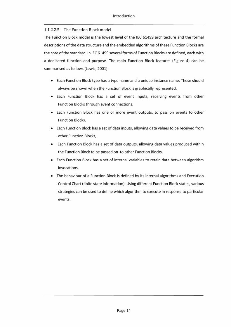
1.1.2.2.5 The Function Block model
The Function Block model is the lowest level of the IEC 61499 architecture and the formal
descriptions of the data structure and the embedded algorithms of these Function Blocks are
the core of the standard. In IEC 61499 several forms of Function Blocks are defined, each with
a dedicated function and purpose. The main Function Block features (Figure 4) can be
summarised as follows (Lewis, 2001):
Each Function Block type has a type name and a unique instance name. These should
always be shown when the Function Block is graphically represented.
Each Function Block has a set of event inputs, receiving events from other
Function Blocks through event connections.
Each Function Block has one or more event outputs, to pass on events to other
Function Blocks.
Each Function Block has a set of data inputs, allowing data values to be received from
other Function Blocks,
Each Function Block has a set of data outputs, allowing data values produced within
the Function Block to be passed on to other Function Blocks,
Each Function Block has a set of internal variables to retain data between algorithm
invocations,
The behaviour of a Function Block is defined by its internal algorithms and Execution
Control Chart (finite state information). Using different Function Block states, various
strategies can be used to define which algorithm to execute in response to particular
events.
-Introduction-
Page 15
Figure 4. IEC 61499 Function Block model
(Figure used with the permission from Magnus Holm)
The structure and composition of the Execution Control Chart define the behaviour of the
Function Block, by describing the relations for how the internal algorithms are triggered.
When input events are received, the Execution Control Chart initiates the algorithm
execution which, depending on the data input values and the internal variables, generates
new data output values and an associated output event. The capabilities of the hosting
resource, i.e. scheduling, communication and process mapping, support the various
processes for Function Block execution. The Function Block execution follows the numbered
sequence in Figure 4, and is described below:
1. Incoming values from other Function Blocks or from the controlled process are
available at the data inputs.
EI_1
EI_2
EO_1
EO_2
DI_1
DI_2
DO_1
DO_2
Internal variables
AlgorithmsAlgorithmsAlgorithmsAlgorithms
Execution Control Chart
Resource capabilities (scheduling, communications
and process mapping)
1
2
3 4 6 7
5
8
Instance name
Type name
-Introduction-
Page 16
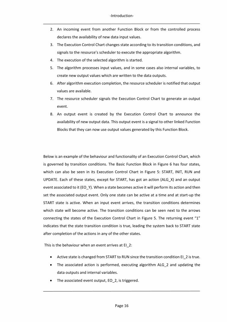
2. An incoming event from another Function Block or from the controlled process
declares the availability of new data input values.
3. The Execution Control Chart changes state according to its transition conditions, and
signals to the resource’s scheduler to execute the appropriate algorithm.
4. The execution of the selected algorithm is started.
5. The algorithm processes input values, and in some cases also internal variables, to
create new output values which are written to the data outputs.
6. After algorithm execution completion, the resource scheduler is notified that output
values are available.
7. The resource scheduler signals the Execution Control Chart to generate an output
event.
8. An output event is created by the Execution Control Chart to announce the
availability of new output data. This output event is a signal to other linked Function
Blocks that they can now use output values generated by this Function Block.
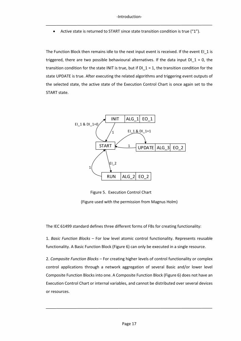
Below is an example of the behaviour and functionality of an Execution Control Chart, which
is governed by transition conditions. The Basic Function Block in Figure 6 has four states,
which can also be seen in its Execution Control Chart in Figure 5: START, INIT, RUN and
UPDATE. Each of these states, except for START, has got an action (ALG_X) and an output
event associated to it (EO_Y). When a state becomes active it will perform its action and then
set the associated output event. Only one state can be active at a time and at start-up the
START state is active. When an input event arrives, the transition conditions determines
which state will become active. The transition conditions can be seen next to the arrows
connecting the states of the Execution Control Chart in Figure 5. The returning event “1”
indicates that the state transition condition is true, leading the system back to START state
after completion of the actions in any of the other states.
This is the behaviour when an event arrives at EI_2:
Active state is changed from START to RUN since the transition condition EI_2 is true.
The associated action is performed, executing algorithm ALG_2 and updating the
data outputs and internal variables.
The associated event output, EO_2, is triggered.
-Introduction-
Page 17
Active state is returned to START since state transition condition is true (“1”).
The Function Block then remains idle to the next input event is received. If the event EI_1 is
triggered, there are two possible behavioural alternatives. If the data input DI_1 = 0, the
transition condition for the state INIT is true, but if DI_1 = 1, the transition condition for the
state UPDATE is true. After executing the related algorithms and triggering event outputs of
the selected state, the active state of the Execution Control Chart is once again set to the
START state.
Figure 5. Execution Control Chart
(Figure used with the permission from Magnus Holm)
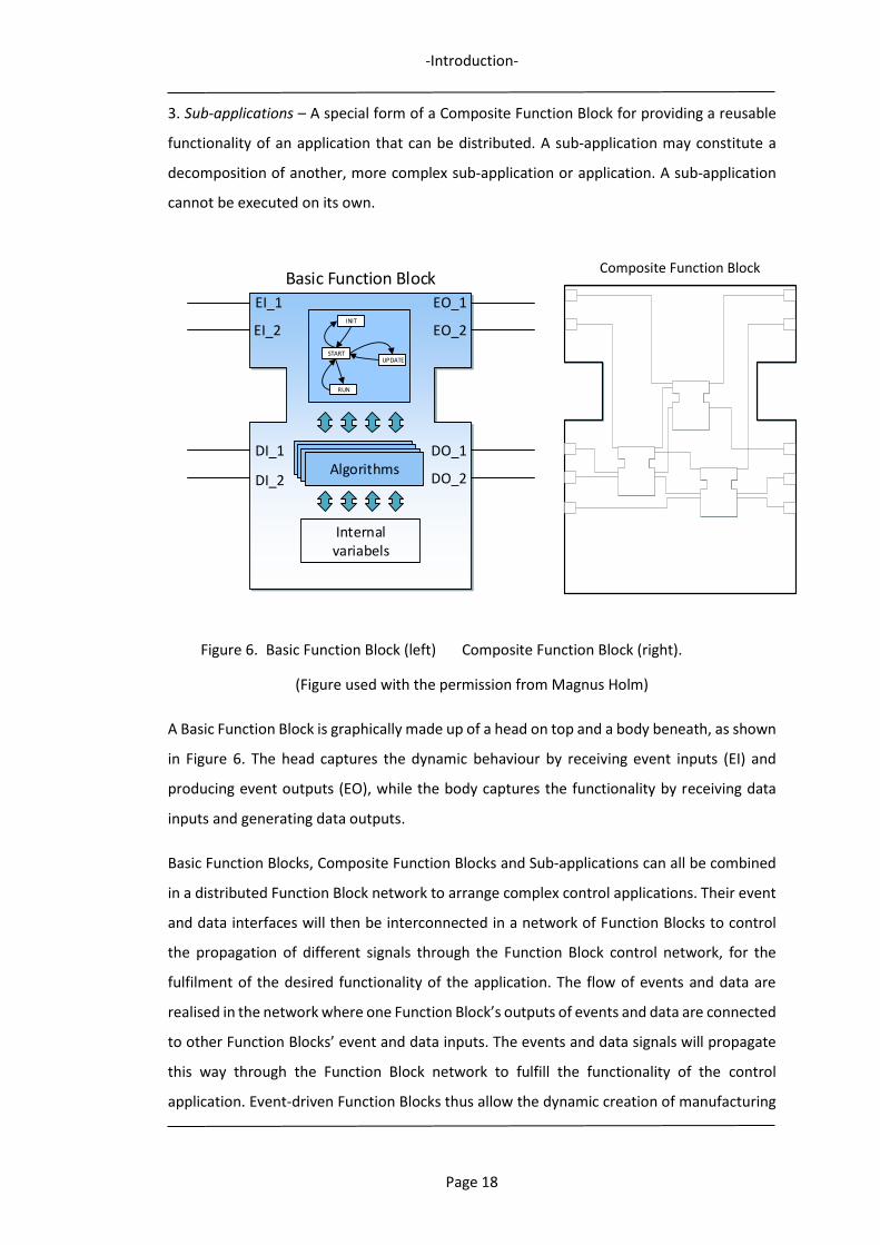
The IEC 61499 standard defines three different forms of FBs for creating functionality:
1. Basic Function Blocks – For low level atomic control functionality. Represents reusable
functionality. A Basic Function Block (Figure 6) can only be executed in a single resource.
2. Composite Function Blocks – For creating higher levels of control functionality or complex
control applications through a network aggregation of several Basic and/or lower level
Composite Function Blocks into one. A Composite Function Block (Figure 6) does not have an
Execution Control Chart or internal variables, and cannot be distributed over several devices
or resources.
INIT ALG_1
UPDATE ALG_3
RUN ALG_2
START
EI_1 & DI_1=0
EI_1 & DI_1=1
EI_2
1
1
1
EO_1
EO_2
EO_2
-Introduction-
Page 18
3. Sub-applications – A special form of a Composite Function Block for providing a reusable
functionality of an application that can be distributed. A sub-application may constitute a
decomposition of another, more complex sub-application or application. A sub-application
cannot be executed on its own.
Figure 6. Basic Function Block (left) Composite Function Block (right).
(Figure used with the permission from Magnus Holm)
A Basic Function Block is graphically made up of a head on top and a body beneath, as shown
in Figure 6. The head captures the dynamic behaviour by receiving event inputs (EI) and
producing event outputs (EO), while the body captures the functionality by receiving data
inputs and generating data outputs.
Basic Function Blocks, Composite Function Blocks and Sub-applications can all be combined
in a distributed Function Block network to arrange complex control applications. Their event
and data interfaces will then be interconnected in a network of Function Blocks to control
the propagation of different signals through the Function Block control network, for the
fulfilment of the desired functionality of the application. The flow of events and data are
realised in the network where one Function Block’s outputs of events and data are connected
to other Function Blocks’ event and data inputs. The events and data signals will propagate
this way through the Function Block network to fulfill the functionality of the control
application. Event-driven Function Blocks thus allow the dynamic creation of manufacturing
Composite Function Block
EI_1
EI_2
EO_1
EO_2
DI_1
DI_2
DO_1
DO_2
Basic Function Block
Internal variabels
AlgorithmsAlgorithmsAlgorithmsAlgorithms
INIT
UPDATE
RUN
START
-Introduction-
Page 19
equipment control code, adapted to the actual shop floor conditions as it may be based on
monitored real-time information.
1.1.2.3 IEC 61499 Applications
Research about the use and implementation of event-driven Function Blocks in different
applications has been ongoing for a while, at least since the late 1990s. Literature reviews
show that a variety of approaches using such Function Blocks have been proposed. However,
even though the first version of the IEC 61499 standard was published in 2005, it will still be
some years before it will be as widely adopted by the manufacturing industry as IEC 61131
(Strömman, Sierla, & Koskinen, 2005; Thramboulidis, 2007, 2009). It seems that the majority
of IEC 61499 applications are limited to low-level process control for PLCs, which are not able
to handle issues of adaptivity and uncertainty regarding process planning and execution
control for complex machining or robotic operations in high-level manufacturing systems.
A rather common Function Block application is the system design of autonomous distributed
systems with intelligent control components. Early research on using Function Blocks
describes holonic control (Lihui Wang, Brennan, Balasubramanian, & Norrie, 2001). Next-
generation manufacturing systems will require agility, flexibility and fault-tolerance and
these requirements can be satisfied by the emerging event-driven Function Block approach
and its real-time control architecture for distributed control. Other examples of how IEC
61499 has been studied and discussed in the research literature are: an automatic
verification of industrial control systems based on function block technology (Völker &
Krämer, 2002), the development of an architecture for Function Block-oriented engineering
support systems (Thramboulidis & Tranoris, 2001) and reconfigurable concurrent Function
Block models and their implementations using real-time Java (Brennan, Zhang, Xu, & Norrie,
2002).
Research on implementations of IEC 61499 in process control systems are also found. The
implementation of a real-time distributed control model using a Java-based platform is
introduced by (Olsen, Wang, Ramirez-Serrano, & Brennan, 2005), where a control application
is distributed across two devices, supported by a MANAGER Function Block, able of providing
management services for devices. Real-time execution of IEC 61499 applications, describing
the execution elements within a device and different scheduling and implementation
approaches is presented by (Zoitl, Grabmair, Auinger, & Sunder, 2005), as well as critique
against and solutions for, ambiguities concerning execution in the standard, leading to
-Introduction-
Page 20
different execution behaviour of elements on different control devices, by (Strasser, Zoitl,
Christensen, & Sünder, 2011). The development, implementation and use of an IEC 61499
Function Block library for embedded closed-loop control is presented and demonstrated by
(Strasser, Auinger, & Zoitl, 2004) on a real experiment: the control of a challenging seesaw
problem.
Targeting the issue of manufacturing equipment control, various applications for e.g. CNC-
machines and robots have been described. An open, layered CNC-FB architecture,
simplifying the design of CNC machine controllers, is demonstrated by (Minhat, Vyatkin, Xu,
Wong, & Al-Bayaa, 2009; Minhat, Xu, & Vyatkin, 2009). The architecture is based on STEP-NC
(STandard for the Exchange of Product model data - for Numerical Control) (ISO, 2007) as the
input data model and IEC 61499 as its development platform. The STEP-NC model provides
data on the machining operation to be executed. A prototype system with a PC controlled
3-axis CNC vertical milling machine has been used to test the proposed architecture, and to
prove that Function Block technology can be used for the development of open and
distributed CNC systems. The actual control has been achieved by interfacing the three
stepper motors of the machine through the parallel port of the PC, through an EMC controller
and through a motor control unit that drives the motors. With this setup, only a signal for
direction and a single pulse are needed to move the motors one step in any direction. A
Composite-Function Block controls the motors by generating an output sequence on the
parallel port.
Targeting the absence of a CNC-controller that is able to directly execute STEP-NC models,
an adaptable CNC system based on STEP-NC and Function Blocks was proposed (H. Wang,
Xu, & Tedford, 2007). It addresses the issue of porting STEP-NC data to different CNC
controllers, to enable a “Plug-and-Play” functionality. The objectives of this STEP-compliant
CNC system with Function Blocks incorporated are: to make product data interchangeable,
to enable information flow seamlessly and to have a system that is independent of CAD/CAM
systems. In their “Plug-and-Play” mapping system, a STEP-NC encoder reads data from an
STEP-NC supporting system and encodes it into Function Blocks. A Function Block mapping
system is then used to translate the STEP-NC code into native CNC-machining G and M codes,
which are executed by an executing sub-system. One advantage with this system is that the
current CNC machine configurations do not have to be modified. From a controller
perspective, machine specific G and M codes can still be used.
-Introduction-
Page 21
An enhanced STEP-NC compliant CNC controller is presented by X. Huang (2010). In order to
adapt the controller to a reconfigurable environment, an extended STEP-NC data model
describing machining data from the viewpoint of product family is applied, as well as the
Function Block device element model of IEC 61499. The approach is demonstrated on a XY
table and linear module in an FMS platform, controlled by a PC with a motion control card.
In Doukas, Thramboulidis, and Koveos (2006) an approach applying IEC 61499 Function
Blocks for robotic arm motion control is presented, using a PID-based control for issuing
motion commands to the robot. The motion behaviour for different variable PID parameters
and sampling periods are examined to prove the correctness of the design and the
implementation of the control application. In a literature review (Vyatkin, 2011) focusing on
how IEC 61499 can enable distributed and intelligent automation, the author concludes that
the standard facilitates control systems which may be automatically generated directly from
the design documentation using integrated design methodologies. This review also
concludes that the standard´s benefits for design of control systems, compared to other
technologies used for automation control, have been well proven by system integrators with
experience of IEC 61499 implementations.
The concept of combining IEC 61499 Function Blocks and Manufacturing Features to realise
event-driven adaptability for process planning and execution control for complex
manufacturing tasks, such as robotic assembly operations, is described in Chapter 3.
1.1.3 Distributed Manufacturing
The increasing globalization is a trend which forces manufacturing industry of today to focus
on more cost-effective manufacturing systems and collaboration within global supply chains
and manufacturing networks. Cloud Manufacturing is evolving as a new manufacturing
paradigm to match this trend, enabling the mutually advantageous sharing of resources,
knowledge and information between distributed companies and manufacturing units.
Combining recently emerged technologies, such as Internet of Things, Cloud Computing,
Semantic Web, service-oriented technologies, virtualisation and advanced high-performance
computing technologies, with advanced manufacturing models and information
technologies, it provides a framework for collaboration within complex and critical tasks,
such as manufacturing and design. This will lead to the flexible usage of different globally
distributed, service-oriented manufacturing systems and resources, increasing the
companies’ ability to successfully compete on a global marketplace.

-Introduction-
Page 22
One major manufacturing challenge for manufacturing companies to be competitive,
identified in section 1.1.1 was:
- The ability to participate in distributed resource sharing and collaborative
manufacturing activities.
This relates to the developing trend within the manufacturing shop floor domain of moving
manufacturing activities into cloud environments, as scalable, on-demand and pay-per-usage
cloud services, which is both timely and economically attractive. It is envisioned that
companies in all sectors of manufacturing will be able to package their resources and know-
hows in the Cloud, making them conveniently available for others. Resources, e.g.
manufacturing software tools, applications, knowledge and fabrication capabilities and
equipment, will then be made accessible to presumptive consumers on a worldwide basis.
This will radically change traditional manufacturing, as borderless, distributed and
collaborative manufacturing missions between volatile, best suited groups of partners will
impose a multitude of advantages.
The evolving Cloud Manufacturing concept will increase opportunities for outsourcing and
new joint ventures both locally and globally (X. Xu, 2012), but the level of complexity
regarding manufacturing control will become significantly higher. Moving towards
distributed manufacturing in new, collaborative and volatile partnerships will increase the
importance of effective and dynamic planning, coordination and execution of manufacturing
activities. Distributed Process Planning will be required for these multi-collaborative
manufacturing environments, especially for those scenarios in which dynamically configured
groups of dispersed resource providers are cooperating in manufacturing missions. Without
an effective approach combining both planning, control and execution, based on both global
and local conditions, the forecasted advantages of Cloud Manufacturing will be severely
restricted (F. Tao, Zhang, Venkatesh, Luo, & Cheng, 2011).
Cloud Manufacturing is often related to, and compared with, other advanced networked
manufacturing concepts, e.g. Networked, Internet-based, Distributed, and Grid
Manufacturing (L. Zheng, Jiang, Qiao, & Xi, 2010; X.-l. Zheng, Chen, & Lu, 2005) (Parker, 2007;
F. Tao, Hu, & Zhang, 2010). There are, however, some major differences. These networked
concepts focus on a single manufacturing task and the integration of distributed resources
for undertaking the task. They do not have a centralised operation management of the
services, choice of different operation modes and embedded access to physical

-Introduction-
Page 23
manufacturing equipment, applications and capabilities, which are prerequisites for a
seamless, stable and quality transaction of manufacturing resource services. Having little
coordination between the resource service provider and the resource service consumer,
these concepts are significantly less effective (X. Xu, 2012). In contrast to these concepts,
Cloud Manufacturing also promises elasticity, flexibility and adaptability through the on-
demand provisioning of manufacturing resources as services, enabling the fundamental and
necessary features such as convenient scalability and pay-as-you-go of resources shared (J.
T. Zhou, Yang, Wang, K., & Mo, 2011).
Cloud Manufacturing has been the focus for a great deal of research interest and suggested
applications during recent years, by both industrial and academic communities, and many of
its anticipated core virtues and enabling technologies have been described. After surveying
a vast array of available publications, a comprehensive review of issues related to adaptive
and distributed control of manufacturing equipment within Cloud Manufacturing is
presented in Chapter 2.
1.1.4 Semantic Web and ontology technologies
Product and manufacturing resource data is often handled by heterogeneous information
systems and stored in different systems at the facilities of manufacturing resource providers
and those consumers requesting the performing of a manufacturing task. Using an ontology-
based approach, the contents of different data sources can be retrieved and represented in
a semantically uniform description. With ontology extraction, information regarding
resources or products can be structured and formalised into local ontologies. In addition,
through the use of semantic augmentation and querying, as well as matching to global
manufacturing ontologies, new information may be inferred.
To support the Function Block-based cloud control approach described in the Chapter 6,
enabling the matching of manufacturing task requests with provider resources’ capabilities,
reference information models of these are required. Building on the concept of product
Manufacturing Features, a unified information framework describing manufacturing tasks
and manufacturing resources’ capabilities from a shared product feature perspective is
outlined in Chapter 3. For description of product manufacturing tasks, a feature-enriched
product data model is presented, and for manufacturing resources’ capabilities, a feature-
level capability model. Together, these two models facilitate manufacturing resource
discovery, and the matching of manufacturing resources to requested tasks. For structured
-Introduction-
Page 24
and formalised semantic model representations, implementation through ontologies and the
Semantic Web is described.
1.2 Motivation
Based on the research background, the need of a manufacturing equipment control approach
for distributed manufacturing environments, such as cloud environments, capable of
handling collaborative manufacturing missions as well as uncertainty and variations
appearing within manufacturing, is identified as the target of this research study.
This research study is therefore focusing on the combination and use of:
- manufacturing feature-based and event-driven Function Blocks for adaptive
manufacturing equipment control,
- a Function Block control structure for manufacturing equipment in distributed
environments, such as cloud environments.
1.3 Aim and objectives
The aim and novelty of this research study has been to design and formulate a method for
adaptive control of manufacturing equipment in cloud environments, enabled by the
combination of event-driven Function Blocks and Manufacturing Features. This involves the
creation of a complete control system framework and structure, and to define its required
system modules, their relationships and interactions in such a system hierarchy, and to
define the complete system functionality and usage. The focus of application has been to
formulate a control system for robotic assembly operations within cloud environments,
which will perform controller-level decisions based on real-time constraints, controlling the
robot by producing high-level robot-specific control instructions. The goal is to enable
adaptability of the control system against uncertainty in collaborative real-world
manufacturing.
The following research objectives have been identified, based on the research background
and the overall aim:
1. Through a literature review, determine the applicability of the event-driven Function
Block technology for adaptive and distributed control of manufacturing equipment
in cloud environments (Chapter 2).
2. Design and formulate a framework for adaptive control of manufacturing equipment
in cloud environments, including a supporting information framework (Chapter 3).
-Introduction-
Page 25
3. Design, implement, analyse and evaluate the framework for control in a local
manufacturing environment (Chapter 4).
4. Design, implement, analyse and evaluate the framework for adaptive control in a
distributed (LAN) manufacturing environment with both real and virtual
manufacturing applications (Chapter 5).
5. Design, analyse and evaluate the framework for adaptive control in a cloud
environment, including Manufacturing Equipment Control-as-a-Service (Chapter 6).
1.3.1 Research Scope and limitations
The scope of adaptivity considered in this research study relates to the systems’ abilities to
adapt to changes, made possible by an adaptive and distributed control system. Realising
adaptivity through the application of different hardware architectural perspectives or
physical reconfigurations of manufacturing equipment, such as CNC machines and robots,
are not considered.
The proposed Manufacturing Feature-Function Block control construct is generic and can be
used for different manufacturing applications. However, in this research study various
robotic assembly applications have been used to demonstrate and evaluate the applicability
of the construct. Robotic assembly is a highly relevant issue within the manufacturing
domain. Assembly operations are often a big part of the total manufacturing process and as
such make up for, in average, 50 % of the total manufacturing time (Nof, Wilhelm, &
Warnecke, 2012) and between 25 – 60 % of the total manufacturing costs (Z. Bi, Wang, &
Lang, 2007). Another relevant aspect is that robotic assembly operations often are tedious
and time-consuming to program, involving the creation of predefined control code for
specific robots, tasks and products.
Scheduling and process planning activities for the proposed control construct is not
addressed, being beyond the scope of this research study.
1.4 Research methodology
"All progress is born of inquiry. Doubt is often better than overconfidence, for it leads to
inquiry, and inquiry leads to invention" - Hudson Maxim.
The definitions for research are many and varying in both scope and perspectives, but most
often describe a common aim: to seek knowledge. It is defined rather succinctly by Creswell
(2008) as “…a process of steps used to collect and analyse information to increase our
-Introduction-
Page 26
understanding of a topic or issue. It consists of three steps: pose a question, collect data to
answer the question, and present an answer to the question”.
Research methodology is a systematic approach for performing research and solving a
research problem. It should formulate the various steps that a researcher needs to adopt in
studying the research problem, along with the logic behind these steps. Research methods
may be understood as all those methods and techniques used for performing the different
research steps.
There are two basic approaches to research, qualitative approach and the quantitative
approach (Robson, 2011). The qualitative approach to research concerns the subjective
assessment of opinions, attitudes and behaviour, which makes the research a function of the
researcher's insights and impressions. The generated results are often non-numerical, e.g. in
the form of words, either in a non-quantitative form or in a form which is not subjected to
rigorous quantitative analysis. Focus group interviews, projective techniques and depth
interviews are often used as research methods. In contrast, the quantitative approach
involves the generation of data in quantitative form which can be subjected to rigorous
quantitative analysis in a formal and rigorous fashion.
This research study presents a framework for a manufacturing system´s control structure, for
the adaptive control of manufacturing equipment in dynamic, distributed and collaborative
cloud environments. It mainly concerns quantitative methods and processes with the aim to
define and implement a networked event-driven Function Block control structure, for which
the utility may be evaluated. The need for such a control structure has been identified in the
literature review, and the construction and evaluation of such an artefact could be performed
following a proper research methodology along with appropriate research methods.
For the research study presented in this dissertation, the Design Science Research
methodology has been used as the overall methodical framework basis. The methodology
adheres to the statements by (A. R. Hevner, March, Park, & Ram, 2004) that “design science
address research through the building and evaluation of artefacts designed to meet the
identified business need” and that ”scientific research should be evaluated in the light of its
practical implications”. They also emphasize the importance of artefact utility as the goal for
the design science research methodology, and also the major evaluation criteria. Figure 7
depicts a model of this research methodology, describing the anticipated knowledge flow,
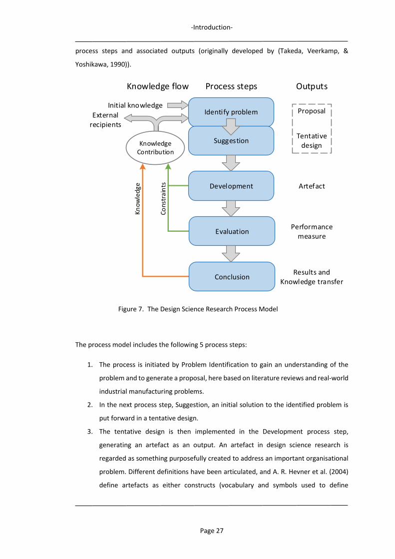
-Introduction-
Page 27
process steps and associated outputs (originally developed by (Takeda, Veerkamp, &
Yoshikawa, 1990)).
Figure 7. The Design Science Research Process Model
The process model includes the following 5 process steps:
1. The process is initiated by Problem Identification to gain an understanding of the
problem and to generate a proposal, here based on literature reviews and real-world
industrial manufacturing problems.
2. In the next process step, Suggestion, an initial solution to the identified problem is
put forward in a tentative design.
3. The tentative design is then implemented in the Development process step,
generating an artefact as an output. An artefact in design science research is
regarded as something purposefully created to address an important organisational
problem. Different definitions have been articulated, and A. R. Hevner et al. (2004)
define artefacts as either constructs (vocabulary and symbols used to define
Identify problem
Suggestion
Development
Evaluation
Conclusion
Process stepsKnowledge flow Outputs
Proposal
Tentative design
Performance measure
Results and Knowledge transfer
Cons
trai
nts
Know
ledg
eKnowledge
Contribution
External recipients
Artefact
Initial knowledge

-Introduction-
Page 28
problems and solutions), models (abstractions and representations), methods
(algorithms and practices), or instantiations (implemented and prototype systems).
The artefacts designed and presented during this research study are mainly
instantiations, which can be regarded as operationalisations of constructs, models
and methods. The following citation is expositive for such artefacts: “…artefacts
constructed in design science research are rarely full-grown information systems that
are used in practice. Instead, artefacts are innovations that define the ideas,
practices, technical capabilities, and products through which the analysis, design,
implementation, and use of information systems can be effectively and efficiently
accomplished” (Tsichritzis, 1997).
4. The performance measures of the artefact is determined in the following Evaluation
step.
5. If the artefact performance measures from the evaluation process are judged as
satisfactory, the final process step Conclusion is reached. This step includes the
documentation of the research and its findings, often in a report, but also the active
knowledge transfer of research contribution to stakeholders within academy and
industry.
If problems or changes are identified during the research process, these should be fed back
to the initial Problem Identification process step, in an iterative up-date cycle if necessary.
The work content for each process step may differ, and depends on the research problem or
questions (Johannesson & Perjons, 2014).
As the research objectives in this research study target real-life manufacturing systems, it has
not been possible to test and evaluate the proposed control structure in real manufacturing
situations, due to potential risk of manufacturing disturbances. Instead, case studies with
prototype demonstrators have been used. Such a demonstrator emulates the desired
manufacturing scenario and enables testing and performance evaluations of the artefact
instantiations, without disturbing the real manufacturing system. Using case studies as a
research method allows for contextual conditions to be included and for contemporary
events to be examined (Yin, 2003).
During the research study, data was collected from the following sources using the described
research methods:
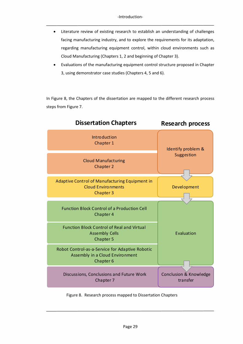
-Introduction-
Page 29
Literature review of existing research to establish an understanding of challenges
facing manufacturing industry, and to explore the requirements for its adaptation,
regarding manufacturing equipment control, within cloud environments such as
Cloud Manufacturing (Chapters 1, 2 and beginning of Chapter 3).
Evaluations of the manufacturing equipment control structure proposed in Chapter
3, using demonstrator case studies (Chapters 4, 5 and 6).
In Figure 8, the Chapters of the dissertation are mapped to the different research process
steps from Figure 7.
Figure 8. Research process mapped to Dissertation Chapters
Function Block Control of a Production CellChapter 4
Cloud ManufacturingChapter 2
IntroductionChapter 1
Adaptive Control of Manufacturing Equipment inCloud Environments
Chapter 3
Function Block Control of Real and VirtualAssembly Cells
Chapter 5
Robot Control-as-a-Service for Adaptive Robotic Assembly in a Cloud Environment
Chapter 6
Discussions, Conclusions and Future WorkChapter 7
Identify problem & Suggestion
Development
Conclusion & Knowledge transfer
Dissertation Chapters Research process
Evaluation
-Introduction-
Page 30
The essence of design science research is that contribution springs from utility. For the
evaluation of the result of the design science research process used in this research study,
the following questions should therefore be answered (A. R. Hevner et al., 2004):
What utility does the new artefact provide?
What demonstrates the utility?
To answer these questions and for evaluating the complete design science research process,
a set of guidelines have been proposed by (A. Hevner & Chatterjee, 2010; A. R. Hevner et al.,
2004). These guidelines are presented in Chapter 7 and used for evaluating and discussing
the conducted research.
1.5 Research contributions
This dissertation presents the following research contributions:
- A novel method for realising adaptive control of manufacturing equipment in cloud
environments. A proposed control structure represents an innovative method of
how to combine already existing techniques i.e. IEC 61499 Function Blocks and
Manufacturing Features, with new enabling technologies, such as Cloud
Manufacturing, cloud services, Internet of Technologies, etc. These are further
combined with an approach for the organisation and structuring of planning and
control capabilities into separate manufacturing control units, located in different
levels of the manufacturing control structure.
- A Feature-based Information Framework which presents a novel approach of how to
match manufacturing task requests with provider resources’ capabilities, using
reference information models. Building on the concept of product Manufacturing
Features, a unified information framework describing manufacturing tasks and
manufacturing resources’ capabilities from a shared product feature perspective is
constructed. For description of product manufacturing tasks, a feature-enriched
product data model is presented, and for manufacturing resources’ capabilities, a
feature-level capability model. Together, these two models facilitate manufacturing
resource discovery, and the matching of manufacturing resources to requested tasks.
-Introduction-
Page 31
1.6 Thesis organisation
The thesis is organised according to the sections described below.
1.6.1 Chapter 2: Cloud Manufacturing and cloud environments
This Chapter presents a comprehensive review of the concept of Cloud Manufacturing and
cloud environments, which introduce a new era of technology that will change the life of the
manufacturing industry.
Part of the work in Chapter 2 has previously been published in:
Adamson, G., Wang, L., Holm, M., & Moore, P. (2017). Cloud manufacturing – a critical review of recent development and future trends. International Journal of Computer Integrated Manufacturing, 30(4-5), 347-380. doi:10.1080/0951192X.2015.103170
Adamson, G., Wang, L., & Holm, M. (2013). The State of the Art of Cloud Manufacturing and Future Trends. (55461), V002T002A004. doi:10.1115/MSEC2013-1123
1.6.2 Chapter 3: Event-driven adaptability using IEC 61499 Function Blocks and
Manufacturing Features
This chapter introduces a method for adaptive, event-driven and feature-based control for
manufacturing equipment in distributed and collaborative manufacturing environments, i.e.
cloud environments, capable of instantly generating control in response to prevailing
requirements and conditions. It presents a framework in which an event-driven IEC 61499
Function Block control structure, in combination with Manufacturing Features, is used for
manufacturing equipment control, as well as using Manufacturing Features for detailing
manufacturing resources’ capabilities and product manufacturing properties, to facilitate
resource composition and matching to manufacturing task requests. The control approach is
generic and can be applied for different manufacturing applications, but is in the following
sections described for robot assembly applications.
Part of the work in Chapter 3 has previously been published in:
Adamson, G., Holm, M., & Wang, L. (2012). Event-Driven Adaptability using IEC 61499 in Manufacturing Systems. Paper presented at the The 5th International Swedish Production Symposium, SPS12, 6–8 November 2012, Linköping, Sweden, Linköping. http://urn.kb.se/resolve?urn=urn:nbn:se:his:diva-7089
-Introduction-
Page 32
Adamson, G., Holm, M., Wang, L., & Moore, P. (2012). Adaptive Assembly Feature Based Function Block Control of Robotic Assembly Operations. Paper presented at the 13th Mechatronics Forum International Conference, Johannes Kepler University, Linz, Monday, September 17, 2012 to Wednesday, September 19, 2012. Adamson, G., Wang, L., Holm, M., & Moore, P. (2014b). Function Block Approach for Adaptive Robotic Control in Virtual and Real Environments. Paper presented at the Proceedings of the 14th Mechatronics Forum International Conference.
1.6.3 Chapter 4: Function Block control of a production cell
In order to test and evaluate the capability of manufacturing equipment control for the
Feature-based Function Block control method described in Chapter 3, a case study with the
control of machining, assembly and material handling operations in a small production cell
demonstrator has been undertaken.
Part of the work in Chapter 4 has previously been published in:
Adamson, G., Holm, M., & Wang, L. (2012). Event-Driven Adaptability using IEC 61499 in Manufacturing Systems. Paper presented at the The 5th International Swedish Production Symposium, SPS12, 6–8 November 2012, Linköping, Sweden, Linköping. http://urn.kb.se/resolve?urn=urn:nbn:se:his:diva-7089 Adamson, G., Holm, M., Wang, L., & Moore, P. (2012). Adaptive Assembly Feature Based Function Block Control of Robotic Assembly Operations. Paper presented at the 13th Mechatronics Forum International Conference, Johannes Kepler University, Linz, Monday, September 17, 2012 to Wednesday, September 19, 2012.
1.6.4 Chapter 5: Function Block control of real and virtual assembly cells in
distributed environment
In order to further test and evaluate the capability of the Feature-based Function Block
control method to realise adaptive manufacturing equipment control, a case study with the
control of assembly operations in a small assembly cell demonstrator has been undertaken.
When setting the scope of this case study, the focus has been to be able to evaluate the
control systems capability to effectively adapt to varying assembly conditions through the
dynamic generation of robot control code for both real and virtual assembly environments,
as well as performing distributed equipment control.
Part of the work in Chapter 5 has previously been published in:

-Introduction-
Page 33
Adamson, G., Wang, L., Holm, M., & Moore, P. (2014b). Function Block Approach for Adaptive Robotic Control in Virtual and Real Environments. Paper presented at the Proceedings of the 14th Mechatronics Forum International Conference.
1.6.5 Chapter 6: Robot Control-as-a-Service for Adaptive Robotic Assembly in a
Cloud Environment
Following the presentation for adaptive control of manufacturing equipment in cloud
environments in Chapter 3, and the outcomes of the case study implementations in Chapters
4 and 5, this chapter presents a comprehensive assembly application scenario for Assembly
Feature-Function Block based control in a cloud environment.
Part of the work in Chapter 6 has previously been published in:
Adamson, G., Wang, L., & Holm, M. (2013). The state of the art of cloud manufacturing and future trends. Paper presented at the ASME 2013 international manufacturing science and engineering conference collocated with the 41st North American manufacturing research conference.
Adamson, G., Wang, L., Holm, M., & Moore, P. (2014a). Adaptive Robotic Control in Cloud Environments. Paper presented at the 24th International Conference on Flexible Automation and Intelligent Manufacturing, FAIM 2014, San Antonio, Texas, USA, May 20-23, Lancaster, Pennsylvania, USA. http://urn.kb.se/resolve?urn=urn:nbn:se:his:diva-9377 Adamson, G., Wang, L., Holm, M., & Moore, P. (2015). Adaptive Robot Control as a Service in Cloud Manufacturing. (56833), V002T004A020. doi:10.1115/MSEC2015-9479 Adamson, G., Holm, M., Moore, P., & Wang, L. (2016). A cloud service control approach for distributed and adaptive equipment control in cloud environments. Procedia CIRP, 41, 644-649. Adamson, G., Wang, L., Holm, M., & Moore, P. (2016a). Feature-Based Adaptive Manufacturing Equipment Control for Cloud Environments. (49903), V002T004A019. doi:10.1115/MSEC2016-8771 Adamson, G., Wang, L., & Moore, P. (2017). Feature-based control and information framework for adaptive and distributed manufacturing in cyber physical systems. Journal of Manufacturing Systems, 43(Part 2), 305-315. doi:https://doi.org/10.1016/j.jmsy.2016.12.003
-Introduction-
Page 34
Adamson, G., Wang, L., Holm, M., & Moore, P. (2017). Cloud manufacturing – a critical review of recent development and future trends. International Journal of Computer Integrated Manufacturing, 30(4-5), 347-380. doi:10.1080/0951192X.2015.1031704
1.6.6 Chapter 7: Discussions, conclusions and future work
In this Chapter, the results from the applied design science research process used in this
dissertation are discussed, and overall conclusions and suggestions of future work are
presented.
- Cloud Manufacturing and Cloud Environments-
Page 35
2 Cloud Manufacturing and Cloud Environments
In this chapter a literature review is presented, addressing the main topics relevant to Cloud
Manufacturing and adaptive and distributed control of manufacturing equipment in cloud
environments.
2.1 In the Cloud
For many years the Internet has been an unequalled infrastructure for collaborative tasks
and activities and information sharing, including within the manufacturing domain. It offers
new means and opportunities to perform manufacturing, leading to new manufacturing
paradigms. Furthermore, the term cloud has been used as a stand-alone concept and
metaphor for the public Internet, as a communication network for delivery of a wide variety
of services. However, cloud may also refer to tasks that involve any data communications
network, i.e. a wide area network like the Internet but shared by a defined group of users, or
a private, local area network within a unique company or organisation (Vaquero, Rodero-
Merino, Caceres, & Lindner, 2008).
2.2 Cloud Environments
The Cloud environment concept has been used for a while regarding Cloud Computing
environments, with different cloud platforms and services being available using a network of
remote servers hosted on the Internet to manage, process and store data. In such Cloud
environments, IT-resources (computing resources, services, storage, servers, applications)
are provided as services, easily and globally accessible in a standardised manner through the
use of service oriented architectures. Services are offered by providers according to a number
of fundamental models, of which Software-as-a-Service, Platform-as-a-Service and
Infrastructure-as-a-Service are the most common (Venters & Whitley, 2012).
Benefits of using these services are many compared to using local, on-premise implemented
IT-resources with high investment and life-cycle maintenance costs, e.g. readily accessible
information with remote access capabilities, usage scalability and unlimited capacity
upgrades for services used, processing power and storage space, automatically updated
systems following the latest standards, as well as both short term and long term financial
savings. Users can focus on their core business instead of in-house IT infrastructure,
competence or knowledge, and will be able to respond faster to market demands as they can
seamlessly increase capacity, enhance functionality or add additional services on demand.
- Cloud Manufacturing and Cloud Environments-
Page 36
Taking this concept and its many advantages to the manufacturing domain, Cloud Computing
is the backbone for realising a new manufacturing paradigm, Cloud Manufacturing, in which
manufacturing resources, similar to IT-resources, are made available as manufacturing
services (Valilai & Houshmand, 2013).
2.3 Cloud Manufacturing
Technological progress in Information and Communication Technology has induced new
opportunities for the manufacturing industry, as Cloud Manufacturing is emerging as a new
paradigm in the manufacturing community. The term and the complete concept were first
introduced by (B. H. Li, Zhang, Wang, & Chai, 2010), but the core ideas, about Manufacturing-
as-a-Service were already presented in the early 1990’s (Goldhar & Jelinek, 1990). However,
at that time the concept’s full potential was not possible to foresee, as Information and
Communication Technology tools and applications enabling distributed manufacturing
collaboration, as networked internet-enabled resource sharing, was still to come. Being a
highly complex manufacturing approach for implementation, still requiring extensive work
and research in a variety of disciplines for its realisation, Cloud Manufacturing holds the key
to the necessary and basic task of resource sharing. It is strongly believed that it will realise
a new and effective approach for performing networked and distributed, collaborative
manufacturing businesses. In a Manufacturing Cloud, providers can make available
manufacturing resources, for consumers to buy and use. (Providers may also act as
consumers, and vice versa.) Here, Cloud refers to Internet as a communication network, for
distributed storage and delivery of services. The core concept of Cloud Manufacturing is the
seamless and convenient realisation and provisioning of all types of distributed
manufacturing resources as service, for all phases of the product development life-cycle, thus
realising the idea of Manufacturing-as-a-Service. The capabilities of Cloud Manufacturing are
intended to support the servicelisation of the whole manufacturing product development
life-cycle, covering a wide spectrum of Cloud services, from analysis of markets and customer
requirements, resource planning, product design, simulation, supply-chain control,
manufacturing and management, maintenance, all the way to services for product end-of-
life activities (B. H. Li, Zhang, Wang, et al., 2010). This is possible through the implementation
of Cloud Computing as well as service-oriented technologies and other supporting
technologies, making possible the flexible sharing and collaboration of distributed
manufacturing resources encapsulated into Cloud services. The working principle is for cloud
providers to effectively organise and encapsulate manufacturing resources and capabilities
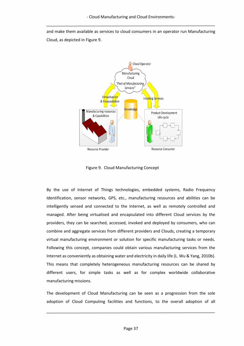
- Cloud Manufacturing and Cloud Environments-
Page 37
and make them available as services to cloud consumers in an operator run Manufacturing
Cloud, as depicted in Figure 9.
Figure 9. Cloud Manufacturing Concept
By the use of Internet of Things technologies, embedded systems, Radio Frequency
Identification, sensor networks, GPS, etc., manufacturing resources and abilities can be
intelligently sensed and connected to the Internet, as well as remotely controlled and
managed. After being virtualised and encapsulated into different Cloud services by the
providers, they can be searched, accessed, invoked and deployed by consumers, who can
combine and aggregate services from different providers and Clouds, creating a temporary
virtual manufacturing environment or solution for specific manufacturing tasks or needs.
Following this concept, companies could obtain various manufacturing services from the
Internet as conveniently as obtaining water and electricity in daily life (L. Wu & Yang, 2010b).
This means that completely heterogeneous manufacturing resources can be shared by
different users, for simple tasks as well as for complex worldwide collaborative
manufacturing missions.
The development of Cloud Manufacturing can be seen as a progression from the sole
adoption of Cloud Computing facilities and functions, to the overall adoption of all
- Cloud Manufacturing and Cloud Environments-
Page 38
manufacturing resources as services, realising the manufacturing version of Cloud Computing
(Dazhong Wu, Matthew John Greer, David W. Rosen, & Dirk Schaefer, 2013; X. Xu, 2012; Z.
Zhou, Liu, & Xu, 2011). As within Cloud Computing, different delivery models of Cloud
Manufacturing can be developed, to support the integration of virtual, intangible and
physical resources, e.g. CAD applications and manufacturing capabilities and equipment, as
services. Infrastructure, platform and software applications can then be offered as services
in Cloud Manufacturing, all referring to a specific phase of the manufacturing life-cycle, i.e.
Design-as-a-Service, Manufacturing-as-a-Service, etc.
It is evident that Cloud Manufacturing and cloud services will be a major driver of productivity
for the manufacturing industry in the near future (X. Xu, 2012). Small to mid-sized businesses
will benefit especially from the ability to use applications and solutions that used to be too
complex or expensive, as designed for use by larger enterprises. The pay-as-you-go solutions,
with low cost for usage and maintenance, eliminate economic barriers such as extensive
investments for IT-systems, and manufacturing equipment rapidly depreciating. By
subscribing to a service, many of the costly on-premise related expenses, like software,
hardware and maintenance, can be reduced or even eliminated. Apart from the cost aspect,
there are many other advantages, e.g. rapid implementation and upgrades in the Cloud with
new features and functions, licensing scalability regarding number of users and scope of
application functionality and capability, enhanced ease of use and secure and standardised
integration to partners and service providers. The best match and mix of resources can be
used, no matter of their physical localisation, leading to the realisation of concepts like DAMA
(Design Anywhere, Manufacture Anywhere) (Heinrichs, 2005; Manenti, 2011; Venkatesh et
al., 2005). No matter of size, companies may utilise the advantages of economy-of-scale,
making them much more competitive. A group of smaller companies can cooperate and
virtually act as a big enterprise. On the other hand, utilisation can be increased, as spare
capacity can be made available for others to buy and use.
Since the concept of Cloud Manufacturing was first introduced a couple of years ago, there
has been a growing interest in the academic and industrial communities, with a steadily
increasing number of research publications as well as research initiatives (Adamson, Wang,
& Holm, 2013; Adamson, Wang, Holm, & Moore, 2017). A large number of articles have been
published, many of which describe a wide spectrum of useful and promising effects that the
use of Cloud Manufacturing could realise and generate. However, there is not yet any
standardised definition of Cloud Manufacturing, or reports on completely developed Cloud

- Cloud Manufacturing and Cloud Environments-
Page 39
Manufacturing systems. Although the concept of Cloud Manufacturing is quite new, the
concepts of distributed, networked and virtual manufacturing have been around for a while
(X. Xu, 2012). In adopting, combining and extending these newly emerged technologies with
existing advanced manufacturing models and information technologies, this computing- and
service-oriented manufacturing model could be realised (F. Tao, L. Zhang, et al., 2011).
In the following sections, specific areas of interest of Cloud Manufacturing are described, and
outstanding research issues and future directions and trends are identified and discussed.
2.3.1 Cloud Manufacturing Drivers
Driving the development of Cloud Manufacturing are a number of foreseen positive effects
of varying nature, many of them of extra importance for SMEs, such as:
2.3.1.1 Economy
To increase utilisation of manufacturing resources and capabilities through outsourcing.
2.3.1.2 Agility
Adaptive and rapid response to changing customer demands through the ability to invoke
different combinations of manufacturing and product design services.
2.3.1.3 Scalability
As demand for throughput and utilisation vary, up and down scaling of required
manufacturing tasks is easily achievable through the addition, removal or modification of
necessary manufacturing resources.
2.3.1.4 Resource sharing
Convenient resource sharing in a flexible pay-as-you-go mode ensures the exchange of
services between manufacturing service providers and consumers.
2.3.1.5 Information sharing
There is a vast, increasing amount of data for the manufacturing activities, in different
formats and information systems. It is envisioned that Cloud Manufacturing could facilitate
the management and sharing of this information within and between the systems of Cloud
Manufacturing users.
In (Y. Liu, Zhang, Tao, & Wang, 2013) the evolution of Cloud Manufacturing is described by
enterprises willingness to participate, measured in relation to: degree of manufacturing task
saturation, cost of joining, and initial condition (number of enterprises offering resources). It
- Cloud Manufacturing and Cloud Environments-
Page 40
is found that the proportion of participants relies closely to these three conditions, with task
saturation having the biggest influence.
2.3.2 Cloud Manufacturing Definitions
Although no international standard for its definition exists, researchers and members of the
manufacturing community have a quite clear view of what Cloud Manufacturing means and
can facilitate. The needs and requirements driving its development and implementation, the
services and solutions it would make available and perform, and the concepts and
technologies it could build upon are reaching a much higher degree of consensus and
agreement. So far, a variety of descriptions and definitions of Cloud Manufacturing exist,
evolved and created from different perspectives and backgrounds, from both academic and
industry communities, national and international. The first definitions date from year 2010,
and many are showing great similarities in emphasising manufacturing services and resource
sharing as typical properties of Cloud Manufacturing (B. H. Li et al., 2011; B. H. Li, Zhang,
Wang, et al., 2010; F. Tao, L. Zhang, et al., 2011; F. L. Tao, Zhang, Gouo, Luo, & Ren, 2011; L.
Zhang, Luo, Tao, Ren, & Guo, 2010; Z. Zhou et al., 2011). Many describe cooperation and
collaboration by network-based resource and capability sharing in the form of services
between different Cloud users (consumers, providers, operators), as the main idea/concept.
Examples of quite typical definitions are:
“A model for enabling ubiquitous, convenient, on-demand network access to a
shared pool of configurable manufacturing resources (e.g., manufacturing
software tools, manufacturing equipment, and manufacturing capabilities) that
can be rapidly provisioned and released with minimal management effort or
service provider interaction.” (X. Xu, 2012)
“Cloud manufacturing is an integrated supporting environment both for the
share and integration of resources in enterprise. It provides virtual
manufacturing resources pools, which shields the heterogeneousness and the
regional distribution of resources by the way of virtualization. Cloud
manufacturing provides a cooperative work environment for manufacturing
enterprises and individuals and enables the cooperation of enterprise.” (L. Wu
& Yang, 2010a)

- Cloud Manufacturing and Cloud Environments-
Page 41
“A new model of manufacturing services, infrastructure and technology that
allows users access to a catalogue of standardised services and meet the needs
of your business, in a flexible and adaptive form, in case of unforeseen demand
or peak workloads, paying only for consumption made.” (Maciá Pérez, Berna-
Martinez, Marcos-Jorquera, Lorenzo Fonseca, & Ferrándiz Colmeiro, 2012)
“Cloud-Based Design and Manufacturing refers to a product realisation model
that enables collective open innovation and rapid product development with
minimum costs through a social networking and negotiation platform between
service providers and consumers. It is a type of parallel and distributed system
consisting of a collection of inter-connected physical and virtualised service
pools of design and manufacturing resources (e.g., parts, assemblies,
CAD/CAM tools) as well as intelligent search capabilities for design and
manufacturing solutions.” (D. Wu, Thames, Rosen, & Schaefer, 2012)
“Cloud Manufacturing is a networked manufacturing model in which locally
and globally distributed manufacturing resources for the complete product
life-cycle are made available by providers for satisfying consumer demands,
and are centrally organised and controlled as manufacturing Cloud services.
The model supports unified interaction between service providers and
consumers, for trading and usage of configurable resources/services, as well as
dynamic and flexible cooperation and collaboration in multi-partner
manufacturing missions. Distinct characteristics for the use of services are that
they are scalable, sold on demand, and fully managed by the
provider.”(Adamson, Wang, Holm, et al., 2017)
Summarising a number of different suggestions, descriptions and definitions, it is obvious
that the interest, acceptance and activities within Cloud Manufacturing are wide-spread and

- Cloud Manufacturing and Cloud Environments-
Page 42
highly active, and that there is a need for an international standardised definition of Cloud
Manufacturing, making possible its realisation as a worldwide manufacturing
implementation. Such a definition would also work as guidance for further necessary
research initiatives concerning enabling technologies and concepts. The problems with the
absence of an international standard have been seen in the fast emerging Cloud Computing
market. Over recent years, this resulted in a variety of heterogeneous and less interoperable
Cloud infrastructures, causing huge problems for Cloud users in selecting their best fitting
Cloud provider(s) (Jrad, Tao, & Streit, 2012; L. Wu & Buyya, 2010). Preferably, a definition
should be solution and implementation neutral, not defining or explaining core or enabling
technologies, as these or their designations may change. Claims of possible effects on
productivity, utilisation, agility, economy, environment, etc. could also be omitted as neither
of these seem relevant in a definition.
2.3.3 Cloud Manufacturing Participants
There are mainly three types of participants or users in a Cloud Manufacturing system:
someone with a manufacturing demand, someone with resources to satisfy this demand, or
parts of it, and someone in between, orchestrating the organisation of demands and
available resources, for a successful match between demands and resources. These
participants have been given different names in some of the proposals, but the following are
the most commonly used (Figure 9):
Consumer: Purchases and consumes available manufacturing services in the Cloud from
providers, after supplying engineering requirements to the Cloud operator. Pays for service
utilisation based on either usage time rates or subscription fees.
Provider: Provides and sells manufacturing resources and capabilities as services, for
consumers’ product development. Services supporting the whole life-cycle of the
manufacturing process can be provided. Processes the consumer requests based on
manufacturing information from the operator and/or consumer.
Operator: Responsible for the operation and management of the Cloud Manufacturing
system. Delivers required support and functions to providers and consumers and maintains
the services and technologies required to run the system. Responsible for finding, combining,
controlling and coordinating the required services for fulfilling consumer requirements. May
charge both consumers and providers for this service.

- Cloud Manufacturing and Cloud Environments-
Page 43
In the center of Figure 9, Knowledge refers to required knowledge support necessary for
crucial Cloud Manufacturing activities, such as: perception, connection, virtualisation and
encapsulation of manufacturing resources and capabilities, Cloud service description,
matching, searching, aggregation, and composition, optimal allocation and scheduling of
activities and services, etc.
2.3.4 Cloud Manufacturing Resources and Services
Cloud Manufacturing being service-oriented rather than production-oriented, a
manufacturing activity is regarded as a service, being requested or provided. A service is the
providing of one or a combination of many resources, and different manufacturing resources
support manufacturing activities through the whole product life-cycle. Some different
resource classifications with minor differences exist, but most agree to that there are two
different types of manufacturing resources which can be provisioned and consumed in Cloud
Manufacturing: physical manufacturing resources and manufacturing capabilities
(sometimes also referred to as “abilities”) (Vincent Wang & Xu, 2013; F. Zhang & Xue, 2012).
Physical resources can be either hard (such as manufacturing equipment, computers,
networks, servers, materials, facilities for transportation and storage, etc.) or soft (e.g.
applications, product design and simulation software, analysis tools, models, data, standards,
human resources such as personnel of different professions and their knowledge, skill and
experience, etc.). Manufacturing capabilities are intangible and dynamic recourses which
represent an organisation’s capability of undertaking a specific task or operation with
competence, using physical resources (e.g. performing product designs, simulations,
manufacturing, management, maintenance, communication, etc.). It is the manufacturing
capabilities that determine if the requirements can be achieved by the manufacturing
resources during product development. Both manufacturing resources and capabilities are
virtualised and encapsulated as manufacturing Cloud services, which are on-demand,
configurable and self-contained services, to fulfil a consumer’s needs. Manufacturing
software, applications and infrastructures can thus be realised as services in Cloud
Manufacturing, in a similar manner as computing resources are being provisioned in different
structures in Cloud Computing.
2.3.5 Cloud Manufacturing Architectures
Many attempts are also made to define more or less complete Cloud Manufacturing systems,
describing typical concepts, characteristics, architectures and enabling technologies. Some
more comprehensive and complete proposals are available in (B. Huang, Li, Yin, & Zhao, 2013;

- Cloud Manufacturing and Cloud Environments-
Page 44
B. H. Li, Zhang, & Chai, 2010; B. H. Li et al., 2011; B. H. Li, Zhang, Wang, et al., 2010; B. Lv,
2012; Macia-Perez, Berna-Martinez, Marcos-Jorquera, Lorenzo-Fonseca, & Ferrandiz-
Colmeiro, 2012; Maciá Pérez et al., 2012; Ning, Zhou, Zhang, Yin, & Ni, 2011; F. Tao, L. Zhang,
et al., 2011; F. L. Tao et al., 2011; Valilai & Houshmand, 2013; D. Wu et al., 2012; Xiaofei,
Lanshun, Dechen, & Lartigau, 2013; X. Xu, 2012; F. Zhang & Xue, 2012; Lin Zhang et al., 2012;
Z. N. Zhang & Zhong, 2012; J. T. Zhou et al., 2011; Z. Zhou et al., 2011).
Some proposed architectures have 4 layers, more detailed have up to 12 layers. The naming
and content of the different layers also differ between the proposed architectures.
Summarising proposed Cloud Manufacturing concept architectures, a typical architecture is
presented in Figure 10. It consists of the following layers (B. Huang et al., 2013):
Figure 10. Cloud Manufacturing Concept Architecture
(based on (F. Tao, L. Zhang, et al., 2011))
- Cloud Manufacturing and Cloud Environments-
Page 45
Resource layer: Different manufacturing resources and capabilities, for the complete
manufacturing life-cycle, supplied by different providers.
Perception layer: Responsible for sensing the physical manufacturing resources and
capabilities, enabling them to be interfaced into the wider network, and processing
the related information and data.
Virtualisation layer: For virtualisation of manufacturing resources and capabilities,
and encapsulation into Cloud services.
Cloud service layer (Core middleware): Handles management of system, services,
resources, tasks, etc. Activities for services such as: access, invocation, description,
publication, registry, matching, composition, monitoring, scheduling, charging, etc.
Application layer: Depending on the participating providers and their offered
manufacturing Cloud services, dedicated manufacturing application systems can be
aggregated, i.e. Manufacturing, Collaborative supply chain, Collaborative design,
Simulation, ERP, etc. Consumers can browse and access these different application
systems for manual/automatic service configurations. A manufacturing resource
provider can let consumers select from different possible part properties and pre-
determined manufacturing constraints (sizes, materials, tolerances, etc.).
Interface layer: Provides consumers with an interface for browsing available services
and publishing their requirements and requests. Manual selection and combination
of available resources/services, or automatic Cloud generated suggested solutions.
Supporting layers:
Knowledge – Provides knowledge needed in the different layers, i.e. for virtualisation
and encapsulation of resources, manufacturing domain knowledge, process
knowledge, etc.
Security – Provides strategies, mechanisms, functions and architecture for Cloud
Manufacturing system security.
Communication – Provides the communication environment for users, operations,
resources, services, etc. in the Cloud Manufacturing system.
- Cloud Manufacturing and Cloud Environments-
Page 46
Finally, it is important to understand that Cloud Manufacturing is not a replacement of
preceding advanced manufacturing paradigms, but rather a combination and evolution of
those. The inclusion and usage of Cloud Computing and service-oriented technologies makes
Cloud Manufacturing an effective paradigm for future manufacturing activities in a
worldwide distributed, resource-sharing, customer-centred, green and dynamic
manufacturing environment.
2.3.6 Research Areas and Technologies
The future development of Cloud Manufacturing will face many challenges in key enabling
technologies and concepts. Besides the integration technologies of Cloud Computing,
Internet of Things, Semantic Web, high performance computing, and embedded systems,
several important technical issues must be solved such as knowledge based resource
Clouding, Cloud management engines, collaboration between Cloud Manufacturing
applications, and visualisation and user interface in Cloud environments (B. H. Li, Zhang, &
Chai, 2010). These would make it possible to offer a personalised manufacturing services
through several processes, e.g. order decomposition into tasks, the selection of one or
several providers to perform them, the scheduling of the whole manufacturing process, etc.
In the following, technologies and research content for realising Cloud Manufacturing are
presented. There is a wide scope of technologies required, and some of these can be seen as
core technologies, while others are of a more general nature as enabling and supporting
technologies. The focus here is on the core technologies, critical for the development of
Cloud Manufacturing, but some of the other most common and characteristic enabling
technologies are also described.
2.3.6.1 Cloud Computing and Service-Orientation
The inclusion of Cloud Computing as a core enabling technology is one of the major
differences between Cloud Manufacturing and other advanced networked manufacturing
paradigms, as it makes possible to provision manufacturing activities as services in a
distributed environment. The aim of Cloud Computing is to provide convenient, scalable
access to IT services and computing resources. It offers on-demand and strategic outsourcing,
providing IT-resources as a standard commodity, delivering real-time access to software,
application development and infrastructure. Since the appearance of the concept of Cloud
Computing, a variety of different descriptions and definitions have been brought forward.
The NIST (Mell & Grance, 2011) definition states:
- Cloud Manufacturing and Cloud Environments-
Page 47
“Cloud computing is a model for enabling ubiquitous, convenient, on-demand
network access to a shared pool of configurable computing resources (e.g.,
networks, servers, storage, applications, and services) that can be rapidly
provisioned and released with minimal management effort or service provider
interaction….”
Within Cloud Computing, IT-resources are provided as different services for users, as Cloud
services. This means that companies can outsource their IT applications and infrastructures
on a practical and economical basis (Armbrust et al., 2010; Buyya, 2009; Vaquero et al., 2008;
Venters & Whitley, 2012). Taking this concept all the way, complete IT-departments could be
outsourced, with IT-personnel instead becoming Cloud adopters. A Cloud service is
differentiated from traditional hosting by three distinct characteristics: it is sold on demand
(typically by usage time or subscription); it is elastic (a user can at any given time decide how
much of a service he wants); and the provider is fully managing the service (the user only
needs a computer and access to the Internet). The three most common services are (Khan,
Naseem, Ahmad, & Khan, 2012; B. H. Li, Zhang, & Chai, 2010; Marston, Li, Bandyopadhyay,
Zhang, & Ghalsasi, 2011; Mell & Grance, 2011):
Software-as-a-Service:
Also known as “software on demand”. The application or software is offered as a
service, in which the application runs in the Cloud, and the need to install and run
the application on the client computer is eliminated. The user interacts with the
software product and hardware infrastructure provided through a front-end portal.
Accessibility from any location, bundled maintenance and rapid scalability are strong
benefits, but security concerns may be an issue for users who require high security
and control, as the provider is in charge of that domain. Examples range from
personal applications such as Web-based email, Facebook and Twitter, to enterprise-
level applications such as database processing, inventory control, Google Apps and
Netsuite (Marston et al., 2011).
Platform-as-a-Service:
The platform is provided as a service, which can enable the development and
deployment of applications without the complexity and cost of buying and managing

- Cloud Manufacturing and Cloud Environments-
Page 48
the required hardware and software layers. While traditional application
development requires the necessary hardware, operating system, database,
middleware, Web servers, etc., working with Platform-as-a-Service, only the
knowledge of how to integrate them is required. Microsoft’s Azure Services Platform,
Google App Engine and Amazon’s Relational Database Services are all examples of
Platform-as-a-Service.
Infrastructure-as-a-Service:
The storage and computing capabilities are provided as a service. This includes
servers, data-center space, software and network equipment. Organisations with in-
house IT expertise can require the necessary infrastructure from Infrastructure-as-a-
Service providers. One popular usage is for hosting websites. Other examples are
Rackspace Cloud Servers, Amazon’s S3 storage service and Elastic Compute Cloud
computing platform.
(There is overlap between Software-as-a-Service, Platform-as-a-Service and
Infrastructure-as-a-Service, and depending on the perspective (manager, system
administrator, developer) the same service can be categorised into any of these
three.)
In addition to these services for IT-resources, service orientation has the capability to
industrialise IT, enabling the exploitation by enterprises in much the same way that industrial
manufacturing technology has been exploited (Padmanabhan & Kamath, 2012). All
manufacturing resources and capabilities for the entire product development life-cycle can
be realised and offered in the Cloud as Infrastructure, Platform or Software services (
Everything-as-a-Service), e.g. Manufacturing-as-a-Service, Design-as-a-Service, Simulation
and Experimentation-as-a-Service, Management-as-a-Service, etc. For computer-aided
product development, Cloud Computing is already being adopted by the manufacturing
society, as companies are replacing their in-house Computer-Aided Design software licenses
with Computer-Aided Design software as a Cloud service (D. Schaefer, 2011). Companies like
Autodesk offer virtually infinite computing power, access anytime and anywhere, shared
insight into data, and more flexible, controllable and predictable costs when using their
Computer-Aided Design-as-a-Service Cloud application (AutoDesk, 2017). Examples of other
possible applications in a Cloud Manufacturing system building on computer-aided software
- Cloud Manufacturing and Cloud Environments-
Page 49
resources, such as parametric virtual design, virtual processing and virtual exhibition are
described in (P. Wang & Diao, 2013). The Cloud Computing technology offers on-demand
access to the distributed resources, and caters for a dynamic provisioning of virtual hardware
and scalable applications to better match usage, being cost-effective by using a transparent
easy pay-as-you-go pricing model (B. H. Li, Zhang, & Chai, 2010; B. H. Li, Zhang, Wang, et al.,
2010; Mezgár, 2011; F. Tao, Cheng, Zhang, Luo, & Ren, 2011; L. Zhang et al., 2010). But
compared to Cloud Computing, which mainly deals with IT infrastructures and software,
implementing and realising Cloud Manufacturing is a much more demanding and wider task
as it, in addition to manufacturing product development related software, also includes an
array of physical manufacturing equipment and devices which need to be deployed in the
Cloud.
2.3.6.2 Resource and Service Issues
To be able to provision manufacturing resources as services in the Cloud, they need to be
virtualised and encapsulated (Guo, Zhang, Tao, Ren, & Luo, 2010a). For capturing the
necessary information of manufacturing resources and capabilities, and enhancing the
performance of discovery and resource sharing, the investigation of effective virtualisation
methods are of great importance. Critical issues in this are manufacturing resource modelling
and manufacturing service description. There also needs to be effective methods for finding,
accessing, combining, scheduling and managing these resources. So far, this seems to be the
major research area within Cloud Manufacturing and includes the following issues:
2.3.6.3 Resource, Capability and Service Description, Publication, Discovery and
Access
A model for describing manufacturing equipment resources is provided in (Zhao, Liu, Xu, &
Gao, 2013). They describe manufacturing capability of machinery equipment from two
aspects: static functional capability and dynamic production capability, using an ontology
methodology to model this. Both these aspects are of great importance to Cloud
Manufacturing users. Functional capabilities are inherent and stationary, and describe what
kind of work a machine can perform, while production capability reflects, during a given time,
the performance of that machine. Functional capability tells if a request can be performed,
while dynamic production capability tells when it can be performed. The use of predefined
Manufacturing Service Description templates for customised products development in a
Manufacturing-as-a-Service environment is proposed in (Rauschecker et al., 2011). The
Manufacturing Service Description contains product information, its manufacturing service
- Cloud Manufacturing and Cloud Environments-
Page 50
and its customisation limitations and are developed by a Manufacturing Service Description
Language.
Based on the main Manufacturing Service Description requirements, the Manufacturing
Service Description Language has been developed to be able to create a formal semantic
description of both product-related and manufacturing technology aspects. In (Arthur Lan
Kuan Yip, Jagadeesan, Corney, Qin, & Rauschecker, 2011) this concept is taken one step
further, introducing a front-end system for integration to the Manufacturing-as-a-Service
environment, facilitating configuration and specification of customised products. The front-
end components are displayed as part of an integrated web-based portal to support
collaborative development, and can be accessed by both service consumers and providers.
For consumers there is a Customised Product Advisory System that is used for browsing of
available products and configuration of specific needs. It also supports the definition of new
product designs. For providers there is an Infrastructure Management that is used to define
specific manufacturing services and configure dynamic virtual production lines. In (Arthur L.
K. Yip, Corney, Jagadeesan, & Qin, 2013) this concept is realised in a case study with a product
configurator for the customisation of a solar and lighting façade module. Two scenarios are
demonstrated: one where a customised façade module specification is automatically
generated from the combination of different services, and one where the system’s ability to
automatically respond to dynamically updated manufacturing service descriptions is shown.
Since semantic heterogeneity is a major problem for business processes’ integration,
manufacturing service capabilities are represented in an unambiguous, computer-
understandable form based on ontologies (Zeng, 2012). By utilising powerful representation
and reasoning abilities of Semantic Web technology, successful matching between request
descriptions, extracted from the manufacturing activity, and service capabilities’ descriptions
of existing manufacturing services, is possible. In order to create an intelligent matching
process between supply and demand in a Cloud Manufacturing environment, an ontology
method to realise unified modelling and semantic description of manufacturing
requirements and resources is presented in (L. J. Tai, Hu, Chen, & Huang, 2013). In a 4-step
process, the manufacturing resources and demand attributes and characteristics are
analysed, using a proposed ontology semantic similarity algorithm. After a comprehensive
evaluation of matching results, the output of the process is a sorted list of best matches
between demand and supply. To realise a mapping from manufacturing requirement,
manufacturing service to manufacturing resource dynamically and hierarchically, (Gao, Yang,

- Cloud Manufacturing and Cloud Environments-
Page 51
Liu, & Hou, 2013) introduces the Cloud Workflow into Cloud Manufacturing, proposing a
conceptual model of multi-agent business collaboration. Including manufacturing service
consumer, provider and operator, the model defines three critical stages: collaborative
business process modelling and verification of Cloud workflow, model instantiation with
modelling and clustering of manufacturing services, and model execution with the optimal
matching of manufacturing service supplies and requirements.
In (W. Wang & Liu, 2012) a resource discovery mechanism is put forward. It combines
Semantic Web services with OWL-S (an ontology for describing Semantic Web services)
techniques and gives manufacturing resources classification and characteristics. In (L. Zhang
et al., 2010), a meta-model for describing manufacturing capability is reported, which can
support efficient and intelligent running of Cloud Manufacturing systems. Multi-Granular
access control, considered to be an important foundation which guarantees the safety,
validity and availability of a Cloud Manufacturing system, is discussed in (C. Li, Shang, Hu, &
Zhu, 2011). A Multi-Granularity Access Control is established, based on the Attribute-Based
Access Control. The concept is verified and performance analysed, showing a high level of
efficiency. For the integration of machining manufacturing resources, the modelling and
realisation of processing actions are investigated (L. Li, Zhao, Gu, & Zhao, 2011). An
architecture for the reasoning of process behaviours is constructed, and process actions are
carried out according to the minimum-machining-cost and the shortest-processing-time
principles. The developed approach will act as a processing actions service for supporting
process engineers. A concept for realising the formal description of Manufacturing Capability,
using a multi-dimensional information model of Manufacturing Capability based on
knowledge, is described in (Y. Luo, Zhang, Zhang, & Tao, 2012). A model describing this is also
provided. In (Xiang & Hu, 2012), a resource-access architecture based on Internet of Things
is described. Several key issues, such as classification of resource information accesses and
access processes, are also discussed.
A device-aware system focusing on manufacturing equipment resources and their static and
dynamic properties is proposed in (Jiming, Zhiping, & Rongbo, 2012). Identification of
manufacturing equipment resources, required operation data and its classification into static
and dynamic properties, real-time information collection, transmission and processing is
described, stressing that the key technology of Cloud Manufacturing systems is to accurately
get access to, and control, real-time devices.
- Cloud Manufacturing and Cloud Environments-
Page 52
2.3.6.4 Resource and Capability Virtualisation and Encapsulation
In (Song, Song, & Zheng, 2012), the application of virtualisation technology in Cloud
Manufacturing is discussed in general terms. A method for virtualisation of both hardware
and software resources is presented in (C. Q. Li, Hu, & Wang, 2011). It builds on the use of a
property document describing all relevant information of resources. A four-layer resource
virtualisation model is discussed in (L. Wu, 2011). Through virtualisation, an insulation layer
is established between manufacturing resources and applications, to eliminate application-
resource dependencies. A resource encapsulation method for Cloud Manufacturing is
described (C. Q. Li, Hu, Wang, & Zhu, 2011), in EDDL (Electronic Device Description Language).
A flow chart is presented for the encapsulation process and the resources can be visited by
web service based on OVF (Open Virtualisation Format, an open standard for packaging and
distributing virtual appliances) encapsulation of resource attribute.
A two-phase method is described in (N. Liu, Li, & Wang, 2011) for transforming
manufacturing resources into Cloud services. Manufacturing resource features are first
comprehensively analysed, and a virtual specification is established for describing
heterogeneous manufacturing resources in an isomorphic manner. By extracting
characteristics of resources, an algorithm is proposed for resources partitioning according to
manufacturing capabilities. The classification and modelling of virtual resources is made in
(C. Hu, Xu, Cao, & Fu, 2012). Factors affecting the classification are analysed, and a conceptual
classification is given. Factors which influence the result of task assignment, i.e. logistics,
granularity, human activity, etc., are also studied and demonstrated. Based on this, a
modelling process and a rough model of a virtual resource is built.
In (Mokhtar & Houshmand, 2010), an approach is presented for how design and
manufacturing resources can be encapsulated and how a Global Service Layer may be
developed. For effective virtualisation of manufacturing resources and capabilities, a multi-
granularity manufacturing resource model which manages manufacturing resources based
on manufacturing capabilities is described in (N. Liu & X. Li, 2012). As manufacturing
resources are changeable during the process of collaborative manufacturing, while
manufacturing capabilities are relatively continual, this decoupling of manufacturing
resources from manufacturing Cloud services would support a scalable and flexible Cloud
service. This approach would also make possible locating manufacturing resources based on
multi-granularity manufacturing capabilities and related constraints, as such supporting
automatic and dynamic Cloud services for discovery and composition. In (Chunsheng Hu, Xu,

- Cloud Manufacturing and Cloud Environments-
Page 53
Cao, & Zhang, 2013) the effect of granularity factor on manufacturing resource virtualisation
is described. Manufacturing resource providers need to describe in detail their resources’
functionality in different granularity levels, and resource consumers need to choose a proper
task decomposition level (granularity level) to get maximum benefits in relation to their
manufacturing missions. Before the virtualisation of resources, the granularity levels, the
resource categories in each granularity level, and the virtual models of each kind of resource,
need to be well defined for a specific Cloud Manufacturing platform. A complete description
of this is also presented.
Requirements, and an architecture for virtualising manufacturing capabilities in the Cloud, is
discussed in (X. Wang & Xu, 2014). The relationships between resources, capabilities and
services are described, and an approach for capability virtualisation, from distributed
resources to robust services, is proposed. A three-layer (Application, Virtual Service,
Manufacturing Capability) Cloud Manufacturing architecture with a Smart Cloud Manager
controlling mechanism is also presented.
2.3.6.5 Resource Service Composition and Integration
Effective service composition will be of the greatest importance for service consumers, as
this will enable them to focus on their core business and outsource other activities in the
Cloud. The task is demanding and complex, finding and combining a mix of services, which
may be heterogeneous and delivered by different providers. The use of manufacturing
service descriptions for flexible integration of production facilities is described in
(Rauschecker & Stöhr, 2012), for realising the application of Manufacturing-as-a-Service. The
work aims at the development of a system that coordinates the manufacturing of complex
configurable products across various production facilities and locations, and also enables to
make the limitations and capabilities of the production network explicitly available during
the complete product specification process. In (Guo, Zhang, Tao, Ren, & Luo, 2010b; Lin
Zhang, Guo, Tao, Luo, & Si, 2010), the definition and classification of flexibility in Resource
Service Composition is described and a flexible management architecture for Resource
Service Composition is introduced. The purpose is to be able to handle dynamic changes
occurred during Resource Service Composition, as well as optimal selection of Resource
Service Composition based on flexibility. The life-cycle of Resource Service Composition is
classified into 4 phases: Designing, Deploying, Executing and Post-processing, and flexibility
is considered for: Task, Flow, Resource service, QoS, and Correlation. Major uncertain
dynamic changing factors are described and optimal selection of RSC based on QoS and

- Cloud Manufacturing and Cloud Environments-
Page 54
flexibility is compared. Adaptive Resource Service Composition, through quantitative
evaluations by the use of the measurement method of flexibility, is also suggested.
A Cloud Manufacturing integrating service mode based on Cloud-agent, in order to control
and coordinate Cloud Manufacturing terminal node efficiently, is presented in (Jiang, Ma,
Zhang, & Xie, 2012). By analysing the type and composition of manufacturing resources,
combined with agent technology, the concept could enable the exploitation of all kinds of
potential manufacturing resources and capabilities fully. Four decision algorithms for judging
composable correlations between Cloud services are evaluated in (Guo, Zhang, Tao, Ren, &
Luo, 2011). The formalised description for composable correlations is presented as well as
the judging activity based on a bipartite graph. The efficiency of these algorithms is
demonstrated in a case study. Considering existing correlations among Cloud services, a
framework for correlation relationship mining for Cloud service composition is demonstrated
in (Guo, Zhang, & Tao, 2011). The key issues are discussed and four function modules for
mining these correlations are analysed. To support decision making on when to outsource
product manufacture and to what extent and mix, a multi-objective optimisation formulation
is proposed, for computing an operational ratio (B. Zheng, Gao, & Wang, 2012). This enables
the determination of which products to make and which to outsource. The approach is
verified in a test case.
Sharing of software resources in Cloud Manufacturing is described in (Xilong, Zhongxiao, &
Linfeng, 2011). A platform supporting software publishing and software using is presented,
with a supply agent service for software providers and an online using service for software
users. The approach builds on the virtualisation technology of Cloud Computing. Different
aspects of collaborative resource sharing and integration are discussed in (Ding et al., 2012),
and an approach is proposed in which resources, information and knowledge for the
manufacturing process is described by abundant semantics. Using a uniform representation
of heterogeneous information, the heterogeneity of manufacturing resources can be
systematically shielded.
The issue for Cloud services consumers of finding the best fitting Cloud provider or service
has been prominent in the fast growing Cloud Computing market, which contains a mixed set
of heterogeneous and not always interoperable Cloud platforms/infrastructures. The
absence of common Cloud standards has hampered the interoperability between different
providers, often resulting in “vendor lock in” problems. This has opened up the market for
- Cloud Manufacturing and Cloud Environments-
Page 55
intermediate broker services (Pettey & van der Meulen, 2009), specialized in finding the best
user-provider matching, given a set of governing prerequisites and conditions, as in Service-
level agreements (Jrad et al., 2012). (Service-level agreement is a formal contract between
service providers and service consumers that should guarantee the achievement of the
consumers’ service quality expectations (L. Wu & Buyya, 2010)). This matching often includes
the selection and combination of service providers as well as the definition of their
collaboration and integration into providing a unified service to the user. This task would be
too complex for the consumer to successfully perform by himself.
2.3.6.6 Resource and Service Scheduling
A scheduling methodology for production services is presented in (Lartigau, Nie, Xu, Zhan, &
Mou, 2012). Order decomposition into tasks, the selection of one or several service providers
to perform them, and the scheduling of the whole manufacturing process is considered. In
(Chunquan Li, Yang, Shang, Hu, & Zhu, 2012), a resource scheduling framework is proposed.
On the basis of stochastic advanced Petri net, Queue Balancing Cutover strategy is put
forward as a solution to the issue of request dispatching. The scheduling of collaborative
design tasks is described in (Laili, Zhang, & Tao, 2011), presenting a new immune genetic
algorithm. Improved searching diversity based on immune strategy, but also adaptive
adjustment for probabilities of crossover and mutation with low time complexity, are
achieved with this concept.
2.3.7 Platform Management
After analysing the characteristics and design principles of the management and control
platform facing the Cloud Manufacturing services, the required system design function is
proposed (Xin-yu & Wei-jia, 2011). Aspects of system cost, convenience of service usage,
system security and service are considered and the approach is verified in a case study. A
model for optimal allocation of computing resources for manufacturing tasks in Cloud
Manufacturing is described in (Laili, Tao, Zhang, & Ren, 2011), in which computing resources
are allocated to different tasks according to various demands of manufacturing tasks. The
issue of resource service transactions is discussed in (Y Cheng et al., 2010) where revenue,
time and reliability are considered for resource service provider, resource service consumer
and resource service agent. With the characteristics of different Cloud services, considering
the multi-layer of logistics, information flow and capital flow, the transactions on hardware-
class, software-class, product-class and capability-class are respectively analysed in (Ying
Cheng et al., 2012). The detailed transaction flow between provider, operator and consumer
- Cloud Manufacturing and Cloud Environments-
Page 56
is also provided. For the management of product information in Cloud Manufacturing, a
system with a 6-layer architecture is proposed (Ai, Mo, Wang, & Zhao, 2013). The feasibility
and validity of the approach has been verified in a prototype system, including modules for:
user management, system management and product information management.
2.3.8 Knowledge and Data Management
All information, descriptions, algorithms, rules, strategies and data which support Cloud
Manufacturing can be considered as knowledge, and knowledge engineering and
management are crucial for making Cloud Manufacturing able to solve problems intelligently.
Fundamental activities which need knowledge support are: virtualisation, encapsulation and
descriptions of resources, capabilities and services, intelligent task decomposition with
searching and optimal composition of required services, and planning and scheduling for the
coordinated execution of sub-tasks and manufacturing equipment. In (Yiwen Zhang & Jin,
2012) a comprehensive approach for knowledge management, for group enterprise Cloud
Manufacturing is presented. A model framework of knowledge management, based on
Knowledge-as-a-Service, is described, for implementing both tactic and explicit knowledge
sharing and reuse within a group of enterprises.
A 6-level architecture of a knowledge management system for Cloud Manufacturing has been
developed, embodying all the required activities from retrieving source knowledge to
publishing knowledge as a service. Methods for acquisition, storage, retrieval, innovation and
publishing of knowledge are also included. After studying the dependencies of knowledge in
Cloud Manufacturing, a 4-layer knowledge life-cycle management system framework is
presented (A. Hu, Zhang, Tao, & Hu, 2013). In a knowledge storage layer, knowledge is stored
in the perspectives of: domain, reasoning, task and description. A logical reasoning layer with
a semantic reasoning engine can interface the stored knowledge when searching for problem
solutions. An application interface layer provides two types of interfaces for users and
system: a Knowledge Operation interface for basic knowledge operations, and a Knowledge
Application interface for knowledge reasoning for submitted tasks. A man-machine
interaction layer is also included for operating the knowledge base, and submitting and
monitoring tasks.
To deal with distributed knowledge and heterogeneity, delimiting the sharing of knowledge
in a Cloud Manufacturing environment, a service-oriented knowledge fusion architecture
supporting design activities is presented in (J. Liu & B. Li, 2012). An ontology-based design

- Cloud Manufacturing and Cloud Environments-
Page 57
knowledge organisation model for extracting, describing and indexing of distributed
resources into the Cloud Manufacturing platform is proposed. For the fusion of knowledge,
a conceptual model including: Service analysis, Knowledge matching, Knowledge integration,
and Ontology-based fusion is used. In the European research project Virtual Factory
Framework, aiming at developing an integrated environment to enable the interoperability
between software tools supporting the factory processes along all the phases of its life-cycle,
a Virtual Factory Data Model was proposed (Terkaj, Pedrielli, & Sacco, 2012). It provides a
common definition of the shared data among the software applications connected to the
framework, using a shared meta-language. The Virtual Factory Data Model has been
developed using Semantic Web technologies, because of their ability in representing formal
semantics, and efficiently modelling and managing distributed data.
2.3.9 Cloud Manufacturing Concepts
Many of the published articles about Cloud Manufacturing present architectures, platforms,
models, frameworks or applications for Cloud Manufacturing concepts. Some describe more
complete Cloud Manufacturing systems while others present discrete Cloud Manufacturing
technologies or parts. For the ease of overview and presentation, these are presented in
Table 1 with short descriptions. It does not seem to be a clear and stringent distinguishing
and use of the concepts of architecture, platform, framework or model. Therefore, the
presentation of different Cloud Manufacturing concepts in Table 1 follows the authors’
naming conventions. Short descriptions of presented applications are also included in Table
1.
Table 1. Cloud Manufacturing architectures, platforms, frameworks, models and applications.
Classification Description/Specification References
Architecture 4-layer (Manufacturing Resource, Virtual Service, Global Service and
Application layers).
(X. Xu, 2012)
10-layer (Resource, Perception, Resource virtualisation, Cloud
service, Application, Portal Enterprise cooperation, Knowledge,
Cloud security and Wider Internet layers).
(F. Tao, Y. Cheng,
et al., 2011)
5-layer (Physical, Virtualised resource, Service (Core Middleware),
Application and User layers).
(B. H. Li, Zhang, &
Chai, 2010; C. Q.
Li, C. Y. Hu, Y. W.
Wang, et al.,
2011)
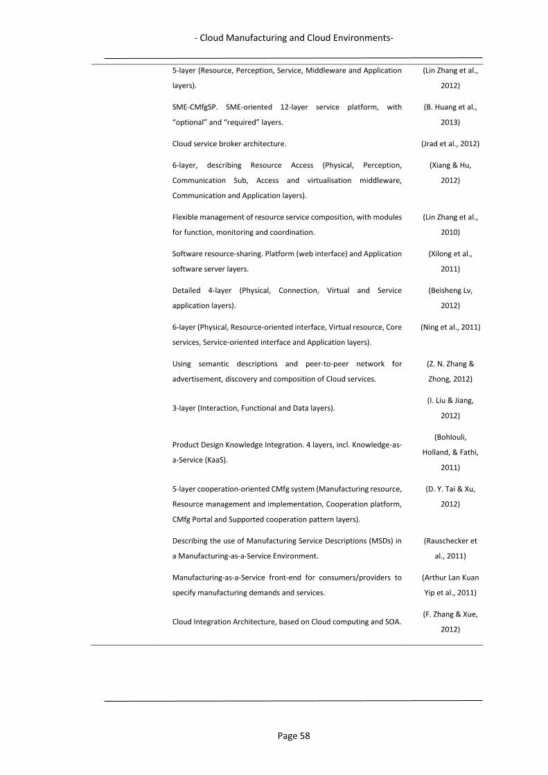
- Cloud Manufacturing and Cloud Environments-
Page 58
5-layer (Resource, Perception, Service, Middleware and Application
layers).
(Lin Zhang et al.,
2012)
SME-CMfgSP. SME-oriented 12-layer service platform, with
“optional” and “required” layers.
(B. Huang et al.,
2013)
Cloud service broker architecture. (Jrad et al., 2012)
6-layer, describing Resource Access (Physical, Perception,
Communication Sub, Access and virtualisation middleware,
Communication and Application layers).
(Xiang & Hu,
2012)
Flexible management of resource service composition, with modules
for function, monitoring and coordination.
(Lin Zhang et al.,
2010)
Software resource-sharing. Platform (web interface) and Application
software server layers.
(Xilong et al.,
2011)
Detailed 4-layer (Physical, Connection, Virtual and Service
application layers).
(Beisheng Lv,
2012)
6-layer (Physical, Resource-oriented interface, Virtual resource, Core
services, Service-oriented interface and Application layers).
(Ning et al., 2011)
Using semantic descriptions and peer-to-peer network for
advertisement, discovery and composition of Cloud services.
(Z. N. Zhang &
Zhong, 2012)
3-layer (Interaction, Functional and Data layers). (I. Liu & Jiang,
2012)
Product Design Knowledge Integration. 4 layers, incl. Knowledge-as-
a-Service (KaaS).
(Bohlouli,
Holland, & Fathi,
2011)
5-layer cooperation-oriented CMfg system (Manufacturing resource,
Resource management and implementation, Cooperation platform,
CMfg Portal and Supported cooperation pattern layers).
(D. Y. Tai & Xu,
2012)
Describing the use of Manufacturing Service Descriptions (MSDs) in
a Manufacturing-as-a-Service Environment.
(Rauschecker et
al., 2011)
Manufacturing-as-a-Service front-end for consumers/providers to
specify manufacturing demands and services.
(Arthur Lan Kuan
Yip et al., 2011)
Cloud Integration Architecture, based on Cloud computing and SOA. (F. Zhang & Xue,
2012)
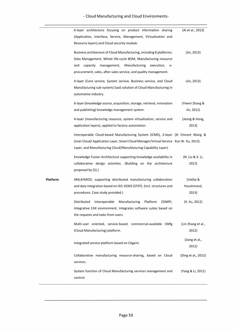
- Cloud Manufacturing and Cloud Environments-
Page 59
6-layer architecture focusing on product information sharing
(Application, Interface, Service, Management, Virtualisation and
Resource layers) and Cloud security module.
(Ai et al., 2013)
Business architecture of Cloud Manufacturing, including 8 platforms:
Data Management, Whole life-cycle BOM, Manufacturing resource
and capacity management, Manufacturing execution, e-
procurement, sales, after-sales service, and quality management.
(Jin, 2013)
4-layer (Core service, System service, Business service, and Cloud
Manufacturing sub-system) SaaS solution of Cloud Manufacturing in
automotive industry.
(Jin, 2013)
6-layer (knowledge source, acquisition, storage, retrieval, innovation
and publishing) knowledge management system.
(Yiwen Zhang &
Jin, 2012)
4-layer (manufacturing resource, system virtualisation, service and
application layers), applied to factory automation.
(Jeong & Hong,
2013)
Interoperable Cloud-based Manufacturing System (ICMS), 3-layer
(User Cloud/ Application Layer, Smart Cloud Manager/Virtual Service
Layer, and Manufacturing Cloud/Manufacturing Capability Layer).
(Xi Vincent Wang &
Xun W. Xu, 2013)
Knowledge Fusion Architecture supporting knowledge availability in
collaborative design activities. (Building on the architecture
proposed by [5].)
(N. Liu & X. Li,
2012)
Platform XMLAYMOD, supporting distributed manufacturing collaboration
and data integration based on ISO 10303 (STEP). (Incl. structures and
procedures. Case study provided.)
(Valilai &
Houshmand,
2013)
Distributed Interoperable Manufacturing Platform (DIMP).
Integrative CAX environment. Integrates software suites based on
the requests and tasks from users.
(X. Xu, 2012)
Multi-user oriented, service-based, commercial-available CMfg
(Cloud Manufacturing) platform.
(Lin Zhang et al.,
2012)
Integrated service platform based on CAgent. (Jiang et al.,
2012)
Collaborative manufacturing resource-sharing, based on Cloud
services.
(Ding et al., 2012)
System function of Cloud Manufacturing services management and
control.
(Yang & Li, 2011)

- Cloud Manufacturing and Cloud Environments-
Page 60
Describing relations between Manufacturing, Business and Resource
Clouds.
(M. Wang, Zhou,
& Jing, 2012)
Framework 6-layer, supported by Service Platform and Standard, Security and
Management functions.
(Z. Zhou et al.,
2011)
For discovering matching manufacturing resources, using OWL-S and
UDDI.
(W. Wang & Liu,
2012)
For correlation relationship mining of Cloud services. (Guo, Zhang, &
Tao, 2011)
Describes a process route for scheduling tasks. (Lartigau, Nie, Xu,
et al., 2012)
Cloud Manufacturing Resource Scheduling (CMRS). Task
decomposition, matching static properties of resources with
requirements of tasks.
(Chunquan Li et
al., 2012)
Process framework of OACR (Optimal Allocation of Computing
Resources).
(Laili, Tao, et al.,
2011)
Three layer Cloud Manufacturing virtualisation framework (man.
resource layer, virtual description layer and service encapsulation
layer)
(N. Liu & X. Li,
2012)
Manufacturing collaboration framework with service- and Web-
oriented architectures with SaaS for combining internal operations
with supply chain cooperation, also realising collaboration with
customers.
(Y. K. Lu, C. Y. Liu,
& B. C. Ju, 2012)
4-layer Life-cycle Knowledge Management System (knowledge
storage layer, logical reasoning layer, application interface layer, and
man-machine interaction layer)
(A. Hu et al.,
2013)
Model Application model describing how user requests are processed for
generating a solution.
(B. H. Li, Zhang, &
Chai, 2010)
Application model of Cloud Manufacturing (Xiaofei et al.,
2013)
Manufacturing resource-sharing. (Z. Zhou et al.,
2011)
Cloud-based Design and Manufacturing (CBDM). Reference model
with Cloud consumer, provider, broker and carrier. Model of
example services available to Cloud consumer.
(D. Wu et al.,
2012)
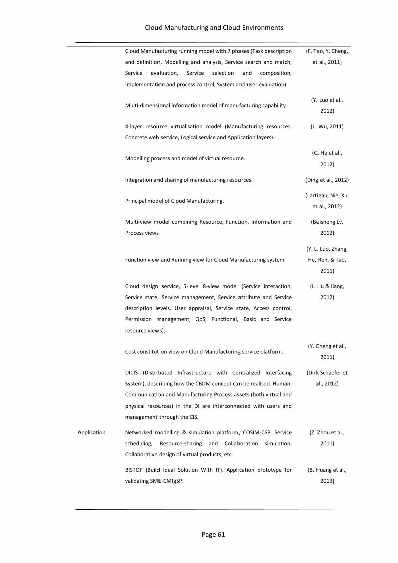
- Cloud Manufacturing and Cloud Environments-
Page 61
Cloud Manufacturing running model with 7 phases (Task description
and definition, Modelling and analysis, Service search and match,
Service evaluation, Service selection and composition,
Implementation and process control, System and user evaluation).
(F. Tao, Y. Cheng,
et al., 2011)
Multi-dimensional information model of manufacturing capability. (Y. Luo et al.,
2012)
4-layer resource virtualisation model (Manufacturing resources,
Concrete web service, Logical service and Application layers).
(L. Wu, 2011)
Modelling process and model of virtual resource. (C. Hu et al.,
2012)
Integration and sharing of manufacturing resources. (Ding et al., 2012)
Principal model of Cloud Manufacturing.
(Lartigau, Nie, Xu,
et al., 2012)
Multi-view model combining Resource, Function, Information and
Process views.
(Beisheng Lv,
2012)
Function view and Running view for Cloud Manufacturing system.
(Y. L. Luo, Zhang,
He, Ren, & Tao,
2011)
Cloud design service, 5-level 8-view model (Service interaction,
Service state, Service management, Service attribute and Service
description levels. User appraisal, Service state, Access control,
Permission management, QoS, Functional, Basic and Service
resource views).
(I. Liu & Jiang,
2012)
Cost constitution view on Cloud Manufacturing service platform. (Y. Cheng et al.,
2011)
DICIS (Distributed Infrastructure with Centralized Interfacing
System), describing how the CBDM concept can be realised. Human,
Communication and Manufacturing Process assets (both virtual and
physical resources) in the DI are interconnected with users and
management through the CIS.
(Dirk Schaefer et
al., 2012)
Application Networked modelling & simulation platform, COSIM-CSP. Service
scheduling, Resource-sharing and Collaboration simulation,
Collaborative design of virtual products, etc.
(Z. Zhou et al.,
2011)
BISTOP (Build Ideal Solution With IT). Application prototype for
validating SME-CMfgSP.
(B. Huang et al.,
2013)
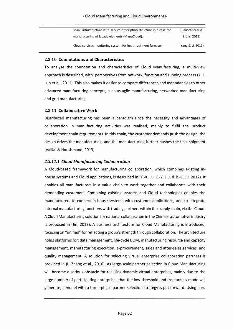
- Cloud Manufacturing and Cloud Environments-
Page 62
MaaS infrastructure with service description structure in a case for
manufacturing of facade elements (ManuCloud).
(Rauschecker &
Stöhr, 2012)
Cloud services monitoring system for heat treatment furnace. (Yang & Li, 2011)
2.3.10 Connotations and Characteristics
To analyse the connotation and characteristics of Cloud Manufacturing, a multi-view
approach is described, with perspectives from network, function and running process (Y. L.
Luo et al., 2011). This also makes it easier to compare differences and ascendancies to other
advanced manufacturing concepts, such as agile manufacturing, networked manufacturing
and grid manufacturing.
2.3.11 Collaborative Work
Distributed manufacturing has been a paradigm since the necessity and advantages of
collaboration in manufacturing activities was realised, mainly to fulfil the product
development chain requirements. In this chain, the customer demands push the design, the
design drives the manufacturing, and the manufacturing further pushes the final shipment
(Valilai & Houshmand, 2013).
2.3.11.1 Cloud Manufacturing Collaboration
A Cloud-based framework for manufacturing collaboration, which combines existing in-
house systems and Cloud applications, is described in (Y.-K. Lu, C.-Y. Liu, & B.-C. Ju, 2012). It
enables all manufacturers in a value chain to work together and collaborate with their
demanding customers. Combining existing systems and Cloud technologies enables the
manufacturers to connect in-house systems with customer applications, and to integrate
internal manufacturing functions with trading partners within the supply chain, via the Cloud.
A Cloud Manufacturing solution for national collaboration in the Chinese automotive industry
is proposed in (Jin, 2013). A business architecture for Cloud Manufacturing is introduced,
focusing on “unified” for reflecting a group’s strength through collaboration. The architecture
holds platforms for: data management, life-cycle BOM, manufacturing resource and capacity
management, manufacturing execution, e-procurement, sales and after-sales services, and
quality management. A solution for selecting virtual enterprise collaboration partners is
provided in (L. Zhang et al., 2010). As large-scale partner selection in Cloud Manufacturing
will become a serious obstacle for realising dynamic virtual enterprises, mainly due to the
large number of participating enterprises that the low-threshold and free-access mode will
generate, a model with a three-phase partner selection strategy is put forward. Using hard
- Cloud Manufacturing and Cloud Environments-
Page 63
(time, cost, quality) and soft (compatibility, agility, coordination) evaluation indicators, the
three phases apply different screening methods for arriving at a solution with optimal
combination of partners for different tasks.
Cooperation within Cloud Manufacturing based on supply and demand networks of
enterprises with multifunction and opening characteristics is introduced in (D. Y. Tai & Xu,
2012). The detailed patterns and mechanisms of resource-oriented cooperation, service-
oriented cooperation, and innovation-oriented cooperation are studied and a 5-layer of a
cooperation-oriented Cloud Manufacturing system is presented. To support collaborative
work, business process interoperability is studied in (Lartigau, Nie, Zhan, Xu, & Mou, 2012).
A new Business Process Model is presented, defining the business communication,
transactions and execution processes occurring in a Cloud Manufacturing environment,
between the Cloud platform, consumers and providers. Data and constraints involved in
order processing decomposition are also identified and formulated. A platform enabling
distributed manufacturing agents collaboration in a Cloud Manufacturing environment is
presented in (Valilai & Houshmand, 2013). In this service-oriented approach, distributed
collaboration of computer-aided software systems is possible, maintaining manufacturing
data integration based on the ISO 10303 (STEP) standard, utilising the capabilities of the
standard to support XML data structures. The functionality of the platform is demonstrated
in a case study for distributed product development. Different computer-aided software
packages collaborate in a setup with product design, process planning and CNC machining,
where manufacturing agents are diverse and geographically distributed.
2.3.11.2 Collaborative Design
A semantic-based modelling method of the Cloud design service together with a 5-level and
8-view conceptual model is proposed in (I. Liu & Jiang, 2012). Through the analysis of the
needs and features of the Cloud design service, modelling this service combining methods
with dynamic generation of a workflow model is introduced to improve the dynamics and
flexibility. Knowledge integration of collaborative product design in Cloud Manufacturing is
presented in (Bohlouli et al., 2011). Supporting a sustainable and innovative product design
and development, a Cloud architecture with four layers is presented, in which Knowledge-
as-a-Service is included. Distributed manufacturing agents' collaboration and manufacturing
data integrity play a major role in global manufacturing enterprises' success. There are
number of works, conducted to enable the distributed manufacturing agents to collaborate
with each other. To achieve the manufacturing data integrity through a variety of different
- Cloud Manufacturing and Cloud Environments-
Page 64
manufacturing processes, avoiding possible interoperability problems within the CAX chain,
numbers of solutions have been proposed, among which one of the successful solutions is to
use ISO 10303 (STEP) standard (Guo et al., 2010a; Nassehi, Newman, Xu, & Rosso Jr, 2008;
Newman & Nassehi, 2007; Valilai & Houshmand, 2013; Venkatesh et al., 2005). This would
cater for a seamless cooperation and integration of systems with different native
languages/standards.
2.3.12 Security
Corporate information often contains sensitive data of customers, consumers and
employees, business know-how and intellectual properties (Mokhtar & Houshmand, 2010;
Ryan, 2011). Securing sensitive data and the ubiquitous availability of requested applications
in the Cloud is of major concern for potential users of Cloud services. Manifestations of these
concerns regularly appear in many existing Cloud Computing services, as a profound
unwillingness and anxiety of letting sensitive and important data escape outside the
boundaries of the physical company premises (Popović & Hocenski, 2010; Venters & Whitley,
2012). The service models (Software-as-a-Service, Platform-as-a-Service and Infrastructure-
as-a-Service) require different levels of security in a Cloud environment. Infrastructure-as-a-
Service is the base of all Cloud Computing services, with Platform-as-a-Service built upon it
and Software-as-a-Service in turn built upon Platform-as-a-Service. Just as capabilities are
inherited, so are the information security issues and risks (X. Xu, 2012).
However, today most SaaS business and manufacturing applications that vendors offer are
hosted in ISO27001 and SAS 70 Type II certified data-centers with Service-level agreements
offered for most applications of 99% and above (Adiseshan, 2012). Data-centers that provide
these services are highly specialised in the fields of security, backup and recovery and have
extensive IT resources to be able to offer and fulfil such high service level commitments. Not
many SMEs, with relatively small IT-resources, are able to equal and maintain this level of
security. (Many of the proposed concepts in Table 1 also include security functionalities.)
2.3.13 Simulation
A Cloud simulation technology based on a platform of COSIM-CSP (COSIM Cloud Simulation
Platform) was developed in (B. H. Li, Zhang, & Chai, 2010; Z. Zhou et al., 2011). It has primarily
been applied in the design of a multi-disciplinary virtual prototype of a flight vehicle. It can
also be used for simulation of resource sharing, migration of multi-granularity resources,
- Cloud Manufacturing and Cloud Environments-
Page 65
fault tolerance, etc. A prototype of Cloud service platform for complex product design and
simulation was also developed in (L. Zhang et al., 2010).
2.3.14 Cost and Price Management
The most typical characteristic of Cloud Manufacturing is the scalable usage of on-demand
resources and services with a pay-as-you-go approach. In (Y. Cheng et al., 2011), the cost of
services is studied from three different cost aspects: Cloud service life-cycle, manufacturing
service providers and the Cloud Manufacturing service platform. With respect to the service
cost constituted, a multi-view model of cost is proposed. For effectively assessing different
aspects of Cloud Manufacturing, a fuzzy group programming decision-making method has
been developed in (Jia, Feng, Tan, & An, 2012). The approach uses an analytical evidential
reasoning algorithm to solve problems caused by fuzzy linguistic expressions,
defected/incomplete information and conflicts among Cloud Manufacturing providers.
Multiple constraints and multiple objective optimisation models have been constructed for
minimisation of manufacturing cost, maximisation of consumer satisfaction degree and
manufacturing service implementation difficulty. After the aggregation of group fuzzy
information from the Cloud Manufacturing provider, an agreement result of collaborative
decision can be derived.
2.3.15 Enabling, Supporting and Application Technologies
2.3.15.1 Internet of Things
Integrates and connects physical objects (things) into an information network, making it
possible to exchange information about themselves and their environments. It can be used
to make manufacturing resources universally available and accessible (Bandyopadhyay &
Sen, 2011; Xiang & Hu, 2012). Internet of Things is quickly growing in line with RFID (X. Xu,
2012) and sensor technologies, and will promote interconnection between things (B. H. Li,
Zhang, & Chai, 2010).
2.3.15.2 Embedded System Technology
The rapid development of embedded system technology enables, together with Internet of
Things, smart and convenient access of manufacturing resources, e.g. physical terminal
devices, for status retrieval and control, (Heath, 2002; B. H. Li, Zhang, & Chai, 2010).
2.3.15.3 Semantic Web
A technology which facilitates knowledge-based intelligent computation and enables users
to search and share data and information more easily by allowing the data from different
- Cloud Manufacturing and Cloud Environments-
Page 66
sources to be processed directly by machines (Berners-Lee, 1998; Martin et al., 2007; D. Wu
et al., 2012). As the amount and complexity of product design and manufacturing data is
increasing, methods and tools to represent this in a Cloud Manufacturing environment is
required (Eck & Schaefer, 2011; D. Y. Tai & Xu, 2012; Zha & Sriram, 2006). Semantic Web
provides a common framework that allows data to be represented and reused across
applications, enterprises, and community boundaries, which promotes the use of different
common formats for data exchange. It is a collaborative effort led by World Wide Web
Consortium with participation from a large number of researchers and industrial partners.
2.3.15.4 Communication Standardisation
Communication with and between shop floor equipment, making computers and machines
“talk” to each other, is a well-known problem, as many use their own proprietary language.
As the core idea of Cloud Manufacturing is the sharing of resources and collaborative
manufacturing, the need for communication standards should have a high priority. An open
and royalty free (non-proprietary) communication standard based on the Extensible Markup
Language, which supports machine-to-machine communications and promote
interoperability between existing technologies, has been developed (MTConnect, 2017).
Many different approaches of using STEP-NC as a communication language between
applications in the computer-aided software chain, and between equipment and systems for
planning and scheduling have been described (Nassehi et al., 2008; Newman & Nassehi,
2007; Valilai & Houshmand, 2013; Xi Vincent Wang & Xun W Xu, 2013; Venkatesh et al., 2005;
X. Xu et al., 2011). A service-oriented implementation in a distributed manufacturing system
is presented in (Valilai & Houshmand, 2013). The OPC Foundation creates and maintains
standards for open connectivity of industrial automation devices and systems (Foundation,
2017). The standards specify the communication of industrial process data between sensors,
controllers, software systems, etc.
2.3.16 On-going Research Areas within Cloud Manufacturing
In Table 2 on-going research areas within Cloud Manufacturing are summarised. The graph
represents the main topics of the reviewed articles, as many also describe generic concepts
and parts of Cloud Manufacturing. Research within enabling, supporting and application
technologies is not included. The figure gives a good picture of the present focus of research,
and also points out areas which need more attention.

- Cloud Manufacturing and Cloud Environments-
Page 67
Table 2. Cloud Manufacturing Research Areas
2.3.17 Cloud Manufacturing Research Initiatives
The interest of the Cloud Manufacturing concept and its potential effects is rapidly
increasing, and a lot of research initiatives are active, with both academic and industrial
participants in local, national and international projects of varying size and scope. The bigger
research initiatives focus on the Cloud Manufacturing concept as a whole, looking at the
higher level concepts, architectures, implementations and realisation issues, while other
initiatives focus on critical, individual issues, necessary for the implementation of different
parts of Cloud Manufacturing. A variety of names and abbreviations for describing the Cloud
Manufacturing concept and its components exists, as many research initiatives establishes
their own Cloud Manufacturing designations. Numerous publications describe much of the
on-going research, and many of these are covered in this review. As could be expected (as
the core concept of Cloud Manufacturing is resource sharing), the focus of most research
initiatives are related to manufacturing resources: how they can be virtualised and
encapsulated into services in the Cloud platform, how they can be searched and combined
for fulfilling customer tasks, how to find optimal solutions, etc. The research within Cloud
Manufacturing has only been ongoing for a couple of years, but ideas are getting more
detailed, and implementations of parts of the concept are now getting realised and
evaluated.
Some of the proposed concepts in Table 1 describe a more complete solution for
implementing Cloud Manufacturing. These originate from some of the research initiatives
0
5
10
15
20
25
30
35
40
Identified Research Areas within CM

- Cloud Manufacturing and Cloud Environments-
Page 68
which seem to be the most active and comprehensive within Cloud Manufacturing. Their
research contribution is far too extensive to be described in detail, but a summary of the
characteristics and unique properties of their work is presented below, introduced with their
Cloud Manufacturing designation:
2.3.17.1 CMfg
National Chinese research initiative (Beihang University, Beijing), often referred to as the first
source and inventor of the Cloud Manufacturing naming 2010 (B. H. Li, Zhang, & Chai, 2010;
B. H. Li, Zhang, Wang, et al., 2010; Lin Zhang et al., 2012). CMfg presents an application model
of Cloud Manufacturing, describing Cloud Manufacturing platform activities in the
propagation from user request to the return of a solution. Also proposed a 5-layer Cloud
Manufacturing architecture with: Physical layer for provider resources and capabilities,
Virtualised resource layer for virtualising resources and encapsulate them as services, Service
layer for Cloud Manufacturing core functions such as: service management deployment,
registration, searching, matching, composition, scheduling, monitoring, cost and pricing and
billing, etc., Application layer for requests within specific manufacturing applications, and
User layer with interfaces for both consumers requests and provider input/registration of
resources. To demonstrate the feasibility of the CMfg concept, a Cloud based application –
Cloud simulation – based on the Cloud Simulation Platform has been demonstrated, in which
the collaborative work in the multi-disciplinary design of a virtual flight vehicle prototype is
simulated. (Further detailed in (F. Tao, L. Zhang, et al., 2011) and in Small Manufacturing
Enterprise-oriented Cloud Manufacturing Service Platform, with 12-layer architecture (B.
Huang et al., 2013), and in MfgCloud (Ren, Zhang, Zhao, & Chai, 2013)).
2.3.17.2 Cmanufacturing
A research group at University of Auckland, New Zealand, presented a public Cloud
infrastructure, the ICMS (Interoperable Cloud-based Manufacturing System) (Xi Vincent
Wang & Xun W. Xu, 2013; Xi Vincent Wang & Xun W Xu, 2013). It is a three-layer architecture,
with service methodologies for supporting two types of users; customer user and enterprise
user. Standardised data models for Cloud services and relevant features are also developed
and described. The architecture consists of: a Smart Cloud Manager for assisting and
supervising the interaction between consumers and providers, a User Cloud for the
consumers and their requests and a Manufacturing Cloud for providers and their resources,
capabilities and services. A distinction is made between customer users and enterprise user;
customer users are defined as customers/organisations requesting a self-contained
- Cloud Manufacturing and Cloud Environments-
Page 69
production task, while enterprise users are organisations/enterprises seeking additional
capabilities and support to fulfil bigger and more demanding production tasks in
collaboration with temporary partners and their services. The concept is evaluated in some
case studies, one where consumers’ requests are optimally mapped to combinations of
services from different providers, one showing how detailed conditions in consumer requests
can be matched to providers’ services based on capabilities.
2.3.17.3 Cloud-Based Design and Manufacturing (CBDM)
A research group at Georgia Institute of Technology, Georgia, USA, has presented a
conceptual reference model for their interpretation of Cloud Manufacturing (Dirk Schaefer
et al., 2012). It builds on the concepts of Cloud Computing, with manufacturing resources
being available as different services. For the implementation they have proposed a
Distributed Infrastructure with Centralized Interfacing System model. The Distributed
Infrastructure is composed of three asset groups (Human: consumers, producers, managers,
Communication: communication network (internet), network security and two interfaces for
communicating with the human and manufacturing processes’ asset groups, and
Manufacturing process: Hardware and Software resources.) The Centralized Interface System
enables the system to function as a whole. Workflow for distributed and collaborative design
and manufacturing in a local and distant user scenario is described, where engineers are able
to simultaneously cooperate using a CAD software, in a Software-as-a-Service mode.
2.3.17.4 Cloud-Based Manufacturing-as-a-Service Environment
ManuCloud, a European project funded by the European Commission, with 8 consortium
members from academy and industry, from four 4 different EU member states (Austria,
Germany, Hungary, United Kingdom) (ManuCloud, 2017; Meier et al., 2010). The objective of
the ManuCloud project is the development of a service-oriented IT environment to support
the transition from mass production to personalised, customer-oriented and eco-efficient
manufacturing. A conceptual architecture with a front-end system and Manufacturing-as-a-
Service Infrastructure to support Cloud-based manufacturing of customized products has
been proposed. The front-end is deployed as part of an integrated web-based portal to
support collaborative development, and consists of a Customized Product Advisory System
and interfaces for Infrastructure Management. A Manufacturing Service Description
Language provides a formal description of both production and product-related information,
and is used for the integration of the front-end and the Manufacturing-as-a-Service
environment. Using Manufacturing Service Descriptions, the concept has been proved in
- Cloud Manufacturing and Cloud Environments-
Page 70
some business cases, one with distributed production and customer specification of small
series, high-value products.
2.3.17.5 GetCM
In a National Chinese research initiative (Northwestern Polytechnical University, Xi’an,
Beijing Institute of Technology, Beijing) (M. Wang et al., 2012) presents the GetCM Paradigm.
It includes 5 parts: Resource Cloud with manufacturing resources expressed in the form of
Cloud services, Business Cloud with business-oriented Cloud services, enabling business
process sharing, Manufacturing Cloud with manufacturing processes encapsulated into
manufacturing Cloud services, which performs a manufacturing process by invoking the
relative resources and business services, Cloud Manufacturing Infrastructure and Public
Platform which holds the basic physical and organisational structures and services for Cloud
Manufacturing. They also propose a 7-layer framework for realising their paradigm, where
one layer provides a semantic reference basis for semantic description of resources,
capabilities and services, so that their contents can be clearly understood in different
computer programs.
2.3.18 Future Directions and Trends
2.3.18.1 Cloud Manufacturing Platforms
It is envisioned that depending on safety, security and utilisation perspectives, there will be
different Cloud Manufacturing platforms coexisting, such as: Public, Private, Community and
Hybrid platforms (B. Huang et al., 2013):
Private
Similar to the public platform but managed within a company or organisation for the
cost-effective coordinated utilisation and sharing of in-house resources, e.g.
reducing the need for duplicate equipment, expensive software or services. Provides
better security and control over data, services and resources, which might be
distributed in different departments, branch companies, etc. locally and/or globally.
Community
Managed and used by a group of companies or organisations, sharing specific
requirements (e.g. extra high security or manufacturing requirements) or a common
high-level manufacturing task or mission (e.g. aerospace industry).
- Cloud Manufacturing and Cloud Environments-
Page 71
Public
Provided for any service provider or consumer by a third-party operator for
facilitating optimal sharing and allocation of manufacturing resources and
capabilities for the complete manufacturing life-cycle of product development. The
available services are owned by and distributed in different companies and
organisations, and the work of different consumers may be mixed when being
processed by provided service infrastructures in the Cloud. Providers benefit from
selling idle manufacturing resources and capabilities, consumers from being able to
buy only what is temporarily required, and the operator from charging a service fee
from both providers and consumers. Mostly used by SME companies.
Hybrid
A combination of a private and a public platform. Business-critical services and
sensitive data are kept unpublished, while services that are not critical are published
for others to share and use. Complexity of determining how to combine and allocate
tasks and services may initially lead to unconditional, simpler applications, not
requiring synchronisation.
2.3.18.2 Competitiveness through Innovative Manufacturing
With the introduction of Cloud Manufacturing an environment will be realised where
manufacturing companies have access to the same manufacturing resources, no matter the
size or location of the company. Customers can reach manufacturers across the planet and
select the best offerings. Then, being the biggest, or internationally distributed, company
would no longer give the most competitive edge, but rather being the most agile to
innovatively use all these resources for successfully meeting worldwide customer demands.
The manufacturing industry of today is traditionally supported by hierarchical supply chains
for completing specific manufacturing demands. These supply chains often encompass many
different layers of suppliers, and are rigid by nature, and tied to specific delivery patterns by
long term contracts. As such they are limitations for successfully satisfying rapidly changing
consumer demands. In Cloud Manufacturing, supply chains will be volatile, temporarily
configured and existing for unique and dynamic manufacturing tasks, and as such, highly
flexible by nature. Based on consumers’ specific key objectives, i.e. cost, time or quality,
supply chains are realised through the dynamic composition of the available Cloud services
which, as a combination, will best fulfill these objectives. To innovatively use available
- Cloud Manufacturing and Cloud Environments-
Page 72
resources, capabilities and collaboration networks in an agile approach to best meet rapidly
changing customer and market demands will be a strong driver for manufacturing
competitiveness.
2.3.18.3 New Scenarios for Cooperation and Collaboration
Customer–Manufacturer cooperation.
As customer/end users’ demands will be more dynamically available for manufacturing
companies, it will be possible to incorporate them more in the design process of products.
Customised products for customer individualisation will then be realised in co-design
activities.
Manufacturing collaboration.
In Cloud Manufacturing, supply chains will be volatile, temporarily configured and existing
for unique and dynamic manufacturing tasks, and as such, highly flexible by nature. Based on
consumers’ specific key objectives, i.e. cost, time or quality, supply chains will be realised
through the dynamic composition of the available Cloud services which, as a combination,
will best fulfil these objectives. This will lead to new manufacturing scenarios with different
mixes of collaborating parties.
2.3.18.4 Cloud Service Brokers
Many new business opportunities will follow the introduction of Cloud Manufacturing. The
issue for Cloud services customers to find the best fitting Cloud provider or combination of
services will open up the market for intermediate broker services, specialised in finding the
best user-provider matching, given a set of governing prerequisites and conditions, as in
service-level agreements (Jrad et al., 2012; L. Wu & Buyya, 2010). Services brokers and their
services can appear in different contexts. They can be delivered through technology as
software, applications, platforms or suites of technologies that enhance the base services
available through the Cloud. They can appear at the service provider’s location, making
available supporting functions to the user beyond the original service, or at the user’s
location, facilitating issues like administration of service levels or local management (F. L. Tao
et al., 2011). They can also exist as a true in the Cloud brokerage service business,
independent of providers and users, providing a service with a higher value to the user, by
making it more specific, i.e. by combining and aggregating multiple services into one or more
new services or enhancing the security. This way, a brokerage service can make it easier, less
- Cloud Manufacturing and Cloud Environments-
Page 73
costly, more secure and more productive for companies/users to find, integrate and consume
Cloud services, particularly when these services are originally delivered by different services
providers. In some companies, there may be the scenario that when the IT-department loses
software and systems to manage, the natural evolution for its role may be to become a
service broker for the company’s use and integration of Cloud services instead.
2.3.18.5 Trading with Production Capacity
As many companies would like to secure their future supply of production capacity on a
longer term basis, there could be a scenario with trading of manufacturing services and
resources, almost as with any other commodity. Consumers could negotiate with providers
about certain amounts of future resource availability and usage, and if redundant at a later
time, sell these rights to other consumers, or back to the original provider. This trading could
also be purely speculative, as an innovative concept to earn a profit from varying prices on
resources and their usage, following access and demand. This trading would mainly deal with
access to resources of a finite supply, as physical manufacturing equipment and human
labour.
2.3.18.6 Real-World Connectivity
There has been a lot of focus on the need for, and proposals of, collaboratively performed
and shared product development activities. Embedded systems, smart sensors and
automation controllers now populate industrial applications, but are often used in local and
isolated environments, within the boundaries of single manufacturing facilities. Internet of
Things will help push the trend to global, secure, seamless and bi-directional interaction with
real-world objects and systems in a variety of applications, not only within the scope of
manufacturing.
The product manufacturing processes (machining, assembly, etc.) will see new applications
where hardware-in-the-loop manufacturing equipment, by the use of sensor feedback and
remote monitoring, will make possible a variety of collaborative and distant manufacturing
activities. By this ability to share hardware resources, manufacturers will finally be able to
fully realise the capabilities of CNC-machines, robots, servomotors, and other computer
controlled flexible devices. Since the introduction of CNC, equipment for machining,
assembling, material handling, etc. has had the ability to change their behaviour on the fly.
The variable setting the pace has always been process control, and ultimately, the demands
of the consumer. In Cloud Manufacturing, this valuable information will be instantly available
- Cloud Manufacturing and Cloud Environments-
Page 74
to manufacturers for immediate product development and manufacturing processes,
through the unprecedented speed of digital connections between providers and consumers
in a networked environment.
Future directions of Cloud Manufacturing will include innovative and adaptive process
planning services, knowledge-based and on-demand quick operation simulation services,
resource utilisation and availability monitoring services, setup planning and optimisation
services, dynamic and real-time scheduling services, and energy and resource usage
estimation services. New services, such as Process-Planning-as-a-Service, Assembly-
Planning-as-a-Service, Maintenance-as-a-Service and Equipment-Control-as-a-Service, will
be possible (LaSelle, 2011; L. Wang, 2008; Lihui Wang, Ma, & Feng, 2011). The hardware
providers will still be responsible for executing the manufacturing tasks and ensuring the
quality, but external control and execution as a service will be possible. If a manufacturing
equipment provider does not possess the best or enough competence or information for
generating the required planning and control, for optimally fulfilling a collaborative
manufacturing task or mission, these services can be available in the Cloud. A machine can
then be available as either a hard resource requiring external services for control, or a “self-
controlled” manufacturing capability by the machine provider.
2.3.18.7 Sustainability
The sharing of resources will not only lead to lower costs and higher productivity and
utilisation for individual companies, but also to a more effective use of resources in a global
perspective. Issues such as sustainability, energy consumption, waste reduction and other
environmental factors will therefore find a better and more effective representation within
Cloud Manufacturing, especially due to its collaborative nature. Consumers will be able to
select and combine different objectives or key performance indicators, i.e. cost, time, quality,
sustainability, etc.
2.3.19 Outstanding Cloud Manufacturing Research Issues
When a new manufacturing paradigm is on the rise, there will inevitably be some research
areas, concepts and technologies that are less well represented than others. Even though
research within Cloud Manufacturing has been ongoing for some years, and is rapidly
increasing, there are still a lot of studies required before the Cloud Manufacturing concept
can be realised to its full extent. The research areas are widespread and numerous, with
different perspectives and issues for consumers, providers and operators. Some research

- Cloud Manufacturing and Cloud Environments-
Page 75
initiatives also choose to focus on, and describe, Cloud Manufacturing in relation to their own
research interests and backgrounds, sometimes resulting in somewhat biased descriptions
of Cloud Manufacturing. Solving issues of both soft and hard nature remains, even though
many of the hard issues, like core and enabling technologies, have reached a rather high
degree of maturity, as used in Cloud Computing. The concept of Cloud Manufacturing
promises many advantages compared to existing manufacturing paradigms, and its evolution
and implementations is driven by strong arguments. The most probable scenario is that we
will see the upcoming of a variety of Cloud Manufacturing platforms, many of which will be
providing similar, or the same, resources and thus competing with each other.
The first complete manufacturing Clouds will probably be realised based on national research
initiatives and local enterprise interests. This may later lead to inter-Cloud interoperability
problems, and sub-optimised manufacturing solutions within separate Clouds, in the
perspective of using the most suitable resources available on a worldwide basis. These
problems could be due to the usage of different procedures (i.e. user agreements, billing
routines), techniques (i.e. knowledge and service management) and standards (i.e. for
communication, distributed control, data representation). Vendor lock-in, due to proprietary
technologies, inefficient processes or contract constraints is then a risk, and if providers are
present in different Cloud Manufacturing platforms, coordination and scheduling of their
resources may also be problematic. This is not optimal and interoperability issues between
different manufacturing Clouds may hinder the exploration of the Cloud Manufacturing
concept’s full potential.
The Cloud Manufacturing evolution will be a step-by-step progression from systems using
some of the proposed services and technologies, to more complete implementations. It is
realistic that we will first see the upcoming of a variety of in-house, enterprise dedicated,
Private Clouds. Being realised within an enterprise, the implementation will not be as
complex as for a Public Cloud, as the enterprise does not need to cooperate with other
enterprises or “unknown” services and can use in-house standards, interfaces and
procedures. Community Clouds, managed and used by a group of enterprises with similar
unique requirements will come next. Drawing on the knowledge and experiences made from
Private and Community Clouds, third-party run Public and Hybrid Clouds will follow later, as
the requirements for these are much more complex and encompassing. To be able to initially
attract resource providers and consumers to these Clouds, Cloud Operators must be able to
offer attractive incentives, mainly regarding ease of operation, cost and security.
- Cloud Manufacturing and Cloud Environments-
Page 76
An international definition and standard for Cloud Manufacturing would facilitate its
development and implementation and generate better manufacturing solutions. It is also of
importance in an environmental perspective, as Cloud Manufacturing is the most effective
approach for world-wide sustainable manufacturing, enabling the most effective use and
combination of resources for fulfilling customer demands.
For the on-going development of Cloud Manufacturing, Cloud Manufacturing concepts,
technologies and standards need to be defined and decided upon. Besides the core and
enabling technologies, several crucial technical issues remain to be solved, such as: how to
bring a diverse base of resources and capabilities to the Cloud as services (knowledge-based
resource Clouding), how the overall control and management of Clouds should be realised,
including the central task of service composition (Cloud management engines), collaboration
between Cloud Manufacturing applications, open communication standards, distributed
control and coordination of manufacturing equipment, and user interfaces in Cloud
environments. One of the major challenges is the implementation description of physical
equipment, Hardware-as-a-Service. A standard or technique for consistently describing
equipment and its functionality, behaviour, structure, etc., is required. Implementation of
applications and knowledge is better provided for using established Cloud Computing
techniques, such as Software-as-a-Service, Platform-as-a-Service and Infrastructure-as-a-
Service. Numerous research initiatives are under way, and many of these are dealing with
the above mentioned issues. Some critical research issues which are missing or not fully
explored in the literature have been identified. They are described in the following, without
consideration of their relevance regarding possible impact or importance:
2.3.19.1 International Definition of Cloud Manufacturing
An international definition is necessary for a unified view and progression of the successful
development and implementation of Cloud Manufacturing. As described in Table 1, a huge
variety of different architectures, platforms, models, frameworks and applications for
implementation of Cloud Manufacturing have been proposed. These concepts have
differences as well as similarities, and vary in respect of detail, complexity and scope.
Together with a Cloud Manufacturing definition, an implementation description for a Cloud
Manufacturing environment is required for realisation, and demonstration, of its potential.
- Cloud Manufacturing and Cloud Environments-
Page 77
2.3.19.2 Standardisation
Closely related to a definition of Cloud Manufacturing, and supporting its realisation, is the
standardisation of core and enabling technologies, as well as procedures and methods for
the complete operation of Cloud Manufacturing systems. This is of extra importance in the
perspective of inter-operability issues for collaborative tasks between different Clouds. Open
standards and communication protocols, supporting “plug and play” scenarios for machine-
to-machine communication in world-wide manufacturing networks, should be a prioritised
research area.
2.3.19.3 Intelligent, Globally and Locally Distributed, Monitoring and Control
Systems
As Cloud Manufacturing will support dynamic cooperation and collaboration in
manufacturing tasks within and between geographically distributed users, the need for
control systems that can perform and coordinate these tasks is an uttermost prerequisite. To
be able to optimally schedule and allocate manufacturing resources such as physical
equipment, monitoring systems based on wireless, smart sensor networks will be necessary
to keep track of manufacturing real-time information. The effectiveness of Cloud
Manufacturing systems will to a large extent be defined by the properties and abilities of
these control systems, which should be able to handle optimal service composition, planning,
scheduling and execution of equipment in a distributed Cloud environment. They will also
need to handle long distance communication regarding time, security and data volume
constraints, as well as inter-connectivity between a huge variety of technologically disparate
and globally dispersed manufacturing resources. From high level collaborative manufacturing
tasks down to shop floor control, from automatic selection and composition of services,
down to automatic run-time generation of control code for unique computer controlled
manufacturing equipment, automation in these systems needs to be combined with
integrated intelligence to generate optimal solutions. This will be a necessity for handling
volatile and dynamic manufacturing scenarios, unpredicted changes and new products, and
to minimise the need for human intervention. As such, the distributed control systems in a
Cloud Manufacturing environment need to be intelligent, agile and flexible:
Intelligent: To be able to automatically generate the optimal service compositions
and equipment control instructions required for completing any task.
Agile: To quickly respond and adapt to changes in the Cloud Manufacturing
environment and customer demands.
- Cloud Manufacturing and Cloud Environments-
Page 78
Flexible: To be able to select alternative control solutions, and service configurations
and combinations from different providers, for realising tasks and demands.
A major problem within control of manufacturing equipment is portability and
interoperability, as the shop floors are populated with manufacturing equipment controlled
by proprietary control systems. The inability of interfacing native controllers hampers
distributed control solutions and enforces the continuous use of equipment specific
programming codes, like native robot languages for industrial robots, and G and M codes for
CNC machines.
2.3.19.4 Knowledge and Information Management and Sharing
With resource sharing also come the encompassing task of information, data and knowledge
sharing. For effective sharing and reuse of knowledge, a strategy for knowledge management
is necessary, enabling the identification, creation, representation, distribution and adoption
of experiences and insights in an organisation (Alavi & Leidner, 2001; Yiwen Zhang & Jin,
2012). These sources of knowledge might either be embodied in individuals or embedded in
organisational processes or practice. Decentralised IT-systems, with isolated island
applications, mean that knowledge is often hard to find and to organise. Knowledge support
is necessary for intelligently performing many crucial Cloud Manufacturing activities, such as:
perception, connection, virtualisation and encapsulation of manufacturing resources and
capabilities, Cloud service description, matching, searching, aggregation, and composition,
optimal allocation, scheduling and control of activities and services, etc. Technologies such
as data mining for intelligently processing large amounts of data, and Semantic Web, which
promotes common data formats, allowing data to be shared and reused between different
services, applications, and enterprises, will need to be used for effective data management.
2.3.19.5 Business Models
Cloud Manufacturing will require the development of new business models, supporting the
collaborative nature of this approach, with networked partners cooperating in distributed
value chains. Traditionally hierarchical business models will not be able to stay competitive,
as Internet-enabled mass collaboration with access to world-wide manufacturing resources
and competence will dramatically improve agility and innovativity, generating an enhanced
ability for rapidly satisfying customer demands (Fuchs, 2008; Dazhong Wu, Matthew J Greer,
David W Rosen, & Dirk Schaefer, 2013). These models need to support value creation and
sharing in collaborative value chains, enabling and appealing to the participation in

- Cloud Manufacturing and Cloud Environments-
Page 79
dynamically configured and temporary existing manufacturing entities. The determination of
the value-adding of each part, when a combination of resources from different providers
collaboratively manufactures a customer product, will need to be defined in these new
business models.
2.3.19.6 Intellectual Property
Intellectual property rights and ownership of information and data is another big issue, as
the once quite clear boundaries between who produced and who uses data will somewhat
diminish in the sharing of applications, services and resources in an Cloud Manufacturing
environment. In the interactions in a volatile and collaborative value-chain, between three
different parts, consumer, operator and provider, may all be claiming property rights (Parker,
2007). Both background rights, which a company brings to a collaboration task, and
foreground rights, resulted from the collaborative task, need proper frameworks for
negotiations and agreements concerning their future ownership, usage and protection.
2.3.19.7 Distributed Manufacturing Simulation
To be able to validate the performance of different possible temporary manufacturing
scenarios, for finding optimal service combinations, will be a key driver for moving to Cloud
Manufacturing. Estimating critical performance metrics such as: cycle times, throughput,
equipment utilisation, etc., according to customer requirements, will be will be a key issue.
2.3.19.8 Populating the Cloud
To attract companies to Cloud Manufacturing, there are mainly three major concerns which
will significantly influence their willingness for Cloud participation: Security, Cost and Cloud
Adoption issues. These issues are crucial for Cloud Manufacturing realisation and success,
and if not satisfactory solved, the evolution and progress of Cloud Manufacturing will be
slow:
Security:
Even though there are many technological measures for handling and securing data
and privacy concerns, many companies hesitate to move to the Cloud. Since Cloud
services have been growing rapidly the last years, many of the legal issues are yet to
be resolved. Today, many Cloud operators use pre-determined and standardised
user agreements, as well as sub-contractors, when establishing legal contracts and
bindings with their customers. National laws may also be in conflict with these
- Cloud Manufacturing and Cloud Environments-
Page 80
agreements, and Cloud operators may be forced to disclose information which may
be sensitive for their customers. Experiences of security issues within Cloud
Computing imply that further research is required before presumptive Cloud
customers can be fully confident to join.
Cost:
The scalable usage of on-demand resources and services in Cloud Manufacturing,
with a pay-as-you-go approach, is very attractive for most companies. Nevertheless,
quantitative and robust cost measurements models and methods for the estimation
of cost savings are required, for justifying a move to Cloud Manufacturing. As a
company’s Cloud adoption initially will be a rather time and resource consuming
project, economic incentives and opportunities must be both appealing and possible
to determine.
Product cost determination at the design phase is of extra interest, as the major
product development costs are determined here, and research in collaborative
economics for Cloud Manufacturing product development is missing.
Cloud adoption:
One important area of research relates to the skills necessary to manage Cloud
adoption within a company. Before starting to move services outside the company,
it is absolutely necessary for the company to have a well-defined Cloud strategy.
Otherwise, the anticipated Cloud benefits may well be hampered by the mess
created inside the company. What kinds of architectural skill sets are required to link
internal processes with the Cloud, and what sort of contract management skills are
necessary to maximise the efficiency of Cloud contracts? For the success of Cloud
Manufacturing, companies should have a good foundation on internal integration of
information and processes. Therefore, there is a relatively high entrance standard to
implement Cloud Manufacturing for the majority of manufacturing companies. Many
of the supporting technologies have reached a sufficient level of maturity, but there
are still numerous issues regarding organisation and implementation to be
addressed. Confidence, through guaranteed performance, will be a crucial
cornerstone for widespread acceptance and usage of Cloud Manufacturing systems,
- Cloud Manufacturing and Cloud Environments-
Page 81
but the fear of vendor lock in may also make companies hesitate about Cloud
adoption.
2.3.19.9 Cloud Manufacturing Equipment Control
One of the major research issues for realising the Cloud Manufacturing environment is how
to access and control physical manufacturing equipment used in collaborative and
distributed manufacturing missions. High level manufacturing tasks need to be divided and
distributed as sub-tasks to the shop floors of different collaborating manufacturing
companies, where they should be coordinated and executed based on real-time information
from both cloud-based and local sources. Therefore, a method for distributed real-time
monitoring and remote control in a Cloud Manufacturing environment requires a shared
standardised closed-loop control approach, which supports distributed control based on
both global and local parameters and conditions.
2.4 Summary
The interest of Cloud Manufacturing is steadily increasing. Proactive companies searching
methods to continuously improve the quality of their manufacturing solutions and looking
for Cloud-based technologies for accelerating their performances will as early Cloud
Manufacturing adopters have a significant advantage over competitors, thanks to the
increases in productivity and lower costs. Productivity gains will then be driven by distributed
resource-sharing and better utilisation of information technology.
The concept of Cloud Manufacturing seriously challenges traditional hierarchical business
models, as the ability of globalised mass collaboration offers a much higher level of creativity
and agility as expertise support in all phases of product development can be shared and
accessed. This by far outweighs the impact of a company’s in-house expertise for being
successful, and will set new standards for manufacturing competitiveness. Large, global
enterprises have already started out on the track of Cloud Manufacturing, by applying
resource sharing. Particularly for SMEs, Cloud Manufacturing will be able to revolutionise
their way of working, as they will benefit from the ability to use resources that used to be
too complex, difficult or expensive, as designed for use by larger enterprises. This will make
them more effective and competitive as it allows them to focus and specialise on their core
manufacturing activities, while retrieving necessary supporting resources from the Cloud.
Being small will no longer hamper them in handling bigger projects, as groups of companies
can team up in the Cloud to form bigger virtual enterprises, in which each of them performs
- Cloud Manufacturing and Cloud Environments-
Page 82
individual specialised tasks and activities, in new collaborative product development chains
and opportunities. Small and fast networked SMEs will be able to dramatically increase their
competitiveness in relation to slow and big single enterprises.
Cloud Manufacturing introduces a new era of technology that will totally change the life of
the manufacturing industry. It moves away from using on-the-premise IT infrastructures,
knowledge structures and long-term dedicated physical resources to support high-level
manufacturing applications, into the Cloud where lower cost, tailor-made resources are
available in a pay-as-you-go concept. The concept seems to include all the necessary pre-
requisites for a comprehensive and dramatic change in the way manufacturing activities are
performed. Covering all the different phases of the product manufacturing development life-
cycle, from analyses of demands and requirements of markets and customers, over product
design and manufacture, to product end-of-life activities, its potential promises many
benefits and improvements. As such, it holds the promise of the new, modern collaborative
and resource-sharing manufacturing paradigm, for effective and sustainable world-wide
manufacturing. However, a cornerstone in realising Cloud Manufacturing is the ability to
access, and adaptively control, manufacturing resources used in such collaborative and
distributed manufacturing missions.

- Adaptive Control of Manufacturing Equipment in Cloud Environments –
Page 83
3 Adaptive Control of Manufacturing Equipment in Cloud
Environments
Summarising the findings from Chapter 1, regarding challenges facing manufacturing
industry, two factors of major importance were identified for manufacturing companies to
be competitive:
- The ability for manufacturing companies to participate in resource sharing and
collaborative manufacturing activities.
- The ability for manufacturing companies to adaptively handle unpredicted events in
their manufacturing systems.
In a Cloud Manufacturing environment, which involves a disparate multitude of participating
and cooperating resource providers and resource types, the quantity of unpredictable
variations that could disturb and cause negative impacts is dramatically increased. As
manufacturing equipment control programs are often created for specific machines and
scenarios, program portability is usually low. Traditional planning (Computer-Aided Process
Planning) and control systems are often not able to handle unforeseen changes efficiently (X.
Xu et al., 2011). Therefore, planning, scheduling and control of physical manufacturing
equipment in distributed environments will be crucial for the successful realisation of Cloud
Manufacturing. The major limitations using traditional Computer-Aided Process Planning
tools within distributed environments such as Cloud Manufacturing are their centralised
decision making, static system structure and off-line data handling (X. Xu et al., 2011). This
delimits their ability to adapt pre-made process plans to shop floor run-time variations. To
cope with the negative impacts of uncertainty effectively and to handle the volatile nature
of manufacturing resources’ conditions and availability within a Cloud Manufacturing
platform, requires an adaptive control approach that can adjust to unplanned changes and
variations and be distributed to different providers, resources and levels of the system
(Monostori et al., 2010). An effective control system should thus possess an in-built property
of being able to react to, and handle, different kinds of uncertainties, by performing dynamic
decision-making. Effective process plan creation and execution therefore require real-time
monitoring of all involved manufacturing resources, to constantly and accurately determine
their dynamic availability and operational status. Without control based on both global and
local environmental conditions for the coordination and execution of distributed and

- Adaptive Control of Manufacturing Equipment in Cloud Environments –
Page 84
cooperating manufacturing resources, the successful implementation of Cloud
Manufacturing will not be possible.
This chapter introduces a method for adaptive, event-driven and feature-based control for
manufacturing equipment in distributed and collaborative manufacturing environments,
capable of instantly generating control in response to prevailing requirements and
conditions. It presents a framework in which an event-driven IEC 61499 Function Block
control structure, in combination with Manufacturing Features, is used for manufacturing
equipment control, as well as using Manufacturing Features for detailing manufacturing
resources’ capabilities and product manufacturing properties, to facilitate resource
composition and matching to manufacturing task requests. The control approach is generic
and can be applied for different manufacturing applications, but is in the following sections
described for robot assembly applications.
In the subsequent three chapters (4, 5, and 6), the concept of adaptive control of robotic
assembly tasks in different scenarios is presented. The framework is further detailed and
evaluated in both local, distributed, real and virtual assembly scenarios, demonstrated
through the use of Assembly Feature-Function Blocks for automated robotic assembly tasks.
The control concept is demonstrated in a research study evolutionary perspective, going
from the local control of a real shop floor robot in Chapter 4, to distributed LAN control of
real and virtual robots in Chapter 5, to a full scale Cloud control approach in Chapter 6.
3.1 Introduction
An effective approach to solving many of the manufacturing issues identified in the literature
review, is to apply Feature-based manufacturing. This approach, which stems from a product
perspective, since it builds on the product manufacturing feature concept, is a viable and
effective method for adaptive and distributed manufacturing since Feature-based
manufacturing can be realised through the application of different manufacturing services.
By using the concept of manufacturing services, in a similar manner to the use of services
within Cloud Computing, manufacturing resources and capabilities can be provided in
distributed environments, e.g. Cloud Manufacturing, in which device network capabilities,
such as Internet of Things, may enable access for controlling distributed manufacturing
equipment. Through the use of Feature-based IEC 61499 event-driven Function Blocks as
smart and distributable decision modules, run-time manufacturing operations in a Cloud
Manufacturing environment may be controlled and executed, in order to meet prevailing
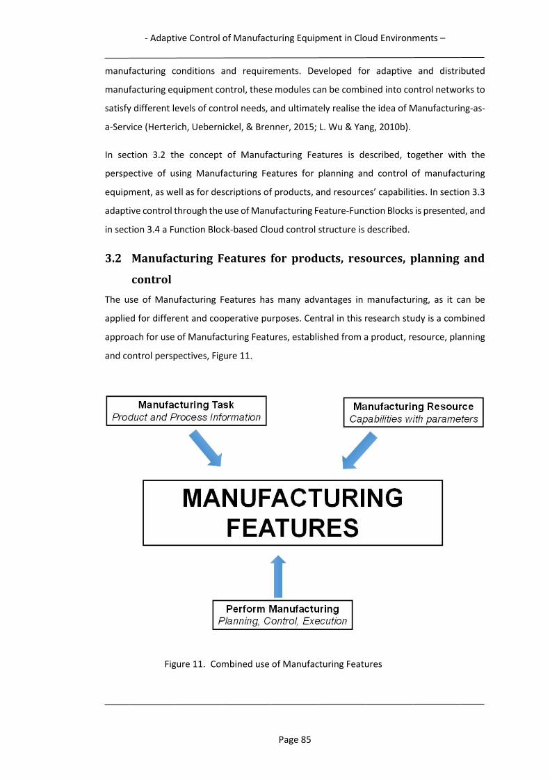
- Adaptive Control of Manufacturing Equipment in Cloud Environments –
Page 85
manufacturing conditions and requirements. Developed for adaptive and distributed
manufacturing equipment control, these modules can be combined into control networks to
satisfy different levels of control needs, and ultimately realise the idea of Manufacturing-as-
a-Service (Herterich, Uebernickel, & Brenner, 2015; L. Wu & Yang, 2010b).
In section 3.2 the concept of Manufacturing Features is described, together with the
perspective of using Manufacturing Features for planning and control of manufacturing
equipment, as well as for descriptions of products, and resources’ capabilities. In section 3.3
adaptive control through the use of Manufacturing Feature-Function Blocks is presented, and
in section 3.4 a Function Block-based Cloud control structure is described.
3.2 Manufacturing Features for products, resources, planning and
control
The use of Manufacturing Features has many advantages in manufacturing, as it can be
applied for different and cooperative purposes. Central in this research study is a combined
approach for use of Manufacturing Features, established from a product, resource, planning
and control perspectives, Figure 11.
Figure 11. Combined use of Manufacturing Features
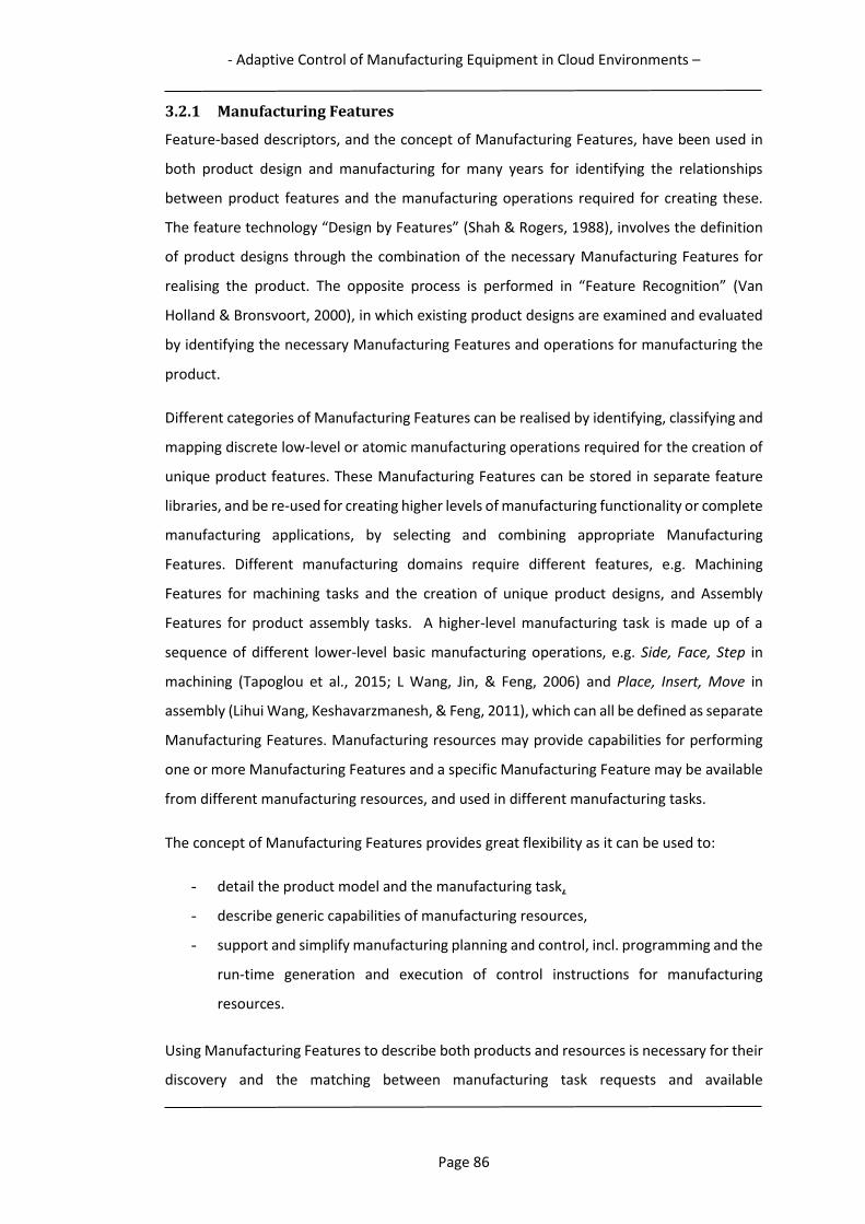
- Adaptive Control of Manufacturing Equipment in Cloud Environments –
Page 86
3.2.1 Manufacturing Features
Feature-based descriptors, and the concept of Manufacturing Features, have been used in
both product design and manufacturing for many years for identifying the relationships
between product features and the manufacturing operations required for creating these.
The feature technology “Design by Features” (Shah & Rogers, 1988), involves the definition
of product designs through the combination of the necessary Manufacturing Features for
realising the product. The opposite process is performed in “Feature Recognition” (Van
Holland & Bronsvoort, 2000), in which existing product designs are examined and evaluated
by identifying the necessary Manufacturing Features and operations for manufacturing the
product.
Different categories of Manufacturing Features can be realised by identifying, classifying and
mapping discrete low-level or atomic manufacturing operations required for the creation of
unique product features. These Manufacturing Features can be stored in separate feature
libraries, and be re-used for creating higher levels of manufacturing functionality or complete
manufacturing applications, by selecting and combining appropriate Manufacturing
Features. Different manufacturing domains require different features, e.g. Machining
Features for machining tasks and the creation of unique product designs, and Assembly
Features for product assembly tasks. A higher-level manufacturing task is made up of a
sequence of different lower-level basic manufacturing operations, e.g. Side, Face, Step in
machining (Tapoglou et al., 2015; L Wang, Jin, & Feng, 2006) and Place, Insert, Move in
assembly (Lihui Wang, Keshavarzmanesh, & Feng, 2011), which can all be defined as separate
Manufacturing Features. Manufacturing resources may provide capabilities for performing
one or more Manufacturing Features and a specific Manufacturing Feature may be available
from different manufacturing resources, and used in different manufacturing tasks.
The concept of Manufacturing Features provides great flexibility as it can be used to:
- detail the product model and the manufacturing task,
- describe generic capabilities of manufacturing resources,
- support and simplify manufacturing planning and control, incl. programming and the
run-time generation and execution of control instructions for manufacturing
resources.
Using Manufacturing Features to describe both products and resources is necessary for their
discovery and the matching between manufacturing task requests and available

- Adaptive Control of Manufacturing Equipment in Cloud Environments –
Page 87
manufacturing resources. For resources, Manufacturing Features for different manufacturing
domains are used to describe the resource’s ability to complete unique manufacturing
operations as product features, through combinations and aggregations of manufacturing
resources’ functionalities and properties, into manufacturing capabilities. For product
manufacturing tasks, Manufacturing Features are used to describe how they are to be
manufactured. By combining these descriptions of manufacturing resources capabilities and
product manufacturing requirements, a supporting Information Framework, for discovery
and matching of manufacturing resources to products, can be realised. Manufacturing
Features can also be used to describe how a manufacturing task should be performed, and
different types of manufacturing tasks can be defined by different categories of
Manufacturing Features.
The use of Manufacturing Features for performing manufacturing tasks is described in
section 3.2.2, and the use of Manufacturing Features for realising a Feature-based
Information Framework, detailing manufacturing resource capabilities and product
manufacturing tasks, is presented in section 3.2.3. In section 3.2.4 a short summary of
Feature-based manufacturing is given.
3.2.2 Assembly Features
Manufacturing processes are completed by a specific combination of manufacturing tasks,
which can be defined by a set of Manufacturing Features. With industrial robots ready to
take the next step in mastering manufacturing tasks, a novel approach to introduce adaptive
robot control, but also to reduce the programming effort, is needed. This is achieved by
applying Manufacturing Features as robot "know-how" and using them as a higher
abstraction level of robot control instructions during programming, control and execution.
An assembly task defines the work to be performed to assemble something. For a more
specific description of the details and use of Manufacturing Features, a robotic assembly task
is selected and therefore the concept of Assembly Features is described in more detail. A
robotic assembly task is performed by a robot or a robot cell or station, and may comprise
e.g. to assemble two parts to a component or sub-assembly, or to assemble a variety of
components into a complete car engine, as described in Chapter 6. Here, robotic assembly
relates to the manipulation of components (parts and sub-assemblies) for the creation of
assembled products, and Assembly Features are used to encode the assembly method
between connected components. An Assembly Feature contains the detailed know-how of
how to perform an atomic or low-level assembly operation, and all unique assembly

- Adaptive Control of Manufacturing Equipment in Cloud Environments –
Page 88
operations can be identified and mapped to Assembly Features, and collected in an Assembly
Feature library to facilitate their reuse in a variety of different assembly tasks. Assembly
Features may be classified in many ways (Hamidullah & Irfan, 2006), depending on criteria
such as: number of connecting form features, type of attachment, mating relationship, soft
or hard relationships, etc., but in this research study only required assembly operations are
considered. As such, typical basic assembly operations e.g. Insert, Screw and Place (Figure
12) are realised as Assembly Features, which are mainly used for coordination of
parametrised motions (Van Holland & Bronsvoort, 2000). Except for motions, there are also
various actions which need to be performed within assembly tasks, including: signal
processing, program logic, decision-making, and communication. Depending on required
functionality, Assembly Features are controlled by various input parameters, e.g. motion
modes, target locations, velocities, tolerances, tool IDs, signal IDs and values, etc. In a
complex robotic assembly task, a sequence of different basic assembly operations is
necessary to complete the task. By grouping different Assembly Features, the coordination
and control of a set of robot motions and actions is possible to complete such an assembly
task. Thus, this approach reduces the creation of complete assembly applications to the
combination of different predefined Assembly Features.
- Adaptive Control of Manufacturing Equipment in Cloud Environments –
Page 89
BASIC ASSEMBLY FEATURES
INS
ER
TIN
G
RIV
ET
ING
PL
AC
ING
GE
AR
PR
ES
S F
ITIN
G
SC
RE
WIN
G
BE
LT
AN
D C
HA
INO
TH
ER
S
Figure 12. Basic Assembly Features
As an example of this approach, the combination of the two Assembly Features Pick and
Insert to define picking and insertion of a pin into a hole, as part of a simple assembly task
(Figure 13), is shown in Figure 14.

- Adaptive Control of Manufacturing Equipment in Cloud Environments –
Page 90
Base Component
Part
Pin
x
y
z
x
z
z
y
x
Figure 13. Assembly task
Figure 14. Step-wise assembly sequence for Assembly Features “Pick” and “Insert”
The two Assembly Features are realised as a sequence of robot movements and actions, the
movements following a series of pi positions of the robot tool’s Tool Center Point. Pi’s for
robot path generation can be calculated once the locations (positions and orientations) of
the hole and pin are known, as well as the trajectory of the inserting operation. These
calculations are performed by Function Block embedded algorithms, as described in section
1.1.2. Coordinates of objects to be assembled can also be received from sensor systems, e.g.
a laser scanner.
- Adaptive Control of Manufacturing Equipment in Cloud Environments –
Page 91
In order to use Manufacturing Features for adaptive manufacturing equipment control, an
executional mechanism is required, which is capable of automatically generating the
required equipment control instructions. By combining Manufacturing Features with event-
driven Function Blocks of the IEC 61499 standard, a Manufacturing Feature-Function Block
control unit is created, as described in the section 3.3. By using such a control approach for
robotic assembly, applying event-driven Assembly Feature-Function Block control, the native
robot controller language can be automatically generated and executed in an adaptive and
dynamic manner for the assembly task described above.
3.2.3 Feature-based Information framework
To support the Function Block-based cloud control approach described in Chapter 6, enabling
the matching of manufacturing task requests with provider resources’ capabilities, reference
information models of these are required. Building on the concept of product Manufacturing
Features, a unified information framework describing manufacturing tasks and
manufacturing resources’ capabilities from a shared product feature perspective is outlined.
For description of product manufacturing tasks, a feature-enriched product data model is
presented, and for manufacturing resources’ capabilities, a feature-level capability model.
Together, these two models facilitate manufacturing resource discovery, and the matching
of manufacturing resources to requested tasks. For structured and formalised semantic
model representations, implementation through ontologies and the Semantic Web is
described.
3.2.3.1 Feature-enriched Product Data Model
A product data model expressing the required manufacturing processes and requirements
for product creation would greatly facilitate the automated discovery and matching to
possible manufacturing resources. This is especially true in distributed manufacturing
environments, in which the complete manufacturing information may not be locally
available. Following the feature technology concept “Design by Features” (Shah & Rogers,
1988) the product data model can be enriched with the necessary information regarding
Manufacturing Features for manufacturing the product. This method for further detailing the
product model is the starting point for a combined approach for adaptive Manufacturing
Feature-Function Blocks enabled manufacturing equipment control and effective resource-
request matching, permeated from a product perspective. A manufacturing task request
implies product manufacturing within one or more manufacturing domains. An assembly task
request thus relates to product assembly. For this request, the required Assembly Features
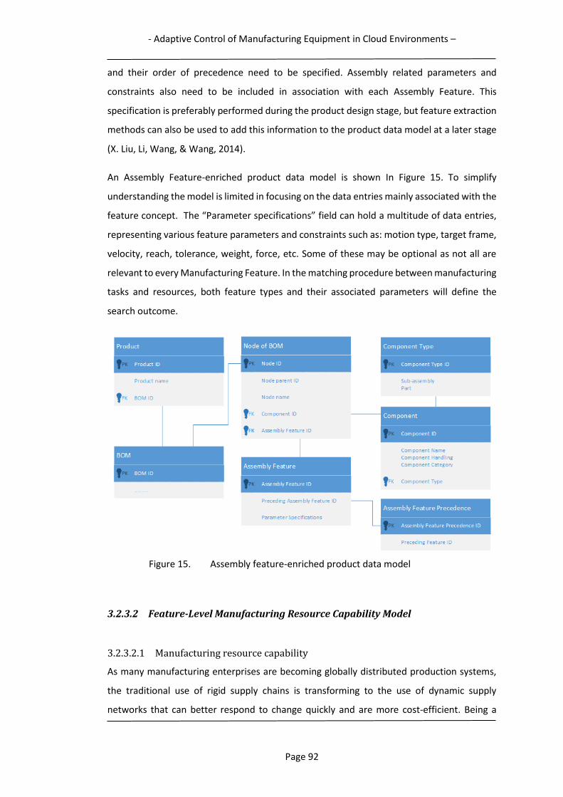
- Adaptive Control of Manufacturing Equipment in Cloud Environments –
Page 92
and their order of precedence need to be specified. Assembly related parameters and
constraints also need to be included in association with each Assembly Feature. This
specification is preferably performed during the product design stage, but feature extraction
methods can also be used to add this information to the product data model at a later stage
(X. Liu, Li, Wang, & Wang, 2014).
An Assembly Feature-enriched product data model is shown In Figure 15. To simplify
understanding the model is limited in focusing on the data entries mainly associated with the
feature concept. The “Parameter specifications” field can hold a multitude of data entries,
representing various feature parameters and constraints such as: motion type, target frame,
velocity, reach, tolerance, weight, force, etc. Some of these may be optional as not all are
relevant to every Manufacturing Feature. In the matching procedure between manufacturing
tasks and resources, both feature types and their associated parameters will define the
search outcome.
Figure 15. Assembly feature-enriched product data model
3.2.3.2 Feature-Level Manufacturing Resource Capability Model
3.2.3.2.1 Manufacturing resource capability
As many manufacturing enterprises are becoming globally distributed production systems,
the traditional use of rigid supply chains is transforming to the use of dynamic supply
networks that can better respond to change quickly and are more cost-efficient. Being a
- Adaptive Control of Manufacturing Equipment in Cloud Environments –
Page 93
manufacturing version of Cloud Computing, Cloud Manufacturing extends the philosophy of
“Everything-as-a-Service” by developing new service concepts such as “Manufacturing
Resource-as-a-Service” and “Manufacturing Capability-as-a-Service”. The main concept
within Cloud Manufacturing is to perform business transactions on manufacturing services
which are composed of distributed manufacturing resources, owned by service providers.
Supply networks are then dynamically created for these collaborative manufacturing
missions. In this process, a key factor is the communication of manufacturing resource
capabilities, e.g. functionality, production processes, capacity, cost, quality, etc. between
participating resource providers and consumers. For the creation of these volatile
manufacturing supply chains, the availability of interoperable and accurate manufacturing
capability information of all supply chain participants is required. A unified reference model
for describing manufacturing resources’ capabilities is required as manufacturing resources
are the most fundamental elements that collaboratively satisfy a certain manufacturing task
request.
A major problem currently is that capability information models are often developed as
resource providers’ proprietary models, leading to many accuracy and interoperability issues
(Kulvatunyou, Lee, Ivezic, & Peng, 2015; W. Xu et al., 2015). These models typically use their
own semantic representation and structure and often include unstructured, and also
conflicting and ambiguous data. Differing representations for expressing production
requirements, as well as differing taxonomies for categorising manufacturing resources, are
commonly used. As a result of this, a diversity of interoperability issues arise related to
resource sharing, leading to incomplete or sub-optimised manufacturing solutions, for which
the most suitable resources are sometimes not used. The largest obstacle to assembly agility
and effective manufacturing supply chains in distributed environments is the absence of an
agreed reference capability model. The often intricate process of matching a manufacturing
task request to manufacturing resources is performed manually, and therefore tend to be
inefficient as the presence of manufacturing data is superfluous and its interrelationships
complex. Lack of agreed interpretation to terms used in the manufacturing domain further
magnifies this problem. Therefore, an information model for description of resources and
their capabilities is required, as well as a language for its implementation.
3.2.3.2.2 Manufacturing Resource Capability Models
Models for the description of manufacturing capability often have different perspectives and
cover different levels of capability. The capability of most interest for this research study is
- Adaptive Control of Manufacturing Equipment in Cloud Environments –
Page 94
the functional capability of manufacturing equipment, which describes what manufacturing
operations the equipment is able to perform. Many other aspects of capability are of course
also of interest in the matching of tasks and resources. Resource properties such as cost,
quality, availability, delivery times, resource location, consumer ratings, etc. may also be
expressed in manufacturing capability models. The functional capability answers the
question of “what” the resource can perform in regard to production capacity, while other
capability descriptions answers the question of “how”, in respect to resource properties. As
such, capability models often include more than the functional resource properties, and
describe both static and dynamic information. A manufacturing machine model with four
different capability attributes are presented by (Yingfeng Zhang, Xi, Li, & Sun, 2015). The
model comprised the following attributes: Basic, Function, Real-time status, and Evaluation.
A cell level model for more complex manufacturing tasks is also described, featuring:
Description, Status, Evaluation, and Resource information. The use of condition information
for dynamic modeling of manufacturing equipment capability is described by (W. Xu et al.,
2015). The unified description model presented includes three fundamental ontologies: for
basic information, manufacturing function, and manufacturing processes. Basic information
and manufacturing function describes static information and characteristics, while
manufacturing processes describes the manufacturing conditions and the dynamic
capabilities. On the basis of the mapping relationship between the real-time condition data
and the model of the manufacturing equipment capability ontology, the knowledge structure
is able to update in real-time. A 5-level manufacturing system capability model supported by
the formal ontology Manufacturing Service Description Language is presented by (Ameri,
Urbanovsky, & McArthur, 2012). The model comprises: Supplier, Shop, Machine, Device, and
Process. Each level is described by an ontological model which enables the capabilities of the
higher level entities, e.g. machine tools and shop floor, to be inferred through aggregation of
device-level capabilities. They also describe manufacturing capabilities in the following
dimensions: Technological, Operational, Geometric, Quality, Relational, and Stochastic.
From a review of some proposed capability models, it is apparent that models often differ in
information scope, the representation of static and dynamic information, and number of
capability levels, often referred to as granularity levels. It is obvious that the lack of a unified
standard for manufacturing vocabulary and definitions, in combination with the wide range
of manufacturing resources and their applicability in different processes and industrial
- Adaptive Control of Manufacturing Equipment in Cloud Environments –
Page 95
scenarios, is reflected in disparate capability models. Discussions regarding appropriate
granularity levels for the most effective task-resource matching are scarce.
3.2.3.2.3 Feature-level Capability Model
The level of granularity in manufacturing capability descriptions plays an important role from
the perspective of discovering, combining and matching of resources in response to a
manufacturing task. In the wide span of various levels of capability descriptions complexity,
two extremes exist: the low-level discrete functional capability of a single manufacturing
resource, e.g. the moving of a robot joint, and the high-level capability of an enterprise, e.g.
the manufacturing of a complete car engine. Between these two extremes, a variety of
approaches for representing manufacturing capability exists, differing in complexity and
number of levels. In some respects, there are advantages with this partitioning of
manufacturing capability into different levels, but it may also be challenged. Using a low-level
capability description approach enables identification of numerous matching resources for a
manufacturing task, and from the perspective of resource allocation flexibility, smaller
granularity levels would be preferred. Searching for a machining resource to perform some
rudimentary machining operations would then result in an immense set of possible
resources. However to the contrary, the search for a car engine manufacturing resource
would probably return a fairly restricted set of resources. A Manufacturing Feature-level
capability partitioning could facilitate and speed up the search for suitable resources.
The number of matching resources for a unique manufacturing task request would be
drastically reduced if a manufacturing resources’ many functional capabilities were matched
to the limited number of pre-defined product Manufacturing Features. The concept of
Manufacturing Feature-level capability can also be used for describing the capabilities of
combinations of resources and their functionalities, e.g. possible assembly operations
realised through the combination of a robot and a gripper tool.
From a resource perspective, a Manufacturing Feature is a combination of a manufacturing
resources’ capabilities, and describes the ability to complete a unique manufacturing product
feature, within a certain manufacturing domain (machining, assembly, etc.). From conceptual
functionalities, it is possible to identify typical manufacturing properties and atomic
manufacturing operations, for matching against different categories of Manufacturing
Features as capabilities.
A feature-level capability model for the robotic assembly domain is presented in Figure 16.

- Adaptive Control of Manufacturing Equipment in Cloud Environments –
Page 96
Figure 16. Feature-level assembly resource capability model
Four manufacturing resources and their associated functionalities, detailed by functional
properties and their defining parameters and constraints, defines a higher conceptual
Assembly Feature capability level (For reasons of clarity, all possible relations have not been
graphically represented, and only a subset of available properties are included.). This
modeling approach thus represents capability as Manufacturing Features defined by specific
parameters and constraints. Here, a manufacturing operation is the detailing of a property
with related parameters within existing constraints. The feature(s) related to a specific
resource and its properties can be explicitly defined by the resource provider or implicitly
inferred from an ontological description (Xia, Gao, Wang, Li, & Chao, 2015). For defining
features, standardised feature templates can be used, describing the required set of unique
operations for each feature, e.g. Insert, Figure 14. Following this capability model and level
of granularity, a quicker assembly task request and manufacturing resource matching can be
performed on an Assembly Feature-level. As a first step in the matching procedure, task
decomposition and parameter-feature identification are used, followed by a feature-level
resource search. The feature-enriched product data model will be the primary defining
source for setting the search conditions in this process. When available resources for the
requested manufacturing task have been found, a second search can be performed among
these, now focusing on other resource capabilities other than the functional ones, e.g.
requirements regarding cost, availability, quality, etc. The outcome would provide the set of
resources which best matches the manufacturing request, and from which the final resource
selection can be made.
- Adaptive Control of Manufacturing Equipment in Cloud Environments –
Page 97
For effective search and inference capabilities, a multi-layer ontology is an effective language
to implement the proposed information framework, which is outlined in the next section.
3.2.3.3 Semantic Ontology Information Representation
A Cloud Manufacturing environment may comprise of a large variety of different distributed
and heterogeneous manufacturing resources, as resource providers can offer services based
on hard, soft and capability manufacturing resources, each which may hold unique
manufacturing capabilities. To improve the quality and efficiency of description, discovery
and matching, Semantic Web and ontology technologies can be used to describe both
manufacturing resources and tasks. In the Semantic Web, information is structured and
linked through the standard rules of grammar and language structure, so semantics meaning
can be expressed. The majority of interoperability issues could be solved by annotating the
manufacturing resource capability and task information using standardised and shared
ontologies. Such a unified ontology framework is required for standardised information
exchange, knowledge management and seamless cooperation between collaborating
providers and consumers and their invoked services. Ontologies provide a solid mechanism
to represent real world objects and are particularly important to provide computers with
explicit definitions of relevant domain knowledge representations, as well as reasoning
capabilities for reviewing knowledge to infer additional information, as well as to allow high-
level interoperability between systems (Guarino, 1998; Staab & Studer, 2013; Yen, Zhu,
Bastani, Huang, & Zhou, 2016).
An alternative method for establishing the proposed resource and product information
models, in case they do not already exist, is to use an ontology-based information
representation and retrieval approach, as described by (Xia et al., 2015). Product and
resource data is often handled by heterogeneous information systems and stored in different
systems at the facilities of providers and those requesting a task. Using an ontology-based
approach, the contents of different data sources can be retrieved and represented
semantically. With ontology extraction, information regarding resources or products can be
structured and formalised into local ontologies. In addition, through the use of semantic
augmentation and querying, as well as matching to global manufacturing ontologies, new
information may be inferred.
It is not feasible to develop a sole, complete Cloud Manufacturing ontology, since different
manufacturers have different requirements. A multi-layer ontology structure is therefore
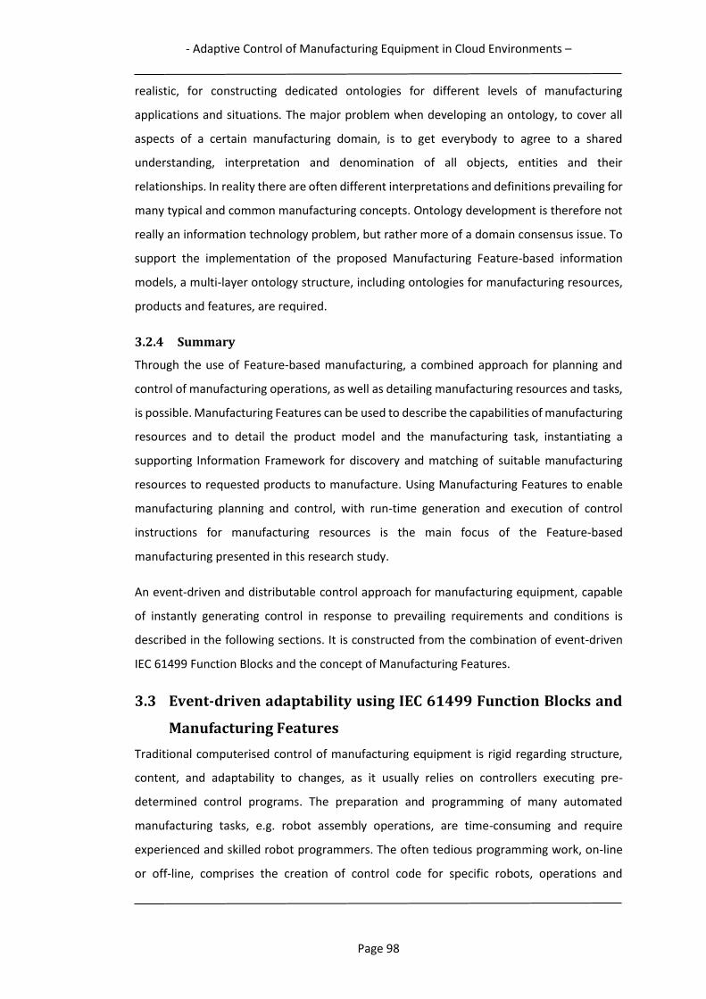
- Adaptive Control of Manufacturing Equipment in Cloud Environments –
Page 98
realistic, for constructing dedicated ontologies for different levels of manufacturing
applications and situations. The major problem when developing an ontology, to cover all
aspects of a certain manufacturing domain, is to get everybody to agree to a shared
understanding, interpretation and denomination of all objects, entities and their
relationships. In reality there are often different interpretations and definitions prevailing for
many typical and common manufacturing concepts. Ontology development is therefore not
really an information technology problem, but rather more of a domain consensus issue. To
support the implementation of the proposed Manufacturing Feature-based information
models, a multi-layer ontology structure, including ontologies for manufacturing resources,
products and features, are required.
3.2.4 Summary
Through the use of Feature-based manufacturing, a combined approach for planning and
control of manufacturing operations, as well as detailing manufacturing resources and tasks,
is possible. Manufacturing Features can be used to describe the capabilities of manufacturing
resources and to detail the product model and the manufacturing task, instantiating a
supporting Information Framework for discovery and matching of suitable manufacturing
resources to requested products to manufacture. Using Manufacturing Features to enable
manufacturing planning and control, with run-time generation and execution of control
instructions for manufacturing resources is the main focus of the Feature-based
manufacturing presented in this research study.
An event-driven and distributable control approach for manufacturing equipment, capable
of instantly generating control in response to prevailing requirements and conditions is
described in the following sections. It is constructed from the combination of event-driven
IEC 61499 Function Blocks and the concept of Manufacturing Features.
3.3 Event-driven adaptability using IEC 61499 Function Blocks and
Manufacturing Features
Traditional computerised control of manufacturing equipment is rigid regarding structure,
content, and adaptability to changes, as it usually relies on controllers executing pre-
determined control programs. The preparation and programming of many automated
manufacturing tasks, e.g. robot assembly operations, are time-consuming and require
experienced and skilled robot programmers. The often tedious programming work, on-line
or off-line, comprises the creation of control code for specific robots, operations and

- Adaptive Control of Manufacturing Equipment in Cloud Environments –
Page 99
products. In the case of an unforeseen assembly change or variation, the predefined robot
program may have to be changed, and sometimes completely recreated. The extent of
control code regeneration then depends on the effects and influences of the change. As a
robot control program is often created for a specific assembly scenario, program portability
is usually low. As Cloud Manufacturing environments often involve many cooperating
manufacturing resource providers, the number of sources for variations and unpredictable
events that could disturb and negatively affect these control programs as a consequence is
increased.
Being exposed to so many variations, these manufacturing environments would need to be
able to rapidly and automatically adapt to changes, to avoid the undesired effects of
unpredictable events. An adaptive and distributed control system, using intelligence and real-
time manufacturing information, could enable dynamic decision-making and control
capabilities in response to prevailing requirements and conditions, and as such realise a
manufacturing system able to successfully cope with unforeseen variations. The
development and increasing use of the Internet of Things facilitate the widespread use of a
multitude of internet-connected sensors, generating massive amounts of manufacturing
data. Using data analytics associated with big data, this could be the basis for creating the
next generation of manufacturing control. But to more effectively utilize this increasing
amount of available data, a transition from time-triggered manufacturing control systems, to
event-triggered, is advantageous. A time-triggered approach builds on a deterministic,
planned system behaviour, based on estimated demand and known manufacturing
scenarios. Unforeseen randomness is not catered for, as the deterministic approach builds
on a predictable demand and a stable manufacturing system without unforeseen variations.
With sensor feedback and an event-triggered approach, the system behaviour can adopt to
actual, prevailing manufacturing conditions, for a more efficient and flexible manufacturing,
in which adaptive decision-making is possible.
In the following sections, such a control approach for event-driven adaptability, combining
IEC 61499 Function Blocks and Manufacturing Features, is described.
3.3.1 Manufacturing Feature-Function Blocks
To practically implement the concept of Manufacturing Features for the adaptive control of
manufacturing equipment, an implementation approach for the planning and execution of
Manufacturing Features is necessary. For this, an executional mechanism, capable of
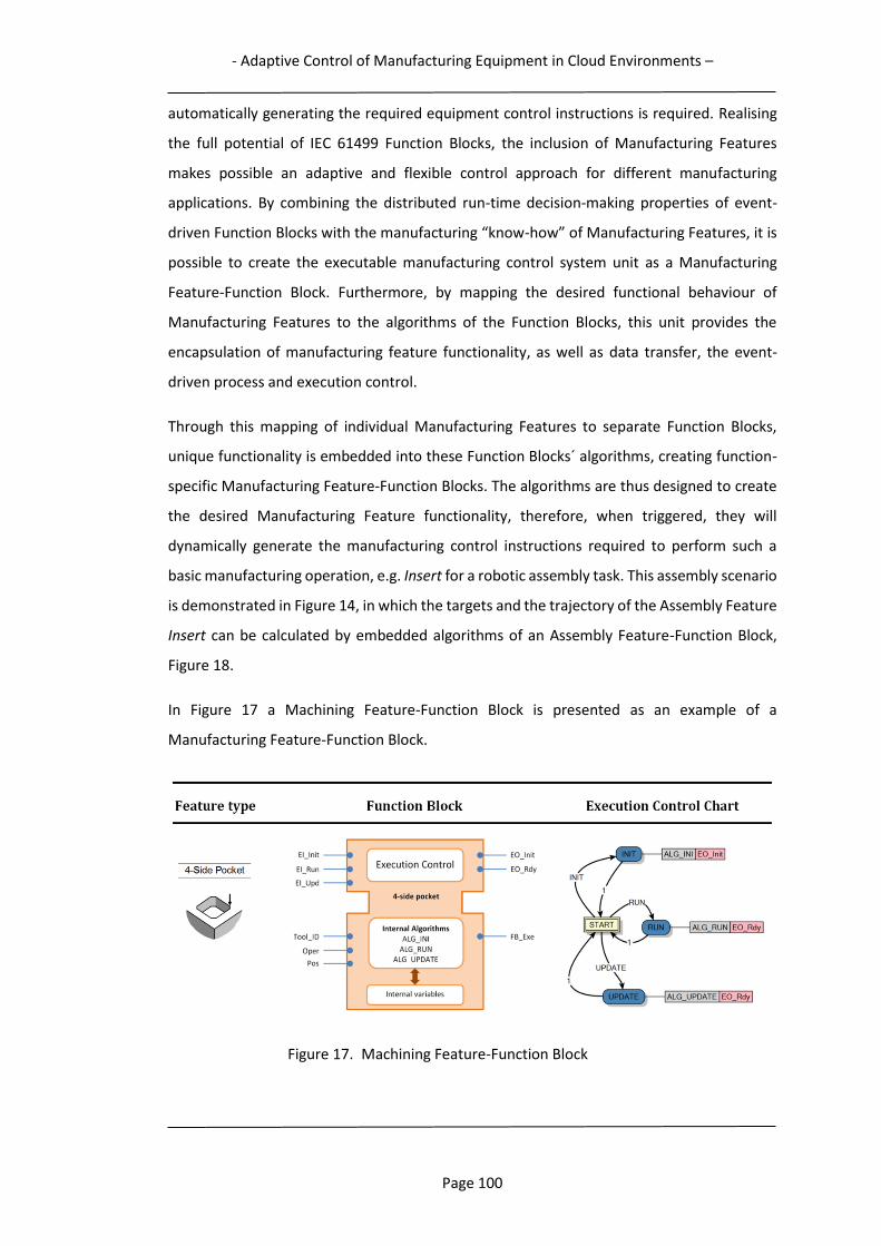
- Adaptive Control of Manufacturing Equipment in Cloud Environments –
Page 100
automatically generating the required equipment control instructions is required. Realising
the full potential of IEC 61499 Function Blocks, the inclusion of Manufacturing Features
makes possible an adaptive and flexible control approach for different manufacturing
applications. By combining the distributed run-time decision-making properties of event-
driven Function Blocks with the manufacturing “know-how” of Manufacturing Features, it is
possible to create the executable manufacturing control system unit as a Manufacturing
Feature-Function Block. Furthermore, by mapping the desired functional behaviour of
Manufacturing Features to the algorithms of the Function Blocks, this unit provides the
encapsulation of manufacturing feature functionality, as well as data transfer, the event-
driven process and execution control.
Through this mapping of individual Manufacturing Features to separate Function Blocks,
unique functionality is embedded into these Function Blocks´ algorithms, creating function-
specific Manufacturing Feature-Function Blocks. The algorithms are thus designed to create
the desired Manufacturing Feature functionality, therefore, when triggered, they will
dynamically generate the manufacturing control instructions required to perform such a
basic manufacturing operation, e.g. Insert for a robotic assembly task. This assembly scenario
is demonstrated in Figure 14, in which the targets and the trajectory of the Assembly Feature
Insert can be calculated by embedded algorithms of an Assembly Feature-Function Block,
Figure 18.
In Figure 17 a Machining Feature-Function Block is presented as an example of a
Manufacturing Feature-Function Block.
Figure 17. Machining Feature-Function Block

- Adaptive Control of Manufacturing Equipment in Cloud Environments –
Page 101
The figure presents a “4-side Pocket” Machining Feature-Function Block, with input and
output connections together with its associated algorithms, Feature type (left) and Execution
Control Chart (right).
The Manufacturing Feature-Function Block control construct is generic and can be used for
different manufacturing applications, however, in the following section it is described for
robotic assembly applications. As described within section 3.2.2, the focus of this research
study is on the use of Manufacturing Features for assembly tasks, i.e. Assembly Features.
3.3.2 Assembly Feature-Function Blocks
Creating robot assembly functionality includes setting typical robot parameters such as;
targets and paths, robot move mode, Tool Centre Point speed, level of accuracy, tool,
reference frame/workobject to use, etc. For successfully performing the required robot
operations, real-time generation of correct control instructions is necessary, therefore
adaptive robot control requires real-time monitoring of the status of the robot and its
working environment, and its process prerequisites. The Assembly Feature-Function Block
algorithms are constructed to realise the specific Assembly Feature functionality, which
means that they will dynamically generate the required robot control instructions to perform
a basic assembly operation, e.g. Placing, Inserting, Screwing, etc., (Figure 14). The Assembly
Feature-Function Block based control system´s adaptivity property derives from the
Assembly Feature-Function Blocks’ ability to adjust their output data to the actual assembly
conditions, as the algorithms are triggered in real-time by arriving input events from the
robot and its environment. Following the defined behaviour in the Execution Control Chart,
the values of available real-time data inputs will be read and the control instructions
automatically generated by the executed algorithms, as Assembly Feature-Function Blocks
data outputs.
Demonstrating this concept, a combination of an event-driven IEC 61499 Basic Function Block
with the Assembly Feature Insert, instantiating an Assembly Feature-Function Block, is
depicted in Figure 18, with its associated Execution Control Chart shown in Figure 19.
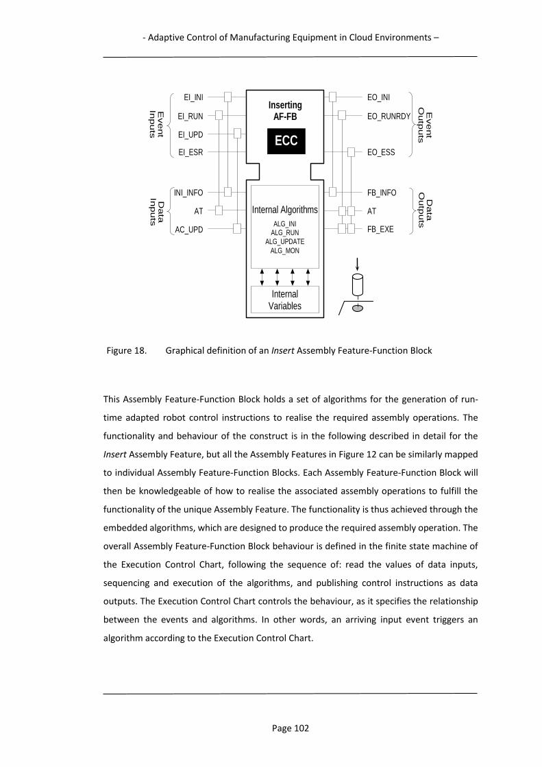
- Adaptive Control of Manufacturing Equipment in Cloud Environments –
Page 102
Figure 18. Graphical definition of an Insert Assembly Feature-Function Block
This Assembly Feature-Function Block holds a set of algorithms for the generation of run-
time adapted robot control instructions to realise the required assembly operations. The
functionality and behaviour of the construct is in the following described in detail for the
Insert Assembly Feature, but all the Assembly Features in Figure 12 can be similarly mapped
to individual Assembly Feature-Function Blocks. Each Assembly Feature-Function Block will
then be knowledgeable of how to realise the associated assembly operations to fulfill the
functionality of the unique Assembly Feature. The functionality is thus achieved through the
embedded algorithms, which are designed to produce the required assembly operation. The
overall Assembly Feature-Function Block behaviour is defined in the finite state machine of
the Execution Control Chart, following the sequence of: read the values of data inputs,
sequencing and execution of the algorithms, and publishing control instructions as data
outputs. The Execution Control Chart controls the behaviour, as it specifies the relationship
between the events and algorithms. In other words, an arriving input event triggers an
algorithm according to the Execution Control Chart.
EO_INI
EO_RUNRDY
EI_UPD
EI_RUN
EI_INI Inserting
AF-FB
INI_INFO
Internal Algorithms
ALG_INI ALG_RUN
ALG_UPDATE
ALG_MON
Internal Variables
EO_ESS
FB_INFO
AT
AC_UPD
EI_ESR
AT
FB_EXE
ECC
Event
Inputs
Event
Outp
uts
Data
In
puts
Data
O
utp
uts
- Adaptive Control of Manufacturing Equipment in Cloud Environments –
Page 103
The depicted Assembly Feature-Function Block in Figure 18 contains the 4 event-driven
algorithms: ALG_INI, ALG_RUN, ALG_UPDATE and ALG_MON, each of which can perform the
following functionality:
- ALG_INI:
For initialization of the Function Block. Retrieves initialisation information from the
data input INI_INFO to be able to perform robot control instruction creation. After
reading information such as: the location of necessary objects, robot ID, component
information, access direction, path parameters such as travel mode, target location,
travel speed, accuracy, tool, etc., it generates the robot control code as the output
data FB_INFO. This information can be used in a preliminary test run of the control
code in a simulation model of the real robot system, for verification of functionality
and estimation of assembly time.
- ALG_RUN:
Runs the generated control code on the data output FB_EXE to perform the assembly
operation of the Assembly Feature-Function Block. Reads estimated assembly time
from data input AT and produces accumulated assembly times on the data output
AT. Due to the fact that robot controllers do not recognise these Assembly Feature-
Function Blocks, the control commands prepared by the ALG_INI can be translated
to the native codes of a specific robot at runtime before execution. (In this research,
a front-end application server with an IEC61499 enabled run-time environment is
chosen to run the Function Blocks, whereas the Function Block-generated native
robot control instructions are transmitted to the robot controller for immediate
execution.)
- ALG_UPDATE:
Generates updated assembly conditions by reading the data input AC_UPD. When
required by changed real-time conditions or updated requirements, it produces new
control code that overrides the by ALG_INI auto-generated code.
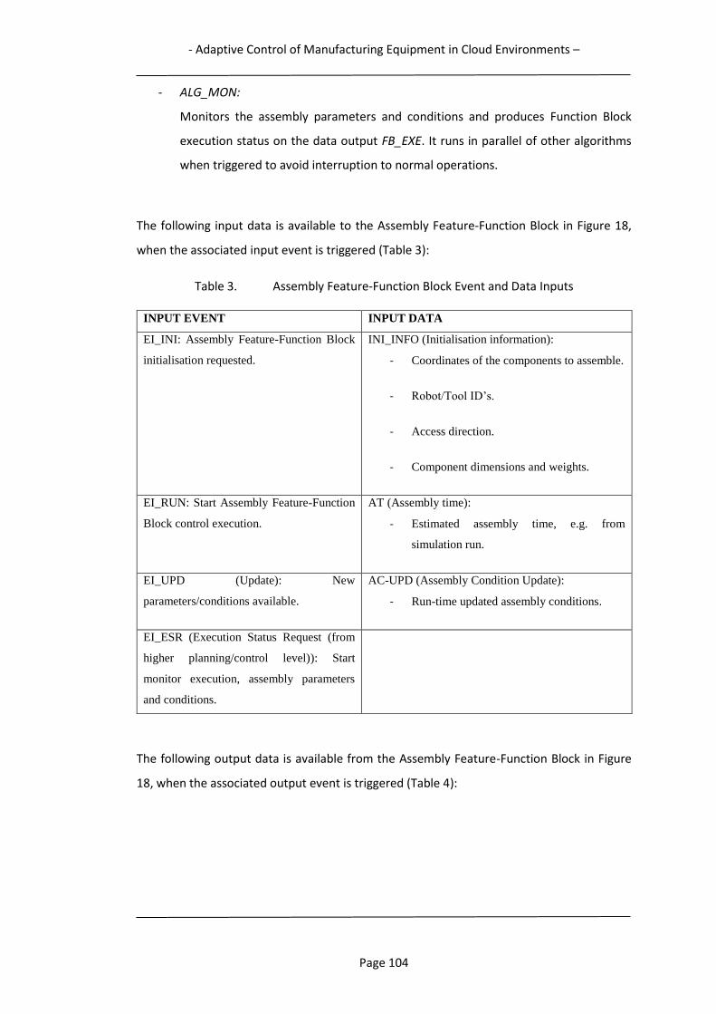
- Adaptive Control of Manufacturing Equipment in Cloud Environments –
Page 104
- ALG_MON:
Monitors the assembly parameters and conditions and produces Function Block
execution status on the data output FB_EXE. It runs in parallel of other algorithms
when triggered to avoid interruption to normal operations.
The following input data is available to the Assembly Feature-Function Block in Figure 18,
when the associated input event is triggered (Table 3):
Table 3. Assembly Feature-Function Block Event and Data Inputs
INPUT EVENT INPUT DATA
EI_INI: Assembly Feature-Function Block
initialisation requested.
INI_INFO (Initialisation information):
- Coordinates of the components to assemble.
- Robot/Tool ID’s.
- Access direction.
- Component dimensions and weights.
EI_RUN: Start Assembly Feature-Function
Block control execution.
AT (Assembly time):
- Estimated assembly time, e.g. from
simulation run.
EI_UPD (Update): New
parameters/conditions available.
AC-UPD (Assembly Condition Update):
- Run-time updated assembly conditions.
EI_ESR (Execution Status Request (from
higher planning/control level)): Start
monitor execution, assembly parameters
and conditions.
The following output data is available from the Assembly Feature-Function Block in Figure
18, when the associated output event is triggered (Table 4):
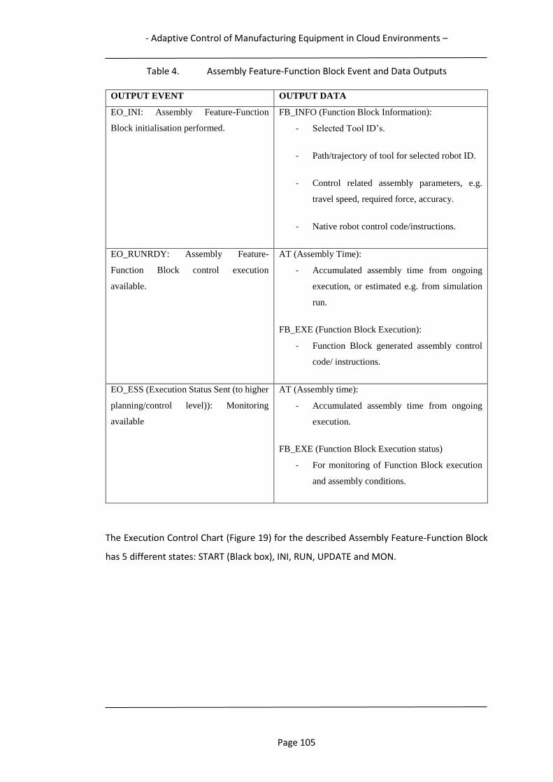
- Adaptive Control of Manufacturing Equipment in Cloud Environments –
Page 105
Table 4. Assembly Feature-Function Block Event and Data Outputs
OUTPUT EVENT OUTPUT DATA
EO_INI: Assembly Feature-Function
Block initialisation performed.
FB_INFO (Function Block Information):
- Selected Tool ID’s.
- Path/trajectory of tool for selected robot ID.
- Control related assembly parameters, e.g.
travel speed, required force, accuracy.
- Native robot control code/instructions.
EO_RUNRDY: Assembly Feature-
Function Block control execution
available.
AT (Assembly Time):
- Accumulated assembly time from ongoing
execution, or estimated e.g. from simulation
run.
FB_EXE (Function Block Execution):
- Function Block generated assembly control
code/ instructions.
EO_ESS (Execution Status Sent (to higher
planning/control level)): Monitoring
available
AT (Assembly time):
- Accumulated assembly time from ongoing
execution.
FB_EXE (Function Block Execution status)
- For monitoring of Function Block execution
and assembly conditions.
The Execution Control Chart (Figure 19) for the described Assembly Feature-Function Block
has 5 different states: START (Black box), INI, RUN, UPDATE and MON.
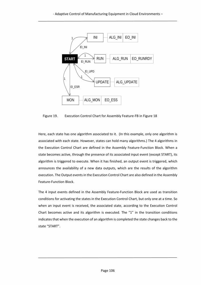
- Adaptive Control of Manufacturing Equipment in Cloud Environments –
Page 106
Figure 19. Execution Control Chart for Assembly Feature-FB in Figure 18
Here, each state has one algorithm associated to it. (In this example, only one algorithm is
associated with each state. However, states can hold many algorithms.) The 4 algorithms in
the Execution Control Chart are defined in the Assembly Feature-Function Block. When a
state becomes active, through the presence of its associated input event (except START), its
algorithm is triggered to execute. When it has finished, an output event is triggered, which
announces the availability of a new data outputs, which are the results of the algorithm
execution. The Output events in the Execution Control Chart are also defined in the Assembly
Feature-Function Block.
The 4 input events defined in the Assembly Feature-Function Block are used as transition
conditions for activating the states in the Execution Control Chart, but only one at a time. So
when an input event is received, the associated state, according to the Execution Control
Chart becomes active and its algorithm is executed. The “1” in the transition conditions
indicates that when the execution of an algorithm is completed the state changes back to the
state “START”.
EO_RUNRDY 1
EI_RUN
EI_UPD
INI ALG_INI EO_INI
EI_INI
1
ALG_RUN
ALG_UPDATE
START
1
MON ALG_MON
1
EI_ESR
EO_ESS
RUN
UPDATE
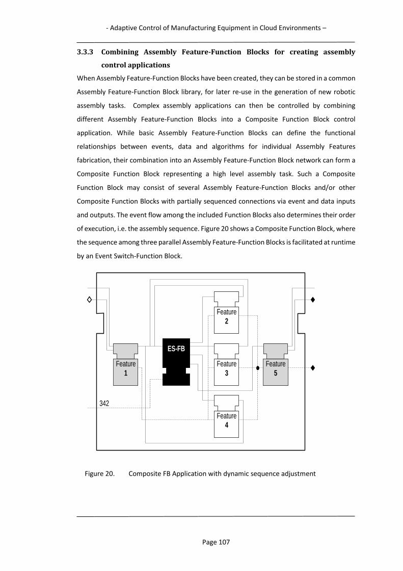
- Adaptive Control of Manufacturing Equipment in Cloud Environments –
Page 107
3.3.3 Combining Assembly Feature-Function Blocks for creating assembly
control applications
When Assembly Feature-Function Blocks have been created, they can be stored in a common
Assembly Feature-Function Block library, for later re-use in the generation of new robotic
assembly tasks. Complex assembly applications can then be controlled by combining
different Assembly Feature-Function Blocks into a Composite Function Block control
application. While basic Assembly Feature-Function Blocks can define the functional
relationships between events, data and algorithms for individual Assembly Features
fabrication, their combination into an Assembly Feature-Function Block network can form a
Composite Function Block representing a high level assembly task. Such a Composite
Function Block may consist of several Assembly Feature-Function Blocks and/or other
Composite Function Blocks with partially sequenced connections via event and data inputs
and outputs. The event flow among the included Function Blocks also determines their order
of execution, i.e. the assembly sequence. Figure 20 shows a Composite Function Block, where
the sequence among three parallel Assembly Feature-Function Blocks is facilitated at runtime
by an Event Switch-Function Block.
Figure 20. Composite FB Application with dynamic sequence adjustment
Feature
1
Feature
2
Feature 4
Feature
5
ES-FB
342
Feature
3

- Adaptive Control of Manufacturing Equipment in Cloud Environments –
Page 108
If an assembly sequence of e.g. “342” is given for the three Assembly Features 2–4, the Event
Switch-Function Block will fire events accordingly to appropriate Assembly Feature-Function
Blocks for feature fabrications in the order of 3-4-2. It thus adds flexibility for the Composite
Function Block to dynamically adjust the assembly sequence of non-critical Assembly
Features. Figure 21 shows the graphical definition of the Event Switch-Function Block, where
the only data input is ROUTE, carrying the dynamically selected assembly sequence string.
The input event EI-P is the request to parse the ROUTE string, and the EO_P event outputs
will trigger the activation of the selected Assembly Feature-Function Block.
Figure 21. Event Switch-Function Block
The data input ROUTE is used as a reserved port for controller-level operation planning to do
the local optimisation of the assembly sequence. Once the final sequence becomes explicit
for those parallel features, a string of integer numbers indicating the sequence is applied to
the port. The function of event switching is realised by an internal algorithm ALG_SWITCH,
which parses the input data string and triggers one execution event at a time until the entire
string is exhausted. An acceptable string must only include non-repetitive numbers, e.g.
“342”, and represent all parallel features needed for switching procedure.
3.3.4 Adaptive Robot Assembly Control using Assembly Feature-Function Blocks
The construct of the control approach provides the ability to dynamically adapt to variations
in assembly tasks, such as: changes in product designs, changes in assembly component
locations, performing operations with a different robot tool, one robot completing the
operations of another robot, etc. In contrast to traditional process planning and
programming of manufacturing equipment at an early stage in the product development
EO_INI
EO_P1 EI_P
EI_INI
Event Switch
FB
Internal Algorithm
ALG_INI
ALG_SWITCH
EO_Pn
……
ROUTE
EO_DONE
EO_P2

- Adaptive Control of Manufacturing Equipment in Cloud Environments –
Page 109
process, the required robot control code is here generated automatically and instantly. By
continuously monitoring the status of the robot and its working environment, the data inputs
can be fed with the real-time information of the ongoing assembly task. When incoming input
events, representing specific requests to generate specific solutions, trigger the execution of
algorithms, the corresponding robotic control commands will be produced. Decision-making
can then be performed on the basis of the prevailing status of the assembly system situation,
available to the Assembly Feature-Function Block through its data inputs. It will then
generate the correct control code, incl. varying parameters, e.g. robot trajectories, targets,
required force, travel speed, process parameters, tools to use, etc., for a selected resource
to assemble a certain product. This adaptive control approach provides great flexibility since
the functionality mapped into the Assembly Feature-Function Block may be able to generate
the same assembly result when performed by different assembly resources. For this,
different algorithms are created and included in the Assembly Feature-Function Block, each
customised to match specified robots, tools and assembly scenarios. A data input is then used
to read e.g. the ID of the robot at Assembly Feature-Function Block initialisation, for the
selection of the corresponding algorithms.
However, the level of adaptability is not unrestricted, but bounded by the assembly system’s
ability to adapt to changes through the functionality of the control system. Architectural
hardware perspectives or different physical reconfigurations of manufacturing equipment,
such as robots, are not considered in this research study. The level of control adaptability is
fully dependent on the sophistication of the construction of the Execution Control Chart and
the Function Block algorithms, as well as the scope of available real-time information to be
accessed and processed, in order to generate control instructions. Control approaches may
range from reading robot target information from a single sensor, to be input to Assembly
Feature-Function Block algorithms generating robot move instructions for an Insert feature,
to the complex processing of information from a network of sensors, actuators and
controllers, by algorithm implemented AI technologies, in order to analyse and generate
optimal robot path control for a robot operation. It is possible for an Assembly Feature-
Function Block to generate legacy robot control instructions code to best utilise the legacy
robot tools, before runtime models of the Function Blocks become the built-in functions of
robot controllers. Assembly Feature-Function Blocks could also be linked to external
computational resources, as applied in Cloud Robotics, for support in calculating e.g. optimal
robot paths.

- Adaptive Control of Manufacturing Equipment in Cloud Environments –
Page 110
Combining IEC 61499 Function Blocks with Manufacturing Features for realising adaptive
equipment control solutions has been successfully demonstrated for some different
manufacturing scenarios. In (Holm, Adamson, & Wang, 2013; Holm, Adamson, Wang, &
Moore, 2012; Lihui Wang, Hao, & Shen, 2007; L. Wang et al., 2010) Machining Features are
used for CNC-machining control, and in (Adamson, Holm, & Wang, 2012; Adamson, Holm,
Wang, & Moore, 2012; Lihui Wang, Adamson, Holm, & Moore, 2012; Lihui Wang, Schmidt,
Givehchi, & Adamson, 2015) Assembly Features are used for robotic assembly control.
3.3.5 Assembly Feature-Function Block Control Advantages
The Assembly Feature-Function Block control approach enables system properties such as:
complexity decomposition, Assembly Feature encapsulation, adaptive assembly execution,
and real-time process monitoring. Overall, the construct yields an agile assembly process
behaviour, with the following advantages:
Since the Assembly Feature-Function Blocks are event-driven they can dynamically
react to, and handle, variations that may appear during assembly operations.
The Assembly Feature-Function Block embedded algorithms enable run-time
decision-making based on monitoring and acting upon real-time manufacturing
information. It is thus the actual conditions within the manufacturing system, fed
back to the Assembly Feature-Function Block control system through a monitoring
system of sensors, which dynamically dictate how the manufacturing equipment will
perform the required operations. This enables adjusting to variations and changes,
and detailed assembly control data are generated by the algorithms at the controller
level. Once a specific robot is chosen, these algorithms can make decisions on robot
trajectory, motion control, and optimal assembly parameters at run-time.
The required robot control code is generated automatically and at run-time.
Traditional programming requires skilled and experienced programmers, and is often
time-consuming. The use of Assembly Feature-Function Blocks speeds up and
simplifies the robot programming effort, and reduces it more or less to the
appropriate selection and combination of a networked set of predefined Assembly
Feature-Function Blocks, which a robot can execute one by one to accomplish the
assembly task. The knowledge of how to perform control is hidden in the Assembly
Feature-Function Blocks, e.g. as a control service provider’s Intellectual Property.
- Adaptive Control of Manufacturing Equipment in Cloud Environments –
Page 111
Function Blocks are resource independent and can be dispatched to different robots.
As such a generated assembly plan can be dispatched to different robots on an as-
needed basis. A key virtue in this concept is that the functionality of Assembly
Feature-Function Blocks is generic, as the functionality mapped into the Function
Block algorithms will generate the same result when performed by different
manufacturing resources. For this, an Assembly Feature-Function Block can hold
different algorithms, customized to match different robots. These Assembly Feature-
Function Blocks can therefore be reused as building blocks in varying robotic
assembly applications. With traditional robot programming, the created control code
is predefined for specific robots, tasks and products, and has to be modified or totally
redefined when a change occurs.
The Assembly Feature-Function Block based design of this control approach is
implementation platform independent. The system on which it can be executed may
be composed of one single device or composed of a network of interconnected
devices. Each device should be equipped with an IEC61499 enabled run-time
environment in order to be considered for the execution of these Assembly Feature-
Function Block based control applications.
3.3.6 Summary
The IEC 61499 Function Block concept is highly relevant to distributed process planning and
adaptive manufacturing equipment control in data encapsulation and process plan
execution. The concept of combining Manufacturing Features with IEC 61499 Function
Blocks, monitoring and acting upon real-time information, enables an intelligent, agile and
flexible solution for performing collaborative and distributed manufacturing tasks, which
facilitates the low-level shop floor implementation of Cloud Manufacturing. Once applied to
robotic tasks, the event-driven model of an IEC 61499 Function Block gives a robot system
more intelligence and autonomy to make decisions on how to adapt an assembly plan to the
change of robot configuration and/or so as to best utilise a specific resource available at the
time. In contrast to the traditional approach of sending data to the robot controller in the
form of pre-determined control instructions, a set of event-driven algorithms, embedded in
Function Blocks will cater for an adaptive scenario to handle different types of assembly run-
time changes, by creating the required control momentarily.

- Adaptive Control of Manufacturing Equipment in Cloud Environments –
Page 112
To realise control in distributed manufacturing environments, a multi-layer control structure
incorporating Assembly Feature-Function Blocks is needed. Such an approach is described in
the next section, in which a Cloud perspective on manufacturing equipment control is
presented.
3.4 Cloud Manufacturing Control Structure
Since the introduction of Cloud Computing, with models to offer software, infrastructure,
platforms and applications in the form of services, cloud technology has been extended to
the manufacturing domain (D. Wu, Rosen, Wang, & Schaefer, 2015). Various distributed
manufacturing systems have been presented (F. Tao, L. Zhang, et al., 2011; X. Xu, 2012; Lin
Zhang et al., 2012), offering on-demand and scalable manufacturing services over the
Internet from a shared pool of distributed manufacturing resources (D. Wu, Terpenny, &
Schaefer, 2016). These resources range from facilities, work-cells, machine tools and robots,
to capabilities and software. The use of such manufacturing services within Cloud
Manufacturing is fundamental for distributed manufacturing and also facilitates
collaborative manufacturing missions.
The Manufacturing Feature-Function Block control approach, described in the former
section, has previously been demonstrated in the local shop floor domain, for realising
adaptive control of local robot applications (Adamson, Holm, Wang, et al., 2012; Adamson,
Wang, Holm, & Moore, 2014b). However, the distributable nature of IEC 61499 Function
Blocks is an important property for their use in distributed manufacturing environments,
such as within Cloud Manufacturing. Besides different Function Block types, the IEC 61499
standard also defines the interaction and communication between distributed Function
Blocks. This enables networked Manufacturing Feature-Function Blocks to be integrated as
manufacturing services in a cloud platform for the planning and execution of manufacturing
tasks at different system control levels. Integrating Assembly Feature-Function Blocks in such
a control structure constitutes a cloud service for robot control, implementing the concept
of Robot Control-as-a-Service. Supporting Function Blocks of different types are needed in
such control structures for control activities beyond the functionality of Assembly Feature-
Function Blocks, to facilitate execution control and enable process monitoring during
function block execution, as well as to enable communication between distributed Function
Blocks. These Function Blocks are described as parts of a complete Cloud Function Block
Control Structure in Chapter 6.
- Adaptive Control of Manufacturing Equipment in Cloud Environments –
Page 113
Amongst a multitude of possible cloud control scenarios for a manufacturing task request,
two extreme alternative solutions exist:
- a complete high level cloud service, for which one service provider performs all
necessary manufacturing tasks, e.g. a provider offering Manufacturing/Assembly-as-
a-Service in a resource-service Many-to-One mapping,
- a low level cloud service approach, for which a combination of service providers each
provide low-level services to collaboratively complete the high-level task. E.g. Robot
Control-as-a-Service together with Robot Software-as-a-Service and Robot
Hardware-as-a-Service, a combination of many One-to-One resource-service
mappings. (Robot Hardware-as-a-Service implies that a provider offers the use of a
robot, which could be provided by dedicated manufacturing centres or by providers
offering the sharing of spare equipment capacity).
Between these two extremes, a multitude of service composition solutions are also possible,
depending on the division of the consumer request into separate services. (As a cloud service
consumer, information about the exact composition of services for completing a
manufacturing task could be irrelevant and hidden by the system, especially when automatic
service retrieval and composition is used.)
The aim of this research study is to describe a cloud service-oriented system for adaptive
control of distributed manufacturing tasks in a Cloud environment. This chapter gives the
technological perspective of how a cloud service can be realised and implemented in a Cloud
Manufacturing platform. It is described for robotic assembly tasks, however, the presented
control concept is not restricted to assembly only, but is also applicable to other
manufacturing applications. It builds on a two-level planning and control structure separating
generic data from resource-specific, in which Supervisory Cloud Planning performs generic
process planning and Local Operation Planning performs detailed shop floor operation
planning and execution (Figure 22).
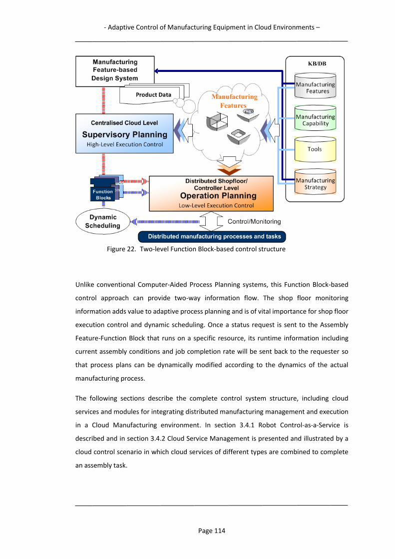
- Adaptive Control of Manufacturing Equipment in Cloud Environments –
Page 114
Figure 22. Two-level Function Block-based control structure
Unlike conventional Computer-Aided Process Planning systems, this Function Block-based
control approach can provide two-way information flow. The shop floor monitoring
information adds value to adaptive process planning and is of vital importance for shop floor
execution control and dynamic scheduling. Once a status request is sent to the Assembly
Feature-Function Block that runs on a specific resource, its runtime information including
current assembly conditions and job completion rate will be sent back to the requester so
that process plans can be dynamically modified according to the dynamics of the actual
manufacturing process.
The following sections describe the complete control system structure, including cloud
services and modules for integrating distributed manufacturing management and execution
in a Cloud Manufacturing environment. In section 3.4.1 Robot Control-as-a-Service is
described and in section 3.4.2 Cloud Service Management is presented and illustrated by a
cloud control scenario in which cloud services of different types are combined to complete
an assembly task.
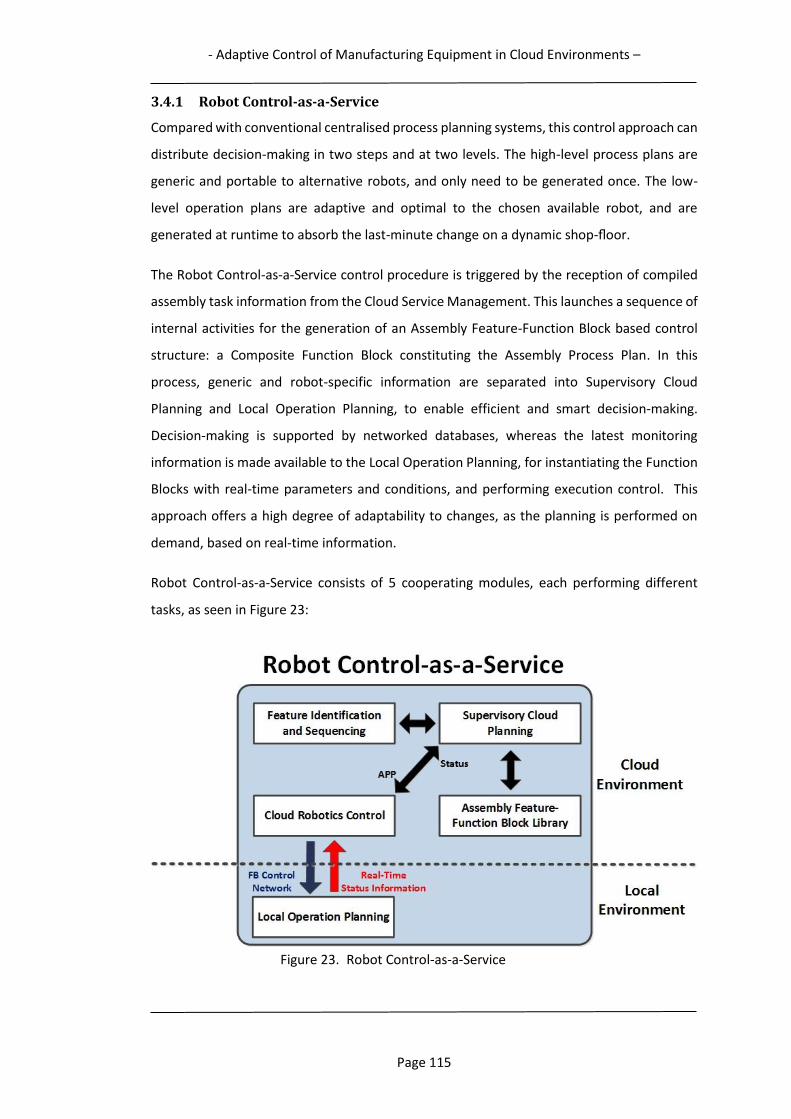
- Adaptive Control of Manufacturing Equipment in Cloud Environments –
Page 115
3.4.1 Robot Control-as-a-Service
Compared with conventional centralised process planning systems, this control approach can
distribute decision-making in two steps and at two levels. The high-level process plans are
generic and portable to alternative robots, and only need to be generated once. The low-
level operation plans are adaptive and optimal to the chosen available robot, and are
generated at runtime to absorb the last-minute change on a dynamic shop-floor.
The Robot Control-as-a-Service control procedure is triggered by the reception of compiled
assembly task information from the Cloud Service Management. This launches a sequence of
internal activities for the generation of an Assembly Feature-Function Block based control
structure: a Composite Function Block constituting the Assembly Process Plan. In this
process, generic and robot-specific information are separated into Supervisory Cloud
Planning and Local Operation Planning, to enable efficient and smart decision-making.
Decision-making is supported by networked databases, whereas the latest monitoring
information is made available to the Local Operation Planning, for instantiating the Function
Blocks with real-time parameters and conditions, and performing execution control. This
approach offers a high degree of adaptability to changes, as the planning is performed on
demand, based on real-time information.
Robot Control-as-a-Service consists of 5 cooperating modules, each performing different
tasks, as seen in Figure 23:
Figure 23. Robot Control-as-a-Service
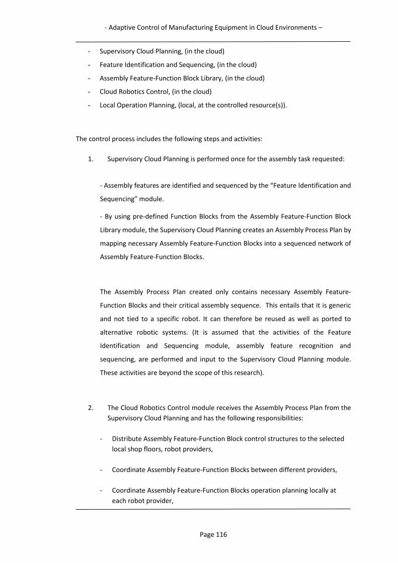
- Adaptive Control of Manufacturing Equipment in Cloud Environments –
Page 116
- Supervisory Cloud Planning, (in the cloud)
- Feature Identification and Sequencing, (in the cloud)
- Assembly Feature-Function Block Library, (in the cloud)
- Cloud Robotics Control, (in the cloud)
- Local Operation Planning, (local, at the controlled resource(s)).
The control process includes the following steps and activities:
1. Supervisory Cloud Planning is performed once for the assembly task requested:
- Assembly features are identified and sequenced by the “Feature Identification and
Sequencing” module.
- By using pre-defined Function Blocks from the Assembly Feature-Function Block
Library module, the Supervisory Cloud Planning creates an Assembly Process Plan by
mapping necessary Assembly Feature-Function Blocks into a sequenced network of
Assembly Feature-Function Blocks.
The Assembly Process Plan created only contains necessary Assembly Feature-
Function Blocks and their critical assembly sequence. This entails that it is generic
and not tied to a specific robot. It can therefore be reused as well as ported to
alternative robotic systems. (It is assumed that the activities of the Feature
Identification and Sequencing module, assembly feature recognition and
sequencing, are performed and input to the Supervisory Cloud Planning module.
These activities are beyond the scope of this research).
2. The Cloud Robotics Control module receives the Assembly Process Plan from the
Supervisory Cloud Planning and has the following responsibilities:
- Distribute Assembly Feature-Function Block control structures to the selected
local shop floors, robot providers,
- Coordinate Assembly Feature-Function Blocks between different providers,
- Coordinate Assembly Feature-Function Blocks operation planning locally at
each robot provider,
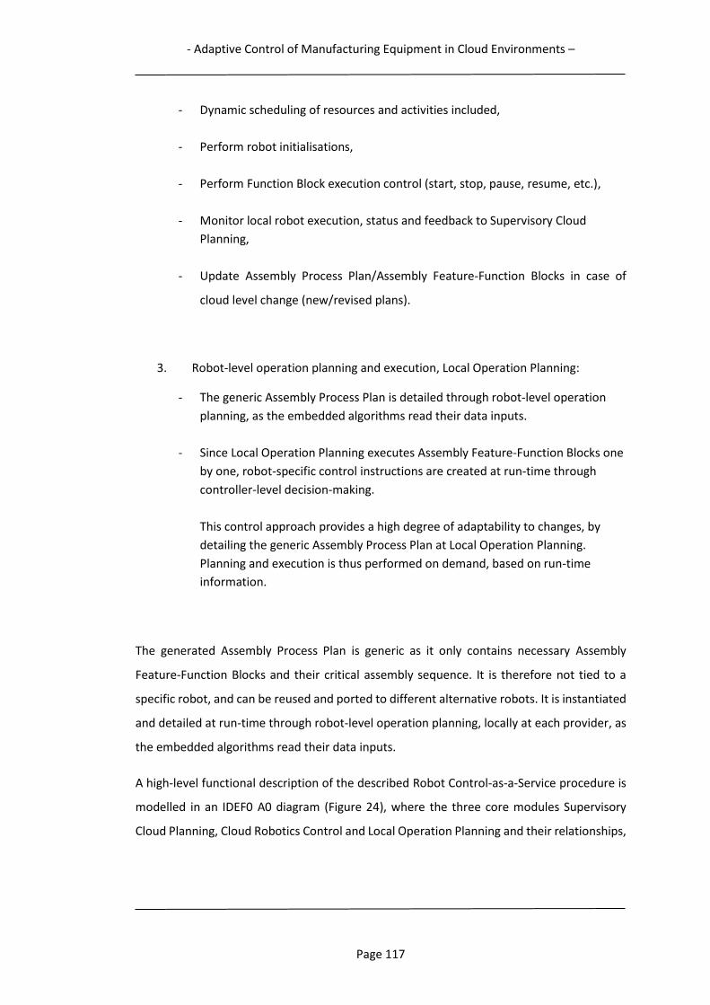
- Adaptive Control of Manufacturing Equipment in Cloud Environments –
Page 117
- Dynamic scheduling of resources and activities included,
- Perform robot initialisations,
- Perform Function Block execution control (start, stop, pause, resume, etc.),
- Monitor local robot execution, status and feedback to Supervisory Cloud
Planning,
- Update Assembly Process Plan/Assembly Feature-Function Blocks in case of
cloud level change (new/revised plans).
3. Robot-level operation planning and execution, Local Operation Planning:
- The generic Assembly Process Plan is detailed through robot-level operation
planning, as the embedded algorithms read their data inputs.
- Since Local Operation Planning executes Assembly Feature-Function Blocks one
by one, robot-specific control instructions are created at run-time through
controller-level decision-making.
This control approach provides a high degree of adaptability to changes, by
detailing the generic Assembly Process Plan at Local Operation Planning.
Planning and execution is thus performed on demand, based on run-time
information.
The generated Assembly Process Plan is generic as it only contains necessary Assembly
Feature-Function Blocks and their critical assembly sequence. It is therefore not tied to a
specific robot, and can be reused and ported to different alternative robots. It is instantiated
and detailed at run-time through robot-level operation planning, locally at each provider, as
the embedded algorithms read their data inputs.
A high-level functional description of the described Robot Control-as-a-Service procedure is
modelled in an IDEF0 A0 diagram (Figure 24), where the three core modules Supervisory
Cloud Planning, Cloud Robotics Control and Local Operation Planning and their relationships,

- Adaptive Control of Manufacturing Equipment in Cloud Environments –
Page 118
data and information flow, and controlling and enabling mechanisms are included. Enabling
mechanisms are denoted M1 – M3, representing human, computer, and network.
Figure 24. IDEF0 Model of Robot Control-as-a-Service
3.4.2 Cloud Service Management
The administration and supervisory management of all cloud services is performed by the
Cloud Manufacturing platform Cloud Service Management module (Figure 26), which is
responsible for service discovery and matching, in which automatic decomposition of
requested manufacturing tasks and composition of services to complete a task is one of the
most attractive properties of Cloud Manufacturing. Cloud Service Management is also
responsible for dynamically coordinating manufacturing planning and execution control of
distributed manufacturing resources. Dynamically coordinating services requires constant
monitoring of run-time conditions and scheduled activities of all resources, which must all be
accessible on-line.
To perform a manufacturing task, a variety of services in combinations are possible. In this
research study the focus is on the low level cloud service approach alternative, to emphasise
the multiple resource sharing and collaborative perspectives of Cloud Manufacturing, and
it´s inherent core virtue of creating higher levels of functionality, through the combination
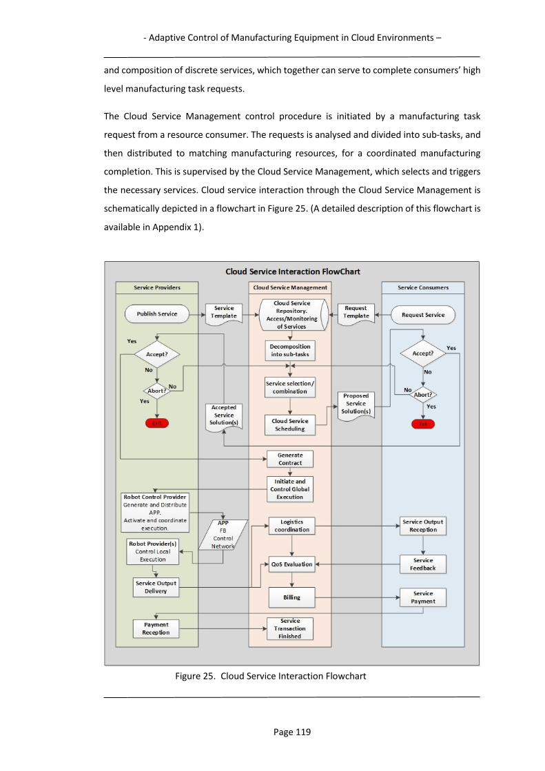
- Adaptive Control of Manufacturing Equipment in Cloud Environments –
Page 119
and composition of discrete services, which together can serve to complete consumers’ high
level manufacturing task requests.
The Cloud Service Management control procedure is initiated by a manufacturing task
request from a resource consumer. The requests is analysed and divided into sub-tasks, and
then distributed to matching manufacturing resources, for a coordinated manufacturing
completion. This is supervised by the Cloud Service Management, which selects and triggers
the necessary services. Cloud service interaction through the Cloud Service Management is
schematically depicted in a flowchart in Figure 25. (A detailed description of this flowchart is
available in Appendix 1).
Figure 25. Cloud Service Interaction Flowchart
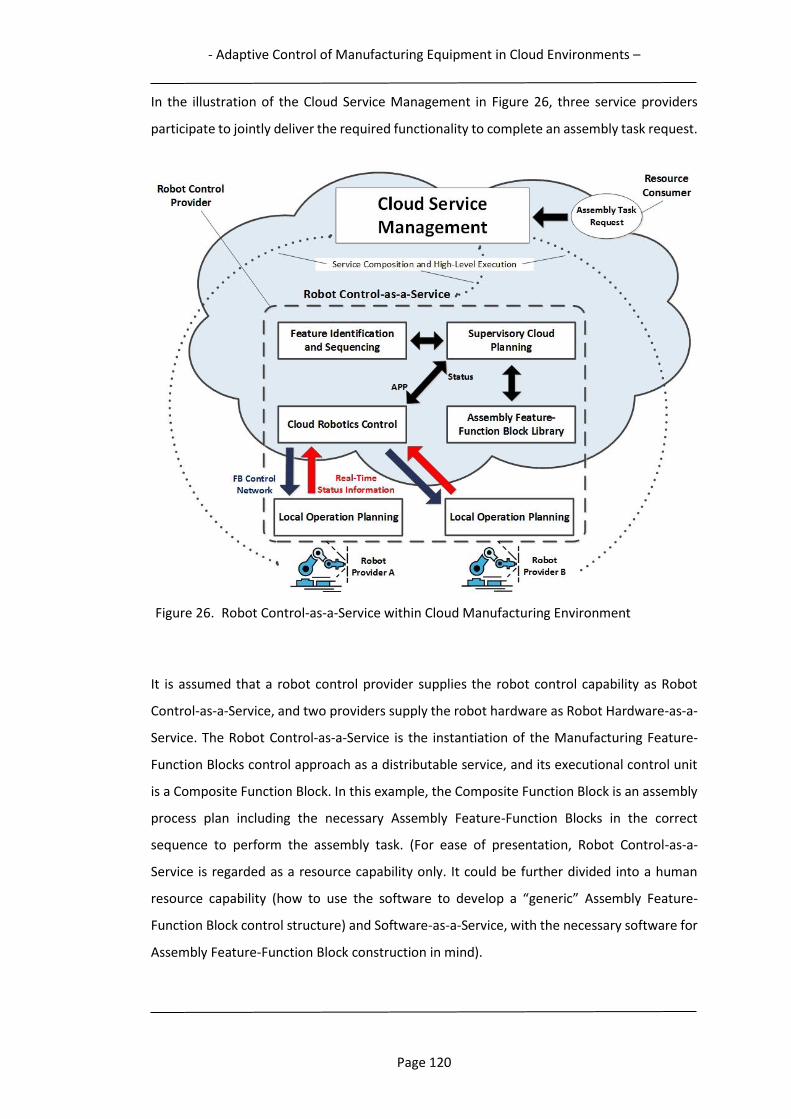
- Adaptive Control of Manufacturing Equipment in Cloud Environments –
Page 120
In the illustration of the Cloud Service Management in Figure 26, three service providers
participate to jointly deliver the required functionality to complete an assembly task request.
Figure 26. Robot Control-as-a-Service within Cloud Manufacturing Environment
It is assumed that a robot control provider supplies the robot control capability as Robot
Control-as-a-Service, and two providers supply the robot hardware as Robot Hardware-as-a-
Service. The Robot Control-as-a-Service is the instantiation of the Manufacturing Feature-
Function Blocks control approach as a distributable service, and its executional control unit
is a Composite Function Block. In this example, the Composite Function Block is an assembly
process plan including the necessary Assembly Feature-Function Blocks in the correct
sequence to perform the assembly task. (For ease of presentation, Robot Control-as-a-
Service is regarded as a resource capability only. It could be further divided into a human
resource capability (how to use the software to develop a “generic” Assembly Feature-
Function Block control structure) and Software-as-a-Service, with the necessary software for
Assembly Feature-Function Block construction in mind).
- Adaptive Control of Manufacturing Equipment in Cloud Environments –
Page 121
3.4.3 Summary
Through the integration of the Manufacturing Feature-Function Block control approach into
a cloud-based two-level planning and control structure, adaptive and distributed
manufacturing equipment control can be realised within Cloud Manufacturing; implemented
in a cloud platform as manufacturing services, e.g. Robot Control-as-a-Service,
Manufacturing Feature-Function Blocks perform planning and execution of manufacturing
tasks at different system control levels. The centralised generation of generic process plans
which, after distribution to selected manufacturing resources, are instantiated and detailed
at run-time through local operation planning, caters for adaptive control behaviour.
In the subsequent three chapters (4, 5, and 6), the concept of adaptive control of robotic
assembly tasks in different scenarios are presented. The control approach is further detailed
and evaluated in both local, distributed, real and virtual assembly scenarios, demonstrated
through the use of Assembly Feature-Function Blocks for automated robotic assembly tasks.
The control concept is demonstrated in a research study evolutionary perspective:
- Chapter 4 presents a local control application with a real gantry robot, in
conjunction with a CNC-milling machine. In this setup, the gantry robot has
served as the material handler and assembler, with tasks such as loading and
unloading of products to be machined, as well as assembling parts of different
variants after machining operations by the CNC machine.
- Chapter 5 presents the adaptive and distributed control of both virtual and real
robots for an assembly cell application, with assembly of washers onto variants
of shafts.
- Chapter 6 presents a full scale Cloud Manufacturing assembly application
scenario for Assembly Feature-Function Block based control, with Robot Control-
as-a-Service.
-Function Block Control of a Production Cell-
Page 122
4 Function Block Control of a Production Cell
In order to test and evaluate the capability of manufacturing equipment control for the
proposed Feature-based Function Block control method, a case study with the control of
machining, assembly and material handling operations in a small production cell
demonstrator has been undertaken. When setting the scope of this case study, the focus has
been to be able to evaluate the control systems capability to effectively handle different
production scenarios, as well as performing direct, local equipment control. The functionality
of both Assembly Feature-Function Blocks for robotic operations, and Machining Feature-
Function Blocks for machining operations have been tested.
The applied research method is described in section 4.1, followed by a description of the
demonstrator production cell in section 4.2. The details of the test case is described in section
4.3, while the case study evaluation is presented in section 4.4, followed by a summary in
section 4.5.
4.1 Research method
To be able to assess the proposed concept for manufacturing equipment control a suitable
research method was needed. Performing test cases on a production cell demonstrator,
emulating a real-world production scenario was identified as the best possible method,
following the Design Science Research methodology. Therefore, a laboratory production cell
demonstrator has been built, which is described in the following section.
4.2 Production cell demonstrator
As robotic assembly has been selected to demonstrate the applicability of the proposed
control method a demonstrator production cell has been built, including a 3-axis gantry
robot. The robot is integrated with a small 3-axis table-top CNC-milling machine to perform
an industrial machining and assembly process, requiring their coordination and cooperation
to fulfill the task (Figure 27).
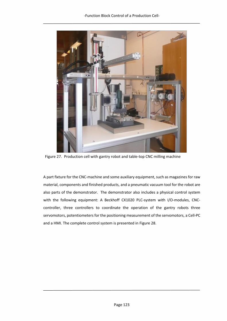
-Function Block Control of a Production Cell-
Page 123
Figure 27. Production cell with gantry robot and table-top CNC milling machine
A part fixture for the CNC-machine and some auxiliary equipment, such as magazines for raw
material, components and finished products, and a pneumatic vacuum tool for the robot are
also parts of the demonstrator. The demonstrator also includes a physical control system
with the following equipment: A Beckhoff CX1020 PLC-system with I/O-modules, CNC-
controller, three controllers to coordinate the operation of the gantry robots three
servomotors, potentiometers for the positioning measurement of the servomotors, a Cell-PC
and a HMI. The complete control system is presented in Figure 28.
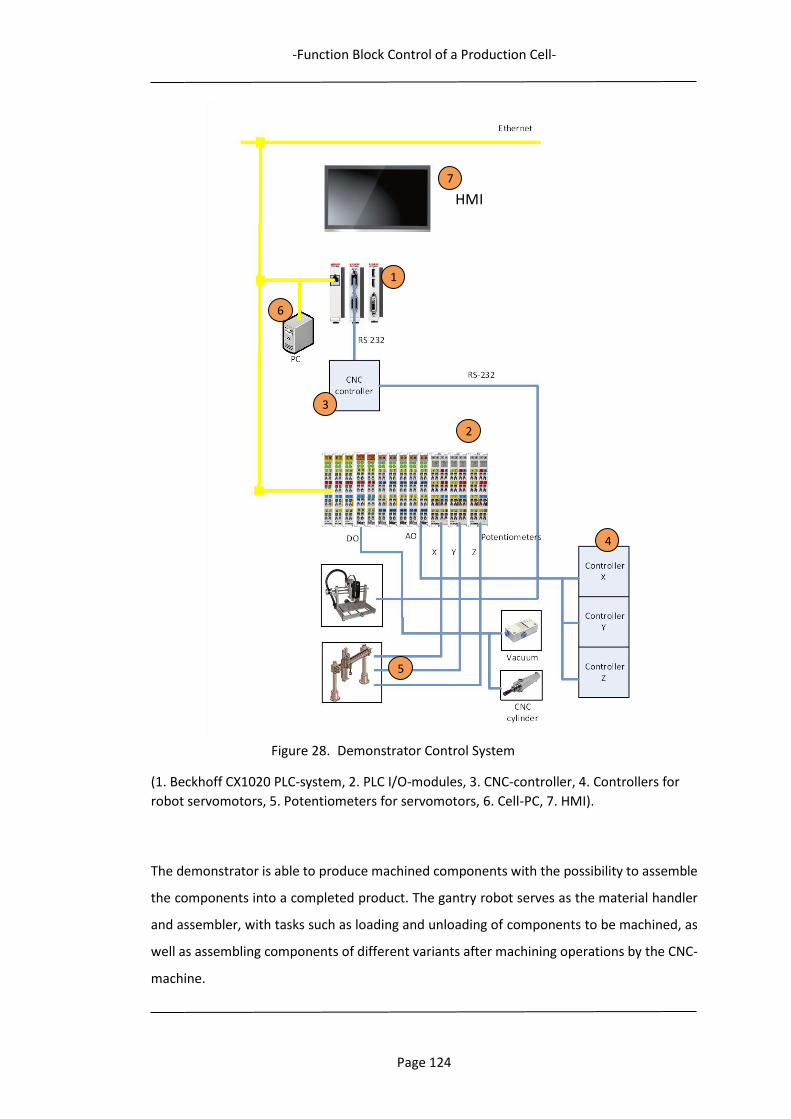
-Function Block Control of a Production Cell-
Page 124
Figure 28. Demonstrator Control System
(1. Beckhoff CX1020 PLC-system, 2. PLC I/O-modules, 3. CNC-controller, 4. Controllers for
robot servomotors, 5. Potentiometers for servomotors, 6. Cell-PC, 7. HMI).
The demonstrator is able to produce machined components with the possibility to assemble
the components into a completed product. The gantry robot serves as the material handler
and assembler, with tasks such as loading and unloading of components to be machined, as
well as assembling components of different variants after machining operations by the CNC-
machine.
HMI
1
2
3
4
5
6
7
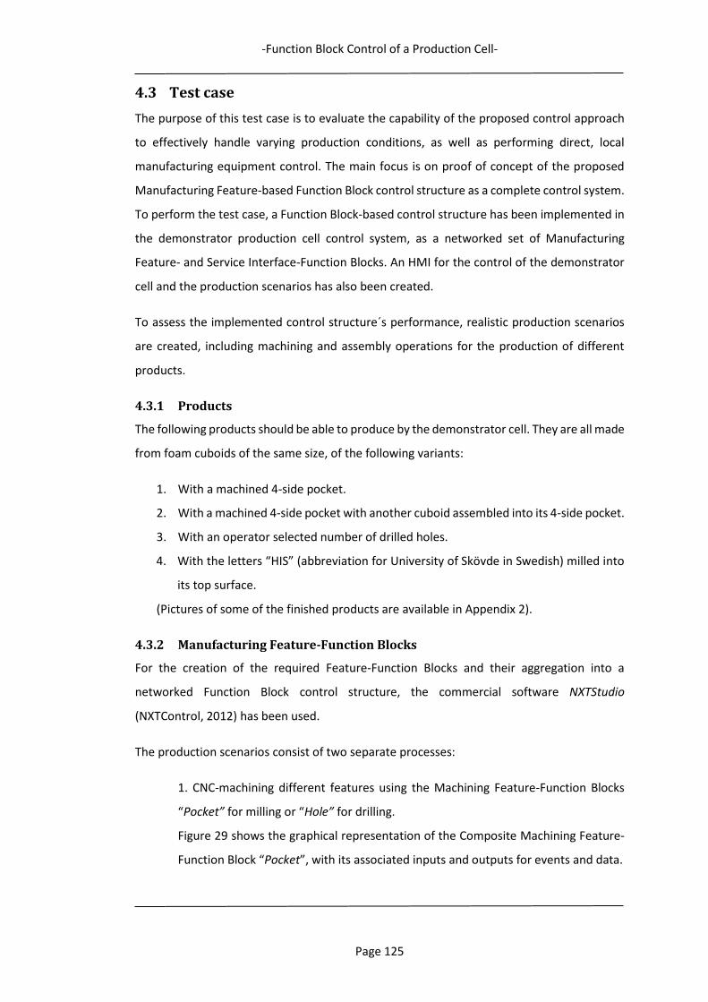
-Function Block Control of a Production Cell-
Page 125
4.3 Test case
The purpose of this test case is to evaluate the capability of the proposed control approach
to effectively handle varying production conditions, as well as performing direct, local
manufacturing equipment control. The main focus is on proof of concept of the proposed
Manufacturing Feature-based Function Block control structure as a complete control system.
To perform the test case, a Function Block-based control structure has been implemented in
the demonstrator production cell control system, as a networked set of Manufacturing
Feature- and Service Interface-Function Blocks. An HMI for the control of the demonstrator
cell and the production scenarios has also been created.
To assess the implemented control structure´s performance, realistic production scenarios
are created, including machining and assembly operations for the production of different
products.
4.3.1 Products
The following products should be able to produce by the demonstrator cell. They are all made
from foam cuboids of the same size, of the following variants:
1. With a machined 4-side pocket.
2. With a machined 4-side pocket with another cuboid assembled into its 4-side pocket.
3. With an operator selected number of drilled holes.
4. With the letters “HIS” (abbreviation for University of Skövde in Swedish) milled into
its top surface.
(Pictures of some of the finished products are available in Appendix 2).
4.3.2 Manufacturing Feature-Function Blocks
For the creation of the required Feature-Function Blocks and their aggregation into a
networked Function Block control structure, the commercial software NXTStudio
(NXTControl, 2012) has been used.
The production scenarios consist of two separate processes:
1. CNC-machining different features using the Machining Feature-Function Blocks
“Pocket” for milling or “Hole” for drilling.
Figure 29 shows the graphical representation of the Composite Machining Feature-
Function Block “Pocket”, with its associated inputs and outputs for events and data.
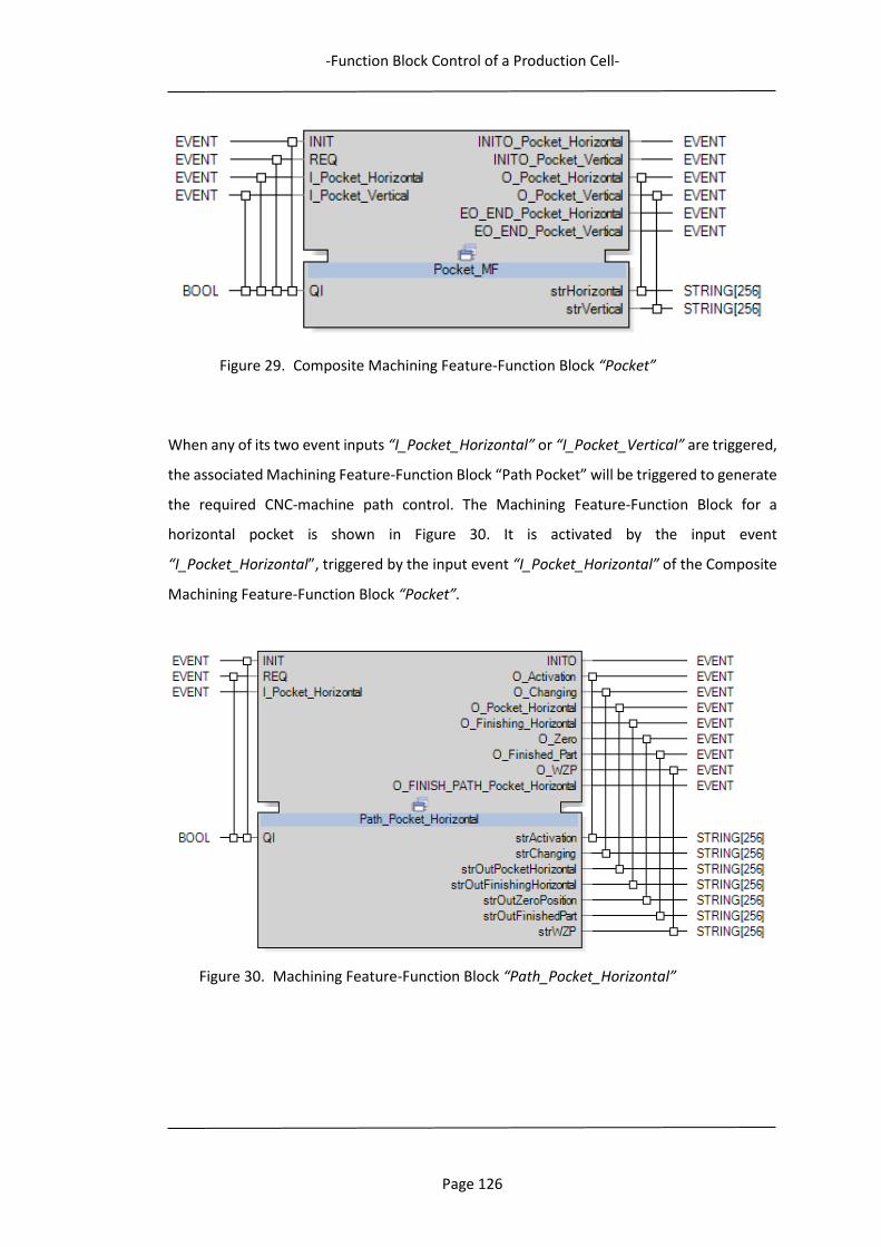
-Function Block Control of a Production Cell-
Page 126
Figure 29. Composite Machining Feature-Function Block “Pocket”
When any of its two event inputs “I_Pocket_Horizontal” or “I_Pocket_Vertical” are triggered,
the associated Machining Feature-Function Block “Path Pocket” will be triggered to generate
the required CNC-machine path control. The Machining Feature-Function Block for a
horizontal pocket is shown in Figure 30. It is activated by the input event
“I_Pocket_Horizontal”, triggered by the input event “I_Pocket_Horizontal” of the Composite
Machining Feature-Function Block “Pocket”.
Figure 30. Machining Feature-Function Block “Path_Pocket_Horizontal”

-Function Block Control of a Production Cell-
Page 127
2. Robotic assembly of components into machined features, using Assembly Feature-
Function Blocks. As Assembly Features in this research are defined as operations
mating two objects, the Assembly Features of the robotic operations sequence are:
“Place”: For placing the base plate in the fixture, and after machining and assembly,
placing the completed component in the correct finished products magazine.
“Insert”: For inserting a component into the base plate machined pocket.
Figure 31 shows the graphical representation of the Assembly Feature-Function Block
“Place”, with its associated inputs and outputs for events and data.
Figure 31. Assembly Feature-Function Block PLACE
The purpose of this Function Block is to generate the path coordinates which the robot should
move to. The coordinates of the path´s start and end positions (pick and place positions) are
provided by data inputs (“CNC_Piece” and “Finish_Pos”) generated at system initialisation or
from HMI operator input. The robot safe position, “NEUTRAL” is also provided, to enable the
robot to move to a safe position at the end of the path, after finishing the placing operations.
The next desired position to move to in a path is calculated by an algorithm and published as
data outputs, together with the correct output values for controlling the fixture and the
vacuum tool. Also, the Assembly Feature-Function Block is notified by the data inputs
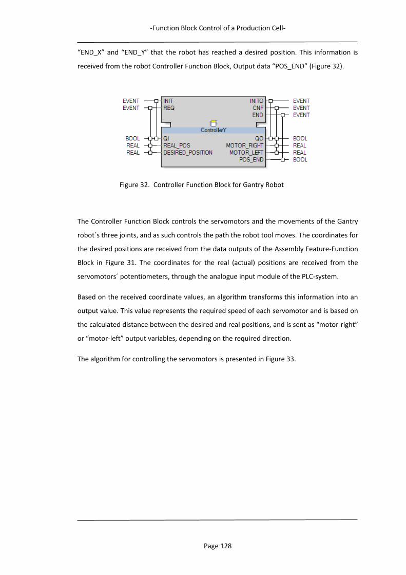
-Function Block Control of a Production Cell-
Page 128
“END_X” and “END_Y” that the robot has reached a desired position. This information is
received from the robot Controller Function Block, Output data “POS_END” (Figure 32).
Figure 32. Controller Function Block for Gantry Robot
The Controller Function Block controls the servomotors and the movements of the Gantry
robot´s three joints, and as such controls the path the robot tool moves. The coordinates for
the desired positions are received from the data outputs of the Assembly Feature-Function
Block in Figure 31. The coordinates for the real (actual) positions are received from the
servomotors´ potentiometers, through the analogue input module of the PLC-system.
Based on the received coordinate values, an algorithm transforms this information into an
output value. This value represents the required speed of each servomotor and is based on
the calculated distance between the desired and real positions, and is sent as “motor-right”
or “motor-left” output variables, depending on the required direction.
The algorithm for controlling the servomotors is presented in Figure 33.
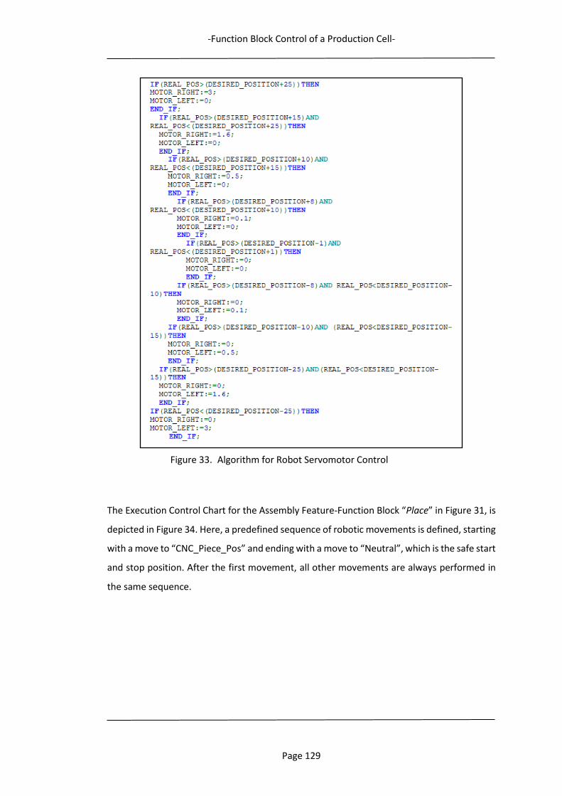
-Function Block Control of a Production Cell-
Page 129
Figure 33. Algorithm for Robot Servomotor Control
The Execution Control Chart for the Assembly Feature-Function Block “Place” in Figure 31, is
depicted in Figure 34. Here, a predefined sequence of robotic movements is defined, starting
with a move to “CNC_Piece_Pos” and ending with a move to “Neutral”, which is the safe start
and stop position. After the first movement, all other movements are always performed in
the same sequence.
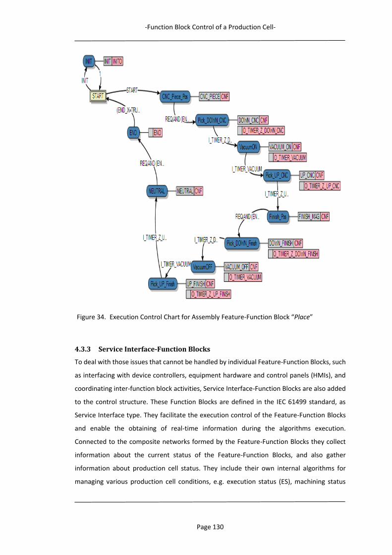
-Function Block Control of a Production Cell-
Page 130
Figure 34. Execution Control Chart for Assembly Feature-Function Block “Place”
4.3.3 Service Interface-Function Blocks
To deal with those issues that cannot be handled by individual Feature-Function Blocks, such
as interfacing with device controllers, equipment hardware and control panels (HMIs), and
coordinating inter-function block activities, Service Interface-Function Blocks are also added
to the control structure. These Function Blocks are defined in the IEC 61499 standard, as
Service Interface type. They facilitate the execution control of the Feature-Function Blocks
and enable the obtaining of real-time information during the algorithms execution.
Connected to the composite networks formed by the Feature-Function Blocks they collect
information about the current status of the Feature-Function Blocks, and also gather
information about production cell status. They include their own internal algorithms for
managing various production cell conditions, e.g. execution status (ES), machining status
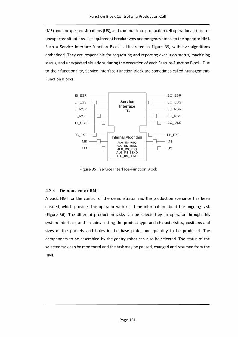
-Function Block Control of a Production Cell-
Page 131
(MS) and unexpected situations (US), and communicate production cell operational status or
unexpected situations, like equipment breakdowns or emergency stops, to the operator HMI.
Such a Service Interface-Function Block is illustrated in Figure 35, with five algorithms
embedded. They are responsible for requesting and reporting execution status, machining
status, and unexpected situations during the execution of each Feature-Function Block. Due
to their functionality, Service Interface-Function Block are sometimes called Management-
Function Blocks.
Figure 35. Service Interface-Function Block
4.3.4 Demonstrator HMI
A basic HMI for the control of the demonstrator and the production scenarios has been
created, which provides the operator with real-time information about the ongoing task
(Figure 36). The different production tasks can be selected by an operator through this
system interface, and includes setting the product type and characteristics, positions and
sizes of the pockets and holes in the base plate, and quantity to be produced. The
components to be assembled by the gantry robot can also be selected. The status of the
selected task can be monitored and the task may be paused, changed and resumed from the
HMI.
Service
Interface
FB
Internal Algorithm
ALG_ES_REQ
ALG_ES_SEND
ALG_MS_REQ
ALG_MS_SEND
ALG_US_SEND
EI_ESR
EI_ESS
EI_MSR
EI_MSS
EO_ESR
EO_ESS
EO_MSR
EO_MSS
EI_USS EO_USS
FB_EXE
MS
US
FB_EXE
MS
US

-Function Block Control of a Production Cell-
Page 132
Figure 36. Production Cell HMI
4.3.5 Demonstrator production sequence
The production sequence starts by selecting the type and quantity of products to be
manufactured, while the CNC machine tool and the gantry robot both are in safe positions.
Raw material, a base plate in the shape of a foam cuboid, is moved by the gantry robot from
the base plate magazine, using a vacuum tool, to the CNC-machine. It is then machined
according to the selected task, while being secured by the pneumatically actuated fixture.
The machining operation starts when the proper Machining Feature-Function Block is fired
by the Function Block control system. If the machining operation is a hole or milling of letters,
the gantry robot picks the plate from the fixture after the machining operation have finished
and places it in the appropriate finished products magazine. If the machining operation is a
pocket, the gantry robot also performs an assembly operation, where a component is
inserted into the milled pocket, before placing the finalised product in another magazine for
finished products. The sequence is repeated until all ordered products have been finalised
and placed in appropriate magazines, after which the CNC machine tool and the robot are
returned to their safe positions.
-Function Block Control of a Production Cell-
Page 133
4.3.6 Robotic assembly sequence
The detailed assembly sequence for robotic operations is:
- Pick up a base plate from base plate magazine.
- Place the base plate in CNC fixture.
- Pick up one component from component magazine (two different variants).
- Wait until the machining of the pocket is finished.
- Assemble the component with the base plate, by inserting it in the correct location
of the pocket.
- Pick up the assembled product from the fixture.
- Place the assembled product in a finished products magazine.
4.3.7 Demonstrator cell control
Direct equipment control is dynamically generated through the use of Machining and
Assembly Features in combination with IEC 61499 Function Blocks. In this case study, the
software NXTStudio is used for both individual Function Block and control structure
development, and for developing and running an HMI. The cell level PC is used as
development platform, running the software NXTStudio, in which the feature-based IEC
61499 Function Block control structure is implemented. The PLC-system constitutes the
demonstrator run-time environment, to which the Function Block control structure is
downloaded for real-time execution of the Feature-Function Blocks and control of the
machining and robotic operations. The CNC-machine is controlled through its native CNC-
controller, and the Machining Feature-Function Blocks in the control structure communicates
with the CNC-controller in real-time using RS-232. The operations of the gantry robot are
controlled by the Assembly Feature-Function Blocks, and the servomotors of the gantry robot
are controlled directly through the PLC I/O-modules, with potentiometers for position
feedback. The HMI, which runs on the Cell-PC, is also implemented using NXTStudio.
To be able to correctly perform these operations, the required input information that the
control system needs to read during initialization are the positions of the CNC-machine, the
fixture, and the magazines, and default system settings for safe positions for the robot and
the CNC-machine. (Orientations do not need to be specified in this setup as the structure of
the 3-axis Cartesian gantry robot, without any rotational joints, restricts its operations to
movements in straight paths only.) To start a production task, the operator uses the HMI to
input the required information, i.e. the data of a pocket or hole, its position and depth,
-Function Block Control of a Production Cell-
Page 134
product quantity, and if required, what components to be assembled by the robot into a
finished product. At start-up, this information is conveyed to the Feature-Function Blocks and
their algorithms for event-driven execution of the selected production task.
The assembly sequence is pre-determined in this scenario. If the selection of assembly
sequence would be included as an option, the sequence must be decided before assembly
starts, for possible generation of correct assembly paths.
4.4 Case study evaluation
The purpose of this case study has been to test and evaluate the proposed Feature-based
Function Block control method, implemented as an operational Function Block control
system network for a production system. The testing included ordering the production of all
four products described in section 4.3.1, using the HMI to detail the production tasks. Tests
of both Assembly Feature-Function Blocks for robotic operations, and Machining Feature-
Function Blocks for machining operations, were thus undertaken to evaluate the capability
of the proposed control approach to effectively handle varying production conditions and
performing direct, local equipment control. The ability to handle fault detection was also
tested.
The findings of the tests undertaken are summarised as follows:
- The pick-up positions for base plates and components, the CNC-fixture and the
magazines, can all be arbitrarily positioned within the robot’s working envelope. This
information is read at system initialization or when changed by the operator, and fed
to the Feature-Function Blocks.
- The pocket where the component should be inserted can be arbitrarily positioned in
the base plate’s top surface. Data inputs with necessary position information for each
movement, make up the possible adaptive real-time scenario by the Execution
Control Chart. Even after the production has been started, new locations for robot
movements can be fed to the Assembly Feature-Function Block, as the information
is forwarded, through the data inputs, to the algorithms as the Function Block
executes.
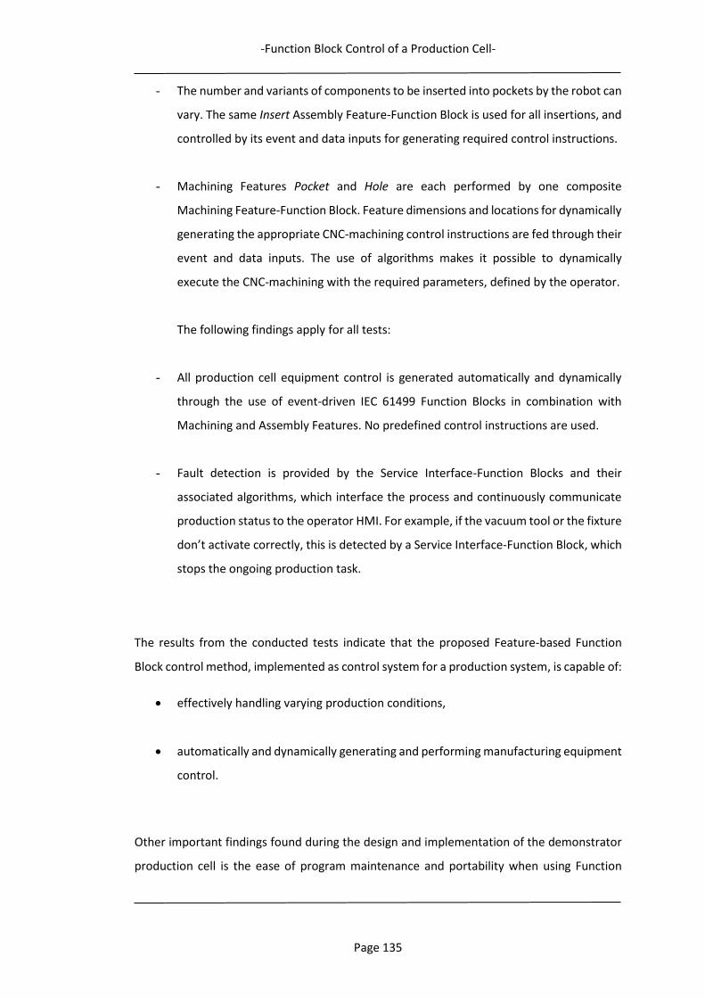
-Function Block Control of a Production Cell-
Page 135
- The number and variants of components to be inserted into pockets by the robot can
vary. The same Insert Assembly Feature-Function Block is used for all insertions, and
controlled by its event and data inputs for generating required control instructions.
- Machining Features Pocket and Hole are each performed by one composite
Machining Feature-Function Block. Feature dimensions and locations for dynamically
generating the appropriate CNC-machining control instructions are fed through their
event and data inputs. The use of algorithms makes it possible to dynamically
execute the CNC-machining with the required parameters, defined by the operator.
The following findings apply for all tests:
- All production cell equipment control is generated automatically and dynamically
through the use of event-driven IEC 61499 Function Blocks in combination with
Machining and Assembly Features. No predefined control instructions are used.
- Fault detection is provided by the Service Interface-Function Blocks and their
associated algorithms, which interface the process and continuously communicate
production status to the operator HMI. For example, if the vacuum tool or the fixture
don’t activate correctly, this is detected by a Service Interface-Function Block, which
stops the ongoing production task.
The results from the conducted tests indicate that the proposed Feature-based Function
Block control method, implemented as control system for a production system, is capable of:
effectively handling varying production conditions,
automatically and dynamically generating and performing manufacturing equipment
control.
Other important findings found during the design and implementation of the demonstrator
production cell is the ease of program maintenance and portability when using Function

-Function Block Control of a Production Cell-
Page 136
Blocks. If some part of the program needs to be replaced or changed, this does not affect the
rest of the program. This also means that new Manufacturing Features can easily be
introduced, as the functional behaviour of a unique Feature-Function Block is self-contained.
4.5 Summary
By using a demonstrator production cell, this case study has demonstrated the capability of
the proposed Feature-based Function Block control approach. The performance of the
demonstrator cell has been evaluated and the results verify the satisfactory functionality of
the control approach, which has demonstrated the ability to handle changing production
conditions (Adamson, Holm, & Wang, 2012; Adamson, Holm, Wang, et al., 2012; Holm et al.,
2013; Holm et al., 2012). The Function Block control structure is fully capable of controlling
the operations of the CNC-machine and the gantry robot, monitoring states and variables of
the system to enable a real-time manufacturing approach for decision-making in the
demonstrator cell, as well as managing the communications within the cell (needed for
integrating the CNC-machine with the operations of the gantry robot and realising the overall
production task).
The case study shows that both the assembly, machining and material handling operations
can be defined and executed using Feature-based IEC 61499 Function Blocks. The gantry
robot and the table-top CNC-machine are both directly controlled by the outputs of such
Function Blocks, and no intermediate translation to G-code is therefore needed. The results
also show that the Function Block control system can handle changes when the production
task is changed, without any reprogramming. No proprietary control instructions are needed
and the necessary data input by the operator is much less, compared to the re-programming
required in case of an ordinary device controller.
The major benefit with the proposed control approach is the event-driven nature of the IEC
61499 Function Blocks, in which the Execution Control Chart facilitates decision-making to
adapt to the requirements of the process, based on real-time conditions. As such, the event-
driven concept enriches the control structure with a higher intelligence and autonomy,
compared to traditional scan-based systems. The use of IEC 61499 Function Blocks also
increases the reusability and maintenance of control programs. The Function Blocks can
easily be exchanged and control code generating algorithms can be modified, without having
a negative impact on the functionality of the rest of the control system. Another benefit is
that the Function Block control structure separates high-level information, such as the

-Function Block Control of a Production Cell-
Page 137
production plan, from the generation of low-level device control instructions. This enables
the exchange of production equipment, as well as the extension of system functionality. And
since the concept of Feature-based IEC 61499 Function Blocks is generic the proposed control
approach may be applied to other production scenarios than the ones described here.
In the following chapter, the applicability of this control approach in a distributed
environment, for both real and virtual robotic assembly, is presented and evaluated.
4.5.1 Acknowledgment
The implementation of the Function Block-based control concept in the test case presented
was realised according to my instructions, with the support of two students at the University
of Skövde, Raul Diaz Rios and Jose Enrique Palomeque Soto. The author of this paper would
like to thank them for their support of this research programme.
- Function Block Control of Real and Virtual Assembly Cells in a Distributed Environment –
Page 138
5 Function Block Control of Real and Virtual Assembly Cells in
a Distributed Environment
In order to further test and evaluate the capability of the Feature-based Function Block
control method to realise adaptive manufacturing equipment control, a case study with the
control of robotic assembly operations in a small demonstrator robot cell has been
undertaken. When setting the scope of this case study, the focus has been to be able to
evaluate the control systems capability to effectively adapt to varying assembly conditions
through the dynamic generation of robot control code, for both real and virtual assembly
environments, as well as performing distributed equipment control. Distribution here implies
control over a network, which can be a local LAN network, or an Internet network, e.g. Cloud
control applications (Chapter 6). A Cell level PC/Controller can therefore be in close proximity
to the controlled application, e.g. in the same room, or further away, e.g. as for a cloud
application. Real-time requirements for the control are not included within the scope of this
research study, which addresses the contents, structure and functionality of the proposed
Function Block control approach.
The applied research method is described in section 5.1, followed by a description of the
robotic assembly cell demonstrators in section 5.2. The details of the test case is described
in section 5.3, while the case study evaluation is presented in section 5.4, followed by a
summary in section 5.5.
5.1 Research method
To be able to assess the proposed concept for adaptive manufacturing equipment control a
suitable research method was needed. Performing test cases on a robotic assembly cell
demonstrator, emulating a real-world assembly scenario was identified as the best possible
method, following the Design Science Research methodology. As the use of virtual
environments for control code verification (e.g. offline-programming and simulation) is an
established and effective system development approach, both real and virtual assembly cell
demonstrators have been developed, which is described in the following sections.
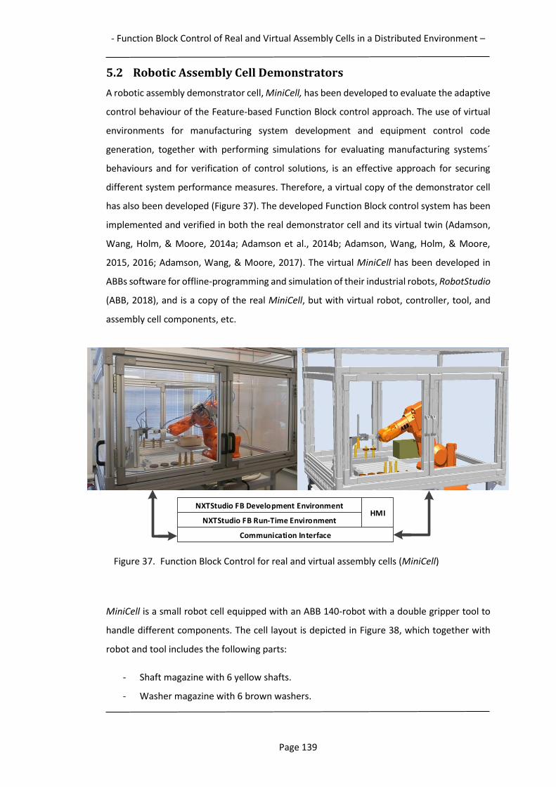
- Function Block Control of Real and Virtual Assembly Cells in a Distributed Environment –
Page 139
5.2 Robotic Assembly Cell Demonstrators
A robotic assembly demonstrator cell, MiniCell, has been developed to evaluate the adaptive
control behaviour of the Feature-based Function Block control approach. The use of virtual
environments for manufacturing system development and equipment control code
generation, together with performing simulations for evaluating manufacturing systems´
behaviours and for verification of control solutions, is an effective approach for securing
different system performance measures. Therefore, a virtual copy of the demonstrator cell
has also been developed (Figure 37). The developed Function Block control system has been
implemented and verified in both the real demonstrator cell and its virtual twin (Adamson,
Wang, Holm, & Moore, 2014a; Adamson et al., 2014b; Adamson, Wang, Holm, & Moore,
2015, 2016; Adamson, Wang, & Moore, 2017). The virtual MiniCell has been developed in
ABBs software for offline-programming and simulation of their industrial robots, RobotStudio
(ABB, 2018), and is a copy of the real MiniCell, but with virtual robot, controller, tool, and
assembly cell components, etc.
Figure 37. Function Block Control for real and virtual assembly cells (MiniCell)
MiniCell is a small robot cell equipped with an ABB 140-robot with a double gripper tool to
handle different components. The cell layout is depicted in Figure 38, which together with
robot and tool includes the following parts:
- Shaft magazine with 6 yellow shafts.
- Washer magazine with 6 brown washers.
NXTStudio FB Development Environment
NXTStudio FB Run-Time Environment
Communication Interface
HMI
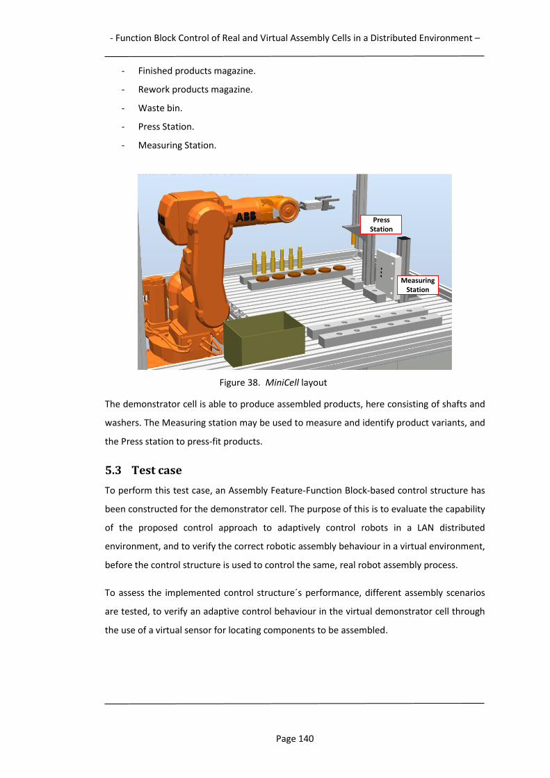
- Function Block Control of Real and Virtual Assembly Cells in a Distributed Environment –
Page 140
- Finished products magazine.
- Rework products magazine.
- Waste bin.
- Press Station.
- Measuring Station.
Figure 38. MiniCell layout
The demonstrator cell is able to produce assembled products, here consisting of shafts and
washers. The Measuring station may be used to measure and identify product variants, and
the Press station to press-fit products.
5.3 Test case
To perform this test case, an Assembly Feature-Function Block-based control structure has
been constructed for the demonstrator cell. The purpose of this is to evaluate the capability
of the proposed control approach to adaptively control robots in a LAN distributed
environment, and to verify the correct robotic assembly behaviour in a virtual environment,
before the control structure is used to control the same, real robot assembly process.
To assess the implemented control structure´s performance, different assembly scenarios
are tested, to verify an adaptive control behaviour in the virtual demonstrator cell through
the use of a virtual sensor for locating components to be assembled.
MeasuringStation
PressStation
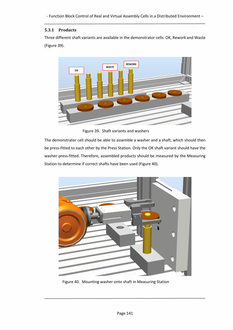
- Function Block Control of Real and Virtual Assembly Cells in a Distributed Environment –
Page 141
5.3.1 Products
Three different shaft variants are available in the demonstrator cells: OK, Rework and Waste
(Figure 39).
Figure 39. Shaft variants and washers
The demonstrator cell should be able to assemble a washer and a shaft, which should then
be press-fitted to each other by the Press Station. Only the OK shaft variant should have the
washer press-fitted. Therefore, assembled products should be measured by the Measuring
Station to determine if correct shafts have been used (Figure 40).
Figure 40. Mounting washer onto shaft in Measuring Station
OKWASTE
REWORK
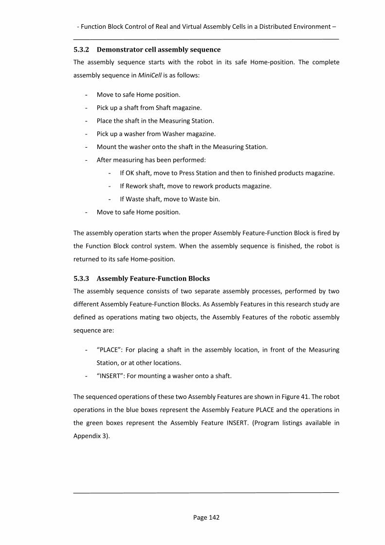
- Function Block Control of Real and Virtual Assembly Cells in a Distributed Environment –
Page 142
5.3.2 Demonstrator cell assembly sequence
The assembly sequence starts with the robot in its safe Home-position. The complete
assembly sequence in MiniCell is as follows:
- Move to safe Home position.
- Pick up a shaft from Shaft magazine.
- Place the shaft in the Measuring Station.
- Pick up a washer from Washer magazine.
- Mount the washer onto the shaft in the Measuring Station.
- After measuring has been performed:
- If OK shaft, move to Press Station and then to finished products magazine.
- If Rework shaft, move to rework products magazine.
- If Waste shaft, move to Waste bin.
- Move to safe Home position.
The assembly operation starts when the proper Assembly Feature-Function Block is fired by
the Function Block control system. When the assembly sequence is finished, the robot is
returned to its safe Home-position.
5.3.3 Assembly Feature-Function Blocks
The assembly sequence consists of two separate assembly processes, performed by two
different Assembly Feature-Function Blocks. As Assembly Features in this research study are
defined as operations mating two objects, the Assembly Features of the robotic assembly
sequence are:
- “PLACE”: For placing a shaft in the assembly location, in front of the Measuring
Station, or at other locations.
- “INSERT”: For mounting a washer onto a shaft.
The sequenced operations of these two Assembly Features are shown in Figure 41. The robot
operations in the blue boxes represent the Assembly Feature PLACE and the operations in
the green boxes represent the Assembly Feature INSERT. (Program listings available in
Appendix 3).
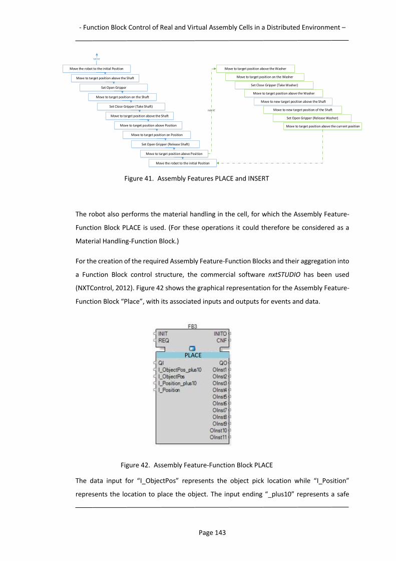
- Function Block Control of Real and Virtual Assembly Cells in a Distributed Environment –
Page 143
Figure 41. Assembly Features PLACE and INSERT
The robot also performs the material handling in the cell, for which the Assembly Feature-
Function Block PLACE is used. (For these operations it could therefore be considered as a
Material Handling-Function Block.)
For the creation of the required Assembly Feature-Function Blocks and their aggregation into
a Function Block control structure, the commercial software nxtSTUDIO has been used
(NXTControl, 2012). Figure 42 shows the graphical representation for the Assembly Feature-
Function Block “Place”, with its associated inputs and outputs for events and data.
Figure 42. Assembly Feature-Function Block PLACE
The data input for “I_ObjectPos” represents the object pick location while “I_Position”
represents the location to place the object. The input ending “_plus10” represents a safe
Move the robot to the initial Position
Move to target position above the Shaft
Set Open Gripper
Move to target position on the Shaft
Set Close Gripper (Take Shaft)
Move to target position above the Shaft
Move to target position above Position
Move to target position on Position
Set Open Gripper (Release Shaft)
Move to target position above Position
Move the robot to the initial Position
Move to target position above the Washer
Move to target position on the Washer
Set Close Gripper (Take Washer)
Move to target position above the Washer
INSERT
Move to new target position above the Shaft
Move to new target position of the Shaft
Set Open Gripper (Release Washer)
Move to target position above the current position
MOVE
PLACE
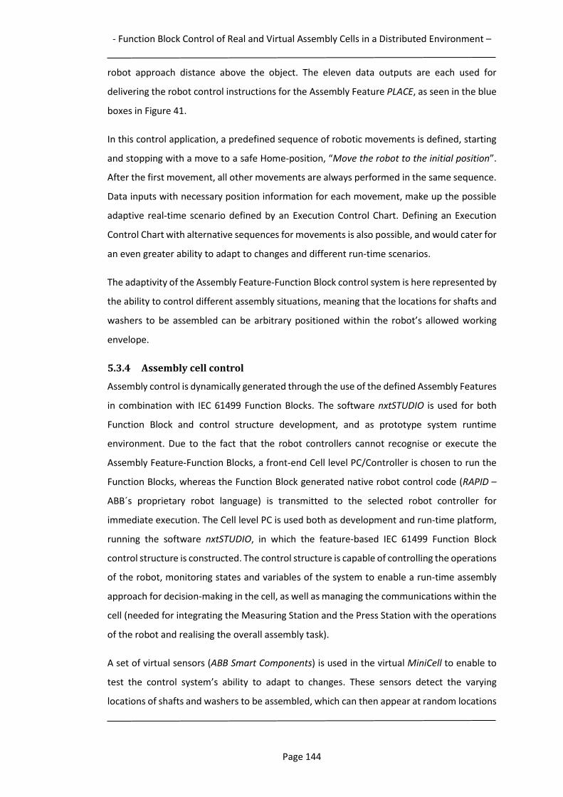
- Function Block Control of Real and Virtual Assembly Cells in a Distributed Environment –
Page 144
robot approach distance above the object. The eleven data outputs are each used for
delivering the robot control instructions for the Assembly Feature PLACE, as seen in the blue
boxes in Figure 41.
In this control application, a predefined sequence of robotic movements is defined, starting
and stopping with a move to a safe Home-position, “Move the robot to the initial position”.
After the first movement, all other movements are always performed in the same sequence.
Data inputs with necessary position information for each movement, make up the possible
adaptive real-time scenario defined by an Execution Control Chart. Defining an Execution
Control Chart with alternative sequences for movements is also possible, and would cater for
an even greater ability to adapt to changes and different run-time scenarios.
The adaptivity of the Assembly Feature-Function Block control system is here represented by
the ability to control different assembly situations, meaning that the locations for shafts and
washers to be assembled can be arbitrary positioned within the robot’s allowed working
envelope.
5.3.4 Assembly cell control
Assembly control is dynamically generated through the use of the defined Assembly Features
in combination with IEC 61499 Function Blocks. The software nxtSTUDIO is used for both
Function Block and control structure development, and as prototype system runtime
environment. Due to the fact that the robot controllers cannot recognise or execute the
Assembly Feature-Function Blocks, a front-end Cell level PC/Controller is chosen to run the
Function Blocks, whereas the Function Block generated native robot control code (RAPID –
ABB´s proprietary robot language) is transmitted to the selected robot controller for
immediate execution. The Cell level PC is used both as development and run-time platform,
running the software nxtSTUDIO, in which the feature-based IEC 61499 Function Block
control structure is constructed. The control structure is capable of controlling the operations
of the robot, monitoring states and variables of the system to enable a run-time assembly
approach for decision-making in the cell, as well as managing the communications within the
cell (needed for integrating the Measuring Station and the Press Station with the operations
of the robot and realising the overall assembly task).
A set of virtual sensors (ABB Smart Components) is used in the virtual MiniCell to enable to
test the control system’s ability to adapt to changes. These sensors detect the varying
locations of shafts and washers to be assembled, which can then appear at random locations
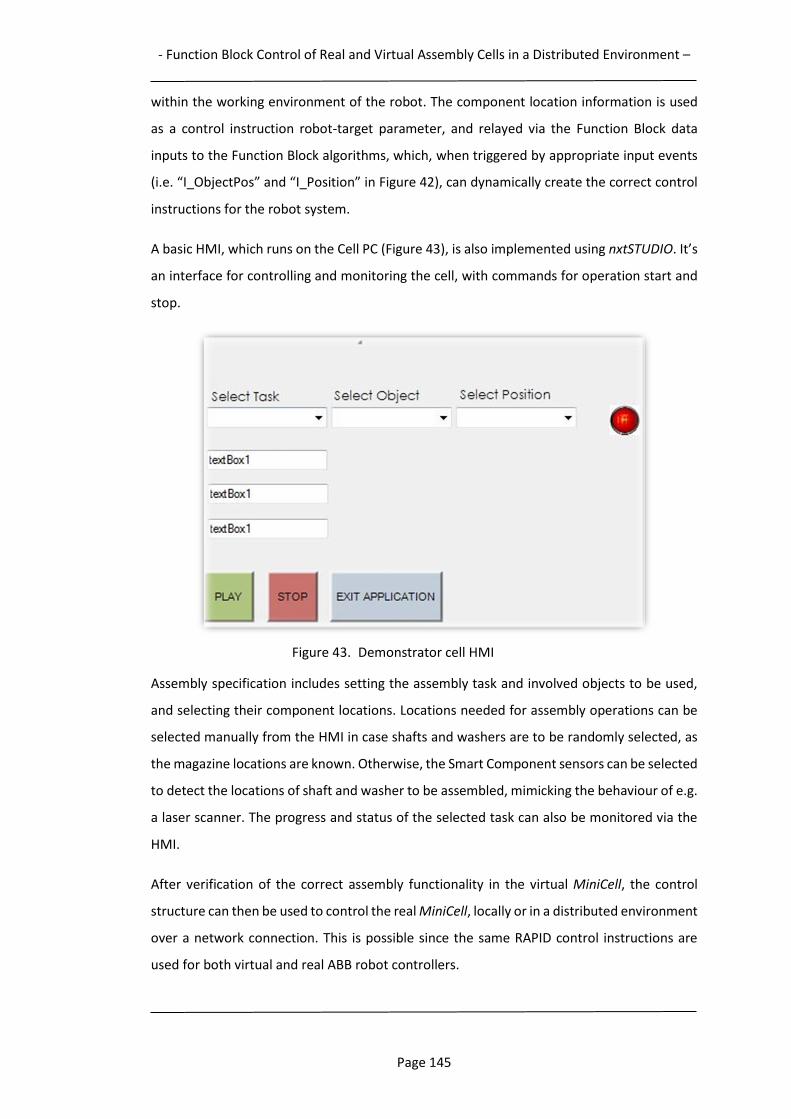
- Function Block Control of Real and Virtual Assembly Cells in a Distributed Environment –
Page 145
within the working environment of the robot. The component location information is used
as a control instruction robot-target parameter, and relayed via the Function Block data
inputs to the Function Block algorithms, which, when triggered by appropriate input events
(i.e. “I_ObjectPos” and “I_Position” in Figure 42), can dynamically create the correct control
instructions for the robot system.
A basic HMI, which runs on the Cell PC (Figure 43), is also implemented using nxtSTUDIO. It’s
an interface for controlling and monitoring the cell, with commands for operation start and
stop.
Figure 43. Demonstrator cell HMI
Assembly specification includes setting the assembly task and involved objects to be used,
and selecting their component locations. Locations needed for assembly operations can be
selected manually from the HMI in case shafts and washers are to be randomly selected, as
the magazine locations are known. Otherwise, the Smart Component sensors can be selected
to detect the locations of shaft and washer to be assembled, mimicking the behaviour of e.g.
a laser scanner. The progress and status of the selected task can also be monitored via the
HMI.
After verification of the correct assembly functionality in the virtual MiniCell, the control
structure can then be used to control the real MiniCell, locally or in a distributed environment
over a network connection. This is possible since the same RAPID control instructions are
used for both virtual and real ABB robot controllers.
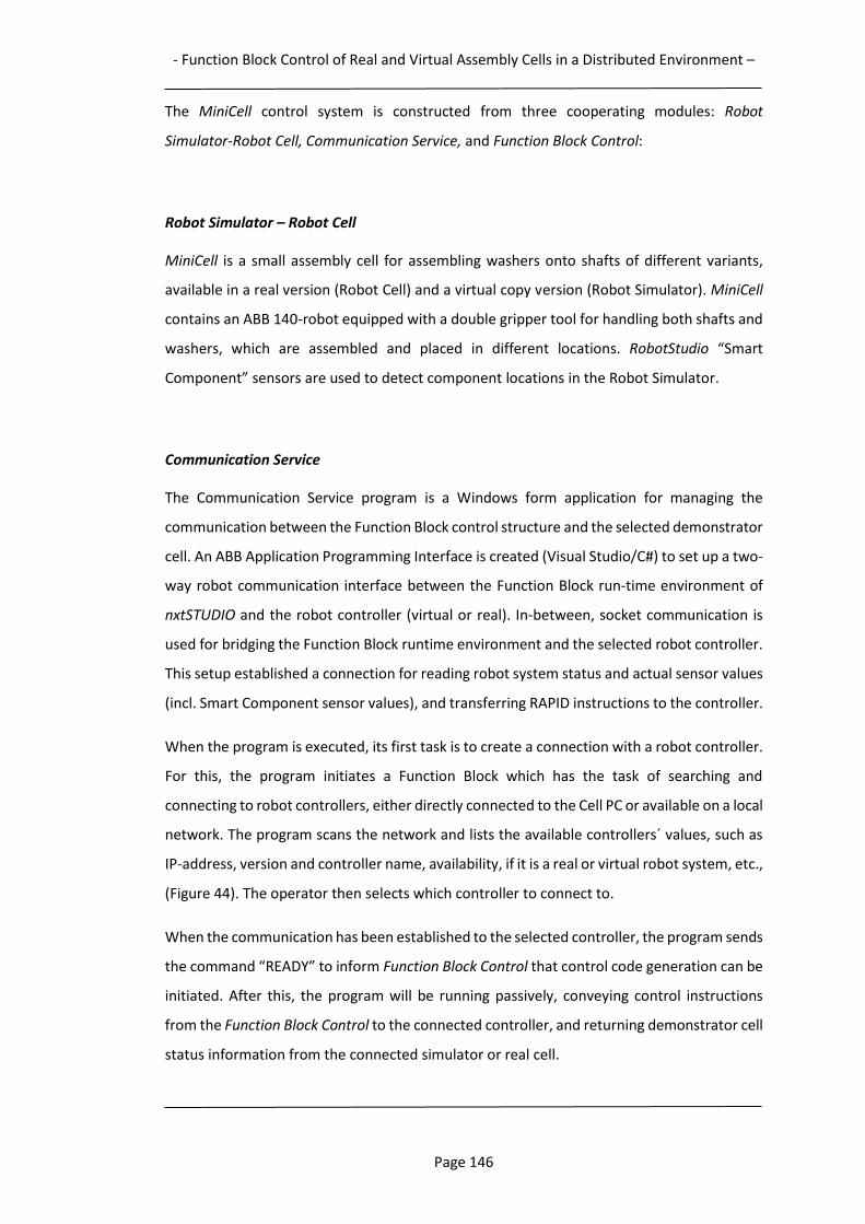
- Function Block Control of Real and Virtual Assembly Cells in a Distributed Environment –
Page 146
The MiniCell control system is constructed from three cooperating modules: Robot
Simulator-Robot Cell, Communication Service, and Function Block Control:
Robot Simulator – Robot Cell
MiniCell is a small assembly cell for assembling washers onto shafts of different variants,
available in a real version (Robot Cell) and a virtual copy version (Robot Simulator). MiniCell
contains an ABB 140-robot equipped with a double gripper tool for handling both shafts and
washers, which are assembled and placed in different locations. RobotStudio “Smart
Component” sensors are used to detect component locations in the Robot Simulator.
Communication Service
The Communication Service program is a Windows form application for managing the
communication between the Function Block control structure and the selected demonstrator
cell. An ABB Application Programming Interface is created (Visual Studio/C#) to set up a two-
way robot communication interface between the Function Block run-time environment of
nxtSTUDIO and the robot controller (virtual or real). In-between, socket communication is
used for bridging the Function Block runtime environment and the selected robot controller.
This setup established a connection for reading robot system status and actual sensor values
(incl. Smart Component sensor values), and transferring RAPID instructions to the controller.
When the program is executed, its first task is to create a connection with a robot controller.
For this, the program initiates a Function Block which has the task of searching and
connecting to robot controllers, either directly connected to the Cell PC or available on a local
network. The program scans the network and lists the available controllers´ values, such as
IP-address, version and controller name, availability, if it is a real or virtual robot system, etc.,
(Figure 44). The operator then selects which controller to connect to.
When the communication has been established to the selected controller, the program sends
the command “READY” to inform Function Block Control that control code generation can be
initiated. After this, the program will be running passively, conveying control instructions
from the Function Block Control to the connected controller, and returning demonstrator cell
status information from the connected simulator or real cell.
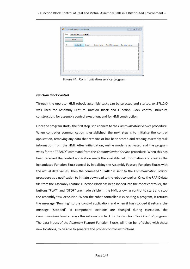
- Function Block Control of Real and Virtual Assembly Cells in a Distributed Environment –
Page 147
Figure 44. Communication service program
Function Block Control
Through the operator HMI robotic assembly tasks can be selected and started. nxtSTUDIO
was used for Assembly Feature-Function Block and Function Block control structure
construction, for assembly control execution, and for HMI construction.
Once the program starts, the first step is to connect to the Communication Service procedure.
When controller communication is established, the next step is to initialise the control
application, removing any data that remains or has been stored and reading assembly task
information from the HMI. After initialization, online mode is activated and the program
waits for the “READY” command from the Communication Service procedure. When this has
been received the control application reads the available cell information and creates the
instantiated Function Block control by initializing the Assembly Feature-Function Blocks with
the actual data values. Then the command “START” is sent to the Communication Service
procedure as a notification to initiate download to the robot controller. Once the RAPID data
file from the Assembly Feature-Function Block has been loaded into the robot controller, the
buttons “PLAY” and “STOP” are made visible in the HMI, allowing control to start and stop
the assembly task execution. When the robot controller is executing a program, it returns
the message “Running” to the control application, and when it has stopped it returns the
message “Stopped”. If component locations are changed during execution, the
Communication Service relays this information back to the Function Block Control program.
The data inputs of the Assembly Feature-Function Blocks will then be refreshed with these
new locations, to be able to generate the proper control instructions.
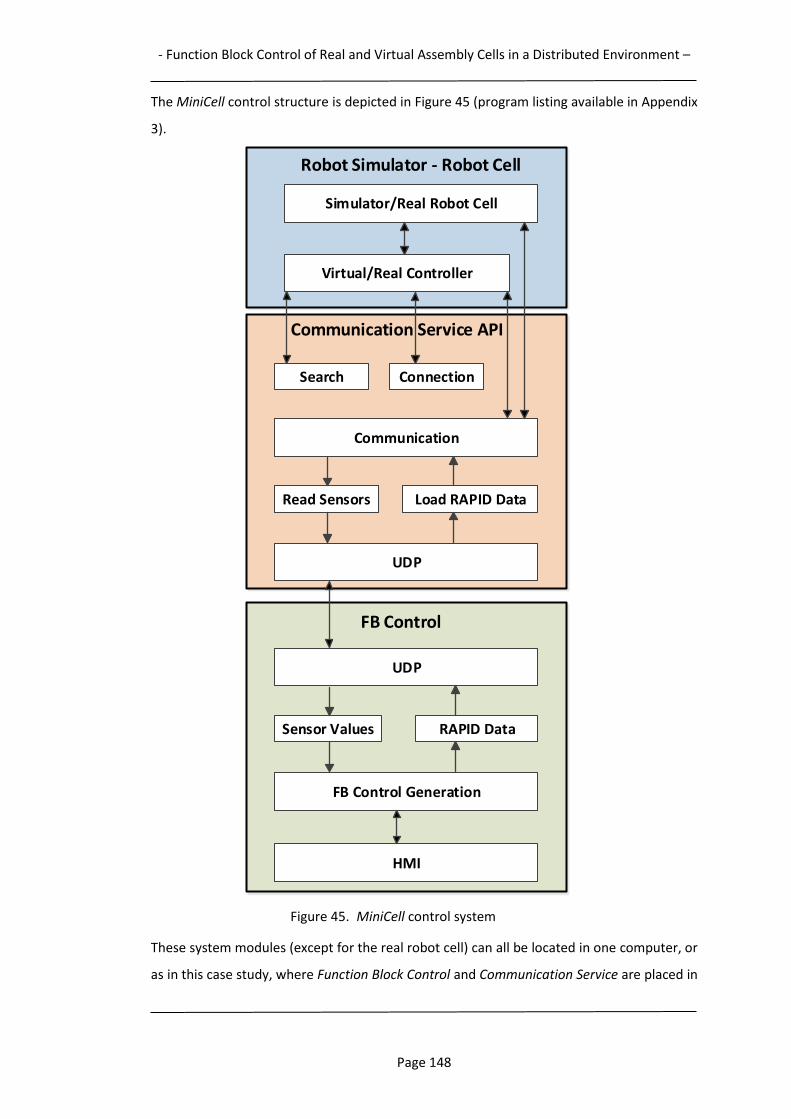
- Function Block Control of Real and Virtual Assembly Cells in a Distributed Environment –
Page 148
The MiniCell control structure is depicted in Figure 45 (program listing available in Appendix
3).
Figure 45. MiniCell control system
These system modules (except for the real robot cell) can all be located in one computer, or
as in this case study, where Function Block Control and Communication Service are placed in
Robot Simulator - Robot Cell
Simulator/Real Robot Cell
Virtual/Real Controller
Search Connection
Communication Service API
Communication
Load RAPID DataRead Sensors
UDP
UDP
RAPID DataSensor Values
FB Control Generation
FB Control
HMI
- Function Block Control of Real and Virtual Assembly Cells in a Distributed Environment –
Page 149
the front-end Cell PC, and the Robot Simulator in another PC, both connected to a local
network. The real MiniCell was also connected to this network.
The assembly sequence is predetermined in this assembly scenario. If the selection of the
assembly sequence would be included as an assembly task option, the assembly sequence
must be decided before assembly starts, for possible generation of correctly sequenced
assembly paths.
5.4 Case study evaluation
The purpose of this case study has been to test and evaluate the capability of the proposed
Feature-based Function Block control approach to effectively adapt to varying assembly
conditions through the dynamic generation of robot control code for both real and virtual
assembly environments, as well as performing distributed robot control. The use of a virtual
demonstrator cell twin enabled a convenient approach for testing of the Function Block
control structure and the verification of its generated assembly control behaviour. The
testing included ordering the assembly of shafts and washers, using an HMI to detail the
assembly tasks. These components could be selected to appear at random locations within
the working environment of the robot, and virtual sensors were used to detect these
locations. Tests of the Assembly Feature-Function Blocks “Place” and “Insert” to effectively
handle such varying assembly conditions, and performing adaptive robot control, were thus
undertaken. Both the real and the virtual demonstrator cell were connected to, and
controlled through, a local network.
The findings of the tests undertaken are summarised as follows:
- The use of the Assembly Feature-Function Blocks Place and Insert allows automatic
generation of the required robot control instructions. The same behaviour is
achieved for both the real and virtual demonstrator cells.
- Adapting Function Block-based operation plans to assembly variations is dynamically
run-time generated and programming-free. No predefined control instructions are
sent in advance to the robot controller. The adaptive behaviour is here realised from
the ability to access and use actual component locations, provided by dedicated
sensors. Compared to manually generating the correct control instructions when
such a change occurs, the amount of time saved is difficult to measure, but may be
considered significant. The required time to manually update a control program for
- Function Block Control of Real and Virtual Assembly Cells in a Distributed Environment –
Page 150
MiniCell when a similar change occurs would be in the estimated region of 15 to 30
minutes. In the event of reoccurring changes, the required time would increase
accordingly.
- Performing tests of the control system on the virtual demonstrator twin indicates
that robot control code verification in a virtual environment is effective for
evaluating different assembly scenarios and control solutions. This can be used for
evaluating the quality of the generated control regarding robot paths, collisions,
cycle times, as well as customer performance requirements and other manufacturing
parameters. This ability to experiment with different control solutions through
performing virtual simulations is a safe, cheap and quick way for improving different
system performance measures.
- Networked robot control of the demonstrator cells (real and virtual) is performed by
a Function Block control structure in a centralised system controller. Distribution of
control is one of the main properties and purposes of the IEC 61499 standard.
The results from the conducted tests indicate that the Feature-based Function Block control
method, implemented as a control system for a robotic assembly cell demonstrator, is
capable of:
automatically and dynamically generating and performing manufacturing equipment
control,
adaptively handling varying assembly conditions,
interfacing a virtual robot system for demonstration and verification of control
capabilities,
performing distributed control.
A run-time generated control structure such as this enables assembly plans to be dynamically
adjusted in order to handle different assembly variations. This means that even though the
assembly task is started, components for assembly can be moved away from their original
locations at start-up, and the robot system will still be able to successfully complete the
assembly task. Reconfiguration or exchange of Assembly Feature-Function Blocks will adjust
- Function Block Control of Real and Virtual Assembly Cells in a Distributed Environment –
Page 151
the control system’s behaviour to suit other assembly scenarios. To completely define an
assembly control structure, the required Assembly Feature-Function Blocks first need to be
identified, and then properly sequenced into an Assembly Process Plan.
5.5 Summary
By using a demonstrator assembly cell and its virtual twin, this case study has demonstrated
the adaptive capability of the proposed Feature-based Function Block control approach. For
creating a robot control system that can adapt and respond to run-time changes, IEC 61499
Function Blocks and Assembly Features are used as the key enabling technologies. The
performance of the proposed Function Block-based control approach has been evaluated in
experiments controlling the robot demonstrator assembly cell MiniCell (Adamson et al.,
2014a, 2014b). The results verify its satisfactory functionality, as the ability to execute
assembly operations to adaptively control both real and virtual networked robot systems
with IEC 61499 Assembly Feature-Function Blocks has been demonstrated in this test case.
The results show that the control system can easily adapt to changes at run-time when the
assembly task is randomly changed, without any reprogramming. Locations of components
to be assembled can be changed, as long as these new locations are within the robot’s reach
and allowed work space.
A major advantage with this control approach is the event-driven nature of the IEC 61499
Function Blocks. The approach enables decision-making to adapt to the requirements of the
assembly process, based on actual conditions, as opposed to traditional robot control which
relies on sending data to the controller in the form of predetermined equipment specific
control instructions. Here, a group of Function Block-embedded algorithms, triggered to
execute at the right time by events in the assembly cell environment, creates the required
control. This caters for an adaptive scenario to handle different types of uncertainties and
run-time changes. Other important advantages are the distributable property of IEC 61499
Function Blocks, as well as portability of functionality between different manufacturing
resources.
Thus far, a major limitation when using Function Blocks for control generation is that
controllers for most manufacturing equipment are legacy controllers, which means they
cannot read and execute these Function Blocks. For the presented demonstrator cells, a
front-end Cell level PC running a Function Block dedicated run-time environment software
was used to overcome this obstacle.
- Function Block Control of Real and Virtual Assembly Cells in a Distributed Environment –
Page 152
In the following chapter, the applicability of the Function Block control approach in a Cloud
Manufacturing assembly applications is presented. The control system structure, including
cloud services and modules for integrating distributed manufacturing management and
execution in a cloud environment, is described for a cloud control scenario in which cloud
services of different types are combined to complete an assembly task.
5.5.1 Acknowledgment
The implementation of the Function Block-based control concept in the test case presented
was realised according to my instructions, with the support of two students at the University
of Skövde, Benjamín Díaz Aranzana and Juan Carlos Rizo Martínez. The author of this paper
would like to thank them for their support of this research programme.
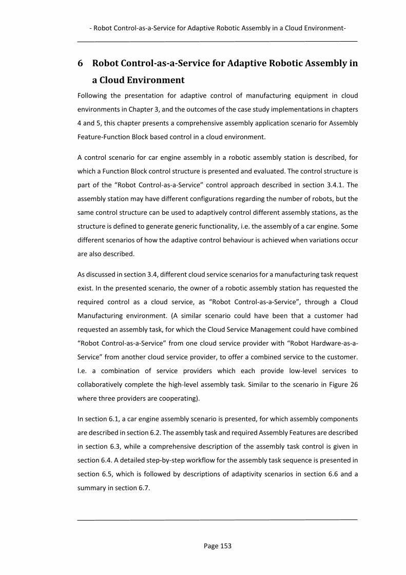
- Robot Control-as-a-Service for Adaptive Robotic Assembly in a Cloud Environment-
Page 153
6 Robot Control-as-a-Service for Adaptive Robotic Assembly in
a Cloud Environment
Following the presentation for adaptive control of manufacturing equipment in cloud
environments in Chapter 3, and the outcomes of the case study implementations in chapters
4 and 5, this chapter presents a comprehensive assembly application scenario for Assembly
Feature-Function Block based control in a cloud environment.
A control scenario for car engine assembly in a robotic assembly station is described, for
which a Function Block control structure is presented and evaluated. The control structure is
part of the “Robot Control-as-a-Service” control approach described in section 3.4.1. The
assembly station may have different configurations regarding the number of robots, but the
same control structure can be used to adaptively control different assembly stations, as the
structure is defined to generate generic functionality, i.e. the assembly of a car engine. Some
different scenarios of how the adaptive control behaviour is achieved when variations occur
are also described.
As discussed in section 3.4, different cloud service scenarios for a manufacturing task request
exist. In the presented scenario, the owner of a robotic assembly station has requested the
required control as a cloud service, as “Robot Control-as-a-Service”, through a Cloud
Manufacturing environment. (A similar scenario could have been that a customer had
requested an assembly task, for which the Cloud Service Management could have combined
“Robot Control-as-a-Service” from one cloud service provider with “Robot Hardware-as-a-
Service” from another cloud service provider, to offer a combined service to the customer.
I.e. a combination of service providers which each provide low-level services to
collaboratively complete the high-level assembly task. Similar to the scenario in Figure 26
where three providers are cooperating).
In section 6.1, a car engine assembly scenario is presented, for which assembly components
are described in section 6.2. The assembly task and required Assembly Features are described
in section 6.3, while a comprehensive description of the assembly task control is given in
section 6.4. A detailed step-by-step workflow for the assembly task sequence is presented in
section 6.5, which is followed by descriptions of adaptivity scenarios in section 6.6 and a
summary in section 6.7.
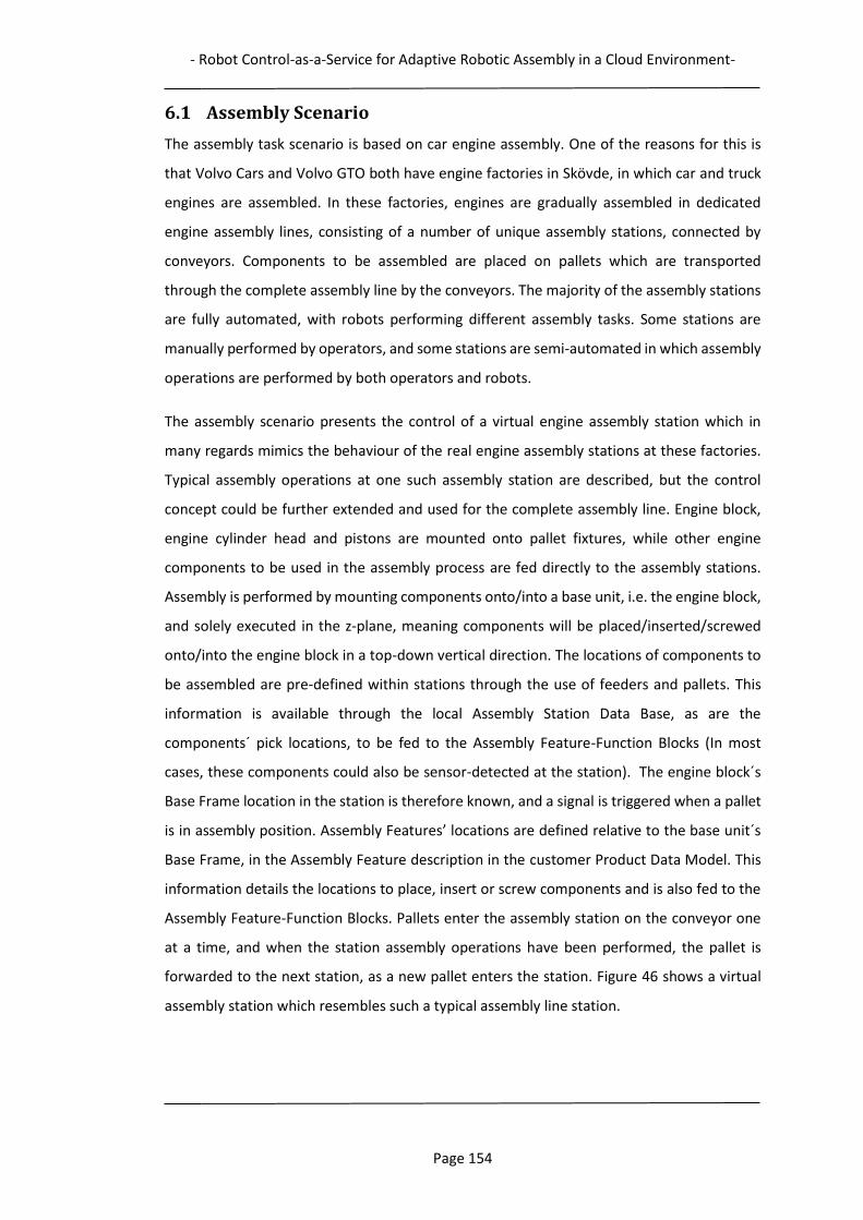
- Robot Control-as-a-Service for Adaptive Robotic Assembly in a Cloud Environment-
Page 154
6.1 Assembly Scenario
The assembly task scenario is based on car engine assembly. One of the reasons for this is
that Volvo Cars and Volvo GTO both have engine factories in Skövde, in which car and truck
engines are assembled. In these factories, engines are gradually assembled in dedicated
engine assembly lines, consisting of a number of unique assembly stations, connected by
conveyors. Components to be assembled are placed on pallets which are transported
through the complete assembly line by the conveyors. The majority of the assembly stations
are fully automated, with robots performing different assembly tasks. Some stations are
manually performed by operators, and some stations are semi-automated in which assembly
operations are performed by both operators and robots.
The assembly scenario presents the control of a virtual engine assembly station which in
many regards mimics the behaviour of the real engine assembly stations at these factories.
Typical assembly operations at one such assembly station are described, but the control
concept could be further extended and used for the complete assembly line. Engine block,
engine cylinder head and pistons are mounted onto pallet fixtures, while other engine
components to be used in the assembly process are fed directly to the assembly stations.
Assembly is performed by mounting components onto/into a base unit, i.e. the engine block,
and solely executed in the z-plane, meaning components will be placed/inserted/screwed
onto/into the engine block in a top-down vertical direction. The locations of components to
be assembled are pre-defined within stations through the use of feeders and pallets. This
information is available through the local Assembly Station Data Base, as are the
components´ pick locations, to be fed to the Assembly Feature-Function Blocks (In most
cases, these components could also be sensor-detected at the station). The engine block´s
Base Frame location in the station is therefore known, and a signal is triggered when a pallet
is in assembly position. Assembly Features’ locations are defined relative to the base unit´s
Base Frame, in the Assembly Feature description in the customer Product Data Model. This
information details the locations to place, insert or screw components and is also fed to the
Assembly Feature-Function Blocks. Pallets enter the assembly station on the conveyor one
at a time, and when the station assembly operations have been performed, the pallet is
forwarded to the next station, as a new pallet enters the station. Figure 46 shows a virtual
assembly station which resembles such a typical assembly line station.
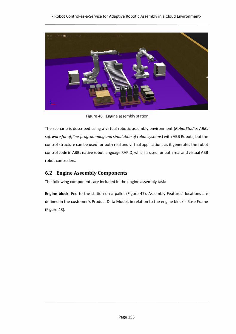
- Robot Control-as-a-Service for Adaptive Robotic Assembly in a Cloud Environment-
Page 155
Figure 46. Engine assembly station
The scenario is described using a virtual robotic assembly environment (RobotStudio: ABBs
software for offline-programming and simulation of robot systems) with ABB Robots, but the
control structure can be used for both real and virtual applications as it generates the robot
control code in ABBs native robot language RAPID, which is used for both real and virtual ABB
robot controllers.
6.2 Engine Assembly Components
The following components are included in the engine assembly task:
Engine block: Fed to the station on a pallet (Figure 47). Assembly Features´ locations are
defined in the customer´s Product Data Model, in relation to the engine block´s Base Frame
(Figure 48).

- Robot Control-as-a-Service for Adaptive Robotic Assembly in a Cloud Environment-
Page 156
Figure 47. Engine Block
Figure 48. Engine Block Base Frame
- Robot Control-as-a-Service for Adaptive Robotic Assembly in a Cloud Environment-
Page 157
Engine cylinder head: Fed to the station on pallet (Figure 49).
Figure 49. Engine Cylinder Head
Pistons: Complete with pin and rod. Fed to the station on pallet, pre-mounted on piston
fixture (Figure 50).
Figure 50. Piston, and pistons pre-mounted on piston fixture
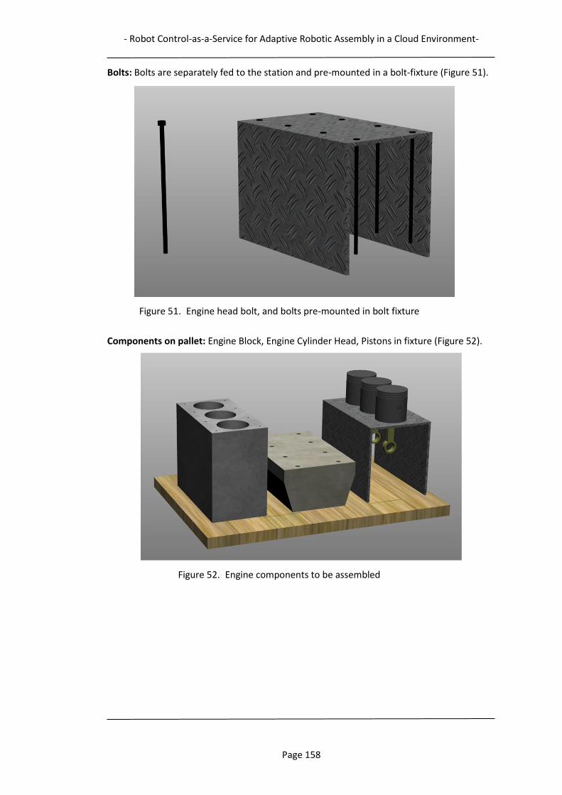
- Robot Control-as-a-Service for Adaptive Robotic Assembly in a Cloud Environment-
Page 158
Bolts: Bolts are separately fed to the station and pre-mounted in a bolt-fixture (Figure 51).
Figure 51. Engine head bolt, and bolts pre-mounted in bolt fixture
Components on pallet: Engine Block, Engine Cylinder Head, Pistons in fixture (Figure 52).
Figure 52. Engine components to be assembled
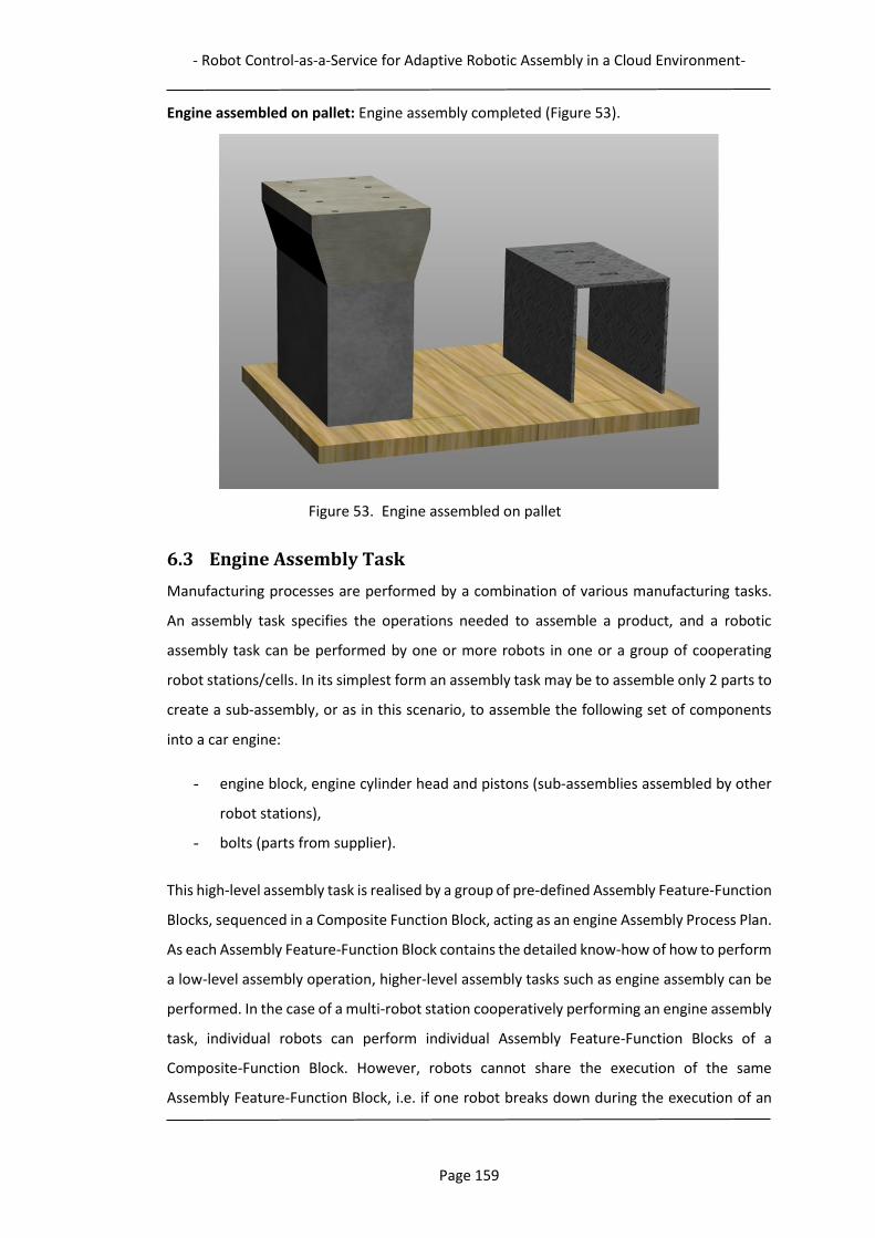
- Robot Control-as-a-Service for Adaptive Robotic Assembly in a Cloud Environment-
Page 159
Engine assembled on pallet: Engine assembly completed (Figure 53).
Figure 53. Engine assembled on pallet
6.3 Engine Assembly Task
Manufacturing processes are performed by a combination of various manufacturing tasks.
An assembly task specifies the operations needed to assemble a product, and a robotic
assembly task can be performed by one or more robots in one or a group of cooperating
robot stations/cells. In its simplest form an assembly task may be to assemble only 2 parts to
create a sub-assembly, or as in this scenario, to assemble the following set of components
into a car engine:
- engine block, engine cylinder head and pistons (sub-assemblies assembled by other
robot stations),
- bolts (parts from supplier).
This high-level assembly task is realised by a group of pre-defined Assembly Feature-Function
Blocks, sequenced in a Composite Function Block, acting as an engine Assembly Process Plan.
As each Assembly Feature-Function Block contains the detailed know-how of how to perform
a low-level assembly operation, higher-level assembly tasks such as engine assembly can be
performed. In the case of a multi-robot station cooperatively performing an engine assembly
task, individual robots can perform individual Assembly Feature-Function Blocks of a
Composite-Function Block. However, robots cannot share the execution of the same
Assembly Feature-Function Block, i.e. if one robot breaks down during the execution of an
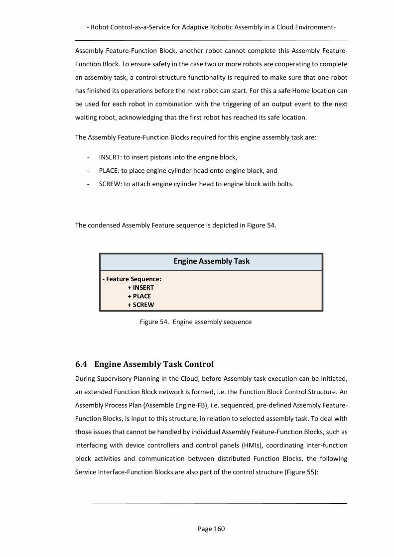
- Robot Control-as-a-Service for Adaptive Robotic Assembly in a Cloud Environment-
Page 160
Assembly Feature-Function Block, another robot cannot complete this Assembly Feature-
Function Block. To ensure safety in the case two or more robots are cooperating to complete
an assembly task, a control structure functionality is required to make sure that one robot
has finished its operations before the next robot can start. For this a safe Home location can
be used for each robot in combination with the triggering of an output event to the next
waiting robot, acknowledging that the first robot has reached its safe location.
The Assembly Feature-Function Blocks required for this engine assembly task are:
- INSERT: to insert pistons into the engine block,
- PLACE: to place engine cylinder head onto engine block, and
- SCREW: to attach engine cylinder head to engine block with bolts.
The condensed Assembly Feature sequence is depicted in Figure 54.
Figure 54. Engine assembly sequence
6.4 Engine Assembly Task Control
During Supervisory Planning in the Cloud, before Assembly task execution can be initiated,
an extended Function Block network is formed, i.e. the Function Block Control Structure. An
Assembly Process Plan (Assemble Engine-FB), i.e. sequenced, pre-defined Assembly Feature-
Function Blocks, is input to this structure, in relation to selected assembly task. To deal with
those issues that cannot be handled by individual Assembly Feature-Function Blocks, such as
interfacing with device controllers and control panels (HMIs), coordinating inter-function
block activities and communication between distributed Function Blocks, the following
Service Interface-Function Blocks are also part of the control structure (Figure 55):
Engine Assembly Task
- Feature Sequence:+ INSERT+ PLACE+ SCREW
- Robot Control-as-a-Service for Adaptive Robotic Assembly in a Cloud Environment-
Page 161
- Cloud Control-Function Block: Acts as a manager on the cloud level.
(Corresponds to the Robot Control-as-a-Service module “Cloud Robotics Control”,
Figures 23 and 26).
- Local Control-Function Block: Acts as a manager on the local level.
(Corresponds to the Robot Control-as-a-Service module “Local Operation Planning”,
Figures 23 and 26).
- Material Handling-Function Block: Controls the material handling in the Assembly
Station.
- Communication-Function Block: Acts as interface for communication between
Function Blocks at different levels.
These Function Blocks are all of the Service Interface type which is defined in the IEC 61499
standard. The control structure also incorporates some assembly task information sources:
Consumer and Assembly Station Data Bases and the Cloud Service Management module
(section 3.4.2).
The Function Block control structure and its constituents are described in the following
sections, together with the structure´s functionality and behaviour.
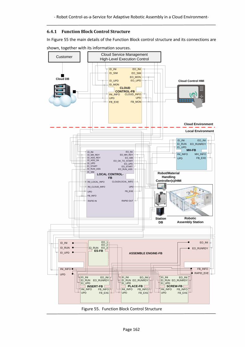
- Robot Control-as-a-Service for Adaptive Robotic Assembly in a Cloud Environment-
Page 162
6.4.1 Function Block Control Structure
In Figure 55 the main details of the Function Block control structure and its connections are
shown, together with its information sources.
Figure 55. Function Block Control Structure
EO_INI
EO_RUNRDY
EI_INI
EI_RUN
EI_UPD
INI_INFO
UPD
FB_INFO
RAPID_EXE
ASSEMBLE ENGINE-FB
EO_INI
EO_RUNRDY
EI_INI
EI_RUN
EI_UPD
INI_INFO
UPD
MH_INFO
FB_EXE
MH-FBEO_INI
EO_MH_RDY
EI_INI
EI_MH_RDY
EI_ASS_RDY
INI_LOCAL_INFO
UPD
CLOUD/LOCAL_INFO
FB_EXE
LOCAL CONTROL-
FB
EO_INI
EO_SIM
EO_MON
EI_INI
EI_SIM
EI_UPD
INI_INFO
UPD
CLOUD_INFO
FB_EXE
EO_SIMEI_ASS_OK
EI_UPD
EI_START
EI_RUN_ASS
EI_SIM
EO_START
EO_RUN_ASS
Station
DB
Robot/Material
Handling
Controller(s)/HMI
RAPID IN RAPID OUT
Cloud DB
CLOUD
CONTROL-FB
EO_UPD
UPD
Cloud Service Management
High-Level Execution Control
UPD
EO_UPD
EO_OK_TO_START
Customer
EI_MON
Cloud Control HMI
FB_MON
Cloud Environment
Local Environment
INI_CLOUD_INFO
Robotic
Assembly Station
EO_INIEO_RUNRDY
EI_INI
EI_RUNEI_UPD
INI_INFO
UPD
FB_INFO
FB_EXE
PLACE-FB
EO_INIEO_RUNRDY
EI_INI
EI_RUNEI_UPD
INI_INFO
UPD
FB_INFO
FB_EXE
SCREW-FB
EO_1
EI_RUN
EO_2EO_3
ES-FB
EO_INIEO_RUNRDY
EI_INI
EI_RUNEI_UPD
INI_INFO
UPD
FB_INFO
FB_EXE
INSERT-FB
FB_INFO
- Robot Control-as-a-Service for Adaptive Robotic Assembly in a Cloud Environment-
Page 163
6.4.2 Control Structure Constituents
6.4.2.1 Cloud Control-Function Block
Responsible for managing assembly task cloud level activities, such as: interface to the Cloud
Service Management module, coordinate activities between participating service providers,
scheduling of resources, perform robot initialisations and Function Block execution control
(start, stop, pause, resume, etc.), perform assembly task simulation, monitor local task
execution, and in the case of changed task requirements (e.g. change in product design),
update Assembly Process Plan.
6.4.2.2 Local Control-Function Block
Responsible for managing assembly task activities at the local Assembly Station level, such
as: local operation planning and Function Block execution, interfacing with Cloud Control-
Function Block, station device controllers and HMIs, coordination and monitoring of activities
to accomplish the assembly task, conducting local equipment initialization, transmitting
Assembly Feature-Function Blocks generated control commands to the robot controller, and
passing updates to Function Blocks.
The Local Control-Function Block is downloaded to a front-end station controller, with an IEC
61499 run-time environment for execution of Function Blocks. It interfaces the Assembly
Station through a local network for access to robot controller and station equipment, e.g.
conveyor and station sensors. As shown in Figure 55, the Local Control-Function Block is also
connected to the Assemble Engine-Function Block and the Material Handling-Function Block,
while interfacing and sharing runtime data with the Assembly Station. This facilitates runtime
information retrieval from the Assembly Station and communicating this information to the
control generating Assembly Feature-Function Blocks.
6.4.2.3 Assemble Engine-Function Block
In this scenario a set of sequenced Assembly Feature-Function Blocks are wrapped in a
Composite-Function Block, acting as an Assembly Process Plan. It contains three Assembly
Feature-Function Blocks to control the robotic task of assembling a car engine. At run-time
execution, each Assembly Feature-Function Block generates detailed operation plans as their
algorithms generate the required robot control instructions. These instructions are
forwarded to the robot controller(s) through the coordinating Local Control-Function Block.
After the execution of one Assembly Feature-Function Block, the next is called according to
the sequence defined in the Assembly Process Plan. During assembly operation execution,
- Robot Control-as-a-Service for Adaptive Robotic Assembly in a Cloud Environment-
Page 164
process monitoring is crucial for successfully completing the assembly task. Based on run-
time monitoring data, it is also possible to effectively coordinate resource selection, job
dispatching and process execution. Therefore, all of the Function Blocks, upon request to
enable monitoring, can convey status information to the Cloud Control-Function Block.
In the lower part of Figure 55 the graphical representation of the Assemble Engine-Function
Block is depicted. This is the Assembly Process Plan which includes the sequenced set of the
Assembly Feature-Function Blocks.
6.4.2.4 Material Handling-Function Block
Another type of Service Interface-Function Block, called Material Handling-Function Block,
(MH-FB) is used as a controller for the conveyor system, controlling the flow and monitoring
the locations of pallets available in the assembly station.
6.4.2.5 Communication-Function Block
A Communication Function Block is a Service Interface Function Block that provides a
construct for information sharing between distributed Function Blocks. It is designed to
facilitate Function Block execution and process monitoring by providing necessary
communications between computers for planning and control and controllers on shop floors.
It is extended from the Service Interface Function Block type defined in IEC-61499, and can
provide services including function block dispatching and run-time operation status sharing
through a distributed network. Two types of Communication Function Blocks are designed
for effective data exchange: a Request Function Block (REQ-Function Block) and a Response
Function Block (RSP-Function Block). This pair resides in different devices at different
locations and are linked via a socket connection. Communication-Function Blocks are not
shown in the control structure, but are situated between cloud and local levels.
6.4.2.6 Cloud Service Management
Responsible for service management, e.g. service composition and high-level control, as part
of the Cloud Manufacturing concept. Coordinating the execution for selected service
providers for a manufacturing task (described in section 3.4.2).
6.4.2.7 Consumer Cloud Data Base
Provides the customer feature-enriched Product Data Model expressing the required
Manufacturing Features, process parameters and requirements for product creation.

- Robot Control-as-a-Service for Adaptive Robotic Assembly in a Cloud Environment-
Page 165
6.4.2.8 Robotic Assembly Station Data Base
Provides status information for the Robotic Assembly Station such as: robot and tool IDs,
component locations, conveyor and station run-time status, etc.
6.4.3 Control Structure Functionality
Before assembly can start, the control structure needs to be initialised with the actual
assembly task and Assembly Station information. The core of the assembly process control is
the Local Control-Function Block. At the very beginning, it is being asked to initialise by
receiving an output event from the Cloud Service Management, EO_INI. This triggers the
initialisation of the Local Control-Function Block, as it reads the local Assembly Station
information from the Station Data Base, and the cloud product information from the
Consumer Cloud Data Base. When initialisation is finished, an output initialisation event is
sent to the Material Handling-Function Block, which is also initialised by the Station Data
Base. After this, the Assemble Engine-Function Block is similarly initialised, as it is triggered
by EO_MH_RDY to read the compiled cloud and local information from the Local Control-
Function Block. As the EI_ASS_RDY is received from the Assemble Engine-Function Block, the
control structure initialisation process is concluded, which is now prepared to commence the
engine assembly task, either as simulation mode or actual assembly operations (EI_SIM or
EI_START activated by operator HMI). Simulation is performed to verify a correct and
collision-free robot path before real assembly is started (Chapter 5). Other parameters of
interest for high-level planning and scheduling, such as cycle time, can also be verified. In this
scenario the Assembly Station provider has uploaded a cloud level simulation model, as part
of the service offered, but the simulation could also be performed on the local level.
The actual assembly task is started as EO_START triggers the Material Handling-Function
Block to forward a loaded pallet to the assembly position. After this, the robot control
instructions for the assembly operations are generated by the three Assembly-Feature-
Function Blocks in the Assemble Engine-Function Block, which is triggered by EI_RUN. Each
Assembly Feature-Function Block generates detailed operation plans at run-time, as its
algorithms execute. The Local Control-Function Block receives these control instructions and
is in charge of conveying these to a robot controller. Depending on the availability of robots,
it can decide which one should be selected.
The Function Blocks on all levels can be updated when assembly conditions change. This
information is conveyed by the EI_UPD event input coupled with the UPD data input. The
- Robot Control-as-a-Service for Adaptive Robotic Assembly in a Cloud Environment-
Page 166
sources for these changes can be both product and station related. Cloud level monitoring of
the ongoing process is also possible, and is initiated by the EI_MON input event to the Cloud
Control-Function Block.
6.5 Assembly Task Sequence
At Assembly Station start-up, local control Function Blocks are initialised, reading actual
conditions regarding assembly task and Assembly Station. Information such as Assembly
Feature locations, robot operational parameters, e.g. target locations, speed, safety levels,
are then read by the Assembly Feature-Function Block´s data inputs. This information is then
used by the algorithms to create a run-time adapted control. A change of the assembly task,
e.g. a change in product design which results in a new location for an Assembly-Feature, can
be directly conveyed to the actual Assembly-Feature-Function Block through the update
event functionality. This information is then accessed directly from the customer´s Cloud
Data Base.
In the following description of the sequenced execution of the engine assembly task,
references are given to the Function Blocks in the control structure generating the control,
as well as details of separate task operations (For the first Assembly Feature procedure,
Inserting Pistons, figures describing the assembly task information flow is presented. The
information flow for the other Assembly Features (Place Engine Cylinder Head, and Screw
Bolts) is performed in the same manner). For ease of understanding in this presentation, all
parameters are not included in the Feature descriptions.
1. A pallet enters the station, and is detected by station conveyor sensors: first at
station entry, and next when it has reached the pre-defined conveyor assembly
location (Figure 56). Controlled by the Material Handling-Function Block.

- Robot Control-as-a-Service for Adaptive Robotic Assembly in a Cloud Environment-
Page 167
Figure 56. Pallet at assembly position
2. The pistons are inserted into the engine block. The robot control instructions are
generated by the INSERT Assembly Feature-Function Block (Figure 57):
Figure 57. INSERT Assembly Feature operations
- Piston pick location, I2, initialised or updated by Station Data Base (Figures 58 and
59):
Engine Assembly Task
- Feature Sequence:- INSERT
* Open tool – Release, Vacuum Off* Move I1 – Above Piston Fixture* Move I2 – Down to pick location, Piston Fixture* Close tool – Pick Pistons, Vacuum On* Move I3 - Lift Pistons vertically (to safe position)* Move I4 - Above Engine Block* Move I5 – Approach Engine Block (with angle)* Move I6 – Down to insertion Location* Move I7 – Insert Pistons (Insertion Depth value)* Open tool – Release Pistons, Vacuum Off* Move I8 – Above Engine Block* Move I9 – Home
+ PLACE+ SCREW
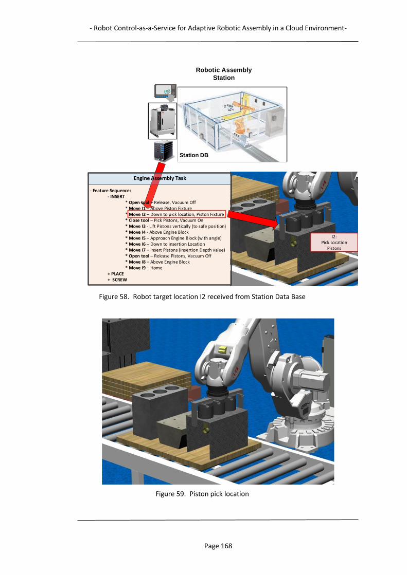
- Robot Control-as-a-Service for Adaptive Robotic Assembly in a Cloud Environment-
Page 168
Figure 58. Robot target location I2 received from Station Data Base
Figure 59. Piston pick location
Robotic Assembly
Station
Station DB
I2:Pick Location
Pistons
Engine Assembly Task
- Feature Sequence:- INSERT
* Open tool – Release, Vacuum Off* Move I1 – Above Piston Fixture* Move I2 – Down to pick location, Piston Fixture* Close tool – Pick Pistons, Vacuum On* Move I3 - Lift Pistons vertically (to safe position)* Move I4 - Above Engine Block* Move I5 – Approach Engine Block (with angle)* Move I6 – Down to insertion Location* Move I7 – Insert Pistons (Insertion Depth value)* Open tool – Release Pistons, Vacuum Off* Move I8 – Above Engine Block* Move I9 – Home
+ PLACE+ SCREW
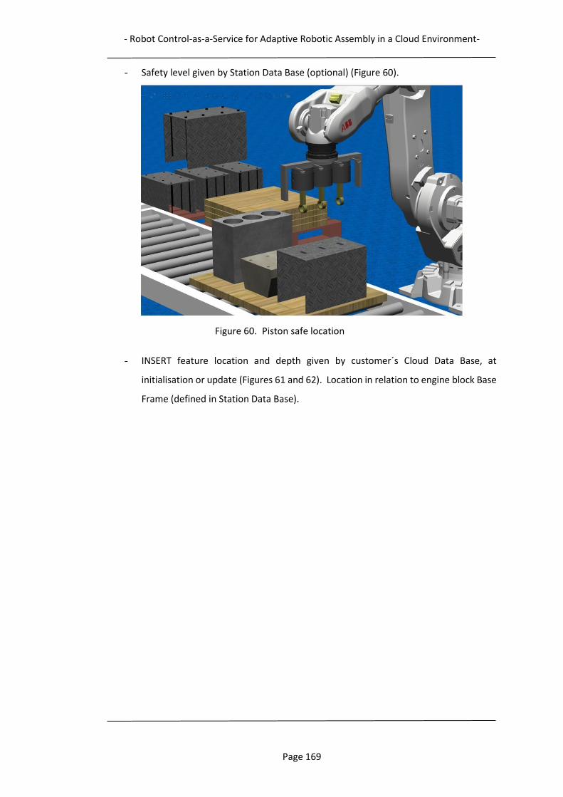
- Robot Control-as-a-Service for Adaptive Robotic Assembly in a Cloud Environment-
Page 169
- Safety level given by Station Data Base (optional) (Figure 60).
Figure 60. Piston safe location
- INSERT feature location and depth given by customer´s Cloud Data Base, at
initialisation or update (Figures 61 and 62). Location in relation to engine block Base
Frame (defined in Station Data Base).
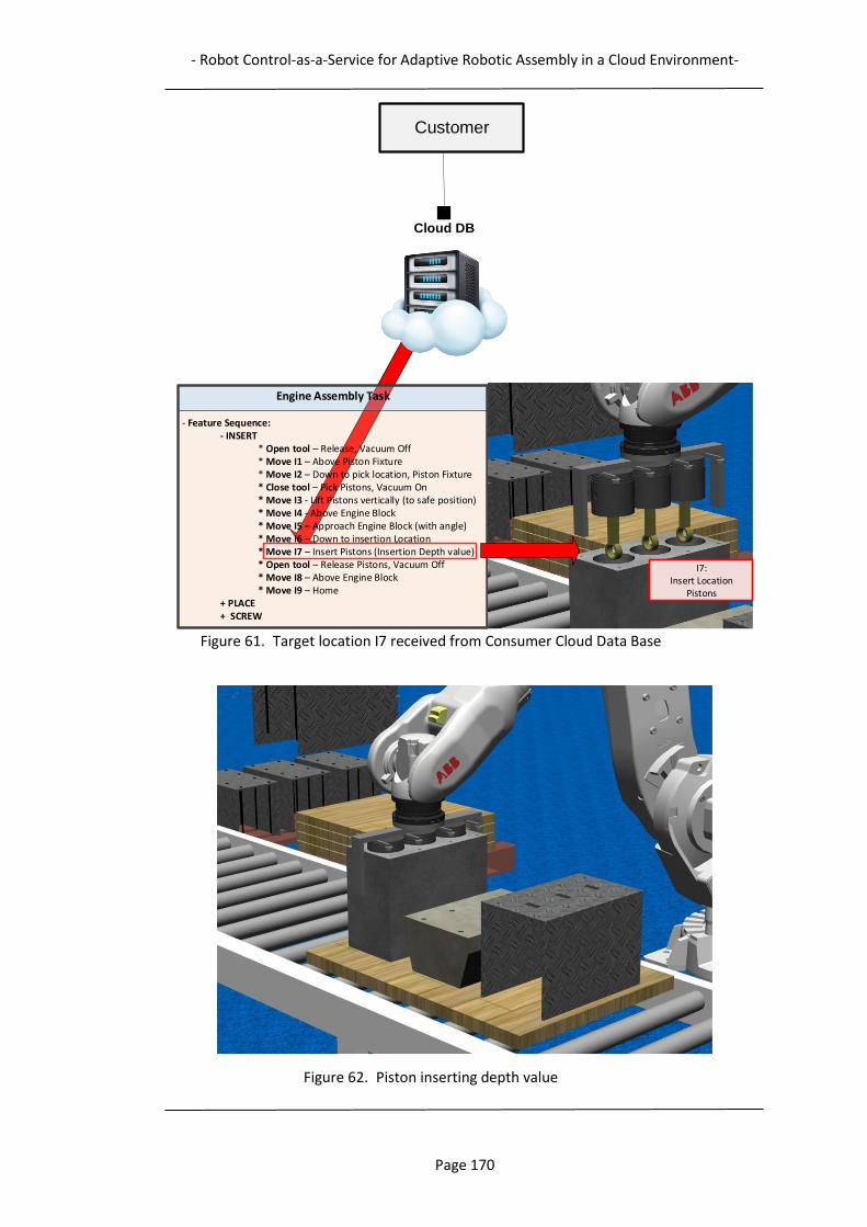
- Robot Control-as-a-Service for Adaptive Robotic Assembly in a Cloud Environment-
Page 170
Figure 61. Target location I7 received from Consumer Cloud Data Base
Figure 62. Piston inserting depth value
Engine Assembly Task
- Feature Sequence:- INSERT
* Open tool – Release, Vacuum Off* Move I1 – Above Piston Fixture* Move I2 – Down to pick location, Piston Fixture* Close tool – Pick Pistons, Vacuum On* Move I3 - Lift Pistons vertically (to safe position)* Move I4 - Above Engine Block* Move I5 – Approach Engine Block (with angle)* Move I6 – Down to insertion Location* Move I7 – Insert Pistons (Insertion Depth value)* Open tool – Release Pistons, Vacuum Off* Move I8 – Above Engine Block* Move I9 – Home
+ PLACE+ SCREW
Cloud DB
Customer
I7:Insert Location
Pistons
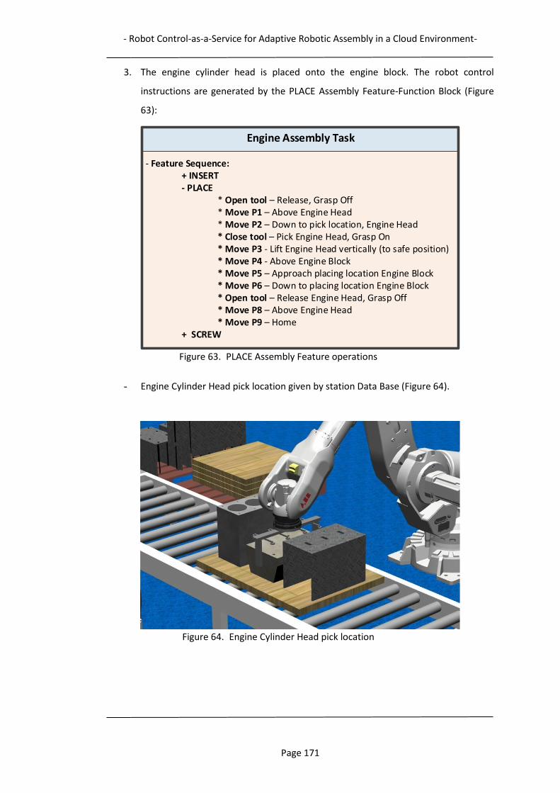
- Robot Control-as-a-Service for Adaptive Robotic Assembly in a Cloud Environment-
Page 171
3. The engine cylinder head is placed onto the engine block. The robot control
instructions are generated by the PLACE Assembly Feature-Function Block (Figure
63):
Figure 63. PLACE Assembly Feature operations
- Engine Cylinder Head pick location given by station Data Base (Figure 64).
Figure 64. Engine Cylinder Head pick location
Engine Assembly Task
- Feature Sequence:+ INSERT- PLACE
* Open tool – Release, Grasp Off* Move P1 – Above Engine Head* Move P2 – Down to pick location, Engine Head* Close tool – Pick Engine Head, Grasp On* Move P3 - Lift Engine Head vertically (to safe position)* Move P4 - Above Engine Block* Move P5 – Approach placing location Engine Block* Move P6 – Down to placing location Engine Block* Open tool – Release Engine Head, Grasp Off* Move P8 – Above Engine Head* Move P9 – Home
+ SCREW
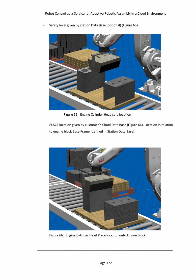
- Robot Control-as-a-Service for Adaptive Robotic Assembly in a Cloud Environment-
Page 172
- Safety level given by station Data Base (optional) (Figure 65).
Figure 65. Engine Cylinder Head safe location
- PLACE location given by customer´s Cloud Data Base (Figure 66). Location in relation
to engine block Base Frame (defined in Station Data Base).
Figure 66. Engine Cylinder Head Place location onto Engine Block
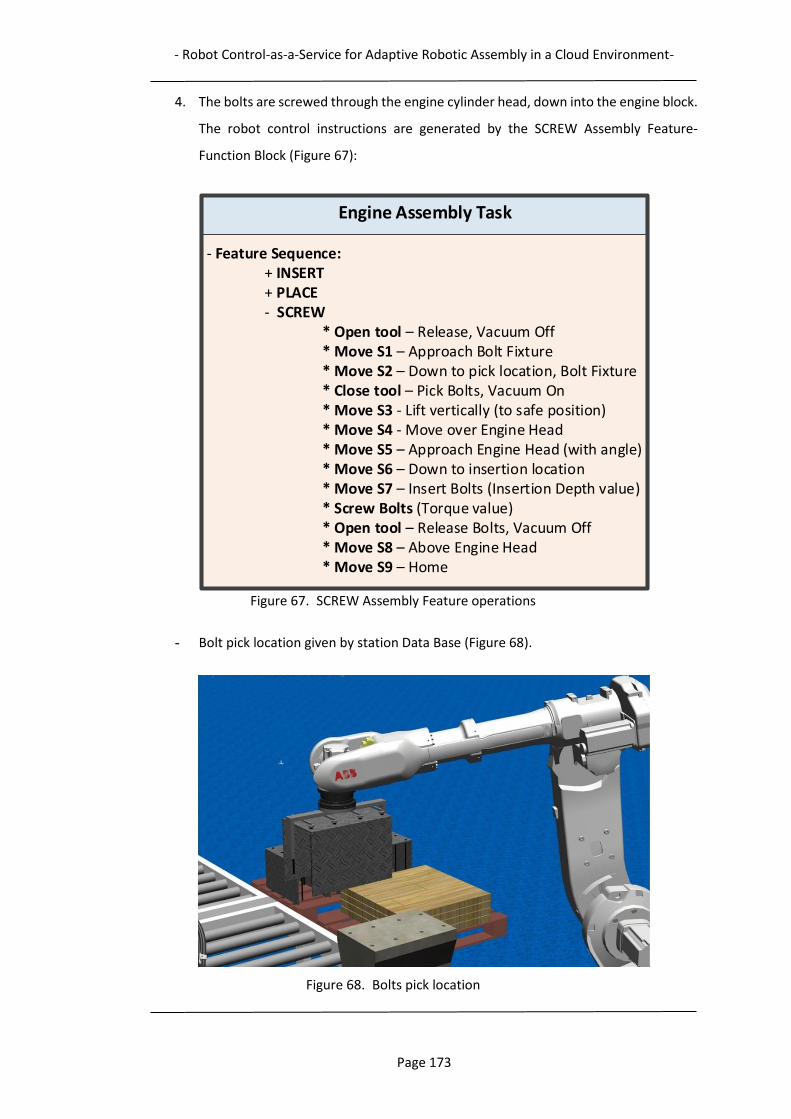
- Robot Control-as-a-Service for Adaptive Robotic Assembly in a Cloud Environment-
Page 173
4. The bolts are screwed through the engine cylinder head, down into the engine block.
The robot control instructions are generated by the SCREW Assembly Feature-
Function Block (Figure 67):
Figure 67. SCREW Assembly Feature operations
- Bolt pick location given by station Data Base (Figure 68).
Figure 68. Bolts pick location
Engine Assembly Task
- Feature Sequence:+ INSERT+ PLACE- SCREW
* Open tool – Release, Vacuum Off* Move S1 – Approach Bolt Fixture* Move S2 – Down to pick location, Bolt Fixture* Close tool – Pick Bolts, Vacuum On* Move S3 - Lift vertically (to safe position)* Move S4 - Move over Engine Head* Move S5 – Approach Engine Head (with angle)* Move S6 – Down to insertion location* Move S7 – Insert Bolts (Insertion Depth value)* Screw Bolts (Torque value)* Open tool – Release Bolts, Vacuum Off* Move S8 – Above Engine Head* Move S9 – Home
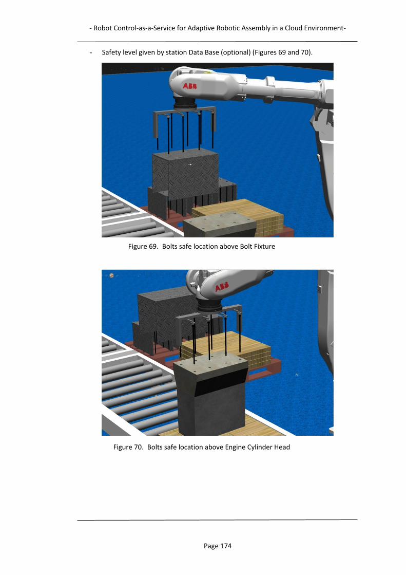
- Robot Control-as-a-Service for Adaptive Robotic Assembly in a Cloud Environment-
Page 174
- Safety level given by station Data Base (optional) (Figures 69 and 70).
Figure 69. Bolts safe location above Bolt Fixture
Figure 70. Bolts safe location above Engine Cylinder Head
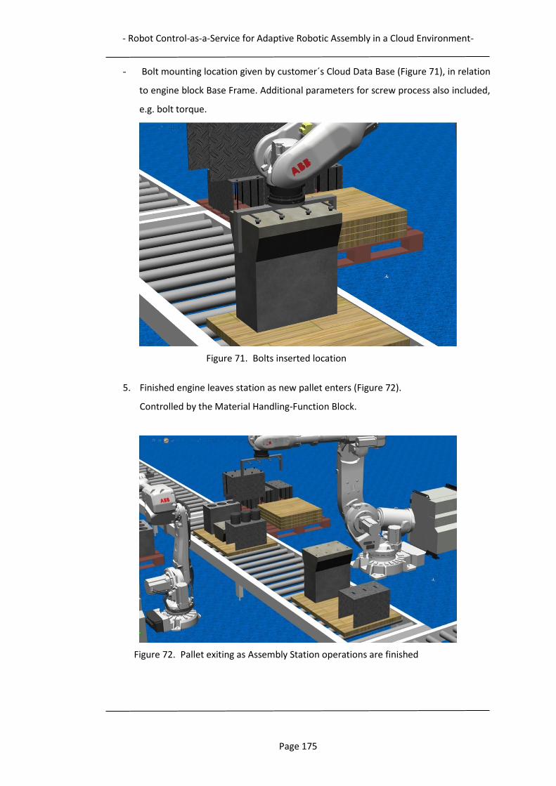
- Robot Control-as-a-Service for Adaptive Robotic Assembly in a Cloud Environment-
Page 175
- Bolt mounting location given by customer´s Cloud Data Base (Figure 71), in relation
to engine block Base Frame. Additional parameters for screw process also included,
e.g. bolt torque.
Figure 71. Bolts inserted location
5. Finished engine leaves station as new pallet enters (Figure 72).
Controlled by the Material Handling-Function Block.
Figure 72. Pallet exiting as Assembly Station operations are finished
- Robot Control-as-a-Service for Adaptive Robotic Assembly in a Cloud Environment-
Page 176
6.6 Adaptivity scenarios - Handling variations
The sources for possible variations in performing the engine assembly are mainly related to
either the engine (Product) or the Assembly Station (Resource):
- Product design change (e.g. a component feature location has been moved):
One example to show the system adaptability to changes during assembly may be the
position change of the Bolt holes in the Engine Cylinder Head and the Engine Block. If the
new location is within the capability of the selected robot, an update of the location from the
Product Model in the Consumer Cloud Data Base, or through the Cloud Control-Function
Block, is enough. This can be handled by the EI_UPD event and its associated UPD data (Figure
55). (If Local Control-Function Block continuously reads component feature locations from
Cloud Control-Function Block or Consumer Cloud Data Base, changed locations will be
handled automatically. If Local Control- Function Block reads all component feature locations
at initialisations only, as in the described scenario, update of changed location is necessary.)
The new locations of the Bolt holes are conveyed to the corresponding Assembly Feature-
Assembly Features whose internal algorithms can make relevant changes to the robot control
instructions on the fly.
If the change is not within the available capability, a new resource needs to be selected by
Cloud Service Management.
If there is a change of the number of components, Cloud Supervisory Planning needs to be
performed, for selecting and sequencing the correct set of Assembly Feature-Function
Blocks.
- Product process change (e.g. bolt torque has been increased):
If the new assembly process parameters are within the capability of the selected robot
station, an update of the process parameter from the Consumer Cloud Data Base or through
the Control-Function Block is enough.
If not within the available capability, a new resource needs to be selected by Cloud Service
Management.

- Robot Control-as-a-Service for Adaptive Robotic Assembly in a Cloud Environment-
Page 177
- Manufacturing resource variations:
The Function Block control structure can also handle some variations in station equipment.
If there is a resource redundancy within the manufacturing system, sometimes another
resource can be automatically invoked as a replacement for a failing resource.
In the case where two robots are cooperating to complete an assembly task, and one of them
becomes unavailable (service, breakdown, etc.) the control structure can re-direct control
commands to the available robot. The Assembly Station Data Base holds the record
“Active/Not active” for each resource, so the Local Control-Function Block can select which
robot ID to convey the control instructions to. This is possible if the “replacing” robot´s
capability matches the capability of the unavailable robot, for the actual operational
parameters (reach, weight, tool, etc.).
To improve this ability, an optional Tool Change-Function Block can also be included in the
control structure. This can be triggered in case of an unavailable or broken tool, and should
include the necessary robot movements and signals for a tool change.
6.7 Summary
The scenario presented summarises the applicability and functionality of the proposed
Function Block based control approach, which has many promising characteristics for use
within both local and distributed environments, such as cloud environments. The biggest
advantage compared to traditional control is that the required control is created at run-time
according to actual manufacturing conditions, facilitating rapid adaptation to the changes in
product design, assembly conditions and assembly environment. This is because the native
control code of a robot is generated after the Function Blocks in the control structure have
been dispatched to the local robot environment. In other words, when operation planning is
performed, the robot to execute the operations is known. Using such an Assembly Feature-
Function Block based control system also leads to the generation of assembly plans which
are resource-neutral, i.e. can be dispatched to different types of robots for assembly
operations. If the assembly station uses Fanuc robots instead of ABB robots, another set of
robot control instructions can be generated by the Assembly Feature-Function Block, as they
at initialization read the robot ID and select the suitable code-generating feature-template.
The Function Block control system can therefore enhance the adaptability and flexibility of
an assembly system.
- Robot Control-as-a-Service for Adaptive Robotic Assembly in a Cloud Environment-
Page 178
The next chapter, which concludes this dissertation, discusses and evaluates the design
science approach applied, the results of the research study, and presents conclusions and
proposes some interesting areas of possible future work.
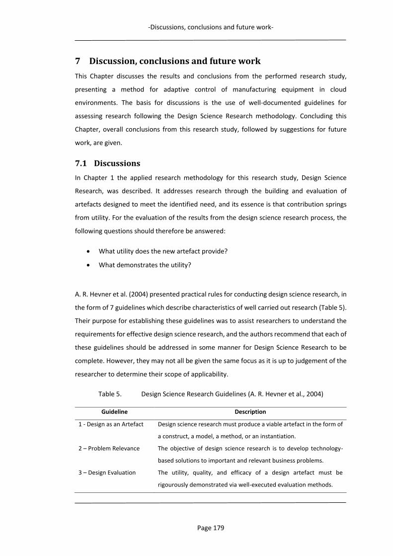
-Discussions, conclusions and future work-
Page 179
7 Discussion, conclusions and future work
This Chapter discusses the results and conclusions from the performed research study,
presenting a method for adaptive control of manufacturing equipment in cloud
environments. The basis for discussions is the use of well-documented guidelines for
assessing research following the Design Science Research methodology. Concluding this
Chapter, overall conclusions from this research study, followed by suggestions for future
work, are given.
7.1 Discussions
In Chapter 1 the applied research methodology for this research study, Design Science
Research, was described. It addresses research through the building and evaluation of
artefacts designed to meet the identified need, and its essence is that contribution springs
from utility. For the evaluation of the results from the design science research process, the
following questions should therefore be answered:
What utility does the new artefact provide?
What demonstrates the utility?
A. R. Hevner et al. (2004) presented practical rules for conducting design science research, in
the form of 7 guidelines which describe characteristics of well carried out research (Table 5).
Their purpose for establishing these guidelines was to assist researchers to understand the
requirements for effective design science research, and the authors recommend that each of
these guidelines should be addressed in some manner for Design Science Research to be
complete. However, they may not all be given the same focus as it is up to judgement of the
researcher to determine their scope of applicability.
Table 5. Design Science Research Guidelines (A. R. Hevner et al., 2004)
Guideline Description
1 - Design as an Artefact Design science research must produce a viable artefact in the form of
a construct, a model, a method, or an instantiation.
2 – Problem Relevance The objective of design science research is to develop technology-
based solutions to important and relevant business problems.
3 – Design Evaluation The utility, quality, and efficacy of a design artefact must be
rigourously demonstrated via well-executed evaluation methods.
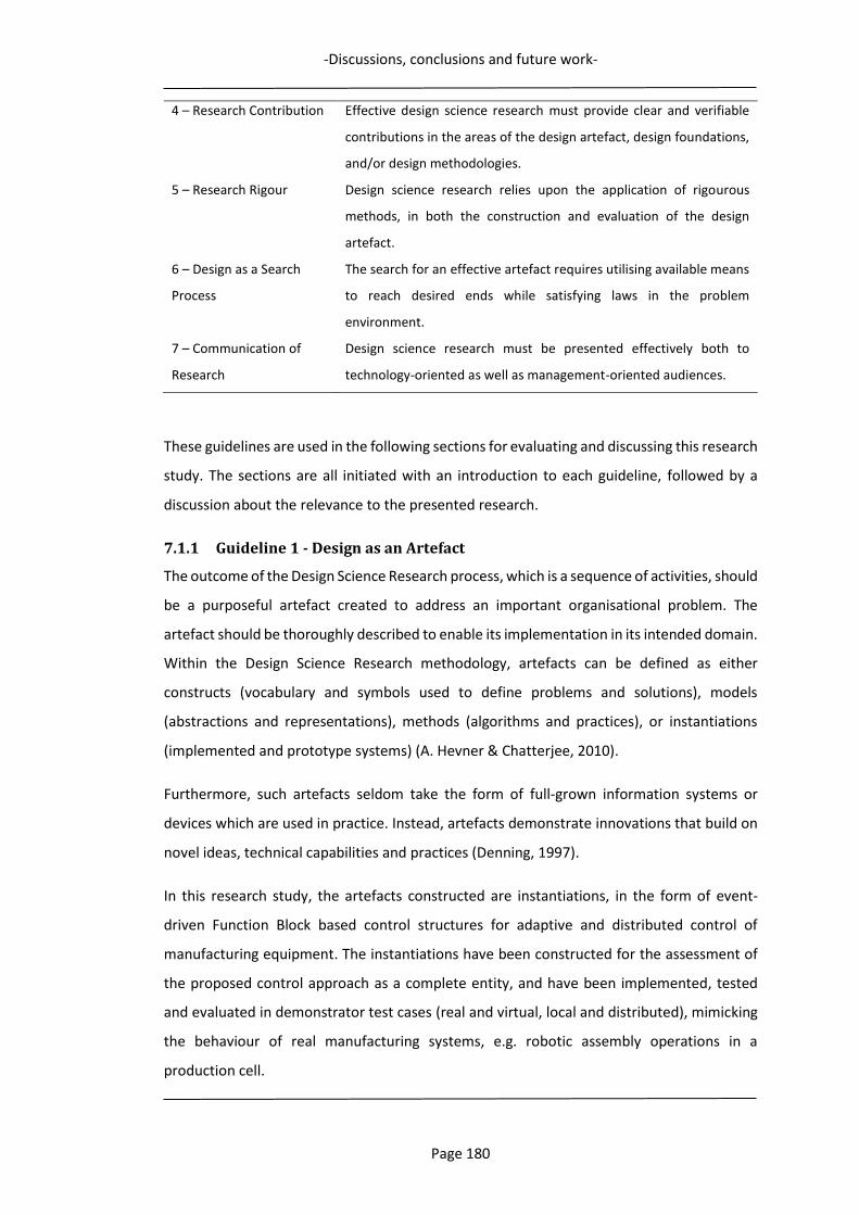
-Discussions, conclusions and future work-
Page 180
4 – Research Contribution Effective design science research must provide clear and verifiable
contributions in the areas of the design artefact, design foundations,
and/or design methodologies.
5 – Research Rigour Design science research relies upon the application of rigourous
methods, in both the construction and evaluation of the design
artefact.
6 – Design as a Search
Process
The search for an effective artefact requires utilising available means
to reach desired ends while satisfying laws in the problem
environment.
7 – Communication of
Research
Design science research must be presented effectively both to
technology-oriented as well as management-oriented audiences.
These guidelines are used in the following sections for evaluating and discussing this research
study. The sections are all initiated with an introduction to each guideline, followed by a
discussion about the relevance to the presented research.
7.1.1 Guideline 1 - Design as an Artefact
The outcome of the Design Science Research process, which is a sequence of activities, should
be a purposeful artefact created to address an important organisational problem. The
artefact should be thoroughly described to enable its implementation in its intended domain.
Within the Design Science Research methodology, artefacts can be defined as either
constructs (vocabulary and symbols used to define problems and solutions), models
(abstractions and representations), methods (algorithms and practices), or instantiations
(implemented and prototype systems) (A. Hevner & Chatterjee, 2010).
Furthermore, such artefacts seldom take the form of full-grown information systems or
devices which are used in practice. Instead, artefacts demonstrate innovations that build on
novel ideas, technical capabilities and practices (Denning, 1997).
In this research study, the artefacts constructed are instantiations, in the form of event-
driven Function Block based control structures for adaptive and distributed control of
manufacturing equipment. The instantiations have been constructed for the assessment of
the proposed control approach as a complete entity, and have been implemented, tested
and evaluated in demonstrator test cases (real and virtual, local and distributed), mimicking
the behaviour of real manufacturing systems, e.g. robotic assembly operations in a
production cell.
-Discussions, conclusions and future work-
Page 181
7.1.2 Guideline 2 - Problem Relevance
The objective of Design Science Research in information systems is to acquire understanding
and knowledge to enable the design and implementation of innovative technology-based
solutions to solve existing and relevant problems.
One of the fundamental questions for Design Science Research is:
What utility does the new artefact provide?
The outcome of the research process should therefore be a purposefully created artefact
with a utility to solve the stated problem. But if existing artefacts are already adequate to
handle the problem, then the research process that creates a new artefact is irrelevant.
In this research study, a research literature review has been conducted for problem
identification. The review indicates that the level of manufacturing complexity will become
significantly higher, with the move to distributed and collaborative manufacturing
environments, which present a higher degree of uncertainties. Variations and unforeseen
events may then be inflicted by all participating companies’ internal and external variations.
Therefore, a prominent property for an adaptive and distributed manufacturing control
structure is the dynamic coordination and distribution of decision-making to both global and
local environment instances. This defines some important challenges for manufacturing
companies to be competitive. Two factors of major importance have been identified as
research problems:
The ability to participate in distributed resource sharing and collaborative
manufacturing activities.
The ability to adaptively handle unpredicted events in their manufacturing systems.
This implies that dynamic, adaptive and distributable decision-making must be a key virtue
for such manufacturing control systems. To satisfy these prime challenges, an adaptive,
event-driven control structure for distributed and collaborative manufacturing environments
is necessary. The overall aim of this research study has been to design, implement, test and
verify the behaviour of such an artefact, providing the required utility. The performance of
the constructed artefact has been verified to fulfill this utility.
-Discussions, conclusions and future work-
Page 182
7.1.3 Guideline 3 - Design Evaluation
Evaluation is a crucial component of the research process, and the utility of a design artefact
must be demonstrated by using well executed evaluation methods. The artefact is complete
when it satisfies the requirements and constraints of the problem it was meant to solve.
One of the fundamental questions for Design Science Research that the evaluation should
answer is:
What demonstrates the utility?
Artefacts can be evaluated in terms of functionality, completeness, consistency, accuracy,
performance, reliability, usability, and other relevant utility attributes. The selection of
evaluation methods must be matched appropriately with the designed artefact and the
desired evaluation criteria. Various methods are possible for the artefact evaluation, such as
Observational, Analytical, Experimental, Testing, and Descriptive methods. For the
evaluation of the constructed artefact´s utility in this research study, various controlled
demonstrator experiments have been performed (e.g. the production cell presented in
Chapter 4 and the robotic assembly cell presented in Chapter 5). For the adaptive robotic
assembly scenario in a cloud environment (in Chapter 6), a descriptive evaluation approach
is used.
The evaluations indicate that the proposed event-driven Function Block control structure can
realise an adaptive manufacturing behaviour in both local and distributed, as well as
collaborative environments, such as within Cloud Manufacturing.
7.1.4 Guideline 4 - Research Contribution
In assessing research contributions, novelty is crucial since the proposed artefact must be
innovative, providing a utility for solving unsolved problem or solving a known problem in a
better manner. The essence of Design Science Research is that contribution springs from
utility. The methodology describes three versions of research contributions, of which at least
one must be found in any Design Science Research project: The artefact itself, Foundations,
and Methodologies. Most often, the artefact is the contribution of the research performed.
Although the proposed control structure can be seen as a major research contribution in the
form of an artefact, it is in reality the product of a novel method for realising manufacturing
control in cloud environments. The proposed control structure actually represents an
innovative method of how to combine already existing techniques (e.g. IEC 61499 Function
-Discussions, conclusions and future work-
Page 183
Blocks) with new enabling technologies, such as Cloud Manufacturing, cloud services,
Internet of Technologies, etc. These are further combined with an approach for the
organisation and structuring of planning and control capabilities into separate manufacturing
control units, located in different levels of the manufacturing control structure. The
successfully evaluated artefact is therefore a proof-of-concept for the underlying method.
The proposed Feature-based Information Framework described in section 3.3.2 is also a
research contribution, which may be regarded as a foundation. It presents a novel approach
of how to match manufacturing task requests with provider resources’ capabilities, using
reference information models. Building on the concept of product Manufacturing Features,
a unified information framework describing manufacturing tasks and manufacturing
resources’ capabilities from a shared product feature perspective can be constructed. For
description of product manufacturing tasks, a feature-enriched product data model is
presented, and for manufacturing resources’ capabilities, a feature-level capability model.
Together, these two models facilitate manufacturing resource discovery, and the matching
of manufacturing resources to requested tasks. For structured and formalised semantic
model representations, implementation through ontologies and the Semantic Web is used.
During the research process, a number of new research questions have arisen which may
also be regarded as research contributions. These questions are presented in section 7.3
“Future work”, and may lead to new research initiatives and the further development of
research undertaken in this research study.
7.1.5 Guideline 5 - Research Rigor
In this context, research rigour addresses how the research is conducted. To secure the
quality of the conducted research the use of motivated and established methods should be
applied in both the construction and evaluation of the designed artefact. A successful
research outcome therefore often depends on the researcher´s competent selection of
appropriate techniques to construct an artefact, but also the careful selection of appropriate
methods to evaluate the artefact. The testing and evaluation of the constructed artefact
need to be performed within a suitable environment, preferably as close as possible to the
anticipated area of application. Research rigour should also be assessed with respect to the
applicability and generalisability of the artefact.
A strong advocate for the research rigour of the conducted research is the use of the Design
Science Research process and the addressing of each of the seven guidelines proposed by A.
-Discussions, conclusions and future work-
Page 184
R. Hevner et al. (2004). The methodology supports the methods used for testing and
evaluating the artefact, and the evaluations have focused on artefact utility, within realistic
manufacturing systems and scenarios. Experimental and descriptive methods have been
used in a quantitative research approach, which have proved the applicability of the artefact
for the intended manufacturing domain.
7.1.6 Guideline 6 - Design as a Search Process
Design Science Research is an iterative process for solving an identified research problem.
From testing and evaluating activities, updated or new design artefact are generated, which
may be further tested and evaluated in a design cycle. This means that research progress is
made iteratively as the scope and knowledge of the design problem is expanded. During this
design cycle the research scope should be refined and made more realistic, to make the
evolving artefact become more relevant for the intended application domain (A. Hevner &
Chatterjee, 2010).
During the conducted research process, a number of new research questions have arisen
which were neither anticipated nor within the initial focus of this research study. Some of
them have helped in broadening the research scope, while others were more aimed at future
research projects for the further development of the work in this research study. These are
presented in section 7.3 “Future work”.
Initially, the research aim was focused on adaptive robot control in a local environment. As a
means to handle local manufacturing variations, the use of control based on event-driven
Function Blocks was first investigated. With the emergence of the concept of manufacturing
cloud services and Cloud Manufacturing (following the established concept of Cloud
Computing), and new ICT technologies, new research questions appeared which changed the
research focus to manufacturing equipment control in cloud environments. After
establishing adaptive manufacturing control in a local environment, this approach was
further expanded to cloud environments. The combination of ideas, novel concepts and new
technologies led to a method for realising such a control structure artefact, which is
presented in this research study. This was a process which evolved through the iterative
testing and evaluation of the designed artefact, and which finally generated a method and
framework for event-driven Function Block based control of manufacturing equipment in
cloud environments. The concept of a Feature-based Information Framework for the
matching of manufacturing task requests with provider resources’ capabilities was also the
-Discussions, conclusions and future work-
Page 185
product of new research questions which appeared during the described design cycle
process.
7.1.7 Guideline 7 - Communication of Research
The results of the Design Science Research should be effectively communicated to audiences
of both technical and management orientation, according to the guideline instructions. For
technology-oriented audiences sufficient detail is needed so that the artefact may be
correctly reproduced, i.e. constructed, implemented and used within the intended
manufacturing domain´s organisational context. Practitioners would then be able to exploit
the utility offered by the artefact, and other researchers could continue the work, to build a
cumulative knowledge base for further extension and evaluation within the scope of this
research. The management-oriented audiences would be needing sufficient detail to be able
to determine if the organisational resources should be engaged in constructing (or
purchasing) and using the artefact within their specific manufacturing domain´s
organisational context (A. R. Hevner et al., 2004)
Being a Ph.D. dissertation in some respects delimits the possibility of purposeful and directed
communication of research findings to dedicated audiences. Therefore, this research study
is not directly communicated to either a technical or a managerial oriented audience.
However, the conducted research has been ongoing for almost 8 years. During these years,
research progress and findings have been continuously presented in both research journals
and conference papers, embracing both these categories of audiences, as well as other
audiences.
7.1.8 Concluding discussion
The use of a well established and applicable research methodology for conducting the
undertaken research study has been a mean to secure a rigourous and valid research process.
The Design Science Research methodology represents a suitable problem solving process,
based on the fundamental principle that solutions of a design problem, as well as
understanding and knowledge, are obtained by artefact design, implementation and
application. For the evaluation of the research outcome of this research process, the
fundamental questions of what utility the new research artefact provides and what
demonstrates this utility, have been answered. During the ongoing research process the
evolving artefact has been continuously evaluated as an important part of the research
progress. The validity of the research process itself has been ensured by following the
-Discussions, conclusions and future work-
Page 186
guidelines for conducting design science research, presented A. R. Hevner et al. (2004). All
of the seven guidelines presented have been addressed, with a focus on problem relevance,
and artefact design, implementation and evaluation.
7.2 Conclusions
With reference to the research objectives stated in Chapter 1, the major conclusions that can
be drawn from the research study presented in this dissertation are summarised as follows:
1. Through a literature review, determine the applicability of the event-driven Function
Block technology for adaptive and distributed control of manufacturing equipment in
cloud environments.
Cloud Manufacturing is a developing collaborative and resource-sharing
manufacturing paradigm, introducing a new era of technology that will totally change
the domain of manufacturing industry. Covering all the phases of the product
manufacturing development life-cycle, it is predicted to set new standards for
manufacturing competitiveness. However, an ultimate requirement for realising
Cloud Manufacturing is the ability to access, and adaptively coordinate and control,
manufacturing equipment used in collaborative and distributed Cloud
Manufacturing missions. Shared, high level manufacturing tasks then need to be
divided and distributed as sub-tasks to the shop floors of collaborating
manufacturing companies. These sub-tasks should then be coordinated and
executed based on real-time information from both cloud-based and local sources.
Therefore, realising real-time monitoring and remote control in Cloud Manufacturing
environments requires a shared standardised closed-loop control approach, which
supports distributed control based on both global and local requirements, conditions
and parameters.
The concepts of the IEC 61499 standard support this approach, as they enable the
use of online information for dynamic and distributed decision-making, as well as
dynamic control capabilities that are able to handle, in a responsive and adaptive
way, different kinds of uncertainty. Some of the most prominent properties of the
IEC 61499 standard is distribution, modularity and portability of functionality
between different manufacturing resources. A major advantage is the event-driven
nature of the IEC 61499 Function Blocks, which enables decision-making to adapt to
the requirements of the manufacturing process, based on actual conditions.

-Discussions, conclusions and future work-
Page 187
The standard supports intelligence to be decentralised and encapsulated in software
components, which can be distributed in a cloud system control network. A
networked and event-driven Function Block-based control system can therefore be
applied to coordinate control of various collaborating manufacturing systems and
resources in a cloud environment.
The control approach is flexible and versatile as it can be designed to handle both
planning and scheduling activities, process monitoring and manufacturing
equipment execution control.
2. Design and formulate a method for adaptive control of manufacturing equipment in
cloud environments, including a supporting information framework.
An effective approach to limit the negative influence of uncertainty and
unpredictable behaviour on manufacturing performance is to use real-time
manufacturing information. Using real-time system information for both planning
and control of a manufacturing system means that the time span between decision-
making and actual execution can be narrowed down to a minimum, facilitating more
correct decisions as well as decreasing the possible negative impact of uncertainty.
Using actual events within a distributed control system to trigger the dynamic
generation of the required control activities makes possible adaptive decision-
making and dynamic control capabilities.
For realising adaptive control of manufacturing equipment in cloud environments,
an event-driven and distributable multi-layer control approach is required, capable
of instantly generating control in response to prevailing requirements and
conditions. Through the use of Feature-based manufacturing, a combined approach
using IEC 61499 Function Blocks for planning and control of manufacturing tasks in
cloud environments, as well as an approach for detailing manufacturing resources
and tasks, are formulated.
A Feature-based Information Framework is proposed which represents a novel
approach of how to match manufacturing task requests with provider resources’
capabilities. Building on the concept of product Manufacturing Features, a unified
information framework describing manufacturing tasks and manufacturing
resources’ capabilities from a shared product feature perspective is constructed. For
description of product manufacturing tasks, a feature-enriched product data model
-Discussions, conclusions and future work-
Page 188
is presented, and for manufacturing resources’ capabilities, a feature-level capability
model. Together, these two models instantiate a supporting Information Framework
for discovery and matching of suitable manufacturing resources to requested
manufacturing tasks in cloud environments, and as such facilitate collaborative
manufacturing activities.
A novel method for realising manufacturing control in cloud environments is
formulated. The concept of combining Manufacturing Features with IEC 61499
Function Blocks enables an intelligent, agile and flexible solution for performing
automated run-time generation and execution of control instructions for
manufacturing resources. Through the integration of the Manufacturing Feature-
Function Block control approach into a cloud-based two-level planning and control
structure, adaptive and distributed manufacturing equipment control within Cloud
Manufacturing has been realised. Implemented as manufacturing services, e.g.
Robot Control-as-a-Service, Manufacturing Feature-Function Blocks can perform
planning and execution of manufacturing tasks at different system control levels. A
centralised generation of generic process plans which, after distribution to selected
manufacturing resources, are instantiated and detailed at run-time through local
operation planning, caters for an adaptive control behaviour.
The presented control method is the main contribution of the conducted research
programme. It was successfully evaluated in a research study evolutionary
perspective, going from the local control of a production cell, to adaptive and
distributed control of real and virtual robots, to a full scale Cloud control approach,
incorporating cooperating manufacturing resource providers. This is further
described in the following three sections.
3. Design, implement, analyse and evaluate the method for control in a local
manufacturing environment.
The control method formulated was implemented and evaluated in a case study with
the control of a demonstrator production cell. The demonstrator consists of a 3-axis
gantry robot, integrated with a small 3-axis table-top CNC-milling machine, to
perform an industrial machining and assembly process, requiring their coordination
-Discussions, conclusions and future work-
Page 189
and cooperation to fulfill the task. The networked Function Block control structure
implemented in the demonstrator control system was created from a combination
of control generating Assembly Feature-Function Blocks and Machining Feature-
Function Blocks, supported by Service Interface-Function Blocks. The case study has
demonstrated the capability of the proposed Feature-based Function Block control
approach.
The Function Block control structure is fully capable of controlling the operations of
the CNC-machine and the gantry robot, monitoring states and variables of the system
to enable a real-time manufacturing approach for decision-making in the
demonstrator cell, as well as managing the communications within the cell.
Assembly, machining and material handling operations can all be constructed and
executed using Feature-based IEC 61499 Function Blocks. The gantry robot and the
table-top CNC-machine are both directly controlled by the outputs of such Function
Blocks, and no proprietary control instructions are needed.
Summarising the results from the tests undertaken, the performance of the
demonstrator cell has been evaluated and confirm that satisfactory functionality is
achieved from the formulated control approach. The tests indicate that the proposed
Feature-based Function Block control method, implemented as a control
architecture for a production system, is capable of effectively handling varying
production conditions, and automatically and dynamically generating and
performing manufacturing equipment control.
4. Design, implement, analyse and evaluate the method for adaptive control in a
distributed (LAN) manufacturing environment with both real and virtual
manufacturing applications.
The control method presented was implemented and evaluated in a case study with
the control of a robotic demonstrator assembly cell and its virtual twin. The
demonstrator cell, MiniCell, consists of an ABB 140-robot with a double gripper tool
to handle different components to be assembled. The cell also includes components,
component magazines and some auxiliary equipment. The virtual twin is a copy of
the real MiniCell, but with virtual robot, controller, tool, and assembly cell
components. The networked Function Block control structure implemented as the
demonstrator control system was created from a combination of control generating
-Discussions, conclusions and future work-
Page 190
Assembly Feature-Function Blocks, supported by Service Interface-Function Blocks.
Through performing experiments controlling the robot demonstrator assembly cell,
the case study has demonstrated the adaptive capability of the proposed Feature-
based Function Block control approach.
The results verify the ability to execute assembly operations to adaptively control
both real and virtual networked robot systems using IEC 61499 Assembly Feature-
Function Blocks. They also show that the control system can easily adapt to changes
at run-time when the assembly task is randomly changed, without any
reprogramming. Through the use of sensors, locations of components to be
assembled can be changed, as long as these new locations are within the robot’s
reach and allowed work space.
Summarising the results from the tests undertaken, the performance of the
demonstrator assembly cells have been evaluated and confirm that the functionality
of the formulated control approach is appropriate. The tests indicate that the
proposed Feature-based Function Block control method, implemented as a control
system for a robotic assembly cell demonstrator, is capable of: automatically and
dynamically generating and performing manufacturing equipment control,
adaptively handling varying assembly conditions, interfacing a virtual robot system
for demonstration and verification of control capabilities, and performing distributed
control.
5. Design, analyse and evaluate the method for adaptive control in a cloud environment,
including Manufacturing Equipment Control-as-a-Service.
Following the proposed approach for adaptive control of manufacturing equipment
in cloud environments in Chapter 3, and the results of the case study
implementations in chapters 4 and 5, the applicability of the Function Block control
method has been evaluated in a Cloud Manufacturing assembly application scenario.
A control system structure has been designed, including cloud services and modules
for integrating distributed manufacturing management and execution in a cloud
environment, and is described for a cloud control scenario in which a cloud service is
used to complete an assembly task.
The cloud control scenario for car engine assembly in a local robotic assembly station
is described, for which a Function Block control structure and the control concept of
-Discussions, conclusions and future work-
Page 191
Robot Control-as-a-Service is presented and evaluated. The control structure can be
used to adaptively control different assembly stations, as it is defined to generate
generic functionality, i.e. the assembly of a car engine, and some different scenarios
are described of how the adaptive control behaviour is achieved when variations
occur. The sources for such variations mainly relate to either the engine (Product) or
the Assembly Station (Resource).
The adaptive behaviour of the control system for the following scenarios have been
described in detail:
- Product design change (e.g. a component feature location has been moved).
- Product process change (e.g. bolt torque has been increased).
- Manufacturing resource variations (e.g. variations in station equipment).
The performance of the cloud control structure proposed for a car engine assembly
scenario has been evaluated and indicate that satisfactory functionality has been
achieved to adaptively handle variations related to both products and manufacturing
resources.
The cloud control scenario presented summarises the applicability of the Function
Block-based control approach, which has shown promising control characteristics for
use within both local and distributed manufacturing environments. Following the IEC
61499 standard, control applications of varying levels of complexity and
sophistication may be created for adaptive control. Being event-driven Function
Blocks, for which the dynamic behaviour may be controlled, they have the capability
to implement the desired functionality, through feature-defined algorithms, which
makes them very versatile. The availability of Function Block-based equipment
controllers, with pre-defined sets of parametrised Feature-Function Blocks, would
therefore close the loop of Feature-based manufacturing.
-Discussions, conclusions and future work-
Page 192
7.3 Future work
During the research process, a number of new research questions have arisen. These
questions may lead to new research initiatives and the further development of the
performed research in this research study. Future research within the presented area for
adaptive control of manufacturing equipment in cloud environments needs to consider the
following:
IEC 61499 enabled device controllers
A high degree of manufacturing equipment populating shop floors is controlled by
proprietary control systems, with native control languages. This means that they
cannot be directly interfaced by Function Blocks. This interoperability and portability
issue hampers distributed control solutions and enforces the continuous use of
equipment specific programming languages. As the commands, instructions and
syntax of a dedicated device language has to be used, full flexibility is not available
which reduces the overall functionality when controlled by Function Blocks. To reach
the full potential of the presented control approach, device controllers which can
interface, interpret and execute IEC 61499 Function Blocks are necessary. Otherwise,
restricted external access to a proprietary or legacy controller’s language, commands
and internal data through an API will limit the degree of adaptability and
functionality. Intermediate solutions such as front-end computers performing code
translations and Function Block generation of device-specific control instructions will
then have to be used, with the Function Block algorithms programmed to generate
data outputs as equipment specific control instructions, such as native robot
languages for industrial robots, and G and M codes for CNC-machines.
Feature-Function Block Library
The development of a structured library with Feature-Function Blocks for different
and complex manufacturing tasks and operations need to be developed, to facilitate
the automated generation of adequate Feature-Function Block process plans. The
effective mapping of different atomic manufacturing operations into unique
Manufacturing Features therefore needs to be established.
-Discussions, conclusions and future work-
Page 193
Automated Assembly Process Planning
Assembly Process Planning establishes, from the design information of a product, the
details on what assembly operations to use to properly assemble the components of
the product in the right order, which is of major concern for efficient assembly tasks.
For an assembly task, the assembly must first be decomposed into a group of basic
assembly operations, e.g. placing, inserting, screwing, etc., which are all defined as
unique Assembly Features. The sequence of assembly and involved components
must then be defined. In most cases the assembly sequence can be determined in
advance, based on assembly constraints.
For the automatic generation of an Assembly Process Plan for a selected assembly
task, the correct Assembly Feature-Function Blocks need to be selected and
sequenced. (Process planning for other manufacturing operations are performed
similarly as for assembly operations). These plans are often able to handle dynamic
assembly environments since the execution of an Assembly Process Plan and its
Assembly Feature-Function Blocks is based on real-time manufacturing information
and is therefore able to handle variations in an adaptive manner.
Function Block algorithm development
It is the generated output data from the Function Block algorithms which is used to
control the robotic operations. For optimal robot path generation the algorithms
could be constructed to link to external cloud services offering methods for robot
path calculations, such as Simulation-based Optimisation. It would then be possible
to find the best solutions for specific task requirements e.g. cycle time, energy
consumption, interfacing humans, shortest path, etc. This approach could also be
used for the optimal sequencing of assembly operations for complex assembly tasks.
Extended manufacturing resource capability models
The supporting Feature-based Information Framework presented enables the
matching of manufacturing task requests with provider resources’ capabilities and as
such only addresses the issue of functional capabilities for manufacturing resources.
Many other aspects of capability are of course also of interest in the matching of
manufacturing tasks and resources. Resource properties such as cost, quality,
capacity, availability, delivery times, resource location, customer ratings, etc., may
also be expressed in manufacturing capability models. The functional capability
-Discussions, conclusions and future work-
Page 194
answers the question of “what” the resource can perform in regard to production
capacity, while other capability descriptions answers the question of “how”, in
respect to resource properties. When a manufacturing task request is published
within a Cloud Manufacturing platform, it ought to be possible for the Consumer to
estimate and compare different proposed service solution on the basis of more
criteria than only the functional capabilities of manufacturing resources. Methods
for finding the best service solution in relation to a group of desired resource
properties need to be established. The use of simulation techniques to solve such a
multi-objective optimisation problem could be one possible approach.
-References-
Page 195
References
ABB. (2018). RobotStudio. (http://new.abb.com/products/robotics/robotstudio). Adamson, G., Holm, M., & Wang, L. (2012). Event-Driven Adaptability using IEC 61499 in
Manufacturing Systems. Paper presented at the The 5th International Swedish Production Symposium, SPS12, 6–8 November 2012, Linköping, Sweden, Linköping. http://urn.kb.se/resolve?urn=urn:nbn:se:his:diva-7089
Adamson, G., Holm, M., Wang, L., & Moore, P. (2012). Adaptive Assembly Feature Based Function Block Control of Robotic Assembly Operations. Paper presented at the 13th Mechatronics Forum International Conference, Johannes Kepler University, Linz, Monday, September 17, 2012 to Wednesday, September 19, 2012.
Adamson, G., Wang, L., & Holm, M. (2013). The state of the art of cloud manufacturing and future trends. Paper presented at the ASME 2013 international manufacturing science and engineering conference collocated with the 41st North American manufacturing research conference.
Adamson, G., Wang, L., Holm, M., & Moore, P. (2014a). Adaptive Robotic Control in Cloud Environments. Paper presented at the 24th International Conference on Flexible Automation and Intelligent Manufacturing, FAIM 2014, San Antonio, Texas, USA, May 20-23, Lancaster, Pennsylvania, USA. http://urn.kb.se/resolve?urn=urn:nbn:se:his:diva-9377
Adamson, G., Wang, L., Holm, M., & Moore, P. (2014b). Function Block Approach for Adaptive Robotic Control in Virtual and Real Environments. Paper presented at the Proceedings of the 14th Mechatronics Forum International Conference.
Adamson, G., Wang, L., Holm, M., & Moore, P. (2015). Adaptive Robot Control as a Service in Cloud Manufacturing. (56833), V002T004A020. doi:10.1115/MSEC2015-9479
Adamson, G., Wang, L., Holm, M., & Moore, P. (2016). Feature-Based Adaptive Manufacturing Equipment Control for Cloud Environments. (49903), V002T004A019. doi:10.1115/MSEC2016-8771
Adamson, G., Wang, L., Holm, M., & Moore, P. (2017). Cloud manufacturing – a critical review of recent development and future trends. International Journal of Computer Integrated Manufacturing, 30(4-5), 347-380. doi:10.1080/0951192X.2015.1031704
Adamson, G., Wang, L., & Moore, P. (2017). Feature-based control and information framework for adaptive and distributed manufacturing in cyber physical systems. Journal of Manufacturing Systems, 43(Part 2), 305-315. doi:https://doi.org/10.1016/j.jmsy.2016.12.003
Adiseshan, B. (2012). Manufacturing in the Cloud: Improved Productivity and Cost Savings Are on the Horizon. Accessed October, 10.
Ai, Q. S., Mo, K., Wang, Y., & Zhao, L. (2013). Research of Product Information Sharing System Based on Cloud Manufacturing. Paper presented at the Applied Mechanics and Materials.
Alavi, M., & Leidner, D. E. (2001). Knowledge management and knowledge management systems: Conceptual foundations and research issues. MIS quarterly, 107-136.
Ameri, F., Urbanovsky, C., & McArthur, C. (2012). A Systematic Approach to Developing Ontologies for Manufacturing Service Modeling. Paper presented at the Proc. 7th International Conference on Formal Ontology in Information Systems (FOIS 2012), Graz, Austria.
Armbrust, M., Stoica, I., Zaharia, M., Fox, A., Griffith, R., Joseph, A. D., . . . Rabkin, A. (2010). A view of cloud computing. Communications of the ACM, 53(4), 50. doi:10.1145/1721654.1721672
AutoDesk. (2017). AutoDesk. Retrieved from https://www.autodesk.com/360-cloud
-References-
Page 196
Bandyopadhyay, D., & Sen, J. (2011). Internet of things: Applications and challenges in technology and standardization. Wireless Personal Communications, 58(1), 49-69.
Berners-Lee, T. (1998). Semantic web road map. Bi, Z., Wang, L., & Lang, S. Y. (2007). Current status of reconfigurable assembly systems.
International Journal of Manufacturing Research, 2(3), 303-328. Bi, Z. M., & Wang, L. (2013). Manufacturing Paradigm Shift Towards Better Sustainability. In
W. Li & J. Mehnen (Eds.), Cloud Manufacturing: Distributed Computing Technologies for Global and Sustainable Manufacturing (pp. 99-119). London: Springer London.
Bohlouli, M., Holland, A., & Fathi, M. (2011, 15-17 May 2011). Knowledge integration of collaborative product design using cloud computing infrastructure. Paper presented at the 2011 IEEE INTERNATIONAL CONFERENCE ON ELECTRO/INFORMATION TECHNOLOGY.
Boutellier, R., Gassmann, O., & von Zedtwitz, M. (2008). Managing Global Innovation, Uncovering the Secrets of Future Competitiveness (3rd ed. ed.). Berlin: Springer.
Brennan, R., Zhang, X., Xu, Y., & Norrie, H. (2002). A reconfigurable concurrent function block model and its implementation in real-time Java. Integrated Computer-Aided Engineering, 9(3), 263-279.
Buyya, R. (2009, 18-21 May 2009). Market-Oriented Cloud Computing: Vision, Hype, and Reality of Delivering Computing as the 5th Utility. Paper presented at the 2009 9th IEEE/ACM International Symposium on Cluster Computing and the Grid.
Cheng, Y., Tao, F., Zhang, L., Zhang, X., Xi, G., & Zhao, D. (2010). Study on the utility model and utility equilibrium of resource service transaction in cloud manufacturing. Paper presented at the Industrial Engineering and Engineering Management (IEEM), 2010 IEEE International Conference on.
Cheng, Y., Zhang, Y., Lv, L., Liu, J., Tao, F., & Zhang, L. (2012). Analysis of cloud service transaction in cloud manufacturing. Paper presented at the Industrial Informatics (INDIN), 2012 10th IEEE International Conference on.
Cheng, Y., Zhao, D., Hu, A. R., Luo, Y. L., Tao, F., & Zhang, L. (2011). Multi-view Models for Cost Constitution of Cloud Service in Cloud Manufacturing System. In M. Zhou & H. Tan (Eds.), Advances in Computer Science and Education Applications: International Conference, CSE 2011, Qingdao, China, July 9-10, 2011. Proceedings, Part II (pp. 225-233). Berlin, Heidelberg: Springer Berlin Heidelberg.
Creswell, J. W. (2008). Educational research. Planning, conducting, and evaluating quantitative and qualitative research.
Denning, P. J. (1997). A new social contract for research. Communications of the ACM, 40(2), 132-134.
Ding, B., Yu, X.-Y., & Sun, L.-J. (2012). A cloud-based collaborative manufacturing resource sharing services. Information Technology Journal, 11(9), 1258.
Doukas, G. S., Thramboulidis, K. C., & Koveos, Y. C. (2006). Using the function block model for robotic arm motion control. Paper presented at the Control and Automation, 2006. MED'06. 14th Mediterranean Conference on.
Eck, O., & Schaefer, D. (2011). A semantic file system for integrated product data management. Advanced Engineering Informatics, 25(2), 177-184.
Foundation, O. (2017). Retrieved from http://www.opcfoundation.org Fuchs, C. (2008). Wikinomics: How mass collaboration changes everything‐by Don Tapscott
& Anthony D. Williams. Journal of Communication, 58(2), 402-403. Gao, X., Yang, M., Liu, Y., & Hou, X. (2013). Conceptual Model of Multi-Agent Business
Collaboration Based on Cloud Workflow. Journal of Theoretical and Applied Information Technology, 48(1), 108-112.
-References-
Page 197
Goldhar, J. D., & Jelinek, M. (1990). Manufacturing as a service business: CIM in the 21st century. Computers in Industry, 14(1), 225-245. doi:https://doi.org/10.1016/0166-3615(90)90126-A
Griffor, E. R., Greer, C., Wollman, D. A., & Burns, M. J. (2017). Framework for Cyber-Physical Systems: Volume 2, Working Group Reports. Retrieved from
Groover, M. P. (2016). Automation, production systems, and computer-integrated manufacturing: Pearson Education India.
Guarino, N. (1998). Formal ontology in information systems: Proceedings of the first international conference (FOIS'98), June 6-8, Trento, Italy (Vol. 46): IOS press.
Guo, H., Zhang, L., & Tao, F. (2011). A framework for correlation relationship mining of cloud service in cloud manufacturing system. Paper presented at the Advanced Materials Research.
Guo, H., Zhang, L., Tao, F., Ren, L., & Luo, Y. L. (2010a). Research on the Measurement Method of Flexibility of Resource Service Composition in Cloud Manufacturing. Advanced Materials Research, 139-141, 1451-1454. doi:10.4028/www.scientific.net/AMR.139-141.1451
Guo, H., Zhang, L., Tao, F., Ren, L., & Luo, Y. L. (2010b). Research on the measurement method of flexibility of resource service composition in cloud manufacturing. Paper presented at the Advanced Materials Research.
Guo, H., Zhang, L., Tao, F., Ren, Z., & Luo, Y. (2011). Composable correlation mining of cloud service in cloud manufacturing. Paper presented at the Industrial Engineering and Engineering Management (IEEM), 2011 IEEE International Conference on.
Hamidullah, E. B., & Irfan, M. (2006). Assembly features: definition, classification, and instantiation. Paper presented at the Emerging Technologies, 2006. ICET'06. International Conference on.
Heath, S. (2002). Embedded systems design: Newnes. Heinrichs, W. (2005). Do It Anywhere. Electronics Systems and Software, 3(4), 30-33. Herterich, M. M., Uebernickel, F., & Brenner, W. (2015). The Impact of Cyber-physical
Systems on Industrial Services in Manufacturing. Procedia CIRP, 30, 323-328. doi:10.1016/j.procir.2015.02.110
Hevner, A., & Chatterjee, S. (2010). Design science research in information systems: Springer. Hevner, A. R., March, S. T., Park, J., & Ram, S. (2004). Design science in information systems
research. MIS quarterly, 28(1), 75-105. Holm, M., Adamson, G., & Wang, L. (2013). Enhancing Adaptive Production Using IEC 61499
Event-Driven Function Blocks. Paper presented at the 41st North American Manufacturing Research Conference 2013, NAMRC 2013, Madison, WI, United States, 10 June 2013 through 14 June 2013. http://urn.kb.se/resolve?urn=urn:nbn:se:his:diva-8582
Holm, M., Adamson, G., Wang, L., & Moore, P. (2012). An IEC 61499 Function Block based Approach for CNC Machining Operations. Paper presented at the 13th Mechatronics Forum International Conference, Johannes Kepler University, Linz, Monday, September 17, 2012 to Wednesday, September 19, 2012, Linz. http://urn.kb.se/resolve?urn=urn:nbn:se:his:diva-6580
Hu, A., Zhang, L., Tao, F., & Hu, X. (2013). Lifecycle Management of Knowledge in a Cloud Manufacturing System. (55461), V002T002A005. doi:10.1115/MSEC2013-1133
Hu, C., Xu, C., Cao, X., & Fu, J. (2012). Study of Classification and Modeling of Virtual Resources in Cloud Manufacturing. Applied Mechanics and Materials, 121-126, 2274-2280. doi:10.4028/www.scientific.net/AMM.121-126.2274
Hu, C., Xu, C., Cao, X., & Zhang, P. (2013). Study on the Multi-Granularity Virtualization of Manufacturing Resources. ASME Paper No. MSC2013-1174.
-References-
Page 198
Huang, B., Li, C., Yin, C., & Zhao, X. (2013). Cloud manufacturing service platform for small- and medium-sized enterprises. The International Journal of Advanced Manufacturing Technology, 65(9), 1261-1272. doi:10.1007/s00170-012-4255-4
Huang, X. (2010). Enhancing STEP-NC compliant CNC controller for distributed and reconfigurable environment in production line. Paper presented at the Computer, Mechatronics, Control and Electronic Engineering (CMCE), 2010 International Conference on.
IEC, I. (2005). 61499-1, function blocks-part 1: Architecture. International Standard, First Edition, International Electrotechnical Commission, Geneva, 1, 2005.
ISO. (2007). ISO 10303-238 STEP for numerical control. Jeong, H. Y., & Hong, B. H. (2013). The Cloud Manufacturing System in Factory Automation.
Applied Mechanics and Materials, 271-272, 528-532. doi:
10.4028/www.scientific.net/AMM.271-272.528 Jia, W., Feng, Y., Tan, J., & An, X. (2012). Fuzzy group programming decision-making for
manufacturing cloud and its application on air separation equipment. Paper presented at the Computer Supported Cooperative Work in Design (CSCWD), 2012 IEEE 16th International Conference on.
Jiang, W., Ma, J., Zhang, X., & Xie, H. (2012). Research on cloud manufacturing resource integrating service modeling based on cloud-agent. Paper presented at the Software Engineering and Service Science (ICSESS), 2012 IEEE 3rd International Conference on.
Jiming, Y., Zhiping, G., & Rongbo, S. (2012). Perception of Manufacturing Resources in Cloud-Manufacturing System. 1993-1996. doi:10.1109/csss.2012.497
Jin, Z. (2013). Research on Solutions of Cloud Manufacturing in Automotive Industry. Paper presented at the FISITA 2012 World Automotive Congress, Berlin, Heidelberg.
Johannesson, P., & Perjons, E. (2014). An introduction to design science: Springer. Jrad, F., Tao, J., & Streit, A. (2012). SLA based Service Brokering in Intercloud Environments.
Paper presented at the CLOSER - 2nd International Conference on Cloud Computing and Services Science.
Khan, Q. T. A., Naseem, S., Ahmad, F., & Khan, M. S. (2012). Usage & Issues of Cloud Computing Techniques in Small & Medium Business Organizations. International Journal of Scientific & Engineering Research, 3(59), 1-7.
Kulvatunyou, B., Lee, Y., Ivezic, N., & Peng, Y. (2015). A framework to canonicalize manufacturing service capability models. Computers & Industrial Engineering, 83, 39-60. doi:10.1016/j.cie.2015.01.027
Laili, Y., Tao, F., Zhang, L., & Ren, L. (2011). The optimal allocation model of computing resources in cloud manufacturing system. Paper presented at the Natural Computation (ICNC), 2011 Seventh International Conference on.
Laili, Y., Zhang, L., & Tao, F. (2011). Energy adaptive immune genetic algorithm for collaborative design task scheduling in cloud manufacturing system. Paper presented at the Industrial Engineering and Engineering Management (IEEM), 2011 IEEE International Conference on.
Lartigau, J., Nie, L., Xu, X., Zhan, D., & Mou, T. (2012). Scheduling Methodology for Production Services in Cloud Manufacturing. 34-39. doi:10.1109/ijcss.2012.19
Lartigau, J., Nie, L., Zhan, D., Xu, X., & Mou, T. (2012). Business Process Interoperability to support Order Processing in a Cloud Manufacturing Environment Enterprise Interoperability V (pp. 367-377): Springer.
LaSelle, R. (2011). Assembly automation: manufacturing in the cloud. Web Link: http://www. assemblymag. com/articles/87223-assemblyautomation-manufacturing-in-the-cloud.
-References-
Page 199
Lee, W., Baines, T., Tjahjono, B., & Greenough, R. (2006). Towards a conceptual framework of manufacturing paradigms. SIMTech Technical Reports, 7(3), 169-177.
Lewis, R. (2001). Modelling distributed control systems using IEC 61499: Applying function blocks to distributed systems: IEE.
Li, B. H., Zhang, L., & Chai, X. (2010). Introduction to Cloud Manufacturing. Retrieved from http://wwwen.zte.com.cn/endata/magazine/ztecommunications/2010Year/no4/articles/201012/t20101219_196752.html
Li, B. H., Zhang, L., Ren, L., Chai, X., -D,, Tao, F., Luo, Y. L., . . . Zhao, X. P. (2011). Further Discussion on Cloud Manufacturing. Computer Integrated Manufacturing Systems, 17(3), 449-457.
Li, B. H., Zhang, L., Wang, S.-L., & Chai, X., -D. (2010). Cloud Manufacturing: a new service oriented networked manufacturing model. Computer Integrated Manufacturing Systems, CIMS, 16(1), 1-7, +16.
Li, C., Shang, Y., Hu, C., & Zhu, P. (2011). Research on Cloud Manufacturing Multi-Granular Resource Access Control Based on Capacity Constraint. Advances in Information Sciences and Service Sciences, 3(5), 79-86.
Li, C., Yang, P., Shang, Y., Hu, C., & Zhu, P. (2012). Research on Cloud Manufacturing resource scheduling and performance analysis. Advanced Science Letters, 12(1), 240-243.
Li, C. Q., Hu, C. Y., & Wang, Y. W. (2011). Research of Resource Virtualization Technology Based on Cloud Manufacturing. Advanced Materials Research, 201-203, 681-684. doi:10.4028/www.scientific.net/AMR.201-203.681
Li, C. Q., Hu, C. Y., Wang, Y. W., & Zhu, P. F. (2011). Research of Cloud Manufacturing and Resource Encapsulation Technology. Applied Mechanics and Materials, 58-60, 562-566. doi:10.4028/www.scientific.net/AMM.58-60.562
Li, L., Zhao, G., Gu, H., & Zhao, Y. (2011). Research on Modeling and Realization of Processing Actions for Cloud Manufacturing Mode. Key Engineering Materials, 486, 111-114. doi:10.4028/www.scientific.net/KEM.486.111
Liu, I., & Jiang, H. (2012, 23-25 May 2012). Research on key technologies for design services collaboration in cloud manufacturing. Paper presented at the Proceedings of the 2012 IEEE 16th International Conference on Computer Supported Cooperative Work in Design (CSCWD).
Liu, J., & Li, B. (2012, 23-25 May 2012). An ontology-based architecture for service-orientated design knowledge fusion in Group Corporation Cloud Manufacturing. Paper presented at the Proceedings of the 2012 IEEE 16th International Conference on Computer Supported Cooperative Work in Design (CSCWD).
Liu, N., & Li, X. (2012). A resource virtualization mechanism for cloud manufacturing systems. Enterprise Interoperability, 46-59.
Liu, N., Li, X., & Wang, Q. (2011, 9-12 Oct. 2011). A resource & capability virtualization method for cloud manufacturing systems. Paper presented at the 2011 IEEE International Conference on Systems, Man, and Cybernetics.
Liu, X., Li, Y., Wang, W., & Wang, L. (2014). A Feature Based Method for Product-Oriented Representation to Manufacturing Resources in Cloud Manufacturing.pdf>. Paper presented at the ASME 2014 International Manufacturing Science and Engineering Conference, Detroit, Michigan, USA.
Liu, Y., Zhang, L., Tao, F., & Wang, L. (2013). Development and Implementation of Cloud Manufacturing: An Evolutionary Perspective. (55461), V002T002A007. doi:10.1115/MSEC2013-1172
Lu, Y.-K., Liu, C.-Y., & Ju, B.-C. (2012). Cloud Manufacturing Collaboration: An Initial Exploration. 163-166. doi:10.1109/wcse.2012.39
-References-
Page 200
Lu, Y. K., Liu, C. Y., & Ju, B. C. (2012, 6-8 Nov. 2012). Cloud Manufacturing Collaboration: An Initial Exploration. Paper presented at the 2012 Third World Congress on Software Engineering.
Luo, Y., Zhang, L., Zhang, K., & Tao, F. (2012). Research on the Knowledge-Based Multi-Dimensional Information Model of Manufacturing Capability in CMfg. Advanced Materials Research, 472-475, 2592-2595. doi:10.4028/www.scientific.net/AMR.472-475.2592
Luo, Y. L., Zhang, L., He, D. J., Ren, L., & Tao, F. (2011). Study on multi-view model for cloud manufacturing. Paper presented at the Advanced Materials Research.
Lv, B. (2012). A Multi-view Model Study for the Architecture of Cloud Manufacturing. 93-97. doi:10.1109/icdma.2012.22
Lv, B. (2012, July 31 2012-Aug. 2 2012). A Multi-view Model Study for the Architecture of Cloud Manufacturing. Paper presented at the 2012 Third International Conference on Digital Manufacturing & Automation.
Macia-Perez, F., Berna-Martinez, J. V., Marcos-Jorquera, D., Lorenzo-Fonseca, I., & Ferrandiz-Colmeiro, A. (2012). Cloud Agile Manufacturing. IOSR Journal of Engineering, 2(5), 1045-1048. doi:10.9790/3021-020510451048
Maciá Pérez, F., Berna-Martinez, J. V., Marcos-Jorquera, D., Lorenzo Fonseca, I., & Ferrándiz Colmeiro, A. (2012). A new paradigm: cloud agile manufacturing. International Journal of Advanced Science and Technology, 45, 47-54.
Manenti, P. (2011). Building the Global Cars of the Future. Managing Automation, 26(1), 8-14.
ManuCloud. (2017). Retrieved from www.manuCloud-project.eu Marston, S., Li, Z., Bandyopadhyay, S., Zhang, J., & Ghalsasi, A. (2011). Cloud computing —
The business perspective. Decision Support Systems, 51(1), 176-189. doi:10.1016/j.dss.2010.12.006
Martin, D., Burstein, M., McDermott, D., McIlraith, S., Paolucci, M., Sycara, K., . . . Srinivasan, N. (2007). Bringing Semantics to Web Services with OWL-S. World Wide Web, 10(3), 243-277. doi:10.1007/s11280-007-0033-x
Meier, M., Seidelmann, J., & Mezgár, I. (2010). ManuCloud: the next-generation manufacturing as a service environment. ERCIM News(83), 33-34.
Mell, P. M., & Grance, T. (2011). SP 800-145. The NIST Definition of Cloud Computing. Retrieved from
Mezgár, I. (2011). Cloud Computing Technology for Networked Enterprises. Paper presented at the The 18th IFAC World Congress, Milano, Italy.
Minhat, M., Vyatkin, V., Xu, X., Wong, S., & Al-Bayaa, Z. (2009). A novel open CNC architecture based on STEP-NC data model and IEC 61499 function blocks. Robotics and computer-integrated manufacturing, 25(3), 560-569.
Minhat, M., Xu, X., & Vyatkin, V. (2009). STEPNCMillUoA: a CNC system based on STEP-NC and Function Block architecture. International Journal of Mechatronics and Manufacturing Systems, 2(1-2), 3-19.
Mokhtar, A., & Houshmand, M. (2010). Introducing a roadmap to implement the Universal Manufacturing Platform using Axiomatic Design theory. IJMR, 5(2), 252-269. doi:10.1504/IJMR.2010.031634
Monostori, L., Csáji, B. C., Kádár, B., Pfeiffer, A., Ilie-Zudor, E., Kemény, Z., & Szathmári, M. (2010). Towards adaptive and digital manufacturing. Annual reviews in Control, 34(1), 118-128.
MTConnect. (2017). Retrieved from http://www.mtconnect.org Nambiar, A. (2010). Modern manufacturing paradigms–a comparison. Paper presented at
the Proceedings of the international multiconference of engineers and computer scientists.
-References-
Page 201
Nassehi, A., Newman, S. T., Xu, X., & Rosso Jr, R. (2008). Toward interoperable CNC manufacturing. International Journal of Computer Integrated Manufacturing, 21(2), 222-230.
Newman, S., & Nassehi, A. (2007). Universal manufacturing platform for CNC machining. CIRP Annals-Manufacturing Technology, 56(1), 459-462.
Ning, F., Zhou, W., Zhang, F., Yin, Q., & Ni, X. (2011, 15-17 Sept. 2011). The architecture of cloud manufacturing and its key technologies research. Paper presented at the 2011 IEEE International Conference on Cloud Computing and Intelligence Systems.
Nof, S. Y., Wilhelm, W. E., & Warnecke, H. (2012). Industrial assembly: Springer Science & Business Media.
NXTControl. (2012). nxtStudio - Engineering Software for All Tasks. Olsen, S., Wang, J., Ramirez-Serrano, A., & Brennan, R. W. (2005). Contingencies-based
reconfiguration of distributed factory automation. Robotics and computer-integrated manufacturing, 21(4-5), 379-390.
Padmanabhan, H., & Kamath, M. (2012). Applicability of Industrial Manufacturing Innovations and Concepts for the Industrialization of IT. 793-802. doi:10.1109/srii.2012.90
Parker, N. (2007). Intellectual property issues in joint ventures and collaborations. Journal of Intellectual Property Law & Practice, 2(11), 729-741. doi:10.1093/jiplp/jpm167
Pettey, C., & van der Meulen, R. (2009). Gartner says cloud consumers need brokerages to unlock the potential of cloud services. Retrieved from
Popović, K., & Hocenski, Ž. (2010). Cloud computing security issues and challenges. Paper presented at the MIPRO, 2010 proceedings of the 33rd international convention.
Rauschecker, U., Meier, M., Muckenhirn, R., Yip, A. L. K., Jagadeesan, A. P., & Corney, J. (2011). Cloud-based manufacturing-as-a-service environment for customized products.
Rauschecker, U., & Stöhr, M. (2012). Using manufacturing service descriptions for flexible integration of production facilities to manufacturing clouds. Paper presented at the Engineering, Technology and Innovation (ICE), 2012 18th International ICE Conference on.
Ren, L., Zhang, L., Zhao, C., & Chai, X. (2013). Cloud Manufacturing Platform: Operating Paradigm, Functional Requirements, and Architecture Design. (55461), V002T002A009. doi:10.1115/MSEC2013-1185
Robson, C. (2011). Real world research: A resource for users of social research methods in applied settings 3rd edition: West Sussex: John Wiley & Sons.
Ryan, M. D. (2011). Cloud computing privacy concerns on our doorstep. Communications of the ACM, 54(1), 36. doi:10.1145/1866739.1866751
Schaefer, D. (2011). Take E-CAD to the Cloud? Control Design, 44-45. Schaefer, D., Thames, J. L., Wellman Jr, R. D., Wu, D., Yim, S., & Rosen, D. W. (2012).
Distributed Collaborative Design and Manufacture in the Cloud–Motivation, Infrastructure, and Education. Paper presented at the ASEE 2012 Annual Conference and Exposition.
Shah, J. J., & Rogers, M. (1988). Expert form feature modelling shell. computer-aided design, 20(9), 515-524.
Song, Y. F., Song, C. G., & Zheng, C. (2012). Study on the Key Technologies for Clouding Manufacturing Based on Virtualization Technology. Advanced Materials Research, 503-504, 86-89. doi:10.4028/www.scientific.net/AMR.503-504.86
Staab, S., & Studer, R. (2013). Handbook on ontologies: Springer Science & Business Media. Strasser, T., Auinger, F., & Zoitl, A. (2004). Development, implementation and use of an IEC
61499 function block library for embedded closed loop control. Paper presented at
-References-
Page 202
the Industrial Informatics, 2004. INDIN'04. 2004 2nd IEEE International Conference on.
Strasser, T., Zoitl, A., Christensen, J. H., & Sünder, C. (2011). Design and execution issues in IEC 61499 distributed automation and control systems. IEEE Transactions on Systems, Man, and Cybernetics, Part C (Applications and Reviews), 41(1), 41-51.
Strömman, M., Sierla, S., & Koskinen, K. (2005). Control software reuse strategies with IEC 61499. Paper presented at the Emerging Technologies and Factory Automation, 2005. ETFA 2005. 10th IEEE Conference on.
Tai, D. Y., & Xu, F. Y. (2012). Cloud Manufacturing Based on Cooperative Concept of SDN. Advanced Materials Research, 482-484, 2424-2429. doi:10.4028/www.scientific.net/AMR.482-484.2424
Tai, L. J., Hu, R. F., Chen, C. W., & Huang, Y. D. (2013). Manufacturing Resources and Demand Intelligent Matching in Cloud Manufacturing Environment. Advanced Materials Research, 616-618, 2101-2104. doi:- 10.4028/www.scientific.net/AMR.616-618.2101
Takeda, H., Veerkamp, P., & Yoshikawa, H. (1990). Modeling design process. AI magazine, 11(4), 37.
Tao, F., Cheng, Y., Zhang, L., Luo, Y. L., & Ren, L. (2011). Cloud Manufacturing. Advanced Materials Research, 201-203, 672-676. doi:10.4028/www.scientific.net/AMR.201-203.672
Tao, F., Hu, Y., & Zhang, L. (2010). Theory and practice: optimal resource service allocation in manufacturing grid. Beijing: ChinaMachinePress.
Tao, F., Zhang, L., & Nee, A. Y. C. (2011). A review of the application of grid technology in manufacturing. International Journal of Production Research, 49(13), 4119-4155. doi:10.1080/00207541003801234
Tao, F., Zhang, L., Venkatesh, V. C., Luo, Y., & Cheng, Y. (2011). Cloud manufacturing: a computing and service-oriented manufacturing model. Proceedings of the Institution of Mechanical Engineers, Part B: Journal of Engineering Manufacture, 225(10), 1969-1976. doi:10.1177/0954405411405575
Tao, F. L., Zhang, L., Gouo, H., Luo, Y. L., & Ren, L. (2011). Typical Characteristics of Cloud Manufacturing and Several Key Issues of Cloud Service Composition. Computer Integrated Manufacturing Systems, 17(3), 477-486.
Tapoglou, N., Mehnen, J., Vlachou, A., Doukas, M., Milas, N., & Mourtzis, D. (2015). Cloud-Based Platform for Optimal Machining Parameter Selection Based on Function Blocks and Real-Time Monitoring. Journal of Manufacturing Science and Engineering, 137(4), 040909.
Terkaj, W., Pedrielli, G., & Sacco, M. (2012). Virtual factory data model. Paper presented at the Workshop on Ontology and Semantic Web for Manufacturing (OSEMA 2012), Graz.
Thramboulidis, K. (2007). IEC 61499 in factory automation Advances in Computer, Information, and Systems Sciences, and Engineering (pp. 115-124): Springer.
Thramboulidis, K. (2009). Τhe Function Block Model in Embedded Control and Automation: From IEC61131 to IEC61499. WSEAS Transactions on Computers, 8(9), 1597-1609.
Thramboulidis, K., & Tranoris, C. (2001). An architecture for the development of function block oriented engineering support systems. Paper presented at the Computational Intelligence in Robotics and Automation, 2001. Proceedings 2001 IEEE International Symposium on.
Tsichritzis, D. (1997). The dynamics of innovation Beyond calculation (pp. 259-265): Springer. Valilai, O. F., & Houshmand, M. (2013). A collaborative and integrated platform to support
distributed manufacturing system using a service-oriented approach based on cloud

-References-
Page 203
computing paradigm. Robotics and computer-integrated manufacturing, 29(1), 110-127. doi:https://doi.org/10.1016/j.rcim.2012.07.009
Van Holland, W., & Bronsvoort, W. F. (2000). Assembly features in modeling and planning. Robotics and computer-integrated manufacturing, 16(4), 277-294.
Wang, H., Xu, X., & Tedford, J. D. (2007). An adaptable CNC system based on STEP-NC and function blocks. International Journal of Production Research, 45(17), 3809-3829.
Wang, L. (2008). Wise-ShopFloor: An Integrated Approach for Web-Based Collaborative Manufacturing. IEEE Transactions on Systems, Man, and Cybernetics, Part C (Applications and Reviews), 38(4), 562-573. doi:10.1109/TSMCC.2008.923868
Wang, L., Adamson, G., Holm, M., & Moore, P. (2012). A review of function blocks for process planning and control of manufacturing equipment. Journal of Manufacturing Systems, 31(3), 269-279. doi:https://doi.org/10.1016/j.jmsy.2012.02.004
Wang, L., Brennan, R. W., Balasubramanian, S., & Norrie, D. H. (2001). Realizing holonic control with function blocks. Integrated Computer-Aided Engineering, 8(1), 81-93.
Wang, L., Feng, H.-Y., Cai, N., & Jin, W. (2007). An Effective Approach for Distributed Process Planning Enabled by Event-driven Function Blocks. In L. Wang & W. Shen (Eds.), Process Planning and Scheduling for Distributed Manufacturing (pp. 1-30). London: Springer London.
Wang, L., Hao, Q., & Shen, W. (2007). A novel function block based integration approach to process planning and scheduling with execution control. International Journal of Manufacturing Technology and Management, 11(2), 228-250. doi:10.1504/ijmtm.2007.013193
Wang, L., Holm, M., & Adamson, G. (2010). Embedding a process plan in function blocks for adaptive machining. CIRP Annals, 59(1), 433-436. doi:https://doi.org/10.1016/j.cirp.2010.03.144
Wang, L., Jin, W., & Feng, H.-Y. (2006). Embedding machining features in function blocks for distributed process planning. International Journal of Computer Integrated Manufacturing, 19(5), 443-452.
Wang, L., Keshavarzmanesh, S., & Feng, H.-Y. (2011). A function block based approach for increasing adaptability of assembly planning and control. International Journal of Production Research, 49(16), 4903-4924.
Wang, L., Ma, J., & Feng, H.-Y. (2011). Web-DPP: towards job-shop machining process planning and monitoring. International Journal of Manufacturing Research, 6(4), 337-353.
Wang, L., Schmidt, B., Givehchi, M., & Adamson, G. (2015). Robotic assembly planning and control with enhanced adaptability through function blocks. The International Journal of Advanced Manufacturing Technology, 77(1-4), 705-715.
Wang, M., Zhou, J., & Jing, S. (2012, 23-25 May 2012). Cloud manufacturing: Needs, concept and architecture. Paper presented at the Proceedings of the 2012 IEEE 16th International Conference on Computer Supported Cooperative Work in Design (CSCWD).
Wang, P., & Diao, X. (2013). Network Manufacturing Technology based on Cloud Computing. Advanced Materials Research, 601, 390-393. doi:10.4028/www.scientific.net/AMR.601.390.
Wang, W., & Liu, F. (2012, 14-17 July 2012). The research of cloud manufacturing resource discovery mechanism. Paper presented at the 2012 7th International Conference on Computer Science & Education (ICCSE).
Wang, X., & Xu, X. (2014). Virtualise manufacturing capabilities in the cloud: requirements, architecture and implementation. International Journal of Manufacturing Research, 9(4), 348-368.
-References-
Page 204
Wang, X. V., & Xu, X. W. (2013). ICMS: A Cloud-Based Manufacturing System. 1-22. doi:10.1007/978-1-4471-4935-4_1
Wang, X. V., & Xu, X. W. (2013). An interoperable solution for Cloud manufacturing. Robotics and computer-integrated manufacturing, 29(4), 232-247.
Vaquero, L. M., Rodero-Merino, L., Caceres, J., & Lindner, M. (2008). A break in the clouds: towards a cloud definition. ACM SIGCOMM Computer Communication Review, 39(1), 50-55.
Venkatesh, S., Odendahl, D., Xu, X., Michaloski, J., Proctor, F., & Kramer, T. (2005). Validating Portability of STEP-NC Tool Center Programming. (47403), 285-290. doi:10.1115/DETC2005-84870
Venters, W., & Whitley, E. A. (2012). A critical review of cloud computing: researching desires and realities. Journal of Information Technology, 27(3), 179-197. doi:10.1057/jit.2012.17
Vincent Wang, X., & Xu, X. W. (2013). An interoperable solution for Cloud manufacturing. Robotics and computer-integrated manufacturing, 29(4), 232-247. doi:https://doi.org/10.1016/j.rcim.2013.01.005
Wu, D., Greer, M. J., Rosen, D. W., & Schaefer, D. (2013). Cloud manufacturing: drivers, current status, and future trends. ASME Paper No. MSEC2013-1106.
Wu, D., Greer, M. J., Rosen, D. W., & Schaefer, D. (2013). Cloud manufacturing: Strategic vision and state-of-the-art. Journal of Manufacturing Systems, 32(4), 564-579. doi:10.1016/j.jmsy.2013.04.008
Wu, D., Rosen, D. W., Wang, L., & Schaefer, D. (2015). Cloud-based design and manufacturing: A new paradigm in digital manufacturing and design innovation. computer-aided design, 59, 1-14.
Wu, D., Terpenny, J., & Schaefer, D. (2016). Digital design and manufacturing on the cloud: A review of software and services. Artificial Intelligence for Engineering Design, Analysis and Manufacturing, Cambridge University Press, 1-15.
Wu, D., Thames, J. L., Rosen, D. W., & Schaefer, D. (2012). Towards a Cloud-Based Design and Manufacturing Paradigm: Looking Backward, Looking Forward. (45011), 315-328. doi:10.1115/DETC2012-70780
Wu, L. (2011). Resource Virtualization Model in Cloud Manufacturing. Advanced Materials Research, 143-144, 1250-1253. doi:10.4028/www.scientific.net/AMR.143-144.1250
Wu, L., & Buyya, R. (2010). Service Level Agreement (SLA) in Utility Computing Systems (Technical Report CLOUDS-TR-2010-5, Cloud Computing and Distributed Systems Laboratory). Retrieved from
Wu, L., & Yang, C. (2010a). A Solution of Manufacturing Resources Sharing in Cloud Computing Environment. In Y. Luo (Ed.), Cooperative Design, Visualization, and Engineering: 7th International Conference, CDVE 2010, Calvia, Mallorca, Spain, September 19-22, 2010. Proceedings (pp. 247-252). Berlin, Heidelberg: Springer Berlin Heidelberg.
Wu, L., & Yang, C. (2010b). A solution of manufacturing resources sharing in cloud computing environment Cooperative Design, Visualization, and Engineering (pp. 247-252): Springer.
Vyatkin, V. (2011). IEC 61499 as enabler of distributed and intelligent automation: State-of-the-art review. Industrial Informatics, IEEE Transactions on, 7(4), 768-781.
Völker, N., & Krämer, B. J. (2002). Automated verification of function block-based industrial control systems. Science of Computer Programming, 42(1), 101-113.
Xia, K., Gao, L., Wang, L., Li, W., & Chao, K.-M. (2015). A Semantic Information Services Framework for Sustainable WEEE Management Toward Cloud-Based Remanufacturing. Journal of Manufacturing Science and Engineering, 137(6), 061011. doi:10.1115/1.4030008
-References-
Page 205
Xiang, F., & Hu, Y. (2012). Cloud Manufacturing Resource Access System Based on Internet of Things. Applied Mechanics and Materials, 121-126, 2421-2425. doi:10.4028/www.scientific.net/AMM.121-126.2421
Xiaofei, X., Lanshun, N., Dechen, Z., & Lartigau, J. (2013). Services for Cloud Manufacturing Enterprise Interoperability (pp. 39-45): John Wiley & Sons, Inc.
Xilong, Q., Zhongxiao, H., & Linfeng, B. (2011). Research of distributed software resource sharing in cloud manufacturing system. International Journal of Advancements in Computing Technology, 3(10), 99-106.
Xin-yu, Y., & Wei-jia, L. (2011). Research and application of the management and control platform oriented the cloud manufacturing services. Paper presented at the System Science, Engineering Design and Manufacturing Informatization (ICSEM), 2011 International Conference on.
Xu, W., Yu, J., Zhou, Z., Xie, Y., Pham, D. T., & Ji, C. (2015). Dynamic modeling of manufacturing equipment capability using condition information in cloud manufacturing. Journal of Manufacturing Science and Engineering, 137(4), 040907.
Xu, X. (2012). From cloud computing to cloud manufacturing. Robotics and computer-integrated manufacturing, 28(1), 75-86. doi:10.1016/j.rcim.2011.07.002
Xu, X., Wang, L., & Newman, S. T. (2011). Computer-aided process planning–A critical review of recent developments and future trends. International Journal of Computer Integrated Manufacturing, 24(1), 1-31.
Yang, X.-y., & Li, W.-j. (2011, 22-23 Oct. 2011). Research and application of the management and control platform oriented the cloud manufacturing services. Paper presented at the 2011 International Conference on System science, Engineering design and Manufacturing informatization.
Yen, I. L., Zhu, W., Bastani, F., Huang, Y., & Zhou, G. (2016, March 29 2016-April 2 2016). Rapid Service Composition Reasoning for Agile Cyber Physical Systems. Paper presented at the 2016 IEEE Symposium on Service-Oriented System Engineering (SOSE).
Yin, R. K. (2003). Design and methods. Case study research. Yip, A. L. K., Corney, J. R., Jagadeesan, A. P., & Qin, Y. (2013). A Product Configurator for Cloud
Manufacturing. (55461), V002T002A010. doi:10.1115/MSEC2013-1250 Yip, A. L. K., Jagadeesan, A. P., Corney, J., Qin, Y., & Rauschecker, U. (2011). A front-end
system to support cloud-based manufacturing of customised products Advances in Manufacturing Technology XXV (pp. 193-199).
Zeng, Y. (2012). Semantic Business Process Integration in Cloud Manufacturing Paradigm. Applied Mechanics and Materials, 235, 379-383. doi:10.4028/www.scientific.net/AMM.235.379
Zha, X. F., & Sriram, R. D. (2006). Platform-based product design and development: A knowledge-intensive support approach. Knowledge-Based Systems, 19(7), 524-543.
Zhang, F., & Xue, H. F. (2012). Cloud Manufacturing-based Enterprise Platform Architecture and Implementation. Applied Mechanics and Materials, 190-191, 60-63. doi:10.4028/www.scientific.net/AMM.190-191.60
Zhang, L., Guo, H., Tao, F., Luo, Y., & Si, N. (2010). Flexible management of resource service composition in cloud manufacturing. Paper presented at the Industrial Engineering and Engineering Management (IEEM), 2010 IEEE International Conference on.
Zhang, L., Luo, L., Tao, F., Ren, L., & Guo, H. (2010). Key Technologies for the Construction of Manufacturing Cloud. Computer Integrated Manufacturing Systems, 16(11), 2510-2520.
Zhang, L., Luo, Y., Tao, F., Li, B. H., Ren, L., Zhang, X., . . . Liu, Y. (2012). Cloud manufacturing: a new manufacturing paradigm. Enterprise Information Systems, 8(2), 167-187. doi:10.1080/17517575.2012.683812

-References-
Page 206
Zhang, Y., & Jin, Y. (2012). Research on Knowledge Management for Group Enterprise in Cloud Manufacturing. 1946-1950. doi:10.1109/csss.2012.486
Zhang, Y., Xi, D., Li, R., & Sun, S. (2015). Task-driven manufacturing cloud service proactive discovery and optimal configuration method. The International Journal of Advanced Manufacturing Technology, 1-17.
Zhang, Z. N., & Zhong, P. S. (2012). Key Issues for Cloud Manufacturing Platform. Advanced Materials Research, 472-475, 2621-2625.
Zhao, Z., Liu, Q., Xu, W., & Gao, L. (2013). Modeling of Resources Capability for Manufacturing Equipments in Cloud Manufacturing. Applied Mechanics and Materials, 271-272, 447-451. doi:10.4028/www.scientific.net/AMM.271-272.447
Zheng, B., Gao, Y. C., & Wang, Y. (2012). The product-mix optimization with outside processing based on theory of constraints oriented cloud manufacturing. Paper presented at the Applied Mechanics and Materials.
Zheng, L., Jiang, P., Qiao, L., & Xi, L. (2010). Challenges and frontiers of manufacturing systems. Jixie Gongcheng Xuebao(Chinese Journal of Mechanical Engineering), 46(21), 124-136.
Zheng, X.-l., Chen, D.-r., & Lu, L. (2005). Research of architecture for grid manufacturing. Paper presented at the Computer Supported Cooperative Work in Design, 2005. Proceedings of the Ninth International Conference on.
Zhou, J. T., Yang, H. C., Wang, M. W., K., J. S., & Mo, R. (2011). GetCM: A Vision of Cloud Manufacturing. Advanced Materials Research, 213, 388-392. doi:10.4028/www.scientific.net/AMR.213.388
Zhou, K., Taigang, L., & Lifeng, Z. (2015, 15-17 Aug. 2015). Industry 4.0: Towards future industrial opportunities and challenges. Paper presented at the Fuzzy Systems and Knowledge Discovery (FSKD), 2015 12th International Conference on.
Zhou, Z., Liu, Q., & Xu, W. (2011). From Digital Manufacturing to Cloud Manufacturing. International Journal of Engineering Innovation and Management, 1(1), 1-14.
Zoitl, A. (2008). Real-Time Execution for IEC 61499: ISA. Zoitl, A., Grabmair, G., Auinger, F., & Sunder, C. (2005). Executing real-time constrained
control applications modelled in IEC 61499 with respect to dynamic reconfiguration. Paper presented at the Industrial Informatics, 2005. INDIN'05. 2005 3rd IEEE International Conference on.
-Publications of Goran Adamson-
Page 207
Publications of Göran Adamson
Best Paper Award
Adamson, G., Wang, L., Holm, M., Moore, P., “Feature-Based Adaptive
Manufacturing Equipment Control for Cloud Environments,” Proceedings of the
ASME 2016 International Manufacturing Science and Engineering Conference,
MSEC2016-8771, June 2016.
Journal Publications
Adamson, G., Wang L., Holm, M., Moore P., “Cloud Manufacturing - A Critical Review
of Recent Development and Future Trends”, International Journal of Computer
Integrated Manufacturing, Published on-line 14 Apr, 2015.
DOI:10.1080/0951192X.2015.1031704
Adamson, G., Wang L., Moore P., “Feature-Based Control and Information
Framework for Adaptive and Distributed Manufacturing in Cyber Physical Systems”,
Journal of Manufacturing Systems, Published on-line 14 Dec, 2016.
DOI:10.1016/j.jmsy.2016.12.003
Conference Publications
Adamson, G., Holm, M., Wang L., Moore P., “Adaptive Assembly Feature Based
Function Block Control of Robotic Assembly Operations.” Proceedings of the 13th
Mechatronics Forum, Vol.1, pp.8-13, ISBN 978-3-99033-042-5, 2012.
Adamson, G., Holm, M., Wang, L., “Event-driven Adaptability using IEC 61499 in
Manufacturing Systems”, Proceedings of the 5th Swedish Production Symposium 2012
(SPS12), Linköping, Sweden, pp.453-460, 2012, ISBN 978-91-7519-752-4, 2012.
Adamson, G., Holm, M., Wang, L., “The state of the art of cloud manufacturing and
future trends.”, Proceedings of the 8th ASME International Manufacturing Science
and Engineering Conference (MSEC 2013), 2013.
-Publications of Goran Adamson-
Page 208
Adamson, G., Wang L., Holm, M., Moore P., ”Adaptive Robotic Control in Cloud
Environments.”, Proceedings of the 24th International Conference on Flexible
Automation and Intelligent Manufacturing, pp.37-44, 2014.
Adamson, G., Wang L., Holm, M., Moore P., ”Function Block Approach for Adaptive
Robotic Control in Virtual and Real Environments.”, Proceedings of the 14th
Mechatronics Forum, Vol.1, pp.473-479, ISBN 978-91-7063-564-9, 2014.
Adamson, G., Wang L., Holm, M., Moore P., “Adaptive Robot Control as a Service in
Cloud Manufacturing”, The 10th ASME International Manufacturing Science and
Engineering Conference (MSEC 2015), Paper No. MSEC2015-9479, pp. V002T04A020;
14 pages doi:10.1115/MSEC2015-9479, ISBN: 978-0-7918-5683-3, 2015.
Adamson, G., Holm, M., Moore P., Wang L., “A Cloud Service Control Approach for
Distributed and Adaptive Equipment Control in Cloud Environments”, 48th CIRP
Conference on Manufacturing Systems - CIRP CMS 2015.
Adamson, G., Wang, L., Holm, M., Moore, P., “Feature-Based Adaptive
Manufacturing Equipment Control for Cloud Environments,” Proceedings of the
ASME 2016 International Manufacturing Science and Engineering Conference,
MSEC2016-8771, June 2016.
Journal Publications, co-author
Wang, L., Holm, M., Adamson, G., “Embedding a process plan in function blocks for
adaptive machining.”, CIRP Annals – Manufacturing Technology, Vol.59, No.1,
pp.433-436, 2010.
Wang, L., Givehchi, M., Adamson, G., Holm, M., "A Sensor-Driven 3D Model-Based
Approach to Remote Real-Time Monitoring.", CIRP Annals – Manufacturing
Technology, Vol.60, No.1, pp.493-496, 2011.
-Publications of Goran Adamson-
Page 209
Wang, L., Adamson, G., Holm, G., Moore, P., “A Review of Function Blocks for Process
Planning and Control of Manufacturing Equipment.”, Journal of Manufacturing
Systems, Vol.31, No.3, pp.269-279, 2012.
Wang, L., Schmidt, B., Givehchi, M., Adamson, G., “Robotic Assembly Planning and
Control with Enhanced Adaptability through Function Blocks.”, IJAMT, 2015, 77:705-
715, DOI: 10.1007/s00170-014-6468-1
Conference articles, co-author
Wang, L., Adamson, G., Holm, M., Moore, P., "Current Status of Function Blocks for
Process Planning and Execution Control of Manufacturing Equipment," Proceedings
of the 21st International Conference on Flexible Automation and Intelligent
Manufacturing, Vol.2, pp.963-973, 2011.
Givehchi, M., Holm, M., Adamson, G., Wang, L., “Web-based Real-time Monitoring
and Control of a Robot.”, Proceedings of the SPS11 conference, p.548-553, 2011.
Holm, M., Adamson, G., Wang, L., “IEC61499 – Enabling Control of Distributed
Systems Beyond IEC 61131-3,” Proceedings of the 5th Swedish Production Symposium
2012 (SPS12), Linköping, Sweden, pp.37-43, 2012. ISBN 978-91-7519-752-4, 2012.
Wang, L., Givehchi, M., Schmidt, B., Adamson, G., “A Function Block Enabled Robotic
Assembly Planning and Control System with Enhanced Adaptability.”, Proceedings of
the 45th CIRP Conference on Manufacturing Systems, pp.194-201, 2012.
Wang, L., Givehchi, M., Schmidt, B., Adamson, G., "Robotic Assembly Planning and
Control with Enhanced Adaptability", Procedia CIRP, Vol. 3, pp. 173-178, ISSN 2212-
8271, 2012.
Holm, M., Adamson, G., Wang L., Moore P. “An IEC 61499 Function Block based
Approach for CNC Machining Operations”, Proceedings of the 13th Mechatronics
Forum, Vol.1, pp.115-121, ISBN 978-3-99033-042-5, 2012.

-Publications of Goran Adamson-
Page 210
Holm, M., Cordero Garcia, A., Adamson, G., Wang, L., “Adaptive decision support for
shop-floor operators in automotive industry.”, Procedia CIRP, Vol. 17, pp.440-445,
2014.
Holm, M., Adamson, G., Wang, L., “Enhancing adaptive production using IEC 61499
event-driven functions blocks.”, Proceedings of the 41st Annual North American
Manufacturing Research Conference (NAMRC 41), ISBN 087-26-3874-X, 2013.
Holm, M., Adamson, G., Wang L., Moore P. “Framework for an Adaptive Decision
Support System for Industrial Shop-floor Operators”, 12th International Industrial
Simulation Conference 2014, ISC'2014, ISBN: 978-90-77381-83-0.
Holm, M., Adamson, G., Wang L., Moore P. “THE FUTURE SWEDISH SHOP-FLOOR
OPERATOR-INTERVIEWS WITH PRODUCTION MANAGERS”, SPS14 Proceedings of the
6th Swedish Production Symposium 2014 (SPS14)
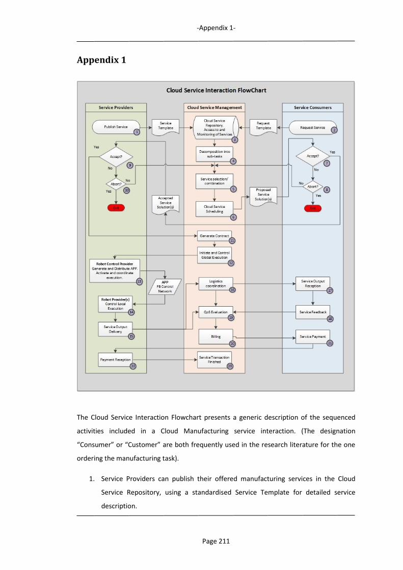
-Appendix 1-
Page 211
Appendix 1
The Cloud Service Interaction Flowchart presents a generic description of the sequenced
activities included in a Cloud Manufacturing service interaction. (The designation
“Consumer” or “Customer” are both frequently used in the research literature for the one
ordering the manufacturing task).
1. Service Providers can publish their offered manufacturing services in the Cloud
Service Repository, using a standardised Service Template for detailed service
description.
-Appendix 1-
Page 212
2. Service Consumers can publish their manufacturing task requests in the Cloud
Service Repository, using a standardised Task Request Template for detailed
manufacturing task description.
3. The Cloud Service Repository is responsible for storing services, as well as the access
to, and monitoring of, services and all the service transactions.
4. Cloud Service Management performs decomposition of published manufacturing
tasks, into sub-tasks.
5. Cloud Service Management performs selection and composition of published
manufacturing services to match all sub-tasks of a manufacturing request.
6. Cloud Service Management performs service scheduling of all services selected for
the requested manufacturing task. (Access to Providers´ resource schedules
required). A service proposal solution is sent to the Consumer.
7. If the service proposal solution is accepted by the Consumer, this is forwarded to the
Provider(s).
8. If the service proposal solution is not accepted by the Consumer, the Consumer can
either exit the process or initiate a new search of available services.
9. If the service proposal solution is accepted by the Provider(s), the process of initiating
the manufacturing process will be started.
10. If the service proposal solution is not accepted by the Provider, the Provider can
either exit the process or initiate a new search of available services.
11. Cloud Service Management generates a manufacturing contract, stating both
Provider, Consumer and cloud owner requirements.
12. Cloud Service Management initiates and controls global execution of included
services.
-Appendix 1-
Page 213
13. In this example, Robot Control-as-a-Service is the provided service, which is initiated
by the Provider. An Assembly Process Plan is generated for the control of a robotic
assembly process.
14. The assembly process is provided as a Robot Hardware-as-a-Service by another
Provider. The process is executed following the Assembly Process Plan.
15. When service execution is finished, the service output is delivered.
16. Cloud Service Management coordinates the logistics for service output delivery.
17. Consumer receives the ordered products.
18. Consumer gives feedback on the invoked service.
19. Cloud Service Management evaluates Quality of Service after input from
participating Consumer and Provider(s). This may be used to establish a quality rating
of the service provider.
20-23. Cloud Service Management generates billing documents and after service
payment and reception the service transaction is finished.
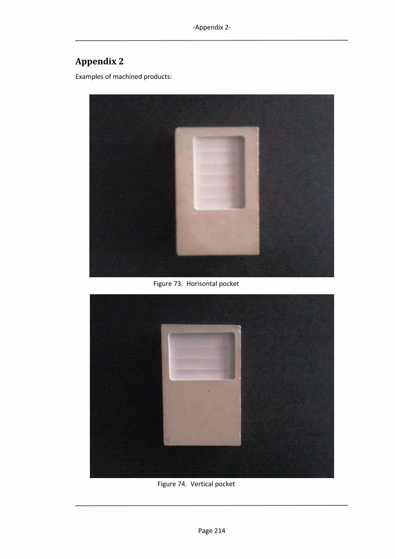
-Appendix 2-
Page 214
Appendix 2
Examples of machined products:
Figure 73. Horisontal pocket
Figure 74. Vertical pocket

-Appendix 2-
Page 215
Figure 75. “HIS” engraved

-Appendix 3-
Page 216
Appendix 3
Program listing: Assembly Feature INSERT
(From nxtSTUDIO).
/*
* Created by nxtSTUDIO.
* User: RIZO
* Date: 4/30/2013
* Time: 6:37 PM
*
* To change this template use Tools | Options | Coding | Edit Standard Headers.
*/
using System;
using System.IO;
using System.Collections;
using NxtControl;
using HMI;
using Microsoft;
using nxtControl;
using NxtStudio;
namespace HMI.Main.Symbols.WriteInsert
{
/// <summary>
/// Description of sDefault.
/// </summary>
public partial class sDefault : NxtControl.GuiFramework.HMISymbol
{
public sDefault()
{
//
// The InitializeComponent() call is required for Windows
Forms designer support.
//
InitializeComponent();
this.Staqrt_Fired += Staqrt_Fired_EventHandler;
}
//Method to enable the button in the HMI once the Input Event Staqrt
void Staqrt_Fired_EventHandler(object sender,
StaqrtEventArgs ea)
{
this.Button.Enabled = true;
}
//Method to be called when the Output Event Start needs to
be triggered. Sends the text "START" to the Output Var -> OStart
public void startmethod()
{
string textStart = "START";
this.OStart.Text = textStart;
FireEvent_Start(textStart);
}
//Method to trigger the event Start when required and write
in the Output Var the value of the string "00000" in order to reset the previous value "START" in the OVAR ->
OStart
public void resetmethod()
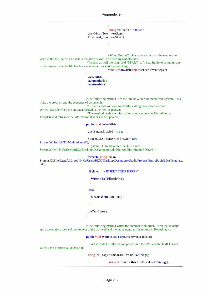
-Appendix 3-
Page 217
{
string textStart1 = "00000";
this.OStart.Text = textStart1;
FireEvent_Start(textStart1);
}
//When ButtonClick is activated it calls the methods to
write in the file that will be sent to the other device to be used by RobotStudio.
//It sents, as well the command "START" to VisualStudio to communicate
to the program that the file has been sent and it can start the searching.
void ButtonClick(object sender, EventArgs e)
{
writeBDA();
startmethod();
resetmethod();
}
//The following method uses the StreamWriter inherited from System.IO to
write the program and the sequence of commands
//to the file that we want to modify, calling the created method
WriteinTxTFile when the button allocated in the HMI is pressed.
//The method reads the information allocated in a txt file defined as
Template and refreshes the information that has to be updated.
public void writeBDA()
{
this.Button.Enabled = true;
System.IO.StreamWriter fileOut = new
StreamWriter(@"D:\Module1.mod");
//System.IO.StreamWriter fileOut1 = new
StreamWriter(@"C:\Users\RIZO\Desktop\DesktopnxtStudioProjects\EntireRapidBDA.txt");
foreach (string line in
System.IO.File.ReadAllLines(@"C:\Users\RIZO\Desktop\DesktopnxtStudioProjects\EntireRapidBDATemplate.
txt"))
{
if (line == "<INSERT CODE HERE>")
{
WriteinTxTFile(fileOut);
}
else
{
fileOut.WriteLine(line);
}
}
fileOut.Close();
}
//The following method writes the commands in order, it sets the velocity
and acceleration, tool and workobject of the workcell and the movement, as it is written in RobotStudio.
public void WriteinTxTFile(StreamWriter fileOut)
{
//First it reads the information passed into the IVars on the HMI FB and
stores them in some variable string.
string text_copy = this.Inst11.Value.ToString();
string textinst1 = this.Inst01.Value.ToString();
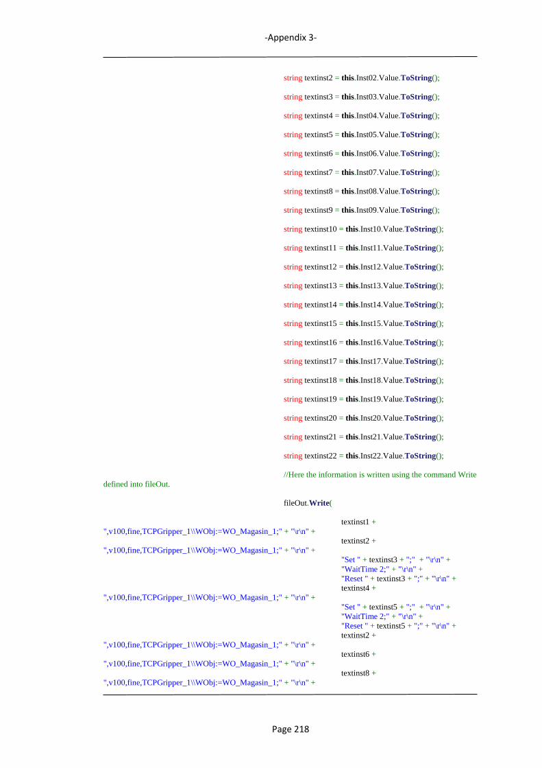
-Appendix 3-
Page 218
string textinst2 = this.Inst02.Value.ToString();
string textinst3 = this.Inst03.Value.ToString();
string textinst4 = this.Inst04.Value.ToString();
string textinst5 = this.Inst05.Value.ToString();
string textinst6 = this.Inst06.Value.ToString();
string textinst7 = this.Inst07.Value.ToString();
string textinst8 = this.Inst08.Value.ToString();
string textinst9 = this.Inst09.Value.ToString();
string textinst10 = this.Inst10.Value.ToString();
string textinst11 = this.Inst11.Value.ToString();
string textinst12 = this.Inst12.Value.ToString();
string textinst13 = this.Inst13.Value.ToString();
string textinst14 = this.Inst14.Value.ToString();
string textinst15 = this.Inst15.Value.ToString();
string textinst16 = this.Inst16.Value.ToString();
string textinst17 = this.Inst17.Value.ToString();
string textinst18 = this.Inst18.Value.ToString();
string textinst19 = this.Inst19.Value.ToString();
string textinst20 = this.Inst20.Value.ToString();
string textinst21 = this.Inst21.Value.ToString();
string textinst22 = this.Inst22.Value.ToString();
//Here the information is written using the command Write
defined into fileOut.
fileOut.Write(
textinst1 +
",v100,fine,TCPGripper_1\\WObj:=WO_Magasin_1;" + "\r\n" +
textinst2 +
",v100,fine,TCPGripper_1\\WObj:=WO_Magasin_1;" + "\r\n" +
"Set " + textinst3 + ";" + "\r\n" +
"WaitTime 2;" + "\r\n" +
"Reset " + textinst3 + ";" + "\r\n" +
textinst4 +
",v100,fine,TCPGripper_1\\WObj:=WO_Magasin_1;" + "\r\n" +
"Set " + textinst5 + ";" + "\r\n" +
"WaitTime 2;" + "\r\n" +
"Reset " + textinst5 + ";" + "\r\n" +
textinst2 +
",v100,fine,TCPGripper_1\\WObj:=WO_Magasin_1;" + "\r\n" +
textinst6 +
",v100,fine,TCPGripper_1\\WObj:=WO_Magasin_1;" + "\r\n" +
textinst8 +
",v100,fine,TCPGripper_1\\WObj:=WO_Magasin_1;" + "\r\n" +
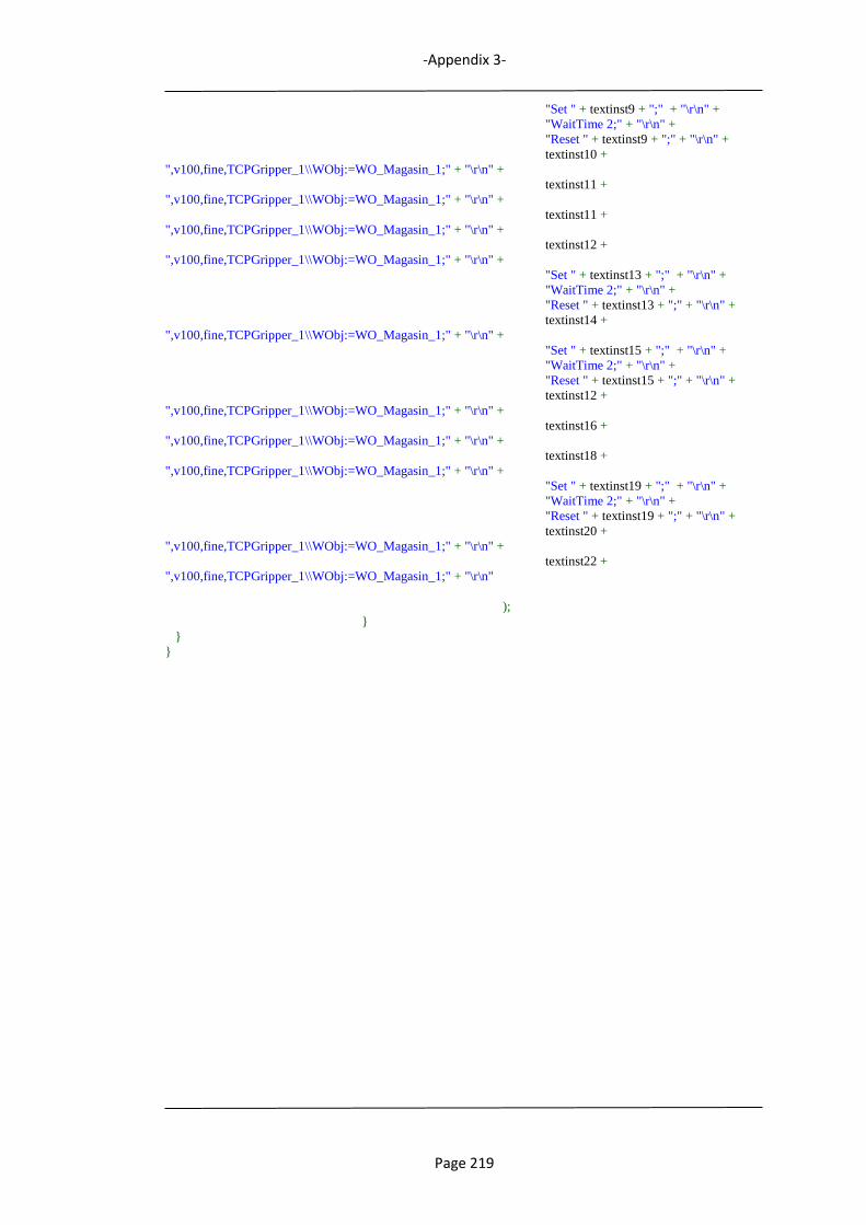
-Appendix 3-
Page 219
"Set " + textinst9 + ";" + "\r\n" +
"WaitTime 2;" + "\r\n" +
"Reset " + textinst9 + ";" + "\r\n" +
textinst10 +
",v100,fine,TCPGripper_1\\WObj:=WO_Magasin_1;" + "\r\n" +
textinst11 +
",v100,fine,TCPGripper_1\\WObj:=WO_Magasin_1;" + "\r\n" +
textinst11 +
",v100,fine,TCPGripper_1\\WObj:=WO_Magasin_1;" + "\r\n" +
textinst12 +
",v100,fine,TCPGripper_1\\WObj:=WO_Magasin_1;" + "\r\n" +
"Set " + textinst13 + ";" + "\r\n" +
"WaitTime 2;" + "\r\n" +
"Reset " + textinst13 + ";" + "\r\n" +
textinst14 +
",v100,fine,TCPGripper_1\\WObj:=WO_Magasin_1;" + "\r\n" +
"Set " + textinst15 + ";" + "\r\n" +
"WaitTime 2;" + "\r\n" +
"Reset " + textinst15 + ";" + "\r\n" +
textinst12 +
",v100,fine,TCPGripper_1\\WObj:=WO_Magasin_1;" + "\r\n" +
textinst16 +
",v100,fine,TCPGripper_1\\WObj:=WO_Magasin_1;" + "\r\n" +
textinst18 +
",v100,fine,TCPGripper_1\\WObj:=WO_Magasin_1;" + "\r\n" +
"Set " + textinst19 + ";" + "\r\n" +
"WaitTime 2;" + "\r\n" +
"Reset " + textinst19 + ";" + "\r\n" +
textinst20 +
",v100,fine,TCPGripper_1\\WObj:=WO_Magasin_1;" + "\r\n" +
textinst22 +
",v100,fine,TCPGripper_1\\WObj:=WO_Magasin_1;" + "\r\n"
);
}
}
}
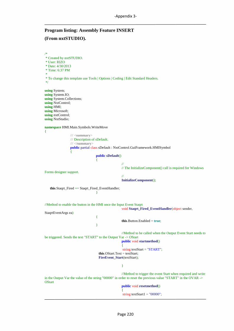
-Appendix 3-
Page 220
Program listing: Assembly Feature INSERT
(From nxtSTUDIO).
/*
* Created by nxtSTUDIO.
* User: RIZO
* Date: 4/30/2013
* Time: 6:37 PM
*
* To change this template use Tools | Options | Coding | Edit Standard Headers.
*/
using System;
using System.IO;
using System.Collections;
using NxtControl;
using HMI;
using Microsoft;
using nxtControl;
using NxtStudio;
namespace HMI.Main.Symbols.WriteMove
{
/// <summary>
/// Description of sDefault.
/// </summary>
public partial class sDefault : NxtControl.GuiFramework.HMISymbol
{
public sDefault()
{
//
// The InitializeComponent() call is required for Windows
Forms designer support.
//
InitializeComponent();
this.Staqrt_Fired += Staqrt_Fired_EventHandler;
}
//Method to enable the button in the HMI once the Input Event Staqrt
void Staqrt_Fired_EventHandler(object sender,
StaqrtEventArgs ea)
{
this.Button.Enabled = true;
}
//Method to be called when the Output Event Start needs to
be triggered. Sends the text "START" to the Output Var -> OStart
public void startmethod()
{
string textStart = "START";
this.OStart.Text = textStart;
FireEvent_Start(textStart);
}
//Method to trigger the event Start when required and write
in the Output Var the value of the string "00000" in order to reset the previous value "START" in the OVAR ->
OStart
public void resetmethod()
{
string textStart1 = "00000";
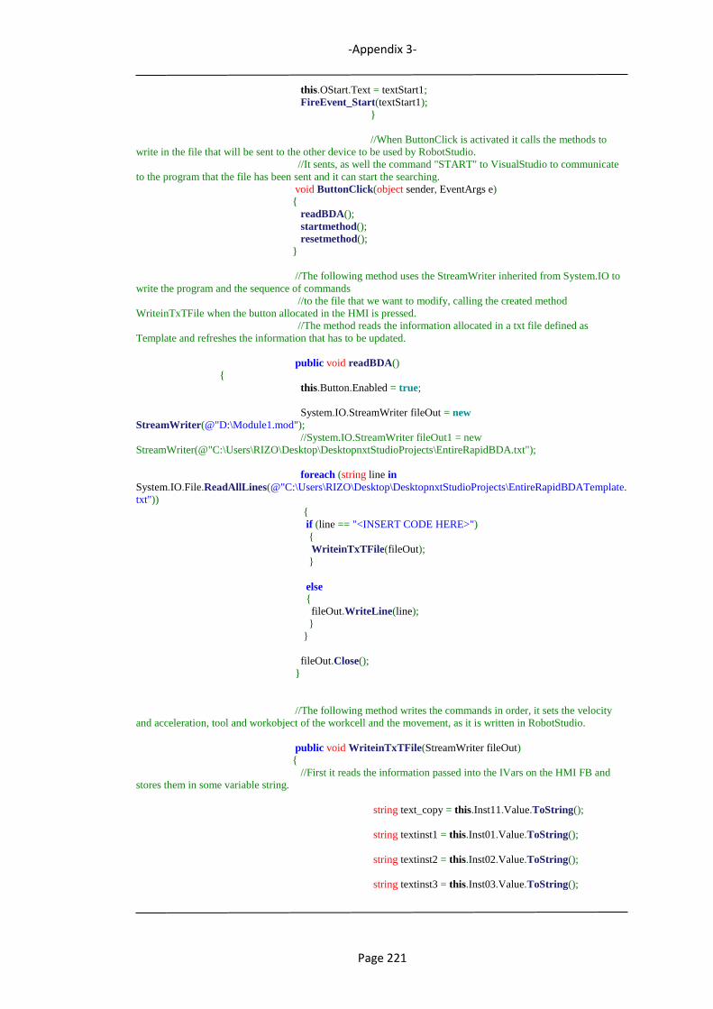
-Appendix 3-
Page 221
this.OStart.Text = textStart1;
FireEvent_Start(textStart1);
}
//When ButtonClick is activated it calls the methods to
write in the file that will be sent to the other device to be used by RobotStudio.
//It sents, as well the command "START" to VisualStudio to communicate
to the program that the file has been sent and it can start the searching.
void ButtonClick(object sender, EventArgs e)
{
readBDA();
startmethod();
resetmethod();
}
//The following method uses the StreamWriter inherited from System.IO to
write the program and the sequence of commands
//to the file that we want to modify, calling the created method
WriteinTxTFile when the button allocated in the HMI is pressed.
//The method reads the information allocated in a txt file defined as
Template and refreshes the information that has to be updated.
public void readBDA()
{
this.Button.Enabled = true;
System.IO.StreamWriter fileOut = new
StreamWriter(@"D:\Module1.mod");
//System.IO.StreamWriter fileOut1 = new
StreamWriter(@"C:\Users\RIZO\Desktop\DesktopnxtStudioProjects\EntireRapidBDA.txt");
foreach (string line in
System.IO.File.ReadAllLines(@"C:\Users\RIZO\Desktop\DesktopnxtStudioProjects\EntireRapidBDATemplate.
txt"))
{
if (line == "<INSERT CODE HERE>")
{
WriteinTxTFile(fileOut);
}
else
{
fileOut.WriteLine(line);
}
}
fileOut.Close();
}
//The following method writes the commands in order, it sets the velocity
and acceleration, tool and workobject of the workcell and the movement, as it is written in RobotStudio.
public void WriteinTxTFile(StreamWriter fileOut)
{
//First it reads the information passed into the IVars on the HMI FB and
stores them in some variable string.
string text_copy = this.Inst11.Value.ToString();
string textinst1 = this.Inst01.Value.ToString();
string textinst2 = this.Inst02.Value.ToString();
string textinst3 = this.Inst03.Value.ToString();
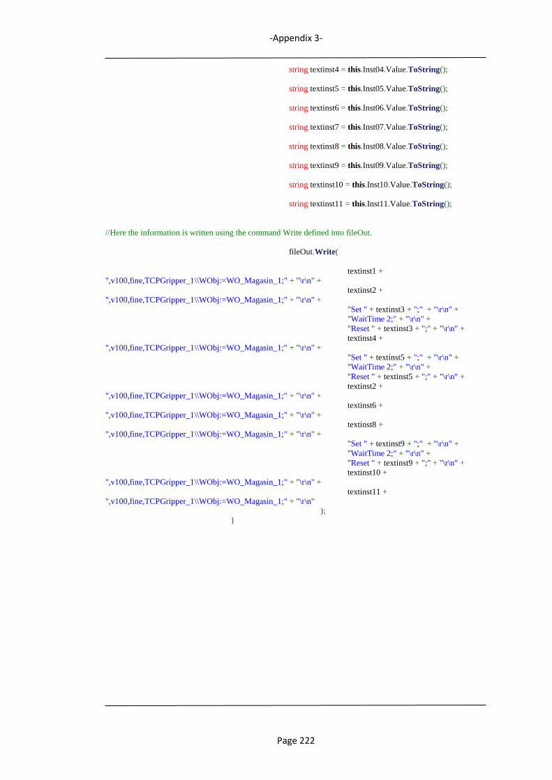
-Appendix 3-
Page 222
string textinst4 = this.Inst04.Value.ToString();
string textinst5 = this.Inst05.Value.ToString();
string textinst6 = this.Inst06.Value.ToString();
string textinst7 = this.Inst07.Value.ToString();
string textinst8 = this.Inst08.Value.ToString();
string textinst9 = this.Inst09.Value.ToString();
string textinst10 = this.Inst10.Value.ToString();
string textinst11 = this.Inst11.Value.ToString();
//Here the information is written using the command Write defined into fileOut.
fileOut.Write(
textinst1 +
",v100,fine,TCPGripper_1\\WObj:=WO_Magasin_1;" + "\r\n" +
textinst2 +
",v100,fine,TCPGripper_1\\WObj:=WO_Magasin_1;" + "\r\n" +
"Set " + textinst3 + ";" + "\r\n" +
"WaitTime 2;" + "\r\n" +
"Reset " + textinst3 + ";" + "\r\n" +
textinst4 +
",v100,fine,TCPGripper_1\\WObj:=WO_Magasin_1;" + "\r\n" +
"Set " + textinst5 + ";" + "\r\n" +
"WaitTime 2;" + "\r\n" +
"Reset " + textinst5 + ";" + "\r\n" +
textinst2 +
",v100,fine,TCPGripper_1\\WObj:=WO_Magasin_1;" + "\r\n" +
textinst6 +
",v100,fine,TCPGripper_1\\WObj:=WO_Magasin_1;" + "\r\n" +
textinst8 +
",v100,fine,TCPGripper_1\\WObj:=WO_Magasin_1;" + "\r\n" +
"Set " + textinst9 + ";" + "\r\n" +
"WaitTime 2;" + "\r\n" +
"Reset " + textinst9 + ";" + "\r\n" +
textinst10 +
",v100,fine,TCPGripper_1\\WObj:=WO_Magasin_1;" + "\r\n" +
textinst11 +
",v100,fine,TCPGripper_1\\WObj:=WO_Magasin_1;" + "\r\n"
);
}
-Appendix 3-
Page 223
Program listing: Minicell Control
(From VisualStudio C#).
using System;
using System.Collections.Generic;
using System.ComponentModel;
using System.Data;
using System.Drawing;
using System.Linq;
using System.Text;
using System.Windows.Forms;
using System.Net;
using System.Net.Sockets;
//Add ABB libraries
using ABB.Robotics;
using ABB.Robotics.Controllers;
using ABB.Robotics.Controllers.Discovery;
using ABB.Robotics.Controllers.RapidDomain;
using ABB.Robotics.Controllers.IOSystemDomain;
using ABB.Robotics.RobotStudio.Environment;
using ABB.Robotics.RobotStudio.Stations.Forms;
using ABB.Robotics.RobotStudio.Stations;
using ABB.Robotics.RobotStudio;
using ABB.Robotics.Math;
using RobotStudio.Services.RobApi;
namespace Scanner
{
public partial class WindowForm : Form
{
//To find all controllers on the network we start by declaring these member variables
private NetworkScanner scanner = null; // scanner is a reference to an object of NetworkScanner class
private Controller controller = null;
private NetworkWatcher networkwatcher = null;
private Task[] tasks = null;
private RapidData rd = null;
private Pos aPos;
private ToolData aTool;
public Station stn;
// used to communicate
Socket sckCommunication;
EndPoint epLocal, epRemote;
// buffer to receive info
byte[] buffer;
public WindowForm()
{
InitializeComponent();
}
private void WindowForm_Load(object sender, EventArgs e)
{
panel1.Visible = false; //Able lstView when start
panel2.Visible = false; //Disable panel2 when start
// set up socket
sckCommunication = new Socket(AddressFamily.InterNetwork, SocketType.Dgram, ProtocolType.Udp);
-Appendix 3-
Page 224
sckCommunication.SetSocketOption(SocketOptionLevel.Socket, SocketOptionName.ReuseAddress,
true);
// get own ip
/*
textBox2.Text = GetLocalIP();
textBox4.Text = GetLocalIP();
*/
// IP and port fixed
textBox2.Text = "192.168.0.2";
textBox4.Text = "192.168.0.1";
textBox3.Text = "49189";
textBox5.Text = "1001";
// Call LoadAll for load the methods needed
LoadAll();
}
private void LoadAll()
{
// Search the controller
SearchController();
// Connect with the specific controller
ConectController();
// Start UDP connection
StartServer();
// Add subscriptions for all events
IORead();
// Send "I am ready" to Automaic Task Builder
SendCommand("READY");
}
private void btnScan_Click(object sender, EventArgs e)
{
SearchController();
}
private void SearchController()
{
DisableControllerFunctionality();
panel2.Visible = true;
lstView.Items.Clear(); //Clear lstView
this.scanner = new NetworkScanner(); //Create scanner object of NetworkScanner class
this.scanner.Scan();
ControllerInfoCollection controllers = scanner.Controllers;
ListViewItem item = null;
foreach (ControllerInfo controllerInfo in controllers)
{
item = new ListViewItem(controllerInfo.IPAddress.ToString());
item.SubItems.Add(controllerInfo.Availability.ToString());
item.SubItems.Add(controllerInfo.IsVirtual.ToString());
item.SubItems.Add(controllerInfo.SystemName);
item.SubItems.Add(controllerInfo.Version.ToString());
item.SubItems.Add(controllerInfo.ControllerName);
this.lstView.Items.Add(item);
item.Tag = controllerInfo;
}
//The watcher is active waiting for found or lost conections
this.networkwatcher = new NetworkWatcher(scanner.Controllers);
// this.networkwatcher.Found += new EventHandler<NetworkWatcherEventArgs>(HandleFoundEvent);
this.networkwatcher.Lost += new EventHandler<NetworkWatcherEventArgs>(HandleLostEvent);
this.networkwatcher.EnableRaisingEvents = true;
}

-Appendix 3-
Page 225
/* void HandleFoundEvent(object sender, NetworkWatcherEventArgs e)
{
this.Invoke(new EventHandler<NetworkWatcherEventArgs>(AddControllerToListView), new Object[] {
this, e });
}
*/
void HandleLostEvent(object sender, NetworkWatcherEventArgs e)
{
this.Invoke(new EventHandler<NetworkWatcherEventArgs>(RemoveControllerFromListView), new
Object[] { sender, e });
}
/* private void AddControllerToListView(object sender, NetworkWatcherEventArgs e)
{
ControllerInfo controllerInfo = e.Controller;
ListViewItem item = new ListViewItem(controllerInfo.IPAddress.ToString());
item.SubItems.Add(controllerInfo.Id);
item.SubItems.Add(controllerInfo.Availability.ToString());
item.SubItems.Add(controllerInfo.IsVirtual.ToString());
item.SubItems.Add(controllerInfo.SystemName);
item.SubItems.Add(controllerInfo.Version.ToString());
item.SubItems.Add(controllerInfo.ControllerName);
this.lstView.Items.Add(item); item.Tag = controllerInfo;
}
*/
private void RemoveControllerFromListView(object sender, NetworkWatcherEventArgs e)
{
MessageBox.Show("Connection with the controller has been lost.");
foreach (ListViewItem item in this.lstView.Items)
{
if ((ControllerInfo)item.Tag == e.Controller)
{
this.lstView.Items.Remove(item);
break;
}
}
}
private void DisableControllerFunctionality()
{
// put all the enable and disable functionality in the same place so that it is easy to reuse
if (this.controller != null) //first, log off of the controller (if is connected)
{
this.controller.Logoff(); // log off of the controller
this.controller.Dispose(); // dispose the controller
this.controller = null; // null indicates that the controller is available
}
panel1.Visible = false; // if it does not connected lstView is visible completely
panel2.Visible = false; // if it does not connected functionality are disabled
}
private void EnableControllerFunctionality()
{
panel1.Visible = true;
panel2.Visible = true;
//load signal events in signal array
//IORead();
}
private void lstView_DoubleClick(object sender, EventArgs e)
{
}
-Appendix 3-
Page 226
private void ConectController()
{
int nItems = lstView.Items.Count;
for (int i = 0; i < nItems; i++)
{
ListViewItem item = lstView.Items[i];
//ListViewItem item = this.lstView.SelectedItems[0];
if (item.Tag != null)
{
ControllerInfo controllerInfo = (ControllerInfo)item.Tag;
if (controllerInfo.Availability == Availability.Available)
{
if (controllerInfo.IsVirtual)
{
if (controllerInfo.SystemName == "JCBENJI")
{
this.controller = ControllerFactory.CreateFrom(controllerInfo);
this.controller.Logon(UserInfo.DefaultUser);
lstView.Items.Clear();
lstView.Items.Add(item);
EnableControllerFunctionality();
}
}
else //real controller
{
if (MessageBox.Show("This is NOT a virtual controller, do you really want to connect to that?",
"Warning", MessageBoxButtons.YesNo, MessageBoxIcon.Warning) ==
System.Windows.Forms.DialogResult.Yes)
{
this.controller = ControllerFactory.CreateFrom(controllerInfo);
this.controller.Logon(UserInfo.DefaultUser);
lstView.Items.Clear();
lstView.Items.Add(item);
EnableControllerFunctionality();
}
}
}
else
{
MessageBox.Show("Selected controller not available.");
}
}
}
}
private void StartProduction()
{
try
{
if (controller.OperatingMode == ControllerOperatingMode.Auto)
{
tasks = controller.Rapid.GetTasks();
using (Mastership m = Mastership.Request(controller.Rapid))
{
tasks[0].Start(RegainMode.Clear, ExecutionMode.Continuous);
//textBox1.Text += "Start execution\r\n";
}
}
else
{
MessageBox.Show("Automatic mode is required to start execution from a remote client.");
}
-Appendix 3-
Page 227
}
catch (System.InvalidOperationException ex)
{
MessageBox.Show("Mastership is held by another client. " + ex.Message);
}
catch (System.Exception ex)
{
MessageBox.Show("Unexpected error occurred: " + ex.Message);
}
}
private void StopProduction()
{
if (this.controller.Rapid.ExecutionStatus == ExecutionStatus.Running)
{
tasks = controller.Rapid.GetTasks();
using (Mastership m = Mastership.Request(controller.Rapid))
{
tasks[0].Stop(StopMode.Immediate);
}
}
}
private void ChangePP(string position)
{
try
{
if (controller.OperatingMode == ControllerOperatingMode.Auto)
{
tasks = controller.Rapid.GetTasks();
using (Mastership m = Mastership.Request(controller.Rapid))
{
tasks[0].SetProgramPointer("Module1", position);
//textBox1.Text += "PP changed to:" + position + "\r\n";
}
}
else
{
MessageBox.Show("Automatic mode is required to start execution from a remote client.");
}
}
catch (System.InvalidOperationException ex)
{
MessageBox.Show("Mastership is held by another client. " + ex.Message);
}
catch (System.Exception ex)
{
MessageBox.Show("Unexpected error occurred: " + ex.Message);
}
}
private void RAPIDWrite()
{
ABB.Robotics.Controllers.RapidDomain.Num rapidNum;
ABB.Robotics.Controllers.RapidDomain.RapidData rd = controller.Rapid.GetRapidData("T_ROB1",
"CalibData", "TCPGripper_1");
if (rd.Value is ToolData)
{
aTool = (ToolData)rd.Value;
this.textBox1.Text += aTool.Tframe.Trans.ToString() + "\r\n";
this.aPos = new Pos();
aPos.FillFromString2("[5,3,5]");
aTool.Tframe.Trans = aPos;
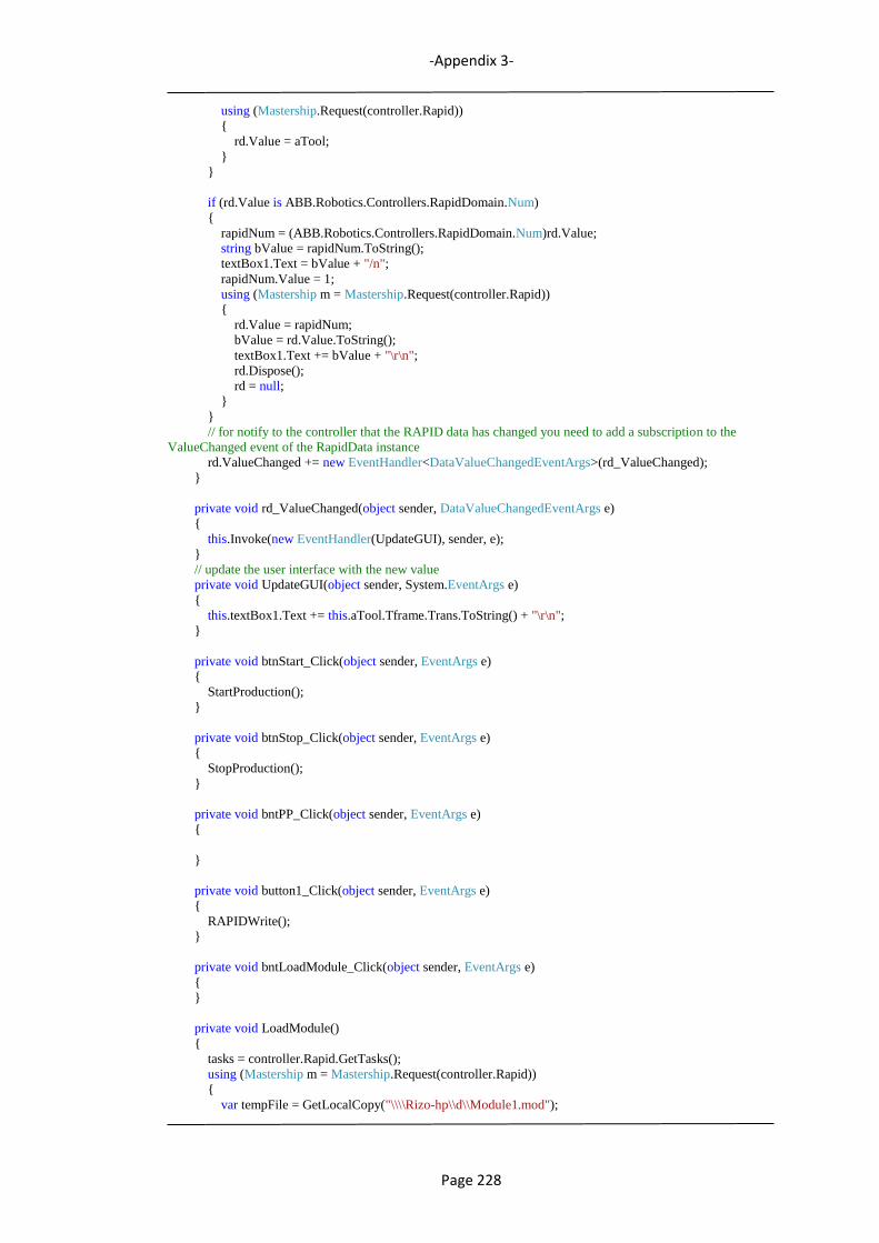
-Appendix 3-
Page 228
using (Mastership.Request(controller.Rapid))
{
rd.Value = aTool;
}
}
if (rd.Value is ABB.Robotics.Controllers.RapidDomain.Num)
{
rapidNum = (ABB.Robotics.Controllers.RapidDomain.Num)rd.Value;
string bValue = rapidNum.ToString();
textBox1.Text = bValue + "/n";
rapidNum.Value = 1;
using (Mastership m = Mastership.Request(controller.Rapid))
{
rd.Value = rapidNum;
bValue = rd.Value.ToString();
textBox1.Text += bValue + "\r\n";
rd.Dispose();
rd = null;
}
}
// for notify to the controller that the RAPID data has changed you need to add a subscription to the
ValueChanged event of the RapidData instance
rd.ValueChanged += new EventHandler<DataValueChangedEventArgs>(rd_ValueChanged);
}
private void rd_ValueChanged(object sender, DataValueChangedEventArgs e)
{
this.Invoke(new EventHandler(UpdateGUI), sender, e);
}
// update the user interface with the new value
private void UpdateGUI(object sender, System.EventArgs e)
{
this.textBox1.Text += this.aTool.Tframe.Trans.ToString() + "\r\n";
}
private void btnStart_Click(object sender, EventArgs e)
{
StartProduction();
}
private void btnStop_Click(object sender, EventArgs e)
{
StopProduction();
}
private void bntPP_Click(object sender, EventArgs e)
{
}
private void button1_Click(object sender, EventArgs e)
{
RAPIDWrite();
}
private void bntLoadModule_Click(object sender, EventArgs e)
{
}
private void LoadModule()
{
tasks = controller.Rapid.GetTasks();
using (Mastership m = Mastership.Request(controller.Rapid))
{
var tempFile = GetLocalCopy("\\\\Rizo-hp\\d\\Module1.mod");
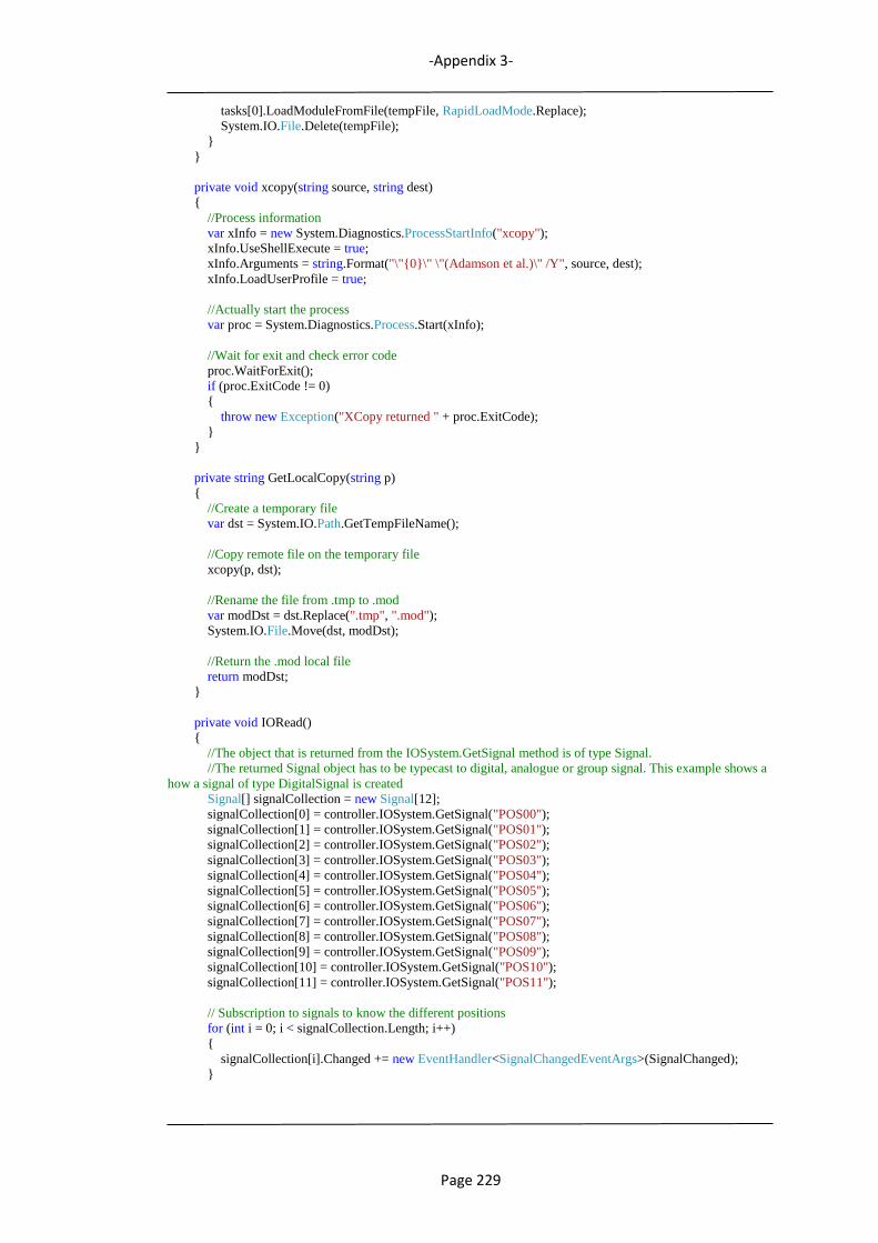
-Appendix 3-
Page 229
tasks[0].LoadModuleFromFile(tempFile, RapidLoadMode.Replace);
System.IO.File.Delete(tempFile);
}
}
private void xcopy(string source, string dest)
{
//Process information
var xInfo = new System.Diagnostics.ProcessStartInfo("xcopy");
xInfo.UseShellExecute = true;
xInfo.Arguments = string.Format("\"{0}\" \"(Adamson et al.)\" /Y", source, dest);
xInfo.LoadUserProfile = true;
//Actually start the process
var proc = System.Diagnostics.Process.Start(xInfo);
//Wait for exit and check error code
proc.WaitForExit();
if (proc.ExitCode != 0)
{
throw new Exception("XCopy returned " + proc.ExitCode);
}
}
private string GetLocalCopy(string p)
{
//Create a temporary file
var dst = System.IO.Path.GetTempFileName();
//Copy remote file on the temporary file
xcopy(p, dst);
//Rename the file from .tmp to .mod
var modDst = dst.Replace(".tmp", ".mod");
System.IO.File.Move(dst, modDst);
//Return the .mod local file
return modDst;
}
private void IORead()
{
//The object that is returned from the IOSystem.GetSignal method is of type Signal.
//The returned Signal object has to be typecast to digital, analogue or group signal. This example shows a
how a signal of type DigitalSignal is created
Signal[] signalCollection = new Signal[12];
signalCollection[0] = controller.IOSystem.GetSignal("POS00");
signalCollection[1] = controller.IOSystem.GetSignal("POS01");
signalCollection[2] = controller.IOSystem.GetSignal("POS02");
signalCollection[3] = controller.IOSystem.GetSignal("POS03");
signalCollection[4] = controller.IOSystem.GetSignal("POS04");
signalCollection[5] = controller.IOSystem.GetSignal("POS05");
signalCollection[6] = controller.IOSystem.GetSignal("POS06");
signalCollection[7] = controller.IOSystem.GetSignal("POS07");
signalCollection[8] = controller.IOSystem.GetSignal("POS08");
signalCollection[9] = controller.IOSystem.GetSignal("POS09");
signalCollection[10] = controller.IOSystem.GetSignal("POS10");
signalCollection[11] = controller.IOSystem.GetSignal("POS11");
// Subscription to signals to know the different positions
for (int i = 0; i < signalCollection.Length; i++)
{
signalCollection[i].Changed += new EventHandler<SignalChangedEventArgs>(SignalChanged);
}

-Appendix 3-
Page 230
controller.Rapid.ExecutionStatusChanged += new
EventHandler<ExecutionStatusChangedEventArgs>(Rapid_ExecutionStatusChanged);
}
// Send when the execution status is running or stopped
void Rapid_ExecutionStatusChanged(object sender, ExecutionStatusChangedEventArgs e)
{
SendCommand(controller.Rapid.ExecutionStatus.ToString());
}
private void SignalChanged(object sender, SignalChangedEventArgs e)
{
SignalState state = e.NewSignalState;
byte val = (byte)state.Value;
//send the signal state by UDP
if (sender.ToString() == "POS06")
{
if (val == 1)
{
//MessageBox.Show("ObWasher1=" + sender.ToString());
SendCommand("ObWasher=" + sender.ToString());
}
}
else
{
if (val == 1)
{
//MessageBox.Show("ObShaft1=" + sender.ToString());
SendCommand("ObShaft1=" + sender.ToString());
}
}
}
// return the own ip
private string GetLocalIP()
{
IPHostEntry host;
host = Dns.GetHostEntry(Dns.GetHostName());
foreach (IPAddress ip in host.AddressList)
{
if (ip.AddressFamily == AddressFamily.InterNetwork)
{
return ip.ToString();
}
}
return "127.0.0.1";
}
private void bntStartServer_Click(object sender, EventArgs e)
{
// bind socket
epLocal = new IPEndPoint(IPAddress.Parse(textBox2.Text), Convert.ToInt32(textBox3.Text));
sckCommunication.Bind(epLocal);
// connect to remote ip and port
epRemote = new IPEndPoint(IPAddress.Parse(textBox4.Text), Convert.ToInt32(textBox5.Text));
sckCommunication.Connect(epRemote);
// starts to listen to an specific port
buffer = new byte[5];
sckCommunication.BeginReceiveFrom(buffer, 0, buffer.Length, SocketFlags.None,
ref epRemote, new AsyncCallback(OperatorCallBack), buffer);
listBox1.Items.Add("Friend: " + buffer.ToString());

-Appendix 3-
Page 231
// release button to send message
btnSend.Enabled = true;
}
private void StartServer()
{
// bind socket
epLocal = new IPEndPoint(IPAddress.Parse(textBox2.Text), Convert.ToInt32(textBox3.Text));
sckCommunication.Bind(epLocal);
// connect to remote ip and port
epRemote = new IPEndPoint(IPAddress.Parse(textBox4.Text), Convert.ToInt32(textBox5.Text));
sckCommunication.Connect(epRemote);
// starts to listen to an specific port
buffer = new byte[5];
sckCommunication.BeginReceiveFrom(buffer, 0, buffer.Length, SocketFlags.None,
ref epRemote, new AsyncCallback(OperatorCallBack), buffer);
listBox1.Items.Add("Friend: " + buffer.ToString());
// release button to send message
btnSend.Enabled = true;
}
private void OperatorCallBack(IAsyncResult ar)
{
try
{
int size = sckCommunication.EndReceiveFrom(ar, ref epRemote);
// check if there is actually information
if (size > 0)
{
// used to help us on getting the data
byte[] aux = new byte[5];
// gets the data
aux = (byte[])ar.AsyncState;
// converts from data[] to string
ASCIIEncoding enc = new ASCIIEncoding();
string msg = enc.GetString(aux);
if (msg == "START")
{
// Load module from a specific root
LoadModule();
// Send "PLAY" to nxtONE
//SendCommand("PUSH PLAY");
}
if (msg == "ESTOP")
{
StopProduction();
}
}
// starts to listen again
buffer = new byte[5];
sckCommunication.BeginReceiveFrom(buffer, 0, buffer.Length, SocketFlags.None,
ref epRemote, new AsyncCallback(OperatorCallBack), buffer);
}
catch (Exception exp)
{
MessageBox.Show(exp.ToString());
}
-Appendix 3-
Page 232
}
private void SendCommand(string message)
{
// converts from string to byte[]
ASCIIEncoding enc = new ASCIIEncoding();
byte[] msg = new byte[1464];
msg = enc.GetBytes(message);
// sending the message
sckCommunication.Send(msg);
// add to listbox
//listBox1.Items.Add("You: " + message);
}
private void btnSend_Click_1(object sender, EventArgs e)
{
SendCommand(textBox6.Text);
// clear txtMessage
textBox6.Clear();
}
}
}