
Manufacturing Engineering - John Targonski
57
Manufacturing Engineering
-
Upload
khangminh22 -
Category
Documents
-
view
2 -
download
0
Transcript of Manufacturing Engineering - John Targonski

Manufacturing Engineering
Manufacturing Processes
• Machining
• Casting
• Moulding
• Forming (Tube Bending, Forging, Explosive Forming, Spin Forming)
• Joining
• Precision Cleaning
• Heat Treatment
• Coating & Finishes
• Non-Destructive Testing
• Measuring & Inspection
Table of Contents
CNC (Computerized Numerical Control)
The main purpose of a CNC program is to provide detailed instructions necessary to machine a part (also called a workpiece) for a given machine setup -with minimal human interaction.
All instructions to the control system must be written in a logical order and in a specified format called the program structure.
The resulting CNC Program or a Part Program can be stored on various media for the future and used repeatedly to achieve identical machining results at any time.
Benefits for 5-Axis vs. 3-Axis CNC:• Number of steps minimized
• For contoured features or machining on multiple faces, multiple setups are required by manually rotating the part
• Often eliminates the need for complex fixtures
• For 5-Axis typically only one feature is needed and the part can be automatically rotated
• Faster Material Removal
• 5-Axis machining allows the cutting tool to remain tangential to the cutting surface. Lower cycle times and costs are achieved because more material can be removed with each pass of the tool
• Better Surface Finishes• Due to 5-axis capabilities on contoured geometry.
With 3-axis small cuts are needed to create good surface finish and this requires longer lead times.
Machining
Top 7 CNC Machining Techniques:
• Turning
• Milling
• Surface Grinding
• Solid Sink EDM
• Wire EDM
• Cylindrical Grinding
• Optical Grinding
Machining cont.
TurningLathes are used to make concentric shapes on the outer circumference of a round part. Slots, ring grooves, stepped shoulders, internal and external threads, cylinders and shafts – many round or circular features are made on a lathe. They are also able to produce characteristically smooth and uniform surface finishes.
Milling• Milling differs fundamentally from turning in that the
workpiece is held stationary and the cutting tool rotates on a spindle. The workpiece is usually held horizontally in a machine vise, mounted on a table that moves in the X and Y directions. The spindle holds a variety of cutting tools and moves in the X, Y and Z axes.
• Although a mill can also drill holes and bores, it excels at removing stock from more complex and asymmetrical parts. Mills are used to make square/flat faces, notches, chamfers, channels, profiles, keyways and other features that depend on precisely cut angles. Together, milling and turning are responsible for the majority of CNC machine tool operations.
• As with all metal machining operations, cutting fluid is used to cool the workpiece and cutting tool, for lubrication and to flush away metal particles.
Machining cont.
Surface Grinding• Making a very flat surface on metal parts is important
for many applications and the best way to make such a precise surface is with a grinder. The grinder is a spinning disk covered with an abrasive grit of a specific coarseness. The workpiece is mounted on a table and is moved back and forth laterally beneath the abrasive wheel or is sometimes held firm while the wheel moves. Notice of course that this process can only be used on faces that are not interfered with by any protrusions sticking up from the surface.
• Different types of abrasives are used depending upon the material being ground. The heat and mechanical stress of the grinding process can adversely effect the work piece so care must be taken to control tool speed and temperature.
Cylindrical Grinding
This is a combination of surface grinding and lathe turning. The workpiece is usually held stationary while a circular or cylindrical grinding wheel is rotated against its surface. Cylindrical grinders can be used on both inside and outside diameters, either all the way through the length of the part or at partial depths.
The great advantage of this process is that it makes very precise and accurate tolerances with extremely smooth surface texture.
Machining cont.
EDM (Electrical Discharge Machining) is a manufacturing process whereby a desired shape is obtained by using electrical discharges (sparks)
Advantages:
• Complex shapes that would otherwise be difficult to produce with conventional cutting tools.
• Extremely hard material to very close tolerances.
• Very small work pieces where conventional cutting tools may damage the part from excess cutting tool pressure.
• There is no direct contact between tool and work piece. Therefore, delicate sections and weak materials can be machined without perceivable distortion.
• A good surface finish can be obtained; a very good surface may be obtained by redundant finishing paths.
• Very fine holes can be attained.
• Tapered holes may be produced.
• Pipe or container internal contours and internal corners down to R .001".
Disadvantages: • Difficulty finding expert machinists.
• The slow rate of material removal.
• Potential fire hazard associated with use of combustible oil based dielectrics.
• The additional time and cost used for creating electrodes for ram/sinker EDM.
• Reproducing sharp corners on the workpiece is difficult due to electrode wear.
• Specific power consumption is very high.
• Power consumption is high.
• "Overcut" is formed.
• Excessive tool wear occurs during machining.
• Electrically non-conductive materials can be machined only with specific set-up of the process
Machining cont.
Wire EDM• Wire EDM uses copper wire as a conductor for a high-voltage
electric charge. Fresh wire is fed from a spool as the conductor is steadily eroded during the cutting process. This technique requires a pass through and can’t be used in a blind hole.
• Wire EDM is used on thick, hardened tool steel to make circular or semi-circular features that would be very difficult to make with conventional cutting tools.
• Wire-cut EDM is typically used to cut plates as thick as 300mm and to make punches, tools, and dies from hard metals that are difficult to machine with other methods.
• Wire-cutting EDM is commonly used when low residual stresses are desired, because it does not require high cutting forces for removal of material.
Solid Sink EDM
• A conductive electrode is placed close to the work piece while bathed in a dielectric fluid. The electrode is precisely shaped for the feature that it’s cutting. As the
electrode discharges, metal particles are forced off the surface of the workpiece. The electrode itself does not touch the workpiece but is sacrificial and may need to be replaced frequently.
• EDM is used to make pockets, holes and square features inside of hardened tool steels that would be
difficult, if not impossible, to make any other way. It’s typically used on molds for plastic injection and pressure die casting, rarely on the finished piece itself. EDM is also used for making textured surfaces or debossed (recessed) lettering and
logos on mold tools.
Machining cont.
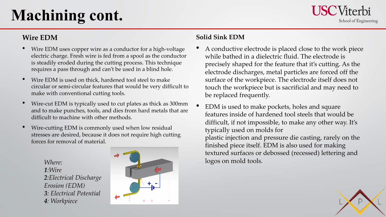
Where: 1:Wire 2:Electrical Discharge Erosion (EDM) 3: Electrical Potential 4: Workpiece
Optical Grinding
So far we’ve been only talking about machining metals, but CNC machining is also used for making specialty optics in glass or plastic. Optics require very fine surfaces with extremely close tolerances, so specialized grinding equipment is used that spins a grinding wheel against a surface while rotating on multiple axes.
This has the effect of averaging out any deviations from the nominal. Grinding paste is also used as a lubricant and to create a polished finished surface.
Machining cont.
Casting is the process where metal is heated until molten. While in the molten or liquid state it is poured into a mold or vessel to create a desired shape.
We use castings for a wide range of wearparts and components that are too large, complicated, intricate or otherwise unsuitable for the forging process. We can forge parts up to 50kgs but the sheer energy required to forge larger items make casting a much more viable alternative.
The advantages of casting include:
• No real upper size limit in casting weight
• Large range of alloy choices
• As forgings remain solid, custom alloys are far more difficult to get into production whereas with casting, alloys including Chrome, Nickel and Moly can be added at the molten stage.
• Tooling is often less expensive than forge dies
• Smaller production “runs” required
• Complicated/complex parts are no problem
Casting Methods:
• Investment Casting: is the term applied to precision moulding using a metal die and ceramic coating in which the chosen metal is injected. (Moulds are typically wax or foam)
• Sand Casting: is considered the traditional method of casting. The various common methods of sand casting revolve around the types of binders used to maintain mould strength (resist the molten metal).
The main points we look at when deciding between sand and investment casting are;
The size of the partInvestment casting is best suited for small parts up to a maximum of 80 kgsand 1.2 metres in length. Larger parts create too much pressure and distortion of the walls of the mould. Larger castings are best made as a sand cast.
TolerancesLower tolerances and a better surface finish can be achieved using the investment method.
CostAs a general rule we can produce investment castings at a better price than sand castings. We only source castings from those who make them better than everyone else. This means that our sand castings come from countries where the costs of production tend to be higher than countries that produce high quality investment castings, thus they are more expensive.
Casting
Moulding is the process of manufacturing by shaping liquid or pliable raw material using a rigid frame called a mold or matrix. This itself may have been made using a pattern or model of the final object.
Moulding
ForgingForging is the application of thermal and mechanical energy to steel billets or ingots to cause the material to change shape while in a solid state.
• Forging offers uniformity of composition and structure. Forging results in metallurgical recrystalisation and grainrefinement as a result of the thermal cycle and deformation process. This strengthens the resulting steel product particularly in terms of impact and shear strength.
• Forged steel is generally stronger and more reliable than castings and plate steel due to the fact that the grain flows of the steel are altered, conforming to the shape of the part.
The advantages of forging include:• Generally tougher than alternatives
• Will handle impact better than castings
• The nature of forging excludes the occurence of porosity, shrinkage, cavities and cold pour issues.
• The tight grain structure of forgings making it mechanically strong. There is less need for expensive alloys to attain high strength components.
• The tight grain structure offers great wear resistance without the need to make products “superhard” We have found that, on a blank HRC 38-42 forged grinder insert wear/wash is about the same as a high alloy HRC 46-50 cast grinder insert. The difference being a HRC 46-50 casting does not have the ductility to handle high impact grinding.
Forming

Tube Bending
Forming cont.
Explosive Forming Spin Forming
Forming cont.
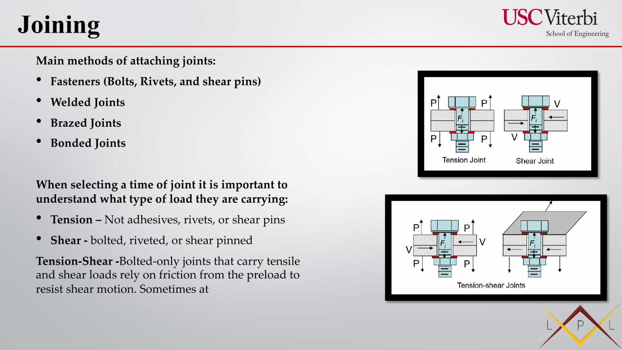
Main methods of attaching joints:
• Fasteners (Bolts, Rivets, and shear pins)
• Welded Joints
• Brazed Joints
• Bonded Joints
When selecting a time of joint it is important to understand what type of load they are carrying:
• Tension – Not adhesives, rivets, or shear pins
• Shear - bolted, riveted, or shear pinned
Tension-Shear -Bolted-only joints that carry tensile and shear loads rely on friction from the preload to resist shear motion. Sometimes at
Joining
Shear Joints
• can be bolted, riveted, or shear pinned
• Eccentricity/bending is ignored unless mating parts are very thick.
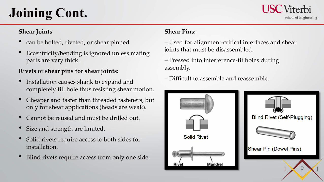
Rivets or shear pins for shear joints:
• Installation causes shank to expand and completely fill hole thus resisting shear motion.
• Cheaper and faster than threaded fasteners, but only for shear applications (heads are weak).
• Cannot be reused and must be drilled out.
• Size and strength are limited.
• Solid rivets require access to both sides for installation.
• Blind rivets require access from only one side.
Shear Pins:
– Used for alignment-critical interfaces and shear joints that must be disassembled.
– Pressed into interference-fit holes during assembly.
– Difficult to assemble and reassemble.
Joining Cont.
Rivets or shear pins for shear joints:
– Installation causes shank to expand and completely fill hole
thus resisting shear motion.
– Cheaper and faster than threaded fasteners, but only for shear applications (heads are weak).
– Cannot be reused and must be drilled out.
– Size and strength are limited.
– Solid rivets require access to both sides for installation.
– Blind rivets require access from only one side.
Shear Pins:
– Used for alignment-critical interfaces and shear joints that
must be disassembled.
– Pressed into interference-fit holes during assembly.
– Difficult to assemble and reassemble.
Joining cont.
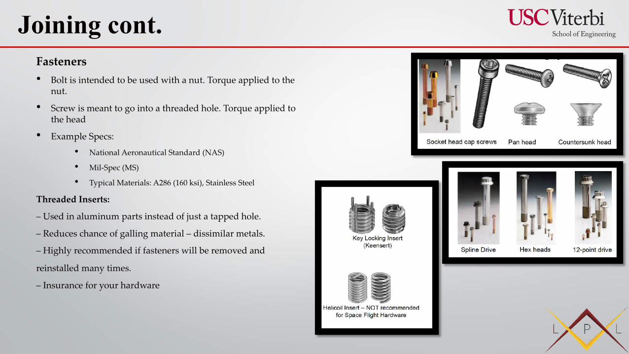
Fasteners• Bolt is intended to be used with a nut. Torque applied to the
nut.
• Screw is meant to go into a threaded hole. Torque applied to the head
• Example Specs:
• National Aeronautical Standard (NAS)
• Mil-Spec (MS)
• Typical Materials: A286 (160 ksi), Stainless Steel
Threaded Inserts:
– Used in aluminum parts instead of just a tapped hole.
– Reduces chance of galling material – dissimilar metals.
– Highly recommended if fasteners will be removed and
reinstalled many times.
– Insurance for your hardware
Joining cont.
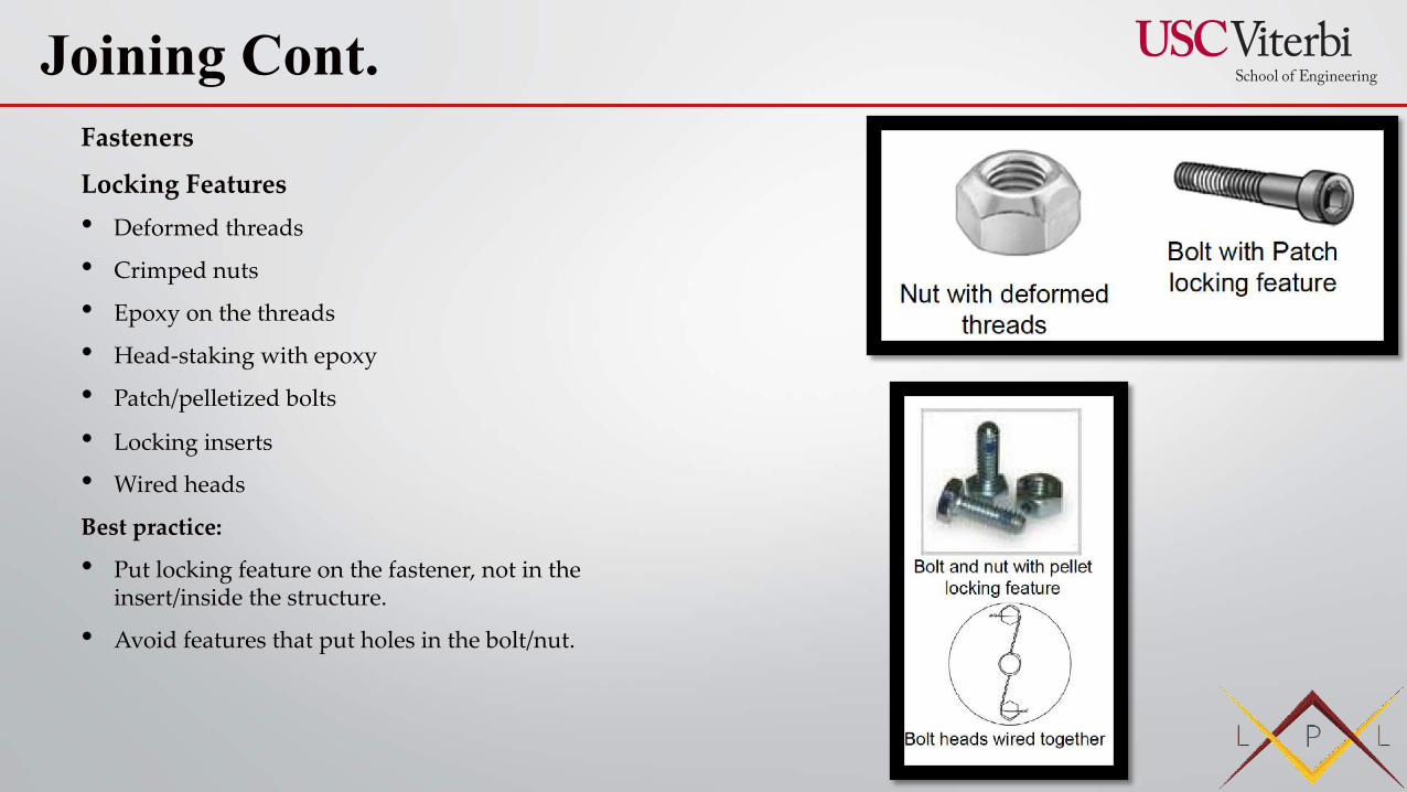
Fasteners
Locking Features• Deformed threads
• Crimped nuts
• Epoxy on the threads
• Head-staking with epoxy
• Patch/pelletized bolts
• Locking inserts
• Wired heads
Best practice:
• Put locking feature on the fastener, not in the insert/inside the structure.
• Avoid features that put holes in the bolt/nut.
Joining Cont.
WeldingWelding is a fabrication or sculptural process that joins materials, usually metals or thermoplastics, by using high heat to melt the parts together and allowing them to cool causing fusion
• Welding is distinct from lower temperature metal-joining techniques such as brazing and soldering, which do not melt the base metal.
• In addition to melting the base metal, a filler material is typically added to the joint to form a pool of molten material (the weld pool) that cools to form a joint that, based on weld configuration (butt, full penetration, fillet, etc.), can be stronger than the base material (parent metal). Pressure may also be used in conjunction with heat, or by itself, to produce a weld. Welding also requires a form of shield to protect the filler metals or melted metals from being contaminated or oxidized.
Advantages:
– Strong, stiff joint that does not lose preload or slip.
– Inexpensive (if you have the staff and machines)
Many different energy sources can be used for welding:
• electric arc (electrical)
• gas flame (chemical)
• laser
• electron beam
• friction
• ultrasound
Disadvantages:
– Requires skilled welders. Quality of joint is 95% a function of the welder.
– Permanent attachment method.
– Weakens aluminum significantly.
– Can cause distortions and cracks.
- Must be stress relieved by heating after welding.
- Helps alignment over time and re-strengthens aluminum.
– Must be inspected using NDI oftentimes off-site.
– Dirty process
Joining cont.
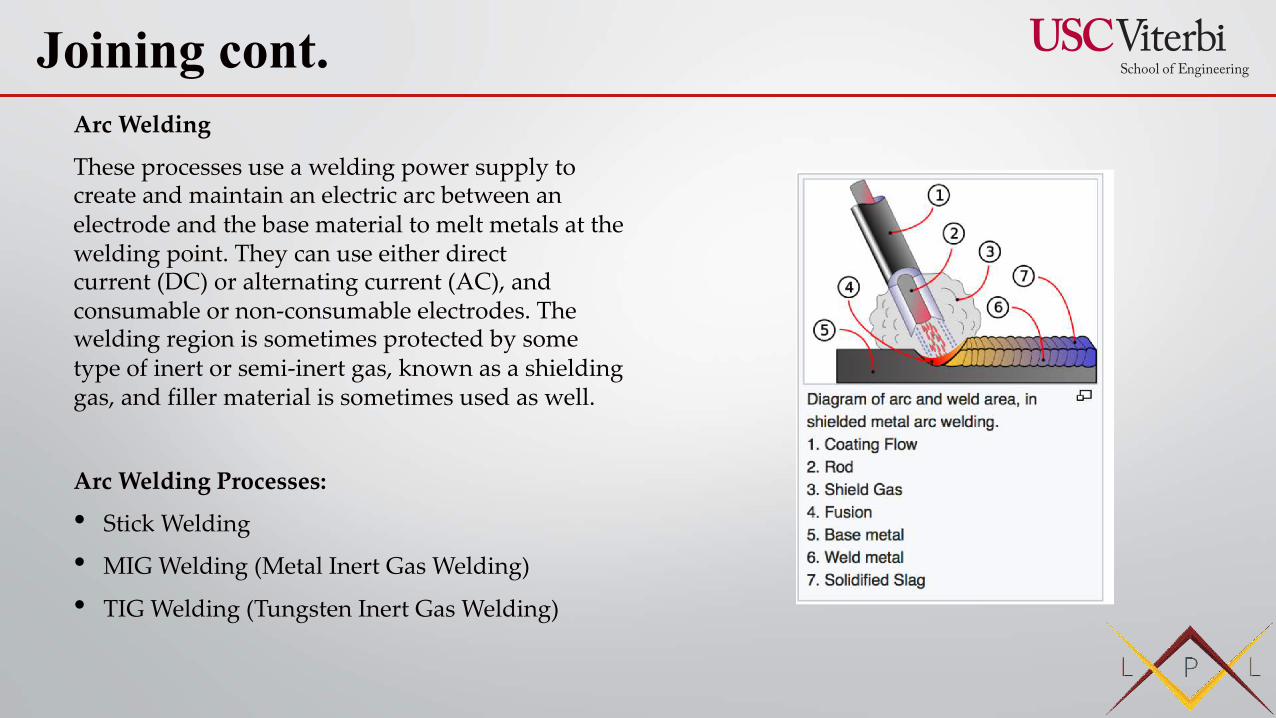
Arc Welding
These processes use a welding power supply to create and maintain an electric arc between an electrode and the base material to melt metals at the welding point. They can use either direct current (DC) or alternating current (AC), and consumable or non-consumable electrodes. The welding region is sometimes protected by some type of inert or semi-inert gas, known as a shielding gas, and filler material is sometimes used as well.
Arc Welding Processes:
• Stick Welding
• MIG Welding (Metal Inert Gas Welding)
• TIG Welding (Tungsten Inert Gas Welding)
Joining cont.
Stick Welding
• Also known as SMAW (Shielded metal arc welding)
• Electric current is used to strike an arc between the base material and consumable electrode rod, which is made of filler material (typically steel) and is covered with a flux that protects the weld area from oxidation and contamination by producing carbon dioxide (CO2) gas during the welding process. The electrode core itself acts as filler material, making a separate filler unnecessary.
• Inexpensive, good for field work, easy to learn, slow process, and fairly limited (mainly on ferrous materials)
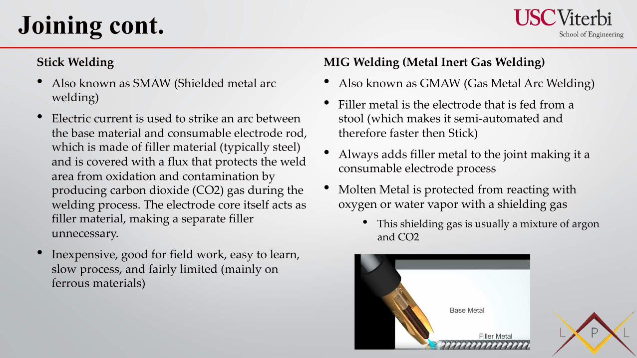
MIG Welding (Metal Inert Gas Welding)
• Also known as GMAW (Gas Metal Arc Welding)
• Filler metal is the electrode that is fed from a stool (which makes it semi-automated and therefore faster then Stick)
• Always adds filler metal to the joint making it a consumable electrode process
• Molten Metal is protected from reacting with oxygen or water vapor with a shielding gas
• This shielding gas is usually a mixture of argon and CO2
Joining cont.
TIG Welding (Tungsten Inert Gas Welding)
• TIG Welding– is an electric arc welding process that uses a non consumable electrode
• Also known as GTAW (Gas Tungsten Arc Welding)
• Is a “Non-Consumable Electrode” – meaning the tungsten doesn’t melt and become part of weld
• MIG and Stick welding the metal melts and becomes part of the weld (Consumable)
• Molten metal is protected by a shielding gas (argon or helium)
• A work led is used to complete the circuit and connect the work piece to the machine
• Limitations – slow compared to MIG and Stick, need to be clean
• Especially useful for welding thin materials, this method is characterized by a stable arc and high quality welds, but it requires significant operator skill and can only be accomplished at relatively low speeds.
• TIG welds can be used on nearly all weldable metals, though it is most often applied to stainless steel and light metals. It is often used when quality welds are extremely important, such as in bicycle, aircraft and naval applications.
Joining cont.
Orbital Tube WeldOrbital welding is a specialized area of welding whereby the arc is rotated mechanically through 360° (180 degrees in double up welding) around a static workpiece, an object such as a pipe, in a continuous process.
• The process was developed to addresses the issue of operator error in gas tungsten arc welding processes (GTAW). In orbital welding, computer-controlled process runs with little intervention from the operator.
• The process is used specifically for high quality repeatable welding.
Reasons for OTW:• Productivity. An orbital welding system will drastically outperform
manual welders, many times paying for the cost of the orbital equipment in a single job.
• Quality. The quality of a weld created by an orbital welding system with the correct weld program will be superior to that of manual welding. In applications such as semiconductor or pharmaceutical tube welding, orbital welding is the only means to reach the weld quality requirements.
• Consistency. Once a weld program has been established an orbital welding system can repeatedly perform the same weld hundreds of times, eliminating the normal variability, inconsistencies, errors and defects of manual welding.
• Skill level. Certified welders are increasingly hard to find. With orbital welding equipment you don't need a certified welding operator. All it takes is a skilled mechanic with some weld training.
• Orbital welding may be used in applications where a tube or pipe to be welded cannot be rotated or where rotation of the part is not practical.
• Orbital welding may be used in applications where access space restrictions limit the physical size of the welding device. Weld heads may be used in rows of boiler tubing where it would be difficult for a manual welder to use a welding torch or view the weld joint.
Joining cont.
Electron Beam Welding• Energy beam welding methods, namely laser beam
welding and electron beam welding, are relatively new processes that have become quite popular in high production applications.
• The two processes are quite similar, differing most notably in their source of power. Laser beam welding employs a highly focused laser beam, while electron beam welding is done in a vacuum and uses an electron beam.
• Both have a very high energy density, making deep weld penetration possible and minimizing the size of the weld area.
• Both processes are extremely fast, and are easily automated, making them highly productive.
• The primary disadvantages are their very high equipment costs (though these are decreasing) and a susceptibility to thermal cracking.
• Developments in this area include laser-hybrid welding, which uses principles from both laser beam welding and arc welding for even better weld properties, laser cladding, and x-ray welding.
Friction Stir WeldingFriction stir welding (FSW) is a solid-state joining process that uses a non-consumable tool to join two facing workpieces without melting the workpiece material.
• Heat is generated by friction between the rotating tool and the workpiece material, which leads to a softened region near the FSW tool. While the tool is traversed along the joint line, it mechanically intermixes the two pieces of metal, and forges the hot and softened metal by the mechanical pressure, which is applied by the tool, much like joining clay, or dough.
• It is primarily used on wrought or extruded aluminium and particularly for structures which need very high weld strength.
Joining cont.
Welding Integrity• Many distinct factors influence the strength of welds
and the material around them, including the welding method, the amount and concentration of energy input, the weldability of the base material, filler material, and flux material, the design of the joint, and the interactions between all these factors
• Types of welding defects include cracks, distortion, gas inclusions (porosity), non-metallic inclusions, lack of fusion, incomplete penetration, lamellar tearing, and undercutting
• Methods such as visual inspection, radiography, ultrasonic testing, phased-array ultrasonics, dye penetrant inspection, magnetic particle inspection, or industrial computed tomography can help with detection and analysis of certain defects
Joining cont.
BrazingBrazing is a metal-joining process in which two or more metal items are joined together by melting and flowing a filler metal into the joint, the filler metal having a lower melting point than the adjoining metal.
• Brazing differs from welding in that it does not involve melting the work pieces and from soldering in using higher temperatures for a similar process, while also requiring much more closely fitted parts than when soldering
• A major advantage of brazing is the ability to join the same or different metals with considerable strength.
• In most cases, joint clearances of 0.03 to 0.08 mm (0.0012 to 0.0031 in) are recommended for the best capillary action and joint strength. However, in some brazing operations it is not uncommon to have joint clearances around 0.6 mm (0.024 in)
• Flux is a chemical cleaning agent, flowing agent, or purifying agent. Unless brazing operations are contained within an inert or reducing atmosphere environment (i.e. a vacuum furnace), a flux such as borax is required to prevent oxides from forming while the metal is heated. The flux also serves the purpose of cleaning any contamination left on the brazing surfaces. Flux can be applied in any number of forms including flux paste, liquid, powder or pre-made brazing pastes that combine flux with filler metal powder.
• Braze alloy is generally available as rod, ribbon, powder, paste, cream, wire and preforms (such as stamped washers)
• As brazing work requires high temperatures, oxidation of the metal surface occurs in an oxygen-containing atmosphere. This may necessitate the use of an atmospheric environment other than air.
Joining cont.
BrazingCommon Techniques: 1. Torch Brazing
by far the most common method of mechanized brazing in use. It is best used in small production volumes or in specialized operations
Manual torch brazing is a procedure where the heat is applied using a gas flame placed on or near the joint being brazed. The torch can either be hand held or held in a fixed position depending on whether the operation is completely manual or has some level of automation.
Automatic torch brazing is a method that almost eliminates the need for manual labor in the brazing operation, except for loading and unloading of the machine. The main advantages of this method are: a high production rate, uniform braze quality, and reduced operating cost
2. Furnance BrazingFurnace brazing is a semi-automatic process used widely in industrial brazing operations due to its adaptability to mass production and use of unskilled labor. There are many advantages of furnace brazing over other heating methods that make it ideal for mass production. One main advantage is the ease with which it can produce large numbers of small parts that are easily jigged or self-locating. The process also offers the benefits of a controlled heat cycle (allowing use of parts that might distort under localized heating) and no need for post braze cleaning.
Disadvantages: high capital equipment cost, more difficult design considerations and high power consumption
Joining cont.
Brazing vs. WeldingBrazing advantages over welding:
• Allows for tighter control over tolerances and finishes because brazing does not melt the base metal of the joint
• Dissimilar metals and non-metals (metalized ceramics) can be brazed
• Brazing produces less thermal distortion due to uniform heating of the brazed piece
• Brazing can be coated
• Brazing can more easily be automated because the individual process parameters are less sensitive to variation
Brazing disadvantages over welding:
• Lack of joint strength because of softer filler metals used
• The strength of the joint is typically less then that of the base metal but greater then the filler metal
• Brazed joints can be damaged under high surface temperatures
• Brazed joints require a high level of base metal cleanliness
• Joint color is typically different then the base material making it not an aesthetic disadvantage
Joining cont.
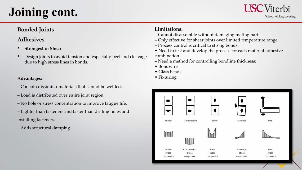
Bonded Joints
Adhesives• Strongest in Shear
• Design joints to avoid tension and especially peel and cleavage due to high stress lines in bonds.
Advantages:
– Can join dissimilar materials that cannot be welded.
– Load is distributed over entire joint region.
– No hole or stress concentration to improve fatigue life.
– Lighter than fasteners and faster than drilling holes and
installing fasteners.
– Adds structural damping.
Joining cont. Limitations:– Cannot disassemble without damaging mating parts.– Only effective for shear joints over limited temperature range.– Process control is critical to strong bonds.• Need to test and develop the process for each material-adhesivecombination.– Need a method for controlling bondline thickness:• Bondwire• Glass beads• Fixturing
ASTM G93 (Oxygen Systems)
• Brush Cleaning (Softer material)
• Ultrasonics
• IPA Wipe
• N2 Purge
• Inspect
Oxygen is a Hazard!• Hazard is that oxygen promotes combustion
• Can Start a Fire
Three elements to promote a fire ~ oxidizer, fuel, ignition • Oxidizer- GOX or LOX
• Fuel- Valve, Regs, Plumbing, Fittings, orifices, seals, etc
• Ignition - Energy from within the system that initiates a “Kindling Chain”• Kindling Chain – ability of a fire to propagate
and burn through components
• Kindling Chain results in something called RUD in the propulsion world
• RUD- Rapid Unscheduled Disassembly (Everything blows the f*** up)
Precision Cleaning
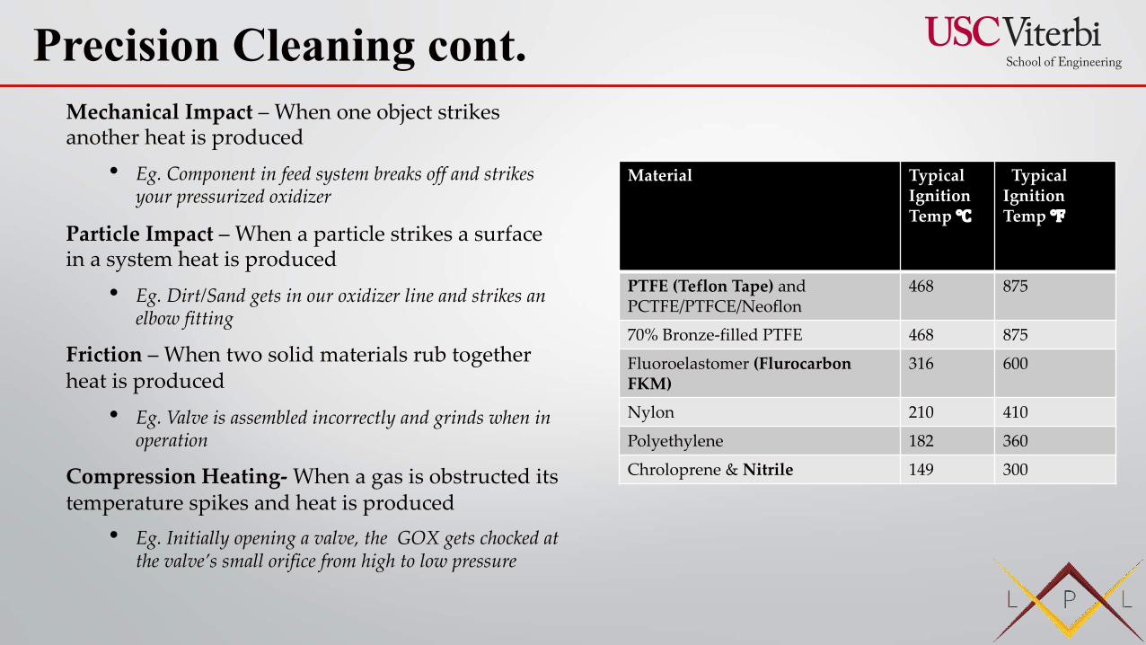
Mechanical Impact – When one object strikes another heat is produced
• Eg. Component in feed system breaks off and strikes your pressurized oxidizer
Particle Impact – When a particle strikes a surface in a system heat is produced
• Eg. Dirt/Sand gets in our oxidizer line and strikes an elbow fitting
Friction – When two solid materials rub together heat is produced
• Eg. Valve is assembled incorrectly and grinds when in operation
Compression Heating- When a gas is obstructed its temperature spikes and heat is produced
• Eg. Initially opening a valve, the GOX gets chocked at the valve’s small orifice from high to low pressure
Precision Cleaning cont.
Material TypicalIgnition Temp ℃
Typical Ignition Temp ℉
PTFE (Teflon Tape) and PCTFE/PTFCE/Neoflon
468 875
70% Bronze-filled PTFE 468 875
Fluoroelastomer (FlurocarbonFKM)
316 600
Nylon 210 410
Polyethylene 182 360
Chroloprene & Nitrile 149 300
Hydrogen Peroxide (High concentration)
• A corrosive substance is one that will damage or destroy other substances with which it comes into contact by means of a chemical reaction.
• Design considerations: compatible material (Stainless steel, weep holes, proper vents for uncontrolled decomposition. Avoid organic materials (cotton, wool, etc.) and Transition metals (iron, manganese, chromium, copper, silver, gold, platium, palladium, rhodium)
Stainless Steel, Inconel, Monel, Nickel Alloys
• Pre-clean DI water non-scratching brushes and lint free cloths
• De-greaser (Simple Green)
• Ultrasonic clean (dilote degreasers Brulin)
• Wipe IPA, purge with nitrogen
• Inspect, visually, micropsoe, borescope,
Material Treatment & Passivation:• LOX Cleaning- clean all components with a desgreasing
solution (Simple Green) to remove residual dirt and oil left over from manufacturer
• Passivation – soak all metal components in a 70% nitric acid bath for 5 hours to “passivate” the material. Surface impurities are removed and a protective oxide layer is formed
• Propellant Conditioning – soak all components in a dilute, 30% H2O2 bath for 48 hours minimum to identify troublesome spots
PPE: Tyvek suit, rubber boots, safety glasses, face shield thick nitrile gloves
SDS or MSDS A safety data sheet (SDS),[1] material safety data sheet (MSDS), or product safety data sheet (PSDS) is a document that lists information relating to occupational safety and health for the use of various substances. SDSs are a widely used system for cataloging information on chemicals, chemical compounds, and chemical mixtures.
Precision Cleaning cont.
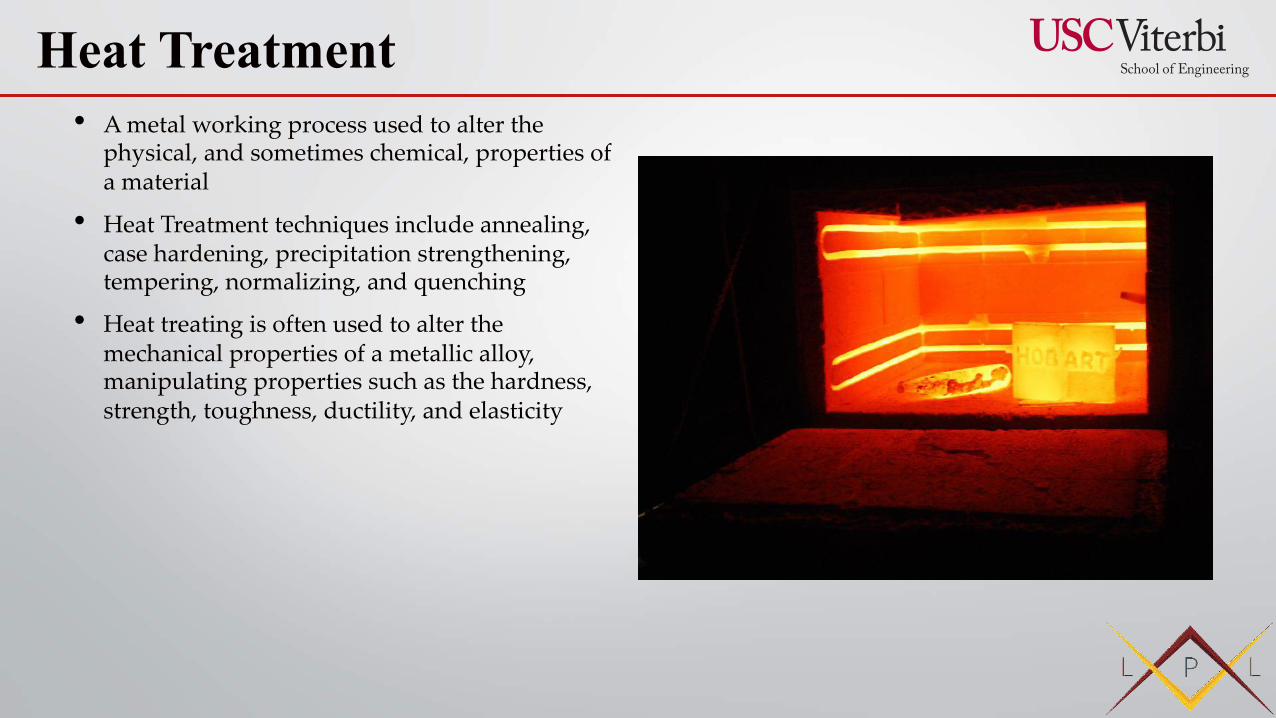
• A metal working process used to alter the physical, and sometimes chemical, properties of a material
• Heat Treatment techniques include annealing, case hardening, precipitation strengthening, tempering, normalizing, and quenching
• Heat treating is often used to alter the mechanical properties of a metallic alloy, manipulating properties such as the hardness, strength, toughness, ductility, and elasticity
Heat Treatment
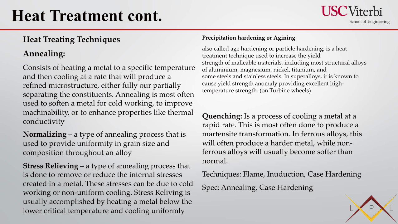
Heat Treating Techniques
Annealing:Consists of heating a metal to a specific temperature and then cooling at a rate that will produce a refined microstructure, either fully our partially separating the constituents. Annealing is most often used to soften a metal for cold working, to improve machinability, or to enhance properties like thermal conductivity
Normalizing – a type of annealing process that is used to provide uniformity in grain size and composition throughout an alloy
Stress Relieving – a type of annealing process that is done to remove or reduce the internal stresses created in a metal. These stresses can be due to cold working or non-uniform cooling. Stress Reliving is usually accomplished by heating a metal below the lower critical temperature and cooling uniformly
Precipitation hardening or Agining
also called age hardening or particle hardening, is a heat treatment technique used to increase the yield strength of malleable materials, including most structural alloys of aluminium, magnesium, nickel, titanium, and some steels and stainless steels. In superalloys, it is known to cause yield strength anomaly providing excellent high-temperature strength. (on Turbine wheels)
Quenching: Is a process of cooling a metal at a rapid rate. This is most often done to produce a martensite transformation. In ferrous alloys, this will often produce a harder metal, while non-ferrous alloys will usually become softer than normal.
Techniques: Flame, Inuduction, Case Hardening
Spec: Annealing, Case Hardening
Heat Treatment cont.
Passivation AMS 2700 (Stainless Steel)
Anodizing is an electrolytic passivation process used to increase the thickness of the natural oxide layer on the surface of metal parts.
Anodizing increases resistance to corrosionandwear, and provides better adhesion for paint primers and glues than bare metal does.
Anodizing is also used to prevent galling of threaded components and to make dielectric films for electrolytic capacitors.
Coating & Finishes

• Methods are typically based on diverse physical phenomena
• ex. heat transport, thermal expansion, air-coupled elastic waves, or non-linear vibrometry responding selectively to defects
• Dynamic Thermography: Excitation using light, ultrasound, and eddy current
• Fluorescent Dye Penetrant Inspection
• Eddy Current Testing (ECT)
• Thermal Imaging - Used properly, thermal imaging can be used to detect corrosion damage, delaminations, disbonds, voids, inclusions as well as many other detrimental conditions.
• Direct visiable inspection (white light)
https://pdfs.semanticscholar.org/8482/f3ebf78d099ad78287dfe3b85b851dae57f4.pdf
https://www.youtube.com/watch?v=UM6XKvXWVFA
https://www.youtube.com/watch?v=xEK-c1pkTUI
https://www.asnt.org/MinorSiteSections/AboutASNT/Intro-to-NDT
NDT (Non-Destructive Testing)

Fluorescent Dye Penetrant Inspection –
which a fluorescent dye is applied to the surface of a non-porous material in order to detect defects that may compromise the integrity or quality of the part in question.
Inspection Steps:
1. Initial Cleaning
2. Penetrant Application
3. Excess Penetrant Removal
4. Developer Application
5. Inspection
6. Final Cleaning
Advantages
• Highly sensitive fluorescent penetrant is ideal for even the smallest imperfections
• Low cost and potentially high volume
• Suitable for inspection of non-magnetic materials and electrical insulators.
Disadvantages
• Doesn’t give you any information into the depth of the crack
• Only determines flaws on the surface
• Only works on non-porous materials
• Training is required for inspectors
https://www.youtube.com/watch?v=zow14e0KuQw
NDT (Non-Destructive Testing) cont.
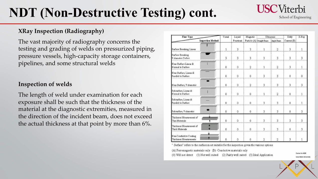
XRay Inspection (Radiography)
The vast majority of radiography concerns the testing and grading of welds on pressurized piping, pressure vessels, high-capacity storage containers, pipelines, and some structural welds
Inspection of welds
The length of weld under examination for each exposure shall be such that the thickness of the material at the diagnostic extremities, measured in the direction of the incident beam, does not exceed the actual thickness at that point by more than 6%.
NDT (Non-Destructive Testing) cont.
Eddy Current Inspection
Uses electromagnetic induction to detect and characterize surface and sub-surface flaws in conductive materials
Detects surface or near surface defects. Highly portable and convenient
This wire coil produces an alternating magnetic field around itself. The magnetic field oscillates at the same frequency as the current running through the coil. When the coil approaches a conductive material, currents opposed to the ones in the coil are induced in the material — eddy currents.
Ultrasound Inspection
Ultrasonic inspection (UT) is a non-destructive test method that utilizes sound waves to detect cracks and defects in parts and materials. It can also be used to determine a material’s thickness, such as measuring the wall thickness of a pipe. Because of the portability of the equipment and variety of methods available, ultrasonic testing allows for inspection of parts that are large, irregularly shaped, or unable to be transported.
Ultrasonic testing is often used in situations where radiographic inspection is not possible, because it requires access to only one side of the test specimen.
NDT (Non-Destructive Testing) cont.
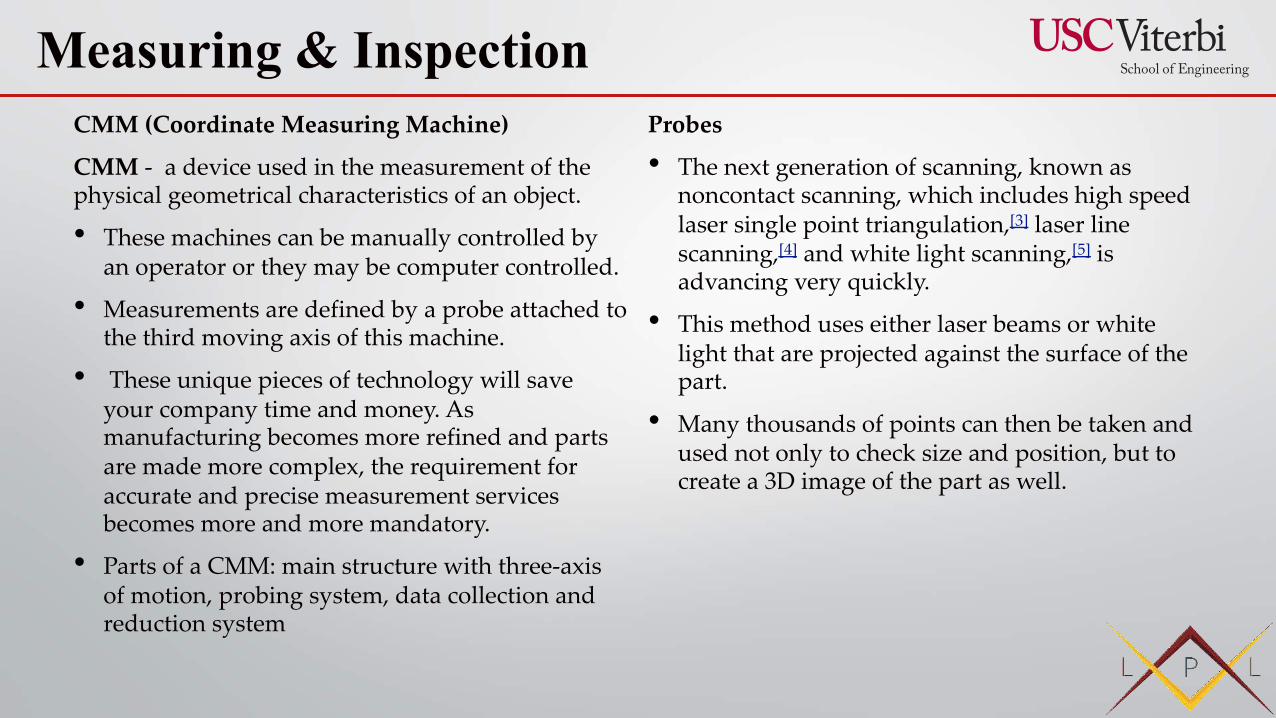
CMM (Coordinate Measuring Machine)
CMM - a device used in the measurement of the physical geometrical characteristics of an object.
• These machines can be manually controlled by an operator or they may be computer controlled.
• Measurements are defined by a probe attached to the third moving axis of this machine.
• These unique pieces of technology will save your company time and money. As manufacturing becomes more refined and parts are made more complex, the requirement for accurate and precise measurement services becomes more and more mandatory.
• Parts of a CMM: main structure with three-axis of motion, probing system, data collection and reduction system
Probes
• The next generation of scanning, known as noncontact scanning, which includes high speed laser single point triangulation,[3] laser line scanning,[4] and white light scanning,[5] is advancing very quickly.
• This method uses either laser beams or white light that are projected against the surface of the part.
• Many thousands of points can then be taken and used not only to check size and position, but to create a 3D image of the part as well.
Measuring & Inspection
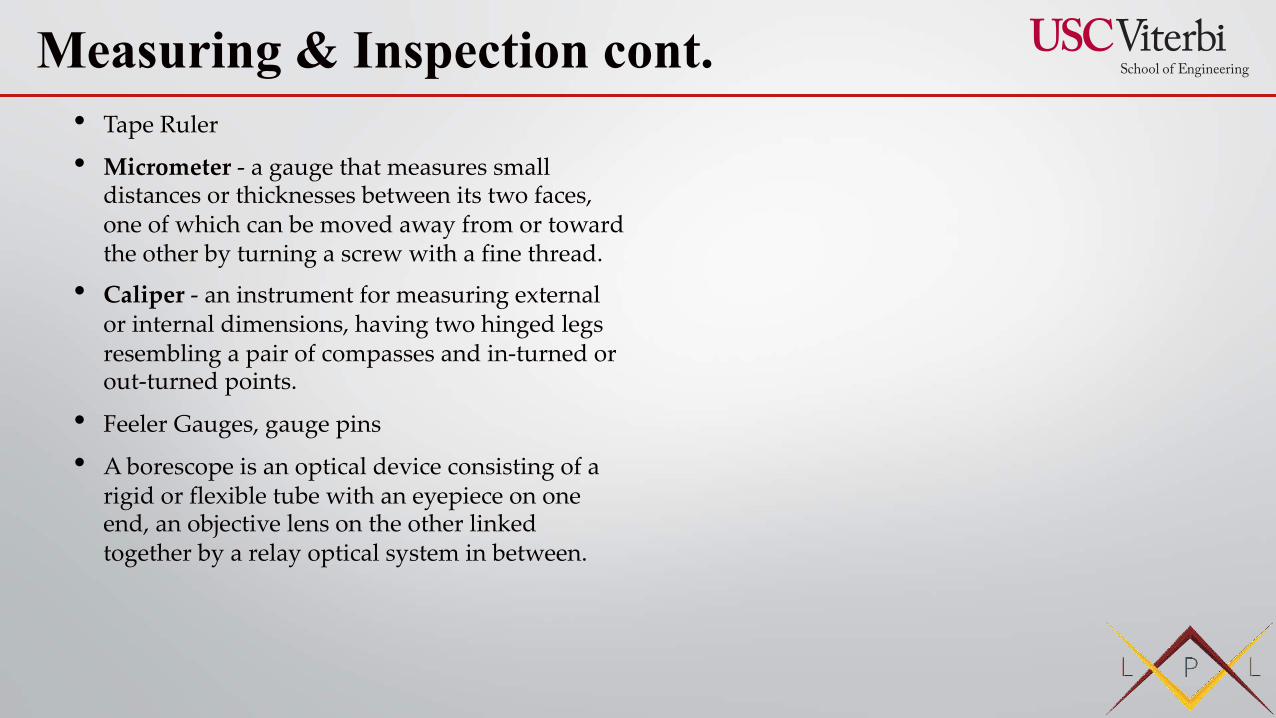
• Tape Ruler
• Micrometer - a gauge that measures small distances or thicknesses between its two faces, one of which can be moved away from or toward the other by turning a screw with a fine thread.
• Caliper - an instrument for measuring external or internal dimensions, having two hinged legs resembling a pair of compasses and in-turned or out-turned points.
• Feeler Gauges, gauge pins
• A borescope is an optical device consisting of a rigid or flexible tube with an eyepiece on one end, an objective lens on the other linked together by a relay optical system in between.
Measuring & Inspection cont.

Manufacturing Engineering (Integration
& Testing)
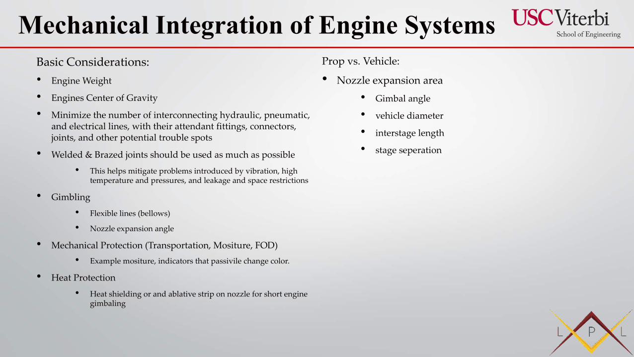
Basic Considerations:• Engine Weight
• Engines Center of Gravity
• Minimize the number of interconnecting hydraulic, pneumatic, and electrical lines, with their attendant fittings, connectors, joints, and other potential trouble spots
• Welded & Brazed joints should be used as much as possible
• This helps mitigate problems introduced by vibration, high temperature and pressures, and leakage and space restrictions
• Gimbling
• Flexible lines (bellows)
• Nozzle expansion angle
• Mechanical Protection (Transportation, Mositure, FOD)
• Example mositure, indicators that passivile change color.
• Heat Protection
• Heat shielding or and ablative strip on nozzle for short engine gimbaling
Prop vs. Vehicle:
• Nozzle expansion area
• Gimbal angle
• vehicle diameter
• interstage length
• stage seperation
Mechanical Integration of Engine Systems
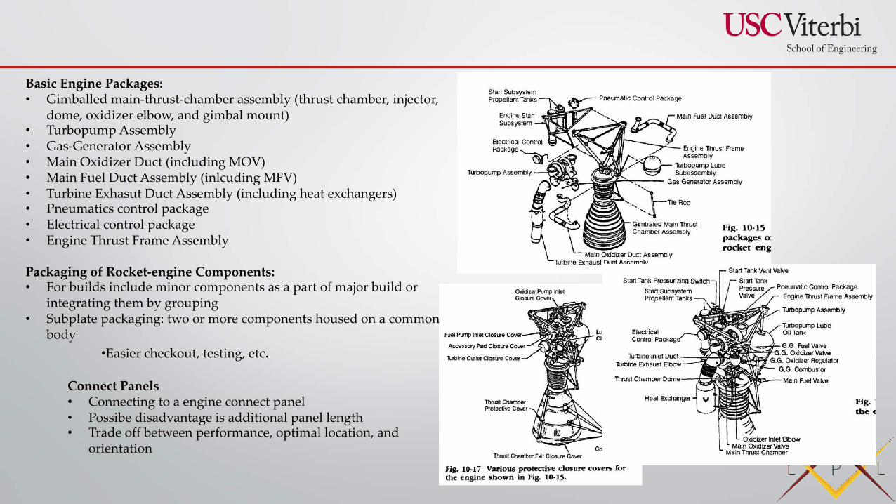
Basic Engine Packages:• Gimballed main-thrust-chamber assembly (thrust chamber, injector,
dome, oxidizer elbow, and gimbal mount)• Turbopump Assembly• Gas-Generator Assembly• Main Oxidizer Duct (including MOV)• Main Fuel Duct Assembly (inlcuding MFV) • Turbine Exhasut Duct Assembly (including heat exchangers)• Pneumatics control package• Electrical control package• Engine Thrust Frame Assembly
Packaging of Rocket-engine Components:• For builds include minor components as a part of major build or
integrating them by grouping• Subplate packaging: two or more components housed on a common
body•Easier checkout, testing, etc.
Connect Panels• Connecting to a engine connect panel• Possibe disadvantage is additional panel length• Trade off between performance, optimal location, and
orientation
Variations between each rocket:
• Mass
• Center of Mass
• Location of engine (moment calcs) and gimbling affects
Design DocumentationInterface Control Document (ICD), controls engine/vehicle interface. Has design/operational requirements and doesn’t not contain instructional information
Also include operational requirements and characteristics –prestart conditioning, thrust buildup curves, steady-state performance, and thrust-decay curves, fluid requirements, interface loads, thermal environment, mass properties, and electrical and software requirements
• General arrangement drawing. This drawing defines the engine envelope and the locations and detail of various agreed-upon vehicle connect points, such as---
• Thrust or gimbal mount
• Gimbal-actuator attach points
• Fuel- and oxidizer-inlet flanges
• Hydraulic and pneumatic system connections
• Propellant bleeds
• Electrical and instrumentation connections
• Autogenous pressurization connections
• Mechanical dimensions, tolerances, seals (if any), fasteners, and loads at the vehicle connect points listed.
• Engine-system mass properties which include engine weights, gimbaled mass, center of gravity, and added moment of inertia for the basic engine, including accessories.
Engine performance data (as in Fig. 3-1).
• Engine functional description (see Chapter 3).
• Engine handling procedures and equipment, needed for installation and maintenance.
• Engine servicing needs.
• Electrical-power requirements for both ac and dc systems; power profiles and surge limitations included.
• Command and data channels and the necessary software details for any computer-driven controller.
• Fluid requirements--purge gases, propellants, propellant-tank pressurant, hydraulic fluids, etc.
Included too will be flowrates, supply pressures, temperatures, and cleanliness requirements.
• Environmental conditions, such as engine compartment thermal conditions at prelaunch, ascent, and, if applicable, on orbit and during re-entry and landing.
• Induced loads and vibration at all mechanical interfaces and aerodynamic loads on the nozzle for ascent, re-entry, and landing.
Engine-to-vehicle Interface
Engine-failure sensing and shutoff system (EFSS)
Major Malfunctions:
• Pump-inlet pressures below safe minimum
• Turbopump overspeed
• Turbopump-bearing overheating
• Turbopump-bearing vibration
• Excessive turbopump leaks
• Turbine-gas overtemperature
• Combustion instability
• Abnormal injection pressures
• Ignition failure
• Premature propellant depletion
• Electrical-power failure
• Pneumatic-pressure failure
• Improper valve positions
• Fires
Automatic Shutdown actions:
• Closing emergency-shutoff valves in the ducts to
the defunct engine, but not those in the others.
• Disconnecting electric power to the defunct
engine only.
• Resetting or disarming backup shutdowntimers,
since the reduced number of engines will
consume the available propellants over a longer
period of time.
• Locking the defunct engine in the neutral gimbal
position.
Propellant Conditioning
Current liquid oxygen feed systems waste propellant and use hardware, unnecessary during flight, to condition the propellant at the engine turbopumps prior to launch. Simplified liquid oxygen propellant conditioning concepts are being sought for future launch vehicles. During a joint program, four alternative propellant conditioning options were studied: (1) passive recirculation; (2) low bleed through the engine; (3) recirculation lines; and (4) helium bubbling. The test configuration for this program was based on a vehicle design which used a main recirculation loop that was insulated on the downcomer and uninsulated on the upcomer. This produces a natural convection recirculation flow. The test article for this program simulated a feedline which ran from the main recirculation loop to the turbopump. The objective was to measure the temperature profile of this test article. Several parameters were varied from the baseline case to determine their effects on the temperature profile. These parameters included: flow configuration, feedline slope, heat flux, main recirculation loop velocity, pressure, bleed rate, helium bubbling, and recirculation lines. The heat flux, bleed rate, and recirculation configurations produced the greatest changes from the baseline temperature profile. However, the temperatures in the feedline remained subcooled. Any of the options studied could be used in future vehicles.
Engine Priming
Tests:
• Dimensional Inspection
• Pressure Tests
• X-Ray,
• Leak Checks
• Electrical continuity test
• Electromechanical checks
• Component tests
• Ignitor test, proofing nozzle, etc.
Test Facilities:
• Test Cell
• Instrumentation System
• Control System
• Systems for handling and lifting
• PPE
• Specilized equipment (Water truck)
Safety Provisions:
• Concrete wall
• Remote controls, indications, and recordings
• automatic or manual emergency water deluge systems
• Closed circut video feed
• Warning signals (sirens)
• Quantity and distance restrictions
• Explosion proof systems
• PPE
Instrumentation and Data Management1. Forces (thrust, thrust vector control side forces, short thrusting pulses).
2. Flows (hot and cold gases, liquid fuels, liquid oxidizers, leaks).
3. Pressures (chamber, propellant, pump inlet/outlet, tank, etc.).
4. Temperatures (chamber or case walls, propellant, structure, nozzle).
5. Timing and command sequencing of valves, switches, igniters, full pressure attainments, and others.
6. Stresses, strains, and vibrations (combustion chamber, structures, solid propellants, liquid propellant lines, local accelerations of vibrating parts) (Ref. 21–7). Also, thermal growths.
7. Movements and positions of parts (valve stems, gimbal position, deflection of parts under load or heat).
8. Voltages, frequencies, and currents in electrical or control subsystems.
9. Visual observations (flame configuration and color, test article failures, explosions) using high-speed cameras or video cameras.
10. Special quantities such as propellant strains, turbopump shaft speeds, liquid levels in propellant tanks, burning rates, flame luminosities, sound pressures and/or exhaust gas composition.
11. Ambient air conditions (pressure, temperature wind speed and direction, toxic
gas content) at stations in the test facility area and also at stations downwind of the test area.
Measuring System Requirements:
• Sensing elements (transducers)
• Device for recording, displaying, and/or indicating the sensed information
• Device for conditioning, amplyfing, correcting, or transforming the sensed signal into the form suitable for recording, indicating, display, or analysis
Range refers to a region extending from the minimum to the maximum rated value over which the measurement system will give a true and linear response. Usually an additional margin is provided to permit temporary overloads without damage to the instrument or need for recalibration.
Errors in measurements are usually of two types: (1) human errors (improperly reading or incorrectly adjusting the instrument, chart, or record and improperly interpreting or correcting these data), and (2) instrument or system errors, which usually fall into four classifications: static errors, dynamic response errors, drift errors, and hysteresis errors
• Static errors are usually fixed errors due to fabrication and installation variations; these errors can usually only be detected by careful calibration, and an appropriate correction can then be applied to the reading.
• Drift error is the change in output over a period of time, usually caused by random wander and environmental conditions. To avoid drift error the measuring system has to be calibrated at frequent intervals at standard environmental conditions against known standard reference values over its whole range.
• Dynamic response errors occur when the measuring system fails to register the true value of the measured quantity while this quantity is changing, particularly when it is changing rapidly.
Measurement System Terminology
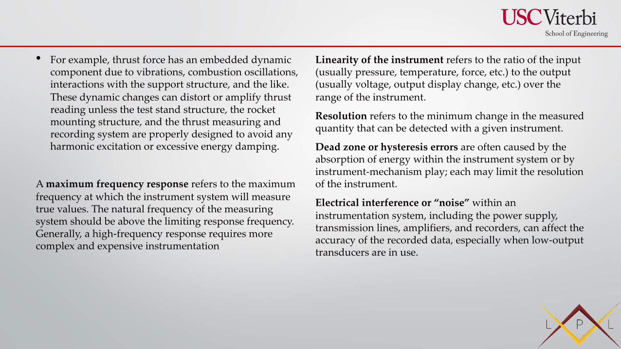
• For example, thrust force has an embedded dynamic component due to vibrations, combustion oscillations, interactions with the support structure, and the like. These dynamic changes can distort or amplify thrust reading unless the test stand structure, the rocket mounting structure, and the thrust measuring and recording system are properly designed to avoid any harmonic excitation or excessive energy damping.
A maximum frequency response refers to the maximum frequency at which the instrument system will measure true values. The natural frequency of the measuring system should be above the limiting response frequency. Generally, a high-frequency response requires more complex and expensive instrumentation
Linearity of the instrument refers to the ratio of the input (usually pressure, temperature, force, etc.) to the output (usually voltage, output display change, etc.) over the range of the instrument.
Resolution refers to the minimum change in the measured quantity that can be detected with a given instrument.
Dead zone or hysteresis errors are often caused by the absorption of energy within the instrument system or by instrument-mechanism play; each may limit the resolution of the instrument.
Electrical interference or “noise” within an instrumentation system, including the power supply, transmission lines, amplifiers, and recorders, can affect the accuracy of the recorded data, especially when low-output transducers are in use.
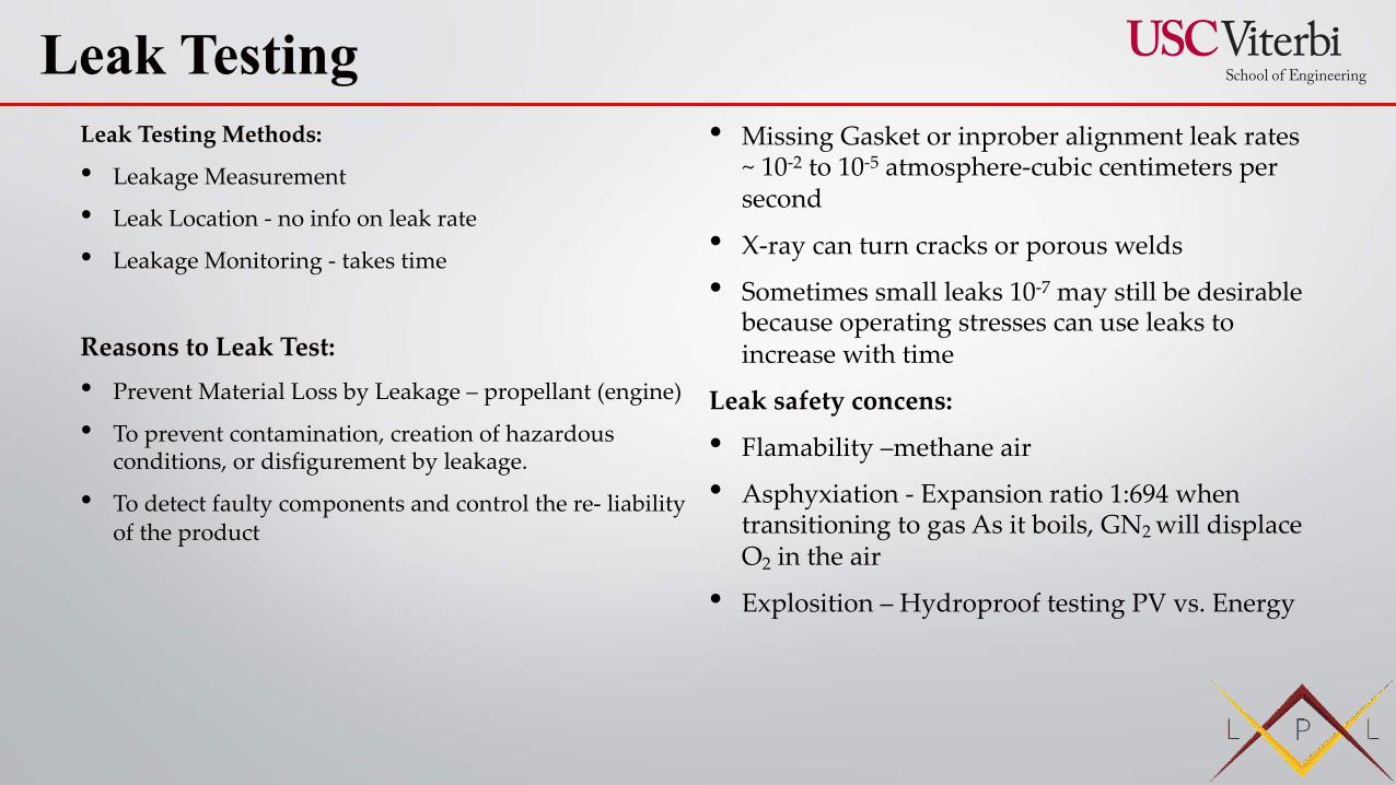
Leak Testing Methods:
• Leakage Measurement
• Leak Location - no info on leak rate
• Leakage Monitoring - takes time
Reasons to Leak Test:• Prevent Material Loss by Leakage – propellant (engine)
• To prevent contamination, creation of hazardous conditions, or disfigurement by leakage.
• To detect faulty components and control the re- liability of the product
• Missing Gasket or inprober alignment leak rates ~ 10-2 to 10-5 atmosphere-cubic centimeters per second
• X-ray can turn cracks or porous welds
• Sometimes small leaks 10-7 may still be desirable because operating stresses can use leaks to increase with time
Leak safety concens:
• Flamability –methane air
• Asphyxiation - Expansion ratio 1:694 when transitioning to gas As it boils, GN2 will displace O2 in the air
• Explosition – Hydroproof testing PV vs. Energy
Leak Testing
The mass spectrometer is a device which identifies atomic or molecular species by their mass-to-charge ratio. The opera- ation consists of ionizing the sample, separating the different ion species, and detecting the separated species. A mass spec-trometer that is built for leak detection is usually limited to the detection of helium.
The dimensions of the rate of gas leakage are:
Pressure X Volume / Time sometimes written as PV.
• The leakage rate is proportional to the mass flow of a given gas at constant temperature. If the nature of the leaking gas and the temperature are known, it is possible to use the formula for an ideal gas to determine the actual mass leakage.
• For example, an operator may have a gas tank whose volume is known in cubic feet. The tank is fitted with a pressure gage calibrated in pounds per square inch. If the gage is read daily, it is convenient for him to express the leakage as the product of the change in pressure which occurs during one day and the cylinder volume. He will then express the leakage as psi-cubic feet per day.
Leak Rates
A Grade 1 leak is a leak that represents an existing or probable hazard to persons or property, and requires immediate repair or continuous action until the conditions are no longer hazardous.
- Leak of Hypergoil
A Grade 2 leak is a leak that is recognized as being non-hazardous at the time of detection, but justifies scheduled repair based on probable future hazard
- Chamber Leak at 2 atms
A Grade 3 leak is non-hazardous at the time of detection and can be reasonably expected to remain non-hazardous.
-Leak of a turbopump that is in aceptable range and routed into main tank
-