The development of a novel high speed fabric manufacturing process
262
This item was submitted to Loughborough University as a PhD thesis by the author and is made available in the Institutional Repository (https://dspace.lboro.ac.uk/) under the following Creative Commons Licence conditions. For the full text of this licence, please go to: http://creativecommons.org/licenses/by-nc-nd/2.5/
-
Upload
khangminh22 -
Category
Documents
-
view
4 -
download
0
Transcript of The development of a novel high speed fabric manufacturing process

This item was submitted to Loughborough University as a PhD thesis by the author and is made available in the Institutional Repository
(https://dspace.lboro.ac.uk/) under the following Creative Commons Licence conditions.
For the full text of this licence, please go to: http://creativecommons.org/licenses/by-nc-nd/2.5/

.C-=C~~. _. ,,", .. ...,.- ,.~., • ---- -------
LOUGHBOROUGH UNIVERSITY OF TECHNOLOGY
LIBRARY
AUTHOR/FILING TITLE I
I VI1"I)I..S R I -- - - - - --- - -- -- - - - ,,- ------ --- ---- -- -- --- -- --- --
ACCESSION/COPY NO.
________________ ~ _?_:_~ ~_,t/~~---------- _______ _ VOL. NO. CLASS MARK
o 7 0", f 94 ,
'.'-J


"
Loughborough University
of T «hnoio~:J Ubrary
o.!. ~- ,,, Class
Ace, oo,~,\-t 102-No,
;' . , :.~ .
~ (I .
, ,
i'l;,
"
, , , "
:'
.,.
"

THE DEVELOPMENT OF A NOVEL
HIGH-SPEED FABRIC MANUFACTURING PROCESS
by
Reinhards Vitols, M.Tech. (Loughborough), C.Eng., M.r.Mech.E.
A Docto ra I Thes is
Submitted in partial fulfilment of the
requi rements for the award of
Doctor of Philosophy of the Loughborough
Universi ty of Technology
April 1979
Department 'of Mechanical Engineering
@ by Reinhards Vitols. 1979.

•
,ABSTRACT
The manufacture of conventional textiles usually involves
either weaving or knitting. The author and his colleagues have
devised a completely new technology for texti le fabric construc-
tion involving the use of simple elements. These elements are
basically similar in shape to sewing machine needles which inter-
act wi th each other in such a way that yarns 'stitch-knit' them-
selves together to produce a fabric. As a result of this unique
interaction the number of loops produced is doubled when com-
pared to the time cycle of a conventional knitting action.
Further enhancement of at least doubled fabric production rates
should accrue from the dual effects of decreased yarn tensions
and the lowered dynamic disturbing forces of the simpl ified
knitting element maripulating system.
A survey has been made of the looped-type textile manufactu-
ring processes and the most appropriate groups have been enumera-
ted in order to form a basis of comparison for the novel process.
A basic study (including computer aided graphics) of probable
textile structures, that could be produced by this technology, has
revealed a substantial range of novel fabrics. These fabrics have
been analysed and possible uses for them ar,e suggested.
A powered research-rig has been des igne,d an'd constructed on
which the important yarn manipulation"characteristics have been I
determined. This experimentation 'has 'facil itated a more positive
yarn pick-up to be evolved. As a result of this, more practicable
design tolerances may be given for the manufacture and setting-up

i i
of the manipulative el"ements. Moreover, narrow-width novel fabric
samples have been produced from spun-staple yarns at rates excee
ding the current commercially available maximum, thereby substan
tiating the earl ier predictions.
Finally, the new technology and its resulting products are
appraised and design proposals for a prototype machine are made;
it is hoped that this will be offered to industry in due course
for further development and potential exploitation.

iii
THE NOVEL PROCESS
THE RESEARCH RI G

iv
ACKNOWLEDGEMENTS
The author would 1 ike to express his indebtedness to the
Science Research Council for sponsoring this work.
He would also like to express his appreciation to Professor
G R Wray for supervision at the beginning of this research, for
subsequent guidance and untiring encouragement and finally for
skilfully editing the presentation of this thesis.
He also wishes to acknowledge the help afforded to him by
many colleagues on the academic, technical, and secretarial
staffs of the Department of Mechanical Engineering, but he would
particularly 1 ike to mention the following individuals:
Or J E Vine (now in industry) for his help in organi
sing the manufacture of the research rig;
Mr S Walkinshaw for tolerance and observance of the
basic principles at his .starting on the current
continuation of this development; and
Hr KW Topley, for taking the excellent photographs
and the highly valued cine film.

Fig. No.
2.1
2.2
2.3
2.4
2.5
2.6
2.7
2.8
2.9
2.10
2. II
2.12
2.13
2.14
2. IS
2.16
2. I 7
2.18
3. I
3.2
3.3
v
Ll Sf OF I LLUSTRAT IONS
Captions
Plai n weft-kni tted structure
Weft kni tting cycle of operations when using latch needles
Weft kni tting cycle of operations when uS i ng bea rded need I es
Plain or jersey weft-knitted structure
Rib-type weft-knitted structure
Single-bar warp~knitted structure
Four positions of warp kni tting cycle of ope ra t ions when us i ng bea rde d needles
Raschel lace structures
Co-We-Ni t kni tting cycle - position (a)
" " " "
" " " " Co-We-Ni t structure (two seam interlaci ng)
Co-We-Ni t structure (one seam interlaci ng)
(b)
(c)
Four posi tions of the 'Mal imo' process
Three types of 'Malimo' structures
Five positions of half of 'Waltex' kni tting cycle
'Waltex' kni tted chains
'Waltex' knitted structure
Six positions of the 'Locstitch' cycle of operations
A seam of 'Locsti tch' structure
A 'Locstitch' chain without the base fab ri c
Page No
7
7
10
10
10
IS
IS
24
28
28
28
30
30
34
35
38
39
39
43
46
46

Fig. No
3.4
3.5
3.6
3.7
3.8
3.9
3.10
3.11
3.12
3.13
3.14
3.15
4.1
4.2
4.3
vi
Captions
(a) Mode 1 seam
(b) 'Basic' Seam
Approximate needle ti p orbi ts
Novel loop formi ng cycle of operations -posi tion (0°)
Novel loop forming cycle of operations -posi tion (60°)
Novel loop forming cycle of operations -position (120°)
Novel loop forming cycle of operations -posi tion (180°)
Novel loop forming cycle of operations -position (240°)
Novel loop forming cycle of operations -pos i t i on (300°)
Novel loop forming cycle of operations -pos i ti on (360°)
Pi ck-up triangle
Warp Kni tting (a) Latch needle orbi t (b) Yarn guide orbi t (c) Graphs of displacements
and accelerations
Novel process (a) R.H. needle orbi t (b) L .H. needle orbi t (c) Graphs of displacements
and accelerations
Novel chain (a) 'Basic' seam (b) 'Basic' seam with one
Page No
46
49
49
50
50
51
51
52
52
54
57 57
57
57 57
57
62
wa rp 62 (c) 'Basic' seam with two
warps
Novel chai n (a) 'Alternative' seam (b) 'Alternative' seam
wi th one warp
'Basic' lays
(c) 'Alternative' seam with two warps
pillar-seams connected by weft (a) edge view (b) face vi ew
62
64
64
64
66 66

Figure No.
4.4
4.5
4.6
4.7
4.8
4.10
4.11
4.12
4.13
4.14
4.15
4.16
4.17
4.18
4.19
4.20
4.21
vi i
Captions
'Basic' pi lIar-seams connected by weft lays and warp lays
(a) edge view (b) face view
'Alternative' pi lIar-seams connected by weft lays and warp lays
'Basic' pillar-seams connected by.warp lays on one side only
'Basic' pi lIar-seams connected by warp lays on both sides
'Basic' pi lIar-seams connected by balanced warp lays on one side of fabric
'Basic' pi lIar-seams connected by balanced warp lays on both sides of fab ri c
'Basic' pillar-seams connected by twoseam 1 ays
'Basic' pi lIar-seams connected by threeseam 1 ays
'Basic·' pi lIar-seams connected by selective-seam lays
'AI ternative' pi lIar-seams connected by warp 1 ays
'AI ternative' pi lIar-seams connected by warp lays and wefts and warps
'Basic' seam interlaced structure
'Basic' two-seam interlaced structure
'Basic' selective-seam interlaced structure
'Alternative' seam interlaced structure
'Basic' seam interlaced structure and weft 1 ays
'Alternative' seam interlaced structure and weft 1 ays
'Alternative' seam interlaced structure and warp lays
Page No
66 66
68
68
70
70
71
71
72
73
75
75
77
77
79
80
80
82
82

Fi g. No.
4.22
4.23
5. I
5.2
5.3
5.4
5.5
5.6
5.7
5.8
5.9
5. I 0
5.11
5.12
5. I 3
5.14
5.15
5.16
5.17
5.18
5.19
5.20
vi i i
Captions
'Basic' seam interlaced structure and selective warp lays
'Basi c' two-seam interlaced structure and weft and warp lays
I Sas i c I seam
'Bas i c' seam I: 2 s ca I e
'Basic' seam 1:5 scale
'Basic' seam and warp lays
'Basic' seam and warp lays 1:2 scale
'Basic' seam and warp lays 1:5 scale
'AI ternati ve' seam
'AI ternative' seam 1:2 scale
'AI ternative' seam 1:5 scale
'Alternative' seam and warp lays
'Basic' pi liar seams connected by weft lays
'Basic' pi liar seams connected by weft I ay si: 2 s ca I e
'Bas i c' pi 11 ar seams connected by weft I ay si: 5 s ca I e
'AI ternative' pillar seams connected by weft lays
'Alternative' pi liar seams connected by weft lays 1:2 scale
'Alternative' pi liar seams connected by weft lays 1:5 scale
'Basic' pi liar seams connected by warp lays
'Bas i c' pi 11 ar seams connected by warp lays 1:2 scale
'Basic' pi liar seams connected by warp lays 1:5 scale
'AI te rnati ve' pill a r seams connected by warp lays
Page No
84
84
87
89
89
91
92
92
94
95
95
97
99
101
101
103 .
105
105
106
108
108
110

i x
Fig. No. Captions Page No
5.21 'AI ternative' pi 11 ar seams connected by warp 1 ays 1:2 scale l' 2
5.22 'AI ternative' pi lIar seams connected by warp 1 ays 1:5 scale 1 12
5.23 'Bas i Cl seam interlaced structure 114
5.24 I Basi Cl seam i nterl aced structure 1 : 2 scale 116
5.25 'Basi c' seam i nte rlaced structure 1: 5 sca le 116
5.26 'AI ternati ve' seam i nte rl aced structure 117
5.27 'AI ternati ye' seam interlaced structure 1:2 scale 119
5.28 'AI ternative' seam inter 1 aced structure 1: 5 scale 119
6.1 Apparatus for producing single seams 121
6.2 Model of 'Basic' seam 123
6.3 Model of I Sas ic' seam and warp lays 123
6.4 Model of I Basi Cl covered yarn 125
6.5 Model of ' Al te rna t i ve ' seam 126
6.6 t-b de 1 of 'AI ternative' seam and warp lays 126
6.7 t-bde 1 of ' Al te r na t i ve ' covered yarn 128
6.8 Appara tus for producing mul ti-seam struc-tures 129
6.9 Model of I Basi Cl pillar seam structure (face and reve rse views) 131
6.10 t-bde 1 of distorted I Sas i Cl pi lIar seam structure 132
6. 11 t-bde 1 of 'Bas i Cl pi lIar seam structure and warp lays 133
6.12 t-b de 1 of ' Al te r na t i ve ' pi lIar seam struc-ture and warp lays 135
6.13 Model of 'Basic' warp 1 aced structure (face and reverse views) 137
6.14 t-bde 1 of I Basi c t warp 1 aced structure and wa rp 1 ays 138

Fig. No.
6.15
6.16
6.17
6.18
6.19
7.1
7.2
7.3
7.4
7.5
7.6
7.7
7.8
7.9
7.10
7.11
7.12
8.1
8.2
8.3
8.4
8.5
8.6
8.7
8.8
8.9
x
Captions
Model \>f 'Alternative' warp laced structure and warp lays
Model of 'Basic' intermeshed structure (face and reverse views)
Model of 'Basic' two-seam intermeshed structure
Model of 'Alternative' intermeshed structure
Model of 'Alternative' two-seam intermeshed s truc ture
Pictorial view of the rig
Sub frame
Creel
Drives
Secondary dri ves
Needl e d ri ve mechani sm
Needle primary motion
Needle secondary motion
Needle planar orbi ts
Needle i ncl i ne
Needle pi ck-up shog
Fab ri c take-up
'Basic' seam
Kni tting zone
Pick-up triangle
Needles with warp-wise eyes
Yarn distortions I/ith warp-wise eyes
Yarn distortions with weft-wise eyes
'Basic' arrangement of needles
'Basle' pick-up shog
'Basic' one-seam intermeshing shog
Page No
138 •
140
141
143
143
148
150
152
153&153a
155 .
158
159
159
160
160
162
164
168
169
170
173
174
174
176
176
176

Fi g. No.
8. 10
8.11
8. 12
8.13
8.14
9. I
9.2
9.3
9.4
9.5
9.6
9.7
9.8
9.9
9.10
9.11
9.12
9.13
9.14
9.15
9.16
9. I 7
10. I
10.2
10.3
I I. I
11.2
xi
Cnptions
IAI te rnati ve I arranqcment of needles
'AI ternative' pick-up shog
IAI ternative' one-seam intenneslting shog
Kni tting zone wi th presser bar
Grabber and needle arrangement
Plots of paths
Grabber primary displacement
Grabber secondary displacement
Grabber mechanism
Grabber 'z' displacement
5hogging module
'AI ternative' weft-lay fabric
Need le shoggi ng cams
5 p ring compe ns a to rs
Yarn tension recording
Fabri c sample
Twi s t-ba I anci ng 0 f yarns
Dispersion of fai lures
Pi ck-up triangle (ror pill a r-seams)
Pick-up t ri angle ( Fo r left to ri gl1 t shog)
Pi ck-up triangle (for r i gh t to le f t shog)
Undercut grabber
Fabric samples
'AI ternative' fabric (Face and reverse views)
The powered research rig
Proposed needle design
Proposed grabber uisplaceme"t
Page No
177
177
177
180
183
185
187
187
188
189
191
193
195
196
196
199
200
202
205
206
208
210
213&214
216
217
221

TABLE 2. I
TABLE 2.2
TABL E 7. I
xi i
LIST OF TABLES
Classification of Warp Knitting Equi pment
The Range of S t i tch-Bondi ng Processes and thei r Characteristics
Table of Requi rements
Page No
19
32
145

xi i i
CONTENTS
ABSTRACT
ACKNOWLEDGEMENTS
LIST OF ILLUSTRATIONS
LI ST OF TABLES
CONTENTS
CHAPTER 1:
1.1
1 .2
1.3
1.4
CHAPTER 2:
2. I
2.2
2.3
2.4
2.5
2.6
CHAPTER 3:
3. I
INTRODUCTION
Previous Investigations in HighSpeed Textile Manufacturing Processes
'Instigation of the Novel Process
Object of this Research
Terms of Reference
SOME EXISTING KNITTING PROCESSES
Weft Kni tti ng
2.1. I Straight Bar Machines
2.1.2 Ci rcular Machines
2.1.3 Flat Machines
Warp Kni tting
2.2.1 Bearded Needle Machines
2.2.2 Latch Needle Machines
Co-We-Nit
Sti tch Bondi ng
Wa I tex Mach i ne
Process Producti vi ty
ORIGINATION OF THE NOVEL KNITTING SYSTEM
Principle of the Locsti tch Process
Page No
iv
v
xi i
xi i i
3
4
4
5
6
11
1I
12
13
20
22
26
31
36
37
41
41

xiv
3.2 The Intermeshing of Loops of Yarn to Form a 'Basic' Seam
3.3 The Intermeshing of Loops of Yarn to Form an 'Alternative' Seam
3.4 Accuracy of Needle Closure
3.5 Relative Dynamics of Loop-Forming
3.6 Potential Production Speeds
CHAPTER 4: LARGE-SCALE GRAPHICAL STUDY OF SOME POTENTIAL FABRIC STRUCTURES
4. I The Single Seam as a Novelty Yarn Structure
Page No
44
48
53
55
58
60
60
4.2 Pillar-Seams Connected by Weft Lays 65
4.3 Pillar-Seams Connected by Warp Lays 67
4.4 Loops Intermeshed with Adjacent Wales 76
4.5 Loops Intermeshed with Adjacent Wales and Weft Lays 78
4.6 Loops ;Intermeshed wi th Adjacent Wales and Warp Lays 81
4.7 Loops Intermeshed with Adjacent Wales and Both Weft and Warp Lays 83
4.8 Summary 83
CHAPTER 5: THE USE OF COMPUTER-AIDED GRAPHICS IN 86 THE INVESTIGATION OF FABRIC STRUCTURES
5. I The Single Seam as a Novel ty Yarn Structure
5. I. I The 'Bdsic' Seam
5.1.2 The 'Alternative' Seam
5.2 Pi liar-Seams Connected by Weft-Lays
86
86
90
96
5.2.1 The 'Basic' Type of Structure 96
5.2.2 The 'Alternative' Type of Structure 98

xv
Page No
5.3 Pillar-Seams Connected by Warp-Lacing
5.4
CHAPTER 6:
6. I
6.2
6.3
5.3.1 The 'Basic-Type' Structure 102
5.3.2 The 'Alternative-Type' Struc-ture 109
Loops Intermeshed with Adjacent Wales by Bridging Loops 109
5.4.1 The 'Basic-Type' Structure 109
5.4.2 The 'AI ternative-Type' Structure 113
LARGE-SCALE MODELS OF NOVEL STRUCTURES
The Single-Seam as a Novelty Yarn Structu re
6.1.1 The 'Basic' Seam
6.1.2 The 'Alternative' Seam
Pi liar Seams Connected by Weft-Lays
120
120
122
124
127
6.2.1 The 'Basic-Type' Structure 130
6.2.2 The 'Alternative-Type' Structure 134
Pillar-Seams Connected by Warp-Lacing 134
6.3.1 Model of a 'Basic-Type' Structure 136
6.3.2 Model of an 'Alternative-Type' Structure 136
6.4 Loops Intermeshed with Adjacent Wales 139
CHAPTER 7:
7. I
6.4.1 Model of the 'Basic-Type' Structu re
6.4.2 Model of an 'Alternative-Type' S t rue tu re
DESIGN AND CONSTRUCTION OF THE POWERED RESEARCH RIG
Basic Concepts
7. I. I Summary of the Needs
7. 1.2 Conceptual Outline
139
142
144
144
144
146

7.2
7.3
7.4
7.5
7.6
CHAPTER 8:
8. I
8.2
8.3
8.4
8.5
8.6
8.7
CHAPTER 9:
9. I
xvi
Gene ra I Structure
7.2. I Stand
7.2.2 Sub frame
7.2.3 Superstructure
7.2.4 Cree I
Drives
7.3. I Primary Dri ve
7.3.2 Seconda ry Drives
Needle Stations
7.4. I Primary and Secondary Motion
7.4.2 Needle Shoggi ng Motion
Yarn Feed
Fabri c Take-up
INITIAL ACTUAL-SIZE EXPERIMENTATION VIA THE POWERED RESEARCH RIG
Looping by the 'Locsti tch ' Principle
Introduction of the I Pi ck-up. Shog I
Drientation of the Needle-Eye
The Genera I Arrangement of the Elements
Addi tlon of Presser-Bar
Basic Defect of the Process Reil abil i ty
Introduction of the I Grabbe r'
DEVELOPMENT OF THE NOVEL PROCESS VIA THE POWERED RESEARCH RIG
Grabber Moti on
9.1.1 Primary and Secondary Motion
9.1.2 Grabber Shogging Motion
Page No
147
147
149
149
151
151
151
154
156
156
157
161
163
166
166
167
171
175
178
179
181
184
184
184
186

xvi i
9.2· Design of the Shogging Mechanisms
9.3
9.4
9.5
9.6
9.2.1 Needle and Grabber Shogging Mechani sms
9.2.2 Seam Interaction Shogging
Grabber Performance
Seam-Intermeshed 'Alternative' Fabric
9.4.1 Seam Interaction
9.4.2 Selvedges
Ya rn Feed
Examination of Reliabi lity Problem
9.6.1 Yarns Used
9.6.2 Dispersion of Fai lures
9.6.3 Fluctuations in Yarn Tension
9.6.4 Formation Cons is tency of Pi ck-up Triangle
9.6.5 Pos i ti on of the Pi ck-up Triangle
9.6.6 Accuracy of Elements
CHAPTER 10: SUMMARY OF THE WORK TO DATE
10.1 Texti le Aspects
10.2 Engineering Aspects
CHAPTER I 1 : PROPOSALS FOR FUTURE WORK
11.1 Texti le Aspects
1 I .2 Engineering Aspects
11. 2. I Needl e Des i gn
I I .2.2 Needl e Primary Orb it
11 .2.3 Needle Shogging Mot ion
11 .2.4 Grabber Design
Page No
190
190
190
192
192
192
194
194
197
197
201
203
203
207
209
212
212
215
219
219
219
220
222
222
223

xvi i i
11.2.5 Grabber Motions
11.2.6 Prototype Machi ne
CHAPTER 12: CONCLUSIONS
REFERENCES
APPENDIX I: Fortrai"l Programme for Drawing the 'Basic' Seam
APPENDIX I I: Fortran Programme for Drawing the 'A 1 te rna t i ve' Seam
APPENDI X Ill: Speci fi cation of Major Bought/Out Transmission Equipment
Page No
223
223
226
227
230
232
235

CHAPTER
INTRODUCTION
By defi ni tion 34 the word "developnent" impl ies: gradual
unfolding, fuller working out; stage of advancement; product;
more el aborate form. If, as in thi s work, the word "DEVELOPMENT"
refers to a textile manufacturing process, then a substantial gain
in efficiency, or qual ity, or both should result.
The adj ecti ve "NCVEE" is defi ned 34 as "of new kind or- natur-e,
(str-ange), hither-to unknown".
The hyphenated adjective "HIGH-SPEED" refers to the fabric
manufacturing process and is used without a specified upper extent
but is intended to i nd i cate the oPPOs i te of "low-speed".
In this work the words "FABRIC MANUFACTURING PROCESS" are
specifically intended to describe a textile activity somewhat
resembl ing "knitting", which is a means of converting textile yarns
into some form of looped configuration, obtained by interlacing6.
I. I Previous Investigations in High-Speed Textile Manufacturing Processes
In 1967, Professor G R Wray and Mr G F Ward, members of the
Department of Mechanical Engineering at Loughborough University of
Technology, .invented a sewing-knitting technique that aimed to
produce a double-faced pile fabric. This technique proposed to
use two yarns to form a type of stitch in which each pile loop was
anchored or locked into a preconstructed base fabric.
Following on his extensive research and development activity
on textile and manipulative machinery projects in industry, t~e

2
author's research at Loughborough on the production of uncon
ventional pile-fabrics, which was presented as a thesisl
for
the M.Tech. degree in 1970, described a high-speed method for
stitch-knitting pile-loops into a preconstructed base fabric.
The work was sponsored by the Science Research Council 2 , the
basic stitch being produced on a small powered research rig,
which was capable of stitching at very high speeds. Patents for
the stitch and the apparatus 3 were formulated and assigned to the
National Research and Development Corporation (NRPC) in 1970, so
that the invention could be commercially exploited. Edgar Pick
ering (Blackburn) Ltd., who entered into 1 icensing agreements
with NRDC in 1971, formed a subsidiary company, known as Picker-
ing Locstitch Ltd., to produce commercial machines utilising the
novel stitch. The new process was given the trade name of 'LOC
STITCH'. The prototype commercial Locstitch machine was designed
within the Department of Mechanical Engineering at Loughborough
University of Technology and was exhibited at the 6th International
Exhibition of Textile Machinery, Paris 1971, with the author in
charge of the practical setting-up and demonstrating the process.
Substantial interest was aroused in the textile manufacturing indus
try and, since then, the Pickering Company has manufactured Locstitch
machines, based largely on the University-designed prototype, prin
cipally for ~xport sales.
The work was a classic example of University research and
development, leading to commercial appl ication, which should bene
fit both the textile industry and the consumer.

3
1.2 Instigation of the Novel Process
Spurred on by the high-speed potential of the 'Locstitch'
stitch-knitting method, but fully appreciative of the severe
economic 1 imitations of the necessity to use a base fabric in
the 'Locstitch' process, the author visualised the possibility
to construct a sequence of connected loops into a looped-chain
without the need for a preconstructed base fabric. The removal
of the base fabric from a piece of Locstitch pile fabric resul
ted in a number of looped-chains. These looped-chains were
distinctly different from the chains produced by other high-speed
knitting or crocheting techniques. Such chains could be used as
strings or special ity chainette effect yarns in other textile
manufacturing processes.
High-speed covering of elastic yarns could also be considered,
although a large commercial demand for such yarns may not exist and
may be difficult to create. However, there is fierce competition
for faster and more versatile textile fabric manufacturing pro
cesses and a major reason why this is 1 ikely to intensify is the
vastness of the consumer market, the effect of which is accelera
ted by the growing labour costs.
It is well known that the fastest fabric manufacturing methods,
such as warp.and weft knitting as well as stitch-bonding and cro
cheting, use the intermeshing of loops to construct the resulting
basic fabrics. By analogy, any attempts to elaborate the initial
visual isation of the novel looped-chain into projected novel looped
fabrics, without losing the proven high-speed loop-forming poten
tial, seemed to be justi fiable objec·tives.

4
1.3 Object of this Research
In the previous section objective predictions of some novel
yarn and fabric structures were made. Further comparison of the
dynamic behaviour of the knitting elements on the Locstitch pro-
cess with that of their equivalents on warp knitting machines
suggested a minimum gain of doubl ing the number of loops produced
per unit time. It is wel I known that many potentially useful
inventions have failed, or have been lost to foreign competition,
due to insufficient basic research and/or lack of pre-prototype
development work being undertaken. It was the considered inten-
tion of this activity thoroughly to investigate the nature of the
special yarn and fabric structures that could result from the
novel loop formation principle, together with practical experi-
mentation at all stages, so as to permit a clear assessment of
the novel process.
Design proposals were to be made, for a prototype machine,
based on this experimentation and on the objective assessment of
the produced chainette yarns and fabric samples.
1.4 Terms of Reference
Subject to the objectives described in the above section, an
4 SRC sponsored research grant was granted in 1974 for a duration
of three years. Substantial progress was made, although clear
proposals could not be passed on to industry; hence further finan
cial support from SRC 5 was sought and obtained as a three years
extension to the earl ier grant.

5
CHAPTER 2
SOME EXISTING KNITTING PROCESSES
Knitting is a process in which rows, or courses, of looped
stitches are formed into certain types of fabric structure such
that each knitted course is looped in with adjacent courses.
The knitted structure may be formed either by weft knitting, in
which one or more individual weft supply yarns are laid across
beds of needles so that loops of yarn are drawn through previously
made loops, or by warp knitting, in which case the fabric is formed
by looping together parallel warp threads as they are fed collec-
tively from a warp beam.
Knitting is becoming an increasingly strong competitor for
many of the fields traditionally associated with woven fabrics,
e.g. shirtings, suitings, dress fabrics, furnishing fabrics, and
sheetings, as well as retaining its conventional uses in hosiery,
underwear, and knitted outerwear. Knitted fabrics are often used
where porosity and extensibil ity are desirable qual ities, since
the knitted loop gives a relatively open structure compared with
weaving, and this can be further enhanced if the stretch types of
textured yarn are used. It is also possible to make bulky fabrics
without their being unduly heavy.
The basic knitting processes are well-known and their products
are used extensively; however, the same is not true with some more
recently introduced developments, e.g. stitch-bonding techniques and
18 the Waltex process. It is acknowledged that, in the free economies,
the criteria for acceptance and progress of new technologies and their
products are very complex, and yet the optimum economy of unit cost is

---------
6
an important factor of the whole. Hence, in order to faci 1 i tate
the establ ishment of the relative potential ity of the novel
knitting process, that is the basis of this current investigation,
the basic loop generating mechanics of some of these existing pro
cesses are briefly summarised in the following sections.
2.1 Weft Knitting
The diagrams and some of the text used in Sections 2.1 and
2.2 are by kind permission of Professor G R Wray.33
Figure 2.1 shows the simplest type of weft-knitted structure,
namely, plain (or Jersey) knitting. Horizontal rows of loops are
called courses, and the rowS of loops down the fabric are known as
wales. Thus, if a circu~r weft knitting machine is producing this
type of fabric, the number of wales will be the same as the number
of needles in the cyl inder of the machine, the number of courses
per inch depending on the size of stitch being produced, i.e. on
the stitch length.
Figure 2.2 illustrates how this basic type of knitted stitch
is produced by a simple vertical reciprocating movement using a
latch needle. It should be noted, however, that this is an end view
of one typical needle only, and that identical needles will be opera
ting in just. the same manner-immediately before and behind it so that
a continuous knitted fabric is produced rather than the simple '~ne
wale" row of stitches shown. At position (a) the needle is rising,
the previously formed loop serving to hold the latch open. When the
needle has risen to its top-most position (b), the previously formed
loop has been cleared below the latch, and new yarn is fed into the

7
FIGURE 2.1
Cb)
Ca)
FIGURE 2.2
C=ONE COURSE W:ONE WALE

8
needle hook. The needle then descends to its lowest position (cl
so that the newly fed loop of yarn is drawn through its immediate
predecessor, which is now cast off to form part of the knitted
fabric body. In being cast off, however, it also performs a use
ful function in closing the latch to retain the new loop. Then the
cycle of operations restarts as the needle rises through position
(al again.
The first knitting machine, the stocking frame, was invented
by the Rev. Will iam Lee in 1589, and his ingenious invention incor
porated the bearded need~e in its mechanism. Bearded needles are
still used in some of the most modern machinery, and Figure 2.3
shows how simple plain knitting is achieved using such needles.
When the needle has risen to its top position (al, yarn is fed on
the needle stem to form a loop below the beard of the needle. The
needle then moves downward to position (bl, where the newly formed
loop is trapped under the beard, which is then closed by an exter
nally applied presser by forcing the tip of the beard into a groove
in the stem. As the needle continues downward, the previously formed
loop slips over the closed beard, whereupon the pressure on the beard
can be released. The stitch is completed at position (cl when the
needle has reached its lowest position and the new loop has been drawn
through the previous loop as the latter has been cast off to form part
of the knitted fabric body. The new loop is then positioned in the
crook of the needle, but it is moved down the stem of the needle as
the needle rises again to position (al to complete the cycle.
In most circu~ar weft knitting machines the vertical movement
is imparted to the needle butts as the needles in their revolving
cyl inder pass over stationary cam tracks mounted on the machine frame

9
around the cylinder. Hence, if the positions of the tracks are
suitably adjusted, or if different types of cams are substituted,
more compl icated variations of this basic stitch may be produced
to give variety to the knitted structure. For instance, particular
needles need not knit at one or more particular yarn feeder stations;
tuck stitches may be formed by using cams which cause the needles at
one particular feeder to rise only to the tuck position, Figure 2.3a
where the needle is able to receive the new loop without having
cleared the old loop below the latch.
Even more variety can be obtained by introducing a second set
of needles in a dial which has its needles positioned radially so
as to be at right angles to the cyl inder needles. Then the yarn
feeders can incorporate a yarn-changing mechanism, so that extra
yarns may be introduced when required by the particular knitted
pattern or design, or alternative colours or yarn types may be
substituted during the process. Also, if jacquard selection mecha
nisms are incorporated, complex patterns can be produced for effect
purposes. As is the case in jacquard weaving, the pattern has first
to be transferred from design paper in codified form to cards or
tapes, usually as a series of punched holes, before it is suitable
for actuating the appropriate knitting elements. However, in rela
tion to loop appearance, machines equipped with one set of needles
produce a distinctive type of loop structure known as "plain" or
"jersey" (see Figure 2.4). Knitting machines with two sets of
angularly opposed needles produce a loop structure known as "rib"
(see Figure 2.5). Another feature of some machines is the provision
for fashioning (i.e. shaping) of garments, which is accompl ished by
devices that automatically increase or decrease the number of stitches
in successive courses.

10
(a)
(b)
(e)
FIGURE 2.3
FIGURE 2.4 FIGURE 2.5

1 1
From the foregoing, it will be appreciated that knitting
machinery is often very complex and defies detailed treatment in
this thesis. However, an introduction to the various types of
weft knitting machinery may be attempted by a subdivision into
the three main generic classes discussed below.
2.1.1 Straight Bar Machines
These are direct descendants of the 1589 stocking frame
invented by Will iam Lee. However, the main improvement for power
operation and the automatic widening or narrowing of the fabric
to make fashioning possible on a continuous basis was invented by
William Cotton in 1864, and machines of this type are often called
"Cotton's Patent" machines. The straight bar frame fashions flat
pieces of fabric by knitting them to the required shape using
bearded needles in conjunction with loop-forming elements known
as sinkers; in this machine the cam is not stationary, the needle
bars being actuated in a complex pattern by a radial camming system,
and the sinkers by the traversing of a plough-type cam known as a
slurcock. Because each garment section is knitted to shape, fash
ioned knitted goods usually have a better appearance than cut-and
sew knitted garments. Although a saving results from the absence
of cutting waste, the production of fashioned garments is inherently
slower and it is therefore used mainly for high-quality knitted under
wear and outerweilr.
2.1.2 Circular Machines
Circular machines may use either latch needles or, less commonly,
bearded needles .. Depending upon the type of product, the cyl inder

12
diameters used vary from about 2 in. (for children's socks) up to
36 in.or more (for piece goods and jersey fabric). At the smaller
end of the scale there are the various types of footwear machines
which can make welts, heels, and toes, as well as provide for fancy
stitches and complex patterning when required. Circular-knitted
.ladies' stockings have become very popular because the use of nylon
yarns has made shaping by heat-setting practicable, and the demand
for such seamless hose has provided the impetus for developments
leading towards automation of the process; the vogue for tights,
however, can also be met by circular hosiery machines for the leg
sections; the gussets can be produced separately on either flat
or straight-bar machines. Larger circular machines are used for
fabric intended for cut-and-sew underwear or outerwear garments,
or for dress fabrics and similar piece goods. Such machines incor
porate many varied mechanisms for pattern selection (jacquard prin
ciple) and for the provision of various types of knitted fabric
structures, e.g. interlock, double jersey, rib structur>es, eyelet
fabric, etc. From this very brief survey, it will be gathered that
circular weft knitting is highly specialised, and that a far more
detailed treatment would be necessary to do justice to its commercial
importance as a fabric production technique.
2.1.3 ~lat Machines
In certain respects, flat machines can be considered as opened
out versions of circular weft knitting machines, although this is a
gross over-simpl ification. The needles are arranged in flat beds,
and these are actuated by a traversing cam carriage. Most hand
operated home-knitting machines are simpl ified versions of flat

13
machines; some of the commercial machines are also hand operated
to allow for mechanical complexity, and a great deal of operator
skill is involved in producing intricate patterns and surface
designs in bulky knitted sweaters and similar garments. The "V"
type rib machine is often power-driven and largely automatic in
operation, and insofar as loop formation is concerned, has similar
characteristics to the cyl inder and dial types of circular knitting
machine. Comparatively speaking, however, there is greater scope
for patterning on the flat machines, but the process is slower and
therefore less productive. Cable stitches and simi larly complex
knitted structures are ideally produced on the flat machine, and
colour changing and striping are more easily performed than on
. circular types. There is also a growing tendency for fashioning
facil ities to be incorporated on modern flat machines.
2.2 Warp Knitting
In warp knitting, each needle can be suppl ied with either a
separate yarn or with several yarns. The simplest type of single
bar fabric is shown in Figure 2.6 where it can be seen that each warp
yarn is caused to zigzag along the length of the fabric; this forms
a loop at every change of direction as individual yarns are inter
meshed with adjacent yarns which have similarly contorted paths.
As with weft kni tting, each row of loops running along the fabric
is known as a wale, and each row of loops running across the fabric
is a course, but in warp knitting the loops in one course are pro
duced simultaneously. This, coupled with the fact that each yarn
usually traverses a horizontal distance of only one or two needle
spaces during the formation of a knitted course, makes warp knitting

14
highly productive when compared with weaving.
The simple fabric shown in Figure 2.6 serves to illustrate
the principle, but would be too unstable for -practical use. In
order to make more stable fabrics, two or more sets of warp yarns
are used, resul ting in a straight wale structure if at least two
yarns forming each loop are wrapped around the needle under suit
able tensioning conditions. The warp yarns are supplied on beams,
there being usually one beam per guide-bar assembly; tension
devices must be provided to absorb the excess lengths of yarn
which may OCcur at certain stages of the knitting cycle, as well
as to provide the tension necessary for the formation of stabl e
loops. As with weaving, the let-off of warp threads may be based
on negative methods, in which case the yarns themselves pull the
beams around, or alternatively a servo-controlled positive drive
to the beams may be used to feed the yarns at the correct speed for
knitting.
The needles used in warp knitting may be either of the beapded
or latch types, but a compound tubulap type of needle has also been
employed in SOme machines. Beapded needle wapp knitting, in its
simplest form, is illustrated in Figure 2.7. In position (a) the
guide bars, G, are moving away from the front of the machine to pass
the warp threads through the spaces between needles. Eac~ needle, N,
is still rising, having just knocked over the previous stitch and
having left it held by the throat of the sinker, S. An overlap has
been formed over the needle beard when position (b) is reached, as
the guide bars have been shogged si ightly sideways before moving for
ward; the needle has risen to slip this lap on to the needle stem.

15
FIGURE 2.6
(b)
(0)
(c)
(d)
FI GURE 2.7

16
The needle descends to position (c), the presser, P, having closed
the beard to trap the newly lapped thread. The sinker retracts to
allow the fabric to be I ifted from its throat so that the pre
viously made stitch is landed on the outside of the needle beard.
The cycle is completed at position (d) when the needle has descended
to its lowest posi tion, having caused the previously formed fabric
loop to be knocked over the needle heads as the fabric is again
brought into the sinker throat, which has moved forward appropriately.
The guides then take up a new lateral position ready to perform a
similar operation on another needle.
Thus one can see that, although the needles remain in the same
vertical plane, the guide bars are able to be shogged sideways by
one or more needle pitches. When the shogging motion occurs on the
beard side of the needle, as between positions (a) and (b), it makes
an overlap; when it occurs in front of the needles, as between pos
itions (d) and (a) an underlap is formed. The provision of up to 48
different guide bars, each capable of independent lateral shogging
motions, together with an additional needle bar in some cases, ena
bles very intricate patterns to be knitted. In such cases a visual
representation of the required fabric design has to be translated onto
either pattern chains or pattern wheels to actuate the guide bars.
The scope for variation in fabric design is wide indeed, but is I imi
ted by the pnysical problem of fitting so many mechanical parts into
the kn i tt i ng reg ion.
The reader will appreciate that the simple cycle of operations
shown for producing the basic stitch using a bearded needle could
just as easily have been represented using either a latch needle or
a compound needle, as the principle remains unchanged. The only
points of detail are that, instead of a presser being used to close

I 7
the beard, the latch is closed by the action of taking the pre
viously formed loop over it, similar to the action shown for weft
knitting (Figure 2.2): in the case of the compound needle, a
mechanically operated tongue, positioned inside the hollow needle
stem, bridges the gap between the needle stem and the hook, thus
obviating the need for a negatively closed latch, but introducing
an extra positively driven element in the same way that the presser
is an extra positively driven element when it closes the latch
needle.
End-uses of warp-knitted fabrics include sheetings, shirtings,
fancy lace, nets, curtains, thermal cloths, packaging bags, uphol
stery and other loop-raised fabrics, simulated suede, as well as
many types of I ingerie and dress fabrics. Hence warp knitting is
not only a competitor in many fields traditionally associated with
lace making and weft knitting, but it also rivals weaving in some
of its outlets, principally because of its very high rates of pro
duction which can be in excess of 1000 courses per minute. Machines
sui table for many fabric types are often 168 in. wide, and widths
can be as great as 240 in. on some curtain net machines; such
machine widths also increase their competitiveness on the basis of
output per machine.
One disadvantage of warp knitting is that it is mainly suitable
for filamen~ yarns rather than for spun staples. The fabric struc
·tures produced by warp knitting, although at first glance often simi
lar to woven fabrics in certain constructions, e.g. filament nylon
shirtings, cannot as yet simulate woven fabrics entirely. No weft
is used and, therefore, the high stability of a closely interwoven
fabric is hardly realised; moreover, the varied weft effects which
are cleverly exploited in many types of weaving are not possible by

18
the very nature of the process. However, it is interesting to note
that warp knitting machines have emerged in recent years that incor
porate the laying in of weft threads during the process; there is
no doubt that such developments will continue to increase the versa-
til ity of the knitting process.
A range of commercially available warp knitting equipment in
generic groups is shown in Table 2.1. The first division of machines
of both types of needles relate to the number of needle bars used.
The double needle bar tricot is called Simplex. There is no special
name for double needle bar Raschels. Double needle bar equipment
normally produces two-faced fabrics with the exception of carpeting
or other pile constructions.·
The division according to needle bar number is similar to one
existing in weft knitting (see Section 2.1) which divides the equip
ment into plain (one set of needles) and rib (two sets of needles).
The number of machine variants is too large to be detailed here;
however, it might be beneficial to out I ine at least some of the
machines and the fabrics they produce.
Several experts have recognised the immense importance of the
warp-knitted fabrics on the modern world economy and subsequently
have produced detailed explanatory surveys of this branch of knitting
technology. For this study the author has drawn references from two
significant publications: "Warp Knit Engineering" by A Reisfeld l7
and "Warp Knitting Technology" by 0 F PalinlO

19
TABLE 2.1
Classification of Warp Knitting Equipment
Latch Needl e ~ I Bea rded Need le
I I Ci rcular
Single Doub le
Milanese t- Needle Needle Bar , Bar
Single Doub le Needle Needle
Bar Ba r
I Rasche 1 Rasche lJ
I
I Flat r- Simplex Mi 1 anese
Milanese
High Low General Bar Bar Purpose Lace Lace
1 , , Ca rpe t IwaffleJ
Ci rcular Milanese r-
Pattern Plain Power Power Lace Lace
\ Tri cot
I Tubul ar Speci al i tyl ,-
Two Multi- Cut Bar Bar Press
'---
Cur-Tull e
tain I Crochet
I Fishing Special i tYI Chain
Loom
Nets General Tullel Purpose
Jacqua rd I Y Stocki ng
1 I Jacquard 'Icarpetl I Jacquard I
Spl it So 1 i d Needle Needl e
Bar Bar
Guide Needle Se lecti on Se lecti on

20
2.2.1 Bearded Needle Machines
The single needle bar machines are divided into two main
groups ca 11 ed Milanese 21 and tricot.
There are several types of Milanese machines but for conve
nience these may be further grouped into (i) Flat Milanese 22 and
(i i) CiY'cula:r> Atilan8 se .23
i) The Flat Milanese machine is invariably a bearded needle
machine similar in construction to tricot but different in
its mode of loop-forming action. The pattern scope is very
restricted because of constructional features of the machine
which 'permit the manufacture of only a few basic fabrics.
Milanese merchandise, because of its excellent qual ities,
for a long time enjoyed the highest reputation. Nevertheless,
the low output, mechanical complexity and lack of pattern po-
tential ities of the flat Milanese process brought about its
rapid decl ine in post-war years.
An attempt has been made to revive the Milanese trade in East
Germany where a new high speed unit has been evolved. It has
a flat needle bar and is capable of running at 400 courses per
minute. However, patterning and other 1 imitations have not been
removed and hence there is 1 ittle possibil ity of it succeeding.
i i) CiY'Cular Milanese machines uti 1 ise ei ther bearded or latch
needles. Modern machines are capable of reasonably high speed,
i.e. 450 to 600 courses per minute. They are built in gauges
of 14 to 30 needles per inch and are up to 28 inches in diameter.
Fabrics made in coarse gauge machines were in good demand in
the European outerwear trade, but the circular Milanese process
is now rapidly losing ground, mainly, due to its inferior prod-

21
uction economics as compared to tricot and to its very
1 imited patterning scope. In fact, there is 1 ittle the
Milanese machine can do that cannot be done on a tricot
machine at a lower cost.
i ii) The largest group of single bearded needle bar machines is
the tricot machine family. From this, the two guide bar tri-
cot is the 'workhorse' of the jersey industry. The machines
are usually 84 in. wide in Europe and 168 in. in the U.S.A.
The three-bar tricot machine is used for more advanced pattern
work. These machines are either 84 or 168 in. wide and almost
invariably in 28 gauge.
Cut presser machines are used for knitting fabrics featuring
surface and raised effects created through loop accumulation.
They usually consist of three guide bars, a plain presser and
a cut presser bar. The most used gauges are 28 and 14, and
the widths vary from 84 to 168 in.
The most versatile of the bearded needle group is the jacquard
. t 24 tnco . This equipment provides almost unl imited scope in
the area of openwork patterns by the appl ication of a jacquard
attachment which selects and actuates individual guides. A
selected guide is displaced laterally to coalesce with the
adjacent one and swing through its pair of needles. In this
way, the needle normally lapped with the yarn of a selected
guide will miss it and so create an openwork effect.

22
2.2.2 Latch Needle Machines
The RascheZ industry is much more diversified than tricot and
consequently its equipment comprises a greater range of machine
types. From the classification (Table 2.1) it may be observed that
the general division again occurs between single and double needle
bar equipment with the exception of the crochet machines and the
general puvpose Raschel. The machine variants are extensive, for
the special ity Raschels, in particular, but the following are
enumerated below: (i) General puvpose Raschel; (ii) Lace machines;
(iii) Net machines; (iv) Carpet machines; (v) Jacquard machines;
(vi) Speciality RascheZ machines.
i) The general purpose Raschel was the main producer in the
industry until the beginning of the post-war era. Most of
them were 80-90 in. long and in 18-30 gauge. They invariably
carried six guide bars and there was always a provision for a
second needle bar. Many machines were equipped with the
following attachments: fall plate, stitch comb, crepe attach
ments, chain automat, fringing device, plain and cut plush
points, weft inlay mechanism.
Many hundreds of these machines are still used by the industry
both in Europe and elsewhere. However, due to the machine's
comple~ity, as the experienced mechanic technicians retire from
their employment, these machines often fall into disuse. The
new generation of mechanics having been trained in narrow,
specialised fields find it difficult to cope with the general
purpose equipment and consequently it faces a gradual but
inevi table decl ine. With the exception of mul ti-bar lace,
the general purpose machine can produce almost anything that a
special ised machine does, but it is greatly inferior production-

23
wise. Many of the modern special ised Raschels have three to
four times the output of the general purpose machine. As new
Raschel products are being developed and knitted in large
volumes, one can anticipate the introduction of more specia
l ised equipment designed for fast and economical manufacture
of such products.
ii) Raschel lace machines25 form the largest and most important
group in the industry. The low bar models comprising 6 to
14 bars are giving way to new high-speed multi-bar machines
of 18, 24 and 30 bars. Usually, three to four knitting bars
are utilised for knitting the ground structure on which the
inlay pattern is developed with the aid of nested pattern bars.
These multi-bar machines, being designed for optimum perfor
mance on lace articles only, would not be suffiCiently effi
cient and competitive if used in fields unrelated to lace.
They carry no provision for mounting of the second needle bar
nor for any of the attachments available with the general pur
pose machine. The lace machines are built in 50-124 in. widths
and 18-42 gauges. A typical Raschel lace structure is shown in
Figure 2.8.
ii i) The Ras~hel net machines are specially designed for knitting
all types of net, mesh and tulle constructions. However, in
the search for ever higher manufacturing efficiency, three dis
tinct types of units have been evolved: (a) Power net machines,
(b) TUlle machines, (c) Fishing net machines.
(a) The Power net machines produce openwork elastic cloth
for foundation garments. Plain units carry four guide

24
FIGURE 2.8

25
bars but, for patterned nets, 8-12 bar units are used.
The equipment is available in 65-172 in. widths and
30-64 gauges.
(c) TUlle machines are employed for the production of tulles,
nets and meshes, either plain or patterned. They usually
carry four guide bars and have widths up to 240 in. and
gauges up to 48.
(c) Raschel fishing net machines are made in medium and coarse
gauges for the purpose of knitting various kinds of fishing
nets which have been found more economical and mechanically
superior to regular knotted nets.
Other net products may also be made on these units for
such end uses as play pens, laundry and dye bags, swimming
pool covers, storage racks, sporting nets, ornamental and
protective packaging, industrial nets and many other types
of network structures.
iv) Raschel carpet machines made their progress in the industry
during the time that the tufted carpet became a volume product
in many world markets. Special equipment was developed invol
ving the use of a two-needle bar system with one proper needle
bar and one point bar around which the pile loops are drawn.
Carpet Rasch71s are massively built to withstand the knitting of
fabrics weighing several pounds per square yard. The machines
are 100-200 in. in width and 14-30 gauge.
v) Jacquapd Raschel machines are d~signed primarily for the manu
facture of openwork structures I ike curtains, lace, furnishing,
etc. Basically, the machine knits a three bar marquisette on

26
which inlaid gimp patterns are created. The jacquards
select guides to operative or idle positions. The guides
selected to operative position receive a motion which causes
their threads to appear on the marquisette ground as a pattern
inlay. The jacquard machines are available in widths of 125
in. and gauges of 9-18 needles per inch.
vi) SpeciaZity RascheZ machines are built in large variety for a
narrow range of products such as tubing, strapping, rib bor-
ders, speaker grillcloth, packaging materials etc. The pro-
ductivity of each particular unit is very high but it is more
difficult to adapt it for the manufacture of a different pro-
duct.
2.3 Co-We-Nit
The Combined-Weaving-Knitting machine, now known as the Co-
. h· 27,28 . d d h· d h B I we-n~t mac ~ne was Intro uce to t e In ustry at teas e
Textile Exhibition26 in 1967. The unique fabric is made on a
Raschel machine of novel design incorporating a special knitting
motion and a fall-plate mechanism.
The following text and illustrations (Figures 2.9 to 2.13) of
the knitting cycle (trade brochure 29) are by kind permission of
Karl Mayer Textilmaschinenfabric GmbH, 6053 Obertshausen, Germany.
The knitting construction consists of a pillar stitchon bar I
with a weft laying under several needles on bar 2. On bars 3 and 4,
filler threads are employed to obtain greater density and stabil ity in
the fabric. It is important to note. that the weft is not laid in one
underlap movement but in two stages, an overlap and an underlap.

27
Depending upon the pattern required, the filler threads are dis
placed so as to avoid the weft and thus 1 ie on the face of the
fabric. Without any, or with an insufficient amount of displace
ment, the warp ends 1 ie on the back of the fabric.
The kn i tt i ng cyc 1 e is as follows:
i) The needles are at their lowest point. Bar 2 (L2) makes an
underlap one needle to the left. Bar 3 (L3) makes an under
lap one needle to the left as the first stage of the displace
ment.
ii) The latch needles rise. The guide bars swing through. Bar 2
(L2) makes an overlap one needle to the right (see Figure 2.9).
i ii) The needles remain in their highest position. The guide bars
swing to the front. The fall-plate pushes the laid threads of
bar 2 (L2) below the latch (Figure 2.10).
iv) The needles remain in the highest position. Bar 3 (L3) makes
one needle underlap to the right. This is the second stage of
the displacement.
v) The needles remain in their highest position. The fall-plate
rises and the guide bars swing backwards.
vi) The needles rema i n in their highest position. Bar 1 (Ll ) makes
one needl e overl ap to the right (F i gu re 2. 1 1 ) .
vi i) The needles rema i n in their highest position. The guide bars
swi ng to the front.
vii i) The needles move down to the lowest position and thus form loops
from the ends on bar 1 (Ll).
The advantages of this structure are as follows:

28
FIGURE 2.9 F/ GURE 2. 10
FIGURE 2. 11

29
The pillar stitch combined with a lay-in is, in itself, stable.
An extension of the weft gives an even greater stabi I ity in the
fabric width and additional filler ends result .in further stability
in the length as well as resistance to tearing. The percentage of
fine ends is very low as only one guide bar forms loops (the pillar
stitch on bar I). Only one bar with weft threads is needed to hold
one or more filler threads between two pillars.
As the filler threads can be arranged as required in front of
or behind the weft, different pattern constructions can be produced
and since the stable combination of pillar stitch and lay-in threads
I ies in between, it is not affected even by high abrasion.
Figures 2.12 and 2.13 show two further fabric structures which
could be compared to dobby patterning in weaving.
It can be clearly seen from Figure 2.12 that two filler ends
from each of the two back guide bars I ie alternately above and below
the surface; thus there are a total of four filler threads between
two pillars. The two back guide bars are therefore twice as fine in
gauge as the needle bar itself. During the loop forming process of
bar I (Li), the filler threads in bars 3 and 4 are in a position
determined by a number 4 height chain I ink. In the case of a lat
eral displacement over two chain I ink heights, the two filler threads
I ie in front of the weft. In the case of a sideways displacement by
only one chain link height only one of the threads from a guide bar
can be displaced and come to I ie in the front of the weft wales, the
other remaining behind the weft.
The gauge of Co-we-nit machines depends on the number of guides
in a 2 in. section of the rear guide .bars in combination with the
number of needles in 2 in. working width, e.g. 48/24 gauge.

30
FIGURE 2.12
FI GURE 2.13

31
Two types of Co-we-nit machines are available:
i) High-speed Rasahel maahine with 4 guide bars and a fall-
plate.
Working widths: 75, 90, 105 and 124 inches.
Gauges: 24/12 gauge (i.e. bar I, bar 2 and needle
bar in 12 gauge, bar 3 and bar 4 in 24
gauge).
28/14, 32/16, 36/18 and 48/24 gauge.
Speed: 350 rpm (2 laying motions per course).
i il Rasahel maahine of RM basia construation with 4 guide bars
and fall-plate.
Working width: 65, 75, 90, 100 and 124 inches.
Gauges, conver- 24/12, 28/14, 32/16, 36/18 and 48/24 ti b 1 e:
gauge.
Speed: 250 rpm (2 laying motions per course).
Co-we-nit fabrics are used for ladies' and mens' outerwear,
upholstery, furnishing fabrics, drapery, household I inen and indus-
trial cloths.
2.4 Stitch Bonding
Some twenty years ago, the Czechoslovakian Knitting Industries
Research Institute first commercially exploited a sewing-knitting
technique for producing Al'aahne stitah-bonded fabPias30, 31 . Since
then a substantial range of stitah-bonding processes have evolved
and a survey32 made in 1977 (Table 2.2) shows at least nine different
types of commercially available machines. In general, stitch-bonding

32
TABLE 2.2
The Range of Stitch-Bonding Processes and their Characteristics
! ARABEVA MALlVLI ES Loose staple-fibre web only
ARACHNE MAL I WATT Loose staple-fibre wi th stitching warp or warps
ARAKNI TT Stitching warps only
ARUTEX MALIMO S t itch i ng warps binding weft way yarns wi th extra pi le warp
SCHUSSOPOOL S t itch i ng warps binding weft way ya rns with extra pi le warp
ARALOOP MALIPOL Stitching warp as pi le sti t-chi ng into a base cloth or web
VOLTEX Loose s tap le- fi b re web as pi le s t i tche d into a base cloth
B I COLOUR Sti tchi ng warps knitted into ARALOOP both sides of a base cloth
on a double needle bed
LIROPOL Triple warp machine formi ng . double-sided pi le
KRAFTAMATI C Stitching warp as pi le sti t-chi ng into a base cloth .

33
processes use pointed compound needles as stitching needles to
pierce the prepared weft layers, base fabrics or fleeces. Guide
needles lay the sewing threads into the hooks of the stitching
needles. In order to form the stitches, the hooks are covered
temporarily by closing wires. A typical cycle of operation is
shown in Figure 2.14 at four positions of the MaZimo (East Germany)
process:
Position (a) - stitching needles are just piercing the
weft layers whilst carrying the old loops
in the hooks.
Position (b) - the needles are through the weft sheet, the
old loops (7) have been pushed on to the shank
of the needles. The guides have laid yarns
(8) in the open hooks.
Position (c) - the needles are retracting, carrying the new
loops in their hooks which are covered by the
closing wires (2).
Position (d) - needles are fully retracted, new stitches (10)
are held in hooks, the structure is progressing
one course downwards.
Figure 2.15 illustrates, diagrammatically, three types of
Mal imo structures:
Type (a)
Type (b)
Type (c)
- Tricot stitch with thpee thpead systems;
- Tpicot stitch with two thpead systems; and
- CZosed chain stitch.

(a)
-'
(c)
1 Itltchlng needlel
2 clollng wires
J aewlng-threod guide needles
" knocking-over Ilnkers
5 retaining plnl
34
(b)
( d)
6 supporting roll
7 s.ltches of the prevIous Course
8 newly laid sewing threads
9 wert thread.
10 new Itltche.
FIGURE 2 _ 14

35
~ ~ It!""':' lie cv.. ~ " '"
~ ~
~. ..... -I(
~
/:: ~ --.j I I "' \ ,
(a)
(b)
r-'=i~ I --, . I \
J. , , i 1~.
I .. ,
~ , \ ..... ~ ~
, \ . -,
I ,
I " . I
(c)
!"CURE z.'5
~
~
.
, b
. .7 a
'\: I
." I '/
/'
.' I "
b
a
I I
-v. ~Il-
~tj , , . -f;!" ,-, •
;-
I '!-I
a=sewing thread b=weft thread c=warp thread

36
2.5 Waltex Machine
I 1961 . k·· h· 18 d h ,., tte TWF/160 n a unique nlttlng mac Ine name t e wav x
was introduced to the industry. Conventional needles and sinkers
are not used on this machine; instead. paired hollow metal hooks
(named interlacing elements) through which the warp ends are
threaded. interlace the yarns into looped structure.
Darl ington41 has enumerated various openwork and sol id fab-
rics that may be knitted from conventional and unconventional yarns
by the Waltex process. He al so demonstrates that the spacing of the
interlacing elements determines the machine gauge. and this is
measured as the distance (mill imetres) between the centres of each
pair of elements in one of two parallel bearer bars. Bars with
spacings of 3. 5. 7. 10 and 14 mm. are available. thus enabl ing
more than one qual ity of fabric to be produced from the same
machine by interchanging the bars between production runs.
Figure 2.16 illustrates five positions in one half of the loop-
forming cycle:
Position (a) - the front bar is in a high position holding
the loop of the back bar.
Posi tion (b) - the front bar has swung back towards the back
bar and now makes a lateral shogging motion out
of the plane of the paper over the back bar
element. This motion is referred to as the
"overlap" and its purpose is to place the yarn
from the front bar over the back bar elements.
Position (c) - the overlap is followed by an upward movement
of the back bar and a downward movement of the
front bar to place the newly formed loops around
the back bar elements.
/

37
Position (d) - the back bar swings away from the front bar
pull ing the loops it formed previously along
the front bar elements.
Position (e) - the half cycle is completed with the new course
of loops resting on the back bar elements.
A similar sequence of movements is then made by the back bar
to form a course of loops over the front bar. If the same elements
in each bar form loops around each other, then only knitted chains
will be formed (see Figures 2.16). However, if a fabric is requi red,
it is necessary to move one or other of the bars sideways, at the
start of a knitting course, so that loops are formed around different
elements from the previous course. This sideways movement is referred
to as " underl ap". Figure 2.17 illustrates a Waltex structure which
is obtained by making several successive underlaps, first in one
direction and then in the other.
2.6 Process Productivi ty
The vast range of machines, their speeds and diversity of
produced fabrics outl ined in this chapter above, precludes a prac-
tical productivity evaluation.
16 Optimum production speeds have been establ ished after extensive
production runs which may vary according to the many influencing fac-
tors. However, to facil itate some form of rational productivity com-
parison of the new process to some of the existing knitting processes,
it seems appropriate to relate the potential of their basic loop for-
ming mechanics (i .e. to relate numbers of loops produced in same time
uni tl as below:

FRONT BAR
(a)
BACK BAR
(e)
38
FI GURE 2.16

39
FIGURE 2.17
FIGURE 2.18

40
i) It is well known that the large multi-feed circular machines
are the fastest loop generators from the weft knitting group
of machines. Several circular machines are 30 in. in diameter,
fi tted with 108 feeders and are capable of sustaining production
of high qual ity jersey fabric at 18 rev/min. Thus, if a gauge
of 13 needles per inch is assumed, then the number of loops
made per minute is given by:
Number of needles in machine x rev/min x number of
feeders = 30 x 3.142 x 13 x 18 x 108
= 2,381,830 loops/min
i i) Applying a simi lar analogy to a 168 inch tricot machine
running at 1300 rev/min the number of loops produced per
minute is given by:
Number of needles in machine x rev/min
= 13 x 168 x 1300
= 2,829,200 loops/min
iii) Therefore, if a Waltex type of knitting machine running at
1300 rev/min is fitted with 13 needles per inch in each bar
of 168 in. length then again the number of loops produced per
minute is given by:
Number of needles in machine x rev/min
= (13 x 168) 2 x 1300
= 5,678,400 loops/min
However, known Wal tex machines would not exceed 400 rev/min.

41
CHAPTER 3
ORIGINATION OF THE NOVEL KNITTING SYSTEM
A kni tted fabric is describei as "fabPic which is formed
by intermeshing of loops of yarn". Any further qual ifications
of such fabric depend on the particular loop forming method used
or on the resulting loop arrangement. In the introduction in
Section 1.2, the author highl ighted the possible adaptation of
the earl ier developed sewing-knitting technique for the purpose
of speeding-up the loop forming process and possibly creating a
greater variety of fabric structures in the sense of various
relative loop arrangements. Consequently the investigation will
be presented mainly in terms relative to existing processes and
fabric structures.
3.1 Principle of the Locstitch Process
The method of producing the locked-loop pile stitch has been
described in several publ ications l ,3,7,8,9,10 but as this was the
stitch from which the present research originated, it might help
the reader if the cycle of operations was to be restated briefly
here. Figure 3.1 shows six equal time sectional views through
the stitching zone representing relative needle positions as the
locked-loopep stitch is formed. Also shown (Figure 3.1g) is a
pictorial view of the fabric produced.
Figure 3.1a: Needle NI pierces the base fabric and forms
a loop of yarn around looper Ll. Needle N2 withdraws from the
opposite side of the base fabric leaving a prone loop (shown
black) around the base of its pile loop (shown clear).

42
Figure 3.1b: Needle NI reaches full penetration through
the base fabric while needle N2 continues to retract. At this
position the looper L2 traverses {shogs} by one seam pitch dis
placement across the point of needle N2 and parallel to the base
fabric in the weft-wise direction.
Figure 3.1c: Needle NI begins to retract from the base
fabric causing a si ight puckering of the yarn in the needle eye
region. Needle N2 approaches the base fabric and picks up the
puckered yarn from needle NI.
Figure 3.1d: Needle NI continues to retract leaving a
'cast-off' loop around needle N2 and also leaving a prone loop
{shown clear} around the base of its pi le loop {shown black} to
'lock' the stitch. Needle N2 pierces the base fabric while for
ming a new pile loop around looper L2.
Figure 3.1e: Needle NI continues to retract clear of looper
Ll which starts to shag by one seam pitch displacement across the
point of the needle. Needle N2 further penetrates the base fabric
pull ing the pile loop tight against looper L2.
Figure 3.1f: Needle NI approaches the base fabric to pick
up the slightly'puckered yarn on needle N2 which is retracting.
The cycle is completed in Figure 3.1a: and the series of
operations is continuously repeated to form the pile-fabric.
It will be noted that there is always a needle inserted into
the base fabric at anyone time; therefore, for a fabric to be
produced the needles must move wi th the base fabric in the di rec
tion F whilst they are inserted and·their points will each then
describe a planar orbi tal motion. Consequently, interacting rows

43
(d)
FIGURE 3.1

44
of sewing type needles on each side of the fabric undergo these
planar orbital motions as they cast off loops from one row to
the corresponding row on the other side of the fabric, and each
pile yarn serves to securely lock the other.
Additional elements and functions (such as cloth facing
bars, fabric take-off means, precise yarn tensioning means, etc)
are essential for a practical loop forming system. However in
this context an examination of Figure 3.19, which is a cutaway
pictorial view of the basic locked-looped pile fabric, should
enable the reader to conclude that if the base fabric was to be
unravelled then a multiplicity of two yarn loop-chains would
remain. In addition both the present author l and Vine lO describe
some locked-looped seams, where the bridging loops are pulled
prone to the face of fabric, i.e. to zero pile height. The pic-
torial view of the looped pile fabric in Figure 3.2 shows one
such seam and this further clarifies the logical basis for the
initiation of this research.
3.2 The Intermeshing of Loops of Yarn to Form a 'Basic' Seam
It is clear from the preceding description and the study of
Figure 3.3, that a double chain of yarns remains when the base-
fabric of a Locstitch fabric has been removed. However, in the
Locstitch process the base structure constrains both sides of the
loop whilst the picking-up of the loop by the complementary needle
is accompl ished; therefore a modified process would be needed to
intermesh the yarns into such a two-yarn chain structure.
The basic study began with large scale graphical three-
dimensional plotting aided by large physical models of manipulating

elements and yarns. As with most textile processes, the
starting-up was sI ightly difficult, an initial loop having to
be tied in one yarn so that the other yarn cou·ld be attached.
A simple gravity device was chosen to provide progression of the
structure thus determining the appropriate attitude in space of
the other yarn manipulating elements. The first original two
yarn chain seam was intermeshed on a simple fixture and with a
pair of large wooden elements. Figure 3.Qa is a photograph of one
such seam, where the two different colour strings have been inter
meshed, by using a similar sequence of steps to those used in the
Locstitch process. A comparison of this seam with the one shown
in Figure 3.Qb illustrates an identical intermeshing of the two
yarns. For convenience, this is referred to as the 'Basic' seam,
to distinguish it from the 'Alternative' two-yarn chain seam to
be described in Section 3.3. In order to gain a better understan
ding of the proposed method, and to provide the basis for its
development, six equal-time views of the cycle of operation were
drawn for producing this 'Basic' seam, Figures 3.6 to 3.12 show
the needles and yarns in their relative positions when animating
one complete cycle of the loop forming operations. The needles
are incl ined at 150 to the horizontal plane and the relative
needle tip locations in simpl ified planar orbi t are shown in
Figure 3.5 .•
Figure 3.6: This is an· arbitrary starting position (00 )
where the needle NL is at its left extremity from the central
fabric plane and is thread~d with the 1 ighter shaded yarn YL.
This yarn is in a form of a loop ML ~round the needle NR and its
darker yarn YR' The needle NR has passed its left extremity and
it is returning along the incl ined path towards the central plane

46
46
ZERO PILE HEIGHT
FIGURE 3.2 FIGURE 3.3
(a) (b)
FIGURE 3·4

47
c. The looped chain is tensioned downwards along the central
plane, C.
Figure 3.7: 600 later, the needle NL has advanced towards
the central plane and the tip of this needle has passed behind
the suspended yarn YR. It shou 1 d be noted that the need le NL is
on a coli ision course with the needle· NR and therefore a trans
verse "shogging" action is required which also serves to pick-up
the suspended yarn YR to form a new loop. The needle NR is
returning axially to the right but at relatively lower speed.
than the advancing needle NL. Both running-yarns must be held
at some tension to prevent the elongation of.the loop ML
.
Figure 3.8: The left-side needle NL has progressed to the
right and has "shogged" transversely (i .e. towards the reader) to
avoid colI ision with the needle NR and to allow the suspended yarn
YR to form a loop around the needle NL and its yarn. Needle NR
has also progressed beyond the central plane and it is about to
cast-off the loop ML. The loop ML envelopes the running yarn YR.
Figure 3.9: The right-side needle NR has reached its right
extremity (1800) and has fully cast-off the loop ML which in turn
envelopes the running yarn YR. The needle NL Is progressing fur
ther to the right whilst it is supporting its loop MR. This for
ward progression of NL may suitably reduce or 'set' the length of
the loop ML between points X and Z.
Figure 3.10: The tip of the right-side needle NR has just
passed In front of the suspended yarn YL
as viewed by the reader.
As with the other needle In FI·gure 3.7 a transverse "shogglng" , motion is again required to avoid collision of the needles and to
pick-up the suspended yarn YL to form a new loop. The needle NL is

48
retracting to the left, supporting the loop HR which must be
cleared away from the approaching point of the needle NR
.
Figure 3.11: The tip of the right-side "needle NR has pro
gressed further to the left, passing between the suspended
running yarn YL and the far side of the needle NL, thus forming
a loop ML, around its projected body cross-section. The 1 eft-
side needle NL is just about to cast-off the formed loop HR
which in turn envelopes the running yarn YL'
Figure 3.12: This figure (3600 ) shows the two needles and
their associated yarns in identical positions to those depicted
in Figure 3.6, which was the arbitrary starting position (00 ),
thus completing one cycle of operations. However, during this
~ cycle, two new loops HL and HR have been formed. This for
mation of two loops per cycle gives rise to the prediction that
at least a doubling of the production rates of warp-knitting
should be possible with this novel fabric production technique
(see Section 1.3 and the ensuing Sections 3.5 and 3.6).
3.3 The Intermeshing of Loops of Yarn to Form an 'Alternative' Seam
As seen by the viewer, Figure 3.7 showed the tip of the left-
side needle NL passing behind the suspended pick-up yarn YR and
Figure 3.10·showed the tip of right-side needle NR passing in
front of the suspended pick-up yarn YL• However if the orbits
are so arranged that either both needles should pass in front of
their respective pick-up yarns, or both needles should pass behind
their respective pick-up yarns, then a different type of chain
structure would be produced. This is here defined as the 'Alter-
native' two-yarn chain seam, to distinguish it from the 'Basic'

49
o ,\R.H.NEEDLE ORBIT L.H.NEEDLE ORBIT 180
~~ 12~ 60 -- ------._
2."e::.:.--_---~~~~b:~@!~::::::D~E~G~REES OF ONE CYCLE 240 --300 ~ 0
WARP PLANE
FIGURE 3.5
le . I
FIGURE 3.6

50
le I
FIGURE 3.7
I le
FI GURE 3.8

51
FIGURE 3.9
FIGURE 3.10

N
52
le I
FIGURE 3.11
FIGURE 3.12

53
seam defined above in Section 3.2; the structure of this 'Alter
native' seam wi 11 be described in Section 4.1 (Figure 4.2a).
3.4 Accuracy of Needle Closure
There is a great similarity between the cycles of operations
of the Locstitch process (described in Section 3.1) and the novel
knitting system (as illustrated in Section 3.2 in forming the
'Basic' seam). The predominant deviation rests with the diff
ering attitude and control of the pick-up or running yarn.
The author l and Vine lO described at some length the problems
associated with the reliabil ity of regular stitching in the Loc
stitch process, and the determining factor which influenced a
clean pick-up relationship was the precise alignment require-
ments between each needle point and its complementary needle
flank; the pick-up yarn was held adjacent to the flank of its
needle by the pressure of the base fabric. However, it may be
observed from the diagrams of the novel knitting cycle (see Fig
ures 3.7 and 3.10 particularly) that the running yarn in each case
is suspended from the eye of its needle to the "fell" of the chain.
It is also clear that the approaching needle point should pass out
side the loop held on the stem of the complementary needle. Thus
a transient relationship of these constraints is shown in Figure
3.13 where the shaded triangle represents the area in which the
tip of the left-side needle may securely gather the pick-up yarn.
However it should be further observed that one leg of the loop is
practically in the same plane as the running yarn and the trian
gular pick-up area. Therefore a transverse motion has to be super
imposed on the planar orbital motion depicted by Figure 3.5 to ful
fil al I the functions of the cycle of operations. Consequently,

- I
-------., I

55
provided adequate time is allocated for this motion a greater
reliability in performance could be expected than in the basic
locstitch process, even with wider manufacturing tolerances of
the manipulating elements. The safe area in which the running
yarn may be gathered is large relative to the locstitch needle
closure conditions. However, from Figure 3.1) it is seen that
only the 'eye-corner' of the pick-up triangle is positively
located. The posi tions of the 'loop-corner' and the 'base
corner' will depend on the yarn tens·ions, friction conditions,
and the nature of the loop formation at the base-corner.
Optimisation of these constraints should prov.ide design data
for the design and construction of a rei iable fabric production
process.
3.5 Relative Dynamics of loop-forming
In the introduction - (Section 1.3) a suggestion was made
that two loops could be formed by the novel method during the time
that only one similar loop is formed by the basic warp knitting
technique. A visual assessment of the two methods may be made by
a diagrammatical comparison of thei r respective cycles of opera
tions·.
A precise representation of a typical warp knitting cycle is
hardly practicable as the types of warp knitting and their develop
ment variations are too numerous. However in all such knitting
processes, the knitting cycle is a recognisably repetitive part
of a continuous process in which a loop of yarn is pulled through
a similar loop that has been made during a previous cycle. This
entails; controlling the previously made loop, gathering and orien-

tating the warp yarn, pulling a loop of this yarn through the
previously made loop and controlling the new loop for the start
of the next cycle. Eyed guides and hooked ne-edles of various
designs are the mostly used yarn manipulating elements.
The latch-needle Raschel type process is used here as a
basis for comparison, since the number of used elements is small
and the manipulating paths are relatively simple and dimensionally
similar to those of the novel process. Figure 3.14 (a and b)
illustrate an approximate locus of the latch-needle hook and its
associated guide-bar respectively on a typical warp-knitting
machine. The needle's ri se and fall paths a.re coinciding as in
pure reciprocation, but the path of the eye of the guide needs
to be orbital and in a plane which is transverse to the needle
path. I t may be further assumed that the mot ions are generated
by cranks (i .e. modified S.H.M) without dwells, thus resul ting in
the lowest accelerations and their associated forces. Figure
3.14c shows the approximate curves of needle and guide displace-
ments and accelerations for a warp knitting machine running at
1000 cycles per minute.
Simi lar assumptions for needle motions may be made for the
novel method, except for the transverse or shogging motion. The
1 author used crank motions to generate both the primary and secon-
dary motions on the original Locstitch research rig (both with
crank- connecting rod ratio modifications). However the shogging
motion in this novel process should be of relatively shorter
duration than a full cycle, thus necessitating a cam motion.
The approximate locus of the two needle tips are shown in Figure
3.15 (a and b). The curves of displacements and accelerations of

YARN GUIDE n ) ~~_(a
LATCH NEEDLE
" ' I ":r
"l·, ';-.:--- (b)
57
FIGURE 3.14c
,_-... /(a) .......... -.....,~
'-.. . ' .......... -........
L.H.NEEDLE
I ;, i . . I . • , , '
LA TCH: NtEDLE '
j , I ........
, ,i I' '.....: I ' , I ,,' )" I .... , , ' ! '~' ~ ;-~" i !" :,.. / I , 4 ___ 'I ,I, , , ! , '" :A".! I I,
. i j_ .. i., ~: .'1":--' LA,TCH NEEDU, ..... -I I I i I I
! I ,I I' I ,
DJ: PIlA~D~ , ;, i ) ACqEllBRjATIOf - f- - -: : • i I
R.H.NEEDLE
1 i J I . t
! j 1 r ! i
. " J,.. .- -: "'": •...• : ", I l ,'" . " , ,
FIGURE 3.15 c
'"
DISPLAC.E:o!ENT ACCELERATION

58
needle tips at 1000 cycles per minute are plotted in Figure
3.15c.
It should be reasonable to assume that the reciprocating
and oscillating masses would be of similar magnitudes for both
the processes being compared. Therefore the acceleration curves
in Figures 3. 14c and 3.15c may be compared directly. Their mag
nitudes are similar and hence the inertia forces will also be
similar in magni tude .• The dynamic behaviour of the knitting
needle latches is complex and is often a limitation to the opti
mum running speeds of latch-needle type machines. Eyed needles
are envisaged for the novel method, thus removing this potential
limitation of running speed. This comparative assessment is used
to predict that the cyclic running speeds of the projected
designs of machines, based on the novel method, should be at
least as fast as the fastest warp knitting machines, whilst pro
ducing two stitches per cycle instead of the conventional single
stitch. However, the directions of the forces are diverse and
careful balancing of the machines will be essential.
It may be relevant to indicate here that the bearded-needle
Tricot machines were not used in the above comparison of dynamic
motions, because of thei r addi tional presser-bar movement and
the much more intricate locus of the needl e hook.
3.6 Potential Production Speeds
In the previous section it was shown that in the novel method
the yarn manipulating elements should be capable of withstanding
machine speeds similar to those of warp knitting machines. How
ever the optimum productivity of all yarn-using machinery (e.g.
knitting and weaving) often depends upon the tolerable stresses

59
experienced by the yarns during the fabric-forming cycle.
Stresses of yarns are usually calculated from supply yarn
tension measurements, since to measure true yarn stresses
that occur during 'back robbing' and loop setting is diffi
cui t.
At this stage in the development, a diagrammatical compa
rison of the yarn manipulation as observed in Figure 3.14 and
Figure 3.15 should suffice. It appears that in the novel knitting
method, si ightly more yarn should be back-robbed for control of
the stitch length and its uniformity than is necessary in the warp
knitting process. However, during stitch formation by the warp
knitting process, successive loops of yarn are subjected to full
rubbing friction between themselves on both sides of the hook of
the needle. On the novel knitting it is feasible to shield,at
least, the feed-side yarn with a suitable groove in the face of
the needle. Thus, on balance, no reduction in loop-forming rates
should result.
It is well known, that in productivity comparisons of knitted
goods, the machine speeds, or courses produced per unit time, are
effective for a particular type of process only. A more repre
sentative comparison of process productivity is obtained by rela
ting the number of similar loops produced per unit time. In con
sequence the relative productivity of the novel knitting should
be at least double to that of comparable warp knitting since two
loops are produced per cycle.

60
CHAPTER 4
LARGE-SCALE GRAPHICAL STUDY OF SOME
POTENTIAL FABRIC STRUCTURES
The 'Basic' loop forming cycle of operations of the novel
method, was outlined in Section 3.2 and the modification of this
cycle to form an 'Alternative' seam was described in Section 3.3.
Successive continuation of such cycles of operations would produce
chains of loops which are products in themselves for novelty
effect yarn purposes (see Sections 1.2 and 4.1). However, it was
anticipated that, as with other loop-forming fabric production
techniques, the novel method would also be capable of generating
a range of structure variants. Consequently'a clearer apprecia
tion of its adaptabil ity was necessary, to provide some guidance
for the necessary design features of the rig for 'experimentation.
All the following diagrams show the yarns and loops to an
approximate enlargement of 10:1. The yarns are differently shaded
to ease the tracing of their continuation. Only the lapping order
of the yarns is precise, the curvatures and the attitudes of loops
relatively to the viewing plane are approximate so as to assist
the legibility of the diagrams.
4. I The Single Seam as a Novelty Yarn Structure
Figure ~.Ia illustrates a looped chain of two yarns. This
chain would result if the yarns were manipulated in a continued
sequence according to the orbits shown for producing the 'Basic'
seam as designated in Section 3.2. It will be recalled from the
illustrations depicting the Novel knitting cycle in Section 3.2,
that the right-side needle passes in front of the suspended pick
up yarn YL as seen by the viewer in Figure 3.10, and the left-side

61
needle passes behind its pick-up yarn YR as seen by the viewer in
Figure 3.7. This arrangement places yarn portions I, 2 and 3
alongside one another across the short leg 4 of all loops, as
shown i n F i gu re 4.1 a.
Varied tensions and different yarn characteristics would
vary the. attitudes and curvatures of the loops, but the order
of overlapping or underlapping of the two yarns must remain the
same. The actual structure would be three-dimensional unless
the loops were set into one plane as shown diagrammatically in
Figure 4. la.
Spedal ity effect yarns (e.g. chainette and mock-chenille)
are used because of their increased bulk and novelty in appearance.
The bulk of such chains may be varied with the singles yarn counts
and with the setting of the loop lengths. The novelty appearance
of such two-yarn chains would be enhanced with the freedom to
select two very different yarns. Coupl ing this to potentially
higher producing rates could create a new market for such novel
products.
Chain structures made from either one yarn (on the Raschel
principle) or two yarns (using the novel technique) would be rela
tively unstable if they were made under low yarn tensions. Better
stability and improved loop size control should be aided with the
laid-in warp 1 in Figure 4.1b or warps 1 and 2 in Figure 4.1c.
These warps could be laced into the chain on every looping cycle,
as shown, or selectively, according to the capabil ity of the produ
cing system, thus further widening the variety of envisaged products.
In the manufacture of elasticised or stretch materials the
elastic yarns are often individually covered with braided or looped

62
(a) (b)
FIGURE 4. I

63
covering. This covering I imits the elongation and recovery of
these elastic yarns and thus materials may be designed to meet
particular requirements.
If the warp I in Figure 4.lb were to be replaced by an
appropriately stretched elastic yarn and the chain loops were
suitably tightened, then this could result in'an alternative,
probably more rapidly-covered, elastic yarn.
All the above looped chain structures have resulted directly
from the cycle of operations as to produce the 'Basic' seam as
described in Section 3.2; however, if both needles should pass
either in front of, or behind, their respective pick-up yarns,
then a different type of chain is produced and this has been
defined as the 'Alternative' seam in Section 3.3.
Figure 4.2a illustrates the 'Alternative' seam and it may
be observed that only two yarn portions I and 2 lie alongside
each other and across the short leg of loop 3. This relationship
of yarns in the chain is true, provided the loops remain open as
shown in the illustration. Again warp I may be laid-in as shown
in Figure 4.2b, and similarly warps I and 2 as in Figure 4.2c;
subject to the versatil ity of the machine, the warps may be laid
in with the chain on every looping cycle or selectively, to suit
the requirem~nts. Similar reasoning of the suitabil ity of the
process should again apply to the covering of elastic yarns as
described in the immediately preceding paragraph.
The differences of the loop arrangement in the chains, i.e.
between the 'Basic' and 'Alternative' seam structures, may appear
to be insignificant for novelty effect yarn constructions. How
ever the ensuing sections of this chapter will show that fabric

64
(a) (b)
FIGURE 4.2

65
constructions are more markedly different when the two seams are
contrasted. Moreover, the design parameters of any prototype
test-rig would be severely affected by the range of seam-types
to be produced since extra mechanisms would be necessary.
4.2 Pillar-Seams Connected by Weft Lays
In the previous section it was shown that repeated cycles
of the twin-yarn knitting would produce looped chains extending
in the warpwise direction. If neck chains were produced simul
taneously on a plural ity of adjacent elements and were inter
connected with each other, a textile fabric would result.
Straight wefts could be laid-in on the left-side of the 'Basic'
chains at about the arbitrary starting position as shown in
Figure 3.6. Similarly on the right-side of the chains the laying
in may occur', 1800 later in time, and as shown in Figure 3.9.
Figure 4.3a shows the edge view of the fabric where the
straight wefts are seen end-on. The face view of the fabric is
shown in Figure 4.3b. The wefts I appear on the near side of the
fabric and the darker wefts 2 are visible on the near side. Such a
fabric would be stable in the weft di rection, but the pillar seams
could possibly sI ide along the wefts, thus causing an irregular
appearance.
Straight warps could also be laid-in as shown in Figures 4.4a
and b. The resulting fabric would be highly stable in both the
weft and warp di rections. However the diagonal stabil ity of the
fabric would depend upon the wale and course densities, and it
would probably have somewhat similar characteristics to woven
fabrics.

66
(a) (b)
FIGURE 4.3
WARPS
(a) (b)
FIGURE 4.4

67
The 'Alternative' looped chains (Figure 4.2a), which could
be produced by the alternative looping sequence as described in
Section 3.3, could also be similarly connected to form a tex
tile fabric, as in Figure 4.5. The physical characteristics of
such fabric should be closely similar to those of the fabric
described immediately above, yet the appearance of the fabric
faces would be substantially different as may be observed by
comparing Figure 4.4 with Figure 4.5.
4.3 Pillar-Seams Connected by Warp Lays
A different fabric structure may be made by connecting the
pillar-seams with additional yarns that progress generally in the
warp direction. These yarns may be laced-into the chain during
a similar period in the cycle to that described above in the
introductory paragraph of Section 4.2. There is a fairly wide
variety of possible lacing patterns and these will be progress
ively described below:
Figure 4.6 illustrates, in two views, a fabric in which a
warp yarn is laced into the adjacent chains from ~ side of the
fabric on successive courses of knitting. The orientation of the
chains and the lacing warps are shown in the unstrained relation
ship. Any e~erted external pull, or even the presence of internal
bending strains on release from the manipulating elements, would
distort the appearance of this fabric from that which has been
conveniently illustrated.
The chains may also be laced together with warps from both
sides of the fabric as in Figure 4.7. In this pattern of lacing
each chain-loop is laced to one or other.of the adjacent chains on

68
FIGURE 4.5
"E9X
View X
FIGURE 4.6

69
successive Courses.
Figure 4.8 shows a fabric in which the chains are laced
to both adjacent chains on one side of fabric only. Assuming
similar warp tensions, this arrangement is very nearly symme
trical in both planes and its structure ought therefore to be
better balanced than the previous two examples.
Figure 4.9 shows a fabric in which the loops are laced to
both adjacent chains on both sides of the fabric. Such fabric,
if made from the same yarns and with similar tensions, would be
of identical appearance on both front and rear faces.
All of the above warp-lacing variants could also be designed
with the next-but-one chains being laced together instead of
the lacing of immediately adjacent chains. Only one such fabric
is shown in Fi gure 4.10 for reasons of economy in the number of
illustrations used.
Similarly it may be assumed that other such warp-lacing
variants are possible if connection is obtained both ways across
'next-but-two' chains, one such fabric being shown in Figure 4.11.
Figure 4.12 illustratesa fabric where the warp-laced chain
may be selected by some form of pattern control device. Again it
is thought to be reasonable to suggest that the selection could
apply to all- the above mentioned lacing variants. However, once
a particular warp movement direction has been selected, then this
movement would naturally apply to all the warp yarns in that par
t i cu I a r bank.
Further fabric variants would arise from this warp-lacing
teChnique if the lacing warps were varied in type and the selected
mode was different on the two fabric faces.

70
Edge Vi ew X
FIGURE 4.7
I
Edge Vi ew X
FI GURE 4.8


72
Ft GURt: 4.11
j j
J
j j j
j
j j j
j j
j j
j j
j j j j j
j j j
j j j
j
j j j j j
j j j j j
j j j
j j
j j j

F 1 GURf 4.12
j j j
j j
j
j j j
j j j j
j j j
j
j j
-~
I
j j j j j j j j
j j j j
j j
j j
j

The fabrics described so far in this 'warp-lacing' section
have all been based on pillar seams of the 'Basic' chain seam
type which was illustrated in Figure 4.1 and defined in Section
3.2. If it is accepted that the 'Alternative' chain seam, shown
in Figure 4.2 and defined in Section 3.3, is sufficiently diff
erent from this 'Basic' type chain seam, then. it must follow that
fabrics made by warp-lacing such 'Alternative' pillar seams would
also appear different. Figure 4.13 shows an example of a warp
laced fabric where the chains are of the 'Alternative' type and
this should be compared with the fabric shown in Figure 4.8.
The two fabrics appear substantially different in that fabrics
made from the 'Alternative' chain seam would not appear alike on
the two faces even if the lacing warps and the modes of lacing
were identical. Moreover, there does not appear to be any reason
why all the above mentioned lacing variants which are incorporated
in the 'Basic' chains as the pillar seams should not equally apply
to fabrics wi th a corresponding use of the 'Alternative' chains as
the pillar seams; in all these cases the appearance of the fabrics
should exhibit discernible differences.
All the above types pf warp-laced structures may be made
denser and more stable by laying-in straight wefts and/or straight
·warps. One such structure is shown in Figure 4.14, which happens
to be based on the 'Alternative' type pillar chain seam. All such
fabric structures would have different appearances and their physi
cal characteristics would also vary.
A general criticism of these warp-laced fabrics, and particu
larly the last mentioned types which. incorporate extra weft-laying
and/or warp-laying, is obviously that they use great amounts of yarn,
and except where fabric weight is important this is undesi rable.

I
I
I
I I
I
I
I I
I
I
I I
I
I
I
I
I
. I
I
I
I
I

76
Similar criticisms were levelled at the Co-We-Knit machine l9 when
it was introduced in 1968. The next section will therefore dis
cuss the possible intermeshing of the chain seams themselves
which should make for economies in yarn usage.
4.4 Loops Intermeshed with Adjacent Wales
The cycle of operations of loop formation is described in
Section 3.2, where only one pair of needles are manipulating two
yarns into the 'Basic' looped chain. If, provided that there are
more than three pairs of needles with their associated yarns, then
this should permit the generation of an interlaced fabric structure,
without necessarily using additional yarns. Figure 3.5 illustrates
the two loci of the needle tips which are substantially planar.
It may be observed that the left-hand needle NL is in open space
between the timing points 3000 and 600 • Thus, in this space and
timing region, a suitable mechanism could displace this needle
tip transversely, say one pitch, without deviating from the locus
as shown in Figure 3.5. Therefore loops should be formed in the
usual manner, yet when viewed in the direction of the needle move
ment, the loops would be seen to be laced into a neighbouring wale.
Alternating the direction of this transverse displacement on
successive cycles, would retain a warp-wise progression of the loop
intermeshing and thus a rectangular sheet of fabric would be made.
Figure 4.15 illustrates a 'Basic' chain structure, where both
needle banks shog relatively to one another, by one wale pitch
in alternate directions on successive loop forming cycles.
Should dynamic conditions permit, then shogging may occur
over two wale pitches as in Figure 4.16, or even over three or

n'
FI GURE 4.15
FI GURE 4.16

78
more pitches. This shogging of the needle banks may be operated
selectively, to a required design, as shown for instance in
Figure 4.17, provided that, over the total Hme period allowed,
the nett shogging in both directions is zero.
The seam interlacing, as described above for the 'Basic'
chain seam, should apply similarly to the 'Al·ternative' method
of forming a chain and consequently the range of generated struc
tures would be doubled. Only one such structure of one-wale
shogging of the 'Alternative' seam is illustrated in Figure 4.18,
for comparison purposes with Figure 4.15. Here it must be empha
sised, that all loops of the yarns have been drawn in positions
as traced by the manipulating elements. Consequent back-robbing
and tension equalization would reshape the curvatures and slopes
of the loops, although the basic structures will be retained.
4.5 Loops Intermeshed with Adjacent Wales and Weft Lays
The fabric structures, as described in Section 4.4, appear to
be the most similar to conventionally knitted fabrics. As with
such knitted structures they have a low resistance to stretching
in the weft direction particularly.
From a consideration of the cycles of the lQop forming opera
tions for the various structures, it appears that additional wefts
(as in Section 4.2) may also be introduced for these loop-inter
meshed structures. Figure 4.19 illustrates one such laterally
intermeshed fabric structure, which is based on the 'Basic' chain
forming principle, with the extra inclusion of stabilizing weft
lays. A structure resulting from the alternately-lapped looping
sequence is also shown in Figure 4.20. Both structures are shown

---~1
1 1 1 1
79
1 1 1 1 1 1 1 1 1 1 1 1 1 1 1 1 1 1 1 1 1 1 1 1 1 1 1 1 1 1 1 1
. 1 1 1 1 1 1 1 1 1 1 I

80
FI GURE 4.18
FIGURE 4.19

81
with inserted weft-lays from both sides of the fabric, i .e. ~
weft insertions per complete cycle. It may also be visualised,
that for each of these structure variants, the weft-lays could be
inserted from one side of the fabric only.
Further extensions to the structure range would result from
a variation of the weft insertion frequency by controlled weft
selection and/or the use of multi-coloured wefts. These would
thus appear as striping effects as well as exhibiting improved
fabric stabil ity and increased fabric density.
4.6 Loops Intermeshed with Adjacent Wales and Warp Lays
Using continuity of I ine as the main constraint, two forms
of warps may be graphically superimposed on all the loop-inter
meshed fabric structures previously described in Section 4.4.
Figure 4.21 shows warps which are laid-in between the wale loops.
These warps are conveniently. illustrated as straight yarns and. are
shown as 'covered' by the intermeshing yarns. However, subject to
high loop setting tensions, the warps would probably be distorted
into a wave form normal to the plane of the fabric, simililr to
the warp path in a loosely woven cloth. Such laid-in warps may
be positioned between each successive wale of loops, as shown in
the Figure 4,21, or alternatively in preferred pillar forms of warp
stri pes.
Within the basic structures, warps may also be laid-in in a
form of a wave lying within the plane of the fabric. The amplitude
of this wave may envelope one, two or more wales. The frequency of
the wave may be the same or lower than the loop forming frequency.
All these warp lays are graphically feasible, for either the 'Basic'

82
FI GURE 4.20
FIGURE 4.21
TRAIGHT WEFTS
STRAIGHT WARPS

83
or 'AI ternative' loop-forming methods, but for simpl ici ty only
the composite waveform is illustrated in Figure 4.22. There
could also be a 'composi te' waveform, compri si·ng 2 warps in
'anti-phase', interlacing with the same pillar seam as shown
in Figure 4.22. This could result in a more stable structure
due to the balancing of warp tensions.
Again, all the warp lays described in this Section could be
graphically feasible for either the 'Basic' or 'Alternative'
loop-formi ng methods.
4.7 Loops Intermeshed with Adjacent Wales and both Weft and Warp ~
The study to date suggests that all the fabric structures
which have been hi therto mentioned in th"is Chapter 4 may be
graphically combined into even more complex fabrics; therefore,
to complete the separate groupings of the main fabric variations,
one such structure, that includes both ~ and warp lays in a
loop-intermeshed structure is shown in Figure 4.23. This struc-
ture contains wefts and the simpler straight warp lays only and
would be expected to possess rather similar weft-wise and warp-
wise stabil ity to a loosely woven fabric.
4.8 Summary.
A very wide variety of graphically possible textile structures
has been described in this Chapter. It now remains to investigate
how many of these variants can be accompl ished on the necessarily
limited capabil ities of a powered experimental rig and these will
be discussed in Chapters 7 and 8. Meanwhile, further consideration

STRAIGHT WAJ~P.C'-~
STRAIGHT WEFTS
84
FIGURE 4 2 • 2
FI GURE

85
of Some of these structures could be aided by the use of Compu
ter Graphics (Chapter 5) and Large-Scale Modelling (Chapter 6).

86
CHAPTER 5
THE USE OF COMPUTER-AIDED GRAPHICS IN THE
INVESTIGATION OF FABRIC STRUCTURES
Following the conception of the novel loop forming principle
a rapid study of its adaptabil ity and versatil ity in probable
fabric structuring was essential. Hence, in parallel with the
large scale graphical study (as described in Chapter 4) the use
of an existing computer-aided topology was considered. However
it was soon apparent that a suitable programme was not yet avail
able, thus rendering this attempt impracticable.
Other aids were considered and a computerised drawing routine
was adapted to speed-up the repetitive drawing of loops and to
improve the visual isation of some potential fabric structures.
5.1 The Single Seam as a Novelty Yarn Structure
5. I . I The' Ba sic' Seam
Using the arc and I ine drawing routines of the 'GINO' system l2
(coupled to the computer l3 of Loughborough University) the centre
I ines of the 'Basic' looped chain of the yarns were defined and
prepared in a spatial coordinate programme (see Appendix I).
The description of this rather complex path was laborious,
but the viewjng and scaling routines were rapid and useful. Figure
5. la illustrates a computer drawn face view of the 'Basic' seam,
each yarn being represented by a single I ine. The I ine is shown
continuous for the yarn introduced from the rear of the structure,
and a dashed line is shown to represent the yarn introduced from
the front of the structure. It is relatively simple to trace the
path of each yarn, but there is no easy separation of over-lapping

, i \ \ \
- -1--' " .. ~ l \ \ : I I \ I \ 1
, , , I
I
I'"
• ,
'I
I
, • ,
, , I \ . I , ' I
. .' I ""'" I \
;/' .:L. " , '. , . . ~ I i \ ! \ i \.. 'I
.,,, ~)
\/ FACE VI EW
(a)
87
"'1 I I I I I
.. -
VI EW X (b)
FI GURE 5.1
.. ,
.. ·l . " ( . :
i I": i
\ i . , \ i ~ ',:
l\') " \ : /\. J .,' \.[ ..•. . '''I '.
i I," 1 i i
\. /,
\ J !, ", .:!-:~.\
If \ )
\ \ I (\l..J
.... '''/.(1; , ',' . . . . I ..
\ If' . . r;"'''')
~' I , , . \ I t -·l ,
: '\"~I'-r"; : : "
\ / .. '~\
. \ , \
I : ;' \, : , \ \ I
I\.l i "'r~:
\ I', I I "
. f''''! ., :1 , 1\
'. 'j
VI EW Y (c)

88
or under-lapping of the yarns. The scale adapted for this drawing
is approximately the same as that used for the looped-chain draw
ings in Section 4.
The repeat accuracy and convenience of these drawings is good,
but their appearance would be enhanced by using a greater 1 ine
thickness, which could beeasily achieved with a broader plotting
pen. It is also feasible to calculate the theoretical loop distor-
tions, due to nominal values of loop setting tensions relative to
the loop lengths and the yarn flexural rigidity. Such analysis,
however, would be extensive in time and cost and could not be just
ified at this stage of the process development. A further useful
feature accrues from viewing the chains from other directions; thus
Figure 5.1b is a side or edge view of the 'Basic' chain (Figure
5.1a) when viewed in the direction of the arrow. This view may
be read as an orthographic left-hand side view in the 'First Angle
Projection System', which is the basic convention" of Engineering
Drawing. This side-view should also correspond to the manually drawn
'Basic' seam previously shown as Figure 4.1a. However, for reasons
of clarity in the drawing of over-lapping and under-lapping of the
yarns, this latter seam was shown as 'flattened', thus resulting in
a relatively more distorted appearance than the projected computer
drawn view of Figure 5.lb. Figure 5. lc shows the same chain in an
isometric pIctorial view. Such views proved useful for the all-round
visual isation of the novelty-effect chainette yarns and covered elas-
tic yarns during the feasibil ity study stages of this development.
An easy change of the scale of the drawings was another useful
gain in the visual isation of the conceived structures. Thus Figure
5.2 shows the same three views of the chain drawn to the scale 1:2
from the size of the loops previously used in Figure 5.1, and Figure
X~
X&;t
FACE VI EW (a)
\ r • .. .
I
" FACE VIEW
(a)
89
VIEW X (b)
FIGURE 5.2
FIGURE 5.3
VIEW X (b)
VI E\~ Y (c)
! ' ,)
VIEW Y (c)

90
5.3 shows the same chain to the scale I :5, this latter drawing
appearing similar in size to an actual-size coarse chainette yarn.
The physical 'bulk' of such chainette structures can be rrore
easily appreciated, because the I ine thickness is also rrore closely
reflecting an actual sized view of a yarn. However it becomes rrore
difficult to trace the paths of the two separate ends of the yarns,
as the resolution of the dashes and spaces, at the smaller scale,
becomes less discernible. Figure 5.4 shows three computer-drawn
views of a 'Basic' seam which incorporates an inlaid warp (corres
ponding to the one such manually drawn seam previously illustrated
in Figure 4.lb). Again Figure 5.5 shows the same three views of
the seam to a scale 1:2 and the Figure 5.6 shows them to a scale
I :5; this latter scale, however, is representing the I ines of
loops to a size that appears to be natural for such special ity
effect yarns. If, in such a 'Basic' seam, the inlaid warp-yarn
were to be replaced by an elastic latex yarn at a suitable tension,
then this structure would result in a 'covered elastic yarn'. Such
elastic yarns could be used in the manufacture of some types of
decoratively-covered elastic bands (e.g. hair-bands, arm bands, etc)
and stretch-fabrics. The extensibil ity of covered yarns can be
closely controlled and thus the elastic characteristics of fabrics
made from these yarns could be predicted and maintained.
5.1.2 The 'Alternative' Seam
Althcugh the looping cycle which produces the 'Alternative' seam
differs I ittle from that which produces the 'Basic' seam (as was des
cribed in Section 3.3), the program~e of computer drawing instruction
is substantially different. A copy of this programme is given in
Appendix 11, for comparison with the. programme for drawing the 'Basic'

I
x . ....
I· I \ \ \
FACE VI EW (a)
91
, ! :
I:. .,
EDGE VIEW X (b)
FIGURE 5.4
\. ,'- .
. I;'! , . , '{';. : , I ~.
0,
r, \
I /1 '. I
. , \ 1 !
iJ!\! /'t:! 'f;
"~/)' , ' I
! I " , , \ l ,I 11,.,;, \,
:" 'Y'" \. ;
,,,Cl":' , J , ,
I· • (,< / 1.' ." ' r,I\ . . - \ _ . .\1
. 1(· ... ·1 ,\' -'1:/
:, \ 1/ ';.. \
, '. t I, I I .: !
t !\:/ , :I.~ ,
.~ ... "')' ." ...... ... ';' I, .
'. i I : "l I
j' ,j\ (1--,/ j
1'0 I . ;:;-.. r
I· '\: /, )
VIEW Y (c)

... l~ (', I
FACE VI EW (a)
X;o>
FACE ~I EW Ca)
92
I!
11
11 !',
I.
I
I ! I
'.
EDGE VI EW X (b)
FI GURE 5.5
EDGE VI EW X (b)
FIGURE 5.6
VIEW Y (c)
VIEW Y (c)

93
seam (Appendix I).
Figure 5.7a shows a computer drawn 'face-view' of the 'Alter
native' seam. As with the corresponding drawing of the 'Basic'
seam (Figure 5.1a) this is a direct front view where a continuous
1 ine is used to represent the yarn which is introduced from the
rear of the structure and a dashed 1 ine is used to represent the
yarn which is introduced from the front of the structure. A
visual comparison of the two 'face-views' clearly illustrates the
difference in appearance between the 'Basic' and the 'Alternative'
seams.
Figure 5.7b is a side or edge view of the 'Alternative' seam
which is viewed in the direction of the arrow X in Figure 5.7a.
This view is not very helpful when it is compared to Figure 5.1b
as without the differentiation of visible and hidden 1 ines the two
chain-seams appear to be similar. However, the isometric view of
the 'Alternative' chain-seam, illustrated in Figure 5.7c, is more
informative as the continuity of both yarns may be traced more
easily. It may also be observed that the loops are drawn to corres
pond with their immediate attitudes as they are manipulated by their
elements, and it would be expected that, in practice, chain-seams
made from resil ient yarns would appear substantially different.
Some curves, for example at p and q in Figure 5.7c, would straighten
out after their release from the constraining elements.
Figures 5.8 and 5.9 illustrate the computer-drawn 'Alternative'
chain-seam to scale 1:2 and scale 1:5 respectively. Again the iso
metric views (Figure 5.8c and Figure 5.9c) appear to be more infor
mative than the other views, and the" smallest scale isometric drawing
permits a nearly-real-size visual isation of the 'Alternative' chain
seam.

J I I I
" ... -,.. ..... " I " f ,
~ I 1 \ I I \ I
, ,-, , \ \
\ i
I I
FACE VI EW (a)
94
~
i I I I I I I I
I
I I ..
I I
I I
\ , I
EDGE VIEW X (b)
FIGURE 5.7
, , f I , \ \ '-.
-\
J I I
VIEW Y (c)

(?-\. ,'I )
X;;
FACE VIEW (a)
X;;
FACE VI EW (a)
95
I
I
I
EDGE VI EW X (b) .
FIGURE 5.8
EDGE VlEW X (b)
FIGURE 5.9
} i:
)
./. { /.:
VIEW Y (c)
VIEW Y (c)

96
Figure 5.10 illustrates the computer-aided drawings of the
'Alternative' seam with warp-in-lays.
5.2 Pi liar Seams Connected by l1eft Lays
Having started with the computer aided drawing of the simplest
structure, i.e. the chain-seam or the pillar-seam as in Chapter 4,
it appears to be beneficial to extend the graphical study into a
similar range of projected structures. A clear graphical appre
ciation of complex structures should lead to later savings in often
lengthy and expensive experimentation.
5.2.1 The 'Basic' Type of Structure
Repeating the computer drawing routines of the 'Basic' seam
(Section 5.1.1) for five parallel pillar-seams, and introducing
straight 1 ines to represent the connecting weft-yarns, a face view
of the structure is drawn. Figure 5.11a shows one such structure
which corresponds to the manually drawn weft-lay structure of
Figure 4.3b. By comparison the manual drawing appears more natural
as the yarn thicknesses are shown to better proportions and more
importantly the 'over-lapping' and 'under-lapping' of yarns is more
cl earl y shown.
Figure 5.11b is a left hand side view of this structure.
When superficially examined this projection appears to be different
than its equivalent drawing in Figure 4.3a, but it will be recalled
(from Chapter 4) that, for reasons of clarity, the manually drawn
edge-views of the seams were shown 'flattened' rather than as now
shown in direct projection.

X;:.-
I I / / /
FACE VI EW (a)
97 .....
I
I /1
I ,
, I 1
JI I , , I 1 I , , I I
/1 !
, I 1
/1 !
\: /1
I ,
I I I 1 1 I I 1 1 I
1 I 1 I
I I I I I
EDGE VI EW X (b)
FIGURE 5.10
'. J / /
VI EW Y (c)

98
Figure 5.11c shows a 'Basic' type weft-laid fabric projec
ted pictorially, but omitting the effects of perspective. This
again is a more informative view than a direct 'face-view' and
the computer-aided drawing is achieved by a relatively simple
viewing routine 12 Two weft yarns are shown per full looping
cycle, a continuous 1 ine representing the weft-yarn, introduced
from the front of the fabric, and a dashed 1 ine representing the
other weft-yarn introduced from the rear. A closer examination of
the front and side views, Figure 5.11a and Figure 5.11b respec
tively, suggests that the same weft-yarn may be introduced at
two weft-lays per one cycle of the operations.
Figure 5.12(a, b and cl. illustrates the 'Basic' type weft
laid fabric in front-view, side-view and a pictorial-view respec
tively but to a scale of ~ from the original drawing, and the same
three views are shown to scale 1:5 in Figure 5.13. The three views
in Figure 5.13 are approximately of real-size and the reader may
visual ise, from such drawings, the potential density of the struc-
ture.
Eventually a programme could be developed to predict the yarn
content of such structures, but such a prog.ramme would have to
correct the curvature and the attitudes of all the loops, relatively'
to the yarn and fabric characteristics.
5.2.2 The 'Alternative' Type of Structure
Using the subroutine for computer-aided drawing of the 'Alter
native' type pillar seam from Section 5.1.2 as a building block,
and superimposing the transversely ~rawn 1 ines to represent the
connecting weft-yarns, a complete drawing programme can be arranged.

( \ 99
t I I , I , , i ,
\ \ , \ I I I I I I I I , I I
····"''''1- ....... • I~·+"'''''' .. . 4-.... ".,.-\0- ..... .' \ "\ .' I '. . \ . , , .
. : 1 j :
_'.. __ 1-1_ ,. 'I '
\ :: t :: \ : _L_'--_ l_L_ ..1, \ I, \
I I I " , I : , LL_
\
I
~-. " , " , " I . ': \ .~ ~
..1_1. __ '-j_ I \ I \
I \ " \ ~~ ~~
'. i
, ,
/ J
FACE VI EW (a)
I \ I \ I t I I I
,
\ "
)
,;r-,-,. I
,
i
.I \
, ..1 I
I I
FI GURE 5, 11
1
I .I I I I i i I , I
I I I
'I' ill , I1
/1
I I I I , I I I I
EDGE VI EW X (b)

•
100
"-'I \ \
... .l , ' , ' , , , , ..\---\
"
1\ ". I I \ I I
\ \
\
"
\ '. \ \
\ \ \ ... -l . " ____ 1.. •
,. \: , ., . \ . , I
\ \ "
./
\ \ •• >
j PlctQRIAL VIEW
f \ GURE 5· 11 c
. I

I.
X~
X5iJ
FACE VI EW (a)
FACE VIEW (a)
101
EDGE VI EW. (b)
FIGURE 5.12
EDGE VI EW X (b)
FIGURE 5.13
VIEW Y (c)
VIEW Y (c)

102
Figure 5.14(a, b and c) illustrates the face-view, edge-view and
a pictorial view of the resulting drawings at an enlarged scale
which was selected at random to ease the detail ing of the yarn
chains. The same three views of this structure are shown to
1:2 scale in Figure 5.15 and 1:5 scale in Figure 5.16.
5.3 Pillar-Seams Connected by Warp-Lacing
The next simplest form of structure results from lacing to
gether the pillar-seams by yarns which progress primarily in the
warp direction. From purely graphical considerations there is no
I imit to the number of seams that this warp~lacing may embrace
(see Section 4.3) and substantial visual appreciation of the
varied projected drawings has been gained; however, for reasons
of conciseness, only one typical example of each group of struc
tures is included in this thesis.
5.3.1 The 'Basic-Type' Structure
Figure 5.17a shows the face-view of the simplest warp-laced
structure, i.e. each pillar-seam is laced to both its neighbouring
seamS by two laces on each complete looping cycle. It may be
observed that such fabric should exhibit similar stabil ity in both
warp and weft directions. Figure 5.17b is an edge-view and Figure
5.17c is an isometric-view of the structure to the same enlarged
scale.
Figures 5.18 and 5.19 show similar views of the same structure
to scales of 1:2 and 1:5 respectively.

I I / / /
I I / / /
I / / /
... _-1- ..... , , .. -r...... " ... -1- ........ '/ .'/" '/ .' ',' "
103
I '" \ ~I ~:I 1:1 ~IJ
_L.1 _1-1-J _'_.J_/ _L_'-L \/ I 1/ I \/ I \/ \ I I I
FACE VI EW (a)
I I / / /
FIGURE 5.14
. i / / /
,--1-..... " I '\. . '
I : J :
1_L...1. ../, I \ / /
I I I I 1 I
I
". i I I I I I I I
, I
EDGE VIEW X (b)

104
, , I
, I '; I
" I , I I
" I 1 I I I
,
PICTORIAL VI EW Y
FIGURE 5.14c

X&a
, , , ,
FACE VIEW (a)
I l.(jl£ I I .
II~
lLi I I
I
I I I
I
v
FACE VI EW (a)
105
) I I
I
I
EDGE VI EW X (b)
FIGURE 5.15
1
EDGE VI EW X (b)
FI GURE 5.16
VIEW Y (c)
VIEW Y (c)
)

I I \ I
\ \ I I \ I
"'--\.- ....... I' \ -\ , ' , , , ' \
I I I I I
FACE VIEW (a)
106
FIGURE 5- 17
i I \ I I
-, I I I I I I I I
EDGE VI EW X (b)

· 107
\
'.
\ \
PIC10RII\L VIEW '{
fiGURE 5· 17c
---1 1 1 1 1 1 1 1 1 1 1 1 1 1 1 1 1 1 1 1 1 1 1 1 1 1 1 1 1 1 1 1 1 1 1 1 1

Xr;;.-
.. 1-, J.~ .1'" .t., ,. " I ,( • ( . \ ' ., • I .
FACE VI EW (a)
Xr;;.-
FACE VIEW (a)
108
I I
I
I
I
EDGE VIEW X (b)
FIGURE 5,18
EDGE VIEW X (b)
FI GURE 5.19
VI EW Y (c)
VI EW Y (c)

109
5.3.2 The 'Alternative-Type' Structure
Again, from purely graphical considerations, a large range
of warp-lacing variants are feasible. The computer-aided drawing
in Figure 5.20(a, b and c) illustrates a structure, where the
'Alternative-Type' pillar seams are laced to their immediate
neighbouring seams at each loop interaction (similar to Figure
5.17 for the 'Basic-Type' structure). Comparison of the two types
of the structures suggests that the 'Alternative-Type' structure
may be less well-balanced due to the unidirectional inclination
of the front and rear bridging loops. Figure 5.20a shows this
structure in a direct face-view, the Figure 5.20b is an edge-view
of the structure if projected in the direction of the arrow X from
Figure 5.20a and Figure 5.20c is an isometric view. Figures 5.21
and 5.22 show the same three views of the structure to scales of
1:2 and 1:5 respectively.
5.4 Loops Intermeshed with Adjacent Wales by Bridging Loops
This thi rd major group of structures (see Chapter 4) should
result, when either both banks of needles or only one bank of needles
move to interact with their neighbouring complementary needles.
Again the probable range of intermeshing and fill ing-in with addi
tional yarn~ is large, although for conciseness only one example of
both types of structure is given here.
5.4.1 The 'Basic-Type' Structure
Figure 5.23a shows a computer-aided drawing of a face-view of
a 'Basic-Type' structure in which all the bridging loops are laced
into their neighbouring wales, alternatively to the right wales and

x . &a
, I , , ,
, ... -~ ..... " I 'I., , ' , I
I '
\ \
I I ,
I ,
110 I I ,
I ,
FACE VI EW (a)
FIGURE 5.20
, , I I I I
I
'I ,
I 'I , ,
-j
1 I I I I I I I
EDGE VI EW X (b)

- - - - -- -------------------
\\\
'\ I
" I
I
) I
I
) I
I
) I
I I
.1

Xp
I I
FACE ViEW . (a)
FACE VI EW (a)
112
•
I I
EDGE VI EW X (b)
.F I GU RE 5. 21
EDGE VIEW X (b)
FIGURE 5.22
VIEW Y (c)
VI E~I Y (c)

113
and to the left waleson successive cycles on both sides of the
structure. It is evident from an examination of Figure- 5.23a
that a substantial reorientation of loops would result once the
actual structure was removed from the yarn manipulating elements.
Figure 5.23b shows an edge-view of the structure which is
projected from Figure 5.23a in the direction of the arrow X.
This view of the structure would have a similar reorientation of
the loops and their curvatures on relaxation of external forces
as in the face-view above.
An isometric view of this structure is shown in Figure 5.23c.
Different viewing positions clarify an alternative aspect in vis
ual isation of potential merits of the structure variant.
The same three views are shown in Figures 5.24 and 5.25 to
reduced scales of 1:2 and 1:5 respectively.
5.4.2 The 'Alternative-Type' Structure
The concluding example of the structure groups is shown in
Figures 5.26, 5.27 and 5.28. As before the Figure 5.26a shows
the computer-aided drawing of the face-view of the 'Alternative
Type' structure, the Figure 5.26b is an edge-view of the structure
and the Figure 5.26c is an isometric projection of the same struc
ture. Figur~s 5.27 and 5.28 repeat the same three views of the
structure to reduced scales.

I
I
I I
I I
I I
I I
I !
I I
I ,
114
I I
I
FACE VIEW (a)
J
FIGURE 5.23
I I ;
I I I I
I ! I .. ---....... !
! "1\ I , Y
'.
i' -
I l
! I
I !
!
r !
I '
EDGE VI EWX (b)

I I I
, i I
\\5 /'
'( l I I I I I I
I I f I
< l I

X;a
Xr;;--
FACE VI EW (a)
FACE VIEW (a)
116
EDGE VI EW X (b)
FIGURE 5024
EDGE VIEW X (b)
FIGURE 5025
,t,1\' I (' i'"
I F;:;i ,\.,.:..;)\ I. ,1'<i ,\ ")\.j) r A' . I 11> j '~ . " '\.', , ','0" '", ',,)' '! '
" I "-" 1 ' ./. I .
(t"'~'Y f.,;, ~/i..: :.'.!.'~;.'I; ,f \' ,:'1, !1 I A 1\:/ . . . '. ' '") ,fJ ,\, / ~ . ,U).,. }.t ".\ , :'(11 ~:: ;\" ij'-,
I !i )1,,'(: '\' , ,~\ (,I \ /
N..~:'''~ " r,.I\\. ,.' '."~' I ." ,,-~\ I. ',', /.
.("" • \"',.1 \J.y.:.: •••. ,I . '~. ( ", r .h' ',," " - >" ,,' .. ,,/ I . , " 1\' ".,.: ',i '~'I"'.I !- .'. I ' , . 'I /. • I , .. , ' '.:...~' .,' .. : ~·Y. IV,.' . \ If (/ },'I~.f·· ~'I , .. / ,:~, I i /,',' I \ , \., J ",' " ' .. \
I li If,!' \' 1 ,~\ .. i"
/'1.(,1,\1,', -' /,\ i
l .. \ ~ ;" \ I ~i'\. : " .~ I \ ~ \ "/ .. ". i:-" :\(7\ ! \ '
~,
VIEW Y (c)
VI EW Y (c)

\ \
x~ I
\ \
\ \
\ \
\ , \ ,-~ \
\ , \ " , '< ,
I I
I I
I I
117
I
I I
I
/
FACE V I EW (a)
I
I I
I
/
FIGURE 5.26
I I
I I
I I
I I
I
I I
I
I I
\ \
/ I
> I I
I
1 I I I I I I I I
EDGE VIEW X (b)
, .

) )
'\ I
)
PICTORIAL VIE\! '(
FIGURE S.26c
_--------I

FACE VI EW (a)
FACE VI EW (a)
119
;1
EDGE VI EW X (b)
FIGURE 5.27
EDGE VIEW X (b)
FIGURE 5.28
" : / . ", ;
.: ·..:'i" /?~/ "' "~" f ,:, \, 1 "''',,,( \':0""'/ "", \ : \:,-" , .... , ,1:' !
\' \' r- ",., " , :",)."" i t,,1 '\ i,\Yf ,~, ;\' \\:\: .... :: :}. \ '" "'; , , , V"\· 'I' '/ . \ "i .. )', i'i ; i .. j: '11' ;'(::-') i .y ""i!J' I'" ' ", , I ' /J : '.,," "
/ /Y'!' 71 ~ /.¥i'.Ir -::;/ v/IXI.-,", , .. \' / ~,.J /- .... I \ :/'~ \", '\ , j- .. , \'t: ,,\ '1'\ ,/';, '\ ,", ',:/: .1,',;"\ . \ ( "f,
, ' ''',';'::'' ''','' '\ ',\ 'AI ' 'f I" .- : " .. ~\I t,'\ ,:\}:'1j
y;Y; ,/ \ I, , "'" ,,0 .. , (, L.)"J .... -. :y' . .J- . . ': '!
/
:'" "I: !i'l0' "1;' 1"'7/ " '1 " 1 X ' • • I'
i7", I I ,,,,J ";-,!
X' V I ,,' , I"
I l!_\ .. I/',,\_,f\.'.,,: , I '".," "". I ~ j- (( '\~d Y":J..'\ ?--\ r 'I" " \ 1 ' \ (I "i", ',~"\:' ,', \ !, \ ')' ,.. \, !\ 1 ," , "\'" "\ i \ , .. ' '. I •. \. \\ : \ } . ' '
I ' ' , '"
VI EW Y (c)
,- ' ....
VI EW Y (c)

120
CHAPTER 6
LARGE-SCALE MODELS OF NOVEL STRUCTURES
There is a very large range of graphically conceivable struc-
tures that may be associated with the twin-needle system as could
be seen from the drawings in Chapters 4 and 5. However, it is
difficult to assess the potential of most of these structures from
mere drawings and it is even more difficult to define the design
parameters of the manufacturing machinery from such graphically
depicted structures. Thus, as a natural progression in this
development, several large eyed needle elements were made and,
using simple wooden frames and coarse rug-wool of different
colours, most of the aforementioned structures were made manually
as large-scale model fabrics. The difficulties and pecul iarities
of the yarn manipulations were observed and noted, together with
some assessments of fabric stability, density and weight.
The model structures were each investigated and are presented
here in the sequence adopted for the treatment of the graphical
structures in Chapters 4 and 5.
6.1 The Single-Seam as a Novelty Yarn Structure
Figure 6.1 is a photograph of the simple apparatus used for
making ,the large models of the single-seam structures. The wooden
needles (1 and 2) are similar to the needles used by the author in
the previous investigation', i.e. eyed-needles similar in appearance
to sewing machine needles but made to scale of approximately 10:1.
The loops are generated upwards by manually tracing the paths of
the needles, as proposed in Section 3.2 in relation to a point 0),
to which the fabric is attached. The course-running yarns (4 and 5)

121
FIGURE 6·1

122
pass through eyelets (6 and 7) and the yarns are tensioned by
means of dead-weights attached to their running ends. In making
the loop sizes are controlled by holding the needles at an appro
priate distance from the point (3), however the eventual loop
forms and their density is dependent upon the tension induced
in the yarns by the dead weights, the progression of the needles
from the point (3) and the protrusion of the needles through the
loops.
6. 1 • 1 The' Ba sic' Seam
Using green wool yarn in the right needle (2) and yellow
wool in the left needle (I), and manipulating the needles as
previously described in Section 3.2, a coarse 'Basic' chain was
produced. The photograph .(Figure 6.2a) i_llustrates a face view
of the chain, i.e. a view along the right-side needle, and Figure
6.2b illustrates an edge view of the chain (a view of the chain
which is also seen in the centre of Figure 6.1).
Apart from the difficulty of maintaining similar loop sizes,
the outlined manipulation technique appears to be correct in
principle. Relatively to the equivalent graphi~ally drawn chains
in Figures 4.la and 5.1 (a and b) the order of overlapping and under
lapping of the two yarns is correct. The 'bulk' and the general
appearance however varies substantially due to the resilience and
cross-sectional packing density of the woollen yarns.
Repeating the procedure as above and sol iciting the assis-
tance of an extra pair of hands for laying-in two additional warps,
the photograph of the resulting chain is shown in Figure 6.3(a and b).
Again this chain corresponds to the chains drawn in Figures 4.lc and
5.4(a and b).

X Iiii>
FACE VIEII (a)
FIGURE 6.2
V I Ell X (b)
123
Xliii>
FACE VIEII (a)
FIGURE fj. 3
V I Ell X 'b)

124
The bulk and extensibil ity of such a chain may be easily
varied by applying appropriate tensions to the inlay-warps and
the setting of loop sizes. However the laying-in of the warps
is difficult, even by hand, and this must be noted as an impor
tant design parameter of the projected machinery.
As a further variant to the single 'Basic' seam, an elastic
band was laid into the chain in place of the two warps. The elas
tic band was laid into the chain at a strain of 25% approximately
.and the structure at this length is shown in Figure 6.4a. Figure
6.4b shows this chain, or 'covered-yarn' fully relaxed (which is
of the same length as the original length of the elastic band).
The 'covered-yarn' is fully extended in Figure 6.4c and this
exhibits a strain of approximately 60% relatively to the relaxed
length. The same elastic band, when unconstrained, sustains a
strain of more than 200%. Such strain constraint characteristics
may not be usable in practice, but it amply demonstrates, at least
on this large scale, that this covering structure is effective for
the strain control of elastic yarns.
6.1.2 The 'Alternative' Seam
Using the same coloured rug-wools, and similar loop sizes, the
'Alternative' chain seam was made by animating the operational cycle
that was described in Section 3.3. The photographs of the face-view
(Figure 6.5a) and the edge-view (Figure 6.5b) were taken from the
same positions as for the 'Basic' seam above to ease the reader's
task in comparing the seams.
The 'Alternative' seam with warp in-lays is shown in Figure
6.6(a and b). The differences between the 'Basic' seam and the
'Alternative' seam appear to be less noticeable than was seen in

125
(a) (b l (c l
F I GURE 6. 4

FACE VIEII (a)
1 Z 6
VI Ell X (b)
FIGURE 6.5
FACE VIEII (a)
FIGURE 6 b
VI Ell \ (bl
127
the graphically drawn diagrams of Sections 4.1 and 5.1, mainly
because the chosen loop sizes together with the bulky rug-wool
hide the rear yarns in both views. The level of difficulty in
animating the warp in-laying however is substantially the same
as it was in the case of the animation of the 'Basic' seam.
Surprisingly, the strain-constraining characteristics of the
'Alternative' type covered yarns were shown to be substantially
different. Consequently, several models were made and Figure
6.7(a, b and c) illustrates a typical example. Figure 6.7a shows
the 'Alternative' covered-yarn at 25% strain (which is the strain
during the manufacturing) and the Figure 6.7b is the same yarn
fully relaxed. The fully extended yarn is shown in Figure 6.7c,
which is approximately SO% longer than its relaxed length.
6.2 Pillar Seams Connected· by Weft-Lays
For making the multi-seam structures, two banks of 7 large
wooden needles were constructed and used in conjunction with a
simple stand, as shown in Figure 6.S. The eyes of these needles
were rotated through 900 relatively to the attitude of the eyes of
the needles, which were shown earl ier in the diagrams appertaining
to Section 3.2. This changed attitude of the needle eyes appeared
to be advantageous for picking-up of the 'suspended-yarn' on both
sides of the needle point.
The pitch spacing of the needles was set to approximately the
same distance as had been used in the large scale drawings (Chapters
4 and 5). Such a close spacing however necessitated the rei ieving
of all needle shanks to permit penetration of the one needle bank
by the other needle bank, which had been previously suggested, as
an essential requirement in the cycle of operations in Section 3.2.

1 28
(a) (b) (c )
FIGURE 6.7

129
FIGURE 6.8

130
6.2. I The 'Basic-Type' Structure
The practicabil ity of the looping cycle for producing a
pillar-seam was outl ined in Section 6.1. Repeating such a cycle
manually with banks of 7 needles in each bank is substantially
more cumbersome, but It appears to be very practicable to be
designed into a mechanical system. However, laying-in the connec
ting weft yarn is easy in this narrow width and slow cycle time,
but it would be very difficult to achieve with practicable working
widths and high running speeds.
The model structure of the 'Basic-Type' (pillar-seams connec
ted by weft-lays) Is shown in Figure 6.9. The green yarns are
introduced by the front needles and the yellow yarns by the rear
needles. The black and the white weft yarns are laid-in from the
front and the rear of the structure respectively.
For this structure the weft-size stabil ity is dependent
entirely upon the characteristics of the weft yarns as the wefts
are practically. straight. However if the packing density of the
pillar seams is low, then these may be easily bunched-up and the
structure may appear to be laddered as shown at (1) in Figure 6.10.
The warp-wise stabil ity is provided only by the loops of the
pillar-seams and therefore it is relatively low. Additional warps
may be laid-in between the pillar seams, as was outl ined in Section
4.2. One such example with laid-in red coloured warps is shown in
Figure 6.11. These additional warps are laid-in easily and provide
good stabi lity in the warp direction of the fabric. Moreover, they
fill-up the space between the pillar-seams and reduce their tendency
for bunching-up.

131
FACE VIIDN
REVERSE VIEW
FIG U R E 6 . 9

132
FIGURE 6.10

133
FIGURE 6.11

134
6.2.2 The 'Alternative-Type' Structure
Figure 6.12 illustrates the 'Alternative-Type' structure
made from rug-wools of the same colouring as in the case of the
'Basic-Type' structure above, but the 'Alternative-Type' looping
sequence is applied to the front needle bank. It should be
observed that the inclination of the bridging loops slope to
the right of a warp I ine that may be assumed to pass along the
centre of the pillar seam for the 'Basic' seam, but they slope
to the left for the 'Alternative' seam. The slopes of the brid
ging loops at the rear of the structures, however, are the same
for both types of structures and, if they are viewed through from
the front as in the photograph, then the bridging loops slope to
the left of a central warp I ine. This structure also contains the
red laid-in warps and therefore it should be compared with the
'Basic-type' structure (Figure 6.11).
6.3 Pi .11 ar-SeamS Connected by Warp-Lac i ng
In Section 4.3 a structure was outlined where the pillar
seams were graphically shown as laced together with yarns that
progress in the warp direction. As all six warps in each bank
have to be manipulated simultaneously, two additional guide bars
were made and used.
For making of the pillar-seams two differently coloured rug
wools were selected, green for use with the front needles and
yellow for the rear needles. The available front lacing warps
were black and the rear warps were white, to ease the tracing of
the progress of the yarns within the structure.

FACE VIEW
REVERSE VIEW
FIGURE 6 . 12

136
6.3.1 Model of a 'Basic-Type' Structure
Figure 6.13 illustrates a front view of a warp-laced fabric
of the 'Basic-Type'. The structure is rather elastic as it con
sists of loops only, but the low-stretch stability is almost the
same in the warp direction as in the weft direction, although the
stabil ity depends upon the loop sizes and the friction characer
istics of the structuring yarns.
Added warp-wise stabil ity is achieved by a simple warp laying
process. One such structure is shown in Figure 6.14, which incor
porates straight laid-in warps coloured red.
The weight of this type of fabric is high, because at some
intersections the structure may be five yarns deep, yet the 'cover'
is not particularly hig·h •. However the manufacturing machinery
could be relatively simple, consisting of two needle banks and
two warp-lacing guide bar banks. Some difficulty was experienced
in the manual lacing, because of the lack of adequate guide support
and excessive varlatiohs of yarn tensions.
6.3.2 Model of an 'Alternative-Type' Structure
For simpler comparison with the 'Basic' structure, the types
and colours of the yarns were retained for the 'Alternative-Type'
warp-laced structure. The difficulties of making these structures
were similar in nature to the making of the 'Basic' structures;
only one such fabric is illustrated in Figure 6.15 which also
incorporates the red-coloured straight warps. The characteristics
of the two types of structure also appear to be similar.
It would be possible additionally to incorporate weft-lays as
was shown graphically in Section 4.3. However it was considered to

13"1
FACE VIEW
REVERSE VIEW
FIGURE 6.13

138
FIGURE 6.14
FIGURE 6.15

139
be impracticable to suggest such complexity to the proposed
mechanisms for experimentation purposes, as laying-in wefts on
wide working widths is extremely difficult.
6.4 Loops Intermeshed with Adjacent Wales
The largest and the most promising group of potential fab
rics appears to be that which is based on the intermeshing of
loops with the adjacent wales by the bridging loops of the same
looping yarns. The main advantages appear to be lower yarn con
tents of the structures, and possibly simpler manipulation
requirements by the machinery.
6.4.1 Models of the 'Basic-Type' Structure
Illustrated In Figure 6.16 is the 'Basic-Type' structure in
which both front and rear needle banks shog one seam pitch to
interact with their immediate neighbouring seams on each succe
ssive looping cycle. The photograph (Figure 6.16) is a di rect
face view of the fabric, the green 'yarns' are introduced by the
front needle bank and the yellow 'yarns' are introduced by the rear
needle bank. The appearance of the structure is simi lar to a' tri
cot' knitted fabric with simi lar yarn characteristics.
A photograph of another model structure of the' intermeshed'
type is shown in Figure 6.17. In this structure both .needle banks
are shogged two seam pitches to interact with the next but one seam,
the 'shogging' alternate in direction on each successive looping
cycle. In addition straight, red-coloured warps are laid-in to
increase the warp-wise stabil ity of the structure.

140
FACE VIEW
REVERSE VIEW
FIGURE 6.16

FIGURE 6.17

142
6.4.2 Model of an 'Alternative-Type' Structure
Again, to provide an easier comparison with the 'Basic'
structures, the same yarns and the same needle bank shogging
sequences are adopted for the examples of the 'Alternative-Type'
model structures. Figure 6.18 illustrates an 'Alternative-Type'
structure which may be directly compared with the 'Basic-Type'
structure i l.lustrated in Figure 6.16 overleaf. The other struc
ture, which was illustrated in Section 6.4.1 (Figure 6.17), is
compared here with the two-seam intermeshed structure of the
'Alternative-Type' illustrated in Figure 6.19. Again the rear
views of the corresponding photographs are identical, and diff
erences in the loop arrangement may be observed and compared from
the visible side in the photographs.

143
FIGURE 6.18
FIGURE 6.19

CHAPTER 7
DESIGN AND CONSTRUCTION OF THE POWERED
RESEARCH RIG
Past experience shows that ideas or hypotheses alone of
potentially good products or processes are seldom successfully
adopted by industry. However, a practical demonstration, even
on a reduced experimental scale, raises the confidence level.
Moreover, when a textile product is involved, 'seeing and feel ing
it' is always highly desirable. Therefore in this work, where the
new process and its product was concerned, some hardware experi
mentation via a powered rig was considered to be essential. For
reasons of conciseness only a functional outline of the powered
research rig is given below, all details of design procedure
having been omitted; supplementary details of bought-out drives
etc. are enumerated in Appendix Ill.
7.1 Basic Concepts
7.1.1 Summary of the Needs
Some probable fabric structures have been diagrammatically
outlined in Chapters 4 and 5 and as large-scale models in Chapter
6. Using the physical analogy of the orbital sequence of the yarn
manipulation (see Section 3.2) the engineering requirements are
enumerated in Table 7.1. For convenience the space is defined in
the usual three axis system, where: the x is defined horizontally
(transverse to the fabric plane); y is vertical; and z is horizon
tal along the weft or machine axis.
Three-dimensional movements for two needle bars and auxiliary

TABLE 7.1
Tab 1 e of Requi rements
STRUCTURE PRIMARY SECONDARY AUXILIARY
REQU I REME NTS REQUIREMENTS REQUIREMENTS
x) Si ngl e Seam 2 needle-bars; y) motions. 1 or 2. guide bars; warp feed;
z) 1 gui de bar (elastic yarn) cha intake-up; looping-zone control:
x! .
) x Pillar Seams 2 needle-bars; y) motions; 1 or 2 warp-l ay bars ) ; warp feed; Connected by z) z looping-zone control; Weft Lays 1 or 2 weft-l ay systems. fab ri c take-up.
x! ) x Pillar Seams 2 needle-bars; y) motions; 1 or 2 warp-lay bars ) z' warp feed;
Connected by z) ) x . weft-l ay sys tern. loopi ng-zone control;
Warp Laci ng 1 or 2 warp lacing ) motl- fab ri c take-up.
bars Yons )z
x! ba rs ; \
x Loops i nter- 2 needl e ba rs; y) motions; 1 or 2 warp-l ay z'
wa rp feed; meshed with z) looping-zone control; adjacent
1 or both needle bars to shog 1 or 2 weft-lay sys terns. fab ri c take-up.
wal es (3) (one, two, th ree pitches both di rections or same shog se 1 ec t i ve 1 y) •

146
functions is the minimum need for the generation of the separate
seams. Also, in the Initial rig design, the author decided to
incorporate the z-dlrection shogging facll ity for both needle
bars; means for operating the pillar seam interlacing warps;
means for laying-In warps; additional driving facil ities (in
x and y dl rections) for loopi ng-zone conttol; means for warp
feed and fabric take-up. However, the weft-laying systems,
required by one group of structures, were Initially set aside.
7.1.2 Conceptual Outline
The author's primary concern in the early part of this
design, was to provide the maximum functional versati 1 ity with
in the one unit, I.e. to fulfil all projected experimentation
requi rements. An arbl trary 150 mm were chosen as the max imum
working width. Variable running speeds were arranged to reach
at least 1200 courses per minute, i.e. the current maximum speed
of the fastest tricot machines, (see Section 2.2). The orbi tal
motions were to be generated by crank-driven linkages, wherever
possible, or cam-driven 1 inkages otherwise. Several concepts were
s imi lar to those used on the author's previous rig l for manufac
turing locked-stitch pile fabrics,e.g.'all--round access and obser
vation visibility, the use of operational linkages (in such design
the author has considerable experience), controlled warp feed etc.
Horeover, the design was to be a compromise of convenience and
expediency wi thin the context of the development here described.

7.2 General Structure
Figure 7.1 is a photograph of the whole research rig shown
at an advanced stage of development. Structurally it consists
of a stand, subframe, superstructure and a separate warp package
c ree I •
7.2.1 Stand
The approximate overall dimensions of the rig were deter
minable from the fixing of the working width (see Section 7.1.2
above) and the adoption of the 'Locstitch' rig l layout. This
led to a relatively small and low unit hence for convenience in
access to the workIng zone it was decided to elevate it via a
stand.
The stand Is a '5peedframe' (1 inch square tubing) structure,
571 mm long, 914 mm deep and 648 mm high and additio
nally stiffened in ail top corners by angle-brackets. The weight
of the subframe.and superstructure (see the following Sections 7.2.2.
and 7.2.3) is supported by four upright corner members I, Figure
7.1, horizontal members 2, 3 etc. form a platform for the moun-
ting of the subframe and other attachments. The stand is hollow
and it houses the electric motor and the speed variator (see Sec
tion 7.3.1), both being mounted on a separate cradle. The drives
and the stand are free-standing on feet that raise the horizontal
members l~, Fi gure 7.1, about 75 mm above the floor level; this
facil itates the accommodation of the yarn-tubes that pass beneath
the stand to the front of the rig. All sides and the top are cov
ered with block-board guards, some including ventilating louvres
to permi t adequate cool ing of the drives.

I i' ,
, , .,
. ;
'.
1 4 8
..
FIGURE 7.1

149
7.2.2 Subframe
Figure 7.2 shows the subframe in a pictorial view. For
the support of all the mechanisms the welded structure was
del iberately overdesigned, using a hot-rolled steel channel of
3 x 2 inch section, in' order to absorb some of the incidental
disturbing forces that usually arise in this type of work. It
was anticipated that self-al igning bearing units would be used
for the support of the driving and lay shafts thus obviating
most of the preci se, otherwi se necessary, machi ni ng. For the
mounting of auxiliary mechanisms additional plates and brackets
were attached to this rigid subframe, which itself was fastened
wi th bol ts to the platform members of the stand.
7.2.3 Superstructure
Clear perspex plates (a inch thick), 4 and 5 in Figure 7.1,
are the main structural members of the superstructure., The plates
are attached to, the subframe via angular brackets 6 and 7, in
Figure 7.2; screwed stays 8,9, la, etc. in Figure 7.1, provide
lateral stabil ity (in thi 5 plane the plates themselves offer I imi
ted rigidity). Clear perspex was used extensively in preference
to other'structural materials, because of its transparency and
adequate strength. The bearing units such as 15, 16 in Figure 7.1,
and slideways 17 are directly mounted on the perspex end plates, yet
the sti tching zone may be observed from all s ides of the rig; (some
photographs for thi s work have even been taken through the plates).
Additional perspex plates 18 and 19, in Figure 7.1, extend on
both sides of the rig along the subframe to support the yarn feed

ISO
//1
./ //
~",./-LLED STEEL CHANNEL 3\2 in.
ALL DIMENSIONS IN MM
FIGlJRE 7.2
419

151
and tensioners. At the control end of the rig, the drives are
mounted on fabricated mi'ld steel brackets such as 20 and 21 in
Figure 7.1, which are attached to the side of the channel sec
tion subframe.
7.2.4 Creel
Figure 7.3 shows part of the 320-end package creel in its
general attitude to the powered test rig. For convenience a free
standing 'Dexion' structure has been assembled to support the
small yarn packages and the necessary yarn guides. It consists
of four upright angles, I, 2, etc., and four tiers of horizontal
trays 3, 4. and 5 are shown in Figure 7.3, these being topped with
block-board 6, 7 and B, for resting the supply ·packages on, and
for attaching the many guides to that are necessary to facilitate
adequate yarn control.
7.3 Drives
7.3.1 Primary Drive
Figure7.4a' shows the subframe (guard removed) exposing the
prime mover I; triple 'A'-section 'V'-belt drive 2 and the input
end of the Carter hydrostatic speed variator 3, (see Appendix I11
for more details of the transmission equipment). An electro-mag
netic clutch couples the output of the speed variator to the dri
ving shaft which is emerging at 11, in Figure 7.1; this is trans
mitted further via a toothed belt drive 12 to a layshaft 13. in
Figure 7.4; a direct ratio toothed belt and pulleys 14 drive the
front camshaft 15; the layshaft 13 also drives the rear camshaft
16 in the opposite direction via 1:1 ratio gears 17 and lB.

1 52
6 FI6'URE 7. 3

I , J
FI&UH 7.4

1 53 a

154
For convenience the electric motor and the Carter speed
variator 3 were chosen with a power capacity substantially in
excess of the projected requirements. All bearings such as 19
in Figure 7.4, are unit type, either plummer block or flange
mounted units, which are readily avai lable, as are 'V'-belts,
toothed belts and most gear drives.
7.3.2 Secondary Drives
It has been outlined above (Section 7.1) that three-dimen
sional movements of the needles and other yarn manipulating
elements would be required. These needs are governed by severe
kinematic and dynamic 1 imits for very precise interaction as
only few functions may be considered independently. Although at
this stage of the rig design the precise requirements of each
function were not fully known, it was, however, certain that mo
tions in the three mutually perpendicular directions would be
required. It is feasible to generate such three dimensional mo
tions from a single rotating input such as a rotating shaft, but
in the author's opinion, for -the convenience or more rapid develop
ment, it was decided to provide a transversely rotating input source
for generation of the z motions.
Figure 7.5 shows the 1:1 transverse drive to the mechanisms
for z-motions; hel ical gears 1 and 2 drive the cross-shaft 3 via
an adjustable coupling 4 (for eventual timing adjustments) and
universal joints 5 (to facil itate alignment). In ,the z-motion
mechanism itself, this drive is split in two contra-rotating shafts
via gears 6 and 7.
For convenience the selecting shog cam-shaft, 8 in Figure

1 5 5
8
FIBURE 7. 5

156
7.5, is driven from the layshaft, 20 in Figure 7.4, via 1:4
ratio hel ical gears 21 and 22, shaft 23 and di rect ratio toothed
belt drive 24 (only the top pulley shown in Figure 7.4). Shaft
23 in Figure 7.4, also drives the fabric take-up roller, 9 in
Figure 7.5, via the chain drive 25 in Figure 7.4, 'Haynau Mini
drive' speed variator 26, and worm-drive 10 and 11, in Figure
7.5. The layshaft, 20 in Figure 7.4, also provides the power
take-off for the yarn feed (see Section 7.5).
7.4 Needle Motions
7.4.1 Primary and Secondary Motion
The orbit of the needles formed the datum around which all
the other elements would have to comply and this was based on the
orbit employed on the 'Locstitch' process l , since it has been shown
in Sections 3.2 and 6.1 that two-yarn chain seams could be made in
such a manner, but without the presence of base fabric.
However, the main design criteria for the needle orbit were
based on thephysical size, shape and dynamic properties of the
needle drive I inkages41 . Some of the design requi reme~ts were:
i) the needle drive mechanism should be dupl icated on both
sides of the machine (without any links passing through the
fabric plane);
ii) the needle drive should be a pure linkage to obviate the use
of expensive cams and their associated mechanical problems;
ii i) the linkage system should not interfere with access to or
sighting of the knitting zone; and

157
iv) the linkage system should be sound dynamically.
To mee t these phys i ca I cons tra i nts, the mechan ism shown
schematically in Figure 7.6 was designed to produce an ellip
ticalorbit. By duplicating this mechanism on the other side
of the machine (at 1800 phase difference) and adjusting the drive
shaft centres, i.e. 2(P-+Q.), to a dimension of 280.2mm., an accep
table interaction of the orbits was achieved. For the convenience
of future work, the linkage was mathematically solved to give
Cartesian coordinate posi tions of the needle point relative to
a predetermined datum point on the central plane of the rig.
Figures 7.7 and 7.8 are graphs of the needle point loci, in the
x and y di rections respectively. The x di rection wi II be referred
to as the di rection of the primary motion and the y di rection as
the secondary motion of the needles. The combination of the two
graphs gives the orbits of the twin needle system shown in Figure
7.9 wi th the two needle points at an arbi trary station 3. The
successively numbered stations are at equal time intervals from
each 0 the r. This linkage system gives a si ight change in
the angular position of the needle flank relative to loll in Figure
7.6, the angle Z direction, and this angular change is given in
Figure 7.10, which is caused by the crank-conrod ratio l5 . After
designing the individual components of the linkage, it was estima
ted that the speed of rotation of the drive shaft could be up to
700 r.p.m. wi thout the need for balancing.
7.4.2 Needle Shogging Motion
The needle shogging motion occurring in the z di rection was
to be driven by a cam and so the displacement curve could be
immediately decided upon. The shog to pick up the yarn should

158
L. H. MECHANISM
. (i I Y
-\.-+ 'DATUN 1
z H s
--..d-~B:---:c~_L -+--\ _ ~ .. _J_
p
ALL DIMENSIONS IN MM
A=2.39 P=177.8 B=173.2 Q=102.4 C=5C).8 . R=7. 9 , eh D=63.5 5=77.0 E=62.1 T=44.6 F:234.3 U=4308 G=300.8 9=90 H:$4 .8 W=DEGREES
VV1 I
Q
~-Xj~'~ --------
'X'&'y'=CO-ORDINATES OF NEEDLE POINT
x'&'eh y'=CO-ORDINATES OF POINT'V' (AT WHICH THE NEEDLE BAR IS SHOGGED)
FIGURE 7.6
,

l,'I""""'j" I' +'1=-1'1' i· If"! : 1'11'1' IJ!I 'II!' I ri' , :: , r,', 1,'·I·lLI:I- ~:.::: : <t·:/·· . '::1: ~ . I I: i Illr~I'! :11, i i ill :! ! i i .. !'I I' I, :. : .: -'J . t f: 1-' I' I i I I" I I" I I I : 11 : I ! 1 :; i . ,I
Y: -: ~ ill:,: = ,!'~ .' :t~r I I :' ',! I' i ,I I !tnt' 1 I:; i i::;:, " I ++1-'H'-++4eJI++g..I-++-I+rl-+++;...H+++ -l-H-+I-+-H+, ;- . 'W-L~' -
, ·i-I·jll·: ,LI:"!' ·.I,~::J. ~rfjw,1 : I' 1·'1 I !!! 11,11 i ,! i ! ~' I ; .' ~K--~-:-" .. 1:'--" 11'\" ,8
/':,-1'1' 'I' :. f," ·:IlI~'l'f'D,EI'~I·II"I'1 11:ll!,;! I! ;': I;,
, 1 I 'I . " ' '1 I' . "1 1 ,i! ':!, I' I' , I' i :, , !,: 'I' ... f 1·1J' I" i" I : I ' , :' I' ,t 'I !,! 1 ":," I,
I ,. ;_. 'I i I' " t I ' "" . , . i-I' . 'I I 1 ,I;' , ! , , , i ,I ':'!" ·'1 Ji it !I~;'" i' '''11''''1 . -,.1 ,. 'I !' 'Ill: i ! i !: i IITTi' ! W1(" ::.-'-: ~,-:~, . ..-.,: ... - .... , ......... , ... ...
',":: .. T. -11' '11' ~I ~~ I' i I ' ! 'I ! I ','!' I ; i ! i i! I : : :;: :
. '.1: 1\ \ ... ~~ 'il ",.1 ',1 il'~ 'It t Ili II:! i i ! I: I; ~ i V: : '! 1: i i : : ' I !
i ', I' !Iil: ['1 ." ., I '" : 1 I " i"! I il, . ' ,I :' i : : ' " I . i' Oi" I ,. '" , .. I !: ,: ' : ' : ! : :/ . , : ,. :
:,,: ; '~i ~!: ~:I ;~!;I: r,! j\'135 I ! ~'" i! 2l>5Illi' i! !;:, i 3115/ 360 ,.45, 1 l't!I~/i~ . 11' !j 1\1' JTi I l,i:11 !11!:'j'i'jlf~NK',ANGLEW (DEGREES) 1·1' , '~I'" . I ' I ~ ! I 'I' ",', I, II!, I ! 11 le I-f.~- II! ,I 11 i i i r-. j: 11 Jk I i ~, 1111 i! I i !: . :,;, I i~ di~ijj'- 'j- ~,.:.l ,iT:I" jl 'l'II'llliL'wrul:'Ttittjlrrr:-'-:'-' ~ ... " I' j .... III:al:f· j--: .'t.,. ,1:" i'll I 'lil~·~J;.: j':EDLEBAm I
~I ~I'! ! k 'l~I'~ . +, 'I: -, ~ ~:- ! ':', '1 ~ J 11 j III I : I ill 11 i i i : i : ; , : I ,.,1 i I ~: . ~. :~:"'.' -. '- .I t .: • ~j I·' I" U- i i Ulli 1.Li~-"~ ,_:.. , ___ ._. _. I 'm': " 1
1
!':: ~ , :1;'1: : . " : ' . . -I: i t I i i -. I r ; I i I H !: i', . ::,1 I. 1-- . ~ :1'1 ' , 'I: . ~ttilt i ~ I? . I : I i I I: i i ',' " . . - - ! ." ,.' -1·,1 . _.. I '1'1 11 . , --" .. I, I '!' I: ' . =1:' r ll' i. :.." i I' 1 ]-11: , I, I! I 1 ! /' I' i I !! i! t :
i· J it· - II·I! : ' HI!I ,Iill' , jJi '1 1:;" '
, ' I 1".1 I" 1 I : I : - I I11 ; I i 'I Tt·; i I !! ,I I j !!-rr~-: -n~ :.- , ... . .. j' J . J~ I 11 "1'1 I ' ' . 'I 11 I 1 i I ,i i i I i ! i i: i: i \ : i ; i ~ :
~ '11'11,1 ,I 11" I,,' I11 I11 "'11 ,! .! I' 'I' i; ,I . . I 1'/ I' , I:' I i ,I i , , "" I I dJ1L ,i " , i. \ i Ii i .11 i i '_ ...:..1 J~lL. r.l.L ~ .. . ...
!' I I : '1 1 1 t' t' l' I' i'f' '-HI. "NEEDLE:" jiK i I i ' ;: :.: I ' : , , "/11'" '11 I" I ,. '1' 1'1'1"', "Ill., ,,,I , I "'I' 11" I . , , I I i' I, I I " " "'", I, , i ". . . , ,: , ., QI I' ,Ill '\.11 j!I!! 1'.":1'1'1' .. ·i: , , I ' 111 . I ·lWtf' , 1 i mtfu" ". "., , ~' It :' , III 11' :11'1 Il'il 11"1' ,,'I "
. :.::i: 101. rr]rnt" I , I 11 " 1 I I I 'I' I i, . I' I ,i' I i ' ' ., .' IX' , I ",. , I' I" ' 'I .,', . 1'1' 11 i:;! ;,,; ,'; tt', ~i::!: I,;~ : i l: I!:':; 1 V~m' i j-H-~-~--r!~: :-: .. 'e ::: .. 'I I h:~ I ,: ,I I :11, 'i "W+nli" I " 'I': 'I: ' V I ,', :.1 I, : "1 1 I,' , ," ,I I 1 I' , I" I ,I , • I I :.! ' . . I "'El4I" '~I' I :" :., ': I :1'1 I ",1. , ' ' . ::a:, H "'i i I 'I i I' ~", .,,:,: r : : , : : , /..., ; , 1 : ' ~ " t I I Ira' ·61.- I I' I' , , . J I I. k I I I I , . I ,'j"-l- ~ I I, ."
'1"'ix'll' I11 ':'p,-' + i'N'E"~I~ KII':I" 'ili· :' , ! ,l!~ L i I I' i I I I I .... • "+ .ct I I 1I I I, It, "
+1 +1 +-' f-ll i..'::iit,)~iljJt;-Hf-4+1 ~'f.#++~:.,..' +H-+il+I ... ' +Hi' l-tl ... i'+ :' yl~i++-;...,' '~:..;...:..I++-ii~I+-! +..' ,...I' :~' _: -+..;.' _'1,.; ,'~--+ ....... i I ! 'I' ; ~ I1 '1' I,' 1·'FI·!,:i~~ bp) i : lJ~ :1 !I lab! I i ~i ~ : i 1I k~q [: 31~i: 360 :45 I I! ,to ' , I I 1- rI, I I I I' , , ; + I.. ! I I" I I I i I " ~ . , . ! : : ::t: i 1 i i I I ! II! i; i I i i eRA,,*; lNGLE Vi pkGRtES)! ,i 1 '
1'1 11 1'1,1
1'1'1,1:1 lill'l \;, ""I'''' I'" "~I' i:;i .. ! . I " . ! 1'1
1' I I I " 'I:" I : " .::1: I i ,; I'. i .
[ '" I I ~I '.. ' "-H-' I I I I : i ! I I' ! i i i I: I: " ,; !, i 1 ; • i : , il :,' i' i ' , ! I i ! ' , ; '. i \ i'l, i! i'" i ; i i , I I: !', i i :, , "
i I' ~-+--"- !'; , • t l....!....-L. . j' t, r~ _~. _L. .. .!--. ~ .'" -
I.I! I" '. I !; .' il Ill': .; "'nU!: '.'!!' I , i : i j: i ' j ! i ,- i I' ! : :-: . ',' , .' I . '1"" !I. I "'. . I" ,'" I .. " ... , ,... , .'. ! J. I I : I ;; ] i' . j 1 l I i \ . 1 . i I ,I 11 ! ! ~ : I !; ~ . . , \ :. \:!:. I ;
I , , I I !: ; i : : I : ! j \ I i, GU''?'E'! ·8": ",:;.;. I :
I "
. ,. ,I "i', ,I I I· \ I I ' ,"" , : I • , , , •• I' .' /1' ., ., I , ' , i 1 j J, ;' •• t I ,;; ;
! 1 i J I ~ !, [r: r ; I I! ,!.! i I; 1; I I : ; t ,I I;· i I ~ , I ; ; : ' i I 'I' ", ! . I " .' I I J : ' ' I: i '1',. , . : \ :!
, " " 'I ' j " ,: '!" j : lit' ',!,; 'I ' i j: :!':.!:;. ;'!,':,:, -'11 I'"'' '1:'l"I Ilu.ill' ,I",;·i: ,:""!,, " 1-'I-:·jl·i-l.I-:"':~·· !-!tr-, (1'1 l:,·!,rJrr,· ·i-l1ttl,i
l-II\"·ntt(:· :: ::..... .. . ...
, It, I .. "I, ,I I, I' , , ,I!',' ,.,,", ,. I!:; ~;'i:~::: :i::ii.r1 !~li l!t !~~lll!:; !1!li: ,:1 ': '

"jl I,ll' jT [f Ill- Ill::! t.t'~t': 'II~ ql' 'I' lljli 1 H !I ; i i; i f i ! ': : i ; ~ . t 1" I I, f . _. - -,I, .. I I I 1 ' ' ; I! .,' i ,; I.: I
·1 , _ L 1'1' i I! ! 11" ~ . -I, 11 , j' i I , I' I I "i i ! : :, ,. :
I t 11 I I, ~ I I i I -I' i! 'I 'I.!!'; , , . , I t II '!! i Ill' 'I 'I J,.H I I Ill: 11 i :; I:!:' '1'-' : .+-: ; -, ,-- -. --- ---. , . ., I I 11 ' I' I ., I i Ill':" , ,I j' ,', , " I I, t ll ','1 I' '1'- i '1:1::: I,;,;!', ",,, I 1.
1 i I 11 I ,t I' --I' I I 1111 :11 i! ill 'Ill : : ' ;: i:,: ' ,
I , i i I I I ! j I I,,:' I ; I .. ~~~ _____ . ____ I
J -,['.'. U ~r 11- I Ji· ~llln11li Ril!i i i i! ;~i j: ; : \H ~ ~:DfO~:l I 1
1.1 11::. ' i I. I 9 ~I ~I .. Lf
II1 ,. I ' ,I, " , .. , '21 . , I.. :.:', I I ' h' I 1'1' [I I 1'1'" " .. ,2' I . - I .. 'I 11:9 ; - fI 1 .' 'I I i 11' : ;, I-.:J!!: 1 : ill: I ! ~ , ;, ' _ '; r j I I ~ t [ I"'ot.", I I _ __ ._*- •. _
, I'~ I1 niA. 1,",'1-1",-1 ,_. : '~" kMi'llll ! I, ~<::;' I - I ,~,: i 1
1. -, . - , 10 ~ 1111' i "~I'!! I' ~ ~ 1 ; : ; : ,: :'"
I ['r ~I! I "=~ - 1 ~ : It f I ' I, I i I i! 11 i 11 ii i ~ ~ 1 i i i : : : i ! ' ~ -"--- ...
'I I '11'-.1 fu.llll: I li- -,!:l.;f, n! '-~j~I.' t9 i. I'"fl t Tf: I: ! i i~ I. : I ~: j6,::: 8110 , i - i I H 'I.i .". ).-' . ' = DISPPCEME\'IT ' ': [(Ml-1): : :: :; i , . : "
"I ! ~Ij ,'I' ~ [11+ j t I ,[ . I it j 11
', i i ,I 1 ! j: I' 1 1I ; " /1 i i: ; it;, ' : I, , I ;: !, I I ! I. 1I i I, ;,111
I j ! I :", .. : . - 4- -I I ,. I1 . "t I i I ," 11 " " " ". .. . 1 i I I I I ;! ,-II- I I- 1:1 I I I! f I : ,: i i ; I I ~::, ,
I J I ! i ! I I' I 1I ' ~' 1 'I 1 , ' h: ' " 'I' I " I" :'-~'-. ,-, -- -, ~ .---f .' ill", : 11 It r 11,_' '- I . ·:'I'FlIr-af~EI if',' 9
1
1. ! i I : I ! i ; '. ::, ' .. 11' _ _ '1
1 I. i 1 tl'~ I' ' 'I' :. - I" .-', ' ;' L! I 'I 1111 ! t i i: " "~.' I _.'j ~r'i· I -·H 11 --I ! i . I I 11: ,i I': I I :! ;:: 'j' -';1 -I~~i' -I' 'ITI r H III I" i ! j i I t I III i: i: '! " , ________ .~ __ ~' _ _i_'._
J+l-fLni: 1-.ll!I~:·['I-I.lltj!.1 ! I1I11 iliill::: :i:::, ,::i + ·.Ilt,1 11' ! i . "fe .~:+ ~H.NEE~~E t 11 !: :!, " i , !: i;::" " +.. It! 11 L[ 1 -, i'I' "1 . [ ": i lj I ' 11 i I I ; I j"," I ' ': i ' " '
:, 'ii 11.1 iT .... ,I -I:'!'~ l'I'·ltx,l: I11 ! I i I I :1': f [ : lit' : [ : IT' , ; i I! 1,,1 t ~~_ ' "Yi ,I, ill i'N I I 11 i , 'I: l.w+1- _I , ',L~~~ __ -,--, .. ,..:. -i.,-.,III· U-lli-'lj I ''-' - I~I' 1-1' I, 11 ill! 11 I1I 11 Ill.' I i 'I'! 11 i 'I ' : I :.' '.,:-7.' i [I ~ni~ll r'~-llr--fl- I-I: l:iili!li ,,1'11Iil! illi,,':, /;,: .!- I'¥ill iill ''111,':11 I, I ,! ill:_! 1I I ill i I: lllfL._~ iJ , __ ·"ri--·-lilf.-i.:?.!j wIIJ'ILI-III'I: ''1'1 1[llllim,!I! I::I:I!"I i.iil '\,., , : -.• ~-I j ,h I~ i .1' 'j' 1/: 1--' I I,' i I I "I' i I III [I i " : i, I: 'I: :', ,':, I~'II",II-,llt~i I 1.
1.111 '1" _ :'1 Ut!' 11' ,'Ill. mui I 'I' 11 i 'I!: ;; I' 'I i ' ., ,
I· + 'I ': i 1 I I it 'li. i 'I ,,(11 1 I I,,':" I I .'11 . 1 :;; :::!,. , - c:r>!!J.Q r' - I ,11',· ..f" I ,I :, I I I '!" ,).--WJ~ . " ~ ._, I, _1..I'! t-lQ ! t ~'II--Il- -~ -11 ,- -f~"'I.' 11 I" 11 , ! ! I 'i i I ' ! , I: I i !,,' ...
f~fl~ . .tl'll.al.:r'<I=I=I+~~.:+Lt=':_jj~~F.li~*D~ki 11 11111.1 ! i. I'i [\;:. '1 1 :;::
I - - -r1· 1-, -! -.. ' '1"+ ,! ,r... _. ,1' 11 I 11' I 11 I I ,I 11 I I , ,:: "," , .- - - '-i I_I ! I I - -I -I ,,- _.. I I' 11 I' I, I" " !!' ,
t, '-tl·I·,"til, l-i'I,1-I1 ~r· i . ,= I· Ill" i! 11' [i I ; il 11: I: I': ::: ::,: .. ' !. ~I i i I i-' ,- -I ! I i , , 'I I I " ,I ,I!", ,i' '
t -\.If-l ~I.lt! ."I--l ~~5Jl .. s1'~I'- ~P( I H~ j i 12~51 ! I ! 2\~ i! !3:1~: i ! 169 ;; :45, : , " 1.._'-'--+1-_1_1.,- t...1-. ±LI-jJ, --1- '-I CRAf&[ANGLB "W'I (DEGREES ,,!:, , , ,
'11_ - 1,','-' I tl r 1-'-' -'lll-l,I d TUI I I' i IITll I I1I : i ! i! ;i!:;::' ,",:::,
, I'i !~' J ! ,h~RE.1 ~.iollLU11_i I_~_UL,!_:: :..:,_:.::; .. ' : ' . t I '11
,1 11 'I' 'I r 11 11 ,11.111 I ,f ,I III i: 11 1
1' I' il 11 I' li: ! I ! i i ! i :; i:: I I : : ' : I , I 11 ,I; I I" , ,I' i ,., , .. ;:': ;

161
ideally occur at the last possible moment when the needles are in
a collision plane. However, because the needles were required to
shog 2 mm. to pick up the loop, it was decided to minimise the
time required by making both needle banks move in opposing direc-
tions at half the displacement needed such that the relative
motion between each bank was fast but, at the same time, the
acceleration characteristic was dynamically sound and one needle
bank would tend dynamically to balance the motion of the other.
The needle shogging motions are shown in Figure 7.11.
7.5 Yarn Feed
Figure 7.3 shows the nature and path of the yarn supply to
the research rig. The feed is basically a negative-type let-off
motion6 but is assisted by a self-serving friction drive, 9 in
Figure 7.3. The yarns are drawn-off vertically over the ends of
packages 10, through spiral eyelets 11 which are attached to the
board 8, via guides 12,13 and 14, into the small-bore PVC tubings
15, to pass underneath platform 16 and leave the tubings at
collector board 17; guides 18 and 19 deflect the yarns around
the roller 9 before passing them through a collective-type disc-
brake 20; then guides 21 and 22 take the yarns into the knitting
zone on the rear-side of the rig.
The roller 9 is driven continuously at a surface speed which
slightly exceeds the maximum demand rate of the yarns; thus when
friction increases upstream from this roller, this serves to increase
the pressure between the yarn and the high-friction (rubber) roller
surface; therefore, the yarn tension in the stitching zone will probably
remain substantially constant.

l[111 i I i i I :. I
I
'! 1-11:.1. 'I! III!I 1
1
, f 11 I I1I ; ~2! I i : ,: '
:.lli·~I!i! r I !Il-,' tip i II:I!!I I1 1 ',: :;:
1 ! ! i I : i ill I! i I il ! 11 ~ 1 ill! I!! i 11 i :: i::, i:: ["1'1' li"'1 ill II1 I': 1,11,.,11'1:'1 'il'I'II' -;-:-:-'1"" ~--.> .. -.... -- ... I 1 I 1I I I, i i I, 1I f I1 - I I ' I " I: !., i .' i;. I' 1 I :: !,: ! I ,I;: I I [ : , I, I I I' i i i : i : I I I; ~ i : , I I ;' ".,.
i i i Ill" i:1 i 111 111' .. 1 I "I I 1 I i Ill' 11, :: i i ; , 1'1 I I' 11, I I 1,1 1, I",,' ", I I, I 11 'i I I 1 1 i i I! 1 I I 11 I I I 1 1 I, ,'i!, , "I
! 11 ! : t I I. :: i '11
11 i [ I! i jl 'I fill! I1 i. i il
I: i I : i i:::::··, :'::-:-~ .-_.. >-.-- ,,, I ' I ; : , , ,; I' 11 I I I I 'i j . i ' . I "I:;" ,., , : ' I I "I I I '11 I , I' I I' I "," " I: I 11' ::; i I '1'\1 I '1
1. i I, 11 I I' 1 I 1 ill' , ! : I I;:"::!: ,;: i
, 11 ! ; I 11'1 I11 i 'I' I I ' I:!,·'::' : I '1 ,. , i , if, :: I I I· i 1 i i i 1 11 I 1 II! ,: i I : I . " : i _L_; ._ ... _.__ .. I I111II1I I i L'I" ~I' 11 I 1
1
' ! II1 t I I' i I 11 !! 'I,: [, !, : " 11 i I i :: . ill i 11 ! :i' I.~ r -I ~Elii1~ ~,Ui 11 i I!: i! i i ::' ! i j t : : ;
1~1!~i~! 1,lllfljl!lil!i 1IIIIIili ii;;,!i'1::':: . _~ ___ '. __ .' ._~ 0-0'" •
- ':'1'1 1 :'/11' LI.I'·I'i'ri . 'j'llll' il!I'!1 11. /11'11111' ;''''\' .1 Eo< ,-0 ."t, '1 i I I 1 I' . -. ., I I ' , I' "". , ' I~ 111101 U! 111111 '-1' 11 ';i j !I; Ill; i i i :' :: I: :, ·v le, "';-' KJ': 1-- - I I , I i i I' : I, I I; ! I ,; ,.
1 ts i I1II1 I I':, I i i 'I I1 I 1 ··1 i!!: I;,! . ~e;--t.-.4i I :: I t' ~' : I . ,!: I I;'!, ,I..., i: " i ' i " I,; . I I ~.l j i I i I IVJ1ftU; 1f.5!-1" 991 ! !J43
15: i 1~? I i ~.~.?5 1 I ,27~ : 1315 ; : ' 360 V\5 1 . -I i' - I ;' I llir ··]' I C'T>A'~ I ANGL '(ut) ,Ill I . ! ' DEGREES I ' , "j' . . t'l j-O' 2 ' . I I JlULl", I ,Il 'I, ,', I' I ' , I , ,
.. I I ; . I J ~ ,; -I I·' 1-1-' + i I' ·1 1I I ; 'I I I 'I' .. ,I, , , .\ t!> I, I'! I ,., f :. t-- I '1'" I I I' , 1 I I i 1 i i : i i : ,: 1 • ' . . .' "1@lld:,t-j'il"'I"I!1 I11 i)~' :ifl' 'ill' " I - ~Ul, ,'7 '·I~ : I i I! .I !, I I" I ,I,.:,' I,' ,'" '.'" . -r,t __ .. I I I . I ' ,I I I I I "I I.. I. _____ .J. .. _ . _ _ _ 1
I ,.1.6 16' I! lilY I!! 11 i[ 11 11 i I I i i! I I!' i," I I
I~ T!ii.!I'I'll-4t~dIJfitrlL~~fl~~ I i 11111. : I::; llli, :::: j.~1 II1 '.1 I, I I'll ,1111) if' : I 11 !: ;: I I' i.: :11: :,
11··!I,I. I .l
11 'I!I'I 11' 'I 11 I ,I I: ,II!" :1111 " I
'1'1 i" 11 1 , I' I i ,11 I I I. ! I I: ." i I' 'I",' . : . "I i ! i i I I" I \ I I I i I:; i ' : i : I It' ~ I '
+f.+I+1 f.+11_.L, H-1-H, I+HI.I+I-HI,I+HI'I+H, I+! h'r 1+: f.+1 1+' H-1-H11+1-i-!I' ,...LI· 1..11. -;-'-:-1";'''-:- :T~T" -~-:'" -, . - I
rill.lllll l 1
1'1 '1IIA9h.k~17.hliil i:i:'::I' ::.I'i:: ",
. I LI·I ·11 IUI !! i I 11 i! ! i i 1 111' II:! i: i i i: ! i i:: ; ::' 11
··I·l L 1,1 I1 Jlilllllll I, 11111,1 111111," ,I.":" ' , '" . '1' +1. ,I, I I I, I11 'I' '1 1 '''I' ,,,, ·1" .. 1·/ I, , ".' . I11 I, .i I I L: 11 LL~.lJ..LJ_, '~JL~: :_~_ .:.~:: '_~,. ; 11: I I1 iI i I ! 1 I i I1I1 I1 11 i I i 11 I 11 i ; I I 'I : i' : 't' ! : i i i i· I I • : .• : ~ I I ;.
'l'I~llt li'\1 If' 1.1 i l
l-J~ I1111111 11 i I i f 1 i I i i I: 11: i 1 : :1' 111; I',
i -11 f! , , 'I I I -.. I· I I , I r! I, I ! i I:: I I' " , " . . , .. ,. 1·1' I - , .. I 'I 'I I" I I I' I ' ,,' , 'I "" . li'hll'lii-liill+ i 111
"1 11'1 i' ·:;,,1, I I'" " .. 'H-l-r I 11 ,I I-H'~ l-h'T 11 I / I i i ! :: i !;; t ! I: !,' i' : I 1 ! ; , . -1+H+++-l-+++++++-++f++H+-+-h-++++l++-H-+++H-+++--f...L!...-f+1-H-:-r-~+----.-L-_I---O-----' .. - - - L.
~:!!:~I::PI'·I.I':! JI! l·j:I::'I! 'llIi! 11 11 i TI'I! i j I 'I 't! I i i : I' i'!:: : i: ,. - . "[ -, ~- .Ii 1 11', ---tl I L '/'1 I' . 'I 11' I 1 • i ' 11 I I I" ,: I ·_,[+I-Llh +-,----+ ,I - ,_L I ,11,11 ' 1'1: I [I,;"'" 'i':' ,
IT.~ct~'1 I-I i. 11 "I~I! I -,-1:1= i 1'/-1"[1"" I I I .,. i I t III I I I I ! i ,I: I ' : : i ,:::! i '
111:1:"\/ . 1-' I i.j - - ·1 '.. ., 1"1 i i I,' 1 I" i II'!'" I ' 'I ,; - - -, .. -1.'1' i+ i'I" .. I· '- - p. - -1'- . i 1 i 1 "11 I I' Ill,: I' : 1ft!" .
j -I +, t 'i '·11 HI+ -I i I I i I I ,I I I i I, ' I I 1 I I ' , : .
1IIIIlIII If I1 JIIIIIIIIII 111 11 '11' illliTil"TIITijcrT,:'
'1 I 1 I I I ~'I' I 1-1 ! I i I 'J., _~LL __ -It .1L!1 J i. J.l. ! I < f' I I I I' I 1I I I 11 III I1111 I I11 i i i I i ! ! Ill! ' I I·· I I I I I I1111 . I I1II i ! I ! i Ill! i :: : : i I

163
Similarly, from the lower board, 6 in Figure 7.3, the yarns
are taken on a similar path along tubings 15, to pass underneath
platform 16, but in this case also underneath the sub-frame 23,
to emerge through a collector board, 13 in Figure 7.1; thence
forth they rrove over a simi lar servo-roller and friction di scs
system to the front of the stitching zone.
Creel ing of this type, and use of tubing (such as 15 in
Figure 7.3) for yarn guiding over tortuous paths, is comrron prac
tice in tufting processes, where the number of warp-ends is also
not excessive.
7.6 Fabric Take-up
Figure 7.12 shows diagrammatically the layout of the fabric
take-up. The variable speed drive to the take-up rollerl was
outl ined in Section 7.3.2. Rollers 2 and 3 are also driven via
spur-gears from roller 1, but the fabric is not nipped between the
adjacent rollers; thus to effect a fabric take-up some tension
T must be appl i ed to the fabric. For thi s purpose, a secondary
tensioner was designed and this is also shown in Figure 7.12.
This secondary tensioner uni t pivots at 4 with a moment appl ied by
an adjustable dead~eight 5; a continuously rotating disc 6
(which is rrounted on the connecting drive shaft of the yarn-feed)
drives the rim of disc 7 by friction, and, via a very 1 ight chain
8, it rotates the tension roller 9. A spring loaded roller 10
nips the fabric onto the surface of roller 9, thus any rotation of
roller 9 serves to increase the value of tension T. The speed ratio
between discs 6 and 7 is variable but, in normal running, the sur-

164
FIGURE 7.12

165
face speed of the rol·l er 9 is at 1 east as fas t as that of the
roll er 1. I t should be noted that the fabric take-up rate is
determi ned by the surface speed of the roll er 1.

166
CHAPTER 8
INITIAL ACTUAL-SIZE EXPERIMENTATION
VIA THE POWERED RESEARCH RIG
8.1 Looping by the 'Locstitch' Principle
Section 3.4 outl ined the envisaged problems of achieving the
practical loop formation by the proposed twin-needle system and
this chapter will describe prel iminary experiments to investigate
these.
In conventional kni,ttlng processes, the new loop is pulled
through the old loop, which is embracing the shank of the element;
therefore, provided that the yarn has been gathered by the hook
and the hook is closed, a new loop will be made. By contrast, on
the proposed twin-needle system the new loop is to be pushed
through a loop which is made-up of the complementary needle on one
side and the suspended pick-up yarn on the other side. This action
is similar in principle to the operation of the 'Locstitch' system.
The author 1 and,Vine lO (Chapter 9) indicated that the reI iabil ity of
the 'Locstitch' process was dependent upon the accuracy of needle
closure, i.e. the precision by which the point of one needle passes
by the flank of its complementary needle. It was also concluded that
the needle deflected because of the constraining effect of the base
fabric and therefore the accuracy of closure could not be maintained.
However, it is reasonable to expect that if no base fabric were present
to induce needle deflections, then the accuracy of needle closure
w()'uld', be considerably improved.
To make the first structure at speed on the new powered rig
(see Chapter 7) the bars were fitted with short banks of 'Locstitch'
needles and their operating mode set to simulate the 'Locstitch'

167
needle orbit (see Section 3. I and Figure 3. I). Using 100 lex
Courtelle spun yarns (i~herited from previous researches 1 ,10) a
multipl icity of separate 'Basic' type chain seams I'/ere produced.
However, the rei iabil ity of looping was totally unacceptable, and
in evidence the photograph (see Figure 8.1) shows several faulty
chains alongside a correctly looped chain marked X. Such unrel ia
bil ity was caused not by inaccuracy of needle closure but by the
inadequate positioning of the yarn that the complementary needle
had to pick-up i.e. without the existence of the base fabric (as
present in the 'Locstitch' process) the yarn extending from the
needle eye to the finished seam was not positioned at a sufficiently
accurate point in space for satisfactory pick-up by the entering
needle.
8.2 Introduction of the 'Pick-up Shog'
The above experiment served a very useful purpose by providing
an actual size spatial model of the knitting zone, shown in Figure
8.2(a, b, c and d). Observations of the yarn positions at various
stages in the needle cycle supported the assumptions made in Section
3.4, and illustrated in Figure 3.13, namely that reliability of the
novel knitting process would be most 1 ikely achieved by the precise
formation of the pick-up triangle. This triangle, being a relatively
1 arge open ing, ought to ensure accurate penet rat ion by, the approach i ng
needle point.
The major portion of the development described in this chapter
is concerned with the formation of this pick-up triangle and for
convenience of subsequent reference it is re-illustrated in Figure
8.3.

1 b 8-
x
FIGURE 8.1

169
(a) (b)
(c) (d)
FIGURE 8.2

PICK-UP YARN
PICK-UP TRIANGLE
TAKE-UP TENSION
170
",
FIGURE 8.3
EYE CORNER
YARN
BASE CORNER

171
Instead of the needles forming an accurate closure with their
complementary set, the motion of the needle bar was modified to
incorporate a side-stepping (shogging) motion. By such means the
needles made exactly the same planar orbit but, during the period
when they were not interacting, the trajectory of the needles was
arranged such that they woul d otherwi se coli i de wi th each other.
The needles thus approached their complementary set on a coli ision
course up to that point in the cycle where the suspended yarn
could be picked-up; at this stage, the shogging motion of the
needle banks produced the pick-up action and thus allowed the
needles to interact between the space of the adjacent complementary
needles. This three-dimensional motion of the needles considerably
improved the reliability of the process and the' need for a needle
point'accuratEdy to' pass the flank of its complementary needle was
obviated.
8.3 Orientation of the Needle-Eye
The type of needle 'side-stepping' (described in Section 8.2
above) offered the possibil ity of picking up the yarn on either
flank of the complementary needle, provided that the attitude of
the needle eye was turned through 900 • A set of such needles (con
veniently termed 'warp-wise' eyed needles) were manufactured and
indeed the yarns could be successfully picked up by shogging these
needles, to 'side-step' their complementary warp-wise eyed needles.
Dynamically this system would make optimum use of the needle shogging
mot i on, but it has two major disadvantages: (i) reduc i ng the f i ne
ne ss 1 imi t of the machine gauge, and (i i) increasing the bending
strain on the yarns during the looping cycle.

172
The I imitation to machine gauge (needles per unit of needle
bed length) is dependent on the section size of the needle in the
transverse plane and, with the needle eye in this plane, the mini-
mum practical needle pitch is 2.97 mm (0.117 in). Such a gauge
(8.5 needles per Inch) does not appear at first sight to be too
coarse but when the relative size of the needle eye is considered,
and thus the maximum count of the yarn that may be used (approxi-
mately 6 cotton count, 10 metric count, spun yarns, and 740 denier,
14 82 tex, filament) , it Is the author's opinion that the density
of the fabric produced would be poor.
Only a small reduction of the pitch would resul t if the
needles were rei leved behind the eyes as shown in Figure 8.4;
also with such needles the eye portions would need to interact
with the relieved portions of their complementary needles, and
vice versa during the other half of the operating cycle, and this
could be an added design constraint.
To investigate the distortion of the yarns during the manipu-
lating cycles (as was suggested above) large wooden models (IOx
scale) were again used. Figures 8.5 and 8.6 are cross-sectional
views of the two types of needle along the fabric plane when looking
towards the rear of the arrangement. The critical region is the
eye of the needle as the yarn is being pulled through it under ten-
sion, and it is clearly seen that, in the case of the warp-wise eyed
needles (Figure 8.5b) the wrap-angle is double in size relatively
to the corresponding wrap-angle for the weft-wise eyed needles
(Figure 8.6b).
For the two reasons outl ined above (i.e. low fabric densi ty
and high yarn distortion) it was decided not to pursue the process

1 7 J
FIGURE 8.4

PICK-UP REEDLE @I
PICK-UP NEEDLE
174
WARP"WISE EYE
(a)
(a)
PICK-UP YARN
FIGURE 8.5
SE EYE WEFT-WI
PICK -UP YARN
FIGURE 8.6
(b)
( b)

175
of us i ng the wa rp-w i se eyed need I es but to reve rt to banks of
needles with the eyes running weft-wise. In fact, all the exis
ting eyed-needle processes, e.g. 'Locstitch', tufting, 'Krafta
matic' etc., have the eyes running weft-wise to make efficient
use of the needle section/strength ratio.
8.4 The General Arrangement of the Elements
The needles so far used were identical on both sides of the
rig; furthermore, their motions were also identical but with a
phase difference of 1800 • Similar needles however may be related
differently to their complementary set of needles if the shogging
motions are changed accordingly. Such changes of the shogging
motion are in the nature of sequential movements and of displace
ment magnitudes.
Figure 8.7 shows an elevation and plan view of symmetrically
arranged offset-point needles in which the pick-up yarn is suspen
ded from the curved flank of both sets of needles. A simpl ified
shogging displacement-time diagram (Figure 8.8) illustrates the
shogging requirements of these two needles in order to produce a
single 'Basic' seam, and Figure 8.9 shows the same requirements for
a one seam-pitch Intermeshing fabric construction.
A different arrangement of similar needles is shown in Figure
8.10, in which the pick-up yarn is suspended from the same side of
both needles. Figures 8.11 and 8.12 illustrate the shogging require
ments for the manufacture of a single 'Alternative' seam and one seam
pitch intermeshing fabric structure respectively.
It should be observed, from the above diagrams, that the 'Basic'

o §'lo tIl
Po. t::>-O. , :.:: '-' H Po.
176
~x L.B.NEEDLE ---,
R.H.NEEDLE
2 i ;:;;, PLAN 'X'
FIGURE 8.7
R.H.NEEDLE BANK
I· i' : ! I ilH ;, I,'
I! .. '"
180 360 720 CRANK ANGLE (W) (DEGREES)
BANK
FIGURE 8.8
.\" :., "XI i .
. ,: .... .1 • . .... )._ .... J' .•.. .. , - .
. . . . . ,
I .. !' .!. - .. . .... _... . .!.
180360 720 CRANK ANGLE 'W' (DEGREES)
FIGURE 8.9

[;~= i:.;' on t &' . >222 ? --- - ,
~
~ '-'
'" o. C!l
~ 0 tIl
'" t::> -0. I ~ t.> H
'"
'" C!l 1.0
lE tIlO
Z o H E-+-1.0 ~ 0; r.l Eo< Z H
,'. . ,
...... 1 •• - . 180
177
PLAN 'X'
FIGURE 8.10
CRANK ANGLE 'W' (DEGREES)
FIGURE 8.11
.. . .. :::1 . .1
360 720 CRANK ANGLE 'W' (DEGREES)
FIGURE 8.12
-! ! i
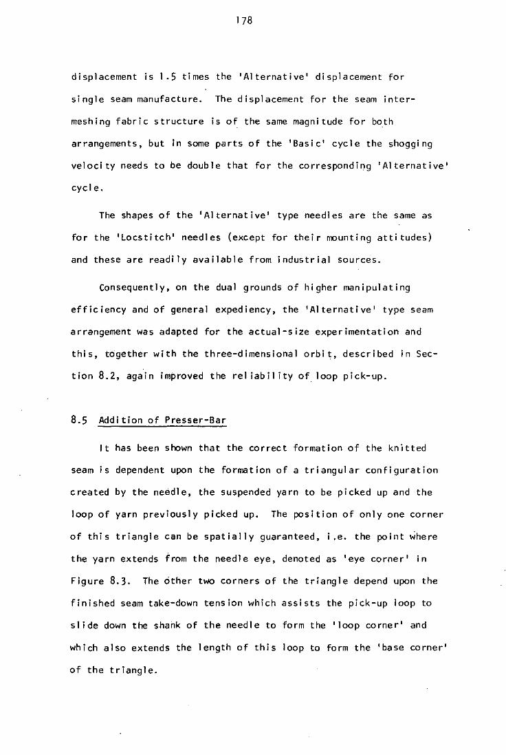
178
displacement is 1.5 times the 'Alternative' displacement for
single seam manufacture. The displacement for the seam inter
meshing fabric structure is of the same magni tude for both
arrangements, but in some parts of the 'Basic' cycle the shogging
velocity needs to be double that for the corresponding 'Alternative'
cycle.
The shapes of the 'Alternative' type needles are the same as
for the 'Locstitch' needles (except for their mounting attitudes)
and these are readily available from industrial sources.
Consequently, on the dual grounds of higher manipulating
efficiency and of general expediency, the 'Alternative' type seam
arrangement was adapted for the actual-size experimentation and
this, together with the three-dimensional orbit, described in Sec
tion 8.2, again improved the rei iabil ity of loop pick-up.
8.5 Addition of Presser-Bar
It has been shown that the correct formation of the knitted
seam is dependent upon the formation of a triangular configuration
created by the needle, the suspended yarn to be picked up and the
loop of yarn previously picked up. The position of only one corner
of this triangle can be spatially guaranteed, i.e. the point where
the yarn extends from the needle eye, denoted as 'eye corner' in
Figure 8.3. The other two corners of the triangle depend upon the
finished seam take-down tension which assists the pick-up loop to
slide down the shank of the needle to form the 'loop corner' and
which also extends the length of this loop to form the 'base corner'
of the triangle.

By experimentation- it was found that process rei iabil ity was
greater with higher seam take-down tensions. However, a high ten-
sion tended to create long stitches and the need to maintain the
* tension meant that back-robbing incurred breaking strains in the
yarn. Therefore, it was decided to introduce another element to
assist precise formation of the pick-up triangle without the need
for high take-down tensions.
Extra I inkages were added to the rig to provide motion to a
presser bar. The function of this bar was to push the loops off
the outgoing needle and to push the pick-up loops to an accurate
predetermined position along the shank of the pick up needle.
Having achieved this, the seam take-down tension was considerably
reduced, but was still higher than that desi red. Figure 8.13
shows four stages in the needle cycle, where the pick-up triangle
can be clearly seen in relation to the needles and the presser bar.
Under these conditions the reliabil ity of production of a single
seam was extremely good.
8.6 Basic Defect of the Process Rei iabil ity
The rei iabil ity so far achieved was in fact found to be largely
dependent upon the consistency of the yarn used, because, under
steady state conditions, the formation of the pick-up triangle and
accuracy of needle movement was satisfactory. In practice, the yarn
consistency cannot be guaranteed and slubs and knots in the yarn
must be tolerated. It may be acceptable with some existing fabric
manufacturing processes that the occasional knot or slub creates a
dropped stitch without affecting continuity of manufacture, but when
this occurred with the system so far developed, a complete breakdown

* On machines that manipulate yarns into looped structures with
fixed-stroke elements, the final loop sizes are usually con
trolled by a back-robbing technique. By thi s technique, as
the geometry of the fixed-stroke element demands a constant
length of yarn per operating cycle, therefore any reduction in
the length of the supply yarn must cause a corresponding reduc
tion (or back-robbing) of the si ze of the previous Iy formed loop.

180
(a) (b)
PRESSER BARS - X & y
(c) (d)
FIGURE 8.1 3

181
of the process occurred. Although the formation of the pick-up
triangle is accurate under steady-state conditions, it is dependent
upon the correct formation of the previous stitch which guarantees
the existence of the base Corner of the triangle. A dropped stitch
fa i I s to form the base corner and all subsequent st itches fai I.
To correct the fault the process must be stopped and the offending
loops must be manually plaeed in their correct positions until a
sufficiently corrected seam length is produced, thereby returning
to steady-state conditions. Thi s inabil ity of the process to
recuperate after dropping only one stitch was totally unacceptable,
and therefore, it was concl uded that the presser bar offered only a
partial solution to the problem; nevertheless it served to demon
strate precisely what function an additional knitting element ought
to perform.
8.7 Introduction of the 'Grabber'
To perform the above suggested functions a new element was
needed and for convenient future reference it will be termed the
'grabber'. Firstly, this grabber element must push the picked-up
yarn loops down the shank of the needle (as the presser bar did),
and secondly, it must position the base corner of the triangle at a
known point in space independently of the formation of the previous
stitches. In so doing, the seam take-off tension may be theoreti
cally zero because all corners of the pick-up triangle will be
formed by the mechanical components rather than by yarn and seam
tens ions.
To perform the function of the superseded presser bar the nose
of each grabber element had to I ie across the shank of the needle.

182
In order to achieve this the needl·es were cranked (in their non
working shank area) to allow the grabber nose to come up through
the spaces between the adjacent needles. Thus as the grabber moved
over the working length of the needle its nose lay transversely to
the seam and pushed the pick-up loops down the shank of the needle
on the complementary bank. Figure 8.14 illustrates this relation
ship in two orthographic views. Having performed this function,
the grabber moved to a point in space to hold the next yarn to be
picked up in a predetermined position irrespective of the correct
or incorrect formation of the previous stitch.
The system has now evolved into a concept of manipulating
knitting elements which appears to be a practical and commercial
proposition. Therefore, before considering the procedure for
producing structures by seam interaction and analysing the yarn
tensions and feed requirements etc., the development of the
mechanical movements, the components, and the manipulating elements,
will be described In more detail.

16.3
END ELEVATION
PLAN
FIGURE 8.14

184
CHAPTER 9
DEVELOPMENT" OF THE NOVEL PROCESS
VIA THE POWERED RESEARCH RIG
The fabric plane and the planar orbit of the needles (outl ined
in Section 7.2) were chosen as the reference datums for development
of all the auxil iary elements and their functions. Although the
experimentation was conducted on a narrow working width of the rig,
the author was fully appreciative of the need to ensure suitabil ity
for scal ing-up in all aspects of thi s work.
9.1 Grabber Motion
9.1.1 Primary and Secondary Motion
The determination of the grabber motion presented considerable
problems. The prime objective of the grabber is to manipulate the
yarn into predeterminate posi tions (see Section 8.7). It interacts
between the gaps In adjacent needles and the needle motion is in
three dimensions. Thus the grabber motion could not be considered
in isolation. The technique devised was to draw, to a high degree
of accuracy, sixteen needle positions at equal time intervals over
one "needle orbit to a IO-times scale; then the required position
of the yarn, such that the needles could not fail to pick it up,
was added to these drawings. A template of a proposed grabber shape
was then superimposed on each of the sixteen needle drawings and
positioned so as to hold the yarn as and where it would be required.
Two typical positions to a reduced scale are shown in Figure 9.1.
These sixteen grabber positions were noted relative to the needle
positions and plotted. Naturally the initial plot was somewhat ad
hoc and conventional curve-fitting techniques could not be used to

1 8 5
F ISURE 9·1

l~
provide a smooth curve through the sixteen points. It will be
appreciated that the displacement of the grabber must be dynami
cally sound and so the graphically determined displacements were
spl it into x and y coordinate positions. Using sine curves the
computer was used to fit a compound motion through the precision
points35 in both the x and y directions independently. Thus the
two displacement curves shown in Figures 9.2 and 9.3 were derived
and checked by finally drawing the derived grabber positions
accurately onto the needle station drawings. The task remained
to design the cam I inkage system to produce these motions. The
criteria for the design was the same as that for the needle motions
and it resulted in a system shown schematically in Figure 9.4. It
will be appreciated that the cam that predominates the motion in the
x direction will affect the grabber position in the y direction and
vice versa. Therefore, one cam could not be designed in isolation
from the other. Again the computer was used to design the machining
polar coordinates of the interdependent cam sets.
9. 1.2 Grabber Shogging Motion
A similar graphical technique was used to determine the motion
of the grabber in the z direction. However, extra precision was
required where the grabber moved around the crank in the needle,
especially as the needle itself was moving in three dimensions at
this stage of the cycle. These extra time-coordinated needle draw
ings were made at 5 degree intervals to ensure that the computed
sine curve motion was satisfactory. The resultant grabber z displace
ment curve is shown in Figure 9.5.

1-11' '-1-1111 -kl
1- -I :11,1 ! i I I I ill i 111~7! i I ! I i I ! :! : i: ,: /1
I I '1 1 I i ' I I! -1- - " , ! I I "I I 'I I ' ! I , : I
-, I' /' 'I I - I 1-1-1 I' I - Ill, il I 'I ;, i I I !: i ' , i I :: ' , i
; i '-I' !1:-i~l- 1 1,/.11
,1 '-1'1.-,-' II1 '-I!: 111
1
,: 'I !I;: ;-H! i I i!!! ;- ;:: i~h' ,-.. ----: - UUH i 1 1 i :.I: bL I I - i-I ! I' ,Ill" i i 'Ill' I !:: i I i
111-; 1/ Eo<~'- wrl,' / "'I I ,: ~II' / i 1/ I: ! 1 : i I , i " i! I :: ' . / : , l :;: : I "11" I: I, -I ' ' : I! ! i ,,! 1 ! " ,:!:: I , I I a:'~ 15~ I, - j ,'I I !:": I 1-, ',:' , I " "I: '
;1 i ~I~ ~i _ I -J mt-Ulll iJ 1/ i LLl..k~! i_' '~_i-1GJL c_, ,. __ , __ .. , _,.. _.
, ' ' ,ip. i I 11 I' , I " ' I : S, ' LV.! ,,:,' ' 'ffilli!': I . I II ~.;:; ,IJ.~ I . I , !; ~ '"-!"""" .! J I I I : I !, ! I ! ! I
! I i er,!~ rl - _ I -_ ' -. I I I I ! ~ I 1 'I I i ' I ' ; i I ;: i ! : ' -' I eb'S' I ,I 1 I -I ') i I 11' I I I , : "I I I I "I I ,,' 1 I .
I : 1·1"1 2"- I! ' - I' I! I I I I I I I " I:' ,I i : i I - 11:; I III I-I 'I I I I, I I ! I' I" .'::' " , i
. L - lib: I,! . - - : I ! I i ! i,! : I:! I; i I i :' i:" . " +1 i t-- ':l:' I· i \" !' I U++~ ~ 1.1 JJ I l I: \I! I lJ_! I r I l ::"1 _ 1. I I !
'/ 1 I 1 ~ i I I " I ~,bi !, I Il~i I ' i I I! i 2't'!~ !! I I : ! : 3bO I -I I! IEr~~ I i 1'1 Ill/ lA 1/1 l'ffi' I i 11 e~N IANGUlI'W' DEal/US) 11
I11111 ~!~ I : ~ 1 ' I I 11 ' ' , I: I I ,I I1I 'I i ~I i 1 , ! ! I i: I":: ' 'I I I ~:~~- <i -I 1 'I ! I Yi' j! 1I 11 '11 'II~ I i~ : i,: ~ ,! I i i :", I Llt~!~I~l-fl~II'~,-l{I'!!li tln~ji if! i::i:-l7tf-·--, I
! t if-1'~d 1.'11 11,'- '1'1-- _:1 !! t 1 i It! !N-~' 10';! 11 i ' ' i "t: 6:- ,-- - 11 1 11,1, '1"1" 1
J! :1,:: _:1 f:: .. , _ -: ,-:- L': f! 11, 11' 11 'i I i 11 _i i i i-l-:.-,--:, ___. __ -:~:-,:~:;,' ti"ft:I:,f~<trllirii'-' ··~I·r iilllll"\I! riil':l. , - ," I, 1-1-1' - 11 -'1 I I' -I I ,I I, "" , II ~ 1'1';-1. 1 1':1-11 1 1'-1 It I IUlUl11-1 '11 1
1',1::::: Ill::
i::i I I' L ! -I .. I i' 'I ill' - I :: i' i , I i ,I I 11 ill' :",
*I-'! U' " "If \' :1 i '1.1 ,I! !i ,':: ,[: 11: I:' 'I -H-: ~WI H--t~,!--:,:.-,- ., ,--, I I" I - ! j ,I - ,I I"'! 1 I I 'I ", I, i i I I , I i 'I , -I I ,,' ' "I I I I I ,I j I , I I I ' I, I I , " ", ".
I-I I i : . i r 1 ,-I : -. I !:! I '11 1
1
1
1-, ! I I ! i i i i ! ! I' ';: '
- "1 'I ~ I -! If! I " ' 1 I I I I I I I I I I I ! i 'I 11 i I '!:' I '
I, i I i!11 ! I 11:1 ' I,: I!;! lW!! I i, Jl-4,J1J, _!J,U.:, __ , 'h_'
, IL'lix' 1/1'1 1 1'1 "i l ,11, ... lj.i l 'I'ili 11,'illi,r'a· ... A . I· - ! : : - ")!!-, . i 'I' - , ; I I L', £..a J!!A'1K ' 'i!', . '1
1 ; I : l}(i ! n. .' II NK, , 1 I; CI'I:' I 1 I il l' 1'1'11' I I i I 'I I'" : I' i:' . .
1 1· 1 :~·j . ':1 1 , 'I,". "1'. ".,Iil l I 'i"': .. ' 1'1 " 115 I ' . I I' , I I I I I:"": I: i j)--" , " ... . " . f!!!!I15~11 III"'I~I' iifllirl :!I'I'II,II'I';':II ~:li:i," >:, #.-~+@l.*; , ,/tt+11 -H-G-ml .,\-t--, i--ll-I : W-
I·,· rr'-: ::: I1 : 1 : ! ' JJKr :-!H';-;-':':-r:-~' :',:, -
; 'I I' J Ptli 11. t, I .. I I', I '! r. i : I! 11! J I ;: :'. : L :,1
1 : ;~r ,I!! L I' \ 1 'I I i '. !'K.I ,I I i, 'I I ! I I! 11 ! I; .. /: : : . , " II!:I' 11" I ' , lll' 'I' I' I """--' . 1 I' .
/'1·,1, '-'" 1111111' i'.II·j i . '11';~.-!"iI'iil:I~..L'·" ".' . I J I! >.a . ' . "I I I I ! -, I . I ......r- 1 I ,I I . I I' , ....
ffii.! I li.h hi :1'1'1.1.1"'-' 1",1 11
1 '\1 l:i:i II1 I il /111: :!i!;:::~ ::j:i: .•
·1 -i'~ ,- . '. I : , I i i i 'i t i! !,' t I! "':'" ~: :':.:.
11: I ~ I \1 i i If '~II 'I ! I i~Q ILi i i I' i Iztci i i ::! i ; · 360 !; I ~ : •
'
''':1: 1\. -~: :"1 III i // _ 11II1 i I ,i! \1 ~~A·f,~o/cj~.~';W:'(b~~~EES) ;:.:; •. I.' 'I·! 1 !., I I ; "Il j 11' I 'I' lli ~~; 19' !,' i 11 I" If : I i 1 i! ; ~ : i ; !: !; • 11· , 1.1, ! 1 'I -I I 1 IJ.G 't', I .,,' ; I";:' ",'!: i' I':'
'!I-illl-!I: i,lill!I!1 illl:!li ll!!!ll-!l !-lu1: 1 :! !:ijL;,:~_i i!.',;:_: .. _, _ II!t l'll!! I I' i i i I" U 1 ill I!I 11 i 1 i 'I'! i i i i! I!: I! i [!! i!': i!:,:
, , • , I" I 11 ' . I 'I' '. I " "I"" , , . , " .. :,.1"1 "1'1" I 11"1':' I'" ": "!,, ':," I I i I i j • I " I • ! 11 I!! I I i; ,! I ! I:! I ~ , I I . , ! I .. IT' I
i i ; ill' ; i 1111: i' , I i I' 1 :' ,,; i : I 1 !, i; i : , ! I;, "": :
illili l:!! !illlil;,+1 rl'jl!ii1ii l!ill'iL:iii t: L:;il:lll! ri[I:::',::
nrlTliri rl'lllll-I-'j' mltli Illllr i I nll n i! i!i!!:: ' : ' ' :
, .

188
L.H.MECHANISM
SYMMETRICAL MECHAN1S~lS
..... -1 -11" eh x--
x
.-- W r-~~~~~._/_·· ____ ~~N __ ~~
A ._=~~·'~.-~-I-' __ ·t-·
CAH'x'
CAM'y'
eh Y Y
-\~L-·f-· VATIJH POI NT I!
~·SHAFT ROTA TI~O:-::N"----, ,
ALL
A:6.0 B:3.4 C:10.7 D:8.6 H:9.5 J:17.3 K:6.7 L=17.3
P -.-----+ .. --- Q ----....
DIMENSIONS IN MM
":6.8 N:5.2 P:17.8 Q:10.2 V:6.8 W:1.9 o e1 :12.130
e2 =167.56
x & Y:GRABBER DISPLACEMENTS (SEE FIGURES 9.2&9.3) eh x&eh y=CO-ORDINATES AT WHICH
GRABBER BAR SHOGS
FIGURE 9.4

---------.-----
I
I

190
9.2 Design of the Shogging Mechanisms
9.2.1 Needle and Grubber Shogging Mechanisms
The unit for providing all the shogging motions to both the
needle and grabbar bars was designed as a single module. All
motions were derived from cams but to achieve the motions shown in
Figures 7.6 and 9.5 for the x direction, drive rods had to extend
from the modules to the bars of the elements. A schematic design
of the shogging module is shown in Figure 9.6. The cam profiles
used had to compensate for the two-dimensional motion of the drive
rod ends (in the x and y plane) as well as provide the requi red z
directional motion. Therefore the mechanism was mathematically
analysed and the computer used to give cam machining polar coor
dinate dimensions.
9.2.2 Seam Interaction Shogging
Initially the arrangement so far described was used to assess
the rei iabil itY.for producing .single seams of interlooped yarn.
However, the shogging module was provided with a segmented cam so
that, at a later stage, Seam interactions could be tested thereby
producing fabric. The seam interaction cam acted on the needle bar
and, since the needle bar already had a shogging movement to pick up
the loops, the mechanism was arranged as a 'seri·es-cam-set', i.e. the
total shog of the needle bar was the sum of the pick-up shog and the
interaction shog (see Section 7.4), the latter being readily change
able to facil itate different fabric constructions. As previously
stated, ·the latter tests were made by making single 'Alternative'
seams of interlooped yarn.

19 1
~ cI'~=:--------~A~----------~--------j\~Z~\ Bh Y .- +z ..:.
(GRABBER)
A=21.2 B=32.9 C=4.8 D=13· 1 E=9.0 F=3·6
15·9 K
\ , I
t 'CAM' G'
/ CAM'eN' \
_---+-..... ___ .18.1 .. ' ..
ALL DIMENSIONS IN MM G=9.
0 ' z'" SHOG D1 sPLAC EM EN '1'
H=6.5 'sh ,,' & 'sh y': CO_ORDINATES A'l' J =6.2 WRI CH GRABBER AN D K=1.8 NEEDLE BARS SHOG
L:9·8
FIGURE 9.6

192
9.3 Grabber Performance
The grabber performed as expected and additionally to pushing
loops down the shank of the needles, it also controlled the base
corner of the pick up triangle irrespective of whether a previous
stitch had been formed correctly. However, there was a further
unforeseen advantage of the grabber which related to the initial
threading up of the needles. Previously each new yarn to be
threaded had to be taken through the needle eye and round the
take down rollers 'before knitting could commence, and this was an
awkward procedure. With the grabbers in operation, the new yarns
could be threaded through the needle eye and the grabber itself
would automatically carry the loose end of yarn into the knitting
zone such that production could Commence immediately. The design
of the grabber was such that any yarn placed in its path as it
moved into the knitting zone was carried into the zone and laced
into the seams. Therefore, fabric could be produced without seam
interaction by tying together the individual seams with weft lay
yarns. An example of this is shown in Figure 9.7 which corresponds
to the 'Alternative' large scale model in Section 6.2.2. The fab
rics produced in this way were fairly interesting and could have
various appl ications, but it was real ised that the most versatile
systems for fabric manufacture would necessitate seam interaction.
9.4 Seam-intermeshed 'Alternative' Fabric
9.4.1 Seam Interaction
With the action of the grabbers producing a high degree of
rei iabil ity, it was possible to study the effects of seam interaction.
By such means it is possible to produce a fabric without the need for

193
WEFTS
FIGURE 9.7

194
extra weft-laid yarns. The seam interaction cams were cut to give
a one pitch shog per needle per cycle, as shown in Figure 9.8, and
a single seam intermeshed 'Alternative' fabric was produced with an
indication of good rei iabil ity for the eventual machinery to be based
on this technique.
9.4.2 Selvedges
Initially the selvedges produced on a narrow-width of fabric
were poor. This was because extra needles were present which were
not carrying yarn at the edges, i.e. the width of the fabric produ
ced was not the total capacity of the rig. A very satisfactory sel
vedge was produced by using exactly the same number of yarns as there
were needles in the bank and by incorporating a spring take-up on the
four yarns comprising the selvedges. The spring compensators (see
Figure 9.9) take-up the unused yarn when the shogging has taken the
needle outside its opposite complementary needle.
9.5 Yarn Feed
The yarn feed system was designed somewhat empirically, being
based on that designed by the author for the 'Locstitch' rig' with
a friction roll driving the yarn from the creel when the demand ten
sion increased. The tension increased when the needles moved forward
demanding yarn from the supply, but the rig was equipped with a reci
procating bar that could be phased to induce tension at any stage in
the needle cycle. After considerable experimentation with the phased
reciprocating bar it was found to be superfluous. The most satisfac
tory stage in the needle cycle for increased tension (and hence yarn
feed) was in fact when yarn was demanded by the needles. Figure 9.10

~
~ ~ ~
UJ E-I Z ~
~ u
~ 1. j Po. UJ 0 H ;j Cl
Cl - ~ C!J ~ -1. g z · UJ III - · :z: ..:I 0 H E-I u
gj E-I Z H ~
~ ~O ~ ~
UJ ~l.O I ~ III :z: • 0 Il:
195
ONE NEEDLE
FIGURE 9.8
ONE 'SHOG'CAM SEGMENT
I .. l I i
I
.:.1. ... .'1,·.
:.,!" : I
,'; . I
I ., y ,',
.'
: ! . _-+.-l.=j~.;-J I" "

196
YARN TO SELVEDGE NEEDLE ,SPRING COMPENSATOR
YARN FROM SUPI-'~
FIGURE 9.9
... _- "._ ... -
0.20 N
FIGURE 9.10
Gramm' T'T.'T~-" '10:- --, -'T'-:'-GRABBER HOLDING:'
YARN DOWN ; ~ 6 .
MOVING FORWARD

197
shows the tension recordings of a yarn and although the tension is
not constant it has been maintained at a maximum peak of 0.2 N
approximately. This is considerably lower than conventional warp
knitting tensions (approximately 0.S-0.7Nl, but because of the
cycl ic characteristics, It is too early to say whether an improve
ment has been achieved. The tension curve exhibits two peaks per
needle cycle, the larger occurring as the needles move forward and
the smaller peak when the grabbers are moving down to hold the base
corner. The primary function of the yarn tension system was to
increase the definition and rei iabil ity of formation of the pick-up
triangle. By retaining relatively high tension as the needles move
forward, the pick-up yarn triangle, from the eye corner to the base
corner, was accurately formed. However, the needles carrying the
pick-up triangles start to retract si ightly before pick-up is com
plete and this causes a relaxation of yarn tension. Therefore,
experiments were conducted to maintain yarn tension a I ittle longer
until pick-up was completed, but these produced no satisfactory solu
tion with the me·chanisms provided on the rig; hence, a considerable
redesign of the yarn feed would be necessary. However, accepting the
fact that the existing yarn/tension system was by no means optimised,
the initial procesS reliabil ity and good fabric density indicated that
the proposed fabric manufacturing process was promising.
9.6 Examination of Rei iabll ity Problem
9.6.1 Yarns Used
Most textile machinery designers would concede that no one
process could accept all the different types of yarn that are COJm,
ercial Iy available. The compromise is to develop processes that wi I I

198
accept a very wide range of yarns and this must obviously be a
criteria for the new fabric manufacturing process. The needle
used is in principle a tufting needle, its eye being of a standard
size for a 5/64 inch (2mm) gauge machine. The needle manufacturers,
Singer U.K. Limitedl4 , state that for this size eyed-needle the
minimum yarn count should be 6's cc. Such a yarn, with the rig's
needle pitch of 2.2mm, and with seam interaction, produces a fab-
ric of reasonable density (see Figure 9.11). However, the use of
6's cc Courtelle and similar spun-fibre singles yarns produced an
undesirable phenomena when yarns havi ng the same tv,ist di rection
were used on both sides of the machine in that their natural twist
livel iness caused snarl ing in up to 4 adjacent yarns during the
low tension part of the cycle; the twisting together of these
yarns was so intense that they could not be corrected by increasing
the yarn tension. If this situation is allowed to continue, a
variety of complex tension conditions occurs in the knitting zone
where the snarled yarns are pulled by the needle and grabber elements.
This occurrence is not in itself surprising, but what is interesting
to no~e is that it only happens on one side of the machine. To
investigate this phenomena further the offending side of the machine
was threaded with a yarn of opposite twist direction (i .e. S twist
one side, Z twist the other side) and the problem was solved. The
provision of yarn twist balancing is wel I-known in certain sections
of the textile industry, e.g. yarn doubl ing36 , weaving37 , etc. but
for this type of fabric production it is sufficient to note that when
using twist-lively yarns the total process needs to be mirror imaged;
as previously stated, the knitting elements on each side of the machine
are mirrored and this has consequently created a similar need to bal-
ance the yarn twist characteristics (see Figure 9.12). However, when

! 9 9
FIGURE g.!!

200 'S ' TWIS T
'z' TWI ST
FIGURE 9.12

201
2-ply yarns were used the above phenomena did not occur wi th
ei ther S or Z twisted yarns. This was probably due to the twist
balancing caused by each yarn in the ply having fibres twisted in
the opposite directions to the ply twist to provide a yarn wi th a
neutral or low twist I ivel iness which could be run satisfactorily
on either side of the machine. The most rei iable knitting was
produced using a 2-ply acryl ic fibre "Orlon" yarn of approximately
2/26 cc with few or no stray fibres protrudi ng from the yarn, i.e.
each yarn in the ply had the high twist factor whilst the ply twist
was fairly low. However, the process should function reliably with
a variety of yarns and it seems reasonable to assume that, having
achieved success with standard types of low qua l ity yarn, then
success with higher quality yarns ought to be achievab l e also.
For further experimentation it was decided to use a 2/26 cc loosely
spun yarn of average quality comprising 75 mm staple length acry-
lie fibres. With this yarn a seam-interacted fabric was produced
on the research rig at speeds up to 600 rev/mi n (1200 courses/minute).
Faults in the fabric due to dropped stitches (i .e. fai l ure to pick up
the loop) resulted in a hole in the fabric in local ised spots, but the
total process did not break down. Because the type of yarn to be
used for the research was now fixed, further Investigation of these •
failures was required.
9.6.2 Dispersion of Failures
The speed of fabric production was very impressive and long
lengths of 100mm wide fabric could be quickly run off. Inspection
of the fabric revealed that in some cases, for a particular warp seam,
a dropped sti tch occurred fai rly regularly (say every 70 or 100mm)
but there were other failures occurring at random (see Figure 9.13

DROPPED
STITCHES
202
FIGURE 9.13
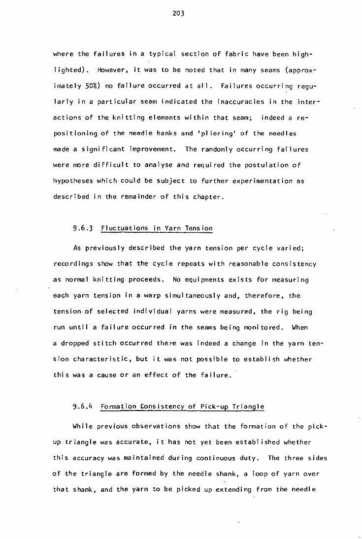
203
where the failures in a typical section of fabric have been high-
I ighted). However, it was to be noted that in many seams (approx
imately 50%) no failure occurred at all. Failures occurring regu
larly in a particular seam indicated the inaccuracies in the inter
actions of the knitting elements within that seam; indeed a re
positioning of the needle banks and 'pI iering' of the needles
made a significant improvement. The randomly occurring failures
were more difficult to analyse and required the postulation of
hypotheses which could be subject to further experimentation as
described in the remainder of this chapter.
9.6.3 Fluctuations in Yarn Tension
As previously described the yarn tension per cycle varied;
recordings show that the cycle repeats with reasonable consistency
as normal knitting proceeds. No equipments exists for measuring
each yarn tension in a warp simultaneously and, therefore, the
tension of selected individual yarns were measured, the rig being
run until a failure occurred in the seams being monitored. When
a dropped stitch occurred there was indeed a change in the yarn ten
sion characteristic, but it was not possible to establish whether
this was a cause or an effect of the failure.
9.6.4 Formation Consistency of Pick-up Triangle
While previous observations show that the formation of the pick
up triangle was accurate, it has not yet been establ ished whether
this accuracy was maintained during continuous duty. The three sides
of the triangle are formed by the needle shank, a loop of yarn over
that shank, and the yarn to be picked up extending from the needle

204
eye. The eye-corner of the triangle can be guaranteed within a
deflection tolerance as It is dependent upon a solid mechanical
component. The loop corner of the triangle is determined by the
pushing action of the grabbers, but its position may be different
due to varying friction characteristics between the yarn loop and
the needle shank. Also, these frictional characteristics are a
function of yarn tension and qual ity, both of which will vary
snghtly at the formation of every sti tch. However close obser
vation of the picking-up procedure over an extensive number of
stitches (even those stitches that are dropped), revealed that
the position of the loop corner of the triangle was not critical
to the process rei iabil ity. The only possibil ity of the loop cor
ner position causing a failure would be if the loop was insuffi
ciently far down the needle such that the picking-up needle caught
it. This occurrence has never been observed under normally set
conditions. Therefore, if the failures are caused by the incon
sistency of the pick-up triangle formation, the base corner must
be at fault. Consider Figure 9.14 which is a diagrammatic illustra
tion of the pick-up triangle formed when no seam interaction is used.
The base corner of the triangle is formed by the intersection of the
pick-up yarn and the loop yarn. In this configuration the position
of the loop yarn is controlled by the grabber but the pick-up yarn
position is controlled by the yarn loop '(A) (a previously formed
loop). This is satisfactory provided there is adequate take-down
tens i on and even if the ya rn loop (A) had not been fo rmed (due to a
prior dropped stitch), the pick up yarn would still 1 ie approximately
in the same position. Consider now Figure 9.15 which shows diagram
matically the position of the yarn in the knitting zone when a single
pitch shog (from left to right) has occurred. It may be observed

--- --
------
FIGURE 9.14
TAKE-UP TENSION
TRIANGLE
N 0 \on

YARN LOOP'A'
nGURE 9.15
N o a-

207
that the base corner of the pick-up triangle is very accurately
controlled by the grabber as both the pick-up and loop yarn are
retained by mechanical components. When the needles make the
return shag (from right to left) a different element relationship
exists (see Figure 9.16). The base corner of the loop yarn is
controlled by the grabber as before, but the pick-up yarn is now
controlled predominantly by the yarn loop 'A'. The take-down ten-
s ion, which controls the pasi tion of loop 'A', is transmitted from
the take-down rollers via several courses of knitted fabric. There
fore, it cannot be guaranteed that every yarn loop 'A' along the
width of the machine is in exactly the same relationship (i.e. it
may be higher or lower than that drawn in Figure 9.16) and thus
the pasi tion of the base corner wi 11 be affected. Thi s passibl e
defect requires further Investigation under single pitch seam
interaction conditions, but it could explain the random failures
that occur.
9.6.5 Pos~tion of the Pick-up Triangle
Under perfect conditions the pick-up n~edle cannot fail to pick
up the yarn. Obviously, perfect conditions will not prevail and
hence the picking-up needle has been designed to have a considerable
spatial pasitional tolerance with respect to the pick-up yarn. The
tolerance may in fact be at the 1 imit of acceptabil ity such that
failures occur randomly as the pick-up yarn or base corner is formed
outside the tolerance band. To increase the tolerance an attempt
was made to move the base corner closer to the picking-up needle
just prior to the yarn pick-up. This was achieved by. studying the
grabber motion which, at that stage in the cycle is retracting
leaving the knitted loops behind. The root corner of the grabber

TAKE-UP I TENSION V
" DIRECTION OF LAST SHOG
PICK-UP TRIANGLE
FIGURE 9.16
IV o co

209
was undercut si ightly to-allow yarns to si ip into a groove (see
Figure 9.17). Thus, as the grabber started to retract it brought
the fabric, and consequently the base corner, to the picking-up
needle. There was a noticeable improvement in the reliability
achieved wi th this grabber modification but the 100% rei iabi lity
target was st i II not attal ned. A further movement of the base
corner into the picking-up needle was not possible by this method
because a retraction of the modified 'hooking' grabber brought the
loop corner forward as well. It was previously stated that the
loop corner has always been wel I clear ot the picking-up needle,
but with the modified grabber this clearance has been reduced to
a narrow margin of acceptabll ity. The conclusioN to be drawn from
this experimentation is not necessarily that tuture designs should
include a hooked grabber, but that the base corner is not always
positioned consistently under continuous rUnNing conditions.
9.6.6 Accuracy of Elements
All the above postulations regarding the occurrence of random
stitch failures are based on the accuracy of formation of the pick
up triangle. However, It has been noted that a large proportion of
the knitted seams (approximately 50%) have never dropped a stitch
for the duration of the experiments (which represented about 20 m
of fabric production). The laws of probabi I i ty dictate that if the
dropped stitches did occur randomly then a much larger number of
faulty seams should have been apparent by this stage, and this
observation suggests that the accuracy of al ignment of the knitting
elements (both needle and grabber) was inadequate. The principle of
the new fabric process was directed towards producing a system requi-

210
1.6
R 0.35
1---- 3.8-__
0·30
~ .. ' Cl ============::J1---'J"-
PLAN 'X'
FIGURE 9.17
ALL DIMENSIONS IN HM
SCALE=lO : 1

211
ring non-critical al ignments and indeed the pitch spacings of
adjacent needles and their points were inconsistent. Originally
this inaccuracy was thought to be within the design tolerance,
but if the pick-up triangle is occasionally being formed inaccu
rately, for the reasons postulated above, then a wel I-al igned
needle might still pick up the loop whilst a poorly-al igned
needle might miss it. Hence the resulting fabric reveals sev-
eral continuous perfect seams produced by well-aligned needles
picking up both accurately formed and inaccurately-formed trian
gles; whilst random faults occur on seams where poorly-al igned
needles pick up the accurately-formed triangles and miss the
inaccurately-formed ones. In order to investigate this possibil ity
further, needle banks should be manufactured to a tolerance that is
more precise, but still commercially acceptable.

212
CHAPTER 10
SUMMARY OF THE WORK TO DATE
10.1 Textile Aspects
The actual size experimentation conducted to date suggests
that the graphically enumerated range of the novel structures (see
Chapters 4 and 5) ought to be practicably realisable. The novel
process and some of its structures (see Figure 10.1) have been
demonstrated in confidence to some textile manufacturers and their
subjective assessments have been very favourable. Various uses
for the envisaged products have been proposed, particularly where
their novelty aspects may be exploited; e.g. novelty fashion outer-
wear, furnishing, industrial and surgical fabrics etc. or as rapidly
produced novel tricot fabrics of medium and heavy weights.
The 'Basic' and 'Alternative' type structures are both of
18 novel confi guration (simi lar to a Wal tex structure onl y); in
addition the 'Basle' structure is identical on both sides, i.e. it
has no face and reverse sides as is usual for tricot fabrics. Con-
versely, for all structure variants, the 'Alternative' type fabric
exhibits a face side (Figure 10.2a) and a different reverse side
(Figure 10.2b).
Any specification of fabric weight is not considered appropriate
at this stage of the development because the structure is unique;
the only reasonable basis for comparison might be an openness ratio
fo r looped fab r i cs.

213
fiGURE 10 ·la
I I ( , U R I 1 0 1 b

214
FIGURE 10 . le
FIGURE 10 . ld

215
10.2 Engineering Aspects
A range of structures of the 'Alternative' type (see Section
3.3) has been produced on the powered research rig (Figure 10.3)
at machine speeds exceeding 600 revolutions per minute. This corres
ponds to effective production rates of more than 1200 kni tted courses
of loops per minute, i.e. equivalent to the current maximum speeds
of the commercial 'high-speed' tricot machines (see Section 2.6).
These production rates have been reached using staple-spun acryl ic
(Courtelle) yarns and there is no indication of these yarns approa
ching their breaking stress 1 imits. Running speeds to date have been
1 imited solely by the 1 ight-weight nature of the powered research rig
and it is confidently estimated that design speeds ought to be at
least doubled for the prototype machine.
As is usual with pilot work of this kind, many aspects pre
viously thought to be of minor importance, and others not even
suspected, now stand out as important subjects for further investi
gation. It is submitted that in this thesis, the major emphasis has
been directed to the engineering aspects of the work in general and
to process performance reI iabil ity in particular. It is the author's
assessment that a still higher reliabil ity of the basic looping ought
to be attained before the process could be considered for industrial
exploitation.
The powered research rig performed its functions satisfactorily.
Moreover, the basic design speeds were even exceeded for the simpler
forms of structures; thus similar design concepts might usefully
be fo 11 owed in the des i gn of the prototype mach i ne. However, the
needle and grabber shogging motions were the first to falter, and
these could also. account for some of the mis-picked loops. The 1 ight-

216
(;:I) FAC E VIEW
(bl REAR VIE W
FIGURE 10 . 2

21 7
FIGURE 10·3

218
weight design of the drives between the needle shafts and the
shogging rrodule pennits excessive back-lash thereby res,ulting in
occasional misal ignment of the Z-rrotion to the primary orbit (see
Section 9.2).

219
. CHAPTER 11
PROPOSALS FOR FUTURE WORK
11.1 Textile Aspects
In the current international awareness of diminishing resour
ces, savings in materials and/or energy must be of utmost priority.
Higher production rates and novelty of appearance could be adequate
to launch a new process, although, its ultimate success would depend
on the total gain, some of which might be unforeseen at this stage,
e.g. savings in yarn costs. Therefore much more needs to be learned
regarding the textile aspects of this work which is not conveniently
studied with the resources of most mechanical engineering teaching
establishments. However, on a shortertermbasis, to facilitate the
design of a successful prototype machine, the potentially most
promi·si ng structures ought to be identified and grouped because to
design a fully general purpose machine to make all these structures
might prove to be impracticable.
Many more fabrics should be manufactured using different yarn
and structure permutations (see Chapters 4, 5 and 6) to facil itate
the scientific evaluation of their characteristics and physical
properties; these are the main ingredients to be considered by any
potential user of the process.
11.2 Engineering Aspects
Assuming that the process is not to fol low an unforeseen radi
cally changed direction, it is the author's opinion that further
optimisation ought to be 'conducted via development of the powered

220
rig to perfect the 'pick-up' or 'looping' reliability before fina
lising the design of a prototype machine. The following suggestions
for future work are based on observations made during the most rec
ent experimentation.
11.2.1 Needle Design
The research rig to date has been fitted with modified 'loc
sti tch' needles merely for expediency. However, experiments have
shown that a specially designed needle would considerably improve
the reliability of the process. Figure 11.1 shows (in two ortho
graphic views) an arrangement of a pair of proposed needles having
the following innovations:
i) The depth of the needle is increased to 1.7 mm. This allows
a larger eye to be used, which ought to facil itate one of
two advantages; 'either larger knots or slubs should be
knitted more successfully, or, for the same needle gauge
(2.2 mm), coarser yarns could be used, to produce denser
fabric constructions.
i i) The distance from the needle point to its eye is reduced to
increase the presentation of the pick-up yarn to the pick-up
needle (see Figure 11.1).
iii) Immediately beyond the eyes I and 2, Figure 11.1, the needles
are relieved to approximately 1.1 mm depth, in an attempt to
bring the pick-up needle 3 in a closer proximity to the pick
up triangle 4, before it is shogged to pick up the yarn 5.
It may be seen (Figure 11.1) that the base corner 6 would now
have to be severely displaced for a pick-up failure to occur.

, _____ 7
1.7mm
,J
PICK-UP SHOG
7 \
\ \ I '--l __ --'_
221
~X
'\ \. . , V ~ SECTION
6~/
l-~DDITIONAL TOLERANCE FOR PICK-UP YARN
--t-~- - - - - - ,-'L_. _ __ _
PICK-UP SHOG
PLAN 'X' SCALE=10:1
'A-A'
FIRST ANGLE PROJECTION
FIGURE 11.1

222
iv) Because only the top flank of the needle is active in the
picking-up process the point 7 could be moved to the top and
to one side of the flank. This should provide a better
angular relationship between the interacting elements.
v) It is proposed to move point 9 on needle 8 to an identical
position as on needle 3, Figure 11.1, thus facilitating the
use of some needles and grabbers on both sides of the machine.
vi) It is further proposed to rei ieve the needles at la and 11.
This ought to shield the suspended pick-up yarn 12 from the
dragging effect of the sliding loop 13, Figure 11.1.
11.2.2 Needle Primary Orbit
It is considered that ·little change in the needle primary orbit
would be requi red since this forms the datum around which all the
other elements and their motions are designed. However, the time
during which the needle bank is retracted clear of the pick-up yarn
could be increased si ightly because this is the period allowed for
the seam interaction shog. With the research rig in its present form
this period of time is insufficient to allow the needles to shog more
than two pitches (i .e. 4.4 mm) in either direction.
11.2.3 Needle Shogging Motion
The shogging necessary for seam interaction has been discussed
above (Section 11.2.2), but due to the proposed new shape of needle
points and the overriding need for performance rei iabi I ity, the pick
up shogging ought to be optimised still further. However,because
identical needles are used on both sides of the machine, the two
motions will also be the same.

223
11.2.4 Grabber Design
The simplicity of the new process is impaired by the need for
the grabber nose to lie across the flank of the needle. I t has been
observed on the research rig that this function of the grabber is
indeed necessary and it performs the function very well; therefore,
the author can see no alternative to the cranked-needle and angled
grabber configuration. Moreover, the grabber ought to be designed
to perform the second, hitherto overlooked, function of stitch
length setting. In general all needles generate the same loop
lengths during all cycles, but the knitted course density is varied
by the amount of back-robbing. To a I imited extent this could be
controlled as a function of the fabric take-down tension, but it
should be achieved more rei iably, and with the uti I i sation of lower
fabric and yarn tensions, if it was set against the nose of an
accurately set grabber element.
11.2.5 Grabber Motions
The existing grabber motions on the research rig are basically
satisfactory and only minor changes are envisaged. During the time
that the grabbers are holding the base-corner of the pick-up triangle,
they could be shogged further to increase the angle between the needle
flank and the pick-up yarn in the Z direction (see Figure 11.2). This
ought to further assist the pick-up needle to collect its yarn.
11.2.6 Prototype Machine
All the above-mentioned proposals will have abearing on the design
of the first prototype machine. However, the change to the use of iden
tical needl-es on both sides of the machine (see Section 11.2.l{v)} is

224 .
R.H.NEEDLE BANK / NEEDLE por NT
-'
, . / , , , ,
/ ,
/: I .. , , .. PICK-UP YARN
'/ ' ,
.1/ 1/ /: .. • I PPROX.ExrSTING ANGLE . , I' !/ // / .. if. . -- -- PROPOSED ANGLE . ,
(r~I' (220
)
((-, ((~I ' .. , I .• . . ..
i i i " .
I'
11 I ,
I! ! • , ' " ' : I ~
i i i " , '" GRABBER 11 I 'U tt, U~ I,
U
SCALE=10:1
FIGURE 11.2

225
of paramount importance. Regarding the textile aspects, this change
would represent the I imiting of the process to the generation of the
'Basic' type structures only. From the engineeri"ng viewpoint, such
identical elements would represent a substantial simpl ification and
the machine would thereby be a better operating prospect at its
introduction in industry. Moreover, the present undesirable need
for twist-matching (see Section 9.6.1) for the yarns on each side
of the machine would be obviated.
Most concerted effort should be subjected to the design of the
shogging motions and the shogged mass inertias38 . The flexible
struts39 used for the author's rig l and Vine's machine lO are ideal
in appl ications for light loads and small oscillations when three-
dimensional motions are required, yet the buck 1 ing strength and
fatigue 1 ife of such struts must be thoroughly investigated.

226
CHAPTER 12
CONCLUSIONS
The author and his colleagues consider the novel process and
its products to be of substantial industrial merit and commercial
potential. A similar conclusion would seem to have been reached
by The National Research and Development Corporation, in that it
is currently securing patent protection with a view to offering
this new product to British industry. Moreover, a considerable
wealth of understanding has been obtained regarding the many fac
tors influencing this form of yarn manipulation by simplified
elements. The author is very gratified that this development
is continuing via further S.R.C. support, thus providing appl ica
tion for some of the unreported knowledge also. Thus it is sub
mitted that the stated objects of the thesis (Section 1.3) have
been fully accompl ished.

227
REFERENCES
I. R. Vi to Is. "Development of a SebJing-Knitting Technique for
Producing Pile-Fabrics". M.Tech. Thesis. 1971.
Loughborough Ul'liversi ty of Technology.
2. S.R.C. Grant No. B/SR/4442. "Pile-Fabric M:l71ufacture by
Sewing-Knitting Technique". March 1968-February 1971.
3. B. P. 126820 I. "Improvements in or Re Zating to TUfted Fabric
Simu~ating Terry Cloth". N.R.D.e. Publ. 22 March 1972.
4. S.R.C. Grant No. B/RG/5013. "Basic Study Of a New Techno~ogy
for Textile Fabric Construction". March 1974-February
1977 •
5. S. R.C. Gran t No. GR/A/1223.6. "New Textile Manufacturing
Processes". March 1977-February 1980.
6. Int. Text. Pub!.. "Textile Te:mts and Definitions". Sixth
Edi tion. August 1970.
7. G.R. Wray. G.F. Ward and R. Vitols. "A New Development in
the Manufacture Of Pile Fabrics by a Sewing-Knitting
Technique". Paper presented at the 'Diamond Jubi lee
Conference'. Int. Text. London. May 1970.
8. Pickeri ng Locstl tch Ltd .• 'Locstitch Producing Terry Fabrics
with Locked Pile". Text. Mon •• Dec. 1971. 37-39.
9. G.R. Wray. "Developments in Textile Machinery". Chartered
Mechanical Engineer. Sept. 1973. 81-83.
10. J.E. Vine. "The Deve~opment Of a Pile-Fabric Patterning
System". Ph.D. Thesis. October 1976. Loughborough
University of Technology.
11. British Standards Institution. B.S. 308: Parts I, 2 and 3:
1972.
12. I.C.L. 1934/4 Drum Plotter. Graphical Input/Output - Fortran . Version (GINO-F).

228
13. I.C.L. 1904A Computer, Core Store of 12Bk Words.
14. Singer U.K. Limited, Blackburn, U.K. Trade Literature ..
15. J.". Prentis, "Dynamics of Mechanical Systems", Publ. 1970,
Longman Group Ltd.
16. N.D. Burns, "The Dynamic BehavioU?> of Latch Needles Dlwil/g
Weft Knitting", Ph.D. Thesis, April' 1973, Loughborough
Universi ty of Technology.
17. A. Reisfeld, "Warp Knit Engineering", Publ. 1966, Texli le
Book Servi ce.
lB. K.D. Darl i ngton. The Hosiery Trade Journal, 1965, October,
IIB-121.
19. C.M. Bottomley, "First Woolmark Co-We- Nit Fabrics", Wool
Record., July 26, 196B.
20. D. Paling, "Warp Knitting Technology", Publ. 1965, Colulllbine
Press.
21. B. Lancash ire, "The Knitting of Milanese", Text. Rec. 1952,
July, 1973.
22. B. Lancash i re, "The Knitting of Milal!ese", Text. Rec. 1952,
July, 1974.
23. B. Lancash i re, "The Knitting of Milanese", Text. Rec. 1952,
July, 1974.
24. A. ReisFeld, "Pattern Scope of Wal"p Knittillg Equ1:pmcnt",
Part 12, Knitted Outerwear Times, 1959, 23 Nov. p.50.
25. A. Reisfeld (and others), "FundamentaZsofRasclzeZ Knittillg",
National Knitted Outerwear Association, 195B.
26. 5th International Texti le Machinery Exhibi lion, 1967, Base I,
Sw; tzerland.
27. K. Lew is, "Co-IYe-Ni t fyoo l Fabl"1:e Dc vcZ01,mcllt" , Th e Hos i e ry
Trade Journal, 196B, Augusl.

229
28. C.M. Bottom1ey, "First WooZmark Co-We- Nit Fabrics", Wool
Record, 1968, 26 July.
29. Kar1 Mayer Texti1maschinenfabric GmbH, Germany, Trade
Li te rature.
30. R. Krcma, "Nonwoven TextiZes", (English Edi tion), Texti le
Trade Press, Manchester, 1967.
31. G. R. Wray, "NorMOven Fabric Manufactu:r>e by Stitch-Bonding",
Textile Recorder, 1961, 79, November, p.80.
32. M.S. Burni p and G. Marsden, "Some Factors Affecting the
Production of Patterned NeedZepunched Fabrics",
European Conference on Nonwovens, Paris 1977.
33. G.R. Wray, "EncycZopaedia Of PoZymer Science and TechnoZogy",
Volume 13, 1970 by John Wi1ey and Sons, Inc.
34. "The Concise Oxford Dictionary Of Current EngUsh", Fi fth
Edi tion, C1arendon Press, 1974.
35. R.M. Parry, "Mechanism Synthesis AppZied to an UnconventionaZ
PUe Fabric Machine", Ph.D. Thesis, 1974, Loughborough
Universi ty of Technology.
36. W.E. Marton and G.R. Wray, "An Introduction to the Study of
. Spinning", 3rd Edi tion, Longmans, 1961, p.169.
37. A.T.C. Robinson and R. Marks, "Woven CZoth Construction",
Int. Text. publ. Butterworths,1967, p.10l.
38. J.M. Prentis, "Dynamics Of MechanicaZ Systems", Longman, 1970,
p.94.
39. ~.P. 24002/74, "Improvements in and ReZating to TextUe Apparatus
for Producing PUe Fabrics and the Like", N. R. D. C. Pub 1 .
30 May 1974.
40. K.D. Dar1ington, "Designing on the WaUex Machine", The Hosiery
Trade Journal, 1965, October, pp.118-121.
41. H.A. Rothbart, "Cams-Design, Dynamics, and ACCUlUCY", John
Wi1ey and Sons, Inc. 1956.

OOUl I) I) U Z COU3 00U4 00U5 lIOU6 VOU7 OUUII 00U9 ') 010 0011
0012 () 0' 3 0014 V015 'i 0 1 ... COl 7 00111 'J019 OOlO OOll Ooa GOl3 00~4
. IlOl5 1J01l6 00117 OO~8 I)Ot9 OO.sD U u.s 1 UOH I) 053 DOH UO.s5 ooH OO.S7 00.,8 00j9 0040 "0" 1 0042 CO .. 3 0044 l'045 n046 11047 0048 (: () 4 9 f)U ,0 .-,11:> 1 I'O~2
230
APPENDIX
A TYPICAL 'GINO' DRAWING PROGRAMME FOR DRAWING THE 'BASIC' SEAM
SE~D TO (tD,~E~ICOMPl)SEQ.AXXX) nUMP ON (tU,PHJGRAM USE~)
WURK (EI,,~JRKFILEUSEq)
R U 'I LI8RAR'(ED'~UBGROUPGrNO) pI!OGRA'1 ("~I)G) CUMpRESs I~TEijER AND LOGICAL INPUT l,5c~"(l
OUTPUT 2,Cl=LPU TRACE Z PlO
'1ASTER Zt'1t: Asr r.ALL LU; 9.)4 CALL DEVpA"(,/,UO .. 7UO.t11 cALL w[:,n U "(3)
r.ALL sHIFfl(1UO .. l00.) CA L L S C ;, I. l l n • :> ) CALL SUVE CALL SHlf l '(101J .. 0.) CALL R01ArjC2'~O.) CALL SU"F. CALL R01Ar5(Z,Z70.) r:ALL SHIFIl(100.,O.) CALL TRAAt~ CALL AXlHjJl-2UU .. 1UO. ,2no.) r.AlL SUVE CALL TRAF.ND CALL SHlf"C-lIvO.,bOO.) CALL SCALll O.4) CALL SUVE CALL SH1FU(H5 .. 0,) CALL Ror" I H2' ~iI.) CIILL SU·Jr CALL ROTA 1j I2,Z70.) CALL SHIFll(111~.,0,) r.ALL TIli\Al~ CALL AXON.)\··?,UO. ,1un. ,200.) CALL SUvF. CIILL TR;,F.NU CALL SHlfr'(-lSO.,'OO.) CALL SCAtl(e,.S) CALL SUVF. CIILL SHlrr~(i')O .. O,) C~LL RU1A'3\l'~U.1
r.A LL SUVF CALL RorAI~(2,l'o.) r. 1\ L L S H 1 F I {( ~) '.1. , 0 • ) r. ALL A X(HP l_?U r) .. l VO. , ?.(In. ) r,HL SUn r.I\LL PF.\f~NU
STI'f> s: I. ~

r '; -
~
I , I ! S
0053 0054 UO~5 OO~6 ~OH OO~8 OO~9
OO~O QObl IIObZ 00b3
0064 00b5 00tl6
.0067 00b8 11069 00 fO 00'1
·00'2 00'3 0074 'JOI5 0016
231
SUBROUTINt SUVE CAl~ piNnA CAL~ SHlrl~(O,v,42,O.O,n)
CAL~ ROTAlj(~,160,O) rAL~ DA~Hcl1(1t4,O.i(.5.t).O)
"CALL PINnA CALL OASHCV(O,l,.1,.I.> CAL~ ROTAIS(Z,1S0.U) ~ALL SHIFrj(n,o.-4~.n.o.o)
11 nUR N E t~o
61, NA~[ SUVE
SUBROUT/Nt HtNOA rAl~ CILPA CAL~ SHIF1~(O.\l"14,o)
CAL~ CII.PA CALL SHIFI~(0.O,R4.0' CAL~ CIU,A CALL SHIFTl(O,O,84,Ol rALL·CILPA CALL SHIF 1 l(O,Ot!14.0) CALL CILPA CIILL SHjFT.s(O,O,-3.56.0.0.0) RETURN FND
END OF SEGMENT. I.EIjGTIf 60. NA'Ir: qlNDA
sU8ROUTINt CILPA r ALL M 0 V TU.s ( 6 •• 0 , • u • , Of)(-' ,6 OTV-S.O OTZeS.O CALL ARCTU.s(8.0~.5.64.0.0.8,05.5,64.6.0,DTX,OTY.DTZ) CALL LINTUS('~.04.~4.83.3.0) 01)(=5,0 OTV=S,O nTZ=-S,O CA L L ARt; TU' (0 , " • 30 • 3 n .3 . ~ • -, 5 , {l4 • .! 4 • A 3 • 3 • 0 • 0 T X • I) T '( • IJ T Z) CALL LINTU~(-6,OS.5,~4,~.0) 1l()(=1,8 01v.-S,6 IlTZ"-6,O CAL~ AR'TU1(~ij,05,~,64,o,O.-6,{I.n.O,O,JiDT~.DTY.~TZ)
rlTX"',O IlTva5,~I. nTz=-S,"4 r.ALL ARl:TUS(-~,,5."4.0,,-5 •• S.\l4.-6 •• 0rX;OTY.t"lrl) CALL LI~TU~(5,64,7~.R~.-ft,O)
t"lrx=_',n OTV=~,H
nT7.=5. ~I. CA L L A q r; T U ~ (5. "4. 7 K , , 5 • 11 • U , S , .) ,1\4.0, n , ;) , D T x • 0 TV. ~ r z)· IIlTU~tJ
r I; ~

0001 0002 0003 0004 0005 OOU6 0007 OU08 0009 0010 0011
0012 0013 0014 0015 0016 0017 0018 0019 00C!0 00.!1 ooa 00~3 00i4 OOc!5 OOc!6 000 OUc!8 00,9 ao.So OO~1 0052 0033 00.14 0055 00.16 00.)7 0038 0039 00 .. 0 0041 0042 0(}t,3 0()",4 001.5 00 q, uO I. 7 (J1J4i\
OVl.9 ('0 ~o oo~,
,JO~?
232
APPENDIX II
A TYPICAL 'GINO' DRAWING PROGRAMME FOR DRAWING 'THE 'ALTERNATIVE' SEAM
SE~D TO eEO,~E~lcUMpuSF~.AXXX) DUMP ON eEO,PROGRAM II~Fq) WORK (EP.WO~KFILEUS~R)
"UN LISRARY\EO,SUBGriOUPGlhO) pRO(,RA'1 (PR(lr.)
CUMPRESS INTEGE~ ANI' lOfilCAl ,NpUT 1, 5"C~O OUTPUT 2.6=LPO TRHf: 2 ENIl
M 11 S lE 11 ,it T E SEA;I r.IIIL LU·i9.s4 CII L L DE'. pA;' (700., 7VI,. ,1) r.AbL w'~nOW(3) . CALL SH;FTi.(100.,1I!i}.) CAI.l SCIIIE«(I.5) r.ALL SU'IF r. A I. L S H i FT i! ( 1 00 • , (, • ) r.ALL ~OTAT3(2'~U.) CAI L SUVF CALL 1I01AT3(7,2(0.) r.AIL sHIFTi.el0iJ.,r.) CALL T~r.REG CAI.l AII'HJ3(-200. ,111;;. ,7"n.) r.AI ~ SU'"F CAI L TR;.F:NO CALL SHiFTi(-2o" •• o .... n.) C A I. Lse., I. E ( 11 • 4) CALL SU.!F CAlL SHIFTt'(125.,O.) CALL 1I01AT3(2,;"'.) r.A, L SU'JF CAll "0I/lT3(2.2(0.) r. A I L S H r F T Z ( 1 2 5 • , (, • ) c: A I. L T R. \ R [ !i CAI L /I)(u,.;3(-700. ,1U'J. ,;J"n.) CA, L SU\'E CAI.L TRAF'"'O CAI.L sH IF Tl( -25"., (~n.) CAI L SC,~I.[ «:.5) CAI l Sll','F. c: A l. L S H IF TZ ~ 2 5 I) .. (l 0) CAI l 1I0io\;j(2,'\'.) CAI.L $IIVF r.A'L ~O;~i.s(?210.) rAil ~H·.FTc!(?'50 .. r,.) r."LL t.x,.":j(~~(jO.,1UIl. ,2';0.) r .1 I. L ~ If, r C" I L Il [, r'd .. ~11)1'
I. Il 11

0053 0054 0055 00~6 0057 0058 OOSQ v(j~O 00(>1 001>2 0063
Out>4 00b5 0111>6
'00b7 vOll8 OObQ'
00(0 0011 00(2 0013 00(4 00(5 0016 0077 0018 00 (9 00110 00 ti 1
QOIl? I) 0 Ii] (iOil4 001)5 ')U66 0007 Olll)/i 0(1 >iQ .)0"10
ii u" I)un I)O,)]
i)O:i 4
00;;S 00;;6 nO:;7 1;(1:":;
o (J'l9
233
SUR flOUT I tIt ;,UVE CA I l R [11 n/\ L CAll SlilFT3(O./ 4 2.'(l.l CALL RO~AT5(2,1DO.) CALL PAS~[O(1,4.0,~.S,o.n)
C/lLL RI .. r,AR CALL DA&HED(Q,1.,'.,1.l CALL flOTAT5(2,1 DO.) r. ~ I. l S tI j r T J ( I). , - 4 2. , n. 1 RE TUI!!; F rHI
S lJ p H fill T , " E f: [ 'I " 11 l r.'\1 L r 1'-.1"\ Cl'1 L 1.."'rAL r./lIL SH;nl(o./ 1i 4.) CI'I.L Cl "pA C~LL l./ljpAL C A I. L S H ; F T i. I) .' , 114 • ) CALL C[~p· .. · • CALL L~:Pt.L CAI.L SH;r T2(,}.,o4.) C A I. L C [ c p.\ CALL LAlpAL r:ALL SHiFTl:n.,1)4.1 CALL CILP~ CAI L lA~p';L
CAlL SHdTJ{u.,-33 b •• O.) Ilt rUIH; r r: n
~lJR"'IIIT. p,f ': I N(I~P C A I L r I ,.1' f, C~IL I.A'I'AIi C" I. L S H : r T i \ 0 • , ,-; 4 • I C /11. L C [ !. IlI\
CAlL lAlpAR rAIL sH.rTZ(O.,04.1 r I. I l. r I I. I' A
r.'d L I. /I i 1''' R rA'L SHIFTC«(I.,64.1 U" L r I l.pA
er" L LA I pAR r.{'IL SH;r Tl CII.,b4.1
U" L r.1 •. p" r. A I I. lA! p /\ R r: f\ i l ~ H j r: T .s ( 0 • , - 3 3 f). • (I . )
"r rllI'iI. f r~ n

0 1 lJ 0 0' ii 1 ,,1u2 01,-,3 01114 0105 O'n6 0107 01011 011.19 V 110 ,) 1 , 1 C,1 , 2 11 1 1 3 I} 1 , 4 J 1 1 5 ;, 16 j 1 , 7
,1 1 1\ ,,1 Q
" ~O 11<' 1 1/2 1£3 1 i 4 125 1£6 la· 1<'11 ,,0 UO
1.11 152 153 1..\4 !.S5 IS(' 157 .18 . 19 40 i.1 42 43
44
!';lIl\~n(lT "lE f.I lPA r,AI l ~~OVTOj(f,. ,l'. ,V., OTX=1.R OTV=5.0 OT7=5.0 C A I l All"; TO 3 ( 1\ • ();, , 5 • f> I. , n •• 1\ • (1 ~ • 5 • 64 , 6 • , Il T X , 0 T Y , I) r Z ) CAll lJ.n05(15,lj4,~ ... hl.L) . oh=S.O [)lv=5.0 n T 7 = - 5 • 11 r.AI.l API.T05(n.,3n.J,~,3,-15.04,24.8],3.0,DTK,~TY,OTl) CAl.l II .. JTOj(-8.!j5,).~4''',(1) nIx=1.8 OTY=-5, (, OI7=-6 .... tAI.L AHI:T03(-II.i;5,).~ ... n.,-f> •• O.,O,,'lTl(,DTV,OT7)
~rTURt.
f I; I)
SU~ROUTINr LA/PAL r.AI L ~'0';T03(-6, ,0. ,0".)
Oh=1.0 0;v=5.94 oT7"-5 ,r, 4 r A I I. A R l. T 03 ( - 5 • , S • y ~ . I', • , - 5 • , 5 .94 , - 6 , , [\ T X , [\ T Y , r T 1)
ri<"L Llr.TO]i5.6/'.7(j.~5.-f>.)
r>TX=' .0 OTV=5,9" 0i7=5.94 r. A I, L ARc T Cl S ( S • '" I • • 7 n • , ~ , I, , • 6 •• !i 4. , (I • , n T ~ • 0 T Y , Il T Z ) prTUP, f. ~; n
sll'<l<nUTI/oJE I.AIPAp 0, I L fl 0 V T 0 j (t~ • , ~ • ,V. ) Of)=-' .1' nTv=5.9,. nT7=-5.r:1. r ,\ I L All,. 1 0 .5 ( ~ • '" ' •• 5 ' .; 4 • 01 • , 5 • /, 4 • 5 , 94 , - (, •• 0 T X , D TV, [) T Z ) r ~ I L II 0. T [I j { - 0; • u I. , (8 • b 5 • - (, , ) ,,1,=-10\' o T Y = 5 • 9 I • OT7=S.~·. (AIL ARCT[l3(-5.64,(!l.1~,n.;-f>"P.4.,u •• OTX.DTY,D'Z) pfTU~N
J. .\ n
1 0'. N,I ~ I

235
APPENDIX I I I
Specification of Major Bought/Out Transmission Equipment
(a) Prime Mover:
Make G. E • C. Mach i nes
f:\ode 1 Kapax Induction Motor
Size DIOOJ No. LE2305 l405S
KW 3 ph 3
rev/mi n - 1440 Hz 50
V220-250/380-440
,A 10.5/6.1 Rtg. - Cont.
Brgs. DE6206z --- NDE 6206Z
Diag. 5 I ns. - Cl as s B
(b) Drive Speed-Variator:
Make Carter Gears Limi ted
Model Hydraulic Infinitely Variable Speed Drive
Size F14/l785l
Input power - 2.3 KW
I nput speed - 960 rev/mi n
Infi ni tely Variable Output Speed
Maximum Forward Speed
Maximum Reverse Speed
Output Power at Maximum Speed 1.9 KII
(c) Main-Drive Clutch:
Make Dyna-torQ C'I utch. Eaton Corporation
960 rev/mi n o
960 rev/mi n
Model Dyna-torQ Electromagnetic Clutch - 308
Overall dia. 232 mm.

236
(cl Continued
Static Torque 170 Nm.
Actuati on 90 vo It D. C.
( d) Take-up Dr; ve Speed Vari ator:
Make Minidrive, Haynau. Munchen
Model Infini tely vari ab le speed
Type 2 HW No. 127458297
Watts 160 (at i np. 1400 -I
mi n )
Outp. 465 - 4200 min -I

· .