Troubleshooting Switch Fabric Level Issues - Cisco
20
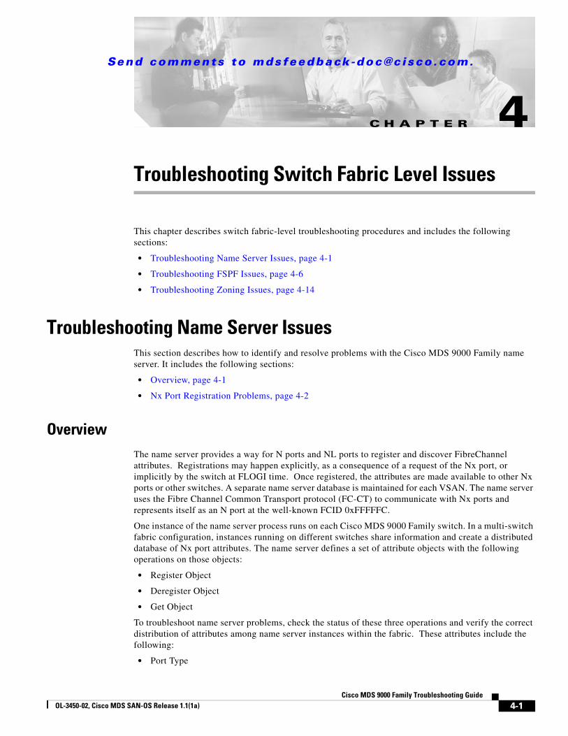
CHAPTER Send comments to [email protected]. 4-1 Cisco MDS 9000 Family Troubleshooting Guide OL-3450-02, Cisco MDS SAN-OS Release 1.1(1a) 4 Troubleshooting Switch Fabric Level Issues This chapter describes switch fabric-level troubleshooting procedures and includes the following sections: • Troubleshooting Name Server Issues, page 4-1 • Troubleshooting FSPF Issues, page 4-6 • Troubleshooting Zoning Issues, page 4-14 Troubleshooting Name Server Issues This section describes how to identify and resolve problems with the Cisco MDS 9000 Family name server. It includes the following sections: • Overview, page 4-1 • Nx Port Registration Problems, page 4-2 Overview The name server provides a way for N ports and NL ports to register and discover FibreChannel attributes. Registrations may happen explicitly, as a consequence of a request of the Nx port, or implicitly by the switch at FLOGI time. Once registered, the attributes are made available to other Nx ports or other switches. A separate name server database is maintained for each VSAN. The name server uses the Fibre Channel Common Transport protocol (FC-CT) to communicate with Nx ports and represents itself as an N port at the well-known FCID 0xFFFFFC. One instance of the name server process runs on each Cisco MDS 9000 Family switch. In a multi-switch fabric configuration, instances running on different switches share information and create a distributed database of Nx port attributes. The name server defines a set of attribute objects with the following operations on those objects: • Register Object • Deregister Object • Get Object To troubleshoot name server problems, check the status of these three operations and verify the correct distribution of attributes among name server instances within the fabric. These attributes include the following: • Port Type
-
Upload
khangminh22 -
Category
Documents
-
view
4 -
download
0
Transcript of Troubleshooting Switch Fabric Level Issues - Cisco
Send comments to mdsfeedback -doc@c i sco .com.
Cisco MOL-3450-02, Cisco MDS SAN-OS Release 1.1(1a)
C H A P T E R 4
Troubleshooting Switch Fabric Level IssuesThis chapter describes switch fabric-level troubleshooting procedures and includes the following sections:
• Troubleshooting Name Server Issues, page 4-1
• Troubleshooting FSPF Issues, page 4-6
• Troubleshooting Zoning Issues, page 4-14
Troubleshooting Name Server IssuesThis section describes how to identify and resolve problems with the Cisco MDS 9000 Family name server. It includes the following sections:
• Overview, page 4-1
• Nx Port Registration Problems, page 4-2
OverviewThe name server provides a way for N ports and NL ports to register and discover FibreChannel attributes. Registrations may happen explicitly, as a consequence of a request of the Nx port, or implicitly by the switch at FLOGI time. Once registered, the attributes are made available to other Nx ports or other switches. A separate name server database is maintained for each VSAN. The name server uses the Fibre Channel Common Transport protocol (FC-CT) to communicate with Nx ports and represents itself as an N port at the well-known FCID 0xFFFFFC.
One instance of the name server process runs on each Cisco MDS 9000 Family switch. In a multi-switch fabric configuration, instances running on different switches share information and create a distributed database of Nx port attributes. The name server defines a set of attribute objects with the following operations on those objects:
• Register Object
• Deregister Object
• Get Object
To troubleshoot name server problems, check the status of these three operations and verify the correct distribution of attributes among name server instances within the fabric. These attributes include the following:
• Port Type
4-1DS 9000 Family Troubleshooting Guide
Send comments to mdsfeedback -doc@c i sco .com.
Chapter 4 Troubleshooting Switch Fabric Level IssuesTroubleshooting Name Server Issues
• Port Identifier
• Port Name
• Node Name
• Port Symbolic Name
• Node Symbolic Name
• Class of Service
• FC-4 Type(s)
• Port IP Addresses
• Node IP Addresses
• Hard Address
• FC-4 Descriptor
• FC-4 Features
• Initial Process Associator
Nx Port Registration ProblemsTo troubleshoot port registration, follow these steps:
Step 1 From the CLI exec mode, enter the following command:
show interface fcx/x
This ensures that the fibre channel (FC) interface connected to the device in question is up and free of any errors.
The system output might look like this:
switch# show int fc3/14fc3/14 is up
Hardware is Fibre Channel Port WWN is 20:8e:00:05:30:00:86:9e Admin port mode is FX Port mode is F, FCID is 0x780200 /* Operational State of the Port */ Port vsan is 99 /* This is the vsan */ Speed is 2 Gbps Receive B2B Credit is 16 Receive data field size is 2112 Beacon is turned off 5 minutes input rate 0 bits/sec, 0 bytes/sec, 0 frames/sec 5 minutes output rate 0 bits/sec, 0 bytes/sec, 0 frames/sec
1700 frames input, 106008 bytes, 0 discards 0 CRC, 0 unknown class 0 too long, 0 too short
2904 frames output, 364744 bytes, 0 discards 0 input OLS, 0 LRR, 0 NOS, 0 loop inits 1 output OLS, 1 LRR, 0 NOS, 0 loop inits
If the interface is not working correctly, check the cabling and the host or storage device interface for faults. If the interface is working correctly, proceed to the next step.
Step 2 Verify that the device in question appears in the FLOGI database. To do this, enter the following command:
4-2Cisco MDS 9000 Family Troubleshooting Guide
OL-3450-02, Cisco MDS SAN-OS Release 1.1(1a)

Send comments to mdsfeedback -doc@c i sco .com.
Chapter 4 Troubleshooting Switch Fabric Level IssuesTroubleshooting Name Server Issues
show flogi database vsan vsanid
The system output might look like this:
switch# show flogi database vsan 99---------------------------------------------------------------------------INTERFACE VSAN FCID PORT NAME NODE NAME---------------------------------------------------------------------------fc3/14 99 0x780200 21:00:00:e0:8b:07:a4:36 20:00:00:e0:8b:07:a4:36
If the device in question appears in this output, skip to Step 8. If the device does not appear in the output, go to the next step.
Step 3 From interface mode, shut down the FC interface connected to the device in question.
config terminalinterface fcx/xshutdown
Step 4 Enter the following command on the FC interface:
no shutdown
By shutting down the interface and bringing it back up, you can determine what happens when the connected device tries to log in to the interface.
Step 5 Enter the following command to view the events that occurred on the interface after you enabled it again:
switch# show flogi internal event-history interface fc3/14
The system output looks like this:
>>>>FSM: <[99]21:00:00:e0:8b:07:a4:36> has 9 logged transitions<<<<</* This is the [VSAN] followed by the pwwn of the N/NL port */
1) FSM:<[99]21:00:00:e0:8b:07:a4:36> Transition at 321686 usecs after Sun Feb 104:18:15 1980
Previous state: [FLOGI_ST_FLOGI_RECEIVED] Triggered event: [FLOGI_EV_VALID_FLOGI] Next state: [FLOGI_ST_GET_FCID]
/* The hba has sent an FLOGI to the switch */
2) FSM:<[99]21:00:00:e0:8b:07:a4:36> Transition at 322974 usecs after Sun Feb 104:18:15 1980
Previous state: [FLOGI_ST_GET_FCID] Triggered event: [FLOGI_EV_VALID_FCID] Next state: [FLOGI_ST_PERFORM_CONFIG]
/* Port Manager Obtains a valid FC_ID from the Domain Mgr */
3) FSM:<[99]21:00:00:e0:8b:07:a4:36> Transition at 323731 usecs after Sun Feb 104:18:15 1980
Previous state: [FLOGI_ST_PERFORM_CONFIG] Triggered event: [FLOGI_EV_CONFIG_DONE_PENDING] Next state: [FLOGI_ST_PERFORM_CONFIG]
/* ACLs are programmed and FIB {VSAN, FC_ID, portindex} is set */
4) FSM:<[99]21:00:00:e0:8b:07:a4:36> Transition at 323948 usecs after Sun Feb 104:18:15 1980
Previous state: [FLOGI_ST_PERFORM_CONFIG] Triggered event: [FLOGI_EV_LCP_RESPONSE] Next state: [FLOGI_ST_PERFORM_CONFIG]
/* LineCard responds that it is done */
4-3Cisco MDS 9000 Family Troubleshooting Guide
OL-3450-02, Cisco MDS SAN-OS Release 1.1(1a)

Send comments to mdsfeedback -doc@c i sco .com.
Chapter 4 Troubleshooting Switch Fabric Level IssuesTroubleshooting Name Server Issues
5) FSM:<[99]21:00:00:e0:8b:07:a4:36> Transition at 325962 usecs after Sun Feb 104:18:15 1980
Previous state: [FLOGI_ST_PERFORM_CONFIG] Triggered event: [FLOGI_EV_NAME_SERVER_REG_RESPONSE] Next state: [FLOGI_ST_PERFORM_CONFIG]
/* Program the NameServer with wwn and FCID */
6) FSM:<[99]21:00:00:e0:8b:07:a4:36> Transition at 330381 usecs after Sun Feb 104:18:15 1980
Previous state: [FLOGI_ST_PERFORM_CONFIG] Triggered event: [FLOGI_EV_ZS_CFG_RESPONSE] Next state: [FLOGI_ST_PERFORM_CONFIG]
/* Response from ZoneServer */
7) FSM:<[99]21:00:00:e0:8b:07:a4:36> Transition at 331187 usecs after Sun Feb 104:18:15 1980
Previous state: [FLOGI_ST_PERFORM_CONFIG] Triggered event: [FLOGI_EV_RIB_RESPOSE] Next state: [FLOGI_ST_PERFORM_CONFIG]
/* Response from RIB */
8) FSM:<[99]21:00:00:e0:8b:07:a4:36> Transition at 331768 usecs after Sun Feb 104:18:15 1980
Previous state: [FLOGI_ST_PERFORM_CONFIG] Triggered event: [FLOGI_EV_ACL_CFG_RESPONSE] Next state: [FLOGI_ST_PERFORM_CONFIG]
/* Response from RIB */
9) FSM:<[99]21:00:00:e0:8b:07:a4:36> Transition at 331772 usecs after Sun Feb 104:18:15 1980
Previous state: [FLOGI_ST_PERFORM_CONFIG] Triggered event: [FLOGI_EV_CONFIG_DONE_COMPLETE] Next state: [FLOGI_ST_FLOGI_DONE]
/* Programming done */
Curr state: [FLOGI_ST_FLOGI_DONE]/* Flogi was successful */
The comments that follow each section of output explain the meaning of the output.
If the device logs in successfully, proceed to the next step. Otherwise, you may have a problem with the device or its associated software.
Step 6 From interface mode, shut down the FC interface and issue a no shutdown after turning on the debug described in the following steps.
Step 7 To watch the FLOGI process take place, enter the following command:
switch# debug fcns events register vsan 99
This command enables debug mode for nameserver registration. The system output looks like this:
switch# conf tEnter configuration commands, one per line. End with CNTL/Z.switch(config)# int fc3/14switch(config-if)# no shut /* enable the port */
switch(config-if)# Feb 17 04:42:54 fcns: vsan 99: Created entry for port-id 27800Feb 17 04:42:54 fcns: vsan 99: Got Entry for port-id 27800Feb 17 04:42:54 fcns: vsan 99: Registered port-name 36a4078be0000021 for port-id 780200Feb 17 04:42:54 fcns: vsan 99: Registered node-name 36a4078be0000020 for port-id 780200/* The wwpn and FCID for the port, note that the bytes in the world wide name are reversed */Feb 17 04:42:54 fcns: vsan 99: Registered cos 8 for port-id 780200/* Class of Service */
4-4Cisco MDS 9000 Family Troubleshooting Guide
OL-3450-02, Cisco MDS SAN-OS Release 1.1(1a)

Send comments to mdsfeedback -doc@c i sco .com.
Chapter 4 Troubleshooting Switch Fabric Level IssuesTroubleshooting Name Server Issues
Feb 17 04:42:54 fcns: vsan 99: Registered port-type 1 for port-id 780200/* Port Type */Feb 17 04:42:54 fcns: vsan 99: Reading configuration for entry with port-name 36a4078be0000021, node-name 36a4078be0000020Feb 17 04:42:54 fcns: vsan 99: No configuration present for this portnameFeb 17 04:42:54 fcns: vsan 99: No configuration present for this nodename/* Port is now registered in nameserver, will send out RSCN to it */
Feb 17 04:42:54 fcns: vsan 99: Trying to send RSCN; affected port 780200Feb 17 04:42:54 fcns: vsan 99: rscn timer started for port 780200Feb 17 04:42:54 fcns: vsan 99: Saving new entry into pssFeb 17 04:42:54 fcns: vsan 99: Sending sync message to the standbyFeb 17 04:42:54 fcns: vsan 99: sending accept response to 780200/* RSCN was received by N/NL port */
Feb 17 04:42:54 fcns: vsan 99: sending accept response to fffc61/* Other switch in fabric is notified */Feb 17 04:42:55 fcns: vsan 99: rscn timer expired for port 780200Feb 17 04:42:55 fcns: vsan 99: Saving modified entry into pssFeb 17 04:42:55 fcns: vsan 99: Sending sync message to the standby
Feb 17 04:42:55 fcns: vsan 99: Registered fc4-types for port-id 780200Feb 17 04:42:55 fcns: vsan 99: Registered fc4-features for fc4_type 8 for port-id 780200/* FC4 Type, type 8 FCP has been registered */
Additional lines like these will be listed if additional nameserver objects are registered
Step 8 From the CLI exec mode, enable FC name server (FCNS) debugging by entering the following command:
debug fcns events register vsan x
If you are managing the switch over a telnet connection, enable terminal monitoring by entering the terminal monitor command from the CLI exec mode.
The system output looks like this:
switch# show fcns database detail v 99------------------------VSAN:99 FCID:0x780200------------------------port-wwn (vendor) :21:00:00:e0:8b:07:a4:36 (QLogic) /* Port world wide name */node-wwn :20:00:00:e0:8b:07:a4:36class :3 /* Fibrechannel class of service */node-ip-addr :0.0.0.0 /* IP Address */ipa :ff ff ff ff ff ff ff fffc4-types:fc4_features:scsi-fcp:init /* Registered FC4 Types: example SCSI and initiator */symbolic-port-name :symbolic-node-name :port-type :N /* Fibrechannel port type (F,FL) */port-ip-addr :0.0.0.0fabric-port-wwn :20:8e:00:05:30:00:86:9e /* wwn of the switch port */hard-addr :0x000000
Other attribute objects of the Nx port are registered one per register operation after the FLOGI process is complete. The Nx port performs PLOGI to the well-known WWN of the Name Server, 0xFFFFFC. The FC_CT Common Transport protocol uses Request and Accept messages to conduct transactions. To verify that additional attributes are correctly registered and recorded in the database, you can use the SAN-OS debug facility.
4-5Cisco MDS 9000 Family Troubleshooting Guide
OL-3450-02, Cisco MDS SAN-OS Release 1.1(1a)

Send comments to mdsfeedback -doc@c i sco .com.
Chapter 4 Troubleshooting Switch Fabric Level IssuesTroubleshooting FSPF Issues
Note The command show fcns database detail vsan X displays a detailed list of all devices registered in the fabric.
Troubleshooting FSPF IssuesThis section describes how to identify and resolve FSFP problems and includes the following sections;
• Overview, page 4-6
• Loss of Two-way Communication, page 4-7
• Wrong Hello Interval on an ISL Interface, page 4-7
• Resolving the Wrong Hello Interval Problem, page 4-8
• Wrong Dead Interval on an ISL Interface, page 4-8
• Resolving a Wrong Dead Interval Problem, page 4-9
• Region Mismatch on Switch, page 4-9
• Resolving a Region Mismatch Problem, page 4-10
• FSPF Issues in a Single-VSAN Environment, page 4-11
• FSPF Issues in a Multi-VSAN Environment, page 4-13
OverviewTo see all the correct FSPF information, as shown in the previous examples, the switches must be configured correctly. If FSPF is misconfigured, then the switches will not reach the “two-way” state. This can happen when:
• The switch fails to receive Hello in expected time (dead interval)
• The switch receives Hello from neighbor that does not contain the correct domain ID in the Recipient Domain ID field.
Note This would not be a configuration issue.
• The switch receives Hello from neighbor with 0xFFFFFFFF in the Recipient Domain ID field.
Note Hellos are sent with 0xFFFFFFFF in neighbor field until switch learns its neighbor’s domain ID.
• The switch receives Hello with incorrect Hello and dead intervals.
4-6Cisco MDS 9000 Family Troubleshooting Guide
OL-3450-02, Cisco MDS SAN-OS Release 1.1(1a)

Send comments to mdsfeedback -doc@c i sco .com.
Chapter 4 Troubleshooting Switch Fabric Level IssuesTroubleshooting FSPF Issues
Loss of Two-way Communication
The following events occur when two-way communication is lost:
1. The Port enters Init state and removes its neighbor’s domain ID from the Recipient Domain ID field and inserts 0xFFFFFFFF.
2. FSPF Removes the ISL (inter switch link) from the topology database.
3. New LSRs (Link State Records) are flooded to adjacent switches to notify them that the FSPF database has changed.
Wrong Hello Interval on an ISL Interface
To identify a mismatch in the Hello interval on the two sides of an ISL interface, follow these steps:
Step 1 To turn on debugging, enter the following command:
switch1# debug fspf all
The system output looks like this:
switch1# debug fspf allJan 5 00:28:14 fspf: Wrong hello interval for packet on interface 100f000 in VSAN 1 Jan 5 00:28:14 fspf: Error in processing hello packet , error code = 4
Step 2 To show FSPF information, enter the following command:
switch1# show fspf internal route v 1
The system output looks like this:
switch1# show fspf internal route v 1FSPF Unicast Routes --------------------------- VSAN Number Dest Domain Route Cost Next hops----------------------------------------------------------------------1 0xEF(239) 1000 fc1/1 -----11 0xED(238) 2000 fc1/1 1 0x01(1) 3000 fc1/1 -----2
1. Indicates that there is no second path to Domain 238, through Domain 1 switch2.
2. Indicates that there is no direct path to Domain 1 switch2; traffic must travel through 3 ISLs.
Step 3 To view the currently configured FSPF parameters on the ISL, enter the following command:
switch1# show fspf v 1 interfac fc1/16
The system output looks like this:
switch1# show fspf v 1 interfac fc1/16FSPF interface fc1/16 in VSAN 1FSPF routing administrative state is activeInterface cost is 500Timer intervals configured, Hello 5 s, Dead 80 s, Retransmit 5 s -----1FSPF State is INIT -----2Statistics counters : Number of packets received : LSU 0 LSA 0 Hello 2 Error packets 1 Number of packets transmitted : LSU 0 LSA 0 Hello 4 Retransmitted LSU 0Number of times inactivity timer expired for the interface = 0
4-7Cisco MDS 9000 Family Troubleshooting Guide
OL-3450-02, Cisco MDS SAN-OS Release 1.1(1a)

Send comments to mdsfeedback -doc@c i sco .com.
Chapter 4 Troubleshooting Switch Fabric Level IssuesTroubleshooting FSPF Issues
1. Shows that the hello timer is not set to the default, so you should check the neighbor configuration to make sure it matches.
2. Shows that FSPF is not in FULL state, indicating a problem.
Step 4 To determine the value of the Hello timer on the adjacent switch, enter the following command:
NEIGHBORswitch2# show fspf v 1 interfac fc1/16
The system output looks like this:
no shutdownNEIGHBORswitch2# show fspf v 1 interfac fc1/16FSPF interface fc1/16 in VSAN 1FSPF routing administrative state is activeInterface cost is 500Timer intervals configured, Hello 20 s, Dead 80 s, Retransmit 5 s -----1FSPF State is INIT -----2Statistics counters : Number of packets received : LSU 0 LSA 0 Hello 2 Error packets 1 Number of packets transmitted : LSU 0 LSA 0 Hello 4 Retransmitted LSU 0 Number of times inactivity timer expired for the interface = 0
1. Shows that the neighbor FSPF Hello interval is set to the default (20 seconds).
2. Indicates that FSPF is not in FULL state, indicating a problem.
Step 5 An alternative to check the hello interval setting is the show run command.
switch1# show runinterface fc1/1fspf hello-interval 5 vsan 1no shutdown
The system output looks like this.
switch1# show runinterface fc1/1no shutdown
This output indicates that the neighbor FSPF hello is set to the default. The default setting does not display in the output from the show run command.
Resolving the Wrong Hello Interval Problem
The Hello interval must match on both sides of an ISL, so you should change either side to match the other. Use the default Hello interval unless you are sure you need change it. To change the default Hello interval, enter the following commands:
ML-88(config)# interface fc 1/16ML-88(config-if)# fspf hello-interval XX vsan 1
Wrong Dead Interval on an ISL Interface
To identify a mismatch in dead intervals on the two sides of an ISL interface, follow these steps:
4-8Cisco MDS 9000 Family Troubleshooting Guide
OL-3450-02, Cisco MDS SAN-OS Release 1.1(1a)
Send comments to mdsfeedback -doc@c i sco .com.
Chapter 4 Troubleshooting Switch Fabric Level IssuesTroubleshooting FSPF Issues
Step 1 To enable the debug output for identifying this condition, enter the following command:
switch1# debug fspf all
The system output looks like this:
switch1# debug fspf allJan 5 00:28:14 fspf: Wrong dead interval for packet on interface 100f000 in VSAN 1 Jan 5 00:28:14 fspf: Error in processing hello packet , error code = 4
Step 2 To display the currently configured FSPF parameters on the interface, enter the following command:
switch1# show fspf v 1 interfac fc1/16
You should run this command on the local interface and on the switch at the other end of the ISL on which the problem is occurring.
The system output looks like this:
switch1# show fspf v 1 interfac fc1/16FSPF interface fc1/16 in VSAN 1FSPF routing administrative state is activeInterface cost is 500Timer intervals configured, Hello 20 s, Dead 95 s, Retransmit 5 s -----1FSPF State is INIT -----2xStatistics counters : Number of packets received : LSU 0 LSA 0 Hello 2 Error packets 1 Number of packets transmitted : LSU 0 LSA 0 Hello 4 Retransmitted LSU 0 Number of times inactivity timer expired for the interface = 0
1. Indicates that the dead timer is not set to the default, so you should check the neighbor configuration.
2. Indicates that FSPF is not in full state, which indicates a problem.
Resolving a Wrong Dead Interval Problem
The dead interval must match on both sides of the ISL, so to resolve this problem, change either side to match the other. Note that under most conditions, the default dead interval value should be used unless there is a demonstrated need to change it.
ML-88(config)# interface fc 1/16ML-88(config-if)# fspf dead-interval XX vsan 1
Region Mismatch on Switch
To identify a region mismatch problem on a switch, follow these steps:
Step 1 To display the currently configured region in a VSAN, enter the following command:
switch# show fspf vsan 99
The system output looks like this:
FSPF routing for VSAN 99FSPF routing administration status is enabledFSPF routing operational status is UPIt is an intra-domain routerAutonomous region is 0 /* This is the region */
4-9Cisco MDS 9000 Family Troubleshooting Guide
OL-3450-02, Cisco MDS SAN-OS Release 1.1(1a)

Send comments to mdsfeedback -doc@c i sco .com.
Chapter 4 Troubleshooting Switch Fabric Level IssuesTroubleshooting FSPF Issues
SPF hold time is 0 msecMinLsArrival = 1000 msec , MinLsInterval = 5000 msecLocal Domain is 0x78(120)Number of LSRs = 2, Total Checksum = 0x000133de
Step 2 To turn on debugging, enter the following command:
switch1# debug fspf all
The system output looks like this:
switch1# debug fspf allJan 5 00:39:31 fspf: FC2 packet received for non existent region 0 in VSAN 1 -----1Jan 5 00:39:33 fspf: FC2 packet received for non existent region 0 in VSAN 1 Jan 5 00:39:45 fspf: Interface fc1/1 in VSAN 1 : Event INACTIVITY , State change INIT -> INIT Jan 5 00:39:45 fspf: Interface fc1/2 in VSAN 1 : Event INACTIVITY , State change INIT -> INIT -----2
1. Indicates that the neighbor switch advertising region is 0.
2. Indicates that FSPF is in INIT state for each ISL.
Step 3 To check region settings, issue a show run command.
switch1# show runfspf config vsan 1 region 1
Resolving a Region Mismatch Problem
The region must match on all switches in the VSAN. To correct a region mismatch, enter the following commands:
switch1(config)# fspf config vsan 1switch1(config-(fspf-config))# region 0
4-10Cisco MDS 9000 Family Troubleshooting Guide
OL-3450-02, Cisco MDS SAN-OS Release 1.1(1a)

Send comments to mdsfeedback -doc@c i sco .com.
Chapter 4 Troubleshooting Switch Fabric Level IssuesTroubleshooting FSPF Issues
FSPF Issues in a Single-VSAN Environment
Figure 4-1 Single VSAN Topology
For the purpose of this example, assume that all interfaces are located in VSAN 1.
Step 1 Verify that each path is in the FSPF database by entering the following command at the exec prompt:
Switch switch1# show fspf database
The system output looks like this:
Switch switch1# show fspf databaseFSPF Link State Database for VSAN 1 Domain 1 -----1LSR Type = 1Advertising domain ID = 1 -----2LSR Age = 81 -----3LSR Incarnation number = 0x80000098 -----4LSR Checksum = 0x2cd3Number of links = 2 NbrDomainId IfIndex NbrIfIndex Link Type Cost------------------------------------------------------------------------------------------------237 0x00010002 0x00010001 1 1000 -----5238 0x00010003 0x00010002 1 1000 -----6
The following is the beginning of another switch’s LSR (Link State Record).
FSPF Link State Database for VSAN 1 Domain 237LSR Type = 1Advertising domain ID = 237 -----7
Metric 1000
Metric 1000
Metric 1000
Metric 1000
Domain_ID1
Switch2 Domain_ID239
Switch3
Domain_ID237
Switch1
Domain_ID238
Switch5
Port 3Index
0x00010002
Port 4 Index 0x00010003
Port 2Index0x00010001
Port 2Index0x00010001
Port 1 Index 0x00010000
Port 1Index
0x00010001
Port 2Index
0x00010001
Port 4Index
0x00010003
91
41
0
4-11Cisco MDS 9000 Family Troubleshooting Guide
OL-3450-02, Cisco MDS SAN-OS Release 1.1(1a)

Send comments to mdsfeedback -doc@c i sco .com.
Chapter 4 Troubleshooting Switch Fabric Level IssuesTroubleshooting FSPF Issues
LSR Age = 185LSR Incarnation number = 0x8000000cLSR Checksum = 0xe0a2Number of links = 2 NbrDomainId IfIndex NbrIfIndex Link Type Cost-------------------------------------------------------------------------------------------------239 0x00010000 0x00010003 1 1000 -----81 0x00010001 0x00010002 1 1000 -----9
The following is the beginning of another switch’s LSR (Link State Record)
FSPF Link State Database for VSAN 1 Domain 238LSR Type = 1Advertising domain ID = 238LSR Age = 1052LSR Incarnation number = 0x80000013LSR Checksum = 0xe294Number of links = 2 NbrDomainId IfIndex NbrIfIndex Link Type Cost-------------------------------------------------------------------------------------------------239 0x00010003 0x00010001 1 10001 0x00010002 0x00010003 1 1000
The following is the beginning of another switch’s LSR (Link State Record)
FSPF Link State Database for VSAN 1 Domain 239LSR Type = 1Advertising domain ID = 239LSR Age = 1061LSR Incarnation number = 0x80000086LSR Checksum = 0x66acNumber of links = 4 NbrDomainId IfIndex NbrIfIndex Link Type Cost----------------------------------------------------------------------------------------------237 0x00010003 0x00010000 1 1000238 0x00010001 0x00010003 1 1000
1. Provides the Domain 1 view of the fabric topology.
2. Indicates that Domain 1 is owner of the LSR (Link State Record).
3. This is a 16-bit counter starting at 0x0000, incremented by one for each switch during flooding and by one for each second held in database. This field is used as a tie-breaker if Incarnation numbers are the same.
4. This is a 32-bit value between 0x80000001 and 0x7FFFFFFF. which is incremented by one each time the originating switch transmits an LSR. This is used first before LSR Age.
5. Indicates the path to Domain 237, Switch switch1.
6. Indicates the path to Domain 238, Switch switch5.
7. Indicates that switch1, Domain ID 237 is the owner.
8. Indicates the path to Domain 239, Switch switch3.
9. Indicates the path to Domain 1, Switch switch2
Step 2 Verify that the FSPF parameters are correct for each interface by entering the following command at the exec prompt:
switch1# show fspf vsan 1 interface fc1/2
4-12Cisco MDS 9000 Family Troubleshooting Guide
OL-3450-02, Cisco MDS SAN-OS Release 1.1(1a)

Send comments to mdsfeedback -doc@c i sco .com.
Chapter 4 Troubleshooting Switch Fabric Level IssuesTroubleshooting FSPF Issues
View the output from this command to verify that the interface is in FSPF “active state.” The system output looks like this:
switch1# show fspf vsan 1 interface fc1/2 FSPF interface fc1/2 in VSAN 1FSPF routing administrative state is active -----1Interface cost is 1000 -----2Timer intervals configured, Hello 20 s, Dead 80 s, Retransmit 5 s -----3FSPF State is FULL -----4Neighbor Domain Id is 1, Neighbor Interface index is 0x00010002 -----5Statistics counters : Number of packets received : LSU 46 LSA 24 Hello 103 Error packets 0 Number of packets transmitted : LSU 24 LSA 45 Hello 104 Retransmitted LSU 0 Number of times inactivity timer expired for the interface = 0
This displays the number of packets; Hellos should be received every 20 seconds.
1. Indicates that FSPF is active and is not disabled on this interface.
2. Indicates the cost of the path out this interface.
3. Identifies the configured FSPF timers for this interface, which must match on both sides.
4. Indicates Full State or Adjacent. Sent and received all database exchanges and required Acks. Port is now ready to route frames.
5. Provides FSPF neighbor information.
Step 3 Verify that all FC routes are available by entering the following command:
switch1# show fspf internal route v 1
The system output looks like this:
switch1# show fspf internal route v 1FSPF Unicast Routes --------------------------- VSAN Number Dest Domain Route Cost Next hops----------------------------------------------------------------------------------------1 0x01(1) 1000 fc1/21 0xEF(239) 1000 fc1/11 0xED(238) 2000 fc1/1 fc1/2
This shows the total cost of all links.
fc1/2
The next hop to (238) has two interfaces. This indicates that both paths will be used during load sharing. Up to sixteen paths can be used by FSPF with a Cisco MDS 9000 Family switch.
FSPF Issues in a Multi-VSAN EnvironmentWith the implementation of VSANs used with Cisco MDS 9000 Family switches, a separate instance of FSPF runs within each VSAN, and each instance is independent of the others. For this reason, FSPF issues affecting one VSAN have no effect on FSPF running in other VSANs.
4-13Cisco MDS 9000 Family Troubleshooting Guide
OL-3450-02, Cisco MDS SAN-OS Release 1.1(1a)

Send comments to mdsfeedback -doc@c i sco .com.
Chapter 4 Troubleshooting Switch Fabric Level IssuesTroubleshooting Zoning Issues
Note For all FSPF configuration statements and diagnostic commands, if the vsan keyword is not specified, VSAN 1 is used by default. When making configuration changes or issuing diagnostic commands in a multi-VSAN environment, be sure to explicitly specify the target VSAN by including the vsan keyword in the statement or command.
Troubleshooting Zoning IssuesThis section describes how to identify and resolve zoning issues that may arise in a multiswitch fabric. It includes the following topics:
• Mismatched Active Zonesets Within the Same VSAN, page 4-14
• Importing or Exporting a Zoneset Between Switches, page 4-16
• Deactivating a Zoneset and Restarting the Zone Merge Process, page 4-17
• Misconfigured Zones Within an Active Zoneset in the Same VSAN, page 4-19
If after you verify the proper operation of the fibre channel name server and FSPF problems remain discovering remote switches and their attached resources, the fabric may have zone configuration problems. Examples of zone configuration problems are mismatched active zonesets and misconfigured zones within the active zoneset.
Mismatched Active Zonesets Within the Same VSANWhen merging switch fabrics, you must ensure that the zones in both active zonesets have unique names, or that any zones with the same name have exactly the same members. If either of these conditions is violated the E port connecting the two fabrics will appear in an isolated state.
Figure 4-2 Topology for Zone Merge Failure Example
In this example, two switches have the same zoneset name, and the same zone names, but different zone members. As a result, the VSAN is isolated on the TE port that connects to two switches.
This issue can be resolved by doing one of the following:
1. Modify the zone members on both zonesets to match and elimiate conflict
2. Deactivate the zoneset on one of the switches and restart the zone merge process
3. Explicitly import or export a zoneset between the switches to synchronize them.
To identify this problem, follow these steps:
Step 1 Enter the following command to display the active zoneset configuration of the first switch:
Switch1# show zoneset active v 99
Domain_ID1
Domain_ID239
Port-channel 1
Switch2 Switch39
14
09
4-14Cisco MDS 9000 Family Troubleshooting Guide
OL-3450-02, Cisco MDS SAN-OS Release 1.1(1a)

Send comments to mdsfeedback -doc@c i sco .com.
Chapter 4 Troubleshooting Switch Fabric Level IssuesTroubleshooting Zoning Issues
The system output looks like this:
Switch1# show zoneset active v 99zoneset name ZoneSet1 vsan 99 zone name VZ1 vsan 99 * fcid 0x7800e2 [pwwn 22:00:00:20:37:04:ea:2b] * fcid 0x7800d9 [pwwn 22:00:00:20:37:04:f8:a1]
Step 2 Enter the following command to display the active zoneset configuration of the second switch:
Switch2# show zoneset active v 99
The system output looks like this:
Switch2# show zoneset active v 99zoneset name ZoneSet1 vsan 99 zone name VZ1 vsan 99 pwwn 22:00:00:20:37:04:f8:a1 pwwn 22:00:00:20:37:0e:65:44
Even though the zones have the same name, their respective members are different.
Step 3 Enter the following command to view information about the TE port:
Switch2# show int fc1/8
This command shows all the information about the interface. The system output looks like this:
Switch2# show int fc1/8fc1/8 is trunking Hardware is Fibre Channel Port WWN is 20:08:00:05:30:00:5f:1e Peer port WWN is 20:05:00:05:30:00:86:9e Admin port mode is E, trunk mode is auto Port mode is TE Port vsan is 1 Speed is 2 Gbps Receive B2B Credit is 255 Receive data field size is 2112 Beacon is turned off Trunk vsans (admin allowed and active) (1,99) Trunk vsans (up) (1) Trunk vsans (isolated) (99) Trunk vsans (initializing) () 5 minutes input rate 120 bits/sec, 15 bytes/sec, 0 frames/sec 5 minutes output rate 88 bits/sec, 11 bytes/sec, 0 frames/sec 10845 frames input, 620268 bytes, 0 discards 0 CRC, 0 unknown class 0 too long, 0 too short 10842 frames output, 487544 bytes, 0 discards 3 input OLS, 4 LRR, 3 NOS, 0 loop inits 18 output OLS, 2 LRR, 14 NOS, 0 loop inits
From this output, you can see that VSAN 99 is isolated.
Step 4 Enter the following command to get information about why the interface is isolated:
switch2# show int fc1/8 trunk vsan
The system output looks like this:
switch2# show int fc1/8 trunk vsanfc1/8 is trunking Vsan 1 is up, FCID is 0x650000 Vsan 99 is down
4-15Cisco MDS 9000 Family Troubleshooting Guide
OL-3450-02, Cisco MDS SAN-OS Release 1.1(1a)

Send comments to mdsfeedback -doc@c i sco .com.
Chapter 4 Troubleshooting Switch Fabric Level IssuesTroubleshooting Zoning Issues
From this output, you can see the VSAN is isolated due to a zone merge failure:
Step 5 To resolve the isolation problem, do one of the following:
• Change the membership of one of the zones to match the other of the same name.
• Discard one of the zonesets completely by either deactivating it, or by overwriting the active zoneset on one switch using the import or export commands. This method is destructive to one of the active zonesets.
For instructions about changing the membership of a zone, refer to the Cisco MDS 9000 Family Configuration Guide.
Step 6 The following example shows the use of the export command:
In this example, the zoneset configuration is correct on switch1, so you would want to discard the zoneset configuration on switch2. You get the same result by entering the zone import command from switch2.
Step 7 Import the active zoneset for VSAN 99 on interface fc1/8 by entering the following command:
Switch1# zone merge interface fc1/8 import vsan 99Zoneset export initiated. check zone status
Step 8 Verify that VSAN 99 is no longer isolated by entering the following command:
Switch1# show int fc1/5 trunk v 99fc1/5 is trunking Vsan 99 is up, FCID is 0x780102
If a VSAN does not have an active zoneset, it automatically takes the active zoneset of the other merging switch. So another way to solve this problem is by deactivating the active zoneset on switch2 by entering the following command:
no zoneset activate name ZoneSet1 v 99
This removes the active zoneset on switch2, which will then automatically take the active zoneset from switch1.
Importing or Exporting a Zoneset Between SwitchesTo import or export a zoneset between switches, follow these steps:
Step 1 Enter the following command <<explain why?>>
switch4#
The system output looks like this:
Nov 19 09:28:45 switch4 %LOG_PORT_CHANNEL-5-FOP_CHANGED: port-channel 1: first operational port changed from none to fc1/14Nov 19 09:28:55 switch4 %LOG_ZONE-2-ZS_MERGE_FAILED: Zone merge failure, Isolating port port-channel 1 (VSAN 1)
Step 2 Enter the following command <<explain why?>>
switch4# zone merge int port-channel 1 import vsan 1
The system output looks like this:
Zoneset Import initiated. check zone status
4-16Cisco MDS 9000 Family Troubleshooting Guide
OL-3450-02, Cisco MDS SAN-OS Release 1.1(1a)
Send comments to mdsfeedback -doc@c i sco .com.
Chapter 4 Troubleshooting Switch Fabric Level IssuesTroubleshooting Zoning Issues
switch4# Nov 19 11:43:02 switch4 %LOG_PORT-5-IF_UP: Interface port-channel 1 is up in mode TENov 19 11:43:02 switch4 %LOG_PORT-5-IF_TRUNK_UP: Interface fc1/14, vsan 1 is upNov 19 11:43:02 switch4 %LOG_PORT-5-IF_TRUNK_UP: Interface fc1/15, vsan 1 is upNov 19 11:43:02 switch4 %LOG_PORT-5-IF_TRUNK_UP: Interface fc1/16, vsan 1 is upswitch4# show zoneset activ
The system output looks like this:
zoneset name wall vsan 1 zone name excal1 vsan 1 * fcid 0x620200 fcid 0x6200cazone name $default_zone$ vsan 1 * fcid 0x6e00da * fcid 0x6e00d9 * fcid 0x6e00d6 * fcid 0x6201d5 * fcid 0x6201d4 * fcid 0x6201d3 * fcid 0x6201d2 * fcid 0x6201d1 * fcid 0x6201ce * fcid 0x6201cd * fcid 0x6201cc * fcid 0x6201cb * fcid 0x6201ca * fcid 0x6e0100switch4#
When you explicitly import a zoneset for VSAN 1 from switch3 on switch4 over the isolated ISL, the active zoneset is copied from switch3 to switch4. The zone databases are now synchronized, and the VSAN is no longer isolated.
Deactivating a Zoneset and Restarting the Zone Merge ProcessTo deactivate a zoneset and restart the zone merge process, follow these steps:
Step 1 Remove the zoneset configuration from the switch, as in the following example:
switch4(config)# no zoneset activate name excal2 vsan 1
The system output looks like this:
Zoneset Dectivation initiated. check zone status
Step 2 To confirm that the zoneset has been removed, enter the following command:
switch4(config)# exitswitch4# show zoneset active
Step 3 Shut down the connection to the zone to be merged.
switch4# config tEnter configuration commands, one per line. End with CNTL/Z.switch4(config)# int port-channel 1switch4(config-if)# shut
The system output looks like this:
Nov 19 10:26:10 switch4 %LOG_PORT-5-IF_DOWN_CHANNEL_ADMIN_DOWN: Interface fc1/14 is down (Channel admin down)
4-17Cisco MDS 9000 Family Troubleshooting Guide
OL-3450-02, Cisco MDS SAN-OS Release 1.1(1a)
Send comments to mdsfeedback -doc@c i sco .com.
Chapter 4 Troubleshooting Switch Fabric Level IssuesTroubleshooting Zoning Issues
Nov 19 10:26:10 switch4 %LOG_PORT-5-IF_DOWN_CHANNEL_ADMIN_DOWN: Interface fc1/15 is down (Channel admin down)Nov 19 10:26:10 switch4 %LOG_PORT-5-IF_DOWN_CHANNEL_ADMIN_DOWN: Interface fc1/16 is down (Channel admin down)Nov 19 10:26:10 switch4 %LOG_PORT-5-IF_DOWN_PORT_CHANNEL_MEMBERS_DOWN: Interface port-channel 1 is down (No operational members)Nov 19 10:26:10 switch4 %LOG_PORT-5-IF_DOWN_ADMIN_DOWN: Interface port-channel 1 is down (Administratively down)Nov 19 10:26:10 switch4 %LOG_PORT_CHANNEL-5-FOP_CHANGED: port-channel 1: first operational port changed from fc1/16 to none
Step 4 To reactivate the connection to the zone to be merged, enter the following command:
switch4(config-if)#switch4(config-if)# no shut
The system output looks like this:
switch4(config-if)# Nov 19 10:28:11 switch4 %LOG_PORT_CHANNEL-5-FOP_CHANGED: port-channel 1: first operational port changed from none to fc1/15Nov 19 10:28:21 switch4 %LOG_PORT-5-IF_UP: Interface port-channel 1 is up in mode TENov 19 10:28:21 switch4 %LOG_PORT-5-IF_TRUNK_UP: Interface fc1/14, vsan 1 is upNov 19 10:28:21 switch4 %LOG_PORT-5-IF_TRUNK_UP: Interface fc1/15, vsan 1 is upNov 19 10:28:21 switch4 %LOG_PORT-5-IF_TRUNK_UP: Interface fc1/16, vsan 1 is upNov 19 10:28:21 switch4 %LOG_PORT-5-IF_TRUNK_UP: Interface fc1/14, vsan 1 is upNov 19 10:28:21 switch4 %LOG_PORT-5-IF_TRUNK_UP: Interface fc1/15, vsan 1 is upNov 19 10:28:21 switch4 %LOG_PORT-5-IF_TRUNK_UP: Interface fc1/16, vsan 1 is up
Step 5 To exit config mode and check the active zone sets, enter the following command:
switch4(config-if)# exitswitch4(config)# exitswitch4# show zoneset active
The system output looks like this:
zoneset name wall vsan 1 zone name excal1 vsan 1 * fcid 0x620200 fcid 0x6200cazone name $default_zone$ vsan 1 * fcid 0x6e00da * fcid 0x6e00d9 * fcid 0x6e00d6 * fcid 0x6e0100 * fcid 0x6201ca * fcid 0x6201cb * fcid 0x6201cc * fcid 0x6201cd * fcid 0x6201ce * fcid 0x6201d1 * fcid 0x6201d2 * fcid 0x6201d3 * fcid 0x6201d4 * fcid 0x6201d5switch4#
After deactivating the zoneset on switch4 and performing a shutdown followed by a no shutdown on the ISL that connects it to switch3, the zone merge is processed again. Because switch3 has no active zoneset, it learns the active zoneset from switch4 during the zone merge process.
4-18Cisco MDS 9000 Family Troubleshooting Guide
OL-3450-02, Cisco MDS SAN-OS Release 1.1(1a)

Send comments to mdsfeedback -doc@c i sco .com.
Chapter 4 Troubleshooting Switch Fabric Level IssuesTroubleshooting Zoning Issues
Misconfigured Zones Within an Active Zoneset in the Same VSANEven when the active zonesets contain the same zones for a VSAN on all the switches within a fabric, the members contained within those zones must also match or the zone merge will fail.
In this example, the active zonesets “wall” for VSAN 1 on switches switch3 and switch4 contain the same zone “excal1”. However, the members of the zone are different on each switch. When the switches they are connected together to form the switch fabric, a zone merge failure occurs and VSAN 1 becomes isolated.
This topic has already been covered in a previous section. All you need to to do is to modify the membership of the zones so that any zones that have the same names also have the exact same membership.
For instructions about changing the membership of a zone, refer to the Cisco MDS 9000 Family Configuration Guide.
4-19Cisco MDS 9000 Family Troubleshooting Guide
OL-3450-02, Cisco MDS SAN-OS Release 1.1(1a)

Send comments to mdsfeedback -doc@c i sco .com.
Chapter 4 Troubleshooting Switch Fabric Level IssuesTroubleshooting Zoning Issues
4-20Cisco MDS 9000 Family Troubleshooting Guide
OL-3450-02, Cisco MDS SAN-OS Release 1.1(1a)