T Rotary Cam switch an P Switch-disconnector catalogue
89
Safe switching, isolating and control T Rotary Cam switch and P Switch-disconnector
-
Upload
khangminh22 -
Category
Documents
-
view
4 -
download
0
Transcript of T Rotary Cam switch an P Switch-disconnector catalogue

Safe switching, isolating and
control
T Rotary Cam switch and P Switch-disconnector

2010 CA08103002Z-EN www.eaton.com
T/TM Cam switchesPerformance up to 10/132 kW +++ Non-standard switches possible (see Online Catalog) +++ Several construction types
P switch-disconnectorsPerformance up to 110 kW and 315 A +++ Switches up to 100 A (P1, P3) in housing IP65 +++ Four construction types
Switch for ATEX Zone 22T Cam switches +++ Switch-disconnector up to 100 A (P1, P3) +++ IP65 Protection type
The high performance and robust cam switch and switch-disconnector are used in industry, manual applications and building services management. Ten basic switch types in four different construction types can be selected in a multitude of standard contact sequences and a wide performance range.
T Cam switches P Switch-disconnectors up to 315 A
ATEX

48
4817
5
41 35
b
48
4817
5
41 35
b
Cam switches, switch-disconnectors
Technical overview
Cam switches, switch-disconnectors 4/2
System overview
Cam switches 4/4
Switch-disconnectors 4/6
Description
Key to part numbers, modular system 4/8
Ordering
Switch-disconnectors, main switches 4/10 maintenance/manual override switches
Switch-disconnectors – On-Off switches 4/22
Switch-disconnectors – safety switches 4/30
Switch-disconnectors – changeover switches 4/32
Switch-disconnectors – reversing switches 4/38
Switch-disconnector - (reversing) star-delta 4/38 switches, reversing multi-speed switch
Switch-disconnectors – multi-speed switches 4/40
Control switches - step switches 4/42
Control switches - On-Off switches 4/46
Control switches - changeover switches, 4/48 manual/automatic switches
Control switches – On switches 4/50
Universal control switches 4/52
Control switches - instrument switches 4/54
Switch with locking mechanism 4/56
Main switch assembly kits, thumb-grips, 4/58 maintenance key
Front plates 4/59
Add-on front plates 4/60
Key operation, locking interlock 4/62
Neutral conductor, auxiliary contact, 4/64 centre mounting accessories, service distribution board mounting accessories
Coupling drive, interlock parts, shaft extension 4/65
Shrouds, keys 4/66
Accessories 4/67
Non-standard switches 4/79
Technical data
Switch-disconnectors 4/89
Switch-disconnectors, auxiliary contacts 4/92
Cam switch 4/94
Dimensions
Cam switches, switch-disconnectors 4/100
Mini rotary switches
Technical overview
Mini rotary switches 4/2
Description
Key to part numbers, modular system 4/9
System overview
Mini rotary switches 4/68
Ordering
Control circuit isolator, ON/OFF switches 4/60
Changeover switches 4/71
Hand/Auto switches 4/72
Control switch - step switch 4/72
Control switches - group switches, 4/75 ON/ OFF switches, reversing switches, coding switches
Locks, front plates 4/77
Non-standard switches 4/83
Technical data
Mini rotary switches 4/99
Dimensions
Mini rotary switches 4/111
Cl-K and Cl basic enclosures and small enclosures 20/92
Cam switches, switch-disconnectors up to 315 A

4/2 (Mini) cam switches, switch-disconnector
2010 CA08103002Z-EN www.eaton.com 2010 CA08103002Z-EN www.eaton.com
(Mini) cam switches, switch-disconnector
Switch, basic type Part no. TM T0 T3 T5B T5 T6 T8 P1-25 P1-32 P3-63 P3-100 P5-125 P5-160 P5-250 P5-315
Max. motor rating AC-23 A, 400/415 V, 50/60 Hz
3.0 kW 6.5 kW 13 kW 22 kW 30 kW 55 kW 132 kW 13 kW 15 kW 37 kW 50 kW 45 kW 55 kW 90 kW 110 kW
Max. rated operational current Iu ≦ 10 A 20 A 32 A 63 A 100 A 160 A 315 A 25 A 32 A 63 A 100 A 125 A 160 A 250 A 315 A
Switch-disconnectors
Main switches, maintenance/manual override switches – → 4/10 → 4/10 → 4/10 → 4/12 → 4/14 → 4/14 → 4/10 → 4/10 → 4/10 → 4/10 → 4/10 → 4/10 → 4/10 → 4/10
On-Off switches → 4/70 → 4/22 → 4/22 → 4/22 → 4/26 – – → 4/28 → 4/22 → 4/22 → 4/22 → 4/22 → 4/22 → 4/22 → 4/22
Safety switches with warning label – – – → 4/30 → 4/30 – – → 4/30 → 4/30 → 4/30 → 4/30 – – – –
Changeover switches – → 4/32 → 4/32 → 4/32 → 4/32 → 4/32 → 4/32 – – – – – – – –
Reversing switch with 0 position – → 4/38 → 4/38 → 4/38 – – – – – – – – – – –
Star-delta switches – → 4/38 → 4/38 → 4/38 – – – – – – – – – – –
Reversing star-delta switches – → 4/38 → 4/38 → 4/38 – – – – – – – – – – –
Multi-speed switch – → 4/40 → 4/40 → 4/40 – – – – – – – – – – –
Reversing multi-speed switches – → 4/40 → 4/40 → 4/40 – – – – – – – – – – –
Control switch
Step switch → 4/72 → 4/42 – – – – – – – – – – – –
On-Off switches – → 4/46 – – – – – – – – – – – – –
Changeover switches → 4/71 → 4/48 – – – – – – – – – – – – –
Manual/Auto switches → 4/72 → 4/48 – – – – – – – – – – – – –
Push button switch – → 4/50 – – – – – – – – – – – – –
Universal control switches – → 4/52 – – – – – – – – – – – – –
Coding switches → 4/76 → 4/52 – – – – – – – – – – – – –
Series switches – → 4/52 – – – – – – – – – – – – –
Instrument selector switches – → 4/54 – – – – – – – – – – – – –
Group switches → 4/75 – – – – – – – – – – – – – –
ON OFF button → 4/75 – – – – – – – – – – – – – –
Reversing switch → 4/76 – – – – – – – – – – – – – –
Switches with interlocks
Panic switches without emergency switching off function – → 4/56 – – – – – → 4/56 → 4/56 – – – – – –
On-Off switches without Emergency-Stop function – → 4/56 – – – – – → 4/56 → 4/56 – – – – – –
Non-standard switches → 4/83 → 4/79 → 4/80 → 4/81 → 4/82 – – – – – – – – – –
Mounting form
Surface mounting …/I… – ✓ ✓ ✓ ✓ – – ✓ ✓ ✓ ✓ – – – –
– ✓ ✓ ✓ ✓ – – ✓ ✓ ✓ ✓ – – – –
Surface mounting main switches …/I…/SVB… – ✓ ✓ ✓ ✓ ✓ ✓ ✓ ✓ ✓ ✓ – – – –
– ✓ ✓ ✓ ✓ – – ✓ ✓ ✓ ✓ – – – –
Mounting .../E… ✓ ✓ ✓ ✓ ✓ ✓ ✓ ✓ ✓ ✓ ✓ ✓ ✓ ✓ ✓
Flush mounting main switch …/E(A)/SVB… ✓ ✓ ✓ ✓ ✓ – – ✓ ✓ ✓ ✓ ✓ ✓ ✓ ✓
Center mounting …/EZ… ✓ ✓ ✓ – – – – ✓ ✓ – – – – – –
Rear mounting …/Z… – ✓ ✓ ✓ ✓ – – ✓ ✓ ✓ ✓ – – – –
Rear mounting main switches …/V/SVB… – ✓ ✓ ✓ ✓ ✓ ✓ ✓ ✓ ✓ ✓ ✓ ✓ ✓ ✓
Service distribution board mounting …/IVS… ✓ ✓ – – – – – ✓ ✓ ✓ ✓ – – – –
ATEX
ATEX
4/3
T, P, TM T, P, TM

4/4 Cam switches, switch-disconnectors
Cam switchesSystem overview
ON-OFF switches T0, T3, T5B, T5
Control switches T0, T3, T5B, T5
ATEX
10
9
8
7
7
6
5
4
3
2
1
6
8
9
10
10
1
2
3
4
99
10
ATEX
2010 CA08103002Z
Cam switches
T
-EN www.eaton.com

Cam switches, switch-disconnectors 4/5
Service distribution board mounting (…/IVS)
1
Front IP30Can be snapped onto top-hat rail as per IEC/EN 60715 (only T0 and T3)Mounting• In service distribution
board up to 3 contact units (45 mm mounting depth)
• In control panel up to 11 contact units
→ Page 4/22
Rear mounting (.../Z) 2Front IP65Fixing: optionally with screw fixing or snap fitting, only T0 und T3For snap fitting to IEC/EN 60715 top-hat railDrive coupling in door or coverConnection from front→ Page 4/22
Rear mounting main switch (...V/SVB)
2
Front IP65To IEC/EN 60204, VDE 0113and IEC/EN 60947-3For T0…: up to 8 contacts; For T3…: up to 12 contactsWith door interlock in "I" position → Page 4/10
Flush mounting (.../E) 3Front IP65Flush mounting and connection from rearTerminals:Crosshead screwdriver PozidriveT8 always with extension terminals→ Page 4/22
Flush mounting main switch (.../EA/SVB)
3
Front IP65To IEC/EN 60204, VDE 0113 and IEC/EN 60947-3,For T0…: up to 8 contacts; For T3…: up to 12 contactsN and PE terminal→ Page 4/10
Center mounting (.../EZ) 3Front IP65Mounted in ⌀ 22.3 fixing hole to IEC/EN 60947-5-1"One man mounting" by center fixing→ Page 4/22
Surface mounting (.../I...) 4IP65
With an additional terminalEnclosures for metric cable glands to EN 50262→ Page 4/22
Surface mounting main switch (.../I...)
4
IP65
To IEC/EN 60204, VDE 0113 and IEC/EN 60947-3,For T0…: up to 8 contacts; For T3…: up to 10 contacts
Position 0 lockable with 3 padlocksEnclosures for metric cable glands to EN 50262With an additional terminal→ Page 4/10
→ Page 4/58
Safety switch (.../I...) 5IP65
With an additional terminalWith cover fixing in 0 positionPosition 0 lockable with 3 padlocksEnclosures for metric cable glands to EN 50262"Safety Switch" label; color: orange→ Page 4/30
→ Page 4/58
ATEX
ATEX
Main switch (kit) for use as emergency switching off device
6
To IEC/EN 60204-1,VDE 0113 part 1With red rotary handle and yellow locking collarLockable in the 0 (Off) position→ Page 4/58
Main switch (kit) 7Black rotary handle and locking collarLockable in the 0 position→ Page 4/58
Thumb-grip, for use as emergency switching off device
8
To IEC/EN 60204-1, VDE 0113 part 1Red thumb-grip and yellow front plate→ Page 4/58
Thumb-grip 9Black thumb-grip with front plate→ Page 4/58
Coupling drive 10Including push-fit shaft For the retrofitting of switch T0(T3)‐.../XZ as rear mounting, spare part for T0(T3)/(P1)‐.../ZFor the conversion of T5(B)‐.../E flush mounting switch to rear mounting, spare part for T5(B)/(P3)‐...Z→ Page 4/65
Note:
Cam switches T5 and T5B are only available with screw connections for fixing on a mounting plate.
Cam switches
T
2010 CA08103002Z-EN www.eaton.com

4/6 Cam switches, switch-disconnectors
Switch-disconnectors
ON-OFF switches P1, P3
ON OFF switches P5
11
9
10
8
7
2
3
1
1
4
4
6
11
5 A TEX
43
10
87
2
4
12
1312
108
4
4
13
7
2010 CA08103002Z
Switch-disconnectors
P
-EN www.eaton.com

Cam switches, switch-disconnectors 4/7
Service distribution board mounting (…/IVS)
1
Front IP30Fitting dimensions according to DIN 43880For snap fitting to top-hat rail according to IEC/EN 60715Space requirementP1, 3 pole: 3 space unitsP3, 3 pole: 4 space unitsP3-.../IVS lockable with padlock in "0" position→ Page 4/22
Rear mounting (.../Z) 2Front IP65Fixing either by snap-on or screw fixing For snap fitting to top-hat rail according to IEC/EN 60715Drive coupling in door or coverConnection from front2 add-on modules can be retrofitted→ Page 4/22
Rear mounting main switch (...V/SVB)
2
Front IP65To IEC/ENEN 60204, VDE 0113 and IEC/EN 60947-3With door interlock in "I" position Maintenance key for commissioning or fault-finding Position 0 lockable with 3 padlocks2 add-on modules can be retrofitted → Page 4/10
Flush mounting (.../E) 3Front IP65Flush mounting and connection from rearTerminals:Crosshead screwdriver PozidriveBack-of-hand proof2 add-on modules can be retrofitted→ Page 4/22
Flush mounting main switch (.../EA/SVB)
3
Front IP65To IEC/ENEN 60204, VDE 0113 and IEC/EN 60947-3N and PE terminalPosition 0 lockable with 3 padlocks2 add-on modules can be retrofitted → Page 4/10
Center mounting (.../EZ) 3Front IP65Mounted in ⌀ 22.3 fixing hole to IEC/EN 60947-5-1"One man mounting" by center fixing→ Page 4/22
Add-on modules 4Switchable N conductor (early-make N/O contact)Auxiliary contactsFinger proofAuxiliary N/O contact:Always connected as a load-shedding contact (late-make on, late-break off)→ Page 4/64
Surface mounting (.../I...) 5IP65
With an additional terminalInstallable add-on modules:P1: HI 11-P1/P3 or N-P1..., P3: HI 11-P1/P3 and/or N-P5Enclosures for metric cable glands to EN 50262→ Page 4/22
Surface mounting main switch (…/I…)
5
IP65
With an additional terminalTo IEC/ENEN 60204, VDE 0113 and IEC/EN 60947-3Position 0 lockable with 3 padlocks
Installable add-on modules: P1: HI 11-P1/P3 or N-P1..., P3: HI 11-P1/P3 and/or N-P5Enclosures for metric cable glands to EN 50262→ Page 4/10
→ Page 4/58
Safety switch (.../I...-SI) 6IP65
With an additional terminalWith cover fixing in 0 positionPosition 0 lockable with 3 padlocks
"Safety Switch" label; color: orangeEnclosures for metric cable glands to EN 50262→ Page 4/30
→ Page 4/58
ATEX
ATEX
Main switch (kit) for use as emergency switching off device
7
To IEC/EN 60204-1, VDE 0113 Part 1With red rotary handle and yellow locking collarLockable in the 0 (Off) position→ Page 4/58
Main switch (kit) 8Black rotary handle and locking collarLockable in the 0 position→ Page 4/58
Thumb-grip, for use as emergency switching off device
9
To IEC/EN 60204-1, VDE 0113 Part 1Red thumb-grip and yellow front plate→ Page 4/58
Thumb-grip 10Black thumb-grip with front plate→ Page 4/58
Coupling drive 11Including push-fit shaft For retrofitting mounting switches T0(T3)-…/XZ as rear mounting design spare part for T0(T3)/(P1)-…/ZFor converting flush mounting switches T5(B)-…/E into rear mounting switch spare part for T5(B)/(P3)-…Z→ Page 4/65
Ground terminal 12Front mounting, rightService distribution board mounting, left
Neutral terminal 13Front mounting, leftService distribution board mounting, right→ Page 4/64
Switch-disconnectors
P
2010 CA08103002Z-EN www.eaton.com

4/8 Cam switches, switch-disconnectors
T0, T3, T5, T5B
Description
Cam switches can be used for many switching and control applications. For example as ON-OFF switches, main switches, main/control switches, instrument switches.
The switches consist of a hand actuator, the switch unit and the mounting accessories.
The contact chamber (contact unit = BE) contains 1 or 2 contacts.
Our "T Cam Switches" catalog has over 800 popular standard contact sequences (please request under K115D/F/GB, article no. 077643).
The following pages feature a selection of our standard contact sequences.
T cam switches and P switch-disconnectors are manufactured without PCB, CFC, asbestos and silicon.The contacts are cadmium free.
The CI-K... insulated enclosures are silicon and halogen free.
Cam switches T0 and T3
Key to part numbers
T . . . . . . . . . . . . - . . . . . . . . . . . . . . . . . . . . . . . . . . . . - . . . . . . . . . . . . . . . . . . . . . . . / . . . . . . . . . . . . . . . . . . . .
Switch sizeT0 or T3
Number of contact chambers= contact units
Contact sequence number
Mounting form→ Page 4/2
Using the modular system to convert the mounting form
Cam switch TB5
Key to part numbers
T . . . . . . . . . . . . - . . . . . . . . . . . . . . . . . . . . . . . . . . . . - . . . . . . . . . . . . . . . . . . . . . . . / . . . . . . . . . . . . . . . . . . . .
Switch sizeT5(B)
Number of contact chambers= contact units
Contact sequence number
Mounting form→ Page 4/2
Using the modular system to convert the mounting form T5(B)
Note 1) Including shaft
CI-K1-T0CI-K2-T3
T0-.../I1T3-.../I2
T0.../IVS1)
T0(3).../E
T0(3).../EZ
EZ-T0 V/EA/SVB-T0 T0(3).../XZ IVS-T0 DE-T0
T0(3).../Z1)
V/EA/SVB-T0
T0-1-(T3-1-).../V/SVB...T0-4-(T3-6-).../V/SVB
T0-1-(T3-1-).../EA/SVB...T0-4-(T3-6-).../EA/SVB
CI-K4-T5BCI-K5-T5
DE-P3V/EA/SVB-T5T5(B)...E
T5(B).../EA/SVBT5(B).../Z
V/EA/SVB-T5
T5(B).../V/SVB
T5B-.../I4T5-.../I5
SVB-P3
T5B-.../I4/SVBT5-.../I5/SVB
2010 CA08103002Z-EN www.eaton.com

Cam switches, switch-disconnectors 4/9
P1, P3, TM
Switch-disconnectors P1 and P3
Key to part numbers
P. . . . . . . . . . . . - . . . . . . . . . . . . . . . . . . . . . . . . . . . . / . . . . . . . . . . . . . . . . . . . . - . . . . . . . . . . . . . . . . . . / . . . . . . . . . . . . . . . . . . . . .
Switch sizeP1 or P3
Rated uninterrupted current Mounting form→ Page 4/2
Part no. suffix(if required)
Accessoriesfrom → Page 7/47
Add-on functions due to modular system
TM mini cam switches
The TM mini cam switch is a particularly small switch with a small space requirement. It is ideally suited for small voltages and currents such as electronic controls. For greater safety the contacts are gold plated.
TM switches have consecutive terminal markings starting with 1.
Selection pages: Starting on → Page7/54
Key to part numbers
TM-. . . . . . . . . . . . . . . . . . . . . . . . . - . . . . . . . . . . . . . . . . . . . . . . . / . . . . . . . . . . . . . . . . . . . . + . . . . . . . . . . . . . . . . . .
Number of contact chambers= contact units
Contact sequence number
Mounting form→ Page 4/2
Accessories→ Page 7/59
Circuit representation
(see also ordering example in the electronic catalogue)
Switch from 0 to 1
Contact 1 – 2 open,Contact 3 – 4 open,Contact 5 – 6 open,Contact 7 – 8 closed
Switch from 1 to START with automatic return to 1
Contact 1 – 2 open,Contact 3 – 4 closed,Contact 5 – 6 open,Contact 7 – 8 remains closed
Switch from 1 to 0
Contact 1 – 2 open,Contact 3 – 4 open,Contact 5 – 6 open,Contact 7 – 8 open
Switch from 0 to 2
Contact 1 – 2 closed,Contact 3 – 4 open,Contact 5 – 6 open,Contact 7 – 8 closed
Switch from 2 to START with automatic return to 2Contact 1 – 2 open,Contact 3 – 4 open,Contact 5 – 6 closes with early make,Contact 7 – 8 opens with late break
Switch from 2 to 0
Contact 1 – 2 open,Contact 3 – 4 open,Contact 5 – 6 open,Contact 7 – 8 open
H-P... UV-P...N-P...Z HI 11-P1/P3ZN-P...E HI 11-P1/P3E
3-pole basic unit.../E or .../Z
Switched neutralCan be fitted left or right(for P1.../I: left only)
Auxiliary contactCan be fitted leftor right(for P1.../I: left only)
Terminal shroudcan be fitted attop or bottom
N + PE terminals,also as cover interlockon .../Z-switches.
or or
1 2 3 4 5 6 7 8
START 1 0 2
START
Links
Terminal markings
Fron
t pla
te la
belin
g
2010 CA08103002Z-EN www.eaton.com

4/10 Cam switches, switch-disconnectorsSwitch-disconnectors – main switches, maintenance/manual override switches
Cam switches, switch-disconnectorsSwitch-disconnectors – main switches, maintenance/manual override switches
4/11
T, P HPL04010EN T, PHPL04011EN
2010 CA08103002Z-EN www.eaton.com 2010 CA08103002Z-EN www.eaton.com
Switch-disconnectors – main switches, maintenance/manual override switches
Ordering
Flush mounting Surface mounting Rear mounting
Front IP65 IP65 Front IP65
Contact sequence
Front plate no.
Main contacts
Auxiliary contacts Max. motor rating AC-23 A, 400/415 V, 50/60 Hz
Rated uninterrupted current
Pole 400 V Part no.Article no.
PriceSee price list
Std. pack Part no.Article no.
PriceSee price list
Std. pack Part no.Article no.
PriceSee price list
Std. pack Information relevant for export to North America
N/O N/O N/C P Iu
kW A
Main switch as emergency switching off/emergency stop device
With red rotary handle and yellow locking collarTo IEC/EN 60204-1, VDE 0113 Part 1Lockable in the 0 (Off) position
Without auxiliary contacts
1 0 0 6.5 20 T0-1-8200/EA/SVB053110
1 Off T0-1-8200/I1/SVB207145
1 Off T0-1-8200/V/SVB057856
1 Off 1)
13 32 T3-1-8200/EA/SVB1)
066576
T3-1-8200/I2/SVB2)
2072001 Off T3-1-8200/V/SVB1)
007255
Product Standards UL 508; CSA-C22.2 No. 14-05; IEC/EN 60947-3; CE marking
UL File No. E36332UL CCN NLRVCSA File No. 12528CSA Class No. 3211-05NA Certification UL Listed, CSA certifiedSuitable for Branch circuits, suitable as motor
disconnectDegree of Protection IEC: IP65; UL/CSA Type 3R, 12
22 63 T5B-1-8200/EA/SVB3)
094279
T5B-1-8200/I4/SVB3)
2072401 Off T5B-1-8200/V/SVB3)
094273
2 0 0 6.5 20 T0-1-102/EA/SVB1)
091078
T0-1-102/I1/SVB207143
1 Off T0-1-102/V/SVB1)
095824
13 32 T3-1-102/EA/SVB1)
014374
T3-1-102/I2/SVB2)
2071981 Off T3-1-102/V/SVB1)
019120
22 63 T5B-1-102/EA/SVB3)
094469
T5B-1-102/I4/SVB3)
2072381 Off T5B-1-102/V/SVB3)
094463
30 100 T5-1-102/EA/SVB098808
1 Off T5-1-102/I5/SVB207273
1 Off
3 0 0 6.5 20 T0-2-1/EA/SVB1)
0388731 Off T0-2-1/I1/SVB
2071471 Off T0-2-1/V/SVB1)
0436191 Off 2)
13 25 P1-25/EA/SVB1)
041097
P1-25/I2/SVB2)
2072931 Off P1-25/V/SVB2)
055335
Product Standards UL 508; CSA-C22.2 No. 14-05; CSA-C22.2 No. 94; IEC/EN 60947-3; CE marking
UL File No. E36332UL CCN NLRVCSA File No. 12528CSA Class No. 3211-05NA Certification UL Listed, CSA certifiedSuitable for Branch circuits, suitable as motor
disconnectDegree of Protection IEC: IP65; UL/CSA Type 3R, 12
13 25 P1-25/I2H/SVB226900
1 Off
15 32 P1-32/EA/SVB1)
081438
P1-32/I2/SVB2)
2073141 Off P1-32/V/SVB1)
095676
37 63 P3-63/EA/SVB1)
031607
P3-63/I4/SVB1)
2073431 Off P3-63/V/SVB1)
048218
45 125 P5-125/EA/SVB4)
280898
P5-125/V/SVB4)
280914
50 100 P3-100/EA/SVB1)
074320
P3-100/I5/SVB1)
2073731 Off P3-100/V/SVB1)
088558
55 160 P5-160/EA/SVB4)
280922
P5-160/V/SVB4)
280928
3)
90 250 P5-250/EA/SVB4)
280936
P5-250/V/SVB4)
280942
Product Standards UL 508; CSA-C22.2 No. 14-05; IEC/EN 60947-3; CE marking
UL File No. E36332UL CCN NLRV7CSA File No. 12528CSA Class No. 3211-05NA Certification UL Listed, CSA certifiedSuitable for Branch circuits, suitable as motor
disconnectDegree of Protection IEC: IP65; UL/CSA Type 1, 3R, 12, 13
110 315 P5-315/EA/SVB4)
280950
P5-315/V/SVB4)
280956
3 + N 0 0 6.5 20 T0-2-8900/EA/SVB1)
2074001 Off T0-2-8900/I1/SVB
2071511 Off T0-2-8900/V/SVB1)
2074051 Off
3 + N 0 0 13 25 P1-25/EA/SVB/N1)
081587
P1-25/I2/SVB/N2)
2072981 Off P1-25/V/SVB/N2)
086333
13 25 P1-25/I2H/SVB/N227860
1 Off
15 32 P1-32/EA/SVB/N1)
091079
P1-32/I2/SVB/N2)
2073191 Off P1-32/V/SVB/N1)
095825
15 32 P1-32/I2H/SVB/N227871
1 Off 4)
37 63 P3-63/EA/SVB/N1)
010398
P3-63/I4/SVB/N1)
2073491 Off P3-63/V/SVB/N1)
015144
Product Standards UL 508; CSA-C22.2 No. 14-05; IEC/EN 60947-3; CE marking
UL File No. E36332UL CCN NLRV, NLRV7CSA File No. 223805CSA Class No. 3211-05NA Certification UL Listed, CSA certifiedSuitable for Branch circuits, suitable as motor
disconnectDegree of Protection IEC: IP65; UL/CSA Type 3R, 12
45 125 P5-125/EA/SVB/N4)
280910
P5-125/V/SVB/N4)
280916
50 100 P3-100/EA/SVB/N1)
019890
P3-100/I5/SVB/N1)
2073791 Off P3-100/V/SVB/N1)
024636
55 160 P5-160/EA/SVB/N4)
280924
P5-160/V/SVB/N4)
280930
FS 908
ON
OFF
1 2
01
1 2 3 4
01
1 2 3 4 5 6
01
1 2 3 4 5 6 7 8
01
1 2 3 4 5 6 N N
01

4/12 Cam switches, switch-disconnectorsSwitch-disconnectors – main switches, maintenance/manual override switches
Cam switches, switch-disconnectorsSwitch-disconnectors – main switches, maintenance/manual override switches
4/13
T,P HPL04012EN T, PHPL04013EN
2010 CA08103002Z-EN www.eaton.com 2010 CA08103002Z-EN www.eaton.com
Main switch as emergency switching off/emergency stop device
With red rotary handle and yellow locking collarTo IEC/EN 60204-1, VDE 0113 Part 1Lockable in the 0 (Off) position
Without auxiliary contacts
3 + N 0 0 90 250 P5-250/EA/SVB/N4)
280938
1 Off P5-250/V/SVB/N4)
280944
1 Off 1)
3 + N 0 0 110 315 P5-315/EA/SVB/N4)
280952
P5-315/V/SVB/N4)
280958
Product Standards UL 508; CSA-C22.2 No. 14-05; IEC/EN 60947-3; CE marking
UL File No. E36332UL CCN NLRVCSA File No. 12528CSA Class No. 3211-05NA Certification UL Listed, CSA certifiedSuitable for Branch circuits, suitable as motor
disconnectDegree of Protection IEC: IP65; UL/CSA Type 3R, 12
6 0 0 6.5 20 T0-3-8342/EA/SVB1)
029382T0-3-8342/I1/SVB207159
1 Off T0-3-8342/V/SVB1)
034128
13 32 T3-3-8342/EA/SVB1)
071326
T3-3-8342/I2/SVB2)
2072081 Off T3-3-8342/V/SVB1)
076072
22 63 T5B-3-8342/EA/SVB3)
092308
T5B-3-8342/I4/SVB3)
2072421 Off T5B-3-8342/V/SVB3)
092300
30 100 T5-3-8342/EA/SVB096383
1 Off T5-3-8342/I5/SVB207279
1 Off T5-3-8342/V/SVB096381
1 Off
8 0 0 6.5 20 T0-4-8344/EA/SVB1)
0082671 Off T0-4-8344/I1/SVB
2071631 Off T0-4-8344/V/SVB1)
0140071 Off
13 32 T3-4-8344/EA/SVB1)
008964
T3-4-8344/I2/SVB2)
2072121 Off T3-4-8344/V/SVB1)
020598
2)
22 63 T5B-4-8344/EA/SVB3)
092062
T5B-4-8344/I4/SVB3)
2072481 Off T5B-4-8344/V/SVB3)
092056
Product Standards UL 508; CSA-C22.2 No. 14-05; CSA-C22.2 No. 94; IEC/EN 60947-3; CE marking
UL File No. E36332UL CCN NLRVCSA File No. 12528CSA Class No. 3211-05NA Certification UL Listed, CSA certifiedSuitable for Branch circuits, suitable as motor
disconnectDegree of Protection IEC: IP65; UL/CSA Type 3R, 12
30 95 T5-4-8344/I5/SVB207283
1 Off
30 100 T5-4-8344/EA/SVB095961
1 Off T5-4-8344/V/SVB095959
1 Off
With auxiliary contacts
3 1 0 6.5 20 T0-2-15679/EA/SVB1)
0815881 Off T0-2-15679/I1/SVB
2071491 Off T0-2-15679/V/SVB1)
0863341 Off
3 1 1 13 25 P1-25/EA/SVB/HI111)
091080
P1-25/I2/SVB/HI112)
2072971 Off P1-25/V/SVB/HI111)
095826
3)
13 25 P1-25/I2H/SVB/HI11226902
1 Off Product Standards UL 508; CSA-C22.2 No. 14-05; IEC/EN 60947-3; CE marking
UL File No. E36332UL CCN NLRV7CSA File No. 12528CSA Class No. 3211-05NA Certification UL Listed, CSA certifiedSuitable for Branch circuits, suitable as motor
disconnectDegree of Protection IEC: IP65; UL/CSA Type 1, 3R, 12, 13
15 32 P1-32/EA/SVB/HI111)
072567
P1-32/I2/SVB/HI111)
2073181 Off P1-32/V/SVB/HI111)
015145
15 32 P1-32/I2H/SVB/HI11227870
1 Off
37 63 P3-63/EA/SVB/HI111)
019891
P3-63/I4/SVB/HI111)
2073481 Off P3-63/V/SVB/HI111)
024637
50 100 P3-100/EA/SVB/HI111)
029383
P3-100/I5/SVB/HI111)
2073781 Off P3-100/V/SVB/HI111)
034129
3 1 0 45 125 P5-125/EA/SVB/HI104)
2808991 Off P5-125/V/SVB/HI104)
2809151 Off
55 160 P5-160/EA/SVB/HI104)
280923
P5-160/V/SVB/HI104)
280929
4)
90 250 P5-250/EA/SVB/HI104)
280937
P5-250/V/SVB/HI104)
280943
Product Standards UL 508; CSA-C22.2 No. 14-05; IEC/EN 60947-3; CE marking
UL File No. E36332UL CCN NLRV, NLRV7CSA File No. 223805CSA Class No. 3211-05NA Certification UL Listed, CSA certifiedSuitable for Branch circuits, suitable as motor
disconnectDegree of Protection IEC: IP65; UL/CSA Type 3R, 12
110 315 P5-315/EA/SVB/HI104)
280951
P5-315/V/SVB/HI104)
280957
Flush mounting Surface mounting Rear mounting
Front IP65 IP65 Front IP65
Contact sequence
Front plate no.
Main contacts
Auxiliary contacts Max. motor rating AC-23 A, 400/415 V, 50/60 Hz
Rated uninterrupted current
Pole 400 V Part no.Article no.
PriceSee price list
Std. pack Part no.Article no.
PriceSee price list
Std. pack Part no.Article no.
PriceSee price list
Std. pack Information relevant for export to North America
N/O N/O N/C P Iu
kW AFS 908
ON
OFF
1 2 3 4 5 6 N N
01
1 2 3 4 5 6 7 8 9 10
01
11 12
1 2 3 4 5 6 7 8 9 10
01
11 12 13 14 15 16
1 2 3 4 5 6 7 8
01
1 2 3 4 5 6 13 14
01
21 22
1 2 3 4 5 6 13 14
01

4/14 Cam switches, switch-disconnectorsSwitch-disconnectors – main switches, maintenance/manual override switches
Cam switches, switch-disconnectorsSwitch-disconnectors – main switches, maintenance/manual override switches
4/15
T, P HPL04014EN T, PHPL04015EN
2010 CA08103002Z-EN www.eaton.com 2010 CA08103002Z-EN www.eaton.com
Main switch as emergency switching off/emergency stop device
With red rotary handle and yellow locking collarTo IEC/EN 60204-1, VDE 0113 Part 1Lockable in the 0 (Off) position
With auxiliary contacts
3 2 1 6.5 20 T0-3-15683/EA/SVB1)
0155711 Off T0-3-15683/I1/SVB
2071571 Off T0-3-15683/V/SVB1)
0156341 Off 1)
3 2 1 13 32 T3-3-15683/EA/SVB1)
040478
T3-3-15683/I2/SVB2)
2072061 Off T3-3-15683/V/SVB1)
045224
Product Standards UL 508; CSA-C22.2 No. 14-05; IEC/EN 60947-3; CE marking
UL File No. E36332UL CCN NLRVCSA File No. 12528CSA Class No. 3211-05NA Certification UL Listed, CSA certifiedSuitable for Branch circuits, suitable as motor
disconnectDegree of Protection IEC: IP65; UL/CSA Type 3R, 12
3 + N 1 1 6.5 20 T0-3-15680/EA/SVB1)
038875
T0-3-15680/I1/SVB207153
1 Off T0-3-15680/V/SVB1)
043621
13 32 P1-25/EA/SVB/N/HI111)
048367
P1-25/V/SVB/N/HI111)
053113
13 32 T3-3-15680/EA/SVB1)
012002
T3-3-15680/I2/SVB2)
2072021 Off T3-3-15680/V/SVB1)
016748
3 + N 1 1 15 32 P1-32/EA/SVB/N/HI111)
057859
P1-32/V/SVB/N/HI111)
062605
3 + N 1 1 6.5 20 T0-3-8901/EA/SVB1)
2319321 Off T0-3-8901/I1/SVB
2319341 Off
13 32 T3-3-8901/EA/SVB1)
231945
T3-3-8901/I2/SVB2)
2189871 Off 2)
22 63 T5B-3-8901/EA/SVB3)
207420
T5B-3-8901/I4/SVB3)
2072441 Off T5B-3-8901/V/SVB3)
2074221 Off Product Standards UL 508; CSA-C22.2 No. 14-05;
CSA-C22.2 No. 94; IEC/EN 60947-3; CE marking
UL File No. E36332UL CCN NLRVCSA File No. 12528CSA Class No. 3211-05NA Certification UL Listed, CSA certifiedSuitable for Branch circuits, suitable as motor
disconnectDegree of Protection IEC: IP65; UL/CSA Type 3R, 12
30 100 T5-3-8901/EA/SVB207408
1 Off T5-3-8901/I5/SVB207277
1 Off
3 + N 1 1 37 63 P3-63/EA/SVB/N/HI111)
0673511 Off P3-63/I4/SVB/N/HI111)
2073501 Off P3-63/V/SVB/N/HI111)
0720971 Off
3 + N 1 1 50 100 P3-100/EA/SVB/N/HI111)
076843
P3-100/I5/SVB/N/HI111)
2073801 Off P3-100/V/SVB/N/HI111)
081589
6 1 1 6.5 20 T0-4-15682/EA/SVB1)
019892
T0-4-15682/I1/SVB207161
1 Off T0-4-15682/V/SVB1)
024638
13 32 T3-4-15682/EA/SVB1)
054716
T3-4-15682/I2/SVB2)
2072101 Off T3-4-15682/V/SVB1)
059462
3)
22 63 T5B-4-15682/EA/SVB3)
207425
T5B-4-15682/I4/SVB3)
2072461 Off T5B-4-15682/V/SVB3)
207427
Product Standards UL 508; CSA-C22.2 No. 14-05; IEC/EN 60947-3; CE marking
UL File No. E36332UL CCN NLRV7CSA File No. 12528CSA Class No. 3211-05NA Certification UL Listed, CSA certifiedSuitable for Branch circuits, suitable as motor
disconnectDegree of Protection IEC: IP65; UL/CSA Type 1, 3R, 12, 13
30 100 T5-4-15682/EA/SVB207413
T5-4-15682/I5/SVB207281
1 Off T5-4-15682/V/SVB207415
1 Off
6 1 1 55 160 T6-160-6/I45/SVB/HI115)
201448
T6-160-6/V/SVB/HI11200619
Notes5) Enclosure without flanges with K95/1N/BR6) With KS4‐CI and K150/1/BR: Ingress protection IP64
6 1 1 132 275 T8-3-8342/I48/SVB/HI116)
201450
T8-3-8342/V/SVB/HI11200620
Flush mounting Surface mounting Rear mounting
Front IP65 IP65 Front IP65
Contact sequence
Front plate no.
Main contacts
Auxiliary contacts Max. motor rating AC-23 A, 400/415 V, 50/60 Hz
Rated uninterrupted current
Pole 400 V Part no.Article no.
PriceSee price list
Std. pack Part no.Article no.
PriceSee price list
Std. pack Part no.Article no.
PriceSee price list
Std. pack Information relevant for export to North America
N/O N/O N/C P Iu
kW AFS 908
ON
OFF
1 2 3 4 5 6 7 8
01
9 10 11 12
1 2 3 4 5 6 7 8
01
9 10 11 12
1 2 3 4 5 6 NN
01
13 14 21 22
1 2 3 4 5 6 7 8
01
9 10 11 12
1 2 3 4 5 6 NN
01
13 14 21 22
1 2 3 4 5 6 7 8
01
9 10 11 12 13 14 15 16
1L1
1T1
1L2
1T2
1L3
1T3
2L1
2T1
01
2L2
2T2
2L3
2T3 13 14 21 22
1L1
1T1
1L2
1T2
1L3
1T3
2L1
2T1
01
2L2
2T2
2L3
2T3
103
104
101
102

4/16 Cam switches, switch-disconnectorsSwitch-disconnectors – main switches, maintenance/manual override switches
Cam switches, switch-disconnectorsSwitch-disconnectors – main switches, maintenance/manual override switches
4/17
T, P HPL04016EN T, PHPL04017EN
2010 CA08103002Z-EN www.eaton.com 2010 CA08103002Z-EN www.eaton.com
Switch-disconnectors – main switches, maintenance/manual override switches
Flush mounting Surface mounting Rear mounting
Front IP65 IP65 Front IP65
Contact sequence
Front plate no.
Main contacts
Auxiliary contacts Max. motor rating AC-23 A, 400/415 V, 50/60 Hz
Rated uninterrupted current
Pole 400 V Part no.Article no.
PriceSee price list
Std. pack Part no.Article no.
PriceSee price list
Std. pack Part no.Article no.
PriceSee price list
Std. pack Information relevant for export to North America
N/O N/O N/C P Iu
kW A
Main switch without emergency switching off/emergency stop function
With black rotary handle and locking collarLockable in the 0 (Off) position
Without auxiliary contacts
1 0 0 6.5 20 T0-1-8200/EA/SVB-SW1)
0554831 Off T0-1-8200/I1/SVB-SW
2071461 Off T0-1-8200/V/SVB-SW1)
0602291 Off 1)
13 32 T3-1-8200/EA/SVB-SW1)
068949
T3-1-8200/I2/SVB-SW2)
2072011 Off T3-1-8200/V/SVB-SW1)
004882
Product Standards UL 508; CSA-C22.2 No. 14-05; IEC/EN 60947-3; CE marking
UL File No. E36332UL CCN NLRVCSA File No. 12528CSA Class No. 3211-05NA Certification UL Listed, CSA certifiedSuitable for Branch circuits, suitable as
motor disconnectDegree of Protection IEC: IP65; UL/CSA Type 3R, 12
22 63 T5B-1-8200/EA/SVB-SW3)
094278
T5B-1-8200/I4/SVB-SW3)
2072411 Off
2 0 0 6.5 20 T0-1-102/EA/SVB-SW1)
093451
T0-1-102/I1/SVB-SW207144
1 Off T0-1-102/V/SVB-SW1)
022330
13 32 T3-1-102/EA/SVB-SW1)
016747
T3-1-102/I2/SVB-SW2)
2071991 Off T3-1-102/V/SVB-SW1)
021493
22 63 T5B-1-102/EA/SVB-SW3)
094468
T5B-1-102/I4/SVB-SW3)
2072391 Off T5B-1-102/V/SVB-SW3)
094462
30 100 T5-1-102/EA/SVB-SW098807
1 Off 2)
Product Standards UL 508; CSA-C22.2 No. 14-05; CSA-C22.2 No. 94; IEC/EN 60947-3; CE marking
UL File No. E36332UL CCN NLRVCSA File No. 12528CSA Class No. 3211-05NA Certification UL Listed, CSA certifiedSuitable for Branch circuits, suitable as
motor disconnectDegree of Protection IEC: IP65; UL/CSA Type 3R, 12
3 0 0 6.5 20 T0-2-1/EA/SVB-SW1)
0412461 Off T0-2-1/I1/SVB-SW
2071481 Off T0-2-1/V/SVB-SW1)
0459921 Off
13 25 P1-25/EA/SVB-SW1)
048365
P1-25/I2/SVB-SW2)
2072941 Off P1-25/V/SVB-SW2)
050738
13 25 P1-25/I2H/SVB-SW227861
1 Off
15 32 P1-32/EA/SVB-SW1)
053111
P1-32/I2/SVB-SW2)
2073151 Off P1-32/V/SVB-SW1)
055484
15 32 P1-32/I2H/SVB-SW227872
1 Off
37 63 P3-63/EA/SVB-SW1)
057857
P3-63/I4/SVB-SW1)
2073441 Off P3-63/V/SVB-SW1)
060230
50 100 P3-100/EA/SVB-SW1)
062603
P3-100/I5/SVB-SW1)
2073741 Off P3-100/V/SVB-SW1)
064976
3)
45 125 P5-125/EA/SVB-SW4)
280911
P5-125/V/SVB-SW4)
280917
Product Standards UL 508; CSA-C22.2 No. 14-05; IEC/EN 60947-3; CE marking
UL File No. E36332UL CCN NLRV7CSA File No. 12528CSA Class No. 3211-05NA Certification UL Listed, CSA certifiedSuitable for Branch circuits, suitable as
motor disconnectDegree of Protection IEC: IP65; UL/CSA Type 1, 3R, 12,
13
55 160 P5-160/EA/SVB-SW4)
280925
P5-160/V/SVB-SW4)
280931
90 250 P5-250/EA/SVB-SW4)
280939
P5-250/V/SVB-SW4)
280945
110 315 P5-315/EA/SVB-SW4)
280953
P5-315/V/SVB-SW4)
280959
3 + N 0 0 6.5 20 T0-2-8900/EA/SVB-SW1)
2074011 Off T0-2-8900/I1/SVB-SW
2071521 Off T0-2-8900/V/SVB-SW1)
2074061 Off
13 25 P1-25/EA/SVB-SW/N1)
083960
P1-25/I2/SVB-SW/N2)
2072961 Off P1-25/V/SVB-SW/N1)
088706
13 25 P1-25/I2H/SVB-SW/N227863
1 Off 4)
15 32 P1-32/EA/SVB-SW/N1)
093452
P1-32/I2/SVB-SW/N2)
2073171 Off P1-32/V/SVB-SW/N1)
098198
Product Standards UL 508; CSA-C22.2 No. 14-05; IEC/EN 60947-3; CE marking
UL File No. E36332UL CCN NLRV, NLRV7CSA File No. 223805CSA Class No. 3211-05NA Certification UL Listed, CSA certifiedSuitable for Branch circuits, suitable as
motor disconnectDegree of Protection IEC: IP65; UL/CSA Type 3R, 12
15 32 P1-32/I2H/SVB-SW/N227874
1 Off
15 32 P1-32/I2H/N227869
1 Off
37 63 P3-63/EA/SVB-SW/N1)
012771
P3-63/I4/SVB-SW/N1)
2073461 Off P3-63/V/SVB-SW/N1)
017517
50 100 P3-100/EA/SVB-SW/N1)
022263
P3-100/I5/SVB-SW/N1)
2073761 Off P3-100/V/SVB-SW/N1)
027009
FS 908
ON
OFF
1 2
01
1 2 3 4
01
1 2 3 4 5 6
01
1 2 3 4 5 6 N N
01

4/18 Cam switches, switch-disconnectorsSwitch-disconnectors – main switches, maintenance/manual override switches
Cam switches, switch-disconnectorsSwitch-disconnectors – main switches, maintenance/manual override switches
4/19
T, P HPL04018EN T, PHPL04019EN
2010 CA08103002Z-EN www.eaton.com 2010 CA08103002Z-EN www.eaton.com
Main switch without emergency switching off/emergency stop function
With black rotary handle and locking collarLockable in the 0 (Off) position
Without auxiliary contacts
3 + N 0 0 45 125 P5-125/EA/SVB-SW/N4)
280913
1 Off P5-125/V/SVB-SW/N4)
280919
1 Off 1)
55 160 P5-160/EA/SVB-SW/N4)
280927
P5-160/V/SVB-SW/N4)
280933
Product Standards UL 508; CSA-C22.2 No. 14-05; IEC/EN 60947-3; CE marking
UL File No. E36332UL CCN NLRVCSA File No. 12528CSA Class No. 3211-05NA Certification UL Listed, CSA certifiedSuitable for Branch circuits, suitable as
motor disconnectDegree of Protection IEC: IP65; UL/CSA Type 3R, 12
90 250 P5-250/EA/SVB-SW/N4)
280941
P5-250/V/SVB-SW/N4)
280947
110 315 P5-315/EA/SVB-SW/N4)
280955P5-315/V/SVB-SW/N4)
280961
6 0 0 6.5 20 T0-3-8342/EA/SVB-SW1)
0317551 Off T0-3-8342/I1/SVB-SW
2071601 Off T0-3-8342/V/SVB-SW1)
0365011 Off
13 32 T3-3-8342/EA/SVB-SW1)
073699
T3-3-8342/I2/SVB-SW2)
2072091 Off T3-3-8342/V/SVB-SW1)
078445
22 63 T5B-3-8342/EA/SVB-SW3)
092307
T5B-3-8342/I4/SVB-SW3)
2072431 Off T5B-3-8342/V/SVB-SW3)
092299
2)
30 100 T5-3-8342/EA/SVB-SW096382
1 Off T5-3-8342/I5/SVB-SW207280
1 Off T5-3-8342/V/SVB-SW096380
1 Off Product Standards UL 508; CSA-C22.2 No. 14-05; CSA-C22.2 No. 94; IEC/EN 60947-3; CE marking
UL File No. E36332UL CCN NLRVCSA File No. 12528CSA Class No. 3211-05NA Certification UL Listed, CSA certifiedSuitable for Branch circuits, suitable as
motor disconnectDegree of Protection IEC: IP65; UL/CSA Type 3R, 12
8 0 0 6.5 20 T0-4-8344/EA/SVB-SW1)
0082681 Off T0-4-8344/I1/SVB-SW
2071641 Off T0-4-8344/V/SVB-SW1)
0082721 Off
13 32 T3-4-8344/EA/SVB-SW1)
008965
T3-4-8344/I2/SVB-SW2)
2072131 Off T3-4-8344/V/SVB-SW1)
008967
22 63 T5B-4-8344/EA/SVB-SW3)
092061
T5B-4-8344/I4/SVB-SW3)
2072491 Off T5B-4-8344/V/SVB-SW3)
092055
30 95 T5-4-8344/I5/SVB-SW207284
1 Off
30 100 T5-4-8344/EA/SVB-SW095960
1 Off T5-4-8344/V/SVB-SW095958
1 Off
With auxiliary contacts 3)
3 1 0 6.5 20 T0-2-15679/EA/SVB-SW1)
0839611 Off T0-2-15679/I1/SVB-SW
2071501 Off T0-2-15679/V/SVB-SW1)
0887071 Off Product Standards UL 508; CSA-C22.2 No. 14-05;
IEC/EN 60947-3; CE markingUL File No. E36332UL CCN NLRV7CSA File No. 12528CSA Class No. 3211-05NA Certification UL Listed, CSA certifiedSuitable for Branch circuits, suitable as
motor disconnectDegree of Protection IEC: IP65; UL/CSA Type 1, 3R, 12,
13
3 1 1 13 25 P1-25/EA/SVB-SW/HI111)
070194
P1-25/I2/SVB-SW/HI112)
2072951 Off P1-25/V/SVB-SW/HI111)
098199
1 13 25 P1-25/I2H/SVB-SW/HI11227862
1 Off
1 13 25 P1-25/I2H/SVB/HI11226902
1 Off
1 15 32 P1-32/EA/SVB-SW/HI111)
012772
P1-32/I2/SVB-SW/HI111)
2073161 Off P1-32/V/SVB-SW/HI111)
017518
1 15 32 P1-32/I2H/SVB-SW/HI11227873
1 Off
1 37 63 P3-63/EA/SVB-SW/HI111)
022264
P3-63/I4/SVB-SW/HI111)
2073451 Off P3-63/V/SVB-SW/HI111)
027010
4)
1 50 100 P3-100/EA/SVB-SW/HI111)
031756
P3-100/I5/SVB-SW/HI111)
2073751 Off P3-100/V/SVB-SW/HI111)
036502
Product Standards UL 508; CSA-C22.2 No. 14-05; IEC/EN 60947-3; CE marking
UL File No. E36332UL CCN NLRV, NLRV7CSA File No. 223805CSA Class No. 3211-05NA Certification UL Listed, CSA certifiedSuitable for Branch circuits, suitable as
motor disconnectDegree of Protection IEC: IP65; UL/CSA Type 3R, 12
3 1 0 45 125 P5-125/EA/SVB-SW/HI104)
2809121 Off P5-125/V/SVB-SW/HI104)
2809181 Off
0 55 160 P5-160/EA/SVB-SW/HI104)
280926
P5-160/V/SVB-SW/HI104)
280932
0 90 250 P5-250/EA/SVB-SW/HI104)
280940
P5-250/V/SVB-SW/HI104)
280946
0 110 315 P5-315/EA/SVB-SW/HI104)
280954
P5-315/V/SVB-SW/HI104)
280960
3 2 1 6.5 20 T0-3-15683/EA/SVB-SW1)
0156001 Off T0-3-15683/I1/SVB-SW
2071581 Off T0-3-15683/V/SVB-SW1)
0156641 Off
3 2 1 13 32 T3-3-15683/EA/SVB-SW1)
0428511 Off T3-3-15683/I2/SVB-SW2)
2072071 Off
Flush mounting Surface mounting Rear mounting
Front IP65 IP65 Front IP65
Contact sequence
Front plate no.
Main contacts
Auxiliary contacts Max. motor rating AC-23 A, 400/415 V, 50/60 Hz
Rated uninterrupted current
Pole 400 V Part no.Article no.
PriceSee price list
Std. pack Part no.Article no.
PriceSee price list
Std. pack Part no.Article no.
PriceSee price list
Std. pack Information relevant for export to North America
N/O N/O N/C P Iu
kW AFS 908
ON
OFF
1 2 3 4 5 6 N N
01
1 2 3 4 5 6 7 8 9 10
01
11 12
1 2 3 4 5 6 7 8 9 10
01
11 12 13 14 15 16
1 2 3 4 5 6 7 8
01
1 2 3 4 5 6 13 14
01
21 22
1 2 3 4 5 6 13 14
01
1 2 3 4 5 6 7 8
01
9 10 11 12

4/20 Cam switches, switch-disconnectorsSwitch-disconnectors – main switches, maintenance/manual override switches
Cam switches, switch-disconnectorsSwitch-disconnectors – main switches, maintenance/manual override switches
4/21
T, P HPL04020EN T, PHPL04021EN
2010 CA08103002Z-EN www.eaton.com 2010 CA08103002Z-EN www.eaton.com
Flush mounting Surface mounting Rear mounting
Front IP65 IP65 Front IP65
Contact sequence
Front plate no.
Main contacts
Auxiliary contacts Max. motor rating AC-23 A, 400/415 V, 50/60 Hz
Rated uninterrupted current
Pole 400 V Part no.Article no.
PriceSee price list
Std. pack Part no.Article no.
PriceSee price list
Std. pack Part no.Article no.
PriceSee price list
Std. pack Information relevant for export to North America
N/O N/O N/C P Iu
kW A
Main switch without emergency switching off/emergency stop function
With black rotary handle and locking collarLockable in the 0 (Off) position
With auxiliary contacts
3 + N 1 1 6.5 20 T0-3-15680/EA/SVB-SW1)
0412481 Off T0-3-15680/I1/SVB-SW
2071541 Off T0-3-15680/V/SVB-SW1)
0459941 Off 1)
13 32 P1-25/EA/SVB-SW/N/HI111)
050740
T3-3-15680/I2/SVB-SW4)
2072031 Off T3-3-15680/V/SVB-SW1)
019121
Product Standards UL 508; CSA-C22.2 No. 14-05; IEC/EN 60947-3; CE marking
UL File No. E36332UL CCN NLRVCSA File No. 12528CSA Class No. 3211-05NA Certification UL Listed, CSA certifiedSuitable for Branch circuits, suitable as
motor disconnectDegree of Protection IEC: IP65; UL/CSA Type 3R,
12
13 32 T3-3-8901/EA/SVB-SW1)
231946
15 32 P1-32/EA/SVB-SW/N/HI111)
060232
P1-32/V/SVB-SW/N/HI111)
064978
3 + N 1 1 6.5 20 T0-3-8901/EA/SVB-SW1)
231933
1 Off T0-3-8901/I1/SVB-SW231935
1 Off 1 Off
13 32 T3-3-15680/EA/SVB-SW1)
014375T3-3-8901/I2/SVB-SW2)
2189881 Off P1-25/V/SVB-SW/N/HI111)
055486
22 63 T5B-3-8901/EA/SVB-SW3)
207421T5B-3-8901/I4/SVB-SW3)
2072451 Off T5B-3-8901/V/SVB-SW3)
2074232)
30 100 T5-3-8901/EA/SVB-SW207409
1 Off T5-3-8901/I5/SVB-SW207278
1 Off Product Standards UL 508; CSA-C22.2 No. 14-05; CSA-C22.2 No. 94; IEC/EN 60947-3; CE marking
UL File No. E36332UL CCN NLRVCSA File No. 12528CSA Class No. 3211-05NA Certification UL Listed, CSA certifiedSuitable for Branch circuits, suitable as
motor disconnectDegree of Protection IEC: IP65; UL/CSA Type 3R,
12
3 + N 1 1 37 63 P3-63/EA/SVB-SW/N/HI111)
0697241 Off P3-63/I4/SVB-SW/N/HI111)
2073471 Off P3-63/V/SVB-SW/N/HI111)
074470
3 + N 1 1 50 100 P3-100/EA/SVB-SW/N/HI111)
0792161 Off P3-100/I5/SVB-SW/N/HI111)
2073771 Off P3-100/V/SVB-SW/N/HI111)
083962
6 1 1 6.5 20 T0-4-15682/EA/SVB-SW1)
0222651 Off T0-4-15682/I1/SVB-SW
2071621 Off T0-4-15682/V/SVB-SW1)
027011
13 32 T3-4-15682/EA/SVB-SW1)
057089
T3-4-15682/I2/SVB-SW2)
2072111 Off T3-4-15682/V/SVB-SW1)
061835
22 63 T5B-4-15682/EA/SVB-SW3)
207426
T5B-4-15682/I4/SVB-SW3)
2072471 Off T5B-4-15682/V/SVB-SW3)
207428
30 100 T5-4-15682/EA/SVB-SW207414
1 Off T5-4-15682/I5/SVB-SW207282
1 Off T5-4-15682/V/SVB-SW207416
1 Off
3)6 1 1 55 160 T6-160-6/I45/SVB-SW/HI115)
2014471 Off T6-160-6/V/SVB-SW/HI11
200127
Product Standards UL 508; CSA-C22.2 No. 14-05; IEC/EN 60947-3; CE marking
UL File No. E36332UL CCN NLRV7CSA File No. 12528CSA Class No. 3211-05NA Certification UL Listed, CSA certifiedSuitable for Branch circuits, suitable as
motor disconnectDegree of Protection IEC: IP65; UL/CSA Type 1, 3R,
12, 13
132 275 T8-3-8342/I48/SVB-SW/HI116)
201449
1 Off
132 315 T8-3-8342/V/SVB-SW/HI11200128
Notes5) Enclosure without flanges with K95/1N/BR6) With KS4‐CI and K150/1/BR: Ingress protection IP64
FS 908
ON
OFF
1 2 3 4 5 6 7 8
01
9 10 11 12
1 2 3 4 5 6 NN
01
13 14 21 22
1 2 3 4 5 6 7 8
01
9 10 11 12
1 2 3 4 5 6 NN
01
13 14 21 22
1 2 3 4 5 6 7 8
01
9 10 11 12 13 14 15 16
1L1
1T1
1L2
1T2
1L3
1T3
2L1
2T1
01
2L2
2T2
2L3
2T3 13 14 21 22
1L1
1T1
1L2
1T2
1L3
1T3
2L1
2T1
01
2L2
2T2
2L3
2T3
103
104
101
102

4/22 Cam switches, switch-disconnectorsSwitch-disconnectors – On-Off switches
Cam switches, switch-disconnectorsSwitch-disconnectors – On-Off switches
4/23
T, P HPL04022EN T, PHPL04023EN
2010 CA08103002Z-EN www.eaton.com 2010 CA08103002Z-EN www.eaton.com
Switch-disconnectors – On-Off switches
Flush mounting Center mounting Surface mounting Distribution board - mounting Rear mounting
Contact sequence
Front plate no.
Main contactsPole
Auxiliary contacts Max. motor rating: AC-23A 400/415 V 50/60 Hz
Rated uninter-rupted current
Front IP65 Front IP65 IP65 Front IP30 Front IP65
Part no.Article no.
PriceSee price list
Part no.Article no.
PriceSee price list
Std. pack Part no.Article no.
PriceSee price list
Std. pack Part no.Article no.
PriceSee price list
Part no.Article no.
PriceSee price list
Std. pack Information relevant for export to North America
N/O N/O N/C P Iu
kW A
On-Off switches
Without auxiliary contactsWith black thumb-grip and front plate
1 0 0 6.5 20 T0-1-8200/E1)
067352T0-1-8200/EZ2)
0697251 Off T0-1-8200/I1
2070741 Off T0-1-8200/IVS3)
074471T0-1-8200/Z1)
0768441 Off 1) → Page 4/24
2) → Page 4/243) → Page 4/244) → Page 4/245) → Page 4/246) → Page 4/247) → Page 4/248) → Page 4/249) → Page 4/24
1 0 0 6.5 20 T0-1-15401/Z1)
048346
1 0 0 13 32 T3-1-8200/E4)
064208T3-1-8200/EZ4)
066581
T3-1-8200/I24)
2071671 Off T3-1-8200/Z4)
071327
1 0 0 22 63 T5B-1-8200/E6)
094281
T5B-1-8200/I45)
2072181 Off T5B-1-8200/Z6)
094270
2 0 0 6.5 20 T0-1-102/E1)
088709T0-1-102/EZ2)
091082
T0-1-102/I1207061
1 Off T0-1-102/IVS3)
015147T0-1-102/Z1)
095828
2 0 0 6.5 20 T0-1-15402/Z1)
062584
2 0 0 13 32 T3-1-102/E1)
076073T3-1-102/EZ1)
078446
T3-1-102/I24)
2071651 Off T3-1-102/Z4)
083192
2 0 0 22 63 T5B-1-102/E6)
094471
T5B-1-102/I45)
2072151 Off T5B-1-102/Z6)
094460
3 0 0 6.5 20 T0-2-1/E1)
024639T0-2-1/EZ1)
027012
T0-2-1/I1207081
1 Off T0-2-1/IVS3)
031758T0-2-1/Z1)
036504
3 0 0 6.5 20 T0-2-15403/I1207088
1 Off T0-2-15403/Z1)
076822
3 0 0 13 25 P1-25/E1)
038724P1-25/EZ1)
041250
P1-25/I28)
2072991 Off P1-25/IVS7)
052962P1-25/Z8)
057708
3 0 0 13 25 P1-25/I2H226898
1 Off
3 0 0 15 32 P1-32/E1)
079065P1-32/EZ1)
048369
P1-32/I28)
2073201 Off P1-32/IVS7)
093303P1-32/Z8)
098049
3 0 0 15 32 P1-32/I2H227866
1 Off
3 0 0 37 63 P3-63/E8)
026861
P3-63/I48)
2073561 Off P3-63/IVS7)
041099P3-63/Z8)
050591
3 0 0 45 125 P5-125/E9)
280897
P5-125/Z9)
280920
3 0 0 50 100 P3-100/E8)
067201
P3-100/I58)
2073811 Off P3-100/IVS7)
081439P3-100/Z8)
090931
3 0 0 55 160 P5-160/E9)
280921
P5-160/Z9)
280934
3 0 0 90 250 P5-250/E9)
280935
P5-250/Z9)
280948
3 0 0 110 315 P5-315/E9)
280949
P5-315/Z9)
280962
3 + N 0 0 6.5 20 T0-2-8900/E1)
207398T0-2-8900/EZ1)
207402
T0-2-8900/I1207109
1 Off T0-2-8900/IVS3)
207403T0-2-8900/Z1)
207407
3 + N 0 0 13 25 P1-25/E/N1)
076845P1-25/EZ/N1)
079218
P1-25/I2/N8)
2073031 Off P1-25/IVS/N7)
083964P1-25/Z/N8)
088710
3 + N 0 0 13 25 P1-25/I2H/N226901
1 Off
3 + N 0 0 15 32 P1-32/E/N1)
093456P1-32/EZ/N1)
095829
P1-32/I2/N8)
2073241 Off P1-32/IVS/N7)
010402P1-32/Z/N8)
015148
3 + N 0 0 15 32 P1-32/I2H/N227869
1 Off
3 + N 0 0 37 63 P3-63/E/N8)
019894
P3-63/I4/N8)
2073601 Off P3-63/IVS/N7)
022267P3-63/Z/N8)
027013
3 + N 0 0 50 100 P3-100/E/N8)
031759
P3-100/I5/N8)
2073851 Off P3-100/IVS/N7)
034132P3-100/Z/N8)
038878
4 0 0 6.5 20 T0-2-15404/I1207089
1 Off T0-2-15404/IVS3)
088687T0-2-15404/Z1)
091060
FS 908
ON
OFF
1 2
01
1 2 3 4
01
1 2 3 4 5 6
01
1 2 3 4 5 6 7 8
01
1 2 3 4 5 6 7 8
01

4/24 Cam switches, switch-disconnectorsSwitch-disconnectors – On-Off switches
Cam switches, switch-disconnectorsSwitch-disconnectors – On-Off switches
4/25
HPL04024EN HPL04025EN
2010 CA08103002Z-EN www.eaton.com 2010 CA08103002Z-EN www.eaton.com
On-Off switches
Without auxiliary contactsWith black thumb-grip and front plate
6 0 0 6.5 20 T0-3-8342/E1)
043624T0-3-8342/EZ1)
0459971 Off T0-3-8342/I1
2071311 Off T0-3-8342/IVS3)
050743T0-3-8342/Z1)
0554891 Off
6 0 0 13 32 T3-3-8342/E4)
045225
T3-3-8342/I24)
2071871 Off T3-3-8342/Z4)
052344
6 0 0 22 63 T5B-3-8342/E6)
092310
T5B-3-8342/I45)
2072261 Off T5B-3-8342/Z6)
092297
8 0 0 6.5 20 T0-4-8344/E1)
014000T0-4-8344/EZ1)
014002
T0-4-8344/I1207139
1 Off T0-4-8344/IVS3)
014006T0-4-8344/Z1)
014009
8 0 0 13 32 T3-4-8344/E4)
020593T3-4-8344/EZ4)
020595
T3-4-8344/I24)
2071941 Off T3-4-8344/Z4)
020600
8 0 0 22 63 T5B-4-8344/E6)
092064
T5B-4-8344/I45)
2072331 Off
Information relevant for export to North America
1) 2) 3) 4) 5)
Product Standards UL 508; CSA-C22.2 No. 14-05; IEC/EN 60947-3; CE marking
UL File No. E36332UL CCN NLRVCSA File No. 12528CSA Class No. 3211-05NA Certification UL Listed, CSA certifiedSuitable for Branch circuits, suitable as
motor disconnectDegree of Protection IEC: IP65; UL/CSA Type 3R, 12
Product Standards UL 508; CSA-C22.2 No. 14-05; IEC/EN 60947-3; CE marking
UL File No. E36332UL CCN NLRVCSA File No. 12528CSA Class No. 3211-05NA Certification UL Listed, CSA certifiedSuitable for Branch circuits, suitable as
motor disconnectDegree of Protection IEC: IP65; UL/CSA Type: –
Product Standards UL 508; CSA-C22.2 No. 14-05; IEC/EN 60947-3; CE marking
UL File No. E36332UL CCN NLRVCSA File No. 12528CSA Class No. 3211-05NA Certification UL Listed, CSA certifiedSuitable for Branch circuits, suitable as
motor disconnectDegree of Protection IEC: IP30; UL/CSA Type: –
Product Standards UL 508; CSA-C22.2 No. 14-05; CSA-C22.2 No. 94; IEC/EN 60947-3; CE marking
UL File No. E36332UL CCN NLRVCSA File No. 12528CSA Class No. 3211-07NA Certification UL Listed, CSA certifiedSuitable for Branch circuits, suitable as motor
disconnectDegree of Protection IEC: IP65; UL/CSA Type 3R, 12
Product Standards UL 508; CSA-C22.2 No. 14-05; CSA-C22.2 No. 94; IEC/EN 60947-3; CE marking
UL File No. E36332UL CCN NLRVCSA File No. 12528CSA Class No. 3211-07NA Certification UL Listed, CSA certifiedSuitable for Branch circuits, suitable as
motor disconnectDegree of Protection IEC: IP65; UL/CSA Type: –
6) 7) 8) 9)
Product Standards UL 508; CSA-C22.2 No. 14-05; CSA-C22.2 No. 94; IEC/EN 60947-3; CE marking
UL File No. E36332UL CCN NLRVCSA File No. 12528CSA Class No. 3211-07NA Certification UL Listed, CSA certifiedSuitable for Branch circuits, suitable as
motor disconnectDegree of Protection IEC: IP65; UL/CSA Type 1
Product Standards UL 508; CSA-C22.2 No. 14-05; CSA-C22.2 No. 94; IEC/EN 60947-3; CE marking
UL File No. E36332UL CCN NLRVCSA File No. 12528CSA Class No. 3211-05NA Certification UL Listed, CSA certifiedSuitable for Branch circuits, suitable as
motor disconnectDegree of Protection IEC: IP65; UL/CSA Type: –
Product Standards UL 508; CSA-C22.2 No. 14-05; CSA-C22.2 No. 94; IEC/EN 60947-3; CE marking
UL File No. E36332UL CCN NLRVCSA File No. 12528CSA Class No. 3211-05NA Certification UL Listed, CSA certifiedSuitable for Branch circuits, suitable as
motor disconnectDegree of Protection IEC: IP65; UL/CSA Type 3R, 12
Product Standards UL 508; CSA-C22.2 No. 14-05; CSA-C22.2 No. 94; IEC/EN 60947-3; CE marking
UL File No. E36332UL CCN NLRVCSA File No. 223805CSA Class No. 3211-05NA Certification UL Listed, CSA certifiedSuitable for Branch circuits, suitable as motor
disconnectDegree of Protection IEC: IP65; UL/CSA Type 3R, 12
Flush mounting Center mounting Surface mounting Distribution board - mounting Rear mounting
Contact sequence
Front plate no.
Main contactsPole
Auxiliary contacts Max. motor rating: AC-23A 400/415 V 50/60 Hz
Rated uninter-rupted current
Front IP65 Front IP65 IP65 Front IP30 Front IP65
Part no.Article no.
PriceSee price list
Part no.Article no.
PriceSee price list
Std. pack Part no.Article no.
PriceSee price list
Std. pack Part no.Article no.
PriceSee price list
Part no.Article no.
PriceSee price list
Std. pack Information relevant for export to North America
N/O N/O N/C P Iu
kW A
FS 908
ON
OFF
1 2 3 4 5 6 7 8 9 10
01
11 12
1 2 3 4 5 6 7 8 9 10
01
11 12 13 14 15 16

4/26 Cam switches, switch-disconnectorsSwitch-disconnectors – On-Off switches
Cam switches, switch-disconnectorsSwitch-disconnectors – On-Off switches
4/27
T, P HPL04026EN T, PHPL04027EN
2010 CA08103002Z-EN www.eaton.com 2010 CA08103002Z-EN www.eaton.com
Switch-disconnectors – On-Off switches
Flush mounting Center mounting
Surface mounting
Distribution board - mounting Rear mounting
Contact sequence Front plate no.
Main contactsPole
Auxiliary contacts
Max. motor rating: AC-23A 400/415 V 50/60 Hz
Rated uninterrupted current
Front IP65 Front IP65 IP65 Front IP30 Front IP65
N/O N/O N/C 400 VPkW
Iu
APart no.Article no.
PriceSee price list
Std. pack Part no.Article no.
PriceSee price list
Std. pack Part no.Article no.
PriceSee price list
Std. pack Part no.Article no.
PriceSee price list
Std. pack Part no.Article no.
PriceSee price list
Std. pack
On-Off switches without emergency switching off/emergency stop function
With auxiliary contacts With black thumb-grip and front plate
3 1 0 6.5 20 T0-2-15679/E1)
0293871 Off T0-2-15679/EZ1)
0317601 Off T0-2-15679/I1
2070941 Off T0-2-15679/IVS2)
0365061 Off T0-2-15679/Z1)
0412521 Off
3 1 1 13 25 P1-25/I2H/HI11226899
3 1 1 15 32 P1-32/I2H/HI11227867
3 2 1 6.5 20 T0-3-15683/E1)
016619
T0-3-15683/EZ1)
016658
T0-3-15683/I1207118
T0-3-15683/IVS2)
016722
3 2 1 13 32 T3-3-15683/E3)
014377
T3-3-15683/I23)
2071821 Off
3 + N 1 1 6.5 20 T0-3-8901/E1)
231938
T0-3-8901/EZ1)
231939
T0-3-8901/I1231941
1 Off T0-3-8901/IVS2)
231940
3 + N 1 1 13 32 T3-3-8901/E3)
231949
T3-3-8901/EZ3)
231950
T3-3-8901/I23)
2319511 Off T3-3-8901/Z3)
231952
6 1 1 6.5 20 T0-4-15682/E1)
010405
T0-4-15682/EZ1)
012778
T0-4-15682/I1207135
1 Off T0-4-15682/IVS2)
017524
T0-4-15682/Z1)
022270
13 32 T3-4-15682/E3)
023869
T3-4-15682/I23)
2071901 Off T3-4-15682/Z3)
030988
22 63 T5B-4-15682/E4)
207424
T5B-4-15682/I45)
2072291 Off T5B-4-15682/Z4)
207429
30 100 T5-4-15682/E207412
T5-4-15682/I5207269
1 Off T5-4-15682/Z207417
FS 908
ON
OFF
1 2 3 4 5 6 7 8
01
1 2 3 4 5 6 13 14
01
21 22
1 2 3 4 5 6 7 8
01
9 10 11 12
1 2 3 4 5 6 7 8
01
9 10 11 12
1 2 3 4 5 6 7 8
01
9 10 11 12 13 14 15 16
Information relevant for export to North America
1) 2) 3) 4) 5)
Product Standards UL 508; CSA-C22.2 No. 14-05; IEC/EN 60947-3; CE marking
UL File No. E36332UL CCN NLRVCSA File No. 12528CSA Class No. 3211-05NA Certification UL Listed, CSA certifiedSuitable for Branch circuits, suitable as motor
disconnectDegree of Protection IEC: IP65; UL/CSA Type 3R, 12
Product Standards UL 508; CSA-C22.2 No. 14-05; IEC/EN 60947-3; CE marking
UL File No. E36332UL CCN NLRVCSA File No. 12528CSA Class No. 3211-05NA Certification UL Listed, CSA certifiedSuitable for Branch circuits, suitable as
motor disconnectDegree of Protection IEC: IP30; UL/CSA Type: –
Product Standards UL 508; CSA-C22.2 No. 14-05; CSA-C22.2 No. 94; IEC/EN 60947-3; CE marking
UL File No. E36332UL CCN NLRVCSA File No. 12528CSA Class No. 3211-07NA Certification UL Listed, CSA certifiedSuitable for Branch circuits, suitable as
motor disconnectDegree of Protection IEC: IP65; UL/CSA Type 3R, 12
Product Standards UL 508; CSA-C22.2 No. 14-05; CSA-C22.2 No. 94; IEC/EN 60947-3; CE marking
UL File No. E36332UL CCN NLRVCSA File No. 12528CSA Class No. 3211-07NA Certification UL Listed, CSA certifiedSuitable for Branch circuits, suitable as
motor disconnectDegree of Protection IEC: IP65; UL/CSA Type 1
Product Standards UL 508; CSA-C22.2 No. 14-05; CSA-C22.2 No. 94; IEC/EN 60947-3; CE marking
UL File No. E36332UL CCN NLRVCSA File No. 12528CSA Class No. 3211-07NA Certification UL Listed, CSA certifiedSuitable for Branch circuits, suitable as
motor disconnectDegree of Protection IEC: IP65; UL/CSA Type: –
6) 7)
Product Standards UL 508; CSA-C22.2 No. 14-05; CSA-C22.2 No. 94; IEC/EN 60947-3; CE marking
UL File No. E36332UL CCN NLRVCSA File No. 12528CSA Class No. 3211-05NA Certification UL Listed, CSA certifiedSuitable for Branch circuits, suitable as motor
disconnectDegree of Protection IEC: IP65; UL/CSA Type: –
Product Standards UL 508; CSA-C22.2 No. 14-05; CSA-C22.2 No. 94; IEC/EN 60947-3; CE marking
UL File No. E36332UL CCN NLRVCSA File No. 12528CSA Class No. 3211-05NA Certification UL Listed, CSA certifiedSuitable for Branch circuits, suitable as
motor disconnectDegree of Protection IEC: IP65; UL/CSA Type 3R, 12

4/28 Cam switches, switch-disconnectorsSwitch-disconnectors – On-Off switches
Cam switches, switch-disconnectorsSwitch-disconnectors – On-Off switches
4/29
HPL04028EN HPL04029EN
2010 CA08103002Z-EN www.eaton.com 2010 CA08103002Z-EN www.eaton.com
Flush mounting Center mounting
Surface mounting
Distribution board - mounting Rear mounting
Contact sequence Front plate no.
Main contactsPole
Auxiliary contacts
Max. motor rating: AC-23A 400/415 V 50/60 Hz
Rated uninterrupted current
Front IP65 Front IP65 IP65 Front IP30 Front IP65
N/O N/O N/C 400 VPkW
Iu
APart no.Article no.
PriceSeeprice list
Std. pack Part no.Article no.
PriceSee price list
Std. pack Part no.Article no.
PriceSee price list
Std. pack Part no.Article no.
PriceSee price list
Std. pack Part no.Article no.
PriceSee price list
Std. pack
On-Off switches as an emergency switching off/emergency stop device
With red thumb-grip and yellow front plate To IEC/EN 60204-1, VDE 113 Part 1
1 0 0 6.5 20 T0-1-8200/E-RT1)
0094741 Off T0-1-8200/I1-RT
2070751 Off T0-1-8200/IVS-RT2)
0819561 Off
13 32 T3-1-8200/E-RT3)
017025
22 63 T5B-1-8200/E-RT4)
094280
30 100 T5-1-8200/E-RT097225
1 Off
2 0 0 6.5 20 T0-1-102/E-RT1)
0090461 Off T0-1-102/I1-RT
2070621 Off T0-1-102/IVS-RT2)
079583
13 32 T3-1-102/E-RT1)
016318
T3-1-102/I2-RT3)
2071661 Off
22 63 T5B-1-102/E-RT4)
094470
3 0 0 6.5 20 T0-2-1/E-RT1)
011082
T0-2-1/I1-RT207082
1 Off T0-2-1/IVS-RT2)
084329
13 25 P1-25/E-RT1)
002388
P1-25/I2-RT7)
2073001 Off P1-25/IVS-RT6)
013140
15 32 P1-32/E-RT1)
003197
P1-32/I2-RT7)
2073211 Off P1-32/IVS-RT6)
022632
37 63 P3-63/E-RT7)
005743
P3-63/I4-RT7)
2073571 Off P3-63/IVS-RT6)
045845
50 100 P3-100/E-RT7)
007189
P3-100/I5-RT7)
2073821 Off P3-100/IVS-RT6)
086185
3 + N 0 0 6.5 20 T0-2-8900/E-RT1)
207399
T0-2-8900/I1-RT207110
1 Off T0-2-8900/IVS-RT2)
207404
FS 908
ON
OFF
1 2
01
1 2 3 4
01
1 2 3 4 5 6
01
1 2 3 4 5 6 7 8
01
Information relevant for export to North America
1) 2) 3) 4) 5)
Product Standards UL 508; CSA-C22.2 No. 14-05; IEC/EN 60947-3; CE marking
UL File No. E36332UL CCN NLRVCSA File No. 12528CSA Class No. 3211-05NA Certification UL Listed, CSA certifiedSuitable for Branch circuits, suitable as motor
disconnectDegree of Protection IEC: IP65; UL/CSA Type 3R, 12
Product Standards UL 508; CSA-C22.2 No. 14-05; IEC/EN 60947-3; CE marking
UL File No. E36332UL CCN NLRVCSA File No. 12528CSA Class No. 3211-05NA Certification UL Listed, CSA certifiedSuitable for Branch circuits, suitable as
motor disconnectDegree of Protection IEC: IP30; UL/CSA Type: –
Product Standards UL 508; CSA-C22.2 No. 14-05; CSA-C22.2 No. 94; IEC/EN 60947-3; CE marking
UL File No. E36332UL CCN NLRVCSA File No. 12528CSA Class No. 3211-07NA Certification UL Listed, CSA certifiedSuitable for Branch circuits, suitable as
motor disconnectDegree of Protection IEC: IP65; UL/CSA Type 3R, 12
Product Standards UL 508; CSA-C22.2 No. 14-05; CSA-C22.2 No. 94; IEC/EN 60947-3; CE marking
UL File No. E36332UL CCN NLRVCSA File No. 12528CSA Class No. 3211-07NA Certification UL Listed, CSA certifiedSuitable for Branch circuits, suitable as
motor disconnectDegree of Protection IEC: IP65; UL/CSA Type 1
Product Standards UL 508; CSA-C22.2 No. 14-05; CSA-C22.2 No. 94; IEC/EN 60947-3; CE marking
UL File No. E36332UL CCN NLRVCSA File No. 12528CSA Class No. 3211-07NA Certification UL Listed, CSA certifiedSuitable for Branch circuits, suitable as
motor disconnectDegree of Protection IEC: IP65; UL/CSA Type: –
6) 7)
Product Standards UL 508; CSA-C22.2 No. 14-05; CSA-C22.2 No. 94; IEC/EN 60947-3; CE marking
UL File No. E36332UL CCN NLRVCSA File No. 12528CSA Class No. 3211-05NA Certification UL Listed, CSA certifiedSuitable for Branch circuits, suitable as motor
disconnectDegree of Protection IEC: IP65; UL/CSA Type: –
Product Standards UL 508; CSA-C22.2 No. 14-05; CSA-C22.2 No. 94; IEC/EN 60947-3; CE marking
UL File No. E36332UL CCN NLRVCSA File No. 12528CSA Class No. 3211-05NA Certification UL Listed, CSA certifiedSuitable for Branch circuits, suitable as
motor disconnectDegree of Protection IEC: IP65; UL/CSA Type 3R, 12

4/30 Cam switches, switch-disconnectorsSwitch-disconnectors – safety switches
Cam switches, switch-disconnectorsSwitch-disconnectors – safety switches
4/31
T, P HPL04030EN T, PHPL04031EN
2010 CA08103002Z-EN www.eaton.com 2010 CA08103002Z-EN www.eaton.com
Switch-disconnectors – safety switches
As an emergency switching off/emergency stop device1)
Without emergency switching off/emergency stop function2)
Contact sequence
Front plate no. Main contactsPole
Auxiliary contacts Max. motor rating AC-23 A, 400/415 V, 50/60 Hz
Rated uninterrupted current
Surface mounting Surface mounting
IP65 IP65
N/O N/O N/C 400 VPkW
Iu
APart no.Article no.
PriceSee price list
Std. pack Part no.Article no.
PriceSee price list
Std. pack Notes
Safety switches with warning label
3 0 0 13 25 P1-25/I2-SI3)
2073081 Off P1-25/I2-SI-SW3)
2073091 Off
15 32 P1-32/I2-SI3)
207329
P1-32/I2-SI-SW3)
207330
37 63 P3-63/I4-SI3)
207361
P3-63/I4-SI-SW3)
207362
50 100 P3-100/I5-SI3)
207386
P3-100/I5-SI-SW3)
207387
3 1 1 13 25 P1-25/I2-SI/HI113)
207310
P1-25/I2-SI/HI11-SW3)
207311
15 32 P1-32/I2-SI/HI113)
207331
P1-32/I2-SI/HI11-SW3)
207332
37 63 P3-63/I4-SI/HI113)
207363
P3-63/I4-SI/HI11-SW3)
207364
50 100 P3-100/I5-SI/HI113)
207388
P3-100/I5-SI/HI11-SW3)
207389
3 + N 0 0 13 25 P1-25/I2-SI/N3)
207312
P1-25/I2-SI/N-SW3)
207313
15 32 P1-32/I2-SI/N3)
207333
P1-32/I2-SI/N-SW3)
207334
37 63 P3-63/I4-SI/N3)
207365
P3-63/I4-SI/N-SW3)
207366
50 100 P3-100/I5-SI/N3)
207390
P3-100/I5-SI/N-SW3)
207391
6 0 0 22 63 T5B-3-8342/I4-SI4)
207250
T5B-3-8342/I4-SI-SW4)
207251
6 0 0 30 100 T5-3-8342/I5-SI4)
207447
T5-3-8342/I5-SI-SW4)
207448
6 1 1 22 63 T5B-4-15682/I4-SI4)
207254
T5B-4-15682/I4-SI-SW4)
207255
6 1 1 30 100 T5-4-15682/I5-SI4)
207285
T5-4-15682/I5-SI-SW4)
207286
6 2 0 22 63 T5B-4-8903/I4-SI4)
207258
T5B-4-8903/I4-SI-SW4)
207259
6 2 0 30 100 T5-4-8903/I5-SI4)
207289
T5-4-8903/I5-SI-SW4)
207290
Notes 1) Surface mounting IP65 : With red rotary handle and yellow locking collar with auxiliary contacts , lockable in position 0 with cover interlock, according to IEC/EN 60204-1, VDE 0113 Part 12) Surface mounting IP65 : With black rotary handle and locking collar with auxiliary contacts Lockable in position 0 with cover interlock
FS 908
ON
OFF
1 2 3 4 5 6
01
EngineeringMaintenance, repair and safety switches all have the same electrical function. They are designed to safely isolate electrical installations (loads) from mains power during maintenance and repair work and to ensure that a hazard does not arise which endangers personnel, machinery and production materials.A safety switch is an additional enclosed main switch = isolator dedicated to an individual electrical load and mounted in the immediate vicinity of the motor or the electrical load.This is particularly important if there is any danger of the main switch being inadvertently operated.
ApplicationBy using his padlock (up to 3), each fitter/electrician involved can protect themselves by preventing unauthorized personnel from switching the unit on. Maintenance/manual override switches are simply additional enclosed main switches with a padlocking feature. Enclosed main switch with padlocking facility
Features• Safety switches are always housed in insulated
enclosures and have an inscription saying "Safety Switch" on a bright orange label.
• Switches to be used for emergency stop switch-ing have a red handle and yellow locking collar in accordance with STOP category O (as per IEC/EN 60204/VDE 0113).
• If the switch is not approved for emergency stop switching, both parts will be black ("SW" part no. suffix).
• The cover and handle are interlocked by fitting a padlock.
SelectionThe switches must be selected according to the following per-formance specifications:1) According to motor switching capacity, when the switch is fitted in such a way that the operator may use it for operational ON and OFF switching.2) The rating data always applies to 3 poles. When the motor rating is divided between 6 poles, such as for star-delta switching, a 6 pole switch can be used to control 1.73 times the rated power.3) If the switch has a load-shedding Contact (LA), you can select the appropriate switch according to the uninterrupted current. The load-shedding contact is an auxiliary contact, which is closed in the ON position and opens early when switching off, so that a contactor located in the circuit takes over the switching duty and the maintenance/safety switch operates at zero load. When switching on, the load-shedding contact closes later than or at the same time as the main con-tacts. With P and T switches this is the N/O auxiliary contact.4)The "ON" position can be locked with a padlock (by altering the handle). This is not permissible for switches with a red/yellow handle.
Safety switch with load shedding and signaling
Q11
L2
NL3
L1
F1
Q112
1
4
3
6
5
F2
1 3 5
2 4 6
M3
7 9 11
8 10 12
Q1
U V W
A2Q11
A1
A2P1 P2
F0
95
96
21
22
F2
O
13
14
I13
14
FAZ-B4/1-HS
1 2 3 4 5 6 13 14
01
21 22
1 2 3 4 5 6 N N
01
1 2 3 4 5 6 7 8 9 10
01
11 12
1 2 3 4 5 6 7 8
01
9 10 11 12 13 14 15 16
1 2 3 4 5 6 7 8
01
9 10 11 12 13 14 15 16

4/32 Cam switches, switch-disconnectorsSwitch-disconnectors – changeover switches
Cam switches, switch-disconnectorsSwitch-disconnectors – changeover switches
4/33
T, P HPL04032EN T, PHPL04033EN
2010 CA08103002Z-EN www.eaton.com 2010 CA08103002Z-EN www.eaton.com
Switch-disconnectors – changeover switches
Flush mounting Center mounting Surface mounting Distribution board mounting
Rear mounting
Contact sequence Front plate no. Main contactsPole
Max. operating powerAC-23A 400/415 V 50/60 Hz
Rated uninterrupted current
Front IP65 Front IP65 IP65 Front IP30 Front IP65
N/O 400 VPkW
Iu
APart no.Article no.
PriceSee price list
Std. pack Part no.Article no.
PriceSee price list
Std. pack Part no.Article no.
PriceSee price list
Std. pack Part no.Article no.
PriceSee price list
Std. pack Part no.Article no.
PriceSee price list
Std. pack
Changeover switches
With black thumb-grip and front platewithout emergency switching off/emergency stop function
1 6.5 20 T0-1-8210/E1)
0127421 Off T0-1-8210/EZ1)
0483371 Off T0-1-8210/I1
2070761 Off T0-1-8210/IVS2)
0744401 Off T0-1-8210/Z1)
0198621 Off
13 32 T3-1-8210/E1)
054718
T3-1-8210/EZ1)
003072
T3-1-8210/I23)
2071691 Off T3-1-8210/Z1)
057091
22 63 T5B-1-8210/E5)
094261
T5B-1-8210/I44)
2074321 Off T5B-1-8210/Z5)
094258
1 6.5 20 T0-1-8214/EZ1)
076815
T0-1-8214/Z1)
050720
2 6.5 20 T0-2-8211/E1)
022234
T0-2-8211/EZ1)
053083
T0-2-8211/I1207102
1 Off T0-2-8211/IVS2)
076813
T0-2-8211/Z1)
029354
13 32 T3-2-8211/E1)
061837
T3-2-8211/EZ1)
003075
T3-2-8211/I23)
2071781 Off T3-2-8211/Z1)
064210
22 63 T5B-2-8211/E5)
093094
T5B-2-8211/I44)
2072201 Off T5B-2-8211/Z5)
093082
3 6.5 20 T0-3-8212/E1)
029353
T0-3-8212/EZ1)
057829
T0-3-8212/I1207123
1 Off T0-3-8212/IVS2)
079186
T0-3-8212/Z1)
036473
13 32 T3-3-8212/E1)
068956
T3-3-8212/EZ1)
003080
T3-3-8212/I23)
2071831 Off T3-3-8212/Z1)
071329
22 63 T5B-3-8212/E5)
092386
T5B-3-8212/I44)
2072231 Off T5B-3-8212/Z5)
092383
30 100 T5-3-8212/E096466
1 Off T5-3-8212/I5207266
1 Off T5-3-8212/Z096464
1 Off
3 55 160 T6-3-8212/E/HI12214781
1 Off
3 132 315 T8-3-8212/E/HI12214782
1 Off
1 2 3 4
20
1
FS 684
01 2
1 2 3 4
10
2
FS 4011
01 2
1 2 3 4 5 6 7 8
20
1
FS 684
01 2
1 2 3 4 5 6 7 8 9 10 11 12
20
11 2 3 4 5 6 7 8 9 10 11 12 101
102
10
2
103
104
105
106
01 2
Information relevant for export to North America
1) 2) 3) 4) 5)
Product Standards UL 508; CSA-C22.2 No. 14-05; IEC/EN 60947-3; CE marking
UL File No. E36332UL CCN NLRVCSA File No. 12528CSA Class No. 3211-05NA Certification UL Listed, CSA certifiedSuitable for Branch circuitsDegree of Protection IEC: IP65; UL/CSA Type 3R, 12
Product Standards UL 508; CSA-C22.2 No. 14-05; IEC/EN 60947-3; CE marking
UL File No. E36332UL CCN NLRVCSA File No. 12528CSA Class No. 3211-05NA Certification UL Listed, CSA certifiedSuitable for Branch circuitsDegree of Protection IEC: IP30; UL/CSA Type: –
Product Standards UL 508; CSA-C22.2 No. 14-05; CSA-C22.2 No. 94; IEC/EN 60947-3; CE marking
UL File No. E36332UL CCN NLRVCSA File No. 12528CSA Class No. 3211-05NA Certification UL Listed, CSA certifiedSuitable for Branch circuitsDegree of Protection IEC: IP65; UL/CSA Type 3R, 12
Product Standards UL 508; CSA-C22.2 No. 14-05; IEC/EN 60947-3; CE marking
UL File No. E36332UL CCN NLRV7CSA File No. 12528CSA Class No. 3211-05NA Certification UL Listed, CSA certifiedSuitable for Branch circuitsDegree of Protection IEC: IP65; UL/CSA Type: –
Product Standards UL 508; CSA-C22.2 No. 14-05; IEC/EN 60947-3; CE marking
UL File No. E36332UL CCN NLRV7CSA File No. 12528CSA Class No. 3211-05NA Certification UL Listed, CSA certifiedSuitable for Branch circuitsDegree of Protection IEC: IP65; UL/CSA Type 1

4/34 Cam switches, switch-disconnectorsSwitch-disconnectors – changeover switches
Cam switches, switch-disconnectorsSwitch-disconnectors – changeover switches
4/35
T, P HPL04034EN T, PHPL04035EN
2010 CA08103002Z-EN www.eaton.com 2010 CA08103002Z-EN www.eaton.com
Flush mounting Center mounting Surface mounting Distribution board mounting
Rear mounting
Contact sequence Front plate no. Main contactsPole
Max. operating powerAC-23A 400/415 V 50/60 Hz
Rated uninterrupted current
Front IP65 Front IP65 IP65 Front IP30 Front IP65
N/O 400 VPkW
Iu
APart no.Article no.
PriceSee price list
Std. pack Part no.Article no.
PriceSee price list
Std. pack Part no.Article no.
PriceSee price list
Std. pack Part no.Article no.
PriceSee price list
Std. pack Part no.Article no.
PriceSee price list
Std. pack
Changeover switches
With black thumb-grip and front plateWithout emergency switching off/emergency stop function
4 13 32 T3-4-8902/E1)
2152221 Off T3-4-8902/EZ1)
2152231 Off T3-4-8902/I23)
2152241 Off T3-4-8902/Z1)
2152251 Off
22 63 T5B-4-8902/E5)
207430
T5B-4-8902/I44)
2072371 Off T5B-4-8902/Z5)
2074311 Off
30 100 T5-4-8902/E207418
T5-4-8902/I5207214
1 Off T5-4-8902/Z207419
1 Off
4 6.5 20 T0-4-8213/E1)
031726
T0-4-8213/EZ1)
0625751 Off T0-4-8213/I1
2071361 Off T0-4-8213/IVS2)
0815591 Off T0-4-8213/Z1)
0435921 Off
13 32 T3-4-8213/E1)
076075
T3-4-8213/EZ1)
0030791 Off T3-4-8213/I23)
2071911 Off T3-4-8213/Z1)
078448
22 63 T5B-4-8213/E5)
092112
T5B-4-8213/I44)
2072301 Off T5B-4-8213/Z5)
092109
30 100 T5-4-8213/E096014
T5-4-8213/I5207270
1 Off T5-4-8213/Z096012
1 Off
4 6.5 20 T0-4-8294/E1)
010371
T0-4-8294/EZ1)
0720691 Off T0-4-8294/I1
2071381 Off T0-4-8294/IVS2)
0435941 Off
13 32 T3-4-8294/E1)
002513
T3-4-8294/I23)
2071931 Off T3-4-8294/Z1)
0048861 Off
22 63 T5B-4-8294/E5)
092084
T5B-4-8294/I44)
2072321 Off T5B-4-8294/Z5)
0920811 Off
30 100 T5-4-8294/E095986
1 Off T5-4-8294/I5207433
1 Off T5-4-8294/Z095984
1 Off
1 2 3 4 5 6 7 8 9 10 11 12 13 14
0
15 16
Netz
Notstrom
0
FS 161629
NETZNOT-
STROM
1 2 3 4 5 6 7 8 9 10 11 12 13 14
10
2
15 16
FS 684
01 2
1 2 3 4 5 6 7 8 9 10 11 12 13 14
10
2
15 16
FS 953
0
1 2
Information relevant for export to North America
1) 2) 3) 4) 5)
Product Standards UL 508; CSA-C22.2 No. 14-05; IEC/EN 60947-3; CE marking
UL File No. E36332UL CCN NLRVCSA File No. 12528CSA Class No. 3211-05NA Certification UL Listed, CSA certifiedSuitable for Branch circuitsDegree of Protection IEC: IP65; UL/CSA Type 3R, 12
Product Standards UL 508; CSA-C22.2 No. 14-05; IEC/EN 60947-3; CE marking
UL File No. E36332UL CCN NLRVCSA File No. 12528CSA Class No. 3211-05NA Certification UL Listed, CSA certifiedSuitable for Branch circuitsDegree of Protection IEC: IP30; UL/CSA Type: –
Product Standards UL 508; CSA-C22.2 No. 14-05; CSA-C22.2 No. 94; IEC/EN 60947-3; CE marking
UL File No. E36332UL CCN NLRVCSA File No. 12528CSA Class No. 3211-05NA Certification UL Listed, CSA certifiedSuitable for Branch circuitsDegree of Protection IEC: IP65; UL/CSA Type 3R, 12
Product Standards UL 508; CSA-C22.2 No. 14-05; IEC/EN 60947-3; CE marking
UL File No. E36332UL CCN NLRV7CSA File No. 12528CSA Class No. 3211-05NA Certification UL Listed, CSA certifiedSuitable for Branch circuitsDegree of Protection IEC: IP65; UL/CSA Type: –
Product Standards UL 508; CSA-C22.2 No. 14-05; IEC/EN 60947-3; CE marking
UL File No. E36332UL CCN NLRV7CSA File No. 12528CSA Class No. 3211-05NA Certification UL Listed, CSA certifiedSuitable for Branch circuitsDegree of Protection IEC: IP65; UL/CSA Type 1

4/36 Cam switches, switch-disconnectorsSwitch-disconnectors – changeover switches
Cam switches, switch-disconnectorsSwitch-disconnectors – changeover switches
4/37
T, P HPL04036EN T, PHPL04037EN
2010 CA08103002Z-EN www.eaton.com 2010 CA08103002Z-EN www.eaton.com
Switch-disconnectors – changeover switches
Flush mounting Center mounting Surface mounting Distribution board mounting
Rear mounting
Contact sequence Front plate no.
Main contactsPole
Max. motor ratingAC-23A 400/415 V 50/60 Hz
Rated uninterrupted current
Front IP65 Front IP65 IP65 Front IP30 Front IP65
N/O 400 VPkW
Iu Part no.Article no.
PriceSee price list
Std. pack Part no.Article no.
PriceSee price list
Std. pack Part no.Article no.
PriceSee price list
Std. pack Part no.Article no.
PriceSee price list
Std. pack Part no.Article no.
PriceSee price list
Std. pack
A
Changeover switches with 0 position
With black thumb-grip and front plateWithout emergency switching off/emergency stop function
with momentary from both directions to 0
1 6.5 20 T0-1-8214/E2)
0198631 Off T0-1-8214/EZ
076815T0-1-8214/I1207077
1 Off T0-1-8214/IVS1)
0459671 Off T0-1-8214/Z
050720
1 13 32 T3-1-8214/E2)
009632
2 6.5 20 T0-2-8215/E2)
022236
T0-2-8215/EZ2)
0815611 Off T0-2-8215/I1
2071031 Off T0-2-8215/IVS1)
0483401 Off
2 13 32 T3-2-8215/E2)
016751
T3-2-8215/I23)
2071791 Off
3 6.5 20 T0-3-8216/E2)
024609
T0-3-8216/EZ2)
0863071 Off T0-3-8216/I1
2074341 Off T0-3-8216/IVS1)
0507131 Off T0-3-8216/Z2)
0554661 Off
3 13 32 T3-3-8216/E2)
023870
T3-3-8216/I23)
2071841 Off
Changeover switches without 0 position
With black thumb-grip and front plateWithout emergency switching off/emergency stop function
Two-way switch
1 6.5 20 T0-1-8220/E2)
0317281 Off T0-1-8220/EZ2)
0957991 Off T0-1-8220/I1
2070781 Off T0-1-8220/IVS1)
0554591 Off T0-1-8220/Z2)
0863121 Off
2 6.5 20 T0-2-8221/E2)
038847
T0-2-8221/EZ2)
0103721 Off T0-2-8221/I1
2071041 Off T0-2-8221/IVS1)
0578321 Off T0-2-8221/Z2)
0744501 Off
13 32 T3-2-8221/E2)
045227
T3-2-8221/EZ2)
0010251 Off T3-2-8221/I23)
2071801 Off T3-2-8221/Z2)
0476001 Off
22 63 T5B-2-8221/E4)
093047
T5B-2-8221/I45)
2072211 Off T5B-2-8221/Z4)
0930441 Off
3 6.5 20 T0-3-8222/E2)
048339
T0-3-8222/EZ2)
0151181 Off T0-3-8222/I1
2071241 Off T0-3-8222/IVS1)
0602051 Off T0-3-8222/Z2)
0886861 Off
13 32 T3-3-8222/E2)
052346
T3-3-8222/EZ2)
0010691 Off T3-3-8222/I23)
2071851 Off T3-3-8222/Z2)
0570921 Off
22 63 T5B-3-8222/E4)
092378
T5B-3-8222/I45)
2072241 Off T5B-3-8222/Z4)
0923751 Off
4 6.5 20 T0-4-8223/E2)
050712
T0-4-8223/EZ2)
0198641 Off T0-4-8223/I1
2071371 Off T0-4-8223/IVS1)
0625781 Off T0-4-8223/Z2)
0863151 Off
13 32 T3-4-8223/E2)
059465
T3-4-8223/I23)
2071921 Off T3-4-8223/Z2)
0618381 Off
22 63 T5B-4-8223/E4)
092108
T5B-4-8223/I45)
2072311 Off T5B-4-8223/Z4)
0921051 Off
5 6.5 20 T0-5-8369/E2)
060204
T0-5-8369/EZ2)
0246101 Off T0-5-8369/IVS1)
0649511 Off
5 13 32 T3-5-8369/E2)
066584
T3-5-8369/I23)
2075361 Off T3-5-8369/Z2)
0689571 Off
6 6.5 20 T0-6-8370/E2)
062577
T0-6-8370/EZ2)
0293561 Off T0-6-8370/IVS1)
0673241 Off T0-6-8370/Z2)
0103801 Off
6 13 32 T3-6-8370/E2)
073703
T3-6-8370/EZ2)
0045061 Off
8 6.5 20 T0-8-8372/E2)
064950
T0-8-8372/EZ2)
0341021 Off T0-8-8372/IVS1)
0696971 Off T0-8-8372/Z2)
0127531 Off
8 13 32 T3-8-8372/E2)
080822
T3-8-8372/Z2)
0831951 Off
1 2 3 4
10
2
FS 4011
01 2
1 2 3 4 5 6 7 8
10
2
1 2 3 4 5 6 7 8 9 10 11 12
10
21 2 3 4
12
1 2
FS 943
1 2 3 4 5 6 7 8
12
1 2 3 4 5 6 7 8 9 10 11 12
12
1 2 3 4 5 6 7 8 9 10 11 12 13 14
12
15 16
1 2 3 4 5 6 7 8 9 10 11 12 13 14
12
15 16 17 18 19 20
1 2 3 4 5 6 7 8 9 10 11 12 13 14
12
15 16 17 18 19 20 21 22 23 24
1 2 3 4 5 6 7 8 9 10 11 12 13 14
12
15 16 17 18 19 20 21 22 23 24 25 26 27 28 29 30 31 32
Information relevant for export to North America
1) 2) 3) 4) 5)
Product Standards UL 508; CSA-C22.2 No. 14-05; IEC/EN 60947-3; CE marking
UL File No. E36332UL CCN NLRVCSA File No. 12528CSA Class No. 3211-05NA Certification UL Listed, CSA certifiedSuitable for Branch circuitsDegree of Protection IEC: IP30; UL/CSA Type: –
Product Standards UL 508; CSA-C22.2 No. 14-05; IEC/EN 60947-3; CE marking
UL File No. E36332UL CCN NLRVCSA File No. 12528CSA Class No. 3211-05NA Certification UL Listed, CSA certifiedSuitable for Branch circuitsDegree of Protection IEC: IP65; UL/CSA Type 3R, 12
Product Standards UL 508; CSA-C22.2 No. 14-05; CSA-C22.2 No. 94; IEC/EN 60947-3; CE marking
UL File No. E36332UL CCN NLRVCSA File No. 12528CSA Class No. 3211-05NA Certification UL Listed, CSA certifiedSuitable for Branch circuitsDegree of Protection IEC: IP65; UL/CSA Type 3R, 12
Product Standards UL 508; CSA-C22.2 No. 14-05; IEC/EN 60947-3; CE marking
UL File No. E36332UL CCN NLRV7CSA File No. 12528CSA Class No. 3211-05NA Certification UL Listed, CSA certifiedSuitable for Branch circuitsDegree of Protection IEC: IP65; UL/CSA Type 1
Product Standards UL 508; CSA-C22.2 No. 14-05; IEC/EN 60947-3; CE marking
UL File No. E36332UL CCN NLRV7CSA File No. 12528CSA Class No. 3211-05NA Certification UL Listed, CSA certifiedSuitable for Branch circuitsDegree of Protection IEC: IP65; UL/CSA Type: –

4/38 Cam switches, switch-disconnectorsSwitch-disconnectors – reversing switches
Cam switches, switch-disconnectorsSwitch-disconnectors – reversing switches
4/39
T, P HPL04038EN T, PHPL04039EN
2010 CA08103002Z-EN www.eaton.com 2010 CA08103002Z-EN www.eaton.com
Switch-disconnectors – reversing switches
Flush mounting Center mounting Surface mounting Distribution board mounting
Rear mounting
Contact sequence Front plate no. Main contactsPole
Max. operating powerAC-23A 400/415 V 50/60 Hz
Rated uninterrupted current
Front IP65 Front IP65 IP65 Front IP30 Front IP65
S 400 VPkW
Iu
APart no.Article no.
PriceSee price list
Std. pack Part no.Article no.
PriceSee price list
Std. pack Part no.Article no.
PriceSee price list
Std. pack Part no.Article no.
PriceSee price list
Std. pack Part no.Article no.
PriceSee price list
Std. pack
Reversing switch with 0 (Off) position
With black thumb-grip and front plateWithout emergency switching off/emergency stop function
Without momentary
2 6.5 20 T0-2-8400/E1)
0530791 Off T0-2-8400/EZ1)
0554521 Off T0-2-8400/I1
2071111 Off T0-2-8400/IVS4)
0601981 Off T0-2-8400/Z1)
0625711 Off
13 32 T3-2-8400/E1)
073695
T3-2-8400/EZ1)
000687
T3-2-8400/I23)
2071811 Off T3-2-8400/Z1)
095060
22 63 T5B-2-8400/E2)
092918
T5B-2-8400/I42)
2072221 Off
3 6.5 20 T0-3-8401/E1)
091047
T0-3-8401/EZ1)
093420
T0-3-8401/I1207132
1 Off T0-3-8401/IVS4)
0981661 Off T0-3-8401/Z1)
010366
13 32 T3-3-8401/E1)
030992
T3-3-8401/EZ1)
000694
T3-3-8401/I23)
2071881 Off T3-3-8401/Z1)
035739
22 63 T5B-3-8401/E2)
092296
T5B-3-8401/I42)
2072271 Off T5B-3-8401/Z2)
092293
With momentary from both directions to 0
3 6.5 20 T0-3-8228/E1)
0151121 Off T0-3-8228/EZ1)
0483341 Off T0-3-8228/I1
2071251 Off T0-3-8228/IVS4)
0625721 Off T0-3-8228/Z1)
074437
13 32 T3-3-8228/E1)
002538
T3-3-8228/EZ1)
0006951 Off T3-3-8228/I23)
2071861 Off T3-3-8228/Z1)
004911
22 63 T5B-3-8228/E2)
092374
T5B-3-8228/I42)
2072251 Off
1 2 3 4 5 6 7 8
10
2
FS 684
01 2
1 2 3 4 5 6 7 8 9 10
10
2
1 2 3 4 5 6 7 8 9 10
10
2
FS 4011
01 2
Star-delta switches
With black thumb-grip and front plateWithout emergency switching off/emergency stop function
3 6.5 20 T0-4-8410/E1)
0246041 Off T0-4-8410/EZ1)
0530801 Off T0-4-8410/I1
2071401 Off T0-4-8410/IVS5)
0649451 Off T0-4-8410/Z1)
0839291 Off
13 32 T3-4-8410/E1)
009657
T3-4-8410/EZ1)
0007211 Off T3-4-8410/I23)
2071951 Off T3-4-8410/Z1)
012030
22 63 T5B-4-8410/E1)
092052
T5B-4-8410/I41)
2072341 Off T5B-4-8410/Z1)
092049
1 2 3 4 5 6 7 8 9 10 11 12 13 14
0y
d
15 16
FS 635
Y0
Reversing star-delta switches
With black thumb-grip and front plateWithout emergency switching off/emergency stop function
Two-way operating direction
3 6.5 20 T0-5-15876/E1)
0008931 Off T0-5-15876/EZ1)
0009001 Off T0-5-15876/IVS4)
0009021 Off T0-5-15876/Z1)
0009421 Off
13 32 T3-5-15876/E1)
016776
T3-5-15876/EZ1)
0007971 Off T3-5-15876/I23)
2075371 Off T3-5-15876/Z1)
0191491 Off
22 63 T5B-5-15876/E2)
214785
T5B-5-15876/Z2)
2147861 Off
1 2 3 4 5 6 7 8 9 10 11 12 13 14
dy
0
15 16 17 18 19 20
yd
FS 638
Y0
Y
1 2 3 4 5 6 7 8 9 10 11 12 13 14
dy
0
15 16 17 18 19 20
yd
FS 4017
Y0
Y
Information relevant for export to North America
1) 2) 3) 4) 5)
Product Standards UL 508; CSA-C22.2 No. 14-05; IEC/EN 60947-3; CE marking
UL File No. E36332UL CCN NLRVCSA File No. 12528CSA Class No. 3211-05NA Certification UL Listed, CSA certifiedSuitable for Branch circuits, suitable as motor
disconnectDegree of Protection IEC: IP65; UL/CSA Type 3R, 12
Product Standards UL 508; CSA-C22.2 No. 14-05; IEC/EN 60947-3; CE marking
UL File No. E36332UL CCN NLRV7CSA File No. 12528CSA Class No. 3211-05NA Certification UL Listed, CSA certifiedSuitable for Branch circuits, suitable as
motor disconnectDegree of Protection IEC: IP65; UL/CSA Type 3R, 12
Product Standards UL 508; CSA-C22.2 No. 14-05; CSA-C22.2 No. 94; IEC/EN 60947-3; CE marking
UL File No. E36332UL CCN NLRVCSA File No. 12528CSA Class No. 3211-05NA Certification UL Listed, CSA certifiedSuitable for Branch circuits, suitable as
motor disconnectDegree of Protection IEC: IP65; UL/CSA Type 3R, 12
Product Standards UL 508; CSA-C22.2 No. 14-05; IEC/EN 60947-3; CE marking
UL File No. E36332UL CCN NLRVCSA File No. 12528CSA Class No. 3211-05NA Certification UL Listed, CSA certifiedSuitable for Branch circuits, suitable as
motor disconnectDegree of Protection IEC: IP30; UL/CSA Type: –
Product Standards UL 508; CSA-C22.2 No. 14-05; IEC/EN 60947-3; CE marking
UL File No. E36332UL CCN NLRVCSA File No. 12528CSA Class No. 3211-05NA Certification UL Listed, CSA certifiedSuitable for Branch circuits, suitable as
motor disconnectDegree of Protection IEC: IP65; UL/CSA Type: –
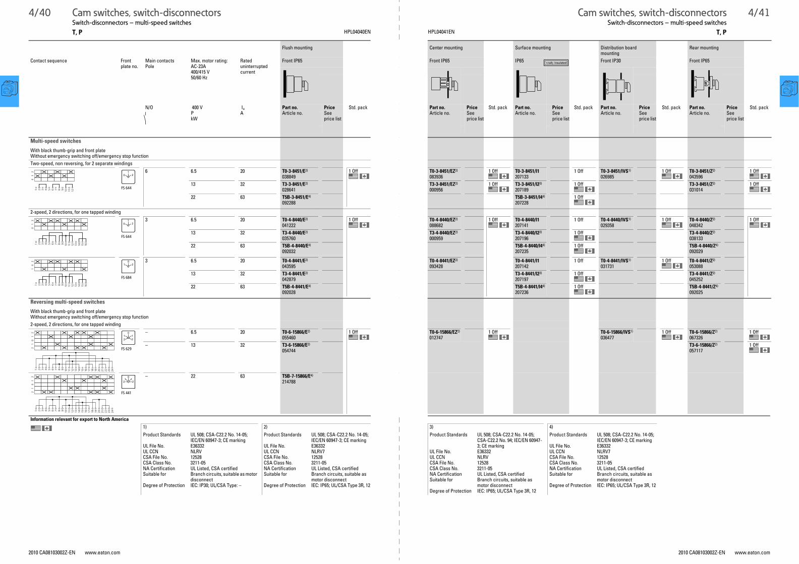
4/40 Cam switches, switch-disconnectorsSwitch-disconnectors – multi-speed switches
Cam switches, switch-disconnectorsSwitch-disconnectors – multi-speed switches
4/41
T, P HPL04040EN T, PHPL04041EN
2010 CA08103002Z-EN www.eaton.com 2010 CA08103002Z-EN www.eaton.com
Switch-disconnectors – multi-speed switches
Flush mounting Center mounting Surface mounting Distribution board mounting
Rear mounting
Contact sequence Front plate no.
Main contactsPole
Max. motor rating: AC-23A 400/415 V50/60 Hz
Rated uninterrupted current
Front IP65 Front IP65 IP65 Front IP30 Front IP65
N/O 400 VPkW
Iu
APart no.Article no.
PriceSee price list
Std. pack Part no.Article no.
PriceSee price list
Std. pack Part no.Article no.
PriceSee price list
Std. pack Part no.Article no.
PriceSee price list
Std. pack Part no.Article no.
PriceSee price list
Std. pack
Multi-speed switches
With black thumb-grip and front plateWithout emergency switching off/emergency stop function
Two-speed, non reversing, for 2 separate windings
6 6.5 20 T0-3-8451/E2)
0388491 Off T0-3-8451/EZ2)
0839361 Off T0-3-8451/I1
2071331 Off T0-3-8451/IVS1)
0269851 Off T0-3-8451/Z2)
0435961 Off
13 32 T3-3-8451/E2)
028641
T3-3-8451/EZ2)
0009561 Off T3-3-8451/I23)
2071891 Off T3-3-8451/Z2)
0310141 Off
22 63 T5B-3-8451/E4)
092288
T5B-3-8451/I44)
2072281 Off
2-speed, 2 directions, for one tapped winding
3 6.5 20 T0-4-8440/E2)
0412221 Off T0-4-8440/EZ2)
0886821 Off T0-4-8440/I1
2071411 Off T0-4-8440/IVS1)
0293581 Off T0-4-8440/Z2)
0483421 Off
13 32 T3-4-8440/E2)
035760
T3-4-8440/EZ2)
000959
T3-4-8440/I23)
2071961 Off T3-4-8440/Z2)
038133
22 63 T5B-4-8440/E4)
092032
T5B-4-8440/I44)
2072351 Off T5B-4-8440/Z4)
092029
3 6.5 20 T0-4-8441/E2)
043595
T0-4-8441/EZ2)
093428
T0-4-8441/I1207142
1 Off T0-4-8441/IVS1)
0317311 Off T0-4-8441/Z2)
053088
13 32 T3-4-8441/E2)
042879
T3-4-8441/I23)
2071971 Off T3-4-8441/Z2)
045252
22 63 T5B-4-8441/E4)
092028
T5B-4-8441/I44)
2072361 Off T5B-4-8441/Z4)
092025
1 2 3 4 5 6 7 8 9 10 11 12
01
2
FS 644
01
2
1 2 3 4 5 6 7 8 9 10 11 12 13 14
01
2
15 16
FS 644
01
2
1 2 3 4 5 6 7 8 9 10 11 12 13 14
10
2
15 16
FS 684
01 2
Reversing multi-speed switches
With black thumb-grip and front plateWithout emergency switching off/emergency stop function
2-speed, 2 directions, for one tapped winding
– 6.5 20 T0-6-15866/E2)
0554601 Off T0-6-15866/EZ2)
0127471 Off T0-6-15866/IVS1)
0364771 Off T0-6-15866/Z2)
0673261 Off
– 13 32 T3-6-15866/E2)
054744
T3-6-15866/Z2)
0571171 Off
– 22 63 T5B-7-15866/E4)
214788
1 2 3 4 5 6 7 8 9 10 11 12 13 14
21
01
2
15 16 17 18 19 20 21 22 23 24
FS 629
10
12 2
1 2 3 4 5 6 7 8 9 10 11 12 13 14
21
01
2
15 16 17 18 19 20 21 22 23 24
FS 441
10
12 2
Information relevant for export to North America
1) 2) 3) 4)
Product Standards UL 508; CSA-C22.2 No. 14-05; IEC/EN 60947-3; CE marking
UL File No. E36332UL CCN NLRVCSA File No. 12528CSA Class No. 3211-05NA Certification UL Listed, CSA certifiedSuitable for Branch circuits, suitable as motor
disconnectDegree of Protection IEC: IP30; UL/CSA Type: –
Product Standards UL 508; CSA-C22.2 No. 14-05; IEC/EN 60947-3; CE marking
UL File No. E36332UL CCN NLRV7CSA File No. 12528CSA Class No. 3211-05NA Certification UL Listed, CSA certifiedSuitable for Branch circuits, suitable as
motor disconnectDegree of Protection IEC: IP65; UL/CSA Type 3R, 12
Product Standards UL 508; CSA-C22.2 No. 14-05; CSA-C22.2 No. 94; IEC/EN 60947-3; CE marking
UL File No. E36332UL CCN NLRVCSA File No. 12528CSA Class No. 3211-05NA Certification UL Listed, CSA certifiedSuitable for Branch circuits, suitable as
motor disconnectDegree of Protection IEC: IP65; UL/CSA Type 3R, 12
Product Standards UL 508; CSA-C22.2 No. 14-05; IEC/EN 60947-3; CE marking
UL File No. E36332UL CCN NLRV7CSA File No. 12528CSA Class No. 3211-05NA Certification UL Listed, CSA certifiedSuitable for Branch circuits, suitable as
motor disconnectDegree of Protection IEC: IP65; UL/CSA Type 3R, 12

4/42 Cam switches, switch-disconnectorsControl switches – step switches
Cam switches, switch-disconnectorsControl switches – step switches
4/43
T HPL04042EN THPL04043EN
2010 CA08103002Z-EN www.eaton.com 2010 CA08103002Z-EN www.eaton.com
Control switches – step switches
Flush mounting1) Center mounting1) Surface mounting Distribution board mounting2) Rear mounting2)
Contact sequence Front plate no.
Main contacts
Front IP65 Front IP65 IP65 Front IP30 Front IP65
Pole Part no.Article no.
PriceSee price list
Std. pack Part no.Article no.
PriceSee price list
Std. pack Part no.Article no.
PriceSee price list
Std. pack Part no.Article no.
PriceSee price list
Std. pack Part no.Article no.
PriceSee price list
Std. pack
N/O
Step switches
With black thumb-grip and front plateOne contact closed per stepWithout overlap
With 0 (Off) position
1 T0-1-8240/E034105
1 Off T0-1-8240/EZ043597
1 Off T0-1-8240/I1207079
1 Off T0-1-8240/IVS027076
1 Off T0-1-8240/Z060208
1 Off
1 T0-2-8241/E050716
T0-2-8241/EZ053089
T0-2-8241/I1207107
T0-2-8241/IVS057835
T0-2-8241/Z062581
1 T0-2-8242/E067327
T0-2-8242/EZ069700
T0-2-8242/I1207108
T0-2-8242/IVS074446
T0-2-8242/Z076819
1 T0-3-8243/E081565
T0-3-8243/EZ083938
T0-3-8243/I1207128
T0-3-8243/IVS088684
T0-3-8243/Z091057
1 T0-3-8244/E095803
T0-3-8244/EZ098176
T0-3-8244/I1207129
T0-3-8244/IVS012749
T0-3-8244/Z015122
3 T0-3-8280/E034106
T0-3-8280/EZ036479
T0-3-8280/I1207130
T0-3-8280/IVS041225
T0-3-8280/Z043598
3 T0-5-8281/E048344
T0-5-8281/EZ050717
T0-5-8281/IVS055463
T0-5-8281/Z057836
3 T0-6-8282/E062582
T0-6-8282/EZ064955
T0-6-8282/IVS069701
T0-6-8282/Z072074
Information relevant for export to North America 1) 2)
Product Standards UL 508; CSA-C22.2 No. 14-05; IEC/EN 60947-3; CE markingUL File No. E36332UL CCN NLRVCSA File No. 12528CSA Class No. 3211-05NA Certification UL Listed, CSA certifiedSuitable for Branch circuitsDegree of Protection IEC: IP65; UL/CSA Type 3R, 12
Product Standards UL 508; CSA-C22.2 No. 14-05; IEC/EN 60947-3; CE markingUL File No. E36332UL CCN NLRVCSA File No. 12528CSA Class No. 3211-05NA Certification UL Listed, CSA certifiedSuitable for Branch circuitsDegree of Protection IEC: IP30; UL/CSA Type: –
1 2 3 4
01
2
FS 418
21
0
1 2 3 4 5 6
01
23
FS 420
21
03
1 2 3 4 5 6 7 8
01
23
4
FS 422
21
034
1 2 3 4 5 6 7 8 9 10
01
23
45
FS 424
21
034
5
1 2 3 4 5 6 7 8 9 10 11 12
01
23
45
6
FS 426
21
034
65
1 2 3 4 5 6 7 8 9 10 11 12
01
2
FS 418
21
0
1 2 3 4 5 6 7 8 9 10 11 12 13 14
01
2
15 16 17 18
3
FS 420
21
03
1 2 3 4 5 6 7 8 9 10 11 12 13 14
01
23
4
15 16 17 18 19 20 21 22 23 24
FS 422
21
034

4/44 Cam switches, switch-disconnectorsControl switches – step switches, On-Off switches
Cam switches, switch-disconnectorsControl switches – step switches, On-Off switches
4/45
T, P HPL04044EN T, PHPL04045EN
2010 CA08103002Z-EN www.eaton.com 2010 CA08103002Z-EN www.eaton.com
Control switches – step switches, On-Off switches
Flush mounting1) Center mounting1) Surface mounting Distribution board mounting2) Rear mounting1)
Contact sequence Front plate no.
Main contacts
Front IP65 Front IP65 IP65 Front IP30 Front IP65
Pole Part no.Article no.
PriceSee price list
Std. pack Part no.Article no.
PriceSee price list
Std. pack Part no.Article no.
PriceSee price list
Std. pack Part no.Article no.
PriceSee price list
Std. pack Part no.Article no.
PriceSee price list
Std. pack
N/O
Step switches
With black thumb-grip and front plateOne contact closed per stepWithout overlap
without 0 (Off) position
1 T0-1-8220/E031728
1 Off T0-1-8220/EZ095799
1 Off T0-1-8220/I1207078
1 Off T0-1-8220/IVS055459
1 Off T0-1-8220/Z086312
1 Off
1 T0-2-8230/E088685
T0-2-8230/EZ091058
T0-2-8230/I1207105
T0-2-8230/IVS095804
T0-2-8230/Z098177
1 T0-2-8231/E012750
T0-2-8231/EZ015123
T0-2-8231/I1207106
T0-2-8231/IVS019869
T0-2-8231/Z022242
1 T0-3-8232/E026988
T0-3-8232/EZ029361
T0-3-8232/I1207126
T0-3-8232/IVS034107
T0-3-8232/Z036480
1 T0-3-8233/E041226
T0-3-8233/EZ043599
T0-3-8233/I1207127
T0-3-8233/IVS048345
T0-3-8233/Z050718
2 T0-4-8251/E013971
T0-4-8251/EZ013972
T0-4-8251/I1218984
T0-4-8251/IVS013974
T0-4-8251/Z013976
3 T0-3-8222/E048339
T0-3-8222/EZ015118
T0-3-8222/I1207124
T0-3-8222/IVS060205
3 T0-5-8270/E091059
T0-5-8270/EZ093432
T0-5-8270/IVS098178
T0-5-8270/Z010378
3 T0-6-8271/E015124
T0-6-8271/EZ017497
T0-6-8271/IVS022243
T0-6-8271/Z024616
Information relevant for export to North America 1) 2)
Product Standards UL 508; CSA-C22.2 No. 14-05; IEC/EN 60947-3; CE markingUL File No. E36332UL CCN NLRVCSA File No. 12528CSA Class No. 3211-05NA Certification UL Listed, CSA certifiedSuitable for Branch circuitsDegree of Protection IEC: IP65; UL/CSA Type 3R, 12
Product Standards UL 508; CSA-C22.2 No. 14-05; IEC/EN 60947-3; CE markingUL File No. E36332UL CCN NLRVCSA File No. 12528CSA Class No. 3211-05NA Certification UL Listed, CSA certifiedSuitable for Branch circuitsDegree of Protection IEC: IP30; UL/CSA Type: –
1 2 3 4
12
FS 943
1 2
1 2 3 4 5 6
12
3
FS 404
32
1
1 2 3 4 5 6 7 8
12
34
FS 606
2
41
3
1 2 3 4 5 6 7 8 9- 10
12
34
5
FS 408
32 4
51
1 2 3 4 5 6 7 8 9 10 11 12
12
34
56
FS 410
32 4
516
1 2 3 4 5 6 7 8 9 10 11 12 13 14
12
15 16
34
FS 406
23
14
1 2 3 4 5 6 7 8 9 10 11 12
12
FS 943
1 2
1 2 3 4 5 6 7 8 9 10 11 12 13 14
12
3
15 16 17 18
FS 404
32
1
1 2 3 4 5 6 7 8 9 10 11 12 13 14
12
3
15 16 17 18 19 20 21 22 23 24
4
FS 406
23
14

4/46 Cam switches, switch-disconnectorsControl switches – step switches, On-Off switches
Cam switches, switch-disconnectorsControl switches – step switches, On-Off switches
4/47
T HPL04046EN THPL04047EN
2010 CA08103002Z-EN www.eaton.com 2010 CA08103002Z-EN www.eaton.com
Flush mounting1) Center mounting2) Surface mounting Distribution board mounting3)
Rear mounting
Contact sequence Front plate no. Main contacts
Front IP65 Front IP65 IP65 Front IP30 Front IP65
Pole Part no.Article no.
PriceSee price list
Std. pack Part no.Article no.
PriceSee price list
Std. pack Part no.Article no.
PriceSee price list
Std. pack Part no.Article no.
PriceSee price list
Std. pack Part no.Article no.
PriceSee price list
Std. pack
N/O
On-Off switches
With black thumb-grip and front plate
1 T0-1-15401/E038854
1 Off T0-1-15401/EZ041227
1 Off T0-1-15401/I1207067
1 Off T0-1-15401/IVS045973
1 Off
2 T0-1-15402/E053092
T0-1-15402/EZ055465
T0-1-15402/I1207068
1 Off T0-1-15402/IVS060211
3 T0-2-15403/E067330
T0-2-15403/EZ069703
T0-2-15403/IVS074449
4 T0-2-15404/E081568
T0-2-15404/EZ083941
Information relevant for export to North America 1) 2) 3)
Product Standards UL 508; CSA-C22.2 No. 14-05; IEC/EN 60947-3; CE marking
UL File No. E36332UL CCN NLRVCSA File No. 12528CSA Class No. 3211-05NA Certification UL Listed, CSA certifiedSuitable for Branch circuits, suitable as motor disconnectDegree of Protection IEC: IP65; UL/CSA Type 3R, 12
Product Standards UL 508; CSA-C22.2 No. 14-05; IEC/EN 60947-3; CE marking
UL File No. E36332UL CCN NLRVCSA File No. 12528CSA Class No. 3211-05NA Certification UL Listed, CSA certifiedSuitable for Branch circuits, suitable as
motor disconnectDegree of Protection IEC: IP65; UL/CSA Type: –
Product Standards UL 508; CSA-C22.2 No. 14-05; IEC/EN 60947-3; CE marking
UL File No. E36332UL CCN NLRVCSA File No. 12528CSA Class No. 3211-05NA Certification UL Listed, CSA certifiedSuitable for Branch circuits, suitable as
motor disconnectDegree of Protection IEC: IP30; UL/CSA Type: –
1 2
01
FS 415
01
1 2 3 4
01
1 2 3 4 5 6
01
1 2 3 4 5 6 7 8
01

4/48 Cam switches, switch-disconnectorsControl switches – changeover switches, manual/automatic switches
Cam switches, switch-disconnectorsControl switches – changeover switches, manual/automatic switches
4/49
T HPL04048EN THPL04049EN
2010 CA08103002Z-EN www.eaton.com 2010 CA08103002Z-EN www.eaton.com
Control switches – changeover switches, manual/automatic switches
Flush mounting1) Center mounting1) Surface mounting Distribution board mounting2) Rear mounting1)
Contact sequence Front plate no. Main contacts
Front IP65 Front IP65 IP65 Front IP30 Front IP65
Pole Part no.Article no.
PriceSee price list
Std. pack Part no.Article no.
PriceSee price list
Std. pack Part no.Article no.
PriceSee price list
Std. pack Part no.Article no.
PriceSee price list
Std. pack Part no.Article no.
PriceSee price list
Std. pack
N/O
Changeover switches
With black thumb-grip and front plate
1 T0-1-15421/E095806
1 Off T0-1-15421/EZ098179
1 Off T0-1-15421/I1207069
1 Off T0-1-15421/IVS012752
1 Off T0-1-15421/Z015125
1 Off
2 T0-2-15422/E019871
T0-2-15422/EZ022244
T0-2-15422/I1207090
T0-2-15422/IVS026990
T0-2-15422/Z029363
3 T0-3-15423/E034109
T0-3-15423/EZ036482
T0-3-15423/I1207114
T0-3-15423/IVS041228
T0-3-15423/Z043601
1 2 3 4
20
1
FS 429
02 1
1 2 3 4 5 6 7 8
20
11 2 3 4 5 6 7 8 9 10 11 12
20
1
Manual/Auto switches
With 0 (Off) position
1 T0-1-15431/E019872
1 Off T0-1-15431/EZ022245
1 Off T0-1-15431/I1207070
1 Off T0-1-15431/IVS026991
1 Off T0-1-15431/Z029364
1 Off
2 T0-2-15432/E034110
T0-2-15432/EZ036483
T0-2-15432/I1207091
T0-2-15432/IVS041229
T0-2-15432/Z043602
3 T0-3-15433/E048348
T0-3-15433/EZ050721
T0-3-15433/I1207115
T0-3-15433/IVS055467
T0-3-15433/Z057840
With momentary from HAND
1 T0-1-15434/E062586
1 Off T0-1-15434/EZ018053
1 Off T0-1-15434/I1207071
1 Off T0-1-15434/IVS069705
1 Off T0-1-15434/Z072078
1 Off
2 T0-2-15435/E003191
1 Off T0-2-15435/EZ003192
1 Off T0-2-15435/I1218971
1 Off T0-2-15435/IVS003195
1 Off T0-2-15435/Z003196
1 Off
With momentary from START
2 T0-2-15907/E066931
1 Off T0-2-15907/EZ069304
1 Off T0-2-15907/I1207095
1 Off T0-2-15907/IVS076423
1 Off T0-2-15907/Z078796
1 Off
Without 0 (Off) position
1 T0-1-15451/E076824
1 Off T0-1-15451/EZ079197
1 Off T0-1-15451/I1207072
1 Off T0-1-15451/IVS083943
1 Off T0-1-15451/Z086316
1 Off
2 T0-2-15452/E091062
T0-2-15452/EZ093435
T0-2-15452/I1207092
T0-2-15452/IVS098181
T0-2-15452/Z010381
3 T0-3-15453/E015127
T0-3-15453/EZ017500
T0-3-15453/I1207116
T0-3-15453/IVS022246
T0-3-15453/Z024619
Information relevant for export to North America 1) 2)
Product Standards UL 508; CSA-C22.2 No. 14-05; IEC/EN 60947-3; CE markingUL File No. E36332UL CCN NLRVCSA File No. 12528CSA Class No. 3211-05NA Certification UL Listed, CSA certifiedSuitable for Branch circuitsDegree of Protection IEC: IP65; UL/CSA Type 3R, 12
Product Standards UL 508; CSA-C22.2 No. 14-05; IEC/EN 60947-3; CE markingUL File No. E36332UL CCN NLRVCSA File No. 12528CSA Class No. 3211-05NA Certification UL Listed, CSA certifiedSuitable for Branch circuitsDegree of Protection IEC: IP30; UL/CSA Type: –
1 2 3 4
HAND0
AUTO
FS 1401
0HAND AUTO
1 2 3 4 5 6 7 8
HAND0
AUTO
1 2 3 4 5 6 7 8 9 10 11 12
HAND0
AUTO
1 2 3 4
HAND0
AUTO
FS 1414000
0HAND AUTO
1 2 3 4 5 6 7 8
HAND0
AUTO
1 2 3 4 5 6 7 8
AUTO0
HANDSTART
FS 1413890
0AUTO HAND
START
1 2 3 4
HANDAUTO
FS 19334
HAND AUTO
1 2 3 4 5 6 7 8
HANDAUTO
1 2 3 4 5 6 7 8 9 10 11 12
HANDAUTO

4/50 Cam switches, switch-disconnectorsControl switches – On switches
Cam switches, switch-disconnectorsControl switches – On switches
4/51
T HPL04050EN THPL04051EN
2010 CA08103002Z-EN www.eaton.com 2010 CA08103002Z-EN www.eaton.com
Control switches – On switches
Flush mounting Center mounting Surface mounting Distribution board mounting Rear mounting
Contact sequence Front plate no. Main contacts
Front IP65 Front IP65 IP65 Front IP30 Front IP65
Pole Part no.Article no.
PriceSee price list
Std. pack Part no.Article no.
PriceSee price list
Std. pack Part no.Article no.
PriceSee price list
Std. pack Part no.Article no.
PriceSee price list
Std. pack Part no.Article no.
PriceSee price list
Std. pack
N/O
On switch (N/O)
With black thumb-grip and front plateMomentary from position 1
1 T0-1-15321/E086317
1 Off T0-1-15321/EZ088690
1 Off T0-1-15321/I1207064
1 Off T0-1-15321/IVS093436
1 Off T0-1-15321/Z095809
1 Off
2 T0-1-15322/E010382
T0-1-15322/EZ012755
T0-1-15322/I1207065
T0-1-15322/IVS017501
3 T0-2-15323/E024620
T0-2-15323/EZ026993
T0-2-15323/I1207087
T0-2-15323/IVS031739
T0-1-15366/E081572
T0-1-15366/EZ083945
1 2
I1
FS 4721
1
1 2 3 4
I1
1 2 3 4 5 6
I1
1 2 3 4
0I
1
FS 456
0 1
ON-OFF momentary switches
With black thumb-grip and front plateMomentary from START position
1 T0-1-15511/E019875
1 Off T0-1-15511/EZ022248
1 Off T0-1-15511/I1207073
1 Off T0-1-15511/IVS026994
1 Off T0-1-15511/Z029367
1 Off
2 T0-2-15512/E034113
T0-2-15512/EZ036486
T0-2-15512/I1207093
T0-2-15512/Z043605
1 Off
3 T0-3-15513/E048351
T0-3-15513/EZ050724
T0-3-15513/I1207117
see K 115
T0-2-8177/E015130
T0-2-8177/EZ017503
T0-2-8177/I1207101
T0-2-8177/IVS022249
1 Off T0-2-8177/Z024622
1 Off
Information relevant for export to North America 1) 2)
Product Standards UL 508; CSA-C22.2 No. 14-05; IEC/EN 60947-3; CE markingUL File No. E36332UL CCN NLRVCSA File No. 12528CSA Class No. 3211-05NA Certification UL Listed, CSA certifiedSuitable for Branch circuitsDegree of Protection IEC: IP65; UL/CSA Type 3R, 12
Product Standards UL 508; CSA-C22.2 No. 14-05; IEC/EN 60947-3; CE marking
UL File No. E36332UL CCN NLRVCSA File No. 12528CSA Class No. 3211-05NA Certification UL Listed, CSA certifiedSuitable for Branch circuitsDegree of Protection IEC: IP30; UL/CSA Type: –
01
START
1 2 3 4
FS 147767
START
1
0
01
START
1 2 3 4 5 6 7 8
01
START
1 2 3 4 5 6 7 8 9 10 11 12
START102
START
1 2 3 4 5 6 7 8
FS 140660
01 2
START START
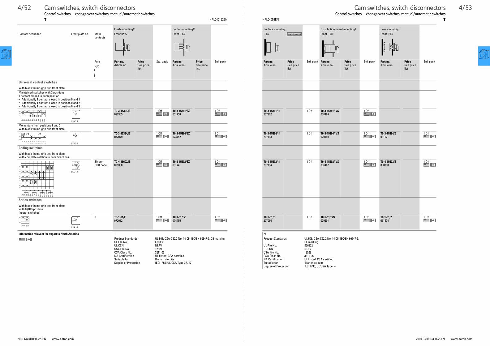
4/52 Cam switches, switch-disconnectorsControl switches – changeover switches, manual/automatic switches
Cam switches, switch-disconnectorsControl switches – changeover switches, manual/automatic switches
4/53
T HPL040152EN THPL04053EN
2010 CA08103002Z-EN www.eaton.com 2010 CA08103002Z-EN www.eaton.com
Control switches – changeover switches, manual/automatic switches
Flush mounting1) Center mounting1) Surface mounting Distribution board mounting2) Rear mounting1)
Contact sequence Front plate no. Main contacts
Front IP65 Front IP65 IP65 Front IP30 Front IP65
Pole Part no.Article no.
PriceSee price list
Std. pack Part no.Article no.
PriceSee price list
Std. pack Part no.Article no.
PriceSee price list
Std. pack Part no.Article no.
PriceSee price list
Std. pack Part no.Article no.
PriceSee price list
Std. pack
N/O
Universal control switches
With black thumb-grip and front plate
Maintained switches with 3 positions1 contact closed in each position• Additionally 1 contact closed in position 0 and 1• Additionally 1 contact closed in position 0 and 2• Additionally 1 contact closed in position 0 and 3
T0-3-15391/E029365
1 Off T0-3-15391/EZ031738
1 Off T0-3-15391/I1207112
1 Off T0-3-15391/IVS036484
1 Off
Momentary from positions 1 and 2With black thumb-grip and front plate
T0-3-15394/E072079
1 Off T0-3-15394/EZ074452
1 Off T0-3-15394/I1207113
1 Off T0-3-15394/IVS079198
1 Off T0-3-15394/Z081571
1 Off
1 2 3 4 5 6 7 8 9 10 11 12
20
1
FS 429
02 1
1 2 3 4 5 6 7 8 9 10 11 12
20
1
FS 458
012
Coding switches
With black thumb-grip and front plateWith complete rotation in both directions.
Binary BCD code
T0-4-15602/E029368
1 Off T0-4-15602/EZ031741
1 Off T0-4-15602/I1207134
1 Off T0-4-15602/IVS036487
1 Off T0-4-15602/Z038860
1 Off
1 2 3 4 5 6 7 8 9 10 11 12 13 14
01
23
45
67
89
15 16
42
0
3
9
6
8
1 5
7
FS 312
Series switches
With black thumb-grip and front plateWith 0 (Off) position(heater switches)
1 T0-1-91/E072082
1 Off T0-1-91/EZ074455
1 Off T0-1-91/I1207080
1 Off T0-1-91/IVS079201
1 Off T0-1-91/Z081574
1 Off
Information relevant for export to North America 1) 2)
Product Standards UL 508; CSA-C22.2 No. 14-05; IEC/EN 60947-3; CE markingUL File No. E36332UL CCN NLRVCSA File No. 12528CSA Class No. 3211-05NA Certification UL Listed, CSA certifiedSuitable for Branch circuitsDegree of Protection IEC: IP65; UL/CSA Type 3R, 12
Product Standards UL 508; CSA-C22.2 No. 14-05; IEC/EN 60947-3; CE marking
UL File No. E36332UL CCN NLRVCSA File No. 12528CSA Class No. 3211-05NA Certification UL Listed, CSA certifiedSuitable for Branch circuitsDegree of Protection IEC: IP30; UL/CSA Type: –
1 2 3 4
01
2
FS 614
0
21

4/54 Cam switches, switch-disconnectorsControl switches – Instrument switches
Cam switches, switch-disconnectorsControl switches – Instrument switches
4/55
T HPL04054EN THPL04055EN
2010 CA08103002Z-EN www.eaton.com 2010 CA08103002Z-EN www.eaton.com
Control switches – Instrument switches
Flush mounting1) Center mounting1) Surface mounting Distribution board mounting2)
Rear mounting1)
Contact sequence Front plate no.
Pole Main contacts
Front IP65 Front IP65 IP65 Front IP30 Front IP65
Pole Part no.Article no.
PriceSee price list
Std. pack Part no.Article no.
PriceSee price list
Std. pack Part no.Article no.
PriceSee price list
Std. pack Part no.Article no.
PriceSee price list
Std. pack Part no.Article no.
PriceSee price list
Std. pack
N/O
Voltmeter selector switch
With black thumb-grip and front plate
3 x phase-N with 0 position 3 + N T0-2-15921/E067337
1 Off T0-2-15921/EZ069710
1 Off T0-2-15921/IVS074456
1 Off T0-2-15921/Z076829
1 Off
3 x phase-phase 3 x phase-N with 0 position
3 + N T0-3-8007/E095813
T0-3-8007/EZ098186
T0-3-8007/I1207120
1 Off T0-3-8007/IVS012759
T0-3-8007/Z015132
3 x phase-phase 3 x phase-N without 0 position with complete rotation in both directions
3 + N T0-3-15924/E019878
T0-3-15924/EZ022251
T0-3-15924/I1207119
1 Off T0-3-15924/IVS026997
T0-3-15924/Z029370
3 x phase-phase with 0 position
3 T0-2-15920/E038861
T0-2-15920/EZ041234
T0-2-15920/IVS029452
T0-2-15920/Z048353
3 x phase-phase without 0 position
3 T0-2-15922/E053099
T0-2-15922/EZ055472
T0-2-15922/IVS060218
T0-2-15922/Z062591
Ammeter selector switch
With black thumb-grip and front plateWith complete rotation in both directions.Measurement via current transformerWith 0 (Off) position
T0-3-8048/E034116
1 Off T0-3-8048/EZ036489
1 Off T0-3-8048/IVS041235
1 Off T0-3-8048/Z043608
1 Off
Information relevant for export to North America 1) 2)
Product Standards UL 508; CSA-C22.2 No. 14-05; IEC/EN 60947-3; CE marking
UL File No. E36332UL CCN NLRVCSA File No. 12528CSA Class No. 3211-05NA Certification UL Listed, CSA certifiedSuitable for Branch circuitsDegree of Protection IEC: IP65; UL/CSA Type 3R, 12
Product Standards UL 508; CSA-C22.2 No. 14-05; IEC/EN 60947-3; CE marking
UL File No. E36332UL CCN NLRVCSA File No. 12528CSA Class No. 3211-05NA Certification UL Listed, CSA certifiedSuitable for Branch circuitsDegree of Protection IEC: IP30; UL/CSA Type: –
1 2 3 4 5 6 7 8
0L1-NL2-NL3-N
L1-NL2-N
L3-N
FS 1410757
0
1 2 3 4 5 6 7 8 9 10 11 12
L3-L1L2-L3L1-L2
0L1-NL2-NL3-N L1-L2
FS 1410759
0
L2-L3
L3-L1
L1-N
L2-N
L3-N
1 2 3 4 5 6 7 8 9 10 11 12
L1-L2L2-L3L3-L1L1-NL2-NL3-N
L1-L2L2-L3
L3-L1
L1-NL2-N
L3-N
FS 164721
1 2 3 4 5 6 7 8
0L1-L2L2-L3L3-L1 L1-L2
L2-L3L3-L1
0
FS 1410755
1 2 3 4 5 6 7 8
L1-L2L2-L3L3-L1
L1-L2L2-L3
L3-L1
FS 164854
1 2 3 4 5 6 7 8 9 10 11 12
0L1L2L3
L1
L2
FS 9440
0
L3

4/56 Cam switches, switch-disconnectorsSwitches with locking mechanism
Cam switches, switch-disconnectorsSwitches with locking mechanism
4/57
T HPL04056EN THPL04057EN
2010 CA08103002Z-EN www.eaton.com 2010 CA08103002Z-EN www.eaton.com
Switches with locking mechanism
Flush mounting Surface mounting Rear mounting
Contact sequence Front plate no. Main contacts
Max. motor rating AC-23 A, 400/415 V, 50/60 Hz
Rated uninter-rupted current
IP65 IP65 IP65
Part no.Article no.
PriceSee price list
Std. pack Part no.Article no.
PriceSee price list
Std. pack Part no.Article no.
PriceSee price list
Std. pack Notes
Pole 400 V Iu
N/O P A
kW
Panic switch
Cylinder lock SVAWithout emergency switching off/emergency stop function, with two keysWith black thumb-grip and front plateIf the key is withdrawn in position 1 the switch can be switched off but not on again without the key.
3 6.5 20 T0-2-1/E/SVA(S)050977
1 Off T0-2-1/I1/SVA(S)207084
1 Off
Code letters for lockable switch positionsLetter S for panic lock with FS908GE
3 13 25 P1-25/E/SVA(S)050966
P1-25/I2/SVA(S)207305
3 15 32 P1-32/E/SVA(S)044977
P1-32/I2/SVA(S)207326
As an emergency switching off/emergency stop deviceTo IEC/EN 60204-1, VDE 0113 Part 1With two keysWith red thumb-grip and yellow front plate
3 6.5 20 T0-2-1/E/SVA(S)-RT228291
1 Off T0-2-1/I1/SVA(S)-RT207085
1 Off
3 13 25 P1-25/E/SVA(S)-RT050967
P1-25/I2/SVA(S)-RT207306
1 Off
3 15 32 P1-32/E/SVA(S)-RT050971
Padlocking feature SVCAs an emergency switching off/emergency stop deviceTo IEC/EN 60204-1, VDE 0113 Part 1, with two keysWith red thumb-grip and yellow front plateIf the locking slide is padlocked in position 1 the switch can be switched off but not on again without removing the padlock.Lockable with max. 3 padlocks.
3 6.5 20 T0-2-1/E/SVC(S)-RT044973
1 Off T0-2-1/I1/SVC(S)-RT207086
1 Off
3 13 25 P1-25/E/SVC(S)-RT044974
P1-25/I2/SVC(S)-RT207307
3 15 32 P1-32/E/SVC(S)-RT044975
P1-32/I2/SVC(S)RT207328
On-Off switches
Without emergency switching off/emergency stop functionWith black thumb-grip and front plateKey can only be withdrawn in position 0 (Pos A)
3 6.5 20 T0-2-1/E/SVA(A)050976
1 Off T0-2-1/I1/SVA(A)207083
1 Off T0-2-1/Z/SVA(A)050978
1 Off
3 13 25 P1-25/E/SVA(A)050965
P1-25/I2/SVA(A)207304
P1-25/Z/SVA(A)050969
1 Off
3 15 32 P1-32/E/SVA(A)050970
P1-32/I2/SVA(A)207325
Key operation lock mechanism ST-0Without emergency switching off/emergency stop functionWith black thumb-grip and front plateKey can only be withdrawn in position 0 (Pos A)
2 6.5 20 T0-1-102/EZ/S014933
1 Off T0-1-102/I1/S207063
1 Off T0-1-102/Z/S014971
1 Off
1 2 3 4 5 6
01
FS 908
ON
OFF
ON
OFF
3300
30
300
240225
210180
150
135120
90
6045
270
F
HG
J
KL
MN
PQ
R
A
BC
DE
315
1 2 3 4 5 6
01
FS 908 GE
1
0
ON
OFF
1 2 3 4 5 6
01
FS 908 GE
1
0
1 2 3 4 5 6
01
FS 908
ON
OFF
ON
OFF
ON
OFF
1 2 3 4
01
FS 908
ON
OFF

4/58 Cam switches, switch-disconnectors
SVB-...-T0(P3), KNB-...-T0(P3) HPL04058EN
2010 CA08103002Z-EN www.eaton.com
Emergency switching off/emergency stop
For use with Part no.Article no.
PriceSee price list
Std. pack Notes
Main switch assembly kits
Padlocking featureonly for main switchPermissible with T0 with up to max. 4 contact unitsPermissible with T3 with up to max. 6 contact units
With red rotary handle and yellow locking collar
As an emergency switching off/emer-gency stop deviceTo IEC/EN 60204-1, VDE 0113 Part 1
T0-…/E, …/Z, …/I1T3-…/E, …/Z, …/I2P1-…/E, …/Z, …/I2
SVB-T0057892
1 off • For locking the 0 position• For switches with positions
0 -I at 90°• Switching angle as front
plate FS908• Lockable with max.
3 padlocks
T5B-…/E, …/Z, …/I4T5-.../E, .../Z, .../I5P3-63/E, …/Z, …/I4P3-100/E, …/Z, …/I5
SVB-P3052999
1 off
With black rotary handle and black locking collar
Without emergency switching off/emer-gency stop function
T0-…/E, …/Z, …/I1T3-…/E, …/Z, …/I2P1-…/E, …/Z, …/I2
SVB-SW-T0060265
1 off • For locking the 0 position• For locking the I position
when required• Lockable with max.
3 padlocksT5B-…/E, …/Z, …/I4T5-.../E, .../Z, .../I5P3-63/E, …/Z, …/I4P3-100/E, …/Z, …/I5
SVB-SW-P3062491
1 off
Main switch assembly kits with PE terminal and N terminal
Padlocking featureonly for main switchPermissible with T0 with up to max. 4 contact unitsPermissible with T3 with up to max. 6 contact units
With red rotary handle and yellow locking collar
As an emergency switching off/emer-gency stop deviceTo IEC/EN 60204-1, VDE 0113 Part 1
T0-…/E, …/ZT3-…/E, …/Z
V/EA/SVB-T0062638
1 off • For converting flush mounting switch T…/E into flush mounting main switch T…/EA/SVB…
• For converting rear mounting switch T…/Z (with FS908 front plate) into interlocked rear mounting main switch T…/V/SVB
T5(B)-…/E, …/Z V/EA/SVB-T5045065
1 off
With black rotary handle and black locking collar
Without emergency switching off/emer-gency stop function
T0-…/E, …/ZT3-…/E, …/Z
V/EA/SVB-SW-T0065011
1 off
T5(B)-…/E, …/Z V/EA/SVB-SW-T5045064
1 off
Thumb-grips
Black – T0-…/E, …/EZ, …/IVS, …/Z, …/I1T3-…/E, …/EZ, …/IVS, …/Z, …/I2P1-…/E, …/EZ, …/IVS, …/Z, …/I2
KNB-T0038909
10 off –
Red Only for emergency switching off/emer-gency stop switchesTo IEC/EN 60204-1, VDE 0113 Part 1
T0-…/E, …/IVS, …/Z, …/I1T3-…/E, …/IVS, …/Z, …/I2P1-…/E, …/IVS, …/Z, …/I2
KNB-RT-T0043655
10 off • Order yellow FS908GE-T0 front plate additionally
Black – T5(B)-…/E, …/Z, …/I4P3-63/E, …/Z, …/I4P3-100/E, …/Z, …/I5
KNB-P3041282
10 off –
Red Only for emergency switching off/emer-gency stop switchesTo IEC/EN 60204-1, VDE 0113 Part 1
T5(B)-…/E, …/Z, …/I4P3-63/E, …/Z, …/I4P3-100/E, …/Z, …/I5
KNB-RT-P3046028
10 off • Order additional yellow front plate FS908GE-P3
Maintenance key for interlocked main switches
T0…P1…
KNK-T0000650
5 off Special devices for electri-cians: interlocked main switches can be switched on and off for repairs with the maintenance key while the door is open (as per IEC/EN 60204-1, Section 5.1.1.1)
P3… KNK-P3000649
5 off
ATEX type
According to 94/9EGTest Certificate BVS04E106X
With metric knock-outs M20 T0-…/I1 +ATEX-I1237513
1 off Only available together with basic unit
With solid side walls T3-…/I2P1-…/I2
+ATEX-I2237514
T5B-…/I4P3-…/I4
+ATEX-I4237516
T5-…/I5P3-…/I5
+ATEX-I5237517
Information relevant for export to North America
UL/CSA certification not required

Cam switches, switch-disconnectorsFront plates
4/59
FS...-T0(P3)HPL04059EN
Front platesBlank plateCan be engraved
Switch size Dimensions (W x H x D)
For use with Part no.Article no.
PriceSee price list
Std. pack Information relevant for export to North America
mm
Standard front plate
Suitable for laser inscriptionT0, T3, P1 45 x 45 (for frame 48 x 48) FS(*)-T0
23189310 off UL/CSA certification not required
P3, T5, T5B 84 x 84 (for frame 88 x 88) FS(*)-P3231895
10 off
Emergency switching off/emergency stop front plates
T0, T3, P1 45 x 45 (for frame 48 x 48) FS908GE-T0003198
5 off
P3, T5, T5B 84 x 84 (for frame 88 x 88) FS908GE-P3031475
5 off
Blank plate
Can be engravedP3, T5, T5B 84 x 84 (for frame 88 x 88) FS-ALU980-P3
26690610 off
T0, T3, P1 45 x 45 (for frame 48 x 48) FS-ALU980-T0266905
50 off
Notes
Standard front plateFor standard switches the normal front plate can be replaced if required with the front plate shown here (not with T6, T8 and TM). This is provided the switching angle, number of positions and the position of the 0 position are the same.
Switching angle 30°
Switching angle 45°
Switching angle 60°
Switching angle 90°
318
12 3
0
309
12
3 4
317
12 3 4
0
308
123 4 5
316
12 3 4
50
307
12
3 4 56
315
12 3 4
560
314
12 3 4
56
70
305
12
3 4 5678
313
12 3 4 5
67
8
0
304
12
3 4 567
89
312
42
0
3
9
6
8
1 5
7
303
12
3 4 5678
910
311
12 3 4
56
78910
0
302
12
3 4 567
891011
310
12 3 4
56
78910
110
301
12
3 4 567
891011
12
OFFON
STOP
STARTAUTO
HAND
START
STOPAUTOHAND
HAND AUTO AUTOOFF
AUTOAUS
HAND
416
01
12
402
01
415 142003 147472 141883 455
10
142010
1
0
141879 4721
1
4722
1 0
4723
0
496
1 2
41409
1 20
429
02 1
1401
0
1413905
0
14140004117
20
1
462
21
0
4026
20
1
461
01
2
147767
1
0
14153814031404147514201411
4011
01 2
458
012
1426
0
14988
0
147474
0
1413903
0
1446
0
456
0 1
1423
1
14510
1
141537 1413890
0
418
21
0
404
32
1
420
21
03
406
23
14
422
21
034
408
32 4
51
441
10
12 2
453
23 1
4
0
4017
Y0
Y
459
21
0
21
1409
02 1
140660
01 2
14712 142074
0
2 1
424
21
034
5
410
32 4
516
426
21
034
65
412
32
1
7 65
4
449
0
211
233
428
0
21 3
4567
414
21
345
687
1410757
0
14196
0
1410755
0
14195
0
1410756
0
1410758
0
1410759
0
147479 14944
0
1410763 140055
0
194321 194323
HAND AUTOOFF
LANG-SAM
AUSSCHNELL ZU-
RUCKLINKS RECHTS
HALT HALTVOR.
STOP
STARTFORW. REV. HAND
TRIPEIN CLOSEAUS ZUAUFRAISE LOWER
LINKS RECHTSEINAUS STARTSTOP
STOP
FORW. REV. START
START
AUTO HAND
STARTSTART
START
REV.STOP
START
FORW.
STARTSTARTSTARTSTART
L2-NL3-NL1-N
S-OT-OR-O
L2-L3L3-L1L1-L2
L2-N
L3-N
L1-N
L2-L3
L3-L1
L1-L2S-T
T-RR-S L2-L3L3-L1
L1-L2L2-NL3-NL1-N
L1-N
L1-L2 L2-N
L3-N
L1-NL2-L3
L3-L1
L1-L2OFF OFF
L2-L3
L3-L1
L1-L2
L2-N
L3-N L1-N
OFF OFF
L2-L3
L3-L1
L1-L2
L2-L3
L3-L1 L1-L2S-T
T-R
R-S
S-O
T-O
R-O
S-T
T-R
R-S R-S
S-T
T-R
START
RUN
STOPSTART
RUN
SLOW
FAST
STOPSLOW
FAST
STOPAUTOSLOWHAND
FAST STOPSTART
RUN NETZAUF
HALTNOT-STROM
AB AUF AB
HALTHALTLINKS RECHTS
AUTO
AUS
HAND AUTO
AUS
HAND AUTO
OFF
HAND
OFF
L2-N L2-L3AUTO
OFFMAN REV.
OFFFORW.
STOPSLOW FAST REV.
STOPFORW. L1-N L3-N
01
611
12
601 1601
01
2
644 16052 635
Y0
16616 684
01 2
621
012
161629
0
161570
0
161359 161358 1610 1614 1673 1617
2 1
6034
0 Y
606
2
41
3
160772616
1
0
2
3
604
2
1
3
614
0
21
164854164855655
21 3
1665166216281627
01
164222
2
1
3
4
0
667 645
2
13
4
0
629
10
12 2
161002 638
Y0
Y
161683
1
0
2
3
4
618 620
1
0
2
345
610
2
1
3
4
56
640
2
10
0
2
1
Y0
0Y
6010 164721 661
L1-L2 L3-L1HIGHOFF
MED.LOW
S-TT-R
R-O
R-S
T-OS-O
L2-L3L3-L1L1-L2
L3-N L1-NL2-N
START
HEIZUNG-NOTSCHALTER
AUS
EIN
STOP
ON OFF
EIN START AUTO ZU SLOW
ZU
OFF
AUS STOP HAND AUF ABAUF DOWNUP FAST
AUTO
AUF
AUS
L3
L2
L1
908
0
1
9508
2
1
902 190719
1
193935
0
1
907
0 1
945 1992
1 2
943 19334 190550 19143 193975 190431
192219589
0
T R
S
935
0
9440
2
1 3
4
906
1
0 2
3
912
1+2
1
0
2
1938409441
0
0
1 2
1
2 2
1
923
1
2
0 0
9281921911957
1
0 0
1
926
2
1 3
904
21
192190
0
1 2
953
0 2
1
910
190334
L3
L2
L1
OFF
ONON ONOFFOFF OFF
ON
OFF
ON
OFF
911
13
0
2
2010 CA08103002Z-EN www.eaton.com

4/60 Cam switches, switch-disconnectorsAdd-on front plates
ZFS ... HPL04060EN
Add-on front platesCam switches T0, T3, P1 Switch-disconnectors T5(B), P3Language Part no.
Article no.PriceSee price list
Std. pack Part no.Article no.
PriceSee price list
Std. pack
Add-on front plate, clip-on, complete
For padlocking featuresconsisting of of label mount and insert label
• Inscribed with standard text "Main switch - Open only in 0 position" in various languages
• Front plates are already included as a standard with:T…/EA/SVB, P…/EA/SVB main switches for flush mountingT…/V/SVB, P…/V/SVB main switches for rear mounting
• Inscribed with standard text German/English ZFS61/62-T0030170
25 off ZFS61/62-P3065739
25 off
French ZFS63-T0047424
ZFS63-P3047423
25 off
Italian ZFS68-T0065751
Portuguese ZFS72-T0205541
Swedish ZFS75-T0205544
Spanish ZFS77-T0065752
ZFS77-P3047422
25 off
Hungarian ZFS80-T0205548
ZFS80-P3205565
Blank, can be engraved none ZFS60-T0019924
ZFS60-P3022297
Label mounts, black, clip-on
ZFSX-T0024670
25 off ZFSX-P3027043
25 off
Insert label
BS45X14-T0029416
25 off BS84X24-P3031789
25 off
P5 switch-disconnector add-on front plate
Clip-onEnter country reference when ordering: D = GermanGB = EnglishF = FrenchI = ItalianE = Spanish
P5-…/EA/SVBP5-…/V/SVB
ZFS(*)-P5105225
1 off
Information relevant for export to North America
UL/CSA certification not required
2010 CA08103002Z-EN www.eaton.com

Cam switches, switch-disconnectorsNotes
4/61
Notes
2010 CA08103002Z-EN www.eaton.com

4/62 Cam switches, switch-disconnectorsKey operation, padlocking feature
2010 CA08103002Z-EN www.eaton.com 2010 CA08103002Z-EN www.eaton.com
Cam switches, switch-disconnectorsKey operation, padlocking feature
Key operation, padlocking feature
For use with Withdrawability Part no.Article no.
PriceSee price list
Std. pack Notes
S-T0 key operated lock mechanism, front IP53
With two keys
KMS 1 lock mechanism: individual lock mechanism, not suitable for master key systemsKey withdrawable in all positions
T0-1.../I1 to T0-4.../I1T0-1.../E to T0-6.../ET0-1.../Z to T0-6.../ZT3-1.../E to T3-5.../ET3-1.../Z to T3-5.../ZT3-1.../I2 to T3-4.../I2P1-.../EP1-.../I2P1-.../Z
Withdrawable positions can be programmed by user
S-T0086709
1 off The key replaces the thumb-grip, cannot be switched without key. The switch position indication is on the lock. Normally the key is withdrawable in every position.On cam switches ordered with front plate FS908 together with key operation, the key is only withdrawable in the 0 position.The key withdraw can be changed (also retrospectively) with the locking cam "VR-T0".When retrofitting the key operation, the existing front plate of the cam switch must be used.Keys → Page 4/66
KMS 2-10, KMS 201-400 lock mechanisms: individual lock mechanisms, not suitable for master key systemsKey withdrawable in all positions
S-SOND-KMS(*)-T0231957
1 off
Lock KMS1: Switches with FS908 are possible as main switch.Key can be withdrawn in positions as specified
Withdrawable positions programmed at factory as ordered
S(*)-T0231959
1 off
SA(...) = master key system (master-key facility) with security certificate. Ordering only with lock plan filled out with the full configuration of the envisaged lock system. When reordering state item number from the lock plan, e.g (A 6294-1.2).Key can be withdrawn in positions as specified
S(*)-SOND-SA(*)-T0231965
1 off
SVA-T3 cylinder lock, front IP65
With two keys
KMS 1 lock mechanism: individual lock mechanism, not suitable for master key systemsKey withdrawable in all positions
T0-…/E, T0-…/I1, T0-…/ZT3-…/E, T3-…/I2, T3-…/Z P1-…/E, P1-…/I2, P1-…/Z
Withdrawable positions can be programmed by user
SVA-T3050974
1 off
KMS 2-10, KMS 201-400 lock mechanisms: individual lock mechanisms, not suitable for master key systemsKey withdrawable in all positions
SVA-SOND-KMS(*)-T3231967
1 off
Lock KMS1: Switches with FS908 are possible as main switch.Key can be withdrawn in positions as specified
T0-1-… to T0-4-…/I1T0-1-.../E to T0-4-.../ET3-1-... to T3-5-.../I2T3-1-... to T3-6-.../EP1-.../I2, P1-.../E
Withdrawable positions programmed at factory as ordered
SVA(*)-T3907745
1 off
SA(...) = master key system (master-key facility) with security certificate. Ordering only with lock plan filled out with the full configuration of the envisaged lock system. When reordering state item number from the lock plan, e.g (A 6294-1.2).Key can be withdrawn in positions as specified
SVA(*)-SOND-SA(*)-T3231971
1 off
SVC-T3 padlocking feature, front IP65
The locking slide can be locked with a max. of 3 padlocks when in its pressed, interlocked position
All positions can be locked T0-…/E, T0-…/I1, T0-…/ZT3-…/E, T3-…/I2, T3-…/Z P1-…/E, P1-…/I2, P1-…/Z
The positions that can be locked can be programmed by the user
SVC-T3050975
1 off
Specific positions or ranges can be locked Switches with FS908 can be used as main switches for:T0-1-... to T0-4-.../I1, .../ET3-1-... to T3-5-.../I2T3-1-... to T3-6-.../EP1-.../I2, P1-.../E
The positions that can be locked are programmable at the factory as ordered
SVC(*)-T3907748
1 off
4/63
S..., SVA..., SVC... HPL04062EN S..., SVA..., SVC...HPL04063EN

4/64 Cam switches, switch-disconnectorsNeutral conductor, auxiliary contact, mounting accessories
N-P1, N-P3, N-P5 HPL04064EN
2010 CA08103002Z-EN www.eaton.com
Neutral conductor, auxiliary contact, mounting accessories
For use with Part no.Article no.
PriceSee price list
Std. pack Information relevant for export to North America
Neutral conductor
Early-make on switching, late-break off switchingThe N contact always behaves as an early-make contact when switching on and as a late-break contact when switching off.N-P1(P3)… switching capacity same as for contacts P1(P3)-…
For left or right side mounting
P1-…/E, …/EA, …/EZ N-P1E000651
5 off Product Standards UL 508; CSA-C22.2 No. 14-05; IEC/EN 60947-3; CE marking
UL File No. CSA report applies to both Canada and US
UL CCN –CSA File No. 12528CSA Class No. 3211-05NA Certification UL Listed, CSA certified
For P1-…/I2: optionally, N-P1Z or HI11-P1/P3Z, can only be fitted on the left
P1-…/Z, …/V, …/I2, …/IVS N-P1Z000652
Product Standards UL 508; CSA-C22.2 No. 14-05; IEC/EN 60947-3; CE marking
UL File No. E36332UL CCN NLRVCSA File No. 12528CSA Class No. 3211-05NA Certification UL Listed, CSA certified
P3-…/E, …/EA… N-P3E062432
P3-…/Z, …/V, …/IVSP3-63…/Z, …/I4P3-100…/Z, …/I5
N-P3Z064805
Neutral terminal
Front mounting, leftService distribution board mounting, right
P5-125(160)/E(EA) N-P5-125/160E280969
1 off
P5-125(160)/Z(V) N-P5-125/160Z280970
P5-250(315)/E(EA) N-P5-250/315E280971
P5-250(315)/Z(V) N-P5-250/315Z280972
Ground terminal
Front mounting, rightService distribution board mounting, left
P5-125(160)/E(EA) PE-P5-125/160E280973
1 off
P5-125(160)/Z(V) PE-P5-125/160Z280974
P5-250(315)/E(EA) PE-P5-250/315E280975
P5-250(315)/Z(V) PE-P5-250/315Z280976
Auxiliary contacts
1 normally open (N/O), 1 normally close contact (N/C)Late-break on switching, early-make off switching. The N/O is always connected as a load-shedding contact.
For left and/or right side mounting
P1-…/E, …/EA…, …/EZP3-…/E, …/EA
HI11-P1/P3E061813
5 off Product Standards UL 508; CSA-C22.2 No. 14-05; IEC/EN 60947-5; CE marking
UL File No. E36332UL CCN NLRVCSA File No. 12528CSA Class No. 3211-05NA Certification UL Listed, CSA certified
For P1…/I2: optionally, HI11-P1/P3Z or N-P1Z, can only be fitted on the left
P1-…/Z, …/V, …/I2, …/IVSP3-63/Z, …/V, …/I4, …/IVSP3-100/Z, …/V, …/I5, …/IVS
HI11-P1/P3Z062031
5 off
2 normally open (N/O), 1 normally close contact (N/C)For left and/or right side mounting
P5-125(160)/E(EA) HI21-P5-125/160E280963
1 off
P5-125(160)/Z(V) HI21-P5-125/160Z280964
P5-250(315)/E(EA) HI21-P5-250/315E280965
P5-250(315)/Z(V) HI21-P5-250/315Z280966
Center mounting accessories
For single-hole fitting 22.3 mmFor cam switches with existing front plate - quick installation with snap fitting system
T0-…/ET3-…/E
EZ-T0081622
1 off UL/CSA certification not required
Mounting diameter 22.3 mm, one man mounting with screw fixing
T0-…/ET3-…/EP1-…/E
EZ-P1091455
1 off

Cam switches, switch-disconnectorsCoupling drive, interlock parts, shaft extension
4/65
DE-T0(P3), ZAV-T0(P3)HPL04065EN
Coupling drive, interlock parts, shaft extensionFor use with Part no.Article no.
PriceSee price list
Std. pack Notes Information rele-vant for export to North America
Service distribution board mounting accessories
Including push-fit shaft For retrofitting in service distribution board mounting T0-…/IVS design. Use the basic switch's front plate.
T0-…/XZ IVS-T0091114
1 off UL/CSA certifica-tion not required
Coupling drive
Including push-fit shaft For the retrofitting of switch T0(T3)‐.../XZ as rear mounting, spare part for T0(T3)/(P1)‐.../Z
– DE-T0093487
1 off UL/CSA certifica-tion not required
For the conversion of T5(B)‐.../E flush mounting switch to rear mounting, spare part for T5(B)/(P3)‐...Z
– DE-P3093972
3 off
Interlock sections
With PE and neutral conductor connectionMounting on the back of flush mounting switch, with interlock function in rear mounting switches.
T0-…/E, …EZ, …ZT3-…/E, …EZ, …ZP1-…/E, …EZ, …Z
UV-T0019925
1 off Mounting on the back of flush mounting switch
UL/CSA certifica-tion not required
T5(B)-…/E, …ZP3-…/E, …Z
UV-P3048289
1 off With interlock function for rear mounting switches
Interlock extensions
A max. of 4 units can be plugged on the interlock section every 25 mm(an equal number of shaft extensions is required for this)
Use only with T0/T3-… and P3-…/Z designs
UV-T0 ZVV-T0022298
10 off – UL/CSA certifica-tion not required
Use only with T5(B)-…/Z and P3-…/Z designs
UV-P3 ZVV-P3024671
10 off –
Shaft extensions
A max. of 4 units can be put on the switch shaft every 25 mmT0-…/Z, T0-…/VT3-…/Z, T3-…/VP1-…/Z, P1-…/V
ZAV-T0027044
10 off – UL/CSA certifica-tion not required
T5(B)-…/Z P3-…/ZP3-…/V
ZAV-P3029417
10 off –
Shaft
Aluminum, length: 480 mm P5-…/V…P5-…/Z
ZAV-P5280979
1 off UL/CSA certifica-tion not required
Interlock extensions und shaft extensions, complete
Extension to 25 mmWhen ordering with basic unit
+ZAV(X1)+ZVV(X1)-T0/P3254546
1 off UL/CSA certifica-tion not required
Control cable terminal
P5-250/315 ST-P5-250/315280978
1 off Terminal capacity: • Solid or stranded:
4 mm2
• Flexible with ferrules to DIN 46228: 4 mm2
UL/CSA certifica-tion not required
2010 CA08103002Z-EN www.eaton.com

4/66 Cam switches, switch-disconnectorsShrouds, keys
H... HPL04066EN
Shrouds, keysFor use with Part no.Article no.
PriceSee price list
Std. pack Notes
Shrouds1)
For flush mounting switches with up to 4 contact units
T0-…/E T3-…/E
H3-T0093828
1 off Cable entriesQuantity:2 x ⌀ 20 mm+ 2 x ⌀ 15 mmCross-section:5 x 6 mm2
5 x 2.5 mm2
For covering the connection terminals of up to 2 contact units
T5(B)-…/E, …/Z H1-T5045062
1 off Can be optionally used for input wiring and/or outgoer
Extension for H1-T5 protective shroud on 3 - 8 contact units
H1-T5 HZ-T5045063
10 off One HZ-T5 required per contact unit
For covering the connection termi-nals on 3 pole switch-disconnectors
P1-…/E, …/EZ, …/Z, …/EA, …/V
H-P1017253
5 off Can be optionally used for input wiring and/or outgoer
For covering the connection termi-nals on 4 pole switch-disconnectors
P1-…N, …HI11, …N…HI11
H-P14019626
5 off Can be optionally used for input wiring and/or outgoer
For covering the connection terminals on 3 pole open switch-disconnectors with N neutral conductor and/or HI11 auxiliary contact
P3-…/E, …/Z, …/EA, …/V P3-…N, …HI11, …N…HI11
H-P3021999
5 off The protective shroud is designed for mounting on the switch-disconnector on both sides; non-required parts can be broken off.
For covering the terminals P5 H-P5-125/160293977
1 off
For covering the terminals P5 H-P5-250/315293978
1 off
Set (6 units) for covering the connection terminals
T8-3-8342/… H-T8200184
6 off
Key
For KMS 1 individual lock mechanism
– ES-KMS1-T0231972
10 off
For KMS 2 - 10 or KMS 201 - 400 individual lock mechanism
– ES-KMS(*)-T0231973
1 off
Individual key, stainless, for master key system and stored individual lock mechanisms, state lock plan no. and key.
– HS-SA(*)-T0256151
1 off Master key must be ordered additionally.The security certificate must be sent when reordering.Ordering example: HS-SA(A6294-1.2)-T0
Locking cams (2 cams per set)
For later change of key withdraw-ability in the engagement positions
S-T0 for all switching angles
VR-T0089082
1 off
For changing the blocked positions/ranges
SVA-T3SVC-T3
VR-T3050987
1 off
Mounting plate shield 2)
To connect the shielding
CI-K2 MBS-I2290191
1 off
To connect the shielding
CI-K4 MBS-I4118742
1 off
Information relevant for export to North America
1) 2)UL/CSA certification not required Product Standards UL 508; CSA-C22.2 No. 14-05; CSA-C22.2
No. 94; IEC/EN 60947-3; CE markingUL File No. E36332UL CCN NLRVCSA File No. 12528CSA Class No. 3211-07NA Certification UL Listed, CSA certified
2010 CA08103002Z-EN www.eaton.com

Cam switches, switch-disconnectorsInsulated enclosures, accessories
4/67
HPL04067EN
Insulated enclosures, accessoriesSystem overview
For use with Part no.Article no.
PriceSee price list
Std. pack Notes
IP65 insulated enclosures
1 - 2 contact units With push-through cable entry diaphragm.
T0-…/Z CI-K1-T0-2207435
1 off The diaphragm can be pierced with the cableMain current/control current:12 mm/- 16 mm/8 mm1 contact unit = 2 contacts
3 - 4 contact units T0-…/Z CI-K1-T0-4207436
1 off
1 - 2 contact units T3-…/Z CI-K2-T3-21)
2074371 off
3 - 4 contact units T3-…/Z CI-K2-T3-41)
225325
5 contact units T3-…/Z CI-K2-T3-51)
207438
1 - 2 contact units With metric knockouts
T0-…/Z CI-K1H-T0-2105854
1 off
3 - 4 contact units T0-…/Z CI-K1H-T0-4105855
1 - 2 contact units T3-…/Z CI-K2H-T3-2269462
3 - 4 contact units T3-…/Z CI-K2H-T3-4105859
5 contact units T3-…/Z CI-K2H-T3-5105860
1 - 2 contact units T5B-…/E CI-K4-T5B-2207439
1 off For converting T5-…/Z into T5-…/I5 and T5B-…/E into T5B…/I4:Order AW-T5-… extension terminal additionally1 contact unit = 2 contacts
3 - 4 contact units T5B-…/Z CI-K4-T5B-4207440
1 - 2 contact units T5-…/Z CI-K5-T5-2207441
3 - 4 contact units T5-…/Z CI-K5-T5-4207442
Only available together with basic unit
T0-…/I1 +I1H105870
1 off
Only available together with basic unit
T3-…/I2P1-…/I2
+I2H105871
1 off
Neutral terminals
For connection of a 5th conductorCI-K2-PKZ0-... K-CI-K1/22)
20745120 off
T5B-…/I4,Cl-K4-T5B-…P3-…/I4, CI-K4
K-CI-K42)
206916
T5-…/I5,CI-K5-T5-…P3-…/I5, CI-K5
K-CI-K52)
218488
Set of external fixing brackets
T5B-…/I4,T5-…/I5,P3-63/I4,P3-100/I5
AB-CI-K4/52)
2069141 off For fixing CI-K4 and CI-K5 directly on
walls.One set contains 4 brackets.
Set of extension terminals
For retrofittingfor connection inside enclosure
For the bottom contact unit T5B-…/I4 T5-…/I5
AW-T5-1/22
03260110 off Already included in equipment
supplied with T5B-…/I4 and T5-…/I5.For the second contact unit from the bottom
T5-…/I5 AW-T5-3/42
0326021 off Already included in equipment
supplied with T5B-…/I4 and T5-…/I5.
Notes Information relevant for export to North America
1) Product Standards UL 508; CSA-C22.2 No. 14-05; CSA-C22.2 No. 94; IEC/EN 60947-3; CE marking
UL File No. E54120UL CCN MITW2CSA File No. 12528CSA Class No. 3211-07NA Certification UL Listed, CSA certifiedDegree of Protection IEC: IP65; UL/CSA Type 1, 3R, 4X, 12, 13 – indoor
and outdoor use2) UL/CSA certification not required
2010 CA08103002Z-EN www.eaton.com

4/68 Mini cam switches
TM ON-OFF switches
TM control switch
1
2
5
3
4
4
4
66
6
7
8
8
8
8
9
8
9
10
8
AUTO
HANDO
1
0
2
11
3
4
4
4
5
66
6
9
9
10
1
11
2010 CA08103002Z-EN www.eaton.com

Mini cam switches 4/69
Product features
Contact chamber• Rated uninterrupted current 10 A• Positively opening contacts• 1 – 2 contacts per contact chamber, up
to 16 contacts per switch• For switching unequal potentials• Control circuit reliability
Switch position• Safety due to indexing• Switching angles 30°, 45°, 60°, 90°• Spring action with automatic return
with max. 6 contacts, switching angle ≧ 60°
• Complete rotation• If the total switching angle is 360°,
complete rotation possible in both operating directions
Flush mounting (.../E) 1Front IP65Mounting from rear in panel sides, plates or doorsTerminalsCrosshead screwdriver PozidrivFinger proof→ Page 4/70
Flush mounting control circuit isolator (.../E/SVB)
1
Front IP65TO IEC/EN 60 947-5, VDE 06600 position lockable with 2 padlocks 4 mm ⌀ or 1 padlock 6 mm ⌀Can be used with up to 250 V AC per contactMaximum 6 contacts permissible→ Page 4/70
Center mounting (.../EZ) 2Front IP65Mounted in 16.2 ⌀ or 22.3 ⌀ fixing hole, as specified in IEC/EN 60 947-5-1, after the included adapter is removed→ Page 4/70
Key operation for center mounting
3, 4
2 keys are suppliedKey withdrawable 90° Key withdrawable 60° with RONIS lock cylinder.→ Page 4/77
Standard switches for center mounting
5, 6
Black thumb-grip→ Page 4/70
Control circuit isolators 7, 8Red rotary handle and yellow locking collarBlack rotary handle and black locking collarLockable in the 0 position→ Page 4/70
Standard switches for flush mounting
9, 10
Black thumb-grip→ Page 4/71
Standard switches for IVS distribution board mounting
11
Mounting in installation distribution boardOverall width: 2 space units (45 mm mounting depth)Up to 2 contact units
2010 CA08103002Z-EN www.eaton.com

4/70 Mini cam switchesControl circuit isolators, ON/OFF switches
TM HPL04070EN
Control circuit isolators, ON/OFF switchesFlush mounting Center mountingFront IP65 Front IP65
Contact sequence Front plate no.
Pole Part no.Article no.
PriceSee price list
Std. pack Part no.Article no.
PriceSee price list
Std. pack
Control circuit isolators, 90°
with padlocking featureLockable in the 0 (Off) positionUp to 250 V AC per contact
1 TM-1-8290/E/SVB045477
1 off
1 TM-1-8290/E/SVB-SW215351
2 TM-1-8291/E/SVB045478
2 TM-1-8291/E/SVB-SW215352
3 TM-2-8292/E/SVB045484
3 TM-2-8292/E/SVB-SW210955
3 + N TM-2-8293/E/SVB045485
6 TM-3-8326/E/SVB045498
On-Off switches, 90°
1 TM-1-8290/E070131
1 off TM-1-8290/EZ000693
1 off
2 TM-1-8291/E072504
TM-1-8291/EZ015073
3 TM-2-8292/E074877
TM-2-8292/EZ015096
3 + N TM-2-8293/E077250
TM-2-8293/EZ045486
6 TM-3-8326/E079623
Information relevant for export to North America Product Standards UL 508; CSA-C22.2 No. 14-05; IEC/EN 60947-3; CE marking
UL File No. E36332UL CCN NLRVCSA File No. UL report applies to both US and CanadaCSA Class No. –NA Certification UL Listed, certified by UL for use in Canada
1 2
01
1 2 3 4
01
1 2 3 4 5 6
01
1 2 3 4 5 6 7 8
01
1 2 3 4 5 6 7 8 9 10
01
11 12
1 2
01 1
0
F 056
1 2 3 4
01
1 2 3 4 5 6
01
1 2 3 4 5 6 7 8
01
1 2 3 4 5 6 7 8 9 10
01
11 12
2010 CA08103002Z-EN www.eaton.com

Mini cam switchesChangeover switches
4/71
TMHPL04071EN
Changeover switchesFlush mounting Center mountingFront IP65 Front IP65
Contact sequence Front plate no.
Pole Part no.Article no.
PriceSee price list
Std. pack Part no.Article no.
PriceSee price list
Std. pack
Changeover switches without 0 (Off) position 60°
1 TM-1-8220/E081996
1 off TM-1-8220/EZ000692
1 off
2 TM-2-8221/E084369
TM-2-8221/EZ015197
3 TM-3-8222/E086742
TM-3-8222/EZ045493
4 TM-4-8223/E089115
TM-4-8223/EZ046119
5 TM-5-8369/E091488
TM-5-8369/EZ046126
6 TM-6-8370/E093861
Changeover switches with 0 (Off) position 60°
1 TM-1-8210/E096234
1 off TM-1-8210/EZ015137
1 off
2 TM-2-8211/E098607
TM-2-8211/EZ015166
3 TM-3-8212/E010807
TM-3-8212/EZ045491
4 TM-4-8213/E013180
TM-4-8213/EZ045847
Changeover switches with 0 (Off) position 90°
2 TM-2-8219/E017926
1 off
3 TM-3-8299/E020299
1 off
Information relevant for export to North America
Product Standards UL 508; CSA-C22.2 No. 14-05; IEC/EN 60947-3; CE markingUL File No. E36332UL CCN NLRVCSA File No. UL report applies to both US and CanadaCSA Class No. –NA Certification UL Listed, certified by UL for use in Canada
1 2 3 4
12
F 072
1 2
1 2 3 4 5 6 7 8
12
1 2 3 4 5 6 7 8 9 10 11 12
12
1 2 3 4 5 6 7 8 9 10 11 12 13 14
12
15 16
1 2 3 4 5 6 7 8 9 10 11 12 13 14
12
15 16 17 18 19 20
1 2 3 4 5 6 7 8 9 10 11 12 13 14
12
15 16 17 18 19 20 21 22 23 24
1 2 3 4
10
2
F 071
1 20
1 2 3 4 5 6 7 8
10
21 2 3 4 5 6 7 8 9 10 11 12
10
21 2 3 4 5 6 7 8 9 10 11 12 13 14
10
2
15 16
1 2 3 4 5 6 7 8
10
2
F 057
0
1 2
1 2 3 4 5 6 7 8 9 10 11 12
10
2
F 071
1 20
2010 CA08103002Z-EN www.eaton.com

4/72 Mini cam switchesManual/auto switches, changeover switches
HPL04072EN
Manual/auto switches, changeover switchesFlush mounting Center mounting Distribution board - mountingFront IP65 Front IP65 Front IP30
Contact sequence Front plate no.
Pole Part no.Article no.
PriceSee price list
Part no.Article no.
PriceSee price list
Part no.Article no.
PriceSee price list
Std. pack
Manual/auto switch 60°
1 TM-1-8220F288/EZ016925
1 off
1 TM-1-15431/E025045
TM-1-15431/EZ000691
TM-1-15431/IVS225342
1 off
2 TM-2-15432/E027418
TM-2-15432/EZ016878
1 off
3 TM-3-15433/E029791
TM-3-15433/EZ045490
1 off
Changeover switches with spring-return from both directions, 30°
1 TM-1-8214/E032164
1 off
2 TM-2-8215/E034537
1 off
Step switches without 0 (Off) position
3 steps, 60°1 TM-2-8230/E
039283TM-2-8230/EZ000701
1 off
3 TM-5-8270/E041656
TM-5-8270/EZ046124
1 off
4 steps, 60°1 TM-2-8231/E
044029TM-2-8231/EZ000700
1 off
3 TM-6-8271/E046402
TM-6-8271/EZ046128
1 off
Information relevant for export to North America
Product Standards UL 508; CSA-C22.2 No. 14-05; IEC/EN 60947-3; CE markingUL File No. E36332UL CCN NLRVCSA File No. UL report applies to both US and CanadaCSA Class No. –NA Certification UL Listed, certified by UL for use in Canada
1 2 3 4
HANDAUTO
F 288
HAND AUTOM
1 2 3 4
HAND0
AUTO
F 085
0HAND AUTO
1 2 3 4 5 6 7 8
HAND0
AUTO
1 2 3 4 5 6 7 8 9 10 11 12
HAND0
AUTO
1 2 3 4
10
2
F 025
01 2
1 2 3 4 5 6 7 8
10
21 2 3 4 5 6
12
3
F 076
2
1
3
1 2 3 4 5 6 7 8 9 10 11 12 13 14
12
3
15 16 17 18
1 2 3 4 5 6 7 8
12
34
F 077
2
1
3
4
1 2 3 4 5 6 7 8 9 10 11 12 13 14
12
3
15 16 17 18 19 20 21 22 23 24
4
2010 CA08103002Z-EN www.eaton.com

Mini cam switchesControl switches, step switches
4/73
TMHPL04073EN
Control switches, step switchesFlush mounting Center mountingFront IP65 Front IP65
Contact sequence Front plate no.
Pole Part no.Article no.
PriceSee price list
Std. pack Part no.Article no.
PriceSee price list
Std. pack
Step switches without 0 (Off) position
5 steps, 60°1 TM-3-8232/E
0392981 off TM-3-8232/EZ
0155921 off
2 TM-5-8252/E041671
1 off TM-5-8252/EZ046123
1 off
6 steps 60°, no full rotation1 TM-3-8233/E
0535211 off TM-3-8233/EZ
0156301 off
2 TM-6-8253/E055894
1 off TM-6-8253/EZ046127
1 off
10 steps, 30°1 TM-5-8237/E
0691501 off TM-5-8237/EZ
0156611 off
Information relevant for export to North America
Product Standards UL 508; CSA-C22.2 No. 14-05; IEC/EN 60947-3; CE markingUL File No. E36332UL CCN NLRVCSA File No. UL report applies to both US and CanadaCSA Class No. –NA Certification UL Listed, certified by UL for use in Canada
1 2 3 4 5 6 7 8 9- 10
12
34
5
F 078
2
1
3
4
5
1 2 3 4 5 6 7 8 9 10 11 12 13 14
12
3
15 16 17 18 19 20
45
1 2 3 4 5 6 7 8 9 10 11 12
12
34
56
21
34
56
F 079
1 2 3 4 5 6 7 8 9 10 11 12 13 14
12
3
15 16 17 18 19 20 21 22 23 24
45
61 2 3 4 5 6 7 8 9 10
12
34
5
11 12
67
89
10
13 14 15 16 17 18 19 20
F 011
12
3 4 567
8910
2010 CA08103002Z-EN www.eaton.com

4/74 Mini cam switchesControl switches, step switches
TM HPL04074EN
Control switches, step switchesFlush mounting Center mountingFront IP65 Front IP65
Contact sequence Front plate no. Pole Part no.Article no.
PriceSee price list
Std. pack Part no.Article no.
PriceSee price list
Std. pack
Step switches
With 0 (Off) position2 steps, 60°
1 TM-1-8240/E058267
1 off TM-1-8240/EZ015226
1 off
2 TM-2-8260/E060640
1 off TM-2-8260/EZ045483
3 TM-3-8280/EZ045496
3 steps, 45°1 TM-2-8241/E
0653861 off TM-2-8241/EZ
0152561 off
2 TM-3-8261/E067759
TM-3-8261/EZ000698
3 TM-5-8281/E070132
TM-5-8281/EZ046125
3 steps, 60°3 TM-3-8280/E
0630131 off
4 steps, 30°1 TM-2-8242/E
0725051 off TM-2-8242/EZ
0155061 off
2 TM-4-8262/E074878
TM-4-8262/EZ046120
1 off
3 TM-6-8282/E077251
Information relevant for export to North America
Product Standards UL 508; CSA-C22.2 No. 14-05; IEC/EN 60947-3; CE markingUL File No. E36332UL CCN NLRVCSA File No. UL report applies to both US and CanadaCSA Class No. –NA Certification UL Listed, certified by UL for use in Canada
1 2 3 4
01
2
F 075
1
0
2
1 2 3 4 5 6 7 8
01
21 2 3 4 5 6 7 8 9 10 11 12
01
21 2 3 4 5 6
01
23
F 109
0
1 2 3
1 2 3 4 5 6 7 8 9 10 11 12
01
23
1 2 3 4 5 6 7 8 9 10 11 12 13 14
01
2
15 16 17 18
31 2 3 4 5 6 7 8 9 10 11 12
01
2
F 075
1
0
2
1 2 3 4 5 6 7 8
01
23
4
F 002
01
2 3 4
1 2 3 4 5 6 7 8 9 10 11 12 13 14
01
23
4
15 16
1 2 3 4 5 6 7 8 9 10 11 12 13 14
01
23
4
15 16 17 18 19 20 21 22 23 24
2010 CA08103002Z-EN www.eaton.com

Mini cam switchesControl switches – step switches, group switches, ON/OFF switches
4/75
TMHPL04075EN
Control switches – step switches, group switches, ON/OFF switchesControl switches – step switches, group switches, ON/OFF switches
Flush mounting Center mountingFront IP65 Front IP65
Contact sequence Front plate no. Pole Part no.Article no.
PriceSee price list
Std. pack Part no.Article no.
PriceSee price list
Std. pack
Step switches
With 0 (Off) position
5 steps, 30°1 TM-3-8243/E
0796241 off TM-3-8243/EZ
0155371 off
6 steps, 30°1 TM-3-8244/E
0819971 off TM-3-8244/EZ
0454951 off
9 steps, 30°1 TM-5-8247/E
0097411 off TM-5-8247/EZ
0155651 off
Group switches
2 groups, 60°1 TM-1-8310/E
0843701 off TM-1-8310/EZ
0454791 off
3 groups, 30°1 TM-2-8311/EZ
0454871 off
ON OFF switches
ON switch 30°1 TM-1-8175/EZ
0156901 off
ON OFF switches 90°/30°With spring-return from start to 1
1 TM-1-8178/E098608
1 off TM-1-8178/EZ016786
1 off
Information relevant for export to North America
Product Standards UL 508; CSA-C22.2 No. 14-05; IEC/EN 60947-3; CE markingUL File No. E36332UL CCN NLRVCSA File No. UL report applies to both US and CanadaCSA Class No. –NA Certification UL Listed, certified by UL for use in Canada
1 2 3 4 5 6 7 8 9 10
01
23
45
F 003
12 3 4
50
1 2 3 4 5 6 7 8 9 10 11 12
01
23
45
6
F 004
12 3 4
560
1 2 3 4 5 6 7 8 9 10
01
23
4
11 12
56
78
9
13 14 15 16 17 18
F 007
01
2 3 456
789
012
1 2 3 4 F 075
1
0
2
1 2 3 4 5 6
01
23
F 001
12 3
0
START
1 2
F 023
START
01
START
1 2 3 4
0
1
F 119
START
2010 CA08103002Z-EN www.eaton.com

4/76 Mini cam switchesControl switches – step switches, group switches, ON/OFF switches
TM HPL04076EN
Flush mounting Center mountingFront IP65 Front IP65
Contact sequence Front plate no. Pole Part no.Article no.
PriceSee price list
Std. pack Part no.Article no.
PriceSee price list
Std. pack
Reversing switches, 60°
3 TM-3-8401/E015554
1 off
Coding switches
BCD code 0-9, 30°1 TM-2-8550/E
0203001 off TM-2-8550/EZ
0006991 off
BCD code 0-9 + complement, 30°1 TM-4-8552/E
0250461 off
Information relevant for export to North America
Product Standards UL 508; CSA-C22.2 No. 14-05; IEC/EN 60947-3; CE markingUL File No. E36332UL CCN NLRVCSA File No. UL report applies to both US and CanadaCSA Class No. –NA Certification UL Listed, certified by UL for use in Canada
1 2 3 4 5 6 7 8 9 10
10
2
F 071
1 20
1 2 3 4 5 6 7 8
01
23
45
67
89
F 007
01
2 3 456
789
1 2 3 4 5 6 7 8 9 10
01
23
4
11 12
56
78
9
13 14 15 16
F 007
01
2 3 456
789
2010 CA08103002Z-EN www.eaton.com

Mini cam switchesLocks
4/77
HPL04077EN
LocksFor mounting form EZWith two keysWhen ordering with basic unitPart no.Article no.
PriceSee price list
Std. pack Notes
Key operated lock mechanism
KABA lock 90° switch angle
Protection type IP65With two keysWhen ordering with basic unit0° +EZ/S-A
045458 1 off Key operation lock mechanism, incl. 2 keys.
The key can only be removed in certain positions; see diagram below. The KABA lock for 90° can be used for other switching angles as well if the key withdrawability characteristics match the type of switch.Example: +EZ/S-B can be used with a step switch with a switching angle of 30° if the key is only to be withdrawable in the 0 position at 270°.
Options for key withdrawal
Position marking as in example
270° +EZ/S-B045459
270 + 0° +EZ/S-F045463
RONIS lock 60° switching angle
Protection type IP55With two keysWhen ordering with basic unit270 + 90° +EZ/S-D
0454611 off
300 + 0 + 60 + 120 + 180 + 240° +EZ/S-H045465
270 + 330 + 30 + 90 + 150 + 210° +EZ/S-J045466
270 + 330 + 90 + 150° +EZ/S-N045468
A B FE
R
GC D
H J M N P Q
3300
30
300
270
240 225
210180
150
135 120
90
60315 45
2010 CA08103002Z-EN www.eaton.com
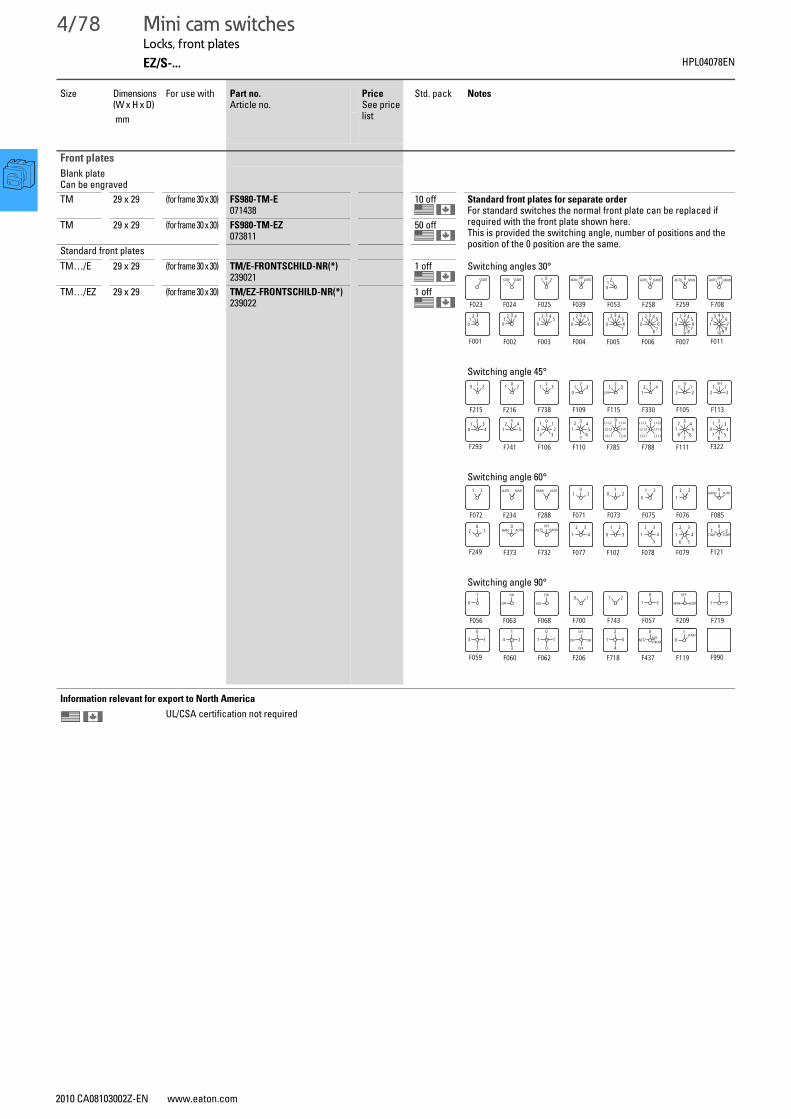
4/78 Mini cam switchesLocks, front plates
EZ/S-... HPL04078EN
Locks, front platesSize Dimensions (W x H x D)
For use with Part no.Article no.
PriceSee price list
Std. pack Notes
mm
Front plates
Blank plateCan be engravedTM 29 x 29 (for frame 30 x 30) FS980-TM-E
07143810 off Standard front plates for separate order
For standard switches the normal front plate can be replaced if required with the front plate shown here.This is provided the switching angle, number of positions and the position of the 0 position are the same.
Switching angles 30°
Switching angle 45°
Switching angle 60°
Switching angle 90°
TM 29 x 29 (for frame 30 x 30) FS980-TM-EZ073811
50 off
Standard front platesTM…/E 29 x 29 (for frame 30 x 30) TM/E-FRONTSCHILD-NR(*)
2390211 off
TM…/EZ 29 x 29 (for frame 30 x 30) TM/EZ-FRONTSCHILD-NR(*)239022
1 off
Information relevant for export to North America
UL/CSA certification not required
F023
START
F024
STOP START
F025
1 0 2
F039
MAN OFFAUTO
F053
01
2
F258
AUTO 0 HAND AUTO 0 MAN
F259 F708
F004 F007F006F005F003F002 F011F001
AUTO OFFHAND
12 3
01
2 3 4
01
2 3 45
01
2 3 4560
12 3 4
56
70
12 3 4
56
78
01
2 3 456
789
02
3 4 567
8910
1
10
234
576
21
345
687
0
L2-L3
L3-L1
L1-L2
L2-L3
L3-L1
L1-L20
L2-N
L3-N
L1-N
L2-L3
L3-L1
L1-L221
345
67
12
012
33
32
145
21
034
OFF1
212
01
212
32
14
21
OFF
32
10
31 321 200 21
F215 F216 F738 F109 F115 F330 F105 F113
F110 F111F788F785F106F741 F322F293
START START1 2
02
1
3
456
2
1
3
45
1
0
2
3
2
1
3
4AUTO HAND
OFFMAN AUTO
02 1
0
HAND AUTO01
0
20 2
11 2
0AUTO MAN1 2
F072 F234 F288 F071 F073 F075 F076 F085
F077 F079F078F102F732F373 F121F249
AUTOHAND 2
1
3
START0
1NOT-STROM
NETZ
0
31
2
4
ON
OFF
ON
OFF
11
0
0
24
1
3
13
0
2
31
2
MAN
OFF
AUTO21
01 20 1
AUS
EIN
OFF
ON
0
1
F056 F063 F068 F700 F743 F057 F209 F719
F206 F119F437F718F062F060 F990F059
2010 CA08103002Z-EN www.eaton.com
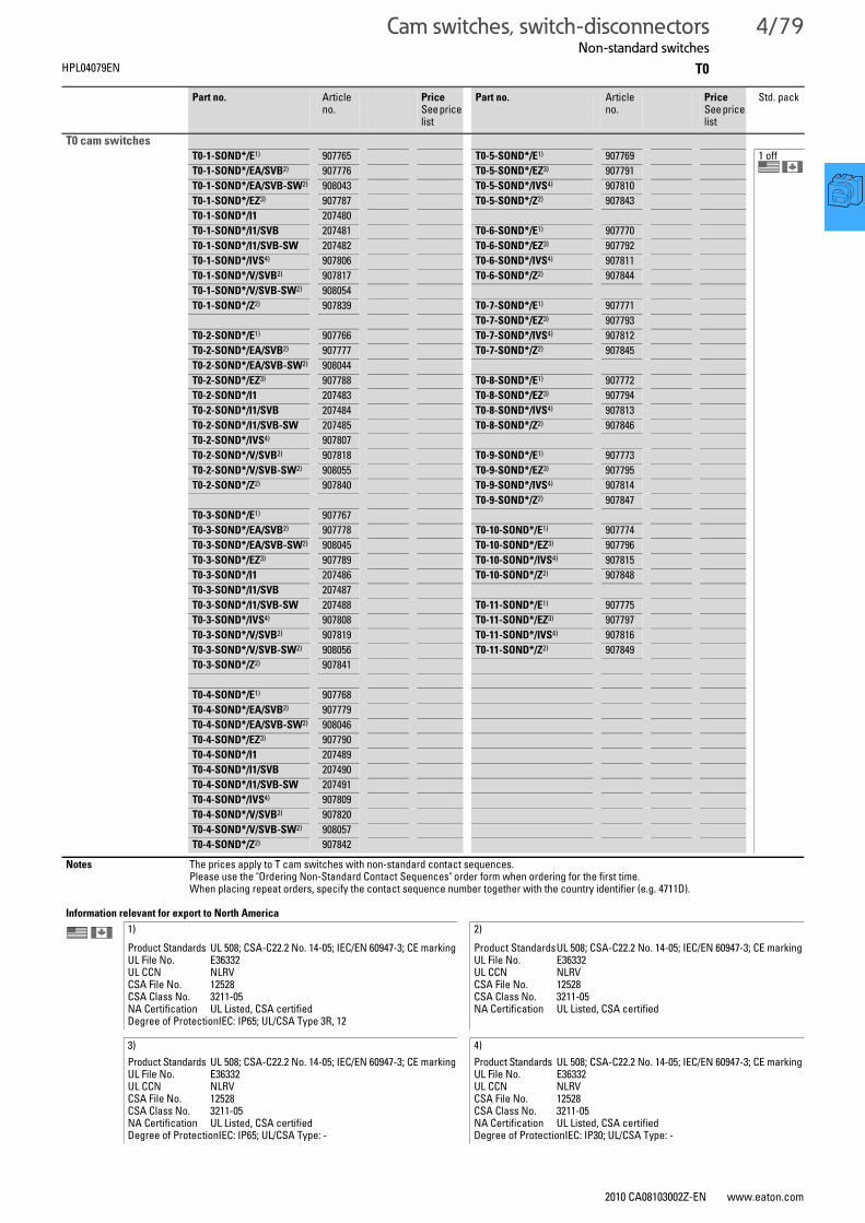
Cam switches, switch-disconnectorsNon-standard switches
4/79
T0HPL04079EN
Non-standard switchesPart no. Article no.
PriceSee price list
Part no. Article no.
PriceSee price list
Std. pack
T0 cam switches T0-1-SOND*/E1) 907765 T0-5-SOND*/E1) 907769 1 offT0-1-SOND*/EA/SVB2) 907776 T0-5-SOND*/EZ3) 907791
T0-1-SOND*/EA/SVB-SW2) 908043 T0-5-SOND*/IVS4) 907810
T0-1-SOND*/EZ3) 907787 T0-5-SOND*/Z2) 907843
T0-1-SOND*/I1 207480
T0-1-SOND*/I1/SVB 207481 T0-6-SOND*/E1) 907770
T0-1-SOND*/I1/SVB-SW 207482 T0-6-SOND*/EZ3) 907792
T0-1-SOND*/IVS4) 907806 T0-6-SOND*/IVS4) 907811
T0-1-SOND*/V/SVB2) 907817 T0-6-SOND*/Z2) 907844
T0-1-SOND*/V/SVB-SW2) 908054
T0-1-SOND*/Z2) 907839 T0-7-SOND*/E1) 907771
T0-7-SOND*/EZ3) 907793T0-2-SOND*/E1) 907766 T0-7-SOND*/IVS4) 907812
T0-2-SOND*/EA/SVB2) 907777 T0-7-SOND*/Z2) 907845
T0-2-SOND*/EA/SVB-SW2) 908044
T0-2-SOND*/EZ3) 907788 T0-8-SOND*/E1) 907772
T0-2-SOND*/I1 207483 T0-8-SOND*/EZ3) 907794
T0-2-SOND*/I1/SVB 207484 T0-8-SOND*/IVS4) 907813
T0-2-SOND*/I1/SVB-SW 207485 T0-8-SOND*/Z2) 907846
T0-2-SOND*/IVS4) 907807
T0-2-SOND*/V/SVB2) 907818 T0-9-SOND*/E1) 907773
T0-2-SOND*/V/SVB-SW2) 908055 T0-9-SOND*/EZ3) 907795
T0-2-SOND*/Z2) 907840 T0-9-SOND*/IVS4) 907814
T0-9-SOND*/Z2) 907847T0-3-SOND*/E1) 907767
T0-3-SOND*/EA/SVB2) 907778 T0-10-SOND*/E1) 907774
T0-3-SOND*/EA/SVB-SW2) 908045 T0-10-SOND*/EZ3) 907796
T0-3-SOND*/EZ3) 907789 T0-10-SOND*/IVS4) 907815
T0-3-SOND*/I1 207486 T0-10-SOND*/Z2) 907848
T0-3-SOND*/I1/SVB 207487
T0-3-SOND*/I1/SVB-SW 207488 T0-11-SOND*/E1) 907775
T0-3-SOND*/IVS4) 907808 T0-11-SOND*/EZ3) 907797
T0-3-SOND*/V/SVB2) 907819 T0-11-SOND*/IVS4) 907816
T0-3-SOND*/V/SVB-SW2) 908056 T0-11-SOND*/Z2) 907849
T0-3-SOND*/Z2) 907841
T0-4-SOND*/E1) 907768
T0-4-SOND*/EA/SVB2) 907779
T0-4-SOND*/EA/SVB-SW2) 908046
T0-4-SOND*/EZ3) 907790
T0-4-SOND*/I1 207489
T0-4-SOND*/I1/SVB 207490
T0-4-SOND*/I1/SVB-SW 207491
T0-4-SOND*/IVS4) 907809
T0-4-SOND*/V/SVB2) 907820
T0-4-SOND*/V/SVB-SW2) 908057
T0-4-SOND*/Z2) 907842
Notes The prices apply to T cam switches with non-standard contact sequences. Please use the "Ordering Non-Standard Contact Sequences" order form when ordering for the first time.When placing repeat orders, specify the contact sequence number together with the country identifier (e.g. 4711D).
Information relevant for export to North America
1) 2)Product Standards UL 508; CSA-C22.2 No. 14-05; IEC/EN 60947-3; CE markingUL File No. E36332UL CCN NLRVCSA File No. 12528CSA Class No. 3211-05NA Certification UL Listed, CSA certifiedDegree of ProtectionIEC: IP65; UL/CSA Type 3R, 12
Product StandardsUL 508; CSA-C22.2 No. 14-05; IEC/EN 60947-3; CE markingUL File No. E36332UL CCN NLRVCSA File No. 12528CSA Class No. 3211-05NA Certification UL Listed, CSA certified
3) 4)Product Standards UL 508; CSA-C22.2 No. 14-05; IEC/EN 60947-3; CE markingUL File No. E36332UL CCN NLRVCSA File No. 12528CSA Class No. 3211-05NA Certification UL Listed, CSA certifiedDegree of ProtectionIEC: IP65; UL/CSA Type: -
Product Standards UL 508; CSA-C22.2 No. 14-05; IEC/EN 60947-3; CE markingUL File No. E36332UL CCN NLRVCSA File No. 12528CSA Class No. 3211-05NA Certification UL Listed, CSA certifiedDegree of ProtectionIEC: IP30; UL/CSA Type: -
2010 CA08103002Z-EN www.eaton.com

4/80 Cam switches, switch-disconnectorsNon-standard switches
T3 HPL04080EN
Part no. Article no.
PriceSee price list
Part no. Article no.
PriceSee price list
Std. pack
T3 cam switches
T3-1-SOND*/E1) 907850 T3-5-SOND*/E1) 907854 1 offT3-1-SOND*/EA/SVB1) 907861 T3-5-SOND*/EA/SVB1) 907865T3-1-SOND*/EA/SVB-SW1) 908080 T3-5-SOND*/EA/SVB-SW1) 908084T3-1-SOND*/EZ1) 907872 T3-5-SOND*/EZ1) 907876T3-1-SOND*/I22) 207492 T3-5-SOND*/I22) 207504T3-1-SOND*/I2/SVB2) 207493 T3-5-SOND*/I2/SVB2) 207506T3-1-SOND*/I2/SVB-SW2) 207494 T3-5-SOND*/I2/SVB-SW2) 207507T3-1-SOND*/V/SVB1) 907891 T3-5-SOND*/V/SVB1) 907895T3-1-SOND*/V/SVB-SW1) 908091 T3-5-SOND*/V/SVB-SW1) 908095T3-1-SOND*/Z1) 907913 T3-5-SOND*/Z1) 907917
T3-2-SOND*/E1) 907851 T3-6-SOND*/E1) 907855T3-2-SOND*/EA/SVB1) 907862 T3-6-SOND*/EA/SVB1) 907866T3-2-SOND*/EA/SVB-SW1) 908081 T3-6-SOND*/EA/SVB-SW1) 908085T3-2-SOND*/EZ1) 907873 T3-6-SOND*/EZ1) 907877T3-2-SOND*/I22) 207495 T3-6-SOND*/V/SVB1) 907896T3-2-SOND*/I2/SVB2) 207496 T3-6-SOND*/V/SVB-SW1) 908096T3-2-SOND*/I2/SVB-SW2) 207497 T3-6-SOND*/Z1) 907918T3-2-SOND*/V/SVB1) 907892T3-2-SOND*/V/SVB-SW1) 908092 T3-7-SOND*/E1) 907856T3-2-SOND*/Z1) 907914 T3-7-SOND*/EZ1) 907878
T3-7-SOND*/Z1) 907919T3-3-SOND*/E1) 907852T3-3-SOND*/EA/SVB1) 907863 T3-8-SOND*/E1) 907857T3-3-SOND*/EA/SVB-SW1) 908082 T3-8-SOND*/EZ1) 907879T3-3-SOND*/EZ1) 907874 T3-8-SOND*/Z1) 907920T3-3-SOND*/I22) 207498T3-3-SOND*/I2/SVB2) 207499 T3-9-SOND*/E1) 907858T3-3-SOND*/I2/SVB-SW2) 207500 T3-9-SOND*/EZ1) 907880T3-3-SOND*/V/SVB1) 907893 T3-9-SOND*/Z1) 907921T3-3-SOND*/V/SVB-SW1) 908093T3-3-SOND*/Z1) 907915 T3-10-SOND*/E1) 907859
T3-10-SOND*/EZ1) 907881T3-4-SOND*/E1) 907853 T3-10-SOND*/Z1) 907922T3-4-SOND*/EA/SVB1) 907864T3-4-SOND*/EA/SVB-SW1) 908083 T3-11-SOND*/E1) 907860T3-4-SOND*/EZ1) 907875 T3-11-SOND*/EZ1) 907882T3-4-SOND*/I22) 207501 T3-11-SOND*/Z1) 907923T3-4-SOND*/I2/SVB2) 207502T3-4-SOND*/I2/SVB-SW2) 207503T3-4-SOND*/V/SVB1) 907894T3-4-SOND*/V/SVB-SW1) 908094T3-4-SOND*/Z1) 907916
Notes The prices apply to T cam switches with non-standard contact sequences. Please use the "Ordering Non-Standard Contact Sequences" order form when ordering for the first time.When placing repeat orders, specify the contact sequence number together with the country identifier (e.g. 4711D).
Information relevant for export to North America
1) 2)Product Standards UL 508; CSA-C22.2 No. 14-05; IEC/EN 60947-3;
CE markingUL File No. E36332UL CCN NLRVCSA File No. 12528CSA Class No. 3211-05NA Certification UL Listed, CSA certified
Product Standards UL 508; CSA-C22.2 No. 14-05; CSA-C22.2 No. 94; IEC/EN 60947-3; CE marking
UL File No. E36332UL CCN NLRVCSA File No. 12528CSA Class No. 3211-05NA Certification UL Listed, CSA certifiedDegree of Protection IEC: IP65; UL/CSA Type 3R, 12
2010 CA08103002Z-EN www.eaton.com

Cam switches, switch-disconnectorsNon-standard switches
4/81
T5BHPL04081EN
Part no. Article no.
PriceSee price list
Part no. Article no.
PriceSee price list
Std. pack
T5B cam switches
T5B-1-SOND*/E 907924 T5B-5-SOND*/E 907928 1 offT5B-1-SOND*/EA/SVB 907934 T5B-5-SOND*/EA/SVB 907938T5B-1-SOND*/EA/SVB-SW 908106 T5B-5-SOND*/EA/SVB-SW 908110T5B-1-SOND*/I4 207510 T5B-5-SOND*/V/SVB 907954T5B-1-SOND*/I4/SVB 207511 T5B-5-SOND*/V/SVB-SW 908118T5B-1-SOND*/I4/SVB-SW 207512 T5B-5-SOND*/Z 907972T5B-1-SOND*/V/SVB 907950T5B-1-SOND*/V/SVB-SW 908114 T5B-6-SOND*/E 907929T5B-1-SOND*/Z 907968 T5B-6-SOND*/EA/SVB 907939
T5B-6-SOND*/EA/SVB-SW 908111T5B-2-SOND*/E 907925 T5B-6-SOND*/V/SVB 907955T5B-2-SOND*/EA/SVB 907935 T5B-6-SOND*/V/SVB-SW 908119T5B-2-SOND*/EA/SVB-SW 908107 T5B-6-SOND*/Z 907973T5B-2-SOND*/I4 207514T5B-2-SOND*/I4/SVB 207515 T5B-7-SOND*/E 907930T5B-2-SOND*/I4/SVB-SW 207516 T5B-7-SOND*/EA/SVB 907940T5B-2-SOND*/V/SVB 907951 T5B-7-SOND*/EA/SVB-SW 908112T5B-2-SOND*/V/SVB-SW 908115 T5B-7-SOND*/V/SVB 907956T5B-2-SOND*/Z 907969 T5B-7-SOND*/V/SVB-SW 908120
T5B-7-SOND*/Z 907974T5B-3-SOND*/E 907926T5B-3-SOND*/EA/SVB 907936 T5B-8-SOND*/E 907931T5B-3-SOND*/EA/SVB-SW 908108 T5B-8-SOND*/EA/SVB 907941T5B-3-SOND*/I4 207518 T5B-8-SOND*/EA/SVB-SW 908113T5B-3-SOND*/I4/SVB 207519 T5B-8-SOND*/V/SVB 907957T5B-3-SOND*/I4/SVB-SW 207520 T5B-8-SOND*/V/SVB-SW 908121T5B-3-SOND*/V/SVB 907952 T5B-8-SOND*/Z 907975T5B-3-SOND*/V/SVB-SW 908116T5B-3-SOND*/Z 907970 T5B-9-SOND*/E 907932
T5B-9-SOND*/Z 907976T5B-4-SOND*/E 907927T5B-4-SOND*/EA/SVB 907937 T5B-10-SOND*/E 907933T5B-4-SOND*/EA/SVB-SW 908109 T5B-10-SOND*/Z 907977T5B-4-SOND*/I4 207521T5B-4-SOND*/I4/SVB 207522T5B-4-SOND*/I4/SVB-SW 207523T5B-4-SOND*/V/SVB 907953T5B-4-SOND*/V/SVB-SW 908117T5B-4-SOND*/Z 907971
Notes The prices apply to T cam switches with non-standard contact sequences. Please use the "Ordering Non-Standard Contact Sequences" order form when ordering for the first time.When placing repeat orders, specify the contact sequence number together with the country identifier (e.g. 4711D).
Information relevant for export to North America
Product Standards UL 508; CSA-C22.2 No. 14-05; IEC/EN 60947-3; CE markingUL File No. E36332UL CCN NLRV7CSA File No. 12528CSA Class No. 3211-05NA Certification UL Listed, CSA certified
2010 CA08103002Z-EN www.eaton.com

4/82 Cam switches, switch-disconnectorsNon-standard switches
T5 HPL04082EN
Part no. Article no.
PriceSee price list
Part no. Article no.
PriceSee price list
Std. pack
T5 cam switches
T5-1-SOND*/E 907978 T5-5-SOND*/E 907982 1 offT5-1-SOND*/EA/SVB 908031 T5-5-SOND*/EA/SVB 907991T5-1-SOND*/EA/SVB-SW 908126 T5-5-SOND*/EA/SVB-SW 908130T5-1-SOND*/I5 207524 T5-5-SOND*/V/SVB 908007T5-1-SOND*/I5/SVB 207525 T5-5-SOND*/V/SVB-SW 908138T5-1-SOND*/I5/SVB-SW 207526 T5-5-SOND*/Z 908025T5-1-SOND*/V/SVB 908003T5-1-SOND*/V/SVB-SW 908134 T5-6-SOND*/E 907983T5-1-SOND*/Z 908021 T5-6-SOND*/EA/SVB 907992
T5-6-SOND*/EA/SVB-SW 908131T5-2-SOND*/E 907979 T5-6-SOND*/V/SVB 908008T5-2-SOND*/EA/SVB 907988 T5-6-SOND*/V/SVB-SW 908139T5-2-SOND*/EA/SVB-SW 908127 T5-6-SOND*/Z 908026T5-2-SOND*/I5 207527T5-2-SOND*/I5/SVB 207528 T5-7-SOND*/E 907984T5-2-SOND*/I5/SVB-SW 207529 T5-7-SOND*/EA/SVB 907993T5-2-SOND*/V/SVB 908004 T5-7-SOND*/EA/SVB-SW 908132T5-2-SOND*/V/SVB-SW 908135 T5-7-SOND*/V/SVB 908009T5-2-SOND*/Z 908022 T5-7-SOND*/V/SVB-SW 908140
T5-7-SOND*/Z 908027T5-3-SOND*/E 907980T5-3-SOND*/EA/SVB 907989 T5-8-SOND*/E 907985T5-3-SOND*/EA/SVB-SW 908128 T5-8-SOND*/EA/SVB 907994T5-3-SOND*/I5 207530 T5-8-SOND*/EA/SVB-SW 908133T5-3-SOND*/I5/SVB 207531 T5-8-SOND*/V/SVB 908010T5-3-SOND*/I5/SVB-SW 207532 T5-8-SOND*/V/SVB-SW 908141T5-3-SOND*/V/SVB 908005 T5-8-SOND*/Z 908028T5-3-SOND*/V/SVB-SW 908136T5-3-SOND*/Z 908023 T5-9-SOND*/E 907986
T5-9-SOND*/Z 908029T5-4-SOND*/E 907981 T5-10-SOND*/E 907987T5-4-SOND*/EA/SVB 907990 T5-10-SOND*/Z 908030T5-4-SOND*/EA/SVB-SW 908129T5-4-SOND*/I5 207533T5-4-SOND*/I5/SVB 207534T5-4-SOND*/I5/SVB-SW 207535T5-4-SOND*/V/SVB 908006T5-4-SOND*/V/SVB-SW 908137
Notes The prices apply to T cam switches with non-standard contact sequences. Please use the "Ordering Non-Standard Contact Sequences" order form when ordering for the first time.When placing repeat orders, specify the contact sequence number together with the country identifier (e.g. 4711D).
Information relevant for export to North America
Product Standards UL 508; CSA-C22.2 No. 14-05; IEC/EN 60947-3; CE markingUL File No. E36332UL CCN NLRV7CSA File No. 12528CSA Class No. 3211-05NA Certification UL Listed, CSA certifiedSuitable for Branch Circuits
2010 CA08103002Z-EN www.eaton.com

Cam switches, switch-disconnectorsNon-standard switches
4/83
TMHPL04083EN
Part no.1) Article no.
PriceSee price list
Part no.2) Article no.
PriceSee price list
Std. pack
TM non-standard switches
TM-1-SOND*/E 907749 TM-1-SOND-ERSTBESTELLUNG/E 208261 1 offTM-3-SOND*/E 907750 TM-1-SOND-ERSTBESTELLUNG/EZ 208262TM-2-SOND*/E 907763 TM-1-SOND-ERSTBESTELLUNG/IVS 225347TM-4-SOND*/E 907751 TM-2-SOND-ERSTBESTELLUNG/E 208263TM-6-SOND*/E 907752 TM-2-SOND-ERSTBESTELLUNG/EZ 208264TM-5-SOND*/E 907764 TM-2-SOND-ERSTBESTELLUNG/IVS 225349TM-7-SOND*/E 907753 TM-3-SOND-ERSTBESTELLUNG/E 208265TM-8-SOND*/E 907754 TM-3-SOND-ERSTBESTELLUNG/EZ 208266TM-1-SOND*/EZ 907755 TM-4-SOND-ERSTBESTELLUNG/E 208267TM-2-SOND*/EZ 907756 TM-4-SOND-ERSTBESTELLUNG/EZ 208268TM-3-SOND*/EZ 907757 TM-5-SOND-ERSTBESTELLUNG/E 208269TM-4-SOND*/EZ 907758 TM-5-SOND-ERSTBESTELLUNG/EZ 208270TM-5-SOND*/EZ 907759 TM-6-SOND-ERSTBESTELLUNG/E 208271TM-6-SOND*/EZ 907760 TM-6-SOND-ERSTBESTELLUNG/EZ 208272TM-7-SOND*/EZ 907761 TM-7-SOND-ERSTBESTELLUNG/E 208273TM-8-SOND*/EZ 907762 TM-7-SOND-ERSTBESTELLUNG/EZ 208274TM-1-SOND*/IVS 225346 TM-8-SOND-ERSTBESTELLUNG/E 208275TM-2-SOND*/IVS 225348 TM-8-SOND-ERSTBESTELLUNG/EZ 208276
Notes 1) 2)TM-…-SOND…/…:For repeat orders for which the design number is already known. Form FO2 is not required for this purpose.The design number is a six-digit number and must always be greater than 200000.
TM-…-SOND-ERSTBESTELLUNG/…:For new orders with a completed form.
Information relevant for export to North America
Product Standards UL 508; CSA-C22.2 No. 14-05; IEC/EN 60947-3; CE markingUL File No. E36332UL CCN NLRV, NLRV7CSA File No. UL report applies to both US and CanadaCSA Class No. –NA Certification UL Listed, certified by UL for use in CanadaDegree of Protection IEC: IP65; UL/CSA Type: -
2010 CA08103002Z-EN www.eaton.com
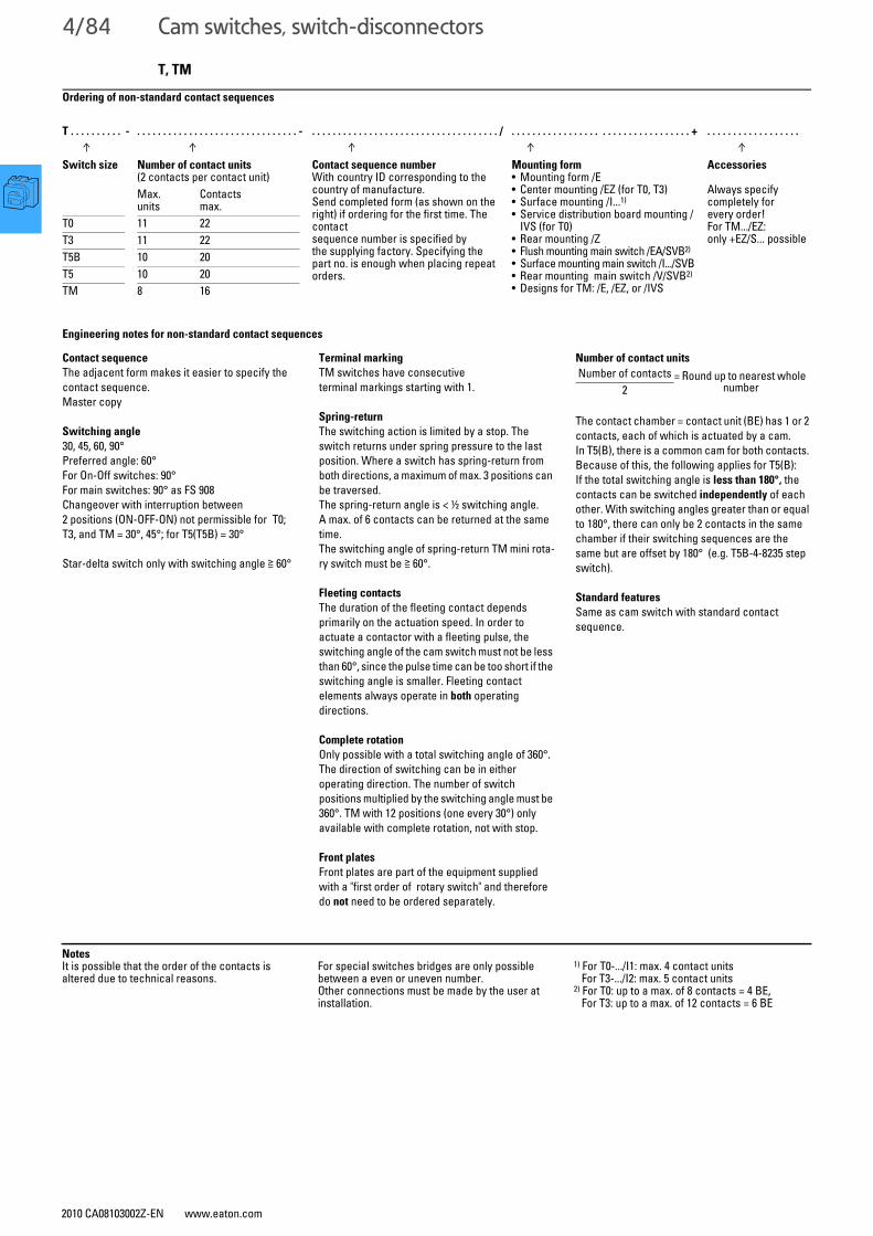
4/84 Cam switches, switch-disconnectors
2010 CA08103002Z-EN www.eaton.com
T, TM
Engineering notes for non-standard contact sequences
Ordering of non-standard contact sequences
T . . . . . . . . . . - . . . . . . . . . . . . . . . . . . . . . . . . . . . . . . . - . . . . . . . . . . . . . . . . . . . . . . . . . . . . . . . . . . . . / . . . . . . . . . . . . . . . . . . . . . . . . . . . . . . . . . . + . . . . . . . . . . . . . . . . . .
↑ ↑ ↑ ↑ ↑Switch size Number of contact units
(2 contacts per contact unit)Contact sequence numberWith country ID corresponding to the country of manufacture.Send completed form (as shown on the right) if ordering for the first time. The contactsequence number is specified bythe supplying factory. Specifying the part no. is enough when placing repeatorders.
Mounting form• Mounting form /E• Center mounting /EZ (for T0, T3)• Surface mounting /I...1)
• Service distribution board mounting /IVS (for T0)
• Rear mounting /Z• Flush mounting main switch /EA/SVB2)
• Surface mounting main switch /I.../SVB• Rear mounting main switch /V/SVB2)
• Designs for TM: /E, /EZ, or /IVS
Accessories
Always specifycompletely forevery order!For TM.../EZ:only +EZ/S... possible
Max. units
Contactsmax.
T0 11 22T3 11 22T5B 10 20T5 10 20TM 8 16
Contact sequence
The adjacent form makes it easier to specify the contact sequence. Master copy
Switching angle
30, 45, 60, 90°Preferred angle: 60°For On-Off switches: 90°For main switches: 90° as FS 908 Changeover with interruption between2 positions (ON-OFF-ON) not permissible for T0;T3, and TM = 30°, 45°; for T5(T5B) = 30°
Star-delta switch only with switching angle ≧ 60°
Terminal marking
TM switches have consecutive terminal markings starting with 1.
Spring-return
The switching action is limited by a stop. The switch returns under spring pressure to the last position. Where a switch has spring-return from both directions, a maximum of max. 3 positions can be traversed.The spring-return angle is < ½ switching angle. A max. of 6 contacts can be returned at the same time.The switching angle of spring-return TM mini rota-ry switch must be ≧ 60°.
Fleeting contacts
The duration of the fleeting contact depends primarily on the actuation speed. In order to actuate a contactor with a fleeting pulse, the switching angle of the cam switch must not be less than 60°, since the pulse time can be too short if the switching angle is smaller. Fleeting contact elements always operate in both operating directions.
Complete rotation
Only possible with a total switching angle of 360°. The direction of switching can be in either operating direction. The number of switch positions multiplied by the switching angle must be 360°. TM with 12 positions (one every 30°) only available with complete rotation, not with stop.
Front plates
Front plates are part of the equipment supplied with a "first order of rotary switch" and therefore do not need to be ordered separately.
Number of contact units
The contact chamber = contact unit (BE) has 1 or 2 contacts, each of which is actuated by a cam.In T5(B), there is a common cam for both contacts. Because of this, the following applies for T5(B):If the total switching angle is less than 180°, the contacts can be switched independently of each other. With switching angles greater than or equal to 180°, there can only be 2 contacts in the same chamber if their switching sequences are the same but are offset by 180° (e.g. T5B-4-8235 step switch).
Standard features
Same as cam switch with standard contact sequence.
Number of contacts = Round up to nearest whole number2
NotesIt is possible that the order of the contacts is altered due to technical reasons.
For special switches bridges are only possible between a even or uneven number.Other connections must be made by the user at installation.
1) For T0-.../I1: max. 4 contact units For T3-.../I2: max. 5 contact units
2) For T0: up to a max. of 8 contacts = 4 BE, For T3: up to a max. of 12 contacts = 6 BE

Cam switches, switch-disconnectors
2010 CA08103002Z-EN www.eaton.com
4/85
Non-standard contact sequence ordering example
Binding document for ordering T cam switch combinations for the first time
Order No.:123456
Item:7
Office:Cologne
Author:HWS
Customer:Sample Company
Customer no.:A4711/2004
Date:29.2.2004
Quantity:3
Switching angle: Part no.: Number of contacts: Mounting form:
□ 30 □ TM □ 1 □ 12 □ E□ 45 □ T0 □ 2 □ 13 □ EA/SVB □ EA/SVB-SW
Euros/unit: □ 60 □ T3 □ 3 □ 14 □ EZ□ 90 □ T5B □ 4 □ 15 □ I...
□ T5 □ 5 □ 16 □ I.../SVB □ I.../SVB-SW□ 6 □ 17 □ IVS□ 7 □ 18 □ V/SVB □ V/SVB-SW□ 8 □ 19 □ Z□ 9 □ 20 □ + ST-0□ 10 □ 21 □ +___________________□ 11 □ 22
Max. characters per positionDegrees TM-E TM-EZ TM-IVS T0(3) T5(B)0.18 5 5 6 13 1330, 210, 330 8 7 4 8 845, 135, 225, 315 6 5 4 6 760, 120, 240, 300 5 5 3 5 790, 270 5 4 1 4 7150 4 4 4 8 8
Front plate no.
FS ______________
Contact units
1 2 3 4 5 6 7 8 9 10 11
○ Complete rotation
○ Automaticspring-return
Inscription
Degrees 12
34
56
78
910
1112
1314
1516
1718
1920
2122
2324
2526
2728
2930
3132
3334
3536
3738
3940
4142
4344
270 1 x x x x x x x300315330 2 x x x x0 x30 3 x x x4560 4 x90
Cont
act o
nly c
lose
d in
po
sitio
n 1
Switc
hing
with
in
terru
ptio
n of
con
tact
Switc
hing
with
out
inte
rrupt
ion
of c
onta
ctCo
ntac
t clo
sed
in p
ositi
ons
1 + 3
Cont
act c
lose
d in
pos
ition
s 1 t
o 3
Fleet
ing
cont
act
(onl
y with
60° o
r 90°
)La
te-b
reak
con
tact
Early
-mak
e co
ntac
t
Cont
act w
ith a
utom
atic
sp
ring-
retu
rn
120135150 Key withdrawability for ..S-T0 and SVA-T3:180 Pos. 1: Key withdrawable } In the case of SVA-T3, the unit can
still be switched between positions 1 and 2 if the key has been removed..
210 Pos. 2: Key withdrawable225 Pos. 3: Key withdrawable240 Pos. 4: Key not withdrawable
Key withdrawable x Part no. for repeat orders (to be filled in by factory) T___________________________________
1
2
3
4
5
6
7
8
9
10
11
12
13
14
15
16
17 19
18
21
20
23
22
25
24
27
26
29
28
31
30
33
32
35
34
37
36
39
38
41
40
43
42 44
3300
30300
270
240 225
210180
150
135 120
90
60315 45
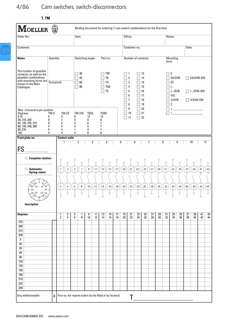
4/86 Cam switches, switch-disconnectors
2010 CA08103002Z-EN www.eaton.com
T, TM
Binding document for ordering T cam switch combinations for the first time
Order No.: Item: Office: Name:
Customer: Customer no.: Date:
Notes:
The number of possible contacts, as well as the possible combinations with mounting forms are shown in the Main Catalogue.
Quantity: Switching angle: Part no.: Number of contacts: Mounting form:
□ 30 □ TM □ 1 □ 12 □ E□ 45 □ T0 □ 2 □ 13 □ EA/SVB □ EA/SVB-SW
Euros/unit: □ 60 □ T3 □ 3 □ 14 □ EZ□ 90 □ T5B □ 4 □ 15 □ I...
□ T5 □ 5 □ 16 □ I.../SVB □ I.../SVB-SW□ 6 □ 17 □ IVS□ 7 □ 18 □ V/SVB □ V/SVB-SW□ 8 □ 19 □ Z□ 9 □ 20 □ +____________________□ 10 □ 21 □ +____________________□ 11 □ 22
Max. characters per positionDegrees TM-E TM-EZ TM-IVS T0(3) T5(B)0.18 5 5 6 13 1330, 210, 330 8 7 4 8 845, 135, 225, 315 6 5 4 6 760, 120, 240, 300 5 5 3 5 790, 270 5 4 1 4 7150 4 4 4 8 8Front plate no.
FS _______________
Contact units
1 2 3 4 5 6 7 8 9 10 11
○ Complete rotation
○ AutomaticSpring-return
Inscription
Degrees 12
34
56
78
910
1112
1314
1516
1718
1920
2122
2324
2526
2728
2930
3132
3334
3536
3738
3940
4142
4344
2703003153300
30456090120135150180210225240
Key withdrawable x Part no. for repeat orders (to be filled in by factory) T__________________________
1
2
3
4
5
6
7
8
9
10
11
12
13
14
15
16
17 19
18
21
20
23
22
25
24
27
26
29
28
31
30
33
32
35
34
37
36
39
38
41
40
43
42 44 330
030
300
270
240 225
210180
150
135 120
90
60315 45

Cam switches, switch-disconnectors
2010 CA08103002Z-EN www.eaton.com
4/87
FS-SOND
Ordering non-standard front plates
Binding document for ordering non-standard front plates for the first time
Order No.: Item:
Office: Name:
Customer: Customer no.:
Quantity: Euros/unit: Date:
The text is always centered in the text block
Non-standard front platesInscription:Front plate with black lettering
Insert textNote the maximum number of characters allowed outside the marked areas!Part no.
□FS-SOND-
T0 (T3, P1)Letter height
≤ 2 Characters ≥ 2 Characters
4 mm3 mm
□FS-SOND-P3 (T5B, T5)Letter height
≤ 2 Characters≥ 2 Characters
8 mm5 mm
□
□
FS-SOND-TM-EFS-SOND-TM-EZ
≤ 2 Characters approx.≥ 2 Characters
3.5 mm3 mm
For P1 and P3, fill out positions 270° and 0° only
Max. possible number of characters
Position
Degrees TM-E TM-EZ T0/P1 T5/P3 Dimensions
0, 180 5 5 13 13 Part no. Front plate size30, 210, 330 8 7 8 845, 135, 225, 315 6 5 6 7 TM-.../E 29 x 29 mm (for frame 30 x 30)60, 120, 240, 300 5 5 5 7 TM-.../EZ(-...) 29 x 29 mm (for frame 30 x 30)90, 270 5 4 4 7 T0, T3, P1 45 x 45 mm (for frame 48 x 48)150 4 4 8 8 P3, T5, T5B 84 x 84 mm (for frame 88 x 88)
Part no. for repeat orders (to be filled in by factory)FS.....................................................................................

4/88 Cam switches, switch-disconnectors
2010 CA08103002Z-EN www.eaton.com
Characteristic curves
Component lifespan based on breaking current and utilization category 1)
To ensure a reasonable service life in utilization category AC-4 (extreme load: 100 % inching, reversing, or plug braking),the motor's standstill current must not exceed the rated operational current of the switch for AC-21A.
Notes 1) AC-3 and AC-21 at 400 V, AC-15 at 230 V
1 2 3 4 5 6 7 8 10 20 A
T0
0.5
1
2
3
4568
10
Breaking currentAs control switch (AC-15)As motor load switch (AC-3)As load-break switch (AC-21)
Com
pone
nt li
fesp
an (o
pera
tions
105 )
Breaking currentAs motor load switch (AC-3)As load-break switch (AC-21)
T3
Com
pone
nt li
fesp
an (o
pera
tions
105 )
1 2 3 4 6 128 30 40 A0.5
1
2
3456
8
10
16 20 25
0.6
0.8
0.5
T5B
T5B T5
T5
1 2 3 4 6 128 30 40
1
2
3456
8
10
16 20
0.6
0.8
60 80 100 A
T5B T5
T5B T5
T5B, T5
Breaking currentAs motor load switch (AC-3)As load-break switch (AC-21)
Com
pone
nt li
fesp
an (o
pera
tions
105 )
Breaking currentAs motor load switch (AC-3)As load-break switch (AC-21)
T6, T8
Com
pone
nt li
fesp
an (o
pera
tions
105 )
4 6 8 16120.1
0.2
0.3
0.5
1
2
3
5
6020 30 40 100 250A
T6 T8
T6 T8
T6
T8
T6
T8
Breaking currentAs motor load switch (AC-3)As load-break switch (AC-21)
P1
Com
pone
nt li
fesp
an (o
pera
tions
105 )
1 2 3 4 6 128 30 40 A0.5
1
2
3456
8
10
16 20 25
0.6
0.8
P1-32
P1-25
P1-25 P1-32
P1-25
Breaking currentAs motor load switch (AC-3)As load-break switch (AC-21)
P3
Com
pone
nt li
fesp
an (o
pera
tions
105 )
1 2 3 5 2010 80 100 A0.1
40 60
0.2
0.3
0.40.50.6
0.81
2
P3-100P3-63
P3-63 P3-100
P3-100
P3-63
T, P

Cam switches, switch-disconnectorsSwitch-disconnectors
2010 CA08103002Z-EN www.eaton.com
4/89
Switch-disconnectors
Technical data
P1-25 P1-32 P3-63 P3-100
General
Standards IEC/EN 60947, VDE 0660, IEC/EN 60204, CSA, UL switch-disconnector to IEC/EN 60947-3
Lifespan, mechanical Operations x 106 0.3 0.3 0.1 0.1Maximum operating frequency Operations/h 50 50 50 50Climatic proofing Damp heat, constant, to IEC 60068-2-78;
Damp heat, cyclical, to IEC 60068-2-30Ambient temperature Open °C -25 - 50 -25 - 50 -25 - 50 -25 - 50
Enclosed °C -25 - 40 -25 - 40 -25 - 40 -25 - 40Mounting position Any Any Any AnyMechanical shock resistance (IEC/EN60068-2-27)
Half-sinusoidal shock 20 ms g 15 15 15 15
Contacts
Rated operational voltage Ue V AC 690 690 690 690Rated impulse withstand voltage Uimp V AC 6000 6000 6000 6000Overvoltage category/pollution degree III/3 III/3 III/3 III/3Rated uninterrupted current Iu A 25 32 63 100Load rating with intermittent operation, class 12
AB 60 % DF x Ie 1.3 1.3 1.3 1.3AB 40 % DF x Ie 1.6 1.6 1.6 1.6AB 25 % DF x Ie 2 2 2 2
Short-circuit rating Fuse A gG/gL 25 50 80 100Rated short-time withstand current (1 s current) Icw Arms 640 640 1260 2000Isolating characteristics to IEC/EN 60947 V AC ≦ 690 ≦ 690 ≦ 690 ≦ 690Safe isolation according to EN 61140
Safe isolation to VDE 0106 Part 101 and Part 101 A1 between the auxiliary contacts and main circuits
V AC 440 440 440 440
Switching angle ° 90 90 90 90Contacts Number Max. 3 (+N) Max. 3 (+N) Max. 3 (+N) Max. 3 (+N)Current heat loss per contact at Ie W 1.1 1.8 4.5 7.5Terminal capacity
Solid or stranded mm2 1 x (1.5 - 6)2 x (1.5 - 6)
1 x (1.5 - 6)2 x (1.5 - 6)
1 x (2.5 - 35)2 x (2.5 - 10)
1 x (2.5 - 35)2 x (2.5 - 10)
Flexible with ferrule to DIN 46228 mm2 1 x (1 - 4)2 x (1 - 4)
1 x (1 - 4)2 x (1 - 4)
1 x (1.5 - 25)2 x (1.5 - 6)
1 x (1.5 - 25)2 x (1.5 - 6)
Terminal screw M4 M4 M5 M5Tightening torque Nm 1.6 1.6 3 3Switching capacity
AC voltageRated making capacity cos ϕ = 0.35 A 240 320 800 950Rated breaking capacity, motor load switch cos ϕ = 0.35
230 V A 190 260 640 760400/415 V A 150 300 600 740500 V A 170 290 590 880 690 V A 150 250 340 520
Rated operational current 440 V, load-break switch AC-21A Ie A 25 32 63 100AC-3 motor load switch motor rating
230 V P kW 5.5 7.5 15 22400/415 V P kW 7.5 13 30 37500 V P kW 7.5 18.5 30 45690 V P kW 7.5 15 30 37
AC-23A motor load switch motor rating
230 V P kW 7 8.5 18.5 30400/415 V P kW 13 15 30 50500 V P kW 11 18.5 37 65690 V P kW 11 18.5 30 45
DC voltageDC-1, load switch L/R = 1 ms Rated operational current Ie A 25 32 63 100
Voltage per contact connected in series V 60 60 60 60DC-23A, motor load switchL/R = 15 ms
24 V Rated operational current Ie A 25 25 50 50Contacts Number 1 1 1 1
48 V Rated operational current Ie A 25 25 50 50Contacts Number 2 2 2 2
60 V Rated operational current Ie A 25 25 50 50Contacts Number 3 3 3 3
120 V Rated operational current Ie A 12 12 25 25Contacts Number 3 3 3 3
Notes Main switch characteristics to IEC/EN 60204; positive opening of contacts, operator element positively located on shaft.Rated uninterrupted current Iu is specified for max. cross-section.For terminal capacity solid, stranded and flexible: Max. 2 cross-section sizes difference admissible when using 2 conductors.
P1, P3

4/90 Cam switches, switch-disconnectorsSwitch-disconnectors
2010 CA08103002Z-EN www.eaton.com
Switch-disconnectors
Rating data for approved types1)
UL File No. E36332 P1-25 P1-32 P3-63 P3-100
Contacts
Rated operational voltage Ue V AC 600 600 600 600Rated uninterrupted current Iu
Current rating A 20 30 60 100Pilot Duty A 600P 600 A 600P 600 – –
Switching capacity
AC-3; max. rated power 40 – 60 Hz AC motors
3-phase 200 V AC HP 5 7½ 15 20230 V AC HP 5 10 15 25460 V AC HP 10 20 40 60575 V AC HP 15 25 50 75
Single-phase 120 V AC HP 1½ 2 3 5200 V AC HP 3 3 7½ 10230 V AC HP 3 5 10 15
Short-circuit rating Standard 600 V AC kA 5 5 10 10With back-up fuse A 110 110 150 150With circuit-breakers Part no. NZMH6 NZMH6 NZMH6 NZMH9Current setting A 125 125 125 125
Disconnect in motor circuits 600 V AC kA 10 10 10 –With back-up fuse Class 50 A/J 50 A/J 100 A 100 A
Terminal capacity
Terminal capacityCu cable Min./ AWG 14 14 14 14
Max. AWG 8 8 2 2Tightening torque Max. in-lb 14.1 14.1 26.5 26.5
HI 11
Auxiliary contacts (1 N/O + 1 N/C)Pilot Duty P 600 Heavy Pilot Duty A 600General Use 10 A – 600 V AC
Notes 1) Devices for world markets IEC ≙ UL/CSA
UL File No:UL approved protection types
E36332 UL/NEMA 3R1) UL/NEMA 12 UL/NEMA 13
Switch-disconnectorsP1-.../EA/SVB • • –P1-.../V/SVB • • –P3-.../EA/SVB • • •P3-.../V/SVB • • •
Notes Details of protection types1) NEMA recommendation
Part no.: P1 P3-63 P3-100
Mounting form
/E; /EA; /EZ/Z; /V; /IVS/I2 +NA-I2
105866/I4 +NA-I4
105868/I5 +NA-I5
105869
P1, P3

Cam switches, switch-disconnectorsSwitch-disconnectors
4/91
P5
Switch-disconnectorsSwitch-disconnectors, auxiliary contacts
P5-125 P5-160 P5-250 P5-315
General
Standards IEC/EN 60947, VDE 0660, IEC/EN 60204, CSA, ULSwitch-disconnectors to IEC/EN 60947-3
Lifespan, mechanical Operations x 106 0.1 0.1 0.08 0.08Maximum operating frequency Operations/h 50 50 50 50Climatic proofing Damp heat, constant, to IEC 60068-2-78;
Damp heat, cyclical, to IEC 60068-2-30Ambient temperature Open °C -25 - 50 -25 - 50 -25 - 50 -25 - 50
Enclosed °C -25 - 40 -25 - 40 -25 - 40 -25 - 40Mounting position Any Any Any Any
Contacts
Rated operational voltage Ue V AC 690 690 690 690Rated impulse withstand voltage Uimp V AC 8000 8000 8000 8000Overvoltage category/pollution degree III/3 III/3 III/3 III/3Rated uninterrupted current Iu A 125 160 250 315Load rating with intermittent operation, class 12
AB 60 % DF x Ie 1.3 1.3 1.3 1.3AB 40 % DF x Ie 1.6 1.6 1.6 1.6AB 25 % DF x Ie 2 2 2 2
Short-circuit rating Fuse A gG/gL 125 160 250 315Rated short-time withstand current (1 s current) Icw Arms 2500 3000 4600 5800Isolating characteristics to IEC/EN 60947 V AC ≦ 690 ≦ 690 ≦ 690 ≦ 690Safe isolation according to EN 61140
Safe isolation to VDE 0106 Part 101 and Part 101 A1 between the auxiliary contacts and main circuits
V AC 440 440 440 440
Switching angle ° 90 90 90 90Contacts Number Max. 3 (+N) Max. 3 (+N) Max. 3 (+N) Max. 3 (+N)Current heat loss per contact at Ie W 8 10 13 16
Terminal capacity
Solid or stranded mm2 1 x (10 - 95)2 x (10 - 35)
1 x (10 - 95)2 x (10 - 35)
1 x (16 - 185)2 x (16 - 70)
1 x (16 - 185)2 x (16 - 70)
Copper strip, 1 flat conductor Number of layers x width x thickness
mm 6 x 9 x 0.8 – 6 x 20 x 1 –
Copper strip, 2 flat conductors mm – 6 x 9 x 0.8 – 6 x 20 x 1Flexible with ferrule to DIN 46228 mm2 1 x (16 - 70)
2 x (16 - 25)1 x (16 - 70)2 x (16 - 25)
1 x (25 - 120)2 x (25 - 50)
1 x (25 - 120)2 x (25 - 50)
Terminal screw Hexagon screw 5
Hexagon screw 5
Hexagon screw 6
Hexagon screw 6
Tightening torque Nm 14 14 16 16
Notes Main switch characteristics to IEC/EN 60204; positive opening of contacts, operator element positively located on shaftRated uninterrupted current Iu is specified for max. cross-section.For terminal capacity solid, stranded, and flexible:Max. 2 cross-section sizes difference admissible when using 2 conductores.
2010 CA08103002Z-EN www.eaton.com

4/92 Cam switches, switch-disconnectorsSwitch-disconnectors, auxiliary contacts
P5
P5-125 P5-160 P5-250 P5-315
Switching capacity
AC voltageRated making capacity cos ϕ = 0.35 A 850 1050 1700 2050Rated breaking capacity,motor load switch cos ϕ = 0.35
230 V A 800 900 1600 1800 400 V A 750 850 1380 1650 500 V A 650 850 1250 1550 690 V A 340 340 400 400
Rated operational current 440 V, load-break switch AC-21A Ie A 125 160 250 315Motor rating motor load switch AC-3
230 V P kW 22 30 37 45 400 V P kW 37 45 55 75 690 V P kW 30 37 45 45
Motor rating motor load switch AC-23 A
230 V P kW 30 30 37 55 400 V P kW 45 55 90 110 690 V P kW 37 37 45 45
DC voltageDC-1, load switch L/R = 1 msDC-1, load switch L/R = 1 ms
Rated operational current Ie A 125 160 250 315Voltage per contact connected in series V 42 42 42 42
DC-23A, motor load switchL/R = 15 ms
24 V Rated operational current Ie A 125 160 250 315Contacts Number 3 3 3 3
48 V Rated operational current Ie A 125 160 250 315Contacts Number 3 3 3 3
60 V Rated operational current Ie A 125 160 250 315Contacts Number 3 3 3 3
120 V Rated operational current Ie A 40 50 80 100Contacts Number 3 3 3 3
Notes Main switch characteristics to IEC/EN 60204; positive opening of contacts, operator element positively located on shaftRated uninterrupted current Iu is specified for max. cross-section.For terminal capacity solid, stranded, and flexible:Max. 2 cross-section sizes difference admissible when using 2 conductores.
HI...-P1(P3)... HI...-P5...
Auxiliary contacts
Standards Control circuit isolator to IEC/EN 60947-5Rated insulation voltage Ui V AC 500 500Rated uninterrupted current Iu A 10 10Rated operational current
AC-15 at 230 V Ie A 6 6400 V/415 V Ie A – 3
DC-13 125 V Ie A 1.1 0.23 250 V Ie A 0.55 0.1
Short-circuit ratingMax. fuse A gG/gL 10 10
Terminal capacitySolid mm2 1 × 0.75 - 2.5
2 × 0.75 - 1.51 × 0.75 - 2.52 × 0.75 - 1.5
Flexible with ferrule to DIN 46228 mm2 1 × 0.5 - 1.52 × 0.5 - 1.5
1 × 0.5 - 1.52 × 0.5 - 1.5
Tightening torque Nm 0.6 0.8Control circuit reliability at 24 V DC, 10 mA Fault probability HF < 10-5, < 1 failure for 100 000 switching operations
2010 CA08103002Z-EN www.eaton.com
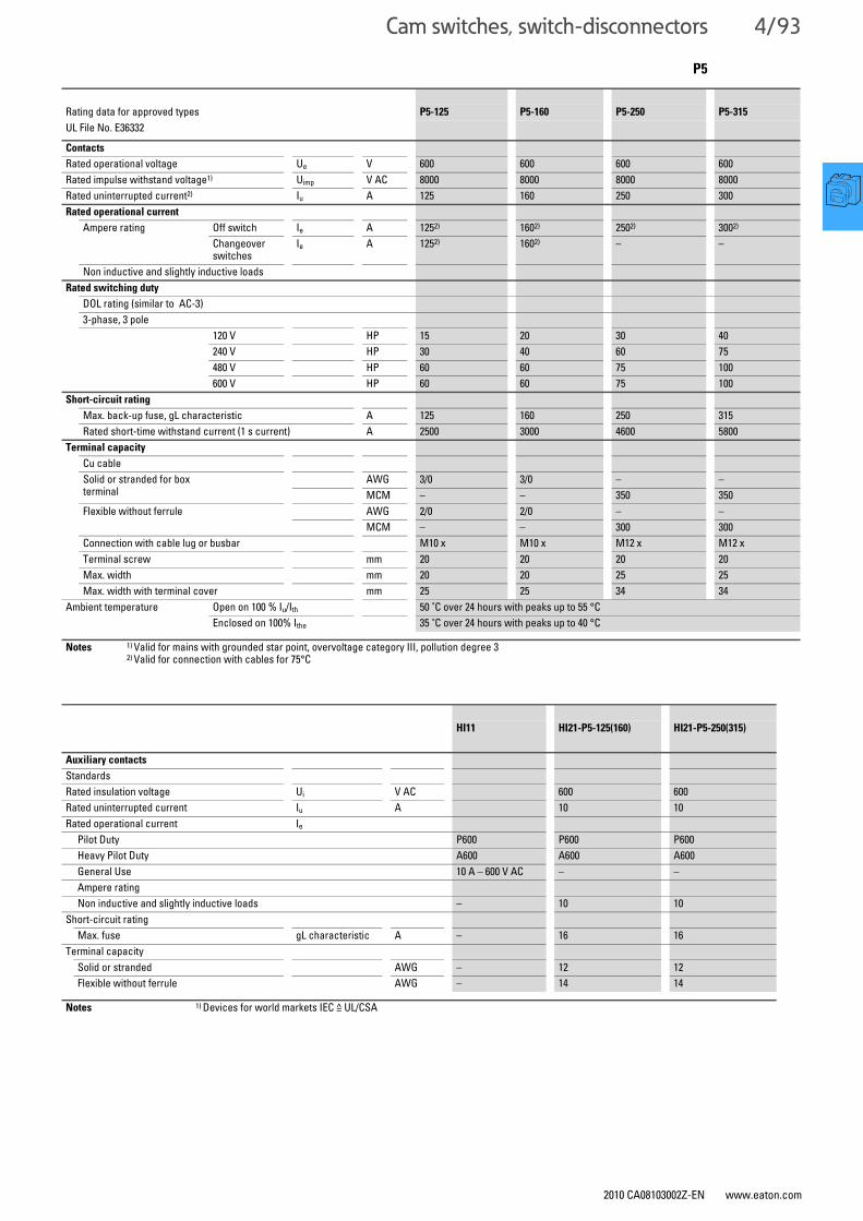
Cam switches, switch-disconnectors
2010 CA08103002Z-EN www.eaton.com
4/93
Rating data for approved types P5-125 P5-160 P5-250 P5-315
UL File No. E36332
Contacts
Rated operational voltage Ue V 600 600 600 600Rated impulse withstand voltage1) Uimp V AC 8000 8000 8000 8000Rated uninterrupted current2) Iu A 125 160 250 300Rated operational current
Ampere rating Off switch Ie A 1252) 1602) 2502) 3002)
Changeover switches
Ie A 1252) 1602) – –
Non inductive and slightly inductive loadsRated switching duty
DOL rating (similar to AC-3)3-phase, 3 pole
120 V HP 15 20 30 40240 V HP 30 40 60 75480 V HP 60 60 75 100600 V HP 60 60 75 100
Short-circuit rating
Max. back-up fuse, gL characteristic A 125 160 250 315Rated short-time withstand current (1 s current) A 2500 3000 4600 5800
Terminal capacity
Cu cableSolid or stranded for box terminal
AWG 3/0 3/0 – –MCM – – 350 350
Flexible without ferrule AWG 2/0 2/0 – –MCM – – 300 300
Connection with cable lug or busbar M10 x M10 x M12 x M12 xTerminal screw mm 20 20 20 20Max. width mm 20 20 25 25Max. width with terminal cover mm 25 25 34 34
Ambient temperature Open on 100 % Iu/Ith 50 °C over 24 hours with peaks up to 55 °CEnclosed on 100% Ithe 35 °C over 24 hours with peaks up to 40 °C
Notes 1) Valid for mains with grounded star point, overvoltage category III, pollution degree 32) Valid for connection with cables for 75°C
HI11 HI21-P5-125(160) HI21-P5-250(315)
Auxiliary contacts
StandardsRated insulation voltage Ui V AC 600 600Rated uninterrupted current Iu A 10 10Rated operational current Ie
Pilot Duty P600 P600 P600Heavy Pilot Duty A600 A600 A600General Use 10 A – 600 V AC – –Ampere ratingNon inductive and slightly inductive loads – 10 10
Short-circuit ratingMax. fuse gL characteristic A – 16 16
Terminal capacitySolid or stranded AWG – 12 12Flexible without ferrule AWG – 14 14
Notes 1) Devices for world markets IEC ≙ UL/CSA
P5

4/94 Cam switches, switch-disconnectorsCam switches
2010 CA08103002Z-EN www.eaton.com 2010 CA08103002Z-EN www.eaton.com
Cam switches, switch-disconnectorsCam switches
Cam switches
T0-... T3-... T5B-... T5-... T6-3-8212/E/HI12 T6-160-... T8-...
General
Standards IEC/EN 60947, VDE 0660, IEC/EN 60204, CSA, UL,Switch-disconnectors to IEC/EN 60947-3Load-break switch according to IEC/EN 60947-3
IEC/EN 60947, VDE 0660, IEC/EN 60204, CSA, UL,Switch-disconnectors to IEC/EN 60947-3Load-break switch according to IEC/EN 60947-3
Lifespan, mechanical Operations x 106 0.5 0.5 0.5 0.5 0.1 0.1 0.1
Maximum operating frequency Operations/h 3000 3000 3000 3000 50 50 50
Climatic proofing Damp heat, constant, to IEC 60068-2-78; Damp heat, cyclic to IEC 60068-2-30
Damp heat, constant, to IEC 60068-2-78; Damp heat, cyclic, to IEC 60068-2-30
Ambient temperature
Open °C -25 - 50 -25 - 50 -25 - 50 -25 - 50 -25 - 50 -25 - 50 -25 - 50
Enclosed °C -25 - 40 -25 - 40 -25 - 40 -25 - 40 -25 - 40 -25 - 40 -25 - 40
Mounting position Any Any Any Any Any Any Any
Mechanical shock resistance to IEC 60068-2-27 Half-sinusoidal shock 20 ms
g > 15 > 15 > 15 > 15
Contacts
Rated operational voltage Ue V AC 690 690 690 690 690 690 690
Rated impulse withstand voltage Uimp V AC 6000 6000 6000 6000 6000 8000 8000
Overvoltage category/pollution degree III/3 III/3 III/3 III/3 III/3 III/3 III/3
Rated uninterrupted current
Open Iu A 20 32 63 100 125 160 315
Enclosed Iu A 20 32 63 100 125 160 275
Load rating with intermittent operation, class 12
AB 25 % DF x Ie 2 2 2 2 2 2 2
AB 40 % DF x Ie 1.6 1.6 1.6 1.6 1.6 1.6 1.6
AB 60 % DF x Ie 1.3 1.3 1.3 1.3 1.3 1.3 1.3
Short-circuit rating
Fuse A gG/gL 20 35 80 100 200 160 315
Rated short-time withstand current (1 s current) Icw Arms 320 650 1300 1850 2000 3000 4200
Safe isolation according to EN 61140
Between the contacts V AC 440 440 440 440
Switching angle ° 90604530
90604530
90604530
90604530
9060
9060
9060
Contact units Max. 11 Max. 11 Max. 10 Max. 10 Max. 3 Max. 3 Max. 3
Contacts with double-break Max. 22 Max. 22 Max. 20 Max. 20 Max. 6 Max. 6 Max. 6
Current heat loss per contact at Ie W 0.6 1.1 4.5 7.5 11 11 11
Terminal capacity
Solid or stranded mm2 1 x (1 - 2.5)2 x (1 - 2.5)
1 x (1 - 6)2 x (1 - 6)
1 x (2.5 - 35)2 x (2.5 - 16)
1 x (2.5 - 35)2 x (2.5 - 16)
1 x 702 x 25
1 x 952 x 25
150
Flexible with ferrule to DIN 46228 mm2 1 x (0.75 - 1.5)2 x (0.75 - 1.5)
1 x (0.75 - 4)2 x (0.75 - 4)
1 x (1.5 - 25)2 x (1.5 - 10)
1 x (1.5 - 25)2 x (1.5 - 10)
1 x 502 x 16
1 x 502 x 16
120
Flat terminal for rails mm2 1 x (25 x 5)2 x (20 x 3)
Terminal screw M3.5 M4 M6 M6 M6 M5, hexagon screw M12
Tightening torque Nm 1 2 4 4 5.6 14 25
Notes The following applies for mechanical shock resistance: T3.../I... >12gApplies to T0(3).../SVB: isolating characteristics to IEC/EN 60947 for rated operational voltage Ue up to 500 VACThe following applies to rated uninterrupted current Iuof contacts: max. 95 A with T5-4-8344/I5The following applies for solid, stranded and flexible terminal capacities:T0(3), (6), (8)...: if 2 conductors are used, a max. difference of 2 cross-section sizes is permissibleT5(B)-...: if 2 conductors are used, a max. difference of one cross-section sizes is permissibleThe following applies for part no. T8-3-8342/...: switching angle = 90° and flat conductor connection = 1 flat conductor, 25 x 5, or 2 flat conductors, 20 x 3
4/95
T T

4/96 Cam switches, switch-disconnectorsCam switches
2010 CA08103002Z-EN www.eaton.com 2010 CA08103002Z-EN www.eaton.com
Cam switches, switch-disconnectorsCam switches
Cam switches
T0-... T3-... T5B-... T5-... T6-3-8212/E/HI12 T6-160-... T8-...
Switching capacity
AC voltage
Rated making capacity cos ϕ = 0.35 A 130 320 800 950 1600 1600 2390
Rated breaking capacity, Motor load switch cos ϕ = 0.35
230 V A 100 260 520 760 1280 1280 1910
400 V A 110 260 600 740 900 900 1800
500 V A 80 240 480 590 880 880 1200
690 V A 60 170 340 420 340 340 420
Rated operational current load break switch AC-21A
440 V Ie A 20 32 63 100 125 160 315
Motor rating Motor load switch AC-3
230 V P kW 3 6.5 15 22 22 22 22
230 V star-delta P kW 4 11 22 30 22 22 37
400/415 V P kW 4 12 22 30 37 45 55
400 V star-delta P kW 5.5 18.5 37 45 37 45 55
500 V P kW 5.5 15 22 37 37 37 37
500 V star-delta P kW 7.5 22 37 55 37 37 37
690 V P kW 4 15 22 30 22 22 37
690 V star-delta P kW 5.5 22 37 45 22 22 37
Motor rating Motor load switch AC-23A
230 V P kW 3.5 7.5 15 18.5 37 37 75
400/415 V P kW 6.5 13 22 30 45 55 132
500 V P kW 7.5 15 22 37 55 75 132
690 V P kW 6.5 15 22 30 30 30 37
Rated operational current Control switch AC-15
230 V Ie A 6 10 16 16 – – –
400/415 V Ie A 4 6 6 6 – – –
500 V Ie A 2 4 4 4 – – –
DC voltage
DC-1, load switch L/R = 1 ms Rated operational current Ie A 10 25 63 80 125 125 315
Voltage per contact connected in series V 60 60 60 60 42 42 42
DC-21A Rated operational current 240 V Ie A 1 1
240 V contacts Number 1 1
DC-23A, motor load switchL/R = 15 ms
24 V Rated operational current Ie A 10 25 50 – 125 125 250
Contacts Number 1 1 1 – 1 1 1
48 V Rated operational current Ie A 10 25 50 – 125 125 250
Contacts Number 2 2 2 – 2 2 2
60 V Rated operational current Ie A 10 25 50 – 125 125 125
Contacts Number 3 3 3 – 3 3 3
120 V Rated operational current Ie A 5 12 25 – 50 50 50
Contacts Number 3 3 3 – 3 3 3
240 V Rated operational current Ie A 5 5 20 – – – –
Contacts Number 5 5 6 – – – –
DC-13, control switch L/R = 50 ms Rated operational current Ie A 10 20 25 – 125 125 250
Voltage per contact connected in series V 32 32 24 – 24 24
Control circuit reliability at 24 V DC, 10 mA Fault probability HF < 10 -5, < 1 failure for 100000 switching operations < 10 -5, < 1 failure for 100000 switching operations
Auxiliary contacts
Standards Control circuit isolator to IEC/EN 60947-5 f
Control circuit isolator to IEC/EN 60947-5 f
Rated insulation voltage Ui V AC – – – – 500 500 –
Rated uninterrupted current Iu A – – – – 10 10 –
Rated operational current
AC-15 at 230 V Ie A – – – – 6 6 –
400 V/415 V Ie A – – – – 4 4 –
Short-circuit rating
Max. fuse A gG/gL – – – – 10 10 –
Terminal capacity
Solid mm2 – – – – 0.75 - 2.5 0.75 - 2.5 –
Flexible with ferrule to DIN 46228 mm2 – – – – 0.5 - 1.5 0.5 - 1.5 –
Tightening torque Nm 0.35 0.35
Control circuit reliability at 24 V DC, 10 mA Fault probability HF – – – – < 10-5, < 1 failure for 100 000 switching operations
4/97
T T

4/98 Cam switches, switch-disconnectorsMiscellaneous switches with "disconnect function"
2010 CA08103002Z-EN www.eaton.com
Miscellaneous switches with "disconnect function"
Approvals for North America
Rating data for approved types1)
UL File No. E36332 T0-... T3-... T5B-...
Contacts
Rated operational voltage Ue V AC 600 600 600Rated uninterrupted current Iu
Current rating A 16 25 65Pilot Duty A 600
P 600A 600
Switching capacity
AC-3; max. rated power 40 – 60 Hz AC motors
3-phase 200 V AC HP 3 5 15230 V AC HP 3 7½ 15460 V AC HP 10 15 40575 V AC HP 10 15 50
Single-phase 115 V AC HP 1 1½ 3200 V AC HP 2 3 7½230 V AC HP 2 3 10
Short-circuit rating Standard 600 V AC kA 5 5 5With back-up fuse A 50 80 CLASS JWith circuit-breakers Part no. NZMH6 NZMH6 –Current setting A 50 125 –
Disconnect in motor circuits 600 V AC kA 10 10 –With back-up fuse Class 20 A/J 40 A/J –
Terminal capacity
Terminal capacityCu cable Min. AWG 18 14 12
Max. AWG 14 10 4Tightening torque Max. in-lb 8.8 17.6 35.3
Notes 1) Devices for world markets IEC ≙ UL/CSA.Accessories a Cam switches for the German market.If required, order English language front plate from the German market product range. Do not use AW extension terminals where UL/CSA approval is required.
UL approved protection types
UL/NEMA 1 UL/NEMA 3R UL/NEMA 12
Cam switchesT0-.../E; /Z; /SVB • • •T3-.../E; /Z; /SVB • • •T5B-.../E;/Z;/SVB • • •
Notes Protection type explanations a Chapter 23, Enclosure protection types as defined in NEC (NFPA 70), UL, CSA, NEMA
T cam switches in NA version
In its NA version, the cam switch features a terminal inscription in English and/or a terminal inscription deviating from the IEC standard. Switches in mounting types I2 to I4 feature an additional inscription on the enclosure's front (e.g. part no. and protection type). Not possible in combination with key operation lock mechanism S-T0; SVA-T3, and SVC-T3.
An overview of these cam switches can be found in the instructional leaflet AWA 1150-2327.
Catalog No.: T0 T3 T5B
Mounting type
/E; /EA; /EZ/Z; /V; /IVS
+NA105864
+NA105864
/I2 +NA-I2105866
/I4
/I5 +NA-I5105869
T

Mini cam switchesMini cam switches
2010 CA08103002Z-EN www.eaton.com
4/99
Mini cam switches
TM
General
Standards IEC/EN 60947, VDE 0660 UL, CSAControl switch to IEC/EN 60947-5-1Control circuit isolators to IEC/EN 60947-5-1
Control circuit isolator (IEC/EN 60947-5-1) Max. 6 contacts; switching angle: 90°Lifespan, mechanical Operations x 106 > 1Maximum operating frequency Operations/h 3000Climatic proofing Damp heat, constant, to IEC 60068-2-78;
Damp heat, cyclical, to IEC 60068-2-30Ambient temperature
Open °C -25.…50Enclosed °C -25.…40
Mounting position AnyTerminal capacity
Solid mm2 1 x 1.52 x 1.5
Flexible without ferrule mm2 1 x 1.52 x 1.5
Solid or stranded AWG 1 x 142 x 14
Flexible AWG 1 x 162 x 16
Terminal screw M2.5Tightening torque Nm 0.35
Contacts
Mechanical dataContacts Number Max. 16Contact units (BE) Max. 8Switching angle ° 90
604530
Smallest switching angle for ON-OFF-ON ° 60Max. switch position ≦ 12
Electrical characteristicsRated operational voltage Ue V AC 500Rated impulse withstand voltage Uimp V AC 4000Overvoltage category/pollution degree III/3Rated insulation voltage Ui V AC 500Rated insulation voltage to UL/CSA V AC 300Rated uninterrupted current Iu A 10
Switching capacityAC-23 motor load switch 230 V AC, 3 pole kW 1.8
440 V AC, 3 pole kW 3230 V AC, 1 pole kW 0.75440 V AC, 1 pole kW 1.1
AC-15 control switch 230 V AC, 1 pole A 2.5400 V AC, 1 pole A 1.5440 V AC, 1 pole A 1
DC-13, control switch L/R = 50 ms Rated operational current Ie A 3Voltage per contact connected in series V 32
Switching capacity (UL489, CSA 22.2 No. 5.1)
240 V AC, 3 pole HP 1277 V AC, 1 pole HP ¾300 V AC Heavy duty A 10
Max. short-circuit protective deviceFuse A gG/gL 10
Control circuit reliability at 24 V DC, 10 mA Fault probability HF < 10-5, < 1 failure for 100000 switching cycles
TM

4/100 Cam switches, switch-disconnectors
Dimensions
Flush mountingT0.../E (+ H3-T0)T3.../E (+ H3-T0) Drilling dimensions
Center mountingT0.../EZT3.../EZ
T0 T3 Drilling dimensions
② Not included as standard
Service distribution board mounting
T0.../IVS Drilling dimensionsbase
48
4817
525 101
c20 35
H3-T0
b
75
90
10 –
11
3.1 – 3.5
12.2
30
48
4817
1.5 – 5b
c21 35
4548
48 54
61
3.2
24.1
+0.
4 0
22.3 +0.4 0
Part no. c20 c21T0-1...T0-2...T0-3...T0-4...T0-5...T0-6...T0-7...T0-8...T0-9...T0-10...T0-11...
41506069798898107117126136
6170808999108118127137146156
Depth of one contact unit: 9.5 mm
Part no. c20 c21T3-1...T3-2...T3-3...T3-4...T3-5...T3-6...T3-7...T3-8...T3-9...T3-10...T3-11...
4456677990102113125136148159
64768799110122133145156168179
Depth of one contact unit: 11.5 mm
54
5545 M4 50
48
60 50
o 5
o 528
45
55c22
5
2010 CA08103002Z
Cam switches
T0, T3
-EN www.eaton.com

Cam switches, switch-disconnectors 4/101
Rear mountingT0.../ZT3.../Z
Drilling dimensionsbase
Drilling dimensionsdoor
① Extension with
ZAV-T0 possible,≦ 4 x 25 = 100 mm
② Not included as standard
Flush mounting main switchT0.../EA/SVBT3.../EA/SVB
Drilling dimensionsdoor
T0
T3
Rear mounting main switchesT0.../V/SVBT3.../V/SVB
Drilling dimensionsbase
Drilling dimensionsdoor
T0
T3
① Interlock extension possible with ZVV-T0 + ZAV-T0, F 4 x 25 = 100 mm② Not included as standard
548
4817
M450
5 – 5.5
36
36
5 – 5.5
36
36M465
48
50 60
63
65 7555
5 5
25
c23c24 35
O 5
O
O
O
5
5
38, 54
22.3 + 0.4 0
22.3 + 0.4 0
100R
a
b
T3
T0
Part no. c20 c21 c22 c23 c24≧/≦
c24 with≦ 4 ZAV
c25
T0-1...T0-2...T0-3...T0-4...T0-5...T0-6...T0-7...T0-8...T0-9...T0-10...T0-11...
41506069798898107117126136
6170808999108118127137146156
778796106115125134144154163173
485767768695105114124133143
86 – 10296 – 112105 – 121115 – 131124 – 140134 – 150143 – 159153 – 169162 – 178172 – 188181 – 197
202212221231240250259269278288297
72729191–––––––
Depth of one contact unit: 9.5 mm
Part no. c20 c21 c22 c23 c24≧/≦
c24 with≦ 4 ZAV
c25
T3-1...T3-2...T3-3...T3-4...T3-5...T3-6...T3-7...T3-8...T3-9...T3-10...T3-11...
4456677990102113125136148159
64768799110122133145156168179
8092103115126138149161172184195
5163748697109120132143155166
86 – 105101 – 115112 – 128124 – 139135 – 151147 – 162158 – 174170 – 185181 – 196193 – 208204 – 219
205216228239251262274285296308319
7979101101–––––––
Depth of one contact unit: 11.5 mm
65
3317
48
ON
OFF
OFF
I
o
o
25 c2035
b F 5
61
54
49
45
3.1 – 3.530
10 –
11
12.2
I
o
o
65
3317
48
b
5 25
c23c24 35
ON
OFF
OFF
a
F 5
f 38, F 54R f 100 65 75
63
5
5
M465
M450
o
o
50 60
49
o 522.3 + 0.4 0
5 – 5.5
36
36
Cam switches
T0, T3
2010 CA08103002Z-EN www.eaton.com

4/102 Cam switches, switch-disconnectors
Surface mounting
T0.../I1Drilling dimensionsbase
T3.../I2 Drilling dimensionsbase
Surface mounting main switches
T0.../I1/padlock facilityDrilling dimensionsbase
T3.../I2/SVB Drilling dimensionsbase
≦ 3 padlocks
80
120
c25 27
137 M20
127
M4
100
160
c25 c33
180 M20 / M25
8
171
M4
80
120
c25 35
M20
137
I
OFFo
ON
oOFF
127
M4
100
160
180
35c25
M20 /M25
o8
I
OFFo
ON
oOFF
d b
d = 4 – 8 mmb + d F 47 mm
171
M4
Part no. c25T0-1...T0-2...T0-3...T0-4...
75759595
Part no. c25 c33T3-1...T3-2...T3-3...T3-4...T3-5...
8080100100145
2727353535
2010 CA08103002Z
Cam switches
T0, T3
-EN www.eaton.com

Cam switches, switch-disconnectors 4/103
Key operated lock mechanism
S-T0S-SOND...-T0
T0.../E(I1) + S-(SOND-)T0T3.../E(I2) + S-(SOND-)T0
T0.../Z + S-(SOND-)T0T3.../Z + S-(SOND-)T0
T0.../EZ = T0../E + EZ-T0 + S-(SOND-)T0T3.../EZ = T3../E + EZ-T0 + S-(SOND-)T0
Cylinder lock
SVA-T3 T0.../I1/SVAT3.../I2/SVAP1.../12/SVA
T0.../E/SVA...T3.../E/SVA...P1.../E/SVA
T0.../Z/SVA...T3.../Z/SVA...P1.../Z/SVA
Padlocking feature
SVC-T3 T0.../I1/SVCT3.../I2/SVCP1.../12/SVC
T0.../E/SVC...T3.../E/SVC...P1.../E/SVC
T0.../Z/SVC...T3.../Z/SVC...P1.../Z/SVC
ModulesSwitched neutral conductor N-P...Auxiliary contacts HI 11-P1/P3
≦ 3 padlocks
② Not included as standard
17
27
48
48
b
19 30
5
36
12.2
3.1 – 3.5
30
10...
11
5 27
44
5 – 5.5
36
36
22.3 + 0.4 0
100 R
2 – 5
c20 22:25 – 28 30:23 – 26
3.2
30.5
17
3.2 12.5
22.3 + 0.4 0
73
48
b 56
73
46 30
56
73
46 30
56
73
46 30
73
48
b 56
73
46
48
56
73
46
48
56
73
46
48
L3 L2 L1
T3 T2 T16 4 2
5 3 1 b31
a3
N-P
H-P...
HI 11
N
N
1 3
2 4 6
a32 a31 a32 a32 a31 a32
a33
5
Part no. a3 a31 a32 a33 b31P1-...P3-..
4972
1518
1515
83114
4960
d b
d = 4 – 8 mmb + d F 47 mm
Cam switches, switch-disconnectors, accessories
T0, T3, P1, P3
2010 CA08103002Z-EN www.eaton.com

4/104 Cam switches, switch-disconnectors
Flush mountingT5(B).../E Drilling dimensions
door
Rear mountingT5(B).../Z
Drilling dimensionsbase
Drilling dimensionsdoor
① Shaft extension possible with ZAV-P3 F 4 x 25 = 100 mmFlush mounting main switchesT5(B).../EA/SVB
Drilling dimensionsdoor
Rear mounting main switchesT5(B).../V/SVB
Drilling dimensionsbase
Drilling dimensionsdoor
①
②
Extension possible with ZVV-P3, ≦ 4 x 25 = 100 mm
Not included as standard
88
8827
ON
OFF
I
o
18
c2
86
37
F 5
b
14
37
4.1 – 4.5
12 – 13
ON
OFFo
I
88
8827
48
5 - 5.5
48
30.5
c20
c2 37
2525
73M6
a
f 38, F 54
F 5
R f 100
b
88
2788
ON
OFF
OFF
I
o
o
25c2
88
80/9
0
40.516.5
44
100
80/9
0
1437
4.1 – 4.5
12 – 13
F 5b
ON
OFF
OFF
o
I
o
48
5 – 5.5
48
30.5
2788
88
1216.5
c205
25 25
40.5
44
73
a
b
R f 100
F 5
Part no. c2 c20≧/≦
c20 with≦ 4 ZAV
c21 c22
T5(B)-1...T5(B)-2...T5(B)-3...T5(B)-4...
547187104
92 – 107109 – 124125 – 140142 – 157
207224240257
9090123123
125 (95)125 (95)160 (160)160 (160)
T5(B)-5...T5(B)-6...T5(B)-7...T5(B)-8...T5(B)-9...T5(B)-10...
120137153170186203
158 – 173175 – 190191 – 206208 – 223224 – 239240 – 356
273290306323339356
––––––
––––––
Depth of one contact unit: 16.5 mm
Cam switches T5B and T5 have identical designs,only their contacts are different
2010 CA08103002Z
Cam switches
T5B, T5
-EN www.eaton.com

Cam switches, switch-disconnectors 4/105
Surface mountingT5B.../I4
T5.../I5
Surface mounting main switches
T5B.../I4/SVB Drilling dimensions≦ 3 padlocks
T5.../I5/SVB Drilling dimensions
External fixing brackets
AB-CI-K415
160 c22 29
M20240
280
200 c22 37
M20
M25M40M50M25
M32
160
240
c22 44
193
142
M5
I
OFFo
ON
oOFF
d b
d = 4 – 8 mmb + d F 47 mm
280
200 c22 44
233
182
M5
I
OFFo
ON
oOFF
Part no. c22T5(B)-1...T5(B)-2...T5(B)-3...T5(B)-4...
125125160160
Depth of one contact unit: 16.5 mm
Cam switches T5B and T5 have identical designs,only their contacts are different20 5.
5
6.5
52
36
3.8
M5t = 3
7.8
6
Cam switches
T5B, T5
2010 CA08103002Z-EN www.eaton.com

4/106 Cam switches, switch-disconnectors
Flush mounting
T6-3-8212/E/HI12T8-3-8212/E/HI12
T6-160-6/V/SVB-SW/HI11 T8-3-8342/V/SVB-(SW)/HI11
Drilling dimensionsdoor
T6: 4 M5 x 20T8: 4 M6 x 20
≦ 3 padlocks for T.../SVB
150
58
5c2 c30
b2
a2
9
88
73
5.5 1
93 216 200
5
76224
6.4 H-T6-100
118
22
68108
100R
7
130
250
1044.5
172.8
315 218
9.2
86.5
7 1
130
68
H-T8
19
100R
a
Part no. a2 b2 c2 c30 d1 d2 x1 y1
T6-3-8212/E/HI12T8-3-8212/E/HI12T8-3-8342/V/SVB-(SW)/HI11
88130–
88130–
152173
4462–
⌀ 26 – 30⌀ 22 – 25⌀ 26 – 30
⌀ 6.0⌀ 7.0⌀ 7.0
6810468
6810468
d2
d1
x1
y1
d b
d = 4 – 8 mmb + d F 47 mm
2010 CA08103002Z
Cam switches
T6, T8
-EN www.eaton.com

Cam switches, switch-disconnectors 4/107
Flush mounting
P.../E
Center mounting
P1.../EZ Drilling dimensionsdoorP1-.../E P1-.../EZ P3-.../E
Service distribution board flush mounting
P3.../IVS ≦ 3 padlocks P1.../IVS
Rear mounting
P.../Z
① Shaft extension with ZAV-... possible ≦ 4 x 25 = 100 mm
Drilling dimensionsbaseP1.../Z
P3.../Z
Drilling dimensionsdoor
ON
0
I
OFF
a2
b2b2
2
b3a3
L3 L1
T3 T1
L2
T2
1
2
3
4
5
6
5c2 c21
P1.../EZ = c2 + 5 mm
4.1 – 4.53.2
22.3 +0.40
12.5
10 –
11
12.2
3.1 – 3.5
30
14
37
12 – 13
b3
a4
c22c23
c3
5
45
N
HI11
L3L2L1
T3T2T1
L3L2L1
T3T2T1
a32 a32
a31
d b
d = 4 – 8 mmb + d F 47 mm
49
L1 L2 L3
T1 T2 T3
55
28
b3 45
5 c3
a
38,
3
5
a3
5
b22
b2
a2
c21c25c20
R 100
c31 c32b3
54
5 – 5.5
M4 65 36
36
22.3 +0.40
M4 75
25
5 – 5.5
48
48
30.5
Part no. a2 a3 a4 a21 a22 a23 a31 a32 a33 b2 b3 b21 b22 b23 b24 b31P1P3
4887
4972
53.571.5
6587
4887
87125
1518
1515
83114
4887
7083
6587
1727
180175
32–
4960
Part no. c2 c3 c20≧/≦
c20 with≦ 4ZAV/ZVV
c21 c22 c23 c24 c25 c27 c28 c31 c32 c33
P1P3
5959
8682
96 – 112103 – 118
212218
3537
3241
6563
6881
5865
3544
7790
2525
2525
2729
Switch-disconnectors
P1, P3
2010 CA08103002Z-EN www.eaton.com

4/108 Cam switches, switch-disconnectors
Flush mounting main switches
P.../EA/SVB Drilling dimensionsdoor
P1... P3
Rear mounting main switches
P.../V/SVB
① Interlock extension with ZVV-...+ZAV... possible ≦ 4 x 25 = 100 mm② Not included as standard
Drilling dimensionsbase
P1/V/SVB
P3/V/SVB
Drilling dimensionsdoor
Surface mounting
P1.../I2
Surface mounting main switches/safety switches
P1.../I2/SVBP1.../I2/SI
Drilling dimensions
b3
a3
ON
OFF
b22
c27c225
o
o OFF
I 1
2
3
4
5
6
N
N y
y
a22
b21
a21b3
1
H-P...
F 5
b
14
4.1 – 4.5
10 –
11
12.2
3.1 – 3.5
30 37
12 – 13
3
I ON
OFF
OFF
5
o
o
1
2
3
4
5
6
N
N
a22
a21 a3 c25c20
c27
b22
b21
b31
b3
H-P... a
F 5
R f 100
f 38, F 54
b
5 – 5.5
M4 65 36
36
22.3 +0.40
M4 75
25
5 – 5.5
48
48
30.5
a23
160
c28 c33
M25
171
c27
M4
b23
M25M25F 8
Part no. a2 a3 a4 a21 a22 a23 a31 a32 a33 b2 b3 b21 b22 b23 b24 b31P1.../I2 48 49 53.5 65 48 100 15 15 83 48 70 65 17 180 35.5 49
Part no. c2 c3 c20≧/≦
c20 with≦ 4ZAV/ZVV
c21 c22 c23 c24 c25 c27 c28 c31 c32 c33
P1... 59 86 96 – 112 212 35 32 65 68 58 35 80 25 25 27
2010 CA08103002Z
Switch-disconnectors
P1, P3
-EN www.eaton.com

Cam switches, switch-disconnectors 4/109
Flush mounting
P5.../E Drilling dimensions
Flush mounting main switches
P5-.../EA/SVB-(SW)
Rear mounting
P5.../Z Drilling dimensions
Rear mounting main switches
P5-.../SVB-(SW)
b
c
8 35a
M5
68 88
F 5
q 8
8
q 6
8
26 – 30
6
68 88
26
49.3
88c21
M5 P5-.../N HI10
a
a1
a2 a2
b2b2
b
F 5
q 8
8
b
c 8 35
b12
2
6.4
a
a1
c1
F 5
q 8
8
q 6
8
26 – 30
6
P5-.../N
b2b2
b
aa2 a2
88
R f 100
c
c1 49.3
26F 5
Part no. a a1 a2 b b1 b2 c c1P5-125/160 112 36 38 108 120 76 91 ≧ 130 ≦ 287P5-250/315 145 44 52.5 126 144 88 98 ≧ 140 ≦ 280
q 8
8
Switch-disconnectors
P5
2010 CA08103002Z-EN www.eaton.com

4/110 Cam switches, switch-disconnectors
Surface mountingP3-63/I4
Surface mounting main switches/safety switchesP3-63/I4/SVBP3-63/I4/SIT5B-.../I4/SI
Drilling dimensions
Surface mounting
P3-100/I5
Surface mounting main switches/safety switchesP3-100/I5/SVBP3-100/I5/SIT5-.../I5/SI
Drilling dimensions
a23 95 29
b23
95 44
193
142
M5
M25M32 M20
a23 125 37 125 44
233
182
M5
M25M50 M20
b23
Part no. a2 a3 a4 a21 a22 a23 a31 a32 a33 b2 b3 b21 b22 b23 b24 b31P3-63/I4P3-100/I5
8787
7272
71.571.5
8787
8787
160200
1818
1515
114114
8787
8383
8787
2727
240280
35.535.5
6060
Part no. c2 c3 c20≧/≦
c20 with≦ 4ZAV/ZVV
c21 c22 c23 c24 c25 c27 c28 c31 c32 c33
P3-63P3-100
5959
8282
103 – 118103 – 118
218218
3737
4141
6363
8181
6565
4444
125125
2525
2525
3737
2010 CA08103002Z
Switch-disconnectors
P3
-EN www.eaton.com

Mini cam switches 4/111
Flush mounting
TM.../E Drilling dimensions
Control circuit isolatorsfor 2 padlocks ⌀ 4 mm or 1 padlock ⌀ 6 mm
TM-.../E/SVB-(SW) Drilling dimensions
Center mounting
TM-.../EZ Drilling dimensions1)
Center mounting with key operation
TM-...+EZ/S-.. Drilling dimensions1)
Service distribution board mounting
TM-.../IVS TM-.../IVS/S
Notes 1) Drilling dimensions optionally: 16.2 mm = without reduction ≙ RMQ16; 22.3 mm = with reduction ≙ RMQ Titan
28
c20
3
o 4.
8
30
30
28
28
M3 M33.2
20
848
48
28
c21
3
35
38
38
M4 M4
104.2
30
F 5.5
28
c20 231230
30
17/19
1.7
17.9
3.2
24.1
+0.
4 0
22.3 +0.4 0
16.2 +0.2 0
30
30
5.5
28
c20 3512
17/19
1.7
17.9
3.2
24.1
+0.
4 0
22.3 +0.4 0
16.2 +0.2 0
Part no. c20 c21TM-1TM-2TM-3TM-4TM-5TM-6TM-7TM-8
395163758799111123
425466
Depth of one contact unit: 12 mm
c1 c235.5
60
45
Part no. c1 c2TM-1TM-2
4446
2126.5
Depth of one contact unit 12 mm
42 21.5 2435.5
60
45
TM
2010 CA08103002Z-EN www.eaton.com

Enclosed Switch-disconnectors with pre-assembled steel EMC screen
T0, P1 and P3 Switch-disconnectorsEMC enclosure range from 20 A to 63 A www.eaton.eu
Electromagnetic compatibility (EMC) refers to the ability of the device to function despite electromagnetic disturbances in the environment without electromagnetically disturbing other devices in the surroundings.
The operation of three-phase motors is becoming more and more common via variable speed drives or frequency inverters, and the use of such equipment can cause EMC disturbance to rise significantly.
If interruption cannot be avoided, then an ideal mitigation method to maintain EMC compliance is to clamp the screened cables to a steel screening plate.
We have now enlarged our reliable CI-K offering with a range of enclosed Switch-disconnectors with pre-assembled steel screening plates for applications where EMC compliance is necessary. The new enclosed products feature units with current ratings of 20 A to 63 A, and can be used for motor applications up to 30 kW (AC-23A) for 415 V nominal current.
Features• Well known Reliable Eaton Series switchgear• Robust IP65 Polycarbonate compact enclosures• Cable clamps provide robust and trouble free connection to the screening plate• A range of cable clamps to suit all cable diameters is supplied as standard• Various Auxiliary switch options to suit customer needs• Red/Yellow or Black lockable handle options.
This range of enclosed switches are available as complete packages with pre-built switched N and Auxiliary contacts. The screeening plate is also available seperately for retrofit purposes.
NEW
IP65

Eaton is a registered trademark of Eaton Corporation
All other trademarks are property of their respective owners.
Eaton Industries GmbHHein-Moeller-Str. 7–11D-53115 B onn / Germany
© 2015 by Eaton CorporationAll rights reservedPublication No.: FL038008_ENip June 2015
100 mm (3.94")
160
mm
(6.3
")
180
mm
(7.0
9")
35 mm (1.38")a
I
OFFo
ON
oOFF
160 mm (6.3")
240
mm
(9.
45")
97 mm (3.82")44 mm (1.73")
I
OFFo
ON
oOFF
4.2 x 8.2
HI11
d1
d2d2
P1-…/MBS/…, T0-…/MBS/…
4.8 x 10.5
HI11
P3-63/I4/MBS/…
d1
d1
d1
d2
d2
7
8
10
12
d1
d1
d1
d2
3.5
3.5
3.5
4.1
0.14
0.14
0.14
0.16
0.28
0.32
0.39
0.47
2 x 4.2 x 8.2
2 x 4.2 x 8.2
2 x 4.2 x 8.2
2 x 4.8 x 10.5
⌀mm in mm inmm
12
16
20
d2
d2
d1
4,1
4,1
3,5
0,16
0,16
0,14
0,47
0,63
0,79
2 x 4,8 x 10,5
2 x 4,8 x 10,5
2 x 4,2 x 8,2
⌀mm in mm inmm
Range of pre-assembled switchesMax. Amp. rating
Motor Rating AC-23A, 415 V
Description Part no. Article no.
20 A 5.5 kW 3 Pol, red/yellow handle T0-2-1/I2H/MBS/SVB 1824253 Pol, black handle T0-2-1/I2H/MBS/SVB-SW 1824263 Pol + N, red/yellow handle T0-2-8900/I2H/MBS/SVB 1824273 Pol + N, black handle T0-2-8900/I2H/MBS/SVB-SW 1824283 Pol + 1 NO, red/yellow handle T0-2-15679/I2H/MBS/SVB 1824293 Pol + 1 NO, black handle T0-2-15679/I2H/MBS/SVB-SW 1824303 Pol + N + 1 NO / 1 NC, red/yellow handle T0-3-15680/I2H/MBS/SVB 1824313 Pol + N + 1 NO / 1 NC, black handle T0-3-15680/I2H/MBS/SVB-SW 1824323 Pol + 2 NO / 1 NC, red/yellow handle T0-3-15683/I2H/MBS/SVB 1824333 Pol + 2 NO / 1 NC, black handle T0-3-15683/I2H/MBS/SVB-SW 1824346 Pol + 1 NO / 1 NC, red/yellow handle T0-4-15682/I2H/MBS/SVB 1824356 Pol + 1 NO / 1 NC, black handle T0-4-15682/I2H/MBS/SVB-SW 182436
25 A 11 kW 3 Pol, red/yellow handle P1-25/I2H/MBS/SVB 1824133 Pol, black handle P1-25/I2H/MBS/SVB-SW 1824143 Pol + 1 NO / 1 NC, red/yellow handle P1-25/I2H/MBS/SVB/HI11 1824153 Pol + 1 NO / 1 NC, black handle P1-25/I2H/MBS/SVB-SW/HI11 182416
32 A 15 kW 3 Pol, red/yellow handle P1-32/I2H/MBS/SVB 1824173 Pol, black handle P1-32/I2H/MBS/SVB-SW 1824183 Pol + 1 NO / 1 NC, red/yellow handle P1-32/I2H/MBS/SVB/HI11 1824193 Pol + 1 NO / 1 NC, black handle P1-32/I2H/MBS/SVB-SW/HI11 182420
63 A 30 kW 3 Pol, red/yellow handle P3-63/I4/MBS/SVB 1824213 Pol, black handle P3-63/I4/MBS/SVB-SW 1824223 Pol + 1 NO / 1 NC, red/yellow handle P3-63/I4/MBS/SVB/HI11 1824233 Pol + 1 NO / 1 NC, black handle P3-63/I4/MBS/SVB-SW/HI11 182424
Note: Switches to be used for emergency stop switching must have a red handle and yellow locking collar type SVB, (as per IEC/EN 60204/VDE0113). Otherwise the black handle should be used (suffix „SVB-SW“).
Range of accessoriesDescription: Part no. Article no.Empty enclosure with screening plate for T0-1 CI-K2H-T0-1-MBS 182408Empty enclosure with screening plate for T0-2 CI-K2H-T0-2-MBS 182409Empty enclosure with screening plate for T0-3, T0-4 CI-K2H-T0-4-MBS 182410Empty enclosure with screening plate for T3-1, T3-2 CI-K2H-T3-2-MBS 182411Empty enclosure with screening plate for T3-3, T3-4 CI-K2H-T3-4-MBS 182412Metal screening plate for CI-K2 MBS-I2 290191Metal screening plate for CI-K4 MBS-I4 118742
Dimensions
P1-…/MBS/…
T0-…/MBS/…
81 mm (3.19")
101 mm (3.98")
Typ a

IP65
P1 and P3 Switch-DisconnectorsMoeller® series www.eaton.eu
The new P1 and P3 versions with Metal Extension Shafts fills a well know gap in the P Switch-Disconnector range. This now opens up new potential in the Panel Building market and use in Machine Control Panels with disconnection from 25A – 100A. With the new extension shafts our reliable P switches can be mounted in electrical cabinets of up to 600mm deep and with several Handle and Shaft options a solution can be found for every application. Also the most common types are available as a complete switch/shaft/handle package.
• Well known P Switch-Disconnector perfor-mance and reliability with low power losses
• Switches can quickly be mounted on DIN rail or fitted to the mounting plate.
• Time & cost saving – Switches available as complete packages saving on order admin, packaging and assembly time. Also availa-ble with pre-built switched N and Auxiliary contacts
• Simple interlock in ON with SVB handle and lockable in OFF with up to 3 x 8mm pad-locks
• By using K Line handles door can also be in-terlocked in OFF position. Also a defeatable option in the ON position for fault finding without disconnecting the power supply.
P1 and P3 Switch-Disconnectors
with Metal Extension Shafts

Order the Switch, Shaft and Handle separately or as standard combination packs.
Description Part no.Article
no.
Basic Switches, type P…/XM 3 pol 25A P1-25/XM 172834
3 pol 32A P1-32/XM 172835
3 pol 63A P3-63/XM 172836
3 pol 100A P3-100/XM 172837
Metal Shafts Shaft for 400mm deep cabinet P1/P3-M400 172844
Shaft for 600mm deep cabinet P1/P3-M600 172845
Operating Handles
Moeller series knobs and handles provide door interlock when in the ON position. SVB Main Switch Handles can be locked in OFF with up to 3 x 8 mm padlocks.
Black Knob for P1 KNB-P1/M 172838
Black Know for P3 KNB-P3/M 172839
Lockable Main Switch Handle P1 Red/Yellow SVB-P1/M 172840
Lockable Main Switch Handle P3 Red/Yellow SVB-P3/M 172841
Lockable Main Switch Handle P1 Black SVB-SW-P1/M 172842
Lockable Main Switch Handle P3 Black SVB-SW-P3/M 172843
K-Line Knobs and Handles provide door interlock when in the ON position and also when locked in the OFF position. The door interlock can also be defeated in the ON position by using a special tool. Lockable with up to 2 x 6 mm padlocks, or Cylinder lock.
Knob for P1, Blue, padlockable K1DB/P 1818029
Knob for P1, Red/Yellow, padlockable K1DR/P 1818030
Knob for P1, Grey, padlockable K1DG/P 1818031
Knob for P3, Blue, padlockable K2SDB/P 1818032
Knob for P3, Red/Yellow, padlockable K2SDR/P 1818033
Knob for P3, Grey, padlockable K2SDG/P 1818034
Knob for P3, Blue, Cylinder lock/key K2SDB/C 1818038
Knob for P3, Red/Yellow, Cylinder lock/key K2SDR/C 1818039
Knob for P3, Grey, Cylinder lock/key K2SDG/C 1818040
Switched N, Auxiliary Contacts Switched Neutral for P1 N-P1Z 000652
Switched Neutral for P3 N-P3Z 064805
1 N/O, 1N/C for P1 or P3 HI11-P1/P3Z 062031
Switch, Shaft and Handle combinations.
Most combinations can be ordered as single packs to reduce order administration and pa-ckaging (only with 400 mm shaft). Here are some common examples:
25A 3 pol P1 switch, with shaft for 400 mm cabinet, with Lockable Main switch Handle, Red/Yellow
P1-25/M4/
SVB
172875
32A 3 pol P1 switch, with 1NO/1NC Auxiliary, shaft for 400mm cabinet, with Lockable Main switch Handle, black
P1-32/M4/
HI11/SVB-SW
172870
63A 3 pol P3 switch, with shaft for 400 mm cabinet, with K Line K2 Knob, padlockable, Red/Yellow
P3-63/M4/
K2-PR
172810
Eaton Industries GmbH
Hein-Moeller-Str. 7–11D-53115 Bonn / Germany
© 2013 by Eaton CorporationAll rights reservedPrinted in Germany 11/13Publication No.: FL038001ENip November 2013Article No.: 173450
Eaton is a registered trademark of Eaton CorporationAll other trademarks are property of their respective owners.SmartWire-DT® is a registered trademark of Eaton Corporation.
600 mm shaft planned