Manufacturing process ass# 1
22
1 HNC/HND in Mechanical Engineering BTEC Diploma in Engineering Unit 10 Manufacturing Process Understanding the use of conventional machines Created by:
-
Upload
independent -
Category
Documents
-
view
1 -
download
0
Transcript of Manufacturing process ass# 1
1
HNC/HND in Mechanical EngineeringBTEC Diploma in Engineering
Unit 10Manufacturing Process
Understanding the use ofconventional machines
Created by:
2
Gabriel StancuHND Mechanical Engineering
YEAR 12014-04-30
Contents
Summary:.....................................3Introduction:................................3Processes, data requirements and machine tools3Manufacturing process........................8Turning process.............................9Horizontal milling process.................12Grinding process...........................15
Conclusion..................................16Refferences:................................16
3
Summary:
Conventional machining processes such as turning, milling, drilling, abrasive cutting, and grinding are used to generate complex shapes by removing material in the form of tinychips.
Turning utilizes a single point cutting tool that is steadily feed against a rotating work piece in order to generate cylindrical surfaces. In a milling process, the cutting tool which often has multiple cutting edges rotates around its axis while a feed motion is introduced in the work. Grinding is a material removal and surface generation process used to shape and finish components made of metals and other materials. An abrasive product, usually arotating wheel brought into controlled contact with a work surface.
4
Introduction:
The purpose of this assignment is to
explain how conventional machine tools are usedto produce a shaft according to the engineeringdrawings, and to describe the basic functional principles of machine tools. The second part of the assignment explains in brief the manufacturing process of the shaft component and gives alternative methods of work holding techniques.
Processes, data requirements and machine tools
According to the engineering drawing (appendix 1) the company XYZ ltd must produce ashaft. Before the mass production of the shaft the production department has to establish the process, time of production of each operation, the data requirements (tolerances, surface finish) and the machine tools needed to produce
5
the component to the required quality standards.
According to the engineering drawing the data requirement to produce the shaft are incomplete. The drawing shows only the final dimensions of the shaft. The dimensional tolerances, the surface finish and the type of material needed are missing. For that reason the tolerances has been defined to be -0.25/0 mm, the surface finish has to be a smooth finish, and the material used to produce the shaft is steel-low carbon.
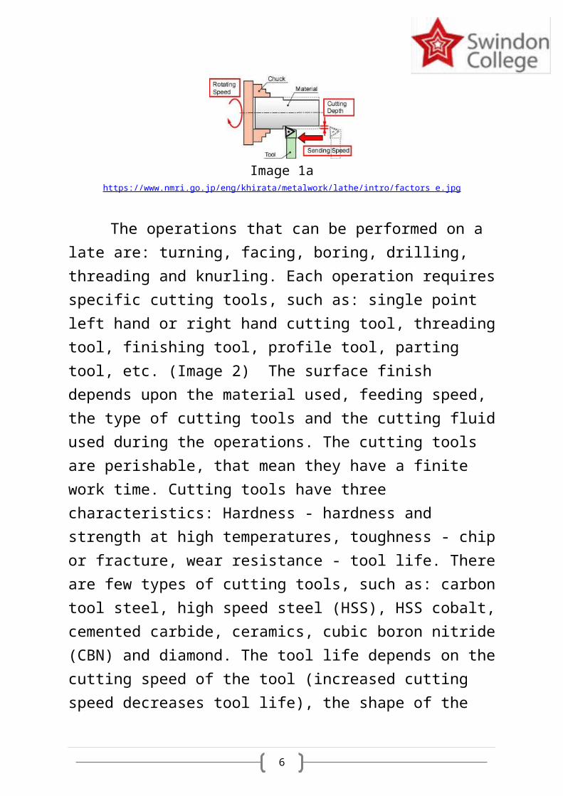
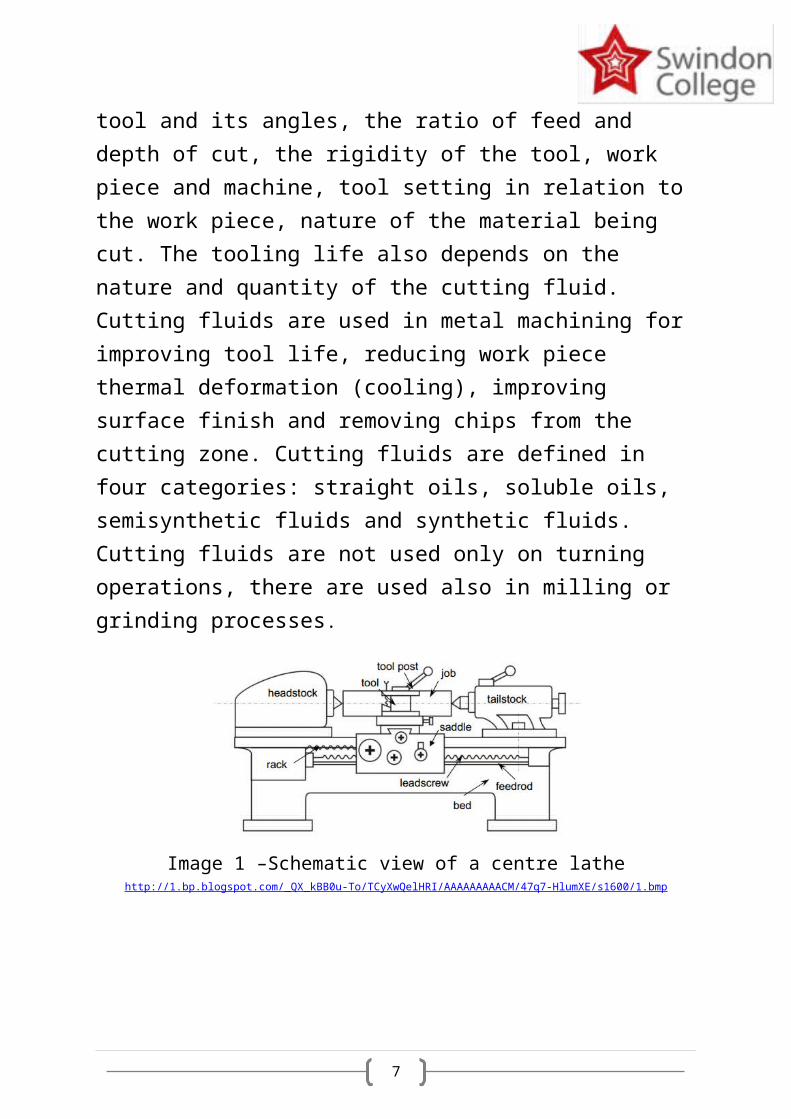
The appropriate conventional machines toolsrequired to produce the shaft are: lathe, horizontal milling machine, surface grinding and cylindrical grinding machine. The lathe (Image 1) is a machine tool which turns cylindrical material, touches a cutting tool tothe work piece and cuts the material (Image 1a). Turning is the removal of metal from the outer diameter of a rotating cylindrical work piece. Turning is used to reduce the diameter of the work piece, usually to a specified dimension, and to produce a smooth finish on the metal.
6
Image 1a https://www.nmri.go.jp/eng/khirata/metalwork/lathe/intro/factors_e.jpg
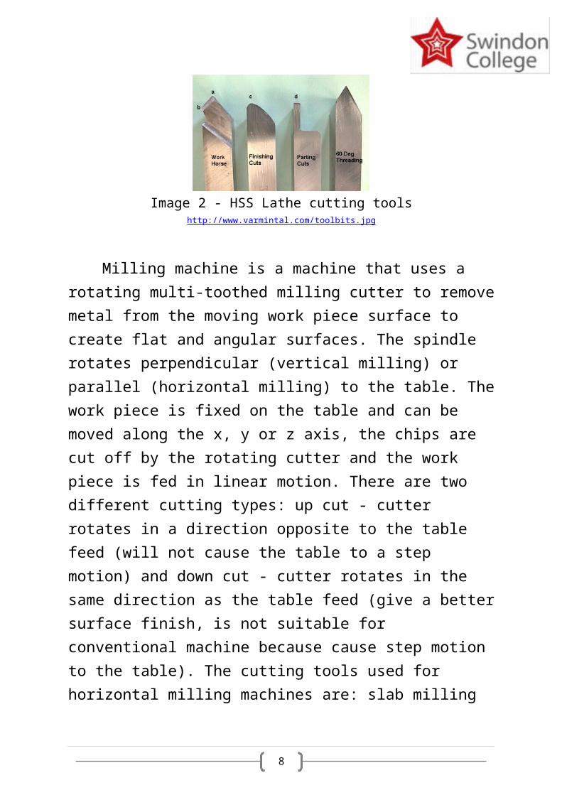
The operations that can be performed on a late are: turning, facing, boring, drilling, threading and knurling. Each operation requiresspecific cutting tools, such as: single point left hand or right hand cutting tool, threadingtool, finishing tool, profile tool, parting tool, etc. (Image 2) The surface finish depends upon the material used, feeding speed, the type of cutting tools and the cutting fluidused during the operations. The cutting tools are perishable, that mean they have a finite work time. Cutting tools have three characteristics: Hardness - hardness and strength at high temperatures, toughness - chipor fracture, wear resistance - tool life. Thereare few types of cutting tools, such as: carbontool steel, high speed steel (HSS), HSS cobalt,cemented carbide, ceramics, cubic boron nitride(CBN) and diamond. The tool life depends on thecutting speed of the tool (increased cutting speed decreases tool life), the shape of the
7
tool and its angles, the ratio of feed and depth of cut, the rigidity of the tool, work piece and machine, tool setting in relation to the work piece, nature of the material being cut. The tooling life also depends on the nature and quantity of the cutting fluid. Cutting fluids are used in metal machining for improving tool life, reducing work piece thermal deformation (cooling), improving surface finish and removing chips from the cutting zone. Cutting fluids are defined in four categories: straight oils, soluble oils, semisynthetic fluids and synthetic fluids. Cutting fluids are not used only on turning operations, there are used also in milling or grinding processes.
Image 1 –Schematic view of a centre lathehttp://1.bp.blogspot.com/_QX_kBB0u-To/TCyXwQelHRI/AAAAAAAAACM/47q7-HlumXE/s1600/1.bmp
8
Image 2 - HSS Lathe cutting toolshttp://www.varmintal.com/toolbits.jpg
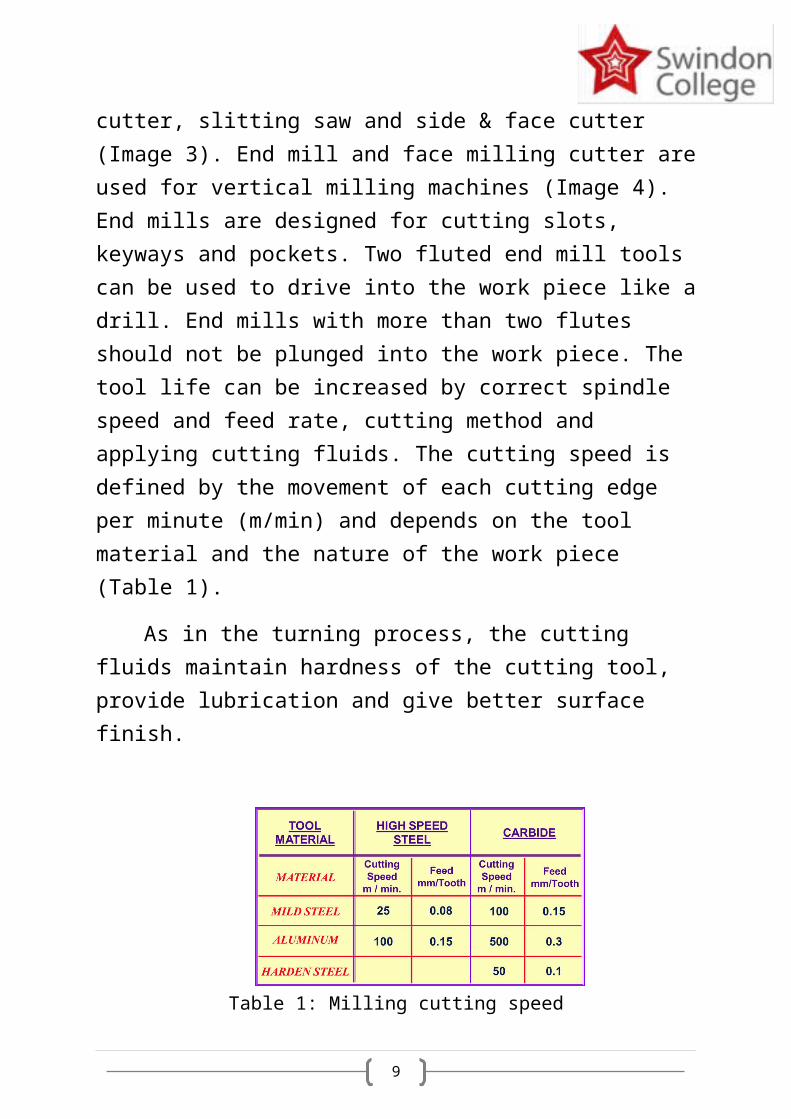
Milling machine is a machine that uses a rotating multi-toothed milling cutter to removemetal from the moving work piece surface to create flat and angular surfaces. The spindle rotates perpendicular (vertical milling) or parallel (horizontal milling) to the table. Thework piece is fixed on the table and can be moved along the x, y or z axis, the chips are cut off by the rotating cutter and the work piece is fed in linear motion. There are two different cutting types: up cut - cutter rotates in a direction opposite to the table feed (will not cause the table to a step motion) and down cut - cutter rotates in the same direction as the table feed (give a bettersurface finish, is not suitable for conventional machine because cause step motion to the table). The cutting tools used for horizontal milling machines are: slab milling
9
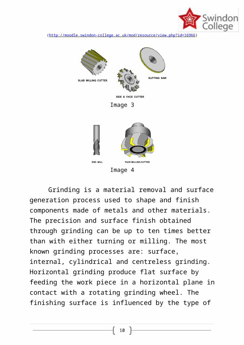
cutter, slitting saw and side & face cutter (Image 3). End mill and face milling cutter areused for vertical milling machines (Image 4). End mills are designed for cutting slots, keyways and pockets. Two fluted end mill tools can be used to drive into the work piece like adrill. End mills with more than two flutes should not be plunged into the work piece. The tool life can be increased by correct spindle speed and feed rate, cutting method and applying cutting fluids. The cutting speed is defined by the movement of each cutting edge per minute (m/min) and depends on the tool material and the nature of the work piece (Table 1).
As in the turning process, the cutting fluids maintain hardness of the cutting tool, provide lubrication and give better surface finish.
Table 1: Milling cutting speed
10
(http://moodle.swindon-college.ac.uk/mod/resource/view.php?id=16966)
Image 3
Image 4
Grinding is a material removal and surfacegeneration process used to shape and finish components made of metals and other materials. The precision and surface finish obtained through grinding can be up to ten times better than with either turning or milling. The most known grinding processes are: surface, internal, cylindrical and centreless grinding. Horizontal grinding produce flat surface by feeding the work piece in a horizontal plane incontact with a rotating grinding wheel. The finishing surface is influenced by the type of
11
the grinding wheel (fine grains give finer finishes), the feed rate, machine rigidity, work piece material and lubricant used.
Manufacturing process
The operational processes to manufacture the shaft are turning process to make the Ø10mmand Ø 16mm, milling process to create the 3mm by 3mm shape, cylindrical grinding for smooth surface and surface grinding for the 3mm by 3mmshape.
The first step is to choose and prepare thematerial for the work piece. To build the cylindrical shaft the material must have at least Ø 17mm and 90mm long. The material does not have to be cylindrical, to create an Ø16mm the material can be square or rectangular but the minimum side must be at least 17mm.
Assuming that the material is cylindrical or hexagonal, the work piece can be clamped on the lathe whit a Three-Jaw Chuck, if the material is square, rectangular or a different
12
shape the work piece can be clamped on the lathe by using a Four-Jaw Chuck. The advantage of four-jaw chuck is that each chuck move independently and they can be used to hold irregularly shaped parts. With the use of a dial indicator they can be used to centre eccentric parts.
Turning processFirst operation: clamping the material in
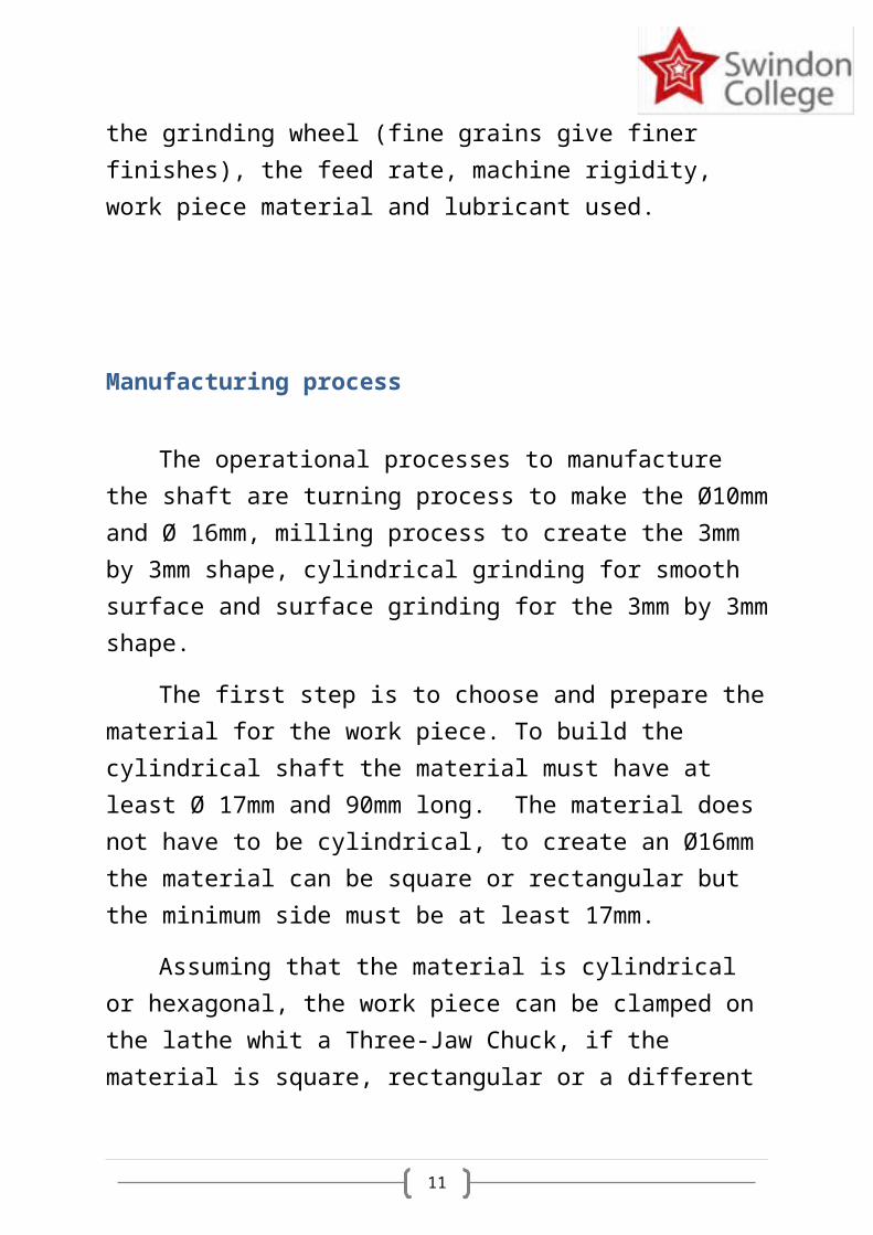
the Four-jaw chuck overhanging 35 to 40 mm.Second operation: facing off one side using
a High steel right hand knife tool and using cutting fluid (Image 5)
.Figure 5
( http://i1.ytimg.com/vi/5tXpKS3lfy0/hqdefault.jpg )
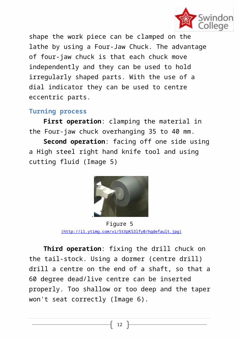
Third operation: fixing the drill chuck on the tail-stock. Using a dormer (centre drill) drill a centre on the end of a shaft, so that a60 degree dead/live centre can be inserted properly. Too shallow or too deep and the taperwon't seat correctly (Image 6).
13
Image 6 (http://www.practicalmachinist.com/vb/attachments/f38/49573d1333235474-
using-center-drill-fig7-37.jpg)
Fifth operation: pushing the tail-stock close to the work piece, inserting the live centre in the drilled hole using the tail-stockhand-wheel, locking the tail-stock using the tail-stock lock lever.
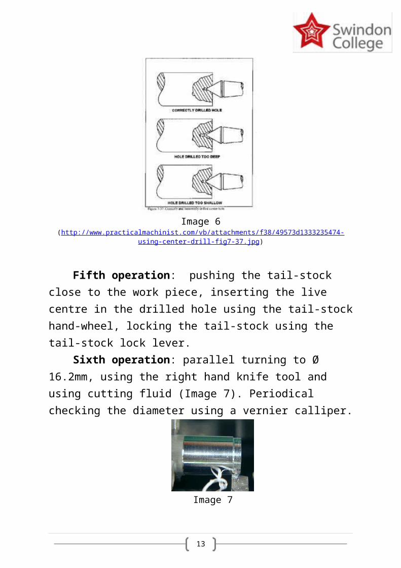
Sixth operation: parallel turning to Ø 16.2mm, using the right hand knife tool and using cutting fluid (Image 7). Periodical checking the diameter using a vernier calliper.
Image 7
14
( http://www.mini-lathe.com/Mini_lathe/Operation/Turning/Turning2.jp g )
Seventh operation: unloading the work piece, measuring the total length of the work piece, turning over and clamping the work piecein the Four-jaw chuck overhanging 35 to 40 mm.
Eighth operation: facing off to 87.2mm using a High steel right hand knife tool and using cutting fluid.
Ninth operation: fixing the drill chuck on the tail-stock. Using a dormer (centre drill) drill a centre on the end of a shaft
Tenth operation: pushing the tail-stock close to the work piece, inserting the live centre in the drilled hole using the tail-stockhand-wheel, locking the tail-stock using the tail-stock lock lever.
Eleventh operation: parallel turning to Ø 16.2mm, using the right hand knife tool and using cutting fluid.
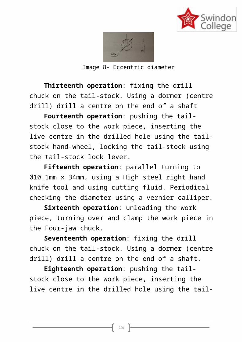
Twelfth operation: using a dial gauge centring the work piece to an eccentric diameter to -3mm from the centre of the work piece (Image 8).
15
Image 8- Eccentric diameter
Thirteenth operation: fixing the drill chuck on the tail-stock. Using a dormer (centredrill) drill a centre on the end of a shaft
Fourteenth operation: pushing the tail-stock close to the work piece, inserting the live centre in the drilled hole using the tail-stock hand-wheel, locking the tail-stock using the tail-stock lock lever.
Fifteenth operation: parallel turning to Ø10.1mm x 34mm, using a High steel right hand knife tool and using cutting fluid. Periodical checking the diameter using a vernier calliper.
Sixteenth operation: unloading the work piece, turning over and clamp the work piece inthe Four-jaw chuck.
Seventeenth operation: fixing the drill chuck on the tail-stock. Using a dormer (centredrill) drill a centre on the end of a shaft.
Eighteenth operation: pushing the tail-stock close to the work piece, inserting the live centre in the drilled hole using the tail-
16
stock hand-wheel, locking the tail-stock using the tail-stock lock lever.
Nineteenth operation: parallel turning to Ø10.1mm x 30mm, using a High steel right hand knife tool and using cutting fluid. Periodical checking the diameter using a vernier calliper.Unload the work piece from the lathe.
Horizontal milling processFirst operation: Holding the work piece on
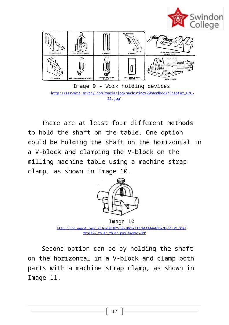
the milling machine table. Comparing to the lathe, which give few options regarding holdingdevices (Three-jaw chuck, Four-jaw chuck and tail-stock), the milling machine can be equipped with a large variety of working holding devices – angle plate, V-block and clamp, V-clamps, C-clamps, step blocks for clamps, machine strap clamps, standard machine table vise, etc. (Image9). Work holding devicesare used to hold the work piece immobile for anaccurate operation.
17
Image 9 – Work holding devices(http://server2.smithy.com/media/jpg/machining%20handbook/Chapter_6/6-
25.jpg)
There are at least four different methods to hold the shaft on the table. One option could be holding the shaft on the horizontal ina V-block and clamping the V-block on the milling machine table using a machine strap clamp, as shown in Image 10.
Image 10http://lh5.ggpht.com/_X6JnoL0U4BY/S0yJKK5YT1I/AAAAAAAADgk/k46NH2Y_QO0/
tmp1022_thumb_thumb.png?imgmax=800
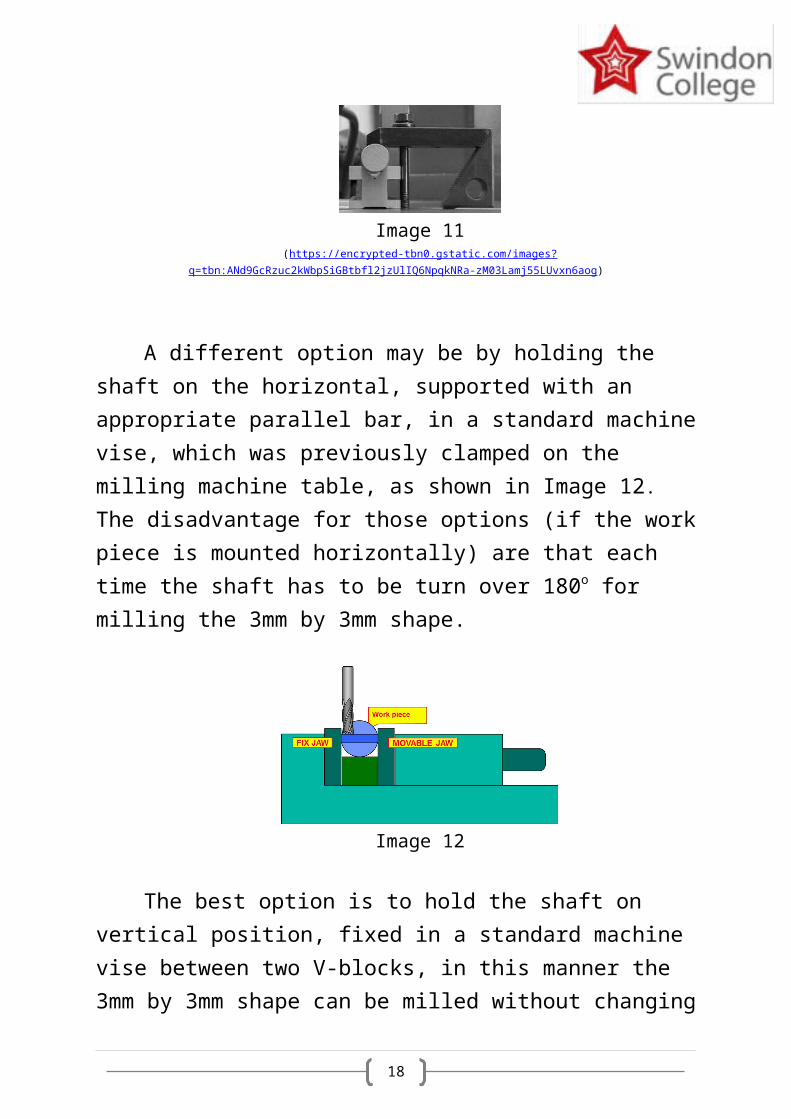
Second option can be by holding the shaft on the horizontal in a V-block and clamp both parts with a machine strap clamp, as shown in Image 11.
18
Image 11(https://encrypted-tbn0.gstatic.com/images?
q=tbn:ANd9GcRzuc2kWbpSiGBtbfl2jzUlIQ6NpqkNRa-zM03Lamj55LUvxn6aog)
A different option may be by holding the shaft on the horizontal, supported with an appropriate parallel bar, in a standard machinevise, which was previously clamped on the milling machine table, as shown in Image 12. The disadvantage for those options (if the workpiece is mounted horizontally) are that each time the shaft has to be turn over 180o for milling the 3mm by 3mm shape.
Image 12
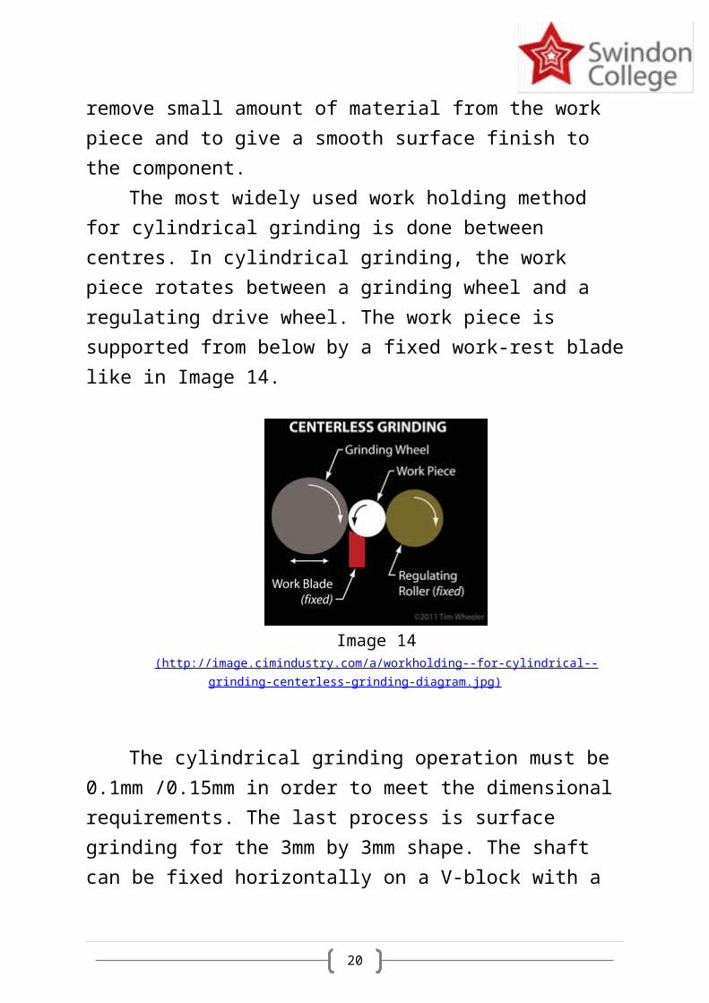
The best option is to hold the shaft on vertical position, fixed in a standard machine vise between two V-blocks, in this manner the 3mm by 3mm shape can be milled without changing
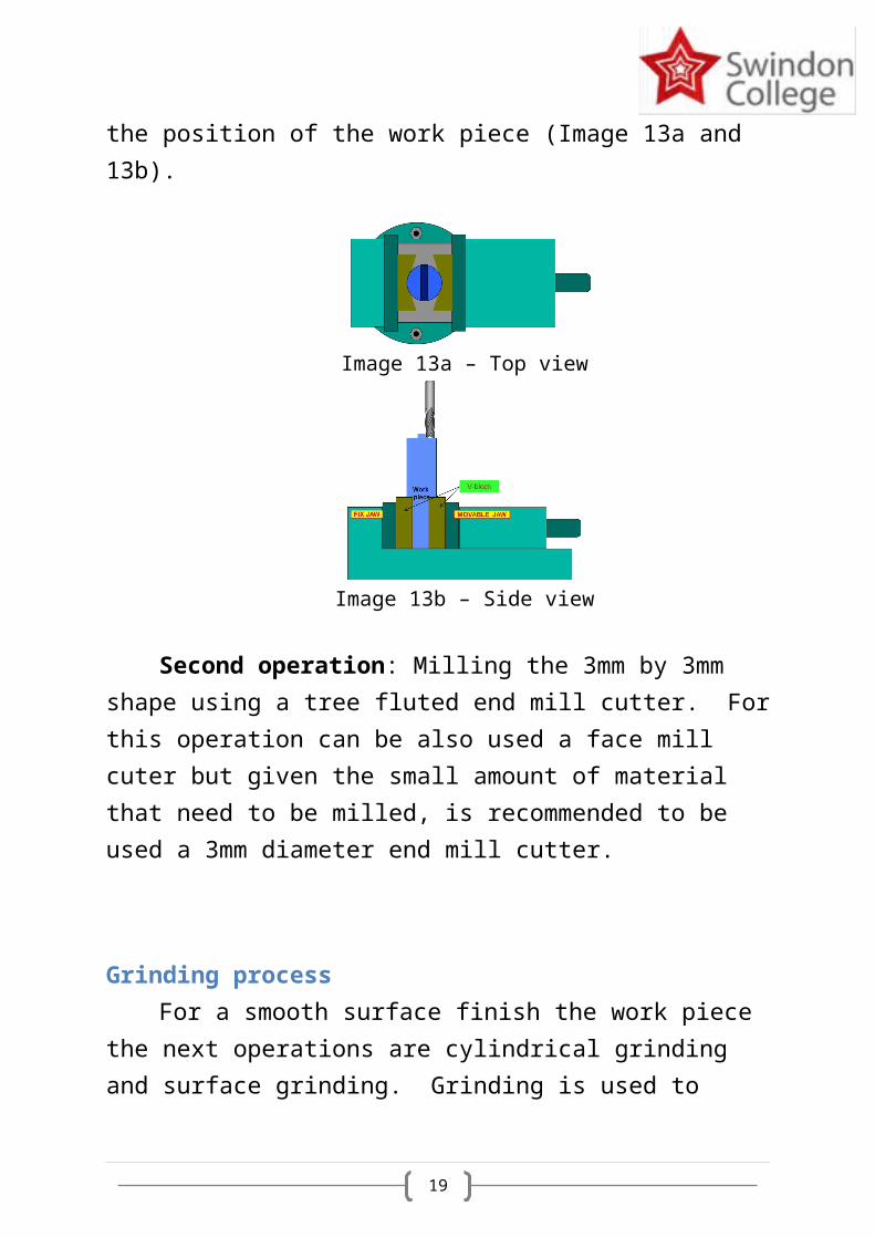
19
the position of the work piece (Image 13a and 13b).
Image 13a – Top view
Image 13b – Side view
Second operation: Milling the 3mm by 3mm shape using a tree fluted end mill cutter. Forthis operation can be also used a face mill cuter but given the small amount of material that need to be milled, is recommended to be used a 3mm diameter end mill cutter.
Grinding processFor a smooth surface finish the work piece
the next operations are cylindrical grinding and surface grinding. Grinding is used to
20
remove small amount of material from the work piece and to give a smooth surface finish to the component.
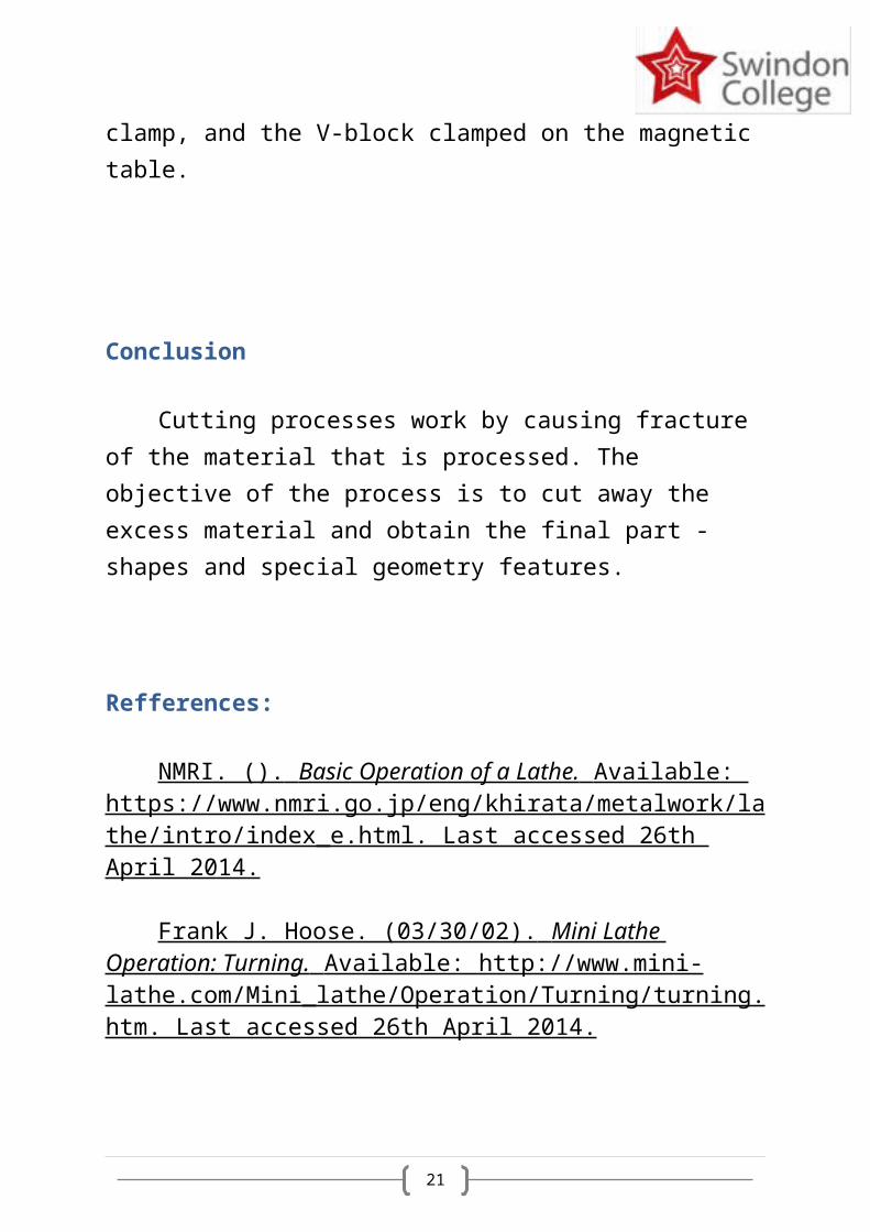
The most widely used work holding method for cylindrical grinding is done between centres. In cylindrical grinding, the work piece rotates between a grinding wheel and a regulating drive wheel. The work piece is supported from below by a fixed work-rest bladelike in Image 14.
Image 14( http://image.cimindustry.com/a/workholding--for-cylindrical--
grinding-centerless-grinding-diagram.jpg )
The cylindrical grinding operation must be 0.1mm /0.15mm in order to meet the dimensional requirements. The last process is surface grinding for the 3mm by 3mm shape. The shaft can be fixed horizontally on a V-block with a
21
clamp, and the V-block clamped on the magnetic table.
Conclusion
Cutting processes work by causing fracture of the material that is processed. The objective of the process is to cut away the excess material and obtain the final part - shapes and special geometry features.
Refferences:
NMRI. (). Basic Operation of a Lathe. Available: https://www.nmri.go.jp/eng/khirata/metalwork/lathe/intro/index_e.html. Last accessed 26th April 2014.
Frank J. Hoose. (03/30/02). Mini Lathe Operation: Turning. Available: http://www.mini- lathe.com/Mini_lathe/Operation/Turning/turning.htm. Last accessed 26th April 2014.
22
Engineering Skill II. (). Lab 1Lathe / Turning work. Available: http://engineeringskill.blogspot.co.uk/2010/07/lab-1-lathe-turning-work.html. Last accessed 26th April 2014.
[email protected]. (). Milling Machine. Available: http://web.mit.edu/2.670/www/Tutorials/Machining/mill/Description.html. Last accessed 26th April 2014.
Basics of Grinding . 2014. . [ONLINE] Available at: http://manufacturing.stanford.edu/processes/ Grinding.pdf . [Accessed 26 April 2014].