Manufacturing process and electrode properties of palladium-electroded ionic polymer–metal...
15
Manufacturing process and electrode properties of palladium-electroded ionic polymer–metal composite This article has been downloaded from IOPscience. Please scroll down to see the full text article. 2012 Smart Mater. Struct. 21 065018 (http://iopscience.iop.org/0964-1726/21/6/065018) Download details: IP Address: 117.32.153.143 The article was downloaded on 13/07/2012 at 13:53 Please note that terms and conditions apply. View the table of contents for this issue, or go to the journal homepage for more Home Search Collections Journals About Contact us My IOPscience
Transcript of Manufacturing process and electrode properties of palladium-electroded ionic polymer–metal...
Manufacturing process and electrode properties of palladium-electroded ionic polymer–metal
composite
This article has been downloaded from IOPscience. Please scroll down to see the full text article.
2012 Smart Mater. Struct. 21 065018
(http://iopscience.iop.org/0964-1726/21/6/065018)
Download details:
IP Address: 117.32.153.143
The article was downloaded on 13/07/2012 at 13:53
Please note that terms and conditions apply.
View the table of contents for this issue, or go to the journal homepage for more
Home Search Collections Journals About Contact us My IOPscience

IOP PUBLISHING SMART MATERIALS AND STRUCTURES
Smart Mater. Struct. 21 (2012) 065018 (14pp) doi:10.1088/0964-1726/21/6/065018
Manufacturing process and electrodeproperties of palladium-electroded ionicpolymer–metal composite
Longfei Chang, Hualing Chen, Zicai Zhu and Bo Li
State Key Laboratory for Strength and Vibration of Mechanical Structures, Xi’an Jiaotong University,28 Xianning West Road, Xi’an 710049, People’s Republic of China
E-mail: [email protected]
Received 14 September 2011, in final form 17 April 2012Published 22 May 2012Online at stacks.iop.org/SMS/21/065018
AbstractThis paper primarily focuses on the manufacturing process of palladium-electroded ionicpolymer–metal composite (IPMC). First, according to the special properties of Pd, manyexperiments were done to determine several specific procedures, including the addition of areducing agent and the time consumed. Subsequently, the effects of the core manufacturingsteps on the electrode morphology were revealed by scanning electron microscopy studies of22 IPMC samples treated with different combinations of manufacturing steps. Finally, theeffects of electrode characteristics on the electromechanical properties, including the sheetresistivity, the elastic modulus and the electro-active performance, of IPMCs were evaluatedexperimentally and analyzed according to the electrode morphology.
(Some figures may appear in colour only in the online journal)
1. Introduction
In the past few decades, it has been well documented that anionic polymer–metal composite (IPMC) is capable of beingeffectively exploited as both actuators and sensors [1–4].Because of its unique advantages, such as low drivingvoltage, large bending displacement, rapid response, lightmass and flexibility, the IPMC has been explored for extensiveapplications including in aerospace [5–7], biomimetic me-chanics [8–10] and biomedicine [11–13], which consequentlyattracts growing interest in its manufacturing technique andtheoretical characterization.
Generally, the IPMC is formed by a polyelectrolytemembrane plated with electrodes on both surfaces, wherePt and Au have been the most widely employed electrodesso far [14–16]. IPMCs electroded with these noble metalsexhibit excellent electromechanical properties but suffer froman unfavorably high cost. While some relatively affordableelectrodes, specifically some non-precious metals (such as Cuand Ni), are also used as possible alternatives but they showless electrochemical stability for long-term work due to somedestructive electrochemical reactions [17–19]. In comparison,
Pd, which has similar physical and chemical properties toPt and is less expensive (approximately one-third cheaper),shows itself as a very promising electrode material. Thegroup of Kim reveals that palladium tends to deposit moredeeply into the membrane than gold and platinum, creatinga much higher interfacial area between the electrodes andthe polymer membrane [20]. They made use of this usefulproperty by manufacturing high-performance IPMCs with abuffer layer of palladium before platinum deposition [21].Kobayashi et al fabricated single palladium-electroded IPMCs(Pd-IPMC) with an electroless plating method and measuredthe deformation under various solvents, temperatures andvoltage frequencies [22]. In spite of these initial attempts,the chemical manufacturing technique of Pd-IPMC stillleaves much room for further investigation. To manufacturebetter-performing Pd-IPMCs, one possible barrier is that thehigh hydrogen permeability and solubility of Pd may affectnegatively the performance of Pd-IPMC and bring manydifficulties to its manufacturing process. To explain in detail,Pd can adsorb hydrogen up to 900 times its own volume ina reversible process at room temperature and atmosphericpressure, and its hydrogen absorption capacity decreases
10964-1726/12/065018+14$33.00 c© 2012 IOP Publishing Ltd Printed in the UK & the USA
Smart Mater. Struct. 21 (2012) 065018 L Chang et al
with increasing temperature [23]; during the current chemicalmanufacturing process of IPMCs [24, 25] a large amount ofinhalation and release of hydrogen will take place on theelectrode, mainly due to the catalyzed oxidation of NaBH4
or NaPH2O2 and a reduction environment of continuouslyincreasing temperature; as a result, an increase in brittlenessand surface porosity of the Pd electrode will be observedand consequently lead to a significant increase in the elasticmodulus and surface resistance of the final product, whichare obviously unfavorable for the final electromechanicalperformance. Unfortunately, hardly any attention has beenpaid to this particular effect so far.
Furthermore, to better understand the manufacturingtechnique and improve the electromechanical properties ofPd-IPMC, the electrode morphologies and their formingmechanisms are one of the key issues to investigate. Thishas been well indicated in the last few research works [16,26–30]. For example, Onish [16] and Kim [27] investigatedthe forming process of Au and Pt electrodes during theimpregnation–reduction plating respectively and further itsinfluence on the resistance, capacitance or displacement of thefinal IPMC. Both reported that the electrode characteristicsare very important to the properties of IPMC products.However, systematic experimental reports on the effect ofIPMC manufacturing steps on electrode morphologies are stillnot available in current studies.
In this paper, we primarily focus on the manufacturingprocess of Pd-IPMC. In section 2, following the work of Liu,Oguro and Shahinpoor [4, 24, 25, 31], and combining theelectroless method of manufacturing industrial Pd catalystsor nanowires [32, 33], we proposed an effective process tomanufacture Pd-IPMCs, mainly by impregnation–reductionplating (IRP) and autocatalytic plating (ACP). Then severalspecific procedures were evaluated, considering the specialproperties of Pd as well as the time and cost efficiencies:ammonia solution of Pd(NH3)4Cl2 was recommended asthe Pd complex solution for its stability; high-pH NaBH4
and ultrasonic stirring were adopted during IRP to reducehydrogen generation and accelerate its discharge; repeatedusage of the Pd complex solution and the time consumedwere investigated primarily to increase the efficiency; also,the additional amount or proportion of the core chemicals wasalso provided to compromise between stability and efficiency.
Subsequently, by manufacturing IPMC samples withdifferent combinations of processes (section 3), the effectsof three core steps, roughing treatment, IRP and ARP, onthe electrode surface and cross-section morphologies wereinvestigated by scanning electron microscopy (SEM) studies(section 4); and those on the electromechanical properties,including the sheet resistivity, elastic modulus, deflection andblocking force, were also evaluated and analyzed according tothe electrode morphology (section 5). IPMCs manufacturedwith roughening, three IRP and two ACP cycles are foundto have relatively lower sheet resistivity and elastic modulus,and furthermore exhibit the most favorable electro-activeperformance.
2. Manufacturing process of palladium-electrodedIPMC
The manufacturing process of Pd-IPMC in this paper typicallyconsists of four steps: pretreatment of substrate membrane,IRP, ACP and post-treatment.
The pretreatment involves roughening, surface cleaning,purifying the counter ions with H+ and complete swelling ofthe substrate membrane (the polyelectrolyte polymer). TheIRP incorporates an ion exchange process and a reductionprocess. The former is to soak the substrate membrane with aPd complex solution and exchange the membrane into the Pdcation form. The latter one is to reduce the platinum complexcations to a metallic state in a location close to the innersurface of the membrane by a strong reducing agent, such asNaBH4. Taking Pd(NH3)4Cl2 as the Pd complex, the primaryreaction is
NaBH4 + 4[Pd(NH3)4]2++ 8OH− ⇒ 4Pd+ 16NH3
+ NaBO2 + 6H2O. (1)
ACP is an efficient way to increase the surface electrodethickness, during which the main salt and the reducing agentare placed simultaneously in the same solution and the initialPd formed by IRP is taken as the catalyst layer. Besides,additives are necessarily required to ensure the uniformityof metal deposition in this process. In this paper, followingthe work in [33], N2H4 is selected as the reducing agent toavoid the generation of hydrogen, with NH3·H2O, Na2 EDTAand PVP as the stabilizing, complexing and diffusing agent,respectively. The primary reaction is
2[Pd(NH3)4]2++ N2H4 + 4OH− ⇒ 2Pd+ 8NH3
+ N2 + 4H2O. (2)
The post-treatment process refers to exchanging the IPMCwith the alkali-metal cation form and cutting it into propershape. The geometry of the samples for electromechanicaltests in this work is illustrated in figure 1(a); a simple cuttingtool was designed to reduce the errors caused by hand-cutting,see figure 1(b).
With NafionTM-117 as the substrate material, somespecific tips for the above-mentioned procedures areinvestigated, as follows.
2.1. The preparation of Pd complex solution
[Pd(NH3)4]Cl2 is recommended as the Pd complex during theIRP and ACP due to its stability and controllability.
During the IRP, if the ion exchange process wasconducted with an aqueous solution of Pd(NH3)4Cl2, theelectrode formed was viewed unstably suspended on thesurface of NafionTM as a result of the decomposition ofPd(NH3)4Cl2, as shown in figure 2(a). This phenomenoncan be avoided by adding ammonia to the soaking solution(figure 2(b)). However, excessive ammonia will lead toinadequate ion exchange and thus reduce the efficiency.Based on our attempts, 45–60 ml ammonia solution of25% g−1 Pd(NH3)4Cl2 is preferred.
2

Smart Mater. Struct. 21 (2012) 065018 L Chang et al
(a) (b)
Figure 1. Pictures of the test sample and the cutting tool. (a) A schematic diagram of the IPMC test sample, where length of the specimenL = 35 mm, free length l = 30 mm, measuring distance d = 25 mm, width h = 5 mm and thickness t ≈ 0.18 mm. (b) A photograph of theIPMC cutting tool.
Figure 2. Optical microscopy images of the cross section of IPMC:(a) and (b) show the electrode formed after soakingNafionTM membrane in the aqueous solution and the ammoniasolution of Pd (NH3)4Cl2, respectively.
Similarly, ammonia is also required to ensure thereduction stability in ACP. According to our experience,120–140 ml ammonia solution of a 25% l−1 plating bath ispreferred.
To take full advantage of the precious metal, we proposedrepeated usage of the Pd complex solution in the IRP. It istheoretically feasible because the ion exchange equilibriumtheory indicates that Pd cations cannot be fully exchangedwith NafionTM in one process; and as the concentration of thePd cation decreases, Nafion’s selectivity of [Pd(NH3)4]
+
2 willgreatly increase in an ion exchange system of univalent ions(H+, Na+ and NH+3 ) and bivalent ions ([Pd(NH3)4]
+
2 ) [34].Furthermore, NaBH4 solution was used to test the Pd cationconsumption after each ion exchange process (see figure 3).Seen from the color of the solution, the [Pd(NH3)4]
+
2concentration declined gradually with the immersion times,and after three cycles of ion exchange, the [Pd(NH3)4]
+
2 inthe solution will be nearly completely consumed. Also, thechange in percentage of the membrane surface area withrespect to its initial area during three cycles of IRP wasmeasured. The swelling and compressing of the substrate
Figure 3. The area change proportion of NafionTM membraneduring repeated usage of Pd(NH3)4Cl2 solution and Pd cationconsumption tested with NaBH4, after each ion exchange process(IE in short for the ion exchange process and RE for the reductionprocess).
membrane is approached less sharply, which implies that,as the concentration of the Pd cations gradually decreased,repeated use of the Pd complex solution may effectivelyalleviate the internal stress in the Pd electrodes caused by theswelling and compressing of the substrate membrane.
2.2. The preparation and addition of reducing agent
During the IRP, the spontaneous or catalyzed hydrolysisreaction of NaBH4 also takes place simultaneously with theprimary reaction. There are two hydrolysis mechanisms asfollows:
NaBH4 + H2O⇒ NaBO2 + 4H2 ↑ . (3)
NaBH4 + H2O⇒ BH3 + NaOH+ H2 ↑ . (4)
The hydrolysis rate has the following relation to theenvironmental temperature and pH value of the solution [35]:
lgt1/2 = PH− (0.034T − 1.92), (5)
where t1/2 (min) is the half-life of NaBH4 and T is the
3

Smart Mater. Struct. 21 (2012) 065018 L Chang et al
Figure 4. Time-dependent surface area of NafionTM during ionexchange and reduction process.
absolute temperature of the environment. Therefore, in neutralsolution, 50% of the NaBH4 will be hydrolyzed within0.5 min even at room temperature, which is very unfavorablefor process control. Considering the stability of the reductantconcentration and to reduce the liberation of hydrogen, anappropriate amount of ammonia should be added to theaqueous solution of NaBH4, ensuring a pH value of over 13.In addition, to get a compromise between the completion ofthe reduction and less hydrogen liberation, about 6–10 molof NaBH4 for 2 mol of Pd (NH3)4Cl2 was recommended.Besides, as the generation of hydrogen in this process isinevitable, we used ultrasound to replace the traditionalstirring methods, which can accelerate the hydrogen dischargeand further impact the electrode surface.
During ACP, about 3 mol of N2H4 was practicallyrequired for reducing 2 mol of Pd(NH3)4Cl2, as a requirementfor both the stability and completion of the process. Inaddition, low-concentration N2H4 (2%) is suggested to beadded at intervals at low elevated temperature (e.g. 30–50 ◦C)with low-speed stirring (magnetic or mechanical).
2.3. Time consumed
The time required for IRP varies greatly in the availableresearch works [16, 25, 36]. In this section, in orderto determine a proper time for IRP, the time-dependentsurface area of NafionTM was measured to monitor the ionexchange (with a practical concentration) and the reactionprogress (figure 4). It is feasible because ion exchanging andswelling (or compressing) of the membrane are conductedsimultaneously During the IRPs, the surface area change canapproximately reflect the progress. We found that at lowstirring speed (i.e. 100 r min−1), 90% of the ion exchangewas completed within 0.5 h. After 1.5 h, macroscopicmeasurable changes of the membrane are unable to beobserved, indicating that ion exchange and swelling has beenapproaching equilibrium. Then, for the reduction process,more than 95% of the reaction finished within 1.5 h. As aconsequence, we believe that the ion exchange and reduction
process can be effectively conducted within 2 h and 1.5 h,respectively.
For ACP, the process time can be determined by NaBH4testing.
3. IPMC sample fabrication
To investigate the effect of the core processes on the electrodecharacteristics and the electromechanical properties of IPMC,22 IPMC samples (nos 1, 2, 3, . . . , 22, each with an area of2 cm× 6 cm) treated with different processes, were prepared(as shown in table 1). To better guarantee the consistencyof the uncontrolled processes and reduce the man-madeerrors, these samples were separated into ten groups (groupA,B,C . . . J). Each group was prepared with one wholepiece of NafionTM-117 membrane in one bath and cut intosamples after every planned process being done. The variationof processing parameters was implemented in three ways:(1) roughening treatment (groups A, B and C): group A wasmanufactured by sandblasting, while B and C were made bysandpapering with different roughening time or grids; (2) IRP(groups B, D, E, F and G): groups B, D and E varied withdifferent cycles of IRP, while E, F and G varied with differentstirring methods and reduction time; (3) ACP (groups E, Hand I): groups E, H and I varied with different cycles of ACP.To check the reproducibility, sample 22 was manufactured bythe same procedures as sample 17.
Taking groups B and H, for example, the preparationrecipe was explained as follows.
For group B: (1) prepare a piece of NafionTM (6 cm ×6 cm). Roughen one-third of both its surfaces with sandpaperof 600 grit (600#) for 10 min and another third with 1200#for 10 min. Treat the membrane with ultrasonic cleaning,acid boiling (with HCl, about 1 mol l−1), rinsing and waterboiling. (2) Immerse the pretreated NafionTM in 160 mlammonia solution of [Pd(NH3)4]Cl2 with 140 mg Pd and20 ml ammonia of 25% for 2 h, with low-speed stirring.Then reduce the Pd complex cations in the NafionTM withan alkaline solution of NaBH4 (2%–5%, Ph > 13) inan ultrasonic environment at a continuously increasingtemperature (i.e. from 30 to 50 ◦C). (3) Immerse themembrane in an aqueous solution of NaOH (0.1–0.5 mol l−1)for 2 h and then divide it into three parts according to theroughening level.
Comparatively, for group H: (1) roughen the NafionTM
with sandpaper of 1200# for 30 min in total. Clean and boilit. (2) This step was the same as group B. This step wasrepeated three times. In each interval, rinse the membraneand immerse it into low-concentration acid (i.e. HCl, about0.2 mol l−1). Place the membrane in 340 ml stirring solutionof [Pd(NH3)4]Cl2 with 85 mg palladium, 38–43 ml ammoniaof 25%, 1.1–1.4 g Na2EDTA and 1.0–1.3 g PVP at acontinuously increasing temperature (30–50 ◦C). Add 0.4 mlof the aqueous solution of NH2NH2 (2%) every 30 min.Immerse the membrane with low-concentration acid and cutdown one-third of it (no. 16). Treat the rest of the membranewith another ACP (with appropriate parameters according tothe membrane area). Acid treat it and cut down half of it(no. 17). Subsequently, treat the rest of the membrane with
4

Smart Mater. Struct. 21 (2012) 065018 L Chang et al
Table 1. Manufacturing process of IPMC samples.
Roughening process
ACP cyclesSandblastingpressure
Sandpapering IRP
Mesh size Process time Process time Stirring Cycles
A 1 0.15 MPa 1.5 Ultrasonic 12 0.3 MPa
B 3 No roughening 1.5 Ultrasonic 1
4 1200 105 600
C 6 600 5 1.5 Ultrasonic 17 20
D 8 600 10 1.5 Ultrasonic 29 No roughening
E 10 600 10 1.5 Ultrasonic 311 No roughening
F 12 600 10 1.5 Magnetic 313 No roughening
G 14 600 10 4.5 Magnetic 315 No roughening
H 16 600 10 1.5 Ultrasonic 3 117 218 3
I 19 No roughening 1.5 Ultrasonic 3 1
20 221 3
J 22 600 10 1.5 Ultrasonic 3 2
ACP again and acid treat it (no. 18). (3) Immerse the threepieces in an aqueous solution of NaOH for 2 h.
4. SEM studies on the electrode morphologies
The surface and cross-section morphology of the sam-ples were observed by SEM (TESCAN-VEGA \ \XMUVG3210677). Sequentially presented in figure 5 are thecross-section images of some representative samples. As acomparison, the electrode morphology of no. 22 was providedin figure 6.
4.1. Effects of the roughening process
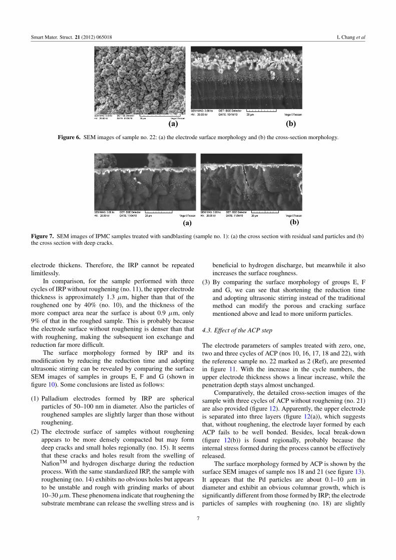
Although some novel methods have been introduced intothe IPMC manufacturing technique, such as plasma [37] andchemical etching [38], sandblasting and sandpapering are stillthe dominant roughening methods for their basic advantagesof convenience and low cost. Based on the experiments,sandblasting with fine glass beads is more efficient and canbetter ensure roughening uniformity. However, a number ofembedded residual sand particles and deep cracks can beobserved regionally in the samples treated with sandblasting(nos 1 and 2) (see figure 7), which will probably result inpoor performance of the IPMC. Also these embedded gridsare difficult to clean up, even after a relatively much longercleaning process. Therefore, sandblasting is not recommendedfor small-area preparation of IPMCs.
The observed electrode parameters (the thickness ofthe upper electrode and the penetration depth) of samples
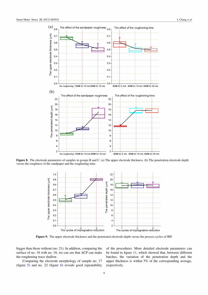
treated with different roughening levels (nos 3, 4, . . . , 7)versus the roughness of sandpaper and the roughening timeare presented in figure 7. First, clearly in the SEM images,we can see roughening provides not only a rough landscapebut also an increase in the electrode penetration depth, bothof which are favorable for increasing the charge storagecapacity [3, 36]. Furthermore, the upper electrode was thinnedslightly with the roughening level (see from the averagevalue in figure 8(a)), whiles its uniformity decreased withthe sandpaper roughness and increased with the rougheningtime (see from the data dispersion). Figure 8(b) illustratesthat the penetration electrode depth significantly increaseswith the roughness of the sandpaper. When roughened withsandpaper of 600#, the Pd particles dispersed 98% deeper thanthe sample without roughening. With the roughening timeincreasing from 5 to 10 min, the penetration depth increasesfrom 12 to 16 µm; however, when the roughening timeincreases up to 20 min, it stays almost unchanged (16.5 µm).This can probably be explained as: the surface roughnessincreases in the initial stage of grinding, which will increasethe electrode penetration depth. But to a certain extent,continuous roughening primarily reduces the film thicknessrather than increases the surface roughness, and consequentlyhardly impacts on the penetration depth. In short, rougheningwith sandpaper of 600# for approximately 10 min cantypically lead to relatively better electrode dispersion.
4.2. Effect of the IRP step
By comparing the cross-section electrode morphology ofsamples treated with one, two and three cycles of IRP (nos 5,
5
Smart Mater. Struct. 21 (2012) 065018 L Chang et al
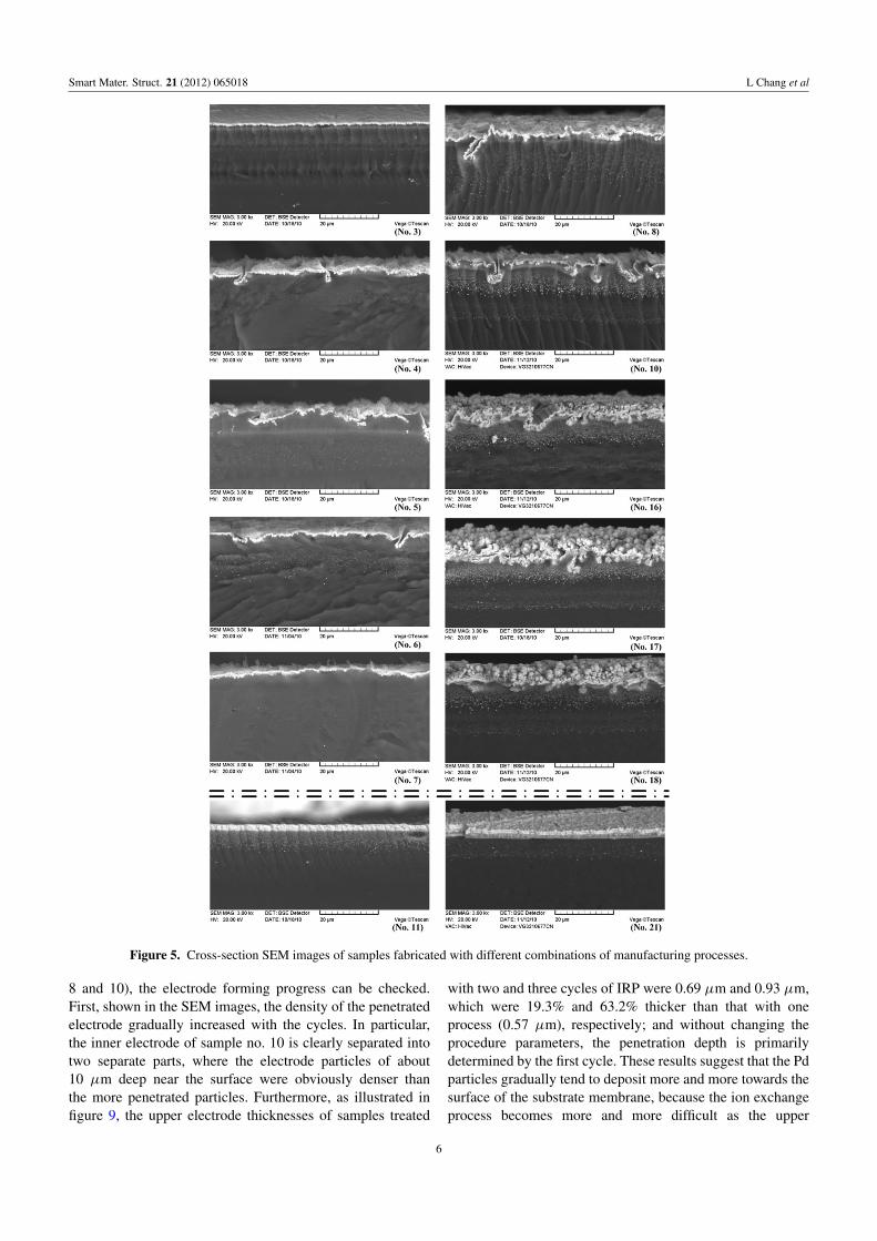
Figure 5. Cross-section SEM images of samples fabricated with different combinations of manufacturing processes.
8 and 10), the electrode forming progress can be checked.First, shown in the SEM images, the density of the penetratedelectrode gradually increased with the cycles. In particular,the inner electrode of sample no. 10 is clearly separated intotwo separate parts, where the electrode particles of about10 µm deep near the surface were obviously denser thanthe more penetrated particles. Furthermore, as illustrated infigure 9, the upper electrode thicknesses of samples treated
with two and three cycles of IRP were 0.69 µm and 0.93 µm,which were 19.3% and 63.2% thicker than that with oneprocess (0.57 µm), respectively; and without changing theprocedure parameters, the penetration depth is primarilydetermined by the first cycle. These results suggest that the Pdparticles gradually tend to deposit more and more towards thesurface of the substrate membrane, because the ion exchangeprocess becomes more and more difficult as the upper
6
Smart Mater. Struct. 21 (2012) 065018 L Chang et al
Figure 6. SEM images of sample no. 22: (a) the electrode surface morphology and (b) the cross-section morphology.
Figure 7. SEM images of IPMC samples treated with sandblasting (sample no. 1): (a) the cross section with residual sand particles and (b)the cross section with deep cracks.
electrode thickens. Therefore, the IRP cannot be repeatedlimitlessly.
In comparison, for the sample performed with threecycles of IRP without roughening (no. 11), the upper electrodethickness is approximately 1.3 µm, higher than that of theroughened one by 40% (no. 10), and the thickness of themore compact area near the surface is about 0.9 µm, only9% of that in the roughed sample. This is probably becausethe electrode surface without roughening is denser than thatwith roughening, making the subsequent ion exchange andreduction far more difficult.
The surface morphology formed by IRP and itsmodification by reducing the reduction time and adoptingultrasonic stirring can be revealed by comparing the surfaceSEM images of samples in groups E, F and G (shown infigure 10). Some conclusions are listed as follows:
(1) Palladium electrodes formed by IRP are sphericalparticles of 50–100 nm in diameter. Also the particles ofroughened samples are slightly larger than those withoutroughening.
(2) The electrode surface of samples without rougheningappears to be more densely compacted but may formdeep cracks and small holes regionally (no. 15). It seemsthat these cracks and holes result from the swelling ofNafionTM and hydrogen discharge during the reductionprocess. With the same standardized IRP, the sample withroughening (no. 14) exhibits no obvious holes but appearsto be unstable and rough with grinding marks of about10–30µm. These phenomena indicate that roughening thesubstrate membrane can release the swelling stress and is
beneficial to hydrogen discharge, but meanwhile it alsoincreases the surface roughness.
(3) By comparing the surface morphology of groups E, Fand G, we can see that shortening the reduction timeand adopting ultrasonic stirring instead of the traditionalmethod can modify the porous and cracking surfacementioned above and lead to more uniform particles.
4.3. Effect of the ACP step
The electrode parameters of samples treated with zero, one,two and three cycles of ACP (nos 10, 16, 17, 18 and 22), withthe reference sample no. 22 marked as 2 (Ref), are presentedin figure 11. With the increase in the cycle numbers, theupper electrode thickness shows a linear increase, while thepenetration depth stays almost unchanged.
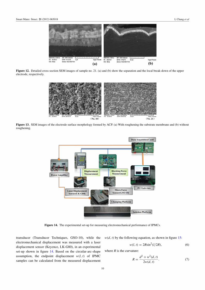
Comparatively, the detailed cross-section images of thesample with three cycles of ACP without roughening (no. 21)are also provided (figure 12). Apparently, the upper electrodeis separated into three layers (figure 12(a)), which suggeststhat, without roughening, the electrode layer formed by eachACP fails to be well bonded. Besides, local break-down(figure 12(b)) is found regionally, probably because theinternal stress formed during the process cannot be effectivelyreleased.
The surface morphology formed by ACP is shown by thesurface SEM images of sample nos 18 and 21 (see figure 13).It appears that the Pd particles are about 0.1–10 µm indiameter and exhibit an obvious columnar growth, which issignificantly different from those formed by IRP; the electrodeparticles of samples with roughening (no. 18) are slightly
7
Smart Mater. Struct. 21 (2012) 065018 L Chang et al
(b)
(a)
Figure 8. The electrode parameters of samples in groups B and C. (a) The upper electrode thickness. (b) The penetration electrode depthversus the roughness of the sandpaper and the roughening time.
Figure 9. The upper electrode thickness and the penetrated electrode depth versus the process cycles of IRP.
bigger than those without (no. 21). In addition, comparing thesurface of no. 18 with no. 10, we can see that ACP can makethe roughening trace shallow.
Comparing the electrode morphology of sample no. 17(figure 5) and no. 22 (figure 6) reveals good repeatability
of the procedures. More detailed electrode parameters canbe found in figure 11, which showed that, between differentbatches, the variation of the penetration depth and theupper thickness is within 5% of the corresponding average,respectively.
8

Smart Mater. Struct. 21 (2012) 065018 L Chang et al
Figure 10. SEM images of surface morphology of IPMC samples with three cycles of IRP, with different processing parameters(nos 10, 11, . . . , 15).
Figure 11. The upper electrode thickness and the penetration electrode depth versus the process cycles of ACP.
5. Studies on the electromechanical properties
5.1. Measurement method
Electromechanical properties, including the sheet resistivity,elastic modulus, deflection and blocking force, of sometypical samples were measured to investigate the effects
of electrode morphology. As a comparison, the electro-active performance of Pt-IPMCs bought from ERI wasalso tested. The sheet resistivity was measured by afour-point surface resistivity meter (MCP-T360) in wetIPMC conditions, repeatedly six times for each sample. Theendpoint blocking force was measured with a microforce
9
Smart Mater. Struct. 21 (2012) 065018 L Chang et al
Figure 12. Detailed cross-section SEM images of sample no. 21. (a) and (b) show the separation and the local break-down of the upperelectrode, respectively.
Figure 13. SEM images of the electrode surface morphology formed by ACP. (a) With roughening the substrate membrane and (b) withoutroughening.
Figure 14. The experimental set-up for measuring electromechanical performance of IPMCs.
transducer (Transducer Techniques, GSO-10), while theelectromechanical displacement was measured with a laserdisplacement sensor (Keyence, LK-G80), in an experimentalset-up shown in figure 14. Based on the circular-arc-shapeassumption, the endpoint displacement w(l, t) of IPMCsamples can be calculated from the measured displacement
w(d, t) by the following equation, as shown in figure 15:
w(l, t) = 2Rsin2(l/2R), (6)
where R is the curvature:
R =d2+ w2(d, t)
2w(d, t). (7)
10
Smart Mater. Struct. 21 (2012) 065018 L Chang et al
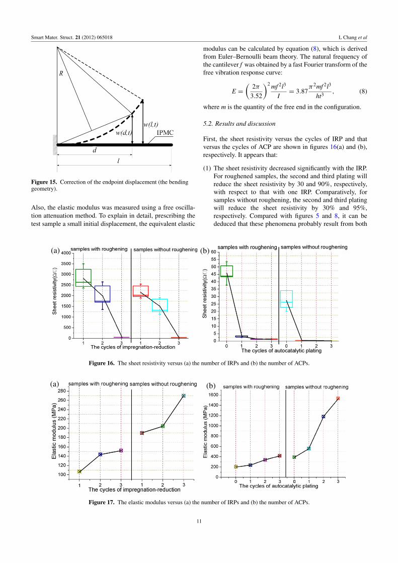
Figure 15. Correction of the endpoint displacement (the bendinggeometry).
Also, the elastic modulus was measured using a free oscilla-tion attenuation method. To explain in detail, prescribing thetest sample a small initial displacement, the equivalent elastic
modulus can be calculated by equation (8), which is derivedfrom Euler–Bernoulli beam theory. The natural frequency ofthe cantilever f was obtained by a fast Fourier transform of thefree vibration response curve:
E =
(2π
3.52
)2 mf 2l3
I= 3.87
π2mf 2l3
ht3, (8)
where m is the quantity of the free end in the configuration.
5.2. Results and discussion
First, the sheet resistivity versus the cycles of IRP and thatversus the cycles of ACP are shown in figures 16(a) and (b),respectively. It appears that:
(1) The sheet resistivity decreased significantly with the IRP.For roughened samples, the second and third plating willreduce the sheet resistivity by 30 and 90%, respectively,with respect to that with one IRP. Comparatively, forsamples without roughening, the second and third platingwill reduce the sheet resistivity by 30% and 95%,respectively. Compared with figures 5 and 8, it can bededuced that these phenomena probably result from both
(a) (b)
Figure 16. The sheet resistivity versus (a) the number of IRPs and (b) the number of ACPs.
(a) (b)
Figure 17. The elastic modulus versus (a) the number of IRPs and (b) the number of ACPs.
11

Smart Mater. Struct. 21 (2012) 065018 L Chang et al
(a)
(b)
Figure 18. The electromechanical displacement of the samples under 2 V ac voltage of sweeping frequency from 0.1 to 1 Hz. (a) Thedisplacement of samples with different cycles of IRP. (b) The displacement of samples with different cycles of ACP, with the results ofPt-IPMCs from ERI as comparison.
the increase of the upper electrode thickness and thepenetrated electrode density, which is consistent with theprevious finding [39].
(2) Also, figure 16(b) suggests the sheet resistivity of samplestreated with one ACP will decrease to a very lowvalue (3 and 0.4 �/� for samples with roughening andwithout roughening, respectively). Then combining thesecond and third plating, the sheet resistivity proceeds todecrease, approaching a metallic conductor. So we can seethat, with a more rapid increase in the upper electrodethickness, the ACP functions more effectively to decreasethe sheet resistivity than IRP.
(3) Treated with the same plating, the sheet resistivity ofsamples with roughening are always higher than for those
without roughening. Also the former exhibited relativelyunsatisfied uniformity, as seen from the dispersion in theexperimental values.
The elastic modulus versus the cycles of IRP and thatversus the cycles of ACP were obtained and presented infigure 17. It can be seen that:
(1) The elastic modulus increased with both the number ofIRPs and ACPs, which is understandable for the growthof the Pd particles.
(2) Treated with the same plating, the elastic modulusof samples with roughening are much lower than forthose without roughening. In particular, for roughenedsamples, one, two and three cycles of ACP would
12

Smart Mater. Struct. 21 (2012) 065018 L Chang et al
(a) (b)
Figure 19. The bending response time (a) and blocking force (b) of sample nos 10, 11, 18 and 21 and Pt-IPMC from ERI.
increase the elastic modulus by 18%, 73% and 115%,respectively, while for samples without roughening, thatwas 62%, 248%, and 350%. Compared with the electrodemorphology mentioned above, it indicates that compactand flat electrodes tend to show a higher elastic modulus,and electrode defects, such as separation and break-down,will further increase the parameter to a much moreunsatisfactory point. In contrast, a rough landscape isbeneficial to forming a more ductile and soft plating layer.
The electro-active displacement of the samples, includingthe Pt-IPMC, were measured and presented in figure 18.Figure 18(a) illustrated that, with only IRP, the displacementgradually increases with the plating cycles, for both thesamples with roughening and without roughening; besides,samples without roughening performed much better thanthose with roughening. Figure 18(b) reveals an interestingphenomenon in that, for roughened samples, the displacementincrease significantly with the cycles of ACP, and withtwo cycles of plating, the sample (no. 17) exhibits thebest performance; while for samples without roughening,thedisplacement decreased sharply with the plating cycles. Incomparison with figures 16 and 17, we can derive that sampleswith relatively lower sheet resistivity and elastic modulus canexhibit better electromechanical displacement. In addition,variation between no. 17 and no. 22 are within 0.3 mm, whichproves the good reproducibility of the procedures.
The bending response, which means the time betweenthe point a dc voltage started and the point when the IPMCreached its largest displacement, as well as the endpointblocking force of four representative samples (nos. 10, 11,18 and 21) and Pt-IPMC are measured under 2 V dc anddisplayed in figure 19. The average bending response ofthe five samples was 0.16 s, 0.89 s, 0.38 s, 0.91 and 0.34,respectively. These data prove that roughening can effectivelyshorten the response time. Besides, the dispersion of the dataillustrates that the roughened samples show a more stableperformance. The average endpoint blocking force of the fivesamples was 0.16, 0.72, 1.74, 0.27 and 1.58 mN. The relativetrend is consistent with that of the deflection.
To sum up, the electromechanical properties of IPMCsare closely associated with the electrode morphology. Without
roughening, NafionTM treated with three cycles of IRPcan exhibit a large displacement but with relatively slowerresponse, while with roughening, NafionTM treated with threecycles of IRP and two of ACP can exhibit the most preferredperformance (large displacement, as well as quick and stableresponse) and comparable with the Pt-IPMC sample.
6. Conclusions and future work
According to the special properties of Pd, we describedan effective process to manufacture Pd-IPMCs. Based onthe experimental investigations presented in this paper, thefollowing conclusions may be made:
(1) With roughening, NafionTM treated with three cycles ofIRP and two of ACP can exhibit the most preferredperformance (large displacement, as well as quick andstable response), comparable with Pt-IPMC. Duringthe processes, roughening provides not only a roughlandscape but also an increase in the electrode penetrationdepth; also it is beneficial in forming a ductile andwell-bonded electrode layer; repeating IRP can make thepenetrated electrodes denser and the upper electrodesthicker to some extent; and ACP can thicken the upperelectrode with high efficiency.
(2) Electromechanical properties of IPMC are found closelyassociated with the electrode morphology. (1) Arough landscape will increase the sheet resistivity andmeanwhile reduce the elastic modulus. (2) The increase ofthe upper electrode thickness and the penetrated electrodedensity can lead to a decrease of the sheet resistivityand an increase of the elastic modulus. (3) IPMCs withrelatively lower sheet resistivity and elastic modulus canexhibit better electro-active performance.
The specific parameters of the manufacturing procedure,including the concentration of reducing agent and additives,temperature, etc, can be optimized by an orthogonal arraymethod, which will be presented in our forthcoming papers.
13
Smart Mater. Struct. 21 (2012) 065018 L Chang et al
Acknowledgment
The authors acknowledge the financial support of thePhD Program Foundation of MOE, China (contractno. 20090201110037).
References
[1] Tiwari R and Garcia E 2011 The state of understanding ofionic polymer metal composite architecture: a review SmartMater. Struct. 20 16
[2] Deivid et al 2010 Ionic polymer–metal compositemechanoelectrical transduction: review and perspectivesPolym. Int. 59 11
[3] Shahinpoor M and Kwang J K 2001 Ionic polymer–metalcomposites: I. Fundamentals Smart Mater. Struct. 10 15
[4] Shahinpoor M et al 1998 Ionic polymer–metal composites(IPMC) as biomimetic sensors and structures—a reviewSmart Mater. Struct. 7 16
[5] Krishen K 2009 Space applications for ionic polymer–metalcomposite sensors, actuators, and artificial muscles ActaAstronaut. 64 1160–6
[6] Colozza A et al 2004 Solid state aircraft concept overviewProc. 2004 NASA/DoD Conf. on Evolvable Hardware(24–26 June 2004) pp 318–24
[7] Bar-Cohen Y et al 2000 Challenges to the application of IPMCas actuators of planetary mechanisms Proc. SPIE 3987 140
[8] Yeom S-W and Oh I-K 2009 A biomimetic jellyfish robotbased on ionic polymer metal composite actuators SmartMater. Struct. 18 085002
[9] Lee H-K et al 2008 Application of ionic polymer–metalcomposites for auto-focusing compact camera modulesProc. SPIE 6927 69271N
[10] Ando B et al 2008 A bio-inspired device to detect equilibriumvariations using IPMCs and ferrofluids Sensors Actuators A144 242–50
[11] Brunetto P et al 2000 A resonant vibrating tactile probe forbiomedical applications based on IPMC IEEE Trans.Instrum. Meas. 59 1453–62
[12] Vohnout S et al 2007 IPMC-assisted miniature disposableinfusion pumps with embedded computer control Proc.SPIE 6524 65241U
[13] Shahinpoor M and Kwang J K 2005 Ionic polymer–metalcomposites: IV. Industrial and medical applications SmartMater. Struct. 14 18
[14] Nemat-Nasser S and Wu Y 2003 Comparative experimentalstudy of ionic polymer–metal composites with differentbackbone ionomers and in various cation formsJ. Appl. Phys. 93 5255–67
[15] Kwang J K and Shahinpoor M 2002 A novel method ofmanufacturing three-dimensional ionic polymer–metalcomposites (IPMCs) biomimetic sensors, actuators andartificial muscles Polymer 43 797–802
[16] Onishi K et al 2000 Morphology of electrodes and bendingresponse of the polymer electrolyte actuator Electrochim.Acta 46 737–43
[17] Bennett M D and Leo D J 2003 Manufacture andcharacterization of ionic polymer transducers employingnon-precious metal electrodes Smart Mater. Struct.12 424–36
[18] Johanson U et al 2008 Electrode reactions in Cu–Pt coatedionic polymer actuators Sensors Actuators B 131 340–6
[19] Siripong M et al 2006 A cost-effective fabrication method forionic polymer–metal composites MRS Proc. 889 W04-03
[20] Park I S, Kim S M and Kim K J 2007 Mechanical and thermalbehavior of ionic polymer–metal composites: effects ofelectroded metals Smart Mater. Struct. 16 1090–7
[21] Kim S M and Kim K J 2008 Palladium buffer-layered highperformance ionic polymer–metal composites Smart Mater.Struct. 17 035011
[22] Kobayashi T et al 2010 A study on properties of ionic polymermetal composite Adv. Mater. Res. 143/144 394
[23] Lide D R and Frederikse H P R 1993–4 CRC Handbook ofChemistry and Physics 74th edn (Boca Raton, FL: CRCPress) pp 4–21
[24] Oguro K, Asaka K and Takenaka H 1993 Actuator element USPatent Specification 5,268,0821993
[25] Shahinpoor M and Mojarrad M 2000 Soft actuators andartificial muscles US Patent Specification 6,109,852
[26] Shahinpoor M and Kwang J K 2000 The effect ofsurface-electrode resistance on the performance of ionicpolymer–metal composite (IPMC) artificial muscles SmartMater. Struct. 9 543–51
[27] Kim S J et al 2007 An electrode model for ionicpolymer–metal composites Smart Mater. Struct.16 2286–95
[28] Zhu Z et al 2011 Influence of fabrication process steps onPd-IPMC Electrode morphologies and mechano-electricalproperties Proc. SPIE 7976 79762T
[29] Noh T-G et al 2002 Electrochemical characterization ofpolymer actuator with larger interfacial area Electrochim.Acta 47 2341–6
[30] Aureli M, Weiyang L and Porfiri M 2009 On thecapacitance-boost of ionic polymer metal composites due toelectroless plating: theory and experiments J. Appl. Phys.105 104911
[31] Liu R, Her W and Fedkiw P S 1992 In situ electrode formationon a Nafion membrane by chemical platinizationJ. Electrochem. Soc. 139 15–23
[32] Bensalem A, Shafeev G and Bozon-Verduraz F 1993Application of electroless procedures to the preparation ofpalladium catalysts Catal. Lett. 18 165
[33] Shi Z L, Wu S Q and Szpunar T A 2006 Self-assembledpalladium nanowires by electroless depositionNanotechnology 17 2161
[34] Tao Z, Zhao A and Zheng Z 1989 Equilibrium and Kinetics ofIon Exchange (Beijing: Atomic Energy Press) p 11 (inChinese)
[35] Brown H C and Brown C A 1962 New highly active metalcatalysts for the hydrolysis of borohydride J. Am. Chem.Soc. 84 1493–944
[36] Kwang J K and Shahinpoor M 2003 Ionic polymer–metalcomposites: II. Manufacturing techniques Smart Mater.Struct. 12 15
[37] Kim S J, Lee I T and Kim Y H 2007 Performanceenhancement of IPMC actuator by plasma surface treatmentSmart Mater. Struct. 16 N6–N11
[38] Bar-Cohen Y et al 1999 Electro-active polymer (EAP)actuators for planetary applications Proc. SPIE 3669 57–63
[39] Kim S J et al 2007 An electrode model for ionicpolymer–metal composites Smart Mater. Struct.16 2286–95
14