A modeling investigation of the impact of street and building configurations on personal air...
20
A modeling investigation of the impact of street and building configurations on personal air pollutant exposure in isolated deep urban canyons Wai-Yin Ng, Chi-Kwan Chau ⁎ Department of Building Services Engineering, The Hong Kong Polytechnic University, Hung Hom, Kowloon, Hong Kong HIGHLIGHTS • Indirect exposure approach was used to evaluate canyon air quality. • Certain building spacing and setback configurations could reduce personal exposures. • Building setbacks were the best option in lowering personal exposures. • Decision making hierarchy guides the canyon planning in high density urban cities. abstract article info Article history: Received 8 November 2012 Received in revised form 21 August 2013 Accepted 26 August 2013 Available online 20 September 2013 Editor: Lidia Morawska Keywords: CFD models Permeability of buildings Building setback Personal exposures Isolated deep canyons Urban planning This study evaluated the effectiveness of different configurations for two building design elements, namely build- ing permeability and setback, proposed for mitigating air pollutant exposure problems in isolated deep canyons by using an indirect exposure approach. The indirect approach predicted the exposures of three different popu- lation subgroups (i.e. pedestrians, shop vendors and residents) by multiplying the pollutant concentrations with the duration of exposure within a specific micro-environment. In this study, the pollutant concentrations for different configurations were predicted using a computational fluid dynamics model. The model was constructed based on the Reynolds-Averaged Navier–Stokes (RANS) equations with the standard k–ε turbulence model. Fifty-one canyon configurations with aspect ratios of 2, 4, 6 and different building permeability values (ratio of building spacing to the building façade length) or different types of building setback (recess of a high building from the road) were examined. The findings indicated that personal exposures of shop vendors were extremely high if they were present inside a canyon without any setback or separation between buildings and when the prevailing wind was perpendicular to the canyon axis. Building separation and building setbacks were effective in reducing personal air exposures in canyons with perpendicular wind, although their effectiveness varied with different configurations. Increasing the permeability value from 0 to 10% significantly lowered the personal exposures on the different population subgroups. Likewise, the personal exposures could also be reduced by the introduction of building setbacks despite their effects being strongly influenced by the aspect ratio of a canyon. Equivalent findings were observed if the reduction in the total development floor area (the total floor area permitted to be developed within a particular site area) was also considered. These findings were employed to formulate a hierarchy decision making model to guide the planning of deep canyons in high density urban cities. © 2013 Elsevier B.V. All rights reserved. 1. Introduction Air pollution problems, which are among the major challenges confronting sustainable city development, are further aggravated by the growing number of vehicles on roads. These problems become even worse in dense city centers, where tall buildings are situated along narrow roads producing so-called ‘street canyon’ effects. Canyon effects can reduce the ventilation effectiveness along roads and elevate the pollutant concentrations at a pedestrian level (Bady et al., 2008; Chan et al., 2003; DePaul and Sheih, 1986). Numerous efforts have been made to understand the air flow and pollutant dispersion patterns in street canyons. Previous studies have employed either field measurements (Ghenu et al., 2008; Kumar et al., 2008, 2009; Murena and Favale, 2007; Murena and Vorraro, 2003), computational simulations (as reviewed by Ahmad et al. (2005) and Li et al. (2006)), or wind tunnel measurements (Bady et al., 2011; Gromke and Ruck, 2007; Uehara et al., 2000). To mitigate the problem of near-road air quality, some urban planning strategies have been investigated in terms of their effects Science of the Total Environment 468–469 (2014) 429–448 ⁎ Corresponding author. Tel.: +852 2766 7780; fax: +852 2765 7198. E-mail address: [email protected] (C.-K. Chau). 0048-9697/$ – see front matter © 2013 Elsevier B.V. All rights reserved. http://dx.doi.org/10.1016/j.scitotenv.2013.08.077 Contents lists available at ScienceDirect Science of the Total Environment journal homepage: www.elsevier.com/locate/scitotenv
Transcript of A modeling investigation of the impact of street and building configurations on personal air...

Science of the Total Environment 468–469 (2014) 429–448
Contents lists available at ScienceDirect
Science of the Total Environment
j ourna l homepage: www.e lsev ie r .com/ locate /sc i totenv
A modeling investigation of the impact of street and buildingconfigurations on personal air pollutant exposure in isolated deepurban canyons
Wai-Yin Ng, Chi-Kwan Chau ⁎Department of Building Services Engineering, The Hong Kong Polytechnic University, Hung Hom, Kowloon, Hong Kong
H I G H L I G H T S
• Indirect exposure approach was used to evaluate canyon air quality.• Certain building spacing and setback configurations could reduce personal exposures.• Building setbacks were the best option in lowering personal exposures.• Decision making hierarchy guides the canyon planning in high density urban cities.
⁎ Corresponding author. Tel.: +852 2766 7780; fax: +E-mail address: [email protected] (C.-K. Ch
0048-9697/$ – see front matter © 2013 Elsevier B.V. All rihttp://dx.doi.org/10.1016/j.scitotenv.2013.08.077
a b s t r a c t
a r t i c l e i n f oArticle history:Received 8 November 2012Received in revised form 21 August 2013Accepted 26 August 2013Available online 20 September 2013
Editor: Lidia Morawska
Keywords:CFD modelsPermeability of buildingsBuilding setbackPersonal exposuresIsolated deep canyonsUrban planning
This study evaluated the effectiveness of different configurations for twobuilding design elements, namely build-ing permeability and setback, proposed for mitigating air pollutant exposure problems in isolated deep canyonsby using an indirect exposure approach. The indirect approach predicted the exposures of three different popu-lation subgroups (i.e. pedestrians, shop vendors and residents) bymultiplying the pollutant concentrations withthe duration of exposure within a specific micro-environment. In this study, the pollutant concentrations fordifferent configurationswere predicted using a computational fluid dynamicsmodel. Themodelwas constructedbased on the Reynolds-Averaged Navier–Stokes (RANS) equations with the standard k–ε turbulence model.Fifty-one canyon configurations with aspect ratios of 2, 4, 6 and different building permeability values (ratio ofbuilding spacing to the building façade length) or different types of building setback (recess of a high buildingfrom the road) were examined. The findings indicated that personal exposures of shop vendors were extremelyhigh if they were present inside a canyon without any setback or separation between buildings and when theprevailing wind was perpendicular to the canyon axis. Building separation and building setbacks were effectivein reducing personal air exposures in canyons with perpendicular wind, although their effectiveness varied withdifferent configurations. Increasing the permeability value from 0 to 10% significantly lowered the personalexposures on the different population subgroups. Likewise, the personal exposures could also be reduced bythe introduction of building setbacks despite their effects being strongly influenced by the aspect ratio of acanyon. Equivalent findings were observed if the reduction in the total development floor area (the total floorarea permitted to be developedwithin a particular site area)was also considered. These findingswere employedto formulate a hierarchy decisionmakingmodel to guide the planning of deep canyons in high density urban cities.
© 2013 Elsevier B.V. All rights reserved.
1. Introduction
Air pollution problems, which are among the major challengesconfronting sustainable city development, are further aggravated bythe growing number of vehicles on roads. These problems becomeeven worse in dense city centers, where tall buildings are situatedalong narrow roads producing so-called ‘street canyon’ effects. Canyoneffects can reduce the ventilation effectiveness along roads and elevate
852 2765 7198.au).
ghts reserved.
the pollutant concentrations at a pedestrian level (Bady et al., 2008;Chan et al., 2003; DePaul and Sheih, 1986).
Numerous efforts have been made to understand the air flowand pollutant dispersion patterns in street canyons. Previous studieshave employed either field measurements (Ghenu et al., 2008;Kumar et al., 2008, 2009; Murena and Favale, 2007; Murena andVorraro, 2003), computational simulations (as reviewed by Ahmadet al. (2005) and Li et al. (2006)), or wind tunnel measurements(Bady et al., 2011; Gromke and Ruck, 2007; Uehara et al., 2000).
To mitigate the problem of near-road air quality, some urbanplanning strategies have been investigated in terms of their effects

430 W.-Y. Ng, C.-K. Chau / Science of the Total Environment 468–469 (2014) 429–448
on dispersion patterns and pollutant concentrations. More recently,a new concept, ‘city breathability’, was introduced to evaluate thecapabilities of proposed strategies to ventilate a city by dilutingand removing pollutants (Buccolieri et al., 2010; Hang et al., 2012;Panagiotou et al., 2013). Round shaped city forms were recommend-ed as they induced better ventilation performance than regular cityforms (Hang et al., 2009a,b). Lowering the building packing densitywithin a city could reduce the pollutant concentrations at streetlevel (Buccolieri et al., 2010; Di Sabatino et al., 2007a; Mfula et al.,2005). Roadway geometry can also modify urban air quality. A roadelevated from the ground level could improve the urban air qualityon flat terrains (Heist et al., 2009). A sloping road with noise barrierserected on two sides produced a higher reduction of ground-levelpollutant concentrations (Heist et al., 2009). Furthermore, attemptshave also been made to examine how the air quality in street can-yons can be enhanced by geometrical street design. Some buildinggeometries like slanted or triangular shaped roofs (Kastner-Kleinet al., 2004; Theodoridis and Moussiopoulos, 2000; Xie et al., 2005)and step-up canyons (Assimakopoulos et al., 2003; Chan et al., 2001)could enhance the ventilation and dilution processes inside streetcanyons. Street intersections induced changes in both air flow andpollutant dispersion patterns by creating additional vortices (Wangand McNamara, 2007; Yassin et al., 2008). For instance, skew-shapedstreet intersections created a roll-type vortex near its vicinity which
(a) The baseline configuration with
(b) Building separation
Fig. 1. Sketches of the studied configurations: (a) baseline; (b) buildin
increased its wind velocity to produce a low exposure environment(Yassin et al., 2008). More recently, passive control measures have be-come a subject of active exploration for their potentials in reducingexposures (Gallagher et al., 2012; McNabola, 2010). It was determinedthat street parking systems (Gallagher et al., 2011), noise barriers(Baldauf et al., 2008; Finn et al., 2010; Ning et al., 2010), and near-roadstructures such as low boundary walls (Bowker et al., 2007; McNabolaet al., 2009) could be employed as passive controls to improve local airquality. In contrast, vegetation was found to exert adverse impacts onlocal air quality inside street canyons (Buccolieri et al., 2009, 2011;Gromke et al., 2008; Gromke and Ruck, 2007, 2012; Ries and Eichhorn,2001; Salim et al., 2011).
Besides understanding air flow and dispersion patterns or citybreathability, many fieldmeasurement campaigns have been organizedto understand how the pedestrian exposures were influenced by sitecharacteristics (Greaves et al., 2008; Kaur et al., 2005). Despite this,there remains a shortage of studies carried out to assess the relation-ships between street and building configurations and personal exposuresfor different population subgroups. Although Zhou and Levy (2008)estimated the exposure factor values for different population subgroupswithin an urban canyon, they did not examine how the exposure factorswould be varied by different street and building configurations. Accord-ingly, our study aims at investigating the impacts of different streetand building configurations on the personal exposures of different
no permeability or setback
g separation; (c) a vertical setback; and (d) a horizontal setback.

(c) A full-height vertical setback
(d) A full-length horizontal setback
Fig. 1 (continued).
431W.-Y. Ng, C.-K. Chau / Science of the Total Environment 468–469 (2014) 429–448
population subgroups present in canyons. Also, this study aims toidentify the configurations which can yield the lowest personalexposures per percentage reduction in total development floor area(the total floor area permitted to be developed within a particularsite area).
The structure of the paper is organized as follows: (i) Section 2provides some background information about the guidelines issued bythe Hong Kong Government to deal with air quality within urban
Table 1A summary of the modeled configurations.
Prevailing wind direction Scenario (s) Configuration
Perpendicular (90°),Parallel (0°)
AR2, AR4, AR6 No building spacing or setback
Perpendicular (90°),Parallel (0°)
AR2, AR4, AR6 Building spacing: 10%, 25%, and 35%permeability
Perpendicular (90°),Parallel (0°)
AR2, AR4, AR6 Vertical setback with setback lengthof 18 m, 45 m, and 63 m
Perpendicular (90°) AR2 Horizontal setback with setback widthof 1.8 m, 4.5 m, and 6.3 m
AR4 Horizontal setback with setback widthof 3.6 m, 9 m, and 12.6 m
AR6 Horizontal setback with setback widthof 5.4 m, 13.5 m, and 18.9 m
areas, (ii) Section 3 provides details of street and building configura-tions employed in this study and describes the methodology used forestimating the exposures together with numerical modeling set-up forpredicting pollutant concentrations, (iii) Section 4 presents the resultsand discussion, and (iv) Section 5 identifies key research highlightsand conclusions.
2. Background
In 2011, the Buildings Department in Hong Kong issued its ‘Sustain-able Building Design (SBD) Guidelines’. The major objectives of the SBDGuidelines were to achieve better air ventilation, enhance environmen-tal quality of living space, particularly at pedestrian level, provide moregreenery and mitigate the heat island effect (HKBD, 2011). The SBDGuidelines identify building separation and building setback as twobuilding design elements that can be used for mitigating the air qualityinside street canyons, particularly at pedestrian level.
Building separation can be implemented by introducing interveningspaces for separating long buildings inside a canyonwith an objective toallowmore air flow out of the canyon. The extent of building separationis evaluated by permeability, which is defined as the percentage of thelength of building separation S to the length of canyon L. The SBDGuide-lines stipulate a permeability value of 20% as a minimum requirementfor building separation.

Fig. 2. A sketch of the domain and boundary conditions.
432 W.-Y. Ng, C.-K. Chau / Science of the Total Environment 468–469 (2014) 429–448
Building setback can be implemented by recessing a building from astreet so as to enhance more air flow at the pedestrian level. Under theSBDGuidelines, the setback zone should allow the flow of an air volumewith a minimum sectional area of 15 m × 15 m along the street. How-ever, no setback zone, which refers to the recessed area from a street, isrequired at the pedestrian level if the full height setback of the buildingis at least 15% of the site area.
To date, there are limited studies reporting on the relationships be-tween the air quality inside canyons and building separation or buildingsetback. Accordingly, it is unclear whether different configurations ofthe two building elements (permeability and setback) are effective inreducing personal exposures inside canyons. This study was built onthe hypothesis that all the configurations proposed for the two buildingdesign elements in complying with the requirements of the SBD Guide-lines were effective in reducing the personal exposures inside canyons.
3. Methodology
In this study, personal exposures for different population subgroups(pedestrians, shop vendors and residents)were estimated by using car-bon monoxide (CO) as a tracer to represent pollutants emitted fromvehicular sources within street canyons, and to fulfill the requirementsof the computational model discussed in Section 4.1.1. Pedestrianswereclassified as peoplewhopassed through the canyon; shop vendorswereclassified as people working along shopfronts at pedestrian level; andresidents were classified as people dwelling in apartments above theshops in the high-rise buildings abutting a canyon.
3.1. Canyon configurations
Canyon configuration can bedescribed as its aspect ratio, AR, definedby the ratio of building height to road width. Canyon configurations ofaspect ratio 2, 4 and 6 (i.e. Scenarios AR2, AR4, and AR6) were includedin this research. The scenarios were constructed by varying the buildingheights but maintaining a constant canyon width W and a constantcanyon length L (i.e.W = 18 mand L = 180 m)where the dimensionsof L and W conform to those of the reference case in the wind tunnelmodel used by Gromke and Ruck (2007).
For each individual scenario (e.g. Scenario AR2), a baseline con-figuration was constructedwith all buildings closely packed together(i.e. without any separation between buildings or building setback).
Fig. 1a shows a typical baseline configuration. The baseline configu-rations were then modified by introducing either:
(i) building separation or(ii) building setback.
For building separation, three different permeability values, i.e. 10%,25% and 35%, were investigated. Fig. 1b shows a typical configuration ofa canyon with building separation.
For building setback, both full-height vertical setback and full-lengthhorizontal setback were investigated. Fig. 1c shows a typical configura-tion of a canyon with a full-height vertical setback. Part of the longbuilding wall was recessed by 9 m (0.5W) from the street. The widthof the setback zone was kept unchanged while three different lengthsof the setback zone (i.e. 18 m, 45 m and 63 m which are equal to 10%,25% and 35% of the total façade lengths respectively) were varied sothat personal exposures for different building setback configurationscould be compared. Fig. 1d shows a typical configuration of a full-length horizontal setback. A full-length horizontal setback differs froma vertical setback by having only the lower part of the buildings recessedfrom the street. For horizontal setback configurations, the length andthe height of the setback zone remained constant while the width ofthe setback zone was varied to maintain the same setback volume asthe corresponding vertical setback case.
The same procedures were repeated for the other two AR scenarios,i.e. Scenarios AR4 and AR6. With the above arrangements, a total of 51different configurations were modeled and analyzed.
3.2. Estimating procedures
The procedures used for estimating personal exposures of variouspopulation subgroups are outlined as follows:
(i) The CO concentrations for different street and building configu-rations were predicted using a computational model. This wasperformed first by constructing the baseline cases (i.e. streetswithout building separation or building setback) for canyonswith aspect ratios (ARs), of 2, 4 and 6 (i.e. AR2, AR4, and AR6)and introducing separation and setbacks as detailed in Table 1.
(ii) Personal exposures of different population subgroups presentin a canyon were then estimated for different configurations byusing the indirect exposure approach. Details of the exposureestimations will be discussed in Section 3.3.4.
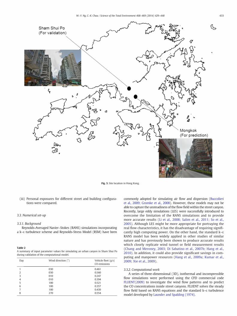
Fig. 3. Site location in Hong Kong.
433W.-Y. Ng, C.-K. Chau / Science of the Total Environment 468–469 (2014) 429–448
(iii) Personal exposures for different street and building configura-tions were compared.
3.3. Numerical set-up
3.3.1. BackgroundReynolds-Averaged Navier–Stokes (RANS) simulations incorporating
a k–ε turbulence scheme and Reynolds-Stress Model (RSM) have been
Table 2A summary of input parameter values for simulating an urban canyon in Sham Shui Poduring validation of the computational model.
Day Wind direction (°) Vehicle fleet (g/s)CO emissions
1 030 0.4612 030 0.5603 010 0.2474 010 0.3945 100 0.5216 100 0.3577 100 0.4398 270 0.554
commonly adopted for simulating air flow and dispersion (Buccolieriet al., 2009; Gromke et al., 2008). However, these models may not beable to capture the unsteadiness of theflowfieldwithin the street canyon.Recently, large eddy simulations (LES) were successfully introduced toovercome the limitation of the RANS simulations and to providemore accurate results (Li et al., 2008; Salim et al., 2011; So et al.,2005). Although LES might be more appropriate for portraying thereal flow characteristics, it has the disadvantage of requiring signifi-cantly high computing power. On the other hand, the standard k–εRANS model has been widely applied in other studies of similarnature and has previously been shown to produce accurate resultswhich closely replicate wind tunnel or field measurement results(Chang and Meroney, 2003; Di Sabatino et al., 2007b; Hang et al.,2010). In addition, it could also provide significant savings in com-puting and manpower resources (Hang et al., 2009a; Kumar et al.,2009; Xie et al., 2009).
3.3.2. Computational workA series of three-dimensional (3D), isothermal and incompressible
flow simulations were performed using the CFD commercial codeFLUENT(2009) to investigate the wind flow patterns and to predictthe CO concentrations inside street canyons. FLUENT solves the steadyflow field based on RANS equations and the standard k–ε turbulencemodel developed by Launder and Spalding (1974).

Table 3A summary of input parameter values used in the computational model for predicting theCO concentrations in Mongkok.
(a) Traffic data
Vehicle category CO emission factor(g/h)a
Number of carsper hour b
Motor cycle 24.2 17Private car 3.62 243Taxi 3.37 508Passenger van 8.95 5Public light bus c 26.4 39Light goods vehicle 1.04 165Medium & heavy goods vehicle 2.39 10Bus 4.69 480Total source generated (g/h) 6503.6
(b) Meteorological data d
Perpendicular Parallel
Wind direction (°) 67.5 337.5Average wind speed (m/s) 4.01 1.48
Reference height (m) 25
(c) Street configurations
Major canyon axis orientation (°) 337.5
Canyon length (m) 180Building height (m) 36/72/108Canyon width (m) 18Pedestrian walkway width (m) 1.5
a Xia and Shao (2005).b HKTD (2011).c Public light bus is a 16 seat mini bus.d HKPlanD (2007).
434 W.-Y. Ng, C.-K. Chau / Science of the Total Environment 468–469 (2014) 429–448
The baseline model was based on the reference case with no treesused by Gromke and Ruck (2007). This was a 1:150 scale wind tunnelmodel corresponding to a canyon of length 180 m and depth and heightof 18 m, i.e. AR1. The inlet boundary was set at 8H from the upstreambuilding of the street canyon, while the outflow boundary was set at30H from the downstream building. The top of the domain was set tobe 7H from the building roof and the lateral domains were 5H fromthe building side walls. The top and lateral sides of the domain weredefined to be symmetry. An outflow condition was assigned for theoutlet surface, while the other solid surfaces were assumed to be non-slip wall boundaries.
A 3D computational domain was initially built with approximately1.5 million hexahedral-based elements as these can produce a better
Table 4Average time spent and CO concentrations in various microenvironments associated withdaily activity patterns of the three population subgroups.
Average time spent (hour per day) Average CO concentration(μg/m3)
Vendors Residents Pedestrians
Inside canyonWorking 12.0 – – 7860–18,500b
Walking – – 2.0a 7860–18,500b
Indoor at home – 13.3 – 4040–4350b
Outside canyon a
Traveling 1.7 1.7 1.7 3650Working indoor – 9.0 9.0 854Indoor at home 10.3 – 11.3 943Total 24.0 24.0 24.0
a Chau et al. (2002).b Predicted from the computational model, e.g. 7860 and 18,500 μg/m3 were the average
CO concentrations for the baseline configurations in Scenarios AR2 and AR6 respectively.
quality solution than tetrahedral ones (Hefny and Ooka, 2009). Afiner mesh size was used near the building structure and at theground to allow more detailed air flow patterns to be examined nearthe building structure. An expansion ratio of 1.2 was employed for themesh located further away from the ground and buildings as less detailsare required in this area. For assessing the grid independency, a finergrid consisting of 3.3 million cells together with a coarser grid consistingof 0.85 million cells were constructed. The quality of simulationwas con-sidered to be adequate as similar flow patterns could be observed fordifferent grid sizes. Following the recommendation given by Tominagaet al. (2008), the grid sizes of the x, y and z directions should set tominimum one-tenth of the building height. The smallest grid spacing inx-, y- and z- directions was set to 0.05 building height (H) to complywith the recommendation.
Fig. 2 shows a sketch depicting the geometry, boundary conditionsof the model and its mesh size. Both the mesh resolution and domainsize complied with the CFD simulation requirements suggested byCOST Action 732 (2005–2009) and AIJ guidelines (Tominaga et al.,2008).
The boundary conditions of the main wind flow inlet were assumedto obey the power law as shown in the following:
u zð ÞuH
¼ zH
� �α ð1Þ
where u(z) is the wind velocity (m/s at height z (in m)), and UH is theflow velocity at the building height H, and α is the wind exponentwhich is dependent on the type of terrain. The turbulent kinetic energyk and dissipation rate ε were calculated based on the following equa-tions, respectively (Di Sabatino et al., 2007a),
k ¼ u�2ffiffiffiffiffiffiCμ
q 1− zδ
� �ð2Þ
ε ¼ u�3
κz1− z
δ
� �ð3Þ
where δ is the boundary layer depth, u* is the friction velocity, κ is thevon Kàrmàn constant, and Cμ is an empirical constant and has a valueof 0.09.
The RANS equations and the species transport equation were solvednumerically by the semi-implicit method using the pressure-linkedequation (SIMPLE) algorithm for pressure–velocity coupling (Patankarand Spalding, 1972). Second order upwind discretization approacheswere applied to momentum, turbulent kinetic energy, turbulent
Table 5Statistical evaluation of the results predicted by the computational model under differentwind directions for wind tunnel data (Gromke and Ruck, 2007).
Wind direction 0° 90° Acceptancecriteria
Wall A Wall A(leewardside)
Wall B(windwardside)
Index of agreement ‘d’ 0.91 0.72 0.86 See footnoteFractional bias ‘FB’ −0.55 0.23 0.29 −
0.3 ≤ FB ≤ 0.3Correlation coefficient ‘R’ 0.97 0.91 0.95 ≥0.8Normalizedmean square error‘NMSE’
0.26 0.34 0.28 ≤4
FAC2 0.55 0.89 0.86 FAC2 N 0.5
Notes: — ‘1’ denotes the computational and experimental data match perfectly and ‘0’denotes the computational and experimental data that do not match.Statistical evaluation was based on comparison of 700 grid points obtained at each wallunder each wind direction. The grid points used are identical to those given in http://www.ifh.uni-karlsruhe.de/science/aerodyn/CODASC.htm.
a) Perpendicular wind
b) Parallel wind
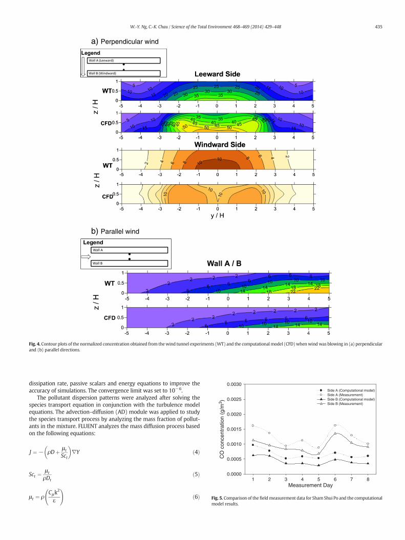
Fig. 4. Contour plots of the normalized concentration obtained from thewind tunnel experiments (WT) and the computationalmodel (CFD)whenwindwas blowing in (a) perpendicularand (b) parallel directions.
Measurement Day1 2 3 4 5 6 7 8
CO
con
cent
ratio
n (g
/m3 )
0.0000
0.0005
0.0010
0.0015
0.0020
0.0025
0.0030Side A (Computational model)Side A (Measurement)Side B (Computational model)Side B (Measurement)
Fig. 5. Comparison of thefieldmeasurement data for ShamShui Po and the computationalmodel results.
435W.-Y. Ng, C.-K. Chau / Science of the Total Environment 468–469 (2014) 429–448
dissipation rate, passive scalars and energy equations to improve theaccuracy of simulations. The convergence limit was set to 10−6.
The pollutant dispersion patterns were analyzed after solving thespecies transport equation in conjunction with the turbulence modelequations. The advection–diffusion (AD) module was applied to studythe species transport process by analyzing the mass fraction of pollut-ants in the mixture. FLUENT analyzes the mass diffusion process basedon the following equations:
J ¼ − ρDþ μ t
Sct
� �∇Y ð4Þ
Sct ¼μ t
ρDtð5Þ
μ t ¼ ρCμk
2
ε
!ð6Þ
436 W.-Y. Ng, C.-K. Chau / Science of the Total Environment 468–469 (2014) 429–448
where J is the diffusion flux of the mixture (kg/m2s), ρ is the density ofthe mixture (kg/m3), D is the mass diffusion coefficient of the pollutantin themixture (m2/s),Dt is the effectivemass diffusion coefficient due toturbulence (m2/s), Y is the mass fraction of the pollutant (kg/kg), μt isthe turbulent viscosity (kg s/m) with its value being determined fromEq. (6), turbulent Schmidt number Sct is a non-dimensional numberwhich is specified to be 0.7 (i.e. similar to the studies reported by DiSabatino et al. (2007b), Hang et al. (2009a,b) and Riddle et al. (2004)).The line source was simulated by separating a volume in the geometryat the centerline of the canyon. The length of this volume was madeequivalent to the canyon length. The height of the volume was set to
(a) Perpendicular wind
(b) Parallel wind
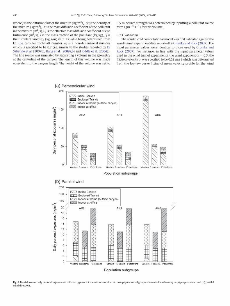
Fig. 6. Breakdowns of daily personal exposures in different types of microenvironments for thewind directions.
0.5 m. Source strength was determined by inputting a pollutant sourceterm (gm−3 s−1) for this volume.
3.3.3. ValidationThe constructed computationalmodel wasfirst validated against the
wind tunnel experiment data reported byGromke and Ruck (2007). Theinput parameter values were identical to those used by Gromke andRuck (2007). For instance, in line with the input parameter valuesused in the wind tunnel experiments, the wind exponent α = 0.3, thefriction velocity u* was specified to be 0.52 m/s (which was determinedfrom the log-law curve fitting of mean velocity profile for the wind
three population subgroupswhenwindwas blowing in (a) perpendicular; and (b) parallel

(a) Baseline configuration in Scenario AR2
(b) Configuration having a permeability value of 25% in Scenario AR2
Fig. 7. Contour plots of the CO concentration at the pedestrian level in Scenario AR2 with (a) the baseline configuration and (b) a configuration having permeability value of 25%.
437W.-Y. Ng, C.-K. Chau / Science of the Total Environment 468–469 (2014) 429–448
tunnel), and the von Kàrmàn constant κ was specified to be 0.4. Inaddition, the wind velocity was set to 4.7 m/s. A line source with aCO emission rate of 10 g/s was used to simulate the pollutant emis-sion pattern of a vehicle fleet.
Secondly, the computational model was then validated againstour field measurement results from Sham Shui Po, an urban districtin Kowloon (see Fig. 3 for location and photo). The model was mod-ified to AR2with L = 163 m,W = 30 m andH = 58 m. The orienta-tion of the canyon was NE–SW (45° from the North). The fieldmeasurement results were obtained from eight site measurementsperformed between December 2011 and April 2012. CO sampleswere collected from the measurement points located at both sidesof the canyon using sample bags. The collected samples were ana-lyzed using a B&K 1302 multi-gas monitor. The wind directions andwind speeds for individual data sets were obtained from the nearbymetrological station (HKO, 2012) and these values were input asthe inlet boundary conditions. The values of the input parametersused for the validation are shown in Table 2 with the validationresults being shown later in Section 4.
3.3.4. Prediction of CO concentrations for exposure assessmentFollowing validation, the model was used to predict the CO concen-
trations inside street canyons of different configurations. In order toobtain realistic estimates for portraying the personal exposures inHong Kong, the meteorological and site characteristics of a selectedstreet canyon in Mongkok (for location see Fig. 3), an urban districtwhich had a much a higher population and traffic density thanSham Shui Po, were used as inputs to the constructed model.
Table 3 summarizes all the input parameter values used to predictthe CO concentrations for the studied street and building configurationsin Mongkok. Traffic counts were determined from the manual countsof the number of vehicles passing by per hour. The traffic counts weresubsequently input into the model proposed by Xia and Shao (2005),as shown in Eq. (7), to estimate the total traffic emission (Sreal) insidecanyon.
Sreal ¼Xni¼1
Ni�Ki
�vi ð7Þ
where Ni refers to the traffic count of ith car type and vi is the averagespeed of the ith car type. Ki is the speed dependent emission factor forthe ith car type. This model was also employed by Parra et al. (2010)to predict the actual concentrations of the on-road traffic pollutants. Inaddition, the speeds for perpendicular and parallelwindswere specifiedto be 4.0 m/s and 1.5 m/s respectively. These values were obtained byextracting wind speed and direction from a publicly available report‘Experimental Site Wind Availability Data for Mongkok’ issued by theHong Kong Planning Department (HKPlanD, 2007), and then weightingthe different wind speeds that occurred in each direction with theiroccurrence probabilities over a one-year period.
3.4. Exposure estimation
Air pollutant exposure is defined as the extent of contact of humanbeings with different air pollutants. In this study, CO exposures wereused as a proxy for evaluating the air quality inside canyons. Shop ven-dors, pedestrians and residents are the major population subgroups offocus present in street canyons. Before estimating the CO exposures ofdifferent population subgroups, two major assumptions were made asfollows: (i) canyons embraced mixed-use buildings with shopfronts atground level and residential apartment units above the shopfronts,and (ii) the average duration of exposure and CO concentrations in dif-ferent types of micro-environments for different population subgroups,which are shown in Table 4, is similar to those extracted from the surveyfindings reported by Chau et al. (2002).
With the aid of these assumptions, the CO concentrations predictedby the computational model were used for estimating the personal ex-posures of different subgroups using the indirect approach introducedby Duan (1982) and Ott (1982). Under this approach, the exposures ofpopulation subgroups were estimated indirectly by multiplying the
Permeability
Per
sona
l exp
osur
es (
mg/
m3 )
0
100
200
300
400
500
AR2AR4AR6Mean exposures
0% 10% 25% 35% 0% 10% 25% 35% 0% 10% 25% 35%
Median exposures
(a) Perpendicular wind
Mean exposures
0% 10% 25% 35% 0% 10% 25% 35% 0% 10% 25% 35%
Permeability
Per
sona
l exp
osur
es (
mg/
m3 )
0
5
10
15
20
25
550
600
AR2AR4AR6Mean exposuresMedian exposures
(b) Parallel wind
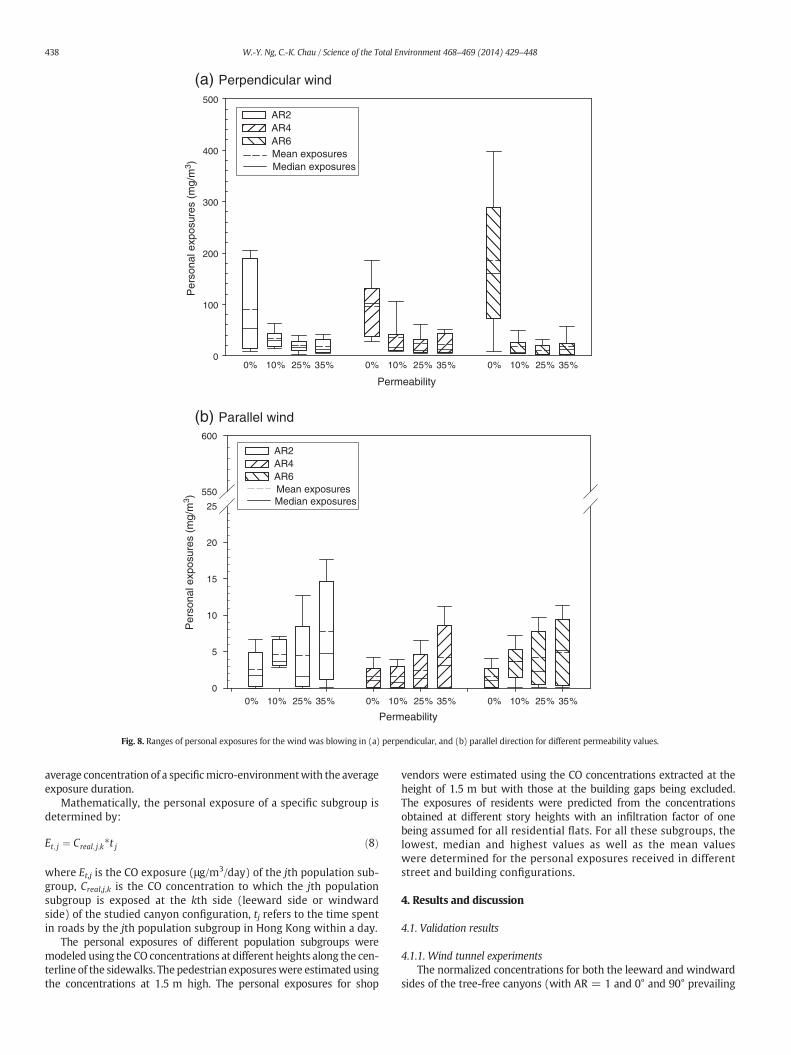
Fig. 8. Ranges of personal exposures for the wind was blowing in (a) perpendicular, and (b) parallel direction for different permeability values.
438 W.-Y. Ng, C.-K. Chau / Science of the Total Environment 468–469 (2014) 429–448
average concentration of a specificmicro-environmentwith the averageexposure duration.
Mathematically, the personal exposure of a specific subgroup isdetermined by:
Et; j ¼ Creal; j;k�t j ð8Þ
where Et,j is the CO exposure (μg/m3/day) of the jth population sub-group, Creal,j,k is the CO concentration to which the jth populationsubgroup is exposed at the kth side (leeward side or windwardside) of the studied canyon configuration, tj refers to the time spentin roads by the jth population subgroup in Hong Kong within a day.
The personal exposures of different population subgroups weremodeled using the CO concentrations at different heights along the cen-terline of the sidewalks. The pedestrian exposureswere estimated usingthe concentrations at 1.5 m high. The personal exposures for shop
vendors were estimated using the CO concentrations extracted at theheight of 1.5 m but with those at the building gaps being excluded.The exposures of residents were predicted from the concentrationsobtained at different story heights with an infiltration factor of onebeing assumed for all residential flats. For all these subgroups, thelowest, median and highest values as well as the mean valueswere determined for the personal exposures received in differentstreet and building configurations.
4. Results and discussion
4.1. Validation results
4.1.1. Wind tunnel experimentsThe normalized concentrations for both the leeward and windward
sides of the tree-free canyons (with AR = 1 and 0° and 90° prevailing

(a) Scenario AR2 @ 10% permeability (b) Scenario AR2 @ 35% permeability
(c) Scenario AR4 @ 10% permeability (d) ScenarioAR4@35%permeability
(e) Scenario AR6 @ 10% permeability (f) Scenario AR6 @ 35% permeability
Fig. 9. Horizontal sections for perpendicular winds showing the velocity contours with two-dimensional streamlines at the pedestrian level (z = 1.5) for permeability values of 10% and35% in Scenarios AR2, AR4 and AR6.
439W.-Y. Ng, C.-K. Chau / Science of the Total Environment 468–469 (2014) 429–448
wind) from the paper by Gromke and Ruck (2007) were extracted forvalidating our computational model. Following the COST 732 recom-mendations (cp. Schatzmann and Leitl, 2011), so-called validationmet-rics were used for a quantitative assessment of the model performance.The metrics that have been selected are fractional bias (FB), normalizedmean square error (NMSE), the factor of two of observations (FAC2),each of which is discussed in the paper by Chang and Hanna (2004).
In addition, correlation coefficient (R) (Chang and Hanna, 2004) andindex of agreement (d) (Willmott, 1982) were also used for checkingthe agreement of the computational results with the experimental re-sults. A total of 700 grid points were compared at each wall under eachwind direction. The details of the grid points can be referred to in thosegiven in http://www/ifh.uni-karlsruhe.de/science/aerodyn/CODAC.htm.Table 5 shows the results of the statistical measures. As all the statistical

Permeability
Per
sona
l exp
osur
es (
mg/
m3 )
0
100
200
300
400
500
600
AR2AR4AR6
Mean exposures
0% 10% 25% 35% 0% 10% 25% 35% 0% 10% 25% 35%
Median exposures
(a) Leeward side
Permeability
Per
sona
l exp
osur
es (
mg/
m3 )
0
100
200
300
400
500
600
AR2AR4AR6
Mean exposures
0% 10% 25% 35% 0% 10% 25% 35% 0% 10% 25% 35%
Median exposures
(b) Windward side
Fig. 10. Ranges of personal exposures on the (a) leeward and (b) windward sides of canyons respectively for perpendicular winds and different permeability values.
440 W.-Y. Ng, C.-K. Chau / Science of the Total Environment 468–469 (2014) 429–448
measures liewithin the acceptance limits, it can be concluded that the re-sults obtained from the computational model exhibit reasonably goodagreement with the experimental results within acceptable ranges oferrors.
In order to further evaluate the deviations between predictions andobservations, the pollutant distribution patterns were also compared.Fig. 4a and b shows comparisons between the concentration contoursproduced by the computational model and those derived from thewind tunnel data for Scenario AR1 for perpendicular wind and parallelwind respectively. Similar concentration profile patternswere observedfor both wind directions. The computational results tended to underpredict the wind tunnel results in the higher concentration zones forperpendicular winds, while the computational results tended to over
predict on the leeward side in higher concentration zones for parallelwinds. These discrepancies were less than a factor of 2, so we consideredthat our computational model performed satisfactorily in qualitativerather than quantitative terms, for simulating the flow and dispersionpatterns inside canyons.
4.1.2. Field measurement results: Sham Shui PoThe computational model was then compared against data collected
from a street canyon in Sham Shui Po, Hong Kong. In comparison to thedata output from the wind tunnel experiments, fewer data pointsexisted for the field measurements due to resource limitation. There-fore, only the concentrationsmeasured at the fieldmeasurement pointswere comparedwith the computational model. Fig. 5 shows that the CO

a) Baseline configuration in Scenario AR2
b) Vertical setback in Scenario AR2
c) Baseline configuration in Scenario AR4
d) Vertical setback in Scenario AR4
Fig. 11. Contour plots of the CO concentration at the pedestrian level in Scenarios AR2 and AR4 for the baseline configuration and a vertical setback with a length of 45 m.
441W.-Y. Ng, C.-K. Chau / Science of the Total Environment 468–469 (2014) 429–448
concentrations predicted by the computational model had an agree-ment value of 48% with the field measurement data (i.e. with a ‘d’value of 0.48). Also, the trend of the measurement data was similar tothat of the predicted results with a correlation coefficient ‘R’ value of0.8. This level of discrepancy is of the same order as observed in thevalidation test described above. However, we observe from Fig. 5 thatonce again the model behaves satisfactorily in qualitative terms ratherthan quantitative terms.
4.2. Predictive work
4.2.1. Exposure estimation for different population subgroupsFig. 6 shows the breakdowns of the daily personal exposures in dif-
ferent types of micro-environments for the three population subgroupswhen theprevailingwindwasblowing in different directions. Due to re-source constraints, we focused on the perpendicular and parallel winddirections only as these were assumed to be limiting cases. Among the

Length of setback (m)
Per
sona
l exp
osur
es (
mg/
m3 )
0
100
200
300
400
500
600
AR2AR4AR6
Mean exposuresMedian exposures
(a) Perpendicular wind
Per
sona
l exp
osur
es (
mg/
m3 )
0
5
10
15
20
500
550
600
AR2AR4AR6Mean exposuresMedian exposures
Length of setback (m)
0 18 45 63 0 18 45 63 630 18 45
0 18 45 63 0 18 45 63 630 18 45
(b) Parallel wind
Fig. 12. Ranges of personal exposures for different building vertical setback lengths when wind was blowing in (a) perpendicular and (b) parallel directions.
442 W.-Y. Ng, C.-K. Chau / Science of the Total Environment 468–469 (2014) 429–448
three subgroups, shop vendors received the highest overall daily expo-sures. Their exposures were even higher than those of residents despitethe latter subgroup spending longer time in canyons. The extent of per-sonal exposures and the relative proportions of the total daily exposureswere greatly influenced by the prevailing wind direction. The pollutantexposures measured inside canyons with perpendicular wind weremuch higher than those with parallel wind. The exposures due to per-pendicular wind accounted for more than 80% of their daily pollutantexposures, while those due to parallel wind only accounted for 5–10%.Their proportions also slightly increased with AR. Approximately 80%of the daily pollutant exposure was due to the canyon exposures inScenario AR2 with perpendicular prevailing wind and this increased to90% in Scenario AR6.
The average personal exposures for shop vendors in the baselineconfigurations for the three AR scenarios under the perpendicular
prevailing wind greatly exceeded the 8-hour threshold value of CO(10,000 μg/m3) laid down by the Hong Kong Air Quality Objectives(HKAQO). The average daily exposures were equal to 74,800 μg/m3,91,700 μg/m3 and 176,200 μg/m3 for Scenarios AR2, AR4 and AR6respectively. These exposures are significantly higher than theHKAQO, even after allowing for over prediction by the model aspreviously noted.
4.2.2. Effects of different types of street and building configurations
4.2.2.1. Building separation. Fig. 1b shows the modeled street canyonconfiguration with building separation ‘S’ being varied to achieve a per-meability value of 10%, 25% or 35%. In line with our hypothesis, themean and highest personal pollutant exposures in canyons with per-pendicular wind reduced quite significantly after introducing spacing

Length of setback (m)
Per
sona
l exp
osur
es (
mg/
m3 )
0
100
200
300
400
500
AR2AR4AR6
Mean exposuresMedian exposures
(a) Leeward side
Per
sona
l exp
osur
es (
mg/
m3 )
0
100
200
300
400
500
600
AR2AR4AR6
Mean exposures
Median exposures
Length of setback (m)
0 18 45 63 0 18 45 63 630 18 45
0 18 45 63 0 18 45 63 630 18 45
(b) Windward side
Fig. 13. Ranges of personal exposure for perpendicular winds on the (a) leeward and (b) windward sides of canyons after different lengths of setback were introduced.
443W.-Y. Ng, C.-K. Chau / Science of the Total Environment 468–469 (2014) 429–448
between buildings. Fig. 7a and b shows the concentration contours inthe horizontal sections in Scenario AR2 at pedestrian level for the base-line configuration and the configuration with permeability value of 25%respectively. In the baseline configuration, pollutants were trapped andaccumulated at the pedestrian level especially at the windward side ofthe canyon. The accumulated pollutants were reduced significantlyafter building separation was introduced as a result of fewer pollutantsbeing accumulated at both windward and leeward sides. Similar dis-persion patterns were found for Scenarios AR4 and AR6 after build-ing separation was introduced.
With a permeability value of 10%, the mean exposures for ScenarioAR2 reduced by 50% compared with the baseline case and by morethan 80% for Scenarios AR4 and AR6 (see Fig. 8a). However, the meanand highest exposures did not display further significant reductionswhen the permeability value was further increased beyond 10%.
The overall wind flow patterns for permeability values of 10% and35%were similar (see Fig. 9). The only difference was that the velocitiesobserved around the buildings and at the building gaps for a permeabil-ity value of 35% were higher than those observed for a permeabilityvalue of 10%. However, the in-canyon velocities were similar for thetwo permeability values. For example, it can be seen from Fig. 9a andb that the velocities near the street ends in Scenario AR2 increasedfrom 0.8 to 1.2 m/s, and the increment in velocity became smallerwith a higher AR. The velocity contours were similar for both the streetends in Scenarios AR4 andAR6 (see Fig. 9c to f). This helped explainwhythe effectiveness in lowering personal exposures quickly diminishedwith a further increase in the permeability values. Although therewere significant reductions in CO concentrations by increasing the per-meability value from 0% to 10%, the reduction was not significant bygoing from 10% to 35% permeability value.

(a) Vertical setbacks – Scenario AR2 (b) Horizontal setbacks – Scenario AR2
(c) Vertical setbacks – Scenario AR4 (d) Horizontal setbacks – Scenario AR4
(e) Vertical setbacks – Scenario AR6 (f) Horizontal setbacks – Scenario AR6
Fig. 14. Vertical cross sections showing the velocity contours and streamlines for horizontal and vertical setbacks in Scenarios AR2, AR4 and AR6.
444 W.-Y. Ng, C.-K. Chau / Science of the Total Environment 468–469 (2014) 429–448
In contrast for parallel winds, the mean and highest exposures in-creased after building separations were introduced into the canyon(see Fig. 8b). Higher aspect ratios gave larger incremental increases inexposures. This was similar to the earlier findings reported by Garberoet al. (2010). In view of this, building separation was only consideredsuitable for canyons with perpendicular prevailing wind.
In addition, the effect of building separation on exposures insidecanyons for perpendicular winds varied considerably between wind-ward and leeward sides. As seen in Fig. 10, the windward side experi-enced a higher percentage reduction in the mean exposures than theleeward side given the same degree of changes in permeability values.An approximate 80% reduction in the mean exposure compared to the
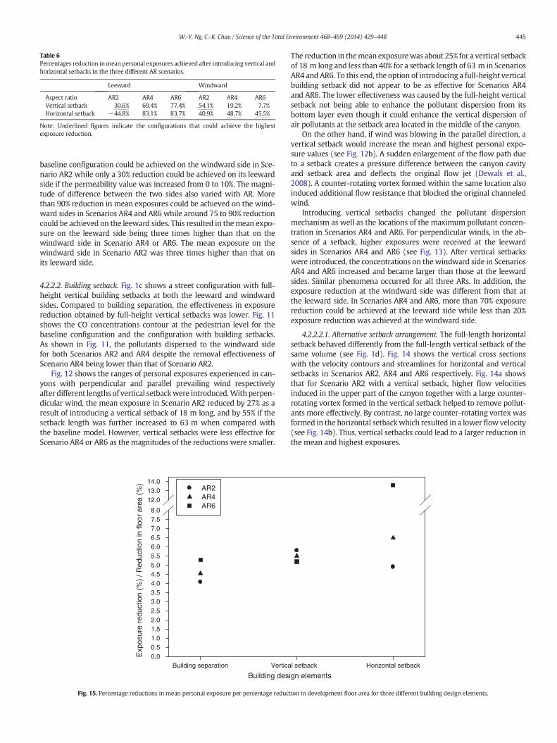
Table 6Percentages reduction inmean personal exposures achieved after introducing vertical andhorizontal setbacks in the three different AR scenarios.
Leeward Windward
Aspect ratio AR2 AR4 AR6 AR2 AR4 AR6Vertical setback 30.6% 69.4% 77.4% 54.1% 19.2% 7.7%Horizontal setback −44.8% 83.1% 83.7% 40.9% 48.7% 45.5%
Note: Underlined figures indicate the configurations that could achieve the highestexposure reduction.
445W.-Y. Ng, C.-K. Chau / Science of the Total Environment 468–469 (2014) 429–448
baseline configuration could be achieved on the windward side in Sce-nario AR2 while only a 30% reduction could be achieved on its leewardside if the permeability value was increased from 0 to 10%. The magni-tude of difference between the two sides also varied with AR. Morethan 90% reduction in mean exposures could be achieved on the wind-ward sides in Scenarios AR4 and AR6 while around 75 to 90% reductioncould be achieved on the leeward sides. This resulted in themean expo-sure on the leeward side being three times higher than that on thewindward side in Scenario AR4 or AR6. The mean exposure on thewindward side in Scenario AR2 was three times higher than that onits leeward side.
4.2.2.2. Building setback. Fig. 1c shows a street configuration with full-height vertical building setbacks at both the leeward and windwardsides. Compared to building separation, the effectiveness in exposurereduction obtained by full-height vertical setbacks was lower. Fig. 11shows the CO concentrations contour at the pedestrian level for thebaseline configuration and the configuration with building setbacks.As shown in Fig. 11, the pollutants dispersed to the windward sidefor both Scenarios AR2 and AR4 despite the removal effectiveness ofScenario AR4 being lower than that of Scenario AR2.
Fig. 12 shows the ranges of personal exposures experienced in can-yons with perpendicular and parallel prevailing wind respectivelyafter different lengths of vertical setbackwere introduced.With perpen-dicular wind, the mean exposure in Scenario AR2 reduced by 27% as aresult of introducing a vertical setback of 18 m long, and by 55% if thesetback length was further increased to 63 m when compared withthe baseline model. However, vertical setbacks were less effective forScenario AR4 or AR6 as the magnitudes of the reductions were smaller.
Building des
Exp
osur
e re
duct
ion
(%)
/ Red
uctio
n in
floo
r ar
ea (
%)
0.00.51.01.52.02.53.03.54.04.55.05.56.06.57.07.58.0
12.013.014.0
AR2AR4AR6
Building separation Vertica
Fig. 15. Percentage reductions in mean personal exposure per percentage reduc
The reduction in themean exposurewas about 25% for a vertical setbackof 18 m long and less than 40% for a setback length of 63 m in ScenariosAR4 and AR6. To this end, the option of introducing a full-height verticalbuilding setback did not appear to be as effective for Scenarios AR4and AR6. The lower effectiveness was caused by the full-height verticalsetback not being able to enhance the pollutant dispersion from itsbottom layer even though it could enhance the vertical dispersion ofair pollutants at the setback area located in the middle of the canyon.
On the other hand, if wind was blowing in the parallel direction, avertical setback would increase the mean and highest personal expo-sure values (see Fig. 12b). A sudden enlargement of the flow path dueto a setback creates a pressure difference between the canyon cavityand setback area and deflects the original flow jet (Dewals et al.,2008). A counter-rotating vortex formed within the same location alsoinduced additional flow resistance that blocked the original channeledwind.
Introducing vertical setbacks changed the pollutant dispersionmechanism as well as the locations of the maximum pollutant concen-tration in Scenarios AR4 and AR6. For perpendicular winds, in the ab-sence of a setback, higher exposures were received at the leewardsides in Scenarios AR4 and AR6 (see Fig. 13). After vertical setbackswere introduced, the concentrations on thewindward side in ScenariosAR4 and AR6 increased and became larger than those at the leewardsides. Similar phenomena occurred for all three ARs. In addition, theexposure reduction at the windward side was different from that atthe leeward side. In Scenarios AR4 and AR6, more than 70% exposurereduction could be achieved at the leeward side while less than 20%exposure reduction was achieved at the windward side.
4.2.2.2.1. Alternative setback arrangement. The full-length horizontalsetback behaved differently from the full-length vertical setback of thesame volume (see Fig. 1d). Fig. 14 shows the vertical cross sectionswith the velocity contours and streamlines for horizontal and verticalsetbacks in Scenarios AR2, AR4 and AR6 respectively. Fig. 14a showsthat for Scenario AR2 with a vertical setback, higher flow velocitiesinduced in the upper part of the canyon together with a large counter-rotating vortex formed in the vertical setback helped to remove pollut-ants more effectively. By contrast, no large counter-rotating vortex wasformed in the horizontal setbackwhich resulted in a lower flow velocity(see Fig. 14b). Thus, vertical setbacks could lead to a larger reduction inthe mean and highest exposures.
ign elementsl setback Horizontal setback
tion in development floor area for three different building design elements.

Fig. 16. A hierarchy decision making model for guiding the planning of deep canyons in high density cities.
446 W.-Y. Ng, C.-K. Chau / Science of the Total Environment 468–469 (2014) 429–448
On the other hand, the flow patterns in Scenarios AR4 and AR6wereremarkably different between horizontal and vertical setbacks. Themajor vortex induced near the roof top made the stagnated air parcelat the pedestrian level flow upwards and draw out the pollutants atthat location (see Fig. 14d and f). Conversely, an air stream flowedfrom the roof top towards the pedestrian level of the canyon having avertical setback (see Fig. 14c and e). The downward flow obstructedthe pollutants upward dispersion process and the air stream was thensuppressed at the bottom level. Hence, the air flow velocities at thepedestrian level for the vertical setbacks were lower than those forhorizontal setbacks which rendered horizontal setbacks more effectivein lowering personal exposures.
Table 6 compares the percentage exposure reductions that couldbe achieved after vertical and horizontal setbacks had been introducedfor different canyon configurations. Generally, both vertical and hori-zontal setbacks could improve air quality in street canyons. One excep-tionwas that a horizontal setbackwould induce highermean exposuresat the leeward side of Scenario AR2. Their effectswere different not onlybetween leeward and windward sides, but also between vertical andhorizontal setbacks. Furthermore, the effects were also different fordifferent AR Scenarios. Interestingly, vertical setbacks were preferablefor Scenario AR2 as they could provide higher percentage exposurereductions at both leeward and windward sides. By contrast, horizontalsetbacks were preferable for Scenarios AR4 and AR6 as they were moreeffective in reducing the personal exposures at both leeward and wind-ward sides (bymore than 10% at the leeward side and bymore than 40%at the windward sides). Accordingly, the decision on whether to incor-porate a vertical or horizontal setback into a canyon greatly dependedon its AR although there may be practical difficulties in introducing asetback to an existing street canyon environment.
4.2.3. Optimized street configurationsBesides focusing on the most vulnerable subgroup, it is also impor-
tant to determine the type of street and building configuration whichcan yield the highest overall personal exposure reduction. To accom-plish this, some supplementary assumptions were made for estimatingthe personal exposures of vendors, pedestrians and residents. They are:
• 5 vendors worked in a shop having an area of 90 m2;• a building block of 180 m long and 18 m wide embracing 60 flats(based on the average domestic household size of 2.9 persons inHong Kong, (HKStatD, 2011) with an average flat area of 50 m2
(HKHA, Hong Kong Housing Authority, 2012));• only half of the residents stayed at home during daytime;
• 3864 pedestrians walked across a meter-wide outdoor pedestriansidewalk eachhour (whichwere estimated basedupon thepedestrianflow data reported by Lam and Cheung (2000)).
Fig. 15 shows the percentage exposure reduction that could beachieved per percentage reduction in total development floor area bythree different building design elements in Scenarios AR2, AR4 andAR6. The effectiveness of the building design elements in reducing thepollutant concentrations was influenced by the aspect ratios. Verticalsetbacks could reduce the exposures by 5–6% per percentage reductionin total development floor area for all the AR scenarios. Horizontalsetbacks could achieve 13% exposure reduction in Scenario AR6, 6.5%in Scenario AR4, and 5.0% in Scenario AR2. Building separation couldachieve 5.5% reduction in Scenario AR6, 4.5% in Scenario AR4, and 4.0%in Scenario AR2. Vertical setbacks were more effective for lower aspectratios where the effectiveness of building separation and horizontalsetbacks increased with aspect ratios.
Above all, the findings arising from this study could be employed forformulating a hierarchy decisionmakingmodel for guiding the planningof deep canyons in high density urban cities. The hierarchy modelshown in Fig. 16 shows that the prevailing wind direction is the firstcriterion to be considered during the planning of urban canyons. If theprevailing wind is parallel, many road and building geometry optionsare feasible. If the prevailing wind is perpendicular, then the aspectratio of the road becomes another important criterion for consideration.Vertical setback is recommended for AR2. By contrast, horizontalsetback is recommended for AR4 and AR6.
5. Conclusions
This study successfully investigated the effects of street and buildingconfigurations on personal exposures received in canyons by employingthe indirect exposure approach. There are a number of interesting find-ings arising from this study which can provide valuable insights fordecision makers and urban planners in formulating appropriate landuse policies to reduce the personal pollutant exposures inside canyons.
First, it was determined that personal exposures in canyons variedpredominately according to the prevailingwinddirection and to a lesserextent their ARs. Alarmingly high exposures occurred in canyons withperpendicular prevailing wind and the exposures would become evenhigher with increasing AR. By contrast, only very low exposures wouldbe encountered in canyons with parallel prevailing wind.
Second, it was considered that the two building design elementsidentified by the SBD Guidelines, i.e. building separation and building
447W.-Y. Ng, C.-K. Chau / Science of the Total Environment 468–469 (2014) 429–448
setback, might not always be effective in mitigating the high exposureproblems in canyons. Indeed their effectiveness was greatly influencedby the prevailing wind direction and aspect ratios. A permeabilityvalue of 10% was sufficient for reducing the exposures inside canyonsto a relatively low level if the canyons were subject to a perpendicularprevailing wind. By contrast, from an air exposures perspective, largebuilding separation, i.e. with permeability value higher than 10%, wasnot recommended for canyons with parallel prevailing wind. Thesefindings contradict the minimum permeability value requirement of20% laid down by the SBD Guidelines.
Third, similar to building separation, building setbacks did notalways appear to be a very effective solution for mitigating personalexposure problems in canyons. The effectiveness of vertical or hori-zontal building setback was greatly influenced by AR. Full-lengthhorizontal setbacks were effective for reducing personal exposuresin Scenarios AR4 and AR6, while full-height vertical setbacks weremore preferable in Scenario AR2. Similarly, it is not recommendedto incorporate building setbacks into canyons with parallel prevail-ing wind as they will result in even higher personal exposures. Itwas shown that these findings could be incorporated into a decisionmaking model for guiding the planning of deep canyons in urbanareas.
Finally, if the reduction in the total development floor area wastaken into account, building setback was also found to be a more effec-tive option for lowering personal exposures than building separation.Vertical setback was the most effective option for Scenario AR2 whilehorizontal setback was found to be more effective for Scenarios AR4and AR6 as it gave the highest percentage exposure reduction perpercentage reduction in total development floor area.
Accordingly, it is recommended to revisit the requirements laiddown in the SBD Guidelines on building separation and building set-back. This study suffered from a number of limitations that may limitthe general applicability of the findings. First, this study only focusedon simple configurations in isolated canyons, although similar resultsare expected to be applicable to more complicated configurations likehigh-rise buildings aligned along streets (McMaster and Shea, 1992).Second, this study only focused on isolated canyons without consider-ing the impacts of the surrounding buildings on the ambient flowpatterns. Third, all the buildings located in the canyons were assumedto be of same height and symmetrically located, which might deviatefrom the real scenarios in urban cities. Fourth, this study also assumedan isothermal situation in which thermal effect was neglected. Thismight restrict the application of the results as thermal effect wasfound to exert some influences on the flow patterns and exposures(Sini et al., 1996; Xie et al., 2005). Fifth, the findings arising from thisstudy were only applicable to perpendicular and parallel wind direc-tions which were considered to be two limiting cases. To overcomethese, it is recommended further studies be conducted formore compli-cated street canyon configurations and thermal stratification effect.More studies should also be conducted to investigate the impacts ofother wind directions (e.g. oblique wind flows) and wind speeds onpersonal exposures. Lastly, it is noteworthy to point out that due careshould be exercised in using the quantitative exposure estimates re-ported in this work due to uncertainties in the computational modelingresults. Although the model behaved well qualitatively by predictingconcentration profiles similar to themeasured results, the discrepanciesbetween the computational and experimental results may impair theaccuracies of our quantitative estimates. However, they would not sig-nificantly affect the conclusion drawn from this work as the discrepan-cies were much smaller when compared with the differences betweenparallel and perpendicular wind.
Acknowledgments
The authors would like to thank the Hong Kong Polytechnic Uni-versity for the funding support through the Central Allocation Grants
no: G-U868. Special thanks to our colleagues Mr. Greg Powell andDr. Danny Then for giving valuable assistance and comments.
References
Ahmad K, Khare M, Chaudhry KK. Wind tunnel simulation studies on dispersion at urbanstreet canyons and intersections—a review. J Wind Eng Ind Aerodyn 2005;93:697–717.
Assimakopoulos VD, ApSimon HM, Moussiopoulos N. A numerical study of atmosphericpollutant dispersion in different two-dimensional street canyon configurations.Atmos Environ 2003;37:4037–49.
Bady M, Kato S, Huang H. Towards the application of indoor ventilation efficiency indicesto evaluate the air quality of urban areas. Build Environ 2008;43:1991–2004.
Bady M, Kato S, Takahashi T, Huang H. An experimental investigation of the wind envi-ronment and air quality within a densely populated urban street canyon. J WindEng Ind Aerodyn 2011;99:857–67.
Baldauf R, Thoma E, Khlystov A, Isakov V, Bowker G, Long T, et al. Impacts of noise barrierson near-road air quality. Atmos Environ 2008;42:7502–7.
Bowker GE, Baldauf R, Isakov V, Khlystov A, PetersenW. The effects of roadside structureson the transport and dispersion of ultrafine particles from highways. Atmos Environ2007;41:8128–39.
Buccolieri R, Gromke C, Di Sabatino S, Ruck B. Aerodynamic effects of trees on pollutantconcentration in street canyons. Sci Total Environ 2009;407:5247–56.
Buccolieri R, SandbergM, Di Sabatino S. City breathability and its link to pollutant concen-tration distribution within urban-like geometries. Atmos Environ 2010;44:1894–903.
Buccolieri R, Salim SM, Leo LS, Di Sabatino S, Chan A, Ielpo P, et al. Analysis of local scaletree–atmosphere interaction on pollutant concentration in idealized street canyonsand application to a real urban junction. Atmos Environ 2011;45:1702–13.
Chan AT, So ES, Samad SC. Strategic guidelines for street canyon geometry to achievesustainable street air quality. Atmos Environ 2001;35:5681–91.
Chan AT, So ES, Samad SC. Strategic guidelines for street canyon geometry to achievesustainable street air quality—part II: multiple canopies and canyons. Atmos Environ2003;37:2761–72.
Chang J, Hanna S. Air quality and model performance evaluation. Meteorol Atmos Phys2004;87:167–96.
Chang CH, Meroney RN. Concentration and flow distributions in urban street canyons:wind tunnel and computational data. J Wind Eng Ind Aerodyn 2003;91:1141–54.
Chau CK, Tu EY, Chan DWT, Burnett J. Estimating the total exposure to air pollutants fordifferent population age groups in Hong Kong. Environ Int 2002;27:617–30.
COST Action 732. Quality assurance and improvement of micro-scale meteorologicalmodels. Available at:http://www.mi.uni-hamburg.de/Home.484.0.html.
DePaul FT, Sheih CM. Measurement of wind velocities in a street canyon. Atmos Environ1986;20:455–9.
Dewals BJ, Kantoush SA, Erpicum S, Pirotton M, Schleiss AJ. Experimental and numericalanalysis of flow instabilities in rectangular shallow basins. Environ Fluid Mech2008;8:31–54.
Di Sabatino S, Buccolieri R, Pulvirenti B, Britter RE. Simulations of pollutant disper-sion within idealised urban-type geometries with CFD and integral models. AtmosEnviron 2007a;41:8316–29.
Di Sabatino S, Buccolieri R, Pulvirenti B, Britter RE. Flow and pollutant dispersion in streetcanyons using FLUENT and ADMS-Urban. Environ Model Assess 2007b;13:369–81.
Duan N. Models for human exposure to air pollution. Environ Int 1982;8:305–9.Finn D, Clawson KL, Carter RG, Rich JD, Eckman RM, Perry SG, et al. Tracer studies to
characterize the effects of roadside noise barriers on near-road pollutant dispersionunder varying atmospheric stability conditions. Atmos Environ 2010;44:204–14.
FLUENT. FLUENT 12.0 user's guide; 2009.Gallagher J, Gill LW, McNabola A. Optimizing the use of on-street car parking system as a
passive control of air pollution exposure in street canyons by large eddy simulation.Atmos Environ 2011;45:1684–94.
Gallagher J, Gill LW, McNabola A. Numerical modelling of the passive control of airpollution in asymmetrical urban street canyons using refined mesh discretizationschemes. Build Environ 2012;56:232–40.
Garbero V, Salizzoni P, Soulhac L. Experimental study of pollutant dispersion within anetwork of streets. Bound-Lay Meteorol 2010;136:457–87.
Ghenu A, Rosant JM, Sini JF. Dispersion of pollutants and estimation of emissions in astreet canyon in Rouen, France. Environ Model Software 2008;23:314–21.
Greaves S, Issarayangyun T, Liu Q. Exploring variability in pedestrian exposure to fineparticulates (PM2.5) along a busy road. Atmos Environ 2008;42:1665–76.
Gromke C, Ruck B. Influence of trees on the dispersion of pollutants in an urban streetcanyon—experimental investigation of the flow and concentration field. AtmosEnviron 2007;41:3287–302.
Gromke C, Ruck B. Pollutant concentrations in street canyons of different aspect ratio withavenues of trees for various wind directions. Bound-Lay Meteorol 2012;144:41–64.
Gromke C, Buccolieri R, Di Sabatino S, Ruck B. Dispersion study in a street canyon withtree planting by means of wind tunnel and numerical investigations — evaluationof CFD data with experimental data. Atmos Environ 2008;42:8640–50.
Hang J, Sandberg M, Li Y. Age of air and air exchange efficiency in idealized city models.Build Environ 2009a;44:1714–23.
Hang J, Sandberg M, Li Y, Claesson L. Pollutant dispersion in idealized city models withdifferent urban morphologies. Atmos Environ 2009b;43:6011–25.
Hang J, Li Y, Sandberg M, Claesson L. Wind conditions and ventilation in high-rise longstreet models. Build Environ 2010;45:1353–65.
Hang J, Li Y, Buccolieri R, Sandberg M, Di Sabatino. On the contribution of mean flow andturbulence to city breathability: the case of long streets with tall buildings. Sci TotalEnviron 2012;416:362–73.
448 W.-Y. Ng, C.-K. Chau / Science of the Total Environment 468–469 (2014) 429–448
Hefny MM, Ooka R. CFD analysis of pollutant dispersion around buildings: effect of cellgeometry. Build Environ 2009;44:1699–706.
Heist DK, Perry SG, Brixey LA. A wind tunnel study of the effect of roadway configurationson the dispersion of traffic-related pollution. Atmos Environ 2009;43:5101–11.
HKBD (Hong Kong Buildings Department). Practice notes for authorized persons,registered structural engineers and registered geotechnical engineers, no. APP-152 —sustainable building design guidelines; 2011.
HKHA (Hong Kong Housing Authority). Housing in figures 2012;c2012 [Cited 2012].Available from:http://www.housingauthority.gov.hk/en/about-us/publications-and-statistics, 2012.
HKO (Hong Kong Observatory). Statistical data of weather information in Hong Kong;c2012 [Cited 2012]. Available from:http://www.hko.gov.hk, 2012.
HKPlanD (Hong Kong Planning Department). Experimental site wind availability data forMong Kok; c2007 [cited 2012]. Available from:http://www.pland.gov.hk/pland_en/info_serv/site_wind/index.html, 2007.
HKStatD (Hong Kong Statistics Department). Population census — summary results;c2011 [cited 2012]. Available from:http://www.census2011.gov.hk/en/publication-feature-articles.html, 2011.
HKTD (Hong Kong Transportation Department). The annual traffic census— 2011; c2011[cited 2012]. Available from:http://www.td.gov.hk/en/publications_and_press_releases/publications/free_publications/the_annual_traffic_census_2011/index.html, 2011.
Kastner-Klein P, Berkowicz R, Britter R. The influence of street architecture on flow anddispersion in street canyons. Meteorol Atmos Phys 2004;87:121–31.
Kaur S, Nieuwenhuijsen M, Colvile R. Personal exposure of street canyon intersectionusers to PM2.5, ultrafine particle counts and carbon monoxide in Central London,UK. Atmos Environ 2005;39:3629–41.
Kumar P, Fennell P, Britter R. Measurements of particles in the 5–1000 nm range close toroad level in an urban street canyon. Sci Total Environ 2008;390:437–47.
Kumar P, Garmory A, Ketzel M, Berkowicz R, Britter R. Comparative study of measuredand modelled number concentrations of nanoparticles in an urban street canyon.Atmos Environ 2009;43:949–58.
Lam WHK, Cheung CY. Pedestrian speed/flow relationships for walking facilities in HongKong. J Transp Eng 2000;126:343–9.
Launder BE, Spalding DB. The numerical computation of turbulent flows. ComputMethods Appl Mech Eng 1974;3:269–89.
Li XX, Liu CH, Leung DYC, Lam KM. Recent progress in CFD modelling of wind field andpollutant transport in street canyons. Atmos Environ 2006;40:5640–58.
Li XX, Liu CH, Leung DYC. Large-eddy simulation of flow and pollutant dispersion inhigh-aspect-ratio urban street canyons with wall model. Bound-Lay Meteorol2008;129:249–68.
McMaster RB, Shea KS. Generalization in digital cartography. American Association ofGeophotographers; 1992.
McNabola A. New directions: passive control of personal air pollution exposure fromtraffic emissions in urban street canyons. Atmos Environ 2010;44:2940–1.
McNabola A, Broderick BM, Gill LW. A numerical investigation of the impact of lowboundary walls on pedestrian exposure to air pollutants in urban street canyons.Sci Total Environ 2009;407:760–9.
Mfula AM, Kukadia V, Griffiths, Hall DJ. Wind tunnel modelling of urban building expo-sure to outdoor pollution. Atmos Environ 2005;39:2737–45.
Murena F, Favale G. Continuous monitoring of carbon monoxide in a deep street canyon.Atmos Environ 2007;41:2620–9.
Murena F, Vorraro F. Vertical gradients of benzene concentration in a deep street canyonin the urban area of Naples. Atmos Environ 2003;37:4853–9.
Ning Z, Hudda N, Daher N, Kam W, Herner J, Kozawa K, et al. Impact of roadside noisebarriers on particle size distributions and pollutants concentrations near freeways.Atmos Environ 2010;44:3118–27.
Ott WR. Concept of human exposure to air pollution. Environ Int 1982;7:179–86.Panagiotou I, Neophytou MKA, Hamlyn D, Britter RE. City breathability as quantified by
the exchange velocity and its spatial variation in real inhomogeneous urban geome-tries: an example from central London urban area. Sci Total Environ 2013;442:466–77.
Parra MA, Santiago JL, Martin F, Martilli A, Santamaria JM. A methodology to urban airquality assessment during large time periods of winter using computational fluiddynamics models. Atmos Environ 2010;44:2089–97.
Patankar SV, Spalding DB. A calculation procedure for heat, mass andmomentum transferin three-dimensional parabolic flows. Int J Heat Mass Transfer 1972;15:1787–806.
Riddle A, Carruthers D, Sharpe A, McHugh C, Stocker J. Comparisons between FLUENTand ADMS for atmospheric dispersion modelling. Atmos Environ 2004;38:1029–38.
Ries K, Eichhorn J. Simulation of effects of vegetation on the dispersion of pollutants instreet canyons. Meteorol Z 2001;10:229–33.
Salim SM, Cheah SC, Chan A. Numerical simulation of dispersion in urban street canyonswith avenue-like tree plantings: comparison between RANS and LES. Build Environ2011;46:1735–46.
Schatzmann M, Leitl B. Issue with validation of urban flow and dispersion CFD models.J Wind Eng Ind Aerodyn 2011;99:169–86.
So ESP, Chan ATY, Wong AYT. Large-eddy simulations of wind flow and pollutantdispersion in a street canyon. Atmos Environ 2005;39:3573–82.
Sini JF, Anquetin S, Mestayer PG. Pollutant dispersion and thermal effects in urban streetcanyons. Atmos Environ 1996;30:2659–77.
Theodoridis G, Moussiopoulos N. Influence of building density and roof shape on thewind and dispersion characteristics in an urban area: a numerical study. EnvironMonit Assess 2000;65:407–15.
Tominaga Y, Mochida A, Yoshie R, Kataoka H, Nozu T, Yoshikawa M, et al. AIJ guidelinesfor practical applications of CFD to pedestrian wind environment around buildings.J Wind Eng Ind Aerodyn 2008;96:1749–61.
Uehara K, Murakami S, Oikawa S, Wakamatsu S. Wind tunnel experiments on how ther-mal stratification affects flow in and above urban street canyons. Atmos Environ2000;34:1553–62.
Wang X, McNamara KF. Effects of street orientation on dispersion at or near urban streetintersections. J Wind Eng Ind Aerodyn 2007;95:1526–40.
Willmott CJ. Some comments on the evaluation of model performance. Bull AmMeteorolSoc 1982;63:1309–13.
Xia L, Shao Y. Modelling of traffic flow and air pollution emissionwith application to HongKong Island. Environ Model Software 2005;20:1175–88.
Xie XM, Huang Z, Wang. Impact of building configuration on air quality in street canyon.Atmos Environ 2005;39:4519–30.
Xie XM, Wang J, Huang Z. Traffic emission transportation in street canyons. J HydrodynSer B 2009;21:108–17.
Yassin MF, Kellnerová R, Jaňour Z. Impact of street intersections on air quality in an urbanenvironment. Atmos Environ 2008;42:4948–63.
Zhou Y, Levy J. The impact of urban street canyons on population exposure totraffic-related primary pollutants. Atmos Environ 2008;42:3087–98.