A comparison of two camera configurations for optic-flow based navigation of a UAV through urban...
8
A Comparison of Two Camera Configurations For Optic-Flow Based Navigation of a UAV Through Urban Canyons Stefan Hrabar and Gaurav S. Sukhatme Robotic Embedded Systems Laboratory Department of Computer Science University of Southern California Los Angeles, California, USA [email protected], [email protected] Abstract— We present a comparison of two camera con- figurations for avoiding obstacles in 3D-space using optic flow. The two configurations were developed for use on an autonomous helicopter, with the aim of enabling it to fly in environments with tall obstacles (e.g. urban canyons). The comparison is made based on real data captured from two sideways-looking cameras and an omnidirectional camera mounted onboard an autonomous helicopter. Optic flow information from the images is used to determine the relative distance to obstacles on each side of the helicopter. We show that on average, both camera configurations are equally effective and that they can be used to tell which of the canyon walls is closer with an accuracy of 74%. It is noted that each configuration is however more effective under certain conditions, and so a suitable hybrid approach is suggested. We also show that there is a linear relationship between the optic flow ratios and the position of the helicopter with respect to the center of the canyon. We use this relationship to develop a proportional control strategy for flying the helicopter along the Voronoi line between buildings. I. I NTRODUCTION Unmanned Aerial Vehicles (UAV) have proved their usefulness recently in military and civilian applications. A certain class of UAV, namely Rotorcraft UAV, is particu- larly suited to environments where there is limited space for maneuvering, since they can perform vertical takeoff and landing, as well as hovering in place. A good example of such an environment is an ’Urban Canyon’ i.e. the space between buildings in a built-up area. In order for a UAV to operate safely in such an environment, it must be able to detect obstacles around it in 3D-space, both in front and to the sides. Detecting obstacles to the side would allow the UAV to fly down the middle of a street for example, while detecting obstacles to the front would enable collision avoidance. A UAV that could safely fly through an urban environment could be used for tasks such as surveillance and urban search and rescue. Much research has been done on how flying insects manage to navigate between obstacles. It is shown in [1] that flying bees estimate the distances to surfaces in terms of the apparent motion of their images. This phenomenon is analogous to observing features through the window of a moving car: features nearby seem to move rapidly, while features on the horizon appear to be almost stationary. To replicate this technique in machine vision for a robot, images from both sides of the robot are needed. This can be achieved with two sideways looking cameras, or a single omnidirectional camera. This approach has been demonstrated to work on a ground-based robot, which navigates along corridors by balancing optic flows [2]. [3] shows simulation results for using optic flow to navigate a helicopter through an urban environment with a single camera. Although the results are promising, the single camera approach limits the helicopter to forward flight. In order to investigate the merits of using these two configurations, our autonomous helicopter platform the AVATAR (Figure 1) was fitted with an omnidirectional camera and two sideways looking cameras, and numerous data collection flights were made in an urban environment. The optic flow-based technique was then tested on the data sets and the results showed that although on average both configurations produce very similar results, each does perform better in different circumstances. The omnicam performed better when the helicopter flew higher, whereas the fisheye cameras gave more consistent results at lower altitudes. A hybrid control approach is suggested that would maximize the utility of each configuration. Fig. 1: Helicopter Test-bed 0-7803-8463-6/04/$20.00 ©2004 IEEE
Transcript of A comparison of two camera configurations for optic-flow based navigation of a UAV through urban...
A Comparison of Two Camera ConfigurationsFor Optic-Flow Based Navigation of a UAV
Through Urban CanyonsStefan Hrabar and Gaurav S. Sukhatme
Robotic Embedded Systems LaboratoryDepartment of Computer ScienceUniversity of Southern California
Los Angeles, California, [email protected], [email protected]
Abstract— We present a comparison of two camera con-figurations for avoiding obstacles in 3D-space using opticflow. The two configurations were developed for use on anautonomous helicopter, with the aim of enabling it to fly inenvironments with tall obstacles (e.g. urban canyons). Thecomparison is made based on real data captured from twosideways-looking cameras and an omnidirectional cameramounted onboard an autonomous helicopter. Optic flowinformation from the images is used to determine the relativedistance to obstacles on each side of the helicopter. Weshow that on average, both camera configurations are equallyeffective and that they can be used to tell which of the canyonwalls is closer with an accuracy of 74%. It is noted thateach configuration is however more effective under certainconditions, and so a suitable hybrid approach is suggested.We also show that there is a linear relationship between theoptic flow ratios and the position of the helicopter with respectto the center of the canyon. We use this relationship to developa proportional control strategy for flying the helicopter alongthe Voronoi line between buildings.
I. I NTRODUCTION
Unmanned Aerial Vehicles (UAV) have proved theirusefulness recently in military and civilian applications. Acertain class of UAV, namely Rotorcraft UAV, is particu-larly suited to environments where there is limited spacefor maneuvering, since they can perform vertical takeoffand landing, as well as hovering in place. A good exampleof such an environment is an ’Urban Canyon’ i.e. thespace between buildings in a built-up area. In order fora UAV to operate safely in such an environment, it mustbe able to detect obstacles around it in 3D-space, bothin front and to the sides. Detecting obstacles to the sidewould allow the UAV to fly down the middle of a streetfor example, while detecting obstacles to the front wouldenable collision avoidance. A UAV that could safely flythrough an urban environment could be used for tasks suchas surveillance and urban search and rescue.
Much research has been done on how flying insectsmanage to navigate between obstacles. It is shown in [1]that flying bees estimate the distances to surfaces in termsof the apparent motion of their images. This phenomenonis analogous to observing features through the window of
a moving car: features nearby seem to move rapidly, whilefeatures on the horizon appear to be almost stationary.To replicate this technique in machine vision for a robot,images from both sides of the robot are needed. Thiscan be achieved with two sideways looking cameras, ora single omnidirectional camera. This approach has beendemonstrated to work on a ground-based robot, whichnavigates along corridors by balancing optic flows [2]. [3]shows simulation results for using optic flow to navigatea helicopter through an urban environment with a singlecamera. Although the results are promising, the singlecamera approach limits the helicopter to forward flight.
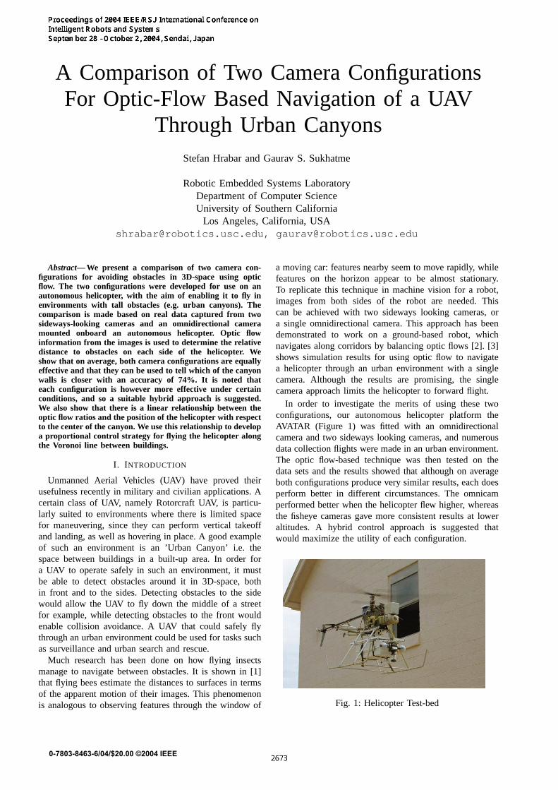
In order to investigate the merits of using these twoconfigurations, our autonomous helicopter platform theAVATAR (Figure 1) was fitted with an omnidirectionalcamera and two sideways looking cameras, and numerousdata collection flights were made in an urban environment.The optic flow-based technique was then tested on thedata sets and the results showed that although on averageboth configurations produce very similar results, each doesperform better in different circumstances. The omnicamperformed better when the helicopter flew higher, whereasthe fisheye cameras gave more consistent results at loweraltitudes. A hybrid control approach is suggested thatwould maximize the utility of each configuration.
Fig. 1: Helicopter Test-bed
0-7803-8463-6/04/$20.00 ©2004 IEEE
II. H ELICOPTERPLATFORM
Our experimental test-bed AVATAR (Autonomous Ve-hicle Aerial Tracking And Reconnaissance) [4] shown inFigure 1is a gas-powered radio-controlled model helicopterbuilt from a Bergen chassis. The helicopter carries twoPC/104 stacks (one for control and one for vision), as wellas a Novatel RT-2 DGPS board, a compass, a CrossbowIMU and a laser altimeter. Both stacks are equipped with802.11b wireless ethernet cards for communication withthe ground station which is a laptop running QNX. This isused to send high-level control commands and differentialGPS corrections to the helicopter. A description of theAVATAR control architecture can be found in [5].
III. V ISION HARDWARE
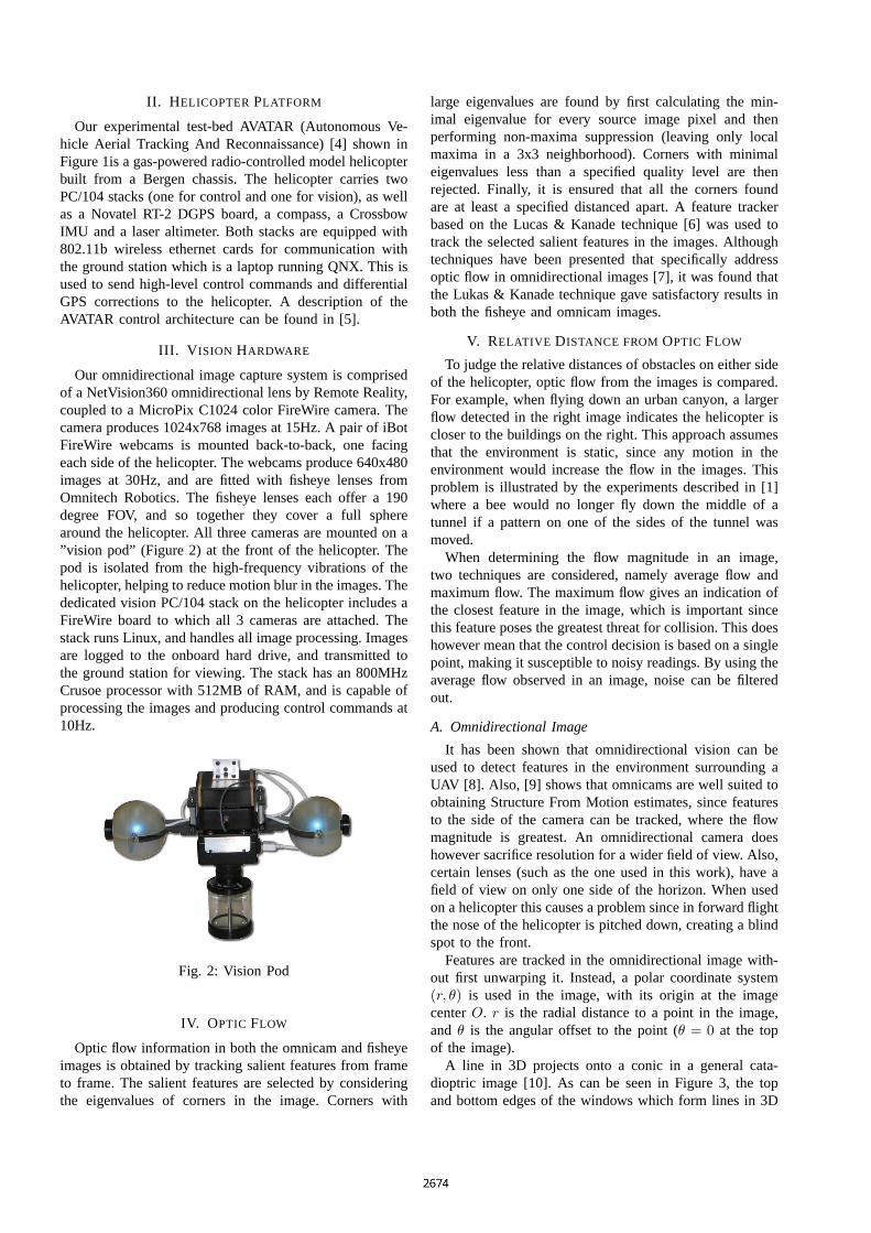
Our omnidirectional image capture system is comprisedof a NetVision360 omnidirectional lens by Remote Reality,coupled to a MicroPix C1024 color FireWire camera. Thecamera produces 1024x768 images at 15Hz. A pair of iBotFireWire webcams is mounted back-to-back, one facingeach side of the helicopter. The webcams produce 640x480images at 30Hz, and are fitted with fisheye lenses fromOmnitech Robotics. The fisheye lenses each offer a 190degree FOV, and so together they cover a full spherearound the helicopter. All three cameras are mounted on a”vision pod” (Figure 2) at the front of the helicopter. Thepod is isolated from the high-frequency vibrations of thehelicopter, helping to reduce motion blur in the images. Thededicated vision PC/104 stack on the helicopter includes aFireWire board to which all 3 cameras are attached. Thestack runs Linux, and handles all image processing. Imagesare logged to the onboard hard drive, and transmitted tothe ground station for viewing. The stack has an 800MHzCrusoe processor with 512MB of RAM, and is capable ofprocessing the images and producing control commands at10Hz.
Fig. 2: Vision Pod
IV. OPTIC FLOW
Optic flow information in both the omnicam and fisheyeimages is obtained by tracking salient features from frameto frame. The salient features are selected by consideringthe eigenvalues of corners in the image. Corners with
large eigenvalues are found by first calculating the min-imal eigenvalue for every source image pixel and thenperforming non-maxima suppression (leaving only localmaxima in a 3x3 neighborhood). Corners with minimaleigenvalues less than a specified quality level are thenrejected. Finally, it is ensured that all the corners foundare at least a specified distanced apart. A feature trackerbased on the Lucas & Kanade technique [6] was used totrack the selected salient features in the images. Althoughtechniques have been presented that specifically addressoptic flow in omnidirectional images [7], it was found thatthe Lukas & Kanade technique gave satisfactory results inboth the fisheye and omnicam images.
V. RELATIVE DISTANCE FROMOPTIC FLOW
To judge the relative distances of obstacles on either sideof the helicopter, optic flow from the images is compared.For example, when flying down an urban canyon, a largerflow detected in the right image indicates the helicopter iscloser to the buildings on the right. This approach assumesthat the environment is static, since any motion in theenvironment would increase the flow in the images. Thisproblem is illustrated by the experiments described in [1]where a bee would no longer fly down the middle of atunnel if a pattern on one of the sides of the tunnel wasmoved.
When determining the flow magnitude in an image,two techniques are considered, namely average flow andmaximum flow. The maximum flow gives an indication ofthe closest feature in the image, which is important sincethis feature poses the greatest threat for collision. This doeshowever mean that the control decision is based on a singlepoint, making it susceptible to noisy readings. By using theaverage flow observed in an image, noise can be filteredout.
A. Omnidirectional Image
It has been shown that omnidirectional vision can beused to detect features in the environment surrounding aUAV [8]. Also, [9] shows that omnicams are well suited toobtaining Structure From Motion estimates, since featuresto the side of the camera can be tracked, where the flowmagnitude is greatest. An omnidirectional camera doeshowever sacrifice resolution for a wider field of view. Also,certain lenses (such as the one used in this work), have afield of view on only one side of the horizon. When usedon a helicopter this causes a problem since in forward flightthe nose of the helicopter is pitched down, creating a blindspot to the front.
Features are tracked in the omnidirectional image with-out first unwarping it. Instead, a polar coordinate system(r, θ) is used in the image, with its origin at the imagecenterO. r is the radial distance to a point in the image,and θ is the angular offset to the point (θ = 0 at the topof the image).
A line in 3D projects onto a conic in a general cata-dioptric image [10]. As can be seen in Figure 3, the topand bottom edges of the windows which form lines in 3D
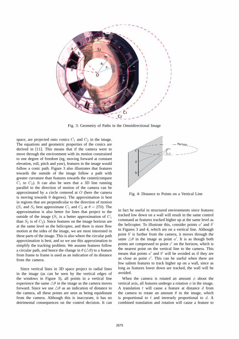
Fig. 3: Geometry of Paths in the Omnidirectional Image
space, are projected onto conicsC1 andC2 in the image.The equations and geometric properties of the conics arederived in [11]. This means that if the camera were tomove through the environment with its motion constrainedto one degree of freedom (eg, moving forward at constantelevation, roll, pitch and yaw), features in the image wouldfollow a conic path. Figure 3 also illustrates that featurestowards the outside of the image follow a path withgreater curvature than features towards the center(compareC1 to C2). It can also be seen that a 3D line runningparallel to the direction of motion of the camera can beapproximated by a circle centered atO (here the camerais moving towards 0 degrees). The approximation is bestin regions that are perpendicular to the direction of motion(S1 andS2 best approximateC1 andC2 at θ = 270). Theapproximation is also better for lines that project to theoutside of the image (S1 is a better approximation ofC1
thanS2 is of C2). Since features on the image horizon areat the same level as the helicopter, and there is more flowmotion at the sides of the image, we are most interested inthese parts of the image. This is also where the circular pathapproximation is best, and so we use this approximation tosimplify the tracking problem. We assume features followa circular path, and hence the change inθ (4θ) to a featurefrom frame to frame is used as an indication of its distancefrom the camera.
Since vertical lines in 3D space project to radial linesin the image (as can be seen by the vertical edges ofthe windows in Figure 3), all points in a vertical lineexperience the same4θ in the image as the camera movesforward. Since we use4θ as an indication of distance tothe camera, all these points are seen as being equidistantfrom the camera. Although this is inaccurate, it has nodetrimental consequences on the control decision. It can
Fig. 4: Distance to Points on a Vertical Line
in fact be useful in structured environments since featurestracked low down on a wall will result in the same controlcommand as features tracked higher up at the same level asthe helicopter. To illustrate this, consider pointsa′ and b′
in Figures 3 and 4, which are on a vertical line. Althoughpoint b′ is further from the camera, it moves through thesame4θ in the image as pointa′. It is as though bothpoints are compressed to pointc′ on the horizon, which isthe nearest point on the vertical line to the camera. Thismeans that pointsa′ and b′ will be avoided as if they areas close as pointc′. This can be useful when there arefew salient features to track higher up on a wall, since aslong as features lower down are tracked, the wall will beavoided.
When the camera is rotated an amountφ about thevertical axis, all features undergo a rotationφ in the image.A translation t will cause a feature at distanced fromthe camera to rotate an amountθ in the image, whichis proportional tot and inversely proportional tod. Acombined translation and rotation will cause a feature to
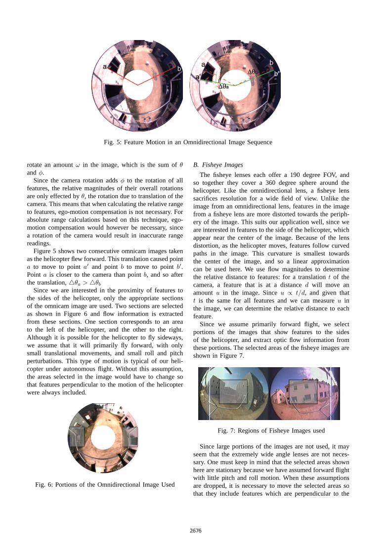
Fig. 5: Feature Motion in an Omnidirectional Image Sequence
rotate an amountω in the image, which is the sum ofθandφ.
Since the camera rotation addsφ to the rotation of allfeatures, the relative magnitudes of their overall rotationsare only effected byθ, the rotation due to translation of thecamera. This means that when calculating the relative rangeto features, ego-motion compensation is not necessary. Forabsolute range calculations based on this technique, ego-motion compensation would however be necessary, sincea rotation of the camera would result in inaccurate rangereadings.
Figure 5 shows two consecutive omnicam images takenas the helicopter flew forward. This translation caused pointa to move to pointa′ and pointb to move to pointb′.Point a is closer to the camera than pointb, and so afterthe translation,4θa > 4θb
Since we are interested in the proximity of features tothe sides of the helicopter, only the appropriate sectionsof the omnicam image are used. Two sections are selectedas shown in Figure 6 and flow information is extractedfrom these sections. One section corresponds to an areato the left of the helicopter, and the other to the right.Although it is possible for the helicopter to fly sideways,we assume that it will primarily fly forward, with onlysmall translational movements, and small roll and pitchperturbations. This type of motion is typical of our heli-copter under autonomous flight. Without this assumption,the areas selected in the image would have to change sothat features perpendicular to the motion of the helicopterwere always included.
Fig. 6: Portions of the Omnidirectional Image Used
B. Fisheye Images
The fisheye lenses each offer a 190 degree FOV, andso together they cover a 360 degree sphere around thehelicopter. Like the omnidirectional lens, a fisheye lenssacrifices resolution for a wide field of view. Unlike theimage from an omnidirectional lens, features in the imagefrom a fisheye lens are more distorted towards the periph-ery of the image. This suits our application well, since weare interested in features to the side of the helicopter, whichappear near the center of the image. Because of the lensdistortion, as the helicopter moves, features follow curvedpaths in the image. This curvature is smallest towardsthe center of the image, and so a linear approximationcan be used here. We use flow magnitudes to determinethe relative distance to features: for a translationt of thecamera, a feature that is at a distanced will move anamountu in the image. Sinceu ∝ t/d, and given thatt is the same for all features and we can measureu inthe image, we can determine the relative distance to eachfeature.
Since we assume primarily forward flight, we selectportions of the images that show features to the sidesof the helicopter, and extract optic flow information fromthese portions. The selected areas of the fisheye images areshown in Figure 7.
Fig. 7: Regions of Fisheye Images used
Since large portions of the images are not used, it mayseem that the extremely wide angle lenses are not neces-sary. One must keep in mind that the selected areas shownhere are stationary because we have assumed forward flightwith little pitch and roll motion. When these assumptionsare dropped, it is necessary to move the selected areas sothat they include features which are perpendicular to the
motion of the helicopter. It is then that the wide anglecharacteristics of the lenses are fully utilized.
VI. EXPERIMENTAL SETUP
In order to compare the effectiveness of the two cameraconfigurations, data was captured from the cameras in twodifferent environments. The first was in a mock urbancanyon constructed indoors, while the second was in areal urban environment. For the indoor setting, the cameraswere mounted to a Pioneer robot which was driven downthe canyon. For the real urban environment, the cameraswere mounted on the AVATAR helicopter which was pi-loted down a street with buildings on both sides. Figure 8shows the helicopter in this urban environment.
Fig. 8: Urban Environment
The indoor data set was used to investigate the rela-tionship between optic flow ratio of the left and rightimages (Ropt) and the ground truth ratio (Rgt). (HereRgt
is defined as the ratio of the distance to features on the leftand right of the cameras). Once this relationship had beenestablished, it was used to develop a proportional controlstrategy that would allow the helicopter to fly the Voronoiline between buildings. This control strategy was tested onthe outdoor data, and its effectiveness was analyzed.
The outdoor data was also used to compare the effective-ness of the fisheye camera pair vs the omnicam in correctlysensing the relative distance to features on either side ofthe helicopter.
This was done by measuring the flow ratios from thecameras, and comparing these to the ground truth data. Thecamera configurations were scored on a frame-by-framebasis. If the flow information from two consecutive framescorrectly showed that the helicopter was on the right handside of street for example, the score for that configurationwas incremented.
VII. E XPERIMENTAL RESULTS
A. Indoor Urban Canyon
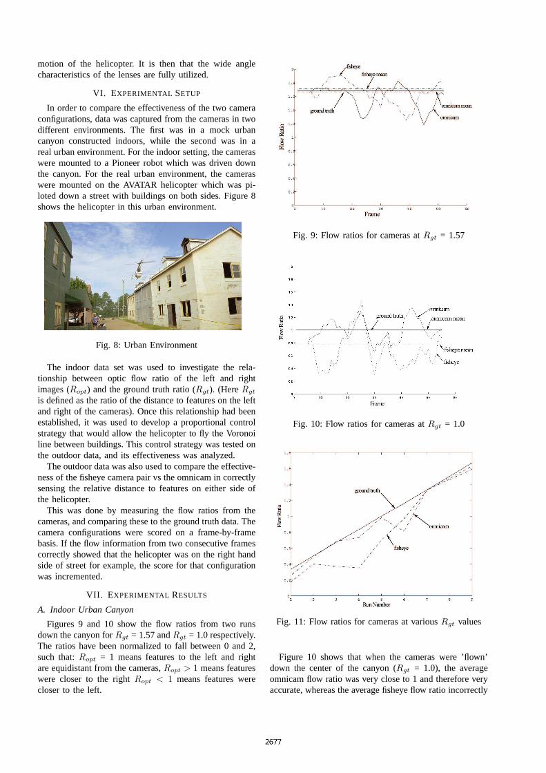
Figures 9 and 10 show the flow ratios from two runsdown the canyon forRgt = 1.57 andRgt = 1.0 respectively.The ratios have been normalized to fall between 0 and 2,such that:Ropt = 1 means features to the left and rightare equidistant from the cameras,Ropt > 1 means featureswere closer to the rightRopt < 1 means features werecloser to the left.
Fig. 9: Flow ratios for cameras atRgt = 1.57
Fig. 10: Flow ratios for cameras atRgt = 1.0
Fig. 11: Flow ratios for cameras at variousRgt values
Figure 10 shows that when the cameras were ’flown’down the center of the canyon (Rgt = 1.0), the averageomnicam flow ratio was very close to 1 and therefore veryaccurate, whereas the average fisheye flow ratio incorrectly
shows that the cameras were closer to the left canyonwall. Figure 9 clearly shows that the whenRgt = 1.57,the omnicam and fisheye flow ratios accurately reflet thatthe cameras are closer to the right hand side of the canyon.A total of 9 runs were made at differentRgt values, andFigure 11 shows a comparison of theRopt andRgt valuesfor all 9 runs.
It is evident from Figure 11 that the flow ratios of boththe fisheye cameras and the omnidirectional camera havea linear correlation to the ground truth ratio. There ishowever a bias towardsRopt < Rgt. This may be becausethe walls of the canyon where not identical, and featureson the left wall could have been tracked more reliably.
B. Outdoor Urban Canyon
The outdoor data logging flights were made over aperiod of three days, accumulating roughly 80 minutes offlight data. From the total data set, 9 runs were selectedwhich could best show the effectiveness of the cameraconfigurations. For some of the selected runs, the helicopterwas flown down the middle of the street, while in othersit was flown closer to the buildings on one side. The pilotalso moved the helicopter from one side of the street to theother while flying forward in some of the runs. The cameracombinations were tested on these runs, which ranged from46 to 180 frames. The images were logged at 5Hz, whilethe helicopter was flown at approximately 0.5m/s, and theportion of the street used was approximately 50m long.In each case, the two techniques for determining flowmagnitude discussed in section V were used. Table I showsthe scores (in percent) for each configuration and run whenmaximum flow was used, while Table II shows the resultsfor average flow. Scores were calculated by comparingRopt andRgt. For each frame thatRopt matchedRgt, thescore was incremented. Thus, for example, Table I showsthat for run 1, the fisheye cameras correctly sensed therelative distance to buildings on each side of the streetfor 54.8% of the frames, while the omnicam was correct43.8% of the time.
Run Frames Fisheye Score Omnicam Score1 73 54.8 43.82 46 71.6 82.63 72 61.1 72.24 120 72.5 69.25 78 73.1 87.26 91 78.0 98.97 180 48.1 42.08 173 65.7 64.09 103 68.9 48.5
Total 936 64.4 64.0
TABLE I
RESULTSFOR MAXIMUM FLOW CONTROL
VIII. P ROPORTIONALCONTROL STRATEGY
Using the knowledge that there is a linear relationshipbetween ground truth ratio and flow ratio (deduced in sec-tion VII-A), a proportional control strategy was developed.following form:
Run Frames Fisheye Score Omnicam Score1 73 78.1 58.92 46 58.7 78.23 72 83.3 79.14 120 76.7 86.75 78 79.5 84.66 91 93.4 93.47 180 63.0 56.48 173 72.7 73.29 103 68.0 78.8
Total 936 74.0 74.8
TABLE II
RESULTSFOR AVERAGE FLOW CONTROL
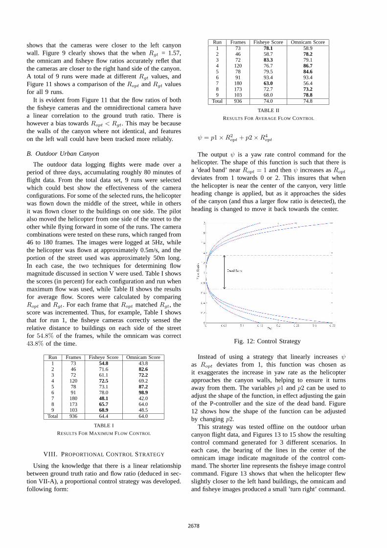
ψ = p1×R2opt + p2×R4
opt
The outputψ is a yaw rate control command for thehelicopter. The shape of this function is such that there isa ’dead band’ nearRopt = 1 and thenψ increases asRopt
deviates from 1 towards 0 or 2. This insures that whenthe helicopter is near the center of the canyon, very littleheading change is applied, but as it approaches the sidesof the canyon (and thus a larger flow ratio is detected), theheading is changed to move it back towards the center.
Fig. 12: Control Strategy
Instead of using a strategy that linearly increasesψas Ropt deviates from 1, this function was chosen asit exaggerates the increase in yaw rate as the helicopterapproaches the canyon walls, helping to ensure it turnsaway from them. The variablesp1 andp2 can be used toadjust the shape of the function, in effect adjusting the gainof the P-controller and the size of the dead band. Figure12 shows how the shape of the function can be adjustedby changingp2.
This strategy was tested offline on the outdoor urbancanyon flight data, and Figures 13 to 15 show the resultingcontrol command generated for 3 different scenarios. Ineach case, the bearing of the lines in the center of theomnicam image indicate magnitude of the control com-mand. The shorter line represents the fisheye image controlcommand. Figure 13 shows that when the helicopter flewslightly closer to the left hand buildings, the omnicam andand fisheye images produced a small ’turn right’ command.
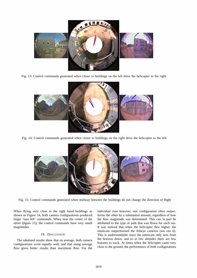
Fig. 13: Control commands generated when closer to buildings on the left drive the helicopter to the right.
Fig. 14: Control commands generated when closer to buildings on the right drive the helicopter to the left
Fig. 15: Control commands generated when midway between the buildings do not change the direction of flight
When flying very close to the right hand buildings asshown in Figure 14, both camera configurations producedlarger ’turn left’ commands. When near the center of thestreet (figure 15), the control commands have very smallmagnitudes.
IX. D ISCUSSION
The tabulated results show that on average, both cameraconfigurations score equally well, and that using averageflow gives better results than maximum flow. For the
individual runs however, one configuration often outper-forms the other by a substantial amount, regardless of howthe flow magnitude was determined. This can in part beattributed to the type of path that was flown for each run.It was noticed that when the helicopter flew higher, theomnicam outperformed the fisheye cameras (see run 6).This is understandable since the omnicam only sees fromthe horizon down, and so at low altitudes there are fewfeatures to track. At times when the helicopter came veryclose to the ground, the performance of both configurations
suffered, since features on the ground were tracked. It wasalso noted that when flying much closer to one side ofthe canyon than the other, both configurations performednoticeably better. This is evident in run number 6, wherethe helicopter was very close to buildings on the left, andboth configurations scored 93.4% (for average flow).
Although it is not shown in these results, we postulatethat the omnicam will be more effective than the fisheyecameras under lateral flight. For example to fly sidewaysdown a canyon with the nose pointed at one of thewalls, flow to the front and rear of the helicopter willneed to be measured. Features are highly compressed inthese portions of the fisheye images, making it difficult tomeasure optic flow here. With the omnidirectional camerahowever (mounted vertically), there is no distortion onthe horizontal plane, and so the bearing to features inthe image has a direct correlation to their bearing in 3Dspace. This means that optic flow can be measured equallywell in all directions, including the front and rear of thehelicopter. Both configurations suffer from occlusions tothe rear because of the helicopter body. The omnicam ismounted lower than the fisheye cameras, and thus has hasa better view to the rear.
Optic flow can be used to determine the ’time-to-collision’ with approaching obstacles [12], and since theomnicam is better suited to measuring flow to the frontof the helicopter, it would also be more effective than thefisheye cameras in avoiding frontal collisions.
X. CONCLUSIONS ANDFUTURE WORK
Although on average no configuration significantly out-performs the other, each configuration does perform betterunder certain circumstances. To maximize the utility ofeach configuration, a hybrid approach could be adopted byusing a weighted sum of the individual control commands.For example, when flying higher or sideways, the omnicamcommand should be weighted more.
An important feature of the optic flow ratio techniqueis that its reliability improves as one side of the canyon isapproached. This is important since it is in these circum-stances that control commands are most critical.
The linear relationship that was discovered betweenRopt and Rgt is useful as it simplifies the developmentof a proportional control scheme to keep the helicopterequidistant from obstacles on either side. It is interestingto note that the linear relationship exists for both lenstypes. The 4th order P-control scheme developed turnsthe helicopter away from obstacles more aggressively thecloser it gets to them.
After further evaluation of this control scheme on thedata we have captured, it will be tested on a ground-basedrobot. Once it proves to be reliable on the ground, it willbe tested on the helicopter under autonomous flight.
By balancing the flows on each side of the helicopter,it is possible to keep it in the middle of a canyon. Insome cases, for example surveillance, it may be desirableto fly closer to either of the canyon walls. This could beachieved by shifting the desired ratio of flows between the
left and right images. For example, by adjusting the controlcommands such that a ratioRopt = 0.5 is achieved, thehelicopter would fly a path at 1/4 the width of the canyon(Rgt = 0.5). Again, the linear relationship betweenRopt
andRgt makes this type of calculation simple.We would also like to test our hypothesis that the
omnicam will perform better during lateral traverses, notonly between buildings, but also with a building only to thefront. Being able to traverse the front of a building ”nose-in” would be useful for surveillance purposes. Future workwill also include investigating the use of these cameras forfrontal collision avoidance.
Acknowledgments
This work is supported in part by NASA underJPL/Caltech contract 1231521 and by DARPA under grantsDABT63-99-1-0015 and 5-39509-A (via UPenn) as partof the Mobile Autonomous Robot Software (MARS) pro-gram.
REFERENCES
[1] MV Srinivasan, M Lehrer, WH Kirchner, and SW Zhang, “Rangeperception through apparent image speed in freely flying honey-bees,” inVis Neurosci. 1991 May;6(5):519-35.
[2] A.N.U. Biorobotic Vision Laboratory Homepage,“http://cvs.anu.edu.au/bioroboticvision/rslide1.html,” .
[3] Jean-Arcady Meyer Laurent Muratet, Stephanie Doncieux, “Abiometric navigation system using optical flow for a rotary-winguav in urban environment,” inISR2004, March 2004.
[4] USC Autonomous Flying Vehicle Homepage, “http://www-robotics.usc.edu/˜avatar,” .
[5] Srikanth Saripalli, James F. Montgomery, and Gaurav Sukhatme,“Visually-guided landing of an unmanned aerial vehicle,”IEEETransactions on Robotics and Automation, vol. 19, no. 3, pp. 371–381, Jun 2003.
[6] B.D. Lucas and T. Kanade, “An iterative image registration tech-nique with an application to stereo vision,” inIJCAI81, 1981, pp.674–679.
[7] Cedric Demonceaux and Djemaa Kachi-Akkouche, “Optical flowestimation in omnidirectional images using wavelet approach,” inConference on Computer Vision and Pattern Recognition Workshop,2003, vol. 7, p. 76.
[8] Stefan E. Hrabar and Gaurav Sukhatme, “Omnidirectional visionfor an autonomous helicopter,” inIEEE International Conferenceon Robotics and Automation, 2003, pp. 558 – 563.
[9] Peng Chang, Robust Tracking and Structure from Motion withSampling Method, Ph.D. thesis, Robotics Institute, Carnegie MellonUniversity, 2002.
[10] J Barreto and H Araujo, “Geometric properties of central catadiop-tric line images,” in7th European Conference on Computer Vision,May 2002, pp. 237 – 251.
[11] C Geyer and K Daniilidis, “A unifying theory for central panoramicsystems and practical implications,” inECCV2000-Proc. EuropeanConference on Computer Vision, 2000, pp. 445–461.
[12] T. A. Camus, “Calculating time-to-collision with real-time opticalflow,” in Proc. SPIE Vol. 2308, p. 661-670, Visual Communicationsand Image Processing ’94, Aggelos K. Katsaggelos; Ed., Sept. 1994,pp. 661–670.