
8108240256'OC DATEi '! - Nuclear Regulatory Commission
495
REGULATORY FORMATION DISTRIBUTION S EM (RIDS) ACCESSION'BR;8108240256'OC DATEi '! 81/08/11 NOTARIZED NO FACILC50 389 S). Lucie'lant~ Unit 2<, Florida- Power tt L'ight Co;,'AUTH", NAME-'UTHOR AFFILIATION UHR I G p R", E' Florida Power L Light» Co ~ RKC IP s NAMEI RECIPIENT AFF ILIAT!ION< EISENHUT'rDOG, Division of Licensing, DOCKEiTI g'5000389 SUBJECT:" Forwards'ddi info.a response's to NRC'uestions Responses will be incorporated into future. FSAR DISTRIBUTION CODEt: BOOlS COPIES RECEilVED'LiTR ' ENCl.! $ 'ITLEL PSAR/FSAR AMDTS and Re»i ated Cor r espondence NOTE S'." for i SER'o. I aNe hd'o . IZE' I I s I s I REC IPIENT'D CODE/NAME; ACTIONiE A/O'ICENSNG. L»ICI BR" ¹3< LA I N TE R N A L»e A C C 'I D K»V A L' R 2 6 'HEM ENG BR ffs CORK PKRF, BR 10. EMRG PRP. DEV 35» EQUIP QUAL BR13 GKOSCIKNCES 28 HYD/GEO. BR 30. I LKl 0 6'lICI QUAL BR 32'ECH'NG BR 18 OEl.D POAKR SYS BR 19 QA BR '1 REAC SYS BR 23i SIT'NAL< BR 24 COPIES „LTTR ENCLr 1 0 0 1 1 '1 1 1 1 1 1 3 3 2 2 2 2 3 1 1 1 1 1" 0 1 1 1 i. 1 1 1 REC IPIENT"; ID CODE/NAMEi L<IC BR ¹3 BC NKRSESgV ~ " 04 AUX SYS'R 27. CONT SYS BR 09 EFF TR SYS BR12'MRG PRP LIC 36' EMA REP D I V 39" HUM FACTI ENG 40,, IEC'YS'R~ 16'»IC'UID BR 33 MATLr ENG BR" 17 MPA OP'" L IC BRi 34" PROC/TST'EV 20'AD'" BR22' ILEUM . 01' R 25<'OP!I ES'»TTRt ENCL< 1 '. 1 f< 1 1 1 1 1< 3i 1 1'~ 1 f~ 1 1 1< 1 1 0 1 1 1 1 f< f» f» ,EXTERNAL% ACRS 41» NRC< POR „02'. NT'I S 9;Ar:M~ 16 1 1 1 1 LPDR> NSIC» 03< 05» 1 1 ! I! AUG,3 8 1S8] »»" TOTAL NUMBER OF COPIES" REQUIRED'TTR 62! ENCL.< 57'
-
Upload
khangminh22 -
Category
Documents
-
view
3 -
download
0
Transcript of 8108240256'OC DATEi '! - Nuclear Regulatory Commission

REGULATORY FORMATION DISTRIBUTION S EM (RIDS)
ACCESSION'BR;8108240256'OC DATEi '! 81/08/11 NOTARIZED NO
FACILC50 389 S). Lucie'lant~ Unit 2<, Florida- Power tt L'ightCo;,'AUTH",NAME-'UTHOR AFFILIATION
UHR IG p R", E' Florida Power L Light» Co ~
RKC IP s NAMEI RECIPIENT AFF ILIAT!ION<EISENHUT'rDOG, Division of Licensing,
DOCKEiTIg'5000389
SUBJECT:" Forwards'ddi info.a response's to NRC'uestionsResponses will be incorporated into future. FSAR
DISTRIBUTION CODEt: BOOlS COPIES RECEilVED'LiTR ' ENCl.! $'ITLELPSAR/FSAR AMDTS and Re»i ated Cor r espondence
NOTE S'."
for i SER'o.
I
aNe hd'o .
IZE' I I s I s I
RECIPIENT'D
CODE/NAME;ACTIONiE A/O'ICENSNG.
L»ICI BR" ¹3< LA
IN T E R N A L»e A C C 'I D K»V AL' R 2 6'HEMENG BR ffs
CORK PKRF, BR 10.EMRG PRP. DEV 35»EQUIP QUAL BR13GKOSCIKNCES 28HYD/GEO. BR 30.I LKl 0
6'lICIQUAL BR32'ECH'NGBR 18
OEl.DPOAKR SYS BR 19QA BR '1REAC SYS BR 23iSIT'NAL< BR 24
COPIES„LTTR ENCLr
1 00
1 1
'1 1
1 1
1 1
3 32 22 2
31 1
1 1
1" 01 1
1 i.1 1
1
REC IPIENT";ID CODE/NAMEi
L<IC BR ¹3 BC
NKRSESgV ~" 04
AUX SYS'R 27.CONT SYS BR 09EFF TR SYS
BR12'MRG
PRP LIC 36'EMA REP D IV 39"
HUM FACTI ENG 40,,IEC'YS'R~
16'»IC'UIDBR 33MATLr ENG BR" 17MPAOP'" L IC BRi 34"PROC/TST'EV
20'AD'"
BR22'ILEUM . 01'
R
25<'OP!I
ES'»TTRtENCL<1'.
1 f<
1
1 1
1 1<
3i1 1'~
1 f~1 1
1< 1
1 0
1 1
1
1
f<f» f»
,EXTERNAL% ACRS 41»NRC< POR „02'.NT'IS
9;Ar:M~
161 1
1 1
LPDR>NSIC»
03<05» 1 1
! I!
AUG,3 8 1S8]
»»"
TOTAL NUMBER OF COPIES" REQUIRED'TTR 62! ENCL.< 57'

hP
hh
R
a I
P R.v
P
h
I P
h)
I hh
)I
hl
~
'h
RP
I'
lit 4 P P
V)

P.O. BOX 529100 MIAMI,F L 33152
lyyk)lliy
FLORIDAPOWER & LIGHTCOMPANY
August 11, 1981L-81-348
Office of Nuclear Reactor RegulationAttention: Mr. Darrell G. Eisenhut, Director
Division of LicensingU. S. Nuclear Regulatory CommissionWashington, D. C. 20555
Dear Mr. Eisenhut:
Re: St. Lucie Unit 2Docket No. 50-389Final Safety Analysis ReportRe uests For Additional Information
I,
Q/
Attached are Florida Power 8 Light Company (FPL) responses to NRC
staff requests for additional information which have not beenformally submitted on the St. Lucie Unit 2 docket. These responseswill be incorporated into the St. Lucie Unit 2 FSAR in a futureamendment.
Very truly yours,
Robert E. UhrigVice PresidentAdvanced Systems 5 Technology
REU/TCG/ah
Attachments
cc: J.P. O'Reilly, Director, Region II (w/o attachments)Harold F. Reis, Esquire (w/o attachments)
go~>
'gcj 7)d)Z 4&@
t~p
8108240256 8108iilP..DRPDR ADOCK 05000389
PEOPLE... SERVING PEOPLE


Attachment to L-81-348
A. Responses to Auxiliary Systems Branch draft SER open items.
B. Revised response to question 451.08
C. Draft FSAR writeup and supporting documentation for undergroundcable qualification.
D. Control Wiring Diagram supplied in support of the response to Chapter8.3 open SER item on power lock out to MOV's.
E. Response to Chapter 8.3,.open,;SER:. item on isolation devices.
Response to Chapter 8.3 open SER item on GDC 18
G. Response to Chapter 8.3 open SER item on MOV Thermal OverloadBypass.
H. Responses to open items from 8/11/81 meeting on Post AccidentSampling System.
I. Revised response to. question 410.19
J. Draft Environmental Report sections on the use of TBTO.
K. Tables 1.9B-3 and 1.9B-4, Evaluation of ICC Detection Instrumenta-tion.
L. Responses to Containment Systems Branch questions.
M. Response to question 492.10
N. Revised responses to question 440.25, 440.28. 440.38, 440.39, 440.41,440.44, 440.51, 440.54$ 440.58, 440.59, 440.61, 440.62
0. Confirmation on MSIV bonnet and seat thickness conservations from,Rockwell International.
P. Response to open item No. 1 from the Structural Engineering Branchdesign audit.
gl08240256 ',


RESPONSES TO AUXILIARYSYSTEMS BRANCHREQUESTS FOR INFORMATION TO COMPLETE
THE ASB DRAFT SER..

Section 3.5.2 Structures, S stems, and Components to be Protected fromExternall Generated tlissi1es
The applicant has verbally committed to providing missile protectionlfor the auxiliary feedwater cross-over piping between the steam trestles'and outside of the missile barriers; however, documentation has notbeen provided. Me will report resolution of this item in a supplementto this SER. This item also impacts Sections 10.3.1 and 10.4.9 of this,SER.
~Res ense
See attached amended response:-to Question 410.25.


().
SL2 PSAR
estion No.
410.25(10.3,10 ' ') a) Verify that the main steam trestle is designed to seismic
Category I and maximum tornado load requirements.
. Qith regard to the main steam trestle, provide the following:
Provide a complete description, including arrangementdrawings, of the main steam trestle area which. illustrates how
'hefollowing items are protected from turbine and tornadomissile s.
(1) Main Steam Isqlation Valve (MSIVs)(2) Hain Steam Safety Valves(3) „Atmospheric Dump Valves(4) Main Steam Piping up to the HSIVs(5) Safety-related portions of the main feedwater piping.
c) Provide detailed layouts of the auxiliary feedwater pump andpiping areas to demonstrate how the main steam trestleprovides support "for missile protection enclosing theAuxiliary Feedwater Pump rooms" (FSAR Subsection 3.8.4.1.9)and its protection from high energy line breaks (eg. meinsteam or main feedwater pipe. breaks) and moderate energy pipecracks
~Res oese
The main steam trestle is provided to house the safety-relatedcomponents of the Main Steam, Feedwater, and AuxiliaryFeedwater System. The trestle is designed to seismic CategoryI requirements and is capable of withstanding the maximumtornado loadings outlined in FSAR Section 3.5. The loadingcombinations for the main steam trestle are provided in FSARSubsection 3.8.4.3.
b) The main steam trestl is comprised of two compartment p FIVSyg te s CC~ialii'I ii located at the west end of the Reactor Bui ing The twotrestle compartments are two total y enc ose structures whichare physically separated from each other. Each trestlecompartment houses the following equipment:
(1) One main steam Line(2) One main steam isolation valve (MSIV)(3) Eight main steam safety valves(4) One main feedwater line(5) Two main feedwater isolation valves (HFIV's)(6) Two atmospheric dump valves (ADV's)(7) Two motor driven aux. feedwater pumps or one steam driven
aux. feedwater pump (with associated piping and valves) ~
QPSRgg y~PSC PjP/Mg I g +MC/sSS+gSR's. a C
6P' sR ~i- ~C'is
410,25-1 Amendment No. 4, (6/81)e

0
0

SL2 PSAR
Each of the two compartments of the testle is approximately 31Eeet wide, 45 feet long and extends vertically from gradelevel to Elevation 62'W". Three sides of the main steamtrestle are completely enclosed with a one inch steel platealong the entire vertical run with a nine inch opening left.onthe base perimeter to provide for natural ventilation- Thefourth side utilizes the containment structure as a missilebarrier and is recessed several feet from the containment inorder to provide adequate ventilation. The roof of thetrestle structure utilizes a steel grating (several inches
. thick) for missile protection purposes. The openings in thisgrating have been designed to inhibit the smallest missileprovided in FSAR Section 3.5 and to provide sufficient mainsteam Mass and'Energy blowdown area to accommodate a mainsteam line break outside the containment.
c) Detailed layouts of the Auxiliary Feedwater Pump and pipingarrangements are provided in FSAR Figures 10.4-14, 15 and 16.The motor driven auxiliary feedwater pumps are physicallyseparated from the turbine driven pump by two one '(1) inchsteel plates. These plates provide adequate protectionagainst the dynamic effects .of a high energy line break. Thedynamic effects associated with pipe rupture and jetimpingement is provided in FSAR Section 3.6i
410.25-2 Amendment No. 4, (6/81)

0

~ ~
2. Section 3.6.1 Plan~t Oesf n for Protection A ainst Postu1ated Pi inailures in F uid S stems Outside Containment
s
The applicant has not provided sufficient information necessary todemonstrate that a- postulated high energy pipe break or moderate energypipe crack will not cause a loss of function of any safety relatedsystem. The applicant has not provided sufficient information toadequately demonstrate that f1ooding due to failure of non-seismicCategory I tanks will not adversely affect safety related equipment.Me will report resolution of this item in a supplement to this SER.This item also impacts Sections 9.3.3, 10.3.1, 10.4.5, 10.4.7, and10.4.9 of this SER.
~Res onse
FP&L has formally submitted the above input vialetter dated L-81-334 dated August 4, 1981.
~P

0
0

3. Section 9.1.3 S ent Fuel Pool Coolin and Cleanu Sstem'he
applicant has verbally committed to the installation of a secondspent fuel pool cooling system heat exchanger by the first refuelingof Unit 2. Documentation to confirm the verbal commitment is required.)le will report resolution of this item in a supplement to this SER.
Response
See attached amended FSAR page 9.1-10 adding the" commitment for the applicant to add a, second fuelpool heat exchanger.

(~
SL2"FSAR
lated by the fuel pool pumps through the fuel pool heat exchanger whereheat is rejected to the Component Cooling Water System. From the outlet ofthe fuel pool heat exchanger, the cooled fuel pool water is returned to thebottom of the fuel pool via a distribution header. The cooling system iscontrolled manually from a local control panel. Control room alarms forhigh fuel pool temperature, high and low water level in the fuel pool, lowfuel pool pump discharge pressure and, as discussed in Subsection 9.1.2, ahigh radiation in the fuel pool area, are provided to alert the operator toabnormal circumstances. Radiation monitoring for spent fuel pool area andFuel Handling Building stack is discussed in Section 11.5. The componentsand piping are Quality Group C, seismic Category I.9.1.3.2.2 Fuel Pool Purification
The clarity and purity of the water in the fuel pool, refueling cavity andrefueling water tank are maintained by the purification portion of the fuelpool system. The purification loop consists of a fuel pool purificationpump, fuel pool filter, fuel pool purification pump suction strainer, fuelpool ion exchanger, fuel pool skimmer, fuel pool ion exchanger strainer,associated valves, and piping. Most of the purification flow is drawndirectly from the fuel pool. A small fraction of the purification flow isdrawn through the fuel pool skimmer. A strainer is provided in the purifi-cation line to the fuel pool purification pump suction to remove particu-late matter before, the fuel pool water is pumped through the fuel poolfilter and the fuel pool ion exchanger. The fuel pool water is circulatedby the fuel pool purification pump through the fuel pool filter, which re-moves particulates larger than five micron size, then through the fuel poolion exchanger to remove ionic material, and finally through a "Y" type fuelpool strainer.
Connections to the refueling water tank provide makeup to the fuel poolthrough the purification loop. In addition to purifying the fuel poolwater, the refueling water tank and the refueling transfer canal arecleaned through connections to the purification loop. Fuel pool waterchemistry is given in Table 9.1-4. The purification loop components andmain process piping are Quality Group C, non-seismic.
9.1.3.2.3 Component Description
The major compnents of the Fuel Pool System are described in this section.The principal component data summary is given in Table 9.1-6.
a) Fuel Pool Heat Exchanger
The fuel pool heat exchanger is a horizontal shell and tube designwith a twq-pass tube side. A slight pitch, three degrees above thehorizontal, is provided for complete draining of the fuel pool heatexchanger. The component cooling water circulates through the shellside, and fuel pool water circulates through the tube side. The in-ternal wetted surface (tube side) is stainless steel. f4 ~p(t>'c~~g «,„,peg+ «Ski
g«'<~i«~4 $ A y ( g~+ tan/
gy ~ 5;~+ peg.«Q'g ~
9.1-10

0

4. Section 9.1e4 Fuel Handlin S stem
Me require that the applicant implement the inLerim actions identifiedin Enclosure 2 of the generic NRC letter dated December 22, 1980, con-concerning NUREG-0612 '!Control of Heavy Loads at Nuclear Power Plants"prior to receipt of an operating license and prior to full implementa-tion of NUREG-0612. The applicant indicated that the bulkhead gates(one between the cask pool and the spent fuel pool and the otherbetween the spent fuel pool and the fuel transfer canal) are seismicCategory I. Documentation to confirm the verbal comitment is required.ate will report resolution of these items in a supplement to this SER.
~Res ense
The six month response to the NRC December 22, 1980letter was issued to the NRC via FPGL letter L-81-338dated August 6, 1981 (Uhrig to Eisenhut).
See attached amended FSAR page 9.1-6 adding the factthat the. removable bulkheads in the spent fuel storagepool are designed to seismic Category I requirements.


SL2-FSAR
kinetic energy associated with the dropped fuel assembly is 29,000 in-lb.This energy is conservatively assumed, to be totally absorbed by one rackmodule. Structural deformations of the racks are limited to preclude anypossibility of criticality. I 0
The structural design also precludes the possibility of a fuel assemblybeing placed in the spaces between the fuel cavities.
Adequate clearance is provided between the top of the stored fuel assemblyand the top of the rack to preclude criticality in the event a fuel as-sembly is dropped and lands in the horizontal position on the top. Rackdesign also ensures adequate convection cooling of a fuel assembly lyinghorizontally across the top of the racks.
0,
The spent fuel storage racks are designed in accordance with the AISCSpecifications and the load combinations and allowable stresses specified I 0in Subsection 3.8.4.3 for seismic Category I steel structures.
The direct dose rate at the pool surface when not refueling is less than2-5 mrem/hr. This dose rate is based on the most active fuel assembly twodays after shutdown. During refueling the limit switches prevent the spentfuel handling machine frorrr raising the spent fuel assembly above a heightwhere less than nine ft. of water provides minimum radiation shielding- Ifthe interlock should fail and if there were no operator action, the fuelhandling machine cannot raise the assembly above a nine ft- water-to-active-fuel-length height 'because of the design geometry. Under the condi-tions described above, the dose rate at the surface of the water above theassembly would be still less than 2.5 mrem/hr. The grappling tool on thespent fuel handling rnachine is designed so that a fuel assembly cannot bereleased accidentally. The shielding provided in the Fuel Handling Build-ing is discussed in Subsection 12-1.2.4 ~
I 0
A concrete wall to,elevation 62 ft. separates the cask storage area from thespent fuel storage area. The wall prevents the water level from uncoveringthe spent fuel assemblies even if a dropped fuel cask causes damage to thepool or pool liner in the cask storage ar6'eh. @~I/: ~~ps~ ~ c.
w.%r™r ~"Irs CD~cm ~ c~e~sE ~ )~I~~ c c4.~«p ~~< ~<~ rg&i"y~ ~
rstartrLI M) 'are. cled)i 6 S~Ss 'c C5gcry' pv ~ j~$ ihe fue enrichment, se ected for detera7ination of the safe geometry is 3.7percent- This is substantially higher than the enrichment for the initialand future cores. In the analysis to determine allowable edge-to-edgespacing, infinite arrays of fuel assemblies are ay~Itmed. +~ analysis of thespent fuel storage rack design uses the CHEETAH-P~ /PDQ-7~ rradel asthe basic engineering tool. CHEETAH-P is the PMR lattice version of 0Nuclear Associates International (NA/) CHEETAH code which is a modifiedvers)g~ of the original LEOPARD code and uses a modified ENDP/.B-II cross section library. The PDQ-7 program is the well-known few-group spatial diffusion 'theory code widely used by the industry. TheCHEETAH"P/PDQ-7 model has been extensively tested by NAI by means of bench-marking calculations for several existing operating power reactors.
CHEETAH-P determines a multigroup neutron spectrum for a given homogeneousmixture of materials and uses this spectrum to weigh the cross sections andprovide average few group cross sections. PDQ-7 uses as input the cross
9.1-6 Amendment No. 0, (12/80)


5. Section 10.4.7 Condensate and Feedwater S stems
The applicant has not committed to performing a water hammer test inaccordance with Branch Technical Position ASB 10-2. We require, thewater hammer test. We will report resolution of this item in a supple-ment to this SER. This item also applies to Section 10.4.9 of thisSER.
~Res onse
A number of paragraphs were inadvertently omitted fromthe response to PSAR question 410.27. See attachedpage for amended response. In addition, PPGL letterL-81-318 dated July 27, 1981 (Uhrig to Eisenhut) pro-vided justification for the applicant's position thatsteam generator water hammer testing need not be per-formed on St Lucie Unit 2 (letter attached).


SL2-FSAR '
estion No.
410.27(10.4.7)
State how Branch Technical position ASB 10-2, "Design Guidelinesfor Water Hammers in Steam Generators with Top Feeding Designs" ismet'iscuss the design features to minimize water hammer and theconfirmatory tests to be performed.
Response
The feedwater piping and feedring have been designed to eliminateor minimize the cause and effects of possible water hammer in the
" feedwater system.
Feedwater enters the steam generator through the feedwater nozzlewhere it is distributed via a feedwater distribution ring. Thefeedwater ring has been constructed to include discharge nozzlescalled "J" tubes which are welded to the top of the ring (seeFigures 5.4-6, 16:; and 17 of the FSAR). 'his construction reducesthe rate at which the feedwater ring drains, helping to provide
"assurance that the ring remains full of water. Thus, the'robability of significant amounts of steam entering the feedring
is greatly reduced, thereby minimizing the condition which canlead to water hammer.
In addition, the length of horizontal feedwater piping immediately'xternalto the steam generator which could pocket steam is
minimized (2 1/2 feet). This short length of horizontal pipinghas a downward sloping 90 elbow followed by approximately 32feet of vertical feedwater piping. This piping arrangementminimizes the drainable volume of feedpipe. Hence, when thefeedrCng and piping are drained and steam enters this region, theexposed surface of subcooled water to saturated steam is minimized.
The minimization of the exposed surface of subcooled water to thesaturated steam reduces the depressurization of the steam space byslowing the rate of steam condensation on the subcooled water.The pressure pulses generated by a water slug in the piping areinitiated by steam-water interaction which causes ripple formationat the steam-water interface. This results in the formation of awater slug which isolates the steam in the feedpipe As theisolated steam condenses, pressures in the region falls and thewater. slug accelerates towards it. The kinetic energy in the slugkeeps increasing until the steam bubble is collapsed. At thismoment, the water slug impacts with the water filling the upstreamside of the pipe and pressure pulses are generated.
410. 27-1 Amendment No. 4, (6/81)


I /os'w~T
Also note, that. since only a small amount of steam can be trappedin a 90 degree elbow, a steam bubble will collapse before thewater slug gains significant kinetic energy duxing a steam-waterinteraction.Consequently, by introducing the combination of a short length ofhorizontal piping and the "J" tube design on the top of the feed-ring, the intensity of the pressure pulses generated (water hammer)is reduced to negligible levels.St. Lucie Unit 1 has conducted extensive feedwatei. hammer testing.A review of the Feedwater Piping drawing and Steam Generatorinternal indicates that St Lucie Unit 1 and St Lucie Unit 2 arevirtually assembly. Based on this review and the testing performedon St Lucie Unit 1, the applicant concludes that additional feed-water hammer testing is not required for St Lucie Unit 2.
Section 10.4.9 of the FSAR has been revised to include the aboveresponse along with revisions for automatic initiation of the *
Auxiliary Feedwater System.


P.o. BOX 529100 MIAh11, F L 33152
~ '
r. 7. P..".;.'::::::Office of Nuclear Reactor
RegulatVbn"'ttention:
Hr. D. G. Eisenhut, DirectorDivision of Licensing
U. S. Nuclear Regulatory CommissionWashington, D. C. 20555
Dear Hr. Eisenhut:
FLORIDA POY/ER 6 LIGHT COMPANY
July 27, 1981L-81-318
Re: St. Lucie Unit 2Docket No. 50-389Steam Generator Mater Hammer Testin
At a June 17, 1981 meeting with Olan Parr et al, Florida Power 8 Light Company{FPL) agreed to provide justification for our position that steam generatorwater hammer testing need not be performed on St. Lucie Unit 2.
A steam generator water hammer test program was conducted on St. Lucie Unit 1 .
with no water hammer observed. The NRC, in a Safety Evaluatio'n.Report issuedFebruary 7, 1980, concluded that steam generator water hammer was not likelyto occur at that facility.The St. Lucie Unit 1 and 2 piping arrangements are essentially identical.Isometric drawings of both units were compared, and dimensional differenceswere measurable in fractions (e.g., the horizontal sections of piping enteringthe steam generator, which are the sections of piping most likely to experiencewater hammer, are all equal in length (two feet long), with one section onUnit 1 3/8 inch shorter than on Unit 2).
The preoperational test program will verify the adequacy of the design. Pre-operational test procedures 2-0700091, "Auxiliary Feedwater Pumps 2A, 2B, and2C Initial Run", and 2-0700081, "Auxiliary Feedwater System Functional andEndurance Test", will verify that the pumps meet or exceed the manufacturershead/flow curves and associated manual controls and alarms function as required,and also verify automatic operation of the system following an actuationsignal. The functional test will be performed prior to hot functional testingof the unit. FPL intends to station an operator inside containmeB; Vi7rVng'he > < ~
initiaI injection phase to monitor for water hammer. Also, FPMMQfiihe"hs.""--:n'rc""
vibration monitoring program during the St. Lucie Unit 2 startup, and piping sI.-vibration wi 1 1 be measured.
LTFPL is reviewing the San Onofre steam generator feed ring collapse;-indd5tand will inform you if any change in our position on steam generh'ter-mat~hammer testing for St. Lucie Unit 2 is required.
L'ZZ
Very--truly yours,I PHD
1
oQ t E. UhrigVice PresidentAdvanced Systems & Technology
rjREU/TCG/ah
~ .rgr 1.4
cc: J.P. O'Reilly, Director, Region IIPEO LE.~ . ~kU~er~1 A 0 D[sm a Car[ ~ [e a as e ~as
nt-r—
VIMQ IIFOP[ ~

6. Section 10.4.9. Auxiliar Feedwater S stem & Post THI Task II.E.1.1The following items pertain to Section 10.4.9 of the SER, "AuxiliaryFeedwater System," for which documentation is required as indicatedfor items a, b, and c.
a. The Unit 2 condensate storage tank includes a dedicated watervolume for Unit 2 auxiliary feedwater system in the event of tornadomissile damage to the Unit 1 condensate storage tank. There arelocked closed valves in the parallel connecting lines. The applicanthas not provided the procedures delineating when these locked valveswill be opened.
b. The applicant has not provided the results of an analysis of theeffects of a potential failure of the Unit 1 condensate storagetank and the most severe failure or operator error on Unit 1 or2 resulting in draining the Unit 2 condensate storage tank belowthe Unit 2 dedicated volume.
c. Additional Short Term Recommendation 2 - The applicant has notcommitted to providing a copy of the pump endurance test resultsspecified in this recommendation. Me require that these resultsbe provided.
d. Our review is not complete with respect to the minimum dedicated,water supply for the auxiliary feedwater system, the minimum flow
. requirements, and the reliability analysis.
e. Additional Short Term Recommendation 3 - The design for emergencyfeedwater flow indication is un'der review by the Instrumentationand Control Systems Branch as part of item II.E.1.2 of NUREG-0737and will be reported in a separate evaluation.
f. Lon Term Recommendation GL-5 - The design for emergency feedwaterautomatic .-initiation is under review by'the Instrumentation andControl Systems Branch as part of Item II.E.1.2 of NUREG-0737 and'will be reported in a separate evaluagion.
Response
a, b and c: See attached revised FSAR pages.d, e and f: NRC Action.

0

A) FPL intends to perform the Auxiliary Feedwater Endurance Test as partof Preoperational Test No. 2-0700081, "Auxiliary Feedwater SystemFunctional and Endurance Test."
B) FPL will modify the St. Lucie Unit 2 FSAR, Section 10.4.9.4 to reflectEndurance Testing and Section 14.2.12.1.4E to address the specifics ofRef. (a). Attached please find copies of the proposed FSAR modifica-tions.
C) FPL will provide the NRC (after completion .of Preoperational TestNo. 2-0700081 results review), a summary of the Endurance Test .consist-ing of the following:
1) Description of the test.
2) Plots of bearing temperature -vs- time.
3) Plots of Pump Room Temperature (Environment) -vs- Time.
4) A statement confirming that pump vibration did not exceedallowable limits.
5) Plot of observed pump performance (pump flow, head, speed, andstem temperature) on the vendor supplied specific equipmentperformance curves.
Equipment is "Qualified" for 100% humidity therefore humidity willnot be rmnitored.

0
0
k

C.'SL 2-FSAR
TABLE 10.4.9A-4 (Cont'd)
ACCEPTANCE CRITERIA COMPLIANCE
Recommendation - The licensee should perform a 72 hour endur-ance test on all AFW system pumps, if such a test or continu-ous period of operation has not been accomplished to date.Following the 72 hour pump run, the pumps should be shut downand cooled down and then restarted and run for one hour.Test acceptance criteria should include demonstrating that thepumps remain within design limits with respect to bearing/bearing oil temperatures and vibration and that pump roomambient conditions (temperature, humidity) do not exceed en-vironmental qualification limits for safety related equipmentin the room.
A 48 hour endurance test will be performedon thc Auxiliary Feedwater pumps . I
q~g~5 ~ill hvz S~$ ~;P~ Ho
pPC.-
11) .5.3.3 Indication of AFW Flow to the Steam Generators
Concern - Indication o! AFW flow to the steam generatorsis considered important to the manual regulation of AFW
flow to maintain the required steam generator water level.This concern is identical to Item 2.1.7.b of NUREG-0578.
cp
I~vp
Recocmdendation - The licensee should implement the follow-ing requirements as specified by Item 2.1.7.b on page A-32of NUREG&578:
(1) Safety-grade indication of AFW flow to each steamgenerator should be provided in the control room.
(2) The AFW flow instrument channels should be poweredfrom the emergency buses consistent with satisfy-ing the emergency power diversity requirements forthe AFW system set forth in Auxiliary SystemsBranch Technical Position 10-1 of the StandardReview Plan, Section 10.4.9.
Safety grade Auxiliary Feedwaterflow indication and safety grade,redundant steam generator levelindication is available to theoperator in the control room.These instrument loops arepowered by the 120V ac Class IEpower source.
12) 5.3.4 AFW System Availability During PeriodicSurveillance Testing
o
op,
to eer - do e plants ret ire losel s st real(a ent odvalves to eo d at p rd di spop os t edttanoe teste on onsAFW system train. When such plants are in this test mode
and there is only one remaining AFW system train availableto respond to a demand for initiation of AFW system opera-tion, the AFW system redundancy and ability to withstanda single failure are lost.
Recomm'endation - Licensees with plants which require localmanual realignment of valves to conduct periodic tests onone AFW system train and which have only one remaining AFW
train available for operation should propose Technical
Not applicable. Local manual re-alignment of valves to conductperiodic pump surveillance testson AFS trains is not required,

0

SL2- FSAR
) The AFkS is designed to withstand pipe rupture effects (see Section3.6).
10.4.9 2 S stem Descri tion
During normal operation, feedwater is supplied to the steam generators bythe Feedwater System. The Auxiliary Feedwater System (AP4S) is utilizedduring normal plant startup, hot standby, and cooldown. During plantstartup and hot standby, the system provides a source of water inventoryfor the steam generators. During cooldown, the AFMS provides a meansof heat removal to bring the Reactor Coolant System to the shutdown coolingsystem activation temperature. brith offsite power and the main condenseravailable, the condenser will be used as a heat sink. The AFRS system isnot utilized during full power operation.
The major active components of the system consist of one steam driven pumpwith greater than iull flow capacity and two full flow capacity motor drivenauxiliary feedwater pumps. Both electrical and steam driven AFbiS pumps arecentrifugal units with horizontal split casings and are designed in accord-ance with AShE Code, Section Ill and Quality Group C requirements. Thelarger pump is driven by a noncondensing steam turbine. 'Ihe turbine receivessteam from the main steam isolation valves, and exhausts to the atmosphere.
e pumps take suction from the condensate storage tank and discharge to theearn generators. The turbine-driven pump is capable of supplying auxiliary
eedwater ilow to the steam generators for the total expected range of steamgenerator pressure by means of a turbine driver controlled by a variablespeea mechanical governor.
Each motor-driven pump supplies ieedwater to one steam generator. A crossconnection is provided to enable the routing of the flow of the two motor-driven pumps to one. steam generator. The turbine-driven pump suppliesfeedwater to both steam generators by means of two with its own controlva ve ana each sized to pass the full'low. The control of auxiliaryfeedwater flow and steam ge'nerator level is accomplished by means of controlroom operated control valves. Local control stations are also provided. Eachof the motor driven auxiliary feedwater pumps utilize a Class XE ac powersupply (4.16 kV safety related bus). The turbine driven pump train reliesstrictly on a'c power supply.
10.4 ' ' Safet Evaluation
The ABLS removes sensible and decay heat from the Reactor Coolant Systemduring hot standby and cooldown for initiation of shutdown cooling. Forevents in which main feedwater flow is unavailable, (e.g., loss of mainfeedwater pump, loss of offsite power, and main steam line break), theAPTS is automatically initiated to provide hot standby and/or cooldown heatremovals
'%he condensate storage tank (CST) discussed'n Subsection 9.2.6, provides~ater supply for the Auxiliary Feedwater System. The CST is sized to1de -I50pHS gallons of demineralized water for St Lucie Un t 2
hot standby and cooldown operations; an additional 550,AGO a ons isreserved in the St Lucie Unit 2 CST only for the unlikely event that a
I Q'fq 40O
10,4-20
)25,ooo
Amendment No. 4, (6(81)


SL2-FSAR
tornado missile somehow ruptures the St Lucie Unit 1 CST and the watercontained therein (116,000 gallons per St Lucie Unit 1 Technical Specifi-cations) is unavailable to St Lucie Unit 1. 4hen no tornado ~arnings arexn effect, the St Lucie bnit 2 total capacity of 300,800 gallons is avail-able if neeaed. Ch.ib e.xe-i<<% C opo4ihg <~>+<~S 4o< the. 4o'Aozaq) Uolai»C'.
'The quantity of water required for St Lucie Unit 2 cooldown has been deter-mined assuming a worst;case condition'herein the unit is brought to hotstandby conditions ana held there for approximately two hours then cooledaown at the maximum rate until the shutdown cooling window is reached.Vnaer this scenario, each Auxiliary Feedwater Pump has the capability ofachieving an orderly shutdown consisting of two hours of hot standbyfollowed by a regulated cooldown to the shutdown cooling entry point within
'henext five hours. The quantity of condensate required for this scenariois approximately 129,000 gallons as shown on Table 10.4-2 (Case 2) 4The. conaensate storage requirements for the Auxiliary Feedwater System werecompared with the requirements of Regulatory Guide 1.139 "Guidance forResiau 1 heat Removal System". Vnder this scenario, the unit is broughtto hot standby conditions and held there for four hours then cooled downat the maximum rate of 75F/hour until the shutdown cooling window of 350F isreached. The condensate storage requirement for this scenario is 149,600gallons as shown on Table IG.4-2 (Case 1)and Figure 10 '-9 ~
D«ing emergency blackout conditions (except the hypothetical tornado missilewhich drains the St Lucie Unit 1 CST) there is sufficient water in the CST toallow hot standby„ operation for 16 hours and a subsequent cooldown to 350 Fover four hours (see Figure 10.4-1G). 'Ihe condensate requirements and theauxiliary feedwater flow rate basis is discussed in FSAR Appendix 10.4.9A.
The steam generated during decay heat removal'nd cooldown after a loss ofoffsite po~er will be discharged through the atmospheric dump valves, ex-cept for the steam used by the turbine driven auxiliary feed pump. Thereare two ac/ac motor operated atmospheric dump valves (ADVs) located on eachmain steam line. The ADV's are capable of automatic modulating serviceusing ac power and are capable of open/close service from the control roomusing dc power only. Each ADV is sized to pass 50 percent of the flow re-quired to bring the Reactor Coolant System to. the shutdown cooling systementry temperature, assuming that onl 4&5~0 gallons of condensate is avail-able from the condensate storage tank.
12 t>0The auxiliary fei duster pumps are located underneath ...; steam trestle.The AFl'S is designed to withstand natural phenomena as described in Sec-tions 3.3 ana 3,5. The condensate storage tank is a s.''~ Category 1structure. It is surrounded by a structural barrier whii: ovides missileand tornado protection for the tank. Components in the ASS are protectedfrom flooding as components are located above the probable'maximum floodlevel (refer to Section 3.4) ~ The design provisions utilized to protectthe AFLS against the dynamic effects of pipe rupture and jet impingementeffects are providea in Section 3.6. The Auxiliary Feedwater System pipinglayout and the steam trestle configuration is provided in Figures 10.4-14,10.4-15 and 10.4-16 ~
10.4-21 Amendment No, 4, (6/81)

0

DATE
aiiED ~ DY DATE
C I.IEHT
PROJECT
SUBJECT
EBASCO SERVICES INCORPOR:-DNEW YORK
OFS HO.
SHKKT OF
DKPTIHO.
~ )
~n.~saVe. Ue)~i~ e.
... Kll WO.G~< 5+eVQXL 4Q(e43 a. V%@ . Q IYiC4M O 08VQ. +44 .SV<~i+<. IDOInK is cans tkeCaeli unuSO)ohe, ~ regis 'I)aden+) cia) DW 9(loo D)a)lans IS
aons'ii).ereI)i. in &c. eke.'cevYD'inacian OE <ha. mxrA'muon my'rek s<orehvolux&ic~ I)o Qre4A is lAkgen 4c the ke.iaYM. 0( IAIQter 'A> 'Qbe.
~net 'in +he IavaluÃian o( &e. <e% Foa)X;ve. sui.'c)an ))each ava,'lalD'le
QO K4+ A eAQ) I)a.i"g FQQAIJJ(L4Q.V P)A~pb
I IA
'Ut 1. Sh.~%down Valu.A voluene- D)T )ksooo gal)ions I'E mrna<a.inek go'Y u.se. )DD) Unit < iY)
%he. eve.n< +h.e. 6)-'-2 c.a'T is <~Meed, 4g o. torose@ YTcissile.„,Th)> QAnounh ls TnoYc &an sup'ie.'Ien< )I'E shuckatun ..'liurpases ..
~n.i< 0 lacy 5pac. level;g IIL,coo gallons,j
U' Mn>u. I ~
I
A voluene. Og )))9I),ee Qeillons is Ino'In&Lnak ta ku.thea)n. 1'Q7nik 2Qs cull'ne.J.,)Dale~,
I II I I I
II
I \!I
I....a Lt u KA KC'WcO'C
)b)+)noug4 inst<ecenen~+lon 'Icrrer '4 egpeekee) oo 4e. neggenter +4e,n 1'7D
) o ee)nservh'we. Tnorgin,a)D 5 /o D)) %l)e,-'.InscYuenan+ reAne)e (R)I')Ieo gallaYIs) QEIs lseen IAAIieg +D Cl)e
'YOOVe.VolgODe.S~,, ) .', l ) I ~
%0~ 'Y 9 hu~t.~we. N+al o0 <lac above. vo4~e.s, ine.'iud;nq Qlla~anc.e. 4'or",~gg<u,m<~KO, CiOn ~<~V
g aiWou.A~ +0 $<S> )t~ go lllDA5"
skeraL voluine. is . 3O7 poe DTA6ens Ii( rox'i)na'talg<e. E) i'V O Q<a 'm u.< &85 ~
FORM IS1 RCV 1 1'I

0

~ ~
r
+ F~+R Sgco~ 4 PAr4. 44 'o.
The Consdensate Storage Tanks (CST) are intertied between Units 1 and 2.Each CST is a seismic Category 1, Safety Class 3 structure designed tostore suf7icient water to bring each plant from power operation to theinititation of shutdown cooling conditions. The Unit 2 tank is locatedwithin a concrete structure designed to withstand the DBE and the im-pact of tornado missiles. The Unit 1 tank, which has been designed towithstand the DBE and horizontal missiles, is not provided with protec-tion from the vertical. missiles. In the unlikely event that a tornadomissile ruptures the Unit 1 CST, an intertie with the Unit 2 tank isprovided. The Unit 2 CST, which stores sufficient condensate to cooldown both plants, can be connected directly with the suctions of theUnit 1 Auxiliary Feedwater Pumps. Should Unit 1 require condensatebefore Unit 2, valves A, D, E & F could be opened. The location of thenozzle on the Unit 2 tank insures that the Unit 2 supply of condensateis not compromised while at the same time providing sufficient coolantfor Unit 1. Alternately, if Unit 2's condensate had been previouslyconsumed, valves B, C, D, E & F are opened to supply Unit 1. Checkvalves are placed in the Unit 1 suction lines between the tank and theinterties to prevent the backflow of condensate to a ruptured tank.The provision" of redundant locked closed manual valves precludes theaccidental loss of condensate. The entire intertie line that runsbetween the Units is buried, thereby providing protection from theeffects of tornado missiles.
'I

t
~

QNlT 2 CONOKM5Ac7KSTORASC TAN
gal z ~ 1 ~ l'!
~ ~
UNlT 1. GOMOEH5ATE.TORA&E TAN
C.LO
LoLt'
C
V'MO'ERGRovg 0
E F
!l.o
N1'T 'R OLV
A= 'l9,2oo CsAL
9: l5O,Lloo GAL
g- l50 goo GgL
2A lA,
IB
UMiT 1. VOLUME
A,: llo,ooo C AL
B= lt.o,Ooo C AL
lo
LO
AVXlLlABY FEEOWATEQ PUMPS
g~r 7F~J'vq~~~/%~Jl'- ~uT
yCE ~/4~~~~/ J~jgfi/~
M 1-U TOR GQ. ANY

0
I
t

Additional request for informationregarding the trestle grating missileproteation.
~Res ense — See amended FSAR page 3.5-40


e
e
'e l
SL2 PSAR
TABLE 3.5-3 (Conttd)
~tui ent
Atmospheric Dunp Valves
~;> Sfect~ /~fat~ galve5
Fld Xqol&c~ Y&afeeic~ cu,fuff ientiecR
LocationSld /Elevation (ft)Steais Trestle Area/+36.0
FSAR Systt'ia~teecri tien
10.4.9
/A3/OP+P 7
~PRRR Pi ure
10.1-1
Enclosure
g„~-( z.a(I~"'~'"~~)(~ frS4
fg $ 3$ rent'Nfo~cec( ~~g ~
T p Ag,~n)9 cine~ ~~~lena,S ~S
~~~+4>6'nfl fcgfs4-jgQP- bCPth 7"
Cns~5~ ~'F ~ '~Oper iq Sizf. ~"Vl~q"

0
Revision II]8/3/81
NRC uestions on St. Lucie FSAR
g i 45l.OB
The terrain correction factors presented inTable 2.3-102 indicate that the straight-line
'nnual average atmospheric dispersion model maynot adequately represent the regular spat-ial andtemporal vari ati ons in a irf1ow in the vicini ty ofthe St. Lucie site. However, the puff-advectionmodel on which these correction factors are basedis most useful when meteorological data from multiplesources can be used to describe spatial and temporalvariations in airflow. Identify the meteoroQicaldata used as input to the puff-advection model, anddiscuss the appropriateness and reasonableness ofcorrection factors at distances of 7.5 miles andbeyond.
The puff-advection model {MESODIF) was used on the FSAR analyses tor
~ ~ ~ ~
develop site-specific terrain/recirculation correction factors. Tnese
adjustments were developed for application to the straight-line airflowmodel to account for, on an annual basis, the airflow ch'aracteristicsin the St. Lucie site vicinity that affect the atmospheric transportand diffusion conditions. For the St. Lucie coastal site, these
conditions consist of sea and land breeze circulations.
The terrain/recirculation correction factors were developed
from the ratio of the relative concentrations calculated using thepuff-advection model and straight-line model for the meteorologicaldata period of August 1977 through August 1978 (8760 valid observa-
tions). Although it is true that the puff-advection model can be
run and is more useful with multiple source input, such a run configura-tion is of more importance in areas of complex topography and/or forlarge distances from the release point. For the St. Lucie application,the one station puff-advection analysis should be appropriate for
"distances less than 7.5 miles as the onsite meteorological data willcontain the land and sea breeze circulations. Topographic modifica-tions within this range shou1d not be of significance. The appropriate-ness of this application is further supported by the fact that sea
breeze ci.rculations have been found to penetrate up to 50 kilometers

Revision /ll8/3/81.
inland and that the expected releases from the St. Lucie site are
at ground level. Therefore, the data as measured at the onsitetower should, in application in the puff-advection model, be
representative of the 7.5 mile radius inland.
Of additional concern is the use of the results of the puff-advection analysis for flows offshore. The fact that the meteorologicaldata are not available over the ocean and on observations of other
investigators indicating the slow adjustment of meteorological para-meters to over water trajectory, the application of the one-stationpuff-advection analysis to the over water trajectories within 7.5miles is appropriate and reasonable for this site.
The magnitude of the terrain/recirculation factors presented inTable 2.3-102 for large distance from the source are expected and
appropriate due to the physical processes involved and the natureof the two models. Because of the lack of major terrain considera-tions and the general persistence of the sea breeze circulations atcoastal sites in Florida, a one-station puff-advection analysis may
be more appropriate at the St. Lucie location then at others withoutsuch ambient meteorological/terrain conditions. But because o thelimitation of the puff-advection analysis to the use of one-station,the terrain/recirculation correction value calculated at large distancesare more uncertain, but not unreasonable, than the values calculatedcloser to the source of the meteorological data.

SL2-FSAR
d) Emergency Core Cooling System piping
e) control rod drive mechanisms
f) fuel assemblies and spacer-grids
g) reactor internals
1.9.4
reactor cavity shield walls
secondary shield walls
LOW TEMPFRATURE OVERPRESSURE PROTECTION (LTOP)
Low temperature overpressure protection will be provided via the installa-tion of power-operated relief valves (PORVs) qualified for both saturatedsteam and liquid relief service ~ The PORVs will be sized to accommodatethe pressure transient associated with a Controlled Rod Withdrawaland also (at the low pressure setpoint) to mitigate the pressuretransient resulting from either a spurious initiation of safety injection,or a reactor coolant pump start with an excessive temperature differencebetween the RCS and the steam generator. The final design is describedin Subsection 5.2.6. Corresponding transients analyses will be providedin Section 15.8 early in 1981.
1.9.5 HYDROLOGICAL DATA
As discussed in Section 2 4. additional information for Hutchinson Islandis being evaluated, on the separate sub)ects of further tide data andpossible potable well locations'n amendment to Section 2.4 will be filedon or about March 1981 incorporating the relevant information.
1-9.6 UNDERGROUND CABLE REVIEW
,
control cables have been reviewed a~) approved'et/dryenvironmental qualification
cablesis ec'sc i'd+~ s«4s<4'm
3,il.4.
Kerite insulated power andby the NRC for underground
lgderground
Per a memorandum and order issued on May 23, 1980, the.NRC has(ll)ordered applicants for operating licenses to meet the requirements of
1 9.7 ENVIRONMENTAL AND SEISMIC QUALIFICATION OF CLASS lEEQUIPMENT
In mid-1978 the NRC issued a letter requesting additional information(10)on Class lE equipment qualification. Sections 3.10 and 3 'l have beenorganized to provide the requested information on seismic and environmentalquali'fication test results. However, at the date of tendering the FSARseveral vendors'ualification test summaries and reports of results arestill being generated and have not yet been received. Therefore, amendmentsto Sections 3.10 and 3.11 will be filed periodically in order to providethe necessary information and also to'provide results of relevant analyseswhen available-'
~ 9-2 'mendment No. 1, (4/81)

0
1

SL2-FSAR
integrated radiation exposure combining 40 years normal nperation and therequired term of functionality during the post design basis accident(DBA) period (up to 1 year). Tables 3.11-1 present .the design parametersfor radiation for each specified envirnnmental condition ~
The normal operations expnsure dnse fnr equipment is either derived moreexplicity from the design source terms presented in Chapter ll takingaccount of equipment arrangement and shielding configuration, nr basedon the maximum dose rate anticipated for the radiation zone in whichthe equipment is generally located. See Section 12.3 and the zonaldose maps on Figures 12.3-4 through 12.3-12. For equipment in lowerradiation zones (I 6 II) the cumulative 40 year exposure is cnnservativelytaken as 10 Rads. For Zone V equipment with a few exceptions, (theCVCS ion exchanger, spent resin tank, spent fuel transfer tube andvolume cnntrol tagk) the dose rate is 100 R/hr. For the aforementionedexceptions,,the design dose rate is higher than 100 R/hr.
The DBA exposure dose affecting ESF systems and associated safety relatedccmpnnents is dependent nn equipment lncatinn. The DBA considered for thecontainment, Reactor Auxiliary, Turbine, and Diesel Gener~t.or rruilar.ngs isthe pg)uiation of a LOCA in accordance with the recommendatinns nf T?D-14S44 and Regulatory Guide 1.4, "Assumptions Used for Evaluating thePotential Radiological Consequences of a Loss of Coolant Accident forPressurized Mater Reactors", June 1974 (R2). The DBA affecting equipmentin the Fuel Handling Building is based on the postulation of a fuel handlingaccident.The few nrganrc materials that exist within the containment are discussedin Subsectinn 6.1.2.
The radiation exposure dnse rates given in Table 3.11"1 i s based on gammaradiation exposure. It is recognized that the beta energy releasefrom nnble gases is as much as 2.5 tirIIp~ greater than the gamma energyrelease within 30 days post accident. However a representative cablegeometry inside containment has protective cover sheathing the insulationlayer and an overall cover of fire prntective Flamemastic or equivalent.Therefnre the integrated beta radiatinn dose for a one year post accidentperind is less than 10 percent of the integrated gamma radiation dnse overthe same 'period. This comparisnn includes the conservative assumption ofcompari ng effective 2.2 Mev betas with effective 2.2 Mev gammas andassumes a spherical cloud, radius 40 ft, of airbnrne nuclides. Othercnmpnnents inside containment are considered sufficiently shieldedfrom beta radiation since it is effectively attenuated by only a fewmills thickness of metal. Therefore based nn the aforementioned discussinnbeta radiation is not considered an environmental qualification problem.
3.11.6 SrJBMERGED CABLES
Safety related cables located outdoors that could be submerged in waterare qualified for nperability under submerged conditions. Pcdb e 'e v,'r~~g@<"Ir'~r~ Q al<~! A„r." p~y M Weri'4.Mp~y m(4.~~( ~+, we+/Ay Mud~~ 'km 4u s~L W~'M M(~ c
P.C.( r.
3.11-5

0

SECTION F 11: REFERENCES
SL2"FSAR
(1) D '8 Vassalo (NRC) letter to Dr. R E Uhrig (FPL), "Environmental andSeismic Qualification nf Class IE Equipment" dated July 28, 1978.
(2) Dr. R E Uhrig (FPL) letter L-78-334 to D B Vassalo (NRC) datedOctober 16, 1978.
(3) J J Di Nunno, F D Anderson, R E Baker and R L Waterfield,"Calculation of Distance Factors for Power and Test ReactorSites," TI0-14844, USAEC,, March 23, 1962.
4
(4) 1976 ANS Paper: "In-containment Radiation Environments follnwingthe Hypothetical LOCA (LWR)."
3.11-6

FLORIDA POWER & LIGHT COMPANY
ST LUCIE UNIT 2DOCKET 50-389
ENVIRONMENTAL DATA FOR UNDERGROUND CABLE. EXPOSEDTO WET/DRY ENVIRONMENTS
I. T es of Cables Used In Under round Ducts
Two cable vendors supply cables for use in underground ducts. They arethe Okonite Company and the Kerite Company. Okonite supplies 5KV & 15KV powercable. Kerite supplies 600V power, control and instrumentation cable.
The 5KV and 15KV power cables are insulated with unfilled cross linkedpolyethylene, wrapped with an extruded layer of semiconducting insulationshield material compatible with the insulation, and covered with a lead sheathand a heavy duty overall neoprene jacket.
The 600V power cables are insulated with a high temperature Keriteinsulation (HTK) and covered with black heavy duty flame resistant (FR), jacket.
The 600V control cables are insulated with Kerite flame resistant (FRII)~ ~
~
insulation and covered with heavy flame resistant (FR) jackets.
The 600V instrumentation cables consists of twisted aired shielded andPunshielded cables. Unshielded cables consist of twisted pairs with Keriteflame resistant (FRII) insulation covered with an extruded polymer layer andhaving an overall flame resistant (FR) jacket. Shielded cables in addition tothe above have a drain wire with each pair in direct contact with a'lumimummylar tape. Each shielded pair is separated by glass mylar tape.

0

II. Test Data
Vendor data (Kerite and Okonite) regarding the environmentalqualification of their cables exposed to a wet/dry environment are attachedfor your use.
In addition'o the above, a procedure was developed on St Lucie Unit 1 totest certain underground cables to confirm their function'ability.
The following is a brief synopsis of this Unit 1 procedure. At leastonce per 18 months, during shutdown, by selecting on a rotating basis at leastthree (3) cables, one from switchgear to intake cooling water motor, one fromswitchgear to component cooling water motor and one from switchgear to dieselgenerator are tested with a 2500VDC megger. Control cables that
are'ssociatedwith each of the above motors and diesel generptors are testedwith 1000VDC megger. The three spare cables are DC pro~<tested at 25,000volts and measured for leakage current at 30 seconds intervals for 10 minutes.
All readings must meet technical specification 4.8.1.1.3. If anyinstalled spare cable fails the Hit Pot test, the NRC will be notified andcorrective action take per technical specification 4.8.1.1.3.
Attached are copies of actual test data taken at St Lucie Unit 1.

'

tACK~et~g„''4. SLORIDA POIKR d LIQIT CCCIPAMt Rests~ 0
STr LUCIK PLANT CycloIMIIIÃIISXtROCCDUlt RI..OI?ONI
nanna gearCtAll 1l 1NStlt1» Stum CuV. iOI4f ~
ltcKKet 1500 T Serial Xo, ~t~ '»N» ~7Rt~ Teccer Serial Xo, ~Q7- 6 l(r a +icy
" .1
A
~~
I~ ~
~~
4» ~ ~ * ~
W ~
to
i 'ps
»
~ ~
00 NIX So SEC
01 NIX» 00 SEC
TEST VOLTS ~ NIX» READ ACTUAL READ CEO'LETED ST
g C. p /./ ~ 0//< 71I
bIELECTRIChII-POTDCTIALREADIXC IX NICROANPS
OS NIX 10 SEC
Od NIX - 00 SEC
agent
~ ~
02 NIX- 3-
l5 NIX $0 SEC
0$ NIX 00 SKC
04 NIX SO SEC
C5 IIIX 00 SEC
/.0
Oi
o6Oi
Ot NIX - OO SEC P.t07 NIX )0 SEC
0$ NIX Oo SEC
CS NIX So SKC gl I
0% NIX - OO SEC
OS NIX 10 SEC
lO NIX «OO SEC P i
lgf
C' '"
NECCKR READER IEST VOLTS NIX, READ ACTUAL READ CQ SLKIED KT
~ 100 N
Cosy laced Xg Deco U I
forlcve4 Sy~ P4
NONA klf rea4$ aKS aeaC Seee Cedaieal CPeeittCaCIOOC lAoloLS~ '4
»
Qlk
sj

0

h6
tLOKIDA tOOKk S LIOIT CCCO'AXT Savie&ooST, LDCIK t1ART cps l6
llllsllllllfCCPCCCtsutS M.sslssst lStS
~ OATh SXEKT66606 IC ttststtts ~ PAIIC ClllC tssst
Cwt. ~PXc)abtity
Ltegger 2SOO V Serial Na. ~~I52~ Teeter Serial Na, ~~ss 4
6( ((
66
0is'I
a
4'2 tlOE et~ll P
~ 0 ~ ('
(6 ~
r( 46 'I
(A
IECCEk kEADIXC TEST VOLTS ~ NIX~ kEAD ACIUAL kKAD Crt LKTED ST
100 N
r
~ ~
00 NIX $0 SEC
01 MIX 00 SEC
01 NIX SO SEC
02 NIX - 00 SEC
02 NIX 20W'0
NO! 00 SEC
r'
ig ~
OS MIX 30 SKC
0$ NIX - 00 SEC
CG NlX 30 SEC
07 NIX 00 SKC
Gi mx SO SEC
OS NIX - 00 SKC
OZELECTXICIXI-tOTEXTIALkKADIXC IX NImurrS
OJ
/ ~ 6
4p ~ Q
o"!6
I~ '6 ' 5 NIX 00 SEC
04 NIX 20 SEC
I'', 08 NIX SO SEC
09 NIX - 00 SKC
OT NIX 20 SKC
)6Ãf
r (
h,,
t-«'4 tp
E.
)6
6
~ 4,
, ~ 6 ~ss 40
0 'I
rhs( I ~ E
'I
„*0 s,
SE
h 'Q)tg
'q
nC 10 NIX 00 SKC
lLECCQL RKADIXC TEST VOLTS MIX, kKAD ACIUAL SKAD CHPLKTKD ST
2SOO V "100 N ~C 'sr 1 ICoapletetr Xy - 6 i ~ Octa
Xaviave1 SX Datehaa r t. EI
NOTXt hll raa4iaka aacat aeet tecltatcal ateciOcatioee 40!Clsls)
'rs
'I~
6
0
6*
~st "
r ~
t"
(~ ('". r 4CQQ'6th +46 ) p
6


, eye4
~ '—4
4 1
''*
1
ass
o~ ~
~v'16
~, ~»Fg 4'
~ 6Fr.
t»6 i
Sa
tACE 4 ef~N20RIDA tfACR S LIGHT CIRftAffT ~ ReofoTea 0
STo LUCIE tLAffT Cyaleloillisclllsc ala»Floss 2N.0620062 Sal
DATA SlfEETcuss is Nora»»u srau cuu 'uaa
Shacaa 2200 O Sarlal Sa, 2»sl
ss~ s lor sa us N . ~2=- 1 ThaIC Ity~<~P
NECCKR RKADISC TEST VOLTS ~ Nlxo READ ACNAL READ CIXPLE1ED SZ
2500 Y
10
FF
I
DIKLKCTRIChn-mmmALRKADIXC IN XICROAXtS
4'»F.'4 ~
~rlg'
1
ia
00 NIff )0 SEC
01 NIN 00 SEC
Ol lCt SO SEC
OS NIN 00 SEC
Cst Nlà 00 SKC
04 NS ~ SO SEC
go
0 2
~'
n ~;
OS Niff ~ SO SKC
06 Niff 00 SKC
0) NIN 00 SKC
07 NIN SO SKC
Ob Nfff 00 SKC
0$ NIN - SO SKC
09 lflN 00 SKC
O'0 NIN SO SEC
10 NIÃ 00 SEC
rs. 4
'.I ~ g' „'
'1
1'4
O
'J,
~.,et''2
F
-',;4 "h
4'KCCKR
RKADIEC Tt~ SOLTS NIS RFAD ACIOAL READ CIC~TED ST
KSOO V "100 N
Ceoltlete4 Ey - ~ Date
~ IeefweiS SlyAoet 0 ~ 'c Loe
IDTEO AO SeeCI2oge met sect tecfsesfcel eteeIOeetfeee 400ololoS
4
l>'",.O '4
2 '
~0
~ ~
alF»
4
„1 '420'4

-

,. Iktk,.!4 1
5~ e ~
. ~I«
«V
~'4
. ~
—~ ~ ~ *r~ e
rib:Ilt«A I'0:L'A A LIf«C!f CILIA'«5'IT
ST, LLYII:I'I '?tttII!Tf~;V; S r;aCI!!T. r". I:O.O~.OOA!
TtATA SI!.".iTCIASS lt: ICSTAI.I.LO St ALL CAktlX yp)~sr
1 ~k'CACS g of~Revlstou 0C« i~tk«
)Soo v s I I r.o. E- lttt ?ot Tester Sertst 4>4 L V6
k~«. ~trii iiii«~I/.
I
«I''
affords
)SOO V )09 1! 5ooo'-bttfrr.kotc/!!1-.)TS)«TILL . '0 SS 111 '.:IC~)AL'S
reef» FJ'J«DID lEST Vk!LTS ~ r!::. Rf 'll . ACLOAI, CEAD CO:LrlLTKO EY
4 ~i
I I
„I
\I
00 I!I:: )0 Slro
Ol 1:111 - 00 SSC
01 1:I'.I 3'I «I'.C
02 l«IS M S'
r.ltc - )0 .:c
0> I:IS )II Sf«C
os rls - 00 sxO'!'" )) S.".C
0;g:- C» SSC 5OI:::S - )0 S~)Ck« I.!IS - 00 S«X
0)'ttl» - )9 SLC OS !!I' 3!1 STC
I4
klI
I
- ' "" '"4
I
r ~, Oh
'V
. ~ «Vt «I »i.
»I
Q.
cs r.tx - OO Su:)
o: r.ts - )o szc
0) rt"..- oo s:x:
OP IIIS - )0 SSC
03 111» - Co SSC 3 10!Ittl 00 SIX /r
r~t trQU4 TZST Y!r-ks 1!I> RCLl ~4'AL ~e CL ~Tel 'LT
' )00 It
Cosstktrted Sy
Rc»rt«ved SgAs I') 4 Ltectrtcot
lkke k
e ~
gCRI N1 reaftaos Nu'C skeet Cecttatrol opectftcottoas 4.$ .).) )
I H
,,2
4
t«kkJ 4« J
'
~ 1 *I,
'14 «4
I I"
4

0
II

W~>PI„»:«14!4~/"I h; s}}egllgy" hgi } I'" eee p>}«}s'}lqhll»', A s (i4»0«s$ }) Q se A~ ++A«s} 4 'ec )s~ehs." «PI}t«I «I/v, .Nl'e« ~g ) «I
~ *e 'M
'1
s
P ~
s-
~ ~ s »
),
)'
I«
PE
1» «
P
}.», 'C
1
1 'P I(S
~,, IP
» 11}
I
I
PI''Se I
)
1 )I
«q-5,.* ''I '.<.}Q
Fits;ID.h Ftt~cd a I.IC!IT F«FIFA.;TST» LI'CIE I'!Asar
I!hit:TI:.i:"i'.E FFALrwRF. I'0,09.'<It!At
DATA SI!ELTCULSS 11. 1!iSIALL!.0 SF"!E CAlLE IOAST
er~gEse I sion 0Se II} I
I!esse ss}s e I I I, C ISI-I I S } S I I SPP.
s P.~Ollama Idle y ~/~
HIXCE" FPAVI!e ~
SEt'ORE
TFSr TOLTS I:IS. EFAO ACTUAL EEAO C0%'LETEO ST
2560 V 100 It
'00 Ie'I'.I - 30 SFFI
Ol I'PIN Iyt SI.C
Ol I!t!: - $0 SEC
02 sti" t«$ S"
02 I:t" - Al $ FC
01 I:I'I OA $ "A:
tQ ltt:! 30 SA
Ss SIS - OS SPS[
OC Ntt - 20 SEC
DIKLECT,.IC/I!I TOTE., I '.'. Es'AOISC s:: VICROh»C S
0$ HIH - 20 SM
0$ N!te 00 SL'C 3Of Ht e $0 $ LC 3r/ ..::i - te SEC
Ovh t.'».1 t«0 SECI
0" Ht» - $0 SFPC g09 H!H CO SEC
09 HIS - $0 SEC
0$ I:IS - 00 SEC 3 10 HIS - 00 SEC
AFTER 2$00 Y
Cossplrced Sy
Rsref cs«r4 1 Ortcssc ~ $ :!Pc» Elrccclcal
Ntfc Nl cadleEs csst csrrt crc'$sctcal sFrclltwltesc h 0.1 ~ 1,5
1GX7~ DEAD!'A «ST TO»TS ttl!I 1rA hPiUAL v~v CO'LsL KD ST
"* h pe ees .S,g P+Peh)
e-v
e
~ ~ 1'
ss ~
e pe'I
}
I
1


NN,- ~ ! -, aal, I: .~NOt'
hh'JC IS." ~ ',I '~ I " "
~ ) s, ~ ~
af
C
II
t 4't~f
c'
tACE 4 ot~lLORIDA tOUKR 4 LIIDIT CSPANT Reo5sjose 0 ~
STO LUCIK PLANT CycietaatstNNscs taoccNIIN NI,CIINata
aaaao'tlTA
SIIKXTcuss as Notaaato staas usas 'aoaaa
C'.
r,I,
I
I Je
a'
lrc
r Lvc.4 pV
taNua SSOO V S eua O . <-CO ISN~ Caoa SNua SO. ~C-.
- 9saao. ~4
Sa$ 85ty~~2300 Y IOO N
DIELECTRIC/NI-POIZmut. READINC IN NmaerS
ICCCKR RFADIÃC TEST VOLTS ~ IQNO READ ACTUAL RtAD CRIPLKTED ST
hl
i,Ih4
ej
„-CI
4"
OD IQN 30 $EC
03 NIN CO SKC
Ol NIN - 30 SP:
02 IQB 00 SKC
1st NN - 30 SCC
58 IQN - 00 5EC
C4 IQN ~ 00 5KC
04 IGN - 30 5t'C
aG ~ 2O)2Qo ~SJ
~ r
)5 ~ r) ~
03 NIN - 30 SEC
C4 NIN 00 SKC
04 IQN 30 SEC
OI NIN 00 SKC
07 NIN - 30 SKC
04 NIN -00 SKC
05 NIN 30 SEC
09 IQN - 00 SEC
09 NLl 30 StC
IO NIN 00 SEC
~ S)
~S
rs.rS
s.l ~ Z
O
„j's
'I 4)
e
Cecstlecel Ky c )). ~ lhce
~ Reofecsed Dyc ~ ~ S
Etetc AII reaf5ege eeet sect teclse5cel epec5E5cettcee 4,R,I l 3
l
~ ~
IIECCKR READIKC TEST EDITS NINO READ ACTUAL READ mtl4~ RT
2300 t "100 N r "- ~ r.
55-" ~
~ ~444 O
hep oe
4„
~ 4'4
Lb
.0JN
ae 4
'4
I
4( aa * " ~ 4
I S ~
~ I 4 4

~ ~
~ s
~ ~ ~
CRKAQRRKR
I ~
RS
ERR'M
~ ' %K&M~ ~
~ r
(gg )
'*

'I

rc~ I "'
-~40'~90~4~I
4'~ ~
~ 0
~ ~
I 0 ~
\
't'w
jgc ~
PAR ~et~FLORIDA tfRKR S LICHT CNO'AXT Sdrlilee
ST0 LUCIE tLAXT CycleIIRIRI0IIIICRRRCCCNIRR 00.00I005R Kate
WuaLCIty~0~
9 ~
~
'ATA
SffEETCIASS lE TIISTALLED STARE CAELA~~
0
t5gger 2SOl V Serfal Xo, ~36S\
acmic zccccc Rccccc 00. ~EZ9
0
tlrtI;
HECCER READIRC TEST VOLTS HIX0 READ ACTUAL READ CfDftLETED RI
100 N S'M"iilrLr
0
I ' fo IGX - SO SEC
Ol Nof - 00 SEC
01 NIX SO SEC
02 HRX 00 SEC
02 HIX SO SEC
OS HIM - 00 SK(
OS IGX Sa StC
DIELECTRIC/UI-tOTQITIALREADIÃC Ilf HICROAHPS
OS lGX SO SEC
06 HIX 00 SEC
OS lfIX SO 5Ã
07 HIX - 00 SEC
07 NIX - SO SEC
08 NIX - 00 SEC
OS lGX - SO SEC
0'I
9
I00
~ 4 j'0
~ ~
Of NTX 00 SEC
Q lGX SO SEC
OS lGX 00 .X
OS HIX - 00 SEC
f6 HIX SO SEC
10 HIX - 00 SEC
TEST VOLTS IGh. READ
2500 V
Caaylccet Sf
Ieelef0ee Sy
NfEIS A?1 see4Seffs wet eeet
Cca 0, ~~ ~
"100 lf
~ ~
0 CC.
todcefcal etcct! Icotfoee 0,0.1,~
~ ~
' '4 ~ + r + + +7L 000'tRII,
~ ~
~
~
A
0


0
~ '
»
el
P
eI( ~
»
» LljI
'I » *
~ hhe=I
e
r'
I
»II,
j'I
e
, 'I
~ »
~ ~ tkCE 21 ehaSLO'IIDA tOMRL S LICll2 CCCIPANY MeToa
ST» LUCIS tilerCpcle't»I»ICCI»ICCtk»CCIN»t 00.~0»t»05 Dete~~ggg+
QTA SllEETCARS 2t IlQZALLED StASE CASLE 1082T
F=PKHHetter 2500 Y Serial Rs, ~QgQt~t Teeter Seria1 %» ~~~ fbafdItg '
0
~~
HIN» LEAD ACIOAL LEAD CCRC'LEIED ST
100 N2500 Y
l0
~0}tr~
Av»
QI
00 NIN»» Q SEC
01 NIN - 00 SEC
01 NIN 20 SEC
0$ XIN - 20 SEC
OS NIN 00 SEC
Cd lQN 20 SEC
~ 2~ ~
02 HIN ~ 00 SEC 07 NIN 00 SEC
02 lN 20 SEC
03 HIN OO CEC
07 NIN SO SEC
OS NIN 00 SEC
CO HIN )0 SEC
09 NIN 00 SEC
09 HIN 20 SEC
OS HIN 00 SEC . 10HIN-00 SEC
2SOO N
Oospleted Sy ~ Date
Eg ta» pt ~ ectrS
,e
cr
C 0+ Jj, h'C.C '.e Irc.hj~
~ ~~ ~
I
C
Itr.
~ ~»
Rerteucd
ACE! L22 resdlese cejet acct tecbdca2 apecQSeatfaas d»L2»LS
tt
I
~ ~ ~ ~
~ ~'i
~ ...Cj"
~ IQXCEL EEADIEC TEST VOLTS ~
RRFOSI
DIELECTRICINI-tOTENTIALNEADINC IN HICEOAHtS .
CCIQ ':I Q
r
h0 ~t ~
e~ ~

0

»
-J,» ~ iid
i I rilr,""6 'I ~ P''„1,, -
'*".,i, 'I »'r'''"O»id JOLC Nt,PJ Lo'6dc
~ 1 r ~ ~ »
r
.i-".~he~P$4~'r*
4~'o
'L'r+ 'r, ~
f L".yW CP
'pv
~
'$r
d
~ ~
;) ~
1
j)f~ »
i,pro
JJ6 ~
3 ~
PC~»+
''1 ~
6
~ ~~ i
~DA 7QAX 4 LtctlT CCttt'ANTSTD LDCEE HJWT
'LILLoprlocc ppdcpcolc CD.DIPDDLL eu~ .jP. p
1
DATA NtEETCCOIC LC LCCCILLCO CPLCC CLOLO LOOCC
~ ESOO r S a I ttoS~O~Ct~ T«acer t«rI«l No,'~~
NECCER RFADINC TEST VCPLTS ~ Nltto READ ACIVALREAD CQCKETEtt ST
25co r lco N
bnXZCTRZChu-TOTESTIAL READIDC XS NImeeS
CO NIIC )0 SEC 0$ NItt So SEC~ /
OS Nttt - Co SEC,/Ol NItt 00 SEC
05 ttItt $0 SEC ~ /50> Nltt - CO SEC,/+07 Nlct So SEC «/OS NItt - 00 SEC /gOS tGN So SEC
Q Nltt 00 CC,,gg IN «X SEC
04 tQt 00 SEC
04 NDt SO SEC
0$ NItt - CO SEC
OS tnt - 00 SEC (golt NItt So SEC g
. ]0 NItt - Co SEC ~ ]$".
HIlt. READ ACIUAL READ CXC~ SY
mIC>q~ ~
RES«sec@ %y
reaStaSs asst
katar S6LOIC ~ ««&5C4L
'
tecbat«ai sp«cILI«atS«ee 0.LLL3
d~ =
d~ ~
'6
Ji,'
I,
~ ~~ ~
~ ~
~ +~ ~
PL,, jO


THEQo ciKciwnE
V'CDMPWNW
Post Office Box 340Ramsey. New Jer sey 07446201-825-0300/Cable: Qkonite
a ~ pa4gl 0' i ~
V
s '~i JuLy 21, 1981
r'babco
Secvmm, 7nc.Two tilo&d T~e, C~mNeul Yak, hl.Y.
hPc. George, Aorta,~
Subject: SC. Luci.e U~ TTP.O. NY-4225745 8 15kV PowM Cabee
P~ A,. A~uun,TRQ M Co con(~ oall, conversation o$ today helative.
Co ouzel, prie&.oufLy dub~ed quaLipc~n documentation on wMand Ay cabLe, ~ru~atiom. Ole, have no obje~n o$ yom sub-n~~g any'p~ o< aLL o( om quaLLPcation rtepo~ W Ae hlRCno< do ue have, any objection W Ae,Ln$oenatian becoming pubicm$ oenation.
Vmy ~iLy yo~,
R. A. Guba
RAG/mg

,

'fHH DKANITB CDMPANYRorrmeg New~~
FLORIDA POWER h LIGHT COMPANY
ST. LUCIE PLANT
~ MEDIUM VOLTAGE POWER CABLE
EBASCO SPECIFICATION NO. 211-73, REV. 3
PROS. ID g FLO-2998-291I
NUCLEAR QUALIFICATIONREPORTfor
X-OLENE INSULATED CABLES
'This document is The Okonite Company's nuclear qualification reportfor X-Olene insulated cables. * It complies literally with IEEE Standard383-1974, Section 1. 4 "Documentation». Section 1. 4 documents theparameters specified in Section l. 3.
Included in this report are seven Appendices which serve to further clar-ifyOkonite's test procedures and results. These App'endices are asfollows:
~AeviixComparison of Okonite's LOCA Qualification Test to theSuggested Test Procedures and NESCR Sheets as givenin the Ebasco 211-73 Specification.
Coxnparison of Okonite's LOCA Test Profile to basco'sPostulated Event
40- Year Life Detail Document.C
Radiation Certification
LOCA Autoclave Drawing
List of Equipment
Elevated Temperature Moisture Absorption
The necessary'data to document satisfactory compliance as specified inSection 2. 6 of XEEE 383, Documentation of Type Testing, is provided. inthis report. The following cross-reference table illustrates where this
~ information can be found.

THQ DKQNITG COMPANYRxrrwg NewJomey C9048
APPENDIX 7
'OISTURE RESISTANCE
Long term'moisture stability is one of the essential factors inselection of an insulation for many applications. It is not un-usual for a power cable to be required to operate in an envi»ronment alternately wet and dry. To determine the long termwater stability of a cable, a sample insulated with a thin walldielectric is immersed in water at an elevated temperature toaccelerate the deteriorating effects of moisture. Monitoringthe electrical properties provides an indication of long termbehavior. Based upon actual experience capability of withstand-ing total,water immersion at 90 C should be capable of a life inexcess of a generating station's designed life in an environmentof 100% humidity.
Figure I shows long term 90oC water immersion on a 1/C 814AWG X-Olene insulated cable. Testing has been performed inaccordance with ICEA S-66-524, paragraph 6. 6 "AcceleratedWater Absorption Tests " except that (1) the water temperaturewas 90 C, (2) three 25 ft. samples were tested, (3).the testperiod was extended for 12 months and (4) a 600 volt ac potentialwas applied continuously. Even with the more strenuous testparameters, the samples met the requirements of ICEA S-66-524,Section 3. 7. 3. 3. The extended 12 month data demonstrates alarge margin of assurance.
Alternate wet/dry cyclic testing on this insulation has never beenperformed. For the purchased 5 and 15 kV cables this ques-tion (as well as the entire question concerning moisture) isacademic since the lead sheath would prevent all moisture frombecoming in contact with the insulation.


~ r
THE OKONITE COlVIPANYFhmcmg New~~
Appendix 7, Page 2
LONG TERM 90 C VOTER IMMERSION TEST
Construction: 1/C, gl4 Solid CC, . 047" X-Olene (Ref. 2-18, pg. 240).Continuous Stress, 600 Volts, Ac
Avera e of 2 Sam les
TimeInitial
Measuring StressVolts /mil
4080
0. 1)0. 10
2. 31
, 2.31
Vo PF SIC
„SIRM ohms-1pppft.
at-500 V
&250, 000
1 Day 40 0. 10 Z. 0980 '.13 " " 2.09 " ~289, 000
I' 4 ~
1 %'eek
2 %'eeks
4080
4080
0. 060. 08
0. 070. 07
Z. 132. 13
2. 152. 15
~ 276, 000
~ 263, 000
4 %Pecks 4p80
0. 070. 08
2. 152. 15
W 237, 000
2 Months 4080
0. 050. 06
2. 152. 15
w 141, 000
3 Months 4080
0. 06 2. 150. 06 2. 15
&257, 000
4 Months
5 Months
6 Months
12 Months
4080
4080
4p80
4080
0. 030. 04
0. 030. 03
0. 050. 05
0. 020. 03
2. 182. 18
2. 182. 18
2. 182. 18
'2. 192, 19
w 257,000
~250, 000
M250, 000
~257, 000


49 Dey StreetSeymour, Connecticut 06483(203) 888-2591
-the kertte company
Ebasco Services Inc.2 World Trade CenterNew York, NY 10048
July 1, 1981
ec s ssiR~EN r44 CI ~ ) ~ EJ t t ~
j r~ I J''i j,! '~t I'I E:r ~
~o
J i. (.'c;",";)~t ~ 7$ ,'r'rr "s
~Lu Z
ATTENT I ON: MR. 'W. LUNDGRENSENIOR ENGINEER, ST. LUG IE g2 PROJECT
Gentlemen:
SUBJECT: FLORIDA POWER s LIGHT COMPANYST. LUCIE PLANT UNIT g2PURCHASE CONTRACT NY-422573
~ ~
~
~
Confirming our conversation of June 29, this is to advise that ourEngineering Department has released the following documents so that youmay copy and submit them to the Nuclear Regulatory Commission:
Kerite Qualification Documents For: Document Reference
Reference 6Kerite FRII/FR Signaland Instrumentation Cable
Engineering Memorandum 240June 6, 1979
Reference 6Kerite HTK/FR Power Cable
Engineering Memorandum 223May 4, 1977
Reference 5Kerite FR/FR Control Cable
Engineering Memorandum 205November 6, 1975
We trust that this will satisfy your requirements.
Yours truly,
THE KERITE COMPANY
From'he office of: E.N. SleightAssistant Vice PresidentNational Generation
NHD:ss
'Signee: rma H. DubeAdministrator-Power Plant Generation
s ssssidisfy of HARVEY HUBBELL INOORPORATEO

~ ~
L,
~'
~'
~ f t ~ I
l ~ '
ST. 'X UCIE NUCLEAR PLANT" "'BASCO SERVICES BlCORPOBATED-.:,FLORIDA POWER AND LIGHTCOMPANY
'QUALIFICATIONDOCUMENTATIONFOR
KERITE FB/FB CONTROL CABLES
ASSIGNED TO EBASCO SERVICES, INC.
T.~ ~ ~ ~
~ ~ ~ JL ~ wC
~ I ~ ~
The information in this documentation package is confidential and as such isnot to be copied or duplicated in any way, without written permission fromThe Kerite Company.
I
;
Ch
REF/dm4/ao/vv
APR 22 SV

e

the hei.it;e company Apr. 20, 19VV
St. Lucie Nuclear PlantKerite FR/FR Control Cable
Other supportive aging data (not referenced in EM 178-A) and not includedbecause of their proprietary nature but available for audit at our plant orupon visitation to other offices are:
Four Hour Overload Cycles - Kerite - October 9, 1956
Overload Cycling Test - Kerite - January 23, 195V
Product Evaluation Test 49 - Kerite - April 18, 1962 - Oven Aging
High Voltage Lab Test Sheet No '; 3 - Oven Aging DielectricStrength - PB Insulation.- D, ~ . ', 19VO
f
—— -Physical Test Sheet -,,K~+ -. n Aged - 4 Years at 52 C-April 19, 1962
Miscellaneous Te - -. ~i ite - February 13, 19V3
QL Water Immersion~~ 2
The subject of wate -'ersion is covered in Kerite Engineering Memoran-dum No. 205 (Bef. 5), with the supporting data avaQable for audit at The KeriteCompany.
. As with the thermal aging, an evaluation technique has been developed by.;: Kerite to compare our later materials to Kerite with its time proven service
record. The data developed shows PB insulation capable of operating at a tem-perature level 22 C higher than Kerite. Again, 'this corresponds with the 90 Cconductor rating assigned to the PR insulation. Summary sheets (attached toEM 205) cover the points used to develop the plots.
In summary, the monitoring of the effect of water on electrical propertiesshowed the XB was the most useful parameter in terms of comparing the later
...compounds with Kerite insulation. The rate of change of insulation resistance
!
rather than the absolute value of insulation resistance is used. The dataplotted on the charts, unless noted in the summary sheet, is for immersed con-ductors continuously energized at 600 volt AC.
A multiconductor PB/FB control. cable of the type recommended for St..-i
iLucie has been immersed in 90 C water with 600 volt DC excitation between
~ conductors and ground (water) for over 39 weeks. Comparison of performanceof multiconductor constructions to individual conductors immersed in water


I,,the kerite company
St. Lucie Nuclear PlantKerite FR/FH Control Cable
April20, 1977
shows the benefit of coverings over the insulation (see summary sheet).
Continuous water immersion would only normally apply to cables that areused for submarine applications although some underground ducts are almostalways Qooded.. Both of these installations also give the alternate wet and dryexposures (i. e., tides, seasonal ground water levels). According to our in-formation, there are several locations in the southeastern U. S. area whereKerite submarine signal cables have been installed and operating since 1926.The Altamaha River'near Everett, Georgia, installed in 1926 and still in ex-
'stence in 19VO. Also Satilla River at Woodbine, Georgia; St. Mary's River,Georgia; and Trout River, Jacksonville. This service record can be veri-fied by the railroads if needed.
XV. Alternate %let and Dr
Kerite Engineering Mew ~y. b a1so states that from our experience,alternate wet and dry is no T~ re than continuously wet and usuallymuch less severe,. depengi0g'~ ~Pe drying temperatures and drying times.Actual supporting test de%<, s eporte8%tarch 16, 1976, ts referenced andattached (Ref. 6). ~ . - ~.'ata i@8eing developed and willbe avaQablefor audit.
V. Radiation
-.. The FR insulation has been subjected to a number of radiation tests. The'eport of April20, 19VO was submitted originally. This report, in itself, con-
tains aQ the supportive data necessary to qualify FR/FR control cables for therequired total 40 years plus one year emergency integrated radiation dose of8;5 x 10~ rad, for inside the containment of the St. Lucie Plant.
However, the specific testprogram based upon Par. 2.3.3 of IEEE 383-1974 including pre-aging by The Kerite Company for 101 hours at 150 C, gam-ma irradiation of 50 megarads, and then the electrical integrity verified byiR measurements and high potential withstand tests is covered in ReportF-C4020-3 prepared by the Franklin Institute Research Laboratories, entitled"Test of Electrical Cables Under Exposure to Gamma Radiation". TheFranklin test was done on single conductor No. 12 AWG, 50 mils FR insulationwithout the benefit of any outer jackets or coverings (a more severe test). Thecable successfully met the requirements. r

I
ENGINEERING MEMORANDUMNO. 205
EPT P"0
November 6, 1975Supersedes ugus , ~Issue
Chart redrawn Oct. 22. 1976
DETERMINING TEMPERATURE 'RATING'F CABLESFOR OPERATION IN ALTERNATEWET AND DRY LOCATIONS
Temperature 'rating'f cables for alternate wet and dry locations is estab-lished utilizing the Arrhenius techniques but incorporating 'a reference material'o relate actual field performance of cables to the higher temperature continu-ous water soak data on small wire.. This relationship is then used to predict the
. 'water aging'f materials in field service that do not hav'e an extended operatinghistory. Continuous immersion is more severe than alternate wet and dry condi-tions, and a relationship between these 'aging'at s is necessary. Supportingdata showing periodic immersion to be no morep ~ re than continuous immer-sion on Kerite and FR insulation is found in -. >$ ,
- g test reports or pro-grams:
A.Hvizd, Jr.'s project No. ', .Cm er,.196V) - Kerit;e15-3 Lab Test Sheet No.. sulation (July 2V, 1970)Engineering Project '-..O', R +sulation (in progress)
geo%
The reference mate j ', is regear Kerite which has had an extendedservice history encompas '--. in excess of 100'millions of feet of many con-struction types in all environments and at conductor operating temperatures ofVO to V5 C. and cable surface temperatures of 60 to 65 C.
The method by which this analysis is performed is described as follows:
The basis for comparison between insulations is the "insula-tion resistance". Tests have shown that this electrical para-meter is representative of aging in wet environments. Changein capacitance or dissipation factor, however, is also meas-ured. Engineering Project No. 75-40 covering the electro-endosmosis program with samples energized. with 600 voltsAC, 600 volts DC, or not energized showed no significanteffect on time to -1/2 IR or approximate doubling of tan deltadue to electrification.
One further question was whether current loading retarded oraccelerated any electrical degradation. A laboratory test toanswer this question (15-3 Lab Test Sheet No. 227 datedMarch 29, 1970)gave no indicatioq that current loading affected'electr icals'.


Pg. ~
Having identified the relevant aging factors to be time and.water temperatures, the relationship between materials wasselected to be based on the time to reach one-half of theoriginal IR level.
*
Other levels could have been selected;however, the 1/2 IR point was something achievable inreasonable time periods.
One other requirement in this analysis is that the 'slopes'fthe'aging curves be essentially parallel. This is the case withthese materials; i. e.; the slopes of FR insulation and Keriteare parallel.
'
Test points in water for Kerite were at 90, V5, and 52 C. andfor FR insulation 90 and V5 C.
~ D
.15-3 Lab Book-B, Pages 1P. ~ '9q.,
15-3 Lab Book-B, Samol 1-,. 5",-
Chemical Lab Record/ ".~ 75-118 (1971), V5-119(1971), V5-8V —,
. 24 (1960), V5-123 (19V1)
on this hasis~c s hav hientical 'aging'lopes areexpected:-t g~ arly undeh similar environmental serviceconditions'aqug" ir operating temperatures for equivalent ag-ing'would therefore be relatable. Thus, from the attachedchart, the performance of Kerite having a proven servicerecord of more than forty years at insulation surface tempera-tures of 60oC, and higher, it is seen that the equivalent con-tinuous water immersion time at 60 C. to reach 1/2 IR iseighty d'a'ys. Also from the chart, for FR insulation, thewater temperature required to reduce the IR to 1/2 the origi.-nal level in eighty days is 82 C. This analysis indicates thatFR insulated cables may be rated 22 C. higher than Kerite.-(FR insulation is conservatively rated at 90 C. conductortemperature. )
~ In actual service, cables fully immersed in water will tend to have theirsurface temperatures approach the temperature of the water. Therefore,attempting to establish a temperature rating for cable (assumed to be dry)may not be as significant as determining what the environmental watertemperature willbe; however, this analysis provides at least a comparisonbetween newer materials and service proven materials for general use eon-'ditions.


EM 205I j',
s
t~
~
t over the cabled insulated conductors or an increaseTheadd»o o a~ac e o e e .el
in insulation thickness shows significant improvemen o pe15-3 Lab'Bopk-B, Simple I MCB.
V
rIt should be no e soted that salt water immersion is less severe than tap water.
d arch 8 1974.Befer to Product Evaluation No. 1VV, report date Mare
insulation in 1966 has given no evidence of fieldt Itha b di b d
t,'d ..h;.ld.d ..bl,...,tire a lications. It s een anas the insulating jacket on 1/c, 5 EV, 90 C. rated non-s ~e e caand dry applications, also without any report d service problems.
~ AH, Jr. /dmcopies:
Engineering MSal'es Offices.
eLQ~'. Hviz, Jr.V.. P. of Engineering

e

EM 205
Determining Temperature Hatings of Fire Hesistant (FB) Cablefor Operation in Wet Locations
~ ~ . ~ I I ~ I ~
~ I ~I
4
I I~ ~
5,000
I ~
'jil!I ~ ~ I
I I I
~ ~ ~ ~
I.. i ~ - .. ~ I
~
I
—!
I ~
I
~ ~
S
~ I I
i !,i i 1
T lJ i t
! I Ti I I
500 .'t
I ~
~ &
't tt',I
-II
t '
I ~
I I
10~ I ~
I I I
~ ~ iI-I
~ ~ t I t~ I I ~
~
i'�
'II" 'I:.I
~I:i
'~ ~ ~ I
1 t II
0 280 260 240 220 200 180 160 140 120 80 60
RS/dm10/22/VG 'C (—SCAL5.. )

.

1
~ ~ ~ICONFIDENTIAL.
March 16, 1976
To:
From.'.F. Parsons
A. Hvizd, Jr.
Subject: St. Lucie NuclearAlternate Wet/Dry Cycle Test - HI-VO Insulation
Reference. 'Electrical Lab Report No. 599
;~Pur oseII lw
Evaluate and compare'the electrical c «acteristics of HI-VO insulationcycled alternately bebveen 90 C. eater r>,- . temperature air to a con-0
trol sample continuously immersed i - - ter.
I
Procedure ~sPrior to the period@pi-0 of +Cycled test samples from the water
bath, measure insulatsch ~q,@tenue 5tisstpation factor and capacitance ofall test. samples. Qp'@iud con 'sts of 3 f/3 days in 90oC. water and 3 /3days in room temp:, .'ir (approximately 33oC. ).
'am
ale Descriotion
ZB-1 (control)'B-1 (cycled)ZB-3 (control)ZB-3 (cycled)
No. 14 (solid) conductor.No. 14 (solid) conductor,No. 14 (solid) conductor,No. 14 (solid) conductor,
. 030" HI-VO insulation.
. 030" HI-70 insulation.
. 050" HI-VO insulation.
. 050" HI-VO insulation.
Data
Sample Reference50/0 of
Initial IR200"/0 of
Initial DF2GC/0 of
Initial Capac.
Elapsed Tin e - 'ays to:
ZB-1 (control)ZB-1 (cycled)ZB-3 (control)ZB-3 (cycled)
3058'r19V
25. 5'5182
110
2956
149p155*
*Test terminated before reaching 200~0 of initial capacitance


NFPSt. Lucio Nucl'car
Mar. 16, 1976.
Besults
~ 1) Tests on samples d to sustained water immersion are moresevere than those consPti ., 1ternatesvet/dry cycles.
2) The relation~':, ween s~~les undergoing sustained water im-mersion and those ~yR." frere cycleB is influenced by sample wall thickness.
I
BS/dm
. Hvizd, r..V. P. of Engineering
4
F

~
:

i;= k.;rite company
9y
. ST. LUCIE NUCLEAR PLANT - UNIT 2 -- "--EBASCO SERVICES INCOHPGHATED
.FLOPIDA POWER AND LIGHT COIL,iPANY~UALIFI ATION DOC UivIENT~ON
FOHKEHITE FR2/FH SIGNAL
AND INSTRUiVIENTATIONCABLES
. Assigned to: Ebasco Services - copy 1ISSUED
WAAR Se ~S>0
The information in this documentation package is confidential and as such is notto be copied or duplicated in any way, without written permission from The KeriteCompany.
3

0
4

kerite company -5- March 1980
qO
SECTION V. HATER IMMERSION
The subject of water immersion is covered in Kerite EngineeringMemorandum No. 240 entitled "Determining Temperature Rating of FR2Insulated Cables for Operation in Het and Alternate Het and DryLocations, dated June 6, 1979 (Ref. 6), with the supporting dataavailable for audit at The Kerite Company.
St. Lucie Nuclear Plant - Unit 2Kerite FR2/FR Si nal and Instrumentation Cables
In summary, the monitoring of the effect of water on electricalproperties showed the IR was the most useful parameter in terms ofcomparing the later compounds with Kerite insulation. The rate ofchange of insulation resistance rather than the absolute value of
'nsulation is for immersed conductors continuously energized at600 Volt AC.
As with the thermal aging, an evaluation technique'has bee'n, developedby The Kerite Company to compare our later materials to Kerite withits time proven service record. The data developed shows FR2 insula-tion capable of operating at a temperature level 30 C higher thanKerite. Again, this corresponds with the 90 C conductor'atingassigned to the FR2 insulation.
Continuous water immersion would only normally apply to cables thatare used for submarine applications although some underground ductsare almost always flooded. Both of these installations also give thealternate wet and dry exposures (i.e., tides, seasonal ground waterlevels). According to our information, there are several locations inthe southeastern U.S. area where Kerite submarine signal cables havebeen installed and operating since 1926. The Altamaha River nearEverett, Georgia, installed in 1926 and still in existence in 1970.Also Satilla River at Woodbine, Georgia; St. Mary's River, Georgia;
'ndTrout River, Jacksonville. This service record can be verifiedby the railroads if needed.
I ALT RNATE HET ND DRYSECTION V, E A
Kerite Engineering Memorandum No. 240 also states that from ourexperience; alternate wet and dry is no more severe than continuouslywet and usually much less severe, depending on the drying temperaturesand drying times.
SECTION VII. RADIATION, LOCA AND POST LOCA
To cover the requirements'f LOCA and Post LOCA exposure for theSt. Lucie Plant, Unit 2, the repor't "St. Lucie Nuclear Plant, Unit 2,LOCA gualification of Kerite 600 volt FR 2 Insulated, FR JacketedSignal and Instrumentation Cables, dated 3/20/80, (Ref. 7) was prepared.

t

June 6, l"...'s
~ ~ ~ P~ I
~ ~ ~ ~EVC1':!:! I',PiC, .'.ll':.li)!!ANDU'..ING. 2'!!)
~ ~
~~
~~
~
~
~
DETEI<''I'I"G TE:!4IPEIRATt;DE IriXTING~g }B II O'SULATEDKEBITE CA13LES FGB GPEBAgg9ii IN %'ET AND
ALTEHVATE~YET AND DRNLO CATICNS
Temperature 'ratin 'f cables for wet and alternate wet and dry locations isestablished utilizin the Arrhenius technique. but incorporatin a referencematerial (o relate actual field performance of cables to the higher temperaturecontinuous moisture absorption tests on small insulated wires, This relation-ship is then us d to predict the 'water aging'f materials in field service thatdo not have an extended operating history.
The reference material used is regular Kerite, which has had an extended servicehistory encompassing u>.excess of one hundred million feet of many constructiontypes in all en;ironments and at conductor ooerating temperatures of 70 to ".5 Cand cable surface temperatures of 60 to 65 C.
The method by which this analysis is performed is described as follows:
The basis for comparison between insulations is the "InsulationResistance". Tests have shown that this electrical parameter isrepresentative of aging in wet environments. Change in capaci-tance and dissipation factor, however, is also measured. Samplesenergized with 600 volts AC, DC or not energized, showed nosignificant effect ori the electrical Parameters measured. (Ref. 1).
Having identified the relevant aging factors to be time and watertemperature, the relationship between materials was selected tobe based on the time to reach one-half of the original IR value.Other criteria, could have been selected; however, the one-half IRpoint was something achievable in reasonable time periods.
Test points in water for Kerite were at 90 C, 75 C and 52 C, and0
for FB II insulation (ED-72), 90oC and 75 C were used.
On this basis, compounds having essentially identical 'aging'lopesare expected to age siniilarly under similar environmental serviceconditions and their operating temperatures for equivalent agingwould therefore be relatable. Thus, from the attached chart, theperfornnnce of Kerite havin~ a proven service record of more
0than forty years at insulation surface temperatures of 60 C andhigher, it is seen that the equivalent continuous water immersiontime at 60"C to reach one-half IH is 1950 hours. Also, from thechart for 1 B II insulation, U>e water temperature in 1950 hoursis 90 C. This analysis indicates that FH II insulation can be rated6
30 C higllcr tlian Kerite. This material, however, is conservativelyrated at 90 C. (References 1, 2, and 3.)

F
)

p'w( 94 I Jp,~
Laboratory tests to determine the effects of alternate wet and dry environmentshave also been conducted and indicate no significant difference b tween'"ntinuouswater immersion and alternate wet and dry immersion. (Reference 4.)
~P ~ \ ~I
(gQgb>''~ 6/6/79
\
aciual service, cablos fully immersed in water will tend to have their surfacetemperatures ap pro..ch the temperature of the water. 'Therefore, atten:ptinto establish a conductor temperature ratin for cable (assumed to be dry) maynot be as significant as determining what ihe environmental water tempc:aiurewillbe; however this analysis provides a ~ood comparison b bveen newer materials
, and service-proven inaterials for general use conditions.P
Laboratory References
The information pres nteQ above and on the attached plot has b en based on thereferences given b low. The data has b en collected as part of a continuingvrater absorption pro ram and represents that which is presently availab'le. These
—references are available for audit at the Kerite Company in the Engineering Depart-ment.
Engineering Project No. 75-40. Sample Nos. 97B, 98B, and 99B.2. Engineering Project No. 75-40 Sample No. 94A.,3. Chemical Lab Records, Samples 75-118 (1971), 75-119 (1971)
75-87 {1965), 52-24 (1960); 75-123 (1971).4. Engineering Project No. 75-40, Sample Nos. ZB-29, 30 and 31.
Sample No. ZBA, 29, 30, and 31.
'P
HFS/lcAttach.
cc: Book Holders~~
~
H. F. Smith J '.Electrical Engineer
t
APPROVED
g
g()~ JO. Gur(41cL'p . p of Engij>< ering

f

j ~
EM 2sjoJuno 6,
lf.'ej
0) 000
0, 000
j j ~
.I,~ ~~~j Ij '
Deter::;inii>„'Tom-. rature Batin,s of I B-EI Insulated Cablesfor Gp ration in 5'ot and Ai(em.i(o KVot an|I Dry J.ocations
(ED-72)~ ~
~ ~ ~ ~
I j ~
j jIj
The actual time to I/2 IR for FR IIat V5 C h~s not been determined.In the absen'ce of this data,. the FR II .,'.
line has been drawn through the Vo C,"time on test'oint. Use of thisdata point is considered conservativesince the actual time to 1/2 IR would - —:-.be somewhat greater, therefore indi-.—'-cating a slower moisture absorption —:—.. —..:
t 4 h tth 1 p t':.:~i
I
i~ ~
~ ~ ~
j ' I~ ' '
~ A~ ~
~ ' j ~
~ ~ ~ ~ ~
temperature range.
~ ~ k ~I
I
i [:Pl
I .I
~ I;j ~
~ j~ ~
i j
II+ I
r
jj
~ 'j g r ~ ~ ~ ~
~ j~ ~ ~ ~ ~
~ j
~ ~ ~ ~ ~ e ~ ~
j ~ r ~ ~ ~ ~ ~
g 100
IL
~ ~ ~
~ I
~ ~ j ~
j ~ ~ ~ ~
~ ~ ~~ -I ~ j
~ ~'
~ ~
j j ~
I~ I
~ ~
~OI+If l
Qp .,I.:I~ ~ ~ v ~ I I
I—I ~
~ ~ ~ ~ j 1 ~ ~ ~ ~ ~ ~ j ~ ~ ~ I I ~ j
s ~ ~ ~ ~ j ~ ~ I
~ ~ j~ ~ ~ ~ ~ j ~
—.L-.~ ~ l
~ jI
~ j l~ ~
—I
~ ~ j
~ j—3
—i
10
,... i&' I
II ~ it ~ ~
~ ~ ~
~ ~
~~
~ ~
~ j ~ ~~ ~ ~ ~ ~ ~ ~ ~
: I:".: I: I:~ l
I ~ ~ ~
~ e 1I j
~ ~ ~ I ~
I I
2t'jo I tlat'
tiO $ 48 60
Temperature c (—', "cnLr.)0

l

~ ~
the kerite company
ST. LUCIE NUCLEAR PLANTEBASCO SERVICES INCORPORATED
FLORIDAPOWER AND LIGHT COMPANYU IFIC TION DOCUiiENT TION
FORKERITE HTK/PR POWER CABLESASSIGNED TO EBASCO SERVICES
The information in this documentation package is confidential and as suchis not to be copied or duplicated in any @ay without written permission fromThe Keri,te Company.
g
I
REF:mc5/5/vv


the teel ice companyST. LUCIE NUCLEAR PLANTKerite HTK/FR Power Cables May 5, 197V
Four-Hour Overload Cycles - Kerite - October 9, 1956
Overload Cycling Test - ICerite - January 23, 1957
Product Evaluation Test 49 - Kerite - April 18, 1962-Oven Aging
Physical Test Sheet - Kerite - Oven Aged - 4Years't
52o C - April 19, 1962~P
Miscellaneous Tests on Kerite - February 13, 19Z3
III. Water Immersion
Ig3s
The subject of water immersion is covered ~, te Engineering MemorandumNo. 223 (Ref. 6),with the supporting da 'tg r audit at The KeriteCompany.
As with the thermal aging, @/on ech'niece has been developed by The'erite Company to compa "jy 0 materials to Eerite vrith its time-provenservice record. 'The d< ', 'io "d shops HTK insulation capable of operatingat a temperature le ~, $ 'er tiara"Rerite. Again, this corresponds withthe 90 C conductor ':. " ssigneP4 the HTK insulation.
In summary, the monito ing of the effect of water on electrical propertiesshovred the insulation resistance was the most useful parameter in terms ofcomparing the later compounds with Eerite insulation. The rate of changeof insulation resistance, rather than the absolute value of insulation resistance,is used. The test results for energized samples {either at 600 volts AC or600 volts DC) versus unenergized samples are, for practical purposes, thesame. Also, the comparison of the performance of finish cables versusinsulated conductors showed the benefit of the jacket.
Continuous vrater immersion would only normally apply to cables that areused for submarine applications, although some underground ducts are almostalvrays Qooded. Both of these installations'also give the alternate wet and dryexposures {i.e., tides, seasonal ground mater levels). According to ourinformation, there are several locations in the southeastern U.S. area whereKerite submarine signal cables have been installed and operating since 1926.The Altamaha River near Everett, Georgia, installed in 1926 and still inexistence in 1970. Also SatQla River at Woodbine, Georgia; St. Mary sRiver, Georgia; and Trout River, Jacksonville. This service record can
*
be verified by the railroads if needed.

,

s
the kerite companyST. LUCIE NUCLEAR PLANTKerite HTK/FR Power Cables May 5, 19VV
XV. Altnerate Wet and Drt
Keiite Engineering Memo No. 223 also states that from our experience,alternate wet and dry is no more severe than continuously wet, and usuallymuch less severe, depending on the drying temperatures and drying times.Supporting data',is available for review and audit at The Kerite Company.
V.. Radiation„s
The HTK insulation has been subjected to a number of radiation tests andis qualified for radiation levels in excess of 200 megarads (more than twice
. the required level for St. Lucie Nuclear 'Plant, Unit 2). Supporting data ispresented in the St. Lucie,Nuclear Plant, Unit No. 2, Qualification Test ofKex ite 600 Volt HTK/FR Power Cable Under Simulated Post AccidentConditions Report of 5/3/VV (Ref; V).
VL LOCA and Post LOCA
~
~
~
~,To cover the requirements of LOCA and: ':I, e St. Lucis 'Plant,
Unit 2, the report "St. Lucis Nuclear ~gag:U 4, Qualification Test of. Kerite 800 Volt HTK/FB Power ~ jigag emulated Post Accident Condi-
tions," (Bef. 7) was prepar.
The one-year Po'st LO .; n req~gd, from practical time considerations,'n accelerated test cycl is "accelerated relationship" is developed fromthe Arrhenius aging analysis in EM 178-A or EM 178-B, using "equivalentaging @mes. " It'hould be noted that the "rate" of aging for HTK insulationis essentially identical, whether the environment is air or water.. The testprofile attached to the LOCA,report shows the accelerated test cycle (alsodescribed in the report) used to encompass the entire one-year NuclearEnvironment. Service Cycle Requirement given in the St. Lucie, NuclearPlant, Unit 2 Specification.
A requirement in IEEE 323 is that equipment--in this case, cable-- performunder LOCA and Post. LOCA conditions for at least the required operating time.This information was not furnished, and the actual "margins" presented in
'these reports may be well beyond the applicable factors suggested in Paragraph6.3.1.5 of IEEE 323.
)Vll. Flame Tests
The HTK/FR power cables meet the fire tests described in IEEE 383. Indi-vidual reports on 1/c, No. 6 (V), 600 volt, HTK insulated and FR jacketed .
power cables are as follows:

h

~ rs ~( EM 223
ENGINEERING MEMORANDUMNO. 223Supersedes ZM 223 dated 8-12-V6
Ma 4 19VV
DETERMININGTEMPERATURE 'RATING'F HIGH TEMPERATURE KERITEINSULATED CABLES FOR OPERATION IN WET AND ALTERNATE WET/DRY
LOCATIONS
4
5
Temperature 'rating'f cables for wet locations is established utilizing theArrhenius techniques but incorporating a reference material to relate actualfield performance of cables to the higher temperature continuous moistureabsorption on small wire. This relationship is then used to predict the'water aging'f materials in field service that do not have an'extendedoperating history.
The reference material used is regular ICerite, which has had an extendedservice history encompassing in excess of 100 millions of feet of many con-struction tpes in all environments and at conductor operating temperaturesof VO to V5 C and cable surface temperatures of,60 to 65 C.
The method by . is analysis is performed is described as follows: ~
+$ „:.~AmThe bass @~'~ajar between insnlations is the"insulation re -.agn( '- y have shown that thiselectrical parameter 5Q e'd~gve of aging in wetenvironments. +ange . ', j 'v@F~d dissipationfactor,= however, l4 a~ rreasW - ~ spies energizedwith 600 volts AC, 600 foMs DC, 6; energized, showedno significant effect on the electrical p ameters measured.
HAY - 6 1977
Having identified the relevant aging factors to be time andwater. temperatures, the relationship between materialswas selected to be based on the time to reach one-half ofthe original IR level. Other levels could have been selected;however,. the 1/2 IR point was something achievable in rea-sonable time periods.
One other requirement in this analysis is that the'slopes'f
the aging curves be similar, which is the case with thesematerials.
Test points in water for Kerite were at V5 and 52 C, and forHTK insulation, 90 and V5 C.
~ ~
H


ENGINEEBING NEMOBANDUMNO.'23~ e "l
I
Page 2'6T47n
5I!I
On this basis,. compounds having essentially identical'aging'lopes
are expected to age similarly under similar environmentalservice conditions and their operating temperatures for equivalentaging would therefore be relatable. Thus, from the attached chart,the performance of Kerite having a proven service record of more
0than forty years at insulation surface temperatures of 60 C andhigher, it is seen that the equivalent continuous water immersiontime at 60 C to reach 1/2 IR is 1950 hours. Also, from thechart, for HTK insulation, the water temperature required toreduce the IB to 1/2 the original level in,1950 hours is 92 C.This analysis indicates that HTK insulated cables may be rated32 C higher surface temperature than Kerite. HTK insulation,,however, is conservatively rated at 90 C conductor temperature.
In actual service, cables fully immersed in water willtend to have theirsurface temperature i=,'p> roach the temperature of the water. Therefore,attempting to estadAiY! J" 'uctor te'mperature rating for cable (assumedto be dry) may notMpgg'qtt,. t as determining what the environmentalwater temperature wiII'4» ',gg's analysis provides a good comparisonbetween newer materials an 4 - 'c~ materials for general useconditions.
Laboratory tests to determine the effects o ~~'u ate wet and dry environmen shave aiso bee~ conducted and indi'cate that cont "us water immersion ismore severe.
4
The addition of a jacket over the individual or the cabled insulated conductorsor an increase. in insulation thickness shows significant improvement of IBperformance. ~ It should also be noted that salt water immersion is lesssevere than tap water. 4
Laborator Beferences
The information presented above and on the attached plot has been based on thereferences given below. The data has been collected as part of a continuingwater absorption program and represents that which is presently available.
Engineering Project'No. V5-40. Sample Nos. 22A, 23A, 24A,228, 238, and 248.
2. Engineering Pr'oject No. V5-40. Sample Nos. 22A, 228, 23A,238, 24A, and 248. Chemical Lab Becords - 52-24, V5-2V,V5-186, V5-202, 75-203, 75-204, and V5-205.
(Continued)

e
l

~ ~
1
ENGlNEERING MEMORANDUMNO; 223~ e ~ ~~ ~
~
(Laboratory References - Contin@ed)
e ~
~ ~
Page3'jv]~
~ j,
~ ~
S. Engineering Project No. V5-40. Sample Nos. 2MCB, 19A-24A,1 9B 24B~ VA 8A~ 9A 85A 86Aj 87A~ VBf 8Bp 85Bp 8 6Bp 8VB
4. Product Evaluation No. 1VV.
5. Engineering Project No. 75-40, Sample Nos. B-12 - ZB-16.
~,4 '4
RFSSr:mc
R.. mith, Jr.. Assistant Electrical Engineer
APPROVED:Care
Chi Electrical Eng e
~co ies: Book Holders

)I "
t
I
.

EM 223b7~/
Determining Temperature Ratings of High Temperature Kerite Insulated'Cables for 0 eration in Wet Locations
00, 000
10, 000
.. a,-000:
;«J'/'.
Q 'tJ
j
I00
5t) ~.hs
~ ~
RFSSr:mc
00 280 260 240 220 200 l80 l60 'l40 l20 l00 80 60

'

5» 64(F84)
RIS PSSIPIOI69965 (ATOR
2I'SM46 18
946 QSw
I 6966 06 (.9606~9610)92OI6AI. I'A'
RIS POSII'lOR64 4 g. I>JO'OA» ASw Zl~ !6.'4
FA 'IZOVl(
~ SIT566 641
u
65 I
Rf5. ITOSITIOH916'R IIIOICATORSw ~ZT
~ 65427 I
LCA2IBRRlS.IO TTi.Sw
69
CAIIBRSfs~ Q 6S2
I Sw
LAIIBRPf5.a6a566
I2TZI
A.SR
]C7232SSA SA w S
8 SR
]C7230558'SA
0 C-S8
]C3o 232SSC SS
IS 58
jC323255'P0
IItT39 60
VALVE
lIMIT Sw
V 3614SII 270 PCSTIISII
2AKII
D2 YTALYE
'LIMIT Sw
Y-368Sv 269 I
PI
IISSltrWTs Iw566.
Zk«
PZ VALVf.I IP'IT SWV-3634SR 27I
OPI L 2
P~WAV566
26'ALVELIMIT SW
v 3644SII 2)2 ~PTTSII
~ 6 466,
ZRSL
P3 P3 AP3
HO fEI-QF BT FIELEI
RCVL
OATC OV APPROVtO
4 I
s Il 7W R I I
"~ I ~P97 117g~ig> ~' l'»
RRV I OAT@ 'CM" APPROVKO
EIIASCO SERVICES INCORPORATED
AR C 966O
lW
NUCLEAR SAFETY RELATEDFLORIDA POWER 8 LIGHTCO.
ST LUCIE PLANT-EXTENSGH.Vt(IT2CONTROL WIRING OIAGRAtII
ISOL YALSCs V 3564 V ~AM,'I-~g~s4 5 ~POSITIPII IIIDICATORS
998-8.327~IHIIT29
M94

t

Ig IO32aloi Sc
se
x
COrrr4CT5 % . ~ uVIa41HTAIttCOCOIITACTStEV RIIIOV40 C
IN COCA CX%ttROSITIOtt OttcV
X covrAcr ctoNo714$ %eccl
LOCI(0close Orc~
E 5 C LtTC H E O N
Itt525
<.Scot)95 -206
(- a AS117133
Vr
37 30 39
S-SA
f Ft C-IIO~II OC-1104+H 1412>0 cttI l41,250
,) .»L';.'"J" '":~
tl. ZG9
HS. Wet 4-2l'
IITACTS v coW
3X;34 3s
O>C tt
552 EII,(SH ~2tAc>4. C TO38/Macy Ip I IIS 3ct24 2/259'
GG
+ T7>29
Ne. cata.l~47„t 27cG 0
I I
G R
trlA«TAI taE 0 COtc TACTStcE> REHOVASLE Itt LOl.tCOOREMOTE POSITtGta OitLV
X-CONTACT CLPSEO'Ttat& 5IIE E T
IOCrloRC™tc
CICCE ORC<
SJ". tc, kl
LI et gL3
) )
a,l,~3Y Px(SI
e3Y
5
tL>Crt - ISOL'3VIO ESCLI ~ C1 EGtc
v'l w ~ ~ rZ
47race( ar se a (tert
41
I+V FII49
T4
74
I7
2474F
342C
~ 3 t3 l9
G l2
JCIcg
I;.AWA~~j'c
~~/'L10Vt,cc q246<nttr rrCrpC 3 ICAL
15 tb'l-lt 14
1 ~
-t
t ~ ~
~ ctc ~rt crt utcu tRatutca c a o
ACTOR
LINE bOO$ -555
. A.SA
gC7
25749 A-SA
5H12SO
5EQUICrt CEOF 'EVT ttTS
IS0 I C48 SAC. 86513 5II $ 571
47. SO, —2326911SA O
OAR CCCSA
PACT OF232',c3C SA
VALVELIHIT 5Hv- 3et4 (-3I35G)51L255
SPACE.IIEATER
45TO
3C7~4.4%A
74
lS1C
? 377914414
QC7
t4
ctc,RT orC-'SA
)C7PART cr232$ 9C-SA
7
Cl R ttuut crtr ~.Wy
cIct440
Or-8Y FI<t Ct
D-f&CAICCR LcrtCEO OPEtcVAIEtl RLACTOP I5 tIOT lttSIIIJTOOrltl Irgt E
Q- c3I 14 + CI2-ce
OJ» O F3'-2rl
Ci
O t-4 VI
ACV OATE CH APPRovio tlcvA%9'1 r t I I ~ r
OATc CH tcl'rAovcct
4. 't 5 I" t4I") FA A
3 lt0'IC IA~,74>l
RIC 'b(u Hct C 4 Su ~ 74'V
EOAr~O SERVICa.S INCOITIcGRATEONcvr vrtttK
DeT~+ 04.~AC
c J.
NUCLEAR SAFETY RELATED
2998-8-327etcEOT egg
LST. LUCIE PLANT-EXTENSION.UNIT2
CONTROL. WIRING DIS-GRANISAFETY INCTECTIOIC 74clcc 2AI ISOI VALVE
v 3524


COIITrtcT 0 (0) .
H 6 ~ '5 C I4 ~ I/2„6V05 II
Ni)N I AI IIE 0CPIIThC 7 5Ilf II»OVACIKIV(CO(n Pm»rps Tip< O~IY
(PI IIACF (III(vTii.< Slgfl ESCutt >KORI
ESC SIRI 4941, SEAS( 71 7)33 A P C ~ «03 I I FC = I I0
S» IC'I 254 SYI I 0 4
0515 9 IO
W Ct r)I SA,
IIT(68.706( 9601)
%5 5C7 5T 523 '59 ro0
F<ATL.270
ORFFACTK 'RP
I4S 56)4 R 2r0
X6667( IR
C 660SR
I IO TIO'I 6 II6 I.III67IOW +
QO R
T7 44
»S»1144
aCI +8
I I
G O
7
51 52.
I h« This)E 0 CONTACTYSREV ft(~ciirtEL 5 w l ocvSF>ftt~orr nnslriea Oi IV
K CON ~ ACT C LOSS D~. THIS gMEF
~,IRF Roptf
Ipsh ORCH
40pV, SPI, SOIVI~ ~I I.'Y
Ll Lt Ls
) ) )g
SA
~ RX('KM ISOLCOMPT r
XX IX iii IY gill ~ 6LO O
I Ii 2i IP'5A
34 '( 11
-'h
r r.8
I3 O 19 (4
ESCLIT 0 H f 0 Iv
7 I
77 NX16 I
74
~ 491
11
74
htC
ga
3
7
' ~ \P
MOTO R
LINE 527(3 555
47
A SA
)CrtSTIPA Sa
Sli.
125'-Ash
frRTcrC. SA
Rhl)T fir23ttOC SASS0()ENC E-
OD EVENTSISOL- CAa sa.
~ 3RSI) SIIIS77J232707(
SA
VALVELIIYII7 5+V 3614 ( 7+56)$ N 255
SPACEMS>TCR
C7
~~F~~4QOV L1CC+2A5IO3 CCI IPT D 'EF2( 3(04)
D ~ 3 3h'
~h.h3*QCIT
'I
3S'TCf7
3 7
J-I:
gcl7 31)TYH Ash
PAOT OFC-SA
3C7'hk'TOP
2327OC SA
h4.Rl Ro
TC PORot Po YYK»IRR667»7 C4% CYT6O
P ~ ORT»t 0» ORTRPYRT' ~ ~ CY
7)43 CABOT~ ~ CP»TROT CT4RIDP
-PY FIELD
EslteA,Kc+ I.OCKKO OOC<WHEE ItEAC >QQ l5 HOT IN
DOWRt rhGC)E
Z~-8f(4 FR CI2-4@ - 8t IA fl P56.24
4D 4 7 VC
kDV OATS CH APPROVCQ IIDV
4 ~ RRSI 5>f1 7 10 hr651 .1 Q'f R. r.o
6..OATC 6(r)67IOVDO
Rtt ~ gt 66@7 ~ C. D. t» TRXXR
K(3ASCO SKRVICKS INCOIXXOI(ATKONCW TOOK
o Rorooo 1 0
~ICC ~266 j»6
NUCLEAR SAFETY RELATED
2998-8-3() 7scar 27O
L 1 AST LUCIE PLANT EXTENSION4HIT 2
CGNTROL NIRING DIAGRAMSAFSTT INITKCTIOliTAIIK2A2ISOLVklVK
V 3SIQ


LIS. 3(33+. QFT
(0 IITACT5
63)oe
qCrtD
I'Sl ~'„tIAIIITAIIIDDCD»TACT5»IY L1. OVASLEI» LO(I ID OOI»t'I3S3TIO33 O 33LY
)ICOIITACTCLOSED
)F THIS SHEET
IO(»t0(IDSI opt»
ESCv TC HE OH RTO8.206 (-( 9LIQ)
%boa tt, ISLI6 II I<
0 ll lZ,
JG55 ~ w
I 0 I5 t(p 0
t c- iios-i P iios If
- ~ ~l5» 93,249 S» Si,249TS ()7 5 M4
6 G22 I.IIII!
7,1: 271
HS. 36'b4 ~ zft
0 I/TACM n It N
I
I
0 3 ( '~t"9'3 I, 7239'2 I-- tIS 5634-2/27) -I
C C'
tz
I 7-.i
iS. 34 '14I
I 2.
I I
G
MAINTntttIE L) C03I TACT 6
KE » R6 tr (r~ntSI f. ~ ti LO(KE tsAEI OTE f305IT to< ouLY
)(-(03ITACT C„OSLOS~EE7
LOCALDR(irOTt
033(it
40OV3 St(3 60IV I 5 Q . P33 31 t
Lt Ll Ls 'I 7 6 6
) ) )@
3
L.D K~6 2f 'I (.Ovtr
3T 5X',(323 3
2
II '5A
t>V FII ~ 49
33t
rt 3t
$3~5
KSov trlec1296CO~F2.+ DF2
t4(-:-IOrT)
t9y32
B-SB
ESCuTCHF Ott
(t33 0
~ li
74
c r rttc
K-ASK
146
~ 3Q ~ 33
lrOTOR
LluE-723B 33S
A.S B)C3
23221 A-SI3
SH125 7
I -ASBS'hgTOFC SB
5'Etzt)ETIC'EOF CYLIITS
ISO'A23 SIS( 5661) 6» I!TtJ
C3
FA~ oo23ZTI(-613
VALVELILIITf)tV 3634S«SS (.NS( )
513ACtlIIEL7at2
70
4 'r
tS(WT
4S 46
CU~I
TI +It IL
jC3~4.466
]C323)III3.L\S
34
26'IC
8 33 ~ 433R 4 ~ r4 tt I 33 L t C
» C-S3
]C3PART Of
~ 432TIC-SB
T ~et ~ vtt~Oak t a~th4'tW ~O
3 "4 Ir 1I rat 'ptt 4t.h
» TI3SCCtithOT ClC%$D
Qf BY FICI-D
BREAKS" LOCXEC) OPEIIIVIIEIIFEACeDQ Ir IIOT tt45IIUT GOLvtt ggDEj ib,-a/»Ctz~
AT I3JY + F'"'24
NUCLEAIII SAFETY RELATED
~ S~LL ~ ~
R~ DATa (.I
3 ')I 330 JIW.36 AR fJr
333 ~
:IS '33 ~ g r IAFTROV40 RCV DATC Qtt rt»RROVCO
AertlOT 3 4
~S. T'I~I~ 'r ICWTC~033 ~IZ(t gg
I(CACAO SEIIVICCS IIICOR?OIIATCDtICW YORK
L It)A ~ 2S
ST. LUCIE PLAt(T-EXTEHSIO,"2 UiklT 2COITTROL NIRING OIAGRAM
SAFETY IIIJECTIONTAIIIL2SIISOI 3IALVEV-3(t 34
2998-8.327maaT 271


N5.3o4 I-$27'ONTACT5»o
.
ll DC
"IO CVIOI»I» 5II
M41 » TAI 4 t0CON TAC 15IICV RIDIOVAQtfIII4««at> 0»tIIPO51I,ON QIIIV
X CoNTAcT «lootTHI5 5I tt1
CIO5t Oot»
E5C vTC HE ON
rESC-SS
LIEve25
OB 206( 96IO)
T 155vR
(PC llOS ~ I ~IV« IIOE7 5».140,270 34. I40,229
1 ~ 9ntta IL 8 ( 1
I'II5 4 ~ 4~
G 5S
35 2vb tl7
F 5S
ZL 272
Irvvo~ ~
33::I'4 7C
Iv(S 3644-3OsrrACTE'l
XOot It
«WOSII
l.o
QFF
I I V Ilj HV.I» -I9G
CI R
w tg
6 4SY
5
L T'2I 2I
25-Sa
~ CIORDI.ISOlCOVIP I
HS >~14
22
Ew 0
3
25 27 2& 29
IVIAINT>ID»E0 CONTACTvrKEV Rf I OiASLE IN LOCICEOREI40TE QOvoITIO»7 GHLV
X-CON TACT CLOSEDT»I15 5kf'c T
IOv V t O4 fl»oft
Oot N
E5Cv ~ CI'Epur
VA v 2»»I»tv (Rtv$ I4
13
45OV MCCr2bsCOMPt.+ ARI(- Btp<)
~ I I7 ~
I+V vO
4E
74
49
74
74 22
QFC
CII
~>i~ 42(O /
K.A'5b
74
~ ~ 4 r
C 45
r- C - SS.I
t« ~ OIDVD Ov ~ID»OIV»O
IODIECT ao Dvtv «Iot
MOTO R
LINE -676S. 335
45SjC3
232224-5S
125 p
Q-AsbPART Or
C.53
TE7 ~ 7'P vwlc
5«OIIEVCEPART OF23222C 5b
OF EVEICt5I50L CAS 5S(. 255 I) 5» I«7rJL
23DQI-SS
SPACEO'EA I EEL
VALVELIHIT SttV-3644 <.Dg«S>SII 255
73 4
~4.45SgC3
r 232QVDAS
r3C3
14
c-sa
]caPART OF23272(-32
II»$ $4<Co»1447 cL0$40
QF- ST F I EL«7
SREAICEP. LOCEEC OPENW H 6 N IfEvtC I C 72 IS 227T INc- It COVVN (7OC~
2'll4+ C12. 4de SIDIF PSS 24
R«V 5« vIAV C . VV». I,4 NUCLEAR SAFETY RELATED
ll .
REV OATS H APPII0VCO
4 '6I I2 EtIOT.:3 AE
REV OATE Q,Q APFAOVEO
EISA»WCO SERVICCS IHCOIIPOIEATEDHEW YOAIC
~VT KVLV tV A V
a Tt>LOO '~INC 77& JDO
L F I
ST. LUCIE PLANT-EXTENSION.UNIT 2CONTROL WIRING DIAGRAM
SAF CATT INITECTIOItTA'4K252 ISOL VALVEv 3fv44
2998-B-M7CDIOOT vi72

"C
FCfi ilS')ITCtttltt)SSQUUIF.
REX�)ii'LTD'))3t)
.))O
I.'iC(IS'iffCt i'IRDS
ALTO '))TCIvIC)i
AR;:ORV%L
COL).)l!is"i:TPRESSi'RE
SI'ts Stf:aSURI StFÃTCILI:CiTI )RIF
'Xi) SLSS wti. SC, 3), SID
0-3
t-FOR TYP) )I)IU)ICIATORVIIHQO')V OESCIEID)TIOH Sc,f.c))t.8OE
~i'
IIISI a iDIPVatic'R OUI RIOR:)
'iL)RSITRIP
IJS I I"i'SPI)LCCILiRCE
i Ii.'St))LwS
IIFSI It.I'.)'i'tRtilt R)
SDS O)TRI:O'I
iO c, cw, CS
)'
'NC I
I+Ii S 4
I)~ltlR E
C IO<fI)
'
SlTA:1'SO)i)TICR
"Qstt, TOS:cCIOSI I)
'C
Sl T.t::I.5. LS Flu':
v-3Q). V 36'ci IOSL)
0-35
I TAX)I ISCLTIN.V- 2C
it iVKRLC'll)ALiRSI ~ RIP
Sl 1A." SIO'
C)'fRl XD
ALSFOI TRS'
ii
IIISIF IO)tI) )'o'c, .".CY-).24I!D'it. IICV Ae
SlOTOR CTRL III)Sl' )2)'fRRit)E
);O ~:. c) ZSS c6) 25<.C62 2SS
4 )
4
R CV DATR RY AFI'ROVED
A I I
I I
I 40 i +4)i2 M IP/~ ti
))EV I DATC ) RY I APP)tOVCD
ESASCO SERVICES INCORPORATED
~SEP 7 'li gt~
FLORIDA POWER 8) LIGH) CO.
ST. LUCIE PLANT-EXTENSGN.I.INIT2CONTROL WIRING DIAGRAM
0 CDiiXRIDS'tFZOUARDS'NiL~CA.ORO Zt. I RTCR 2C6
299 B-8-'32
ii)t< T 6

Cha ter 8.3 SER Item - Isolation Devices
The St Lucie 2 design utiliies circuit breakers, fuses, and CT's (4.16KV systemon3y) as isolation devices for power and contxol (120,125VDC) circuits Thisis in accordance with the PSAR, section 8.3 w'hich states:
The design ~<ll comply arith the intent of Regulatory GuMe 1.75 (RG 1.7S)and complies in toto with one mception, i.e., the design includes faultcurrent interrupting devices which serve an isolation function. This isrequired to preserve to the extent practicable the duplicity of Units I 6 Z.CompLiance with this regulatory guide will result in modification of thecable tray system cr the RTGB, or some combination thereof. The exact modi-fications will be delineated during the detailed design. Circuit intorrL>ptingdevices actuated by fault current (fuses, circuit breakers) are commonly usedas isolating devices. Once actuated these devices pre~ant the faulted circuitfrom influencing the unfaulted circuit in an unacceptable manner. Thus, thedesign is both compatible |lith the duplication concept and is responsive to theintent of RG l.75.
The definition of an Isolation device was clearly identified as well & PBAR
Section 8.3.1.2.3 c)8 which states:
A dw<ce in a circuit which prevents malfunctions in one section of a circuitfrom causing unacceptable influences in other sections of the circuit or othercircuits. Class XE circuit interrupting devices actuated by fault currentare considered to be isolation devices.
Although this approach was accepted by the HRC as evidence by issue of a con-struction pendt based on the E'SAR, the St Lucia 2 electrical design was en-hanced such that:
a. All cables downstream from isolation devices are fu11y qualifiedto IEEE 383.
b. A11 cables downstream from isolation devices are subject to the. saiccable dexating, raceway fillflame retardance and splicing restrictionsas that af class IE caMe.
c. The isolation devices axe qualified to the same level of qualificationas Hnas XR cixcuit breakers and fuses.
Other than unique i6ent&icertion and not routing these cables in class IE orassociated raceway, the requirements discussed $a a and b above are in accor-dance with RC 1.15 R 0 paragraph 4.5a for associated circuits.
Xt must be considered that all non-class lE cable that share the same racewayas those down stream of isolation devices are of the same quality f..e. envixon-csentally qualified; quality assurance requirements etc as that of cXass IEcables.
It must also be considexed that for the 4.16KV and 4SOV systems, single lineto ground faults as suggested in RG 1.75 Rev 2 Section C villnot cause thetripping of any bus breaker or back up breaker since these systems featurehigh xesistance grounding which limits the fault current to 10 to 15 amps, and
fs insufficient to trip a bus breaker. Pox 125V DC power circuits, fuses ineach leg or n~ pole thermal magnetic breakers assure that in the unlikelyevent that both lines axe faulted together two interrupting means are provided.

Furthermore, since these cables are routed only with cables that. are «jualifiedto IEEE 383 as are the safety related- cables, the 1&ely hood of a cable fire ina non safety cable tray where a cable dcnmstrecm of an iaolation device isrouted is no greater than in a safety tray. Should this cable fire cause athree phase fault and the quaXified isolation device fail to clear the fault,it would be considered as a single failure as wouM be the sam event on asafety cable.
V
Qased upon the previous acceptability by NRC and recognizing the enhancementsto the St Xucie 2 design as discussed above, we consider the use of circuitbreakers fuses, and CT's as acceptable isolation devices.

0

Tests are per5iodically perform on the onsite safety related electrical dis-tribution system in accordance with the Technical Specifications. Since thetwo electrical onsite distribution systems (divisions) are physically andelectrically redundant and independent, either of the divisions can be testedwhile the other loadgroup provides power.
The diesel generators are tested at 1east once per 31 days and at 18 monthintervals during shutdown. During these tests portions of the onsite distri-bution system is also exercised to assure that each safety division is ia aready state to perfoxm izs intended function. Fox further description ofthese tests, see the appropriate technical specification.
The 4.16KV nndervoltage relays can also be tested through test circuitryprovided at the 4.16KV safety related swLtchgear.
I
Various safety related equipmcnr. is also tested and/or monisored as per the'ecoaanendations of the equipment. amnufacturer.
The CESAR will be rcvfsed accordingly.


Chapter S.3 SEE - YOV Thermal Overload Bypass
'.'afety
related 480V motor operated valves that are required to be manuallyoperated during a deoign bases event will have their thermal overload p'o-tection bypassed. This is conoistant with the RG 1.106 "Thexmal OverloadProtection for Hlectric Hotoro on HotorOperated Valves.
Por safety related 480V motor operated valves inside the containment, manualor automatic, starter thermal overloads are bypassed. However, because thevalve operators are located inside containment., and containment integritymust be maintained at all times, thermal magnetic breakers are utilized inthe feeder circuits for these valves. -These-circuit--breakers-are sized suchthat-they-will-trip between-10 and-20 secceds-of valve-lock rotor-time-;-so aomot to damage-the. penetration-integrity.

POST ACCIDENT SAMPLING SYSTEM
Re: P.A.S.S, Meeting between FPL and NRC S/ll/81
Pursuant to the above referenced meeting, Flordia Power & Lightis providing the following concerning the Post Accident SamplingSystem:
1. Section 9.3.6 is revised to include diluted andundiluted samples. (see attached),
2. Section 9.3.6.2 is "revised by deleting the world"chloride" from 4th paragraph of 9.3.6.2 and from3rd sentence prior to INSERT "B" (see attached),
3. INSERT "A" of Section 9.3.6.2 is revised to;.includemonitoring dissolved 02 in accordance with Regula-tory Guide 1.97, revision 2 (see attached),
4. INSERT "B" of Section 9.3.6.2 will be revised toinclude a narrative description of how sampleactivity is correlated to core relative damage.Revision to this section will be formally trans-mitted on .or before 9/1/Sl,
5. , Flordia Power & Light will also provide the fol-lowing items 4 months prior to 5% power operatinglicense:
a) An instrument and analysis appliacabilitytest for the acciden't environment,
b) Procedures which correlates isotopic con-centration with degrees of core damage.

~ ~~9.3.6 POST ACCIDENT SAt'IPLING SYSTEN
.The Post Accident Sampling System (PASS) consists of a shieldedskid-mounted sample station and a remotely located control panel.The PASS provides a means to obtain and analyze pressurized and
unpressurized reactor coolant samples „.. containment building samples,diluted a'nd u'ndilht8d sampl'es.The Piping and Instrumentation diagrams for the PASS are shown inFigures 9.2.6a and 9.3.6b. Design data is provided in Tables
9.3.10, 9.3.11 and 9.3.12.
9.3.6.1 ~Bi 6
The PASS is designed in accordance with the criteria stated inSection II.B.3 of Enclosure 3 to NUREG 0737. The quantitativedesign criteria for the PASS are as follows:a) The PASS provides a means to promptly obtain a reactor coolant
liquid, containment building sump liquid, and containment build-ing gas samples. The combined time required for sampling and
analysis is less than three hours.
b) The PASS allows for post-accident sampling with resulting per-sonnel radiation exposure not exceeding the criteria of GDC 19
(Appendix A to 10 CFR Part 50).
c) The PASS is capable of accomnodating an initial reactor'coolantradiochemistry spectrum corresponding to a postulated releaseequivalent to that assumed in Regulatory Guide 1.4, Assumptions
Used'or Evaluating the Potential Radiological Consequences ofa Loss of Coolant Accident for Pressurized Hater Reactors, Rev. 2
dated June, 1974, and Regulatory Guide 1.7, Control of Combustible
Gas Concentrations in Containment Following a Loss of Coolant Ac-
cident, Rev. 2 dated September 1976.
d) The PASS provides a means to remotely quantify pH and the concen-
trations of total dissolved gas, hydrogen, oxygen and boron inthe liquid samples.


e) Sample flow is returned to the containment to preclude un-
necessary contamination of other auxiliary systems and toensure that radioactive waste remains isolated within the
containment.
f) Components and piping are designed to equality Group D (a'
defined in Regulatory Guide 1.26) non-seismic requirements.
The equipment is located downstream of double isolation valves
from safety code systems.
9.3.6.2 S stem Descri tion
. The requirements for post-accident sampling of the reactor coolantand containment building atmosphere are met through the Post-Acci-
dent Sampling System (PASS). The PASS provides a means to obtainpressurized and unpressurized reactor coolant samples and containment
building atmosphere samples. A reactor coolant sample can be
drawn directly from the Reactor Coolant System (RCS) whenever
the'CS pressure is between 200 psig and 2485 psig. RCS sample
lines are provided with orifices inside containment so as tolimit the flow from any postulated break in the sample line.At pressures below 200 psig, reactor coolant samples can be drawn
from a Safeguards System sample line, This pathway also provides
a means of sampling the containment building sump during the
recirculation mode of Safeguajds system. operatio'n. A containment
building atmosphere sample can be drawn with containment buildingpressure between 10 psia and 75 psia. All sample flow is returnedto the containment building to oreclude unnecessary contaminationof other auxiliary systems and to ensure that high level waste re-mains isolated within the containment. These sample process path-
ways were selected to insure a representative sample under allmodes of decay heat removal, The PASS samplinq,flow rates are
provided in Table 9.3. 10.

0
t
4

eThe PASS consists of a remotely located control panel and a
skid-mounted sample station which are designed to maintainradiation exposures to plant personnel as low as 'reasonably
achievable (ALARA) and which is located to minimize the
length of sample lines. The PASS is interfaced with the~ existing reactor coolant and safeguards system sample lines.. Post accident sampling does not require an isolated auxiliary
system to be placed in operation.
The PASS is a totally closed system (i.e., samples taken from'ontainmentare returned to the containment). The grab samples
are extracted from sample vessels by injection of a syringethrough a.septum plug mounted in the vessels. In addition,the PASS sample station skid is provided with a ventilationflowpath that is sized for 333 scfm in air flow from the
surrounding room to the ventilation system exhaust. The
exhaust air is directed through an activated charcoal filterfor iodine removal.
The PASS provides the capability for remote chemical analyses
of the reactor coolant including total dissolved gas concen-
tration, dissolved hydrogen and oxygen concentration", boron
concentration and pH. Reactor coolant analysis isprovided through the use of. an undiluted grab sample facility.Shielded grab samples of the depressurized undiluted reactorcoolant liquid may be obtained. Unshielded, depressurizedand diluted grab samples of the degassed reactor coolant liquid,reactor coolant dissolved gas and containment building atmosphere
may also be obtained.
The operation of the PASS for collecting and analyzing reactorcoolant and containment building atmosphere samples may be
ca'tegorized as (1) reactor coolant sample purging, (2) reactor

coolant sample gaseous analyses and dilution, (4) undilutedliquid grab sample collection, (5) containment buildingatmosphere sample purging and dilution, and (6) system flush-'ing. An operation description for these categories is provided
- below:
Reactoi coolant sample purging is accomplised by directing theI
sample flow through the system isolation valves, the sample
vessel/heat exchanger, the pressure reducing throttle valve,and out to the containment building sump. At reactor. coolantpressures of less than 200 psig the containment sump sample
flow is purged in the same manner using the safeguards pump
discharge connection.
Reactor coolant gaseous analysis is performed on a pressurizedsample which is collected by isolating the sample vessel/heatexchanger. Total dissolved gas concentration is determined by
. degassing the sample. This is accomplished by depressurizationand circulation by alternate operation of the burette isolationvalve and the sampl'e-circulatio'n pump.- The resulting displace-ment of liquid into. the burette is used to calculate the dis-solved gas concentration; The collected gases, which have been
stripped from the liquid, are then di rected through a float valve
for moisture separation and"circulated through hydrogen and
oxygen analyzers. After recording the hydrogen and oxygen gas
,concentrations, the gas sar>pie vessel, which contains nitrogen,may. be placed on line to dilute the gas volume. This dilutionoperation reduces the radiation levels such that local samples
can be drawn from the gas sample vessel; if desired, by injec-tion of a syringe through a septum plug mounted in the vessel.
Prior to sample withdrawal, additional dilution, which may be
necessary for this quantification, may be performed by furthernitrogen addition, circulation and venting.


Reactor coolant liquid analyses is accomplished by reinitiattngand directing the, sample flow through the in-line chemistryanalysis equipment. The gas residence chamber and float valvedownstream of the thrott')e valve allows for automatic ventingof gases coming out of solution. This venting is required inorder to prevent gas bubble interference with flow rate 'and
chemistry measurements in the downstream instrumentation.Boron and pH readings are obtained from the in-line instrumen-
tation. A small fixed volume of depressurized liquid sample
(collected in a four-way valve) is then drained to the depres-
.surized liquid sample vessel and a sample is withdrawn in the
same manner as described above for the gas sample.
An undiluted liquid grab, sample for chloride analysis can be
collected by directing reactor coolant purge flow through the
undiluted depressurized liquid sample vessel. This vessel isprovided with a lead shielded container and cart for transferof sampl'e to the analysis location. The isolation valves forthe vessel are provided with stem extensions penetrating the
shielding.~(Vs c'g-7 p
gP Containmeni building atmosphere sampling is initiatedby opening the containment isolation valves and by using the
containment sample pump to purge" the air sample through the
system. Purge f')ow is directed back to containment. A sample
is manually withdrawn from the containment sample vesselcontain-'ng
nitrogen. The initial nitrogen volume dilutes the sample tolevels 'acceptable for. withdrawal. A containment'air sample may
then be withdrawn from the containment sample vessel in the same
manner as described previously for the reactor coolant samples.
System flushing of the liquid and gaseous portions is accom-
plised by purging with demineralized water and nitrogen, respec-
tively, to reduce personnel exposure during withdrawal of the
diluted samples and to reduce contamination plateout betweenP
samples.


INSERT A
In accordance with item II.B.3 of NUREG-0737 (pg. 3-67, item 4) PASS has
'he capability to monitor total dissolved gases and H2 concentration. „The
capability of'onitoring dissolved 02 will be in accordance with Regulatory
Guide 1.97 rev. 2.


Radionuclide ana')yses are performed on grab samples. These
samples are counted in standard radionuclide counting equipment.
Grab sample techniques are utilized for analysis.
Backuo boron analysis is performed using atomic absorption techniq~es.
Containment hydrogen analyzers are described in Subsection 6.2.5.
9.3.6.3 Com onent Description
The major PASS components are described in this section. The
principal component data summary including design code is pro-vided in Table 9.3.11.
l. Sam le Station
The sample station is a free-standing skid-mounted enclosure.
The enclosure contai ns the piping, valves, components and in-strumentation necessary to provide the sampling and analysiscapability. The enclosure is provided with louvers sized topass up to 333 scfm from the surrounding room to the ventila-tion system suction connection 'in the upper portion of the
enclosure. This air flow precludes any possible buildup ofradioactive or hydrogen gas and provides for removal of heatgenerated by internal components. The enclosure is provided
with removable panels on all four sides to ensure accessibilityfor maintenance.
2. Sam le Circulation Pum
The sample circulation pump is a peristaltic type postitivedisplacement pump. This pump is capable of pumping liquidsand/or gases. The pump will be used in the tota'I gas, hydrogen,
and oxygen gas analyses operations to strip the gases out ofsolution in the sample fluid and circulate them through the
hydrogen and oxygen analyzers. '


INSERT 8
The estimation of core damage will be done by analyzing gas sample activity
(samples from the RCS loop), sump activity, and containment air activity.
The total curies availab'le will be determined and'elated to total activity
in the "core (based on Chapter 15 data and plant shielding studies) to deter-
mine what 'A of the total core activity was released.


3. Sur e Vessel Pum
The surge vessel pump is a progressing cavity (helical)pump. The pump is used to pump down the surge vessel con-
tents to the containment building sump and is also used,in the calibration operation of the pH in the liquid sample
line.
4. Containment Sam le Pum
The containment sample pump is a vacuum pump/compressor
unit that operates as a positive displacement compressor
using a stainless'teel diaphram. The pump is used tocollect a containment atmosphere sample and to dilute'hesample via circulation through the containment sample vessel.
5. Gas Sam le Vessel
The gas sample vessel is a 12,000 ml sample vess'el initiallyfilled with nitrogen gas. The vessel supplies the gas analysisloop with nitrogen gas to dilute the radioactive gases presentin the sample line. The vessel is equipped with a septum
plug which allows the operator to withdraw a diluted gaseous
sample with a syringe for radiological analysis.
6. De ressurized Li uid Sam le Vessel'I ~
The depressurized liquid sample vessel is a 12,000 mll sample
vessel. This vessel col'Iects a liquid sample trapped in the
four-way valve located above the sample vessel. The vessel ispartially filled with demineralized ~ater before the sample isdrained into the vessel. Additional demineralized water is then
added to obtain the proper dilution factor so that a liquid sample
'can be withdrawn for radiological analysis. This vessel is. equip-
ped with a septum plug for sample withdrawal using a syringe.


7. Containment Sam le Vessel
The containment sample vessel is a 12,000 ml sample vessel
that is initially filled with nitrogen gas for dilution.The containment sample pump draws a sample from con'tainment
and ci rculates it through the sample vessel where the ni'trogen
gas dilutes the sample so that it can be withdrawn for radio-
logical analysis. This vessel iq equipped with a septum plug
for sample withdrawal.
8. ~5VThe surge vessel has a 10 ga]ion capacity and serves as a vent
and drain tank for the depressurized liquid sample vessel and
the total gas analysis burette. This vessel can also be filledwith buffer solution used to calibrate the in-line pH meter.
9. Sam le Vessel/Heat Exchan er
. The sample vessel/heat exchanger is a vertically mounted, shell
and tube type heat exchanger. The heat. exchanger uses component
cooling water to cool the reactor coolant, sample flow from,a
maximum RCS temperature of 650o to 120oF to allow low temperature
sample analysis. The tube side of the heat exchanger serves as
a sample vessel for collection of a pressurized reactor coolant
sample.
10. Stainless Steel Burette
The stainless steel burette has a 1,000 ml capacity. The burette
is used to determine the amount of total gas present in the sample/
fluid by measuring a difference in the fluid level, of the burette
upon degassification of -the pressurized reactor coolant sample.
11. Strainer
The. strainer is designed to remove insoluble particles which'ay
cause sample station chemistry instrumentation to become
plugged. The strainer can be backflushed with demineralized
water remotely by operation of valves at the control pan'el.


12. Grab Sam 1 e Faci1 i tThe grab sample facility is designed to obtain a 75 cc
undiluted sample of reactor coolant liquid. The facilityconsisted of a lead shielded sample'vessel and valves
mounted on a cart for transport within the plant. The
facility is manually operated.
13. Gas Residence Chamber
The gas residence chamber is a horizontally mounted lead
shielded baffled cylindrical vessel. The chamber is 'used
to remove undissolved gases from reactor coolant samples
to prevent interference with the in-line process monitors.
14. Charcoal Exhaust Filter
The charcoal filter is designed to remove radioactive iodineand particulate 'material from the enclosure ventilation exhaust.
The filter is mounted in a separate housing located on top ofthe sample skid enclosure.
9.3.6.4 Instrumentation and Control Descri tion
The major PASS instruments and controls are described in thissection. The on-line process monitor data is provided in Table
9.3.12.I
Control Panel
The panel .is designed to meet NEYiA-12 requi rements. Allsample system non-code isolation valves and pumps are con-
trolled from this panel. Indication of all process para-
meters and chemistry readouts are displayed on the panel.To facilitate system and~operability all controls and indi-cations are arranged in a mimic-of the system. All process
pumps and valves are equipped with hand switches at the
control panel.

e

5. ~55The containment building atmosphere sample piping is heat
traced to limit plateout of radioiodine and condensation
of containment atmosphere vapor. The heat tracing ensures
a representative gas sample.
3. Boron Heter
The Boron Heter is a specific gravity measuring device which
determines and remotely indicates the concentration of boron
present in the liquid sample.
4. ~HNe te r
The pH meter determines and remotely indicates pH in the
liquid sample.
5. ~il 5 ~A. The hydrogen analyzer is a thermal conductivity device that
determines and remotely indicates the volume percent of hy-
drogen in the gas stripped from the reactor coolant.
5. ~DA 'I
The oxygen analyzer is a paramagnetic device that determines
and remotely indicates the volume percent of oxygen in the
gas stripped from the rea'ctor"coolant.
9.3.6.5 S stem Evaluation
The location of the post-accident reactor coolant and containment
atmosphere sampling system are in an area of relatively low post-accident background radiation. This ensures compliance with thepersonnel exposure limits of NUREG 0737 during sampling and .
analysis. Additional plant shielding along with selective routingof interconnecting piping to the existing sampling system ensures.
that (1) the exposure limits for personnel are not exceeded and
(2) the on-site radiochemistry analysis equipment is available for

t

\
post-accident sample analyses. The sample station is also physical-ly separated from safety related equipment such that failure of the
associated non-seismic equipment does not cause damage to theII
safety related equipment.
Cooling water to the reactor coolant sampling system is availableduring post-accident conditions to enable low temperature sample
analyses. Overrides are also available to enable opening of con-
tainment isolation valves following a CIAS so that post-accidentsampling can be accomplished. Control for the reactor coolant .
sampling system return containment. isolation valve is providedin the control room. An interlock is provided to ensure that thisvalve and the containment sump isolation valve is open before the
system inlet isolation valve is open.
*As much as practicable, reactor coolant sampling system connecting
piping is pitched downward at least 1Q degrees to prevent settlingor separation of solids contained by the sample. Traps and pockets
in which condensate or crud.may settle'..are avoided since they may
be partially emptied with changes in flow conditions and may resultin sample contamination.
9.3.6.6 Testin and Ins ection
The sample station skid and control panel are equipped wi th doors
for testing and inspection during normal operations. The samp'je
station is provided with removable panels on all'our sides forinspection. Each component is tested and inspected prior to in-stallation in the sample system. Instruments are calibratedduring initial system installation. Automatic controls are
tested for actuation at the proper setpoints'. The system is,operated and tested upon installation with regard to flow paths,flow capacity and mechanical operability.


Period calibration is performed according to the schedule
provided in Table 9.3.13. The PASS is designed to function
for six months under post-accident conditions without recali-
bration. System operability will be tested at a frequency mini-
mum of six months, coinciding with the required six-month
Emergency Plan sampling exercise. Such operating tests will
check the functioni ng of all aspects of the system.
,9.3.6.7 . 0 erator Trainin
All FP8L Chemistry Department technicians will be trained both
in the classroom and in actual hands-on operations, as a function
of the Chemistry Department training program. Operating proce-
dures will be developed and they will be consistent with the recom-
mendations of the PASS supplier (Combustion Engineering).


Table 9.3.10
Post-Accident Sam lin S stem Flow Rates
Source
Nominal
Flow
Reactor Coolant Hot Leg 0.2 - 1.0 gpm
Containment Building Sump 0.2 - 1.0 gpm
Containment Atmosphere 0.2 cfm

0

Table 9.3.11
Desi n Data for Post-Accident Sam linS stem Com onents
1. .Sam le Circulation Pum
2.
TypeFlui dSuction Pressure (max)
psig'uctionTemperature (max) oFRated Flow, gpmRated Head, ftCode
Sur e Vessel Pum
Peristaltic Positive DisplacementPost-Accident Reactor Coolant51601
50Non-Code
3.
TypeFluidSuction Pressure (max) psig
~ Suction Temperature (max) oFRated Flow, gpmRated Head, ftCode
Containment Sam le Pum
TypeFluidSuction Pressure (max) psiaSuction Temperature (max) oFRated Flow, cfmMaximum Discharge Pressure, psigCode
Positive DisplacementPost-Accident Reactor Coolant5160
1'85
Non-Codet
Vacuum Pump/CompressorPost-Accident Containment Atmosphere10-753000.295
-%on-Code
4. Sam le Vessel/Heat Exchan er
TypeTube Sides:
FluidPiping Design Pressure (max) psigInlet Temperature (min/max) oFShell Side:
~ FluidPiping Design Pressure, psigInlet Temperature (min/max) oFFlow (max) gpmCode
Shell (cooling); Tube (sample flow)
Post Accident Reactor Coolant2485120/650
Component Cooling Mater15065/12030Non-Code


Table 9.3.l.l (cont'd)
Desi n Data for Post-Accident SamplinS stem Com onents
5. Depressurized Li uid Sam le Vessel
Internal Volume', ccDesign Pressure, psigDesign Temperature, oFOperational Pressure, psig*
Operational Temperature, FHaterialFluid
'ode
12000 ml502005120Stainless Steel 316LPost-Accident Reactor Coolant'Non-Code
6. Gas Sample Vessel
-- Internal Volume, ccDesign Pressure, psigDesion Temperature, oF
Operational Pressure, psigOperational Temperature, oFHaterialFluidCode
1200050200 .
5120Stainless Steel 316LN2, H2, 02, Fission ProductsNon-Code
7. Containment Sample Vessel
Internal Volume, cc.Design Pressure, ps.igDesign Temperature, F
Operational Pressure, psigOperational Temperature, oFHaterialFluidCode
1200050100
~..Q.to 20.
275'tainless Steel 316LSteam, Air, H2, Fission ProductsNon-'Code
„8. Sur e Vessel
Internal Volume, gal.Design Pressure, psi~Design Temperature, F
Operational Pressure, psi~Operational Temperature, FHaterialFluidCode
10100200 .5120Stainless Steel 316LPost-Accident Reactor CoolantNon-Code


Table 9.3.11 (cont'd)
Desi n Data for Post-Accident SamplingS stem Com onents
9. Surette
Internal Volume, ccDesign Pressure, psigDesign Temperature, F
Operational Pressure, psigOperational Temperature, oFHaterialFluidCode
10001002005120Stainless Steel 316LPost-Accident Reactor CoolantNon-Code
10. Strainer
TypeParticle Size RetentionOperating Pressure, psigOperating Temperature, oF
~ Design Flow, gpmOperating Flow (max) gpmClean aP (psig 8 gpm)Loaded aP (psig 8 gpm)Collapse sP (psig 8 gpm)
"Y" Type Hesh250 Hicrons2235621,21
28110817081
Gas Pesidence Chamber
Design Pressure, psigDesign Temperat'ure, oFOperational Pressure, psigOperational'emperature, .oF
Volume,ccFluidHaterial
.Code
13035080"t204600Post-Accident Reactor CoolantStainless Steel 316LNon-Code
12. Exhaust Charcoal Filter
TypeType ElementDesign Flow, scfmOperational Flow, scfmOperational PressureFluidClean a,P, inches water 8 scfmLoaded aP, inches water 8 scfmCode
Replaceable CartridgeActivated Charcoal333250-333AtmosphericAux. Bldg., Atmosphere
( 1'8 3331 8 333Non-Code


Table 9.3.12
Desi n Data for Post-Accident Sam lin S stemProcess Instruments
Instrument
,'oron Meter
Descri tion
Density Sensor
Accuracy
- 100 ppm
~Ran e
0 to 5000 ppm
pH Meter Electrode Sensor - 0.05 3 to 12
Hydrogen Analyzer Thermal Conductivity - 2% of scale 0 to 100";,Sensor 0 to 10%
Oxygen Analyzer Paramagnetic Sensor - 2% of scale 0 to 25%,+
Oto5%

Table 9.3.13
Instrument Calibration Fre uenci
ComponentIdehtification
Calibration Maintenance Maintenance or~F ~F C1;1 t,; |
Charcoal Filter
Pumps
Yalves
Level Instruments 6 mos.
as req'6
as req'd
l8 mos.
Replace filter whensaturated, or when dosaoeis unacceptable (test withfreon)
As required
Functionally test and repairas required
Reset zero and span againstknown vessel levels
Pressure Instruments 6 mos. Check accuracy against a
standard
Pressure Inst'rumentswith alarm In controlfunctions
6 mos. Check pressure setooints
pH Monitor
H~ 8 Op Meters
Boron Heter
Flow Meters
. Panalarm
6 mos.*
6 mos.-l yr
6 mos.*
6 mos.
6 mos.
Calibrate with buffersolution
Set zero and span usingstandard gases
Check zero, span, and temp.compensator against testboron solution and de-mineralized water
Check accuracy against a
standard
Check alarm function
*Calibration frequency can be extended until instrument malfunctions. orgets unstable readings in a post-accident situation
7,''


4 ~ \ ~
SL2-FSAR
ST LUCIE FSAR
Qu'estion No.
In accordance with the FSAR, the St Lucie 2 designincorporates an automatic reactor trip 10 minutes after loss ofthe component cooling water (CCW),to the reactor coolant pumps(RCP) The 'FSAR also states that the trip is designed to IEEE279-197l requirements. The RCP's would be tripped manually onloss of CCW. The portion of the CCW system supplying coolingwater to the RCP's is not safety grade. Regarding loss of coolingto the RCP, provide the following information:
a) State whether the instrumentation that alerts the operators inthe control room of the cause of the reactor trip discussedabove is safety grade-
b) Provide test data or other information to demonstrate that theRCP's can operate without CCW flow for a period of time,compatible with operator action to trip the RCP's.
c) Assuming the reactor is i'n hot standby with the RCP's tripped,how long will the pump seals perform their function withoutCCW flow?
Response
a) The reactor trip upon a loss of component cooling water to thereactor coolant pumps is not required for reactor protection.The reactor trip upon loss of component cooling water isdelayed for ten (10) minutes after it reaches the presetpoint. .Four channels of Class IE indication of component
. cooling water total flow from all reactor coolant pumps isprovided on the RTC Board.
The instrumentation that alerts the operators in the controlroom of the cause of the reactor trip consists of thefollowing safety grade instruments & control devices. Safetygrade isolation devices are also provided to isolate signalsgenerated by safety grade equipment to non-safety gradestation annunciators and sequence of events recorder.
410.19-1


SL2- FSAR
ST LUCIE FSAR
Tag No. Device Function Class Channel
:1. FIS-14-15A)B)C)D
Indicator &
BistableIndicates CCW Flow IEfrom RC Pumps &
Provides RPS TripSignal
ma,mb,mc,md
2 ~ FF-14-15A,B,C,D
Sq RootExtractor
Signal Conditioner & IE" Transmitter Power
Supplys
ma,mb,mc,md
3. 80XA,b',c,d 10 min; timer Alarms lov CCM flovinstantly & DelayReactor trip for10 minutes
ma,mb,mc,md
4. CS-206-1,2,3,4*
Control Switch Provides testabilityfor Indicator—Bistable 10 min.timer
IE ma,mb,mc,md
*- Includes set of safety grade test resistors.
b) San Onofre Units 2 and'3 reactor coolant pumps have beenoperationally tested to demonstrate s'atisfactory sealperformance with seal cooling water shut off for 30 minuteswith the pump operating. Based on the 30 minute operationaltest, i.t vas demonstrated that the seals would not losefunction (i.es ) gross leakage) but the seal assemblies didrequire refurbishment following the test. It is the judgmentof Combustion Engineering that the. RCP seals vould not losefunction following a loss of power two hours in duration.Based on these test results, the simi,larity of these pumpswith those of St Lucie Unit 2, and the information availableto the operator (see FSAR Subsection 9.2.2.3.1), the operatoris expected to have sufficient time to trip the reactorcoolant pumps..
The San Onofre Units 2 and 3 pumps were also operationallytested to demonstrate satisfactory motor bearing performancewith cooling water shut off and with the pump operating. Thecooling water was shut off for 23 minutes and a post-testexamination shoved the bearings to be in excellent condition(i.es) no observable damage) ~ Analysis of test resultsindicated that the pump motor could run at least 30 minuteswithout cooling water and remain operable.
s
410. 19-2

SL2- FSAR
ST LUCIE FSAR
The motor bearings for the St Lucie Unit 2 pumps are of thesame design as those in the above mentioned test. Therefore,acceptable performance of the St Lucie Unit 2 bearings after aloss of component cooling water was demonstrated by the testof the San Onofre pumps'n addition, there have, been twooccurrences of loss of component cooling water at St LucieUnit 1 (Licensee Event Reports 335-77-23 and 335-80-29). Thepump bearings have performed satisfactorily since theseincidents, indicating the'cceptable performance of thebearings after loss of component cooling water.
c) Tests have been performed to simulate the loss of componentcooling water..to the RCPs while at hot standby with the RCPstripped. After approximately 50 hours at coolant'conditionsof 550 F and 2250 psig, the RCP seal cartridge stillperformed satisfactorily with the pump idle. Some seal damagewas observed during the post-test inspection; however, themaximum seal leakage during the test was only 16 gph(Reference: FP&L letter L-81-107, Harch 10, 1981).
No FSAR change required as a result of the above responses.
410.19-3


3.4.2.3.3 Diffuser
Each of the 58 ports is mounted on a 14 foot high r1ser, with a four footinside diameter (Figure.3.4-4). To control marine growth, the 1nsidewall of each riser is line8 w'1th NOFOUL, a rubber containingbis-(n-tributyltin) oxide (TBTO). TBTO release rates and its effects onbiota are discussed 1n Section 3.6 and 5.3.
3.6.8.4 Bis-(n-Tributyltin) Oxide
NOFOUL rubber is a neoprene rubber base with bis-(n-tributyltin) oxide,otherwise known as TBTO, d1ssolved in it. TBTO is toxic at lowconcentrations to barnacles, snails, tube worms, mussels,- oysters,encrusting byrozoa, algae and other fouling organisms. The antifoulingpropert1es of NOFOUL are, maintained by the controlled, slow release ofTBTO from the rubber. At St Lucie Unit 2, the lining will be 0.5 inchthick with a five percent concentrat1on of TBTO.
From estimates made by B F Goodrich(>); the following continuousrelease rates of TBTO from the NOFOUL liner are expected from the StLucie plant (total area = 10,950 sq ft; discharge pipe water flow rate ~
515,000 gpm):
1st year of operation average release rate ~ 0.039 ppb1st ten years of operation average release rate ~ 0.025 ppb2nd ten years of operation, average release rate ~ 0.018 ppb
The TBTO is released directly to the ocean from the discharge piperisers. These data are summarized in Table 3.6-1.
5 1.3.2.3 Effects of NOFOUL
NOFOUL rubber with TBTO (bis (tri-n-butyltin) oxide) as the act1veingredient has been tested as an ant1foulant on coast guard buoys, sonardomes and,recreational boats. Marine paints using TBTO for 1tsantifouling properties have been commercially marketed for the lastseveral years. TBTO is currently registered with the US EPA — (Office ofPesticides) for use as an antifoulant. The proposed use of NOFOUL at StLucie Unit 2 is consistent with the existing registration guidelines.(4)
TBTO is released from the NOFOUL lining of the discharge pipe risersdirectly to the Atlantic Ocean at an estimated average concentrationrange of 0.018 to 0.039 ppb over the life of the plant (see Section3.6.8.4) . The expected degradation pathway of TBTO in water is(5):
trialkyltin form dialkyltin form monoalkyltin form 1norganic tin form'mosttox1c) " (moderately toxic) (geaerally non toxic)
where each degradation product is less toxic than TBTO.
TBTO is toxic at low concentrations to barnacles, snails, tube worms,mussels oysters, encrusting bryozoa, algae and other fouling organisms.Results of acute, subacute and chr'onic toxicity studies for a variety ofaquatic species are presented in Table 5.3-3. The lowest concentrationof TBTO reported to cause acute effects for any species tested 1s about10 ppb (50 percent of the pink shrimp d1ed in 96 hours). For longer

0

exposure times, the lowest concentration of TBTO reported to cause deathis 0.2 ppb (5 percent of the guppies died after a 30 day exposure) and0.96 ppb (5 percent of the sheepshead m1nnows died after a 21 dayexposure)
'In evaluating the potential toxicity of TBTO to biota offshore ofHutchinson Island, three environmental pathways of TBTO were cons1dered.The first case assumes all the released TBTO remains in the water phaseand none is lost to the sediments or degraded to other forms. This is aworst case situation for the water phase with respect to organotin. Thesecond case assumes that the released TBTO may associate with thesediment phase. Since TBTO is known to readily associate with organicmaterial and sediments, this situation is considered more real1stic ~ Thethird case considers the impact of the inorganic tin form (which isassumed to be the eventual degradat1on product) in.the water phase. Thissituation assumes complete and rapid conversion to the inorganic form.These cases are considered in more detail below.
The first case assumes that all released TBTO is fully mixed in the waterphase, with no, loss tb t'e sediments. Under these conditions, theexpected concentration of TBTO would not exceed that of the maximumdischarge (0.039 ppb first year average) ~ The dilution factor, understagnant conditions, established from hydrothermal studies at the StLucie plant (assuming a 28oF discharge temperature rise and a 3.5 Fsurface temperature increase for St Lucie Unit 2) is eight for a volumeof approximately one acre-foots The estimated TBTO concentration afterdilution from St Lucie Unit 2 is 0 .005 ppb. Both the immediate dischargeconcentration and the diluted concentration are below those seen to causeacute or chronic effects in the fish species tested to date.
Case two considers the potential partitioning of TBTO between suspendedsolids in the water column and the water at the St Lucie plant discharges1te. Calculat1ons of relative TBTO distribut1ons have been based uponFreundlich isotherm equilibrium constant values reported bySlesinger(6) for TBTO adsorption to sediments. Utilizing a Freundlichequation constant K ~ 40 (ml/g) (conservatively based upon TBTOadsorption to sandy loam soil) and a probable maximum concentration oftotal suspended solids (TSS) measured at the site (see Table 2.4-5), TBTOmass distribution percentages have been calculated. The results indicatethat for TSS levels of l00 ppm or less, more than 99 percent of the massof the released TBTO will remain in the aqueous phase with less than onepercent of the TBTO adsorbed onto suspended solid particles. Thiscalculation appears conservative for the sandy sediment materialcharacteristic of the St Lucie site. Therefore, the case two analysis issimilar to,the case one situation where adverse impact is not expected tooccur.
Case three, the addition of inorganic tin to the water phase throughdegradation of TBTO, was also examined. If all the TBTO,discharged(0.039 ppb first year average discharge) is converted to inorganic
tin,'he
aqueous tin concentration of tin would be 0.016 ppb. After dilution(dilution factor of eight), the expected concentration is 0-002 ppb.Ambient sea water tin concentration has been reported as 0.8 ppb(7)


with a range of 0.002-0.8 ppb(8). This addition of tin to the ambientconcentration is expected to have minimal impact on water quality orbiota.
These TBTO calculations, including the release rate calculations, arebased on a discharge rate of 515,000 gpm. The rate of release of TBTO isindependent of the amount of water passing through the pipe. Significantdecreases in the discharge rate of 515,000 gpm will result inapproximately the same quantity of TBTO released into a smaller volume ofwater. Thus, higher concentrations of TBTO may be expected in thedischarge water at these times. Because of the improved thermal mixingproperties of the St Lucie Unit 2 discharge pipeline, this pipeline willbe the preferred discharge route for both St Lucie Units 1 and 2.Consequently, operation of either plant will result in normal flow ratesthrough the St Lucie Unit 2 discharge pipeline.
Several swimming areas exist hear the discharge pipeline. Although noinformation is available on potentially harmful affects of TBTO exposurein water, TBTO concentration level are expected to be very low at anyswimming area due to the low initial release rate and the dilution thatwill occur through mixing in the discharge plume.
In summary, TBTO release from the St Lucie Unit 2 discharge diffuserduring normal operation of the plant is not expected to advers'ely affectwater quality or biota as examined in the three cases described above'.The TBTO levels expected in these cases are below those seen to causeacute or chronic effects in aquatic species tested to date.


3 ~ Written Communication, B F Goodrich to Ebasco Services, Inc. 1981
4 ~ Written Communication, US EPA to B F Goodrich, 1976
5. Cardarelli,, N, 1977. Controlled Release Molluscicides. EnvironmentalManagement Laboratory Monograph, University of Akron,Akron, Ohio.
6 ~ Slesinger, A. The Safe Disposal of Organotins in Soil, 1978. inOrganotin Workshop Report, M.LE Good, Editor. Sponsored by theOffice of Naval Research.
7 ~ NOFOUL Anti-Fouling Rubber. Technical Background Document, B F
Goodrich, 1980.
8 ~ Riley, J P and G Skirrow, 1965. Chemical Oceanography Vol l.Academic Press, New York.
9 ~ Bowen, H J M, 1979. Environmental Chemistry of the Elements.Academic Press, New York.


Acute Studies
TABLE 5.3 -3
TBTO TOXICITY
Sheet 1 of 2
~Secies
Iteterotis hemichromes
ExposureTime
120+hr120+hr
Test ConcentrationCondition in ppm
LC5p** 0.03
Reference
'ardarelli(1977) (3)
~Ttla ia nilotica
~Tila ia nilotica,
Hemichromis sp
Carassius auratus(goldifsh)
Lebistes reticulatuss
(guppy)
Salmo gairdneri(rainbow trout)
15 days LD7p
15 days LD7p
24hr LD100
0.045
0.045
0.075
24hr LD100 0.075
24hr LD100 0.028
120+hr LD5p* . 0.03 Cardarelli (1977)(
Cardarelli (1977)(3)
Cardarelli (1977)(3)
Cardarelli (1977)(3)
Cardarelli (1977) (
Cardarelli (1977)(
Salmo Ssirdneri(rainbow trout)
~Le ernie macrochirus(blue gill)
~Le omis macrochirus(blue gill)
(fungus)
Bacillus mycoides(bacterium)
Bulinus tropicus(snail)
Bulinus contortus(snail)
Common mumm ichog
48hr
24hr
48hr
96hr
LDlpp
LD5p
LD5p
LD100
LD100
LD5p
10P
LC5p
0 02
,0'07
0.0405
0.5
0.1
0.01
0.075
0.024
Cardarelli (1977) (
Cardarelli (1977)(
Cardarelli (1977) (5)
Cardarelli (1977)(5)
Cardarelli (1977) (
Cardarelli (1977)(5)
Cardarelli (1977) (5)
Slesinger 1979 asnoted in refe'rence 7.


Sheet 2 of 2
~See in eExposureTime
TABLE 5.3-3
Test ConcentrationCondition ~in n Reference
Pink shrimp 96hr LC5p 0.011 Slesinger 1979 asnoted in reference 7.
Piddler crabs 96hr EC5p 7.3. Slesinger 1979 asnoted in reference 7.
Subacute and Chronic Studies
Lebistes reticulatus(guppy)
30 day LC5 0.0002 Cardarelli (1977) (5)
Lebistes reticulatus(guppy)
60 day LC5 0.0014 Cardarelli (1977)(5)
ep(sheepshead minnow)
(sheepshead minnow)
21 day
e
21 day
LC5p
LCp
0 00096
0.00033
Slesinger 1979 asnoted in reference 7.
Slesinger 1979 asnoted in reference 7.
(sheepshead minnow)177 day LClpp 0.0048 Slesinger 1979 as
noted in reference 7.
e
ECx ~ estimated concentration which results in mortality to "x" percent of thetest organisms
"LDx dose, which results in mortality to "x" percent of the test organisms
*"LCx concentration which results in mortality to "x" percent of the testorganisms

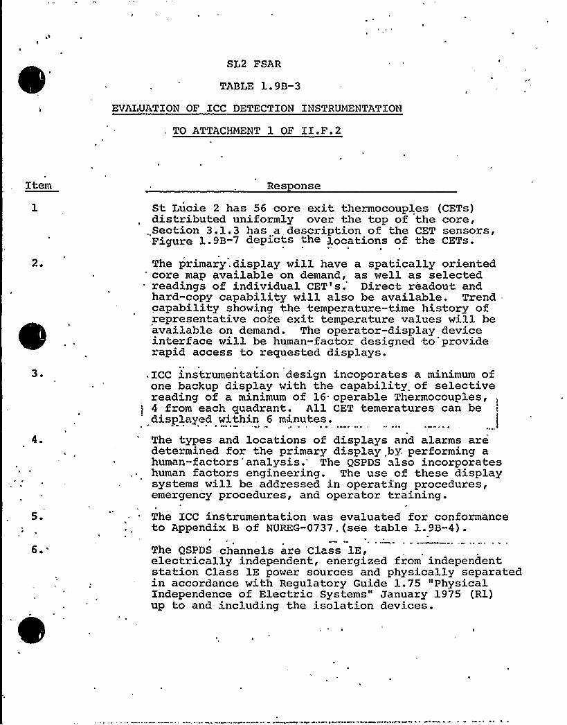
SL2 FSAR
TABLE 1.90-3
EVALUATION OF XCC DETECTION INSTRUMENTATION
. TO ATTACHMENT 1 OF IX.F.2
Item Res onse
2.
St Lucie 2 has 56 core exit thermocouples (CETs)distributed uniformly over the top of the core,
.Section 3.1.3 has a description of the CET sensors,Figure 1.9B-7 dep>«s the locations of the CETs.
The primary. display will have a spatically oriented'ore map available on demand, as well as selectedreadings of individual CET's. Direct readout andhard-copy capability will also be available. Trendcapability showing the temperature-time history ofrepresentative core exit temperature values will beavailable on demand. The operator-display deviceinterface will be human-factor designed to providerapid access to requested displays.
3.
4
5.
6.'
.XCC instrumentation design incoporates a minimum ofone backup display with the capability of selectivereading of a minimum of 16 operable Thermocouples,4 from each quadrant. All CET temeratures can bedisplayed within 6 minutes.
The types and locations of displays and alarms are'determined for the primary display by. performing ahuman-factors'analysis.'he QSPDS also incorporateshuman factors engineering. The use of these displaysystems will be addressed in operating procedures,emergency procedures, and operator training.The XCC instrumentation was evaluated for conformanceto Appendix B of NUREG-0737.(see table 1.9B-4).
The QSPDS channels are Class 1E,electrically independent, energized from independentstation Class lE power sources and physically separatedin accordance with Regulatory Guide 1.75 "PhysicalIndependence of Electric Systems" January 1975 (Rl)up to and including the isolation devices.


Res onse
ICC instrumentation shall be environmentallyqualified pursuant to C-E owners group qualificationprogram. The isolation devices in the QSPDS areaccessible for maintenance following an accident.
Primary and backup display channels are designed toprovide the highest availability possible. The QSPDSis designed to provide 99% availability. The avail-ability of the QSPDS will be addressed in the TechnicalSpecifications.The quality assurance provision of Appendix B, Item 5,will be applied to the ICC detection instruments asdescribed in the Appendix B evaluation in Table 1.9B-4.

'

SL2,FSAR
TABLE le9B-4
EVALUATION OF ICC DETECTION INSTRUMENTATION
TO APPENDIX B OF NUREG-0737
Item
l.
2.
Res onse
The ICC detection instrumentation is environmentallyand seismically qualified as specified in Section 5.0.The isolation devices in the QSPDS are accessible formaintenance following an accident.
t
The ICC detection instrumentation through the QSPDSlE'solators meet the'. single,.'failure, requirementsspecifi,ed j,n Appendix B of NUREG 0737.
3 ~ The ICC detection instrumentation through the QSPDSlE isolators are powered from the Class lE power sourcesfor channels A and B.
The ICC detection instrumentation through the QSPDSlE isolators are designed to operate during normal aswell as emergency conditions. The availability will beaddressed in the technical, specification.
5. Recommendations of the following Regulatory Guides were.considered in the design of ICC instrumentation;1.28 "Quality Assurance Program Requirements (Design 6
Construction)"
1.30 "Quality Assurance Requirements for the InstallationInspection and Testing of Instrumentation and ElectricEquipment".
r,r
1.38 "Quality Assurance Requirements for Packaging,Shipping, Receiving, Storage, and Handling ofItems for Mater-Cooled Nuclear Power Plants".
1.58 "Qualification of Nuclear Power, Plant Inspection,Examination,, and Testing Personnel"..
1.64 "Quality Assurance Requirements for the Design ofNuclear Power Plants".
'.741.88
1.123
"Quality Assurance Terms and Definitions"."Collection, Storage, and Maintenance of NuclearPower Plant Quality. Assurance Records".
"Quality Assurance Requirements for Control ofProcurement of Items and Services for NuclearPower Plants".

J

tern Res onse
5.(cont d)
1.144 "Auditing of Quality Assurance Programsfor Nuclear Power Plants".
6.
7 ~
The ICC detection instrumentation outputs arecontinuously available on the QSPDS displays.
The ICC instrumentation is designed to providereadout display and trending information to theoperator.
8. The inadequate core cooling instrumentation isspecifically and singularly identified so that theoperator can easily discern their use during anaccident condition.
F
Transmission of signals from 'instruments of associatedsensors between redundant lE channels or betweenlE and non-1E instrument channels are isolated withisolation devices qualified to the provisions ofAppendix B. 1
0. The QSPDS consists of two redundant channels to avoidinterruptions of display due to a single failure. Ifin the remote chance that, one complete QSPDS channelfails, the operator has
l. Additional channels of ICC sensor inputs for coldleg temperature, hot leg temperature, and pressuizerpressure on the control board separate from the QSPDS.
2. The HJTCS and CET have multiple sensors in eachchannel for the operator to correlate and checkinputs.
'3. The HJTCS sensor output may be tested by the operatorreading the temperature of the unheated thermocoupleand comparing to other temperature indications. FurtherHJTC sensor tests can be performed with special testequipment.
2.
4.'ther variables are available to the operator on theMain Cbntrol Board. for verifying the ICC parameter.
Servicing, testing and calibrating programs shall beconsistent with operating technical specifications.
The system design is such as to facilitate administrativecontrol during periods when channels are removed fromservice.


Res onse
The system design is such as to facilitateadministrative control of access to all setpointsadjustments, calibration adjustments and testpoints.Monitoring instrumentation is designed to minimizeanomalous indications to the operator.
Instrumentation is designed to facilitate replacementof components or modules. The instrumentation design.is such that malfunctioning components can be identifiedeasily.The-design incorporates this requirement to the extentpractical.The design incorporates this requirement to the extentpractical.The system is designed to be capable of periodic testingof instrument channels.

0

1 ~ 0 Figure 6.2-9 and Figure 6.2-10, with respect to containment.pressure and temperature responses following a MSLB accident,should be revised to show the containment pressure/temperatureresponse profiles (from time = 0 second to 10 seconds follow-ing the accident) for use in equipment qualification.
~Res onse See FSAR revised text and new FSAR Figures 6.2-9a and 6.2-9bfor containment pressure and temperature responses followinga MSLB accident for the range of 0 to 105 seconds.

0

SL2-FSAR
Pipe break locations, break areas, peak pressures and temperatures, timesof peak pressure and total energy released to containment are summarized inTable 6 ~ 2-4 for each LOCA analyzed. The DBAs are identified in Table6 '-2.Figure 6 '-S gives the rate of energy distribution inside containment forthe LOCA containment pressure DBA. The long-term performance is essential-ly the same for all the LOCA cases'll mechanisms of energy storagewithin the containment are addressed. Included are the vapor, energy (steamplus air), sump (liquid) energy, and energy contained in heat sinks.Table 6 ~ 2-10 summarizes the containment energy distribution at several keypoints in time ~ For the a@st severe Reactor Coolant System pipe breaksthis table shows the distribution of energy prior to the accident, at thetime of peak pressure, at the end of the blowdown phase, at the end of thecore reflood phase (cold leg breaks), and steam generator energy releaseduring the post-reflood phase (peak pressure only) ~
Hain Steam Line Breaks
Analyses are performed to show that the containment design pressure is notexceeded even if the following single active failures are postulated: (1)loss of one containment heat removal train (i.e., two fan coolers and onespray pump); or (2) MSIV failure to close; or (3) main feedwater isolationvalve (MFIV) failure to close. The assumptions for each case are discussedmore fully in Subsection 6.2.1.4.2.
The peak containment pressure is calculated to occur following the DBA102 percent power MSL.~ with a failure of one MSIU assuming the availabilityof offsite power. The peak containment temperature is calculated to occur
'ollowing the DBA 102 percent power MSLB with the failure of one of thetrains of the Containment Heat Removal System with the availability of off-site power. The. containment pressure and temperature transients for themost severe HSLB pressure and temperature uses are shown on Figures 6 '-9
~through 6.2-12.+Figures 6 ~ 2-12 and 13 show the calculated transient con-nsC.r tainment vessel surface temperature and shield wall temperature gradients,respectively, for the containment temperature DBA. Pipe break locations,break areas, peak pressures and temperatures, times of peak pressure,initial power level, single active failure assumed and total energyreleased to the containment are summarized in Table 6 2"4 for each MSLBanalyzed. The DBAs are identified in Table 6.2-2.
Figures 6.2-14 and 15 are plots of the condensation heat transfer coeffi-cient versus time for the containment pressure and temperature DBAs. TheUchida heat transfer coefficient contained in the unmodified CO"tTBHPT-LTcomputer code is used for the analysis of all secondary system breaks.
The containment analyses for the MSLBs are performed using all the con-tainment initial conditions, heat sinks and methodology assumed for theLOCA analyses except for the following:
a) For the MSIV and MFl'V failure cases, two containment spray pumpsoperate and spray 5,300 gpm of water at 100 F into the contain-ment.
I*i d2 —9'" -/d I .I, Ig+ +p~ ~P
higgle~oP+Ite Qe7ki n~f f'~~'"ee
6.2-10 Amendment Yo. 0, (12/80)

,I'I"~Q>,
Il«',J t ))f'b
i4 l'rr~t I!)I
)(% ~ II
Ii!)I' PF@)))I IZ~P4),'ll;
ii'„44)4IL(j'4
i
I
I I}ij
f,j)',
i.iTI~.Lg )It )4iI )sy
I!kii":
!!)'p ( jI!I'.'™"ll'
I 9 'k: I'l
I j' I '9
I)J
I I II4Pdk«g))),t'.)i.'LLII>!„)u' W) ~
XR'i
"sp4',
, )Li1+ <I) )44I)t«r'l
VAA„.„IfI;il'$.'~~)~i)
)))!Il':l ',~p I+8'4~,I
})Ilf AIL ij 1)lj «i I«IMI~
L~ V
t))-'aO
~ h. m
f)!,"!"p't!j,,!
I! [ttlltrrrt„,)f8)I
I)) I}j!ft~'It')ff'.)1I I"44
'l4)ri ~
I)
)
I
!f, Iqjt')4«)lj!"I 1'll'„!, «r,,;,)Ilrig
'l",i'.
5)
ii,l,r)PP„, Il,,4+I
}I')Ii:,'Sg)
'!)'i',, w")
)tg",$ 4iL'L
SK~ . 'III,)III«rt).mc+<t)«w., Ag,)I,
it) ~I4I
! i f@'iglgl gi4
P~Q; )it)LI
t)44)'I«'gQ~l~ P-
Itillt44:I W' 'i I
«4'IIIII)'"A<l,':j''..ri~
4Pi '; ' Lilt)PCQ
,;4)II:j«rent«HALI
I
II
4
i«i)hq)rL)!Ir)«+~~4
)fir!))I
~~,),l!
.:I. ')4+ ')
)I l[)>k.«1i),Ir4) iit4
llrlrk)4lpt«IFr)«
ri!i'«6~ I«j)LLL~'p
I) I14«r)4«44I ~ I II«««L4,«IIIIOI'. I«.r«L4.)«I Itr')Li
p~4't
I) 'Iig «44'~ I.a'.M~
)'j)".-4+7~)',Iq
q"'):)))
)Pg!)C~l Ij I "I"a~- ':li 'I'r4.™), l;4!I I lit:I'I Ii'
I!Il
lIIIaL)
7'in)8 gS'Bag
I ~
I
>I «I'(I) . i~«
Jlj tj)« 'CH) i)~q".'4II4 'I4 ". j I I
I ~ I~gj ll lj
li
f','. '- ":Iljji'.I,I4)
4,)llk4 4.IIIIIl«44't.
I;)4 piI '4 'lb'
) ff.! ti + I)4)IL~
pl+.6.2.-$ A. coNTA ~ AMENT p'gcssoRE—hg (02% t
owcF'et.a-gSiV Phtt UR&


(fIOO
jmj
Il1
l iI gill
7II«IE CSBC )
ltj
lill i>!
l,k
ll
f«fi
Il
tOOOO
}
}itI
I
I
r,r,
F.
ll
t. ~


For compartment (e.g., reactor cavit y, secondary shieldwall area, and pressurizer area) structural design evaluations,provide the design differential pressure and discuss whetherthe design differential pressure is uniformaly applied tothe compartment structure or whether it is spatially varied.
R~es onseDesign differential pressures are 24 PSI and 14 PSI forsecondary shield wall, and pressurizer compartment aboveelevation 62-00, respectively. The pressures are uniformlyapplied to the compartment structures.
Design differential pressures for the primary shield wallhave been spat ially varied from a peak value of 86 PSIwith provision for dynamic load factor.See revised FSAR Table 6.2-3 and new FSAR Figure 6.2-2~:.

K

SL2"FSAR
TABLE 6.2-3
Parameter
PRINCIPAL CONTAINs~i.NT DESIGN PARA'.DIETERS
De c~in ltargi nl
Containment
Internal design pressure, psig (LOCA)(VSLS)
~ Shell surface design temperature, F
44.044.0
264 9 44 psig Refer to Figure6.2"12
Differential design pressure, psid
Net free volume, 10 ft6 3
0.70
2 '0> 6.6"»
)lr t appli-cable
Design leak rate, percent free volumeper day at 44.0 psig
0.5 Nnt applicable
-Shield Euilding
External design pressure, psig 3.0
, I.~XI C))))t )))q I)))')q)g Q'g '),Rc).~ r ~'i>< Re=i) )) vs))l Indi))r) .~c))
) C.')))) C))-))VLVtl Cd I PA) LI )): I))
~ ~oiuF<~"4v t'.<ag d„.;t~~i w.ypcy-
387
'IOQ
/-~~3o 7 ~/))
I
't77 y
)BOOTES:
(1)Hargin (~) desi n value - eak calculated value,
peak calculated value
Actual margin, i.e. the margin between design values sod I ak cal-culated values when using realistic nr median parameter values wouldbe much larger. J
6.2-86

caQ CV
CZ
2CE(2.~0-6-78)RC2R2-200 IN" Dl. GU
I.c (X-a<~BK RVN077l „'REI RCTj'0YSN 1 .2/14/79
>-e
G..r~l~
.c ~
, V3
. C3
C1 cus rg
hJ
Q/
N cu
~ ~
1
~ ~~ ~ ~
~ r~ 'r," ~ eT . r ~
~ ~ ~ . ~ r,', I' .
r L
*~ ~*,f ~
1 ~ ~
p ~
4
t
07
C)O
r ~
~ i"
/ ~
'
42

Question.3e0 Provide analyses to determine the external forces and
moments, resulting from postulated hot leg and coldleg ruptures within the reactor cavity, on reactorvessel supports.'f applicable, similar analyses shouldbe performed for steam generator and/or pressurizercompartments that may be subject to pressurization wheresignificant component support loads may result. For eachanalysis, provide the following information:
(1) Provide and justify the pipe break type, area, andlocation. Specify whether the pipe break was post-ulated for the evaluation of the compartment structuraldesign, component support design, or both.
R~es onseFSAR Table .6.2-13 is a summary of postulated pipe rupturesfor the containment subcompartment analysis-. Contained inthis table is the pipe break location, description of thebreak, break area and release rate data and table numbers.
Pipe break locations were chosen based upon the hign stresspoint criteria in accordance with Reg. Guide 1.46 and SRP3.6.2. Refer to MEB question N2 attached.
The peak leads tabulated from each of. the pipe breaks listedon, Table 6.2.13 was applied to the corresponding structure.Xn al'1 cases it has'been found tnat the structural des'.gn wasadequate to withstand the differential forces resulting fromthe break. Table 6.2-3 (see revised table contained in answerto CSB branch question I2) provides a comparison between thepeak calculated force and the structural design.
The major components of "the RCS are designed to withstand theforces associated with the design basis pipe breaks. Thesepipe thrust forces at, the break location, resultant subcompartment differential pressurization forces and internal asymmetryhydraulic forces acting in the reactor internals. A completedescription of the evaluation of the plant faulted conditionfor these'omponents is provided in the response to MEB questsN35 attached.
The major portion of the Asymetric Analysis nas been completec-MEB question response N35. contains a table (Table 1), that
'rovides the current asymmetric loading analysis schedule.for botn the major components and the structural design in-dicating the anticipated completion date for. each item.
~ ~


It must be demonstrated that St. Lucie plant analysis system para-meters fall within the design envelope of CENPD-)68, Revision ).
~Res onse 2
The system parameters of the St. Lucie 2 plant fall within the designenvelope of CENPD-)68, Revision )., See attached proposed FSARamendment to 3.6.2.).).


3.6.2 DETEP81,'iAT10ti OF BREAK LOCATIO,iS At,'D DYtiAHIC EFFECTS ASSOCIATEDWITH THE POSTULATED RUPTURE OF PIPItJG
3.6.2.1 Criteria Used to Define Break locations for Pipe M~h> ~Anal s>s~ ~ I—//2.1.2 High Energy Piping Systems
P
section provides the criteria used to determine postulated piping
failure locations for high energy piping systems both inside and outside /RJ
containrent. He) Reactor Coo1ant System Hain Loop Piping /=sH/2,
) A stress survey of the St. Lucie 2 Reactor Coo1ant System Hain Loop Pipint
performed in accordance uith the methods described in CENPD 16BA (Reference 1)
The St. I.ucie 2,Reactor Coolant System geometries and transients were employed ithe analysis. The results of this analysis are presented in Figure 3.6-4. In
accordance with the criteria specified in Reference (1) circumferential type
pipe breaks are postulated to occur at all terminal ends and pipe breaks are
p ulated at a1) intemediate locations throughout the, piping system where the
of primary plus secondary'stress intensity exceeds 2.4 Sm or the cumulative>
usage factor exceeds 0.10.
Where all intermediate pipe break locations would be considered unlikely becauser '
the stresses and cumulative usage factors calculated for a particular run of
piping betwe n terminal ends are everywhere less than the stress and fatigue
limits stated above, the two intermediate locations of highest cumulative usage
-'actor are chosen as the most likely break locations for piping runs longer than
.' )0 diameters tota1 length", and for piping ruris having more than one change in
direction through-out the run.
>) The results presented in Figure 3.6-4 confirm the break location and types
,of Reference (1) for the main loop pipe.
>) For the partial. area guillotine type pipe breaks at the reactor inlet andoutlet'o
les 'and the steam generator inlet nozzles, the methods of Reference (I) were
yed to calculate the f1ow areas and opening times of the break at these locations.The stiffness values are provided in Table 3.6-2 and Figure 3.6-5.

I
The resultant break characteristics are shown in Table 3.6-1. The pipe whip
restraint at the reactor vessel inlet is shown in Figure 3.6.3.'ll other
llotine breaks have been assumed to open to full area.
The break locations for RCS are shown in Figures 3.6C-2.1 and 3.6C-2.2.,

.
C040 LRQ P 1P"- ~7oP q-,)ppgK55
5,npP)P'-
0¹C,'po, 9;op
+W~ pg'c)yi'gop
Nds Z
+To pee $
svir-r-~a~s c ~ t,<)g,~No gg'S
zCI
'z
P.A 1
2 B.l
33ao;3 Klo
854,.2.< ~c
gz.Z.C < (o
Q) f.ZWlO
yg,gx, (e
~o.g <W
g~.g>(io
) f.oK)o
5, l <)o
)X)O
2'X2,,8 s l o
34{'.> f~to'),Ox~a
q[.gx lo
4,1.)xl4 .
95,)x IcP
3< gg,Q K(o
'555 g Klo
'Zl )iO ~l~
pig 3x<o
gp,.5x>o
+dan) 8 )+
4+ l~lo-'J
I l o>t~
F
gv
f J


P/PE BREAk'REAS AA/0 &REAR'RNER/A/8 TrhfE5
A / E. ARLA r /Lr077h!F
yZece 3.6-E
pvSrucATED Ru~Ee .8<EAv Floe/ ARHR
(g~z)g/SE 77WE
(nrizusaccwmp
ZO.
89 /AflE'7 Fo/// oT/NL

I

'pfPICA) RCPD)seHARCE LE.G
s
r
aQlnx
V~Pl
V)E.VC S-80ETAlL
~p>CAl Z~ACE,~
~O ~@ o'
lQl
io
ZC>
0
J'g
STO'PMO.R
1
. 7Q
J~
jR
~0 y DE'7All
VlFW A-A
"o~ oo ~

. q"%..Jz~ pO
Q kgb .bolji,>hgqqI
'L'tabb, .apQ;l,yq$ q. lVlp<.oiw,y.6og
KX5Xg,b»r IP. V~$
ob'gxpib E6 lLVQ
(pro,.poop >K.R o% X)
~ ~
STEAMGENE RATOR
2h
Q„
li~ ~
»lo,.opW, l,woo/gal,
.bb tQ, l:b6$$~~, Io oar, agqgj
(<lfo1.2 pp p> l<l6E
f>$6o ) op bo (\ x lg'lbpL oli6IQ
: >Cs>„pw6,5 >Tip=64,.bog j,Qllho
q>~o,.obwl, l.LV>.)
~ U)o,.abIP,g! )x
;PUi~>P:l. 2hhg
l2
~ re ~
h 2 (~Xc>+oOPO l 4 ppg)
i"'tq eeE.a,'Iqng)
'UMP'h2
(6oo<.OK l+ 'lhVQ
rc o,.ou t
Lobo>-oaO l.+opI'go
>.Pbqt>'L.QKQW
@3%0 ab'lj P~
-0>, ob-pI~.ggqg
c~t,ww,.ooO, W(4< t~ >'j~ t.bbXg )l.qXC$)
l402.o bop>t.6o'%o) QS 0~
+o o
C.~~o ~b u,l.WV~+~
~%'lLO,.Oab O,'L,&69)
t Q~o,.ooq+,4.6l4.(6»,.cp--\> L.%gee6 2 <.pp lh,>4Kb@
l 4 X,.op~ a,k.ggcg)
LL42 okoogloio'E4$~ - L$6o].op»gy ~t,gJ 53X,.o e il,gWt( I
'g&,+oath~ w i>gQJ 0 ~
QtWW,.ob -L< Alt)807E: DATh POIl<T.hOei lbhGB PACER Ct eV F ) and
Sn/Sa are fndkcatcd Jn thc parenthcscs~0 ~
~ ~
~
~
0
ISO:m..IC S~:nCa
CMnATIi llS..>GB FhCKR g'0 yOR-M,IZ"=a FRISKY PLUS S=.CC:,0<.Y S7R."~S Zhtl 'SITE
RhNQP (tL'SUt.TS FOR Sh" IStGC LOAOING (LCW'> LA)
'LT,<o „,'lg5p,
F l&ORK 3.6-'ISHRED l oF. p

0

0
OP(K~O .o«o, ihi~~)
(33)o .ooC3 %,galI
~oooo) LA~'\s.
o< +Co o'l~l.<1 \(
'AXo .oo~og~ ~+>l~2~,'.oo-0~\.4)63 IB iX,goya,i,gus
STEAf.lGElxLRrXTOD
2B
kI
5+0) Cot/~($ $ $+Q)
Qt'Lo,.oo O'L< h >gh35! 4o> oo+ (,g~~~
~so
~+ 3~ OAT ~ L,)4 0
Jl
5!(> «XW,LQ'b>gl
L<QK, ooM i'\-L4g
~to
IPUii'tP'281
6yy>.oo63 gpqfi)
XCN),oo'1'h $ 3)oy~ ~
v b3r)agog@ 'L, QQ5I '
Q 16t,.co o o,(,sqgg )
l'5 ) lo5>gf
(ACE .oo m, g,~gq)
gtC) oo'Q
g,pygmy)
Q l6o<.oog,l,~qq~ "~) oo4 4 4$6l
WR 4 t) .o o gg,4.(o~
g'A~o>.oot 4>(ZWW
(g oo
36eo,.o(c7 x.(go«6 ol woo?t J(+Eolo
QW I6T( ooW L.3<t'L)
(hlt o,.oCq y.qqqq)
$518o,~on (pggq~ 0
~tt>>.C<oosV4g c~ r
(5520~ 8 1k'(l lifo)
; r~ lqa4y .oo$ t, (XQ)tM, eon,tq.to%
%laic
REACTOR~ e
(p Q>,coZt,L.iong)
4%%~~>.oooo, X iWoZ)
NOTE: DATA POINT?lO.s USAGE FANCP. (C.U.F ) and
Sn/Sm are fndicated fn the parentheses
lSO~oSWIG gy,ET~
CNfiQATIVH USAGE FA fOR A'.:3 NCNQLIZ":.D P..IN'LUS SF'AND.'~Y
RA!ea R~Suus FCR S~IS:aC I DI.;~ (C.OC>l 28)~ ~
F|Gvac. 3 a-'f%HELD d'or?


/" S YA1BOLS:- CIL CIRCUMFERENTIAL BREAK
L LONGITUDINALBREAK
STEAMGENERATOR
.0 a
O~~ 0
jPUMPg
C
SUCTEONLEG
W W
CgPUM)P
.L
SUCTION;—
CLEG
DI SCHARGELEG
HOT LEG
DIS CHARGE.LEG
NOTES:
1. CORRE SPONDING BREAKS AREPOSTULATED IN OTHER HALF OF
. SYSTEM (NOT SHOWN FOR CLARITY)
REACTOR
C-c'. C-mbvstion Enolneering
b..c.
DESIGN BASIS PIPE BREAKS
TYPES AND LOCATIONS
3-4
Figl&c


NCL Cs(040)QVJ SIC'tCSCtC QNAt<4 PAPCMlO (C if( PC@ HALt INCH
CQCCNC OIC CXC2(C f((L~SAOC }N }L 8 Ia
ft t''IJJ' ~ I ~tl 4')
I ~
0(sj I(i ls
~ II ( '.I'il'
00>'ID>J( lff (ef.~ ~ ~ Li~ ~ V~ i ~ 0 J ~ ~ LI
~ kk 4 aku 0 ~ 44 tkk \ 4> 0 0 144 0 ~ ~ ~ 1 ~ OAOALII J lh'f"iIH.'j'
'f!I-." Jif'tJ VH'='"=:<~Qi"-6iiifkV 6Q'la ~ ~ 1)0> ~ ~ flkef vkko} JJ/0 1 4( ~ ~ S I ~ ~ 4 ~ ~ 0040 ~ ~ it ~ I ~ ~
~ ( ~ i t i 0 4 ~ pLt0 to 4 M~ktkfI LJ)kf ll 4>fl\fJ Uk( Vkl)+II fJp t I IiI
I I OJ
if
~ ~ I ~ ~ ~ I 1'I ''lI
)iti lftl
't"6Qi'
'1 ~
~ I I
~ ~
I
I (( ~ ~ ~ ~ ~ Ii)~ ~ ~ ~ ~ ~ rfl
I~ ~
~
~
~l 'ii) i!'f ~j: i 'i(
t
~ ~
I
I ~ ~
)I
orfl
(I ~
)~
f~
I~
it,sit!~ i
'I ~ ~ I ~ I ~
I I'}ll
0 ~ I~)
I
I ')'
('iil~ltea''ll'i'i!
~ Ill:(J I''
i""'tiiii!')f'
futk I~
(ti™JL f~ L ~ ~ ~ ~ LJ
~ ~ rk ~fitful ~4~0}. )j++l.i}ok~(( vlVÃd4]IfJf~t~ 104
~ LLIJ lkki4.1> O
1 ~.4100L OAV L4Ltl~ LkltoJ.a J LULIkli 4
UJsite
1 ~
~ 0J
~
I~ ~
I
i~ ~ (I
~ ~ ~ ~ ~ ~ ~ ifI
I[tt! I! ~
'tll~ ~
,( t Ii t !
~ ~ ~ . ~(
t ~I
I ~
i~ t. ~II
~ ~
~ ~I ~fls ~ I ~~ ~ ~ (i
~La I
af~
!~ 4 ~ ~ 4 ~
I~ ~ ~
IIs li11
~ ~I ~
~ ~ tl ~ ~ 4 ~ ~ ~ 4>kkt ~ 1 ~ OOU kt ~ lk ~ art& WL ~ ~ ~ ~ LVAUkookklklekuakt>~ LIJ,~ Ll~ alta ~ ~ \011 ~ ~ OAV lkti~ L4JLJJ44J10044+Llkk+LaksiakL4JJJ ~ ~ UU 4 ~ ~ Laikti lkks ~ IJI ~ f ~ lkak}OJJ Utk LJJJJlto 4144LAUJII«44444 ~ akt I ~ QL~ki ~ Luoa ~ ~ ~ ~ ~ 4LI ~ «ILL lt JJktt ~ ~ taarruuaaJALLta«rkufk k>J ~ > 4
4> ~ t ~ ~ ~ ~ I ~ ~~ ~ i ~ ~ I
J
111 ~ 10 ~ ~ ~ ~ ~ ~ ~ ~ ~ I ~ ai ta>OJ> V.~ ~ LOALLar 441 ti ~ OAULLtl>JALO~ ~ ~ 4 ~ 41 ~ 11> ~ ~ Ill04 ~ tt~ ~ 1 ~ ~ 1 4 I ~ ~ ~ ~ ~ ~ J ~ tk>kLt ~ ~ i I 4 IkLLLU1 I4 0k4 4 ~ IUAJ akak IJ 1 0 41 4 L L ~ ~ ~ Jll I J I ~ I ~ I T I
to~ tiai LIJU I ~ ~ ~ ~ 0JLLOOAua ~ Llsik«VUUJJAOALOIJ>444Lsakt>kk« ~ ~ 4 ~ ~ ~ I ~ 1 ~ te ~ 4 ~ II ~ 4 ~ Llk ~ ~ Lr L Aakk>AUILLLLLULLJALAI>lk LLV>lkr LL1~ Le I ~ Il~ ~ I ~ ~ ~ ti
L) ~ ~
J~ ( )
~ ~ ~ ~ I(
~ ~ )~)J!g)gf f t
'0
t ~ tis!1 I
j.!.";if.I'i!"i!Bjfji'U.
))t) ~ lili f(ejr ~ .iI ~
ht(
I I
') > I
)I ~
~ I
I~ ~ I ~ ~ ~ ~sit I(
~ Ils (i)I ~
~ ~ ~ fe ~ ~)
~ I ~ I ~J
~~ 0 r) f ~ i ~ ~ ~ I
~ !t~ I ~
}I~ 0 ~ I ~ > ~ 0$ I ~ } ~ ~ ~ ~
f~ I f ''elil if)t..i .,II.l(.I s ~ t' ~ ~ I ~
t
les�'
g(~ 41 ~ ~ ~ ~ ~ Vt~~ 0 ~ ~ ~ I ~ ~ ~ ~ ~ I ~ aau o, at ~ 4kk4k 0 ~ ~ \ ~ 4 ~ tk4 ~ ~ ~ ~ 0 ~ ~ ~ I ~
iakuuk ~ 1 ~ LLOJ ~ J,tr J 44I ~ ~ L~ ~ v ~ ~ I ~ Ia44 ~ 1 0 ~ ~ 0 LtLL4i~ 0 4 > 44.14 liLLtI I I I ~ ~ I ~ ~ ~~4 ~ Le 441\kakkrJ ~ JJ4JJ ~ ~ i ~ ~ IJ tl I s
~ 4 > I~ ~ ~ ~ * I 44 O~UOAUvkkkkrok~ vJJJ J OUJ ekttkav J ~ 0 a4 ~ ~ ~ IJ ~ ~~ 04 ~ VJJJ ~ ~ I ~ i ~ ~ ~ ~ I fLekkarkUJJUklJ Lk 4kkoke«V I LtiUekLkl ~ Ik» eki ~ 4 \ tj I I ~ ~ 4 LI
~ 0 ~ Ik> lit&0Vof 1JAOJrkkkskJ 44444 I~a 4404>LLLLLVatilt 4 4 ~ J illa«if ~Jikl> UJ ~ ~ ~ ~ > Ae 04O tkki ~ 0 OALUALUO~ L44441LOLa kllAat~ atL10 >tk ~ 4 ~
~ ~ ~ I ~ ~ ~~ I 0 ~ ~ I ~ 11~ ~ I ~ > ~ ~
~ I ~ ~ ~J
~ ~ I ~ )
)~it(]g( ~~fl 0 s I i ij 0
>t'I't ~ (t ''is ''~ ~ ~ Ii'ol't'! Le ~ ~ ~
~1 ~L>etlJ~a«~I ~
i~ ej
~ ~(
~ ti ~ I ~ ~ I'f '"'"i"' ~ 'ii't"!
Il(i)I '(Js vs
lsfsI) IQ)aj.~
) (~ ~ ~ ~ ~ ~
(~
~ I I ~ f ~ I se
~ ~ I
~
f~ I
~ 1 ~ )1, (I ~ ~ ~ ~ ~ I
~ I I ~
~ ge ~ ~ ~ ~ e ~
<I~ ~ > I ~ ~ J> I ~
t. ii')f)I i Il)I I
0 4 I ( f' (
~) ~ ~
(f. IfJ.fo 4> IQA ~ i&Ok 0~4 to~as ~aUk(I ~ OJ 4
~ ~
il iglepU(l)LI4141 ~ ~ ~
r.' I ti:"I')tflj6,'(t .f
~ 4 ~ I al
444 akoku ~ 404 ~ 0 0 ~ 1044kkkrkV I Io I ~tkkkk«tu 0 1 LLII 11 I ~ ~ ll1J ~ ~ JJ ~ lt ~ ~ ~
%.""2 >>f:!))'!!" 'lt 40 Llk14 ~ ~ ~ 10 ~ ~ ~ ~ ~ ~ ~ ~ I ~ ~ ~ ~ 4 I ~ ~ ~ ~ ~
ji'I~ 0
! ILVLLLU044kk, III44. ~ ~ 40A> VJ ~~ 4 ~ ~ . 04 ~ ~ te 4 ik> ILelk
J~ ~
(ilt 1) ~)
II~ > ~ ~
I e~ aatfe~lk IJ L(JJ f 41 s
~ ~
! !t! i(I"il ~.Vs~lIJAL fL(AJJ ttLkAL
f tf'tifLeo L i. ~ ~ ~ > ~ ~ L ~ ~ ~ ~ ~ 10 ~ I k. 4 ~ ~ ~ ~ ~J ~ ~ ~ ~ L ~ ~ ~
~ ~ 1 ~I
~I ~ i.~ I~ kouk 0 ~
~ 01444 4LO I 10 ~ 14LUII
J If1 4 or J 0 fieft Ltgu j4> f ~ i L.U:laUUIAL't 'u ef I Lt>f III(~ 4 L ~ ~
~ 4> 10 ~ tktk>ALVIN ~0 tao vtkkuk>4 ~ I
444 ~ 4 ~ katkko ~ ~ I ~ L I 1 J>40044 ~ > ~ ~ 1 ~ ~ I ~ 1 ~4 0 0 I I ~ ~ I I LJL>i ~ Lr LL0 JJJ kk> 1 I4 Ii> AI ~ i0 ~ I I ~ ~ ~ I I ~ LI I~ ~ ~ 1 4 JLLLJ I IJ 0AU 0 1 ~ LLLLILli~ 4 ~ 11 Is okt ILkk aJA
t ~ '~ )k> «LOA> 4LaLO ak IU ~ ~ I ~ ~
g
Jinni
~ }f ~ ~ 0 ~ ~~ ~ ~ ~ )11} ~ fet ~ ~ )) ~
I
~ ~ U 4 Vkal> 44 4 O
I ~
~ Lt 4 okffkkkk 4> 4 0 ~ UUakt LUrkkku 4 UJ ~ Ikkat ~ 11 14 ~ o 4 ~ 14katka 1141 vkutok OJke ~ ~ ~ ~ L}ke>kkiL +11 ' ltkvLUJJ 0 («Utile L>. ~ LLLOf ~ I
);i"'" ."'" '~~(
~
I lf~ ~ I ~ e
~ ~ ~ ~ ~
> i i jj
I i ' fatti"~ I Vol>J(
I ~ ~ti
0
I i r J'0 ~ > ~ LJ ~ ~ ~ ~ ~ ~~ ~ «it 0 ">ts
I l>t I~
~ Q ~ ~ ~
s)fif i~ I
~ ~ ~ ~ I ~ ~ ~ll if'~ ~ ~ ~
~ > ~ ~ I I I ~
6'iiiV~I5hR"'I"I'I'!I[ iji sl'II
~ ~ ~I II ~
I)
~ ~ ~ I ' ~)'f)fit())'I). ~ ~ ~ ~ r ~ ~
II ~ f ~ Ji le~ I ~
I IIIII I
Iittt)'f slI if(
(fs
'f)'f'lj'"" iii~ i:~ ~
~ ~ ~ ~ ~ ~}' lisilt~ I ~ ~
~~We)g'~~ I ~
f}'i'
tt~4 4'1 s ~ 1>J ~ iko~ ~
~ I UI4> ~ ~ UlVkt0 a ~ LUI ~ ~
glut'IIL!It)t ll"iaaf.f. J i'I
~ ~
)~ 1 ~f0 4 al(J ~ 0
~ t I IAtkflLI~ 0 ~
0 ~ ~ ~ 44444> 0kk ~ ~ >Ak ~ LI I ~ ~ ~ ~~ LL ~ 4 )
> I ~ I4 I QQ4 [II ~ f IJ't' 4'll'J '1.'f ~ ~ ~ )) ~ ~ ~ I~i'i I 'tij~ ~I ~
4 ~ f ~ 1 ~ ~ ~.) 1 ~ >4 ~ ~ t) f 0 ~ ~ I ~ ~ ~ ~
lt 'ftia tt 0'q. f( }'!'I ~ ~(
~ ~ I ~ 140Its'L4 ~
Ittj)If tt)fit ~ st 0 (I (i( ~ Iate44 ~I4
~ I~ ~ ~ 4 el! }J) t j)) I; I ~
) ~ } ~ OLI tkaa> Lt~
"(Kfft 'ULOkt>4/$ 4I 0 JJ ~ 4 ~ + IV1 4 4 IJL JLIA
tl"4, sts~ AL} lkJ
~ LLvk1 f JJ ~ I ~ tJ ~ 0 4440 4 JJ+rk ~ lo LLL ~ t ~ ~ ~ Lf1 1 I f ~ ~ f (4 ~J
~ f ~ Itk ~ Iku LIJ
'~ ~ taiJJ di«tk>4 kkUU~J J ~ IJ J ia>Lief}~ I ~ su 1 I ~ s III ~
AOJ 44444 ~ )ef 4 \0 ~ ~ ~ ~ ~ L 14440 ~ ~ ~ 10 ~ I ~ I ~ ~ ~ ~ ~ ~ ~ ~ I ~ 0 f1 ~ ~44J OJ 0 Lt ~ ~ I il ~ ~ ~ ~ ILL> 4 ~ I ~ I ~ LIL0 ~ ~ ~ ~ I> ~ . ~ JI ~ ~ ~ 1( } ~ ~ ~ Irk~ 4 ~ alla 4 ski ~ llI ~ te ~ i 1JI J I +4JJ I ~ > ~ ~ 1> 1 ~ I ~ ~ i ill~ r ~ ~ I tl I ~ S ~
ill!ii+I
(lit4(I
Lr ~ ~
[I tI'e(sI~fj. '
)) ~ I~ (
i jll'(tffl(i)tt. Jdiiel}~ lt
)~ ~
Ll
'!iJjl(I!(Is(
f'I:i'i'i'~ I ~ ~ I ~ I I
~ ~I ~ ~ I ~ ~
I ~
llt ( liijfjtl (.lf.iLV
Ill~'iIl'}IIIi );; iiii:} ~ I
I~ f ~ ~ ~ I> (
~
I I ~ ~
Ii t! I s)i' (I sj It I l}sf:I
IJl ~
tl~ ~ I ~ ~ I ~ ~
Jft(I)j)J40114
~ ~ ~ ~ 4> ~ 0 ~ La >4 4k 4104.4>e ~ IJ ~~ I ~tfefgfk J ~af MV.Mfft(f})I
I 0AO ~ LL>.~ ~Uk LLLL~ \«tt>L 1 ~ 1st
~ J) ~ 4 ~ IJ Je ~ ~ )4 ~ Jf ~ f~
4 ~tii!I'Ut t)l.i)tf .i „
44 I [tl'jJ~ 4
(to J~
st
~ >i«
~ fe io ~ ~ ~
I
!!i~ s.
~ ~ >i~ I
ti i ~
Is 'I ~ ~
~ ~
lsI
flip i
,"i 'iiI Ii I ~ I I I I
I~ I I~ ~ }S I~
~ III
i~ ~ I
'if'I ~ ~
I sJ"ts
~ 4It
~ ~ II~ ~ ~ ~ ~ aa 4 oof ~ > ~ l ~
s( I 1. ..Itl )I lsake 4 LU 1 'jljlii}'fL'tt>t J s', 't" t~ ~ ~ ~ >OJ ~ I ~ ~ >4\1> ~ ~ 1L' ~ ~ i ~ I ~
I :. "." !lf !Iiiitfs'e 1!I s . f ~ > )tiffiffy'.'„"",:,!J'jf i ~
~ i(I ~ ~ e! ~ e
I I~ ~ ~ 00 ~
I~)
I ~ I ~
~ I~ ~
)~ ~
)
~
if
~~)I!jest):!Blp~!3' gt~t!
/fan
'(klt t I)I'lg!t li
tk ~ ~ 0444 ~ OA,~ (JJ ~ fffI ~ I f
1 '.e t~j-.
~ ~ ~ a> 90 ~ ~ ~ ~ e ~ I s I ~ ~ ~f
~~ I IJ ~ ~ ~ ~ I ~ I ' ~ ~ ~ ~ ~it'II~ttt')i )j
~ ~ I ~ ~ ~ ~ ~ ~ ~ ~I, ~ ~ ~ I ' OI ~ JJ}4f ~ ~ f ~ ~ If
'I 0 ~ ~~ ~ 0 ~ ~ ~~ ~
( I)iggteggff jf y I
( ~ I I I
~ ei
I )elf. )IJ!(I
Ill!Li'!I}LIIl':lJllll '
i If!!i' " )fl~
fPi[
,'tf'If.tiijail~
)
'«I}IPL('}
I L t I ~ I ~ I ~ ~ tka ~ Ular I ~ ~ ~ 1 ~ ~ ~ ~ ~ 4 ~fe I) IHl <
~ I I
i,sl ~ ~
iI ~
I
}II@Ij)tflj(I'iij)j}lt
~ I)
~ ~
)) i'e . ~ ~ I ~ IL )te
I ~ I ~
t
~ ~
I
;" I) I I
lt's II }I
~)
~ s
I
(li
01 I
I
i~ I ~
I.~
l~ 10 ~
~ I I
ls
jf(fiefJiLU
~ 11)I ~ ~
i(it' i
}
�If;(f''j)
s lfI
I
IJ

ues
uestion 35
The response of certain reactor coolant system components and theirsupports to postulated asymmetri0 LOCA loads needs to be addressed inaccordance with NVREG-0609.
~Ra8 onse
TABLE I provides the status of the evaluation of components, structures,and attachments to the RCS when sub)ected to asymmetric loads. Where theevaluation has been completed, the results have been shown acceptable.


TABLE 1: Assessment of Structures/Asymmetric Loads~ ~ Oi
Component/Structure AssessmentStatus
EvaluationBasis Reference Comments
Reactor PressureVessel'team
Generators
Reactor Coolant Pumps
Reactor Vessel Supports
~ Steam Generator Supports
Complete Plant Specific Analysis FSAR 3.9.1.4 ' Complete
Reactor Coolant Pump Supports
Biological Shield Well FSAR 6.2.1.2
Steam Gen., R C Pump FSAR 6.2.1.2
Compartment Wall
RCS Main Piping Complete Plant Specific Analysis

TABLE 1: Assessment of Structures/Asymmetric Loads~ ~ IO
Component/Structure AssessmentStatus
EvaluationBasis Reference Comments
ECCS Piping -In Progress :. Plant Specific FSAR 3.9.1.4.5Analysis
Preliminary analysespredict acceptable results.FSAR Amendment Nov. 1981.
ECCS Piping Supports & Restraints In Progress
CEDMS In Progress FSAR 3.9.1.4.3
Reactor Internals
Fuel
In Progress
In Progress
FSAR 3.7.3.14FSAR 3.9.2.5
Analysis nearly completeResults to date areacceptable.
Analyses expected to becompleted 3/82.

e

i.s
'
I is t t
I I
~ ~ ~I l

ST. LUCIE 2 CEDM
~ GEONETRY AND MOMENT CAPABILITY SIMILAR TO PALO
VERDE
a
PIPE BREAK + SSE HEAD VELOCITIES LOWER THAN THOSE
FOR PALO VERDE
SINCE PALO VERDE HAS BEEN DEMONSTRATED ACCEPTABLE,
ST. LUCIE 2 CEDM ARE EXPECTED TO BE DEMONSTRATED
TO BE ACCEPTABLE
~ ANALYSIS IS EXPECTED TO BE COMPLETED SY SEPTEMBER
1, 1983,


4oo
PihS KQ)- H)C.
,KO-
p„ggz zc~BL tAt l Tule (go% P4 Sic>~ ~4Llii4 lij)'
D
O ED CO0 C)
p~~le. e xu>oo
ChO
Lv CX.E
go~~LE ROMBgt ~fr '- yp9,>(STY


ST. LUCIE 2 ECCS PIPING
'PRELIMINARY CALCULATIONS INDICATE THAT LINES
lA AND 1B ARE THE MOST SEVERELY LOADED
~ COMPARISON OF 'INPUT MOTIONS WITH OTHER ECCS
LINES PREVIOUSLY ANALYZED INDICATE THAT
1) PLASTIC ANALYSIS IS REQUIRED.
2) RESULTS ARE ANTICIPATED TO DEMONSTRATE
ACCEPTAB I LITY.
~ ANALYSIS. IS EXPECTED TO BE COMPLETED BY SEPTEMBER
30, 1981


fA ca'fcu1atfon pf the ref'oreatfon of the St. lucfe 2 RC p$ pfng Ken subjectedto tgte aexftram rionent a11mad by Section Ill. Nb 3652 was pilaf'omed. The
,bteached mteria1 sh~s the vesu1ts of that, ca1culatkon.


~ ~
r~ .r
~ I/I
II. ~
IC
I '
o+ ~g es&r~
r~ ~ ~ Q
1
l\
~ ~
III
Oy ~ ~
I~ ~
'
~ /
rrr
~+
SUCTION iL80H TOTAL CISP. RT HIGGLE SECTION

0

3.9.1.4 Consideration for the Evaluation of the Faulted Condition3.9.1.4.1 Seismic Category I NSSS Items
'he
major components of the reactor 'coolant system (RCS) are designed towithstand the forces associated with the design basis pipe breaks discussed
$ n Section 3.6.2, in combination with the forces associated with the Safe
Shutdown Earthquake and normal operating conditions. See Sections 3.9.1.1 and 3.9.3r~r-discussion of loading combinations. The forces associated with, the postulatedpipe breaks include pipe thrust forces at the break location, resultantsubcompartment differential pressurization forces, and internal asymmetric
hydraulic forces acting on the reactor internals. The pipe break thrustforces are determined by the methods discussed in Section 3.6.2. 6.1. The
time and spatially dependent asymmetric hydraulic loads acting on thereactor internals are determined by the methods discussed in Section3,9.2.5.
0A dynamic non-linear time history analysis was performed to generate reactorvessel loads and motions due to the forces associated with the partial area pipebreaks at the reactor inlet and outlet nozzles and the steam generator inletnozzles (See Section3.6.2.1.1.3). The analysis used the DAGS code to perform a
direct integration of the coupled equations of motion, in which the system
characteristics are updated at each integration step to account for localnon-linearities., These non-linearities include initial gaps and preloads atsystem restraints or local plastic response which may occur following a pipebreak. The FORCE code post-processes DAGS response output in order to providethe loads and motions at pre-specified locations.-
The analysis used a lumped parameter model including details of the reactor vesseland supports, major connected piping and components,and the reactor internals(Figures 3.9-19 through 3.9-22). This mathematical model provides a three-dimensional representation of the dynamic response of the RCS major components
subjected .to the simultaneous time varying pipe break forcing functions. Thisaedel is defined mathematically in terms of the ICES STRUDL II computer code
to develop appropriate matrices for the elements of the three-dimensional space
frame model.

The results generate reactor vessel and support loads and time history motions
of ACS piping at,ECCS piping juncture points, and RV shell motions at internals
and CEDN support points. These motions provide input excitations.for the pipe
break analyses of the reactor internals, fuel, CEAS, CEDARS and ECCS piping.
The component and support loads for the Steam Generator, Reactor Coolant
Pump, and Pressurizer were determined by equivalent static analyses.
A load factor equal to 2.0 on the calculated thrust, jet impingement, and
subcompartment pressure loads is employed to account for the dynamic response
of the structure. The model employed for static analysi is shown in Figure 3.9-18
The system or subsystem analysis used to establish, or confirm, loads which
~
~
~~
are specified for the design of components and supports is performed on an
elastic basis.
Mhen an elastic system analysis is employed to establish the loads which act
on components and supports, elastic stress analysis methods are also used
$ n the design calculations to evaluate the effects of the loads on the
components and supports. In particular, inelastic methods such as plastic
instability and limit analysis methods, as defined in Section III of the
ASHE Code, are not used in conjunction with an elastic system analysis.
Analyses of the reactor coolant system components (reactor vessel, steam generator,reactor coolant pump, pressuriier, . and reactor coolant piping) and their supports
have been performed in accordance with the methods described above. For each
component and support member, the calculated loads, in combination with the seismic
loads, are below the loads specified for design, and the stresses (piping rupture4n combination with SSE) are below those allowed by Section III of the ASNE BKPV
code for Service level 0.

.

3.9.1.4.2 Reactor Internals
See Sections 3.7.3.14 and 3.9.2.5
'.9.1.4.3 Control Element Drive Mechanisms (CEDMs)
The capability of the control element drive mechanisms {CEDMs) to withstand
the effects of design basis pipe breaks in combination with safe shutdown
seismic (SSE) loadings is evaluated by analysis. This dynamic loading isexperienced by the CEDNs via the motion of the reactor vessel head. The
reactor vessel head/CEON motions due to pipe rupture and seismic loadings
are calculated using the models described in section 3.9. 1.4. 1.


3.9.1.4.3. I Method of Analysis~ ~ ~ ~ ~~
Previous studies on other CF plants (Reference I) have'indicated that thereactor vessel asyornetric load aspects of a hypothetical guillotine breakproduce motions which result in stresses which exceed the ASIDE Code'evel0 allowable stresses for elastic calculation. Elastic plastic dynamicanalyses have demonstrated for those plants that the structural. integrityOf the CEDNs is not impaired by these loadings and that the ASIDE Code
Level D allowable limits for elastic plastic calculation are not exceeded.In order to demonstrate that*the integrity of the CEDHs are not impairedby pipe break and SSE loads, elastic-plastic dynamic analyses areperformed.
In the elastic plastic analysis, the motions of the RV are input to thefinite element model of the CEDN. Moments and deformation are computedas a function of time during the event. The moment to cause plasticinstability of the most severely loaded section is computed by elasticplastic static analysis. The actual moments during the dynamic eventare then compared to the plastic instability moment in order to evaluateintegrity.3.9.1.4.3.2 Models,,Dynamic analysis finite element models are prepared for CEDMs near thecenter of the RV head and near the outer edge. The models are made upof beam type elements.,
Yhe model of the calculation of the plastic insta6ility load is made upof shell elements in order to consider the effects of ovalization of thecylindrical section. The nozzle at the RV head is usually the mostseverely loaded section.
3.9.l.4.3.3 Material PropertiesRecently the material properties necessary'or elastic plastic analysishave been developed by the CE Metallurigical and Materials Laboratory.Yhese properties are available for all of the materials at all of thetemperatures that the CEON normally experiences.
~ ~ ~ ~~.9.1.4.3.4 Loading.
The effects of pipe break and SSE are transmitted to the CEDN by the~ motion of the reactor vessel head resulting from the analysis of
Section 3:9.1.4.1..


A response spectrum is calculated for the motion of the reactor vessel
~
~
head resulting from the primary system dynamic analysis for pipe break
loads. This response spectrum is combined with the SSE response spectrum
! by taking the square root of the sum of the squares (RSS) of the ordinatesof the two spectra. An artificial time history of motion is then developed
from the combined acceleration spectrum and used as the input to the
dynamic GEOM analysis.
Acceleration spectra resulting from pipe rupture at the RV inlet nozzle,the RV outlet nozzle, and at the steam generator inlet nozzle are compared
in order to determine the most severe loading condition. If one loadingcondition can be identified as the most severe case, only that loadingcondition is used in the dynamic CEDH analysis. Other loadings are also used
4f they are not clearly enveloped by the most severe one.
3.9.1.4.3.5 Response
The models, material properties and RY head motion history are used inthe NRC finite element program fot analysis. The ANSYS
program may also be used. The results of the dynamic
analysis include moments, strains, stresses and deformation as a functionof time. These results are presented graphically for critical regionsof the CEDM. The same material properties are used in the static analysisfor the plastic instability moment.
3.9.1.4.3.6 Evaluation
3.9. 1.4,3.6.1 Acceptance criteriaThe CEOMs are not required to operate for safe shutdown after a loss ofcoolant event resulting from the design basis pipe breaks. In order tocomply with existing ECCS analysis methods, however, the integrity of theCEDMs must be maintained and leakage must be prevented. The ASME Boilerand Pressure Vessel Code Section III Division 1 Appendix F lists a number
of cHteria which assure that the. pressure boundary will not be violated.These criteria include an instability limit for comparison to elasticplastic analysis results. The integrity of the pressure boundary is assured
$ f the applied loads do not exceed 70" of the plastic instability1oad.


3.9.1.4.3.6.2 Evaluation of Integrity
The results of each dynamic analysis are compared to the results of thestatic plastic instability moment analysis. Integrity of the CEDMs isazured if the, acceptance criteria are satisfied. Based on Reference (1)studies, it is expected that results of these analyses will demonstrate theintegrity of the CEDMs. Results will be submitted in a November, 1981amendment.
REFERENCES
1. "Reactor Coolant System Asymmetric Loads Evaluation Program FinalReport", Combustion Engineering, Inc., July 1, 1980.
3.9.1.4.4
~~
The components not covered by the ASME Code but which are related to plantsafety include: (1) fuel, (2) non pressure boundary portions of controlelement drive mechanisms (CEDMs) and (3) control element assemblies (CEAs).Each of these components is designed in accordance with specific criteriato insure their operability as it relates to safety.


3.9,1.4.5 EMERGENCY CORE COOLING SYSTEH+ECCS) PIPING AND SUPPORTS
The capability of the emergency core cooling system (ECCS) piping and supports
to withstand the effects of design basis pipe breaks are evaluated by analysis. '
The capability of the ECCS piping and supports to withstand the combined effects
of pipe break and safe shutdown seismic (SSE) loadings are also evaluated. Pipe'
rupture loadings are experienced by the ECCS piping via the motion of the primary
system piping, and the SSE loadings are experienced by the ECCS piping via the motion
of the primary system piping and the ECCS piping supports.
The primary piping motions due to pipe rupture loadings are calculated using the'
models described in section 3.9.1.4.1. The seismic loadings are provided from
the code stress'nalysis of the ECCS lines.
3.9.1.4.5. l Method of Ana~lsis
Previous studies on other CE plants (Reference 1) have indicated that the motion~
~
~
~
~
~
f the primary system piping at the ECCS injection nozzle due to pipe rupture
loads contains frequencies which are in the range of the natural frequencies of
the ECCS piping.. The ECCS piping response, therefore, is sensitive to small
geometry and input frequency changes. Because of this sensitivity the analysis
of a pipe system may require either elastic or elastic plastic analysis.
Each ECCS pipeline to be evaluated will be analyzed by traditional dynamic elastic
analysis and evaluated according to appropriate elastic stress limits for ASHE
Level B and Level 0 conditions. For pipelines where Level 0 limits are not
satisfied, a detailed elastic plastic analysis to demonstrate integrity and
functionability of the piping will be performed.
3.9.1.4.5.2 Nodels
The elastic @namic analysis will be performed by using distributed mass models
and the appropriate ECCS nozzle motion history. The NRC finite element program
ill be used for the elastic dynamic analysis for pipe rupture loads. The program
will determine the motion history of the ECCS pipeline and the loads in the supports
by performing the time history analysis.

Elastic plastic dynamic analysis, if required, will .also be performed with the
HARC finite element program. A detailed analysis of a typical pipe elbow
and a typical straight section will be performed to determine the moment
carrying capability, or plastic instability moment, of the elbow and pipe.
This analysis also provides an elastic plastic stiffness of the elbow to be.
used in the pipeline dynamic analysis.
The finite element model used for the elastic plastic dynamic analysis is
riade up of pipe elements with modified stiffness at elbows to incorporate
the ovalization effects observed in the detailed plastic elbow analyses.
The stiffness and load carrying capability of the supports input to the analysis
is computed by elastic or elastic plastic analysis.
3.9.1.4.5. 3 Materi al s
The material used for the 'ECCS piping is ASNE SA376 GRT316 stainless steel.
'The elastic properties required for analysis will be taken directly from the
ASHE Code, The elastic plastic properties will be established by scaling stress
strain data available from previous CE tests to the specified code yield and1
ultimate stress values.4
3.9. 1.4.5.4 ~Loadin
The effects of primary, system pipe breaks are transmitted to the ECCS piping
by the motion of the primary piping. For the evaluation of pipe break loads "only,
the displacement time history of the primary piping (at the ECCS'injection nozzle)
Mill be applied directly to each dynamic ECCS pipeline analysis. The displacement
time history is obtained from a dynamic analysis of the reactor coolant system for
Postulated pipe breaks at the vessel inlet, outlet nozzles and steam generator inlet
nozzle. '"'~ ~ ~3.9.1.4.5.5 ~Res onse
The natural frequency of all ECCS pipelines will be determined. The r esults of the
Primary system dynamic analysis for pipe rupture at; the reactor vessel inlet nozzle
Mill be compared to the. pipeline frequencies to determine which hot leg injection


~ ~ ~
~
~
~
and which intact cold leg injection line is loaded most severely. The most
verely'loade4 pipelines are analyzed for cold leg pipe rupture loads.
The resul'ts of the primary system dynamic analysis for pipe rupture at the reactor
vessel. outlet nozzle and steam generator inlet nozzle will also be compared to the
pipelibe .frequencies. This will enable determination of the cold leg injection
line which is loade4 most severely. The most severely loaded cold leg injection line
and the intact hot leg'injection line will be ana1yzed for the most severe hot leg
pipe rupture loads.
The analyses will result in motions and stresses in the piping an4 pipe support loads.
Elastic-plastic analyses will in addition, result in plastic strains and deformation
in the pipe and elbows.
3.9.1.4.5.6 Evaluation
9.1.4.5.6.1 Acceptance Criteria
The integrity and functionability of the ECCS piping must be demonstrated. Integrity
and functionability are assured if the Level 8 (upset condition) limits of the ASME
Boiler and pressure.Yessel Code Section III, Division I, are not exceeded. If the
Level 8- limits are excee4ed, then Level D or faulted limits may be used to demonstrate
that'ntegrity is .maintained. Functionability may be assured by demonstrating that
the deformations of the piping are acceptable.
3.9.1.4.5.6.2 Evaluation of Integrity and Functionability
The evaluation of the effects of pipe break loads and SSE. loads combined when both
loadings produce only elastic stresses is by the comparison of the square root of
the sum of the squares of the stresses caused by the two loadings with the elastic
stress allowable.
The elastic dynamic stress results will be compared to the Level 8 stress'imits
f the ASME Code. In the event that these stress limits are not satisfied, Level
limits will be compared for demonstration of integrity. If Level D elastic limits
are met, functionability will be evaluated by assessing the extent of deformation
of the pipe.

0

The evaluation of the effects of pipe break loads and SSE loads combined in the
case where significant plasticity exists in the pipe is conducted by computing the
sum of the strains due to the two loa'dings and comparing the sum to the strain at
.70% of the plastic instability load.
Integrity is demonstrated if the applied maximum moment is less than 70% of the
plastic instability moment or correspondingly if the applied strain is less than the
strain at 70K of the plastic instability moment.
Functionability will be evaluated by comparing the extent of deformation at the
maximum loading to the deformation required to significantly affect ECCS1I
flow.
Results will be submitted in a November l981 amendment.
REFERENCES
1. "Reactor Coolant System Asymmetric Loads Evaluation Program Final Report,
Combustion Engineering, Inc. Duly 1, 1980.

eh
l

3.S.2.5 ~Dnamic S stem Anal sis of the Reactor Internals Under FaultedConditions
ynamic analyses are performed to determine blowdown loads and structuralresponses of the reactor internals and fuel to postu1ated LOCA loadings andto verify the adequacy of their design. A brief description of thesemethods is provided below.
The LOCA maximum stress intensities in the reactor internals are det'erminedusing the combinations of lateral and vertical LOCA time-dependent loadingswhich result in maximum stress intensities. The maximum LOCA stresses andthe maximum stresses resulting from the SSE are then combined using theroot sum square method to obtain the total stress intensities.
3.9.2.5.1 D namic Anal sis Forcin Functions
The hydrodynamic forcing functions during a postulated LOCA result fromtransient pressure, flow rate, and density distributions throughout theprimary reactor coolant system.
3.9.2.5.1.1 H draulic Pressure Loads
The transient pressure, flow rate and density distributions are computed forthe subcooIed and saturated portions of the blowdown period during a LOCA.
e computer code utilized is based on a node-flowpath concept in whichntrol volumes (nodes) are connected in any desired manner by flow areas
(flowpaths). A complex node-flow path network is used to model the ReactorCoolant System {RCS). The modeling procedure has been compared to a largescale experimental blowdown test with excellent agreement.
The laws of conservation of mass, energy and momentum along with a repre-sentation of the equation of state are solved simultaneously. The hydraulictransient of the reactor is coupled to the thermal response of the core byanalytically solving .the one-dimensional radial heat conduction equation ineach core node.
Pre-blowdown steady state conditions in the RCS are established through theuse of specified input quantities.
The blowdown loads model uses a nonequilibrium critical flow correlation forcomputing the subcooled and saturated critical fluid discharge through thebreak.
3.9.2.5.1.2 ~DL d
A break in the primary coolant system will result in large local pressure'ifferences across 'various reactor vessel internal components and an accel-eration.of the local fluid velocity in various regions. The accelerationof the local fluid velocity can result in higher component drag loads thanoccur during steady state reactor operation.

e

~ g
h
.9.'2.5.1.3 Core'oads
he total instantaneous load across the core is given by the sumnation of thepressure and drag forces acting parallel to the flow. The loads are obtainedusing a control volume approach utilizing an integrated fluid momentum equation.The drag forces are represented by the fluid shear term in this equation andconsist of both frictional and form drag.
3.9.2.5;1.4 CEA Shroud Loads
During normal operation, the reactor coolant flow axially through the core intothe upper guide structure. Hithin the upper guide structure, the coolant flowchanges direction so that it exits radially through the hot leg nozzles. Duringa t.OCA, the transverse flow of the coolant across the CEA shroud gives rise toloads which induce deflections in these shrouds.
The transverse drag forces were determined from flow model experiments whichwere geometrically and 'dynamically similar to the full-scale upper guidestructure design. The measured experimental model forces were scaled-up torepresent the actual forces on the upper guide structure using the computedtransient flow rate and density information.
3.9.2.5.1.5 Results of Blowdown Loads Anal sis
alysis was performed of a postulated pipe break at the reactor vessel inletozzie. The transient pressure differences throughout the vessel are evaluated
and used in the structural response calculation described below. The pressuredifference across the core is also evaluated for the break.
A postulated pipe break occurring at the reactor vessel outlet nozzle was alsoanalyzed. The pressure difference throughout the vessel is calculated. Thedecompression in the annulus is syometric early in the transient because thepressure wave must tiavel through the core barrel internals to reach the lowerplenum from where the wave propagates uniformly up through the downcomer. The
.axial pressure diffe'rence across the core was also calculated.
A postulated pipe break .occurring at the steam generator inlet nozzle was alsoanalyzed. The pressure difference throughout the reactor vessel was calculated.The axial pressure difference across the core was also calculated.


3 9.2.5.2 Structural Res onse Anal sesI
-dynamic LOCA analyses of the reactor internals and core determine the shelbeam and rigid body motions of the internals, using established computerizedstructural response techniques. The analyses consist basically of three partsiin the first part, the time-dependent shell response of the core support barreto the transient loading is calculated using the finite-element computer code,
. ASHSD<B>. The second part of the analysis evaluates the buckling potential ofthe core support barrel for hog ]eg freak conditions using the finite-elementcomputer code, SANNSOR-DYNASOR<1'~'2>. In the third part, the nonlinear dynamictime history responses of the reactor internals and core to vertical and hor-5zontal loads resulting from hot and cold leg breaks are determined with theCESHOCK code, which is further described in Reference $ 10).
3.9.2.5.2.1 Shell Res onse of the Core Su ort Barrel
A cold leg break causes a pressure transient on the core support barrel thatvaries circumferentially as well as longitudinally. The ASHSD finite-elementcomputer code is used to analyze the .shell response of the CSB to the pressuretransient from a cold leg break.
The CSB is modeled as a series of shell elements joined at their nodal pointcles as shown in Figure 3.9-1. The length of the elements in each model iscted to be a fraction of the shell attenuation length.
A damped equation of.~wtion is formulated for each degree of freedom of thesystem. Four degrees of freedom, radial displacement, circumferential displace-ment, vertical displacement, and meridional rotation are considered in theanalysis. The differential equations of motion are solved numerically using astep-by-step integration procedure.
The circumferential variation of the pressure time-history is considered byrepresenting the pressure as a Fourier expansion. The pressure at each elevation$ n the model is determined by linear interpolation. Thus,. a complete spatialtime load distribution compatible with the ASHSD computer program is.,obtained.Each load harmonic is considered separately by ASHSD. The results for each har-nenic are then added to obtain the nodal displacements, resultant shell forcesand shell stresses as a function of time.
V
3.9.2.5.2.2- D namic Stabilit Anal sis of CSB
'A hot leg break causes net external radial pressure on .the coi e 'support barrel.A stability analysis of the CSB is performed using the finite-element computercode, SANNSOR-DYNASOR. The effects of an initially imperfect shape based onactual out-of-roundness measurements are included in the analysis.
e CSB is modeled as a series of shell elements, es.shown in Figure 3.9-2.iffness and mass matrices for the barrel are generated utilizing the SAMMSOR
pal t of the code. The equations of motion of the shell are solved in DYNASORusing the Houbolt numerical procedure.


n initial imperfection is applied to the core support barrel by means of a pseu-load for each circumferential harmonic considered. The actual pressure tran-ent loading generated by the outlet break is uniform circumferentially but varies
longitudinally. The response is obtained for each of the imperfection harmonics.
Appendix F, Section III of the ASME Boiler and Pressure Yessel Code requires thatpermissible dynamic external pressure loads be limited to 75K of the dynamicinstabi15ty pressure loads, or alternately, the dynamic instability loads mvst begreater than 1.33 times the actual loads. Consequently, this analysis is repeatedwith the imperfection applied in the critical harmonic and the pressure loadinp isi cr ased beyond 1.33 times the actual loads in order to demonstrate the stabi iityot tie core support barrel.
'0~ ~
3.9.2.5.2.3 ~Di 2 I 2 t I I't 2 t I t t
Dynamic analyses are 'performed to determine the structural response of the reactorinternals to postulated asyrhnetric LOCA loading {including reactor vessel motioneffects) and to verify the adequacy of their structural design. The postulatedpipe breaks result in horizontal and vertical forcing functions which cause theinternals to respond to both beam and shell modes.
Detailed structural mathematical models of the reactor internals are developedbased on the geometrical design. These models are constructed in terms of lumped
sses connected by beam or bar elements, and inclvde nonlinear effects such aspacting and friction. The models are developed for input to the CESHOCK codeich solves the differential equations of motion for lumped parameter models by
a direct step-by-step numerical integration procedure. The model definitionsemploy the procedures established in Combustion Engineering Topical Report CENPD-42and, in additiog include hydrodynamic coupling effects and a detailed representation ofthecore supportbarrel to upper guidestructure to reactor vessel interfaces. Separatemodels are formulated for the horizontal {fig. 3.9-3) and vertical {fig. 3.9-4)directions to more efficiently account for structural and response differences inthose directions.
The models for the'or'izontal directions are developed in terms of lumped massesconnected by beam elements. The stiffness values for the beam elements are gen- .
erally evaluated using beam characteristic equations. The lumped-mass weights arebased upon the mass distribution of the internals structvres. Local masses such.as plates and snubber blocks are included at appropriate nodes;--The effect"of thesurrounding water on the dynamics of the internals for horizontal motion is accountedfor by hydrodynamically coupling the components separated by a narrow annulus-the vessel, core barrel, core shroud, lower support structure cylinder, and upperguide structure cylinder. The clearance between the core support barrel and the
. reactor vessel snubbers as well as the clearance between th'e core shroud guide lugsand the fuel alignment plate is simulated by nonlinear springs which account forthe loads generated should impacting occur. A representation of the core is inre is includedin the internals models which provides appropriate inertial and impact feedbackeffects on the internals response.
~~ ~~ ~ ~~
~~
~~
~~
~~
The vertical model stiffness values are generally calculated using bar character-stic eqvations. Nonlinear. couplings are )nclvded between components to accountor structural interactions such as those between the fuel and core support plate»
( 'nd between the core support barrel and upper guide structure upper flanges. pre-1oads, which are caused by the combined action of applied external forces, deadWeights, and holddowns are also included. friction elements are used to simulatethe coupling between, the fuel rods and spacer grids.

i ~ '« " ~ ~,j s y~+I~eg~>~~ ~~~~~~ -~ . ~g~~~~~Q~~P} ~~~~sh~s'~> 4"I >M~A
I
s
I
A reduced model of the reactor vessel internals (Fig. 3.9-5) is developed for',incorporation into the reactor coolant system model. The detailed nonlinear '.,
orizontal and vertical internals (plus core) models are condensed and combinednto a three-dimensi'onal model compatible with the reactor coolant system model
and the computer programs through which the latter model is analyzed. The purposeof this reduced internals model is to account vr the effects of the internal LOCA loads onthe reactor vessel support motion and the structural loading interaction betweenthe internals and the ~essel. The reduced internals model is developed so as:toproduce reactor vessel support motions and loadings equivalent to those producedby the detailed internals models.
The dynamic responses of the reactor internals to the postulated pipe breaks aredetermined with the CESHOCKcode utilizing the detailedmodels. Horizontal and ver-tical analyses are performed for both hot and cold leg breaks to determine the1ateral and axial responses of the internals to the simultaneous internal fluidforces and vessel motion excitation.
The vertical excitation of the internals is calculated by the LOAD2 computer codeusing the control volume method. In this method, the reactor internals are dividedinto volumes containing both structure and fluid or structure alone.'he momentumequation is then applied to each volume, and a resultant force. is calculated whichis distributed over the structural nodes within the volume. This method takes intoconsideration pressure, fluid friction, momentum changes, and gravitational'forcesacting on each volume. The resulting load time histories are in a form consistentor CESHOCK code input.
order to achieve an initial (prior to the pipe break) equilibrium, the initialstatic deflections and'aps are calculated. The resulting initial conditions and'load time histories are input to the CESHOCK code and the dynamic response of themodel is calculated.
„
The horizontal input excitations resulting from a cold leg break are the core supportbarrel force time history and the vessel motion time history determined from thereactor coolant system analysis. The core support barrel forces are obtained byrepresenting the asymmetric pressure distribution time history as a Fourier expan-.sion. The two terms (sine and cose) which excite the beam mode of vibration -are
-then integrated over the core support barrel and transformed into nodal forcetime histories.
The horizontal input excitations resulting from a hot 1eg break are the CEA shroudcrossflow load time histories and the vessel motion time history determined fromthe reactor coolant system analysis. The forces applied to the shroud mass pointsare determined directly from the blowdown pressure time history and include the'drag force and forces due to the pressure differential on the shrouds.
'he
results from these analyses consist of time-dependent member forces, and nodaldisplacements, velocities and accelerations. The load and displacement responsesare used in the detailed stress analyses of the internals.
Preliminary results of reactor internals analyses indicate, on a load comparisonbasis. that the adequacy of the structural design of the internals will be confirmed
the detailed stress analyses. Results of the stress analysis will be submitteda later amendment in December 1981.
(

~ II

~
~
~
~
~
~
31. "LOAD2 - A computer Code to Calculate Vertical Hydraulic Loadson Reactor Internals Using CEFLASH-4B Data As Input",Calculation No. 79-STA-003, G. Garner, August 24, 1979.

0
e

Q y+(Q 'l7A'L2-PSAR3!9.5.3 ~Desi n Loadin Cata orion
The design loading conditions are categorized below:
3.9.5.3al Normal'perating and Upset
The normal and upset category includes the combinations of design loadingsconsisting of normal operating temperature and pressure differentials,loads due to flow, weights, reactions, superimposed loads, vibration, shockloads including operating baris earthquake, and transient loads not re-quiring shutdown.
3.9.5.3.2 Faulted,C
The faulted category consists of the mechanical loading combinations nfSubsection 3,9.5.3.1 with the exception that the safe shutdown earthquake(SSE) (in piace of the operating basis earthquake) and the loads resultingfran the Loss-of-coolant accident (LOCA) are included.
3.9.5.4
3.9.5.4.1 'eactor XnternaLs
The stress limits to which the reactor internals are designed are listed inTable 3.9-14.
No emergency condition has been identified for the applicable components,therefore, no appropriate stress criteria are provided.X'g~ 8 ~
~psr~g~atagoziae-end~C . are e in
The maximum stress intensities in the reactor internal components are de-termined utilizing the most conservative combinations of the lateral
and'ertical
LOCA time-dependent loadings in the structural analysis. These~ maximum stresses and 'the maximum stresses resulting from the SSE are then
combined absoluteLy to obtain the total stress. intensities.
b)
To properly perform their functions, the reactor internal structures'aredesigned to meet the deformation limits listed below:
a
Under design loadings plus operating basis earthquake forces, de-flection is limited so that the control element assemblies(CEAs) can function and adequate core cooling is preserved.
I
Under normal;operating loadings, plus SSE forces, plus pipe 'ruptureloadings resulting fran a break equivalent in size to the largestkine connected to the Reactor Coolant System piping, deflections arelimited'o that the core is held in place, adequate core cool-ing is preserved, and aLL CEAs can be inserted. Those deftectinnswhich would influence CEA movement are limited to less than 80 per-cent of the deflections required to prevent CEA insertion.
3.9-54


Reactor internals are designed according to Subsection NG of the ASME Code,Section III, with the exception of stamping and a code stress report.

0

4
~e
~ ~
~ ~
~ ~
7/I5 i!
IS'CS
7gJS' '
>AY of~ 0
~ ~
«/5 5n
..(
~ ~
9%saon
~0 ~l6U/Lp
Cow 5u orat 8rrr~lWw// A~~ ~~~~ ~do J~/
~t
~ e ee ee1
be ~ ~ ~e 0'
~ ~
~ ~


i ~
4L OOO
N9/2 20
:22
/49 zs
20
I 32
~ ~
~ ~ 8 W& A

0

h'VSf&ZSIS
p+s~oaJ
VPPM GVlOEQc,Tv'Y LWP6+
Hf- ~PPDD 5P<rme- j7
'ti2.CDt&5)L. ~g~
'PGngiyfh'rfoup5
N
Vo~~ I9L16'NRE+7pjitr~
avion'~'.865
c lel Io'itCl
III 'zI
7« ya —f
'l1 S7 lol l67 l (2, ill
'N 'Oj lg8 Ilg llg
l~ log lJ4P Ill
'f5 (00 I f flo J(5 I
p~ yg Q7 QoL~(0~ /g~ o&LY)
l2~vessels
5&/oR7 5
egg j'5ccRE
VE55L.L
~ ~
$7
<7 co 58MGCh'ggt
CGNARL
f'uEL.
\ Ot ~ 4'0 I gf
«2 C'I
f$- 6
5'7 'g $ 6/
sr ss
7ft
e,oRE'H<o~O
Z7
jolO
'-qgp s'upt'~ g&wgR sufp ~
Slurer 8<>~$~ f CYME<<
LouER'Sing= g ~i
g Cyg I&PE~l2 g2
~P/uddMS
~
~
i JGUwW~ ~ ~
' 'i
A'sacr+- %~4) .n~/g Zp fg~~ -zocA AoJe C~s~o~~ ft


441
.s46.r A.I4kC~ ~
g8 +$ 50
C+LI&DCR~iQ(s
WS ~Cg
++5 cRIP >o
~ ~
I
Q(( A(o C (I/u~yCgAl —PfcwbM, JOvI ldF.Q
J. Ll~Ch ~ g/Zr&5-
Afd&LuJCAR Spy(AJW
+~ Fwscrlou Eccngmr
c ><>fP Crt'~H
QO~'rt.
5gf.'su p5 Q05
4~Qs
458uPPERFMPeG.
~AC(cog =ca%'II c( Bf~= 4~fgg Cir>OH'rj",
y ass-Lot ebs p "~~<"~=c ~a~ 5~~1:.
ris-0. Sow~$'Pguf>5
Qi . Q54 $ (
5
O5
.QNO 2
{ - - -'t:-t3; e„ay
fuEL N~W ~cg(- POp5 31 g <~
wuIoE's~ Q ru~cs
Q37. K
Q3.'>
G'C4 is35 . yg
N /—~i
o /XO
gi O~'I I.KF'~
&LSS CoLcc @gus'~. <8
Qi
'55 88lltfs~ (7 tss evL(v((cR u
]5
. coCE~QHAo~o
C,ORE fuP+g7P~Arz
~ g
Qv
coRE',
<ygPPoR rgARAC'c-
6
+x~+8'IS
CSd LoMWRFM&6-E'g
~ %
pi O~ 8 /6> + F-+-h Y~/:
n/o J~

0

~ AC K 4 4 ~
LwM'wi~ ghee
(~y~ARIA/ &AH
IJ0AlL/&EAR SPRIAJG
'
Ie(A)
pjgfhf, g,r
eerier@Earn
~x60m
Ups Gula ~iVCTVl'85EAM5, G.VL,
A&0 Fc.+M~
l9
P7 -.
SHA!ouDS
(a)10
g4
+ (cC). I 20
VE55EL-
yurHn~f'o~
Qr
FvFA
l5 ALIGiVRSV7 0
CotEEfHRoaD
(a(i-)
lll
l
s(L> ~
l
l.
~ ltI
lI
ccqgwgi.e
s (~)
2l(cg
PRF-SPAREYSSSEc-
29 (L)
~gag Sofp~Cr~VcgJM
e - x, glz<crioa'ue y
(


0
n ~
(n
Ci
~ Rp
C~ 0
F,g
~
b
1A'o~
)4I
~fl (pl
"-Qe cZl ll
--'o";if<i
~REACV3R.VK~5+ QLt4L ET MEA4
Q)
(~
(I
Q1
'I
0gl
fl)I
()l6)l
0 0
rz~ ~


4—4'ip(Q
J)
DQ
D
7'Jl
OJ
=0
0aQl
zl
Co
.)Iil
l
tso
P'xfl0I
~o~c~ fT1
~$6CTOZ.XF. 5'~U.\oisin(aw CREAK
(N
0)'I~~u
,)-
~ I ~
'0l
~ Q


~ ~
A
$ le
~FcPcÃATgp„~tl 0
t
~ ~ ~P~ ))I
~ ~ ~


~ ~
~cRAL GAP ~lAXlALGAP
HOG l 1NEAR, SPRIQS
ups B P&s,cv'~,~D F'I.AHGK
CCASHROUDS. L
h.s 20
VESSElSUPPOR T
CsB,,
Foe'Lt4(Q .,
C5P
f.55
CoRE5HROU9 I
I
t
9(~) I
t
I
t
2t (L)
PRr=SSua E:VE>SK I
22
fhODE1 OF REACTOR MTERhlAl S-
V16uRK 3,8-22

0

SL2-FSAR
TABLE 3.9-2 (Cont'd)
3. Emoterenc Conditions
Five Cycles of complete loss of secondary pressure. This transient wouldfollow a steam line break. A steam line break is not considered crediblein forming the basis for design of the Reactor Coo1ant System. However,system components will not fail structurally in the unlikely event that itdoes happen.
4. Faulted Conditions
The loading combination resulting from the combined effects of the designbasis earthquake and normal operation at full power are categorizedasfaulted condition .
The loading combinations resulting from the design basis earthquake,'ormal operation at full power and pipe rupture conditions are categorizedas faulted condition. Oesign basis earthquake and pipe rupture loadingsare combined by the SRSS method.
S. Test Conditions
Ten cycles 'of system hydrostatic testing at 3110 psig and at a temperaturenot less than 60 F above the'ighest component reference .temperature (RTgpT )or 100 F above the highest component section (RT >) value. This isbased on one initial hydrostatic test plus .a majIII repair every four yearsfor 36 years which includes equipment failure and normal plant cycles.
200 cycles 'of leak testing at 2235 psig and at a temperature not less than60 F above the highest component reference temperature (RTR0T) or 100 Fabove the hijhest pipe section RTR0 . This is based on normal p'lant operationinvolving five shutdowns for head emoval or valve repair per year for 40years.
3.9-64

H

SL2-FSAR4
The fuel assembly is designed,to be capable of vithstanding the axial loadsvithout buckling and vithout sustaining excessive strcsscs.
4.2.3.1.2.2 Safe Shutdovn Earthquake (SSE)
The axial and lateral loads and deformation sustained by the fuel assemblyduring a postulated SSE have thc same origin as those discussed above forthc OBE, but they arise from initial ground accelerations tvicc thoseassumed for the OBE. The analytical methods used for the SSE are identicalto those used for the OBE.
4.2.3.1.2.3 Loss of Coolant Accident (LOCh)
Xn the event of a'arge break LOCh, there vill occur rapid changes in pres-sure and flov vithin the reactor vessel. hssociated vith the transient arerelatively large axial and lateral loads on the'uel assemblies. Theresponse of a fu'el assembly to thc mechanical loads produced by a LOCA isconsidered acceptable if the fuel rods are maintained in a eoolable array,k,e., acceptably lov grid 'crushing. The methods used for analysii of-combincd seismic and LOCA loads and s resses is described in Reference 50.
To qualify the complete fuel assembly, full scale hot loop testing vas'con-ducted. The tests vere designed to evaluate fretting and vear of compo-nents, refueling procedures, fuel assembly uplift forces, holddovn perfor-mance and compatibility of the fuel assembly vith interfacing. reactor in-ternals, CEAs and CEDHs under conditions of reactor vater chemistry, flovvelocity, temperature, and pressure. The test assembly vas a 16 x 16 fiveguide tube design.'he test vas run for approximately 2000 hours ~ Thetests 'results demonstrated the acceptability of the design.
llechanical'esting of the fuel assembly and its components is being per-formed to support analytical means of defining the assembly's structuralcharacteristics. The te'st program consists of static and dynamic testaof spacer grids i'nd static and vibratory tests of a full siae fuel as-sembly.
4.2.3.).2.4 Combined SSE and LOCh
lt is not considered appropriate to combine the stresses resulting from the SSEand LOCh events. 'evertheless, for purposes of demonstrating margin in thedesign, the maximum" stress intensities for each individual event vill be 3Combined by a square root of sum of the squares (SRSS) method. This vill beperformed as a funct'ion of fuel assembly elevation and posit'ion, eg, the maximum 490..stress intensities 'for the center guide tube at the upper grid elevation {asdetermined in the analysis discussed in Subsections 4.2.3.1.2.2 and 4.2.3.1.2.3)vill bc combined by the SRSS method. Zt is expected that the results villdemonstrate that the allovable stresses described in Subsection 4.2.1.1 are notexceeded for any position along'thc fuel assembly, even under the added con-oervatism provided by this load combination.
4.2.3.1.3 Spacer Grid Evaluation
The function of the spacer grids is to provide lateral support to fuel andburnablc poison rods in such a manner that the axial forces arc not suffi-
ge ~
~\~ < ~
~ ~~ ~ ~ ~~ ( ~
~ ~ ~~ ~
4,2-39 hmcndmcnt No. 3, (6/81)


C
~ ~
FIICK WSSQ~~fg p8$rW<IL& Ll.MC ASQM~I~f<>~/< ~ p. gs Qvr~s+~Q 4 <WV aVaha ho~.
g g p&/tO~ ~++ ~+'O CA'l1 ClP~+~
g(g ~(~ag <Q vJi l( M A~OMfWIPg
~giflKa4lrg 4P,L~J 5($ Ml lf 4h
+y pg+Q Ct,A&llljftlgli+Q ++) l98 2,P
' '


$ 35
ST. LUCIE UNIT 2
REACTOR VESSEL SUPPORT LOADS
LOCATION LOCA ONLYCOMBINED
LOCA + N.Op. + SSESPECIFICATION
Vl
4.291
4.697
4.74
6.47
8.00
8.50
H2
V2
4.100
2.642
4.71
3.75
7.00
7.00
H3
V3
3.904
3.216
4.44
4.29
7.00
7.00
Units —millions of pounds


~ I ~ ~ ~ I ~ ~ I
~ ' IL I~ ~
~ ~
~ ~
I I
~ ~
~ f~ ~
~ ~
~ ~ ~
~ ~ ~ ~ ~
I ~
~ ~
I ~ ~
~ ~
~ ~ ~ ~ ~ ~ I
I ~
ll ~ ~ ~ ~ ~


ST. LUCIE UNIT 2
RCS COMPONENT NOZZLE LOADS
RSS MOMENTS
NOZZLE:LOCATION COMBINEDLOCA + N.O . + SSE
SPECIFICATION
R V Inlet
R V Outlet
S G Inlet
S G Outlet
RCP Suction
RCP Discharge
3.47
14.01
6.73
6.20
3.90
3.98
9.93
42.49
21.75
7.79
4.45
5.42
Units —millions of pounds


uestion
~ 3 ~ Provide analyses to determine the external forces andmoments, resulting from postulated hot. leg .and cold leg
~ 'ruptures within the reactor cavity, on reactor vesselsupports. Xf applicable, similar analyses should beperformed for steam generator and/or pressurizer compart-ments that may be subject to pressurization where, sign-ificant component support loads may result. For eachanalysis, provide the following information:
. ~2~ For each compartment, provide a table of blowdown massflow rate and energy release rate as function of timefor the break which was used for the component support.evaluation.
Response
FSAR Table 6.2-13 is a summary of postulated pipe rupturesfor containment subcompartment analysis. The last columnin this table "Release Rate Data Table Numbers" will referto, for each compartment, a table o f blowdown mass flow rate'and energy release rates as a function of time for. the breakwhich was used for the component, support, evaluation.

0

question~ ..
(3)
Provide analyses to determine the external forces andmoments, resulting from postulated hot leg and coldleg ruptures within the reactor cavity, on reactorvessel supports. If applicable, similar analyses shouldbe performed for steam generator'nd/or pressurizercompartments that may be subject to pressurizationwhere significant component support loads may result.Far each analysis, provide the following information:Describe and justify the nodalization sensitivitystudies performed for the major component supportsevaluation (if different from the strucutural analysismodel), where transient forces and moments acting onthe components are of concern. Where component loadsare of primary interest, show the effect of nodingvariations on the transient forces and- moments. Usethis information to justify the nodal model selectedfor use in the component supports evaluate.on.
s onse The analysis performed for the 'mayor component supports doesnot differ from the structural analysis model. As discribedin FSAR subsection 6. 2. 1. 2. 3 divisions between subcompart-ment are determined by the, physical flow restrictionswithin each compartment. A flow .restriction is definedby the presence of an object in the flow path that changesthe flow area in that direction, with the subdivisiondefined at, the point of minimum flow area. This minimum flowarea becomes the junct ion flow area used in the RELAP 4 analysis
. For the models constructed for the reactor cavity and second-ary shield wall area flow restrictions included the pre-sence of steel and concrete supports, doorways, ventshafts and gratings, as well as large equipment such asthe reactor vessel, primary piping, the steam generator,reactor coolant. pumps and the pressurizer. By choosingnode boundaries at the various physical flow restrictions,a method consistent with the lumped-parameter calculationmodel used by RELAP 4 and described above, calculateddifferential pressures and consequent support loadsare realistically maximized. The nodalization sensitivitystudy performed for the Shearon Harris PSAR (Docket50-400, 401, 402 and 403) shows that the peak calculateddifferential pressure is very sensitive to an increasingnumber of nodes until that, number. equals the number de-fined by physical flow restrictions. Increasing thesubdivision of the compartment is unwarranted and canlead to unrealistic results if these "fictitpo'us junctions" <—are modeled. The subcompartment models discussed belowtake account, of-all physical flow restrictions presentin a manner identical to that shown to be optimum by thesensitivity study.
~ Table 6.2-25 presents the overall results of the sub-'compartment analyses. The reactor cavity, SecondaryShield Wall and Pressurizer Area Design evaluation is
FSAR Subsection 6.2.1.F 3 '

0

uestion
3 ~ Provide analyses to'determine the external forces andmoments, resulting from postulated hot leg and coldleg ruptures within the reactor cavity, on reactorvessel supports. If applicable, similar analysesshould be performed"for steam generator and/or press-urizer compartments that may be subject to pressuriza-tion where significant component support loads mayresult. For each analysis, provide the following= in-formation:
(4) Graphically show the pressure (psia)'nd differentialpressure (psi) response as functions of time for arepresentative number of nodes to indicate the spatialpressure response. Discuss the basis for establishingthe'ifferential pressure on components.
~Res onse
FSAR Table 6.2-25 list the Results of the SubcompartmentAnalysis. In this table the peak node pressure, andpeak differential pressure is listed. Along with thesevalves a figure is referenced for both of those valves.The component and support loads for the Steam Generator,Reactor Coolant Pump, and Pressurizer were determined by'quivalent static analyses. A load factor of two on thecalculated thrust, jet impingment, and subcompartmentpressure loads is employed. to account for the dynamicresponse of the structure. The model employed for staticanalysis is shown in Figure 3.9-18.

e

Question
,
(5)
Provide analyses to determine the external forces andmoments, resulting from postulated hot leg and coldleg ruptures within the reactor cavity, on reactorvessel supports. If applicable, similar analyses shouldbe performed for steam generator and/or pressurizercomponent support. loads may result. For each analysis,.provide the following information:Provide the peak. and transient loading on -'the majorcomponents used to establish the adequacy of the supportdesign. This should include the load forcing functions(e g, ~ f«(t) fp) f (t) ) and transient moments (e.g.,Mg(t) I My(t), M>(t) as resolved about, a specific identifiedcoordinate system. The centerline of the break nozzle isrecommended as the X-axis and the center line of the vesselas the 2 axis. Provide the projected area used to calculatethese loads and identify the location of the area pro-jections on plan and section drawings in the selectedcoordinate system. This information should be presentedin such a manner that confirmatory evaluations of the loadsand moments can be made.
ponse
Refer to FSAR Tables 6.2-25 and 6.2-26 for a discussionon the peak and transient loading on the major componentsused to establish the adequacy of the support design.The mass and energy release data that was utilized forthe structural design is identical to that used for com-ponent support design verification. Therefore, the peakand transient forces provided in FSAR Figures 6.2-23 thru6.2-30 were utilized for both the structural and componentdesign, where applicable. The analysis of the RCS com-ponents (i.e., Reactor Vessel, Steam Generator, RC Pumps,Pressurizer and RC Piping) due to the asymmetric pressureloadings is provided in revised FSAR Section 3.9.1.4.1.A tabulation of results and comparison with the appropriateallowables is also provided.


Question
4. Figure 6.2-71,'regarding containment isolation valves,should be revised to show the containment isolationvalve arrangements for each containment penetration.In addition, the:isolation valve arrangements shown in'this figure should be consistent with the valve arrange-ments as shown in the system flow diagrams.
~Res ossaThe attached figures show the containment isolation valvearrangement for each containment penetration. Thesefigures will be placed in the FSAR via Amendment 6.

0

BV
CNKD.BY'LlENT
PROJECT
1 SUBJECT
DATE OPS NO.
EBASCO SERVICES INCORPORATED
..„ io 8-8 NEW YORKSHEET. OH
DE PT,NO.
CowWiAI+/&rg
VRuH + 2&i
t1 ~ H
&Ye a 8)Z-Had-cg- lA
y~
y
MuJL
lO blN. FEk'D '/tt/TE(S Ps>lP TVRBI!J"
(PIP cP 8)Z- QCV-c6-(P
X-by-d3-IP
X-HCV-D9-/R, I-HcY-D5-1 B
ZXV~z~z(3= jp
Xt&aioa Zed-Si3/. zV->:ass
IVg+3gJ xvg~sz5T-BcV-og-2+
t1
I-R4- g»zg,
2s'v8zu(gyp) ~l/M/Z ml/-Oy-/O
<~-3-ZzeZL5'-g/0$ Xlg.g<CH
t t
Z49%95 ZVP /3H
FOAM 681.REV 7 7i
Zrff-o9-//, ltd.o9 $


CHKDo BY
CI.IENT
PROJECT
SUBJECT
DATE
DATE
EBASCO SERVICES INCORPORATEDNEW YORK
OFS NO+
SHEET OF
DEPT,NO.
y+5gSF„. c~k78INPt&/7 Z- Fcv -z&"4 Og7S5t ~ &e~A55J p~~l
l- Vz3-3>7
E&vJ ww.
g- Fcg - z3-9
5qZP
I-'V-Z~-go)
/@he CP5I57 CWl. Ci/jji"5
~rg-grg W>/p'-l4-l4
r~ COn(p C'OJ" u /T
O'C~ C~~u5 aug
I'o5/7 Cong amer'
4PgPCd~. I/JJ/t
70 Cnup C<>L tw/g
No< Cgd7 4"L uq
l7upi/&
55/5415 $
roc'dg5
Zrau r~-i4
ZZHy4-/o
Z&Y-/4-$
82hgp-/p "/2
75 drd7 COOL ~if 22
zv,/de~ g2~V'-/4 -//
F0llM 441 R EV 7 7 1


INSIDE CONTAINMENT
AIR TESTCONNECTION
OUTSIDE CONTAINMENT
BLEED-OFFCONT. PURGE
I.FCV-25-3 I-FCV-25-2
ANNULUSI-FCV-25-1
V-6338 V.6340
N2 SUPPLY
V-6699 V-6792 V-6741
I-V-14.625Y-7of/
I-HCV-14-123
RC PUMP COOLING
I-HCV-14.7
I-V-14.625
<o>ot"C ~~ rn>.
~ rn~C: cn<
rn z+I gOl ~~p~K
nrp27
-r oC gC p0 grrr ITi
0po
~ I
H C)
'KC ~~ o
Q
K
zO
zz0a
V-2464
V-2463
V-2515
I HCV-14.2
V-2516
24RC PUMP COOLING
I-HCV.14 6
V-248'I
LET DOWN LINE
V-2522


BV
CNKD. BY
CLIENT
PROJECT
DATE OfS NOF
EBASCO SERVlCES INCORPORATED
O*TE ~lO 5 NEW YORK SHEET OF
DE PT.NOF
~ SUBJECT
L.W'vÃe/hi&/0"
fgeNS~ Tur3E)C IF'8
l-@SAN
yMSj'e'-z3-F
I-V-89 «329P
A'-83-gizp
MyOggg
/~~ ~MITT<)
fOllM '6I I REV 7 71

e

CHKO. OT DATE
EBASCO SERVICES INCORPORATEDNEW YORK
OFS NOT
SHEET OF
DE PT.NO,
CLIENT
PROJECT
SUBJECT
rMSpPE- ~f:
COjV75qwp F..Sl!hf
j'v~p-iaQ
LO
z 6'y'~7-/8
fo/N Cc/H
mPh 'F/
XI-o7-I52$
rV-o7- i553 rU-o7-rgb
S- V-aP-'rz
7V-cy7- 1525
X-gV-z3q
2: Y-r 3-szSP
FORM 6 ~ 1 RCV 7 71


BY
CHAD, DT DATE
CLIENT
PROJECT
SUBJECT
OPS NOT
/&WAN CP4'j A'liy&EA'7
8ri3
EBASCO SERVICES INCORPORATED
DATE~/~/~ NEW YORKSHEET DT
DE PTANO.
, WZ&7r'.$~ mV34rc
s ~HZVS~>
McVWr~
i P9/zQ
%~ ~3
VdgyS'Mig~l
HCV84= p
yo Ave ~l V&zz4 h'CV,+~
V88iotvZggg
ABLS
VZi/3 g ~ >I/~c r9
Hc Y-.4'?4
MY.~~~72'u
Z i~iVzi&
Va?ai
f/cV-~'~.==.
... VzAs'ic
~cvZWS
FOllM Ill I%LV 7 7'I

4

NTAIM "i<MTI I l
V 5'171 p V 5170 ~ V.5169,~V'5177
K>~am zo Ksse ray ~«e~s ls-&I '
'28'V
5206
~ ' A M.'(~+V,
2-Sa&-]E-
V.5181 V 520028B
V.52
RC SCAMPI.E 9$ i.
3 V-r/85'-g/Q
.
V-5182
V-5207
V-520129A~l
V 5'/~( ~$"I'~
PRESS. SAMPLERS
V-gipo
V-5183
V.5208
2SB
I/-'s/8 r!
4$ lI~PRESS. SAMPLE~
Pi&lg I
V-6001
V-6000
Y-o7-t5'g
/ zg7+T .
C/~~8)
V-399yVENT ~
VM.1525YA
V->~PS
C 5xz
I-LCVC7-11A
H'6-o3 8
C.I
41
I"lingCONT. VENT VP "
V~SO Y-74Sg,~ac cx ',
D
I
y.~opI" )Ine
V~ .
f5+c, lc I .
~VI
FLORIDA PO'HER 6 LIGHT COMPANY57, LUCIK PL HT UHIT 2
X-ss-o5-ZCONTAINMENT ISOLATION
VALVE TE57ING - MEET ".'


H ~
INSIDE CONTAINMENT OUl SIDE CONTAlNisiENT
Y.GMO v-7~gg
I-Y 07- l609 Y.6341
V-6002
V-83'2
RDT PU"P SVCTIG.'~k
V7''4
V-z(',yy
Y.2M
V-2524
V~87i
I Y41.1344
RWSf E.') Qc
Is) gg~>„-.
y'g~y'pE~/r, '
A$"Ifog) g ~I V47.1609 I-V%7-1609
I-V<7.1~~
I-V<7-1609 I.V<7.1609
V-07-'(4e g+ Y~j-(,"
F VL(L POOLCLc:APIUP
FLORIDA PO>ER 8 LIG(lT COMIC-iYST. LUCIE FLAhT UHIT 2
CONTAIHM2!47 ! SOLA e !OhVALVETESTING - SHEET 4
~g
~ ~ .XO$C4i~


INSIDE CONTAINMENT OuTSIDE CONTAINMENT
I.F S E-27-11
S
I-FSE 27.10
S
I.FSE-27.9LJ
I-FSE-27-8FLANGE
CAPPED STUB
I-FSE.27.15
H2 SAMPLE
I V 271342 u I.FS E.27-16
I-FS E-27-12
I-FSE-27-13
S
I~ FSE 27-14
51
I-FSE-27-18
FLORIDA POWER 8 LIGHT COMPANY
ST. LUCIE PLANT UNIT 2
CONTAINMENT ISOLATIONVALVETESTING —SHEET 5
FIGURE 6.2-73

0
0

INSIDC CONTAINMENT OUTSIDE CQNTAIIVMLNT
-
I-V.27-1342
,z-v-6
I.FSE-27-17
.p]D CpIAt4EjP
I-V.25 25
Kv-25'»$QX-V-Z54Z g/
I.FCV-25-26
HZPUAGE
IiIIJ:V
~n( t7
~ )pI 'g~Anm Ill
:U0
-I C1xC
AIJ
~ DllI~
~ C
I-FCV-25-20
z-'sH-'/385/
I.FCV-Z6.1,3,.
I-IICV-ZO-
SLR5OO'C$
MO
7/
/
'i
5Z,C
I.FCV-25.21
I-FCV-28 2,4,''5't
JD
I-FCV-ZG-,C)
II2 PURGE
CONT. AMOS.BAD. I'liOiNITOP,S
CONT, ATIViOS.l >AD. biOIATOMS


~ ~
OPII ~
V
II V ~
Ip
ER
ljjf
8Pl
~ ~
Q6>
~'
~ ~ ~ ~ ~
~ ~

EBASCO SERVICES INCORPORATED
BY DATE o 0»
CNKDI BY DATE
CLIENT
PROJECT
SUBJECT
NEW YORK
OPS NO.
SHEET OF
DEPTHNO.
/NSIPC
(OV7R/nWE AJ
VSC~I vas65
L.c. L.C.
Pzgai
l1$8 6
V8942
I/84 ~+.
...L„c„.., I/F57 VZW85
l sc.
ysP92Var o
M
V3552
1C
I
—VgE48 . Vugg V~gg
yzsz4
I/3SZ 3 V~iM
VSSE< 7. v>as'vs6~o
II ORM 501 Rgv T 71

BY DATE
CHKDA BY DATE
CLIEkT
EBASCO SERVICES INCORPORATEDNEW YORK
OFS ko.
CHEAT DB
DE PT.kOA
PROJECT1
SUBJECT E~F'Pion Wyo~<
I/I/'SJaF C.O~rPI /.UWZD7
P Lp I.II P I.P
PD7 PD PaiS Pni5 PoT25-/h 5-6 0-PC'-IIA 25-7$
HP gp Hp HP, HP
pr07-P
PDT5-/8
i'p
g P 1P CP
io/77 Pni5 Pl'/ "> POT5 /3 5 2 8-/'" ~5-7B
pp hj-'P Hp
moped
4P'oe'-i
s
F<
SArtpc<'~
PD/Ss
i/PP77+8/
FOAM d$ 1 RCV 7 7'I

CHKD. DYt CI IENT
PROJECT
SUBJECT
DATE
DATE
EBASCO SERVICES INCORPORATEDNEW YORK
OFS NO.
sZ~ o
SHEET OF
DEPT.NO,
Ih'S JDZ COkVAIAWE~r
PrO7.28
PTCI7-2E
58 PT07-2C
PTOT-2D
~ \
FORM SSl RKV 7 1'I


uestion 5
FSAR Sections 6.2.4.1.'1 and 7.3.1.1.4 indicate that either a high con-tainment pressure signal- or a high containment radiation level signalwill generate a containment isolation actuation signal. However, SRP
Section 6.2.4 also recommends that a high radiation signal should notbe considered one of the diverse containment isolation parameters.Therefore, we reauest that the safety injection actuation signal shouldbe used as one of the parameters for the initiation of containmentisolation, and the above cited FSAR sections should be revised accordingly.
Res onse 5
The Safety Injection Actuation Signal (SIAS) will be used as one nfthe parameters for initiation of Containment Isolation.

e

stion
6.(
FSAR Section 6.2.4.4 indicates that the following penetrationswill not-be considered possible sources of bypass leakage and,therefore, will not be subject to Type C leak rate testing:a) Main steam (Penetrations 1 and 2);b) FeeQwater (Penetrations 3 and 4);c) Steam generator blowdown (Penetrations 5 and 6); andd) Steam generator blowdown samp'ling (Penetrations 30 and 49).
In order for us to determine the acceptability of this, discussthe conditions that will exist or the action to be taken toassure that outleakage will not occur after a LOCA for a period''of 30 days. In this regard, discuss the pressure response ofthe steam generators relative to the containment pressure, inthe short term, and the feasibility of reflooding the steamgenerators, in the long term, to preclude outleakage.
~Res enseThe Main Steam System, Main Feedwater System, Steam GeneratorBlowdown and Blowdown Sampling System are connected to aclosed seismic Category I, Quality Group B system insidecontainment and are therefore classified as GDC 57 systems inaccordance with 10CFR50 Appendix A. These systems are main-tained at a temperature and pressure cond&ion that is higherthan the containment, atmosphere during normal plant operations.
During accident conditions, the Main 5'team and FeedwaterIsolation valves will close upon receipt of a MSIS (high con-tainment. pressure or low S.G. pressure) while the Steam Gener-a/or Blowdown and Blowdown Sampling Isolation valves will closeupton receipt of a CIAS (hign containment pressure or high con-tainment radiation) . FSAR Figure 6.2A (attached to CBS questionIl) provides the containment pressure response for the worstbieak scenario and illustrates that the containment atmesphere rieto a peak of 58.4 psia and reduces to atmosphere pressure withinthe first day post-LOCA. Therefore, the Steam Generator inventorythat existed prior to the accident will be available post-LOCA .and will act as a steam seal at, the onset of the accident.Subsequent to the decay of the steam, generator pressure andlevel, the Auxiliary Feedwater System will automaticallymaintain the steam generator level to guarantee the pressureof a water seal and thereby preclude bypass leakage.


stion
FSAR Section 6.2.4.2 indicates that only one isolationvalve outside 'containment is provided for the isolationof each of the containment emergency sump suction lines.For this type of isolation valve arrangement, the pipingbetween the containment and the valve should be enclosedin a leak-tight. or controlled leakage hou ing (as des-cribed in SRP Section 6.2.4) leakage housing. If, inlieu of a housing, conservative design of the piping andvalve is assumed to preclude a break of piping integrity,the design should conform to the requirement of SRP Section3.6.2. Also, design of the valve and/or the pipingcompartment should provide the capability to detect leak-age from the valve shaft and/or bonnet seals and terminatethe leakage. Therefore, discuss the design of the con-tainment 'emergency sump suction penet'rations (Penetrations32 and 33), and the leakage detection and control provisions.
Response
The emergency sump suction penetrations process lines areenclosed in a leak-tight housing, (i.e., carbon'teelguard pipes) which extend from the sump inside containmentto the Containment Isolation Valve located outside contain-ment. Each guard pipe is directly welded to a steel con-tainment vessel nozzle and acts as an extension of thecontainment in both directions. Passing through'ach guardpipe is the stainless steel sump suction line. These linesare welded to the guard pipe in the sump so that. water cannotenter the annulus formed by the concentric pipes. Outsidecontainment the suction lines are sealed to the guard pipesby means of a stainless steel bqllows to allow for thermalmovement. FSAR Figure 3.8-6 provides a detailed descriptionof this type IV penetrations.The containment isolation valves are located 'in the ReactorAuxiliary Building pipe tunnel which is a controlled leakagearea. Leakages from these systems are directed to the ECCSroom sump which is provided with safety grade, seismicCategory I level indications. A backup seismic Category Ilevel indicator is also provided in each ECCS room sump toalert the operator of any abnormal condition. The ECCSarea is also provided with two safety related radiationmonitors to measure the airborne effluent. A completedescription of these monitors is provided in FSAR Section11.5.2.2.10.


Table 6.2-52, "Containment Penetration and Isolation Valve Information,"should be revised to designate the fuel transfer tube (Penetration 25)and charging line (Penetration 27) as direct bypass leakage paths.
FSAR Table 6.2-52 will be revised to designate the fuel transfer tube(Penetration 25) as a direct bypass leakage path.
The charging line (Penetration 27) is not considered a credible sourceof bypass leakage following a LOCA. Charging'umps 2A and '2B areautomatically started following receipt of a Safety Injection ActuationSignal .(SIAS) and are powered by the emergency diesel generators.Thus, after an accident flow is directed into containment throughthis penetration precluding bypass leakage by establishing a waterseal. If the pumps were not operating radioactive contaminants areprevented from reaching the environment by a minimum of three seismic-ally qualified, Safety Class 2 check valves in series. These designfeatures virtually eliminate any possibility of bypass leakage.

1

uestion
9.~ ~
I
Provide the information as required by NUREG-0737 concerningthe following TMI Action Plan items:
a) IX.E.4.2 — Containment Xsolation Dependability;b) XX.F.1.4 — Containment Pressure Monitor; andc) IX.F.1.6 — Containment Hydrogen Monitor
~Res ense
The information as required by NUREG 0737 concerning thefollowing TMI Action Plan items has or will be incorporatedinto the,.St Lucie 2 FSAR.
') II.E.4.2 — Containment Isolation Dependability informationis contained in Appendix 1.9A and is attached for your use.
b) XI.F.1.4 — Containment pressure monitor information isattached to the question/response. This information willappeax in Amendment, 5 to the St Lucie Unit 2 FSAR to beissued August 17, 1981.
c) II.F.1.6 — Containment Hydrogen Monitor information iscontained in Appendix 1.9A item II.F.l(c) from there werefer you to Subsection 6.,2.5.2.1 in which we completelydescribe the Containment Hydrogen Analyzer Subsystem. Thisis also attached for your information and use.


SL2 "FSAR
EMERGENCY POWER SUPPLY FOR PRESSURIZER HEATERS'
sufficient number of pressurizer heaters and associated controlsnecessary to maintain natural circulation at hot standby condition areprovided with power supply from either the offsite power source or theemergency power source (when offsite power not av'ailable) ~ Eachredundant group of heaters has access to only one Class lE division ofpower supply
1
tol3
0
b) Any changeover of the heaters from normal offsite power to emergencyonsite power is accomplished manually in the control room. (SeeSubsection 8.3.1.1.1)
c) Procedures and training will be-established to make the operator awareof when and how the required pressurizer heaters are connected to theemergency buses. The procedures will identify a) which engineeredsafety features loads may be appropriately shed for a given situation,b) manual operation of the heaters and c) instrumentation and criteriato prevent overloading a diesel 'generator.
The time required to accomplish the connection of the necessarynumber'f
pressurizer heaters to emergency buses is consistent with the timelyinitiation and maintenance of natural circulation.
5Pressurizer heater motive and contgol power'nterfaces with emergencybuses are through devices which arg<qualified to safety graderequirements. Safety grade circuit breakers are provided to protectthis Class lE interface's per the St Lucie Unit 2 commitment to Regula-tory Guide 1.75, "Physical Independence of Electric System" 1/75(R1) inSection 8.3.
)0l3I o
fo3
f) Being non-class lE loads, the pressurizer heaters are automatically shedfrom the emergency power sdurce upon occurrence of a SIAS ~
IleE ~ 4 ~ 1 DEDICATED HYDROGEN PENETRATIONS
As discussed in Subsection 6.2'5, redundant internal hydrogen recombiners areprovided. Therefore this requirement is not applicable to St Lucie Unit 2.
II.Eo4 ~ 2 CONTAINMENT ISOLATION DEPENDABILITY
The following items address corresponding NRC positions contained inNlJ REGW7 37:
1) As discussed in Subsection 7.3.1.1 the containment isolation actua-tion signal (CIAS) is initiated upon high pressure or high radiationinside the containment. Therefore, the CIAS gomplies with therecommendation in Standard Review Plan 6.2 ~ 4 "Containment IsolationSystem" (Rl) with respect to diversity in the parameters sensed forinitiation of containment isolation.
1,9A-7 Amendment No. 3, (6/81)


SL2-F SAR
0" Using the definition in Appendix A to the Branch Technical PositionAPCSB 3-1 (ll/24/75) (attached to the Standard Review Plan 3.6.1),essential system and components are defined as those systems andcomponents required to shutdown the reactor and mitigate the conse-quences of an accident. Table 6-2-52 identifies the essentialpenetrations as ESP penetrations's indicated in Subsection 6.2.4,all containment penetrations associated with nonessential systemsare either administratively locked closed or automatically isolatedupon a CIAS. Penetrations for systems like post accident monitoringinstrumentation and RCS sampling however are provided with manualoverride of the CIAS to enable the operator to open the containmentisolation valves and activate the systems as necessary.
3) The St Lucie Unit 2 containment isolation system complies withGeneral Design Criteria (GDC) 55, 56 and 57- A CIAS is used toisolate nonessential systems. GDC 57 permits the use of one con-tainment isolation valve located outside containment which iscapable of automatic or remote manual operation and does not requireclosure on a CIAS- The penetrations that fall into this categoryare main steam and feedwater which are automatically isolated uponreceipt of a MSIS. However, with the diversity of high containmentpressure or low steam generator pressure, a MSIS is generated andisolates the main steam isolation valves and Main Peedwater isola"tion valves The component cooling water lines to and from thereactor coolant pump fall under the requirements of GDC 56. An SIASisolates these penetrations and is initiated by diverse parameters,1ow pressurizer pressure or high containment pressure.
4) The present design of control systems for automatic containmentisolation valves are such that resetting the isolation signal doesnot result in the automatic reopening of containment isolationvalves. Certain valves (eg, post accident sampling, containmentradi'ation monitoring~instrument air) which are required to openduring an accident are provided with the capability of manuallyoverriding the automatic isolation signal- Reopening of thesecontainment isolation valves requires deliberate operator action, ~
and can be accomplished only on a valve-by-valve basis. The con-tainment isolation design does not utilize "ganged" control switchesfor containment isolation valves.
5) The CIAS, MSIS and SIAS containment pressure setpoint is selected toaccount for the normal operating pressure inside containmentfequipment uncertainty, setpoint drift and associated instrumentationtime delay- The pressure setpoint selected is far enough above themaximum expected pressure inside containment during normal operationso that inadvertent containment isolation does not occur duringnormal operation from instrument drift or fluctuations due to theinaccuracy of the pressure sensor.
1 ~ 9A-8 Amendment No. 1, (4/81)


SL2- FSAR
6) The containment purge valves will comply with the operabilitycriteria provided in Branch Technical Position CSB 6-4 (Rl) and thestaff inte'ri'm position of October 23, 1979. The 48" purge valvesare administratively closed during normal plant operation and onlyopened when the reactor is in cold shutdown or refueling mode. The8" continuous containment purge valves will be able to close underthe DBA pressure and flow condition loading (time dependent) withinthe required valve closure time limit.The 48"'urge valves are verified to be closed at least every 31days.
7) The continuous containment purge valves close on a CIAS which, asstated in Item 1, is initiated upon a high radiation or high pres-sure inside containment.
II+F 1 ADDITIONALACCIDENT MONITORING INSTRUMENTATION
In order to minimize the potential for operator error, display panel controlsadded to the control room as a result of this action item will undergo a humanfactor analysis.
a) The containment pressure measurement and indication capability will beupgraded to four times the design pressure of steel containment. Acontinuous indication of containment pressure will be provided in thecontrol room, in addition to recording.
b) A continuous indication and recording of water level in the reactorcavity sump will be provided in the control room. The following will beprovided:
1) A permanently installed narrow range reactor cavity sump levelinstrument will cover the range from the bottom of the reactorcavity sump to elevation 0-0 ft inside the containment.
2) Permanently installed redundant wide range containment water levelinstrument will cover the range from elevation -1.0 ft to theelevation on equivalent to 600,000 gallons inside the containment.
c) Redundant physically separate safety related hydrogen analyzers arepresently provided with a measurement range of 0'to 10 percent hydrogenconcentration. The analyzers are manually operated from the controlroom and readings are continuously displayed in a panel meter andrecorded on an analob~ strip chart in the control room., As indicated inSections'.10 and 3.11 the analyzer system are seismic Category I,- meetsthe seismic qualification of IEEE 344-1975, and environmental qualifi-cation of IEEE 323-1974. The power is supplied from Class 1E emergencybus with automatic loading onto the diesel generators. Provisions aremade for periodic testing. Subsection 6-2.5.2.1 provides a detaileddescription of the hydrogen analyzers-
1 'A-9 Amendment No. 1, (4/81)

0

.5.3
.3.1
TMX RELATED ADDITIONALACCXDENT MONITORING INSTRUMENTATION
TMI Containment Pressure Monitors
7.5.3.1.1
In Compliance with NUREG 0737 permanently installed widerange containment pressure monitors are provided for postaccident monitoring of containment pressure.
Design Bases
a) Measurement and indication capability is provided overa range of -5 psig to four times. the containment designpressure (175 psig)
b) Safety related redundant instrumentation channelsare provided to meet the single failure criteria.
c) The redundant containment pressure monitoring instrumen-tation channels are energerized from independent classXE power sources, and are physically separated in accordancewith regulatory Guide 1.75 "Physical Independance ofElectric Systems" January 1975 (Rl)
d) The containment pressure monitoring instrumentation isqualified in accordance with XEEE 323-1974 for the .
design bases accident environment in which they operate.
e) = The containment pressure monitors are designed seismiccategory I and qualified per the IEEE .344-1975 criteria.
g)
Continuous indication and recording of conthinmentpressure, is provided in the control room.
Each instrument covers the entire pressure range.
h) The monitoring instrumentation inputs are from sensorsthat directly measure containment pressure and provideinput only to the containment pressure monitors.
i) . An instrumentation channel is available during normal— operation prior to an accident as specified in plant
technical specification.
j) Testing and calibration requirements are specified inplant technical specification
k) The instruments are specifically identified on the controlpanels so that the operator can easily discern that theyare intended for use under accident conditions.
'7~ l.2 Design Description
The containment pressure detectors are electronic trans-mitters (Rosemount 1153GB7) mounted outside the Reactor


7.5.3.1.3
Containment Building'. The detectors utilize independentsensing lines which penetrate the containment. A normallyopen fail closed solenoid valve with remote manual controloperated from the control room is provided for containment
ksolation for each loop. The redundant containment. pressuremonitoring channels are provided with indicators in thecontrol xoom and one of the channels is recorded in the controlzoom. Instrument loop accuracy, provided in Table 7.5-1
Safety Evaluation
The TMX containment pressure monitors are designatedseismic category I and designed to the Quality Group Bstandard; Two more channels of containment. pressuremonitoring instrumentations with a range of 0 to 60 psig "
are provided as post. accident monitors (refer to Table 7.5-1).Hence in the unlikely event when the two redundant TMIcontainment pressure monitor displays disagree the operatorhas available to his disposition these other monitoringchannels for verification purposes as described in theplant technical specifications, Channel calibration andchannel check are performed periodically.
~ ~5.3.2 TMI Containment Mater Level Monitors
7 '.3.2.1
Xn compliance with NUREG 0737, permanently installed=narrowand wide range containment water level monitors are providedfor post accident monitoring. The narrow range instrumentcovers the range from the =bottom to the top of the. reactorcavity sump. The wide range instruments cover the rangefx'om the bottom of the containment to the evelation equiv-alent to 600,000 gallon capacity.
Design Bases
a) Safety related, redundant. wide range water level monitorsare provided to meet the single failure criteria. Thewide range monitors are designed to seismic Category Irequirements.
c) One narrow range containment water level monitor isprovided.
d) Both the narrow and wide range containmenh water levelmonitoring channels are qualified to IEEE 323-1976 Q
for post accident environment in which they operateSeismic qualification per XEEE 344-1975 is also provided.
Continuous..indication and recording of containment waterlevel is provided in the control xoom.
e)
b) The redundant wide range water level instrumentationchannels are energized from independent class IE powersources and are physically separated in accordance withRegulatory Guide 1.75 "Physical Xndependence of ElectricSystems" January 1975 (Rl) ~

0,

f) Adequate overlapping of the ranges of narrow and widerange monitors are provided.
g) Signals from the associated sensors are only used formonitoring the containment water level.
h) The availability requirement. of the wide range containmentwater level monitors is specified in plant technicalspecification.
i) Testing and calibration requirements are specified inplant technical specification.
j) The instruments are specifically identified on the controlpanels so that the operator can easily discern that, theyare intended for use under accident conditions.
7.5.3.2.2 Design Description
The wide 'and narrow range containment level transmittersare located 'inside +he containment. The narrow rangemonitor measures discrete level points from the bottom ofthe reactor cavity sump (elevation -7ft.) to the top ofthe sump (elevation Oft.). The wide range monitors measurediscrete level points from elevation -1 ft. to elevation26 ft. of the containment. The electronics portion of eachof the sensors are located outside the containment andconverts the discrete point measurement to a continuouslkvel indication in the control rooms. .The two channels ofwide range level monitors are indicated in the control room,one ch'annel is recorded. The narrow range level monitoringchannel-is both indicated and recorded in the control room..
7.5.3 '.3 Safety Evaluati'on
The redundant wide range water level monitors are safetyrelated and designated seismic, Category I. They are qualifiedfor 'the design basis accident environment in which theyoperate per IEEE 323-1974, seismic qualification .is perIREE '344-l975. These mo itors are provided strictly formonitoring purpose. Hc'' 0'etymo3ated-operator-action-ks~ed~~ formalism-pk~dedMyMhis-instrument;The narrow range water level instrument is primarily usedduring normal operation and does not serve any safetyrelated function post accident.


SL2-PSALM
In addition to the redundant CGCS, the Continuous Containment Purge/HydrogenPurge System is available for fission product removal and hydrogen purgefollowing a LOCA.
6.2.5.2 S stem Desi n
6.2.5.2.1 'Containment Hydrogen Analyzer Subsystem
The Containment Hydrogen Analyzer System consists of two redundant subsystemsas shown on Figure 6.2-62, consisting of the sample and return piping,associated valves, hydrogen analyzer, grab sample cylinder, sample pump,moisture separator, cooler, instruments, calibration gas line and reagentgas line.
Each of the redundant subsystems is physically separate and operates in-dependently of the other, and is powered from an independent onsite powersource. No single failure can result in a total loss of hydrogen concen-tration measurement capability. Failure of one train is annunciated in the
-control room.
Components of the system are accessible for periodic inspection and main-tenance. The system is designed to permit local calibration at periodicintervals with a reference hydrogen gas standard (span gas) and a zerohydrogen content reference gas. The system is independent of any systemused during normal plant operation, so that plant operation does not imposerestrictions on such testing.
The Containment Analyzer System is designed to seismic Category I and appli-cable Quality Group B requirements.'omponents at the hydrogen analyzersystem, including pumps, val ves and tubing are specified to ASME CodeSection III, Code Class 2. Instrumentation'nd -controls and electricequipment associated with the system are Class 1E. Conformance to appl i-cable IEEE Standards is discussed in Chapter 7, Sections 3.10 and 3.11.
The system is initiated by manual operator action from the control room. Noaction outside the control room is necessary for system operation. Howevercalibration can be done only at the 1 ocal panels
Once initiated, the system draws a continuous air sample from one of thesample points inside containment. Sampling valves can be manually controlledto analyze any samp1 e point. The air is passed through the detector,analyzed, and pumped back into containment. Analyzer readings'are recordedin the control room, and an alarm is actuated if concentration is abovethree percent. Alarm is also provided for low flow and high temperatureof the sample gas. Design and performance data f'r the analyzer is listedin Table 6.2-54.
The system is designed for 40 years of normal and one year post-LOCAenvironmental.'ondition and the components are qualified to operateunder the applicable environmental conditions as described in Section3.11.
The operating princip] e of the hydrogen analyzer is thermal conductivity ofthe sample Air samples are drawn from any of the following samp]e points
6.2-63 Amendment No. 0, (12/80)


SL2-FSAR
inside containment:
a) Containment dome
c) Pressurizer enclosure
d) Vicinity of reactor coolant pump (RCP) 2A1
e) Vicinity of reactor coolant pump 2A2
f) Vicinity of reactor coolant pump 2Bl
g) Vicinity of reactor coolant pump 2B2
These points provide broad coverage of the containment for hydrogen monitor-ing and constitute a redundant independent H2 Samp) ing System. Samplingl ines originating from the containment dome, pressurizer, RCP 2Al and RCP
2A2 areas constitute one independent train of the H Sampling System. Theother train consists of sampling lines originating from the upper contain-ment, RCP 2Bl and RCP 2B2 areas. Each train of the sampling lines has a
common header inside the containment and penetrates the containment in a
separate penetration assembly.
As discussed in Subsection 6.2.2.2, there is adequate mixing of containmentatmosphere so that local stratification or pocketing of hydrogen does notoccur. The analyzer cubicles are located at elevation 19.5 ft of theReactor Auxiliary Building (RAB). The analyzer, system control panel islocated in the control room.
A grab sample chamber located at elevation 19.5 ft of the RAB is providedto permit hydrogen concentration measurement independent of the containment
'ydrogen analyzer detector.
6.2.5.2.2 Containment Hydrogen Recombiner Subsystem
The containment hydrogen recombiners control hydrogen in containment by usingheat to cause recombination of liberated hydrogen with free oxygen in the airto form water.
The hydrogen pcombiner system is described in Westinghouse Topical ReportWCAP 7709-Li i and shown on Figure 6.2-63. Supplement 1 through 4 ofWCAP 7709-L were accepted by NRC on May 1, 1976. It is designed seismicCategory I and Quality Group B requirements.
Each recombiner consists of a thermally insulated vertical metal duct withelectric resistance metal sheathed heaters provided to heat a continuousflow of containment air to a temperature which is sufficient to cause a
reaction between the hydrogen and the oxygen in the air. The recombineris provided with an outer enclosure to provide protection from water spraycoming from the Containment Spray System. The recombiner consists of aninlet preheater section, a heater-recombination section, a mixing chamber,and a cooling/exhaust section. Mixing of containment air is by the con-
6. 2- 64 Amendment No. 0, (12/80)


Q35
ST. LUCIE UNIT 2
STEAM GENERATOR SUPPORT LOADS
LOCATION COMBINEDLOCA + N.Op. + SSE
SPECIFICATION
Upper keys (ea.)
Snubbers (ea.)
Z1Z2
1.512.00
0.22
2.1722.172
0.55
SLIDING BASE
Vertical pads Y1Y2Y3Y4
1.712.332.231.72
5.9743.5882.458.2.586
Anchor bolts Y1(per pair of bolts) Y2
Y3Y4
1.851.720.581.73
2.716,2.8562.0862.948
Lower stop
Lower keys
X3
Z11Z12
5.648
3.281.06
7.085
3.7552.772
Units - millions of pounds

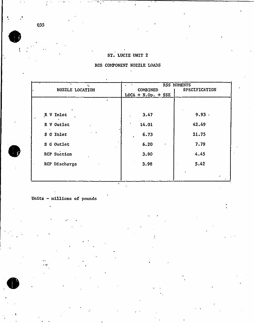
$35
ST. LUCIE UNIT 2
RCS COMPONENT NOZZLE LOADS
RSS MOMENTSNOZZLE LOCATION COMBINED
LOCA + N.O . + SSESPECIFICATION
R V Inlet
R V Outlet
S G Inlet
S G Outlet
RCP Suction
RCP Discharge
3.47
14.01
6.73
6. 20,
3.90
3.98
9.93
42.49
21.75
7.79
4.45
5.42
Units —millions of pounds


stionProvide analyses to.determine the external'orces andmoments, resulting from postulated hot. leg and cold legruptures within the reactor cavity, on reactor vesselsupports. Xf applicable, similar analyses should beperformed for steam generator and/or pressurizer compart-ments that may be subject to pressurization where sign-ificant component support loads may result. For eachanalysis, provide the following information:
For each compartment, provide a table of blowdown massflow rate and energy. release rate as function of timefor the break which was used for the component supportevaluation.
Response
FSAR Table 6.2-l3 is a summary of postulated pipe rupturesfor containment subcompartment analysis. The last columnin this table "Release Rate Data Table Numbers" will referyou to, for each compartment, a table of blowdown mass flowrate and energy release rates as a function of time for thebreak which was used for the component. support evaluation.


question5
Provide analyses to determine the external forces andmoments, resulting from postulated hot,leg and coldleg ruptures within the reactor cavity, on reactorvessel supports. If applicable, similar analyses shouldbe performed for steam generator and/or pressurizercompartments that may be subject to pressurizationwhere significant component support loads may result.For each analysis, provide the following information:
Describe and justify the nodalization'sensitivitystudies performed for the major component supportsevaluation (if different from the strucutural analysismodel), where transient forces and moments acting onthe components are of concern. Where component loadsare of primary interest, show the effect of nodingvariations on the transient forces and moments. Usethis information to justify the nodal model selectedfor use in the component supports evaluation.
ResponseDivisions between subcompartment are determined by thephysical flow restrictions within each compartment. Aflow restriction is defined by the presence of an ob-ject in the flow path that changes the flow area in thatdirection, with the subdivision defined at, the point ofminimum flow area. This minimum flow area becomes thejunction flow area used in the RELAP 4 analysis. Forthe models constructed for the reactor cavity and second-ary shield wall area flow restrictions included the pre-sence of steel and concrete supports, doorways, ventshafts,and gratings, as well as large equipment such
as'hereactor vessel, primary piping, the steam generator,reactor coolant pumps and the pressurizer. By choosingnode boundaries at. the various physical flow restrictions,a method consistent with the lumped-parameter calculationmodel used by RELAP 4 and described above,.calculateddifferential pressures and consequent support loadsare"realistically maximized. The nodalization sensitivitystudy performed for the Shearon Harris PSAR (Docket50-400, 401, 402 and 403) shows that the peak calculateddifferential pressure is very sensitive to an increasingnumber of nodes until that number equals the number de-fined by physical flow restrictions. Increasing thesubdivision of the compartment is unwarranted and canlead to unrealistic results if these "fictituous junctions" ~
are modeled. The subcompartment models discussed belowtake account of all physical flow restrictions presentin a manner identical to that. shown to be optimum by thesensitivity study.
Table 6.2-25 presents the overall results of the sub-compartment analyses. The reactor cavity, SecondaryShield Wall and Pressurizer Area Design evaluation isdescribed in FSAR Subsection 6.2.1.2.3.

(

Question
Provide analyses to determine the external forces andmoments, resulting from postulated hot leg and coldsleg ruptures within the reactor cavity, on reactorvessel supports. If applicable, similar analysessh'ould be performed for steam generator and/or press-urizer compartments .that may be subject, to pressuriza-tion where significant component support loads mayresult. For each analysis, provide the following in-formation:
Graphically show the pressure (psia) and differentialpressure (psi) response as functions of time for arepresentative number of nodes to indicate the spatialpressure response. Discuss the basis for establishingthe differential pressure on components.
Response
FSAR Table 6.2-25 list the Results of the SubcompartmentAnalysis. In this table the peak node pressure, andpeak differential pressure is listed. Along with thesevalves a figure is referenced for both of those valves.The component and support loads for the Steam Generator,Reactor Coolant Pump, and Pressurizer were determined byequivalent static analyses. A load factor of two on thecalculated thrust, jet impingment, and subcompartmentpressure loads is employed to account for the dynamicresponse of the structure. The model employed for staticanalysis is shown in Figure 3.9-l8.


8 Figure 6.2-71, regarding containment isolation valves,should be revised to show the containment isolationvalve arrangements for each containment penetration.In addition, the isolation valve arrangements shown inthis figure should be consistent with the valve arrange-ments as shown in the system flow diagrams.
ResponseThe attached figures show the containment isolation valvearrangement for each containment penetration. Thesefigures will be placed in the FSAR via Amendment 6.

0

CNCC.CY D*YE
CL!KNT
OFS NO.
EBASCO SERVlCES 'tNCORPORATED
..„ io-8-8 NEW YORKSHKKT OF
DKPT.NO.
PROD KCT
SUOJKCT
Corv&iNPIEeg Ca~ ~a)
+ging ~P 2'[
H-ttV-AHS "C.P
»Yr 1
4Y»
lSIL(K, PE:D +AT&(X Pg,!i!P TURB',!C
A/I m8)Z- PClJ-C6-f E
I-III-CB-IZ
I-kkY-O9-Ih I-H<liI-Og-\ 9
ZZ Ysz~il3~7)
ztl-9-9 758~-3'~ l~d.SiA
I~Bi l>
Sg Mgt5 I+~SZ5'-HCV- og-2A-
rlZ. HEI-cg-25
zsVezsc(espy IHV~IZ ZP!L'W9.lo
,SV-P-Z~
V9-gfD4 zing.SIC
t t
ZN&15'e->SS5
M
FORM 44l RKV 7 7l
Zel-o9-II Ih'P o9-P


DATE
CHKO. BY OSTE
CLIENT
PROJECT
I SUBJECT
EBASCO SERYICES INCORPORATEDNEW YORK
OFS NO.
SHEET OF
DE PT.NO.
rrr'5/~ cojv7+g~w~7 Z- FcY -Z3-4 z av'-Z9-S OSC7Si C C CON, ssI igP rfsF/
l- trzHo7~k
PROVE LLriY/
Z.-R.V-ZS-4 Z,- Fag- Z~-3
z-y-zg-go)
z'Qw'
~pf Ccrrt7 Coal 44'JiF
ru Camp C~t. u /7
S'aH chv7c~l. ~i7
CO~ Crag. u~/7
gztl4-4/g
ZVr@'rs
zYr4t4S
l7sVrrr&5
~r~4z5
'+IVr4Fr4
Zse-'r 4-r3
Zr~/Wr~-r4
ZZHy-rd-ro
'CC
70 Cary CdaL 4w/g
~oq Qdp &Lu//g
75 Cd@7" Cdogs C//I'/f 22
xV/Wz5'vrg4iy
zv4~e
Z~Y-/4-g
&~y-rp-Q.
22'~V-r4 -//
FORM 44 I RRV 7 7'I


INSIDE CONTAINMENT
V-15.1325
OUTSIDE CONTAINMENT
B 0X'-Y-15-1323
~ MAKEUPWATER
V-15-1327 I-V-15-1347
I-V-IS-$9
Su.III-ga
I-HCV-15-1
I.S H-18.955
9-IS-/M7
8x
L.C. STATION AIR
SII-I&-eCV I-V-18-947P I-V-18 947
V-18 94
3
SH-I5-35K
V.18.947'
I.V-18-957P I-HCV-18-1
INS. AIR
I-Y-18-~ 2'7
IVIIIbaal .
v/g-3'IR
TESTCONNECTION
I-FCV-25 4,10
I-FCV-25-5
CONT. PURGE
I FCV-25-6
ANNULUS
AMENDMENTNO, 0 I1ZIBPI
FLORIDA POWER 8 LIGHT COMPANYST. LUCIE PLANT UNIT 2
CONTAINMENT ISOLATIONYALYETESTING —SH EET 1
~ FIGURE 6.2-69

f
~

INSIDE CONTAINMENT
AIR TESTCONNECTION
OUTSIDE CONTAINMENT
BLEED-OFFCONT. PURGE
I-FCV-25-3
-gee
V.6338 V-6340
II-FCV-25-2
ANNULUSI-FCV-25.1
V-6699 V-6792f4
V-6741
I-V-14-625
N2 SUPPLY
v'-A%7
Y-7of/.
I-HCV-14-123
RC PUMP COOLING
I-HCV-14.7
I-V-14-625
~nroX~ fll~~m~~ ~fTl
a 5I 'g
rn~~Oh)
IO
~O
C
I
o~~ fll
mgo
'X~rH Cl
KC ~~ A
0z
mZ03arnzROa
o
V-2464
V.2463
V-2515
I-HCV-14.2
V-2516
24
26
RC PUMP COOLING
I-HCV-14 6
V-246'1
LET DOV/N LINE
V-2522


BY
CHKD. BY
CLIENT
PROJECT
SUBJECT
DATE Ofs NO.
EBASCO SERVICES INCORPORATED
DATE (+' INEIN YORK SHEET OF
DE PT.NOF
CW'vCIrPRI&lf7~+8+~ 7MQ
~V+
ma v~~~~FM T~s
g a5E3
Vga'' l.Mz
V.z>~s
L.o.
v-zanCi/lP+tfi~&j
Xfe'-z3-f
X-Y-83 -929P
3o P" PddW'D9Im~J~E g/gfgF /
ME3-322'y
@/gal
r~~ ~LI>ttOI
'ORM
541 RKY 7 Tl


EBASCO SERVICES INCORPORATED
BY C C
CHKD. BY
CLIENT
PROJECTl
SUBJECT
DATE ~ 'I
DATE
HEW YORK
OFS NO.
SHEET OT
DEPT ~
NO. I
r~SioC, ~g.
CCK/7
5'o7-c"I
„5siMQ
~p-u7-r~Q ZIr-cIr- ru<
4o
xv o7-1525
rV-o7- r583 xU-o7-rg@
7p-o7-
/5'-gV-Z3-gg
XY-2 3-ozkp8CPQZdI P
~j>CE
FORM 44I RRV 7 74


SL2-FSAR
inside containment:
a) Containment dome
c) Pressurizer enclosure
d) Vicinity of reactor coolant pump (RCP) 2Al
e), Vicinity of reactor coolant pump 2A2
f) Vicinity of reactor coolant pump 2B1
g) Vicinity of reactor coolant pump 2B2
These points provide broad coverage of the containment for hydrogen monitor-ing and constitute a redundant independent H Samp) ing System. Samplinglines originating from the containment dome, pressurizer, RCP 2Al and RCP
2A2 areas constitute one independent train of the H Sampling System. Theother train consists of sampling lines originating from the upper contain-ment, RCP 2Bl and RCP 2B2 areas. Each train of the sampling lines has acommon header inside the containment and penetrates the containment in aseparate penetration assembly.
As discussed in Subsection 6.2.2.2, there is adequate mixing of containmentatmosphere so that local stratification or pocketing of hydrogen does notoccur. The analyzer, cubicles are located at elevation 19.5 ft of theReactor Auxiliary Building (RAB). The analyzer system control panel, islocated in the control room.
A grab sample chamber located at elevation 19.5 ft of the RAB is providedto permit hydrogen concentration measurement independent of the containmenthydrogen analyzer detector.
6.2 '.2.2 Containment Hydrogen Recombiner Subsystem
The containment hydrogen recombiners control hydrogen in containment by usingheat to cause recombination of liberated hydrogen with free oxygen in the airto form water.
The hydrogen jqcombiner system is described in Westinghouse Topical ReportWCAP 7709-L~ ~ and shown on Figure 6.2-63. Supplement 1 through 4 ofWCAP 7709-L were accepted by NRC on May 1, 1976. It is designed seismicCategory I and Quality Group B requirements.
Each recombiner consists of a thermally insulated vertical metal duct withelectric resistance metal sheathed heaters provided to heat a continuousflow of containment air to a temperature which is sufficient to cause areaction between the hydrogen and the oxygen in the air. The recombineris provided with an outer enclosure to provide protection from water spraycoming from the Containment Spray System. The recombiner consists of aninlet preheater section, a heater-recombination section, a mixing chamber,and a cooling/exhaust section. Mixing of containment air is by the con-
6. 2- 64 Amendment No. 0, (12/80)


492.10
~Res ense
With regard to the Analog Core Protection Calculator, provide a listingof the algorithms used, discuss their verification and evaluation.
The algorithm for the Thermal Margin/Low Pressure Limiting Safety System Setting(LSSS) has been discussed in the answer to question 492.9.
The "algorithm" for the Local Power Density (LPD) LSSS results in a trip limit-line of power vs. axial shape index as shown in the attached figure. FSAR Figure7. 2-'16 is the LPD trip functional diagram.
The verification and evaluation of the LPD trip limits are discussed in CENPD-199-P"CE Setpoint Methodology". As noted in the answer to question 492.9, C-E is cur-rently updating this report for final NRC review and approval.


p-; '(Vz.io -1
ST, LUC1E 0i'11T 2
CPC-2 LOCAL POh'EB DENSITY TRIP
~ ~ t~ ~ I
~ ~ t~ ~ ~ ~
~ ~ ~ ~
~ ~ I ~ ~~ t
~ ~ ~ p ~
l ~ s
i ~ ~ s~ 4 ~ ~
~ ~ S ~ ~
t
~ i
~ ~ I ~~ ~ L ~
~ IS~ t ~ ~
~ t~ ~ ~
1,0'
~ ~ 4 ~~ ~ ~" ~ i"
~ ~ ~ ~ ~
t ~
~ «~ ~
~ I ~
f ''''
8
'Qi(
. 6::".:".: ..——.....
~ ~~ *
~ 8 ~
~ ~ tI
~ 't
S
~ L ~
~ \ ~ ~
. ~ ~
+-S
~ L
~ ~ t ~ ~
~ t ~ ~ ~
~ ~ S ~
S
~ ~ t ~ ~ ~
~ It ~ ~ ~~ ~
~ t ~ ~
~ ~ ~ ~ ~
~ \ ~
~ ~
~ t ~S
~ ~ S
~ ~ I
~ ~
~ S
~ ~ ~~ ~ S
~ t ~ "~ ~ ~ ~
~ 2~ ~ ~ '
~ ~ ~
~ ~
~ ~ ~ ~ ~ ~
BISE~ ~ ST ~ ~
S ~~ '
~ i ~ ~S
~ ~
i ~ ~ ~
S ~
I~ ~ ~ ~ t ~ ~ ~ ~
t
0'!: I
~ ~ r ~ ~
~ S ~ ~
~ ~ ~t ~
I ~~ ~ ~
~ ~ ~
~ ~
—.6 I2 0
ASI
+.2 +,6

0

(0)
L-UU,+-f
L>NEAP,FUiXCTIOl\I
I
CEA FNCT
GAINAD)
qvzYp
Ie Y~


SL-2 Round One uestions
440.25(15.3.3)
Provide a detailed analysis on the consequences of a RCP shaftseizure event. Justify selection of limiting single failures.The time at temperature studies which justify your claims of peakclad temperature beind limited to 1300"F are not accepted by thestaff. In assessing fuel failures, any rod which experiencesa DNBR of less than 1.19 must be assumed failed. Confirm thatthe results of the analysis meet the acceptance criteria ofSRP 15.3.3.(2). Provide your assumptions on flow degradationdue to the locked rotor in the faulted loop, and referenceappropriate studies which verify these assumptions. Alsoprovide a similar analysis for the locked rotor event presentedin section 15.3.4.1, and show that acceptable consequencesresult.
~Res onse:
The justification for the selection of limiting single failureswas presented in the response to NRC guestion 440.9. For the onepump resistance to forced flow with a loss of offsite power as aresult of turbine trip event, the percent of fuel pins with CE-1DNBR less than 1.19 should not be used to determine fuel failuresince; (1) a CE-1 ONBR less than 1.19 does not mean thatagiven,fuelpin will experience DNB, and (2) DNB does not necessarily resultin fuel failure. For. these reasons, the approach proposed byNRC for calculation of fuel failures is unduly 'conservative. Amore reasonable, yet still. conservative, method of calculatingfuel failures, presented in CENPD-183, was submitted to NRC inJuly 1975. Using this method for St. Lucie Unit No. 2 resultsis postulated DNB and assumed failure of 134 of the fuel pins aspresented in the FSAR. The percentage should be used in::eval-uating the consequences of this accident; The description andjustification of the C-E method is provided in the response toNRC guestion 440.11.
The flow. coastdown which was used in the analysis of the one pumpresistance to forced flow is presented in Figure 440.25-1. Thisfigure shows the variation of core flow fraction with time. Theseized shaft is assumed to instantaneously stop at time 0.0 withthe seized. rotor acting only as a resistance to flow. Thiscoastdown was generated using the COAST code as documented inCENPO-98 (see Reference 440,25-1).
Reference:
l. "Coast Code Description", CENPD-98, April 2, 1973.
~P/fhflgA change to the FSAR, Sec+i~15.~.~., accompanies this response.

e

0 ~ fI T'.,
~ ~ ~ ~ ~ ~ ~ «« ~ 0 « 4 ~
I ':::".": '..:."'..:: '
~
IU'." ''
[".I. ~"
r: ..:: .. '.::.::-:: ..-.:: .-':: .
~L'
~ f ~ % ~ ~ ~ ~ ~ ~ ~ ~ 00» ~ \ ~ ~ ~ ~ 00 ~~ ~
Figure 440.25-1,St. Lucie.2Seized Shaft
Core Flow Fraction versus Time
O ~ ~ ~ ~ I
'L——'' ,'.:,—:..-.:—:.—;,—.'~
':.:: ~ ~''
O
.: ~ .:.: .' ~:. '~ 9~ ~ ~
~ ~
t.~ ~ ~ ~ I ~
C ~ ~ ~"': ''..'.:" " '. ~ 'p'
~ ~ ~
.t':-:;'..... I 0 ~
~ ~~ 0
~ ~ ~~ 00% A % ~
~ 0
~ % ~
~ 0....~ ... 00 .... ~....... ~ 00 ...$ ~
~ f 0 A ' ~ ~ IO ~
~ ~ ~ % ~ ~ ~ 0 ~ 00 ~
I~ I '
~ ~
~ ~ » ~ » 0 ~ ~ V ~
~ ' ~ ~ g ~ ~ ~~ ~
~ ~ I ' ~ ~ ~ ~ ~ ~ I ~ ~ ~ ~ ~ 0 ~ 00 ~ 0 ~ ~ ~ ~ .
V ~ ~ ~ ~ 0~ ~
~ % 0 ~ g 0» ' ~ ~ ~I
~ ~
S~
~~
I~ 0%0 00 ~ ~
~ ~
~ 0 ~
~ ~ ~ ~
~ 0 ~
~ ~
~ ~ ~ ~ ~ ~
~
~
0
~ ~~ 0 0 ~ ~ 0% ~ oo ~ ~ 0 rr 0 0 ~ ~ O»%% % ~
g p ~ '--+ 4',. 7 8'
~ ~
~,~ ~00% 0% «r ~ ~ ~ ~ ~ ~ I »»
arrear»
00 ~ A J w ~ ~ ~~ ~ ~ r ~
~ ~ ~ ~ ~ ~ ~ ~ ~ I~ 0 ~ ~
~ 0 0 0 ~ ~ ~ ~ ~ r ~ ~ ~ ~ ~ ~ oo ~ r r ~ ~ ~ l~ 0 ~ ~ ~ ~ ~ ~ ~
~ ~ ~ ~ ~ ~ ~ ~ ~ 00 ~ 0 00 ~ ~ ~ 0 0 % 0 ~ ~ 0 ~ 0 ~ 0 ~ ~
~ ~ ~S
~ ~ ~ ~ ~ 0 0 ~ ~ 0 ~ ~ ~ ~ ~ ~ ~ ~ ~ ~ « ~ ~ ~ ~ I~ ~ 0 ~ ~ ~
~ ~ ~ ~ ~ ~~ ~ ~
0 ~ 0 ~ I 0 00 4 ~ PO ~ 0 «0 0 0 00»» ~ ~ '0 ~ 0» ~ ~ «» 00~ 0
~ I ~~ O ~ ~ ~
0 ~ ~ ~ ~ 0 0~ ~ ~ 0 ~ ~
0 ~ ~ ~ \ ~ ~ 0 ~ ~ 0 ~ 0 ~ ~ » 000
' ~ 0 0' ~ ~ ~ ~ ~ ~ 0 ~ OO
I
~ OS ~ ~ I ~
~ ~ \ O ~
~ ~ ~ 0 ~ 0 ~ ~ ~ 0 ~ 0 0 \ 000
0 ~
~ ~~ ~ ~ ~ ~ ~ ~ ~ ~~ ~
~ o oo«r & 0
0 ~ ~ ~ ~ ~ ~ ~ ~ ~ ~ ~~ ~ ~ ~ ~ ~ ~ ~ ~ ~ ~ ~ ~ ~ ~ ~ ~ ~ ~ ~ ~ ~ ~ ~ ~ ~ ~ ~ ~ ~ ~ ~ ~ ~ ~ ~ ~ ~ ~ ~ ~ ~ ' ''
~ ~ ~ ~ ~ ~ I ~ ~ ~ 0 ~ 0 ~ ~ 00 ~ 0 ~ \ ~ ~ 0 ~ « ~ ~ ~ ~ ~ ~ O
~ ~ \ ~ ~ 0 ~ 0 ~ 0 ~ I ~ ~ ~ ~ 0% ~ ~ ~ 0 ~ % ~ ~ ~ % 0 ~ ~


~ ~ ~ ' ~R
~ ~ ~ ~
\R
~ ~
< ~ ~, ~
~ ~
~ ~ ~ ~'
'I
Figure 440.25-2St. Luci e Uni t'Seized Shaft + LOAC
Core Flow Fraction Vs. — Time
~ ~ ~ ~ ~ ~ ~ ~ . ~ ~ ~ ~ ~ ~ R ~'
~ V g~ ~ ~ V ~
~ ~l 'R
I
~ ~
R ~ ~ ~ ~
~ ~ ~ ~
~ ~
R
1 ~, r ~ ~
~, IR ~ ~
P, ~\'
~
r
I ~ ~ ~ ~ ~ ~
~ ~ ~ ~ ~
~ ~
I
~ » V ~
~ ~ ~ ~ ~ ~ I ~ ~ « ~ ~ ~ ~
l ~ l P
V ~
r
V ~ R R~ q ~ & ~ '
~ ~ R R ~
~ g i ~
l
.Rl q~'
~ ~
l~ ~
~ ~ V t
~ ~ ~
q ~
I
a
~ ~ R ~ R ~ r ~ ~ ~ ~ ~ ~
' ~ r '4 ~
~ R
I « ~~ ~ ~ ~ ~
R
~ ~ ~ ~
~ ~ ~
R
R ~
1> 2lr J'u
6'7Aj'r... 6 Eco/as).R
R'I
~ ~ ~
~ ~~ V R ~
I&p
~ ~
~ ~ R
r ~ > j "* ~ ~
l" ~' '
~ ~
~ V t
R R ~
~ ~ ~
\ ~


'SL-2 II d Ot0 ti
'40.28 Your FSAR i rdicates that operational procedures allow detection of a(15.4.2) boron dilution event 15 minutes prior to criticality. This is not
acceptable. The staff »ill require that alarms be available to alertthe operator to a. boron dilution transient 15 minutes prior to crit-icality (30 minutes when in refueling mode). Show that, the plant isprotected for all postulated boron dilution events assuming the worsesingle active failure. In particular, consider the failure of thefirst alarm. If a second alarm is not provided, show that the con-sequences of the most limiting unmitigated boron dilution event meetthe staff criteria and are acceptable. Also, indicate for all sixmodes, what alarms would identify to the operators that a boron dilutionevent was occurring. Confirm that the results of these analysesmeet the acceptance criteria for these events per SRP 15.5.1.
~Res ense:
SRP 15.4.6 requires that at least 15 minutes is available from the time*the operator is made aware of an unplanned boron di,lution event to thetime a loss of 'shutdown margin occurs during power operation (auto-matic control and manual modes), startup, hot standby, and cold shutdown.For NODES 1 through.6 any of several alarms and/or indications willprovide the operator with at least 15 minutes (For NODE 6, 30 minutes)to terminate the event before the shutdown margin is lost.
The indications and/or alarms available to alert the'operatorsthat a boron dilution event is occurring in each of the operationalmodes are outlined below.
l. The'„following control room indications and corresponding pre-tripalarms are available for NODES 1 and 2: a high power or, for someset of conditions, a high pressurizer pressure trip in fODE 1 or ahigh logarithmic power level trip in MODE 2. Furthermore, a highTANG 'alarm may also occur prior .to trip.
2. In MODES 3'and 4 with CEAs withdrawn, the high logarithmic powerlevel trip and pre-trip alarm will provide an indication to alertthe operator of an inadvertent boron dilution.
3. In MODES 3, 4, and 5 with CEAs fully inserted and in MODE 6, 'a highneutron flux alarm on the startup flux channels will provideindication of any boron dilution event. Limiting boron dilutionevents in subcritical operating modes will be analyzed to establishthe startup channel alarm setpoint and reset time. The times tocomplete loss of shutdown margin, and hence reactivity insertionrates, and neutron flux responses at the startup channel excoredetectors will be determined such that the startup channel alarm
*setpoints based on these responses satisfy the requirements ofSRP 15.4.6.
'his
alarm will be powered by an onsite power source in the eventthe offsite power is lost.


w
The times to loss of shutdown margin calculated for the postulatedboron dilution event represent the fastest credible dilution ratesand, therefore, the shortest time for each mode. Conside'ration ofadditional single failures would not increase the dilution rate,and therefore, would hot reduce the time to loss of shutdown margin.The only failure of significance involves the loss of the indications-that alert the operators to a boron dilution. In HODES 1 and 2, thereare no single active <-ailures that result in the loss of any of theRPS alarms used to alert the operators that a boron dilution is, inprogress. In HODES 3, 4, 5, or 6, in case one or both startup fluxchannel alarms become inoperable, the operators would be required toimplement operational procedure guidelines which would assuredetection of a boron dilution event. In HODES 3, 4, and 5; theguidelines are based on determining the RCS boron concentrationby either boronometer or RCS sampling at frequencies which dependon the mode of operation. No single active failure can eliminatemore than'one of the methods of monitoring or determining the RCS
boron concentration. In NODE 6, the boron dilution event is pre-cluded becasue the manual isolation valve (V 2183) in the makeup.water line and the primary makeup water supply to char ging pumpisolation valve {V 2180) are normally, locked closed in this
mode.'+
7 7aI
A change to eth FSAR, Sections15. f.2 /&accompanies this response.
4


SL2"PSAR
7,7.1.1.10.3 Turbine Runback
The following inputs cause a.turbine runback:
a) One main feedwater pump tripped
b) Two heater drain pumps tr.ipped
The runback input causes e contact to close in the DEll runback circuitry.The turbine runs baclc at a predetermined rate until the contact opens atwhich time the runback is stopped. In the case of the heater drain pumps,the runback is stopped at 70 p rcent of full load as determined by firststage pressure, and in the other case the runback is stopped when feed-water flow and steam flow are equal.
XNSBh' 887.7.1.2 Design Com arison
The design differences between the control systems in'the St I.ucie Unit 2design scope and the control systems provided for the reierence plant arediscussed in this section.
7.7.1.2.1 Reactivity Control Systems
The RRS is functionally identical to that supplied for St Lucie Unit 1
(HRC Docket 50-335).
The CED!JCS combines the Control Element Drive System (CEDS) and the coilpower programmers (CPP) into one integrated system thus reducing the inter-facing required between the previous two separate subsystems. The'EDlfCSis functionally identical to the CEDS/CPP of St Lucie Unit 1 with thefollowing changes:
The CEAs axe controlled in subgroups consisting of four or five CEAslocated symmetrically about. the core;
All timing functions within the CEDHCS are performed using digital tech-niques to increase the accuracy and flexibility of the integrated system;
The CEA withdrawal prohibit (CWP) is effective in all modes, and CWP can bebypassed at the operator's module;
. While the CEDNCS is in the automatic sequential mode, either or both part-length CEA (PLCEA) groups can be inserted or withdrawn, but motion ofindividual CHAs or PLCEAs is not possible;
While in the automatic sequential mode, the CEA motion inhibit (CHX) cannotbe bypassed and the system can handle up to 91 CEAs,
7.7.1.2.2 Reactor Coolant Pressure Control System
The reactor coolant pressure. contxol system is functionally identical tothat sup'plied for. St Lucie Unit 1 (NRC Docket 50-335).
7.7-9 Amendment No. 0, (12/80)


S3.2"FSAR
7.7.1.2.3 Prc. surizer Level Control System
The Pressurizer 3.evcl Control Syrtcm is functionally identical to thatsupplied for St Lucic Unit 1 (NRC Docket 50-335).
7.7 '.2.4 Feedwatcr Regulating Sy"tern1
The Fcedwater Regulating Syst"m is functionally identical to that suppliedfor St Lucie Unit 1 (NRC Dockbt 50-335).
7.7.1.2.5 Steam Dump and Bypass Control System
The Steam Dump and Bypass Control System is functionally identical to thatsupplied for St Lucie Unit 1 (NRC Docket 50-335).
7.7 '.2 ' Analog Display System
The Analog Di. play System is functionally identical to the metrascope~ supplied for St Lucie Unit 1 (NRC Docket 50-335).
7.7.1.2.7 . Boron Control System.
The boronometer is functionally identical to that supplied for 4'aterfordSteam Electric Station Unit 3 (NRC Docket 50-382). The only difference isthat the recording range is switch selectahle for 0-1250 ppm and 0-5000ppm. For any di.fferences in the control of boration and deboration seeSubsection 9.3.4.*
Incore Instrumentation
The Incore Instrumentation System. is similar to that supplied for ArkansasNuclear One-Unit 2 (NRC Docket 50-368). The difference being 44 detectorassemblies vs 56 on St Lucie Unit 2.
7.7.1.2.9 Excore Neutron Fl ux 3fonitoring System
The start-up and control channels of the Excore Neutron Fl'ux HonitoringSystem are functionally identical to that supplied on System 80 (NRC DocketSTH-50470F). The safety channel's are of a new design but based on System80 circuitry.
7.F 1.2.10 Digital Data Processing Syst: em
The Digital Data Processing System is functionally identical to that sup-plied for St. Lucie Unit 1 (NRC Docket 50-335). The only difference isthat the Unit 2 system has redundant computers.
7.7-10 Amrndmcnt No. 0, (12/80)

t

nsert BB
7.7. 1. 1. 11 Boron Dilution Alarm System
Reactivigy control in the reactor core is affected, in part, by solubleboron ih 'reactor'oolant system. The Boron Dilution Alarm System
(Figure 7.7-8) utilizes the startup channel nuclear instrumentationsignals to detect a possible inadvertent boron dilution event whilein Modes 3-6. There are two redundant and independent channels inthe Boron Dilution Alarm System (BDAS) to ensure detection and
alarming of the event.
The BDAS contains logic which will detect a possible inadvertent borondilution event by monitoring the startup channel neutron flux in-dications. 1<hen these neutron flux signals increase (during shut-down) to equal or greater than the calculated alarm setpoint, alarmsignals are initiated to the Plant Annunciation System, The alarmsetpoint will only follow decreasing or steady flux levels, not an
increasing signal. The current neutron flux indication and alarmsetpoint (per channel) are displayed". There is also a reset
capa-'ility
to allow the operator to acknowledge the alarm and initializethe system.
The BDAS will be powered from an offsite power source with an onsitebackup power source.
Insert CC
7.7. 1.2.11 Boron Dilution Alarm System
„ The Boron Dilution Alarm System is an addition to the St. Lucie Unit.'2design. There is no functional comparison to St. Lucie Unit I (NRC
Docket 50-335).

e

FIGURE 7.7-g
, BOROtl D I LUTION ALARl1
SYSTEtl S It)PL I F I ED~ BLOCK DIAGRlN
Reset
Startup ChannelNuclear
'nstrumentation Signal
Boron Dilution
Alarm System
Logic
Current Flux 8
Setpoint Display
Alarm Signal tothe Plant Annunciation
~ System
Note: Only one of two identical channels is shown.


SI,2- 1'SAR
lh,d,2.S l.imitinr~lo.".s nf Shutdow~nhsr la fvaat " Slow Po'litivr. Rrsc"~tivit lnsnrtion
15 ~ 4 ~ 2.4 ~ 1 Identificat:inn of Event and Causes
The Infrequent .event groups from the Reactivity and 1'ower Distributionlhnomalies event type and the Infrequent event coiobinations shown in'ableJ.5,4.2-1 were compared to find. the event: combinar ion res»)ting in theclosest approach to the complete loss of shutdown margin. Tire Slow Posi"tive Reactivity Insert:ion was identifit:d as tlute most limiting event becauseno other Infrequent event affects shutdown margin.
The.event:groups and event combinations evaluat:ed and the significance ofthe approach to the loss of shutdown margin,acceptanc'e guideline for eachare indicated in Table I 5.4 a 2-1 a
The slow positive reactivity insertion may occur due to a closure of aboron flow cont:rol valve or a m lfuncticn of the makeup controller whichcauses a boron dilution.
'
I
The most limiting initiating event'resulting in a slow positive reactivi yinsertich is a malfunction of the makeup controller mode selector swi'ch in
. the di'lute mode. This may occur. by a failure in the boron control systemwhich causes continuation of the makeup operation after a planned dilutionhas been completed. This failure results in the maximum possible dilutionrate.
The other initiating event which can cause a slow positive reactivity in-sertion is the failure of thc solenoid in the. boron flow control valve inthe boric acid line with the boron control syst: em in t:he autorlatic orborate modes, This failure result:s in termination of the boron flow to t:hekCS and thus'ould approach the loss of shutdown margin at the same rate as
'makeup mode selector swit:ch malfunction, \lowever, this event yields a
low flow alarm in the boric acid line which alerts the operator at the ini"tiation of the event:. The makeup mode. selector switch malfunction wouldnot produce an immediate alarri. and therefore is more 1" miting than the in-advertent closure of the boron flow contxol .valve.
Analysis of a slow positive x'eactivity insertion event initiat:ed duringeach of the six operational modes defined in the Technical Specifications
„was performed. These analyses show t:hat bode 5 (cold shutdowr.) results inthe learnt t:ime ava-lable for detection and t:ermination of the event. Thisis because the shutdorv~> margin requirement which will be speci fied oy theTechnical Specification" ia "mallest in Hade 5 (i.cat tvo percent dpauhcritical). 'ln either. Hode five orl,tode -tx, and utch the RSS 'erallowered, administ:rative procedures governing the frequency of boric acidsam ling will preclude reaching criticality.15a4a2e4a2 Sequence of Events and Systems Operations
Table l5.4.2.4-1 presents a chronological list and t:iming of system actionswhich occur fo11owing a boron dilution eventa Refer to Table 15a4a2a4"l.wl>ile reading this and the following section. The success patlrs referencedare'hose given on t:he sequence „of. events diagran (SED), Figure 15.4 ~ 2.4-I ~
15.4-53 Anlen(lllrent No. 2, (5/81)

e

SL2-) S/;It
This f i„-»r~p t.'u"-thrr with Table 1'p ~ 0-6, whici> contains a glossary ot Sl;Dmbols and acronyn<s, may br usrd to trace thr actu;<tion and interaction of
systems uord to mitigate th» «ouse<)u!nces oE t)iis event, The timingsTable 15 4 s 2 s4 1 <nay be used to determine when, af ter the initiat i ng
eve<tt, each action occurss
The sequence nE event;s and systrms operastiono described below representsthe way tn w)tic)t'th» plant was stszunad tn respcnd to the event initiator,))any plant responses are possible, however, certain responses are lin<itingwit)t reaps>«t to the acceptancr. guidon'nes for this sections Of" th" li<nit-ing responses, the most: likely one to bc followed was selecteds
Table 15,4,2,4-2 contains a inatrix which describes the 'extent t:o <kichnor<nally operating plant systems are assuned to function du<in'he tran-sients The operation of these systems is consistent with the guidelinesof Subsection 15.0s2.3.
Table 15'4s2s4-3 contains a matrix which describeo the extent to whichsafety systems arr. assumed to function during the transient,
'The success paths inare as follows:
the sequence of event:s dia< rams, Figure 15,4,2,4-1,
~4tAP~~ $Lv ~ wJ cJ~.J x.React:ivity Control:~ ~
~e operator is al erted to a decrease in Reactor Coolant System (PCS) boro
concentration e!.tner throughVsempling,'."boronoineter indications~ or-by-etartup-eflux-channel —inaicationeo. Vie t;urns off the cha'ging pumps andcloses the letdown control valves. in order'to halt further dilut'ion, Theoperator then turns off,the primary makeup pu.np tnd closes the primarymakeup isolation valve to stop the flow of primary makeup water to thecharging pumps, .)text, he increases the RCS boron conc'entration by openingthe boric acid gravity feed line from th'e boric acid makeup tank to thecharging pump suction and restarting the charging pumps to provide boratedwater to the RCS, Letdown flow may be diverted to the flash tank to in-crease the rate. of boration,
'I Arl Gs~Q
FP<L is rsvicwinp a proposed uethod of providins rtdurdant indicationsof boron dilution t'bat utilis: control rosie indicstron and RCS samplin<at varying frequencies (depending nn plant operating node), FP&L willadvise t:>e NRC of the results of this review,
s
15d4d2s4s3, . Analysis of Ef frets and Consequences
a) Hathematical l)odel
Complete mixing of boron in the RCS and equal letdown and cnargingElowrates arr. assumed. The <at:e nf change of boron concentration
~ during a diLution in which «atcr without boron is added and coolant atthe tine deprndent RCS boron concentration is re ioved is described bythe following differentia1 equation:
15.4-54 Antendment No. 4, (6/81)

t

Sl.?-FSAR
4) Complete mixing of: thc boron in t:hc RCS is a ss~nncd because ofthe large RCS mass circu1ation by a minianmi of one low prcssuresafety injection pump operating in thc:hutdown cooling mode,compared to thc 'relatively small mass added through the charg-ing pumps.
2th'/6~7 i~i ~
The critical boron concentration at cold "hutdown wi.th a11 CEAsin is 845 ppm including,uncertainties. The inverse boronworth is 55.8 ppm/% lb'hich includes uncertainties. Applyinguncertainties to this number in the most conservative direc-
~tion I'be initial subcritical boron concentration for the cold.'hutdownmode is found by adding the product of the inverse
boron worth and the minimum shutdown margin required (i.e., twopercent hp ) to the critical boron concentration. The result-ing minimum initial boron concentration'n Hode 5 is .956.6 ppm.
The parameters discussed above arc summarized in Table 15.4.2.4"4.
c) Results
-The conservative parameters listed in Table 15.4.2.4-4 are used inEquation 3 to calculate the time to criticality during a Slow Posi-tive Insertion.. The minimum possible time to dilute from two~ rcenths sub-cri"ical to criticality is 62 minutes. fOperational procedures
periodic monitoring of the startup flux channels allow detection ofthe event with at least 15 minutes available to terminate the eventbefore criticality is reached.
('skc d... CcLK paar . d... rue.vc,The 61Ota PO" itiVa ReaCtiVity InSertiOn in fcdR=F dcaS bbT rbranir 'iu
7.any pressure or temperature perturbations in the RCS because the event ggterminated before criticality is reached. Other principal 1'CS andsecondary system parameters are not perturbed by this event.
As the RCS. boron concentration is reduced by the dilution, positivereactivity is inserted. This causes the two percent Ap subcriticalitymargin to be reduced but the core does not become cr tical.
15.4,2.4.4 Conclu'sionsII
This evaluation shows that the plant response to a Slow Positive ReactivityInsertion vill produce results within the acceptance guideline for Infre-quent events in Table 15.0-4,f r
15. 4- 56 Amendment No. 2, -(5'/8l)


S),2-1'SAR
,SESQUI''NCI'. OF )>V)'.HTS, COB)l) SPOKE'))ihC Tii(I'.S AND SU)li~)h)LY OF Rl',SU].TSFOR SI.O';) )>OS'CATV); )<I',hG'1')VJTY 1HSI.'I<T10N
Success Pat)cs
TimeSec Event
AnalysisSet Pointoz'alue
0Lt
Q 4Jcs rc> o
S4 O
4Joj0>
Sw MQ Q
c> 0C> E:C
0C>» C»
C!
r. C00 0C> 4J
CC>> W
0
C>>4J
C> COf- C>
~g 4J4 C
Rc >-C
0 Makeup mode selector switchmalfunction, 'RCS boron concen-tration, ppm«
1800 Operator'dc.tects,event through„operating.'procedures ZtuZG)~7'~
0
37zoOperator turns off chargingpumps to terminate the event~QGS-boron-ee~n trwt.ia~pm-
+78
Amendment No, 2, (5/81)


Inserts to 15.4 '.4~%7 3 The indications and/or alarms available to alert the operators that a boron
dilution -event is occurring in each of the operational modes are outlinedbelow.
1. The following control room indications and corresponding pre-trip alarmsare available for NODES 1 and 2: a high power or, for some set of eon-'itions, a high pressurizer pressure trip in MODE 1 or a high logarithmicpower level trip in MODE 2. Furthermore, a high TAVG alarm may alsooccur prior to trip.
2. In MODES 3 and 4 wi'th CEAs withdrawn, the high logarithmic power leveltrip and pre-trip alarm will provide an indication to alert the oper-ator of an inadvertent boron dilution.
3. In NODES 3, 4, and 5 with CEAs fully inserted and in MODE 6, a highneutron flux alarm on the startup flux channels will provide indicationof any boron dilution event.
4. In NODE 5 with the RCS par tially drained for system maintenance, thestartup flux channel. alarm will provide indication of. any boron dilutionevent. In this plant condition, administrative controls would allowoperation of only one charging pump at a maximum rate of 44 gpm. Plantoperating procedures will require that the power to the other two char-ging pumps be removed and their breakers locked out.This drained down case is less limiting than th'e MODE 5 event presentedabove.
The operational procedure guidelines, in addi tion to these indications and/oralarms, will assure. detection and termination of the boron dilution event beforethe shutdown margin is lost in accordance with the requirement of SRP 15.4.6.
gp5EW . The critical boron concentration with CEAs withdrawn (All Rods Out);. theinverse boron worth, and the net rod worth for the cold shutdown conditionsare 984.5 ppm, 55.8 ppm/Khp, and 2.5Ahp respectively, including uncertainties.The critical boron concentration value of 845 ppm was obtained by subtractingthe product of the inverse boron worth and the net rod worth from the criticalboron concentration with all rods out.
~5~7 3. A high neutron flux alarm on the startup flux channel will assure detectionof' boron dilution event with at least 15 minutes prior to criticalityas'er the requirements of SRP 15.4.6.
2820 High neutron flux alarm on the startup flux channel alerts operator .
to a boron dilution event.

e

~
~
~
~
~
~
40.38 Discuss the provisions and precautions for assuring proper, system filling(6.3) and venting of ECCS to minimize the potential for water hammer.and air
binding. Address piping and pump casing venting provisions and sur-veillance frequencies.
~Res onse
The ECCS system is provided with sufficient drainage capability on the piping lowpoints and system vents on the piping high points to assure that air will not be
entrained in the system. The ECCS components are provided with vent and drainagecapability. The HPSI pumps, LPSI pumps, and shutdown heat exchangers are providedwith component vents and drains as shown in Figure 1.2-34. The piping vents and
drains are shown on Figure 6.3-1a'nd 6.3-1b. Prior to system operation, theECCS piping and components will be adequately vented in order to minimize thepotential for water ha+acr and,air binding.
Administrative procedures will be written to ensure that the ECCS piping andcomponents are properly drained and filled.


~
~
~
~40.39 Identify all ECCS valves that are required to have power locked out;
(6.3) confirm they are included under the appropriate Technical Specifications,with surveillance requirements listed.
~Res ense
The ECCS valves that are required to have power locked out are listed below. TheTechnical Specification section of the St. Lucie-2 FSAR is'urrently being gen-erated. Surveillance requirements for these valves will be listed.
1) V-3550, Y-3551 - Hot Leg Injection Isolation Valves. "Power rack out requiredto motor during plant power operation".
2) V-3614, V-3624, V-3634, V-3644 - SIT Isolation Valves. "Power rack out tomotor required when pressurizer pressure greater than 700 psig."
3) V-3613, V-3623, Y-3633, V-3643 - SIT Vent Valves. Power to those valves isremoved in the control room during normal operation.


40.41 Identify the plant operating conditions under which certain automatic~
~
~
~
safety injection signals are blocked to preclude unwanted actuation ofthese systems.
Describe the alarms available to alert the operator to a failure in thepi y ~d 1 ill t'ai Pt f 0 ti Ith tiavailable to mitigate the consequences of such an accident.
~Res onse
Mhile the plant is in power operation, the safety injection signals may not beblocked. During the interim phase, while RCS pressure, is being reduced to re-fueling mode, it becomes necessary to partially block the SIAS.
A safety injection block is provided to permit shutdown depressurization of theReactor Coolant System (RCS) without initiating safety injection. This blockis accomplished manually after pressurizer pressure has been reduced and a per-missive signal is generated by the Engineered Safety Features Actuation System.
~ This blocking proce'dure is under strict administrative control; block and blockpermissive is annunciated and indicated in the control room. It is not possibleto block above a preset pressure: if the system is blocked and pressure risesabove that point, the block is automatically removed. The block circuit com-
~ plies with the s'ingle fail'ure criterion in IEEE 279-1971.
he SIAS block removes only the pressurizer pressure signal from the SIAS triplogic. The high containment pressure transmitters still remain in direct con-nection with the trip logic. Should an event occur whereby the containmentpressure is sufficiently raised, high containment pressure alarms sound onRTG B-206 and the SIAS is initiated automatically, regardless of the pressurizersignal block.
The Technical Specifications will permit blockage of the SIAS in plant modes 5and 6, while the'hutdown cooling system is in operation. In these modes pro-tection against overpressurization of the Reactor Coolant and Shutdown CoolingSystem, due to a spurious actuation of the HPSI, is provided by relief valvesY-3666 and V-3667 in the SDC suction lines. FSAR Tables 7,5-1 and 10.4-5 in-dicates the display instrumentation and their alarms<h~~h<'available to theoperator to establish primary and secondary system conditions.
During cold shutdown or r'efueling {modes 5 and 6) should a loss of coolant occur,. level guages in the containment and cavity sump and the safeguards room sumpwith alarms would alert the operator of such an accident. During the plant
- cooldown, operator action is required to continually monitor the S.G. secondarywater 3evel and feedwater flow. Because of this the operator is aware of thesecondary system conditions.
During a refueling, for specific maintenance tasks, it is'xpected that someinstrumentation will be inoperable. Administrative procedures will assure thatthe operator will be able to assess the status of the primary and secondary sys-tems for the specific situations,'


40.44
~Res on'se
A reported event has raised.a question related to the conservatism ofNPSH calculations with respect to whether the absolute minimum avail-able NPSH has been taken by the staff as a fixed number
supplied'hrough
the applicant by either the architect engineer or the pumpmanufacturer. Since a number of methods exist and the method usedcan affect the suitability or unsuitability of a particular pump,i't is requested that the basis oh which the required NPSH was de-termined be branded (i.e., test, Hydraulic Institute Standards) forall the ECCS pumps including the testing inaccuracies be provided.
The required NPSH of the St. Lucie Unit 2 ECCS pumps is confirmed by test. Thehigh pressure safety injection pumps are supplied by Bingham-!li llamette Co.These'pumps are tested in accordance with the ASNE power test. code 8.2.(cen-trifugal pumps), Each of the St. Lucie Unit 2 HPSI pumps were tested for theNPSH required at the runout flow. Similar pumps were also supplied for St. Lucie'nit l. Each of the St. Lucie Unit 1 pumps were also tested for the NPS)I re-quired. The results show (see following table) little variance between pumpsfor s,imilar flow.
The LPSI pumps are supplied by Ing rsol-Rand. The NPSH characteristic is eon-'firmed by test. Both of the St. Lucie Unit 2 LPSI 'pumps were tested. Theydrualic Institute Standards were used for the tests.
NPSH;,TEST RESULTS FOR ST. LUCIE UNITS 1 AND 2
1
St. Lucie Unit 1, HPSI. Pum s
¹200113¹200114¹200115
St. Lucie Unit 2 HPSI Pum s
¹14210014 (spare pump)'14210015
¹14210016
St. Lucie Unit 2 LPSI Pum s
¹1076149¹1076150
, GPN
640'40
640
640631639
30003000
~NPSH ft19. 719.919.6
19.919.019.4
13.0-11.0
The NPSH vs. flow curves for the St. Lucie Unit 2 HPSI and LPSI pumps are shownin'igures 6. 3-3a, 6. 3-3b, 6. 3-4a, and 6. 3-4b.


440. 516.3)
~Res ense
I
In the event of early manual reset of the safety injection actuationsignal (SIAS) fo1'lowed by a.loss of offsite power during the injectionphase, operator action may be required to reposition ECCS valves andrestart some pumps.- The staff requires that operating procedures specifySIAS manual reset not to be permitted for a minimum of IO minutes after a
LOCA..Provide the administrative procedures to ensure correct loadapplication to the dies@ generators in the event of loss of offsitepower following an SIAS reset.
The SIAS can only be reset when the initiating signal has been removed; i.e.normal conditions have been reestablished. If the signal that generates anSI'AS is still present, the SIAS cannot be reset.
Following a loss of offsite power subsequent to an SIAS manual reset, thesafety injection pumps and valves will not load onto the diesels if the con-ditions that require automatic safety injection are not present. However,. ifthe conditions that require automatic safety injection are present after themanual SIAS reset followed by loss of offsite power, the, safety injectionpumps and valves will sequence onto the diesels automatically. No operatoraction is required.
uring low pressure operation of the safety injection system, during shutdownooling; the. operating procedures will require the operator to manually load
the low pressure safety injection pumps onto the diesel generator following aloss of offsite power.
The required actions that would provide SIAS when the pressurizer pressure signalis locked out (during depressurization for shutdown) are given below.
I
An SIAS is initiated by a low pressurizer pressure signal or a high containmentpressure signal.. There are four independent pressure transmitters each for thecontainment and the" pressurizer. In order to allow depressurization of thepressurizer (i.e. system) a safety injection block is provided by manuallyblock'ing only the pressurizer transmitter's signals to the SIAS trip logic.The containment pressure transmitters remain in direct connection with theSIAS trip logic. Therefore, an inci'dent which would raise the containmentpressure sufficiently »ill automatically initiate an SIAS (no operator actionis required).
If necessary, the 'operator can manually initiate an SIAS, as described in FSARSection 7.3. 1. 1. 1. Should the situation be evaluated as requiring less thanfull actuati'on, the operator can align the safeguard pumps'n a component basisto provide makeup water for the reactor coolant system.

e
e

C/Ielgi
Question 440.54
Describe the means provided for ECCS pump protection including instrumentationand alarms available to indicate degradation of ECCS pump performance. Ourposition is«that suitable means should bc provided to alert the operatorto possible degradation of ECCS pump performance. All instrumentationassociate'd with monitoring the ECCS pump, performance should .be operablewithout offsite power, hand should be able to detect conditions of lowdischarge flow.
Describe dur'ing post-LOCA operation (injection mode and recirculationmode).
t
Response 440.54
Below are listed instrumentation used in conjunction with the Low andHigh Pressure Safety Injection (LPSI and HPSI) pumps for use in determiningpump performance:
1. P-3314 and P-3315 are used for LPSI 2A and 28, respectively. Theyare used to determine pump discharge pressure. They have indicatorson local panels.
2. P-3316 and P-3318 are used for HPSI 2A and 28, respectively. Theydetermine pump discharge pressure, and have indicators on localpanels.
3. F-3301 and F-3306 determine total flow (minus any miniflow) for,LPSI 28 and 2A, respectively. They indicate, record, and controlthe flow. The recorder. is usable as'n indicator by the operator.There is an indicator display on t'e Hot Shutdown Panel.
4. F-3312 (LPSI A), F-3322 (LPSI'A),'-3332 (LPSI 8), and F-3342 (LPSI 8)are used to determine flow through the various LPSI flow branches — theyhave indicator displays in the control room.
S. F-3317 and F-3327 determine total SDC flow from HPSI 2A and 28,respectively. The results are recorded in the control room.
6. F-3315 and F-'3325 determine total SDC flow from HPSI 2A and 28,respectively. „ The results are displayed on an indicator in thecontrol zoom.
7.'-3313, F-3323, and F-3343 determine branch flow from HPSI pumpsA and B. The flows determined are recorded in the control room.
8. F-3311, F-3321, and F-3341 determine branch flow from HPSI pumpsA and B. The results are displayed on an indicator in the controlroom.
, 9. Low flow alarms are being added'to the LPSI and HPSI pumps. Thesealarms will have emergency power.


Question 440.58
0 List all ECCS valve operations and controls that are'ocated belowthe maximum fIood level following a postulated LOCA or main steamline break. If any are flooded, evaluate the potential consequencesof this flooding both for short and long-tenn ECCS functions andcontainment isolation. List all control room instrumentation lostfollowing these accidents.
Response 440.58
The maximum flooding event, which results from a large LOCA, willcause the water level inside containment to reach an elevation of26 feet. This conservatively assumes that the entire contents ofthe Reactor Coolant System drains and that the Refueling Mater Tankwas at its overflow level at the time of the accident.
The operation of safety related equipment in a post-LOCA, potentiallysubmerged, environment will be addressed in accordance with NUREG 0588Appendix E and will be submitted by November 30, 1981. As stated inFSAR section 3.11.6 this study will confirm that no essential equip-ment will be'ost as a result of the maximum postulated postaccident containment water level.

r
,ct

440.59 (If) it is our position that the SIS hotleg injection valves should be(6;3) locked closed with power removed during normal plant operation in order
to prevent premature hotleg injection following a LOCA.
~Res ense
The hotleg SIS injection valves (V-3540, V-3523, V-3550, and V-3551) do not havepower removed during normal plant operation because there are two (redundant)valves in each line. Administrative procedures ensure that these valves arelocked closed„'"the control room. In addition, each set of valves is providedwith an open/closed status indication in the control room.


Question 440.61
During our reviews of license applications we have identified concernsrelated to the containment sump design and its effect on long termcooling following a Loss of Coolant Accident (LOCA).
These concerns are related to (1) creation of debris which could'potentially block the sump screens and flow passages in the ECCS
and the core, (2) inadequate NPSH of the pumps taking suction from ~ .
the containment sump, (3) air entrainment from streams of water orsteam which can cause loss of adequate YPSH, (4) formation of vorticeswhich can cause loss of adequate NPSH, air entrainment and suctionof floating debris into the ECCS and (5) inadequate emergency pro-cedures and operator training to enable a correct response to theseproblems. Preoperational recirculation tests performed by utilitieshave consistently identified the need for plant modifications.
The NRC has begun a generic program to resolve this issue. However,more immediate actions are required to assure greater reliability ofsafety system operation, Ve therefore require you take the followingactions to provide additional assurance that long term cooling of
the'eactorcore can be achieved and maintained following a postulated LOCA.
1. Establish a procedure to perform an inspection of the cootainment,and the containment sump area in particular,„ to identify anymaterials which have the potential for becoming debris capable ofblocking the containment sump'when required for recirculat'ion ofcoolant water. Typically,'hese materials consist of: plasticbags, step-off pads, health physics instrumentation, welding equip-ment, scaffolding, metal chips and screws, portable inspect,ionlights, unsecured wood, constuction materials and tools as well'as other miscellaneous loose equipment. "As licensed" cleanlinessshould be assured prior to each startup.
2. Institute an inspection program according to the requirementsof Regulatory Guide 1.82, item 14.. This item addresses inspectionof the containment sump components including screens and intakestructures.
3. Develop and implement procedures for the operator which addressboth a possible vortexing problem (with consequent pwnp cavitation)and sump blockage due to debris. These procedures should addressall likely scenarios and s3iould list all instrumentation" availableto the proper operator (and its location) to aid in detectingproblems which may arise, indications the operator should look for,and operator actions to mitigate these problems. '
~ Pipe breaks, drain flow and channeling of spray flow releasedbelow or impinging on the containment water surface in the areaof the sump can cause a variety of problems; for example, airentrainment, cavitation and vortex formation-
Describe any changes you plan to make to reduce vortical flowin tlute neighborhood of the sump. Ideally, flow s3iould approach'n iformly from all d i rect fons.

0

e Question 440, 61 (Cont'd)
5. Eva]uate the extent to which the containment sump(s) in your plantmeet the requirements for each of the items previously identified;namely debris, inadequate NPSll, air entrainment, vortex formation,and.operator actions.
The following additional guidance is provided for performing thisevaluation.
(1) Refer to the recommendations in Regulatory Guide 1.82 (Section C)which may be of assistance in performing this evaluation.
(2) Provide a drawing showing the location of the drain sumprelative to the containment sump.
(3) Provide the following information with your evaluation of debris:
(a) Provide the size of openings in the fine screens and comparethis with the minimum dimensions in the pumps which takesuction from the sump (or torus), the minimum dimensions inany spray nozzles and in the fuel assemblies in the reactorcore or any other line in the recirculation flow path whosesize is comparable to or smaller than the sump screen meshsize in order to show that no flow blockage will occur atany point past the screen.
(b) Estimate the extent to which debris could block the trash rackor screens (50 percent limit). If a blockage problem isidentified, describe the corrective actions you plan to take(replace insulation, enlarge cages, etc.)
(c) For. each type of thermal insulation used in the containment,provide the following information:.
(i) type of material including composition and density,
(ii) manufacturer and brand name,
(iii) method of attachment,
(iv) location and quantity in containment of each type,
(v) an estimate of the tendency of each type to form particlessmall enough to pass through the tine screen in the suctionlines.
(d) Estimate what the effect of these insulation particles wouldbe on the operability and performance of all pumps used forrecirculation cooling. Address effects on pump seals and
bearings.


Response
l. St Lucie wi11 institute an inspection program to verify that thecontainment is free of debris that .may lead to blockage of ordamage to the ECCS sump. These inspections will assure that thecontainment and sump are in the "as licensed" state of cleanlinessprior to each reactor startup.
2 ~ The sump inspection program will include an examination of sumpstructures, such as intakes and screens, as outlined in RegulatoryGuide 1.82.
3 ~ Long term cooling operating procedures will require periodic veri-fication of system performance to insure safe operation under re-circulation conditions.
4. The dynami.c effects associated with pipe whip and jet impingementof all high energy lines in the vicinity of the sump have beenevaluated. In no case would any high or moderate energy pipingfailure compromise the functional capability of the ESF sump when .
it is required. Therefore, the sump model test outlined in theresponse to question 440.60 will not simulate spray flows im-pinging on the containment ~ater surface. However, various screenblockage tests will be performed to simulate worst case approachflow and flow channeling conditions.
5. 1. The St Lucie Unit 2 sump consists of one large full capacity res-ervoir which physically separates the redundant ESF suction linesby approximately 15 feet. The sump design, described in detail inFSAR section,6.2.2.2.3, meets all the requirements of RegulatoryGuide 1.82 with the exception that only one sump is provided. Theliteral intent of this last requirement is satisfied by the use offine screen to separate the suction lines.
5. 2. The relative locations of the Reactor Cavity and containment sumpscan be seen on FSAR figure > ~ 2
5.3. a) The sump design incorporates a ninety (90) mil fine mesh filterscreen to protect the suction piping from entrained particles.These screens are sized to eliminate all particles too largeto pass through the reactor fuel assemblies whiih is the mostrestrictive flow path in the system. Particles smaller thanthis will pass through all system components including reactor,pumps, heat-exchangers and spray nozzles.
b) Debris generated inside containment as a result of an accidentwill be confined between the primary and secondary shield walls.Large debris generated here is prevented from reaching andpossibly damaging the sump by the Seismic Category I trash rackslocated at the secondary shield wall openings. Although it isbelieved that this design vill minimize debris at the sump,model tests will be performed assuming blockage of half of thevertical screens and all of the horizontal screens.


Response
~.~.
440.61 (Cont'd),
(Cont'd)
c) A description of the various types of insulation expected tobe used inside containment and an estimate of the quantitiesappear in FSAR Table 6.2-40.
d) As stated previously, particles small enough to pass throughthe fine,screens can pass through the systems without dele-terious effects. Pump operability is not expected to beimpaired.
6. The Reactor Drain Tank, located in the sump, is designed to remainin place following an accident. The effect of uplift loads re- *
suiting from the submergence of an empty tank have been analyzedand found to be well within the capabilities of the holdown bolts.A Containment Isolation Signal (CIS) isolates the tank and stops thedrain pumps.
esponse 6 address addxticnal NRC concern expressed in the review 'meetingf July 23 and 24, 1.98l regardi ng Reactor Drain Tank.


The submittal for the LOCA analyses does not address the effects of steam
generator tube plugging. The effect of a decrease in steam generator tube
flow area is an increase in the peak cladding temperature (when the peak
occurs during the reflood portion of the transient). If the analyses provided
are considered to support generators with plugged tubes, describe the extentof the plugging the analyses support and the method used to account for the
plugging. If steam generator tube plugging was not considered, the appli-cant will be required to perform additional ECCS analyses prior to operationwith plugged generator tubes. In either case, the applicant is required toinclude an interface requirement on the validity of the LOCA analyses
(acceptance criteria of 10CFP50.46) and the Technical Specification .limitfor the number (or percentage) of allowable plugged s.earn generator tubes.
Res onse to uestion 440.62
The St. Lucie Unit 2 ECCS analysis does not assume any steam generator tubes
are plugged. The effect of tube plugging has been treated on an as needed
basis for C-E operating. plants and to date tube plugging has been'inimal.In one example, an ECCS analysis w'as performed assuming 500 tubes per SG
plugged which, represents approximately 6~~ of the unplugged total. The pre-dicted ECCS performance changed very little and the allowable peak linearheat generation rate remained unchanged from the case with no SG tubes
plugged. The method of analysis for the assessment of ECCS performance
with a portion of the SG tubes plugged is provided in the Reference.
Since the NSSS design utilized in the referenced calculation is similar tothe St. Lucie Unit 2 design, a similar conclusion is anticipated for this plant.
Presently, St. Lucie Unit 2 has 47 steam generator tubes which have been
plugged, which represents approximately 0.6i. of the unplugged total. This
is significantly below the 6~ plugged analysis which demonstrated minimal
change in ECCS performance and no change in the allowable peak linear heat
'eneration rate.
Based on this, C-E feels that the current ECCS perfo~iiance analysis, which does
not consider steam generator tube plugging, remains applicable and no new analysis
is required unless tube plugging becomes more significant.t
FS~g 5'cc-k'~s 4 3 7 Q 3 ~ 0 G 3 3 3 s ha~a. Lco~ ~od AcJ. 0o s@kc M+»Mre ~$ ~~+ 'fo ~ p(u pp g.Q ~


6.3.3 '.3 Core and System Paramctcrs
SL2"FSARs
pump flow is credited. The actual delay time will not exceed 30 sccon<" fol-lowing a SIAS. ~ In the large break analysis, no operator action has been
assumed
The significant core and sy. tern parameters used in thc large break calcula-tions are presented in Tablc6.3-7. Thc Peak Linear Heat Generation Ratewas assumed to occur in t)ie 'top of the core, the conservative location as
identified in Section IV.A.4 of Reference 2. A copservativc beginning-of-life moderator temp.rature coefficient (80.5 x 10 'p/F) was used inall large break cases
zi~srp7 >1'.r Tl>e initial steady state tool rod conditions sere determined as a function'1
of burnup using 'the FATES computer program. The limiting conditionfor ECCS performance was determined to occur for a hot rod average burnupof 620 tI'liD/SITU. A parameter study was performed which demonstrates thatclad temperature and oxidation were maximized at this exposure. The
results of this study are presented on Figure 6.3-13.
Q
f/''g~'.3.3.2.4.
Containment Parameters
Subsection 6.2.1.5 discusses in detail the containment parameters assumed
in the ECCS analysis. The values for these parameters'ere chosen tominimize containment pressure such that a conservative determ1nation of thecore reflood rate was made. Pressure suppression equipment startup times
~ were selected at their m1nimum values corresponding to offsite power beingavailable
6.3.3.2.5 Break Spectrum
In'general, all 'possible break locations are considered in a LOCA analysis.However, as demonstrated 1n other Appendix K LOCA calculations (References8 and 9 for example), hot leg .ruptures and cold leg ruptures on the suc-tion side of the reactor coolant pump, yield clad temperatures substantial-ly lower than those observed for cold leg ruptures on the discharge sideof the pump. Pump discharge leg ruptures are:limit1ng due to the minimiz-ing of blowdown core flow and reflood rate for the break location. Thus,only these breaks need to be considered in order to identify that rupturewhich results in the h1ghest clad temperature or largest amount of cladoxidation. Since core flow is a function of break size, calculations have
been performed for both guillotine and slot breaks over a range of brealsizes up to twice the flow area of the cold leg. A list of the breaksexam1ned appears in Table 6.3-8 which refer to Figures 6.3-5 throughFigures 6.3-11.
6.3.3.2.6 Results and Conclusions
.
The important results of this analysis are summarized in Table 6.3-9 and
the transient behav1or of important VASSS parameters is shown in the fig<ircslisted in Tables 6.3-10 and 11 which refer to Figures 6.3-5 through 6.3"11and Figures 6.3-9 respectively. Peak clad temperature vs. brcak size 1"
6. 3«17 Amcndmcnt No. 0, (12/80)


SL2-FSAR
IcI
Based on these assuniptions, the following credit is taken for injectionflow in the smal1 break analysis. For a discharge leg break:
75% of the flow from one.1IPSI pump50% of the flow from one LPSI pump
100% of the flow from three safety injection tanks50% of the ilow from one charging pump
and ~ for breaks in other. local.ons:
100% of'the flow from one HPSI,pump100% of the flow from one LPSI pump
100% of the flow. from four safety injection tanks100% of the flow from one charging
pump'able
6.3-12 presents the high and low pressure safety injection pump flowrates assumed at each of the four injection points as a function of reactorcoolant system pressure.
6.3.3.3.3 Core and System Parameters
gtj to4R
The significant core and system parameters used in the small break calcula-tions are presented in Table 6.3-13. The peak linear heat generation rateof 15.0 kw/ft was assumed to occur 15 percent from the top of the activecore. A conservative beginning-of-life moderator temperature coefficient
~
~
~
~
~
~
~
~
~
~
of +0.2xlo ha/oF wss used.~met'-T ()A
The initial steady stake fuel rod conditions were obtained from theFATES ( ) computer program. -The'small break analysis assumed the same
hot rod average burnup as was found limiting in the large break analysisdescribed in Subsection 6.3.3.2. 11owever, since the small. break analysis'conservatively used a higher PL11GR than did the large break analysis(15.0 kw/ ft" vs 13.0 kw/ft) .the fuel rod parameter values given in Table6.3-13 differ from those in Table 6.3-7,
's
6.3.3.3e4 Containment Parameters
The small break analysis does not credit any rise in containment pressure.Therefore, other than the initial containment pressure, 'which is assumed
.to remain constant, no containment parameters are employed for thisanalysis. The initial containment pressure was assumed to be 0.0 psig.
6.3.3.3.5 , Break Spectrum
Five breaks were analyzed to charac(erize the small break spectrum. Fourbreaks, ranging in size from 0.5 ft to 0.015 'ft were 'postulated tooccur in the pump discharge leg. The 0.5 ft .freak was also analyzed forthe lar'ge.break ~~~ctrum (Subsection 6.3.3.2) and is defined as the transi-tion break size . One. break representing a fINlly open pressurizerrelief valve with an equivalent area of 0.008 ft was postulated to occurin the top of the pressurizer. The equivalent area is based on the designflow. requirements qf the relief valve as utilized in the C-E small 'break .
evaluation model( ~. Table 6.3-14 lists the various break sizes andlocations examined for this analysis.
.6 '-18a ,Amendo>cnt No. I, (4/81)


Insert AA
The ECCS performance analyses, as pe'rformed, do not account for steam generatortube plugging which may occur during the plant's lifetime.


August 18, 1981
Kbasco Services, Inc.Agents for Florida Power 6 Light, St. Lucie2 world Trade Center, 83''d FloorHew York, NT 10048
Attention: R. Ragbavan ~
Subject: Florida Power and Light CoSt. Lucia Unit No. 232" MSXV Ebasco PO 422528RockMell S.O. No. 36-11000
Xn response to your TVX dated July 31, 1981 Rockwell is providing thefollowing Interim response re1ative to "as do11vered" valve bonnet, andmain disk thicknesses for pressure retaining purposes:
Sa ed on "on-going" iterative finite element analysis the bonnet thick-ness is at. least 30 percent greater and the main disk thickness is atleast 25 percent greater than minimum thickness required for pressureretention purposes. The exact 'percentages and other considerationsfor thickness .allowances for corrosion and mechanical loads vi11 beidentified in our final report scheduled for cosapletion this month.
Prospect Bngineering SupervisorRockwell International
cc: N. Hangieri - FL-9R. D. Hordea3. R, BlackS. 3, MumB. B. Hildreth


SNEET 0 OF l l
OFS NO. 2 SZ 4 a f O~ NO,C~
l ~o ~A'T~ + ~ /Z++~ ++ ~op'A C O<C amTRATE n YOR SAP O >I +S~ g ) 0~~
(
EBASCO SERYtCES tNCORPORATED
BY~CHl~ll >6 oAT(. '8 ~ IZ.S INElh'YORK
r
~
~CHg(( gy jC/'//l D((g~u/( ///CLIENT
PROJECT 5 ~ L+&I 6 2 ""~*'' " — (( ~s ~~.
...RF-V> P.W P~oc:ey~~F< Wp. g«»„< Sv. t
gavieW @Re ~EpOR~S Fog. 6HeAg. SH, z.
.R F-.v.l f& dF QgA|'~gg .. ~PP,P = 8'-a
gF V'lE,W OF
~ (
Span@ = Q-0~ \
RF Vt~I,. OF 4 gq7<H 6 yp
RK V < E W Op QRATIh)G 5p~~ = 5~-0
SH- 5
R E Vl E.vb Op 5P~W -.-. W'-oI
U~V~S OF Cor t'uTeg ~ VS A55O~ay..t+ VAR10u& 5pA<$ . op g pA~~~q
.. <~p~<~ Ot- ~ep~a~~~e. SH 9- I l
~ t
~ ~
l 'p
~ ~
FOAM 6 ~ 'I ACV 1 1I

('

sHFav I oFoc pT.
RLvlEw t.'p stN pl-'( 5~ggdg5'Eb '6RATiH4 Su85'6c'7 A.~PhlC Eh~Tf"A7E.D YDRt4AE o Ml&<lLE t-OA >
EBASCO SERVICES INCORPORATED
BY T.CIIIANCh BAYK 8 Kl~ hOYI RKWYORK
,h
OBKO. BY /CW!I'A'AYKQEifll/CLIENT F P L.
A
pRosacv aT I Uc 1c. 2.BBBiKOY~KIKUC LYJZIL IIW KAIQAI ADS &U~ACh A UDiT —IYIISSILK+I~OTK 'T-IOAS
(LAN>Zt~ 9E+iC e 5|=tH oD:'l
Kevin.m @~Ego REs Rn..sE,~slag:.
I. ASSUM'K + (i)ocTI LITT RAZio')
COMPUTE~KP, I
RML L
tO mHi|" H M'5 THG MOmG~ fgoMcXC
5)'~~ t OAD&
L'
COMPUTE. N/MyQHCAQ Mg= Fg 5 ) 5 = ELAH'l~ SEcTI09.4ioPOLUQ
IF Iw/~„p i g
IF </any ( ls 0
To SE. Ta&TF P, ~HE<t:- I 5= &HAPC Fwc.Tc~
QR. P RGC7WNqytgg gaCylo~l
q'gy. ILAa.C Eg.
fR.y 'SmAu, a.w
LE f'EAT ~ALcu.LA T'i og /go~ rT& P
1"!n. enAIPUIZ P - "~ . IF I ~ /l.'~ IO,TKSIa~r~ j
N )-2 ~ ........ ts oK (sea. pl DTxep c.oars).. ~ .D...:. '............ ~
M ~ ~ " '
( ~N'.E, ORAT|~C 3)ESi6Q F0P P~Ft. RE~CF C <~-8>S ~H.SQ
lKS/ER. To pLASTIC MCTIIU95 ol SiIlociUIKISL AIIALySI& sy8 G. HEAL r PP. Il+..
QS IARlTF Ktk, EBS W lTQ l4=—FORM Sll RKY VB77

-
e

OFS HO. 7
PRDIECT~iLU C I R
EBASCO SERVlCES lNCORPORATED
BY I'CIIIAIDiD DATE I3~4, J NEW YERK
CIIKD. BY ~ .. '/T DATE~/5 8/CLIENT F L
SHaaT 3 OP
DEPT,
BBBIECT~R<Jr[O-J~ZAL EPPI~&P Dl:AU~AC. ~ LI'DI~M!$~&l( 6 IPTD ICCfIc'AiRl 1
/EVICT
W 0P Cjgr>>IH> FP8- l 2 ~< l5- 0 5C.<, 4+ Pl/< h %15>I l..l.
+PA< = 5" 09CAAiag SAR&'~ 8 P i g, r/~3
CRo55 gag~ ~i~ <l~ @ Z c/~6 = 2( . g 3 '~/ vzA ~< II DA-IC/ YD. I2//I 315 22 q Iu /F
h3//urea. ~ = io ) RI3>I~E HITg 8 4 5I/Y~
Z. COWL) ) TE.
J13$ . / (3WE GREITIN+ ~ QCPPi/'AQ I'. IID CI= >D)
l 32 x.,l o cot.5 N+l,gzV
1 i MIhSS F>~'Tc < = C,„-~,igP~ W lh). Pi Airrl~ PAH+e
2$ ~P5 )ff
R~ I D,3SSXi.3~s/> qq~ q IK I'-1 BI L
Ig)(5 = 3@x 24.7312 5l2
S<'I O.+
, = I.4+5 < l 5> tBO
ggPGaq 51~p I vo 5 > A9 SHg~g
4
k-F7QoD ~ Q
lN Tact E.
QS5uMP
loe.8g I
R4f
t,MSlB9f$l.sl l
lBg'I5
I'HS
thrall O'K
BRl )
'3,&l+|5
3.4)lo
'E. etc pJ )9 ~lcfR0
IBORLI $ 01 REV 7 71


EBASCO SERVICES INCORPORATED~lc: f«.B4 B.I
CHKO ~ BY~I(.II I CATO ~gf/Qi
C LIEN T L
SHE T 4 OFE
OEPT. /OFS NO. c- ~<'C'2 NO. iP5-
PROJKCT PT. LIIC IC~pE (16.2 'l- 6gbfi N(i pE.5t g hl —5p+ t4
KUBJKCT Pt QIC7II ZA I '0 Z g~l RI A ITP 8 TI Ar~Au IT~i- MQ POPZLI C+ I"OTZ C~~OH
CHc.CI+ . +HC.Ag
wx ei >< E. 5 A.V
4
uJHaa l Z >y.I5'-o ~, +g PiP~ ~ASSI~~
)g I) +IS'Sll < 8IT3 + 0 SP&~
CoMpLz TK
Z3Z Z ~/I~
h~AI- i
+ .3 s. 8 x z 5' T lz =
733.Z X I cooI. 5 O i + I,'Ix+
tZ.Q P i 3Q Z X ZIO IO&
FORM 5I'I RCV 1 13


<
EBASCO SERYICES INCORPORATED
BY Q, C If IP g CT OAT E Ss 0' I NEW YORK
CIIKB, BT~CJ// JJI BATE ~F/CIJ/CLIENT ''
L'HEET~ OF I
,s»F DEPT. ~ .OF5 NQ. ~"'" J ~ / O NO.
'PROJECT ~ L U + I E»
R.&4 l 6 V4 lH 4 Cj P.ATrH Q
SUBJECT '5~T,II CT4</I L 2>C 5 I/S 6 >ISC 0 UAC~Au'DIT —h1IS~LI- +RU+C 'IO ~ J
SpAv = >0-8CIIEtk. PEIJT)IIICT
I. P JJJUI JKI f ~- 10 h)lSSIt.E IZ ~ply-~ 5</. QO PiPE, HlTS Q 4 5PPQ
'2 . c.chipu+E. R~
( 02.3 +' 'ACE C1IIATIIE) jSZ SI CT N '2H,2 2 )
UJ — ~ i CI2.' BSS
2.ci+ i,924.
P~ „'SING i. 24 X l392<l/ I 3 qq >
4. q- g~ L+.ejc/SI/25 Xldg~//5 = Zgg,5fz. 8
I
~oo, > "- '7
>772 8 — I gagNyl" 'oy,g,gpp~I7 gq~ ~ Vo g AS SHOTO <N ~>OLl=-
l.= S.e3- 2. — 3- Zxl.4'7?.
Ny~ (ct.of K. )
<C, ~c. ~O
I *
A~50r <u
to
&.7
8 leS,L5
M
l.kb t
t. q87
t,+97lo FSI
i'-4mpu
ting
'L 6$3, QO'f
6I t)8clo, f,
( Py C~P R IuQ iHE, R~ VALVE Wl~ Qt= ..5-0 0PR~ ~,~HM~ »
FORM 4 ~ I RKV 7 11


(
EBASCG SERVICES INCORPORATED
BY 5 HIAl6 DATE (( ~ ~8(CBED. BY~</YA.V 0*YE E Ql8/CI.IENT I" I +
PROJECT + L0C I&
0 AMB Y I. 0 — ' L~Cia.r TI8 g
SHEET ~ OF ' L
+j>A.H ™ 5-o
(, Q 05 DlfY15 rA Lo (I (Y(l55(( 8 ((115
<>Mpg76.
x'9 0. Q l(5D s cg(EATlB((0 zllES,(BA( IA. (9 Dp 0 0)
z3 0,5 uo 2 IO S ooo,iv)+ J,9z cp r
(5g (~f< x( 392 x 318,5 (98 ~Y
Bl((~
gg- 0,33g2.S xgpx.$2 2)(IL
y Cf QcfIN
»358((z Sxs/g = z<p.4. ""EE
AS5oeEp
10
LE, 9
8
4. ~ .+5 . ~~5 = ~t'2@,~3X< 5 'oo 5- g-Fy12.
8 ' „'zl(1 5.)( 2DO. I
5a. RgpgAT 57M t To Q w sQuPp lv 7+)
C .. 'I30 2(((.l(89
S.c. ~ ~ l~
l.20$ ,
I,g o+Ii%87
II'%g Q
Cdn>t(0p
je'H I
I5g2 ID/
FORM $ 8 I IIKV 807I

P

EBASCO.SFRVICI.:S INCORPORATED
I'BY .CIIIU cICT o*TE E 0 BlCIINO. OT J CT.Pr>'ATE QP~+5/CLIENT &PL
, PRO)EOT 6 fc LVEON l 6
SuS~ECT~~r 0 F A L 'P)'rido 4
HE'W YORKsHEET oF II
C:: RT.CTB No, iD~CZ- No. 'o
PZ CUIUAC~P CI IY> T — III I55I E~EZOTEC TI COI
g.EVI Gm . &RAaiW6 PE.St QM
+pal& = 5 c
c.Q E,cl< 5H EAR
I . p 55 U M E. jl.=' o
N
Cow pu TQ
lYIICO5ILE. IZ,W IS-CO 5CII.OO PIPE P P OP*II] I
g g uD i q~q~PI
X l,3 z X 3ol 2.T
Icf ~ (see 6. 8 38 5H.S
5k{. >I 0F 3og* T"
9. V= > iS'~t o.ss8<z 585/zKiP's
.../V=I l 5X. I,S g i%9;12 5x zz.cI
Cog{ z ~@o Ic.
~ ~
IBOA54 ddl ACV 7 Tl


EBASCO SERVICES INCORPOIRAl ED
(BY 3 ~ ~Nt A+ 6 DATE He ~R 9CHER. BY /C//I IF CATE~/+i/PCLIENT
FRCJEOT~ST VC lE,
NEW YORKSHEET OF f]
DEI T. /OFB RO.~2LII ~ C / IIO. u'
I- .'»«R a Y A» C:— '.RE,V i 5 VJ OP 5IMPLJ $D PPbRT E.O g P.A+IPJQ $ 0 Gg ~T AC0$4c.~»YQAYEro RgvAQO N11&&i~C LOA> .: .
CoM t'OTAL P
10/-. Io
L=8-0
Q t lb.S
~ ~ I
O
CvRvEs 0P Gal> llYKD P. Vs AssulnaPVAR1CU 6 6 AH 5 CF 4RP T1NC
F I
I
E
I'I ~
M
I ~ 00I. I O
t. 'ZQ
l. 30l+0l.< g
l,g(I.+1I,WS
(,Qgl,~'f~l'H9I W'f6
I 'H8l So
I, ago1 ~ 115(.Z<IIi'58l2 ~34P, lpga'3,l r4+,os'.5,00t,o111.9o 6Q I I Z,8
l l. 150I5.S l l
$ Bl
10F
IX ' )3 '"-.'>4'BQ5tE'8
IEOIIM $ $ I RCV 7 Tl


TH PLASTIC METHODS'F
STRUCTURAL ANALYSIS.
. B. G. Nealhl.A., Ph.l)., M.l.C.l'... hl.l.Mech.E.,
A.M.I.Slcuct.E.
Pr%seer of Applied Science
fmperioi Collrgr of Scirnce~nd Trchnofo~
CHAPMAN & HALLLTDand
SCIENCE PAPERBACKS

i\

.| 40
g30
o4~20
Q 10
Initialaihph,625 Aipaphr ~. In.
rr~r
III
I I< 6ippc, JQ000Inps pe'~.nr.I
II
w II
II
lgI
> 0nhht PfPtrain-harChning
IIIII
vl0 20 JP 40
PPh P.P2 0 PJ OPS JP6train
ta> fb)
(o) Strees-strain relation. (b) Bending moment~rvatursrelation! AI~ Ah
Fig. 5.8. Bcadingnunncnt~in'c rchtion for I.section tsith
strain-hardening (after Hrennikoff).
that the stress. strain relations obtained hem tensile specimens
cut from various positions in rolled steel joists are known to
vary widely, as pointed out in Section 6.2.
T lif th analysis it was assumed that the thickness ofo simp y e
the flanges vias negligible in comparison with thc depth o t e
beam, so that each flange area could be regarded as concentrated
at a constant distance from the neutral axis. With this assump-
tion thc form of the bending moment-curvature relation depends
only on a single parameter, namely, thc ratio of the total flange
area Ar to the web area A„. Up to the curvature at which strain-
hardening develops in the outermost fibres, thc analysis was a
simple extension of the theory which has just been given for a
172
ESTIXATES OF DXFLECTION8
which are discussed in Section 6,2, have indicated that the
-material of rolled steel joists exhibits either a small or zero drop
of stress at yield. However, the particular feature of the assume
stress-strain relation which is of especial interest is that it includes'hc
strain-hardening range. Thc strain
ha d commences is 0 018 whereas the strain c„at the yieldr ening co
0 018
point is 0 0011, so that the ratio of c, to cs is0 0011
or 16 4.
A further implicit assumption in the analysis is that of homo-
geneity This is rather difficult to justify in view-of the factgeneity. is is ra er
LOAD DEFLECTION RELATLONS FOR BEAM
beam of rectangular cross-section. 'To determine the bendingmoment for a given curvature, and thus a given linear'distribu-tion of strain across the section, it was only ncccssnry to add thebending moment due to thc rectangular.web to the bending-momcnt due to the flanges, which is equal to thc product of thcstress in a flange, its area, and the depth of the beam. At highercurvatures, a process ofstep-by-step integration became necessary.
Four values of the ratio of total flang area to wcb area wercconsidered, namely, 0, 05, 10 nnd 15. The value zero cor-responds to the case of a beam of rcctangiilar cross-section, andthe other values cover the range of standard I-sections. Theresults were presented in the form of curves, and for the purposeof accurate calculation were tabulated for the case in which thisratio is 1 0, so that Ar ——A„. Thc bending moment-curvatiirerelation for a beam of I-section of this type, as dcrivcd froin thesetabulated results, is shown in Fig, 5,8(b). The results are plottednon-dimensionally, the ordinates being the ratio of the bendingmoment to the yield moment and the abscissae being the ratioof the curvature to the curvature at'yield. It is readily verifiedthat for such a cross-section the shape factor ct is 1 125, so thatMP = 1125 Mr. It will be seen from the figure that strain-
hardening commences when —~164, this being t)ie ratio ofKs
Sh tO Cs ~
Further results were also tabulated which enable the load-deflection curves of statically determinate beams and simplestatically indeterminate beams and frames to be derived. Someapplications of this work willbe given in Sections 5.8 and 5.4,
For a more general treatment of the problem of determiningbending moment-curvature relations from any assumed form ofstress-strain relation, the work of Kadai r may bc consulted.Several comparisons with experimental results for light alloybeams have been made, for instance by Rappleyca and Eastman
'nd
by Dwight, s and the case of a light alloy beam of rectangularsection which is subjected to hendi»g moments about axes otherthan the principal axes has been discussed by
Barrett.'.3
Load-deflection relations for simply supported beams
For a beam resting on two simple supports thc bending momentdistribution in the beam for a given loading is known from
178


r.sTIM~TEs or DErLEcTIoNsconsiderations of statics alone. Once the bending moment-curva-ture relation is specified the curvature at any section is known, andthe deAected form of the beam can then be found by integration.In the first place beams of rectangular cross-section will be con-sidered, with the bending moment-curvature relation of equation5.6; subsequently, some of thc results'btained by Hrennikolf s
for joists with the bending moment-curvature relation of Fig.5.8(b) will be given.
Beam of rectangular cross-section Ioith central conccntratcd load
Consider a uniform beam of rectangular cross-section, breadth b
and depth h, which is simply supported over a span J, as shown in
JYg. 6,4 Simply capportcd rectangular scctims beam arsAccatrnt conccntratcd toad.
Fig. 5.4. It will be assumed that the relation between bendingmoment and curvature in the yielded regions is the relation givenby equation 5.6, and for simplicity it will be assumed in the firstpla'ce that f~ ~f~, so that
M-~<- 8 — —"o o o 5.8
This relation corresponds to the assumption of the ideal-plasticstress-strain relation of Fig. 1.4(b).
The bending moment diagram for the beam is as shown inFig. 5.4, the central bending moment being HAJJ'l. Yield firstoccurs at the centre of thc beam when this bending moment
1V4
~ ~
LOhD-DEFLECTION RELATION8 roR REawareaches the value M„o The corresponding value of the load,JJ» is therefore given by the equation
M„~)JV„l... - . 5.9If the load is increased to a value W greater than JJ'„, the yieldmoment M„willbe attained at some distance a from the sup-ports, as shown in the figure. In thc central portion of the beamwhere the bending moment exceeds M» yield occurs, and plastic-ity spreads inwards towards the neutral axis. The general formof thc plastic zones thus crcateil is shown in the figui.c; a deriva-tion of the shape of the elastic-plastic bounilary will bc givenlater. Eventually, collapse occurs wlicn thc central bcnilingmoment reaches the value M~, so that plasticity has spread rightdown to the neutral axis at thc centre of the beam. The cor-responding collapse load JV, is given by the. equation81~ ~ )JYP
Using equation 5,9 it follows thatJV, NJV„N„
since the shape factor for a rectangular beam has the value 1 5.From statical considerations it follows that1lfv = JJJa
Combining this equation with equation 5.9, it is found that
tSince the slope at the centre of the beam is zero by symm the central deflection 8 is seen to be given by the integral.
Ia'e dz .. ~ . 5.11
0where a; is measured from the left-hand support. For 0 < e < a,the beam is elastic, so that the curvature ic is equal to -~,. Fortc~ ~ ora < ai < —,, the beam has partly yielded, so that the relationbetween bending moment and curvature is given by equation 5,8.Solving this equation for e, it is found that
.,fora (a < —,
\
'D
l
~ t
r-Y I~
1
1
r
~ ~ . ~ '4,
o
P
I ptI
4