6-DOF Robotic Arm Using Haptic Feedback Wired and ...
10
International Journal of Computing and Network Technology ISSN (2210-1519) Int. J. Com. Net. Tech. 4, No. 2 (May-2016) E-mail: [email protected], [email protected], [email protected], [email protected], [email protected], [email protected] http://journals.uob.edu.bh 6-DOF Robotic Arm Using Haptic Feedback Wired and Wireless Platforms Yasser Ismail 1,2 , Luisella Balbis 1 , Ahmed Abdelgawad 3 , Hawra Mansour 1 , Fatema Fareed 1 , and Jalila Mohsen 1 1 Department of Computer Engineering, College of Information Technology, University of Bahrain. 2 Electronics and Communications Engineering Department – Faculty of Engineering – Mansoura University – Mansoura – Egypt. 3 School of Engineering and Technology, Central Michigan University, USA. Received: 23 Nov. 2015, Revised: 5 Apr. 2016, Accepted: 20 Apr. 2016, Published: 1 May 2016 Abstract: In the last few decades, humanoid robots have drawn attention due to their versatile applications in a variety of fields such as industrial, medical, space, military, marine, and household applications. For a human, moving an object from one location to another requires a seamless communication between brain and both arm and hand. Designing a robotic arm that performs such a task presents many challenges from the mechanical and the electrical point of view. The human arm has multiple degrees of freedom that can be used simultaneously. Additionally, the human hand can grasp both delicate and hard objects. The human brain can manipulate both arms and hands independently and do so quickly and accurately. The goal of this paper is to present a design and a control methodology of an articulated robotic arm and hand that can mimic its human counterpart. The proposed system is a 6-Degree-Of- Freedom (DOF) hand gesture controlled robotic arm having an end-effector to lift light loads and place them in the desired locations. A haptic feedback that gives the human operator a feeling of the amount of force applied by the end gripper is also provided for the designed robotic arm. A complete wired and wireless platform is provided with a comprehensive comparison. Keywords: DOF, Haptic Feedback, Wired, Wireless, Robotic Arm 1. INTRODUCTION Robots have been applied successfully in various fields especially in industrial applications targeting high speed in manufacturing [1], [2]. Considerable developments are also achieved in the medical domain, space operations, military, marine, and household applications. Robots can perform similar functions as humans and they are able to carry out jobs either autonomously or with some supervision or basically with the aid of a remote control. Robots have been replacing human beings in various areas since they outperform humans in tasks that need stability, precision, speed and reliability [3]. Moreover, robotic arms are increasingly being used for critical missions in the most dangerous areas like nuclear fields for monitoring hazardous nuclear fuels and wastes [4]. A robotic arm is an electromechanical device capable of mimicking human arm behavior. It can stand alone to achieve specific tasks, or it can be just a part of a bigger robot [5]. It mainly consists of 3 segments: shoulder to elbow, elbow to wrist and finally a hand like part called end-effector (gripper). Those segments are linked together by joints that allow for either rotational or linear motions [6]. One major specification of a robotic arm is its Degree Of Freedom (DOF), which is the number of ways in which it can move freely. Simple designs have 3 or 4 DOF while complex designs can have up to 15 DOF or more [7]. Other specifications are: speed, rigidity, accuracy and force [8]. The end-effector of the arm can be designed to exert different movements and forces in its environment to perform various tasks such as handling delicate objects, welding, drilling, defusing bombs or working with hazardous environments where human access is hard or impossible. Robots were first introduced in medical and surgical domain in 1994. Medical robots improved open surgery procedures and allowed minimally invasive surgeries with small incisions in the skin to be implemented instead of one big opening; this type of surgery takes longer time operation but has the advantage of fast recovery times and
-
Upload
khangminh22 -
Category
Documents
-
view
0 -
download
0
Transcript of 6-DOF Robotic Arm Using Haptic Feedback Wired and ...

International Journal of Computing and Network Technology ISSN (2210-1519)
Int. J. Com. Net. Tech. 4, No. 2 (May-2016)
E-mail: [email protected], [email protected], [email protected], [email protected],
[email protected], [email protected]
http://journals.uob.edu.bh
6-DOF Robotic Arm Using Haptic Feedback
Wired and Wireless Platforms
Yasser Ismail
1,2, Luisella Balbis
1, Ahmed Abdelgawad
3, Hawra Mansour
1, Fatema Fareed
1,
and Jalila Mohsen1
1Department of Computer Engineering, College of Information Technology, University of Bahrain.
2Electronics and Communications Engineering Department – Faculty of Engineering – Mansoura University – Mansoura – Egypt. 3School of Engineering and Technology, Central Michigan University, USA.
Received: 23 Nov. 2015, Revised: 5 Apr. 2016, Accepted: 20 Apr. 2016, Published: 1 May 2016
Abstract: In the last few decades, humanoid robots have drawn attention due to their versatile applications in a variety of fields such
as industrial, medical, space, military, marine, and household applications. For a human, moving an object from one location to
another requires a seamless communication between brain and both arm and hand. Designing a robotic arm that performs such a task
presents many challenges from the mechanical and the electrical point of view. The human arm has multiple degrees of freedom that
can be used simultaneously. Additionally, the human hand can grasp both delicate and hard objects. The human brain can manipulate
both arms and hands independently and do so quickly and accurately. The goal of this paper is to present a design and a control
methodology of an articulated robotic arm and hand that can mimic its human counterpart. The proposed system is a 6-Degree-Of-
Freedom (DOF) hand gesture controlled robotic arm having an end-effector to lift light loads and place them in the desired locations.
A haptic feedback that gives the human operator a feeling of the amount of force applied by the end gripper is also provided for the
designed robotic arm. A complete wired and wireless platform is provided with a comprehensive comparison.
Keywords: DOF, Haptic Feedback, Wired, Wireless, Robotic Arm
1. INTRODUCTION
Robots have been applied successfully in various
fields especially in industrial applications targeting high
speed in manufacturing [1], [2]. Considerable
developments are also achieved in the medical domain,
space operations, military, marine, and household
applications. Robots can perform similar functions as
humans and they are able to carry out jobs either
autonomously or with some supervision or basically with
the aid of a remote control. Robots have been replacing
human beings in various areas since they outperform
humans in tasks that need stability, precision, speed and
reliability [3]. Moreover, robotic arms are increasingly
being used for critical missions in the most dangerous
areas like nuclear fields for monitoring hazardous nuclear
fuels and wastes [4]. A robotic arm is an electromechanical device capable
of mimicking human arm behavior. It can stand alone to achieve specific tasks, or it can be just a part of a bigger
robot [5]. It mainly consists of 3 segments: shoulder to elbow, elbow to wrist and finally a hand like part called end-effector (gripper). Those segments are linked together by joints that allow for either rotational or linear motions [6]. One major specification of a robotic arm is its Degree Of Freedom (DOF), which is the number of ways in which it can move freely. Simple designs have 3 or 4 DOF while complex designs can have up to 15 DOF or more [7]. Other specifications are: speed, rigidity, accuracy and force [8]. The end-effector of the arm can be designed to exert different movements and forces in its environment to perform various tasks such as handling delicate objects, welding, drilling, defusing bombs or working with hazardous environments where human access is hard or impossible.
Robots were first introduced in medical and surgical domain in 1994. Medical robots improved open surgery procedures and allowed minimally invasive surgeries with small incisions in the skin to be implemented instead of one big opening; this type of surgery takes longer time operation but has the advantage of fast recovery times and

90 Yasser Ismail, et. al. : 6-DOF Robotic Arm Using Haptic Feedback Wired and Wireless Platforms …
http://journals.uob.edu.bh
less discomfort. In such an operation, a camera called endoscope is held in one of the incisions that enable the surgeon to see clearly the patient's internal organs, based on that, the surgeon can perform the operation through other incisions using special precise instruments controlled by a robotic arm and in this case it is called robot-assisted surgery and has higher DOF than usual [9]. Moreover, robotic arms can be used to perform an operation by being remotely controlled by a surgeon and can also operate autonomously with no human intervention.
Hazardous Applications such as those machines
manufactured and designed to replace humans in
hazardous environments is another important fields that
use robotic arm. This is not only considered challenging
to human but can potentially threaten their health and life.
Because robots are unaffected by fear and fatigue they can
perform well in dangerous areas such as nuclear radiation
exposure fields and can perform several tasks such as
material handling, bomb disposal, undersea operations,
security issues and wars [10]. Also, robots can be used in
natural phenomena and disasters e.g. taking readings from
an active volcano. In space, robots have been sent to
place satellites and return others for maintenance. Such
robots are equipped with cameras for inspection purposes
and were successful in exploration missions [11]. More importantly, such robots are used for
handicapped people to replace their truncated or lost arm. An advanced and ingenious thought in this trend that serves paralyzed people is implanting a sensor on the brain responsible for reading neurons that usually get activated when moving arm joints, to control robotic arm using mind thoughts.
This paper introduces the design and the control
methodology of a 6-DOF hand gesture controlled robotic
arm with an end-effector to lift light loads and place them
in desired locations. A human operator is able to remotely
control the movement of the robotic arm through a gesture
and posture gear made of a hand glove, elbow, and
shoulder bands. The gesture and posture gear captures the
movements of the operator and send them to the robot,
which replicate the gestures. The communication glove
also provides a haptic feedback that gives the human
operator a feeling of the amount of force applied by the
end gripper. The design of the robotic arm lends itself to
an endless number of applications. Engineers and
manufacturers could design robotic arms with their range
of motion surpasses that of a human, and to some extent
can replace humans in tasks that require high precision,
such as in surgeries. The end-effecter could be simply a
gripper to grab objects and serve handicapped and
paralyzed people or it could be a more complicated way
that consists of sharp edges for shearing in surgeries.
Indeed, those beneficial implementations of robotic arms
were the motive and inspiration to design and implement a
wired and a wireless robotic arm. The paper is organized
as follows. In section II a complete design description of
the Wired Robotic Arm is explained. Section III explains
the Design of the Wireless Robotic Arm. Section IV
introduces the mused mechanical components of the
proposed design. Section V continues with the proposed
architectures’ implementation and discussion. Section VI
draws the conclusion.
2. DESIGN OF WIRED ROBOTIC ARM
A 6-DOF wired robotic arm that is capable of
replicating human arm motion is proposed. Two flex
sensors and 2 Inertial Measurement Units (IMU) will be
mounted on the human finger, elbow, wrist and shoulder,
respectively. These sensor units will be interfaced with the
Microcontroller (Arduino) to to generate control signals to
actuate the robotic arm in the corresponding direction.
Table 1 illustrates the arm’s degrees of freedom used in
the robot bearing in mind that the arm will be in hanging
in (human-like) position. The degree of freedom selection
is used to decide the number of motors used in our design.
Due to the weight of the arm used, two motors are used
for the rolling movement of shoulder. Additionally, one
motor is used for the gripper movement. The total number
of used motors is seven. It is worth mentioning that as the
number of movements increases, the required number of
motors and control signals will increase accordingly. Also,
another factor affecting the selected movement is the
position of the used robotic arm.
TABLE I. ARM’S DEGREES OF FREEDOM BEARING
Movement Joint
Shoulder Elbow Wrist
Roll
Pitch
Yawn
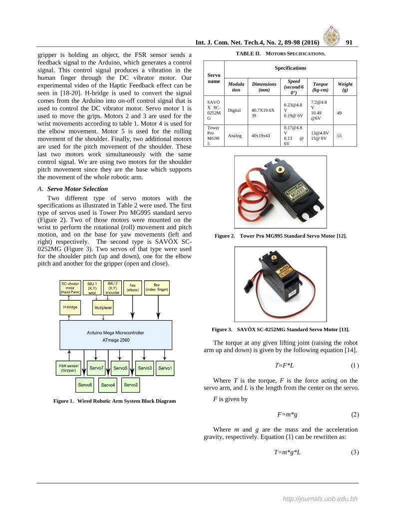
The wired 6-DOF robotic system consists of four main
parts: the wearable gesture, posture gear, the processing
unit, and the robotic arm. Figure 1 shows the proposed 6-
DOF wired robotic arm system that is capable to mimic
human arm motion. Two flex sensors are used for sensing
the pitch movement of the elbow and the gripper finger,
respectively. Two Inertial Measurement Units (IMU1 and
IMU2) are mounted on the human shoulder and wrist,
respectively. Both IMUs communicates with the Arduino
through a multiplexer since they are using the same
address pins. These sensor units are interfaced with the
Arduino that reads and generates the control signals to
actuate the robotic arm in the corresponding direction.
The haptic feedback is achieved by using a Force
Sensitive Resistor (FSR) sensor in the gripper. Once the
Int. J. Com. Net. Tech.4, No. 2, 89-98 (2016) 91
http://journals.uob.edu.bh
gripper is holding an object, the FSR sensor sends a
feedback signal to the Arduino, which generates a control
signal. This control signal produces a vibration in the
human finger through the DC vibrator motor. Our
experimental video of the Haptic Feedback effect can be
seen in [18-20]. H-bridge is used to convert the signal
comes from the Arduino into on-off control signal that is
used to control the DC vibrator motor. Servo motor 1 is
used to move the grips. Motors 2 and 3 are used for the
wrist movements according to table 1. Motor 4 is used for
the elbow movement. Motor 5 is used for the rolling
movement of the shoulder. Finally, two additional motors
are used for the pitch movement of the shoulder. These
last two motors work simultaneously with the same
control signal. We are using two motors for the shoulder
pitch movement since they are the base which supports
the movement of the whole robotic arm.
A. Servo Motor Selection
Two different type of servo motors with the specifications as illustrated in Table 2 were used. The first type of servos used is Tower Pro MG995 standard servo (Figure 2). Two of those motors were mounted on the wrist to perform the rotational (roll) movement and pitch motion, and on the base for yaw movements (left and right) respectively. The second type is SAVÖX SC-0252MG (Figure 3). Two servos of that type were used for the shoulder pitch (up and down), one for the elbow pitch and another for the gripper (open and close).
Figure 1. Wired Robotic Arm System Block Diagram
TABLE II. MOTORS SPECIFICATIONS.
Servo
name
Specifications
Modula
tion
Dimensions
(mm)
Speed
(second/6
0°)
Torque
(kg-cm)
Weight
(g)
SAVÖ
X SC-
0252M
G
Digital
40.7X19.6X
39
V
0.19@ 6V
V
10.49
@6V
49
Tower
Pro
MG99
5
Analog 40x19x43
V
0.13 @
6V
15@ 6V 55
Figure 2. Tower Pro MG995 Standard Servo Motor [12].
Figure 3. SAVÖX SC-0252MG Standard Servo Motor [13].
The torque at any given lifting joint (raising the robot arm up and down) is given by the following equation [14].
=F*L
Where T is the torque, F is the force acting on the servo arm, and L is the length from the center on the servo.
F is given by
F=m*g (
Where m and g are the mass and the acceleration gravity, respectively. Equation (1) can be rewritten as:
T=m*g*L

92 Yasser Ismail, et. al. : 6-DOF Robotic Arm Using Haptic Feedback Wired and Wireless Platforms …
http://journals.uob.edu.bh
Using the data of Figure 4 and equation (3), the Torque for each part of the arm is calculated as seen in Table 3.
Figure 4. Parameters for Torque Calculations and Motors
Selection.
TABLE III. TORQUE REQUIREMENTS AND MOTOR SELECTIONS
Motor location
Torque
Minimum Torque
(Kg-cm)
Used
(Kg-cm)
Base 12.8 13
Shoulder 12.28 20
Elbow 5.636 10
Wrist Pitch 2.975 13
Wrist Roll 1.449 13
Gripper 0.877 10
B. Electrical Components
• Arduino Microcontroller Board: Arduino Mega 2560 that is based on ATmega2560 is used in this paper. This board supports communication protocols such as UART, SPI and I2C to receive and transmit data. Also, it can provide 40 mA current for each IO pin and has a flash memory of 256 KB to save the program code with clock speed of 16 MHz.
• Flex Sensor: flex sensors were chosen to capture the operators’ joints movements because they work well on areas of the body that bend in a broad, round arc. Therefore, they are a good option to be placed on an elbow, knees, wrist, fingers and other joints. Since the flex sensor provides an acceptable level of accuracy when controlling just one servo motor, we used bend sensors in the joints which consist of only one motor in proposed design. Hence, two flex sensors have been used; one mounted on the operator’s glove finger to open and close the end-effector and the other one placed on the elbow band to move the elbow vertically (i.e. up and down). The motor responsible for the robotic arm elbow joint moves up and down depending on the amount of bending in the flex sensor. Similarly, the gripper opens and closes as the operator’s finger bends [7], [8]. There are different sizes of flex sensors available. We have chosen two 4.5 inches uni-directional flex sensors to be mounted on the index finger and elbow to cover most of the bending area. Our
chosen flex sensor has a range of resistance of 10KΩ to 110KΩ. If the sensor is unbent it will has a nominal resistance of 10,000 ohms (10KΩ), and a maximum resistance of 110KΩ value when the sensor is 180 degrees bent.
• FSR (Force Sensitive Resistor): Unlike flex sensors that change resistance when bent, FSR sensors resistance changes when pressure is applied. Therefore, it is considered to be a touch sensor [15]. The FSR sensor selected for this project has a resistance between infinity to maximum of 200KΩ and is paired with a static resistor of 22KΩ to form the voltage divider circuit. The resistance is inversely proportional to the force applied (i.e. the more applied force, the lower the resistance value). Moreover, FSRs are made of plastic and they come in a wide variety of shapes and sizes. We chose the basic one, which has a little round button. Due to the importance of force feedback to the operator for controlling the robot arm and taking the right decisions, FSR touch sensor is placed on the robotic end-effector. The pressure exerted by the gripper on various object is perceived through the vibrations of a haptic actuator mounted on the operator’s hand. The mapping functionality used with the flex sensors is also used with the pressure sensor, with the range of readings that has been measured for the FSR.
• Adafruit 9-DOF IMU Breakout - L3GD20H + LSM303: To measure the positional changes, the Adafruit 9-DOF IMU Breakout is chosen. This is to sense the motion of a human arm in 9 different axes and feed it to the microcontroller so that it is able to issue control commands to the servo motors on the robotic arm side. Two IMUs were used; one for detecting the shoulder movements and the other one for detecting the wrist movements. Since only one SCL and one SDA pins are available in the Arduino, connecting multiple I2C devices required I2C bus multiplexing to make the microcontroller able to read more than one IMU at a time correctly.
• Haptic Feedback Circuit Design: To achieve haptic feedback, an FSR sensor (pressure sensor) is attached to the end-effector. This sensor is responsible of measuring the amount of force being applied by the gripper on the object it is holding. The sensor communicates with a haptic feedback device that is mounted on the operator’s hand though the Arduino microcontroller board. The feedback device then vibrates in accordance to the amount of the exerted force. This allows the operator to adjust the gripper so that delicate and heavy objects can be picked up with no damages [16]. As an actuator, we have used a DC vibrator motor with cylindrical configuration and non-polarized terminals. This motor has an operating voltage range of 1-3V, and has some components in its internal construction. This type of motors consists of the basic element of a typical DC motor, which is the non-stationary (rotor) and stationary (stator) parts as well as commutator, armature, windings and brushes. The vibration is generated by the high speed displacement of a

Int. J. Com. Net. Tech.4, No. 2, 89-98 (2016) 93
http://journals.uob.edu.bh
weight attached to the shaft of the motor. This motor is small and lightweight. It has been employed to vibrate whenever the gripper’s exerted force on an object exceeds a certain threshold. A dc motor vibrates whenever connected to power and ground terminals of a power supply. However, it is desired to control its operation using Arduino so that it vibrates only at a certain condition. To further explain, the FSR sensor acts as an open circuit when un-pressed causing no vibrations in the DC motor. As the force applied to the FSR sensor increases, the circuit will be closed and the motor will be ready to receive the signal. Once the FSR reads the threshold value, the motor will give an alerting vibration. As mentioned, a DC motor should be controlled by a controlling signal and this is usually done using an H-bridge circuit. In our case, the SN754410 IC chip is used to serve this purpose. Figure 5 shows the final electrical design for the wired robotic arm system.
Figure 5. Final Wired Robotic Arm.
3. WIRELESS CONTROL OF ROBOTIC ARM
A wireless 6-DOF hand gestures controlled robotic arm was also implemented by splitting the wired circuit into two parts; one for the sensing and the other for robotic arm with its servo motors. Figure 6 shows the proposed wireless robotic arm transmitter. The four control signals (IMU1, IMU2, flex1 and flex2) were mapped to the range of 0-180 then transmitted. This mapping was done before transmitting to reduce the size of data to be sent. Since Zigbee modules work on the principle of serial communication over the air, each value is attached to two special characters, one in the beginning and another in the end to be distinguished in the receiver side.
Figure 6. Proposed Wireless Robotic Arm Transmitter System.
Figure 7 shows the wireless receiver system. Each control value is extracted by software based on the special characters attached to it, and then directed to the intended servo motor.
Figure 7. Proposed Wireless Robotic Arm Transmitter System
Following is an explanation of the used components in both the transmitter and the receiver of the wireless robotic arm system.
• Zigbee Protocol: ZigBee wireless protocol is suitable for use in wireless light switches, thermostats, electricity meters within home displays, management of traffic systems, wireless sensor networks (WSN), embedded sensing, building automation and various industrial equipment with low-data rate transmission requirements. It operates mostly in 2.4 GHz radio band worldwide, 0.868 GHz in Europe, 0.784 GHz in China and 0.915 GHz in the U.S and Australia.
• Xbee Module: XBee modem is popular wireless module that come in a variety of versions and styles. XBee family is manufactured by Digi international and it is small, affordable device that allow low power, low bandwidth easy wireless communication between end-points. The module can be used for peer-to-peer or mesh networking topology. IEEE 802.15.4 data link protocol is used to create those networks and manage transmission data between two or more nodes.
• XBee Shield: To simplify the task of interfacing an XBee with Arduino, XBee shield from Sparkfun is mounted on the Arduino board directly. It enhances the functionality of Arduino board to communicate wirelessly. This shield is compatible with all XBee versions including series1 and series2.
• Xbee Explorer Dongle: The Xbee Explorer Dongle is specifically designed for Digi Xbee modules. Basically it is an FTDI cable used to convert TTL serial transmissions to USB signals to enable XBee modules to communicate with computer. This breakout board does not require a USB cable and it has a reset button, voltage regulator to provide the Xbee module with required power and 4 LEDs for Tx, Rx, Received Signal Strength

94 Yasser Ismail, et. al. : 6-DOF Robotic Arm Using Haptic Feedback Wired and Wireless Platforms …
http://journals.uob.edu.bh
Indicator (RSSI) and power indicator. Also, the Xbee dongle headers are compatible with breadboard to allow greater utilization of Xbee functionalities by simply soldering some wires or header pins [17].
To implement the wireless design, sensors were mounted on human arm joints to detect hand postures and gestures. The readings from the sensors were stored and manipulated at the transmitter Arduino before being wirelessly transferred to the receiver’s circuit. The receiver’s circuit consists of the servomotors and robotic arm’s exoskeleton; it is responsible for receiving commands wirelessly and then mapping them to the corresponding motor. In the Sender side, an Xbee S2 module is connected to Arduino uno using Xbee shield. Flex sensors and IMUs along with the multiplexer were also attached to the Arduino with the Xbee module. Sensors readings were arranged before transfer such that each sensor responsible for controlling a specific servo motor was sent in the middle of two special characters, thus it can be distinguished in the receiver side and used to perform the desired movement. The receiving Xbee on the other Arduino reads the serial port checking for any transmissions. If there's a data transfer it checks for the special characters engaged with each sensor to decide which motor has to be moved. Actually, these special characters have to be shared between sender and receiver in advance.
4. MECHANICAL COMPONENTS
The mechanical design had three main objectives: have a sufficient range of motion, increase the scalability of the design, and decrease the excess movement and lag. The range of motion can be achieved by adding a gear to the joints of the mechanical arm. This solution however. increases the weight of the arm. Consequently, more expensive motors should be used to be able to move such arm. In our design we used light components that need less and cheap number of motors as mentioned in Table 2. The designed robotic arm is scalable one since it is designed from small similar pieces (base component) that can be joined together to change the length of either shoulder-elbow or elbow-wrist part. Additionally, the number of motors required for the arm joints is linearly proportional to the number of the base component. The speed of the arm and the response time is measured in the implementation section. Following sub-section describes the full design of our mechanical partThe mechanical design had three main objectives: have a sufficient range of motion, increaes the scalability of the design, and decrease the excess movement and lag. The range of motion can be achieved by adding a gear to the joints of the mechanical arm. This solution however. increases the weight of the arm. Consequently, more expensive motors should be used to be able to move such arm. In our design we used light components that need less and cheap number of motors as mentioned in Table 2. The designed robotic arm is scalable one since it is designed from small
similar pieces (base component) that can be joined together to change the length of either shoulder-elbow or elbow-wrist part. Additionally, the number of motors required for the arm joints is linearly proportional to the number of the base component. The speed of the arm and the response time is measured in the implementation section. Following sub-section describes the full design of our mechanical part
A. Exoskeleton Design
Building the mechanical system for the exoskeleton was challenging. It required some knowledge in the field of mechanical engineering including design, analysis and manufacturing. Therefore to achieve this goal, an intense study and search about the fundamentals of mechanical design was first done. Then, similar robotic arm designs were studied and used to come up with a proper robotic arm exoskeleton. In addition to that, some assistance and support from specialists in this field was needed to construct the desired 6-DOF robotic arm.
The first and most fundamental concept in mechanical designs is the concept of torque. Torque is defined as the force that tends to spin or rotate an object about an axis. Using the torque of equation (1), one can deduce that the magnitude of torque depends on the force applied F, lever-arm length L, and the angle between the force vector and length vector θ. It is expressed by the equation:
T=F|| L || sin θ
Force is the process of changing the motion of an object with specific mass by accelerating it due to gravity or in other words changing its velocity. It is expressed by the equation:
F=M*g
Where F is the force, M is the mass and g is the gravitational constant equals to 9.81 m/s
2.
The weight W of an object is equivalent to the force on it due to gravity and can also be expressed as:
W=M*g
So, the torque needed to hold a mass M at specified length L from the center point of a rotational system, known as pivot point, is calculated using the equation:
T=(M*g)*L
The relationship between torque, applied force and lever-arm distance is illustrated in Figure 8. The length L is considered between the perpendicular component of the applied force F and pivot point.

Int. J. Com. Net. Tech.4, No. 2, 89-98 (2016) 95
http://journals.uob.edu.bh
Figure 8. Torque Balance [14].
To calculate the torque at a specific joint, the torque caused by the different masses on that joint need to be calculated. For example, to calculate the torque required at the first joint in Figure 9, the weight of the motor or load A1 and the weight of the link at the center of mass of the joint W1 must be considered, so the torque at the first joint is calculated as follows:
T1=L1*A1+L1*W1
Figure 9. Calculation of Toque at Various Joints [14]
The load A2 is not included in the calculation of
torque of the first joint, because the length L between the
center of mass and the pivot point is equal to zero. To
calculate the torque of the second joint, all the torques
required from the first to the second joint must be added
up, so the torque at the second joint is calculated as
follows:
T2 = L3*A1+ L1*W1+ L 2*A2+L4*W2
Similar procedures have to be taken to calculate the
torques required at other joints, by finding the length
between the new pivot point and the weight [14].
Some tools are available online to provide the user
with the required torque at each joint by inputting
information about arm lengths, weight and actuator
weight. In that way, the torques required at each joint for
this project were calculated
In order to construct any machine, the appropriate
material should be selected. Actually, the material is the
backbone of any machine as it plays an important role in
defining its quality. To specify the price, strength, rigidity
and durability of any machine structure, one must decide
the material carefully taking into consideration machine
specification and needs. The exoskeleton of the robotic
arm designed in this project was chosen to be made of
thin aluminum for its characteristics, namely:
- It is light weight, only one third of the weight of steel.
- Resistant to corrosion and damage caused by air,
temperature, humidity and chemical attacks.
- Non-toxic, non-magnetic and non- combustible.
- Malleable, can be easily shaped and decorated.
Each mechanical part of the arm consists of a number
of holes to give it a lighter weight that helps making
movements more smooth and flexible. The designed
robotic arm is composed of three joints; shoulder
mounted on a turn table, elbow and wrist joint that is
connected to a gripper part representing human hand.
Each joint is responsible for performing 1 or 2
movements (pitch, roll, yaw) and is equipped with
suitable motors accordingly. These joints were made and
connected together using two basic bracket designs
besides other smaller brackets.
B. The servo mount bracket
The servo mount bracket is the mechanical part for
holding the servo motor. It is made of 2 mm thickness
aluminum with most of its holes having 3 mm diameter.
five pieces of this bracket were constructed, two for the
shoulder, one for the elbow and two for the wrist joint.
Their dimensions were specified to be compatible with
standard hobby servos. The final shape and the CAD
template of the servo mount bracket design are shown in
Figure 10.
Figure 10. Final shape and the CAD template of the servo mount
bracket design.
C. The C-bracket
The C-bracket is used to interconnect joints together.
It is made in a similar manner to the servo bracket using
2 mm thickness aluminum with 3 mm and 8 mm diameter
holes. Three pieces of this bracket were constructed; the
measurements of the CAD drawing are shown in Figure
11, while the final shape is shown in Figure 12.

96 Yasser Ismail, et. al. : 6-DOF Robotic Arm Using Haptic Feedback Wired and Wireless Platforms …
http://journals.uob.edu.bh
Figure 11. C-Bracket CAD Design.
Figure 12. Final C-Bracket design.
D. The L-brackets
Three L-brackets with different measurements for the
elbow, wrist and the end-effecter were designed. The
aluminum thickness and holes diameters are similar to
the servo mount and C-brackets. The measurements of
the CAD drawing for the two L-brackets are shown in
Figures 13 and 14 while the final shape is shown in
Figure 15, respectively.
Figure 13. Mid-arm L-Bracket CAD Design.
Figure 14. End-arm L-Bracket CAD Design.
Figure 15. End-arm L-Bracket on the left and Mid-arm L-Bracket
on the right.
E. The robotic arm base
The robotic arm base is designed to be a heavy flat
surface to protect the robotic arm from overbalance. It is
attached to the turn table through four 8mm tubes with
1mm thickness 30mm length each. The CAD drawing is
provided in Figure 16.
Figure 16. Robotic Arm Stand CAD template.
F. The end-effector:
For the end-effector the gripper kit shown in Figure
17 was used. It is ready to use with any standard size
servo motor and can open up to 5 inches wide (
approximately 127 mm), and has the dimensions of 5
inches long by 3 inches wide. It is easily integrated with
the designed robotic arm.
Figure 17. Assembled Gripper Kit.
The final assembled mechanical robotic arm is shown
in Figure 18.
Figure 18. Final assembled mechanical robotic arm.

Int. J. Com. Net. Tech.4, No. 2, 89-98 (2016) 97
http://journals.uob.edu.bh
5. EXPERIMENTAL RESULTS
We analyzed the performance and characteristics of
both wired and wireless systems in order to provide a
detailed comparison between them. In particular, we
aimed at drawing conclusions about the effectiveness of
each system in relation to design objectives and
requirements and at providing a guide about possible
applications of wired and wireless systems.
Thus, we defined a list of comparison metrics to
determine strengths and weaknesses of both systems.
These include network delays such as transmission time,
propagation delay, packet delivery delay and response
time. Moreover, other aspects like implementation
difficulties, accuracy, consistency and functionality were
analyzed.
Table II shows a comprehensive comparison between
the wired and wireless robotic arm.
The transmission delay is a function of packet size and
bit rate of the link, it simply describes the time required
to push all packet bits into the link and is calculated using
the following equation:
Transmission time=Packet size/Bit rate (9)
The propagation delay is measured based on the
distance between the transmitter and the receiver and the
speed of light.
It is the time required to transfer all packet bits through
the medium and is calculated using the following
equation:
Propagation time=Distance/propagation speed (10)
The packet delivery delay is defined as the time it
takes the first stream of a message to leave the sender
side until the last stream of a message arrives at the
receiver side. So, it is the result of adding the
transmission and propagation delay. In order to calculate
the transmission time for the wired and wireless systems,
we had to know the data rate and packet size of both
systems. The data rate of ZigBee-based wireless system
is equal to 250 Kbits/sec, whereas copper wires using in
wired system has a data rate equals to 1 Mbits/sec.
The packet size of the wired system is 18 bytes (since we
transfer 6 sensors values represented as angles between
0-180, considering a maximum of 3 bytes for each value).
In the wireless system two characters (1 byte each) are
transmitted before and after that value to distinguish it at
the receiver side. So, every time the program is executed,
a total of 5 bytes are transmitted for each angle value,
which results in 5*6=30 bytes for all values.
To calculate the propagation delay, the propagation
speed of both systems should be known. For wired
networks where the physical medium could be a copper
wire, fiber optics or twisted-pair copper wire, the
propagation speed is equal to 2*108
meters/second which
is equal to the speed of light. The wireless networks
propagation speed is usually equal to 3*108
meters/second.
Table IV shows that the wired system outperforms the
wireless system. For some applications wireless system is
more suitable because it does not have to run the wires.
Complete experiments for wired and wireless experiments
can be seen in [18-20].
TABLE IV. COMPARISON BETWEEN WIRED AND WIRELESS
ROBOTIC ARM
Comparison Metrics Transmission Type
Wired Wireless
Transmission Time 144 ns 960us
Propagation Delay
1 meters distance 5 ns 3.3 ns
2 meters distance 10 ns 6.6 ns
3 meters distance 15 ns 9.9 ns
4 meters distance 20 ns 13.2 ns
5 meters distance 25 ns 16.5 ns
Packet Delivery Delay (1 meter distance) 149 ns 960.0033 us
6. CONCLUSION
In this paper a robotic arm and hand that can mimic
the human counterparts has been designed. We introduced
a wired and wireless solution for the 6- DOF hand gesture
controlled robotic arm. The complete wired and wireless
platforms were implemented and a comprehensive
comparison was carried out.
ACKNOWLEDGMENT
The authors thank the Computer Engineering Department – College of Information Technology – University of Bahrain - Bahrain, Mansoura University - Egypt, and Central Michigan University - USA for supporting this work.
REFERENCES
[1] G. Hu, W. Peng Tay, Y. Wen, "Cloud robotics:
architecture, challenges and applications", IEEE Network,
vol.26, no.3, pp.21,28, May-June 2012.
[2] R. Jarvis,"Intelegent Robotics: Past, Present and Future",
International Journal of Computer Science and
Applications, Vol. 5, No.3,pp 23 – 35, 2008.
[3] E. Garcia, M.A. Jimenez, P.G. De Santos, M. Armada,
"The evolution of robotics research," in IEEE Robotics &
Automation Magazine, vol.14, no.1, pp.90-103, March
2007.
[4] W.R. Hamel, "e-maintenance robotics in hazardous
environments," in IEEE/RSJ International Conference on
Intelligent Robots and Systems, (IROS 2000), vol.2, no.,
pp.838-842 vol.2, 2000

98 Yasser Ismail, et. al. : 6-DOF Robotic Arm Using Haptic Feedback Wired and Wireless Platforms …
http://journals.uob.edu.bh
[5] A. Rama Krishna, G. Sowmya Bala, A.S.C.S. Sastry, B.
Bhanu Prakash Sarma , Gokul Sai Alla, “Design And
Implementation Of A Robotic Arm Based On Haptic
Technology”, International Journal of Engineering
Research and Applications (IJERA), Vol. 2, Issue 3,
pp.3098-3103, May-Jun 2012.
[6] K. Gandhi, H. Kotak, S. Joshi, V. Pandita, “Motion
controlled robotic arm”, International Journal of
Electronics and Communication Engineering (IJECE), Vol.
2, Issue 5,pp. 81-86, Nov 2013.
[7] M. Dascalu, M. Teodorescu, A. Plavitu, L. Milea, E. Franti,
D. Coroama, D. Moraru, “Tele-operated robotic arm and
hand with intuitive control and haptic feedback”, American
Journal of Aerospace Engineering, Vol. 1, Issue 4,pp. 21-
27, December, 2014.
[8] K. Brahmani, K. Roy, M. Ali, “Arm 7 Based Robotic Arm
Control By Electronic Gesture Recognition Unit Using
Mems”, International Journal of Engineering Trends and
Technology, Vol. 4, Issue 4, pp. 50-63, April, 2013.
[9] G. Saggio, “ Electrical Resistance Profiling of Bend
Sensors Adopted to Measure Spatial Arrangement of the
Human Body”, The 4th International Symposium on
Applied Sciences in Biomedical and Communication
Technologies (ISABEL); Barcelona, Spain. 26–29 October
2011.
[10] J.P. Trevelyan, S.C. Kang, W.R. Hamel, “ Robotics in
Hazardous Applications”, In Bruno Siciliano, Oussama
Khatib (Eds.), Springer Handbook of Robotics (pp. 1101-
1126). Berlin, Heidelberg: Springer.
[11] M. Alfraheed, A. Al-Zaghameem, "Exploration and
Cooperation Robotics on the Moon", Journal of Signal and
Information Processing, Vol. 4 No. 3, pp. 253-258, 2013.
[12] http://www.amain.com/rc-cars/savox-sc-0253mg-standard-
digital-servo-sav-sc-0253mg/p234360
[13] http://www.turbines-rc.com/en/servos/1019-tower-pro-
mg995-13kg013s-60g-standard-servo.html
[14] M. A. Rahman, A. Khan, T. Ahmed, M. M. Sajjad,
“Design, Analysis and Implementation of a Robotic Arm-
The Animator”, American Journal of Engineering
Research (AJER), Vol. 2 No. 10, pp. 298-307, 2013.
[15] A. Syed, Z. Agasbal, T. Melligeri and B. Gudur, "Flex
Sensor Based Robotic Arm Controller Using Micro
Controller", Journal of Software Engineering and
Applications, Vol. 5 No. 5, pp. 364-366, 2012.
[16] T. Tay, K.Wong, “Creating and measuring relative
hardness feeling via master-slave haptic gripper”. Yanbu
journal of engineering and science, Vol. 1 No. 2, pp.
1658-5321, 2010.
[17] “https://www.sparkfun.com/products/11697”, March, 2015.
[18] “https://youtu.be/QCj-SIBdLrw”, February, 2016.
[19] “https://youtu.be/LQHQH4-bNjA”, February, 2016.
[20] “https://youtu.be/1C5_sq5By1s”, February, 2016.
Dr. Yasser Ismail received the B.Sc.degree in
Electronics & Communications Engineering from Mansoura University, Mansoura, Egypt, in 1999,
the M.Sc. degree in Electrical Communications
from Mansoura University, Mansoura, Egypt, in 2002, the M.Sc. degree in Computer Engineering
from University of Louisiana at Lafayette,
Louisiana, USA, in 2007. Dr. Yasser Ismail got his Ph.D. from the University of Louisiana at Lafayette in May 2010.
Dr. Yasser Ismail worked as an assistant professor in Umm Alqura
University – KSA from 2010 to 2012. He is currently working as an assistant professor in University Of Bahrain (UOB) - Bahrain. Dr.
Yasser permanently working at the Electronics and Communications
Engineering Department – Faculty of Engineering – Mansoura University – Mansoura – Egypt. Dr. Yasser is served as a reviewer for
several conferences and journals, including ISCAS 2010, ICIP 2010,
ICIP 2011, ICECS2013, Transaction on Circuit and System for Video
Technology (TCSVT), and IEEE Transactions on Image Processing,
and Signal Processing. He has also gained many valuable projects from
KSA, NSF, and Bahrain. Dr. Yasser served in the organizing committee of 2013 IEEE International Conference on Electronics, Circuits, and
Systems (ICECS2013). His research of interest includes video
processing, digital signal processing, Robotics, RFID, Localization, VLSI, FPGA, wireless communication systems, and low power
embedded systems.
Dr. Luisella Balbis received her MSc. Degree
in Computer Engineering from University of
Genoa, Italy in 2002. She completed her PhD in
Control Engineering at University of Strathclyde, Glasgow, in 2007. After a period spent as senior
engineering in industry, she joined University of
Bahrain, where she is currently Assistant Professor
in the Department of Computer Engineering,
College of IT. Her research interests include
control systems, model predictive control and optimization techniques.
Dr. Ahmed Abdelgawad received his M.S. and Ph.D. degree in Computer Engineering from
University of Louisiana at Lafayette in 2007 and
2011 and subsequently joined IBM as a Design Aids & Automation Engineering Professional at
Semiconductor Research and Development
Center. In Fall 2012 he joined Central Michigan University as a Computer Engineering Assistant
Professor. His area of expertise is distributed
computing for Wireless Sensor Network (WSN), Internet of Things (IoT), Structural Health
Monitoring (SHM), data fusion techniques for WSN, low power
embedded system, video processing, digital signal processing, Robotics, RFID, Localization, VLSI, and FPGA design. He has published two
books and more than 30 articles in related journals and conferences. Dr.
Abdelgawad served as a reviewer for several conferences and journals, including IEEE WF-IoT, IEEE ISCAS, IEEE SAS, Springer, Elsevier,
IEEE Transactions on VLSI, and IEEE Transactions on I&M. He
severed in the technical committees of IEEE ISCAS 2007, IEEE ISCAS 2008, and IEEE ICIP 2009 conferences. He served in the administration
committee of IEEE SiPS 2011. Dr. Abdelgawad has been appointed as a
Track Chair of the International Conference on Cognitive and Sensor Networks (MIC-CSN 2013). He also served in the organizing
committee of ICECS2013 and 2015 IEEE ICECS2015. Dr. Abdelgawad
is the publicity chair in North America of the IEEE WF-IoT 2016 conference. He is the finance chair of the IEEE ICASSP 2017. He is
currently the IEEE Northeast Michigan section chair. In addition, Dr.
Abdelgawad served as a PI and Co-PI for several funded grants from NSF.