Development of a Novel 2-DOF Rotary–Linear Piezoelectric ...
22
micromachines Article Development of a Novel 2-DOF Rotary–Linear Piezoelectric Actuator Operating under Hybrid Bending–Radial Vibration Mode Andrius ˇ Ceponis 1, *, Dalius Mažeika 2 and Daiva Makut ˙ enien˙ e 1 Citation: ˇ Ceponis, A.; Mažeika, D.; Makut ˙ enien ˙ e, D. Development of a Novel 2-DOF Rotary–Linear Piezoelectric Actuator Operating under Hybrid Bending–Radial Vibration Mode. Micromachines 2021, 12, 728. https://doi.org/10.3390/ mi12060728 Academic Editor: Jose Luis Sanchez-Rojas Received: 26 May 2021 Accepted: 18 June 2021 Published: 21 June 2021 Publisher’s Note: MDPI stays neutral with regard to jurisdictional claims in published maps and institutional affil- iations. Copyright: © 2021 by the authors. Licensee MDPI, Basel, Switzerland. This article is an open access article distributed under the terms and conditions of the Creative Commons Attribution (CC BY) license (https:// creativecommons.org/licenses/by/ 4.0/). 1 Department of Engineering Graphics, Faculty of Fundamental Sciences, Vilnius Gediminas Technical University, Saulet˙ ekio al. 11, LT-10223 Vilnius, Lithuania; [email protected] 2 Department of Information Systems, Faculty of Fundamental Sciences, Vilnius Gediminas Technical University, Saulet˙ ekio al. 11, LT-10223 Vilnius, Lithuania; [email protected] * Correspondence: [email protected] Abstract: The paper presents a numerical and experimental investigation of a novel two degrees of freedom (2-DOF) piezoelectric actuator that can generate rotary motion of the sphere-shaped rotor as well as induce planar motion of the flat stage. The actuator has a small size and simple design and can be integrated into a printed circuit board (PCB). The application field of the actuator is small-dimensional and high-precision positioning systems. The piezoelectric actuator comprises three rectangular bimorph plates joined with arcs and arranged by an angle of 120 degrees. A high-stiffness rod is glued on the top surface of each bimorph plate and is used to rotate the rotor or move flat stage employing contact friction force. Three U-shaped structures are used for the actuator clamping. 2-DOF rotational or planar movement is obtained by applying a harmonic or asymmetric electrical signal. The operation principle of the actuator is based on the superposition of the B 20 out-of-plane bending mode of the bimorph plates and the B 03 radial vibration mode of the ring. Design optimization has been performed to maximize amplitudes of contact point vibration. A prototype of the actuator was made, and a maximum rotation speed of 795.15 RPM was achieved while preload of 546.03 mN was applied. The linear velocity of 36.45 mm/s was obtained at the same preload force. Resolution measurement showed that the actuator can achieve an angular resolution of 17.48 μrad and a linear resolution of 2.75 μm. Keywords: piezoelectric actuator; 2-DOF rotation; 2-DOF linear motion 1. Introduction Piezoelectric actuators and motors are widely used in high-precision systems such as laser beam position and focusing systems, scanning and manipulation systems, robotics, etc. [1–3]. Wide application of piezoelectric actuators and motors is affected by the following advantages as nanoscale or microscale resolution, self-locking, high volume-to-torque ratio, gear free-motion transfer, low backlash or no backlash when motion direction is changing, magnetic-field-free operation, etc. [4,5]. Usually, piezoelectric actuators and motors provide a single degree of freedom linear or rotational motion [6,7]. Therefore, multidegree of freedom systems comprise several actuators or motors. As a result, the mechanical systems have a complex structure, occupy larger space, and control becomes more complicated. A separate driver and controller is required for each motor because the resonant frequencies of the transducers are different. In addition, it is difficult to achieve high resolution and adapt such systems for specific applications [8,9]. The piezoelectric actuators and motors generating several degrees of freedom have smaller overall sizes, are simple to manufacture, and provide the possibility of obtaining different types of motion [10]. Multi-DOF actuators allow one to simplify the overall structural design of the mechanical system and reduce the size and space allocation of the system. In addition, it allows one to extend the scope of the actuator application [11,12]. Micromachines 2021, 12, 728. https://doi.org/10.3390/mi12060728 https://www.mdpi.com/journal/micromachines
-
Upload
khangminh22 -
Category
Documents
-
view
1 -
download
0
Transcript of Development of a Novel 2-DOF Rotary–Linear Piezoelectric ...
micromachines
Article
Development of a Novel 2-DOF Rotary–Linear PiezoelectricActuator Operating under Hybrid Bending–RadialVibration Mode
Andrius Ceponis 1,*, Dalius Mažeika 2 and Daiva Makuteniene 1
Citation: Ceponis, A.; Mažeika, D.;
Makuteniene, D. Development of a
Novel 2-DOF Rotary–Linear
Piezoelectric Actuator Operating
under Hybrid Bending–Radial
Vibration Mode. Micromachines 2021,
12, 728. https://doi.org/10.3390/
mi12060728
Academic Editor: Jose
Luis Sanchez-Rojas
Received: 26 May 2021
Accepted: 18 June 2021
Published: 21 June 2021
Publisher’s Note: MDPI stays neutral
with regard to jurisdictional claims in
published maps and institutional affil-
iations.
Copyright: © 2021 by the authors.
Licensee MDPI, Basel, Switzerland.
This article is an open access article
distributed under the terms and
conditions of the Creative Commons
Attribution (CC BY) license (https://
creativecommons.org/licenses/by/
4.0/).
1 Department of Engineering Graphics, Faculty of Fundamental Sciences, Vilnius Gediminas TechnicalUniversity, Sauletekio al. 11, LT-10223 Vilnius, Lithuania; [email protected]
2 Department of Information Systems, Faculty of Fundamental Sciences, Vilnius Gediminas TechnicalUniversity, Sauletekio al. 11, LT-10223 Vilnius, Lithuania; [email protected]
* Correspondence: [email protected]
Abstract: The paper presents a numerical and experimental investigation of a novel two degrees offreedom (2-DOF) piezoelectric actuator that can generate rotary motion of the sphere-shaped rotoras well as induce planar motion of the flat stage. The actuator has a small size and simple designand can be integrated into a printed circuit board (PCB). The application field of the actuator issmall-dimensional and high-precision positioning systems. The piezoelectric actuator comprisesthree rectangular bimorph plates joined with arcs and arranged by an angle of 120 degrees. Ahigh-stiffness rod is glued on the top surface of each bimorph plate and is used to rotate the rotoror move flat stage employing contact friction force. Three U-shaped structures are used for theactuator clamping. 2-DOF rotational or planar movement is obtained by applying a harmonic orasymmetric electrical signal. The operation principle of the actuator is based on the superposition ofthe B20 out-of-plane bending mode of the bimorph plates and the B03 radial vibration mode of thering. Design optimization has been performed to maximize amplitudes of contact point vibration. Aprototype of the actuator was made, and a maximum rotation speed of 795.15 RPM was achievedwhile preload of 546.03 mN was applied. The linear velocity of 36.45 mm/s was obtained at the samepreload force. Resolution measurement showed that the actuator can achieve an angular resolutionof 17.48 µrad and a linear resolution of 2.75 µm.
Keywords: piezoelectric actuator; 2-DOF rotation; 2-DOF linear motion
1. Introduction
Piezoelectric actuators and motors are widely used in high-precision systems such aslaser beam position and focusing systems, scanning and manipulation systems, robotics,etc. [1–3]. Wide application of piezoelectric actuators and motors is affected by the followingadvantages as nanoscale or microscale resolution, self-locking, high volume-to-torque ratio,gear free-motion transfer, low backlash or no backlash when motion direction is changing,magnetic-field-free operation, etc. [4,5]. Usually, piezoelectric actuators and motors providea single degree of freedom linear or rotational motion [6,7]. Therefore, multidegree offreedom systems comprise several actuators or motors. As a result, the mechanical systemshave a complex structure, occupy larger space, and control becomes more complicated. Aseparate driver and controller is required for each motor because the resonant frequenciesof the transducers are different. In addition, it is difficult to achieve high resolution andadapt such systems for specific applications [8,9]. The piezoelectric actuators and motorsgenerating several degrees of freedom have smaller overall sizes, are simple to manufacture,and provide the possibility of obtaining different types of motion [10]. Multi-DOF actuatorsallow one to simplify the overall structural design of the mechanical system and reducethe size and space allocation of the system. In addition, it allows one to extend the scope ofthe actuator application [11,12].
Micromachines 2021, 12, 728. https://doi.org/10.3390/mi12060728 https://www.mdpi.com/journal/micromachines

Micromachines 2021, 12, 728 2 of 22
The structural design of multi-DOF actuators in most cases is based on simple struc-tures such as piezoelectric rings, cylinders, bimorph plates, or discs that compose onemechanical system and are driven by several electric signals [13]. Usually, one electri-cal signal per degree of freedom is needed to drive a multi-DOF actuator; therefore, thedriving circuit becomes more sophisticated than a single-DOF actuator [14,15]. Dynamiccharacteristics of the multi-DOF actuators depend on the design and operating principle.Resonant-type ultrasonic actuators are excited by harmonic signal and achieve higher veloc-ity and torque, while inertial type actuators are characterized by higher resolution [16,17].There are several multi-DOF actuators that can achieve high velocity and few micronrange resolution. Most of the multi-DOF actuators can provide one type of motion, i.e.,rotational or linear [18–20]. However, considering the demand of modern positioningand manipulation systems, dual-function actuators are developed. A piezoelectric dual-function rotary–linear multi-DOF actuator was developed for high-resolution microscopyapplications [20]. The actuator was composed of rotary and linear actuators placed on eachother. The actuators operates in nonresonant mode and achieves high resolution. However,the actuator has a complicated design and limited scalability options. A more advanceddual-function rotary–linear 2-DOF piezoelectric actuator was proposed by Mashimo andTouama [21]. The design of the actuator is based on a small-size hollowed cube and cylin-drical shaft. The actuator operates at two different deformation modes and can move theshaft linearly and rotate it about the longitudinal axis. However, in order to drive theactuator, four excitation signals are needed, and the clamping of the actuator is complicated.A dual-function 2-DOF actuator was developed that provides linear-rotary motion of theslider placed on a cylindrical shaft [22,23]. However, the linear motion of the slider islimited by the length of the shaft, and the clamping of the actuator can be challenging.There are screw-type piezoelectric actuators that can provide coupled or independentrotary–linear motion of the shaft [24]. This type of actuator has a simple and scalabledesign, but some of these type actuators have a restriction for one direction of the motionby the structural design, thus reducing the number of degrees of freedom.
In this paper, a novel design of a 2-DOF rotary–linear actuator was proposed that canachieve high velocity and micrometric resolution. The flat design of the actuator allows oneto integrate it into PCB. A single harmonic signal is needed to drive the actuator. Controlof motion direction is implemented by a simple digital switch box.
The rest of the paper is organized as follows: Section 2 describes the structure, dimen-sions, and operation principle of the actuator. In addition, excitation schematics of theelectrodes are described. Section 3 presents the results of numerical modelling and designoptimization. Section 4 provides measured characteristics of the actuator, i.e., rotationaland linear speed for different applied voltages and measurement results of angular andlinear resolution. Finally, Section 5 concludes this work.
2. Design and Operation Principle of the Actuator
The piezoelectric actuator is composed of three stainless-steel plates joined with thearcs and arranged by an angle of 120 degrees (Figure 1a). Two piezoceramic plates areglued on the top and bottom surfaces of the steel plate and form piezoelectric bimorphs. Po-larization of the piezoelectric plates is aligned with thickness and has the same direction inthe assembled bimorph the out-of-plane bending mode of the bimorph plates is employedfor motor operation; therefore, the junction point of the arcs and bimorph plates coincidewith the end of the nodal line of the bimorph vibrations. Three U-shaped supports are usedto clamp the actuator. Supports are connected to the arcs’ outer surface via flexible hingesto reduce structural damping of the stator vibrations (Figure 1b). The junction points ofthe supports coincide with the nodes of the radial vibrations of the arcs in order to reducestructural damping of the stator vibration. The lengths of the supporting beams are chosenso that the resonant frequency of the first bending mode of the beams coincides with theoperating frequency of the motor.

Micromachines 2021, 12, 728 3 of 22
Micromachines 2021, 12, x FOR PEER REVIEW 3 of 23
supporting beams are chosen so that the resonant frequency of the first bending mode of the beams coincides with the operating frequency of the motor.
(a) (b)
Figure 1. Design of the actuator; (a)—sketch of the stator; (b)—view of the actuator clamped into the PCB; 1—stator; 2—piezo ceramic plates; 3—cylinder rod; 4—actuator clamping frame (PCB); 5—fixing bolts; 6—fixing nuts; 7—U-shaped supports; 8—clamping spot; and 9—connecting arc.
The actuator is clamped into the PCB housing frame using three bolts. A high-stiffness cylindrical rod is glued on the top surface of each bimorph plate. The spherical rotor or flat sliding stage is placed on the rods, and the rotational or linear motion of the rotor or slider is achieved. The chamfers are designed at the free end of the high-stiffness rods to increase the contact area between rods and spherical rotor. The sketch of the stator is presented in Figure 1a, while geometrical parameters are listed in Table 1.
The operation of the actuator is based on the superposition of the B20 bending vibration mode of the bimorph plate and the B03 radial vibration mode of the ring. Describing the operation of the motor, we assumed that arcs joined with the bimorph plates form a ring-type structure. The bimorph plate bends in the out-of-plane direction when the B20 bending mode is excited and generates minor in-plane motion as well. Therefore, the radial vibrations of the ring are excited when the radial and bending vibration modes have the same resonant frequencies. Such stator vibrations create curvilinear vibrations of the contact point in the plane perpendicular to the stator plane. In order to increase amplitudes of the contact point vibrations, the dimensions of the bimorph plates and the ring must be optimized so that resonant frequencies of the B20 bending mode of the bimorph plates and the B03 radial vibration mode of the ring coincide. In addition, the position of the rods on the top surface of the plate is moved by distance ξ from the antinode of the bending standing wave. It allows for the increase in contact point vibration amplitudes in the radial direction. A sine wave electrical signal is applied to the piezoelectric bimorph electrodes while the metal layer is grounded This type of circuit is used to excite out-of-plane bending vibrations of the bimorph and radial oscillation of the ring.
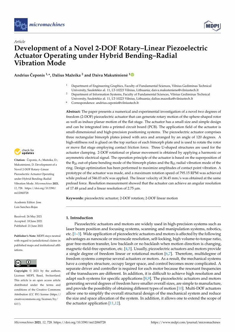
Table 1. Geometrical parameters of stator.
Parameter Value Description Lplate 9.33 mm Length of stainless-steel plate Lpzt 8 mm Length of piezo ceramic plate
LClamp 3.9 mm Length of U-shaped support
Figure 1. Design of the actuator; (a)—sketch of the stator; (b)—view of the actuator clamped into the PCB; 1—stator;2—piezo ceramic plates; 3—cylinder rod; 4—actuator clamping frame (PCB); 5—fixing bolts; 6—fixing nuts; 7—U-shapedsupports; 8—clamping spot; and 9—connecting arc.
The actuator is clamped into the PCB housing frame using three bolts. A high-stiffnesscylindrical rod is glued on the top surface of each bimorph plate. The spherical rotor or flatsliding stage is placed on the rods, and the rotational or linear motion of the rotor or slideris achieved. The chamfers are designed at the free end of the high-stiffness rods to increasethe contact area between rods and spherical rotor. The sketch of the stator is presented inFigure 1a, while geometrical parameters are listed in Table 1.
The operation of the actuator is based on the superposition of the B20 bending vibrationmode of the bimorph plate and the B03 radial vibration mode of the ring. Describing theoperation of the motor, we assumed that arcs joined with the bimorph plates form aring-type structure. The bimorph plate bends in the out-of-plane direction when the B20bending mode is excited and generates minor in-plane motion as well. Therefore, theradial vibrations of the ring are excited when the radial and bending vibration modes havethe same resonant frequencies. Such stator vibrations create curvilinear vibrations of thecontact point in the plane perpendicular to the stator plane. In order to increase amplitudesof the contact point vibrations, the dimensions of the bimorph plates and the ring mustbe optimized so that resonant frequencies of the B20 bending mode of the bimorph platesand the B03 radial vibration mode of the ring coincide. In addition, the position of the rodson the top surface of the plate is moved by distance ξ from the antinode of the bendingstanding wave. It allows for the increase in contact point vibration amplitudes in the radialdirection. A sine wave electrical signal is applied to the piezoelectric bimorph electrodeswhile the metal layer is grounded This type of circuit is used to excite out-of-plane bendingvibrations of the bimorph and radial oscillation of the ring.
A simplified model of the bimorph vibrations is shown in Figure 2, where motiondecomposition is presented. It was assumed that bending vibrations have a sine wavemodal shape. Contacting point K is located on the top of the cylindrical rod and is placedat point O, which is moved by distance ξ from antinode Lm. The position of the contactpoint K along the x axis can be written as:
xK = Lm + ξ (1)
Micromachines 2021, 12, 728 4 of 22
Table 1. Geometrical parameters of stator.
Parameter Value Description
Lplate 9.33 mm Length of stainless-steel plateLpzt 8 mm Length of piezo ceramic plate
LClamp 3.9 mm Length of U-shaped supportLBeam 3 mm Length of cylinder shaped beamWPlate 4 mm Width of stainless-steel plateWpzt 3.6 mm Width of piezo ceramic plate
WRing 0.8 mm Width of ringWClamp 0.5 mm Width of U-shaped supportRHinge 0.18 mm Radius of flexible hingeRBeam 0.75 mm Radius of cylinder shaped beam
DClamp 1.4 mm Diameter of clamping spotDTotal 22.5 mm Diameter of whole statorDRing 8.46 mm Centre diameter of ringttotal 0.9 mm Total thickness of bimorph platetpzt 0.2 mm Thickness of piezo ceramic plate
tplate 0.5 mm Thickness of stainless-steel plateα 120 Distribution angle of bimorph platesβ 45 Inclination angle of U-shaped supportγ 225 Ange of contact zone inclinationS 391.5 mm2 Surface area of the stator
Micromachines 2021, 12, x FOR PEER REVIEW 5 of 23
The vibration amplitude A is very small compared to the wavelength; therefore, angle α is very small too. Based on that, it can be assumed that sin(α) ≈ α and cos(α) ≈ 1; therefore, the displacement of the point K can be written as follows:
=
+
=
KK
KK
xAΔz
BxhAΔx
λπ
λπ
λπ
2sin
2cos2
(6)
Assuming that the bimorph plate operates at the bending mode when λ = 2L, then the total amplitude of the point K vibrations can be expressed as:
222
222 1cos211cos1 B
LLhAB
LLhAUK +
++
+
+
−= ξππξππ (7)
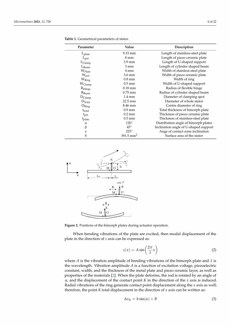
Figure 2. Positions of the bimorph plates during actuator operation.
It can be seen that contact point displacements in x direction depend on the height of the rod and amplitude of bending and radial vibrations. In addition, rod position on the top surface of the bimorph is important, because as distance ξ from the antinode increases, the displacement in the x direction increases but decreases in the z direction. Therefore, the rod position must be optimized in order to maximize total displacement amplitudes of contact point K.
The design and operation principle of the actuator provides the possibility to obtain planar or rotation motion of the stage or rotors employing the same vibration mode of the actuator that composes bending mode of the plate (B20) and radial mode of the ring (B30). The proposed actuator allows one to achieve controllable rotation of the rotor or planar motion of the slider when the harmonic electric signal is applied to the corresponding piezoelectric plates. The excitation schematics and direction of the induced linear or rotary motion are given in Figure 3 and Table 2.
It can be seen that control of the motion direction can be implemented using digitally controlled switching of a single harmonic signal. Special trajectory-planning algorithms can be used to generate the required planar or rotational motion of the output link [25]. The algorithms include variation in amplitudes of electric signals, duration time, and sequences of switching control. High displacement and rotation resolution of the motor can be achieved applying burst type electric signal. In order to increase the output velocity, force, and torque of the actuator, switching between pairs of the bimorph plates can be implemented.
Figure 2. Positions of the bimorph plates during actuator operation.
When bending vibrations of the plate are excited, then modal displacement of theplate in the direction of z axis can be expressed as:
z(x) = A sin(
2π
λx)
(2)
where A is the vibration amplitude of bending vibrations of the bimorph plate and λ isthe wavelength. Vibration amplitude A is a function of excitation voltage, piezoelectricconstant, width, and the thickness of the metal plate and piezo ceramic layer, as well asproperties of the materials [2]. When the plate deforms, the rod is rotated by an angle ofα, and the displacement of the contact point K in the direction of the x axis is induced.Radial vibrations of the ring generate contact point displacement along the x axis as well;therefore, the point K total displacement in the direction of x axis can be written as:
∆xK = h sin(α) + B (3)
Micromachines 2021, 12, 728 5 of 22
where B is the vibration amplitude of radial vibrations and h is the height of the rod.Vibration amplitude B is a function of external and internal radius, material properties, andexcitation force of the ring. Based on geometric relations (Figure 1b), the displacement ofpoint K in the direction of z axis is:
∆zK = A sin(
2π
λxK
)− h(1 − cos(α)) (4)
Angle α can be expressed as follows:
α ≈ ∂zK∂x
= A2π
λcos(
2π
λxK
)(5)
The vibration amplitude A is very small compared to the wavelength; therefore, angleα is very small too. Based on that, it can be assumed that sin(α) ≈ α and cos(α) ≈ 1;therefore, the displacement of the point K can be written as follows:
∆xK = hA 2πλ cos
( 2πλ xK
)+ B
∆zK = A sin( 2π
λ xK) (6)
Assuming that the bimorph plate operates at the bending mode when λ = 2L, then thetotal amplitude of the point K vibrations can be expressed as:
UK =
√A2((
h2π2
L2 − 1)
cos2(
π
(1 +
ξ
L
))+ 1)+ 2AB
hπ
Lcos(
π
(1 +
ξ
L
))+ B2 (7)
It can be seen that contact point displacements in x direction depend on the height ofthe rod and amplitude of bending and radial vibrations. In addition, rod position on thetop surface of the bimorph is important, because as distance ξ from the antinode increases,the displacement in the x direction increases but decreases in the z direction. Therefore,the rod position must be optimized in order to maximize total displacement amplitudes ofcontact point K.
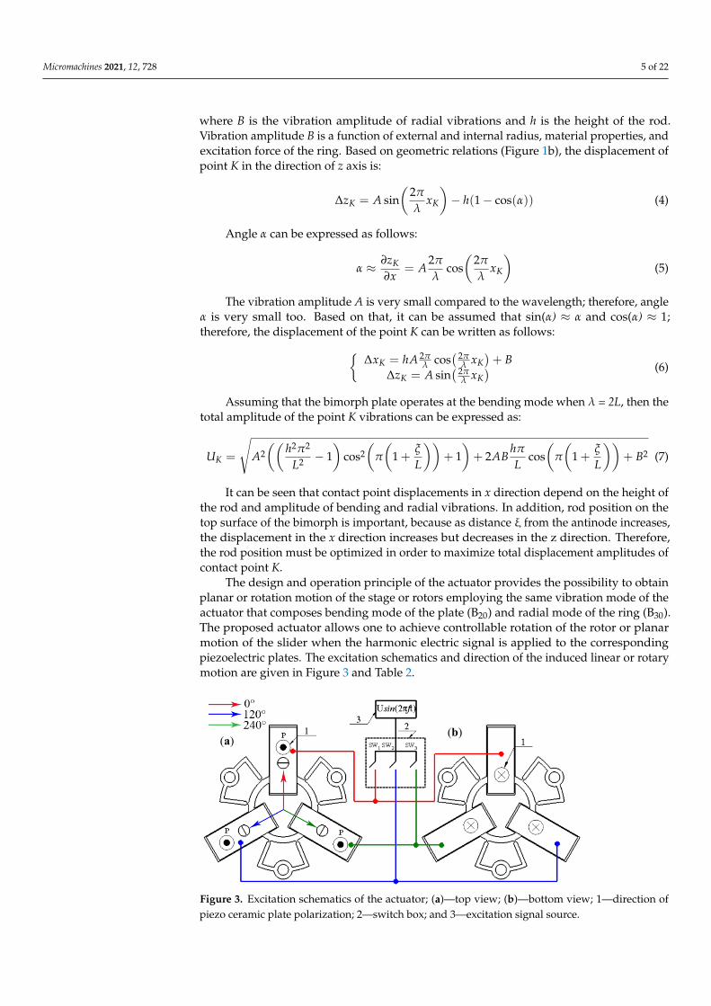
The design and operation principle of the actuator provides the possibility to obtainplanar or rotation motion of the stage or rotors employing the same vibration mode of theactuator that composes bending mode of the plate (B20) and radial mode of the ring (B30).The proposed actuator allows one to achieve controllable rotation of the rotor or planarmotion of the slider when the harmonic electric signal is applied to the correspondingpiezoelectric plates. The excitation schematics and direction of the induced linear or rotarymotion are given in Figure 3 and Table 2.
Micromachines 2021, 12, x FOR PEER REVIEW 6 of 23
Figure 3. Excitation schematics of the actuator; (a)—top view; (b)—bottom view; 1—direction of piezo ceramic plate polarization; 2—switch box; and 3—excitation signal source.
Table 2. Switch positions for motion direction control.
Case No. Direction SW1 SW2 SW3 1 0° 1 0 0 2 60° 0 0 1 3 120° 0 1 0 4 180° 0 1 1 5 240° 1 1 0 6 300° 1 0 1
3. Numerical Study of the Actuator Numerical modeling of the actuator was performed to optimize dimensions of the
actuator, find the optimal location of the rod, and make frequency response analysis. The finite element model of the actuator was built using Comsol 5.4. The following materials were used in the model: i.e., stainless steel was used for the passive layer of the stator, PIC181 (PI Ceramic GmbH, Germany) material properties were used for piezo ceramic plates, and alumina oxide was used for cylindrical rods. Material properties are listed in Table 3. Boundary conditions of the model were set as follows: clamping spots were fixed rigidly, while electrical boundary conditions were set as it is shown in Figure 3.
Table 3. Materials properties.
Material Properties Stainless-Steel ISO A2
PI Ceramics PIC181
Aluminum Oxide Ceramic
Density, [kg/m3] 8000 7800 3980 Young’s modulus, [N/m2] 10 × 109 7.6 × 10¹⁰ 41.9 × 10¹⁰
Poisson`s coefficient 0.3 - 0.33 Isotropic structural loss factor 0.02 - 0.2 × 10⁻³
Relative permittivity - ε11T/ ε0 = 1200 ε33T/ε0 = 1500 -
Elastic compliance coefficient [10−12 m2/N] - S11E = 15.00 S33E = 19.00
-
Elastic stiffness coefficient c33D, [N/m2] - 1.6 × 10¹⁰ - Piezoelectric constant d33 [10−12 m/V] - 225 - Piezoelectric constant d31 [10−12 m/V] - −97 - Piezoelectric constant d15 [10−12 m/V] - 330 -
(a) (b)
Figure 3. Excitation schematics of the actuator; (a)—top view; (b)—bottom view; 1—direction ofpiezo ceramic plate polarization; 2—switch box; and 3—excitation signal source.

Micromachines 2021, 12, 728 6 of 22
Table 2. Switch positions for motion direction control.
Case No. Direction SW1 SW2 SW3
1 0 1 0 02 60 0 0 13 120 0 1 04 180 0 1 15 240 1 1 06 300 1 0 1
It can be seen that control of the motion direction can be implemented using digitallycontrolled switching of a single harmonic signal. Special trajectory-planning algorithmscan be used to generate the required planar or rotational motion of the output link [25].The algorithms include variation in amplitudes of electric signals, duration time, andsequences of switching control. High displacement and rotation resolution of the motorcan be achieved applying burst type electric signal. In order to increase the output velocity,force, and torque of the actuator, switching between pairs of the bimorph plates canbe implemented.
3. Numerical Study of the Actuator
Numerical modeling of the actuator was performed to optimize dimensions of theactuator, find the optimal location of the rod, and make frequency response analysis. Thefinite element model of the actuator was built using Comsol 5.4. The following materialswere used in the model: i.e., stainless steel was used for the passive layer of the stator,PIC181 (PI Ceramic GmbH, Germany) material properties were used for piezo ceramicplates, and alumina oxide was used for cylindrical rods. Material properties are listed inTable 3. Boundary conditions of the model were set as follows: clamping spots were fixedrigidly, while electrical boundary conditions were set as it is shown in Figure 3.
Optimization of actuator dimensions was carried out with the goal to match resonantfrequencies of the B20 bending mode of the bimorph plate and the B03 radial mode of thering by parametric. The diameter of the ring and the length of metal plates were selectedas design variables. The optimization problem is described below:
minL,D
(∣∣ fB20(LPlate, DRing)− fB03(LPlate, DRing)
∣∣); (8)
subject to:Lmin
Plate ≤ LPlate ≤ LmaxPlate (9)
DminRing ≤ DRing ≤ Dmax
Ring (10)
fmin ≤ f ≤ fmax. (11)
where LPlate is the length of metal plates; DRing is the diameter of ring; fB20 is the resonantfrequency of B20 out of the plane bending mode of the bimorph plate; fB03 is the resonantfrequency of B03 radial mode of the ring; Lmin
Plate and LmaxPlate are the minimum and the
maximum lengths of metal plates, respectively; DminRing and Dmax
Ring are the minimum and themaximum diameters of ring; f is the resonant frequency of the actuator; fmin and fmax areminimum and maximum limits of the analyzed frequency range. Lmin
Plate and LmaxPlate were
set to 8.4 and 10.5 mm, respectively. The minimum and maximum values of ring centerdiameter were as follows: Dmin
Ring = 7.3 mm and DmaxRing = 9.2 mm. The linear search was
used to find the optimal value of the objective function. The step size of ring diameterand plate length variation was 0.1 mm for course analysis, while the step of 0.01 mm wasused to make fine resolution analysis in the narrower range in order to get a more precisevalue. The frequency range from fmin = 35 kHz to fmax = 52 kHz and step size of 2.5 Hzwere determined. Frequency response analysis was performed applying a voltage of 100Vp-p for the actuator excitation.

Micromachines 2021, 12, 728 7 of 22
Table 3. Materials properties.
Material Properties Stainless-SteelISO A2
PI Ceramics PIC181
Aluminum OxideCeramic
Density, [kg/m3] 8000 7800 3980Young’s modulus, [N/m2] 10 × 109 7.6 × 10¹⁰ 41.9 × 10¹⁰
Poisson‘s coefficient 0.3 - 0.33Isotropic structural
loss factor 0.02 - 0.2 × 10⁻³
Relative permittivity - ε11T/ ε0 = 1200
ε33T/ε0 = 1500
-
Elastic compliance coefficient[10−12 m2/N] - S11
E = 15.00S33
E = 19.00-
Elastic stiffness coefficientc33
D, [N/m2] - 1.6 × 10¹⁰ -
Piezoelectric constant d33[10−12 m/V] - 225 -
Piezoelectric constant d31[10−12 m/V] - −97 -
Piezoelectric constant d15[10−12 m/V] - 330 -
First of all, dependencies of the resonant frequencies of the bending vibration modeB20 and radial vibration mode B03 from the length of the plate and diameter of the ringwere calculated (Figure 4a,b). It must be pointed out that these calculations cannot befully automated, because the sequence of the vibration modes changes in the determinedfrequency range when dimensions of the plate and ring vary within specified ranges.Analysis of the obtained results revealed that the resonant frequency of the bimorphplate strongly depends on the plate length, and frequency decreases when the length ofthe plate increases. On the other hand, the resonant frequency of the radial vibrationmode B03 increases when the length of the plate and diameter of the ring decreases. Themodulus of difference between resonant frequencies of aforementioned vibration modes,i.e., objective function, was calculated at the next step of the optimization study. Resultsare shown in Figure 5a, when a step size of 0.1 mm was applied. Analyzing the results, itcan be seen that the objective function reaches minimum value when plate length and ringdiameter are within the range of 9.30–9.40 mm and 8.40–8.50 mm, respectively. Therefore,a study with a step size of 0.01 mm was performed in order to get more precise results(Figure 5b). This split analysis when coarse and fine steps were used allowed us to savethe computational time.
Micromachines 2021, 12, x FOR PEER REVIEW 8 of 23
Figure 4. Dependence of resonant frequency from the length of the plate and diameter of the ring: (a)—bending mode (B20) and (b)—radial mode (B03).
Figure 5. Modulus of the difference between resonant frequencies versus length of the plate and diameter of the ring when step size of 0.1 mm (a), and 0.01 mm (b) is used.
Optimization of the cylindrical rod position along the symmetry axis of the bimorph plate was performed with the goal to increase amplitudes of contact point vibrations. The analyzed actuator has a symmetrical structure; therefore, only one bimorph plate with the rod was analyzed. The total vibration amplitude of the contact point was defined as an objective function. The optimization problem is written as:
( ) ( )( )posL2zuposL2xumaxposL
+ (12)
subject to:
maxminpospospos LLL ≤≤ (13)
(a)
(a)
(b)
(b)
Figure 4. Dependence of resonant frequency from the length of the plate and diameter of the ring: (a)—bending mode (B20)and (b)—radial mode (B03).

Micromachines 2021, 12, 728 8 of 22
Micromachines 2021, 12, x FOR PEER REVIEW 8 of 23
Figure 4. Dependence of resonant frequency from the length of the plate and diameter of the ring: (a)—bending mode (B20) and (b)—radial mode (B03).
Figure 5. Modulus of the difference between resonant frequencies versus length of the plate and diameter of the ring when step size of 0.1 mm (a), and 0.01 mm (b) is used.
Optimization of the cylindrical rod position along the symmetry axis of the bimorph plate was performed with the goal to increase amplitudes of contact point vibrations. The analyzed actuator has a symmetrical structure; therefore, only one bimorph plate with the rod was analyzed. The total vibration amplitude of the contact point was defined as an objective function. The optimization problem is written as:
( ) ( )( )posL2zuposL2xumaxposL
+ (12)
subject to:
maxminpospospos LLL ≤≤ (13)
(a)
(a)
(b)
(b)
Figure 5. Modulus of the difference between resonant frequencies versus length of the plate and diameter of the ring whenstep size of 0.1 mm (a), and 0.01 mm (b) is used.
Analyzing obtained result, it can be seen that the objective function has a minimumvalue of 520 Hz at the following dimensions: LPlate = 9.33 mm and DRing = 8.46 mm. Theresonant frequency of the actuator is 42.91 and 42.39 kHz of the B20 bending and B03 radialmodes, respectively.
Optimization of the cylindrical rod position along the symmetry axis of the bimorphplate was performed with the goal to increase amplitudes of contact point vibrations. Theanalyzed actuator has a symmetrical structure; therefore, only one bimorph plate with therod was analyzed. The total vibration amplitude of the contact point was defined as anobjective function. The optimization problem is written as:
maxLpos
(√u2
x(
Lpos)+ u2
z(
Lpos) )
(12)
subject to:Lmin
pos ≤ Lpos ≤ Lmaxpos (13)
fB20 = fB03 (14)
where ux and uz are the displacement amplitudes in the direction of X and Z axis, respec-tively; Lpos is the position of the cylindrical rod along the axis of symmetry of the bimorphplate measured from the inner edge of the plate; Lmin
pos and Lmaxpos are the lower and upper
limits, respectively. The following limit values were used: Lminpos = 3 mm and Lmax
pos = 7 mm,while the increment step was 0.25 mm. The constraint defined in Equation (14) ensures thatthe mode superposition condition is fulfilled. The dependence of the objective functionfrom rod position is shown in Figure 6.
It can be seen that graph of total displacement amplitudes has two peaks, i.e., 113.5and 106.1 µm, obtained when the position of the cylindrical rod is equal to 4.25 and 5.5 mm.The peaks have different values, because the bimorph plate has an asymmetrical modalshape due to the asymmetrical clamping, i.e., the bimorph plate has a junction with thering at just one side (Figure 1). The total displacement curve has a minimum point at theposition of 5.0 mm. The displacement amplitude of the contact point is equal to 25.3 µm atthis position (Figure 6). It corresponds to the position of the antinode of the B20 bendingmode of the bimorph plate. Analysis of the displacement amplitude projections whenthe rod is placed in antinode showed that the contact point vibrates mainly in Z axisdirection, while the displacement in the X and Y directions is 1.8% and 0.75% of the totaldisplacement, respectively. Lpos of 4.25 mm was chosen as the optimal position of the rod

Micromachines 2021, 12, 728 9 of 22
due to the highest displacement amplitude. The optimization of the rod position allowedone to increase the contact point displacement amplitude up to 22.7% compared to theprevious study results. A summary of the results is given in Table 4.
Micromachines 2021, 12, x FOR PEER REVIEW 9 of 23
0320 BB ff = (14)
where ux and uz are the displacement amplitudes in the direction of X and Z axis, respectively; Lpos is the position of the cylindrical rod along the axis of symmetry of the
bimorph plate measured from the inner edge of the plate; minposL and max
posL are the lower
and upper limits, respectively. The following limit values were used: minposL = 3 mm and
maxposL = 7 mm, while the increment step was 0.25 mm. The constraint defined in Equation
(14) ensures that the mode superposition condition is fulfilled. The dependence of the objective function from rod position is shown in Figure 6.
Figure 6. Dependence of the contact point total displacement amplitude from the position of the rod.
It can be seen that graph of total displacement amplitudes has two peaks, i.e., 113.5 and 106.1 µm, obtained when the position of the cylindrical rod is equal to 4.25 and 5.5 mm. The peaks have different values, because the bimorph plate has an asymmetrical modal shape due to the asymmetrical clamping, i.e., the bimorph plate has a junction with the ring at just one side (Figure 1). The total displacement curve has a minimum point at the position of 5.0 mm. The displacement amplitude of the contact point is equal to 25.3 µm at this position (Figure 6). It corresponds to the position of the antinode of the B20
bending mode of the bimorph plate. Analysis of the displacement amplitude projections when the rod is placed in antinode showed that the contact point vibrates mainly in Z axis direction, while the displacement in the X and Y directions is 1.8% and 0.75% of the total displacement, respectively. Lpos of 4.25 mm was chosen as the optimal position of the rod due to the highest displacement amplitude. The optimization of the rod position allowed one to increase the contact point displacement amplitude up to 22.7% compared to the previous study results. A summary of the results is given in Table 4.
Table 4. Optimal values of variables and values of the objective functions.
LPlate, mm RingD , mm Lpos, mm Δf, Hz utot, µm
9.33 8.46 4.25 590 113.5
The next step of the numerical investigation was to perform modal analysis of the actuator. The optimization of the actuator dimensions allowed one to achieve a difference of the resonant frequencies equal to 590 Hz. The resonance frequency of the B20 bending mode of the bimorph plates and B03 radial mode of the ring is 42.80 and 43.39 kHz,
Figure 6. Dependence of the contact point total displacement amplitude from the position of the rod.
Table 4. Optimal values of variables and values of the objective functions.
LPlate, mm DRing,mm Lpos, mm ∆f, Hz utot, µm
9.33 8.46 4.25 590 113.5
The next step of the numerical investigation was to perform modal analysis of theactuator. The optimization of the actuator dimensions allowed one to achieve a difference ofthe resonant frequencies equal to 590 Hz. The resonance frequency of the B20 bending modeof the bimorph plates and B03 radial mode of the ring is 42.80 and 43.39 kHz, respectively.The modal shapes are shown in Figure 7. It can be seen that modal shapes are similar,and the bending mode of the bimorphs induces radial vibrations of the ring, and the B03radial vibration mode composes B20 bending mode of the bimorph plates. In addition, itmust be noted that the junction points of the U-shaped clamping structure and the ringare located precisely at nodal points of B03 vibration mode and vibrate in the first bendingmode. Harmonization of the vibration modes of the individual structural components ofthe actuator makes it possible to achieve low structural damping and increase amplitudesof vibrations.
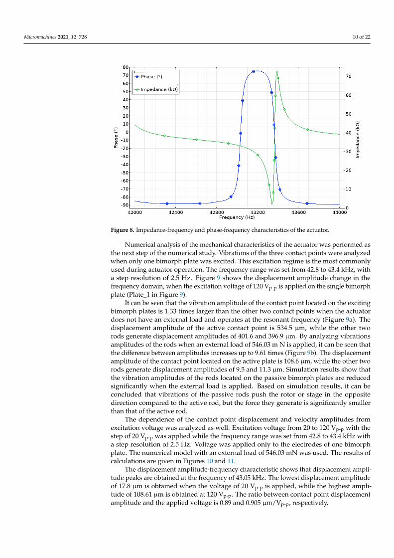
The further step of the numerical study was to analyze impedance and phase char-acteristics of the actuator in the frequency range from 42 to 44 kHz with the step of 5 Hz(Figure 8). It can be seen that the lowest impedance value of 1.34 kΩ is obtained at theresonant frequency of 43.345 kHz. Moreover, the calculated mechanical quality factor of theactuator is Qm = 2422.7, while the effective coupling coefficient is keff = 0.047. This meansthat the actuator has low mechanical loss at the operating frequency of the actuator.
Micromachines 2021, 12, x FOR PEER REVIEW 10 of 23
respectively. The modal shapes are shown in Figure 7. It can be seen that modal shapes are similar, and the bending mode of the bimorphs induces radial vibrations of the ring, and the B03 radial vibration mode composes B20 bending mode of the bimorph plates. In addition, it must be noted that the junction points of the U-shaped clamping structure and the ring are located precisely at nodal points of B03 vibration mode and vibrate in the first bending mode. Harmonization of the vibration modes of the individual structural components of the actuator makes it possible to achieve low structural damping and increase amplitudes of vibrations.
Figure 7. The modal shape of the stator at the frequency of 42.80 (a) and 43.39 kHz (b).
The further step of the numerical study was to analyze impedance and phase characteristics of the actuator in the frequency range from 42 to 44 kHz with the step of 5 Hz (Figure 8). It can be seen that the lowest impedance value of 1.34 kΩ is obtained at the resonant frequency of 43.345 kHz. Moreover, the calculated mechanical quality factor of the actuator is Qm = 2422.7, while the effective coupling coefficient is keff = 0.047. This means that the actuator has low mechanical loss at the operating frequency of the actuator.
Numerical analysis of the mechanical characteristics of the actuator was performed as the next step of the numerical study. Vibrations of the three contact points were analyzed when only one bimorph plate was excited. This excitation regime is the most commonly used during actuator operation. The frequency range was set from 42.8 to 43.4 kHz, with a step resolution of 2.5 Hz. Figure 9 shows the displacement amplitude change in the frequency domain, when the excitation voltage of 120 Vp-p is applied on the single bimorph plate (Plate_1 in Figure 9).
Figure 8. Impedance-frequency and phase-frequency characteristics of the actuator.
(a) (b)
Figure 7. The modal shape of the stator at the frequency of 42.80 (a) and 43.39 kHz (b).
Micromachines 2021, 12, 728 10 of 22
Micromachines 2021, 12, x FOR PEER REVIEW 10 of 23
respectively. The modal shapes are shown in Figure 7. It can be seen that modal shapes are similar, and the bending mode of the bimorphs induces radial vibrations of the ring, and the B03 radial vibration mode composes B20 bending mode of the bimorph plates. In addition, it must be noted that the junction points of the U-shaped clamping structure and the ring are located precisely at nodal points of B03 vibration mode and vibrate in the first bending mode. Harmonization of the vibration modes of the individual structural components of the actuator makes it possible to achieve low structural damping and increase amplitudes of vibrations.
Figure 7. The modal shape of the stator at the frequency of 42.80 (a) and 43.39 kHz (b).
The further step of the numerical study was to analyze impedance and phase characteristics of the actuator in the frequency range from 42 to 44 kHz with the step of 5 Hz (Figure 8). It can be seen that the lowest impedance value of 1.34 kΩ is obtained at the resonant frequency of 43.345 kHz. Moreover, the calculated mechanical quality factor of the actuator is Qm = 2422.7, while the effective coupling coefficient is keff = 0.047. This means that the actuator has low mechanical loss at the operating frequency of the actuator.
Numerical analysis of the mechanical characteristics of the actuator was performed as the next step of the numerical study. Vibrations of the three contact points were analyzed when only one bimorph plate was excited. This excitation regime is the most commonly used during actuator operation. The frequency range was set from 42.8 to 43.4 kHz, with a step resolution of 2.5 Hz. Figure 9 shows the displacement amplitude change in the frequency domain, when the excitation voltage of 120 Vp-p is applied on the single bimorph plate (Plate_1 in Figure 9).
Figure 8. Impedance-frequency and phase-frequency characteristics of the actuator.
(a) (b)
Figure 8. Impedance-frequency and phase-frequency characteristics of the actuator.
Numerical analysis of the mechanical characteristics of the actuator was performed asthe next step of the numerical study. Vibrations of the three contact points were analyzedwhen only one bimorph plate was excited. This excitation regime is the most commonlyused during actuator operation. The frequency range was set from 42.8 to 43.4 kHz, witha step resolution of 2.5 Hz. Figure 9 shows the displacement amplitude change in thefrequency domain, when the excitation voltage of 120 Vp-p is applied on the single bimorphplate (Plate_1 in Figure 9).
It can be seen that the vibration amplitude of the contact point located on the excitingbimorph plates is 1.33 times larger than the other two contact points when the actuatordoes not have an external load and operates at the resonant frequency (Figure 9a). Thedisplacement amplitude of the active contact point is 534.5 µm, while the other tworods generate displacement amplitudes of 401.6 and 396.9 µm. By analyzing vibrationsamplitudes of the rods when an external load of 546.03 m N is applied, it can be seen thatthe difference between amplitudes increases up to 9.61 times (Figure 9b). The displacementamplitude of the contact point located on the active plate is 108.6 µm, while the other tworods generate displacement amplitudes of 9.5 and 11.3 µm. Simulation results show thatthe vibration amplitudes of the rods located on the passive bimorph plates are reducedsignificantly when the external load is applied. Based on simulation results, it can beconcluded that vibrations of the passive rods push the rotor or stage in the oppositedirection compared to the active rod, but the force they generate is significantly smallerthan that of the active rod.
The dependence of the contact point displacement and velocity amplitudes fromexcitation voltage was analyzed as well. Excitation voltage from 20 to 120 Vp-p with thestep of 20 Vp-p was applied while the frequency range was set from 42.8 to 43.4 kHz witha step resolution of 2.5 Hz. Voltage was applied only to the electrodes of one bimorphplate. The numerical model with an external load of 546.03 mN was used. The results ofcalculations are given in Figures 10 and 11.
The displacement amplitude-frequency characteristic shows that displacement ampli-tude peaks are obtained at the frequency of 43.05 kHz. The lowest displacement amplitudeof 17.8 µm is obtained when the voltage of 20 Vp-p is applied, while the highest ampli-tude of 108.61 µm is obtained at 120 Vp-p. The ratio between contact point displacementamplitude and the applied voltage is 0.89 and 0.905 µm/Vp-p, respectively.

Micromachines 2021, 12, 728 11 of 22
Micromachines 2021, 12, x FOR PEER REVIEW 11 of 23
It can be seen that the vibration amplitude of the contact point located on the exciting bimorph plates is 1.33 times larger than the other two contact points when the actuator does not have an external load and operates at the resonant frequency (Figure 9a). The displacement amplitude of the active contact point is 534.5 µm, while the other two rods generate displacement amplitudes of 401.6 and 396.9 µm. By analyzing vibrations amplitudes of the rods when an external load of 546.03 m N is applied, it can be seen that the difference between amplitudes increases up to 9.61 times (Figure 9b). The displacement amplitude of the contact point located on the active plate is 108.6 µm, while the other two rods generate displacement amplitudes of 9.5 and 11.3 µm. Simulation results show that the vibration amplitudes of the rods located on the passive bimorph plates are reduced significantly when the external load is applied. Based on simulation results, it can be concluded that vibrations of the passive rods push the rotor or stage in the opposite direction compared to the active rod, but the force they generate is significantly smaller than that of the active rod.
Figure 9. Displacement amplitude versus frequency of the three contact points when one bimorph plate is excited with no load (a) and the mechanical load is applied (b).
The dependence of the contact point displacement and velocity amplitudes from excitation voltage was analyzed as well. Excitation voltage from 20 to 120 Vp-p with the step of 20 Vp-p was applied while the frequency range was set from 42.8 to 43.4 kHz with a step resolution of 2.5 Hz. Voltage was applied only to the electrodes of one bimorph
(a)
(b)
Figure 9. Displacement amplitude versus frequency of the three contact points when one bimorphplate is excited with no load (a) and the mechanical load is applied (b).
Micromachines 2021, 12, x FOR PEER REVIEW 12 of 23
plate. The numerical model with an external load of 546.03 mN was used. The results of calculations are given in Figures 10 and 11.
The displacement amplitude-frequency characteristic shows that displacement amplitude peaks are obtained at the frequency of 43.05 kHz. The lowest displacement amplitude of 17.8 µm is obtained when the voltage of 20 Vp-p is applied, while the highest amplitude of 108.61 µm is obtained at 120 Vp-p. The ratio between contact point displacement amplitude and the applied voltage is 0.89 and 0.905 µm/Vp-p, respectively.
Figure 10. Displacement amplitude-frequency characteristics at different excitation voltages.
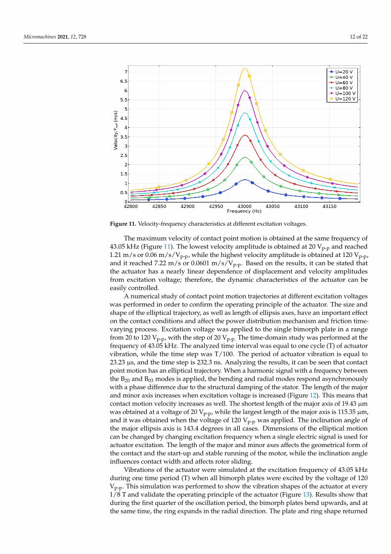
Figure 11. Velocity-frequency characteristics at different excitation voltages.
The maximum velocity of contact point motion is obtained at the same frequency of 43.05 kHz (Figure 11). The lowest velocity amplitude is obtained at 20 Vp-p and reached 1.21 m/s or 0.06 m/s/Vp-p, while the highest velocity amplitude is obtained at 120 Vp-p, and it reached 7.22 m/s or 0.0601 m/s/Vp-p. Based on the results, it can be stated that the actuator
Figure 10. Displacement amplitude-frequency characteristics at different excitation voltages.
Micromachines 2021, 12, 728 12 of 22
Micromachines 2021, 12, x FOR PEER REVIEW 12 of 23
plate. The numerical model with an external load of 546.03 mN was used. The results of calculations are given in Figures 10 and 11.
The displacement amplitude-frequency characteristic shows that displacement amplitude peaks are obtained at the frequency of 43.05 kHz. The lowest displacement amplitude of 17.8 µm is obtained when the voltage of 20 Vp-p is applied, while the highest amplitude of 108.61 µm is obtained at 120 Vp-p. The ratio between contact point displacement amplitude and the applied voltage is 0.89 and 0.905 µm/Vp-p, respectively.
Figure 10. Displacement amplitude-frequency characteristics at different excitation voltages.
Figure 11. Velocity-frequency characteristics at different excitation voltages.
The maximum velocity of contact point motion is obtained at the same frequency of 43.05 kHz (Figure 11). The lowest velocity amplitude is obtained at 20 Vp-p and reached 1.21 m/s or 0.06 m/s/Vp-p, while the highest velocity amplitude is obtained at 120 Vp-p, and it reached 7.22 m/s or 0.0601 m/s/Vp-p. Based on the results, it can be stated that the actuator
Figure 11. Velocity-frequency characteristics at different excitation voltages.
The maximum velocity of contact point motion is obtained at the same frequency of43.05 kHz (Figure 11). The lowest velocity amplitude is obtained at 20 Vp-p and reached1.21 m/s or 0.06 m/s/Vp-p, while the highest velocity amplitude is obtained at 120 Vp-p,and it reached 7.22 m/s or 0.0601 m/s/Vp-p. Based on the results, it can be stated thatthe actuator has a nearly linear dependence of displacement and velocity amplitudesfrom excitation voltage; therefore, the dynamic characteristics of the actuator can beeasily controlled.
A numerical study of contact point motion trajectories at different excitation voltageswas performed in order to confirm the operating principle of the actuator. The size andshape of the elliptical trajectory, as well as length of ellipsis axes, have an important effecton the contact conditions and affect the power distribution mechanism and friction time-varying process. Excitation voltage was applied to the single bimorph plate in a rangefrom 20 to 120 Vp-p, with the step of 20 Vp-p. The time-domain study was performed at thefrequency of 43.05 kHz. The analyzed time interval was equal to one cycle (T) of actuatorvibration, while the time step was T/100. The period of actuator vibration is equal to23.23 µs, and the time step is 232.3 ns. Analyzing the results, it can be seen that contactpoint motion has an elliptical trajectory. When a harmonic signal with a frequency betweenthe B20 and B03 modes is applied, the bending and radial modes respond asynchronouslywith a phase difference due to the structural damping of the stator. The length of the majorand minor axis increases when excitation voltage is increased (Figure 12). This means thatcontact motion velocity increases as well. The shortest length of the major axis of 19.43 µmwas obtained at a voltage of 20 Vp-p, while the largest length of the major axis is 115.35 µm,and it was obtained when the voltage of 120 Vp-p was applied. The inclination angle ofthe major ellipsis axis is 143.4 degrees in all cases. Dimensions of the elliptical motioncan be changed by changing excitation frequency when a single electric signal is used foractuator excitation. The length of the major and minor axes affects the geometrical form ofthe contact and the start-up and stable running of the motor, while the inclination angleinfluences contact width and affects rotor sliding.
Vibrations of the actuator were simulated at the excitation frequency of 43.05 kHzduring one time period (T) when all bimorph plates were excited by the voltage of 120Vp-p. This simulation was performed to show the vibration shapes of the actuator at every1/8 T and validate the operating principle of the actuator (Figure 13). Results show thatduring the first quarter of the oscillation period, the bimorph plates bend upwards, and atthe same time, the ring expands in the radial direction. The plate and ring shape returned

Micromachines 2021, 12, 728 13 of 22
to their original position during the second quarter of the period. In the third quarter of theperiod, the plates bend downwards, and the ring contracts to the center. Later, the shapeof the actuator returns to its original position. It can be concluded that the vibrations ofthe actuator combine the bending mode of the plate and radial mode of the ring, while thecontacting point of the rod moves in an elliptical trajectory.
Micromachines 2021, 12, x FOR PEER REVIEW 13 of 23
has a nearly linear dependence of displacement and velocity amplitudes from excitation voltage; therefore, the dynamic characteristics of the actuator can be easily controlled.
A numerical study of contact point motion trajectories at different excitation voltages was performed in order to confirm the operating principle of the actuator. The size and shape of the elliptical trajectory, as well as length of ellipsis axes, have an important effect on the contact conditions and affect the power distribution mechanism and friction time-varying process. Excitation voltage was applied to the single bimorph plate in a range from 20 to 120 Vp-p, with the step of 20 Vp-p. The time-domain study was performed at the frequency of 43.05 kHz. The analyzed time interval was equal to one cycle (T) of actuator vibration, while the time step was T/100. The period of actuator vibration is equal to 23.23 µs, and the time step is 232.3 ns. Analyzing the results, it can be seen that contact point motion has an elliptical trajectory. When a harmonic signal with a frequency between the B20 and B03 modes is applied, the bending and radial modes respond asynchronously with a phase difference due to the structural damping of the stator. The length of the major and minor axis increases when excitation voltage is increased (Figure 12). This means that contact motion velocity increases as well. The shortest length of the major axis of 19.43 µm was obtained at a voltage of 20 Vp-p, while the largest length of the major axis is 115.35 µm, and it was obtained when the voltage of 120 Vp-p was applied. The inclination angle of the major ellipsis axis is 143.4 degrees in all cases. Dimensions of the elliptical motion can be changed by changing excitation frequency when a single electric signal is used for actuator excitation. The length of the major and minor axes affects the geometrical form of the contact and the start-up and stable running of the motor, while the inclination angle influences contact width and affects rotor sliding.
Figure 12. Motion trajectories of contact point at different excitation voltage amplitudes.
Vibrations of the actuator were simulated at the excitation frequency of 43.05 kHz during one time period (T) when all bimorph plates were excited by the voltage of 120 Vp-
p. This simulation was performed to show the vibration shapes of the actuator at every 1/8 T and validate the operating principle of the actuator (Figure 13). Results show that during the first quarter of the oscillation period, the bimorph plates bend upwards, and at the same time, the ring expands in the radial direction. The plate and ring shape returned to their original position during the second quarter of the period. In the third quarter of the period, the plates bend downwards, and the ring contracts to the center. Later, the shape of the actuator returns to its original position. It can be concluded that the vibrations of
Figure 12. Motion trajectories of contact point at different excitation voltage amplitudes.
Micromachines 2021, 12, x FOR PEER REVIEW 14 of 23
the actuator combine the bending mode of the plate and radial mode of the ring, while the contacting point of the rod moves in an elliptical trajectory.
Figure 13. The operation sequence of the actuator during one period of vibrations.
Results of the numerical investigation confirmed that the proposed design of the actuator can be used to generate the rotary motion of the spherical rotor as well as the liner motion of the flat stage. Moreover, optimized geometrical parameters allowed minimizing the difference between resonant frequencies of B20 and B03 vibration modes. The obtained results show that the actuator has a nearly linear dependence of the displacement and velocity from the applied voltage.
4. Experimental Investigation of the Motor An experimental investigation of the actuator was performed to validate the
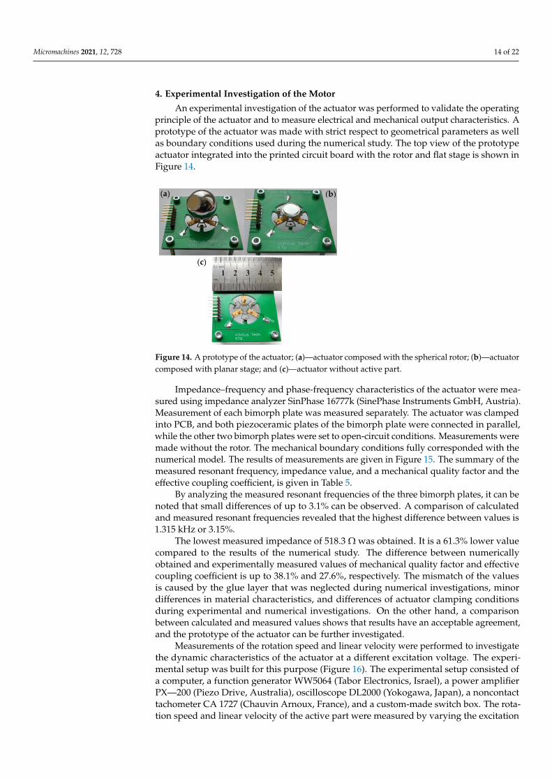
operating principle of the actuator and to measure electrical and mechanical output characteristics. A prototype of the actuator was made with strict respect to geometrical parameters as well as boundary conditions used during the numerical study. The top view of the prototype actuator integrated into the printed circuit board with the rotor and flat stage is shown in Figure 14.
Impedance–frequency and phase-frequency characteristics of the actuator were measured using impedance analyzer SinPhase 16777k (SinePhase Instruments GmbH, Austria). Measurement of each bimorph plate was measured separately. The actuator was clamped into PCB, and both piezoceramic plates of the bimorph plate were connected in parallel, while the other two bimorph plates were set to open-circuit conditions. Measurements were made without the rotor. The mechanical boundary conditions fully corresponded with the numerical model. The results of measurements are given in Figure 15. The summary of the measured resonant frequency, impedance value, and a mechanical quality factor and the effective coupling coefficient, is given in Table 5.
By analyzing the measured resonant frequencies of the three bimorph plates, it can be noted that small differences of up to 3.1% can be observed. A comparison of calculated and measured resonant frequencies revealed that the highest difference between values is 1.315 kHz or 3.15%.
Figure 13. The operation sequence of the actuator during one period of vibrations.
Results of the numerical investigation confirmed that the proposed design of theactuator can be used to generate the rotary motion of the spherical rotor as well as the linermotion of the flat stage. Moreover, optimized geometrical parameters allowed minimizingthe difference between resonant frequencies of B20 and B03 vibration modes. The obtainedresults show that the actuator has a nearly linear dependence of the displacement andvelocity from the applied voltage.
Micromachines 2021, 12, 728 14 of 22
4. Experimental Investigation of the Motor
An experimental investigation of the actuator was performed to validate the operatingprinciple of the actuator and to measure electrical and mechanical output characteristics. Aprototype of the actuator was made with strict respect to geometrical parameters as wellas boundary conditions used during the numerical study. The top view of the prototypeactuator integrated into the printed circuit board with the rotor and flat stage is shown inFigure 14.
Micromachines 2021, 12, x FOR PEER REVIEW 15 of 23
Table 5. Results of impedance and frequency measurement.
Bimorph Plate Frequency, kHz Impedance, Ω Qm keff Plate No.1 42.03 548.1 1798.1 0.0348 Plate No.2 42.35 518.3 1754.3 0.034 Plate No.3 42.17 625.8 1801.3 0.0351
The lowest measured impedance of 518.3 Ω was obtained. It is a 61.3% lower value compared to the results of the numerical study. The difference between numerically obtained and experimentally measured values of mechanical quality factor and effective coupling coefficient is up to 38.1% and 27.6%, respectively. The mismatch of the values is caused by the glue layer that was neglected during numerical investigations, minor differences in material characteristics, and differences of actuator clamping conditions during experimental and numerical investigations. On the other hand, a comparison between calculated and measured values shows that results have an acceptable agreement, and the prototype of the actuator can be further investigated.
Figure 14. A prototype of the actuator; (a)—actuator composed with the spherical rotor; (b)—actuator composed with planar stage; and (c)—actuator without active part.
(a) (b)
(a) (b)
(c)
Figure 14. A prototype of the actuator; (a)—actuator composed with the spherical rotor; (b)—actuatorcomposed with planar stage; and (c)—actuator without active part.
Impedance–frequency and phase-frequency characteristics of the actuator were mea-sured using impedance analyzer SinPhase 16777k (SinePhase Instruments GmbH, Austria).Measurement of each bimorph plate was measured separately. The actuator was clampedinto PCB, and both piezoceramic plates of the bimorph plate were connected in parallel,while the other two bimorph plates were set to open-circuit conditions. Measurements weremade without the rotor. The mechanical boundary conditions fully corresponded with thenumerical model. The results of measurements are given in Figure 15. The summary of themeasured resonant frequency, impedance value, and a mechanical quality factor and theeffective coupling coefficient, is given in Table 5.
By analyzing the measured resonant frequencies of the three bimorph plates, it can benoted that small differences of up to 3.1% can be observed. A comparison of calculatedand measured resonant frequencies revealed that the highest difference between values is1.315 kHz or 3.15%.
The lowest measured impedance of 518.3 Ω was obtained. It is a 61.3% lower valuecompared to the results of the numerical study. The difference between numericallyobtained and experimentally measured values of mechanical quality factor and effectivecoupling coefficient is up to 38.1% and 27.6%, respectively. The mismatch of the valuesis caused by the glue layer that was neglected during numerical investigations, minordifferences in material characteristics, and differences of actuator clamping conditionsduring experimental and numerical investigations. On the other hand, a comparisonbetween calculated and measured values shows that results have an acceptable agreement,and the prototype of the actuator can be further investigated.
Measurements of the rotation speed and linear velocity were performed to investigatethe dynamic characteristics of the actuator at a different excitation voltage. The experi-mental setup was built for this purpose (Figure 16). The experimental setup consisted ofa computer, a function generator WW5064 (Tabor Electronics, Israel), a power amplifierPX—200 (Piezo Drive, Australia), oscilloscope DL2000 (Yokogawa, Japan), a noncontacttachometer CA 1727 (Chauvin Arnoux, France), and a custom-made switch box. The rota-tion speed and linear velocity of the active part were measured by varying the excitation

Micromachines 2021, 12, 728 15 of 22
voltage from 20 to 120 Vp-p. In addition, four different preload force values were applied.The detailed experimental study was performed with the bimorph plate No. 2 because ithas the lowest impedance value. The remaining two bimorph plates were investigated onlywhen an excitation voltage of 120 Vp-p was applied. The results of plate No. 2 measurementare given in Figures 17 and 18. In addition, Videos S1–S3, were included as a supplementarymaterial in order to show actuator operation while different plates are excited. Moreover,Video S4 shows actuator operation in step mode.
Micromachines 2021, 12, x FOR PEER REVIEW 15 of 23
Table 5. Results of impedance and frequency measurement.
Bimorph Plate Frequency, kHz Impedance, Ω Qm keff Plate No.1 42.03 548.1 1798.1 0.0348 Plate No.2 42.35 518.3 1754.3 0.034 Plate No.3 42.17 625.8 1801.3 0.0351
The lowest measured impedance of 518.3 Ω was obtained. It is a 61.3% lower value compared to the results of the numerical study. The difference between numerically obtained and experimentally measured values of mechanical quality factor and effective coupling coefficient is up to 38.1% and 27.6%, respectively. The mismatch of the values is caused by the glue layer that was neglected during numerical investigations, minor differences in material characteristics, and differences of actuator clamping conditions during experimental and numerical investigations. On the other hand, a comparison between calculated and measured values shows that results have an acceptable agreement, and the prototype of the actuator can be further investigated.
Figure 14. A prototype of the actuator; (a)—actuator composed with the spherical rotor; (b)—actuator composed with planar stage; and (c)—actuator without active part.
(a) (b)
(a) (b)
(c)
Micromachines 2021, 12, x FOR PEER REVIEW 16 of 23
(c)
Figure 15. The measured impedance and phase characteristics in the frequency domain; (a)—bimorph plate No.1; (b)—bimorph plate No.2; and (c)—bimorph plate No.3.
Measurements of the rotation speed and linear velocity were performed to investigate the dynamic characteristics of the actuator at a different excitation voltage. The experimental setup was built for this purpose (Figure 16). The experimental setup consisted of a computer, a function generator WW5064 (Tabor Electronics, Israel), a power amplifier PX—200 (Piezo Drive, Australia), oscilloscope DL2000 (Yokogawa, Japan), a noncontact tachometer CA 1727 (Chauvin Arnoux, France), and a custom-made switch box. The rotation speed and linear velocity of the active part were measured by varying the excitation voltage from 20 to 120 Vp-p. In addition, four different preload force values were applied. The detailed experimental study was performed with the bimorph plate No. 2 because it has the lowest impedance value. The remaining two bimorph plates were investigated only when an excitation voltage of 120 Vp-p was applied. The results of plate No. 2 measurement are given in Figures 17 and 18. In addition, Videos S1–S3, were included as a supplementary material in order to show actuator operation while different plates are excited. Moreover, Video S4 shows actuator operation in step mode.
Figure 16. Scheme of the experimental setup: 1—a computer with data acquisition and switch control software; 2—function generator; 3—power amplifier; 4—oscilloscope; 5—noncontact tachometer; 6—a prototype of the actuator; and 7—digitally controlled switch box.
Figure 15. The measured impedance and phase characteristics in the frequency domain; (a)—bimorphplate No.1; (b)—bimorph plate No.2; and (c)—bimorph plate No.3.
Table 5. Results of impedance and frequency measurement.
Bimorph Plate Frequency, kHz Impedance, Ω Qm keff
Plate No.1 42.03 548.1 1798.1 0.0348Plate No.2 42.35 518.3 1754.3 0.034Plate No.3 42.17 625.8 1801.3 0.0351
By analyzing the results of the measured rotation speed, it can be seen that the lowestvalue of 54.6 RPM was obtained at the preload force of 68.2 m N and voltage of 20 Vp-p(Figure 17). On the other hand, the rotation speed of 259.1 RPM was reached at the same

Micromachines 2021, 12, 728 16 of 22
preload when the voltage was increased up to 120 Vp-p. The average speed–voltage ratio is2.66 RPM/Vp-p.
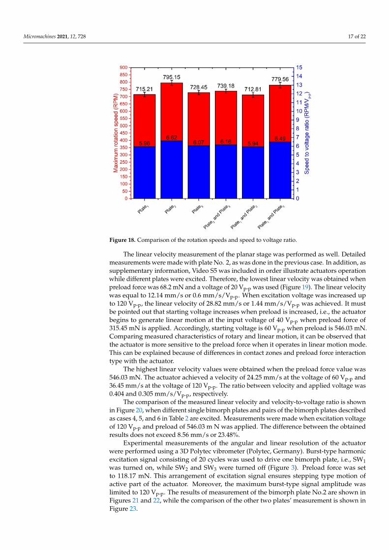
The highest rotation speed of 795.15 RPM was obtained when plate No.2 was excited,and preload force was 546.03 m N, and voltage of 120 Vp-p was applied. The ratio betweenspeed and voltage is 6.62 RPM/Vp-p in this case. However, the starting voltage is 40 Vp-pat this preload value, and rotation speed is 130.3 RPM or 3.26 RPM/Vp-p, respectively. Thestarting voltage of the actuator was 20 Vp-p at other preload force values. Results showedthat that rotation speed has an almost linear dependence from the voltage. The comparisonof the measured rotation speed and speed to voltage ratio is shown in Figure 18, whendifferent single bimorph plates and pairs of the bimorph plates described as cases 4, 5, and6 in Table 2 are excited. Measurements were made when excitation voltage of 120 Vp-pand preload of 546.03 mN was applied. The difference between obtained results does notexceed 82.34 RPM or 10.35%. The differences are mainly caused by minor different resonantfrequencies as well as minor differences in contact conditions between the spherical rotorand cylinder-shaped beams used to transfer the vibration from plates to the active part ofthe actuator.
Micromachines 2021, 12, x FOR PEER REVIEW 16 of 23
(c)
Figure 15. The measured impedance and phase characteristics in the frequency domain; (a)—bimorph plate No.1; (b)—bimorph plate No.2; and (c)—bimorph plate No.3.
Measurements of the rotation speed and linear velocity were performed to investigate the dynamic characteristics of the actuator at a different excitation voltage. The experimental setup was built for this purpose (Figure 16). The experimental setup consisted of a computer, a function generator WW5064 (Tabor Electronics, Israel), a power amplifier PX—200 (Piezo Drive, Australia), oscilloscope DL2000 (Yokogawa, Japan), a noncontact tachometer CA 1727 (Chauvin Arnoux, France), and a custom-made switch box. The rotation speed and linear velocity of the active part were measured by varying the excitation voltage from 20 to 120 Vp-p. In addition, four different preload force values were applied. The detailed experimental study was performed with the bimorph plate No. 2 because it has the lowest impedance value. The remaining two bimorph plates were investigated only when an excitation voltage of 120 Vp-p was applied. The results of plate No. 2 measurement are given in Figures 17 and 18. In addition, Videos S1–S3, were included as a supplementary material in order to show actuator operation while different plates are excited. Moreover, Video S4 shows actuator operation in step mode.
Figure 16. Scheme of the experimental setup: 1—a computer with data acquisition and switch control software; 2—function generator; 3—power amplifier; 4—oscilloscope; 5—noncontact tachometer; 6—a prototype of the actuator; and 7—digitally controlled switch box.
Figure 16. Scheme of the experimental setup: 1—a computer with data acquisition and switch controlsoftware; 2—function generator; 3—power amplifier; 4—oscilloscope; 5—noncontact tachometer;6—a prototype of the actuator; and 7—digitally controlled switch box.
Micromachines 2021, 12, x FOR PEER REVIEW 17 of 23
By analyzing the results of the measured rotation speed, it can be seen that the lowest value of 54.6 RPM was obtained at the preload force of 68.2 m N and voltage of 20 Vp-p (Figure 17). On the other hand, the rotation speed of 259.1 RPM was reached at the same preload when the voltage was increased up to 120 Vp-p. The average speed–voltage ratio is 2.66 RPM/Vp-p.
Figure 17. The rotation speed of spherical rotor at different excitation voltages and preload forces when bimorph plate No. 2 is excited.
Figure 18. Comparison of the rotation speeds and speed to voltage ratio.
The highest rotation speed of 795.15 RPM was obtained when plate No.2 was excited, and preload force was 546.03 m N, and voltage of 120 Vp-p was applied. The ratio between speed and voltage is 6.62 RPM/Vp-p in this case. However, the starting voltage is 40 Vp-p at this preload value, and rotation speed is 130.3 RPM or 3.26 RPM/Vp-p, respectively. The
Figure 17. The rotation speed of spherical rotor at different excitation voltages and preload forceswhen bimorph plate No. 2 is excited.
Micromachines 2021, 12, 728 17 of 22
Micromachines 2021, 12, x FOR PEER REVIEW 17 of 23
By analyzing the results of the measured rotation speed, it can be seen that the lowest value of 54.6 RPM was obtained at the preload force of 68.2 m N and voltage of 20 Vp-p (Figure 17). On the other hand, the rotation speed of 259.1 RPM was reached at the same preload when the voltage was increased up to 120 Vp-p. The average speed–voltage ratio is 2.66 RPM/Vp-p.
Figure 17. The rotation speed of spherical rotor at different excitation voltages and preload forces when bimorph plate No. 2 is excited.
Figure 18. Comparison of the rotation speeds and speed to voltage ratio.
The highest rotation speed of 795.15 RPM was obtained when plate No.2 was excited, and preload force was 546.03 m N, and voltage of 120 Vp-p was applied. The ratio between speed and voltage is 6.62 RPM/Vp-p in this case. However, the starting voltage is 40 Vp-p at this preload value, and rotation speed is 130.3 RPM or 3.26 RPM/Vp-p, respectively. The
Figure 18. Comparison of the rotation speeds and speed to voltage ratio.
The linear velocity measurement of the planar stage was performed as well. Detailedmeasurements were made with plate No. 2, as was done in the previous case. In addition, assupplementary information, Video S5 was included in order illustrate actuators operationwhile different plates were excited. Therefore, the lowest linear velocity was obtained whenpreload force was 68.2 mN and a voltage of 20 Vp-p was used (Figure 19). The linear velocitywas equal to 12.14 mm/s or 0.6 mm/s/Vp-p. When excitation voltage was increased upto 120 Vp-p, the linear velocity of 28.82 mm/s or 1.44 mm/s/Vp-p was achieved. It mustbe pointed out that starting voltage increases when preload is increased, i.e., the actuatorbegins to generate linear motion at the input voltage of 40 Vp-p when preload force of315.45 mN is applied. Accordingly, starting voltage is 60 Vp-p when preload is 546.03 mN.Comparing measured characteristics of rotary and linear motion, it can be observed thatthe actuator is more sensitive to the preload force when it operates in linear motion mode.This can be explained because of differences in contact zones and preload force interactiontype with the actuator.
The highest linear velocity values were obtained when the preload force value was546.03 mN. The actuator achieved a velocity of 24.25 mm/s at the voltage of 60 Vp-p and36.45 mm/s at the voltage of 120 Vp-p. The ratio between velocity and applied voltage was0.404 and 0.305 mm/s/Vp-p, respectively.
The comparison of the measured linear velocity and velocity-to-voltage ratio is shownin Figure 20, when different single bimorph plates and pairs of the bimorph plates describedas cases 4, 5, and 6 in Table 2 are excited. Measurements were made when excitation voltageof 120 Vp-p and preload of 546.03 m N was applied. The difference between the obtainedresults does not exceed 8.56 mm/s or 23.48%.
Experimental measurements of the angular and linear resolution of the actuatorwere performed using a 3D Polytec vibrometer (Polytec, Germany). Burst-type harmonicexcitation signal consisting of 20 cycles was used to drive one bimorph plate, i.e., SW1was turned on, while SW2 and SW3 were turned off (Figure 3). Preload force was setto 118.17 mN. This arrangement of excitation signal ensures stepping type motion ofactive part of the actuator. Moreover, the maximum burst-type signal amplitude waslimited to 120 Vp-p. The results of measurement of the bimorph plate No.2 are shown inFigures 21 and 22, while the comparison of the other two plates’ measurement is shown inFigure 23.

Micromachines 2021, 12, 728 18 of 22
Micromachines 2021, 12, x FOR PEER REVIEW 18 of 23
starting voltage of the actuator was 20 Vp-p at other preload force values. Results showed that that rotation speed has an almost linear dependence from the voltage. The comparison of the measured rotation speed and speed to voltage ratio is shown in Figure 18, when different single bimorph plates and pairs of the bimorph plates described as cases 4, 5, and 6 in Table 2 are excited. Measurements were made when excitation voltage of 120 Vp-p and preload of 546.03 mN was applied. The difference between obtained results does not exceed 82.34 RPM or 10.35%. The differences are mainly caused by minor different resonant frequencies as well as minor differences in contact conditions between the spherical rotor and cylinder-shaped beams used to transfer the vibration from plates to the active part of the actuator.
The linear velocity measurement of the planar stage was performed as well. Detailed measurements were made with plate No. 2, as was done in the previous case. In addition, as supplementary information, Video S5 was included in order illustrate actuators operation while different plates were excited. Therefore,the lowest linear velocity was obtained when preload force was 68.2 mN and a voltage of 20 Vp-p was used (Figure 19). The linear velocity was equal to 12.14 mm/s or 0.6 mm/s/Vp-p. When excitation voltage was increased up to 120 Vp-p, the linear velocity of 28.82 mm/s or 1.44 mm/s/Vp-p was achieved. It must be pointed out that starting voltage increases when preload is increased, i.e., the actuator begins to generate linear motion at the input voltage of 40 Vp-p when preload force of 315.45 mN is applied. Accordingly, starting voltage is 60 Vp-p when preload is 546.03 mN. Comparing measured characteristics of rotary and linear motion, it can be observed that the actuator is more sensitive to the preload force when it operates in linear motion mode. This can be explained because of differences in contact zones and preload force interaction type with the actuator.
Figure 19. The linear velocity of the flat stage at different preload forces and voltages when bimorph plate No.2 is excited.
The highest linear velocity values were obtained when the preload force value was 546.03 mN. The actuator achieved a velocity of 24.25 mm/s at the voltage of 60 Vp-p and 36.45 mm/s at the voltage of 120 Vp-p. The ratio between velocity and applied voltage was 0.404 and 0.305 mm/s/Vp-p, respectively.
The comparison of the measured linear velocity and velocity-to-voltage ratio is shown in Figure 20, when different single bimorph plates and pairs of the bimorph plates described as cases 4, 5, and 6 in Table 2 are excited. Measurements were made when
Figure 19. The linear velocity of the flat stage at different preload forces and voltages when bimorphplate No.2 is excited.
Micromachines 2021, 12, x FOR PEER REVIEW 19 of 23
excitation voltage of 120 Vp-p and preload of 546.03 m N was applied. The difference between the obtained results does not exceed 8.56 mm/s or 23.48%.
Figure 20. Comparison of linear velocity and velocity-to-voltage ratio of the flat stage.
Experimental measurements of the angular and linear resolution of the actuator were performed using a 3D Polytec vibrometer (Polytec, Germany). Burst-type harmonic excitation signal consisting of 20 cycles was used to drive one bimorph plate, i.e., SW1 was turned on, while SW2 and SW3 were turned off (Figure 3). Preload force was set to 118.17 mN. This arrangement of excitation signal ensures stepping type motion of active part of the actuator. Moreover, the maximum burst-type signal amplitude was limited to 120 Vp-
p. The results of measurement of the bimorph plate No.2 are shown in Figures 21 and 22, while the comparison of the other two plates’ measurement is shown in Figure 23.
Figure 21. Angular motion resolution characteristics of the actuator.
Figure 20. Comparison of linear velocity and velocity-to-voltage ratio of the flat stage.
Micromachines 2021, 12, x FOR PEER REVIEW 19 of 23
excitation voltage of 120 Vp-p and preload of 546.03 m N was applied. The difference between the obtained results does not exceed 8.56 mm/s or 23.48%.
Figure 20. Comparison of linear velocity and velocity-to-voltage ratio of the flat stage.
Experimental measurements of the angular and linear resolution of the actuator were performed using a 3D Polytec vibrometer (Polytec, Germany). Burst-type harmonic excitation signal consisting of 20 cycles was used to drive one bimorph plate, i.e., SW1 was turned on, while SW2 and SW3 were turned off (Figure 3). Preload force was set to 118.17 mN. This arrangement of excitation signal ensures stepping type motion of active part of the actuator. Moreover, the maximum burst-type signal amplitude was limited to 120 Vp-
p. The results of measurement of the bimorph plate No.2 are shown in Figures 21 and 22, while the comparison of the other two plates’ measurement is shown in Figure 23.
Figure 21. Angular motion resolution characteristics of the actuator. Figure 21. Angular motion resolution characteristics of the actuator.
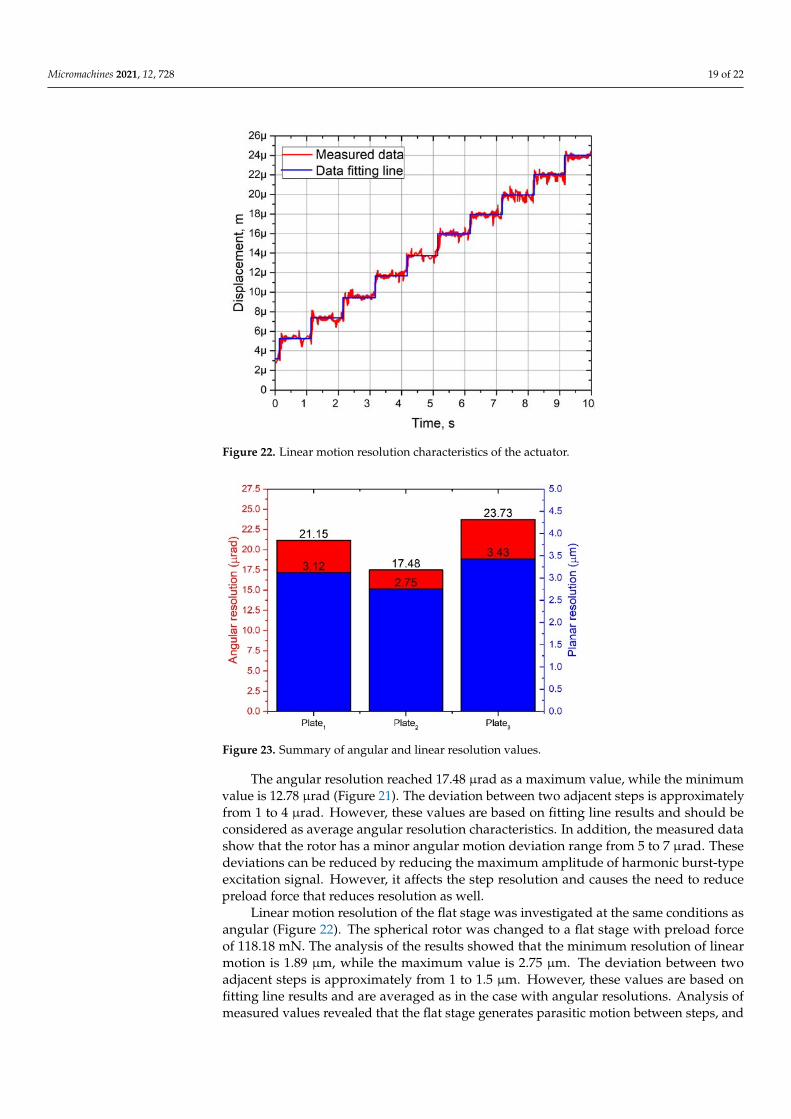
Micromachines 2021, 12, 728 19 of 22Micromachines 2021, 12, x FOR PEER REVIEW 20 of 23
Figure 22. Linear motion resolution characteristics of the actuator.
The angular resolution reached 17.48 µrad as a maximum value, while the minimum value is 12.78 µrad (Figure 21). The deviation between two adjacent steps is approximately from 1 to 4 µrad. However, these values are based on fitting line results and should be considered as average angular resolution characteristics. In addition, the measured data show that the rotor has a minor angular motion deviation range from 5 to 7 µrad. These deviations can be reduced by reducing the maximum amplitude of harmonic burst-type excitation signal. However, it affects the step resolution and causes the need to reduce preload force that reduces resolution as well.
Linear motion resolution of the flat stage was investigated at the same conditions as angular (Figure 22). The spherical rotor was changed to a flat stage with preload force of 118.18 mN. The analysis of the results showed that the minimum resolution of linear motion is 1.89 µm, while the maximum value is 2.75 µm. The deviation between two adjacent steps is approximately from 1 to 1.5 µm. However, these values are based on fitting line results and are averaged as in the case with angular resolutions. Analysis of measured values revealed that the flat stage generates parasitic motion between steps, and it deviates in the range from 0.5 to 2 µm. Compares to the angular resolution measurement, these parasitic motions are notably lower.
Figure 22. Linear motion resolution characteristics of the actuator.
Micromachines 2021, 12, x FOR PEER REVIEW 20 of 23
Figure 22. Linear motion resolution characteristics of the actuator.
The angular resolution reached 17.48 µrad as a maximum value, while the minimum value is 12.78 µrad (Figure 21). The deviation between two adjacent steps is approximately from 1 to 4 µrad. However, these values are based on fitting line results and should be considered as average angular resolution characteristics. In addition, the measured data show that the rotor has a minor angular motion deviation range from 5 to 7 µrad. These deviations can be reduced by reducing the maximum amplitude of harmonic burst-type excitation signal. However, it affects the step resolution and causes the need to reduce preload force that reduces resolution as well.
Linear motion resolution of the flat stage was investigated at the same conditions as angular (Figure 22). The spherical rotor was changed to a flat stage with preload force of 118.18 mN. The analysis of the results showed that the minimum resolution of linear motion is 1.89 µm, while the maximum value is 2.75 µm. The deviation between two adjacent steps is approximately from 1 to 1.5 µm. However, these values are based on fitting line results and are averaged as in the case with angular resolutions. Analysis of measured values revealed that the flat stage generates parasitic motion between steps, and it deviates in the range from 0.5 to 2 µm. Compares to the angular resolution measurement, these parasitic motions are notably lower.
Figure 23. Summary of angular and linear resolution values.
The angular resolution reached 17.48 µrad as a maximum value, while the minimumvalue is 12.78 µrad (Figure 21). The deviation between two adjacent steps is approximatelyfrom 1 to 4 µrad. However, these values are based on fitting line results and should beconsidered as average angular resolution characteristics. In addition, the measured datashow that the rotor has a minor angular motion deviation range from 5 to 7 µrad. Thesedeviations can be reduced by reducing the maximum amplitude of harmonic burst-typeexcitation signal. However, it affects the step resolution and causes the need to reducepreload force that reduces resolution as well.
Linear motion resolution of the flat stage was investigated at the same conditions asangular (Figure 22). The spherical rotor was changed to a flat stage with preload forceof 118.18 mN. The analysis of the results showed that the minimum resolution of linearmotion is 1.89 µm, while the maximum value is 2.75 µm. The deviation between twoadjacent steps is approximately from 1 to 1.5 µm. However, these values are based onfitting line results and are averaged as in the case with angular resolutions. Analysis ofmeasured values revealed that the flat stage generates parasitic motion between steps, and
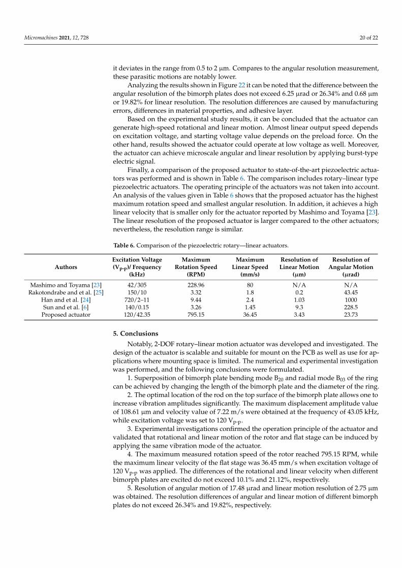
Micromachines 2021, 12, 728 20 of 22
it deviates in the range from 0.5 to 2 µm. Compares to the angular resolution measurement,these parasitic motions are notably lower.
Analyzing the results shown in Figure 22 it can be noted that the difference between theangular resolution of the bimorph plates does not exceed 6.25 µrad or 26.34% and 0.68 µmor 19.82% for linear resolution. The resolution differences are caused by manufacturingerrors, differences in material properties, and adhesive layer.
Based on the experimental study results, it can be concluded that the actuator cangenerate high-speed rotational and linear motion. Almost linear output speed dependson excitation voltage, and starting voltage value depends on the preload force. On theother hand, results showed the actuator could operate at low voltage as well. Moreover,the actuator can achieve microscale angular and linear resolution by applying burst-typeelectric signal.
Finally, a comparison of the proposed actuator to state-of-the-art piezoelectric actua-tors was performed and is shown in Table 6. The comparison includes rotary–linear typepiezoelectric actuators. The operating principle of the actuators was not taken into account.An analysis of the values given in Table 6 shows that the proposed actuator has the highestmaximum rotation speed and smallest angular resolution. In addition, it achieves a highlinear velocity that is smaller only for the actuator reported by Mashimo and Toyama [23].The linear resolution of the proposed actuator is larger compared to the other actuators;nevertheless, the resolution range is similar.
Table 6. Comparison of the piezoelectric rotary—linear actuators.
AuthorsExcitation Voltage(Vp-p)/ Frequency
(kHz)
MaximumRotation Speed
(RPM)
MaximumLinear Speed
(mm/s)
Resolution ofLinear Motion
(µm)
Resolution ofAngular Motion
(µrad)
Mashimo and Toyama [23] 42/305 228.96 80 N/A N/ARakotondrabe and et al. [25] 150/10 3.32 1.8 0.2 43.45
Han and et al. [24] 720/2–11 9.44 2.4 1.03 1000Sun and et al. [6] 140/0.15 3.26 1.45 9.3 228.5
Proposed actuator 120/42.35 795.15 36.45 3.43 23.73
5. Conclusions
Notably, 2-DOF rotary–linear motion actuator was developed and investigated. Thedesign of the actuator is scalable and suitable for mount on the PCB as well as use for ap-plications where mounting space is limited. The numerical and experimental investigationwas performed, and the following conclusions were formulated.
1. Superposition of bimorph plate bending mode B20 and radial mode B03 of the ringcan be achieved by changing the length of the bimorph plate and the diameter of the ring.
2. The optimal location of the rod on the top surface of the bimorph plate allows one toincrease vibration amplitudes significantly. The maximum displacement amplitude valueof 108.61 µm and velocity value of 7.22 m/s were obtained at the frequency of 43.05 kHz,while excitation voltage was set to 120 Vp-p.
3. Experimental investigations confirmed the operation principle of the actuator andvalidated that rotational and linear motion of the rotor and flat stage can be induced byapplying the same vibration mode of the actuator.
4. The maximum measured rotation speed of the rotor reached 795.15 RPM, whilethe maximum linear velocity of the flat stage was 36.45 mm/s when excitation voltage of120 Vp-p was applied. The differences of the rotational and linear velocity when differentbimorph plates are excited do not exceed 10.1% and 21.12%, respectively.
5. Resolution of angular motion of 17.48 µrad and linear motion resolution of 2.75 µmwas obtained. The resolution differences of angular and linear motion of different bimorphplates do not exceed 26.34% and 19.82%, respectively.
Micromachines 2021, 12, 728 21 of 22
6. Excitation of the actuator can be performed using a single harmonic signal or adigitally controlled switch box. More sophisticated excitation schemes consisting of two orthree electric signals may also be used.
7. A study of the proposed actuator revealed several drawbacks. Impedance mea-surements showed that bimorph plates have different resonant frequencies because ofmanufacturing errors. Therefore, control of the actuator becomes more complex. Thenumerical study showed that all three rods vibrate even if a single bimorph plate is excited.It means that two rods located on non-excited plates drive the spherical rotor or stage inthe opposite direction compared to the driving direction of the active rod, although the dis-placements of these two rods are minor. In order to solve this problem, the actuator shouldbe revised by including passive or active vibration damping of non-excited bimorph plates.
Supplementary Materials: The following are available online at https://www.mdpi.com/article/10.3390/mi12060728/s1; Video S1: represents the rotation of the spherical rotor while Plate_1 is excited;Video S2 represents the rotation of the spherical rotor while Plate_2 is excited; Video S3 representsthe rotation of the spherical rotor while Plate_3 is excited; Video S4 represents the rotation of thespherical rotor in step mode; and Video S5 represents actuator operation in planar motion mode.
Author Contributions: Conceptualization, D.M. (Dalius Mažeika); data curation, A.C.; Investigation,A.C.; Sspervision, D.M. (Dalius Mažeika); validation, D.M. (Daiva Makuteniene); visualization, D.M.(Daiva Makuteniene); writing—original draft, A.C. and D.M. (Daiva Makuteniene); writing—reviewand editing, D.M. (Dalius Mažeika). All authors have read and agreed to the published version ofthe manuscript.
Funding: This research has received funding from the European Regional Development Fund (projectNo 01.2.2-LMT-K-718-01-0010) under a grant agreement with the Research Council of Lithuania.
Conflicts of Interest: The authors declare no conflict of interest.
References1. Spanner, K.; Koc, B. Piezoelectric Motors, an Overview. Actuators 2016, 5, 1–6. [CrossRef]2. Zhao, C. Ultrasonic Motors; Science Press: Beijing, China, 2010; ISBN 978-7-03-029018-9.3. Shome, S.K.; Datta, U.; Mukherjee, A.; Bhattacharjee, P. Piezoelectric actuation and motors: An overview of nonlinearities,
control and emerging industrial applications. In Proceedings of the 3rd International Conference on Innovative Applications ofComputational Intelligence on Power, Energy and Controls with their Impact on Humanity, CIPECH, Ghaziabad, India, 1–2November 2018; Volume 2018, pp. 160–164. [CrossRef]
4. Behera, B.; Nemade, H.B. Recent developments of piezoelectric motors with diverse operating principles. ISSS J. Micro Smart Syst.2017, 6, 173–185. [CrossRef]
5. Wang, S.; Rong, W.; Wang, L.; Xie, H.; Sun, L.; Mills, J.K. A survey of piezoelectric actuators with long working stroke in recentyears: Classifications, principles, connections and distinctions. Mech. Syst. Signal Process. 2019, 123, 591–605. [CrossRef]
6. Sun, X.; Chen, W.; Zhang, J.; Zhou, R.; Chen, W. A novel piezo-driven linear-rotary inchworm actuator. Sens. Actuators A Phys.2015, 224, 78–86. [CrossRef]
7. Liu, Y.; Deng, J.; Su, Q. Review on Multi-Degree-of-Freedom Piezoelectric Motion Stage. IEEE Access 2018, 6, 59986–60004.[CrossRef]
8. Zhang, S.; Liu, J.; Deng, J.; Liu, Y. Development of a novel two-DOF pointing mechanism using a bending-bending hybridpiezoelectric actuator. IEEE Trans. Ind. Electron. 2019, 66, 7861–7872. [CrossRef]
9. Zhang, S.; Liu, Y.; Deng, J.; Li, K.; Chang, Q. Development of a low capacitance two-axis piezoelectric tilting mirror used foroptical assisted micromanipulation. Mech. Syst. Signal Process. 2021, 154, 107602. [CrossRef]
10. Tian, X.; Liu, Y.; Deng, J.; Wang, L.; Chen, W. A review on piezoelectric ultrasonic motors for the past decade: Classification,operating principle, performance, and future work perspectives. Sens. Actuators A Phys. 2020, 306, 111971. [CrossRef]
11. Mohith, S.; Upadhya Adithya, R.; Navin Karanth, P.; Kulkarni, S.M.; Rao, M. Recent trends in piezoelectric actuators for precisionmotion and their applications: A review. Smart Mater. Struct. 2021, 30. [CrossRef]
12. Sabarianand, D.V.; Karthikeyan, P.; Muthuramalingam, T. A review on control strategies for compensation of hysteresis and creepon piezoelectric actuators based micro systems. Mech. Syst. Signal Process. 2020, 140, 106634. [CrossRef]
13. Gao, X.; Yang, J.; Wu, J.; Xin, X.; Li, Z.; Yuan, X.; Shen, X.; Dong, S. Piezoelectric Actuators and Motors: Materials, Designs, andApplications. Adv. Mater. Technol. 2020, 5, 1–26. [CrossRef]
14. Zhang, S.; Liu, Y.; Deng, J.; Tian, X.; Gao, X. Development of a two-DOF inertial rotary motor using a piezoelectric actuatorconstructed on four bimorphs. Mech. Syst. Signal Process. 2021, 149, 107213. [CrossRef]

Micromachines 2021, 12, 728 22 of 22
15. Fatikow, S.; Magnussen, B.; Rembold, U. A piezoelectric mobile robot for handling of microobjects. In Proceedings of theInternational Symposium on Microsystems, Intelligent Materials and Robots, Sendai, Japan, 27–29 September 1995.
16. Breguet, J.M.; Driesen, W.; Kaegi, F.; Cimprich, T. Applications of piezo-actuated micro-robots in micro-biology and materialscience. In Proceedings of the 2007 IEEE International Conference on Mechatronics and Automation, ICMA, Harbin, China, 5–9August 2007; Volume 2007, pp. 57–62. [CrossRef]
17. Zhang, J.H.; Cai, L. An autofocusing measurement system with a piezoelectric translator. IEEE/ASME Trans. Mechatron. 1997, 2,213–216. [CrossRef]
18. Bergander, A.; Driesen, W.; Varidel, T.; Meizoso, M.; Breguet, J.M. Mobile cm3-microbots with tools for nanoscale imaging andmicromanipulation. In Proceedings of the 2004 Mechatronics & Robotics Conference, Aachen, Germany, 13–15 September 2004.
19. Fuchiwaki, O.; Ito, A.; Misaki, D.; Aoyama, H. Multi-axial micromanipulation organized by versatile micro robots and microtweezers. Proc. IEEE Int. Conf. Robot. Autom. 2008, 893–898. [CrossRef]
20. Fatikow, S. Automated micromanipulation desktop station based on mobile piezoelectric microrobots. In Microrobotics: Componentsand Applications; International Society for Optics and Photonics: Bellingham, WA, USA, 1996; Volume 2906. [CrossRef]
21. Mashimo, T.; Toyama, S. Rotary-Linear Piezoelectric Microactuator. IEEE Trans. Ultrason. Ferroelectr. Freq. Control 2010, 57,1825–1830. [CrossRef] [PubMed]
22. Bai, Y.; Tuncdemir, S.; Wang, J.; Guo, J.; Uchino, K. Design optimization of a dual function piezoelectric actuator. Appl. Mech.Mater. 2012, 229–231, 795–798. [CrossRef]
23. Tuncdemir, S.; Ural, S.O.; Koc, B.; Uchino, K. Design of translation rotary ultrasonic motor with slanted piezoelectric ceramics.Jpn. J. Appl. Phys. 2011, 50, 027301. [CrossRef]
24. Han, L.; Yu, L.; Pan, C.; Zhao, H.; Jiang, Y. A novel impact rotary-linear motor based on decomposed screw-type motion ofpiezoelectric actuator. Appl. Sci. 2018, 8, 2492. [CrossRef]
25. Bansevicius, R.; Drukteiniene, A.; Kulvietis, G.; Tumasoniene, I. Design of mobile microrobot based on standing and travellingwaves. Int. J. Adv. Robot. Syst. 2013, 10, 1–7. [CrossRef]