4.RAM - Nuclear Regulatory Commission
148
4.RAM Srvices, Inc. 17 February 2014 Mr. John Jankovich United States Nuclear Regulatory Commission MS T-8E24 11555 Rockville Pike Rockville, MD 20852 In Re: SSDR application Dear Mr. Jankovich, RAM Services submits the accompanying revision to our Sealed Source and Device Registration Application for your consideration. We will gladly provide any additional information that you require to complete your review or additional explanations of any ambiguities that remain in the application. Changes to the original submission are indicated by bold and italics. We thank you for your consideration and look forward to assisting you in the review process. Sincerely, Jerry Wiza, President 510 County Highway V A Two Rivers, Wisconsin 54241 A Phone 920-686-3889 A Fax 920-686-3899
-
Upload
khangminh22 -
Category
Documents
-
view
2 -
download
0
Transcript of 4.RAM - Nuclear Regulatory Commission

4.RAMSrvices, Inc.
17 February 2014
Mr. John JankovichUnited States Nuclear Regulatory CommissionMS T-8E2411555 Rockville PikeRockville, MD 20852
In Re: SSDR application
Dear Mr. Jankovich,
RAM Services submits the accompanying revision to our Sealed Source and Device RegistrationApplication for your consideration. We will gladly provide any additional information that you require tocomplete your review or additional explanations of any ambiguities that remain in the application.Changes to the original submission are indicated by bold and italics.
We thank you for your consideration and look forward to assisting you in the review process.
Sincerely,
Jerry Wiza, President
510 County Highway V A Two Rivers, Wisconsin 54241 A Phone 920-686-3889 A Fax 920-686-3899

Application for sealed source and device registration
Application
for a
Sealed Source and Device Registration
for
Real Time Instruments
Allscan Analyzer
Revision February, 2014

Application for sealed source and device registration
List of changes to the original submission" General changes:
1. Added the current drawings
2. Renumbered attachments
3. Added QA program
* Section 5
1. Modified maximum activity2. Clarified dose rate assumptions
3. Working life limited to 15 years and source cup replacement every 7.5 years." Section 7.1 and 7.2
1. Corrected dose estimate from 24 mRem to 240 mRem2. Removed expansion statements for polycarbonate.
3. Deleted sentence regarding maximum pressure limit of source capsule.4. Explained the operation of the Belimo Actuator and removed reference to the
device shutdown circuit.
* Section 7.3
1. Rewrote the description of the source disc assembly
2. Rewrote the source cup section3. Corrected source disc description
4. Added source cup radiation exposure estimate and justification for 7.5 yearreplacement.
5. Corrected and added mathematical assumptions for dose rates to workers.

Application for sealed source and device registration
Abbreviations
BHDPE Borated High Density PolyethyleneRTI Real Time Instruments Pty. Ltd.
FTC Frontier Technology CorporationPGNAA Prompt Gamma Neutron Activiation Analysis
SSDR Sealed Source and Device RegistrationQA Quality AssuranceQC Quality Control

Application for sealed source and device registration
List of Attachments
1. Device Approval
2. Device Dose Profile
3. Device installation
4. Vibration analysis
5. Schedule D tests
6. Material radiation considerations
7. Belimo datasheet
8. QA Program
9. Controlled Drawings

Application for a Sealed Source Device Registration
1. Device Manufacturer.
The manufacturer of the device is:
Real Time Instruments Pty Ltd.Lot J Mackay Marina Village
Mackay, Queensland Australia. 4740
Tel. +61 0749 555944
Fax +61 0749 657099
Contact: Scott Simpson [email protected]
2. Device Distributor.
The distributor of the device will be:
RAM Services, Inc.
510 County Highway VTwo Rivers, WI 54241
Tel. +1-920-686-3889Fax: +1-920-686-3899
Contact: Jerry Wiza, [email protected]

3. Distribution, Redistribution, and Remanufacturing.
RAM Services intends to amend its Wisconsin license, 071-1234-01, when this
application is approved to permit distribution, redistribution, and remanufacturing. Wewill only distribute the device to persons specifically licensed by the NRC or an
Agreement State to possess and use the device.
Devices to be redistributed will only be obtained from the manufacturer or licensees to
whom RAM Services initially distributed them. At this time we believe that RAM
Services will be the only U.S. distributor. Sealed sources for capsule exchange will be
obtained from the U.S manufacturer.
Gauges will be remanufactured using parts and procedures supplied or approved by the
manufacturer, Real Time Instruments. If domestic [U.S.A.] parts are approved by the
manufacturer, RAM Services will employ the manufacturer's Quality Assurance
procedures for that part.
4. Model Number, Sealed Source or Device Type, and Principal Use Code.
The device is an elemental analyzer that determines the composition of process
materials using Prompt Gamma Neutron Activation Analysis [PGNAA]. The Model is
Real Time Instruments [RTI] Allscan and the principal use code is H. The device
-.-. -manufacturer's-postal address is:
Real Time Instruments Pty. Ltd.
PO BOX 6920
Mackay, Queensland MMC 4741
Australia
Sealed source capsules will be obtained from Frontier Technology Corporation [FTC]
Frontier Technology Corp.
1641 Burnett Drive
P.O. Box 486
Xenia, OH 45385

or from OSA Global:
QSA Global, Inc.
40 North Avenue
Burlington, MA 01803
Initially, RAM Services expects to distribute devices to coal mines and coal-fired power
plants. However, producers and consumers of other minerals employ similar gauges,e.g., potash mining and Portland cement plants, and we intend to distribute to these
potential users as well.
This gauge has been evaluated by Queensland Health and approved for a prototype
installation at an Australian open pit coal mine. Subsequently, on 30 March 2012,
Queensland Health issued Approval Number, RD245, for the AIlscan to be used for
industrial gauging [See Attachment 1].
5. Radionuclides Used in the Product.
The ALLSCAN gauge may contain a maximum loading of 14.5 mCi (27 micrograms) of
Cf-252 contained in up to 3 sealed source capsules. The gauge has the capability of
using up to three sources to compensate for radioactive decay during the life of the
device. The half-life of this isotope requires source additions at 2.5 and 5.0 years and
the first replacement at 7.5 years. The total activity in the device will never exceed
14.5 mCi.
The sealed source used in the device will be one of the FTC-100 Series, which are
registered under OH-0298-S-102-S. Frontier Technology Corporation makes several
minor variants to suit particular needs. The ISO Classification of the sealed source is
C6X644.
Alternatively, Real Time Instruments may use a QSA Global capsule, Model CVN.CYn,where n is a number denoting the specific capsule configuration and loading. These
capsules are registered under SSDR MA-1059-S-271-S. RTI expects to use the CVN.CY6
capsule configured as a "Savannah River Capsule" so that it may be exchanged directly
for one of the FTC-100 series without modifying the "Source Cup Assembly", [Drawing
M-1-0179-6, 8 & 9]. The ANSI rating of the CVN.CY6 (model X.224) capsule is C64545.

Californium-252 has a half-life of 2.6 years. The majority of Cf-252 decay is alphadecay, (with a negligible gamma photon). The alpha particles do not escape the sourcecapsule. A small, 3.1%, of Cf-252 decay is through spontaneous fission resulting inphotons, neutrons, beta particles and fission products. The fission products will buildup in the source capsule, but their contribution to gamma dose is offset by the decayof Cf-252 resulting in a constant dose rate over the life of the capsule. Bremsstrahlungx-rays, resulting from the beta decay of fission products will be shielded by the sourcecapsule and not contribute to dose rates.
The manufacturer recommends a working life of 15 years. The source capsule
manufacturer asserts in the SSDR that the source capsule will still meet Special Form
criteria after 30 years, well beyond its useful life as a neutron source. The shutter
actuator's working life of 50,000 cycles will not be approached by its occasional use
during system maintenance. Since the gauge will be serviced regularly by trained
personnel during source exchanges, damaged or aging components will be repaired or
replaced as needed. Because of the high radiation level exposure of the source cup
(discussed latter) it will be replaced every 7.5 years.
6. Leak Test Frequency
The device will be tested for leakage at 6 month intervals.
7. Conditions of Use
7.1 Intended Users
PGNAA measures the amounts of one or more chemical elements in process materials.These gauges are currently used in coal and other mines, and by the users of those
products, such as coal-fired power plants, to monitor and control product quality
continuously. The device requires no routine attention by personnel other than,
perhaps, a weekly inspection to verify system integrity1 . This process would require no
'This is the manufacturer's experience with the current prototype installation. Operation in other environmentsmay require more or less frequent inspections.

more than 0.5 hours and the system housing would discourage access closer than 1
meter. The maximum dose rate at I meter is 9.2 mr/hr (attachment 2).
At 9.2 mr/hr a worker would receive 9.2 x 0.5 hr = 4.6 MR/week. 4.6 X 52 weeks = 240
mRem/year.
A possible cause for closer and extended attention would be a problem with the
conveyor belt causing process material, e.g., coal, to pile up at the conveyor's entrance
into the system's housing. This would have to be removed manually by shoveling the
material away from the gauge installation. Even under this imagined event workers
would probably not need to work inside the system housing since any material that gets
into the system housing can get out. Untrained workers could work on the problem for
extended periods without exceeding either hourly or annual dose limits. Extensive
damage would obviously require remediation by trained and monitored personnel.
Alternatively, the source block may be removed to a safe, shielded location if the
gauging system requires extensive work.
We do not envision any circumstances where the device could be incorporated into
another product. If they arise we will amend the SSDR before proceeding.
7.2 Locations of Use
Gauges are typically mounted above conveyor belts moving material through the
neutron beam. The complete gauging system will be enclosed on two sides and above to
protect it from the elements, in outdoor installations, and to provide stabile operating
conditions:The-sides perpendicular to the conveyor belt travel are obviously open. -Aprototype system installed at an Australian mine is shown in attachment 3 and figure 1.
The source holder assembly is installed inside the enclosure above the conveyor belt.

Figure 1. All Scan prototype installation.
Environmental temperature limits are set by the -30 to +50 °C operating range of the
Belimo shutter [See Attachment 71 actuator. Systems installed in more challengingenvironments may require more elaborate enclosures to obtain the required conditions;
i.e., the proper operating environment will be created if necessary.
Thermal cycling does not appear to be a major concern because the plausible range of
daily environmental fluctuations is well within the shutter actuator's operating range!
The shutter actuator's manufacturer claims a working life in excess of 50,000 cycles
which is much greater than any shutter is likely to be used since the gauge operates
continuously with the shutter open to perform its function. To verify actuatorperformance, the gauge manufacturer operated the actuator for 5000 cycles without
degradation.

The source assembly housing completely encloses the source disc except for one 20 mmpenetration to permit entry of the source disc drive rod. In operation, this hole iscovered by the mounted shutter actuator. These features provide reasonableprotection against accumulations of dust and debris which might prevent rotation of the
source into the OFF position.
Corrosive environments will not be encountered at coal mines or coal burning plants.Potash and Portland cement are strongly alkaline when mixed with water but the dustprotection discussed above protects the gauge from damage by these materials as well.As with other extreme excursions outside the system's normal operating range, acorrosive environment would be addressed by the manufacturer, distributor andcustomer before installation to ensure proper functioning and safety.
Since the gauge is mounted on a conveyor system, vibration was a design concern.Consequently, the gauge manufacturer had vibration testing performed by an Australianvendor to demonstrate compliance with Australian Standard AS60068.2.6-2003, Test Fc
Vibrations (sinusoidal). [See Attachment 4]
Coal dust explosions are nearly impossible in an outdoor setting because one of the 5necessary elements for an explosion, confinement, is missing. Explosives are used atmany mines but the gauging system will be installed on the mine's permanent material
handling facilities far from the working face.
If, however, an explosion were to occur closer to the gauging system or at an
underground mine installation, the gauge's enclosure would dissipate some energy.
Greater protection is provided by the fireproof impact protection required by ScheduleD of the Australian Radioactive Gauge Code [See Attachment 5]. Radiation levels mustnot increase more than 20% following the drop. Finally, the source disc is immediately
encased in borated high density polyethylene [BHDPE] providing additional cushioning.In the event of a catastrophic explosion the radioactive material should be contained bythe Special Form Capsule.
Fire is a major hazard at coal mines. Mine Safety and Health Administration regulationsat 30 CFR 56.4503 require a detection system that automatically stops the conveyor beltif fire is detected and 30 CFR 75.1101-7 through 30 CFR 75.1101-9 require fire
suppression systems for underground mines.

Fires at the working face of an open pit mine are managed by digging out the burning
coal and trucking it to a place where it can be safely extinguished.
Additionally, the National Fire Protection Association standards NFPA 120 and NFPA 654
apply to coal processing plants and coal handling systems. So burning coal should not
reach the gauging system.
In the event that plant systems fail and burning coal, or a burning conveyor belt, reaches
the gauge installation, then the system has its own means of detecting and resisting fire.
The Belimo shutter actuator (Drawing BAE72B-S) is a 24 Volt thermoelectric tripping
device which will cause the shutter to close at 72 degree C.
The actuator moves the damper to its normal working position while tensioning thereturn spring at the same time. If the power supply is interrupted, the energy stored inthe spring moves the damper back to its safe position. There are three thermalfuses(Tfl, Tf2, Tf3) and a switch in series between the power supply and the actuator. Tfloperates (opens) if the ambient temperature exceeds 72 degrees C. Tf2 and Tf3operates (opens) at 72 degrees C inside the duct. Operation of Tfl, Tf2, Tf3 or the testswitch will interrupt power to the actuator.
The source housing assembly and the BHDPE shielding are both protected by an outer
layer of fireproof and impact resistant composite and an inner layer of heat resistant
composite to provide additional thermal protection. Schedule D of the Australian
Radiation Gauge Code requires that the impact protection withstand exposure to 800 °C
for 30 minutes without releasing the contents of the gauge and without allowing
radiation to increase by more than 20%. These measures provide plant personnel with
a reasonable amount of time to respond to a fire that threatens the gauge.
Additionally, the source capsule meets D.O.T specifications for Special Form radioactive
material providing some protection from release of the radioactive material in the event
the gauge hosing block is consumed.
Finally, since fire is such a significant hazard, coal mines and power plants often have
trained fire fighters and professional equipment available on site.

7.3 Construction of the Gauge
The source holder disc is 251 mm in diameter (ALL-M-l-0179-13) and has 4components: a BHDPE source disc, a "Perspex" source cup, a source disc graphitemoderator and a source disc HDPE wear ring (ALL-M-1-0179-01). The graphite reducesthe neutron's energy and results in more efficient absorption in the BHPDE since boronhas a large thermal cross section for neutron capture. Borated Polyethylene is aneffective thermal neutron poison and has a high hydrogen content making it aneffective neutron shield.The high boron content causes thermal neutron attenuation. This results in a largereduction in beam radiation when the source disc is rotated into the OFF (closed)position.
The Perspex source cup has 3 wells to accept source capsules. Perspex, Poly (methylmethacrylate) (PMMA), is a transparent thermoplastic, often used as a lightweight orshatter-resistant alternative to glass. Chemically, it is the synthetic polymer of methylmethacrylate. The material can withstand up to 100 KGy before degradation occurs(Attachment 6) Worst case radiation dose to the source cup can be estimated by usingthe reference radiation level for ICi of Cf-252 at 30 cm (46 R/Hr neutron and 2.8 R/Hrgamma). The maximum loading of this device is 14.5 mCi which yields a dose rate of1/14.5 of the above values or 0.667 R/Hr and .0406 R/Hr. The source cup is in closeproximity to the source capsule. We use I CM as the effective distance to approximatethe energy deposition in the materiaL
Using simple inverse the square law, the dose rate will be 30 squared or 900 timeshigher at I CM or about 600 R/Hr Neutron and 36.5 R/Hr gamma. Using the QFfromlOCFR20;1004,-neutron =10 and gamma =1. Converting the dose rate to RADS:Neutron = 60 RADS/Hr and gamma = 36.5 RADS/Hr. (total = 96.5 RADS/HR).Using an approximate value of 100 RADS/Hr (which is I Gray/Hr) and dividing into100,000 RADS (100KGy) yields 100,000 hours or about 11.5 years. Changing the sourcecup at 7.5 years (third source change) should be sufficient to prevent failure. Thiscalculation is conservative using 14.5 mCi and not accounting for decay.
The source disc assembly (ALL-M-I-0179-01) is constructed of HDPE. Polyethyleneprovides excellent mechanical strength and equals the radiation resistance of thesource cup assembly. Since it is a greater distance from the source, radiation
degradation is not an issue.
The source disk is rotated between ON and OFF positions by a stainless steel rod that
rotates in sealed bearing and is operated by the Belimo spring return actuator, which

fails safe in the event of loss of power or fire. The actuator is equipped with 3 thermal
sensing tips to rotate the source disk to the OFF position if the temperature exceeds 72
*C. Source position is indicated mechanically by a rotating stainless steel locking plate
with a window [Drawing M-1-0179-47] to reveal the ON/OFF text engraved into a plate
mounted on the source holder assembly.
The source disk can be locked the in the OFF with a padlock but it cannot be locked in
the ON position.
The materials of construction are mutually compatible physically and chemically, and
only the Belimo actuator and stainless steel connecting rod would be susceptible to
corrosion. The connecting rod is well sheltered so corrosion is unlikely. Corrosion of the
actuator will be readily apparent during periodic inspections, such as leak test collection
and shutter checks, while the connecting rod may be inspected during capsule
exchanges if there are environmental concerns.
The mounting permits a worker to put a hand into the beam path. While the belt is
operating movement of the belt and rollers, which pose a much greater hazard, should
discourage this action.
The reference rod levels for 1 Ci of Cf-252 at 30 cm are 46 R/hr Neutron and 2.8 R/hr.
gamma. For 14.5 mCi, this becomes .70 R/Hr neutron and 0.04 R/Hr gamma at 30 cm.
At 10 cm, the dose will be 9 times greater or 9*(0.70 + 0.04) = 6.7 R/Hr
At 150 cm, the dose will be 25X less than at 30 cm or .74 R/Hr/25 = 0.03 R/Hr. or 30
mr/_hr. .
If a worker did place a hand in the beam path while the source was ON, we calculate a
dose rate of 6.7 Rem/h at 10 cm from a maximally loaded capsule. If a worker's torso
was exposed to the beam at the center of the belt the dose rate would be about 30millirem/hour, assuming a distance of 150 cm from a maximally loaded capsule.

7.4 Labeling
The label will be black lettering on painted stainless steel, except that certain variable
information (source S/N and assay dates) may be stamped. The label will be at least 75 mm by
50 mm and attached by rivets, tamper resistant nuts and bolts, or adhesive to the outer fire
resistant layer. The sample label above depicts a gauge with two separate source capsules, and
provides space for a third capsule as may be required by the application. New labels will be
applied whenever capsules are exchanged.
7.5 Prototype Testing
A prototype system is currently operating at a coal mine near Clermont, Queensland.
Long-term average temperatures at Clermont range from 7.1 to 34.6 *C. Installations at
American mine locations are likely to experience colder average low temperatures and
similar average high temperatures. Extreme low temperatures at northern U.S.A.
locations will challenge the operating range of the Belimo actuator and may require
active environmental control.
The prototype installation is expected to broadly demonstrate system response to
vibration, dust, and elevated temperatures.
As of the date of this submission, the prototype installation has been operating for more
than 6 months without noticeable deterioration of the gauge or shielding. RTI
personnel inspect this gauge installation for deterioration approximately every 3months. Prior to field evaluation, the gauge was tested at RTI's facility for 6 months
without problems.
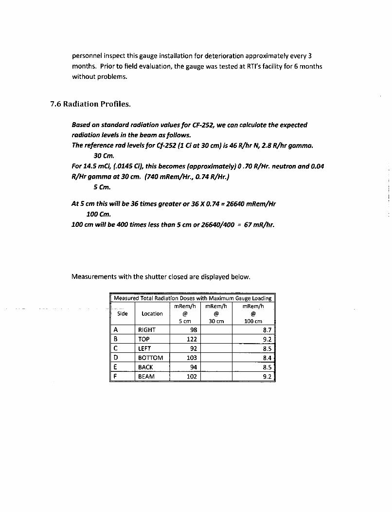
7.6 Radiation Profiles.
Based on standard radiation values for CF-252, we can calculate the expected
radiation levels in the beam as follows.The reference rod levels for Cf-252 (1 Ci at 30 cm) is 46 R/hr N, 2.8 R/hr gamma.
30 Cm.
For 14.5 mCi, (.0145 Ci), this becomes (approximately) 0.70 R/Hr. neutron and 0.04
R/Hr gamma at 30 cm. (740 mRem/Hr., 0. 74 R/Hr.)
5 Cm.
At 5 cm this will be 36 times greater or 36 X 0. 74 = 26640 mRem/Hr
100 Cm.
100 cm will be 400 times less than 5 cm or 26640/400 = 67 mR/hr.
Measurements with the shutter closed are displayed below.
Measured Total Radiation Doses with Maximum Gauge Loading
mRem/h mRem/h mRem/hSide Location @ @ @
5 cm 30 cm 100 cm
A RIGHT 98 8.7
B TOP 122 9.2
C LEFT 92 8.5
D BOTTOM 103 8.4
E BACK 94 8.5
F BEAM 102 9.2

7.7 Quality Assurance
7.7.1 Real Time Instruments Quality Assurance Program
The Quality Assurance program is provided as Attachment 8.
7.7.2 RAM Services Q/A program.
We anticipate that the manufacturer will ship completed source housing assemblies,
without the source capsule either to RAM Services facility or, more likely, directly to the
customer. These gauges will have passed the manufacturer's quality assurance program
so RAM Services main duty will be to inspect for damage in transport.
Prior to installation RAM Services will inspect the outer shipping container for obvious
signs of rough handling or damage. This inspection will be documented, supplemented
by photographs as deemed appropriate, whether damage is observed or not.
The source housing assembly will then be removed and its condition inspected and
documented as above. It will then be mounted according to the manufacturer's
instructions and proper operation of the shutter and warning lights will be
demonstrated and documented.
Finally, the source capsule will be retrieved from its separate shipping container and
installed in the source assembly housing according to the manufacturer's procedures.
-.. RAM-Services will perform and document the customary initial survey for neutron and-
gamma radiation with the shutter both open and closed.
If radiation more than 20% above the manufacturer's reference measurements is
detected, the source capsule will be secured and the manufacturers will be contacted
for advice on further actions. A leak test sample will be collected and sent to RAM
Services for analysis. If the system housing restricts access by the neutron detector,
this survey may be performed before the source housing assembly is mounted.
Before the first U.S. installation, and annually after that, RTI will engage a qualified local
(Australian) consultant to audit its QOA program. Copies will be provided to RAM
Services in a timely manner for review and retention. If a local auditor is not available,
RAM Services personnel will audit RTI's 0/A program on the aforementioned schedule.

If possible, RAM Services will conduct these audits by exchange of electronic
documents.
7.8 Installation, Servicing, and Instructions to Users
RAM Services requests that the Specific Licensees who receive this product should not
be allowed to initially mount the device, exchange source capsules, or relocate the
device, unless they have a specific authorization in their license. We request this
prohibition is based on the high potential dose rates if these operations are conductedimproperly, and the requirement for specialized equipment. The user's RSO should be
permitted to provide training to workers and Authorized Users on routine gauge
operation and maintenance.
RAM Services is currently licensed by the State of Wisconsin to provide all necessary2support services: leak testing, surveys, source exchange , user training, and source
disposal. Additionally, we have been verbally informed by both source manufacturers
that they accept return of their sources.
RAM Services will obtain additional training and procedures from the manufacturer to
perform maintenance, calibration, leak test collection, source exchange, and repair in
order to amend our Wisconsin license appropriately.

ATTACHMENT 1
ALL SCAN APPROVAL

Queensland Government Approval Number RD245
Radiation Safety Act 1999
This is to certify that the
AllScan Elemental Analyser
Manufactured by
Realtime Instruments Pty Ltd
is approved as a
Sealed source apparatus used for industrial gauging
The device has been certified to hold a maximum capacity of 0.43 GBq of Cf-252
Assessment criteria for this device.
ARPANSA. Code of Practice for the Safe Use offixed Radiation Gauges (2007)
This approval is valid until 7 February 2017
W\ý 30 'd2on-A/Senior DirecEnvironmental
torHealth B aijch
ttatW
Any changes to the device, other than the specified modifications, will necessitate re-assessment of thedevice to establish whether it continues to satisfy the assessment criteria.

ATTACHMENT 2
DOSE PROFILE

SIDE Dose rateO@ Im (uSv/hr) Dose rate @ Scm (uSv/hr)
A_ 8.7 98B 9.2 122C 8.5 92D 8.4 103E 8.5 94F 9.2 102
SIDE B
SIDE C SIDE A
SIDE D
SIDE C
SIDE E
SIDE F
SIDE A
ES-03 Dose ProfileOA3

ATTACHMENT 3
INSTALLATION

AIIScan TM
NewGeneration
AIIScanTM combines a ruggedconstruction with the most recentadvances in PGNAA technologyto deliver the most affordable,accurate, and easy-to-installanalyser of its kind in the world.
a division of
Group Limited I =_
PGNAAElementalAnalyser
A
L

• :. ".' ..i
Why use OnlineElemental Analysis?Online Elemental Analysers provide the ultimate incontinuous real-time coal quality measurement, byperforming a complete on-line elemental analysis of a movingstream of coal on a conveyer.
This allows real-time control of processes and allows costsavings by reducing material handling and enabling immediate
decisions for controlling material quality. eraQrsý by useo
Online Elemental Analysers are widely used in mining andblending, and have two key advantages over conventionalAsh Analysers:
(i) A much higher tolerance to changing coal types(eg from different seams), eliminating the need formultiple calibrations.
(ii) They provide much more information than just Ash, asthey directly measure individual elements like Fe, Al, Si, K,S, Ti, Ca (the AIIScanTM also directly measures moisture).
Why Real TimeInstruments?RTI have over 15 years of experience in
supplying and servicing these types ofAnalysers to the coal industry in Australia.Our reputation for Quality and excellent FieldService and Support has led us to become theleading supplier in Australia.
RTI's sister division RSS (Radiation SafetyServices) is the largest industrial radiationservice provider in Australia, which means weprovide the total package of Analyser
plus radioactive sources, and we take careof all radiation related requirements.
..... .... ... A A .. ................ .............. .... .. ...... .................................. .. . .. ............. .
What is PGNAA?Prompt Gamma Neutron Activation Analysis.It is the best suited and most widely used technology for online elemental analysis of coal.
II

Stringer
Detector ReturnConveyer
Benefits.The Benefits of AIIScanTM's design are many, and include
Online, Real-Time Results.Accurate results every minute, for flows from 500 tonnes perhour to several thousand tonnes per hour.
Higher Performance.Advances in PGNAA design and technology have allowedsignificant improvements in analysis performance, even foron-belt applications with varying bed depths.
Full Elemental plus Moisture Analysis.AIIscanTM directly measures Fe, Al, Si, K, S, Ti, Ca and otherelements, and also incorporates our patented MoistScan®microwave technology for direct measurement ofmoisture content.
Easy to Install.AIIScanTM is considerably lighter and smaller than mostElemental Analysers, and bolts on to most conveyer structureswithout any alterations or foundations required.
Safe.Through improved design AIIScanTM can employ smallersources thus reducing dose rates and permitting operators tosafely stand next to or near the Analyser. The Fail-Safe sourceholder has Automatic Source ON / OFF, and is fully droptested and fire tested.
Low Running Costs.Source disposal is only required every 7.5 years,reducing running costs.
Rugged and Reliable.Like all RTI Analysers and Gauges, the AIIScanTM has beenpurpose designed to work in harsh mine environments.
Easy Operation.IP66 housed touch screen at analyser for easy interrogation.
Flexible I/O.Multiple interface protocols are available to suit theClient's needs.
Remote Access as Standard.Includes a 3G interface linked to a secure website for fullremote diagnostics and viewing results.

PGNAA.The AIIScanTM utilises the well-established technique of PGNAA is also very sensitive to Chlorine, hence care should
PGNAA (Prompt Gamma Neutron Activation Analysis) which be taken not to install these types of Analysers on belts with
performs a direct measurement of elements such as Fe, Al, Si, high chlorine content as this may adversely affect overallK, S, T, Ca and many others. analytical performance.
The sensitivity of PGNAA varies depending on the elementbeing measured, as shown in the periodic table in Figure IFor example Fe (Iron) has excellent sensitivity.
<0.01%0.01-0.1%0.1-0.3%0.3-1.0%
IA 1.0-3.0% VIIIB
Mg III, IVA V A VIA VIIA I .- VillA-....- .. B inII P .S Ar
V C nC nAs Kr
Ri Nb Mo T R gin S Te _X
6 Ta ABi PO A Rn
L Fr Ra Rl' Db Sg Bh Hs M1 Uunq
16) Nd Pin EU Th Er Yb Lu
i7) Ac Th Pa U Np Pu Am Bk I'm Md
Figure IPGNAA Sensitivity
Th AIca 7Mi wlsuite to al coa tyes
fro hihvral As feed
to lo As prouct

AlIScan1m: New Generation PGNAA Elemental Analyser
Ash Tracking Plot Ani- out
.•=0.345
Ah % i8
Figure 2Comporison of AIIScan
ttand Laboratory Analysis for Ash in coal, from a moving conveyer
Results.The AIIScanIT directly reports theindividual amounts of Fe, Al, Si,K, S, T, Ca etc.
From this it can calculate anaccurate Ash Value.
Importantly, the AIIScan T
measurement of Ash is independentof changing coal composition sothat coal flows from different seamsdo not require recalibration of the
analyser (see Figure 2).
Moisture.The AIIScanTM incorporates ourMoistScan® microwave technologyfor direct online measurement ofmoisture content.
Unlike other Moisture measurementtechnologies MoistScang samples thefull bed depth of the coal insuring anaccurate representation
Other parameters such as SE andVolatiles etc. can also be reported
Z's0
MoistScan' vs Laboratory - Typical results
MOist$SCan Laboratory
•14S£71
Sample Number
Figure 3Comparison of AliScon" and Laboratory Analysts for Moisture on coal, from a maovng conveyer

The AIIScan- is designed to mount on the support rails of aconveyor system and consists of four main sections: two sideassemblies, the top with source assembly, and the detectorbox that mounts between the conveyor and return belts.Individually, each section can be lifted into place by a crane.
The small size and weight of AIIScanTM greatly simplifiesinstallation as it can fit on to most conveyer structureswithout any alteration. In addition there is minimal intrusiononto walkways.

Ll~a I e eeainPNAEeetlAaye
Technology.The system utilises the most advanced software algorithms forspectra stabilisation and deconvolution including innovativetreatment of signal noise and pulse pile-up. The system isa "stateless" machine which means that once a calibrationstandard is run or dynamic calibration data is obtained it canbe run and re-run as many times as desired to optimise thecalibration and performance of the Analyser. This uniquefeature means the Client can minimise the effort to getthe unit up and running so it begins adding value to theiroperation in a very short time.
The Analyser software archives all incoming spectralinformation rather than converting the spectrum to data andarchiving only the data. The archiving of spectra proves veryuseful whenever there is a desire to add data to the existingcalibration database. In this way the calibration is continuallyrefined, being made more robust, precise, and accurate.
I/0 and Diagnostics.The AIIScanTm comes with a browser based touch panelinterface in the control cabinet, allowing immediate access toall data and functions including trending displays.
A variety of interface protocols are available and the systemcan be set up to suit user requirements. Options include
PLC Interface
Ethernet
Serial Communications such as ModBus.
4 - 2OmA
Complicated wiring between the Analyser and the ControlCentre is eliminated.
In addition a 3G interface is included so that data is uploadedautomatically to a secure site (viewable by the Client andRTI Engineers). This provides an alternative way to viewand retrieve data, that is completely independent of sitecommunication infrastructure, providing a backup in caseof site communications issues, and allowing simple remotemonitoring over the internet. It also greatly assists fast remotediagnostics and troubleshooting by RTI engineers.
All diagnostics are performed by the on-board computer,which provides continuous verification of the detector andelectronics and verification of the status of componentsin the computer. This information is accessible to RTIEngineers remotely via the Internet through the 3G interface.The Analyser can also automatically send an email to theAIIScanT support team to report any errors/faults.

Specifications.
Measurement Technique
Elements Measured
Moisture and BTU
Weight
Belt Widths
Aperture
Source
Source Holder
Radiation Exposure
I/0 Protocols Available
Environmental Conditions
Power
Control Cabinet
Prompt Gamma Neutron Activation Analysis (PCNAA).
Fe, Al, Si, K, S, Ti, Ca and others.Total Ash calculated using elements found in Ash.
Standard.
1200 - 1500 typical.
750 - t800 standard.
Variable; height of the tunnel should be sufficient to clear the material that flowsthrough it so the Analyser does not sustain damage from materials on the belt.AlIScanTr Analysers can be easily adjusted for the appropriate tunnel height duringmanufacture and installation. Customer should provide means of preventing largerocks from striking the Analyser.
20pg Cf-252 (2.6 years half-life). Source is topped up with IlOpg after 2.5 years andagain after 5 years. Disposal occurs at 7.5 years.
Automatic Source Drive, Physical Isolation Point, Complies with all radiationsafety requirements.
Typically below 5pSv/hour outside and around the exterior of the Analyser.Average 1.3pSv/hr on or near the catwalk beside the Analyser.
Set up to suit application. Standard ModBus over RS485 and 3G interface.User Optional PLC Interface, Ethernet, Serial Communications such as ModBus.
Sensitive parts of the AIlScanTM are sealed from the environment. The Analyser isdesigned to operate in all outdoor weather conditions from -10 to +50 degreesCelsius in high or low humidity or precipitation.
Instrument quality 120/240VAC 10 2400W 50/60Hz at Analyser Control Station.
Stainless Steel IP66 as standard.
GI
Group Limited s''.,ws,
Mackay Head OfficeLot J Mackay Marina VillageMulherin DriveMackay QLD 4740PO Box 9117Slade Point OLD 4740
P +61 7 49 555 944F +61 7 49 657 099
Perth Office24 Brennan WayBelmont WA 6104P +61 8 9475 0099IF +6t 8 9475 0165
www.realtimegrp.com
es Western Radiation ServicesMQIS#P5CAN Radiation Safetyaervic
EP 0004 R2012-

ATTACHMENT 4
VIBRATION

AS 60068.2.6-2003IEC 60068-2-6:1995IEC 60068-2-6:1995/C0orr 1:1995
C,0
0
Australian Standard TM
Environmental testing
0Co
0zLOC11
00
zwU-D
0
UiwuLJ
z
"0D
V,
Part 2.6: Tests--Test Fc: Vibration(sinusoidal)
*Standards Australia

This Australian Standard was prepared by Committee EL-026, ProtectiveEnclosures and Environmental Testing for Electric/Electronic Equipment. It wasapproved on behalf of the Council of Standards Australia on 14 February 2003 andpublished on 20 March 2003.
The following are represented on Committee EL-026:Australian Chamber of Commerce and Industry
Australian Electrical and Electronic Manufacturer's Association
Electrical Compliance Testing Association
Electrical Regulatory Authorities Council
Electricity Supply Association of Australia
Testing Interests (Australia)
Keeping Standards up-to-dateStandards are living documents which reflect progress in science, technology andsystems. To maintain their currency, all Standards are periodically reviewed, andnew editions are published. Between editions, amendments may be issued.Standards may also be withdrawn. It is important that readers assure themselvesthey are using a current Standard, which should include any amendments whichmay- •-felibein published since the Standard was purchased.Detailed information about Standards can be found by visiting the StandardsAustralia web site at www.standaids.com.au and looking up the relevant Standardin the on-line catalogue.
o Alternatively, the printed Catalogue provides information current at I January eachyear, and the monthly magazine, The Australian Standard, has a full listing of
z revisions and amendments published each month.qWe also welcome suggestions for improvement in our Standards, and especially0 encourage readers to notify us immediately of any apparent inaccuracies or0 ambiguities. Contact us via email at [email protected], or write to the Chiefz Executive, Standards Australia International Ltd, GPO Box 5420, Sydney, NSWCn2001.zUj.-j
LIU
z
, This Standard was issued in draft form for conmnent as DR 02481.

AS 60068.2.6-2003
Australian StandardTM
Environmental testing
Part 2.6: Tests-Test Fc: Vibration(sinusoidal)
First published as AS 60068.2.6-2003.
COPYRIGHT© Standards Australia International
All rights are reserved. No part of this work may be reproduced or copied in any form or by anymeans, electronic or mechanical, including photocopying, without the written permission of thepublisher.
Published by Standards Australia International LtdGPO Box 5420, Sydney, NSW 2001, Australia
ISBN 0 7337 5084 2
0zUf)
z
U-
0
U)
z
U)W

Hi
PREFACE
This Standard was prepared by the Standards Australia Committee EL-026, ProtectiveEnclosures and Environmental Testing for Electric/Electronic Equipment.The objective of this Standard is to provide the electrotechnology industry with a complete setof environmental test procedures published as a series under AS 60068 Environmental testing.This Standard is Part 2.6 of that series.This Standard is identical with, and has been reproduced, from IEC 60068-2-6:1995,Environmental testing - Part 2: Tests - Test Fc: Vibration (sinusoidal) including itsCorrigendum 1:1995.As this Standard is reproduced friom an International Standard, the following applies:(a) Its number does not appear on each page of text and its identity is shown only on the
cover and title page.(b) In the source text 'this international standard' should read 'this Australian Standard'.(c) A full point should be substituted for a comma when referring to a decimal marker.
(d) Any French text on figures should be ignored.
In this Standard, the following print types are used:- requirements proper: in arial type;- test specifications: in italic type;- explanatory matter: in smaller arial type.
Any international Standard referenced should be replaced by an equivalent Australian Standardwhen one is available. The availability of equivalent Australian Standards can be determinedeither fr'om the Standards Australia catalogue or firom the Standards Australia website(www.standards.com.au).
0
0z
0a
(0
U-
Wwz
D
Li.0
.U)U)
a,.tu_>

iii
CONTENTS
Page
1 S c o p e .............................................................................................................................. 1
2 Norm ative references ................................................................................................... 1
3 D e fin itio n s ....................................................................................................................... 2
4 Requirem ents for testing .............................................................................................. 4
4.1 Required characteristics ..................................................................................... 4
4.1.1 Basic motion ............................................................................................ 44.1.2 Spurious m otion ...................................................................................... 4
4.1.3 Signal tolerance ...................................................................................... 54.1.4 Vibration am plitude tolerances ................................................................ 54.1.5 Frequency tolerances ............................................................................. 6
4 .1 .6 S w e e p .................................................................................................. . . 64 .2 M o u n tin g ................................................................................................................ 6
5 S e v e ritie s ........................................................................................................................ 6
5.1 Frequency range ............................................................................................... 75.2 Vibration am plitude .............................................................................................. 85.3 Duration of endurance ......................................................................................... 9
5.3.1 Endurance by sweeping ........................................................................... 95.3.2 Endurance at fixed frequencies .............................................................. 10
6 P re c o n d itio n in g ............................................................................................................... 1 0
7 Initial measurem ents .................................................................................................. 10
8 T e s tin g ........................................................................................................................... 1 0
8.1 Vibration response investigation ........................................................................ 118.2 Endurance procedures ........................................................................................ 11
8.2.1 Endurance by sweeping ......................................................................... 118.2.2 Endurance at fixed frequencies .............................................................. 11
-9--1 iter-•-diatb-M-e-su em ents ............................................................................................ 12
1 0 R e c o v e ry ........................................................................................................................ 1 2
11 Final measurements .................................................................................................... 12
12 Information to be given in the relevant specification ...................... .... 12
0> Annex A (informative) Guide to test Fc ............................................................................. 14z
Annex B (informative) Examples of severities primarily intended for components ............. 26
o Annex C (informative) Examples of severities primarily intended for equipment ................ 27zU) TableszwI0lTable 1 - Lower frequency ............................................................................................................ 7.Table 2-U pper frequency ..................................................................................................... 7
0Table 3 - Recom mended frequency ranges ......................................................................... 7
XTable 4 - Recommended vibration amplitudes with lower crossover frequency (8 Hz to>_ 1 0 H z ) .............................................................................................................................. 8z
Table 5 - Recommended vibration amplitudes with higher crossover frequency (58 Hzto 6 2 H z ) .......................................................................................................................... 9
Table 6 - Recommended vibration displacement amplitudes applicable only forfrequency ranges with an upper frequency of 10 Hz ............ 9..........9

iv
Page
Table A.1 - Number of sweep cycles and associated endurance times per axis ................ 21
T able A .2 - C B response tim e ........................................................................................ . . 22
T able A .3 - C P B response tim e ....................................................................................... . 23
Table B.1 - Endurance by sweeping - Examples with higher crossover frequency ............ 26
Table C.1 - Endurance by sweeping - Examples with lower crossover frequency ............. 27
Table C.2 - Endurance by sweeping - Examples with higher crossover frequency ............ 28
Figures
Figure 1 - Nomogram relating vibration amplitude to frequency with lower cross-overfreq uency (8 H z to 10 H z) ......................................................................................... . 29
Figure 2 - Nomogram relating vibration amplitude to frequency with higher cross-overfrequency (58 H z to 62 H z) ......................................................................................... . 30
Figure 3 - Nomogram relating vibration displacement amplitude to frequency (onlyapplicable for frequency ranges with an upper frequency of 10 Hz) ............................ 31
Figure A.1 - Generalized transmissibility factors for vibration isolators .............................. 32
z
ZLOlC..4C:0
Zz5
n,aLl
0
Z,C'
wz

1
STANDARDS AUSTRALIA
Australian Standard
Environmental testingPart 2.6: Tests-Test Fc: Vibration (sinusoidal)
I Scope
This part of IEC 60068 gives a method of test which provides a standard procedure todetermine the ability of components, equipment and other articles, hereinafter referred to asspecimens, to withstand specified severities of sinusoidal vibration.
The purpose of this test is to determine any mechanical weakness and/or degradation in thespecified performance of specimens and to use this information, in conjunction with therelevant specification, to decide the acceptability of the specimens. In some cases, the testmethod may also be used to demonstrate the mechanical robustness of specimens and/or tostudy their dynamic behaviour. Categorization of components can also be made on the basisof a selection from within the severities quoted in the test.
2 Normative references
The following normative documents contain provisions which, through reference in this text,constitute provisions of this part of IEC 60068. At the time of publication, the editionsindicated were valid. All normative documents are subject to revision, and parties toagreements based on this part of IEC 60068 are encouraged to investigate the possibility ofapplying the most recent editions of the normative documents indicated below. Members ofIEC and ISO maintain registers of currently valid International Standards.
IEC 60050(721): 1991, International Electrotechnical Vocabulary (1EV) - Chapter 721:Telegraphy facsimile and data communication
.....E 60068-1:988-,Ev-ironmental testing - Part 1: General and guidanceAmendment 1 (1992)
IEC 60068-2-34: 1973, Environmental testing - Part 2: Tests - Test Fd: Random vibrationwide band - General requirements*Amendment 1 (1983)0
C0
0)Z
LL0
U)Of
IEC 60068-2-35: 1973, Environmental testing -wide band - Reproducibility High*Amendment 1 (1983)
IEC 60068-2-36: 1973, Environmental testing -wide band - Reproducibility Medium*Amendment 1 (1983)
IECG 60068-2-37: 1973, Environmental testing -wide band - Reproducibility Low*Amendment 1 (1983)
. Tests Fd, Fda, Fdb and Fdc are to be withdrawn in 1998.
Part 2: Tests - Test Fda: Random vibration
Part 2: Tests - Test Fdb: Random vibration
Part 2: Tests - Test Fdc: Random vibration
wwAv/ standards.com.aua C Standards Australia

2
IEC 60068-2-47: 1982, Environmental testing - Part 2: Tests - Mounting of components,equipment and other articles for dynamic tests including shock (Ea), bump (Eb), vibration (Fcand Fd) and steady-state acceleration (Ga) and guidance
IEC 60068-2-64: 1993, Environmental testing - Part 2: Tests - Test Fh: Vibration broad-bandrandom (digital control) and guidance
IEC 60721-1: 1990, Classification of environmental conditions - Part 1: Environmentalparameters and their severitiesAmendment 1 (1992)
ISO 2041: 1990, Vibration and shock - Vocabulary
3 Definitions
Definitions in alphabetical order:
Actual motion 3.7
Basic motion 3.6
Centred resonance frequency 3.10
Check point 3.2.1
Critical frequencies 3.9
Damping 3.8
Fictitious reference point 3.2.2.1
Fixing point 3.1
gn 3.12
Measuring points 3.2
Multipoint control 3.3.2
Reference point 3.2.2
Restricted frequency sweeping 3.11
. Signal-tolerance 3.5
Single point control 3.3.1
Sweep cycle 3.4
CThe terms used are generally as defined in ISO 2041 and in IEC 60068-1. However, sweep0cycle (3.4) and signal tolerance (3.5) have specific meanings in this standard.z
0The other terms described below are not identical to, or not defined in, ISO 2041 or in- IEC 60068-1.
Z
z 3.1 fixing point: Part of the specimen in contact with the fixture or vibration table at a pointl, where the specimen is normally fastened in service. If a part of the real mounting structure is
a used as the fixture, the fixing points shall be taken as those of the mounting structure and notULo of the specimen.
W 3.2 measuring points: The test is carried out using data gathered at certain specific points._ These are of two main types, the definitions of which are given below.z
NOTE - Measurements may be made at points within the specimen in order to assess its behaviour, but these arenot considered as measuring points in the sense of this standard. For further details, see A.2. 1.
a
© Standards Australia Wwvw.slandards.com1.aL1

3
3.21 check point: Point located on the fixture, on the vibration table or on the specimen asclose as possible to one of its fixing points, and in any case rigidly connected to it.
NOTES
1 A number of check points are used as a means of ensuring that the test requirements are satisfied.
2 If four or fewer fixing points exist, each is used as a check point. If more than four fixing points exist, fourrepresentative fixing points will be defined in the relevant specification to be used as check points.
3 In special cases, for example for large or complex specimens, the check points will be prescribed in therelevant specification if not close to the fixing points.
4 Where a large number of small specimens are mounted on one fixture, or in the case of a small specimenwhere there are several fixing points, a single check point (i.e. the reference point) may be selected for thederivation of the control signal. This signal is then related to the fixture rather than to the fixing points of thespecimen(s). This is only valid when the lowest resonance frequency of the loaded fixture Is well above theupper frequency of the test.
3.2.2 reference point: Point chosen from the check points whose signal is used to controlthe test, so that the requirements of this standard are satisfied.
3.2.2.1 fictitious reference point: A fictitious point derived from multiple check points eithermanually or automatically, the result of which is used to control the test, so that therequirements of this standard are satisfied.
3.3 Control points
3.3.1 single point control: This is achieved by using the signal from the transducer at thereference point in order to maintain this point at the specified level (see 4.1.4.1).
3.3.2 multipoint control: This is achieved by using the signals from each of the transducersat the check points. The signals are either continuously averaged arithmetically or processedby using comparison techniques, depending upon the relevant specification (see 4.1.4.1).
3.4 sweep cycle: A traverse of the specified frequency range once in each direction, forexample 10 Hz to 150 Hz to 10 Hz.
NOTE - Manufacturer's handbooks for digital sine control systems often refer to a sweep cycle as f, to f2 , not f, tof2 to fl.
-1.3-5 signal tolerance:-Signal tolerance T F- 1) x 100 (per cent).
where
0 NF is the r.m.s value of the unfiltered signal;
0o F is the r.m.s value of the filtered signal.zU, NOTE - This parameter applies to whichever signal, i.e. acceleration, velocity or displacement, is being used to0control the test (see A.2.2).
3.6 basic motion: Motion at the driving frequency of vibration at the reference point (seealso 4.1.1).
wwLU0
a 3.7 actual motion: Motion represented by the wideband signal returned from the referenceo point transducer.
3.8 damping: The generic term ascribed to the numerous energy dissipation mechanisms in>' a system. In practice, damping depends on many parameters, such as the structural system,z mode of vibration, strain, applied forces, velocity, materials, joint slippage, etc.D
'5)
a3ao
jww.sta nda rds.con. atS © Standards Australia

4
3.9 critical frequencies: Frequencies at which:
- malfunctioning and/or deterioration of performance of the specimen are exhibited whichare dependent on vibration, andlor
- mechanical resonances and/or other response effects occur, for example, chatter.
3.10 centred resonance frequency: Frequency automatically centred on the actualresonance frequency derived from the vibration response investigation.
3.11 restricted frequency sweeping: Sweeping over a restricted frequency range between0,8 and 1,2 times the critical frequency.
3.12 gn: Standard acceleration due to the earth's gravity, which itself varies with altitude and
geographical latitude.
NOTE - For the purpose of this standard, the value of gn is rounded up to the nearest whole number, that is10 mls 2
.
4 Requirements for testing
4.1 Required characteristics
The required characteristics apply to the complete vibration system, which includes the poweramplifier, vibrator, test fixture, specimen and control system when loaded for testing.
4.1.1 Basic motion
The basic motion shall be a sinusoidal function of time and such that the fixing points of thespecimen move substantially in phase and in straight parallel lines, subject to the limitationsof 4.1.2 and 4.1.3.
4.1.2 Spurious motion
4.1.2.1 Transverse motion
The maximum vibration amplitude at the check points in any axis perpendicular to the• specified axis shall not exceed 50 % of the specified amplitude up to 500 Hz or 1.00 %for frequencies in excess of 500 Hz. The measurements need only cover the specifiedfrequency range. In special cases, e.g. small specimens, the amplitude of the permissibletransverse motion may be limited to 25 %, if required by the relevant specification.
In some cases, for example for large size or high mass specimens or at some frequencies, it0may be difficult to achieve the figures quoted above. In such cases the relevant specificationLoshall state which of the following requirements apply:0
C a) any transverse motion in excess of that stated above shall be noted and stated in theZ test report; or
z b) transverse motion which is known to offer no hazard to the specimen need not beW monitored.0
0 4.1.2.2 Rotational motion
UIn the case of large size or high mass specimens, the occurrence of spurious rotational, motion of the vibration table may be important. If so, the relevant specification shall prescribe
a tolerable level. The achieved level shall be stated in the test report (see also A.2.4).z.0
(3V.
© Standards Australia vwvw.standards.com.aul

5
4.1.3 Signal tolerance
Unless otherwise stated in the relevant specification, acceleration signal tolerancemeasurements shall be performed. They shall be carried out at the reference point and shallcover the frequencies up to 5 000 Hz or five times the driving frequency whichever is thelesser. However, this maximum analysing frequency may be extended to the upper testfrequency for the sweep, or beyond, if specified in the relevant specification. Unless otherwisestated in the relevant specification, the signal tolerance shall not exceed 5 % (see 3.5).
If stated in the relevant specification, the acceleration amplitude of the control signal at thefundamental driving frequency shall be restored to the specified value by use of a trackingfilter (see A.4.4).
In the case of large or complex specimens, where the specified signal tolerance valuescannot be satisfied at some parts of the frequency range and it is impracticable to use atracking filter, the acceleration amplitude need not be restored, but the signal tolerance shallbe stated in the test report (see A.2.2).
NOTE - If a tracking filter is not used and the signal tolerance is in excess of 5 %, the reproducibility may besignificantly affected by the choice of either a digital or analogue control system (see A.4.5).
The relevant specification may require that the signal tolerance, together with the frequencyrange affected, is stated in the test report whether or not a tracking filter has been used(see A.2.2).
4,1.4 Vibration amplitude tolerances
The basic motion amplitude in the required axis at the check and reference points shall beequal to the specified value, within the following tolerances. These tolerances includeinstrumentation errors. The relevant specification may require that the confidence level usedin the assessment of measurement uncertainty is stated in the test report.
At low frequencies or with large size or high mass specimens it may be difficult to achieve therequired tolerances. In these cases it is expected that a wider tolerance or the use of analternative method of assessment shall be prescribed in the relevant specification and statedin the test report.
4.1.4.1 Reference point
Tolerance on the control signal at the reference point: +15 % (see A.2.3).
The relevant specification shall state whether single point or multipoint control shall be used.If multipoint control is prescribed, the relevant specification shall state whether the averagevalue of the signal at the check points or the value of the signal at a selected point (for
Z example, that with the largest amplitude) shall be controlled to the specified level (see A.2.3).Nc NOTE - If it is not possible to achieve single point control, then multipoint control may be used by controlling theo average or extreme value of the signals at the check points. In either of these cases of multipoint control, the pointZ is a fictitious reference point. The method used shall be stated in the test report.
C,)z 4.1.4.2 Check pointsLULu
o At each check point:LL.0 ±25 % up to 500 Hz;C,)W: ±50 % above 500 Hz.UJ>z (See A.2.3.)D0
,www.stanclards.con aS d© Standards Australia

4.1.5 Frequency tolerances
The following frequency tolerances apply.
4.1.5.1 Endurance by sweeping
±0,05 Hz up to 0,25 Hz;
±20 % from 0,25 Hz to 5 Hz;
±1 Hz from 5 Hz to 50 Hz;
±2 % above 50 Hz.
4.1.5.2 Endurance at fixed frequency
a) Fixed frequency:
±2 %.
b) Almost fixed frequency:
+0,05 Hz up to 0,25 Hz;
±20 % from 0,25 Hz to 5 Hz;
±1 Hz from 5 Hz to 50 Hz;
±2 % above 50 Hz.
4.1.5.3 Measurement of critical frequency
When the critical frequencies (see 8.1) before and after endurance are to be compared, i.e.during vibration response investigations, the following tolerances shall apply:
±0,05 Hz up to 0,5 Hz;
±10 % from 0,5 Hz to 5 Hz;
±0,5 Hz from 5 Hz to 100 Hz;
±0,5 % above 100 Hz.
4.1.6 Sweep
The sweeping shall be continuous and the frequency shall change exponentially with time(see A.4.3). The sweep rate shall be one octave per minute with a tolerance of ±10 %. Thismay b-eYva-ie-d-for -vib-r-ation response investigation (see 8.1).
NOTE - With a digital control system it is not strictly correct to refer to the sweeping being "continuous", but thedifference is of no practical significance.
C9 4.2 Mounting0z Unless otherwise stated in the relevant specification, the specimens shall be mounted on theCq test apparatus in accordance with the requirements in IEC 60068-2-47. For specimens0 normally mounted on vibration isolators, see in addition 8.2.2 NOTE, A.3.1, A.3.2 and A.5.02
U)5 SeveritieszLuuJ
o A vibration severity is defined by the combination of the three parameters: frequency range,o vibration amplitude and duration of endurance (in sweep cycles or time).
For each parameter, the relevant specification shall choose the appropriate requirements from' those listed below or derived from other known sources of relevant data (for examplenIEC 60721). If the known environment is substantially different, the requirements shall be., related to it by the relevant specification.
© Standards Australia wwv,.sta nd ards.com, aLl

7
To permit some flexibility in situations where the real environment is known, it may beappropriate to specify a shaped acceleration versus frequency curve and in these cases therelevant specification shall prescribe the shape as a function of frequency. The different levelsand their corresponding frequency ranges, that is the break points, shall be selected,wherever possible, from the values given in this standard.
Examples of severities for components are given in annex B and for equipment in annex C(see also A.4.1 and A.4.2).
5.1 Frequency range
The frequency range shall be stated in the relevant specification by selecting a lowerfrequency from table 1 and an upper frequency from table 2. The recommended ranges areshown in table 3.
Examples of ranges for particular applications are given in tables B.1, C.1 and C.2.
Table 1 - Lower frequency Table 2 - Upper frequency
f1 f2
Hz Hz
0,1 10
1 20
5 35
10 55
55 100
100 150
300
500
2 000
5 000
Table 3 - Recommended frequency ranges
From f1 to f2Hz
1 to 351 to 100
10 to 55zLO 10 to 150C\
10 to 500
z 10 to 2000rl, 10 to 5000zLLIw 55 to 500
u_ 55 to 20000
55 to 5000
100 to 2000ofW
z.0
'\V\/wV. st and ( a rds. Co Ill. a u ©D Standards Australia

8
5.2 Vibration amplitude
The vibration amplitude (displacement or acceleration or both) shall be stated in the relevantspecification.
Below a certain frequency known as the crossover frequency, all amplitudes are specified asconstant displacement, whilst above this frequency, amplitudes are given as constantacceleration. The recommended values are stated in tables 4 and 5 for the two differentcrossover frequencies.
Each value of displacement amplitude is associated with a corresponding value ofacceleration amplitude (shown on the same line in tables 4 and 5) so that the amplitude ofvibration is the same at the crossover frequency (see A.4.1).
Where it is not technically appropriate to adopt the crossover frequencies stated in thissubclause, the relevant specification may couple displacement and acceleration amplitudesgiving a different value of crossover frequency. In some circumstances more than onecrossover frequency may also be specified.
NOTE - Nomograms relating vibration amplitude to frequency are given in figures 1, 2 and 3 but, before their usein the low-frequency region, consideration should be given to the guidance in A.4.1.
Up to an upper frequency of 10 Hz, it is normally appropriate to specify a displacementamplitude over the whole frequency range. Therefore, in table 6 and figure 3 onlydisplacement amplitudes are specified.
Table 4 - Recommended vibration amplitudes with lowercrossover frequency (8 Hz to 10 Hz)
Displacement amplitude Acceleration amplitudebelow the crossover above the crossover
frequency frequency
mm (in) m/s 2 (gn)
0,35 (0,014) 1 (0,1)
0,75 (0,03) 2 (0,2)
1,5 (0,06) 5 (0.5)
3,5 (0,14) 10 (1,0)
7,5 (0,30) 20 (2,0)
10 (0,40) 30 (3,0)
15 (0,60) 50 (5,0)
NOTES
I All figures quoted are amplitudes (peak values).
2 The inch values which are given for information are derived fromthe original millimetric values and are approximate. Similarly, thegn values are given for information.
3 The displacement amplitude of 15 mm is primarily intended forhydraulic vibration generators.
R04,
0z
C)0
z
z
0
U)
zD
© Standards Australia www.standards.comi.au

9
Table 5 - Recommended vibration amplitudes with highercrossover frequency (58 Hz to 62 Hz)
Displacement amplitude Acceleration amplitudebelow the crossover above the crossover
frequency frequency
mm (in) mis2
(gn)
0,035 (0,0014) 5 (0,5)
0,075 (0,003) 10 (1,0)
0,15 (0,006) 20 (2,0)
0,35 (0,014) 50 (5,0)
0,75 (0,03) 100 (10)
1,0 (0,04) 150 (15)
1,5 (0.06) 200 (20)
2,0 (0,08) 300 (30)
3,5 (0,14) 500 (50)
NOTES
1 All figures quoted are amplitudes (peak values).
2 The inch values which are given for information are derived fromthe original millimetric values and are approximate. Similarly, thegn values are given for information.
Table 6 - Recommended vibration displacement amplitudes applicableonly for frequency ranges with an upper frequency of 10 Hz
Displacement amplitude
mm (in)
10 (0,40)
35 (1,4)
75 (3,0)
100 (4,0)
NOTES
1 All figures quoted are amplitudes (peak values).
2 The inch values which are given for information are derived fromthe original millimetric values and are approximate.
3 The displacement amplitude of greater than 10 mm are primarilyintended for hydraulic vibration generators.0
z
0
zIn
zwLU.wLU0
a0)10
a)0
5.3 Duration of endurance
The relevant specification shall select the duration(s) from the recommended values givenbelow. If the specified duration leads to an endurance time of 10 h or more per axis orfrequency, this time may be split into separate testing periods provided that stresses in thespecimen are not thereby reduced (see A.1 and A.6.2).
5.3.1 Endurance by sweeping
The duration of the endurance in each axis shall be given as a number of sweep cycles(see 3.4) chosen by the relevant specification from the list given below:
1, 2, 5, 10, 20, 50, 100.
When a higher number of sweep cycles is required, the same series should be applied(see A.4.3).
www.standards.corn.aS d0 Standards Australia

10
5.3.2 Endurance at fixed frequencies
5.3.2.1 Endurance at critical frequencies
The duration of the endurance in each appropriate axis at each frequency found during thevibration response investigation (see 8.1) shall be chosen by the relevant specification from
the values given below with a tolerance of +5 % (see A.1 and A.6.2):0
10 min; 30 min; 90 min; 10 h.
For almost fixed frequencies, see A.1.
5.3.2.2 Endurance at predetermined frequencies
The duration stated in the relevant specification shall take into account the total time thespecimen is expected to be submitted to such vibration during its operational life. An upperlimit of 107 stress cycles shall apply for each stated combination of frequency and axis (seeA.1 and A.6.2).
6 Preconditioning
The relevant specification may call for preconditioning and shall then prescribe the conditions(see IEC 60068-1).
7 Initial measurements
The specimen shall be submitted to the visual, dimensional and functional checks prescribedby the relevant specification (see A.9).
8 Testing
The relevant specification shall state the number of axes in which the specimen shall bevibrated and their relative positions. If not stated in the relevant specification, the specimenshall be vibrated in three mutually perpendicular axes in turn which should be so chosen thatfaults are-most likely to be revealed.
The control signal at the reference point shall be derived from the signals at the check pointsand shall be used for single point or multipoint control (see subclause A.4.5).
0
0The test procedure to be applied shall be chosen, by the relevant specification, from thezUstages given below. Guidance is given in annex A. In general, the test stages shall be0 performed in sequence in the same axis and then repeated for the other axes (see,- clause A.3).Z
z Special action is necessary when a specimen normally intended for use with vibrationwU isolators needs to be tested without them (see clause A.5).DLL~O When called for by the relevant specification, control of the specified vibration amplitude shall_be supplemented by a maximum limit of the driving force applied to the vibrating system. Theamethod of force limitation shall be stated in the relevant specification (see clause A.7).ILl
z
-U
© Standards Australia wvim.stand(a rds coun.@u

11
8.1 Vibration response investigation
When called for in the relevant specification, the response of the specimen in the definedfrequency range shall be investigated in order to study the behaviour of the specimen undervibration. Normally, the vibration response investigation shall be carried out over a sweepcycle under the same conditions as for the endurance (see 8.2), but the vibration amplitudemay be diminished and the sweep rate decreased below the specified value if, thereby, moreprecise determination of the response characteristics can be obtained. Undue dwell time andoverstressing of the specimen shall be avoided (see A.3.1).
The specimen shall be functioning during this vibration response investigation if required bythe relevant specification. Where the mechanical vibration characteristics cannot be assessedbecause the specimen is functioning, an additional vibration response investigation with thespecimen not functioning shall be carried out.
During the vibration response investigation, the specimen and the vibration response datashall be examined in order to determine critical frequencies. These frequencies, appliedamplitudes and the behaviour of the specimen shall be stated in the test report (see clauseA.1). The relevant specification shall state what action shall be taken.
When digital control is used, care shall be taken when determining the critical frequenciesfrom the plot of the response curve, due to limitations as a result of the number of data pointsper sweep chosen, or the discrimination ability of the control system display screen(see A.3.1).
In certain circumstances, the relevant specification may require an additional vibrationresponse investigation on completion of an endurance procedure so that the criticalfrequencies before and after can then be compared. The relevant specification shall statewhat action is to be taken if any change of frequency occurs. It is essential that both vibrationresponse investigations are carried out in the same manner and at the same vibrationamplitudes (see 4.1.5.3 and A.3.1).
8.2 Endurance procedures
The relevant specification shall prescribe which of the following endurance procedures shallbe employed.
8.2.1 Endurance by sweeping
This endurance procedure is preferred.
The frequency shall be swept over the frequency range at the sweep rate, the amplitude and0for the duration selected by the relevant specification (see 5.3.1). If necessary, the frequencyz range may be sub-divided, provided that the stresses in the specimen are not therebyrreduced.0z5; 8.2.2 Endurance at fixed frequencieszwW Vibration shall be applied either at:D0U, a) those frequencies derived from the vibration response investigation given in 8.1, using00one of the following methods:
1) fixed frequency,W> - centred resonance frequency.z
The applied frequency shall always be maintained at the actual critical frequency.
C,)
www. st and a rd s. coli. a S@ Standards Australia

12
2) almost fixed frequency,
- restricted frequency sweeping.
If the actual critical frequency is not clearly evident, for example if there is chatter,or where a number of individual specimens are being tested simultaneously, itmay be convenient to sweep over a restricted frequency range between 0,8 and1,2 times the critical frequency in order to be sure of exciting the effect fully. Thismay also apply where the resonance is non-linear (see A. 1).
b) predetermined frequencies stated in the relevant specification.
The test shall be applied at the amplitude and for the duration stated in the relevantspecification (see A.3.2).
NOTE - In the case of a specimen mounted on vibration isolators, the relevant specification will need to statewhether or not the resonance frequencies of the specimen on its isolators should be chosen for this endurance(see A.5).
9 Intermediate measurements
When prescribed by the relevant specification, the specimen shall be functioning and itsperformance checked during the test for the specified proportion of the total time (see A.3.2and A.8).
10 Recovery
It is sometimes necessary, when prescribed by the relevant specification, to provide a periodof time after testing and before final measurements to allow the specimen to attain the sameconditions, for example of temperature, as existed for the initial measurements. The relevantspecification shall prescribe the precise conditions for recovery.
11 Final measurements
The specimen shall be submitted to the visual, dimensional and functional checks prescribedby the relevant specification.
....... -The-relevant-specification shall provide the criteria upon which the acceptance or rejection of
the specimen is to be based (see A.9).
-12 Information to be given in the relevant specification0
z• When this test is included in a relevant specification, the following details shall be given in soOfar as they are applicable, paying particular attention to the items marked with an asterisk (*)0as this information is always required.z5• ClauseU) and/orZU subclause
L ~ a) Choice of check points 3.2.1
0 b) Choice of control points* 3.3.2
c) Transverse motion 4.1.2.1C')
L, d) Rotational motion 4.1.2.2>z e) Signal tolerance 4.1.3
f) Vibration amplitude tolerance 4.1.4in g) Confidence level 4.1.4
h) Single or multipoint control* 4.1.4.1
C Standards Australia kvww.standardJs.conm au

13
Clauseandlor
subclause
i) Mounting 4.2
j) Severities, real environment, if known 5
k) Frequency range* 5.1
I) Vibration amplitude* 5.2
m) Special crossover frequency 5.2
n) Duration of endurance* 5.3and 8.2
o) Preconditioning 6
p) Initial measurements* 7
q) Axes of vibration* 8
r) Force limitation 8
s) Test stages to be performed and sequence* 8, 8.1and 8.2
t) Functioning and functional checks* 8.1 and9
u) Action to be taken after the vibration response investigation* 8.1
v) Action to be taken if a change of response frequency is found when a 8.1final response investigation is performed*
w) Predetermined frequencies 8.2.2
x) Testing at the resonance frequencies of the specimen on its vibration 8.2.2isolators
y) Recovery 10
z) Final measurements* 11
aa) Acceptance or rejection criteria* 11
0N
0z
C'J
CN
00z
zILliii
LL0U-
z
1L)
uJ(>0i03
U
www.stanldarcls.corwau a c© Standards Australia

14
Annex A(informative)
Guide to test Fc
A.1 Introduction
The test provides a method by which effects comparable with those likely to be experienced inpractice can be reproduced in the test laboratory. The basic intention is not necessarily toreproduce the real environment.
The parameters given are standardized and suitable tolerances chosen in order to obtainsimilar results when a test is run at different locations by different people using eitheranalogue or digital control techniques. The standardization of values also enablescomponents to be grouped into categories corresponding to their ability to withstand certainvibration severities given in this standard.
In vibration testing, the usual approach in previous specifications has been to search for theresonances and then to undertake an endurance test in which a specimen is vibrated atresonance frequencies for a prescribed time. Unfortunately, it is difficult to differentiate, bymeans of a general definition, between resonances which are liable to cause failure in serviceand those unlikely to cause trouble, even when the specimen is vibrated for long periods.
In addition, such testing procedures are often unrealistic when applied to the majority ofmodern specimens. Direct observation is almost impossible in the assessment of vibrationcharacteristics of any enclosed item, or of modern miniaturized assemblies. Vibrationtransducer techniques often cannot be applied without altering the mass-stiffness distributionof the assembly. In cases where transducers can be used, success depends entirely on theskill and experience of the test engineer in selecting appropriate points in the assembly formeasurement.
The procedure preferred here, i.e. endurance by sweeping, minimizes these difficulties andavoids the necessity of defining significant or damaging resonances. The recommendation ofthis method has been influenced by the need to specify test methods which are as welldefined as the present state of environmental testing will allow, and which reduce the
..... --- dependence-upon-the skill-of the test engineer to a minimum. The endurance -by sweeping isgiven by the number of sweep cycles which are derived from related numbers of stresscycles.
The procedure may, however, in some cases lead to inconveniently long times if theendurance duration is intended to be long enough to ensure a fatigue life comparable to the
> required service time, or unlimited fatigue life under conditions of vibration comparable with4those experienced in service. Therefore, other methods have been given, including endurance0 at fixed frequencies, which are either predetermined or found during the responsea investigation. It is expected that fixed frequency endurance is applicable if, during theZ5• vibration response investigation, the number of such frequencies in each axis is found to beci)z small and not normally exceeding four. If the number exceeds four, endurance by sweeping
i, may be more appropriate.
0 In the case of almost fixed frequencies the duration of endurance should be based on thevalues stated for critical frequencies. However, to the selected value, a proportion of that time
Ci),,. should be added which is dependant upon the range of critical frequencies of the specimens>" (see 5.3.2.1).
It may be appropriate to carry out endurance testing both by sweeping and at fixedfrequencies. It needs to be remembered that endurance at fixed frequencies still requires acertain amount of engineering judgement in application.
@ Standards Australia ww.'stand ards.corn.au

15
In addition, for any predetermined frequency, the endurance time needs to be given in therelevant specification.
The fixed frequency endurance is given as time in the case of critical frequencies. This time isoften based on an anticipated number of stress cycles. Owing to the wide variety of materialsit is obvious that no realistic single figure could be given for the number of stress cycles.Nevertheless, it is considered that 107 is a sufficiently practicable upper figure to be quotedfor general vibration testing and need not be exceeded (see 5.3.2.1 and 5.3.2.2).
In some cases where there is a high level of background vibration which may be of a randomor complex nature, sinusoidal testing may not be adequate. It is, therefore, left to the user todetermine if sinusoidal testing alone is suitable for the particular application.
If it is known that the real environment is essentially random vibration, a random vibration testshould be used for the endurance phase wherever economically possible. This is particularlyapplicable in the case of equipment. For some component-type specimens of simpleconstruction a sinusoidal test is usually adequate. The random vibration tests are dealt with inIEC 60068-2-34* , IEC 60068-2-35*, IEC 60068-2-36*, IEC 60068-2-37* and for digital controlin IEC 60068-2-64.
A.2 Measurement and control
A.2.1 Measuring points
Two main types of measuring points are defined in clause 3. However, on occasions it may benecessary to measure local responses within a specimen in order to establish that thevibration at these points is not likely to cause damage. Under certain circumstances such asduring the design stage, it may even be necessary to incorporate the signals from suchmeasuring points into the control loop in order to avoid costly degradation of the specimen. Itshould be noted, however, that this technique is not recommended herein as it cannot bestandardized (see 3.2).
A.2.2 Errors caused by signal tolerance
Where the signal tolerance is less than 5 % there is no practical difference between actualmotion and basic motion.
Where a small size or low mass specimen is used with a large vibration table there shouldgenerally not be a problem with signal tolerance. Indeed, where system signal tolerancemeasurements were taken when the vibration system was newly installed, the originalmeasurements may be assumed to apply. However, laboratories need to be aware of potentialproblems with large specimens.
0Z
4In cases where the signal tolerance is high, the measuring system will indicate a vibrationC:0 level which is incorrect since it contains the required frequency and many unwantedz frequencies. This will result in a lower amplitude at the required frequency than is specified.Cn Up to the signal tolerance value specified in 4.1.3, this error can be tolerated; however, aboveW this value it may be necessary to restore the level of the fundamental to its requireduJ
'" amplitude. There are a number of ways of doing this, but it is recommended that a trackingo filter be used. If the level of the fundamental is restored, the specimen will be subjected to theLLo intended stress at the required frequency.
WY It may be that, under these conditions, the unwanted frequencies will also increase and as a>- result some additional stresses will be caused. If this gives rise to unrealistically highZ stresses, it may be more appropriate to waive the signal tolerance level requirement0prescribed in the relevant specification (see 4.1.3).
These standards are to be withdrawn in 1988.
www.standards.corn a£1 Q Standards Australia

16
For a digital system, additional information on the wide band unfiltered control signal can beobtained by passing the signal into a spectrum analyser. An analysis can then be performedover the specified frequency range and will show the fundamental, harmonics and other noisecontent, caused, for example, by chattering and impacting.
NOTE - The relationship between distortion D and signal tolerance T is given by:
1 00 100
where 0 and Tare expressed as percentage values.
(When a signal tolerance T = 5 is inserted in the above equation a distortion D = 32 will result.)
A.2.3 Derivation of control signal
A number of methods are available for derivation of the control signal.
If an averaged multipoint control signal is specified, i.e. one derived from the arithmetic mean,one method is where the averaged signal is obtained by processing the direct voltagesproportional to the peak acceleration levels at each check point.
If time-division multiplexing (see item 721-04-11 in IEC 60050(721)) is used to establish aperiodic interrogation of each check point, the interrogation frequency should not be greaterthan the driving frequency so as to ensure that at least one period of each signal is taken intoaccount. For example, if four transducers are used, at 100 Hz the period of interrogation foreach check point should not be less than 0,01 s. There may, however, be problems wheresuch a system is used in conjunction with a tracking filter and due care needs to be taken.
The sampled data system may cause problems when the test is to be controlled to a constantdisplacement amplitude since the acceleration signal, which is integrated twice, will not beproportional to the displacement amplitude owing to the signal tolerance caused by the phasedifference between the sampled signals (see 3.3.2).
It is important that the complete vibration system has a low residual noise level so that mostof the tolerance quoted is available during the test (see 4.1.4.1). Typically, 0,6 m/s 2 is anacceptable noise threshold for the vibration system.
. ..... A.2.4 'Rbm-atio6ialr(iotion (see 4.1.2.2)
Large size or high mass specimens can react to the sinusoidal excitation with overturningmoments, caused either by the eccentricity of the inertial force of the rigid mass with respectto the thrust axis of the vibration table, or by the distribution of the inertial forces of the modal
oq shapes in correspondence with the natural frequencies. These overturning moments can,0 induce rotational motions around axes lying in any plane orthogonal to the basic motionUzdirection and, as a result, some additional stresses will be caused in the specimen. This couldC0 give rise to unrealistically high stresses. Thus it may be appropriate to reduce the rotational0 motions or at least to know their magnitude. The natural frequencies and relevant modal
shapes of the specimen are normally not known before the test and general assumptionsregarding these parameters are difficult to make.
ww
a Some useful approximate criteria can be obtained by considering the mass of the specimenLLO (m), the mass of the moving parts of the vibration table including fixture (mt), the distance (d)
between the centre of gravity of the specimen and the thrust axis of the vibration table andothe height (h) of the centre of gravity of the specimen with respect to the horizontal thrust axisLU> of the vibration table.z
0 Standards Australia twv/i.standards.con .a L

17
For theoretically rigid specimens the maximum foreseen overturning moment (Mo) can be
calculated as follows in the presence of a maximum excitation acceleration A:
- rigid mass with eccentricity: Mo = m x d x A;
- rigid mass with high centre of gravity horizontally excited: Mo = m x h x A.
For specimens with a resonance in the specified frequency range, the same formulae asabove are still valid, but m represents the resonant mass and A is the maximum predictedresponse acceleration. It is important that, in the above cases, consistent units are used.
Both electrodynamic and servo-hydraulic test equipment have maximum overturning momentlimitations. In the case of single vibration generator facilities, of either type, there is amaximum allowable overturning moment, normally specified by the equipment manufacturer inorder to avoid vibration generator damage.
In the case of multiple vibration generator facilities there is a maximum ability of the vibrationtable to counterbalance the overturning moments and to exceed this means to have somerotational motions (pitch or roll) of the vibration table.
The following criteria may be applied.
If the ratio mlme is less than 0,2, no check is needed, otherwise the following checks may be
appropriate.
For single vibration test equipment (with or without slip tables) and for mechanically guidedequipment the overturning moment is counterbalanced by elastic members or bearings. Thusit is only necessary to measure the rotational motion when the specimen overturning momentis greater than 50 % of the maximum allowable overturning moment of the test equipment.
For multiple vibration generators and for test equipment with many degrees of freedom, theoverturning moment is counterbalanced by the vibration generators being regulated by acontrol system. Thus it is only necessary to measure the rotational motion when the specimenoverturning moment is greater than the maximum overturning moment capability of the testequipment.
A.3 Testing procedures
A.3.1 Vibration response investigation (see 8.1)
Vibration response investigations are of use for many purposes, particularly when it is known0that the specimen will experience considerable vibration of a periodic nature such as is foundZzO in ships, aircraft, and rotating machinery. The response investigation is also of use when it is
considered important to investigate the dynamic behaviour of the specimen and where fatigueais to be assessed.Z5UDue consideration should be given to the amplitude used during the vibration responseZ'" investigation, particularly with respect to the linearity of the dynamic behaviour of the
specimen and also because malfunction and chatter may only occur at the test level.
0A vibration response investigation applied before and after the endurance test can be used to
U) identify changes in the frequency at which resonance or some other response occurs. Aw change in frequency may indicate that some fatigue has occurred and the specimen may,Z therefore, be unsuitable for the operational environment.
.0*0
wv,,.sta nd a rds. conSt, a u ©) Standards Australia

18
When prescribing the vibration response investigation, the relevant specification shouldclearly state, where appropriate, the actions to be taken during and following the test, forexample:
- any special values of dynamic magnification which, if exceeded, would requireendurance by sweeping;
- changes in frequency;
- levels of response which are unacceptable;
- electrical noise.
It is important that any arrangements made to detect the effect upon internal parts during avibration response investigation should not substantially change the dynamic behaviour of thespecimen as a whole. It should also be remembered that, in the case of a non-linearresonance, a specimen may respond differently depending upon the direction of the frequencyvariation during the sweep. Critical frequencies should be determined on the upward anddownward part of the sweep cycle since the specimen may have structurally settled(stabilized) during the upward portion of the sweep.
The starting point of the sweep may be at f2 instead of fl, if it is suspected that either asoftening or hardening spring non-linearity is present. Critical frequency determination will bedifferent for the upward and downward parts of the sweep.
When digital control is used, it is important that a sufficiently large number of data points arechosen between f, and f2 in order to adequately describe each resonance peak and,therefore, each critical frequency of the specimen. Insufficient data points may result ininaccurate determination of the critical frequencies, especially in the low frequency range withspecimens having a low damping ratio. Normally it is considered that sufficient data has beenobtained when there are at least three (five if possible) data points within the -3 dB bandwidthof the associated resonance. However, the response investigation will need to be repeated ifinsufficient data is obtained but there is a strong indication that a resonance exists. In suchinstances it may also be necessary to sweep over a restricted frequency range.
Further errors in determining the critical frequencies may result from the choice of method forany graphical representation of the data since some systems may be limited in their ability toaccurately display all of the data. It may, therefore, be necessary to expand the graph around
-.......each-critical-frequency to overcome this problem.
When a vibration response investigation is called for in the relevant specification theavailability of any vibration isolators used is of fundamental importance. If vibration isolatorsare available, a first investigation is often carried out with the vibration isolators removed or
Nblocked in order to determine the critical frequencies of the specimen.0zUA second stage may then also be performed in which the vibration response investigation is0 repeated with the vibration isolators mounted and free so that the effect which they have on0 the specimen can be determined. At the first stage, different vibration amplitudes will bez5• needed in order to take into account the transmissibility characteristics of the vibrationz isolators (see figure A. 1).uJ:3o If the isolators are not available, see A.5.1.LL0
A.3.2 Endurance (see 8.2)n)
> Endurance by sweeping is normally the most appropriate method for simulating the effect ofz the stresses undergone by specimens in use (see 8.2.1).
Endurance at fixed frequencies is appropriate to a limited range of service conditions of8 specimens whose operational site is influenced by machinery or whose installation is<restricted to one or a few types of vehicle or aircraft. In these cases, the dominant frequencies
@ Standards Australia wve~v.sta~d a rds.COlml.aLl

19
are usually known or can be predicted. It may also be appropriate for the rapid accumulationof stress cycles in order to demonstrate the effects of fatigue, for example arising fromexcitation during a mobile transportation environment (see 8.2.2).
In some cases it may be important to consider possible fatigue aspects at some discretefrequencies, as well as to establish the general ability of a specimen to withstand vibration.Under these circumstances, it would be appropriate to carry out endurance at fixedfrequencies followed by endurance by sweeping. This would then provide the informationrequired in the shortest possible time.
In the case of small components, where there is confidence that no resonances exist below55 Hz or 100 Hz, according to circumstances it is sufficient to commence the endurance atthese frequencies.
For endurance testing of an equipment normally mounted on vibration isolators, the vibrationisolators are usually fitted. If it is not practicable to carry this out with the appropriate vibrationisolators, for example if the equipment is installed together with other equipment on acommon mounting device, the equipment may be tested without them at a different severity tobe stated in the relevant specification. This amplitude should be determined by taking intoaccount the transmissibility of the vibration isolating system in each axis used for the test.When the characteristics of the vibration isolators are not known, refer to A.5.1.
The relevant specification may require an additional test on a specimen with the externalvibration isolators removed or blocked in order to demonstrate that minimum acceptablestructural resistance has been achieved. In this case, the severity to be applied should begiven in the relevant specification.
A.4 Test severities (see clause 5)
A.4.1 Selection of test severities
The frequencies and amplitudes given have been selected to envelop the frequencyresponses appropriate to a wide range of applications. When an equipment is for use in oneapplication only, it is preferable to base the severity on the vibration characteristics of theactual environment, if known. When the vibration conditions of the actual environment are notknown for an equipment, the appropriate test severity should be selected from annex C which
- -- gives-examples-of test-severities related to various applications.
In determining the test severity, the specification writer should take into account theinformation given in IEC 60721 (see clause 5).
0
0> As the value of displacement amplitude is associated with a corresponding value ofz acceleration amplitude in such a manner that the magnitude of vibration is the same at theto
crossover frequency, the frequency range may be swept continuously, changing from constanto displacement to constant acceleration and vice versa at the crossover frequency. Crossoverz frequencies between 8 Hz and 10 Hz and between 58 Hz and 62 Hz are given.(,0z" Crossover frequencies other than the standard ones may be required where it is desirable to
simulate the actual environment, if known. If this results in a high crossover frequency thea,, capability of the vibration generator must be borne in mind. It is important that the0odisplacement amplitude chosen does not correspond to an acceleration amplitude in the low
frequency region comparable to the residual noise level of the vibration system. If necessary,, the problem could be overcome by either using a tracking filter or, if the test was conducted-> all at low frequencies, to employ a displacement transducer in the control loop (see 5.2).nD
",
(6
V',w. st a IldC ard S. Co 111. a LS © Standards Australia

20
A.4.2 Selection of test severities for components
The selection of test severities for components is complicated by the fact that, in many cases,it is not known in which equipment they are to be installed nor the stresses to which they willbe subjected. Even where it is known that components are for use in specific items ofequipment, it should be borne in mind that the vibration environment to which the componentwill be subjected may be different from that to which the equipment will be subjected, due tothe dynamic response of the structure, equipment, sub-assemblies, etc. Caution should,therefore, be observed in selecting component test severities related to equipment severitiesand some margin may need to be allowed for the effect of these responses.
Where components are mounted in the equipment in a manner designed to protect them fromvibration, the equipment test severities, or possibly a lower severity, may be appropriate.
An alternative approach to the selection of component test severities is to test and gradecomponents to stated severities so that equipment designers may select componentsappropriate to their application.
Reference should be made to annex B which gives examples of severities related to variousapplications.
A.4.3 Sweep
During sweeping, the frequency is required to change exponentially with time so that:
f ekt
where
f is the frequency;
f, is the lower frequency limit of the sweep;
k is a factor depending on sweep rate;
t is the time.
-For-this-test,-the.sweep rate is one octave per minute (see 4.1.6) and thus k = loge 2 = 0,693,if the time is expressed in minutes.
The number of octaves for a sweep cycle is given by:
zX= 2 log 2 - log 1 0 = 6,644 log1 0f, ogt0 2 f
0CI' whereZ
U) X is the number of octaves;Z
L" fl is the lower frequency limit of the sweep;
U" f2 is the upper frequency limit of the sweep.
-) Values produced utilizing the above formula are given in table A.1 and show the rounded0times associated with the recommended numbers of sweep cycles and frequency ranges (seeLU
5.3.1).Z
For a digital system the output sine wave can be produced either from an external analogueUsynthesizer or internally from a frame of digital data containing a portion of a sinusoidalU signal.
C Standards Australia ww,.standards.con. aut

21
In the first case, a pure continuous sine wave is generated; this results in there being nodifference between analogue and digital systems.
In the second case, the analogue drive frame produced by the D/A converter is not smooth,but consists of a number of small steps. A smoothing filter is necessary to operate on thesignal to smooth out these steps and produce an essentially pure sinusoidal shape. It is alsoimportant to ensure that the drive frames are joined so as to produce a smooth sine wave.
Table A.1 - Number of sweep cycles and associated endurance times per axis
Frequency Number of sweep cycles
range
Hz 1 2 5 10 20 50 100
1 to 35 10min 21 min 50rmin 1 h 45 min 3 h 30 min 9h 17,h
1 to 100 13rmin 27rmin 1 h05min 2 h15min 4 h 30rmin 11 h 22h
10 to 55 5 min 10 min 25 min 45 min 1 h 45 min 4 h 81h
10 to 150 8 min 16 min 40 min 1 h 15 min 2 h 30 min 7h 13h
10 to 500 11 min 23rmin 55rmin 2.h 3 h 45 min 9h 19h
10 to 2000 15rmin 31rmin lh 15rmin 2 h30min 5h 13h 25h
10 to 5000 18 min 36 min 1 h 30 min 3 h 6 h 15 h 30 h
55 to 500 6rmin 13nmin 30rmin lhh 2h 5h 11h
55 to 2000 10rmin 21 min 50rmin 1 h 45 min 3 h 30 min 9h 17h
S5 to 5000 13rmin 26rmin 1 h05min 2h 15rmin 4h 15rmin 11h 22h
t00 to 2000 9rmin 17rmin 45rmin lh30min 3h 7h 14h
NOTES
1 The endurance times given in the table have been calculated for a sweep rate of one octave per minute andare rounded up or down. The error caused by this in no case exceeds 10 %.
2 The figures underlined have been derived from annexes B and C.
An estimation of the number of stress cycles (N), the number of octaves (X) and the sweepduration (T) for one sweep cycle (f, - f2 - fl) may be obtained from the following:
N (f2 4f) x 60 x 2 (stress cycles)
loge 2 x SR
log6 ý- x 2z ''-(octaves)Ologe 2
01
X• loge" T -_-_(minutes)
w SR log6 2 x SR
i4.o where
f2 is the upper frequency limit of the sweep;Lu>f is the lower frequency limit of the sweep;
SR is the sweep rate in octaves/minute.
This method of estimation of the number of stress cycles is also valid for tables B.1, C.1 and8 C.2.
www.standard s.coni.au @ Standards Australia

22
A.4.4 Tracking filters
A.4.4.1 Analogue filters
These may be constant bandwidth (CB) or constant percentage bandwidth (CPB). In eachcase the response time (Tr) is given by:
Tr-W
where
Tr is in seconds;
BW is the bandwidth in hertz (Hz).
For example:
for a CB type of filter set to 10 Hz bandwidth
1Tr = - =100 ms and is constant across the whole tuning range;
for a CPB type of filter set, for example, to 10 % at the tuned frequency f
BW= 0,1 f;1
Tr =- = 10 periods at the tuned frequency.BWN
When tracking filters are used in a control loop the response time is very important. A longresponse time can slow down the overall control response and may result in instability or evenloss of control. In addition, the response time may limit the sweep speed in swept sine tests,particularly at low frequencies for CPB types where Tr can be tens of seconds (see 4.1.3).
0N
U',r
0aZ
w
IL0
w
For this reason many tracking filters compromise by having eitherautomatically switched by the tuning frequency, or they have afrequencies up to some set frequency and CPB response above this.
As a general rule, the tracking filter should respond at least fivecontroller compression speed in order to prevent mutual interactionThe filter bandwidth will need always to be less than the working tuned
See tables A.2 and A.3 for response times.
Table A.2 - CB response time
Bandwidth TimeHz s
0,1 10
0,5 2
1 1
5 0,2
10 0,1
multiple CB settings,CB response at low
times faster than theand control instability.frequency.
© standards Australia vSv/iv.slancdards.corn.au

23
Table A.3 - CPB response time
Bandwidth
Frequency 1 5 10Hz
Time Time Times S s
5 20 4 2
10 10 2 1
50 2 0,4 0,2
100 1 0,2 0,1
500 0,2 0,04 0,02
1 000 0,1 0,02 0,01
2 000 0,05 0,01 0,005
A.4.4.2 Digital filters
Digital systems employ a numerical algorithm technique to reproduce an equivalent of ananalogue tracking filter. The final result is no different in the extraction of the fundamentalsignal but, in the case of digital control, it could be at the cost of increasing the loop responsetime. This may effect the accuracy of the control at higher frequencies.
A.4.5 Control signal measurement
Digital systems employ an anti-aliasing filter before digitizing the data. This filter isprogressively stepped along the frequency range as the frequency sweep progresses and hasthe effect of removing the high frequency components. As a result of this, the signal seen by adigital system may have a lower r.m.s. value, which could result in the digital systemcontrolling the test at a higher level when compared to an equivalent analogue control system.Use of a tracking filter with both digital and analogue control systems will overcome thisproblem.
A.5- -Equipment-normally used with vibration isolators
A.5,1 Transmissibility factors for vibration isolators
When a specimen would normally be mounted on vibration isolators, but they are not0 available and their characteristics are unknown and, in addition, the relevant specification has
not allowed for this situation, it is necessary to modify the specified level in such a way as toZ provide a more realistic vibration input to the specimen. It is recommended that this modified4level be derived by using values taken from the curves given in figure A.1 described below:0
az a) curve A relates to a type of loaded vibration isolator of high resilience having a naturalfrequency, when considering a single degree of freedom, not exceeding 10 Hz;U)
, b) curve B relates to a type of loaded vibration isolator of medium resilience having anatural frequency, as qualified above, in the range 10 Hz to 20 Hz;a
o c) curve C relates to a type of loaded vibration isolator of low resilience having a natural_frequency, as qualified above, in the range of 20 Hz to 35 Hz.
W Curve B is derived from vibration measurements made on typical aircraft equipment fitted with> highly damped all-metal mountings having a natural frequency of approximately 15 Hz
considering a single degree of freedom.
Very little data were available for vibration isolators represented by curves A and C. Thesewere derived by extrapolation from curve B, considering natural frequencies of 8 Hz and 25Hz respectively.
www standarcls.coni.au Q Standards Australia

24
The transmissibility curves have been estimated to envelop the transmissibility characteristicslikely to arise in an installation in which modes are coupled. The use of these curves,therefore, makes an allowance for the vibration levels arising at the periphery of a specimenfrom the combined effects of translational and rotational motions.
The most appropriate transmissibility curve should be selected from figure A.1 and thespecified vibration levels should be multiplied by values taken from this curve over therequired frequency range. The product of these values may result in test levels which may notbe reproducible in the laboratory. In this case the test engineer should adjust the levels insuch a way that the maximum possible level is achieved at all times throughout the completefrequency range. It is of the utmost importance that the actual values used are stated in thetest report.
A.5.2 Temperature effect
It is important to note that many vibration isolators contain material which is temperature-dependent. If the fundamental resonance frequency of the specimen on the vibration isolatorsis within the test frequency range, caution must be exercised in deciding the length of time forwhich any endurance should be applied. In some circumstances it may be unreasonable toapply continuous excitation without permitting recovery. If the actual time distribution ofexcitation of this fundamental resonance frequency is known, an attempt should be made tosimulate it. If the actual time distribution is not known then excessive overheating should beavoided by limiting the periods of excitation in a manner which will require engineeringjudgement, taking into account 5.3.
A.6 Duration
A.6.1 Basic concept (see 5.3.1)
Many existing specifications describe the sweep endurance phase of a vibration test in termsof time duration. This makes it virtually impossible to correlate the behaviour of one resonantspecimen with another if their frequency ranges are dissimilar, since the number of occasionson which the resonance will be excited will be different. For instance, it is often consideredthat, for a given acceleration value and endurance time, the test is more severe with a widefrequency range than with a narrow one; in fact the reverse is the case. The concept of thenumber of sweep cycles as an endurance parameter overcomes this problem since the
... resonances will be excited equally, irrespective of the frequency range.
A.6.2 Test
Where the test is simply to demonstrate the ability of a specimen to survive and/or operate at0 the appropriate amplitudes, the test need only continue for a duration sufficient to
demonstrate this requirement over the specified frequency range. In cases where the ability ofz an item to withstand the cumulative effects of vibration such as fatigue and mechanicalCN deformation is to be demonstrated, the test should be of a sufficient duration to accumulate0the necessary stress cycles. For demonstration of unlimited fatigue life, a total of 10 7 stressz cycles is normally considered adequate.
zu,, A.7 Dynamic responseDaLI.0 The major causes of damage are the dynamic stresses produced within the test specimen.
The classic example is the stress produced within a simple spring/mass system when theU) system is attached to a vibrating body whose inertia is large in relation to that of the mass. At,,, the frequency of resonance the spring/mass responds with an increase in amplitude ofz motion, inducing increased stress in the spring. The performance of an endurance test at
such a resonance frequency requires a great deal of engineering judgement. The difficulty liesmainly in determining which resonances are significant. An additional problem might be that ofmaintaining the driving frequency at resonance.
@ Standards Australia aa iwww.slanldards comn aul

25
At higher frequencies particularly, the resonances may not be very apparent but neverthelesshigh stress levels may occur locally. Whilst some specifications attempt to define the severityof a resonance by an arbitrary value for the dynamic magnification, this method has not beenadopted for this test.
The procedures given herein imply that the vibration amplitude (displacement or acceleration)shall be kept to a prescribed value independent of the dynamic reaction of the specimen. Thisis in accordance with the state of the art of vibration testing of a general kind suitable forstandardization.
It is well known that when a specimen is excited at its resonance frequency, its apparentmass can be high in relation to that of its operational mounting structure. In such a case thereaction of the specimen can be considerable. The driving force and the mechanicalimpedance of the structure are normally not known and general assumptions regarding theseparameters are usually extremely difficult to make.
Force control is foreseen as a means of reducing the above problem but is not included in thetest, since it is not possible at present to give information on procedures, measurements andtolerances. When such a test is called for by the relevant specification, it is possible either touse force transducers or to rely on a measurement of the driving current. This latter procedurehas certain drawbacks, since the current may not be proportional to the force over parts of thefrequency range specified for the test. Nevertheless, with good engineering judgement themethod utilizing current measurement can be used, particularly if a limited frequency range isinvolved.
Thus, whilst a force-controlled test may appear to be attractive, caution must be exercised inits use. Certainly in some cases, for example components, the amplitude-controlled test isalmost always more appropriate (see clause 8).
A.8 Performance evaluation
When appropriate, items should be operated either throughout the test or at appropriatephases of the test, in a manner representative of their functioning conditions. At suitableintervals throughout the endurance phase, and towards the end of it, functional checks of thespecimen are recommended.
For specimens in which vibration may influence the switch-on and switch-off function(e.g. interfering with the operation of a relay) such functioning should be repeated todemonstrate a satisfactory performance in this respect, either over the frequency range of thetest, or at those frequencies likely to cause interference.
0If the test is to demonstrate survival only, the functional performance of specimens should beZ assessed after the completion of vibration endurance (see 8.2 and clause 11).
00z A.9 Initial and final measurements
C,)~z The purpose of the initial and final measurements is to compare particular parameters in orderW to assess the effect of vibration on the specimen.oLLo The measurements may include, as well as visual requirements, electrical and mechanical
operational and structural characteristics (see clauses 7 and 11).
eL
wz>
0o,V
www. staind a ris.co in. a n sQ Standards Australia

26
Annex B
(informative)
Examples of severities primarily intended for components
The possible number of severities allowed by clause 5 is very large. To simplify theapplication of this standard, examples of severities primarily intended for components havebeen selected from the recommended parameters for endurance stated in clause 5 of this testand are given in table B.I. The conditions for testing are as prescribed in this standard.
Table B.1 - Endurance by sweeping -Examples with higher crossover frequency
Number of sweep cycles Examples of application
In each axis
Amplitude 1)
0,35 mm or 0,75 mm or 1,5 mm orFrequency 50 m/s
2 100 m/s2
200 m/s2
rangeHz
Large industrial power plant, heavy rotating10 to 55 10 10 machinery, steel rolling mills, large merchant
and naval ships
General purpose land-based and land10 to 500 10 10 transport, fast small marine craft (naval or
civil) and general aircraft use
Space launchers (200 m/s2). Engine
10 to 2 000 10 10 mounted components in aircraft
Application as for 10 Hz to 500 Hz but55 to 500 10 10 applicable to small rigid components with no
resonance response at frequencies below 55Hz
Application as for 10 Hz to 2 000 Hz but55 to 2 000 10 10 applicable to small rigid components with no
resonance response at frequencies below 55Hz
Application as for 55 Hz to 2 000 Hz butapplicable to very small components of very
100 to 2 000 10 10 rigid construction, for example, encapsulatedtransistors, diodes, resistors, capacitors andintegrated circuits
0
zU)N00
zU)z
LL0U-X
z'D
U)
NOTE - Where there is more than one amplitude for a stated frequency range, only one is used.
1) Displacement amplitude below the crossover frequency and acceleration amplitude above the crossover frequency. Thecrossover frequencies are between 58 Hz and 62 Hz (see 5.2 and table 5).
For a method of estimation of the number of stress cycles see A.4.3.
Endurance at fixed frequencies
The typical durations for the endurance at each critical frequency in each axis are 10 min,30 min, 90 min and 10 h.
For almost fixed frequencies see A. 1.
For predetermined frequencies an endurance time should be chosen so that an upper limit of107 stress cycles is applied for each stated combination of frequency and axis. When theenvironmental conditions are well known the time duration to be applied at fixed frequenciesshould be based upon the number of stress cycles that occur during a normal lifetime.
C Standards Australia vSvrd t.sl nda rds.com.au

27
Annex C(informative)
Examples of severities primarily intended for equipment
When the actual vibration severity is known, it should be used (see A.4.1). When the severityis not known, it is necessary to make an arbitrary choice, but one which is based, as far aspossible, on similar generalized severities for related applications as given in this annex.
Several combinations of frequency range, vibration amplitude and endurance duration aregiven as examples of severities primarily intended for the testing of equipment, and otherarticles (see tables C.1 and C.2). These severities have been selected from the recommendedparameters for endurance stated in clause 5 of this standard and they are considered to coverthe more common applications of the vibration test. No attempt has been made to produce anexhaustive list and requirements not covered by this annex should be chosen from the otherrecommended severities of this standard and should be prescribed in the relevantspecification.
In certain applications, it may not be practicable to use endurance by sweeping and it may benecessary to carry out tests at critical frequencies. Such tests should be prescribed by therelevant specification, in accordance with the appropriate clauses of this standard, and usingthis annex for guidance.
Table CA - Endurance by sweeping -Examples with lower crossover frequency
Number of sweep cycles Examples of applicationin each axis
Amplitude
n-mis2
Frequency 5 10 0
rangeHz
Stationary equipment such as large10 to 150 50 - - computers and rolling mills, long-term
exposure
Stationary equipment such .as large10 to 150 20 - - transmitters and air conditioners, intermittent
exposure
Equipment intended for installation in or10 to 150 - 20 20 transport by ships, railway and land vehicles
NOTE - Where there is more than one amplitude for a stated frequency range, only one is used.
For a method of estimation of the number of stress cycles, see A.4.3.
Endurance at fixed frequencies
The typical durations for the endurance at each critical frequency in each axis are 10 min,30 min, 90 min and 10 h.
For almost fixed frequencies see A.1.
For predetermined frequencies an endurance time should be chosen so that an upper limit of107 stress cycles is applied for each stated combination of frequency and axis. When theenvironmental conditions are well known the time duration to be applied at fixed frequenciesshould be based upon the number of stress cycles that occur during a normal lifetime.
0
04
C0
a0
Is
LU
OfaC.)
C.)
www.standards.com au @ Standards Australia

28
Table C.2 - Endurance by sweeping -Examples with higher crossover frequency
Number of sweep cycles Examples of application
in each axis
Amplitude '1
0,15mm or 0,35 mm or 0,75 mm or 1,5 mm orFrequency 20 m/s
2 50 m/s
2 100 m/s
2 200 mIs
2
rangeHz
I to 352) -100 100 Equipment mounted adjacent toheavy rotating machinery
10 - - - Equipment intended for large10 to 552) 20 20 - - power plants and for general
100 -- - industrial use
10 to 150 10 - Equipment intended for largepower plants and for general
20 20 industrial use, where it hasbeen found that appreciable
vibration components existbeyond 55 Hz
Equipment for general aircraft10 to 500 10 10 - use, the higher values apply to
equipment close to, but notwilhin, the engine compartment
Equipment for high-speed10 to 2 000 10 10 - aircraft, the higher values apply
to equipment close to, but notwithin, the engine compartment
10 Aircraft engine compartments
NOTE - Where there is more than one amplitude for a stated frequency range, only one is to be used.
1) Displacement amplitude below the crossover frequency and acceleration amplitude above the crossover frequency 58 Hzto 62 Hz (see 5.2 and table 5).
2) Constant displacement amplitude test.
For a method of estimation of the number of stress cycles see A.4.3.
Endurance at fixed frequencies
0zLOCN
0
U,zwu.0
U)
w
z
L)
The typical durations for the endurance at each critical frequency in each axis are 10 min,30 min, 90 min and 10 h.
For almost fixed frequencies see A.1.
For predetermined frequencies an endurance time should be chosen so that an upper limit of107 stress cycles is applied for each stated combination of frequency and axis. When theenvironmental conditions are well known the time duration to be applied at fixed frequenciesshould be based upon the number of stress cycles that occur during a normal lifetime.
@ Standards Australia www. sta ndards. corn. mi

Accessed by UNIVERSITY OF QUEENSLAND on 25 Nov 2011
C2
a)SA tAcceleration rn/sn
00 10303 Acceleration Break point&
M/ m~ 2 Hz
102 50 9,2 MS
30 8.7 rnso20 8,210 8,5 30
5 9.2 20
101 2 8,2 101 8,5 10- ""
5
f • 2
100
10-I0.1 0,5 1 5 t0 20 2000 5000
Frequency Hz
0,5 IEC 1:4,95
NOTE - This nomogram should not be taken as being a precise graphical representation of the severities.CL
LFigure 1 - Nomogram relating vibration amplitude to frequency with lower cross-over frequency (8 Hz to 10 Hz)
C

Accessed by UNIVERSITY OF QUEENSLAND on 25 Nov 2011
0
a. Acceleration m/s2
c> 10 2n/s
'5Acceleration Break points 00
M/5s2 Hz 2 I150
102 100102 500 60.1 100
300 61,6 50
200 58.1 so
, 150 616 20
100 58.1
101 so 60.1 10
20 58.110 58.1
' 5 60.1
100
C ~C,
10-3X
1o-2 .
0.1 0.5 5 10 20 60 100 5000Frequency Hz
IEC 2
~. NOTE - This nomnogram should not be taken as being a precise graphical representation of the severities.
0 ~ Figure 2 - Nomogram relating vibration amplitude to frequency with higher cross-over frequency (58 Hz to 62 Hz)0
100
5). !J

31
Acceleration rnIs2
102
100
100
I0,1 0.5 5 10
Freouency Hz
IEC M20
QIN0zLC)
0
zw
U-
(0r
z
NOTE - This nomogram should not be taken as being a precise graphical representation of the severities.
Figure 3 - Nomogram relating vibration displacement amplitude to frequency(only applicable for frequency ranges with an upper frequency of 10 Hz)
www.standards.coni.au @ Standards Australia

32
A,
E-
10- _ _ -
5
2
0.5
0.2 ----
0,1 - _ _ - -- -
IV ZU OU IVU ,6UU OUU I UUU
Frequency Hz
IEC 12779.
Figure A.1 - Generalized transmissibility factors for vibration isolators
018s0
C,)
ww
0
Ch)ww
.0
D,
@ Standards Australia S a sivA.standIards con,.ati

Standards AustraliaStandards Australia is an independent company, limited by guarantee, which prepares and publishes
most of the voluntary technical and commercial standards used in Australia. These standards are
developed through an open process of consultation and consensus, in which all interested parties are
invited to participate. Through a Memorandum of Understanding with the Commonwealth government,
Standards Australia is recognized as Australia's peak national standards body.
Australian Standards
Australian Standards are prepared by committees of experts from industry, governments, consumers
and other relevant sectors. The requirements or recommendations contained in published Standards are
a consensus of the views of representative interests and also take account of comments received from
other sources. They reflect the latest scientific and industry experience. Australian Standards are kept
under continuous review after publication and are updated regularly to take account of changing
technology.
International Involvement
.-StanddfdsýAustralia is-responsible for ensuring that the Australian viewpoint is considered in the
formulation of international Standards and that the latest international experience is incorporated in
national Standards. This role is vital in assisting local industry to compete in international markets.
Standards Australia represents Australia at both ISO (The International Organization
C) for Standardization) and the International Electrotechnical Commission (IEC).Nz
4Electronic StandardsC0o All Australian Standards are available in electronic editions, either downloaded individually from our Webzzýsite, or via on-line and CD ROM subscription services. For more information phone 1300 65 46 46 or
U)z visit us atLU
www.standards.com.au0
U)
n.0ofZ
0)UU

0N
0
0
zt
z
IL0
u)
z
V)L)V)
-*Standards AustraliaGPO Box 5420 Sydney NSW 2001
Administration Phone (02) 8206 6000 Fax (02) 8206 6001 Email [email protected]
Customer Service Phone 1300 65 46 46 Fax 1300 65 49 49 Email [email protected]
Internet v~wi.slandards.com.au
ISBN 0 7337 5084 2 Printed in Australia

Accessed by UNIVERSrTY OF QUEENSLAND on 25 Nov 2011
Cl"
"/3
{;.Q
a0
CE)CD
(D
C
0-
0,
=1

ATTACHMENT 5
SCHEDULE D TESTS

Schedule D RadiationProtectionSeries
Tests for Source Containers, Shutters and Source No. 13Control Mechanisms
Fixed radiation gauges must be tested to ensure that they can withstand harshworking environments and incidents, without compromising safety. Acceptablefixed radiation gauges will be able to comply with the following tests, as appropriateto the type of gauge under examination, as follows:
(a) Tests specified in clauses D1-D5 of this Schedule apply to a gauge orprototype gauge designed for use with a radioactive source are to be carried •out with the gauge loaded with a specimen that represents the radioactivesource. The specimen must have the same physical dimensions and a similarmass to the radioactive source.
(b) Tests specified in clauses D4-D5 of this Schedule apply to a gauge orprototype gauge that uses an X-ray tube as the radiation source and are to becarried out with the X-ray tube insert installed in the gauge.
On completion of a test procedure, inspect the gauge or prototype gauge for faults inany of its safety features and to determine its compliance. Include in the inspectionthe use of an appropriate radiation monitor or radiographic method to examineshielding integrity and radiation pattern. In the case of a gauge designed to containa radioactive source, measurement of the radiation profiles will require the gauge tobe loaded with a radioactive source of the maximum activity for which the gauge isdesigned. The criteria for passing these tests are that:
(a) the radiation source, or specimen that represents a radioactive source, ,remains captive within the shielded containment; and
(b) the change in effectiveness of either the containment shielding or any otherdesigned safety feature does not result in more than a 20% increase in theradiation level at any external surface of the containment.
-Di - -THE FREE DROP TEST
DI.1 The requirements of the free drop test are as follows:
(a) The loaded source container must be dropped, free of restraint, ontothe target so as to suffer maximum damage with respect to its safetyfeatures.
(b) The height of the free drop, measured from the lowest point of thesource container to the upper surface of the target, must not be lessthan nine metres.
(c) The target surface must be flat, horizontal and rigid and must be ofsuch character that any increase in its resistance to displacement ordeformation upon impact by the source container would notsignificantly increase the damage to the source containeris.
11 A suitable target may be constructed using a reinforced concrete block that is set in firmsoil and has a steel plate for the target surface. A concrete block, of at least ten times themass of the source container under test, would be required. A steel plate of at least1.25 centimetres thickness and which is wet floated onto the concrete surface to ensureintimate contact, would be required.
37

Radiation D2 THE COMPRESSION TESTProtectionSeries D2.1 The requirements of the compression test are as follows:No. 13 (a) The source container is to be subjected, for a period of at least
24 hours, to not less than the greater compressive load of either:
(i) five times the mass of the source container; or
(ii) 13oo kg.m-2 multiplied by the vertically projected area of thesource container.
(b) The load is to be applied uniformly to two opposite sides of the sourcecontainer, one of which being the base on which it would normallyrest.
S D3 THE THERMAL TEST
D3.1 The requirements of the thermal test are that:
(a) the heat input to the loaded source container will be at least that whichwould result if exposed uniformly, for at least 30 minutes, to atemperature of 8oo0 C; and
(b) the average emissivity coefficient of the exposure environment will beat least 0.919.
D3.2 In determining the effect of this test, artificial cooling is not permitted or4assumed for at least three hours after the heat input, unless it can be shown
that the internal temperature has begun or would begin to fall before theend of this period2o.
D4 CORROSION AND VIBRATION TESTS
D4.1 Several tests are set out in the Australian Standard series AS 6oo68Environmental Testing. Refer to this document for further information - inparticular to:
(a) AS 6o068.2.6-2003 Environmental testing - Part 2.6: Tests - TestFec: Vibration (sinusoidal);
(b) AS 6oo68.2.52-2003 Environmental testing - Part 2.52: Tests-TestKb: Salt mist, cyclic (sodium chloride solution);
(c) AS 60o68.2.42-2004 Environmental testing - Part 2.42: Tests-TestKc: Sulphur dioxide test for contacts and connections; and
(d) AS 6oo68.2.43-2004 Environmental testing - Part 2.43: Tests-TestKd: Hydrogen sulphide test for contacts and connections.
D4.2 Although these tests were primarily intended for electronic componentapplications, they may be used in other fields of technology as consideredappropriate.
19 In determining this heat input, an absorption coefficient of o.8 can be assumed for thesurfaces of the source container.
2( The prescribed duration of heat input, temperature and emissivity coefficient constitutean arbitrary standard to provide a precise criterion rather than a description of a real fire.It is virtually impossible to stage an open fire test that accurately reproduces the furnaceconditions specified in this test requirement.
38

D4.3 Some potential uses may need special consideration but do not lendthemselves to a rigid system of testing2l.
D5 SHUTTER AND SOURCE CONTROL MECHANISM TEST
D5.1 Subject to the testing criteria specified in clause D5.2 of this Schedule:
(a) a sample manual operated shutter or source control mechanism mustbe tested for a minimum of 500 cycles of operation; or
(b) a sample power operated (i.e. electrical or pneumatic) shutter orsource control mechanism must be tested for a minimum of5000 cycles of operation.
D5.2 A shutter or source control mechanism will be considered to comply withthis test requirement if it operates for the specified number of cycles withoutthe component either failing to operate in the intended manner or showingundue signs of deterioration.
RadiationProtectionSeriesNo. 13
0
21 This applies, in particular, to corrosion and vibration.
39

ATTACHMENT 6
MATERIAL CONSIDERATION

Slaterial (Considcrations
Irradiation Processing
Stabilizers and Additives\dditixes and stahilizers are c iimtnily includel in stmmll amounts (lessthan 1Pi) in (ommercial polymer prodnucts to aid in iro)ccssi),g, staiiliZe thematerial and impart pirticular properties to the pnriict.
lint-laed. multi-finction stahiliers, ftor example, are adied to lV~- to•oLmteract the color change that is ty pl ii when the, material is irradiated-an important cnnsideration in ituatimns wvhere col()r plxky a str(mg role inCustomer realton to the protduct. Other additit e' known ai "antirads"fiitiction as antioxidants and help prcetet radiation daawge.
These additiv es perform either as racotants, which readily •inlhine withradiation-generated free radicals within the polyier, t i oirs primary eiinergyahsorhers, preventing the interaction (f the radianim energy with thepolymer itself.
Material Evaluation\Vheii weighing the ratitiit~ stadility of a polymer and the ultimatesuccess o)f a componIen[t or medical device, the fh-lhowing f[ct<or> houlkid hetaken into considerati m:
5/a'ltii/z:z' aold a•n/t) s:tailt ,i/cl La a pi/tici' c0! ,a/ol,, t/,<' tt'ia,'tv I
i/li/lao anW f/a /ora/t i hTt iapcr' io lit! mJ p/ i! ,771clpp'a Co
1 1)1! 7Dpu / <c)/j'o•,, thinT ti/no7. aol~ li/mt 3prun''T en! in a ontpntot!i/ o prat'onlc/ can
/aI /a.•ur ,tactVe av.Vn 'spoonlre ý /ll irthle ra/ialrinn p , I/mis faaa.u/Igi'ng ni,/a/ioii a 'the polymnr inaleriat
A'ta/'zia/ mold ites preen!~m aWh'i al/oo<igmd aol au hl '0I a coanlpnro o/r
pr•lat an pr u mae ma!' n/ainI r C',Va7ii ?',i aurln , h a/cai
i l a{ l un z /r I t !, //lein I, z--111h a rl ntg ii /1, a k1,i aillra/i rdi a faIc, cih ;n tin ,iso/i. N XII / VII, u/ •n ,),? I / Ii i• i. ,it•r
ru/lia/io n /'cucr A1> pra'oaidit7 /ailthr 0 ./:'o<l," aia / 'ii go,~. pat /t /mia.,' ,aid
,//ci ral -•i<K/to .

Tolerance
Table 1.Radiation Tolerance Levels
of Polymers Usedfor Medical Applications
Table 1 1ndidc1 prmidc AII OVer'ileix ) otthe
1 )('1\11Crs coInIIoni] Uocld ftOr nedijal dexiccW ,
along xxitl their t )pical chxara tersti ts ihI 1xin1
irradliatioin. It I, 1i1portalst to rcn inl)cr that lnt
all brand products dharc the miie characteristics.
[Ir ()mc material, and pT-) ,,lt, that ire scnitilc
to OxItatixe etftcet, 1h I'Mx i lecCilr weight
p))lvpto ) p icoc, 1p sx tctralunorcthxylcnc and
psl] 5 ctall, r mdiitmn ts Iraliec levels t ir Ch:ctron
beam (c-beam) cxpss, uic iiax lie 1higliti\ higher
than for gainnia expo{surc. This is due to thehigher do se ratcs and dwrter exposurc tiic, of'
c-beam irradiatim ýi hich have beei Sin s)wi to)reduce the de gr idan (-e ctt, ( '(xygen.
\lo),t mnaterial, hlowever, haxe goodO(islativc resistance and rctali physical propertiec
ejually well regardless U4 the radiation source.
a, the refercnccs , ]shi aki and I Iertnansoii
haý e den ionitrated.
\ isinparioin (r idiathm', cf'efect (ofc-beam'cmsrstr• ,an/ iis IsiOt cavil} acomplished uiiles's
t5rodllct-s 1)ciii chIaractcriCtiOs-inchldiig partthickiiess, volume of product, molecular wcight,
scinsioi to Crosslink ratio, •xx cn sen si tivitv, use ofantioxidant, and agin ctffects-are known and
entcrcd into the cv aluation.
I Ehisecmers
1. Radiation t ierane . isacted by tbe base poaltmer
and the curing sornem used. Ssjisr and resin cures are more durable
2. All eaastomer, are subjec: ta' .ol,/ing in the shape packaged
during sterilization and can he expected ti :ake on a memory q-/that ShapeAooidjo/ds, coils, cuove,.
Where a range o; dose ss is.,ted thbe o-er number i the threshold
oj damage where theJirso change tn phosisal properties can be de.tected
ýall radiation is cumulative). Where coonjicting data is preoessted in the
literature, the lower, more conwervative dose has been selerted

Tolerance
Table 1. (continued)Radiation Tolerance Levels
of Polymers Used
for Medical Applications
Material Compatibilityand Validationlath po!x ncr react, ditfcirnth to ioniizin
raliatiu. Thus, it i, Important to vcrik that thetaxinmin / n i adiitered dosc will not have
d Jetrhiental effect oi the prodinuct's fimction or
the paticntit safete over the product>, intended,Jlclf'lifc'
I[xperjCniuuu tal sam uples ofthe producut >hluldlc irradiated to at lcast the highest dose to beciICOu)nterCd duriuu< routine PYrmel'sIg. Forexvu-ple, a product 'which is to receuve a steriliziindo>age ot 2ý to 40 kilo( ,rax k( W ) >houtil be
tcstcd bh doýing sanples to at least 40 kl( yA konIsc atieC approach is to irradiatc sample, atdolises up to twice the anticipated maximum dose.
Succ mariouo product applications call ftor certainpeort ta Ice propcrtics or fuiiictionalcharactcristic,, it i> important to te>t each
un)lpmulelt or pro duct III an a pprnpri atc IIIanner,
nm hboth nesm, ani aeCd unaterial.
Ilahlc 2 tokcr) rcvleww tpical tct> ,t pO h Sical
promperties. {Other tests, which i 1 orc cillciapprlximate the actual mechatickal apphlication,tn:x also be emmuplosed by the etmgincecrithg orr~eearch >taff.
Rtcsult. ,F the c% aluiation ,hiuMlk he retaiedi inthe prlodoct' d& ice hictorx hie, Crx iII' a' ph1 vWialcnhrmtiation that all product c1lim, and >pecifckmisc beef] n I•t. lproduct tchtimg inditale
A pJmttitllS aIIverse r~cct tutuFm higih lcsc]< oft
ratli Itot), a mu lxiIIu omIt lcr iei- 1 Ii ti o c me , UIld be
CetlliýihCui is thie uumuuuhmcturmcr a1t1i entphas)ized
III tepcitc proce.inu ius'trumcti m> t o lthe

Test Method I Test References
Table 2.Physical and Functional
Test Methods for PlasticsMaterial Evaluation
NOTE So-re lntrnatioral
Atomic Energy Agency. Guidelinesfor industrial radiation
rIeridization / diipotable medicalproduct. CU 60gamma
irradiation. TC DOC -539ýVienna !AEA, 1990
References
... N:: N:. iF F': 'FF,,h t i i[3 C.: ->, 1>1 '
F\' N.1 ISO ~ ' F i, 1 F F,,FFii i)-k";ýl l! 1%~i 1%[it: ~ l+ * • • • 1 1 1[[ K ý,,ýd:[ I I~i
H, HI '''
-N 'N :. \]F Nrm F\ H'," : L t . - P.w •, . .. l• h>1[ ,.\,.:I ], -: Il Im ' iit. u . ~ c :, 1'u .*;
BH+k :H ' > (:H~ttt'1ttt~ + ! , tN i) . .. +' P '.:I \ ,:[+, m m ':, .: -Ni : . x
F%{\ + Ni Ni F i:
F <'> - F FH F i'_'2 I'/[: l l I % a ; t : ~ : : 1+ V:] ' ,t Jt+,' " :u ,
l v ''l.,, , N - -i ! [{ ::,.7T " ii,' !:t , .
F: • 1', }+ \ ' • t : . .-. ; : L I : ,
"dl:::'+l,
+•*:t '. '+1
-F-I[ F Ii'- F-il''. -'{I Fil :! Ir FI I
1 . - U . :, - 27 1 ',; * . :
J+::! ::•~ m '4r ]+ .I N,,: : ::c ,I l'~ -'
iF' Fi iF'F I! 1FF
F I:~' F - FFINN
F-i-. 2- F NNNi
K <~i-v
F'-! ,,i.'F~-- F i'-.
--- "i--I- Ni.,
I! .:' Z1 ,
-,M1 ,'- .i P
F N "-2~~~' 1 1 -i-F .: Il
JNF iF
F- ~' 1'IN F-~-,', F
'-'1 -' ' I N F) F' NF ''iii N1
ii-- ,, Ni
NY H~ ,, F <~~ Ni F--, , -',.,-' Ni 1'-: N.l:>i • :
II>: F-,>1 - -' i-,,rt j N;,r i 2v: F).--
-i - F ~ '- F -ii I I.:-i - ~ I -
-2-
Ni-
F-' i-F-----i Ni- >11'','I INi,- I:
N " Ni F'
ii N Ni FiNI FF' = 1)1 K ,I -- '.F NF
iF:rn-,s'u',F'W -:,. V.
K)-.---I-. I 1 - ii,., ~1 1.1K',' -
Mi'
Sterigenics. 2015 Spring Road. Smite 650 Oak Brook. IL 60523 8004'2 4 08wwwsterigenics.com

ATTACHMENT 7
BELIMO

BELIMO I Technical data sheet BFG24-T-ST
Spring return actuator, combined withthermo-electric tripping device (72°C),for fire and smoke dampers 180°<4 inventilation and air-conditioning systems,integrated via communication and powersupply units into monitoring and controlsystems or bus networks* Torque 11/8.5 Nm* Nominal voltage AC/DC 24 V* Control: Open/close* Damper rotation: 10 mm form-fit 0,01000/00
Electrical data Nominal voltage __
Nominal voltagqe rangePower consumption Motoring
HoldingS For wire sizing ... .
Auxiliary switchContact rating (contacts gold plate on silver)Switching points
Thermal trips
Connecting Motor
Auxiliary switch
Functional data Torque MotorS p ring re tu rn ........ .. ----...................
Direction of rotationAngle of rotationRunning time Motor
SprinreeturnSound power level Motor
Spring returnDamper rotationPosition indicationService life
Safety Protection classDegree of protection ........EMCLow voltage directiveMode of operation _
Rated impulse voltageControl pollution degree _
Ambient temperature Normal duty.. .. .. ..........S afety duty .. .......
Non-operating temperature
Ambient humidityMaintenance
AC 24 V, 50/60 Hz / DC 24 VAC 19.2 .. 28.8 V /DC 21.6 ... 28.8 V7 W @ nominal torque2W10 VA / Imax. 8.3 A @ 5 ms2 x SPDT1 mA ... 6 A (3 A), DC 5 V... AC 250 V [25od / 145o<:[
(angles of rotation of damper 5 °I4 / 80'°4) _Tfl: duct outside temperature 721CTf2 + Tf3: duct inside temperature 72°CCable, 1 m, 2 x 0.75 mm 2 (halogen-free)with plug three-core, suitable for communication andpower supply units (see ,Accessories,,)Cable, 1 m, 6 x 0.75 mm 2 (halogen-free)with plug six-core, suitable for communication andpower supply units (see ,,Accessories,,)
Min. 1 NmMin. 8.5 NmSelected by mountingL!RMax. 180' .140s-20 s pamb - 20'C)-"Max. 45 dB (A)-62 d[BA) _
Form-fit 10 mmMechanical with pointer _Min. 50'000 safe positions
Ill Safety extra-low voltageIP54 in all mounting positionsCE according to 2004/108/ECCE according to 2006/95/ECType 1.AA.B.EN60730-1)0.8 kV (EN60730-1)3 (EN60730-1)-30... +50'CThe safeposition will be attained unt max. 7.5 "'C-40... +50'C95% r.H., non-condensatingjEN 60730-1 .Maintenance-free
See ,Dimensions", on page 3Approx. 2.8 k9_
Dimensions / weight DimensionsWeight
www~belimo rorn T3-BFG24-T-ST en - v2.0 -02.2010' Subject to changes 1 /3

BFG24-T-ST Spring return actuator 1800<4, AC/DC 24 V, 11/8.5 Nm,with thermo-electric tripping device, with plug connectors BELIMO
The actuator is not allowed to be used outside the specified field of application, especially inaircraft or in any other airborne means of transport.
* The actuator is adapted and mounted to the fire and smoke damper by the damper manufac-turer. For this reason, the actuator is only supplied direct to safety damper manufacturers.The manufacturer then bears full responsibility for the proper functioning of the damper.
* The device may only be opened at the manufacturer's site. It does not contain any parts thatcan be replaced or repaired by the user.
* The device contains electronic and electrical components and may not be disposed of withthe household waste. Observe local regulations and valid laws.
Mode of operation The actuator moves the damper to its normal working position while tensioning the return springat the same time. If the power supply is interrupted, the energy stored in the spring moves thedamper back to its safe position.
Thermo-electric tripping device Thermal trip Tf1 operates if the ambient temperature exceeds 720C.BAE72B-S Replaceable thermal trip Tf2/Tf3 operates if the temperature inside the duct exceeds 720C.
Tf 1, Tf2 or Tf3 trips cause the power supply to be interrupted permanently so that it cannot beNote uncancelled.The function of the thermal trip and the test switch The LED is lit whenis only warranted if the actuator is connected to - there is a supply voltage,the power supply and has reached its operating - the temperature fuses are OK andposition. - _ - the test switch is not pressed.
Signalling Two microswitches with fixed settings are installed in the actuator for indicating the damper endpositions. The position of the damper blade can be read off on a mechanical position indicator.
Manual operation Without power supply, the damper can be operated manually and fixed in any required position.Release of the locking mechanism can be achieved manually or automatically by applying thesupply voltage.
Connections The actuator is fitted with plugs. In this way, it can be connected via a communication and powersupply unit (see ,Accessories,,) into control and monitoring systems (e. g. SBS-Control) or inbus networks (e. g. MP-Bus or Ringbus Solutions).
Plug connectors _ _ _
Description Type
Electrical accessories Cable set with plug (L = 0.5 m) for BF.. and BLF. ZST-BSon communication and power supply unitsBlanking cover (without canal sensor function) ZBAEOSpare thermoelectric tripping device ZBAE72Duct inside temperature 72°CSpare thermoelectric tripping device ZBAE95Duct inside temperature 95'C, colour green
Communication and power supply units For integration in the SBS-Control control system BKN230-24For integration in the SBS-Control control system and MP-Bus networks BKN230-24-C-MPFor integration in Ringbus solutions (single module) RBFU 1.01 STFor integration in Ringbus solutions (double mudule) RBFU 1.05 ST
2/3 T3-BFG24-T-ST - en - v2.0 - 02.2010 - Subject to changes www~belimo~com

I BFG24-T-STSpring return actuator 1800-<4, AC/DC 24 V, 11/8.5 Nm,with thermo-electric tripping device, with plug connectors BELIMO
Wiring with a plug connection to a Application examples for the integration into monitoring and control systems or into bus networks can
communication and power supply unit be found in the documentation of the connected communication and power supply unit.
Communication and power supply unit
1 2TSTT2S1 S2 S3 S4 S5 S6
fl M L BAE72B-S
Dimensional drawings
T3-BFG24-T-ST • en • v2.0 • 02.2010. Subject to changes 3/3

ATTACHMENT 8
QA PROGRAM

Real Time Instruments Document ID: QAIP-IO
AlIscan Analyzer Revision ID 0
Quality Assurance Implementation Revision Date: 2013-06
Procedure
Purpose of QAIP-100
Quality Assurance Implementing Procedure (QAIP-100) defines the methods used to implement the
quality assurance program.
Appendix list for this procedure:
A Quality assurance applicable parts
1.0 This document [QAIP-IO0] defines the implementation details for the Real Time Instruments quality
assurance program.
1.1 The controlled drawing list (APPENDIX A) will contain all QA applicable parts. These parts
must be:
1.1.1 Obtained from a qualified vendor or supplier as defined in QAP-100.
1.1.2 Any QA applicable part, obtained from a vendor or supplier not meeting therequirements of QAP-IO0, must be subjected to:
a. Analytical chemical test to verify identify andb. Specification comparison per applicable drawings in appendix A.
c. Where tolerance is not specified on the drawing, +/- 1% will be used as the
standard.
1.2 Receipt inspection of O.A related materials.
1.2.1 Upon receipt of any parts, the package will be placed in a QA HOLD area.
Materials in a QA hold area cannot be used for work.
1.2.2 The package and material will be inspected to determine if damage has
occurred during shipment.1.2.3 If the package is satisfactory, the original purchase order will be reviewed. If the
purchase order indicates QA related, the adequacy of the supplier will be
validated.
1.2.4 If the supplier is not satisfactory, the CIA manager will be notified to determine
the testing requirements. A OQA hold will be placed on the order.
1.2.5 All QIA related parts must match the purchase order regarding size, partnumber, quantity and specifications listed on the purchase order.
1.2.6 An operability check will be performed and documented prior to being released
for use.

Real Time Instruments
AlIscan Analyzer
Quality Assurance Implementation
Procedure
Document ID: QAIP-100Revision ID 0
Revision Date: 2013-06
1.2.7 The QA manager is responsible for maintaining the documentation of the
receipt inspection.
1.2.8 Any QA related item which fails a receipt inspection will be labeled as NON-
CONFORMING. The material will be returned or disposed of. A record of all nonconforming items will be maintained by the QA manager.
1.2.9 QA items passing receipt inspection will be labeled with the followinginformation and placed in a segregated QA release area.
1.2.9.1 Purchase order number
1.2.9.2 Date received
1.2.9.3 Shelf life1.2.9.4 Drawing number(s) applicable to the part
1.2.9.5 "QA RELEASE" WILL BE WRITTEN ON THE ITEM.
1.3 Purchase Orders
1.3.1 QA applicability will be determined for all purchase orders.
1.3.2 Any parts identified in an appendix A drawings will be listed asQA applicable
1.3.3 QA applicable purchase orders will have one or more drawings attached whichwill indicate the specification(s) required.
1.3.4 The QA manager will approve the QA determination on all purchase orders.
1.4 Inventory
1.4.1 All QA applicable parts will have a shelf life. If one is not designated, 3 monthsfrom the date of delivery will be used,
1.4.2 Before using any QA part in production, all information on the QA release labelwill be verified.
1.4.3 Once every 30 days, the inventory in the QA release area will be verified and anyitems beyond its shelf life will be marked as NON-CONFORMING.
1.5 Production procedures and processes
1.5.1 IP-100 Aliscan source block build procedure defines the steps required to assemblethe device.
1.5.2 IP-100 references controlled drawing during the build process.

Real Time Instruments
AlIscan Analyzer
Quality Assurance Implementation
Procedure
Document ID: QAIP-100
Revision ID 0
Revision Date: 2013-06
1.5.3 Acceptance criteria are listed on the controlled drawings.
1.5.4 Reference step 1. 1 of this procedure to determine drawing tolerances if not listed.
1.5.5 The Allscan source holder installation requires the completion of the AllscanSource Holder QA V 1.3 document which defines the QA requirements for theSource Holder.
1.5.6 Product manual (both hard copy and electronic) will be included with the shipmentto the customer.

Real Time Instruments
AlIscan Analyzer
Quality Assurance Implementation
Procedure
Document ID: QAIP-100
Revision ID 0
Revision Date: 2013-06
APPENDIX A QUALITY ASSURANCE APPLICABLE PARTS
Source Holder Assembly M-1-0179-00 2
Source Disc Assembly M-I-0179-01 0
Source Draw Base M-1-0179-04 0
Source Draw Stop M-1-0179-05 0
Source Cup M-1-0179-06 0
Source Cup Top 1 M-1-0179-08 0
Source Cup Top 2 M-1-0179-09 0
Source Disc Borated HDPE M-1-0179-10 0
Source Disc Graphite M-1-0179-11 0
Source Disc HDPE Wear Ring M-1-0179-12 0
Source Holder Borated HDPE Center Block M-1-0179-13 0
Source Holder Side Sheet with Graphite Cutout and M-1-0179-14 0Shaft Hole
Source Holder Side Sheet with Graphite Cutout M-1-0179-16 0
Source Holder Bismuth Shadow Shield M-1-0179-18 0
Source Holder Lower Center Sheet Graphite M-1-0179-20 0
Source Holder Side Sheet with Shaft Hole M-1-0179-23 1
Source Holder Side Sheet M-1-0179-25 1
Source Holder Side Sheet 2? M-1-0179-27 0
Source Disc Shaft M-1-0179-28 1Source Holder Side Sheet with Shaft Hole -2 M-1-0179-29 1
Source Holder Shaft Plug M-1-0179-31 0
Source Holder Shaft Protector M-1-0179-32 0
Source Holder Entry Protector M-1-0179-33 0Belimo Mounting Plate M-1-0179-37 0
Source Holder Lifting Lug Plates M-1-0179-42 0
Source Holder Source Access Block M-1-0179-43 0
Belimo Cover M-1-0179-45 0
Source Position Indicator and Locking Disc M-1-0179-47 0
Extraction Rod M-1-0179-52 0
Extraction Rod Plate M-1-0179-53 0
Lifting Rod M-1-0179-54 0
Thermoelectric tripping device BAE72B(-S) BAE72B-S 0
+
-I-
+
+ 4

Real Time Instruments
Quality Assurance Program
Document ID: QAP-100
Revision ID 0
Revision Date: 2013-06
Purpose of QAP-100
Quality Assurance Program (QAP-100) defines general Quality Assurance scope, positions,
responsibilities and authority. The Quality Assurance Implementing procedure defines the specific items
which will be verified and controlled.
Appendix list for this procedure
A Procedure review and approval form
B United States (US) Distributor contact information
C Audits
1.0 This document [QAP-100] defines the quality assurance program for Real Time Instruments. This
procedure defines the overall scope and position responsibilities of the quality assurance program.
1.1 Device operation must meet pertinent quality standards and objectives before the Analyzer is
delivered to the customer or returned to service. The specific standards are found in the quality
assurance implementing procedure.
1.2 All procedures will be issued under a revision control system. After final approval of a procedural
change, all previous copies of manual(s) will be removed and replaced with the new revision(s). The
QA manager will maintain a list of the procedure copies and their locations.
1.3 Changes to procedures will be reviewed, approved and documented. Approvals are required from
the manager of each department (Quality assurance, Instrumentation, Analyzer and Moisture).
Revisions will be documented using Appendix A
1.4 Organizational Structure of Real Time Instruments
1.4.1 The QA Manager and department managers report to the chief executive officer of RTI. The
following diagram describes the organizational structure of RTI.

Real Time Instruments
Quality Assurance Program
Document ID: QAP-100
Revision ID 0
Revision Date: 2013-06
REAL TIME INSTRUMENTS ORGANIZATIONAL CHART
-E -
1.4.2 The QA Manager responsibilities and authority are as follows:
1.4.2.1 Halt production, maintenance or repair whenever non-conforming parts or processes are
discovered1.4.2.2 Review and approve all quality assurance checks prior to release of the equipment
1.4.2.3 Maintain training records and verify all QA inspector and worker qualifications
1.4.2.4 Inform US Distributor(s) of product failure or defects that may require design changes.
1.4.2.5 Review all procedures annually to verify they are current.
1.4.2.6 Maintain a list of the procedure copies and their locations (controlled copies)
1.5 The QA department will have positions designated to perform QA functions with expertise in each
department of RTI. These positions will report to the QA manager.
Their responsibilities are:
1.5.1 Inspect all parts and components when received
1.5.2 Verify that construction and assembly meet RTI design specifications
1.5.3 Stop work if any quality assurance check is not satisfactory
1.5.4 Maintain records of completed quality control checks1.5.5 Notify the QA manager if any quality check is unsatisfactory

Real Time Instruments Document ID: QAP-100
Quality Assurance Program Revision ID 0
Revision Date: 2013-06
1.6 General Quality Assurance requirements
1.6.1 Workers must comply with Quality Assurance requirements
1.6.2 Workers must be qualified before performing production, maintenance or repair functions.
Details for worker qualifications are contained in the Quality Assurance Implementing
procedure (QAIP-100)
1.7 Procedure revision and control.
1.7.1 Design changes may be generated internally or externally.
1.7.2 All department managers will review design changes to determine if the change is
acceptable and if procedural change(s) is/are required. The QA manager will coordinate
and verify timely reviews.
1.7.3 After final approval of a procedure revision, all previous copies of the manual will be
removed and replaced with the new revision. The QA manager will maintain a list of the
procedure copies and their locations.
1.7.4 Procedure changes will be approved by the manager of the responsible department.
1.7.5 The procedure change and approval sheet will list the details of the change and will
document the approval signatures. (Appendix A)
1.7.6 Until procedure changes have been approved, the previous procedure revision will be
used. No procedure shall be used until final approval is completed.
1.7.7 All previous revisions will be maintained on file.
1.7.8 All procedure changes will be reviewed by the QA manager. If the procedure change will
affect the structure, geometry or radiation field of the radioactive source, the US
distributor will be notified of the change.
1.7.9 All procedures will be reviewed once per year to assure that all information is up to date.
The QA manger will verify that this review is complete.
1.8 Best engineering judgment will be used in cases where procedural guidance does not exist. These
situations will be documented and maintained by the QA manager.
1.9 Adequacy of suppliers
1.9.1 All suppliers and vendors will be required to maintain a quality assurance program.
1.9.2 The Quality Assurance manager will be responsible to verify that all suppliers and vendors of
QA related parts have been audited at least every three years. The supplier shall not be used
if the three year requirement has not been met.

Real Time Instruments Document ID: QAP-IO
Quality Assurance Program Revision ID 0
Revision Date: 2013-06
1.9.3 The Quality Assurance Manager will be responsible for obtaining and maintaining a copy of
the audit results.
1.9.4 If a qualified supplier or vendor cannot be located, a diagnostic test will need to be
performed that verifies the identity of the product. The QA manager will be required to
approve all such diagnostic tests.
1.10 Operational feedback from customers
1.10.1 On a yearly basis, customers will receive a survey requesting information on the operation
of the device.
1.10.2 A customer may file a complaint at any time. The complaint will be evaluated for a common
cause failure.
1.10.3 All indications of product failure, including internal testing and external supplier reports,
will be tracked to determine if a common cause failure is indicated.
1.10.3.1 A common cause failure is any failure which can be tracked to an individual
component or assembly step.
1.10.4. A Common cause failure will be corrected by customer site visit as appropriate.
1.10.5. Common cause failures will be reported to the US distributors.
1.10.6. All records of surveys, customer complaints and common cause evaluations will be
maintained by the QA manager.
1.10.7 The number of complaints per month will be tracked by the QA manager to determine
increasing trends. An increasing trend for 3 consecutive months will require analysis to
determine the root cause.
1.12 Audits
1.12.1 On an annual basis, the quality assurance program will be audited by an external
vendor.
1.12.2 Appendix C will be used as a guide to review all requirements of the QA program.
Any deviation from the requirements will be considered a deficiency.
1.12.3. All non-compliance identified will be documented and corrective actions completed
within 30 days of the finding.

Real Time Instruments
Quality Assurance Program
Document ID: QAP-100
Revision ID 0
Revision Date: 2013-06
1.12.4 All non-compliance items will be tracked and the corrective actions taken will be
documented.

Real Time Instruments
Quality Assurance Program
Document ID: QAP-100
Revision ID 0
Revision Date: 2013-06
Appendix A Procedure review and approval form
PROCEDURE
ApprovalsInstrumentation Analyzer MoistureRevision No. Revision Date. OA Manager mageMngr Mngr
manager Manager Manager
Initials Initials Initials Initials
Date Date Date Date
Description of Changes

Real Time Instruments
Quality Assurance Program
Document ID: QAP-100
Revision ID 0
Revision Date: 2013-06
APPENDIX B United States (US) Distributor contract information
Radiation Safety OfficerJerry P. Wiza
Assistant Radiation Safety OfficerDonald K. Jordan
RAM Services, Inc.
510 County Highway V
Two Rivers, WI 54241
USA
Voice: +1-920-686-3889
Fax: +1-920-686-3899

Real Time Instruments
Quality Assurance Program
Document ID: QAP-100
Revision ID 0
Revision Date: 2013-06
APPENDIX C AUDITS
The following items will be reviewed (at a minimum) during audits of the QA program
ITEM Completed By & Date/ QA mgr Satisfactory/ Unsatisfactory
Review all receipt inspections
during the last 12 months for
conformance to QAIPrequirements (section 1.0)
Review the controlled drawinglist for conformance to QAIP
drawing control requirements(section 1.0)
Review all purchase orders for
the last year to determine
compliance with QAIP (section
1.3)
Perform a random sampling of
inventory to very section 1.4
QAIP requirements for shelf life
Verify records for 30 dayrequirement to verify shelf life
QAIP (section 1.4)
Review all procedures for
compliance with section 1.7
QAP-IO_Review training records as
required by section 1.4 QAP-100.Verify operational feedback from
customers is being received and
reviewed (section 1.11 QAP-IO0)Verify customer complaints are
being tracked as required by
QAP-100Verify root cause analysis is
adequate when required by
QAP-I0
Verify that external vendor QAaudits have been performed
every three years.
Verify that all procedures being
used are in agreement with thelatest revision.
Verify that all records are beingmaintained and up to date.
Verify annual procedure review

ABN: 30 108 037 252
Lot J, Mackay Marina VillageMulherin Drive
Mackay QLD 4740PO Box 9117
RlE:ALZfntRe N STRU A E NTrs Slade Point QLD 4740Ph: (61) 7 49 555 944 Fax: (61) 7 49 657 099
On-line Ash Analysers Elemental Analysers Moisture Analysers Density Gauges Belt Weighers Metal Detectors
AlIscan Source Holder QA
1. Sour
Serial No.
Job No.
Date.
Gauge type
Special Note•
'ce Holder Details
Customer
Customer order No.
S
.........................
.........................
2. Assembly Checks
Pre-fibre Glassing
" Visual inspection of Boron HDPE Shielding for damageNoids
* Visual inspection of Graphite for damage and secured to disc
" Check Boron HDPE alignment
* Check Source loading hole alignment
* Check outer source block dimensions meet required tolerances
" Check the movement of the source wheel
* Take photos of assembly
CE]
E]D010l
MOI¶j/5CA
A Division of Realtime GrouD Ltd ACN: 107 618 502
www.realtimeinstruments.com.au

Fibre Glassing
" Check all layers are applied, include Photos:
Layers of 20mm PET core I-
Steel Lifting Brackets and source drive mounting bracket ElPlies of Double Bias E Glass --
Wrap of Aramid tow ElPlies of Double Bias E Glass --
Wrap of E Glass tow El
Ply of Double Bias E Glass ElPly of Fire shield Tissue E]
* Check for Dry fibres, Cracks, Voids, delamination's, or foreign matter El* Inspect for fibre glass intrusion into source block --
* Check outer source block dimensions meet required tolerances E]" Check Source wheel still moves freely E]
Post Fibre Glassing
* Check lifting Points are secure. Look for cracks, and delamination E]* Check Source drive mounting and alignment E1
3. Operational Checks
" Operate source drive 100 times. Log data and check for faults E]* Check source ON and OFF engraving and alignment E]* Check locking point alignment El
21 Page

4. Dose Rates
/
Point Gamma Neutron Total Gamma Neutron_Svlh 5cm pSvlh 5cm pSvlh uSv/h 1m pSvl lm
1
23456
5. Statement of Inspection
Note: This document when completed should be filed with the project documentation.
As an authorised company representative, I certify that Real Time Instruments Pty Ltd hasimplemented the above Inspection and testing Plan.
Authorised Company representative:
Title:
Signature:
Manager:
Signature:
Date:
31 Page

ATTACHMENT 9
EQUIPMENT DRAWINGS

Il -MI - nT 11- 1c
- -------------- "--- ---- - - - - -- - - - - ---------
÷~i::
A A
/X@
B: B
30 33 32
SC tolernces SR EN 22728-1 0±
MsE Aens. >30±120 ±0:
20TO A-A 16 11 9dinr. 120 t S400 ±
2. RE040613 Thena TO Adde 2mnS Z40t10
B. M 040.3Desegn updated Ilmens.'l {•o t 250 ±1
Rev Drawn Checked Date Description Ohs, dren. >20001±o4OO0
NU....ALL-Ml-019-13 Source Holder Borated HDPItI ALL-M-l-0179-1 Center BlockI
2 tALL-M-I-0179-01 Source Disc Assembly FSource Holder Side Sheet with
3 ALL-M-t-0179-14 Graphite Cutout and Shaft IHole
4 ALL-M-I-0179-16 Source Holder Side Sheet withGraphite Cutout
5• IALL-M-I-0179-18 _ource Holder Bismuth Shadow
Source Holder ower Center6 ALL-M-1-0179-20 Sheet Graphite
StALL-M-I-0179-22 Source Holder Side Graphite 28 ALL-M-I-0179-23 Source Holder Side Sheet With
Shaft Hole- -9 ALL-M-l-0l179-25 Source Holder Side Sheet - I I10 ALL-M-I-0179-27 Source Disc Shaft III ALL-M-l-0l 79-28 Source Holder Side Sheet - 2 I12 IAtL--I-0179-29 Source Holder Side Sheet with -12 IALL-M-I-0 179-29 Shaft Hole I
STTtVU~Y- ource Holder Saf PugI4ALL.MI_0179_33 Source Holder ntr Potctr14 ALL-M-t-0179-32 Source Holder Shaft Protector I15ALL-M--0179-33 Source Holder En roecor16 ALL-M-I-0179-34 Source Holder Wooden Box 1
,-.. 17 ALL-M-I-0179-36 Source Holder Wooden Box Lid I8W -A -M- Belimo Mounting Paeit!n AL -M--I7-3 Source a der mpac Foami 1
20 ALL-M-1-0179-40 Source Holder Fire Fiber Glass 17 21 ALL-M-I-0179-43 Source Holder Sokurce Access
22 ALL-M-k-0179-44 Belimo I23 ALL-M-l-0 179-45 Belimo Cover 124 IALL-M--0179-47 Source Position Indicator and ILockin Disc25 JALLMI-0179-3 Bea~nn
1LM-I0179-3 Extraction rod plate27 ALL-M-I-0179-52 Extraction rod I28 IE-flp •20 rclip29 ALL-M-l-0179-49 Ball handle 1
30 ALL-M--017 Assem ing ro 431 ALL-M-I-0 79-42 Source Ho er iin g Plates 432 Hex Nut Plain M16 833 Plain Washer M 16 8
43 AE72B-S- hermoelectric Tripping Device I
- @ Date. MATERIAL
uWEIGHT ngular d-• nrs. ntl. ISO 2276&-2 1 va.
_________[k,9] Geom~e~vl Mi. ISO 22768-2 vie.K
____________305 _ rorraned scae edges 0.5±45I. B -rq T Titde
Aliscan
2 Source Holder Assembly35 E'I/'.I~T U F 'q Dwg. no. h=,)Jtee
8 OI Man iMackay OLD 474g t
At.-,,. ALLIM-D-0179-00* phove 'r1 7 495 5906
±ax ý01 7 4965 7099± (42X27)

ITrK, M•YHI
RJ
rerspex tIpi iZ3 A( siSe l ILUl
2.2.5.1 1Z.I
ALL-iALL-M
kLL-M-
UMTL-M-V-L-M-I-L-M-1-
teri
Perspex IM} GS Acryllc Cast Sheet IPerspex ic Cast Sheet 1
3Perspex (TM) GS Acrylic Cast Sheet IPerspex ( I ic Mas eet 2
raphie &- BoraTed PE High Density I
aTrt Hol Borated FE High DensityI
Borated FE High Density IBismuth 1
____Greaphire2
'laOEurc
8 ALL-M-t- Borated PE High Density Ir!
15 ALL-M--O1 79-33 Source Holder Entry Protector16 ALL-M4-0179-34 Source Holder Wooden Box17 ALL-M-I-0 179-36 Source Holder Wooden Box Lid1 ALL-M-I-O79-3 Belimo Mounting Fate
AL--I- I I7-39- Source Holder Impact oam7U ALL-N-I-T79-40 Source Holder Fire Fiber Glass
ALL-M-I-U79-43 Source Holder Source Access block2 ALL-M-I-0179-44 Belimo3 ALL-M-I-0i 79-45 Belimo Cover
24 ALL-M-I-179-47 Source Position Indicator and Locking Disc25 ALL-M-I- Bearn-6 ALL-M-I -O/7-53 Extraction rod plate27 ALL-M-I-0179-52 Extraction rod
8 -Cip 020 Circle29 LL-M-IU I179-49 Ball -handl
30 ALL-M-I- 17/-54 ssemb ing rod3F ALL-M-I-17-42 Source Holder Litting Lug Plates
32 Hex Nut Plain M1633 !Plain Washer M 1634 BAE72B-S
Borated FE HighAIS1316
Borated PE Hi ghBorated PE High
AISI3 16A1S1316
WoodWood
AISI 316 Stainless Ste(Impact toc
Fiber alasBorated PE R-iqh
AIS1316
material <not spAISI 316 Stainless Ste(
AIS1316AMT
Materia <not sp1
F'tm
SCALE IProj.otion
1:10
B Data
8.oiocanu 1/12;2011
[mm] iAppo.d I
WEIGHT
3kg]305
Anguar dimene. toi ISO 22768-i dc. m
-oestrical tol. ISO 22768-2 cis. K
Un -rsed sha- .- 0 .5.45°
Toioran SR EN 2276"1 ci. 8 Tifle
imn.- 0.5 . 3 ;t,1 AllscanImeco.. 31co6 l1 Hle
... ~en. .0830 ,Source Holder Assemblydimens. -30 w 120 t0,3
d-n,. .120l00400 a0,s DIAI.1iiNSTRUMF.NT Dwg. no. shsh4,68. -4001 LotJMarini 711a•i " 1:12
dir,. 10A ...2000 Mk... ALL-M-I-0179-00phone -61 1 49S 5968
dimens. '2000 W 4M)00 2 fa. 0 14965 7099 (4200 27
Default

Source Installation Hole
\Source Drive Shaft
Source Box as Supplied from Blakey Engineering

Plates shown without impact foam layer for placement reference
!Defoi

:1 11

1=Outer fiberglass layerto cover all
SCALE PloJeio :] @ Dee: MATERIAL
Dr-aw B.Moldoveanu 11122r2011:0 Checked WEIGHT 06g~a0611-.. MIl ISO 22768-11. d,.
[mm]T Approvd 1kg] Geon- tcal tol. ISO 22768-2 dl• K
2305 Unrrked s, alp edges 0.5&45"
J,-- e 0.5 .
11-4.
26-ý .W 02-Ma 2 o.
Lot J Marn ' VlageMackay OL0 474
phone •1 7 4955 S966fte .01 7 4965 7099
Title
AliscanSource Holder Assembly
2. 1RS 04.05.13 Therma Tnt Added1. BEM 04.13.13 Design updated dl . o1000 o 200(
RonlDraw Checked Date Description 0 l. n. >20000t 400
.O05
1 .2
Dw• Rn0. 6R 6
ALL-M-I-0179-00i142011 297)
I
Default I I

mill
ITEM NO. PART NUMBER SW-Title(Title) Default/pQTY
I ALL-M-I-0179-10 Source Disc Borated HDPE 12 A LL-M-I-0179-02 Source Cup Assembly 13 ALL-M-I-0179-11 Source Disc Graphite 1
I- 4 JALL-M-kl 079-12 Source Disc HDPE Wear Rinq I
SCALE Projection @ © Date: MATERIAL
Drawn B.Moldoveanu 31/01/20131:5
Checked WEIGHT Angular dimens. tol. ISO 22768-1 cts. m
[mm] Approved [kg] Geometrical tol. ISO 22768-2 cts. K
Unmarked sharp edges 0.5x45*
Tolerances SR EN 22768-1 ds. B
dimens. 0.5 to 3 ±0,1
dimens. >3 to 6 -0,1
dimens. '6 to 30 -02
i II I I I -l
dimens. >30 to 120
dimens. >120 to 400
dimens. >400 to 1000
dimens. >1000 to 2000
dimens. >2000 to 4000
-0,3
±0,8
±1.2
n2
,LAL•/•1t I N.ST-L1 W,, I, NTýLot J Marina Villa eMackay OLD 4749Australiaphone '61 7 4955 5966fax +61 7 4965 7099
Dwg. no.
ALL-M-I-01 79-01
Title
AlisconSource Disc Assembly
I I I iRe.0Sheet
(3420 X 971I I I II I i IRev. Drawn I Checked I Date I Description IObs.
Default

17 3

3
SCALE Projection C:j Q Date: MATERIAL
Dr.CE B.Molado 30/1112011 Perope (TMJ GS10:1 -re Ac llC Cast Sheet
Checked WEIGHT Angular diee- tel. ISO 22768-1 d.
[mm] Approve [kgj G ec a tol. ISO . .7.8-2 c.. ._n IdI~o desO54
Tm e RE 268-1 ,
- 1280W400 .0F•E ALUl'te I N 5-1IRU NIE N'I".Lot J Marn- VdilaMacka• geO4
Aus'LTiraLD4
Title
AlisconSource Draw Stop
Dwog. nI I I I
Mi-,eI I ddzena
>40D tW 100• c ,8
.'1000 to 2000 1.2
0. 0.
ALL-M-I -0179-05A3
(02002027)I IIRev. IDraw ICheckad M~ate I Descrotion lobs. diens. >2000 W 4000 L,9 ft, ,•61 7 4965 709
DefaultIRon. IDtocerr Checked Dote I Desenctior, lOSS. tlincins. o2000todOOO I., tee 001 740057000

SECTION A-A
A 20•2 0A
63 3

3
SCALE Projection : @ Date MATERIAL
Dr- B.Mcldoean 30/11/2011 Perspex I(Ts GS2:1 AcIcC. heal
Checked WEIGHT Angu.ar dd.r-. tWl. ISO 22768-1 ds..,
[m in Aprc1ed [kg] G.9n.,c. tol. ISO 2276&2 d.. K
Unmarkexd ahan, edge. 0.5x46'
Tolramnces SR EN 2276a-1 cds. B
dimero, 0.5 to 3 - 0,.1dl-ns. >3 to 6 .01
dlrne. >8 W 30 ,02
dirnns. >30Oto 120 ,O3
di-ns >120 to 400 0,5Lot J Marina VillageMacka= OLD 4740
phone +61 7 49S5 5966fax 0-1 7 4965 7099
Title
AliscanSource Cup Top 1
dimns 14Mto 1 )0 ,8X]O ,2
]00
D•g. no. hOe.
ALL-M-I-0179-081 1420 2V7.
,x-• >.X] t.4I
Default

CD

[2.50]63.5
DETAIL ASCALE I : I

63
MK II

[2.50]63.5
-

[ 2.50in ]. )-- . m
C/ E [8.66in]220mm
[2.50in]63.5mm . E
E -------
I .,ý El Note: OD of Disc,60 a' is ,4mm less thanID of cut out /
Disc cut out to be retained[ ,AA 1 1 Required per Source Holder

WATERJET CUT
[24.00in]609.6mm
[2.50i]S63.5mm __
/ .mm[8.66in]
r 220mm
[ 2.50in ]63.5mm
Disc cut out to be retainedI Required per Source Holder

[2.50]63.5

WATERJET CUT
[24.00][2.50]63.5
AliscanSource Holder Side Sheet withGraphite Cutout and Shaft Holo
Dwg. no. Ra0
ALL-M-I-0179-14

[2.50]63.5
SCAL Prjecet, © ate MATERIALSCAL "jehon ~ j @ Date Borated PE
Oron- B.Motdoveallc 30/11/2011 H,gh Dernsity1:10
Checked WVEIGHT Angidar dl-e. tol. ISO 2276&-1 cts. mo
[mm] Approvd (kgj Geerneatecal Mil. ISO 2276&-2 cia K
Unmared anarp edge. 0.U5e4Toh14s SIR EN 227 81 cls. E
1•,--.3.t6 0,1
firne. >6 o Mo -02
dJana- >-0W 120 ý,
REALtilfCI NS'I'RUMEN'I'SLet J Macca VillageMac.ry -0 4740
phone a., 749555966tee 61 7 4965 7M0
Title
AliscanSource Holder Side Sheetwith Graphite Cutout
01- - 120 W 400
-- 400.- ID00Drg. no. R- 0 -
ALL-M-I-0179-16I 1420 j 2.71 1 I I I I 100...0....2000. 1
IRe,. IDrawn IChecked IDate I Description lob.. dimens. >2(000 Wo 4000 L1

WATERJET CUT
[2.50o63.5
[24.00]
SCALE Pojecton @ MATERIAL: Borated PE
110 e Dr- B.MoIdo.e.n. 30/1112011 HigH -en ..ty
Checked W/EIGHT Angwer dlren.. .1l. ISO 2276&-1 cl.. n,
[mm] Approved [kg J Geoe,.1.01toI. ISO 2276S-2 o.KIUenmemted e om dg9,0 5605*
oleWMrmSR31EN 227681 ý.me• 0.5 to ,
6im.n.. >3 to 6 , 1di . 6 to 30 S,2
dlen$. -W0to 12000
I.- 1000 .o 2000ý,o
10
R CALfinte I N 5 ['F.UM L N'['.'Lot J M.Hne Vile,( OLD .7mec" 14,Au e
Title
AliscanSource Holder Side Sheetwith Graphite Cutout
I I I I
Water C -Ut
Dwg. no. I.0. 0h2
ALL-M-I-0179-16 r2
I 1420 X 2.7I I I i I
I- i - I-. . ý I- ý I- . ....... ... .-- -- . 4MO ft, -61 7 4NS ,Ogg
Water CL.it

01
113.5
SCALE Prjcto c:. ] @ . et. MATERIAL
" ra' , B. odo r 301 f2 1 Bismuth
122
" Checked WEIGHT Angular dlne. tol. ISO 22768-1 mh
I ] Aprvd[kg) GoorInecal tol. ISO 2276&,2 cls K
63.5kl 63.51 05 5
Tol en ces SR EI 227G T 1 U... B 'l.1 1 2 1.Title
, 0 5 o 3 -. 0.1Aliscan
dl to M '6 .2 Source Holder BismuthJd6$ -3D to 120 3 Shadow Shield
nlfl*.n '1250t405 5 REALb/;t•INST-IJI.MEN 'S Owg. no Rev.0(
tmen, >4 nW 1000 8 M ae8nim..... 00 to "000 8 hone ,c 1 1147SS ALL-M-I-0179-18
,phone 61 749655 6 A099
Rev. Draw, Checked e Desript.on O. nmess 020010000 F14 +61 b96 7099A22
Default

63
'CD

[ 2.50in ]63.5mm
I Sheet Required per Source Holder
SCALE P"cjection cl @ Date: MATERIALBorated PE
5 cDr-w B.Moldoveanu 11/01/2012 High Density
Checked WEIGHT Angldar dren. tel. ISO 22768-1 deI. mo
Imm) Approved [kgj Ge.e .ical tel. ISO 22768-2 de.. .
Unmrked sharp edges 0.5O45sTolamnces SIR EN 22768-1 1,s. B
JI-n.. >6 to 30 ý.jirnens. >3W te 12O [0 .
JL,•2.ý ýFan-
soA UPt I 9ccU E ''
Title
AliscanSource Holder Side Sheet WithShaft Hole - 1
Dwg. n
1. IBM I 101.03.13 1-1 added to the drawng TUle 20Mit°. t ot3
A. I"-.M 1-7"
ALL-M-1-O1 79-23 I1
lRev. jDraws [Checked Date Descrtion JObs. sane.. "040o 0 4= , .fax .. 74965 7099 1iad0cZan)Default

WATERJET CUT[ 2.50in ]63.5mm [24.00in]
609.6mm
E;5 0
I Sheet Required per Source Holder
SCALE Projent~on C :]© Date MATERIALrAL En Borated PE
-High Density1:5 I
Checked WEIGHT Atguj.r dlen-. tel. ISO 22768-1 1e..
IMM, Appro•ed [kg] Gonenmcal tel. ISO 22768-2 a. K
JU-ark.4 sherp cag.. 0.5.45'TMmnces SR EN 22 68-7 d'. E
di-n.. 30 t0,2
dinens. -30 W- 120 ýO 3R £ IN S'T..U V£N'P.Lot J Manna VIllaeMackay OLD 4748
phone n61 7 495S 5966t.x 001 7 4965 7099
Title
AliscanSource Holder Side Sheet WithShaft Hole - 1
Water C 'ul
Id, n,. '4001W
11. E jO1 01. 03. 1 J -1 added to thre 01404Kg TrtIte
ýo 5ý-S
,,2
Dwg. no.
ALL-M-I-0179-23 S2/2(40900"X97)
Water C , - .-.- . - - I I - I ---. I . !L2 , [
Cut

[2.50]63.5
SCALE Projechon : @ DWte MATERIALB.goated PE
Dra- B.Moldoveanu 3011/2011 High DesityChecked WEIGHT Angur dimens. M. ISO 22768-1 sF. m
Imm] Approved 1kg, ..... .1. ISO 227..2 d K
Unmarked sharp edges O.5,arTlm- SR EN 227ý1 8
di-n.. -6 W 3D ý,2
diýns. >30 W 120
- .120 , -DO atMackay QLD 47,
A.sah
Title
AliscanSource Holder Side Sheet - 1
I II I +11006
I I{cn.n, I.
. '100 tW 1000Dwg. no. Rev. 1
ALL-M-I-0179-25F 42.02.1.1 ec 1~ov 0I031 -1ke D dded t. Do trhon lrbs. TRWolO I26taO Ln n tO 017405 50..
IRev. I D-w IChecked Ioat. I Descrothon lob.. d-r-ns >2000 .o 400 L, fa +6 4%57099
Default

WATERJET CUT
[24.00]609.6
[2.50]63.5
o no
• ,
ON0
SCAL Proectin C:] @ ate MATERIALSCAL Proeotin - © Dte Erated PE
Dr-68 B.Moldoveanu 30/11/12011 Hogh DenSoty1:10
Checked WEIGHT Angria, dimonen. tot. ISO 22768-1 Ole. m
[mm] Apoe k G~orn.biOCI W0. ISO 22768-2 Ole. KI
Unmerkad snarp edges 0.5046
Tolerace SR EN 22765-1 c1s. E
Arnen$ >6 to 30 ,2
•n.•30 tW 120 ,
di1nn. ! 120 Wo 400 ,
,-~n.. .400 WOO I"r E1LP,'11111 N S'I'RUNE NTSLot J Manna VillageMackay QLD 4740
phone 061 7 4055 5966far 061 746,570N
Tile
AliscanSource Holder Side Sheet - I
I Dwg. nI LI I I IJ ALL-M-I-0179-25
/14200% j97!..I .. ism.. i 0.31 1addt h rwn Thte to 20()o ~iRe,. D rawn i Gnecka IUat, Description
waferWnater C~ut

Q

[5.001127
CD '0
SECTION A-A
SCALE Pr[mm] Io ~te. MATERIALBorated PE
Drawn B.Moldoveanu 30111/2011 High Density1:10
Checked WEIGHT Angular d-na•, tol. ISO 22768-1 ci. m
[mm] Approved [kg G..,,e ...o.1.. ..S.22768-2c1. .
Unmarked s-arp edges 0 5,45'
Tolerances SR EN 22768-1 cis. B
ll• ~ ~~~ý Is 3t l
1i-n.. >6 to 30 t,2
J- -. >3Mto 120 ,(Cot J
Lti N -I P2UN/E N'IENManna V.ll"ge
8.1 74955700
Title
AliscanSource Holder Side Sheet - 2
:jd~n.. .120 to 400 KEA•,im' .lel 400 tO 1 000 8Lo t Joc
1. BM 01.03.13 -2 added to the drawng TRIe O JI~a. 118m Ceckd Dte I Dacrptin •be m9n$0. 02000to10000 ,8 ac
Dwg. no. 1 ;
ALL-M-I-0179-28 IX 29027)IRev. I Dr- IChecked IDate I Descni~tion 10bs.. JIMeM~. >2000 Wo 4000 L, f..
Default

WATERJET CUT
[24.00]609.6
A [5.00]127
O-,o
ONý '0
SECTION A-A K
SCALE Projection @2 © aDte MATERIALE1 10 Drawn B.Moldoveanu 3011112011 High Denty
Checked WEIGHT Angular dimens. tol. ISO 22768-1 ds. in
[mm I Approved [kg] Geo.n.c.l.te....27.8-2 .
U nmarked sharp edges 0.5e450Tolerances SR EN 22768-1 cis. E
.to IJl--. -6 Id 30 _ ,2
Jim-ns >30 to 120 ,ý3
dim-ns >120 to 400 ±05 fAI N [NS-I.RU\ENTSLot J Mana Village'_&~KOLD 4740
hone +61 74055 0966fao +61 7 4965 7009
Title
AliscanSource Holder Side Sheet - 2
ItI I I I jimens.'400ro1000o •16I I
Dwg. no. R- h2/2
ALL-M-I-0179-28 r2
20 027,1 . 1M I 101.03.13 -2 edded to the drown.Toe...e .' O 0
IRev. IDr-n JChecked IDate IDescritbon labs, b•ns. >2000 to 4000 •.•Water Cut

[5.00]127
- ,qN
SECTION A-A
SCALE Projection rJ @ ate: MATERIALSCALEBorated PE
S10 Dr.c B.Moldoveanu 30/1112011 High Density
Checked WEIGHT dAnguar dlnrmn. WI. ISO 2276&-I Kg.
[mm] Approved [kg] G.onrecdl tol ISO 227Kg-2 cd. K
Iig UnMakd! snarp edge. 0.5e45-Tolerances SIR EN 22768-1 ds. B
1,--.0.5.3 - .0.1
1,--. ý3 to 6 ýo I
to m _ý2
>M to 120 ý 3•,EA ; Le I N T-I UA E N''1"LLot J Manna VillageMackay OLD 4740
phone -61 7 4955 5966fa, .617 4965 7019
Title
Source Holder Side Sheetwith Shaft Hole - 2
.I , ,i
1. BM 01.03.13 -2 added to the drawing Tide I ns. 0w0 to 20MIC11. Wr IB Iecito lo E- tnEnE .201ME20
ý08.2g. n0. ReO 1 relý
ALL-M-I-0179-29 1/242027
I~ev I Draw It~heckedi p~ate I Description lobs. 1-~ne. ,2M0 to 400DDefault

WATERJET CUT
[5.001127
IOo 'o.qO~
SECTION A-A
SCALE Proledion IcE! @ Dale: MATERIALBoraled PE
Dra-o B.Moldoveanu 30/11/2011 High Density1:10
Checked WEIGHT Anguifr di-, t.1ol. ISO 2276&-1 cs. n,
[mm] Approved [kg] G.01...... .0. ISO 22768-2 d.. K
Tille Unmwkd -hrp edges 0.5.,t5
Toleras SR EN 2276-1 d,.
11-n.n. >6 to 30 ý02
Jimens. -30 to 120 0.
RE,, v I NYI-F LIAI E N'I'NLot J Marina Village
Mack.y OLD 0740Austrgliaphone .61 7 4955 5966fat -61 7 4965 7099
Title
AlIscan
Source Holder Side Sheetwith Shaft Hole - 2
ýd=, I= to ý1= p•,vDwg. no.
ALL-M-I-0179-29 000. 1 r212
14200 201IL.. 1. .03.13 12ade t h e dr awing Titles 10sfe000 W 2f000 1li-s. ý200 W 4000
Water Cut

A
4
LII
SECTION A-ASCALE 2: 1
SCALE P'ojetion LJ ©Drawn B.Moldocea
Checked
[mm] A•pr68ed
Tolere1 s SR EN 22768-1 ds. 8
diinen*. .Oto 3O 2~
1-mens. '30 to 120 ,3
jimens. .120Wo400 ,5 REALt;/OlI
dim en s. >4 0o t 1 0L o t J M ac n aA1 LOaka
imen.. 1000 to 2000 12 phoue+aa
Rec. Drown Checked Date Description ls mens. '2000 W 4000 tax +f 1 7Default

70 5
SECTION A-A
A
75

-----------------
----------------

150
C
oN

I0012
c

S10.Omin')S4mm
.C: E
254mm
5EEU
[1.97in ]50mm
1 Required per Source Holder

62 Q6.5 THRU 14 8.4
-.J. .-.
SECTION A-A
2

12.5
25
--- 20
0
SCALE Projection :: @ Date. MATERIAL
1 Dr-wn B.Moldoveanu 21/0112012 AIS1316
Checked WEIGHT AngiAr diren,. SL. ISO 22768-1 cla.
[miI Approved [kg] Getrecal .. . ISO 22768.2 Cie. K
Unmarked h~arp edg.s O.5x45-
Tolarances SR EN 22768-1 4s. B Title
inne... 053z •,1 AIIscan.... 36 1 Source Position Indicator
,-n.. 6to30 ,2 and Locking Discdm•n.. .30 to 120 ,3
Omien.. .120 A to 4W S rEALinteINS1'IU N'['ý Dwg. no. R., 0__noena. 400 to 1000 ,8 Mackaa OLD 4740 M,,,,
S.-w 0 ý ,2 = &Oi ALL-M-I-0179-47den$, '16000o 2000 ,2 phone .* 7 4955 5966 03
Rev. Drawn khecked loot I Description lob-S mins. 2000 to 4000 12 Sae .R1 7 4965 7068 420 13207iDefault

0z S
10 __ 55 63 _____ 40
---Uz (0)
SCALE .Jec-- Jt
Dtr.-t BM.Ic ler, 30101201312 - - - -o - -__
(mm]-F
Tolerances SR EN 227WI- cht. 8
canpfoe 0.503to 01
Qt3
0 2
don n. .30200120 o0 -, A /11N~l/JFl
~~Inrsý .40t 100 -1ot J fn0V L JNAF
PE.n .0 24955590
-- 00 e, 4000 2 -O 7 49%570 _
4 MATERIAL
wEIGHT AogLar Anon to; ISO 22768.-I. on
[kg] Geometnca to- ISO 22768-2 ols K
0.20 Unmk s .S
Title
AliscanExtraction rod
Dw9g no.
ALL-M-I-0179-52-LRý i n-n hte c- Date Deectiption
R200 79A3
Default

4 x 0 6 THRU ALL0 11 X 900
f I- m
-i-
5
0
80

K800
0

Thrmelcti tippn deic I A7B( BEUMCY
Thermoelectric tripping deviceBAE72-S, without LED (order separately)BAE72B-S, with LED (not available for orderseparately, only integrated with actuator)
IElectrical data Rated voltaqe AC/DC 24V
Rated current
Through resistance
Connection
Operating temperaturethermal trips
(-S) with test button
LED
Functional data
Testing
Working conditions Protection class
Degree of protection
Ambient temperature range
Non operation temperature
Max 3A
,1 i
Cable 1 2m long, 2x0.5 mm2. BETA flam 145
(interchangeable wires)
I ff duct outside temperature 72'CIf2, If3: duct inside temperature 72'C (replaceable)
Ior function check
Light whenthere is a supply voltagethe temperature fuses are okthe test switch is not pressed
VdS Verband der Sachversicherer, D-Kolnto DIN 4102, Part 06
CNPP Centre National de Prevention et Protection.F-Vernon, to NF S61-937
III (safety extra low voltage)
IP54
-30 -50'C
-40 .,50'C
To LN 60730-1
C[ according to 89/336/LLC
Maintenance-free
See 'Dimensions'
Approx 85g
Humidity test
EMC
Maintenance
Dimensions (L x W x H)
Weight
Dimensions / weight
-- AC 24V- + DC 24V Sisolating transocrmer
Ff3
R* Remove factory fitted jmper
BKN230-24...
-"80 ( BF.-ST
2
I '1 2
EV- ~ BLF24, BF(G)24
Spare parts
Thermal trip Tf2fTf3Thermal trip Tf2/95°C
ZBAE72ZBAE95
32