4-PAM for high-speed short-range optical communications
10
Szczerba et al. VOL. 4, NO. 11/NOVEMBER 2012/J. OPT. COMMUN. NETW. 885 4-PAM for High-Speed Short-Range Optical Communications Krzysztof Szczerba, Petter Westbergh, Johnny Karout, Johan S. Gustavsson, Åsa Haglund, Magnus Karlsson, Peter A. Andrekson, Erik Agrell, and Anders Larsson Abstract—In this work, we compare 4-pulse amplitude modulation and on–off keying modulation formats at high speed for short-range optical communication systems. The transmission system comprised a directly modulated vertical- cavity surface-emitting laser operating at a wavelength of 850 nm, an OM3+ multimode fiber link, and a photodetector detecting the intensity at the receiver end. The modulation formats were compared both at the same bit-rate and at the same symbol rate. The maximum bit-rate used was 25 Gbps. Propagation distances up to 600 m were investigated at 12.5 Gbps. All measurements were done in real time and without any equalization. Index Terms—Data communications; Fiber-optical commu- nications; IM/DD; Interconnects; MMF; 850 nm; OOK; 4-PAM; Short range; VCSEL. I. I NTRODUCTION T he increasing demand for capacity in short-range optical communications, such as optical interconnects and stor- age area networks, has motivated the development of fast and low-cost vertical-cavity surface-emitting lasers (VCSELs) and multimode fiber (MMF). Graded index MMF, optimized for the 850 nm wavelength, has been successfully used to reduce the impact of modal dispersion induced intersymbol interference (ISI) and extend the reach in such systems. Currently, 10 Gbps links are commercialized, and lasers and photoreceivers (although with limiting amplifiers only) for 25 Gbps at the wavelength of 850 nm are becoming available. However, with increased bit-rates and the recent development of VCSELs capable of operating at 40 Gbps at the wavelength of 850 nm [1] and 44 Gbps at the wavelength of 980 nm [2], it turns out that the transmission distance in MMF at such high bit-rates is limited by the modal dispersion, if on–off keying (OOK) modulation is used. Multilevel modulation, with higher spectral efficiency, is a potential way to extend the reach of MMF-based links at high bit-rates. Because of cost constraints, intensity modulation and direct detection (IM/DD) is appealing in short-range optical networks. There are two main possibilities for increasing the spectral efficiency in IM/DD links: subcarrier modulation (SCM) and pulse amplitude modulation (PAM). In SCM schemes, a Manuscript received April 20, 2012; revised August 25, 2012; accepted September 7, 2012; published October 31, 2012 (Doc. ID 167141). The authors are with the Department of Microtechnology and Nanoscience, Chalmers University of Technology, Göteborg, Sweden (e-mail: krzysztof. [email protected]). Digital Object Identifier 10.1364/JOCN.4.000885 microwave subcarrier signal is first modulated with, for example, quadrature amplitude modulation (QAM) or phase shift keying modulation (PSK). Single-cycle SCM with 16-QAM has been demonstrated in links using VCSELs and MMFs [3], with the transmitter operating in real time and the digital processing on the receiver side being implemented off-line. Discrete multi-tone modulation, which is a multiple subcarrier scheme, has been demonstrated at 30 Gbps for the same type of link [4], also with off-line processing. The main advantages of the multiple subcarrier approaches are easier electronic equalization and increased robustness to effects of modal dispersion due to reduced symbol rates. A general disadvantage of IM/DD subcarrier schemes, compared to PAM, is worse sensitivity, in terms of optical received power [5,6]. Another disadvantage of the subcarrier schemes is their implementation complexity, whether implemented using analog electronics or digital signal processing. The complexity of the electronic modulator, demodulator and laser driver circuits is an important limitation in the design of short-range data communication links. Higher complexity means higher power consumption, which is undesired in densely packed data centers, and therefore it is difficult to justify use of subcarrier modulation in such environments. On the other hand, PAM offers probably the lowest implementation complexity of all multilevel modulation formats. Complementary metal-oxide-semiconductor (CMOS) electronic circuits for real-time 4-PAM transmitters and receivers, operating at bit-rates up to 22 Gbps, have already been developed [7,8]. In [9], multilevel intensity modulation formats, including PAM in particular, were investigated for increasing the reach of 10 Gbps links, using 1550 nm wavelength and standard single-mode fiber. It was shown that 4-PAM modulation can increase the dispersion-limited distance. Electronic pre-distortion for extension of the reach of 4-PAM in MMF was analyzed and demonstrated at 10 Gbps in [10], and eye diagrams from real-time operation at 32 Gbps with electronic pre-distortion were demonstrated in [11]. In [12], 4-PAM and OOK were compared in short-range optical links with VCSELs and MMF, with promising results. Recently, we have demonstrated 30 Gbps error-free trans- mission over 200 m of MMF, using 4-PAM and a 850 nm VCSEL [13]. The 4-PAM signal was generated in real time and the bit error rate (BER) measurement was also done in real time. No equalization was used in the receiver, nor was any pre-distortion used in the transmitter. Although electronic equalization may become commonplace in the future, implemented for example with transversal filters [11], the objective of this work is to provide a baseline comparison 1943-0620/12/110885-10/$15.00 © 2012 Optical Society of America
Transcript of 4-PAM for high-speed short-range optical communications

Szczerba et al. VOL. 4, NO. 11/NOVEMBER 2012/J. OPT. COMMUN. NETW. 885
4-PAM for High-Speed Short-Range OpticalCommunications
Krzysztof Szczerba, Petter Westbergh, Johnny Karout, Johan S. Gustavsson, Åsa Haglund,Magnus Karlsson, Peter A. Andrekson, Erik Agrell, and Anders Larsson
Abstract—In this work, we compare 4-pulse amplitudemodulation and on–off keying modulation formats at highspeed for short-range optical communication systems. Thetransmission system comprised a directly modulated vertical-cavity surface-emitting laser operating at a wavelength of850 nm, an OM3+ multimode fiber link, and a photodetectordetecting the intensity at the receiver end. The modulationformats were compared both at the same bit-rate and at thesame symbol rate. The maximum bit-rate used was 25 Gbps.Propagation distances up to 600 m were investigated at12.5 Gbps. All measurements were done in real time andwithout any equalization.
Index Terms—Data communications; Fiber-optical commu-nications; IM/DD; Interconnects; MMF; 850 nm; OOK; 4-PAM;Short range; VCSEL.
I. INTRODUCTION
T he increasing demand for capacity in short-range opticalcommunications, such as optical interconnects and stor-
age area networks, has motivated the development of fastand low-cost vertical-cavity surface-emitting lasers (VCSELs)and multimode fiber (MMF). Graded index MMF, optimizedfor the 850 nm wavelength, has been successfully used toreduce the impact of modal dispersion induced intersymbolinterference (ISI) and extend the reach in such systems.Currently, 10 Gbps links are commercialized, and lasers andphotoreceivers (although with limiting amplifiers only) for25 Gbps at the wavelength of 850 nm are becoming available.However, with increased bit-rates and the recent developmentof VCSELs capable of operating at 40 Gbps at the wavelengthof 850 nm [1] and 44 Gbps at the wavelength of 980 nm [2], itturns out that the transmission distance in MMF at such highbit-rates is limited by the modal dispersion, if on–off keying(OOK) modulation is used. Multilevel modulation, with higherspectral efficiency, is a potential way to extend the reach ofMMF-based links at high bit-rates. Because of cost constraints,intensity modulation and direct detection (IM/DD) is appealingin short-range optical networks.
There are two main possibilities for increasing the spectralefficiency in IM/DD links: subcarrier modulation (SCM) andpulse amplitude modulation (PAM). In SCM schemes, a
Manuscript received April 20, 2012; revised August 25, 2012; acceptedSeptember 7, 2012; published October 31, 2012 (Doc. ID 167141).
The authors are with the Department of Microtechnology and Nanoscience,Chalmers University of Technology, Göteborg, Sweden (e-mail: [email protected]).
Digital Object Identifier 10.1364/JOCN.4.000885
microwave subcarrier signal is first modulated with, forexample, quadrature amplitude modulation (QAM) or phaseshift keying modulation (PSK). Single-cycle SCM with 16-QAMhas been demonstrated in links using VCSELs and MMFs [3],with the transmitter operating in real time and the digitalprocessing on the receiver side being implemented off-line.Discrete multi-tone modulation, which is a multiple subcarrierscheme, has been demonstrated at 30 Gbps for the sametype of link [4], also with off-line processing. The mainadvantages of the multiple subcarrier approaches are easierelectronic equalization and increased robustness to effectsof modal dispersion due to reduced symbol rates. A generaldisadvantage of IM/DD subcarrier schemes, compared toPAM, is worse sensitivity, in terms of optical receivedpower [5,6]. Another disadvantage of the subcarrier schemes istheir implementation complexity, whether implemented usinganalog electronics or digital signal processing.
The complexity of the electronic modulator, demodulatorand laser driver circuits is an important limitation in thedesign of short-range data communication links. Highercomplexity means higher power consumption, which isundesired in densely packed data centers, and therefore itis difficult to justify use of subcarrier modulation in suchenvironments. On the other hand, PAM offers probably thelowest implementation complexity of all multilevel modulationformats. Complementary metal-oxide-semiconductor (CMOS)electronic circuits for real-time 4-PAM transmitters andreceivers, operating at bit-rates up to 22 Gbps, have alreadybeen developed [7,8]. In [9], multilevel intensity modulationformats, including PAM in particular, were investigated forincreasing the reach of 10 Gbps links, using 1550 nmwavelength and standard single-mode fiber. It was shownthat 4-PAM modulation can increase the dispersion-limiteddistance. Electronic pre-distortion for extension of the reachof 4-PAM in MMF was analyzed and demonstrated at 10 Gbpsin [10], and eye diagrams from real-time operation at 32 Gbpswith electronic pre-distortion were demonstrated in [11].In [12], 4-PAM and OOK were compared in short-range opticallinks with VCSELs and MMF, with promising results.
Recently, we have demonstrated 30 Gbps error-free trans-mission over 200 m of MMF, using 4-PAM and a 850 nmVCSEL [13]. The 4-PAM signal was generated in real timeand the bit error rate (BER) measurement was also donein real time. No equalization was used in the receiver, norwas any pre-distortion used in the transmitter. Althoughelectronic equalization may become commonplace in thefuture, implemented for example with transversal filters [11],the objective of this work is to provide a baseline comparison
1943-0620/12/110885-10/$15.00 © 2012 Optical Society of America

886 J. OPT. COMMUN. NETW./VOL. 4, NO. 11/NOVEMBER 2012 Szczerba et al.
of OOK and 4-PAM. A detailed description of the experimentalprocedures was presented in [14].
In this work, we further investigate the application of4-PAM in short-range optical links using VCSELs, MMF,and direct detection. We present theoretical and experimentalcomparisons of the sensitivity and ISI penalties of 4-PAM andOOK. An experimental comparison of sensitivities and ISIpenalties for both modulation formats is also presented.
There are two cases of particular interest when comparingOOK and 4-PAM. The first one is when 4-PAM is used todouble the bit-rate, compared to an OOK system. The mainquestions are how much more optical power is required andhow the propagation in the MMF is affected. To answer thesequestions we have compared experimentally OOK and 4-PAMat the same symbol rate of 12.5 Gbaud, which in other wordsmeant comparison of 12.5 Gbps OOK with 25 Gbps 4-PAM.
The other case is when 4-PAM is run at the same bit-rateas OOK, to increase the propagation distance in MMF. Themain interesting question here is how large the improvementin propagation distance in the MMF is, and again, whatthe power penalty is. From a simplistic point of view, thepropagation distance should be doubled, because of the signalbandwidth being reduced by half, but, on the other hand,the power expense for using more levels means that lessdispersion penalty can be tolerated. To investigate this, wehave experimentally compared 4-PAM and OOK at 12.5 Gbps.
This paper is organized as follows. In Section II, we brieflycompare OOK and 4-PAM theoretically. In Section III, weelaborate on the experimental setup. In Section IV, we presentexperimental results and discussion. Section V contains closingconclusions.
II. 4-PAM AND OOK FOR SHORT-RANGE
LINKS—THEORETICAL CONSIDERATIONS OF BERPERFORMANCE AND SENSITIVITY
A. Relative Sensitivity
With the limited bandwidth–distance product of MMFs itis desirable to reduce the signal bandwidth. Unfortunately,with OOK modulation this means that the data rate will alsobe reduced. However, if multilevel modulation, such as PAM,is used, the bandwidth of the signal can be reduced, for thesame bit-rate, at the expense of the optical power efficiency,manifested through the receiver sensitivity. The bandwidth ofM-level PAM is 1/log2(M) of the OOK signal bandwidth at thesame bit-rate, where M is the number of levels [9]. For 4-PAM,this means that the bandwidth is reduced by half, compared toOOK at the same bit-rate. Under assumptions that the noiseis additive, white, and stationary, the optical power penalty forusing a multilevel PAM, compared to OOK at the same symbolrate, in terms of the required optical power in dB to reach thesame BER is
Pps = 10log10(M−1), (1)
where M is the number of PAM levels [15]. This means that4.8 dB more received optical power is needed for 4-PAM at the
same symbol rate as OOK. The penalty is less when the bit-rateis kept fixed, because of reduced bandwidth. The optical powerpenalty for M-PAM, relative to OOK at the same bit-rate Ppb,is expressed in dB as
Ppb = 10log10
(M−1√log2(M)
), (2)
according to [9]. For 4-PAM this gives that 3.3 dB more opticalpower is required compared to the OOK signal at the samebit-rate to reach the same BER.
B. SER and BER Calculation
To calculate the theoretical BER values for M-PAM systems,we start with the symbol error rate (SER) calculation.Assuming that all M symbols are equiprobable, the SER canbe calculated in an exhaustive manner through
SER= 1M
M−1∑i=0
M−1∑j=0, j 6=i
Pi j , (3)
where Pi j is the probability of receiving symbol j when symboli was transmitted [16, Ch. 4.2]. Assuming Gaussian noise, thisprobability is found as
Pi j =12
erfc
(I th, j − I i
σip
2
)− 1
2erfc
(I th, j+1 − I i
σip
2
). (4)
Here, I i denotes the photocurrent at symbol i, and I th, j isthe threshold current, where I th,0 = −∞, and I th,M = +∞.The remaining decision thresholds are located between thesubsequent symbols. The root mean square (RMS) value of thenoise current at the symbol i level is denoted σi .
The BER is dependent on the labeling of the symbols. TheGray labeling usually provides the best performance [17], butsometimes in experiments it is easier to implement naturallabeling. In general, the BER can be expressed as
BER= 1M
M−1∑i=0
M−1∑j=0, j 6=i
di j
log2(M)Pi j , (5)
where the di j is the Hamming distance between the labels ofsymbols i and j [17]. An example of the two labelings for M = 4is given in Table I.
Assuming that the thermal noise is dominating, all symbollevels are equally spaced, and the decision thresholds areequidistant from adjacent symbols, the SER can be expressedas
SER= M−1M
erfc(
Iavg
(M−1)p
2σ
), (6)
where Iavg is the average photodetector current and σ=σi forall i is the RMS noise current. For high signal to noise ratios(SNRs), it can be assumed that only errors between adjacentsymbols occur. In that case, the BER can be approximated as
BERapprox ≈ davgSER
log2(M), (7)

Szczerba et al. VOL. 4, NO. 11/NOVEMBER 2012/J. OPT. COMMUN. NETW. 887
TABLE IGRAY AND NATURAL LABELING FOR M = 4
Symbol Gray labeling Natural labeling
3 10 11
2 11 10
1 01 01
0 00 00
where davg is the average Hamming distance between thelabels of adjacent symbols. If Gray labeling is used, davg = 1,which yields
BERG ≈ SERlog2(M)
. (8)
If natural labeling is used, the BER is still well approximatedby Eq. (7), where in this case
davg =∑log2(M)−1
k=0
(log2(M)−k
)2k
M−1= 2− log2(M)
M−1. (9)
C. Theoretical BER and Sensitivity for Our ExperimentalSystem
The value of I i is related to the optical power P as Ip = RP,where R is the responsivity of the photodetector. The total noisecurrent variance can be expressed as
σ2k = 4kBTFn∆ f /RL +2qI i∆ f +RINI2
i ∆ f , (10)
where the three terms of the sum on the right-hand side ofthe equation describe, respectively, the thermal noise, the shotnoise, and the relative intensity noise (RIN) [18]. The valuesdenoted by kB,T,Fn,∆ f ,RL, q, and RIN are, respectively, theBoltzmann constant, temperature in Kelvin, receiver amplifiernoise figure, receiver bandwidth, load resistance, elementarycharge, and average RIN spectral density. The photodiode darkcurrent of the detector is small compared to the photocurrentand therefore is ignored. The values R = 0.4 A/W, T =298 K, Fn = 5 dB, RL = 50 Ω, and RIN = −155 dB/Hzcharacterize our experimental setup and are used to findthe theoretical BER for our experiments. The bandwidth wasset to 12.5 GHz for 12.5 Gbps OOK and to 12.5 GHz for25 Gbps 4-PAM and 6.25 GHz for 12.5 Gbps 4-PAM. Thesymbols were set equispaced, and the thresholds were set inthe middle between adjacent symbols. This would be optimalat high SNR if thermal noise was dominating and suboptimalif power-dependent noise (shot noise and RIN) was dominating.
The theoretical BER values for OOK and 4-PAM, both exact,obtained using Eq. (5), and approximated, including both Grayand natural labeling, obtained using Eq. (7), are illustrated inFig. 1. The relative sensitivities of 4-PAM and OOK signalsat the same bit-rate and at the same symbol rate agree withresults from Eq. (2) and Eq. (1). The difference between theexact and approximate BER is very small in the low-BERregion and becomes apparent only for very high BER. Onthe other hand, operation of short-range optical links in that
Fig. 1. (Color online) Theoretical BERs versus received optical powerfor OOK and 4-PAM. The approximate values of the BER wereobtained using Eq. (7).
Fig. 2. (Color online) Contributions from the thermal noise, shot noise,and relative intensity noise for given system parameters at a receiverbandwidth of 12.5 GHz.
region is of limited interest in data center and supercomputingapplications, because forward error correction (FEC) wouldhave to be implemented. Although FEC would increase thepower consumption and heat generation, and it is not used atpresent in short-range applications, it may become an optionin the future. The small difference (at low BER) between theGray and natural labelings is also worth noting. The penaltyfor using natural labeling is small, and it is easier to implementnatural than Gray labeling in experiments.
The noise contributions are plotted in Fig. 2. The RIN andshot noise powers are stronger than RIN only for receivedpower levels greater than 3 dBm. On the other hand, thephotodetector at our disposal saturates at 3 dBm receivedoptical power, so the system is always dominated by thethermal noise. Since the thermal noise is not signal dependent,we can use equally spaced levels and decision thresholds atequal distances from the symbol levels [9,18].

888 J. OPT. COMMUN. NETW./VOL. 4, NO. 11/NOVEMBER 2012 Szczerba et al.
D. ISI Penalties Due to Modal Dispersion
The ISI penalty due to the modal dispersion is wellunderstood for OOK systems. The basic ISI penalty calculationmethods have been outlined in [19]. The worst-case ISI penalty(expressed in dB) is
PISI = 10log10
(1
1−Em
), (11)
where Em is the worst-case eye closure. For OOK it isapproximated as
Em,OOK = 1.425exp
(−1.28
(T
TC
)2)
. (12)
The bit period is denoted as T and the channel 10%–90%rise time is denoted as TC . This ISI penalty calculationmethod, which is valid under assumptions of Gaussian channelresponse and rectangular input pulse, was given in [20]. It isused in the IEEE 802.3 link budget spreadsheet [21]. Methodsof calculation of the 10%–90% rise time for a given system aredescribed in [20].
We can now extend the ISI penalty estimates to 4-PAM,assuming that it contains three stacked OOK eye diagrams.Assuming that the channel response is Gaussian, it is easy toobserve that, for the same system rise time and symbol rate,the eye closure for 4-PAM is twice as large as that for OOK,
Em,4PAM = 2.85exp
(−1.28
(T
TC
)2)
. (13)
It must be noted here that the top and bottom eye openingsfor 4-PAM signals are not symmetric, and therefore there isan additional power penalty if the decision thresholds are notadjusted.
The bandwidth of the experimental link was measuredfor various fiber lengths, and the results are presented inSubsection III.B. The measured system bandwidth was usedto calculate the approximate theoretical ISI penalties for OOKand 4-PAM at 12.5 Gbps and 25 Gbps for both modulationformats. The theoretical ISI penalties are illustrated in Fig. 3.The theoretical ISI penalties for 4-PAM are substantially lowerthan for OOK at the same bit-rate, and at 25 Gbps OOK suffersfrom ISI even in the back-to-back (BTB) case. The theoreticalISI penalties will be compared with experimental results inSection IV.
III. EXPERIMENTAL SETUP
A. 4-PAM and OOK Signal Generation
The OOK test signal was generated using an SHF 12103Apattern generator. The 4-PAM signal was generated from twobinary pseudo-random binary signals (PRBS) of length 27 −1,at the same symbol rate as the target 4-PAM signal. It would beinteresting to investigate the effects of longer PRBS patterns,since both VCSEL performance and effects of ISI are affected.
Fig. 3. (Color online) Theoretical ISI power penalties for OOK and4-PAM.
Fig. 4. Generalized experimental setup with 4-PAM signal generator.The photoreceiver (PR) and error analyzers were different in variousconfigurations, which are listed in Table III.
On the other hand, short PRBS patterns are commonly usedin experiments with VCSELs to model short run lengthcodes, such as the 8B10B code used in data communicationapplications [22,23]. The binary streams were offset by halfof the pattern length for optimum decorrelation, which isimportant in order to obtain all transitions between the 4-PAMsymbols and for proper SER measurement. It was also verifiedthat the 4-PAM signal was bias neutral, i.e., it contained thesame number of low-power and high-power symbols. The bitswere mapped to symbols using natural coding, rather thanGray coding, which is an inherent characteristic of this wayof generating a 4-PAM signal. The amplitudes of the binarysignals were approximately 900 mV and 450 mV, but theywere adjusted slightly to optimize the resulting 4-PAM signallevel spacing. The two binary signals were clock aligned andcombined together, as illustrated in Fig. 4. The generated4-PAM signal was then fed to a VCSEL through a bias-T.
B. VCSEL and Transmission Fiber
The VCSEL used in these experiments was developedin-house and comes from the same batch as the one reportedin [24]. The VCSEL was biased at 8 mA; at this bias current,
Szczerba et al. VOL. 4, NO. 11/NOVEMBER 2012/J. OPT. COMMUN. NETW. 889
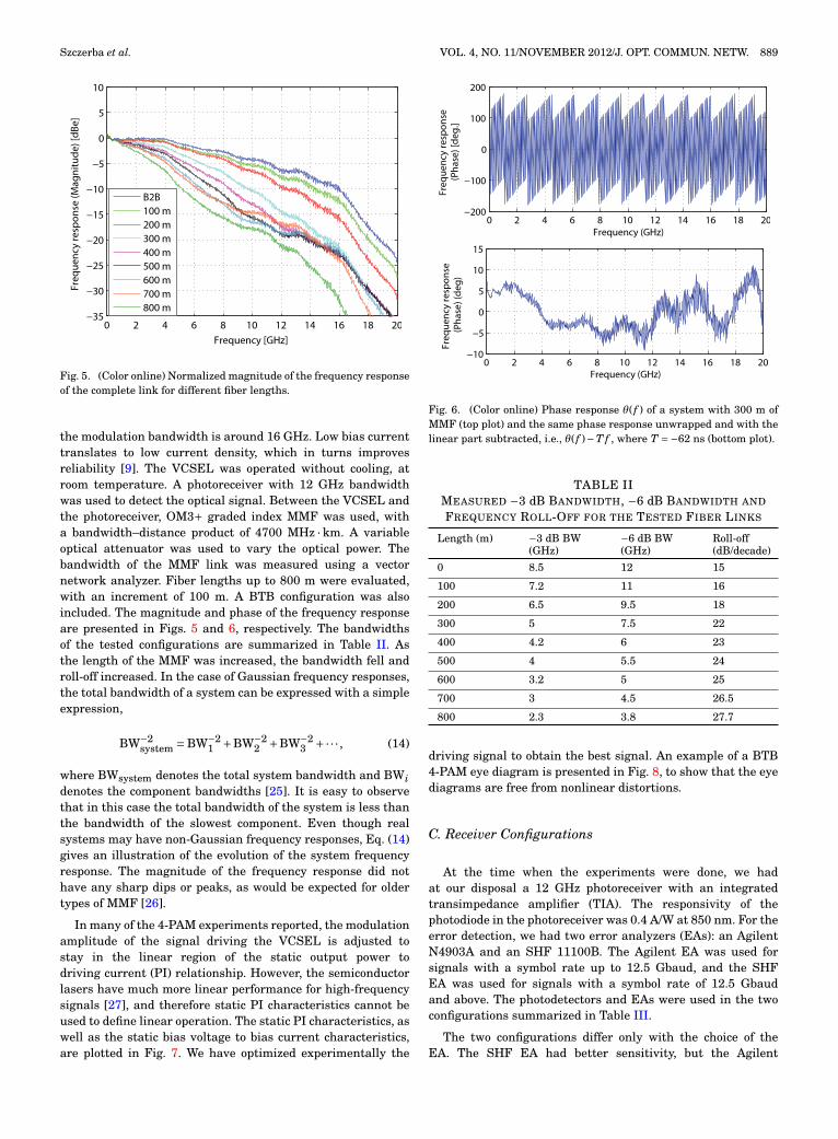
Fig. 5. (Color online) Normalized magnitude of the frequency responseof the complete link for different fiber lengths.
the modulation bandwidth is around 16 GHz. Low bias currenttranslates to low current density, which in turns improvesreliability [9]. The VCSEL was operated without cooling, atroom temperature. A photoreceiver with 12 GHz bandwidthwas used to detect the optical signal. Between the VCSEL andthe photoreceiver, OM3+ graded index MMF was used, witha bandwidth–distance product of 4700 MHz · km. A variableoptical attenuator was used to vary the optical power. Thebandwidth of the MMF link was measured using a vectornetwork analyzer. Fiber lengths up to 800 m were evaluated,with an increment of 100 m. A BTB configuration was alsoincluded. The magnitude and phase of the frequency responseare presented in Figs. 5 and 6, respectively. The bandwidthsof the tested configurations are summarized in Table II. Asthe length of the MMF was increased, the bandwidth fell androll-off increased. In the case of Gaussian frequency responses,the total bandwidth of a system can be expressed with a simpleexpression,
BW−2system =BW−2
1 +BW−22 +BW−2
3 +·· · , (14)
where BWsystem denotes the total system bandwidth and BWidenotes the component bandwidths [25]. It is easy to observethat in this case the total bandwidth of the system is less thanthe bandwidth of the slowest component. Even though realsystems may have non-Gaussian frequency responses, Eq. (14)gives an illustration of the evolution of the system frequencyresponse. The magnitude of the frequency response did nothave any sharp dips or peaks, as would be expected for oldertypes of MMF [26].
In many of the 4-PAM experiments reported, the modulationamplitude of the signal driving the VCSEL is adjusted tostay in the linear region of the static output power todriving current (PI) relationship. However, the semiconductorlasers have much more linear performance for high-frequencysignals [27], and therefore static PI characteristics cannot beused to define linear operation. The static PI characteristics, aswell as the static bias voltage to bias current characteristics,are plotted in Fig. 7. We have optimized experimentally the
Fig. 6. (Color online) Phase response θ( f ) of a system with 300 m ofMMF (top plot) and the same phase response unwrapped and with thelinear part subtracted, i.e., θ( f )−T f , where T =−62 ns (bottom plot).
TABLE IIMEASURED −3 dB BANDWIDTH, −6 dB BANDWIDTH AND
FREQUENCY ROLL-OFF FOR THE TESTED FIBER LINKS
Length (m) −3 dB BW −6 dB BW Roll-off(GHz) (GHz) (dB/decade)
0 8.5 12 15
100 7.2 11 16
200 6.5 9.5 18
300 5 7.5 22
400 4.2 6 23
500 4 5.5 24
600 3.2 5 25
700 3 4.5 26.5
800 2.3 3.8 27.7
driving signal to obtain the best signal. An example of a BTB4-PAM eye diagram is presented in Fig. 8, to show that the eyediagrams are free from nonlinear distortions.
C. Receiver Configurations
At the time when the experiments were done, we hadat our disposal a 12 GHz photoreceiver with an integratedtransimpedance amplifier (TIA). The responsivity of thephotodiode in the photoreceiver was 0.4 A/W at 850 nm. For theerror detection, we had two error analyzers (EAs): an AgilentN4903A and an SHF 11100B. The Agilent EA was used forsignals with a symbol rate up to 12.5 Gbaud, and the SHFEA was used for signals with a symbol rate of 12.5 Gbaudand above. The photodetectors and EAs were used in the twoconfigurations summarized in Table III.
The two configurations differ only with the choice of theEA. The SHF EA had better sensitivity, but the Agilent

890 J. OPT. COMMUN. NETW./VOL. 4, NO. 11/NOVEMBER 2012 Szczerba et al.
Fig. 7. (Color online) The power and voltage versus currentcharacteristics of the VCSEL used in the experiments.
Fig. 8. (Color online) Back-to-back eye diagram of a 4-PAM signal at25 Gbps, at 0 dBm received optical power. Because of the invertingamplifier in the photoreceiver, the highest power level is in the bottomof the eye diagram.
TABLE IIIRECEIVER CONFIGURATIONS
No. Photodetector Amplifier Error analyzer
1 12 GHz PR Integrated Agilent N4903A
2 12 GHz PR Integrated SHF 11100B
EA could be used at lower symbol rates. Additionally, forthe 12.5 Gbps 4-PAM signal, a 7.5 GHz passive electricallow-pass filter (LPF) was added to reject the noise outside thesignal bandwidth. Because of different performances of the tworeceiver configurations, all comparisons are always done withthe same configuration. The test setup illustrated in Fig. 4corresponds to the configuration with receiver no. 2.
D. Bit Error Rate Measurement
The BER measurement was performed using an EAdesigned for conventional OOK modulation. Since it is the
low-BER operation that is of highest interest, it is enoughto measure the error rates between the adjacent symbols(as motivated in Section II). This kind of measurementcan be easily done with an EA with adequate decisionthreshold, programed with patterns corresponding to givendecision thresholds. For 4-PAM, three decision thresholds areapplicable. The error rates measured at these thresholds aredenoted ER1, ER2, and ER3, and the total BER is given by
BER= 12
ER1 +ER2 +12
ER3, (15)
as was discussed in more detail in [14].
IV. RESULTS AND DISCUSSION
A. Comparison at the Same Symbol Rate—12.5 Gbaud
The comparison of 4-PAM with OOK at the same symbolrate of 12.5 Gbaud was performed using receiver configurationno. 2. A BTB eye diagram at 0 dBm received optical power isillustrated in Fig. 8: all levels had the same width, indicatingthat the noise is not signal dependent and that the theoreticalconsiderations on noise in Section II are correct. The BERresults are illustrated in Figs. 9 and 10. The BTB sensitivityat BER = 10−9 of OOK at 12.5 Gbps was about −13 dBm,which agrees very well with the theory (see Fig. 1). Onthe other hand, 4-PAM at 25 Gbps had BTB sensitivity ofaround −6.5 dBm, which was about 1.2 dB off the theoreticalexpectation, and consequently the difference between OOKand 4-PAM sensitivity was 6 dB, rather than the expected4.8 dB.
The comparison of the receiver sensitivities versus propa-gation distance for the 12.5 Gbaud case is shown in Fig. 11.The propagation penalty for 200 m of the OM3+ MMF wassmall for both modulation formats, but, beyond this length,4-PAM degraded much faster than OOK. This agrees with thetheoretical ISI penalty evolution from Fig. 3. The absoluteISI penalties with respect to the BTB configuration are ingood agreement with theory up to 400 m for OOK and upto 200 m for 4-PAM, or roughly up to 2 dB ISI penalty,which comes at shorter distances for 4-PAM. Consequently,the approximate theoretical ISI expression for 4-PAM isuseful for shorter fiber lengths. The theoretical ISI penaltyis apparently overestimated for OOK and underestimated for4-PAM for longer fiber lengths. The theoretical ISI penaltieswere calculated under the assumption of Gaussian channelresponse and pulse shape, which is only a rough approximationof the real conditions. For 4-PAM, the eye closing is largerfor the two outer levels than in the center (see the insert inFig. 11), while the theoretical model approximates it with thesame eye closing for all levels.
B. Comparisons at the Same Bit-Rate—12.5 Gbps
The comparison at the same bit-rate was done at 12.5 Gbps.Receiver configuration no. 1 was used both for 4-PAM and OOKat 12.5 Gbps, with a 7.5 GHz LPF for the 4-PAM. The BTB

Szczerba et al. VOL. 4, NO. 11/NOVEMBER 2012/J. OPT. COMMUN. NETW. 891
Fig. 9. (Color online) BER versus average received optical power for4-PAM at 25 Gbps.
Fig. 10. (Color online) BER versus average received optical power forOOK at 12.5 Gbps, obtained with receiver in configuration no. 2.
receiver sensitivity of OOK with this receiver configurationwas 4.5 dB worse than with receiver configuration no. 2. Therelative BTB sensitivity of 4-PAM at 12.5 Gbps was 4 dBworse than of OOK at 12.5 Gbps, while a 3.3 dB differencewas expected from theory in Section II. The BER resultsfor the 12.5 Gbps case are illustrated in Figs. 12 and 13.The receiver sensitivities after propagation over MMF areillustrated in Fig. 14. Within the available received power,both OOK and 4-PAM could reach 600 m at 12.5 Gbps,although the propagation penalty for 4-PAM is much loweruntil 500 m is reached. In fact, at 500 m, the sensitivity of12.5 Gbps 4-PAM was only 2.5 dB worse than of 12.5 GbpsOOK. Beyond 500 m, the propagation penalty for 4-PAMstarted to increase much faster. Similar behavior is observedin Fig. 3; however, the expected ISI penalty beyond 500 mis lower that what was observed in the experiments. Fromthe theoretical consideration in Section II, it follows that
Fig. 11. (Color online) Sensitivity at BER = 10−9 versus MMFpropagation distance compared at the same symbol rate (12.5 Gbaud)with 4-PAM eye diagram after 300 m in the insert.
Fig. 12. (Color online) BER versus average received optical power for4-PAM at 12.5 Gbps and 25 Gbps.
4-PAM should have better sensitivity than OOK at the samebit-rate after propagation over 500 m. In the experiments, thesensitivity and ISI penalties for 4-PAM were worse than thetheoretical values. The theoretical penalties for 4-PAM areagain underestimated compared to the experimental results.Similarly to the 12.5 Gbaud 4-PAM case, the eye closingbecomes uneven for different levels, and that adds to thepenalty, as illustrated in the insert in Fig. 14. There arealso implementation penalties for 4-PAM, which could lowerif electronic circuits dedicated for 4-PAM were developed. Forexample, the microwave combiners used are non-ideal, and adedicated multilevel circuit would improve the performance.A highly linear optical receiver with automatic gain control(AGC), similar to the one used in [28], would make the BERmeasurements more reliable and simplify the design of adecision stage for 4-PAM in real applications.

892 J. OPT. COMMUN. NETW./VOL. 4, NO. 11/NOVEMBER 2012 Szczerba et al.
Fig. 13. (Color online) BER versus average received optical power forOOK at 12.5 Gbps, obtained with receiver in configuration no. 1.
Fig. 14. (Color online) Sensitivity versus MMF propagation distancecompared at the same bit-rate (12.5 Gbps) with 4-PAM eye diagrams,BTB ad 500 m, in the insert.
C. Discussion
The experiments show that 4-PAM required significantlymore receiver power than OOK in both scenarios: 6 dBat the same symbol rate and 4 dB more at the samebit-rate. This is more than is expected from the theoreticalconsiderations, which yield 4.8 dB and 3.3 dB in the tworespective scenarios (Section II). The implementation penaltiesare thus 1.2 dB and 0.7 dB, respectively. Possible reasonsfor the implementation penalties are the suboptimal electricalsignal from the microwave couplers and lack of AGC in thereceiver.
The ISI penalties of 4-PAM were lower than of OOK at thesame bit-rate, but because of the implementation penaltieswe could not reach the point where the lower ISI penaltiesof 4-PAM would offset its higher power requirements. Also,
the theoretical ISI penalties of 4-PAM were underestimated by1–2 dB at longer fiber length, compared to the experimentalresults. This is reasonable, given the simplicity of thetheoretical model, which assumes Gaussian pulses as well aschannel responses and equal eye closing for all levels. Thetheoretical calculation gives good estimates up to roughly 2 dBof ISI penalty.
The difference in sensitivity between 4-PAM and OOK wascomparable to, for example, the link budget foreseen for shortdata links in the IEEE 802.3 standard [29]. The link budgetforeseen by this standard is 8.3 dB and allocation for penaltiesis 6.5 dB. This means that, should an existing OOK system beupgraded to 4-PAM in order to double the bit-rate in the samebandwidth, the power budget would be exhausted. On the otherhand, the power budgets might be different in applicationssuch as active optical cables, where, for example, the connectorlosses are eliminated. Because of the closed nature of activeoptical cables, multi-source agreements do not have to befollowed and, for example, the link budgets can be adjusted tothe specific needs and 4-PAM could be used. As we show in ourexperiments, it is possible to make links with sufficient powerbudget for 4-PAM operation. The main benefit of 4-PAM in suchan application would be doubled throughput, using the samecomponents. In a bandwidth-constrained case, 4-PAM allowsdoubling the bit-rate and has lower propagation penalties, butthe lower penalties after propagation in the MMF do not offsetthe higher optical power required by 4-PAM.
Given that at 12.5 Gbps we need −12 dBm to achieveerror-free performance with OOK and that the maximumavailable power at the photoreceiver is around 1 dBm, it shouldbe possible to increase the number of modulation levels to 8,since 8-PAM should require around 8.5 dB more power to reachthe same BER (plus implementation penalty between 1 and2 dB).
V. CONCLUSION
We have shown that 4-PAM can be used to double thebit-rate of short-range optical links using existing componentsand OOK, although it required 6 dB more optical power. Wehave also demonstrated that 4-PAM had lower propagationpenalties than OOK at the same bit-rate, but required 4 dBmore optical power in the BTB case. Due to implementationpenalties, this was more than expected from the theoreticalconsiderations. Because of the additional penalties, thereduced propagation penalties did not offset the increasedpower requirements of 4-PAM in the case of the particulartested system. Higher linearity requirements of 4-PAM,compared to OOK, were not a problem when VCSELs wereused. Implementation of 4-PAM was relatively simple, and forexperimental purposes does not require customized electronics.
ACKNOWLEDGMENTS
This work was supported by the Swedish Foundation forStrategic Research (SSF) and the European FP7 project VISIT,and we would like to thank them for their support.

Szczerba et al. VOL. 4, NO. 11/NOVEMBER 2012/J. OPT. COMMUN. NETW. 893
REFERENCES
[1] P. Westbergh, J. S. Gustavsson, B. Kögel, Å. Haglund, A. Larsson,A. Mutig, A. Nadtochiy, D. Bimberg, and A. Joel, “40 Gbit/serror-free operation of oxide-confined 850 nm VCSEL,” Electron.Lett., vol. 46, no. 14, pp. 1014–1016, July 2010.
[2] W. Hofmann, P. Moser, P. Wolf, A. Mutig, M. Kroh, and D. Bim-berg, “44 Gb/s VCSEL for optical interconnects,” in Proc. OFC,Mar. 2011, PDPC5.
[3] K. Szczerba, B.-E. Olsson, P. Westbergh, A. Rhodin, J. S. Gustavs-son, Å. Haglund, M. Karlsson, A. Larsson, and P. A. Andrekson,“37 Gbps transmission over 200 m of MMF using single cyclesubcarrier modulation and a VCSEL with 20 GHz modulationbandwidth,” in Proc. ECOC, Sept. 2010, We.7.B.2.
[4] S. C. J. Lee, F. Breyer, S. Randel, D. Cardenas, H. P. A. vanden Boom, and A. M. J. Koonen, “Discrete multitone modulationfor high-speed data transmission over multimode fibers using850-nm VCSEL,” in Proc. OFC, Mar. 2009, OWM2.
[5] S. Randel, F. Breyer, and S. C. J. Lee, “High-speed transmissionover multimode optical fibers,” in Proc. OFC, Feb. 2008, OWR2.
[6] J. R. Kahn and J. M. Barry, “Wireless infrared communications,”Proc. IEEE, vol. 85, no. 2, pp. 265–298, Feb. 1997.
[7] D. Watanabe, A. Ono, and T. Okayasu, “CMOS optical 4-PAMVCSEL driver with modal-dispersion equalizer for 10 Gb/s 500 mMMF transmission,” in Proc. ISSCC, Feb. 2009, pp. 106–107.
[8] T. Toifl, C. Menolfi, M. Ruegg, R. Reutemann, P. Buchmann,M. Kossel, T. Morf, J. Weiss, and M. L. Schmatz, “A 22 Gb/sPAM-4 receiver in 90-nm CMOS SOI technology,” IEEE J.Solid-State Circuits, vol. 41, no. 4, pp. 954–965, Apr. 2006.
[9] S. Walklin and J. Conradi, “Multilevel signaling for increasingthe reach of 10 Gb/s lightwave systems,” J. Lightwave Technol.,vol. 17, no. 11, pp. 2235–2248, Nov. 1999.
[10] J. D. Ingham, R. V. Penty, and I. H. White, “10 Gb/s & 20 Gb/sextended-reach multimode-fiber datacommunication links usingmultilevel modulation and transmitter-based equalization,” inProc. OFC, Feb. 2008, OTuO7.
[11] J. D. Ingham, R. V. Penty, I. H. White, P. Westbergh, J. S. Gus-tavsson, Å. Haglund, and A. Larsson, “32 Gb/s multilevel modu-lation of an 850 nm VCSEL for next-generation datacommunica-tion standards,” in Proc. CLEO, May 2011, CWJ2.
[12] J. E. Cunningham, D. Beckman, X. Zheng, D. Huang, T. Sze,and A. V. Krishnamoorthy, “PAM-4 signaling over VCSELs with0.13 µm CMOS chip technology,” Opt. Express, vol. 14, no. 25, pp.12028–12038, Dec. 2006.
[13] K. Szczerba, P. Westbergh, J. S. Gustavsson, Å. Haglund,J. Karout, M. Karlsson, P. A. Andrekson, E. Agrell, and A. Lars-son, “30 Gbps 4-PAM transmission over 200 m of MMF using an850 nm VCSEL,” in Proc. ECOC, Sept. 2011, Tu.3.C.
[14] K. Szczerba, P. Westbergh, J. Karout, J. S. Gustavsson,Å. Haglund, M. Karlsson, P. A. Andrekson, E. Agrell, and A. Lars-son, “30 Gbps 4-PAM transmission over 200 m of MMF using an850 nm VCSEL,” Opt. Express, vol. 19, no. 26, pp. B203–B208,Dec. 2011.
[15] J. K. Pollard, “Multilevel data communication over optical fibre,”IEE Proc.-Commun., vol. 138, no. 3, pp. 162–168, June 1991.
[16] J. G. Proakis and M. Salehi, Digital Communications. 5th ed.McGraw-Hill, New York, 2008.
[17] E. Agrell, J. Lassing, E. G. Ström, and T. Ottosson, “On theoptimality of the binary reflected Gray code,” IEEE Trans. Inf.Theory, vol. 50, no. 12, pp. 3170–3182, Dec. 2004.
[18] G. P. Agrawal, Lightwave Technology: Telecommunication Sys-tems. Wiley Interscience, New York, 2005.
[19] J. Gimlett and N. Cheung, “Dispersion penalty analysis forLED/single-mode fiber transmission systems,” J. Lightwave Tech-nol., vol. 4, no. 9, pp. 1381–1392, Sept. 1986.
[20] D. Cunningham, M. Nowell, D. Hanson, and L. Kazovsky, TheIEEE 802.3z Worst Case Link Model for Optical Physical MediaDependent Specification [Online]. Available: http://www.ieee802.org/3/z/public/presentations/mar1997/DCwpaper.pdf.
[21] IEEE 802.3ae 10G Ethernet optical link budget spreadsheet[Online]. Available: http://ieee802.org/3/10G_study/public/email_attach/All_1250v2.xls.
[22] J. D. Ingham, R. V. Penty, and I. H. White, “Modulation for-mats for next-generation optical datacommunications,” in Proc.ICTON, June 2011, Mo.C1.2.
[23] J. D. Ingham, R. V. Penty, I. H. White, and D. Cunningham,“40 Gb/s carrierless amplitude and phase modulation for low-costoptical datacommunication links,” in Proc. OFC, Mar. 2011,OThZ3.
[24] P. Westbergh, J. S. Gustavsson, Å. Haglund, A. Larsson,F. Hopfer, G. Fiol, D. Bimberg, and A. Joel, “32 Gbit/s multimodefibre transmission using high-speed, low current density 850 nmVCSEL,” Electron. Lett., vol. 45, no. 7, pp. 366–368, Mar. 2009.
[25] G. Brown, “Bandwidth and rise time calculations for digitalmultimode fiber-optic data links,” J. Lightwave Technol., vol. 10,no. 5, pp. 672–678, May 1992.
[26] A. M. E.-A. Diab, J. D. Ingham, R. V. Penty, and I. H. White,“Statistical analysis of subcarrier-modulated transmission over300 m of 62.5-µm-core-diameter multimode fiber,” J. LightwaveTechnol., vol. 23, no. 8, pp. 2380–2398, Aug. 2005.
[27] W. I. Way, Broadband Hybrid Fiber Coax Access System Tech-nologies, 1st ed. Academic Press, Orlando, FL, 1998.
[28] M. Atef, R. Swoboda, and H. Zimmermann, “170 Mb/s multileveltransmission over 115 m standard step-index plastic optical fiberusing an integrated optical receiver,” Opt. Commun., vol. 284, no.1, pp. 191–194, 2011.
[29] IEEE Standard for Information Technology—Telecommun-ications and Information Exchange Between Systems—Local andMetropolitan Area Networks—Specific Requirements, IEEE Std802.3ba-2010, 2010.
Krzysztof Szczerba received his M.Sc. degree in Telecommunicationsfrom the Technical University of Denmark, Lyngby, Denmark, andhis M.Sc. degree in Electronics and Telecommunications from theTechnical University of Lodz, Poland, both in 2008. In 2008, he workedat the Technical University of Denmark, DTU Fotonik, Department ofPhotonics Engineering as a research assistant. In 2009, he joined theChalmers University of Technology, Department of Microtechnologyand Nanoscience, in Göteborg, Sweden, where he is currently workingtoward a Ph.D. degree in optical communications. His researchinterests are focused on modulation formats for short-range opticallinks for datacommunication applications.
Petter Westbergh received his M.Sc. degree in Engineering Physicsand his Ph.D. degree in Microtechnology and Nanoscience fromChalmers University of Technology, Göteborg, Sweden, in 2007 and2011, respectively. His thesis focused on the design, fabrication, andcharacterization of high-speed 850 nm vertical-cavity surface-emittinglasers (VCSELs) intended for application in short-reach communica-tion networks. He is currently continuing his work on improving theperformance of high-speed VCSELs with the Department of Microtech-nology and Nanoscience at Chalmers University of Technology.
Johnny Karout received his B.E. (with distinction) in ComputerEngineering from the Lebanese American University, Byblos, Lebanon,in 2007, and his M.Sc. in Communication Engineering and Licentiatedegree in Electrical Engineering, both from Chalmers University ofTechnology, Göteborg, Sweden, in 2009 and 2011, respectively. SinceJune 2009, he has been pursuing his Ph.D. at the Department ofSignals and Systems, Chalmers University of Technology, Göteborg,Sweden.

894 J. OPT. COMMUN. NETW./VOL. 4, NO. 11/NOVEMBER 2012 Szczerba et al.
From October to December 2011, he was a visiting scholar atthe Institute for Communications Engineering at the TechnischeUniversität München, Germany. His research interests are in thebroad areas of modulation and coding, with a focus on optical channels.
He is the co-founder of the project Optium, which is related toshort-haul optical communications at Chalmers Innovation, a businessincubator located in Göteborg, Sweden. He is also a recipient of the2011 GlobeCom Best Paper Award.
Johan S. Gustavsson received his M.Sc. degree in ElectricalEngineering and his Ph.D. degree in Photonics from the ChalmersUniversity of Technology, Göteborg, Sweden, in 1998 and 2003,respectively.
He was involved in mode dynamics and noise in vertical-cavitysurface-emitting lasers (VCSELs). He is currently an AssociateProfessor in the Photonics Laboratory, Department of Microtechnologyand Nanoscience, Chalmers University of Technology. His currentresearch interests include the design, modeling, and characterizationof long-wavelength semiconductor lasers, mode and polarizationcontrol in VCSELs using shallow surface structures, and improvingthe bandwidth of conventional GaAs-based VCSELs.
Åsa Haglund received her M. Sc. degree in Physics from GöteborgUniversity, Göteborg, Sweden, in 2000, and her Ph.D. degree inElectrical Engineering from Chalmers University of Technology,Göteborg, Sweden, in 2005. Her Ph.D. thesis was focused on modeand polarization control in vertical-cavity surface-emitting lasers(VCSELs) using surface structures. She is currently an AssistantProfessor at the Photonics Laboratory at Chalmers University ofTechnology, and her research is mainly focused on GaAs-based vertical-cavity surface-emitting lasers and III-nitride-based vertical-cavitysurface-emitting lasers and deep-ultraviolet light-emitting diodes.
Magnus Karlsson received his Ph.D. in Electromagnetic Field Theoryin 1994 from Chalmers University of Technology, Göteborg, Sweden.The title of his Ph.D. thesis was “Nonlinear propagation of opticalpulses and beams.” Since 1995, he has been with the PhotonicsLaboratory at Chalmers, first as an Assistant Professor and since2003 as a Professor in Photonics. He has authored or co-authored over190 scientific journal and conference contributions, served as guesteditor for the Journal of Lightwave Technology, and is currently anassociate editor of Optics Express. He has served in the technicalcommittees for the Optical Fiber Communication Conference (OFC)(2009 as subcommittee chair), and the Asia Communications andPhotonics Conference (ACP, formerly APOC). His research has beendevoted to a variety of aspects of fiber optic communication systems,in particular transmission effects such as fiber nonlinearities andpolarization effects, but also applied issues such as high-capacity datatransmission and all-optical switching. Currently he is devoted toparametric amplification, multilevel modulation formats, and coherenttransmission in optical fibers.
Peter Andrekson received his Ph.D. from Chalmers University ofTechnology, Sweden, in 1988. After about three years with AT&T BellLaboratories, Murray Hill, NJ, USA, during 1989–1992, he returnedto Chalmers, where he is now a Full Professor in the Departmentof Microtechnology and Nanoscience. He was Director of Research atCenix Inc. in Allentown, PA, USA, during 2000–2003 and with thenewly established Center for Optical Technologies at Lehigh Univer-sity, Bethlehem, PA, USA, during 2003–2004. His research interestsinclude nearly all aspects of fiber communications such as optical
amplifiers, nonlinear pulse propagation, all-optical functionalities, andvery high-capacity transmission. He is a co-founder of the optical testand measurement company Picosolve Inc., now part of EXFO; he is aDirector of EXFO Sweden AB.
Andrekson is a Fellow of the Optical Society of America and aFellow of the IEEE. He is the author of about 350 scientific publicationsand conference papers in the area of optical communications, amongwhich 80 were invited papers at leading international conferences andjournals, including two tutorials at the Optical Fiber CommunicationConference (OFC) in 2004 and 2011. He is an elected member of theBoard of Governors for the IEEE Photonics Society and is serving orhas served on several technical program committees, including OFCand ECOC, and as an international project and candidate evaluator,and has also twice served as an expert for the evaluation of theNobel Prize in Physics. He was an associate editor for IEEE PhotonicsTechnology Letters during 2003–2007. In 1993, he was awarded a prizefrom the Swedish government research committee for outstandingwork performed by young scientists, and in 2000 he was awardedthe Telenor Nordic research award for his contribution to opticaltechnologies.
Erik Agrell received his M.S. degree in Electrical Engineering in1989 and his Ph.D. degree in Information Theory in 1997, both fromChalmers University of Technology, Sweden.
From 1988 to 1990 he was with Volvo Technical Development as aSystems Analyst, and from 1990 to 1997 he was with the Departmentof Information Theory, Chalmers University of Technology, as aResearch Assistant. In 1997–1999, he was a Postdoctoral Researcherwith the University of Illinois at Urbana-Champaign and theUniversity of California, San Diego. In 1999, he joined the faculty ofChalmers University of Technology, first as an Associate Professor andsince 2009 as a Professor in Communication Systems. His researchinterests belong to the fields of information theory, coding theory,and digital communications, and his favorite applications are foundin optical communications. More specifically, his current researchincludes bit-interleaved coded modulation and multilevel coding,polarization-multiplexed coding and modulation, transmission overthe optical intensity channel, phase noise mitigation, and bit-to-symbolmappings in coded and uncoded systems.
Anders Larsson received his M.Sc. and Ph.D. degrees in ElectricalEngineering from Chalmers University of Technology, Göteborg,Sweden, in 1982 and 1987, respectively. In 1991, he joined the facultyat Chalmers University of Technology, where he was promoted toProfessor in 1994. From 1984 to 1985 he was with the Departmentof Applied Physics, California Institute of Technology, and from1988 to 1991 with the Jet Propulsion Laboratory, both at Pasadena,CA, USA. He has been a guest professor at Ulm University(Germany), at the Optical Science Center, University of Arizona,Tucson, Arizona (USA), at Osaka University (Japan), and at theInstitute of Semiconductors, Chinese Academy of Sciences (China).He co-organized the IEEE Semiconductor Laser Workshop 2004,organized the European Semiconductor Laser Workshop 2004, andwas the Program and General Chair for the IEEE InternationalSemiconductor Laser Conference in 2006 and 2008, respectively. He isan associate editor for the IEEE Journal of Lightwave Technology. Hisscientific background is in the areas of materials and devices for opticalcommunication, information processing, and sensing. Currently, hisresearch is focused on vertical-cavity surface-emitting lasers, opticallypumped semiconductor disk lasers, and III-nitride emitters. He haspublished more than 400 scientific journal and conference papers. Heis a Fellow of the European Optical Society and a Senior Member ofIEEE.