325.13R-06 Concrete Overlays for Pavement Rehabilitation
39
ACI 325.13R-06 became effective February 27, 2006. Copyright © 2006, American Concrete Institute. All rights reserved including rights of reproduction and use in any form or by any means, including the making of copies by any photo process, or by electronic or mechanical device, printed, written, or oral, or recording for sound or visual reproduction or for use in any knowledge or retrieval system or device, unless permission in writing is obtained from the copyright proprietors. ACI Committee Reports, Guides, and Commentaries are intended for guidance in planning, designing, executing, and inspecting construction. This document is intended for the use of individuals who are competent to evaluate the significance and limitations of its content and recommendations and who will accept responsibility for the application of the material it contains. The American Concrete Institute disclaims any and all responsibility for the stated principles. The Institute shall not be liable for any loss or damage arising therefrom. Reference to this document shall not be made in contract documents. If items found in this document are desired by the Architect/Engineer to be a part of the contract documents, they shall be restated in mandatory language for incorporation by the Architect/Engineer. 325.13R-1 Concrete Overlays for Pavement Rehabilitation Reported by ACI Committee 325 ACI 325.13R-06 This report provides information on the use of concrete overlays for rehabilitation of both concrete (rigid) and asphalt (flexible) pavements. Selection, design, and construction of both bonded and unbonded overlays are discussed. The overlay categories reviewed include bonded concrete overlays, unbonded concrete overlays, whitetopping overlays, and concrete overlays bonded to asphalt (ultra-thin and thin whitetopping). Information is also provided on selecting overlay alternatives. Significant portions of this document are based on a synthesis report prepared for the Federal Highway Administration (FHWA) by Applied Pavement Technology, Inc., under contract number DTFH61-00-P-00507. The report, “Portland Cement Concrete Overlays: State of the Technology Synthesis,” is available from the FHWA as publication FHWA-IF-02-045. Keywords: bond; concrete; joint; overlay; pavement (concrete); rehabilitation; repair. CONTENTS Chapter 1—Introduction, p. 325.13R-2 1.1—Background 1.2—Purpose of report 1.3—Definitions and notation Chapter 2—Concrete overlay types and construction materials, p. 325.13R-4 2.1—Introduction 2.2—Types of concrete overlays 2.3—Overlay materials 2.4—Interface materials 2.5—Incidental materials 2.6—Concrete production, construction, and quality-control issues Chapter 3—Selection of concrete overlay alternatives, p. 325.13R-11 3.1—Introduction 3.2—Effectiveness of different types of concrete overlays 3.3—Selection process David J. Akers Ben Gompers David N. Richardson Imran M. Syed Richard O. Albright W. Charles Greer John W. Roberts Shiraz D. Tayabji * William L. Arent Jerry A. Holland Raymond S. Rollings Susan L. Tighe Jamshid M. Armaghani Mark K. Kaler Jack A. Scott Samuel Tyson Bob J. Banka Gary Mitchell Sanjaya P. Senadheera Suneel N. Vanikar Donald L. Brogna Paul E. Mueller Kieran G. Sharp Steven M. Waalkes Archie F. Carter Jon I. Mullarky * Terry W. Sherman Don J. Wade Van T. Cost Kamran M. Nemati James M. Shilstone, Sr. W. James Wilde * Juan P. Covarrubias Kelly L. Nix Hak-Chul Shin Gergis William Mohamed N. Darwish Nigel Parkes Kurt D. Smith † James M. Willson Martin Gendreau Thomas J. Pasko, Jr. Tim J. Smith Dan G. Zollinger Nader Ghafoori Steven A. Ragan Anthony M. Sorcic * Members of the task group drafting this document. † Chair of the task group drafting this document. Norbert J. Delatte * Chair David W. Pittman Vice Chair Neeraj J. Buch Secretary
-
Upload
khangminh22 -
Category
Documents
-
view
0 -
download
0
Transcript of 325.13R-06 Concrete Overlays for Pavement Rehabilitation

Concrete Overlays for Pavement RehabilitationReported by ACI Committee 325
ACI 325.13R-06
David J. Akers Ben Gompers David N. Richardson Imran M. Syed
Richard O. Albright W. Charles Greer John W. Roberts Shiraz D. Tayabji*
William L. Arent Jerry A. Holland Raymond S. Rollings Susan L. Tighe
Jamshid M. Armaghani Mark K. Kaler Jack A. Scott Samuel Tyson
Bob J. Banka Gary Mitchell Sanjaya P. Senadheera Suneel N. Vanikar
Donald L. Brogna Paul E. Mueller Kieran G. Sharp Steven M. Waalkes
Archie F. Carter Jon I. Mullarky* Terry W. Sherman Don J. Wade
Van T. Cost Kamran M. Nemati James M. Shilstone, Sr. W. James Wilde*
Juan P. Covarrubias Kelly L. Nix Hak-Chul Shin Gergis William
Mohamed N. Darwish Nigel Parkes Kurt D. Smith† James M. Willson
Martin Gendreau Thomas J. Pasko, Jr. Tim J. Smith Dan G. Zollinger
Nader Ghafoori Steven A. Ragan Anthony M. Sorcic
*Members of the task group drafting this document.†Chair of the task group drafting this document.
Norbert J. Delatte*
Chair
David W. PittmanVice Chair
Neeraj J. BuchSecretary
ACI Committee Reports, Guides, and Commentaries areintended for guidance in planning, designing, executing, andinspecting construction. This document is intended for the useof individuals who are competent to evaluate the significanceand limitations of its content and recommendations and whowill accept responsibility for the application of the material itcontains. The American Concrete Institute disclaims any andall responsibility for the stated principles. The Institute shallnot be liable for any loss or damage arising therefrom.
Reference to this document shall not be made in contractdocuments. If items found in this document are desired by theArchitect/Engineer to be a part of the contract documents, theyshall be restated in mandatory language for incorporation bythe Architect/Engineer.
This report provides information on the use of concrete overlays forrehabilitation of both concrete (rigid) and asphalt (flexible) pavements.Selection, design, and construction of both bonded and unbonded overlaysare discussed. The overlay categories reviewed include bonded concreteoverlays, unbonded concrete overlays, whitetopping overlays, and concreteoverlays bonded to asphalt (ultra-thin and thin whitetopping). Informationis also provided on selecting overlay alternatives. Significant portions ofthis document are based on a synthesis report prepared for the FederalHighway Administration (FHWA) by Applied Pavement Technology, Inc.,under contract number DTFH61-00-P-00507. The report, “PortlandCement Concrete Overlays: State of the Technology Synthesis,” is availablefrom the FHWA as publication FHWA-IF-02-045.
Keywords: bond; concrete; joint; overlay; pavement (concrete); rehabilitation;repair.
325.1
ACI 325.13R-06 became effective February 27, 2006.Copyright © 2006, American Concrete Institute.All rights reserved including rights of reproduction and use in any form or by any
means, including the making of copies by any photo process, or by electronic ormechanical device, printed, written, or oral, or recording for sound or visual reproductionor for use in any knowledge or retrieval system or device, unless permission in writingis obtained from the copyright proprietors.
CONTENTSChapter 1—Introduction, p. 325.13R-2
1.1—Background1.2—Purpose of report1.3—Definitions and notation
Chapter 2—Concrete overlay types and construction materials, p. 325.13R-4
2.1—Introduction2.2—Types of concrete overlays2.3—Overlay materials2.4—Interface materials2.5—Incidental materials2.6—Concrete production, construction, and quality-control
issues
Chapter 3—Selection of concrete overlay alternatives, p. 325.13R-11
3.1—Introduction3.2—Effectiveness of different types of concrete overlays3.3—Selection process
3R-1

325.13R-2 ACI COMMITTEE REPORT
Chapter 4—Bonded concrete overlays, p. 325.13R-134.1—Introduction4.2—Design4.3—Construction
Chapter 5—Unbonded concrete overlays,p. 325.13R-18
5.1—Introduction 5.2—Design 5.3—Construction 5.4—Performance
Chapter 6—Conventional whitetopping overlays, p. 325.13R-25
6.1—Introduction 6.2—Design 6.3—Construction 6.4—Performance
Chapter 7—Ultra-thin and thin whitetopping overlays, p. 325.13R-30
7.1—Introduction 7.2—Design 7.3—Construction 7.4—Performance
Chapter 8—References, p. 325.13R-358.1—Referenced standards and reports8.2—Cited references
CHAPTER 1—INTRODUCTION1.1—Background
Hydraulic cement concrete overlays are used as a rehabilita-tion technique for both existing concrete and asphaltpavements. Concrete overlays offer the potential forextended service life, increased structural capacity, reducedmaintenance requirements, and lower life-cycle costs whencompared with hot-mix asphalt overlay alternatives.
Concrete overlays have been used to rehabilitate existingconcrete pavements since 1913 and to rehabilitate existingasphalt pavements since 1918 (Hutchinson 1982). Beginningaround the mid-1960s, many highway agencies began to searchfor alternative means of rehabilitating existing pavements, andthe use of concrete overlays increased significantly (McGhee1994). In the 1990s, there was an even higher increase in theuse of concrete overlays, spurred by improvements in concretepaving technology. For example, the use of zero-clearancepavers, fast-track paving concepts, and high-early-strengthconcrete mixtures greatly increased the ability of concreteoverlays to serve as a viable rehabilitation alternative.
Parallel with the increased use of concrete overlays,significant research aimed at advancing the state of theknowledge of concrete overlays was conducted. One impetusfor this research was the Intermodal Surface TransportationAct (ISTEA) of 1991, which included a provision underSection 6005 allocating designated funding for the assessmentof thin bonded concrete overlays and surface laminationtechnology. The goals of the assessment were to evaluate thefeasibility, costs, and benefits of the techniques in minimizing
overlay thickness, initial laydown costs, and time out of service,and also to maximize life-cycle durability. As part of thiseffort, the Federal Highway Administration (FHWA)participated in funding 12 test-and-evaluation projectsthroughout the country (Sprinkel 2000).
Other examples of ongoing studies of concrete overlaysare those being conducted under the FHWA’s Long-TermPavement Performance (LTPP) program. The LTPPprogram is divided into two complementary studies: theGeneral Pavement Studies (GPS) and the Specific PavementStudies (SPS). Under GPS-9, the performance of unbondedconcrete overlays is being investigated; currently, 14 projectsare being evaluated. Under SPS-7, the performance of fourbonded overlay projects is being studied. The long-termmonitoring of these GPS and SPS projects is expected toprovide valuable information on the design and constructionof concrete overlays. Additional information may beobtained by visiting the LTPP website at www.tfhrc.gov/pavement/ltpp/ltpp.htm.
Resurfacing asphalt pavements with concrete overlays, aprocess known as whitetopping, is another example ofoverlay research. In particular, several studies on the use ofultra-thin whitetopping (UTW), a very thin (2 to 4 in. [50 to100 mm]) layer of concrete bonded to an existing asphaltpavement, have been conducted. In the 1990s, this techniqueevolved from a radical rehabilitation concept to a mainstreamrehabilitation alternative. Several studies on whitetoppingoverlays are currently being conducted by the FHWA. Addi-tional information may be obtained at www.tfhrc.gov/pavement/utwweb/utw.htm.
1.2—Purpose of reportTwo ACI Committee 325 reports (ACI Committee 325 1958,
1967) discussed the pioneering work by the U.S. ArmyCorps of Engineers to develop design procedures for concreteoverlays. The equations developed by the Corps for bonded,partially bonded, and unbonded concrete-on-concrete overlaysare still used. The report suggested the design of concreteoverlays on flexible pavement using the flexible pavement asa stiff base.
During the 1980s and 1990s, two National CooperativeHighway Research Program (NCHRP) syntheses wereprepared on concrete overlays: “Resurfacing with PortlandCement Concrete” (Hutchinson 1982), and “Portland CementConcrete Resurfacing” (McGhee 1994). There has been consid-erable work, however, in the area of concrete overlays sincethe most recent NCHRP synthesis.There is a need to assembleand synthesize information on the selection, design, andconstruction of concrete overlays for pavement rehabilitation.
This report discusses the selection, design, construction,and performance of concrete overlays. It is intended toprovide the current state of the technology (as of 2004) ofconcrete overlays of both existing concrete pavements andexisting asphalt pavements.
1.3—Definitions and notation1.3.1 Definitions—This section presents definitions and
notations unique to this report. Additional definitions for
CONCRETE OVERLAYS FOR PAVEMENT REHABILITATION 325.13R-3
common concrete terminology can be found in ACI 116R.Definitions shown in italics are terms that may be found inACI 116R, but have been redefined for this report.
break and seat—technique similar to crack and seat,except conducted on jointed reinforced concrete pavementsand using higher impact energy; uses more impact energy torupture the steel or break its bond with the concrete to ensureindependent movement, and seating with a heavy roller.
crack and seat—technique involving fracturing theexisting jointed plain concrete pavements into pieces 1 to 4 ft(0.3 to 1.2 m) on a side by inducing full-depth cracks usinga modified pile driver, guillotine hammer, whip hammer, orother equipment, and seating with a heavy roller.
curling—concrete distortion, usually in a slab, resultingfrom differential temperatures.
drainage, subsurface—inclusion of specific drainageelements in a pavement structure intended to remove excesssurface infiltration water from a pavement.
equivalent single-axle loads (ESALs)—summation of18 kip (80 kN) single-axle load applications used to combinemixed traffic to design traffic during the analysis period.
falling weight deflectometer—device in which electronicsensors measure the deflection of the pavement as a result ofan impact load of known magnitude; results can be used toestimate the elastic moduli of subgrade and pavement layersand the load transfer across joints and cracks.
faulting—difference of elevation across a joint.fracturing, slab—technique in which an existing port-
land-cement concrete pavement is cracked or broken intosmaller pieces to reduce the likelihood of reflection cracking.
hot-mix asphalt (HMA)—an asphalt cement-aggregatemixture that is mixed, spread, and compacted at an elevatedtemperature; also commonly referred to as “asphaltconcrete” or “asphalt.”
joint orientation—alignment of transverse joints in a concretepavement with respect to the centerline of the pavement.
layer, separator—layer of hot-mix asphalt, bituminousmaterial, or other stress-relieving material used at theinterface between an unbonded concrete overlay and theexisting concrete pavement to ensure independent behavior.
leveling course—thin layer of hot-mix asphalt or otherbituminous material to produce a uniform surface for paving.
load transfer—means through which wheel loads aretransferred or transmitted across a joint from one slab to the next.
life-cycle cost analysis (LCCA)—economic assessmentof competing pavement design alternatives in which allsignificant costs over the life of each alternative are considered.LCCA is used to evaluate a design solution. Life-cycle costsmay be measured for different designs to determine whichdesign will meet the economic and performance goals.
mill—process using drum-mounted carbide steel cuttingbits to remove material from a pavement and provide textureto promote bonding with an overlay.
overlay, bonded concrete—hydraulic cement concreteoverlay bonded directly to an existing concrete pavement toform a monolithic structure.
overlay, partially bonded—hydraulic cement concreteoverlay that is placed directly on an existing portland-cement
concrete pavement with little or no surface preparation;consequently, partial bonding between the two pavements isexpected.
overlay, unbonded concrete—hydraulic cement concreteoverlay placed on an existing distressed concrete pavementsuch that the overlay is separated from the existing pavementthrough a separator layer.
pavement, continuously reinforced concrete (CRCP)—pavement with uninterrupted longitudinal steel reinforcementand no intermediate transverse expansion or contraction joints.
pavement, jointed plain concrete (JPCP)—hydrauliccement concrete pavement system characterized by shortjoint spacings and no distributed reinforcing steel in the slab,with or without dowels.
pavement, jointed reinforced concrete (JRCP)—hydraulic cement concrete pavement system containingdowels, characterized by long joint spacings and distributedreinforcing steel in the slab to control crack widths.
repair, preoverlay—repair or renovation activityperformed on an existing pavement before the placement ofan overlay.
roughness—irregularities in the pavement surface thatadversely affect ride quality, safety, and vehicle maintenancecosts.
rubblize, rubblization—breaking the existing pavementinto pieces no larger than 6 in. (150 mm) on a side using avibratory beam breaker or resonant frequency pavementbreaker.
shotblasting—surface preparation technique in whichsteel shots are propelled against the surface of a portland-cement concrete pavement, effectively cleaning and preparingthe surface to receive a bonded concrete overlay.
slab, shattered—concrete pavement with extensivelongitudinal and transverse cracking.
slab, widened—concrete pavement slab that is pavedwider (usually at least 18 in. [450 mm] wider) than aconventional 12 ft (3.7 m) traffic lane to increase thedistance between truck tires and slab edge, thereby reducingedge stresses due to loading.
stripping—separation of asphalt cement from aggregatedue to moisture attack.
user costs—in a life-cycle cost analysis, costs incurred bythe user, such as delay costs, vehicle operating costs, andaccident costs.
variable joint spacing—series of different joint spacingsrepeated in a regular pattern intended to reduce the rhythmicresponse of vehicles traveling over uniformly spaced joints.
warping—concrete distortion caused by differential moisture.whitetopping—concrete overlay placed on an existing
asphalt pavement. Whitetopping may be used in referring toconventional whitetopping, thin whitetopping, or ultra-thinwhitetopping.
whitetopping, conventional—overlay placed on asphaltpavement, typically with a thickness higher than 8 in. (200 mm).
whitetopping, thin—bonded concrete overlay of thicknessbetween 4 and 8 in. (100 and 200 mm) and typically havinga joint spacing between 6 and 12 ft (1.8 and 3.7 m) that isplaced on milled asphalt pavement.
325.13R-4 ACI COMMITTEE REPORT
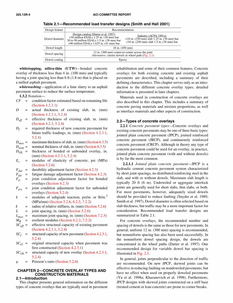
Table 2.1—Recommended load transfer designs (Smith and Hall 2001)Design feature Recommendation
Dowel diameter
Design catalog (Darter et al. 1997)<30 million ESALs 1.25 in. (30 mm) bar
30 to 90 million ESALs 1.5 in. (38 mm) bar>90 million ESALs 1.625 in. (41 mm) bar
Industry (ACPA 1991a)<10 in. (250 mm) slab 1.25 in. (30 mm) bar≤10 in. (250 mm) slab 1.5 in. (38 mm) bar
Dowel length 18 in. (450 mm)
Dowel spacing 12 in. (300 mm) center-to-center across the jointAlternative: cluster dowels in wheel path (Fig. 2.1)
Dowel coating Epoxy
whitetopping, utltra-thin (UTW)—bonded concreteoverlay of thickness less than 4 in. (100 mm) and typicallyhaving a joint spacing less than 6 ft (1.8 m) that is placed ona milled asphalt pavement.
whitewashing—application of a lime slurry to an asphaltpavement surface to reduce the surface temperature.
1.3.2 Notation—CF = condition factor estimated based on remaining life
(Section 4.2.3.1)
D = actual thickness of existing slab, in. (mm)(Section 4.2.3.1, 5.2.4)
Deff = effective thickness of existing slab, in. (mm)(Section 4.2.3, 5.2.4)Df = required thickness of new concrete pavement for
future traffic loadings, in. (mm) (Section 4.2.3.1,5.2.4)
Dmax = maximum thickness of slab, in. (mm) (Section 6.3.5)Dnom = nominal thickness of slab, in. (mm) (Section 6.3.5)
DOL = thickness of bonded or unbonded overlay, in.(mm) (Section 4.2.3.1, 5.2.4)Ec = modulus of elasticity of concrete, psi (MPa)
(Section 5.2.6)
Fdur = durability adjustment factor (Section 4.2.3)Ffat = fatigue damage adjustment factor (Section 4.2.3)Fjc = joint condition adjustment factor for bondedoverlays (Section 4.2.3)
Fjcu = joint condition adjustment factor for unbondedoverlays (Section 5.2.4)k = modulus of subgrade reaction, psi/in. or lb/in.3
(MPa/mm) (Section 5.2.6, 6.2.2, 7.2.2)
l = radius of relative stiffness, in. (mm) (Section 5.2.6)L = joint spacing, in. (mm) (Section 5.2.6)Lmax = maximum joint spacing, in. (mm) (Section 7.2.5) MR = resilient modulus (Section 6.2.2, 7.2.2)SCeff = effective structural capacity of existing pavement(Section 4.2.3.1, 5.2.4)SCf = structural capacity of new pavement (Section 4.2.3.1,
5.2.4)SCO = original structural capacity when pavement was
first constructed (Section 4.2.3.1)SCOL = structural capacity of new overlay (Section 4.2.3.1,
5.2.4)µ = Poisson’s ratio (Section 5.2.6)
CHAPTER 2—CONCRETE OVERLAY TYPES AND CONSTRUCTION MATERIALS
2.1—IntroductionThis chapter presents general information on the different
types of concrete overlays that are typically used in pavement
rehabilitation and some of their common features. Concreteoverlays for both existing concrete and existing asphaltpavements are described, including a summary of theirdefining characteristics. This chapter serves only as an intro-duction to the different concrete overlay types; detailedinformation is presented in later chapters.
Materials used in construction of concrete overlays arealso described in this chapter. This includes a summary ofconcrete paving materials and mixture proportions, as wellas interface materials and other aspects of construction.
2.2—Types of concrete overlays2.2.1 Concrete pavement types—Concrete overlays and
existing concrete pavements may be one of three basic types:jointed plain concrete pavement (JPCP), jointed reinforcedconcrete pavement (JRCP), and continuously reinforcedconcrete pavement (CRCP). Although in theory any type ofconcrete pavement could be used for an overlay, in practice,jointed plain concrete pavement (with and without dowels)is by far the most common.
2.2.1.1 Jointed plain concrete pavement—JPCP is ahydraulic cement concrete pavement system characterizedby short joint spacings, no distributed reinforcing steel in theslab, and with or without dowels. Maximum slab length istypically 20 ft (6 m). Undoweled or aggregate interlockjoints are generally used for short slabs, thin slabs, or both.For most pavements, however, adequately sized dowelsshould be provided to reduce faulting (Snyder et al. 1989;Smith et al. 1997). Dowel diameter is often selected based onslab thickness, but traffic may be a more important factor forconsideration. Recommended load transfer designs aresummarized in Table 2.1.
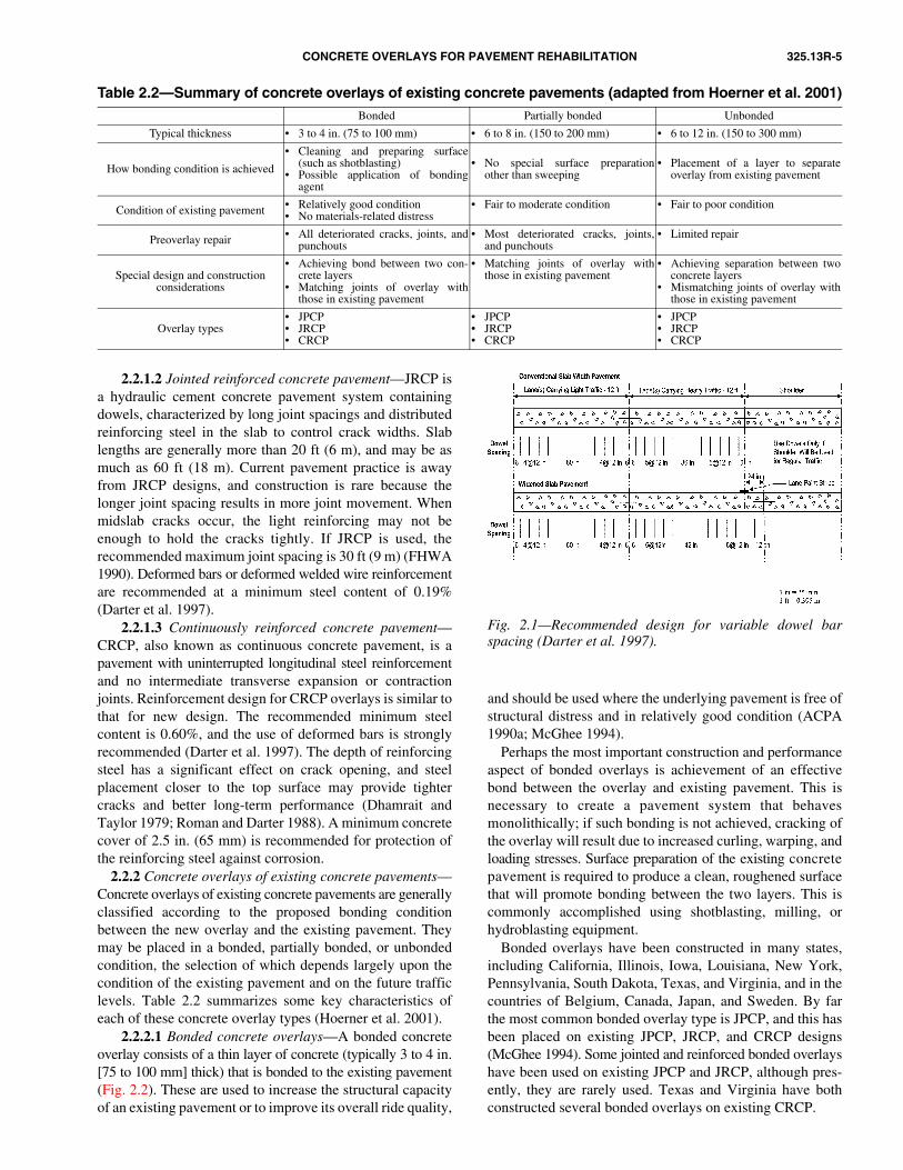
For concrete overlays, the recommended number andspacing of dowels is the same as those for new pavements. Ingeneral, uniform 12 in. (300 mm) spacing is recommended,but nonuniform spacing has also been used successfully. Inthe nonuniform dowel spacing design, the dowels areconcentrated in the wheel paths (Darter et al. 1997). Onerecommended design for variable dowel bar spacing isillustrated in Fig. 2.1.
In general, joints perpendicular to the direction of trafficare recommended. On new JPCP, skewed joints can beeffective in reducing faulting on nondoweled pavements, buthave no effect when used on properly doweled pavements(Yu et al. 1998a; Khazanovich et al. 1998). Furthermore,JPCP designs with skewed joints constructed on a stiff base(treated cement or lean concrete) are prone to corner breaks.
CONCRETE OVERLAYS FOR PAVEMENT REHABILITATION 325.13R-5
Fig. 2.1—Recommended design for variable dowel barspacing (Darter et al. 1997).
Table 2.2—Summary of concrete overlays of existing concrete pavements (adapted from Hoerner et al. 2001)Bonded Partially bonded Unbonded
Typical thickness • 3 to 4 in. (75 to 100 mm) • 6 to 8 in. (150 to 200 mm) • 6 to 12 in. (150 to 300 mm)
How bonding condition is achieved
• Cleaning and preparing surface(such as shotblasting)
• Possible application of bondingagent
• No special surface preparationother than sweeping
• Placement of a layer to separateoverlay from existing pavement
Condition of existing pavement • Relatively good condition• No materials-related distress
• Fair to moderate condition • Fair to poor condition
Preoverlay repair • All deteriorated cracks, joints, andpunchouts
• Most deteriorated cracks, joints,and punchouts
• Limited repair
Special design and constructionconsiderations
• Achieving bond between two con-crete layers
• Matching joints of overlay withthose in existing pavement
• Matching joints of overlay withthose in existing pavement
• Achieving separation between twoconcrete layers
• Mismatching joints of overlay withthose in existing pavement
Overlay types• JPCP• JRCP• CRCP
• JPCP• JRCP• CRCP
• JPCP• JRCP• CRCP
2.2.1.2 Jointed reinforced concrete pavement—JRCP isa hydraulic cement concrete pavement system containingdowels, characterized by long joint spacings and distributedreinforcing steel in the slab to control crack widths. Slablengths are generally more than 20 ft (6 m), and may be asmuch as 60 ft (18 m). Current pavement practice is awayfrom JRCP designs, and construction is rare because thelonger joint spacing results in more joint movement. Whenmidslab cracks occur, the light reinforcing may not beenough to hold the cracks tightly. If JRCP is used, therecommended maximum joint spacing is 30 ft (9 m) (FHWA1990). Deformed bars or deformed welded wire reinforcementare recommended at a minimum steel content of 0.19%(Darter et al. 1997).
2.2.1.3 Continuously reinforced concrete pavement—CRCP, also known as continuous concrete pavement, is apavement with uninterrupted longitudinal steel reinforcementand no intermediate transverse expansion or contractionjoints. Reinforcement design for CRCP overlays is similar tothat for new design. The recommended minimum steelcontent is 0.60%, and the use of deformed bars is stronglyrecommended (Darter et al. 1997). The depth of reinforcingsteel has a significant effect on crack opening, and steelplacement closer to the top surface may provide tightercracks and better long-term performance (Dhamrait andTaylor 1979; Roman and Darter 1988). A minimum concretecover of 2.5 in. (65 mm) is recommended for protection ofthe reinforcing steel against corrosion.
2.2.2 Concrete overlays of existing concrete pavements—Concrete overlays of existing concrete pavements are generallyclassified according to the proposed bonding conditionbetween the new overlay and the existing pavement. Theymay be placed in a bonded, partially bonded, or unbondedcondition, the selection of which depends largely upon thecondition of the existing pavement and on the future trafficlevels. Table 2.2 summarizes some key characteristics ofeach of these concrete overlay types (Hoerner et al. 2001).
2.2.2.1 Bonded concrete overlays—A bonded concreteoverlay consists of a thin layer of concrete (typically 3 to 4 in.[75 to 100 mm] thick) that is bonded to the existing pavement(Fig. 2.2). These are used to increase the structural capacityof an existing pavement or to improve its overall ride quality,
and should be used where the underlying pavement is free ofstructural distress and in relatively good condition (ACPA1990a; McGhee 1994).
Perhaps the most important construction and performanceaspect of bonded overlays is achievement of an effectivebond between the overlay and existing pavement. This isnecessary to create a pavement system that behavesmonolithically; if such bonding is not achieved, cracking ofthe overlay will result due to increased curling, warping, andloading stresses. Surface preparation of the existing concretepavement is required to produce a clean, roughened surfacethat will promote bonding between the two layers. This iscommonly accomplished using shotblasting, milling, orhydroblasting equipment.
Bonded overlays have been constructed in many states,including California, Illinois, Iowa, Louisiana, New York,Pennsylvania, South Dakota, Texas, and Virginia, and in thecountries of Belgium, Canada, Japan, and Sweden. By farthe most common bonded overlay type is JPCP, and this hasbeen placed on existing JPCP, JRCP, and CRCP designs(McGhee 1994). Some jointed and reinforced bonded overlayshave been used on existing JPCP and JRCP, although pres-ently, they are rarely used. Texas and Virginia have bothconstructed several bonded overlays on existing CRCP.

325.13R-6 ACI COMMITTEE REPORT
Fig. 2.2—Bonded concrete overlay (McGhee 1994).
2.2.2.2 Partially bonded concrete overlays—Partiallybonded concrete overlays are placed directly on existingconcrete pavements with little, if any, surface preparation.These are used when the degree of bonding is not critical tothe performance of the overlay (Lokken 1981). Partiallybonded overlays are more commonly used on airfield pavementwhere a thicker overlay is required because of heavy aircraftloads, and where the slabs are more fully restrained. Onairfield pavements, partially bonded overlay thicknesses aregenerally higher than 12 in. (300 mm), whereas on highwayapplications, thicknesses are generally in the range of 6 to8 in. (150 to 200 mm).
As previously mentioned, no special measures are taken toeither promote or prevent bond. As a result, varying degreesof bonding will occur, so reflection cracking is a potentialproblem. Consequently, partially bonded overlays should beused only when the existing concrete pavement is in a sound,well-seated condition and with no major distresses, distortions,or rocking slabs (Lokken 1981).
According to the comprehensive list of concrete overlayconstruction projects prepared by McGhee (1994), mostpartially bonded overlays are either JPCP or JRCP designs,although a few CRCP designs have been constructed. Thatsame list, however, also shows that partially bonded overlaysare not widely used for highway applications.
2.2.2.3 Unbonded concrete overlays—An unbondedconcrete overlay (sometimes called a separated overlay)contains an interlayer between the existing pavement and thenew overlay (Fig. 2.3). This separation layer is placed to ensureindependent behavior between the two slabs, thereby mini-mizing the potential for reflection cracking. Unbonded overlaysare typically between 6 and 12 in. (150 and 300 mm) thick.
Unbonded concrete overlays are used when the existingpavement deterioration is so advanced that it cannot be
Fig. 2.3—Unbonded concrete overlay (McGhee 1994).
effectively corrected before overlaying (ACPA 1990b).Because the two pavements will be separated, little preoverlayrepair is typically required. The separator layer should beeffective at ensuring independent behavior between the tworigid layers. Hot-mix asphalt layers (typically approximately1 in. [25 mm] thick) are commonly used as an interlayer.
In both highway and airfield applications, unbonded over-lays have seen far greater use than either bonded or partiallybonded overlays. Most unbonded overlays have been jointedplain concrete designs, although a significant number ofunbonded continuously reinforced concrete designs havebeen used.
2.2.3 Concrete overlays of existing asphalt pavements—Whitetopping, the use of concrete overlays of existing asphaltpavements, increased considerably in the 1990s. These overlaysare generally classified as conventional, thin, or ultra-thinwhitetopping, according to the thickness of the concreteoverlay. Table 2.3 summarizes some of the key characteristics
Fig. 2.4—Whitetopping overlay of asphalt pavement(McGhee 1994).
of the conventional whitetopping and ultra-thin whitetopping(UTW) concrete overlay types (Grogg et al. 2001).
2.2.3.1 Conventional whitetopping—Conventionalwhitetopping is the placement of a concrete overlay on anexisting asphalt pavement. These are generally designed asnew concrete pavement structures, and can range from 4 to12 in. (100 to 300 mm) thick, although they are typically atleast 8 in. (200 mm) thick. A typical cross section of awhitetopped pavement is shown in Fig. 2.4 (McGhee 1994).The interface shown may be on a milled surface, on ahot-mix asphalt leveling course, or may have no treatment atall (direct placement).
Conventional whitetopping is an alternative solution tohot-mix asphalt for rehabilitating deteriorated flexiblepavements that exhibit such distresses as rutting, shoving,and alligator cracking (ACPA 1998). Preoverlay repair ofbadly distressed or failed areas is required, and many agenciescold mill the existing asphalt surface to remove ruts or surfaceirregularities before placing the overlay (McGhee 1994).
A conventional whitetopping overlay is designed essentiallyas a new concrete pavement on a treated base course,assuming an unbonded condition between the layers. Somepartial bonding between the overlay and existing asphaltpavement can occur, however, which can contribute to theperformance of the pavement. Conventional whitetoppinghas been designed as jointed plain concrete overlays (mostcommon), jointed reinforced concrete overlays (rarely used),and continuously reinforced concrete overlays.

CONCRETE OVERLAYS FOR PAVEMENT REHABILITATION 325.13R-7
Table 2.3—Summary of whitetopping and ultra-thin whitetopping overlays (Grogg et al. 2001)Conventional whitetopping Ultra-thin whitetopping
Typical thickness • 8 to 12 in. (200 to 300 mm) • 2 to 4 in. (50 to 100 mm)
Condition of existing pavement • All deteriorated hot-mix asphalt pavements• Low-volume deteriorated hot-mix asphalt
pavements (particularly in areas where rutting isa problem
Bonding condition• Designed as unbonded, but some partial
bonding occurs (and may enhancepavement performance)
• Strong bond required between existing hot-mixasphalt pavement and new concrete overlay
Preoverlay repair • Limited repair (failed areas only)• Possible milling to correct profile
• Repair of areas unable to contribute to load-carrying capacity
• Milling of hot-mix asphalt surface
Minimum thickness of hot-mix asphalt • 2 in. (50 mm) (after any milling) • 3 to 6 in. (75 to 150 mm) (after any milling)
Special design and construction considerations
• Adequate support critical to performance• Adequate joint design (including joint spacing
and load transfer)• Placement of a whitewash on hot-mix asphalt
surface on hot days
• Bonding with hot-mix asphalt pavement• Concrete mixture proportioning is often high-
strength, fiber-modified, or both• Extremely short joint spacings (typically
between 2 and 6 ft [0.6 and 1.8 m])
Concrete overlay types• JPCP• JRCP• CRCP
• JPCP
2.2.3.2 Ultra-thin and thin whitetopping—UTW andthin whitetopping overlays are both designed assuming thatthe overlay bonds to the existing asphalt. Most overlays inthis category are UTW, although there have been a few thinwhitetopping projects constructed; this is an area ofincreasing research interest. Thin whitetopping represents anextension of the UTW to thicker overlays for pavementscarrying heavier traffic.
UTW is a process in which a thin layer of concrete(between 2 and 4 in. [50 and 100 mm] thick) is placed overa rutted or cracked asphalt pavement (ACPA 1998). In aUTW project, the existing hot-mix asphalt surface is coldmilled to enhance the bond between the concrete overlay andthe pavement to create a monolithic structure. Milling alsoremoves surface irregularities and provides a more uniformsurface for overlay placement.
UTW was originally intended for parking lots, residentialstreets, low-volume roads, general aviation airports, andhot-mix asphalt intersections where rutting is a problem butno other significant structural deterioration is present(ACPA 1998). Since the mid-1990s, its use has beenextended to highway applications in Alabama, Kansas,Missouri, and other states.
UTW overlays employ short slabs, typically square andwith joint spacing between 2 and 6 ft (0.6 and 1.8 m). This isto help reduce bending and thermal curling stresses. Figure 2.5shows a schematic of a UTW overlay (Grogg et al. 2001).
The use of UTW grew rapidly during the 1990s, with over200 projects in 35 states since 1992 (ACPA 2000a). As of2003, Tennessee had constructed the most UTW projects,followed closely by Kentucky and Kansas. All UTWprojects have been jointed, plain concrete overlay designs,but some have used fiber-reinforced concrete (FRC).
Thin whitetopping overlays are between 4 and 8 in. (100and 200 mm) thick concrete slabs with joint spacing between6 and 12 ft (1.8 and 3.7 m) that are placed on a milled asphaltpavement. As with the UTW design, milling of the asphaltsurface is intended to promote bonding between the overlayand the existing pavement. This bonding is accounted for indesign, and improves the performance of the overlay. Thin
whitetopping overlays have been used by a few highwayagencies, primarily on state highways.
An inlay is a variation of UTW and thin whitetoppingoverlays where one or more of the travel lanes of an existingpavement are milled, and the concrete overlay is placed inthat milled area. This technique has the advantages oftargeting only the distressed lanes, maintaining existingpavement elevations, and eliminating the need for anyunnecessary shoulder work or repair. A 6 in. (150 mm) thickthin whitetopping inlay was placed in October 2001 on U.S.78 in Jasper, Ala. (Delatte et al. 2001).
2.2.3.3 Summary of whitetopping overlay characteristics—The following design and construction characteristics can beused to distinguish between the various types of whitetop-ping overlays:• Conventional whitetopping is designed essentially as a
new pavement on a stabilized base and assumes anunbonded condition between the concrete overlay and thepavement, even if the pavement is milled. Conventionalwhitetopping can be used on any type of pavementfacility;
• Thin whitetopping is a moderately thin concrete overlay(thicknesses between 4 and 8 in. [100 and 200 mm])that is placed on a milled asphalt pavement. Bondbetween concrete overlay and asphalt pavement isconsidered in design, and short joint spacing (between6 and 12 ft [1.8 and 3.7 m]) is used. Thin whitetoppingoverlays have been used most often on state highwaysand secondary routes; and
Fig. 2.5—Schematic of UTW overlay (Grogg et al. 2001).

325.13R-8 ACI COMMITTEE REPORT
• UTW is similar in concept to thin whitetopping in that theoverlay is bonded to a milled asphalt surface, and bondingis considered in the design. The concrete overlaythicknesses are between 2 and 4 in. (50 and 100 mm), andsquare slabs (between 2 and 6 ft [0.6 and 1.8 m] in plan)are used. FRC is commonly used. UTW overlays arecommonly used on urban streets and intersections.
2.2.4 Other concrete overlay types—A review of theavailable literature reveals several other types of concreteoverlays that have been used. These primarily includefiber-reinforced overlays and prestressed-concrete overlays.These, however, represent changes to the concrete mixture orpavement construction method, and do not alter the way ofclassifying overlays into the existing categories alreadydefined.
Prestressed overlays have seen limited use in the U.S., andare not discussed in this report. FRC overlays have been usedsince the 1950s, and have since seen an increase in use aspart of many UTW projects. Some additional information onthe use of fiber in concrete is presented in ACI 544.1R.
2.3—Overlay materialsThis section describes materials used in overlays.
Conventional portland cement concrete is by far the mostcommonly used paving surface material, although otherhydraulic cements and fiber-reinforced portland cementconcretes are also used to construct overlays.
2.3.1 Portland and hydraulic cement concrete—Conventional concrete paving mixtures are typically used toconstruct overlays. As with conventional concrete pavements,properly proportioned mixtures are essential to satisfactoryperformance. Each of the components used in a concretemixture should be carefully selected so that the resultingmixture is dense, relatively impermeable, and resistant toboth environmental effects and deleterious chemical reactionsover its service life (Van Dam et al. 2002). Additionalinformation on mixture proportioning can be found inACI 211.1, 211.2, 211.3R, 211.4R, 211.5R, and PCA’s“Design and Control of Concrete Mixtures” (2002).
As with conventional concrete pavements, Type I and IIcements are commonly used in concrete mixtures for overlays.In situations where high early strength is desired, some agenciesuse Type III cement, which may have a slightly differentchemical composition, and is more finely ground to promotethe development of high early strength. Depending on themixture proportion and strength requirements, cementcontents are typically in the range of 500 to 700 lb/yd3 (295to 415 kg/m3), although higher contents are sometimes used.For more information about types of cement, refer to ASTMC 150, C 595, and C 1157, and ACI 225R.
Aggregates used in paving concrete range from stone togravel and glacial deposits (McGhee 1994). To help ensurethe longevity of the pavement, these aggregates should notonly possess adequate strength, but should also be physicallyand chemically stable within the concrete mixture (Van Damet al. 2002). Consequently, extensive laboratory testing ordemonstrated field performance is often required to ensurethe selection of a durable aggregate. Many agencies use
ASTM C 1260 to evaluate aggregates for alkali-silica reac-tion (ASR). ACI 221.1R contains more information on ASR.
The maximum coarse aggregate size permitted in concretemixtures is a function of the pavement thickness or theamount of reinforcing steel (if used) (ACI 211.1; PCA2002). The largest and most practical maximum coarseaggregate size should be used to minimize paste content,reduce shrinkage, minimize costs, and improve mechanicalinterlock properties at joints and cracks (Van Dam et al.2002). Although maximum coarse aggregate sizes of 0.75 to1 in. (19.0 to 25.0 mm) have been common, some agenciesare examining the use of larger maximum coarse-aggregatesizes (1.5 to 2 in. [37.5 to 50 mm]) for conventional concretepaving. For thinner overlays (such as bonded concrete orUTW), however, smaller maximum coarse-aggregate sizesare required. For unreinforced pavement structures, the PortlandCement Association (PCA) recommends a maximumaggregate size of one-third of the slab thickness (PCA 2002).For more information on aggregates, refer to ACI 221Rand 221.1R.
ACI 211.1 and PCA (2002) provide guidance on theselection of the appropriate water-cementitious materialratio (w/cm). A maximum w/cm of 0.45 is common forpavements in a moist environment and subjected to cycles offreezing and thawing (PCA 2002). Lower w/cm values areused on thinner concrete overlays (bonded overlays andUTW) to accelerate strength gain and to minimize dryingshrinkage (McGhee 1994; ACPA 1998). Low water andpaste content, however, are more important than the w/cm inminimizing shrinkage.
Various admixtures (ACI 212.3R) are commonly introducedinto concrete mixtures:• Air entrainment protects the hardened concrete from
freezing-and-thawing deterioration and deicer scalingand also helps increase the workability of fresh concrete,significantly reducing segregation and bleeding (PCA2002). Typical entrained air contents of concretepavement are in the range of 4 to 6%;
• Accelerators increase the rate of concrete strengthdevelopment. In pavement, they are commonly used infull-depth repairs or on fast-track paving projects inwhich early opening times are required. Calcium chlorideis commonly used as a set accelerator. Nonchlorideaccelerators should be used if steel reinforcement anddowels are present; and
• Water reducers are added to concrete mixtures to reducethe amount of water required to produce concrete of agiven consistency. This allows for a lowering of thew/cm while maintaining a desired slump, and thus hasthe beneficial effect of increasing strength and reducingpermeability (Van Dam et al. 2002).
Supplementary cementitious materials, such as fly ash,slag cement, and silica fume may be used as additions toconcrete mixtures. These materials may be placed in addition tothe portland cement or as a partial substitution for apercentage of the portland cement. Of these, fly ash is themost commonly used. Fly ash is a by-product of coal-firedpower plants, and may be classified as either Class C (high

CONCRETE OVERLAYS FOR PAVEMENT REHABILITATION 325.13R-9
calcium fly ash) or Class F (low calcium fly ash). Fly ashhelps to improve the workability of the mixture and reduceits permeability. It can also increase the long-term strengthof the concrete, although the early-age strength may be less.In addition, Class F fly ash is effective in reducingalkali-silica reactivity. ACI 232.2R provides additionalinformation on fly ash.
Most agencies specify a minimum concrete strengthrequirement for their pavements. Typical values includecompressive and flexural strengths (third-point loading) of4000 and 650 psi (28 and 4.5 MPa), respectively, at an ageof 28 days. Fast-track paving mixtures, using a low w/cm(typically less than 0.43), a higher cement content (typicallyhigher than 650 lb/yd3 [385 kg/m3]), and perhaps a Type IIIportland cement, rapid-setting hydraulic cement, or chemical-admixture systems have been used by highway agencies tomeet opening times of as little as 4 to 8 hours (Hoerner et al.2001). Fast-track paving technology entails not only thedevelopment of fast-setting concrete mixtures, but also theplanning and coordination of all construction activitiesneeded to minimize down time (ACPA 1994a; FHWA 1994;ACI 325.11R).
Although the use of fast-track mixtures and paving practiceshas become more common, there has been some concernregarding the potential detrimental effect of faster-settingcements and reduced construction times on the long-termdurability of concrete mixtures (Van Dam et al. 2002). Thus,it may be that both the speed of construction and thelong-term concrete durability need to be considered duringthe mixture proportioning phase of a project.
2.3.2 Fiber-reinforced concrete—FRC is portland cementconcrete containing randomly distributed fibers throughoutthe mixture. The principal reason for incorporating fibers isto increase the toughness of the concrete, which is a measureof its energy-absorbing capacity, and to improve its crackingand deformation characteristics. In some cases, flexuralstrength may also be increased (PCA 1991).
A wide variety of fiber materials have been used to reinforceconcrete; steel, polypropylene, and polyester fibers are mostcommonly used in the U.S. (PCA 1991). Polyolefin fibershave also been used on several paving projects. ACI 544.1Rdescribes the characteristics of these fibers. Further detailsare shown in Table 2.4 and provided by Smith et al. (2002).
Table 2.4—Summary of fiber usage in concrete overlays (AASHTO 2000)
Location Year builtType of overlay Type of fiber
I-10, Baton Rouge, La. 1990 BondedSteel
(85 lb/yd3 [50 kg/m3])
Cherokee County, Okla. 1994 BondedPolypropylene
(3 lb/yd3 [1.8 kg/m3])
Beltway 8, Houston, Tex. 1996 Bonded Steel
Beltway 8, Houston, Tex. 1999 Bonded Steel
Iola, Kans. 2000 BondedPolypropylene
(3 lb/yd3 [1.8 kg/m3])
I-29, Atchison County, Mo. 1998 Unbonded Steel, polyolefin, and polypropylene
Various projects in Tennessee (Chattanooga, Nashville,
Memphis, Knoxville,and others)
1992-present UTW
Polypropylene(3 lb/yd3 [1.8 kg/m3])
Leawood, Kans. 1995 UTWPolypropylene
(3 lb/yd3 [1.8 kg/m3])
U.S. Highway 14, Pierre,S. Dak. 1996 UTW
Polyolefin(25 lb/yd3 [15 kg/m3])
Various street intersections in Springfield, Mass. 1999 UTW
Polypropylene(3 lb/yd3 [1.8 kg/m3])
2.4—Interface materialsInterface materials are used either to enhance the bond
between the overlay and the existing pavement (to ensuremonolithic behavior) or to separate the overlay from theexisting pavement (to ensure independent behavior) (McGhee1994). Materials commonly used for these applications aredescribed as follows.
2.4.1 Bonding agents—For bonded concrete overlays,bond between the two layers is critical to obtain monolithicbehavior of the existing pavement and overlay. To helpachieve this, many agencies specify application of a cementgrout to the existing concrete pavement just ahead of thepaver. Cement grouts are generally produced in a mobilemixer from a mixture of portland cement and water; the
grout should have a maximum water-cement ratio (w/c) of0.62 (ACPA 1990a). Before the placement of either type ofbonding agent, the pavement surface should have alreadybeen prepared and should be surface dry (ACPA 1990a).
Some studies suggest that no bonding agent is necessaryfor properly prepared surfaces (Whitney et al. 1992; Wells et al.1999). In addition, there is the possibility that the bondingagent could act as a bond breaker if allowed to dry before theplacement of the concrete overlay (ACPA 1990a; Delatte et al.1998; Sprinkel 2000). Therefore, many practitioners excludethe use of bonding agents.
2.4.2 Separator layers—The performance of unbondedconcrete overlays over existing concrete pavements dependslargely on effective separation between the overlay and existingpavement. Because unbonded concrete overlays are placed onconcrete pavements in a more advanced state of deterioration,distresses in the underlying pavement can reflect through thenew overlay and compromise its performance.
To minimize the effect of the distresses in the underlyingpavement on the performance of the overlay, a separator layeris placed so that the two pavements act independently of eachother. Other functions of the separator layer include providinga leveling layer for uniform overlay thickness construction,and providing sufficient friction so that joints and the properamount of cracks can form in overlays (ERES 1999a).
A wide variety of materials has been used as separatorlayers, including polyethylene sheeting, wax-based curingcompounds, liquid asphalts, and hot-mix asphalt materials(McGhee 1994). The most successful interlayer, and the onemost commonly used, is a thick (1 in. [25 mm] or more) layerof hot-mix asphalt (ERES 1999a). Thin asphaltic interlayers,such as chip seals or slurry seals, have worked well in somecases, but are not generally recommended because they do notprovide sufficient leveling capabilities, they erode near joints,and they do not effectively separate the two layers (ERES

325.13R-10 ACI COMMITTEE REPORT
1999a). Polyethylene sheeting and curing compounds are alsonot recommended because they do not prevent active cracksfrom reflecting through the new overlay (ERES 1999a).
The hot-mix asphalt separator layer is typically adense-graded mixture meeting the agency’s standard pavingspecification. A few agencies have experimented with theuse of permeable hot-mix asphalt interlayers, but long-termperformance data for these types of interlayers are not available(ERES 1999a).
If the temperature of the hot-mix asphalt interlayer isexpected to exceed 110 °F (43 °C) at the time of overlayplacement, whitewashing of the surface may be required.The light-colored whitewash reflects sunlight and reducesheat buildup. This reduces the temperature of the interlayerbefore placement of the concrete overlay, and reduces therisk of shrinkage cracking (ACPA 1990b). Whitewashingmay be accomplished using either a lime slurry mixture or awhite-pigmented curing compound (ACPA 1990b).
2.5—Incidental materialsOther materials used in the construction of concrete overlays
are essentially the same as used in conventional concretepavement construction, summarized as follows:• Dowel bars are typically billet steel, Grade 60 (420)
bars that conform to ASTM A 615 or AASHTO M 31.The dowel bar size, layout, and coatings should be selectedfor the specific project location and traffic levels;
• Tie bars are typically billet steel, Grade 40 (280) orGrade 60 (420) bars that meet ASTM A 615 orAASHTO M 31 specifications. Tie bars are deformedbars, and should be at least No. 5 bars (0.62 in. [16 mm])spaced no more than 30 in. (760 mm) apart;
• Reinforcement in concrete overlays may be eitherdeformed bars or welded wire fabric (WWF).Deformed reinforcing bars should conform to ASTM A615 or AASHTO M 31, and WWF should conform toASTM A 185 or AASHTO M 55. The amount of steelreinforcement should be determined based on thedesign conditions; and
• Joint sealant materials may be of three major types (seealso ACI 504R):1. Hot-poured rubberized materials conforming toASTM D 6690, AASHTO M 301, or a governing statespecification;2. Silicone materials conforming to a governing statespecification; or3. Preformed compression seals conforming to ASTM D2628, AASHTO M 220, or a governing state specification.
2.6—Concrete production, construction, and quality-control issues
2.6.1 Concrete production—Concrete production foroverlays is no different than that for conventional pavementconstruction. ACI 304R provides guidance for materialshandling, and requirements for measurements and batchingequipment required to supply uniform, quality concrete to apaving job. The document also provides guidance for
transporting concrete in revolving drum truck mixers andopen-top truck bodies with and without agitators.
2.6.2 Concrete placement and finishing—The placement ofa concrete overlay is generally no different from conventionalconcrete pavement placement. Specific recommendations foroverlay placement include grade adjustments that leave therequired thickness of the concrete overlay. The finishing ofthe overlay surface should follow the same practices used tofinish any concrete pavement.
2.6.3 Texturing—Texturing of the finished concrete overlaysurface is required to ensure adequate surface friction of theroadway. Initial texturing is often done with a burlap drag orturf drag, with the final texturing provided by tining. For road-ways designed for vehicle speeds less than 50 mi/h (80 km/h),texturing the surface with a burlap drag, turf drag, or broomshould be adequate, provided the corrugations produced areapproximately 0.06 in. (1.5 mm) deep (ACPA 1999a).
For roadways designed for vehicle speeds higher than50 mi/h (80 km/h), tining of the concrete pavement surfaceis required (ACPA 1999a). Tining provides macrotexture,which contributes to surface friction by tire deformation, andalso channels surface water from between the pavement andthe tire.
Tining has traditionally been conducted transversely andat uniform intervals, but some studies suggest that uniformlyspaced transverse tining produces irritating pavement noise(Larson and Hibbs 1997; Kuemmel et al. 2000). Consequently,some agencies are experimenting with transverse tining thatis randomly spaced and skewed to the centerline of thepavement, the pattern of which should be carefully designedand constructed to minimize discrete noise frequencies thatare most objectionable to the human ear. In addition, someagencies are investigating the use of longitudinal tining,which produces lower noise levels than either uniformly orrandomly spaced transverse tining. Tining should beperformed as soon as the moisture sheen disappears from theconcrete surface. Additional guidance on surface tining is foundin reports by Kuemmel et al. (2000) and ACPA (2000b).
2.6.4 Curing—ACI 308R discusses curing concrete.Curing of the completed overlay may be accomplished usingwet burlap, polyethylene, or liquid membrane-formingcuring compounds that meet ASTM C 309 or AASHTO M 148.Proper curing is extremely important to the long-termperformance of a concrete overlay.
While factors that have an effect on the curing of aconcrete overlay are generally no different than for conven-tional concrete pavement, there are several characteristics ofbonded overlays, UTW, and thin whitetopping that makecuring particularly important. These include the presence ofthe existing pavement with its own thermal properties, thethinness of the overlay, and the lower w/cm and higher heatof hydration in bonded systems. With conventional concretepavement, improper curing affects the rate of strength gainand can lead to drying shrinkage cracking and other surfacedefects; with bonded overlays, improper curing affects thebond strength and contraction stresses and can lead tooverlay failure.

CONCRETE OVERLAYS FOR PAVEMENT REHABILITATION 325.13R-11
Challenges to proper curing occur at both the surface andthe base of the overlay. If the temperature of the existingpavement is either very hot or very cold, it will impact thecuring of the overlay. Similarly, if there is low ambient humidityor the ambient temperatures drop substantially after placementof the bonded concrete overlay, conditions are created thathave an adverse effect on the curing of the pavement.
The application of a curing compound to the surface andexposed edges should be sufficient to control the rate ofdrying shrinkage in a bonded overlay. For bonded overlays,UTW, and thin whitetopping, a minimum application rate of100 ft2/gal. (2.5 m2/L), which is about twice the typicalmanufacturer’s recommended rate, should be used (ACPA1990a; Delatte et al. 1996a). Under harsh climatic conditions,the use of curing blankets may also be advisable. In somecases, temporarily halting paving when evaporation ratesexceed ACI 305R recommendations is the best insuranceagainst plastic shrinkage cracking. Delatte et al. (1996b)provide recommendations for curing under the harsh environ-mental conditions of southwestern Texas. Under suchconditions, it is advisable to use a portable weather station tomonitor ambient temperatures, wind speed, and relativehumidity for determining rate of evaporation and potentialfor plastic shrinkage cracking (Delatte et al. 1998).
Because of the sensitivity of thin overlays to curingconditions, consideration may be given to the use ofinternal curing using a partial replacement of saturatedlightweight fine aggregate. Background for internal curingand suggestions for mixture proportioning are given inBentz et al. (2005) and Lam (2005).
2.6.5 Quality control—As with conventional concretepavement construction, the quality-control program is animportant element of the construction process. The programshould be written and should include procedures that ensure allmaterials comply with job specifications, and that concreteproduction and construction procedures are consistent withgood practice and relevant specifications. Information onprograms can be found in ACI 311.4R, 311.5, and 121R.Personnel inspecting, testing, or finishing concrete should becertified, either under the ACI Certification Program or theprogram required by the state highway agency. Information onthe ACI program can be found at www.concrete.org/certification.
CHAPTER 3—SELECTION OF CONCRETE OVERLAY ALTERNATIVES
3.1—IntroductionThe selection of a particular type of concrete overlay as a
possible rehabilitation alternative for an existing pavement isa subset of the overall pavement rehabilitation selectionprocess. The basic principles of that overall pavement rehabilita-tion selection process are summarized in several documents,including the 1993 “Guide for Design of Pavement Structures”(AASHTO 1993), “Pavement Rehabilitation StrategySelection” (ACPA 1993), and the reference manuals for twoNational Highway Institute (NHI) training courses (Grogg et al.2001; Hoerner et al. 2001). With the implied goal of optimizingpavement rehabilitation, the process involves first identifyingrehabilitation alternatives that are technically feasible, and
then evaluating the candidate alternatives in terms of cost andperformance benefits to identify the most appropriate option.
Conceptually, a general relationship exists between theexisting pavement condition and the required type ofrehabilitation, as shown in Fig. 3.1. That is, as pavementsreach a more advanced state of deterioration, moresubstantial rehabilitation measures are required.
The selection process, however, is complicated by theneed to consider a variety of factors, many of which are difficultto quantify and evaluate in comparable terms. Examples ofsuch factors include user costs, lane-closure requirements,traffic-control considerations, desired performance life,duration of construction, and local experience with therehabilitation alternative. The inability to reliably predictthe performance of rehabilitated pavements is also asignificant shortcoming in the process. Concrete pavementrehabilitation selection has been the topic of several researchprojects, including NCHRP Web Document 45 and NCHRPResearch Results Digest 272, and an FHWA-sponsoredresearch project that is part of the Concrete PavementTechnology Program (Task 54 (99)) entitled “Repair andRehabilitation of Concrete Pavements.” It can be found athttp://www.fhwa.dot.gov/pavement/concrete/sr04apb2.cfm.
3.2—Effectiveness of different types ofconcrete overlays
In practice, candidate alternatives for pavement rehabilitationconsiderations are not limited to concrete overlays; therefore,where appropriate, hot-mix asphalt counterparts to concreteoverlays are also mentioned. Table 3.1 provides a summary of
Fig. 3.1—Conceptual relationship between pavement conditionand required concrete pavement rehabilitation treatments(Darter and Hall 1990). Note: AC = asphalt concrete (HMA);OL = overlay; and PCC = portland cement concrete.
the advantages and disadvantages of different types ofoverlays.
3.2.1 Bonded concrete overlays—Bonded overlays areappropriate for concrete pavements that are in good conditionbut are in need of structural enhancement. Bonded overlayscan also be used to address various types of functionaldeficiencies, including the following:• Poor surface friction;• Surface roughness (other than faulting);• Surface rutting caused by studded tires; and• Excessive noise levels.

325.13R-12 ACI COMMITTEE REPORT
Table 3.1—Advantages and disadvantages of different types of pavement overlaysTreatment Applicability Advantages Disadvantages Typical life*
Concrete overlays
Bonded
• Concrete pavement inrelatively good conditionwith no materials-relateddistress
• Significant increase in structural capacitycan be achieved with a relatively thin (3 to6 in. [75 to 100 mm]) overlay
• For pavements in good condition only• Requires extensive preoverlay repairs.
Working cracks on existing pavementwill reflect through
• Bond is essential to good performance• Longer duration of construction than
hot-mix asphalt overlays• High initial cost
15 to 25 years
Unbonded • All concrete pavements
• Relatively insensitive to condition of theunderlying pavement—can be applied toconcrete pavements in poor condition
• Requires minimal preoverlay repairs• High reliability
• Vertical clearances can be a problem• Longer duration of construction than
hot-mix asphalt overlays• High initial cost
20 to 30 years
Whitetopping • All hot-mix asphaltpavements
• Longer design life than hot-mix asphalt• Can be applied on badly deteriorated
hot-mix asphalt pavements• Eliminates rutting and shoving problems• High reliability
• Vertical clearances can be a problem• Longer duration of construction than
hot-mix asphalt overlays• High initial cost
20 to 30 years
UTW • Hot-mix asphalt pavementsin fair to good condition
• Longer design life than hot-mix asphalt• Eliminates rutting and shoving problems
• Debonding can lead to premature failure• Requires a thicker hot-mix asphalt
pavement with adequate structuralcapacity
• Longer duration of construction thanhot-mix asphalt overlays
• High initial cost
5 to 15 years
(estimated)
Hot-mix asphalt overlays
Hot-mix asphalt overlays without slab fracturing
• Concrete pavement in fairto good condition
• East to construct• Short duration of construction• Low cost
• Susceptible to reflection cracking• Existing structural distresses should be
repaired full depth to avoid reflectioncracking
• May accelerate materials-relateddistress
8 to 15 years
Hot-mix asphalt overlays with slab fracturing
• All badly deterioratedconcrete pavements
• Shorter duration of construction thanconcrete overlays
• High reliability for preventing reflectivecracking (rubblization)
• Breaking or cracking and seating maynot always prevent reflection cracking
• A relatively thick overlay is needed afterrubblization to obtain desirable perfor-mance
• Vertical clearances can be a problem
8 to 25 years
*Life estimates based on data provided by Hall et al. (2001).
Studies on the field performance of bonded concreteoverlays have shown mixed results (Hutchinson 1982;Voigt et al. 1989; Peshkin and Mueller 1990; McGhee1994). Although many projects have provided goodlong-term performance, several failed within a few yearsafter construction. These failures were often characterizedby reflective cracking and corner breaks (in areas wherebond was lost). Most of these failures, however, wereattributed to the application of the bonded overlay to apavement that was extensively cracked (McGhee 1994).Others are attributed to inadequate or ineffectivepreoverlay repair (Peshkin and Mueller 1990). Theperformance of those projects is summarized elsewhere(Hutchinson 1982; McGhee 1994). Nevertheless, whereused in an appropriate application, bonded concrete overlayshave provided good performance. Details of case studies areprovided by Smith et al. (2002).
When considering a bonded concrete overlay, it is imperativethat the existing structural capacity of the underlying pavementnot already be compromised. Where structural-relateddistresses are present, such as pumping, faulting, midpanelcracks, or corner breaks, the load-carrying capabilities of theunderlying pavement are already compromised, and abonded concrete overlay is not an appropriate rehabilitationtechnique. Furthermore, the presence of D-cracking or other
materials-related distresses in the underlying concretesuggest conditions where the effectiveness of a bondedoverlay may be limited.
Structurally, hot-mix asphalt overlays (without slabfracturing) are similar to bonded concrete overlays, so if a10- to 15-year service life is acceptable, then a hot-mixasphalt overlay could be used to obtain similar performanceas a bonded concrete overlay, although with a shorter servicelife. Concrete pavements overlaid with hot-mix asphalt aresubjected to much lower temperature gradients (Nishizawaet al. 2000). Thus, while hot-mix asphalt overlays do notprovide the same level of reduction in load stresses asbonded concrete overlays, a reduction in combined stressescan be achieved with a moderate thickness hot-mix asphaltoverlay because of the lower thermal curling stresses.
3.2.2 Unbonded concrete overlays—An unbonded overlayis a feasible rehabilitation alternative for concrete pavementsin practically any condition, including those with materials-related distresses, such as D-cracking or reactive aggregate.Unbonded overlays are particularly effective on badlydeteriorated concrete pavements because they can be placedwith minimal preoverlay repairs.
Although unbonded overlays are relatively insensitive tothe condition of the underlying pavement, some limitedpreoverlay repair may be required. Instead of conducting

CONCRETE OVERLAYS FOR PAVEMENT REHABILITATION 325.13R-13
preoverlay repairs, the existing pavement may also be fracturedbefore overlaying, which may be appropriate if the existingpavement is severely deteriorated structurally or if it isexhibiting materials-related problems.
An alternative to an unbonded overlay is the placementof a hot-mix asphalt overlay, with or without slab fracturing.These can be placed very quickly and at a lower initial costthan unbonded concrete overlays. For severely deterioratedconcrete pavements or concrete pavements with material-related deterioration, slab fracturing may be the mosteconomical and reliable approach to preparing the existingpavement for the overlay. On the other hand, the main advantageof the unbonded concrete overlay option over the hot-mixasphalt overlay option is the longer expected service life.Other benefits include lower maintenance costs, betterreflectivity for improved visibility, and higher skid resistance.
3.2.3 Whitetopping overlays—Whitetopping is an effectivemethod for rehabilitating deteriorated hot-mix asphaltpavements that exhibit severe structural deterioration, suchas rutting, shoving, and alligator cracking. Little preoverlayrepair is required before placing a whitetopping overlay,although some milling may be needed if significant ruttingexists or if other profile corrections are needed (ACPA1991b, 1998). Structurally, whitetopping overlays are similar toconventional concrete pavements constructed on anasphalt-treated base. Whitetopping overlays have beensuccessfully constructed with JPCP, JRCP, and CRCPdesigns, but JPCP designs are most common. The majorityof the whitetopping projects have provided good to excellentperformance (Lokken 1981; Hutchinson 1982; McGhee1994; ACPA 1998).
3.2.4 UTW overlays—UTW overlays are best suited tohot-mix asphalt pavements on local roads, intersections, orparking lots that exhibit severe rutting, shoving, and potholeproblems. Because the underlying hot-mix asphalt pavementis an integral part of the structural system for UTW overlays,a minimum hot-mix asphalt thickness of 3 in. (75 mm) (aftermilling) is required for UTW projects (Grogg et al. 2001),although some suggest a minimum hot-mix asphalt thicknessof 6 in. (150 mm) (Silfwerbrand 1997). Proper preparation ofthe existing hot-mix asphalt pavement is also essential toensure good performance of UTW overlays. This includesrepair of any failed or severely deteriorated areas to provideadequate (and uniform) load-carrying capacity and millingof the hot-mix asphalt surface to promote good bonding.Although long-term performance data are limited, theshort-term performance of UTW projects has generally beengood (Cole 1997).
3.3—Selection processAlthough some aspects of pavement rehabilitation selection
are well defined, the selection process is complicated by theneed to consider numerous factors that are difficult to quantifyand evaluate in comparable terms. The process involves thefollowing steps:• Phase 1: Problem definition—In this step, the
condition of the pavement is established, the needs aredetermined, and any project constraints identified;
• Phase 2: Potential problem solutions—This step sortsthrough all available solutions and develops a short listof feasible solutions that address the needs andconstraints of the project; and
• Phase 3: Select preferred solutions—This stepconsiders both monetary and nonmonetary factors toselect the alternative deemed most appropriate fordesign conditions and constraints.
In general, the pavement-related aspects of this process arewell defined, and the guidelines provided in numerousreferences can be used to identify technically feasible andpreferable rehabilitation alternatives.
The selection process is much simpler if only concreteoverlay alternatives are considered, but there is no practicalvalue in limiting rehabilitation choices in that way. Thechoice among concrete overlays is often clearly defined bythe engineering criteria. Where more than one type ofconcrete overlay is feasible, the selection may be based onlife-cycle costing, because the impact of construction, whichaffects most of the nonmonetary factors, is similar for allconcrete overlays. When other rehabilitation alternatives,such as hot-mix asphalt overlay alternatives, concrete pavementrestoration alternatives, and reconstruction, are alsoconsidered, user costs and nonmonetary factors becomemore relevant. The decision matrix shown in Table 3.1 canbe a useful tool for identifying the alternative that best satisfiesmultiple selection criteria. One limitation of this approach isthat it is difficult to rate different alternatives so that the relativemerits of each alternative are properly represented in therating for many of the factors.
Although most state highway agencies regard user costand nonmonetary factors as very important decision factorsin rehabilitation selection, there are no generally acceptedmeans of combining these factors. For the most part, aninformal process is used, although systematic procedures forrehabilitation selection are currently being developed underongoing research projects.
CHAPTER 4—BONDED CONCRETE OVERLAYS4.1—Introduction
A bonded overlay increases the overall structural capacityof the pavement, but that structural benefit only occurs whenthe overlay and the underlying concrete behave monolithically.Thus, effective bond between the concrete overlay and theexisting pavement is critical to the performance of theseoverlays. When a bonded overlay is properly constructedand the application is appropriate, its expected advantagesare that it lasts longer than conventional hot-mix asphaltoverlays, and it provides a higher level of serviceability overits service life.
Bonded concrete overlays have been used as a pavementrehabilitation technique for almost 90 years (Hutchinson1982; Delatte and Laird 1999). A number of highway agencieshave substantial experience with bonded overlays, both inthe U.S. and internationally. Among some of the agencies inthe U.S. that have constructed bonded concrete overlays areTexas, Iowa, Pennsylvania, Louisiana, Virginia, Illinois, andCalifornia. These experiences cover a wide range of overlay

325.13R-14 ACI COMMITTEE REPORT
4.2.3.1 AASHTO overlay design procedure—Onewidely used bonded overlay design procedure is described inthe AASHTO “Guide for Design of Pavement Structures”(1993). This methodology is based on the structural deficiencyapproach, in which the required structural capacity of a newoverlay (SCOL) is equal to the difference between the structuralcapacity of a new pavement (SCf) needed to carry theprojected (future) traffic and the effective structural capacityof the existing pavement (SCeff). This concept is illustratedin Fig. 4.1.
4.2.3 Thickness design—The typical thickness of a bondedconcrete overlay is between 2 and 4 in. (50 and 100 mm).This range is defined at the low end by the minimum thicknessthat can be placed by slip form paving equipment. At thehigh end, economic considerations and practical concerns,such as clearances and matching grades, control themaximum overlay thickness.
designs placed over a variety of pavement types and condi-tions. Sprinkel (2000) documents the performance of bondedconcrete overlays that were constructed under the 1991ISTEA legislation.
4.2—Design4.2.1 General design considerations—As previously
mentioned, a bonded concrete overlay is an appropriaterehabilitation strategy when the structural capacity of apavement needs to be increased. This need is identified by ananticipated increase in traffic rather than by signs of pavementdeterioration, which are the more common triggers of pavementrehabilitation. Even after a bonded overlay is determined to befeasible, however, it is important to evaluate the pavement toconfirm that it is a good candidate for a bonded overlay.Recommended evaluation steps include the following:
• Evaluation of existing pavement condition—Refer toSection 4.2.2; and
• Traffic evaluation—Bonded concrete overlays are agood method for improving the load-carrying capacityof an existing concrete pavement. Because a properlydesigned and constructed bonded overlay can providemany years of performance, care should be taken todevelop meaningful projections of future traffic as aninput to the design process.
Bonded concrete overlays are constructed within the samegeneral range of thicknesses as hot-mix asphalt overlays. Assuch, the same construction considerations regarding over-head clearances, shoulder drop-offs, and guardrails thatapply to the use of hot-mix asphalt overlays also apply to theuse of bonded concrete overlays.
Most bonded concrete overlays are JPCP designs, withtransverse and longitudinal joints matching those in theunderlying pavement. Some bonded JRCP overlays havebeen used on existing JPCP and JRCP; although presently,JRCP designs are rarely used. A few states, such as Texasand Virginia, have constructed bonded overlays on existingCRCP. In the case of overlays of JRCP and CRCP pave-ments, embedded steel is generally not used in the bondedoverlay itself, as the overlay simply serves to increase thethickness and load-carrying capacity of the existing concretepavement. For exceptionally thick overlays, reinforcing steelmay be placed at the interface between the overlay and theprepared surface in order to keep the percentage of steel thesame as for the original CRCP (Delatte et al. 1996b).
4.2.2 Pavement evaluation—As with the design of othertypes of overlays, an evaluation of the existing pavementprovides important information used to determine whether abonded overlay is the appropriate method of structuralimprovement. A comprehensive evaluation typically consistsof a visual distress survey, deflection testing using the fallingweight deflectometer, and coring. The visual distress survey isthe first step in determining the suitability of the pavement fora bonded overlay. The visual survey should be carried outusing the FHWA Distress Identification Manual.
The primary purpose is to determine if structural deteriorationis present to the extent that it will impair the performance of the
overlay. Examples of distresses that indicate structuraldeterioration include:• Deteriorated transverse cracking;• Corner breaks;• Pumping;• Faulting; and• Punchouts (CRCP).
Where any of these are present, their severity and extentshould be considered to determine whether a bonded overlayis appropriate. If not widespread, full-depth repairs beforeplacement of the overlay will help to minimize their effect onfuture performance. Where these distresses are widespreador too severe, a bonded overlay will not perform well.
If material-related distress, such as D-cracking or reactiveaggregate, is present, an analysis of the cores from theexisting pavement can help to identify the nature and extentof the problem. D-cracking, for example, typically begins atthe bottom of the pavement, so that by the time it is visibleon the surface much of the pavement’s integrity iscompromised. Pavements with material-related distress arenot good candidates for bonded overlays.
The existing pavement’s structural capacity is a keyconsideration in selection of the proper type of overlay, andthe best method to determine structural capacity is by deflectiontesting with a falling-weight deflectometer. The informationthat can be obtained from falling-weight deflectometer testingresults includes the following:• Back-calculated subgrade k-value and concrete modulus;• Subgrade variability;• Load transfer efficiency; and• Presence of voids under joints and cracks.
The back-calculation can be accomplished using theprocedure provided in the AASHTO “Guide for Design ofPavement Structures” (AASHTO 1993), the “Supplement tothe AASHTO Guide for Design of Pavement Structures(AASHTO 1998), or any other established procedures. Moredetailed information on concrete pavement back-calculationis provided by Hall (1992). Recommended void detectionprocedures are described by Crovetti and Darter (1985).
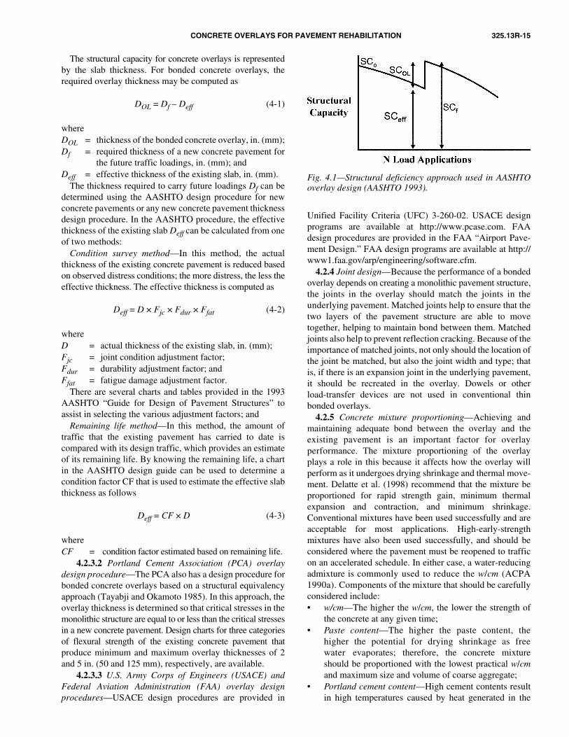
CONCRETE OVERLAYS FOR PAVEMENT REHABILITATION 325.13R-15
and 5 in. (50 and 125 mm), respectively, are available.
Fig. 4.1—Structural deficiency approach used in AASHTOoverlay design (AASHTO 1993).
The structural capacity for concrete overlays is representedby the slab thickness. For bonded concrete overlays, therequired overlay thickness may be computed as
DOL = Df – Deff (4-1)
whereDOL = thickness of the bonded concrete overlay, in. (mm);Df = required thickness of a new concrete pavement for
the future traffic loadings, in. (mm); andDeff = effective thickness of the existing slab, in. (mm).
The thickness required to carry future loadings Df can bedetermined using the AASHTO design procedure for newconcrete pavements or any new concrete pavement thicknessdesign procedure. In the AASHTO procedure, the effectivethickness of the existing slab Deff can be calculated from oneof two methods:
Condition survey method—In this method, the actualthickness of the existing concrete pavement is reduced basedon observed distress conditions; the more distress, the less theeffective thickness. The effective thickness is computed as
Deff = D × Fjc × Fdur × Ffat (4-2)
whereD = actual thickness of the existing slab, in. (mm);Fjc = joint condition adjustment factor;Fdur = durability adjustment factor; andFfat = fatigue damage adjustment factor.
There are several charts and tables provided in the 1993AASHTO “Guide for Design of Pavement Structures” toassist in selecting the various adjustment factors; and
Remaining life method—In this method, the amount oftraffic that the existing pavement has carried to date iscompared with its design traffic, which provides an estimateof its remaining life. By knowing the remaining life, a chartin the AASHTO design guide can be used to determine acondition factor CF that is used to estimate the effective slabthickness as follows
Deff = CF × D (4-3)
whereCF = condition factor estimated based on remaining life.
4.2.3.3 U.S. Army Corps of Engineers (USACE) andFederal Aviation Administration (FAA) overlay designprocedures—USACE design procedures are provided in
Unified Facility Criteria (UFC) 3-260-02. USACE designprograms are available at http://www.pcase.com. FAAdesign procedures are provided in the FAA “Airport Pave-ment Design.” FAA design programs are available at http://www1.faa.gov/arp/engineering/software.cfm.
4.2.3.2 Portland Cement Association (PCA) overlaydesign procedure—The PCA also has a design procedure forbonded concrete overlays based on a structural equivalencyapproach (Tayabji and Okamoto 1985). In this approach, theoverlay thickness is determined so that critical stresses in themonolithic structure are equal to or less than the critical stressesin a new concrete pavement. Design charts for three categoriesof flexural strength of the existing concrete pavement thatproduce minimum and maximum overlay thicknesses of 2
4.2.4 Joint design—Because the performance of a bondedoverlay depends on creating a monolithic pavement structure,the joints in the overlay should match the joints in theunderlying pavement. Matched joints help to ensure that thetwo layers of the pavement structure are able to movetogether, helping to maintain bond between them. Matchedjoints also help to prevent reflection cracking. Because of theimportance of matched joints, not only should the location ofthe joint be matched, but also the joint width and type; thatis, if there is an expansion joint in the underlying pavement,it should be recreated in the overlay. Dowels or otherload-transfer devices are not used in conventional thinbonded overlays.
4.2.5 Concrete mixture proportioning—Achieving andmaintaining adequate bond between the overlay and theexisting pavement is an important factor for overlayperformance. The mixture proportioning of the overlayplays a role in this because it affects how the overlay willperform as it undergoes drying shrinkage and thermal move-ment. Delatte et al. (1998) recommend that the mixture beproportioned for rapid strength gain, minimum thermalexpansion and contraction, and minimum shrinkage.Conventional mixtures have been used successfully and areacceptable for most applications. High-early-strengthmixtures have also been used successfully, and should beconsidered where the pavement must be reopened to trafficon an accelerated schedule. In either case, a water-reducingadmixture is commonly used to reduce the w/cm (ACPA1990a). Components of the mixture that should be carefullyconsidered include:• w/cm—The higher the w/cm, the lower the strength of
the concrete at any given time;• Paste content—The higher the paste content, the
higher the potential for drying shrinkage as freewater evaporates; therefore, the concrete mixtureshould be proportioned with the lowest practical w/cmand maximum size and volume of coarse aggregate;
• Portland cement content—High cement contents resultin high temperatures caused by heat generated in the
325.13R-16 ACI COMMITTEE REPORT
hydration process, which affect the rate of set. If rapidsetting and high temperatures are not anticipated andcontrolled, they can be a problem for the contractor andmay cause early-age cracking when the concrete coolsunder restrained conditions;
• Thermal properties—The differences in the coefficientof thermal expansion between the concrete overlay andthe subbase determine how much stress occurs at thebonded interface during thermal cycling of the pavement.To minimize the stress, the overlay concrete and theexisting concrete should have similar thermal properties.Because the coefficient of thermal expansion (CTE) ofthe aggregate is the primary determinant of the concreteCTE, the overlay concrete should use aggregates withthermal characteristics similar to the existing concrete; and
• Aggregate moisture condition—Loss of moisture fromthe concrete can contribute to early-age shrinkagecracking and debonding of the concrete overlay. Porespace in the aggregate should be fully saturated beforebatching, otherwise the aggregate will tend to pullwater from the mixture at early ages, increasing thepossibility of shrinkage, which can lead to debonding.
Examples of bonded concrete overlay mixture proportionsare provided in Smith et al. (2002). As described in Chapter 2,fibers have also been used in bonded overlay mixtures, butthey are not a required constituent. The potential benefits ofusing fibers are addressed in ACI 544.1R as well as PCAdocuments (1991, 2002).
4.2.6 Drainage—The bonded overlay evaluation anddesign phases provide an opportunity to evaluate existingpavement drainage characteristics and to upgrade them ifnecessary. Pavement performance indicators that signal aneed to improve drainage capabilities include pumping,faulting, and corner breaks. The pavement cross slope shouldalso be evaluated; current recommendations suggest aminimum cross slope of 1.5%, and this should be carriedthrough to the bonded overlay.
If it is determined that the existing pavement’s drainagecharacteristics are deficient, the feasibility of retrofittingedge drains should be considered. Several National HighwayInstitute training courses (ERES 1999b; Hoerner et al. 2001)provide detailed information on the evaluation and design ofdrainage facilities in pavement rehabilitation.
4.3—Construction4.3.1 Preoverlay repair—Although a bonded overlay is
most appropriate for pavements in good structural condition,some degree of preoverlay repair may be required. Animportant consideration is whether movement in the under-lying pavement, either due to environmental conditions or toapplied loads, will cause movement in the overlay. Anymovement in the overlay that does not occur at matchedjoints (or cracks) will contribute to debonding and the subse-quent deterioration of the overlay.
Appropriate preoverlay repairs include:• Full-depth repair of medium- and high-severity transverse
and longitudinal cracking, corner breaks, and punchouts(CRCP);
• Partial-depth repair of joint spalling;• Slab stabilization to fill voids and prevent future pumping
and loss of support; and• Load transfer restoration across working cracks or
nondoweled joints.Hoerner et al. (2001) provide more detailed information
on these repair activities. Note that if any deterioration, suchas joint spalling, is due to a materials-related distress, abonded overlay is probably not an appropriate rehabilitationstrategy. A life-cycle cost analysis is recommended to evaluatewhether the cost of extensive repairs, in combination withthe cost of the bonded concrete overlay, suggest the need toconsider alternatives such as unbonded concrete overlays.
4.3.2 Surface preparation—After selection of the properoverlay type, surface preparation probably has the greatestimpact on the long-term performance of bonded overlays.The objective is to remove contaminants, loose concrete,paint, and other materials that could adversely affect thebonding of the overlay, and to provide a coarse macrotexturethat promotes the mechanical bond between the old and thenew pavement.
Over the years, many different surface preparationprocedures have been used, including sandblasting, shot-blasting, waterblasting, scabbling, milling, and acid etching.Today, the most commonly used (and most effective)surface preparation procedure is shotblasting, which is oftenfollowed by sandblasting and air blasting immediately beforeplacement of the overlay. Shotblasting and air blastingequipment and a prepared surface are illustrated in Fig. 4.2.
Alternatively, waterblasting is also reported to provide a suitablesurface, but the surface should be allowed to dry before theplacement of the overlay (Delatte and Laird 1999).The surface preparation technique should not be soaggressive that it damages the underlying pavement. Warneret al. (1998) note that commonly used preparation techniques,such as shotblasting and waterblasting, cause little bruisingof the existing surface, while more aggressive preparationtechniques (scabblers and drum-type carbide pick mills, forexample) strike the pavement with great force and can createa weak layer in the existing pavement immediately below thebond interface. ACI 546R provides additional guidance onconcrete removal and surface preparation techniques.
The ability of a surface preparation method to create thedesired surface texture can be assessed by physical measure-ment. The sand patch test (ASTM E 965) is one widely-usedsurface texture measurement procedure. ASTM C 1583 is amethod for evaluating the strength of prepared surfaces.
Another surface preparation issue involves whether or notto prewet the surface. Some believe the surface should becompletely dry, whereas others believe that prewetting of theexisting surface (to a saturated surface dry [SSD] condition)can be extremely beneficial because it can help control themoisture demand from the bonded concrete overlay. If toomuch moisture is absorbed by the existing pavement fromthe plastic concrete, shrinkage will occur, and debonding islikely to follow. Regardless of whether the surface isprewetted, Wells et al. (1999) recommend that some degreeof surface preparation be required to achieve bond.
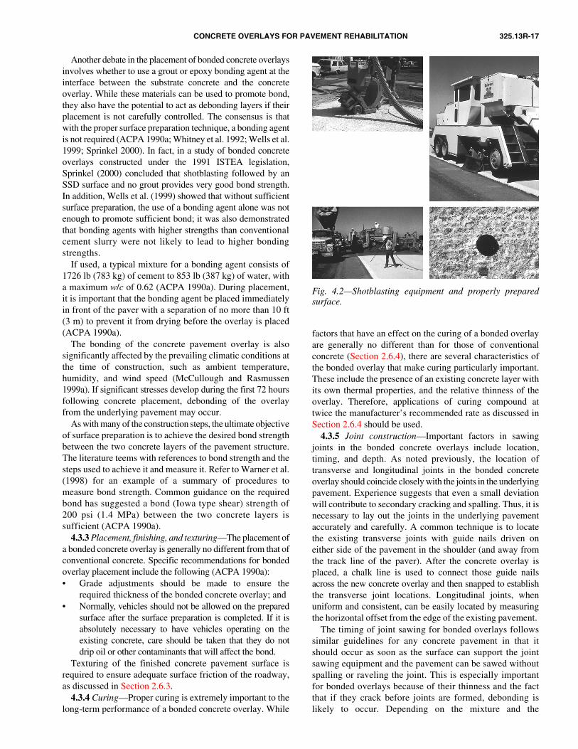
CONCRETE OVERLAYS FOR PAVEMENT REHABILITATION 325.13R-17
Fig. 4.2—Shotblasting equipment and properly preparedsurface.
Another debate in the placement of bonded concrete overlaysinvolves whether to use a grout or epoxy bonding agent at theinterface between the substrate concrete and the concreteoverlay. While these materials can be used to promote bond,they also have the potential to act as debonding layers if theirplacement is not carefully controlled. The consensus is thatwith the proper surface preparation technique, a bonding agentis not required (ACPA 1990a; Whitney et al. 1992; Wells et al.1999; Sprinkel 2000). In fact, in a study of bonded concreteoverlays constructed under the 1991 ISTEA legislation,Sprinkel (2000) concluded that shotblasting followed by anSSD surface and no grout provides very good bond strength.In addition, Wells et al. (1999) showed that without sufficientsurface preparation, the use of a bonding agent alone was notenough to promote sufficient bond; it was also demonstratedthat bonding agents with higher strengths than conventionalcement slurry were not likely to lead to higher bondingstrengths.
If used, a typical mixture for a bonding agent consists of1726 lb (783 kg) of cement to 853 lb (387 kg) of water, witha maximum w/c of 0.62 (ACPA 1990a). During placement,it is important that the bonding agent be placed immediatelyin front of the paver with a separation of no more than 10 ft(3 m) to prevent it from drying before the overlay is placed(ACPA 1990a).
The bonding of the concrete pavement overlay is alsosignificantly affected by the prevailing climatic conditions atthe time of construction, such as ambient temperature,humidity, and wind speed (McCullough and Rasmussen1999a). If significant stresses develop during the first 72 hoursfollowing concrete placement, debonding of the overlayfrom the underlying pavement may occur.
As with many of the construction steps, the ultimate objectiveof surface preparation is to achieve the desired bond strengthbetween the two concrete layers of the pavement structure.The literature teems with references to bond strength and thesteps used to achieve it and measure it. Refer to Warner et al.(1998) for an example of a summary of procedures tomeasure bond strength. Common guidance on the requiredbond has suggested a bond (Iowa type shear) strength of200 psi (1.4 MPa) between the two concrete layers issufficient (ACPA 1990a).
4.3.3 Placement, finishing, and texturing—The placement ofa bonded concrete overlay is generally no different from that ofconventional concrete. Specific recommendations for bondedoverlay placement include the following (ACPA 1990a):• Grade adjustments should be made to ensure the
required thickness of the bonded concrete overlay; and• Normally, vehicles should not be allowed on the prepared
surface after the surface preparation is completed. If it isabsolutely necessary to have vehicles operating on theexisting concrete, care should be taken that they do notdrip oil or other contaminants that will affect the bond.
Texturing of the finished concrete pavement surface isrequired to ensure adequate surface friction of the roadway,as discussed in Section 2.6.3.
4.3.4 Curing—Proper curing is extremely important to thelong-term performance of a bonded concrete overlay. While
factors that have an effect on the curing of a bonded overlayare generally no different than for those of conventionalconcrete (Section 2.6.4), there are several characteristics ofthe bonded overlay that make curing particularly important.These include the presence of an existing concrete layer withits own thermal properties, and the relative thinness of theoverlay. Therefore, applications of curing compound attwice the manufacturer’s recommended rate as discussed inSection 2.6.4 should be used.
4.3.5 Joint construction—Important factors in sawingjoints in the bonded concrete overlays include location,timing, and depth. As noted previously, the location oftransverse and longitudinal joints in the bonded concreteoverlay should coincide closely with the joints in the underlyingpavement. Experience suggests that even a small deviationwill contribute to secondary cracking and spalling. Thus, it isnecessary to lay out the joints in the underlying pavementaccurately and carefully. A common technique is to locatethe existing transverse joints with guide nails driven oneither side of the pavement in the shoulder (and away fromthe track line of the paver). After the concrete overlay isplaced, a chalk line is used to connect those guide nailsacross the new concrete overlay and then snapped to establishthe transverse joint locations. Longitudinal joints, whenuniform and consistent, can be easily located by measuringthe horizontal offset from the edge of the existing pavement.
The timing of joint sawing for bonded overlays followssimilar guidelines for any concrete pavement in that itshould occur as soon as the surface can support the jointsawing equipment and the pavement can be sawed withoutspalling or raveling the joint. This is especially importantfor bonded overlays because of their thinness and the factthat if they crack before joints are formed, debonding islikely to occur. Depending on the mixture and the
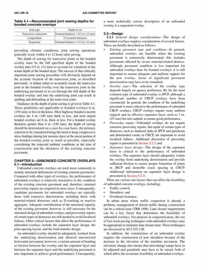
325.13R-18 ACI COMMITTEE REPORT
prevailing climatic conditions, joint sawing operationsgenerally occur within 4 to 12 hours after paving.
The depth of sawing for transverse joints in the bondedoverlay must be the full specified depth of the bondedoverlay plus 0.5 in. (12 mm) to account for variations in theactual depth of the bonded layer. The success of this criticallyimportant joint sawing procedure will obviously depend onthe accurate location of the transverse joint, as describedpreviously. A failure either to accurately locate the transversejoint in the bonded overlay over the transverse joint in theunderlying pavement or to cut through the full depth of thebonded overlay and into the underlying joint can result inspalling and debonding at the transverse joint.
Guidance on the depth of joint sawing is given in Table 4.1.These guidelines are applicable to bonded overlays 6 in.(150 mm) or less in thickness. Most highway bonded concreteoverlays are 4 in. (100 mm) thick or less, and most airportbonded overlays are 6 in. thick or less. For a bonded overlaythickness greater than 6 in. (150 mm), the depth of sawingshould be determined on a case-by-case basis, the primarycriterion to be considered being the need to keep compressivestress buildup (during hot summer days) at the uncut portion ofthe bonded overlay joint as small as possible, especiallyconsidering the expected ambient conditions at the time ofconstruction and the thickness of the existing concretepavement.
CHAPTER 5—UNBONDED CONCRETE OVERLAYS5.1—Introduction
Unbonded concrete overlays are used most commonly toremedy structural deficiencies of existing concrete pavements.Compared with other types of overlays, the performance ofunbonded overlays is relatively insensitive to the conditionof the existing concrete pavement and, therefore, minimalpreoverlay repairs are required in most cases. Consequently,candidate pavements for unbonded overlays are typicallythose with extensive deterioration, including those withmaterial-related distresses such as D-cracking or reactiveaggregate. Adequate consideration of the structural capacityof the existing pavement, however, is still necessary for thestructural design of unbonded overlays, and preoverlay repairsof certain types of distresses are still needed to avoid localizedfailures. Other critical factors that affect the performance ofunbonded overlays include the separator layer design, thejoint spacing layout, and the load-transfer design.
An unbonded overlay should be adequately isolated fromthe underlying deterioration and allowed unrestrictedhorizontal movement; however, a certain amount of bondingor friction between the overlay and the separator layer andbetween the separator layer and the underlying pavement isalso important to achieve good performance. Consequently,
Table 4.1—Recommended joint sawing depths for bonded concrete overlays
Joint type Depth of cut
Transverse contraction Nominal thickness + 0.5 in. (12 mm)
Longitudinal 1/2 nominal thickness
Expansion Nominal thickness + 0.5 in. (12 mm)
a more technically correct description of an unbondedoverlay is a separated overlay.
5.2—Design5.2.1 General design considerations—The design of
unbonded overlays requires consideration of several factors.These are briefly described as follows:• Existing pavement type and condition—In general,
unbonded overlays are feasible when the existingpavement is extensively deteriorated; this includespavements affected by severe material-related distress.Although pavement condition is less important forunbonded overlays than for bonded overlays, it is stillimportant to ensure adequate and uniform support forthe new overlay. Areas of significant pavementdeterioration may have to be remedied;
• Overlay type—The selection of the overlay typedepends largely on agency preference. By far the mostcommon type of unbonded overlay is JPCP, although asignificant number of CRCP overlays have beenconstructed. In general, the condition of the underlyingpavement is more critical to the performance of unbondedCRCP overlays; CRCP overlays require more uniformsupport and an effective separator layer, such as 1 in.(25 mm) hot-mix asphalt, to ensure good performance;
• Preoverlay repair—Unbonded overlays do not requireextensive preoverlay repairs, but repair of certain types ofdistresses, such as shattered slabs in JPCP and punchoutsand deteriorated cracks in CRCP, are important to avoidlocalized failures. Additional discussion of preoverlayrepairs is presented in Section 5.2.3; and
• Separator layer design—The design of the separatorlayer is critical to the performance of unbondedoverlays. The separator layer should adequately isolatethe overlay from underlying deterioration and providesufficient friction to ensure proper formation of jointsin JRCP and desirable crack spacing in CRCP.Additional information on separator layer design ispresented in Section 5.2.5.
There are various site factors that can affect the feasibilityof unbonded concrete overlays, including:• Traffic control;• Shoulders; and• Overhead clearance.
In urban areas where traffic congestion is already aproblem, management of detour traffic during constructioncan be a critical issue (TRB 1998). Lane closure requirementscan be a key factor that determines the feasibility ofunbonded overlays. For projects in congested areas, the useof fast-track paving techniques with unbonded overlays maybe appropriate to minimize lane closure time. These techniquesare discussed in ACI 325.11R.
In addition, the construction of an unbonded overlayrequires the construction of new shoulders because of theincrease in the elevation of the mainline pavement. Theelevation change also means that interchange ramps have tobe adjusted and guardrails may have to be raised, both ofwhich affect the economic feasibility of unbonded overlays.

CONCRETE OVERLAYS FOR PAVEMENT REHABILITATION 325.13R-19
overlays (ERES 1999a).
5.2.4 Thickness design—The thickness of unbondedoverlays on major highways has ranged from approximately7 in. (175 mm) to more than 10 in. (250 mm). Thicknessescan be determined using several design methods, several ofwhich are described in Sections 5.2.4.1 through 5.2.4.3. It is
5.2.4.1 AASHTO overlay design procedure—The mostcommon procedure for the design of unbonded concreteoverlays is the methodology used in the AASHTO “Guidefor Design of Pavement Structures” (1993). This methodologyis based on the structural deficiency approach, in which therequired structural capacity of a new overlay SCOL is equalto the difference between the structural capacity of a newpavement SCf needed to carry the projected traffic and theeffective structural capacity of the existing pavement SCeff.This concept was previously illustrated in Fig. 4.1.
The structural capacity for concrete overlays is representedby the slab thickness. For unbonded concrete overlays, therequired overlay thickness may be computed as
(5-1)
The origin of Eq. (5-1) is believed to date back to the analysisof the performance data at the Bates Road Test (Older 1924),and it remains the most widely used procedure for the structuraldesign of unbonded overlays (Hall et al. 1993).
The thickness required to carry future loadings Df can bedetermined using the AASHTO design procedure for newconcrete pavements or any new thickness design procedure.In the AASHTO procedure, the effective thickness of theexisting slab Deff can be calculated from one of two methods:• Condition survey method—In this method, the actual
thickness of the existing pavement is reduced based onobserved distress conditions; the more distress, the lessthe effective thickness. The effective thickness iscomputed as
DOL Df2 Deff
2–=
important, however, to recognize that thickness alone doesnot ensure adequate performance, and other key factors, such asseparator layer design and joint design, should be considered.
5.2.3 Preoverlay repair—Unbonded concrete overlaysgenerally require minimal preoverlay repairs. Only thedistresses that cause a major loss of structural integrityrequire repair. Those distresses, and their recommendedmethod of repair, are as follows (Hutchinson 1982; ACPA1990b; ERES 1999a):• Shattered slabs should be replaced;• Punchouts in CRCP should be full-depth repaired;• High-severity transverse cracks with ruptured steel on
CRCP should be full-depth repaired;• Unstable slabs or pieces of slabs with large deflections or
pumping should be full-depth repaired or undersealed; • High-severity spalling at existing pavement joints or
cracks should be filled and compacted with hot-mixasphalt; and
• Settlements, if significant, should be leveled up withhot-mix asphalt.
Faulting is generally not a problem when a thick separatorlayer (1 in. [25 mm] or more of hot-mix asphalt) is used.Diamond grinding or milling, however, is recommended forfaulting higher than 0.25 in. (6 mm). Alternatively, a thickerseparator layer (2 in. [50 mm] hot-mix asphalt) may be usedwhen faulting exceeds 0.25 in. (6 mm).
If construction of an unbonded CRCP overlay iscontemplated, more attention should be paid to preoverlayrepair activities to ensure that the existing distresses do not
reflect through the overlay (ERES 1999a). Depending on thecondition of the existing pavement, a thicker separator layer, ahigher steel content, or a thicker overlay may be used toaddress concerns for reflection cracking.
As an alternative to preoverlay repairs, the existing pavementmay be fractured to provide a more uniform support underthe overlay. Some European countries have used this techniquewith excellent results (FHWA 1993). In Germany, thestandard practice for unbonded overlay construction is tocrack and seat the existing concrete pavement, place a 4 in.(100 mm) lean-concrete separator layer, and place theconcrete overlay (FHWA 1993). Notches are cut into thelean-concrete separator layer (matched to the joints in theoverlay) to prevent random cracking. For pavements withsevere material-related distress, slab fracturing may beparticularly applicable because the continued progression ofmaterial-related distress in the original pavement can causepremature deterioration of thinner (7 in. [175 mm]) unbonded
Overhead clearances also affect the feasibility of unbondedoverlays. Because unbonded overlays add significant thicknessto a pavement’s overall cross section, short sections of recon-struction may be required at overhead structures, such asbridge overpasses, to ensure that adequate vertical clearance isprovided. Raising the structure is another alternative. Both ofthese options, however, add complexity, time, and cost topavement rehabilitation projects, which makes unbondedoverlays less favorable on projects that include many over-head structures.
5.2.2 Pavement evaluation—As with other types of overlays,a thorough evaluation of the existing pavement is alsoimportant in the unbonded overlay design process. Pavementevaluation techniques typically include a visual distresssurvey, deflection testing using a falling weight deflectometer,and coring. If material-related distress, such as D-cracking orreactive aggregate problems, is present, laboratory testing ofthe cores may also be needed to verify the nature ofmaterial-related distress and to assist in avoiding similarproblems in the new overlay.
The existing pavement condition is a key input to thicknessdesign in all design procedures. In both the AASHTO (1993)and PCA (Tayabji and Okamoto 1985) overlay designprocedures, the structural value of the existing pavement isdetermined based on visual distress survey results. Thecondition survey is also important for identifying the areasthat should be repaired before overlaying and for identifyingmaterial-related distress or drainage problems that requirespecial consideration. The preferred method of characterizingthe structural condition of the existing pavement for reha-bilitation design is through falling weight deflectometertesting as discussed in Section 4.2.2.

325.13R-20 ACI COMMITTEE REPORT
where D = actual thickness of the existing slab, in. (mm)(maximum of 10 in. [250 mm]); and Fjcu = joint conditionadjustment factor for unbonded overlays.Unlike the bonded overlay design equation, there are noadjustment factors for durability or fatigue damagebecause of their minimal effect on the performance ofthe unbonded overlay (AASHTO 1993). A chart fordetermining Fjcu is provided in the AASHTO “Guidefor Design of Pavement Structures” (1993); and
• Remaining life method—In this method, the amount oftraffic that the existing pavement has carried to date iscompared with its design traffic, which provides anestimate of its remaining life. This method was describedin Section 4.2.3.1. The designer should recognize thatthe effective thickness determined using this methoddoes not reflect the benefit of any preoverlay repair.5.2.4.2 PCA overlay design procedure—PCA has a
design procedure for unbonded overlays that uses a structuralequivalence approach (Tayabji and Okamoto 1985), asdescribed in Section 4.2.3.3. Three different design charts
are available to determine the required unbonded overlaythickness for existing pavements in good, fair, and poorcondition. The PCA design procedure is consistent withmechanistic design principles, and accurate results can beobtained if the stress equivalencies are established consideringall stress components (that is, both load and curling/warpingstresses). Curling and warping stresses, however, are notconsidered in the procedure.5.2.4.3 USACE and FAA overlay design procedures—These procedures are the same as those cited in Section 4.2.3.3.
5.2.5 Separator layer design—The separator layer design isone of the primary factors influencing the performance ofunbonded concrete overlays. The separator layer performsseveral important functions (Voigt et al. 1989; ERES 1999a):• It isolates the overlay from underlying irregularities to
allow uninhibited horizontal movement. Withoutadequate isolation, the underlying deterioration cancause localized locking of the overlay, which canresult in reflection cracking;
• It provides adequate friction to ensure proper formation ofjoints in JPCP and cracks in CRCP. The use of materialsthat offer minimal frictional resistance, such as limeslurry or polyethylene sheeting, can cause problems withjoints not forming at the intended intervals. The frictionbetween pavement layers also contributes to the compositeaction that is beneficial to overlay performance; and
• It provides a level surface for the overlay construction.Recognition that debonding of pavement layers is not
essential nor always desirable for proper functioning ofunbonded overlays is an important development inunbonded overlay design; however, modeling structuraleffects of the separator layer requires further research.
Many different separator designs have been used inunbonded overlay construction. The design that has giventhe best results are hot-mix asphalt layers at least 1 in. (25 mm)thick (Voigt et al. 1989; ACPA 1990b; Hall et al. 1993;ERES 1999a), which is also the design recommended in the1993 AASHTO guide. In some applications, chip seals, slurry
Deff = D × Fjcu (5-2)
5.2.4.4 Discussion on current unbonded overlay designprocedures—Current unbonded overlay design procedureshave significant limitations. Some of the major flaws in theexisting thickness design procedures include:• Lack of consideration of layer interaction—The structural
contribution of the separator layer and the effects offriction or bonding between the overlay and the separatorlayer and between the separator layer and the underlyingconcrete pavement are ignored;
• Excessive credit given to existing pavement—Designprocedures that are based on structural deficiency(AASHTO 1993) tend to produce unconservative resultswhen the existing pavement is relatively thick; and
• Lack of consideration of curling and warpingstresses—The effects of curling and warping are evenmore critical for unbonded overlays than for newpavements because of the very stiff support provided bythe underlying pavement; however, existing designprocedures do not consider the effects of curling andwarping. The main result of this deficiency is that theeffects of joint spacing on critical stresses are notreflected in the thickness design. For unbonded JPCPoverlays with long joint spacings, such as higher than15 ft (4.6 m), the lack of consideration of curling andwarping stresses is a critical deficiency that often leadsto unconservative overlay thicknesses.
These deficiencies offset each other to a certain extent foroverlays that have a relatively thick (1 in. [25 mm] or more)hot-mix asphalt separator layer as long as the joint spacing isnot excessive (higher than 15 ft [4.6 m]). For example,ignoring the structural contribution of the hot-mix asphaltseparator layer and the layer interactions leads to conserva-tive overlay thicknesses; however, excessive credit given tothe existing pavement and lack of consideration of curlingand warping stresses tend to produce unconservative overlaythicknesses. The net result is reduced overall design errordue to the opposing effects of the errors from differentsources. If the joint spacing is excessive, however, anybeneficial effects of layer interaction can be overshadowedby excessive curling or warping stresses.
A thin separator layer, such as a curing compound orpolyethylene sheeting, does not promote layer interaction.For those designs, all errors in thickness design are additiveand lead to less conservative designs.
Current practice in mechanistic analysis also has manylimitations, including the inability to consider interlayerfriction in all but the most sophisticated general purposethree-dimensional finite-element analysis programs. Thebest measure of the adequacy of the designs obtained usingexisting thickness design procedures is field performance.The field performance of unbonded overlays has been generallyvery good; however, inadequate overlay thickness can beblamed for premature failure of some unbonded overlayprojects. The development of a robust mechanistic thicknessdesign procedure would greatly improve design reliabilityand help optimize unbonded overlay designs.
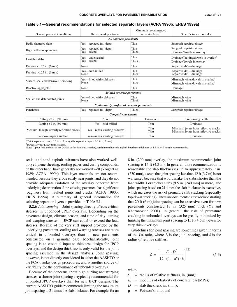
CONCRETE OVERLAYS FOR PAVEMENT REHABILITATION 325.13R-21
5.2.6 Joint spacing—Joint spacing directly affects criticalstresses in unbonded JPCP overlays. Depending on thepavement design, climate, season, and time of day, curlingand warping stresses in JPCP can equal or exceed the loadstresses. Because of the very stiff support provided by theunderlying pavement, curling and warping stresses are morecritical in unbonded overlays than in new pavementsconstructed on a granular base. Mechanistically, jointspacing is an essential input to thickness design for JPCPoverlays, and the design thickness is only valid for the jointspacing assumed in the design analysis. Joint spacing,however, is not directly considered in either the AASHTO orthe PCA overlay design procedures, and is another source ofvariability for the performance of unbonded overlays.
Because of the concerns about high curling and warpingstresses, a shorter joint spacing is typically recommended forunbonded JPCP overlays than for new JPCP designs. Thecurrent AASHTO guide recommends limiting the maximumjoint spacing to 21 times the slab thickness. For example, for an
8 in. (200 mm) overlay, the maximum recommended jointspacing is 14 ft (4.3 m). In general, this recommendation isreasonable for slab thicknesses up to approximately 9 in.(230 mm), except that joint spacing less than 12 ft (3.7 m) is notwarranted because that would make the slabs shorter than thelane width. For thicker slabs (9.5 in. [240 mm] or more), thejoint spacing based on 21 times the slab thickness is excessive,which increases the risk of premature slab cracking (especiallytop-down cracking). There are documented cases demonstratingthat 20 ft (6 m) joint spacing can be excessive even for newpavements constructed 13 in. (325 mm) thick (Yu andKhazanovich 2001). In general, the risk of prematurecracking in unbonded overlays can be greatly minimized bylimiting the maximum joint spacing to 15 ft (4.6 m), even forvery thick overlays.
Guidelines for joint spacing are sometimes given in termsof the L/l ratio, where L is the joint spacing, and l is theradius of relative stiffness
(5-3)
wherel = radius of relative stiffness, in. (mm);Ec = modulus of elasticity of concrete, psi (MPa);D = slab thickness, in. (mm);µ = Poisson’s ratio; and
lEc D3
⋅
12 1 µ2–( ) k⋅ ⋅
-------------------------------------
0.25
=
seals, and sand-asphalt mixtures have also worked well;polyethylene sheeting, roofing paper, and curing compounds,on the other hand, have generally not worked well (Voigt et al.1989; ACPA 1990b). Thin-layer materials are not recom-mended because they erode easily near joints, and they do notprovide adequate isolation of the overlay concrete fromunderlying deterioration if the existing pavement has significantroughness from faulted joints and cracks (ACPA 1990b;ERES 1999a). A summary of general information forselecting separator layers is provided in Table 5.1.
Table 5.1—General recommendations for selected separator layers (ACPA 1990b; ERES 1999a)
General pavement condition Repair work performedMinimum recommended
separator layer* Other factors to consider
All concrete pavements
Badly shattered slabs Yes—replaced full-depth Thin Subgrade repair/drainage
High deflection/pumping Yes—replaced full-depthYes—seated
ThinThick
Subgrade repair/drainageDrainage/dowels in overlay†
Unstable slabs Yes—undersealedYes—seated
ThinThick
Drainage/faulting/dowels in overlay†
Drainage/dowels in overlay†
Faulting <0.25 in. (6 mm) None Thin Repair voids?—drainage
Faulting >0.25 in. (6 mm) Yes—cold-milledNone
ThinThick
Repair voids?—drainageRepair voids?—drainage
Surface-spalled/extensive D-cracking Yes—filled with cold patchNone
ThinThick
Mismatch joints/dowels in overlay†
Mismatch joints/dowels in overlay†
Reactive aggregate None Thin Drainage
Jointed concrete pavements
Spalled and deteriorated joints Yes—filled with cold patchNone
ThinThick
Mismatch jointsMismatch joints
Continuously reinforced concrete pavements
Punchouts Yes—replaced full-depth Thick Subgrade repair/drainage
Composite pavements
Rutting <2 in. (50 mm) None Thin/none Joint sawing depth
Rutting >2 in. (50 mm) Yes—cold-milled Thin Drainage
Medium- to high-severity reflective cracks Yes—repair existing concrete ThinThin
Mismatch joints from reflective cracksMismatch joints from reflective cracks
Remove asphalt surface Yes—repair existing concrete Thin Drainage*Thick separator layer > 0.5 in. (12 mm), thin separator layer < 0.5 in. (12 mm).†Particularly for heavy traffic routes.Note: If poor load transfer exists (<50% deflection load transfer), a minimum hot-mix asphalt interlayer thickness of 1.5 in. (40 mm) is recommended.

325.13R-22 ACI COMMITTEE REPORT
k = modulus of subgrade reaction, psi/in. or lb/in.3
(MPa/mm).The maximum recommended L/l ratio for unbonded overlays
is 4.5 to 5.5 (ERES 1999a). This recommendation iscomparable to the guidelines given in the AASHTO guide fortypical design conditions. Again, however, the results may beunconservative for thick slabs (higher than 9.5 in. [240 mm])and overly conservative if the k-value is very high.
Fig. 5.1—Illustration of mismatched joints (ACPA 1990b).
5.2.7 Load transfer design—Joint performance inunbonded concrete overlays is significantly better than innew JPCP construction because of the load transfer providedby the underlying pavement slabs (Hall et al. 1993; ERES1999a). Mismatched joints are recommended for unbondedoverlays (Fig. 5.1) to maximize the benefits of load transferfrom the underlying pavement.
Doweled joints are still highly recommended forunbonded concrete overlays that will be subjected to heavytruck traffic to avoid corner breaks and to minimize faulting.Without dowels, the risk of corner breaks is high in unbondedoverlays because of the very stiff support conditions.
5.2.8 Mixture proportion—As described in Chapter 2, thesame concrete mixtures used for new construction are generallyused for unbonded overlays. For projects in congested urbanareas, however, extended lane closures due to pavementrehabilitation may be highly undesirable. For those projects,the use of fast-track paving may be considered to minimizetraffic disruptions. Numerous fast-track concrete mixtures areavailable that can provide the strength required for opening totraffic in 4 hours, and the techniques for fast-track paving arewell established (ACPA 1994a; FHWA 1994; ACI 325.11R).Fast-track paving has been used successfully on a number ofprojects where traffic congestion or accessibility is a criticalissue (ACPA 1994a; ACI 325.11R). Little information,however, is available on the long-term performance anddurability of pavements constructed using high-early-strengthconcrete mixtures.
5.2.9 Edge support—Edge support is a design featureprovided to either reduce critical edge stresses or reduce theoccurrences of edge-loading conditions that cause the higheststresses in concrete pavements. These features include tiedconcrete shoulders and widened slabs. In general, widenedslabs are more effective than tied concrete shoulders incontributing to the performance of the pavement (Smith et al.1995). The effectiveness of tied concrete shoulders depends onthe effectiveness of the tie system, and shoulders constructedmonolithically with the mainline pavement provide signif-
icantly better support than those paved separately. Evenwith an effective tie system, however, tied concrete shouldershave not significantly improved faulting performance,although they have been shown to be effective in reducingcritical edge stresses (Smith et al. 1995; Yu et al. 1995).
Widened slabs are effective in improving both faulting andcracking performance (Smith et al. 1995). One study showedthat the structural benefit of widened slabs is roughlyequivalent to approximately 1 in. (25 mm) of additional slabthickness (Yu et al. 1995); however, widened slabs should beused with care on unbonded overlays because of the increasedrisk of longitudinal cracking. This is because unbondedoverlays are constructed on very stiff foundations and aregenerally constructed thinner than new concrete pavements,both of which increase the potential for longitudinal cracking.
Although widened slabs are a better edge support designfeature for new pavements, tied shoulders may be preferablefor unbonded overlays. This is because of the increased riskof cracking due to high curling or warping stresses (resultingfrom stiff support conditions) of the widened slab. Furthermore,if the unbonded overlay is doweled, the effect of the widenedslab on the faulting performance is minimal. Finally, becauseshoulder work is required for unbonded overlays, anopportunity exists for including tied concrete shoulders aspart of the overlay project.
5.2.10 Lane widening—Construction of unbonded overlaysmay involve the widening of an old pavement with narrowtraffic lanes, the addition of new travel lanes, or the extensionof ramps. On such projects, the potential for longitudinalcracking is again a concern. In general, before the placementof the separator layer for the overlay, the widened portionshould be provided with a cross section that closely matchesthat of the underlying pavement (AASHTO 1993). Eitherconcrete or hot-mix asphalt can be used as fill beneath thewidening (Fig. 5.2). A study conducted by the Minnesota
Department of Transportation (MnDOT) showed no signifi-cant difference in performance between the wideningaccomplished using either hot-mix asphalt or concretematerials (Engstrom 1993). The main concern is to ensure thatthe widened portion provides adequate support withoutsettlement or loss of support (ERES 1999a).5.2.11 Drainage—The effectiveness of subsurface drainageon the performance of unbonded overlays is not well knownbecause very little performance data are available. Becauseunbonded overlays are structurally similar to new concretepavements constructed on a lean concrete base, the effects ofedge drains may be similar. The possible benefits of properlydesigned, constructed, and maintained edge drains on newpavements include (Smith et al. 1995; ERES 1999b):• Reduced pumping and faulting;• Lower rate of cracking in CRCP; and• Improved material performance, such as D-cracking or
hot-mix asphalt separator layer stripping.Some states, such as Minnesota and Pennsylvania, have
experimented with permeable asphalt-treated separatorlayers; however, extensive stripping of these layers wasobserved on several projects investigated in Minnesota(ERES 1999a). Further research is needed to determine the

CONCRETE OVERLAYS FOR PAVEMENT REHABILITATION 325.13R-23
Fig. 5.2—Lane widening options for unbonded overlayconstruction.
effectiveness of permeable separator layers; however, theappropriateness of using a permeable separator layer isquestionable. This is because on an unbonded overlay, thepermeable separator layer transfers the infiltrated water tojoints and cracks in the underlying pavement. While thewater in the permeable separator layer can be drainedquickly, the permeable layer offers no advantage in drainingthe water in the underlying pavement. Without the permeableseparator layer, less water is allowed into the underlyingpavement. Therefore, while a permeable separator mayimprove the exposure condition for the overlay concrete,it may actually worsen the drainage condition for theunderlying pavement.
Unfortunately, no information is currently available tosubstantiate any of the aforementioned performance benefits,so further research is needed to determine the effectivenessof edge drains on the structural performance of unbondedoverlays. Based on the evaluation of edge drains in newconcrete pavements, however, it might be that edge drainscould improve material performance in whitetopping overlays(Smith et al. 1995; ERES 1999b).
5.2.12 Job-site considerations—Several job-site factorsrequire special considerations, including bridge approaches,overhead clearances, and shoulders. At bridge approaches orunderpasses, reconstruction of a short section may be necessaryto satisfy vertical clearance requirements. Reconstructionrequires sections at both ends to provide a smooth transitionbetween the overlay and the reconstructed section. Therecommended taper length for the transition is 300 to 500 ft(90 to 150 m) (ACPA 1990b). A similar transition section isalso needed at bridge approaches. An example transitionsection is shown in Fig. 5.3.
Fig. 5.3—Example transition detail for bridge approachesand overpasses (ACPA 1990b).
The construction of unbonded overlays requires shoulderwork. Either concrete or hot-mix asphalt shoulders could beprovided, but as discussed previously, tied concrete shouldersmay be advantageous for unbonded overlays, particularly inurban areas or in areas where the shoulder may at some pointin the future be used as a travel lane. When used, it is importantthat the transverse joints in the concrete shoulder matchthose in the mainline pavement.
5.3—ConstructionThe construction of unbonded overlays involves limited
preoverlay repairs, placement of the separator layer, and theplacement of the overlay. Instead of preoverlay repairs, theexisting pavement may be fractured to provide uniformsupport. These construction activities are briefly described inthe following sections.
5.3.1 Preoverlay repair—The techniques for preoverlayrepairs are the same as those for concrete pavement restoration.Recommended practices for these techniques are summarized inseveral references by the ACPA (1990b, 1994a, 1994b,1995) and in an NHI training course (Hoerner et al. 2001).
As emphasized previously, unbonded overlays do notrequire significant preoverlay repairs. Typical repairs consistof full-depth repair of badly shattered slabs for JPCP andJRCP, and punchouts for CRCP. Section 4.2.3 providesadditional discussion on preoverlay repair.
5.3.2 Slab fracturing—Slab fracturing may be appropriateif the existing pavement is extensively deteriorated or if ithas severe material-related distress. Depending on the typeof pavement, the existing pavement may be cracked andseated (JPCP), break and seated (JRCP or CRCP), orrubblized (all pavement types).
The aforementioned techniques are used more commonlybefore placing a hot-mix asphalt overlay, but there has beensome use for concrete overlays as well. The techniques forslab fracturing are documented in numerous references,including Hoerner et al. (2001); Thompson (1999); Ksaibatiet al. (1999); and Dykins and Epps (1987).
Weak subgrades can cause looseness and shifting of thefractured concrete, especially under saturated conditions,resulting in premature surface failures. For hot-mix asphaltoverlays, rubblization is not recommended if the underlyingsubgrade is very weak (Ksaibati et al. 1999). Similarconcerns may be applicable to unbonded overlays.
5.3.3 Separator layer placement—The placement of aseparator layer does not involve any special or unusualconstruction techniques. The procedure depends on theinterlayer material, but standard application proceduresapply. Before placement of the separator layer, the existingpavement surface needs to be swept clean of any loosematerials. Either a mechanical sweeper or an air blower maybe used (ACPA 1990b).
With bituminous separator layers, precautionary stepsmay be needed to prevent the development of excessivelyhigh surface temperatures before concrete placement. If thesurface of the separator layer is above 110 °F (43 °C),uncomfortable to touch with an open palm, water fogging isrecommended to cool the surface (ACPA 1991b; McGhee1994). An alternative to this is to construct the concreteoverlay at night.
As described in Chapter 2, whitewashing of the bituminoussurface using a lime slurry may also be performed to cool the
325.13R-24 ACI COMMITTEE REPORT
5.3.6 Joint sawing and sealing—As with new concretepavements, timely sawing is critical on unbonded overlays toavoid random cracking. The same procedures and recommen-dations given for new pavements are applicable to unbondedoverlays. Joint sawing recommendations are given innumerous references, including Okamoto et al. (1994) andthe NHI training course on pavement construction (ACPA2000b). For fast-track projects, early-entry sawing may beadvantageous because that procedure allows sawing atconcrete strengths as low as 150 psi (1 MPa) flexuralstrength using ultra-light saws (Hoerner et al. 2001).
surface (ACPA 1990b). This practice, however, may lead todebonding between the overlay and the separator layer, andsome degree of friction between the overlay and the separatorlayer is believed to be beneficial to the performance ofunbonded overlays (ERES 1999a).
5.3.4 Placement, finishing, and texturing—The proceduresfor placing and finishing concrete for unbonded overlays arethe same as those for new pavements. Refer to ACI 325.9Rfor more specific information. The only reported problemwith placement and finishing for unbonded overlays is thedifficulty of anchoring dowel baskets in relatively thinseparator layers (ERES 1999a). While agencies need to beaware of this potential problem, it is manageable. Forexample, some contractors have used nail guns to secure thebaskets to the underlying concrete pavement. Alternatively,pavers equipped with dowel bar inserters could be used toavoid this problem altogether. Texturing of the finishedpavement surface is required to ensure adequate surface frictionof the roadway, as discussed in Section 2.6.3.
5.3.5 Curing—The curing of unbonded overlays generallyfollows conventional practices as discussed in Section 2.6.5.For unbonded overlays, particular attention should be paid tothe environmental conditions during construction to avoidexcessively high temperature gradients through the pavementduring curing. An excessive temperature gradient throughthe slab at the time of concrete hardening can causelocking-in of a significant amount of curling into slabs,which can be deleterious to fatigue performance (Yu et al. 1995;Yu et al. 1998a; Byrum 2000). The locked-in constructioncurling is a special concern for unbonded overlays because ofthe very stiff support conditions. The HIPERPAV computerprogram may be used to predict the potential for uncontrolledearly-age cracking of concrete pavements (including unbondedoverlays) for given environmental and mixture proportioninginputs (McCullough and Rasmussen 1999a,b).
5.4—PerformanceThe performance of unbonded overlays has generally been
very good. Unbonded overlays are usually considered along-term rehabilitation solution, and they are expected toprovide the level of service and performance life comparableto those of new concrete pavements. A review of availableperformance data shows that, for the most part, unbondedoverlays have been effective in meeting those expectations.Sections 5.4.1 through 5.4.3 present a brief discussion of the
5.4.1 Factors affecting performance—The performance ofunbonded overlays is relatively insensitive to the conditionof the underlying pavement, and the overlays can be placedwith minimal preoverlay repair. Various factors, however,can significantly influence the performance of unbondedoverlays, including:• Separator design (type of material and layer thickness);• Overlay design features (overlay thickness, joint spacing,
load-transfer design, reinforcement design, and drainagedesign);
• Traffic (axle weights and number);• Climate (temperature and moisture conditions); and• Construction quality and curing.
Further research is needed to quantify the effects of manyof these factors on the performance of unbonded overlays.While there is significant experience in the design and construc-tion of unbonded overlays, conclusive data documenting thebasis of many design and construction practices that havebecome standard today are not available in many cases. Forexample, the effects of the existing pavement condition orthe effects of preoverlay repairs on the performance ofunbonded overlays are not well documented.
5.4.2 Current state practices—The use of unbonded over-lays dates back as early as 1916 (McGhee 1994). NCHRPSynthesis 204 (McGhee 1994) catalogs 392 unbonded andpartially bonded overlay projects, over half of which wereconstructed since 1970. An extensive survey of state practiceconducted in 1996 under NCHRP Project 10-41 (ERES1999a) showed that 23 states have constructed unbondedconcrete overlays since 1970. Of those, 11 states constructedmore than five projects during that period, with Colorado,Iowa, Minnesota, Ohio, Pennsylvania, and Wisconsin eachconstructing 10 or more projects.
Historically, unbonded JPCP has been the most popular typeof concrete resurfacing. NCHRP Synthesis 204 showed thatnearly two-thirds of concrete overlays are JPCP. The surveyconducted under NCHRP Project 10-41 showed similarresults, with unbonded JPCP overlays comprising 65% of theprojects reported (ERES 1999a). Trends have been towardeven greater use of JPCP designs for unbonded overlays.
Unbonded overlay thicknesses range from 3 to 13 in. (75to 325 mm); however, very few projects have overlay thick-nesses less than 6 in. (150 mm). A complete discussion of therelationship between unbonded overlay and performance isprovided by Smith et al. (2002).
5.4.3 Overall field performance—In general, theperformance of unbonded overlays has been very good(McGhee 1994; ERES 1999a). Where premature failureshave occurred, the failures are often attributed to (Voigt et al.1989; McGhee 1994; ERES 1999a):• Poor separator layer design;• Excessive joint spacing; and• Inadequate slab thickness.
A complete discussion on the relationship betweenunbonded overlay and performance is provided by Smith etal. (2002).
For JPCP, the risk of poor performance is high for overlaysthinner than 7 in. (175 mm). Figure 5.4 shows slab thickness
factors affecting the performance of unbonded overlays,followed by an overview of field performance.

CONCRETE OVERLAYS FOR PAVEMENT REHABILITATION 325.13R-25
CHAPTER 6—CONVENTIONALWHITETOPPING OVERLAYS
versus the probability of poor performance for unbondedJPCP overlays. The risk of poor performance is moderatelyhigh for 6 and 7 in. (150 and 175 mm) overlays, but signifi-cantly lower for overlays 8 in. (200 mm) or thicker.
For JRCP, slab thicknesses in the range of 9 to 11 in. (225to 280 mm) all gave good performance, and slab thicknessesof 6 to 8 in. (150 to 200 mm) performed well at least 60% ofthe time. Although Smith et al. (2002) found poor performancefor two 10 in. (250 mm) thick overlays, the main cause ofpoor performance was probably some factor other than slabthickness. One of the two poorly performing sections wasconstructed without a separator layer. For CRCP, the risk ofpoor performance is very high for an overlay thickness of 6 in.(150 mm) or less.
The report by Smith et al. (2002) suggests that establishinglower limits on unbonded overlay thickness may be desirableto avoid high-risk designs. JPCP and CRCP overlays 7 in.(175 mm) or thicker may be used, but improved designprocedures are needed to improve overall design reliability.The poor performance of two 10 in. (250 mm) thick JRCPoverlays and one 8 in. (200 mm) thick CRCP overlay showsthat not all design issues can be addressed through overlaythickness. Proper consideration of the condition of theunderlying pavement, preoverlay repair needs, separatorlayer design, joint design, and reinforcement design areneeded to obtain good performance.
Fig. 5.4—Slab thickness versus probability of poor perfor-mance for unbonded JPCP overlays (1 in. = 25 mm).
6.1—IntroductionWhitetopping is the construction of a new concrete pavement
over an existing asphalt pavement. It is a useful rehabilitationalternative for badly deteriorated asphalt pavements,especially those that exhibit such distresses as rutting,shoving (sideways flow of hot-mix asphalt), and alligatorcracking (ACPA 1998). Because a relatively thick concretesurface is capable of bridging a significant amount of deterio-ration in the underlying asphalt pavement, minimal preoverlayrepairs are needed for whitetopping. The whitetoppingdescribed in this chapter is contrasted with UTW and thinwhitetopping, which are described in detail in Chapter 7.
A conventional whitetopping overlay is typically designedassuming an unbonded condition between the overlay andthe underlying asphalt pavement; although in actuality, somebonding does occur. Thicknesses for whitetopping overlaysare similar to those of new concrete pavements.
6.2—Design6.2.1 General design considerations—Structurally,
conventional whitetopping overlays are similar to newconcrete pavements, and they are designed as such. Never-theless, the design of whitetopping overlays involves theconsideration of factors that are common to pavementrehabilitation projects, including:• Existing pavement condition—The condition of the
existing pavement affects the thickness design ofwhitetopping overlays and their economic feasibility. Ingeneral, whitetopping overlays are most appropriate forasphalt pavements that are extensively deteriorated.Pavements with excessive rutting, shoving, or alligatorcracking are considered good candidates for conventionalwhitetopping overlays because these problems are noteasily corrected with a hot-mix asphalt overlay;
• Overlay pavement type—The selection of the pavementtype is usually a reflection of agency preference, but thecondition of the existing pavement may be a factor thatinfluences that decision. By far the most common typeof whitetopping overlay is JPCP, but CRCP is alsoused. JRCP designs have also been used, but only a fewhave been built, and most of those were constructedbefore 1960 (McGhee 1994); and
• Preoverlay repair—Conventional whitetopping overlaysdo not require extensive preoverlay repairs, but the repairof certain types of distresses may be important to avoidlocalized failures. In general, the condition of the under-lying pavement is more critical to the performance ofCRCP whitetopping overlays. Additional information onpreoverlay repairs is presented in Section 6.2.3.
In terms of assessing the feasibility of whitetopping as arehabilitation alternative, several site factors should beconsidered:• Traffic control;• Shoulders; and• Overhead clearance.
In urban areas where traffic congestion is already a dailyproblem, management of detour traffic during constructioncan be a critical issue (TRB 1998). At some point, pavementreconstruction is unavoidable; however, while rehabilitationalternatives with less severe lane closure requirements arestill viable (such as a hot-mix asphalt overlay) the laneclosure requirement can be a key factor that determines thefeasibility of whitetopping overlays. For projects incongested areas, the use of fast-track paving techniques asdiscussed in ACI 325.11R may be appropriate to minimizelane closure times. Fast-track paving can be used to accomplishconcrete pavement reconstruction and overlays withweekend lane closures (ACPA 1994a). Shoulder and overheadclearance considerations for whitetopping are similar tothose for unbonded overlays discussed in Section 5.2.12.
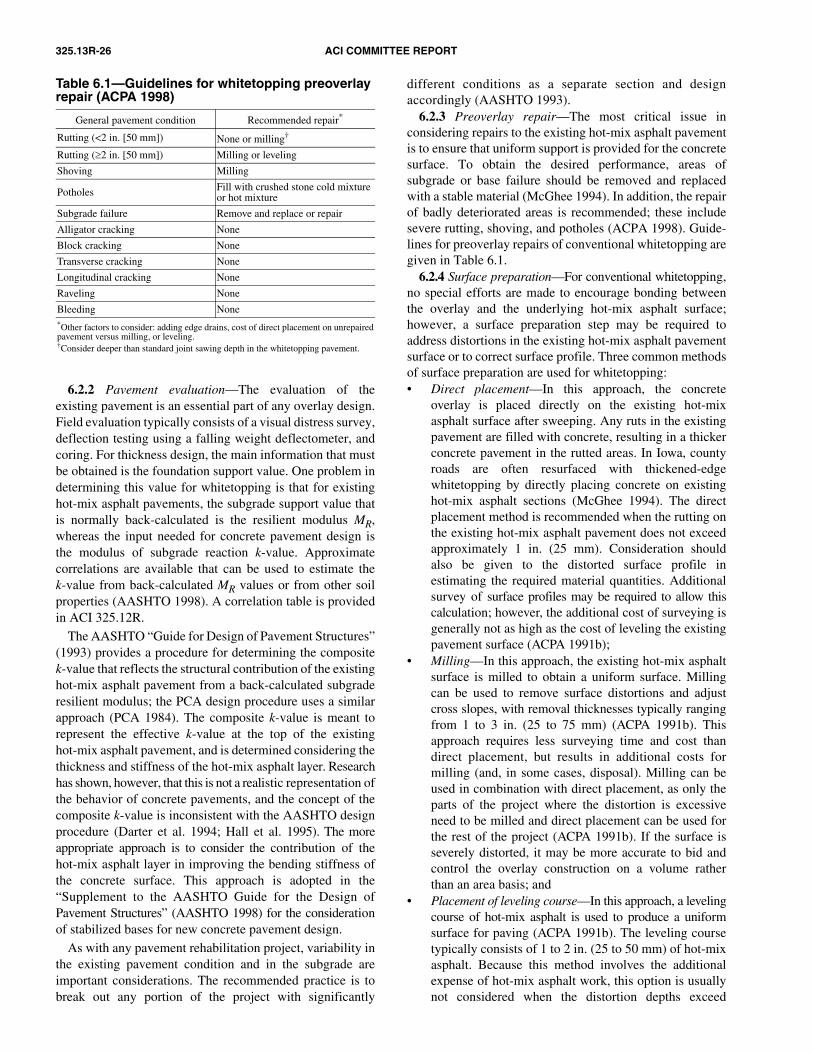
325.13R-26 ACI COMMITTEE REPORT
6.2.2 Pavement evaluation—The evaluation of theexisting pavement is an essential part of any overlay design.Field evaluation typically consists of a visual distress survey,deflection testing using a falling weight deflectometer, andcoring. For thickness design, the main information that mustbe obtained is the foundation support value. One problem indetermining this value for whitetopping is that for existinghot-mix asphalt pavements, the subgrade support value thatis normally back-calculated is the resilient modulus MR,whereas the input needed for concrete pavement design isthe modulus of subgrade reaction k-value. Approximatecorrelations are available that can be used to estimate thek-value from back-calculated MR values or from other soilproperties (AASHTO 1998). A correlation table is providedin ACI 325.12R.
The AASHTO “Guide for Design of Pavement Structures”(1993) provides a procedure for determining the compositek-value that reflects the structural contribution of the existinghot-mix asphalt pavement from a back-calculated subgraderesilient modulus; the PCA design procedure uses a similarapproach (PCA 1984). The composite k-value is meant torepresent the effective k-value at the top of the existinghot-mix asphalt pavement, and is determined considering thethickness and stiffness of the hot-mix asphalt layer. Researchhas shown, however, that this is not a realistic representation ofthe behavior of concrete pavements, and the concept of thecomposite k-value is inconsistent with the AASHTO designprocedure (Darter et al. 1994; Hall et al. 1995). The moreappropriate approach is to consider the contribution of thehot-mix asphalt layer in improving the bending stiffness ofthe concrete surface. This approach is adopted in the“Supplement to the AASHTO Guide for the Design ofPavement Structures” (AASHTO 1998) for the considerationof stabilized bases for new concrete pavement design.
As with any pavement rehabilitation project, variability inthe existing pavement condition and in the subgrade areimportant considerations. The recommended practice is tobreak out any portion of the project with significantly
different conditions as a separate section and designaccordingly (AASHTO 1993).
6.2.3 Preoverlay repair—The most critical issue inconsidering repairs to the existing hot-mix asphalt pavementis to ensure that uniform support is provided for the concretesurface. To obtain the desired performance, areas ofsubgrade or base failure should be removed and replacedwith a stable material (McGhee 1994). In addition, the repairof badly deteriorated areas is recommended; these includesevere rutting, shoving, and potholes (ACPA 1998). Guide-lines for preoverlay repairs of conventional whitetopping aregiven in Table 6.1.
Table 6.1—Guidelines for whitetopping preoverlay repair (ACPA 1998)
General pavement condition Recommended repair*
Rutting (<2 in. [50 mm]) None or milling†
Rutting (≥2 in. [50 mm]) Milling or leveling
Shoving Milling
Potholes Fill with crushed stone cold mixture or hot mixture
Subgrade failure Remove and replace or repair
Alligator cracking None
Block cracking None
Transverse cracking None
Longitudinal cracking None
Raveling None
Bleeding None*Other factors to consider: adding edge drains, cost of direct placement on unrepairedpavement versus milling, or leveling.†Consider deeper than standard joint sawing depth in the whitetopping pavement.
6.2.4 Surface preparation—For conventional whitetopping,no special efforts are made to encourage bonding betweenthe overlay and the underlying hot-mix asphalt surface;however, a surface preparation step may be required toaddress distortions in the existing hot-mix asphalt pavementsurface or to correct surface profile. Three common methodsof surface preparation are used for whitetopping:• Direct placement—In this approach, the concrete
overlay is placed directly on the existing hot-mixasphalt surface after sweeping. Any ruts in the existingpavement are filled with concrete, resulting in a thickerconcrete pavement in the rutted areas. In Iowa, countyroads are often resurfaced with thickened-edgewhitetopping by directly placing concrete on existinghot-mix asphalt sections (McGhee 1994). The directplacement method is recommended when the rutting onthe existing hot-mix asphalt pavement does not exceedapproximately 1 in. (25 mm). Consideration shouldalso be given to the distorted surface profile inestimating the required material quantities. Additionalsurvey of surface profiles may be required to allow thiscalculation; however, the additional cost of surveying isgenerally not as high as the cost of leveling the existingpavement surface (ACPA 1991b);
• Milling—In this approach, the existing hot-mix asphaltsurface is milled to obtain a uniform surface. Millingcan be used to remove surface distortions and adjustcross slopes, with removal thicknesses typically rangingfrom 1 to 3 in. (25 to 75 mm) (ACPA 1991b). Thisapproach requires less surveying time and cost thandirect placement, but results in additional costs formilling (and, in some cases, disposal). Milling can beused in combination with direct placement, as only theparts of the project where the distortion is excessiveneed to be milled and direct placement can be used forthe rest of the project (ACPA 1991b). If the surface isseverely distorted, it may be more accurate to bid andcontrol the overlay construction on a volume ratherthan an area basis; and
• Placement of leveling course—In this approach, a levelingcourse of hot-mix asphalt is used to produce a uniformsurface for paving (ACPA 1991b). The leveling coursetypically consists of 1 to 2 in. (25 to 50 mm) of hot-mixasphalt. Because this method involves the additionalexpense of hot-mix asphalt work, this option is usuallynot considered when the distortion depths exceed

CONCRETE OVERLAYS FOR PAVEMENT REHABILITATION 325.13R-27
approximately 2 in. (50 mm) (McGhee 1994). In suchcases, milling is typically less expensive (ACPA 1991b).
A minimum hot-mix asphalt thickness of 2 in. (50 mm)(after any milling) is recommended for conventionalwhitetopping overlays (Grogg et al. 2001).
6.2.5 Thickness design—6.2.5.1 Design procedures—Conventional whitetopping
is designed as a new concrete pavement, treating the existinghot-mix asphalt pavement as a stabilized base. The requiredoverlay thickness is determined using any establishedconcrete design procedure for new pavements, such as the1993 AASHTO methodology (AASHTO 1993), the PCAprocedure (1984), or the 1998 AASHTO supplement procedure(AASHTO 1998). In all of these procedures, the overlaythickness is taken as the new concrete slab thicknessrequired for the future traffic projections and for the givendesign conditions.
In addition to the design procedures described previously,simple design charts have also been developed for selectingthicknesses for whitetopping overlays (ACPA 1998). Inthese charts, the slab thickness is selected based on thenumber of trucks per day, the design concrete flexural strength,and the subgrade k-value. A minimum overlay thickness of 6 in.(150 mm) is recommended for conventional whitetopping ofprimary and interstate roads (ACPA 1998).
6.2.5.2 Bonding condition—In the design of conventionalwhitetopping overlays, the effects of any bonding betweenthe concrete overlay and the underlying hot-mix asphaltlayer is typically ignored, and the 1993 AASHTO and the1984 PCA design procedures do not have any provisions forhandling the effects of bonding.
The tendency for the concrete overlay to bond to theunderlying hot-mix asphalt surface has long been recognized,and some degree of bonding nearly always occurs betweenthe concrete overlay and the underlying hot-mix asphaltsurface (Mack et al. 1992; Grove et al. 1993; Cole 1997; Tarret al. 2000). The findings from these studies gave rise to thedevelopment of UTW overlays and to the concept of thinwhitetopping overlays, both of which depend on achievingand maintaining a good bond between the concrete overlayand the underlying hot-mix asphalt. Design procedures thattake into consideration the bonding between the concreteoverlay and the underlying hot-mix asphalt pavement havebeen developed for these types of overlays (Tarr et al. 1998;Tarr et al. 2000; Wu and Sheehan 2002).
Incorporating the effects of bonding in the thicknessdesign produces a thinner overlay; however, it is importantto note that the long-term durability of the bond between theconcrete overlay and the underlying hot-mix asphalt surfaceis not known. One study showed that concrete pavementsconstructed on a stabilized base nearly always exhibitbonded behavior (as indicated in falling weight deflecto-meter basin testing results), but long-term pavement perfor-mance (JPCP cracking) indicates unbonded behavior (Yu etal. 1998a). The debonding along the slab edges and corners(where the critical stresses occur in concrete pavements)could explain the apparently conflicting findings. A ColoradoDOT study of the load response of instrumented slabs in the
field also showed that whitetopping overlays can exhibitboth bonded and unbonded behavior, depending on thetemperature and loading conditions, and that actual bondingbetween the pavement layers is not necessary for the pavementto show bonded response (Yu et al. 1998b). Therefore,further study is needed to ensure that the long-term benefitsof partial bonding can be counted on to ensure the satisfactoryperformance of whitetopping overlays of reduced thickness.
The effects of layer interaction are included in the“Supplement to the AASHTO Guide for the Design ofPavement Structures” (AASHTO 1998). The interactionbetween the concrete surface and stabilized base is handledthrough the use of a friction factor. The guide provides arange of recommended friction factors to account for a rangeof bonding conditions for different types of bases. Therefore,at least in principle, partial bonding can be considered byassigning the appropriate friction factor. The design thickness isinsensitive to the friction factors in the range that isrecommended for hot-mix asphalt base. Further validation ofthe design procedure may be needed to ensure the reliability ofthe design thicknesses obtained using this procedure.
The main advantages of conventional whitetopping arethat it is an effective rehabilitation alternative for badlydeteriorated hot-mix asphalt pavement and that it can beplaced with minimal preoverlay repairs. Note that in Table 6.1,no preoverlay is required for alligator cracking and otherstructural distresses; however, a badly deteriorated hot-mixasphalt pavement does not have a significant structural valueto a concrete overlay, even if it is bonded to the overlay.Thus, if partial bonding were considered in the thicknessdesign, consideration should also be given to the condition ofthe existing hot-mix asphalt pavement and the appropriaterepairs made to ensure that the condition assumed in thedesign is valid.
6.2.6 Joint spacing—Transverse joint spacing directlyaffects the magnitude of critical stresses in JPCP whitetopping.Depending on the pavement design, the climate, season, andtime of day, curling stresses in JPCP can equal or exceed theload stresses. Mechanistically, joint spacing is an essentialinput to thickness design for JPCP, and the design thicknessis only valid for the joint spacing assumed in the designanalysis. Joint spacing, however, is not directly consideredin either the 1993 AASHTO or the 1984 PCA designprocedures, and is a source of variability for the performanceof concrete pavements. Joint spacing is directly consideredas an input in the “Supplement to the AASHTO Guide forDesign of Pavement Structures” (AASHTO 1998).
The maximum joint spacing recommended for conventionalwhitetopping constructed as JPCP is 21 times the slab thickness(ACPA 1998). For example, the recommended maximumjoint spacing for an 8 in. (200 mm) whitetopping is 14 ft (4.3 m).As a basic rule of thumb, this guideline is generally consid-ered adequate, although it may result in excessive jointspacing in slabs thicker than 9.5 in. (240 mm). For reliableperformance, it is recommended that the joint spacing bedirectly considered in the thickness design.
6.2.7 Load-transfer design—Load-transfer designs forconventional whitetopping are identical to those for new

325.13R-28 ACI COMMITTEE REPORT
concrete pavements discussed in Section 2.2.1. In general,doweled joints are recommended for all pavements that willbe subjected to significant truck traffic. Experience inWyoming and Utah showed that whitetopping projects builtwithout dowels develop significant faulting in a few yearsunder interstate traffic (McGhee 1994). Load-transferrecommendations are summarized in Table 2.1.
6.2.8 Concrete mixture proportion—Considerations are thesame as those for unbonded overlays reported in Section 5.2.8.
6.2.9 Edge support—Considerations are the same as thosefor unbonded overlays reported in Section 5.2.9.
6.2.10 Drainage—The effect of subsurface drainage onthe performance of whitetopping is not well known, but theeffects may be expected to be similar to those on newconcrete pavements. The possible benefits of properlydesigned, constructed, and maintained edge drains on newconcrete pavements include the following (Smith et al. 1995;ERES 1999b):• Reduced pumping and faulting;• Lower rate of crack deterioration on CRCP; and• Improved material performance, such as D-cracking
and hot-mix asphalt stripping.Unfortunately, no information is currently available to
substantiate any of these benefits, so further research isneeded to determine the effectiveness of edge drains on thestructural performance of whitetopping overlays. Based onthe evaluation of edge drains in new concrete pavements,however, it might be that edge drains could improve materialperformance in whitetopping overlays (Smith et al. 1995;ERES 1999b).
6.2.11 Job-site considerations—Considerations are thesame as those for unbonded overlays reported in Section5.2.12. The recommended taper length for the transition is300 to 500 ft (90 to 150 m) (ACPA 1991b). A similar transitionsection is also needed at bridge approaches. An exampletransition detail is shown in Fig. 6.1.
The construction of whitetopping overlays requiresshoulder work. Either concrete or hot-mix asphalt shoulderscould be provided, with the use of tied concrete shouldersgenerally recommended for urban areas or in areas where theshoulder may be used as a travel lane at some point in thefuture. When used, it is important that the transverse joints inthe concrete shoulder match those in the mainline pavement.
6.3—ConstructionConstruction of whitetopping overlays involves limited
preoverlay repair of existing asphalt pavement followed by
Fig. 6.1—Example transition detail for bridge approachesand overpasses (ACPA 1991b).
placement of a concrete overlay. Concrete placement forwhitetopping is no different than that for new construction.
6.3.1 Preoverlay repair—As discussed in Section 6.2.3,conventional whitetopping requires minimal preoverlayrepairs.
Recommended preoverlay repairs for conventionalwhitetopping include:• Removal and replacement of areas of subgrade or base
failure;• Repair or removal of severe rutting, shoving, or other
distortions; and• Repair of potholes.
The ACPA guidelines for preoverlay repairs for conven-tional whitetopping are given in Table 6.1 (ACPA 1998).The techniques for preoverlay repairs are the same as the repairtechniques for hot-mix asphalt pavements. Recommendedpractices for these techniques are summarized in severalreferences by the ACPA (1991b, 1998) and in an NHItraining course manual (Grogg et al. 2001).
6.3.2 Surface preparation—As discussed in Section 6.2.4,if surface distortions on the existing asphalt pavement areexcessive (higher than 1 in. [25 mm]), either milling or theplacement of a leveling course may be necessary. Millingand placement of a leveling course are a part of standardhot-mix asphalt paving techniques, and the procedures areno different for whitetopping overlays. The referencemanual for the NHI training course “Hot-Mix AsphaltConstruction” (NHI 1998) provides details of hot-mixasphalt construction techniques.
6.3.3 Concrete placement, finishing, and texture—Theprocedures for placing and finishing concrete for whitetoppingoverlays are the same as those for new pavements. Standardpractices apply, and the NHI training course, “Constructionof Portland Cement Concrete Pavements” (ACPA 2000c),provides a good summary of recommended practices forconcrete placement and finishing.
When the air temperature is higher than approximately 90 °F(32 °C), the surface temperature of the existing hot-mixasphalt pavement can become excessive (ACPA 1998).Placing concrete on a hot asphalt surface can lead to crackingdue to shrinkage and excessive thermal restraint stressesresulting from the large temperature difference between theconcrete at hardening and overnight low temperatures. Whenthe hot-mix asphalt pavement surface becomes uncomfortableto touch with an open palm, water fogging or whitewashingis recommended to reduce the surface temperature (ACPA1998). Although the use of water fogging has worked well inreducing the surface temperature, the use of whitewashingshould be used cautiously as it can reduce the frictionbetween the concrete overlay and the hot-mix asphalt, whichis believed to be beneficial to the performance of thewhitetopping overlay. Texturing of the finished concretepavement surface is required to ensure adequate surfacefriction of the roadway, as discussed in Section 2.6.3.
6.3.4 Curing—Curing of whitetopping overlays is nodifferent than for new concrete pavement construction, asdiscussed in Section 2.6.5. Special attention to the temperatureconditions during concrete placement may be warranted to

CONCRETE OVERLAYS FOR PAVEMENT REHABILITATION 325.13R-29
6.3.5 Joint sawing and sealing—As with new concretepavements, timely sawing is critical to avoid randomcracking for whitetopping overlays. The same proceduresand recommendations given for unbonded overlays inSection 5.3.6 are applicable to whitetopping overlays.
The saw-cut depth is of particular concern for conventionalwhitetopping overlays because the distortions in the under-lying hot-mix asphalt pavement can effectively increase theslab thickness. This is illustrated in Fig. 6.2. A minimum
Fig. 6.2—Consideration of rut depth in the hot-mix asphaltpavement in determining the appropriate saw-cut depth(ACPA 1991b).
saw-cut depth of one-third of the greatest concrete thicknessis recommended (ACPA 1998). A deeper cut should be madeat locations where the overlay thickness as placed is morethan 1 in. (25 mm) greater than the nominal thickness. Forearly-entry sawing, a shallower saw cut may be allowable(ACPA 1998).
avoid excessively high temperature gradients through theconcrete during curing. An excessive temperature gradientthrough concrete at the time of concrete hardening can causelocking-in of a significant amount of curling into concreteslabs, which can be deleterious to fatigue performance (Yuet al. 1995, 1998b; Byrum 2000).
6.4—Performance6.4.1 Factors affecting performance—The performance of
conventional whitetopping overlays is insensitive to thecondition of the underlying hot-mix asphalt pavements, andin most cases, the overlays can be placed with minimalpreoverlay repair. Exceptions are when the asphalt is soextensively cracked as to be nearly disintegrated, or wherethe subgrade has failed. The same factors that affect theperformance of new concrete pavements affect the perfor-mance of conventional whitetopping overlays, including:• Overlay design features (overlay thickness, joint spacing,
load-transfer design, reinforcement design, and drainagedesign);
• Traffic (axle weights and number);• Climate (temperature and moisture conditions); and• Construction quality and curing.
For the most part, existing design procedures have beeneffective in producing workable design thicknesses forwhitetopping. There is, however, a possibility that conventionaldesign practices may be overly conservative in some casesbecause the bond effects have been ignored.
6.4.2 State practice—Whitetopping has been used bymany highway agencies, including California, Iowa,Missouri, Nebraska, Nevada, Texas, Wyoming, and Utah,and has become an increasingly popular technique forrehabilitating deteriorated hot-mix asphalt pavements(McGhee 1994). For example, of the 189 whitetoppingprojects listed in NCHRP Synthesis 204 (McGhee 1994),125 of those were built since 1980. Between 1970 and 1980,whitetopping was used in numerous projects to upgrade theexisting pavement to the interstate standards (Webb andDelatte 2000).
Whitetopping thicknesses typically range from 8 to 12 in.(200 to 300 mm) when placed on primary interstate highways,and from 5 to 7 in. (125 to 175 mm) when placed onsecondary roads (ACPA 1998). JPCP designs are by far the
most common type of whitetopping, although some stateshave constructed CRCP whitetopping overlays.
The effect of bond between the concrete overlay and theunderlying hot-mix asphalt has been gaining more attentionsince the early 1990s in the design of whitetopping overlays.In 1991, the Iowa DOT conducted a study to determine thebond contribution to whitetopping overlays (Grove et al.1993). Their report concluded that the existing hot-mixasphalt pavement does contribute significantly to the structuralcapacity of the concrete overlay, and that the bond effectsshould be considered in the thickness design, at least in caseswhere the traffic loads are not expected to cause stresses thatexceed the bond strength. The Colorado DOT developed amechanistic design procedure for thin (5 to 7 in. [125 to175 mm]) whitetopping that takes into consideration theeffects of partial bonding between the pavement layers (Tarret al. 1998, 2000; Wu and Sheehan 2002).
6.4.3 Field performance—The field performance ofwhitetopping overlays has generally been very good. Themajority of whitetopping overlays have provided good toexcellent performance (Lokken 1981; Hutchinson 1982;McGhee 1994). The success of this design is often attributedto the uniform support and bond provided by the underlyinghot-mix asphalt pavement (Hutchinson 1982; Grove et al.1993; McGhee 1994).
California has used whitetopping extensively since the1960s, and has enjoyed considerable success with thetreatment. For example, numerous highway pavementsections were whitetopped with 7 to 9 in. (175 to 225 mm)thick nondoweled JPCP in the 1960s and 1970s, and thesewere reported to be performing well after up to 20 years ofservice (Lokken 1981; Hutchinson 1982).
Iowa also has had outstanding performance fromwhitetopping overlays, many of which have been placed ontheir county highway system. For example, beginning in thelate 1970s, three Iowa counties (Dallas, Boone, andWashington) began paving with whitetopping overlays, andsince that time, an average of 19 miles (31 km) of countypavement are whitetopped each year (ACPA 2000d). In mostcases, the concrete overlays are placed directly on theexisting hot-mix asphalt with little preparation other thansweeping (ACPA 2000d). In addition, the concrete overlaysare constructed with 15 ft (4.6 m) joint spacings and thickened-edge slab designs, in which the center of the pavement isconstructed 5 or 6 in. (125 or 150 mm) thick, and the outeredges are constructed 6 or 7 in. (150 or 175 mm) thick(ACPA 2000d). After 22 years of service, the oldestwhitetopping overlays have required minimal maintenance,and are performing well (ACPA 2000d).
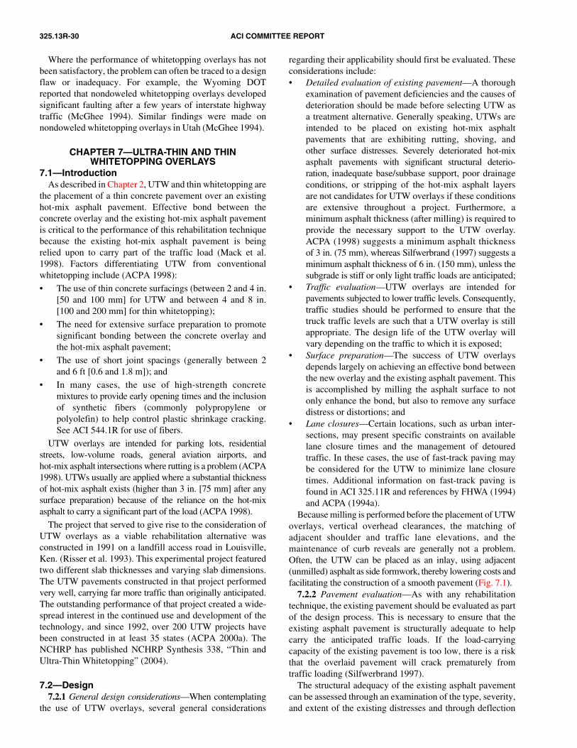
325.13R-30 ACI COMMITTEE REPORT
7.2.2 Pavement evaluation—As with any rehabilitationtechnique, the existing pavement should be evaluated as partof the design process. This is necessary to ensure that theexisting asphalt pavement is structurally adequate to helpcarry the anticipated traffic loads. If the load-carryingcapacity of the existing pavement is too low, there is a riskthat the overlaid pavement will crack prematurely fromtraffic loading (Silfwerbrand 1997).
The structural adequacy of the existing asphalt pavementcan be assessed through an examination of the type, severity,and extent of the existing distresses and through deflection
CHAPTER 7—ULTRA-THIN AND THIN WHITETOPPING OVERLAYS
Where the performance of whitetopping overlays has notbeen satisfactory, the problem can often be traced to a designflaw or inadequacy. For example, the Wyoming DOTreported that nondoweled whitetopping overlays developedsignificant faulting after a few years of interstate highwaytraffic (McGhee 1994). Similar findings were made onnondoweled whitetopping overlays in Utah (McGhee 1994).
7.1—IntroductionAs described in Chapter 2, UTW and thin whitetopping are
the placement of a thin concrete pavement over an existinghot-mix asphalt pavement. Effective bond between theconcrete overlay and the existing hot-mix asphalt pavementis critical to the performance of this rehabilitation techniquebecause the existing hot-mix asphalt pavement is beingrelied upon to carry part of the traffic load (Mack et al.1998). Factors differentiating UTW from conventionalwhitetopping include (ACPA 1998):
• The use of thin concrete surfacings (between 2 and 4 in.[50 and 100 mm] for UTW and between 4 and 8 in.[100 and 200 mm] for thin whitetopping);
• The need for extensive surface preparation to promotesignificant bonding between the concrete overlay andthe hot-mix asphalt pavement;
• The use of short joint spacings (generally between 2and 6 ft [0.6 and 1.8 m]); and
• In many cases, the use of high-strength concretemixtures to provide early opening times and the inclusionof synthetic fibers (commonly polypropylene orpolyolefin) to help control plastic shrinkage cracking.See ACI 544.1R for use of fibers.
UTW overlays are intended for parking lots, residentialstreets, low-volume roads, general aviation airports, andhot-mix asphalt intersections where rutting is a problem (ACPA1998). UTWs usually are applied where a substantial thicknessof hot-mix asphalt exists (higher than 3 in. [75 mm] after anysurface preparation) because of the reliance on the hot-mixasphalt to carry a significant part of the load (ACPA 1998).
The project that served to give rise to the consideration ofUTW overlays as a viable rehabilitation alternative wasconstructed in 1991 on a landfill access road in Louisville,Ken. (Risser et al. 1993). This experimental project featuredtwo different slab thicknesses and varying slab dimensions.The UTW pavements constructed in that project performedvery well, carrying far more traffic than originally anticipated.The outstanding performance of that project created a wide-spread interest in the continued use and development of thetechnology, and since 1992, over 200 UTW projects havebeen constructed in at least 35 states (ACPA 2000a). TheNCHRP has published NCHRP Synthesis 338, “Thin andUltra-Thin Whitetopping” (2004).
7.2—Design7.2.1 General design considerations—When contemplating
the use of UTW overlays, several general considerations
regarding their applicability should first be evaluated. Theseconsiderations include:• Detailed evaluation of existing pavement—A thorough
examination of pavement deficiencies and the causes ofdeterioration should be made before selecting UTW asa treatment alternative. Generally speaking, UTWs areintended to be placed on existing hot-mix asphaltpavements that are exhibiting rutting, shoving, andother surface distresses. Severely deteriorated hot-mixasphalt pavements with significant structural deterio-ration, inadequate base/subbase support, poor drainageconditions, or stripping of the hot-mix asphalt layersare not candidates for UTW overlays if these conditionsare extensive throughout a project. Furthermore, aminimum asphalt thickness (after milling) is required toprovide the necessary support to the UTW overlay.ACPA (1998) suggests a minimum asphalt thicknessof 3 in. (75 mm), whereas Silfwerbrand (1997) suggests aminimum asphalt thickness of 6 in. (150 mm), unless thesubgrade is stiff or only light traffic loads are anticipated;
• Traffic evaluation—UTW overlays are intended forpavements subjected to lower traffic levels. Consequently,traffic studies should be performed to ensure that thetruck traffic levels are such that a UTW overlay is stillappropriate. The design life of the UTW overlay willvary depending on the traffic to which it is exposed;
• Surface preparation—The success of UTW overlaysdepends largely on achieving an effective bond betweenthe new overlay and the existing asphalt pavement. Thisis accomplished by milling the asphalt surface to notonly enhance the bond, but also to remove any surfacedistress or distortions; and
• Lane closures—Certain locations, such as urban inter-sections, may present specific constraints on availablelane closure times and the management of detouredtraffic. In these cases, the use of fast-track paving maybe considered for the UTW to minimize lane closuretimes. Additional information on fast-track paving isfound in ACI 325.11R and references by FHWA (1994)and ACPA (1994a).
Because milling is performed before the placement of UTWoverlays, vertical overhead clearances, the matching ofadjacent shoulder and traffic lane elevations, and themaintenance of curb reveals are generally not a problem.Often, the UTW can be placed as an inlay, using adjacent(unmilled) asphalt as side formwork, thereby lowering costs andfacilitating the construction of a smooth pavement (Fig. 7.1).

CONCRETE OVERLAYS FOR PAVEMENT REHABILITATION 325.13R-31
testing using a falling-weight deflectometer. Falling-weightdeflectometer results can provide information on the stiffness ofthe asphalt pavement and on the subgrade support conditions,which are needed in the design process. Furthermore,falling-weight deflectometer results can help to reveal thevariability of these properties over the length of the project,and can help identify localized weak areas requiring strength-ening. As discussed in Chapter 6, the back-calculation process
on an existing asphalt pavement produces a subgrade resilientmodulus value MR, and this should be converted to amodulus of subgrade reaction k-value for whitetoppingdesign. Approximate correlations are available that can beused to estimate the k-value from back-calculated MR valuesor from other soil properties (AASHTO 1998). A correlationtable is provided in ACI 325.12R for estimating the k-valueon the basis of other parameters.In particular, the existing asphalt pavement should beassessed to ensure that there will be enough asphalt to forma composite section, and that the asphalt is not stripped.Cores should be extracted from the existing pavement atseveral locations to ensure that there is enough asphalt andthat there are no visual indications of stripping.
Fig. 7.1—UTW placement as inlay.
7.2.3 Preoverlay repair—UTW overlays may requiresome preoverlay repair of the existing asphalt pavement toachieve the desired level of performance. Because theexisting asphalt pavement is being relied upon to carry partof the traffic loading, any deteriorated areas that wouldotherwise detract from its load-carrying capacity should berepaired (Grogg et al. 2001). This includes potholes, areaswith moderate to severe alligator cracking, and other areasexhibiting structural inadequacies. In addition, milling of theexisting asphalt surface is required to remove rutting, restoreprofile, and provide a roughened surface to enhance bondingbetween the new concrete overlay and the existing hot-mixasphalt pavement (ACPA 1998). The thickness of theexisting asphalt pavement should also be verified with coresto help determine appropriate milling depths to ensure thatsufficient asphalt thickness remains after milling tocontribute structurally to the UTW overlay.
7.2.4 Thickness design—Because it is a relatively newtechnology, it has been only in the last several years thatresearch activities have focused on the development of aformal design procedure for UTW and thin whitetoppingoverlays. The procedures discussed previously—such as thoseof AASHTO and PCA—that are valid for other overlay typesdo not apply to UTW and thin whitetopping. The design ofUTW is more complex than conventional overlay designbecause of the following factors (ACPA 1998, 1999b):• The bond between the concrete and the asphalt pavement;• The short joint spacings associated with the design; and• Concrete mixtures used in UTW projects often have
higher strength and may use fibers.As previously described, the bond between the concrete
and the asphalt pavement is particularly critical to theperformance of UTW overlays. Bond between these layersenables the pavement to act monolithically, which greatlyreduces the magnitude of the stresses that develop in thepavement structure (ACPA 1998, 1999b).
An interim design procedure for estimating theload-carrying capacity and service life of UTW projects has beendeveloped based on field performance results, instrumentedslabs, and three-dimensional, finite-element modeling (Wu etal. 1997). The design procedure considers the development ofcritical stresses at both the corner and joint locations of a slab,and also incorporates the effects of temperature- inducedstresses (Wu et al. 1997). Based on that procedure, two sets ofsimplified design charts were developed, each for a specifictruck category (ACPA 1998, 1999b):• Axle load Category A (for low-truck-volume facilities)
uses an assumed axle load distribution with a maximumsingle-axle load of 18,000 lb (80 kN) and a maximumtandem-axle load of 36,000 lb (160 kN); and
• Axle load Category B (for medium-truck-volumefacilities) uses an assumed axle load distribution with amaximum single-axle load of 26,000 lb (116 kN) and amaximum tandem-axle load of 44,000 lb (196 kN).
The assumed axle load distributions for each axle loadcategory are defined in a document by ACPA (1992).
One set of design tables (Tables 7.1 and 7.2) has been
developed for low-truck-volume facilities, and one set ofdesign tables (Tables 7.3 and 7.4) has been developed for medium-truck-volume facilities. The output of the tables isthe allowable number of trucks per lane (in thousands) for anassumed axle load distribution and a given UTW design,which is defined in terms of subgrade support, concrete flexuralstrength, asphalt thickness, concrete pavement thickness,and joint spacing. Thus, in using the tables, the adequacy ofa selected design is evaluated, rather than the determinationof a specific slab thickness design. The ACPA web siteprovides a UTW calculator (http://www.pavement.com/PavTech/Tech/UTWCalc/Main.asp) that automates thisdesign procedure.As an example of using the tables, assume that a UTWoverlay is being contemplated for a city street subjected totruck traffic in axle load Category B. The existing subgradehas a k-value of 200 psi/in. (54 kPa/mm), and the existingasphalt pavement will be 4 in. (100 mm) thick after milling.If the UTW will be 3 in. (75 mm) thick with a flexuralstrength of 700 lb/in.2 (5 MPa) and a joint spacing of 3 ft (0.9 m),then it should be able to withstand 284,000 trucks in axle

325.13R-32 ACI COMMITTEE REPORT
7.2.5 Joint design—Joint spacings for UTW overlays arevery short, typically in the range of 2 to 6 ft (0.6 to 1.8 m).Such short joint spacings are needed to reduce the magnitudeof curling, warping, and bending stresses. The ACPArecommends that the joint spacing of UTW projects shouldbe limited to 12 to 15 times the slab thickness (ACPA 1998);that is
Lmax = (12 to 15) × t (7-1)
where Lmax = maximum joint spacing, in. (mm); and D =slab thickness, in. (mm).
For example, a 3 in. (75 mm) thick slab should have a jointspacing between 3 and 3.7 ft (0.9 and 1.1 m). In addition, itis recommended that the slabs for UTW overlays shouldgenerally be square (for example 2 x 2 ft [0.6 x 0.6 m], 3 x 3 ft[0.9 x 0.9 m], and so on).
Dowel bars, tie bars, and other embedded steel items arenot used in UTW overlays. This is because the thin UTWslabs make their installation impractical, and effective loadtransfer at joints is expected to be provided by the aggregateinterlock across the abutting joint faces and by the stiffsupport of the underlying asphalt pavement.
Thickened slabs are required for UTW overlays at transitionareas between the concrete overlay and an adjacent asphaltpavement because impact loadings from traffic may inducehigh stresses in the UTW and cause cracking. A suggestedtransition detail is shown in Fig. 7.2 (ACPA 1998).
To date, specific design procedures have not been establishedfor thin whitetopping. The simple design charts developedfor selecting thicknesses for whitetopping overlays in ACPAEB 210P (ACPA 1998), however, may be conservativelyused to design thin whitetopping. These charts do notconsider the effect of bond between the thin whitetoppingoverlay and existing asphalt, but they do account for thesupport provided by the existing asphalt to the overlay.
Table 7.1—Allowable number of trucks (in thousands) per UTW traffic lane*
Average flexural strength,psi (MPa)
h2, asphalt thickness,in. (mm)
h1, UTW thickness
2 in. (50 mm) 3 in. (75 mm) 4 in. (100 mm)
Joint spacing
3 ft(0.9 m)
2 ft(0.6 m)
4 ft(1.2 m)
3 ft(0.9 m)
6 ft(1.8 m)
4 ft(1.2 m)
700 (4.8) 3 (75) 6 60 40 104 137 303
700 (4.8) 4 (100) 56 156 125 234 294 546
700 (4.8) 5 (125) 169 375 314 507 593 996
700 (4.8) 6 (150)or more 462 839 709 1070 1188 1862
800 (5.5) 3 (75) 24 77 90 158 273 458
800 (5.5) 4 (100) 81 183 201 311 478 748
800 (5.5) 5 (125) 213 422 428 625 858 1290
800 (5.5) 6 (150)or more 507 935 880 1249 1572 2301
*Axle load Category A, k = 100 psi/in. or lb/in.3 (27 kPa/mm) (ACPA 1998, 1999b).
Table 7.2—Allowable number of trucks (in thousands) per UTW traffic lane*
Average flexural strength,psi (MPa)
h2, asphalt thickness,in. (mm)
h1, UTW thickness
2 in. (50 mm) 3 in. (75 mm) 4 in. (100 mm)
Joint spacing
3 ft(0.9 m)
2 ft(0.6 m)
4 ft(1.2 m)
3 ft(0.9 m)
6 ft(1.8 m)
4 ft(1.2 m)
700 (4.8) 3 (75) 30 163 117 258 331 640
700 (4.8) 4 (100) 140 385 310 519 606 1045
700 (4.8) 5 (125) 384 842 664 1008 1099 1748
700 (4.8) 6 (150)or more 765 1709 1092 1663 1591 2499
800 (5.5) 3 (75) 70 209 221 374 577 915
800 (5.5) 4 (100) 201 450 436 667 912 1396
800 (5.5) 5 (125) 480 938 840 1222 1487 2190
800 (5.5) 6 (150)or more 882 1877 1334 2227 2039 3574
*Axle load Category A, k = 200 psi/in. or lb/in.3 (54 kPa/mm) (ACPA 1998, 1999b).
Table 7.3—Allowable number of trucks (in thousands) per UTW traffic lane*
Average flexural strength,psi (MPa)
h2, asphalt thickness,in. (mm)
h1, UTW thickness
2 in. (50 mm) 3 in. (75 mm) 4 in. (100 mm)
Joint spacing
3 ft(0.9 m)
2 ft(0.6 m)
4 ft(1.2 m)
3 ft(0.9 m)
6 ft(1.8 m)
4 ft(1.2 m)
700 (4.8) 3 (75) NR 29 1 38 8 136
700 (4.8) 4 (100) 15 90 43 122 98 299
700 (4.8) 5 (125) 90 228 168 301 273 593
700 (4.8) 6 (150)or more 259 529 428 672 639 1181
800 (5.5) 3 (75) 2 43 31 84 106 268
800 (5.5) 4 (100) 39 110 98 188 238 471
800 (5.5) 5 (125) 129 263 252 406 501 845
800 (5.5) 6 (150)or more 328 596 576 840 1007 1581
*Axle load Category B, k = 100 psi/in. or lb/in.3 (27 kPa/mm) (ACPA 1998, 1999b).
Table 7.4—Allowable number of trucks (in thousands) per UTW traffic lane*
Average flexural strength,psi (MPa)
h2, asphalt thickness,in. (mm)
h1, UTW thickness
2 in. (50 mm) 3 in. (75 mm) 4 in. (100 mm)
Joint spacing
3 ft(0.9 m)
2 ft(0.6 m)
4 ft(1.2 m)
3 ft(0.9 m)
6 ft(1.8 m)
4 ft(1.2 m)
700 (4.8) 3 (75) NR 75 6 102 56 298
700 (4.8) 4 (100) 55 216 110 284 230 578
700 (4.8) 5 (125) 197 497 331 620 553 1076
700 (4.8) 6 (150)or more 511 1053 771 1221 1148 1915
800 (5.5) 3 (75) 9 111 79 197 266 551
800 (5.5) 4 (100) 101 261 221 398 502 875
800 (5.5) 5 (125) 277 622 495 778 922 1460
800 (5.5) 6 (150)or more 639 1183 1002 1493 1583 2438
*Axle load Category B, k = 200 psi/in. or lb/in.3 (54 kPa/mm) (ACPA 1998, 1999b).Note: NR = not recommended.
load Category B (from Table 7.4). If the street is subjected to75 trucks per day, then the UTW is expected to provide a servicelife of approximately 10 years (284,000/[75 × 365.25]).
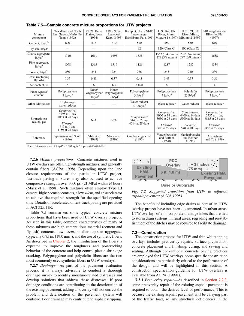
CONCRETE OVERLAYS FOR PAVEMENT REHABILITATION 325.13R-33
Fig. 7.2—Suggested transition from UTW to adjacentasphalt pavement (ACPA 1998).
Table 7.5—Sample concrete mixture proportions for UTW projects
Mixturecomponent
Woodland and North First Streets, Nashville,
Tenn. (1992)
Rt. 21, Belle Plaine, Iowa
(1994)
119th Street, Leawood,
Kans. (1995)
Ramp D, U.S. 22/I-83 Interchange,
Harrisburg, Pa. (1995)
U.S. 169, Elk River, Minn.,
Mixture 1 (1997)
U.S. 169, Elk River, Minn.,
Mixture 2 (1997)
I-10 weigh station, Ellaville, Fla.
(1997)
Cement, lb/yd3 800 573 610 520 450 550 610
Fly ash, lb/yd3 — — — 92 120 (Class C) 100 (Class C) —
Coarse aggregate, lb/yd3 1710 1661 1693 1835 1552 (3/4 minus)
277 (3/8 minus)1552 (3/4 minus)277 (3/8 minus) 1658
Fine aggregate,lb/yd3 1098 1363 1319 1126 1287 1287 1334
Water, lb/yd3 280 244 224 266 245 240 239
w/cm (including fly ash) 0.35 0.43 0.37 0.43 0.43 0.37 0.39
Air content, % 5 6 6.5 5 to 8 6 6 4
Fiber type(s)/content
Polypropylene3 lb/yd3
None/Polypropylene
3 lb/yd3
None/Polypropylene
3 lb/yd3
Polypropylene3 lb/yd3
Polypropylene3 lb/yd3
Polyolefin25 lb/yd3
Polypropylene3 lb/yd3
Other admixtures High-rangewater reducer — —
Water reducer3.7 oz/yd3 Water reducer Water reducer Water reducer
Strength test results, psi
Compressive:4795 at 1 day
8033 at 28 days
Flexural:615 at 1 day
1159 at 28 days
N/A N/ACompressive:3440 at 7 days
4514 at 28 days
Compressive:4900 at 14 days5650 at 28 days
Flexural:590 at 28 days
Compressive:4400 at 14 days5300 at 28 days
Flexural:570 at 28 days
Compressive:2755 at 1 day
6815 at 28 days
Flexural:870 at 28 days
Reference Speakman and Scott (1996)
Cable et al.(1999)
Mack et al.(1998)
Cumberledge et al. (1996)
Vandenbossche and Rettner
(1998)
Vandenbossche and Rettner
(1998)
Armaghaniand Tu (1999)
Note: Unit conversions: 1 lb/yd3 = 0.593 kg/m3; 1 psi = 0.00689 MPa.
7.2.6 Mixture proportions—Concrete mixtures used inUTW overlays are often high-strength mixtures, and generallycontain fibers (ACPA 1998). Depending upon the laneclosure requirements of the particular UTW project,fast-track paving mixtures may also be used to achievecompressive strengths over 3000 psi (21 MPa) within 24 hours(Mack et al. 1998). Such mixtures often employ Type IIIcement, higher cement contents, a low w/cm, and an acceleratorto achieve the required strength for the specified openingtime. Details of accelerated or fast-track paving are providedin ACI 325.11R.
Table 7.5 summarizes some typical concrete mixtureproportions that have been used on UTW overlay projects.As seen in this table, common characteristics of many ofthese mixtures are high cementitious material (cement andfly ash) contents, low w/cm, smaller top-size aggregates(typically 0.75 in. [19.0 mm]), and the use of synthetic fibers.As described in Chapter 2, the introduction of the fibers isexpected to improve the toughness and postcrackingbehavior of the concrete and help control plastic shrinkagecracking. Polypropylene and polyolefin fibers are the twomost commonly used synthetic fibers in UTW overlays.
7.2.7 Drainage—As part of the pavement evaluationprocess, it is always advisable to conduct a thoroughdrainage survey to identify moisture-related distresses anddevelop solutions that address these distresses. If poordrainage conditions are contributing to the deterioration ofthe existing pavement, adding an overlay will not correct theproblem and deterioration of the pavement system willcontinue. Poor drainage may contribute to asphalt stripping.
The benefits of including edge drains as part of an UTWoverlay project have not been documented. In urban areas,UTW overlays often incorporate drainage inlets that are tiedto storm drain systems; in rural areas, regrading and reestab-lishment of the ditches may be required to facilitate drainage.
7.3—ConstructionThe construction process for UTW and thin whitetopping
overlays includes preoverlay repairs, surface preparation,concrete placement and finishing, curing, and sawing andsealing. Although conventional concrete paving practicesare employed for UTW overlays, some specific constructionconsiderations are particularly critical to the performance ofthe design, and will be highlighted in this section. Aconstruction specification guideline for UTW overlays isavailable from ACPA (1999a).
7.3.1 Preoverlay repair—As described in Section 7.2.3,some preoverlay repair of the existing asphalt pavement isrequired to obtain the desired level of performance. This isbecause the existing asphalt pavement will be carrying partof the traffic load, so any structural deficiencies in the

325.13R-34 ACI COMMITTEE REPORT
existing asphalt pavement should be corrected before theplacement of the UTW overlay. Among the types of preoverlayrepair activities typically required for UTW overlays are(McGhee 1994; ACPA 1998):• Localized repair of failed areas caused by loss of base
or subgrade support;• Filling of medium- and high-severity potholes; and• Localized repair of medium to severe alligator cracking. If
significant alligator cracking exists throughout theproject, this suggests a structural inadequacy and thepavement may not be a suitable candidate for UTW.
These activities should follow conventional asphalt patchingpractices. In the case of patching of alligator cracking, it isimportant that the entire distressed area be removed andreplaced through the entire thickness of the asphalt pavement.
At least one highway agency has experimented with the useof cold in-place recycling (CIR) of the existing asphaltpavement before the placement of the UTW overlay. On partof the Route 21 project near Belle Plaine, the Iowa DOT useda continuous recycling train to first mill the existing asphaltpavement to a depth of 3.75 in. (95 mm), resize the removedmaterial and mix it with an emulsion, and place the rejuvenatedmaterial back on the pavement surface (Cable et al. 1999).
7.3.2 Surface preparation—Milling of the existing asphaltpavement is critical to the performance of the UTW overlay.Not only does it remove rutting and restore the surfaceprofile, it also provides a roughened surface to enhance thebonding between the new concrete overlay and the existingasphalt (ACPA 1998). This will increase the load-carryingcapacity of the pavement system by enabling it to behave asa monolithic structure.
Milling should be conducted after the existing asphaltpavement has been patched. Milling machines usecarbide-tipped bits attached to a revolving drum to cut awaythe existing asphalt. A variety of milling machines are availablefor asphalt removal, ranging from small equipment withnarrow, 1 ft (0.3 m) wide drums to larger equipment withfull-lane width (12 ft [3.7 m]) wide drums. Although someequipment can remove asphalt depths up to 12 in. (300 mm)in a single pass, common asphalt removal depths in preparationfor UTW overlays are 1 to 3 in. (25 to 75 mm). The amountof asphalt removal for a particular project will depend on thetype and severity of distress (especially the depth of ruttingor other surface distortions) and the thickness of the asphaltpavement. After milling, the remaining asphalt pavementshould be checked to ensure adequate thickness remains forthe composite pavement.
After the pavement has been milled, the pavement surfaceshould be cleaned to help ensure bonding between the existingasphalt and the new concrete overlay. This may be accom-plished by air blasting or power brooming, but occasionallywater blasting or sandblasting may be required to remove anyslurry or residue from the milling. If water blasting or washingoperations are used, the surface should be allowed to drybefore the placement of the concrete overlay (ACPA 1998).
7.3.3 Placement, finishing, and texturing—Once thesurface of the existing asphalt pavement has been prepared,the concrete overlay is placed. Paving is accomplished using
either fixed-form or slipform construction, the selection ofwhich will depend on the size of the project and anygeometric constraints. In either case, conventional concretepaving practices and procedures are followed. Primaryactivities in this part of the operation include spreading,consolidation, screeding, and float finishing. Texturing isdiscussed in Section 2.6.3.
7.3.4 Curing—Effective curing of the new UTW overlaypromotes continued cement hydration and strength gain bycontrolling the rate of moisture loss in the concrete slabs.Although curing is important to all concrete pavements, it iseven more critical to UTW overlays because their highsurface area-to-volume ratio make them more susceptible torapid moisture loss. Curing is most often accomplishedthrough the application of a curing compound immediatelyafter the final texturing of the concrete surface, as discussedin Section 2.6.5.
7.3.5 Joint sawing and sealing—Timely joint sawing isrequired to establish the contraction joints in the concretepavement and prevent random cracking. Because of the greatamount of joint sawing required on UTW overlays, jointsawing should commence as soon as the concrete hasdeveloped sufficient strength such that the joints can be cutwithout significant raveling or chipping. This will typicallybe within approximately 3 to 6 hours after concrete placement.The contractor should ensure that there are sufficientsaw-cutting crews available for the work and that all crewsare familiar with the prescribed joint-sawing patterns.Because of the need to get on the pavement as soon aspossible, the use of lightweight early-entry saws is particularlyadvantageous for UTW overlay construction.
Criteria for saw-cut depths on UTW overlays have notbeen established, but a minimum 1 in. (25 mm) deep cutappears to perform satisfactorily for both transverse andlongitudinal joints (ACPA 1998). The joints are typicallysawed to a width of 0.12 in. (3 mm). Generally, the joints inUTW projects are not sealed, although a few agencies haveconstructed experimental UTW sections comparing sealedand nonsealed joints.
7.4—PerformanceBecause this is a new and evolving technology, very little
long-term performance data are available for UTW and thinwhitetopping overlays. The available data suggest that UTWoverlays are a viable pavement rehabilitation alternative forlow-volume roadways. Performance of specific projects isdiscussed in Smith et al. (2002).
7.4.1 ACPA UTW performance evaluations—In 1995 and1996, the ACPA conducted detailed condition surveys onnine UTW projects: six in Tennessee and three in Georgia.The purpose of these surveys was to examine the earlyperformance of UTW overlays, and the nine projects wereselected primarily because they were some of the older UTWoverlays (Cole 1997).
Based on the results of the condition surveys, whichrepresent approximately 4 to 5 years of performance data,the following conclusions were drawn (Cole 1997):• Nine of the 10 sections are rated in excellent condition;
CONCRETE OVERLAYS FOR PAVEMENT REHABILITATION 325.13R-35
• Some cracks have occurred on the various concreteslabs, but most of these cracks are low severity (lessthan 0.02 in. [0.5 mm] wide) and do not appear to beaffecting pavement ride quality;
• The first and last panels (approach and leave ends) ofthe UTW overlays contain a higher percentage of crackingthan the rest of the project. This is believed to be theresult of impact loading as the wheel crosses from theadjacent asphalt pavement to the UTW overlay; and
• Sections with the best condition have the smallestpanel size and a significant underlying hot-mixasphalt thickness.
7.4.2 Thin whitetopping performance—To date, only onethin whitetopping project has been documented in theliterature. This pavement was 6 in. (150 mm) thick with 6 ft(1.8 m) joint spacing and was constructed on U.S. 78 inJasper, Ala., in October 2001. The thin whitetopping wasconstructed as an inlay in the traffic lanes at an intersection(Delatte et al. 2001). The project was inspected 2 years afterconstruction, and no distress was observed.
CHAPTER 8—REFERENCES8.1—Referenced standards and reports
The latest editions of the standards and reports listedbelow were used in the preparation of this document.
American Concrete Institute116R Cement and Concrete Terminology121R Quality Management System for Concrete
Construction211.1 Standard Practice for Selecting Proportions for
Normal, Heavyweight, and Mass Concrete211.2 Standard Practice for Selecting Proportions for
Structural Lightweight Concrete211.3R Guide for Selecting Proportions for No-Slump
Concrete211.4R Guide for Selecting Proportions for
High-Strength Concrete with Portland Cementand Fly Ash
211.5R Guide for Submittal of Concrete Proportions212.3R Chemical Admixtures for Concrete221R Guide for Use of Normal Weight and Heavy-
weight Aggregates in Concrete221.1R State-of-the-Art Report on Alkali-Aggregate
Reactivity 225R Guide to the Selection and Use of Hydraulic
Cements232.2R Use of Fly Ash in Concrete304R Guide for Measuring, Mixing, Transporting,
and Placing Concrete305R Hot Weather Concreting308R Guide to Curing Concrete311.4R Guide for Concrete Inspection311.5 Guide for Concrete Plant Inspection and
Testing of Ready-Mixed Concrete325.9R Guide for Construction of Concrete Pavements
and Bases325.11R Accelerated Techniques for Concrete Paving
325.12R Guide for Design of Jointed Concrete Pavementsfor Streets and Local Roads
504R Guide to Joint Sealants for Concrete Structures544.1R State-of-the-Art Report on Fiber Reinforced
Concrete546R Concrete Repair Guide
American Association of State and Highway TransportationOfficials
M 31 Deformed and Plain Billet-Steel Bars forConcrete Reinforcement
M 55 Steel Welded Wire Fabric, Plain, for ConcreteReinforcement
M 148 Liquid Membrane-Forming CuringCompounds for Curing Concrete
M 220 Preformed Polychloroprene ElastometericJoint Seals for Concrete Pavements
M 301 Joint Sealants, Hot-Poured, for Concrete andAsphalt Pavements
ASTM InternationalA 185 Standard Specification for Steel Welded Wire
Reinforcement, Plain, for ConcreteA 615 Standard Specification for Deformed and Plain
Carbon-Steel Bars for Concrete ReinforcementC 150 Standard Specification for Portland CementC 309 Standard Specification for Liquid Membrane-
Forming Compounds for Curing ConcreteC 595 Standard Specification for Blended Hydraulic
CementC1157 Standard Performance Specification for
Hydraulic CementC 1260 Standard Test Method for Potential Alkali
Reactivity of Aggregates (Mortar-Bar Method) C 1583 Standard Test Method for Tensile Strength of
Concrete Surfaces and the Bond Strength orTensile Strength of Concrete Repair andOverlay Materials by Direct Tension (Pull-OffMethod)
D 2628 Standard Specification for Preformed Poly-chloroprene Elastomeric Joint Seals forConcrete Pavements
D 6690 Standard Specification for Joint and CrackSealants, Hot-Applied, for Concrete andAsphalt Pavements
E 965 Standard Test Method for Measuring PavementMacrotexture Depth Using a VolumetricTechnique
These publications may be obtained from these organizations:
American Concrete InstituteP.O. Box 9094Farmington Hills, MI 48333-9094(248) 848-3800www.concrete.org
325.13R-36 ACI COMMITTEE REPORT
American Association of State and HighwayTransportation Officials
444 North Capitol Street N.W., Suite 249Washington, D.C. 20001www.aashto.org
ASTM International100 Barr Harbor DriveWest Conshohocken, PA 19428-2959www.astm.org
8.2—Cited referencesACI Committee 325, 1958, “Recommended Practice for
Design of Concrete Pavements (ACI 325-58),” ACI Standards1958, American Concrete Institute, Farmington Hills, Mich.,pp. 17-52.
ACI Committee 325, 1967, “Design of Concrete Overlays forPavements (ACI 325.1R-67),” American Concrete Institute,Farmington Hills, Mich., 5 pp.
American Association of State Highway and TransportationOfficials (AASHTO), 1993, “Guide for Design of PavementStructures,” Washington, D.C.
American Association of State Highway and TransportationOfficials (AASHTO), 1998, “Supplement to theAASHTO Guide for Design of Pavement Structures,”Washington, D.C.
American Association of State Highway and TransportationOfficials (AASHTO), 2000, “The Use and theState-of-the-Practice of Fiber Reinforced Concrete,” TaskForce 36 Report, AASHTO-AGC-ARTBA Joint Committee,Washington, D.C.
American Concrete Pavement Association (ACPA),1990a, “Guidelines for Bonded Concrete Overlays,”Technical Bulletin TB-007P, Arlington Heights, Ill.
American Concrete Pavement Association (ACPA),1990b, “Guidelines for Unbonded Concrete Overlays,”Technical Bulletin TB-005P, Arlington Heights, Ill.
American Concrete Pavement Association (ACPA),1991a, “Design and Construction of Joints for ConcreteHighways,” Technical Bulletin TB-010.D, ArlingtonHeights, Ill.
American Concrete Pavement Association (ACPA),1991b, “Guidelines for Concrete Overlays of ExistingAsphalt Pavements (Whitetopping),” Technical BulletinTB-009P, Arlington Heights, Ill.
American Concrete Pavement Association (ACPA), 1992,“Design of Concrete Pavements for City Streets,” InformationSeries IS184P, Skokie, Ill.
American Concrete Pavement Association (ACPA), 1993,“Pavement Rehabilitation Strategy Selection,” TechnicalBulletin TB-015.P, Skokie, Ill.
American Concrete Pavement Association (ACPA),1994a, “Fast-Track Concrete Pavements,” TechnicalBulletin TB-004.02, Skokie, Ill.
American Concrete Pavement Association (ACPA),1994b, “Slab Stabilization Guidelines for Concrete Pavements,”Technical Bulletin TB-018P, Skokie, Ill.
American Concrete Pavement Association (ACPA), 1995,“Guidelines for Full-Depth Repair,” Technical BulletinTB002.02P, Skokie, Ill.
American Concrete Pavement Association (ACPA), 1998,“Whitetopping—State of the Practice,” Engineering BulletinEB210P, Skokie, Ill.
American Concrete Pavement Association (ACPA),1999a, “Construction Specification Guideline for Ultra-ThinWhitetopping,” Information Series IS120P, Skokie, Ill.
American Concrete Pavement Association (ACPA),1999b, “Ultra-Thin Whitetopping,” Information SeriesIS100.02, Skokie, Ill.
American Concrete Pavement Association (ACPA),2000a, “Repair of Ultra-Thin Whitetopping,” PublicationPA397P, Skokie, Ill.
American Concrete Pavement Association (ACPA),2000c, “Construction of Portland Cement Concrete Pavements,”FHWA-HI-96-027, National Highway Institute,Arlington, Va.
American Concrete Pavement Association (ACPA),2000b, “Concrete Pavement Surface Textures,” SpecialReport SR902P, Skokie, Ill.
American Concrete Pavement Association (ACPA), 2000d,“Iowa Whitetopping—20 Years and Still Going Strong,”Concrete Pavement Progress, V. 36, No. 2, Skokie, Ill.
Armaghani, J. M., and Tu, D., 1999, “Rehabilitation ofEllaville Weigh Station with Ultrathin Whitetopping,”Transportation Research Record 1654, TransportationResearch Board, Washington, D.C.
Bentz, D. P.; Lura, P.; and Roberts, J. W., 2005, “MixtureProportioning for Internal Curing,” Concrete International,V. 27, No. 2, Feb., pp. 35-40.
Byrum, C. R., 2000, “Analysis by High-Speed Profile ofJointed Concrete Pavement Slab Curvature,” TransportationResearch Record 1730, Transportation Research Board,Washington, D.C.
Cable, J. K.; Hart, J. M.; and Ciha, T. J., 1999, “ThinBonded Overlay Evaluation,” Construction Report, IowaDOT Project HR-559, Iowa Department of Transportation,Ames, Iowa.
Cole, L. W., 1997, “Pavement Condition Surveys ofUltrathin Whitetopping Projects,” Proceedings of the SixthInternational Purdue Conference on Concrete PavementDesign and Materials for High Performance, Indianapolis,Ind.
Crovetti, J. A., and Darter, M. I., 1985, “Void Detection forJointed Concrete Pavements,” Transportation Research Record1041, Transportation Research Board, Washington, D.C.
Cumberledge, G.; King, P.; and Hawk, S., 1996,“Ultra-Thin Portland Cement Concrete Overlay,” ConstructionReport, Project 37P-0001-001, Pennsylvania Department ofTransportation, Harrisburg, Pa.
Darter, M. I., and Hall, K. T., 1990, “Structural OverlayStrategies for Jointed Concrete Pavements, Volume IV:Guidelines for the Selection of Rehabilitation Alternatives,”FHWA-RD-89-145, Federal Highway Administration,Washington, D.C.

CONCRETE OVERLAYS FOR PAVEMENT REHABILITATION 325.13R-37
Darter, M. I.; Hall, K. T.; and Kuo, C. M., 1994, “SupportUnder Concrete Pavements,” NCHRP Report 372, Trans-portation Research Board, Washington, D.C.
Darter, M. I.; Von Quintus, H.; Jiang, Y. J.; Owusu-Antwi,E. B.; and Killingsworth, B. M., 1997, “Catalog ofRecommended Pavement Design Features,” Final Report,NCHRP Project 1-32, Transportation Research Board,Washington, D.C.
Delatte, N. J.; Gräter, S.; Treviño, M.; Fowler, D.; andMcCullough, B. F., 1996a, “Partial Construction Report of aBonded Concrete Overlay on IH-10, El Paso and Guide forExpedited Bonded Concrete Overlay Design andConstruction,” Report 2911-5F, Texas Department ofTransportation, Austin, Tex.
Delatte, N. J.; Gräter, S.; Treviño, M.; Fowler, D.; andMcCullough, B. F., 1996b, “Partial Construction Report of aBonded Concrete Overlay on IH-10, El Paso and Guide forExpedited Bonded Concrete Overlay Design andConstruction,” Report 2911-4, Texas Department ofTransportation, Austin, Tex.
Delatte, N. J.; Fowler, D. W.; and McCullough, B. F.,1996, “High-Early Strength Bonded Concrete OverlayDesigns and Construction Methods,” Research Report2911-4, Center for Transportation Research, Austin, Tex.
Delatte, N. J.; Fowler, D. W.; McCullough, B. F.; andGräter, S. F., 1998, “Investigating Performance of BondedConcrete Overlays,” Journal of Performance of ConstructedFacilities, V. 12, No. 2, American Society of Civil Engineers,New York.
Delatte, N. J., and Laird II, J. T., 1999, “Performance ofBonded Concrete Overlays,” Preprint Paper 99-0715, 78thAnnual Meeting of the Transportation Research Board,Washington, D.C.
Delatte, N. J.; Chen, S.-E.; Davidson, J.; Sehdev, A.;Amer, N.; and Endfinger, M., 2001, “Design and QualityControl of Concrete Overlays,” Report No. 01220, UniversityTransportation Center for Alabama, Dec. 31.
Dhamrait, J. S., and Taylor, R. K., 1979, “Behavior ofExperimental CRC Pavements in Illinois,” FHWA-IL-PR-82,Illinois Department of Transportation, Springfield, Ill.
Dykins, S. E., and Epps, J. A., 1987, “Portland CementConcrete Pavement Pulverizing Equipment,” TransportationResearch Record 1126, Transportation Research Board,Washington, D.C.
Engstrom, G. M., 1993, “Unbonded Concrete Overlays—Minnesota Experience,” Interim Report, Minnesota Departmentof Transportation, Maplewood, Minn.
ERES Consultants, Inc., 1999a, “Evaluation of UnbondedPortland Cement Concrete Overlays,” NCHRP Report 415,National Cooperative Highway Research Program,Washington, D.C.
ERES Consultants, Inc., 1999b, “Pavement SubsurfaceDrainage Design,” Reference Manual, NHI Training CourseNo. 13126, National Highway Institute, Arlington, Va.
Federal Aviation Administration Advisory Circular (AC)150/5320-6d, “Airport Pavement Design,” available athttp://www1.faa.gov/arp/150acs.cfm.
Federal Highway Administration (FHWA), 1990,“Concrete Pavement Joints,” Technical Advisory T 5040.30,Federal Highway Administration, Washington, D.C.
Federal Highway Administration (FHWA), 1993, “Reporton the 1992 U.S. Tour of European Concrete Highways,”FHWA-SA-93-012, Federal Highway Administration,Washington, D.C.
Federal Highway Administration (FHWA), 1994,“Accelerated Rigid Paving Techniques—State-of-the-ArtReport,” FHWA-SA-94-080, Federal Highway Administration,Washington, D.C.
Federal Highway Administration (FHWA), DistressIdentification Manual, http://www.tfhrc.gov/pavement/ltpp/reports/03031/.
Grogg, M. G.; Smith, K. D.; Seeds, S. B.; Hoerner, T. E.;Peshkin, D. G.; and Yu, H. T., 2001, “HMA PavementEvaluation and Rehabilitation,” Reference Manual, NHICourse 131063, National Highway Institute, Arlington, Va.
Grove, J. M.; Harris, G. K.; and B. J. Skinner, 1993, “BondContribution to Whitetopping Performance on Low-VolumeRoads,” Transportation Research Record 1286, TransportationResearch Board, Washington, D.C.
Hall, K. T., 1992, “Backcalculation Solutions for ConcretePavements,” Technical Memo, SHRP Contract P-020,Strategic Highway Research Program, Washington, D.C.
Hall, K. T.; Darter, M. I.; and Kuo, C. M.; 1995,“Improved Methods for Selection of k-Value for ConcretePavement Design,” Transportation Research Record 1505,Transportation Research Board, Washington, D.C.
Hall, K. T.; Darter, M. I.; and Seiler, W. J., 1993,“Improved Design of Unbonded Concrete Overlays,”Proceedings of the 5th International Conference onConcrete Pavement Design and Rehabilitation, PurdueUniversity, West Lafayette, Ind.
Hall, K. T.; Correa, C. E.; Carpenter, S. H.; and Elliott, R. P.,2001, “Rehabilitation Strategies for Highway Pavements,”Final Report, NCHRP Project 1-38, TransportationResearch Board, Washington, D.C.
Hoerner, T. E.; Smith, K. D.; Yu, H. T.; Peshkin, D. G.;and Wade, M. J., 2001, “PCC Pavement Evaluation andRehabilitation,” Reference Manual, NHI Course 131062,National Highway Institute, Arlington, Va.
Hutchinson, R. L., 1982, “Resurfacing with PortlandCement Concrete,” NCHRP Synthesis of Highway PracticeNo. 99, Transportation Research Board, Washington, D.C.
Khazanovich, L.; Darter, M. I.; Bartlett, R.; and McPeak,T., 1998, “Common Characteristics of Good and PoorlyPerforming PCC Pavements,” FHWA-RD-97-131, FederalHighway Administration, McLean, Va.
Ksaibati, K.; Miley, W.; and Armaghani, J.; 1999,“Rubblization of Concrete Pavements,” TransportationResearch Record 1684, Transportation Research Board,Washington, D.C.
Kuemmel, D. A.; Sonntag, R. C.; Crovetti, J. A.; Becker, Y.;Jaeckel, J. R.; and Satanovsky, A., 2000, “Noise and Textureon PCC Pavements—A Multi-State Study,” WI/SPR-08-99,Wisconsin Department of Transportation, Madison, Wis.
325.13R-38 ACI COMMITTEE REPORT
Lam, H., “Effects of Internal Curing Methods onRestrained Shrinkage and Permeability,” PCA R&D SerialNo. 2620, Portland Cement Association, Skokie, Ill., 2005.
Larson, R. M., and Hibbs, B. O., 1997, “Tire PavementNoise and Safety Performance—PCC Surface TextureTechnical Working Group,” Proceedings of the SixthInternational Purdue Conference on Concrete Design andMaterials for High Performance, Indianapolis, Ind.
Lokken, E. C., 1981, “Concrete Overlays for Concrete andAsphalt Pavements,” Proceedings of the Second InternationalConference on Concrete Pavement Design, Purdue University,West Lafayette, Ind.
Mack, J. W.; Cole, L. W.; and Mohsen, J. P., 1992,“Analytical Considerations for Thin Concrete Overlays onAsphalt,” Portland Cement Association, Skokie, Ill.
Mack, J. W.; Hawbaker, L. D.; and Cole, L. W., 1998,“Ultrathin Whitetopping: State-of-the-Practice for ThinConcrete Overlays of Asphalt,” Transportation ResearchRecord 1610, Transportation Research Board, Washington,D.C.
McCullough, B. F., and Rasmussen, R. O., 1999a,“Fast-Track Paving: Concrete Temperature Control andTraffic Opening Criteria for Bonded Concrete Overlays—V. I,”Final Report FHWA-RD-98-167, Federal HighwayAdministration, McLean, Va.
McCullough, B. F., and Rasmussen, R. O., 1999b,“Fast-Track Paving: Concrete Temperature Control andTraffic Opening Criteria for Bonded Concrete Overlays—V. II:HIPERPAV User’s Manual,” FHWA-RD-98-168, FederalHighway Administration, McLean, Va.
McGhee, K. H., 1994, “Portland Cement ConcreteResurfacing,” NCHRP Synthesis of Highway Practice 204,Transportation Research Board, Washington, D.C.
National Cooperative Highway Research Program, “AProcess for Selecting Strategies for Rehabilitation of RigidPavements,” NCHRP Web Document 45, www.trb.org.
National Cooperative Highway Research Program, “AProcess for Selecting Strategies for Rehabilitation of RigidPavements,” NCHRP Research Results Digest 272,www.trb.org.
National Cooperative Highway Research Program, “Thinand Ultra-Thin Whitetopping,” NCHRP Synthesis 338,Transportation Research Board, 2004.
National Highway Institute (NHI), 1998, “Hot-Mix AsphaltConstruction,” Participant’s Manual, NHI Training CourseNo. 131032, National Highway Institute, Arlington, Va.
Nishizawa, T.; Shimeno, S.; Komatsubara, A.; andKoyanagawa, M., 2000, “Temperature Gradient of ConcretePavement Slab Overlaid with Asphalt Surface Course,”Transportation Research Record 1730, TransportationResearch Board, Washington, D.C.
Okamoto, P. A.; Nussbaum, P. J.; Smith, K. D.; Darter, M. I.;Wilson, T. P.; Wu, C. L.; and Tayabji, S. D., 1994, “Guidelinesfor Timing Contraction Joint Sawing and Earliest Loading forConcrete Pavements,” Final Report, V. I, FHWA-RD-91-079,Federal Highway Administration, McLean, Va.
Older, C., 2004, “Highway Research in Illinois,”Transactions, V. 87, American Society of Civil Engineers,New York.
Peshkin, D. G., and Mueller, A. L., 1990, “Field Performanceand Evaluation of Thin Bonded Overlays,” TransportationResearch Record 1286, Transportation Research Board,Washington, D.C.
Portland Cement Association (PCA), 1984, “ThicknessDesign for Concrete Highway and Street Pavements,”Engineering Bulletin EB109P, Portland Cement Association,Skokie, Ill.
Portland Cement Association (PCA), 1991, “FiberReinforced Concrete,” Special Publication SP039.01T,Portland Cement Association, Skokie, Ill.
Portland Cement Association (PCA), 2002, “Design andControl of Concrete Mixtures,” 14th Edition, EngineeringBulletin EB001.13T, Portland Cement Association, Skokie, Ill.
Risser, R. J.; LaHue, S. P.; Voigt, G. F.; and Mack, J. W.,1993, “Ultra-Thin Concrete Overlays on Existing AsphaltPavement,” Proceedings of the Fifth International Conferenceon Concrete Pavement Design and Rehabilitation, PurdueUniversity, West Lafayette, Ind.
Roman, R., and Darter, M. I., 1988, “Pavement DistressStudy for Interstate Route 77, Fairfield and Chester Counties,South Carolina,” Final Report, South Carolina Department ofHighways and Public Transportation, Columbia, S.C.
Silfwerbrand, J., 1997, “Whitetoppings—Swedish FieldTests and Recommendations,” Proceedings of the SixthInternational Purdue Conference on Concrete PavementDesign and Materials for High Performance, Indianapolis, Ind.
Smith, K. D.; Wade, M. J.; Peshkin, D. G.; Khazanovich,L.; Yu, H. T.; and Darter, M. I., 1995, “Performance ofConcrete Pavements, V. II—Evaluation of In-ServiceConcrete Pavements,” FHWA-RD-95-110, FederalHighway Administration, Washington, D.C.
Smith, K. D.; Wade, M. J;. Yu, H. T.; and Darter, M. I.,1997, “Design Considerations for Improved JPCP Perfor-mance,” Proceedings of the Sixth International PurdueConference on Concrete Pavement Design and Materials forHigh Performance, Indianapolis, Ind.
Smith, K. D., and Hall, K. T., 2001, “Concrete PavementDesign Details and Construction Practices—TechnicalDigest,” NHI Training Course 131060, National HighwayInstitute, Arlington, Va.
Smith, K. D.; Yu, H. T.; and Peshkin, D. G., 2002, “PortlandCement Concrete Overlays: State of the TechnologySynthesis,” FHWA-IF-02-045, U.S. Department of Transpor-tation Federal Highway Administration, Washington, D.C.
Snyder, M. B.; Reiter, M. J.; Hall, K. T.; and Darter, M. I.,1989, “Rehabilitation of Concrete Pavements, Volume I—Repair Rehabilitation Techniques,” FHWA-RD-88-071,Federal Highway Administration, Washington, D.C.
Speakman, J., and Scott, H. N., 1996, “Ultra-Thin,Fiber-Reinforced Concrete Overlays for Urban Intersections,”Transportation Research Record 1532, TransportationResearch Board, Washington, D.C.

CONCRETE OVERLAYS FOR PAVEMENT REHABILITATION 325.13R-39
Sprinkel, M. M., 2000, “Thin Bonded Overlays andSurface Lamination Projects for Pavements,” Final Report,Federal Highway Administration, Washington, D.C.
Tarr, S. M.; Sheehan, M. J.; and Ardani, A., 2000,“Mechanistic Design of Thin Whitetopping Pavements inColorado,” Transportation Research Record 1730,Transportation Research Board, Washington, D.C.
Tarr, S. M.; Sheehan, M. J.; and Okamoto, P., 1998,“Guidelines for the Thickness Design of Bonded WhitetoppingPavements in the State of Colorado,” CDOT-DTD-R-98-10,Colorado Department of Transportation, Denver, Colo.
Tayabji, S. D., and Okamoto, P. A., 1985, “ThicknessDesign of Concrete Resurfacing,” Proceedings of the ThirdInternational Conference on Concrete Pavement Design andRehabilitation, Purdue University, West Lafayette, Ind.
Thompson, M. R., 1999, “Hot-Mix Asphalt OverlayDesign Concepts for Rubblized Portland Cement ConcretePavements,” Transportation Research Record 1684,Transportation Research Board, Washington, D.C.
Transportation Research Board (TRB), 1998, “Get In GetOut Stay Out!” Proceedings of the Workshop on PavementRenewal for Urban Freeways, Transportation ResearchBoard, Washington, D.C.
Unified Facility Criteria (UFC) 3-260-02 “PavementDesign for Airfields,” available at http://www.hnd.usace.army.mil/techinfo/index.asp.
Van Dam, T. J.; Sutter, L. L.; Smith, K. D.; Wade, M. J.;and Peterson, K. R., 2002, “Guidelines for Detection,Analysis, and Treatment of Materials-Related Distress inConcrete Pavements, Volume 2: Guidelines Description andUse,” FHWA-RD-01-164, Federal Highway Administration,McLean, Va.
Vandenbossche, J. M., and Rettner, D., 1998, “TheConstruction of US-169 and I-94 ExperimentalUltra-Thin Whitetopping Sections in Minnesota,” StateProject No. 7106-60, Minnesota Department of Transportation,Maplewood, Minn.
Voigt, G. F.; Carpenter, S. H.; and Darter, M. I., 1989,“Rehabilitation of Concrete Pavements, Volume II: OverlayRehabilitation Techniques,” FHWA-RD-88-072, FederalHighway Administration, McLean, Va.
Warner, J.; Bhuhan, S.; Smoak, W. G.; Hindo, K. R.; andSprinkel, M. M., 1998, “Surface Preparation for Overlays,”Concrete International, V. 20, No. 5, May, pp. 43-46.
Webb, R. D., and Delatte, N. J., 2000, “Performance ofWhitetopping Overlays,” Preprint Paper No. 00-1068, 79thAnnual Meeting of the Transportation Research Board,Washington, D.C.
Wells, J. A.; Stark, R. D.; and Polyzois, D., 1999, “GettingBetter Bond in Concrete Overlays,” Concrete International,V. 21, No. 3, Mar., pp. 49-52.
Whitney, D. P.; Isis, P.; McCullough, B. F.; and Fowler,D. W., 1992, “An Investigation of Various Factors AffectingBond in Bonded Concrete Overlays,” Research Report920-5, Texas Department of Transportation, Austin, Tex.
Wu, C. L.; Tarr, S. M.; Refai, T. M.; Nagi, M. A,; andSheehan, M. J., 1997, “Development of Ultra-ThinWhitetopping Design Procedure,” PCA Research and Develop-ment Serial No. 2124, Portland Cement Association, Skokie, Ill.
Wu, C., and Sheehan, M., 2002, “Instrumentation andField Testing of Whitetopping Pavements in Coloradoand Revision of the TWT Design Procedure,” InterimReport, CDOT-DTD-R-2002-3, Colorado Department ofTransportation, Denver, Colo.
Yu, H. T., and Khazanovich, L., 2001, “Effects ofConstruction Curling on Concrete Pavement Behavior,”Proceedings of the Seventh International Conference onConcrete Pavements, Orlando, Fla.
Yu, H. T.; Smith, K. D.; and Darter, M. I., 1995, “Field andAnalytical Evaluation of the Effects of Tied PCC Shouldersand Widened Slabs on Performance of JPCP,” Final Report,Colorado Department of Transportation, Denver, Colo.
Yu, H. T.; Khazanovich, L.; Darter, M. I.; and Ardani, A.,1998b, “Analysis of Concrete Pavement Responses toTemperature and Wheel Loads Measured from InstrumentedSlabs,” Transportation Research Record 1639, TransportationResearch Board, Washington, D.C.
Yu, H. T.; Smith, K. D.; Darter, M. I.; Jiang, J.; andKhazanovich, L., 1998a, “Performance of Concrete Pavements,Volume III—Improving Concrete Pavement Performance,”FHWA-RD-95-111, Federal Highway Administration,McLean, Va.