2004 NASA Seal/Secondary Air System Workshop
405
2004 NASA Seal/Secondary Air System Workshop NASA/CP—2005-213655/VOL1 October 2005
-
Upload
khangminh22 -
Category
Documents
-
view
1 -
download
0
Transcript of 2004 NASA Seal/Secondary Air System Workshop

2004 NASA Seal/Secondary Air SystemWorkshop
NASA/CP—2005-213655/VOL1
October 2005

The NASA STI Program Office . . . in Profile
Since its founding, NASA has been dedicated tothe advancement of aeronautics and spacescience. The NASA Scientific and TechnicalInformation (STI) Program Office plays a key partin helping NASA maintain this important role.
The NASA STI Program Office is operated byLangley Research Center, the Lead Center forNASA’s scientific and technical information. TheNASA STI Program Office provides access to theNASA STI Database, the largest collection ofaeronautical and space science STI in the world.The Program Office is also NASA’s institutionalmechanism for disseminating the results of itsresearch and development activities. These resultsare published by NASA in the NASA STI ReportSeries, which includes the following report types:
• TECHNICAL PUBLICATION. Reports ofcompleted research or a major significantphase of research that present the results ofNASA programs and include extensive dataor theoretical analysis. Includes compilationsof significant scientific and technical data andinformation deemed to be of continuingreference value. NASA’s counterpart of peer-reviewed formal professional papers buthas less stringent limitations on manuscriptlength and extent of graphic presentations.
• TECHNICAL MEMORANDUM. Scientificand technical findings that are preliminary orof specialized interest, e.g., quick releasereports, working papers, and bibliographiesthat contain minimal annotation. Does notcontain extensive analysis.
• CONTRACTOR REPORT. Scientific andtechnical findings by NASA-sponsoredcontractors and grantees.
• CONFERENCE PUBLICATION. Collectedpapers from scientific and technicalconferences, symposia, seminars, or othermeetings sponsored or cosponsored byNASA.
• SPECIAL PUBLICATION. Scientific,technical, or historical information fromNASA programs, projects, and missions,often concerned with subjects havingsubstantial public interest.
• TECHNICAL TRANSLATION. English-language translations of foreign scientificand technical material pertinent to NASA’smission.
Specialized services that complement the STIProgram Office’s diverse offerings includecreating custom thesauri, building customizeddatabases, organizing and publishing researchresults . . . even providing videos.
For more information about the NASA STIProgram Office, see the following:
• Access the NASA STI Program Home Pageat http://www.sti.nasa.gov
• E-mail your question via the Internet [email protected]
• Fax your question to the NASA AccessHelp Desk at 301–621–0134
• Telephone the NASA Access Help Desk at301–621–0390
• Write to: NASA Access Help Desk NASA Center for AeroSpace Information 7121 Standard Drive Hanover, MD 21076

2004 NASA Seal/Secondary Air SystemWorkshop
NASA/CP—2005-213655/VOL1
October 2005
National Aeronautics andSpace Administration
Glenn Research Center
Proceedings of a conference held at Ohio Aerospace Institutesponsored by NASA Glenn Research CenterCleveland, OhioNovember 9–10, 2004

Available from
NASA Center for Aerospace Information7121 Standard DriveHanover, MD 21076
National Technical Information Service5285 Port Royal RoadSpringfield, VA 22100
Trade names or manufacturers’ names are used in this report foridentification only. This usage does not constitute an officialendorsement, either expressed or implied, by the National
Aeronautics and Space Administration.
Available electronically at http://gltrs.grc.nasa.gov
This work was sponsored by the Low Emissions AlternativePower Project of the Vehicle Systems Program at the
NASA Glenn Research Center.
Contents were reproduced from author-providedpresentation materials.

NASA/CP—2005-213655/VOL1 iii
Executive Summary Volume 1
The 2004 NASA Seal/Secondary Air System workshop covered the following topics: (i) Overview
of NASA’s new Exploration Initiative program aimed at exploring the Moon, Mars, and beyond; (ii) Overview of the NASA-sponsored Ultra-Efficient Engine Technology (UEET) program; (iii) Overview of NASA Glenn’s seal program aimed at developing advanced seals for NASA’s turbomachinery, space, and reentry vehicle needs; (iv) Reviews of NASA prime contractor and university advanced sealing concepts including tip clearance control, test results, experimental facilities, and numerical predictions; and (v) Reviews of material development programs relevant to advanced seals development.
The NASA UEET overview illustrated for the reader the importance of advanced technologies, including seals, in meeting future turbine engine system efficiency and emission goals. For example, the NASA UEET program goals include an 8- to 15-percent reduction in fuel burn, a 15-percent reduction in CO2, a 70-percent reduction in NOx, CO, and unburned hydrocarbons, and a 30-dB noise reduction relative to program baselines.
The workshop also covered several programs NASA is funding to develop technologies for the Exploration Initiative and advanced reusable space vehicle technologies. NASA plans on developing an advanced docking and berthing system that would permit any vehicle to dock to any on-orbit station or vehicle, as part of NASA’s new Exploration Initiative. Plans to develop the necessary mechanism and “androgynous” seal technologies were reviewed. Seal challenges posed by reusable re-entry space vehicles include high-temperature operation, resiliency at temperature to accommodate gap changes during operation, and durability to meet mission requirements.


NASA/CP—2005-213655/VOL1 v
Contents Overview of NASA Glenn Seal Developments
Bruce M. Steinetz, Margaret P. Proctor, and Patrick H. Dunlap, Jr., NASA Glenn Research Center; Irebert Delgado, U.S. Army Research Laboratory; Joshua Finkbeiner, NASA Glenn Research Center; Jeffrey J. DeMange and Christopher C. Daniels, University of Toledo; and Scott B. Lattime, Ohio Aerospace Institute ....................................... 1
Overview of NASA’s Exploration Initiative Joseph Nainiger, NASA Glenn Research Center......................................................................... 31 Overview of the Ultra-Efficient Engine Technology and Quiet Aircraft Technology Projects Carol Ginty, NASA Glenn Research Center................................................................................ 47 High Misalignment Carbon Seals for the Fan Drive Gear System Technologies
Dennis Shaughnessy and Lou Dobek, United Technologies—Pratt & Whitney......................... 89 Leakage and Power Loss Test Results for Competing Turbine Engine Seals
Margaret P. Proctor, NASA Glenn Research Center; and Irebert R. Delgado, U.S. Army Research Laboratory.................................................................................................. 111
Test Rig for Evaluating Active Turbine Blade Tip Clearance Control Concepts: An Update
Scott B. Lattime, Ohio Aerospace Institute; Bruce M. Steinetz and Kevin Melcher, NASA Glenn Research Center; Jonathan A. Decastro, QSS; and Malcolm G. Robbie and Arthur H. Erker, Analex Corporation.................................................................................... 131
Wear Prediction of Strip Seals Through Conductance Norman Turnquist and Farshad Ghasripoor, GE Global Research; and Mark Kowalczyk and Bart Couture, GE Energy ...................................................................................................... 149
Parametrical Study of Hydrodynamic Seal Using a 2D Design Code and Comparing with a 3D CFD Model Xiaoqing Zheng, Perkin Elmer Centurion Mechanical Seals ...................................................... 165 Non-Contacting Finger Seal Developments and Design Considerations: Thermofluid and Dynamics Characterization, Experimental
M. Jack Braun, Hazel M. Pierson, and Dingeng Deng, University of Akron; and Margaret P. Proctor, NASA Glenn Research Center ................................................................... 181
Role of Distributed Inter-Bristle Friction Force on Brush Seal Hysteresis Helen Zhao and Robert Stango, Marquette University................................................................ 209 DOE/PG&E LNG-Turboexpander Seal and Bearing Retrofit
Donald E. Bently, Dean W. Mathis, and G. Richard Thomas, Bently Pressurized Bearing Company ........................................................................................................................ 223
Advanced Docking/Berthing System Brandan Robertson, NASA Johnson Space Center ..................................................................... 247

NASA/CP—2005-213655/VOL1 vi
Evaluation of Ceramic Wafer Seals for Future Space Vehicle Applications
Patrick H. Dunlap, Jr., and Bruce M. Steinetz, NASA Glenn Research Center; and Jeffrey J. DeMange, University of Toledo................................................................................... 263
On the Development of a Unique Arc Jet Test Apparatus for Control Surface Seal Evaluations
Joshua R. Finkbeiner, Patrick H. Dunlap, and Bruce M. Steinetz, NASA Glenn Research Center; and Malcolm Robbie, Gus Baker, Arthur Erker, and Joe Assion, Analex Corporation...................................................................................................................... 279
Investigations of High-Temperature Knitted Spring Tubes for Structural Seal Applications
Shawn C. Taylor, Case Western Reserve University; Jeffrey J. DeMange, University of Toledo; and Patrick H. Dunlap, Jr., and Bruce M. Steinetz, NASA Glenn Research Center ...... 297
Modeling of Canted Coil Springs and Knitted Spring Tubes as High-Temperature Seal Preload Devices
Jay J. Oswald and Robert L. Mullen, Case Western Reserve University; and Patrick H. Dunlap, Jr., and Bruce M. Steinetz, NASA Glenn Research Center ........................................... 323
High-Temperature Metallic Seal Development for Aero Propulsion and Gas Turbine Applications
Greg More, Advanced Products; and Amit Datta, Advanced Components and Materials .......... 341 Oxidation of High-Temperature Alloy Wires for Hybrid Seal Applications
Elizabeth J. Opila, NASA Glenn Research Center; Jonathan A. Lorincz, CON/SPAN; Marissa M. Reigel, Colorado School of Mines; and Jeffrey J. Demange, University of Toledo...................................................................................................................................... 359
Attendees List ........................................................................................................................................... 393

OVERVIEW OF NASA GLENN SEAL DEVELOPMENTS
Bruce M. Steinetz, Margaret P. Proctor, and Patrick H. Dunlap, Jr. National Aeronautics and Space Administration
Glenn Research Center Cleveland, Ohio
Irebert Delgado
U.S. Army Research Laboratory Glenn Research Center
Cleveland, Ohio
Joshua Finkbeiner National Aeronautics and Space Administration
Glenn Research Center Cleveland, Ohio
Jeffrey J. DeMange and Christopher C. Daniels
University of Toledo Toledo, Ohio
Scott B. Lattime
Ohio Aerospace Institute Brook Park, Ohio
NASA Glenn Research CenterSeal Team
Overview ofNASA Glenn Seal Developments
Dr. Bruce M. SteinetzNASA Glenn Research Center
Cleveland, Ohio
ContributorsMargaret Proctor, Patrick Dunlap, Irebert Delgado
Josh Finkbeiner, Jeff DeMange, Chris Daniels, Scott Lattime
2004 NASA Seal/Secondary Air System Workshop November 9-10, 2004
NASA Glenn Research CenterOhio Aerospace Institute Auditorium
NASA/CP—2005-213655/VOL1 1

NASA Glenn Research CenterSeal Team
Overview ofNASA Glenn Seal Developments
Dr. Bruce M. SteinetzNASA Glenn Research Center
Cleveland, Ohio
ContributorsMargaret Proctor, Patrick Dunlap, Irebert Delgado
Josh Finkbeiner, Jeff DeMange, Chris Daniels, Scott Lattime
2004 NASA Seal/Secondary Air System Workshop November 9-10, 2004
NASA Glenn Research CenterOhio Aerospace Institute Auditorium
NASA Glenn hosted the Seals/Secondary Air System Workshop on November 9-10, 2004. At this workshop NASA and our industry and university partners shared their respective seal technology developments. We use these workshops as a technical forum to exchange recent advancements and “lessons-learned” in advancing seal technology and solving problems of common interest. As in the past we are publishing the presentations from this workshop in two volumes. Volume I will be publicly available and individual papers will be made available on-line through the web page address listed at the end of this chapter. Volume II will be restricted under International Traffic and Arms Regulations (I.T.A.R.).
NASA/CP—2005-213655/VOL1 2

NASA Glenn Research CenterSeal Team
Workshop AgendaTuesday, Nov. 9, Morning
Registration 8:00 a.m.–8:30 a.m.
Introductions 8:30-9:30 Introduction Dr. Bruce Steinetz, R. Hendricks/NASA GRCWelcome Dr. Rich Christiansen, Deputy Director/NASA GRCOverview of NASA Glenn Seal Program Dr. Bruce Steinetz/NASA GRC
Program Overviews and Requirements 9:30-10:30Overview of NASA’s Exploration Initiative Mr. Joe Naininger for Harry Cikanek/NASA GRCOverview of NASA’s UEET/QAT Project Ms. Carol Ginty/NASA GRC
Break 10:30 -10:45
Turbine Seal Development Session I 10:45-12:30GE90 Aspirating Seal Engine Demonstration Test Ms. Marcia Boyle, B. Albers/GE Aircraft EnginesGeared Fan High Misalignment Seal Development Mr. Dennis Shaughnessy, L. Dobek/Pratt & WhitneyFace Seal Development Mr. Bud Watts for John Munson/Rolls-Royce-AllisonNASA GRC’s Turbine Seal Test Rig: Mr. Irebert Delgado/U.S. Army Res. Lab,
Unique Features M. Proctor/NASA GRCLeakage and Power Loss Test Results for Ms. Margaret Proctor/NASA GRC, I. Delgado/ARL-VTC
Competing Turbine Engine Seals
Lunch: OAI Sun Room 12:30-1:30
The first day of presentations included overviews of NASA programs devoted to the President’s new Space Exploration Initiative and advancing the state-of-the-art in turbine engine technology. Ms. Ginty presented an overview of the Ultra-Efficient-Engine Technology (UEET) and Quiet Aircraft Technology (QAT) programs. The UEET program is aimed at developing highly-loaded, ultra-efficient engines that also have low emissions (NOx, unburned hydrocarbons, etc.). Mr. Naininger of NASA’s Exploration Project office summarized key elements and long range plans for exploring the Moon and Mars through both robotic and manned missions.
Dr. Steinetz presented an overview of NASA seal developments. Representatives from GE provided insight into their advanced seal developments for both aircraft engines and ground power. Mr. Shaughnessy presented an overview of the work P&W and Stein Seal are doing on the development of high misalignment carbon seals for a geared fan application. Mr. Delgado of NASA Glenn presented an overview of turbine testing at NASA GRC. Ms. Proctor presented a comparison of leakage and power loss results for brush and finger seals NASA GRC obtained using the turbine seal rig.
NASA/CP—2005-213655/VOL1 3

NASA Glenn Research CenterSeal Team
Workshop AgendaTuesday, Nov. 9, Afternoon
Turbine Seal Development Session II: 1:30-3:30 Tip Clearance
Benefits of High Pressure Turbine Active Clearance Control Mr. Rafael Ruiz, B. Albers/General Electric Aircraft EnginesAADC/Rolls-Royce Active Tip Clearance Control Dev. Mr. Bud Watts, D. Dierksmeier/Allison Advanced Development Co.
-Rolls RoyceMicrowave Blade Tip Sensor Development: An Update Mr. Jon Geisheimer/Radatech Inc.Test Rig for Active Turbine Blade Tip Clearance Dr. Scott Lattime/OAI, B. Steinetz, K. Melcher/NASA GRC,
Control Concepts: An Update J. Decastro/QSSLatest Developments in Wear Prediction of Strip Seals Mr. Norm Turnquist, F. Ghasripoor/GE Global Research Center,
through Conductance M. Kowalczyk, B. Couture/GE Energy
Break 3:30-3:45
Turbine Seal Development Session III 3:45-5:00Parametrical Study of Hydrodynamic Seal Using a 2D Dr. Xiaoqing Zheng/Perkin Elmer Centurion Mech. Seals
Design Code and Comparing with a 3D CFD ModelNon-Contacting Finger Seal Investigations Dr. Jack Braun, H. Pierson, D. Deng, F. Choi/University of AkronNon-Contacting Seal Developments Mr. John Justak/Advanced Technologies GroupRole of Distributed Inter-bristle Friction Force Ms. Helen Zhao, R. Stango/Marquette University
On Brush Seal HysteresisDOE/PG&E LNG-Turboexpander Seal and Bearing Retrofit Dr. Donald Bently, D. Mathis, G. Richard Thomas
Bentley Pressurized Bearing Co.
Group Dinner: Viva Barcelona, Westlake 6:15-?
Turbine engine studies have shown that reducing high pressure turbine (HPT) blade tip clearances will reduce fuel burn, lower emissions, retain exhaust gas temperature margin and increase range. Mr. Ruiz, of General Electric Aircraft Engines, presented results of their Propulsion 21 HPT advanced clearance control study contract. Mr. Watts of Allison Advanced Development Co. presented plans to develop an innovative SMART-Track clearance control mechanism to actively control HPT clearances in the AE30XX series of engines. Mr. Geisheimer of Radatech presented an overview of their microwave blade tip sensor technology. Microwave tip sensors show promise of operation in the extreme gas temperatures present in the HPT location. Dr. Lattime presented the design and development status of a new Active Clearance Control Test rig aimed at demonstrating advanced ACC approaches and sensors. Mr. Turnquist of General Electric Global Research Center presented an overview of wear studies of strip seals used extensively in the ground based power industry.
Dr. Zheng, of PerkinElmer Centurion Mechanical Seals, discussed a non-contacting seal for main shaft locations and component attributes of 2-D and 3-D modeling programs. Dr. Braun presented investigations into a non-contacting finger seal under development by NASA GRC and University of Akron. Mr. Justak presented an overview of non-contacting hybrid seal that combines flexible-beam supported seal pads with a brush secondary seal. Dr. Stango presented analytical assessments of the role of inter-bristle friction force on brush seal hysteresis.
Mr. Richard Thomas of the Bentley Pressurized Bearing Co. presented an overview of a successful program to replace the improperly designed magnetic bearings and brush seals with pressurized bearings and labyrinth seals in a liquid natural gas turboexpander allowing the machine to operate at the required 70,000rpm.
NASA/CP—2005-213655/VOL1 4

NASA Glenn Research CenterSeal Team
Workshop AgendaWednesday, Nov. 10, Morning
Registration at OAI 8:00-8:30
Space Vehicle Development 8:30-10:45Future Space Vehicle Docking/Berthing Mechanism and Mr. Brandan Robertson, J. Lewis /NASA JSC
Seal NeedsX-37 Project Overview, Status and Seal Needs Dr. Victor Chen/BoeingOverview of Scramjet Engine Demonstrator Program Mr. Ed Pendleton, AFRL/WPAFB
Break 10:45-11:00
Structural Seal Development Session I 11:00-12:30Evaluation of Ceramic Wafer Seals for Future Mr. Patrick Dunlap, B. Steinetz/NASA GRC,
Space Vehicle Applications J. DeMange/University of ToledoEvaluation of X-37 Flaperon Seal Components Mr. Jeff DeMange/U. of Toledo, P. Dunlap/NASA GRCDevelopment of a Unique Arc Jet Test Apparatus for Mr. Josh Finkbeiner, P. Dunlap, B. Steinetz/NASA GRC
Control Surface Seal Evaluations M. Robbie, A. Erker, J. Assion/AnalexInvestigations of High Temperature Knitted Spring Mr. Shawn Taylor/Case Western Reserve University,
Tubes for Structural Seal Applications J. DeMange/U. of Toledo, P. Dunlap, B. Steinetz/NASA
Lunch OAI Sun Room 12:30-1:30
Mr. Robertson of NASA Johnson Space Center presented an overview of a novel docking and berthing mechanism being developed by NASA JSC with support from NASA Glenn Research Center and Marshall Space Flight Center for future space vehicles as part of NASA’s new Exploration Initiative. This androgynous docking/berthing system would enable any vehicle to dock or berth with any other on-orbit vehicle. To meet this requirement, a seal-on-seal interface is required posing several interesting challenges. Dr. Chen of Boeing-Huntington Beach presented an overview of the X-37 vehicle development status and seal needs. Mr. Ed Pendleton of Wright-Patterson Air Force Base presented a summary of the goals and objectives of the Air Force Scramjet Engine Demonstrator (SED) program.
Mr. Dunlap presented promising flow and high temperature durability results for a ceramic wafer seal being considered for a variety of applications including engine ramps of future hypersonic airbreathing engines. Mr. DeMange presented recent flow and high temperature scrub results for several seals and counter-face materials being considered for the X-37’s control surfaces.
Mr. Finkbeiner presented an overview of an unique arc jet test apparatus being developed to evaluate control surface seals for next generation re-entry and hypersonic vehicles. Mr. Taylor presented high temperature resiliency test results for candidate knitted spring tubes being evaluated for future re-entry vehicle seal needs. Mr. Taylor demonstrated the temperature and resiliency benefits of Rene’41 over the baseline Inconel X-750 wire material.
NASA/CP—2005-213655/VOL1 5

NASA Glenn Research CenterSeal Team
Workshop AgendaWednesday, Nov. 10, Afternoon
Structural Seal Development Session II 1:30-3:00Modeling of Canted Coil Springs and Knitted Spring Mr. Jay Oswald, R. Mullen/Case Western Reserve Univ.
Tubes as High Temperature Seal Preload Devices P. Dunlap, B. Steinetz/NASA GRCDevelopment of High Temperature Seal Preloaders: An Update Mr. Ted Paquette/Refractory CompositesHigh Temperature Metallic Seal Development Mr. Greg More/Advanced Products,
A. Datta/Advanced Components & MaterialOxidation of High-Temperature Alloy Wires Ms. Beth Opila/NASA GRC, J. Lorincz/Professional Service
for Hybrid Seal Applications Industries, Inc., M. Reigel/Colorado School of Mines J. DeMange/U. of Toledo
Tour of NASA Seal Test Facilities 3:15-4:15
Adjourn
In the afternoon session, Mr. Oswald presented finite element analysis results for two candidate seal preloaders: the canted coil spring and the knitted spring tube. Mr. Oswald’s results are providing useful insight into the stress states that exist under load helping guide seal preloader design and selection.
Advanced structural seals and preloading elements require application of advanced high temperature materials. The closing session of the workshop presented seal concepts and materials being developed at several locations. Mr. Paquette presented Refractory Composites’ efforts to develop a refractory metal canted coil spring seal preloader, under contract to NASA GRC. Mr. More (Advanced Products) and Dr. Datta (Advanced Components and Materials) presented recent progress in their high temperature (1600-1800°F) metallic seal development.
Another Seal Team goal is to increase the temperature capability of our braided hybrid seal. The hybrid seal combines the features of a lightweight braided ceramic core with an abrasion resistant metallic core outer sheath. Formerly the outer sheath was made of Haynes 188 wires limiting use to <1800°F. Ms. Opila investigated the oxidation behavior of several promising wire materials (e.g. Kanthal and PM2000) for service potentially to 2200°F.
NASA/CP—2005-213655/VOL1 6

NASA Glenn Research CenterSeal Team
NASA Glenn Seal Team
Seal Team Leader: Bruce SteinetzMechanical Components Branch/RSM 5950
Turbine Seal DevelopmentDevelop non-contacting, low-leakage turbine sealsMargaret Proctor: Principal Investigator/POCIrebert Delgado, Dave Fleming, Joe Flowers Dan Breen
Structural Seal DevelopmentDevelop resilient, long-life, structural seals for extreme environmentsPat Dunlap: Principal Investigator/POCJeff DeMange, Josh Finkbeiner
Jay Oswald, Shawn TaylorMalcolm Robbie, Art Erker, Joe Assion
Emerging AreasFuel Cell Seals, Acoustic SealsPulse Detonation/Constant Vol. Combustion Engine SealsChris Daniels: Principal Investigator/POCJosh Finkbeiner
Turbine Clearance ManagementDevelop novel approaches for blade-tip clearance control.Scott Lattime: Principal Investigator/POCJim Smialek (5160), Kevin Melcher (5530), Malcolm Robbie
The Seal Team is divided into four primary areas. The principal investigators and supporting researchers for each of the areas are shown in the slide. These areas include turbine seal development, structural seal development, turbine clearance management, and seals for emerging areas. The first area focuses on high temperature, high speed shaft seals for turbine engine secondary air system flow management. The structural seal area focuses on developing resilient structural seals required to accommodate and seal structural distortions in extreme space-and aero-applications. Our goal in the turbine clearance management project is to develop advanced sealing approaches for minimizing blade-tip clearances and leakage. We are planning on applying either rub-avoidance or regeneration clearance control concepts (including smart structures and materials) to promote higher turbine engine efficiency and longer service lives.
We are also contributing seal expertise in a range of emerging areas. These include acoustic seals (a GRC innovation, see Daniels et al, 2004), fuel cell seals, and seals for pulse detonation/constant volume combustion engines. The fuel cell power and pulse detonation engine applications would see significant efficiency gains through the improvement of their sealing systems.
NASA/CP—2005-213655/VOL1 7

NASA Glenn Research CenterSeal Team
Attributes of Future Flight Vehicles
Vehicle 50% lighter
25% to 50% more Efficient
PropulsionIntegrated Wing-Body Structure:
25% less drag40% greater range
Extreme Maneuverability and
Control
Highly Intelligent Systems
“Zero” Emissions
“Whisper” Quiet
Attributes of future aircraft are illustrated here. Future vehicles will incorporate advanced materials to reduce weight and drag. Future aircraft will also use highly efficient quiet propulsion systems to reduce fuel burn, reduce emissions and reduce noise in and around airports.
One might ask: What role would advanced seals play in these future vehicles? Lower leakage engine seals reduce engine fuel burn and as a result reduce aircraft emissions. Cycle studies have shown the benefits of increasing engine pressure ratios and cycle temperatures to decrease engine weight and improve performance in next generation turbine engines (Steinetz and Hendricks, 1998). Advanced seals have been identified as critical in meeting engine goals for specific fuel consumption, thrust-to-weight, emissions, durability and operating costs. NASA and the industry are identifying and developing engine and sealing technologies that will result in dramatic improvements and address each of these goals.
NASA/CP—2005-213655/VOL1 8

NASA Glenn Research CenterSeal Team
Aspirating Seal Development: GE90 Demo ProgramFunded UEET Seal Development Program
Goal:Complete aspirating seal developmentby conducting full scale (36 in. diameter)aspirating seal demonstration tests inGE90 engine.
Payoffs:- Leakage ~1/4th labyrinth seal - Decrease SFC by 1.86% for three locations- Operates without contact under severe conditions:
+ 10 mil TIR+ 0.25°/0.8 sec tilt maneuver loads
(0.08” deflection!)-
Schedule:– Complete engine assembly: 4Q CY03– GE90 engine test (completed): 1Q CY04
Partners:GE/Stein Seal/CFDRC/NASA GRC
General Electric GE90
Sealing dam
Retraction spring
Hydrostatic bearing
Rotor
Phi
Labyrinth seal
General Electric is developing a low leakage aspirating face seal for a number of locations within modern turbine applications. This seal shows promise both for compressor discharge and low-pressure turbine balance piston locations.
The seal consists of an axially translating mechanical face that seals the face of a high speed rotor (Turnquist et al, 1999). The face rides on a hydrostatic cushion of air supplied through ports on the seal face connected to the high pressure side of the seal. The small clearance (0.001-0.002 in.) between the seal and rotor results in low leakage (1/4th that of new labyrinth seals). Applying the seal to 3 balance piston locations in a GE90 engine can lead to >1.8% SFC reduction. GE Corporate Research and Development tested the seal under a number of conditions to demonstrate the seal’s rotor tracking ability. The seal was able to follow a 0.010 in. rotor face total indicator run-out (TIR) and could dynamically follow a 0.25˚ tilt maneuver (simulating a hard maneuver load) all without face seal contact. The NASA GRC Ultra Efficient Engine Technology (UEET) Program funded GE to demonstrate this seal in a ground-based GE-90 demonstrator engine in 2003-2004. More details can be found in Boyle and Albers, 2005 in this Seal Workshop Proceedings and Turnquist, et al 1999.
NASA/CP—2005-213655/VOL1 9

NASA Glenn Research CenterSeal Team
Non-Contacting Finger Seal DevelopmentNASA GRC/University of Akron
Objective:Develop non-contacting finger seal to overcome
finger element wear and heat generation for future turbine engine systems
Approach:• Solid modeling for finger and pad
motion/stresses • Fluid/solid interaction for leakage evaluation• Experimental verification
Status:• Developed a simplified spring-mass-damper
model to assess seal’s dynamic response.• CFD-ACE+ (3-D Navier-Stokes code) utilized
to analyze the thermofluid behavior and to obtain stiffness and damping parameters.
• First prototype built: Testing underway
Program:NASA/Univ. of Akron Coop. Agreement: Dr. Braun (U. of Akron) M. Proctor, Monitor
Axial View of Staggered High/Low Pressure Fingers Assembly (View A-A)
A
A
Downstream Fingers With Pads (Low P)
Upstream Fingers(High P)
Seal Prototype
1 2
Conventional finger seals like brush seals attain low leakage by operating in running contact with the rotor (Proctor, et al, 2002). The drawbacks of contacting seals include wear over time, heat generation, and power loss (Proctor and Delgado, 2004).
NASA Glenn has developed several concepts for a non-contacting finger seal. In one of these concepts the rear (low-pressure, downstream) fingers have lift pads (see pads 1 & 2 in inset figure) and the upstream (high pressure side) fingers are pad-less, and are designed to block the flow through the slots of the downstream fingers. The pressure-balance on the downstream-finger lift-pads cause them to lift. The front fingers are designed to ride slightly above the rotor preventing wear. Pressure acts to hold the upstream fingers against the downstream fingers. It is anticipated that the upstream/downstream fingers will move radially as a system in response to shaft transients. The NASA Glenn non-contacting finger seal was recently awarded a U.S. patent No. 6,811,154. (Proctor and Steinetz, 2004)
Dr. J. Braun of University of Akron is performing analyses and tests of this GRC concept through a cooperative agreement (Braun et al, 2003). University researchers developed an equivalent spring-mass-damper system to assess lift characteristics under dynamic excitation. Fluid stiffness and damping properties were obtained utilizing CFD-ACE+ (3-D Navier-Stokes code) and a perturbation approach. These stiffness and damping properties were input into the dynamic model expediting the solution to aid in the design of the finger and pod configurations. Dr. Braun and his team subsequently fabricated a first generation non-contacting finger seal based on this design. Early test results showed that the finger seal operates without contact with the shaft at pressures up to 15 psid. Non-contact operation was proven via both electric-circuit continuity and high magnification photo-imagery. More details can be found in Braun et al, 2005 in this Seal Workshop Proceedings. After feasibility tests are complete at the University, seals will be tested under high speed and high temperature conditions at NASA GRC.
NASA/CP—2005-213655/VOL1 10

NASA Glenn Research CenterSeal Team
Turbine Clearance Management Goal
Develop and demonstrate clearance management technologies to improve turbine engine performance, reduce emissions, and increase service life
HPT blade
HPT disk
CDP air
HPT blade tip seal
Combustor
System studies have shown the benefits of reducing blade tip clearances in modern turbine engines, especially the high pressure turbine. Minimizing blade tip clearances throughout the engine will contribute materially to meeting NASA’s Ultra-Efficient Engine Technology (UEET) turbine engine project goals of reducing fuel burn and emissions. NASA GRC is examining two candidate approaches including rub-avoidance and regeneration.
NASA/CP—2005-213655/VOL1 11

NASA Glenn Research CenterSeal Team
Tip Clearance Variation: Motivation for Clearance Management
SOA Thermal Clearance Control
Active Clearance Control
Cruise(new engine)
Cruise (worn engine)
15-20 mil
30-50 mil ~5 mil
~5 mil
0-10 mil ~5 milblade
shroudTakeoff
(new engine)blade
shroud
The Problem:Clearances between the shroud and blade tips vary over the operation and life of an engine. Wear and thermal erosion increases blade tip clearance.
Impacts:• Loss of engine efficiency & increased SFC• Increase in NOx & CO emissions• Rise in exhaust gas temperature (EGT)
ACC System Challenges:
Temperature: Gas path - >2500°FCooling air - >1200°FCase - 600°F (w/ soak back)
Load/Response: Actuators must react ~2000 lbf move ~0.05” in 10 sec
Accuracy: Current Systems - 0.015-0.020-inGoal – <0.005-in
Size/Weight: Small, lightweight ACC systems requiredGoal current thermal systems (<100 lbs).
Clearances between the shroud and blade tips vary over the operation and life of an engine. During operation, variations in tip clearance occur primarily due to differences in thermal growth of the case and thermal-mechanical growth of the rotor. Wear of the shroud and blade tips due to rubs and thermal erosion increases over the engine's life and contributes to permanent increases in blade tip clearance. As clearances increase, the engine runs hotter (less efficient) to achieve the same thrust and speed.
Current ACC systems use fan and compressor air to contract the HPT case flanges, varying the shroud diameter, and hence blade-tip clearance during cruise (see thermal clearance control illustration above). These systems cannot respond to fast transient events such as takeoff, re-accel, and sudden step altitude changes. Adequate cold-build clearances are chosen to prevent rubbing between the blade tips and shroud seals during minimum clearance events. As such, tip clearances are larger than desired throughout the flight profile causing greater fuel burn and emissions and shorter range. Utilizing our proposed fast-response, mechanical systems will minimize clearances throughout flight operation, including fast transient events. (See active clearance control illustration above)
There are a number of challenges that must be overcome in developing a successful active clearance control (ACC) system. One of the largest challenges of those listed above is the extreme thermal environment the ACC system must operate in. Gas path temperatures exceed 2500°F and shroud cooling temperatures exceed 1200°F.
NASA/CP—2005-213655/VOL1 12

NASA Glenn Research CenterSeal Team
• Fuel Savings/ Reduced Emissions (HPT)– 0.010-in tip clearance is worth ~0.8-1% SFC– Emissions Reduction (Landing/Takeoff – Ref. GE
Propulsion 21 Study)»NOx»CO
• Increased Cycle Life (Reduced Maintenance Costs)
– Deterioration of exhaust gas temperature (EGT) margin is the primary reason for aircraft engine removal from service
– 0.010-in tip clearance is worth ~10 ºC EGT– Allows turbine to run at lower temperatures,
increasing cycle life of hot section components and engine time-on-wing (~1000 cycles)
• Increased Efficiency/Operability– Increased payload and mission range capabilities– Increased high pressure compressor (HPC) stall
margin
Benefits of Blade Tip Clearance Control
Clearance Control Technology Promotes High Efficiency and Long Life
Exh
aust
Gas
Tem
per
atu
re(E
GT
) o
r 1/
Eff
icie
ncy
Increased Time-on-Wing
Time
Engine withoutclearance control technology:Shorter service life
FAA EGT Limit
Engine withclearance control technology:Longer service life
Blade tip clearance opening is a primary reason for turbine engines reaching their FAA certified exhaust gas temperature (EGT) limit and subsequent required refurbishment. As depicted in the chart on the right, when the EGT reaches the FAA certified limit, the engine must be removed and refurbished. By implementing advanced clearance control measures, the EGT rises slower (due to smaller clearances) increasing the time-on-wing.
In summary, benefits of clearance control in the HPT turbine section include lower specific fuel consumption (SFC), lower emissions (NOx, CO), retained exhaust gas temperature (EGT) margins, higher efficiencies, longer range (because of lower fuel-burn) (see General Electric Report, 2004 and Lattime et al, 2002). Benefits of clearance control in the compressor include better compressor stability (e.g. resisting stall/surge), higher stage efficiency, and higher stage loading. All of these features are key for future NASA and military engine programs.
NASA/CP—2005-213655/VOL1 13

NASA Glenn Research CenterSeal Team
Active Clearance Control Concept & Evaluation Test Rig
Heat Inputs:+ Radiant+ Air Supply
Chamber
Seal carrier assembly
ActuatorsGen 1: servo-hydraulic
Purpose:• Evaluate actuator concept
response and accuracy under appropriate thermal (to 1500°F) and pressure (to 120 psi) conditions.
• Evaluate clearance sensor response and accuracy
– Capacitance– Microwave
• Measure secondary seal leakage due to segmented design and case penetration.
AdvancedClearance Sensors
NASA GRC is developing a unique Active Clearance Control (ACC) concept and evaluation test rig. The primary purpose of the test rig is to evaluate actuator concept response and accuracy under appropriate thermal (to 1300+F) and pressure (up to 120 psig) conditions. Other factors that will be investigated include:
•Actuator stroke, rate, accuracy, and repeatability
•System concentricity and synchronicity
•Component wear
•Secondary seal leakage
•Clearance sensor response and accuracy
The results of this testing will be used to further develop/refine the current actuator design as well as other advanced actuator concepts. More details regarding this test rig can be found in Lattime and Steinetz 2005 in this Seal Workshop Proceedings, and Lattime et al, 2003.
NASA/CP—2005-213655/VOL1 14

NASA Glenn Research CenterSeal Team
ACC Test Rig Details
Multiple independently controlled actuators permit either axisymmetric or asymmetric control
radiant heater
inlet air (Phigh)
exhaust air (Plow)
chamber
seal carrier
proximity probe
footactuator rod
main housing
chamber support tubeactuator
movement
chamber metal TC’s
chamber air TC
flow deflector
actuator mount
radiant heater
inlet air (Phigh)
exhaust air (Plow)
chamber
seal carrier
proximity probe
footactuator rod
main housing
chamber support tubeactuator
movement
chamber metal TC’s
chamber air TC
flow deflector
actuator mount
Axisymmetric Asymmetric
turbine wheelturbine shroud
turbine wheelturbine shroud
ACC Test Rig fabrication complete(rig assembly at vendor)
The ACC test rig under development utilizes nine independently controlled actuators. This will permit assessment of both axisymmetric control and asymmetric control. Because of engine thermal and structural non-uniformities, engine case structures can become egg-shaped. Under these circumstances, asymmetric control strategies would permit more uniform clearances around the circumference.
The ACC test rig fabrication has been completed, as shown in the lower right figure. However, the hydrotest performed revealed some weld cracks that are currently being investigated.
NASA/CP—2005-213655/VOL1 15

NASA Glenn Research CenterSeal Team
NASA GRC Structural Seal Development Goals
Develop hot (2000-2500+°F), flexible, dynamic structural seals for ram/scramjet propulsion systems (TBCC, RBCC)
Develop reusable re-entry vehicle control surface seals to prevent ingestion of hot (6000 °F) boundary layer flow
Example: X-37; X-38 CRV
ControlSurface Seals
ISTAR EngineInlet Ramp Seal
LRC
TBCCRam/Scramjet Engines
RBCC
NASA GRC is developing advanced structural seals for both propulsion and vehicle needs by applying advanced design concepts made from emerging high temperature ceramic materials and testing them in advanced test rigs. See Dunlap 2005, et al, and Finkbeiner 2005, et al in this Seal Workshop Proceedings and Dunlap 2004a, b, et al and DeMange 2004, et al for further details.
NASA/CP—2005-213655/VOL1 16

NASA Glenn Research CenterSeal Team
FALCON Hypersonic Vehicle Seal Development
• Objective: Develop high temperature seals for control surfaces and access doors on future hypersonic vehicles
• Requirements– Temperature: Extreme– Life: Reusable– Mission duration: Less than 2 hrs
• Approach– Identify and develop high
temperature seals and preload devices
– Perform critical function performance tests at GRC
– Perform arc jet tests on leading concepts at JSC
• Partner organizations: DARPA, Lockheed Martin
Model of GRC seal arc jet test fixture
NASA GRC is working under DARPA sponsorship to develop control surface seals for future hypersonic weapon systems under a program known as FALCON.
In this program we plan on identifying and developing seals and preloader system that can meet the expected temperatures and pressures. We will perform critical function performance tests utilizing our new test capabilities described on the next chart. Those concepts that meet functional requirements will then be tested in an arc jet environment at NASA JSC. We will use an arc jet test fixture that can subject candidate seals and ceramic matrix composites to simulated hypersonic flight conditions.
A unique feature of this new test fixture is the ability to asses the effects of flap motion on seal performance during arc jet testing. More detail regarding this fixture can be found in Finkbeiner, et al, 2004 and Finkbeiner, et al 2005 in this Seal Workshop Proceedings.
NASA/CP—2005-213655/VOL1 17

NASA Glenn Research CenterSeal Team
Example Structural Seals Being Investigated
Ceramic Wafer Seal• High temperature operation: 2500+˚F• Low Leakage• Flexibility: Relative sliding of adjacent wafers
conforms to wall distortions• Ceramic material lighter weight than metal
system• Tandem seals permit central cavity purge
(cooling)
Braided Rope Seal• High temperature operation: 2400+°F• Flexible: seals & conforms to complex
geometries• Hybrid design (ceramic core/superalloy wire
sheath) resists abrasion• Tandem seals permit central cavity purge
(cooling)
NASA GRC’s work on high temperature structural seal development began in the late 1980’s during the National Aero-Space Plane (NASP) project. GRC led the in-house propulsion system seal development program and oversaw industry efforts for propulsion system and airframe seal development for this vehicle.
Two promising concepts identified during that program included the ceramic wafer seal (Dunlap, 2004a et al and Steinetz, 1991) and the braided rope seal (DeMange, 2004 et al, Steinetz and Adams, 1998) shown here. By design, both of these seals are flexible, lightweight, and can operate to very high temperatures (2400+˚F). Both types of seals require some form of high temperature preload system. A high temperature canted coil spring is shown behind the seals shown. More information on the features and benefits of the canted coil spring can be found in Dunlap et al, 2004b and Oswald et al 2004 and Oswald 2005, et al in this Seal Workshop Proceedings. Refractory metals and oxygen resistant coatings being considered for the spring can be found in Paquette, 2005 in this Seal Workshop Proceedings.
A second type of preload system is also under development at GRC for textile based thermal barriers. A spring tube knitted out of Rene ’41 shows greater resiliency at both 1500° and 1750°F than if made of the conventional Inconel X-750 material. (Taylor et al, 2004 and in Taylor et al, 2005 in this Seal Workshop Proceedings.)
NASA/CP—2005-213655/VOL1 18

NASA Glenn Research CenterSeal Team
Hot Compression/Scrub Seal Test Rig: Overview
Load frame
Laser extensometer
3000 °F furnace
Seal
Seal holder
Wafer seals
Seal holder
Inconel or Shuttle tile rub surfaces
NASA GRC has installed state-of-the-art test capabilities for evaluating seal performance at temperatures up to 3000 °F (1650 °C). This one-of-a-kind equipment is being used to evaluate existing and new seal designs by simulating the temperatures, loads, and scrubbing conditions that the seals have to endure during service. The compression test rig (upper left photo) is being used to assess seal load vs. linear compression, preload, & stiffness at temperature. The scrub test rig (middle photo) is being used to assess seal wear rates and frictional loads for various test conditions at temperature. Both sets of fixtures are made of silicon carbide permitting high temperature operation in air.
The test rig includes: an MTS servo-hydraulic load frame, an ATS high temperature air furnace, and a Beta LaserMike non-contact laser extensometer, and the special purpose seal holder hardware. Unique features of the load frame include dual load cells (with multi-ranging capabilities) for accurate measurement of load application, dual servo-valves to permit precise testing at multiple stroke rates (up to 8 in./s.), and a non-contact laser extensometer system to accurately measure displacements.
NASA/CP—2005-213655/VOL1 19

NASA Glenn Research CenterSeal Team
Shuttle Main Landing Gear Door Seal Tests
• Objective: Perform flow and compression tests on Shuttle main landing gear (MLG) door environmental seal at different compression levels
• Why important?– JSC using data to determine acceptable seal
gap range that can be verified each time MLG doors are closed for flight
– Concerned about long term seal creep; need way to predict when to change out seals
• Two phases of testing– Phase I (Summer 2004): Flow tests on “as-
received” seals– Phase II (1Q FY05):
» Flow tests on “flown” seals» Compression tests on “flown” and “as-
received” seals including 30-day compression test
At the request of NASA Johnson Space Center (JSC), a series of tests are being conducted by the Seal Team at GRC on the Shuttle main landing gear (MLG) door environmental seal in support of the Shuttle Return-to-Flight Program. This includes both flow tests and compression tests on the seals at different compression levels. JSC is using the data to determine an acceptable seal gap range that can be verified each time the MLG doors are closed for flight. They are also concerned about the effects of long-term creep when the seal is compressed for extended periods of time. The seal takes on a permanent set under these conditions and may not stay in contact with the opposing sealing surface at all times. JSC would like to determine a way to predict when the seals need to be replaced to avoid possibly dangerous situations that could occur if they take on too much permanent set.
This work has been divided into two phases of testing. This past summer the Seal Team completed a series of flow tests for JSC on samples of the “as-received” seal that had not yet flown on the Shuttle. Upon recently inspecting the MLG door environmental seals installed on several of the Shuttle orbiters, JSC discovered that they had taken on a set and were permanently compressed. JSC asked the Seal Team to repeat the sequence of leakage tests on these “flown” seals to determine how much flow gets past them if the seals do not stay in contact with the sealing surfaces in their permanently-compressed state. JSC has also requested that a series of compression tests be performed on as-received and flown seals to determine how much resiliency they have in each condition. A 30-day compression test will also be performed to evaluate the effects of long-term seal creep on seal resiliency.
NASA/CP—2005-213655/VOL1 20

NASA Glenn Research CenterSeal Team
Shuttle MLG Door Seal Tests – Phase I Results
• Performed series of flow tests on “as-received” seals at different compression levels and gap sizes
• Seal: Molded silicone rubber tadpole wrapped with Nomex fabric
• Amount of flow past seals decreased as:
– Amount of compression increased
– Gap size decreased
• Shared results with JSC to input into their models
• Tests will be repeated using “flown” seals in Phase II tests
Main landing gear door environmental seal
Flow Results
0.0
0.4
0.8
1.2
1.6
2.0
0 3 6 9 12 15
Delta P across seal (psid)
Flo
w p
er in
ch o
f se
al
(SL
PM
/in)
0.410-in. gap0.345-in. gap0.270-in. gap0.195-in. gap0.120-in. gap
Vent hole
Hollow bulb
Attachment tail
Sealing surface
In Phase I, a series of successful flow tests were conducted on the “as-received”seals at different compression levels and gap sizes. Samples were leak tested at pressures up to 14.7 psid. This seal is currently produced by Northrop Grumman and consists of a silicone (ZZ-R-765, Class IIIa, Grade 50) core and tail which are wrapped with Nomex fabric. As expected, the amount of flow past the seals decreased as the amount of compression on the seals was increased and the gap size decreased. A final report was completed and forwarded to JSC for review and further analysis. These flow tests will be repeated in Phase II using “flown” seals that were removed from the Shuttle.
NASA/CP—2005-213655/VOL1 21

NASA Glenn Research CenterSeal Team
Shuttle RCC Leading Edge Permeability Tests
• Objective: Measure permeability of Shuttle leading edge reinforced carbon/carbon (RCC) material (coated & uncoated) in support of Return-to-Flight program
• Why important?– Material permeability determines amount of hot gas that can pass through leading edge
and into cavity behind it
– JSC using permeability values for carbon/carbon oxidation calculations under reentry conditions
Individual leading edge panel
The GRC Seal Team is also supporting the Return-to-Flight program by measuring the permeability of the reinforced carbon/carbon (RCC) material that makes up the Shuttle leading edges. This material is being evaluated in both coated and uncoated states to determine how the coating affects RCC permeability. These tests are important because the permeability of this material determines how much hot gas is able to pass through the leading edge and into the cavity behind it where lower-temperatures structures are located. JSC is also planning to use the permeability values that GRC records to calculate oxidation of the RCC material under reentry conditions.
NASA/CP—2005-213655/VOL1 22

NASA Glenn Research CenterSeal Team
Shuttle RCC Leading Edge Permeability Tests
• New test fixture used to measure permeability of porous and semi-porous materials based on data recorded during leak decay testing
• Automated data system tracks pressure decay vs. time
• Data used to calculate mass flow and permeability
• Initial results for coated RCC specimen show good correlation in mass flow vs. ΔP between GRC data and data recorded by Vought in 1980
Pressure transducersPressurized cylinder in water
bath (for temp. control)
Mass Flow Rate vs Pressure Drop
0.0E+00
3.0E-06
6.0E-06
9.0E-06
1.2E-05
1.5E-05
1.8E-05
0 1 2 3 4 5 6 7
Specimen Pressure Drop [psi]
Mas
s F
low
Rat
e [l
bm
/s] GRC Data
GRC RepeatGRC Reassemble, RepeatVought DataVought Data, No Glaze
Specimen (2”x2”) in
holder
To perform these tests, GRC has installed a new test fixture that is being used to measure material permeability based on data recorded during leak decay tests. During these tests, a cylinder upstream of the test specimen is pressurized to a desired pressure. This pressure is then allowed to decay as air flows through the test specimen. An automated data acquisition system monitors the pressure decay versus time, and this data is then used to calculate the amount of mass flow through the specimen and the permeability of the material. Initial results for a coated RCC specimen have shown good correlation in the amount of mass flow through the specimen versus the pressure drop across the specimen when comparing GRC data to data presented in a report by Vought in 1980. The next step is to test an uncoated specimen and compare its permeability to that of the coated specimen.
NASA/CP—2005-213655/VOL1 23

NASA Glenn Research CenterSeal Team
Seal Development for Advanced Docking/Berthing SystemSpace Exploration Initiative
• Objective: Support NASA JSC by developing seals for advanced docking/berthing system
• Requirements– Seal diameter: 54 in.– Near hermetic seal– Seal-on-seal interface for androgynous system– Survive space environment (atomic oxygen, UV,
thermal cycling) for long duration (est. 3-5+ yrs)
• Approach– Identify candidate elastomeric and metallic seals– Perform coupon-level and small-scale
environmental exposure and flow tests– Perform mid-scale flow tests before and after
environmental exposure (incl. variable gap, offset, hot and cold, seal-on-seal)
– Down-select between competing concepts– Support scale-up and thermal-vacuum system-
level tests at MSFCSeal-on-seal interface
Docking/BerthingSystem
NASA plans on developing an advanced docking and berthing system that would permit any vehicle to dock to any on-orbit station or vehicle, as part of NASA’s new Exploration Initiative. (More detail on this new docking and berthing system can be found in Robertson 2005, in this Seal Workshop Proceedings.) To meet this “androgynous” operational goal, a seal-on-seal interface is required, as depicted in the lower graphic.
GRC will be supporting JSC in developing seal technology for this seal interface. Any seal developed must meet the stringent requirements identified including near-hermetic operation, prevent seal pull-out and resist space environments (atomic oxygen, UV, radiation and thermal cycling) for five plus years, amongst others. An evolutionary development approach has been identified as outlined above.
NASA/CP—2005-213655/VOL1 24

NASA Glenn Research CenterSeal Team
Solid Oxide Fuel Cells and NASA Applications
Auxiliary Power Units (APU)• Greater efficiency than traditional
turbine APUs• Aviation fuel capable and facilitates
transition to H2 based systems• Up to 20% Ground / Landing-Take-
Off aircraft NOx reduction• About 20 dB noise reduction at the
gateNet reaction: 2H2 + O2 → 2H2O
Electrolyzer• Night time power-production• “Reversed” cell operation can create
– Breathable Oxygen– Fuel for return-to-Earth
Unmanned Aerial Vehicles• Increased fuel economy
– More time aloft for mission• Emissions reduction
How Does it Work?
Fuel Cell APU
Turbine APU
A fuel cell is an energy conversion device that generates electricity and heat by electrochemically combining fuel and oxidizer via an ion-conducting electrolyte. The electrochemical reaction is more attractive than combustion since the process is more efficient and less polluting. Solid Oxide Fuel Cells (SOFCs) are unique in that they are fuel flexible, using hydrogen, carbon monoxide, natural or coal gas, or low-sulfur jet fuel as the reactant.
NASA has three potential applications for SOFCs... (1) Commercial aircraft would benefit greatly by the substitution of SOFC-powered auxiliary power units (APUs) with (a) increased efficiency at both ground idle and in cruise, (b) reduced emissions of NOx, SOx, and particulates, (c) potentially greater power generating capability at altitude, and (d) gate noise reduction. (2) A hydrogen powered unmanned aerial vehicle (UAV) capable of flying for up to 10 days and solar-electric aircraft capable of multiple-week duration flights are both candidates for SOFC propulsion power. (3) A reversible SOFC could provide Space Exploration Initiative missions with power generation for base operations, fuel generation for the return trip, and breathable oxygen for astronaut explorers.
NASA/CP—2005-213655/VOL1 25

NASA Glenn Research CenterSeal Team
Fuel Cell Seal Development
What are the problems with SOFC seals?
• Coefficient of Thermal Expansion (CTE) mismatch between the adjacent components causes relative displacements and seal damage
• Loss of seal integrity reduces SOFC performance due to
– Fuel/air leakage– Electrode poisoning
Approach: Pursue a multidisciplinary development effort including:
• Thermo-structural analyses• Novel seal design concepts • Advanced materials• Experimentation
Test Apparatus Capabilities:– Temperatures (up to 1100°C)– Temperature transients (approx.
1°C/second)
– Gases (helium, air, and other non-combustibles)
– Gas pressures (up to 2.5 psig)
– Mechanical loads (up to 1000 lbf)
Seal
Gas Supply
Ceramic/ Metal Sealing Surfaces
Planar SOFCs require high temperature hermetic seals to (1) prevent mixing of the fuel and oxidant within the stack, (2) prevent parasitic leakage of the fuel from the stack, (3) prevent contamination of the anode by air leaking into the stack, (4) electrically isolate the individual cells within the stack, and (5) mechanically bond the cell components. The sealing challenges are aggravated by the need to maintain hermetic boundaries between the different flow paths during transient (heating / cooling) operation with vibration loads.
NASA GRC is taking a multidisciplinary approach to developing SOFC seals. Thermo-structural analyses, novel seal concept development, advanced materials development, and experimental leakage determination are being simultaneously pursued to solve the sealing challenges.
A leakage facility has been built at NASA GRC to accurately measure any leakage through SOFC seals while simultaneously exposing the seal to an environment that closely resembles that of an operating fuel cell. Capable of heating to temperatures as high as 1100 Celsius at ramp rates of approximately 1 degree Celsius per second, the system measures the leakage of any non-combustible gas while maintaining compressive mechanical loads on the seal.
NASA/CP—2005-213655/VOL1 26

NASA Glenn Research CenterSeal Team
• Seals technology recognized as critical in meeting next generation aero- and space propulsion, power and space vehicle system goals
• Performance • Efficiency • Life/Reusability• Safety• Cost
• NASA Glenn is developing seal technology and/or providing technical consultation for the Nation’s key aero- and space advanced technology development programs.
Summary
NASA Glenn is currently performing seal research supporting both advanced turbine engine development and advanced space vehicle/propulsion system development. Studies have shown that decreasing parasitic leakage through applying advanced seals will increase turbine engine performance and decrease operating costs.
Studies have also shown that higher temperature, long life seals are critical in meeting next generation space vehicle and propulsion system goals in the areas of performance, reusability, safety, and cost.
NASA Glenn is developing seal technology and providing technical consultation for the Agency’s key aero- and space technology development programs.
NASA/CP—2005-213655/VOL1 27

NASA Glenn Research CenterSeal Team
NASA Seals Web Sites
• Turbine Seal Development– http:/www.grc.nasa.gov/WWW/TurbineSeal/TurbineSeal.html
» NASA Technical Papers
» Workshop Proceedings
• Structural Seal Development– http://www/grc.nasa.gov/WWW/structuralseal/
» NASA Technical Papers
» Discussion» Seal Patents
– http://www/lerc.nasa.gov/WWW/TU/InventYr/1996Inv_Yr.htm
The Seal Team maintains three web pages to disseminate publicly available information in the areas of turbine engine and structural seal development. Please visit these web sites to obtain past workshop proceedings and copies of NASA technical papers and patents.
NASA/CP—2005-213655/VOL1 28

NASA Glenn Research CenterSeal Team
References
• Braun, M.J., Choy, F.K., Pierson, H.M., 2003, “Structural and Dynamic Considerations Towards the Design of Padded Finger Seals”, AIAA-2003-4698 presented at the AIAA/ASME/SAE/ASEE conference, July, Huntsville, AL.
• Daniels, C., Finkbeiner, J, Steinetz, B.M., Li, Xiaofan, Raman, G, 2004, “Non-linear Oscillations and Flow of Gas Within Closed and Open Conical Resonators,” AIAA-2004-0677. To be presented at the 82nd AIAA Aerosciences Meeting, Reno, NV, January.
• DeMange, J.J., Dunlap, P.H., Steinetz, B.M., 2004,“Advanced Control Surface Seal Development for Future Space Vehicles,” Presentation and Paper at 2003 JANNAF Conference, Dec. 1-5, Colorado Springs, CO. (NASA TM-2004-212898).
• Dunlap, P.H., Steinetz, B.M., DeMange, J.J., 2004a, “Further Investigations of Hypersonic Engine Seals,” NASA TM-2004-213188, AIAA-2004-3887, August. Presented at the 2004 AIAA/ASME/SAE/ASEE Joint Propulsion Conference, July 2004, Ft. Lauderdale, FL.
• Dunlap, P.H., Steinetz, B.M., DeMange, J.J., 2004b, “High Temperature Propulsion System Structural Seals for Future Space Launch Vehicles,” Presentation and Paper at 2003 JANNAF Conference, Dec. 1-5, Colorado Springs, CO. (NASA TM-2004-212907).
• Finkbeiner, J.R., Dunlap, P.H., Steinetz, B.M., Robbie, M., Baker, F., and Erker, A., 2004, “On the Development of a Unique Arc Jet Test Apparatus for Control Surface Seal Evaluations,” NASA TM-2004-213204, AIAA-2004-3891, August. Presented at the 2004 AIAA/ASME/SAE/ASEE Joint Propulsion Conference, July 2004, Ft. Lauderdale, FL.
• General Electric Aircraft Engines, 2004, “HPT Clearance Control (Intelligent Engine Systems) – Phase 1 – Final Report,” NASA Contract NAS3-01135, April.
• Lattime, S.B., Steinetz, Bruce M., Robbie, M., 2003, “Test Rig for Evaluating Active Turbine Blade Tip Clearance Control Concepts,” NASA TM-2003-212533, also AIAA-2003-4700, presented at the AIAA/ASME/SAE/ASEE conference, July, Journal of Propulsion and Power, 2004, Huntsville, AL.
• Lattime, S.B., Steinetz, B.M., 2002, “Turbine Engine Clearance Control Systems: Current Practices and Future Directions, “ NASA TM-2002-211794, AIAA 2002-3790.
NASA/CP—2005-213655/VOL1 29

NASA Glenn Research CenterSeal Team
• Oswald, J.J., Mullen, R.H., Dunlap, P.H., and Steinetz, B.M., 2004, “Modeling and Evaluation of High Temperature Canted Coil Springs as Seal Preloading Devices,” NASA TM-2004-213189, AIAA-2004-3889, August. Presented at the 2004 AIAA/ASME/SAE/ASEE Joint Propulsion Conference, July 2004, Ft Lauderdale, FL.
• Proctor, M.P., Delgado, I.R., 2004, “Leakage and Power Loss Test Results for Competing Turbine Engine Seals,” ASME GT2004-53935, Proceedings of ASME Turbo Expo, Vienna Austria, June.
• Proctor, M.P., Steinetz, B.M., 2004, “NonContacting Finger Seal,” U.S. Patent 6,811,154, Issued 11/02/04, (LEW 17,129-1).
• Proctor, M.P; Kumar, A.; Delgado, I.R., 2002, “High-Speed, High Temperature, Finger Seal Test Results,” NASA TM-2002-211589, AIAA-2002-3793.
• Steinetz, B.M., Hendricks, R.C., and Munson, J.H., 1998, “Advanced Seal Technology Role in Meeting Next Generation Turbine Engine Goals,” NASA TM-1998-206961.
• Steinetz, Bruce M.; Adams, Michael L., 1998, “Effects of Compression, Staging and Braid Angle on Braided Rope Seal Performance”, J. of Propulsion and Power, Vol. 14, No. 6, also AIAA-97-2872, 1997 AIAA Joint Propulsion Conference, Seattle, Washington, July 7-9, 1997, NASA TM-107504, July 1997.
• Steinetz, B.M., 1991, “High Temperature Performance Evaluation of a Hypersonic Engine Ceramic Wafer Seal,” NASA TM-103737
• Taylor, S.C., DeMange, J.J., Dunlap, P.H., Steinetz, B.M., 2004, “Evaluation of High Temperature Knitted Spring Tubes for Structural Seal Applications,” NASA TM-2004-213183, AIAA-2004-3890. Presented at the 2004 AIAA/ASME/SAE/ASEE conference, July, Ft Lauderdale, FL.
• Turnquist, N.A.; Bagepalli, B; Lawen, J; Tseng, T., McNickle, A.D., Kirkes; Steinetz, B.M., 1999, “Full Scale Testing of an Aspirating Face Seal”, AIAA-99-2682.
References (cont’d)
NASA/CP—2005-213655/VOL1 30

OVERVIEW OF NASA’S EXPLORATION INITIATIVE
Joseph Nainiger National Aeronautics and Space Administration
Glenn Research Center Cleveland, Ohio
Exploration Systems Mission Directorate
Overview of NASA’s
Exploration Initiative
Joseph J. NainigerDeputy Chief for CapabilityExploration Systems DivisionNASA GRC, Cleveland, OhioNovember 9, 2004
NASA/CP—2005-213655/VOL1 31

The Vision for Space Exploration
Implement a sustained and affordable human and robotic program to explore the solar system and beyond
Extend human presence across the solar system, starting with a human return to the Moon by the year 2020, in preparation for human exploration of Mars and other destinations;
Develop the innovative technologies, knowledge, and infrastructures both to explore and to support decisions about the destinations for human exploration; and
Promote international and commercial participation in exploration to further U.S. scientific, security, and economic interests.
THE FUNDAMENTAL GOAL OF THIS VISION IS TO ADVANCE U.S. SCIENTIFIC, SECURITY, AND ECONOMIC INTEREST THROUGH A ROBUST
SPACE EXPLORATION PROGRAM
• On January 14th, the President announced that we were going back to the moon, continuing to Mars and Beyond.
• The plan to accomplish this is laid out in the Vision document
• Read “Fundamental Goal” Statement on chart
• Scientific – From a scientific standpoint, exploration and science leads to discovery, which is what drives us
• Security – Security in this sentence is not homeland security, but rather allowing other gov’t agencies to leverage our technologies to further their objectives.
• Economic Interest - For less than 1% of the budget, we have improved the quality of life and the aerospace industry has a major economic impact on the nation. We know we will have the same type of return through exploration and discovery in the future, we just can’t define what specifically it will be.
• The key word here is sustainability – we are in it for the long haul – we have to get through 30 budget cycles, 8 presidential elections and multiple congresses. We need to be credible. When you have credibility and affordability, you have sustainability.
NASA/CP—2005-213655/VOL1 32

• Objectives
– Implement a sustained and affordable human and robotic program
– Extend human presence across the solar system and beyond
– Develop supporting innovative technologies, knowledge, and infrastructures
– Promote international and commercial participation in exploration
• Major Milestones
– 2008: Initial flight test of CEV
– 2008: Launch first lunar robotic orbiter
– 2009-2010: Robotic mission to lunar surface
– 2011 First Uncrewed CEV flight
– 2014: First crewed CEV flight
– 2015: Prometheus 1 - Jupiter Icy Moon Orbiter (JIMO)
– 2015-2020: First human mission to the Moon
Key Elements of the Vision
➘ We have identified a number of transforming changes discussed in our Strategic Plan that are important ingredients for fulfilling our Vision & Mission
➘ Highlight SUSTAINED being through the future not just for set amount of years.
➘ Establish credibility by achieving these milestones
➘ On time and within budget
➘ Sept 04 a RFI was sent out and over 1000 concepts were received for CEV and 11 selections have been made
➘ Talk to timeline (major milestones)
➘ 2012 -2015 Maintaining the importance of Nuclear propulsion research through JIMO
Other questions if asked:
Difference from OSP to CEV is that OSP was low orbit crew return vehicle to ISS, but CEV is planned to travel to the moon and mars.
NASA/CP—2005-213655/VOL1 33

Realizing the FutureEarth, Moon, Mars, and Beyond
Foster and sustain the exploration culture across generations
• Open new frontiers
• Continuing and inspiring
• A constant impetus to educate and train
Identify, develop, and apply advanced technologies to…
• Enable exploration and discovery
• Allow the public to actively participate in the journey
• Translate the benefits of these technologies to improve life on Earth
Harness the brain power
• Engage the nation’s science and engineering assets
• Motivate successive generations of students to pursue science, math, engineering and technology
• Create the tools to facilitate broad national technical participation
NASA/CP—2005-213655/VOL1 34

-This is a snap shot of the activities that NASA is engaged in across the agency
-Across the Agency everyone is involved and an intricate part of the success for the Vision
*Possible tailoring to the centers as what piece of the plan each center is involved with
This chart shows how comprehensive the Vision is. It encompasses Science, missions – human and robotic – and includes the Exploration Systems Mission Directorate’s portion.
NASA/CP—2005-213655/VOL1 35

Preparing for Mars ExplorationMoon as a test bed to reduce risk for future human Mars
missions• Technology advancement reduces mission costs and
supportsexpanded human exploration
• Systems testing and technology test beds to develop reliability in harsh environments.
• Expand mission and science surface operationsexperience and techniques
• Human and machine collaboration: Machines serve as an extension of human explorers, together achieving more than either can do alone
• Breaking the bonds of dependence on Earth: (e.g./Life Science/Closed loop life support tests)
• Power generation and propulsion development and testing• Common investments in hardware systems for Moon, Mars
and other space objectives
-Traveling to the Moon is important as it enables us to set test beds to go to Mars to minimize risk.
-Establishing an infrastructure by going to the Moon will build sustainability, affordability, and establish credibility.
-Reiterates points outlined
Questions:
Why are we going to the Moon and Mars? Resources. Life Science.
NASA/CP—2005-213655/VOL1 36

Evolutionary AcquisitionINCREMENT 2
INCREMENT 3
• Urgency of requirement
• Maturity of key technologies
• Interoperability, supportability, and affordability of alternative acquisition approaches
• Cost/Benefit of evolutionary vs. single step approach
Key ConsiderationsKey Considerations
Single Step to Single Step to Full Capability ?Full Capability ?
OROR
Evolutionary Acquisition
• Spiral Development: The end-state requirements are not known at program initiation. Those
requirements are refined through system development and demonstration, risk management and continuous user feedback
• Incremental Development: The end-state requirement is known, and that requirement is met over time by developing several increments, each dependent on available mature technology and
resources
Evolutionary Acquisition allows us to deliver a capability in increments, understanding that there is a need for future capability improvements. It allows us to time phase our requirements and integrate matured technologies into future increments to provide ever increasing capabilities. It is a method that allows for requirement uncertainty due to the inherent phasing of the development.
Evolutionary Acquisition directly contrasts the single step acquisition processes. In the single step acquisition process all of the requirements and the end state must be known up front. This has led to long lead acquisitions and changing requirements that are not able to benefit from maturing technology.
The two approaches utilized in evolutionary acquisition include Spiral Development and Incremental Development. These two approaches need not be used in separation from each other. In our case we are using the two in combination. We are acquiring the systems necessary to go to Mars using spiral development. We do not know the end point of the system capabilities required to go to Mars, but we do know that we need to have crewed flight, which is the first spiral. Within that spiral we have an increment to develop a CEV. We also know we will have a spiral to take us to the moon between 2015 and 2020. The capabilities required for this spiral are still being defined. Once they are defined one or more increments that are managed as unique acquisitions will be used.
NASA/CP—2005-213655/VOL1 37

Strategy-to-Task-to-Technology Process
Required Features &Characteristics
Nation’s Vision
NSPD
Mission Concepts &Requirements
Science Objectives &Concepts of Operations
Tasks & TechnologyRoadmaps
PROGRAM
MISSION
ENGINEERING
DeficienciesDeficiencies
TradeTradeStudiesStudies
Investment Plan
Operational Environments
Available Technologies
PROGRAM
MISSION
OPERATIONS
Modeling& Modeling& Simulation Simulation
Modeling/Simulation
SystemRequirementDocuments
AffordableSystem Design& Development
Specific program tasks derive from management rigor – a disciplined approach to management that includes an acquisition and investment plan targeted toward building new capabilities and engaging in essential research and development. The process of flowing from our strategy to program tasks is iterative. Our strategy for ensuring affordable and sustainable design and development requires extensive modeling and simulation of concepts and their interactions within a range of anticipated operational environments. Cost, performance, and risk data are evaluated iteratively to determine the optimal:
•Requirements set and priorities
•Design for desired capabilities
•Acquisition plan for new capabilities
•Investment plan for research and technology development.
Like our overall efforts, this strategy-to-task process is spiral in nature in that, through repeated cost analysis and performance options, trends and results –including progress in developing specific capabilities and progress in maturing essential technologies – we spiral towards the deployment of new transformational capabilities in a manner that is safe, effective, and affordable.
NASA/CP—2005-213655/VOL1 38

Requirements and TechnologyInvestment Flow
Requirements
Prometheus
Constellation
Technology Maturation
Directorates
Directorates
Prototype Block I Block IISpiral Development:
Advanced Planning
Technologies
MatureDesign
Slide shows the process and flow kicked off by requirements definition. The other directorates and advance planning will provide requirements. This flow helps develop and identify the technology in which we need to invest. Once the technologies are to a point of maturity, they can be integrated.
Analogy: If a car company wants to release a new model, they first build a prototype to be used as their concept car. When the concept is ready for manufacture, it moves to Block 1, which is similar to the first release of the car to the general public – say, a 2005. After gathering data on things that can be added, improved, repaired, or streamlined, the car manufacturer begins work on the next model, most likely to be released in 2006. This continuous improvement helps bring the design closer to maturity in a logical, controlled fashion based upon solid data. In addition, consumers who get a positive feeling from the 2005 model will tell friends and family and the market will be more willing to invest additional funds in a new, improved 2006 model. This allows the manufacturer to add more features and options to their car, just as NASA will be able to add more and more technology to projects as they evolve.
NASA/CP—2005-213655/VOL1 39

Cross-Agency, System of Systems Integration(Lunar Architecture – Illustrative Example Only)
QuickTime™ and aGraphics decompressor
are needed to see this picture.
Transit andLaunch Systems
CrewTransport
Launch
CrewSupport
QuickTime™ and aGraphics decompressor
are needed to see this picture.
Supporting Research
Resource Identificationand Characterization
Biomedical Countermeasuresand Limits
Surface andOrbital Systems
LandingSystems
SurfaceMobility
Comm/Nav
Commonality/EvolvabilityFor Future Missions
MarsCandidates
TelescopeCandidates
Outer Moons Candidates
Technology Options
Long-DurationHabitation
Surface Power andResource Utilization
Pre-PositionedPropellants
Level 0, 1…
Requirements
Requirements
Production &Deployment
Operations& Support
IOCA
SystemIntegration
SystemDemonstration
System Development and DemonstrationDesign
ReadinessReview
FRPDecision
TechnologyDevelopment
OT&E
B C
Concept Refinement
ConceptDecision
ProgramInitiation
Production &Deployment
Operations& Support
IOCAA
SystemIntegration
SystemDemonstration
System Development and DemonstrationDesign
ReadinessReview
FRPDecision
TechnologyDevelopment
OT&E
BB CC
Concept Refinement
ConceptDecision
ProgramInitiation
Level 0, 1É
Production &Deployment
Operations& Support
IOCA
SystemIntegration
SystemDemonstration
System Development and DemonstrationDesign
ReadinessReview
FRPDecision
TechnologyDevelopment
OT&E
B C
Concept Refinement
ConceptDecision
ProgramInitiation
Production &Deployment
Operations& Support
IOCAA
SystemIntegration
SystemDemonstration
System Development and DemonstrationDesign
ReadinessReview
FRPDecision
TechnologyDevelopment
OT&E
BB CC
Concept Refinement
ConceptDecision
ProgramInitiation
Spiral nth?
VisionVision
Level 0, 1É
Requirements
Requirements
Production &Deployment
Operations& Support
IOCA
SystemIntegration
SystemDemonstration
System Development and DemonstrationDesign
ReadinessReview
FRPDecision
TechnologyDevelopment
OT&E
B C
Concept Refinement
ConceptDecision
ProgramInitiation
Production &Deployment
Operations& Support
IOCAA
SystemIntegration
SystemDemonstration
System Development and DemonstrationDesign
ReadinessReview
FRPDecision
TechnologyDevelopment
OT&E
BB CC
Concept Refinement
ConceptDecision
ProgramInitiation
Level 0, 1É
Production &Deployment
Operations& Support
IOCA
SystemIntegration
SystemDemonstration
System Development and DemonstrationDesign
ReadinessReview
FRPDecision
TechnologyDevelopment
OT&E
B C
Concept Refinement
ConceptDecision
ProgramInitiation
Production &Deployment
Operations& Support
IOCAA
SystemIntegration
SystemDemonstration
System Development and DemonstrationDesign
ReadinessReview
FRPDecision
TechnologyDevelopment
OT&E
BB CC
Concept Refinement
ConceptDecision
ProgramInitiation
Spiral nth?Spiral nth?
VisionVision
System of SystemsIntegration
Explain that each of the areas mentioned are subject to their own individual spirals, such as the phases involved in creating the CEV.
This slide exhibits the system of systems approached in ESMD, but for all of the technology and technical prowess, it is missing one key element. (Note: recommend adding picture of human using animation on this slide.) Humans are a key piece of functionality in any NASA system of systems.
NASA/CP—2005-213655/VOL1 40

Constellation Systems (Crew Exploration Vehicle)
CrewedFlight
CrewedFlight
Moon(2015-2020)
Moon(2015-2020)
Spiral 1
Spiral 2
Level 0, 1É
Requirements
Requirements
Non-advocacy ReviewsIndependent Cost Reviews
Spiral nth?
04 05 06 07 08 09 10 11 12 13 14 15 16 17 18 19 2004 05 06 07 08 09 10 11 12 13 14 15 16 17 18 19 20
VisionVision � CEV Demo� 1st Launch Lunar Robotic Orbiter
1st CrewedCEV Flt
1st HumanMoon Mission
1st UncrewedCEV Flt
Mars(2020+)
Mars(2020+)
Production &Deployment
Operations& Support
IOCA
SystemIntegration
SystemDemonstration
System Development and DemonstrationDesign
ReadinessReview
FRPDecision
TechnologyDevelopment
OT&E
B C
Concept Refinement
ConceptDecision
ProgramInitiation
Production &Deployment
Operations& Support
IOCAA
SystemIntegration
SystemDemonstration
System Development and DemonstrationDesign
ReadinessReview
FRPDecision
TechnologyDevelopment
OT&E
BB CC
Concept Refinement
ConceptDecision
ProgramInitiation
Spiral Nth
Systems Engineering
Critical Milestones
Level 0, 1É
System Demonstration
System Integration
DesignReadiness Review
CB
SRR SFR PDR CDR
System Demonstration
System Integration
DesignReadiness Review
CB
SRRSRR SFRSFR PDRPDR CDRCDR
Production &Deployment
Operations& Support
IOCA
SystemIntegration
SystemDemonstration
System Development and DemonstrationDesign
ReadinessReview
FRPDecision
TechnologyDevelopment
OT&E
B C
Concept Refinement
ConceptDecision
ProgramInitiation
Production &Deployment
Operations& Support
IOCAA
SystemIntegration
SystemDemonstration
System Development and DemonstrationDesign
ReadinessReview
FRPDecision
TechnologyDevelopment
OT&E
BB CC
Concept Refinement
ConceptDecision
ProgramInitiation
Shows the systems engineering rigor of the program
Shows overall integration of all spirals
Spiral develop and milestones within each spiral, rigorous implementation plans
How systems engineering permeates throughout each spiral and between spirals
NASA/CP—2005-213655/VOL1 41

Exploration Systems Mission Directorate
Assistant AAAdministration
Deputy AASystems Integration
BusinessOperations
Research &Tech Development
CapabilityDevelopment
Procurement
Deputy AADev
Programs/PEO
Deputy AAResearch
RequirementsFormulation
Program/Risk Assessment
Vacant
Strategic PlanningP. Sunshine
EducationB. McClain
ISS ProgramScientist
D. Thomas
SI ManagerL. Guerra
Sr AdvisorT. Lomax
Deputy PEOM. Hecker
Outreach/Congressional
LiaisonD. Ladwig
Info Mgmt &OperationsC. McCaslin Centennial Challenges
B. Sponberg
Associate Administrator (AA) for
Exploration Systems
Deputy AA
NASA/CP—2005-213655/VOL1 42

Development Programs
for Exploration SystemsDeputy AA
Development Programs/ Program Executive Officer (PEO)
CEV
Space TransSystems
Supporting Surface Systems
SupportingIn-space Systems
Nehman’s AcqBus to Hell
Exploration SystemsResearch & Tech
Human SystemResearch & Tech
Note 1 Transition Programs: X-37, Orbital Express,, DART, PAD, NGLT, OSP
Research & Technology
Development
HubbleServiceMission
ConstellationSystems
TransitionPrograms1
Nuclear Technology & Demonstration
Advanced Systems& Technology
Jupiter Icy Moons Orbiter
Capability Development
Research &Technology Development
Our Development Programs Division develops capabilities and their supporting technologies to sustained and affordable human and robotic exploration. Our Development team is responsible for implementing the requirements and developing the systems to realize the Vision.
This chart demonstrates that the things that we are working in the Research & Technology Development and Nuclear Technology & Demonstration directly feed into Constellation System
NASA/CP—2005-213655/VOL1 43

It is affordable and sustainable
• Paced by experience, technology readiness and flexibility
• Establishing Stepping Stones
• Developing Building Blocks –technology to enable each successive step
• Employing New Approaches – spiral development – build and test
• Fiscal Acquisition Management – Disciplined
It is focused and achievable
• Responds to the nation’s call for a long term space vision
• We have an integrated agency approach
• We have the talent, experience and leadership – recent successes and demonstrated management reforms
• We have the passion and commitment to succeed
-
One Step at a Time
We are implementing the Vision one step at a time
NASA/CP—2005-213655/VOL1 44

Major Challenges
• Integration of piecesBAAs / Trades / RFP / Acq Plan / Budget / International
Detailed Plan - Disciplined Execution
• Refinement of Organization to ExecuteIdentify Needs -- Recruit
• IT Tools to ManageSupport In-House / Buy
• Cross Agency Integration with IndustryStick to Plan -- Communicate
• Maintain Credibility with all Shareholders• Sustainability with Budget Changes
Plan Contingencies
NASA/CP—2005-213655/VOL1 45

Thoughts
• We Have a Great Team – Greater Than the Sum of Its Parts
• We Are Putting Together “World Class” Programs and Processes
• We Are Substantially Changing the Way NASA Does Business by Infusing
Management Rigor, Consistency of Purpose, and Disciplined Processes
• Tremendous Support From Our Administrator, the White House and Growing
Support in Our Congress
• Great Enthusiasm From US and International Industry to Participate
• We Have the Privilege to Be Working on Programs of High National Importance
on Behalf of All Americans
• We Are Inspiring Our Children - the Next Generation of Americans That Will
Pick up the Baton of Exploration
• United Support of Vision will Ensure Sustainability
NASA/CP—2005-213655/VOL1 46

OVERVIEW OF THE ULTRA-EFFICIENT ENGINE TECHNOLOGY AND QUIET AIRCRAFT TECHNOLOGY PROJECTS
Carol Ginty
National Aeronautics and Space Administration Glenn Research Center
Cleveland, Ohio
November 9, 2004
Carol GintyVehicle Systems Projects Office
Acting Deputy ChiefNASA GRC, Cleveland, Ohio
Overview of the Ultra-Efficient Engine Technology
and Quiet Aircraft Technology
Projects
NASA/CP—2005-213655/VOL1 47

Veh
icle
Syst
em
s P
rog
ram
–V
SP
Vis
ion
an
d M
issi
on
•P
rovid
es
tech
no
log
y f
ou
nd
ati
on
fo
r fu
ture
aero
space
veh
icle
s•
Develo
ps
an
d d
em
on
stra
tes
ad
van
ced
co
nce
pts
–A
irfra
me
–A
dvan
ced
valid
ated
tool
s an
d te
chni
ques
–C
once
ptua
l des
ign
and
syst
ems
anal
yses
–A
erod
ynam
ic a
nd s
truc
ture
des
ign
and
deve
lopm
ent
–A
dvan
ced
prop
ulsi
on s
yste
m c
once
pts
and
inst
alla
tions
–A
irbor
ne s
yste
ms
desi
gn a
nd te
stin
g–
Flig
ht a
nd s
yste
ms
dem
onst
ratio
ns
NASA/CP—2005-213655/VOL1 48
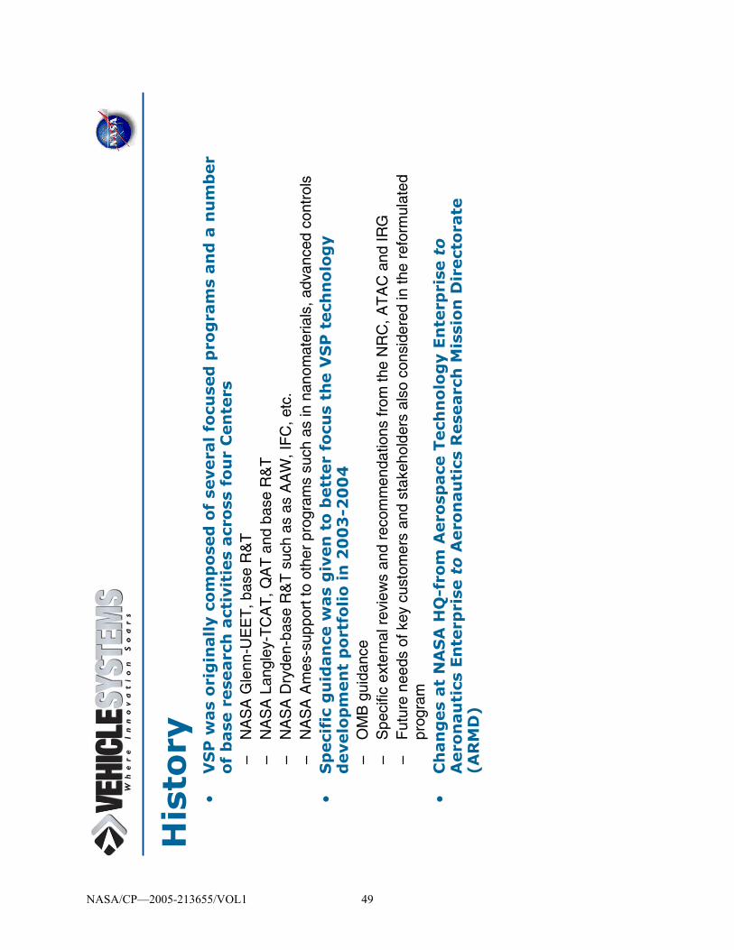
•V
SP
was
ori
gin
ally c
om
po
sed
of
severa
l fo
cuse
d p
rog
ram
s an
d a
nu
mb
er
of
base
rese
arc
h a
ctiv
itie
s acr
oss
fo
ur
Cen
ters
–N
AS
A G
lenn
-UE
ET
, bas
e R
&T
–N
AS
A L
angl
ey-T
CA
T, Q
AT
and
bas
e R
&T
–N
AS
A D
ryde
n-ba
se R
&T
suc
h as
as
AA
W, I
FC
, etc
.–
NA
SA
Am
es-s
uppo
rt to
oth
er p
rogr
ams
such
as
in n
anom
ater
ials
, adv
ance
d co
ntro
ls•
Sp
eci
fic
gu
idan
ce w
as
giv
en
to
bett
er
focu
s th
e V
SP
tech
no
log
y
develo
pm
en
t p
ort
folio
in
20
03
-20
04
–O
MB
gui
danc
e–
Spe
cific
ext
erna
l rev
iew
s an
d re
com
men
datio
ns fr
om th
e N
RC
, AT
AC
and
IRG
–F
utur
e ne
eds
of k
ey c
usto
mer
s an
d st
akeh
olde
rs a
lso
cons
ider
ed in
the
refo
rmul
ated
pr
ogra
m•
Ch
an
ges
at
NA
SA
HQ
-fro
m A
ero
space
Tech
no
log
y E
nte
rpri
se t
o
Aero
nau
tics
En
terp
rise
to
Aero
nau
tics
Rese
arc
h M
issi
on
Dir
ect
ora
te
(AR
MD
)
His
tory
NASA/CP—2005-213655/VOL1 49

Veh
icle
Syst
em
s R
est
ruct
uri
ng
Obj
ectiv
es
Out
com
eF
utur
e tr
ansp
orta
tion
syst
em
Pro
gram
Vis
ion
Wha
t we
will
ena
ble
Pro
gram
Goa
lsW
hat w
e w
ill a
chie
ve
Goa
l Set
sH
ow te
chno
logy
wou
ld b
e in
tegr
ated
Tec
hnol
ogy
Por
tfolio
Dev
elop
men
tW
hat t
echn
olog
ies
are
need
ed
To
NA
SA
S
trat
egic
P
lan
Veh
icle
Sys
tem
s
Inve
stm
ent S
trat
egy
Wha
t tec
hnol
ogie
s N
AS
A d
evel
ops
Pro
gram
Pla
n
Sui
te o
f Req
uire
d T
echn
olog
ies
Aer
on
auti
cs
NASA/CP—2005-213655/VOL1 50

Pro
gra
m
Str
uct
ure Tech
no
log
y
Fo
cus
Are
as
Cap
ab
ilit
y S
ets
Ob
ject
ives
NASA/CP—2005-213655/VOL1 51

Exp
lore
New
Aer
osp
ace
Mis
sio
ns
Pio
neer
nov
el a
eron
autic
al c
once
pts
and
tech
nolo
gies
to s
uppo
rt s
cien
ce
mis
sion
s an
d te
rres
tria
l and
spa
ce a
pplic
atio
ns
Pro
tect
th
e E
nvi
ron
men
t P
rote
ct lo
cal a
nd g
loba
l env
ironm
enta
l qua
lity
by r
educ
ing
airc
raft
nois
e an
d em
issi
ons.
Incr
ease
Mo
bili
ty
Ena
ble
mor
e pe
ople
and
goo
ds to
trav
el fa
ster
and
fart
her,
with
few
er d
elay
s
Par
tner
ship
s fo
r N
atio
nal
Sec
uri
tyE
nhan
ce th
e N
atio
n’s
secu
rity
thro
ugh
aero
naut
ical
par
tner
ship
s w
ith D
OD
, D
HS
, an
d ot
her
U.S
. or
inte
rnat
iona
l gov
ernm
ent a
genc
ies
Ob
ject
ives
for
the P
ub
lic
Go
od
NASA/CP—2005-213655/VOL1 52

Str
ate
gic
Tech
no
log
y F
ocu
s A
reas
•E
nvir
on
men
tally F
rien
dly
, C
lean
Bu
rnin
g E
ng
ines
–D
evel
op in
nova
tive
tech
nolo
gies
to e
nabl
e in
telli
gent
turb
ine
engi
nes
with
si
gnifi
cant
ly r
educ
ed h
arm
ful e
mis
sion
s w
hile
mai
ntai
ning
hig
h pe
rfor
man
ce
and
incr
easi
ng r
elia
bilit
y•
New
Air
craft
En
erg
y S
ou
rces
an
d M
an
ag
em
en
t –
Inve
stig
ate
new
ene
rgy
sour
ces
and
inte
llige
nt m
anag
emen
t tec
hniq
ues
for
zero
em
issi
ons
and
enab
le n
ew v
ehic
le c
once
pts
for
publ
ic m
obili
ty a
nd n
ew
scie
nce
mis
sion
s•
Qu
iet
Air
craft
fo
r C
om
mu
nit
y F
rien
dly
Serv
ice
–D
evel
op a
irfra
me
and
engi
ne n
oise
red
uctio
n te
chno
logy
and
ope
ratio
nal
conc
epts
to b
ring
obje
ctio
nabl
e no
ise
with
in th
e ai
rpor
t bou
ndar
y •
Aero
dyn
am
ic P
erf
orm
an
ce f
or
Fu
el
Eff
icie
ncy
–Im
prov
e ae
rody
nam
ic e
ffici
ency
, str
uctu
res
and
mat
eria
ls te
chno
logi
es, a
nd
desi
gn to
ols
and
met
hodo
logi
es to
red
uce
fuel
bur
n an
d m
inim
ize
envi
ronm
enta
l im
pact
and
ena
ble
new
veh
icle
con
cept
s an
d ca
pabi
litie
s fo
r pu
blic
mob
ility
and
new
sci
ence
mis
sion
s
NASA/CP—2005-213655/VOL1 53

Str
ate
gic
Tech
no
log
y F
ocu
s A
reas
(con
t.)
•A
ircr
aft
Weig
ht
Red
uct
ion
an
d C
om
mu
nit
y A
ccess
–
Dev
elop
ultr
alig
ht s
mar
t mat
eria
ls a
nd s
truc
ture
s, a
erod
ynam
ic c
once
pts,
and
lig
htw
eigh
t sub
syst
ems
to e
nabl
e ad
vanc
ed c
onfig
urat
ions
for
publ
ic m
obili
ty,
high
alti
tude
long
end
uran
ce v
ehic
les,
and
pla
neta
ry a
ircra
ft•
Sm
art
Air
craft
an
d A
uto
no
mo
us
Co
ntr
ol
–E
nabl
e ai
rcra
ft to
fly
with
red
uced
or
no h
uman
inte
rven
tion,
toop
timiz
e fli
ght
over
mul
tiple
reg
imes
, and
to p
rovi
de m
aint
enan
ce o
n de
man
d to
war
ds th
e go
al o
f a fe
elin
g, s
eein
g, s
ensi
ng, s
entie
nt a
ir ve
hicl
e
Cro
ss-c
utt
ing
th
e S
ix T
ech
no
log
y F
ocu
s A
reas
•Flig
ht
an
d S
yst
em
Dem
on
stra
tio
ns
–M
atur
e an
d va
lidat
e ne
w a
ircra
ft ca
pabi
litie
s in
rel
evan
t flig
hten
viro
nmen
t in
part
ners
hip
with
indu
stry
and
oth
er g
over
nmen
t age
ncie
s•
Str
ate
gic
Tech
nic
al D
irect
ion
s (V
ISTA
)–
Gat
her
data
and
per
form
str
ateg
ic a
naly
sis
to p
rovi
de g
uida
nce
on fu
ture
pr
ogra
m d
irect
ions
NASA/CP—2005-213655/VOL1 54

Cap
ab
ilit
y S
ets
Base
d o
n
Co
nce
ptu
al V
eh
icle
s
NASA/CP—2005-213655/VOL1 55

Veh
icle
Sect
ors
Su
bso
nic
Tra
nsp
ort
s
Su
per
son
ic A
ircr
aft
Per
son
al A
ir V
ehic
les
Un
inh
abit
ed A
ir V
ehic
les
Ro
torc
raft
Ass
oci
ate
Pro
gra
m
Man
ager
fo
r V
IST
A
Ext
rem
e S
TO
L
NASA/CP—2005-213655/VOL1 56

LaR
CR
oy B
ridge
sG
RC
Julia
n E
arls
DFR
CK
evin
Pet
erse
n
Ass
oci
ate
Pro
gra
m
Man
ager
fo
r S
trat
egy
Bo
b M
cKin
ley
Ter
esa
Klin
e
Su
bso
nic
Tra
nsp
ort
sF
ay C
olli
erR
ub
en D
el R
osa
rio
Su
per
son
ic A
ircr
aft
Pet
er C
oen
Jon
Sei
del
Ro
torc
raft
Glo
ria
Yam
auch
iM
ike
Wat
ts
Un
inh
abit
ed A
ir V
ehic
les
Lar
ry C
amac
ho
Jeff
Yet
ter
Per
son
al A
ir V
ehic
les
Mar
k M
oo
re
An
dy
Hah
n
Ext
rem
e S
TO
LJo
hn
Zu
k D
ou
g W
ard
ell
Veh
icle
Syst
em
Pro
gra
m S
tru
ctu
re
Ass
oci
ate
Pro
gra
m
Man
ager
fo
r T
ech
no
log
yV
acan
t
Ass
oci
ate
Pro
gra
m
Man
ager
fo
r O
per
atio
ns
Vac
ant
Pro
gra
m M
anag
er —
Dr.
Ric
h W
lezi
enD
epu
ty P
M —
Her
b S
chlic
ken
mai
er
Qu
iet
Air
craf
t T
ech
no
log
y (Q
AT
)M
ike
Mar
colin
i an
dL
ind
a B
ang
ert
Ult
ra-E
ffic
ien
t E
ng
ine
Tec
hn
olo
gy
(UE
ET
)K
estu
tis
“Kaz
”C
ivin
skas
an
dM
ary
Jo L
on
g-D
avis
Eff
icie
nt
Aer
od
ynam
ics
Sh
apes
and
Inte
gra
tio
n
(EA
SI)
Jim
Pit
tman
an
dD
ave
Hah
ne
Inte
gra
ted
Tai
lore
d
Aer
oS
tru
ctu
res
(IT
AS
)L
on
g Y
ip a
nd
Jeff
Jo
rdan
Au
ton
om
ou
s R
ob
ust
Avi
on
ics
(Au
RA
)Ji
m B
url
ey a
nd
D
ave
Ric
hw
ine
Lo
w-E
mis
sio
n
Alt
ern
ativ
eP
ow
er (
LE
AP
)M
ark
Kle
m a
nd
Bar
b E
sker
Flig
ht
& S
yste
ms
Dem
on
stra
tio
n
(F&
SD
)E
dd
ie Z
aval
a
Program Office
Vehicle SectorManagers Project Managers
NASA/CP—2005-213655/VOL1 57

Flig
ht
Dem
os
Har
dw
are
So
ftw
are
Met
ho
ds
To
ols
Dat
a… +
Sp
ino
ffs
Pro
ject
Del
iver
able
sT
HEM
EA
ero
naut
ics
LEV
EL
IV
ehic
le S
yste
ms
LEV
EL
IIE
ffici
ent
Aer
odyn
amic
Sh
apes
and
Inte
gra
tion
(EAS
I)
OB
JEC
TIV
E
LIN
KAG
E T
O V
S G
OA
LS, O
BJE
CTI
VES,
TEC
HN
ICA
L CH
ALL
ENG
ES, a
nd A
PP
RO
AC
HES
(GO
TChA
's)
KEY
DEL
IVE
RAB
LES
111
/04
26
/05
37
/06
43
/07
57
/09
IMP
AC
T
TEC
HN
ICA
L A
PP
RO
AC
H
SC
HEDU
LE
FY04
FY05
FY0
6FY
07FY
08F
Y09
MIL
ESTO
NES
111
/04
26
/05
37
/06
Red
uce
d F
uel B
urn
Tra
nsp
ort W
ing
(RFB
TW)
Sw
ept h
igh-
spe
ed s
lotte
d w
ing
tech
nol
ogy
(TR
L 5
)
Leve
l III
RFB
TW
Aero
dyn
am
ic G
roun
d-to
-Flig
ht S
calin
g G
uid
elin
es C
omp
lete
d
Flig
ht d
emo
nst
ratio
n o
f se
lect
ed (T
BD
) ef
ficie
nt a
ero
dyna
mic
tech
nolo
gy
(TR
L 6
)
Aero
dyn
am
ic g
roun
d-to
-flig
ht s
calin
g g
uid
elil
nes
(TR
L 6
) (in
L2
Pla
n, w
as
not
in T
CA
T/E
AS
I L3
pla
n a
s k
ey
del
ive
Cha
ract
eriz
atio
n o
f flig
ht d
yna
mic
s &
co
ntro
l cha
ract
eris
tics
of a
BW
B-c
las
s ve
hic
le (T
RL
5)
Tra
nson
ic A
dap
tive
Bu
mp
tech
no
log
y ( T
RL
5)
Tra
nson
ic W
ing
Ad
aptiv
e B
ump
Te
chn
olo
gy D
em
ons
tratio
n C
om
ple
ted
Sw
ept H
igh
Spe
ed S
lotte
d W
ing
Te
chn
olo
gy A
sse
ssm
ent C
omp
lete
d
The
pu
rpo
se o
f the
Red
uce
d F
uel B
urn
Tra
nsp
ort W
ing
Su
bPro
ject
is to
de
velo
p a
nd d
em
ons
trate
adv
ance
d a
ero
dyna
mic
a
irfra
me
com
pone
nt te
chn
olo
gie
s a
nd in
tegr
ate
d co
nfig
urat
ion
conc
ept
s e
nab
ling
impr
oved
ae
rody
na
mic
effi
cien
cy fo
r re
duc
ed
fuel
bur
n a
nd/o
r e
nhan
ced
mob
ility
. Te
chn
olo
gie
s w
ill d
irec
tly s
uppo
rt th
e E
ASI p
roje
ct g
oals
of e
nha
ncin
g p
ublic
m
obi
lity
and
en
abl
ing
red
uce
d C
O2/
AS
M e
mis
sio
ns b
y XX
% f
or a
rep
res
enta
tive
20
22 fl
eet r
ela
tive
to a
ba
selin
e 1
997
flee
t. D
eve
lopm
ent a
nd
dem
ons
tratio
n w
ill b
e u
p to
an
d in
clud
ing
TR
L 6
, dep
endi
ng
on
the
tech
nol
ogy
.
The
RF
BTW
Su
bP
roje
ct w
ill d
eve
lop
an
d d
emo
nstra
te a
dvan
ced
ae
rody
nam
ic a
irfra
me
com
pon
ent t
ech
nol
og
ies
an
d in
tegr
ate
d co
nfig
urat
ion
conc
ept
s th
at w
ill e
nla
rge
the
des
ign
sp
ace
for
futu
re v
ehic
les
. Spe
cific
ally
, te
chn
olo
gie
s w
ill ta
rge
t m
eetin
g fu
ture
ve
hicl
e ca
pabi
lity
goa
ls fo
r: 1
) sub
son
ic tr
ansp
orts
with
ext
rem
e cr
uis
e e
ffici
enc
y, 2
) ex
trem
ely
sho
rt ta
ke-
off/l
and
ing
air
cra
ft w
ith re
volu
tion
ary
hig
h s
pee
d cr
uis
e e
ffici
ency
, an
d 3
) hig
h e
ffice
ncy/
low
boo
m s
uper
soni
c cr
uis
e a
ircra
ft.
The
key
con
trib
utio
n o
f the
Sub
Pro
ject
is e
xpe
rime
nta
lly d
em
ons
trate
d te
chno
log
y be
nef
it co
mb
ine
d w
ith d
esi
gn
gui
del
ines
an
d a
n u
nder
sta
ndin
g/r
educ
tion
of m
ulti
dis
cipl
inar
y ri
sk to
pra
ctic
al im
ple
me
nta
tion
. Te
chn
olo
gy tr
ans
fer
will
be
sig
nifi
can
tly
The
RFB
TW
Su
bPro
ject
de
velo
ps
and
de
mon
stra
tes
ad
van
ced
ae
rod
yna
mic
air
fram
e c
om
pon
ent t
ech
nolo
gie
s a
nd
inte
gra
ted
con
figu
ratio
n c
once
pts
ena
blin
g im
pro
ved
aer
odyn
amic
effi
cie
ncy
for r
edu
ced
fue
l bu
rn a
nd
enh
ance
d m
obili
ty o
f fu
ture
airc
raft.
Tec
hno
log
ies
are
sel
ect
ed b
ase
d o
n th
e p
ote
ntia
l im
pact
tow
ard
s e
nabl
ing
the
Veh
icle
Sys
tem
s P
rog
ram
-d
efin
ed fu
ture
ve
hicl
e ca
pabi
lity
goa
ls r
equ
irin
g re
volu
tiona
ry im
prov
eme
nt in
ae
rody
nam
ic e
ffice
ncy
; exa
mp
les
of
tech
nol
ogi
es
incl
ud
e h
igh
sp
eed
slo
tted
win
gs,
tran
son
ic a
dapt
ive
bum
ps,
and
ve
hicl
e co
nce
pts
su
ch a
s th
e b
len
ded-
win
g-
bod
y. S
tate
-of-
the
-art
and
em
ergi
ng
adv
an
ced
co
mp
uta
tion
al to
ols
are
use
d to
de
velo
p th
e va
riou
s te
chn
olo
gie
s, w
hich
are
ve
rifie
d th
rou
gh g
rou
nd-b
ase
d te
sts
up
to fl
igh
t Mac
h a
nd
Rey
nold
s n
um
ber.
Th
e fo
cus
is o
n e
xpe
rime
nta
l de
mo
nstra
tion
of
airc
raft-
enab
ling
tech
nolo
gy
at r
ele
vant
flig
ht c
ond
itio
ns, a
nd
est
abl
ishi
ng
pro
cess
es to
des
ign
an
d a
naly
ze b
ene
fits
of t
he
te
chn
olo
gy; s
ele
cted
tech
nolo
gie
s m
ay b
e d
em
onst
rate
d to
TR
L 6
by
fligh
t tes
t. M
ulti
dis
cip
lina
ry, f
ull-
flig
ht-e
nve
lop
ri
sks
/ba
rrie
rs to
pra
ctic
al/v
iab
le te
chn
olo
gy im
ple
men
tatio
n w
ill b
e id
ent
ifie
d a
nd a
ddr
ess
ed; i
n c
ritic
al r
isk
are
as,
det
aile
d
inve
stig
atio
ns
will
cha
ract
eriz
e a
nd/
or r
edu
ce r
isks
suc
h th
at t
he te
chno
log
y is
und
erst
oo
d a
nd re
adily
tra
nsfe
rred
to in
dust
ry
12
35
41
26
43
5
The
pu
rpo
se o
f the
Red
uce
d F
uel B
urn
Tra
nsp
ort W
ing
Su
bPro
ject
con
nect
s to
the
Pro
gram
GO
TC
hA's
as
follo
ws
:S
T10
202
.06
: Ad
van
ced
air
foils
…E
S10
101.
02:
Inve
stig
ate
nov
el c
onf
igu
ratio
ns...
Lev
el 3
Su
b-
Pro
ject
Pla
ns
V
SP
-L2-
01
Nat
iona
l Aer
onau
tics
and
D
RA
FT
X
Spac
e A
dmin
istr
atio
n E
FF
EC
TIV
E D
AT
E:
10/0
1/04
O
ffic
e of
Aer
onau
tics
Veh
icle
Sys
tem
s Pr
ogra
m
NA
SA H
eadq
uart
ers
Was
hing
ton,
DC
205
46
Veh
icle
Sys
tem
s Pr
ogra
m (V
SP)
EA
SI P
RO
JEC
T P
LA
N
DR
AF
T V
ER
SIO
N X
5 M
AY
20
004
App
rove
d fo
r Pu
blic
Rel
ease
. Dis
trib
utio
n U
nlim
ited
Lev
el 2
Pro
ject
Pla
ns
V
SP
-L1-
01
Nat
iona
l A
eron
auti
cs a
nd
DR
AF
T X
Spac
e A
dmin
istr
atio
n E
FF
EC
TIV
E D
AT
E:
10/
01/0
4 O
ffic
e of
Aer
onau
tics
Veh
icle
Sys
tem
s Pr
ogra
m
NA
SA H
eadq
uart
ers
Was
hing
ton,
DC
205
46
Veh
icle
Sys
tem
s Pr
ogra
m (V
SP)
PR
OG
RA
M P
LA
N
DR
AFT
VE
RS
ION
X
5 M
AY
200
04
App
rove
d fo
r Pu
blic
Rel
ease
. Dis
trib
utio
n U
nlim
ited.
Lev
el 1
Pro
gra
m P
lan
Pro
gra
m
Str
uct
ure Tech
nolo
gy
Focu
s A
reas
Capab
ilit
y S
ets
Obje
ctiv
es
Veh
icle
Sys
tem
sS
tru
ctu
re
Thr
ust-
to-
Wei
ght>
1.0
SO
A~0
.3
Em
pty
Wei
ght t
o P
aylo
ad W
eigh
t R
atio
= 1
.0S
OA
= 9
.0
Lift-
to-D
rag
Rat
io =
50
Sta
te-o
f-th
e-A
rt (S
OA
): 3
6
GO
TC
hA
Ch
art
Exam
ple
: U
AV
Sect
or
GO
ALS
OB
JEC
TIV
ES
TE
CH
NIC
AL
C
HA
LL
EN
GE
S
AP
PR
OA
CH
ES
100%
Aut
onom
ous
Mis
sion
Ope
ratio
nsS
OA
: 9
0%
Aut
onom
ous
O&
M C
ost
(per
fli
ght h
our)
=
$400
SO
A:
$4,0
00
L/D
~10
0 ai
rfoi
ls w
ith
t/c>
15%
, C
m>
0, @
R
e~5
00,0
00
SO
A:
L/D
=80
Impl
emen
t a
dvan
ced
bou
nd
ary
laye
r co
ntro
l te
chni
ques
su
ch a
s m
icro
-a
dapt
ive
flo
w c
ontr
ol
Prev
ent
thin
-w
all b
uckl
ing
with
out
wei
ght
pena
lty
Com
pens
ate
for n
on-
unifo
rm g
ust
load
s wi
thou
t we
ight
pe
nalty
De
velo
p co
mpe
ting
stru
ctu
ral
conc
ept
s w
ith
optim
ized
ge
omet
ries
an
d m
ater
ial
pro
pert
ies
Dev
elo
p sm
art
and
pass
ive
ly
tailo
red
mu
lti-
func
tiona
l st
ruct
ure
s in
clud
ing
flexi
ble
mat
eria
ls
Spe
cific
Fue
l C
onsu
mpt
ion
< 0.
2S
OA
~0.5
Vehi
cle
& Su
bsys
tem
St
ruct
ural
Wt
to P
aylo
ad
Wt R
atio
=
0.5
@ A
R>
30 SOA:
4.5
Red
uce
wei
ght &
vo
lum
e of
en
ergy
&
powe
r sou
rce
with
out
outp
ut
degr
adat
ion
Dev
elop
re
gene
rativ
e en
ergy
and
po
wer
te
chno
logy
Ener
gy
stor
age
> 1k
w-h
r/kg
SOA:
0.25
kw
-hr/k
g
Ener
gy
effic
ienc
y >
50%
SOA:
35%
Impr
ove
effic
ienc
y of
m
otor
/ en
gine
/ pr
opel
ler /
ge
arbo
xFAA
appr
oved
sa
me
day
file
& fly
in N
ASSO
A: 6
0 D
ays
COA
Dev
elop
real
-tim
e fli
ght
plan
ning
, he
alth
m
onito
ring
and
re-
conf
igur
atio
n
Deve
lop
real
-tim
e d
etec
t, an
d av
oid
tech
niqu
es
Prev
ent
lam
inar
se
para
tion
while
m
aint
aini
ng
high
Lift
De
velo
p sm
art a
nd
pas
sive
ly
tailo
red
flexi
ble
aer
oela
stic
stru
ctu
res
resp
ondi
ng
to i
n-s
itu
envi
ron
men
t
Full
auto
nom
y du
ring
emer
genc
ies
SOA:
10%
Dev
elop
lig
htwe
ight
cr
yoge
nic
LH2
stor
age
tech
nolo
gy
Ord
er o
f m
agni
tude
re
duct
ion
in
hum
an
invo
lvem
ent
SOA:
2/
Vehi
cle
Deve
lop
real
-tim
e hu
man
flig
ht
man
agem
ent
inte
rface
s
Deve
lop
real
-tim
e sy
stem
s di
spla
ys fo
r m
ultip
le
airc
raft
oper
atio
ns
Deve
lop
min
iatu
re
robu
st
inte
grat
ed
avio
nics
&
sens
ors
Dev
elop
long
en
dura
nce
unai
ded
auto
nom
ous
navig
atio
n
As
of M
ar 0
1, 2
004
Prop
ulsi
on
Syst
em W
t to
Paylo
ad W
t Ra
tio =
0.5
SOA:
4.5
Deve
lop
artif
icia
l in
tellig
ence
&
inte
grat
ed
vehi
cle
heal
th m
gmt
incl
dam
age
tole
ranc
e
Veh
icle
Sys
tem
sG
OT
Ch
A’s
Veh
icle
Sys
tem
sR
oad
map
s
Th
e N
AS
AS
trat
egic
Pla
n
Th
e P
resi
den
t’s
Man
agem
ent
Ag
end
a
ES
2020
3.04
:R
educ
e a
ctua
tor
size
to
elim
inat
e a
ctua
tor
“bum
ps.”
ES
2020
3.05
: O
ptim
ize
airf
oil s
ect
ion
& w
ing
desi
gn.
ES
2020
3.06
: In
teg
rate
air
fra
me
& p
rop
ulsi
on
syst
em
to
red
uce
inte
rfe
renc
e d
rag
.
Larg
e-S
cale
, G
roun
d D
emo
CL=
8, L
/D=1
4
0506
07
08
0910
1112
13
141
516
1718
0419
GO
AL
ES
1: I
ncre
ase
Max
imum
Pow
ered
-Lift
Coe
ffici
ent (
CL m
ax
= 10
, SO
A =
7)
Inte
gra
ted
Po
were
d L
ift/
Eff
icie
nt
Cru
ise
Ro
ad
map
Flig
ht D
emo
CL=
8, L
/D=1
4Fl
ight
Dem
oC
L=10
, L/D
=16
Pow
ered
-Lif
tTe
chno
logy
Dow
n-se
lect
GO
AL
ES
2: E
ffic
ient
Cru
ise
(L/D
= 1
6, S
OA
= 1
2)
ES
101:
Incr
ease
circ
ulat
ion
of th
e po
wer
ed
high
-lift
syst
em b
y 50
%.
ES
1010
1.02
:In
vest
igat
e n
ove
l co
nfig
ura
tion
s e
nab
ling
hig
h-li
ft a
nd h
igh-
spee
d cr
uis
e.
ES
1010
1.01
:In
cre
ase
circ
ulat
ion
& r
educ
e/e
limin
ate
se
para
tion
by c
om
bini
ng m
echa
nica
l & f
luid
ic
mea
ns (
mic
ro-a
dap
tive
flow
co
ntro
ls, b
low
ing
, et
c.).
ES
1010
1.03
:In
vest
igat
e t
hru
st v
ecto
ring
/ aug
me
ntat
ion
(US
B, E
BF
, IB
F,
ejec
tors
, flu
idic
, etc
.).
ES
202:
Red
uce
drag
of a
pow
ered
-lift
conf
igur
ed a
ircra
ft by
33%
at a
cr
uise
Mac
h#
of 0
.8.
SS
A
Indu
stry
/Aca
dem
ia
Fun
ded
O
verg
uid
e
Cro
sscu
t U
nfun
ded
Lev
era
ged
NA
SA
OG
A
VS
P F
undi
ng f
or G
oals
ES
1&
ES
2: b
y %
16.5
17.
920
.821
.723
.1 b
y pe
rce
ntag
e fo
r th
e f
irst f
ive
ye
ars
onl
y
$ 47
.3%
$ 10
.5%
$ 27
.9%
$ 10
.5%
$ 3.
8%
Th
e S
yste
ms
Vee
Lin
kag
e:
the W
ho
le P
ictu
re
NASA/CP—2005-213655/VOL1 58

VS
: P
rog
ram
Ou
tco
mes,
FY
05
-09
En
viro
nm
ent:
•70
% N
Ox
Red
uctio
n fo
r su
bson
ic tr
ansp
orts
•P
lus
foun
datio
n te
chno
logi
es fo
r an
add
ition
al 1
0% r
educ
tion
•25
% C
O2
Red
uctio
n fo
r su
bson
ic tr
ansp
orts
•P
lus
foun
datio
n te
chno
logi
es fo
r an
add
ition
al 2
5% r
educ
tion
•10
dB
Noi
se R
educ
tion
for
subs
onic
tran
spor
ts
•P
lus
foun
datio
n te
chno
logi
es fo
r an
add
ition
al 1
0 dB
red
uctio
n
•24
dB
noi
se r
educ
tion
for
adva
nced
gen
eral
avi
atio
n ai
rcra
ft
•D
efin
e “a
ccep
tabl
e so
nic
boom
”fo
r ov
erla
nd s
uper
-cru
isin
g ai
rcra
ft
NASA/CP—2005-213655/VOL1 59

UE
ET
-U
ltra
-Eff
icie
nt
En
gin
e T
ech
no
log
y P
roje
ct
NASA/CP—2005-213655/VOL1 60

UEET O
verv
iew
•S
trate
gic
Fo
cus:
En
vir
on
men
tall
y F
rien
dly
, C
lean
Bu
rnin
g
En
gin
es
–D
evel
op in
nova
tive
tech
nolo
gies
to e
nabl
e in
telli
gent
turb
ine
engi
nes
that
sig
nific
antly
red
uce
harm
ful e
mis
sion
s w
hile
mai
ntai
ning
hig
h pe
rfor
man
ce a
nd in
crea
sing
rel
iabi
lity.
•C
ross
-cu
ttin
g t
ech
no
log
y d
evelo
pm
en
t &
matu
rati
on
fo
cuse
d o
n t
he S
ub
son
ic,
Su
pers
on
ic a
nd
Ro
torc
raft
–S
T,
“R
educ
ed N
Ox
and
Impr
oved
TS
FC
& T
/W”
–S
SA
, “
Hig
h P
erfo
rman
ce In
lets
”–
RC
, “
Adv
ance
d D
rive
Sys
tem
s”
NASA/CP—2005-213655/VOL1 61

Pu
rpo
se(s
)•
Develo
p a
nd
dem
on
stra
te p
rop
uls
ion
tech
no
log
ies
that
ad
dre
ss t
he
go
als
of
the S
ub
son
ic,
Su
pers
on
ic,
an
d R
oto
rcra
ft S
ect
ors
in
th
e V
eh
icle
Syst
em
s P
rog
ram
.
•D
evelo
p p
rop
uls
ion
tech
no
log
ies
to r
ed
uce
Th
rust
Sp
eci
fic
Fu
el C
on
sum
pti
on
(T
SFC
) an
d t
o in
crease
Th
rust
/W
eig
ht
(T/
W)
that
will
resu
lt in
fu
el b
urn
re
du
ctio
ns
of
up
to
15
%,
eq
uati
ng
to
15
% r
ed
uct
ion
s in
CO
2.
•D
evelo
p c
om
bu
sto
r te
chn
olo
gie
s (c
on
fig
ura
tio
n a
nd
mate
rials
) th
at
will
en
ab
le r
ed
uct
ion
s in
Lan
din
g/Take-O
ff (
LTO
) N
Ox
of
70
% r
ela
tive t
o 1
99
6
ICA
O (
Inte
rnati
on
al C
ivil A
via
tio
n O
rgan
izati
on
) st
an
dard
s.
NASA/CP—2005-213655/VOL1 62

UEET
Ult
ra E
ffic
ien
t En
gin
e T
ech
no
log
y
5-y
ear
Pro
ject
Low
Em
issi
ons
Com
bust
or
Hig
hly
Inte
gra
ted I
nle
t
Hig
hly
Load
ed.
Light
Wei
ght
Com
pre
ssor
&
Turb
ines
Inte
lligen
t Pr
opuls
ion
Sys
tem
Foundat
ion
Tec
hnolo
gie
s
Sys
tem
s In
tegra
tion
and D
emonst
ration
Adva
nce
d D
rive
Sys
tem
s fo
r H
eavy
-lift
Roto
rcra
ft
NASA/CP—2005-213655/VOL1 63

Org
an
izati
on
al B
reakd
ow
n S
tru
ctu
re
Ult
ra-E
ffic
ien
t E
ng
ine
Tec
hn
olo
gy
(UE
ET
)M
anag
er:
Kes
tuti
s C
ivin
skas
Act
ing
Dep
uty
: M
ary
Jo L
on
g-D
avis
Hig
hly
Lo
aded
L
igh
t W
eig
ht
Co
mp
ress
ors
an
d
Tu
rbin
esM
anag
er:
Car
ol G
inty
GR
C
Sys
tem
s In
teg
rati
on
&
Dem
on
stra
tio
nM
anag
er:
M
ary
Jo L
on
g-D
avis
GR
C
Inte
llig
ent
Pro
pu
lsio
n S
yste
ms
Fo
un
dat
ion
T
ech
no
log
ies
Man
ager
:
C
aro
lyn
Mer
cer
GR
C
Veh
icle
Sys
tem
s P
rog
ram
(V
SP
)M
anag
er:
Dr.
Ric
har
d W
lezi
en
Veh
icle
Inte
gra
tio
n, S
yste
m &
T
ech
no
log
y A
sses
smen
t (V
IST
A)
Man
ager
: R
ob
ert
McK
inle
y
Bu
sin
ess
Su
pp
ort
Lea
d:
Kar
en C
ran
dal
l
Lo
w E
mis
sio
ns
Co
mb
ust
or
Man
ager
:
Jo
hn
Ro
hd
eG
RC
Hig
hly
Inte
gra
ted
In
let
Man
ager
:M
ich
ael W
atts
LaR
C
Ad
van
ced
Dri
ve
Sys
tem
s fo
r H
eavy
-L
ift
Ro
torc
raft
Man
ager
:
Mar
y Jo
Lo
ng
-Dav
isG
RC
NASA/CP—2005-213655/VOL1 64

Veh
icle
Sect
ors
Su
pp
ort
ed
(1
of
2)
ST
41
42
3.3
2 -
Flo
w m
an
ag
em
en
t an
d co
ntr
ol te
chn
iqu
es
SS
10
20
2.0
3 -
Vari
ab
le f
idelity
in
teg
rate
d M
DO
tools
for
inn
ovati
ve
low
boom
con
fig
ura
tion
s w
ith
hig
h L
/D
Su
bso
nic
(S
T)
Su
pers
on
ic
(SS
)
2.7
.4H
igh
ly
Inte
gra
ted
In
lets
ST
41
22
0.3
0 -
Ad
van
ced
mate
rials
an
d c
oolin
g t
ech
nolo
gie
s fo
r re
du
ced
co
olin
g
ST
41
42
4.3
4 -
Imp
roved
mate
rials
wit
h h
igh
er
tem
pera
ture
ca
pab
ilit
y a
nd
str
en
gth
per
weig
ht
ST
41
22
0.3
1 -
Ad
van
ced
en
gin
e c
om
pon
en
ts
ST
41
22
0.2
9 -
Measu
rem
en
t to
ols
an
d v
alid
ate
d p
hysi
cs-b
ase
d
cod
es
for
hig
hly
load
ed
tu
rbom
ach
inery
SS
51
11
9.2
9 -
Hig
h t
em
pera
ture
lig
ht
weig
ht
mate
rials
, st
ruct
ura
l ass
em
blies
an
d t
herm
al/
en
vir
on
men
tal b
arr
ier
coati
ng
s
SS
71
62
3-3
4 -
Cre
ep
resi
stan
t h
igh
tem
pera
ture
mate
rials
Su
bso
nic
(S
T)
Su
pers
on
ic
(SS
)
2.7
.3H
igh
ly L
oad
ed
Lig
ht
Weig
ht
Co
mp
ress
ors
an
d T
urb
ines
ST
61
93
2.4
1 -
Ad
van
ced
co
mb
ust
or
tech
niq
ues
to r
ed
uce
NO
x
ST
61
93
2.4
3 -
Ad
van
ced
mate
rials
fo
r re
du
ced
co
mb
ust
ion
lin
er
coolin
g
ST
61
93
2.4
5 -
Valid
ate
d c
om
bu
stio
n c
od
es
for
desi
gn
an
d c
on
trol
of
low
em
issi
on
s co
mb
ust
ors
Su
bso
nic
(S
T)
2.7
.2
Lo
w E
mis
sio
ns
Co
mb
ust
or
Ap
pro
ach
es
Sect
or
WB
S
NASA/CP—2005-213655/VOL1 65

Veh
icle
Sect
ors
Su
pp
ort
ed
(2
of
2)
ST
41
22
0.2
9 -
Measu
rem
en
t to
ols
an
d v
alid
ate
d p
hysi
cs-b
ase
d c
od
es
for
hig
hly
-lo
ad
ed
tu
rbo
mach
inery
ST
61
72
7.3
8 -
Measu
rem
en
t to
ols
an
d v
ali
date
d g
lob
al an
d l
oca
l m
od
els
to
im
pro
ve c
ycl
e d
esi
gn
s
ST
41
42
6.3
6 -
Hig
hly
reliab
le lig
ht
weig
ht
mech
an
ical sy
stem
s
SS
51
01
5.2
3 -
Inle
t d
isto
rtio
n a
nd
fan
dyn
am
ic c
on
tro
l
SS
51
11
6.2
4 -
Inle
t o
pera
bilit
y a
nd
vis
cou
s lo
ss r
ed
uct
ion
Su
bso
nic
(S
T)
Su
pers
on
ic
(SS
)
2.7
.5S
yst
em
In
teg
rati
on
an
d
Dem
on
stra
tio
n
TB
D-
Sp
eci
fic
ap
pro
ach
es
will
be i
den
tifi
ed
pen
din
g t
he r
esu
lts
of
aco
mp
eti
tive p
rocu
rem
en
t p
roce
ssS
ub
son
ic
(ST)
Su
pers
on
ic
(SS
)
2.7
.7In
tellig
en
t P
rop
uls
ion
S
yst
em
s Fo
un
dati
on
te
chn
olo
gy
RC
60
91
1.2
6 -
Meth
od
s to
au
tom
ati
cally d
ete
ct f
ailu
re o
f p
ow
er
train
Ro
torc
raft
(R
C)
2.7
.6
Ad
van
ced
Dri
ve
Syst
em
s fo
r H
eavy-l
ift
Ro
torc
raft
Ap
pro
ach
es
Sect
or
WB
S
NASA/CP—2005-213655/VOL1 66

UEET T
ech
no
log
ies
LO
W N
Ox
CO
MB
US
TO
R
TE
CH
NO
LO
GIE
S-
Lea
n B
urn
Inje
ctio
n-
Ric
h B
urn
Inje
ctio
n-
Co
atin
gs
for
met
allic
lin
ers
HIG
H-L
OA
DE
D A
XIA
L
CO
MP
RE
SS
OR
-3D
aer
o-
Inve
rse
des
ign
-R
ecir
cula
tin
g c
asin
g t
reat
men
t
AC
TIV
E F
LO
W C
ON
TR
OL
F
OR
BW
B IN
LE
TS
-S
ynth
etic
jets
HIG
H-W
OR
K S
ING
LE
-ST
AG
E
HIG
H-P
RE
SS
UR
E T
UR
BIN
E-
Lo
w s
ho
ck lo
ss d
esig
n-
Red
uce
d c
oo
ling
loss
es
HIG
H-L
OA
DE
D L
OW
PR
ES
SU
RE
T
UR
BIN
E (
Reg
ion
al)
-H
ub
en
dw
all b
leed
-L
P s
tag
e re
du
ctio
n
PH
YS
ICS
-BA
SE
D M
OD
EL
ING
& C
FD
-A
P20
00 (
mu
ltib
lock
AP
NA
SA
)-
Nat
ion
al C
om
bu
stio
n C
od
e-
MS
U-T
UR
BO
-G
len
n-H
T
UE
ET
Tec
hn
olo
gy
Po
rtfo
lio D
eriv
ed t
o S
up
po
rt V
ehic
le S
yste
ms
Pro
gra
m
Go
als
for
Imp
rove
d T
SF
C a
nd
T/W
an
d R
edu
ced
NO
x
HIG
H-L
OA
DE
D H
P/L
P
TU
RB
INE
SY
ST
EM
-R
edu
ced
inte
ract
ion
loss
-S
yste
m w
eig
ht
red
uct
ion
AD
VA
NC
ED
MA
TE
RIA
LS
-C
eram
ic M
atri
x C
om
po
site
Van
es-
Lo
w C
on
du
ctiv
ity
TB
C-
Po
lym
er M
atri
x C
om
po
site
C
om
po
nen
ts-
Ad
van
ced
Allo
ys
ME
CH
AN
ICA
L C
OM
PO
NE
NT
S-
Ad
van
ced
No
n-C
on
tact
ing
Sea
ls-
Lig
htw
eig
ht
Gea
rbo
x C
om
po
nen
ts
for
Lar
ge
Gea
red
Tu
rbo
fan
En
gin
e
TU
RB
INE
TIP
CL
EA
RA
NC
E S
EN
SO
R-
Mic
row
ave
sen
sor
-C
on
tro
l gap
s to
imp
rove
eff
icie
ncy
NASA/CP—2005-213655/VOL1 67

UEET B
ud
get
Sp
lit
By S
ect
or
Subso
nic
Super
sonic
Roto
rcra
ft
Bu
dg
et:
% b
y S
ect
or
3%R
otor
craf
t
11%
Sup
erso
nic
86%
Sub
soni
c
To
tal d
oes
no
t in
clu
de
the
UE
ET
Pro
ject
’s 2
0% f
un
din
g
of
fou
nd
atio
nal
tec
hn
olo
gie
s.
NASA/CP—2005-213655/VOL1 68

UE
ET
L2
Pla
nS
ecto
r w
ith
Ob
ject
ives
0506
0708
Fis
cal Y
ear
UE
ET
Tec
hA
sses
smen
t
Fin
aliz
e IP
SIn
vest
men
tP
ortfo
lio
Che
ck-o
ut o
fS
ingl
e S
pool
Tur
bine
Fac
ility
Cro
ss C
utt
ing
Su
bso
nic
Tra
nsp
ort
sR
educ
e E
ngin
e N
Ox
emis
sio
ns
ove
r th
e L
TO
cyc
le
Incr
ease
Th
erm
al E
ffic
ien
cy
Red
uce
Bar
e E
ngin
e W
eigh
t
Red
uce
TS
FC
Red
uce
Inst
alla
tion
Pen
altie
s
Red
uce
Par
ticu
late
s an
d A
ero
sols
by
10%
Red
uce
Pod
/Eng
ine
Sub
syst
em W
eigh
t -- 1
5%
Su
per
son
ic A
ircr
aft
Dec
reas
e F
uel
Bu
rn
Incr
ease
Hot
Sec
tion
Life
Air
fram
e In
visc
id D
rag
--
20%
Incr
ease
inle
t rec
over
y ac
ross
rang
e M
0 an
d M
2: 0
.97
and
0.95
5
Ro
torc
raft
Red
uce
subs
yste
m w
eigh
t by
25%
Cap
italiz
e on
new
eng
ine
tech
nolo
gy to
impr
ove
perf
orm
ance
,w
eigh
t, no
ise,
etc
. of R
/C s
yste
ms
Com
bust
orD
etai
led
Des
ign
Rev
iew
s
Val
idat
e T
SF
CIm
prov
emen
tA
ttrib
uted
toH
ighl
y Lo
aded
2-
Sta
ge C
ompr
esso
r
Dow
nsel
ect K
ey N
Ox
and
CO
2 R
educ
tion
Tec
hs fo
r T
RL6
Dem
osUE
ET
Tec
hA
sses
smen
t
Low
NO
xC
ombu
stor
Ann
ular
Rig
Tes
t
UE
ET
Tec
hA
sses
smen
t
Qua
ntify
IPS
Goa
ls R
elat
edto
Aer
osol
s &
Par
ticul
ates
� Dem
o C
O2
Red
uctio
n th
roug
ha
Hig
hly-
Load
edT
urbo
mac
hine
ryH
ardw
are
Tes
t at
TR
L4-5
� Val
idat
e P
hysi
cs-
Bas
ed C
ombu
stor
Cod
es a
t Rea
lE
ngin
e C
ondi
tions
� M
atur
e K
ey IP
ST
echn
olog
ies
toT
RL3
for
Fur
ther
Dev
elop
men
t
� M
atur
e K
eyN
Ox
and
CO
2R
educ
tion
Tec
hnol
ogie
s to
TR
L6D
emo
App
licab
ility
of P
AI D
esig
nT
ools
to S
BJ
Veh
icle
Cla
ss
Dem
o Li
ghtw
eigh
t,H
igh
Per
form
ance
Sup
erso
nic
Inle
tT
echn
olog
ies
toT
RL
3-4
Dem
o A
dvan
ced
Driv
e S
yste
mT
echn
olog
ies
for
Hea
vy L
iftR
otor
craf
t
UE
ET
L2
Pla
n V
.1a
09S
ep04
IPS
Pro
ject
Pla
n
NASA/CP—2005-213655/VOL1 69

QA
T -
Qu
iet
Air
craf
t T
ech
no
log
yP
roje
ct
NASA/CP—2005-213655/VOL1 70

QA
T O
verv
iew
•S
trate
gic
Fo
cus:
Qu
iet
air
craft
fo
r C
om
mu
nit
y F
rien
dly
S
erv
ice
–D
evel
op a
nd in
tegr
ate
nois
e re
duct
ion
tech
nolo
gies
to e
nabl
e un
rest
ricte
d ai
r tr
ansp
orta
tion
serv
ice
to a
ll co
mm
uniti
es
•Fo
cuse
d p
rim
ari
ly o
n t
he S
ub
son
ic T
ran
spo
rt (
ST)
sect
or,
w
ith
so
me s
up
po
rt o
f th
e R
oto
rcra
ft (
R/
C),
Su
pers
on
ic,
an
d P
ers
on
al A
ir V
eh
icle
(P
AV
) se
cto
rs
–S
T,
“R
educ
e C
omm
unity
Noi
se b
y 20
EP
NdB
”an
d “R
educ
e E
mpt
y W
eigh
t Fra
ctio
n by
20%
”–
RC
, “
Red
uce
Com
mun
ity N
oise
”an
d “R
educ
e C
abin
Noi
se a
nd
Vib
ratio
n T
hrou
ghou
t Flig
ht E
nvel
ope”
–S
SA
, “
Son
ic B
oom
Ann
oyan
ce R
educ
ed to
Allo
w S
uper
soni
c F
light
O
verla
nd”
–P
AV
, “
Red
uce
Com
mun
ity N
oise
”
NASA/CP—2005-213655/VOL1 71

Pu
rpo
se o
f Q
AT
•S
trate
gic
Fo
cus:
No
ise R
ed
uct
ion
Tech
no
log
y
•1
5-y
ear
goals
–S
ubso
nic
Tra
nspo
rt,
“R
educ
e C
omm
unity
Noi
se b
y 20
EP
NdB
”
–R
otor
craf
t,
“Red
uce
Com
mun
ity N
oise
by
14 E
PN
dB”
and
“Red
uce
Cab
in N
oise
by
11 d
BA
and
Vib
ratio
n by
0.1
g’s
Thr
ough
out F
light
E
nvel
ope”
–S
uper
soni
c,
“Son
ic B
oom
Ann
oyan
ce R
educ
ed to
Allo
w S
uper
soni
c F
light
Ove
rland
”an
d “T
akeo
ff an
d La
ndin
g N
oise
Impa
ct: S
tage
4 -
4+E
PN
dB”
–P
erso
nal A
ir V
ehic
les,
“R
educ
e C
omm
unity
Noi
se b
y 24
dB
A a
t T
akeo
ff an
d La
ndin
g”
NASA/CP—2005-213655/VOL1 72

QA
TQ
uie
t A
ircr
aft
Tech
no
log
y
7-y
ear
Pro
ject
en
din
g i
n F
Y0
7
Airfr
ame
Sys
tem
N
ois
e Red
uct
ion
Engin
e Sys
tem
N
ois
e Red
uct
ion
Com
munity
Nois
e Im
pac
t an
d M
odel
ing
Roto
rcra
ft
Sys
tem
Nois
e Red
uct
ion
NASA/CP—2005-213655/VOL1 73

Qu
iet
Air
craf
t T
ech
no
log
y (Q
AT
)M
anag
er:
Mic
hae
l Mar
colin
i (ac
tin
g)
Dep
uty
: L
ind
a B
ang
ert
Air
fram
e S
yste
m
No
ise
Red
uct
ion
(AS
NR
)M
anag
er:
Dr.
Ch
arlo
tte
Wh
itfi
eld
LaR
C
Co
mm
un
ity
No
ise
Imp
act
and
Mo
del
ing
(CN
IM)
Man
ager
:D
r. G
ary
Gib
bs
(act
ing
)L
aRC
En
gin
e S
yste
m N
ois
e R
edu
ctio
n(E
SN
R)
Man
ager
:D
r. J
oe
Gra
dy
GR
C
Ro
torc
raft
Sys
tem
N
ois
e R
edu
ctio
n(R
SN
R)
Man
ager
:C
asey
Bu
rley
LaR
C
Veh
icle
Sys
tem
s P
rog
ram
(V
SP
)M
anag
er:
Dr.
Ric
har
d W
lezi
en (
acti
ng
)D
epu
ty:
Her
b S
chlic
ken
mai
er
Veh
icle
Inte
gra
tio
n,
Sys
tem
&
Tec
hn
olo
gy
Ass
essm
ent
(VIS
TA
)M
anag
er:
Ro
ber
t M
cKin
ley
Man
agem
ent
Su
pp
ort
Res
ou
rces
: R
ich
ard
Law
Sch
edu
le:
Am
and
a E
ber
win
e
Org
an
izati
on
al B
reakd
ow
n S
tru
ctu
re
NASA/CP—2005-213655/VOL1 74

Veh
icle
Sect
ors
Su
pp
ort
ed
ST3
08
12
.20
Real-
tim
e c
alc
ula
tio
n o
f n
ois
e m
inim
al
traje
cto
ries
an
d p
ilo
t/co
ntr
oller
too
ls t
o f
ly n
ois
e m
inim
al
traje
cto
ries
ST3
09
13
.21
-D
evelo
p a
nd
valid
ate
to
ols
to
air
craft
level
syst
em
ass
ess
men
ts f
or
con
ven
tio
nal an
d u
nco
nven
tio
nal
con
fig
ura
tio
ns
SS
30
71
2.1
9 -
Bo
om
aco
ust
ic a
nd
str
uct
ura
l re
spo
nse
st
ud
ies,
sim
ula
tor
an
d in
ho
me s
tud
ies
Su
bso
nic
(S
T)
Su
pers
on
ic
(SS
)
2.6
.3C
om
mu
nit
y
No
ise
Imp
act
an
d
Mo
delin
g
ST2
05
/2
06
08
.15
-M
ult
ifu
nct
ion
al st
ruct
ura
l d
esi
gn
acc
ou
nti
ng
fo
r th
erm
al,
aco
ust
ic lo
ad
s
ST2
05
/2
06
08
.16
-A
ctiv
e in
teri
or
no
ise c
on
tro
l fo
r lig
htw
eig
ht
fuse
lag
e d
esi
gn
s
ST3
07
10
/3
07
11
.18
-R
ed
uce
id
en
tifi
ed
no
ise s
ou
rces
thro
ug
h m
eth
od
s d
eri
ved
fro
m p
hysi
cs-b
ase
d
un
ders
tan
din
g
ST3
09
13
.22
-Id
en
tify
, acc
ou
nt
for
an
d r
ed
uce
no
ise v
ia
pro
pu
lsio
n/
air
fram
e in
tera
ctio
ns
PA
60
60
6.1
1 -
Develo
p in
teg
rate
d a
nd
sh
ield
ed
du
cted
p
rop
eller
syst
em
wit
h a
ctiv
e w
ake c
on
tro
l, a
nd
aco
ust
ical
sup
pre
ssio
n.
Su
bso
nic
(S
T)
Pers
on
al
Air
Veh
icle
(P
A)
2.6
.2
Air
fram
e
Syst
em
N
ois
e
Red
uct
ion
Ap
pro
ach
es
Sect
or
WB
S
NASA/CP—2005-213655/VOL1 75

Veh
icle
Sect
ors
Su
pp
ort
ed
(co
nti
nu
ed
)
ST1
11
15
.24
-A
dvan
ced
lo
w n
ois
e f
an
desi
gn
s, lin
er
con
cep
ts a
nd
act
ive c
on
tro
l
ST1
11
15
.25
-R
ed
uce
jet
no
ise s
ou
rces
thro
ug
h m
eth
od
s d
eri
ved
fro
m p
hysi
cs
PA
60
60
6.1
1 -
Develo
p in
teg
rate
d a
nd
sh
ield
ed
du
cted
p
rop
eller
syst
em
wit
h a
ctiv
e w
ake c
on
tro
l, a
nd
aco
ust
ical
sup
pre
ssio
n.
Su
bso
nic
(S
T)
Pers
on
al
Air
Veh
icle
(P
A)
2.6
.4En
gin
e
Syst
em
N
ois
e
Red
uct
ion
RC
40
60
6.1
4 -
Develo
p a
nd
valid
ate
so
urc
e n
ois
e
pre
dic
tio
n a
nd
pro
pag
ati
on
cap
ab
ilit
ies.
RC
40
60
6.1
5 -
Develo
p a
nd
valid
ate
syst
em
/so
urc
e n
ois
e
an
d p
rop
ag
ati
on
pre
dic
tio
n c
ap
ab
ilit
ies.
RC
40
70
7.1
7 -
Develo
p a
nd
dem
on
stra
te lo
w n
ois
e
op
era
tio
ns
an
d c
ap
ab
ilit
ies
wit
h a
ccep
tab
le h
an
dlin
g
qu
aliti
es.
Ro
torc
raft
(R
C)
2.6
.5R
oto
rcra
ft
Syst
em
N
ois
e
Red
uct
ion
Ap
pro
ach
es
Sect
or
WB
S
NASA/CP—2005-213655/VOL1 76

Tech
no
log
y H
igh
lig
hts
Fan
No
ise
Red
uct
ion
(For
war
d sw
ept f
an, p
orou
s st
ator
s, v
aria
ble
area
fan
nozz
le)
Jet
No
ise
Red
uct
ion
(Adv
ance
d ch
evro
ns,
vort
ex b
reak
dow
n co
ntro
l, of
fset
fan
flow
)
Bas
elin
eC
on
tin
uo
us
mo
ld li
ne
flap
an
d s
lat
cove
fill
er
Hig
h N
ois
e R
egio
ns
Bas
elin
e
Ch
evro
n
Air
fram
e N
ois
e R
edu
ctio
n(S
lats
, fla
ps, g
ears
)
Lo
w N
ois
e F
ligh
t P
roce
du
res
(Con
tinuo
us d
esce
nt a
ppro
ach,
low
no
ise
guid
ance
)L
and
ing
gea
r
NASA/CP—2005-213655/VOL1 77

Bu
dg
et:
% b
y S
ect
or
(FY
05
-07
)
91
%
4%
2%3
%
Su
bso
nic
Tra
nsp
ort
Ro
torc
raft
Su
pers
on
ic
Pers
on
al A
ir V
eh
icle
NASA/CP—2005-213655/VOL1 78

QA
T L
2 P
lan
NASA/CP—2005-213655/VOL1 79

Tech
nic
al S
po
tlig
hts
NASA/CP—2005-213655/VOL1 80

Ult
ra E
ffic
ien
t En
gin
e T
ech
no
log
y
Pro
ject
Asp
irati
ng
Seal
Dem
on
stra
tio
n
Asp
irat
ing
Sea
l Har
dw
are
Ou
ter
Dia
met
er V
iew
of
the
Asp
irat
ing
Sea
l Sta
tor
Ass
emb
ly
Su
pp
ort
Co
ne
Asp
irat
ing
Sea
l
GE
90-9
4B E
ng
ine
Tes
t C
om
ple
ted
¥A
spira
ting
seal
test
ed o
n a
grou
nd-b
ased
GE
90 te
st e
ngin
e fo
r 33
hou
rs¥
Tes
ting
cond
ucte
d at
the
GE
AE
Tes
t Ope
ratio
n F
acili
ty in
Pee
bles
, Ohi
o
¥C
yclic
test
con
sist
ing
of 2
50 B
-Cyc
les
¥F
low
mea
sure
men
t rep
eata
bilit
y w
ithin
5%
at h
igh
pow
er (
15%
at g
roun
d id
le)
GE
90 T
est
Sta
nd
Pee
ble
s, O
HB
-Cyc
leT
ime
Idle
Idle
Tak
e-O
ffT
ake-
Off
1 C
ycle
GE
90-9
4B T
urb
ine
Rea
r F
ram
e/A
spir
atin
g S
eal A
ssem
bly
Asp
iratin
g S
eal
TR
F
Sup
port
Con
e
NASA/CP—2005-213655/VOL1 81

Lo
w E
mis
sio
n
Co
mb
ust
or
Sm
art
Tra
ckT
urb
ine
Cle
aran
ceC
on
tro
l Sys
tem
Gas
Film
-Rid
ing
Fac
e S
eal
Pro
po
sed
tes
tbed
en
gin
e is
7,0
00-
to 9
,000
-lb
th
rust
cla
ss
EV
NER
T P
hase
1-
AA
DC
NASA/CP—2005-213655/VOL1 82

Inte
gra
ted
Mu
ltif
un
ctio
n
Aco
ust
ic C
om
po
site
Fan
Cas
e
Vo
rtex
Sta
bili
zin
g J
ets
Sh
ape
Mem
ory
Allo
y C
hev
ron
Tec
hn
olo
gy
Fan
Wak
e M
anag
emen
t
Co
un
ter
Ro
tati
ng
Fan
an
d L
P S
yste
m
Pro
po
sed
tes
tbed
en
gin
e is
35,
000-
lb t
hru
st c
lass
EV
NE
RT P
hase
1-
GE
AE
NASA/CP—2005-213655/VOL1 83

Nan
o-L
amin
ate
Th
erm
al
Bar
rier
Co
atin
gs
Ad
van
ced
Du
al
Allo
y Im
pel
ler
Mu
lti-
blo
ck
AP
NA
SA
V
alid
atio
n
Qu
iet
Hig
h
Sp
eed
Fan
II
H-Q
Tu
be
& O
pti
miz
ed
Lin
er
EV
NE
RT P
hase
1-
Ho
neyw
ell
Pro
po
sed
tes
tbed
en
gin
e is
8,0
00-l
b t
hru
st c
lass
NASA/CP—2005-213655/VOL1 84

Lo
w D
rag
Lig
htw
eig
ht
Nac
elle
Var
iab
le A
rea
Fan
No
zzle
(VA
FN
)
Hig
h S
pee
d L
ow
No
ise
LP
TA
cou
stic
Sp
litte
r
Fan
Dri
veG
ear
Sys
tem
Lo
w E
mis
sio
ns
Co
mb
ust
or
Sen
sor-
Bas
edH
PT
Tip
Cle
aran
ce C
on
tro
l
Pro
po
sed
tes
tbed
en
gin
e is
35,
000-
lb t
hru
st c
lass
EV
NE
RT P
hase
1-
P&
W
NASA/CP—2005-213655/VOL1 85

OB
JEC
TIV
E:M
atur
e m
echa
nica
l com
pone
nt te
chno
logi
es fo
r tu
rbin
e en
gine
s to
su
ppor
t Sub
soni
c S
ecto
r go
al o
f inc
reas
ed T
/W; D
evel
op e
nabl
ing
tech
nolo
gies
for
a la
rge
gear
ed tu
rbof
an e
ngin
eB
enef
its:
•E
ffici
ency
is in
crea
sed
by a
llow
ing
fan
to o
pera
te o
ptim
um s
peed
En
ablin
g T
ech
no
log
ies:
•U
nint
erru
ptib
le lu
bric
atio
n sy
stem
for
high
ly lo
aded
jour
nal b
earin
gs o
f ge
ared
eng
ines
•B
earin
g co
mpa
rtm
ent s
eals
with
hig
h m
isal
ignm
ent c
apab
ilitie
s
•W
ave
bear
ings
for
a lig
hter
and
mor
e st
able
sys
tem
Ad
van
ced
Pla
net
ary
Tra
nsm
issi
on
UE
ET
Mech
an
ical
Co
mp
on
en
ts
NASA/CP—2005-213655/VOL1 86

Lu
be S
yst
em
an
d H
igh
Mis
ali
gn
men
t S
eal
Un
inte
rru
pti
ble
Lu
bri
cati
on
Sys
tem
1-P
iece
Seg
men
ted
Cir
cum
fere
ntia
l(B
asel
ine
- Tes
ted
)
3-P
iece
Seg
men
ted
Cir
cum
fere
ntia
l(M
anu
fact
uri
ng
in P
roce
ss)
Cir
cum
fere
ntia
lS
eal R
ing
Sea
l Ho
usin
g
Bac
kpla
te
Ret
aini
ng R
ing
Gar
ter
Sp
ring
Co
mp
ress
ion
Sp
ring
Bac
k R
ing
Seg
men
t
Sea
l Ho
usin
g
Bac
kpla
te
Ret
aini
ng P
late
Gar
ter
Sp
ring
s
Co
mp
ress
ion
Sp
ring
Sea
l Rin
g
Ret
aini
ng R
ing
Co
ver
Rin
g
Hig
h M
isal
ign
men
t Sea
ls T
ech
nic
al R
esu
lts
Car
bon
Sea
l Wea
r D
amag
eat
0.0
40Ó
Mis
alig
nm
ent
Rad
ial P
ad
Rad
ial L
ip
Axi
al L
ip
Axi
al P
ad
Ant
i-rot
atio
n sl
ot
NASA/CP—2005-213655/VOL1 87

Su
mm
ary
Co
mm
en
ts•
Veh
icle
Syst
em
s P
rog
ram
has
pass
ed
th
e
No
n-A
dvo
cate
Revie
w a
nd
is
pro
ceed
ing
o
nto
im
ple
men
tati
on
•U
ltra
-Eff
icie
nt
En
gin
e T
ech
no
log
y a
nd
Qu
iet
Air
craft
Tech
no
log
y p
roje
cts
have b
een
re
form
ula
ted
to
su
pp
ort
th
e g
oals
of
the
Veh
icle
Syst
em
s P
rog
ram
•N
um
ero
us
tech
no
log
ies
are
bein
g m
atu
red
in
clu
din
g s
eals
wh
ich
wil
l en
ab
le t
he
pro
ject
s to
su
ccess
full
y m
eet
the e
mis
sio
ns
an
d n
ois
e r
ed
uct
ion
go
als
NASA/CP—2005-213655/VOL1 88

2004 NASA Seal/Secondary Air System Workshop2004 NASA Seal/Secondary Air System Workshop
High Misalignment Carbon Seals
High Misalignment Carbon SealsFor The
Fan Drive Gear System Technologies
Dennis Shaughnessy / Lou Dobek
United Technologies - Pratt & Whitney
East Hartford, Connecticut
860-557-1675 / 860-565-3034
[email protected] / [email protected]
HIGH MISALIGNMENT CARBON SEALS FOR THE FAN DRIVE GEAR SYSTEM TECHNOLOGIES
Dennis Shaughnessy and Lou Dobek
United Technologies Pratt & Whitney
East Hartford, Connecticut
The Ultra Efficient Engine Technology (UEET) program is a NASA supported program to develop and
demonstrate technology for quiet, fuel-efficient, low-emissions next generation commercial gas turbine aircraft engines. An essential role for achieving lower noise levels and higher fuel efficiencies is played by the power transmission gear system connected to the fan. Reduction geared systems driving the fan will be subjected to inertia and gyroscopic forces resulting in extremely high angular and radial misalignments. Because of the high misalignment levels, compartment seals capable of accommodating angularities and eccentricities are required. Pratt & Whitney and Stein Seal Company selected the segmented circumferential carbon seal as the best candidate seal type to operate at highly misaligned conditions and developed a test program to determine misalignment limits of current segmented circumferential seals. The long-term goal is to determine a seal design able to withstand the required misalignment levels and provide design guidelines. A technical approach is presented, including design modification to a “baseline” seal, carbon grade selection, test rig configuration, test plan and data acquisition. Near term research plans are also presented.
NASA/CP—2005-213655/VOL1 89

2004 NASA Seal/Secondary Air System Workshop2004 NASA Seal/Secondary Air System Workshop
High Misalignment Carbon Seals
Background
Tomorrow’s Engines with Geared Fans will be subjected to extreme conditions such as:
• High angular and radial seal misalignmentsGyroscopic loads - angular misalignment
Sun input gear orbiting - radial/eccentric misalignment
• Higher LPC shaft speed; ~10,000 RPM
• Large Diameter Fan Hub
Seals capable of accommodating high misalignment, high rubbing speeds,
low pressure differentials and large diameters must be developed.
Background information on principal causes of extreme conditions in Advanced Commercial Engines. Such conditions impose on seals high misalignment, high rubbing speed, large diameters and low pressure differentials.
NASA/CP—2005-213655/VOL1 90

2004 NASA Seal/Secondary Air System Workshop2004 NASA Seal/Secondary Air System Workshop
High Misalignment Carbon Seals
Program Objective
The use of the reduction gear system as the platform for UEET demonstration engines will provide revolutionary improvements inengine performance, weight, size, and noise. Due to high periodic radial and angular misalignments introduced into the gear system, high misalignment seals are required to provide adequate compartment sealing beyond present capability. These seals must also have adequate life.
Current Phase Objective
Using data and lessons learned from previous test phases, continue testing the advanced seal design to 0.105” with both the baseline material and an alternate material.
Overall program objective identifies the need for seals capable of periodic high radial and angular misalignment.
The current phase objective is to test an advanced seal design up to 0.105” of total misalignment using both the baseline material as well as an alternate material.
NASA/CP—2005-213655/VOL1 91

2004 NASA Seal/Secondary Air System Workshop2004 NASA Seal/Secondary Air System Workshop
High Misalignment Carbon Seals
Gear system must be flexibly connected between low spool and fan shaft
Geared Turbofan Engine (GTF)
Geared Turbo Fan Provides• 3%-4% TSFC improvement over conventional turbofan engines.• 30db noise reduction.
Misalignment seals are located along the flexible shaft between the low spool and fan shaft.
NASA/CP—2005-213655/VOL1 92

2004 NASA Seal/Secondary Air System Workshop2004 NASA Seal/Secondary Air System Workshop
High Misalignment Carbon Seals
FWD. AIR/OILSEAL
REAR AIR/OILSEAL
LPC COMPART-MENT SEAL
Advanced Engine Seal Locations
Angular Misalignment
Eccentricity
High Angular MisalignmentHigh Eccentricity/Oil Flooding
High Speed / Wear Life
Large Diameter Low Pressure Seal
Seal locations within the forward compartments of the fan drive geared engine. Forward air/oil seal represents the location of the highest source of angular and radial misalignment.
NASA/CP—2005-213655/VOL1 93

2004 NASA Seal/Secondary Air System Workshop2004 NASA Seal/Secondary Air System Workshop
High Misalignment Carbon Seals
Seal Operating Conditions
CURRENT FOCUS
FWD. REAR FDGS/LPCAIR/OIL SEAL AIR/OIL SEAL COMPARTMENT SEAL
Required Life (hours) 30,000 30,000 30,000
Delta P (psi) <50 <50 40-50
Surface Speed (ft/s) 33 90 345
Buffer Air Temperature (deg. F) 350 350 415
Angular Misalignment (deg) 0.5 0.2 0.1
Eccentricity (inches) 0.005 0.02 0.005
Sealing Diameter (inches) 2.95 2.95 11.2
Type Segmented/ Segmented/ Segmented/bellows/ other ring/other other
Seal operating conditions (required life, pressure differentials, speeds, misalignment levels and others).
Critical requirements are highlighted.
NASA/CP—2005-213655/VOL1 94

2004 NASA Seal/Secondary Air System Workshop2004 NASA Seal/Secondary Air System Workshop
High Misalignment Carbon Seals
LPT Input Shaft RotationCCW from rear
A
Detail A
FWD Air/Oil SealHigh Misalignment Seal
LPC Compartment Seal
High Misalignment Seal
Sun Gear
Fan Drive Gear System must withstand periodic misalignments as high as 0.105” due to “g” and gyro loads.
Rear Air/Oil Seal
Fan drive gear systems must withstand periodic misalignments as high as 0.105”due to “g” and gyro loads.
NASA/CP—2005-213655/VOL1 95

2004 NASA Seal/Secondary Air System Workshop2004 NASA Seal/Secondary Air System Workshop
High Misalignment Carbon Seals
Approach
Misalignment Seal Test Rig Program
Stein Seal selected as the seal supplier/tester.
Testing at supplier’s facilities.Step 1 – Previous Update• “Baseline” seal design• Carbon grade “X” - high strength, low modulus.• Misalignment increased in steps up to 0.020 in. radial & 0.5° angularStep 2 – Previous Update• Misalignment increased in steps up to 0.040 in. radial & 0.5° angularStep 3• Alternate seal with Carbon grade “X” tested• Misalignment increased in steps up to 0.105 in. radial & 0.5° angular• Alternate seal with Carbon grade “Y” tested• Misalignment increased in steps up to 0.105 in. radial & 0.5° angular
Technical approach of misalignment seal development program. Three main steps will be followed starting from “baseline” seal testing.
NASA/CP—2005-213655/VOL1 96

2004 NASA Seal/Secondary Air System Workshop2004 NASA Seal/Secondary Air System Workshop
High Misalignment Carbon Seals
High Misalignment Test Rig Facility
High Misalignment Test Rig
NASA/CP—2005-213655/VOL1 97

2004 NASA Seal/Secondary Air System Workshop2004 NASA Seal/Secondary Air System Workshop
High Misalignment Carbon Seals
Air Side
Oil Side
Rig Bearing
Drive Section
CL
Test Section
Test SealHeater
Shim
Pilot RingShim
Shims - angular misalignmentPilot ring - radial misalignment
A
Detail A
Radially Eccentric Runner
Runner
Offset
Seal Rig Imposes Radial and Angular Misalignment
Seal test rig schematics used to impose radial and angular misalignment. Shims are used to impose angular misalignment and pilot rings are used to impose radial misalignment.
NASA/CP—2005-213655/VOL1 98

2004 NASA Seal/Secondary Air System Workshop2004 NASA Seal/Secondary Air System Workshop
High Misalignment Carbon Seals
Carbon Seal Designs
1-Piece Segmented Circumferential
(Baseline Design)
3-Piece Segmented Circumferential
(Advanced Design)
Circumferential Seal Ring
Seal Housing
Backplate
Retaining Ring
Garter Spring
Compression Spring
Back Ring Segment
Seal Housing
Backplate
Retaining Plate
Garter Springs
Compression Spring
Seal Ring
Retaining Ring
Cover Ring
• 1 Piece design resulted in wear rates that exceeded project limit goals.
• Base material (Carbon X) is suspect to be inappropriate for this application.
• Alternate design & material need to be investigated.
Baseline seal is compose of a one-piece 4 segmented seal. Alternate design is composed of a three-piece design, each piece consisting of four segments.
NASA/CP—2005-213655/VOL1 99

2004 NASA Seal/Secondary Air System Workshop2004 NASA Seal/Secondary Air System Workshop
High Misalignment Carbon Seals
0.00000
0.00100
0.00200
0.00300
0.00400
0.00500
0.000 0.0
0.030 0.0
0.060 0.0
0.090 0.0
0.096 0.0
0.096 0.2
0.096 0.2
0.096 0.3
0.096 0.4
0.096 0.5
Misalignment Tests
100
Ho
ur
Wea
r (I
nch
es)
Back Ring Seal Ring
Carbon X - Radial Wear Results
Carbon X - Axial Wear Results
0.00000
0.00100
0.00200
0.00300
0.00400
0.00500
0.0000.0
0.0300.0
0.0600.0
0.0900.0
0.0960.0
0.0960.2
0.0960.2
0.0960.3
0.0960.4
0.0960.5
Misalignment Test
100
Ho
ur
Wea
r (I
nch
es)
Back Ring Cover Ring Seal Ring
• Carbon X repeatedly exceeds 100 hour wear limit.
1. Excessive coking indicated negative wear.
2. Test terminated after two attempts resulted in broken seal segments.
3-Piece Segmented Circumferential
Back Ring Segment
Seal Ring
Cover Ring
100 Hour Wear Limit
100 Hour Wear Limit
1 2
2
Carbon X repeatedly exceeds the 100 hour wear limit goal and testing was terminated after multiple failures.
NASA/CP—2005-213655/VOL1 100

2004 NASA Seal/Secondary Air System Workshop2004 NASA Seal/Secondary Air System Workshop
High Misalignment Carbon Seals
0.00000
0.00100
0.00200
0.00300
0.00400
0.00500
0.000 0.0
0.030 0.0
0.060 0.0
0.090 0.0
0.096 0.0
0.096 0.2
0.096 0.2
0.096 0.3
0.096 0.4
0.096 0.5
Misalignment Tests
100
Hou
r W
ear
(Inch
es)
Back Ring Seal Ring Carbon Y - Axial Wear Results
0.00000
0.00100
0.00200
0.00300
0.00400
0.00500
0.0000.0
0.0300.0
0.0600.0
0.0900.0
0.0960.0
0.0960.2
0.0960.2
0.0960.3
0.0960.4
0.0960.5
Misalignment Test
100
Ho
ur
Wea
r (I
nch
es)
Back Ring Cover Ring Seal Ring
Carbon Y - Radial Wear Results
• All components using Carbon Y meets the 100 hour wear limit in Radial misalignment tests.
• Carbon Y components exceed 100 hour wear limit in axial misalignment tests. Mounting hardware damage identified.
3-Piece Segmented Circumferential
Back Ring Segment
Seal Ring
Cover Ring
100 Hour Wear Limit
100 Hour Wear Limit
Carbon Y meets the 100 hour wear limit under purely radial misalignment conditions. Seal retaining hardware suffered fatigue and failure during combination radial & angular misalignment tests. These failures are to be investigated at the potential reasons for the 100 hour wear limit to be exceeded.
NASA/CP—2005-213655/VOL1 101

2004 NASA Seal/Secondary Air System Workshop2004 NASA Seal/Secondary Air System Workshop
High Misalignment Carbon Seals
Backplate tang steadily wearing into slot of Retaining Ring. Current Seal Housing prohibited design change to increase Retaining Ring to the full thickness of the tang.
Back Ring Segment
Seal Housing
Backplate
Retaining Plate
Garter Springs
Compression Spring
Seal Ring
Retaining Ring
Cover Ring
Retaining Ring
Backplate
Photos of seal retaining hardware show the wear the occurred during misalignment testing.
NASA/CP—2005-213655/VOL1 102

2004 NASA Seal/Secondary Air System Workshop2004 NASA Seal/Secondary Air System Workshop
High Misalignment Carbon Seals
Back Ring Segment
Seal Housing
Backplate
Retaining Plate
Garter Springs
Compression Spring
Seal Ring
Retaining Ring
Cover Ring
Backplate failure during test phase of advanced design misalignment tests
Seal Ring wear during test phase of advanced design misalignment tests
Backplate Key steadily wore into slot of Back Ring and Seal Ring. Modification increased the number of Keys from one to two.
Backplate stress crack identified after test with the largest combination of Radial and Angular misalignment. Modification increased the corner radii at the keys.
Photos of seal and associated retaining hardware show the wear and stress fracture that occurred during misalignment testing.
NASA/CP—2005-213655/VOL1 103

2004 NASA Seal/Secondary Air System Workshop2004 NASA Seal/Secondary Air System Workshop
High Misalignment Carbon Seals
Conclusions• The baseline design does not meet wear requirements based on Phase II test
results and should not be further developed.• The optimized three-piece carbon design is a significant improvement over the
baseline seal.• The Carbon Y material appears to offer more consistent results and improved
wear performance than the baseline Carbon X material.• Seal retaining hardware on the 3-piece design worn in several instances and
may explain carbon wear rates that were greater than goal.
Recommendations1. Seal retaining hardware should be scrutinized and optimized for the three-
piece design.2. Misalignment tests should be run on the improved seal retaining hardware
with the three-piece carbon seal, fabricated from Carbon Y, and compared to current test results.
3. Upon successful completion of the misalignment tests, durability testing should be run on the three-piece carbon seals with improved hardware.
Conclusions identify that baseline seal design should not be further developed. Also the 3-piece design is a significant improvement over the baseline design. Carbon Y material appears to offer improved wear results from that of Carbon X. Further work is needed to improved the seal retaining hardware.
Recommendations are to investigate seal retaining hardware and improve. Another battery of tests utilizing Carbon Y and improved retaining hardware should be run and compared to the current results.
NASA/CP—2005-213655/VOL1 104

2004 NASA Seal/Secondary Air System Workshop2004 NASA Seal/Secondary Air System Workshop
High Misalignment Carbon Seals
Plans for Next Year & Beyond
Optimize seal designsFabricate test sealsRadial & angular misalignment testsOptimized seal durability tests
Oil windback designUEET demo engine hardware
Oil windback tests
2005
2006
2007
Plans for continuation include design optimization, durability testing, and windback design and testing.
NASA/CP—2005-213655/VOL1 105

2004 NASA Seal/Secondary Air System Workshop2004 NASA Seal/Secondary Air System Workshop
High Misalignment Carbon Seals
Goal: Develop durable seals with 0.105” misalignment capability.
Schedule:0.040 Baseline
Misalignment Tests
Optimize Seal Design
Design & Mfg Improved Seal
0.105 Misalignment Tests on Baseline & Improved Design
Analysis & Report
Assess Current Cir. Seal Capability - Mfg. Seals for 0.040 Misalignment Tests
Fabricate Test Seals
Radial & Angular Misalignment Tests Durability Tests
UEET Demo Engine Hardware
Oil Windback Development Tests
Oil Windback Design for High Misalignment Seals
2003
2005
2006
2007
Objective – Development of seals capable of 0.105” misalignment for use in the Pratt & Whitney reduction gear system.
NASA/CP—2005-213655/VOL1 106

2004 NASA Seal/Secondary Air System Workshop2004 NASA Seal/Secondary Air System Workshop
High Misalignment Carbon Seals
Base Seal - Radial Misalignment Tests
0.00000
0.00100
0.00200
0.00300
0.00400
0.00500
0.000 0.0
0.000 0.0
0.010 0.0
0.015 0.0
0.020 0.0
0.030 0.0
0.040 0.0
0.040 0.0
Misalignment Test
100
Ho
ur
Wea
r (I
nch
es)
Axial Wear Radial Wear
RadialAngular
Step one and two test results indicate wear rates in excess of those desired. Unexpected reduction in wear rates at higher levels of misalignment under investigation.
NASA/CP—2005-213655/VOL1 107

2004 NASA Seal/Secondary Air System Workshop2004 NASA Seal/Secondary Air System Workshop
High Misalignment Carbon Seals
Base Seal - Angular Misalignment Tests
0.00000
0.00100
0.00200
0.00300
0.00400
0.00500
0.000 0.1
0.000 0.2
0.000 0.3
0.000 0.4
0.000 0.5
0.030 0.5
0.030 0.5
Misalignment Test
100
Ho
ur
Wea
r (I
nch
es)
Axial Wear Radial Wear
RadialAngular
Step one and two test results indicate wear rates in excess of those desired. Unexpected reduction in wear rates at higher levels of misalignment under investigation.
NASA/CP—2005-213655/VOL1 108

2004 NASA Seal/Secondary Air System Workshop2004 NASA Seal/Secondary Air System Workshop
High Misalignment Carbon Seals
Carbon Seal Wear Damage at 0.040” Misalignment
Radial Pad
Radial Lip
Axial Lip
Axial Pad
Anti-rotation slot
Baseline Design Seals
Step one Carbons indicate excessive wear and chipping along the tongue and sockets of the segments.
NASA/CP—2005-213655/VOL1 109

2004 NASA Seal/Secondary Air System Workshop2004 NASA Seal/Secondary Air System Workshop
High Misalignment Carbon Seals
Commercialization Aspects
Fan Drive Gear System development identified certain technologies as key requirements of which, High Misalignment Seals are extremely important.
Geared Turbo Fan Provides:
• 3%-4% TSFC improvement over conventional turbofan engines.
• 30db noise reduction.
Gear System technology also lends itself to Rotorcraft transmissions.
The circumferential seals are Stein Seal designs that are being optimized in this program.
The Fan Drive Gear System offers significant advances in the areas of weight reduction, noise reduction and fuel consumption.
NASA/CP—2005-213655/VOL1 110

LEAKAGE AND POWER LOSS TEST RESULTS FOR COMPETING TURBINE ENGINE SEALS
Margaret P. Proctor
National Aeronautics and Space Administration Glenn Research Center
Cleveland, Ohio
Irebert R. Delgado U.S. Army Research Laboratory
Glenn Research Center Cleveland, Ohio
Advanced brush and finger seal technologies offer reduced leakage rates over conventional labyrinth seals used
in gas turbine engines. To address engine manufacturers’ concerns about the heat generation and power loss from these contacting seals, brush, finger, and labyrinth seals were tested in the NASA High Speed, High Temperature Turbine Seal Test Rig. Leakage and power loss test results are compared for these competing seals for operating conditions up to 922 K (1200 °F) inlet air temperature, 517 KPa (75 psid) across the seal, and surface velocities up to 366 m/s (1200 ft/s).
Leakage and Power Loss Test Resultsfor Competing Turbine Engine Seals
Margaret P. ProctorGlenn Research Center,
Cleveland, Ohio
Irebert R. DelgadoU. S. Army Research Laboratory,
Glenn Research Center,Cleveland, Ohio
NASA Seal/Secondary Air Delivery WorkshopNASA Glenn Research Center
Cleveland, OhioNovember 9-10, 2004
CD-04-82658
NASA/CP—2005-213655/VOL1 111

Leakage and Power Loss Test Resultsfor Competing Turbine Engine Seals
Margaret P. ProctorGlenn Research Center,
Cleveland, Ohio
Irebert R. DelgadoU. S. Army Research Laboratory,
Glenn Research Center,Cleveland, Ohio
NASA Seal/Secondary Air Delivery WorkshopNASA Glenn Research Center
Cleveland, OhioNovember 9-10, 2004
CD-04-82658
The authors acknowledge contributions of:
Arun Kumar – Development of finger seal tested.
NASA GRC – conducted all testing.
Bruce Steinetz – guided the design, procurement, and fabrication of the High Temperature, High Speed Turbine Seal Test Rig
For the complete story please see “Leakage and Power Loss Test Results for Competing Turbine Engine Seals” paper by M. P. Proctor and I. R. Delgado presented at Turbo Expo 2004 sponsored by the American Society of Mechanical Engineers in Vienna, Austria, June 14-17, 2004, GT2004-53935, NASA/TM-2004-213049, ARL-TR-3157.
NASA/CP—2005-213655/VOL1 112

NASA Glenn Research Center CD-04-82658
Reducing Secondary Air Leakage in Jet Engines
Benefits:• Higher engine performance
– Decreased specific fuel consumption– Increased thrust
• Better investment towards performance gain than components, such ascompressors and turbines.
Some Considerations: Heat Generation and Power Loss• Changes in engine air temperatures from stage to stage cannegatively affect engine efficiencies.
• Friction from contacting seals increases the amount of torque needed.
• Advanced engines operate at very high temperatures. Excessive heatgeneration at the seal could expose downstream components totemperatures that exceed material capabilities.
Self-explanatory
NASA/CP—2005-213655/VOL1 113

NASA Glenn Research Center CD-04-82658
Test Results Compared for…
Three Seals:
• 4-Knife Labyrinth
• Brush seal
• Finger seal
Test Rotors:
• 215.9 mm (8.5 in)
• Grainex Mar-M-247
• CrC (HVOF) coating on o.d.
Initial radial clearance Axial length
229.0 μm ( .009 in) 11.20 mm (.44 in)
–96.5 μm (-.0038 in) 4.27 mm (.168 in)
–165.0 μm (-.0065 in) —
Leakage rate, power loss and wear results are compared for 3 seals: 4-knife labyrinth seal, a brush seal, and a finger seal.
The labyrinth seal had an initial radial clearance of 229 microns.
Both the brush seal and the finger seal initially had an interference with the rotor.
The radial interference of the brush seal was 96.5 microns.
The radial interference of the finger seal was 165 microns.
The finger seal has an axial length similar to the brush seal.
The axial length of the brush seal is 38 percent of the labyrinth seal.
The 216 mm test rotors used are made of Grainex Mar M-247 and have a chrome carbide coating on the o.d.
NASA/CP—2005-213655/VOL1 114

NASA Glenn Research Center CD-04-82658
Four-Knife Labyrinth Seal
Labyrinth Seal Design Parameters
229 μm
4 knife labyrinth seal has straight thru knife-edges and a radial clearance of 229 microns.
It is made of Inconel 625.
Only static tests were conducted.
It was determined that for safe operation at maximum speed and temperature that the labyrinth seal would need radial clearance of 305 microns at build.
KTK, an labyrinth seal analysis code, was used to predict the flowrates of this larger clearance seal.
NASA/CP—2005-213655/VOL1 115

NASA Glenn Research Center CD-04-82658
Brush Seal With Flow Deflector
• Inconel-625 sideplates
• Bristles are:– Haynes-25– 102 μm diameter– At 50° angle to radius– 675 bristles/cm of circumference
at seal i.d.
• Fence height: 1.27 mm
• Total axial thickness: 4.27 mm
This is the brush seal we tested.
A brush seal is simply an annular pack of bristles sandwiched between two annular plates. This brush seal has a flow deflector on the upstream side to prevent the flow from jetting thru the bristles.
The sideplates are made of Inconel 625 and the bristles are made of Haynes-25.
The 102 micron (.004 in) diameter wire bristles are at a 50 degree angle to the radius allowing them to deflect away from the rotor as cantilever beams to accommodate rotor growth or deflections.
There are 675 bristles/cm of circumference at the seal id and the seal has a fence height of 1.27 mm (.050 in).
Fence height is the distance from the bristle i.d. to the i.d. of the seal backplate.
Total axial thickness is 4.27 mm (.168 in).
NASA/CP—2005-213655/VOL1 116

NASA Glenn Research Center CD-04-82658
Finger Seal Design
The finger seal functions similarly to the brush seal.
It is made of AMS 5537, a cobalt-base alloy.
It is comprised of forward and aft coverplates, 2 spacers, and 3 finger elements.
The annular finger elements are made of sheet stock and have a series of cuts along the inner diameter to create the fingers.
These fingers deflect as cantilever beams when loaded by rotor interference due to design, thermal or centrifugal growth or rotordynamics.
NASA/CP—2005-213655/VOL1 117

NASA Glenn Research Center CD-04-82658
High-Temperature, High-Speed Turbine Seal Rig
All the seals were tested in the High Temperature, High Speed Turbine Seal Rig at NASA Glenn Research Center.
Hot air enters the bottom of the test section, passes thru the seal and exits thru the 2 exhaust lines.
Under some conditions it is necessary to bypass the seal to maintain the test temperature.
Seal supply and bypass flow rates are measured. The difference of these 2 flows is the seal leakage rate.
An air turbine is used to power the rig.
The torquemeter is located between the turbine and the test rig.
A balance piston is used to control the thrust loads on the bearings due to the pressure differential acting on the seal test rotor.
NASA/CP—2005-213655/VOL1 118

NASA Glenn Research Center CD-04-82658
Test Seal Configuration and Location of Research Measurements
Here is the (Point out) the Test Rotor, Seal holder, and test seal.
The test seal is held in place by the spacer and the seal clamp.
For some tests proximity probes were mounted in the spacer to measure changes in clearance.
A metal c-seal is used to prevent flow from bypassing the test seal.
Inlet and exit pressures and temperatures are measured as well as the seal backface temperature.
NASA/CP—2005-213655/VOL1 119

NASA Glenn Research Center CD-04-82658
Flow Factor
m = air leakage flow rate, kg/s.
Tavg = average seal air inlet temperature, K.
Pu = air pressure upstream of seal, MPa.
Dseal = outside diameter of the test rotor, m.
•
We present the leakage performance of the seals in terms of flow factor. Use of flow factor allows comparison of data taken at different test conditions and between seals of different diameters.
Flow factor is a function of:
the mass leakage rate
average seal air inlet temperature and upstream pressure
and seal diameter
NASA/CP—2005-213655/VOL1 120

NASA Glenn Research Center CD-04-82658
Tests Conducted
• 4 hour endurance test: inspections after 1, 2, and 4 hours
This is a table showing the tests conducted.
4 tests were conducted on both the brush seal and finger seal: a static test, a performance test, an endurance test, followed by a post-endurance performance test. For the brush seal, the static test was repeated too.
Data was taken at five temperature conditions up to 922 K.
For the static tests, at each temperature the pressure differential was increased to 517 kPa (75 psid) and then decreased to 0.
In the performance tests, at each temperature, and at each of three pressure levels of 69, 276, and 517 kPa, the speed was stepped up to 366 m/s (1200 ft/s) and the stepped back down.
The 4 hour endurance test was conducted at the maximum conditions of 922 K, 517 kPa, and 366 m/s with inspections after hours 1, 2, and 4.
Only a room temperature static test was conducted for the labyrinth seal.
NASA/CP—2005-213655/VOL1 121

NASA Glenn Research Center CD-04-82658
Initial Static Leakage Performance of Brush and Labyrinth Sealswith KTK Predictions
297 K Average Seal Inlet Air Temperature
229 μm
This is a comparison of the initial static leakage performance data measured for the brush seals and the labyrinth seal at room temperature. The plot shows flow factor versus pressure drop across the seal.
Brush seal leakage is 24% less than the labyrinth seal and uses only 38% of the axial space the labyrinth seal requires.
The KTK predicted leakage rate for the seal tested is shown by the solid line.
The measured labyrinth seal leakage is 91% of KTK predicted flow factor of 17.6 kg–√K/MPa-m-s.
For safe operation to 922 K and 366 m/s a labyrinth seal with a 305 μm radial clearance is required.
At that clearance, the KTK predicted flow factor is 25 which is twice the brush seal leakage.
NASA/CP—2005-213655/VOL1 122

NASA Glenn Research Center CD-04-82658
Time History of Finger and Brush Seal Endurance Tests
922 K, 366 m/s, 517 kPa
This is a time history of the leakage performance of the brush and finger seals during the endurance test conducted at 922 K, 366 m/s and 517 kPa.
The finger seal flow factor shown by the solid symbols is less than the brush seal through out the test.
Initially the brush seal leakage is only slightly higher than the finger seal.
However, after 4 hours of testing the finger seal leakage flow factor was 36% less than the brush seal flow factor.--------------• The predicted flow factor for 305 μm radial clearance labyrinth seal at these
conditions is 26.1 kg–√K/MPa-m-s, which is 2.16 × brush seal, 3.38 × finger seal.
NASA/CP—2005-213655/VOL1 123

NASA Glenn Research Center CD-04-82658
Post-endurance Performance Tests – Finger and Brush SealLeakage Data
922 K Average Seal Inlet Air Temperature
After the endurance test the performance test was repeated. This is a comparison of the brush and finger seal leakage performance data at 922 K.
The brush seal flow factor data shown in black is higher than the finger seal data in red.
The finger seal shows a definite pressure closing effect as the flow factor is lower at higher pressure differentials.
At 922 K, 366 m/s, 517 kPa, the flow factors are greater than in the initial performance test by a factor of 1.6 for the Finger Seal and 2.5 for the Brush Seal.
NASA/CP—2005-213655/VOL1 124

NASA Glenn Research Center CD-04-82658
Post-Endurance Performance Tests – Finger Seal (FS) and Brush Seal (BS)Average Power Loss Versus Average Surface Speed
922 K Average Seal Inlet Air Temperature
Seal power loss was calculated by measuring the torque with a seal and subtracting the tare torque measured without a seal to determine the seal torque and then multiplying the seal torque by the speed.
This is a comparison of the finger and brush seal power loss at 922 K (1200 ºF). The data shown here is from the post-endurance performance test, which is very similar to the first performance test.
As expected the power loss increases with speed and with pressure differential across the seal.
At all three pressure conditions the brush seal power loss is slightly higher than the finger seal power loss.
At the maximum speed and pressure of 366 m/s and 517 kPa the power loss for the brush seal is 10.5 kW and for the finger seal it is 9.72 kW.
We recognize that these seal power loss values may be substantially higher than the true seal power loss since the tare torque was measured at ambient pressure.
NASA/CP—2005-213655/VOL1 125

NASA Glenn Research Center CD-04-82658
Finger Seal Approximated True Power Loss Versus Average SurfaceSpeed for Performance Test
922 K Average Seal Inlet Air Temperature
Windage losses on the high pressure side of the test rotor and balance piston were approximated using a solution provided by Schlicting. The additional torque on the bearings due to the thrust loads was also estimated. These estimations were then used to determine the approximated true power loss for the finger seal shown here.
The approximated true power loss increases with speed and with pressure, but not to the same degree as the data based on the ambient pressure tare torque.
At the maximum conditions of 922 K, 366 m/s, and 517 kPa the approximated true seal power loss is 2.36 kW. This is 1/4 of the seal power loss based on the ambient pressure tare torque.
Hence, this finding suggests that additional testing with a straight cylindrical seal or labyrinth seal is needed to establish tare torque data that accounts for pressure differentials across the test seal.
Using the ambient pressure tare torque is adequate for comparing performance, however.
NASA/CP—2005-213655/VOL1 126

NASA Glenn Research Center CD-04-82658
Finger and Brush Seal Accumulative Weight Loss Versus AccumulativeRun Time
This is a comparison of the finger and brush seal accumulative weight loss versus accumulative run time.
The finger seal had a final weight loss of 6 g and the brush seal lost ~1g.
70–71% of the seal weight loss occurred in the initial performance tests.
Weight loss was used to calculate change in seal inner radius and final static,room temperature clearance.
The brush seal had a final clearance of 34.5 microns and the finger seal final clearance was 724 microns, which is 21 times greater than the brush seal.
---------------
Brush seal
• Calculated radius change
• Final clearance
131 µm
34.5 µm
Finger seal
889 µm
723.9 µm
NASA/CP—2005-213655/VOL1 127

NASA Glenn Research Center CD-04-82658
Rotor Wear
• Rotor wear due to brush seal was very minimal.
• Rotor wear due to finger was measurable, but small.
Average rotor wear track measurements for finger seal
Rotor wear was measured using a profilometer at 8 circumferential locations around the rotor od to measure wear track depth and width.
The average wear track measurements for the finger seal are shown here and are quite small with a maximum track depth of about 6 microns.
Rotor wear due to the brush seal was minimal.
The Chrome Carbide coating performed well.
NASA/CP—2005-213655/VOL1 128

NASA Glenn Research Center CD-04-82658
Conclusions
• Brush and finger seals have substantiality less leakage than labyrinth seals.
• The finger seal exhibited a more pronounced pressure closing effect than thebrush seal.
• Finger seal flow factor was 36% less than brush seal after 4 hour endurance test.
• Finger and brush seals have very similar power losses.
• Additional testing with cylindrical or labyrinth seal needed to establish pressurized tare data.
• Finger seal wear resulted in final radial clearance 21 times the brush seal.
• CrC rotor coating wear was minimal.
Self-Explanatory.
NASA/CP—2005-213655/VOL1 129

NASA Glenn Research Center CD-04-82658
Lox Seal Test Rig During Test
This photograph shows the Lox Seal Test Rig during a test at the old Rocket Engine Test Facility.
As you may recall our cryogenic seals testing has been on hold due to the airport expansion.
Our cryogenic component laboratory has been re-located to Plum Brook Station in Sandusky, Ohio. The facility systems verification testing is beginning as we speak and should be completed by March 1, 2005. The facility has LN2, LH2, LOX, GN2, GH2, and GHe capabilities. We are working to get resources to re-establish the cryogenic seal test rigs at Plum Brook. If you have any need for cryogenic seals testing or testing of other cryogenic components, please let me know. We’d like to put this new facility to good use. You can contact me, Margaret Proctor, at 216-977-7526 or speak with me over lunch or at a break while you are here.
NASA/CP—2005-213655/VOL1 130

at Lewis FieldGlenn Research CenterUEET – Tip Clearance Control
Test Rig For Evaluating Active Turbine Blade Tip Clearance Control Concepts: An Update
Scott B. LattimeOhio Aerospace Institute, Cleveland, Ohio
Bruce M. Steinetz and Kevin J. MelcherNASA Glenn Research Center, Cleveland, Ohio
Jonathan A. DecastroQSS, Inc., Cleveland, Ohio
Malcolm G. Robbie and Arthur H. ErkerAnalex Corp., Cleveland, Ohio
2004 NASA Seal/Secondary Air System WorkshopNovember 9, 2004
Cleveland, Ohio
TEST RIG FOR EVALUATING ACTIVE TURBINE BLADE TIP CLEARANCE CONTROL CONCEPTS: AN UPDATE
Scott B. Lattime
Ohio Aerospace Institute Cleveland, Ohio
Bruce M. Steinetz and Kevin Melcher
National Aeronautics and Space Administration Glenn Research Center
Cleveland, Ohio
Jonathan A. Decastro QSS Group
Cleveland, Ohio
Malcolm G. Robbie and Arthur H. Erker Analex Corporation
Cleveland, Ohio
NASA/CP—2005-213655/VOL1 131

at Lewis FieldGlenn Research CenterUEET – Tip Clearance Control
Objectives
• Design a fast mechanical ACC system for HPT tip seal clearance management– Improve upon slow thermal response of “case cooling” methods used today.– Provide continuous ACC throughout entire flight profile.
• Design a test rig to evaluate ACC system concepts.– Evaluate actuator concept response and accuracy under appropriate thermal and
pressure conditions in a non-rotating environment.– Evaluate clearance sensor response and accuracy in a non-rotating “hot“
environment.– Measure secondary seal leakage due to segmented shroud design, shroud
actuation, and case penetration.
• Test Rig Capabilities:– Chamber temperatures up to 1500 °F.– Seal carrier backside pressure up to 120 psi (simulate cooling air Δp).– Sized for actual seal hardware (20” diameter turbine).– Simulate realistic tip seal clearance changes due to mechanical and thermal
loading (electronically).– Positioning feedback sensing, rig construction, and actuation system designed to
achieve positioning accuracy 0.004-in.
NASA/CP—2005-213655/VOL1 132

at Lewis FieldGlenn Research CenterUEET – Tip Clearance Control
Test Rig/ ACC System Specifications
• Temperature– The backside of the HPT shroud (blade
outer-air-seal) is generally cooled with compressor discharge air (P3 air: 1200 to 1300 ºF)
• Pressure– The cooling air is also used to purge the
leading and trailing edges of the shroud segments, providing a positive backflow margin from the hot rotor inlet flow.
– P3 is highest during maximum thrust events such as takeoff and re-accel. For large commercial engines this translates to a maximum cooling air pressure differential of up to 150-psid across the shroud.
• Actuation Range and Rate– Maximum tip clearance changes due to
axisymmetric and asymmetric loads on the rotor and stator components are on the order of 0.050-in.
– FAA requires that engines have the ability to reach 95% rated takeoff power from flight idle (or from 15% rated takeoff power) in 5.0 seconds.
→ 0.01-in/s
HPT shroud hanger and seal w/ cooling and purge flow
compressor discharge air
leading edge cooling holes
impingement cooling holes
trailing edge cooling holes
~0.7P3
~0.3P3
~0.8P3
P3
shroud hanger
shroud tip seal
turbine blade
1200-1300 °F
The design was concentrated on simulating the temperature and pressure conditions that exist on the backsides of the seal segments, without the need for a rotating turbine. This greatly simplified the rig design. We plan to assess the response of the ACC system to the effects of a turbine wheel (i.e., rapid clearance closures due to mechanical and thermal loads) by simulating closures electronically, as will be discussed in a later.
NASA/CP—2005-213655/VOL1 133

at Lewis FieldGlenn Research CenterUEET – Tip Clearance Control
Design Criteria
• The substantial diameter of the segmented shroud structure (~20-in), under moderate pressures (~120-psi), gives rise to significant loads, and hence stresses, to which the actuation system and components must react.
• These stresses coupled with high temperatures (1200 to 1300 °F) can significantly reduce component cycle life due to creep.
• Managing these stresses with adequate materials and geometry to improve component cycle life was a driving factor in the rig component design.
• Larson-Miller parameter data for a variety of high temperature, super alloys was utilized to design components to achieve a desired minimum cycle life.
– Inconel 718 utilized for most of the hot section components.
– Components were designed for less than 0.5% creep strain, resulting in a 15-ksi limiting stress.
– 15-ksi stress level corresponds to over 100,000 hours life at 1300 ˚F and approximately 300 hours life at 1500 ˚F.
NASA/CP—2005-213655/VOL1 134

at Lewis FieldGlenn Research CenterUEET – Tip Clearance Control
ACC Concept Evaluation Rigchamber
lower housing
radiant heater (lower half)
actuator mount
seal carrier assembly
air supply pipe (3 locations)
hydraulic servo actuator
Here we see the Gen 1 ACC System Concept and Test rig.
The test rig comprises six main components: the housing, the radiant heater, the pressurized chamber, the seal carrier assembly, the actuator rod assemblies, and the hydraulic actuators.
At the heart of the rig is a segmented shroud structure (seal carrier) that would structurally support the tip seal shroud segments in the engine. Radial movement of the seal carriers controls the effective position/diameter of the seal shroud segments, thereby controlling blade tip clearance.
The rig housing consists of two concentric cylinders, which form an annular cavity. An annular radiant heater made of upper and lower halves surrounds the segmented seal carrier structure to simulate the HPT tip seal backside temperature environment. A pressurized chamber encloses the carrier segments inside the annular heater through which heated pressurized air is supplied to simulate the P3 cooling/purge air pressure on the seal backsides. Heated air enters the chamber via three pipes that are fed from a manifold at the air heater exhaust through radial inlet ports as shown.
NASA/CP—2005-213655/VOL1 135

at Lewis FieldGlenn Research CenterUEET – Tip Clearance Control
ACC Rig Cutaway
radiant heater
inlet air (Phigh)
exhaust air (Plow)
chamber
seal carrier
proximity probe
footactuator rod
main housing
chamber support tubeactuator
movement
chamber metal TC’s
chamber air TC
flow deflector
actuator mount
The carrier segments are connected to independent hydraulic actuators through an actuator rod assembly. The foot of the actuator rod assembly positions the carrier segments in the radial direction, while allowing relative circumferential movement or dilation of the seal carrier segments through a pinned and slotted arrangement.
A series of radial tubes projecting outward from the chamber’s inner and outer side walls serve as supports, air supply and exhaust ports, probe fixtures, and the actuator rod guides. The chamber functions to support and align the carrier segments and actuator rods, as well as to house instrumentation and to seal the pressurized air from the radiant heater which is not designed to carry any pressure loading.
The inlet flow is baffled circumferentially around the outer chamber wall by a flow deflector to achieve uniform heating of the seal carrier assembly. The pressurized air is sealed along the sides of the seal carrier segments by contacting face seals that are energized via metal “E”-seals imbedded in the upper and lower chamber plates. The joints between adjoining carrier segments are sealed with thin metal flexures. Air that escapes over and between the carrier segments is vented out of the rig through a number of exhaust pipes that protrude radially along the inner chamber wall. The number and inner diameter of exhaust pipes were chosen to eliminate the possibility of backpressure at the exhaust ports.
High temperature proximity probes measure the radial displacement of the seal carriers at various circumferential locations. These measurements provide direct feedback control to the independent actuators and allow the desired radial position (clearance) to be set. The direct feedback control system allows for simulation of realistic transient tip clearance changes in lieu of a rotating turbine wheel. Superimposing a mission-clearance-profile over the actual clearance measurement input to the actuator controllers will allow researchers to assess the system’s response to the most dramatic transient events such as mechanical and thermal loading of the rotor during takeoff and re-accel.
The proximity probes are held at a constant standoff to the chamber inner wall via a spring-loaded piston arrangement. The spring-loaded mounting keeps the proximity sensor at a relatively constant position to the chamber inner sidewall during the initial heating of the rig. This arrangement also allows for easy removal of the probes without dismantling the housing.
The chamber air temperatures will be measured at three circumferential locations on the high-pressure side of the carriers to show how well the pressurized air is mixed by the chamber baffle. The chamber flange metal temperatures will be measured via two surface thermocouples attached to the inner and outer flange on the lower cover plate.
NASA/CP—2005-213655/VOL1 136

at Lewis FieldGlenn Research CenterUEET – Tip Clearance Control
ACC Rig Test Stand
7’ 4’
Air Inlet
Air Exhaust
Air Heater
3’
Exhaust mixing air inlet
This slide shows the rig’s air supply and exhaust plumbing layout as well as the test stand dimensions.
The air heater system comprises two 36-kW, inline, flanged heaters, manufactured by Osram Sylvania. It is designed to supply up to 75-scfm of air at 120-psi and 1500 °F.
NASA/CP—2005-213655/VOL1 137

at Lewis FieldGlenn Research CenterUEET – Tip Clearance Control
Carrier-Actuator Rod Assembly
• The slots are cut on a tangent to the radius on which the carrier pinholes are located.
• Prevents the carrier segment from cocking while it is displaced radially and circumferentially.
• The length of the slot allows a radial displacement of 0.2-in for each of the nine segments.
pivotslot
&10.25”
0.25”
2.0”
carrier pin(Inconel x750)
foot(Inconel 718)
seal carrier(Inconel 718)
flexure seal(Inconel x750)
actuator rod(Inconel 718)
Because the carriers are constrained by a pinned connection at one end and a slotted connection at the other, the segments must shift circumferentially as they are displaced in the radial direction. The slots in the feet are cut on a tangent to the radius on which the carrier pinholes are located. This keeps the carrier segments from cocking while it is displaced in both the radial and circumferential directions. The circumferential length of the carrier segments as well as the length of the slot in the actuator rod foot allows a radial displacement of 0.2-in for each of the nine segments. The slots for the flexure seals have adequate clearance to prevent the segments from becoming arch-bound as the segments are moved radially inward.
The pins are made of Inconel X750. This material was selected to help minimize galling against adjacent Inconel 718 components. The pins have flats machined on the diameter that contacts the slots, providing a bearing surface and reducing the contact stress developed between the pin and foot
NASA/CP—2005-213655/VOL1 138

at Lewis FieldGlenn Research CenterUEET – Tip Clearance Control
Cooled Actuator Rod Design
exit cooling holes air inlet
air outlet
actuator mount
inlet cooling holes
ring seals (Stellite 25 /Inconel 625)
elastometric O-rings
support tube
actuator rod
The cooling scheme allows the actuator rod and support tube to function as a tube-in-tube heat exchanger using a small flow rate of ambient air to cool the assembly.
The cooling holes were made from three sets of six, 0.03-in diameter holes drilled around the circumference of the hollow rod. Ambient air, supplied at the rod end through features in the actuator mount, travels axially through the center of the rod, passes radially through the cooling holes, and exits between the support tube and outer diameter of the rod.
NASA/CP—2005-213655/VOL1 139

at Lewis FieldGlenn Research CenterUEET – Tip Clearance Control
Rod Cooling Scheme Validation
0
200
400
600
800
1000
1200
1400
1600
8:24 9:36 10:48 12:00 13:12 14:24 15:36 16:48
time
tem
pera
ture
(8F
)0.0
0.5
1.0
1.5
2.0
2.5
3.0
3.5
4.0
4.5
flow
(sc
fm)furnace
masstube endrod endflow (scfm)
test hardware in furnace
air inletrod
tubemass (foot)
Air flow of 4.0 scfm kept both rod and tube ends < 250 °F.
A mockup of the cooled actuator rod design was built to validate the design. A solid steel block (simulating the actuator foot) was bolted to one end of a stainless steel tube (simulating the rod). Another larger tube was welded to the block (simulating the support tube) in a concentric arrangement. An air supply line was attached to the end of the inner tube from which the assembly was supported and inserted into a box furnace. The insulation thickness of the furnace closely approximated that of the radiant heater designed for the rig. A plastic supply line was used minimize heat loss through the supply tube. Thermocouples were attached to measure the temperatures of the mass, the end of the inner rod, and the end of the outer tube. The furnace was heated to 1500 °F and after the mass temperature stabilized at 1500 °F, ambient air at approximately 70 °F was supplied to the assembly. Temperatures of the furnace, mass, tube end, and rod end are shown as a function of time on the left vertical axis. The cooling air volumetric flow is shown on the right vertical axis. The chart shows that for minimal air flow (3.0 to 4.0-scfm) both the tube and rod end temperatures were kept below 250 °F. Thus the cooling scheme design was successfully validated and implemented into the rig design to allow the use of conventionalactuators.
NASA/CP—2005-213655/VOL1 140

at Lewis FieldGlenn Research CenterUEET – Tip Clearance Control
Chamber Seal Locations & Leakage
1.611500120C-seal (outer flange)
5.401500120E-seals (behind face)
2.101500120face seals
0.651500120piston rings
33.1Total
23.341500120flexure seals
Flow(scfm)
Temp (°F)
ΔP (psi)
location
E-seal (Waspaloy)
face seal (Stellite 6B)
flexure seal (Inconel X750)
sacrificial stud (Inconel 718)
Phigh ~ 120-psig T ~ 1500 °F
bearing pads
C-seal (Waspaloy)
Plow ~ 0-psig T ~ 1500 °F
ring seals (Stellite 25 /Inconel 625)
The nature of this ACC concept with its segmented shroud design and case penetration requires multiple high temperature seals. The test rig will allow the development and evaluation of these seals that will eventually be required in an engine. Obviously the leakage created by the use of these secondary seals must be minimized to gain the benefits of the ACC system. For the test rig, the secondary seal leakage drove the design of the air heater.
Flexure seals are used to prevent the radial flow of pressurized air between the carrier segment joints. The 2.0-in wide by 0.9-in long flexures are made of 0.02-in Inconel X750 sheet stock. This material was chosen for its galling resistance to the carrier material. The carrier slits that contain the flexures are designed with a 0.01-in clearance.
The chamber contains four “C-seals”, two on the upper and lower outer diameter flanges and two on the upper and lower inner diameter flanges of the cover plates. The seals are made of Waspalloy and have a cross sectional thickness of 0.015-in. The seals were designed by Perkin-Elmer to seal against a 120-psi pressure at 1500 °F and they require a 150-lbf/in seating load per seal at assembly.
The upper and lower cover plates also house a metal face seal assembly. These seals act to block the pressurized air from flowing between the cover plates and carrier segments. The face seal, made of Stellite 6B, is a pressure balanced design and utilizes an “E-seal” as a preload and secondary seal device. Stellite 6B was selected for the face seal material due to its high temperature properties and anti-galling performance against Inconel 718. The E-seals, also designed by Perkin-Elmer Fluid Sciences and made of Waspalloy, provide a closing force to the face seal on the carrier segments and prevent air from leaking between the face seal and cover plate. Each E-seal provides about 10-lbf/in preload to its corresponding face seal. The face seal was designed with a generous cross section, due to its large diameter, to provide stiffness for operation as well as manufacturing.
The actuator rod contains two pairs of expanding concentric ring seal sets on its bearing surface. Each pair is made of an outer Stellite 25 ring and an inner Inconel 625 ring. The seals were designed by Precision Rings, Inc. (Indianapolis, IN) for a 120-psi at 1500 °F.
NASA/CP—2005-213655/VOL1 141

at Lewis FieldGlenn Research CenterUEET – Tip Clearance Control
ACC Controller Framework
ActuatorPositionSensor
++
ACC Test Rig
Real-time Controller& Simulation
Desired Clearance
SimulatedTransients
+-
ShroudActuator
Error Shroud PositionActuator
Command
Actuator Position
SimulatedClearance
AdvancedMultivariableControl Laws
ClearanceProbe
Engine Model
This slide shows a diagram of the control system strategy that will employed to operate and evaluate this first generation ACC system as well as future systems. Each of the nine independent hydraulic actuators will have its own feedback control allowing the positioning of each cylinder or actuator. An outer loop will be monitoring the position of the carrier segments. The outer loop will determine the minimum clearance off of which the desired clearance will be measured. The control system will be used to evaluate the accuracy and response of the ACC system to both steady state and transient clearance profiles.
Our next speaker, Mr. Kevin Melcher of the Controls and Instrumentation Branch at NASA GRC, will provide a more in depth discussion on his development of this control system and his work on defining control system requirements and architecture for advanced ACC systems.
NASA/CP—2005-213655/VOL1 142

at Lewis FieldGlenn Research CenterUEET – Tip Clearance Control
Test Rig Fabrication Status
Housing with lower heater half & TC’s
ACC Rig with shroud assembly
Shroud Assembly with Flow Deflector
capacitance sensor
ACC Rig with Chamber Installed
Displacement Sensor Assembly
Housing with upper & lower heater halves, TC’s
Here we can see some of the main components of the test rig as they are currently being fabricated. The components are about 75% complete. We expect assembly to occur at the end of the month, with rig check out occurring towards the end of December.
NASA/CP—2005-213655/VOL1 143

at Lewis FieldGlenn Research CenterUEET – Tip Clearance Control
Rig Assembly w/ Mechanical Checkouts & Gage Plate
Gage Plate
Mechanical Checkout
NASA/CP—2005-213655/VOL1 144

at Lewis FieldGlenn Research CenterUEET – Tip Clearance Control
Carrier Segments Cycled Through 0.2”
Gage Plate Pin Captured at Neutral Diameter
Segments at + 0.1”( &max )
Segments at - 0.1”( &min )
NASA/CP—2005-213655/VOL1 145

at Lewis FieldGlenn Research CenterUEET – Tip Clearance Control
Chamber Hydro Test
Deflections measured over face seal groove
0
2
4
6
8
10
12
14
0 100 200 300 400
psig
tho
san
dth
s o
f an
inch
Cracked boss weld
NASA/CP—2005-213655/VOL1 146

at Lewis FieldGlenn Research CenterUEET – Tip Clearance Control
Schedule
Q1 FY05
Q1 FY05
Q2 FY05
Q2 FY05
Q1-2 FY06
Q1-2 FY06
Complete Assembly/ Facilities
Complete Rig Checkout
Evaluate Gen 1 ACC Concept (Ambient)
Evaluate Gen 1 ACC Concept (~1300 °F)
Evaluate AADC SMART Track Concept (Ambient)
Evaluate AADC SMART Track Concept (~1300 °F)
NASA/CP—2005-213655/VOL1 147

at Lewis FieldGlenn Research CenterUEET – Tip Clearance Control
Plans
• The ACC Test Rig will be used to evaluate the performance of GRC’s 1st Gen ACC system and others (AADC –SMART Track). Performance will be evaluated under a series of HPT simulated temperature and pressure conditions. – Actuator stroke, rate, accuracy, repeatability– System concentricity, synchronicity– Component wear– Secondary seal leakage– Clearance sensor response and accuracy
• The results of this testing will be used to further develop/refine the current actuator designs as well as other actuator concepts. – SMA’s, piezoelectric, magnetostrictive, other
• Optimization of ACC system components for future flight hardwaredevelopment.– increased cycle life – reduced size and weight
NASA/CP—2005-213655/VOL1 148

NASA Seals WorkshopNovember, 2004
NASA Seals WorkshopNASA Seals WorkshopNovember 9November 9--10, 200410, 2004
Norman Turnquist – GE Global Research
Farshad Ghasripoor – GE Global Research
Mark Kowalczyk – GE Energy
Bart Couture – GE Energy
Wear Prediction of Strip Seals through Wear Prediction of Strip Seals through ConductanceConductance
WEAR PREDICTION OF STRIP SEALS THROUGH CONDUCTANCE
Norman Turnquist and Farshad Ghasripoor GE Global Research
Niskayuna, New York
Mark Kowalczyk and Bart Couture GE Energy
Schenectady, New York
NASA/CP—2005-213655/VOL1 149

Advanced Sealing Technologyat GE Global Research
TeamShorya AwtarNitin BhateBruce BrielBruce BrissonRay ChuppBiao FangFarshad GhasripoorChuck GoldenMohsen SalehiOmprakash SamudralaNorman TurnquistKripa VaranasiChris Wolfe
Advanced Seal team at GE Global Research
-Developing advanced seal technologies for GE Aircraft Engines, Land-Based Gas Turbines, Steam Turbines, Industrial Compressors, etc.
-Developing seals for both new products and retrofits into existing equipment
NASA/CP—2005-213655/VOL1 150

NASA Seals WorkshopNovember, 2004
Advanced Sealing Synergy
• Rotor dynamics• Frictional heating• Rub tolerant seal
• Short Cycle• Low Cost
• Multi-Stage
• Seal Stability• High swirl ratio & High speed• High Temps & Creep• Seal life & Reliability• System Integration
• Longer life: 48,000 hrs• Large Interference• Secondary flow
system optimization• Field Performance
Monitoring
Gas Turbine
Steam Turbine
Aircraft Engine
GRCSeal fundamentals
GE AE/PS applicationsSeal Design/Development/Testing
Generator• Oil & H2 Sealing
• Non-metallic Seals
Compressor• Reverse Rotation
• Particles • Chemicals• 2500 psi
Seal design toolsSeal wear/life
StabilityReliability
Field Performance & Validation
Different applications have different design considerations for advanced seals.
Seals are developed for each application, analytical design tools are developed, and the design tools can be applied across the spectrum of applications.
GE Global Research is a “hub” for Advanced Seals development across GE.
NASA/CP—2005-213655/VOL1 151

NASA Seals WorkshopNovember, 2004
High Pressure RigStatic Seal Rig
Large Diameter Rig Abradable Seal Rig
ADVANCED SEALS - Test Facilities at GE-GRC
Several experimental rigs are used to quantify performance and characteristics of advanced seals. A static rig is employed for testing both static and dynamic seals. It is a high pressure, high temperature rig that gives comparative leakage performance data for various seals types, i.e., cloth, labyrinth, brush, honeycomb, C-, E-, etc. A smaller rotary rig (High Pressure Rig) is used for testing in air or steam of dynamic seals. This rig is used to test subscale seals at full turbine conditions. A larger rotary rig is used for testing full-scale dynamic seals at subscale conditions. This rig is the one that has been used to test aspirating face seals as well as brush seals. An abradable rub rig is a versatile rig for testing candidate abradable shroud materials rubbing against tipped and untipped blades. It can simulate turbine blade-tip rotation and incursion rates, and has heating capability to operate at turbine environment temperatures. Wear characteristics are determined from measured level of shroud and blade-tip wear.
NASA/CP—2005-213655/VOL1 152

NASA Seals WorkshopNovember, 2004
Abradable Abradable -- Strip Seal Strip Seal ConfigurationConfiguration
Help reduce clearances at tips:
• 2% Section Efficiency
• Easily refurbishable
Detail of strip seal configuration
GE HEAT Steam Turbine has 28 stages.
Caulked-in strip seals used in drum rotor turbine construction; strips caulked directly into rotor.
Strips used in conjunction with abradable coating on shrouded nozzle tips.
Strips can be replaced if damaged.
Abradable coating permits tight assembly clearances without risk of hard metal-to-metal rubs.
NASA/CP—2005-213655/VOL1 153

NASA Seals WorkshopNovember, 2004
Mushroomed vs. UnMushroomed vs. Un--Mushroomed strip after rubsMushroomed strip after rubsagainst an abradable coatingagainst an abradable coating
Broken strip after a Broken strip after a hard rubhard rub
Able to simulate rub events using a lab based rig
Rig Capability:• Surface Speeds up to 335 m/s (1100 ft/s)• Temperatures up to 1000 °C (1832) °F• Radial, Axial and combined incursions between
stator & rotor• Incursion rates from 0.5 μm/s – 38 mm/s
(0.00002 – 1.5 in/s)• Continuous rails/strips or individual blades
Subscale rub tests demonstrate effectiveness of abradable coating in preventing strip damage during rub events test rig also used to investigate rub behavior of various strip materials.
NASA/CP—2005-213655/VOL1 154

NASA Seals WorkshopNovember, 2004
The combined effect of high temperature increasing electron energy and electron scatter can lead to very different thermal behaviors for different materials
Thermal Conductivity Thermal Conductivity & Conductance& ConductanceTHERMAL CONDUCTANCETHERMAL CONDUCTANCE - Also known as Heat Transfer Coefficient is a measure of the rate at which heat energy flows through a surface. It is a measure of the amount of energy flowing through a unit area, in unit time, when there is a unit temperature difference between the two sides of the surface.
Strip tip-base temperature disparity during rub
Definition of Aspect Ratio (α): (Thk/H)
.000"R
.000" Seal
.000 +.000 -.000
.000" +/-.000
.000"
.000"
Square Caulk Wire
t2
P
ra
rb
>900 °C
~200 °C
Conductance accounts for strip geometry as well as conductivity of the strip material. Ability of strips to draw away heat from rub event is key to minimizing strip wear.
Aspect ratio is an important variable that is purely a function of the strip geometry.
NASA/CP—2005-213655/VOL1 155

NASA Seals WorkshopNovember, 2004
Conductance as a function of aspect ratioConductance as a function of aspect ratio
Increasing strip thickness and/or aspect ratio improves conductance
Conductance increases linearly with increasing aspect ratio.
NASA/CP—2005-213655/VOL1 156

NASA Seals WorkshopNovember, 2004
Wear of strip as a function of strip aspect ratioWear of strip as a function of strip aspect ratio
Un-Mushroomed tip
Mushroomed tip
• Increasing strip thickness improves wear behavior• Strip wear is minimum for aspect ratios >0.07
Increasing strip thickness increases Aspect Ratio, and therefore Conductance.
For the cases considered, Aspect Ratio = 0.07 is the cutoff between excessive and acceptable strip wear.
NASA/CP—2005-213655/VOL1 157

NASA Seals WorkshopNovember, 2004
Wear of strip as a function ConductanceWear of strip as a function Conductance
• Transition in wear behavior occurs over a narrow range of conductance• Beyond a certain conductance (i.e. aspect ratio) conductance model for
rub is ineffective
The transition from Severe Wear to Mild Wear is abrupt, and occurs when the heat transferred away by Conductance is inadequate to prevent melting at the tip.
NASA/CP—2005-213655/VOL1 158

NASA Seals WorkshopNovember, 2004
Thermal Conductivity vs. Tensile StrengthThermal Conductivity vs. Tensile Strength
• Strength of strip has secondary effect at rub surface speeds in excess of 50m/s• Conductivity has the most effect on rub behavior of strip
Tensile strength of the strip material has only a secondary effect on wear behavior; the wear is primarily driven by conductance.
The implication is that high strength superalloys are not necessarily good strip materials from a wear standpoint.
NASA/CP—2005-213655/VOL1 159

NASA Seals WorkshopNovember, 2004
Predictive wear modelPredictive wear model
Mathematical correlation is established based on test data
A predictive model for strip wear has been developed and validated with subscale rig tests.
NASA/CP—2005-213655/VOL1 160

NASA Seals WorkshopNovember, 2004
<418.0°F
1268.1°F
AR01
Test Test –– High thermal Conductivity stripHigh thermal Conductivity strip
Tested strip aspect ratio
Baseline temperature of ~ 350 °C with peaks approaching ~700 °C.
Strip temperatures measured using thermal imaging show peak temperatures of ~700C for a high conductivity strip
NASA/CP—2005-213655/VOL1 161

NASA Seals WorkshopNovember, 2004
Test Test –– Low thermal Conductivity stripLow thermal Conductivity strip
150.7°F
1874.6°F
1000AR01
Strip temperature during rub validates conductance model
Tested strip aspect ratio
Baseline temperature of ~ 550 °C with peaks approaching ~1000 °C.
Strip temperatures measured using thermal imaging show peak temperatures of ~1000C for a low conductivity strip.
NASA/CP—2005-213655/VOL1 162

NASA Seals WorkshopNovember, 2004
ConclusionsConclusions
Test data indicate strong influence of conductance in rub behavior of strip seals at speeds in excess of 50 m/s.
Material strength appears to have little effect on rub for strip seals with aspect ratios <0.07
A predictive model is established as a tool to help select the strip material and in design of the strip
Best strip material selection and design would extend the strip seal’s ability to severe rub events beyond the abradable thickness
Conclusions
NASA/CP—2005-213655/VOL1 163

Page intentionally left blank

CENTURION TM
MECHANICAL SEALS
CenturionCenturionTMTM Mechanical SealsMechanical Seals
Parametrical Study of Hydrodynamic Parametrical Study of Hydrodynamic Seal Using a 2D Design Code and Seal Using a 2D Design Code and
Comparing with 3D CFD ModelComparing with 3D CFD Model
Contact Info:
Xiaoqing ZhengCenturion Mechanical Seals
15 Pioneer AvenueWarwick RI 02888
(401) [email protected]
PARAMETRICAL STUDY OF HYDRODYNAMIC SEAL USING A 2D DESIGN CODE AND COMPARING WITH A 3D CFD MODEL
Xiaoqing Zheng
Perkin Elmer Centurion Mechanical Seals Warwick, Rhode Island
Hydrodynamic film-riding gas seal, having been successfully used in industrial pump and compressor applications for decades, is now finding way into aero-engines. Aerospace applications require the seal work robustly under various speeds and constantly changing pressures. Maintaining seal face flatness is also more challenging in aerospace than in industrial applications because of the seal size and the rapid thermal transition in aero-engines. Another difficulty in aerospace application comes from the altitude condition, where air is thin, not enough opening force may be generated to separate the seal faces from touching. Therefore, the hydrodynamic groove design is more critical in aerospace application. In order to maximize the seal performances, the groove shape and depth are optimized for the worst application condition, such as at the altitude, with using a 2D model coupled with a non-linear optimization procedure.
Seals designed in this way have been found working well both in rig test and in on-flight evaluation. However, two recently designed seals based on full optimization were found not working during rig test. These two seals features very fine grooves that is thinner than the other seals that worked well. The 2D code from time to time predicted that seals work better if more grooves were engraved. The under-performed two seals indicted there might be something missing in the 2D model. It was speculated that the entrance losses and 3D effects for narrow grooves become significant, resulting in reduction of hydrodynamic opening force. In order to quantify the influences of 3D effect, a three-dimensional model is therefore developed to calculate the fluid flow between the seal faces, and then the results are compared with the 2D solution. The model solves a circumferential section of seal face that consists one land and one groove region. A small region outside the sealing face is also included to simulate the flow entrance and exit. It was found that the 3D CFD model generally agrees with the 2D model in determining the optimum groove dimensions. The 3D code gives similar trend predictions of seal opening force under the influences of groove depth, number of grooves, land to groove ratio and groove angle, although there exist differences in the absolute value levels. The 3D CFD results forced a re-examination of hardware and further re-test the seal. It is concluded that the problems were due to manufacture tolerance with such fine grooves. The design code is correct, but manufacture capability should be incorporated. CFD results and test data are reported in this paper.
NASA/CP—2005-213655/VOL1 165

CENTURION TM
MECHANICAL SEALS
IntroductionIntroduction
Hydrodynamic Face Seal• Riding on a thin film• No contacting, no wear• Extremely small air leakage, no oil leakage
Challenge in Aerospace Application• High-altitude: Thin air• Transient• Large diameter
Hydrodynamic film-riding gas seal, having been successfully used in industrial pump and compressor applications for decades, is now finding way into aero-engines. Aerospace applications require the seal work robustly under various speeds and constantly changing pressures. Maintaining seal face flatness is also more challenging in aerospace than in industrial applications because of the seal size and the rapid thermal transition in aero-engines. Another difficulty in aerospace application comes from the altitude condition, where air is thin, not enough opening force may be generated to separate the seal faces from touching. Therefore, the hydrodynamic groove design is more critical in aerospace application. In order to maximize the seal performances, the groove shape and depth are optimized for the worst application condition, such as at the altitude, with using a 2D model coupled with a non-linear optimization procedure.
NASA/CP—2005-213655/VOL1 166

CENTURION TM
MECHANICAL SEALS
1. Seal Equation:
2. Code uses CFD to solve groove equations
3. Code is coupled with ADINA to analyze face deflections
4. Optional Dam Section Hydrostatic Equation: (for high pressure drop)
PKI “State Of The Art” Design Code Solves The Seal Equations
0}6{ 3 =−∇•∇ θωμ rphpphrr
hM
fMM
hdr
dh
rM
MM
dr
dM
)1(
)1(2)
1(
1
)1(22
22
14
2
222
12
−+++
−+=
−− γγ γ
Film Riding Hydrodynamic Face SealFilm Riding Hydrodynamic Face Seal
Automatic 6 design Automatic 6 design parameters Nonparameters Non--linear linear optimizationoptimization
The 2D seal code has been validated against rig test data including high-altitude conditions. It is then incorporated into the powerful ADINA program for 3D dynamic analysis. A non-linear procedure has been developed on top of the program. Each design is optimized based on the worst operating condition. Therefore each design is a result of full DOE analysis with direct simulations. As shown here, each design is distinctive in the shape, depth, and number of grooves.
NASA/CP—2005-213655/VOL1 167

CENTURION TM
MECHANICAL SEALS
Design Tool ReliabilityDesign Tool Reliability??
• When seal failed• When seal contacts / wears• When certain kind of seal under-performed
Is the design tool reliable?If not sure, what is missing?
❧ 2D simplification in fluid simulation?❧ Entrance loss (inadequate computational domain)?
Seals designed in this way have been found working well both in rig test and in on-flight evaluation. However, two recently designed seals based on full optimization were found not working during rig test. These two seals features very fine grooves that is thinner than the other seals that worked well. The 2D code from time to time predicted that seals work better if more grooves were engraved. The under-performed two seals indicted there might be something missing in the 2D model. It was speculated that the entrance losses and 3d effects for narrow grooves become significant, resulting in reduction of hydrodynamic opening force.
NASA/CP—2005-213655/VOL1 168

CENTURION TM
MECHANICAL SEALS
Design / Analytical ToolsDesign / Analytical Tools
• ADINA - Integrated Structural, Thermal, Dynamic and CFD Analysis
• Multiple Proprietary Design Codes (ADINA FEA plug-ins)
ADINA, a multi-physics engineering program specialized in Fluid-Structure Interaction simulation is used in our seal design and optimization. Uniquely, we have plugged our seal code into the ADINA system, therefore 3D CFD, Structural, Thermal dynamic analysis can be done efficiently for hydrodynamic seal design.
NASA/CP—2005-213655/VOL1 169

CENTURION TM
MECHANICAL SEALS
• 3D CFD hydrodynamic analysis
3D CFD Model3D CFD Model
3D Gas Film Surface Pressure
Grooves
Gas film
Gas film Carbon OD
Carbon face
Mating ring surface
Groove Side
Groove ID
Groove OD Carbon ID
Periodical boundary
Block Outside of the Sealing region
The fluid flow domain includes the groove that extends beyond the carbon ID, the land area, dam area and areas outside of the sealing faces to include entrance losses in the model. One slice consisting of one groove and one land area is actually solved.
NASA/CP—2005-213655/VOL1 170

CENTURION TM
MECHANICAL SEALS
Governing EquationsGoverning Equations
Governing Equations
• The equations solved are 3D Navier-Stokes Equations. No simplification is made.
Boundary conditions
1. The mating ring surface and grooves are rotating at a constant speed and the seal ring is stationary. The seal OD and ID are exposed to ambient pressure and room temperature.
2. Stationary and rotating walls are treated as non-slipping
3. Periodical boundary condition for section interfaces
NASA/CP—2005-213655/VOL1 171

CENTURION TM
MECHANICAL SEALS
Model SealModel Seal
Parameter Value Notes
Groove profile radius 1.47
Film thickness 0.000100
Number of grooves 20-70 While land to groove ratio is kept 0.75
Land to groove ratio 0.25-2 Number of groove is fixed
Groove depth 100-750 groove number and angle are fixed
Groove angle 6-30 Groove depth, number of grooves and land to groove ratio are fixed
Shaft speed 10,000 and 20,000 rpm
Pressure Ambient for ID and OD
NASA/CP—2005-213655/VOL1 172

CENTURION TM
MECHANICAL SEALS
The Influences of Number of GroovesThe Influences of Number of Grooves
Influence of Number of Groovesat 20,000 rpm (260 ft/sec)
0
2
4
6
8
10
12
14
25 35 45 55 65 75
Number of Grooves
Net
Op
enin
g F
orc
e
AeroSeal 3D CFD
The influences of number of grooves for this seal are studied at 10,000 rpm and 20,000 rpm. The groove depth is set to 0.000350 inches more than the design value, the land to groove ratio is 0.75, and the groove angle is set to the design value. Both 2D and 3D models predict that more grooves, more opening force. Despite the difference of absolute opening force between the 3D and 2D results, the trend is parallel for both models.
NASA/CP—2005-213655/VOL1 173

CENTURION TM
MECHANICAL SEALS
The Influences of Groove DepthThe Influences of Groove Depth
Influence of Groove Depth
02468
101214161820
0 200 400 600 800
Groove Depth (micro-inch)
Hyd
rod
ynam
ic
Fo
rce(
lbf)
3D CFD (10000 rpm) AeroSeal (10000 rpm)
3D CFD (20000 rpm) AeroSeal (20000 rpm)
The groove number, the land to groove ratio and the groove angle are set to the design values in this study. Both 2D and 3D models show strong dependency of hydrodynamic force on the groove depth. It is also interesting to note the difference between 2D and 3D model becomes smaller at the groove depth gets shallower or getting very deep.
In this case, the optimal groove depth under seal level pressure condition is close to the design value, predicted by both 2D and 3D models
NASA/CP—2005-213655/VOL1 174

CENTURION TM
MECHANICAL SEALS
The Influences of Groove AngleThe Influences of Groove Angle
Groove Angle Effects
0
2
4
6
8
10
12
14
16
18
20
5 10 15 20
Groove Angle (degree)
Dyn
amic
Op
enin
g F
orc
e
3D CFD (10000 rpm) AeroSeal (10000 rpm)
3D CFD (20000 rpm) AeroSeal (20000 rpm)
The groove depth and the land to groove ratio are fixed with design values. The groove radius of curvature is 1.470 inches representing a spiral groove at the initial angle of groove.
Both 2D and 3D models show considerable dependency of hydrodynamic force on the groove angle. In this study, the groove profile curvature is fixed; only angle is changed to isolate the influence. For real spiral grooves, the curvature is a function of the groove angle.
In this case, the optimal groove angle predicted by the 2D model is only one degree higher than that by the 3D model.
NASA/CP—2005-213655/VOL1 175

CENTURION TM
MECHANICAL SEALS
The Influences of Land to Groove RatioThe Influences of Land to Groove Ratio
Land to Groove Ratio Effects
0
2
4
6
8
10
12
14
16
18
20
0 0.5 1 1.5 2 2.5
Land to Groove Ratio
Dyn
amic
Op
enin
g F
orc
e
3D CFD (10000 rpm) AeroSeal (10000 rpm)
3D CFD (20000 rpm) AeroSeal (20000 rpm)
NASA/CP—2005-213655/VOL1 176

CENTURION TM
MECHANICAL SEALS
Revisit Tested SealRevisit Tested Seal
❖ Both 2D and 3D models suggest more grooves work better within the range that we are looking
Manufacture Discrepancy
➘ The designed land to groove ratio is 0.75. ➘ The made is only 0.5. The grooves were made too
wide. ➘ If the land to groove ratio is set to 0.5, rerun the
2D seal analysis confirms rig observation.
NASA/CP—2005-213655/VOL1 177

CENTURION TM
MECHANICAL SEALS
ReRe--TestTest
0
50
100
150
200
250
300
350
0 20 40 60 80 100 120
Time
Tem
per
atu
re(F
)
0
5
10
15
20
25
30
35
Sp
eed
(Krp
m),
Pre
ssu
re(p
si)
Air Cavity Seal Temp. #1 Seal Temp #2 Oil inOil out Speed (krpm) Air Pressure
Temperature increases as pressure
Seal touches down
Seal lifts off
NASA/CP—2005-213655/VOL1 178

CENTURION TM
MECHANICAL SEALS
ConclusionConclusion
1. The 3D CFD model generally agrees with the 2D model.
2. The physical model of the 3D code is more accurate than that of the 2D code.
3. However, the 2D model is solved numerically more accurately than the 3D model is.
4. In most cases, At least theoretically, seals with more grooves work better.
5. 3D CFD simulation also supports the groove design from the 2D model.
NASA/CP—2005-213655/VOL1 179

CENTURION TM
MECHANICAL SEALS
Production Seal ExampleProduction Seal Example
Lift Off Grooves Clean
920 Hours on Field Evaluation Seals (Jan 2004)920 Hours on Field Evaluation Seals (Jan 2004)
This is a picture we obtained from Honeywell earlier this year. It shows the hydrodynamic grooves still clean and there is no oil leakage. The seal has been qualified for production and has accumulated more than 51,000 hours in field with no failure.
NASA/CP—2005-213655/VOL1 180

ATIGAT
NON-CONTACTING FINGER SEAL DEVELOPMENTS AND DESIGN CONSIDERATIONS:
Thermofluid & Dynamics Characterization, Experimental
M.J. Braun, ProfessorH. M. Pierson, D. Deng, Graduate StudentsDepartment of Mechanical Engineering,University of Akron, Akron, Ohio
M. Proctor, NASA GRC, Cleveland, OhioTechnical Supervisor
NASA Seal Workshop, November 9-10, 2004Cleveland, Ohio
NON-CONTACTING FINGER SEAL DEVELOPMENTS AND DESIGN CONSIDERATIONS: THERMOFLUID AND DYNAMICS CHARACTERIZATION, EXPERIMENTAL
M. Jack Braun, Hazel M. Pierson, and Dingeng Deng
University of Akron Akron, Ohio
Margaret P. Proctor
National Aeronautics and Space Administration Glenn Research Center
Cleveland, Ohio
NASA/CP—2005-213655/VOL1 181
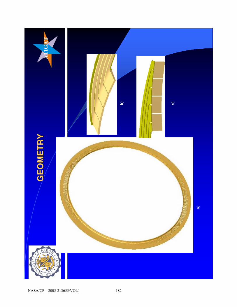
AT
IGA
TA
TIG
AT
GE
OM
ET
RY
GE
OM
ET
RY
a)
b) c)
NASA/CP—2005-213655/VOL1 182

AT
IGA
TA
TIG
AT
HP
an
d L
P S
eal D
etai
lsH
P a
nd
LP
Sea
l Det
ails
LP p
adde
d S
eal
HP
un-
padd
ed S
eal
Man
ufa
ctu
red
by:
R
F C
oo
kS
tow
, OH
442
24
NASA/CP—2005-213655/VOL1 183

AT
IGA
TA
TIG
AT
HP
an
d L
P S
eal D
etai
ls (
con
tH
P a
nd
LP
Sea
l Det
ails
(co
nt ’’
d)
d)
HP
and
LP
Waf
ers
of th
e S
eal
Bac
kpla
te
Pre
ssur
e da
m
Pre
ssu
re
equ
aliz
atio
n
man
ifo
ld
Bac
kpla
te
man
ufa
ctu
rin
g
NASA/CP—2005-213655/VOL1 184

AT
IGA
TA
TIG
AT
GE
OM
ET
RY
(co
nt
GE
OM
ET
RY
(co
nt ’’
d)
d)
a) b)c)
Low
Pre
ssur
e pa
dded
sea
l det
ails
NASA/CP—2005-213655/VOL1 185

ATI
GAT
TH
E T
EST
SE
CT
ION
A
SSE
MB
LY
Sol
id m
odel
des
ign
Act
ual t
est s
ectio
n
NASA/CP—2005-213655/VOL1 186

AT
IGA
TA
TIG
AT
SP
AC
ER
PL
AT
E A
ND
SE
AL
PO
SIT
ION
SP
AC
ER
PL
AT
E A
ND
SE
AL
PO
SIT
ION
Sea
l hol
der
asse
mbl
y
Rot
orH
P
zone
LP
zone
LP s
eal
NASA/CP—2005-213655/VOL1 187

AT
IGA
TA
TIG
AT
Axi
al P
ress
ure
=5 p
si;
RP
M =
10K
rpm
Axi
al P
ress
ure
=5 p
si;
RP
M =
10K
rpm
Axi
al D
ispl
acem
ent
Rad
ial D
ispl
acem
ent
NASA/CP—2005-213655/VOL1 188

AT
IGA
TA
TIG
AT
253545556575
050
100
150
HP
(p
si)
Pressure Force (N)
V21
6, IN
CO
M
V21
6, C
OM
, IS
O
V21
6, C
OM
, H
TC10
00
V21
6, C
OM
, H
TC50
0
V21
6, C
OM
, H
TC10
0
253545556575
050
100
150
HP
(p
si)
Pressure Force (N)
V43
2, IN
CO
M
V43
2, C
OM
, IS
O
V43
2, C
OM
, H
TC10
00
V43
2, C
OM
, H
TC50
0
PR
ES
SU
RE
IND
UC
ED
FO
RC
ES
Var
iatio
n w
ith a
xial
pre
ssur
e di
ffere
ntia
l, H
TC
and
ru
nner
spe
ed
Inco
mp
resi
ble
an
d (
com
pre
ssib
le,
iso
ther
mal
): L
INE
AR
var
iati
on
Co
mp
ress
ible
, PG
L:
NO
N-L
inea
r
Th
e H
TC
100
vs
1000
is e
qu
ival
ent
to t
he
limit
ing
cas
es o
f:
adia
bat
ic v
s. is
oth
erm
al
NASA/CP—2005-213655/VOL1 189

AT
IGA
TA
TIG
AT
Mas
s F
low
as
a F
un
ctio
n o
f th
e H
P s
ide
Pre
ssu
re
0.0E
+00
2.0E
-05
4.0E
-05
6.0E
-05
8.0E
-05
1.0E
-04
1.2E
-04
1.4E
-04
050
100
150
HP
(p
si)
Mass Flow (kg)
V21
6, IN
CO
M
V21
6, C
OM
, IS
O
V21
6, C
OM
, H
TC10
00
V21
6, C
OM
, H
TC50
0
V21
6, C
OM
, H
TC10
0
0.0E
+00
2.0E
-05
4.0E
-05
6.0E
-05
8.0E
-05
1.0E
-04
1.2E
-04
1.4E
-04
050
100
150
HP
(p
si)
Mass Flow (kg)
V43
2, IN
CO
M
V43
2, C
OM
, IS
O
V43
2, C
OM
, H
TC10
00
V43
2, C
OM
, H
TC50
0
μ=co
nst;ρ
cons
t
PG
L
As
HT
C g
oes
up, T
goe
s do
wn,
➠ρ
goes
up
➠m
ass
flow
goe
s up
At
HT
C=1
00, T
goe
s up
, ➠ρ
goes
dow
n ➠
Mas
s fl
ow g
oes
dow
n
At
cons
tant
HT
C=1
000,
low
er s
peed
(216
vs
432
) ha
s lo
wer
tem
pera
ture
s ➠ρ
goes
up
➠m
ass
goes
up
NASA/CP—2005-213655/VOL1 190
AT
IGA
TA
TIG
AT
PA
RT
IAL
CO
NC
LU
SIO
NS
PA
RT
IAL
CO
NC
LU
SIO
NS
It w
as f
ound
that
:
●th
e in
terp
lay
betw
een
the
rota
tion
indu
ced
pres
sure
ge
nera
tion
and
the
axia
l pre
ssur
e dr
ops
cont
rolle
d by
the
HP
side
, is
dom
inat
ed b
y ro
tatio
n at
low
HP
side
pre
ssur
e, b
ut it
is
then
take
n ov
er b
y th
e ax
ial p
ress
ure
drop
whe
n th
e la
tter
beco
mes
larg
er th
en 1
73kP
a at
216
mps
.
●th
e ef
fect
of
allo
win
g th
e dy
nam
ic v
isco
sity
to v
ary
with
te
mpe
ratu
re is
to in
trod
uce
stro
ng n
on-l
inea
ritie
s bo
th in
the
beha
vior
of
the
leak
age
flow
and
the
load
car
ryin
g ca
pabi
lity.
NASA/CP—2005-213655/VOL1 191

AT
IGA
TA
TIG
AT
PA
RT
IAL
CO
NC
LU
SIO
NS
PA
RT
IAL
CO
NC
LU
SIO
NS
●th
e nu
mer
ical
exp
erim
ents
sho
wed
that
the
FS b
ehav
es
mor
e lik
e a
bear
ing
at lo
w a
xial
ΔPs
and
like
a s
eal a
t hig
h on
es
●th
at th
e in
crea
se in
the
rota
tion
al v
eloc
ity c
ause
s in
crea
sed
LC
C, b
ut
●th
e in
crea
se in
the
heat
tran
sfer
coe
ffic
ient
cau
ses
mor
e le
akag
e an
d di
min
ishe
s th
e lo
ad c
arry
ing
capa
bilit
y.
●th
at th
e te
mpe
ratu
re m
aps
show
ed th
at th
e hi
gh te
mpe
ratu
re
regi
ons
shif
t fro
m u
nder
the
HP
fing
ers
at lo
w Δ
Ps a
nd
tow
ards
the
oute
r re
gion
s of
the
LP
fing
er p
ad w
hen
the
axia
l ΔPs
incr
ease
NASA/CP—2005-213655/VOL1 192

AT
IGA
TA
TIG
AT
DY
NA
MIC
SIM
UL
AT
ION
CO
NC
EP
TS
AN
D
RE
SU
LT
S
NASA/CP—2005-213655/VOL1 193

AT
IGA
TA
TIG
AT
FIN
GE
R S
EA
L E
QU
IVA
LEN
T M
OD
EL
FO
R
FIN
GE
R S
EA
L E
QU
IVA
LEN
T M
OD
EL
FO
R
DY
NA
MIC
SIM
ULA
TIO
ND
YN
AM
IC S
IMU
LAT
ION
——22--
DO
FD
OF
Flu
id la
yer
equi
vale
ntSp
ring
+D
ampe
r
k Sti
ck
Fix
ed p
osit
ions
due
to
anc
hori
ng t
o th
e to
rroi
dal r
oot
5
4
3
2
1
Stic
kFi
nger
m
ass
Mov
ing
Bou
ndar
y
k sti
ck
mfi
nger
k flu
id
c flu
id
1
34
5
2 a)b)
Solid
mod
el a
nd E
quiv
alen
t Spr
ing-
Mas
s-Sp
ring
/Dam
per
repr
esen
tati
on fo
r us
e in
the
equa
tion
of m
otio
n si
mul
atio
n
NASA/CP—2005-213655/VOL1 194

AT
IGA
TA
TIG
AT
RO
TO
R
MA
SS
FL
UI
DD
AM
PI
NG
FI
NG
ER
ST
IF
FN
ES
S
FS
M
AS
Sx
1
x2
FL
UI
DS
TI
FF
NE
SS
F1
CO
UL
OM
BD
AM
PI
NG
TW
O D
EG
RE
E O
F F
RE
ED
OM
MO
DE
L –
2 D
OF
RO
TO
R S
UR
FA
CE
FS
MA
SS
FL
UID
ST
IFF
NE
SS
FL
UID
DA
MP
ING
FIN
GE
RS
TIF
FN
ES
S
y
x
a) b)
()
yx
c FE
qu&
&−
xx
x&&
&,
,
xk
SEqu
()
yx
kF
Equ
−
equ
m
2 D
OF
1
-DO
F
⎭⎬⎫
⎩⎨⎧=
⎭⎬⎫
⎩⎨⎧ ⎥ ⎦⎤⎢ ⎣⎡
+−
−+
⎭⎬⎫
⎩⎨⎧ ⎥ ⎦⎤⎢ ⎣⎡
+−
−+
⎭⎬⎫
⎩⎨⎧ ⎥ ⎦⎤⎢ ⎣⎡
00
01
21
21
21F
xx
kk
k
kk
xx
cc
c
cc
xx
m
m
sf
f
ff
cf
f
ff
FS
R
&
&
&&
&&
()
yk
yc
xk
kx
cx
m
FE
quF
Equ
SEqu
FE
quF
Equ
Equ
+=
=+
++
&
&&&
Fin
ger
seal
mas
s fo
llow
ing
a di
spla
cem
ent
inpu
t
Inte
ract
ion
of fi
nger
and
rot
or m
ass
thro
ugh
the
flui
d la
yer
and
subj
ect
to a
forc
ing
func
tion
inpu
t +
Cou
lom
b fr
icti
on
NASA/CP—2005-213655/VOL1 195

AT
IGA
TA
TIG
AT
ti e
FF
ω0
= Now
con
side
ring
the
inpu
t for
ce to
be
harm
onic
,, w
e ca
n as
sum
e th
e re
spon
se o
f the
mas
ses
to b
e ch
arac
teri
zed
by
() ()t
i
ti e
tx
et
xωω
22
11
Χ=
Χ=
Thu
st
iti e
x
ei
xω
ω
ωω
Χ−
=
Χ=
22,1
2,1
&&
&
Subs
titu
ting
into
the
mat
rix
equa
tion
abo
ve
⎭⎬⎫
⎩⎨⎧=
⎭⎬⎫
⎩⎨⎧ ΧΧ⎥ ⎦⎤
⎢ ⎣⎡
ΖΖ
ΖΖ
00
21
2221
1211
iwt
eF
whe
re
()
()
sf
cf
FS
ff
ff
R
kk
cc
im
kc
i
kc
im
++
++
−=
Ζ
−−
=Ζ
=Ζ
++
−=
Ζ
ωω
ωω
ω
222
2112
211
The
sol
utio
n is
then
()
[]
Fi
vv
1−Ζ
=Χ
ω2-D
OF
co
nt’
d
NO
TE
: The
mot
ion
of th
e fin
ger
whe
n th
e ro
tor/
finge
r in
tera
ct is
rep
rese
nted
by
thes
e eq
uatio
ns a
nd s
olut
ion
NASA/CP—2005-213655/VOL1 196

AT
IGA
TA
TIG
AT
Fre
e vi
bra
tio
n o
f th
e fi
ng
er (
2 H
P-
2 L
P) w
ith
an
init
ial p
osi
tive
rad
ial d
efle
ctio
n a
nd
va
ryin
g a
mo
un
ts o
f C
ou
lom
b f
rict
ion
.
x+FS
MA
SSFIN
GE
RS
TIF
FN
ESS
BA
CK
PLA
TE
fF
kxx
m±
=+&&
The
+ a
nd –
sign
s ar
e de
pend
ent o
f the
dire
ctio
n of
mot
ion
of th
e fin
ger
and
thus
orie
ntat
ion
of th
e C
oulo
mb
fric
tion
for
for
nt
ωπ
≤≤
0 ()kF
tkF
xt
xf
nf
+⎥ ⎦⎤
⎢ ⎣⎡−
=ω
cos
0
nn
tω
πω
π2
≤≤
()kF
tkF
xt
xf
nf
−⎥ ⎦⎤
⎢ ⎣⎡−
=ω
cos
30
nn
tω
πω
π3
2≤
≤
()kF
tkF
xt
xf
nf
+⎥ ⎦⎤
⎢ ⎣⎡−
=ω
cos
50
for
NASA/CP—2005-213655/VOL1 197

AT
IGA
TA
TIG
AT
-1.5
000E
-03
-1.0
000E
-03
-5.0
000E
-04
0.00
00E+
00
5.00
00E-
04
1.00
00E-
03
1.50
00E-
03 0.00
000.
0010
0.00
200.
0030
0.00
400.
0050
0.00
600.
0070
0.00
tim
e (
s)
displacement (inches)
0 ps
i1
psi
2 ps
i3
psi
4 ps
i5
psi
6 ps
i7
psi
8 ps
i9
psi
10 p
si
Pre
ssur
e D
rop
thro
u gh
equa
lizat
ion
hole
s (d
elta
p)
Fre
e F
ing
er M
oti
on
Wit
h V
ario
us
Am
ou
nts
Of
Co
ulo
mb
Fri
ctio
n. F
ing
er S
tiff
nes
s is
Co
nst
ant
The
se le
vels
do
mot
hav
e en
ough
ene
rgy
left
to
mov
e ba
ck t
o eq
uilib
rium
line
The
se le
vels
do
mot
hav
e en
ough
ene
rgy
left
to
mov
e ba
ck t
o eq
uilib
rium
line
Cou
lom
b fr
ictio
n W
INS
Init
ial D
isp
lace
men
t o
f th
e fi
ng
er
NASA/CP—2005-213655/VOL1 198

AT
IGA
TA
TIG
AT
Fre
e F
ing
er M
oti
on
Wit
h C
on
stan
t C
ou
lom
b
Fri
ctio
n. F
ing
er S
tiff
nes
s is
Var
ied
.
∆p
=5 p
si
∆p
=10
psi
-0.0
01
-0.0
008
-0.0
006
-0.0
004
-0.0
0020
0.00
02
0.00
04
0.00
06
0.00
08
0.00
1
00.
001
0.00
20.
003
0.00
40.
005
0.00
6
Tim
e (
s)
Displacement from Equilibrium (in)
0.5k
(11
.72)
0.75
k (1
7.58
)
curr
ent
k (2
3.44
)1.
5k (
35.1
6)
2.0k
(46
.88)
2.5k
(58
.60)
3.0k
(70
.32)
Equ
ival
ent
Stic
k S
tiffn
ess
(lbf/
in)
-0.0
01
-0.0
008
-0.0
006
-0.0
004
-0.0
0020
0.00
02
0.00
04
0.00
06
0.00
08
0.00
1
0.00
12
0.00
14
0.00
16
00.
001
0.00
20.
003
0.00
40.
005
0.00
6
Tim
e (
s)Displacement from Equilibrium (in)
0.5k
(11
.72)
0.75
k (1
7.58
)
curr
ent
k (2
3.44
)1.
5k (
35.1
6)2.
0k (
46.8
8)2.
5k (
58.6
0)
3.0k
(70
.32)
Equ
ival
ent
Stic
k S
tiffn
ess
(lbf/
in)
As
the
stic
k be
com
es s
tiffe
r, th
e C
oulo
mb
fric
tion
has
less
effe
ct o
n da
mpi
ng
out t
he fr
ee v
ibra
tions
.
NASA/CP—2005-213655/VOL1 199

AT
IGA
TA
TIG
AT
3000
0 rp
m (
3141
rad
/sec
)
4000
0 rp
m (
4188
rad
/sec
)
RO
TO
R A
ND
FIN
GE
R R
ES
PO
NS
E T
O A
P
ER
IOD
IC F
OR
CIN
G F
UN
CT
ION
-0.0
012
-0.0
009
-0.0
006
-0.0
0030
0.00
03
0.00
06
0.00
09
0.00
12
00.
001
0.00
20.
003
0.00
40.
005
0.00
60.
007
Tim
e (
s)
Displacement (in)
Rot
orF
inge
r-10
psi
del
taF
inge
r-5
psi d
elta
Fin
ger-
1 ps
i del
ta-0
.001
2
-0.0
009
-0.0
006
-0.0
0030
0.00
03
0.00
06
0.00
09
0.00
12
00.
0005
0.00
10.
0015
0.00
20.
0025
0.00
30.
0035
Tim
e (
s)
Displacement (in)
Rot
orF
inge
r-10
psi
del
taF
inge
r-5
psi d
elta
Fin
ger-
1 ps
i del
ta
1000
0 rp
m (
1047
rad
/sec
)
2000
0 rp
m (
2094
rad
/sec
)
-0.0
012
-0.0
009
-0.0
006
-0.0
0030
0.00
03
0.00
06
0.00
09
0.00
12
00.
0005
0.00
10.
0015
0.00
20.
0025
Tim
e (
s)
Displacement (in)
Rot
orF
inge
r-10
psi
del
taF
inge
r-5
psi d
elta
Fin
ger-
1 ps
i del
ta-0
.001
2
-0.0
009
-0.0
006
-0.0
0030
0.0
003
0.0
006
0.0
009
0.0
012
00.
000
50
.001
0.0
015
0.0
02
Tim
e (
s)
Displacement (in)
Rot
orF
ing e
r-10
psi
del
taF
inge
r-5
psi d
elta
Fin
ger-
1 ps
i del
ta
The
rot
or p
ulls
aw
ay f
aste
r (n
atur
al f
requ
ency
of
the
fing
er
is lo
wer
than
the
forc
ing
func
tion
freq
uenc
y
Rot
or m
eets
fi
nger
1-ps
i fin
ger
free
fal
ls f
aste
r th
an th
e ro
tor,
but
has
to
follo
w th
e ro
tor
The
fre
e fa
ll o
f th
e 5-
psi
fing
er h
appe
ns a
t the
sam
e ra
te a
s th
e ro
tor
dow
n m
otio
n
Fin
ger
s d
o n
ot
follo
w t
he
roto
r to
o w
ell,
the
roto
r fr
equ
ency
bei
ng
mu
ch
hig
her
th
en t
he
nat
ura
l fr
equ
ency
of
the
fin
ger
s.
NASA/CP—2005-213655/VOL1 200

AT
IGA
TA
TIG
AT
-0.0
012
-0.0
009
-0.0
006
-0.0
0030
0.00
03
0.00
06
0.00
09
0.00
12
00.
0005
0.00
10.
0015
0.00
20.
0025
0.00
30.
0035
0.00
4
Tim
e (s
)
Displacement (in
Rot
or
FS
k=
11.7
2 lb
f/in
FS
k=
17.5
8 lb
f/in
FS
k=
23.4
4 lb
f/in
FS
k=
35.1
6 lb
f/in
FS
k=
36.8
8 lb
f/in
FS
k=
58.6
0 lb
f/in
FS
k=
70.3
2 lb
f/in
Ro
tor
and
Fin
ger
Res
po
nse
to
a P
erio
dic
Fo
rcin
g F
un
ctio
n
wit
h
freq
uen
cy
of
2094
ra
d/s
(2
0000
rp
m)
and
a
dro
p
thro
ug
h t
he
pre
ssu
re e
qu
aliz
atio
n h
ole
s o
f 5
psi
. F
ING
ER
S
TIF
FN
ES
S IS
VA
RIE
D
Flu
id s
tiff
nes
s
6852
lbf/
in
0.09
00.
090
70.3
2
0.07
50.
075
58.6
0
0.06
00.
060
46.8
8
0.04
50.
045
35.1
6
0.03
00.
030
23.4
4
0.01
50.
030
17.5
8
0.01
50.
015
11.7
2
LP
Fin
ger
Thi
ckne
ss
(in)
LP
Fin
ger
Thi
ckne
ss
(in)
K lb
f/in
Ks
that
allo
ws
smo
oth
er
roto
r/fi
ng
er
inte
ract
ion
NASA/CP—2005-213655/VOL1 201

AT
IGA
TA
TIG
AT
Wh
at d
oes
th
is m
ean
??
??
•Flu
id s
tiffn
ess
muc
h la
rger
than
that
of a
ny p
ract
ical
fing
er s
tiffn
ess
•The
fing
er fr
ee fa
ll po
rtio
n is
gre
atly
influ
ence
d by
sm
all c
hang
es in
eq
uiva
lent
fing
er s
tiffn
ess.
•The
tran
smis
sibi
lity
port
ion
(rot
or p
ositi
ve p
ush)
is n
ot a
ffect
ed in
the
prac
tical
ran
ge o
f fin
ger
stiff
ness
.
•A to
o th
in o
f a fi
nger
will
sta
y op
en (
up)
beca
use
it do
es n
ot p
osse
ss
enou
gh in
ner
sprin
g st
iffne
ss to
ove
rcom
e ev
en a
sm
all a
mou
nt o
fC
oulo
mb
fric
tion
•Con
vers
ely
a to
o th
ick
finge
r co
uld
caus
e ch
atte
r os
cilla
tion
•For
the
case
s st
udie
d he
re th
e be
st c
hoic
es s
how
ing
a fin
ger
pick
ing
up
smoo
thly
with
the
roto
r ar
e fo
r st
iffne
sses
bet
wee
n 35
and
58
lbf/i
n
fing
er
sn
mk
=ω
NASA/CP—2005-213655/VOL1 202
AT
IGA
TA
TIG
AT
So
me
no
tes
reg
ard
ing
pre
vio
us
two
slid
esS
om
e n
ote
s re
gar
din
g p
revi
ou
s tw
o s
lides
●In
fre
e vi
brat
ion
the
ener
gy o
f th
e fi
nger
ge
ts e
xpen
ded
even
tual
ly th
roug
h C
oulo
mb
fric
tion
●T
he f
ree
vibr
atio
n ho
wev
er d
oes
not c
arry
th
e da
y, b
ecau
se th
e fi
nger
re-
enco
unte
rs
the
roto
r●
The
nat
ural
fre
quen
cy o
f th
e fi
nger
rem
ains
th
e sa
me
NASA/CP—2005-213655/VOL1 203

AT
IGA
TA
TIG
AT
CO
NC
LU
SIO
NS
CO
NC
LU
SIO
NS
A
thre
e di
men
sion
al
Nav
ier-
Stok
es
base
d co
de
(CF
D-
AC
E+/
FE
MST
RE
SS)
was
ut
ilize
d to
an
alyz
e th
e th
erm
oflu
id b
ehav
ior
of a
mod
ifie
d F
S1 .
•T
he
pres
sure
pa
tter
ns,
mas
s fl
ows
and
load
car
ryin
g ca
pabi
litie
s of
thi
s st
ruct
ure
wer
e as
sess
ed.
It w
as f
ound
th
at e
ven
at a
low
er li
near
vel
ocit
y of
216
mps
(70
8 fp
s) t
he
geom
etry
pro
pose
d ha
s go
od li
ftin
g ca
pabi
lity.
.
NASA/CP—2005-213655/VOL1 204

AT
IGA
TA
TIG
AT
CO
NC
LU
SIO
NS
CO
NC
LU
SIO
NS
●T
he in
terp
lay
betw
een
the
rota
tion
indu
ced
pres
sure
ge
nera
tion
and
the
axi
al p
ress
ure
drop
s co
ntro
lled
by
the
HP
sid
e, is
dom
inat
ed b
y ro
tati
on a
t lo
w H
P s
ide
pres
sure
, but
it is
the
n ta
ken
over
by
the
axia
l pr
essu
re d
rop
whe
n th
e la
tter
bec
omes
larg
er t
hen
173k
Pa
at 2
16m
ps.
●T
he p
ress
ure
patt
erns
gen
erat
ed b
y th
is g
eom
etry
at
low
pre
ssur
e dr
ops
prov
e th
at t
he s
eal b
ehav
es in
the
fa
shio
n of
a m
ini-
slid
er b
eari
ng.
NASA/CP—2005-213655/VOL1 205

AT
IGA
TA
TIG
AT
CO
NC
LU
SIO
NS
(co
nt
CO
NC
LU
SIO
NS
(co
nt ’’
d)
d)
.
The
dyn
amic
mod
el i
ntro
duce
d a
sim
plif
ied
spri
ng-
mas
s-da
mpe
r eq
uiva
lent
to
th
e co
mpl
icat
ed
stru
ctur
e pr
esen
ted
by t
he F
S.
The
1-D
OF
num
eric
al e
xper
imen
ts c
once
ntra
ted
on
the
dete
rmin
atio
n of
the
pha
se s
hift
and
dis
plac
emen
t tr
ansm
issi
bilit
y Υ.
The
se t
wo
para
met
ers
indi
cate
how
wel
l an
d un
der
wha
t co
ndit
ions
the
fin
ger
will
fol
low
the
rot
or.
NASA/CP—2005-213655/VOL1 206

AT
IGA
TA
TIG
AT
CO
NC
LU
SIO
NS
CO
NC
LU
SIO
NS
●It
was
fou
nd t
hat
●(i
) th
e ph
ase
shif
t va
lues
incr
ease
d w
hen
flui
d st
iffn
ess
was
low
and
com
para
ble
to t
hat
of t
he s
tick
, ●
(ii)
the
pha
se s
hift
val
ue d
ecre
ases
wit
h fl
uid
dam
ping
incr
ease
,●
(iii)
the
com
bina
tion
of
smal
l kSE
qu a
nd la
rge
kFE
qu a
mou
nts
to a
tra
nsm
issi
bilit
y Υ
=1,a
nd a
rev
ersa
l in
rol
e le
ads
to v
ery
smal
l Υs,
●
(iv)
for
dam
ping
val
ues
low
er t
han
175
N.s
/m2
(1
lbf.
s/in
2) d
ampi
ng h
as n
o ef
fect
on Υ
and
NASA/CP—2005-213655/VOL1 207

AT
IGA
TA
TIG
AT
CO
NC
LU
SIO
NS
CO
NC
LU
SIO
NS
●(v
) ce
rtai
n co
mbi
nati
ons
of m
ass
and
flui
d an
d so
lid
stif
fnes
s le
ad t
o ve
ry la
rge Υ
whe
n th
e ro
tor
spee
d ap
proa
ches
the
nat
ural
fre
quen
cy o
f th
e sy
stem
●(v
i) in
the
2-D
OF
mod
el s
mal
l cha
nges
in K
stic
k ca
n si
gnif
ican
tly
affe
ct t
he r
otor
/sti
ck in
terp
lay.
NASA/CP—2005-213655/VOL1 208

ROLE OF DISTRIBUTED INTER-BRISTLE FRICTION FORCE ON BRUSH SEAL HYSTERESIS
Helen Zhao and Robert Stango
Marquette University Milwaukee, Wisconsin
Role of Distributed Inter-bristle Friction Force On Brush Seal
Hysteresis
By
Helen Zhao and Robert Stango
Department of Mechanical and Industrial EngineeringMarquette University, Milwaukee, WI
Email: [email protected] ; [email protected]
NASA/CP—2005-213655/VOL1 209

Intr
oduc
tion
and
Back
grou
nd
θ
θ
α
μ ξ
Δ*o
ω
Figu
re 1
•Int
erfe
renc
e pa
ram
eter
•In
war
d ra
dial
flo
w-in
duce
d lo
ad
q o •Con
tact
for
ce
F res
gene
rate
d at
in
terf
ace
of f
iber
tip
and
rot
or
•Loc
al o
ncom
ing
flow
of
gas
tow
ard
bris
tle
pack
qx
Figu
re 1
Bru
sh s
eal w
ith v
ario
us w
orki
ng lo
ads
* oΔ
NASA/CP—2005-213655/VOL1 210

Inte
r-br
istle
fric
tion
forc
e m
odel
Fron
t Pla
te
Bris
tle P
ack
Z
X
AA
t/2t/2
ψ
Bac
kP
late(a)
Dow
nstre
am
Ups
tream
(b)
g c z
X
ς
Sec
tion
A-A1
23
y
Figu
re 2
(a)D
epic
tion
of p
artia
l br
ush
seal
with
fro
nt
and
back
pla
te t
hat
cons
trai
n br
istle
pac
k
(b)S
ectio
n A-
A vi
ew,
depi
ctin
g th
e co
mpa
ctiv
elo
ad g
car
ound
bris
tle p
ack.
Th
e in
tera
ctiv
e fo
rces
of
thr
ee f
iber
s (1
, 2,
3)
are
stu
died
for
hyst
eres
is
phen
omen
on
NASA/CP—2005-213655/VOL1 211

Inte
r-br
istle
Fric
tion
Mod
el (
cont
’d)
Figu
re 3
•Th
ree
un-d
efor
med
ne
ighb
orin
g fib
ers
subj
ecte
d to
the
co
mpa
ctiv
elo
ad g
c
•D
efor
mat
ion
of
fiber
s un
der
com
pact
ive
load
gc.
NASA/CP—2005-213655/VOL1 212

Inte
r-br
istle
Fric
tion
Mod
el (
cont
’d)
Figu
re 4
(a)S
egm
ent
of t
he d
efor
med
fib
er s
ubje
cted
to
the
unifo
rm c
ompa
ctiv
elo
ad
g can
d tr
actio
n fo
rce
f A-A
'an
d f B
'-B
(b)s
impl
ified
mod
el
depi
ctin
g in
tera
ctio
n be
twee
n ne
ighb
orin
g br
istle
s as
uni
form
ly
dist
ribut
ed m
omen
t m
* al
ong
defo
rmed
fib
er
NASA/CP—2005-213655/VOL1 213

Inte
r-br
istle
Fric
tion
Mod
el--
-der
ivat
ion
of m
*
dNdf
dNdf
BB
AA
μμ
==
−′′
−;
cdN
dsg
=⋅
dsg
df
dsg
df
cB
B
cA
A
μμ==
−′
′−
dsr
gdm
wc
μ 2=
Lr
gm
wc
μ 2=
wcr
gm
μ2*
=If
Hex
agao
nalc
lose
d-pa
ck, t
hen
)60
cos
21(
2*
+=
wcr
gm
μ
Ref
er t
o Fi
g.3
and
Fig.
4:
1. D
iffer
entia
l fric
tiona
l for
ce d
f A-A
’an
d df
B’-B
2. D
iffer
entia
l mom
ent
dm:
3. R
esis
ting
bend
ing
mom
ent
m
4. D
istr
ibut
ed b
endi
ng m
omen
t pe
r un
it le
ngth
m
NASA/CP—2005-213655/VOL1 214

Gov
erni
ng E
quat
ion
Acco
rdin
g to
Eul
er-B
erno
ulli
Law
:
*re
sF
mE
IM
Mκ
=+
d dsφκ
=w
ith
Gov
erni
ng E
quat
ion:
2*
2co
s()
res
dE
Im
Fds
φα
μφ
=−
−−
Non
-dim
ensi
onal
for
m o
f go
vern
ing
equa
tion:
)co
s(2
2*
**
2*2
φμ
αφ
−−
−=
EIH
F
EIH
m
dsdre
s
NASA/CP—2005-213655/VOL1 215

Boun
dary
con
ditio
ns a
nd
cons
trai
nt c
ondi
tions
Boun
dary
con
ditio
ns:
1. s
lope
con
stra
int
at t
he b
ristle
orig
in, i
.e.
Φ=
0 at
s=
0
2. F
ree
of m
omen
t at
the
bris
tle t
ip, i
.e.
dΦ/d
s=0
at s
=L
Cons
trai
nt c
ondi
tions
:
;t
tx
xy
yξ
ξε
ε−
<−
<
00
cos
;si
nL
L
tt
xds
yds
φφ
==
∫∫
θξ
θ
ξθ
θ
ξξ
sin
)(
)si
n(
)co
s(co
s)
(
**
**
os
ss
ss
os
HR
RR
y
RR
HR
x
Δ−
+−
+=
+−
Δ−
+=
Whe
re,
NASA/CP—2005-213655/VOL1 216

Ecce
ntric
ity o
f Sh
aft
Figu
re 5
Ecce
ntric
m
ovem
ent
of
roto
r an
d di
spla
cem
ent
of
bris
tle p
ack
NASA/CP—2005-213655/VOL1 217

Num
eric
al R
esul
ts a
nd D
iscu
ssio
n
00.
020.
040.
060.
080.
10.
120.
14−
0.2
−0.
15
−0.
1
−0.
050
0.050.1
0.150.2
0.250.3
Δ* /H*
Fres H*2
/EI
FAH
*2
FBH
*2
FCH
*2
Δ g/H*
EI
EI E
I
Act
ual p
ath
for
unlo
adin
g cy
cle
Fic
titio
us p
ath
for
unlo
adin
g cy
cle
A
B
C
EIH
F res
2 *
Figu
re 6
Rel
atio
nshi
p be
twee
n
and
durin
g lo
adin
g an
d un
load
ing Δ*
for
a tr
ansi
tion
seal
with
R s
/H* =
8.9,
θ=
450
and
=
=
0.13
5.
Δ g/H
* sh
ows
the
posi
tion
whe
re f
iber
s ar
e “s
tuck
”,
i.e.,
cann
ot c
ompl
etel
y re
cove
r fr
om b
endi
ng
durin
g un
load
ing Δ***
HΔ
2*
*m
H EI
m
NASA/CP—2005-213655/VOL1 218

Num
eric
al R
esul
ts a
nd
Dis
cuss
ion
(Con
t’d)
00.
020.
040.
060.
080.
10.
120.
14−
0.2
−0.
15
−0.
1
−0.
050
0.050.1
0.150.2
0.250.3
Δ* /H*
Fres H*2
/EI
m1=
0m
2=0.
045
m3=
0.09
0m
4=0.
135
Δ gΔ g
Δ g H
*m
2 H
*m
3 H
*m
4
00.
020.
040.
060.
080.
10.
120.
140
0.02
0.04
0.06
0.080.1
0.12
0.14
m* H
*2/E
I
Δg/H*
Figu
re 7
(a)
Rel
atio
nshi
p be
twee
n di
men
sion
less
con
tact
for
ce a
nd
dim
ensi
onle
ss p
enet
ratio
n de
pth
for
=0,
0.0
45, 0
.090
, 0.1
35.(
Resu
lts
show
n ar
e fo
r R s
/H* =
8.9,
θ=
45o ;
(b)
rel
atio
nshi
p be
twee
n Δ g
/H*
and
non-
dim
ensi
onal
ben
ding
mom
ent
m
m
NASA/CP—2005-213655/VOL1 219

Num
eric
al R
esul
ts a
nd
Dis
cuss
ion
(Con
t’d)
00.
020.
040.
060.
080.
10.
120.
140
0.2
0.4
0.6
0.81
1.2
1.4
Δ* /H*
Fres H*2
/EI
θ 1=15
o
θ 2=30
o
θ 3=45
o
Δ g
Δ g
Δ g H*
θ 1
H*
θ 2
H*
θ 3 15
2025
3035
4045
0
0.02
0.04
0.06
0.080.1
0.12
0.14
θ (d
egre
e)
Δg/H*
Figu
re 8
(a)
Rel
atio
nshi
p be
twee
n di
men
sion
less
con
tact
for
ce a
nd
dim
ensi
onle
ss p
enet
ratio
n de
pth
for θ=
15, 30
and
45
degr
ees.
(R
esul
ts s
how
n ar
e fo
r a
bris
tle w
ith R
s/H
* =8.
9, Δ
* o=0,
=0.
135)
an
d (b
) Re
latio
nshi
p be
twee
n Δ g
/H*
and
bris
tle la
y an
gle θ
m
NASA/CP—2005-213655/VOL1 220

Conc
lusi
ons/
Sum
mar
yTh
e m
icro
-mom
ent
can
give
ris
e to
a d
elay
ed
filam
ent
disp
lace
men
t as
the
sha
ft u
nder
goes
tr
ansi
ent
excu
rsio
n an
d m
oves
rad
ially
tow
ard
bris
tle p
ack
(upl
oadi
ng).
H
owev
er, a
s th
e sh
aft
retu
rns
back
to
its c
once
ntric
po
sitio
n (d
ownl
oadi
ng),
the
fila
men
t CA
NN
OT
com
plet
ely
reco
ver
from
its
defo
rmed
pos
ition
and
re
mai
ns lo
cked
in a
n al
tern
ate
conf
igur
atio
n.
Cons
eque
ntly
, an
annu
lar
gap
is g
ener
ated
be
twee
n th
e fib
er t
ips
and
shaf
t su
rfac
e, w
hich
pr
omot
es b
rush
sea
l lea
kage
and
red
uces
tur
bo-
mac
hine
ry p
erfo
rman
ce.
NASA/CP—2005-213655/VOL1 221

Conc
lusi
ons/
Sum
mar
y (c
ont’d
)
In g
ener
al, f
or a
giv
en b
rush
sea
l, th
e an
nula
r ga
p in
crea
ses
linea
rly a
s th
e m
icro
mom
ent
m*
is
incr
ease
d.
The
brus
h se
al h
avin
g a
shal
low
est
lay
angl
e (1
5o)
resu
lts in
the
sm
alle
st a
nnul
ar g
ap, i
ndic
atin
g th
at a
br
ush
seal
des
ign
with
sha
llow
lay
angl
e is
leas
t pr
one
to h
yste
resi
s ph
enom
enon
, and
can
lead
to
impr
oved
per
form
ance
.
NASA/CP—2005-213655/VOL1 222

DOE/PG&E LNG-TURBOEXPANDER SEAL AND BEARING RETROFIT
Donald E. Bently, Dean W. Mathis, and G. Richard Thomas Bently Pressurized Bearing Company
Minden, Nevada
DOE/PG&E LNG-Turboexpander
Seal and Bearing Retrofit
2004 NASA Seal / Secondary Air System Workshop9 November 2004
Donald E. Bently, P.EDean W. Mathis
G. Richard Thomas, P.E.
Bently Pressurized Bearing Company1711 Orbit WayMinden, NV USA
NASA/CP—2005-213655/VOL1 223

DOE/PG&E LNG-Turboexpander
Seal and Bearing Retrofit
2004 NASA Seal / Secondary Air System Workshop9 November 2004
Donald E. Bently, P.EDean W. Mathis
G. Richard Thomas, P.E.
Bently Pressurized Bearing Company1711 Orbit WayMinden, NV USA
The U.S. Department of Energy (DOE), the Idaho National Engineering and Environmental Laboratories (INEEL), and Pacific Gas & Electric (PG&E) have been involved in the development of new technologies to produce liquefied natural gas (LNG) for diverse consumer use at a PG&E facility in Sacramento, California. Their goal is to establish packaged LNG facilities at/near conventional high-pressure natural gas letdown stations where high-pressure (750 to 900 psig) pipeline gas is throttled to distribution pressures of 50 to 60 psi.
Typically, in the past, this throttling process was achieved via pressure regulation valves. The new technology utilizes a turboexpander as the pressure throttling device. The turboexpander consists of a single stage radial inflow expansion turbine wheel on end of the shaft and a centrifugal compressor wheel on the other end of the shaft, in a conventional, double overhung arrangement. The benefit of the new process is to recover the energy of expanding pipeline gas from 750 psig to 60 psig, while at the same time recompressing a portion of the pipeline gas.
Initially, the turboexpander was delivered with shaft contacting brush seals behind both wheels, 17-4 PH shaft material, and two combination radial/thrust magnetic bearings. INEEL and PG&E worked with the turboexpander OEM from early 2002 through March 2004, unsuccessfully trying to commission the turboexpander. Due to stability issues, the turboexpander could not operate above 55 to 60,000 rpm. Required design speed is 70,000 rpm.
In late March 2004, Bently Pressurized Bearing Company was asked to solve the stability issue. This was accomplished by modifying:
- the existing shaft seal design, replacing the originally supplied brush seals with labyrinth seals (reduction in both axial loading and destabilizing tangential forces)
- the existing shaft material to a titanium alloy (12 percent gain in stability margin) - the combination radial/thrust bearing design from magnetic bearings to pressurized gas bearings (increase in load
carrying capability and stiffness with significant improvement in damping). The pressurized gas radial/thrust bearings utilizing the high pressure pipeline gas (methane) as the pressure source (425 psi) for the bearings and the gas distribution system as the low-pressure sink (60 psi) for the bearings.
This presentation documents the:
- operating characteristics of the turboexpander as originally supplied from the OEM with brush seals, 17-4 PH shaft material, and magnetic bearings,
- the design modifications made to the turboexpander, - operating characteristics of the turboexpander with the modified labyrinth seals, titanium alloy shaft material, and
pressurized radial and thrust gas(methane) bearings.
The turboexpander now successfully and continually operates at 70,000 rpm.
NASA/CP—2005-213655/VOL1 224

Project Definition❏ The US Department of Energy (DOE), the Idaho National Engineering
and Environmental Laboratories (INEEL), and Pacific Gas & Electric (PG&E) have developed new technologies to produce liquefied natural gas (LNG) for diverse consumer use.
❏ The goal is to establish packaged LNG facilities at / near conventional high-pressure natural gas letdown stations where the high-pressure (750 psig) pipeline gas is throttled to distribution pressure of 50 to 60 psi.
❏ The turboexpander consists of an expansion turbine stage on end of a shaft and a centrifugal compressor stage on the other end of the shaft, in a double overhung arrangement.
❏ The benefit of the new process is to recover the energy of expanding pipeline gas from 750 psig to 60 psig, while at the same time re-compressing a portion of the pipeline gas.
NASA/CP—2005-213655/VOL1 225

Project Definition❏ Original turboexpander design:
■ Brush shaft seals - expander and compressor wheels■ Combination radial / thrust magnetic bearings■ 17-4 PH shaft material■ Large Keyphasor hole / crude balancing■ 85,000 rpm design speed
❏ 667 ft/sec (455 mph) journal surface velocity❏ 450 ft/sec ≈typical maximum for most industrial turbomachinery
❏ Turboexpander failed to operate satisfactorily during previous two years of field testing (Jan 2002 – March 2004).■ Unacceptable seal leakage and thrust loading
❏ 300 ft/sec surface velocity ■ Lack of both radial and thrust load carrying capability of the
magnetic bearings■ Magnetic bearing control system instability■ Inability of magnetic bearings to operate above 55-60,000 rpm
NASA/CP—2005-213655/VOL1 226

Cross section of original turboexpander rotor/bearing assembly
Compressor Expander
Overall cross section of turboexpander. Original configuration with magnetic radial/thrust bearings, rolling element catcher bearings, brush type shaft end seals.
NASA/CP—2005-213655/VOL1 227

Shaft Material: 17-4 PHShaft Mass: 6.35 lbm
7.06 lbm (including wheels)Length: 10.2 in
Cross section of original turboexpander rotor/bearing assembly
Compressor Expander
Overall cross section of turboexpander. Original configuration with magnetic radial/thrust bearings, rolling element catcher bearings, brush type shaft end seals. Note that original shaft material is 17-4 PH hardened steel.
NASA/CP—2005-213655/VOL1 228

Brush Seals
Seal Plate
Brush Seal
Original design shaft end seals – radial brush seal design
NASA/CP—2005-213655/VOL1 229

Brush Seals
Brush Seal
Original design shaft end seal – radial brush seal design. This particular seal is one of several that failed during operation – potentially due to surface velocities and diff pressure across the seal.
NASA/CP—2005-213655/VOL1 230

Revised turboexpander seal geometry
Original shaft end seal design replaced with multi tooth labyrinth seals. Laby seals also included axial steps or swirl brakes.
NASA/CP—2005-213655/VOL1 231

Revised turboexpander shaft geometry
Physical Vapor Deposition (PVD) is the act of vaporizing a solid material within a vacuum chamber. The temperature of the vaporized material is much higher than the inside the chamber, thus allowing the material to physically condense onto a substrate and form a coating. Coatings produced by the PVD process are hard and have high density.
Shaft (Ti Alloy) Mass = 3.67 lbm (4.38 lbm including aluminum wheels)Overall Length = 10.20 in
Coating material: WC/C (tungsten-carbon-carbide)Friction coefficient (dry steel): 0.10 – 0.20 Coating process: Physical Vapor Deposition (PVD)Coating color: black-greyCoating structure: lamellar
Redesigned shaft: Ti Alloy, internal magnetic once per turn speed reference, WC-C PVD coating
NASA/CP—2005-213655/VOL1 232

Cross section of rotor/bearing assembly
Expander Compressor
Shaft
Bearings
Gas exhaust Backers
Machine CasePressurized gas manifold
Cross section of turboexpander with replacement externally pressurized gas bearings, laby seals, and new shaft installed
NASA/CP—2005-213655/VOL1 233

Bearing Geometry and Features
Bearing Bearing and Backer
Left picture is the bearing itself
Right picture shows the bearing installed in the backer which was utilized to adopt the bearing geometry into the existing turboexpancer casing. Oval port w/O-Ring groove is gas inlet port. O-ring used to seal the backer to the casing.
NASA/CP—2005-213655/VOL1 234

410,000 lbf/in stiffness100 lbf *sec/in damping
Predicted damped response for the turboexpander retrofitted with labyrinths seals, Ti alloy shaft, and pressurized gas bearings
Predicted damped response, from finite element model, of the turboexpander rotor startup utilizing the new laby seals, new externally pressurized gas bearings, and redesigned Ti Alloy shaft.
NASA/CP—2005-213655/VOL1 235

Predicted damped response for the turboexpander retrofitted with labyrinths seals, Ti alloy shaft, and pressurized gas bearings
410,000 lbf/in stiffness100 lbf *sec/in damping
Predicted damped response, from finite element model, of the turboexpander rotor startup utilizing the new laby seals, new externally pressurized gas bearings, and redesigned Ti Alloy shaft.
Based on known residual unbalance in the impellers, vibration response was predicted to be 70-90 degrees out of phase with the expander end leading.
NASA/CP—2005-213655/VOL1 236

Root locus stability analysis of redesigned turboexpander rotor/bearing system
δ = π ( )-αω
“Log Dec” loses information by taking the ratio ofGrowth Rate to Natural Frequency:
δ = π ( )-αω
“Log Dec” loses information by taking the ratio ofGrowth Rate to Natural Frequency:
α-α
ωd
Predicted Stability analysis via Root Locus methodology – predicted stable to 137,000 rpm, discounting aerodynamic effects
NASA/CP—2005-213655/VOL1 237

Test Stand Bearing Design Verification - to 55,000 rpm on air
From Expander EndFrom Compressor End
Rotor run up in externally pressurized gas (air) bearings at Bently Pressurized Bearing Company test stand – to 55,000 rpm
NASA/CP—2005-213655/VOL1 238

Installed field instrumentation
Viewed from the Expander End
Radial ProbesRTD Leads Thrust Probe Lead
Field commissioning: expander end instrumentation
NASA/CP—2005-213655/VOL1 239

Installed field instrumentation
Viewed from the Compressor End
Radial Probes RTD LeadsThrust Probe Lead
Field commissioning: compressor end instrumentation
NASA/CP—2005-213655/VOL1 240

Field static thrust load testViewed from the Compressor End
250 Pound Static Load
Thrust Probe Lead
Viewed from the Expander End
Dial Indicator –Axial Movement
250 lb static thrust load test – radial and thrust bearings pressurized with 450 psig air
NASA/CP—2005-213655/VOL1 241

Transient Startup – 6 Oct 2004
NASA/CP—2005-213655/VOL1 242

1X startup data – Bode plot
NASA/CP—2005-213655/VOL1 243

Direct and 1X shaft relative orbit plots from expander and compressor end.
Note that expander 1X phase leads compressor 1X phase by 74 deg and that compressor response is 33% larger than expander end. Refer back to predicted response on slide 13. Very good agreement between predicted and actual response.
NASA/CP—2005-213655/VOL1 244

Transient Startup – 6 Oct 2004
Full spectrum from expander end xy shaft relative probes, shows forward and reverse vibration frequencies up to 74,200 rpm. Response is all forward 1X, circular, symmetric response as would be expected from the externally pressurized gas bearings.
NASA/CP—2005-213655/VOL1 245

Thank You
❏ Questions?
NASA/CP—2005-213655/VOL1 246

Brandan Robertson, NASA-JSC/ES5 281-483-3732, Houston, TX
Advanced Docking/Berthing System NASA Seal Workshop
GRC
November 9-10, 2004
ADVANCED DOCKING/BERTHING SYSTEM
Brandan Robertson National Aeronautics and Space Administration
Johnson Space Center Houston, Texas
NASA/CP—2005-213655/VOL1 247

Bra
ndan
Rob
erts
on, N
ASA
-JSC
/ES5
281
-483
-373
2, H
oust
on, T
X
Out
line
•B
ackg
roun
d
•Fu
ture
Pro
gram
Nee
ds
•E
xist
ing
Syst
ems
•St
atus
•A
dvan
ced
Doc
king
/Ber
thin
g Sy
stem
(A
DB
S)
Ove
rvie
w
•K
ey S
eal R
equi
rem
ents
•E
arly
Sea
l Dev
elop
men
t Wor
k
NASA/CP—2005-213655/VOL1 248

Bra
ndan
Rob
erts
on, N
ASA
-JSC
/ES5
281
-483
-373
2, H
oust
on, T
X
Bac
kgro
und
Ber
thin
gre
fers
to m
atin
g op
erat
ions
whe
re a
n in
activ
e m
odul
e/ve
hicl
e is
pla
ced
into
th
e m
atin
g in
terf
ace
usin
g a
Rem
ote
Man
ipul
ator
Sys
tem
-R
MS.
Doc
king
ref
ers
to m
atin
g op
erat
ions
whe
re a
n ac
tive
vehi
cle
flie
s in
to th
e m
atin
g in
terf
ace
unde
r its
ow
n po
wer
.
RM
S B
erth
ing
Dep
ictio
n
NASA/CP—2005-213655/VOL1 249

Bra
ndan
Rob
erts
on, N
ASA
-JSC
/ES5
281
-483
-373
2, H
oust
on, T
X
Futu
re N
eeds
Fut
ure
Mat
ing
Syst
em C
apab
ility
Req
uire
men
ts:
–A
sys
tem
abl
e to
sup
port
a v
arie
ty o
f m
issi
ons:
CT
V/C
EV
/CR
V, l
unar
gat
eway
, M
oon,
and
Mar
s–
Lig
htw
eigh
t, fa
ult t
oler
ant s
yste
m th
at b
lend
s w
ell i
nto
vehi
cle
OM
L (
aero
)–
Cap
able
of
auto
nom
ous
rend
ezvo
us &
doc
king
–
Ber
thin
g ca
pabl
e fo
r m
odul
ar a
ssem
bly
and
vehi
cle
swap
-out
–So
ftw
are
reco
nfig
urab
le f
or a
ran
ge o
f ve
hicl
es a
nd o
pera
tions
–Fa
st s
epar
atio
n fo
r ra
pid
rele
ase
–M
odul
ar f
or m
aint
enan
ce a
nd s
ervi
cing
–C
onst
ella
tion
saf
ety
& r
elia
bilit
y go
als
–A
dapt
able
to I
SS
–C
rew
and
larg
e ca
rgo
tran
sfer
–Po
wer
, dat
a, a
nd f
luid
tran
sfer
–V
ehic
le to
veh
icle
mat
ing
(CR
V-C
TV
-oth
ers)
req
uire
s an
drog
ynou
s in
terf
ace
NASA/CP—2005-213655/VOL1 250

Bra
ndan
Rob
erts
on, N
ASA
-JSC
/ES5
281
-483
-373
2, H
oust
on, T
X
And
rogy
nous
Per
iphe
ral
Doc
king
Sys
tem
(A
PA
S)W
eigh
t: ~9
50 lb
s (
660
lbs
AP
DA
-600
1 +
276
lbs
avio
nics
) (
hatc
h no
t inc
l.)
Max
OD
: 69”
dia
Hat
ch P
ass
Thr
ough
: 31.
38”
dia
Sour
ce: J
SC-2
6938
, “P
rocu
rem
ent S
peci
fica
tion
for
the
And
rogy
nous
Per
iphe
ral D
ocki
ng S
yste
m f
or th
e IS
S M
issi
ons
Pas
sive
Com
mon
Ber
thin
g M
echa
nism
(P
CB
M)
Wei
ght:
680
lbs2
(440
lbs
PC
BM
+ 2
40 lb
s ha
tch)
H
atch
Pas
s T
hrou
gh: 5
0”sq
uare
Max
OD
: 86.
3”di
aSo
urce
: SSP
410
04, P
art 1
, “C
omm
onB
erth
ing
Mec
hani
sm to
Pre
ssur
ized
E
lem
ents
IC
D”
& S
SP 4
1015
, Par
t 1, C
omm
onH
atch
& M
echa
nism
s T
o P
ress
uriz
ed E
lem
ents
IC
D
Rus
sian
Pro
beW
eigh
t: 70
0 lb
s(5
50 lb
s co
ne +
150
lbs
avio
nics
)M
ax O
D: 6
1”di
aH
atch
Pas
s T
hrou
gh: 3
1.5”
dia
(app
roxi
mat
e)
Sour
ce: E
nerg
ia
Adv
ance
d D
ocki
ng/B
erth
ing
Syst
em (
AD
BS)
1
Wei
ght:
est.
750
lbs
(inc
lude
s el
ectr
onic
s &
hat
ch)
Max
OD
: 54”
dia
Hat
ch P
ass
Thr
ough
: 31”
dia
Sour
ce: X
-38
Pro
gram
Gro
up
1 AD
BS
curr
entl
y un
der
deve
lopm
ent
2 Bul
khea
d ha
tch
ring
str
uctu
re n
ot in
clud
ed
Exi
stin
g Sy
stem
s
NASA/CP—2005-213655/VOL1 251

Bra
ndan
Rob
erts
on, N
ASA
-JSC
/ES5
281
-483
-373
2, H
oust
on, T
X
Lim
itat
ions
of
exis
ting
sys
tem
s:–
Do
not m
eet 2
-fau
lt to
lera
nt, t
ime-
crit
ical
rel
ease
req
uire
men
t for
cre
wed
veh
icle
s•A
PAS
for
Shut
tle
reli
es o
n 96
bol
t EV
A to
mee
t 2nd
faul
t tol
eran
ce•C
BM
pow
ered
bol
ts in
nom
inal
ops
are
not
tim
e cr
itic
al a
nd a
re s
ingl
e fa
ult t
oler
ant
–U
niqu
e ac
tive
& p
assi
ve h
alve
s: p
recl
udes
veh
icle
-to-
vehi
cle
mat
ing
–D
o no
t sup
port
aut
onom
ous
oper
atio
ns
•No
auto
mat
ic m
atin
g of
flu
id, p
ower
(A
PA
S d
oes
have
a s
ingl
e po
wer
/dat
a co
nnec
tor)
an
d fo
rced
air
um
bili
cals
•CB
M c
anno
t mat
e to
unm
anne
d ve
hicl
es–
Stan
dard
ISS
rac
ks c
anno
t pas
s th
roug
h ex
isti
ng d
ocki
ng p
orts
–S
igni
fica
nt v
eloc
itie
s re
quir
ed to
pro
vide
ali
gnm
ent &
cap
ture
for
ces
–C
rit-
1 op
erat
ions
sup
port
ed b
y in
tens
ive
trai
ning
& a
naly
sis
–H
igh
part
cou
nt /
mec
hani
cal c
ompl
exit
y w
ith
sing
le p
oint
fai
lure
s (r
elia
bili
ty a
nd f
ailu
re
tole
ranc
e pr
oble
ms)
–B
erth
ing
mec
hani
sms
do n
ot d
ock
and
dock
ing
mec
hani
sms
do n
ot b
erth
–R
ussi
an s
yste
ms
are
supp
lied
by
a fo
reig
n ve
ndor
wit
h su
bsta
ntia
l eco
nom
ic c
once
rns
•Pur
chas
e of
add
itio
nal u
nits
ban
ned
by I
ran
Mis
sile
Pro
life
rati
on S
anct
ions
Act
of
1997
•V
ery
lim
ited
acc
ess
to e
ngin
eeri
ng d
ata
–S
yste
ms
desi
gned
and
/or
cert
ifie
d fo
r ve
ry f
ew c
ycle
s an
d sh
ort e
xpos
ure
life
Exi
stin
g Sy
stem
s
NASA/CP—2005-213655/VOL1 252

Bra
ndan
Rob
erts
on, N
ASA
-JSC
/ES5
281
-483
-373
2, H
oust
on, T
X
Cur
rent
Sta
tus
Adv
ance
d M
atin
g Sy
stem
Dev
elop
men
t A
ctiv
itie
s–
Exp
lora
tion
Syst
ems
Tec
hnol
ogy
Mat
urat
ion
Prog
ram
has
sel
ecte
d ad
vanc
ed
mat
ing
syst
ems
for
cont
inua
tion
duri
ng th
e re
cent
IC
P ac
tivity
.
–JS
C h
as b
een
deve
lopi
ng a
n ad
vanc
ed m
atin
g sy
stem
(A
DB
S) s
ince
199
6.
•O
rigi
nall
y in
tend
ed f
or u
se o
n th
e X
-38
proj
ect
•D
esig
ned
to s
uppo
rt b
oth
bert
hing
and
doc
king
ope
rati
ons
and
to p
rovi
de f
utur
e m
issi
on a
rchi
tect
ure
flex
ibil
ity
(cro
ss-c
utti
ng te
chno
logy
)•
The
cur
rent
des
ign
base
line
is a
X-3
8-si
zed
risk
red
ucti
on u
nit (
RR
U)
Ful
ly a
ndro
gyno
us in
terf
ace
Use
s el
ectr
omag
nets
and
clo
sed-
loop
for
ce-f
eedb
ack
for
soft
-cap
ture
Min
imal
ly s
ized
for
cre
w tr
ansf
erF
ully
inte
grat
ed g
roun
d ba
sed
syst
em to
sho
w T
RL
4 m
atur
ity
•W
ork
on C
onst
ella
tion
sca
le s
yste
m to
beg
in a
s R
RU
mat
ures
–L
ong-
dura
tion
seal
tech
nolo
gy (
seal
-on-
seal
) ha
s be
en id
enti
fied
as
a cu
rren
t de
sign
gap
.
NASA/CP—2005-213655/VOL1 253

Bra
ndan
Rob
erts
on, N
ASA
-JSC
/ES5
281
-483
-373
2, H
oust
on, T
X
CA
D I
mag
e
AD
BS
Ove
rvie
w
A N
ext-
Gen
erat
ion
Mat
ing
Mec
hani
sm–
Des
igne
d sp
ecif
ical
ly to
take
adv
anta
ge o
f m
oder
n el
ectr
omec
hani
cal t
echn
olog
y
–In
corp
orat
es th
e le
sson
s le
arne
d an
d ex
peri
ence
s fr
om p
revi
ous/
curr
ent m
atin
g m
echa
nism
dev
elop
men
t and
use
–D
esen
siti
zes
mat
ing
mec
hani
sm o
pera
tion
s an
d pe
rfor
man
ce f
rom
oth
er v
ehic
le s
yste
ms
requ
irem
ents
–S
uppo
rts
both
doc
king
and
ber
thin
g op
erat
ions
–S
uppo
rts
auto
nom
ous
rend
ezvo
us &
mat
ing
–A
ligne
d w
ith N
AS
A S
trat
egic
Pla
n
Inte
ract
ive
Ove
rvie
w
NASA/CP—2005-213655/VOL1 254

Bra
ndan
Rob
erts
on, N
ASA
-JSC
/ES5
281
-483
-373
2, H
oust
on, T
X
Key
Sea
l Req
uire
men
ts
•Se
al-o
n-se
al in
terf
ace
•V
ery
low
leak
rat
e
•L
ong
life
–L
ong-
dura
tion
expo
sed
peri
ods
–L
ong-
dura
tion
mat
ed p
erio
ds
–D
eep-
spac
e en
viro
nmen
ts
–M
ay a
lso
be a
pot
entia
l for
hig
h m
ate/
dem
ate
cycl
e lif
e
•R
edun
danc
y
NASA/CP—2005-213655/VOL1 255

Bra
ndan
Rob
erts
on, N
ASA
-JSC
/ES5
281
-483
-373
2, H
oust
on, T
X
AD
BS
Sea
l Loc
atio
ns
Inte
rfac
e Se
al
Hat
ch S
eal
3X L
ockd
own
Act
uato
r M
anua
l Inp
ut S
eal
3X L
atch
Act
uato
r M
anua
l Inp
ut S
eal
3X S
epar
atio
n S
yste
m
Man
ual I
nput
Sea
l
21X
Ele
ctro
nics
C
onne
ctor
Sea
lV
ehic
le S
truc
tura
l In
terf
ace
Seal
Bot
tom
Rin
g E
xten
sion
Sea
l
NASA/CP—2005-213655/VOL1 256

Bra
ndan
Rob
erts
on, N
ASA
-JSC
/ES5
281
-483
-373
2, H
oust
on, T
X
To
pres
erve
the
fully
and
rogy
nous
des
ign
conc
ept t
he s
eal d
esig
nap
proa
ch b
asel
ined
w
as a
sea
l-on
-sea
l im
plem
enta
tion
sim
ilar
to th
e A
poll
o So
yuz
(AST
P) s
eals
.
Subs
cale
sea
l-on
-sea
l ela
stom
eric
dev
elop
men
t with
Par
ker
Inc.
•Qui
ck d
evel
opm
ent a
nd te
stin
g to
eva
luat
e se
al-o
n-se
al p
oten
tial
•2 c
ross
-sec
tion
s (f
lat t
op a
nd e
llip
tica
l) a
nd 2
dif
fere
nt d
urom
eter
sil
icon
mat
eria
ls•H
eliu
m le
ak te
stin
g an
d se
al lo
ad f
orce
test
ing
com
plet
ed in
Jul
y 20
01•A
dhes
ion
test
ing
is o
ngoi
ng
Tes
t res
ults
•Lea
k ra
tes
com
para
ble
to I
SS C
BM
sea
ls w
ith
offs
et o
f 0.
050
inch
es a
nd n
o ga
ppin
g (~
20
conf
igur
atio
ns te
sted
)•C
ompr
essi
on f
orce
test
ing
show
ed th
at “
flat
top”
slig
htly
hig
her
than
“el
lipt
ical
”fo
r th
e 70
du
rom
eter
at (
96 &
87
lb/i
n) a
nd f
or th
e 50
dur
omet
er a
t (46
& 4
2 lb
/in)
. R
esul
ts in
dica
ted
that
sea
l-on
-sea
l in
the
“acc
epta
ble”
rang
e fo
r us
e.
•Adh
esio
n te
st r
esul
ts p
endi
ng; s
erie
s of
“bu
ttons
”m
olde
d fr
om e
ach
mat
eria
l are
cur
rent
ly
mat
ed a
nd c
ompr
esse
d fo
r ev
entu
al s
epar
atio
n an
d in
spec
tion
at T
BD
reg
ular
inte
rval
s of
ti
me.
Ear
ly A
DB
S Se
al D
evel
opm
ent
NASA/CP—2005-213655/VOL1 257

Bra
ndan
Rob
erts
on, N
ASA
-JSC
/ES5
281
-483
-373
2, H
oust
on, T
X
1.00
”
26”
rad
Tun
nel F
lang
e
Tun
nel F
lang
e
Seal
Ret
aine
r
Seal
Ret
aine
r
Seal
-on-
met
al
C/L
Seal
ing
Plan
e
RR
U I
nter
face
Sea
l Con
cept
NASA/CP—2005-213655/VOL1 258

Bra
ndan
Rob
erts
on, N
ASA
-JSC
/ES5
281
-483
-373
2, H
oust
on, T
X
Con
clus
ions
•N
o el
asto
mer
ic s
eal-
on-s
eal s
how
sto
pper
s ye
t
Forw
ard
wor
k•
As
soon
as
fund
ing
pict
ure
clea
rs u
p, m
ove
forw
ard
wit
h a
full
dev
elop
men
t sea
l pur
chas
e fo
r th
e R
RU
•N
eed
to e
stab
lish
“the
”ba
seli
ne s
eal c
ross
-sec
tion
•O
ptim
ize
seal
to g
uara
ntee
opt
imal
sea
ling
: per
cent
of
fill
, squ
eeze
, cro
wn
prof
ile
and
heig
ht, i
f el
asto
mer
ic•
Est
abli
sh to
tal p
oten
tial
sea
l mis
mat
ch: m
isal
ignm
ent,
ther
mal
exp
ansi
on, f
lang
e de
flec
tion
•E
stab
lish
acc
epta
ble
seal
for
ce a
nd le
ak r
ate
•D
eter
min
e if
a s
ingl
e pi
ece
~54”
seal
/ret
aine
r co
nstr
ucti
on p
ossi
ble.
Par
ker
has
indi
cate
d th
ey d
o th
is n
ow in
a n
ewly
acq
uire
d fa
cili
ty.
•E
valu
ate
conc
epts
and
res
ults
for
ful
l-sc
ale
Con
stel
latio
n im
plem
enta
tion
•E
valu
ate
RR
U d
esig
n up
war
d sc
alin
g•
Are
met
alli
c se
als
a be
tter
sol
utio
n?
Ear
ly A
DB
S Se
al D
evel
opm
ent
NASA/CP—2005-213655/VOL1 259

Bra
ndan
Rob
erts
on, N
ASA
-JSC
/ES5
281
-483
-373
2, H
oust
on, T
X
Bac
kup
Slid
es
NASA/CP—2005-213655/VOL1 260

Bra
ndan
Rob
erts
on, N
ASA
-JSC
/ES5
281
-483
-373
2, H
oust
on, T
X
Exi
stin
g Sy
stem
Sea
ls
Apo
llo S
oyuz
Tes
t P
rogr
amD
ocki
ng S
yste
m I
nter
face
Sea
l Dia
gram
NASA/CP—2005-213655/VOL1 261

Page intentionally left blank

NASA Glenn Research Center
Evaluation of Ceramic Wafer Seals for Future Space Vehicle Applications
Mr. Patrick H. Dunlap, Jr.Dr. Bruce M. Steinetz
NASA Glenn Research Center, Cleveland, OH
Mr. Jeffrey J. DeMangeUniversity of Toledo, Toledo, OH
2004 NASA Seal/Secondary Air System WorkshopNovember 9-10, 2004
Mr. Patrick H. Dunlap, Jr.Dr. Bruce M. Steinetz
NASA Glenn Research Center, Cleveland, OH
Mr. Jeffrey J. DeMangeUniversity of Toledo, Toledo, OH
2004 NASA Seal/Secondary Air System WorkshopNovember 9-10, 2004
EVALUATION OF CERAMIC WAFER SEALS FOR FUTURE SPACE VEHICLE APPLICATIONS
Patrick H. Dunlap, Jr., and Bruce M. Steinetz
National Aeronautics and Space Administration Glenn Research Center
Cleveland, Ohio
Jeffrey J. DeMange University of Toledo
Toledo, Ohio
NASA/CP—2005-213655/VOL1 263

NASA Glenn Research Center
♦High temperature, dynamic seals required in future space vehicles for sealing:• Perimeters of movable ramps in hypersonic engines• Heatshields and thermal protection systems (TPS) for aerocapture
and atmospheric entry systems• Perimeters of movable control surfaces
Hypersonic engine seals
Introduction & Background
Seal location
Controlsurface seals
Heatshield seals
High temperature, dynamic structural seals are required in many different locations on future space vehicles. Seals are required in advanced hypersonic engines to seal the perimeters of movable engine ramps for efficient, safe operation in high heat flux environments at temperatures from 2000 to 2500 °F. High temperature seals are also required around heatshields and within thermal protection systems for aerocapture and atmospheric entry systems. If a winged vehicle is used as an entry system, seals would also be required around the perimeters of movable control surfaces on the vehicle.
NASA/CP—2005-213655/VOL1 264

NASA Glenn Research Center
♦ Design requirements are demanding:• Restrict flow of hot gases at extreme temperatures
– Propulsion system applications: Up to 2500 °F with high heat fluxes
– Airframe applications:• 2100 °F for tile-based TPS• 2600+ °F for CMC systems
• Seal against distorted/curved surfaces
• Limit loads against sealing surfaces
• Stay resilient for multiple load/heating cycles
• Resist scrubbing damage
♦ Existing seals do not meet requirements
Seal Challenges & Design Requirements
Goal: Develop sealing systems that meet these requirements and demonstrate performance in relevant environments
CMC control surface
Sealgap
The design requirements for these seal applications are very demanding. The seals must restrict the flow of hot gases and survive at very extreme temperatures. For propulsion system applications, temperatures can reach 2500 °F in the presence of very high heat fluxes. For airframe applications, such as TPS and control surface seals, peak temperatures depend on the type of materials used in the structures surrounding the seals. If insulating tiles are used around the seals, temperatures can reach about 2100 °F. However, if hot structure ceramic matrix composite (CMC) materials are used, seal temperatures can reach 2600 °F or even hotter.
In addition to surviving at extreme temperatures, the seals must seal against distorted, curved surfaces while not applying excessive loads to those surfaces. The seals must remain resilient for multiple load cycles and heating cycles in order to stay in contact with the opposing sealing surface. These seals are used in dynamic applications in which the sealing surfaces move during each mission. Because these surfaces are often rough, the seals must be able to survive scrubbing against them without a large change in leakage performance.
Existing seals do not meet these challenging requirements, so the Seal Team at NASA GRC is developing sealing systems that do meet these requirements and demonstrating their performance in relevant environments.
NASA/CP—2005-213655/VOL1 265

NASA Glenn Research Center
♦ Ceramic wafer seals originally developed during NASP program♦ Preload device behind wafers maintains contact with sealing surface♦ Current design:
• Material: monolithic silicon nitride (Honeywell AS800)• Size: 0.5 in. wide x 0.92 in. long x 0.125 in. thick
Seal Specimens
0.5 in.
0.5 in.
The seals examined in this study were ceramic wafer seals that were originally developed during the NASP program. They are composed of a series of thin ceramic wafers installed in a channel in a movable panel and preloaded from behind to keep them in contact with the opposing sealing surface. Preload devices that have been considered for this application include helical compression springs and canted coil springs.
Materials that were evaluated for the wafer seals during the NASP program included a cold-pressed and sintered aluminum oxide, a sintered alpha-phase silicon carbide, a hot-isostatically-pressed silicon nitride, and a cold-pressed and sintered silicon nitride. A detailed analytical comparison of all the materials that were considered ranked the advanced silicon nitride ceramics as the most promising material for future consideration. Given that those tests were performed in the late 1980’s, considerable improvements have been made since then to produce stronger and tougher ceramic materials. Because of these improvements and the high ranking of silicon nitride as a candidate wafer seal material, GRC selected silicon nitride as the best candidate for these seals. The wafers tested in the current study were made of monolithic silicon nitride (Honeywell AS800) and were 0.5-in. wide, 0.92-in. tall, and 0.125 in. thick. They had corner radii of 0.050 in.
NASA/CP—2005-213655/VOL1 266
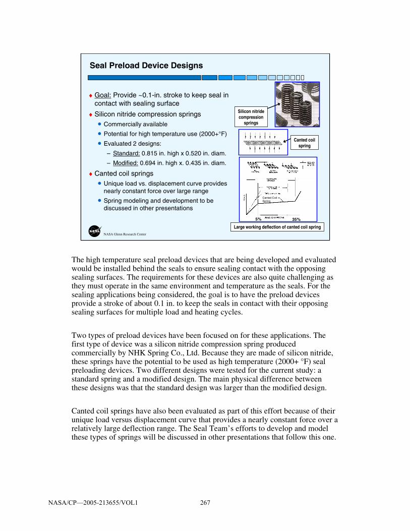
NASA Glenn Research Center
♦ Goal: Provide ~0.1-in. stroke to keep seal in contact with sealing surface
♦ Silicon nitride compression springs• Commercially available
• Potential for high temperature use (2000+°F)
• Evaluated 2 designs:
– Standard: 0.815 in. high x 0.520 in. diam.
– Modified: 0.694 in. high x. 0.435 in. diam.
♦ Canted coil springs• Unique load vs. displacement curve provides
nearly constant force over large range
• Spring modeling and development to be discussed in other presentations
Seal Preload Device Designs
Large working deflection of canted coil spring
5% 35%
Canted Coil Spring
Canted coil spring
Silicon nitride compression
springs
The high temperature seal preload devices that are being developed and evaluated would be installed behind the seals to ensure sealing contact with the opposing sealing surfaces. The requirements for these devices are also quite challenging as they must operate in the same environment and temperature as the seals. For the sealing applications being considered, the goal is to have the preload devices provide a stroke of about 0.1 in. to keep the seals in contact with their opposing sealing surfaces for multiple load and heating cycles.
Two types of preload devices have been focused on for these applications. The first type of device was a silicon nitride compression spring produced commercially by NHK Spring Co., Ltd. Because they are made of silicon nitride, these springs have the potential to be used as high temperature (2000+ °F) seal preloading devices. Two different designs were tested for the current study: a standard spring and a modified design. The main physical difference between these designs was that the standard design was larger than the modified design.
Canted coil springs have also been evaluated as part of this effort because of their unique load versus displacement curve that provides a nearly constant force over a relatively large deflection range. The Seal Team’s efforts to develop and model these types of springs will be discussed in other presentations that follow this one.
NASA/CP—2005-213655/VOL1 267

NASA Glenn Research Center
♦ Measure load vs. linear compression, resiliency, and stiffness of:• Springs alone• Wafer seals on top of springs
♦ Multiple load cycles at room temperature, 1600, 2000, 2200, & 2500 °F♦ Silicon carbide test fixtures (test temperatures up to 3000 °F)
Hot Compression Test Fixture
Seal (4 in. long)
Seal holder
Loading rod connected to
actuator
Box furnace rated to 3000 °F
Load cell below furnace
A series of hot compression tests were performed on the wafer seals and silicon nitride compression springs using GRC’s hot compression test rig. Compression tests were performed inside a box furnace capable of 3000 °F using the test setup shown here. These tests were performed to determine the resiliency and stiffness of the springs by themselves and for the wafers on top of the springs. Load versus displacement (i.e., linear compression) data was also generated by these tests. Test specimens were installed into a holder that rested on a stationary base. A movable platen attached to the actuator was translated up and down to load and unload the test specimens. Test specimens were loaded for multiple load cycles at a variety of test temperatures including room temperature, 1600 °F, 2000 °F, 2200 °F, and 2500 °F.
NASA/CP—2005-213655/VOL1 268

NASA Glenn Research Center
0.0
0.5
1.0
1.5
2.0
2.5
3.0
3.5
0.000 0.020 0.040 0.060 0.080 0.100
Linear compression (in.)
Forc
e, lb
f
70 F - Cycle 10
2000 F - Cycle 10
2200 F - Cycle 10
2500 F - Cycle 1
2500 F - Cycle 10
Compression Test Results: Standard Silicon Nitride Compression Springs
♦ No permanent set at room temperature, 2000 °F, or 2200 °F after 10 cycles♦ Observations from 2500 °F testing:
• Spring exhibited 44% permanent set after 10 cycles at 2500 °F• Some load-bearing capability still exists• Need to optimize material and design for multiple use at 2500 °F
28 lbf/in.
46 lbf/in.
28 lbf/in.
13 lbf/in.
31 lbf/in.
Springs show promise as high temperature seal preload devices
Permanent set
70°F, Cycle 102000°F, Cycle 102200°F, Cycle 102500°F, Cycle 12500°F, Cycle 10
17 lbf/in.
This figure shows the results for the compression tests performed on the standard silicon nitride compression spring design. For the tests performed at room temperature, 2000 °F, and 2200 °F, there was no permanent set or relaxation observed after 10 load cycles. For clarity, the figure only shows the curves for cycle 10 of these tests because they were almost identical to the curves for all other load cycles.
The test at 2500 °F produced somewhat different results than the tests performed at lower temperatures. The figure shows load cycles 1 and 10 for this test. For both of these load cycles, the peak loads were lower than those for the other tests. After 10 load cycles at 2500 °F the spring exhibited 44% permanent set but still had some load-bearing capability.
The results of these tests indicate that the silicon nitride compression springs show promise as high temperature seal preload devices, but some work needs to be done to optimize this material and spring design for use at 2500 °F.
NASA/CP—2005-213655/VOL1 269

NASA Glenn Research Center
Compression Test Results: Modified Silicon Nitride Compression Springs
♦ No permanent set at any temperature even for wafer seals on top of springs
♦ Some hysteresis for wafers on top of springs; possibly due to friction between wafers and groove side walls
*Note: 4 springs tested under wafer seals; 1 spring used for other tests
0.0
0.5
1.0
1.5
2.0
2.5
0.000 0.010 0.020 0.030 0.040
Linear Compression, in.
Fo
rce,
lb
f
70°F2000°F2200°F70°F, Wafers+Springs1600°F, Wafers+Springs2000°F, Wafers+Springs
Test Results for 10th Load Cycle65 lbf/in.
58 lbf/in.60 lbf/in.
57 lbf/in.
64 lbf/in.
60 lbf/in.
This figure shows the results for the compression tests performed on the modified silicon nitride compression spring design. The modified springs were smaller than the standard springs, allowing them to be installed in a groove behind the wafer seals so that compression tests could be performed on the sealing system as a whole. In all of these tests there was no permanent set or relaxation observed after 10 load cycles at room temperature, 1600 °F, 2000 °F, or 2200 °F. For clarity, the figure only shows the curves for cycle 10 of each test because they were almost identical to the curves for all other load cycles. For all of the tests performed on the silicon nitride springs by themselves, there was very little hysteresis in their load vs. linear compression data. For the tests performed with seals on top of the springs, there was virtually no hysteresis for the room temperature tests but a small amount for the tests at 1600 °F and 2000 °F. It is possible that during the high temperature tests, there was some small amount of friction between the wafers and the side walls of the seal groove that caused this hysteresis as the wafers and springs were unloaded during each load cycle.
NASA/CP—2005-213655/VOL1 270

NASA Glenn Research Center
Dwell Tests on Silicon Nitride Compression Springs
♦ Observed creep after 1.5 hrs under compression:• At 2000 °F load dropped by 13.5%
• At 2200 °F load dropped by 34%
♦ Still residual load on springs after 1.5 hrs
Time, hr.
0.00 0.25 0.50 0.75 1.00 1.25 1.50
Lo
ad, l
bf
0.0
0.5
1.0
1.5
2.0
2.5
2000°F 2200°F
Test Results for Standard Spring Design
Dwell tests were also performed on the standard silicon nitride compression springs in which the springs were held under load for an extended period of time. After an hour and a half under compression at 2000 °F the load dropped off by 13.5%. At 2200 °F the load dropped by 34% after an hour and a half. Although theloads dropped, the springs were still able to bear a good amount of load in both cases after an hour and a half of loading at high temperatures. If these springs are used as preload devices in future seal applications, this drop in load will have to be accounted for.
NASA/CP—2005-213655/VOL1 271

NASA Glenn Research Center
♦ Measure seal frictional loads and wear rates
♦ Test parameters:• Tests at room temperature and 1600 °F
– Inconel 625 rub surfaces– Rub surface roughness before testing =
6 μin• Test performed at 2000 °F
– Silicon carbide rub surfaces– Rub surface roughness before testing =
29 μin• Two sets of 32 wafers preloaded by silicon
nitride compression springs
• Seal gap size = 0.125-0.135 in.• 1000 scrub cycles; 2000 in. of scrubbing
Hot Scrub Test Fixture
Wafer seals
Seal holder
Inconel 625 rub surfaces
Wafer seals Seal holder
Silicon carbide rub surfaces
The main test rig that was used for the compression tests was also used to perform scrub tests on the seals using the set of test fixtures shown here. Tests were performed at room temperature, 1600 °F, and 2000 °F to evaluate seal wear rates and frictional loads as the seals were scrubbed against Inconel 625 and silicon carbide rub surfaces. The seals were installed in grooves in two stationary seal holders on either side of a pair of movable rub surfaces. The rub surfaces were assembled in a holder that was connected through the upper load train to the actuator.
Inconel 625 rub surfaces were used for the tests performed at room temperature and 1600 °F, while silicon carbide rub surfaces were used for the test performed at 2000 °F. The Inconel 625 rub surfaces had an average surface roughness before testing of about 6 μin. The roughness of the silicon carbide rub surfaces before testing was 29 μin. The gaps between the rub surfaces and the seals were set by spacer shims in front of and behind the seal holders. Gap sizes of 0.125-0.135 in. were used for these tests.
Four silicon nitride compression springs (modified spring design) were installed in the bottom of each seal groove to keep the wafer seals preloaded against both rub surfaces. A load transfer element was placed on top of the springs to support the wafers and distribute the load from the springs. Thirty two wafers were installed into each seal holder to fill the 4-in.-long seal grooves. The amount of compression on the seals and springs (0.030 in.) was set through an interference fit between the seals and the rub surfaces resulting in a preload of about 2 lb per inch of seal.
During these tests, the seals were held in place in the holders while the rub surfaces were scrubbed up and down against them. The seals were subjected to 1000 scrub cycles at 1 Hz for a total scrub length of 2000 in. for each test. Frictional loads were measured by the load cell under the furnace below the test fixture base. Seal wear rates were determined by examining the condition of the seals before and after each test and by measuring seal weight changes and changes in flow rates.
NASA/CP—2005-213655/VOL1 272

NASA Glenn Research Center
Scrub Test Results
♦Room temperature test against Inconel 625• Frictional loads peaked at 15.5 lb• Friction coefficient reached ~1• Rub surfaces became rougher
(43 μin)
♦1600 °F test against Inconel 625• Loads reached 23.5 lb• Max friction coefficient = 1.5 • Final rub surface roughness =
34 μin
♦2000 °F test against silicon carbide• Loads peaked at 12.8 lb• Friction coefficient ~1 by end of test; surface roughness stayed ~28-29 μin• No load spike at start of test; seals did not stick to surface during furnace heatup
Peak Frictional Loads During Scrub Testing
0
5
10
15
20
25
30
0 200 400 600 800 1000
Scrub Cycle
Lo
ad, l
bf
70°F - IN 6251600°F - IN 6252000°F - SiC
Peak frictional loads for each of the scrub tests are presented in this figure. For the test performed at room temperature against Inconel 625 rub surfaces, the frictional loads started around 6 lbf at the beginning of the test and gradually rose as the test proceeded until they reached about 15.5 lbf by the end of the test. Based on these loads, the friction coefficient at the end of the test was about 1.0. Before this scrub test, the average surface roughness of the rub surfaces was about 6 μin. After the test, the surface roughness had risen to about 43 μin. This increase in surface roughness during testing likely contributed to the increase in frictional forces as the test proceeded.
For the test performed at 1600 °F against Inconel 625 rub surfaces, the load peaked initially before quickly dropping and then slowly rising again to about 23.5 lbf by the end of the test. The friction coefficient reached 1.5 by the end of this test, corresponding well with an increased surface roughness of 34 μin.
For the test at 2000 °F using silicon carbide rub surfaces, lower loads were recorded than for the tests performed at lower temperatures against Inconel 625 rub surfaces. There was no load spike at the start of the test, indicating that the seals did not stick to the silicon carbide rub surfaces during furnace heatup. By the end of the test, the load peaked at about 12.8 lbf. The friction coefficient for this test reached about 1.0, and the surface roughness of the silicon carbide rub surfaces remained at about 28-29 μin, the same roughness as at the start of the test.
NASA/CP—2005-213655/VOL1 273

NASA Glenn Research Center
Scrub Test Results
♦ Little if any damage to silicon nitride wafers during scrub testing• No chips in wafers• Weight of wafer stacks almost identical before and after testing
♦ Superficial burnishing on Inconel 625 rub surfaces after testing♦ Some debris on SiC rub surfaces after testing; believed due to
abrasion of oxide layer
Wafer seals after 1600 °F scrub test against Inconel 625
Wafer seals before 1600 °F scrub test against Inconel 625
Wafer seals before 2000 °F scrub test against silicon carbide
Wafer seals after 2000 °F scrub test against silicon carbide
After the scrub tests were completed, the seals and rub surfaces were inspected for signs of damage. These figures show what the seals looked like before and after scrubbing at 1600 °F against Inconel and before and after scrubbing at 2000 °F against silicon carbide. The seals showed little if any damage after testing. None of the wafers were chipped or broken during testing, and the total weight of the wafers before and after testing was almost identical. Superficial burnishing was observed on the Inconel rub surfaces after testing, but this was not deemed to be significant. A small amount of debris was observed on the silicon carbide rub surfaces after testing (also visible in the photo of the wafers after this test). It is believed that this debris is due to abrasion of the oxide layer that forms on the silicon carbide rub surfaces at high temperatures.
NASA/CP—2005-213655/VOL1 274

NASA Glenn Research Center
Flow Test Results
Metered air supply
Cover plate
Gap = 0.135 in.
Test seal
Seal cartridgePlenum
Springs
Flow fixture
Flow Rates Before and After Scrubbing
0.00
0.20
0.40
0.60
0.80
1.00
1.20
0 20 40 60 80 100
Delta P (psid)F
low
per
in
ch o
f se
al (
SC
FM
/in
) Before RT scrubbingAfter RT ScrubbingBefore 1600°F scrubbingAfter 1600°F scrubbingBefore 2000°F scrubbingAfter 2000°F scrubbing
♦ No change in flow rates after scrubbing at room temp., 1600°F, or 2000°F♦ Flow rates were ~32 times lower than those for best braided rope seals♦ Flow rates lower for wafers tested at 1600°F and 2000°F due to tighter
wafer height tolerance (0.0005 in. vs. 0.001 in. for RT test)
Flow test results for the wafer seals before and after each scrub test are presented here for a gap size of 0.135 in. These tests were performed with four silicon nitride springs installed behind the wafers to keep them preloaded against the cover plate. Flow rates for the wafers before and after scrubbing were almost identical in each case. This is consistent with the observation that the wafers were not damaged during the scrub test. These results are encouraging because they show that the seals are still effective at blocking flow even after 1000 scrub cycles at room temperature. Additionally, flow rates for the wafer seals were up to 32 times better than those for the best braided rope seals.
Flow rates for the wafers tested at 1600°F and 2000°F were lower than those for the test performed at room temperature. This was because a tighter wafer height tolerance was used for the high temperature tests (0.0005 in.) than what was used for the room temperature test (0.001 in.).
NASA/CP—2005-213655/VOL1 275

NASA Glenn Research Center
Flow Test Results
♦ Recorded “seal activating” pressure behind seals during flow tests before and after 2000 °F scrub test• Augments preload devices to keep seals in contact with sealing surface
• Pressure behind seals was ~93% of pressure differential across seals
0
10
20
30
40
50
60
70
80
90
100
0 20 40 60 80 100
Pressure differential across seal, psid
Pre
ssu
re b
ehin
d s
eal,
psi
g
For the flow tests that were performed on the wafers before and after the 2000 °F scrub test, a new pressure measurement was made that was not recorded in the previous flow tests. This pressure measurement allowed the pressure behind the wafers to be recorded as a function of the differential pressure across the seals. The figure on the right presents pressure data behind the wafer seals versus the pressure differential across the seals for the flow test performed on the wafers that were scrub tested at 2000 °F. This plot shows a linear relationship between these pressures such that the pressure behind the seals was equal to about 93% of the pressure differential across the seals. The pressure behind the seals serves as a “seal activating” pressure that augments the preload devices to further preload the seals against the sealing surface and keep them in contact with it. This seal activating pressure phenomenon for wafer seals was observed previously for wafer seals tested during the NASP program.
NASA/CP—2005-213655/VOL1 276

NASA Glenn Research Center
♦ Wafer seals performed well in room temperature, 1600 °F, and 2000 °F scrub tests• No chips in wafers or any other signs of damage
• No change in flow rates after scrub testing
♦ Wafer seal flow rates were ~32 times lower than those for best braided rope seals
♦ Silicon nitride compression springs continue to show promise as high temperature seal preload devices; need to optimize materialand design for multiple use at 2500 °F
♦ Future work:• Investigate other wafer shapes and sizes• Investigate seal + preloading device combinations that satisfy requirements
at higher temperatures
Summary
Based on the results of these tests, the following conclusions were made:
1. The silicon nitride wafer seals performed very well in scrub tests performed at room temperature, 1600 °F, and 2000 °F. No chips or any other signs of damage were observed on the wafers after testing, and there was no change in flow rates past the seals after scrub testing.
2. Flow rates for the wafer seals were up to 32 times better than those for the best braided rope seals.
3. Commercially available silicon nitride compression springs continue to show promise as high temperature seal preload devices, but the material and design for these springs needs to be optimized for multiple uses at 2500 °F.
More work needs to be done to investigate seal and preloading device combinations that ultimately satisfy all of the seal requirements. The authors plan to investigate other wafer shapes and sizes to see if those changes affect seal durability, frictional forces, and flow rates. Longer scrub tests will also be performed at higher temperatures to examine seal durability.
NASA/CP—2005-213655/VOL1 277


On the Development of a Unique On the Development of a Unique Arc Jet Test Apparatus for Arc Jet Test Apparatus for
Control Surface Seal EvaluationsControl Surface Seal Evaluations
Joshua R. Finkbeiner, Patrick H. Dunlap, and Bruce M. SteinetzJoshua R. Finkbeiner, Patrick H. Dunlap, and Bruce M. SteinetzNASA John H. Glenn Research Center, Cleveland, OHNASA John H. Glenn Research Center, Cleveland, OH
Malcolm Robbie, Gus Baker, Arthur Erker, and Joe AssionMalcolm Robbie, Gus Baker, Arthur Erker, and Joe AssionAnalex Corp., Cleveland, OHAnalex Corp., Cleveland, OH
Seal WorkshopSeal WorkshopNovember 10, 2004November 10, 2004
ON THE DEVELOPMENT OF A UNIQUE ARC JET TEST APPARATUS FOR CONTROL SURFACE SEAL EVALUATIONS
Joshua R. Finkbeiner, Patrick H. Dunlap, and Bruce M. Steinetz
National Aeronautics and Space Administration Glenn Research Center
Cleveland, Ohio
Malcolm Robbie, Gus Baker, Arthur Erker, and Joe Assion Analex Corporation
Cleveland, Ohio
NASA/CP—2005-213655/VOL1 279

OutlineOutline
Future seal requirementsFuture seal requirementsTest fixture design objectivesTest fixture design objectivesSimulation of reentry environmentSimulation of reentry environmentTest fixture design and capabilitiesTest fixture design and capabilities
Modular seal cartridgeModular seal cartridgeModular flapModular flapMetalMetal--toto--ceramic flap transmission systemceramic flap transmission systemInstrumentationInstrumentationAngular positioningAngular positioning
NASA/CP—2005-213655/VOL1 280

Future Vehicle Seal NeedsFuture Vehicle Seal Needs
Survive higher Survive higher temperaturestemperatures
Proximity to outer mold lineProximity to outer mold lineCMC hot structures CMC hot structures (2400(2400ººF) with high F) with high conductivityconductivity
Compatibility with Compatibility with advanced flap materialsadvanced flap materialsImproved resiliency to Improved resiliency to follow gap openingsfollow gap openings
ElevonRudder
Future reentry vehicles will require more advanced seals than the current generation of vehicles (i.e. Shuttle). The seals must be capable of surviving higher temperatures for two primary reasons. Next-generation vehicles will be smaller in size than the Shuttle, and as a consequence, the seals will be closer to the outer mold line of the vehicle. Additionally, the next generation vehicles will employ CMC hot structures in place of the tile-insulated aluminum control surfaces currently used in Shuttle. These materials will be exposed directly to temperatures of (anticipated) 2400 ºF. Combined with the high thermal conductivity of these materials, new seal designs will be exposed to more severe thermal environments.
The use of CMC materials also introduces a second challenge in the design of new control surface seals. The seal materials must be chosen with care to ensure that the seal does not stick to the control surface material.
Finally, the seal must be able to maintain resiliency at the elevated temperatures. The seal gap size can change due to thermal expansion and movement of the control surface during flight. The seal must be capable of responding to gap size changes in these conditions.
NASA/CP—2005-213655/VOL1 281

Seal Test RequirementsSeal Test RequirementsRequire environment Require environment representative of reentryrepresentative of reentry
NASA JSC Arcjet simulates NASA JSC Arcjet simulates reentry environmentreentry environment
Heat FluxHeat Flux
Seal temp 1800Seal temp 1800--24002400ººFF
Pressure drop 56Pressure drop 56--100 psf100 psf
Exposure time ~15 minExposure time ~15 min
A simulated reentry environment is ideal for testing next-generation reentry vehicle control surface seals. This includes a combination of the heat flux, temperature, pressure drop, and exposure time encountered during hypersonic flight.
The arcjet facility at NASA Johnson Space Center will provide the simulated reentry heat. Depending on the nozzle used in the facility, the arcjet will expose the seal to temperatures of 1800-2200 ºF with a pressure drop of 56-100 psf. The facility is actively cooled, allowing it to simulate the reentry environment for 15 minutes, a typical reentry time for Shuttle.
NASA/CP—2005-213655/VOL1 282

Seal Test Fixture ObjectivesSeal Test Fixture Objectives
Test control surface seals in JSC arcjet tunnelTest control surface seals in JSC arcjet tunnelExpose seals to reentry conditionsExpose seals to reentry conditions
Survive arcjet environmentSurvive arcjet environment
Movement of control surface during hot testMovement of control surface during hot test
Variability of test parametersVariability of test parametersSeal shapes, sizes, and materialsSeal shapes, sizes, and materials
Fixture position (angular, spacial)Fixture position (angular, spacial)
NASA/CP—2005-213655/VOL1 283

Fixture DesignFixture Design
Insulating Tile
Water-cooledCopper Sides
C/SiC Flap
Water-cooledMotor Housing
Water-cooledBrake Housing
Seal Gap
Height Adjustment
Sting Arm
The design of the advanced seal arcjet test fixture provides flexibility for testing diverse seal designs at the same time as it is capable of surviving the harsh arcjet environment. The leading edge of the fixture contains the seal specimen, instrumentation, and provides the primary structure of the test fixture. The underlying structure of the leading edge is formed from water-cooled oxygen-free high-conductivity (OFHC) copper and is covered with insulating tile panels designed to minimize heat transfer to the structure. The tiles are coated with a high emissivity coating to further reduce the heat loading on the interior structure.
The leading edge is mounted against a C/SiC flap. The leading edge and flap are connected via a set of motor and brake systems housed inside water-cooled OFHC copper enclosures. The motor and brake systems allow the flap to move while the arcjet test is active. This simulates loading on the seal during reentry conditions, including the effects of scrubbing a rough surface against the seal at high temperature.
The sting arm supports the test fixture in the arcjet facility and holds the fixture in the arcjet flow. The sting arm allows movement of the fixture in the direction of the arcjet flow, while a high adjustment mechanism allows adjustment of the position of the fixture perpendicular to the flow stream.
NASA/CP—2005-213655/VOL1 284

Test Fixture CapabilitiesTest Fixture CapabilitiesAbility to move flap Ability to move flap during testduring test
Immersion in arc jet Immersion in arc jet flowflow
Modular seal cartridgeModular seal cartridge
Modular flap designModular flap design
Modify angle of attack Modify angle of attack and yaw angleand yaw angle
The flap can be moved while the arcjet is active while a test is in progress. This allows recording of dynamic changes in the seal environment and permits recording the seal response to these dynamic changes.
The seal specimen is mounted in a modular cartridge. This cartridge allows diverse seal shapes and materials to be tested in the fixture while minimizing changes to the fixture. New seal designs can be incorporated into the fixture by manufacturing a new low-cost cartridge instead of requiring expensive design changes to the entire fixture.
The flap is also modular, allowing not only the standard C/SiC flap, but also other designs (such as a tile-insulated aluminum flap). The attachment mechanism of other flap designs need only conform to the interface transmission system of the fixture.
The fixture also permits changes to the angle of attack of the leading edge and the yaw angle.
NASA/CP—2005-213655/VOL1 285

Modular Seal CartridgeModular Seal CartridgeRapid swapRapid swap--out of out of candidate sealscandidate seals
Tailor instrumentation Tailor instrumentation locations to specific seal locations to specific seal designdesign
Secondary seals Secondary seals eliminate sneak flowseliminate sneak flows
Permit proper evaluation Permit proper evaluation of candidate sealsof candidate seals
Prohibit hot gas Prohibit hot gas ingestion into fixtureingestion into fixture
The modular seal cartridge allows inexpensive testing of diverse seal shapes, sizes, and materials as well as fast turn-around time to incorporate new seal designs. The cartridge is formed from a series of insulating tile blocks mounted to a metal backing plate. The seal (in this case, a stack of ceramic wafers) fits between the two blocks. A secondary rope seal fits around the cartridge, sealing the edges of the test seal and preventing sneak flows into the internals of the leading edge. Each test seal has its own seal cartridge, providing a low-cost solution to expanding the capabilities of the test fixture. Furthermore, the instrumentation locations can be altered for different seal designs by altering the instrument locations in the tile blocks.
The seal cartridge attaches to a removable instrumentation tray which slides in and out of the bottom of the fixture along a series of guiding rails. These rails constrain the instrumentation tray such that the seal is compressed uniformly against the flap.
NASA/CP—2005-213655/VOL1 286

InstrumentationInstrumentation
ThermocouplesThermocouplesLeading EdgeLeading Edge
Above coveAbove cove
Above sealAbove seal
Behind sealBehind seal
Pressure TransducersPressure TransducersAbove sealAbove seal
Behind sealBehind seal
Seal performance measurements include both pressures and temperatures.
Thermocouple passages are machined into the top tile cover and seal cartridge and provide temperature measurements above the seal cove, inside the seal cove both immediately above and below the seal, and downstream of the seal cove, all at several locations along the width of the fixture. Additionally, temperatures are monitored in sensitive locations inside the test fixture (e.g. the pressure transducers, motor and brake, etc.) to ensure that electronic components are not exposed to temperatures above their design specifications.
Pressure taps are also embedded in the top insulating tile and in the seal cartridge. These lines pass through the tile material and connect to one of two manifold blocks. Each manifold block contains machined passages leading from the pressure taps to threaded connectors. Small pressure transducers thread into these connectors. This system allows fast-response pressure measurements while at the same time protecting the pressure transducers from the harsh arcjet environment. The manifold block permits the pressure transducers to fit into the small space provided in the leading edge.
NASA/CP—2005-213655/VOL1 287

FlapFlapModular design permits Modular design permits testing of diverse testing of diverse materialsmaterials
MR&D/GE C/SiC flapMR&D/GE C/SiC flapAnticipated test Anticipated test temperature of 2400temperature of 2400ººFF
Surface roughnessSurface roughness
TileTile--insulated insulated aluminum flapaluminum flap
7.9 in
C/SiC flap received from MR&D
The flap is a modular design, permitting diverse flap materials to be tested in the advanced seal arcjet test fixture. As with the modular approach to seal designs, the modularized flap permits testing of various flap materials and finishes with candidate seal designs.
The flap shown here is a C/SiC flap provided by MR&D and GE Power Systems. The flap is expected to be exposed to temperatures as high as 2400 ºF. The C/SiC material represents future sealing challenges in an environment including a combination of high heat loading, high temperature, rough sealing surface, and scrubbing conditions.
The modular design of the flap permits the use of other flap designs such as a tile-insulated aluminum flap characteristic of Shuttle.
NASA/CP—2005-213655/VOL1 288

Flap Transmission SystemFlap Transmission SystemTransmission interfaces Transmission interfaces cooled metal to hot flapcooled metal to hot flap
Differences in thermal Differences in thermal growthgrowthInhibits heat transferInhibits heat transfer
Drive PlateDrive PlateBoundary between metal Boundary between metal and ceramicand ceramicNN22--cooled pins interface to cooled pins interface to hot ceramic flaphot ceramic flapLocates motor and reduces Locates motor and reduces heat transferheat transfer
Brake prevents unpowered Brake prevents unpowered movement of flapmovement of flap
Motor
N2-cooled Pins
Motor MountingBrackets
N2 CoolingHoles
The flap transmission system is capable of altering the flap angle while the fixture is in the arcjet flow stream. At the same time, the transmission system holds the flap despite the differences in thermal expansion between the hot C/SiC flap and the cooled metallic components. Furthermore, the transmission system inhibits heat transfer from the flap to the motor and brake, keeping the temperatures of these critical components below their design temperature limits. The transmission system also permits manual adjustment of the angle of attack of the leading edge.
The key to the transmission system is the nitrogen-cooled drive plate. Nitrogen is fed into the plate through a channel around the outer diameter of the disk. Three pairs of cooling holes blow nitrogen onto the motor/brake face and onto the inboard labyrinth seal. These holes can be orificed or plugged completely in order to supply more nitrogen to three Inconel drive pins. Each pin has an internal Inconel tube which supplies nitrogen directly to the internal tip of the pin. The nitrogen flows along the inside surface of the hot pin and exits through holes near the plate. The flow of nitrogen maintains the pin tips below 1500 ºF, even though the flap temperature is approximately 2400 ºF. After exiting the pin, the nitrogen maintains a positive purge pressure in the motor/brake housings, preventing the ingestion of hot arcjet gases. This effect is boosted by the inboard labyrinth seal.
Heat transfer from the flap to the inboard labyrinth seal is inhibited by a silicon nitride insulating disk.
NASA/CP—2005-213655/VOL1 289

Variable AnglesVariable AnglesFlap angleFlap angle
Variable from 0Variable from 0°° -- 30+30+°°
Increments of 1.5Increments of 1.5°°
Angle of attackAngle of attackAlter seal environmentAlter seal environment
Variable from 0Variable from 0°° -- 9090°°
Increments of 6Increments of 6°° (finer (finer possible)possible)
Yaw angleYaw angleAllow flow along seal gapAllow flow along seal gap
Rudder seals or special Rudder seals or special flight conditionsflight conditions
Yaw Angle
Angle of Attack
Flap Angle
Three test fixture angles are capable of being independently adjusted.
The flap angle can be adjusted while the test fixture is exposed to the arcjet flow stream. The angle can be adjusted between 0º and 30º, with small negative angles possible. The brake constrains the flap angle to increments of 1.5º.
The angle of attack of the leading edge can be manually adjusted between tests. This permits alteration of the seal environment by manipulating the shock structure near the seal cove. The angle of attack can be easily adjusted between 0ºand 90º in increments of 6º. Finer angular increments can be obtained with some disassembly and reassembly of the fixture.
The fixture yaw angle can also be manually adjusted. This adjustment permits some of the arcjet flow to move along the seal gap, exposing the seal to higher heat fluxes. This simulates control surface environments such as rudders as well as special flight conditions where flow moves along seal gaps.
NASA/CP—2005-213655/VOL1 290

SummarySummary
Future reentry vehicles pose greater sealing Future reentry vehicles pose greater sealing challenges than shuttlechallenges than shuttle
Seal proximity to outer mold lineSeal proximity to outer mold lineHot (2400Hot (2400°°F) CMC control surfacesF) CMC control surfaces
Control surface seal test fixture permits seal Control surface seal test fixture permits seal tests:tests:
Under reentryUnder reentry--like conditions (arc jet)like conditions (arc jet)With variable position/geometryWith variable position/geometryUsing several diverse seal conceptsUsing several diverse seal conceptsAgainst various flap materials and shapesAgainst various flap materials and shapes
NASA/CP—2005-213655/VOL1 291

ScheduleSchedule
Prepare final drawings: 1Q FY05Prepare final drawings: 1Q FY05
Complete wood model test: 1Q FY05Complete wood model test: 1Q FY05
Complete fixture fabrication: 3Q FY05Complete fixture fabrication: 3Q FY05
Perform seal tests: FY06Perform seal tests: FY06
Checkout tests may be conducted in late FY05
NASA/CP—2005-213655/VOL1 292

Wood Model TestsWood Model TestsEnsure that tunnel does Ensure that tunnel does not block due to size of not block due to size of modelmodel
Establish tunnel Establish tunnel operating settingsoperating settings
Check for hot spots on Check for hot spots on modelmodel
Perform critical fit Perform critical fit checkschecks
The advanced seal arcjet test fixture is anticipated to be one of the largest objects tested in JSC’s Arcjet facility. The large size of the fixture has introduced the possibility that the fixture could block the JSC Arcjet tunnel. In this situation, the fixture deflects flow into the arcjet vacuum chamber, increasing the chamber pressure. The higher chamber pressure prevents the arcjet stream from expanding, resulting in a high enthalpy gas stream tightly focused on a small area of the fixture. This situation would result in the destruction of the fixture. Fortunately, this situation is avoided by an automatic tunnel shutdown sequence.
To permit the successful completion of seal tests, the test fixture must not block the arcjet tunnel. The use of a larger tunnel nozzle can prevent the fixture from blocking the tunnel, although this comes with the trade-off of lower seal temperature and heat flux. To determine the correct nozzle, a wood model of the test fixture was constructed and shipped to JSC.
The wood model will be placed in the arcjet stream for a few seconds. The short time increment will be enough to determine whether the fixture size is too large for a particular nozzle. Additionally, the wood model will reveal hotspots. If these hotspots occur in places not forseen, the fixture cooling system can be modified to account for the higher heat transfer in these locations.
NASA/CP—2005-213655/VOL1 293

Test Fixture AnalysisTest Fixture AnalysisTemperature profileTemperature profile
Within limits for OFHC Within limits for OFHC coppercopper
Below annealing Below annealing temperaturetemperature
Heating rates are Heating rates are conservativeconservative
Stagnation heating over Stagnation heating over front face, housingsfront face, housings
Side wall heating ratesSide wall heating rates
This is the temperature profile of the fixture before an insulating tile panel was added to the front face of the fixture.
NASA/CP—2005-213655/VOL1 294

Test Fixture SurvivalTest Fixture SurvivalWater cooling positioned Water cooling positioned in high heating areasin high heating areas
Insulating tile cover Insulating tile cover minimizes cooling of minimizes cooling of flowflow
Measures to prevent hot Measures to prevent hot gas ingestiongas ingestion
Labyrinth sealsLabyrinth seals
Positive purge pressurePositive purge pressure
Secondary sealsSecondary seals
MotorHousing
BrakeHousing
The cooling system for the leading edge and motor/brake housings. This shows the water passages before an insulating tile was added to the front face of the leading edge.
NASA/CP—2005-213655/VOL1 295

Brazing Trials for Main HousingBrazing Trials for Main Housing
Brazing trials on OFHC copper test specimens Brazing trials on OFHC copper test specimens Motor and brake housingsMotor and brake housings
SidewallsSidewalls
Passed hydrotest at 750 psi for 10 min.Passed hydrotest at 750 psi for 10 min.
Test specimen for side walls
Braze joint
Test specimen for motor and brake housings
Braze joints
NASA/CP—2005-213655/VOL1 296

INVESTIGATIONS OF HIGH-TEMPERATURE KNITTED SPRING TUBES FOR STRUCTURAL SEAL APPLICATIONS
Shawn C. Taylor
Case Western Reserve University Cleveland, Ohio
Jeffrey J. DeMange
University of Toledo Toledo, Ohio
Patrick H. Dunlap, Jr., and Bruce M. Steinetz
National Aeronautics and Space Administration Glenn Research Center
Cleveland, Ohio
NASA/CP—2005-213655/VOL1 297

Control Surface Seal Design Challenges
• Prevent hot gas ingestion around actuated structures during atmospheric reentry
• Protect underlying temperature-intolerant structures• Survive high temperature exposure (1800 – 2200°F)
• Maintain resiliency through multiple load/heating cycles
• Limit loads against sealing surfaces• Resist abrasion damage
Control surface seals are used to fill the gap at the interface of static panels and actuated control surfaces such as rudders and elevons. These seals protect underlying temperature-intolerant structures such as mechanical actuators from the hot gases encountered during atmospheric reentry. The seals are typically installed in a compressed state that is 80% of the nominal seal diameter (20% compression). This allows the seal to accommodate expansions and contractions of the gap as panels shift relative to one another during flight.
To be effective, control surface seals must maintain enough resiliency to survive multiple compressive cycles at temperatures ranging from 1800-2200°F and remain in contact with both sealing surfaces. Since control surface seals often experience scrubbing across the sealing surfaces as the control surfaces are actuated they must also be capable of resisting abrasion damage. In addition, these seals must also limit the force that they apply to contacted surfaces, as some surface materials (e.g., Shuttle tiles) are easily damaged if compressive loads are excessive.
NASA/CP—2005-213655/VOL1 298

Baseline Seal Design on the X-38
Seal installed between the rudders and fins on the X-38 CRV
Control surface seals are typically installed in locations like the rudder/fin section shown above on the X-38 Crew Return Vehicle (CRV). The baseline control surface seal to be discussed in this presentation was selected as the primary seal installed in this location to protect the CRV’s rudder drive motors from hot gas ingestion during atmospheric reentry.
NASA/CP—2005-213655/VOL1 299

Baseline Seal Design on the Space Shuttle
Seal Locations• Landing gear doors• Payload bay door vents• Orbiter external tank
umbilical door
Different sized versions of the baseline control surface seal are used as thermal barriers on the Space Shuttle. Seals are located around the landing gear doors, the payload bay door vents, and the orbiter external tank umbilical door.
NASA/CP—2005-213655/VOL1 300

Baseline Seal Components
• Inconel X-750 knitted wire spring tube– Primary resilient element
• Saffil core– Limits hot gas flow
• 2-layer Nextel 312 ceramic fabric sheath– Provides a uniform sealing surface– Acts as a thermal barrier– Prevents loss of Saffil batting from seal core
Saffil core
Spring tube
Nextel 312 sheath
The baseline control surface seal is comprised of three parts:
1. A knitted Inconel X-750 spring tube which is the primary resilient element of the seal
2. A Saffil core that limits the flow of hot gases through the seal
3. A 2-layer Nextel 312 ceramic fabric sheath which provides a uniform sealing surface, acts as a thermal barrier, and prevents the loss of Saffil from the core of the seal through the walls of the knitted spring tube
NASA/CP—2005-213655/VOL1 301

Addressing Seal Inadequacies
• Permanent set and loss of seal resiliency occur above 1200°F
• Poor performance due to creep and low yield strength of Inconel X-750
• Potential Resiliency Improvements– Material substitution – Knit geometry modifications
Permanent set
Baseline Seal
Goal: Enhance seal resiliency through spring tube design improvements
The baseline control surface seal has shown significant levels of permanent set in previous compression tests at elevated temperatures. The image above presents a comparison between an untested seal and a seal that has been compressed and heated to 1900°F in a tube furnace. The loss of resiliency in the tested seal is attributed to a decrease in strength of the Inconel alloy at the elevated test temperature. Further testing has shown that resiliency loss becomes evident at test temperatures as low as 1200°F. This temperature is noticeably close to the temperature at which the yield strength of the Inconel X-750 alloy begins to sharply decrease. Based on these observations, efforts to enhance seal resiliency by improving the performance of the spring tube have become the primary focus. To enhance spring tube resiliency, material substitutions and knit geometry modifications are being investigated.
NASA/CP—2005-213655/VOL1 302

Spring Tube Knit Geometry
Knit Parameters– Number of Wire Strands – Courses per Inch (CPI) – Needles (N)– Wire Diameter – Tube Diameter
The schematic above shows a representative geometry of a spring tube. A defined set of knit parameters is used describe the spring tube geometry as follows:
•Number of Wire Strands: The number of individual wires that are knitted in a parallel fashion to form the spring tube. The baseline design has three wire strands, where the illustration above shows only a single strand.
•Courses per Inch (CPI): The number of individual courses (loops) counted per inch along the length of a spring tube. The baseline design has 4.9 CPI.
•Needles (N): The number of individual loops counted in a single rotation around the spring tube circumference. The baseline spring tube has 10 needles.
•Wire Diameter: The diameter of the individual wires that are knitted to make the spring tube. The baseline wire diameter is 0.009”.
•Tube Diameter: The outer diameter of the spring tube. The baseline tube diameter is 0.560”.
Spring tube loop density (LD) was defined to facilitate an equivalent comparison of modified spring tube geometries. This value combines both CPI and needles into a single parameter which represents the number of loops per square inch.
NASA/CP—2005-213655/VOL1 303

Spring Tube Material Selection
• Inconel X-750 baseline material
• Material substitution requirements– High temperature yield strength– Resistance to creep deformation at elevated temperatures– Available in wire form
• Rene 41 chosen as X-750 replacement– Improved high temperature yield strength– Better resistance to creep deformation
The spring tube in the baseline control surface seal is fabricated from Inconel X-750 wire. Inconel X-750 is a precipitation hardenable nickel based superalloy. To improve high temperature spring tube performance, material substitutions were investigated. Replacement materials were screened on the basis of availability of wire form, high temperature yield strength, and resistance to creep deformation at elevated temperatures. Based on these criteria, Rene 41, another precipitation hardenable nickel based superalloy, was selected as a potential near term replacement for the baseline material. Rene 41 is commercially available in wire form, and it has high temperature creep and yield strength properties superior to those of Inconel X-750. Oxide dispersion strengthened (ODS) alloys including PM 2000 and Inconel MA754 have high temperature creep properties better than Rene 41 above approximately 1550°F; however, these materials are difficult to obtain in wire form.
NASA/CP—2005-213655/VOL1 304

Spring Tube Material Selection
Creep Resistance• Rene 41 superior to X-750• ODS alloys best at high temp.
Yield Strength• Rene 41 superior up to 1900°F• ODS alloys better above 1900°F
The plots above present yield and creep rupture strength values at multiple temperatures for candidate materials. On the plot of yield strength vs. temperature, it can be seen that Rene 41 is superior to the other alloys up to approximately 1900°F. After that temperature, the ODS alloys maintain higher yield strengths. The plot of rupture strength vs. temperature shows a similar trend. Up to approximately 1550°F Rene 41 has the highest rupture strength, but once that temperature is exceeded, the ODS alloys have better strength. It is notable that Rene 41 has better strength properties than the baseline Inconel X-750 material at all temperatures. These figures also suggest that if the ODS alloys were obtainable in wire form for knitting, they could hold promise for improved spring tube performance at temperatures near 2000°F.
NASA/CP—2005-213655/VOL1 305

Compression Test Fixture
Seal
Seal holder
Silicon carbide test fixture facilitates tests up to 3000°F
General test conditions– 4 in. specimen length– Preload = 0.2 lbf (0.05lbf/in.)– Multiple load cycles to 20%
compression– 250 s. dwell– Various test temperatures
To evaluate the performance of spring tubes and seals, samples were tested using a state-of-the-art test rig at NASA Glenn Research Center. This rig facilitates high temperature compression testing at temperatures up to 3000°F. This is made possible by the SiC test fixture shown above that can withstand the elevated test temperatures. Spring tubes were tested in 4” lengths. A preload 0.2 lbf was used in the testing to define uniform contact between the spring tube and the loading platen. This was necessary because the samples are not visible during high temperature testing, as the furnace doors are closed. The spring tubes were subjected to multiple load cycles to a nominal 20% compression. At maximum deflection, a dwell period of 250 seconds was used to simulate the predicted time of maximum heating during atmospheric reentry. Multiple test temperatures were used to evaluate the performance of the spring tube samples.
NASA/CP—2005-213655/VOL1 306

Knit Geometry Screening Tests
• Test matrix– Inconel X-750 spring tube specimens
• Baseline, 3 strand, 28 loop density
• Modified, 1 strand, 34 loop density
• Modified, 1 strand, 64 loop density
– Heat treated and non-heat treated samples– Single tests (no replicates)
• Additional test conditions– Room temperature and 1500°F– Flat platen spring tube support– 10 compression cycles
A preliminary set of tests was conducted to evaluate the impact of knit geometry modifications on spring tube resiliency and load generation. The investigated geometry parameters included the number of wire strands and spring tube loop density. Single strand designs having loop densities of 34 and 64 loops per in.2
were compared to the three strand 28 LD baseline design. Both heat treated and non-heat treated samples were tested. Only single tests were run during the screening stage due to scheduling limitations and sample availability. These tests were conducted at both room temperature and 1500°F, and consisted of 10 loading cycles. Spring tubes were supported with a flat platen to simplify contact conditions allowing test results to be used in support of numerical modeling efforts.
NASA/CP—2005-213655/VOL1 307

Loop Density Effects at 1500°F
Loop density increase from 34 to 64• Improved cycle 10 resiliency by 21%• Had a negligible effect on cycle 10 peak load
Effects plots were used to highlight trends in the collected data. In the effects plot above, residual interference (seal spring-back) at the start of compression cycle 10 is plotted against loop density. A greater line slope suggests a more dominant influence of the factor on the response variable, which in this case is residual interference. A zero slope would indicate that the factor had no influence on the response. As shown above, increasing spring tube loop density from 34 to 64 improved post deflection spring back by approximately 21%. The effect of loop density on cycle 10 load was determined to be negligible.
NASA/CP—2005-213655/VOL1 308

Strand Effects at 1500°F
Increasing the number of strands from 1 to 3• More than doubled cycle 10 peak load• Had a negligible effect on cycle 10 resiliency
In the effects plot above, the influence of the number of wire strands on the peak load generated by the spring tube at maximum deflection is highlighted for testing at 1500°F. Increasing the number of strands from 1 to 3 more than doubled the cycle 10 peak load. The change in the number of wire strands had a negligible effect on the resiliency.
NASA/CP—2005-213655/VOL1 309

Material Selection Tests
• Test matrix– Inconel X-750 and Rene 41 spring tube specimens
• Baseline knit geometry
• Heat treated and non-heat treated samples
– Rene 41 tests were repeated once– Inconel X-750 tests were not replicated
• Additional test conditions– Room temperature, 1200°F, 1500°F, 1750°F, and 2000°F– Grooved seal holder spring tube support– 20 compression cycles
To evaluate the impact of material selection on spring tube performance, baseline geometry spring tubes fabricated from Inconel X-750 and Rene 41 were tested at room temperature, 1200°F, 1500°F, 1750°F, and 2000°F. Spring tubes of both materials were tested in the as-knitted (non-heat treated) and heat treated state. Material selection tests used a grooved seal holder to support the samples and were extended to 20 compression cycles instead of 10. These procedural changes were used to create a test that was more representative of typical re-entry conditions. Other test variables such as dwell time and compression level remained the same as in previous tests. Tests on Rene 41 samples were repeated once, whereas tests on the Inconel X-750 samples were not.
NASA/CP—2005-213655/VOL1 310

Rene 41 Performance Improvements
• Rene 41 spring tubes showed large resiliency improvements over Inconel X-750 specimens
– Maintained >95% resiliency through 1200°F
– Exhibited a 5.2x resiliency improvement at 1500°F after 20 cycles – Maintained reasonable resiliency up to 1750°F
The impact of material substitution (Rene 41 for Inconel X-750) is highlighted in the bar chart above, where average residual interference (spring back) at the start of cycles 2 and 20 is plotted against test temperature. Unlike the baseline Inconel X-750 spring tubes, Rene 41 samples maintained greater than 95% resiliency through 1200°F for all 20 compression cycles. At 1500°F, Rene 41 spring tubes showed a 5.2x improvement during cycle 20 over the baseline design. At 1750°F, Rene 41 spring tubes maintained a 28% cycle 20 residual interference when all resiliency was lost in the Inconel specimens. Despite the performance improvements achieved by the interim material substitution, further material substitutions will be necessary in order to satisfy the 1800°-2200°F design requirements, as all resiliency was lost by cycle 20 in both spring tubes at 2000°F.
NASA/CP—2005-213655/VOL1 311

Rene 41 Performance Improvements
Rene 41 substitution enhanced temperature capability ~275°F
The chart above plots cycle 20 residual interference vs. temperature for both spring tube materials to highlight the improvement in temperature capability attained through material selection only. For an arbitrary 75% spring back, the substitution of Rene 41 for Inconel X-750 showed a temperature improvement of ~275°F.
NASA/CP—2005-213655/VOL1 312

Rene 41 Performance Improvements
Pre-test 2000°F1750°F1500°F1200°F
20% Compression Tests on IN X-750 Spring Tube
Permanent set
20% Compression Tests on Rene 41 Spring Tube
Pre-test 1200°F 1500°F 1750°F 2000°F
Significant permanent set in Inconel at 1500°F
No visible permanent set in Rene until 1750°F
Calculated resiliency improvements resulting from material substitution were visually confirmed during post test inspection of the spring tube samples. As shown above, permanent set in the Inconel X-750 specimens was clearly evident at 1500°F. In the Rene 41 samples, however, resiliency loss was not visually distinguishable until 1750°F.
NASA/CP—2005-213655/VOL1 313

Rene 41 Performance Improvements
• Improved resistance to load relaxation during dwell at 1500°F – Force during cycle 1 dropped ~17% for Rene 41 vs. 40% for Inconel
• Produced higher peak loads than Inconel – 26% load increase at room temperature
– Loads still within the 5 lbf/in. limit for shuttle tiles
Rene 41 spring tubes knitted using the baseline knit geometry produced higher peak loads throughout all test cycles at 1500°F and resisted load relaxation during dwell better than the baseline Inconel X-750 spring tube samples. The plot of load vs. time above shows that during compression cycle 1, the load generated by the Inconel X-750 spring tube decreased approximately 40%, whereas the Rene 41spring tube suffered only a 17% load relaxation. Even though the Rene 41 spring tube generated room temperature peak loads that were approximately 26% higher than those produced by the Inconel X-750 spring tube, contact forces were still well below the 5 lbf/in. load limit for Space Shuttle tiles.
NASA/CP—2005-213655/VOL1 314

Heat Treatment Effects
• Heat treatment of Rene 41 spring tubes improved cycle 20 resiliency 9.3x at 1750°F
• Heat treatment did not improve Inconel spring tube performance
A comparison was also made during screening tests to determine the effects of heat treatment on the performance of the individual materials. As illustrated above, heat treated Rene 41 maintained much better high temperature resiliency than the non-heat treated samples. At the start of cycle 20 at 1750°F, heat treated Rene 41 spring tubes showed a 9.3x higher residual interference than the non-heat treated specimens. This behavior was not observed in tests of the baseline Inconel X-750 spring tubes.
NASA/CP—2005-213655/VOL1 315

Modification Effects on 1500°F Resiliency
• Material substitution improved cycle 10 resiliency by 2.5x• Rene 41 heat treatment improved resiliency by 93%• Loop density increase from 34 to 64 improved resiliency ~21%• Effect of number of strands was negligible
The effects plot above summarizes the relative influence of each of the evaluated spring tube factors on average residual interference at the start of cycle 10 for tests ran at 1500°F. As shown, the most significant factors were material selection and heat treatment of the Rene 41 spring tube. Material substitution of heat treated Rene 41 improved cycle 10 resiliency by approximately 2.5x when compared to the baseline Inconel X-750 spring tube. Heat treatment of the Rene 41 spring tube increased resiliency by 93% over the non-heat treated sample. Geometry effects were determined to be less significant; however, results did show that moderate performance improvements through knit geometry modification were feasible. Increasing the loop density in single stranded Inconel X-750 spring tubes from 34 to 64 improved residual interference by approximately 21%. Resiliency changes due to increasing the number of wire strands from 1 to 3 were determined to be negligible.
NASA/CP—2005-213655/VOL1 316

Further Improvements
• Rene 41 material substitution for Inconel X-750 yielded ~275°F temperature improvement
• Further improvements needed to reach design goal of 2200°F– Material selection– Heat treatment– Geometry
• Determination of dominant deformation mechanism– Identify creep or time-independent plastic flow as primary
cause of resiliency loss • Eliminated test dwell periods and increased load rates to
minimize ‘time effects’• Tested heat treated Rene 41 spring tubes (standard geometry)
at 1750°F
Screening tests showed that a material substitution of heat treated Rene 41 for the baseline Inconel X-750 alloy could increase temperature capabilities of the baseline knit geometry spring tube by ~275°F for an arbitrary residual interference of 75%. Preliminary geometry modifications also showed potential for enhancing spring tube performance. However, to reach the operating temperature design goal of 2200°F, further spring tube improvements will be needed. Utilizing data collected through the effects screening tests, material selection, heat treatment, and knit geometry will be revisited as opportunities for additional spring tube performance enhancement.
Previous tests showed a correlation between the temperature at which resiliency loss was detected and the temperature at which the alloys being tested were known to suffer significant decreases in yield strength. Permanent deformation in the spring tubes was suspected to be the result of both creep deformation and non time dependent plastic flow, but the dominant deformation mechanism was unknown. To distinguish between the two mechanisms, standard test conditions were modified to minimize the ‘time effects’ influencing the experimental results. Dwell periods were eliminated, and load rates were increased to limit the amount of creep deformation occurring during the tests. These tests were conducted at 1750°F using heat treated Rene 41 spring tubes with standard geometries and a 20% compression level.
NASA/CP—2005-213655/VOL1 317

Deformation Mechanism Identification
Eliminating dwell and increasing load rates at 1750°F• Showed higher resiliency: 2.1x at cycle 10 and 2.5x at cycle 20• Identified creep as dominant mechanism causing permanent set
The bar chart above plots average residual interference vs. compression cycle to illustrate the effect of eliminating the dwell periods and increasing load rate of the standard spring tube compression tests. Calculated resiliencies for spring tubes tested without dwell periods at maximum deflection were 2.1x higher at the start of cycle 10 and 2.5x higher at the start of cycle 20 when compared to the corresponding resiliencies calculated from standard compression tests with dwell periods. These results provided a strong indication that creep deformation was the dominant mechanism that will need to be addressed in order to further improve spring tube performance.
NASA/CP—2005-213655/VOL1 318

Spring Tube Microscopy
• Enhanced performance of larger grain, heat treated Rene 41 supports creep deformation theory
• Improved resiliency may be achieved through modified Rene 41 heat treatments or ODS alloy substitution
Heat Treated Inconel X-750
Non-Heat Treated Rene 41
Heat Treated Rene 41
To support the theory identifying creep as the dominant deformation mechanism leading to permanent set in tested spring tubes, a microstructure evaluation was conducted. Untested samples of heat treated Inconel X-750, non-heat treated Rene 41, and heat treated Rene 41 spring tubes were mounted in epoxy, sectioned, and examined using an optical microscope. As shown above, heat treated Inconel X-750 and non-heat treated Rene 41 samples had comparable grain sizes. These two spring tubes performed similarly during high temperature compression testing, taking on significant permanent set, whereas larger grain, heat treated Rene 41 spring tubes showed significant resiliency improvement. These findings support the theory of creep dominance, as large grain metals are classically better for resisting creep deformation than fine grain alloys. Based on this, improved resiliency may be achieved through modified Rene 41 heat treatments or ODS (oxide dispersion strengthened) alloy substitution that would provide an enhanced resistance to creep deformation.
NASA/CP—2005-213655/VOL1 319

DOE Analysis
• DOE based on screening tests• Results will be combined for an
optimized spring tube design
Heat Treatment• Rene 41 baseline• Rene 41 modified for
enhanced γ’ growth
Knit Geometry• Number of strands
• 3 strands
• 10 strands
• Wire diameter• 0.005” dia.
• 0.009” dia.
• Loop Density• 28 LD
• 127 LD
Spring tube samples ordered for testing in early December
Factors and Levels
In order to apply and test the concepts for improving spring tube performance generated through preliminary testing, a formalized design of experiments (DOE) study will be conducted. The factors to be tested include heat treatment, number of strands, wire diameter, and loop density. The levels for these factors are presented above. Spring tubes will be fabricated from Rene 41 and tested using previously defined test parameters, including a 20% nominal compression, 1750°F test temperature, and a 250 second dwell period at maximum deflection during each of the 20 compression cycles. Results from these tests will be used to produce an ‘optimized’ spring tube design which will then be incorporated into a control surface seal for evaluation.
NASA/CP—2005-213655/VOL1 320

Conclusions
• Current baseline control surface seal is inadequate for future space vehicles
• Heat treated Rene 41 material substitution for Inconel X-750 yielded ~275°F temperature improvement
• Material substitution showed resiliency improvements as high as 5.2x at cycle 20, 1500°F
• Preliminary geometry modification showed resiliency improvements as high as 21% at cycle 10, 1500°F
• Creep deformation identified as dominant mechanism leading to resiliency loss
• DOE analysis will be used to optimize Rene 41 spring tube design
• Further material substitution may be needed to reach 2200°F design goal
NASA/CP—2005-213655/VOL1 321


MODELING OF CANTED COIL SPRINGS AND KNITTED SPRING TUBES AS HIGH-TEMPERATURE SEAL PRELOAD DEVICES
Jay J. Oswald and Robert L. Mullen Case Western Reserve University
Cleveland, Ohio
Patrick H. Dunlap, Jr., and Bruce M. Steinetz National Aeronautics and Space Administration
Glenn Research Center Cleveland, Ohio
NASA/CP—2005-213655/VOL1 323

Sea
l Pre
load
ers
-A
pplic
atio
ns
Can
ted
Coi
l Spr
ings
Kni
tted
Spr
ing
Tub
es
Rop
e se
als
inst
alle
d in
gr
oove
Can
ted
coil
sprin
g in
stal
led
behi
nd w
afer
se
als
Spr
ing
tube
in
rop
e se
al
NASA/CP—2005-213655/VOL1 324

Can
ted
Coi
l Spr
ings
Can
ted
coil
sprin
gs o
ffer
a ne
arly
con
stan
t for
ce o
ver
a w
ide
disp
lace
men
t ran
ge
NASA/CP—2005-213655/VOL1 325

Wire
Mes
h
•20
nod
e so
lid e
lem
ents
•M
esh
dens
ity r
efin
ed b
y in
crea
sing
:–
Ele
men
ts p
er fa
ce–
Fac
es p
er u
nit l
engt
h
•E
valu
ated
low
and
hig
h m
esh
dens
ities
5 el
emen
ts p
er fa
ce20
ele
men
ts p
er fa
ce
NASA/CP—2005-213655/VOL1 326

Can
ted
Coi
l Spr
ing
Ani
mat
ion
NASA/CP—2005-213655/VOL1 327

Can
ted
Coi
l Spr
ing
Beh
avio
r CT
CT
BA
(A)
and
(B)
rota
te a
bout
the
botto
m o
f eac
h co
il.
Eac
h ar
c m
ust f
ollo
w p
ath
(C)
(A)
is s
tret
ched
(B)
is c
ompr
esse
d
NASA/CP—2005-213655/VOL1 328

Ver
ifica
tion
of S
prin
g B
ehav
ior
Mod
el
Com
pres
sion
Ten
sion
B
A
A
B
FE
A r
esul
ts s
how
com
pres
sion
and
tens
ion
as p
redi
cted
in b
ehav
ior
mod
el
Can
ted
co
il sp
rin
gs
sto
re e
ner
gy
in b
end
ing
rat
her
th
an t
ors
ion
NASA/CP—2005-213655/VOL1 329

Com
paris
on o
f Exp
erim
enta
l and
Ana
lytic
al
Res
ults
Obs
erva
tions
–G
ood
agre
emen
t in
beha
vior
and
mag
nitu
de
–M
odel
acc
urac
y de
crea
ses
with
hig
her
stiff
ness
spr
ings
–M
odel
initi
ally
und
eres
timat
es s
prin
g st
iffne
ss
NASA/CP—2005-213655/VOL1 330

Effe
ct o
f Spr
ing
Leng
th
•S
prin
g st
iffne
ss
depe
nds
on le
ngth
–S
hort
er s
egm
ents
ar
e so
fter,
mor
e no
n-lin
ear
–S
hort
er s
prin
gs
com
pres
s ax
ially
un
der
tran
sver
se
load
ing
NASA/CP—2005-213655/VOL1 331

Effe
ct o
f Fric
tion
on C
ante
d C
oil S
prin
gs
•F
rictio
n is
mod
eled
w
ith a
Cou
lom
b ap
prox
imat
ion
(F =
μN
)
•In
crea
sing
fric
tion
incr
ease
s th
e st
iffne
ss o
f the
sp
ring
NASA/CP—2005-213655/VOL1 332

Sum
mar
y of
a C
ante
d C
oil S
prin
g P
aram
eter
Stu
dyP
aram
eter
stu
dy–
wid
th–
ecce
ntric
ity–
coils
per
inch
–w
ire d
iam
eter
–ca
nt a
mpl
itude
Incr
easi
ng c
ant a
mpl
itude
➠
Incr
easi
ng w
ire d
iam
eter
➠
NASA/CP—2005-213655/VOL1 333

Spr
ing
Tub
e C
onst
ruct
ion
1()
ft
%
2()
ft
%
1e%
2e%
Bas
e sh
ape:
•Lin
e•C
ircle
seg
men
t
Mirr
or b
ase
shap
e 2x
“Wra
p”ba
se
shap
e pa
ttern
ar
ound
hel
ix
Sta
ck h
elix
pa
ttern
to
crea
te tu
be
Hal
f “n
eedl
e”
NASA/CP—2005-213655/VOL1 334

Sym
met
ry/N
ode
Cou
plin
g
All
coup
led
sets
ar
e pa
ralle
l to
the
axia
l dire
ctio
n
NASA/CP—2005-213655/VOL1 335

Nee
dle
Inte
ract
ion
Mod
els
Lin
ked
:N
eedl
es
are
“hin
ged”
with
ad
jace
nt n
eedl
es
Fre
e:A
djac
ent
need
les
have
no
influ
ence
on
allo
wed
mot
ion
Link
ed n
eedl
es a
ssum
e m
ore
need
le in
tera
ctio
n an
d in
crea
se th
e st
iffne
ss o
f the
mod
el.
NASA/CP—2005-213655/VOL1 336

Spr
ing
Tub
e A
nim
atio
n
NASA/CP—2005-213655/VOL1 337

Sin
gle
Str
and
Res
ults
Sin
gle
stra
nd6
cour
ses
per
inch
10 n
eedl
es p
er tu
rn
Sin
gle
Str
and
7 co
urse
s pe
r in
ch16
nee
dles
per
turn
Bot
h si
ngle
str
and
case
s ar
e be
st a
ppro
xim
ated
with
free
(un
linke
d) n
eedl
es
NASA/CP—2005-213655/VOL1 338

Trip
le S
tran
d R
esul
ts
•E
xper
imen
tal d
ata
show
s 2
regi
ons
–S
mal
l com
pres
sion
–le
ss in
tera
ctio
n
–H
igh
com
pres
sion
–m
ore
inte
ract
ion
•Li
ne s
lope
s–
Link
ed m
odel
: 0.0
07 lb
f/in.
–H
igh
com
pres
sion
0.0
07 lb
f/in.
–U
nlin
ked
mod
el: 0
.004
lbf/i
n.
–Lo
w c
ompr
essi
on 0
.005
lbf/i
n.
Hig
her
wir
e d
ensi
ty s
pri
ng
tu
bes
ex
hib
it m
ore
nee
dle
inte
ract
ion
Trip
le s
tran
d4.
9 co
urse
s pe
r in
ch10
nee
dles
per
turn
NASA/CP—2005-213655/VOL1 339

Sum
mar
y of
Pre
load
Dev
ice
Ana
lyse
s
•B
oth
mod
els
verif
ied
with
exp
erim
enta
l dat
a
•C
ante
d C
oil S
prin
g–
Ene
rgy
stor
age
is in
ben
ding
–In
clud
ing
a fr
ictio
n m
odel
and
com
parin
g w
ith a
long
er te
st
sprin
g im
prov
es a
ccur
acy
•S
prin
g tu
be–
Line
ar b
ehav
ior
pred
icte
d
–“F
ree”
need
les
mod
el is
bet
ter
for
less
den
se tu
bes
–C
ombi
natio
n of
“fr
ee”
and
linke
d m
odel
s yi
elds
bes
t pre
dict
ion
for
mor
e de
nse
sprin
g tu
bes
•B
oth
mod
els
guid
e an
d op
timiz
e de
sign
of h
igh
tem
pera
ture
sea
l pre
load
dev
ices
NASA/CP—2005-213655/VOL1 340

HIGH-TEMPERATURE METALLIC SEAL DEVELOPMENT FOR AERO PROPULSION AND GAS TURBINE APPLICATIONS
Greg More
Advanced Products North Haven, Connecticut
Amit Datta
Advanced Components and Materials East Greenwich, Rhode Island
High Temperature Metallic High Temperature Metallic Seal Development For Seal Development For
Aero Propulsion and Gas Aero Propulsion and Gas Turbine ApplicationsTurbine Applications
Greg More, Advanced ProductsNorth Haven, CT
Dr. Amit Datta, Advanced Components & MaterialsEast Greenwich, RI
NASA/CP—2005-213655/VOL1 341

Ou
tlin
e■
Bac
kgro
un
d
■In
no
vati
ve s
eal d
esig
n w
ith
tu
rbin
e b
lad
e al
loy
spri
ng
an
d it
s p
erfo
rman
ce
■N
ew c
on
cep
t w
ith
sin
gle
cr
ysta
l bla
de
allo
y sp
rin
gs
■C
on
clu
sio
ns
NASA/CP—2005-213655/VOL1 342

Bac
kgro
un
d:
Str
ess
rela
xati
on
of
curr
ent
cold
fo
rmab
le s
eals
Sea
l gap
is c
reat
ed r
esu
ltin
g f
rom
str
ess
rela
xati
on
at
elev
ated
tem
per
atu
res.
Th
e o
rig
inal
sea
l hei
gh
t h
o is
red
uce
d t
o h
c cr
eati
ng
a g
ap w
hen
th
e fl
ang
e m
ove
s aw
ay f
rom
th
e co
mp
ress
ed c
on
dit
ion
.
NASA/CP—2005-213655/VOL1 343

Bac
kgro
un
d:
Inef
fici
ency
ass
oci
ated
wit
h
curr
ent
seal
s
■E
xpen
sive
ble
ed a
ir is
nee
ded
fo
r co
olin
g c
urr
ent
seal
s if
u
sed
ab
ove
130
0ºF
. Les
s co
mp
ress
ed a
ir is
ava
ilab
le t
o
gen
erat
e p
ow
er!
■S
eals
are
pro
tect
ed f
rom
hig
h t
emp
erat
ure
en
viro
nm
ents
w
ith
co
mp
lex
stru
ctu
res,
incr
easi
ng
wei
gh
t an
d c
ost
NASA/CP—2005-213655/VOL1 344

Bac
kgro
un
d:
Mar
ket
Nee
ds
for
Hig
h
Tem
per
atu
re(1
500
-18
00ºF
)Sea
ls o
r S
pri
ng
s
■R
edu
ce c
oo
ling
air
an
d s
imp
lify
seal
cav
ity
st
ruct
ure
in c
urr
ent
gas
tu
rbin
e en
gin
es.
■G
as T
urb
ine
Co
mb
ust
or
ap
plic
atio
ns
to h
old
th
e C
MC
lin
er.
■S
pri
ng
load
ing
dev
ice
for
extr
emel
y h
igh
(>20
00ºF
)te
mp
erat
ure
cer
amic
slid
ing
sea
ls.
■S
eals
fo
r en
gin
e h
eat
exch
ang
er p
anel
s an
d b
ack-
up
st
ruct
ure
s fo
r fu
ture
hyp
erso
nic
en
gin
es.
NASA/CP—2005-213655/VOL1 345

Inn
ova
tive
Sea
l wit
h B
lad
e A
lloy
Sp
rin
g
Th
in c
old
fo
rmab
le a
lloy
jack
et p
rovi
din
g a
co
nti
nu
ou
s se
alin
g s
urf
ace
Cas
t b
lad
e al
loy
spri
ng
en
erg
izer
fo
r o
per
atio
n u
p t
o 1
800
oF
MA
RM
247
Sp
rin
g
Hay
nes
214
Jac
ket
NASA/CP—2005-213655/VOL1 346
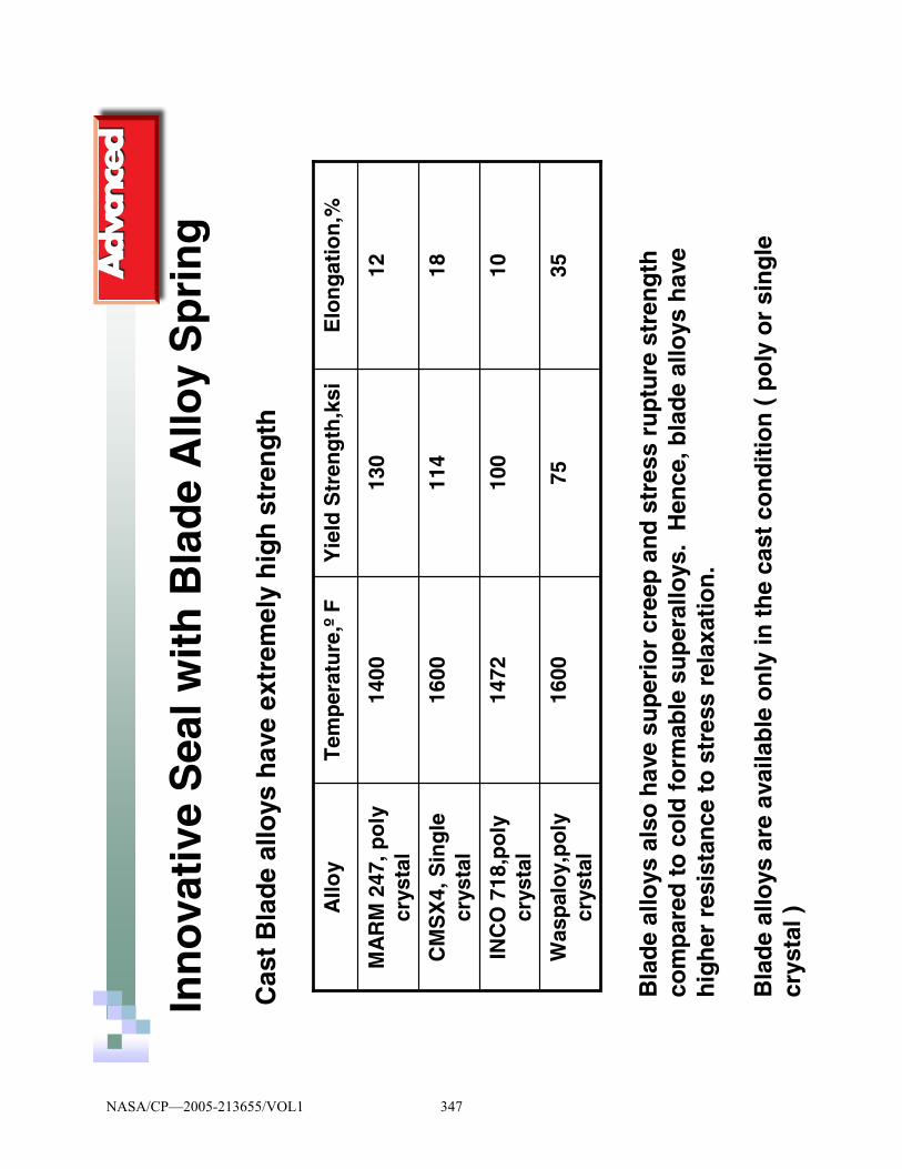
Inn
ova
tive
Sea
l wit
h B
lad
e A
lloy
Sp
rin
g
Cas
t B
lad
e al
loys
hav
e ex
trem
ely
hig
h s
tren
gth
3575
1600
Was
pal
oy,
po
ly
crys
tal
1010
014
72IN
CO
718
,po
ly
crys
tal
1811
416
00C
MS
X4,
Sin
gle
cr
ysta
l
1213
014
00M
AR
M 2
47, p
oly
cr
ysta
l
Elo
ng
atio
n,%
Yie
ld S
tren
gth
,ksi
Tem
per
atu
re,º
FA
lloy
Bla
de
allo
ys a
lso
hav
e su
per
ior
cree
p a
nd
str
ess
rup
ture
str
eng
th
com
par
ed t
o c
old
fo
rmab
le s
up
eral
loys
. H
ence
, bla
de
allo
ys h
ave
hig
her
res
ista
nce
to
str
ess
rela
xati
on
.
Bla
de
allo
ys a
re a
vaila
ble
on
ly in
th
e ca
st c
on
dit
ion
( p
oly
or
sin
gle
cr
ysta
l )
NASA/CP—2005-213655/VOL1 347

Inn
ova
tive
Sea
l wit
h B
lad
e A
lloy
Sp
rin
gC
om
par
iso
n o
f h
igh
tem
per
atu
re s
ealin
g d
esig
n
Sta
nd
ard
E-S
eal w
ith
bla
de
allo
y sp
rin
g
Cro
ss s
ecti
on
Sta
nd
ard
E-S
eal p
rod
uce
d
fro
m h
igh
tem
per
atu
re
Was
pal
oy
allo
y
Cro
ss s
ecti
on
NASA/CP—2005-213655/VOL1 348

Inn
ova
tive
Sea
l wit
h B
lad
e A
lloy
Sp
rin
g
Exp
erim
enta
l pro
ced
ure
:■
Sea
ls w
ere
com
pre
ssed
20%
bet
wee
n f
lan
ges
an
d h
eate
d t
o 1
600
oF
fo
r va
rio
us
tim
e p
erio
ds
■A
fter
eac
h e
xpo
sure
, sea
ls w
ere
coo
led
to
ro
om
te
mp
erat
ure
to
mea
sure
ch
ang
e in
sea
l fre
e h
eig
ht
■S
eals
wer
e le
ak t
este
d t
o e
valu
ate
hig
h
tem
per
atu
re e
xpo
sure
on
sea
ling
per
form
ance
■B
oth
fre
e h
eig
ht
chan
ge
and
sea
l lea
kag
e w
ere
plo
tted
as
a fu
nct
ion
of
exp
osu
re t
ime
at 1
600
oF
NASA/CP—2005-213655/VOL1 349

Inn
ova
tive
Sea
l wit
h B
lad
e A
lloy
Sp
rin
gC
om
par
iso
n o
f se
al f
ree
hei
gh
t ch
ang
e vs
. exp
osu
re t
ime
at 1
600F
NASA/CP—2005-213655/VOL1 350

Inn
ova
tive
Sea
l wit
h B
lad
e A
lloy
Sp
rin
g
Co
mp
aris
on
of
seal
leak
age
vs. e
xpo
sure
tim
e at
160
0F
NASA/CP—2005-213655/VOL1 351

New
Des
ign
wit
h s
ing
le c
ryst
al s
pri
ng
■C
ast
po
lycr
ysta
llin
e M
AR
M24
7 ri
ng
was
mac
hin
ed
usi
ng
ED
M -
--p
roh
ibit
ivel
y ex
pen
sive
!■
By
con
tro
llin
g f
ing
er d
esig
n(
ang
le, t
hic
knes
s, w
idth
, #o
f fi
ng
ers/
linea
r in
ch…
) sp
rin
g r
ate
or
seal
ing
load
co
uld
be
adju
sted
■S
ing
le c
ryst
als
are
mo
re r
esis
tan
t to
cre
ep a
nd
st
ress
rel
axat
ion
bec
ause
of
the
elim
inat
ion
of
gra
in
bo
un
dar
ies
■S
ing
le c
ryst
al f
ing
ers
can
be
cast
to
nea
r–n
et s
hap
e an
d a
ttac
hed
to
eas
ily m
ach
inab
le a
nd
ch
eap
er
sup
eral
loy
rin
g
NASA/CP—2005-213655/VOL1 352

New
Des
ign
wit
h s
ing
le c
ryst
al
spri
ng
Co
st e
ffec
tive
des
ign
with
cas
t si
ng
le c
ryst
al b
lad
e al
loy
spri
ng
s at
tach
ed t
o lo
wer
co
st m
ach
ined
rin
g
NASA/CP—2005-213655/VOL1 353

■H
igh
est
stre
ss c
om
po
nen
ts(
fin
ger
s) a
re m
ade
fro
m
the
mo
st c
reep
res
ista
nt
sin
gle
cry
stal
s, c
ost
ef
fect
ivel
y ca
st t
o n
et s
hap
e
■In
div
idu
al f
ing
ers
are
atta
ched
to
a lo
wer
co
st
sup
eral
loy
rin
g w
hic
h a
re e
asily
fab
rica
ted
. Str
esse
s in
th
e ri
ng
are
sig
nif
ican
tly
low
er
■D
evic
e sp
rin
g r
ate
can
be
easi
ly c
han
ged
by
sele
ctin
g t
he
# fi
ng
er/li
nea
r in
ch a
nd
th
e fi
ng
er
des
ign
New
Des
ign
wit
h s
ing
le c
ryst
al s
pri
ng
NASA/CP—2005-213655/VOL1 354

■B
y se
lect
ing
“so
ft”
crys
tallo
gra
ph
ic a
xis,
<10
0>,
alo
ng
th
e sp
rin
g a
xis,
th
e el
asti
c ra
ng
e o
f d
efle
ctio
n
can
be
max
imiz
ed
■F
or
Ni,
E11
1/ E
100
= 2.
2
■E
last
ic r
ang
e o
f se
al h
eig
ht
chan
ge
or
seal
def
lect
ion
ca
n b
e m
ore
th
an d
ou
ble
d b
y se
lect
ing
cry
stal
o
rien
tati
on
■F
EA
op
tim
izat
ion
has
yie
lded
des
ign
s w
ith
ela
stic
ra
ng
es m
ore
th
an 3
0% o
f se
al h
eig
ht
at 1
600-
1800
ºF
New
Des
ign
wit
h s
ing
le c
ryst
al s
pri
ng
NASA/CP—2005-213655/VOL1 355

Maximum Stress in Finger Spring
Def
lect
ion
or
Ch
ang
e in
Sea
l Hei
gh
t
Fin
ger
Axi
s II
to <
111>
Fin
ger
Axi
s II
to <
100>
1
2
Infl
uen
ce o
f C
ryst
allo
gra
ph
ic D
irec
tio
n
on
Sea
l Def
lect
ion
Cap
abili
ties
NASA/CP—2005-213655/VOL1 356

New
Des
ign
wit
h s
ing
le c
ryst
al s
pri
ng
Ap
plic
atio
ns
oth
er t
han
sea
ls
Tra
nsi
tio
n f
aste
ner
bet
wee
n m
etal
an
d c
eram
ic
com
po
nen
ts w
ith
a la
rge α-
mis
mat
ch
Co
mb
ust
or
CM
C li
ner
–lo
w lo
ad, l
arg
e d
efle
ctio
n
spri
ng
at
1800
F
Lo
w-l
oad
/ hig
h d
efle
ctio
n s
pri
ng
en
erg
izer
fo
r ex
trem
ely
hig
h t
emp
erat
ure
(>2
000F
) ce
ram
ic
slid
ing
sea
l
Cer
amic
R
ope
Sea
l
Zirc
oniu
m S
eal
Inte
rfac
e
Sin
gle
Cry
stal
B
lade
Allo
y S
prin
g
Met
al
Cas
ing
Cer
amic
Lin
er
Hig
h T
empe
ratu
re
Ann
ular
Spr
ing
NASA/CP—2005-213655/VOL1 357

Co
ncl
usi
on
s
■A
n in
no
vati
ve s
eal c
on
sist
ing
of
a b
lad
e al
loy
spri
ng
en
erg
izer
an
d c
old
fo
rmab
le s
up
eral
loy
jack
et c
an b
e d
esig
ned
fo
r ap
plic
atio
ns
abo
ve 1
500
oF
■T
he
seal
is e
xpec
ted
to
min
imiz
e co
olin
g a
ir a
nd
leak
age
ther
eby
enh
anci
ng
en
gin
e ef
fici
ency
■T
he
des
ign
can
be
furt
her
imp
rove
dw
ith
cas
t n
et s
hap
e si
ng
le c
ryst
al s
pri
ng
s at
tach
ed t
o a
n e
asily
mac
hin
able
su
per
allo
y ri
ng
■T
he
sin
gle
cry
stal
sp
rin
g s
tru
ctu
re c
an a
lso
be
use
d w
her
e lo
w
load
/ hig
h d
efle
ctio
n d
evic
e is
req
uir
ed f
or
extr
emel
y h
igh
te
mp
erat
ure
ap
plic
atio
ns
NASA/CP—2005-213655/VOL1 358

OXIDATION OF HIGH-TEMPERATURE ALLOY WIRES FOR HYBRID SEAL APPLICATIONS
Elizabeth J. Opila
National Aeronautics and Space Administration Glenn Research Center
Cleveland, Ohio
Jonathan A. Lorincz CON/SPAN
Dayton, Ohio
Marissa M. Reigel Colorado School of Mines
Golden, Colorado
Jeffrey J. Demange University of Toledo
Toledo, Ohio
Small diameter wires (150 to 250 μm) of the high-temperature alloys Haynes 188, Haynes 230, Haynes 214, Kanthal A1 and PM2000 were oxidized at 1204 °C in dry oxygen or 50 percent H2O/50 percent O2 for 70 hours. The oxidation kinetics were monitored using a thermogravimetric technique. Additional cyclic oxidation exposures were conducted in air for one hour cycles at 1204 °C for times up to 70 hours. Oxide phase composition and morphology of the oxidized wires were determined by x-ray diffraction, field emission scanning electron microscopy, and energy dispersive spectroscopy. The alumina-forming alloys, Kanthal A1 and PM2000, out-performed the chromia-forming alloys under these test conditions. Correlations between oxidation lifetime and wire diameter were considered. PM2000 was recommended as the most promising candidate for advanced hybrid seal applications for space reentry control surface seals or hypersonic propulsion system seals.
Glenn Research Center at Lewis Field
Oxidation of High-Temperature Alloy Wires for Hybrid Seal Applications
Elizabeth J. Opila, Jonathan A. Lorincz*, Marissa M. Reigel^, Jeffrey J. DeMange&
NASA Glenn Research Center, Cleveland, Ohio*CON/SPAN, Dayton, OH
^Colorado School of Mines, Golden, CO&University of Toledo, Toledo, OH
2004 NASA Seal/Secondary Air System WorkshopOhio Aerospace Institute
November 10, 2004
NASA/CP—2005-213655/VOL1 359

Glenn Research Center at Lewis Field
Why study oxidation of wires?Understanding of wire oxidation needed for development of advanced high-temperature seals for future hypersonic and reentry vehicles.
•Structural seal restricts hot gas leakage to underlying low-temperature control actuators
• Wire overwrap needed for wear resistance
NASA/CP—2005-213655/VOL1 360

Glenn Research Center at Lewis Field
State of the art hybrid seals
• Tmax=800°C• Ceramic batting or fiber core (alumina or
aluminosilicate)
• Haynes 188 or 230 overwrap/overbraid, 40-125 micron diameter wire
Nextel 312 fibersHaynes 230 overbraid
NASA/CP—2005-213655/VOL1 361

Glenn Research Center at Lewis Field
Requirements for advanced hybrid seals
• Withstand temperatures up to 1400°C• Operate without active cooling• Flexible, resilient, wear resistant
• Airframe control surface seals– Reentry environment: reduced pressure air, plasma– Reusability of 10 to 100 cycles of 30 minutes each
• Hypersonic propulsion system seals– Propulsion environment: high pressure water vapor– Reusability of 1000 cycles of 250 sec/cycle (70 hours)
NASA/CP—2005-213655/VOL1 362

Glenn Research Center at Lewis Field
Objectives of this study
• Characterize isothermal and cyclic oxidation resistance of high-temperature alloy wires
• Guide selection of higher temperature alloys for hybrid seal applications
NASA/CP—2005-213655/VOL1 363

Glenn Research Center at Lewis Field
Alloy wires
Fe base, 20 Cr, 5.5 Al, 0.5 Ti, 0.5 Y2O3
Fe base, 22 Cr, 5.8 Al, Si<0.7, Mn<0.4
Ni base, 16 Cr, 4.5 Al, 3 Fe, 0.2 Si, trace: Mn, Zr, C, B, Y
Ni base, 22 Cr, 14 W, Co<5, Fe<3, 2 Mo, 0.5 Mn, 0.4 Si, 0.3 Al, trace: C, La, B
Co base, 22 Cr, 22 Ni, 14 W, Fe< 3, Mn <1.25, 0.5 Si, 0.12 La, trace: C, B
Composition, wt%
150
250
250
250
250
Diameter, μm
PM 2000
Kanthal A1
Haynes 214
Haynes 230
Haynes 188
Alloy
Haynes 188, and 230 are chromia forming alloys. Haynew 214 is a marginal alumina forming alloy. Kanthal A1 and PM2000 are alumina forming alloys. PM2000 contains the reactive element Y2O3 which improves oxide adherence.
Note smaller diameter wire for PM2000.
NASA/CP—2005-213655/VOL1 364

Glenn Research Center at Lewis Field
Experimental Procedure
• Coil 60 cm length of wire• Oxidation of wires
– 1204°C (2200°F)– 1 atm– 70h– Three exposure environments
• Isothermal: O2 (0.4 cm/sec) • Isothermal: 50% H2O/50% O2 (4.4
cm/sec)• Cyclic: stagnant air, 1h hot, 20
min. cool, 70 cycles
• Weight change of wires• X-ray diffraction (XRD) analysis• Field Emission-Scanning Electron
Microscopy/Energy Dispersive Spectroscopy (FE-SEM/EDS)
0.5 cm
Weight gain indicates oxide formation. Weight loss indicates loss of oxide by spallation or volatilization.
NASA/CP—2005-213655/VOL1 365

Glenn Research Center at Lewis Field
Thermogravimetric Analysis
NASA/CP—2005-213655/VOL1 366

Glenn Research Center at Lewis Field
Cyclic Oxidation
One cycle = 1 hour hot, 20 minute cool..
NASA/CP—2005-213655/VOL1 367

Glenn Research Center at Lewis Field
Results for wire oxidation in dry O2
NASA/CP—2005-213655/VOL1 368

Glenn Research Center at Lewis Field
Weight change of wire: 1204°C, dry O2, 0.4 cm/s
0 10 20 30 40 50 60 70
time, h
0
2
4
6
8
10
12
14
16
18
20
spec
ific
wei
ght c
hang
e, m
g/cm
2Haynes 188Haynes 230Haynes 214Kanthal A1Kanthal A1PM 2000PM 2000
Haynes 188 completely oxidized after about 20 hours.
NASA/CP—2005-213655/VOL1 369

Glenn Research Center at Lewis Field
Weight change of wire: 1204°C, dry O2, 0.4 cm/s
0 10 20 30 40 50 60 70
time, h
0.0
0.5
1.0
1.5
2.0
2.5
3.0
3.5
4.0
spec
ific
wei
ght c
hang
e, m
g/cm
2Haynes 230
Haynes 214
PM2000
Kanthal A1
Haynes 188
Note: All compositions except PM2000 exhibited spallation on cooling
Haynes 230, PM2000, Kanthal A1 show desired parabolic oxidation kinetics.
Haynes 214 shows protective oxidation after initial transient of fast oxidation.
Bump in PM2000 kinetics at 45h may be due to depletion of alumina and beginning of chromia scale formation.
NASA/CP—2005-213655/VOL1 370

Glenn Research Center at Lewis Field
Coiled wires after oxidation: 1204°C, 70h, dry O2, 0.4 cm/s
Haynes 188 Haynes 230 Haynes 214
PM 2000Kanthal A1
0.5 cm
Haynes 188 brittle. Haynes 230, 214, Kanthal A1 show spallation to bare metal.
NASA/CP—2005-213655/VOL1 371

Glenn Research Center at Lewis Field
X-ray diffraction results for wires:1204°C, 70h, dry O2, 0.4 cm/s
Fe base, 20 Cr, 5.5 Al, 0.5 Y2O3
Fe base, 22 Cr, 5.8 Al
Ni base, 16 Cr, 4.5 Al
Ni base, 22 Cr, 14 W
Co base, 22 Cr, 22 Ni, 14 W
Major components of alloy, wt%
α Al2O3
α Al2O3
NiCr2O4/NiAl2O4NiO
Cr2O3NiCr2O4
NiO
NiWO4NiCr2O4
NiO
Oxidation products
PM 2000
Kanthal A1
Haynes 214
Haynes 230
Haynes 188
Alloy
Chromia formation not observed for Haynes 188 after 70h. Note presence of NiWO4 oxide phase.
First three alloys show spinel (AB2O4) formation. This is not a protective oxide.
NASA/CP—2005-213655/VOL1 372

Glenn Research Center at Lewis Field
Cross-sectional FE-SEM of wire: 1204°C, 70h, dry O2, 0.4 cm/s
100 μm
Haynes 214
100 μm
Haynes 230
100 μm
Kanthal A1
100 μm
Haynes 188
100 μm
PM2000
Haynes 188: (Co,Ni)O, CoCr2O4, CoWO4-bright phase. Wire completely consumed.
Haynes 230: Cr2O3
Haynes 214: Al2O3 inner layer, spinel outer layer, NiO blocks on surface
Kanthal A1: Oxide scale completely nonadherent.
NASA/CP—2005-213655/VOL1 373

Glenn Research Center at Lewis Field
Summary of results:Wire oxidation 1204°C, 70h, dry O2, 0.4 cm/s
• Haynes 188 completely oxidized• Haynes 230 formed chromia scale, spalled on cool down• Haynes 214 formed inner alumina scale, external spinel, NiO,
spalled on cool down• Kanthal A1 formed alumina scale, completely nonadherent after
cool down• PM2000 smaller diameter wire formed an adherent alumina
scale, aluminum completely depleted from wire, inner discontinuous layer of chromia, internal void formation
NASA/CP—2005-213655/VOL1 374

Glenn Research Center at Lewis Field
Results for wire oxidation in 50% H2O/50% O2
NASA/CP—2005-213655/VOL1 375

Glenn Research Center at Lewis Field
0 10 20 30 40 50 60 70
time, h
0
1
2
3
4
5
6
7
8
spec
ific
wei
ght c
hang
e, m
g/cm
2Haynes 188Kanthal A1PM2000
Weight change of wire: 1204°C, 50% H2O/50 %O2, 4.4 cm/s
Different weight change behavior for Haynes 188 explained on next slide.
NASA/CP—2005-213655/VOL1 376

Glenn Research Center at Lewis Field
0 10 20 30 40 50 60 70
time, h
0
2
4
6
8
10
12
14
16
18
20
spec
ific
wei
ght c
hang
e, m
g/cm
2
dry O250% O2/50% H2O
wire completely oxidized
oxid
atio
n
oxid
atio
n &
vola
tiliz
atio
n
volatilization: WO2(OH)2(g), Ni(OH)2(g)
Weight change of Haynes 188 wire: 1204°C
NASA/CP—2005-213655/VOL1 377

Glenn Research Center at Lewis Field
Volatility of oxides formed on Haynes 188 exposed at 1204°C, 50% H2O/50 %O2
Deposit found on hanger downstream of sample. Deposit determined to be WO3and NiWO4 by XRD.
Calculated gas species formed from oxides in water vapor. W is very volatile.
NASA/CP—2005-213655/VOL1 378

Glenn Research Center at Lewis Field
0 10 20 30 40 50 60 70
time, h
0.0
0.2
0.4
0.6
0.8
1.0
1.2
1.4
1.6
1.8
2.0
spec
ific
wei
ght c
hang
e, m
g/cm
2
Kanthal A1PM2000
Weight change of wire: 1204°C, 50% H2O/50 %O2, 4.4 cm/s
Breakaway oxidation for PM2000 at 68 h.
NASA/CP—2005-213655/VOL1 379

Glenn Research Center at Lewis Field
0 10 20 30 40 50 60 70
time, h
0.0
0.2
0.4
0.6
0.8
1.0
1.2
1.4
1.6
1.8
2.0
spec
ific
wei
ght c
hang
e, m
g/cm
2
dry O2dry O250% O2/50% H2O
Weight change of PM2000 wire: 1204°C
NASA/CP—2005-213655/VOL1 380

Glenn Research Center at Lewis Field
Correlation between breakaway oxidation and wire diameter
• Breakaway oxidation occurs when aluminum is depleted to low level: protective oxide scale formation no longer possible
• Aluminum depletion depends on ratio of wire volume to surface area.– Extrapolating time to breakaway for PM2000 at 1204°C in 50% H2O for
other wire diameters.
Wm = weight of metal consumed during oxidation, V = wire volume, A = wire surface area, r = wire radius, t = oxidation time
– Experimentally determined time to breakaway for 150 μm dia wire is 68h.
– Predict time to breakaway for 250 μm dia wire is 189h for comparison to other alloy wires of 250 μm dia.
– Predict time to breakaway for 40 μm dia wire at 5h for finest diameter wire proposed for use in seal applications.
2b
2a
b
a
mAV
m
r
rtt
tWrW
=
∝=∝
NASA/CP—2005-213655/VOL1 381

Glenn Research Center at Lewis Field
Fe base, 20 Cr, 5.5 Al, 0.5 Y2O3
Fe base, 22 Cr, 5.8 Al
Co base, 22 Cr, 22 Ni, 14 W
Major components of alloy, wt%
(Fe,Cr)2O3
α Al2O3
NiO NiCr2O4
Oxidation products
PM 2000
Kanthal A1
Haynes 188
Alloy
X-ray diffraction results for wires:1204°C, 70h, 50% H2O/50% O2, 4.4 cm/s
No W containing phase found on Haynes 188. W is completely volatilized.
Al2O3 not found on PM2000 after 70h in this environment in contrast to results in dry O2.
NASA/CP—2005-213655/VOL1 382
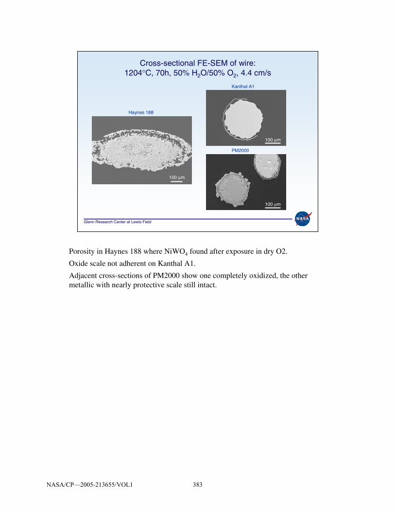
Glenn Research Center at Lewis Field
Cross-sectional FE-SEM of wire: 1204°C, 70h, 50% H2O/50% O2, 4.4 cm/s
100 μm
100 μm
100 μm
Haynes 188
Kanthal A1
PM2000
Porosity in Haynes 188 where NiWO4 found after exposure in dry O2.
Oxide scale not adherent on Kanthal A1.
Adjacent cross-sections of PM2000 show one completely oxidized, the other metallic with nearly protective scale still intact.
NASA/CP—2005-213655/VOL1 383

Glenn Research Center at Lewis Field
Summary of results: Wire oxidation, 1204°C, 70h, 50% H2O/50% O2, 4.4 cm/s
• Haynes 188 completely oxidized, all W volatilized leaving porosity.
• Kanthal A1 formed alumina scale, completely nonadherent, much of scale spalled.
• PM2000 smaller diameter wire experienced breakaway oxidation. Portions of wire completely oxidized, show remainderof alumina scale. Portions of wire show protective alumina scale.
• Time to breakaway oxidation expected to vary with the square of the wire diameter.
NASA/CP—2005-213655/VOL1 384

Glenn Research Center at Lewis Field
Cyclic Oxidation Results
NASA/CP—2005-213655/VOL1 385

Glenn Research Center at Lewis Field
Weight change of wire: 1204°C, stagnant air, 1 h cycles
0 10 20 30 40 50 60 70
Time (h)
0
2
4
6
8
10
Spe
cific
wei
ght c
hang
e (m
g/cm
2 )
Haynes 188Haynes 188PM2000PM2000Kanthal A1Kanthal A1failure
Haynes 188 weight change similar to isothermal exposures in that oxidation is about complete at 20h.
PM2000 showing parabolic oxidation to 60+ hours.
Kanthal A1 shows weight loss and spallation after third cycle. Breakaway oxidation at 55h.
NASA/CP—2005-213655/VOL1 386

Glenn Research Center at Lewis Field
X-ray diffraction results for wires:1204°C, 1h cycles, stagnant air
>70
60
30
Time to failure, h
Fe base, 20 Cr, 5.5 Al, 0.5 Y2O3
Fe base, 22 Cr, 5.8 Al
Co base, 22 Cr, 22 Ni, 14 W
Major components of alloy, wt%
tbd
Fe2O3
(Ni,Co)O (Ni,Co)Cr2O4
Oxidation products
PM 2000
Kanthal A1
Haynes 188
Alloy
Non protective Fe2O3 found for Kanthal A1.
NASA/CP—2005-213655/VOL1 387

Glenn Research Center at Lewis Field
Cross-sectional FE-SEM of wire: 1204°C, 1h cycles, stagnant air
100 μm
100 μm
100 μm
Haynes 188, 30 cycles
Kanthal A1, 60 cycles
Haynes 188 shows core of wire still present after 30 cycles.
Kanthal A1 has some cross-sections just beginning non-protective oxide formation (top) and others completely oxidized (bottom). The original wire diameter of Kanthal A1 is marked by darker phases (alumina and chromia) in lower right micrograph.
NASA/CP—2005-213655/VOL1 388

Glenn Research Center at Lewis Field
• Haynes 188 had similar failure time as in isothermal testing.
• Kanthal A1 failed earlier in cyclic oxidation testing. Weight loss and oxide spallation detected as early as third temperature cycle. Breakaway oxidation occurred after 55 cycles.
• PM2000 showed parabolic oxidation kinetics throughout 70h cyclic test. No evidence of spallation.
Summary of results: Wire oxidation, 1204°C, 1h cycles, stagnant air
NASA/CP—2005-213655/VOL1 389

Glenn Research Center at Lewis Field
Conclusions
• Alumina-forming alloys with reactive element additions perform best at 1204°C under all test conditions: O2, H2O, temperature cycling– Slow growing oxide– Alumina is the most stable protective oxide scale in water vapor
– Adherent scales
• Small diameter wires have limited oxidation lifetimes. – Limited reservoir of aluminum for protective scale formation
– Smaller diameter wires more prone to spallation: increased stress in oxide due to larger radius of curvature
• Oxidation lifetimes can be predicted based on the wire diameter and rate of aluminum loss.
• From these results PM2000 is recommended as the best candidate for further development in advanced hybrid seal applications.
NASA/CP—2005-213655/VOL1 390

Glenn Research Center at Lewis Field
Acknowledgments
Jim Smialek, many helpful discussionsRalph Garlick, X-ray diffraction
Patrick Dunlap, Bruce Steinetz, program support
This work was funded by the Next Generation Launch Technology Program
NASA/CP—2005-213655/VOL1 391


200
4 N
ASA
Sea
l/Sec
onda
ry A
ir S
yste
m W
orks
hop
Att
ende
esL
ast
Fir
stC
om
pan
yC
ity
Sta
teZ
ipP
ho
ne
Em
ail
Alb
ers
Rob
ert J
.G
ener
al E
lect
ricC
inci
nnat
iO
H45
215
513.
243.
7039
bob.
albe
rs@
ae.g
e.co
mA
ssio
nJo
eA
nale
x C
orp.
Cle
vela
ndO
H44
135
216.
433.
6712
jass
ion@
grc.
nasa
.gov
Bau
man
Ste
veN
AS
A G
lenn
Res
earc
h C
ente
rC
leve
land
OH
4413
521
6.43
3.38
26st
eve.
baum
an@
nasa
.gov
Bill
Rob
ert
NA
SA
Gle
nn R
esea
rch
Cen
ter
Cle
vela
ndO
H44
135
216.
433.
3694
robe
rt.c
.bill
@gr
c.na
sa.g
ovB
ond
Bru
ceJa
ckso
n B
ond
Ent
erpr
ises
, LLC
Roc
hest
erN
H03
867
603.
335.
7913
bruc
ebon
d@ea
rthl
ink.
net
Bow
nC
harle
sA
TK
Thi
okol
Brig
ham
City
UT
8430
243
5.27
9.62
59C
harle
y.B
own@
AT
K.c
omB
oyle
Mar
cia
GE
Airc
raft
Eng
ines
Cin
cinn
ati
OH
4521
551
3.24
3.53
15M
arci
a.B
oyle
@ae
.ge.
com
Bra
unM
inel
(Ja
ck)
Uni
vers
ity o
f Akr
onA
kron
OH
4432
533
0.97
2.77
34m
jbra
un@
uakr
on.e
duB
reen
Dan
NA
SA
Gle
nn R
esea
rch
Cen
ter
Cle
vela
ndO
H44
135
216.
433.
2660
dani
el.p
.bre
en@
g rc.
nasa
.gov
Cas
hC
arol
GE
Airc
raft
Eng
ines
Nor
th O
lmst
edO
H44
070
440.
777.
9545
caro
l.cas
h@ae
.ge.
com
Che
nV
icto
rT
he B
oein
g C
ompa
nyH
untin
gton
Bea
chC
A92
647
714.
896.
4989
vict
or.c
hen@
boei
ng.c
omC
hris
tians
enR
icha
rdN
AS
A G
lenn
Res
earc
h C
ente
rC
leve
land
OH
4413
521
6.43
3.53
08R
icha
rd.C
hris
tians
en@
nasa
.gov
Chu
ppR
ayG
E G
loba
l Res
earc
hN
iska
yuna
NY
1230
251
8.38
7.75
50ra
ymon
d.ch
upp@
crd.
ge.c
omC
ikan
ekH
arry
NA
SA
Gle
nn R
esea
rch
Cen
ter
Cle
vela
ndO
H44
135
216.
433.
6196
harr
y.ci
kane
k@na
sa.g
ovC
lark
Ste
phen
Boe
ing
Sea
ttle
WA
9812
442
5.23
7.12
24st
ephe
n.f.c
lark
@bo
eing
.com
Cla
rke
Dan
aA
pplie
d In
nova
tion
Alli
ance
, LLC
Wes
t Blo
omfie
ldM
I48
323
248.
682.
3368
dcla
rke@
aia-
cons
ultin
g.co
mC
ompt
onT
omG
E T
rans
port
atio
nE
vand
ale
OH
4521
551
3.24
3.24
22to
m.c
ompt
on@
ae.g
e.co
mD
anie
lsC
hris
NA
SA
Gle
nn R
esea
rch
Cen
ter
Cle
vela
ndO
H44
135
216.
433.
6714
chris
toph
er.c
.dan
iels
@gr
c.na
sa.g
ovD
atta
Am
itA
dvan
ced
Com
pone
nts
& M
ater
ials
Inc.
E. G
reen
wic
hR
I02
818
401.
885.
5064
AD
atta
@w
orld
net.a
tt.ne
tD
eCas
tro
Jona
than
NA
SA
Gle
nn R
esea
rch
Cen
ter
Cle
vela
ndO
H44
135
216.
433.
3946
jona
than
.dec
astr
o@gr
c.na
sa.g
ovD
elga
doIr
eber
tN
AS
A G
lenn
Res
earc
h C
ente
rC
leve
land
OH
4413
521
6.43
3.39
35ire
bert
.r.d
elga
do@
nasa
.gov
DeM
ange
Jeff
rey
J.N
AS
A G
lenn
Res
earc
h C
ente
rC
leve
land
OH
4413
521
6.43
3.35
68Je
ffre
y.D
eman
ge@
nasa
.gov
DiC
arlo
Jam
esN
AS
A G
lenn
Res
earc
h C
ente
rC
leve
land
OH
4413
521
6.43
3.55
14ja
mes
.a.d
icar
lo@
nasa
.gov
Die
tzel
Bill
Flo
wse
rve
FS
DK
alam
azoo
MI
4900
126
9.22
6.34
93w
diet
zel@
flow
serv
e.co
mD
imof
teF
lorin
Uni
vers
ary
of T
oled
oC
leve
land
OH
4413
521
6.43
3.74
68flo
rin.d
imof
te@
nasa
.gov
Dob
ekLo
uis
J.P
ratt
and
Whi
tney
Eas
t Har
tford
CT
0610
886
0.56
5.30
34
dobe
klj@
pweh
.com
Dun
lap
Pat
NA
SA
Gle
nn R
esea
rch
Cen
ter
Cle
vela
ndO
H44
135
216.
433.
3017
patr
ick.
h.du
nlap
@na
sa.g
ovE
berly
Eric
NA
SA
Mar
shal
l Spa
ce F
light
Cen
ter
MS
FC
AL
3581
225
6.54
4.20
92er
ic.a
.ebe
rly@
nasa
.gov
Epp
ehim
erJo
hnS
tein
Sea
l Com
pany
Kul
psvi
lleP
A19
443
215.
256.
0201
John
Epp
ehim
er@
stei
nsea
l.com
Erk
erA
rtN
AS
A G
lenn
Res
earc
h C
ente
rC
leve
land
OH
4413
521
6.43
3.29
11ar
thur
.erk
er@
anal
ex.c
omF
inkb
eine
rJo
shua
NA
SA
Gle
nn R
esea
rch
Cen
ter
Cle
vela
ndO
H44
135
216.
433.
6080
josh
ua.fi
nkbe
iner
@na
sa.g
ovF
lahe
rty
And
rew
Flo
wse
rve
Cor
p.T
emec
ula
CA
9259
095
1.71
9.44
12A
flahe
rty@
Flo
wse
rve.
com
Gar
rett
Will
iam
Pow
derm
et In
c.E
uclid
OH
4411
721
6.40
4.00
53x1
18w
rgar
rett@
p ow
derm
etin
c.co
mG
arris
onG
lenn
Ste
in S
eal C
ompa
nyK
ulps
ville
PA
1944
321
5.25
6.06
07gl
enng
arris
on@
stei
nsea
l.com
Gei
shei
mer
Jon
Rad
atec
, Inc
.A
tlant
aG
A30
308
404.
526.
6037
jong
@ra
date
c.co
mG
inty
Car
olN
AS
A G
lenn
Res
earc
h C
ente
rC
leve
land
OH
4413
521
6.43
3.33
35C
arol
.Gin
ty@
nasa
.gov
Giri
unas
Juliu
sN
AS
A G
lenn
Res
earc
h C
ente
rC
leve
land
OH
4413
521
6.43
3.37
94ju
lius.
giriu
nas@
nasa
.gov
Giro
nM
ark
Per
kinE
lmer
Flu
id S
cien
ces
Bel
tsvi
lleM
D20
705
301.
902.
3648
mar
k.gi
ron@
perk
inel
mer
.com
Gos
horn
Dav
idG
E A
ircra
ft E
ngin
esC
inci
nnat
iO
H45
215
513.
243.
8164
davi
d.go
shor
n@ae
.ge.
com
Gra
vere
aux
Ste
phen
J.
Adv
ance
d P
rodu
cts
Com
pany
, Inc
Nor
th H
aven
CT
0647
3 86
0.65
8.62
00sg
rave
reau
x@ad
vpro
.com
Gro
ndah
lC
layt
onC
MG
Tec
h, L
LCR
exfo
rdN
Y12
148
518.
371.
5050
cmgt
ech@
eart
hlin
k.ne
tH
arm
onC
ryst
alP
ratt
& W
hitn
eyN
orth
Olm
sted
OH
4407
044
0.73
4.39
90cr
ysta
l.har
mon
@pw
.utc
.com
Hen
dric
ksR
ober
t C.
NA
SA
Gle
nn R
esea
rch
Cen
ter
Cle
vela
ndO
H44
135
216.
977.
7507
robe
rt.c
.hen
dric
ks@
nasa
.gov
Her
ron
Will
iam
L.
Gen
eral
Ele
ctric
Cin
cinn
ati
OH
4521
551
3.24
3.74
45w
illia
m.h
erro
n@ae
.ge.
com
Hig
gins
Mar
kP
erki
nElm
er F
luid
Sci
ence
sB
elts
ville
MD
2070
530
1.90
2.36
45m
ark.
higg
ins@
perk
inel
mer
.com
Jack
son
Han
kJa
ckso
n B
ond
Ent
erpr
ises
, LLC
Roc
hest
erN
H03
867
603.
335.
7913
Just
akJo
hn F
.A
dvan
ced
Tec
hnol
ogie
s G
roup
Stu
art
FL
3499
477
2.28
3.02
53jju
stak
@ad
vanc
edtg
.com
Kei
thT
heo
G.
NA
SA
Gle
nn R
esea
rch
Cen
ter
Cle
vela
ndO
H44
135
216.
433.
3944
theo
.g.k
eith
@na
sa.g
ov
NASA/CP—2005-213655/VOL1 393

200
4 N
ASA
Sea
l/Sec
onda
ry A
ir S
yste
m W
orks
hop
Att
ende
esL
ast
Fir
stC
om
pan
yC
ity
Sta
teZ
ipP
ho
ne
Em
ail
Kis
erJ.
Dou
glas
NA
SA
Gle
nn R
esea
rch
Cen
ter
Cle
vela
ndO
H44
135
216.
433.
3247
Jam
es.D
.Kis
er@
nasa
.gov
Kla
mar
Jose
phJG
K T
echn
oSys
tem
sH
udso
nO
H44
236
330.
656.
3274
jgkl
amar
@ya
hoo.
com
Kra
ftT
hom
asN
AS
A G
lenn
Res
earc
h C
ente
rC
leve
land
OH
4413
521
6.43
3.29
36th
omas
.g.k
raft@
nasa
.gov
Kro
haM
icha
elF
low
serv
eK
alam
azoo
MI
4900
126
9.22
6.34
28m
kroh
a@flo
wse
rve.
com
Kru
mpe
ltM
icha
elA
rgon
ne N
atio
nal L
abor
ator
yA
rgon
neIL
6043
963
0.25
2.85
20kr
umpe
lt@cm
t.anl
.gov
Latti
me
Sco
ttO
AI -
NA
SA
Gle
nn R
esea
rch
Cen
ter
Cle
vela
ndO
H44
135
216.
433.
5953
scot
t.lat
time@
nasa
.gov
Loew
enth
alR
ober
tA
dvan
ced
Com
pone
nts
& M
ater
ials
Inc.
Jam
esto
wn
RI
0283
540
1.42
3.19
57bo
bloe
w@
cox.
net
Mak
hobe
yM
ark
Car
-Gra
ph, I
nc.
Tem
peA
Z85
281
480.
894.
1356
mm
akho
bey@
car-
grap
h.co
mM
cCal
lR
yan
Gar
lock
Hel
icof
lex
Col
umbi
aS
C29
209
803.
783.
1880
ryan
.mcc
all@
garlo
ck.c
omM
elis
Mat
thew
NA
SA
Gle
nn R
esea
rch
Cen
ter
Cle
vela
ndO
H44
135
216.
433.
3322
Mat
thew
.Mel
is@
grc.
nasa
.gov
Mor
eD
. Gre
gA
dvan
ced
Pro
duct
s C
ompa
nyN
orth
Hav
enC
T06
473
203.
985.
3141
gmor
e@ad
vpro
.com
Mun
son
John
Rol
ls R
oyce
Cor
p.In
dian
apol
isIN
4626
031
7.23
0.64
09Jo
hn.H
.Mun
son@
Rol
ls-R
oyce
.com
Nag
pal
Vin
odN
&R
En g
inee
ring
and
Man
g ag m
ent S
ervi
ces
Par
ma
Hts
.O
H44
130
440.
845.
7020
vnag
p al@
nren
g ine
erin
g .co
mO
pila
Eliz
abet
hN
AS
A G
lenn
Res
earc
h C
ente
rC
leve
land
OH
4413
521
6.43
3.89
04E
lizab
eth.
Opi
la@
nasa
.gov
Osw
ald
Jay
Cas
e W
este
rn R
eser
ve U
.C
leve
land
OH
4410
621
6.75
4.18
08jx
o26@
po.c
wru
.edu
Pao
lillo
Rog
erP
ratt
& W
hitn
eyE
ast H
artfo
rdC
T06
108
860.
557.
1460
paol
ilre@
pweh
.com
Paq
uette
Ted
Ref
ract
ory
Com
posi
tes,
Inc.
Gle
n B
urni
eM
D21
060
410.
768.
2490
tedp
aque
tte@
rciu
sa.c
omP
arris
hT
omE
aton
Aer
oqui
pJa
ckso
nM
I49
202
517.
789.
4171
Tom
AP
arris
h@ea
ton.
com
Pen
dlet
onE
dmun
dA
ir F
orce
Res
earc
h La
b/V
AS
DW
right
Pat
ters
on A
FB
O
H45
433
937.
255.
7387
Edm
und.
Pen
dlet
on@
wpa
fb.a
f.mil
Pic
kett
Pau
lS
olar
Tur
bine
s, In
c.S
an D
iego
CA
9218
661
9.54
4.54
20pi
cket
t_pa
ul_e
@so
lart
urbi
nes.
com
Pie
rson
Haz
el M
.U
nive
rsity
of A
kron
Akr
onO
H44
325
330.
941.
3017
hmp i
erso
n@y s
u.ed
uP
roct
orM
arga
ret
NA
SA
Gle
nn R
esea
rch
Cen
ter
Cle
vela
ndO
H44
135
216.
977.
7526
mar
gare
t.p.p
roct
or@
nasa
.gov
Raw
lings
Chr
isto
pher
Flo
rida
Tur
bine
Tec
hnol
ogie
s, In
c.Ju
pite
rF
L33
477
561.
746.
3317
craw
lings
@ftt
inc.
com
Rob
bie
Mal
colm
NA
SA
Gle
nn R
esea
rch
Cen
ter
Cle
vela
ndO
H44
135
216.
433.
5490
mal
colm
.g.r
obbi
e@gr
c.na
sa.g
ovR
ober
tson
B
rand
anN
AS
A J
ohns
on S
pace
Cen
ter
Hou
ston
TX
7705
828
1.48
3.37
32br
anda
n.r.
robe
rtso
n@na
sa.g
ovR
oche
Bria
nS
tein
Sea
l Com
pany
Kul
psvi
lleP
A19
443
215.
256.
0201
bria
nroc
he@
stei
nsea
l.com
Rui
zR
afae
lG
ener
al E
lect
ricC
inci
nnat
iO
H45
215
513.
243.
5364
rafa
el.r
uiz@
ae.g
e.co
mS
anko
vic
Den
isR
adia
n M
ilpar
tsE
astla
keO
H44
095
440.
946.
5921
deni
s@m
ilpar
ts.n
etS
haug
hnes
syD
enni
sP
ratt
& W
hitn
eyE
ast H
artfo
rdC
T06
108
860.
557.
1675
denn
is.s
haug
hnes
sy@
pw.u
tc.c
omS
herm
anA
ndre
wP
owde
rmet
Inc.
Euc
lidO
H44
117
216.
404.
0053
pow
derm
et@
eart
hlin
k.ne
tS
hiJu
nU
nite
d T
echn
olog
ies
Res
earc
h C
ente
rE
ast H
artfo
rdC
T06
108
860.
610.
1539
shij@
utrc
.utc
.com
Sm
allw
ood
Dre
wT
he B
oein
g C
ompa
nyH
untin
gton
Bea
chC
A92
648
714.
896.
2098
Dre
w.S
mal
lwoo
d@bo
eing
.com
Sol
omon
Dan
Per
kinE
lmer
Flu
id S
cien
ces
Bel
tsvi
lleM
D20
705
301.
902.
3442
dan.
solo
mon
@pe
rkin
elm
er.c
omS
poth
Kev
inH
oney
wel
l - E
ngin
es &
Sys
tem
sP
hoen
ixA
Z85
034
602.
231.
2524
kevi
n.sp
oth@
hone
ywel
l.com
Sta
ngo
Rob
ert
Mar
quet
te U
nive
risty
Milw
auke
eW
I53
233
414.
288.
6972
Rob
ert.S
tang
o@m
u.ed
uS
tein
etz
Bru
ceN
AS
A G
lenn
Res
earc
h C
ente
rC
leve
land
OH
4413
521
6.43
3.33
02br
uce.
m.s
tein
etz@
nasa
.gov
Tay
lor
Sha
wn
Cas
e W
este
rn R
eser
ve U
.C
leve
land
Hts
.O
H44
106
216.
320.
1332
smt1
6@cw
ru.e
duT
aylo
rT
hom
asP
raxa
ir S
urfa
ce T
echn
olog
ies
Indi
anap
olis
IN46
224
317.
240.
2614
Tho
mas
_Tay
lor@
prax
air.
com
Tho
mas
G. R
icha
rdB
ently
Pre
ssur
ized
Bea
ring
Com
pany
Min
den
NV
8942
377
5.78
3.46
42ric
hard
.thom
as@
bpb-
co.c
omT
hom
asM
ark
D.
AT
K T
hiok
ol In
cB
righa
m C
ityU
T84
302
435.
863.
3582
mar
k.th
omas
@at
k.co
mT
ritz
Ter
ryT
he B
oein
g C
ompa
nyS
eattl
eW
A98
124
425.
234.
5194
terr
ance
.g.tr
itz@
boei
ng.c
omT
urnq
uist
Nor
mG
E G
loba
l Res
earc
h C
ente
rN
iska
yuna
NY
1230
951
8.38
7.59
78tu
rnqu
ist@
crd.
ge.c
omV
allie
reA
lan
Car
-Gra
ph, I
nc.
Tem
peA
Z85
281
480.
894.
1356
aval
liere
@ca
r-gr
aph.
com
Virt
ueJo
hnP
ratt
& W
hitn
eyE
ast H
artfo
rdC
T06
450
860.
565.
4770
virt
uej@
pweh
.com
Wat
tsO
. A. (
Bud
)A
lliso
n A
dvan
ced
Dev
elop
men
t Co.
Indi
anap
olis
IN46
202
317.
230.
6726
bud.
wat
ts@
aadc
.com
Yun
Hee
Man
NA
SA
Gle
nn R
esea
rch
Cen
ter
Cle
vela
ndO
H44
135
216.
433.
6089
heem
an.y
un@
grc.
nasa
.gov
Zhe
ngX
iaoq
ing
Per
kinE
lmer
War
wic
kR
I02
888
401.
473.
2274
Xia
oqin
g.Z
heng
@P
erki
nElm
er.c
om
NASA/CP—2005-213655/VOL1 394

This publication is available from the NASA Center for AeroSpace Information, 301–621–0390.
REPORT DOCUMENTATION PAGE
2. REPORT DATE
19. SECURITY CLASSIFICATION OF ABSTRACT
18. SECURITY CLASSIFICATION OF THIS PAGE
Public reporting burden for this collection of information is estimated to average 1 hour per response, including the time for reviewing instructions, searching existing data sources,gathering and maintaining the data needed, and completing and reviewing the collection of information. Send comments regarding this burden estimate or any other aspect of thiscollection of information, including suggestions for reducing this burden, to Washington Headquarters Services, Directorate for Information Operations and Reports, 1215 JeffersonDavis Highway, Suite 1204, Arlington, VA 22202-4302, and to the Office of Management and Budget, Paperwork Reduction Project (0704-0188), Washington, DC 20503.
NSN 7540-01-280-5500 Standard Form 298 (Rev. 2-89)Prescribed by ANSI Std. Z39-18298-102
Form ApprovedOMB No. 0704-0188
12b. DISTRIBUTION CODE
8. PERFORMING ORGANIZATION REPORT NUMBER
5. FUNDING NUMBERS
3. REPORT TYPE AND DATES COVERED
4. TITLE AND SUBTITLE
6. AUTHOR(S)
7. PERFORMING ORGANIZATION NAME(S) AND ADDRESS(ES)
11. SUPPLEMENTARY NOTES
12a. DISTRIBUTION/AVAILABILITY STATEMENT
13. ABSTRACT (Maximum 200 words)
14. SUBJECT TERMS
17. SECURITY CLASSIFICATION OF REPORT
16. PRICE CODE
15. NUMBER OF PAGES
20. LIMITATION OF ABSTRACT
Unclassified Unclassified
Conference Publication
Unclassified
National Aeronautics and Space AdministrationJohn H. Glenn Research Center at Lewis FieldCleveland, Ohio 44135–3191
1. AGENCY USE ONLY (Leave blank)
10. SPONSORING/MONITORING AGENCY REPORT NUMBER
9. SPONSORING/MONITORING AGENCY NAME(S) AND ADDRESS(ES)
National Aeronautics and Space AdministrationWashington, DC 20546–0001
Available electronically at http://gltrs.grc.nasa.gov
October 2005
NASA CP—2005-213655–VOL1
E–15144–1
WBS–22–714–70–42
400
2004 NASA Seal/Secondary Air System Workshop
Bruce M. Steinetz and Robert C. Hendricks, editors
Seals; Turbine; Clearance control, Materials; Analyses; Experimental; Design, Dockingmechanism; Leakage
Unclassified -UnlimitedSubject Categories: 37, 16, and 99 Distribution: Nonstandard
Proceedings of a conference held at Ohio Aerospace Institute sponsored by NASA Glenn Research Center, Cleveland,Ohio, November 9–10, 2004. Responsible person, Bruce M. Steinetz, organization code RSM, 216–433–3302.
The 2004 NASA Seal/Secondary Air System workshop covered the following topics: (i) Overview of NASA’s new ExplorationInitiative program aimed at exploring the Moon, Mars, and beyond; (ii) Overview of the NASA-sponsored Ultra-Efficient EngineTechnology (UEET) program; (iii) Overview of NASA Glenn’s seal program aimed at developing advanced seals for NASA’sturbomachinery, space, and reentry vehicle needs; (iv) Reviews of NASA prime contractor and university advanced sealing conceptsincluding tip clearance control, test results, experimental facilities, and numerical predictions; and (v) Reviews of material developmentprograms relevant to advanced seals development. The NASA UEET overview illustrated for the reader the importance of advancedtechnologies, including seals, in meeting future turbine engine system efficiency and emission goals. For example, the NASA UEETprogram goals include an 8- to 15-percent reduction in fuel burn, a 15-percent reduction in CO2, a 70-percent reduction in NOx, CO,and unburned hydrocarbons, and a 30-dB noise reduction relative to program baselines. The workshop also covered several programsNASA is funding to develop technologies for the Exploration Initiative and advanced reusable space vehicle technologies. NASA planson developing an advanced docking and berthing system that would permit any vehicle to dock to any on-orbit station or vehicle, aspart of NASA’s new Exploration Initiative. Plans to develop the necessary mechanism and “androgynous” seal technologies werereviewed. Seal challenges posed by reusable re-entry space vehicles include high-temperature operation, resiliency at temperature toaccommodate gap changes during operation, and durability to meet mission requirements.