
WORKSHOP DEPARTMENT
24
WORKSHOP DEPARTMENT 1. DISMANTLING SECTION 2. ENGINE OVERHAULING & ASSEMBLY SECTION 3.UNIT 4. FUEL INJECTION SECTION (FIS) 5.RETRIVAL 6. ELECTRICAL SECTION 7. SUSPENSION SECTIONAND VEHICLE OVERHAULING SECTION BODY - BUILDING DEPARTMENT 1. WELDING SECTION 2. CARPENTRY & SHEET METAL SECTION 3. PAINTING SECTION WORKSHOP DEPARTMENT 1. DISMANTLING SECTION This section deals with the dismantling of the various parts of the vehicle. The vehicle accessories are separated to provide for keen scrutiny of the defective parts.
Transcript of WORKSHOP DEPARTMENT
WORKSHOP DEPARTMENT
1.DISMANTLING SECTION
2.ENGINE OVERHAULING & ASSEMBLY SECTION
3.UNIT
4.FUEL INJECTION SECTION (FIS)
5.RETRIVAL
6.ELECTRICAL SECTION
7.SUSPENSION SECTIONAND VEHICLE OVERHAULING SECTION
BODY - BUILDING DEPARTMENT
1.WELDING SECTION
2.CARPENTRY & SHEET METAL SECTION
3.PAINTING SECTION
WORKSHOP DEPARTMENT
1.DISMANTLING SECTION
This section deals with the dismantling of the
various parts of the vehicle. The vehicle accessories
are separated to provide for keen scrutiny of the
defective parts.
Generally the overhauling is required in the
following events:
1. Power loss due to poor engine compression
2. Excessive consumption of lubricating oil.
3. Mechanical failures such as excessive noise due to
defective ignition or
injection.
The hood of the engine compartment is first
removed. All coolants hoses are disconnected, the
radiator mounting bolts are removed and the radiator
is lifted from the engine compartment. All wires,
tubing and controls connecting the engine to the
automobile are removed and tagged. The alternator and
fans are removed to avoid damage during removal of
engine. After that the driver shaft and exhaust pipes
are disconnected. The mounting bolts are at last
removed and the hoist is operated to lift the engine.
The dismantling procedure is then followed by:
Removal of:
1. Cylinder head.
2. Valves and valve mechanism.
3. Piston-connecting rod assembly.
4. Cylinder.
5. Crankshaft and main bearings.
2. ENGINE OVERHAULING AND ASSEMBLY SECTION
This department deals with the reconditioning and
testing of engines and engine parts. The
reconditioning process consists of various steps such
as de-assembly, maintenance and assembly of the
engine.
Duringthe de-assembly of the engine each part is
removed from the engine with great care. The main
parts while considering an engine are cylinder block,
cylinder head, crank case, And each have its own
sections for its maintenance. During the maintenance
of each engine, the damaged parts are found out and
it is replaced. And the non-damaged parts are cleaned
and reused. All parts are well lubricated and is
assembled. The testing of the engine is done at the
testing area. During the process the engine is tested
for analyzing its performance.
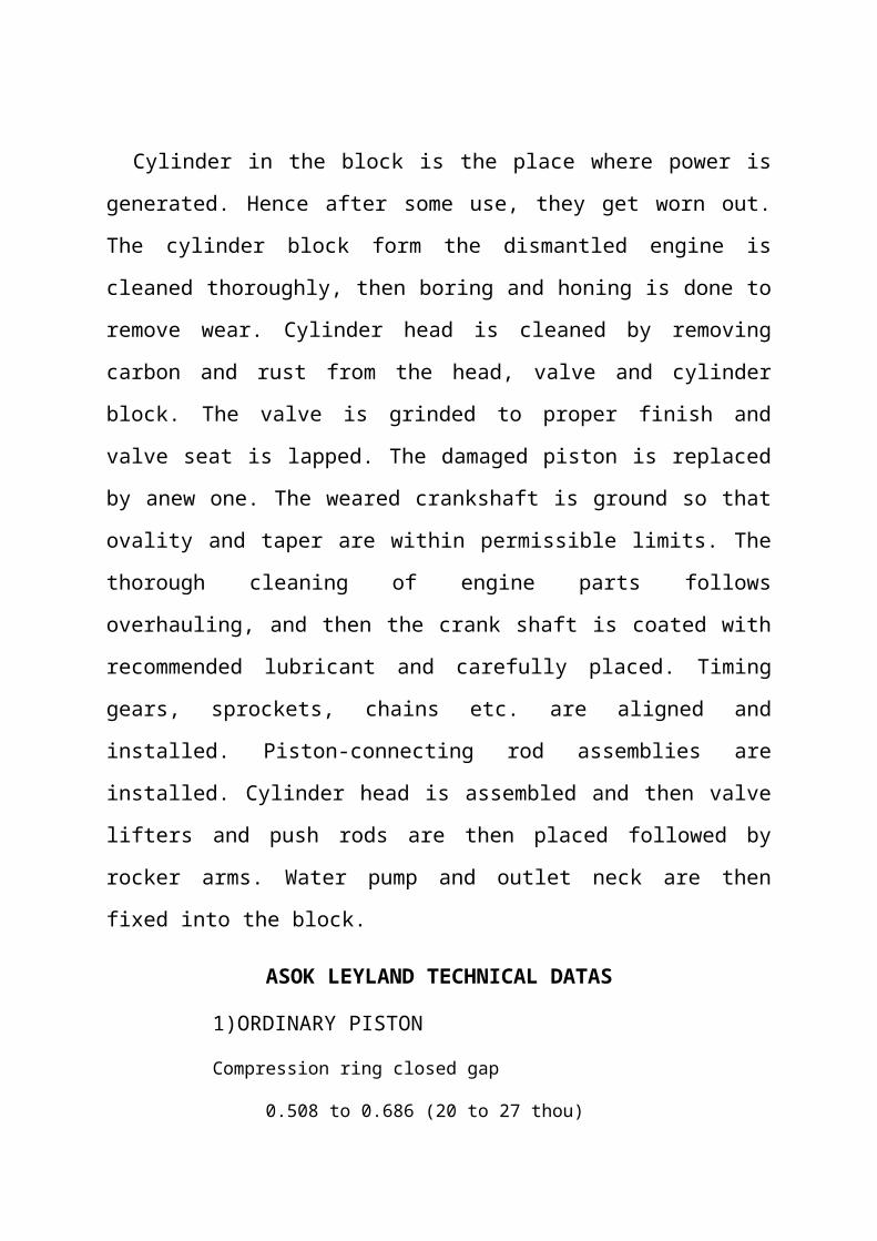
Cylinder in the block is the place where power is
generated. Hence after some use, they get worn out.
The cylinder block form the dismantled engine is
cleaned thoroughly, then boring and honing is done to
remove wear. Cylinder head is cleaned by removing
carbon and rust from the head, valve and cylinder
block. The valve is grinded to proper finish and
valve seat is lapped. The damaged piston is replaced
by anew one. The weared crankshaft is ground so that
ovality and taper are within permissible limits. The
thorough cleaning of engine parts follows
overhauling, and then the crank shaft is coated with
recommended lubricant and carefully placed. Timing
gears, sprockets, chains etc. are aligned and
installed. Piston-connecting rod assemblies are
installed. Cylinder head is assembled and then valve
lifters and push rods are then placed followed by
rocker arms. Water pump and outlet neck are then
fixed into the block.
ASOK LEYLAND TECHNICAL DATAS
1)ORDINARY PISTON
Compression ring closed gap
0.508 to 0.686 (20 to 27 thou)
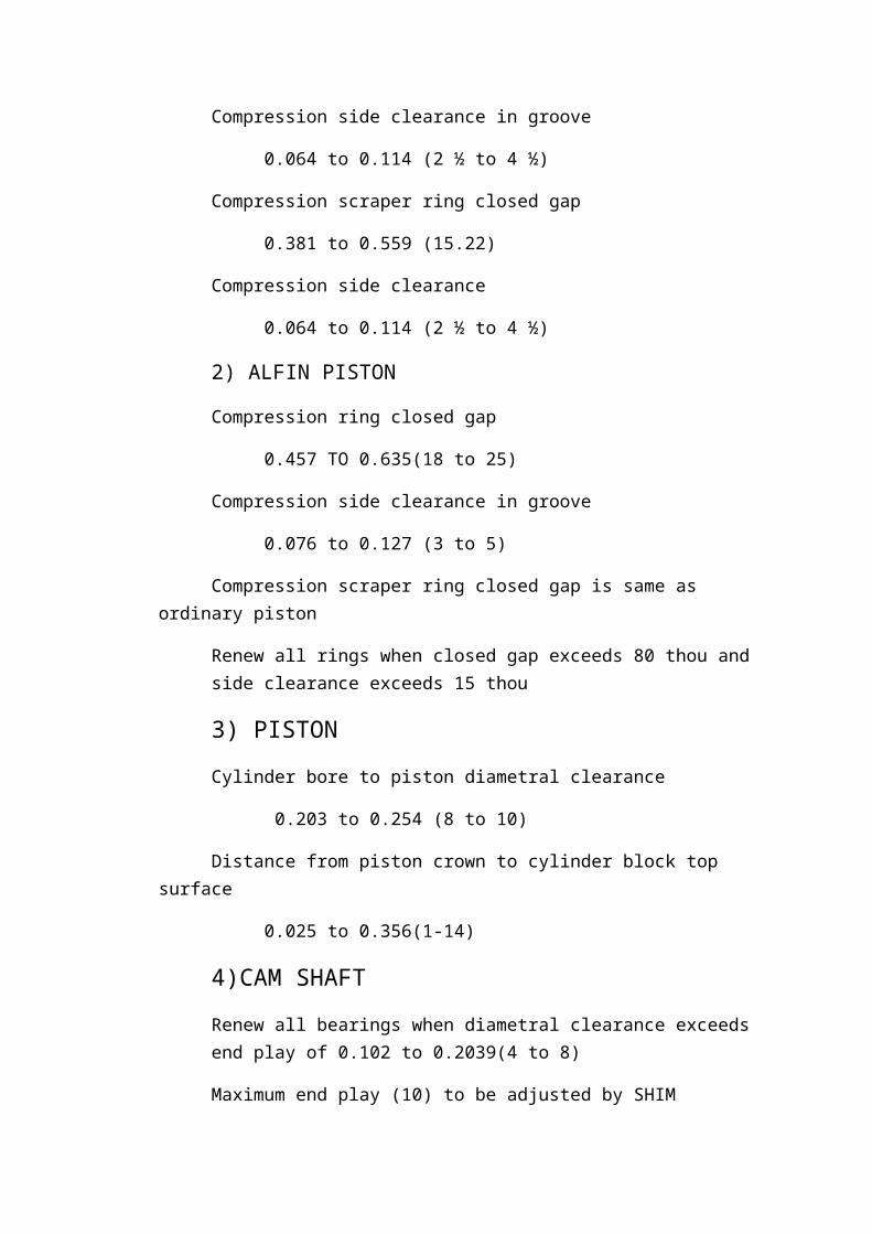
Compression side clearance in groove
0.064 to 0.114 (2 ½ to 4 ½)
Compression scraper ring closed gap
0.381 to 0.559 (15.22)
Compression side clearance
0.064 to 0.114 (2 ½ to 4 ½)
2) ALFIN PISTON
Compression ring closed gap
0.457 TO 0.635(18 to 25)
Compression side clearance in groove
0.076 to 0.127 (3 to 5)
Compression scraper ring closed gap is same as ordinary piston
Renew all rings when closed gap exceeds 80 thou and side clearance exceeds 15 thou
3) PISTONCylinder bore to piston diametral clearance
0.203 to 0.254 (8 to 10)
Distance from piston crown to cylinder block top surface
0.025 to 0.356(1-14)
4)CAM SHAFTRenew all bearings when diametral clearance exceeds end play of 0.102 to 0.2039(4 to 8)
Maximum end play (10) to be adjusted by SHIM
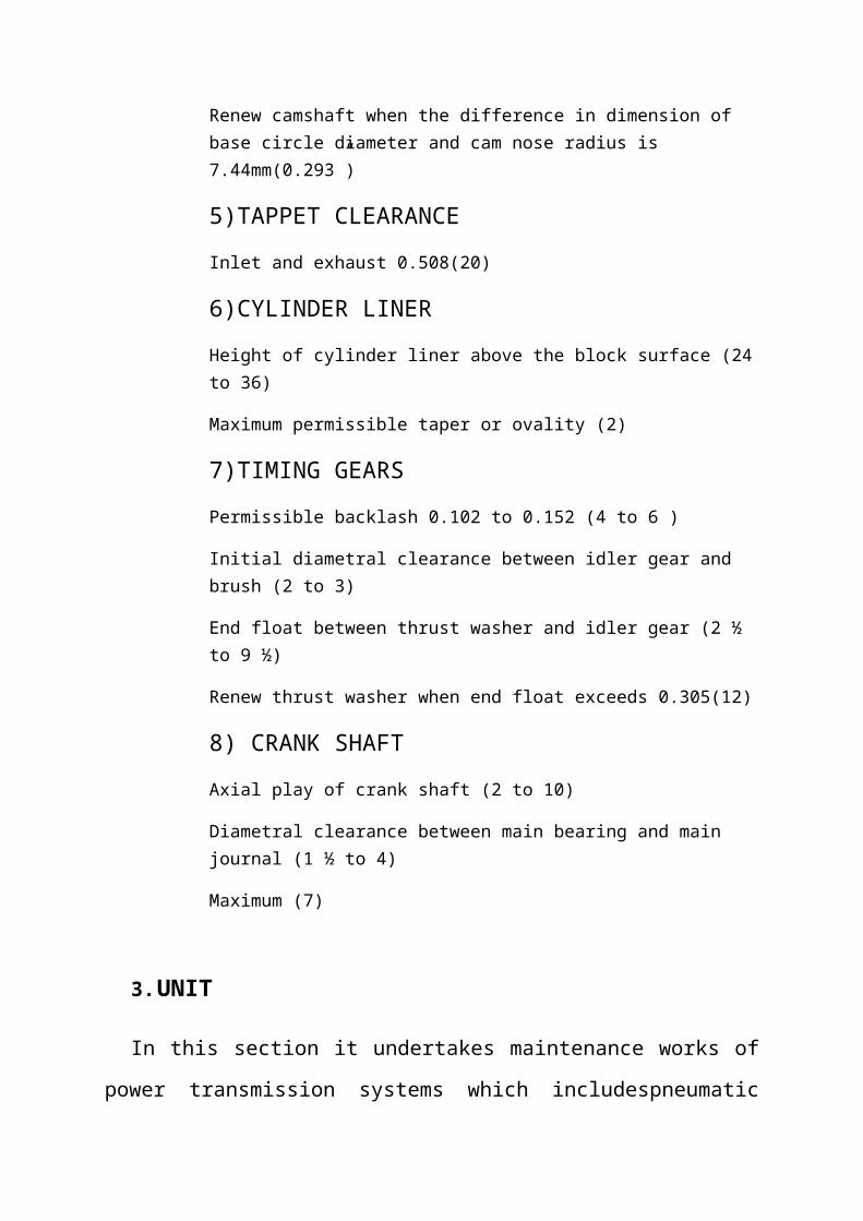
Renew camshaft when the difference in dimension of base circle diameter and cam nose radius is 7.44mm(0.293”)
5)TAPPET CLEARANCEInlet and exhaust 0.508(20)
6)CYLINDER LINER Height of cylinder liner above the block surface (24to 36)
Maximum permissible taper or ovality (2)
7)TIMING GEARSPermissible backlash 0.102 to 0.152 (4 to 6 )
Initial diametral clearance between idler gear and brush (2 to 3)
End float between thrust washer and idler gear (2 ½ to 9 ½)
Renew thrust washer when end float exceeds 0.305(12)
8) CRANK SHAFTAxial play of crank shaft (2 to 10)
Diametral clearance between main bearing and main journal (1 ½ to 4)
Maximum (7)
3.UNIT
In this section it undertakes maintenance works of
power transmission systems which includespneumatic
braking, steering, propeller shafts, gear
box,differential power transmission unit, front and
rear axles.
The teeth of all gears are checked and the needle
bearing if worn out is replaced. The clutchand the
sleeve are checked for wear and the splines are checked
for wear. Thegear parts are then assembled, reverse
gear first and then the second, third, fourth gears in
correct order with adequate provision for the washer and
slide needle.
The repairing of gear boxes take place, gears which
have either worn out or gone out of alignment are
brought to this section, where it is cleaned
thoroughly and then the entire gear box is dismantled
and the parts which are damaged beyond recovery are
replaced and the parts that can be repaired are done
so. After which the parts are assembled back together
using sufficient lubricants for each set of gears.
Propeller shafts are a different section within the
Unit, the old buses used a two propeller shaft
system. Now a three shaft system is used, where there
is a front shaft,a central shaft and a rear shaft.
Which are attached using universal joints. The shafts
are checked for bends and straightened out.
Differential is fitted in the rear axle and is a
mechanism in which one wheelis allowed to run faster or
slower than the second rear wheel as and when required.
The systems used in the buses are of crown and pinion
arrangement. This department is handled by technical
staff specializing in it. These gears are very prone
to wear and tear, the transmission system requires
constant maintenance as it is needed for high
efficient power transmission. Each toothon crown
wheelpinion, sun and star pinion is inspected for any
broken teeth.
Front and rear axles are also repaired in the Unit.
The part which gets damaged more quickly are the
bearings in the axle which are replaced with new
bearings and then sent to be fit back in the bus.
Pneumatic system i.e., it works on compressed air
is used as the braking system in the buses. This
department is isolated from all other departments and
have specialized technical staff and they do the
repairs for the compressor, distribution system. They
repair it and on the pressure checking system they
check the condition. There are two models of air
braking system. OVERHAULING OF GEAR BOX
Gearbox is fitted after clutch assembly and has a
set of gears, which can be engaged to increase
driving torque to cope up road and load condition of
vehicle. The teeth of all gears are checked & the
needle bearing if worn out is replaced. The dog
clutch and the sleeve are checked for pitted teeth
and the splines are checked for wear. The gear parts
are then assembled, reverse gear first and then the
second, third, fourth gears in correct order with
adequate provision for the washer and slide needle.
OVERHAULING OF PROPELLER SHAFT
The propeller shaft is used to transmit power
from the gear box to the rear axle.Keeping the
propeller shaft on the v-block and with a dial gauge
check the propellershaft for bends, this should not
exceed 2mm.If more, it is straightened out using
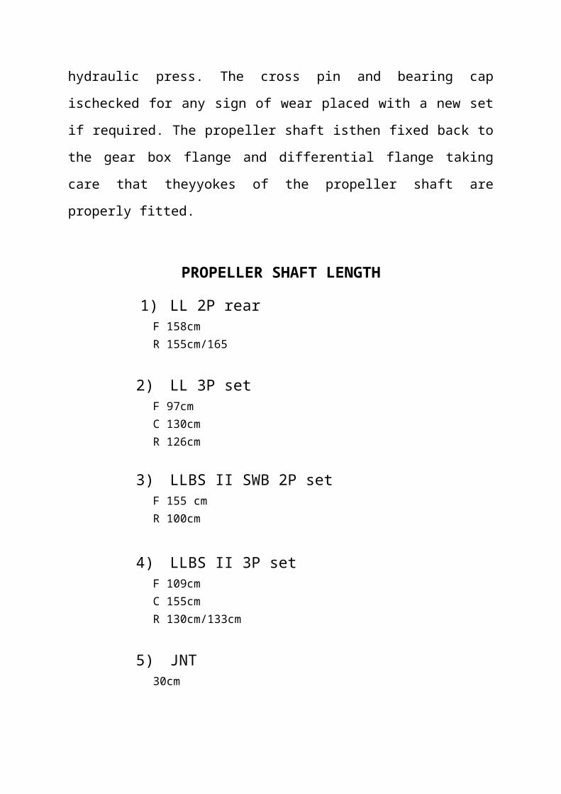
hydraulic press. The cross pin and bearing cap
ischecked for any sign of wear placed with a new set
if required. The propeller shaft isthen fixed back to
the gear box flange and differential flange taking
care that theyyokes of the propeller shaft are
properly fitted.
PROPELLER SHAFT LENGTH
1) LL 2P rearF 158cmR 155cm/165
2) LL 3P setF 97cmC 130cmR 126cm
3) LLBS II SWB 2P setF 155 cmR 100cm
4) LLBS II 3P setF 109cmC 155cmR 130cm/133cm
5) JNT30cm
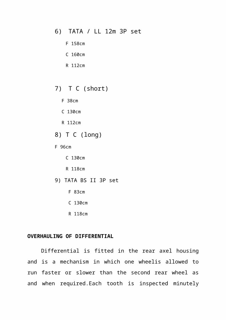
6) TATA / LL 12m 3P set F 158cm
C 160cm
R 112cm
7) T C (short)F 38cm
C 130cm
R 112cm
8) T C (long)F 96cm
C 130cm
R 118cm
9) TATA BS II 3P set
F 83cm
C 130cm
R 118cm
OVERHAULING OF DIFFERENTIAL
Differential is fitted in the rear axel housing
and is a mechanism in which one wheelis allowed to
run faster or slower than the second rear wheel as
and when required.Each tooth is inspected minutely

for any pitting or broken teeth on crown wheelpinion,
sun and star pinion and if worn out is replaced. The
thrust washer and pinionbearing are also checked for
damages. Checking the back lash of the sun pinion
with astar pinion using dial gauge does assembly of
the differential. The pinion is assembledin oil seal
with new oil seal in reverse order and after washing
the differential castingthe pinion is inserted. The
differential assembly is then fixed back in axle
housingwith new gasket and nuts are all tight.
PARTS
1)CROWN PARTS
TEETH 35, 37, 41
BOLT
TATA-8,16
LEYLAND-16,12
PINION TEETH
FOR CROWN TEETH(35,37) -6TEETH
FOR CROWN TEETH(41) - 7 TEETH
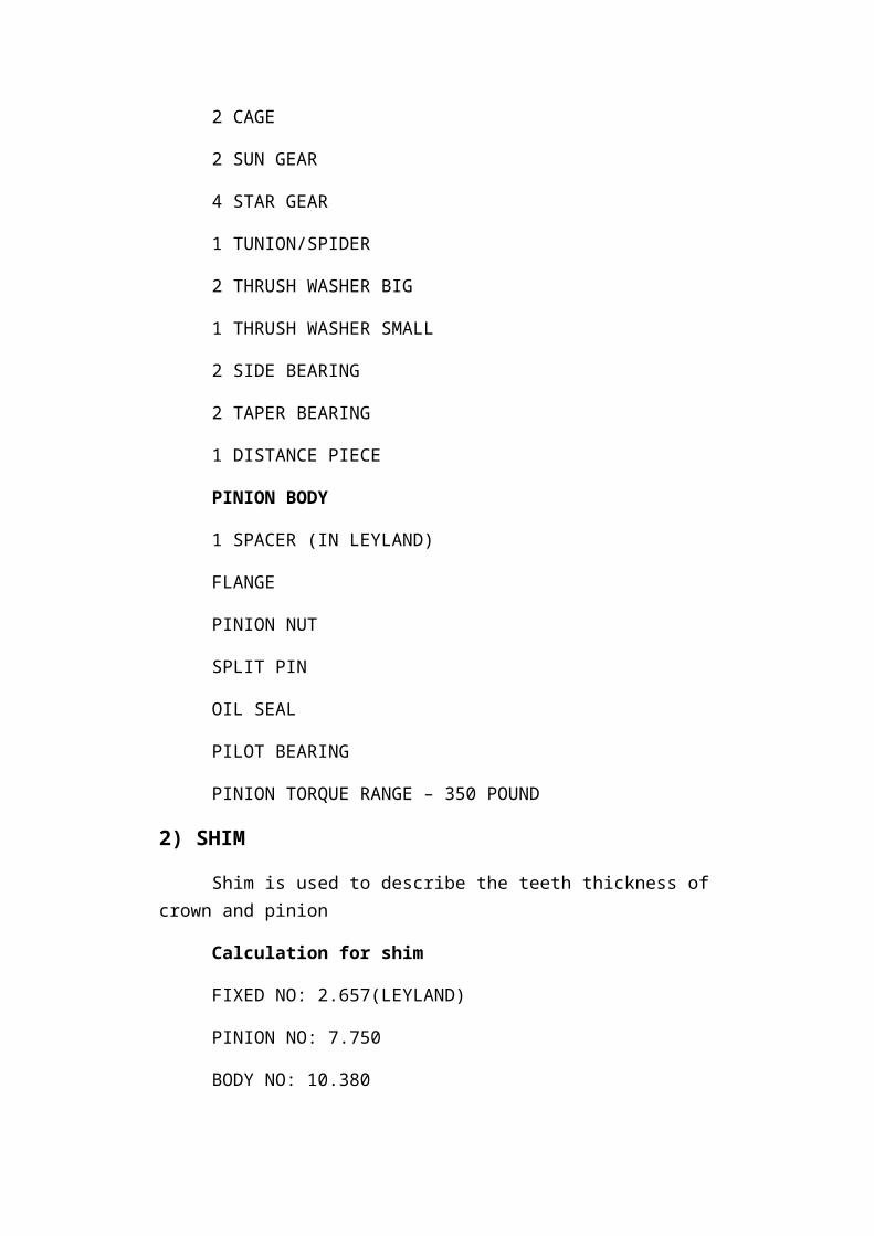
2 CAGE
2 SUN GEAR
4 STAR GEAR
1 TUNION/SPIDER
2 THRUSH WASHER BIG
1 THRUSH WASHER SMALL
2 SIDE BEARING
2 TAPER BEARING
1 DISTANCE PIECE
PINION BODY
1 SPACER (IN LEYLAND)
FLANGE
PINION NUT
SPLIT PIN
OIL SEAL
PILOT BEARING
PINION TORQUE RANGE – 350 POUND
2) SHIM
Shim is used to describe the teeth thickness of crown and pinion
Calculation for shim
FIXED NO: 2.657(LEYLAND)
PINION NO: 7.750
BODY NO: 10.380

SHIM=(FIXED NO + PINION NO) – BODY NO
DIAMETER OF SHIM IS 27
PLAY RATE IN LEYLAND – 12 TO 20 THOU
1 THOU =1 inch/1000
PLAY RATE IN TATA -8 TO 12 THOU
BODY ASSEMBLY TORQUE RANGE 250 POUND
PROVIDE OIL GRADE 140
4. FUEL INJECTION SECTION
The injection system consists of fuel tank, fuel
feed pump, fuel injection pump, fuelfilter, fuel
injection nozzle and a governor. The injection pump
pumps meteredquantity of fuel to all injectors and
ands should build enough pressure so that dieselgets
sprayed in fine atomized form. To increase or
decrease the quantity of the fuel a helix is cut on
top of the plunger. The alignment of this helix
determines the quantityf fuel pumped.The delivery
valve keeps the injector pipe always filled up with
diesel oil. This valvesits back on its seat after the
pumping operation and the space vacated by the
pistonmade on delivery valve is taken up by the
diesel oil under pressure in the pipe. These engines
are equipped with governors to ensure that engine
doesn’t pick up speedwhen there is no load, as the
engine speed is dependent on quantity of fuel
supplied.
The diesel is fed into the injection pump in two
ways namely gravity feed and forcedfeed. The
injection pump must give equal quantity of fuel to
all cylinders and thesupply should commence and stop
at fixed degree of crank angle both of which
arechecked and adjusted on the injection pump test
bench. Phasing of injection pump isdone by mounting
the injection pump on the test bench and noting the
angle of delivery on its flywheel.Fuel filter is
necessary to supply clean fuel otherwise dust will
wear the plunger andbarrel. Primary filter made of
felt and secondary filter made of paper, which needs
tobe replaced at regular intervals, are highly
recommended.Injectors are used to spray diesel in
fine atomized state before the piston reaches TDCin
compression stroke. Injectors should commence and cut
off fuel rapidly and at thesame time should not
dribble. Facilities have been provided for suitable
testing of theinjectors, which includes
i. Leak off test: The injector tester is worked up
to build a pressure of 150 atms,which is kept for
10 seconds (without spraying).In case there is a
drop inpressure the body seat and the needle is
lapped.
ii. Spray test: The injector is fixed up as done
earlier and pressure gauge isdisconnected by
closing the valve. The tester is worked up four
times and asecond and the spray pattern is noted.
If the spray pattern is in the form of astream or
jet, the needle and the nozzle body seat requires
grinding.
Nozzle and needle come in as one unit with the
needle circular in shape having a taperend while
nozzle body has fine finish. Where the needle can
slide there is a circulargroove called pressure
chamber at the lower end connected to the oil gallery
in the body though a drilled hole and it is from this
hole diesel oil reaches the pressurechamber and lifts
the nozzle valve of its seat and gets sprayed in
atomized form.
5.RETRIVALIn this department they deal with the maintenance
and reconditioning of the clutch assembly. The clutch
plate is checked for wear of the clutch lining wear.
Clutch is a coupling fitted immediately after the
engine in between the gear box to disconnect engine
power to gear box to change gear, to stop the vehicle
as well as to allow the engine to take up load
gradually. Visual inspection of friction flywheel
surface is done for any scoring mark, heat crack and
the pilot bearing play is checked by inserting a
finger in the bearing and feeling the play. Clutch
plate is checked for wear of the clutch lining wear.
Cracks in the clutch plate steel disc are also
checked. The pressure plate is checked for heat
damages, cracks and flatness using a steel rule of
feeler gauge. After cleaning all the parts and
checking for any undue play in the linkage, the parts
are assembled.

TATA CLUTCH TECHNICAL DATAS
Pressure plate diameter=310mm
Finger=4nos
Spring=16nos
Return spring=4nos
Push type
TATA FOUR FINGER/TC
Pressure plate=330mm
Spring=16nos
Finger=4nos
Return spring=4nos
TATA THREE FINGER T/C
Pressure plate=330mm
Spring=9nos
Finger=3nos
Withdraw plate=1nos
Return spring=1nos
TATA-1616 (BS-3 ENGINE)
Pressure plate dia=350mm
Spring=21
12big,9small
Finger=3nos
Release bearing=1nos
Roll type
Tapered cover
5.ELECTRICAL SECTION
In the electrical department, they deal with the
reconditioning work of alternators and starter
motors. Alternators are present in many different
models depending upon the engine manufacturer. There
are two types of starters repaired in this section
one is the old type using a solenoid. The starter has
a main housing, pinion gear, armature, field coils
with brushes and a solenoid. The engine oil at times
leaks into the starter motor and thus it stops
running. The parts except the casing are replaced.
Alternator is used to recharge the battery using the
engine power, it is a generator. It is given to the
engine using a belt. The coil in the alternator is
replaced and reconditioned for use in the future.
6. SUSPENSION SECTION & VEHICLE OVERHAULING
SECTION
The automobile chassis is mounted on the axles, not
direct but through some for m of springs. This is
done to prevent road shocks form being transmitted to
the vehiclecomponents, safe guard the occupants from
road shocks and to preserve the stabilityof vehicle
in pitching or rolling while in motion. All the parts
which perform thefunction of isolating the automobile
from the road shocks are collectively
calledsuspension systems. The buses here commonly use
the semi-elliptic steel leaf springvariety. These are
selected for their excellent durability and elastic
capability.The spring consists of a number of leaves
called blades. All t he blades are boundtogether by
means of steel straps. The spring is supported on the
axle, front or rear bymeans of a v-belt. One end of
the spring is mounted on the frame with a simple
pinwhile on the other end connection is made with a
shackle. When the vehicle comesacross a projection on
the road surface, the wheel moves up deflecting the
spring, thischanges the length between the spring
eyes. If both the ends are fixed the spring willnot
be able to accommodate this change of length. This is
provided by means of ashackle, which gives a flexible
connection.
REPAIR AND MAINTENANCE OF SUSPENSION SYSTEMS
After prolonged us or over loading, spring
assembly gets flattened or one or two of itsleaves
get broken. The centre bolt is then removed ant the
broken leaf is dismantledand replaced with the new
one. The rubber bushes, which are used to hinge
thesuspension systems to the chassis, are greased and
are replaced if these are worn out.
The Chassis frame supports the load of the vehicle
and provides connecting link between frame and rear
axle to withstand stresses caused due to cornering,
breaking,sudden acceleration or bad road
conditions.Rough use of vehicle may cause the chassis
to crack, bent and dislocate its weldedparts. The
loose and distorted rivets are removed and new heated
rivets are fixed. Redoxide paint is s prayed on the
chassis frame to prevent corrosion. If the chassis
hasmet with an accident, it should be straightened
out and the alignment checked, failingwhich, running
the bent chassis will make the steering hard and eat
away the tyre.Defects in the external body of the
bus, which is made of sheet metal, are checked andthe
necessary corrective steps are taken. These include
providing fresh coat of paint tothe rusted parts.
Distorted portions of the sheet metal are then
sharpened out. Newones replace the worn out furniture
if necessary or the existing ones are repaired.
BODY BUILDING DEPARTMENT
The chassis coming from the factories is brought
to this section and the body is builtthrough a
continuous process of welding, carpentry, sheet metal
and painting. Thisdepartment essentially deals with
the assembly of the interior and the exterior parts

of the bus with the engine, gear parts etc. being
bought from other automobilecompanies like TATA and
ASHOK LEYLAND.In the welding section the steel
structure is welded to the chassis. To this frame
work wooden attachments consisting of the platform,
the foot board and the wooden partsby the window sill
are fixed. The skeleton frame work is then covered
using the sheetmetal section. Care is taken to ensure
a clean and stable fit. Nuts, bolts along
withadditional fixtures are provided wherever
necessary to provide compactness to thestructure.
Painting glass fixing, seating arrangements and other
finishing touches aredone to ready out the interior
and exterior portions.
CONCLUSION
The industrial training to KSRTC gave us an
insight into the operation of industry and also the
various operations done in various departments.The
implant training we have done in KSRTC Central Works
provided as with great exposure in the field of
automotive engineering and in the management of
industrial activities taking place in an organized
manner. The most efficient way of work done is also
studied from that industry. That is the great
experience of all the group members.