
Levetiracetam (LEV) bei Epilepsien im Kindesalter?Erste Multicenter-Erfahrungen in Deutschland

4 IEEEA&ESYSTEMSMAGAZINE NOVEMBER2013
INTRODUCTION
To take the heat off Soviet accusations of American aggres-sion following the downing of Gary Powers’s U-2 spy plane, on May 26, 1960, U.S. Ambassador Henry Cabot Lodge, Jr., displayed a large carved relief of the Great Seal of the United States at a United Nations’ Security Council debate. Unusu-ally, the seal contained a small cavity into which had been inserted a novel radio transmitter that had been used to bug the ambassador’s residence in Moscow.
On August 4, 1945, this seal, shown in Figure 1, had been presented to W. Averell Harriman, the U.S. ambassador to the Soviet Union, by the Soviet Young Pioneers (the equiv-alent of the Boy Scouts) as a gesture of friendship [1], [2]. After passing a routine x-ray check, the seal had been hung behind Harriman’s desk in his office at Spaso House, No. 10 Spasopeskovskaya Square, Moscow (the official residence of U.S. ambassadors to the Soviet Union from 1934).
This article examines the anecdotal and technical evidence relating to the bug in an attempt to determine whether it was just an early example of a passive radio-frequency identification (RFID) tag or a more sophisticated device that relied on harmonic reradiation. These consider-ations are important, because they resulted in the bug’s re-mained undetected until it was found, rather fortuitously, during George F. Kennan’s ambassadorship in September 1952. Most bug sweeps were undertaken by technicians af-ter hours, but according to Kennan [3], he had been asked by one of the security technical officers, Joseph Bezjian, if he could spend an evening going through the motions of performing some official work. It was during this session, while dictating to his secretary, that the bug was activated by the Soviet eavesdroppers. Its broadcasts had been de-
tected using a wideband (untuned) crystal detector [4], or according to Wright [5], the device had been discovered using a tunable receiver operating in the “howl-round” mode around 1800 MHz. The howl-round principle oper-ates by generating an amplified audio signal based on the demodulated radio-frequency signal transmitted by a bug. This feedback process produces a high-pitched squeal that can be useful in pinpointing the position of the transmis-sion.
After some searching, a small cylinder, about 20 mm in diameter, attached to a short rod antenna was found within the seal. The cylinder appeared to be some sort of micro-phone, as one face was covered by a thin diaphragm. Tiny holes drilled beneath the eagle’s beak (or through its nostril) coupled sound from the room to the device [4].
The bug had apparently been developed by Lev Termen (later Leon Theremin) during his time at the Sharashka (se-cret research and development labs associated with the Sovi-et Gulag labor camp system) at Kuchino, which was a facili-ty for radio electronics and measuring devices near Moscow.
Lev Termen’s Great Seal Bug AnalyzedGraham Brooker University of Sydney
Jairo Gomez Universidad de San Buenaventura, Colombia
Authors’ current address: G. Brooker, Australian Centre for Field Robotics, University of Sydney, Rose St. Building (J04), Sydney, NSW 2006, Australia, (E-mail: [email protected]). J. Gomez, Laboratorio de Medios Digitales e Interac-ción (MDI), Parque Tecnológico de la Umbría, Universidad de San Buenaventura, Avenida 10 de Mayo, La Umbría, Vía a Pance. Cali, Valle del Cauca, Colombia, South America, (E-mail: [email protected]). Manuscript received April 2, 2013, and ready for publication June 10, 2013. Review handled by P. Willett. 0885/8985/13/ $26.00 © 2013 IEEE
Figure 1. Copy of the Great Seal of the United States presented to W. Averell Harriman [2].

NOVEMBER2013 IEEEA&ESYSTEMSMAGAZINE 5
Termen was both a musician and a physicist and is probably best known as the inventor and player of the aetherphone, later known as the thereminvox, which had so impressed Lenin. After World War I, he had been in-vited to head a new experimental laboratory in the Ioffe Physical Laboratory, where he worked on high-frequency measurement methods. In 1927, during an international tour to promote his inventions, he decided to stay in the United States, where he changed his name to Leon Ther-emin. He returned, abruptly and for unknown reasons, to the Soviet Union in 1938; shortly after, he was arrested during one of Stalin’s purges and sentenced to 8 years in the Kolyma Gulag. Here he would almost certainly have died, but fortunately after only a few months, he was transferred to the Sharashka to work on military projects [6].
PHYSICAL CHARACTERISTICS OF THE BUG
According to various descriptions and drawings of the bug [1], [2], it consists of a silver-plated copper cylinder about
13 mm long and 20 mm in diameter, as shown in Figure 2. A central tuning post “mushroom” attached to a threaded backplate can be positioned relative to the thin conduc-tive diaphragm covering the front of the cavity to adjust the capacitance and hence the its resonant characteristics. Finally, an insulated rod antenna extending through the side of the cylinder terminates in a coupling disc within the cylinder.
Some sources include slots cut through the walls of the cylinder to limit the air-cushioning effects, but these have not been reproduced in the figure, nor are they considered during the subsequent analysis.
PRELIMINARY ANALYSIS
According to one reference [1], the bug is simply a long-range passive RFID tag that uses standard modulated back-scatter principles. However, other references suggest that it was tuned to one of the harmonics of the illuminating frequency [2], [5], [7]. This could be the reason howl-round techniques, standard at the time, were not effective unless
the bug was being illuminated by the external microwave source at the same time.
If the external antenna is considered as both the receiver for the excitation signal and the transmitter, it should be resonant at those frequencies. Taking into account the end effect for a /4 Marconi antenna with a length-to-diameter ratio of 50:1, the scale factor should be K = 0.955 [8]. An antenna with L = 0.228 m (9 in.) would therefore be resonant at
(1)
This equates to a resonant fre-quency of fres = 314 MHz in air. For higher-frequency operation, the resonant frequencies are not di-rect multiples of this fundamental because the end effect only occurs
Figure 2. Drawing showing the construction of the bug found in the great American seal.

6 IEEEA&ESYSTEMSMAGAZINE NOVEMBER2013
Lev Termen’s Great Seal Bug Analyzed
once. The general formula for the resonant frequency, where N is the number of quarter wavelengths, is [8]
(2)
Table 1 lists the first six resonant frequencies, from which it is clear that the 1800-MHz howl-round frequency men-tioned by Wright [5] is feasible. The frequency of the illu-minating source would still be reasonably well matched to the antenna if the 1800-MHz signal was a harmonic of the fundamental, say, 600 or 900 MHz.
The main question that now needs to be answered is, Would the cavity resonate at one of these frequencies?
DETAILED ANALYSIS
CAVITYRESONANCEFREQUENCY
According to [1], [2], and [4], the bug was made from silver-plated copper. However, to simplify the modeling process using the high-frequency structure simulator (HFSS), the
cylinder material was specified to be copper, with polytet-rafluoroethylene insulating the antenna feed, as shown in Figure 3. The resonant characteristics of the cavity were then determined using eigenmode analysis.
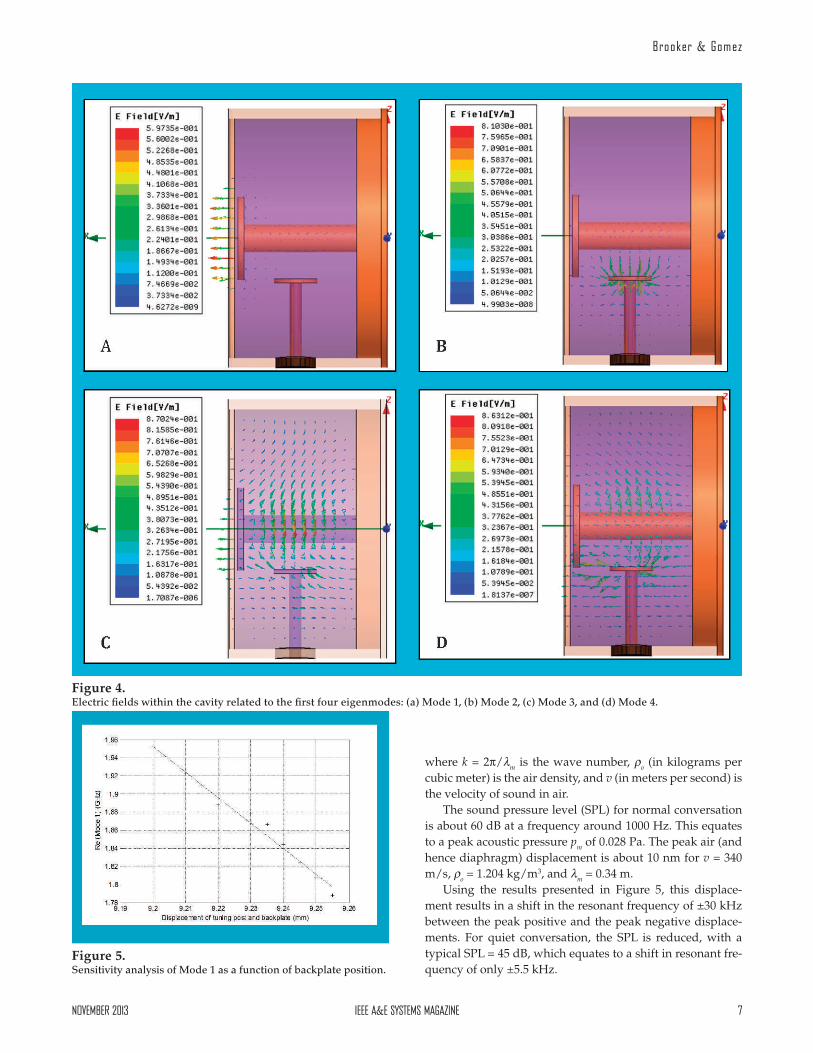
Examination of the first four modes, listed in Table 2 and shown in Figure 4, indicates that most of the resonant fre-quencies are too high. However, the first mode is sufficiently close to 1800 MHz to be useful. In addition, it can be seen that this mode couples strongly to the diaphragm and so should be sensitive to acoustically induced vibrations.
ACOUSTICCOUPLING
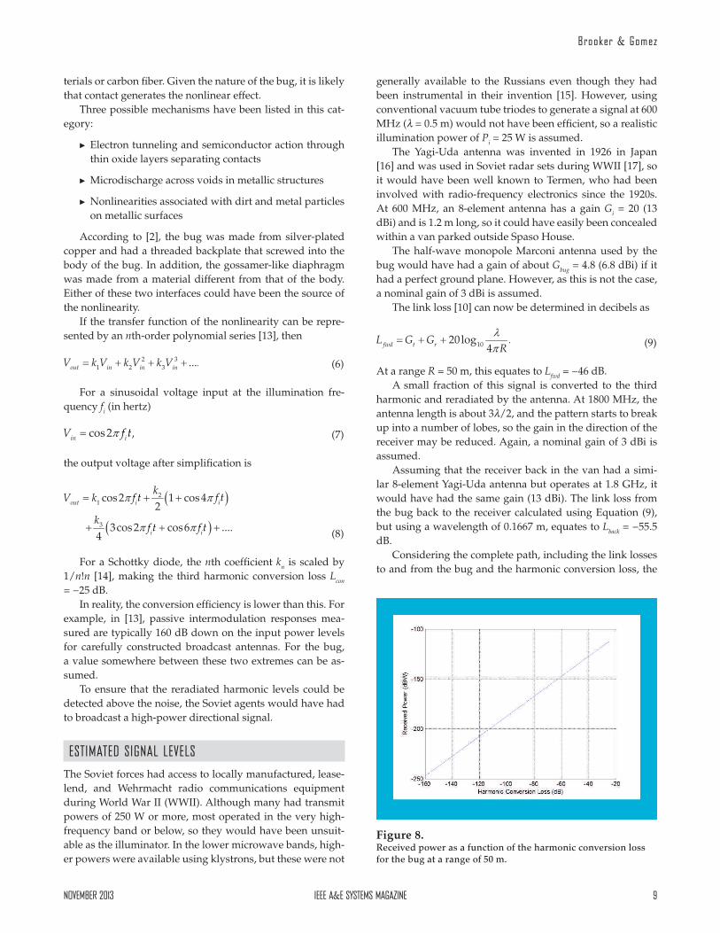
A sensitivity analysis made for the tuning post and backplate position, as a function of the resonant frequency of Mode 1, is shown in Figure 5. For a linear fit, the slope of the graph is −2.82 MHz/µm.
As can be seen from Figure 6, acoustically induced dis-placements of the diaphragm result in changes of the reso-nant frequency of the cavity with respect to the illumination frequency (and its harmonics). This in turn results in changes in the amplitude of the reradiated signal in a manner similar to that generated by an old-fashioned frequency-modulation discriminator. Depending on the Q of the cavity, and the off-set between its resonant frequency and the harmonic, a rea-sonably undistorted amplitude modulation (AM) signal is produced.
DISPLACEMENTOFTHEDIAPHRAGM
All of the references to the bug talk of an extremely delicate, gossamer-thin diaphragm that is easily damaged, so it can be assumed that the diaphragm was sufficiently thin and that its displacement would equal the acoustically induced displacement of the air molecules during normal conversa-tion within the ambassador’s office.
The peak displacement of air molecules ym (in meters) is related to the peak acoustic pressure pm (in pascals) accord-ing to [9], by
(3)Figure 3. HFSS-generated model of the cylindrical portion of the bug.
Table 1.
Resonant Frequencies for a 0.228-m Marconi Antenna
Number of Quarter Wavelengths
Resonant Frequency (MHz)
1 314
2 524
3 972
4 1301
5 1630
6 1959
Table 2.
Eigenmode Resonant Frequencies for the Cavity
Eigenmode Frequency (GHz) Q
1 1.816+j0.000475 1911
2 6.558+j0.001475 2225
3 15.774+j0.00144 5475
4 16.489+j0.00169 4888
5 16.986+j0.00159 5340
6 18.172+j0.00160 5670
NOVEMBER2013 IEEEA&ESYSTEMSMAGAZINE 7
Brooker & Gomez
where k = 2π/m is the wave number, o (in kilograms per cubic meter) is the air density, and v (in meters per second) is the velocity of sound in air.
The sound pressure level (SPL) for normal conversation is about 60 dB at a frequency around 1000 Hz. This equates to a peak acoustic pressure pm of 0.028 Pa. The peak air (and hence diaphragm) displacement is about 10 nm for v = 340 m/s, o = 1.204 kg/m3, and m = 0.34 m.
Using the results presented in Figure 5, this displace-ment results in a shift in the resonant frequency of ±30 kHz between the peak positive and the peak negative displace-ments. For quiet conversation, the SPL is reduced, with a typical SPL = 45 dB, which equates to a shift in resonant fre-quency of only ±5.5 kHz.
Figure 4. Electric fields within the cavity related to the first four eigenmodes: (a) Mode 1, (b) Mode 2, (c) Mode 3, and (d) Mode 4.
Figure 5. Sensitivity analysis of Mode 1 as a function of backplate position.

8 IEEEA&ESYSTEMSMAGAZINE NOVEMBER2013
Lev Termen’s Great Seal Bug Analyzed
The relationship between the Q and the bandwidth, (in hertz), of a tuned circuit is [10]
(4)
Therefore, for a calculated Q = 1911 at a resonant frequen-cy of 1800 MHz, the half-power bandwidth is = 0.94 MHz. This is much larger than the acoustically induced changes in the resonant frequency; therefore, little AM would occur unless the illumination frequency harmonic was tuned off resonance, as shown in Figure 6.
AMPLITUDEMODULATION
The AM of a carrier (in this case, the harmonic) with a fre-quency fres (in hertz), by a sinusoidal signal with a frequency fm (in hertz) can be described by [11]
(5)
The percentage modulation (Aam × 100) for the signal is determined by the offset of the harmonic from the resonant frequency and shift in the resonant frequency with acoustic input, as illustrated in Figure 7. In this case, the harmonic is centered on 1800.5 MHz, and the total shift in the resonant frequency is ±30 kHz on either side of 1800 MHz. It can be
seen that a change in amplitude of 0.6 dB occurs. This equates in a change in output voltage after detection by a factor of only 1.07 (a percentage modulation of 7%).
Such a small modulation depth is obviously not ideal, but it would still have been easy to detect using a standard narrow-band heterodyne receiver fol-lowed by one of several vacuum-tube AM detector configurations used at the time [12].
HARMONICGENERATION
If the bug operated in a similar manner to a modern RFID tag, by modulating the backscatter am-plitude, the power of the modu-lated component compared to that reflected from other objects within the illuminating beam would be extremely small and hence difficult to detect. This op-tion is analyzed later in this ar-ticle.
The question that now needs to be answered is, How could the tag generate harmonics of the illumination frequency?
It is well known that passive parts of antennas and close-ly located objects can support nonlinear current–voltage re-lationships and thus support the generation of harmonics. According to Golikov et al. [13], there are two dominant generators of nonlinearities, namely, contact generators, of which loose, oxidized or contaminated metallic joints are ex-amples, and material generators, such as ferromagnetic ma-
Figure 6. Conversion of acoustic signals into an amplitude-modulated carrier.
Figure 7. Resonant cavity characteristics for Mode 1 with Q = 1911 showing changes in amplitude for a resonant frequency shift of ±30 kHz.
NOVEMBER2013 IEEEA&ESYSTEMSMAGAZINE 9
Brooker & Gomez
terials or carbon fiber. Given the nature of the bug, it is likely that contact generates the nonlinear effect.
Three possible mechanisms have been listed in this cat-egory:
C Electron tunneling and semiconductor action through thin oxide layers separating contacts
C Microdischarge across voids in metallic structures
C Nonlinearities associated with dirt and metal particles on metallic surfaces
According to [2], the bug was made from silver-plated copper and had a threaded backplate that screwed into the body of the bug. In addition, the gossamer-like diaphragm was made from a material different from that of the body. Either of these two interfaces could have been the source of the nonlinearity.
If the transfer function of the nonlinearity can be repre-sented by an nth-order polynomial series [13], then
(6)
For a sinusoidal voltage input at the illumination fre-quency fi (in hertz)
(7)
the output voltage after simplification is
(8)
For a Schottky diode, the nth coefficient kn is scaled by 1/n!n [14], making the third harmonic conversion loss Lcon = −25 dB.
In reality, the conversion efficiency is lower than this. For example, in [13], passive intermodulation responses mea-sured are typically 160 dB down on the input power levels for carefully constructed broadcast antennas. For the bug, a value somewhere between these two extremes can be as-sumed.
To ensure that the reradiated harmonic levels could be detected above the noise, the Soviet agents would have had to broadcast a high-power directional signal.
ESTIMATEDSIGNALLEVELS
The Soviet forces had access to locally manufactured, lease-lend, and Wehrmacht radio communications equipment during World War II (WWII). Although many had transmit powers of 250 W or more, most operated in the very high-frequency band or below, so they would have been unsuit-able as the illuminator. In the lower microwave bands, high-er powers were available using klystrons, but these were not
generally available to the Russians even though they had been instrumental in their invention [15]. However, using conventional vacuum tube triodes to generate a signal at 600 MHz ( = 0.5 m) would not have been efficient, so a realistic illumination power of Pi = 25 W is assumed.
The Yagi-Uda antenna was invented in 1926 in Japan [16] and was used in Soviet radar sets during WWII [17], so it would have been well known to Termen, who had been involved with radio-frequency electronics since the 1920s. At 600 MHz, an 8-element antenna has a gain Gi = 20 (13 dBi) and is 1.2 m long, so it could have easily been concealed within a van parked outside Spaso House.
The half-wave monopole Marconi antenna used by the bug would have had a gain of about Gbug = 4.8 (6.8 dBi) if it had a perfect ground plane. However, as this is not the case, a nominal gain of 3 dBi is assumed.
The link loss [10] can now be determined in decibels as
(9)
At a range R = 50 m, this equates to Lfwd = −46 dB.A small fraction of this signal is converted to the third
harmonic and reradiated by the antenna. At 1800 MHz, the antenna length is about 3/2, and the pattern starts to break up into a number of lobes, so the gain in the direction of the receiver may be reduced. Again, a nominal gain of 3 dBi is assumed.
Assuming that the receiver back in the van had a simi-lar 8-element Yagi-Uda antenna but operates at 1.8 GHz, it would have had the same gain (13 dBi). The link loss from the bug back to the receiver calculated using Equation (9), but using a wavelength of 0.1667 m, equates to Lback = −55.5 dB.
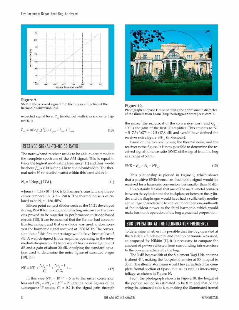
Considering the complete path, including the link losses to and from the bug and the harmonic conversion loss, the
Figure 8. Received power as a function of the harmonic conversion loss for the bug at a range of 50 m.
10 IEEEA&ESYSTEMSMAGAZINE NOVEMBER2013
Lev Termen’s Great Seal Bug Analyzed
expected signal level Prec (in decibel watts), as shown in Fig-ure 8, is
(10)
RECEIVEDSIGNAL-TO-NOISERATIO
The narrowband receiver needs to be able to accommodate the complete spectrum of the AM signal. This is equal to twice the highest modulating frequency [11] and thus would be about rec = 6 kHz for a 3-kHz audio bandwidth. The ther-mal noise Nt (in decibel watts) within this bandwidth is
(11)
where k = 1.38×10⁻²³ J/K is Boltzmann’s constant and the re-ceiver temperature is T = 290 K. The thermal noise is calcu-lated to be Nt = −166 dBW.
Silicon point contact diodes such as the 1N21 developed during WWII for mixing and detecting microwave frequen-cies proved to be superior in performance to triode-based circuits [18]. It can be assumed that the Termen had access to this technology, and that one diode was used to downcon-vert the harmonic signal received at 1800 MHz. The conver-sion loss of this first mixer stage would have been at least 7 dB. A well-designed triode amplifier operating in the inter-mediate-frequency (IF) band would have a noise figure of 4 dB and a gain of about 20 dB. Applying the standard equa-tion used to determine the noise figure of cascaded stages [10], [19],
(12)
In this case NF1 = 107/10 = 5 is to the mixer conversion loss and NF2 = NF3 = 104/10 = 2.5 are the noise figures of the subsequent IF stages. G1 = 0.2 is the signal gain through
the mixer (the reciprocal of the conversion loss), and G2 = 100 is the gain of the first IF amplifier. This equates to NF = 5+7.5+0.075 = 12.5 (17.8 dB) and would have defined the receiver noise figure, NFrec (in decibels).
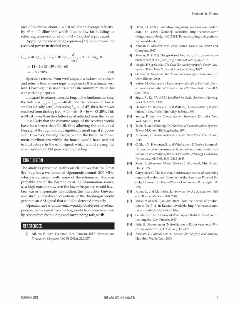
Based on the received power, the thermal noise, and the receiver noise figure, it is now possible to determine the re-ceived signal-to-noise ratio (SNR) of the signal from the bug at a range of 50 m:
(13)
This relationship is plotted in Figure 9, which shows that a positive SNR; hence, an intelligible signal would be received for a harmonic conversion loss smaller than 60 dB.
It is certainly feasible that one of the metal–metal contacts between the cylinder and the backplane or between the cylin-der and the diaphragm would have had a sufficiently nonlin-ear voltage characteristic to convert more than one-millionth of the incident power to the third harmonic, which would make harmonic operation of the bug a practical proposition.
BUG OPERATION AT THE ILLUMINATION FREQUENCY
To determine whether it is possible that the bug operated at the 600-MHz fundamental and that no harmonic was used, as proposed by Nikitin [1], it is necessary to compare the amount of power reflected from surrounding infrastructure to the power reradiated by the bug.
The 3-dB beamwidth of the 8-element Yagi-Uda antenna is about 41°, making the footprint diameter at 50 m equal to 35 m. The illuminator beam would have irradiated the com-plete frontal section of Spaso House, as well as intervening foliage, as shown in Figure 10.
From the photograph shown in Figure 10, the height of the portico section is estimated to be 8 m and that of the wings is estimated to be 6 m, making the illuminated frontal
Figure 9. SNR of the received signal from the bug as a function of the harmonic conversion loss.
Figure 10. Photograph of Spaso House showing the approximate diameter of the illumination beam (http://ericajgreen.wordpress.com/).
NOVEMBER2013 IEEEA&ESYSTEMSMAGAZINE 11
Brooker & Gomez
area of the house about A = 220 m2. For an average reflectiv-ity ° = −10 dBm2/m2, which is quite low for buildings, a reflecting cross-section of = °A ≈ 14 dBm2 is produced.
Applying the radar range equation [20] to determine the received power in decibel watts,
(14)
Specular returns from well-aligned windows or corners and returns from close-range foliage make this estimate very low. However, it is used as a realistic minimum value for comparison purposes.
In regard to returns from the bug, in the fundamental case, the link loss Lback = Lfwd = −46 dB and the conversion loss is smaller (ideally zero). Assuming Lcon = −3 dB, then the power received from the bug is Prec = 14 − 46 − 5 − 46 = −83 dBW. This is 30 dB lower than the clutter signal reflected from the house.
It is likely that the dynamic range of the receiver would have been better than 30 dB, thus allowing the modulated bug signal through without significant small signal suppres-sion. However, moving foliage within the beam, or move-ment or vibrations within the house, would have resulted in fluctuations in the echo signal, which would swamp the small amount of AM generated by the bug.
CONCLUSION
The analysis presented in this article shows that the Great Seal bug has a well-coupled eigenmode around 1800 MHz, which is consistent with some of the references. This was probably one of the harmonics of the illumination source, as a high transmit power at the lower frequency would have been easier to generate. In addition, the interaction between acoustically introduced vibrations of the diaphragm would generate an AM signal that could be detected remotely.
Operation at the fundamental would probably not have been possible, as the signal from the bug would have been swamped by echoes from the building and surrounding foliage.
REFERENCES
[1] Nikitin, P. Leon Theremin (Lev Termen). IEEE Antennas and
Propagation Magazine, Vol. 54 (2012), 252–257.
[2] Davis, H. (2005) Eavesdropping using microwaves—adden-dum. EE Times. [Online]. Available: http://eetimes.com/design/audio-design/4015284/Eavesdropping-using-micro-waves-addendum).
[3] Kennan, G. Memoirs: 1925–1950. Boston, MA: Little Brown and Company, 1967.
[4] Murray, K. (1996) The great seal bug story, http://www.spy-busters.com/Great_Seal_Bug.html, last access Jan. 2013.
[5] Wright, P. Spy Catcher: The Candid Autobiography of a Senior Intel-
ligence Officer. New York and London: Viking, 1987.[6] Glinsky, A. Theremin; Ether Music and Espionage. Champaign, IL:
Univ. Illinois, 2000.[7] Kaiser, M. Odyssey of an Eavesdropper: My Life in Electronic Coun-
termeasures and My Battle against the FBI. New York: Carroll & Graf, 2006.
[8] Straw, R., Ed. The ARRL Handbook for Radio Amateurs. Newing-ton, CT: ARRL, 1990.
[9] Halliday, D., Resnick, R., and Walker, J. Fundamentals of Physics (4th ed.). New York: John Wiley & Sons, 1993.
[10] Young, P. Electronic Communication Techniques (3rd ed.). New York: Merrill, 1990.
[11] Taub, H., and Schilling, D. Principles of Communication Systems. Tokyo: McGraw-Hill Kogakusha, 1971.
[12] Anderson, E. Audels Radiomans Guide. New York: Theo Audel, 1948.
[13] Golikov, V., Hienonen, S., and Vainikainen, P. Passive intermod-ulation distortion measurements in mobile communication an-tennas. In Proceedings of the 54th Vehicular Technology Conference, Piscataway, NJ:IEEE, 2001, 2623–2625
[14] Maas, S. Microwave Mixers (2nd ed.). Norwood, MA: Artech House, 1993.
[15] Caryotakis, G. The klystron: A microwave source of surprising range and endurance. Presented at the American Physical So-ciety, Division of Plasma Physics Conference, Pittsburgh, PA, 1997.
[16] Kraus, J., and Marhefka, R. Antennas for All Applications (3rd ed.). Boston: McGraw Hill, 2002.
[17] Museum of Nitel (January 2012). From the history of produc-tion of the P-18, in Russian. Available: http://www.museum.nnov.ru/nitel/vista/vistav1.htm.
[18] Guerlac, H. The History of Modern Physics: Radar in World War II. Los Angeles, CA: Tomash, 1987.
[19] Friis, H. Discussion on “Noise Figures of Radio Receivers,” Pro-
ceedings of the IRE, vol. 33 (1945), 125–127.[20] Brooker, G., Introduction to Sensors for Ranging and Imaging.
Herndon, VA: SciTech, 2008.
Copyright © 2022 FDOKUMEN