
บริษัท เบเจอร บี.กริม (ประเทศไทย)...
230
บริษัท เบเจอร บี.กริม (ประเทศไทย) จำกัด
-
Upload
khangminh22 -
Category
Documents
-
view
4 -
download
0
Transcript of บริษัท เบเจอร บี.กริม (ประเทศไทย)...

บรษท เบเจอร บ.กรม (ประเทศไทย) จำกด
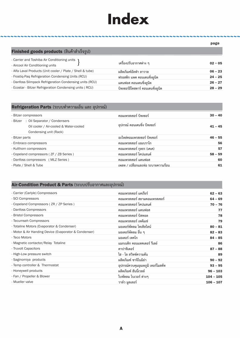
Finished goods products (สนคาสำเรจรป)
- Carrier and Toshiba Air Conditioning units - Aircool Air Conditioning units - Alfa Laval Products (Unit cooler / Plate / Shell & tube) - Frostiq-Paq Refrigeration Condensing Units (RCU) - Danfoss Slimpack Refrigeration Condensing units (RCU)- Ecostar - Bitzer Refrigeration Condensing units ( RCU)
Refrigeration Parts (ระบบทำความเยน และ อปกรณ)
- Bitzer compressors - Bitzer : Oil Separator / Condensers Oil cooler / Air-cooled & Water-cooled Condensing unit (Rack) - Bitzer parts - Embraco compressors - Kulthorn compressors - Copeland compressors ( ZF / ZB Series ) - Danfoss compressors ( MLZ Series ) - Plate / Shell & Tube
Air-Condition Product & Parts (ระบบปรบอากาศและอปกรณ)
- Carrier (Carlyle) Compressors - SCI Compressors - Copeland Compressors ( ZR / ZP Series ) - Danfoss Compressors - Bristol Compressors - Tecumseh Compressors - Totaline Motors (Evaporator & Condenser)- Motor & Air Handing Device (Evaporator & Condenser) - Teco Motors- Magnetic contactor/Relay Totaline - Truvolt Capacitors - High-Low pressure switch - Saginomiya products - Temp controller & Thermostat - Honeywell products- Fan / Propeller & Blower - Mueller valve
Index
06 – 2324 – 2526 – 2728 – 29
30 – 40
41 – 45
46 – 555657
58 – 596061
~~~~~~~~~~~~~~~~~~~~~~~~~~~~~~~~~~~~~~~~~~~~~~~~~~~~~~~~~~~~~~~~~~~~~~~~
} 02 − 05
62 – 6364 – 6970 – 76
777879
80 – 8182 – 8384 – 85
8687 – 88
8990 – 9293 – 95
96 – 103104 – 105106 – 107
page
เครองปรบอากาศตาง ๆ
ผลตภณฑอลฟา ลาวาลฟรอสตก แพค คอนเดนซงยนตแดนฟอส คอนเดนซงยนตบทเซอรอโคสตาร คอนเดนซงยนต
คอมเพรสเซอร บทเซอร
อปกรณ คอนเดนซง บทเซอร
อะไหลคอมเพรสเซอร บทเซอรคอมเพรสเซอร เอมบราโกคอมเพรสเซอร กลธร (เคเค)คอมเพรสเซอร โคปแลนดคอมเพรสเซอร แดนฟอสเพลท / เปลอกและทอ ระบายความรอน
คอมเพรสเซอร แคเรยรคอมเพรสเซอร สยามคอมเพรสเซอรคอมเพรสเซอร โคปแลนดคอมเพรสเซอร แดนฟอสคอมเพรสเซอร บสทอลคอมเพรสเซอร เทคมเชมอเตอรพดลม โทเทลไลนมอเตอรพดลม อน ๆมอเตอร เทคโกแมกเนตก คอนแทคเตอร รเลยคาปาซเตอรไฮ - โล สวทซความดนผลตภณฑ ซาจโนมยาอปกรณควบคมอณหภม เทอรโมสตทผลตภณฑ ฮนนเวลลใบพดลม โบเวอร ตางๆวาลว มลเลอร
A

Finished goods products (สนคาสำเรจรป)
- Carrier and Toshiba Air Conditioning units - Aircool Air Conditioning units - Alfa Laval Products (Unit cooler / Plate / Shell & tube) - Frostiq-Paq Refrigeration Condensing Units (RCU) - Danfoss Slimpack Refrigeration Condensing units (RCU)- Ecostar - Bitzer Refrigeration Condensing units ( RCU)
Refrigeration Parts (ระบบทำความเยน และ อปกรณ)
- Bitzer compressors - Bitzer : Oil Separator / Condensers Oil cooler / Air-cooled & Water-cooled Condensing unit (Rack) - Bitzer parts - Embraco compressors - Kulthorn compressors - Copeland compressors ( ZF / ZB Series ) - Danfoss compressors ( MLZ Series ) - Plate / Shell & Tube
Air-Condition Product & Parts (ระบบปรบอากาศและอปกรณ)
- Carrier (Carlyle) Compressors - SCI Compressors - Copeland Compressors ( ZR / ZP Series ) - Danfoss Compressors - Bristol Compressors - Tecumseh Compressors - Totaline Motors (Evaporator & Condenser)- Motor & Air Handing Device (Evaporator & Condenser) - Teco Motors- Magnetic contactor/Relay Totaline - Truvolt Capacitors - High-Low pressure switch - Saginomiya products - Temp controller & Thermostat - Honeywell products- Fan / Propeller & Blower - Mueller valve
Flow Control (for Both Refrigeration and Air-conditioning system) - อปกรณควบคมนำยา
- Vibration lsolator / Globe valves / Reciever valves - Solenoid Valves & Coil - Ball valves - Expansion valves- Shut-off valves( Hand valve )- Bracket Valves - Check valves- Motorized valves- Filter Drier- Drier Core- Sight Glass- oil Separator- oil Management system- Liquid Reciever- Accumulators
Installation - Equipment and Others - อปกรณตดตงและเครองมอ
- Copper Tube (Totaline / Sampo) - Aeroflex products ( Insulation / Adhesive / Flexible ducts)- Armacell products ( Insulation / Adhesive / Flexible ducts) - Aluminium Filter - Totaline Duct Liner ( Premium series ) - Totalduct Duct Liner ( Standard series ) - Totalslim Duct Liner ( Eco series ) - Nibco , SMI Copper Fitting - Brass Fitting - Flexible Capillary tube - Condensate drain pump - OIL & CHEMICAL- Refrigerant- Vacumm Pump - Digital Gauge - Manifold Gauge - Tube Cutter- Tube Bender - Flaring & Swaging- Flaring TooI , Condenser Fin comb - Tube Cleaning - Brazing Alloys & Flux (HARRIS)- Air Cond Stand (Bracket/Rubber)- Other (Tape / gasket / PVC tape etc)- Refrigerant recovery Unit
Index~~~~~~~~~~~~~~~~~~~~~~~~~~~~~~~~~~~~~~~~~~~~~~~~~~~~~~~~~~~~~~~~~~~~~~~~~~~~~~~~~~~~~~~~~~~~~~~~~~~~~~~~~~~~~~~~~~~~~~~~~~~~~~~~~~~~~~~~~~~~~~~~
108 – 110111 – 119120 – 122123 – 131132 – 133
134135
136 – 139140 – 145146 – 147148 – 149150 – 152
153154
155 – 156
page
157 – 165166 – 177178 – 187
188189190191
192 – 198199200
201 – 202203 – 204
205206 – 208209 – 213214 – 215216 – 217218 – 219220 – 222
223224225
226
227
ขอตอกนกระเทอน โกลบวาลว รซพเวอร วาลวโซลนอยดวาลว และ คอยยบอลลวาลวแอกแปนชนวาลวสตอปวาลว หรอ แฮนดวาลวแบรคเกท วาลวเชควาลวมอเตอรไรซวาลวดรายเออรแบบตาง ๆไสดรายเออร (แบบเปลยนไส)ไซทกลาส - ตาแมวตวแยกนำมนอปกรณจดการนำมนลควค รซพเวอรแอคควมเลเตอร
ทอทองแดงฉนวนยาง "แอโรเฟลกซ"ฉนวนยาง "อามาเฟลกซ"ฟลเตอร อลมเนยมรางครอบทอ โทเทลไลนรางครอบทอ โทเทลดกทรางครอบทอ โทเทลสลมขอตอ ของอ ทองแดงขอตอ ของอ ทองเหลองแคปทวแบบออนปมนำทงนำมน และ เคมภณฑนำยาทำความเยนแวคคมปมเกจดจตอล ตาง ๆเกจวดความดน ตาง ๆตวตดทอตวดดทอบานแฟรบานแฟร ตวตดทอ หวอปกรณทำความสะอาดทอลวดเชอมและฟลกซขาแขวนคอนเดนซงเทปพนทอแอรเครองดดกลบนำยา
}
1
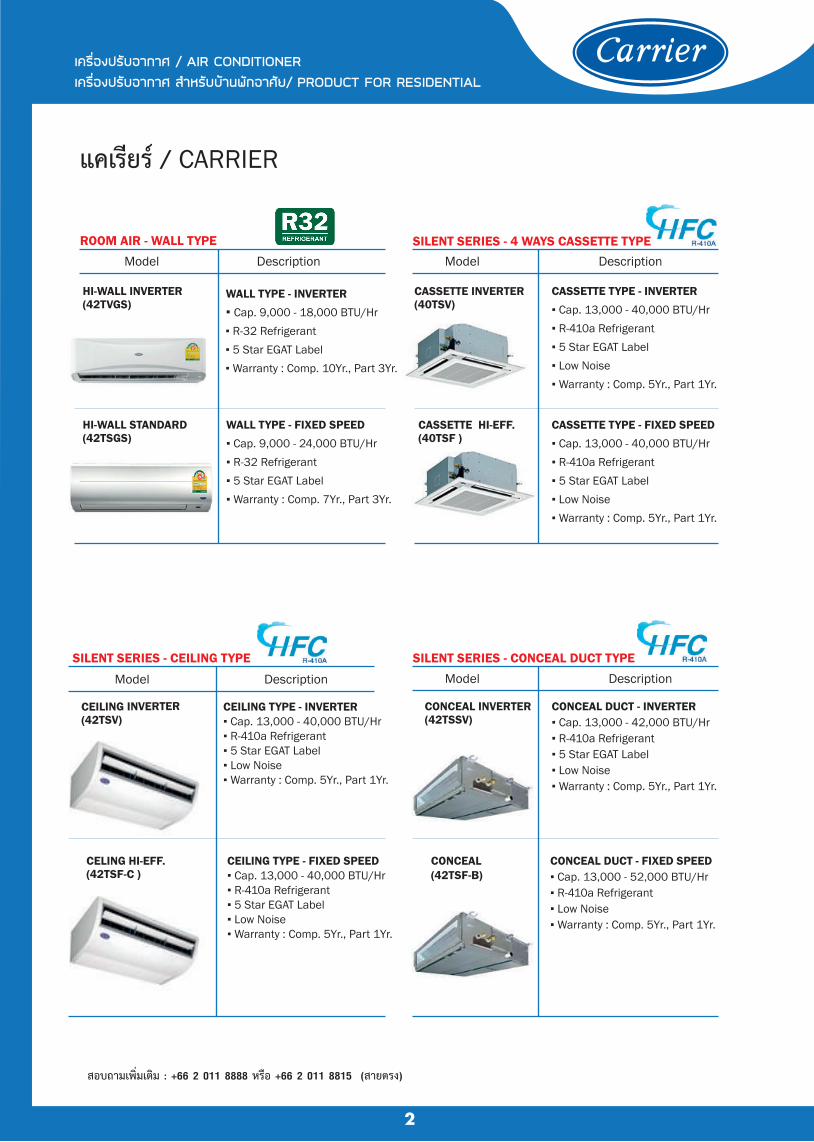
แคเรยร / CARRIER
ROOM AIR - WALL TYPE
WALL TYPE - INVERTER ▪ Cap. 9,000 - 18,000 BTU/Hr ▪ R-32 Refrigerant ▪ 5 Star EGAT Label ▪ Warranty : Comp. 10Yr., Part 3Yr.
HI-WALL INVERTER(42TVGS)
WALL TYPE - FIXED SPEED ▪ Cap. 9,000 - 24,000 BTU/Hr ▪ R-32 Refrigerant ▪ 5 Star EGAT Label ▪ Warranty : Comp. 7Yr., Part 3Yr.
SILENT SERIES - 4 WAYS CASSETTE TYPE
CASSETTE TYPE - INVERTER ▪ Cap. 13,000 - 40,000 BTU/Hr ▪ R-410a Refrigerant ▪ 5 Star EGAT Label ▪ Low Noise ▪ Warranty : Comp. 5Yr., Part 1Yr.
CASSETTE TYPE - FIXED SPEED ▪ Cap. 13,000 - 40,000 BTU/Hr ▪ R-410a Refrigerant ▪ 5 Star EGAT Label ▪ Low Noise ▪ Warranty : Comp. 5Yr., Part 1Yr.
CASSETTE INVERTER (40TSV)
CASSETTE HI-EFF. (40TSF )
SILENT SERIES - CEILING TYPE
CEILING TYPE - INVERTER ▪ Cap. 13,000 - 40,000 BTU/Hr ▪ R-410a Refrigerant ▪ 5 Star EGAT Label ▪ Low Noise ▪ Warranty : Comp. 5Yr., Part 1Yr.
CELING HI-EFF. (42TSF-C )
CEILING TYPE - FIXED SPEED ▪ Cap. 13,000 - 40,000 BTU/Hr ▪ R-410a Refrigerant ▪ 5 Star EGAT Label ▪ Low Noise ▪ Warranty : Comp. 5Yr., Part 1Yr.
SILENT SERIES - CONCEAL DUCT TYPE
CONCEAL DUCT - INVERTER ▪ Cap. 13,000 - 42,000 BTU/Hr ▪ R-410a Refrigerant ▪ 5 Star EGAT Label ▪ Low Noise ▪ Warranty : Comp. 5Yr., Part 1Yr.
CONCEAL INVERTER (42TSSV)
CONCEAL DUCT - FIXED SPEED ▪ Cap. 13,000 - 52,000 BTU/Hr ▪ R-410a Refrigerant ▪ Low Noise ▪ Warranty : Comp. 5Yr., Part 1Yr.
CONCEAL (42TSF-B)
à¤Ã×èͧ»ÃѺÍÒ¡ÒÈ / AIR CONDITIONER à¤Ã×èͧ»ÃѺÍÒ¡ÒÈ ÊÓËÃѺºŒÒ¹¾Ñ¡ÍÒÈÑÂ/ PRODUCT FOR RESIDENTIAL
สอบถามเพมเตม : +66 2 011 8888 หรอ +66 2 011 8815 (สายตรง)
2
HI-WALL STANDARD(42TSGS)
DescriptionModel DescriptionModel
CEILING INVERTER (42TSV)
DescriptionModel DescriptionModel

à¤Ã×èͧ»ÃѺÍÒ¡ÒÈ / AIR CONDITIONER à¤Ã×èͧ»ÃѺÍÒ¡ÒÈ ÊÓËÃѺºŒÒ¹¾Ñ¡ÍÒÈÑÂ/ PRODUCT FOR RESIDENTIAL
3
โตชบา / TOSHIBA
DescriptionModel ROOM AIR - WALL TYPE
HI-WALL INVERTER (RAS-PKCVG)
WALL TYPE - INVERTER ▪ Cap. 9,000 - 20,500 BTU/Hr ▪ R-32 Refrigerant ▪ 5 Star EGAT Label ▪ Warranty : Comp. 10Yr., Part 3Yr.
HI-WALL STANDARD(RAS-PKSG)
WALL TYPE - FIXED SPEED ▪ Cap. 9,000 - 24,000 BTU/Hr ▪ R-32 Refrigerant ▪ 5 Star EGAT Label ▪ Warranty : Comp. 7Yr., Part 3Yr.
DescriptionModel
CASSETTE INV. (RAV-SE*1UP-T)
CASSETTE TYPE - INVERTER ▪ Cap. 18,000 - 40,000 BTU/Hr ▪ R-410a Refrigerant ▪ 5 Star EGAT Label ▪ Warranty : Comp. 7Yr., Part 2Yr.
4 WAYS CASSETTE - SPI INVERTER
DescriptionModel
CEILING TYPE - SPI INVERTER
CEILING TYPE (RAV-SE*CP-T)
CEILING TYPE - INVERTER ▪ Cap. 18,000 - 42,000 BTU/Hr ▪ R-410a Refrigerant ▪ 5 Star EGAT Label ▪ Warranty : Comp. 7Yr., Part 2Yr.
DescriptionModel DescriptionModel
DescriptionModel
CONCEAL TYPE - SPI INVERTER INVERTER MULTI SYSTEM
CONCEAL TYPE (RAV-SE*1BP-T)
CONCEAL TYPE - INVERTER ▪ Cap. 18,000 - 42,000 BTU/Hr ▪ R-410a Refrigerant ▪ 5 Star EGAT Label* ▪ Warranty : Comp. 7Yr., Part 2Yr.
RAS-*M*ACV-T
INVERTER MULTI SYSTEM ▪ FCU Cap. 9,000 - 24,000 BTU/Hr ▪ CDU Cap. 26,000 - 38,000 BTU/Hr ▪ R-410a Refrigerant ▪ 4 FCUs & 5 FCUs ▪ Warranty : Comp. 7Yr., Part 2Yr.
แอรคล / AIRCOOL SKY AIR - FLOOR/CEILING TYPE
FLEXI ( ACFX )HI-WALL (Blue Sky)
DescriptionModel ROOM AIR - WALL TYPE
FLOOR/CEILING TYPE ▪ Cap. 12,000 - 24,000 BTU/Hr ▪ R-32 Refrigerant ▪ 5 Star EGAT Label ▪ Warranty : Comp. 5Yr., Part 1Yr.
WALL TYPE ▪ Cap. 9,000 - 24,000 BTU/Hr ▪ R-32 Refrigerant ▪ 5 Star EGAT Label ▪ Warranty : Comp. 5Yr., Part 1Yr.
à¤Ã×èͧ»ÃѺÍÒ¡ÒÈ / AIR CONDITIONER à¤Ã×èͧ»ÃѺÍÒ¡ÒÈ ÊÓËÃѺºŒÒ¹¾Ñ¡ÍÒÈÑÂ/ PRODUCT FOR RESIDENTIAL
สอบถามเพมเตม : +66 2 011 8888 หรอ +66 2 011 8815 (สายตรง)

à¤Ã×èͧ»ÃѺÍÒ¡ÒÈ / AIR CONDITIONERà¤Ã×èͧ»ÃѺÍÒ¡ÒÈ ÊÓËÃѺ¡ÒþҳԪÂ� / PRODUCT FOR COMMERCIAL
FLOOR/CEILING TYPE #5
FLOOR/CEILING TYPE #5 ▪ Cap. 13,000 - 40,000 BTU/Hr ▪ R-410a Refrigerant ▪ 5 Star EGAT Label ▪ Warranty : Comp. 5Yr., Part 1Yr.
FLEXI TYPE #5 (42VLG)
FLOOR/CEILING TYPE (T.I.S.)
FLEXI TYPE T.I.S. (42VLU)
FLOOR/CEILING TYPE (T.I.S.) ÁÍ¡.
▪ Cap. 12,000 - 60,000 BTU/Hr
▪ R-410a Refrigerant
▪ T.I.S. Standard
▪ Warranty : Comp. & Part 1Yr.
4-WAY CASSETTE TYPE FLOOR STANDINIG TYPE
4-WAY CASSETTE TYPE ▪ Cap. 18,000 - 60,000 BTU/Hr ▪ R-410a Refrigerant ▪ T.I.S. Standard ▪ Warranty : Comp. & Part 1Yr.
4-WAY CASSETTE (40VLU)
FLOOR STANDINIG TYPE ▪ Cap. 30,000 - 150,000 BTU/Hr ▪ R-410a Refrigerant ▪ T.I.S. Standard ▪ Warranty : Comp. & Part 1Yr.
FLOOR MOUNT (40QBG/40QDU)
CEILING CONCEAL TYPE CONCEAL DUCT TYPE
CEILING CONCEAL TYPE ▪ Cap. 13,000 - 40,000 BTU/Hr
▪ R-410a Refrigerant
▪ 5 Star EGAT Label
▪ Warranty : Comp. 5Yr., Part 1Yr.
CONCEAL TYPE (42CLG)
CONCEAL TYPE (42CLU)
CONCEAL DUCT TYPE ▪ Cap. 12,000 - 60,000 BTU/Hr
▪ R-410a Refrigerant
▪ T.I.S. Standard
▪ Warranty : Comp. & Part 1Yr.
DUCT TYPE - HI STP. ▪ Cap. 48,000 - 150,000 BTU/Hr
▪ R-410a Refrigerant
▪ Warranty : Comp. & Part 1Yr.
DUCT TYPE - HI STP. COMMERCIAL DUCT
DUCT TYPE (40LAU)
COMMERCIAL DUCT ▪ Cap. 120,000 - 300,000 BTU/Hr ▪ R-410a Refrigerant ▪ Warranty : Comp. & Part 1Yr.
COMMERCIAL DUCT (40RBU)
âµªÔºÒ / TOSHIBA VRF SYSTEM
SMMS e VRF SYSTEM / MINI SMMS - VRF SYSTEM ▪ Cap. 8 - 60 Hp / System (76,000 - 574,000 BTU/Hr) ▪ 11 Types , 69 Models FCU ▪ DC Twin Rotary Technology ▪ Farthest Pipe Length 235 m. ▪ R-410a Refrigerant ▪ Warranty : Comp. 7Yr., Part 2Yr.
4
à¤Ã×èͧ»ÃѺÍÒ¡ÒÈ / AIR CONDITIONER à¤Ã×èͧ»ÃѺÍÒ¡ÒÈ ÊÓËÃѺºŒÒ¹¾Ñ¡ÍÒÈÑÂ/ PRODUCT FOR RESIDENTIAL
แคเรยร / CARRIER
DescriptionModel DescriptionModel
DescriptionModel DescriptionModel
DescriptionModel Model
DescriptionModel Model
Description
Description
DescriptionModel
à¤Ã×èͧ»ÃѺÍÒ¡ÒÈ / AIR CONDITIONERà¤Ã×èͧ»ÃѺÍÒ¡ÒÈ ÊÓËÃѺ¡ÒþҳԪÂ� / PRODUCT FOR COMMERCIAL
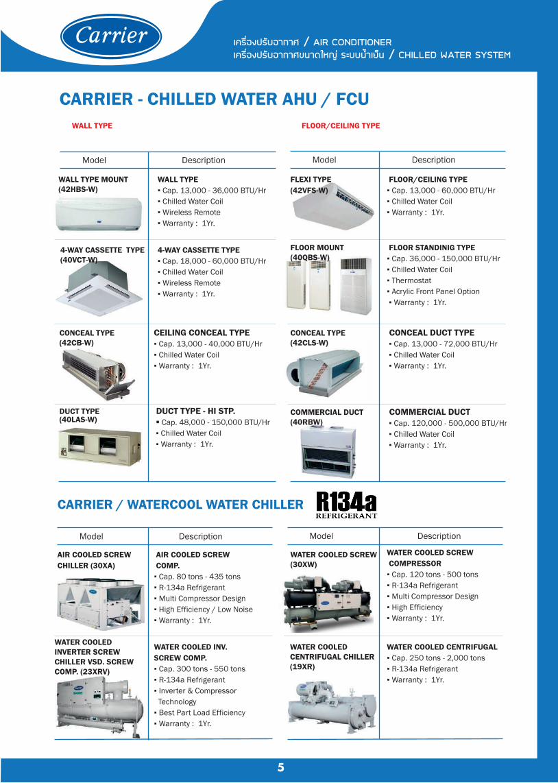
CARRIER - CHILLED WATER AHU / FCU WALL TYPE FLOOR/CEILING TYPE
WALL TYPE ▪ Cap. 13,000 - 36,000 BTU/Hr ▪ Chilled Water Coil ▪ Wireless Remote ▪ Warranty : 1Yr.
WALL TYPE MOUNT (42HBS-W)
FLEXI TYPE (42VFS-W)
FLOOR/CEILING TYPE ▪ Cap. 13,000 - 60,000 BTU/Hr ▪ Chilled Water Coil ▪ Warranty : 1Yr.
4-WAY CASSETTE TYPE ▪ Cap. 18,000 - 60,000 BTU/Hr ▪ Chilled Water Coil ▪ Wireless Remote ▪ Warranty : 1Yr.
FLOOR STANDINIG TYPE ▪ Cap. 36,000 - 150,000 BTU/Hr ▪ Chilled Water Coil ▪ Thermostat ▪ Acrylic Front Panel Option ▪ Warranty : 1Yr.
4-WAY CASSETTE TYPE(40VCT-W)
FLOOR MOUNT (40QBS-W)
CEILING CONCEAL TYPE ▪ Cap. 13,000 - 40,000 BTU/Hr ▪ Chilled Water Coil ▪ Warranty : 1Yr.
CONCEAL TYPE (42CB-W)
CONCEAL DUCT TYPE ▪ Cap. 13,000 - 72,000 BTU/Hr ▪ Chilled Water Coil ▪ Warranty : 1Yr.
CONCEAL TYPE (42CLS-W)
DUCT TYPE - HI STP. ▪ Cap. 48,000 - 150,000 BTU/Hr ▪ Chilled Water Coil ▪ Warranty : 1Yr.
DUCT TYPE (40LAS-W)
COMMERCIAL DUCT (40RBW)
COMMERCIAL DUCT ▪ Cap. 120,000 - 500,000 BTU/Hr ▪ Chilled Water Coil ▪ Warranty : 1Yr.
CARRIER / WATERCOOL WATER CHILLER
AIR COOLED SCREW COMP.▪ Cap. 80 tons - 435 tons ▪ R-134a Refrigerant ▪ Multi Compressor Design ▪ High Efficiency / Low Noise ▪ Warranty : 1Yr.
AIR COOLED SCREW CHILLER (30XA)
WATER COOLED SCREW COMPRESSOR ▪ Cap. 120 tons - 500 tons ▪ R-134a Refrigerant ▪ Multi Compressor Design ▪ High Efficiency ▪ Warranty : 1Yr.
WATER COOLED SCREW (30XW)
WATER COOLED INVERTER SCREW CHILLER VSD. SCREW COMP. (23XRV)
WATER COOLED INV. SCREW COMP. ▪ Cap. 300 tons - 550 tons ▪ R-134a Refrigerant ▪ Inverter & Compressor Technology ▪ Best Part Load Efficiency ▪ Warranty : 1Yr.
WATER COOLED CENTRIFUGAL ▪ Cap. 250 tons - 2,000 tons ▪ R-134a Refrigerant ▪ Warranty : 1Yr.
5
à¤Ã×èͧ»ÃѺÍÒ¡ÒÈ / AIR CONDITIONERà¤Ã×èͧ»ÃѺÍÒ¡ÒÈ¢¹Ò´ãËÞ‹ Ãкº¹éÓàÂç¹ / CHILLED WATER SYSTEM
DescriptionModel DescriptionModel
DescriptionModel DescriptionModel
WATER COOLED CENTRIFUGAL CHILLER (19XR)
6
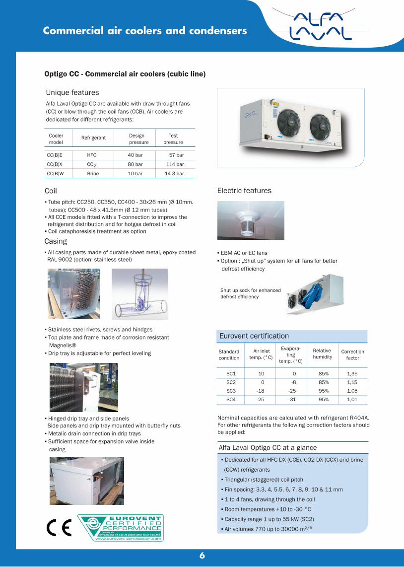
Optigo CC - Commercial air coolers (cubic line)
Commercial air coolers and condensers
Unique featuresAlfa Laval Optigo CC are available with draw-throught fans (CC) or blow-through the coil fans (CCB). Air coolers are dedicated for different refrigerants:
Coolermodel
Refrigerant Designpressure
Testpressure
Coil▪ Tube pitch: CC250, CC350, CC400 - 30x26 mm (Ø 10mm. tubes); CC500 - 48 x 41.5mm (Ø 12 mm tubes)▪ All CCE models fitted with a T-connection to improve the refrigerant distribution and for hotgas defrost in coil▪ Coil cataphoresisis treatment as option
Casing▪ All casing parts made of durable sheet metal, epoxy coated RAL 9002 (option: stainless steel)
Electric features
▪ Dedicated for all HFC DX (CCE), CO2 DX (CCX) and brine
(CCW) refrigerants
▪ Triangular (staggered) coil pitch
▪ Fin spacing: 3.3, 4, 5.5, 6, 7, 8, 9, 10 & 11 mm
▪ 1 to 4 fans, drawing through the coil
▪ Room temperatures +10 to -30 °C
▪ Capacity range 1 up to 55 kW (SC2)
▪ Air volumes 770 up to 30000 m3/h
Alfa Laval Optigo CC at a glance
Shut up sock for enhanceddefrost efficiency
Eurovent certification
Air inlettemp. (°C)
Evapora-ting
temp. (°C)
Relativehumidity
Correctionfactor
▪ Stainless steel rivets, screws and hindges▪ Top plate and frame made of corrosion resistant Magnelis®▪ Drip tray is adjustable for perfect leveling
▪ Hinged drip tray and side panels Side panels and drip tray mounted with butterfly nuts▪ Metalic drain connection in drip trays▪ Sufficient space for expansion valve inside casing
▪ EBM AC or EC fans▪ Option : „Shut up” system for all fans for better defrost efficiency
CC(B)E
CC(B)X
CC(B)W
HFC
CO2Brine
40 bar
80 bar
10 bar
57 bar
114 bar
14.3 bar
Standardcondition
SC1
SC2
SC3
SC4
10
0
-18
-25
0
-8
-25
-31
85%
85%
95%
95%
1,35
1,15
1,05
1,01
Nominal capacities are calculated with refrigerant R404A. For other refrigerants the following correction factors should be applied:

7
Technical specification
Electric defrost (E1 defrost system)*
Fans
Diametermm
Speedcode
PowersupplyV/Ph
Fan speed rpm
Freq.Hz
Max.current
A*
250250350350400400400400500500500500
Dimensions
Coolermodel
Dimensions (mm)
C H L A B
Code description
L
CØ1"
A( B ) ( B )
H
50 18
Coil defrost Drip tray defrostHeater
elementsno.
Power perelement
W
Heaterele-ments
CC251.1 2 420 840 1 420CC251.1 (C) 4 420 1680 1 420CC252.1 2 760 1520 1 760CC252.1 (C) 4 760 3040 1 760CC253.1 2 1120 2240 1 1120CC253.1 (C) 4 1120 4480 1 1120CC254.1 2 1470 2940 1 1470CC351.1 4 420 1680 1 420CC351.1 (C) 5 420 2100 1 420CC352.1 4 760 3040 1 760CC352.1 (C) 5 760 3800 1 760CC353.1 4 1120 4480 1 1120CC353.1 (C) 5 1120 5600 1 1120CC354.1 4 1470 5880 1 1470CC401 (A,B) 5 460 2300 1 460CC401 (C) 8 460 3680 1 460CC402 (A,B) 5 880 4400 1 880CC402 (C) 8 880 7040 1 880CC403 (A,B) 5 1290 6450 1 1290CC403 (C) 8 1290 10320 1 1290CC404 (A,B) 5 1700 8500 1 1700CC404 (C) 8 1700 13600 1 1700CC501 (A,B) 5 630 3150 1 630CC501 (C) 8 630 5040 1 630CC502 (A,B) 5 1220 6100 1 1220CC502 (C) 8 1220 9760 1 1220CC503 (B) 5 1810 9050 1 1810CC503 (C) 8 1810 14480 1 1810CC504 (B) 5 2400 12000 1 2400CC504 (C) 8 2400 19200 1 2400
*at temp. = -30 °C.
Commercial air coolers and condensers
1. Commercial unit cooler (CC=draw-through, CCB=blow-through)2. Refrigerant system (E = H(C)FC DX, X=CO2, W=brine)3. Fan speed (H = high; L = low)4. Fan motor type (empty=AC, E=EC fan) 5. Fan diameter (25=250, 35=350, 40=400, 50=500 mm) 6. Number of fans (1 to 4) 7. CC version 8. Tube rows code (A, B, C) 9. No. of phases (S= 1 phase, T= 3 phases)10. Motor voltage11. Packing (BO=box, CR=crate)12. Casing material (PC=powder coated, SS= stainless steel)13. Defrost system (A= air defrost, E= electric defrost, HG= hotgas, HG+E= hotgas + electic defrost in driptray)14. Coil protection(EP= epoxy coated aluminium, CA=cataphoresis)15. Fin spacing (3.3, 4, 5.5, 6, 7, 8, 10 or 11 mm)16. Tube material (CU=copper)
CC E H E 35 1 .1 A S 230V BO SS E - EP 4.0 CU HD1 2 3 4 5 6 7 8 9 10 11 12 13 14 15 16 17
CC251CC252CC253CC254CC351CC352CC353CC354CC401CC402CC403CC404CC501CC502CC503CC504
84113411841234184113411841234110371637223728371288213829883838
405405405405598598598598691691691691854854854854
410410410410410410410410583583583583583583583583
530103015302030530103015302030600120018002400860170025503400
---
1015---
1015---
1200---
1700
HLHLHLHLHLHL
230/1230/1230/1230/1230/1230/1400/3400/3230/1230/1400/3400/3
2250135014009451380870134090013009101390870
50-605050-6050-6050-6050-6050-6050-6050-6050-605050-60
0,650,261,000,371,160,640,660,343,601,501,690,89
Coolermodel(coil)
Total power
W
Total power
W
Commercial air coolers and condensers
8
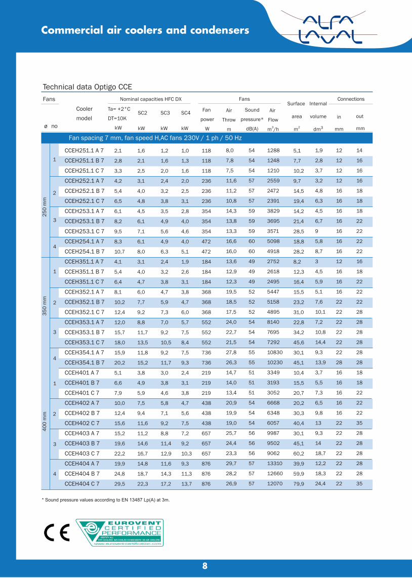
Technical data Optigo CCEFans Nominal capacities HFC DX Fans Connections
Ta= +2°C
DT=10K
kW ø no
Fan spacing 7 mm, fan speed H,AC fans 230V / 1 ph / 50 Hz
250
mm
1
1
1
2
2
2
350
mm
400
mm
* Sound pressure values according to EN 13487 Lp(A) at 3m.
CCEH251.1 A 7
CCEH251.1 B 7
CCEH251.1 C 7
CCEH252.1 A 7
CCEH252.1 B 7
CCEH252.1 C 7
CCEH253.1 A 7
CCEH253.1 B 7
CCEH253.1 C 7
CCEH254.1 A 7
CCEH254.1 B 7
CCEH351.1 A 7
CCEH351.1 B 7
CCEH351.1 C 7
CCEH352.1 A 7
CCEH352.1 B 7
CCEH352.1 C 7
CCEH353.1 A 7
CCEH353.1 B 7
CCEH353.1 C 7
CCEH354.1 A 7
CCEH354.1 B 7
CCEH401 A 7
CCEH401 B 7
CCEH401 C 7
CCEH402 A 7
CCEH402 B 7
CCEH402 C 7
CCEH403 A 7
CCEH403 B 7
CCEH403 C 7
CCEH404 A 7
CCEH404 B 7
CCEH404 C 7
2,1
2,8
3,3
4,2
5,4
6,5
6,1
8,2
9,5
8,3
10,7
4,1
5,4
6,4
8,1
10,2
12,4
12,0
15,7
18,0
15,9
20,2
5,1
6,6
7,9
10,0
12,4
15,6
15,2
19,6
22,2
19,9
24,8
29,5
out
mm
in
mm
Internal
volume
dm3
Surface
area
m2
Air
Flow
m3/h
Sound
pressure*
dB(A)
Air
Throw
m
Fan
power
W
SC4
kW
SC3
kW
SC2
kW
Coolermodel
1,6
2,1
2,5
3,1
4,0
4,8
4,5
6,1
7,1
6,1
8,0
3,1
4,0
4,7
6,0
7,7
9,2
8,8
11,7
13,5
11,8
15,2
3,8
4,9
5,9
7,5
9,4
11,6
11,2
14,6
16,7
14,8
18,7
22,3
1,2
1,6
2,0
2,4
3,2
3,8
3,5
4,9
5,6
4,9
6,3
2,4
3,2
3,8
4,7
5,9
7,3
7,0
9,2
10,5
9,2
11,7
3,0
3,8
4,6
5,8
7,1
9,2
8,8
11,4
12,9
11,6
14,3
17,2
1,0
1,3
1,6
2,0
2,5
3,1
2,8
4,0
4,6
4,0
5,1
1,9
2,6
3,1
3,8
4,7
6,0
5,7
7,5
8,4
7,5
9,3
2,4
3,1
3,8
4,7
5,6
7,5
7,2
9,2
10,3
9,3
11,3
13,7
118
118
118
236
236
236
354
354
354
472
472
184
184
184
368
368
368
552
552
552
736
736
219
219
219
438
438
438
657
657
657
876
876
876
8,0
7,8
7,5
11,6
11,2
10,8
14,3
13,8
13,3
16,6
16,0
13,6
12,9
12,3
19,5
18,5
17,5
24,0
22,7
21,5
27,8
26,3
14,7
14,0
13,4
20,9
19,9
19,0
25,7
24,4
23,3
29,7
28,2
26,9
54
54
54
57
57
57
59
59
59
60
60
49
49
49
52
52
52
54
54
54
55
55
51
51
51
54
54
54
56
56
56
57
57
57
1288
1248
1210
2559
2472
2391
3829
3695
3571
5098
4918
2752
2618
2495
5447
5158
4895
8140
7695
7292
10830
10230
3349
3193
3052
6668
6348
6057
9987
9502
9062
13310
12660
12070
5,1
7,7
10,2
9,7
14,5
19,4
14,2
21,4
28,5
18,8
28,2
8,2
12,3
16,4
15,5
23,2
31,0
22,8
34,2
45,6
30,1
45,1
10,4
15,5
20,7
20,2
30,3
40,4
30,1
45,1
60,2
39,9
59,9
79,9
1,9
2,8
3,7
3,2
4,8
6,3
4,5
6,7
9
5,8
8,7
3
4,5
5,9
5,1
7,6
10,1
7,2
10,8
14,4
9,3
13,9
3,7
5,5
7,3
6,5
9,8
13
9,3
14
18,7
12,2
18,3
24,4
12
12
12
12
16
16
16
16
16
16
16
12
16
16
16
22
22
22
22
22
22
28
16
16
16
16
16
22
22
22
22
22
22
22
14
16
16
16
18
18
18
22
22
22
22
16
18
22
22
22
28
28
28
28
28
28
18
18
22
22
22
35
28
28
28
28
28
35
3
3
3
4
4
4
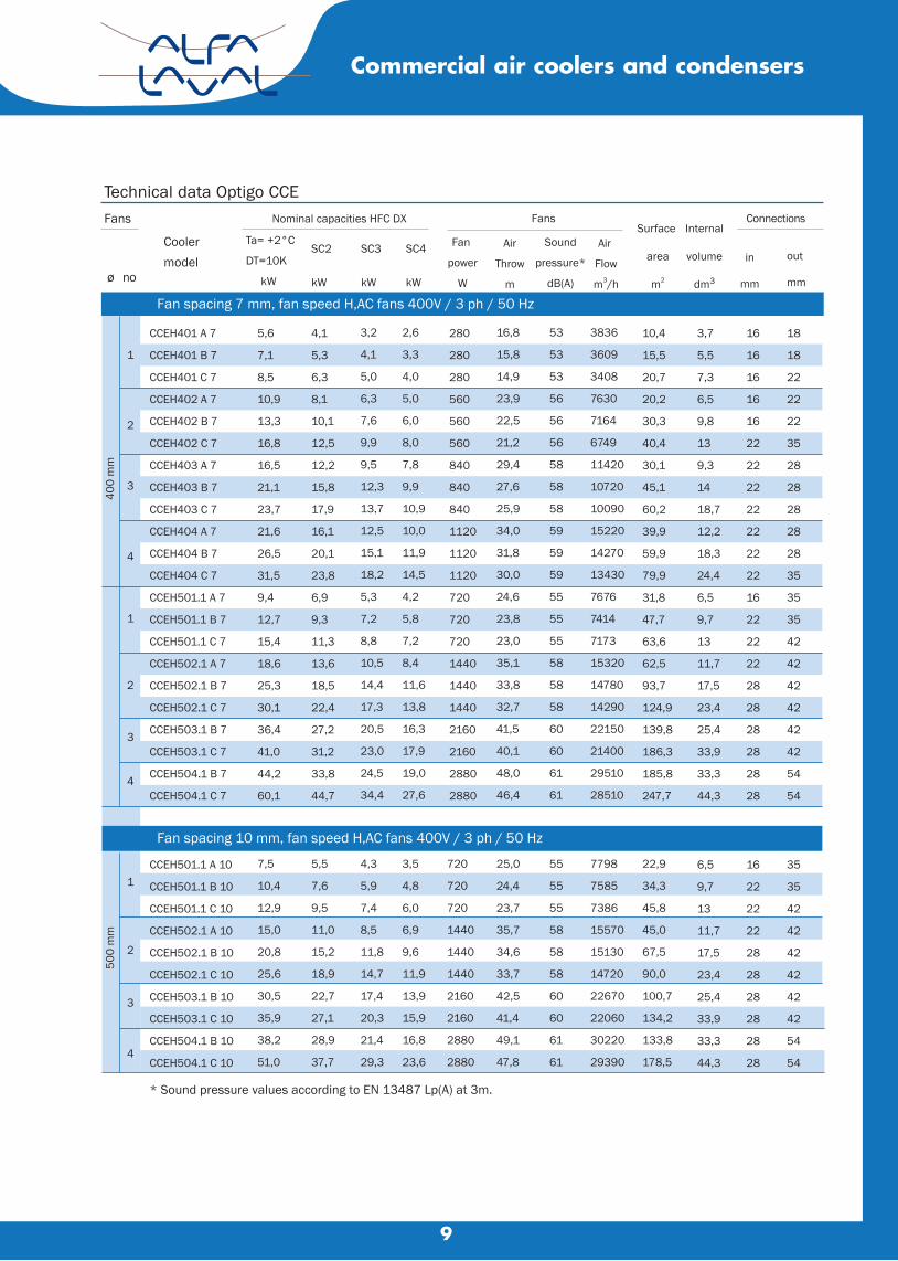
Fan spacing 7 mm, fan speed H,AC fans 400V / 3 ph / 50 Hz
Commercial air coolers and condensers
400
mm
1
2
3
4
1
2
3
4
500
mm
1
2
3
4
* Sound pressure values according to EN 13487 Lp(A) at 3m.
9
Technical data Optigo CCEFans Nominal capacities HFC DX Fans Connections
Ta= +2°C
DT=10K
kW ø no
out
mm
in
mm
Internal
volume
dm3
Surface
area
m2
Air
Flow
m3/h
Sound
pressure*
dB(A)
Air
Throw
m
Fan
power
W
SC4
kW
SC3
kW
SC2
kW
Coolermodel
Commercial air coolers and condensers
CCEH401 A 7
CCEH401 B 7
CCEH401 C 7
CCEH402 A 7
CCEH402 B 7
CCEH402 C 7
CCEH403 A 7
CCEH403 B 7
CCEH403 C 7
CCEH404 A 7
CCEH404 B 7
CCEH404 C 7
CCEH501.1 A 7
CCEH501.1 B 7
CCEH501.1 C 7
CCEH502.1 A 7
CCEH502.1 B 7
CCEH502.1 C 7
CCEH503.1 B 7
CCEH503.1 C 7
CCEH504.1 B 7
CCEH504.1 C 7
Fan spacing 10 mm, fan speed H,AC fans 400V / 3 ph / 50 Hz
CCEH501.1 A 10
CCEH501.1 B 10
CCEH501.1 C 10
CCEH502.1 A 10
CCEH502.1 B 10
CCEH502.1 C 10
CCEH503.1 B 10
CCEH503.1 C 10
CCEH504.1 B 10
CCEH504.1 C 10
5,6
7,1
8,5
10,9
13,3
16,8
16,5
21,1
23,7
21,6
26,5
31,5
9,4
12,7
15,4
18,6
25,3
30,1
36,4
41,0
44,2
60,1
4,1
5,3
6,3
8,1
10,1
12,5
12,2
15,8
17,9
16,1
20,1
23,8
6,9
9,3
11,3
13,6
18,5
22,4
27,2
31,2
33,8
44,7
3,2
4,1
5,0
6,3
7,6
9,9
9,5
12,3
13,7
12,5
15,1
18,2
5,3
7,2
8,8
10,5
14,4
17,3
20,5
23,0
24,5
34,4
2,6
3,3
4,0
5,0
6,0
8,0
7,8
9,9
10,9
10,0
11,9
14,5
4,2
5,8
7,2
8,4
11,6
13,8
16,3
17,9
19,0
27,6
280
280
280
560
560
560
840
840
840
1120
1120
1120
720
720
720
1440
1440
1440
2160
2160
2880
2880
16,8
15,8
14,9
23,9
22,5
21,2
29,4
27,6
25,9
34,0
31,8
30,0
24,6
23,8
23,0
35,1
33,8
32,7
41,5
40,1
48,0
46,4
53
53
53
56
56
56
58
58
58
59
59
59
55
55
55
58
58
58
60
60
61
61
3836
3609
3408
7630
7164
6749
11420
10720
10090
15220
14270
13430
7676
7414
7173
15320
14780
14290
22150
21400
29510
28510
10,4
15,5
20,7
20,2
30,3
40,4
30,1
45,1
60,2
39,9
59,9
79,9
31,8
47,7
63,6
62,5
93,7
124,9
139,8
186,3
185,8
247,7
3,7
5,5
7,3
6,5
9,8
13
9,3
14
18,7
12,2
18,3
24,4
6,5
9,7
13
11,7
17,5
23,4
25,4
33,9
33,3
44,3
16
16
16
16
16
22
22
22
22
22
22
22
16
22
22
22
28
28
28
28
28
28
18
18
22
22
22
35
28
28
28
28
28
35
35
35
42
42
42
42
42
42
54
54
7,5
10,4
12,9
15,0
20,8
25,6
30,5
35,9
38,2
51,0
5,5
7,6
9,5
11,0
15,2
18,9
22,7
27,1
28,9
37,7
4,3
5,9
7,4
8,5
11,8
14,7
17,4
20,3
21,4
29,3
3,5
4,8
6,0
6,9
9,6
11,9
13,9
15,9
16,8
23,6
720
720
720
1440
1440
1440
2160
2160
2880
2880
25,0
24,4
23,7
35,7
34,6
33,7
42,5
41,4
49,1
47,8
55
55
55
58
58
58
60
60
61
61
7798
7585
7386
15570
15130
14720
22670
22060
30220
29390
22,9
34,3
45,8
45,0
67,5
90,0
100,7
134,2
133,8
178,5
6,5
9,7
13
11,7
17,5
23,4
25,4
33,9
33,3
44,3
16
22
22
22
28
28
28
28
28
28
35
35
42
42
42
42
42
42
54
54
9
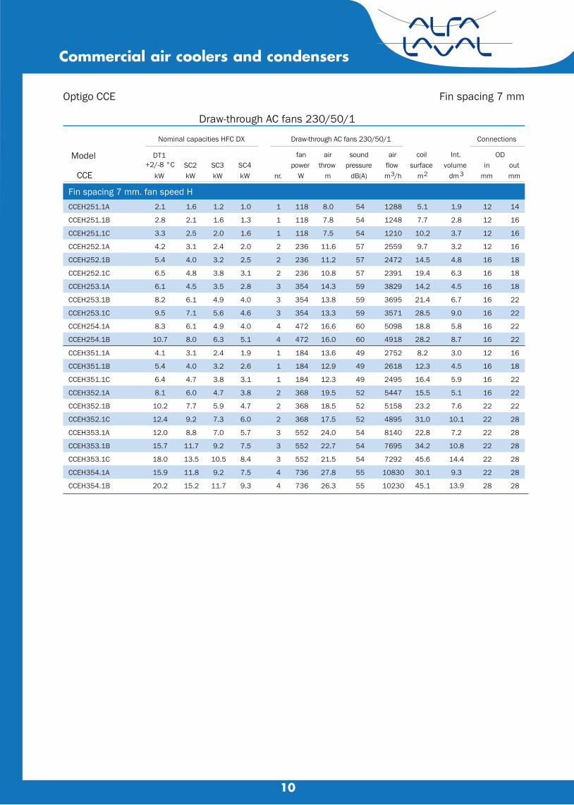
Draw-through AC fans 230/50/1
Fin spacing 7 mm
Model
Nominal capacities HFC DX Draw-through AC fans 230/50/1 Connections
DT1+2/-8 °C
fan air sound air coil Int. ODSC2 SC3 SC4 power throw pressure flow surface volume in out
CCE kW kW kW kW nr. W m dB(A) m3/h m2 dm3 mm mm
Fin spacing 7 mm. fan speed HCCEH251.1A 2.1 1.6 1.2 1.0 1 118 8.0 54 1288 5.1 1.9 12 14
CCEH251.1B 2.8 2.1 1.6 1.3 1 118 7.8 54 1248 7.7 2.8 12 16
CCEH251.1C 3.3 2.5 2.0 1.6 1 118 7.5 54 1210 10.2 3.7 12 16
CCEH252.1A 4.2 3.1 2.4 2.0 2 236 11.6 57 2559 9.7 3.2 12 16
CCEH252.1B 5.4 4.0 3.2 2.5 2 236 11.2 57 2472 14.5 4.8 16 18
CCEH252.1C 6.5 4.8 3.8 3.1 2 236 10.8 57 2391 19.4 6.3 16 18
CCEH253.1A 6.1 4.5 3.5 2.8 3 354 14.3 59 3829 14.2 4.5 16 18
CCEH253.1B 8.2 6.1 4.9 4.0 3 354 13.8 59 3695 21.4 6.7 16 22
CCEH253.1C 9.5 7.1 5.6 4.6 3 354 13.3 59 3571 28.5 9.0 16 22
CCEH254.1A 8.3 6.1 4.9 4.0 4 472 16.6 60 5098 18.8 5.8 16 22
CCEH254.1B 10.7 8.0 6.3 5.1 4 472 16.0 60 4918 28.2 8.7 16 22
CCEH351.1A 4.1 3.1 2.4 1.9 1 184 13.6 49 2752 8.2 3.0 12 16
CCEH351.1B 5.4 4.0 3.2 2.6 1 184 12.9 49 2618 12.3 4.5 16 18
CCEH351.1C 6.4 4.7 3.8 3.1 1 184 12.3 49 2495 16.4 5.9 16 22
CCEH352.1A 8.1 6.0 4.7 3.8 2 368 19.5 52 5447 15.5 5.1 16 22
CCEH352.1B 10.2 7.7 5.9 4.7 2 368 18.5 52 5158 23.2 7.6 22 22
CCEH352.1C 12.4 9.2 7.3 6.0 2 368 17.5 52 4895 31.0 10.1 22 28
CCEH353.1A 12.0 8.8 7.0 5.7 3 552 24.0 54 8140 22.8 7.2 22 28
CCEH353.1B 15.7 11.7 9.2 7.5 3 552 22.7 54 7695 34.2 10.8 22 28
CCEH353.1C 18.0 13.5 10.5 8.4 3 552 21.5 54 7292 45.6 14.4 22 28
CCEH354.1A 15.9 11.8 9.2 7.5 4 736 27.8 55 10830 30.1 9.3 22 28
CCEH354.1B 20.2 15.2 11.7 9.3 4 736 26.3 55 10230 45.1 13.9 28 28
10
Commercial air coolers and condensers
Optigo CCE
11
Fin spacing 7 mm. fan speed HCCEH401A 5.6 4.1 3.2 2.6 1 280 16.8 53 3836 10.4 3.7 16 18
CCEH401B 7.1 5.3 4.1 3.3 1 280 15.8 53 3609 15.5 5.5 16 18
CCEH401C 8.5 6.3 5.0 4.0 1 280 14.9 53 3408 20.7 7.3 16 22
CCEH402A 10.9 8.1 6.3 5.0 2 560 23.9 56 7630 20.2 6.5 16 22
CCEH402B 13.3 10.1 7.6 6.0 2 560 22.5 56 7164 30.3 9.8 16 22
CCEH402C 16.8 12.5 9.9 8.0 2 560 21.2 56 6749 40.4 13.0 22 35
CCEH403A 16.5 12.2 9.5 7.8 3 840 29.4 58 11420 30.1 9.3 22 28
CCEH403B 21.1 15.8 12.3 9.9 3 840 27.6 58 10720 45.1 14.0 22 28
CCEH403C 23.7 17.9 13.7 10.9 3 840 25.9 58 10090 60.2 18.7 22 28
CCEH404A 21.6 16.1 12.5 10.0 4 1120 34.0 59 15220 39.9 12.2 22 28
CCEH404B 26.5 20.1 15.1 11.9 4 1120 31.8 59 14270 59.9 18.3 22 28
CCEH404C 31.5 23.8 18.2 14.5 4 1120 30.0 59 13430 79.9 24.4 22 35
CCEH501A 9.4 6.9 5.3 4.2 1 720 24.6 55 7676 31.8 6.5 16 35
CCEH501B 12.7 9.3 7.2 5.8 1 720 23.8 55 7414 47.7 9.7 22 35
CCEH501C 15.4 11.3 8.8 7.2 1 720 23.0 55 7173 63.6 13.0 22 42
CCEH502A 18.6 13.6 10.5 8.4 2 1440 35.1 58 15320 62.5 11.7 22 42
CCEH502B 25.3 18.5 14.4 11.6 2 1440 33.8 58 14780 93.7 17.5 28 42
CCEH502C 30.1 22.4 17.3 13.8 2 1440 32.7 58 14290 124.9 23.4 28 42
CCEH503B 36.4 27.2 20.5 16.3 3 2160 41.5 60 22150 139.8 25.4 28 42
CCEH503C 41.0 31.2 23.0 17.9 3 2160 40.1 60 21400 186.3 33.9 28 42
CCEH504B 44.2 33.8 24.5 19.0 4 2880 48.0 61 29510 185.8 33.3 28 54
CCEH504C 60.1 44.7 34.4 27.6 4 2880 46.4 61 28510 247.7 44.3 28 54
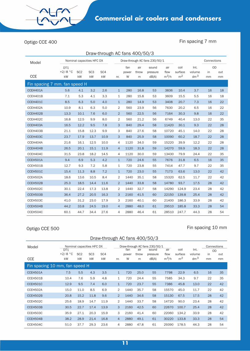
Draw-through AC fans 400/50/3
Fin spacing 7 mmOptigo CCE 400
Commercial air coolers and condensers
Model Nominal capacities HFC DX Draw-through AC fans 230/50/1 Connections
DT1+2/-8 °C
fan air sound air coil Int. ODSC2 SC3 SC4 power throw pressure flow surface volume in out
CCE kW kW kW kW nr. W m dB(A) m3/h m2 dm3 mm mm
Draw-through AC fans 400/50/3
Fin spacing 10 mmOptigo CCE 500
Model Nominal capacities HFC DX Draw-through AC fans 230/50/1 ConnectionsDT1
+2/-8 °Cfan air sound air coil Int. OD
SC2 SC3 SC4 power throw pressure flow surface volume in outCCE kW kW kW kW nr. W m dB(A) m3/h m2 dm3 mm mm
Fin spacing 10 mm, fan speed HCCEH501A 7.5 5.5 4.3 3.5 1 720 25.0 55 7798 22.9 6.5 16 35
CCEH501B 10.4 7.6 5.9 4.8 1 720 24.4 55 7585 34.3 9.7 22 35
CCEH501C 12.9 9.5 7.4 6.0 1 720 23.7 55 7386 45.8 13.0 22 42
CCEH502A 15.0 11.0 8.5 6.9 2 1440 35.7 58 15570 45.0 11.7 22 42
CCEH502B 20.8 15.2 11.8 9.6 2 1440 34.6 58 15130 67.5 17.5 28 42
CCEH502C 25.6 18.9 14.7 11.9 2 1440 33.7 58 14720 90.0 23.4 28 42
CCEH503B 30.5 22.7 17.4 13.9 3 2160 42.5 60 22670 100.7 25.4 28 42
CCEH503C 35.9 27.1 20.3 15.9 3 2160 41.4 60 22060 134.2 33.9 28 42
CCEH504B 38.2 28.9 21.4 16.8 4 2880 49.1 61 30220 133.8 33.3 28 54
CCEH504C 51.0 37.7 29.3 23.6 4 2880 47.8 61 29390 178.5 44.3 28 54

Commercial air coolers and condensers
12
Draw-through CC
ModelCoil defrost Driptray defrost
Optigo CC
Tuberowsno.
heaterelements
no.
powerper
heaterW
totalpower
W
heaterelements
no.
totalpower
W
std heavy std heavy std heavy std heavy
Draw-through CC
ModelCoil defrost Driptray defrost
Optigo CC
Tuberowsno.
heaterelements
no.
powerper
heaterW
totalpower
W
heaterelements
no.
totalpower
W
std heavy std heavy std heavy std heavy251.1A 4 2 - 420 840 - 1 - 420 -251.1B 6 2 - 420 840 - 1 - 420 -251.1C 8 4 - 420 1680 - 1 - 420 -252.1A 4 2 - 760 1520 - 1 - 760 -252.1B 6 2 - 760 1520 - 1 - 760 -252.1C 8 4 - 760 3040 - 1 - 760 -253.1A 4 2 - 1120 2240 - 1 - 1120 -253.1B 6 2 - 1120 2240 - 1 - 1120 -253.1C 8 4 - 1120 4480 - 1 - 1120 -254.1A 4 2 - 1470 2940 - 1 - 1470 -254.1B 6 2 - 1470 2940 - 1 - 1470 -351.1A 4 4 - 420 1680 - 1 - 420 -351.1B 6 4 - 420 1680 - 1 - 420 -351.1C 8 5 - 420 2100 - 1 - 420 -352.1A 4 4 - 760 3040 - 1 - 760 -352.1B 6 4 - 760 3040 - 1 - 760 -352.1C 8 5 - 760 3800 - 1 - 760 -353.1A 4 4 - 1120 4480 - 1 - 1120 -353.1B 6 4 - 1120 4480 - 1 - 1120 -353.1C 8 5 - 1120 5600 - 1 - 1120 -354.1A 4 4 - 1470 5880 - 1 - 1470 -354.1B 6 4 - 1470 5880 - 1 - 1470 -
401A 4 5 7 460 2300 3220 1 2 460 920401B 6 5 7 460 2300 3220 1 2 460 920401C 8 8 10 460 3680 4600 1 2 460 920402A 4 5 7 880 4400 6160 1 2 880 1760402B 6 5 7 880 4400 6160 1 2 880 1760402C 8 8 10 880 7040 8800 1 2 880 1760403A 4 5 7 1290 6450 9030 1 2 1290 2580403B 6 5 7 1290 6450 9030 1 2 1290 2580403C 8 8 10 1290 10320 12900 1 2 1290 2580404A 4 5 7 1700 8500 11900 1 2 1700 3400404B 6 5 7 1700 8500 11900 1 2 1700 3400404C 8 8 10 1700 13600 17000 1 2 1700 3400501A 4 5 7 630 3150 4410 1 2 630 1260501B 6 5 7 630 3150 4410 1 2 630 1260501C 8 8 10 630 5040 6300 1 2 630 1260502A 4 5 7 1220 6100 8540 1 2 1220 2440502B 6 5 7 1220 6100 8540 1 2 1220 2440502C 8 8 10 1220 9760 12200 1 2 1220 2440503B 4 5 7 1810 9050 12670 1 2 1810 3620503C 8 8 10 1810 14480 18100 1 2 1810 3620504B 4 5 7 2400 12000 16800 1 2 2400 4800504C 8 8 10 2400 19200 24000 1 2 2400 4800
Optigo CC(B)
Dimensionscoolermodel
Dimensions (mm) Shippingvolume
C H L A B m3
Draw-through CC
CC 251 841 405 410 530 - 0.4
CC 252 1341 405 410 1030 - 0.6
CC 253 1841 405 410 1530 - 0.8
CC 254 2341 405 410 2030 1015 1.0
CC 351 841 598 410 530 - 0.5
CC 352 1341 598 410 1030 - 0.7
CC 353 1841 598 410 1530 - 1.0
CC 354 2341 598 410 2030 1015 1.3
CC 401 1037 691 583 600 - 0.9
CC 402 1637 691 583 1200 - 1.3
CC 403 2237 691 583 1800 - 1.7
CC 404 2837 691 583 2400 1200 2.2
CC 501 1288 854 583 850 - 1.3
CC 502 2138 854 583 1700 - 2.0
CC 503 2988 854 583 2550 - 2.7
CC 504 3838 854 583 3400 1700 3.5
L
CØ1"
A( B ) ( B )
H
30
10
50
18
CC250/300/350
CC400/500
G ext.
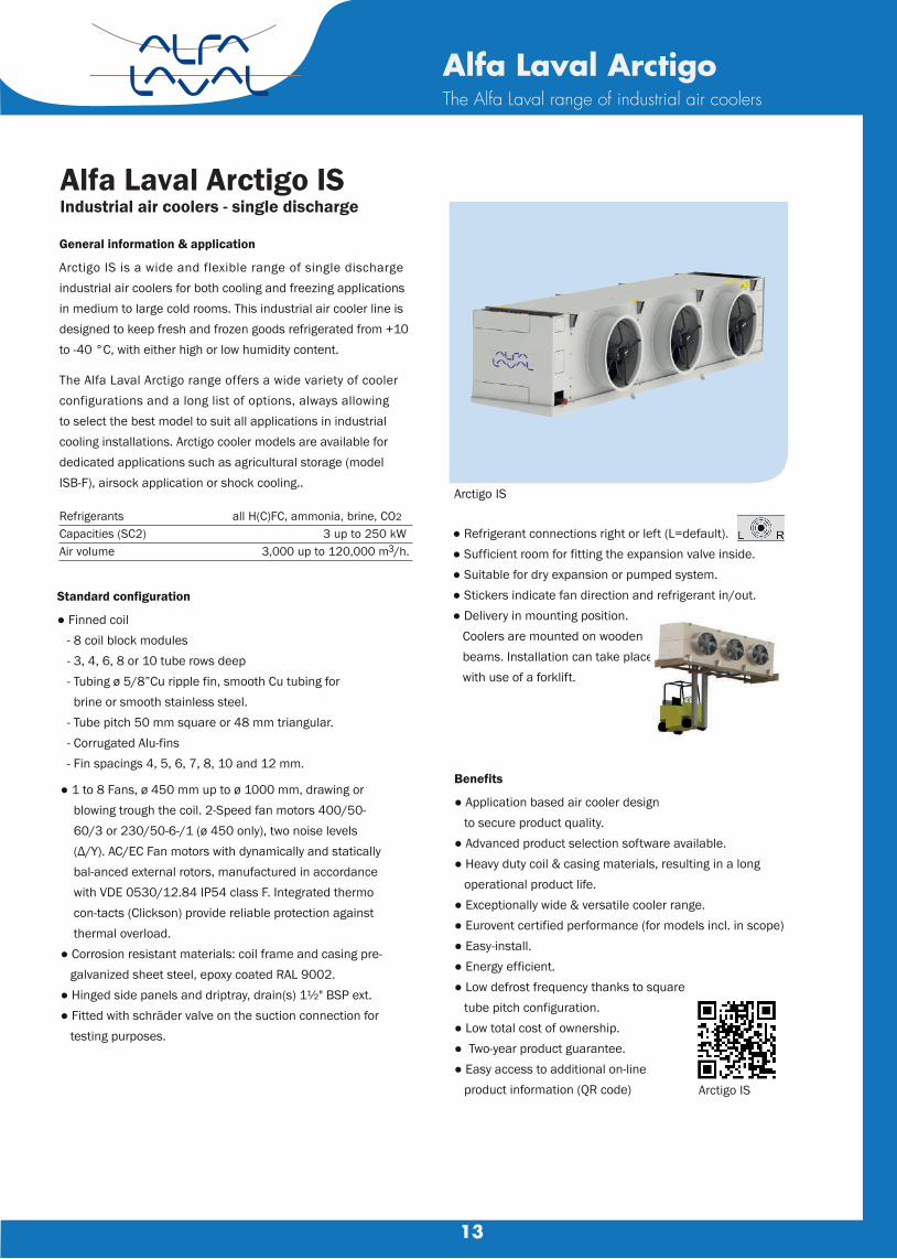
General information & application
Arctigo IS is a wide and flexible range of single discharge industrial air coolers for both cooling and freezing applications in medium to large cold rooms. This industrial air cooler line is designed to keep fresh and frozen goods refrigerated from +10 to -40 °C, with either high or low humidity content.
Refrigerants all H(C)FC, ammonia, brine, CO2
Capacities (SC2) 3 up to 250 kWAir volume 3,000 up to 120,000 m3/h.
Standard configuration
● Finned coil - 8 coil block modules - 3, 4, 6, 8 or 10 tube rows deep - Tubing ø 5/8”Cu ripple fin, smooth Cu tubing for brine or smooth stainless steel. - Tube pitch 50 mm square or 48 mm triangular. - Corrugated Alu-fins - Fin spacings 4, 5, 6, 7, 8, 10 and 12 mm.
● Refrigerant connections right or left (L=default).● Sufficient room for fitting the expansion valve inside.● Suitable for dry expansion or pumped system. ● Stickers indicate fan direction and refrigerant in/out.● Delivery in mounting position. Coolers are mounted on wooden beams. Installation can take place with use of a forklift.
Benefits
● Application based air cooler design to secure product quality.● Advanced product selection software available.● Heavy duty coil & casing materials, resulting in a long operational product life.● Exceptionally wide & versatile cooler range.● Eurovent certified performance (for models incl. in scope)● Easy-install.● Energy efficient.● Low defrost frequency thanks to square tube pitch configuration.● Low total cost of ownership.● Two-year product guarantee.● Easy access to additional on-line product information (QR code)
Alfa Laval Arctigo ISIndustrial air coolers - single discharge
Arctigo IS
Arctigo IS
Alfa Laval ArctigoThe Alfa Laval range of industrial air coolers
● 1 to 8 Fans, ø 450 mm up to ø 1000 mm, drawing or blowing trough the coil. 2-Speed fan motors 400/50- 60/3 or 230/50-6-/1 (ø 450 only), two noise levels (Δ/Y). AC/EC Fan motors with dynamically and statically bal-anced external rotors, manufactured in accordance with VDE 0530/12.84 IP54 class F. Integrated thermo con-tacts (Clickson) provide reliable protection against thermal overload. ● Corrosion resistant materials: coil frame and casing pre- galvanized sheet steel, epoxy coated RAL 9002. ● Hinged side panels and driptray, drain(s) 1½" BSP ext. ● Fitted with schräder valve on the suction connection for testing purposes.
The Alfa Laval Arctigo range offers a wide variety of cooler configurations and a long list of options, always allowing to select the best model to suit all applications in industrial cooling installations. Arctigo cooler models are available for dedicated applications such as agricultural storage (modelISB-F), airsock application or shock cooling..
13
14
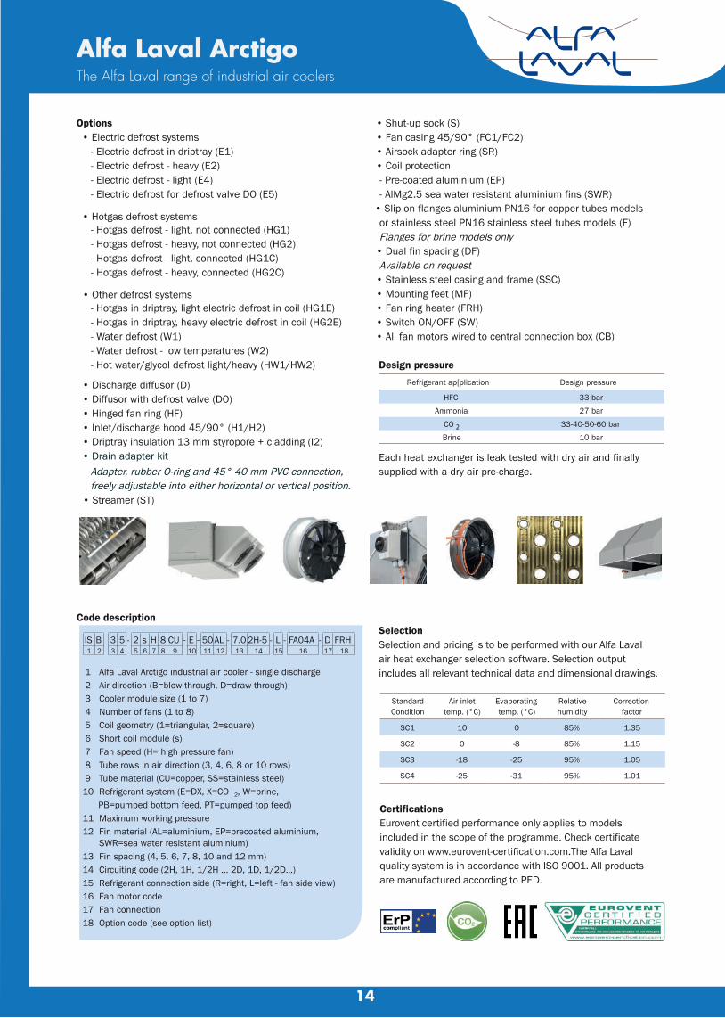
Options • Electric defrost systems
- Electric defrost in driptray (E1) - Electric defrost - heavy (E2) - Electric defrost - light (E4) - Electric defrost for defrost valve DO (E5)
• Hotgas defrost systems - Hotgas defrost - light, not connected (HG1) - Hotgas defrost - heavy, not connected (HG2) - Hotgas defrost - light, connected (HG1C) - Hotgas defrost - heavy, connected (HG2C)
• Other defrost systems - Hotgas in driptray, light electric defrost in coil (HG1E) - Hotgas in driptray, heavy electric defrost in coil (HG2E) - Water defrost (W1) - Water defrost - low temperatures (W2) - Hot water/glycol defrost light/heavy (HW1/HW2)
• Discharge diffusor (D) • Diffusor with defrost valve (DO) • Hinged fan ring (HF) • Inlet/discharge hood 45/90° (H1/H2) • Driptray insulation 13 mm styropore + cladding (I2) • Drain adapter kit
Adapter, rubber O-ring and 45° 40 mm PVC connection, freely adjustable into either horizontal or vertical position.
• Streamer (ST)
Code description
1 Alfa Laval Arctigo industrial air cooler - single discharge 2 Air direction (B=blow-through, D=draw-through) 3 Cooler module size (1 to 7) 4 Number of fans (1 to 8) 5 Coil geometry (1=triangular, 2=square) 6 Short coil module (s) 7 Fan speed (H= high pressure fan) 8 Tube rows in air direction (3, 4, 6, 8 or 10 rows) 9 Tube material (CU=copper, SS=stainless steel)10 Refrigerant system (E=DX, X=CO 2, W=brine, PB=pumped bottom feed, PT=pumped top feed)11 Maximum working pressure12 Fin material (AL=aluminium, EP=precoated aluminium, SWR=sea water resistant aluminium)13 Fin spacing (4, 5, 6, 7, 8, 10 and 12 mm)14 Circuiting code (2H, 1H, 1/2H ... 2D, 1D, 1/2D...)15 Refrigerant connection side (R=right, L=left - fan side view)16 Fan motor code 17 Fan connection18 Option code (see option list)
• Shut-up sock (S) • Fan casing 45/90° (FC1/FC2) • Airsock adapter ring (SR)• Coil protection - Pre-coated aluminium (EP) - AlMg2.5 sea water resistant aluminium fins (SWR)
• Slip-on flanges aluminium PN16 for copper tubes models or stainless steel PN16 stainless steel tubes models (F) Flanges for brine models only
• Dual fin spacing (DF) Available on request
• Stainless steel casing and frame (SSC)• Mounting feet (MF)• Fan ring heater (FRH)• Switch ON/OFF (SW)
• All fan motors wired to central connection box (CB)
Design pressureRefrigerant ap[plication Design pressure
HFC 33 barAmmonia 27 bar
CO 2 33-40-50-60 barBrine 10 bar
Each heat exchanger is leak tested with dry air and finally supplied with a dry air pre-charge.
SelectionSelection and pricing is to be performed with our Alfa Laval air heat exchanger selection software. Selection output includes all relevant technical data and dimensional drawings.
CertificationsEurovent certified performance only applies to modelsincluded in the scope of the programme. Check certificate validity on www.eurovent-certification.com.The Alfa Laval quality system is in accordance with ISO 9001. All products are manufactured according to PED.
IS B 3 5 - 2 s H 8 CU - E - 50AL - 7.0 2H-5 - L - FA04A - D FRH1 2 3 4 5 6 7 8 9 10 11 12 13 14 15 16 17 18
Alfa Laval ArctigoThe Alfa Laval range of industrial air coolers
StandardCondition
Air inlettemp. (°C)
Evaporatingtemp. (°C)
Relativehumidity
Correctionfactor
SC1 10 0 85% 1.35
SC2 0 -8 85% 1.15
SC3 -18 -25 95% 1.05
SC4 -25 -31 95% 1.01

15
Alfa Laval ArctigoThe Alfa Laval range of industrial air coolers
Technical data
ISD32 - 110CU
ISD33 - 18CU
ISD34 - 110CU
ISD61 - 16CU
ISD62 - 16CU
ISD43 - 110CU
ISD63 - 16CU
ISD73 - 110CU
Nominal capacities HFC DX
Draw-through AC fans 400/50/3
Fan diameter
mm
Number of Fan
Nom.power consumption
air throw (m)
sound pressure (dB(A))
air flow (m3/s)
coil
surface
(m2)
Int.
volume
(dm3) in
(mm) (mm)
Connections OD
Model
- EH33
- EH33
- EH33
- EH33
- EH33
- EH33
- EH33
- EH33
- EH33
- EH33
- EH33
- EH33
- EH33
- EH33
- EH33
- EH33
29.84
37.07
61.21
30
61.29
74.27
88.49
121.8
23.99
30.2
49.68
24.42
49.77
60.4
70.72
98.97
SC3
kW
SC4
kW
710
710
710
1000
1000
800
1000
1000
2
3
4
1
2
3
3
3
2000
2160
4000
2700
5400
4710
8100
8100
36
35
39
68
75
53
79
71
57
54
59
62
65
58
66
66
5.825
8.008
11.65
8.527
17.1
13.82
25.65
23.12
138.9
166.7
277.8
121.6
243.1
347.3
364.7
555.7
74.7
87.4
144.1
66
126.9
180.1
187.9
288.2
28
35
42
35
2X28
2X35
2X28
2X42
54
64
76.1
64
2X54
2X64
2X54
2X76.1
ISD32 - 110CU
ISD33 - 18CU
ISD34 - 110CU
ISD61 - 16CU
ISD62 - 16CU
ISD43 - 110CU
ISD63 - 16CU
ISD73 - 110CU
Dimensional drawings
Length
mm
Height
mm
Depth
mm
Unit weight
kg
Fin spacing
mm
Number of fans
Fan Diameter
mm
No of circuits Row
3075
4275
5475
2675
4675
5475
6675
5475
910
910
910
1510
1510
1110
1510
1710
1170
1170
1170
1195
1195
1145
1195
1195
377.8
519.2
720.6
437.7
747.7
792.8
1026
1242
12
12
12
12
12
12
12
12
2
3
4
1
2
3
3
3
710
710
710
1000
1000
800
1000
1000
16
32
40
28
42
50
42
80
10
8
10
6
6
10
6
10
Model
out

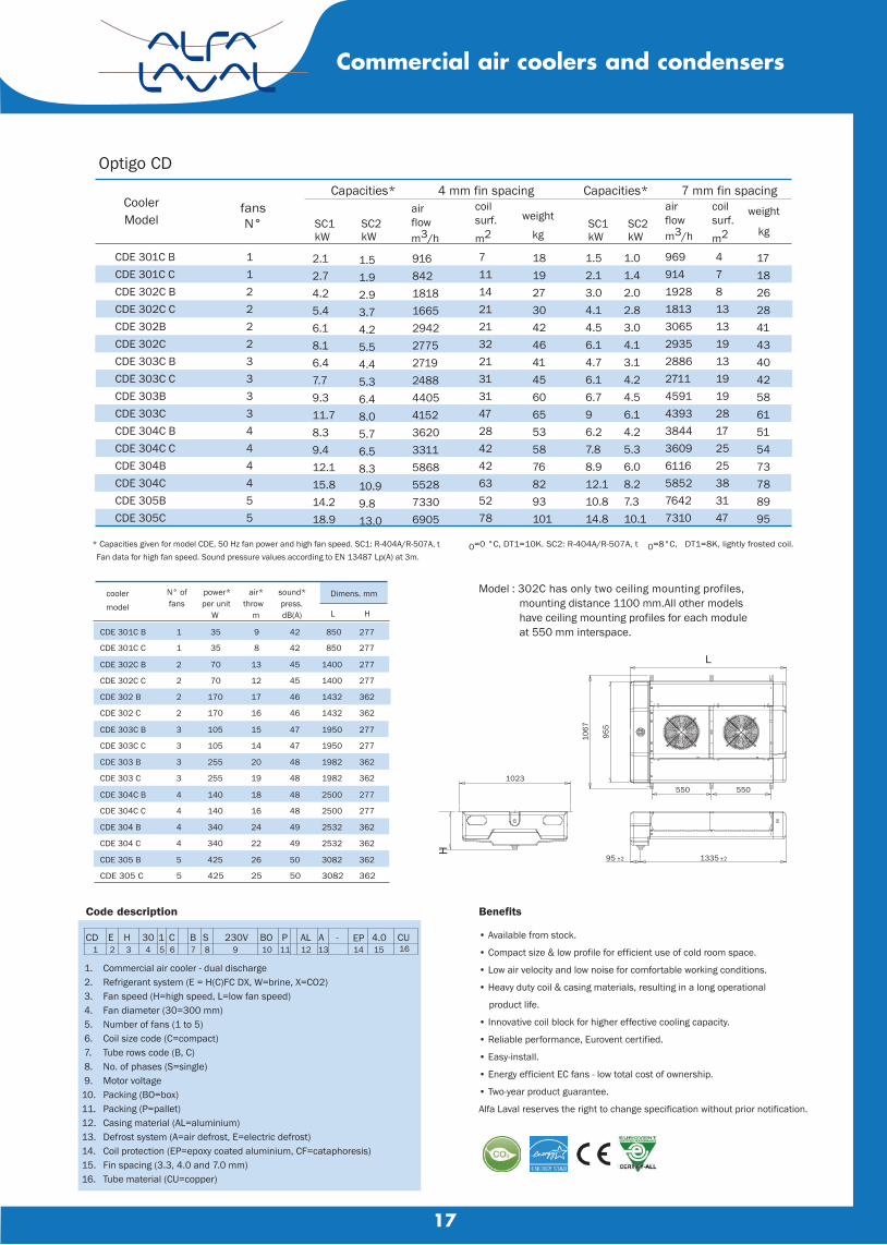
Optigo CD General information & application
+10 to -30 °C
all H(C)FC, CO2 and brine
1.0 up to 14 kW
819 up to 7642 m3/h
Fan motors1 to 5 fans fitted with state-of-the-art dual fan speed EC motors, fan diameter 300 mm blowing through the coil. Power supply is 230/1/50-60. Enclosed design spray-tight fan motors, protection class IP-54. Fan motors pre-wired to a central terminal box.
CertificationsAll DX cooler models are “Eurovent Certify All” certified. The Alfa Laval quality system is in accordance with ISO 9001. All products are manufactured according to CE and PED regulations.
Design pressureDesign pressure 31 bar (H(C)FC/ammonia, 80 bar (CO2) or 9 bar (brine). Higher design pressures on request. Each heat exchanger is leak tested with dry air and supplied with a nitrogen pre-charge (models CDE & CDX).
Options● Electric defrost (E)● Coil corrosion protection - epoxy coated aluminium fins (EP) - cataphoresis treatment (CF)● Liquid or gas re-heating coil (RH)
SelectionSelection and pricing is to be performed with our Alfa Laval air heat exchanger selection software. Selection output includes all relevant technical data and dimensional drawings. Please contact our sales organization for details and full technical documentation.
Optigo CD
16
Commercial air coolers and condensers
Alfa Laval Optigo is a new platform for commercial air cooler ranges. Forming a common 'DNA', this platform offers a newly developed and highly efficient coil block and many other features. The Optigo CD is a commercial dual discharge air cooler for general application in small to medium-sized cooling, freezing and working rooms. Low air velocity and noise level make them especially suitable for refrigerated working & processing rooms. Optigo CD coolers are available from stock.
Evaporating temperatures
Refrigerants
Capacities (SC2)
Air volume
CoilInnovative coil manufactured from internally grooved Cu tubes ø 5/16”(smooth 3/8" tubing for brine applications) and aluminium fins.Tube pitch 30x26 mm staggered. Fin spacings 3.3, 4.0 and 7.0 mm.
CasingDurable aluminium casing, white epoxy coated RAL 9010. Removable plastic side panels for easy access. All models fitted with a hinged drip tray construction. Internal air deflectors enhance coil efficiency.
4 mm fin spacingfansN°
Capacities*airflowm3/h
coilsurf.m2
weight
kg
Code description
1. Commercial air cooler - dual discharge 2. Refrigerant system (E = H(C)FC DX, W=brine, X=CO2) 3. Fan speed (H=high speed, L=low fan speed) 4. Fan diameter (30=300 mm) 5. Number of fans (1 to 5) 6. Coil size code (C=compact) 7. Tube rows code (B, C) 8. No. of phases (S=single) 9. Motor voltage10. Packing (BO=box)11. Packing (P=pallet)12. Casing material (AL=aluminium)13. Defrost system (A=air defrost, E=electric defrost)14. Coil protection (EP=epoxy coated aluminium, CF=cataphoresis)15. Fin spacing (3.3, 4.0 and 7.0 mm)16. Tube material (CU=copper)
Benefits
• Available from stock.
• Compact size & low profile for efficient use of cold room space.
• Low air velocity and low noise for comfortable working conditions.
• Heavy duty coil & casing materials, resulting in a long operational
product life.
• Innovative coil block for higher effective cooling capacity.
• Reliable performance, Eurovent certified.
• Easy-install.
• Energy efficient EC fans - low total cost of ownership.
• Two-year product guarantee.
Alfa Laval reserves the right to change specification without prior notification.
* Capacities given for model CDE, 50 Hz fan power and high fan speed. SC1: R-404A/R-507A, t Fan data for high fan speed. Sound pressure values according to EN 13487 Lp(A) at 3m.
0=0 °C, DT1=10K. SC2: R-404A/R-507A, t 0=8°C, DT1=8K, lightly frosted coil.
CD E H 30 1 C B S 230V BO P AL A - EP 4.0 CU1 2 3 4 5 6 7 8 9 10 11 12 13 14 15 16
L
955
1067
1023
1335 ±295 ±2
550 550
H
Model : 302C has only two ceiling mounting profiles, mounting distance 1100 mm.All other models have ceiling mounting profiles for each module at 550 mm interspace.
CDE 301C BCDE 301C CCDE 302C BCDE 302C CCDE 302BCDE 302CCDE 303C BCDE 303C CCDE 303BCDE 303CCDE 304C BCDE 304C CCDE 304BCDE 304CCDE 305BCDE 305C
1122223333444455
SC1kW
SC2kW
2.12.74.25.46.18.16.47.79.311.78.39.412.115.814.218.9
1.51.92.93.74.25.54.45.36.48.05.76.58.310.99.813.0
91684218181665294227752719248844054152362033115868552873306905
7111421213221313147284242635278
181927304246414560655358768293101
1.52.13.04.14.56.14.76.16.796.27.88.912.110.814.8
1.01.42.02.83.04.13.14.24.56.14.25.36.08.27.310.1
96991419281813306529352886271145914393384436096116585276427310
47813131913191928172525383147
17182628414340425861515473788995
CoolerModel
7 mm fin spacingCapacities*airflowm3/h
coilsurf.m2
weight
kgSC1kW
SC2kW
Optigo CD
17
Commercial air coolers and condensers
coolermodel
N° of fans
power*per unit
W
air*throw
m
sound*press.dB(A)
Dimens. mm
L H
CDE 301C B 1 35 9 42 850 277
CDE 301C C 1 35 8 42 850 277
CDE 302C B 2 70 13 45 1400 277
CDE 302C C 2 70 12 45 1400 277
CDE 302 B 2 170 17 46 1432 362
CDE 302 C 2 170 16 46 1432 362
CDE 303C B 3 105 15 47 1950 277
CDE 303C C 3 105 14 47 1950 277
CDE 303 B 3 255 20 48 1982 362
CDE 303 C 3 255 19 48 1982 362
CDE 304C B 4 140 18 48 2500 277
CDE 304C C 4 140 16 48 2500 277
CDE 304 B 4 340 24 49 2532 362
CDE 304 C 4 340 22 49 2532 362
CDE 305 B 5 425 26 50 3082 362
CDE 305 C 5 425 25 50 3082 362

18
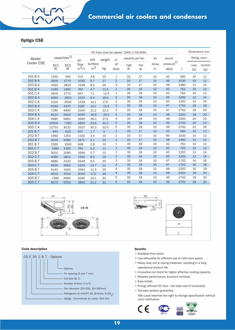
Optigo CS
General information & application
Alfa Laval Optigo is a new platform for commercial air cooler ranges.
Forming a common 'DNA', this platform offers a newly developed and
highly efficient coil block and many other features. The Optigo CS is a
commercial air cooler for general application in small to medium-sized
cooling and freezing rooms. The model's design is characterised by a
low silhouette (only 15 cm for CS20) for the efficient use of cold room
space. Optigo CS coolers are available from stock.
Evaporating temp. +10 to -30°C
Refrigerants all H(C)FC, brine and CO2Capacities (SC2) 620 up to 8110 W
Air volume 510 up to 4240 m3/h.
Casing
Durable aluminium casing,
white epoxy coated RAL 9003.
CS30 removable plastic side panels
for easy access. Hinged drip tray construction. Separated fan
sections. The CS20 model is available with drip tray for wall
mounting.
Fan motors
Standard fitted with state-of-the-art dual fan speed EC
motors in two diameters (200 & 300 mm), blowing through
the coil. Power supply is 230/1/50-60. Enclosed design
spray-tight fan motors, protection class IP-55. Motors are
equipped with a thermal safety device in the windings, con-
nected to separate terminals in the box.
Easy installation
Easy installation and maintenance thanks to hinged drip tray
construction and removable side panels (CS30). Delivery with
dismounted side panels in cardboard shipping box. Mounting
mould is printed on the inside cover of the box.
Certifications
All DX cooler models are “Eurovent Certify All” certified. The Alfa Laval quality system is in accordance with ISO 9001. All products are manufactured according to CE and PED regulations.
Test
Design pressure 31 barg. Each heat exchanger is leak
tested with dry air and supplied with a nitrogen pre-charge.
Options
• Electric defrost (separate kit)
• Epoxy coated aluminium fins
• Coil corrosion protection
• Wall mounting (CS20 only)
Selection
Please use AlfaSelect Air selection software
for cooler selection and RCPL pricing.
Optigo CS20 (top) & CS30
Commercial air coolers and condensers
Coil
Innovative coil manufactured from internally grooved Cu tubesø 5/16” (3/8" for brine applications) and aluminium fins. Tube pitch 30x26 mm staggered. Standard fin spacings 4 and 7 mm.
19
EC Fans dual fan speed 230V/1/50-60Hz
Dimensions mm
capacities1)
coil weight nr. capacity per fan air sound Refrig. conn.
SC1 SC2 surface of high low throw pressure2)
inlet suction W W m2 kg fans
W W m dB(A) L OD OD
33 17 10 580 10 12 33 17 10 1030 10 12 33 17 10 1480 12 14 35 18 10 762 10 12 35 18 10 762 10 12 35 18 10 1262 12 14 35 18 10 1262 14 16 35 18 10 1762 16 18 35 18 10 1762 18 20 35 18 10 2262 18 20 35 18 10 2262 20 22 35 18 10 2762 20 22 35 18 10 2762 22 26 33 17 10 580 10 12 33 17 10 1030 10 12 33 17 10 1480 12 14 35 18 10 762 10 12 35 18 10 762 10 12 35 18 10 1262 12 14 35 18 10 1262 12 14 35 18 10 1762 14 16 35 18 10 1762 16 18 35 18 10 2262 16 18 35 18 10 2262 18 20 35 18 10 2762 18 20
1 2 3 1 1 2 2 3 3 4 4 5 5 1 2 3 1 1 2 2 3 3 4 4 5 5 35 18 10
43 46 48 42 42 45 45 47 47 48 48 49 49 43 46 48 42 42 45 45 47 47 48 48 49 49 2762 18 20
Benefits• Available from stock.• Low silhouette for efficient use of cold room space.• Heavy duty coil & casing materials, resulting in a long operational product life.• Innovative coil block for higher effective cooling capacity.• Reliable performance, Eurovent certified.• Easy-install. • Energy efficient EC fans - low total cost of ownership.• Two-year product guarantee.
Alfa Laval reserves the right to change specification without prior notification.
Code description
CS E 30 2 B 7 - Options
Options
Fin spacing (4 and 7 mm)
Coil size (B, C)
Number of fans (1 to 5)
Fan diameter (20=200, 30=300mm)
Refrigerant (E=H(C)FC DX, B=brine, X=CO2)
Optigo - Commercial air cooler, Slim line
CS 30 CS 20
Model Cooler CSE
201 B 4 202 B 4 203 B 4 301 B 4 301 C 4 302 B 4 302 C 4 303 B 4 303 C 4 304 B 4 304 C 4 305 B 4 305 C 4 201 B 7 202 B 7 203 B 7 301 B 7 301 C 7 302 B 7 302 C 7 303 B 7 303 C 7 304 B 7 304 C 7 305 B 7 305 C 7
1350 2600 4160 2180 2600 4060 5100 6340 7280 8110 9980
10500 11750
940 1980 3020 1560 1980
3020 4060 4680 5930 6140 8010 73809570
940 1770 2810 1460 1770 28103540
4370 4990 5620 6860 72808110 620
1350 2080 1040
1350 2080 2810 3220 4060 4160 5510 4990 6550
513 1025 1538 762667 1525 133422872000 3050 2669 3800 3337 557 11001671848 760 1696 1500254422503392 3000 4240 3800
2.85.7 8.5 4.7 7.1 9.4 14.1 14.1 21.218.9 28.3 23.635.31.7 3.45.12.8 4.2 5.78.5 8.5 12.711.3 17.014.121.2
10 17 24 11.5 12.5 16.5 17.5 21.5 22.5 26.5 27.5 31.5 32.5 9 15 22 10 11 15 16 20 21 25 26 30 31
air flow m3/h
Commercial air coolers and condensers
Optigo CSE
20
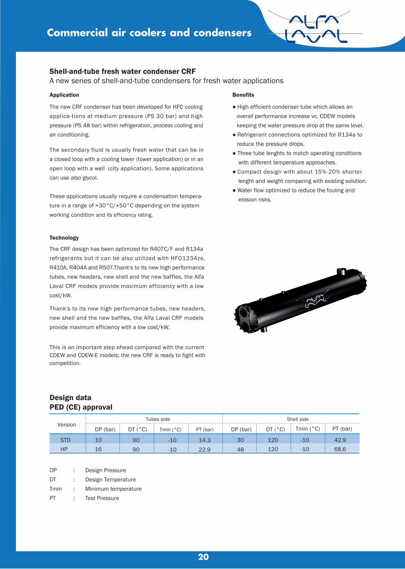
Shell-and-tube fresh water condenser CRFA new series of shell-and-tube condensers for fresh water applications
Application
The new CRF condenser has been developed for HFC cooling applica-tions at medium pressure (PS 30 bar) and high pressure (PS 48 bar) within refrigeration, process cooling andair conditioning.
Benefits
● High efficient condenser tube which allows an overall performance increase vc. CDEW models keeping the water pressure drop at the same level.● Refrigerant connections optimized for R134a to reduce the pressure drops.● Three tube lenghts to match operating conditions with different temperature approaches. ● Compact design with about 15%-20% shorter lenght and weight comparing with existing solution.● Water flow optimized to reduce the fouling and erosion risks.
Design dataPED (CE) approval
Version Tubes side Shell side
DP (bar) DT (°C) Tmin (°C) PT (bar) DP (bar) DT (°C) Tmin (°C) PT (bar)
STD 10 90 -10 14.3 30 120 -10 42.9HP 16 90 -10 22.9 48 120 -10 68.6
DP : Design PressureDT : Design TemperatureTmin : Minimum temperaturePT : Test Pressure
The secondary fluid is usually fresh water that can be in a closed loop with a cooling tower (tower application) or in an open loop with a well (city application). Some applications can use also glycol.
These applications usually require a condensation tempera-ture in a range of +30°C/+50°C depending on the system working condition and its efficiency rating.
Technology
The CRF design has been optimized for R407C/F and R134a refrigerants but it can be also utilized with HFO1234ze, R410A, R404A and R507.Thank's to its new high performance tubes, new headers, new shell and the new baffles, the Alfa Laval CRF models provide maximum efficiency with a low cost/kW.
Thank's to its new high performance tubes, new headers, new shell and the new baffles, the Alfa Laval CRF models provide maximum efficiency with a low cost/kW.
This is an important step ahead compared with the current CDEW and CDEW-E models; the new CRF is ready to fight with competition.
Commercial air coolers and condensers

21
Shell-and-tube dry expansion evaporators Alfa Laval DHA new shell-and-tube dry expansion evaporator for positive temperature applications
Performance and featuresThe Alfa Laval’s DH design has been optimized for R407F, R407C and R410A refrigerants but it can also work with R134a as well as other HFC , HFO refrigerants ( like R1234ze) and also natural refrigerants like R290 andR1270. It has beeen developed for commercial and industrial refrigeration cooling with positive evaporation temperature, tipically in a range of 0°C/10°C
With its innovative patented refrigerant distributor and new optimized plastic baffles designed to improve the brine side heat transfer performances, Alfa Laval’s new DH shell-and-tube evaporator series guarantees maximum efficiency, low cost and compactness. Alfa Laval’s DH exchange tubes has a specific inner grooved pattern to maximize the heat transfer coefficient and to limit the pressure drop negative effects..
STD 30 90 -10 42.9 10 90 -10 14.3HP 45 90 -10 64.4 10 90 -10 14.3
Commercial air coolers and condensers
Design dataPED (CE) approval
Version Tubes side Shell side
DP (bar) DT (°C) Tmin (°C) PT (bar) DP (bar) DT (°C) Tmin (°C) PT (bar)
DP : Design pressure
DT : Design temperature
Tmin : Minimum design temperature
PT : Test pressure
DH special version with Tmin = -40°C is available on demand.
Please refer to your Alfa Laval local sales organization to have more information.

22
AlfaLavalGasketed plate-and-frame heat exchanger for a wide range of applications
Alfa Laval Industrial line is a wide product range that is used in virtu allyall types of industry.Suitable for a wide range applications, this model is available with a large selection of plate and gasket types.In addition to normal single plate configuration, this model is also available with double wall plates. Double wall plates are used as an extra precaution to avoid intermixing of fluids.
Applications
• Biotech and Pharmaceutical• Chemicals• Energy and Utilities• Food and Beverages• Home and Personalcare• HVAC and Refrigeration• Machinery and Manufacturing• Marine and Transportation• Mining,Minerals and Pigments• Pulp and Paper• Semiconductor and Electronics• Steel• Water and Wastetreatment
.Benefits
• High energy efficiency–low operating cost• Flexible configuration–heat transfer area can be modified• Easy to install–compact design• High serviceability–easy to open for inspection and cleaning and easy to clean by CIP• Access to Alfa Laval’s global service network
Features
Every detail is carefully designed to ensure optimal performance,maximum uptime and easy maintenance. Selection of available features :• Corner guided alignment system• Chocolate pattern distribution area• Glued gasket• Clip-on gasket• Leak chamber• Fixed bolt head• Key hole bolt opening• Lifting lug• Lining• Lock washer• Tightening bolt cover
Plate heat exchanger
23
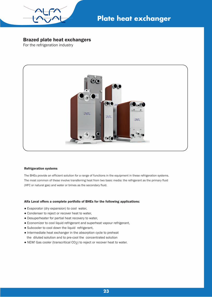
Brazed plate heat exchangersFor the refrigeration industry
Plate heat exchanger
Refrigeration systems
The BHEs provide an efficient solution for a range of functions in the equipment in these refrigeration systems. The most common of these involve transferring heat from two basic media: the refrigerant as the primary fluid(HFC or natural gas) and water or brines as the secondary fluid.
Alfa Laval offers a complete portfolio of BHEs for the following applications:
● Evaporator (dry expansion) to cool water,● Condenser to reject or recover heat to water, ● Desuperheater for partial heat recovery to water, ● Economizer to cool liquid refrigerant and superheat vapour refrigerant,● Subcooler to cool down the liquid refrigerant,● Intermediate heat exchanger in the absorption cycle to preheat the diluted solution and to pre-cool the concentrated solution● NEW! Gas cooler (transcritical CO2) to reject or recover heat to water.

24
ECOROBUST SERIES
Refrigeration Condensing UnitsM e d i u m Te m p . R a n g e 2 - 7 . 5 H P
Performance Data : Medium Temperature ( R404A - 380V/3Ph/50 Hz )
FROS-020MYE-C
FROS-025MYE-C
FROS-030MYE-C
FROS-035MYE-C
FROS-040MYE-C
FROS-050MYE-C
FROS-060MYE-C
FROS-075MYE-C
Fully-Hermetic Scroll compressorBetter energy saving application with the most advance high efficiency scroll compressor. Lower sound level for environment with prolonged usage lifetime.
Unit is fully installed with protective devices which ensure serviceability and durability under wide range of application.• High-low pressure switches, to ascertain compressor full protection.• High-low pressure gauge, which enable the system’s refrigerant condition monitoring.The protective maintenance then can be executed in the right time, when the pressure condition is warned to be out of range.• Shut-off valve and service valve, easy to service the system and even to replace compressor.
Designed for Easy- for-Maintainance and less service work after installation.
Condenser assembled with robust copper tube and aluminum fin to enable sturdy and longer lifetime usage. Aluminum fan with high- graded Aluminum material, to bear high ambient temperature, and still keepsthe best efficient function. Direct-drive fan motor, to derive the highest efficiency for energy saving, with fully-protective overload component. Easily accessible with Back & Side service door, designed for ease of inspection and reparation.
27323843482732384348273238434827323843482732384348273238434827323843482732384348
Model
Ambient
Temperature
(°C)
Capacity Evaporating Temperature (°C)
-25 -20 -15 -10 -5 0 5 -25 -20 -15 -10 -5 0 5
1,623 1,543 1,303 1,198 926
2,136 2,039 1,797 1,619 1,411 2,560 2,406 2,133 1,906 1,653 2,977 2,798 2,512 2,254 1,950 3,412 3,275 2,861 2,635 2,265 3,877 3,657 3,164 2,906 2,491 4,592 4,319 3,875 3,492 3,003 5,143 4,819 4,304 3,837 3,287
2,444 2,290 1,983 1,807 1,490 3,085 2,911 2,594 2,343 2,066 3,665 3,423 3,058 2,743 2,414 4,243 3,960 3,560 3,199 2,806 4,994 4,728 4,199 3,845 3,369 5,905 5,530 4,880 4,453 3,897 6,883 6,428 5,782 5,212 4,563 7,604 7,087 6,353 5,694 4,977
3,343 3,111 2,728 2,485 2,104 4,124 3,876 3,480 3,150 2,804 4,885 4,542 4,074 3,661 3,247 5,636 5,244 4,710 4,236 3,750 6,745 6,344 5,680 5,200 4,600 7,933 7,403 6,596 6,000 5,302 9,175 8,537 7,688 6,931 6,124
10,065 9,354 8,403 7,551 6,666
4,053 3,759 3,314 2,990 2,595 4,945 4,614 4,145 3,742 3,332 5,821 5,403 4,856 4,372 3,894 6,705 6,223 5,611 5,051 4,483 8,077 7,557 6,806 6,190 5,519
10,059 9,362 8,396 7,624 6,785 11,576 10,748 9,685 8,736 7,768
12,641 11,736 10,556 9,507 8,447
4,817 4,436 3,955 3,571 3,127 5,831 5,427 4,909 4,446 3,953 6,866 6,372 5,749 5,185 4,627 7,912 7,327 6,590 5,926 5,280 9,564 8,920 8,066 7,330 6,553
11,891 11,065 9,949 9,023 8,040
13,644 12,653 11,415 10,289 9,163 14,864 13,771 12,393 11,161 9,947
5,692 5,239 4,659 4,197 3,713 6,825 6,345 5,726 5,188 4,656 8,021 7,433 6,712 6,056 5,422 9,250 8,552 7,696 6,922 6,185
11,235 10,454
9,474 8,614 7,716
13,919 12,927 11,645 10,551 9,432
15,945 14,762 13,310 11,998 10,725 17,343 16,048 14,460 13,033 11,655
6,628 6,105 5,455 4,926 4,362 7,926 7,368 6,678 6,047 5,420 9,309 8,609 7,770 7,007 6,284
10,689 9,891 8,907 8,021 7,181
13,075 12,161 11,035 10,038
9,023 16,144 14,984 13,550 12,272 11,006 18,447 17,075 15,409 13,898 12,450 20,017 18,535 16,699 15,073 13,508
1,386 1,541 1,908 2,133 2,578 1,573 1,736 2,048 2,291 2,618 1,928 2,140 2,503 2,815 3,208 2,256 2,511 2,939 3,324 3,778 2,484 2,723 3,229 3,581 4,119 3,1643,5004,1664,6225,279
3,639 4,058 4,751 5,348 6,087 3,987 4,471 5,215 5,906 6,728
1,388 1,546 1,890 2,114 2,529 1,606 1,775 2,080 2,327 2,645 1,971 2,191 2,546 2,862 3,243 2,318 2,582 3,001 3,388 3,827 2,531 2,782 3,273 3,634 4,153 3,2363,5844,2284,6975,335
3,735 4,166 4,841 5,444 6,159 4,110 4,603 5,334 6,023 6,816
1,393 1,553 1,879 2,102 2,492 1,640 1,816 2,111 2,360 2,671 2,015 2,246 2,591 2,908 3,274 2,384 2,654 3,069 3,453 3,876 2,578 2,835 3,314 3,675
4,185 3,3083,6704,2914,7725,391
3,832 4,274 4,932 5,539 6,231 4,233 4,735 5,452 6,141 6,905
1,394 1,557 1,852 2,073 2,428 1,673 1,852 2,144 2,402 2,701 2,056 2,291 2,630 2,954 3,312 2,445 2,727 3,128 3,517 3,929 2,622 2,902 3,362 3,747 4,221 3,3803,7534,3514,8465,445
3,932 4,383 5,026 5,635 6,301 4,366 4,868 5,576 6,257 6,992
1,390 1,558 1,830 2,051 2,368 1,708 1,900 2,182 2,439 2,726 2,098 2,342 2,676 3,005 3,349 2,505 2,795 3,181 3,575 3,976 2,673 2,966 3,410 3,802 4,263 3452.53841.24416.94922.55502.8 4,021 4,486 5,110 5,729 6,377 4,475 4,996 5,688 6,377 7,082
1,388 1,559 1,813 2,033 2,328 1,738 1,931 2,207 2,469 2,751 2,144 2,396 2,718 3,051 3,386 2,561 2,864 3,240 3,639 4,024 2,718 3,016 3,447 3,844 4,295 3,5263,9254,4784,9965,557
4,119 4,600 5,203 5,828 6,449 4,585 5,127 5,795 6,495 7,175
1,407 1,578 1,811 2,028 2,298 1,776 1,977 2,242 2,507 2,781 2,187 2,449 2,762 3,094 3,410 2,640 2,941 3,324 3,711 4,077 2,764 3,073 3,490 3,889 4,321 3,5964,0084,5385,0705,612
4,222 4,704 5,298 5,921 6,517 4,740 5,263 5,936 6,609 7,256

25
Specification
Outline Dimension of Unit
Frostiq-paq
Fros 020 M Y * C F 1
Nomenclature
Refrigeration Condensing UnitsM e d i u m Te m p . R a n g e 2 - 7 . 5 H P
ECOROBUST SERIESNominal RatingModelPower Supply
Performance
Horsepower HP 2 2.5 3 3.5 4 5 6 7.5FROS- 020 025 030 035 040 050 060 075Volt/Ph/HzET/AT/RGTCapacityCOPModel ZB15KQE ZB19KQE ZB21KQE ZB26KQE ZB29KQE ZB38KQE ZB45KQE ZB48KQECompressor type Hermatic Scroll RLALRAOil Type
Oil Recharge Volume Crankcase Heater Number of Fan Diameter Fan Speed Air Flow RLA Oil Separator Receiver Hight-Low Pressure Switch Hight-Low Pressure Guage Sight glass & Filter dryer Suction Liquid WxDxH Net
°Ckw
w/w
AmpAmpR-22
R-404ALiters
wPieces
mmrpm
m3/hAmp
Inch 3/4 7/8 Inch 3/8 1/2mm 970x440x707 970x440x707 970x440x810 970x440x962 970x440x1265 970x440x1420
kg 77 79 81 82 87 119 121 123
380/3/50 -6.7/32/18.3
Compressor
Fan Motor
Other
Med. Temp.
DimensionWeight
STD. STD. STD. STD. STD.
4.21 5.15 6.04 6.95 8.46 10.49 12.01 13.08 2.70 2.73 2.60 2.51 2.87 2.75 2.70 2.64
5.0 5.0 7.4 6.4 7.9 9.6 10.1 13.6
26.0 32.0 40.0 46.0 50.0 65.5 74.0 101.0MINERAL POE
1.24 1.3 1.45 1.48 1.36 2.07 1.89 1.870
1 2 508 x 3 950
3750 7500 0.9 0.9 x 2
Model Unit Outside Dimensions (Inch) mm. Valve Size (Inch) A B C D E Liquid Gas
2 HP
2.5 HP
3 HP
3.5 HP
4 HP
5 HP
6 HP
7.5 HP
(38.18)970
(38.18)970
(38.18)970
(38.18)970
(38.18)970
(38.18)970
(38.18)970
(38.18)970
(14.96)380
(14.96)380
(14.96)380
(14.96)380
(14.96)380
(14.96)380
(14.96)380
(14.96)380
(27.83)707
(27.83)707
(31.89)810
(37.88)962
(50.00)1265
(50.00)1265
(50.00)1265
(56.00)1420
(17.32)440
(17.32)440
(17.32)440
(17.32)440
(17.32)440
(17.32)440
(17.32)440
(17.32)440
(25.10)639
(25.10)639
(25.10)639
(25.10)639
(25.10)639
(25.10)639
(25.10)639
(25.10)639
3/8"
3/8"
3/8"
3/8"
3/8"
1/2"
1/2"
1/2"
3/4"
3/4"
3/4"
3/4"
3/4"
7/8"
7/8"
7/8"
020 = 2.0 HP025 = 2.5 HP030 = 3.0 HP035 = 3.5 HP040 = 4.0 HP050 = 5.0 HP060 = 6.0 HP075 = 7.5 HP
H = High Temp.M = MediumL = Low Temp.
V = 1 PhaseY = 3 Phase
R = R22E = R404A/R507
C = CopelandD = Danfross
F = Full OptionW = Without
1 = Version 1▼ ▼ ▼ ▼ ▼ ▼ ▼ ▼
26
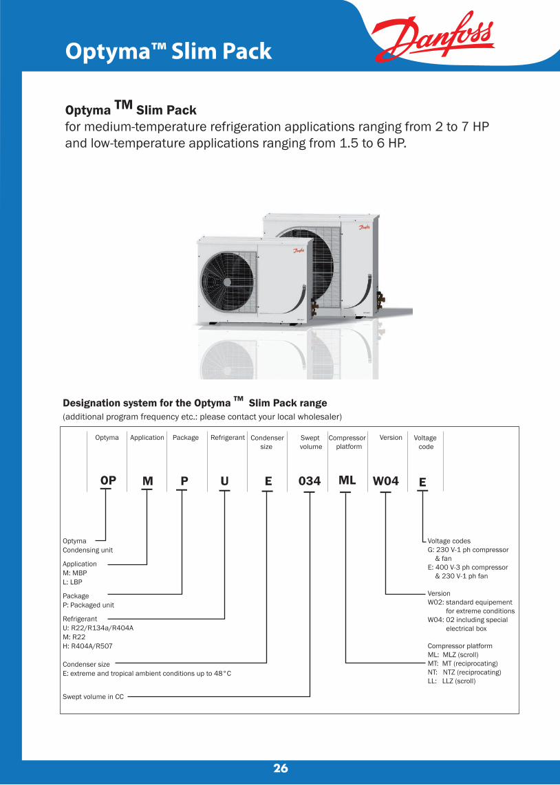
Optyma™ Slim Pack
Optyma TM Slim Pack for medium-temperature refrigeration applications ranging from 2 to 7 HP and low-temperature applications ranging from 1.5 to 6 HP.
Designation system for the Optyma TM Slim Pack range(additional program frequency etc.: please contact your local wholesaler)
Optyma Condensing unit
ApplicationM: MBPL: LBP
PackageP: Packaged unit
RefrigerantU: R22/R134a/R404A M: R22H: R404A/R507
Condenser sizeE: extreme and tropical ambient conditions up to 48°C
Swept volume in CC
034M
Application
OP
Optyma
ML
Compressor platform
W04
Version
EU
Refrigerant
E
Condensersize
Package
P
Swept volume
▬ ▬ ▬ ▬ ▬ ▬ ▬ ▬ ▬
Voltage codesG: 230 V-1 ph compressor & fanE: 400 V-3 ph compressor & 230 V-1 ph fan
VersionW02: standard equipement for extreme conditionsW04: 02 including special electrical box
Compressor platformML: MLZ (scroll)MT: MT (reciprocating)NT: NTZ (reciprocating)LL: LLZ (scroll)
Voltage code

27
Meat +1°C - 18h
Fish +1°C - 18h
Laboratories +12°C - 18h
Fruits & vegetables
+8°C - 18h
Fruits & vegetables 0°C - 18h +5°C - 18h
Freezers
-18°C - 16h
Cap.(W)
CR* (ft3) (ft3) (ft3) (ft3) (ft3) (ft3) (ft3)
Cap.(W)
CR* Cap.(W)
CR* Cap.(W)
CR* Cap.(W)
CR* CR*Cap.(W)
Cap.(W)
CR*
Butter, eggs & cheese
Data refers to +43°C ambient temperature, MBP R22, LBP R404ARefer to Danfoss for other refrigerants or different working conditionsApplication-Cold room temperature-Daily working hours*Volume of cold room in cubit feet.
Optyma™ Slim Pack
3720
4190
4920
5100
5520
8080
9400
10600
11770
1000
1000
1750
1750
2000
2750
3500
4500
6000
3720
4190
4920
5100
5520
8080
9400
10600
11770
Select the right Danfoss OptymaTM Slim Pack condensing unit according to your needsModel and cooling capacity by cold room type
Nominal HP
OP-MPUE034
OP-MPME048
OP-MPUE046
OP-MPME060
OP-MPUE057
OP-MPUE068
OP-MPUE080
OP-MPUE093
OP-MPUE108
OP-LPHE048
OP-LPHE068
OP-LPHE067
OP-LPHE084
OP-LPHE098
2.0
2.0
3.0
3.0
3.5
4.0
5.0
6.0
7.0
1.5
2.0
3.5
5.0
6.0
1000
1000
1750
1750
2000
2750
3500
4500
6000
5360
6040
7080
7340
7950
11640
13530
15270
16950
2500
2500
3500
3500
4000
5500
7500
8500
10000
4700
5300
6220
6440
6980
10220
11880
13400
14880
1500
1500
2750
2750
3000
3500
6000
7000
8500
3590
4050
4750
4920
5330
7800
9070
10230
11360
1000
1000
1750
1750
2000
2750
3500
4500
6000
4410
4970
5830
6040
6550
9580
11140
12560
13950
1500
1500
2750
2750
3000
3500
6000
7000
8500
1400
2100
3400
4050
4650
400
600
900
1500
1750
28
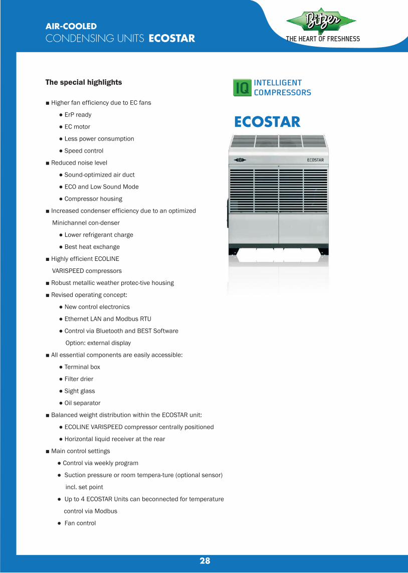
AIR-COOLEDCONDENSING UNITS ECOSTAR
ECOSTAR
The special highlights
■ Higher fan efficiency due to EC fans
● ErP ready
● EC motor
● Less power consumption
● Speed control
■ Reduced noise level
● Sound-optimized air duct
● ECO and Low Sound Mode
● Compressor housing
■ Increased condenser efficiency due to an optimized
Minichannel con-denser
● Lower refrigerant charge
● Best heat exchange
■ Highly efficient ECOLINE
VARISPEED compressors
■ Robust metallic weather protec-tive housing
■ Revised operating concept:
● New control electronics
● Ethernet LAN and Modbus RTU
● Control via Bluetooth and BEST Software
Option: external display
■ All essential components are easily accessible:
● Terminal box
● Filter drier
● Sight glass
● Oil separator
■ Balanced weight distribution within the ECOSTAR unit:
● ECOLINE VARISPEED compressor centrally positioned
● Horizontal liquid receiver at the rear
■ Main control settings
● Control via weekly program
● Suction pressure or room tempera-ture (optional sensor)
incl. set point
● Up to 4 ECOSTAR Units can beconnected for temperature
control via Modbus
● Fan control
29
AIR-COOLEDCONDENSING UNITS ECOSTAR
A W
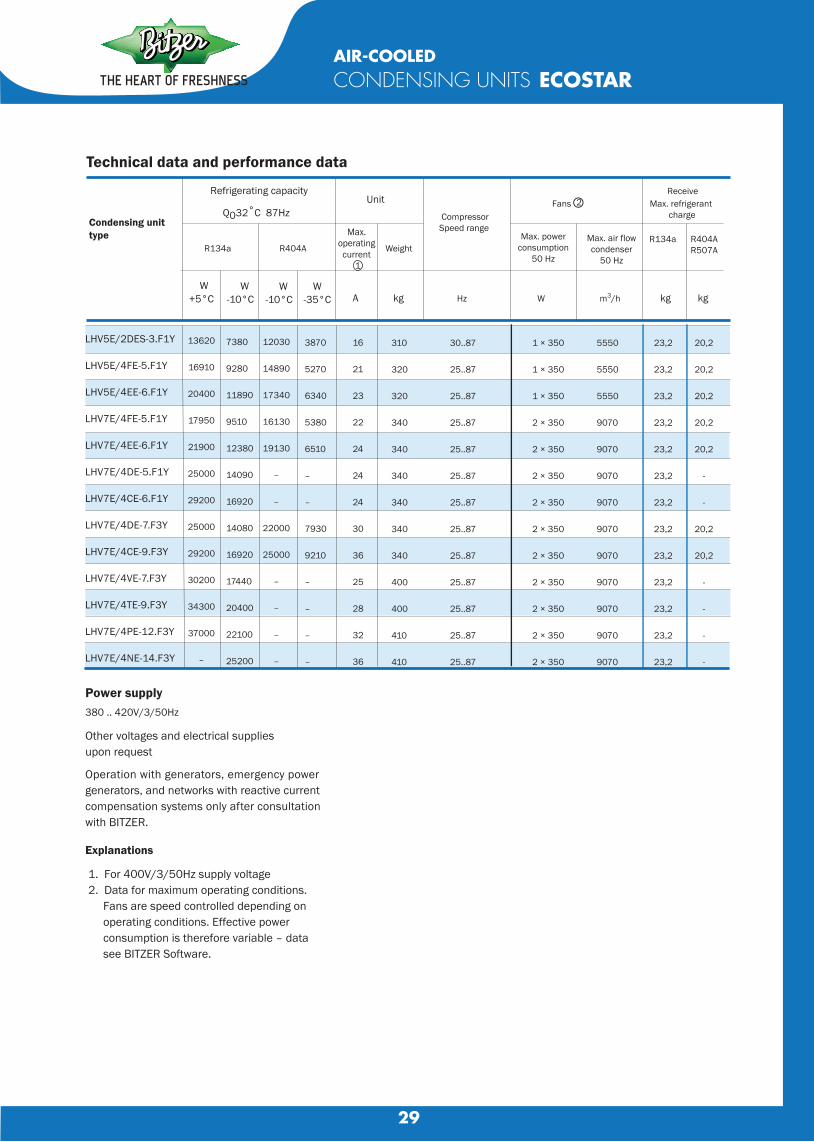
Technical data and performance data
Condensing unit type
Refrigerating capacity
Q032°C 87Hz
R134a R404A
W+5°C
W-10°C
W-10°C
W-35°C
Unit
Weight
kg
Power supply380 .. 420V/3/50Hz
Other voltages and electrical supplies upon request
Operation with generators, emergency powergenerators, and networks with reactive currentcompensation systems only after consultationwith BITZER.
Explanations
1. For 400V/3/50Hz supply voltage 2. Data for maximum operating conditions. Fans are speed controlled depending on operating conditions. Effective power consumption is therefore variable – data see BITZER Software.
LHV5E/2DES-3.F1Y
LHV5E/4FE-5.F1Y
LHV5E/4EE-6.F1Y
LHV7E/4FE-5.F1Y
LHV7E/4EE-6.F1Y
LHV7E/4DE-5.F1Y
LHV7E/4CE-6.F1Y
LHV7E/4DE-7.F3Y
LHV7E/4CE-9.F3Y
LHV7E/4VE-7.F3Y
LHV7E/4TE-9.F3Y
LHV7E/4PE-12.F3Y
LHV7E/4NE-14.F3Y
13620
16910
20400
17950
21900
25000
29200
25000
29200
30200
34300
37000
–
7380
9280
11890
9510
12380
14090
16920
14080
16920
17440
20400
22100
25200
12030
14890
17340
16130
19130
–
–
22000
25000
–
–
–
–
3870
5270
6340
5380
6510
–
–
7930
9210
–
–
–
–
16
21
23
22
24
24
24
30
36
25
28
32
36
Max. operating current
1
310
320
320
340
340
340
340
340
340
400
400
410
410
CompressorSpeed range
Hz
30..87
25..87
25..87
25..87
25..87
25..87
25..87
25..87
25..87
25..87
25..87
25..87
25..87
1 × 350
1 × 350
1 × 350
2 × 350
2 × 350
2 × 350
2 × 350
2 × 350
2 × 350
2 × 350
2 × 350
2 × 350
2 × 350
m3/h
5550
5550
5550
9070
9070
9070
9070
9070
9070
9070
9070
9070
9070
kg kg
23,2
23,2
23,2
23,2
23,2
23,2
23,2
23,2
23,2
23,2
23,2
23,2
23,2
20,2
20,2
20,2
20,2
20,2
-
-
20,2
20,2
-
-
-
-
Max. powerconsumption
50 Hz
Fans○
Max. air flowcondenser
50 Hz
ReceiveMax. refrigerant
charge
R134a R404AR507A
2
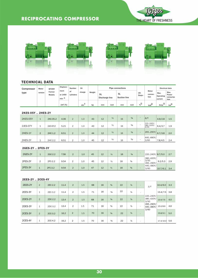
30
RECIPROCATING COMPRESSOR
Pipe connections
Pipe connections Electrical dataCompressortype
Motor
version
Displace -
ment
at 1450
min -1
Number
of
cylindersWeight
(m³/h) dm3 kg mm inch mm inch
1
1
2
1
½
½
½
½
⅝
⅝
⅝
⅝
Δ/Y
220..240Y/380..420Y/3/50
265..290Y/
440..480Y/3/60
4.9/2.8
6.4/3.7
6.7/3.8
7.8/4.5
1.5
1.9
2.0
2.4
TECHNICAL DATA
2KES-05Y .. 2HES-2Y
BITZER Former Models
2KC-05.2
2JC-07.2
2HC-1.2
2HC-2.2
1 7.58 2 1.0 45 12 ½ 16 ⅝ 8.7/5.0 2.7
2 9.54
9.54
2
2
1.0
1.0
45 12
12
½
½
16
16
⅝
⅝
9.2/5.3 2.9
1 47 10.7/6.1 3.4
2GES-2Y .. 2FES-3Y
2GC-2.2
2FC-2.2
2FC-3.2
2EES-2Y .. 2CES-4Y
11.4
11.4
2 68 16 ⅝ 22 ⅞
71
13.4
13.4
2
68
16 ⅝ 22 ⅞
71
16.2
16.2
2
2
2
2
70
16
16
16
16
⅝
⅝
⅝
⅝
22
22
22
22
⅞
⅞
⅞
⅞70
220..240Y/380..420Y/3/50265..290Y/440..480Y/3/60
10.4/6.0 3.3
13.4/7.5 3.8
13.4/7.5 4.0
15.0/8.6 4.6
15.8/9.1 5.0
17.4/10.0 5.6
Max. Operating current
Max. Power consump-tion
Motor
connec-tion
SL Suction line
DL Discharge line
Oil
charge CR- Steps -
Amp.3
Volt2%
1kw3
4.06
5.21
6.51
6.51
1.0
1.0
1.0
1.0
43
43
44
45
12
12
12
12
16
16
16
16
2KES-05Y
2JES-07Y
2HES-1Y
2HES-2Y
2
2
2
2
220..240Y/
380..420Y/3/50265..290Y/440..480Y/3/60
2EES-2Y
2EES-3Y
2DES-2Y
2DES-3Y
2CES-3Y
2CES-4Y
2
1
2
1
2
1
2EC-2.2
2EC-3.2
2DC-2.2
2DC-3.2
2CC-3.2
2CC-4.2
-
-
-
-
2GES-2Y
2FES-2Y
2FES-3Y
1.5
1.5
1.5
1.5
1.5
1.5
-
-
-
-
-
-
-
-
-
∆/Y
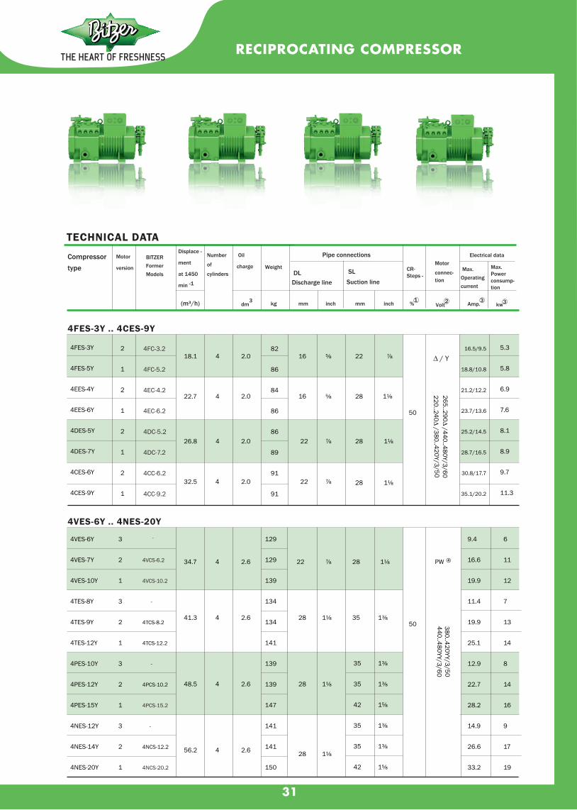
31
RECIPROCATING COMPRESSOR
18.1 4 2.0
22.7 4 2.0
26.8 4 2.0
32.5 4 2.0
16 ⅝ 22 ⅞
16 ⅝ 28 1⅛
22 ⅞ 28 1⅛
22 ⅞ 28 1⅛
265..290∆ /440..480Y/3/60
4FES-3Y .. 4CES-9Y
34.7 4 2.6
41.3 4 2.6
48.5 4 2.6
56.2 4 2.6
22 ⅞ 28 1⅛
28 1⅛ 35 1⅜
28 1⅛
28 1⅛
50
PW ④
380..420YY/3/50440..480YY/3/60
4VES-6Y .. 4NES-20Y
50
4FES-3Y
4FES-5Y
4EES-4Y
4EES-6Y
4DES-5Y
4DES-7Y
4CES-6Y
4CES-9Y
2
1
2
1
2
1
2
1
4FC-3.2
4FC-5.2
4EC-4.2
4EC-6.2
4DC-5.2
4DC-7.2
4CC-6.2
4CC-9.2
82
86
84
86
86
89
91
91
16.5/9.5
18.8/10.8
21.2/12.2
23.7/13.6
25.2/14.5
28.7/16.5
30.8/17.7
35.1/20.2
5.3
5.8
6.9
7.6
8.1
8.9
9.7
11.3
4VES-6Y
4VES-7Y
4VES-10Y
4TES-8Y
4TES-9Y
4TES-12Y
4PES-10Y
4PES-12Y
4PES-15Y
4NES-12Y
4NES-14Y
4NES-20Y
3
2
1
3
2
1
3
2
1
3
2
1
-
4VCS-6.2
4VCS-10.2
-
4TCS-8.2
4TCS-12.2
-
4PCS-10.2
4PCS-15.2
-
4NCS-12.2
4NCS-20.2
129
129
139
134
134
141
139
139
147
141
141
150
35
35
42
35
35
42
1⅜
1⅜
1⅝
1⅜
1⅜
1⅝
9.4
16.6
19.9
11.4
19.9
25.1
12.9
22.7
28.2
14.9
26.6
33.2
6
11
12
7
13
14
8
14
16
9
17
19
Pipe connections
Pipe connections Electrical dataCompressortype
Motor
version
Displace -
ment
at 1450
min -1
Number
of
cylindersWeight
(m³/h) dm3 kg mm inch mm inch
TECHNICAL DATA
BITZER Former Models
Max. Operating current
Max. Power consump-tion
Motor
connec-tion
SL Suction line
DL Discharge line
Oil
charge CR- Steps -
Amp.3
Volt2%
1kw3
220..240∆ /380..420Y/3/50
∆ / Y

32
63.5 4 4.0
73.7 4 4.0
84.6 4 4.5
101.8 4 4.5
28 1⅛ 42 1⅝
28 1⅛
42 1⅝
42 1⅝
54 2⅛
28 1⅛ 54 2⅛
28 1⅛ 54 2⅛
50
PW ④
380..420YY/3/50
440..480YY/3/60
380..420YY/3/50
440..480YY/3/60
4J-13.2
4H-15.2
4JE-13Y .. 4FE-35Y
-
4J-22.2
-
4H-25.2
-4G-20.2
4G-30.2
-
6JE-22Y .. 6GE-40Y
95.3 6 4.75
110.5 6 4.75
126.8 6 4.75
35 1⅜ 54 2⅛
35 1⅜ 54 2⅛
35 1⅜ 54 2⅛
66
altern.
33
PW ④
-
6J-22.2
6J-33.2
-
6H-25.2
6H-35.2
-
6G-30.2
6G-40.2
6FE-40Y 3
151.6 6 4.75
238
42 1⅝ 54 2⅛66
altern.33
380..420YY/3/50440..480YY/3/60
PW ④48.5 27
6FE-44Y 2 241 380..400YY/3/50 83.2 46
6FE-50Y 1 241 440..460YY/3/60 96.2 51
6FE-40Y .. 6FE-50Y-
6F-40.26F-50.2
8GE-60(Y) 1 185 8 5.0 350 42 1⅝ 76 3⅛ 75 PW ④
113 63altern. 380..420DDY/3/50
8FE-70(Y) 1 221 8 5.0 374 54 2⅛ 76 3⅛ 50 440..480DDY/3/60 139 78
8CG-60.2
8FC-70.2
8GE-60Y .. 8FE-70Y
Pipe connections
Pipe connections Electrical dataCompressortype
Motor
version
Displace -
ment
at 1450
min -1
Number
of
cylinders Weight
(m³/h) dm3 kg mm inch mm inch
TECHNICAL DATABITZER
Former Models Max.
Operating current
Max. Power consump-tion
Motor connection
SL Suctionline DL Dischargeline
Oil
charge CR- Steps -
Amp.3
Volt2%
1kw3
4JE-13Y
4JE-15Y
4JE-22Y
4HE-15Y
4HE-18Y
4HE-25Y
4GE-20Y
4GE-23Y
4GE-30Y
4FE-25Y
4FE-28Y
4FE-35Y
3
2
1
3
2
1
3
2
1
3
2
1
179
190
190
183
190
194
192
192
206
196
207
207
18.8
30.8
37.2
21.4
36.7
44
24.6
43.9
51.2
30.5
52.8
62.1
11
19
21
13
22
25
16
27
28
19
31
35
6JE-22Y
6JE-25Y
6JE-33Y
6HE-25Y
6HE-28Y
6HE-35Y
6GE-30Y
6GE-34Y
6GE-40Y
3
2
1
3
2
1
3
2
1
213
228
231
224
228
235
228
228
238
26.6
46.4
53.2
31.3
53.2
64.4
38
65.5
73.9
16
27
30
19
33
36
23
40
42
RECIPROCATING COMPRESSOR

33
TECHNICAL DATA
OPEN DRIVE
RECIPROCATING COMPRESSORS
TYPE 0(Y) .. VIIW(Y)
ø mm dm3
Weight
kg
Number
ø mm
Stroke
mm
Displace-ment
1
565735900
1060
565735900975
500615725840
1000
500615725840
1000
425495570670750
355415475635700
355410475565
365420505
0,961,241,521,80
1,702,202,702,92
2,262,783,283,804,52
4,705,796,837,909,42
8,459,85
11,3413,3314,92
14,5016,9519,4025,9628,61
27,6631,9337,0044,00
42,0048,4058,00
7090
110130
7090
110120
90110130150180
90110130150180
110130150180200
110130150200220
110130150180
130150180
2
2
2
2
2
2
2
2
30
35
40
50
65
85
105
120
10,5
13,5
18
22
45,5
80,5
156
223
20
26
30
40
50
60
75
85
10 L
12 L
12 L
16 L
22 L
28 L
35 L
42 L
10 L
10 L
12 L
–
–
–
12 L
16 L
22 L
28 L
35 L
3/8
1/2
1/2
5/8
7/8
11/8
13/8
15/8
3/8
3/8
1/2
1/2
3/4
7/8
11/8
13/8
G3/8
G3/8
G1/2
G1/2
G3/4
1 x 13
1 x 13
1 x 13
1 x 13(1 x 17)
2 x 17
2 x 17
3 x 17
4 x 17
0,35
0,4
0,65
0,9
1,5
2,5
5
6
2
Compressor
speed with
motor speed
1450 min-1
Motorpulley
CylinderBore
Oil charge
V-beltsNumber x profileaccording toDIN 2215
SLSuction line
mm inch
ConnectionsDLDischarge line
mm inch
Coolingwater
inch
L = brazed connection
m3/h
0(Y)
I(Y)
II(Y)
III(Y)
IV(Y)
V(Y)
VIW(Y)
VIIW(Y)
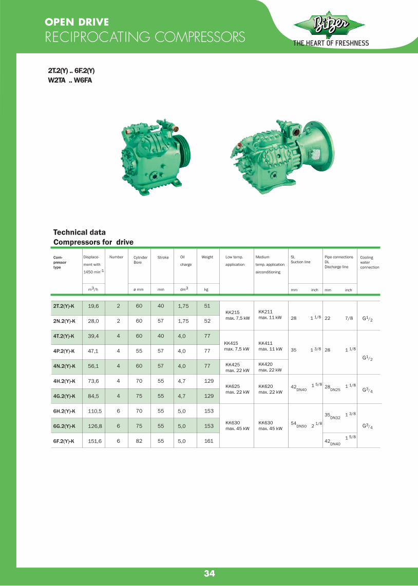
34
Com-pressortype
dm3
Weight
kg
Number
ø mm
Stroke
mm
Displace-
ment with
1450 min-1
CylinderBore
Oil
charge
SLSuction line
mm inch
Pipe connectionsDLDischarge line
mm inch
Cooling waterconnection
Technical dataCompressors for drive
2T.2(Y) .. 6F.2 (Y) W2TA .. W6FA
m3/h
Low temp.
application
Medium
temp. application
airconditioning
2T.2(Y)-K
2N.2(Y)-K
4T.2(Y)-K
4P.2(Y)-K
4N.2(Y)-K
4H.2(Y)-K
4G.2(Y)-K
6H.2(Y)-K
6G.2(Y)-K
6F.2(Y)-K
19,6
28,0
39,4
47,1
56,1
73,6
84,5
110,5
126,8
151,6
2
2
4
4
4
4
4
6
6
6
60
60
60
55
60
70
75
70
75
82
40
57
40
57
57
55
55
55
55
55
1,75
1,75
4,0
4,0
4,0
4,7
4,7
5,0
5,0
5,0
51
52
77
77
77
129
129
153
153
161
KK215max. 7,5 kW
KK211max. 11 kW
KK415max. 7,5 kW
KK411max. 11 kW
KK425max. 22 kW
KK420max. 22 kW
KK625max. 22 kW
KK620max. 22 kW
KK630max. 45 kW
KK630max. 45 kW
28 1 1/8
35 1 3/8
42DN40
1 5/8
54DN50 2 1/8
22 7/8
28 1 1/8
28DN25
1 1/8
35DN32
1 3/8
G1/2
G1/2
G3/4
G3/4
42DN40
1 5/8
OPEN DRIVE
RECIPROCATING COMPRESSORS
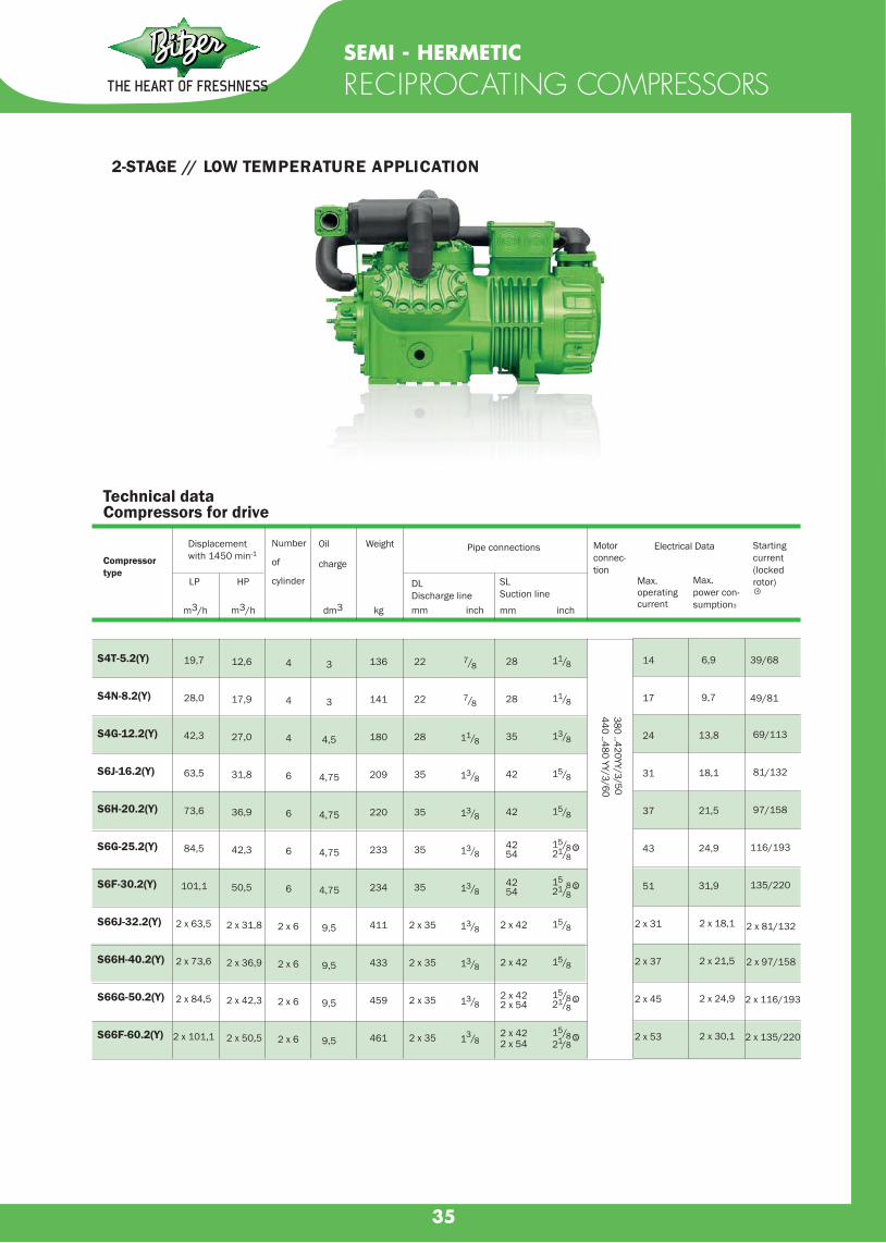
35
SEMI - HERMETIC
RECIPROCATING COMPRESSORS
2-STAGE // LOW TEMPERATURE APPLICATION
dm3
Weight
kg
Number
of
cylinder
Displacement with 1450 min-1
Compressortype
Oil
charge
Technical data Compressors for drive
m3/h
LP HP
Pipe connections
DLDischarge linemm inch
SLSuction line
Motorconnec-tion
Electrical Data
Max. operating current
Max. power con-sumption3
Starting current(lockedrotor)○4
mm inch
136
141
180
209
220
233
234
411
433
459
461
3
3
4,5
4,75
4,75
4,75
4,75
9,5
9,5
9,5
9,5
14
17
24
31
37
43
51
2 x 31
2 x 37
2 x 45
2 x 53
39/68
49/81
69/113
81/132
97/158
116/193
135/220
2 x 81/132
2 x 97/158
2 x 116/193
2 x 135/220
22
22
28
35
35
35
35
2 x 35
2 x 35
2 x 35
2 x 35
7/8
7/8
11/8
13/8
13/8
13/8
13/8
13/8
13/8
13/8
13/8
28
28
35
42
42
4254
4254
2 x 42
2 x 42
2 x 422 x 54
2 x 422 x 54
11/8
11/8
13/8
15/8
15/8
15/821/8
158
21/8
15/8
15/8
15/821/8
15/821/8
S4T-5.2(Y)
S4N-8.2(Y)
S4G-12.2(Y)
S6J-16.2(Y)
S6H-20.2(Y)
S6G-25.2(Y)
S6F-30.2(Y)
S66J-32.2(Y)
S66H-40.2(Y)
S66G-50.2(Y)
S66F-60.2(Y)
6,9
9,7
13,8
18,1
21,5
24,9
31,9
2 x 18,1
2 x 21,5
2 x 24,9
2 x 30,1
5
5
5
380 ..420YY/3/50440 ..480 YY/3/60
19,7
28,0
42,3
63,5
73,6
84,5
101,1
2 x 63,5
2 x 73,6
2 x 84,5
2 x 101,1
12,6
17,9
27,0
31,8
36,9
42,3
50,5
2 x 31,8
2 x 36,9
2 x 42,3
2 x 50,5
4
4
4
6
6
6
6
2 x 6
2 x 6
2 x 6
2 x 6
m3/h
Ο
Ο
Ο
Ο5

36
Performance Data R22Cooling capacity in Watts based on 25°C suction gas temperature, 1450 rpm
Open Drive
Reciprocating Compressors 2 - stage
Type
Required Driving Motor
KW
Cond.Temp.
tc
◦C
Evaporating temperature to◦C
-20 -25 -30 -35 -40 -45 -50
with liquid subcooler
S6H.2-K
S6H.2-S230*
S6G.2-K
S6G.2-S230*
S6F.2-K
S6F.2-S230*
15,018,522,0
18,522,022,0
22,030,030,0
304050
304050
304050
365003560034700
419004085039800
502004885047700
306002990029200
351003430033500
420004100040100
253002480024200
290502840027800
347503400033300
206502020019800
237002320022700
284002780027200
166001620015750
190001855018100
227002220021650
1290012450
1485014300
1770017100
97009000
1110010300
1330012350
Correction factors for other pulley diametersS210 f = 0,89S190 f = 0,80
Performance date for refrigerant R404A/R507A on request!

37
SEMI - HERMETIC
SCREW COMPRESSORS
HS.53 // HS.64 // HS.74 SERIES
Technical data
/8 5
Compressortype
Motorversion
Displace-ment50 Hz
Displace-ment60 Hz
Weight Pipe connections
Discharge line Suction line
mm inch mm inch
Capacity
steps
nominal
Motor
connec-
tion
Max.
operating
current
Max.
power
consum.
Starting
current
(locked rotor)
○1 m3/h○2 m3/h○2 kg
HSK5343-30
HSN5343-20
HSK5353-35
HSN5353-25
HSK5363-40
HSN5363-30
HSK6451-40
HSK6451-50
HSN6451-40
HSK6461-40
HSK6461-60
HSN6461-50
HSK7451-50
HSK7451-70
HSN7451-60
HSK7461-60
HSK7461-80
HSN7461-70
HSK7471-70
HSK7471-90
HSN7471-75
170
166
178
169
183
174
234
238
234
238
246
238
297
305
297
310
314
310
326
336
326
1
1
1
1
1
1
2
1
1
2
1
1
2
1
1
2
1
1
2
1
1
101
121
142
168
198
232
266
302
84
100
118
140
165
192
220
250
42 15/8"
42 15/8"
42 15/8"
42 15/8"
42 15/8"
54 21/8"
54 21/8"
54 21/8"
54 21/8"
54 21/8"
54 21/8"
54 21/8"
54 21/8"
76 3 1/8"
76 3 1/8"
76 3 1/8"
52
48
58
52
66
58
65
79
65
65
98
79
79
124
98
98
144
124
124
162
144
33
29
37
33
42
37
40
50
40
40
65
50
50
75
65
65
85
75
75
92
85
126/218
129/201
153/266
126/218
182/311
153/266
187/313
206/355
187/313
187/313
267/449
206/355
206/355
290/485
267/449
267/449
350/585
290/485
290/485
423/686
350/585
100/90/70
100/90/55
100/85/60
100/80/50
100/80/55
100/75/45
100/85/60
100/75/50
100/80/55
100/75/45
100/75/45
100/80/65
100/70/40
100/75/60
100/60/40
100/75/55
400
V ±1
0%
Δ/Δ
Δ–3
–50H
z46
0 V
±10%
Δ
/ΔΔ
–3–6
0Hz
Part
Win
ding

38
COMPACT
SCREW COMPRESSORS
CSH SERIES 65 // 75 // 85 // 95
Compressortype
Motorversion
Displace-ment50/60 Hz
Motorconnection
Max.operatingcurrent
Max.powerconsum.
m3/h○3
Technical data and Performance data
Oil charge
R134a R407C
to/tc5˚c/50˚c
w
to/tc
w w w
to/tc to/tc-10˚c/45˚c 5˚c/50˚c -10˚c/45˚c
dmз A○ kW○
9,5
9,5
1010
CSH6553-35YCSH6553-50(Y)CSH6563-40YCSH6563-60(Y)CSH6583-50YCSH6593-60YCSH7553-50YCSH7553-70(Y)CSH7563-60YCSH7563-80(Y)CSH7573-70YCSH7573-90(Y)CSH7583-80YCSH7583-100(Y)CSH7593-90YCSH7593-110(Y)CSH8553-80YCSH8553-110(Y)CSH8563-90YCSH8563-125(Y)CSH8573-110YCSH8573-140(Y)CSH8583-125YCSH8583-160(Y)CSH8593-140YCSH8593-180(Y)
CSH9553-180(Y)
CSH9563-160YCSH9563-210(Y)CSH9573-180YCSH9573-240(Y)CSH9583-210YCSH9583-280(Y)CSH9593-240YCSH9593-300(Y)CSH95103-280YCSH95103-320(Y)
CSH95113-320Y
21212221212121212121212121
1
2121212121
2
4140041600524005230060700685005780058600682006810078500797009320094200
106200107100
97300102600112200117000
133000135100147300143800167600167500
167800
197400197200230900229700270200265300307100307100328200328200
359000
75600751009430094300
108800122800106700108400125800125000144600145000168600169100192000192500177500181700204600207000239600239000264800259500301400302400
303800
357000354300417200409500480500471900546000546000588200588200
644400
400V
(±10
%) ∆
–3–5
0Hz
460V
(±10
%) ∆
–3–6
0Hz
Y/∆
400V
(±10
%) ∆
/∆∆ –
3–50
Hz
460V
(±10
%) ∆
/∆∆ –
3–60
Hz
Part
Win
ding
400V
(±10
%) Δ
–3–5
0Hz
460V
(±10
%)Δ
–3–6
0Hz
Y/Δ
55
588666
10881
10579
12898
144124162144170162180
144185155216182246196260214310
330
280370
310420320450360450413
566
447
34524165515652786588789688
10296
112
88112
96132110150120160131186
205
155246
175255204280222280254
305
277
137/165
170/205
195/236220/266
197/238
227/274
258/311
295/356
336/406
315/380
359/433
410/495
470/567
535/646
535/646
615/742
700/845
805/972
910/1098
1015/1225
1120/1351
15
15
15
15
15
22
22
22
19
19
30
30
30
30
30
32
32
–106400
–133700
–155000
–175400
–203600
–238200
–270500
–256900
–293000
–383400
–378900
–454500
–443700
–505000
–601200
–688900
–783000
–868000
–61900
–77700
–89200
–
101700–
119900–
141700–
160800
–151800
–173000
–199800
–217800
–260300
–254300
–294300
–345100
–398600
–453100
–494600
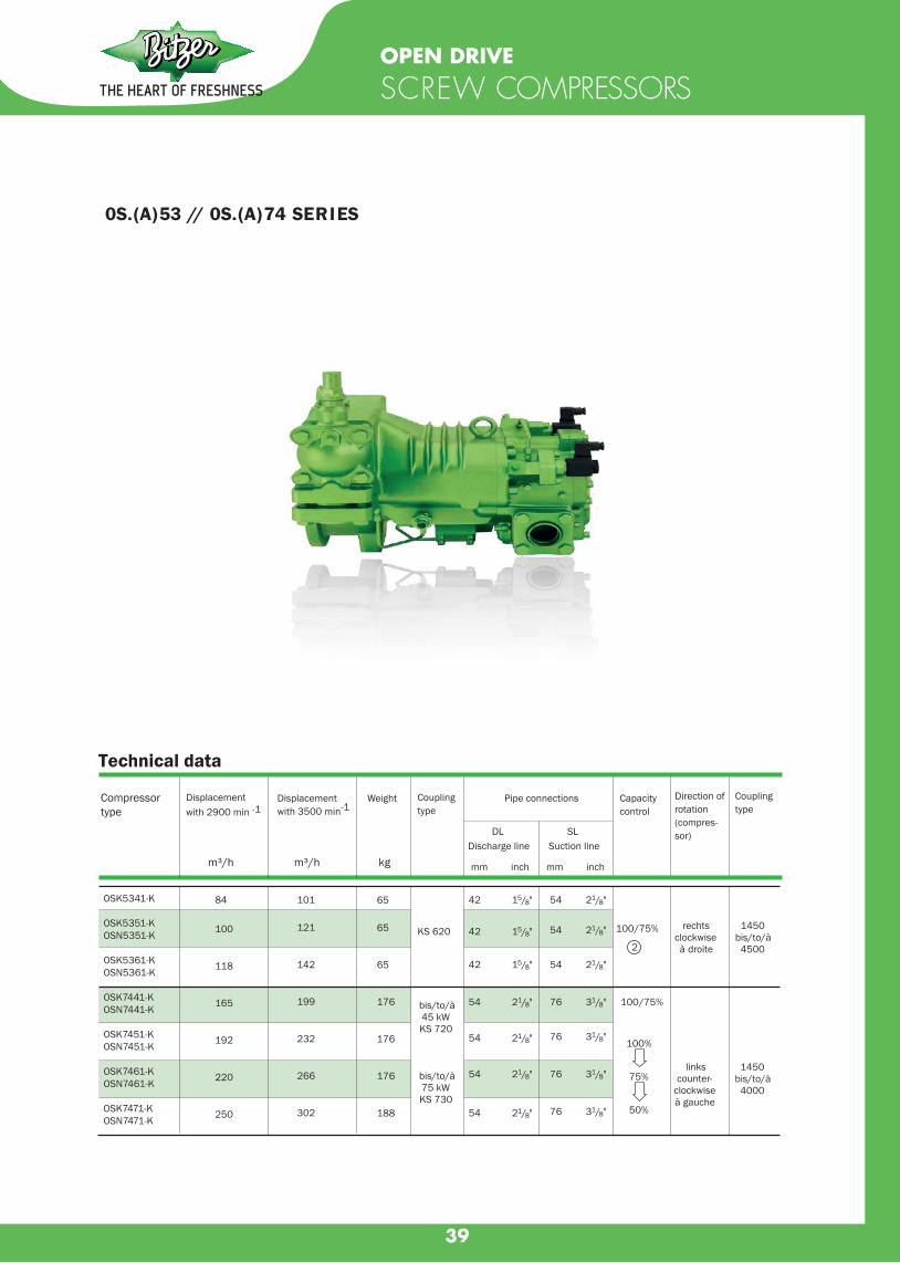
39
0S.(A)53 // 0S.(A)74 SERIES
OPEN DRIVE
SCREW COMPRESSORS
Technical data
Compressortype
Weight
DLDischarge line
mm inch
SLSuction line
mm inch
Pipe connections
42 15/8" 54 21/8"
rechtsclockwiseà droite
1450bis/to/à
4500
KS 620 42 15/8" 54 21/8" 100 / 75%
42 15/8" 54 21/8"
bis/to/à45 kWKS 720
bis/to/à75 kWKS 730
54 21/8" 76 31/8" 100 / 75%
linkscounter-
clockwiseà gauche
1450bis/to/à
4000
54 21/8" 76 31/8"100%
75%
50%
54 21/8" 76 31/8"
54 21/8" 76 31/8"
2
m³/h m³/h kg
Displacement with 2900 min -1
Displacement with 3500 min-1
Couplingtype
Capacity control
Direction of rotation(compres-sor)
Couplingtype
OSK5341-K
OSK5351-KOSN5351-K
OSK5361-KOSN5361-K
OSK7441-KOSN7441-K
OSK7451-KOSN7451-K
OSK7461-KOSN7461-K
OSK7471-KOSN7471-K
84
100
118
165
192
220
250
101
121
142
199
232
266
302
65
65
65
176
176
176
188

40
OPEN DRIVE
SCREW COMPRESSORS
OS.85 SERIES
Technical data
100
50
oder/or/ou
1007550
rechtsclockwiseà droite
KS800
1450...
4000
Compressortype
Weight
DLDischarge line
mm inch
SLSuction line
mm inch
Pipe connections
m³/h m³/h kg
Displacement with 2900 min -1
Displacement with 3500 min-1
Capacity control
Direction of rotation(compres-sor)
Couplingtype
OSK8551-K
OSK8561-K
OSK8571-K
OSN8571-K
OSK8581-K
OSK8581-K
OSN8591-K
315
359
410
410
470
535
535
380
433
495
495
567
640
640
Allowed speedrange
min-1
330
340
350
350
360
360
360
76
76
76
76
76
76
76
31/8"
31/8"
31/8"
31/8"
31/8"
31/8"
31/8"
DN 100
DN 100
DN 100
DN 100
DN 100
DN 100
DN 100
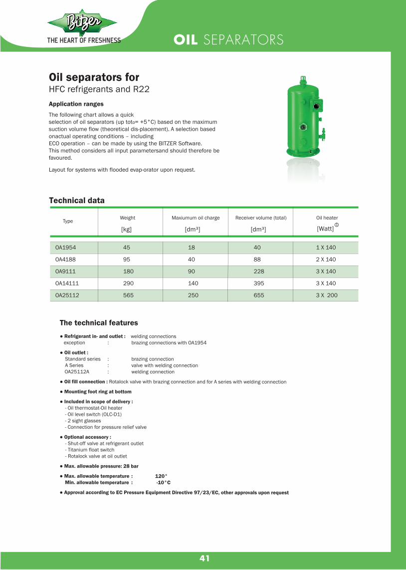
41
OIL SEPARATORS
Technical data
Oil separators forHFC refrigerants and R22Application ranges
The following chart allows a quickselection of oil separators (up toto= +5°C) based on the maximumsuction volume flow (theoretical dis-placement). A selection based onactual operating conditions – includingECO operation – can be made by using the BITZER Software. This method considers all input parametersand should therefore be favoured.
Layout for systems with flooded evap-orator upon request.
Type Weight Maxiumum oil charge Receiver volume (total) Oil heater
[kg] [dm³] [Watt]○1[dm³]
The technical features
● Refrigerant in- and outlet : welding connections exception : brazing connections with OA1954
● Oil outlet : Standard series : brazing connection A Series : valve with welding connection OA25112A : welding connection
● Oil fill connection : Rotalock valve with brazing connection and for A series with welding connection
● Mounting foot ring at bottom
● Included in scope of delivery : - Oil thermostat-Oil heater - Oil level switch (OLC-D1) - 2 sight glasses - Connection for pressure relief valve
● Optional accessory : - Shut-off valve at refrigerant outlet - Titanium float switch - Rotalock valve at oil outlet
● Max. allowable pressure: 28 bar
● Max. allowable temperature : 120° Min. allowable temperature : -10°C
● Approval according to EC Pressure Equipment Directive 97/23/EC, other approvals upon request
OA1954
OA4188
OA9111
OA14111
OA25112
45
95
180
290
565
18
40
90
140
250
40
88
228
395
655
1 X 140
2 X 140
3 X 140
3 X 140
3 X 200

42
WATER-COOLED CONDENSERS
TypeMax. flow
Pressure
drop
Capacity
Δte15 K
Capacity
Δte10 K Max. flow
Pressure
drop
Capacity
Δte 10 K
Standard designK033NK073HK123H
K203HK283HK373H
K573HK813HK1053HK1353T
K1973TK2923T
K3803TK4803T
0,380,760,76
1,782,382,98
5,096,486,488,33
12,0317,56
23,1729,64
1,372,742,74
6,418,56
10,71
18,3223,3223,3230,00
43,3263,22
83,40106,70
0,110,110,15
0,330,330,40
0,300,300,380,38
0,380,38
0,380,39
80001530021400
361005110077700
124800157100204600262200
377400540800
713400913200
53301020014270
241003410051800
83200104700136400174800
251600360500
475600608800
0,190,380,38
0,891,191,49
2,313,243,244,17
6,028,78
11,5814,83
0,681,371,37
3,204,285,35
8,3311,6611,6615,00
21,6631,61
41,7053,40
0,220,220,28
0,640,640,78
0,590,580,740,74
0,740,74
0,740,75
69001320017200
308004360063500
100200131100161300206900
298300426800
562900720500
46008800
11500
205002910042300
6680087400
107500138000
198900284500
375300480300
Seawater resistant design
K033NBK073HBK123HB
K203HBK283HBK373HB
K573HBK813HBK1053HBK1353TB
K1973TBK2923TB
K3803TBK4803TB
0,380,760,76
1,782,382,97
5,096,486,488,33
12,0417,56
23,1729,67
1,382,752,75
6,428,56
10,71
18,3223,3423,3430,00
43,3363,22
83,40106,80
0,100,110,14
0,320,320,39
0,300,290,370,37
0,370,37
0,370,37
66001320018600
314004470067100
107300130700176000221000
321700452400
596000780000
44508900
12300
211002970045600
7155087700
117000150000
215000304500
402000524000
0,190,380,38
0,891,891,49
2,313,243,244,17
6,028,78
11,5814,83
0,691,381,37
3,214,285,35
8,3311,6611,6615,00
21,6631,61
41,7053,40
0,220,220,28
0,640,640,78
0,590,580,740,74
0,740,74
0,740,75
57001150015000
271003790055000
86200110100136800175500
255000361000
484000621000
39007700
10000
182002550037300
575007400091200
117900
170300241000
322700416400
2 Pass 4 Pass
w w I / s m³/h bar w w I / s m³/h bar
Condenser capacity Coolant flow Pressure drop
Capacity
Δte15 K
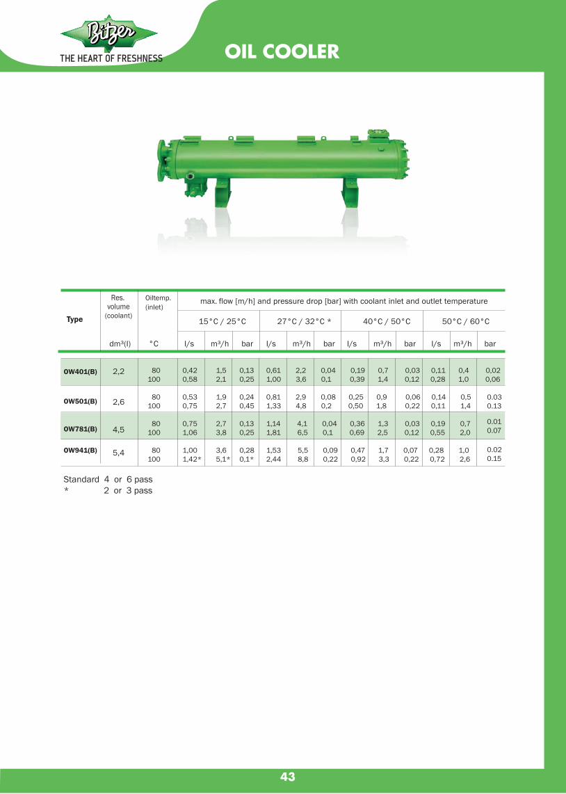
43
OIL COOLER
max. flow [m/h] and pressure drop [bar] with coolant inlet and outlet temperature
15°C / 25°C 27°C / 32°C * 40°C / 50°C 50°C / 60°CType
Oiltemp.(inlet)
°C
Res. volume
(coolant)
Standard 4 or 6 pass* 2 or 3 pass
dm³(I) I/s m³/h bar I/s m³/h bar I/s m³/h bar I/s m³/h bar
OW401(B)
OW501(B)
OW781(B)
OW941(B)
2,2
2,6
4,5
5,4
80100
80100
80100
80100
0,420,58
0,530,75
0,751,06
1,001,42*
1,52,1
1,92,7
2,73,8
3,65,1*
0,130,25
0,240,45
0,130,25
0,280,1*
0,61 2,2 0,04 0,19 0,7 0,03 0,11 0,4 0,021,00 3,6 0,1 0,39 1,4 0,12 0,28 1,0 0,06
0,81 2,9 0,08 0,25 0,9 0,06 0,14 0,5 1,33 4,8 0,2 0,50 1,8 0,22 0,11 1,4
1,14 4,1 0,04 0,36 1,3 0,03 0,19 0,7 1,81 6,5 0,1 0,69 2,5 0,12 0,55 2,0
1,53 5,5 0,09 0,47 1,7 0,07 0,28 1,0 2,44 8,8 0,22 0,92 3,3 0,22 0,72 2,6
0.030.13
0.010.07
0.020.15

44
AIR-COOLED
CONDENSING UNITS
Air cooled condensing unit with Bitzer Compressors (Rack Assembly) Standard & Option accessory
} For open type air cooled condensing unit

45
WATER - COOLED
CONDENSING UNITS
Shell and Tube Water / Sea-water Condenser
Water - cooled condensing unit with Bitzer Compressors Standard & Option accessory
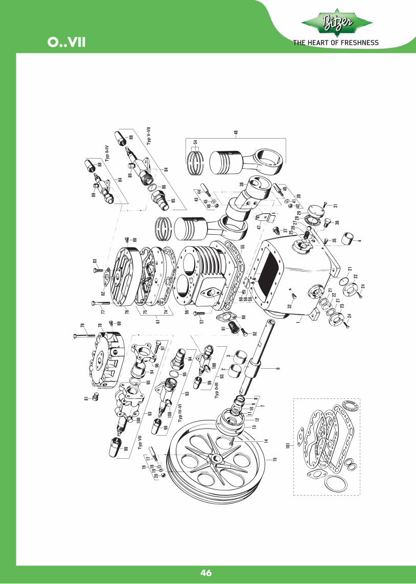
O..VII
46

2KES-05....2FES-3
47

2EES-2...2CES-4
48
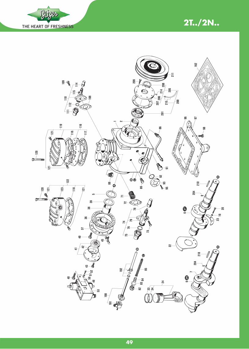
2T../2N..
49
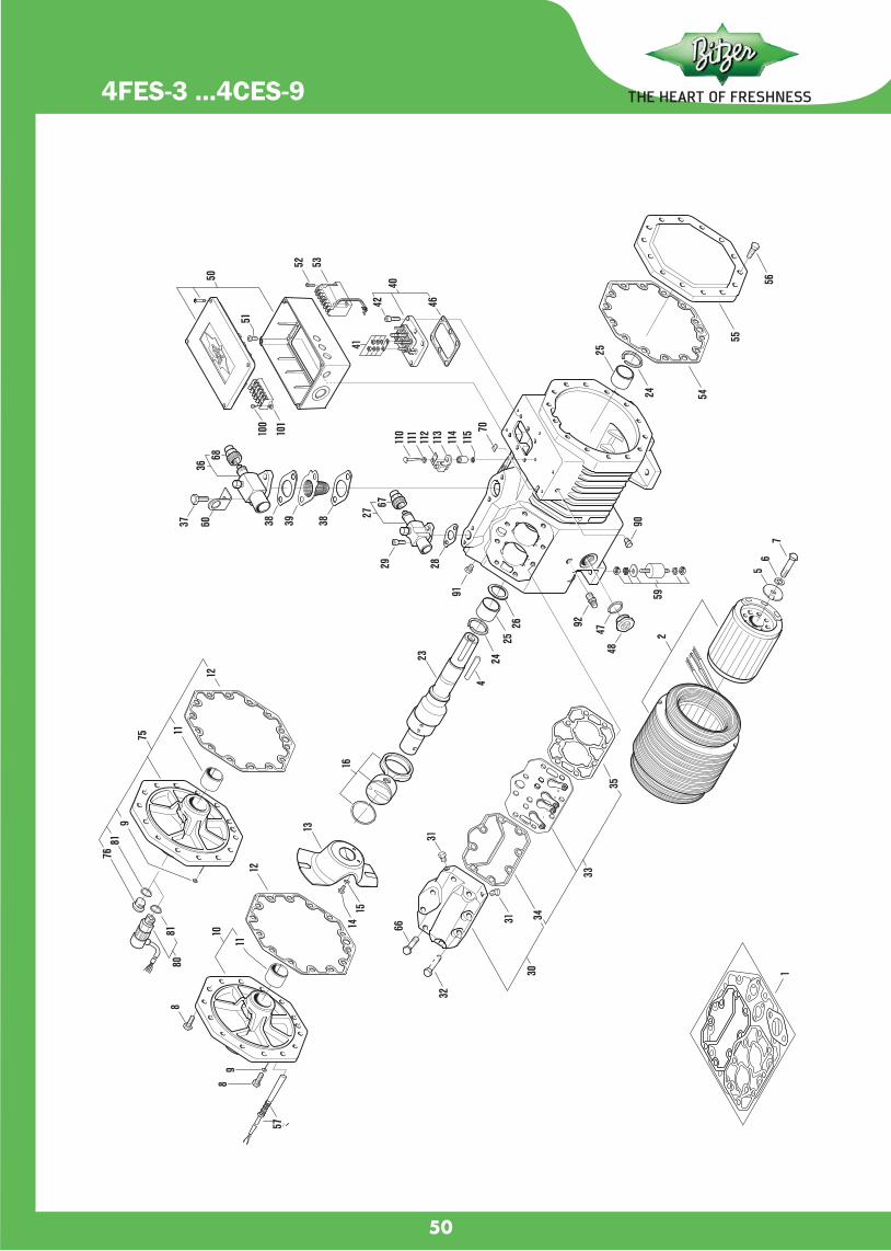
4FES-3 ...4CES-9
45
50
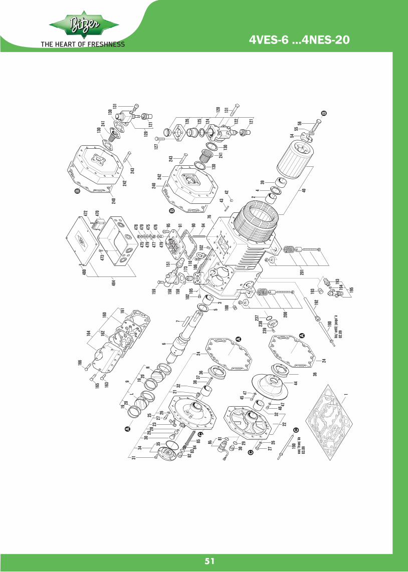
46
51
4VES-6 ...4NES-20

4T ..4N(A)
45
52

4JE-13 ..6FE-50
46
53

54
4H(.2) ..6F.2W4HA ..W6FA
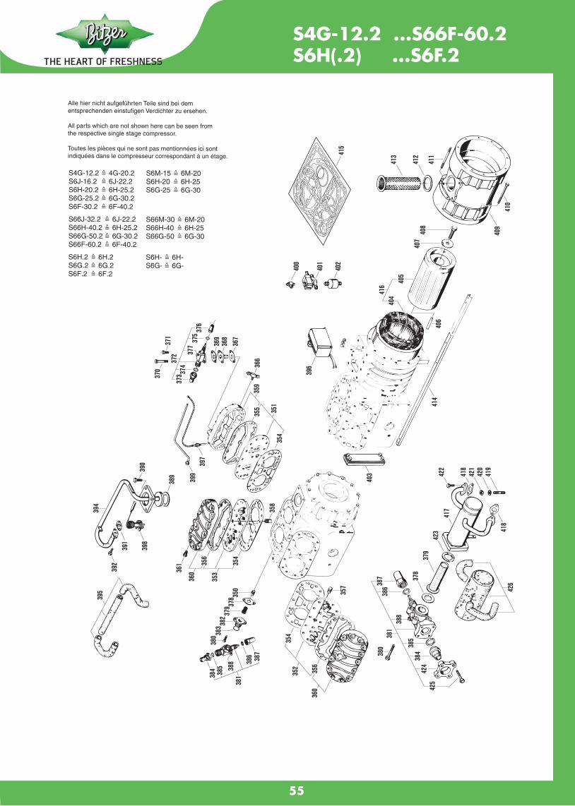
55
S4G-12.2 ...S66F-60.2S6H(.2) ...S6F.2

Model Type Appl. HP Cooling Capacity COP Eng. Motor Weight Btu/h Kcal/h W W/W no. Type kgs
Electrical 50 Hz : 220-240 : 1 Phase
EM C3121U R-290 LBP-MBP 1/4 924 233 271 1.85 711IA72 RSCR 8.17
EM C3125U R-290 LBP-MBP 1/3 1,041 262 305 1.86 711JA72 RSCR 8.17
NE K2134U R-290 LBP 1/2 1,533 386 449 1.36 862AA51 CSIR 11.00
NE K2150U R-290 LBP 1/2+ 1,985 500 582 1.31 863AA51 CSIR 11.60
NE K2168GK R-404A LBP 3/4 2,348 592 688 1.13 959HA51 CSIR 11.60
NE U2168GK R-404A LBP 3/4 2,539 640 744 1.27 959MA51 CSIR 11.60
NT 2168GK R-404A LBP 1,210 305 355 1.03 922DN04 CSCR 17.00
Please contact our sals team,for other models and Quotation
APPLICATION
LBP MBP HBP AC
Table 1 : Compressor Series - Application-Refrigerants
SERIES
Table 2 : Application
TYPE DESCRIPTION
R134a - R600a - R404A - R290
R134a - R600a - R404A - R507
R22 - R134a - R404A - R507 - R290
R22 - R134a - R404A - R507 - R290
R22 - R134a - R404A - R507
R404A - R290
R404A - R507
R404A - R507 - R290
R404A - R507 - R290
R404A - R507
R134a - R600a
R22 - R134a
R22 - R134a R600a
R22 - R134a
R22 - R134a
R22 - R407C
R22 - R407C
R22 - R407C
-
-
EM
NB
NE
T - NT
NJ
LBP
MBP
HBP
AC
WHAT ARE YOU LOOKING FOR YOURCOOLING SYSTEM?
56

AE4430EK 6.92 1/4 2,907 852 HBP 2.30 AE4440EK 7.57 1/3 3,412 1,000 HBP 2.20 AE4448EK 8.85 1/2 3,999 1,172 HBP 2.70 AE7415EK 5.48 1/4 1,262 370 MBP 2.10 AE7422EK 7.55 1/3 1,877 550 MBP 2.40 AE7426EK 8.85 1/3 2,184 640 MBP 2.70 AE7435EK 12.04 1/2 2,968 870 MBP 2.50 AE7440EK 14.14 1/2 3,446 1,010 MBP 3.00 AE7445EK 16.08 1/2 3,798 1,113 MBP 3.66
DISP./REV.
CC. BTU./HR WATTS
COOLING CAPACITYAPP. FLAHP.Model
AE2410ZKAE2413ZKAE2416ZK-SRAE2420ZK-SRAE2425ZK-SRAE2428ZK-SR
AE SERIES 220/240/50Hz
5.996.918.12
12.0514.1416.08
1/41/31/33/81/25/8
9211,1091,3991,6382,0922,388
270325410480613700
LBPLBPLBPLBPLBPLBP
1.532.00
1.41.752.712.88
AZ1335Y 4.00 317 93 AZA1320YK 3.11 194 57 C-QN77L5DL 4.08 270 79 AZA1340Y 5.11 375 110 AZA1350Y 5.99 461 135 AZA1360Y 6.91 539 158 AE1370Y 8.12 635 186 AE1390Y 9.42 757 252 AE2370Y 8.12 631 185 AE2390Y-F 9.42 809 237 AE2410Y-F 14.14 921 270 AE2413Y-SR 16.08 1,126 330 AEA2415Y 16.15 1,262 370 AE3417Y 5.68 1,706 500 AE3425Y 7.55 2,491 730 AE3440Y 12.05 3,634 1,065 AE4425Y 7.55 2,388 700 AE4430Y 8.86 2,798 820 AE4435Y 9.42 3,078 902 AE4440Y 12.05 3,668 1,075 AE4448Y 14.14 4,060 1,190 AE4459Y-SR 16.08 4,947 1,450 AE7415Y 7.55 1,259 369 AE7430Y 16.80 2,542 745
AE9437Y-SR 18.00 3,139 920 5,732 1,680
1/81/20
1/81/61/61/51/51/41/51/41/33/81/21/61/53/81/51/33/81/21/21/21/41/2
5/8
LBPLBPLBPLBPLBPLBPLBPLBPLBPLBPLBPLBPLBPHBPHBPHBPHBPHBPHBPHBPHBPHBPMBPMBP
MBP
HBP
0.730.540.550.770.901.001.171.281.181.402.001.401.341.602.203.002.152.502.703.103.453.001.822.18
2.64
3.50
HERMETIC COMPRESSOR
57
ใชสำหรบนำยา R-22 = E นำมนธรรมชาต (MINERAL OIL)
ใชสำหรบนำยา R-404A = Z,R-507=Z นำมนสงเคราะห (Polyol ester oil)
AZ - AE SERIES 220/240/50Hz
ใชสำหรบนำยา R-404A = Z,R-507=Z นำมนสงเคราะห (Polyol ester oil)
AE
AE
AZ
AE
DISP./REV.
CC. BTU./HR WATTS
COOLING CAPACITYAPP. FLAHP.Model

58
Scroll Compressors for Refrigeration
ZF Copeland Scroll ™ Compressor Range for Low Temperature Refrigeration using R404A,R407F,R407A, and R22
Features and Benefits
● Wide operating envelope with 10 ºc low condensing temperature to minmize energy consumption ● One model for multiple refrigerants ● Light weight and compactness,more than half the weight of equivalent semi-hermetic compressor ● Optional Sound Shell allowing 10 dBA sound attenuation ● ZF models with liquid injection ◦ Easy,efficient and injection via discharge Tem- -perature Control(DTC)on the smaller models● ZF models withEnhanced Vapr Injection ◦ Seasonal effciencies compared to Emerson's best semi-hermetic compressors ◦ Improved system capacity and efficency by 40% and 25% respectively,making them the most efficient compressors on the market. ◦ Possidility to reduce the equipment and component sizes by using smaller compressors
ZF Compressor for Low Temperature Refrigerationwith and without Sound Shell
Technical Overview
Model
Models with Liquid Injection
ZF Summit Models with Liquid Injection
Models with Enhanced Vapor Injection
Nom
inal
hpD
ispl
acem
ent
(m3 /
h)
Rota
Suc
tion
(inch
)
Rota
Dis
char
ge(in
ch)
Oil Q
uant
ity(l)
Leng
th/W
idth
/
Hei
ght
(mm
)
Net
Wei
ght
(kg)
MotorVersion/Code
MaximumOperatingCurrent (A)
Locked RotorCurrent (A)
Soun
d Pr
essu
re@
1 m
(dBA
)***
3Ph** 3Ph** 3Ph**
ZF06K4E
ZF08K4E
ZF09K4E
ZF11K4E
ZF13K4E
ZF15K4E
ZF18K4E
ZF25K5E
ZF34K5E
ZF41K5E
ZF49K5E
ZF13KVE EVI
ZF18KVE EVI
ZF25KVE EVI
ZF34KVE EVI
ZF41KVE EVI
2.0
2.5
2.8
3.5
4.0
5.0
6.0
3.5
4.5
4.8
6.0
7.1
8.6
10.4
1.3
1.3
1.3
1.3
1.3
1.3
1.3
1.0
1.0
1.0
1.0
1.0
1.0
1.0
1.3
1.5
1.5
1.5
1.9
1.9
1.9
243/245/369
243/245/391
243/244/391
243/244/405
246/251/442
246/251/442
246/251/442
25.4
27.2
27.0
28.0
38.0
39.0
41.0
TFD
TFD
TFD
TFD
TFD
TFD
TFD
5
6
6
7
8
10
13
26
32
40
46
52
64
74
57.0
59.0
62.0
63.0
65.0
65.0
67.0
7.5 13.0
17.2
21.3
25.7
1.3
1.8
1.8
1.8
1.3
1.3
1.3
1.3
1.9
3.4
3.4
3.4
246/257/52
280/280/534
280/280/534
280/280/552
39.5
63.1
63.1
66.2
TFD
TFD
TFD
TFD
14
25
29
30
102
100
118
139
71.0
63.0
63.0
71.0
4.0
6.0
7.5
9.7
14.1
16.9
23.5
29.1
1.3
1.3
1.3
1.8
1.8
1.0
1.0
1.3
1.3
1.3
1.4
1.9
1.9
3.4
3.4
246/251/442
246/251/442
246/257/452
280/280/534
280/280/534
38.0
39.5
39.5
63.1
63.1
TFD
TFD
TFD
TFD
TFD
9
14
16
25
29
52
74
102
100
118
63.0
67.0
70.0
72.0
72.0

NomenclatureThe model designation contains the following technical information about the standard and vapour injection compressors :
Z B 56K C E - TWD - 551
Oil type:
None = mineral oil
Application range temperature:B = high/medium *S = high/medium *F = low **
Compressor family: Z = Scroll
Model variation
Motor version
Bill of material number
E = POE oil
Nominal capacity [BTU/h] @ 60 Hz and *, ** ARI conditions
Scroll Compressors for Refrigeration
Common information about Copeland ScrollТM
compressors
The Scroll compressor has been under development at Emerson Climate Technologies since 1979. It is the most efficient and durable compressor Emerson Climate Technologies has ever developed for air conditioning and refrigeration.
This application guideline deals with all vertical single Copeland Scroll ™ compressor for refrigeration application fromZB15K* to ZB220K*, ZS21K* to ZS11M*and ZF06K* to ZF48K* including vapour injection compressors.
* EN 12900 Conditions for medium temperature: R404A
Evaporating temperature ......... -10°C Suction gas return temperature .......... 20°C
Condensing temperature ......... 45°C Liquid sub -cooling ............................... 0 K
** EN 12900 Conditions for low temperature: R404A
Evaporating temperature ......... -35°C Suction gas return temperature .......... 20°C
Condensing tempe rature ......... 40°C Liquid sub -cooling ............................... 0 K
MotorModel
59
ZB15KCEZB19KCEZB21KCEZB26KCEZB30KCEZB38KCEZB45KCEZB56KCEZB75KCEZB92KCEZB11MCE
3.324.165.055.856.878.5310.0511.7517.1521.2025.80
PFJ/TFDPFJ/TFDPFJ/TFDPFJ/TFDPFJ/TFDPFJ/TFDTFDTWDTWDTWDTWD
ZS21K4EZS26K4EZS30K4EZS38K4EZS45K4EZS56K4EZS75K4EZS92K4EZS11M4E
4.846.027.078.6610.3012.6017.6521.7025.30
TFDTFDTFDTFDTFDTWDTWDTWDTWD
TFDTFDTFDTFDTFDTWDTWDTWDTWD
ZF06K4EZF08K4EZF09K4EZF11K4EZF13K4EZF15K4EZF18K4EZF24K4EZF33K4EZF40K4EZF48K4E
1.431.761.942.462.783.424.185.167.098.7810.60
Cooling capacity
kW*MotorModel Cooling
capacitykW*
MotorModelCooling capacity
kW*
These compressors have one Scroll compression set driven by a single or three-phase induction motor. The Scroll set is mounted at the upper end of the rotor shaft of the motor. The rotor shaft axis is in the vertical plane.
Product description
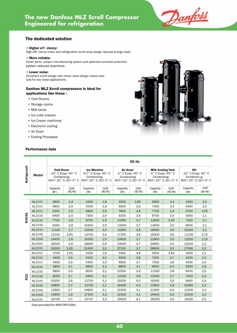
The dedicated solution
• Higher e� ciency:High e� ciency motor and refrigeration scroll wrap design reduces energy costs.
• More reliable:Fewer parts, unique manufacturing system and patented overload protection system reduces downtime.
• Lower noise:Compliant scroll design with check valve design means less cost for low noise applications.
Danfoss MLZ Scroll compressors is ideal for applications like these : • Cold Rooms • Storage rooms • Milk tanks • Ice cube makers • Ice Cream machines • Electronic cooling • Air Dryer • Cooling Processes
The new Danfoss MLZ Scroll CompressorEngineered for refrigeration
Ref
riger
ant
Cold Room-10° C Evap/ 40° C
Condensing;RGT= 20° C; SC= 0° C
Ice Machine-6,7° C Evap/ 40° C
Condensing;RGT= 20° C; SC= 0° C
Air Dryer0° C Evap/ 40° C
Condensing;RGT= 20° C; SC= 0° C
Milk Cooling Tank4° C Evap/ 45° C
Condensing;RGT= 20° C; SC= 0° C
EN-10° C Evap/ 45° C
Condensin g;RGT= 20° C; SC= 0° C
Capacity(W )
COP(W/W)
Capacity(W)
COP(W/W)
Capacity(W)
COP(W/W)
Capacity(W)
COP(W/W)
Capacity(W)
COP(W/W)
3800 2,4 4400 2,8 5500 3,65 5800 3,4 3450 1,94800 2,5 5500 2,8 6900 3,6 7300 3,4 4400 2,05100 2,5 5800 2,8 7400 3,6 7700 3,4 4700 2,056400 2,5 7300 2,9 9200 3,6 9700 3,4 5900 2,17700 2,6 8700 2,9 11000 3,7 11600 3,45 7100 2,1
9200 2,6 10400 2,9 13200 3,7 13900 3,5 8500 2,111100 2,7 12500 3,0 15900 3,8 16600 3,6 10200 2,212100 2,65 13700 3,0 17200 3,8 18300 3,6 11100 2,1514400 2,6 16300 2,9 20600 3,7 21800 3,5 13200 2,1516500 2,6 18600 2,9 23500 3,7 24800 3,5 15200 2,219000 2,65 21400 3,0 27100 3,7 28600 3,5 17500 2,2
3700 2,55 4200 2,9 5400 3,8 5900 3,63 3450 2,14400 2,6 5100 3,0 6500 3,8 7100 3,7 4100 2,24600 2,9 5400 3,0 6900 3,7 7500 3,6 4400 2,45800 3,1 6800 3,3 8800 4,1 9600 4,0 5600 2,66800 2,9 8000 3,2 10300 3,9 11300 3,8 6400 2,5
8000 2,7 9400 3,1 12100 3,8 13200 3,7 7500 2,310000 2,8 11700 3,2 15000 4,0 16300 3,9 9400 2,410800 2,7 12700 3,1 16400 4,0 17800 3,9 10300 2,212600 2,7 14800 3,1 19300 4,1 21300 4,0 11500 2,314800 2,9 17300 3,3 22300 4,1 24500 4,0 14200 2,516700 3,3 25600 4,1 28200 4,0 16100 2,5
Data provided for 400V/3Ph/50Hz
Performance data
50 Hz
Model
60
R40
4AR
22
3,0 19700
MLZ015MLZ019MLZ021MLZ026MLZ030MLZ038MLZ045MLZ048MLZ058MLZ066MLZ076MLZ015MLZ019MLZ021MLZ026MLZ030MLZ038MLZ045MLZ048MLZ058MLZ066MLZ076

PLATE HEAT EXCHANGER
SHELL & TUBE HEAT EXCHANGER
EVAPORATOR
CONDENSER
*Exclude pressure relief valve
07TB 005 117
07TB 016 117
07TB 017 112
07TB 018 118
07TB 009 111
07TB 010 111
B8H X 16
B8H X 24
B8H X 28
B8H X 40
B15H X 26
B15H X 30
9,600 12,000 7/8" 7/8" 3/4" 16
12,000 18,000 7/8" 7/8" 3/4" 24
18,000 24,000 7/8" 7/8" 3/4" 28
24,000 36,000 7/8" 7/8" 3/4" 40
36,000 48,000 7/8" 7/8" 3/4" 26
48,000 60,000 7/8" 7/8" 3/4" 30
Model TypeEVAP CDU IN OUT NPT OF PLATE
CAP . BTU WATER No.REFRIGERANT
TVCC-7.5-1-08
TVCC-010-1-08
TVCC-012-1-08
TVCC-015-1-08
TVCC-020-1-08
TVCC-025-1-08
TVCC-030-1-08
TVCC-010-1-10
TVCC-012-1-10
TVCC-015-1-10
TVCC-020-1-10
TVCC-025-1-10
TVCC-030-1-10
TVCC-035-1-10
TVCC-040-1-10
TCST-3.5-1-6
TCST-4-1-6
TCST-5-1-6
TCST-6-1-6
TCST-8-1-6
TCST-10-1-8
TCST-12-1-8
TCST-15-1-8
TCST-20-1-8
TCST-25-1-10
TCST-30-1-10
TCST-35-1-10
TCST-40-1-12
TVCC-050-1-1
TVCC-060-1-12
TVCC-070-1-12
TVCC-080-1-12
TVCC-090-1-12
TVCC-100-1-14
TVCC-120-1-14
TVCC-150-1-14
TVCC-170-1-16
TVCC-190-1-16
TVCC-220-1-18
TVCC-255-1-18
TVCC-295-1-18
TVCC-390-1-24
TVCC-450-1-24
TCST-50-1-12
TCST-60-2-12
TCST-70-2-12
TCST-80-2-12
TCST-100-2-14
TCST-110-2-16
TCST-120-2-14
TCST-140-2-16
TCST-150-2-18
TCST-170-2-16
TCST-180-2-18
TCST-220-2-20
TCST-260-2-20
7.5
10
12
15
20
25
30
10
12
15
20
25
30
35
40
50
60
70
80
90
100
120
150
170
190
220
255
295
50
60
70
80
90
100
120
150
170
190
220
255
295
390
450
3.5
4
5
6
8
10
12
15
20
25
30
35
40
CAPACITY
HP
CAPACITY
HPModel
Plate / Shell & Tube
61
Model
CONDENSER
EVAPORATOR
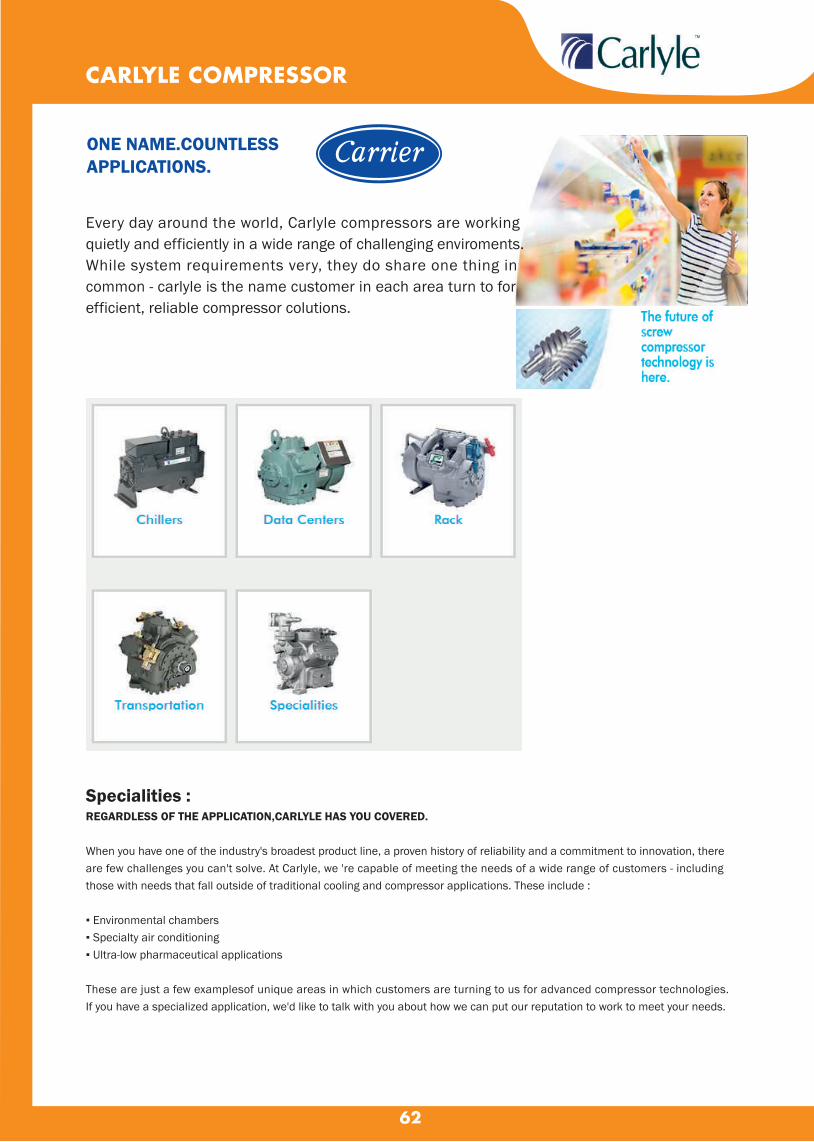
62
Every day around the world, Carlyle compressors are working quietly and efficiently in a wide range of challenging enviroments. While system requirements very, they do share one thing in common - carlyle is the name customer in each area turn to for efficient, reliable compressor colutions.
CARLYLE COMPRESSOR
ONE NAME.COUNTLESSAPPLICATIONS.
Specialities :
REGARDLESS OF THE APPLICATION,CARLYLE HAS YOU COVERED. When you have one of the industry's broadest product line, a proven history of reliability and a commitment to innovation, there are few challenges you can't solve. At Carlyle, we 're capable of meeting the needs of a wide range of customers - including those with needs that fall outside of traditional cooling and compressor applications. These include : ▪ Environmental chambers ▪ Specialty air conditioning ▪ Ultra-low pharmaceutical applications These are just a few examplesof unique areas in which customers are turning to us for advanced compressor technologies. If you have a specialized application, we'd like to talk with you about how we can put our reputation to work to meet your needs.

63
Specialities :
REGARDLESS OF THE APPLICATION,CARLYLE HAS YOU COVERED. When you have one of the industry's broadest product line, a proven history of reliability and a commitment to innovation, there are few challenges you can't solve. At Carlyle, we 're capable of meeting the needs of a wide range of customers - including those with needs that fall outside of traditional cooling and compressor applications. These include : ▪ Environmental chambers ▪ Specialty air conditioning ▪ Ultra-low pharmaceutical applications These are just a few examplesof unique areas in which customers are turning to us for advanced compressor technologies. If you have a specialized application, we'd like to talk with you about how we can put our reputation to work to meet your needs.
06DA3280BC0601
06DF3280BC0601
06DA5370BC0601
06DF5370BC0601
06EA250611
06E2250611
06EA265611
06E2265611
06EA275611
06E6275611
06EA299611
06E6299611
10
10
15
15
20
20
25
25
30
30
40
40
6
6
6
6
4
4
6
6
6
6
6
6
-
1
-
1
-
1
-
1
-
1
-
1
3.80
3.80
3.80
3.80
6.60
6.60
9.00
9.00
9.00
9.00
9.00
9.00
143.00
143.00
147.00
147.00
195.00
195.00
220.00
220.00
222.00
222.00
236.00
236.00
1-1/8"
1-1/8"
1-1/8"
1-1/8"
1-1/8"
1-1/8"
1-3/8"
1-3/8"
1-3/8"
1-3/8"
1-5/8"
1-5/8"
1-3/8"
1-3/8"
1-5/8"
1-5/8"
1-5/8"
1-5/8"
1-5/8"
1-5/8"
2-1/8"
2-1/8"
2-1/8"
2-1/8"
156,000.-
162,000.-
165,000.-
171,000.-
168,000.-
188,000.-
178,000.-
198,000.-
189,000.-
210,000.-
210,000.-
230,000.-
05F & 05H OPEN - DRIVE RECIPROCATING COMPRESSOR - OIL LESS
Electrical : 400/460-3Phase - 50/60 Hz5F20S-2195F30S-2195F40S-2195F60S-2195H40S-2195H46S-2195H60S-2195H66S-2195H80S-2195H86S-2195H120S-2195H126S-219
57.5101525404050507575100
101520254060607575100125150
101520254060607575100125150
23464466881212
600 700 800 900 800 800 900 900 1100 1100 900 900
2.402.605.706.208.508.509.909.90
19.4019.4028.9028.90
79.4097.50
161.00181.00277.00277.00361.00361.00506.00506.00717.00717.00
435,000.-508,000.-557,000.-683,000.-732,000.-
1,138,000.-1,347,000.-1,347,000.-1,374,000.-1,374,000.-1,944,000.-1,944,000.-
CARLYLE COMPRESSOR
Motor No. of Electric Oil Charge Weight Discharge Suction
HP Cylinder Unload Ltr kgs Valve Valve
Price
BahtModel
Electrical : 400/460-3Phase - 50/60 Hz
06D & 06E SEMI -HERMETIC COMPRESSOR OIL LESS -HIGH TEMP
Rating Tons No.of Min speed for Oil Charge Weight
R-12 R-22 R-502 Cylinder unloader operate Ltr kgs
Price
BahtModel
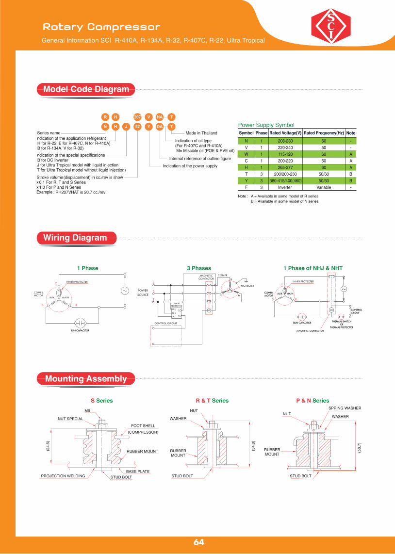
64
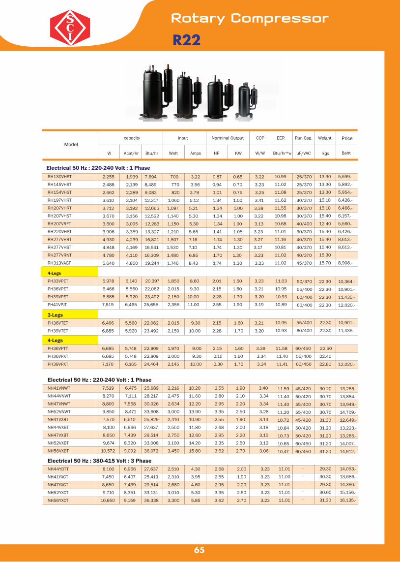
65
R22
RH130VHST
RH145VHST
RH154VHST
RH197VHRT
RH207VHRT
RH207VHST
RH207VRFT
RH220VHST
RH277VHRT
RH277VHST
RH277VRNT
RH313VAGT
2,255 1,939 7,694 700 3.22 0.87 0.65 3.22
2,488 2,139 8,489 770 3.56 0.94 0.70 3.23
2,662 2,289 9,083 820 3.79 1.01 0.75 3.25
3,610 3,104 12,317 1,060 5.12 1.34 1.00 3.41
3,712 3,192 12,665 1,097 5.21 1.34 1.00 3.38
3,670 3,156 12,522 1,140 5.30 1.34 1.00 3.22
3,600 3,095 12,283 1,150 5.30 1.34 1.00 3.13
3,906 3,359 13,327 1,210 5.65 1.41 1.05 3.23
4,930 4,239 16,821 1,507 7.16 1.74 1.30 3.27
4,848 4,169 16,541 1,530 7.10 1.74 1.30 3.17
4,780 4,110 16,309 1,480 6.85 1.70 1.30 3.23
5,640 4,850 19,244 1,746 8.43 1.74 1.30 3.23
10.99
11.02
11.08
11.62
11.55
10.98
10.68
11.01
11.16
10.81
11.02
11.02
25/370
25/370
25/370
30/370
30/370
30/370
40/400
30/370
40/370
40/370
40/370
45/370
13.30
13.30
13.30
15.10
15.10
15.40
12.40
15.40
15.40
15.40
15.30
15.70
5,599.-
5,892.-
5,954.-
6,426.-
6,466.-
6,157.-
5,560.-
6,426.-
8,613.-
8,613.-
8,908.-
4-Legs
PH33VPET 5,978 5,140 20,397 1,850 8.60 2.01 1.50 3.23 11.03
PH36VPET 6,466 5,560 22,062 2,015 9.30 2.15 1.60 3.21 10.95
PH39VPET 6,885 5,920 23,492 2,150 10.00 2.28 1.70 3.20 10.93
PH41VPJT 7,519 6,465 25,655 2,355 11.00 2.55 1.90 3.19 10.89
50/370
55/400
60/400
60/400
22.30
22.30
22.30
22.30
10,364.-
10,901.-
11,435.-
12,020.-
3-Legs PH36VTET 6,466 5,560 22,062 2,015 9.30 2.15 1.60 3.21
PH39VTET 6,885 5,920 23,492 2,150 10.00 2.28 1.70 3.20
10.95
10.93
55/400
60/400
22.30
22.30
10,901.-
11,435.-
4-Legs PH36VPTT 6,685 5,748 22,809 1,970 9.00 2.15 1.60 3.39 11.58 60/450 22.50
PH36VPXT 6,685 5,748 22,809 2,000 9.30 2.15 1.60 3.34 11.40 55/400 22.40
PH39VPXT 7,170 6,165 24,464 2,145 10.00 2.30 1.70 3.34 11.41 60/450 22.80 12,020.-
Electrical 50 Hz : 220-240 Volt : 1 Phase NH41VNWT 7,529 6,475 25,689 2,216 10.20 2.55 1.90 3.40
NH44VNWT 8,270 7,111 28,217 2,475 11.60 2.80 2.10 3.34
NH47VNWT 8,800 7,568 30,026 2,634 12.20 2.95 2.20 3.34
NH52VNWT 9,850 8,471 33,608 3,000 13.90 3.35 2.50 3.28
NH41VXBT 7,570 6,510 25,829 2,410 10.90 2.55 1.90 3.14
NH44VXBT 8,100 6,966 27,637 2,550 11.80 2.68 2.00 3.18
NH47VXBT 8,650 7,439 29,514 2,750 12.60 2.95 2.20 3.15
NH52VXBT 9,674 8,320 33,008 3,100 14.20 3.35 2.50 3.12
NH56VXBT 10,572 9,092 36,072 3,450 15.80 3.62 2.70 3.06
Electrical 50 Hz : 220-240 Volt : 1 Phase
11.59
11.40
11.40
11.20
10.72
10.84
10.73
10.65
10,47
45/420
50/420
55/400
55/400
45/420
50/420
50/420
60/450
60/450
30.20
30.70
30.70
30.70
31.30
31.20
31.20
31.20
31.20
13,285.-
13,884.-
13,949.-
14,709.-
12,649.-
13,223.-
13,285.-
14,007.-
14,912.-
Electrical 50 Hz : 380-415 Volt : 3 Phase NH44YDTT 8,100 6,966 27,637 2,510 4.30 2.68 2.00 3.23
NH41YXCT 7,450 6,407 25,419 2,310 3.95 2.55 1.90 3.23
NH47YXCT 8,650 7,439 29,514 2,680 4.60 2.95 2.20 3.23
NH52YXCT 9,710 8,351 33,131 3,010 5.30 3.35 2.50 3.23
NH56YXCT 10,650 9,159 36,338 3,300 5.85 3.62 2.70 3.23
11.01
11.00
11.01
11.01
11.01
-
-
-
-
-
29.30
30.30
29.30
30.60
31.30
14,053.-
13,686.-
14,380.-
15,156.-
16,135.-
Modelcapacity Input Norminal Output COP EER Run Cap. Weight Price
Baht W Kcat/hr Btu/hr Watt Amps HP KW W/W Btu/hr*w uF/VAC kgs

66
Electrical 50 Hz : 220-240 Volt : 1 PhaseKV092VBBMT 2,295 1,974 7,831 850 3.90 0.94 0.70 2.70 9.21 25/370 9.90 3,096.-
RV092VDCMT 2,240 1,926 7,643 820 3.80 0.94 0.70 2.73 9.32 25/370 14.00
RV130VCAMT 3,270 2,812 11,157 1,140 5.20 1.21 0.90 2.87 9.79 30/370 14.80 3,406.-
RV135VCAMT 3,400 2,924 11,601 1,180 5.50 1.21 0.90 2.88 9.83 30/370 15.10 3,417.-
RV174VAAMT 4,460 3,836 15,218 1,530 7.20 1.74 1.30 2.92 9.95 40/370 15.60 3,962.-
RV220VEBMT 5,510 4,739 18,800 1,950 9.10 2.15 1.60 2.83 9.64 45/400 16.60 4,985.-
RV231VFFMT 5,960 5,126 20,336 2,080 9.90 2.15 1.60 2.87 9.78 50/400 17.30 5,131.-
PV23VAAMT 5,880 5,057 20,063 2,080 9.40 2.41 1.80 2.83 9.65 60/420 23.70 5,401.-
R32
R32,R134
Electrical 50 Hz : 220-240 Volt : 1 PhaseRB135VRYMT 1,560 1,341 5,323 500 2.30 0.58 0.43 3.12 10.65 25 / 370 12.70
RB145VHSMT 1,700 1,462 5,800 560 2.60 0.67 0.50 3.04 10.36 25 / 370 13.20
RB154VHSMT 1,740 1,496 5,937 610 2.80 0.74 0.55 2.85 9.73 25 / 370 13.20
RB165VHSMT 1,920 1,651 6,551 650 3.00 0.79 0.59 2.95 10.08 25 / 370 13.20
RB174VRXMT 2,000 1,720 6,824 640 3.00 0.80 0.60 3.13 10.66 25 / 370 13.50
RB189VHSMT 2,210 1,900 7,541 720 3.30 0.82 0.61 3.07 10.47 30 / 370 15.10
RB247VRYMT 2,880 2,476 9,827 900 4.20 1.14 0.85 3.20 10.92 30 / 400 15.40
RB277VHSMT 3,240 2,786 11,055 1,060 5.10 1.23 0.92 3.06 10.43 40 / 370 15.10
RB313VHSMT 3,730 3,207 12,727 1,290 6.10 1.27 0.95 2.89 9.87 45 / 370 15.70
R134
Modelcapacity Input Norminal Output COP EER Run Cap. Weight Price
Baht W Kcat/hr Btu/hr Watt Amps HP KW W/W Btu/hr*w uF/VAC kgs
Modelcapacity Input Norminal Output COP EER Run Cap. Weight
W Kcat/hr Btu/hr Watt Amps HP KW W/W Btu/hr*w uF/VAC kgs
-

67
R410A
Electrical 50 Hz : 220-240 Volt : 1 PhaseRN092VHSMT 2,240 1,926 7,643 770 3.60 0.80 0.60 2.91
RN096VHSMT 2,340 2,012 7,984 805 3.70 0.87 0.65 2.91
RN099VHSMT 2,390 2,055 8,155 820 3.80 0.87 0.65 2.91
RN104VHSMT 2,510 2,158 8,564 865 4.00 0.94 0.70 2.90
RN110VHSMT 2,680 2,304 9,144 920 4.20 1.01 0.75 2.91
RN117VHSMT 2,850 2,450 9,724 975 4.40 1.07 0.80 2.92
RN125VHSMT 3,050 2,623 10,407 1,050 4.90 1.07 0.80 2.90
RN135VHVMT 3,220 2,768 10,987 1,120 5.20 1.21 0.90 2.88
RN140VHNMT 3,450 2,967 11,771 1,160 4.00 1.21 0.90 2.97
RN145VHSMT 3,570 3,070 12,181 1,220 5.80 1.34 1.00 2.93
RN154VHSMT 3,820 3,285 13,034 1,320 6.20 1.48 1.10 2.89
RN165VHSMT 4,070 3,499 13,887 1,410 6.60 1.48 1.10 2.89
RN196VHQMT 4,800 4,128 16,378 1,580 5.00 1.74 1.30 3.04
RN207VHQMT 5,190 4,462 17,708 1,700 8.10 1.88 1.40 3.05
Electrical 50 Hz : 220-240 Volt : 1 PhasePN25VAAMT 6,360 5,468 21,700 2,165 10.00 2.41 1.80 2.94
PN27VAAMT 6,800 5,846 23,202 2,290 10.70 2.55 1.90 2.97
PN31VBBMT 7,900 6,794 26,955 2,660 12.30 2.95 2.20 2.97
PN33VABMT 8,490 7,301 28,968 2,920 13.30 3.08 2.30 2.91
Electrical 50 Hz : 380-415 Volt : 3 Phase
PN31YBAMT 8,050 6,923 27,467 2,650 4.70 3.08 2.30 3.04 10.36 - 23.90 16,317.-
Electrical 50 Hz : 220-240 Volt : 1 Phase
NN21VBAMT 5,400 4,644 18,425 1,820 8.30 1.74 1.30 2.97 10.12 50 / 400 29.20 12,154.-
NN27VBAMT 6,720 5,779 22,929 2,260 10.40 2.28 1.70 2.97 10.15 55 / 400 30.40 14,030.-
NN33VAAMT 8,490 7,301 28,968 2,800 13.10 2.95 2.20 3.03 10.35 55 / 420 31.90 16,287.-
NN40VAAMT 10,200 8,772 34,802 3,430 16.10 3.62 2.70 2.97 10.15 60 / 450 31.90 18,269.-
Electrical 50 Hz : 380-415 Volt : 3 PhaseNN21YDAMT 5,500 4,730 18,772 1,780 3.00 1.74 1.30 3.09 10.54 - 29.90 16,161.-
NN33YCAMT 8,600 7,396 29,343 2,730 4.70 2.95 2.20 3.15 10.75 - 30.10 17,601.-
NN40YCAMT 10,400 8,944 35,484 3,300 5.70 3.62 2.70 3.15 10.75 - 31.90 19,737.-
9.93
9.92
9.94
9.90
9.94
9.97
9.91
9.81
10.15
9.98
9.87
9.85
10.37
10.42
20 / 370
20 / 370
25 / 370
25 / 370
25 / 370
25 / 370
25 / 370
35 / 370
30 / 370
30 / 370
30 / 400
30 / 400
40 / 370
45 / 420
13.80
13.80
13.80
13.80
13.80
13.80
13.80
13.50
15.20
15.80
15.80
15.80
15.30
15.30
3,104.-
7,263.-
7,290.-
7,309.-
7,376.-
7,429.-
7,452.-
3,254.-
7,643.-
7,786.-
7,931.-
8,435.-
10,587.-
4,653.-
10.02
10.13
10.13
9.92
60 / 450
65 / 420
65 / 420
65 / 420
23.70
23.70
24.00
24.50
11,864.-
5,785.-
14,308.-
15,474.-
Modelcapacity Input Norminal Output COP EER Run Cap. Weight Price
Baht W Kcat/hr Btu/hr Watt Amps HP KW W/W Btu/hr*w uF/VAC kgs

68
Electrical 50 Hz : 220-240 Volt : 1 PhaseRN092VHSMT 2,240 1,926 7,643 770 3.60 0.80 0.60 2.91
RN096VHSMT 2,340 2,012 7,984 805 3.70 0.87 0.65 2.91
RN099VHSMT 2,390 2,055 8,155 820 3.80 0.87 0.65 2.91
RN104VHSMT 2,510 2,158 8,564 865 4.00 0.94 0.70 2.90
RN110VHSMT 2,680 2,304 9,144 920 4.20 1.01 0.75 2.91
RN117VHSMT 2,850 2,450 9,724 975 4.40 1.07 0.80 2.92
RN125VHSMT 3,050 2,623 10,407 1,050 4.90 1.07 0.80 2.90
RN135VHVMT 3,220 2,768 10,987 1,120 5.20 1.21 0.90 2.88
RN140VHNMT 3,450 2,967 11,771 1,160 4.00 1.21 0.90 2.97
RN145VHSMT 3,570 3,070 12,181 1,220 5.80 1.34 1.00 2.93
RN154VHSMT 3,820 3,285 13,034 1,320 6.20 1.48 1.10 2.89
RN165VHSMT 4,070 3,499 13,887 1,410 6.60 1.48 1.10 2.89
RN196VHQMT 4,800 4,128 16,378 1,580 5.00 1.74 1.30 3.04
RN207VHQMT 5,190 4,462 17,708 1,700 8.10 1.88 1.40 3.05
Electrical 50 Hz : 220-240 Volt : 1 PhasePN25VAAMT 6,360 5,468 21,700 2,165 10.00 2.41 1.80 2.94
PN27VAAMT 6,800 5,846 23,202 2,290 10.70 2.55 1.90 2.97
PN31VBBMT 7,900 6,794 26,955 2,660 12.30 2.95 2.20 2.97
PN33VABMT 8,490 7,301 28,968 2,920 13.30 3.08 2.30 2.91
Electrical 50 Hz : 380-415 Volt : 3 Phase
PN31YBAMT 8,050 6,923 27,467 2,650 4.70 3.08 2.30 3.04 10.36 - 23.90 16,317.-
Electrical 50 Hz : 220-240 Volt : 1 Phase
NN21VBAMT 5,400 4,644 18,425 1,820 8.30 1.74 1.30 2.97 10.12 50 / 400 29.20 12,154.-
NN27VBAMT 6,720 5,779 22,929 2,260 10.40 2.28 1.70 2.97 10.15 55 / 400 30.40 14,030.-
NN33VAAMT 8,490 7,301 28,968 2,800 13.10 2.95 2.20 3.03 10.35 55 / 420 31.90 16,287.-
NN40VAAMT 10,200 8,772 34,802 3,430 16.10 3.62 2.70 2.97 10.15 60 / 450 31.90 18,269.-
Electrical 50 Hz : 380-415 Volt : 3 PhaseNN21YDAMT 5,500 4,730 18,772 1,780 3.00 1.74 1.30 3.09 10.54 - 29.90 16,161.-
NN33YCAMT 8,600 7,396 29,343 2,730 4.70 2.95 2.20 3.15 10.75 - 30.10 17,601.-
NN40YCAMT 10,400 8,944 35,484 3,300 5.70 3.62 2.70 3.15 10.75 - 31.90 19,737.-
R407C
Electrical 50 Hz : 220-240 Volt : 1 Phase
RE135VHSMT 2,240 1,926 7,463 730 3.30 0.87 0.65 3.07
RE145VHSMT 2,420 2,081 8,257 790 3.60 0.94 0.70 3.06
RE154VHSMT 2,580 2,219 8,803 840 3.80 1.01 0.75 3.07
RE165VHSMT 2,770 2,382 9,451 890 4.10 1.07 0.80 3.11
RE174VHSMT 2,920 2,511 9,963 940 4.30 1.07 0.80 3.11
RE189VHSMT 3,210 2,761 10,953 1,010 4.80 1.14 0.85 3,18
RE207VHSMT 3,520 3,027 12,010 1,110 5.20 1.34 1.00 3.17
RE231VHSMT 3,940 3,388 13,443 1,250 5.90 1.48 1.10 3.15
RE247VHSMT 4,220 3,629 14,399 1,340 6.40 1.61 1.20 3.15
RE277VHSMT 4,700 4,042 16,036 1,520 7.20 1.74 1.30 3.09
RE313VADMT 5,380 4,626 18,357 1,770 8.34 1.74 1.30 3.04
Electrical 50 Hz : 220-240 Volt : 1 Phase
4Legs
PE33VPEMT 5,777 4,967 19,711 1,850 8.60 2.01 1.50 3,12
PE36VPEMT 6,227 5,354 21,247 2,010 9.40 2.15 1.60 3.10
PE39VPEMT 6,664 5,730 22,738 2,150 10.10 2.28 1.70 3.10
PE41VPJMT 7,360 6,328 25,114 2,305 10.80 2.55 1.90 3.19
3Legs
PE41VTJMT 7,360 6,328 25,114 2,305 10.80 2.55 1.90 3.19 10.89 60 / 450 22.30 14,124.-
Electrical 50 Hz : 220-240 Volt : 1 Phase
NE41VNHMT 7,270 6,252 24,805 2,330 10.60 2.55 1.90
NE44VNHMT 7,850 6,751 26,784 2,500 11.70 2.68 2.00
NE47VNHMT 8,380 7,207 28,593 2,670 12.40 2.95 2.20
NE52VNHMT 9,380 8,067 32,005 3,020 14.10 3.35 2.50
NE56VNHMT 10,260 8,824 35,007 3,360 15.90 3.62 2.70
Electrical 50 Hz : 380-415 Volt : 3 Phase
NE41YDNMT 7,150 6,149 24,396 2,210 3.80 2.55 1.90
NE44YDNMT 7,790 6,699 26,579 2,420 4.10 2.68 2.00
NE47YDNMT 8,350 7,181 28,490 2,580 4.50 2.95 2.20
NE52YDNMT 9,480 8,153 32,346 2,950 5.20 3.35 2.50
NE56YDNMT 10,200 8,772 34,802 3,240 5.60 3.62 2.70
10.47
10.45
10.48
10.62
10.60
10.84
10.82
10.75
10.75
10.55
10.37
25 / 370
25 / 370
25 / 370
25 / 370
25 / 370
30 / 370
30 / 370
30 / 400
35 / 400
40 / 370
45 / 370
13.20
13.20
13.20
13.20
13.20
15.10
15.10
15.10
15.10
15.10
15.70
6,357.-
6,442.-
6,641.-
6,558.-
6,601.-
6,645.-
6,703.-
7,417.-
7,756.-
9,117.-
10,486.-
10.65
10.57
10.58
10.89
50 / 370
55 / 400
60 / 450
60 / 450
22.70
22.70
22.70
22.30
12,209.-
12,836.-
13,442.-
10.65
10.71
10.71
10.60
10.42
45 / 420
50 / 420
50 / 420
60 / 450
60 / 420
31.30
31.30
32.20
32.20
32.20
14,990.-
15,361.-
15,737.-
16,605.-
17,674.-
3.12
3.14
3.14
3.11
3.05
3.24
3.22
3.24
3.21
3.15
11.04
10.98
11.04
10.96
10.74
30.30
30.30
30.30
31.30
32.20
16,057.-
16,433.-
16,829.-
17,748.-
18,891.-
-
-
-
-
-
Modelcapacity Input Norminal Output COP EER Run Cap. Weight Price
Baht W Kcat/hr Btu/hr Watt Amps HP KW W/W Btu/hr*w uF/VAC kgs
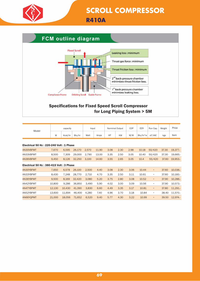
69
SCROLL COMPRESSORR410A
Specifications for Fixed Speed Scroll Compressor for Long Piping System > 5M
Electrical 50 Hz : 220-240 Volt : 1 PhaseAN30VBFMT 7,670 6,595 26,170 2,570 11.90 3.08 2.30 2.98 10.18 50/420 37.30 19,377.-
AN33VBFMT 8,500 7,309 29,000 2,790 13.00 3.35 2.50 3.05 10.40 50/420 37.30 19,665.-
AN36VBFMT 9,450 8,126 32,250 3,100 14.60 3.55 2.65 3.05 10.4 55/420 37.60 19,953.-
Electrical 50 Hz : 380-415 Volt : 3 Phase
AN30YBFMT 7,650 6,578 26,100 2,500 4.40 3.08 2.30 3.06 10.44 37.60
AN33YBFMT 8,430 7,248 28,770 2,710 4.70 3.35 2.50 3.11 10.61 37.60
AN36YBFMT 9,500 8,169 32,420 3,080 5.20 3.75 2.80 3.08 10.52 37.90
AN42YBFMT 10,800 9,286 36,850 3,490 5.90 4.02 3.00 3.09 10.56 37.90
AN47YBFMT 12,130 10,430 41,390 3,830 6.60 4.49 3.35 3.17 10.81 37.80
AN52YBFMT 13,600 11,694 46,400 4,280 7.40 4.96 3.70 3.18 10.84 38.40
AN66YQPMT 21,000 18,056 71,652 6,520 9.40 5.77 4.30 3.22 10.99 39.50
10,036.-
10,160.-
10,286.-
10,573.-
11,291.-
11,570.-
12,974.-
FCM outline diagram
Modelcapacity Input Norminal Output COP EER Run Cap. Weight Price
Baht W Kcat/hr Btu/hr Watt Amps HP KW W/W Btu/hr*w uF/VAC kgs
-------
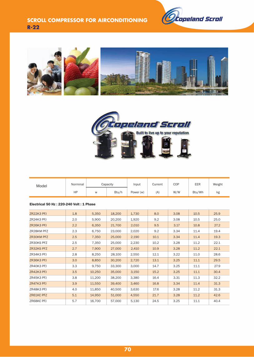
70
SCROLL COMPRESSOR FOR AIRCONDITIONINGR-22
Norminal Capacity Input Current COP EER Weight
HP w Btu/h Power (w) (A) W/W Btu/Wh kg
Electrical 50 Hz : 220-240 Volt : 1 Phase
ZR22K3 PFJ
ZR24K3 PFJ
ZR26K3 PFJ
ZR28KM PFZ
ZR30KM PFZ
ZR30KS PFZ
ZR32KS PFZ
ZR34K3 PFJ
ZR36K3 PFJ
ZR40K3 PFJ
ZR42K3 PFJ
ZR45K3 PFJ
ZR47K3 PFJ
ZR48K3 PFJ
ZR61KC PFZ
ZR68KC PFJ
1.8
2.0
2.2
2.3
2.5
2.5
2.7
2.8
3.0
3.3
3.5
3.8
3.9
4.0
5.1
5.7
5,350
5,900
6,350
6,750
7,350
7,350
7,900
8,250
8,850
9,750
10,250
11,200
11,550
11,850
14,950
16,700
18,200
20,200
21,700
23,000
25,000
25,000
27,000
28,100
30,200
33,300
35,000
38,200
39,400
40,500
51,000
57,000
1,730
1,920
2,010
2,020
2,190
2,230
2,410
2,550
2,720
3,000
3,150
3,380
3,460
3,630
4,550
5,130
8.0
9.2
9.5
9.2
10.1
10.2
10.9
12.1
13.1
14.7
15.2
16.4
16.8
17.6
21.7
24.5
3.08
3.08
3.17
3.34
3.34
3.28
3.28
3.22
3.25
3.25
3.25
3.31
3.34
3.28
3.28
3.25
10.5
10.5
10.8
11.4
11.4
11.2
11.2
11.0
11.1
11.1
11.1
11.3
11.4
11.2
11.2
11.1
25.9
25.0
27.2
19.4
19.3
22.1
22.1
28.6
29.5
27.9
30.4
32.2
31.3
31.3
42.6
40.4
Model
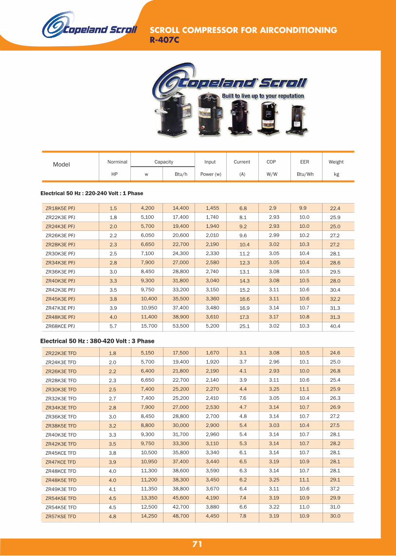
71
Electrical 50 Hz : 220-240 Volt : 1 Phase
ZR18K5E PFJ
ZR22K3E PFJ
ZR24K3E PFJ
ZR26K3E PFJ
ZR28K3E PFJ
ZR30K3E PFJ
ZR34K3E PFJ
ZR36K3E PFJ
ZR40K3E PFJ
ZR42K3E PFJ
ZR45K3E PFJ
ZR47K3E PFJ
ZR48K3E PFJ
ZR68KCE PFJ
1.5
1.8
2.0
2.2
2.3
2.5
2.8
3.0
3.3
3.5
3.8
3.9
4.0
5.7
4,200
5,100
5,700
6,050
6,650
7,100
7,900
8,450
9,300
9,750
10,400
10,950
11,400
15,700
14,400
17,400
19,400
20,600
22,700
24,300
27,000
28,800
31,800
33,200
35,500
37,400
38,900
53,500
1,455
1,740
1,940
2,010
2,190
2,330
2,580
2,740
3,040
3,150
3,360
3,480
3,610
5,200
6.8
8.1
9.2
9.6
10.4
11.2
12.3
13.1
14.3
15.2
16.6
16.9
17.3
25.1
2.9
2.93
2.93
2.99
3.02
3.05
3.05
3.08
3.08
3.11
3.11
3.14
3.17
3.02
9.9
10.0
10.0
10.2
10.3
10.4
10.4
10.5
10.5
10.6
10.6
10.7
10.8
10.3
22.4
25.9
25.0
27.2
27.2
28.1
28.6
29.5
28.0
30.4
32.2
31.3
31.3
40.4
Electrical 50 Hz : 380-420 Volt : 3 Phase
ZR22K3E TFD
ZR24K3E TFD
ZR26K3E TFD
ZR28K3E TFD
ZR30K3E TFD
ZR32K3E TFD
ZR34K3E TFD
ZR36K3E TFD
ZR38K5E TFD
ZR40K3E TFD
ZR42K3E TFD
ZR45KCE TFD
ZR47KCE TFD
ZR48KCE TFD
ZR48K5E TFD
ZR49K3E TFD
ZR54KSE TFD
ZR54K5E TFD
ZR57KSE TFD
1.8
2.0
2.2
2.3
2.5
2.7
2.8
3.0
3.2
3.3
3.5
3.8
3.9
4.0
4.0
4.1
4.5
4.5
4.8
5,150
5,700
6,400
6,650
7,400
7,400
7,900
8,450
8,800
9,300
9,750
10,500
10,950
11,300
11,200
11,350
13,350
12,500
14,250
17,500
19,400
21,800
22,700
25,200
25,200
27,000
28,800
30,000
31,700
33,300
35,800
37,400
38,600
38,300
38,800
45,600
42,700
48,700
1,670
1,920
2,190
2,140
2,270
2,410
2,530
2,700
2,900
2,960
3,110
3,340
3,440
3,590
3,450
3,670
4,190
3,880
4,450
3.1
3.7
4.1
3.9
4.4
7.6
4.7
4.8
5.4
5.4
5.3
6.1
6.5
6.3
6.2
6.4
7.4
6.6
7.8
3.08
2.96
2.93
3.11
3.25
3.05
3.14
3.14
3.03
3.14
3.14
3.14
3.19
3.14
3.25
3.11
3.19
3.22
3.19
10.5
10.1
10.0
10.6
11.1
10.4
10.7
10.7
10.4
10.7
10.7
10.7
10.9
10.7
11.1
10.6
10.9
11.0
10.9
24.6
25.0
26.8
25.4
25.9
26.3
26.9
27.2
27.5
28.1
28.2
28.1
28.1
28.1
29.1
37.2
29.9
31.0
30.0
SCROLL COMPRESSOR FOR AIRCONDITIONINGR-407C
Norminal Capacity Input Current COP EER Weight
HP w Btu/h Power (w) (A) W/W Btu/Wh kg
Model

72
ZR61KSE TFD
ZR61KHE TFM
ZR68KCE TFD
ZR72KCE TFD
ZR81KCE TFD
ZR84KCE TFD
ZR94KCE TFD
ZR108KCE TFD
ZR125KCE TFD
ZR144KCE TFD
ZR160KCE TFD
ZR190KCE TFD
ZR250KCE TWD
ZR310KCE TWD
ZR380KCE TWD
5.1
5.1
5.7
6.0
6.8
7.0
7.8
9.0
10.4
12.0
13.3
15.8
20.8
25.8
31.7
15,200
14,350
15,800
16,600
18,600
19,600
23,000
25,800
30,000
34,500
37,500
44,000
58,500
72,500
91,500
52,000
48,900
54,000
56,500
63,500
67,000
78,600
88,100
103,000
118,000
128,000
150,000
200,000
248,000
313,000
4,760
4,470
5,100
5,150
5,900
6,150
6,950
7,580
8,950
10,150
11,450
13,650
18,000
22,300
26,700
8.2
8.0
8.9
9.1
10.9
11.4
12.9
13.8
16.0
17.7
20.5
26.5
30.1
37.9
45.5
3.22
3.19
3.11
3.22
3.17
3.19
3.34
3.40
3.40
3.40
3.28
3.22
3.25
3.25
3.43
11.0
10.9
10.6
11.0
10.8
10.9
11.4
11.6
11.6
11.6
11.2
11.0
11.1
11.1
11.7
29.9
39.5
39.0
38.6
39.0
57.2
57.2
59.9
61.2
61.2
64.9
66.2
139.3
160.1
176.9
R-410A
ZP16KSE PFZ
ZP20KSE PFZ
ZP23K3E PFZ
ZP24KSE PFZ
ZP25KSE PFZ
ZP26K3E PFZ
ZP29KSE PFZ
ZP31KSE PFZ
ZP32K3E PFJ
ZP36KSE PFZ
ZP39KSE PFZ
ZP41K3E PFZ
ZP41K3E PFJ
ZP42KSE PFZ
Electrical 50 Hz : 220-240 Volt : 1 Phase
1.3
1.7
1.9
2.0
2.1
2.2
2.4
2.6
2.7
3.0
3.3
3.4
3.4
3.5
3,600
4,800
5,700
5,750
5,950
6,050
6,900
7,350
7,550
8,800
9,200
9,850
9,850
10,200
12,300
16,300
19,400
19,600
20,300
20,700
23,500
25,100
25,700
30,000
31,400
33,600
33,600
34,800
1,400
1,750
2,050
2,000
2,110
2,300
2,400
2,550
2,860
2,940
3,140
3,510
3,570
3,480
6.6
8.1
9.5
9.3
9.8
11.0
11.0
11.8
13.2
14.1
14.5
17.20
16.90
16.7
2.58
2.73
2.78
2.87
2.81
2.64
2.87
2.89
2.64
2.99
2.93
2.80
2.75
2.93
8.8
9.3
9.5
9.8
9.6
9.0
9.8
9.9
9.0
10.2
10.0
9.60
9.40
10.0
21.7
21.7
28.6
21.9
22.0
28.9
22.8
22.8
31.3
29.4
33.1
29.50
31.80
33.1
SCROLL COMPRESSOR FOR AIRCONDITIONING
Electrical 50 Hz : 380-420 Volt : 3 Phase
Norminal Capacity Input Current COP EER Weight
HP w Btu/h Power (w) (A) W/W Btu/Wh kg
Model
Norminal Capacity Input Current COP EER Weight
HP w Btu/h Power (w) (A) W/W Btu/Wh kg
Model
R-407C

73
ZP50K3E PFZZP51KSE PFZZP54KSE PFZZP57K3E PFJZP61KCE PFZZP67KCE PFZ
4.24.34.54.85.15.6
12,50012,15013,05013,95014,80016,100
42,60041,50044,50047,60050,50055,000
4,1004,0504,3204,7004,9505,450
19.519.820.924.023.325.7
3.053.003.022.962.992.96
10.410.310.310.110.210.1
44.034.434.441.740.339.9
Electrical 50 Hz : 380-420 Volt : 3 Phase
ZP24K5E TFD
ZP26K3E TFD
ZP29K5E TFD
ZP29KSE TFM
ZP31KSE TFM
ZP32K3E TFD
ZP34K5E TFD
ZP36K5E TFD
ZP36KSE TFM
ZP38K3E TFD
ZP39KSE TFM
ZP41K3E TFD
ZP42KSE TFM
ZP44K5E TFD
ZP49K5E TFD
ZP49KSE TFM
ZP50K3E TFD
ZP51K5E TFD
ZP51KSE TFM
ZP54K5E TFD
ZP54KSE TFM
ZP57K3E TFD
ZP61KCE TFD
ZP67KCE TFD
ZP72KCE TFD
ZP76KCE TFD
ZP83KCE TFD
ZP90KCE TFD
ZP103KCE TFD
ZP120KCE TFD
ZP137KCE TFD
2.0
2.2
2.4
2.4
2.6
2.7
2.8
3.0
3.0
3.2
3.3
3.4
3.5
3.7
4.1
4.1
4.2
4.3
4.3
4.5
4.5
4.8
5.1
5.6
6.0
6.3
6.9
7.5
8.6
10.0
11.4
5,700
6,200
6,800
7,000
7,350
7,400
8,200
8,600
8,900
9,050
9,250
9,800
10,050
10,700
11,950
11,950
12,400
12,050
12,150
12,900
12,900
13,900
14,650
16,100
17,100
18,400
19,900
21,800
25,200
29,300
32,500
19,400
21,100
23,200
23,900
25,000
25,200
28,000
29,300
30,400
30,800
31,600
33,500
34,300
36,500
40,700
40,700
42,300
41,200
41,500
44,000
44,100
47,500
50,000
55,000
58,500
62,700
68,000
74,500
86,000
100,000
111,000
2,020
2,270
2,420
2,380
2,580
2,680
2,830
2,940
2,920
3,120
3,150
3,380
3,310
3,540
3,870
3,870
4,100
4,000
4,040
4,280
4,210
4,610
4,750
5,200
5,700
5,850
6,400
6,950
7,800
9,110
10,200
3.6
4.1
4.4
4.3
4.6
4.7
5.2
5.4
5.4
5.5
5.3
6.0
5.6
6.1
6.5
6.5
7.3
6.9
7.0
7.0
7.1
8.1
8.3
9.1
9.8
11.0
11.7
12.3
14.4
16.6
18.3
2.81
2.73
2.81
2.93
2.84
2.75
2.90
2.93
3.05
2.90
2.93
2.90
3.03
3.02
3.09
3.09
3.02
3.02
3.02
3.02
3.08
3.02
3.11
3.11
3.02
3.14
3.11
3.14
3.22
3.22
3.19
9.6
9.3
9.6
10.0
9.7
9.4
9.9
10.0
10.4
9.9
10.0
9.9
10.4
10.3
10.6
10.6
10.3
10.3
10.3
10.3
10.5
10.3
10.6
10.6
10.3
10.7
10.6
10.7
11.0
11.0
10.9
21.3
27.2
21.8
22.3
22.3
28.1
28.9
29.2
29.4
29.9
30.9
29.5
30.9
30.9
33.0
33.0
39.5
32.4
33.0
32.4
33.0
41.7
40.3
39.9
39.9
39.5
39.5
57.6
61.2
61.2
62.1
R-410A
Electrical 50 Hz : 220-240 Volt : 1 Phase
SCROLL COMPRESSOR FOR AIRCONDITIONING
Norminal Capacity Input Current COP EER Weight
HP w Btu/h Power (w) (A) W/W Btu/Wh kg
Model

74
ZR22K3E PFJ
ZR28K3E PFJ
ZR34K3E PFJ
ZR40K3E PFJ
ZR47K3E PFJ
ZR48K3E PFJ
1.8
2.3
2.8
3.3
3.9
4.0
3,500
4,700
5,600
6,450
7,950
8,150
12,000
16,000
19,100
22,000
27,200
27,800
1,190
1,510
1,780
2,170
2,620
2,670
5.5
7.4
8.8
11.5
16.2
16.5
2.96
3.11
3.14
2.96
3.05
3.05
10.1
10.6
10.7
10.1
10.4
10.4
25.9
27.2
28.6
27.9
31.3
31.3
R-134A
Electrical 50 Hz : 380-420 Volt : 3 Phase
ZR22K3E TFD
ZR28K3E TFD
ZR34K3E TFD
ZR36K3E TFD
ZR40K3E TFD
ZR48KCE TFD
ZR61KCE TFD
ZR81KCE TFD
ZR84KCE TFD
ZR94KCE TFD
ZR108KCE TFD
ZR125KCE TFD
ZR144KCE TFD
ZR160KCE TFD
ZR190KCE TFD
ZR250KCE TWD
ZR310KCE TWD
ZR380KCE TWD
1.8
2.3
2.8
3.0
3.3
4.0
5.1
6.8
7.0
7.8
9.0
10.4
12.0
13.3
15.8
20.8
25.8
31.7
3,600
4,750
5,550
5,400
6,500
7,900
10,050
13,300
13,350
15,700
17,600
20,500
23,300
25,500
30,500
40,000
50,000
63,000
12,300
16,200
18,900
18,500
22,100
26,900
34,300
45,400
45,600
53,500
59,900
70,000
79,500
87,000
104,000
137,000
170,000
215,000
1,230
1,570
1,830
1,992
2,090
2,420
2,990
4,010
4,200
4,710
5,260
6,150
6,950
7,600
9,200
12,200
15,300
18,800
2.4
3.2
3.7
3.8
4.1
4.8
6.3
8.6
10.0
10.4
11.6
12.2
13.6
15.7
20.6
22.6
28.3
35.6
2.93
3.02
3.02
2.72
3.11
3.25
3.37
3.31
3.18
3.33
3.34
3.34
3.37
3.37
3.31
3.28
3.25
3.34
10.0
10.3
10.3
9.3
10.6
11.1
11.5
11.3
10.9
11.4
11.4
11.4
11.5
11.5
11.3
11.2
11.1
11.4
24.5
25.4
26.9
27.2
28.1
28.1
36.1
39.0
57.2
57.2
59.9
61.2
61.2
64.9
66.2
139.3
160.1
176.9
Electrical 50 Hz : 220-240 Volt : 1 Phase
SCROLL COMPRESSOR FOR AIRCONDITIONING
Norminal Capacity Input Current COP EER Weight
HP w Btu/h Power (w) (A) W/W Btu/Wh kg
Model

75
R22
Copeland Scroll™ Digital Compressors for R22, R407C and R410A refrigerant
Copeland Scroll™ Digital Compressors offer stepless capacity modulation in air conditioning
applications and a flexible solution for R22,R407C and R410A refrigerant.
In many cooling and heating systems, load and operating conditions vary over a wide range,
thus, requiring theuse of capacity modulation. The Digital Scroll™ is a simple compressor
solution able to assure stepless modulationdown to 10% of the nominal capacity allowing
for precise temperature and humidity control, superior comfortand energy saving.
This compressor range is the preferred choice for VRF, rooftop, chilled water and process
cooling applications.
Electrical 50 Hz : 220-240 Volt : 1 Phase
ZRD42KC PFJ
ZRD48KC PFZ
ZRD61KC PFZ
ZRD68KC PFZ
3.5
4.0
5.0
6.0
10,300
11,950
14,950
16,700
35,100
40,800
51,000
57,000
3,200
3,630
4,640
5,150
15.3
16.7
22.5
23.9
3.22
3.28
3.22
3.22
11.0
11.2
11.0
11.0
31.2
32.8
38.1
39.0
Electrical 50 Hz : 380-420 Volt : 3 Phase
ZRD42KC TFD
ZRD48KC TFD
ZRD49KC TFD
ZRD61KC TFD
ZRD68KC TFD
ZRD72KC TFD
ZRD81KC TFD
3.5
4.0
4.0
5.0
6.0
6.0
7.0
10,400
11,950
12,050
14,950
17,100
17,600
19,900
35,500
40,800
41,100
51,000
58,500
60,200
68,000
3,080
3,510
3,660
4,550
5,100
5,330
6,000
5.4
6.1
7.1
8.1
8.9
9.6
11.1
3.37
3.40
3.28
3.28
3.37
3.31
3.31
11.5
11.6
11.2
11.2
11.5
11.3
11.3
31.2
32.7
42.6
38.1
40.2
39.9
40.8
Electrical 50 Hz : 220-240 Volt : 1 Phase
ZRD42KCE PFJ
ZRD48KCE PFZ
ZRD61KCE PFZ
3.5
4.0
5.0
10,350
11,250
14,200
35,400
38,400
48,500
3,430
3,690
4,750
16.4
17.1
22.2
3.02
3.05
2.99
10.3
10.4
10.2
31.2
32.8
38.1
Electrical 50 Hz : 380-420 Volt : 3 Phase
ZRD36KCE TFD
ZRD42KCE TFD
ZRD48KCE TFD
ZRD49KCE TFD
ZRD61KCE TFD
ZRD68KCE TFD
ZRD72KCE TFD
ZRD81KCE TFD
3.0
3.5
4.0
4.0
5.0
6.0
6.0
7.0
8,450
10,000
12,050
11,200
14,150
15,700
16,900
20,100
28,800
34,100
41,200
38,300
48,300
53,500
57,500
68,500
2,610
3,130
3,780
3,700
4,610
5,200
5,350
6,450
4.6
5.6
6.6
6.9
8.1
9.2
9.3
12.0
3.24
3.19
3.19
3.05
3.08
3.02
3.14
3.11
11.1
10.9
10.9
10.4
10.5
10.3
10.7
10.6
27.3
31.2
32.7
42.6
38.1
40.2
39.9
40.8
R-407C
Norminal Capacity Input Current COP EER Weight
HP w Btu/h Power (w) (A) W/W Btu/Wh kg
Model
Norminal Capacity Input Current COP EER Weight
HP w Btu/h Power (w) (A) W/W Btu/Wh kg
Model
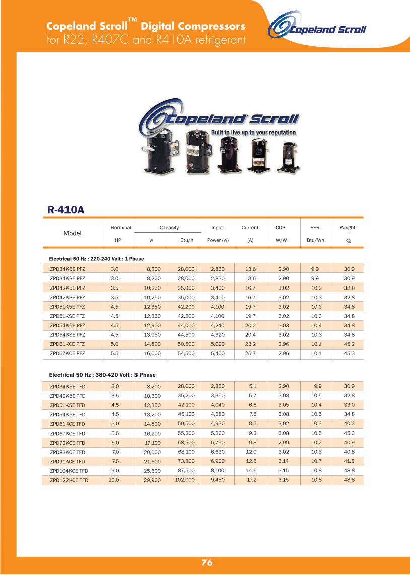
76
R-410A
Electrical 50 Hz : 220-240 Volt : 1 Phase
ZPD34K5E PFZ
ZPD34KSE PFZ
ZPD42K5E PFZ
ZPD42KSE PFZ
ZPD51K5E PFZ
ZPD51KSE PFZ
ZPD54K5E PFZ
ZPD54KSE PFZ
ZPD61KCE PFZ
ZPD67KCE PFZ
3.0
3.0
3.5
3.5
4.5
4.5
4.5
4.5
5.0
5.5
8,200
8,200
10,250
10,250
12,350
12,350
12,900
13,050
14,800
16,000
28,000
28,000
35,000
35,000
42,200
42,200
44,000
44,500
50,500
54,500
2,830
2,830
3,400
3,400
4,100
4,100
4,240
4,320
5,000
5,400
13.6
13.6
16.7
16.7
19.7
19.7
20.2
20.4
23.2
25.7
2.90
2.90
3.02
3.02
3.02
3.02
3.03
3.02
2.96
2.96
9.9
9.9
10.3
10.3
10.3
10.3
10.4
10.3
10.1
10.1
30.9
30.9
32.8
32.8
34.8
34.8
34.8
34.8
45.2
45.3
Electrical 50 Hz : 380-420 Volt : 3 Phase
ZPD34K5E TFD
ZPD42K5E TFD
ZPD51K5E TFD
ZPD54K5E TFD
ZPD61KCE TFD
ZPD67KCE TFD
ZPD72KCE TFD
ZPD83KCE TFD
ZPD91KCE TFD
ZPD104KCE TFD
ZPD122KCE TFD
3.0
3.5
4.5
4.5
5.0
5.5
6.0
7.0
7.5
9.0
10.0
8,200
10,300
12,350
13,200
14,800
16,200
17,100
20,000
21,600
25,600
29,900
28,000
35,200
42,100
45,100
50,500
55,200
58,500
68,100
73,800
87,500
102,000
2,830
3,350
4,040
4,280
4,930
5,260
5,750
6,630
6,900
8,100
9,450
5.1
5.7
6.8
7.5
8.5
9.3
9.8
12.0
12.5
14.6
17.2
2.90
3.08
3.05
3.08
3.02
3.08
2.99
3.02
3.14
3.15
3.15
9.9
10.5
10.4
10.5
10.3
10.5
10.2
10.3
10.7
10.8
10.8
30.9
32.8
33.0
34.8
40.3
45.3
40.9
40.8
41.5
48.8
48.8
Copeland Scroll™ Digital Compressors for R22, R407C and R410A refrigerant
Norminal Capacity Input Current COP EER Weight
HP w Btu/h Power (w) (A) W/W Btu/Wh kg
Model

77
Model
Nominal
tons 60 Hz
TR
Nominal cooling capacity
W Btu/h
Power
input
kw
E.E.R
Btu/h/W
Oil
charge
dm3
Net
weight
kw
R-22/R-407C Volts Phase Hz ; 380/415-3-50 SM084
SM090
SM100
SM110
SM112
SM120
SM124
SM147
SM148
SM161
SM175
SM185
SZ084
SZ090
SZ100
SZ110
SZ120
SZ148
SZ161
SZ175
SZ185
R-2
2
7
7.5
8
9
9.5
10
10.5
12
12
13
14
15
7
7.5
8
9
10
12
13
14
15
20400
21800
23100
25900
27600
30100
31200
36000
36100
39000
42000
45500
19300
20400
21600
24600
28600
35100
38000
40100
43100
69600
74400
78800
88400
94200
102700
106500
122900
123200
133100
143300
155300
65900
69600
73700
84000
97600
119800
129700
136900
147100
6.12
6.54
6.96
7.82
7.92
8.96
8.75
10.08
10.8
11.59
12.47
13.62
6.13
6.45
6.84
7.76
8.99
10.99
11.84
12.64
13.62
11.4
11.4
11.4
11.3
11.9
11.5
12.2
12.2
11.4
11.5
11.5
11.4
10.8
10.8
10.8
10.8
10.9
11.0
10.8
10.8
10.8
3.25
3.25
3.25
3.25
3.3
3.25
3.3
3.3
3.6
3.6
6.2
6.2
3.25
3.25
3.25
3.25
3.25
3.6
3.6
6.2
6.2
64
65
65
73
64
73
64.2
67
88
88
100
100
64
65
65
73
73
88
88
100
100
R-4
07C
Scroll Compressors
76,100 7.19 10.58 3.0 58.0
91,500 8.47 10.82 3.3 64.0
102,400 9.46 10.82 3.3 64.0
118,400 10.58 11.19 3.3 67.0
132,400 12.15 10.89 3.3 69.0
152,600 13.73 11.09 3.6 71.5
151,900 13.87 10.96 6.7 108.0
203,800 18.50 11.02 6.7 108.0
249,800 22.51 11.09 6.7 111.0
308,900 28.18 10.96 6.7 159.0
397,300 35.65 11.13 6.7 175.0
* SH295 replaces SH300 model remains available for after-market
R-410A Volts Phase Hz ; 380/415-3-50
7.5
9
10
12
13
15
15
20
25
30
40
22300
26800
30000
34700
38800
44700
44500
59700
73200
90500
116400
SH090
SH105
SH120
SH140
SH161
SH184
SH180
SH240
SH295*
SH380
SH485

78
HERMETIC COMPRESSOR
ModelRun Cap.MFD/VOLTS
Start Cap.MFD/VOLTS
Electrical Data Electrical Start ComponentsCapacity
BTU/HR FLA LRA
EER/COP
BTU/WH Relay
Pice
Baht
H23A383 ABK
H23A423 ABK
H23A463 ABK
R-22 Volts Phase Hz ; 220/240-1-50 32,400
35,000
39,200
10.1
10.2
10.4
15.5
16.7
18.8
82
90
101
35/440
40/440
40/440 145-175/330 3ARR3*4AA*
145-175/330
145-175/330
3ARR3*4AA*
3ARR3*27AA*
15,500.-
16,000.-
18,000.-
R-22 Volts Phase Hz ; 380/415-3-50
H23A383 DBE
H23A423 DBE
H23A463 DBE
H23A543 DBE
H23A563 DBE
H23A623 DBE
H29A683 DBV
H29A723 DBE
31,400
35,200
38,800
46,000
47,500
51,800
58,800
61,700
5.2
5.8
6.3
7.2
7.5
8.2
9.1
9.6
10.3
10.3
10.1
10.3
10.4
10.3
11.1
11.1
39
39
45
53
62
62
79
-
-
-
-
-
-
-
-
-
-
-
-
-
-
-
-
-
-
-
-
-
-
-
-
-
-
-
-
-
-
-
-
17,800.-
19,500.-
20,000.-
21,800.-
22,000.-
22,500.-
27,000.-
29,800.-
H92G094DBE
H92G104DBE
H92G134DBZ
H92G144DBE
H92G184DPE
H92G204DRE
H92G244DRE
H92G294DPE
R-22/R-407C @45/130. F Volts Phase Hz ; 380/415-3-50
69,900
81,700
103 900
112,500
144,800
166,300
195,200
222,400
10.8
10.5
10.3
10.5
10.9
10.7
10.5
9.6
12
14.2
17.5
21.6
26
30
36.5
44
72
77
93
126
125
150
190
215
-
-
-
-
-
-
-
-
-
-
-
-
-
-
-
-
60,000.-
63,000.-
64,500.-
68,000.-
125,000.-
130,000.-
150,000.-
160,000.-
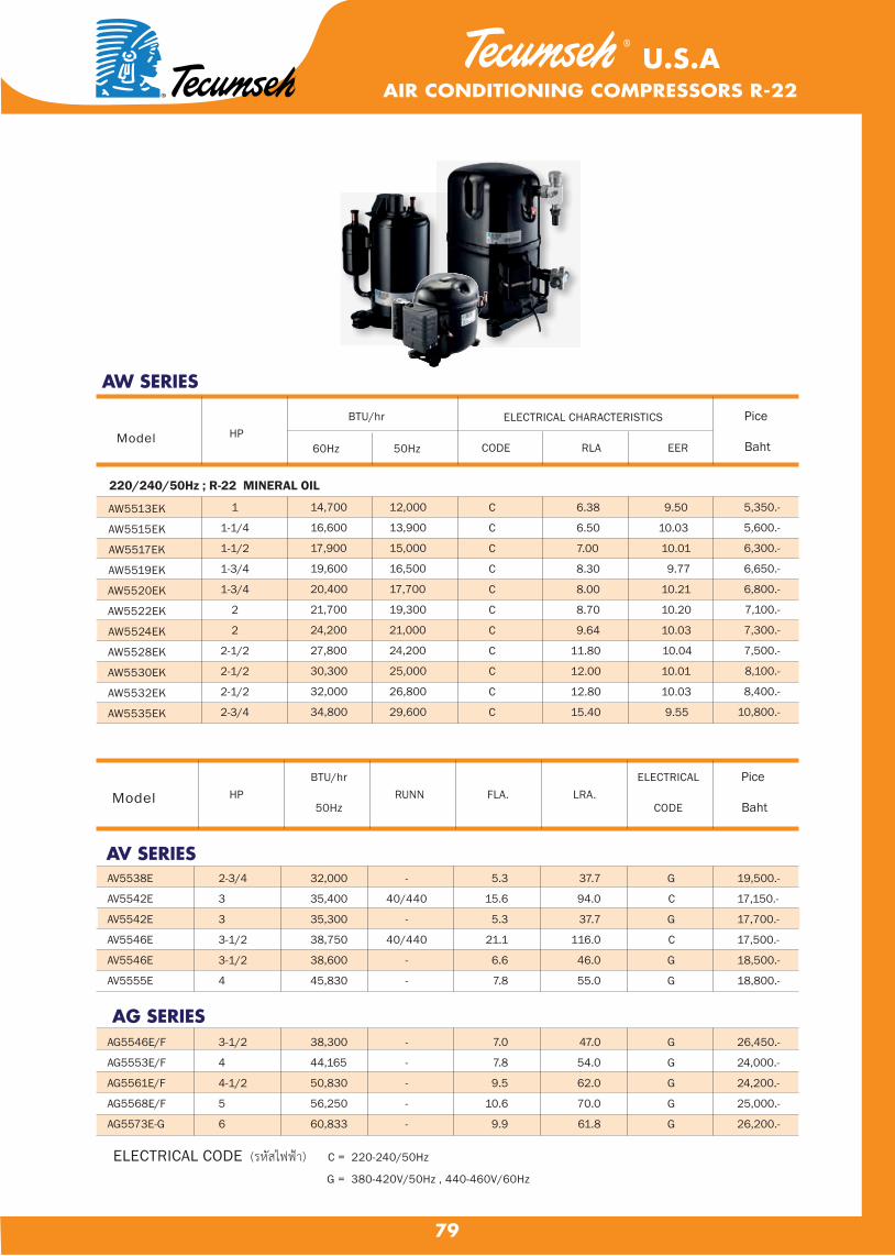
79
Model
ELECTRICAL CHARACTERISTICS
CODE RLA EER
BTU/hr
60Hz 50HzHP
AW SERIES
Pice
Baht
AW5513EK
AW5515EK
AW5517EK
AW5519EK
AW5520EK
AW5522EK
AW5524EK
AW5528EK
AW5530EK
AW5532EK
AW5535EK
1
1-1/4
1-1/2
1-3/4
1-3/4
2
2
2-1/2
2-1/2
2-1/2
2-3/4
14,700 12,000
16,600 13,900
17,900 15,000
19,600 16,500
20,400 17,700
21,700 19,300
24,200 21,000
27,800 24,200
30,300 25,000
32,000 26,800
34,800 29,600
C 6.38 9.50
C 6.50 10.03
C 7.00 10.01
C 8.30 9.77
C 8.00 10.21
C 8.70 10.20
C 9.64 10.03
C 11.80 10.04
C 12.00 10.01
C 12.80 10.03
C 15.40 9.55
5,350.-
5,600.-
6,300.-
6,650.-
6,800.-
7,100.-
7,300.-
7,500.-
8,100.-
8,400.-
10,800.-
AV5538E
AV5542E
AV5542E
AV5546E
AV5546E
AV5555E
AG5546E/F
AG5553E/F
AG5561E/F
AG5568E/F
AG5573E-G
2-3/4
3
3
3-1/2
3-1/2
4
3-1/2
4
4-1/2
5
6
32,000
35,400
35,300
38,750
38,600
45,830
38,300
44,165
50,830
56,250
60,833
ELECTRICAL CODE (รหสไฟฟา) C = 220-240/50Hz
G = 380-420V/50Hz , 440-460V/60Hz
-
40/440
-
40/440
-
-
-
-
-
-
-
ModelBTU/hr
50HzHP RUNN FLA. LRA.
ELECTRICAL
CODE
5.3
15.6
5.3
21.1
6.6
7.8
7.0
7.8
9.5
10.6
9.9
37.7
94.0
37.7
116.0
46.0
55.0
47.0
54.0
62.0
70.0
61.8
G
C
G
C
G
G
G
G
G
G
G
19,500.-
17,150.-
17,700.-
17,500.-
18,500.-
18,800.-
26,450.-
24,000.-
24,200.-
25,000.-
26,200.-
220/240/50Hz ; R-22 MINERAL OIL
AV SERIES
AG SERIES
AIR CONDITIONING COMPRESSORS R-22U.S.A
Pice
Baht

80
EVAPORATOR FAN MOTORS ®
TOTALINE® EVAPORATOR FAN MOTORS
• Ball Bearing Design• Double Shaft• 3 Speed• Sigle Phase• 4 Poles & 6 Poles• Class B Insulation• High Efficiency• Shaft Dia. 12.695 mm
S2 - 1/4 - C
S2 - 1/6 - A
S2 - 1/8 - B
S2 - 1/10 - B
S2 - 1/15 - B
S2 - 1/20 - B
HP Current (A) Out Put (w) MfD/V POLE RPMModel
1/4
1/6
1/8
1/10
1/15
1/20
1.60
1.25
0.65
0.90
0.76
0.86
173
165
67
74
60
34
5/400
5/400
3/400
2.5/400
2.5/400
2.5/400
6
6
4
4
4
4
900/820/660
900/770/550
1210/1040/850
1250/1080/890
1290/1160/980
1350/1250/1070
Dia A (mm) Dia B (mm) Dia C1 (mm) Dia C2 (mm) Dia D1 (mm) Dia D2 (mm)
S2 - 1/4 - C
S2 - 1/6 - A
S2 - 1/8 - B
S2 - 1/10 - B
S2 - 1/15 - B
S2 - 1/20 - B
530.00
530.00
500.00
500.00
500.00
500.00
132.00
132.00
116.00
116.00
116.00
116.00
212.00
212.00
203.00
203.00
203.00
203.00
212.00
212.00
203.00
203.00
203.00
203.00
75.00
75.00
75.00
75.00
75.00
75.00
75.00
75.00
75.00
75.00
75.00
75.00
Model
D2D1
C1 C2B
HG
A

81
CONDENSER FAN MOTORS
®
Ball Bearig Design• Sigle Shaft• Single Phase• Condensing motor • 6 Poles• Automatic reset Thermal Protection• Nema 48 Flame• Class B Insulation• High Efficiency• Shaft Dia 12.695 mm
TOTALINE® CONDENSER FAN MOTORS
B1 - 1/2 - A
B1 - 1/3 - A
B1 - 1/4 - A
B1 - 1/6 - B
B1 - 1/8 - K
B1 - 1/10 - E
B1 - 3/4 - A
381
236
75
160
60
65
454
7.5/460
5/400
3/400
5/400
5/400
3/400
12/400
6
6
6
6
6
6
6
880
850
900
900
930
860
925
B1 - 1/2 - A
B1 - 1/3 - A
B1 - 1/4 - A
B1 - 1/6 - B
B1 - 1/8 - K
B1 - 1/10 - E
B1 - 3/4 - A
285.50
245.50
189.00
226.00
165.00
165.00
292.00
158.00
118.00
86.00
98.00
90.00
90.00
173.00
102.00
102.00
77.50
102.50
75.00
75.00
101.50
65.0065.0058.0065.0045.0050.0065.00
185.00
165.00
124.50
151.50
120.00.
120.00
188.00
Dia A (mm) Dia B (mm) Dia C (mm) Dia D (mm) Dia E (mm)Model
1/2
1/3
1/4
1/6
1/8
1/10
3/4
3.18
2.20
0.86
1.20
0.94
0.77
4.50
E
D
BC
A
HP Current (A) Out Put (w) MfD/V POLE RPMModel
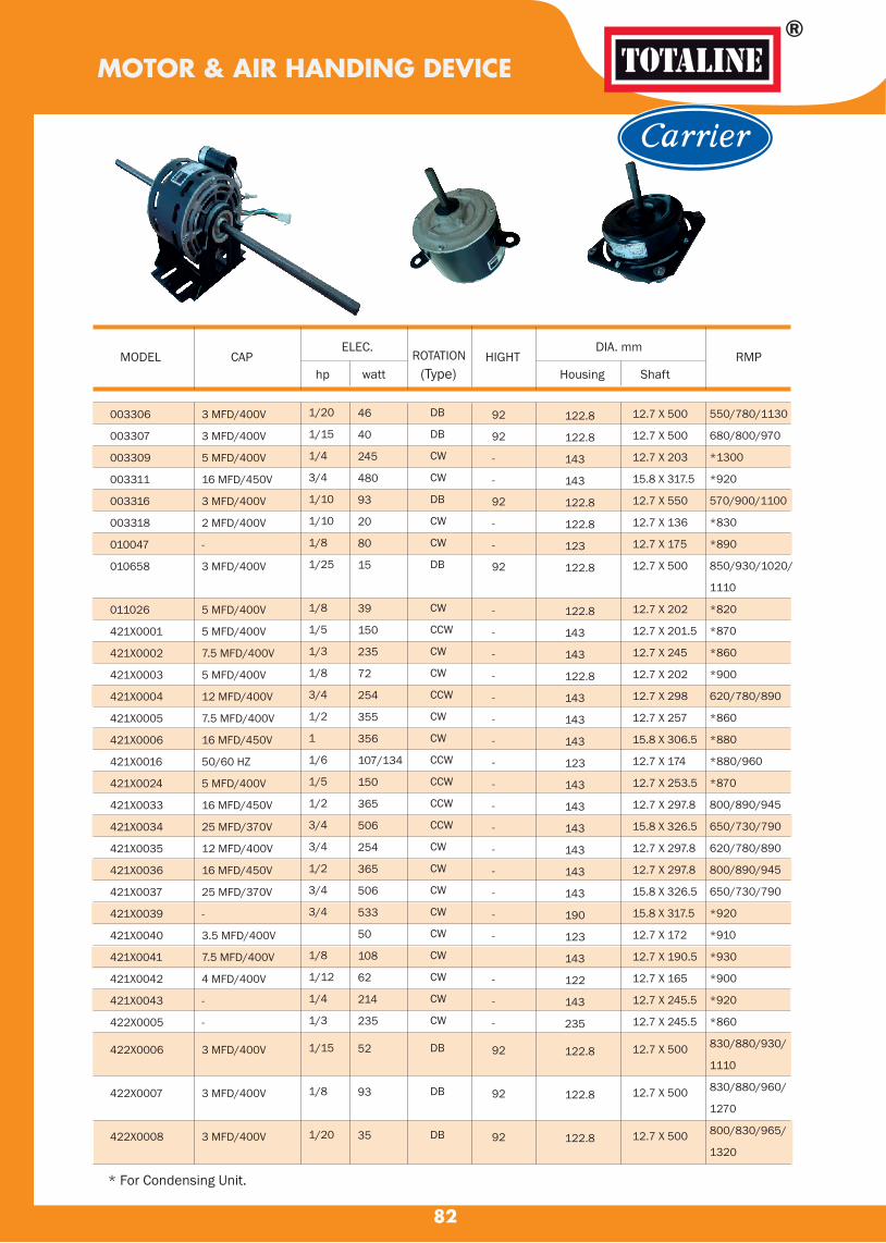
MOTOR & AIR HANDING DEVICE
82
®
MODEL
CAP ELEC.
ROTATION
HIGHT DIA. mm
RMP hp watt Housing Shaft
003306
003307
003309
003311
003316
003318
010047
010658
011026
421X0001
421X0002
421X0003
421X0004
421X0005
421X0006
421X0016
421X0024
421X0033
421X0034
421X0035
421X0036
421X0037
421X0039
421X0040
421X0041
421X0042
421X0043
422X0005
422X0006
422X0007
422X0008
3 MFD/400V
3 MFD/400V
5 MFD/400V
16 MFD/450V
3 MFD/400V
2 MFD/400V
-
3 MFD/400V
5 MFD/400V
5 MFD/400V
7.5 MFD/400V
5 MFD/400V
12 MFD/400V
7.5 MFD/400V
16 MFD/450V
50/60 HZ
5 MFD/400V
16 MFD/450V
25 MFD/370V
12 MFD/400V
16 MFD/450V
25 MFD/370V
-
3.5 MFD/400V
7.5 MFD/400V
4 MFD/400V
-
-
3 MFD/400V
3 MFD/400V
3 MFD/400V
1/20
1/15
1/4
3/4
1/10
1/10
1/8
1/25
1/8
1/5
1/3
1/8
3/4
1/2
1
1/6
1/5
1/2
3/4
3/4
1/2
3/4
3/4
1/8
1/12
1/4
1/3
1/15
1/8
1/20
46
40
245
480
93
20
80
15
39
150
235
72
254
355
356
107/134
150
365
506
254
365
506
533
50
108
62
214
235
52
93
35
DB
DB
CW
CW
DB
CW
CW
DB
CW
CCW
CW
CW
CCW
CW
CW
CCW
CCW
CCW
CCW
CW
CW
CW
CW
CW
CW
CW
CW
CW
DB
DB
DB
92
92
-
-
92
-
-
92
-
-
-
-
-
-
-
-
-
-
-
-
-
-
-
-
-
-
-
92
92
92
122.8
122.8
143
143
122.8
122.8
123
122.8
122.8
143
143
122.8
143
143
143
123
143
143
143
143
143
143
190
123
143
122
143
235
122.8
122.8
122.8
12.7 X 500
12.7 X 500
12.7 X 203
15.8 X 317.5
12.7 X 550
12.7 X 136
12.7 X 175
12.7 X 500
12.7 X 202
12.7 X 201.5
12.7 X 245
12.7 X 202
12.7 X 298
12.7 X 257
15.8 X 306.5
12.7 X 174
12.7 X 253.5
12.7 X 297.8
15.8 X 326.5
12.7 X 297.8
12.7 X 297.8
15.8 X 326.5
15.8 X 317.5
12.7 X 172
12.7 X 190.5
12.7 X 165
12.7 X 245.5
12.7 X 245.5
12.7 X 500
12.7 X 500
12.7 X 500
550/780/1130
680/800/970
*1300
*920
570/900/1100
*830
*890
850/930/1020/
1110
*820
*870
*860
*900
620/780/890
*860
*880
*880/960
*870
800/890/945
650/730/790
620/780/890
800/890/945
650/730/790
*920
*910
*930
*900
*920
*860
830/880/930/
1110
830/880/960/
1270
800/830/965/
1320
* For Condensing Unit.
(Type)
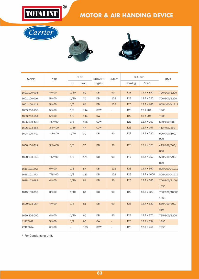
MOTOR & AIR HANDING DEVICE
83
®
MODEL
CAP ELEC.
ROTATION
HIGHT DIA. mm
RMP hp watt Housing Shaft
* For Condensing Unit.
1601-100-008
1601-100-010
1601-100-112
1603-200-253
1603-200-254
1605-100-433
1606-103-864
1608-100-741
1608-100-743
1608-103-655
1616-101-372
1616-101-373
1618-103-682
1618-103-685
1620-003-964
1620-306-000
421X0017
421X0024
4/400
5/400
5/400
5/400
5/400
7.5/400
3.5/400
1.8/400
3.5/400
7.5/400
5/400
7.5/400
4/400
3/400
4/400
4/400
5/400
6/400
1/10
1/10
1/8
1/8
1/8
1/6
1/15
1/20
1/6
1/3
1/8
1/8
1/10
1/10
1/3
1/10
1/4
-
60
70
87
114
114
106
47
30
75
175
87
117
82
67
81
60
95
133
DB
DB
DB
CCW
CW
CCW
CCW
DB
DB
DB
DB
DB
DB
DB
DB
DB
CW
CCW
90
102
102
-
-
-
-
90
90
90
102
102
90
90
90
90
-
-
123
123
123
123
123
123
123
123
123
143
123
123
123
123
123
123
123
123
12.7 X 880
12.7 X 520
12.7 X 480
12 X 204
12 X 204
12.7 X 269
12.7 X 157
12.7 X 520
12.7 X 620
12.7 X 650
12.7 X 660
12.7 X 1000
12.7 X 880
12.7 x 520
12.7 X 620
12.7 X 370
12.7 X 194
12.7 X 254
700/900/1200
700/900/1200
805/1000/1212
*900
*900
500/600/680
410/465/550
600/700/800/
900
495/638/800/
880
550/700/790/
880
805/1000/1212
805/1000/1212
700/800/1100/
1350
780/920/1080/
1360
560/700/800/
880
735/900/1200
*895
*850
(Type)
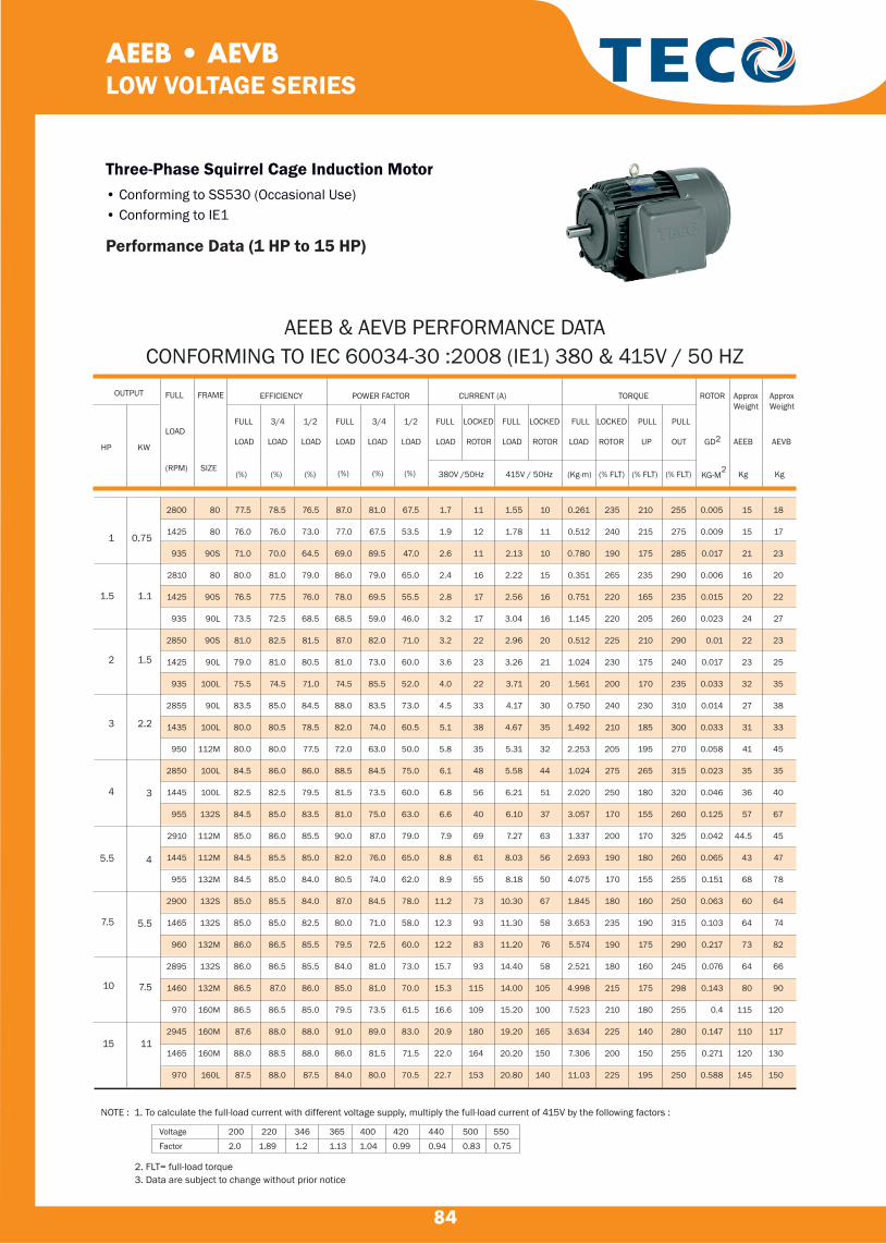
84
AEEB • AEVBLOW VOLTAGE SERIES
Three-Phase Squirrel Cage Induction Motor• Conforming to SS530 (Occasional Use)• Conforming to IE1
Performance Data (1 HP to 15 HP)
ApproxWeight
OUTPUT
LOAD
(RPM)
FRAME
SIZE
GD2
KG-M2
AEEB
Kg
AEVB
Kg
FULL
LOAD
(%)
3/4
LOAD
(%)
1/2
LOAD
(%)
FULL
LOAD
(%)
3/4
LOAD
(%)
1/2
LOAD
(%)
FULL
LOAD
LOCKED
ROTOR
FULL
LOAD
LOCKED
ROTOR
FULL
LOAD
LOCKED
ROTOR
(% FLT)
PULL
UP
(% FLT)
PULL
OUT
(% FLT)380V /50Hz 415V / 50Hz
HP KW
FULL
ROTOR
(Kg-m)
EFFICIENCY POWER FACTOR CURRENT (A) TORQUE
NOTE : 1. To calculate the full-load current with different voltage supply, multiply the full-load current of 415V by the following factors :
Voltage 200 220 346 365 400 420 440 500 550
Factor 2.0 1.89 1.2 1.13 1.04 0.99 0.94 0.83 0.75
2. FLT= full-load torque3. Data are subject to change without prior notice
AEEB & AEVB PERFORMANCE DATACONFORMING TO IEC 60034-30 :2008 (IE1) 380 & 415V / 50 HZ
ApproxWeight
1
1.5
2
3
4
5.5
7.5
10
15
0.75
1.1
1.5
2.2
3
4
5.5
7.5
11
77.5
76.0
71.0
80.0
76.5
73.5
81.0
79.0
75.5
83.5
80.0
80.0
84.5
82.5
84.5
85.0
84.5
84.5
85.0
85.0
86.0
86.0
86.5
86.5
87.6
88.0
87.5
78.5
76.0
70.0
81.0
77.5
72.5
82.5
81.0
74.5
85.0
80.5
80.0
86.0
82.5
85.0
86.0
85.5
85.0
85.5
85.0
86.5
86.5
87.0
86.5
88.0
88.5
88.0
76.5
73.0
64.5
79.0
76.0
68.5
81.5
80.5
71.0
84.5
78.5
77.5
86.0
79.5
83.5
85.5
85.0
84.0
84.0
82.5
85.5
85.5
86.0
85.0
88.0
88.0
87.5
87.0
77.0
69.0
86.0
78.0
68.5
87.0
81.0
74.5
88.0
82.0
72.0
88.5
81.5
81.0
90.0
82.0
80.5
87.0
80.0
79.5
84.0
85.0
79.5
91.0
86.0
84.0
81.0
67.5
89.5
79.0
69.5
59.0
82.0
73.0
85.5
83.5
74.0
63.0
84.5
73.5
75.0
87.0
76.0
74.0
84.5
71.0
72.5
81.0
81.0
73.5
89.0
81.5
80.0
67.5
53.5
47.0
65.0
55.5
46.0
71.0
60.0
52.0
73.0
60.5
50.0
75.0
60.0
63.0
79.0
65.0
62.0
78.0
58.0
60.0
73.0
70.0
61.5
83.0
71.5
70.5
1.7
1.9
2.6
2.4
2.8
3.2
3.2
3.6
4.0
4.5
5.1
5.8
6.1
6.8
6.6
7.9
8.8
8.9
11.2
12.3
12.2
15.7
15.3
16.6
20.9
22.0
22.7
11
12
11
16
17
17
22
23
22
33
38
35
48
56
40
69
61
55
73
93
83
93
115
109
180
164
153
1.55
1.78
2.13
2.22
2.56
3.04
2.96
3.26
3.71
4.17
4.67
5.31
5.58
6.21
6.10
7.27
8.03
8.18
10.30
11.30
11.20
14.40
14.00
15.20
19.20
20.20
20.80
10
11
10
15
16
16
20
21
20
30
35
32
44
51
37
63
56
50
67
58
76
58
105
100
165
150
140
0.261
0.512
0.780
0.351
0.751
1.145
0.512
1.024
1.561
0.750
1.492
2.253
1.024
2.020
3.057
1.337
2.693
4.075
1.845
3.653
5.574
2.521
4.998
7.523
3.634
7.306
11.03
235
240
190
265
220
220
225
230
200
240
210
205
275
250
170
200
190
170
180
235
190
180
215
210
225
200
225
210
215
175
235
165
205
210
175
170
230
185
195
265
180
155
170
180
155
160
190
175
160
175
180
140
150
195
255
275
285
290
235
260
290
240
235
310
300
270
315
320
260
325
260
255
250
315
290
245
298
255
280
255
250
0.005
0.009
0.017
0.006
0.015
0.023
0.01
0.017
0.033
0.014
0.033
0.058
0.023
0.046
0.125
0.042
0.065
0.151
0.063
0.103
0.217
0.076
0.143
0.4
0.147
0.271
0.588
15
15
21
16
20
24
22
23
32
27
31
41
35
36
57
44.5
43
68
60
64
73
64
80
115
110
120
145
18
17
23
20
22
27
23
25
35
38
33
45
35
40
67
45
47
78
64
74
82
66
90
120
117
130
150
2800
1425
935
2810
1425
935
2850
1425
935
2855
1435
950
2850
1445
955
2910
1445
955
2900
1465
960
2895
1460
970
2945
1465
970
80
80
90S
80
90S
90L
90S
90L
100L
90L
100L
112M
100L
100L
132S
112M
112M
132M
132S
132S
132M
132S
132M
160M
160M
160M
160L
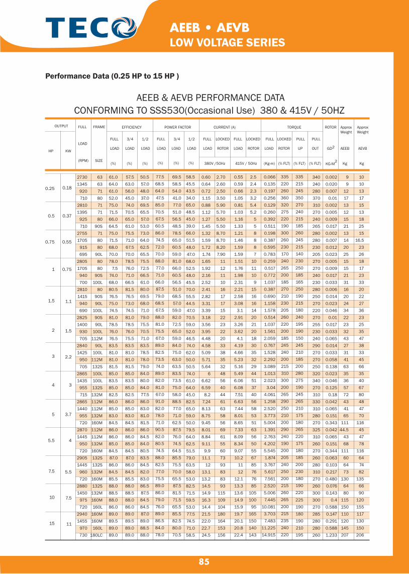
85
AEEB • AEVBLOW VOLTAGE SERIES
Performance Data (0.25 HP to 15 HP )
AEEB & AEVB PERFORMANCE DATACONFORMING TO SSS530(Occasional Use) 380 & 415V / 50HZ
ApproxWeight
OUTPUT
LOAD
(RPM)
FRAME
SIZE
GD2
KG-M2
AEEB
Kg
AEVB
Kg
FULL
LOAD
(%)
3/4
LOAD
(%)
1/2
LOAD
(%)
FULL
LOAD
(%)
3/4
LOAD
(%)
1/2
LOAD
(%)
FULL
LOAD
LOCKED
ROTOR
FULL
LOAD
LOCKED
ROTOR
FULL
LOAD
LOCKED
ROTOR
(% FLT)
PULL
UP
(% FLT)
PULL
OUT
(% FLT)380V /50Hz 415V / 50Hz
HP KW
FULL
ROTOR
(Kg-m)
EFFICIENCY POWER FACTOR CURRENT (A) TORQUE ApproxWeight
27301345
920710
28101395
925710
27551705
915695
28051705
940700
28101415940690
28251400
930705
28401425
950705
28651435
955715
28651440
955720
28701445
950720
29051445
960720
28801450
975720
29401455
970730
0.25
0.5
0.75
1
1.5
2
3
4
5
5.5
7.5
10
15
0.18
0.37
0.55
0.75
1.1
1.5
2.2
3
3.7
4
5.5
7.5
11
63637180717180
90S718080
90L8080
90S100L
8090S90L
100L90S90L
100L112M
90L100L
112M132S100L100L132S132M112M112M132M160M112M112M132M160M132S132S132M160M132S132M160M160L
160M160M160L
180LC
61.064.061.052.075.071.566.064.575.071.568.070.078.0
7.574.068.080.576.575.074.581.078.576.076.583.581.081.081.585.083.585.082.586.085.083.084.586.086.085.084.587.086.084.585.588.088.588.086.089.089.589.089.0
57.563.056.045.074.070.565.061.075.571.067.570.078.576.071.066.581.576.573.074.581.078.576.075.583.581.081.081.585.083.585.082.586.085.083.084.586.086.085.084.587.086.084.585.588.088.588.086.089.089.589.089.0
50.557.048.037.069.565.557.053.073.064.062.565.575.572.566.561.080.069.568.071.079.075.570.571.083.578.578.079.084.080.084.077.586.083.081.081.586.084.584.080.583.584.582.083.086.587.584.584.587.089.088.588.0
77.568.564.047.585.070.567.560.586.074.572.070.088.077.071.066.087.579.068.567.588.081.075.567.089.082.573.574.089.082.081.067.091.082.078.071.090.582.080.574.588.082.577.075.589.086.079.076.089.086.584.078.0
69.558.554.041.077.051.056.548.578.565.060.559.081.066.060.556.551.068.557.059.082.072.565.059.084.075.063.063.583.573.575.058.088.577.071.062.587.576.074.564.585.575.570.065.587.581.571.565.585.582.580.070.5
58.545.543.534.065.048.545.039.066.051.5
48.047.068.052.548.045.570.055.544.547.070.559.052.046.574.062.050.050.574.061.064.045.082.565.059.050.079.564.062.551.579.063.558.053.082.571.559.553.077.574.571.058.5
0.600.640.721.150.881.121.271.451.321.591.721.741.651.922.162.522.412.823.313.393.183.563.954.484.585.095.715.64
66.626.59
8.27.248.138.759.458.018.849.11
9.911.1
1213.113.214.514.916.314.421.522.022.724.5
2.702.602.503.505.905.705.505.508.708.708.207.90
111211101617171522232220333835324856404461635856696155607393838393
115109104180164153156
0.550.590.661.050.811.031.161.331.211.461.591.591.511.761.982.312.212.583.08
3.12.913.263.62
4.14.194.665.235.165.496.066.087.516.637.448.018.657.338.098.349.0710.2
1112
12.113.313.614.915.919.720.120.822.4
2.52.42.33.25.45.2
558887
101110
91516161420212018303532294451374056585351635650556785767685
105100
95165150140143
0.0660.1350.1970.2560.1290.2600.3920.5110.1980.3870.5950.7830.2590.5170.7721.0370.3870.6901.1581.5780.5141.0371.5612.0590.7671.5282.2923.0891.0132.023
3.044.0611.2582.5203.7735.0041.3912.7634.2025.5451.8743.7675.6177.5612.5205.0067.445
10.0813.7037.483
11.22514.915
335220260360320275220190300260230170240265200185270210230205260220200185245240200215310300200265290250210200290240190200205240250200215260265200215235240220
335215245350270240215185260245215140230250185165250190215180240195190150245210185200280275190245265210175180265220175180185200230180190220
225190180190210195
340240280370310270240265280280230205270270240230280250270220270255230240290270270250320340270310330310280270325310260270260280310270260300300270285280280260
0.0020.0200.007
0.010.0020.0050.0090.0170.0020.0070.0120.0230.0050.0090.0170.0330.0060.0140.0230.046
0.010.0170.0330.0650.0140.0330.0580.1380.0230.0460.125
0.180.0420.0650.1510.3430.0420.0650.1510.3440.0630.1030.2170.4800.0760.143
0.40.5880.1470.2910.5881.233
99
121713121521131420251515213116202434222332432731416335365772434165
11144.5
4368
111606473
1306480
115150110120145207
101013171513182515
16.523261817233320222736232535473833456635406780484770
116454778
116647482
1356690
120155117130150206

86
Totaline® 1 ,2 and 3 Pole Contactors
Design Construction :• 50 / 60 HzCoil Insulation : • Standard class B insulationMounting :• Panel mount and straight thru wiringApplications :• Designed for use in residential and commercial refrigeration ,air conditioning and heating applications.Standards :• UL• CSA• Rohs• Intertek• TUV• CE
Model No. POLE FLA COIL RATING 1 POLE 2 POLE 3 POLE
Norminal Coil Voltage
Norminal Coil Resistance Ohms
Maximum Pickup Voltage
Maximum Drop out Voltage
Norminal Inrush VA @ 50 Hz
Norminal Sealed VA @ 50 Hz
Maximum Coil Voltage
208 / 240
1800
177
40-140
31
6
264
208 / 240
1000
177
40-140
33
8
264
208 / 240
720
177
40-140
65
7.5
264
CONTACTORS / RELAY
®
RELAY
P282-0113
P282-0213
P282-0313
P282-0123
P282-0223
P282-0323
P282-0233
P282-0333
P282-0433A
P282-0733
1
1
1
2
2
2
3
3
3
3
20
25
30
20
25
30
25
30
40
75

Film Capacitors / AC Capacitors / Running CapacitorsMotor Run Capacitors
Features :● Low dissipation factor ● Small inherent temperature rise ● Excellent self-healing stability ● Safety and high voltage withstand● With inner anti-explosion device
Applications :Run starting in household electric appliances like air conditioner & Refrigerators with 50/60Hz AC power supply
Testing voltageT-TRate voltage
- 0.022408964 370 /440 /450 VAC 2000 V . AC / 5s
87
CAPACITOR
Capacitance range :
Dimension (mm) :
Reference standard :
Certification :
Safety Class to UL :
Component Body :
Filling Compound :
Life Expanctancy :
Safety grade :
2MFD-100MFD & 15+5MFD-80+7.5MFD
D: Φ40-Φ60, H:60-150
UL810, IEC252, EN60252, GB3667
UL 10,000AFC, VDE, TUV, CE, CQC
810 with UL recongnition
Plastic
Oil filled
Class B
P2
Climaticcategory
Testing voltageT-C
Capacitancetolerance
Dissipationfactor
1.75Un/5S(2Un/5S)
±5%(±10%)
≤0.002(100Hz)

Drawing 1 Drawing 2
d D H HT Drawing No.
1 2 370 - 440 50 Aluminium 40 .00 56 .70 60 .00 16 .00 1
2 2 .5 370 - 440 50 Aluminium 40 .00 56 .70 60 .00 16 .00 1
3 3 370 - 440 50 Aluminium 40 .00 56 .70 60 .00 16 .00 1
4 4 370 - 440 50 Aluminium 40 .00 56 .70 60 .00 16 .00 1
5 5 370 - 440 50 Aluminium 40 .00 56 .70 60 .00 16 .00 1
6 6 370 - 440 50 Aluminium 40 .00 66 .70 70 .00 16 .00 1
7 7.5 370 - 440 50 Aluminium 40 .00 66 .70 70 .00 16 .00 1
8 10 370 - 440 50 Aluminium 40 .00 66 .70 70 .00 16 .00 1
9 12 370 - 440 50 Aluminium 40 .00 66 .70 70 .00 16 .00 1
10 15 370 - 440 50 Aluminium 40 .00 76 .70 80 .00 16 .00 1
11 16 370 - 440 50 Aluminium 40 .00 76 .70 80 .00 16 .00 1
12 20 370 - 440 50 Aluminium 40 .00 76 .70 80 .00 16 .00 1
13 25 370 - 440 50 Aluminium 45 .00 86 .00 90 .00 18 .00 1
14 30 370 - 440 50 Aluminium 50 .00 101 .70 105 .00 20 .00 1
15 35 370 - 440 50 Aluminium 50 .00 101 .70 105 .00 20 .00 1
16 36 370 - 440 50 Aluminium 50 .00 101 .70 105 .00 20 .00 1
17 40 370 - 440 50 Aluminium 50 .00 101 .70 105 .00 20 .00 1
18 45 370 - 440 50 Aluminium 50 .00 101 .70 105 .00 20 .00 1
19 50 370 - 440 50 Aluminium 50 .00 116 .70 120 .00 20 .00 1
20 60 370 - 440
370 - 440
370 - 440
370 - 440
370 - 440
370 - 440
370 - 440
370 - 440
370 - 440
370 - 440
50 Aluminium 50 .00 116 .70 120 .00 20 .00 1
21 36+2 50 Aluminium 50.00 101.70 105.00 20.00 2
22 36+4 50 Aluminium 50.00 101.70 105.00 20.00 2
23 36+6 50 Aluminium 50.00 101.70 105.00 20.00 2
24 45+2 50 Aluminium 55.00 101.70 105.00 20.00 2
25 45+4 50 Aluminium 55.00 101.70 105.00 20.00 2
26 45+6 50 Aluminium 55.00 101.70 105.00 20.00 2
27 50+2 50 Aluminium 55.00 101.70 105.00 20.00 2
28 50+4 50 Aluminium 55.00 101.70 105.00 20.00 229 50+6 50 Aluminium 55.00 101.70 105.00 20.00 2
RUNNING CAPACITOR
Sr. No Mfd VoltPacking
sizeBody mm
88
CAPACITOR
HT ±1
Φ15 X 2 Nos1 mm Thk
D ±
1
H ±
1
Φd ±0.5
HT ±1
Φ15 X 2 Nos1 mm Thk
D ±
1
H ±
1
Φd ±0.5
HT ±1
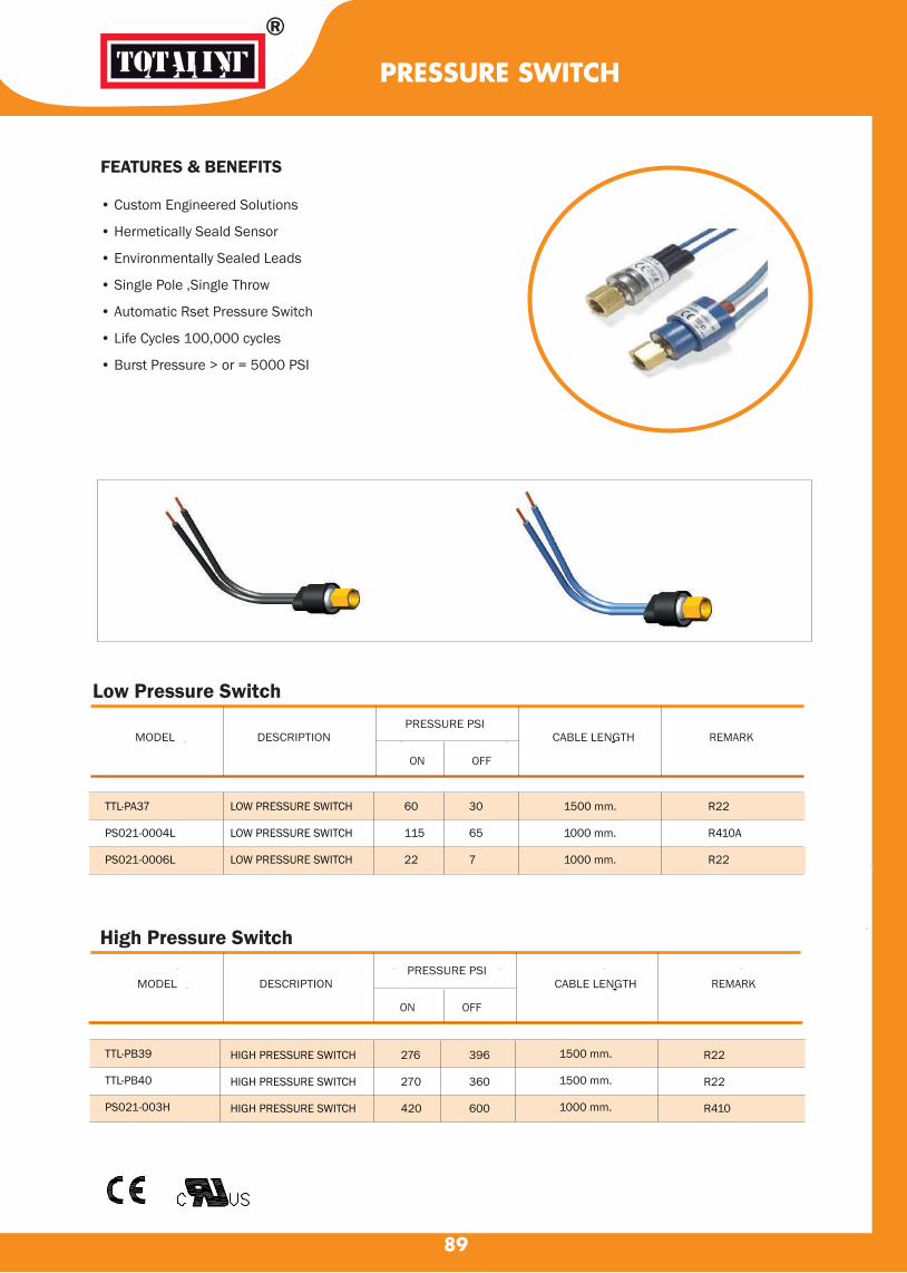
FEATURES & BENEFITS
• Custom Engineered Solutions
• Hermetically Seald Sensor
• Environmentally Sealed Leads
• Single Pole ,Single Throw
• Automatic Rset Pressure Switch
• Life Cycles 100,000 cycles
• Burst Pressure > or = 5000 PSI
Low Pressure Switch
High Pressure Switch
®
PRESSURE SWITCH
TTL-PA37
PS021-0004L
PS021-0006L
FF TTL-PB39
TTL-PB40
PS021-003H
HIGH PRESSURE SWITCH
HIGH PRESSURE SWITCH
HIGH PRESSURE SWITCH
LOW PRESSURE SWITCH
LOW PRESSURE SWITCH
LOW PRESSURE SWITCH
60
115
22
30
65
7
1500 mm.
1000 mm.
1000 mm.
R22
R410A
R22
1500 mm.
1500 mm.
1000 mm.
R22
R22
R410
276
270
420
396
360
600
89
MODEL DESCRIPTION PRESSURE PSI
CABLE LENGTH REMARK
ON OFF
MODEL DESCRIPTION PRESSURE PSI
CABLE LENGTH REMARK
ON OFF

Model
Type
Range Setting (PSI) Pressure Reset Price
(PSI) ON OFF Connections
Type
350.-
400.-
420.-
500.-
590.-
850.-
590.-
750.-
1,550.-
1,550.-
1,900.-
1,650.-
1,200.-
1,400.-
1,920.-
2,030.-
90
PRESSURE CONTROL
ACB - IB21
ACB - IB39
LCB - PA26
LCB - PA55
LTB - A301
ETB - A301
HTB - A301
FTB - A301
SNS - C106X
SNS - C110X
SNS - C106XM2
SNS - 2C106Y
HNS - C130X
HNS - C130XM1
DNS - D306X
DNS - D306XM
High pressure
High pressure
Low pressure
Low pressure
Low pressure
Low pressure
High pressure
High pressure
Low pressure
Low pressure
Low pressure
Low pressure
High pressure
High pressure
High-Low pressure
High-Low pressure
295 - 395
280 - 350
27 - 45.5
8 - 22
0 - 57
14 - 36
284 - 427
284 - 427
(-50cmHg)-85
14.2 - 142
(-50cmHg)-85
14 - 55
114 - 426
114 - 426
Low : (-50cmHg)-85
High : 114-427
Low : (-50cmHg)-85
High : 114-426
295
280
45.5
22
43
Manual
284
Manual
43
85
Manual
14
228
Manual
43
228
43
Manual
395
350
27
8
28
14
356
356
28
57
28
55
284
284
28
284
28
284
1/4 Female Flare
ODS
1/4" SAE Flare
Automatic
Automatic
Automatic
Automatic
Automatic
Manual
Automatic
Manual
Automatic
Automatic
Manual
Automatic
Automatic
Manual
Automatic
Automatic
Manual
Baht
Type ACB Type SNS Type HNS
Type DNSType FTB Type HTB

FLOW SWITCH
PRESSURE ACTUATED WATER REGULATING VAVLES
CHECK VALVE
91
Model
Range
Differential Timer Specification
Connection Price
Delay Time Timer (sec.) Voltage
OIL PROTECTION CONTROLS
ONS - C106XQ5 7 - 50 7 Psig 90 110/220V.AC 1/4" Flare Nut 4,500.-
ENS - 1C106YQ11
Baht
Fixed Adjustable 120
Max.WorkingPressure
(PSI)
PaddleSize
Max.Temp
(◦C)Connection
Price
Baht
FQS - U30G
BQS - C130PW
142
142
80
80
3"
3"
1"
1"
TypeModel
กนนำ
- 3,750.-
6,690.-
Price
BahtModel Connection
(PSI)
Range
(PSI)
Max.Working
Pressure
Max.Bellows
Pressure
AWR - 1504 GLW
AWR - 2510 GLW
AWR - 3212 GLW
1/2"
1"
1-1/4"
85 - 256
85 - 256
85 - 256
284
284
284
341
341
341
4,790.-
7,330.-
7,790.-
Connection
Copper Tube (O.D.)
StylePort Size (mm)
Max.Working
PressureModel
BCV - 603 DY
BCV - 603 DY
3/8"
1/2"Solder
5.5
8.0600 psi
Price
Baht
250.-
330.-
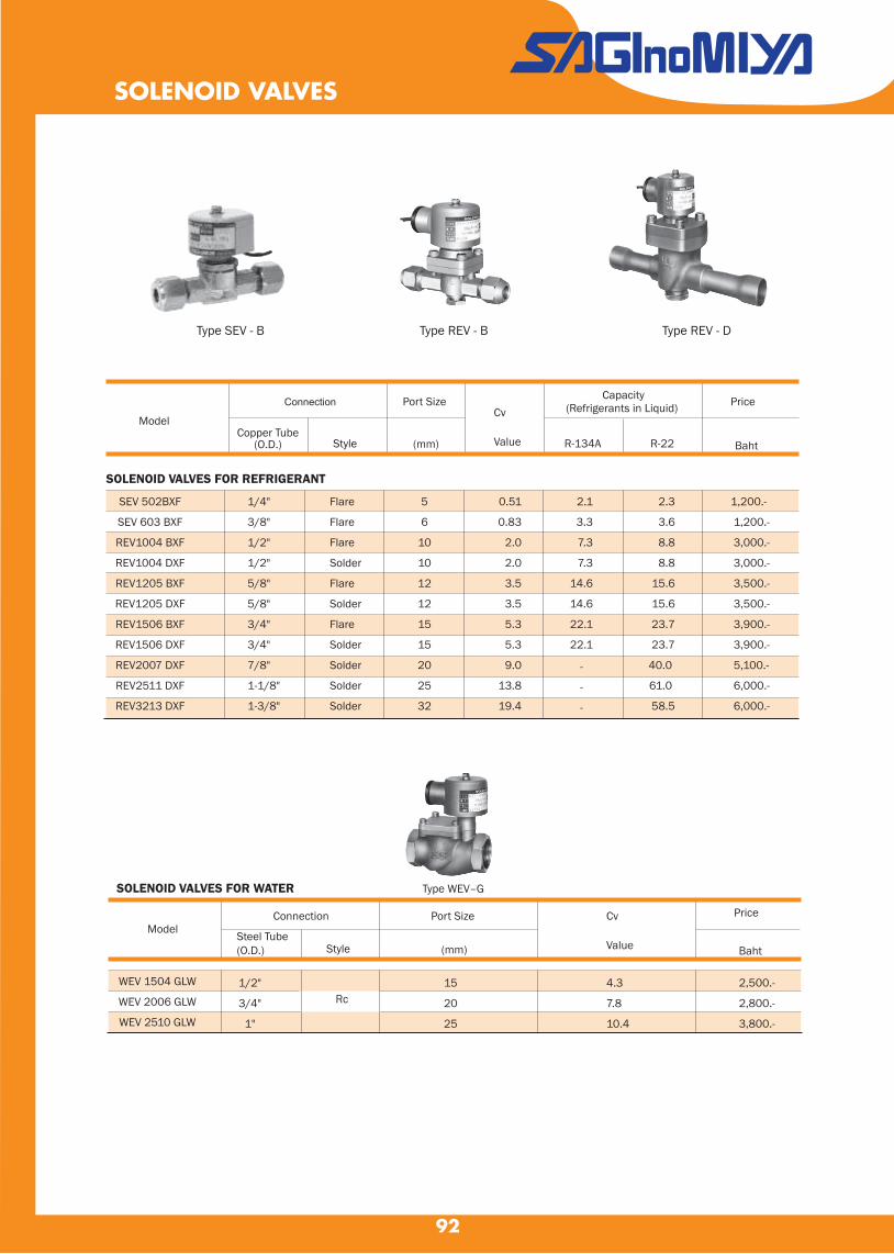
92
SOLENOID VALVES
Type SEV - B Type REV - B Type REV - D
Model
Port Size
(mm)
Cv
Value
Price
Baht
SOLENOID VALVES FOR REFRIGERANT
SOLENOID VALVES FOR WATER Type WEV–G
SEV 502BXF
SEV 603 BXF
REV1004 BXF
REV1004 DXF
REV1205 BXF
REV1205 DXF
REV1506 BXF
REV1506 DXF
REV2007 DXF
REV2511 DXF
REV3213 DXF
1/4"
3/8"
1/2"
1/2"
5/8"
5/8"
3/4"
3/4"
7/8"
1-1/8"
1-3/8"
5
6
10
10
12
12
15
15
20
25
32
2.1
3.3
7.3
7.3
14.6
14.6
22.1
22.1
2.3
3.6
8.8
8.8
15.6
15.6
23.7
23.7
40.0
61.0
58.5
1,200.-
1,200.-
3,000.-
3,000.-
3,500.-
3,500.-
3,900.-
3,900.-
5,100.-
6,000.-
6,000.-
Capacity(Refrigerants in Liquid) Connection
Style
Flare
Flare
Flare
Solder
Flare
Solder
Flare
Solder
Solder
Solder
Solder
0.51
0.83
2.0
2.0
3.5
3.5
5.3
5.3
9.0
13.8
19.4
R-134A R-22
-
-
-
WEV 1504 GLW
WEV 2006 GLW
WEV 2510 GLW
Model Price
Baht
Connection
StyleSteel Tube (O.D.)
Copper Tube(O.D.)
Port Size
(mm)
1/2"
3/4"
1"
Rc15
20
25
4.3
7.8
10.4
Cv
Value
2,500.-
2,800.-
3,800.-

Temp. Sensing
ElementModel
Price
Baht
Range (◦C)
Min. Max.Type
TEMPERATURE CONTROL
93
Range (◦C)
Min. Max.
Type TNS
Model TypeCapillary Tube
Length (m.)Voltage
Price
Baht
TNS - C114X
TNS - C134X
TNS - C1034XC
BLS - C1020L1
LWS - 1030AGL2
LWS - C1060AGL2
LWS - C1074AGL2
-15
0
-20
-20
-35
-5
30
15
35
35
20
30
60
75
1
1
1
1
1
2
2
1 Step,Automatic Reset Type
220
2,260.-
2,450.-
Call
Call
2,280.-
2,280.-
2,280.-
Type BLS Type LWS
Type FSE
FSE - 4040A22 0 40 SEK-14H
ELECTRONIC STEP THERMOSTATS
4 Step thermostat. Call
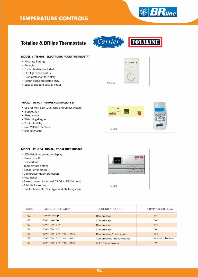
94
TEMPERATURE CONTROLS
Totaline & BRline Thermostats
MODEL : TTL-001 ELECTRONIC ROOM THERMOSTAT
• Accurate Setting • Reliable • 3 minute delay included • LED light show status • Fuse protection for safety • Circuit surge protection MOV • Easy to use and easy to install
MODEL : TTL-003 REMOTE CONTROLLER SET
• Use for Mini-Split ,Duct type and Chiller system• 3 speed fan• Sleep mode• Watchdog diagram• 3 minute delay• Non Volatile memory• self diagnostic
MODEL : TTL-004 DIGITAL ROOM THERMOSTAT
• LED digital temperature display• Power on -off• 3 speed fan• Temperature setting• Sensor error alarm• Compressor delay protection• Auto Reset• Sweep motor ( for model DR 01 to DR 04 only )• 7 Mode for setting• Use for Mini split ,Duct type and Chiller system
MODE OF OPERATION COOLING / HEATING COMPRESSOR DELAY
TTL-001
TTL-003
TTL-004
cool + sweep
cool + sweep
cool - fan - dry
cool - fan - dry
cool - fan - dry - heat - auto
cool - fan - dry - heat - auto
cool - fan - dry - heat - auto
Compressor
Chilled water
Compressor
Chilled water
Compressor / Heat pump
Compressor / Electric heater
hot / Chilled water
yes
no
yes
no
yes
yes ,only for cool
no
01
02
03
04
05
06
07
MODE
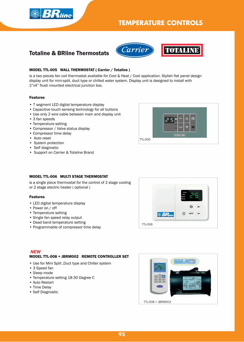
95
MODEL TTL-005 WALL THERMOSTAT ( Carrier / Totaline )is a two pieces fan coil thermostat available for Cool & Heat / Cool application. Stylish flat panel designdisplay unit for mini-split, duct type or chilled water system. Display unit is designed to install with2”x4” flush mounted electrical junction box.
Features
• 7 segment LED digital temperature display• Capacitive touch sensing technology for all buttons• Use only 2 wire cable between main and display unit• 3 fan speeds• Temperature setting• Compressor / Valve status display• Compressor time delay• Auto reset • System protection• Self diagnostic• Support on Carrier & Totaline Brand
MODEL TTL-006 MULTI STAGE THERMOSTATis a single piece thermostat for the control of 2 stage coolingor 2 stage electric heater ( optional )
Features
• LED digital temperature display• Power on / off• Temperature setting• Single fan speed relay output• Dead band temperature setting• Programmable of compressor time delay
MODEL TTL-008 + JBRM002 REMOTE CONTROLLER SET
• Use for Mini Split ,Duct type and Chiller system• 3 Speed fan• Sleep mode• Temperature setting 18-30 Degree C• Auto Restart• Time Delay• Self Diagnostic
TTL-005
TTL-006
TTL-008 + JBRM002
TEMPERATURE CONTROLS
Totaline & BRline Thermostats
NEW
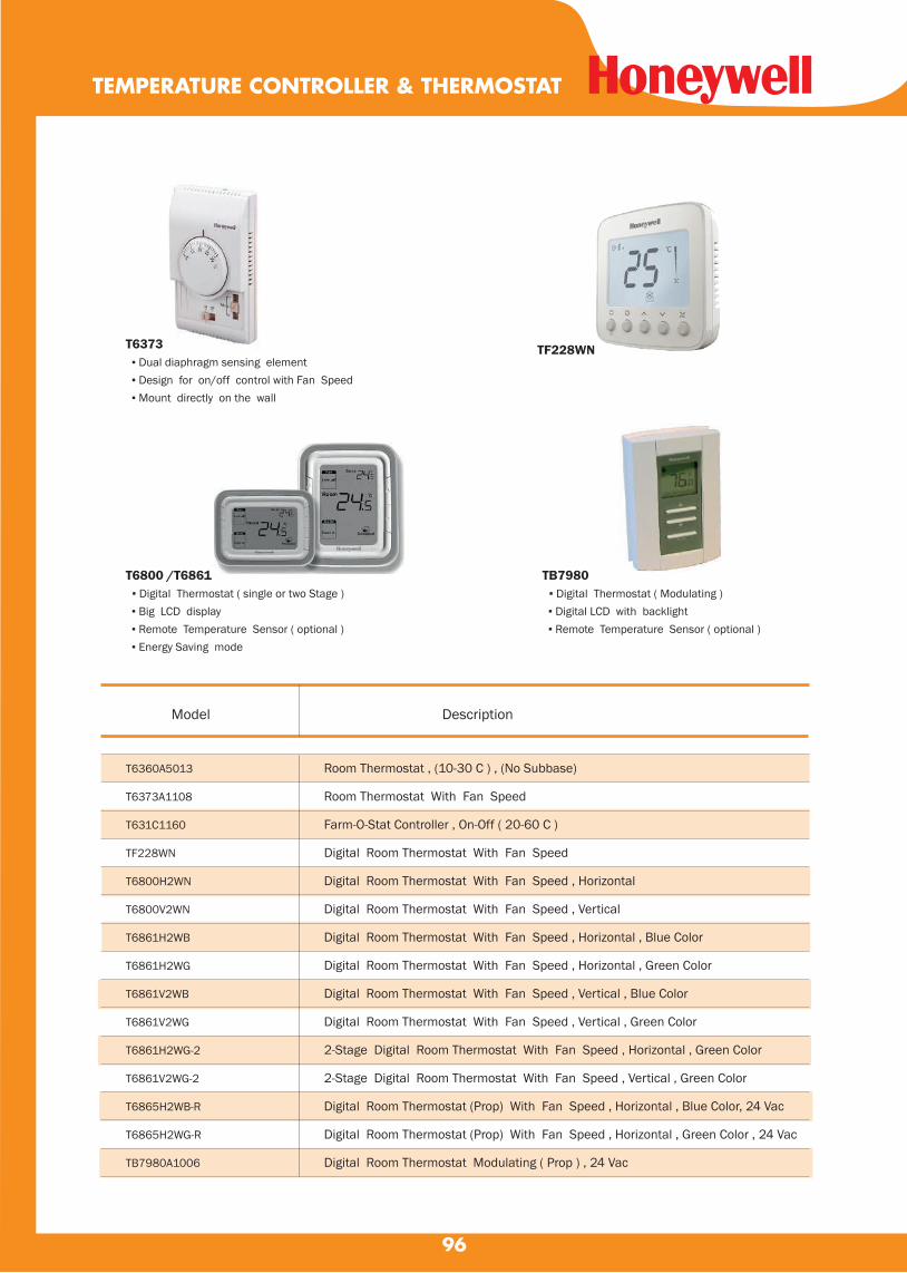
96
TEMPERATURE CONTROLLER & THERMOSTAT
T6360A5013
T6373A1108
T631C1160
TF228WN
T6800H2WN
T6800V2WN
T6861H2WB
T6861H2WG
T6861V2WB
T6861V2WG
T6861H2WG-2
T6861V2WG-2
T6865H2WB-R
T6865H2WG-R
TB7980A1006
DescriptionModel
Room Thermostat , (10-30 C ) , (No Subbase)
Room Thermostat With Fan Speed
Farm-O-Stat Controller , On-Off ( 20-60 C )
Digital Room Thermostat With Fan Speed
Digital Room Thermostat With Fan Speed , Horizontal
Digital Room Thermostat With Fan Speed , Vertical
Digital Room Thermostat With Fan Speed , Horizontal , Blue Color
Digital Room Thermostat With Fan Speed , Horizontal , Green Color
Digital Room Thermostat With Fan Speed , Vertical , Blue Color
Digital Room Thermostat With Fan Speed , Vertical , Green Color
2-Stage Digital Room Thermostat With Fan Speed , Horizontal , Green Color
2-Stage Digital Room Thermostat With Fan Speed , Vertical , Green Color
Digital Room Thermostat (Prop) With Fan Speed , Horizontal , Blue Color, 24 Vac
Digital Room Thermostat (Prop) With Fan Speed , Horizontal , Green Color , 24 Vac
Digital Room Thermostat Modulating ( Prop ) , 24 Vac
T6373 ▪ Dual diaphragm sensing element ▪ Design for on/off control with Fan Speed ▪ Mount directly on the wall
T6800 /T6861 ▪ Digital Thermostat ( single or two Stage ) ▪ Big LCD display ▪ Remote Temperature Sensor ( optional ) ▪ Energy Saving mode
TB7980 ▪ Digital Thermostat ( Modulating ) ▪ Digital LCD with backlight ▪ Remote Temperature Sensor ( optional )
TF228WN

97
TEMPERATURE CONTROLLER & VFD
T675A1179
T675A1029
T675A1474
T675A1102
T675B1002
T775B2032
T775U2006
HCRDC0050A1000T
HCRDC0075A1000T
HCRDC0100A1000T
HCRDC0150B1000T
HCRDC0250B1000T
HCRDC0300C1000T
Temperature Controller , (-15 to 35 C ) , 5 ft
Temperature Controller , (0 to 100 F ) , 20 ft
Temperature Controller , (15 to 75 C ) , 20 ft
Temperature Controller , (160 to 260 F ) , 20 ft
Temperature Controller , (30 to 50 F ) ,(Freezestat) , 10 ft ( Manual Reset )
Temperature Controller (-40 To 52 C )
Temperature Controller (Modulating)
VFD,3PH,460V,5 HP
VFD,3PH,460V,7.5 HP
VFD,3PH,460V,10 HP
VFD,3PH,460V,15 HP
VFD,3PH,460V,25 HP
VFD,3PH,460V,30 HP
T775B / T775U ▪ electronic stand-alone controllers ▪ Remote Temperature Sensor ▪ 2 or 4 Relays Output ▪ 2 Modulating Outputs ( T775U only ) ▪ Quick and easy installation
HCRDC ▪ Easy Installation & Monitoring ▪ High-performance variable-frequency technology ▪ Automatic fault reset ▪ Speed/torque/position control mode ▪ Local / Remote button on keypad
T675
DescriptionModel
T775B
HCRDC

98
(Proportional : 2-10 VDC) ELECTRIC RETURN
VC7931AF1111
VC7931AJ1111
VC7931AP1111
1/2" 3.0 BSPP (Internal Thread)
3/4" 4.7 BSPP (Internal Thread)
1" 6.6 BSPP (Internal Thread)
2-Way Modulating Valve , 24 Vac
3-Way Modulating Valve , 24 Vac
VC7931ME1111
VC7931MJ1111
VC7931MP1111
1/2" 3.7 BSPP (Internal Thread)
3/4" 6.6 BSPP (Internal Thread)
1" 8.6 BSPP (Internal Thread)
(Proportional : 2-10 VDC) SPRING RETURN
VC7936AF1111
VC7936AJ1111
VC7936AP1111
1/2" 3.7 BSPP (Internal Thread)
3/4" 5.3 BSPP (Internal Thread)
1" 6.6 BSPP (Internal Thread)
VC7936ME1111
VC7936MJ1111
VC7936MP1111
1/2" 3.7 BSPP (Internal Thread)
3/4" 6.2 BSPP (Internal Thread)
1" 7.4 BSPP (Internal Thread)
Model DIA CV CONNECT
MODULATING VALVE
Feature :
▪ 2 or 3 way Valve ( complete Set )
▪ High close-off rating
▪ Quick and easy replacement of part
▪ Model available with Proportional
▪ Power Supply 24 V
9
Model DIA CV CONNECT
2-Way Modulating Valve , 24 Vac
3-Way Modulating Valve , 24 Vac
VC7931A/VC7936A VC7931M/VC7936M

99
MOTORIZED VALVE (ON-OFF)
VC4013AF1000
VC6013AF1000
VC4013AJ1000
VC6013AJ1000
VC4013AP1000
VC6013AP1000
VC4013ME6000
VC6013ME6000
VC4013MJ6000
VC6013MJ6000
VC4013MP6000
VC6013MP6000
V4043C1370
V4043C1362
VC4043AF1000
VC4043AJ1000
VC4043AP1000
V4044C1668B
V4044A1704B
V4044C1312B
1/2" 3.5
1/2" 3.5
3/4" 6.2
3/4" 6.2
1" 7.0
1" 7.0
1/2" 4.0
1/2" 4.0
3/4" 8.2
3/4" 8.2
1" 9.0
1" 9.0
1/2" 3.5
3/4" 8.0
1/2" 3.0
3/4" 5.3
1" 6.0
1/2" 3.5
3/4" 7.0
1” 9.5
2-Way Motorized Valve (300 PSI) 220V. ELECTRIC RETURN
3-Way Motorized Valve (300 PSI) 220V. ELECTRIC RETURN
2-Way Motorized Valve (125 PSI) 220V. SPRING RETURN
2-Way Motorized Valve (300 PSI) 220V. SPRING RETURN
3-Way Motorized Valve (125 PSI) 220V. SPRING RETURN
BSPP (Internal Thread)
BSPP (Internal Thread)
BSPP (Internal Thread)
BSPP (Internal Thread)
BSPT (Internal Thread)
VC4013A/VC6013A VC4013M/VC6013MV4043 V4044
Model DIA CV CONNECT
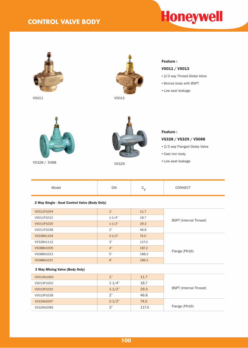
100
V5011P1004
V5011P1012
V5011P1020
V5011P1038
V5328A1104
V5328A1112
V5088A1005
V5088A1013
V5088A1021
1”
1-1/4”
1-1/2”
2”
2-1/2”
3”
4”
5”
6”
11.7
18.7
29.3
46.8
74.0
117.0
187.2
188.2
189.2
BSPT (Internal Thread)
Flange (PN16)
2 Way Single - Seat Control Valve (Body Only)
V5013N1063
V5013P1002
V5013P1010
V5013P1028
V5329A2007
V5329A2085
1”
1-1/4”
1-1/2”
2”
2-1/2”
3”
11.7
18.7
29.3
46.8
74.0
117.0
BSPT (Internal Thread)
Flange (PN16)
3 Way Mixing Valve (Body Only)
V5011
CONTROL VALVE BODY
V5013
V5328 / 5088
Model DIA CV CONNECT
V5329
Feature :
V5011 / V5013
▪ 2/3 way Thread Globe Valve
▪ Bronze body with BSPT
▪ Low seat leakage
Feature :
V5328 / V5329 / V5088
▪ 2/3 way Flanged Globe Valve
▪ Cast iron body
▪ Low seat leakage

101
VALVE ACTUATOR & MODUTROL MOTORS
M 9186G1006
ML 6984A4000
ML 6420A3007
ML 6421A1009
ML 6421B1032
ML 7984A4009
ML 7420A8088
ML 7421A1032
ML 7421B8012
ML 7425A8018
M 7410C1015
M 7410E1028
ML 6435B1008
ML 7161A2008
ML 6161B2024
CN 4610A1001
CN 7510A2001
Modutrol Motor (0-135 Ohm),24 VAC (160 deg)
Valve Actuator (On-Off) , 24 VAC
Valve Actuator (On-Off) , 24 VAC
Valve Actuator (On-Off) , 24 VAC (19mm. Stroke)
Valve Actuator (On-Off) , 24 VAC (40mm. Stroke)
Valve Actuator (2-10 VDC) , 24 VAC
Valve Actuator (Proportional) , 24 VAC (20mm. Stroke)
Valve Actuator (2-10 VDC) , 24 VAC (20mm. Stroke) 1800 N
Valve Actuator (2-10 VDC) , 24 VAC (38mm. Stroke) 1800 N
Valve Actuator (2-10 VDC) , Spring Return, 24 VAC (20mm. Stroke) 600 N
Small Linear Actuator , (Floating/On-Off), 24 VAC
Small Linear Actuator , (2-10 VDC), 24 VAC
Valve Actuator (On-Off) , Spring Return, 24 VAC
Damper Actuator 2-10Vdc 4Nm,24V
Damper Actuator 24Vac, 4 Nm
Floating Aotuator 220V. , Electric , 10 Nm
Modulating Control 24 Vac , 10 Nm
Model Description
ML6161ML6420 / ML7420
Feature :ML Series
▪ Quick and easy installation
▪ Direct / Reverse action adjustable
▪ Model available with Proportional or On-Off
▪ Power supply 24 Vac
ML7161 CN4610A1001 CN7510A2001

102
H600A1022
L4029E1037
L404F1078
L404F1102
L404F1094
DPS200
DPS400
DPS500
DPS1000
DPS2500
DPSK
DPT250
WFS-1001-H
WFS-1002-H
S6065A1003
D4240
DST3
DST5
T4057A1007
On-Off Humidifier Controller , (20-80% RH)
High Limit Controller (Fire Stat),(Fixed Temp. 125 F)
Pressure Controller Range 5-50 PSI
Pressure Controller Range 10-150 PSI
Pressure Controller Range 20-300 PSI
Airflow Differential Pressure Switch (20-200 PA)
Airflow Differential Pressure Switch (40-400 PA)
Airflow Differential Pressure Switch (50-500 Pa)
Airflow Differential Pressure Switch (200-1000 Pa)
Airflow Differential Pressure Switch (500-2500 Pa)
Duct kit for DPS,DPT
Differential Pressure Transmitter 2-10 Vdc (0-250 PA)
Water Flow Switch 150 PSI (IP54)
Water Flow Switch 300 PSI (IP54)
Water Flow Switch 150 PSI (IP65)
Duct Smoke Detector
Sampling Tube , 3 ft. (Use with Duct Smoke )
Sampling Tube , 5 ft. (Use with Duct Smoke )
Heat Detector
H600
CONTROLLER
Model Description
L404Feature :
▪ Models available in a series of control
ranges, and pressure scales in kPa and psi.
▪ All models automatically reset and have an
adjustable differential
DPS
Feature :
▪ Differential pressure switch e.g. for monitoring
filter, fan, fire damper or air flow status of air
handling systems
WFSFeature :
▪ The paddle Type
▪ Max Temp. of Fluid 100 C
D4240Feature :
▪ Air velocity rating from 100 ft/min to 4,000 ft/min
(0.5 m/s to 20.32 m/sec)
▪ Photoelectric, integrated low-flow technology
▪ 24 VAC/DC or 220 VAC

103
V5032Y0015
V5032Y0020
V5032Y0025
V5032Y0032
V5032Y0040
V5032Y0050
1/2”
3/4”
1”
1-1/4”
1-1/2”
2”
2.7
6.4
6.8
21.0
22.0
38.0
KOMBI II PLUS : FEMALE THREAD (PN16) WITH MEASURING PORT
BALANCING VALVEFEMALE THREAD (PN16) WITH MEASURING PORT
KOMBI F II : FLANGE END (PN16) WITH MEASURING PORT
V4-BLC-GP16-G065
V4-BLC-GP16-G080
V4-BLC-GP16-G100
V4-BLC-GP16-G125
V4-BLC-GP16-G150
V4-BLC-GP16-G200
V4-BLC-GP16-G250
V4-BLC-GP16-G300
V4-BLC-GP16-G350
VM242A0101
6861005200
6861200100
2-1/2”
3”
4”
5”
6”
8”
10”
12”
14”
74.4
111.0
165.0
242.0
372.0
704.0
945.0
1380.0
1651.0
Basic MES Measuring Computer
Flow Plus Measuring Computer
Flow Measuring Basic MES
Model DIA. Kv
V4 Kombi-F SeriesFLANGED BALANCING AND SHUT-OFF VALVES
VM242
V5032Y
V5032 / V4-BLC Static Balancing Valve Feature :▪ Quick and casy measuring by measuring computer▪ Equipped with both pressure test cocks.▪ visiblc pre-setting display
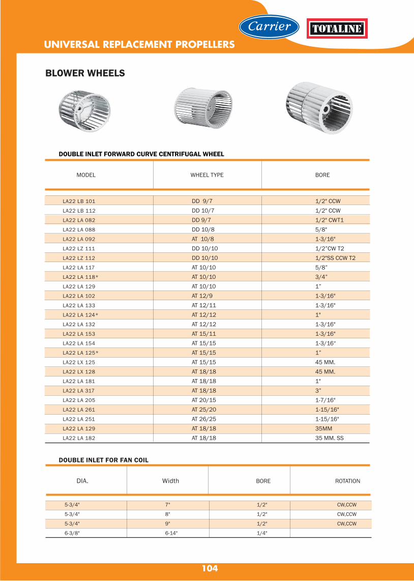
104
UNIVERSAL REPLACEMENT PROPELLERS
DOUBLE INLET FORWARD CURVE CENTRIFUGAL WHEEL
WHEEL TYPE BOREMODEL
LA22 LB 101
LA22 LB 112
LA22 LA 082
LA22 LA 088
LA22 LA 092
LA22 LZ 111
LA22 LZ 112
LA22 LA 117
LA22 LA 118*
LA22 LA 129
LA22 LA 102
LA22 LA 133
LA22 LA 124*
LA22 LA 132
LA22 LA 153
LA22 LA 154
LA22 LA 125*
LA22 LX 125
LA22 LX 128
LA22 LA 181
LA22 LA 317
LA22 LA 205
LA22 LA 261
LA22 LA 251
LA22 LA 129
LA22 LA 182
DD 9/7DD 10/7DD 9/7DD 10/8AT 10/8DD 10/10DD 10/10AT 10/10AT 10/10AT 10/10AT 12/9AT 12/11AT 12/12AT 12/12AT 15/11AT 15/15AT 15/15AT 15/15AT 18/18AT 18/18AT 18/18AT 20/15AT 25/20AT 26/25AT 18/18AT 18/18
1/2" CCW1/2" CCW1/2" CWT15/8"1-3/16"1/2”CW T21/2"SS CCW T25/8”3/4”1”1-3/16"1-3/16"1"1-3/16"1-3/16"1-3/16“1”45 MM.45 MM.1"3”1-7/16"1-15/16"1-15/16"35MM35 MM. SS
BLOWER WHEELS
DOUBLE INLET FOR FAN COIL
DIA. Width BORE ROTATION
5-3/4"
5-3/4"
5-3/4"
6-3/8"
7"
8"
9"
6-14"
1/2"
1/2"
1/2"
1/4"
CW,CCW
CW,CCW
CW,CCW
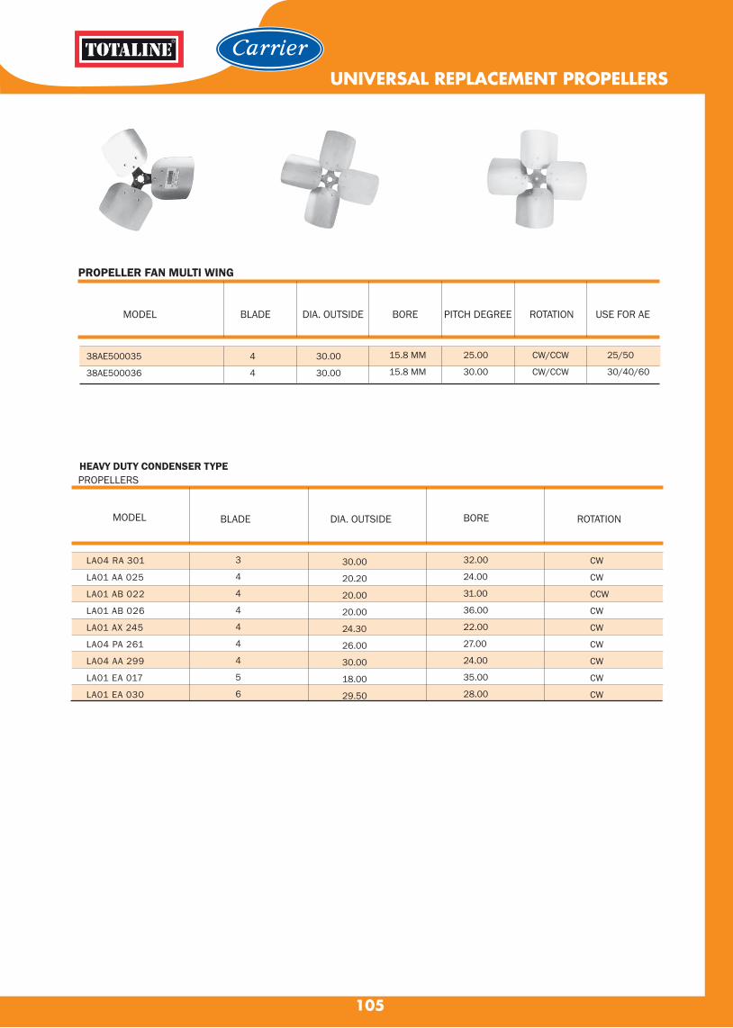
105
MODEL
PROPELLER FAN MULTI WING
38AE500035
38AE500036
4
4
30.00
30.00
15.8 MM
15.8 MM
25.00
30.00
CW/CCW
CW/CCW
25/50
30/40/60
BLADE ROTATIONDIA. OUTSIDE BORE PITCH DEGREE USE FOR AE
UNIVERSAL REPLACEMENT PROPELLERS
HEAVY DUTY CONDENSER TYPEPROPELLERS
LA04 RA 301
LA01 AA 025
LA01 AB 022
LA01 AB 026
LA01 AX 245
LA04 PA 261
LA04 AA 299
LA01 EA 017
LA01 EA 030
3
4
4
4
4
4
4
5
6
30.00
20.20
20.00
20.00
24.30
26.00
30.00
18.00
29.50
32.00
24.00
31.00
36.00
22.00
27.00
24.00
35.00
28.00
CW
CW
CCW
CW
CW
CW
CW
CW
CW
MODEL BLADE DIA. OUTSIDE BORE ROTATION

COMPRESSOR VALVES
106
our compressor valves and kits are manufactured to the strictest quality standards in the industry. Built with valve openings designed for
maximum flow and minimum pressure drop, specialized asbestos-free valve packing material allows component accessibility without
refrigerant loss.Offering a complete line of compressor valves, we furnish compressor valves machined to fit standard dimensions and several
special flange dimensions used by many manufacturers.Direct OEM replacement part kits are a vailable for leading compressor manufacturers
in the industry.
Quality & Technical Information
▪ Maximum abnormal pressure (MAP): 700 psig, 48 bar▪ Continuous operating temperature (COT): -40°F/300°F, -40°C/149°C▪ Compatible with all CFC, HCFC and HFC refrigerants and oils▪ UL/cUL Recognized, Conforms to Pressure Equipment Directive 2014/68/EU▪ 100% tested▪ Asbestos-free valve packing▪ Valve openings designed for maximum flow and minimum pressure drop
Uses▪ Refrigeration▪ Air Conditioning
Brass Compressor ValvesStraight Port, Solder
No . 06DA660064
Brass Compressor ValvesFour-Bolt Mounting, SolderFlat Gasket Surface
No. 06DA660065
Cast Iron Compressor ValvesFour-Bolt Flange Union, Solder
No. 06EA660091
Brass Compressor ValvesFour-Bolt Mounting, SolderFlat Gasket Surface
No. 06EA660090

107
06DA660064
06DA660065
06EA660090
06EA660091
1-1/8 brass
1-3/8 brass
1-5/8 brass
2-1/8 brass
1-3/4
2-1/2 sq.
2-1/2 sq.
3-1/16 sq.
VALVE PACKAGE NO. ODS (in.) BOLT HOLE SPACING (in.)
Compressor Service Valves (O6D,E)
COMPRESSOR VALVES
41 0.81 216.64 1692.06 52 0.90 23 .34 9 1/8
in mm
VALVE PACKAGE No.
DIMENSIONAL DATA
No . 06DA660064 No . 06DA660065
No. 06EA660090 No. 06EA660091
06DA660064
06DA660065
06EA660090
06EA660091
in mm in mm in mm in mm in mm in mm in mm
Bolt Centers
Bolt Hole Diameter
Pipe Plug
Size in
A B C D E F
1 1/8
1 3/8
1 5/8
2 1/8
29
35
41
54
88.0 22 1 5/8
096
1.10
1.31
24
28
33
2.72
2.88
5.06
69
73
129
7.61
7.89
11.95
193
200
304
1.56
1.81
2.53
40
46
64
1.00
1.03
3.22
25
26
82
2.5
2.5
3.06
64
64
78
.53
.53
.69
13
13
17
1/4
1/4
1/4
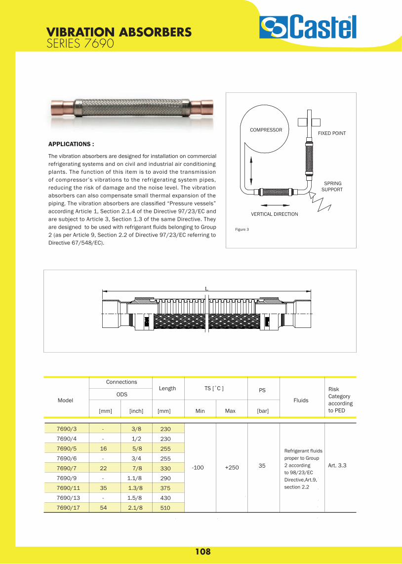
108
VIBRATION ABSORBERS SERIES 7690
Connections Length
ODS
[mm] [inch] [mm]
7690/3 - 3/8
7690/4 - 1/2
7690/5 16 5/8
7690/6 - 3/4
7690/7 22 7/8
7690/9 - 1.1/8
7690/11 35 1.3/8
7690/13 - 1.5/8
7690/17 54 2.1/8
230
230
255
255
330
290
375
430
510
Art. 3.3
SPRINGSUPPORT
VERTICAL DIRECTION
FIXED POINTCOMPRESSOR
Figure 3
Model Fluids
PS
[bar]
TS [˚C ]
Min Max
-100 +250 35
APPLICATIONS :
The vibration absorbers are designed for installation on commercial refrigerating systems and on civil and industrial air conditioning plants. The function of this item is to avoid the transmission of compressor’s vibrations to the refrigerating system pipes, reducing the risk of damage and the noise level. The vibration absorbers can also compensate small thermal expansion of the piping. The vibration absorbers are classified “Pressure vessels” according Article 1, Section 2.1.4 of the Directive 97/23/EC and are subject to Article 3, Section 1.3 of the same Directive. They are designed to be used with refrigerant fluids belonging to Group 2 (as per Article 9, Section 2.2 of Directive 97/23/EC referring to Directive 67/548/EC).
RiskCategory according to PED
Refrigerant fluidsproper to Group 2 according to 98/23/EC Directive,Art.9,section 2.2

109
APPLICATIONS :
T h e g l o b e va l ve s , s h ow n i n t h i s c h a p te r, a r e c l a s s i fi e d “ P r e s s u r e a c c e s s o r i e s ” i n t h e s e n s e o f t h e P r e s s u r e Equipment Directive 97/23/EC, Ar ticle 1, Section 2.1.4 and are subject of Ar ticle 3, Section 1.3 of the same Directive.They are designed for installation on commercial refrigeratingsystems and on civil and industrial conditioning plants, which use the fo l lowing refr igerant fluids: R22, R134a, R404A, R407C, R410A; R507 proper to the Group II (as defined in Ar t icle 9, Section 2.2 of Directive 97/23/EC and referred to in Directive 67/548/EEC). For specific applications with refr igerant fluids not l is ted above, a lways proper to the GroupII, please contact Castel Technical Department.
GLOBE VALVES
GLOBE VALVES
General Characteristics
ConnectionsKv Factor
[m3/h]
TS [°C] PS
[bar] ODS ODM
min. max.Ø [in.] Ø [mm] Ø [in.] Ø [mm]
6512/M22
6512/7
6512/M28
6512/9
6512/11
6512/13
6512/M42
6512/17
6532/M22
6532/7
6532/M28
6532/9
6532/11
6532/13
6532/M42
6532/17
7,1
-35 +160 45
8,4
25,0
8,2
9,1
38,0
-
7/8”
-
1.1/8”
1.3/8”
1.5/8”
-
2.1/8”
-
7/8”
-
1.1/8”
1.3/8”
1.5/8”
-
2.2/8”
22
-
28
-
35
-
42
54
22
-
28
-
35
-
42
54
-
1.1/8”
1.3/8”
1.3/8”
1.5/8”
2”
2”
-
-
1.1/8”
1.3/8”
1.3/8”
1.5/8”
2”
2”
-
28
-
35
35
-
-
-
-
28
-
35
35
-
-
-
- 48,5
15.0
40,0
18.7
Model
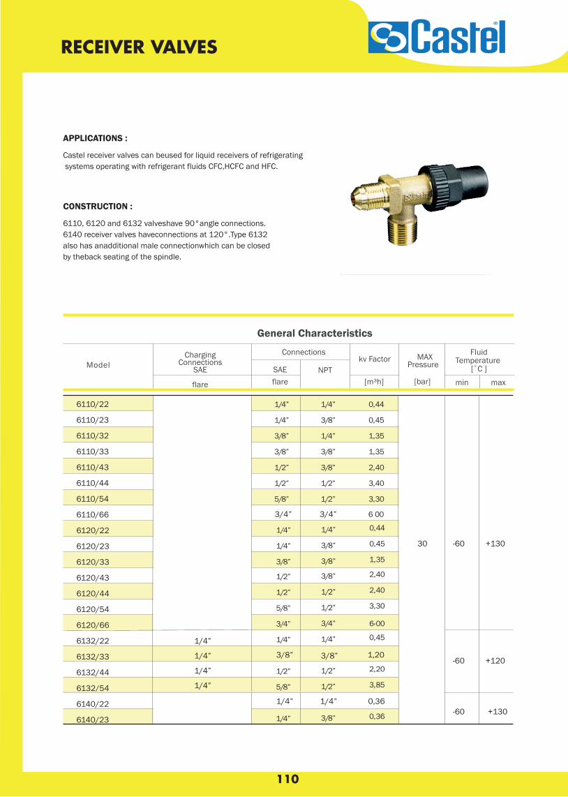
110
RECEIVER VALVES
CONSTRUCTION :
6110, 6120 and 6132 valveshave 90°angle connections.6140 receiver valves haveconnections at 120°.Type 6132 also has anadditional male connectionwhich can be closed by theback seating of the spindle.
APPLICATIONS :
Castel receiver valves can beused for liquid receivers of refrigerating systems operating with refrigerant fluids CFC,HCFC and HFC.
1/4” 1/4” 0,36
FluidTemperature
[˚C ]MAX
Pressure
min max[bar]
kv Factor
[m³h]NPTSAE
flare
Model
General Characteristics
ConnectionsChargingConnections
SAE
flare
”4/1
”4/1
”8/3
”8/3
”2/1
”2/1
”8/5
”4/1
”8/3
”4/1
”8/3
”8/3
”2/1
”2/1
44,0
54,0
53,1
53,1
04,2
04,3
03,3
44,0”4/1”4/1
54,0”8/3”4/1
53,1”8/3”8/304,2”8/3”2/1
04,2”2/1”2/1
03,3”2/1”8/5
00,6”4/3”4/3
54,0”4/1”4/1
02,2”2/1”2/1
58,3”2/1”8/5
63,0”8/3”4/1
3/4” 3/4” 006
1/4”
1/4”
1/4”
1/4”
3/8” 3/8” 1,20
30 -60 +130
-60 +120
-60 +130
6110/22
6110/23
6110/32
6110/33
6110/43
6110/44
6110/54
6110/66
6120/22
6120/23
6120/33
6120/43
6120/44
6120/54
6120/66
6132/22
6132/33
6132/44
6132/54
6140/22
6140/23

111

112
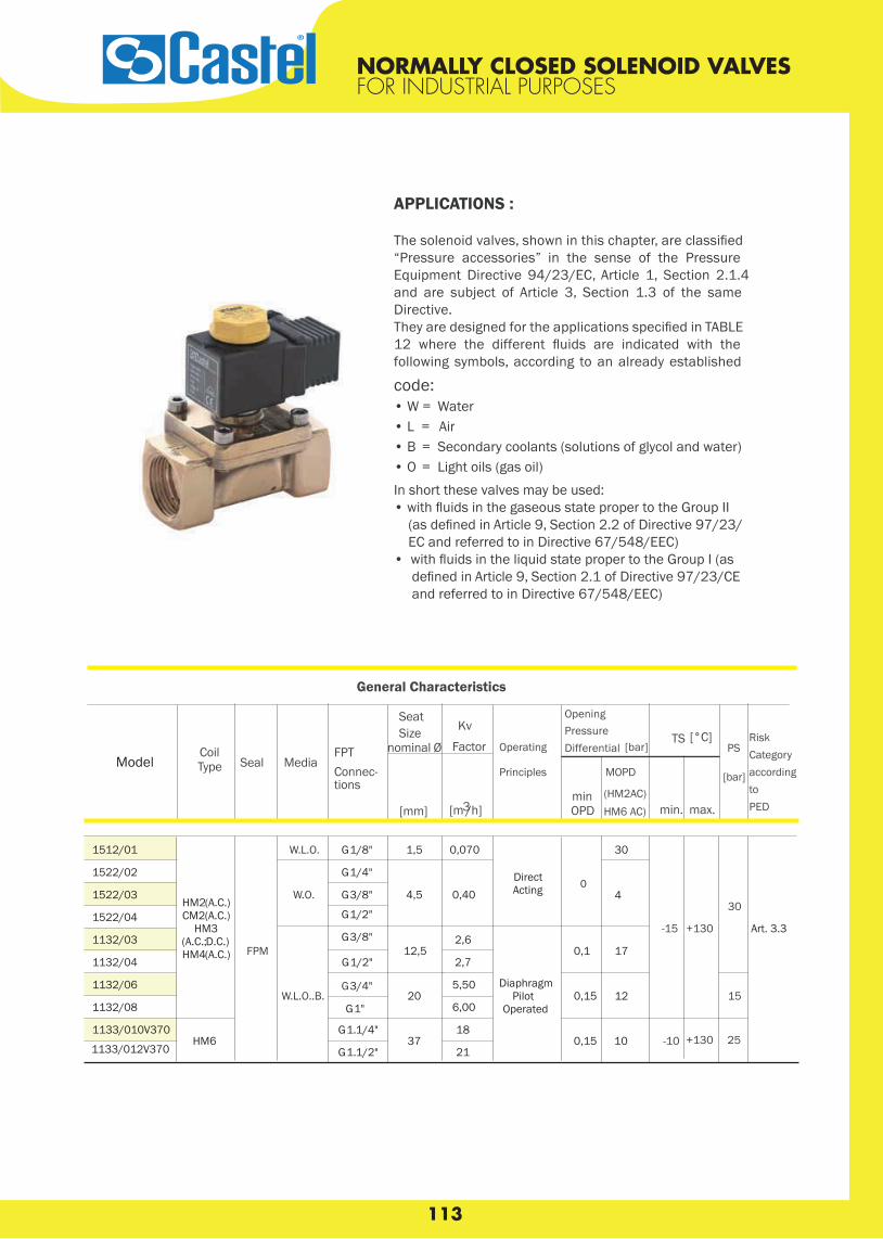
113

114

The 100RB is a direct-acting, 2-way, normally closed valve. 100 RBvalves are used for liquid or discharge gas refrigerant service.
Features• One coil fits all valve sizes• Extended ends for easy installation (standard)• Long-life molded coils• PTFE O-ring for superior external sealing
Options• SAE or ODF connection sizes in 1/4” and 3/8”, 1/4” NPTF
115
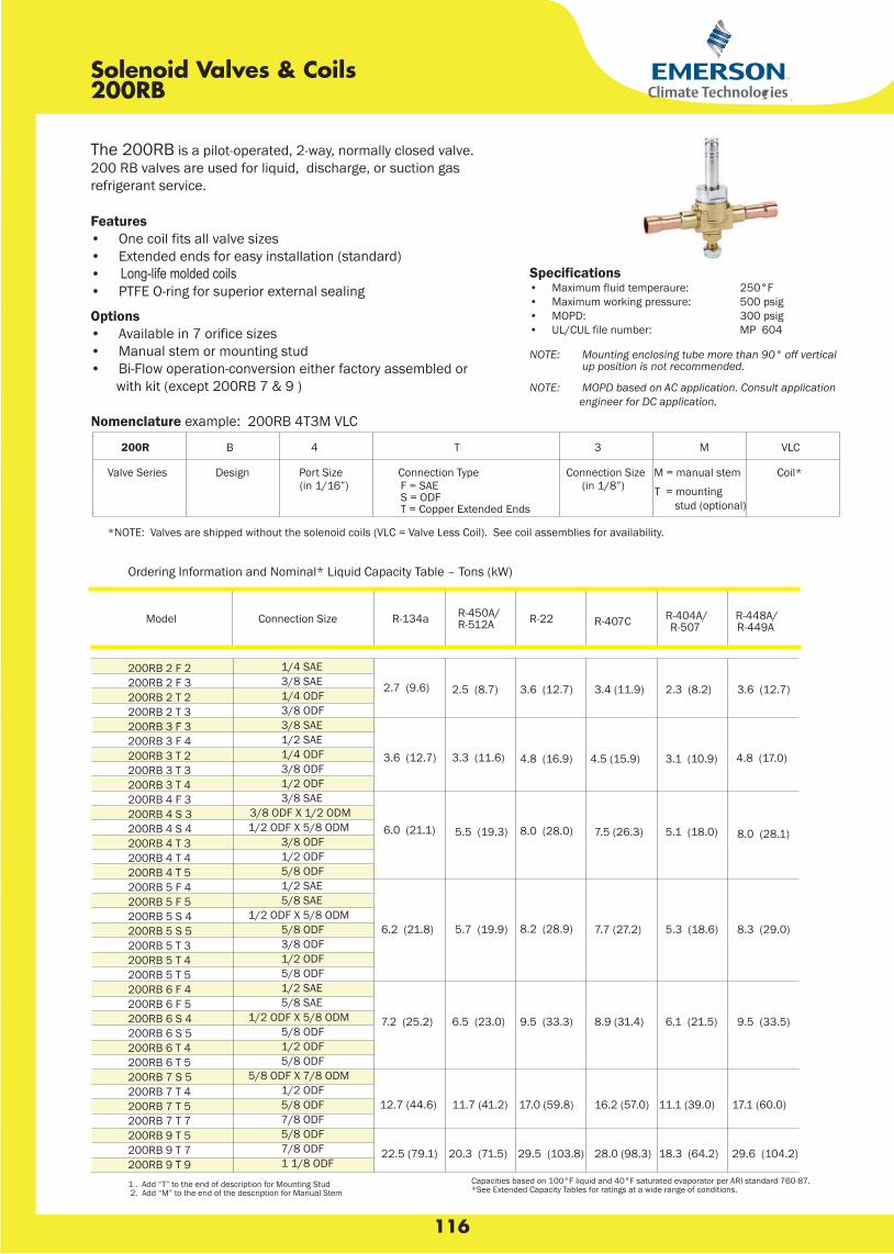
116

117
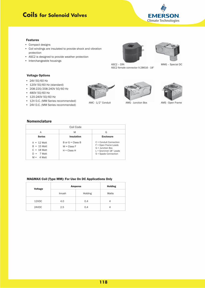
118
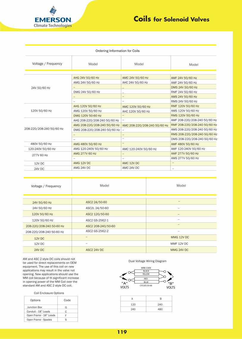
119
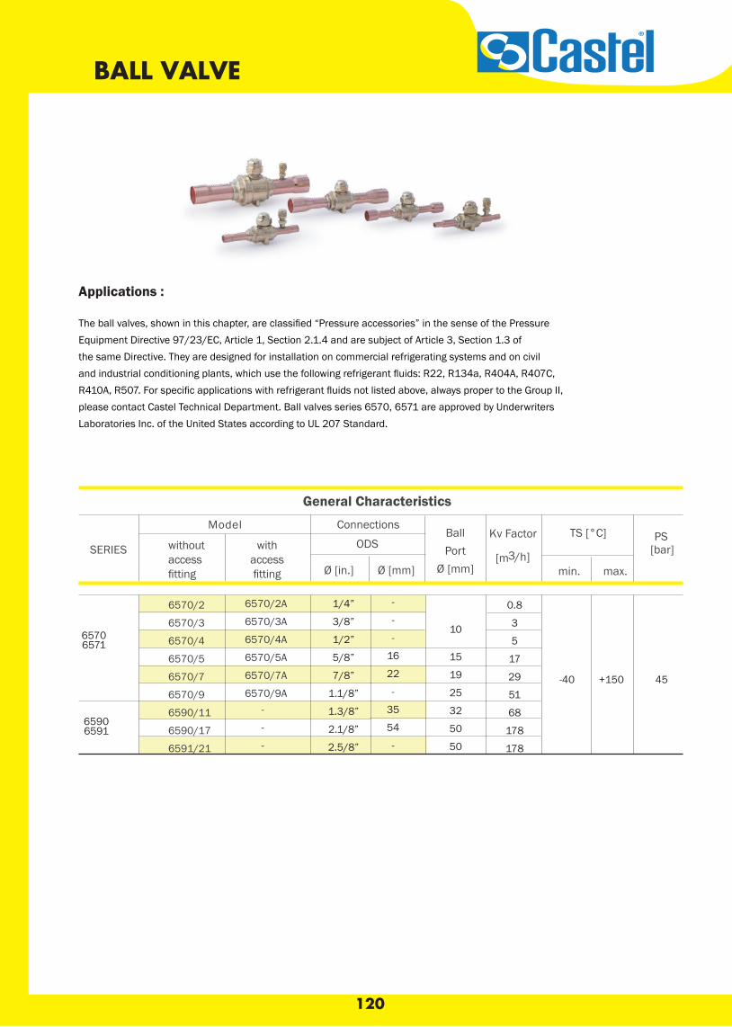
120
Applications :
The ball valves, shown in this chapter, are classified “Pressure accessories” in the sense of the PressureEquipment Directive 97/23/EC, Article 1, Section 2.1.4 and are subject of Article 3, Section 1.3 of the same Directive. They are designed for installation on commercial refrigerating systems and on civil and industrial conditioning plants, which use the following refrigerant fluids: R22, R134a, R404A, R407C, R410A, R507. For specific applications with refrigerant fluids not listed above, always proper to the Group II, please contact Castel Technical Department. Ball valves series 6570, 6571 are approved by Underwriters Laboratories Inc. of the United States according to UL 207 Standard.
General Characteristics
ConnectionsKv Factor
[m3/h]
TS [°C] PS [bar] ODS
min. max.Ø [in.] Ø [mm]
ModelBallPort
Ø [mm]
withoutaccessfitting
withaccessfitting
SERIES
6570/2
6570/3
6570/4
6570/5
6570/7
6570/9
6590/11
6590/17
6591/21
6570/2A
6570/3A
6570/4A
6570/5A
6570/7A
6570/9A
1/4”
3/8”
1/2”
5/8”
7/8”
1.1/8”
1.3/8”
2.1/8”
2.5/8”
-
-
-
16
22
-
35
54
-
65706571
10
15
19
25
32
50
50
0.8
3
5
17
29
51
68
178
178
-40 +150 45
65906591
-
-
-
BALL VALVE
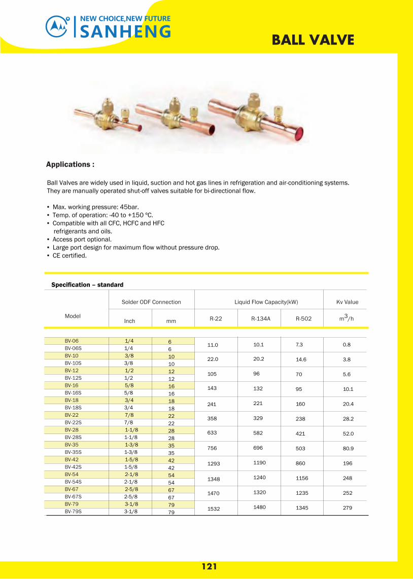
121
SANHENGNEW CHOICE,NEW FUTURE
BALL VALVE
Ball Valves are widely used in liquid, suction and hot gas lines in refrigeration and air-conditioning systems. They are manually operated shut-off valves suitable for bi-directional flow.
▪ Max. working pressure: 45bar. ▪ Temp. of operation: -40 to +150 ºC. ▪ Compatible with all CFC, HCFC and HFC refrigerants and oils. ▪ Access port optional. ▪ Large port design for maximum flow without pressure drop.▪ CE certified.
Specification – standard
BV-06BV-06SBV-10BV-10SBV-12BV-12SBV-16BV-16SBV-18BV-18SBV-22BV-22SBV-28BV-28SBV-35BV-35SBV-42BV-42SBV-54BV-54SBV-67BV-67SBV-79BV-79S
Solder ODF Connection
1/4
3/8
1/2
5/8
3/4
7/8
1-1/8
1-3/8
1-5/8
2-1/8
2-5/8
3-1/8
6
10
12
16
18
22
28
35
42
54
67
79
11.0
22.0
105
143
241
358
633
756
1293
1348
1470
1532
10.1
20.2
96
132
221
329
582
696
1190
1240
1320
1480
7.3
14.6
70
95
160
238
421
503
860
1156
1235
1345
0.8
3.8
5.6
10.1
20.4
28.2
52.0
80.9
196
248
252
279
Liquid Flow Capacity(kW) Kv Value
Model R-22 R-134A R-502 m3/hInch mm
1/4
3/8
1/2
5/8
3/4
7/8
1-1/8
1-3/8
1-5/8
2-1/8
2-5/8
3-1/8
6
10
12
16
18
22
28
35
42
54
67
79
Applications :

122
Technical BulletinThe BVE /BVS Ball valve is a fully hermetic ball valve for the Refrigeration and A/C industry.
Features
▪ BVS models with 7/16-20 UNF – ¼” flare connection and Schrader valve ▪ Two threads at valve body for easy mounting ▪ Hermetic design ▪ Compatible for high pressure refrigerants as R 410A and CO2 (sub-critical) ▪ Light weight design ▪ Virgin PTFE seat gaskets ▪ Bi-directional flow characteristics ▪ Valve cap retained by strap attached to main body ▪ Pressure relief port design ▪ Full flow design (minimal pressure drop)
▪ UL approval ; produced acc. CE requirements ▪ Applied Standards EN 12284, EN 378, EN12420, PED 97/23/EC, RoHS 2002/95/EC
BALL VALVE Type BVE / BVS
Type BVE Type BVS
Connection SizeModel
Type BVE Type BVS
BVE-014
BVE-M06
BVE-038
BVE-M10
BVE-012
BVE-M12
BVE-058
BVE-034
BVE-078
BVE-118
BVE-M28
BVE-138
BVE-158
BVE-M42
BVE-218
BVE-258
BVE-318
BVS-014
BVS-M06
BVS-038
BVS-M10
BVS-012
BVS-M12
BVS-058
BVS-034
BVS-078
BVS-118
BVS-M28
BVS-138
BVS-158
BVS-M42
BVS-218
BVS-258
BVS-318
Inch mm
0.36
0.36
0.36
0.36
0.36
0.38
0.38
0.66
0.66
1.04
1.04
1.64
2.43
2.43
4.76
5.54
7.72
Technical Data Maximum allowable
pressure PS 45 bar Construction
Test pressure PT 49,5 barMedium compatibility *
HFC, HCFC, CO 2, Mineral, Synthetic Polyol - Ester (POE) lubricants
Burst pressure 225 bar
Medium temp. TS 40 … 120°C (150°C short term)Material Body CW617N, Copper Tubes CW
024A acc. EN12420
* BVE / BVS Ball valves are not released for use with caustic, poisonous or flammable substances.
Weight (kg)
1/4”
3/8”
1/2”
5/8”
3/4”
7/8”
1 1/8”
1 3/8”
1 5/8”
2 1/8”
2 5/8”
3 1 /8”
6mm
10mm
12mm
16mm
22mm
28mm
35mm
42mm
54mm
Forged brass body, Copper extensiontubes, Chrome plated Ball
and

Thermostatic Expansion ValvesAFA Series
Features
• Stainless steel power element eliminates corrosion and prevents valve failure• External superheat adjustment• Replaceable inlet strainer
Wrench flats on inlet and outletSAE connections only
The AFA series is designed for air conditioning and commercialrefrigeration applications requiring angle configuration SAE connections. The AFA is ideal for those applications requiringcompact size combined with stable and accurate control overwide load and evaporator temperature ranges.
Specifications• Maximum working pressure: 700 psig
SA 5312
Options
• External or internal equalizer
AFA Series – Nominal* Capacity Table in Tons (kW)
R-12 R-134a R-22 R-502 R-507/R-404A R-407C
All capacities shown are at 100°F condensing, 40°F evaporator temperature.*See Extended Capacity Tables for ratings at a wide range of conditions per ARI standard 750.
123
•• • UR/CUR file number :
1/8 (0.4)
1/4 (0.9)
1/2 (1.8)
3/4 (2.7)
1 (3.5)
1¼ (4.4)
2 (7.0)
2¼ (8.0)
2½ (9.0)
3½ (12.0)
1/5 (0.7)
1/4 (0.9)
1/2 (1.8)
1 (3.5)
1¼ (4.4)
2 (7.0)
2½ (9.0)
3¼ (11.5)
4 (14.0)
5¼ (19.0)
–
1/8 (0.4)
1/4 (0.9)
1/2 (1.8)
1 (3.5)
–
1½ (5.3)
2 (7.0)
–
3 (11.0)
1/5 (0.7)
1/4 (0.9)
1/2 (1.8)
1 (3.5)
1½ (5.3)
2 (7.0)
2½ (9.0)
3 (11.0)
–
5 (17.0)
1/8 (0.4)
1/4 (0.9)
1/2 (1.8)
3/4 (2.7)
1 (3.5)
1½ (5.3)
2 (7.0)
2½ (9.0)
3 (11.0)
4 (14.0)
–
1/8 (0.4)
1/4 (0.9)
1/2 (1.8)
1 (3.5)
–
1½ (5.3)
2 (7.0)
–
3 (11.0)
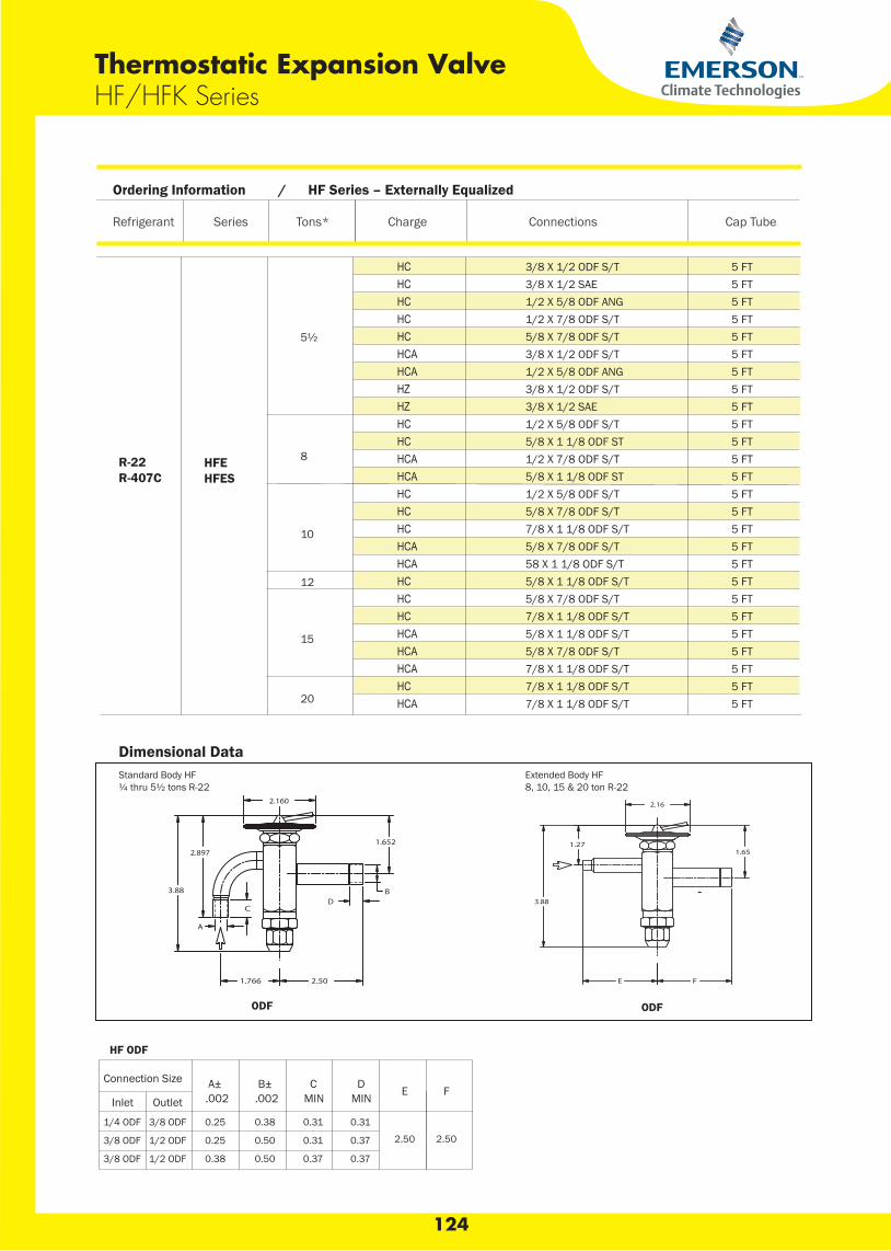
Refrigerant Series Tons* Charge Connections Cap Tube
R-22R-407C
HFEHFES
5½
3/8 X 1/2 ODF S/T3/8 X 1/2 SAE1/2 X 5/8 ODF ANG1/2 X 7/8 ODF S/T5/8 X 7/8 ODF S/T3/8 X 1/2 ODF S/T1/2 X 5/8 ODF ANG3/8 X 1/2 ODF S/T3/8 X 1/2 SAE1/2 X 5/8 ODF S/T5/8 X 1 1/8 ODF ST1/2 X 7/8 ODF S/T5/8 X 1 1/8 ODF ST1/2 X 5/8 ODF S/T5/8 X 7/8 ODF S/T7/8 X 1 1/8 ODF S/T5/8 X 7/8 ODF S/T58 X 1 1/8 ODF S/T5/8 X 1 1/8 ODF S/T5/8 X 7/8 ODF S/T7/8 X 1 1/8 ODF S/T5/8 X 1 1/8 ODF S/T5/8 X 7/8 ODF S/T7/8 X 1 1/8 ODF S/T7/8 X 1 1/8 ODF S/T7/8 X 1 1/8 ODF S/T
8
10
12
15
20
Ordering Information / HF Series – Externally Equalized
5 FT5 FT5 FT5 FT5 FT5 FT5 FT5 FT5 FT5 FT5 FT5 FT5 FT5 FT5 FT5 FT5 FT5 FT5 FT5 FT5 FT5 FT5 FT5 FT5 FT5 FT
HCHCHCHCHCHCAHCAHZHZHCHCHCAHCAHCHCHCHCAHCAHCHCHCHCAHCAHCAHCHCA
Extended Body HF8, 10, 15 & 20 ton R-22
ODF ODF
HF ODF
Connection Size A± .002
B± .002
C MIN
D MIN E F
Inlet Outlet
1/4 ODF 3/8 ODF 0.25 0.38 0.31 0.31
2.50 2.503/8 ODF 1/2 ODF 0.25 0.50 0.31 0.37
3/8 ODF 1/2 ODF 0.38 0.50 0.37 0.37
Dimensional DataStandard Body HF¼ thru 5½ tons R-22
Thermostatic Expansion ValveHF/HFK Series
124
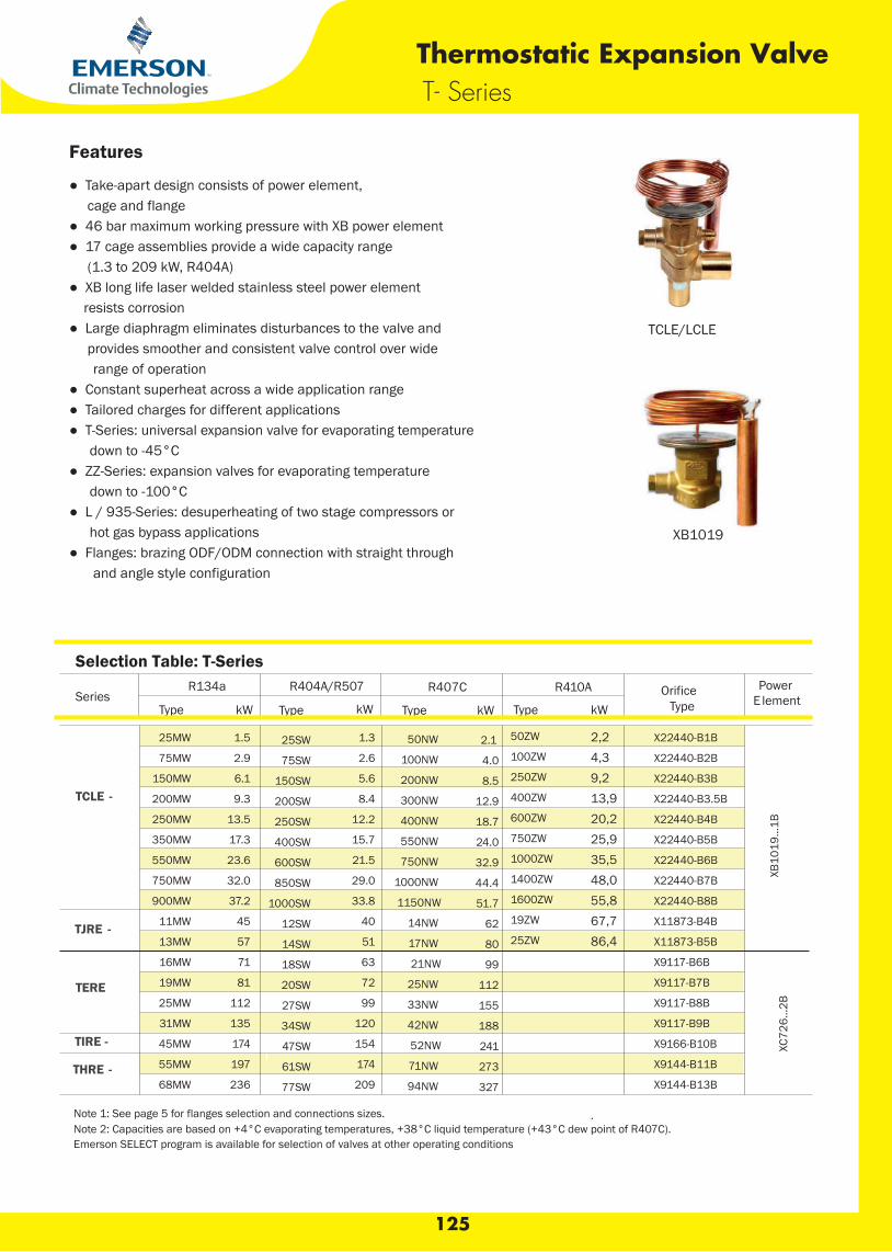
Thermostatic Expansion ValveT- Series
Features
● Take-apart design consists of power element, cage and flange ● 46 bar maximum working pressure with XB power element ● 17 cage assemblies provide a wide capacity range (1.3 to 209 kW, R404A) ● XB long life laser welded stainless steel power element resists corrosion ● Large diaphragm eliminates disturbances to the valve and provides smoother and consistent valve control over wide range of operation ● Constant superheat across a wide application range ● Tailored charges for different applications ● T-Series: universal expansion valve for evaporating temperature down to -45°C ● ZZ-Series: expansion valves for evaporating temperature down to -100°C ● L / 935-Series: desuperheating of two stage compressors or hot gas bypass applications ● Flanges: brazing ODF/ODM connection with straight through and angle style configuration
TCLE/LCLE
XB1019
Selection Table: T-Series
SeriesR134a R404A/R507 R407C
R410A Orifice Power E lement
Type kW Type kW Type kW Type
TCLE -
2.1
4.0
8.5
12.9
18.7
24.0
32.9
44.4
51.7
62
80
99
112
155
188
241
273
327
XB10
19...
1B
TJRE -
TERE
XC72
6...2
B
TIRE -
THRE -
Note 1: See page 5 for flanges selection and connections sizes.
Note 2: Capacities are based on +4°C evaporating temperatures, +38°C liquid temperature (+43°C dew point of R407C).
Emerson SELECT program is available for selection of valves at other operating conditions
.
1.3
2.6
5.6
8.4
12.2
15.7
21.5
29.0
33.8
40
51
63
72
99
120
154
174
209
25MW
75MW
150MW
200MW
250MW
350MW
550MW
750MW
900MW
11MW
13MW
16MW
19MW
25MW
31MW
45MW
55MW
68MW
1.5
2.9
6.1
9.3
13.5
17.3
23.6
32.0
37.2
45
57
71
81
112
135
174
197
236
25SW
75SW
150SW
200SW
250SW
400SW
600SW
850SW
1000SW
12SW
14SW
18SW
20SW
27SW
34SW
47SW
61SW
77SW
50NW
100NW
200NW
300NW
400NW
550NW
750NW
1000NW
1150NW
14NW
17NW
21NW
25NW
33NW
42NW
52NW
71NW
94NW
Type
2,2 4,3 9,2 13,9 20,2 25,9 35,5 48,0 55,8 67,7 86,4
50ZW
100ZW
250ZW
400ZW
600ZW
750ZW
1000ZW
1400ZW
1600ZW
19ZW
25ZW
X22440-B1B
X22440-B2B
X22440-B3B
X22440-B3.5B
X22440-B4B
X22440-B5B
X22440-B6B
X22440-B7B
X22440-B8B
X11873-B4B
X11873-B5B
X9117-B6B
X9117-B7B
X9117-B8B
X9117-B9B
X9166-B10B
X9144-B11B
X9144-B13B
125
kW
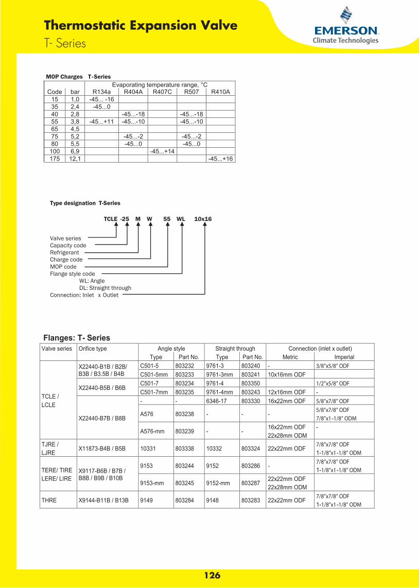
Thermostatic Expansion ValveT- Series
MOP Charges T -Series Evaporating temperature range, °C Code bar R134a R404A R407C R507 R410A
15 1,0 -45... -16 35 2,4 -45...0 40 2,8 -45...-18 -45...-18 55 3,8 -45...+11 -45...-10 -45...-10 65 4,5 75 5,2 -45...-2 -45...-2 80 5,5 -45...0 -45...0
100 6,9 -45...+14 175 12,1 -45...+16
Type designation T-Series
TCLE -25 M W 55 WL 10x16 Valve series Capacity code Refrigerant Charge code MOP code Flange style code WL: Angle DL: Straight through Connection: Inlet x Outlet
126
Valve series Orifice type Angle style Straight through Connection (inlet x outlet) Type Part No. Type Part No. Metric Imperial
TCLE / LCLE
X22440-B1B / B2B/ B3B / B3.5B / B4B
C501-5 803232 9761-3 803240 - 3/8”x5/8” ODF C501-5mm 803233 9761-3mm 803241 10x16mm ODF
X22440-B5B / B6B C501-7 803234 9761-4 803350 1/2”x5/8” ODF C501-7mm 803235 9761-4mm 803243 12x16mm ODF -
X22440-B7B / B8B
- - 6346-17 803330 16x22mm ODF 5/8”x7/8” ODF
A576 803238 - - - 5/8”x7/8” ODF 7/8”x1-1/8” ODM
A576-mm 803239 - - 16x22mm ODF 22x28mm ODM
-
TJRE / LJRE X11873-B4B / B5B 10331 803338 10332 803324 22x22mm ODF 7/8”x7/8” ODF
1-1/8”x1-1/8” ODM
TERE/ TIRE LERE/ LIRE
X9117-B6B / B7B / B8B / B9B / B10B
9153 803244 9152 803286 - 7/8”x7/8” ODF 1-1/8”x1-1/8” ODM
9153-mm 803245 9152-mm 803287 22x22mm ODF 22x28mm ODM
THRE X9144-B11B / B13B 9149 803284 9148 803283 22x22mm ODF 7/8”x7/8” ODF 1-1/8”x1-1/8” ODM
Flanges: T- Series
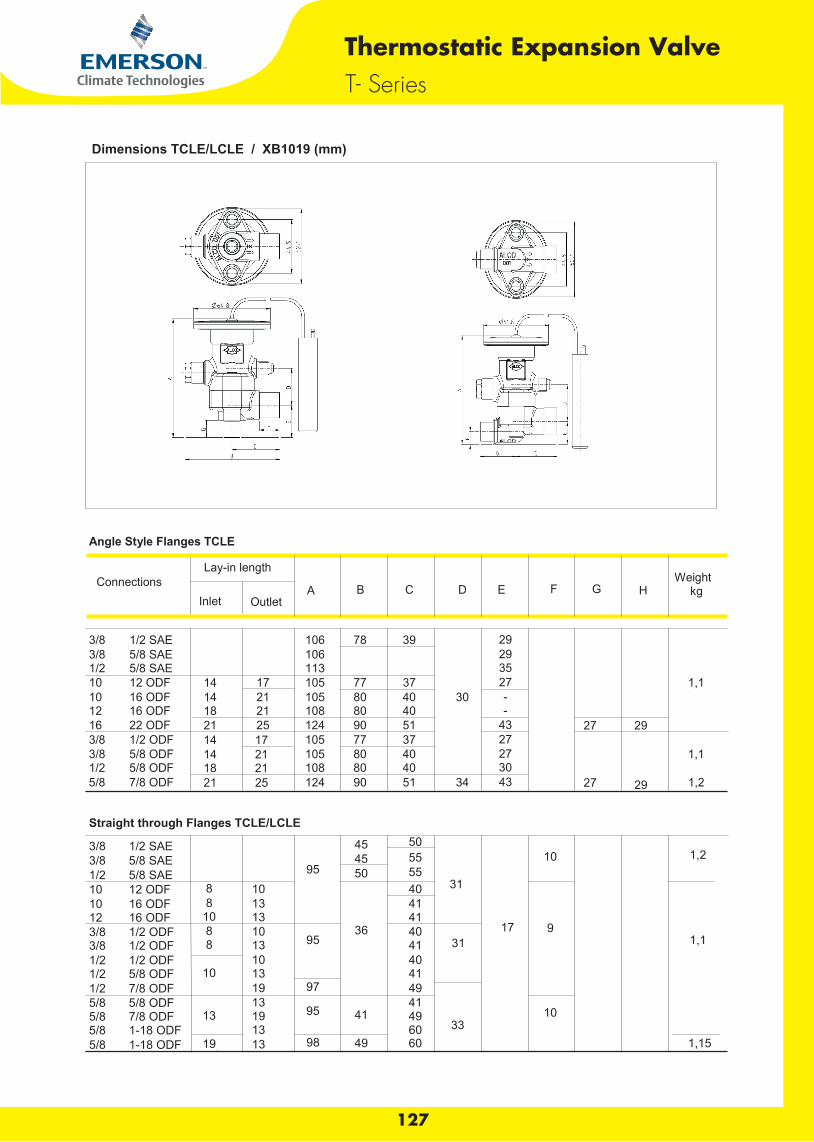
Angle Style Flanges TCLE
ConnectionsLay-in length
Weight
Inlet Outlet
A B C D E F G H kg
3/8 1/2 SAE
106 78 39
29 3/8 5/8 SAE
106
29
1/2 5/8 SAE
113
35 10 12 ODF 14 17 105 77 37
27
1,1
10 16 ODF 14 21 105 80 40 30 - 12 16 ODF 18 21 108 80 40
-
16 22 ODF 21 25 124 90 51
43
27 29 3/8 1/2 ODF 14 17 105 77 37
27
3/8 5/8 ODF 14 21 105 80 40
27
1,1 1/2 5/8 ODF 18 21 108 80 40
30
5/8 7/8 ODF 21 25 124 90 51 34 43
27 29 1,2
Straight through Flanges TCLE/LCLE
3/8 1/2 SAE
45 50 3/8 5/8 SAE
45 55
10 1,2
1/2 5/8 SAE
95 50 55 10 12 ODF 8 10
40 31
10 16 ODF 8 13
41 12 16 ODF 10 13
41
3/8 1/2 ODF 8 10
36 40
17 9 3/8 1/2 ODF 8 13 95
41 31
1,1
1/2 1/2 ODF
10
40 1/2 5/8 ODF 10 13
41
1/2 7/8 ODF
19 97
49 5/8 5/8 ODF
13
41
5/8 7/8 ODF 13 19 95 41 49 33
10 5/8 1-18 ODF
13
60
5/8 1-18 ODF 19 13 98 49 60
1,15
Thermostatic Expansion ValveT- Series
127
Dimensions TCLE/LCLE / XB1019 (mm)
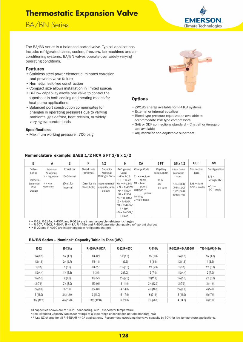
The BA/BN series is a balanced ported valve. Typical applications include: refrigerated cases, coolers, freezers, ice machines and air conditioning systems. BA/BN valves operate over widely varying operating conditions.
Features • Stainless steel power element eliminates corrosion and prevents valve failure• Hermetic, leak-free construction• Compact size allows installation in limited spaces• Bi-Flow capability allows one valve to control the superheat in both cooling and heating modes for heat pump applications• Balanced port construction compensates for changes in operating pressures due to varying ambients, gas defrost, heat reclaim, or widely varying evaporator loads
Specifications • Maximum working pressure : 700 psigN Series
BA/BN Series
Thermostatic Expansion Valve
Options
• ZW195 charge available for R-410A systems• External or internal equalizer • Bleed type pressure equalization available to accommodate PSC type compressors• SAE or ODF connections standard – Chatleff or Aeroquip are available• Adjustable or non-adjustable superheat
B A E B 1/2 H CA 5 FT 3/8 x 1/2 ODF S/TValve Series
Hermetic Balanced
Port Design
Superheat Adjustment
A = Adjustable
N = Non-Adjustable
Equalizer
E=External
(Omit for Internal)
Capacity Nominal
Rating in Tons
(See nominal capacity table
below)
Refrigerant Code
+F = R-12• H = R-22
+M = R-134a• N = R-407C*P = R-507*R = R-502*S = R-404AZ = R-410A
*B = R-448A/R-449A
+D = R-450A/R-513A
Charge Code
C = medium tempCA = heat pumpW(MOP) = press.limitingZ = low temp
Capillary Tube Length
Inlet x Outlet Connection
Sizes
1/4 x 3/83/8 x 1/21/2 x 5/85/8 x 7/8
Connection Type
ODF = solder
S/T = straight-thru
ANG = 90° angle
Nomenclature example: BAEB 1/2 HCA 5 FT 3/8 x 1/2
R-12 R-134a R-450A/R-513A R-22/R-407C R-410A R-502/R-404A/R-507 **R-448A/R-449A
1/4 (0.9) 1/2 (1.8) 1/4 (0.9) 1/2 (1.8) 1/2 (1.8) 1/4 (0.9) 1/2 (1.8)1/2 (1.8) 3/4 (2.7) 1/2 (1.8) 1 (3.5) 1 (3.5) 1/2 (1.8) 1 (3.5)1 (3.5) 1 (3.5) 3/4 (2.7) 1½ (5.3) 1½ (5.3) 1 (3.5) 1½ (5.3)
1¼ (4.4) 1½ (5.3) 1 (3.5) 2 (7.0) 2 (7.0) 1¼ (4.4) 2 (7.0)1½ (5.3) 2 (7.0) 1½ (5.3) 2½ (9.0) 3 (11.0) 1½ (5.3) 2½ (8.8)2 (7.0) 2¼ (8.0) 1¾ (9.5) 3 (11.0) 3½ (12.0) 2 (7.0) 3 (11.0)
2½ (9.0) 3 (11.0) 2¼ (8.0) 4 (14.0) 4½ (16.0) 2½ (9.0) 4 (14.0)3 (11.0) 3½ (12.0) 3 (11.0) 5 (17.0) 6 (21.0) 3 (11.0) 5 (17.5)
3½ (12.0) 4¼ (15.0) 3½ (12.0) 6 (21.0) 7½ (26.0) 4 (14.0) 6 (21.0)
BA/BN Series – Nominal* Capacity Table in Tons (kW)
All capacities shown are at 100°F condensing, 40°F evaporator temperature. *See Extended Capacity Tables for ratings at a wide range of conditions per ARI standard 750** Use SZ charge for all R-448A/R-449A applications. Recommend oversizing the valve capacity by 50% for low temperature applications.
+ = R-12, R-134a, R-450A and R-513A are interchangeable refrigerant charges* = R-507, R-502, R-404A, R-448A, R-449A and R-404A are interchangeable refrigerant charges• = R-22 and R-407C are interchangeable refrigerant charges
128
Configuration
SAE = flare30 IN
&5 FT (std)
Bleed Hole (optional)
(Omit for no bleed hole)
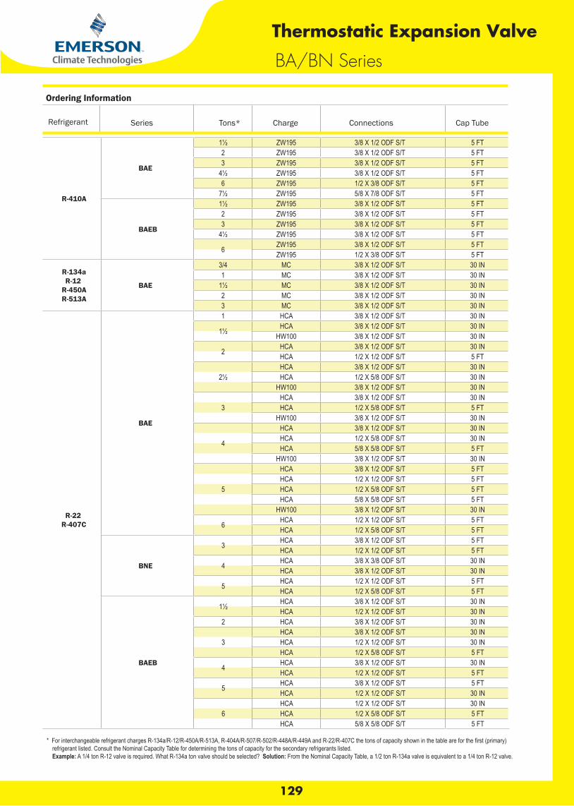
Ordering Information
Refrigerant Series Tons* Charge Connections Cap Tube
R-410A
BAE
1½ ZW195 3/8 X 1/2 ODF S/T 5 FT2 ZW195 3/8 X 1/2 ODF S/T 5 FT3 ZW195 3/8 X 1/2 ODF S/T 5 FT
4½ ZW195 3/8 X 1/2 ODF S/T 5 FT6 ZW195 1/2 X 3/8 ODF S/T 5 FT
7½ ZW195 5/8 X 7/8 ODF S/T 5 FT
BAEB
1½ ZW195 3/8 X 1/2 ODF S/T 5 FT2 ZW195 3/8 X 1/2 ODF S/T 5 FT3 ZW195 3/8 X 1/2 ODF S/T 5 FT
4½ ZW195 3/8 X 1/2 ODF S/T 5 FT
6 ZW195 3/8 X 1/2 ODF S/T 5 FTZW195 1/2 X 3/8 ODF S/T 5 FT
R-134aR-12
R-450AR-513A
BAE
3/4 MC 3/8 X 1/2 ODF S/T 30 IN1 MC 3/8 X 1/2 ODF S/T 30 IN
1½ MC 3/8 X 1/2 ODF S/T 30 IN2 MC 3/8 X 1/2 ODF S/T 30 IN3 MC 3/8 X 1/2 ODF S/T 30 IN
R-22R-407C
BAE
1 HCA 3/8 X 1/2 ODF S/T 30 IN
1½ HCA 3/8 X 1/2 ODF S/T 30 INHW100 3/8 X 1/2 ODF S/T 30 IN
2 HCA 3/8 X 1/2 ODF S/T 30 INHCA 1/2 X 1/2 ODF S/T 5 FT
2½HCA 3/8 X 1/2 ODF S/T 30 INHCA 1/2 X 5/8 ODF S/T 30 IN
HW100 3/8 X 1/2 ODF S/T 30 IN
3HCA 3/8 X 1/2 ODF S/T 30 INHCA 1/2 X 5/8 ODF S/T 5 FT
HW100 3/8 X 1/2 ODF S/T 30 IN
4
HCA 3/8 X 1/2 ODF S/T 30 INHCA 1/2 X 5/8 ODF S/T 30 INHCA 5/8 X 5/8 ODF S/T 5 FT
HW100 3/8 X 1/2 ODF S/T 30 IN
5
HCA 3/8 X 1/2 ODF S/T 5 FTHCA 1/2 X 1/2 ODF S/T 5 FTHCA 1/2 X 5/8 ODF S/T 5 FTHCA 5/8 X 5/8 ODF S/T 5 FT
HW100 3/8 X 1/2 ODF S/T 30 IN
6 HCA 1/2 X 1/2 ODF S/T 5 FTHCA 1/2 X 5/8 ODF S/T 5 FT
BNE
3 HCA 3/8 X 1/2 ODF S/T 5 FTHCA 1/2 X 1/2 ODF S/T 5 FT
4 HCA 3/8 X 3/8 ODF S/T 30 INHCA 3/8 X 1/2 ODF S/T 30 IN
5 HCA 1/2 X 1/2 ODF S/T 5 FTHCA 1/2 X 5/8 ODF S/T 5 FT
BAEB
1½ HCA 3/8 X 1/2 ODF S/T 30 INHCA 1/2 X 1/2 ODF S/T 30 IN
2 HCA 3/8 X 1/2 ODF S/T 30 IN
3HCA 3/8 X 1/2 ODF S/T 30 INHCA 1/2 X 1/2 ODF S/T 30 INHCA 1/2 X 5/8 ODF S/T 5 FT
4 HCA 3/8 X 1/2 ODF S/T 30 INHCA 1/2 X 1/2 ODF S/T 5 FT
5 HCA 3/8 X 1/2 ODF S/T 5 FTHCA 1/2 X 1/2 ODF S/T 30 IN
6HCA 1/2 X 1/2 ODF S/T 30 INHCA 1/2 X 5/8 ODF S/T 5 FTHCA 5/8 X 5/8 ODF S/T 5 FT
* For interchangeable refrigerant charges R-134a/R-12/R-450A/R-513A, R-404A/R-507/R-502/R-448A/R-449Arefrigerant listed. Consult the Nominal Capacity Table for determining the tons of capacity for the secondary refrigerants listed.
Example: A 1/4 ton R-12 valve is required. What R-134a ton valve should be selected? Solution: From the Nominal Capacity Table, a 1/2 ton R-134a valve is equivalent to a 1/4 ton R-12 valve.
BA/BN Series
Thermostatic Expansion Valve
129
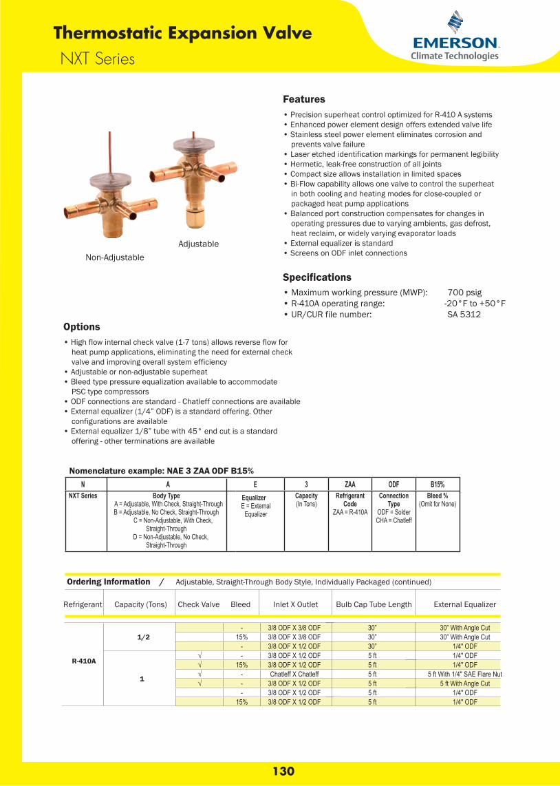
NXT SeriesThermostatic Expansion Valve
Non-AdjustableAdjustable
Options• High flow internal check valve (1-7 tons) allows reverse flow for heat pump applications, eliminating the need for external check valve and improving overall system efficiency• Adjustable or non-adjustable superheat• Bleed type pressure equalization available to accommodate PSC type compressors• ODF connections are standard - Chatleff connections are available• External equalizer (1/4” ODF) is a standard offering. Other configurations are available• External equalizer 1/8” tube with 45° end cut is a standard offering - other terminations are available
Features• Precision superheat control optimized for R-410 A systems• Enhanced power element design offers extended valve life• Stainless steel power element eliminates corrosion and prevents valve failure• Laser etched identification markings for permanent legibility• Hermetic, leak-free construction of all joints• Compact size allows installation in limited spaces• Bi-Flow capability allows one valve to control the superheat in both cooling and heating modes for close-coupled or packaged heat pump applications• Balanced port construction compensates for changes in operating pressures due to varying ambients, gas defrost, heat reclaim, or widely varying evaporator loads• External equalizer is standard• Screens on ODF inlet connections
Specifications• Maximum working pressure (MWP): 700 psig• R-410A operating range: -20°F to +50°F• UR/CUR file number: SA 5312
Nomenclature example: NAE 3 ZAA ODF B15% N A E 3 ZAA ODF B15%
NXT Series Body Type A = Adjustable, With Check, Straight-Through
B = Adjustable, No Check, Straight-Through C = Non-Adjustable, With Check,
Straight-Through D = Non-Adjustable, No Check,
Straight-Through
EqualizerE = External
Equalizer
Capacity(In Tons)
Refrigerant Code
ZAA = R-410A
Connection Type
ODF = SolderCHA = Chatleff
Bleed %(Omit for None)
Ordering Information / Adjustable, Straight-Through Body Style, Individually Packaged (continued)
Refrigerant Capacity (Tons) Check Valve Bleed Inlet X Outlet Bulb Cap Tube Length External Equalizer
1/2- 3/8 ODF X 3/8 ODF 30” 30” With Angle Cut
15% 3/8 ODF X 3/8 ODF 30” 30” With Angle Cut- 3/8 ODF X 1/2 ODF 30” 1/4" ODF
1
√ - 3/8 ODF X 1/2 ODF 5 ft 1/4" ODF√ 15% 3/8 ODF X 1/2 ODF 5 ft 1/4" ODF√ - Chatleff X Chatleff 5 ft 5 ft With 1/4" SAE Flare Nut√ - 3/8 ODF X 1/2 ODF 5 ft 5 ft With Angle Cut
- 3/8 ODF X 1/2 ODF 5 ft 1/4" ODF15% 3/8 ODF X 1/2 ODF 5 ft 1/4" ODF
R-410A
130

R-410A
8- 5/8 ODF X 7/8 ODF 5 ft 1/4" ODF
15% 5/8 ODF X 7/8 ODF 5 ft 1/4" ODF
10- 5/8 ODF X 7/8 ODF 5 ft 1/4" ODF
15% 5/8 ODF X 7/8 ODF 5 ft 1/4" ODF
12
- 1/2 ODF X 5/8 ODF 5 ft 1/4" ODF- 5/8 ODF X 7/8 ODF 5 ft 1/4" ODF
15% 5/8 ODF X 7/8 ODF 5 ft 1/4" ODF- 5/8 ODF X 1-1/8 ODF 5 ft 1/4" ODF- 7/8 ODF X 1-1/8 ODF 5 ft 1/4" ODF
15
- 5/8 ODF X 7/8 ODF 5 ft 1/4" ODF15% 5/8 ODF X 7/8 ODF 5 ft 1/4" ODF
- 5/8 ODF X 1-1/8 ODF 5 ft 1/4" ODF- 7/8 ODF X 1-1/8 ODF 5 ft 1/4" ODF
1-1/2
√ - 3/8 ODF X 1/2 ODF 5 ft 1/4" ODF√ 15% 3/8 ODF X 1/2 ODF 5 ft 1/4" ODF√ - Chatleff X Chatleff 5 ft 5 ft With 1/4" SAE Flare Nut√ - 3/8 ODF X 1/2 ODF 5 ft 5 ft With Angle Cut
- 3/8 ODF X 1/2 ODF 5 ft 1/4" ODF15% 3/8 ODF X 1/2 ODF 5 ft 1/4" ODF
2
√ - 3/8 ODF X 1/2 ODF 5 ft 1/4" ODF√ 15% 3/8 ODF X 1/2 ODF 5 ft 1/4" ODF√ - Chatleff X Chatleff 5 ft 5 ft With 1/4" SAE Flare Nut√ - 3/8 ODF X 1/2 ODF 5 ft 5 ft With Angle Cut
- 3/8 ODF X 1/2 ODF 5 ft 1/4" ODF15% 3/8 ODF X 1/2 ODF 5 ft 1/4" ODF
3
√ - 3/8 ODF X 1/2 ODF 5 ft 1/4" ODF√ 15% 3/8 ODF X 1/2 ODF 5 ft 1/4" ODF√ - Chatleff X Chatleff 5 ft 5 ft With 1/4" SAE Flare Nut√ - 3/8 ODF X 1/2 ODF 5 ft 5 ft With Angle Cut
- 3/8 ODF X 1/2 ODF 5 ft 1/4" ODF15% 3/8 ODF X 1/2 ODF 5 ft 1/4" ODF
4
√ - 3/8 ODF X 1/2 ODF 5 ft 1/4" ODF√ 15% 3/8 ODF X 1/2 ODF 5 ft 1/4" ODF√ - Chatleff X Chatleff 5 ft 5 ft With 1/4" SAE Flare Nut√ - 3/8 ODF X 1/2 ODF 5 ft 5 ft With Angle Cut
- 3/8 ODF X 1/2 ODF 5 ft 1/4" ODF15% 3/8 ODF X 1/2 ODF 5 ft 1/4" ODF
5
√ - 3/8 ODF X 1/2 ODF 5 ft 1/4" ODF√ - 1/2 ODF X 5/8 ODF 5 ft 1/4" ODF√ 15% 1/2 ODF X 5/8 ODF 5 ft 1/4" ODF√ - Chatleff X Chatleff 5 ft 5 ft With 1/4" SAE Flare Nut√ - 1/2 ODF X 5/8 ODF 5 ft 5 ft With Angle Cut
- 1/2 ODF X 5/8 ODF 5 ft 1/4" ODF15% 1/2 ODF X 5/8 ODF 5 ft 1/4" ODF
6
√ - 1/2 ODF X 5/8 ODF 5 ft 1/4" ODF√ 15% 1/2 ODF X 5/8 ODF 5 ft 1/4" ODF√ - Chatleff X Chatleff 5 ft 5 ft With 1/4" SAE Flare Nut√ - 1/2 ODF X 5/8 ODF 5 ft 5 ft With Angle Cut
- 1/2 ODF X 5/8 ODF 5 ft 1/4" ODF15% 1/2 ODF X 5/8 ODF 5 ft 1/4" ODF
7
√ - 5/8 ODF X 7/8 ODF 5 ft 1/4" ODF√ 15% 5/8 ODF X 7/8 ODF 5 ft 1/4" ODF√ - Chatleff X Chatleff 5 ft 5 ft With 1/4" SAE Flare Nut√ - 5/8 ODF X 7/8 ODF 5 ft 5 ft With Angle Cut
- 5/8 ODF X 7/8 ODF 5 ft 1/4" ODF15% 5/8 ODF X 7/8 ODF 5 ft 1/4" ODF
Refrigerant Capacity (Tons) Check Valve Bleed Inlet X Outlet Bulb Cap Tube Length External Equalizer
Ordering InformationAdjustable, Straight-Through Body Style, Individually Packaged (continued)
131
NXT SeriesThermostatic Expansion Valve
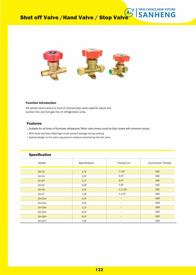
132
Specification
SANHENGNEW CHOICE,NEW FUTURE
Shut off Valve /Hand Valve / Stop Valve
Function Introduction
SH series hand valve is a kind of manual stop valve,used for liquid line,suction line and hot gas line of refrigeration units.
Thread (in) Connection Thread
Features•
• With three stainless diaphragm,could prevent leakage during working.• Special design on the valve cap,prevent moisture penetrating into the valve.
SH-02
SH-03
SH-04
SH-05
SH-06
SH-07
SH-02H
SH-03H
SH-04H
SH-05H
SH-06H
SH-07H
1/4"
3/8"
1/2"
5/8"
3/4"
7/8"
1/4"
3/8"
1/2"
5/8"
3/4"
7/8"
7/16"
5/8"
3/4"
7/8"
1-1/16"
1-1/4"
--
--
--
--
--
--
SAE
SAE
SAE
SAE
SAE
SAE
ODF
ODF
ODF
ODF
ODF
ODF
Model Specification
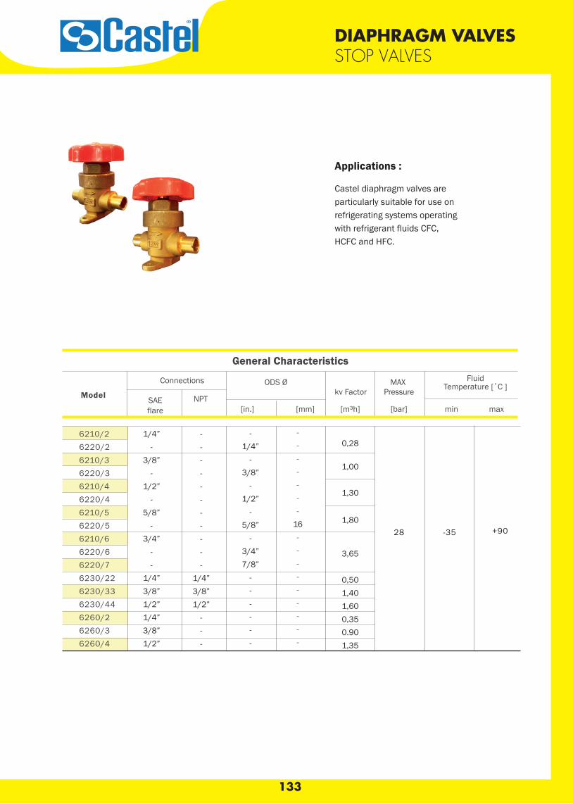
133
DIAPHRAGM VALVESSTOP VALVES
Castel diaphragm valves areparticularly suitable for use onrefrigerating systems operatingwith refrigerant fluids CFC,HCFC and HFC.
Applications :
FluidTemperature [˚C ]
[in.] [mm]
MAXPressure
min max[bar]
kv Factor
[m³h]
ODS Ø
NPTSAEflare
6210/26220/26210/36220/36210/46220/46210/56220/56210/66220/66220/76230/226230/336230/446260/26260/36260/4
1/4”-
3/8”-
1/2”-
5/8”-
3/4”--
1/4”3/8”1/2”1/4”3/8”1/2”
-----------
1/4”3/8”1/2”
---
-1/4”
-3/8”
-1/2”
-5/8”
-3/4”7/8”
------
-------
16---------
0,28
1,00
1,30
1,80
3,65
0,501,401,600,350.901,35
28 -35 +90
Model
General Characteristics
Connections
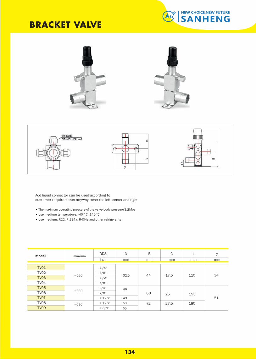
BRACKET VALVE
Add l iquid connector can be used according to customer requirements any way t o set the left, center and right.
• The maximum operating pressure of the valve body pressure 3.2Mpa • Use medium temperature: -40 °C -140 "C • Use medium: R22. R 134a. R404a and other refrigerants
ODS mmxmm
inch
▪ 020
▪ 030
▪ 036
D B mm mm
32.5 44
46 60
49 53 72 55
C L y mm mm mm
17.5 110 34
25 153 51
27.5 180
1 /4" 3/8" 1 /2" 5/8" 3/4"7/8" 1-1 /8" 1-1 /8" 1-3/8"
TV01 TV02 TV03 TV04 TV05 TV06 TV07 TV08TV09
Model
0
y
D
<
134
SANHENGNEW CHOICE,NEW FUTURE
BRACKET VALVE

ACK Check Valves
Nomenclature example: ACK-4
ACK 4Check Valve Series Copper ODF
Connection Size(in 1/16”)
Dimensional Data
The ACK check valve is a normally closed magnetic check valve that prevents refrigerant flow in liquid and compressor discharge lines.
Features
• Copper Connection Sizes 1/4” through 2-5/8”• Hermetic Spun Copper Design• Magnetic Checking Action• Built-In 30 Mesh Stainless Steel Strainer• Can Be Installed In Any Position
Specifications• UL/CUL File number: SA 5312
Ordering Information and Dimensional Data (in)
Model Connection Size A B C DOpening Pressure(oz/sq in)
Opening Pressure
(psig)
MWP(psig)
4.00 0.88 800ACK-6 3/8 ODF 0.379 ± 0.002 0.4 1.3 0.08ACK-8 1/2 ODF
5.00 1.130.504 ± 0.002 364
3.5 0.22 680ACK-10 5/8 ODF 0.629 ± 0.002 0.5ACK-12 3/4 ODF
7.00 1.630.754 ± 0.002 0.63
3.8 0.24 680ACK-14 7/8 ODF 0.879 ± 0.003 342ACK-18 1-1/8 ODF 8.38 2.13 1.130 ± 0.003 394 6.8 0.43 680ACK-22 1-3/8 ODF 9.38 2.63 1.380 ± 0.003 1.04 10.2 0.64 680ACK-26 1-5/8 ODF 10.50 3.13 1.630 ± 0.003 1.07 11.4 0.71 680ACK-34 2-1/8 ODF 12.00 3.63 2.130 ± 0.003 1.34 18.1 1.13 680ACK-42 2-5/8 ODF 13.00 4.13 2.630 ± 0.003 1.50 23.00 1.44 680
ACK Check Valves
135
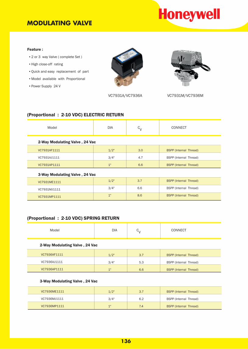
136
MODULATING VALVE
(Proportional : 2-10 VDC) ELECTRIC RETURN
VC7931AF1111
VC7931AJ1111
VC7931AP1111
1/2" 3.0 BSPP (Internal Thread)
3/4" 4.7 BSPP (Internal Thread)
1" 6.6 BSPP (Internal Thread)
2-Way Modulating Valve , 24 Vac
3-Way Modulating Valve , 24 Vac
VC7931ME1111
VC7931MJ1111
VC7931MP1111
1/2" 3.7 BSPP (Internal Thread)
3/4" 6.6 BSPP (Internal Thread)
1" 8.6 BSPP (Internal Thread)
(Proportional : 2-10 VDC) SPRING RETURN
VC7936AF1111
VC7936AJ1111
VC7936AP1111
1/2" 3.7 BSPP (Internal Thread)
3/4" 5.3 BSPP (Internal Thread)
1" 6.6 BSPP (Internal Thread)
VC7936ME1111
VC7936MJ1111
VC7936MP1111
1/2" 3.7 BSPP (Internal Thread)
3/4" 6.2 BSPP (Internal Thread)
1" 7.4 BSPP (Internal Thread)
Model DIA CV CONNECT
Feature :
▪ 2 or 3 way Valve ( complete Set )
▪ High close-off rating
▪ Quick and easy replacement of part
▪ Model available with Proportional
▪ Power Supply 24 V
Model DIA CV CONNECT
2-Way Modulating Valve , 24 Vac
3-Way Modulating Valve , 24 Vac
VC7931A/VC7936A VC7931M/VC7936M
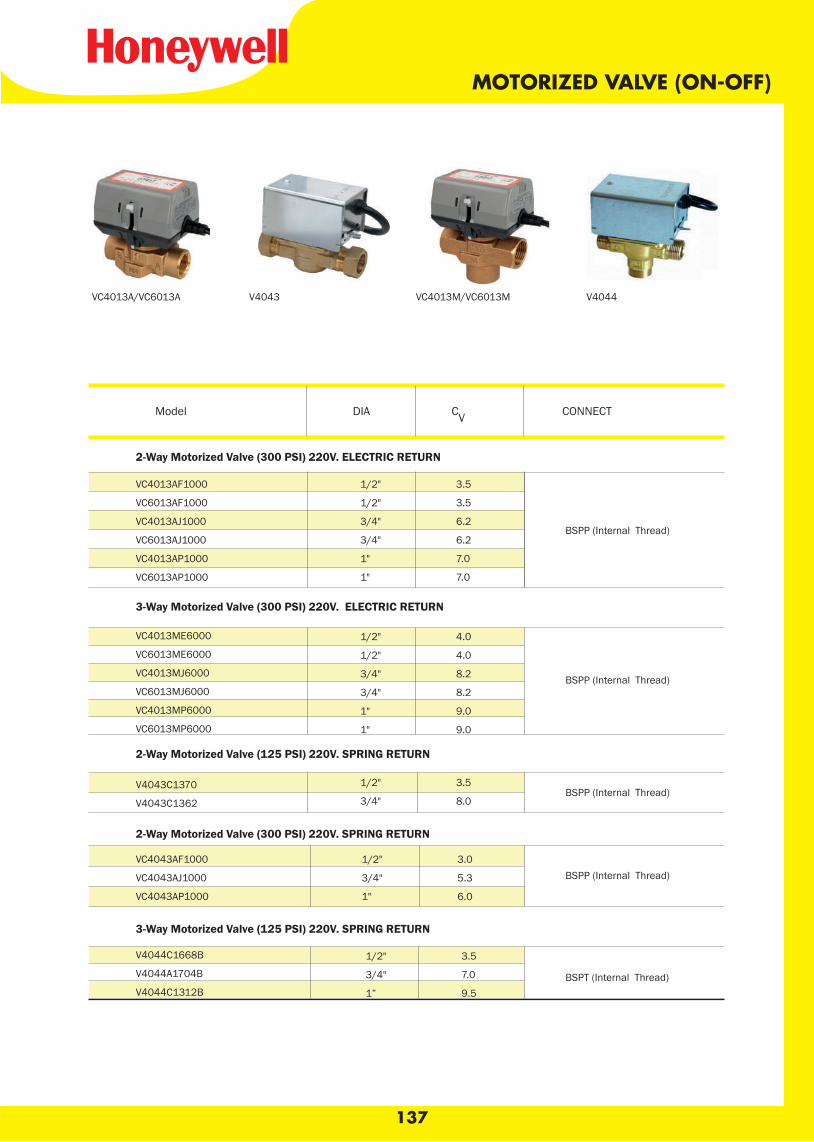
137
MOTORIZED VALVE (ON-OFF)
VC4013AF1000
VC6013AF1000
VC4013AJ1000
VC6013AJ1000
VC4013AP1000
VC6013AP1000
VC4013ME6000
VC6013ME6000
VC4013MJ6000
VC6013MJ6000
VC4013MP6000
VC6013MP6000
V4043C1370
V4043C1362
VC4043AF1000
VC4043AJ1000
VC4043AP1000
V4044C1668B
V4044A1704B
V4044C1312B
1/2" 3.5
1/2" 3.5
3/4" 6.2
3/4" 6.2
1" 7.0
1" 7.0
1/2" 4.0
1/2" 4.0
3/4" 8.2
3/4" 8.2
1" 9.0
1" 9.0
1/2" 3.5
3/4" 8.0
1/2" 3.0
3/4" 5.3
1" 6.0
1/2" 3.5
3/4" 7.0
1” 9.5
2-Way Motorized Valve (300 PSI) 220V. ELECTRIC RETURN
3-Way Motorized Valve (300 PSI) 220V. ELECTRIC RETURN
2-Way Motorized Valve (125 PSI) 220V. SPRING RETURN
2-Way Motorized Valve (300 PSI) 220V. SPRING RETURN
3-Way Motorized Valve (125 PSI) 220V. SPRING RETURN
BSPP (Internal Thread)
BSPP (Internal Thread)
BSPP (Internal Thread)
BSPP (Internal Thread)
BSPT (Internal Thread)
VC4013A/VC6013A VC4013M/VC6013MV4043 V4044
Model DIA CV CONNECT
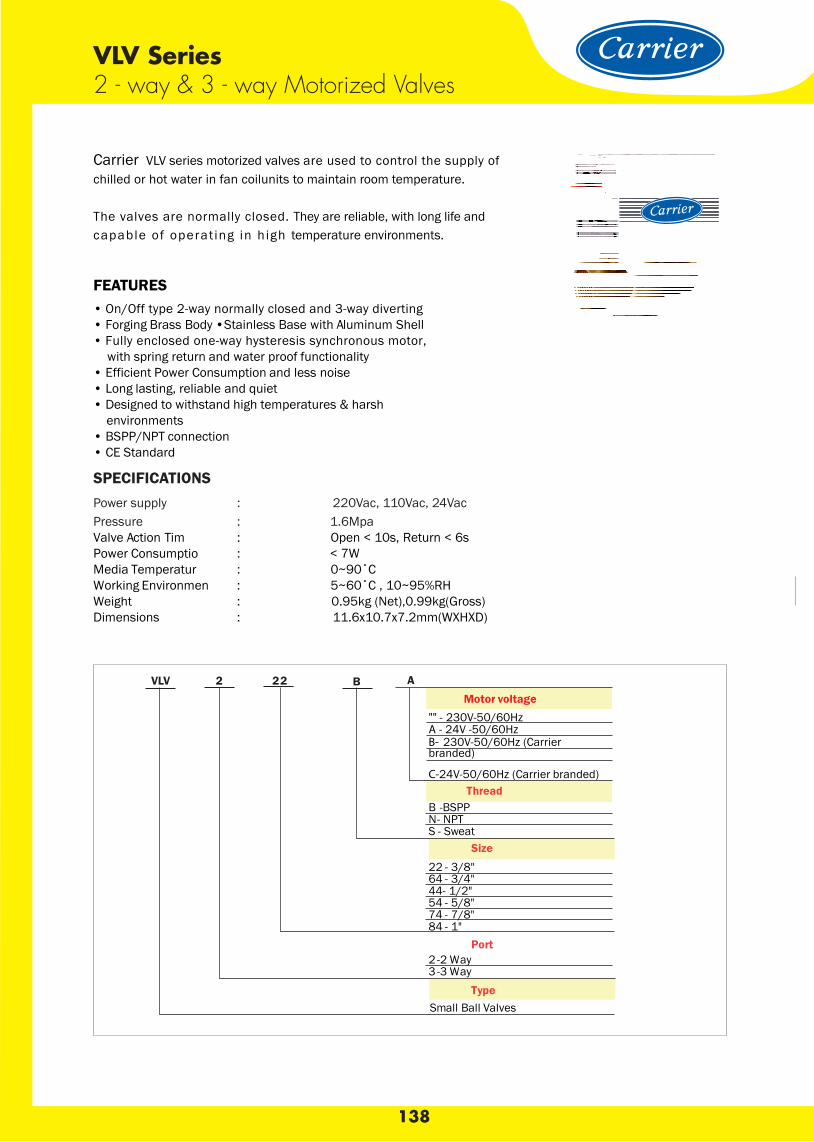
138
Carrier VLV series motorized valves are used to control the supply ofchilled or hot water in fan coilunits to maintain room temperature.
The valves are normally closed. They are reliable, with long life andcapable of operat ing in h igh temperature environments.
VLV Series 2 - way & 3 - way Motorized Valves
FEATURES• On/Off type 2-way normally closed and 3-way diverting• Forging Brass Body •Stainless Base with Aluminum Shell• Fully enclosed one-way hysteresis synchronous motor, with spring return and water proof functionality• Efficient Power Consumption and less noise• Long lasting, reliable and quiet • Designed to withstand high temperatures & harsh environments• BSPP/NPT connection• CE Standard
SPECIFICATIONSPower supply : 220Vac, 110Vac, 24VacPressure : 1.6MpaValve Action Tim : Open < 10s, Return < 6sPower Consumptio : < 7WMedia Temperatur : 0~90˚CWorking Environmen : 5~60˚C , 10~95%RHWeight : 0.95kg (Net),0.99kg(Gross)Dimensions : 11.6x10.7x7.2mm(WXHXD)
Motor voltage"" - 230V-50/60HzA - 24V -50/60HzB- 230V-50/60Hz (Carrier branded)
C-24V-50/60Hz (Carrier branded)Thread
B -BSPPN- NPTS - Sweat
Size
22 - 3/8"64 - 3/4"44- 1/2"54 - 5/8"74 - 7/8"84 - 1"
Port2 -2 Way3 -3 Way
TypeSmall Ball Valves
AVLV 2 22 B
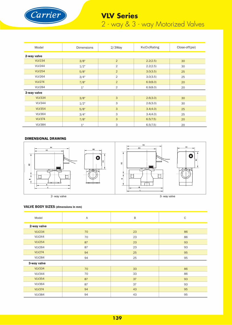
3-way valve
139
VLV Series 2 - way & 3 - way Motorized Valves
DIMENSIONAL DRAWING
2- way valve 3- way valve
VALVE BODY SIZES (dimensions in mm)
Model Dimensions 2/3Way Kv(Cv)Rating Close-off(psi)
VLV234 3/8" 2 2.2(2.5) 30
VLV244 1/2" 2 2.2(2.5) 30
VLV254 5/8" 2 3.0(3.5) 25
VLV264 3/4" 2 3.0(3.5) 25
VLV274 7/8" 2 6.9(8.0) 20
VLV284 1" 2 6.9(8.0) 20
VLV334 3/8" 3 2.6(3.0) 30
VLV344 1/2" 3 2.6(3.0) 30
VLV354 5/8" 3 3.4(4.0) 25
VLV364 3/4" 3 3.4(4.0) 25VLV374 7/8" 3 6.5(7.5) 20
VLV384 1" 3 6.5(7.5) 20
Model A B C
VLV234 70 23 86
VLV244 70 23 86
VLV254 87 23 93
VLV264 87 23 93
VLV274 94 25 95
VLV284 94 25 95
VLV334 70 33 86
VLV344 70 33 86
VLV354 87 37 93
VLV364 87 37 93
VLV374 94 43 95
VLV384 94 43 95
2-way valve
2-way valve
3-way valve
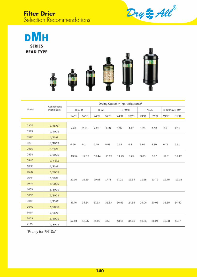
140
Filter Drier Selection Recommendations
Connections lnlet/outletModel R-134a R-22 R-407C R-410A R-404A & R-507
Drying Capacity (kg refrigerant)¹
24ºC 52ºC 24ºC 52ºC 24ºC 52ºC 24ºC 52ºC 24ºC 52ºC
032F
032S
052F
52S
053S
083S
084F
163F
163S
164F
164S
165S
303F
304F
304S
305F
305S
417S
1/4SAE
1/4ODS
1/4SAE
1/4ODS
3/8SAE
3/8ODS
1/4 SAE
3/8SAE
3/8ODS
1/2SAE
1/2ODS
5/8ODS
3/8ODS
1/2SAE
1/2ODS
5/8SAE
5/8ODS
7/8ODS
2.26 2.15 2.26 1.98 1.92 1.47 1.25 1.13 2.2 2.15
6.66 6.1 6.49 5.53 5.53 4.4 3.67 3.39 6.77 6.11
13.54 12.53 13.44 11.29 11.29 8.75 9.03 6.77 12.7 12.42
21.16 19.19 20.88 17.78 17.21 13.54 11.68 10.72 19.75 19.18
37.46 34.54 37.13 31.83 30.93 24.55 29.06 20.03 35.55 34.42
52.94 48.25 51.92 44.3 43.17 34.31 40.35 26.24 49.38 47.97
SERIESBEAD TYPE
"Ready for R410a"
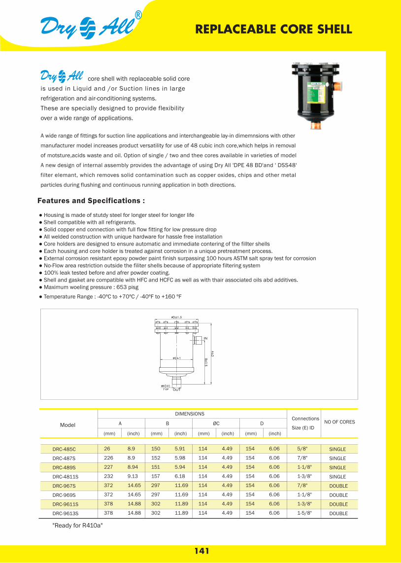
141
Drying Capacity (kg refrigerant)¹
core shell with replaceable solid core is used in Liquid and /or Suction lines in large refrigeration and air-conditioning systems. These are specially designed to provide flexibility over a wide range of applications.
REPLACEABLE CORE SHELL
A wide range of fittings for suction line applications and interchangeable lay-in dimemnsions with other
manufacturer model increases product versatility for use of 48 cubic inch core,which helps in removal
of motsture,acids waste and oil. Option of single / two and thee cores available in varieties of model
A new design of internal assembly provides the advantage of using Dry All 'DPE 48 BD'and ' DSS48'
filter elemant, which removes solid contamination such as copper oxides, chips and other metal
particles during flushing and continuous running application in both directions.
Features and Specifications :
● Housing is made of stutdy steel for longer steel for longer life ● Shell compatible with all refrigerants. ● Solid copper end connection with full flow fitting for low pressure drop ● All welded construction with unique hardware for hassle free installation ● Core holders are designed to ensure automatic and immediate contering of the fillter shells ● Each housing and core holder is treated against corrosion in a unique pretreatment process. ● External corrosion resistant epoxy powder paint finish surpassing 100 hours ASTM salt spray test for corrosion ● No-Flow area restriction outside the filiter shells because of appropriate filtering system ● 100% leak tested before and afrer powder coating. ● Shell and gasket are compatible with HFC and HCFC as well as with thair associated oils abd additives. ● Maximum woeling pressure : 653 pisg ● Temperature Range : -40ºC to +70ºC / -40ºF to +160 ºF
DRC-485C
DRC-487S
DRC-489S
DRC-4811S
DRC-967S
DRC-969S
DRC-9611S
DRC-9613S
DIMENSIONS
A B ØC D Connections
Size (E) IDNO OF CORES
(mm) (inch) (mm) (inch) (mm) (inch) (mm) (inch)
26 8.9 150 5.91 114 4.49 154 6.06
226 8.9 152 5.98 114 4.49 154 6.06
227 8.94 151 5.94 114 4.49 154 6.06
232 9.13 157 6.18 114 4.49 154 6.06
372 14.65 297 11.69 114 4.49 154 6.06
372 14.65 297 11.69 114 4.49 154 6.06
378 14.88 302 11.89 114 4.49 154 6.06
378 14.88 302 11.89 114 4.49 154 6.06
5/8"
7/8"
1-1/8"
1-3/8"
7/8"
1-1/8"
1-3/8"
1-5/8"
SINGLE
SINGLE
SINGLE
SINGLE
DOUBLE
DOUBLE
DOUBLE
DOUBLE
Model
"Ready for R410a"
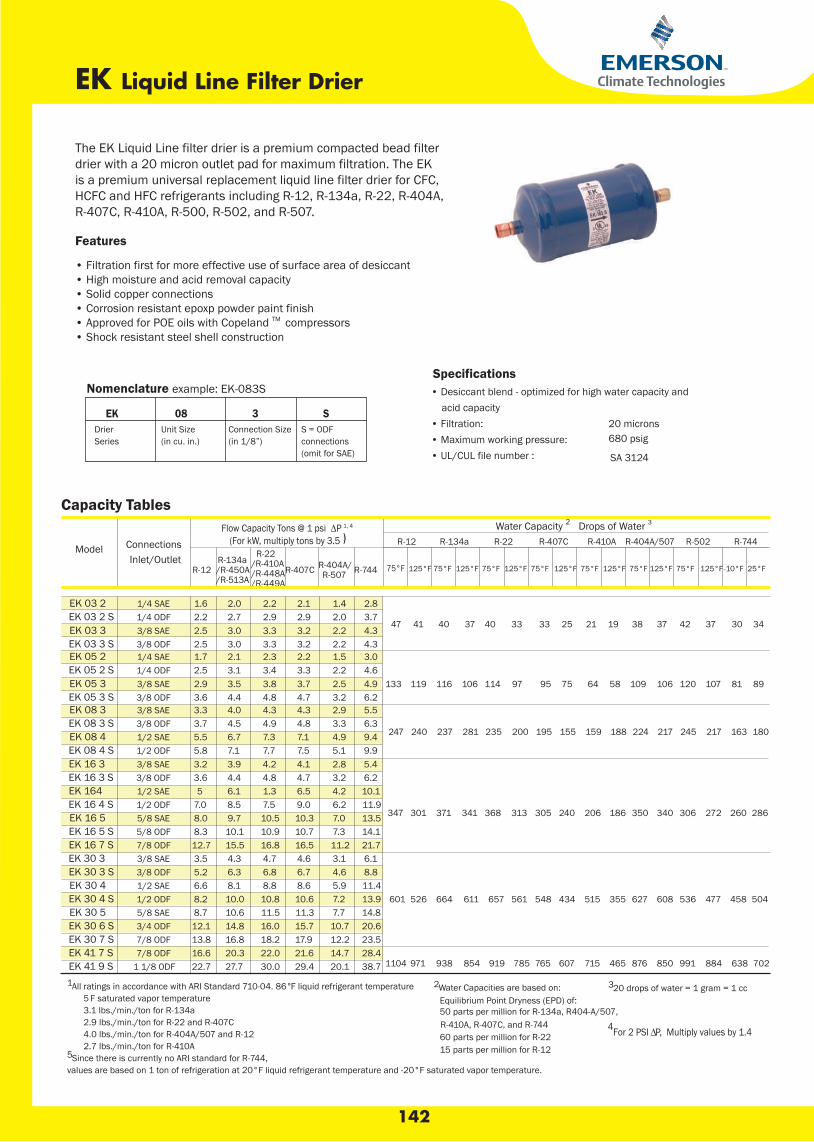
142
EK Liquid Line Filter Drier
Features
• Filtration first for more effective use of surface area of desiccant• High moisture and acid removal capacity• Solid copper connections • Corrosion resistant epoxp powder paint finish• Approved for POE oils with Copeland TM compressors• Shock resistant steel shell construction
Specifications• Desiccant blend - optimized for high water capacity and
acid capacity • Filtration:
20 microns • Maximum working pressure:• UL/CUL file number :
680 psig
SA 3124
Nomenclature example: EK-083S
EK 08 3 SDrierSeries
Unit Size(in cu. in.)
Connection Size(in 1/8”)
S = ODFconnections(omit for SAE)
Capacity Tables
ConnectionsInlet/Outlet
Flow Capacity Tons @ 1 psi ∆P 1, 4 (For kW, multiply tons by 3.5 )
Water Capacity 2 Drops of Water 3
R-12 R-134a R-22 R-407C R-410A R-404A/507 R-502 R-744
R-12R-134a/R-450A/R-513A
R-22/R-410A/R-448A/R-449A
R-407C R-404A/R-507 R-744 75°F 125°F 75°F 125°F 75°F 125°F 75°F -10°F 25°F
47 41 40 37 40 33 33 25 21 19 38 37 42 37 30 34
EK 03 2 1/4 SAE 2.0 2.2 2.1 1.4 2.8EK 03 2 S 1/4 ODF 2.7 2.9 2.9 2.0 3.7EK 03 3 3/8 SAE 3.0 3.3 3.2 2.2 4.3EK 03 3 S 3/8 ODF 3.0 3.3 3.2 2.2 4.3
133 119 116 106 114 97 95 75 64 58 109 106 120 107 81 89
EK 05 2 1/4 SAE 2.1 2.3 2.2 1.5 3.0EK 05 2 S 1/4 ODF 3.1 3.4 3.3 2.2 4.6EK 05 3 3/8 SAE 3.5 3.8 3.7 2.5 4.9EK 05 3 S 3/8 ODF 4.4 4.8 4.7 3.2 6.2EK 08 3 3/8 SAE 4.0 4.3 4.3 2.9 5.5EK 08 3 S 3/8 ODF 4.5 4.9 4.8 3.3 6.3EK 08 4 1/2 SAE 6.7 7.3 7.1 4.9 9.4EK 08 4 S 1/2 ODF 7.1 7.7 7.5 5.1 9.9
347 301 371 341 368 313 305 240 206 186 350 340 306 272 260 286
EK 16 3 3/8 SAE 3.9 4.2 4.1 2.8 5.4EK 16 3 S 3/8 ODF 4.4 4.8 4.7 3.2 6.2EK 164 1/2 SAE 6.1 1.3 6.5 4.2 10.1EK 16 4 S 1/2 ODF 8.5 7.5 9.0 6.2 11.9EK 16 5 5/8 SAE 9.7 10.5 10.3 7.0 13.5EK 16 5 S 5/8 ODF 10.1 10.9 10.7 7.3 14.1EK 16 7 S 7/8 ODF 15.5 16.8 16.5 11.2 21.7EK 30 3 3/8 SAE 4.3 4.7 4.6 3.1 6.1
601 526 664 611 657 561 548 434 515 355 627 608 536 477 458 504
EK 30 3 S 3/8 ODF 6.3 6.8 6.7 4.6 8.8EK 30 4 1/2 SAE 8.1 8.8 8.6 5.9 11.4EK 30 4 S 1/2 ODF 10.0 10.8 10.6 7.2 13.9EK 30 5 5/8 SAE 10.6 11.5 11.3 7.7 14.8EK 30 6 S 3/4 ODF 14.8 16.0 15.7 10.7 20.6EK 30 7 S 7/8 ODF 16.8 18.2 17.9 12.2 23.5
1104 971 938 854 919 785 765 607 715 465 876 850 991 884 638 702EK 41 7 S 7/8 ODF 20.3 22.0 21.6 14.7 28.4EK 41 9 S 1 1/8 ODF
1.62.22.52.51.72.52.93.63.33.75.55.83.23.65
7.08.08.312.73.55.26.68.28.712.113.816.622.7 27.7 30.0 29.4 20.1 38.7
Model
247 240 237 281 235 200 195 155 159 188 224 217 245 217 163 180
1 All ratings in accordance with ARI Standard 710-04. 86°F liquid refrigerant temperature 2 Water Capacities are based on: 3 20 drops of water = 1 gram = 1 cc5 F saturated vapor temperature Equilibrium Point Dryness (EPD) of:3.1 lbs./min./ton for R-134a 50 parts per million for R-134a, R404-A/507,2.9 lbs./min./ton for R-22 and R-407C R-410A, R-407C, and R-744 4 For 2 PSI ∆P, Multiply values by 1.44.0 lbs./min./ton for R-404A/507 and R-12 60 parts per million for R-222.7 lbs./min./ton for R-410A 15 parts per million for R-12 5 Since there is currently no ARI standard for R-744,
values are based on 1 ton of refrigeration at 20°F liquid refrigerant temperature and -20°F saturated vapor temperature.
The EK Liquid Line filter drier is a premium compacted bead filterdrier with a 20 micron outlet pad for maximum filtration. The EKis a premium universal replacement liquid line filter drier for CFC,HCFC and HFC refrigerants including R-12, R-134a, R-22, R-404A,R-407C, R-410A, R-500, R-502, and R-507.
125°F 75°F 125°F 75°F 125°F 75°F 125°F
A wide range of fittings for suction line applications and interchangeable lay-in dimemnsions with other
manufacturer model increases product versatility for use of 48 cubic inch core,which helps in removal
of motsture,acids waste and oil. Option of single / two and thee cores available in varieties of model
A new design of internal assembly provides the advantage of using Dry All 'DPE 48 BD'and ' DSS48'
filter elemant, which removes solid contamination such as copper oxides, chips and other metal
particles during flushing and continuous running application in both directions.
Features and Specifications :
● Housing is made of stutdy steel for longer steel for longer life ● Shell compatible with all refrigerants. ● Solid copper end connection with full flow fitting for low pressure drop ● All welded construction with unique hardware for hassle free installation ● Core holders are designed to ensure automatic and immediate contering of the fillter shells ● Each housing and core holder is treated against corrosion in a unique pretreatment process. ● External corrosion resistant epoxy powder paint finish surpassing 100 hours ASTM salt spray test for corrosion ● No-Flow area restriction outside the filiter shells because of appropriate filtering system ● 100% leak tested before and afrer powder coating. ● Shell and gasket are compatible with HFC and HCFC as well as with thair associated oils abd additives. ● Maximum woeling pressure : 653 pisg ● Temperature Range : -40ºC to +70ºC / -40ºF to +160 ºF
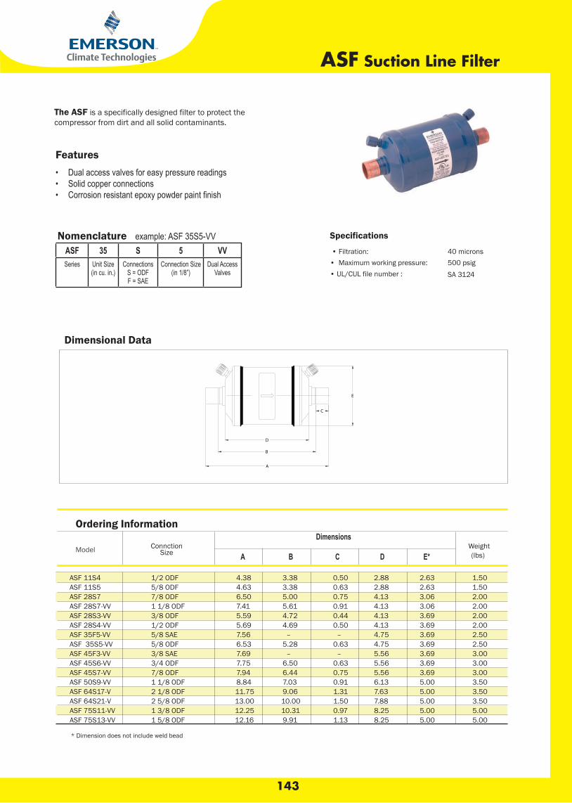
143
Features• Dual access valves for easy pressure readings• Solid copper connections•
Nomenclature example: ASF 35S5-VVASF 35 S 5 VVSeries Unit Size
(in cu. in.)Connections
S = ODFF = SAE
Connection Size(in 1/8”)
Dual AccessValves
Dimensional Data
Specifications
• Filtration: 40 microns• Maximum working pressure:• UL/CUL file number :
500 psig
Ordering Information
Model
DimensionsWeight(lbs)A B C D E*
ASF 11S4 1/2 ODF 4.38 3.38 0.50 2.88 2.63 1.50ASF 11S5 5/8 ODF 4.63 3.38 0.63 2.88 2.63 1.50ASF 28S7 7/8 ODF 6.50 5.00 0.75 4.13 3.06 2.00ASF 28S7-VV 1 1/8 ODF 7.41 5.61 0.91 4.13 3.06 2.00ASF 28S3-VV 3/8 ODF 5.59 4.72 0.44 4.13 3.69 2.00ASF 28S4-VV 1/2 ODF 5.69 4.69 0.50 4.13 3.69 2.00ASF 35F5-VV 5/8 SAE 7.56 – – 4.75 3.69 2.50ASF 35S5-VV 5/8 ODF 6.53 5.28 0.63 4.75 3.69 2.50ASF 45F3-VV 3/8 SAE 7.69 – – 5.56 3.69 3.00ASF 45S6-VV 3/4 ODF 7.75 6.50 0.63 5.56 3.69 3.00ASF 45S7-VV 7/8 ODF 7.94 6.44 0.75 5.56 3.69 3.00ASF 50S9-VV 1 1/8 ODF 8.84 7.03 0.91 6.13 5.00 3.50ASF 64S17-V 2 1/8 ODF 11.75 9.06 1.31 7.63 5.00 3.50ASF 64S21-V 2 5/8 ODF 13.00 10.00 1.50 7.88 5.00 3.50ASF 75S11-VV 1 3/8 ODF 12.25 10.31 0.97 8.25 5.00 5.00ASF 75S13-VV 1 5/8 ODF 12.16 9.91 1.13 8.25 5.00 5.00
* Dimension does not include weld bead
ConnctionSize
ASF Suction Line Filter
The ASF is a specifically designed filter to protect thecompressor from dirt and all solid contaminants.
SA 3124

144
STAS Steel Liquid and Suction Line Filter DrierSTAS CO Steel Liquid and Suction Line Filter Drier for CO2
Features• Slotted cover/unique internal hardware for hassle-free installation• Full flow fittings for low pressure drop• Corrosion resistant epoxy powder paint finish• Sturdy steel shells for long life• Solid copper connections• 100 mesh outlet screen
Nomenclature example: STAS 489TSTAS 48 9 TSteel
Take-ApartSeries
Unit Size(in cu. in.)
Connection Size(in 1/8”)
System ServiceT = Liquid Line Service
SV = Suction Line Service
Specifications
• Filtration (with core): 40 microns
• Maximum working pressure:
• UL/CUL file number :
SV version = 500 psigT version = 680 psig
SA7175
inch cores.
oF
1 All ratings in accordance with ARI Standard 710-04. 86º F liquid refrigerant temperature • 5°F saturated vapor temperature • 3.1 lbs./min./ton for R-134a • 2.9 lbs./min./ton for R-22 and R-407C • 4.0 lbs./min./ton for R-404A/507 and R-122 For 2 PSI ∆P, Multiply values by 1.4
3 For kW, multiply by 3.5
4 R-744: Since there is currently no ARI standard for R-744, values are based on 1 ton of refrigeration at 20liquid refrigerant temperature and -20oF saturated vapor temperature.
Liquid Flow Capacity Tons @ 1 psi ΔP 1, 2, 3
Connections R-134a R-450AR-513A
R-22R-410AR-448AR-449A
R-407C R-404A/507 R-502 R-410A R-744
21 22 21 14 22 2838 41 39 25 41 5353 58 56 36 58 7575 81 78 41 8181 89 85 58 8942 45 43 27 4565 71 68 42 71 9280 87 83 54 87 11292 100 95 58 10066 72 69 41 7292 100 96 60 10093 101 97 66 101110 120 115 76 12094 102 98 64 102103 113 108 69 113
STAS-485TSTAS-487TSTAS-489TSTAS-4811TSTAS-4813TSTAS-967TSTAS-969TSTAS-9611TSTAS-9613TSTAS-1449TSTAS-14411TSTAS-14413TSTAS-14417TSTAS-19211TSTAS-19213TSTAS-19217T
5/8 ODF7/8 ODF
1 1/8 ODF1 3/8 ODF1 5/8 ODF7/8 ODF
1 1/8 ODF1 3/8 ODF1 5/8 ODF1 1/8 ODF1 3/8 ODF1 5/8 ODF2 1/8 ODF1 3/8 ODF1 5/8 ODF2 1/8 ODF 113 123 117
15273853583047576547656678677480 78 123
Model
The STAS is a replaceable core filter drier for CFC,HCFC,andHFC refrigerants for use in large commercial air conditioning and refrigeration systems. The STAS-CO is specifically designed for CO2 (R-744) systems.

145
DCL 419 S
DCL 304 S
DCL 305 S
DCL 307 S
DCL 417 S
DCL 163 S
DCL 164 S
DCL 165 S
DCL 303 S
DCL 304
DCL 305
DCL 053 S
DCL 083 S
DCL 164
DCL 165
DCL 303
DCL 053
DCL 083
DCL 163
5 3/8”SAE 5.0 4.2 4.0
8 3/8”SAE 6.0 4.2 4.0
16 3/8“SAE 6.8 5.1 4.5
16 1/2“SAE 9.4 6.8 6.2
16 5/8”SAE 13.4 10.0 8.5
30 3/8”SAE 6.5 4.8 4.2
30 1/2”SAE 9.7 7.1 6.2
30 5/8”SAE 14.0 10.5 9.4
5 3/8”ODF 5.4 4.2 4.0
8 3/8”ODF 6.0 4.2 4.0
16 3/8”ODF 6.8 5.1 4.5
16 1/2”ODF 9.4 6.8 6.2
16 5/8”ODF 13.4 10.0 8.5
30 3/8”ODF 19.5 4.8 4.2
30 1/2”ODF 9.7 7.1 6.2
30 5/8”ODF 14.0 10.5 9.4
30 7/8”ODF 18.5 14.0 12.2
41 7/8”ODF 28.5 21.1 18.5
41 1-1/8”ODF 28.5 21.1 18.5
VALUE
(CU INCH ) SIZE R134 R22 R404A Model CONNECTION
FLOW CAPACITY ( TON ) @ 1 PSIG
LIQUID LINE FILTER DRIER

146
Filter Drier Cores
Universal replacement Cores and filter cores for use in Our shell and all other take a part type filter drier shells
Features • Moulded Core is a composite of carefully selected desiccant material, Artfully blended, providing very high Mechanical Strength, high filtering capability, Outstanding moisture adsorption and acid removal. DA - 48 • Adsorb both moisture and acid in entire systems for the full temperature range • Recommended for use in combination with mineral oil and Alkyl- benzene oil Suitable for use with CFC, HFC and HCFC refrigerants. • Solid Core are individually packed in metal cans , fully activated and hermetically sealed against moisture and dirt and to preserve freshness.
DA 48 Series Cabic Inch
Model Recommended
Refrigerant Type
Nomenclature
Function R-134a R-22 R-407C R-404A R-410A R-507
75°F 125°F 75°F 125°F 75°F 125°F 75°F 125°F 75°F 125°F 75°F 125°F
DA-48
DB-48
DC-48
DC-100
CFC, HFC, HCFC
CFC, HFC, HCFC
CFC, HFC, HCFC
CFC, HFC, HCFC
Standard Replaceable
Burnout Clean up
Universal Replaceable
Universal Replaceable
1195
680
1525
3015
1130
520
1447
2845
1178 1097 1195 1097 1277 1206 1082 995 1284 1182
590 400 510 290 730 500 579 375 725 497
1501 1388 1533 1404 1632 1547 1380 1276 1634 1530
2995 2775 3037 2796 3262 3098 2785 2598 3245 3095
• Water Capacities are based on :
Equilibrium Point Dryness (EPD) of
50 parts per million for R-134a, R404-A/R410A and R-407C
60 Parts per million for R-22
30 parts per million for R-502
DC - 48
DB - 48
• 20 drops of water = 1 gram = 1 cc
ModelDIMENSIONS
A B C
mm inch mm inch mm inch
DA-48DA-48DA-48DC-100
959595123
3.743.743.744.85
140140140160
5.515.515.516.3
60606050
2.362.362.361.97
Water Capacity*Drops of Water*
"Ready for R410a"
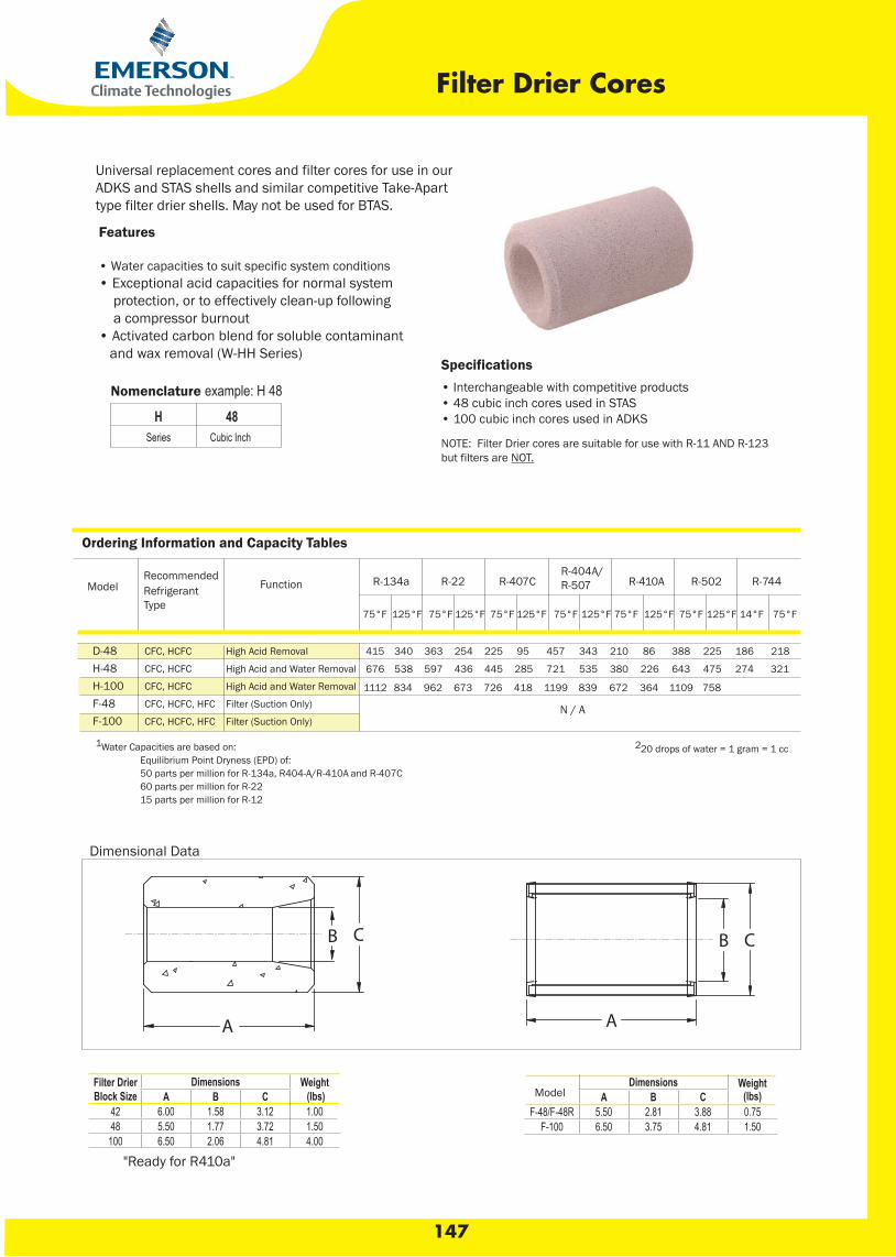
"Ready for R410a"
147
• 20 drops of water = 1 gram = 1 cc
Features
• Water capacities to suit specific system conditions• Exceptional acid capacities for normal system protection, or to effectively clean-up following a compressor burnout• Activated carbon blend for soluble contaminant and wax removal (W-HH Series)
Nomenclature example: H 48
H 48Series Cubic Inch
Specifications• Interchangeable with competitive products• 48 cubic inch cores used in STAS• 100 cubic inch cores used in ADKS
NOTE: Filter Drier cores are suitable for use with R-11 AND R-123but filters are NOT.
Ordering Information and Capacity Tables
Recommended Refrigerant Type
Function R-134a R-22 R-407CR-404A/R-507 R-410A R-502 R-744
75°F 125°F 75°F 125°F 75°F 125°F 75°F 125°F 75°F 125°F 75°F 125°F 14°F 75°F
415 340 363 254 225 95 457 343 210 86 388 225 186 218
676 538 597 436 445 285 721 535 380 226 643 475 274 321
1112 834 962 673 726 418 1199 839 672 364 1109 758
D-48H-48H-100F-48F-100
CFC, HCFC
CFC, HCFC
CFC, HCFC
CFC, HCFC, HFC
CFC, HCFC, HFC
High Acid Removal
High Acid and Water Removal
High Acid and Water Removal
Filter (Suction Only)
Filter (Suction Only)
Model
Filter Drier Cores
Universal replacement cores and filter cores for use in ourADKS and STAS shells and similar competitive Take-Apart type filter drier shells. May not be used for BTAS.
N / A
1 Water Capacities are based on: 2 20 drops of water = 1 gram = 1 cc Equilibrium Point Dryness (EPD) of: 50 parts per million for R-134a, R404-A/R-410A and R-407C 60 parts per million for R-22 15 parts per million for R-12
Dimensional Data
Dimensions Weight (lbs)A B C
F-48/F-48R 5.50 2.81 3.88 0.75F-100 6.50 3.75 4.81 1.50
Filter Drier Block Size
Dimensions Weight (lbs)A B C
42 6.00 1.58 3.12 1.0048 5.50 1.77 3.72 1.50100 6.50 2.06 4.81 4.00
Model
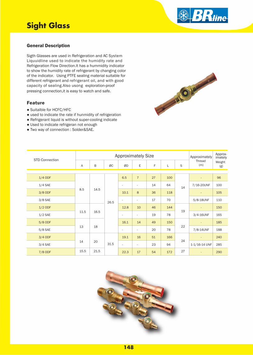
148
Sight Glass
General Description Sigth Glasses are used in Refrigeration and AC System Liquuidline used to indicate the humidity rate and Refrigeration Flow Direction.lt has a hummidity indicator to show the humidity rate of refrigerant by changing color of the indicator. Using PTFE sealing material suitable for different refrigerant and refrigerant oil, and with good capacity of sealing.Also usong exploration-proof pressing connection,it is easy to watch and safe.
Feature ● Suitalble for HCFC/HFC ● used to indicate the rate if hunmidity of refrigeration ● Refrigerant liquid is without super-cooling indicate ● Used to indicate refrigeran not enough ● Two way of connection : Solder&SAE.
A B ØC ØD E F L S
STD Connection
1/4 ODF
1/4 SAE
3/8 ODF
3/8 SAE
1/2 ODF
1/2 SAE
5/8 ODF
5/8 SAE
3/4 ODF
3/4 SAE
7/8 ODF
6.5 7 27 100
- - 14 64
10.1 8 36 118
- - 17 70
12.8 10 46 144
- - 19 78
16.1 14 49 150
- - 20 78
19.1 16 51 166
- - 23 94
22.3 17 54 172
-
7/16-20UNF
-
5/8-18UNF
-
3/4-16UNF
-
7/8-14UNF
-
1-1/16-14 UNF
-
96
100
105
110
150
165
185
188
240
285
290
14
19
22
24
27
8.5
11.5
13
14
15.5
14.5
16.5
18
20
21.5
26.5
31.5
Approximately Size ApproximatelyThread
(m)
Approx-imatelyWeight
(g)
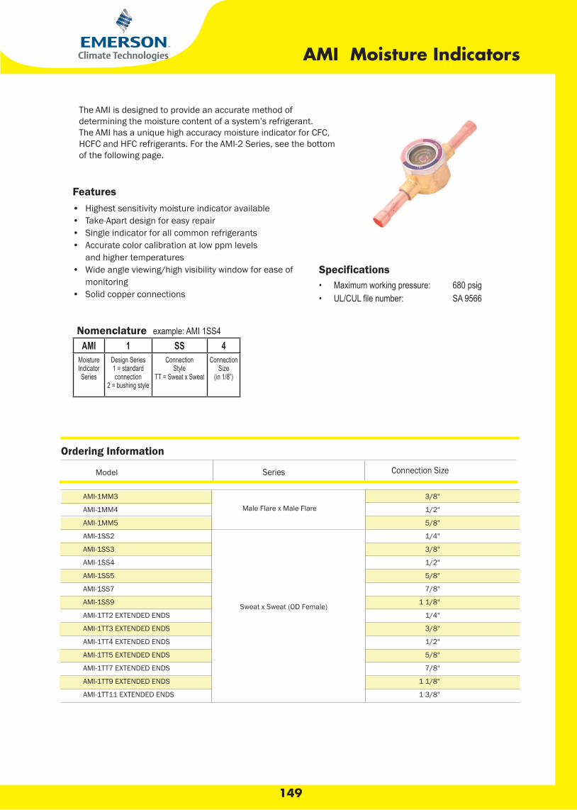
149
AMI Moisture Indicators
Specifications• Maximum working pressure: 680 psig• SA 9566
The AMI is designed to provide an accurate method ofdetermining the moisture content of a system’s refrigerant.The AMI has a unique high accuracy moisture indicator for CFC, HCFC and HFC refrigerants. For the AMI-2 Series, see the bottom of the following page.
Features• Highest sensitivity moisture indicator available• Take-Apart design for easy repair• Single indicator for all common refrigerants• Accurate color calibration at low ppm levels and higher temperatures• Wide angle viewing/high visibility window for ease of monitoring• Solid copper connections
Nomenclature example: AMI 1SS4AMI 1 SS 4
MoistureIndicatorSeries
Design Series1 = standardconnection
2 = bushing style
ConnectionStyle
TT = Sweat x Sweat
ConnectionSize
(in 1/8”)
Ordering Information
Series Connection SizeModel
AMI-1MM3
AMI-1MM4
AMI-1MM5
AMI-1SS2
AMI-1SS3
AMI-1SS4
AMI-1SS5
AMI-1SS7
AMI-1SS9
AMI-1TT2 EXTENDED ENDS
AMI-1TT3 EXTENDED ENDS
AMI-1TT4 EXTENDED ENDS
AMI-1TT5 EXTENDED ENDS
AMI-1TT7 EXTENDED ENDS
AMI-1TT9 EXTENDED ENDS
AMI-1TT11 EXTENDED ENDS
Male Flare x Male Flare
Sweat x Sweat (OD Female)
3/8"
1/2"
5/8"
1/4"
3/8"
1/2"
5/8"
7/8"
1 1/8"
1/4"
3/8"
1/2"
5/8"
7/8"
1 1/8"
1 3/8"

150
OIL SEPARATOR
DIMENSIONAL DATA
DRAWING - 1 DRAWING - 2
Model Connection
Size
ØA B C D
In&Out mm inch mm inch mm inch mm inch
Oil Return
Connectl ON
DIMENTION Mount-ing
Detail
Oil
Charge
Amount
Refer
Drawing
No.
HERMETIC WELDED TYPE
DAHW-5582-4
DAHW-5585-5
DAHW-5587-7
DAHW-5588-9
ACCESSIBLE BOLTED FLANGE TYPE
DAAF-5585-5
DAAF-5587-7
DAAF-5588-9
1/2"ODS
5/8"ODS
7/8"ODS
1-1/8"ODS
5/8"ODS
7/8"ODS
1-1/8"ODS
3/8" SAE
3/8" SAE
101.6
101.6
101.6
101.6
101.6
101.6
101.6
4 250 9.84 37 1.46
4 297 11.69 38 1.5
4 344 13.54 37 1.46
4 375 14.76 37 1.46
4 421 16.57 37 1.46
4 421 16.57 37 1.46
4 503 19.80 37 1.46
N/A
145 5.71
145 5.71
145 5.71
N/A
M10x1.5 Bolt with
washer&
nut
500 ml 1
M10x1.5 Bolt with
washer&
nut
500 ml 1
DAHW-5582-4
DAHW-5585-5
DAHW-5587-7
DAHW-5588-9
DAFF-5585-5
DAAF-5887-7
DAAF-5889-9
EVAPORATOR TEMPERATUR
R-134a R-22,R-502,R-507,R-404A,R407c
CAPACITY TABLE
+40 -40 +40 -40
1.83
4.6
6.7
8.5
4.6
6.7
8.7
1.2
3.3
4.8
6.5
3.3
4.8
6.5
2.2
5.6
8.5
11
5.6
8.5
11.2
1.5
4.76
7.15
9
4.76
7.15
9.52
"Ready for R410a"

151
A-W & A-F Oil Separators
Nomenclature example: AW 5582 4A W 5582 4
Series W = WeldedF = Flanged
Model Number Connection Size(in 1/8”)
The A-W and A-F are used for multiple compressor racks in supermarkets and air conditioning systems for use with HCFCs, HFCs and their lubricants.
Features• Hermetic welded or accessible bolted flange construction • Solid copper connections• Corrosion resistant epoxy powder paint
Specifications• Maximum working pressure: 450 psi• UL/CUL file number: SA10468
Dimensional Data
Ordering Information* and Capacity Table
R-12 R22/R-407C R-502 R-134a R-404A/R-507
FLANGED SEALED -40 F/C 40F (4C) -40F/C 40F(4C) -40F/C 40F(4C) -40F/C 40F(4C) -40F/C 40F(4C)
Tons kW Tons kW Tons kW Tons kW Tons kW Tons kW Tons kW Tons kW Tons kW Tons kW
*See replacement parts page. Repair kits for style 2 only.
Seal Units: A-W
Model Style No. ConnectionSize
Dimensions (in)A B
A-W 55824
1
1/2 ODF
4.0
10.752.31FDO 8/555855 W-A0.51FDO 8/777855 W-A52.61FDO 8/1-198855 W-A
5.91FDO 8/3-1110955 W-AA-W 569011 1-3/8 ODF
6.015.75
0.91FDO 8/5-1312965 W-A5.91FDO 8/1-2714965 W-A
Flanged Units: A-F
A-F 58824
3
1/2 ODF
4.0
10.5
5.5
A-F 58855 5/8 ODF 15.0A-F 58877 7/8 ODF 18.0A-F 58889 1 1/8 ODF 21.25A-F 589011 1 3/8 ODF 21.37A-F 589213 1 5/8 ODF 21.75A-F 579213 2 1 5/8 ODF 6.0A-F 579417 2 1/8 ODF 20.31 4.63
Model
Model Style No. ConnectionSize
Dimensions (in)A B c
20.12 4.37
HERMETIC WELDED TYPE
DAHW-5582-4
DAHW-5585-5
DAHW-5587-7
DAHW-5588-9
ACCESSIBLE BOLTED FLANGE TYPE
DAAF-5585-5
DAAF-5587-7
DAAF-5588-9
A-F 58824
A-F 58855
A-F 58877
A-F 58889
A-F 589011
A-F 589213
-
A-F 579213
A-F 579417
A-W 55824
A-W 55855
A-W 55877
A-W 55889
A-W 559011
A-W 559213
A-W 569011
A-W 569213
A-W 569417
1
3
4.5
6
7.5
9
9
11
17
3.5
10.6
15.9
21.2
26.6
31.9
31.7
38.9
60.2
1.5
4
5.5
7.5
10
11.5
12
14
22
5.3
14.2
19.5
26.6
35.4
40.7
42.3
49.6
77.9
1.5
4.5
7
9
11.5
14
13
16
25
5.3
15.9
24.8
31.9
40.7
49.6
45.8
56.6
88.5
2
5.5
8
11
14
18
14
18
30
7.1
19.5
28.3
37.2
47.8
62
49.8
63.7
106
1.5
4.8
7.5
9.5
12
16
15
20
30
5.3
16.8
26.6
33.6
42.5
56.6
52.8
70.8
106
2
5.8
8.5
11.5
14.5
17.5
20
24
35
7.08
20.4
30.1
40.7
51.3
62
70.4
85
124
1
3.3
4.8
6.5
8
9.5
9.5
11.8
18
3.5
11.5
16.8
23
28
33.6
33.4
41.6
63.7
1.8
4.5
6.5
8.5
11.5
13.3
13.7
16
25.6
6.2
15.9
23
30.1
40.7
46.9
48.2
56.6
89.4
1.5
4
6.5
8.6
10.5
14
11
17.5
26
5.3
14.2
23
30.1
37.2
49.6
38.7
62
92
2
5.5
8.5
11
14
17
19
23
34
7
19
30
38
49
60
66.9
81
121
"Ready for R22/R134a/R404a/R407c/R410a"
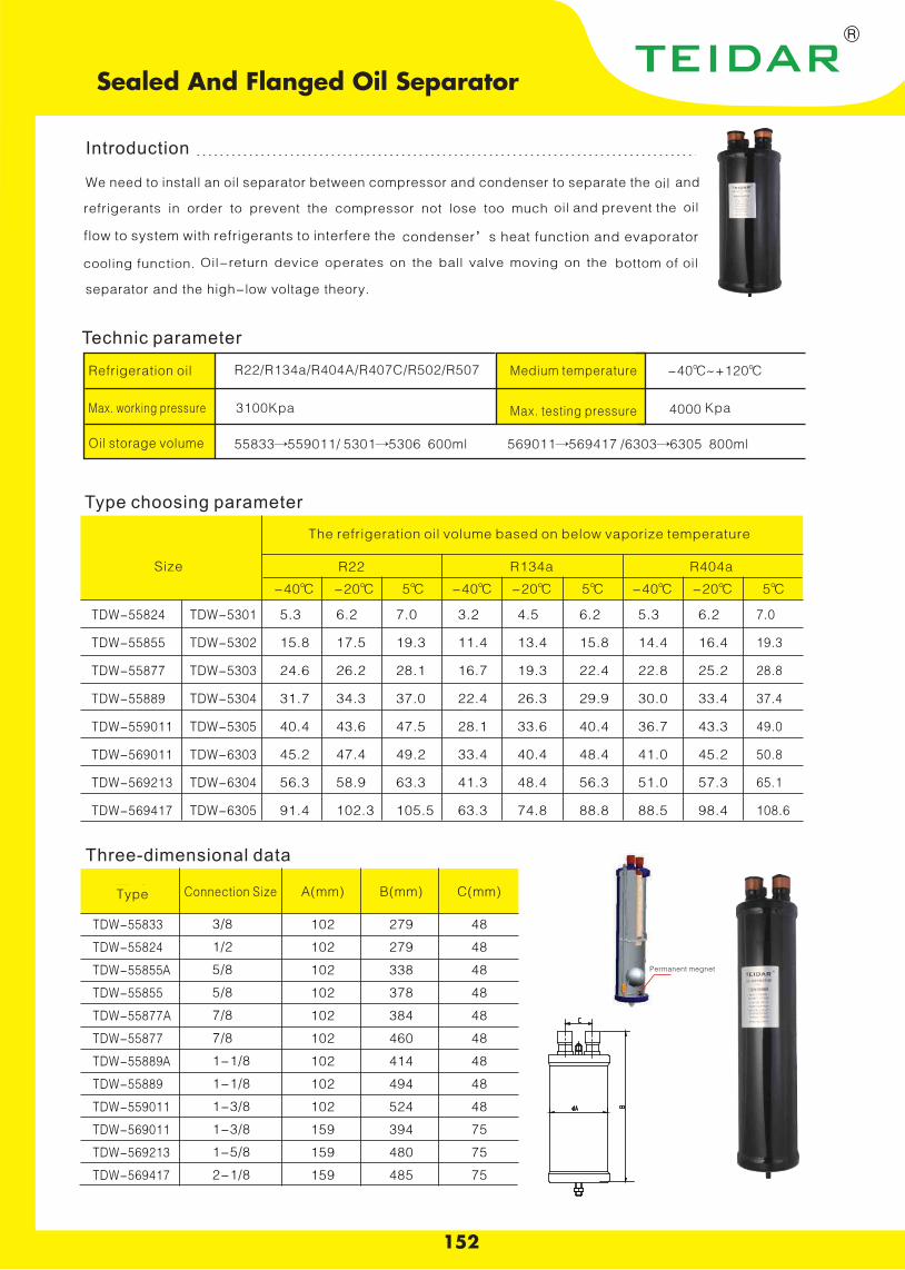
152
Sealed And Flanged Oil Separator
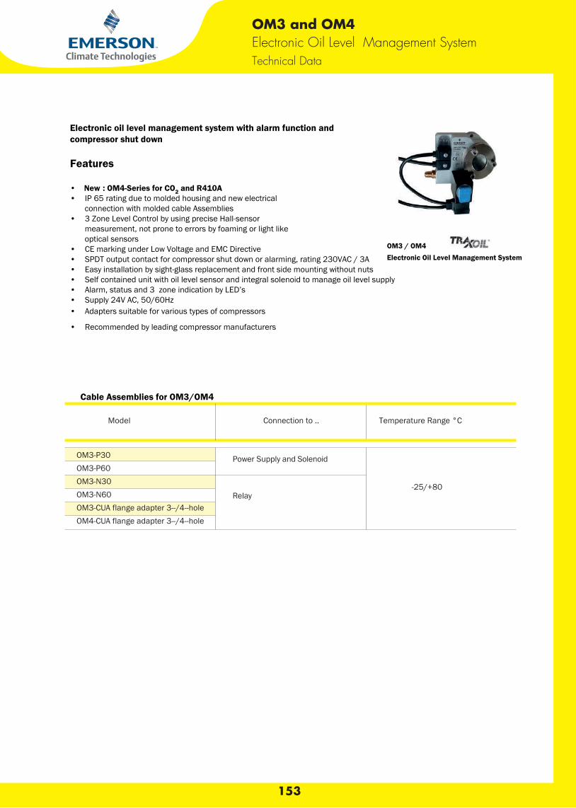
OM3 and OM4Electronic Oil Level Management System Technical Data
Electronic oil level management system with alarm function and compressor shut down
Features
• New : OM4-Series for CO2 and R410A • IP 65 rating due to molded housing and new electrical connection with molded cable Assemblies • 3 Zone Level Control by using precise Hall-sensor measurement, not prone to errors by foaming or light like optical sensors • CE marking under Low Voltage and EMC Directive • SPDT output contact for compressor shut down or alarming, rating 230VAC / 3A • Easy installation by sight-glass replacement and front side mounting without nuts • Self contained unit with oil level sensor and integral solenoid to manage oil level supply • Alarm, status and 3 zone indication by LED’s • Supply 24V AC, 50/60Hz • Adapters suitable for various types of compressors
• Recommended by leading compressor manufacturers
OM3 / OM4 Electronic Oil Level Management System
Cable Assemblies for OM3/OM4
Model Connection to .. Temperature Range °C
OM3-P30 OM3-P60 OM3-N30 OM3-N60 OM3-CUA flange adapter 3--/4--holeOM4-CUA flange adapter 3--/4--hole
Relay-25/+80
153
Power Supply and Solenoid
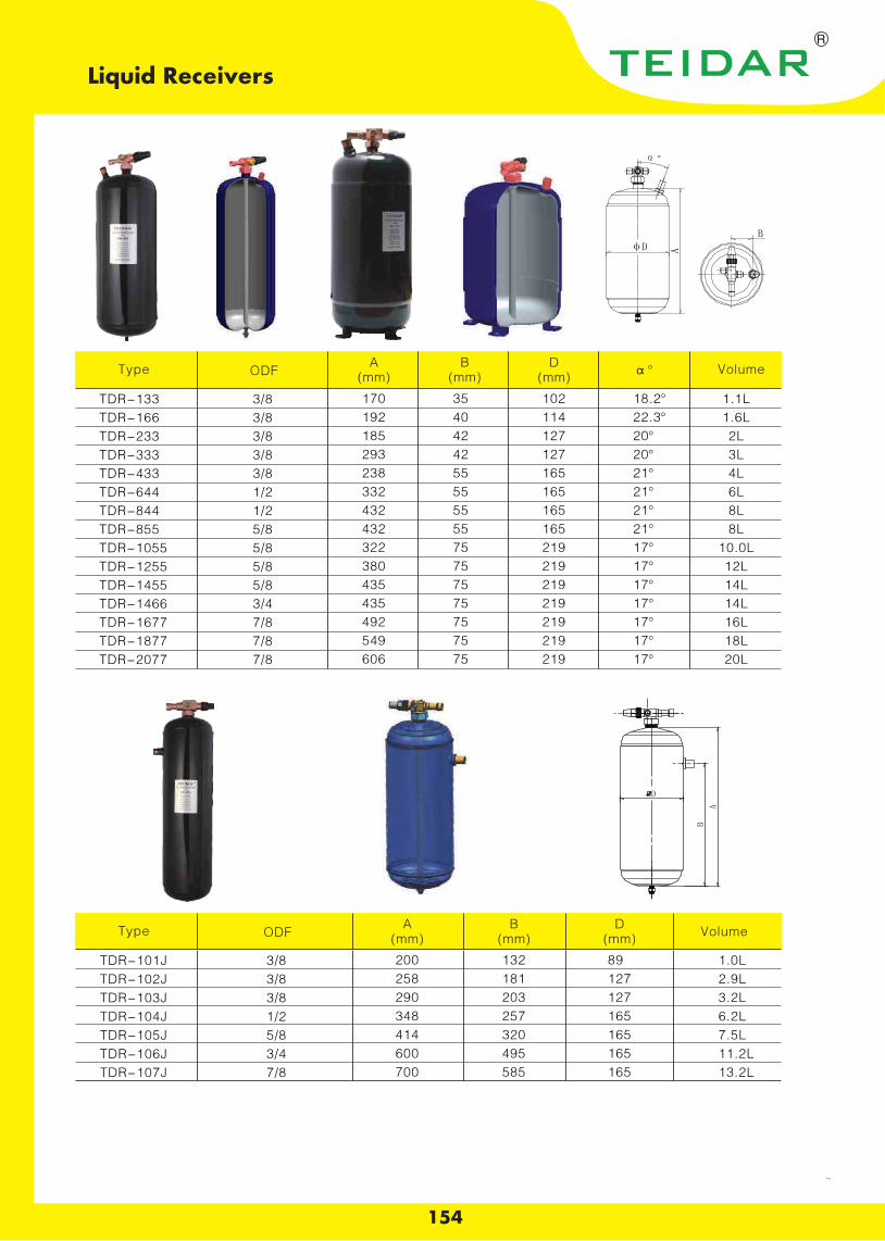
154
Liquid Receivers
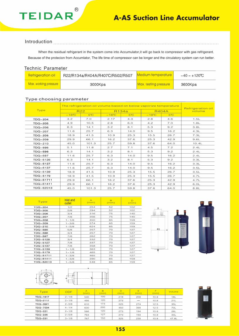
155
A-AS Suction Line Accumulator
When the residual refrigerant in the system come into Accumulator,it will go back to compressor with gas refrigerant.
Because of the protecion from Accumlator, The life time of compressor can be longer and the circulatory system can run better.
lnlet andoutlet
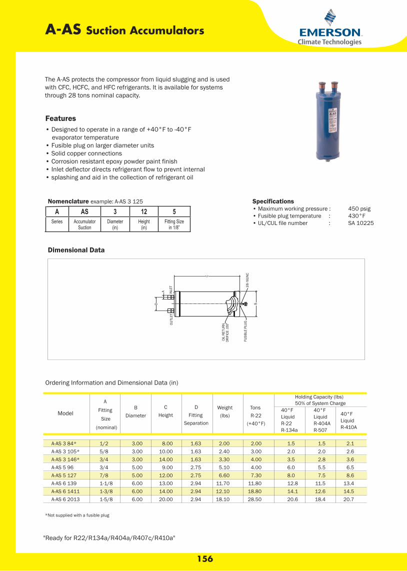
156
A-AS Suction Accumulators
Specifications• Maximum working pressure : 450 psig• Fusible plug temperature : 430°F• UL/CUL file number : SA 10225
The A-AS protects the compressor from liquid slugging and is usedwith CFC, HCFC, and HFC refrigerants. It is available for systemsthrough 28 tons nominal capacity.
Features• Designed to operate in a range of +40°F to -40°F evaporator temperature• Fusible plug on larger diameter units• Solid copper connections• Corrosion resistant epoxy powder paint finish• Inlet deflector directs refrigerant flow to prevnt internal• splashing and aid in the collection of refrigerant oil
Nomenclature example: A-AS 3 125
A AS 3 12 5Series Accumulator
SuctionDiameter
(in)Height
(in)Fitting Size
in 1/8”
Ordering Information and Dimensional Data (in)
Holding Capacity (lbs)50% of System Charge
*Not supplied with a fusible plug
Dimensional Data
A-AS 3 84*A-AS 3 105*A-AS 3 146*A-AS 5 96A-AS 5 127A-AS 6 139A-AS 6 1411A-AS 6 2013
1/25/83/43/47/81-1/81-3/81-5/8
3.003.003.005.005.006.006.006.00
8.0010.0014.00
9.0012.0013.0014.0020.00
1.631.631.632.752.752.942.942.94
2.002.403.305.106.60
11.7012.1018.10
2.003.004.004.007.30
11.8018.8028.50
1.52.03.56.08.012.814.120.6
1.52.02.85.57.5
11.512.618.4
2.12.63.66.58.6
13.414.520.7
Model
A
Fitting
Size
(nominal)
BDiameter
CHeight
DFitting
Separation
Weight(lbs)
Tons R-22
(+40°F)
40°F LiquidR-22R-134a
40°F LiquidR-404AR-507
40°F LiquidR-410A
"Ready for R22/R134a/R404a/R407c/R410a"
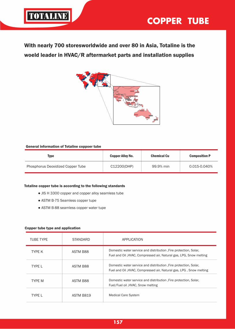
Domestic water service and distribution ,Fire protection, Solar, Fuel and Oil ,HVAC, Compressed air, Natural gas, LPG, Snow melting Domestic water service and distribution ,Fire protection, Solar, Fuel and Oil ,HVAC, Compressed air, Natural gas, LPG , Snow melting Domestic water service and distribution ,Fire protection, Solar, Fuel/Fuel oil ,HVAC, Snow melting Medical Care System
TUBE TYPE STANDARD APPLICATION
COPPER TUBE
157
Copper tube type and application
With nearly 700 storesworldwide and over 80 in Asia, Totaline is the
woeld leader in HVAC/R aftermarket parts and installation supplies
General information of Totaline coppoer tube
Type Copper Alloy No. Chemical Cu Composition P
Phosphorus Deoxidized Copper Tube C12200(DHP) 99.9% min 0.015-0.040%
Totaline copper tube is according to the following standards
● JIS H 3300 copper and copper alloy seamless tube
● ASTM B-75 Seamless copper tupe
● ASTM B-88 seamless copper water tupe
TYPE K ASTM B88
TYPE L ASTM B88
TYPE M ASTM B88
TYPE L ASTM B819

Table 2. ASTM B88 Type L Copper Tube: Dimensions and Physical Characteristics
Table 3. ASTM B88 Type M Copper Tube: Dimensions and Physical Characteristics
Table 1. ASTM B88 Type K Copper Tube: Dimensions and Physical Characteristics
COPPER TUBE
158
O.D (in)
Nominal/Standardsize (in)
Tolerance(in)
Wall Thickness(in)
Tolerance(in)
Theoretical Weight.
(Ib/ft)(kg/m)
Working PressurePsi (Mpa)
Diameter ofDrilled Holes
(in)
DrillNumber
3/8
1/2
5/8
3/4
7/8
1-1/8
1-3/8
1-5/8
2-1/8
2-5/8
3-1/8
O.D (in)
Nominal/Standardsize (in)
Tolerance(in)
Wall Thickness(in)
Tolerance(in)
Theoretical Weight.
(Ib/ft)(kg/m)
Working PressurePsi (Mpa)
Diameter ofDrilled Holes
(in)Drill
Number
O.D (in)
Nominal/Standardsize (in)
Tolerance(in)
Wall Thickness(in)
Tolerance(in)
Theoretical Weight.
(Ib/ft)(kg/m)
Working PressurePsi (Mpa)
Diameter ofDrilled Holes
(in)Drill
Number
3/8
1/2
5/8
3/4
7/8
1-1/8
1-3/8
1-5/8
2-1/8
2-5/8
3-1/8
3/8
1/2
5/8
3/4
7/8
1-1/8
1-3/8
1-5/8
2-1/8
2-5/8
3-1/8
With nearly 700 storesworldwide and over 80 in Asia, Totaline is the
woeld leader in HVAC/R aftermarket parts and installation supplies
1/4
3/8
1/2
5/8
3/4
1
1-1/4
1-1/2
2
2-1/2
3
0.0010
0.0010
0.0010
0.0010
0.0010
0.0015
0.0015
0.0020
0.0020
0.0020
0.0020
0.0010
0.0010
0.0010
0.0010
0.0010
0.0015
0.0015
0.0020
0.0020
0.0020
0.0020
0.035
0.049
0.049
0.049
0.065
0.065
0.065
0.072
0.083
0.095
0.109
0.0035
0.0050
0.0050
0.0050
0.0060
0.0060
0.0060
0.0070
0.0080
0.0100
0.0110
0.145(0.216)
0.269(0.400)
0.344(0.512)
0.418(0.622)
0.641(0.954)
0.839(1.249)
1.04(1.548)
1.36(2.024)
2.06(3.066)
2.93(4.360)
4.00(5.953)
1842.95(12.71)
1932.85(13.33)
1528.30(10.54)
1251.80(8.64)
1442.75(9.95)
1104.90(7.62)
897.55(6.19)
838.10(5.78)
735.15(5.07)
681.50(4.7)
655.40(4.52)
0.025
0.025
0.025
0.025
0.031
0.036
0.042
0.046
0.052
0.052
0.052
72
72
72
72
68
64
58
56
55
55
55
72
72
72
72
68
64
58
56
55
55
55
1/4
3/8
1/2
5/8
3/4
1
1-1/4
1-1/2
2
2-1/2
3
0.0010
0.0010
0.0010
0.0010
0.0010
0.0015
0.0015
0.0020
0.0020
0.0020
0.0020
1/4
3/8
1/2
5/8
3/4
1
1-1/4
1-1/2
2
2-1/2
3
0.030
0.035
0.040
0.042
0.045
0.050
0.055
0.060
0.070
0.080
0.090
0.0030
0.0040
0.0040
0.0040
0.0040
0.0050
0.0060
0.0060
0.0070
0.0080
0.0090
0.126(0.188)
0.198(0.295)
0.285(0.424)
0.362(0.539)
0.455(0.677)
0.655(0.975)
0.844(1.316)
1.114(1.658)
1.75(2.604)
2.48(3.691)
3.33(4.956)
1552.95(10.71)
1352.85(9.33)
1231.05(8.49)
1078.80(7.44)
980.20(6.76)
843.90(8.52)
755.45(5.21)
696.00(4.8)
617.70(4.26)
643.80(4.44)
600.30(4.14)
0.025
0.025
0.025
0.025
0.031
0.036
0.042
0.046
0.052
0.052
0.052
72
72
72
72
68
64
58
56
55
55
55
0.025
0.025
0.025
0.025
0.031
0.036
0.042
0.046
0.052
0.052
0.052
0.025
0.028
0.032
0.035
0.042
0.049
0.058
0.065
0.072
/
/
/ /
/ /
/
/
0.0020
0.0030
0.0030
0.0040
0.0040
0.0050
0.0060
0.0060
0.0070
0.145(0.216)
0.204(0.304)
0.328(0.488)
0.465(0.692)
0.682(1.015)
0.94(1.399)
1.46(2.173)
2.03(3.021)
2.68(3.988)
951.20(6.56)
848.25(5.85)
685.85(4.73)
584.35(4.03)
578.55(3.99)
565.50(3.9)
503.15(3.47)
462.55(3.9)
427.75(2.95)
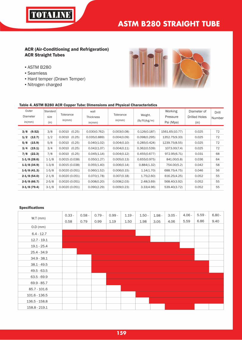
159
ASTM B280 STRAIGHT TUBE
ACR (Air-Conditioning and Refrigeration)ACR Straight Tubes
▪ ASTM B280 ▪ Seamless▪ Hard temper (Drawn Temper) ▪ Nitrogen charged
Table 4. ASTM B280 ACR Copper Tube: Dimensions and Physical CharacteristicsOuter
Diameter
in(mm)
Standerd
size
(in)
Tolerance
in(mm)
wall
Thickness
in(mm)
Tolerance
in(mm)
Weight.
(Ib/ft)(kg/m)
Working PressurePsi (Mpa)
Diameter ofDrilled Holes
(in)
DrillNumber
3/8 (9.52)
1/2 (12.7)
5/8 (15.9)
3/4 (19.1)
7/8 (22.3)
1-1/8 (28.6)
1-3/8 (34.9)
1-5/8 (41.3)
2-1/8 (54.0)
2-5/8 (66.7)
3-1/8 (79.4)
3/8
1/2
5/8
3/4
7/8
1-1/8
1-3/8
1-5/8
2-1/8
2-5/8
3-1/8
0.0010 (0.25)
0.0010 (0.25)
0.0010 (0.25)
0.0010 (0.25)
0.0010 (0.25)
0.0015 (0.038)
0.0015 (0.038)
0.0020 (0.051)
0.0020 (0.051)
0.0020 (0.051)
0.0020 (0.051)
Specifications
0.030(0.762)
0.035(0.889)
0.040(1.02)
0.042(1.07)
0.045(1.14)
0.050(1.27)
0.055(1.40)
0.060(1.52)
0.070(1.78)
0.008(0.20)
0.090(2.29)
0.003(0.08)
0.004(0.09)
0.004(0.10)
0.004(0.11)
0.004(0.12)
0.005(0.13)
0.006(0.14)
0.006(0.15)
0.007(0.18)
0.008(2.03)
0.009(0.23)
0.126(0.187)
0.098(0.295)
0.285(0.424)
0.362(0.539)
0.455(0.677)
0.655(0.975)
0.884(1.32)
1.14(1.70)
1.75(2.60)
2.48(3.69)
3.33(4.96)
1561.65(10.77)
1352.75(9.33)
1239.75(8.55)
1073.00(7.4)
972.95(6.71)
841.00(5.8)
754.00(5.2)
688.75(4.75)
616.25(4.25)
568.40(3.92)
539.40(3.72)
0.025
0.025
0.025
0.025
0.031
0.036
0.042
0.046
0.052
0.052
0.052
72
72
72
72
68
64
58
56
55
55
55
W.T (mm)
O.D (mm)
6.4 - 12.7
12.7 - 19.1
19.1 - 25.4
25.4 - 34.9
34.9 - 38.1
38.1 - 49.5
49.5 - 63.5
63.5 - 69.9
69.9 - 85.7
85.7 - 101.6
101.6 - 136.5
136.5 - 158.8
158.8 - 219.1
0.33 -
0.58
0.58 -
0.79
0.79 -
0.99
0.99 -
1.19
1.19 -
1.50
1.50 -
1.98
1.98 -
3.05
3.05 -
4.06
4.06 -
5.59
5.59 -
6.86
6.80 -
9.40
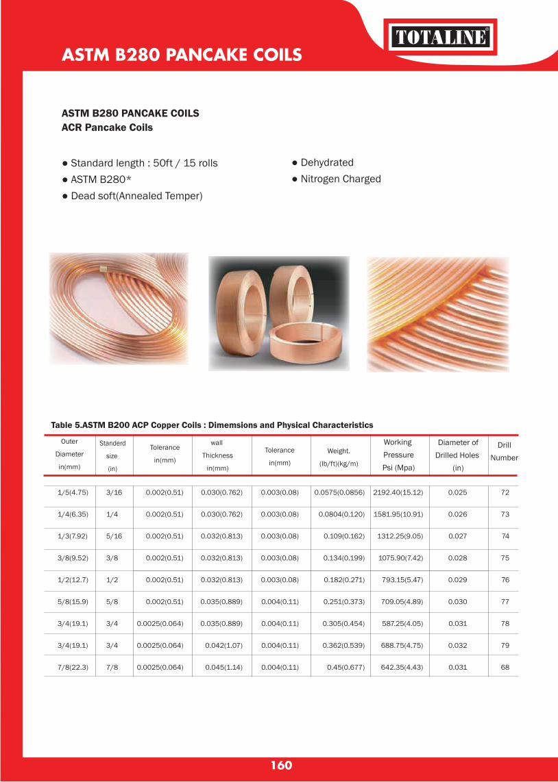
160
Outer
Diameter
in(mm)
Standerd
size
(in)
Tolerance
in(mm)
wall
Thickness
in(mm)
Tolerance
in(mm)
Weight.
(Ib/ft)(kg/m)
Working PressurePsi (Mpa)
Diameter ofDrilled Holes
(in)
DrillNumber
ASTM B280 PANCAKE COILS ACR Pancake Coils
● Standard length : 50ft / 15 rolls ● ASTM B280* ● Dead soft(Annealed Temper)
● Dehydrated● Nitrogen Charged
ASTM B280 PANCAKE COILS
Table 5.ASTM B200 ACP Copper Coils : Dimemsions and Physical Characteristics
1/5(4.75)
1/4(6.35)
1/3(7.92)
3/8(9.52)
1/2(12.7)
5/8(15.9)
3/4(19.1)
3/4(19.1)
7/8(22.3)
3/16
1/4
5/16
3/8
1/2
5/8
3/4
3/4
7/8
0.002(0.51)
0.002(0.51)
0.002(0.51)
0.002(0.51)
0.002(0.51)
0.002(0.51)
0.0025(0.064)
0.0025(0.064)
0.0025(0.064)
0.030(0.762)
0.030(0.762)
0.032(0.813)
0.032(0.813)
0.032(0.813)
0.035(0.889)
0.035(0.889)
0.042(1.07)
0.045(1.14)
0.003(0.08)
0.003(0.08)
0.003(0.08)
0.003(0.08)
0.003(0.08)
0.004(0.11)
0.004(0.11)
0.004(0.11)
0.004(0.11)
0.0575(0.0856)
0.0804(0.120)
0.109(0.162)
0.134(0.199)
0.182(0.271)
0.251(0.373)
0.305(0.454)
0.362(0.539)
0.45(0.677)
2192.40(15.12)
1581.95(10.91)
1312.25(9.05)
1075.90(7.42)
793.15(5.47)
709.05(4.89)
587.25(4.05)
688.75(4.75)
642.35(4.43)
0.025
0.026
0.027
0.028
0.029
0.030
0.031
0.032
0.031
72
73
74
75
76
77
78
79
68
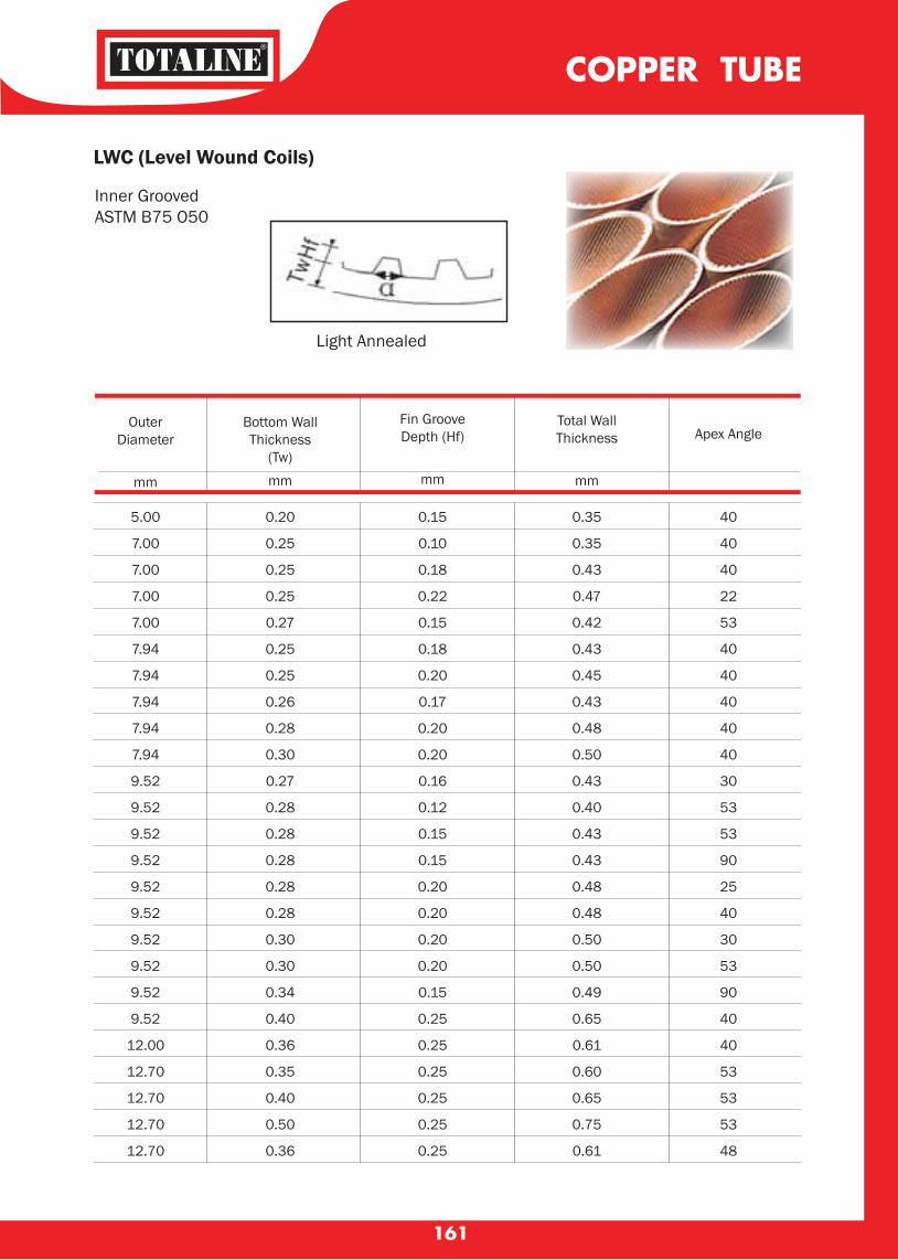
COPPER TUBE
161
LWC (Level Wound Coils)
Inner Grooved ASTM B75 O50
Light Annealed
OuterDiameter
mm
Bottom WallThickness
(Tw)mm
Fin GrooveDepth (Hf)
mm
Total WallThickness
mm
Apex Angle
5.00
7.00
7.00
7.00
7.00
7.94
7.94
7.94
7.94
7.94
9.52
9.52
9.52
9.52
9.52
9.52
9.52
9.52
9.52
9.52
12.00
12.70
12.70
12.70
12.70
0.20
0.25
0.25
0.25
0.27
0.25
0.25
0.26
0.28
0.30
0.27
0.28
0.28
0.28
0.28
0.28
0.30
0.30
0.34
0.40
0.36
0.35
0.40
0.50
0.36
0.15
0.10
0.18
0.22
0.15
0.18
0.20
0.17
0.20
0.20
0.16
0.12
0.15
0.15
0.20
0.20
0.20
0.20
0.15
0.25
0.25
0.25
0.25
0.25
0.25
0.35
0.35
0.43
0.47
0.42
0.43
0.45
0.43
0.48
0.50
0.43
0.40
0.43
0.43
0.48
0.48
0.50
0.50
0.49
0.65
0.61
0.60
0.65
0.75
0.61
40
40
40
22
53
40
40
40
40
40
30
53
53
90
25
40
30
53
90
40
40
53
53
53
48
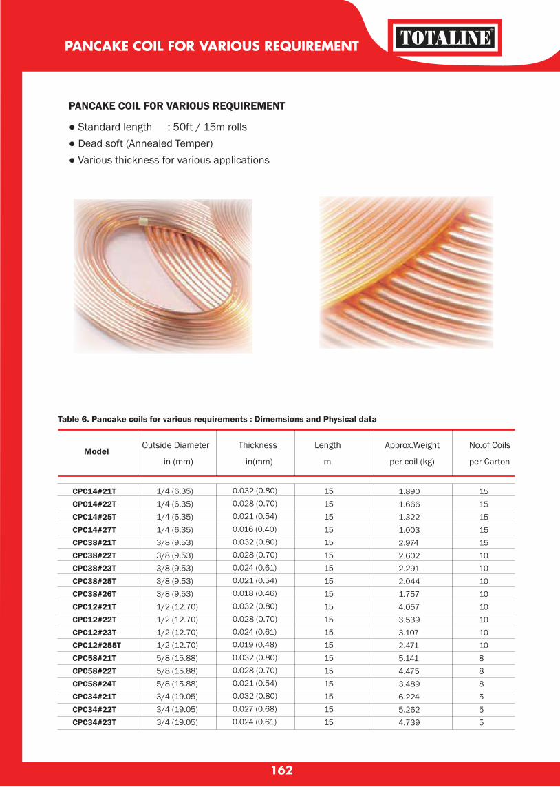
162
PANCAKE COIL FOR VARIOUS REQUIREMENT
Table 6. Pancake coils for various requirements : Dimemsions and Physical data
Model Outside Diameter Thickness Length Approx.Weight No.of Coils
in (mm) in(mm) m per coil (kg) per Carton
PANCAKE COIL FOR VARIOUS REQUIREMENT
● Standard length : 50ft / 15m rolls● Dead soft (Annealed Temper)● Various thickness for various applications
CPC14#21TCPC14#22TCPC14#25TCPC14#27TCPC38#21TCPC38#22TCPC38#23TCPC38#25TCPC38#26TCPC12#21TCPC12#22TCPC12#23TCPC12#255TCPC58#21TCPC58#22TCPC58#24TCPC34#21TCPC34#22TCPC34#23T
1/4 (6.35)1/4 (6.35)1/4 (6.35)1/4 (6.35)3/8 (9.53)3/8 (9.53)3/8 (9.53)3/8 (9.53)3/8 (9.53)1/2 (12.70)1/2 (12.70)1/2 (12.70)1/2 (12.70)5/8 (15.88)5/8 (15.88)5/8 (15.88)3/4 (19.05)3/4 (19.05)3/4 (19.05)
0.032 (0.80)0.028 (0.70)0.021 (0.54)0.016 (0.40)0.032 (0.80)0.028 (0.70)0.024 (0.61)0.021 (0.54)0.018 (0.46)0.032 (0.80)0.028 (0.70)0.024 (0.61)0.019 (0.48)0.032 (0.80)0.028 (0.70)0.021 (0.54)0.032 (0.80)0.027 (0.68)0.024 (0.61)
15151515151515151515151515151515151515
15151515151010101010101010888555
1.8901.6661.3221.0032.9742.6022.2912.0441.7574.0573.5393.1072.4715.1414.4753.4896.2245.2624.739
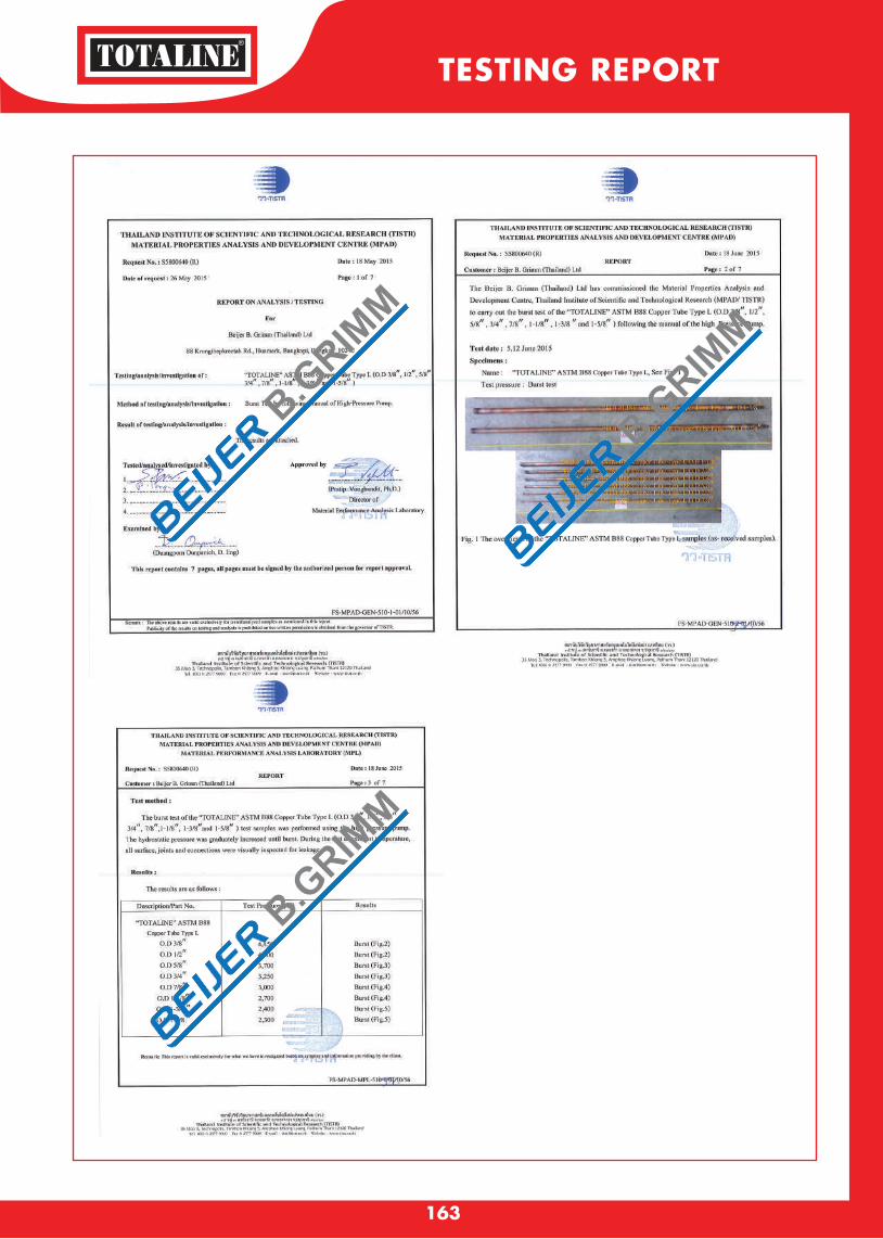
TESTING REPORT
163
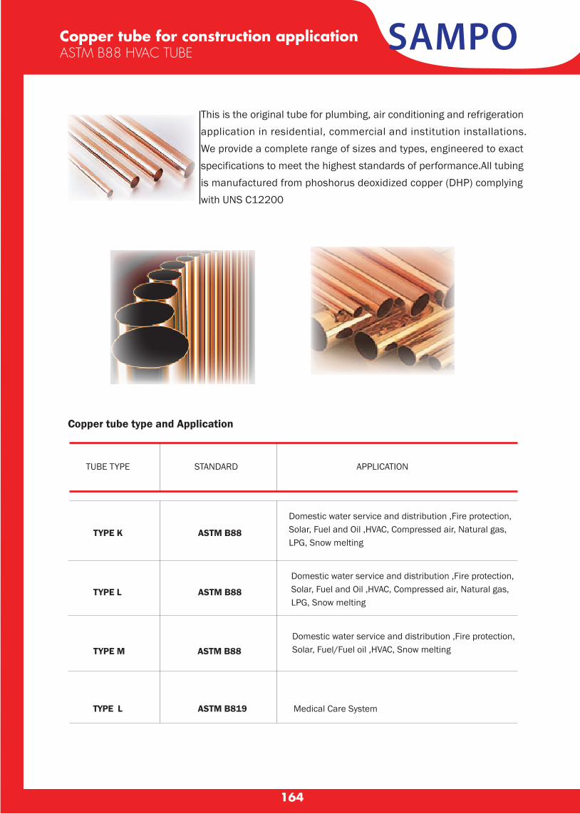
SAMPOCopper tube for construction applicationASTM B88 HVAC TUBE
Copper tube type and Application
TYPE L ASTM B819
TYPE K ASTM B88
Domestic water service and distribution ,Fire protection, Solar, Fuel/Fuel oil ,HVAC, Snow melting
TYPE L ASTM B88
TYPE M ASTM B88
TUBE TYPE STANDARD APPLICATION
Medical Care System
164
This is the original tube for plumbing, air conditioning and refrigeration application in residential, commercial and institution installations. We provide a complete range of sizes and types, engineered to exact specifications to meet the highest standards of performance.All tubing is manufactured from phoshorus deoxidized copper (DHP) complying with UNS C12200
Domestic water service and distribution ,Fire protection, Solar, Fuel and Oil ,HVAC, Compressed air, Natural gas, LPG, Snow melting
Domestic water service and distribution ,Fire protection, Solar, Fuel and Oil ,HVAC, Compressed air, Natural gas, LPG, Snow melting
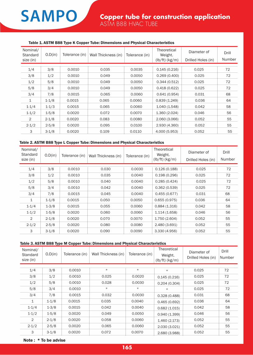
Table 2. ASTM B88 Type L Copper Tube: Dimensions and Physical Characteristics
Table 3. ASTM B88 Type M Copper Tube: Dimensions and Physical Characteristics
Table 1. ASTM B88 Type K Copper Tube: Dimensions and Physical Characteristics
1/4 3/8 0.0010 0.030 0.0030 0.126 (0.188) 0.025 72
3/8 1/2 0.0010 0.035 0.0040 0.198 (0.296) 0.025 72
1/2 5/8 0.0010 0.040 0.0040 0.285 (0.424) 0.025 72
5/8 3/4 0.0010 0.042 0.0040 0.362 (0.539) 0.025 72
3/4 7/8 0.0015 0.045 0.0040 0.455 (0.677) 0.031 68
1 1-1/8 0.0015 0.050 0.0050 0.655 (0.975) 0.036 64
1-1/4 1-3/8 0.0015 0.055 0.0060 0.884 (1.316) 0.042 58
1-1/2 1-5/8 0.0020 0.060 0.0060 1.114 (1.658) 0.046 56
2 2-1/8 0.0020 0.070 0.0070 1.750 (2.604) 0.052 55
2-1/2 2-5/8 0.0020 0.080 0.0080 2.480 (3.691) 0.052 55
3 3-1/8 0.0020 0.090 0.0090 3.330 (4.956) 0.052 55
1/4 3/8 0.0010 * * 0.025 72
3/8 1/2 0.0010 0.025 0.0020 0.025 72
1/2 5/8 0.0010 0.028 0.0030 0.025 72
5/8 3/4 0.0010 * * 0.025 72
3/4 7/8 0.0015 0.032 0.0030 0.031 68
1 1-1/8 0.0015 0.035 0.0040 0.036 64
1-1/4 1-3/8 0.0015 0.042 0.0040 0.042 58
1-1/2 1-5/8 0.0020 0.049 0.0050 0.046 56
2 2-1/8 0.0020 0.058 0.0060 0.052 55
2-1/2 2-5/8 0.0020 0.065 0.0060 0.052 55
3 3-1/8 0.0020 0.072 0.0070 0.052 55
1/4 3/8 0.0010 0.035 0.0035 0.145 (0.216) 0.025 72
3/8 1/2 0.0010 0.049 0.0050 0.269 (0.400) 0.025 72
1/2 5/8 0.0010 0.049 0.0050 0.344 (0.512) 0.025 72
5/8 3/4 0.0010 0.049 0.0050 0.418 (0.622) 0.025 72
3/4 7/8 0.0015 0.065 0.0060 0.641 (0.954) 0.031 68
1 1-1/8 0.0015 0.065 0.0060 0.839 (1.249) 0.036 64
1-1/4 1-1/3 0.0015 0.065 0.0060 1.040 (1.548) 0.042 58
1-1/2 1-5/8 0.0020 0.072 0.0070 1.360 (2.024) 0.046 56
2 2-1/8 0.0020 0.083 0.0080 2.060 (3.066) 0.052 55
2-1/2 2-5/8 0.0020 0.095 0.0100 2.930 (4.360) 0.052 55
3 3-1/8 0.0020 0.109 0.0110 4.000 (5.953) 0.052 55
Nominal/Standard size (in)
O.D(in) Tolerance (in) Wall Thickness (in) Tolerance (in)Diameter of
Drilled Holes (in)
Drill Number
Note : * To be advise
165
SAMPO Copper tube for construction applicationASTM B88 HVAC TUBE
O.D(in) Tolerance (in) Wall Thickness (in) Tolerance (in)Theoretical
Weight. (lb/ft) (kg/m)
Diameter of
Drilled Holes (in)
Drill
Number
O.D(in) Tolerance (in) Wall Thickness (in) Tolerance (in)Theoretical
Weight. (lb/ft) (kg/m)
Diameter of Drilled Holes (in)
Drill Number
Theoretical Weight.
(lb/ft) (kg/m)
Nominal/Standard size (in)
Nominal/Standard size (in)
*
0.145 (0.216)
0.204 (0.304)
*
0.328 (0.488)
0.465 (0.692)
0.682 (1.015)
0.940 (1.399)
1.460 (2.173)
2.030 (3.021)
2.680 (3.988)
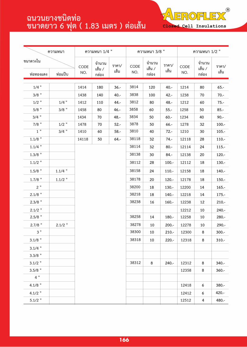
ความหนา
ขนาดวงใน
ทอทองแดง ทอแปบ
ราคา/เสน
จำนวนเสน /กลอง
CODENO.
ฉนวนยางชนดทอ ขนาดยาว 6 ฟต ( 1.83 เมตร ) ตอเสน
166
ความหนา 1/4 " ความหนา 3/8 " ความหนา 1/2 "
ราคา/เสน
จำนวนเสน /กลอง
CODENO.
ราคา/เสน
จำนวนเสน /กลอง
CODENO.
240.-10122122.1/2 "
280.-1012258180.-14382582.5/8 "
290.-1012278200.-10382782.1/2 "2.7/8 "
210.-1212238160.-16382382 "2.3/8 "
175.-1412218140.-18382182.1/8 "
165.-1412200130.-18382002 "
150.-1812178120.-20381781.1/2 "1.7/8 "
140.-1812158110.-24381581.1/4 "1.5/8 "
130.-1812112100.-28381121.1/2 "
120.-201213884.-30381381 "1.3/8 "
115.-241211480.-32381141.1/4 "
110.-281211874.-323811864.-50141181.1/8 "
105.-30121072.-40381058.-6014103/4 "1 "
100.-32127866.-50387852.-7014781/2 "7/8 "
90.-40123460.-50383448.-7014343/4 "
85.-50125855.-60385846.-8014583/8 "5/8 "
75.-60121248.-80381244.-11014121/4 "1/2 "
70.-70123842.-100383840.-14014383/8 "
65.-80121440.-120381436.-18014141/4 "
480.-4125125 "5.1/2 "
420.-6124124 "4.1/2 "
380.-6124184.1/8 "
4 "
360.-8123583.5/8 "
340.-812312240.-8383123 "3.1/2 "
3.3/8 "
3.1/4 "
310.-812318220.-10383183.1/8 "
300.-812300210.-10383003 "
Closed Cell Insulations

ฉนวนยางชนดทอ ขนาดยาว 6 ฟต ( 1.83 เมตร ) ตอเสน
167
ความหนา
ขนาดวงใน
ทอทองแดง ทอแปบ
ราคา/เสน
จำนวนเสน /กลอง
CODENO.
ความหนา 3/4 " ความหนา 1 " ความหนา 1.1/4 "
ราคา/เสน
จำนวนเสน /กลอง
CODENO.
ราคา/เสน
จำนวนเสน /กลอง
CODENO.
300.-10341341.3/4 "
400.-8342122.1/2 "
680.-4114258500.-610258420.-8342582.5/8 "
780.-4114278570.-610278470.-6342782.1/2 "2.7/8 "
610.-4114238450.-610238380.-8342382 "2.3/8 "
560.-6114218420.-810218350.-8342182.1/8 "
540.-6114200400.-810200340.-8342002 "
500.-6114178370.-810178320.-10341781.1/2 "1.7/8 "
440.-8114158330.-810158280.-12341581.1/4 "1.5/8 "300.-1010112250.-12341121.1/2 "
380.-8114138260.-1010138210.-16341381 "1.3/8 "
340.-8114114250.-1210114200.-18341141.1/4 "
320.-8114118230.-1210118190.-18341181.1/8 "
300.-1011410210.-121010180.-1834103/4 "1 "
280.-1211478190.-161078160.-2034781/2 "7/8 "260.-1211434180.-181034150.-2434343/4 "
230.-1411458160.-181058140.-2834583/8 "5/8 "
210.-1411412150.-201012130.-3234121/4 "1/2 "140.-241038120.-3234383/8 "130.-241014110.-3234141/4 "
1,300.-2114512850.-210512790.-4345125 "5.1/2 "
960.-4114358700.-410358600.-6343583.5/8 "
1,370.-21146121,040.-2106126 "6.1/2 "
1,120.-2114412790.-410412700.-4344124 "4.1/2 "
1,060.-2114418760.-410418630.-4344184.1/8 "
620.-4344004 "730.-4103783.1/2 "3.7/8 "
920.-4114312670.-410312570.-6343123 "3.1/2 "
3.3/8 "640.-6103143.1/4 "
840.-4114318620.-610318520.-6343183.1/8 "
820.-4114300600.-610300500.-6343003 "
Closed Cell Insulations
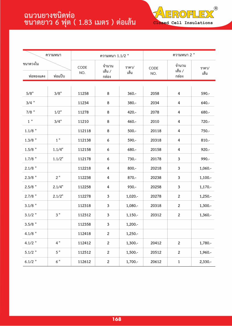
1,780.-2204121,300.-21124124 "4.1/2 "
1,960.-2205121,500.-21125125 "5.1/2 "
2,330.-1206121,700.-21126126 "6.1/2 "
1,250.-21124184.1/8 "
1,200.-31123583.5/8 "
1,360.-2203121,150.-31123123 "3.1/2 "
1,300.-2203181,080.-31123183.1/8 "
1,250.-2202781,020.-31122782.1/2"2.7/8 "
1,170.-320258930.-41122582.1/4"2.5/8 "
1,100.-320238870.-41122382 "2.3/8 "
1,060.-320218800.-41122182.1/8 "
990.-320178730.-61121781.1/2"1.7/8 "
920.-420158680.-61121581.1/4"1.5/8 "
810.-420318590.-61121381 "1.3/8 "
750.-420118500.-81121181.1/8 "
720.-42010460.-8112103/4"1 "
680.-42078420.-8112781/2"7/8 "
640.-42034380.-8112343/4 "
590.-42058360.-8112583/8"5/8"
ฉนวนยางชนดทอ ขนาดยาว 6 ฟต ( 1.83 เมตร ) ตอเสน
168
ความหนา
ขนาดวงใน
ทอทองแดง ทอแปบ
ความหนา 1.1/2 " ความหนา 2 "
ราคา/เสน
จำนวนเสน /กลอง
CODENO.
ราคา/เสน
จำนวนเสน /กลอง
CODENO.
Closed Cell Insulations

3,500.-2,600P3440001,700.-P124000( 130 " x 48 " )40 "
2,800.-2,120P3432001,440.-P123200( 104 " x 48 " )32 "
2,700.-2,050P3430001,400.-P123000( 90 " x 48 " )30 "
2,160.-1,650P3424001,140.-P122400( 79 " x 48 " )24 "
2,000.-1,500P3422001,000.-P122200( 73 " x 48 " )22 "
1,850.-1,400P342000950.-P122000( 67 " x 48 " )20 "
1,650.-1,250P341800850.-P121800( 60 " x 48 " )18 "
1,500.-1,130P341600760.-P121600( 54 " x 48 " )16 "
1,320.-61,0008P341400680.-12P121400( 48 " x 48 " )14 "
1,200.-69008P341212600.-12P121212( 44 " x 48 " )12 "
960.-67208P341012480.-P121012( 37 " x 48 " )10 "
820.-66208P34812420.-12P12812( 30 " x 48 " )8 "
690.-65008P34612340.-12P12612( 24 " x 48 " )6 "
P104000
P103200
P103000
P102400
P102200
P102000
P101800
P101600
P101400
P101212
P101012
P10812
P10612
12
ฉนวนยางชนดแผน ขนาดยาว 4 ฟต ( 1.22 เมตร ) ตอแผน
169
ความหนาแผน
แผนยางสำหรบทอเหลก
ความหนา 1/2"
ราคา/แผน
จำนวนแผน /กลอง
CODENO.
ความหนา 3/4"
ราคา/แผน
จำนวนแผน /กลอง
CODENO.
ความหนา 1"
ราคา/แผน
จำนวนแผน /กลอง
CODENO.
∆ แผนยางชนดตดสาเรจ ( Pre-cut Sheet )ไดผลตขนเพอความสะดวกของการใชงานมความยาวมาตรฐาน 4 ฟต
ความกวางขนาดตางๆ ตดใหพอดสาหรบหมทอเหลก ตงแตทอ 6"ถง 24"โดยไมตองเสยเศษ
∆ มผวเรยบ และหนาทงสองดานเพอปองกนการดดซมของนำ และการแทรกซมของความชนอยางไดผล
Closed Cell Insulations

�น
7,180.-P2040005,300.-P11240004,380.-P114400040 "
5,775.-P2032004,320.-P11232003,620.-P114320032 "
5,500.-P2030004,140.-P11230003,420.-P114300030 "
4,500.-P2024003,430.-P11224002,780.-P114240024 "
4,160.-P2022003,140.-P11222002,570.-P114220022 "
3,850.-P2020002,850.-P11220002,350.-P114200020 "
3,500.-P2018002,600.-P11218002,125.-P114180018 "
3,150.-P2016002,350.-P11216001,925.-P114160016 "
2,820.-3P2014002,080.-4P11214001,700.-5P114140014 "
2,520.-3P2012121,880.-4P11212121,540.-5P114121212 "
2,160.-3P2010121,560.-4P11210121,260-5P114101210 "
1,780.-3P208121,300.-4P1128121,060.-5P1148128 "
1,550.-3P206121,130.-4P112612910.-56 "
Closed Cell Insulations
170
ความหนาแผน
แผนยางสำหรบทอเหลก
ความหนา 1-1/4"
ราคา/แผน
จำนวนแผน /กลอง
CODE NO.
ความหนา 1-1/2"
ราคา/แผน
จำนวนแผน /กลอง
CODE NO.
ความหนา 2"
ราคา/แผน
จำนวนแผน /กลอง
CODE NO.
ฉนวนยางชนดแผน ขนาดยาว 4 ฟต ( 1.22 เมตร ) ตอแผน

ฉนวนยางชนดแผนมาตรฐาน ขนาด 3 X 4 ฟต ( ฟต ) ตอแผน
∆ ผลตภณฑ Aeroflex® ไดผลตตามมาตรฐานของ ASTM STANDARD( AMERICAN SOCIETY FOR
TESTING AND MATERIALS )
ASTM D1667 :
ASTM D1016 :
ASTM E355 :
ASTM D1171 :
1,930.-350.00 m.m.36" x 48" x 2"S.2043
1,450.-438.00 m.m.36" x 48" x 1.1/2"S.11243
1,150.-532.00 m.m.36" x 48" x 1.1/4"S.11443
1,050.-628.00 m.m.36" x 48" x 1.1/8"S.11843
960.-625.00 m.m.36" x 48" x 1"S.1043
720.-820.00 m.m.36" x 48" x 3/4"S.3443
600.-1016.00 m.m.36" x 48" x 5/8"S.5843
480.-1213.00 m.m.36" x 48" x 1/2"S.1243
396.-1610.00 m.m.36" x 48" x 3/8"S.3843
288.- 246.5 m.m.36" x 48" x 1/4"S.1443
150.-483.2 m.m.36" x 48" x 1/8"S.1843
CODE ขนาดแผน ( ม.ม ) จำนวนแผน /กลอง ราคา / แผน
Closed Cell Insulations
171
ความหนาแนน 4 ถง 6 ปอนดตอลกบาศกฟต ( 60 –90 Kg / m3)
ปรมาณการดดซมนำไมเกน 5 % ตอนำหนกยาง ( By Weight )
ปรมาณการดดซมไอนำผานผวยางอยในระดบตำมาก
ปองกนกาซโอโซน แสงแดด และสภาวะอากาศดเยยม

5,150.-32842"AFSR20
4,840.-401041.1/2"AFSR112
4,980.-521341.1/4"AFSR114
5,760.-721841"AFSR10
5,520.-922343/4"AFSR34
5,760.-1443641/2"AFSR12
6,600.-2005043/8"AFSR38
6,920.-2807241/4"AFSR14
7,500.-60015041/8"AFSR18
Price / Roll
( Bath )Ft 2/ RollLength
( ft )Width
( ft )
Thickness
( inch )
SIZECODE
NUMBER
ฉนวนยางชนดแผนแบบมวน Closed Cell Insulations
172
มาตรฐาน ASTM
ASTM C177 : K.FACTOR คาเฉลยคาสมประสทธการนาความรอน 0.26ทอณหภมเฉลย 75 °F ,
0.27ทอณหภมเฉลย 90 °F / BTU / hr / ft 2/ F / IN ( 0.037 – 0.039 W/mkท 24 °C )
ASTM D635 : SELF EXTINGUISH / LOWSMOKE DENSITY / NO FLAMMING BALL
UL - 94 : ไฟดบไดเองไมเกดหยดไฟ และมปรมาณควนนอยเมอเผาไหม
Aeroflex® : ∆ เปนทอยางฉนวนหมทอแอรทผลตจากยางสงเคราะหชนดพเศษ
ซงทนทานตอสภาวะอากาศตาง ๆ
∆ เหมาะสาหรบหมทอนำรอนเพอประหยดพลงงาน และหมทอนำเยน
ปองกนการเกดหยดเหงออยางไดผล
∆ แผนยางขนาดความหนาตงแต 1/2"ขนไป มผวเรยบทงสองดานเพอ
ปองกนการดดซมนำอยางไดผล

10 X 30 X 1/2
POLYMERIC RIGID
FOAM PIPE HANGER WITH SELF-SEALING TAPE
ความยาว :
ID.10"IPS - 12"IPS ยาว 3"
ID.3/8" - 1.7/8" ยาว 1.1/2"
ID. 2.1/8" - 4"IPS ยาว 2"
ขนาดทอ I.D.
ทอทองแดง ทอเหลก
ความหนา 1/2”
CODE NO. ชน/กลอง ราคา/ชน
Closed Cell Insulations
173
ความหนา 3/4”
CODE NO. ชน/กลอง ราคา/ชน
ID. 5"IPS - 8"IPS ยาว 2.1/2"
3/8"
5/8"
3/4"
7/8"
1"
1.3/8"
1.5/8"
1.7/8"
2.1/8"
2.3/8"
2.5/8"
2.7/8"
3.1/8"
3.1/2"
4.1/2"
5.1/2"
6.5/8"
8.5/8"
-
-
-
1/2" IPS
3/4" IPS
1" IPS
1.1/4" IPS
1.1/2" IPS
-
2" IPS
-
2.1/2" IPS
-
3" IPS
4" IPS
5" IPS
6" IPS
8" IPS
UXI0120038 - 112
UXI0120058 - 112
UXI0120034 - 112
UXI0120078 - 112
UXI01200100 - 112
UXI01200138 - 112
UXI01200158 - 112
UXI01200178 - 112
UXI01200218 - 112
UXI01200238 - 112
UXI01200258 - 112
UXI01200278 - 112
UXI01200318 - 112
UXI01200312 - 112
UXI01200412 - 112
UXI01200512 - 112
UXI01200658 - 112
UXI01200858 - 112
480
480
480
480
360
240
240
180
120
120
108
108
60
60
48
30
20
10
25.00
30.00
35.00
40.00
45.00
50.00
65.00
70.00
75.00
80.00
90.00
95.00
100.00
110.00
120.00
130.00
150.00
220.00
UXI0340038 - 112
UXI0340058 - 112
UXI0340034 - 112
UXI0340078 - 112
UXI03400100 - 112
UXI03400138 - 112
UXI03400158 - 112
UXI03400178 - 112
UXI03400218 - 200
UXI01200238 - 200
UXI03400258 - 200
UXI03400278 - 200
UXI03400318 - 200
UXI03400312 - 200
UXI03400412 - 200
UXI03400512 - 212
UXI03400658 - 212
UXI03400858 - 212
300
240
240
240
240
180
120
144
108
108
108
72
48
48
48
24
15
10
35.00
40.00
45.00
50.00
55.00
60.00
70.00
75.00
85.00
90.00
100.00
120.00
130.00
140.00
150.00
160.00
200.00
260.00
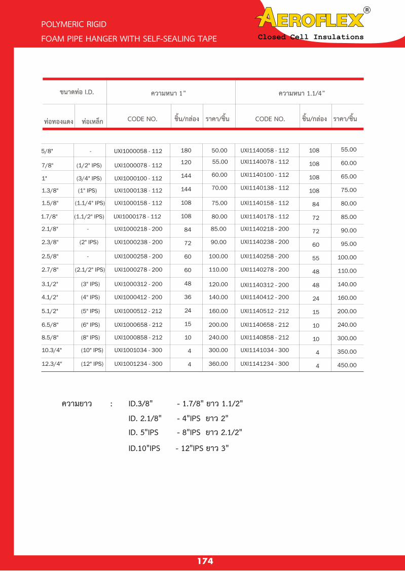
Closed Cell Insulations
5/8" - UXI1000058 - 112
7/8" (1/2" IPS) UXI1000078 - 112 55.00
1" (3/4" IPS) UXI1000100 - 112 60.00 UXI1140100 - 112
1.3/8" (1" IPS) UXI1000138 - 112 70.00 UXI1140138 - 112
1.5/8" (1.1/4" IPS) UXI1000158 - 112 75.00 UXI1140158 - 112
1.7/8" (1.1/2" IPS) UXI1000178 - 112 80.00 UXI1140178 - 112
2.1/8" - UXI1000218 - 200 85.00 UXI1140218 - 200
2.3/8" (2" IPS) UXI1000238 - 200 90.00 UXI1140238 - 200
2.5/8" - UXI1000258 - 200 100.00 UXI1140258 - 200
2.7/8" (2.1/2" IPS) UXI1000278 - 200 110.00 UXI1140278 - 200
3.1/2" (3" IPS) UXI1000312 - 200 120.00 UXI1140312 - 200
4.1/2" (4" IPS) UXI1000412 - 200 140.00 UXI1140412 - 200
5.1/2" (5" IPS) UXI1000512 - 212 160.00 UXI1140512 - 212
6.5/8" (6" IPS) UXI1000658 - 212 200.00 UXI1140658 - 212
8.5/8" (8" IPS) UXI1000858 - 212 240.00 UXI1140858 - 212
10.3/4" (10" IPS) UXI1001034 - 300 300.00 UXI1141034 - 300
12.3/4" (12" IPS) UXI1001234 - 300 360.00
50.00
120
144
144
108
108
84
72
60
60
48
36
24
15
10
4
4
180 UXI1140058 - 112
UXI1140078 - 112
UXI1141234 - 300
108
108
108
108
84
72
72
60
55
48
48
24
15
10
10
4
4
55.00
60.00
65.00
75.00
80.00
85.00
90.00
95.00
100.00
110.00
140.00
160.00
200.00
240.00
300.00
350.00
450.00
174
Closed Cell Insulations
POLYMERIC RIGID
FOAM PIPE HANGER WITH SELF-SEALING TAPE
ขนาดทอ I.D.
ทอทองแดง ทอเหลก
ความหนา 1”
CODE NO. ชน/กลอง ราคา/ชน
ความหนา 1.1/4”
CODE NO. ชน/กลอง ราคา/ชน
ความยาว :
ID.10"IPS - 12"IPS ยาว 3"
ID.3/8" - 1.7/8" ยาว 1.1/2"
ID. 2.1/8" - 4"IPS ยาว 2"
ID. 5"IPS - 8"IPS ยาว 2.1/2"

Closed Cell Insulations
5/8" - UXI1120058 - 112 UXI2000058 - 112
7/8" (1/2" IPS) UXI1120078 - 112
1" (3/4" IPS) UXI1120100 - 112
1.1/8" - UXI1120118 - 112
1.3/8" (1" IPS) UXI1120138 - 112
1.5/8" (1.1/4" IPS) UXI1120158 - 112
1.7/8" (1.1/2" IPS) UXI1120178 - 112
2.3/8" (2" IPS) UXI1120238 - 200
2.5/8" - UXI1120258 - 200
2.7/8" (2.1/2" IPS) UXI1120278 - 200
3.1/2" (3" IPS) UXI1120312 - 200
4.1/2" (4" IPS) UXI1120412 - 200
5.1/2" (5" IPS) UXI1120512 - 212
6.5/8" (6" IPS) UXI1120658 - 212
8.5/8" (8" IPS) UXI1120858 - 212
10.3/4" (10" IPS) UXI1121034 - 300
12.3/4" (12" IPS) UXI1121234 - 300
14" (14" IPS) UXI1121400 - 300 UXI2001400 - 300
16" (16" IPS) UXI1121600 - 300
18" (18" IPS) UXI1121800 - 300 UXI2001800 - 300
20" (20" IPS) UXI1122000 - 300 UXI2002000 - 300
22" (22" IPS) UXI1122200 - 300 UXI2002200 - 300
24" (24" IPS) UXI1122400 - 300
UXI2000078 - 112
UXI2000100 - 112
UXI2000118 - 112
UXI2000138 - 112
UXI2000158 - 112
UXI2000178 - 112
UXI2000238 - 200
UXI2000258 - 200
UXI2000278 - 200
UXI2000312 - 200
UXI2000412 - 200
UXI2000512 - 212
UXI2000658 - 212
UXI2000858 - 212
UXI2001034 - 300
UXI2001600 - 300
UXI2002400 - 300
UXI2001234 - 300
120
108
108
84
72
72
60
48
48
48
36
24
15
10
10
4
4
4
4
4
4
4
4
60.00
65.00
70.00
75.00
80.00
85.00
95.00
100.00
110.00
120.00
160.00
200.00
240.00
300.00
400.00
520.00
650.00
900.00
1,200.00
1,400.00
1,600.00
1,800.00
2,000.00
70
60
60
48
48
48
48
36
36
36
24
18
10
10
10
4
4
4
4
4
4
4
4
65.00
70.00
75.00
80.00
85.00
95.00
110.00
130.00
150.00
170.00
200.00
240.00
300.00
400.00
600.00
750.00
850.00
1,250.00
1,500.00
1,800.00
2,100.00
2,300.00
2,500.00
POLYMERIC RIGID
FOAM PIPE HANGER WITH SELF-SEALING TAPE
175
ความยาว :
ID.10"IPS - 12"IPS ยาว 3"
ID.3/8" - 1.7/8" ยาว 1.1/2"
ID. 2.1/8" - 4"IPS ยาว 2"
ID. 5"IPS - 8"IPS ยาว 2.1/2"
ขนาดทอ I.D.
ทอทองแดง ทอเหลก
ความหนา 1.1/2”
CODE NO. ชน/กลอง ราคา/ชน
ความหนา 2”
CODE NO. ชน/กลอง ราคา/ชน

CELFLEX-NVR
CLOSED CELL INSULATION
ฉนวนยางชนดทอ ขนาดยาว 6 ฟต (1.83 ม.) / เสน หนา 3/8”
MODEL (ทอเหลก)
ราคาตอเสน (บาท )
TFNVCF3838XJB
TFNVCF3812XJB
TFNVCF3858XJB
TFNVCF3834XJB
TFNVCF3878XJB
TFNVCF38118XJB
3/8”
1/2” (1/4”IPS)
5/8” (3/8”IPS)
3/4”
7/8” (1/2”IPS)
1-1/8”
140
108
88
76
62
48
15.00
15.00
16.00
17.00
21.00
27.00
14.00
14.00
15.00
16.00
20.00
27.00
13.00
13.00
14.00
15.00
19.00
27.00
- ไมตดไฟ ไมหลอมละลายเมอถกเปลวไฟ หรอ ความรอนจากการเชอมตอทอทอง
- มความยดหยนสง ตดตงงาย สะดวกรวดเรว
- มคาสมประสทธการนำความรอนตำ ( คา K ตำ ) ไมเกดหยดเหงอ
คณสมบต
Adhesive
for bonding
closed cell elastomeric insulation
Description :
AEROSEAL is a Modified Neoprene Contact Adhesive specially formulated for bonding Aeroflex Insulating Materials firmly together. Also, ideal for use with other materials like Metal (painted / unpainted), Cork Board, Polyurethane Foam Rigid PVC Sheet, Formica, and Melamine Board and Rubber Sheet.
The high water vapor resistance and
good weathering properties of AEROSEAL can prevent water or moisture from penetrating through the joining points.
AEROSEAL is able to form a strong,
firm and permanent bonding between the
applied materials providing long lasting service.
ขนาดบรรจ ราคา / แกลลอน
700 กรม3.75 ลตร
180.00900.00
176
Closed Cell Insulations
รใน ทอทองแดงจำนวน เสน/กลอง
ครงละ20 กลอง
ครงละ50 กลอง
ครงละ100 กลอง
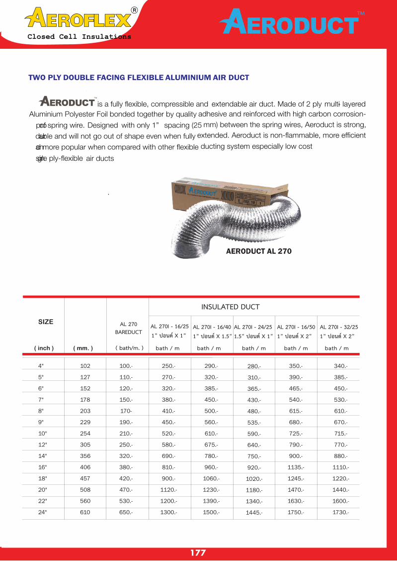
Closed Cell Insulations
TWO PLY DOUBLE FACING FLEXIBLE ALUMINIUM AIR DUCT
AERODUCT AL 270
SIZE
INSULATED DUCT
AL 270I - 16/251” ปอนด X 1”
( inch ) ( mm. )
AL 270 BAREDUCT
( bath/m. )
AL 270I - 16/401” ปอนด X 1.5”
AL 270I - 24/251.5” ปอนด X 1”
AL 270I - 16/501” ปอนด X 2”
AL 270I - 32/251” ปอนด X 2”
bath / m bath / mbath / m bath / m bath / m
177
4"
5"
6"
7"
8"
9"
10"
12"
14"
16"
18"
20"
22"
24"
102
127
152
178
203
229
254
305
356
406
457
508
560
610
100.-
110.-
120.-
150.-
170-
190.-
210.-
250.-
320.-
380.-
420.-
470.-
530.-
650.-
250.-
270.-
320.-
380.-
410.-
450.-
520.-
580.-
690.-
810.-
900.-
1120.-
1200.-
1300.-
290.-
320.-
385.-
450.-
500.-
560.-
610.-
675.-
780.-
960.-
1060.-
1230.-
1390.-
1500.-
280.-
310.-
365.-
430.-
480.-
535.-
590.-
640.-
750.-
920.-
1020.-
1180.-
1340.-
1445.-
350.-
390.-
465.-
540.-
615.-
680.-
725.-
790.-
900.-
1135.-
1245.-
1470.-
1630.-
1750.-
340.-
385.-
450.-
530.-
610.-
670.-
715.-
770.-
880.-
1110.-
1220.-
1440.-
1600.-
1730.-

178
ทอทองแดง ทอเหลก
ฉนวนยางชนดทอ ขนาดยาว 2 เมตร ตอเสน
(mm.)
ID ฉนวน ความหนา 6 mm. (1/4”) ความหนา 9 mm. (3/8”)
CODENO.
จำนวนเสน / กลอง
บาท / เสนCODENO.
จำนวนเสน / กลอง
บาท / เสน
6
10
12
15
20
22
25
28
32
35
42
48
54
60
1/4"
3/8"
1/2"
5/8"
3/4"
7/8"
1"
1 1/8"
1 1/4"
1 3/8"
1 5/8"
1 7/8"
2 1/8"
2 3/8"
-
-
1/4"
3/8"
-
1/2"
-
3/4"
-
1"
1 1/4"
1 1/2"
-
2"
6.5 - 8.5
9.5 - 11.5
13.0 - 15.0
16.0 - 18.0
19.5 - 21.5
22.5 - 24.5
27.0 - 29.0
29.0 - 31.0
31.5 - 34.0
35.0 - 37.5
42.5 - 51.0
48.5 - 51.0
54.5 - 63.0
60.5 - 63.0
1414
1438
1412
1458
1434
1478
1410
14118
-
14114
-
-
-
-
-
-
-
143
110
100
81
68
-
53
-
-
-
-
-
-
-
50.00
53.00
57.00
64.00
70.00
-
85.00
-
-
-
-
3814
3838
3812
3858
3834
3878
3810
38118
38114
38138
38158
38178
38218
38238
176
132
120
100
72
68
63
49
42
42
35
28
24
24
44.00
46.00
53.00
60.00
66.00
72.00
79.00
81.00
88.00
92.00
120.00
132.00
153.00
175.00
(mm.) (inch) (inch)

179
6
10
12
15
20
22
25
28
32
35
38
42
48
54
60
67
73
76
80
89
105
114
140
1/4"
3/8"
1/2"
5/8"
3/4"
7/8"
1"
1 1/8"
1 1/4"
1 3/8"
1 1/2"
1 5/8"
1 7/8"
2 1/8"
2 3/8"
2 5/8"
2 7/8"
3"
3 1/8"
3 1/2"
4 1/8"
4 1/2"
5 1/2"
-
-
1/4"
3/8"
-
1/2"
-
3/4"
-
1"
-
1 1/4"
1 1/2"
-
2"
-
2 1/2"
-
-
3"
-
4"
5"
6.5 - 8.5
9.5 - 11.5
13.0 - 15.0
16.0 - 18.0
19.5 - 21.5
22.5 - 24.5
27.0 - 29.0
29.0 - 31.0
31.5 - 34.0
35.0 - 37.5
42.5 - 51.0
48.5 - 51.0
54.5 - 63.0
60.5 - 63.0
67.5 - 70.5
74.0 - 77.0
77.0 - 80.0
81.0 - 84.5
89.5 - 93.0
106.0 - 110.0
1150 - 119.0
141.5 - 145.5
1214
1238
1212
1258
1234
1278
1210
12118
12114
12138
12158
12178
12218
12238
12258
12278
12300
12318
12312
12418
12412
90
90
72
64
56
53
42
36
30
25
-
25
20
20
15
12
12
12
11
11
8
8
-
71.00
77.00
82.00
93.00
99.00
110.00
115.00
120.00
126.00
132.00
-
153.00
165.00
192.00
230.00
284.00
317.00
328.00
339.00
372.00
430.00
459.00
-
3414
3438
3412
3458
3434
3478
3410
34118
34114
34138
34112
34158
34178
34218
34238
34258
34278
34300
34318
34312
34418
34412
34512
56
46
39
39
30
30
25
20
20
18
17
16
16
16
12
10
9
9
8
8
6
6
3
120.00
132.00
142.00
153.00
164.00
175.00
197.00
208.00
218.00
230.00
273.00
307.00
350.00
383.00
415.00
460.00
514.00
547.00
569.00
623.00
700.00
765.00
863.00
ทอทองแดง ทอเหลก
(inch) (mm.)
ID ฉนวน ความหนา 13 mm. (1/2”) ความหนา 19 mm. (3/4”)
CODENO.
จำนวนเสน / กลอง
บาท / เสนCODENO.
จำนวนเสน / กลอง
บาท / เสน(mm.) (inch)
ฉนวนยางชนดทอ ขนาดยาว 2 เมตร ตอเสน
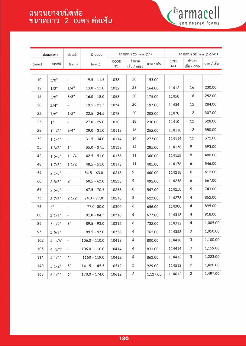
ทอทองแดง ทอเหลก
(inch) (mm.)
ID ฉนวน ความหนา 25 mm. (1”) ความหนา 32 mm. (1-1/4”)
CODENO.
จำนวนเสน / กลอง
บาท / เสนCODENO.
จำนวนเสน / กลอง
บาท / เสน(mm.) (inch)
ฉนวนยางชนดทอ ขนาดยาว 2 เมตร ตอเสน
180
10
12
15
20
22
25
28
32
35
42
48
54
60
67
73
76
80
89
93
102
105
114
140
168
3/8"
1/2"
5/8"
3/4"
7/8"
1"
1 1/8"
1 1/4"
1 3/8"
1 5/8"
1 7/8"
2 1/8"
2 3/8"
2 5/8"
2 7/8"
3"
3 1/8"
3 1/2"
3 5/8"
4 1/8"
4 1/4"
4 1/2"
5 1/2"
6 1/2"
-
1/4"
3/8"
-
1/2"
-
3/4"
-
1"
1 1/4"
1 1/2"
-
2"
-
2 1/2"
-
-
3"
-
-
4"
5"
6"
9.5 - 11.5
13.0 - 15.0
16.0 - 18.0
19.5 - 21.5
22.5 - 24.5
27.0 - 29.0
29.0 - 31.0
31.5 - 34.0
35.0 - 37.5
42.5 - 51.0
48.5 - 51.0
54.5 - 63.0
60.5 - 63.0
67.5 - 70.5
74.0 - 77.0
77.0 -80.0
81.0 - 84.5
89.5 - 93.0
89.5 - 93.0
106.0 - 110.0
106.0 - 110.0
1150 - 119.0
141.5 - 145.5
170.0 - 174.0
1038
1012
1058
1034
1078
1010
10118
10114
10138
10158
10178
10218
10238
10258
10278
10300
10318
10312
10358
10418
10414
10412
10512
10612
28
28
20
20
20
18
16
14
14
11
11
9
9
8
8
6
6
6
4
4
4
4
3
2
153.00
164.00
175.00
197.00
208.00
230.00
252.00
273.00
285.00
360.00
405.00
460.00
492.00
547.00
623.00
656.00
677.00
732.00
765.00
800.00
831.00
863.00
929.00
1,137.00
11412
11458
11434
11478
11410
114118
114114
114138
114158
114178
114218
114238
114258
114278
114300
114318
114312
114358
114418
114414
114412
114512
114612
-
16
16
12
12
12
12
12
9
8
6
6
6
5
4
4
4
4
3
3
3
3
2
2
-
230.00
252.00
284.00
307.00
328.00
350.00
372.00
393.00
480.00
546.00
612.00
667.00
743.00
852.00
895.00
918.00
1,005.00
1,050.00
1,100.00
1,159.00
1,223.00
1,420.00
1,497.00
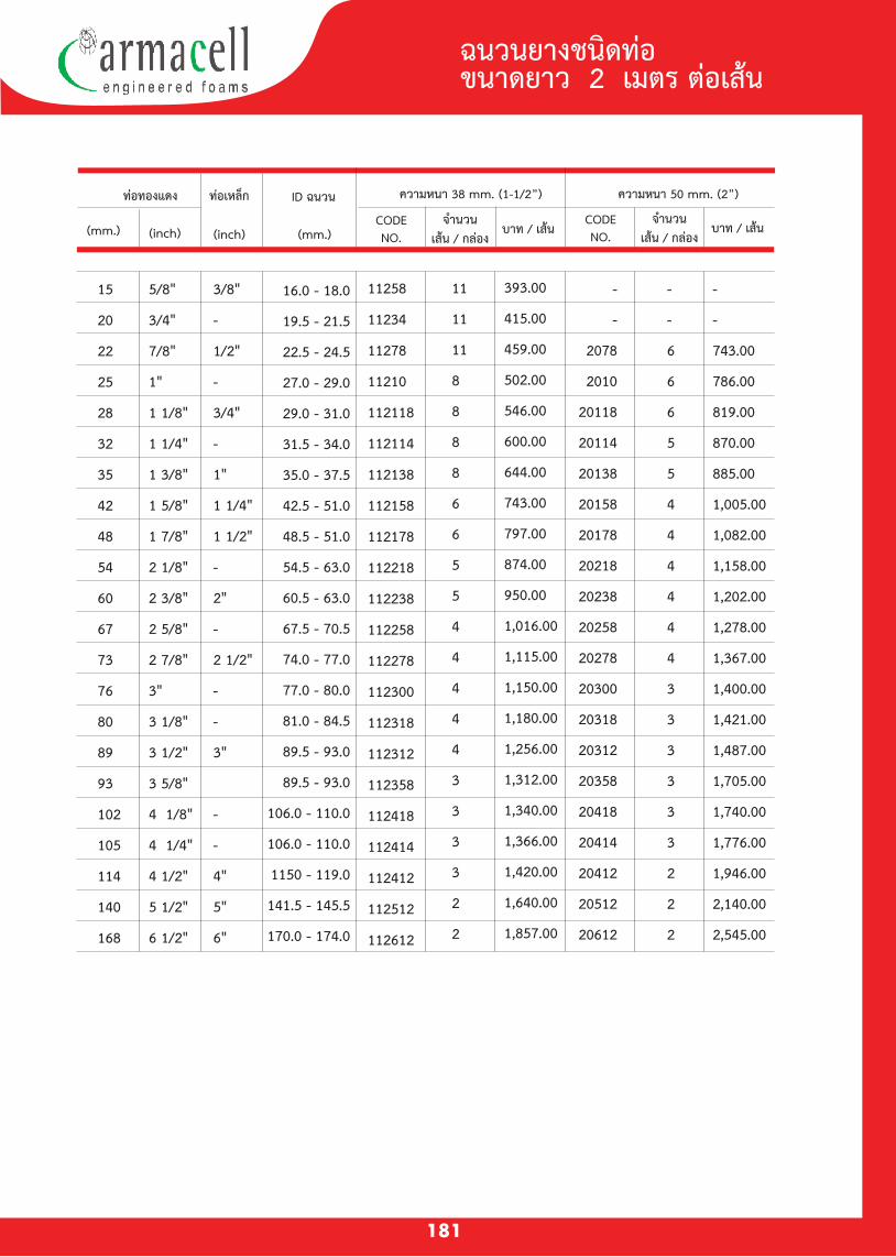
ทอทองแดง ทอเหลก
(inch) (mm.)
ID ฉนวน ความหนา 38 mm. (1-1/2”) ความหนา 50 mm. (2”)
CODENO.
จำนวนเสน / กลอง
บาท / เสนCODENO.
จำนวนเสน / กลอง
บาท / เสน(mm.) (inch)
181
ฉนวนยางชนดทอ ขนาดยาว 2 เมตร ตอเสน
15
20
22
25
28
32
35
42
48
54
60
67
73
76
80
89
93
102
105
114
140
168
5/8"
3/4"
7/8"
1"
1 1/8"
1 1/4"
1 3/8"
1 5/8"
1 7/8"
2 1/8"
2 3/8"
2 5/8"
2 7/8"
3"
3 1/8"
3 1/2"
3 5/8"
4 1/8"
4 1/4"
4 1/2"
5 1/2"
6 1/2"
3/8"
-
1/2"
-
3/4"
-
1"
1 1/4"
1 1/2"
-
2"
-
2 1/2"
-
-
3"
-
-
4"
5"
6"
16.0 - 18.0
19.5 - 21.5
22.5 - 24.5
27.0 - 29.0
29.0 - 31.0
31.5 - 34.0
35.0 - 37.5
42.5 - 51.0
48.5 - 51.0
54.5 - 63.0
60.5 - 63.0
67.5 - 70.5
74.0 - 77.0
77.0 - 80.0
81.0 - 84.5
89.5 - 93.0
89.5 - 93.0
106.0 - 110.0
106.0 - 110.0
1150 - 119.0
141.5 - 145.5
170.0 - 174.0
11258
11234
11278
11210
112118
112114
112138
112158
112178
112218
112238
112258
112278
112300
112318
112312
112358
112418
112414
112412
112512
112612
11
11
11
8
8
8
8
6
6
5
5
4
4
4
4
4
3
3
3
3
2
2
393.00
415.00
459.00
502.00
546.00
600.00
644.00
743.00
797.00
874.00
950.00
1,016.00
1,115.00
1,150.00
1,180.00
1,256.00
1,312.00
1,340.00
1,366.00
1,420.00
1,640.00
1,857.00
-
-
2078
2010
20118
20114
20138
20158
20178
20218
20238
20258
20278
20300
20318
20312
20358
20418
20414
20412
20512
20612
-
-
6
6
6
5
5
4
4
4
4
4
4
3
3
3
3
3
3
2
2
2
-
-
743.00
786.00
819.00
870.00
885.00
1,005.00
1,082.00
1,158.00
1,202.00
1,278.00
1,367.00
1,400.00
1,421.00
1,487.00
1,705.00
1,740.00
1,776.00
1,946.00
2,140.00
2,545.00
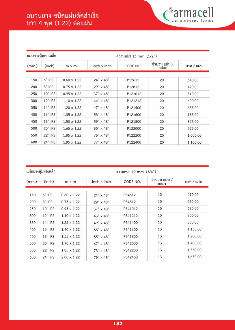
182
ฉนวนยาง ชนดแผนตดสำเรจ ยาว 4 ฟต (1.22) ตอแผน
แผนยางหมทอเหลก
m x m inch x inch CODE NO.
ความหนา 13 mm. (1/2”)
(mm.) (inch) จำนวน แผน /กลอง บาท / แผน
แผนยางหมทอเหลก
m x m inch x inch CODE NO.
ความหนา 19 mm. (3/4”)
(mm.) (inch) จำนวน แผน /กลอง บาท / แผน
150
200
250
300
350
400
450
500
550
600
6" IPS
8" IPS
10" IPS
12" IPS
14" IPS
16" IPS
18" IPS
20" IPS
22" IPS
24" IPS
150
200
250
300
350
400
450
500
550
600
6" IPS
8" IPS
10" IPS
12" IPS
14" IPS
16" IPS
18" IPS
20" IPS
22" IPS
24" IPS
0.60 x 1.22
0.75 x 1.22
0.95 x 1.22
1.10 x 1.22
1.20 x 1.22
1.35 x 1.22
1.50 x 1.22
1.65 x 1.22
1.85 x 1.22
1.95 x 1.22
24" x 48"
29" x 48"
37" x 48"
44" x 48"
47" x 48"
53" x 48"
59" x 48"
65" x 48"
73" x 48"
77" x 48"
P12612
P12812
P121012
P121212
P121400
P121600
P121800
P122000
P122200
P122400
20
20
20
20
20
20
20
20
20
20
340.00
420.00
510.00
600.00
655.00
735.00
825.00
925.00
1,000.00
1,100.00
0.60 x 1.22
0.75 x 1.22
0.95 x 1.22
1.10 x 1.22
1.25 x 1.22
1.40 x 1.22
1.55 x 1.22
1.70 x 1.22
1.85 x 1.22
2.00 x 1.22
24" x 48"
29" x 48"
37" x 48"
43" x 48"
49" x 48"
55" x 48"
55" x 48"
67" x 48"
73" x 48"
79" x 48"
P34612
P34812
P341012
P341212
P341400
P341600
P341800
P342000
P342200
P342400
13
13
13
13
13
13
13
13
13
13
470.00
580.00
670.00
750.00
850.00
1,150.00
1,280.00
1,400.00
1,550.00
1,650.00
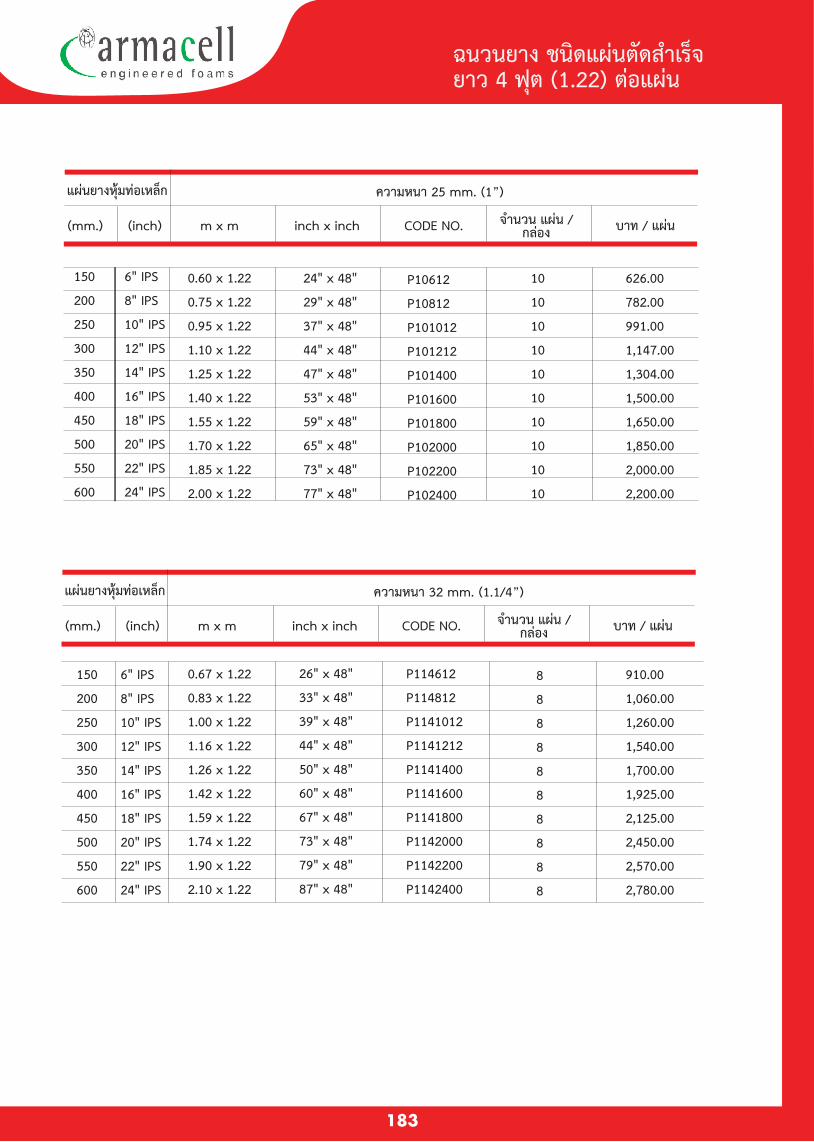
183
แผนยางหมทอเหลก
m x m inch x inch CODE NO.
ความหนา 25 mm. (1”)
(mm.) (inch) จำนวน แผน /กลอง บาท / แผน
แผนยางหมทอเหลก
m x m inch x inch CODE NO.
ความหนา 32 mm. (1.1/4”)
(mm.) (inch) จำนวน แผน /กลอง บาท / แผน
150
200
250
300
350
400
450
500
550
600
6" IPS
8" IPS
10" IPS
12" IPS
14" IPS
16" IPS
18" IPS
20" IPS
22" IPS
24" IPS
150
200
250
300
350
400
450
500
550
600
6" IPS
8" IPS
10" IPS
12" IPS
14" IPS
16" IPS
18" IPS
20" IPS
22" IPS
24" IPS
ฉนวนยาง ชนดแผนตดสำเรจ ยาว 4 ฟต (1.22) ตอแผน
0.60 x 1.22
0.75 x 1.22
0.95 x 1.22
1.10 x 1.22
1.25 x 1.22
1.40 x 1.22
1.55 x 1.22
1.70 x 1.22
1.85 x 1.22
2.00 x 1.22
24" x 48"
29" x 48"
37" x 48"
44" x 48"
47" x 48"
53" x 48"
59" x 48"
65" x 48"
73" x 48"
77" x 48"
P10612
P10812
P101012
P101212
P101400
P101600
P101800
P102000
P102200
P102400
10
10
10
10
10
10
10
10
10
10
626.00
782.00
991.00
1,147.00
1,304.00
1,500.00
1,650.00
1,850.00
2,000.00
2,200.00
0.67 x 1.22
0.83 x 1.22
1.00 x 1.22
1.16 x 1.22
1.26 x 1.22
1.42 x 1.22
1.59 x 1.22
1.74 x 1.22
1.90 x 1.22
2.10 x 1.22
26" x 48"
33" x 48"
39" x 48"
44" x 48"
50" x 48"
60" x 48"
67" x 48"
73" x 48"
79" x 48"
87" x 48"
8
8
8
8
8
8
8
8
8
8
910.00
1,060.00
1,260.00
1,540.00
1,700.00
1,925.00
2,125.00
2,450.00
2,570.00
2,780.00
P114612
P114812
P1141012
P1141212
P1141400
P1141600
P1141800
P1142000
P1142200
P1142400
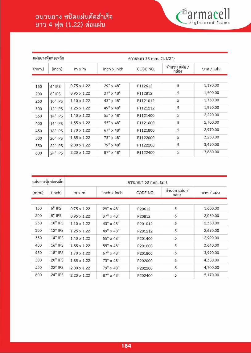
184
แผนยางหมทอเหลก
m x m inch x inch CODE NO.
ความหนา 38 mm. (1.1/2”)
(mm.) (inch) จำนวน แผน /กลอง บาท / แผน
แผนยางหมทอเหลก
m x m inch x inch CODE NO.
ความหนา 50 mm. (2”)
(mm.) (inch) จำนวน แผน /กลอง บาท / แผน
ฉนวนยาง ชนดแผนตดสำเรจ ยาว 4 ฟต (1.22) ตอแผน
0.75 x 1.22
0.95 x 1.22
1.10 x 1.22
1.25 x 1.22
1.40 x 1.22
1.55 x 1.22
1.70 x 1.22
1.85 x 1.22
2.00 x 1.22
2.20 x 1.22
29" x 48"
37" x 48"
43" x 48"
49" x 48"
55" x 48"
55" x 48"
67" x 48"
73" x 48"
79" x 48"
87" x 48"
0.75 x 1.22
0.95 x 1.22
1.10 x 1.22
1.25 x 1.22
1.40 x 1.22
1.55 x 1.22
1.70 x 1.22
1.85 x 1.22
2.00 x 1.22
2.20 x 1.22
29" x 48"
37" x 48"
43" x 48"
49" x 48"
55" x 48"
55" x 48"
67" x 48"
73" x 48"
79" x 48"
87" x 48"
5
5
5
5
5
5
5
5
5
5
1,190.00
1,500.00
1,750.00
1,990.00
2,220.00
2,700.00
2,970.00
3,230.00
3,490.00
3,880.00
P112612
P112812
P1121012
P1121212
P1121400
P1121600
P1121800
P1122000
P1122200
P1122400
150
200
250
300
350
400
450
500
550
600
6" IPS
8" IPS
10" IPS
12" IPS
14" IPS
16" IPS
18" IPS
20" IPS
22" IPS
24" IPS
150
200
250
300
350
400
450
500
550
600
6" IPS
8" IPS
10" IPS
12" IPS
14" IPS
16" IPS
18" IPS
20" IPS
22" IPS
24" IPS
5
5
5
5
5
5
5
5
5
5
1,600.00
2,030.00
2,350.00
2,670.00
2,990.00
3,640.00
3,990.00
4,350.00
4,700.00
5,170.00
P20612
P20812
P201012
P201212
P201400
P201600
P201800
P202000
P202200
P202400
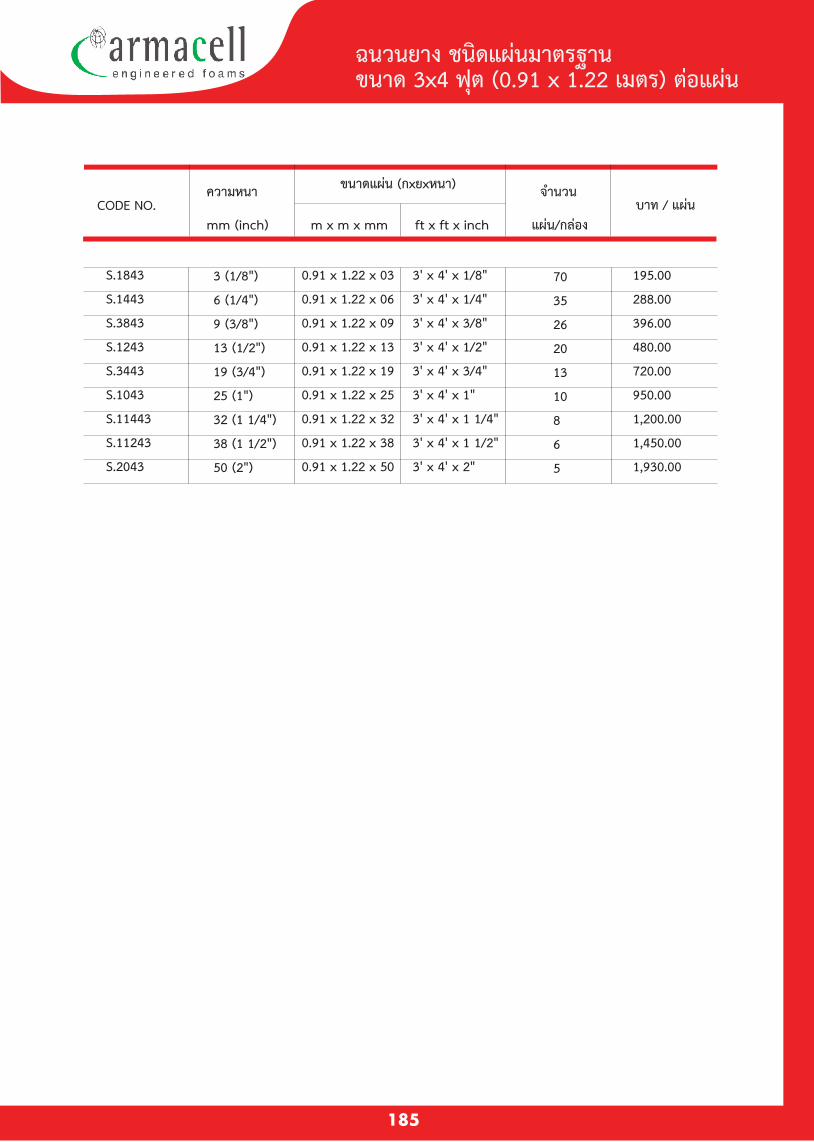
185
ฉนวนยาง ชนดแผนมาตรฐาน ขนาด 3x4 ฟต (0.91 x 1.22 เมตร) ตอแผน
ความหนา ขนาดแผน (กxยxหนา) จำนวน
บาท / แผน mm (inch) m x m x mm ft x ft x inch แผน/กลอง
CODE NO.
S.1843
S.1443
S.3843
S.1243
S.3443
S.1043
S.11443
S.11243
S.2043
3 (1/8")
6 (1/4")
9 (3/8")
13 (1/2")
19 (3/4")
25 (1")
32 (1 1/4")
38 (1 1/2")
50 (2")
0.91 x 1.22 x 03
0.91 x 1.22 x 06
0.91 x 1.22 x 09
0.91 x 1.22 x 13
0.91 x 1.22 x 19
0.91 x 1.22 x 25
0.91 x 1.22 x 32
0.91 x 1.22 x 38
0.91 x 1.22 x 50
3' x 4' x 1/8"
3' x 4' x 1/4"
3' x 4' x 3/8"
3' x 4' x 1/2"
3' x 4' x 3/4"
3' x 4' x 1"
3' x 4' x 1 1/4"
3' x 4' x 1 1/2"
3' x 4' x 2"
70
35
26
20
13
10
8
6
5
195.00
288.00
396.00
480.00
720.00
950.00
1,200.00
1,450.00
1,930.00

186
ฉนวนยาง ชนดมวน บกโรล หนากวาง 1.22 เมตร (4 ฟต)
CODE NO.ความหนา
mm (inch)
หนากวาง
mm (inch)
ความยาว
m (feet)
พนท
m2/roll,(ft2/roll)บาท / มวน
AFSR18PP
AFSR14PP
AFSR38PP
AFSR12PP
AFSR34PP
AFSR10PP
AFSR114PP
AFSR112PP
AFSR20PP
3 (1/8")
6 (1/4")
9 (3/8")
13 (1/2")
19 (3/4")
25 (1")
32 (1 1/4")
38 (1 1/2")
50 (2")
1200 (48")
1200 (48")
1200 (48")
1200 (48")
1200 (48")
1200 (48")
1200 (48")
1200 (48")
1200 (48")
15 (49')
15 (49')
15 (49')
15 (49')
15 (49')
15 (49')
6 (20')
6 (20')
6 (20')
18.3 (196)
18.3 (196)
18.3 (196)
18.3 (196)
18.3 (196)
18.3 (196)
7.32 (80)
7.32 (80)
7.32 (80)
3,660.00
4,758.00
6,496.50
7,869.00
11,712.00
15,646.50
7,503.00
9,516.00
12,810.00
3 (1/8")
6 (1/4")
9 (3/8")
13 (1/2")
19 (3/4")
25 (1")
1200 (48")
1200 (48")
1200 (48")
1200 (48")
1200 (48")
1200 (48")
15 (49')
15 (49')
15 (49')
15 (49')
15 (49')
15 (49')
18.3 (196)
18.3 (196)
18.3 (196)
18.3 (196)
18.3 (196)
18.3 (196)
3,660.00
8,088.60
10,998.30
12,645.30
17,970.60
22,692.00
CODE NO.ความหนา
mm (inch)
หนากวาง
mm (inch)
ความยาว
m (feet)
พนท
m2/roll,(ft2/roll)บาท / มวน
ฉนวนยางพรอมเทปกาว ชนดมวน บกโรล หนากวาง 1.22 เมตร (4 ฟต)
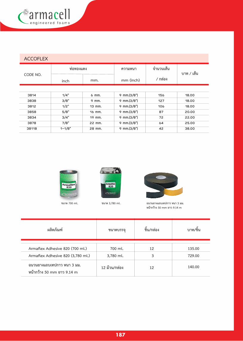
820
187
ACCOFLEX
38143838381238583834387838118
1/4“3/8“1/2“5/8“3/4“7/8“
1-1/8“
6 mm.9 mm.13 mm.16 mm.19 mm.22 mm.28 mm.
9 mm.(3/8“)9 mm.(3/8“)9 mm.(3/8“)9 mm.(3/8“)9 mm.(3/8“)9 mm.(3/8“)9 mm.(3/8“)
15612710687726442
18.0018.0018.0020.0022.0025.0038.00
CODE NO.inch mm.
บาท / เสนทอทองแดง ความหนา
mm (inch)
จำนวนเสน
/ กลอง
ขนาด 700 ml. ขนาด 3,780 ml. ฉนวนยางแถบเทปกาว หนา 3 มม. หนากวาง 50 mm ยาว 9.14 m
ผลตภณฑ ขนาดบรรจ ชน/กลอง บาท/ชน
ฉนวนยางแถบเทปกาว หนา 3 มม.
หนากวาง 50 mm ยาว 9.14 m
Armaflex Adhesive 820 (700 ml.)
Armaflex Adhesive 820 (3,780 ml.)
700 ml.
3,780 ml.
12 มวน/กลอง
12
3
12
135.00
729.00
140.00
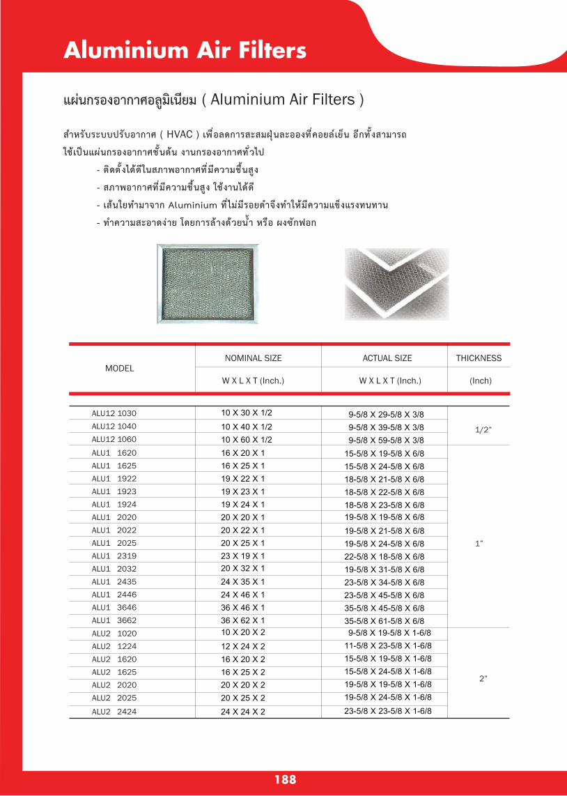
188
Aluminium Air Filters
แผนกรองอากาศอลมเนยม ( Aluminium Air Filters )
สำหรบระบบปรบอากาศ ( HVAC ) เพ อลดการสะสมฝ นละอองท คอยลเยน อกท งสามารถ
ใชเปนแผนกรองอากาศช นตน งานกรองอากาศท วไป
- ตดต งไดดในสภาพอากาศท มความช นสง
- สภาพอากาศท มความช นสง ใชงานไดด
- เสนใยทำมาจาก Aluminium ท ไมมรอยดำจงทำใหมความแขงแรงทนทาน
- ทำความสะอาดงาย โดยการลางดวยนำ หรอ ผงซกฟอก
ALU12 1030ALU12 1040ALU12 1060
ALU1 1620ALU1 1625
ALU1 1924ALU1 2020ALU1 2022ALU1 2025ALU1 2319ALU1 2032ALU1 2435ALU1 2446ALU1 3646ALU1 3662
ALU1 1923ALU1 1922
ALU2 2424
ALU2 2025ALU2 2020ALU2 1625ALU2 1620ALU2 1224ALU2 1020
19 X 24 X 120 X 20 X 120 X 22 X 1
23 X 19 X 120 X 32 X 124 X 35 X 1
36 X 46 X 136 X 62 X 1
16 X 20 X 116 X 25 X 119 X 22 X 119 X 23 X 1
20 X 25 X 1
24 X 46 X 1
10 X 30 X 1/210 X 40 X 1/210 X 60 X 1/2
24 X 24 X 220 X 25 X 220 X 20 X 216 X 25 X 216 X 20 X 212 X 24 X 210 X 20 X 2
18-5/8 X 23-5/8 X 6/819-5/8 X 19-5/8 X 6/819-5/8 X 21-5/8 X 6/8
22-5/8 X 18-5/8 X 6/819-5/8 X 31-5/8 X 6/823-5/8 X 34-5/8 X 6/8
35-5/8 X 45-5/8 X 6/835-5/8 X 61-5/8 X 6/8
15-5/8 X 19-5/8 X 6/815-5/8 X 24-5/8 X 6/818-5/8 X 21-5/8 X 6/818-5/8 X 22-5/8 X 6/8
19-5/8 X 24-5/8 X 6/8
23-5/8 X 45-5/8 X 6/8
9-5/8 X 59-5/8 X 3/8
9-5/8 X 29-5/8 X 3/89-5/8 X 39-5/8 X 3/8
23-5/8 X 23-5/8 X 1-6/819-5/8 X 24-5/8 X 1-6/819-5/8 X 19-5/8 X 1-6/815-5/8 X 24-5/8 X 1-6/815-5/8 X 19-5/8 X 1-6/811-5/8 X 23-5/8 X 1-6/89-5/8 X 19-5/8 X 1-6/8
1/2”
1”
2”
NOMINAL SIZE ACTUAL SIZE THICKNESS
W X L X T (Inch.) W X L X T (Inch.) (Inch)MODEL

189
®Premum Seriesราง เด นท อปร บอากาศ
ModelA B C D E
Pkg.Dimension (mm.)
ฝาครอบเพดาน SLIM WALL
ฝาครอบ SLIM WALL
SLIM WALL TA - 65
SLIM WALL TA - 75
SLIM WALL TA - 100
SLIM WALL TV - 65
SLIM WALL TV - 75
SLIM WALL TV - 100
SLIM JOINT TS - 65
SLIM JOINT TS - 75
SLIM JOINT TS - 100
SLIM FIEXIBLE CORNER TX - 65
SLIM FIEXIBLE CORNER TX - 75
SLIM FIEXIBLE CORNER TX- 100
SLIM CORNER 90.
TQ - 65
SLIM CORNER 90.
TQ - 75
SLIM CORNER 90.
TQ- 100
SLIM ELBOW TL - 65
SLIM ELBOW TL - 75
SLIM ELBOW TL- 100
SLIM CROSS OVER TLF - 65
SLIM CROSS OVER TLF - 75
SLIM CROSS OVER TLF - 100
SLIM DUCT TR - 65
SLIM DUCT TR - 75
SLIM DUCT TR - 100
SLIM FLEXIBLE TE - 65
SLIM FLEXIBLE TE - 75
SLIM FLEXIBLE TE - 100
ขอตอตรง SLIM JOINT
ของอปรบได SLIM FIEXIBLE CORNER
ขอตอขามคาน SLIM CROSS OVER
ทอหม SLIM DUCT
ทอยด SLIM FLEXIBLE
ของอเขามม 90. SLIM CORNER 90
.
ของอโคง SLIM ELBOW
64
80
103
60
67
70
66
66
66
110
125
140
105
124
149
60
76
100
60
63
68
200
210
231
81
83
96
77
94
110
60
76
100
60
63
68
80
80
80
60
76
100
60
63
68
137
153
193.5
60
76
100
60
63
68
120
124
135
60
76
100
60
63
68
117.5
122.5
153
60
76
100
60
63
68
180
180
180
114
116
123
58
75.5
101
52
63.5
65
2000
2000
2000
57
74
98
57
64
66
25
25
35
475
465
700
20
20
20
20
20
20
20
5
20
-
-
-
-
-
-
-
-
-
-
-
-
-
-
-
-
-
-
-
-
-
-
-
-
-
-
-
-
-
-
-
-
-

190
ModelA B C D E
Pkg.Dimension (mm.)
Standard Seriesร า ง เ ด น ท อ ป ร บ อ า ก า ศ
ฝาครอบ SLIM WALL
SLIM WALL DV - 65
SLIM WALL DV - 75
SLIM WALL DV - 100
ของอเขามม 90. SLIM CORNER 90
.
SLIM CORNER 90.
DQ - 65
SLIM CORNER 90.
DQ - 75
SLIM CORNER 90.
DQ - 100
ของอโคง SLIM ELBOW
SLIM ELBOW DX - 65
SLIM ELBOW DX - 75
SLIM ELBOW DX - 100
ขอแยกสามทาง SLIM TYPE JOINT
SLIM TYPE JOINT DT - 65
SLIM TYPE JOINT DT - 75
SLIM TYPE JOINT DT - 100
ขอตอขามคาน SLIM CROSS OVER
SLIM CROSS OVER DIF - 65
SLIM CROSS OVER DIF - 75
SLIM CROSS OVER DIF - 100
ขอตอตรง SLIM JOINT
SLIM JOIN DS - 65
SLIM JOIN DS - 75
SLIM JOIN DS - 100
ทอหม SLIM DUCT
SLIM DUCT DR - 65
SLIM DUCT DR - 75
SLIM DUCT DR - 100
ทอยด SLIM FLEXIBLE
SLIM FLEXIBLE DE - 65
SLIM FLEXIBLE DE - 75
SLIM FLEXIBLE DE - 100
57
74
98
57
63
66
25
25
35
475
482
700
60
62
102
60
77
69.5
77
74.5
93
184
194
190
-
-
-
60
76
100
60
62
68
98
117
128
-
-
-
-
-
-
-
-
-
-
-
-
60
76
100
60
62
68
100
131.5
171.5
60
76
100
60
62
69
-
-
-
163
179
202
114
130
153
-
-
-
60
76
100
60
62
68
180
180
180
114
116
123
-
-
-
-
-
-
60
76
100
60
62
68
51.5
65
80
-
-
-
-
-
-
60
74
100
57.5
64
68
2000
2000
2000
20
20
20
20
20
20
5
20
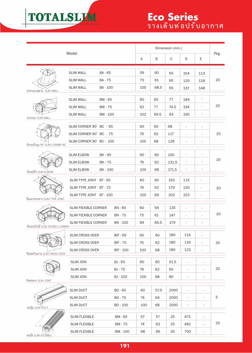
191
Eco Seriesราง เด นท อปร บอากาศ
ModelA B C D E
Pkg.Dimension (mm.)
SLIM CORNER 90.
BC - 65
SLIM CORNER 90.
BC - 75
SLIM CORNER 90.
BC - 100
SLIM ELBOW BK - 65
SLIM ELBOW BK - 75
SLIM ELBOW BK - 100
ทอยด SLIM FLEXIBLE
ฝาครอบเพดาน SLIM WALL
ฝาครอบ SLIM WALL
ขอตอตรง SLIM JOINT
ของอปรบได SLIM FIEXIBLE CORNER
ขอตอขามคาน SLIM CROSS OVER
ทอหม SLIM DUCT
ของอเขามม 90. SLIM CORNER 90
.
ของอโคง SLIM ELBOW
ขอแยกสามทาง SLIM TYPE JOINT
SLIM WALL BA - 65
SLIM WALL BA - 75
SLIM WALL BA - 100
SLIM WALL BW - 65
SLIM WALL BW - 75
SLIM WALL BW - 100
SLIM TYPE JOINT BT - 65
SLIM TYPE JOINT BT - 75
SLIM TYPE JOINT BT - 100
SLIM FIEXIBLE CORNER BN - 65
SLIM FIEXIBLE CORNER BN - 75
SLIM FIEXIBLE CORNER BN - 100
SLIM CROSS OVER BIF - 65
SLIM CROSS OVER BIF - 75
SLIM CROSS OVER BIF - 100
SLIM JOIN BJ - 65
SLIM JOIN BJ - 75
SLIM JOIN BJ - 100
SLIM DUCT BD - 65
SLIM DUCT BD - 75
SLIM DUCT BD - 100
SLIM FLEXIBLE BM - 65
SLIM FLEXIBLE BM - 75
SLIM FLEXIBLE BM - 100
59
75
100
60
61
68.5
65
65
65
104
120
137
113
118
148
20
20
60
62
102
60
77
69.5
77
74.5
93
184
194
190
-
-
-
60
76
100
60
62
68
98
117
128
-
-
-
-
-
-
20
2060
76
100
60
76
100
60
62
68
60
62
69
100
131.5
171.5
-
-
-
-
-
-
-
-
-
-
-
-
-
-
-
-
-
-
-
-
-
-
-
-
-
-
-
-
-
-
163
179
202
114
130
153
20
20
60
75
99
59
61
66.5
135
147
179
60
76
100
60
76
100
60
74
100
60
62
68
60
62
68
180
180
180
51.5
65
80
114
116
123
20
20
5
20
57.5
64
68
2000
2000
2000
57
74
98
57
63
66
25
25
35
475
482
700
-
-
-
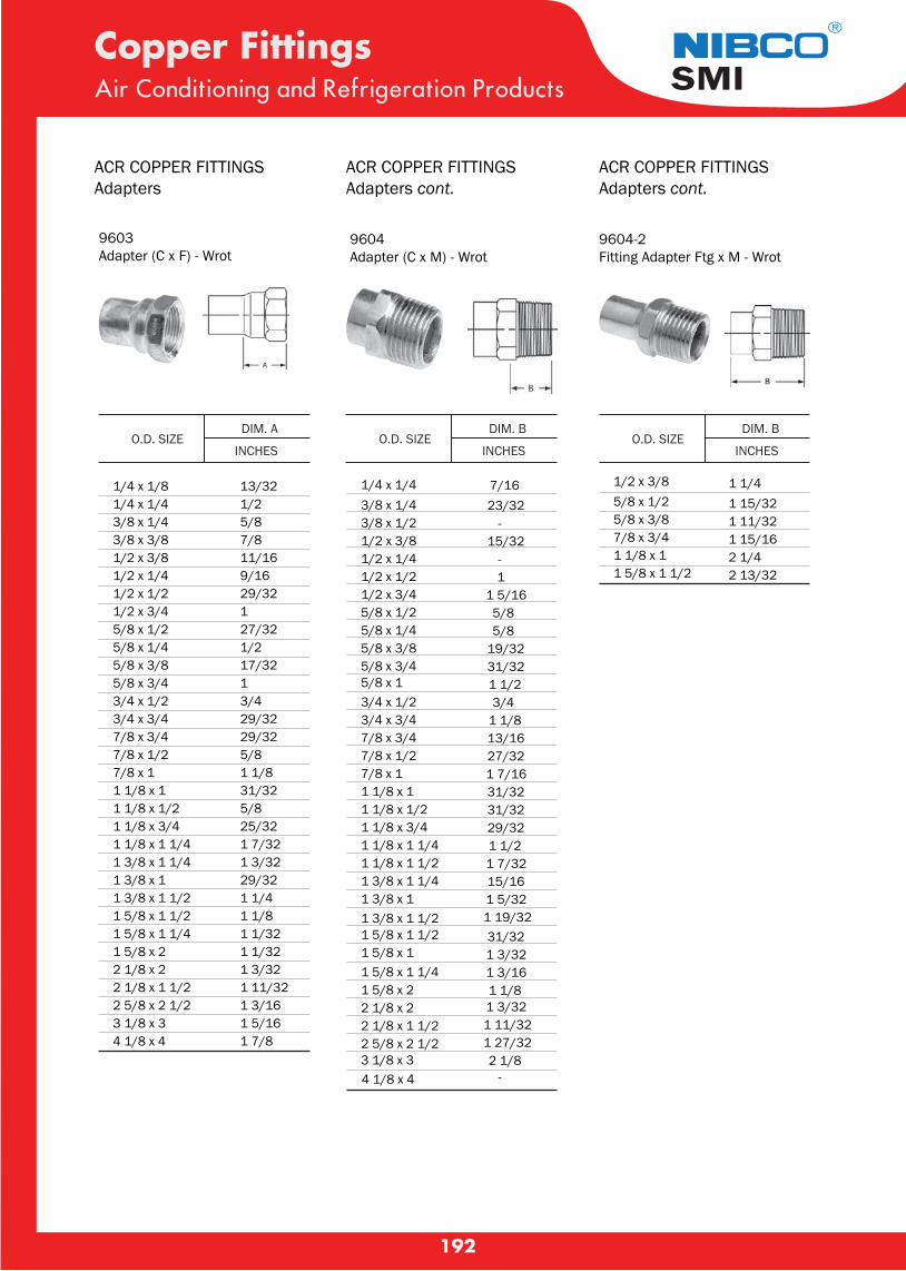
192
®
SMI
9603Adapter (C x F) - Wrot
ACR COPPER FITTINGSAdapters
O.D. SIZE DIM. A
INCHES
1/4 x 1/81/4 x 1/43/8 x 1/43/8 x 3/81/2 x 3/81/2 x 1/41/2 x 1/21/2 x 3/45/8 x 1/25/8 x 1/45/8 x 3/85/8 x 3/43/4 x 1/23/4 x 3/47/8 x 3/47/8 x 1/27/8 x 11 1/8 x 11 1/8 x 1/21 1/8 x 3/41 1/8 x 1 1/41 3/8 x 1 1/41 3/8 x 1 1 3/8 x 1 1/21 5/8 x 1 1/21 5/8 x 1 1/41 5/8 x 22 1/8 x 22 1/8 x 1 1/22 5/8 x 2 1/23 1/8 x 34 1/8 x 4
13/321/25/87/811/169/1629/32127/321/217/3213/429/3229/325/81 1/831/325/825/321 7/321 3/3229/321 1/41 1/81 1/321 1/321 3/321 11/321 3/161 5/161 7/8
9604Adapter (C x M) - Wrot
1/4 x 1/4 7/163/8 x 1/4 23/323/8 x 1/2 -1/2 x 3/8 15/321/2 x 1/4 -1/2 x 1/2 11/2 x 3/4 1 5/165/8 x 1/2 5/85/8 x 1/4 5/85/8 x 3/8 19/325/8 x 3/4 31/325/8 x 1 1 1/23/4 x 1/2 3/43/4 x 3/4 1 1/87/8 x 3/4 13/167/8 x 1/2 27/327/8 x 1 1 7/161 1/8 x 1 31/321 1/8 x 1/2 31/321 1/8 x 3/4 29/321 1/8 x 1 1/4 1 1/21 1/8 x 1 1/2 1 7/321 3/8 x 1 1/4 15/161 3/8 x 1 1 5/321 3/8 x 1 1/2 1 19/321 5/8 x 1 1/2 31/321 5/8 x 1 1 3/321 5/8 x 1 1/4 1 3/161 5/8 x 2 1 1/82 1/8 x 2 1 3/322 1/8 x 1 1/2 1 11/322 5/8 x 2 1/2 1 27/323 1/8 x 3 2 1/84 1/8 x 4 -
9604-2Fitting Adapter Ftg x M - Wrot
1/2 x 3/8 1 1/45/8 x 1/2 1 15/325/8 x 3/8 1 11/327/8 x 3/4 1 15/161 1/8 x 1 2 1/41 5/8 x 1 1/2 2 13/32
Copper FittingsAir Conditioning and Refrigeration Products
O.D. SIZE DIM. B
INCHESO.D. SIZE
DIM. B
INCHES
ACR COPPER FITTINGSAdapters cont.
ACR COPPER FITTINGSAdapters cont.
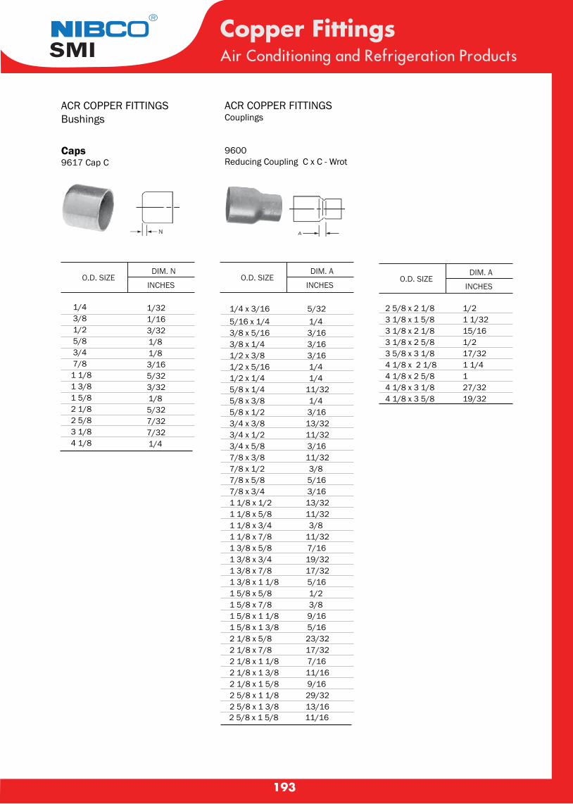
193
Caps9617 Cap C
1/4 1/32 3/8 1/16 1/2 3/32 5/8 1/8 3/4 1/8 7/8 3/161 1/8 5/321 3/8 3/321 5/8 1/82 1/8 5/322 5/8 7/323 1/8 7/324 1/8 1/4
9600Reducing Coupling C x C - Wrot
1/4 x 3/165/16 x 1/43/8 x 5/163/8 x 1/41/2 x 3/81/2 x 5/161/2 x 1/45/8 x 1/45/8 x 3/85/8 x 1/23/4 x 3/83/4 x 1/23/4 x 5/87/8 x 3/87/8 x 1/27/8 x 5/87/8 x 3/41 1/8 x 1/21 1/8 x 5/81 1/8 x 3/41 1/8 x 7/81 3/8 x 5/81 3/8 x 3/41 3/8 x 7/81 3/8 x 1 1/81 5/8 x 5/81 5/8 x 7/81 5/8 x 1 1/81 5/8 x 1 3/82 1/8 x 5/82 1/8 x 7/82 1/8 x 1 1/82 1/8 x 1 3/82 1/8 x 1 5/82 5/8 x 1 1/82 5/8 x 1 3/8
5/321/43/163/163/161/41/4
11/321/43/1613/3211/323/1611/323/85/163/1613/3211/323/8
11/327/1619/3217/325/161/23/89/165/1623/3217/327/1611/169/1629/3213/16
2 5/8 x 2 1/8 1/23 1/8 x 1 5/8 1 1/323 1/8 x 2 1/8 15/163 1/8 x 2 5/8 1/23 5/8 x 3 1/8 17/324 1/8 x 2 1/8 1 1/44 1/8 x 2 5/8 14 1/8 x 3 1/8 27/324 1/8 x 3 5/8 19/32
Copper FittingsAir Conditioning and Refrigeration Products
O.D. SIZE DIM. N
INCHESO.D. SIZE
DIM. A
INCHESO.D. SIZE
DIM. A
INCHES
®
SMI
ACR COPPER FITTINGSBushings
ACR COPPER FITTINGSCouplings
2 5/8 x 1 5/8 11/16
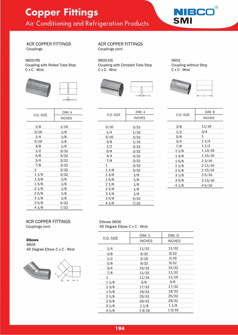
194
9600-RSCoupling with Rolled Tube Stop C x C - Wrot
1/83/16 1/45/16 3/8 1/2 5/8 3/4 7/81 1 1/81 3/81 5/82 1/82 5/83 1/83 5/84 1/8
1/161/81/81/81/83/323/323/323/323/323/321/81/81/81/81/85/327/32
Copper FittingsAir Conditioning and Refrigeration Products
O.D. SIZE DIM. A
INCHESO.D. SIZE
DIM. A
INCHESO.D. SIZE
DIM. B
INCHES
®
SMI
ACR COPPER FITTINGSCouplings
ACR COPPER FITTINGSCouplings cont.
9600-DSCoupling with Dimpled Tube Stop C x C - Wrot
3/16 1/45/16 3/8 1/2 5/8 3/4 7/81 1 1/81 3/81 5/82 1/82 5/83 1/83 5/84 1/8
3/321/163/321/163/323/323/323/323/323/321/81/81/81/81/85/327/32
3/8 11/16 1/2 3/4 5/8 1 3/4 1 1/4 7/8 1 1/21 1/8 1 13/161 3/8 1 15/161 5/8 2 3/162 1/8 2 11/162 5/8 2 15/163 1/8 3 5/163 5/8 3 13/164 1/8 4 5/16
9601Coupling without Stop C x C - Wrot
Elbows960645 Degree Elbow C x C - Wrot
O.D. SIZE DIM. C
INCHES
1/4 11/32 11/32
3/8 9/32 9/32 1/2 3/16 3/16 5/8 9/32 9/32 3/4 15/32 15/32 7/8 11/32 11/321 11/16 11/161 1/8 3/8 3/81 3/8 17/32 17/321 5/8 19/32 19/322 1/8 25/32 25/322 5/8 29/32 29/323 1/8 1 1/8 1 1/84 1/8 1 9/16 1 9/16
DIM. DINCHES
Elbows 960645 Degree Elbow C x C - Wrot
ACR COPPER FITTINGSCouplings cont.

195
Copper FittingsAir Conditioning and Refrigeration Products
®
SMI
960790 Degree Elbow - Close Rough C x C - Wrot
1/4 13/32 13/32 3/8 3/8 3/8 1/2 1/2 1/21/2 x 3/8 - - 5/8 11/32 11/325/8 x 1/2 7/16 21/32 7/8 1/2 13/167/8 x 5/8 9/16 25/327/8 x 3/4 29/32 7/81 29/32 29/321 1/8 21/32 21/321 1/8 x 5/8 - -1 1/8 x 7/8 27/32 1 1/161 3/8 15/16 15/161 3/8 x 1 1/8 1 5/8 1 15/321 5/8 1 1/32 1 1/321 5/8 x 1 3/8 1 5/32 1 3/322 1/8 1 13/32 1 13/322 1/8 x 1 5/8 1 7/16 1 1/42 5/8 1 5/8 1 5/83 1/8 2 23 5/8 2 7/16 2 7/164 1/8 2 15/32 2 15/32
9607-LT90 Degree Elbow - Long Radius C x C - Wrot
DIM. DINCHES
3/16 13/32 13/32 1/4 13/32 13/325/16 9/16 9/16 3/8 17/32 17/323/8 x 1/4 19/32 1/2 1/2 23/32 23/32 5/8 7/8 7/85/8 x 1/2 13/16 13/165/8 x 3/8 25/32 21/32 3/4 1 3/32 1 3/323/4 x 5/8 1 1/16 1 1/16 7/8 1 1/8 1 1/87/8 x 3/4 1 1/4 1 3/327/8 x 5/8 1 1/8 1 1/161 1 19/32 1 19/321 1/8 1 7/16 1 7/161 1/8 x 7/8 1 1/4 1 1/81 1/8 x 3/4 1 13/32 1 3/321 3/8 1 7/8 1 7/81 3/8 x 1 1/8 1 25/32 1 1/21 5/8 2 1/4 2 1/42 1/8 2 15/16 2 15/162 5/8 3 11/16 3 11/162 5/8 x 2 1/83 1/8 4 1/32 4 1/323 5/84 1/8 5 1/4 5 1/49607-I
90 Degree Elbow- Intermediate Radius C x C - Wrot
DIM. DINCHES 5/8 19/32 19/32
3/4 7/8 7/8 7/8 3/16 3/161 1/8 1 1/16 1 1/16
ACR COPPER FITTINGSElbows cont.
O.D. SIZE DIM. C
INCHESDIM. DINCHES
O.D. SIZE DIM. C
INCHES
O.D. SIZE DIM. C
INCHESDIM. DINCHES
DIM. DINCHES
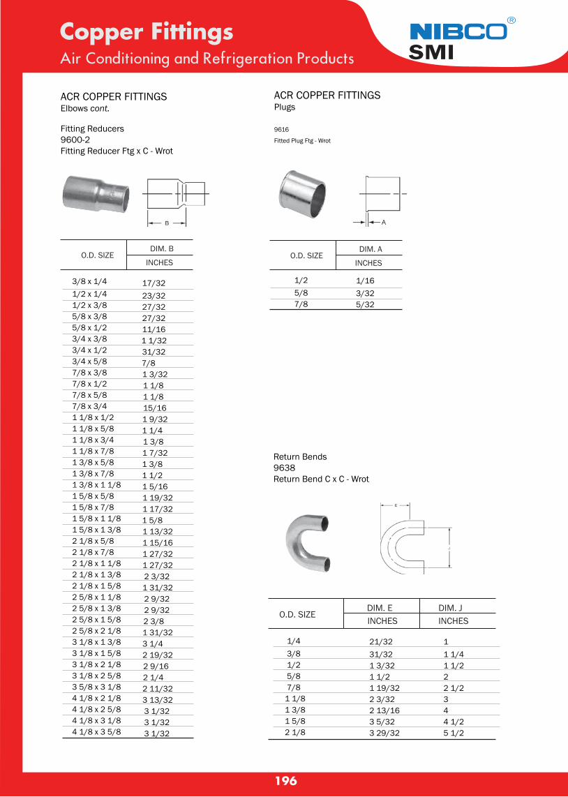
196
Copper FittingsAir Conditioning and Refrigeration Products
®
SMI
Fitting Reducers9600-2Fitting Reducer Ftg x C - Wrot
3/8 x 1/4 17/321/2 x 1/4 23/321/2 x 3/8 27/325/8 x 3/8 27/325/8 x 1/2 11/163/4 x 3/8 1 1/323/4 x 1/2 31/323/4 x 5/8 7/87/8 x 3/8 1 3/327/8 x 1/2 1 1/87/8 x 5/8 1 1/87/8 x 3/4 15/161 1/8 x 1/2 1 9/321 1/8 x 5/8 1 1/41 1/8 x 3/4 1 3/81 1/8 x 7/8 1 7/321 3/8 x 5/8 1 3/81 3/8 x 7/8 1 1/21 3/8 x 1 1/8 1 5/161 5/8 x 5/8 1 19/321 5/8 x 7/8 1 17/321 5/8 x 1 1/8 1 5/81 5/8 x 1 3/8 1 13/322 1/8 x 5/8 1 15/162 1/8 x 7/8 1 27/322 1/8 x 1 1/8 1 27/322 1/8 x 1 3/8 2 3/322 1/8 x 1 5/8 1 31/322 5/8 x 1 1/8 2 9/322 5/8 x 1 3/8 2 9/322 5/8 x 1 5/8 2 3/82 5/8 x 2 1/8 1 31/323 1/8 x 1 3/8 3 1/43 1/8 x 1 5/8 2 19/323 1/8 x 2 1/8 2 9/163 1/8 x 2 5/8 2 1/43 5/8 x 3 1/8 2 11/324 1/8 x 2 1/8 3 13/324 1/8 x 2 5/8 3 1/324 1/8 x 3 1/8 3 1/324 1/8 x 3 5/8 3 1/32
O.D. SIZE DIM. E
INCHESDIM. JINCHES
ACR COPPER FITTINGSElbows cont.
O.D. SIZE DIM. B
INCHESO.D. SIZE
DIM. A
INCHES
9616
Fitted Plug Ftg - Wrot
1/2 1/16 5/8 3/32 7/8 5/32
1/4 21/32 1 3/8 31/32 1 1/4 1/2 1 3/32 1 1/2 5/8 1 1/2 2 7/8 1 19/32 2 1/21 1/8 2 3/32 31 3/8 2 13/16 41 5/8 3 5/32 4 1/22 1/8 3 29/32 5 1/2
Return Bends9638Return Bend C x C - Wrot
ACR COPPER FITTINGSPlugs

197
Copper FittingsAir Conditioning and Refrigeration Products
®
SMI
9611Tee C x C x C - Wrot
3/16 1/41/4 x 1/4 x 3/81/4 x 1/4 x 3/161/4 x 3/16 x 1/45/165/16 x 1/4 x 1/45/16 x 1/4 x 5/165/16 x 5/16 x 1/45/16 x 5/16 x 3/8
3/83/8 x 1/4 x 1/43/8 x 1/4 x 3/83/8 x 5/16 x 3/83/8 x 3/8 x 1/43/8 x 3/8 x 1/23/8 x 3/8 x 5/83/8 x 3/8 x 3/163/8 x 3/8 x 5/16 1/21/2 x 1/4 x 1/41/2 x 1/4 x 1/21/2 x 3/8 x 1/41/2 x 3/8 x 3/81/2 x 3/8 x 1/21/2 x 1/2 x 1/41/2 x 1/2 x 5/161/2 x 1/2 x 3/81/2 x 1/2 x 5/8 5/85/8 x 3/8 x 1/25/8 x 1/2 x 3/85/8 x 1/2 x 1/25/8 x 1/2 x 5/85/8 x 5/8 x 1/45/8 x 5/8 x 3/85/8 x 5/8 x 1/25/8 x 5/8 x 3/45/8 x 5/8 x 7/85/8 x 5/8 x 1 1/8
7/3215/1613/325/165/163/83/83/83/83/85/165/165/165/165/1617/3219/325/165/1611/3211/3211/3211/3211/3211/3211/3211/3211/3217/3211/325/165/165/167/161/45/165/165/817/321
7/3215/1613/325/1611/323/813/3213/323/83/85/1613/3213/323/85/1617/3219/325/165/1611/3219/3219/3217/3217/3217/3211/3211/3211/3217/3211/325/817/3217/3217/321/45/165/165/817/321
7/321/49/325/161/45/1611/325/165/169/321/411/329/329/325/1611/323/87/165/1611/3219/3211/329/1615/3211/329/1615/3215/323/811/3213/329/161/23/811/169/1613/327/1611/3221/32
3/4 7/163/4 x 1/2 x 1/2 7/163/4 x 1/2 x 3/4 7/163/4 x 5/8 x 5/8 7/163/4 x 5/8 x 3/4 7/163/4 x 3/4 x 3/8 7/163/4 x 3/4 x 1/2 7/163/4 x 3/4 x 5/8 7/163/4 x 3/4 x 7/8 23/32 7/8 7/167/8 x 1/2 x 1/2 7/167/8 x 1/2 x 5/8 7/167/8 x 1/2 x 7/8 17/327/8 x 5/8 x 1/2 7/167/8 x 5/8 x 5/8 13/327/8 x 5/8 x 7/8 1/27/8 x 3/4 x 3/4 1/27/8 x 3/4 x 7/8 17/327/8 x 7/8 x 1/4 7/167/8 x 7/8 x 3/8 13/327/8 x 7/8 x 1/2 13/327/8 x 7/8 x 5/8 3/87/8 x 7/8 x 3/4 17/327/8 x 7/8 x 1 1/8 23/321 23/321 1/8 11/161 1/8 x 5/8 x 5/8 1/21 1/8 x 5/8 x 7/8 9/161 1/8 x 5/8 x 1 1/8 11/161 1/8 x 7/8 x 5/8 15/321 1/8 x 7/8 x 7/8 9/161 1/8 x 7/8 x 1 1/8 11/161 1/8 x 1 1/8 x 3/8 1/21 1/8 x 1 1/8 x 1/2 1/21 1/8 x 1 1/8 x 5/8 1/21 1/8 x 1 1/8 x 3/4 19/321 1/8 x 1 1/8 x 7/8 19/321 1/8 x 1 1/8 x 1 3/8 1 5/321 1/8 x 1 1/8 x 1 5/8 1 11/321 3/8 13/161 3/8 x 5/8 x 1 3/8 13/161 3/8 x 7/8 x 5/8 15/321 3/8 x 7/8 x 7/8 21/321 3/8 x 7/8 x 1 1/8 25/321 3/8 x 7/8 x 1 3/8 13/161 3/8 x 1 1/8 x 5/8 15/321 3/8 x 1 1/8 x 7/8 21/321 3/8 x 1 1/8 x 1 1/8 25/321 3/8 x 1 1/8 x 1 3/8 13/161 3/8 x 1 3/8 x 1/2 15/321 3/8 x 1 3/8 x 5/8 15/321 3/8 x 1 3/8 x 7/8 21/321 3/8 x 1 3/8 x 1 1/8 25/321 3/8 x 1 3/8 x 1 5/8 1 3/16
7/16 7/163/4 5/83/4 7/1619/32 13/325/8 7/167/16 3/47/16 5/87/16 13/3223/32 1/27/16 7/1623/32 21/3223/32 17/3227/32 1/221/32 21/3219/32 1/25/8 15/323/4 11/1611/16 1/27/16 13/1613/32 25/3213/32 21/323/8 15/3217/32 11/1623/32 1/223/32 23/3211/16 21/3225/32 11/167/8 11/161 1/32 21/3211/16 11/1625/32 23/3231/32 21/321/2 1 3/161/2 29/321/2 11/1619/32 29/3219/32 23/321 5/32 7/81 11/32 31/3213/16 13/161 7/32 13/163/4 25/3215/16 3/41 1/16 29/321 1/8 13/1619/32 13/1613/16 25/3231/32 29/321 1/32 13/1615/32 29/3215/32 25/3221/32 3/425/32 27/321 3/16 29/32
DIMENSIONS INCHES C F G
OD SIZE
ACR COPPER FITTINGSTees DIMENSIONS INCHES
C F G OD SIZE
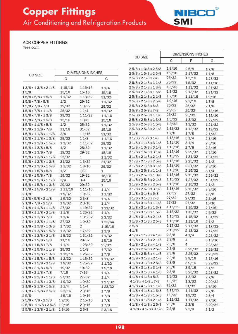
198
Copper FittingsAir Conditioning and Refrigeration Products
®
SMI
C F G
1 3/8 x 1 3/8 x 2 1/8 1 15/161 5/8 15/161 5/8 x 5/8 x 1 5/8 1 1/321 5/8 x 7/8 x 5/8 1/21 5/8 x 7/8 x 7/8 19/321 5/8 x 7/8 x 1 1/8 25/321 5/8 x 7/8 x 1 3/8 29/321 5/8 x 7/8 x 1 5/8 15/161 5/8 x 1 1/8 x 5/8 1/21 5/8 x 1 1/8 x 7/8 11/161 5/8 x 1 1/8 x 1 1/8 3/41 5/8 x 1 1/8 x 1 3/8 29/321 5/8 x 1 1/8 x 1 5/8 1 1/321 5/8 x 1 3/8 x 5/8 1/21 5/8 x 1 3/8 x 7/8 19/321 5/8 x 1 3/8 x 1 1/8 25/321 5/8 x 1 3/8 x 1 3/8 31/321 5/8 x 1 3/8 x 1 5/8 1 1/321 5/8 x 1 5/8 x 5/8 1/21 5/8 x 1 5/8 x 7/8 19/321 5/8 x 1 5/8 x 1 1/8 3/41 5/8 x 1 5/8 x 1 3/8 29/321 5/8 x 1 5/8 x 2 1/8 1 11/162 1/8 1 9/322 1/8 x 5/8 x 2 1/8 1 9/322 1/8 x 7/8 x 2 1/8 1 9/322 1/8 x 1 1/8 x 1 1/8 27/322 1/8 x 1 1/8 x 2 1/8 1 1/82 1/8 x 1 3/8 x 7/8 1 1/42 1/8 x 1 3/8 x 1 1/8 27/322 1/8 x 1 3/8 x 1 3/8 1 7/322 1/8 x 1 3/8 x 1 5/8 1 3/322 1/8 x 1 3/8 x 2 1/8 1 9/322 1/8 x 1 5/8 x 5/8 11/162 1/8 x 1 5/8 x 7/8 1 1/42 1/8 x 1 5/8 x 1 1/8 29/322 1/8 x 1 5/8 x 1 3/8 1 15/162 1/8 x 1 5/8 x 1 5/8 1 3/322 1/8 x 1 5/8 x 2 1/8 1 9/322 1/8 x 2 1/8 x 5/8 19/322 1/8 x 2 1/8 x 7/8 7/162 1/8 x 2 1/8 x 1 1/8 27/322 1/8 x 2 1/8 x 1 3/8 1 9/322 1/8 x 2 1/8 x 1 5/8 1 1/42 1/8 x 2 1/8 x 2 5/8 2 3/162 5/8 1 9/162 5/8 x 7/8 x 2 5/8 1 9/162 5/8 x 1 1/8 x 2 5/8 1 9/162 5/8 x 1 3/8 x 2 1/8 1 9/16
1 15/16 1 1/415/16 15/161 13/32 31/3229/32 1 1/321 3/32 29/321 1/4 1 1/321 11/32 1 1/161 3/8 15/1625/32 1 1/3231/32 15/161 1/16 31/321 1/8 1 1/161 11/32 29/3225/32 1 1/3229/32 15/161 1 1/321 3/32 31/321 3/16 29/321/2 119/32 15/163/4 15/1629/32 11 11/16 1 1/41 9/32 1 1/322 3/8 1 1/42 3/16 1 1/41 19/32 1 11/321 25/32 1 1/41 31/32 2 3/321 9/32 1 23/642 1 15/161 7/32 1 3/81 31/32 1 1/3229/32 1 5/161 23/32 23/321 1/8 1 7/321 25/32 1 7/81 15/32 1 11/321 25/32 1 1/3219/32 1 5/167/16 1 1/427/32 1 1/41 9/32 1 27/321 1/4 1 23/322 3/16 1 7/81 9/16 1 7/82 15/16 1 7/82 9/16 1 7/82 5/8 2 3/16
2 5/8 x 1 3/8 x 2 5/82 5/8 x 1 5/8 x 2 5/82 5/8 x 2 1/8 x 7/82 5/8 x 2 1/8 x 1 1/82 5/8 x 2 1/8 x 1 3/82 5/8 x 2 1/8 x 1 5/82 5/8 x 2 1/8 x 2 1/82 5/8 x 2 1/8 x 2 5/82 5/8 x 2 5/8 x 5/82 5/8 x 2 5/8 x 7/82 5/8 x 2 5/8 x 1 1/82 5/8 x 2 5/8 x 1 3/82 5/8 x 2 5/8 x 1 5/82 5/8 x 2 5/8 x 2 1/83 1/83 1/8 x 7/8 x 3 1/83 1/8 x 1 1/8 x 3 1/83 1/8 x 1 3/8 x 3 1/83 1/8 x 1 5/8 x 3 1/83 1/8 x 2 1/8 x 2 1/83 1/8 x 2 1/8 x 2 5/83 1/8 x 2 1/8 x 3 1/83 1/8 x 2 5/8 x 1 1/83 1/8 x 2 5/8 x 1 3/83 1/8 x 2 5/8 x 2 1/83 1/8 x 2 5/8 x 2 5/83 1/8 x 2 5/8 x 3 1/83 1/8 x 3 1/8 x 5/83 1/8 x 3 1/8 x 7/83 1/8 x 3 1/8 x 1 1/83 1/8 x 3 1/8 x 1 3/83 1/8 x 3 1/8 x 1 5/83 1/8 x 3 1/8 x 2 1/83 1/8 x 3 1/8 x 2 5/83 5/84 1/84 1/8 x 1 1/8 x 4 1/84 1/8 x 2 1/8 x 2 1/84 1/8 x 2 1/8 x 4 1/84 1/8 x 2 5/8 x 2 5/84 1/8 x 2 5/8 x 4 1/84 1/8 x 3 1/8 x 2 1/84 1/8 x 3 1/8 x 2 5/84 1/8 x 3 1/8 x 3 1/84 1/8 x 3 1/8 x 4 1/84 1/8 x 4 1/8 x 5/8 4 1/8 x 4 1/8 x 7/84 1/8 x 4 1/8 x 1 1/84 1/8 x 4 1/8 x 1 3/84 1/8 x 4 1/8 x 1 5/84 1/8 x 4 1/8 x 2 1/84 1/8 x 4 1/8 x 2 5/84 1/8 x 4 1/8 x 3 1/8
1 9/161 9/1625/3225/321 3/321 3/321 7/161 9/1625/3225/3225/321 3/321 3/321 13/321 7/81 13/161 13/161 13/161 13/161 15/321 13/161 13/161 13/161 13/161 15/321 13/161 13/1627/3227/3227/321 15/321 15/321 15/321 13/162 17/322 13/322 3/82 3/82 3/82 3/82 3/82 3/82 3/82 3/82 3/81 3/321 3/3231/321 11/321 9/321 11/322 3/82 3/8
2 5/82 17/321 3/161 5/321 13/322 13/321 11/162 3/1625/3225/3225/321 3/321 3/321 13/321 7/83 1/43 1/42 7/82 29/321 31/322 25/322 21/322 15/322 15/321 27/322 15/322 15/3227/3227/3227/321 15/321 15/321 15/321 13/162 17/322 13/324 1/4443 25/323 25/323 9/163 9/163 9/163 23/321 3/321 3/3231/321 11/321 9/321 11/322 3/82 3/8
1 7/81 7/81 27/321 11/161 27/321 21/321 9/161 7/82 1/81 13/161 11/161 27/321 21/321 19/322 1/322 3/162 3/162 3/162 3/161 31/322 1/22 3/163 1/42 29/321 31/322 1/23 3/162 3/82 3/1615/162 7/162 9/321 31/322 1/22 17/322 17/322 23/323 15/162 23/323 29/322 23/323 15/163 29/323 1/22 23/322 7/82 29/322 9/162 7/82 3/42 7/163 29/323 1/2
ACR COPPER FITTINGSTees cont.
DIMENSIONS INCHES C F G
OD SIZE
C F G
DIMENSIONS INCHES
C F G OD SIZE

199
BRASS FITTING¢ Œ ͵ ‹ Í ·Í § à ËÅ × Í §
แฟรนททองเหลองแบบหนา ตวส น
OD.SIZE
1/4"5/16"3/8"1/2"5/8"3/4"
ปล กอด
แฟรนททองเหลอง
1/4"3/8"1/2"5/8"
หมวดอด
หวตอทอนำยา 1/2" X 1/4"3/4" X 1/4"
1/4"3/8"1/2"
วาลวลกศร วาลวลกศร 1/4"
วาลวลกศร หาง ไส 1/4"
วาลวลกศร ไส 1/4"
ฝาวาลวลกศร 1/4"
ไสวาลวลกศร 1/4"
1/4"5/16"3/8"1/2"5/8"3/4"
ฮารฟยเนยนทองเหลอง 1/4" X 1/8"1/4" X 1/4"1/4" X 3/8"1/2" X 3/8"1/2" X 1/2"5/8" X 1/2"5/8" X 3/4"3/4" X 3/4"
ยเนยนงอฉาก 1/4" X 3/4"1/4" X 1/8"1/4" X 3/8"1/2" X 3/8"1/2" X 1/2"5/8" X 1/2"
ยเนยนทองเหลอง
ฮารฟยเนยนงอฉาก 1/4" X 1/8"1/4" X 1/4"3/8" X 1/4"
ÊÒÁ·Ò§·Í§àËÅ×ͧ 1/4"5/16"3/8"1/2"5/8"3/4"
DESCRIPTION OD.SIZEDESCRIPTION
OD.SIZE
1/4"5/16"3/8"1/2"5/8"3/4"
DESCRIPTION OD.SIZEDESCRIPTION
OD.SIZEDESCRIPTION
OD.SIZEDESCRIPTION
OD.SIZEDESCRIPTION
OD.SIZEDESCRIPTION
OD.SIZEDESCRIPTION
OD.SIZEDESCRIPTION
OD.SIZEDESCRIPTION
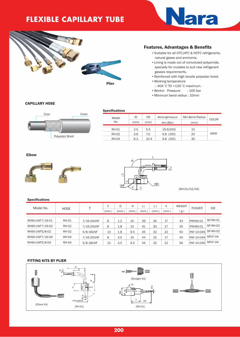
200
FLEXIBLE CAPILLARY TUBE Nara Features, Advantages & Benefits ▪ Suitable for all CFC,HFC & HCFC refrigerants, natural gases and ammonia. ▪ Lining is made out of convoluted polyamide, specially for mulates to suit new refrigerant gasses requirements. ▪ Reinforced with high tensile polyester braid. ▪ Working temperature : -40A˚C TO +130˚C maximum. ▪ Workin Pressure : 100 bar ▪ Minimum bend redius : 10mm
Model No. HOSE T DIEPUSHERC
(mm.)D H L1 L 2 X WEIGHT
( g )
FITTING KITS BY PLIER
Specifications
CAPILLARY HOSE
ModelNo.
ID
(mm) (Min.Bend Radius
(mm)(COLOR
GRAY
CoverCore
Polyester Braid
Plier
Elbow
(mm.) (mm.) (mm.) (mm.) (mm.)
[RH-01]
3825
45。
Ø7
Ø47/16� -20UNF-28
Ø1.2
16
2836
CH14
[Elbow Kit]
[Straight Kit]
[RH-01]
11 24.2
45。
Ø1.2
Ø4Ø9.4
Specifications
RH-01RH-02RH-04
OD
(mm)
WorkingPressure
MPa (Bar)
2.53.66.3
5.57.010.4
19.6(200)9.8 (100)9.8 (100)
152030
[RH-01/02/04]
90。
H
UNF A CHEX
D
L1
L2
RH90-UNF7/16-01
RH90-UNF7/16-02
RH90-UNF5/8-02
RH90-UNF7/16-04
RH90-UNF5/8-04
RH-01
RH-02
RH-02
RH-04
RH-04
7/16-20UNF
7/16-20UNF
5/8-18UNF
7/16-20UNF
5/8-18UNF
PRH90-01
PRH90-01
PAF-14-04N
PAF-14-04N
PAF-14-04N
SP-RH-01
SP-RH-02
SP-RH-02
SP07-04
SP07-04
8
8
13
8
13
1.2
1.8
1.8
3.5
3.5
10
10
9.5
10
9.5
39
41
45
44
44
30
30
32
32
32
17
17
22
17
22
33
35
50
45
56

APPLICATIONS :For use with any air-conditioning units,up to 5.6 tons (67 kBtu - 20 kW)
▪ Wall mounted ▪ Ceiling suspended ▪ Ducted ▪ Fan-coils
201
TECHNICAL SPECIFICATIONMax. flow rate Max. suction head Max. discharge head Max pressure Sound level at 1m according to EN ISO 3744 (Measured at LNE lab, pump operating with water, out of application)
Sound level in application at 1m: (Measured in Sauermann acoustic lab, pump operating with water)
Mains supply
5.0 gph (19 l/h) 10 ft (3 m)33ft (10 m); flow rate= 1gph (4l/h)46 ft (14 m); flow rate = 0 gph (0l/h)
20 dBA
≤ 27 dBA
120V ~ 60 Hz - 14 W (SI3000SIUS11) 230 V ~ 50/60 Hz - 14 W (SI3000SIUS23)
RECOMMENDED ACCESSORIES ACC 00105, ACC 00150 Clear PVC hose, Øint 1/4’’ (6mm) ACC 00105 : 16 ft (5m)ACC 00150 : 164 ft (50m)ACC 00151 : reinforced, 164 ft (50m)
ACC 00205 6 self-sealing fittings Øext. 1/4" (6mm)
ACC 00214 5 fittings to prevent siphoning
PISTON PUMP
APPLICATIONS....▪ Column air conditioning units▪ Condensing boilers ▪ Refrigerating display cabinets ▪ Multi cassettes▪ High efficiency gas furnace▪ Evaporators▪ Ducted units
TECHNICAL CHARACTERISTICS Max. flow rate 500 l/h Max. discharge head 5.0m Max pressure 5.4 m (flowrate=0) Sound level in application at 1m(3.3ft): ≤ 45 dBA (Measured in Sauermann acoustic lab, pump operating with water) Mains supply 230V~ 50Hz - 70 W – 0.67A Detection levels
On : 53mm, Off : 42mm,
Alarm : 64mm
Safety switch NC 4 A resistive – 250V
Max. condensate 65°C, 80°C in short peak temperature
Max. condensate pH > 2.5 (Gas condensing acidity boilers)
RECOMMENDED ACCESSORIES
ACC 00125, ACC 00126 Hose Øint 10 mm (3/8") ACC 00125 : 25 m roll ACC 00126 : reinforcing 25 m roll
ACC 00801 Replacement check valve Øext 10 mm (3/8”)
ACC 02040 Inlet adaptor Øint 24/25 - 32 - 40mm(Øint 1''- 1"¼ - 1"-½)
Si-82
Feature :▪ Piston pump▪ Anti-vibration mounting bracket▪ Plug in power cable with 2 safety switch wires (5ft - 1,5 m)▪ 6 tie wraps, 1/10" x 4" (2.5 x 100mm)▪ Detection unit SI2958, with (5 ft - 1.5m) cable▪ Detection unit installation kit:▪ rubber elbow 90° Øint. 19/32" x 2"3/8 (Øint. 15 x L 60mm)▪ Vent tube Øint. 5/32" x L 2"15/16 (Øint.4 x L 75 mm), mounting rail, adhesive.
Si - 30
Si - 30

202
WIPC-PC-40A
FEATURES :
▪ Suitable for all voltage in the world
▪ Rate power at 3W
▪ Energy saving design
▪ Max discharge head at 10m
▪ Two inlet ports on top or side
▪ Very quiet & non vibration
▪ 3A-250V non voltage safety switch
▪ Buckle design,easy assemble
▪ CE Certificate
WIPC-PC-40A
Model WIPC-PC-40A WIPC-PC-12B WIPC-PC-24B WIPC-PC-40B WIPC-PC-36C WIPC-PC-760A
Voltage
Discharge head
Flow rate
Tank capacity
Mini splits up to
Sound level at 1m 1
Ambient temp.
Power consumption
100-230V~50-60Hz
Max. 10m(33ft)
Max. 40L/h(10.5GPH)
200 ml
15KW(45,000btu/hr)
21dB(A)
0℃~50℃
3W
100-230V~50-60Hz
Max. 10m(33ft)
Max. 18L/h(4.8GPH)
35 ml
8KW(30,000btu/hr)
19dB(A)
0℃~50℃
3W
100-230V~50-60Hz
Max. 10m(33ft)
Max. 24L/h(6.2GPH)
55 ml
8KW(30,000btu/hr)
19dB(A)
0℃~50℃
3W
100-230V~50-60Hz
Max. 10m(33ft)
Max. 40L/h(10.5GPH)
55 ml
15KW(45,000btu/hr)
21dB(A)
0℃~50℃
3W
100-230V~50-60Hz
Max. 10m(33ft)
Max. 36L/h(9.6GPH)
55 ml
15KW(45,000btu/hr)
21dB(A)
0℃~50℃
3W
100-230V~50-60Hz
Max. 8m(26ft)
Max. 760L/h(200GPH)
4 L
15KW(45,000btu/hr)
38dB(A)
0℃~50℃
40W
TECHNICAL DATA
WIPC-PC-12B
FEATURES :
▪ Suitable for all voltage in the world
▪ Rated power only 3W
▪ High flow rate
▪ Low noise
▪ Very quiet & non vibration
▪ Max discharge head at 10M
▪ Compact construction,easy assemble
▪ CE Certificate
WIPC-PC-24B
FEATURES :
▪ Suitable for all voltage in the world
▪ Low power,rated power only 3W
▪ High flow rate
▪ Low noise
▪ Very quiet & non vibration
▪ Max discharge head at 10M
▪ Compact construction,easy assemble
▪ CE Certificate
CONDENSATE PUMPMini pump
WIPC-PC-12B
WIPC-PC-24B WIPC-PC-40B
WIPC-PC-36C
FEATURES :▪ Suitable for all voltage in the world▪ Compact design,small space▪ 3A-250V non voltage safety switch▪ Rated power only 3W▪ Compact construction, easy assemble▪ Low noise & non vibration▪ Max discharge head at 10M▪ Bigger reservoir 55ML WIPC-PC-36C
WIPC-PC-760A
FEATURES : ▪ Max flow rate at 760L/ h▪ Anti-backflow design ▪ 4L water tank ▪ Easy to take ,easy to clean ▪ Dual float control design ▪ Easy to assemble ▪ CE certificate WIPC-PC-760A
WIPC-PC-40B
FEATURES :
▪ Suitable for all voltage in the world
▪ Low power,rated power only 3W
▪ High flow rate
▪ Low noise
▪ Very quiet & non vibration
▪ Max discharge head at 10M
▪ Compact construction,easy assemble
▪ CE Certificate
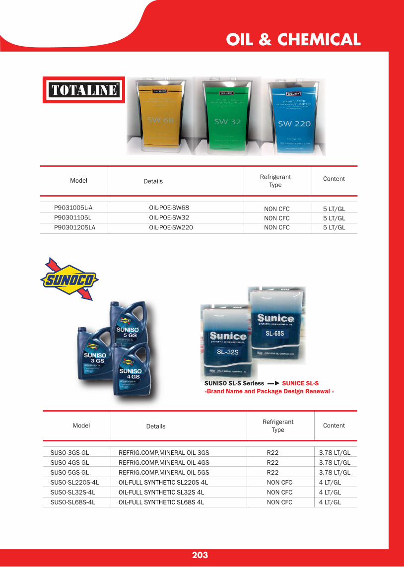
203
P9031005L-A OIL-POE-SW68P90301105L OIL-POE-SW32P90301205LA OIL-POE-SW220
NON CFCNON CFCNON CFC
5 LT/GL5 LT/GL5 LT/GL
SUSO-3GS-GLSUSO-4GS-GLSUSO-5GS-GLSUSO-SL220S-4LSUSO-SL32S-4LSUSO-SL68S-4L
REFRIG.COMP.MINERAL OIL 3GSREFRIG.COMP.MINERAL OIL 4GSREFRIG.COMP.MINERAL OIL 5GSOIL-FULL SYNTHETIC SL220S 4LOIL-FULL SYNTHETIC SL32S 4L OIL-FULL SYNTHETIC SL68S 4L
R22R22R22NON CFCNON CFCNON CFC
3.78 LT/GL3.78 LT/GL3.78 LT/GL4 LT/GL4 LT/GL4 LT/GL
OIL & CHEMICAL
Model Details
SL-68S
SUNISO SL-S Seriess ▬► SUNICE SL-S«Brand Name and Package Design Renewal »
RefrigerantType
Content
Model DetailsRefrigerant
TypeContent
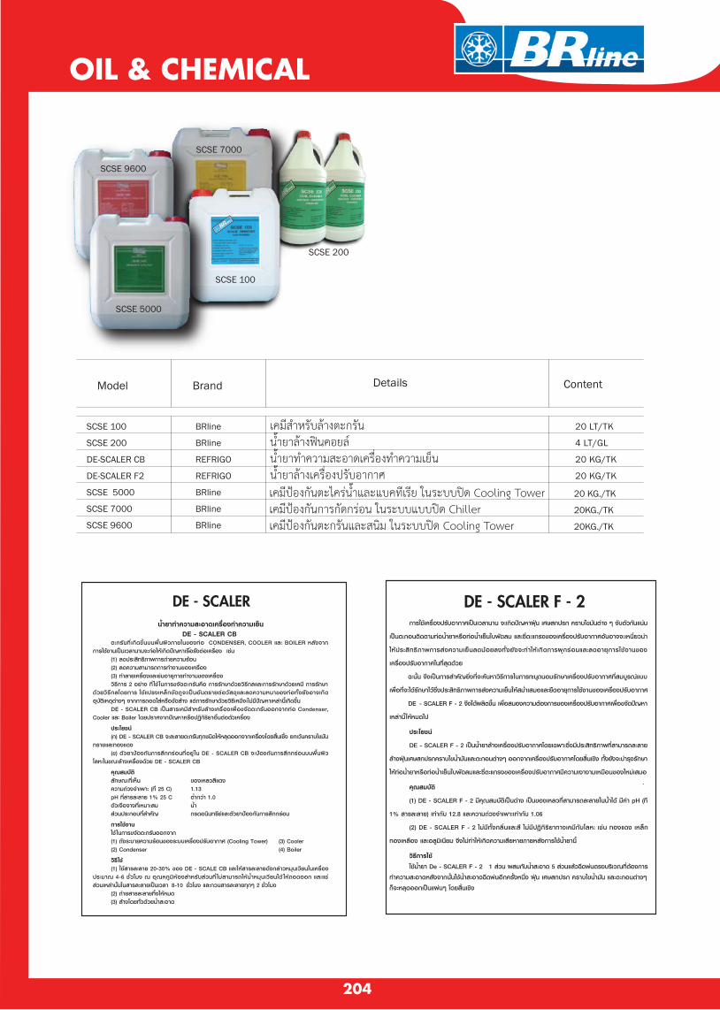
204
20 LT/TK
4 LT/GL
20 KG/TK
20 KG/TK
เคมปองกนตะไครนำและแบคทเรย ในระบบปด Cooling Towerเคมปองกนการกดกรอน ในระบบแบบปด Chillerเคมปองกนตะกรนและสนม ในระบบปด Cooling Tower
20 KG./TK
20KG./TK
20KG./TK
BRline
BRline
REFRIGO
REFRIGO
BRline
BRline
BRline
OIL & CHEMICAL
Model Brand Details Content
SCSE 100
SCSE 200
DE-SCALER CB
DE-SCALER F2
SCSE 5000
SCSE 7000
SCSE 9600
เคมสำหรบลางตะกรนนำยาลางฟนคอยล นำยาทำความสะอาดเครองทำความเยนนำยาลางเครองปรบอากาศ
SCSE 200
SCSE 100
SCSE 5000
SCSE 9600
SCSE 7000
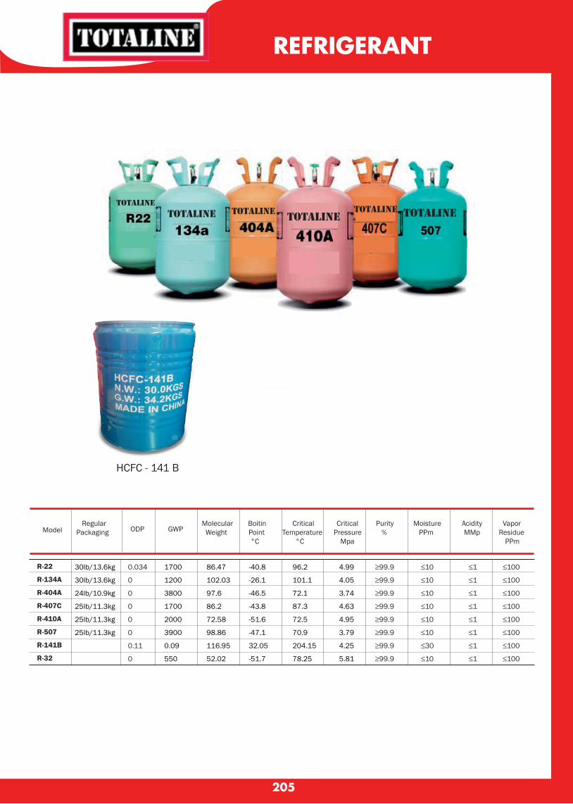
205
REFRIGERANT
Model
Regular ODP
GWP
Molecular Boitin Critical Critical Purity Moisture Acidity Vapor Packaging Weight Point Temperature Pressure % PPm MMp Residue °C °C Mpa PPm
R-22
R-134A
R-404A
R-407C
R-410A
R-507
R-141B
R-32
30lb/13.6kg
30lb/13.6kg
24lb/10.9kg
25lb/11.3kg
25lb/11.3kg
25lb/11.3kg
0.034
0
0
0
0
0
0.11
0
1700
1200
3800
1700
2000
3900
0.09
550
86.47
102.03
97.6
86.2
72.58
98.86
116.95
52.02
-40.8
-26.1
-46.5
-43.8
-51.6
-47.1
32.05
-51.7
96.2
101.1
72.1
87.3
72.5
70.9
204.15
78.25
4.99
4.05
3.74
4.63
4.95
3.79
4.25
5.81
≥99.9
≥99.9
≥99.9
≥99.9
≥99.9
≥99.9
≥99.9
≥99.9
≤10
≤10
≤10
≤10
≤10
≤10
≤30
≤10
≤1
≤1
≤1
≤1
≤1
≤1
≤1
≤1
≤100
≤100
≤100
≤100
≤100
≤100
≤100
≤100
totalinetotaline totaline totaline
totaline totaline
HCFC - 141 B

206
VACUMM PUMP
New Refrigerant Series vacumm pumps especially for all refrigeration
• High quality solenoid valae (มโซลนอยลวาลวปองกนอากาศยอนกลบ) • Automatic disconnection with HV AC system while in interruption of elecricity (ตดการเชอมตอระบบโดยอตโนมตเมอไฟฟาฟาดบ) • Special material of the seal
Dual Stage (With solenoid valve)
Item NO. VP245(2VP-2) VP260(2VP-3) VP280(2VP-4) VP2100(2VP-5)
Voltage
Flow Rate
Ultimate Vacuum
Stage
Power
Inlet Port
Oil Capacity
Dimensions
Weight
V/Hz
CFM
I/min
Pa
microns
HP
Flare
ml
mm
kg
220/50
4.5
128
3x10¹
25
2
1/2
1/4"
350
320x134x232
11.8
220/50
6
170
3x10¹
25
2
3/4
1/4"
700
370x140x250
15
220/50
8
226
3x10¹
25
2
1
1/4"
600
370x140x250
15
220/50
10
283
3x10¹
25
2
1
1/4"
700
390x140x250
16
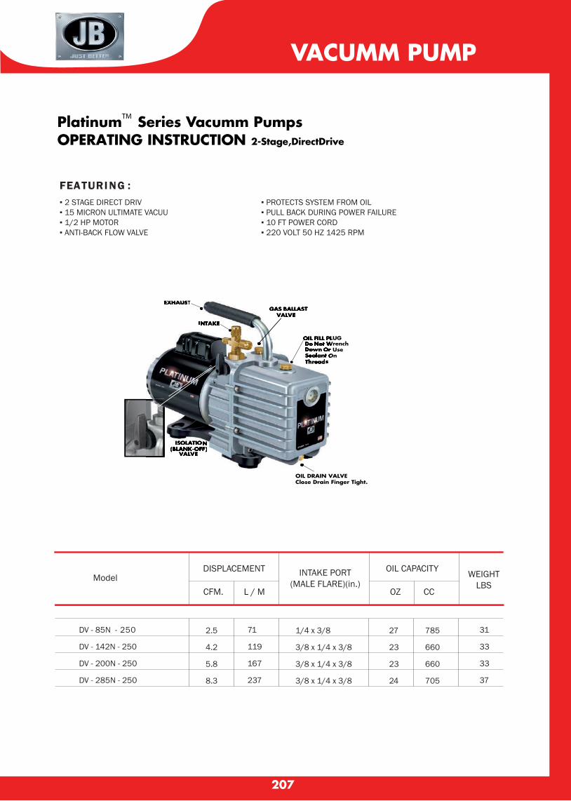
DV - 85N - 250
DV - 142N - 250
DV - 200N - 250
DV - 285N - 250
2.5
4.2
5.8
8.3
71
119
167
237
1/4 x 3/8
3/8 x 1/4 x 3/8
3/8 x 1/4 x 3/8
3/8 x 1/4 x 3/8
27
23
23
24
785
660
660
705
31
33
33
37
207
VACUMM PUMP
New Refrigerant Series vacumm pumps especially for all refrigeration
• High quality solenoid valae (มโซลนอยลวาลวปองกนอากาศยอนกลบ) • Automatic disconnection with HV AC system while in interruption of elecricity (ตดการเชอมตอระบบโดยอตโนมตเมอไฟฟาฟาดบ) • Special material of the seal
PlatinumTM Series Vacumm Pumps OPERATING INSTRUCTION 2-Stage,DirectDrive
EXHAUST
OIL FILL PLUGDo Not WrenchDown Or UseSealant OnThreads
GAS BALLASTVALVE
INTAKE
ISOLATION(BLANK-OFF)
VALVE
FEATURI NG :▪ 2 STAGE DIRECT DRIV ▪ PROTECTS SYSTEM FROM OIL ▪ 15 MICRON ULTIMATE VACUU ▪ PULL BACK DURING POWER FAILURE ▪ 1/2 HP MOTOR ▪ 10 FT POWER CORD ▪ ANTI-BACK FLOW VALVE ▪ 220 VOLT 50 HZ 1425 RPM
Model DISPLACEMENT
CFM. L / M
INTAKE PORT(MALE FLARE)(in.)
OIL CAPACITY
OZ CC
OIL DRAIN VALVE Close Drain Finger Tight.
WEIGHTLBS
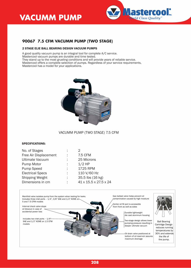
SPECIFICATIONS:
No. of Stages : 2Free Air Displacement : 7.5 CFMUltimate Vacuum : 25 MicronsPump Motor : 1/2 HPPump Speed : 1725 RPMElectrical Specs : 110 V/60 HzShipping Weight : 35.5 lbs (16 kg)Dimensions in cm : 41 x 15.5 x 27.5 x 24
90067 7.5 CFM VACUMM PUMP (TWO STAGE)
2 STAGE ELIE BALL BEARING DESIGN VACUUM PUMPS
A good quality vacuum pump is an integral tool for complete A/C service. Mastercool vacuum pumps are durable and time tested. They stand up to the most grueling conditions and will provide years of reliable service. Mastercool offers a complete selection of pumps. Regardless of your service requirements, Mastercool has a model for your applications.
Manifold valve isolates pump from the system when testing for leaks. Includes three inlet ports – 1/4”, 3/8” SAE and 1/2” ACME on 5 and 7.5 CFM models
Internal check valve stops oil blowout in case of accidental power loss
Includes two inlet ports – 1/4” SAE and 1/2” ACME on 1.5 CFM models
Gas ballast valve helps prevent oilcontamination caused by high moisture
Center oil fill port is accessiblefrom front as well as sides
Durable lightweightdie cast aluminum housing
Two-stage design allows lowerpumping pressure resulting indeeper ultimate vacuum
Oil drain valve positioned at bottom of oil reservoir assures maximum drainage
Ball Bearing
Cartridge Designreduces running
temperatures by 30% and extends
the life of the pump.
208
VACUMM PUMP
VACUMM PUMP (TWO STAGE) 7.5 CFM
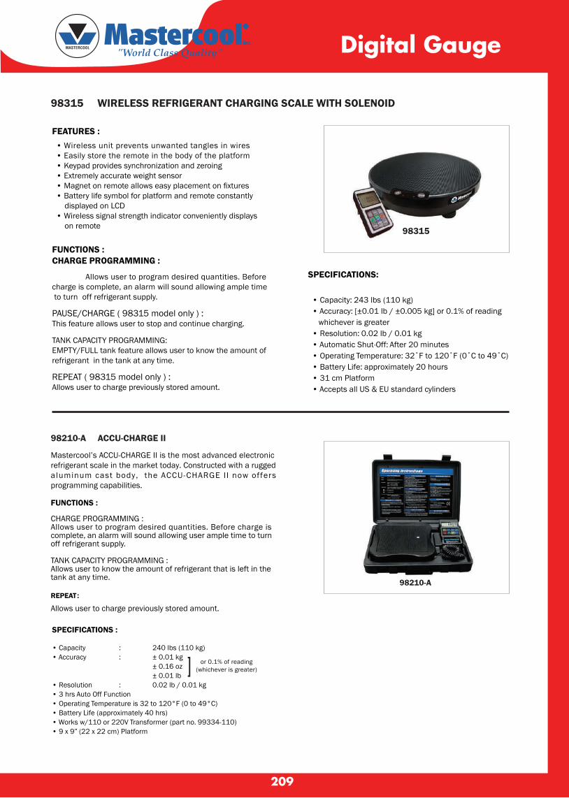
209
98315 WIRELESS REFRIGERANT CHARGING SCALE WITH SOLENOID
FEATURES : • Wireless unit prevents unwanted tangles in wires • Easily store the remote in the body of the platform • Keypad provides synchronization and zeroing • Extremely accurate weight sensor • Magnet on remote allows easy placement on fixtures • Battery life symbol for platform and remote constantly displayed on LCD • Wireless signal strength indicator conveniently displays on remote
FUNCTIONS :CHARGE PROGRAMMING :
Allows user to program desired quantities. Before charge is complete, an alarm will sound allowing ample time to turn off refrigerant supply.
PAUSE/CHARGE ( 98315 model only ) :This feature allows user to stop and continue charging.
TANK CAPACITY PROGRAMMING:EMPTY/FULL tank feature allows user to know the amount of refrigerant in the tank at any time.
REPEAT ( 98315 model only ) : Allows user to charge previously stored amount.
98210-A ACCU-CHARGE II
Mastercool’s ACCU-CHARGE II is the most advanced electronic refrigerant scale in the market today. Constructed with a rugged aluminum cast body, the ACCU-CHARGE I I now offers programming capabilities.
FUNCTIONS :
CHARGE PROGRAMMING :Allows user to program desired quantities. Before charge is complete, an alarm will sound allowing user ample time to turn off refrigerant supply.
TANK CAPACITY PROGRAMMING :Allows user to know the amount of refrigerant that is left in the tank at any time.
SPECIFICATIONS:
• Capacity: 243 lbs (110 kg) • Accuracy: [±0.01 lb / ±0.005 kg] or 0.1% of reading whichever is greater • Resolution: 0.02 lb / 0.01 kg • Automatic Shut-Off: After 20 minutes • Operating Temperature: 32˚F to 120˚F (0˚C to 49˚C) • Battery Life: approximately 20 hours • 31 cm Platform • Accepts all US & EU standard cylinders
or 0.1% of reading(whichever is greater)
REPEAT :
Allows user to charge previously stored amount.
98315
98210-A
SPECIFICATIONS :
• Capacity : 240 lbs (110 kg)• Accuracy : ± 0.01 kg ± 0.16 oz ± 0.01 lb• Resolution : 0.02 lb / 0.01 kg• 3 hrs Auto Off Function• Operating Temperature is 32 to 120°F (0 to 49°C)• Battery Life (approximately 40 hrs)• Works w/110 or 220V Transformer (part no. 99334-110)• 9 x 9” (22 x 22 cm) Platform
]
Digital Gauge

210
98061 DIGITAL VACUUM GAUGE
SPECIFICATIONS:
• Response Time: 250 mSec • Sensor Cable: Spiral cable extended to 6.5 feet (2.6 meter). • Sensor: Thermocouple sensor • Connection Fitting: 1/4” flare female adapter • Operating Temperature: 32 to 120˚F (0 to 45˚C) • Power: 9V DC battery (AC/DC Adapter optional) • Battery Life: 36 hours • Low Battery Indicator: Special ICON on LCD • Vacuum Units: Micron, Torr, mTorr, mmHg, mBar, Pa • Range: 20,000 to 1 micron • Accuracy Range*: ATM - 1000 Microns : ± 10% of reading 1000 - 100 Microns : ± 7% of reading, 100 - 1 Micron : ±5% of reading
* Unit accuracy refers to sensor specifications and is based on optimal laboratory conditions. Field operations may greatly deviate from these levels.
99772 - AR 2-WAY DIGITAL MANIFOLD
SPECIFICATIONS:
• Class 1.0 standard gauge reading• Pressure Display: PSI, INHg, Bar, MPa, Kg/cm2• Temperature Display: °F or °C• Deep Vacuum Display: Micron, mBar, KPa, Pa, Torr, mTorr, mmHg• Sensing Resolution: 1 psi (.07 Bar, .007 MPa, .07 Kg/cm2)• Sensing Accuracy: ±1 psi or 1% of reading (whichever is greater)• Working Pressure: 0 to 750 psi (52 Bar, 5 MPa, 52 Kg/cm2) (does not display 0-5 psi)• Proof Pressure: 1000 psi (70 Bar, 7 MPa, 70 Kg/cm2) (Tolerable pressure without internal damage)• Refrigerant Temperature Range: -40 to 200°F (-40 to 93°C)• Operating Temperature: 32 to 122°F (0 to 45°C)• Temperature Accuracy: ±1˚F (±0.5˚C) between 32 to 160˚F (0 to 71˚C)• Storage Temperature: 10 to 120˚F (-12 to 49˚C)• Connections: 1/4” M-Flare• Power: 9V DC battery with optional AC/DC adapter• Battery Life: 30-36 hours pressure and temperature mode only (continuous use) / 25-30 hours vacuum and backlight mode (continuous use)• Auto-Off: 15 min. with disabling capability
HVAC 2-Way Digital Manual Gauge Set includes 3-72″manual shut-off valve hoses, vacuum sensor and cable (98062), clamp-on thermocouple (52336) packaged in a blow molded box.
98061
Digital Gauge
99772-AR
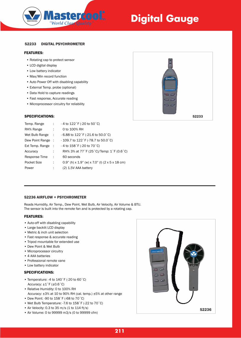
211
52233 DIGITAL PSYCHROMETER
• Rotating cap to protect sensor • LCD digital display • Low battery indicator • Max/Min record function • Auto Power Off with disabling capability • External Temp. probe (optional) • Data Hold to capture readings • Fast response, Accurate reading • Microprocessor circuitry for reliability
SPECIFICATIONS:
52233
52236 AIRFLOW + PSYCHROMETER
Reads Humidity, Air Temp., Dew Point, Wet Bulb, Air Velocity, Air Volume & BTU. The sensor is built into the remote fan and is protected by a rotating cap.
FEATURES:
• Auto-off with disabling capability • Large backlit LCD display• Metric & inch unit selection • Fast response & accurate reading • Tripod mountable for extended use • Dew Point & Wet Bulb • Microprocessor circuitry • 4 AAA batteries • Professional remote vane • Low battery indicator
SPECIFICATIONS:
• Temperature: -4 to 140˚F (-20 to 60˚C) Accuracy: ±1˚F (±0.6˚C) • Relative Humidity: 0 to 100% RH Accuracy: ±3% at 10 to 90% RH (cal. temp.) ±5% at other range • Dew Point: -90 to 158˚F (-68 to 70˚C) • Wet Bulb Temperature: -7.6 to 158˚F (-22 to 70˚C) • Air Velocity: 0.3 to 35 m/s (1 to 114 ft/s) • Air Volume: 0 to 99999 m3/s (0 to 99999 cfm)
52236
Digital Gauge
FEATURES:
Temp. Range : RH% Range : Wet Bulb Range : Dew Point Range :Ext Temp. Range :Accuracy : Response Time : Pocket Size : Power :
- 4 to 122˚F (-20 to 50˚C) 0 to 100% RH - 6.88 to 122˚F (-21.6 to 50.0˚C) - 109.7 to 122˚F (-78.7 to 50.0˚C) - 4 to 158˚F (-20 to 70˚C) RH% 3% at 77˚F (25˚C)/Temp: 1˚F (0.6˚C) 60 seconds 0.9” (h) x 1.9” (w) x 7.0” (l) (2 x 5 x 18 cm) (2) 1.5V AAA battery
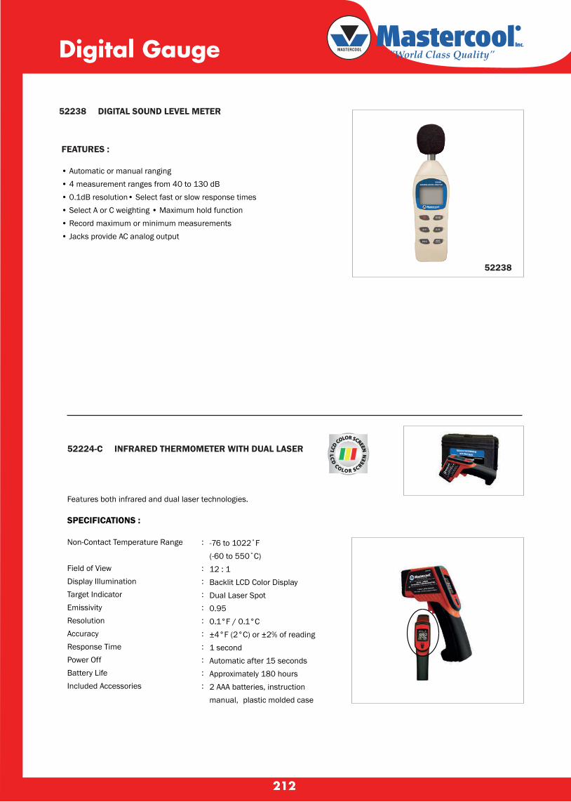
212
52238 DIGITAL SOUND LEVEL METER
52238
52224-C INFRARED THERMOMETER WITH DUAL LASER
Features both infrared and dual laser technologies.
SPECIFICATIONS :
Non-Contact Temperature Range :
Field of View :Display Illumination :Target Indicator :Emissivity :Resolution :Accuracy :Response Time :Power Off :Battery Life :Included Accessories :
Digital Gauge
FEATURES :
• Automatic or manual ranging • 4 measurement ranges from 40 to 130 dB• 0.1dB resolution• Select fast or slow response times • Select A or C weighting • Maximum hold function• Record maximum or minimum measurements• Jacks provide AC analog output
-76 to 1022˚F (-60 to 550˚C) 12 : 1 Backlit LCD Color Display Dual Laser Spot 0.95 0.1°F / 0.1°C ±4°F (2°C) or ±2% of reading 1 second Automatic after 15 seconds Approximately 180 hours 2 AAA batteries, instruction manual, plastic molded case
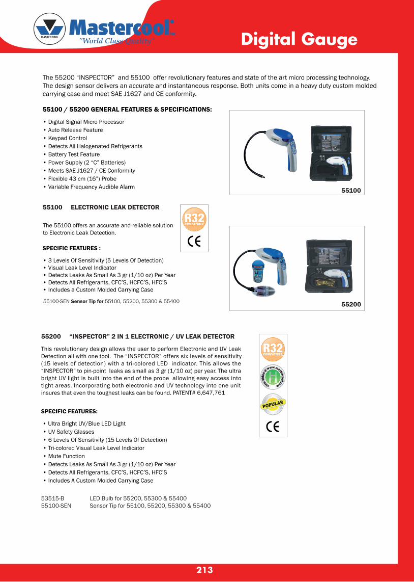
213
The 55200 “INSPECTOR” and 55100 offer revolutionary features and state of the art micro processing technology. The design sensor delivers an accurate and instantaneous response. Both units come in a heavy duty custom molded carrying case and meet SAE J1627 and CE conformity.
55100 / 55200 GENERAL FEATURES & SPECIFICATIONS:
• Digital Signal Micro Processor • Auto Release Feature • Keypad Control • Detects All Halogenated Refrigerants • Battery Test Feature • Power Supply (2 “C” Batteries) • Meets SAE J1627 / CE Conformity • Flexible 43 cm (16”) Probe • Variable Frequency Audible Alarm
55100 ELECTRONIC LEAK DETECTOR
The 55100 offers an accurate and reliable solutionto Electronic Leak Detection.
55200 “INSPECTOR” 2 IN 1 ELECTRONIC / UV LEAK DETECTOR
SPECIFIC FEATURES:
• Ultra Bright UV/Blue LED Light • UV Safety Glasses • 6 Levels Of Sensitivity (15 Levels Of Detection) • Tri-colored Visual Leak Level Indicator • Mute Function • Detects Leaks As Small As 3 gr (1/10 oz) Per Year • Detects All Refrigerants, CFC’S, HCFC’S, HFC’S • Includes A Custom Molded Carrying Case
Digital Gauge
SPECIFIC FEATURES :
• 3 Levels Of Sensitivity (5 Levels Of Detection)• Visual Leak Level Indicator• Detects Leaks As Small As 3 gr (1/10 oz) Per Year• Detects All Refrigerants, CFC’S, HCFC’S, HFC’S• Includes a Custom Molded Carrying Case
55100-SEN Sensor Tip for 55100, 55200, 55300 & 55400
This revolutionary design allows the user to perform Electronic and UV Leak Detection all with one tool. The “INSPECTOR” offers six levels of sensitivity (15 levels of detection) with a tri-colored LED indicator. This allows the “INSPECTOR” to pin-point leaks as small as 3 gr (1/10 oz) per year. The ultra bright UV light is built into the end of the probe allowing easy access into tight areas. Incorporating both electronic and UV technology into one unit insures that even the toughest leaks can be found. PATENT# 6,647,761
53515-B LED Bulb for 55200, 55300 & 5540055100-SEN Sensor Tip for 55100, 55200, 55300 & 55400
55100
55200
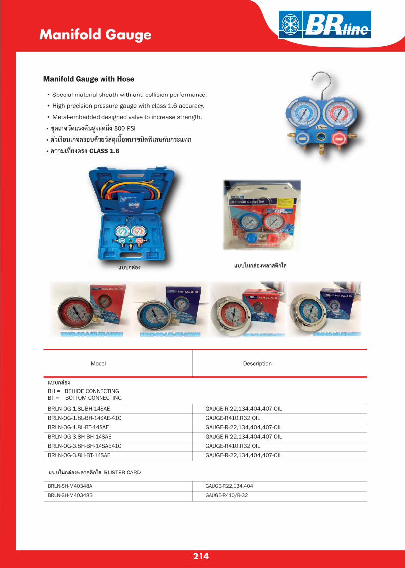
214
• Special material sheath with anti-collision performance.
• High precision pressure gauge with class 1.6 accuracy.
• Metal-embedded designed valve to increase strength.
• ชดเกจวดแรงดนสงสดถง 800 PSI
• ตวเรอนเกจครอบดวยวสดเนอหนาชนดพเศษกนกระแทก
• ความเทยงตรง CLASS 1.6
Manifold Gauge
Manifold Gauge with Hose
Model Description
แบบกลอง BH = BEHIDE CONNECTINGBT = BOTTOM CONNECTING
BRLN-OG-1.8L-BH-14SAEBRLN-OG-1.8L-BH-14SAE-410BRLN-OG-1.8L-BT-14SAEBRLN-OG-3.8H-BH-14SAEBRLN-OG-3.8H-BH-14SAE410BRLN-OG-3.8H-BT-14SAE
GAUGE-R-22,134,404,407-OILGAUGE-R410,R32 OILGAUGE-R-22,134,404,407-OILGAUGE-R-22,134,404,407-OILGAUGE-R410,R32 OILGAUGE-R-22,134,404,407-OIL
แบบในกลองพลาสตกใส BLISTER CARD
BRLN-SH-M40348A
BRLN-SH-M40348B
GAUGE-R22,134,404
GAUGE-R410/R-32
แบบกลอง แบบในกลองพลาสตกใส

215
Non-flutter gauges with high-visibility faceplates
800 PSI working and 4,000PSI burst pressure hoses
Larger knobs with soft-touch grip surface
Needle valve design withfull-flow porting
Gauge boots are standard on 400 and 500 Series
400 SERIES500 SERIES
Manifold Gauge
Gauge boots are standard on 4-valve manifolds
800 PSI working and 4,000PSI burst pressure hoses
Rugged lightweight body features laser-etched graphics
Non-flutter gauges with high-visibility faceplate
Diaphragm design allowsfinger touch operationand 1 turn for full open
3/8” vac port and hose for faster evacuation
600 SERIES 4-VALVE
Larger knobs withsoft-touch grip surface
495 - CD
496 - CD36
500 - CD6
451 - C
452 - C6
416 - C*
417 - C6*
560 - CB
621 - C6
423 - CR
425 - CB
451 - CR
451 - CB
803 - MRS
806 - MRS
เกจค ร นมยางห ม (ไมรวมสายชารท)
เกจค ร นมยางห ม พรอมสายชารท 36”
เกจค ร นมยางห ม พรอมสายชารท 72”
เกจค ร นมยางห ม พรอมสายชารท 36”
เกจค ร นมยางห ม พรอมสายชารท 72”
เกจค ร นมยางห ม พรอมสายชารท 36”
เกจค ร นมยางห ม พรอมสายชารท 72”
เกจค ร นมยางห ม -ตาแมว (ไมรวมสายชารท)
เกจค ร นมยางห ม พรอมสายชารท 72” 4 WAY
เกจเด ยวร นมยางห ม ทางสง
เกจเด ยวร นมยางห ม ทางตำ
เกจเด ยวร นมยางห ม ทางสง
เกจเด ยวร นมยางห ม ทางตำ
สายชารทนำยา ยาว 36” (1 ชด 3 เส น )
สายชารทนำยา ยาว 72” (1 ชด 3 เส น )
MODEL DESCRIPTIONS
Model 416 - C* , 417 - C6* เพม ADAPTER

216
For 1/8” to 1-1/8” (4 mm to 28 mm) O.D. tubing.Includes (2) S75015 general purpose cutter wheels.Length 5”. Wt. 8.8 oz.
TUBE CUTTERS For hard or soft copper, aluminum, brass, thin wall steel, stainless steel, monel, titanium and other tubing.
For 1/4” to 1-5/8” (7 mm to 41 mm) O.D. tubing.ncludes (2) S75015 general purpose cutter wheels.Length 5-1/2”. Wt. 10.4 oz.
For 1/8” to 5/8” (4 mm to 15 mm) O.D. tubing. Includes (1) S32633 general purpose cutter wheel. Swing radius 1-1/4” (1-3/8” swing radius with 5/8” tube). Length 1-3/4”. Wt. 2.5 oz.
Mini Tube CuttersTC-1050 Big capacity in small size 174 - F
For 3/8” to 2-5/8” (10 mm to 66 mm) O.D. tubing. Includes (2) S74761 general purpose cutter wheels.Length closed 7-3/4”. Wt. 2.0 lbs.
For 2” to 4-1/8” (51 mm to 104 mm) O.D. tubing. Includes (2) S74833 general purpose cutter wheels.Length closed 11-1/4”. Wt. 3.5 lbs.
For 3/8” to 1-1/8” (10 mm to 28 mm) O.D. tubing.Includes (2) S75015 general purpose cutter wheels. Swing radius 1-15/16” (2-1/4” swing radius with 1-1/8” tube). Length 2-11/16”. Wt. 5.0 oz.
TC - 1000
312 - FC
174 - F
206 - FB
206-FB406-FA
ADJUST-O-MATIC™ TUBE CUTTERS
406 - FA
TC - 1050
Hi - Duty Tube CuttersTC-1000
Hi - Duty Tube Cutters312 - FC
S75015 - Spare cutting wheel
General purpose cutter wheel. for TC-1000 , 312-FC , 174-F Cutter wheel for 206-FB , 206-FBP Cutter wheel for TC-1050 , 227-FA
S75015
S74761
S32633
TUBE CUTTERS
MODEL DESCRIPTIONS
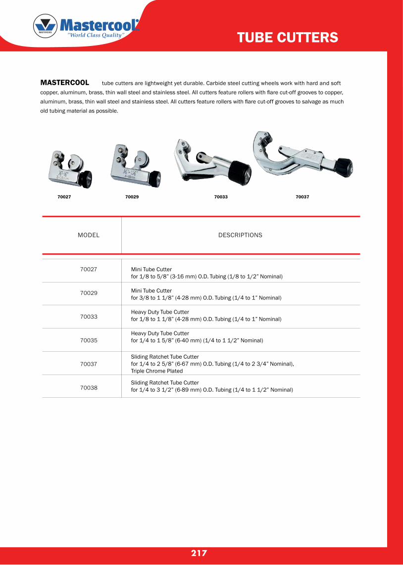
217
MASTERCOOL tube cutters are lightweight yet durable. Carbide steel cutting wheels work with hard and softcopper, aluminum, brass, thin wall steel and stainless steel. All cutters feature rollers with flare cut-off grooves to copper, aluminum, brass, thin wall steel and stainless steel. All cutters feature rollers with flare cut-off grooves to salvage as much old tubing material as possible.
70037700337002970027
TUBE CUTTERS
MODEL DESCRIPTIONS
Mini Tube Cutter for 1/8 to 5/8” (3-16 mm) O.D. Tubing (1/8 to 1/2” Nominal)
Mini Tube Cutter for 3/8 to 1 1/8” (4-28 mm) O.D. Tubing (1/4 to 1” Nominal)
Heavy Duty Tube Cutter for 1/8 to 1 1/8” (4-28 mm) O.D. Tubing (1/4 to 1” Nominal)
Heavy Duty Tube Cutter for 1/4 to 1 5/8” (6-40 mm) (1/4 to 1 1/2” Nominal)
Sliding Ratchet Tube Cutter for 1/4 to 2 5/8” (6-67 mm) O.D. Tubing (1/4 to 2 3/4” Nominal), Triple Chrome Plated
Sliding Ratchet Tube Cutterfor 1/4 to 3 1/2” (6-89 mm) O.D. Tubing (1/4 to 1 1/2” Nominal)
70027
70029
70033
70035
70037
70038

218
368-FH
364-FHA LEVER TYPE TUBE BENDERSFor 1/8” to 1” and 6 mm to 12 mm O.D. tubing.
Each tool bends one size. Open-side type which slips over tube at any point. Makes smooth, tight radius bends up to 180
. with minimum effort. No
scoring or flattening of tubing. Calibrated to show angle of bend. Wide hook grips tubing securely.
TUBE O.D. (in.)
WEIGHT EACH(lbs.)
RADIUS TO CENTER OF TUBE (in.)
DESCRIPTIONS
MODEL
TUBE O.D.
(in.)
TO CENTER OF TUBE (in.)MODEL
364-FHA-06 Style for 1/4” through 1/2” and 6 mm to 12 mm O.D. tubing.
364-FHA-10 Style for 5/8” and 3/4” O.D. tubing.
368 - FH TRIPLE HEAD BENDERS For soft copper, aluminum and thin wall steel tubing. Makes up to 90° bends.For 3/16”, 1/4”, 5/16” and 3/8” (6 mm and 8 mm) O.D. tubing. Wt. 1.0 lbs.
3/16
1/4
5/16
3/8
1-1/64 26
1-1/64 26
1 25
24
TUBE BENDERS
Each tool bends only one size.Conforms to Federal Specification GGG-B-191a Type III, Class 2.* For bending annealed copper and aluminum tubing only.
368 - FH
RADIUS
(in.) (mm)
364-FHA-04 1/4 9/16
364-FHA-05 5/16 11/16
364-FHA-06 3/8 15/16
364-FHA-08 1/2 1-1/2
364-FHA-10* 5/8 2-1/4
364-FHA-12* 3/4 3
1.0
1.0
1.75
3.5
5.5
7.0
15/16

219
70061 70066
LEVER STYLE TUBE BENDERSOpen side design slips over tube at any point. Makes smooth short radius bends up to 180° with minimum effort. Calibrated to show angle of bend. Easy 90° start requires much less effort to make fast and accurate bends. Each tool bends one size.
MODEL OUTSIDE DIAMETEROF TUBING
NOMINAL SIZE RADIUS TO CENTEROF TUBE
70070-RD REVERSE DIRECTION BENDING ADAPTERBends: 1/4”, 5/16”, 3/8”, 1/2”, 5/8”, 3/4”, 7/8” O.D. tubing
TUBE BENDERS
70061
70062
70063
70064
70065
70066
70067
1/4”
5/16”
3/8”
1/2”
5/8”
3/4”
7/8”
1/8”
1/4”
3/8”
1/2”
5/8”
3/4”
9/16”
11/16”
15/16”
1 1/2”
2 1/4”
3”
3”

220
FLARING & SWAGING
FLARING & SWAGING For soft tubing only - copper, aluminum, brass and steel.
45° FLARING TOOLS195 - FC For 3/16”, 1/4”, 5/16”, 3/8”, 7/16”, 1/2” and 5/8” O.D. tubing. Wt. 2.0 lbs.
Flares 7 sizes of tubing. Rugged forged steel slip-on yoke and hardened flaring bar. Positive clamping action of bars prevents tube slippage. Self-centering yoke with swivel-type, hardened steel,chrome finished flaring cone forms better flares with less effort. Design of yoke permits flaring where there is little spacebetween nut and tube end. Satin finish nickel chrome plated.
Outside Tube Diameter
Wall Thickness
195 - FC
(in.)
(in.)
3/16
.028
1/4
.035
5/16
.035
3/8
.035
7/16
.035
1/2
.035
5/8
.035
45° LARGE SIZE FLARING TOOLS203 - FA For sizes 5/8”, 3/4”, 7/8” and 1-1/8” O.D. tubing. Wt. 3.75 lbs.Flares larger tube sizes.Quick slip - on yoke with hardened steel,chrome finished swivel flaring cone reduces effort. Positive clamping action of flaring bar eliminates tube movement. Nickel chrome finish.
Outside Tube Diameter (in.)
Wall Thickness (in.)
203 - FA
203 - FA
1/8 3/16 1/4 5/16 3/8 7/16 1/2 5/8 3/4 7/8 1 1-1/8
.025 .028 .035 .035 .035 .035 .035 .049 .049 .049 .058 .058
For 3/16”, 1/4”, 5/16”, 3/8” and 1/2” O.D. tubing. Wt. 3.0 lbs.Recommended for Bundy and other annealed soft steel tubing (wal thickness to .035”)Also makes single or double flares in soft coppr or aluminum tubing. Small, lightweight, easy to handle. Steel yoke; swivel - type hadened steel,chrome finished flaring cone. Bar provides positive grip of tubing. Includes tool case. Conforms to Federal Specification GGG-F-451a, Type 1, Class 2, Style A.
195-FB
45° DOUBLE FLARING TOOL
93 - FB
For 1/4”, 5/16”, 3/8”, 1/2”, 5/8” and 3/4” O.D. tubing.Designed for automotive air-conditioning service. Makes double flaresin soft copper or aluminum tubing (wall thickness to .035”). Easy operating,ball bearing swivel-type hardened steel flaring cone with chrome finish.Quick slip-on yoke. Flaring bar offers positive grip of tubing. Also makessingle flares.Includes metal tool case. Wt.5.5 lbs.
DOUBLE FLARING ADAPTERS-Screw down flaring conewith proper size adapter intube. Retract cone, remove adapter,compter,complete flare.
195 - FC
SWIVEL-TYPE BALLBEARING CONE -Ball thrust bearingin flaring coneminimizes friction,makes operation easier.
DESCRIPTIONS MODEL

221
PRICE
FLARING (45°) & SWAGING TOOL For 1/8” to 3/4” (4 mm to 22 mm) O.D. tubing.
275-FS
Outside Tube Diameter (in.)
Wall Thickness (in.)
Outside Tube Diameter
Wall Thickness
1/8
.020
4
1.0
3/16
.028
6
1.0
1/4
.035
8
1.0
5/16
.035
10
1.0
3/8
.035
12
1.0
7/16
.035
14
1.0
1/2
.035
15
1.0
5/8
.035
16
1.0
3/4
.035
18
1.0
22
1.0
(mm)(mm)
45° FLARING, SWAGING AND CUTTING KIT For soft copper, aluminum, steel, stainless steel and brass tubing. Kit contains a TC-1000 tube cutter for 1/8” to 1-1/8” O.D. tubing and 275-FS 45° flaring and swaging tool.Includes tool case. Wt. 3.0 lbs.
275-FSC :
1/8”, 3/16”, 1/4”, 5/16”, 3/8”, 7/16”, 1/2”, 5/8” and 3/4” O.D. tubing.
3/16”, 1/4”, 5/16”, 3/8”, 1/2”, 5/8” and 3/4” and 3/4” O.D. tubing. Flares :Swages :
MODEL WEIGHT(lbs.)
TUBE WORKING KITS CUTTING AND FLARING KITS
TUBE CUTTER FLARING TOOL RANGE OF FLARING TOOL (in.)
1226 - FA TC-1000 195-FC(45.)
3/16,1/4,5/16,3/8,
7/16,1/2,5/8 O.D.3.0
1226-FA : Each kit contains a TC -1000 tube cutter for 1/8” to 1-1/8” O.D. tubing and a 45
. or 37
. flaring tool. Includes tool case.
Flares and swages. Converts quickly. Screw-type feed. Ideal for use in closequarters. Two bars included cover 9 sizes. Swivel-type swaging adapters andflaring cone are hardened steel,chrome finished for easy operationFlares and swages. Converts quickly. Screw-type feed. Ideal for use in closequarters. Two bars included cover 9 sizes. Swivel-type swaging adapters andflaring cone are hardened steel,chrome finished for easy operation Self-centering, slip-on forged steel yoke. Includes tool case. Wt. 3.5 Ibs.
Flares 1/8”, 3/16”, 1/4”, 5/16”, 3/8”, 7/16”, 1/2”, 5/8” and 3/4” O.D.Includes 5 swage adapters for 7 tube sizes: 3/16”, 1/4”, 5/16”, 3/8”, 1/2”, 5/8”, 3/4” O.D.
275-FS :
FLARING & SWAGING

The rotary style blade is perfect for removing burrs from holes and edges. Large ergonomic handle reduces user fatigue. Ships complete with two heavy duty blades - extra blade stores inside the handle. For copper, steel, aluminum, zinc, cast iron, brass and plastic tubing. Length 5-3/4”. Wt. 1.5 oz.
210 - FDEBURRING TOOL
208 - FINNER-OUTER REAMING AND DEBURRING TOOLS
Reamer for copper, aluminum and brass tubing. Hardened steel cutter blades.For 3/16” to 1-1/2” (5 mm to 38 mm) O.D. tubing.Blue finish. Wt. 63 lbs.
Compressor access valve wrench. Chrome plated. Has 1/4”, 3/8”, 3/16” and 5/16” square drive ratchets and is specially designed for use on compressors with access valves in hard to reach places. Reversible ratchets.
Combination wrench with the four sizes most needed for• 1/2” hex for compressor mounting bolts. servicing air-conditioning and refrigerator equipment:• 9/16” hex for dust cap on access valves and plug oil check on compressor.• 1/4” square for valve stem and service valves and old style compressor valves.• 3/16” square for valve refrigerant charging tanks.
Square ratchet drives for use on compressorswith access valves in hard to reach places
127-C
Reversible ratchets
124-C
222
FLARING & SWAGING
193 - S93 - S - 0493 - S - 0593 - S - 0693 - S - 0893 - S - 1093 - S - 12
Vinyl case contains 4 swaging punchesSwaging punchesSwaging punchesSwaging punchesSwaging punchesSwaging punchesSwaging punches
For soft tubing only - copper, aluminum and brass.PUNCH TYPE SWAGING TOOLS
SWAGING
193-SEnlarge end of tube,insert another tube,solder like a sweatfitting.
Tube height gauged by placingtubing even with bevel onswaging punch.
MODEL DESCRIPTIONTUBE
O.D.(in)WALL
THICKNESS (in.)
WEIGHT(lbs.)
1/4,3/8,1/2,5/81/4
5/163/81/25/83/4
.035
.035
.035
.035
.035
.035
.20
.25
.25
.50
.50
.751.0
MODEL DESCRIPTION
●
●
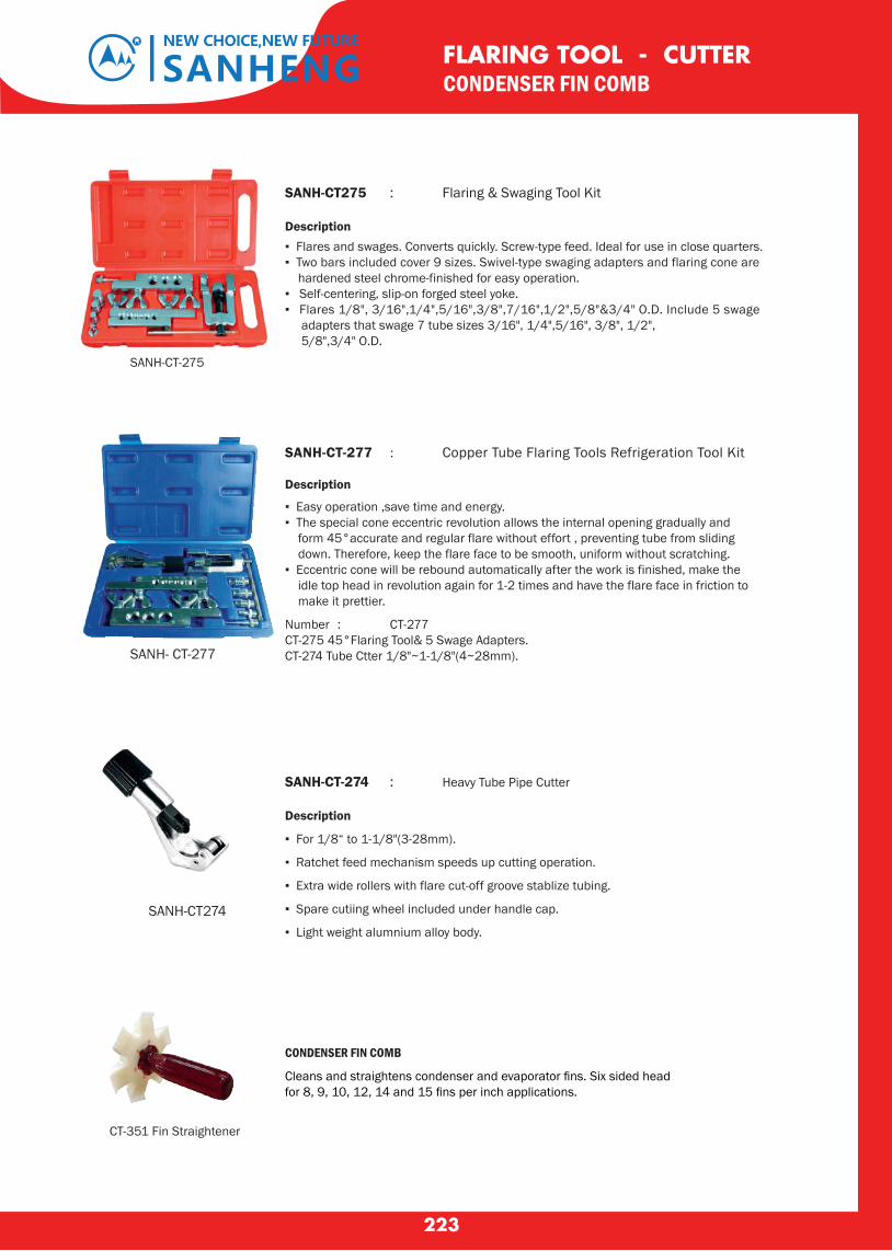
223
FLARING TOOL - CUTTERCONDENSER FIN COMB
SANH- CT-277
SANH-CT275 : Flaring & Swaging Tool Kit Description ▪ Flares and swages. Converts quickly. Screw-type feed. Ideal for use in close quarters.▪ Two bars included cover 9 sizes. Swivel-type swaging adapters and flaring cone are hardened steel chrome-finished for easy operation.▪ Self-centering, slip-on forged steel yoke.▪ Flares 1/8", 3/16",1/4",5/16",3/8",7/16",1/2",5/8"&3/4" O.D. Include 5 swage adapters that swage 7 tube sizes 3/16", 1/4",5/16", 3/8", 1/2", 5/8",3/4" O.D.
SANH-CT-275
SANH-CT-277 : Copper Tube Flaring Tools Refrigeration Tool Kit
Description
▪ Easy operation ,save time and energy.▪ The special cone eccentric revolution allows the internal opening gradually and form 45°accurate and regular flare without effort , preventing tube from sliding down. Therefore, keep the flare face to be smooth, uniform without scratching.▪ Eccentric cone will be rebound automatically after the work is finished, make the idle top head in revolution again for 1-2 times and have the flare face in friction to make it prettier.
Number : CT-277CT-275 45°Flaring Tool& 5 Swage Adapters.CT-274 Tube Ctter 1/8"~1-1/8"(4~28mm).
SANH-CT274
SANH-CT-274 : Heavy Tube Pipe Cutter
Description
▪ For 1/8“ to 1-1/8"(3-28mm).
▪ Ratchet feed mechanism speeds up cutting operation.
▪ Extra wide rollers with flare cut-off groove stablize tubing.
▪ Spare cutiing wheel included under handle cap.
▪ Light weight alumnium alloy body.
CONDENSER FIN COMB
Cleans and straightens condenser and evaporator fins. Six sided head for 8, 9, 10, 12, 14 and 15 fins per inch applications.
CT-351 Fin Straightener
SANHENGNEW CHOICE,NEW FUTURE
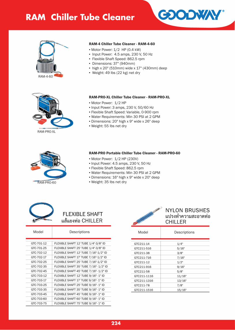
224
RAM Chiller Tube Cleaner
RAM-4 Chiller Tube Cleaner - RAM-4-60▪ Motor Power: 1/2 HP (0.4 kW)▪ Input Power: 4.5 amps, 230 V, 50 Hz▪ Flexible Shaft Speed: 862.5 rpm▪ Dimensions: 37" (940mm) ▪ high x 20" (510mm) wide x 17" (430mm) deep▪ Weight: 49 lbs (22 kg) net dry
RAM-PRO-XL Chiller Tube Cleaner - RAM-PRO-XL▪ Motor Power: 1/2 HP▪ Input Power: 3 amps, 230 V, 50/60 Hz▪ Flexible Shaft Speed: Variable, 0-900 rpm▪ Water Requirements: Min 30 PSI at 2 GPM▪ Dimensions: 20" high x 9" wide x 26" deep▪ Weight: 55 lbs net dry
RAM-PRO Portable Chiller Tube Cleaner - RAM-PRO-60▪ Motor Power: 1/2 HP (230V)▪ Input Power: 4.5 amps, 230 V, 50 Hz▪ Flexible Shaft Speed: 862.5 rpm▪ Water Requirements: Min 30 PSI at 2 GPM▪ Dimensions: 16" high x 9" wide x 20" deep▪ Weight: 35 lbs net dry
RAM-4-60
RAM-PRO-XL
RAM-PRO-60
FLEXIBLE SHAFTแสแยงทอ CHILLER
NYLON BRUSHESแปรงทำความสะอาดทอ CHILLER
GTC211-14GTC211-516GTC211-38GTC211-716GTC211-12GTC211-916GTC211-58GTC211-1116GTC211-1316GTC211-78GTC211-1516
1/4"5/16"3/8"7/16"1/2"9/16"5/8"11/16"13/16"7/8"15/16"
Model Descriptions Model Descriptions
GTC-701-12GTC-701-25GTC-702-12GTC-702-17GTC-702-25GTC-702-35GTC-702-45GTC-703-12GTC-703-17GTC-703-25GTC-703-35GTC-703-45GTC-703-60GTC-703-75
FLEXIBLE SHAFT 12' TUBE 1/4"-3/8" IDFLEXIBLE SHAFT 25' TUBE 1/4"-3/8" IDFLEXIBLE SHAFT 12' TUBE 7/16"-1/2" IDFLEXIBLE SHAFT 17' TUBE 7/16"-1/2" IDFLEXIBLE SHAFT 25' TUBE 7/16"-1/2" IDFLEXIBLE SHAFT 35' TUBE 7/16"- 1/2" IDFLEXIBLE SHAFT 45' TUBE 7/16"- 1/2" IDFLEXIBLE SHAFT 12' TUBE 9/16"- 1" IDFLEXIBLE SHAFT 17' TUBE 9/16"- 1" IDFLEXIBLE SHAFT 25' TUBE 9/16"- 1" IDFLEXIBLE SHAFT 35' TUBE 9/16"- 1" IDFLEXIBLE SHAFT 45' TUBE 9/16"- 1" IDFLEXIBLE SHAFT 60' TUBE 9/16"- 1" IDFLEXIBLE SHAFT 75' TUBE 9/16"- 1" ID
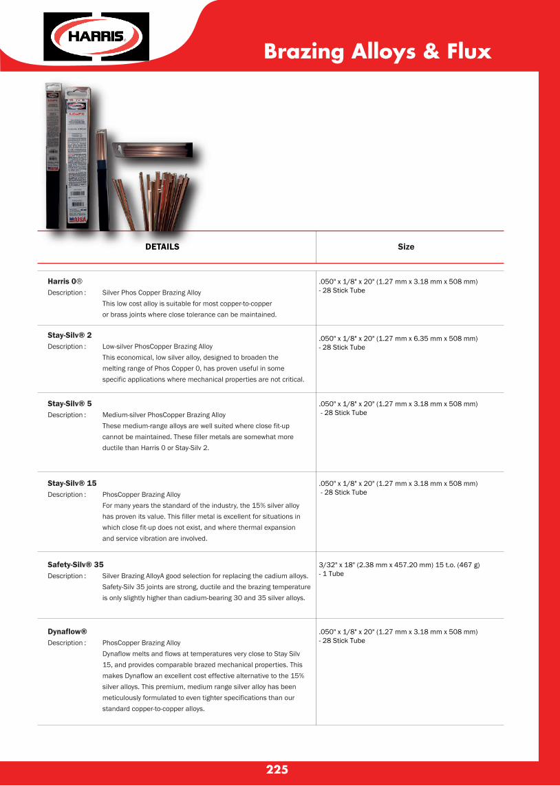
225
Harris 0®Description : Silver Phos Copper Brazing Alloy This low cost alloy is suitable for most copper-to-copper or brass joints where close tolerance can be maintained.
Stay-Silv® 2Description : Low-silver PhosCopper Brazing Alloy This economical, low silver alloy, designed to broaden the melting range of Phos Copper 0, has proven useful in some specific applications where mechanical properties are not critical.
.050" x 1/8" x 20" (1.27 mm x 3.18 mm x 508 mm) - 28 Stick Tube
DETAILS Size
.050" x 1/8" x 20" (1.27 mm x 6.35 mm x 508 mm) - 28 Stick Tube
Stay-Silv® 5Description : Medium-silver PhosCopper Brazing Alloy These medium-range alloys are well suited where close fit-up cannot be maintained. These filler metals are somewhat more ductile than Harris 0 or Stay-Silv 2.
.050" x 1/8" x 20" (1.27 mm x 3.18 mm x 508 mm) - 28 Stick Tube
Stay-Silv® 15Description : PhosCopper Brazing Alloy For many years the standard of the industry, the 15% silver alloy has proven its value. This filler metal is excellent for situations in which close fit-up does not exist, and where thermal expansion and service vibration are involved.
.050" x 1/8" x 20" (1.27 mm x 3.18 mm x 508 mm) - 28 Stick Tube
Safety-Silv® 35Description : Silver Brazing AlloyA good selection for replacing the cadium alloys. Safety-Silv 35 joints are strong, ductile and the brazing temperature is only slightly higher than cadium-bearing 30 and 35 silver alloys.
3/32" x 18" (2.38 mm x 457.20 mm) 15 t.o. (467 g) - 1 Tube
Dynaflow®Description : PhosCopper Brazing Alloy Dynaflow melts and flows at temperatures very close to Stay Silv 15, and provides comparable brazed mechanical properties. This makes Dynaflow an excellent cost effective alternative to the 15% silver alloys. This premium, medium range silver alloy has been meticulously formulated to even tighter specifications than our standard copper-to-copper alloys.
.050" x 1/8" x 20" (1.27 mm x 3.18 mm x 508 mm)- 28 Stick Tube
Brazing Alloys & Flux

226
¢Òá¢Ç¹à¤Ã×èͧ»ÃѺÍÒ¡ÒÈ¢ÒÂÒ§áÅÐà·»¾Ñ¹·‹Í
นำหนกสทธ
ขนาด
ประเภทของเหลก
ความหนาของเหลก (mm)
ประเภทของส
ส
เนอผว
สกรนอต/ชด
รองรบนำหนกสงสด (kgs)
รองรบเครองปรบอากาศนาด (BTU)
ขอมลเฉพาะ STANDCOND-45 STANDCOND-50 STANDCOND-60 STANDCOND-100
2.80
45 CM.
เหลกแผน
4
150
9000 - 12000
3.15
50 CM.
4
180
9000 - 28000
4.45
60 CM.
4
250
9000 - 38000
2
สฝนพนเรยบชนดพเศษ
ครม
ผวเรยบ/มนวาว
6
100 CM.
10
250
9000 - 38000
ขายาง ขนาด 3" , 4"ขาแขวนเครองปรบอากาศ เทปพนทอ

Refrigerants CFC,HCFC,HFC
Power Supeed 100-240V/50-60Hz
Motor 1 HP
Compressor oil free,piston style
Automatic safe Shut-off 38.5bar/3850kpa
Vapor
Liquid
Push/Pull
Dimensions(mm) 400×250×360
Weight(kg) 14.5
Recovery Unit
Refrigerant Recovery Unit
▪ Oil-less compressor
▪ Multi-refrigerant capable with Self-clearing
feature,which prevents cross-contamintion
▪ One key operation,easy to use
▪ Self-purge function
▪ Installed 4-pole motor,more durable
Model BRLN-RR500-OSP
(kg/min)Recovery Rate
0.5
3.6
10
BRLN-RR500-OSP
227
Beijer B.grimm is a technology-oriented trading Group
Which, through added-value products,
offers competutive solutions within
refrigeration, aircondition and
climate control
ºÃÔÉÑ· àºà¨ÍÃ� ºÕ.¡ÃÔÁ (»ÃÐà·Èä·Â) ¨Ó¡Ñ´ ÊÒ¢ÒÁËҪѠàÅ¢·Õè 72/21 ËÁÙ‹·Õè 1 µÓºÅ¹Ò´Õ ÍÓàÀÍàÁ×ͧÊÁØ·ÃÊҤà ¨Ñ§ËÇÑ´ÊÁØ·ÃÊҤà Tel. : 034 134 900 ¶Ö§ 3 Fax. : 034 134 904
ºÃÔÉÑ· àºà¨ÍÃ� ºÕ.¡ÃÔÁ (»ÃÐà·Èä·Â) ¨Ó¡Ñ´ ÊÒ¢Ò ¤ÅѧÊÔ¹¤ŒÒ äÍ«Õ´Õ ÅÒ´¡Ãкѧ àÅ¢·Õè 9/2 ¶¹¹ äÍ «Õ ´Õ á¢Ç§¤ÅͧÊÒÁ»ÃÐàÇÈ à¢µÅÒ´¡Ãкѧ ¡ÃØ§à·¾Ï 10520Tel: +66 2 088 0901 ¶Ö§ 3 Fax. : +66 2 088 0900
ºÃÔÉÑ· àºà¨ÍÃ� ºÕ.¡ÃÔÁ (»ÃÐà·Èä·Â) ¨Ó¡Ñ´ Êӹѡ§Ò¹ãËÞ‹àÅ¢·Õè 5 ¶¹¹¡Ã§à·¾¡ÃÕ±Ò á¢Ç§ËÑÇËÁÒ¡ ࢵºÒ§¡Ð»� ¡ÃØ§à·¾Ï 10240Tel. : +66 2 011 8888 Fax. : +66 2 011 8801-6
ºÃÔÉÑ· àºà¨ÍÃ� ºÕ.¡ÃÔÁ (»ÃÐà·Èä·Â) ¨Ó¡Ñ´ ÊÒ¢ÒàªÕ§ãËÁ‹ àÅ¢·Õè 136 ËÁÙ‹ 2 µÓºÅ»†Òº§ ÍÓàÀÍÊÒÃÀÕ ¨Ñ§ËÇÑ´àªÕ§ãËÁ‹ 50140 Tel. : 053 442 773 ¶Ö§ 5 Fax. : 053 442 776
¶¹¹ ¡ÒÞ¨¹ÒÀÔàÉ¡ (ǧáËǹÃͺ¹Í¡)
ä» ´ÒǤйͧ ä» ÊÁØ·Ãʧ¤ÃÒÁ
¶¹¹ ¾ÃÐÃÒÁ 2
·Ò§´‹Ç¹à©ÅÔÁÁËÒ¹¤Ã
ä» ºÒ§º
͹
¶¹¹ ྪÃà¡ÉÁ
ä»ÊÁطûÃÒ¡ÒÃ
ï ʶҹյÓÃǨ
Êоҹ
ï þ.àÍ¡ªÑÂ
ï
ï þ
.ÁËÒ
ªÑÂ
ï þ
.ÊÁØ·
ÃÊÒ¤
Ã
ï
ï
ï
ï
¶¹¹ àÍ¡ªÑÂ
ï ÈÒ
ÅÒ¡Å
Ò§¨. Ê
ÁØ·ÃÊ
Ò¤Ã
¶¹¹
àÈÃÉ
°¡Ô¨
¶¹¹
¡Ô¨Á³
Õ
º.à¤ËÐÁËҪѠï
¶¹¹
ÇÑ´âÊ
¶³ÒÃ
ÒÁ
ï ÁËÒªÑÂàÁ×ͧãËÁ‹ï
ä» ¡
Ãз؋Á
ẹ
¶¹¹ à
Í¡ªÑÂ
ï ºÃÔÉÑ· àºà¨ÍÃ� ºÕ.¡ÃÔÁ (»ÃÐà·Èä·Â) ¨Ó¡Ñ´
ï
ï ·Ò§Ã¶ä¿ÊÒÂǧàÇÕ¹ãËÞ‹ - ÁËÒªÑÂ
( ÍÒ¤ÒÃÊÕÊŒÁàËÅ×ͧ )
ï
Êоҹ
Motor way to Chonburi ถนนกรงเทพ - ชลบรสายใหม
Rama IX Rd.ถนนพระราม 9
พ
ฒนาการ
Samitivej Hospitalโรงพยาบาลสมตเวช
U-Turn Under Motor way กลบรถใตมอเตอรเวย
ถนนศรนครนทร
บางกะป
ABAC
มสยด
กรงเทพกรฑา (กอลฟ)KRUNGTHEP KREETHA UNICO GOLF COURSE
ยนโก (กอลฟ)
ทางเบยงคขนาน(มอเตอรเวย) Frontage Rd.
เลศประสทธอพารทเมนท
B.GRIMM B.GRIMM
Soi Krungthepkreetha 8 ซ. กรงเทพ
กรฑา 8
Soi Krungthepkreetha 4 ซ. กรงเทพ
กรฑา 4
Soi Krungthepkreetha 7
ซ. กรงเทพกรฑ
า 7
Saun-Son Villageม.มาลสวนสน
Mitsubishi Elec.office
บ.มตซบช อเลคทรค กนยงวฒนา จำกด
SYN MUN KONG INSURANCE PUBLIC COMPANY LIMITED
SIAM COMMERCIAL BANKSrinakarin R
d.
Krungthep Kreetha Rd. ถนนกรงเทพกรฑา
Beijer B.Grimm (Thailand) Ltd.บรษท เบเจอร บ.กรม (ประเทศไทย) จำกด
Phatthanakan Rd.
Bangkapi
Lupprasit Apartment
mosque
www.beijerrefthai.com
beijerbgrimmnew @beijerbgrimm
Website Facebook LINE ADD
ºÃÔÉÑ· àºà¨ÍÃ� ºÕ.¡ÃÔÁ (»ÃÐà·Èä·Â) ¨Ó¡Ñ´ ÊÒ¢ÒÀÙà¡çµ204/7 ËÁÙ‹ 7 µÓºÅà·¾¡ÃÐÉѵÃÕ ÍÓàÀͶÅÒ§ ¨Ñ§ËÇÑ´ÀÙà¡çµ 83110Tel. : 076 634 071 ¶Ö§ 4 Fax. : 076 634 075
หาดไมขาว
หาดในยาง
หาดในทอน
หาดบางเทา
หาดกมลา
¾Ñ§§Ò
ÊоҹÊÒÃÊÔ¹
ถนนสนามบนเมองใหม
·‹ÒÍÒ¡ÒÈÂÒ¹¹Ò¹ÒªÒµÔÀÙà¡çµ
ʹÒÁ¡ÍÅ�¿�ºÅÙहÂ͹�¤Ñ¹·ÃÕ�¤ÅѺ
วทยาลยเทคนคถลาง
รร.เมองถลาง
รร.กลางวทยา
คณแมจ
ถนนบานเหรยง
ถนนเทพกระษตร-ในยาง
ถนนตอนจอมเฒา
ถนนศรสนทร
วดพระบางสราง
วดมวงโกมารภจจ
ซอยพรสมภาร
ถนนส
ายรม
คลอง
ถนนเ
ทพกร
ะษตร
ไปเชงทะเล
หาดสรนทร
(แยกสนามบนเกา)
หาดแหลมทราย
หาดในแป
Mission Hills Golf Resort
ทาเรอบางโรง
ถนนสายทาเรอ-ปาคลอก-เมองใหมวงเวยนทาวเทพกระษตรทาวศรสนทร
เขาเมองภเกต
รพ.กลาง
ถนนนำตกโตนไทร นำตกโตนไทร
สาขาถลาง
บรษท มารน คาเหลก จำกด
บรษท เบเจอร บ.กรม (ประเทศไทย) จำกด สาขาภเกต
THEPLANT
เทพกระษตร-ถลางปม shell
วดพระหลวง ทวาการอำเภอถลาง