Wind buckling of metal tanks during their construction
7
Wind buckling of metal tanks during their construction Rossana C. Jaca a , Luis A. Godoy b, a Department of Constructions, School of Engineering, National University of Comahue 8300-Neuque´n, Argentina b Structures Department, FCEFyN, National University of Cordoba and CONICET, PO Box 916, Cordoba 5000, Argentina article info Article history: Received 20 August 2009 Accepted 14 January 2010 Keywords: Buckling Finite elements Structural collapse Tanks Wind abstract Shell structures are usually designed by considering their final shape and configuration, so that it is assumed that stability during the construction will be satisfied without further thought. However, evidence from recent collapses of metal tanks under moderate winds shows that this is a matter that requires special attention. This paper reports analytical studies of tanks for the oil industry that failed during their construction in the Argentinean Patagonia under moderate winds. The cylindrical part of the tanks was set up in place with point welding, but the roof was not yet in place at the time of collapse. To understand the mechanism of failure, static, geometrically nonlinear finite element modeling of the tanks was carried out, in which the shell was represented as close as possible to the actual conditions during the construction stage at which it failed. The results show that for the wind velocities prevalent at the time of collapse, an explanation of the failure mechanism can only be achieved by taking into account several special features of the structure under construction, i.e. the localized nature of welding and the influence of the incomplete junction with the bottom plate. & 2010 Elsevier Ltd. All rights reserved. 1. Introduction Many structures fail during their construction stages because calculations were made assuming the complete structure and not enough provisions were taken to withstand loads before comple- tion. This paper reports failures of aboveground steel tanks in Patagonia (Argentina), in which the structures were designed with a top roof but failure occurred under moderate wind loads before the cylindrical part was completed and the roof added to the resisting structure. The authors have not been able to find reports or studies of such failures, although a case is mentioned in a book by Noon (Fig. 2.2) [11]. Cylindrical metal shells without a roof are highly flexible structures and may buckle under low external pressure levels. Flores and Godoy [4] investigated bifurcation buckling of this class of shells under wind. The influence of geometric imperfections on the buckling response was investigated by Greiner and Derler [8], who found that the worst imperfection shape in short tanks was that of the eigenvector associated with the lowest eigenvalue in a bifurcation analysis. The imperfection sensitivity was further explored by Godoy and Flores [7] and Jaca et al. [9]. The incidence of ring stiffeners in geometrically perfect shells and their stabilizing role was studied by Schmidt et al. [13]; these authors highlighted the importance of having such stiffen- ers to control the deflections at the free end in an open tank. Flores and Godoy [5,6] and Sosa and Godoy [14] considered nonlinear static and dynamic response of open top tanks, and concluded that for the most common geometric configurations employed in the oil industry, the incidence of inertia forces in an empty tank may be neglected, with the consequence that tanks can be safely analyzed using static buckling methods. This was confirmed by a study of natural frequencies of empty tanks by Virella et al. [15]. Although those references are closely related to the topic of this paper, the models are not entirely adequate to represent the buckling of tanks during their construction, at least for the cases reported in the northern part of Patagonia. The reasons are that incomplete welding is used during the construction, and this further reduces the buckling strength of the shell. The collapses investigated are reported in Section 2, whereas the computational modeling is explained in Section 3. The results of both cases are discussed in Section 4. 2. Description of two collapses in Patagonia 2.1. Collapse in General Roca, 2001 On January 30, 2001, a tank that was under construction at an oil plant located 10 Km north of General Roca (Province of Neuque ´n, Argentina), collapsed under moderate winds. The diameter of the tank was 31 m, with a design height for the ARTICLE IN PRESS Contents lists available at ScienceDirect journal homepage: www.elsevier.com/locate/tws Thin-Walled Structures 0263-8231/$ - see front matter & 2010 Elsevier Ltd. All rights reserved. doi:10.1016/j.tws.2010.01.001 Corresponding author. E-mail addresses: [email protected] (R.C. Jaca), [email protected] (L.A. Godoy). Please cite this article as: Jaca RC, Godoy LA. Wind buckling of metal tanks during their construction. Thin Walled Struct (2010), doi:10.1016/j.tws.2010.01.001 Thin-Walled Structures ] (]]]]) ]]]–]]]
Transcript of Wind buckling of metal tanks during their construction

ARTICLE IN PRESS
Thin-Walled Structures ] (]]]]) ]]]–]]]
Contents lists available at ScienceDirect
Thin-Walled Structures
0263-82
doi:10.1
� Corr
E-m
lgodoy@
Pleasdoi:1
journal homepage: www.elsevier.com/locate/tws
Wind buckling of metal tanks during their construction
Rossana C. Jaca a, Luis A. Godoy b,�
a Department of Constructions, School of Engineering, National University of Comahue 8300-Neuquen, Argentinab Structures Department, FCEFyN, National University of Cordoba and CONICET, PO Box 916, Cordoba 5000, Argentina
a r t i c l e i n f o
Article history:
Received 20 August 2009
Accepted 14 January 2010
Keywords:
Buckling
Finite elements
Structural collapse
Tanks
Wind
31/$ - see front matter & 2010 Elsevier Ltd. A
016/j.tws.2010.01.001
esponding author.
ail addresses: [email protected] (R.C. Jaca)
com.uncor.edu (L.A. Godoy).
e cite this article as: Jaca RC, Godo0.1016/j.tws.2010.01.001
a b s t r a c t
Shell structures are usually designed by considering their final shape and configuration, so that it is
assumed that stability during the construction will be satisfied without further thought. However,
evidence from recent collapses of metal tanks under moderate winds shows that this is a matter that
requires special attention. This paper reports analytical studies of tanks for the oil industry that failed
during their construction in the Argentinean Patagonia under moderate winds. The cylindrical part of
the tanks was set up in place with point welding, but the roof was not yet in place at the time of
collapse. To understand the mechanism of failure, static, geometrically nonlinear finite element
modeling of the tanks was carried out, in which the shell was represented as close as possible to the
actual conditions during the construction stage at which it failed. The results show that for the wind
velocities prevalent at the time of collapse, an explanation of the failure mechanism can only be
achieved by taking into account several special features of the structure under construction, i.e. the
localized nature of welding and the influence of the incomplete junction with the bottom plate.
& 2010 Elsevier Ltd. All rights reserved.
1. Introduction
Many structures fail during their construction stages becausecalculations were made assuming the complete structure and notenough provisions were taken to withstand loads before comple-tion. This paper reports failures of aboveground steel tanks inPatagonia (Argentina), in which the structures were designedwith a top roof but failure occurred under moderate wind loadsbefore the cylindrical part was completed and the roof added tothe resisting structure.
The authors have not been able to find reports or studies ofsuch failures, although a case is mentioned in a book by Noon(Fig. 2.2) [11]. Cylindrical metal shells without a roof are highlyflexible structures and may buckle under low external pressurelevels. Flores and Godoy [4] investigated bifurcation buckling ofthis class of shells under wind. The influence of geometricimperfections on the buckling response was investigated byGreiner and Derler [8], who found that the worst imperfectionshape in short tanks was that of the eigenvector associated withthe lowest eigenvalue in a bifurcation analysis. The imperfectionsensitivity was further explored by Godoy and Flores [7] and Jacaet al. [9]. The incidence of ring stiffeners in geometrically perfectshells and their stabilizing role was studied by Schmidt et al. [13];these authors highlighted the importance of having such stiffen-
ll rights reserved.
,
y LA. Wind buckling of me
ers to control the deflections at the free end in an open tank.Flores and Godoy [5,6] and Sosa and Godoy [14] considerednonlinear static and dynamic response of open top tanks, andconcluded that for the most common geometric configurationsemployed in the oil industry, the incidence of inertia forces in anempty tank may be neglected, with the consequence that tankscan be safely analyzed using static buckling methods. This wasconfirmed by a study of natural frequencies of empty tanks byVirella et al. [15].
Although those references are closely related to the topic ofthis paper, the models are not entirely adequate to represent thebuckling of tanks during their construction, at least for the casesreported in the northern part of Patagonia. The reasons are thatincomplete welding is used during the construction, and thisfurther reduces the buckling strength of the shell.
The collapses investigated are reported in Section 2, whereasthe computational modeling is explained in Section 3. The resultsof both cases are discussed in Section 4.
2. Description of two collapses in Patagonia
2.1. Collapse in General Roca, 2001
On January 30, 2001, a tank that was under construction at anoil plant located 10 Km north of General Roca (Province ofNeuquen, Argentina), collapsed under moderate winds. Thediameter of the tank was 31 m, with a design height for the
tal tanks during their construction. Thin Walled Struct (2010),
ARTICLE IN PRESS
R.C. Jaca, L.A. Godoy / Thin-Walled Structures ] (]]]]) ]]]–]]]2
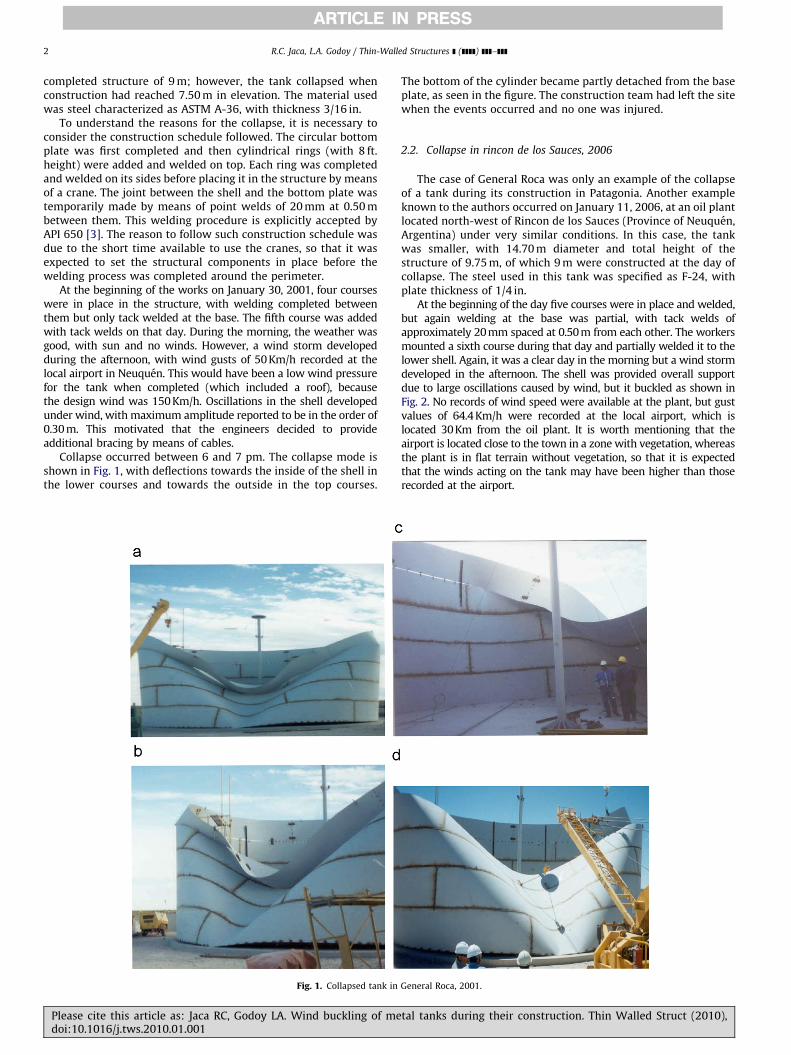
completed structure of 9 m; however, the tank collapsed whenconstruction had reached 7.50 m in elevation. The material usedwas steel characterized as ASTM A-36, with thickness 3/16 in.
To understand the reasons for the collapse, it is necessary toconsider the construction schedule followed. The circular bottomplate was first completed and then cylindrical rings (with 8 ft.height) were added and welded on top. Each ring was completedand welded on its sides before placing it in the structure by meansof a crane. The joint between the shell and the bottom plate wastemporarily made by means of point welds of 20 mm at 0.50 mbetween them. This welding procedure is explicitly accepted byAPI 650 [3]. The reason to follow such construction schedule wasdue to the short time available to use the cranes, so that it wasexpected to set the structural components in place before thewelding process was completed around the perimeter.
At the beginning of the works on January 30, 2001, four courseswere in place in the structure, with welding completed betweenthem but only tack welded at the base. The fifth course was addedwith tack welds on that day. During the morning, the weather wasgood, with sun and no winds. However, a wind storm developedduring the afternoon, with wind gusts of 50 Km/h recorded at thelocal airport in Neuquen. This would have been a low wind pressurefor the tank when completed (which included a roof), becausethe design wind was 150 Km/h. Oscillations in the shell developedunder wind, with maximum amplitude reported to be in the order of0.30 m. This motivated that the engineers decided to provideadditional bracing by means of cables.
Collapse occurred between 6 and 7 pm. The collapse mode isshown in Fig. 1, with deflections towards the inside of the shell inthe lower courses and towards the outside in the top courses.
Fig. 1. Collapsed tank in
Please cite this article as: Jaca RC, Godoy LA. Wind buckling of medoi:10.1016/j.tws.2010.01.001
The bottom of the cylinder became partly detached from the baseplate, as seen in the figure. The construction team had left the sitewhen the events occurred and no one was injured.
2.2. Collapse in rincon de los Sauces, 2006
The case of General Roca was only an example of the collapseof a tank during its construction in Patagonia. Another exampleknown to the authors occurred on January 11, 2006, at an oil plantlocated north-west of Rincon de los Sauces (Province of Neuquen,Argentina) under very similar conditions. In this case, the tankwas smaller, with 14.70 m diameter and total height of thestructure of 9.75 m, of which 9 m were constructed at the day ofcollapse. The steel used in this tank was specified as F-24, withplate thickness of 1/4 in.
At the beginning of the day five courses were in place and welded,but again welding at the base was partial, with tack welds ofapproximately 20 mm spaced at 0.50 m from each other. The workersmounted a sixth course during that day and partially welded it to thelower shell. Again, it was a clear day in the morning but a wind stormdeveloped in the afternoon. The shell was provided overall supportdue to large oscillations caused by wind, but it buckled as shown inFig. 2. No records of wind speed were available at the plant, but gustvalues of 64.4 Km/h were recorded at the local airport, which islocated 30 Km from the oil plant. It is worth mentioning that theairport is located close to the town in a zone with vegetation, whereasthe plant is in flat terrain without vegetation, so that it is expectedthat the winds acting on the tank may have been higher than thoserecorded at the airport.
General Roca, 2001.
tal tanks during their construction. Thin Walled Struct (2010),

ARTICLE IN PRESS
Fig. 2. Collapsed tank in Rincon de los Sauces, 2006.
R.C. Jaca, L.A. Godoy / Thin-Walled Structures ] (]]]]) ]]]–]]] 3
3. Modeling of the tanks under construction
A finite element model of tanks during their constructionrequires representing wind pressures acting on an incompletestructure. The pressure distributions due to wind has beenmodeled in a classical way by means of pressure distributionsfor open tanks in the form:
q¼ lXn
i ¼ 1
CicosðiyÞ ð1Þ
where q is the external static pressure due to wind; l is the loadparameter used to increase the reference load; and y is thecircumferential angle with respect to the windward meridian. TheFourier coefficients play the role of Cp (pressure coefficient) valuesand are given by [12]: C0=0.387, C1=�0.338, C2=�0.533,C3=�0.471, C4=�0.166, C5=0.0666, C6=0.055.
The relation between wind pressures q and velocities V wasassumed in the form given by ASCE-7-05 [2]:
q¼ 0:613KzKztKdIV2 ð2Þ
where q is given in [N/m2]; V is given in [m/s]; and unit valueswere assumed for the topographic factor Kzt, the wind direction-ality factor Kd, and the importance factor I for Category II . A valueKz=0.94 was adopted for the exposure factor.
The structure was modeled using the general purpose finiteelement code ABAQUS [1] using eight-node two dimensional shellfinite elements, identified as S8R5 in the program. The modelsincluded both the bottom plate and the shell, as illustrated inFig. 3. Preliminary studies indicated that it was not necessary toinclude the complete bottom plate in the model, because only its
Please cite this article as: Jaca RC, Godoy LA. Wind buckling of medoi:10.1016/j.tws.2010.01.001
contribution to the stiffness of the structure was required toachieve a representative model.
It was assumed that the structure had a discontinuous junctionbetween the cylinder and the plate, and a discontinuous jointbetween the top two courses. The incomplete wielding wasrepresenting by attaching some cylinder nodes to the bottomplate and leaving some without connection. Notice that the finiteelement mesh at the tack welds did not attempt to representstress concentrations and only part of a global representation ofthe structural stiffness for the purpose of computing the overallstability of the shell. A similar scheme was adopted at the jointbetween the two upper courses to represent welding pointsspaced at 0.50 m. The reports indicated that the cylinder lost partof its support during the process leading to buckling. For thisreason, several scenarios were considered in the analysis, inwhich spacing between welds at the windward zone wereassumed.
Two types of stability analyses were carried out in each case: abifurcation analysis, to compute approximate estimates ofbuckling loads (eigenvalues) and buckling modes (eigenvectors),and a nonlinear analysis. The geometrically nonlinear analysiswas carried out using an incremental algorithm in which theexternal pressures were increased by means of a parameter l thatscales a reference pressure configuration of Eq. (1).
Shell structures are sensitive to the presence of smallgeometric imperfections with respect to the as-designed shape.This incidence was taken into account by means of an initialimperfection with an assumed geometry and a maximumamplitude value denoted by x. Based on experience of similartanks, the assumed shape of the imperfection was adopted as theeigenmode of the lowest eigenvalue computed in the bifurcationanalysis of the structure in each case. The imperfection amplitudewas taken as twice the shell thickness, i.e. x=2t.
4. Results
4.1. Analysis of the collapse at General Roca
For the worse scenario at the base, the separation a betweenwelds was assumed to be uniform around the circumference. Theequilibrium paths computed from the nonlinear analysis areshown in Fig. 4. In all cases, there was a stable path up to amaximum lmax of the load parameter and then the path becameunstable and descendent. For a=5 m, lmax=0.162 kN/m2 whereasfor a=6.25 m, lmax=0.133 kN/m2 (or V=54.6 Km/h). Such valuesare of the same order as those recorded at the time of the collapseof the structure.
Alternative scenarios were also investigated, in which there wasa section with length b that was detached from the base and thenthe shell was joined by welds at 0.50 m. Results for this case areshown in Fig. 5. For b=4.5 m, lmax=0.130 kN/m2 (V=54.1 Km/h);whereas for b=8.5 m (but with a tack weld at the windwardmeridian), then lmax=0.126 kN/m2 (V=53.2 Km/h).
The previous results are indicative that the wind velocitiesrequired to buckle the tank are consistent with what wasrecorded in the field. The deflected shape of the tank resultingfrom the computations (Fig. 6) is also consistent with the buckledshape shown in Fig. 1.
Next, attention focuses on the connection between the top twocourses of the tank at the time of collapse. Reports of theconstruction team indicated that about 30% of the perimeter hadtack welds. Several cases were computed by assuming welds spacedat uniform distance c along the perimeter between the fourthand fifth courses. For c=3 m, a maximum value lmax=0.13 kN/m2
was computed, whereas for an arbitrarily larger value of c=6 m,
tal tanks during their construction. Thin Walled Struct (2010),

ARTICLE IN PRESS
Fig. 3. Finite element model adopted for the computations. (a) Supports at 0.5 m with a free segment at windward; (b) support details.
-2.50.0
0.1
0.2
0.3λ
[kN
/m2 ]
Continuous support Tack welds at 0.50 m Tack welds at 5.00 m Tack welds at 6.25 m
U2[m]
0.0-0.5-1.0-1.5-2.0
Fig. 4. Equilibrium paths for tank at General Roca. Displacements are measured at
the top in the windward meridian. Supports are uniformly distributed around the
circumference, with spacing a.
-4.00.0
0.1
0.2
0.3
λ [k
N/m
2 ]
Continuous support Tack welds at 0.50 m Tack welds at 0.50 m from 4.5m Tack welds at 0.50 m from 8.5m.
with restricted windward node
U2[m]
0.0-0.5-1.0-1.5-2.0-2.5-3.0-3.5
Fig. 5. Equilibrium paths for tank at General Roca. Supports at 0.5 m with a free
zone of length b at windward.
Fig. 6. Deflected shape of tank at General Roca.
R.C. Jaca, L.A. Godoy / Thin-Walled Structures ] (]]]]) ]]]–]]]4
the maximum was drastically reduced to lmax=0.07 kN/m2. Thedeflected shape for c=3 m is shown in Fig. 7, and is consistent withfield observations and photographs. The wind speed at whichbuckling occurs in this scenario is V=52 Km/h.
The buckling process in this thin-walled tank is basically elastic,but as the structure has large deflections in the post-critical range,
Please cite this article as: Jaca RC, Godoy LA. Wind buckling of medoi:10.1016/j.tws.2010.01.001
it is expected that it will have plasticity. The von Misses criterionwas employed to model plasticity using sy=216 MPa, and thestresses are shown in Fig. 8 for two models, one in which the topcourses remain attached by a continuous joint, and anotherconfiguration in which the two are separated as explained before,with c=3 m. The zones colored in green or yellow show theoccurrence of plasticity, and it is found to start at the lower levelsof the shell in the windward region and extend towards theopen top.
4.2. Other welding scenarios
It was shown in the previous section that the tank in GeneralRoca was unable to stand low wind speeds due to the weaknesses
tal tanks during their construction. Thin Walled Struct (2010),

ARTICLE IN PRESS
R.C. Jaca, L.A. Godoy / Thin-Walled Structures ] (]]]]) ]]]–]]] 5
introduced by the incomplete welding schedule employed. Thequestion remains about the expected behavior if a more completewelding had been introduced in the structure during itsconstruction. In an attempt to answer such question, othermodels were investigated.
First, a scenario was assumed in which the cylindrical shell wascompletely welded at the base before the top rings were set in place.As a reference value, a bifurcation analysis of this case yieldslmax=0.46 kN/m2 (or V=102 Km/h), whereas the nonlinear analysisidentifies a maximum at lmax=0.31 kN/m2 (or V=83 Km/h). Theequilibrium path is shown in Fig. 4, with a large drop in the post-buckling path that takes a maximum at lmax=0.31 kN/m2 and aminimum at lmax=0.06 kN/m2.
Second, it was assumed that the tack welds were present at thebase at 0.50 m of each other, and that failure of such localizedwelds did not occur. The equilibrium path is also shown in Fig. 4,with lmax=0.29 kN/m2 and V=81 Km/h, thus showing a responsesimilar to the case with a continuous support. As a referencevalue, a bifurcation analysis in this case leads to lc=0.41 kN/m2
(V=96 Km/h).
Fig. 7. Deflected shape of tank at General Roca, for welding spaced at 3 m between
fourth and fifth courses.
Fig. 8. Von Mises stresses in the shell for tank at General Roca (a) with continuous join
Please cite this article as: Jaca RC, Godoy LA. Wind buckling of medoi:10.1016/j.tws.2010.01.001
4.3. Analysis of the collapse at Rincon de los Sauces
A similar study was conducted for the tank that collapsed atRincon de los Sauces in 2006. This tank had a smaller diameter and athicker shell, and the collapse occurred under higher wind speeds.The equilibrium paths computed via a geometrically nonlinearanalysis are shown in Fig. 9. In the most severe configuration, it wasassumed that the shell was attached at the base plate on thewindward meridian but that there was a part not attached withlength b. For b=11 m, lmax=0.43 kN/m2 (V=98 Km/h), whereas forb=14 m, lmax=0.36 kN/m2 (V=90 Km/h). The deflected shape of thetank is shown in Fig. 10, and is in good agreement with the actualfailure mode reported in the field (Fig. 2).
If the cylinder had been completely welded at its base, the valueof maximum load before buckling would be lmax=1.64 kN/m2
(V=192 Km/h), whereas with welds at 0.50 m, one gets lmax=1.52kN/m2 (V=185 Km/h), which are much higher than those obtainedfrom incomplete attachment models.
5. Discussion
To have a more complete view on the behavior of tanks underconstruction, a third case was investigated with R=15.5 m, L=10 m,and t=5.6 mm, leading to lmax=0.35 kN/m2 (V=88 Km/h) for a
t between top two courses, (b) with a discontinuous link between top two courses.
-3.50.0
0.2
0.4
0.6
0.8
1.0
1.2
1.4
1.6
1.8
2.0
Continuous support Tack welds at 0.50 m Tack welds at 3.00 m Tack welds at 0.50 m from 11.00 m
with restricted windward node Tack welds at 0.50 m from 14.00 m.
with restricted windward node
U2[m]
0.0-0.5-1.0-1.5-2.0-2.5-3.0
λ [k
N/m
2 ]
Fig. 9. Equilibrium paths for tank at Rincon de los Sauces. Displacements are
measured at the top in the windward meridian.
tal tanks during their construction. Thin Walled Struct (2010),

ARTICLE IN PRESS
Fig. 10. Tank at Rincon de los Sauces, deflected shape at buckling.
40
60
80
100
120
140
160
180
200
600 800 1000 1200 1400 1600 1800Z
V[
km/h
]
Continuous support
Failed tack welds
Design Velocity
Fig. 11. Wind velocities that produce collapse mechanisms, under the conditions
studied in this paper.
R.C. Jaca, L.A. Godoy / Thin-Walled Structures ] (]]]]) ]]]–]]]6
continuous support, and lmax=0.15 kN/m2 (V=58 Km/h) for thedetached joint at the base with b=5.5 m.
The results of this investigation have been summarized inFig. 11 in terms of the Batdorf parameter (Z), given by:
Z ¼L2
rt
ffiffiffiffiffiffiffiffiffiffiffiffi1�n2
pð3Þ
where L is the length of the cylinder, r is the radius, t is thethickness, n is Poisson’s coefficient. The tank at General Roca hasZ=726, the tank at Rincon de los Sauces has Z=1655, while thethird tank has an intermediate value Z=1099. Two curves areshown in this figure: one that is based on a scenario with tackwelds that fail along a significant part of the perimeter, and asecond curve assuming that welding at the base was completedbefore construction continued at higher levels. As a referencevalue, the figure also shows the design wind speed for that part ofPatagonia, which is V=158 Km/h.
6. Conclusions
The collapses under similar conditions are not limited to thetwo cases illustrated in this paper, but they tend to be outside
Please cite this article as: Jaca RC, Godoy LA. Wind buckling of medoi:10.1016/j.tws.2010.01.001
public knowledge because they occur in the private property of anoil facility. The strong similarities between the two collapsesreported in this paper are indicative of a pattern that occurs in thenorthern part of Patagonia, with high winds during January [10]and at the same time, being that part of the summer adequate tocarry out construction tasks that are difficult to do during winterbecause of the rigorous weather.
The lessons learned from the cases studied in this paper maybe considered from two different perspectives, i.e. constructionaspects and models of analysis. At present, the construction oftanks in Patagonia follows API recommendations, in which the useof tack welding is allowed before continuous welding iscompleted:
‘‘Shell plates may be aligned by metal clips attached to thebottom plates, and the shell may be tack welded to the bottom beforecontinuous welding is started between the bottom edge of the shellplate and the bottom plates.’’ (API 650, Section 5.2.2.3) [3].
However, it was found that in both cases reported in thispaper, the continuous welding between the shell and thebottom plate had not been completed even at the stage offinishing the construction of the complete cylinder. The construc-tion team should not take critical strengthening decisions in thepresence of large amplitude vibrations, so that such situationsshould be avoided. Our main conclusion is that continuouswelding between the base plate and the first course should becompleted before other courses are added on top; this wouldprovide a much higher stiffness to the shell and the windspeeds required to buckle the shell would be within acceptablelevels.
Regarding the structural analysis of the tank, it is recom-mended that models should be considered to account for theconstruction stages, thus assuring that the structure is stablebefore it is completed and with the roof set in place. The modelsshould carefully follow the construction stages, so as to providetemporary buckling strength for the stages in which the finalconfiguration has not been completed.
Acknowledgments
This work was supported by grants from Universidad Nacionaldel Comahue and Universidad Nacional de Cordoba.
References
[1] ABAQUS, User’s Manuals, Version 6.3, Hibbitt, Karlsson and Sorensen, Inc.Rhode Island, 2002.
[2] ASCE-7-02, Minimun Design Loads for Building and other Structures, ASCE,Reston, VA, 2002.
[3] API Standard 650. Welded Steel Tanks for Oil Storage. Washington, D.C.:American Petroleum Institute; 1988.
[4] Flores FG, Godoy LA. Instability of shells of revolution using ALREF:studies for wind loaded shells. In: Buckling Of Shells Structures,On Land, In The Sea And In The Air. Oxford: Elsevier Applied Science;1991. p. 213–22.
[5] Flores FG, Godoy LA. Buckling of short tanks due to hurricanes. Journal ofEngineering Structures 1998;20(8):752–60.
[6] Flores FG, Godoy LA. Forced vibrations of silos leading to buckling. Journal ofSound and Vibration 1999;224(3):431–54.
[7] Godoy LA, Flores FG. Imperfection-sensitivity to elastic buckling of windloaded open cylindrical tanks. Journal of Structural Engineering andMechanics 2002;13(5):533–42.
[8] Greiner R, Derler P. Effect of imperfections on wind-loaded cylindrical shells.Thin Walled Structures 1995;23:271–81.
[9] Jaca RC, Godoy LA, Flores FG. Analisis poscrıtico de tanques de pared delgadabajo cargas de viento. Mecanica Computacional 2002;21:1842–61.
[10] Lassig JL, Cogliati MG, Bastanky MA, Palese C. Wind characteristics inNeuquen, North Patagonia, Argentina. Journal of Wind Engineering andIndustrial Aerodynamics 1999;79:183–99.
[11] Noon RK. Forensic Engineering Investigation. Boca Raton, FL: CRC Press;2001.
tal tanks during their construction. Thin Walled Struct (2010),

ARTICLE IN PRESS
R.C. Jaca, L.A. Godoy / Thin-Walled Structures ] (]]]]) ]]]–]]] 7
[12] Rish RF. Forces in cylindrical shells due to wind. Proceedings of theInstitution of Civil Engineers 1967;36:791–803.
[13] Schmidt H, Binder B, Lange H. Postbuckling strength design of open thin-walled cylindrical tanks under wind load. Thin-Walled Structures 1998;31:203–20.
Please cite this article as: Jaca RC, Godoy LA. Wind buckling of medoi:10.1016/j.tws.2010.01.001
[14] Sosa EM, Godoy LA. Non-linear dynamics of above-ground thin-walledtanks under fluctuating pressures. Journal of Sound and Vibration 2005;283:201–15.
[15] Virella JC, Godoy LA, Suarez LE. Influence of the roof on the natural periods ofempty steel tanks. Engineering Structures 2003;25:877–87.
tal tanks during their construction. Thin Walled Struct (2010),