Modelling and Designing Cryogenic Hydrogen Tanks for ...
23
energies Article Modelling and Designing Cryogenic Hydrogen Tanks for Future Aircraft Applications Christopher Winnefeld 1 , Thomas Kadyk 2 ID , Boris Bensmann 1, *, Ulrike Krewer 2 ID and Richard Hanke-Rauschenbach 1 1 Institute of Electric Power Systems, Leibniz Universität Hannover, Appelstr. 9a, 30167 Hanover, Germany; [email protected] (C.W.); [email protected] (R.H.-R.) 2 Institute of Energy and Process Systems Engineering, TU Braunschweig, Franz-Liszt-Straße 35, 38106 Braunschweig, Germany; [email protected] (T.K.); [email protected] (U.K.) * Correspondence: [email protected]; Tel.: +49-511-762-14404 Received: 14 December 2017; Accepted: 26 December 2017; Published: 3 January 2018 Abstract: In the near future, the challenges to reduce the economic and social dependency on fossil fuels must be faced increasingly. A sustainable and efficient energy supply based on renewable energies enables large-scale applications of electro-fuels for, e.g., the transport sector. The high gravimetric energy density makes liquefied hydrogen a reasonable candidate for energy storage in a light-weight application, such as aviation. Current aircraft structures are designed to accommodate jet fuel and gas turbines allowing a limited retrofitting only. New designs, such as the blended-wing-body, enable a more flexible integration of new storage technologies and energy converters, e.g., cryogenic hydrogen tanks and fuel cells. Against this background, a tank-design model is formulated, which considers geometrical, mechanical and thermal aspects, as well as specific mission profiles while considering a power supply by a fuel cell. This design approach enables the determination of required tank mass and storage density, respectively. A new evaluation value is defined including the vented hydrogen mass throughout the flight enabling more transparent insights on mass shares. Subsequently, a systematic approach in tank partitioning leads to associated compromises regarding the tank weight. The analysis shows that cryogenic hydrogen tanks are highly competitive with kerosene tanks in terms of overall mass, which is further improved by the use of a fuel cell. Keywords: fuel tanks; energy storage; hydrogen storage; aviation; proton-exchange membrane fuel cell 1. Introduction In future aircraft scenarios, facing challenges to satisfy the global market growth requires new approaches in air transport solutions while simultaneously reducing the environmental impact. Boeing [1] and Airbus [2] predict revenue passenger kilometres to double in less than 20 years. In addition, twice the current fleet is expected to operate until 2036 as well. In order to achieve sufficient reduction of overall aviation-related emissions, new propulsion technologies and aircraft designs along with tremendous aerodynamic improvements have to be introduced. In the visionary commitment Flightpath 2050 [3], CO 2 emissions should be cut by 75%, NO x emissions by 90% and noise footprint by 60% in 2050 compared to the reference value of the year 2000. Considering a supply by fossil fuel, these goals appear to be far from being achieved. In order to replace fossil fuels, hydrogen is a reasonable candidate for a prospective energy supply with a gravimetric energy density of 33.3 kWh/kg compared to kerosene with 12 kWh/kg. Assuming its production by renewable energy sources, the well-to-wheel emissions in terms of greenhouse gases can be reduced significantly. Although hydrogen can be stored in several ways, only liquid hydrogen Energies 2018, 11, 105; doi:10.3390/en11010105 www.mdpi.com/journal/energies
-
Upload
khangminh22 -
Category
Documents
-
view
3 -
download
0
Transcript of Modelling and Designing Cryogenic Hydrogen Tanks for ...

energies
Article
Modelling and Designing Cryogenic Hydrogen Tanksfor Future Aircraft Applications
Christopher Winnefeld 1, Thomas Kadyk 2 ID , Boris Bensmann 1,*, Ulrike Krewer 2 ID
and Richard Hanke-Rauschenbach 1
1 Institute of Electric Power Systems, Leibniz Universität Hannover, Appelstr. 9a, 30167 Hanover, Germany;[email protected] (C.W.); [email protected] (R.H.-R.)
2 Institute of Energy and Process Systems Engineering, TU Braunschweig, Franz-Liszt-Straße 35,38106 Braunschweig, Germany; [email protected] (T.K.); [email protected] (U.K.)
* Correspondence: [email protected]; Tel.: +49-511-762-14404
Received: 14 December 2017; Accepted: 26 December 2017; Published: 3 January 2018
Abstract: In the near future, the challenges to reduce the economic and social dependencyon fossil fuels must be faced increasingly. A sustainable and efficient energy supply based onrenewable energies enables large-scale applications of electro-fuels for, e.g., the transport sector.The high gravimetric energy density makes liquefied hydrogen a reasonable candidate for energystorage in a light-weight application, such as aviation. Current aircraft structures are designed toaccommodate jet fuel and gas turbines allowing a limited retrofitting only. New designs, such asthe blended-wing-body, enable a more flexible integration of new storage technologies and energyconverters, e.g., cryogenic hydrogen tanks and fuel cells. Against this background, a tank-designmodel is formulated, which considers geometrical, mechanical and thermal aspects, as well as specificmission profiles while considering a power supply by a fuel cell. This design approach enablesthe determination of required tank mass and storage density, respectively. A new evaluation valueis defined including the vented hydrogen mass throughout the flight enabling more transparentinsights on mass shares. Subsequently, a systematic approach in tank partitioning leads to associatedcompromises regarding the tank weight. The analysis shows that cryogenic hydrogen tanks arehighly competitive with kerosene tanks in terms of overall mass, which is further improved by theuse of a fuel cell.
Keywords: fuel tanks; energy storage; hydrogen storage; aviation; proton-exchange membranefuel cell
1. Introduction
In future aircraft scenarios, facing challenges to satisfy the global market growth requires newapproaches in air transport solutions while simultaneously reducing the environmental impact.Boeing [1] and Airbus [2] predict revenue passenger kilometres to double in less than 20 years.In addition, twice the current fleet is expected to operate until 2036 as well. In order to achievesufficient reduction of overall aviation-related emissions, new propulsion technologies and aircraftdesigns along with tremendous aerodynamic improvements have to be introduced. In the visionarycommitment Flightpath 2050 [3], CO2 emissions should be cut by 75%, NOx emissions by 90% and noisefootprint by 60% in 2050 compared to the reference value of the year 2000. Considering a supply byfossil fuel, these goals appear to be far from being achieved.
In order to replace fossil fuels, hydrogen is a reasonable candidate for a prospective energy supplywith a gravimetric energy density of 33.3 kWh/kg compared to kerosene with 12 kWh/kg. Assumingits production by renewable energy sources, the well-to-wheel emissions in terms of greenhouse gasescan be reduced significantly. Although hydrogen can be stored in several ways, only liquid hydrogen
Energies 2018, 11, 105; doi:10.3390/en11010105 www.mdpi.com/journal/energies

Energies 2018, 11, 105 2 of 23
(LH2) appears to be feasible in aviation. Gaseous hydrogen (GH2) offers a specific volume of 5.6-timesthe volume of LH2, if stored at 164 bar and 288.15 K [4]. Additionally, the tank-wall thicknessesrise tremendously for the required internal pressures, which are at least two orders of magnitudegreater than the cryogenic storage solution [5]. Reasonable numbers in the share of hydrogen mass oncomposite tank mass are between 7.5% and 8.5%, while steel cylinders provide values between 1% and3% [6]. Gaseous hydrogen can further be stored in metal hydrides. However, this technology offers acapability of about 5% mass fraction of hydrogen [5,7]. Although metal borohydrides store hydrogenmass fractions greater than 10% in more recent studies about unmanned aerial vehicles, those storagedensities with associated challenges regarding the rate of fuel withdrawal do not appear to representthe favoured storage option [6].
Numerous studies, such as from Lockheed and NASA [8] or the Cryoplane project [9], attestto the feasibility of liquid hydrogen as aviation fuel. Brewer [7] summarised various studies onhydrogen-fuelled passenger aircraft showing slightly higher (1–2%) operating empty weights. Grossweights can be reduced by 20% for medium range and by 10% for short range aircraft. Furthermore,the fuel shares approximately 72% in the fuel system weight. The results by Verstraete [10] demonstratesimilar behaviour in terms of energy density of the storage system. Values of approximately 78% arereached relating the hydrogen mass on the sum of system and fuel mass. Common practical kerosenetanks offer fuel shares of around 75% including periphery [11]. These theoretical studies show thatthe cryogenic hydrogen tank has a significant share of the fuel, but are nonetheless competitive withkerosene tanks. Consequently, the storage density is mainly driven by the tank design. For thisreason, it is worth investigating the hydrogen tank more in detail. Since the direct operating costs(DOCs) and aerodynamic requirements of an aircraft relate directly to the mass, the herein presentedstudy evaluates mainly weight-dependent parameters. In addition to that, the energy density of thehydrogen storage shall be investigated and compared preferable to conventional jet fuel. For thesereasons, a mass-related evaluation appears to be suitable and is further applied to this study.
Whereas previous studies on cryogenic hydrogen tanks discuss the storage dimensioning only onparticular aircraft geometries, this contribution covers a general approach. Future aircraft conceptsprovide more volume especially in the outer and rear fuselage parts compared to conventional aircraftdesigns. A more effective use of cylindrical and elliptical tank designs appears to be enabled [12].Furthermore, complex tank geometries, such as obround and complex conformal tanks, are feasible [13].Motivated by those aircraft concepts, a widely-flexible description of cylindrical and elliptical tankshapes is applied. Along with future energy storage concepts, a fuel cell is considered to supply thepropulsion system with electrical power. Because of its superior efficiency compared to conventionalaero engines, the feasibility of hydrogen storage increases, because of less fuel burn [11].
Dimensionless parameters are introduced characterising the tank geometry and enabling a flexiblegeometric description. An objective of this study is to elaborate the most favourable design if a sphericalgeometry is unpractical or rather a non-cylindrical design is contemplated. Further evaluations showexpected shares of the tank wall and insulation mass in the overall tank mass while making theevaluation process more transparent. Within the first phase of this study, the hydrogen tank is observedonly. Commencing with an overview about hydrogen properties, a description of the tank-designapproach follows subsequently. Parametric studies are executed based on a specific flight missionafter introducing the tank model. Conclusively, a comparison in terms of weight is drawn betweenhydrogen and kerosene tanks.
2. Principles of the Modelling Approach
This chapter introduces the principles of the modelling approach. Since the focus of the presentcontribution is on cryogenic hydrogen storage, the first section provides brief information aboutthermodynamic properties of hydrogen in general. The subsequent section treats the modellingapproach of the tank design followed by paragraphs about the operation management and the overalldesign routine.
Energies 2018, 11, 105 3 of 23
2.1. Properties of LH2
To classify the characteristics of hydrogen, selected thermodynamic properties are compared toconventional jet fuel. In the following, additional peculiarities of hydrogen are discussed. The mainadvantage of hydrogen compared to conventional Jet-A fuel is the 2.8-times greater heat of combustion.Attributed to its superior heat capacity, hydrogen appears to be more suitable for component coolingespecially if electrically-driven propulsion systems and superconductors are considered. Nevertheless,liquid hydrogen stored at 1 bar requires four-times the volume of jet fuel for the same energy amount.It further ought to be stored at cryogenic temperatures. Table 1 summarises selected properties ofliquid hydrogen and jet fuel.
Table 1. Properties of liquid hydrogen at normal boiling point [14] and Jet-A fuel [15].
Parameter Unit LH2 Jet-A (CH1.93)
Molecular weight kg/mol 2.016× 10³ 168× 103
Temperature K 20.369 439.817Heat of combustion J/kg 120× 106 42.798× 10⁶
Density kg/m3 70.9 810.53Specific heat capacity J/kgK 9.747× 10³ 1.968× 10³
If normal hydrogen is liquefied, ortho-H2 converts spontaneously into para-H2 under exothermicconditions. For long-term storages, this leads to considerable boil-off rates depending on theambient temperature. Triggering this conversion during the liquefaction process, which requiresa certain amount of extra energy input, avoids the hydrogen conversion afterwards. Depending onthe application, considering this conversion during liquefaction is favourable from the economicperspective. In accordance with Verstraete [10], para-hydrogen is used to enable a more conservativetank design, because the pressure fluctuations are slightly greater (ca. 1%). Since the basic characteristicsof para-hydrogen are similar to normal-hydrogen, in the following, the term “hydrogen” is introduced,although the properties of para-hydrogen are taken as a basis.
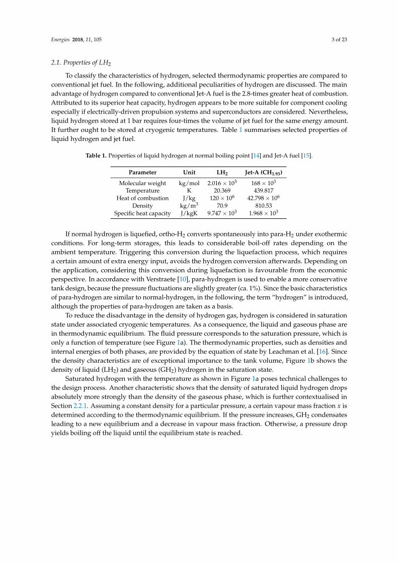
To reduce the disadvantage in the density of hydrogen gas, hydrogen is considered in saturationstate under associated cryogenic temperatures. As a consequence, the liquid and gaseous phase arein thermodynamic equilibrium. The fluid pressure corresponds to the saturation pressure, which isonly a function of temperature (see Figure 1a). The thermodynamic properties, such as densities andinternal energies of both phases, are provided by the equation of state by Leachman et al. [16]. Sincethe density characteristics are of exceptional importance to the tank volume, Figure 1b shows thedensity of liquid (LH2) and gaseous (GH2) hydrogen in the saturation state.
Saturated hydrogen with the temperature as shown in Figure 1a poses technical challenges tothe design process. Another characteristic shows that the density of saturated liquid hydrogen dropsabsolutely more strongly than the density of the gaseous phase, which is further contextualised inSection 2.2.1. Assuming a constant density for a particular pressure, a certain vapour mass fraction x isdetermined according to the thermodynamic equilibrium. If the pressure increases, GH2 condensatesleading to a new equilibrium and a decrease in vapour mass fraction. Otherwise, a pressure dropyields boiling off the liquid until the equilibrium state is reached.
Energies 2018, 11, 105 4 of 23
21 24 27 30 33024
68
1012
Temperature T in K
Pres
sure
pin
bar
(a)
0 2 4 6 8 10 120
20
40
60
80
Pressure p in bar
Den
sity
ρin
kg/m
3 LH2
GH2
(b)
Figure 1. (a) The saturation curve of para-hydrogen is shown. (b) The density of liquid and gaseouspara-hydrogen in saturation state is plotted.
2.2. Cryogenic Tank Design
Having introduced the fluid, which shall be stored, this section discusses the required modulesand constraints of the tank design approach. The first paragraphs contain the tank model, which inturn covers the geometric, mechanical and thermal design modules, fundamental assumptions, as wellas boundary conditions, such as material properties. Subsequently, the overall design process isshown schematically.
2.2.1. Determining the Tank Volume
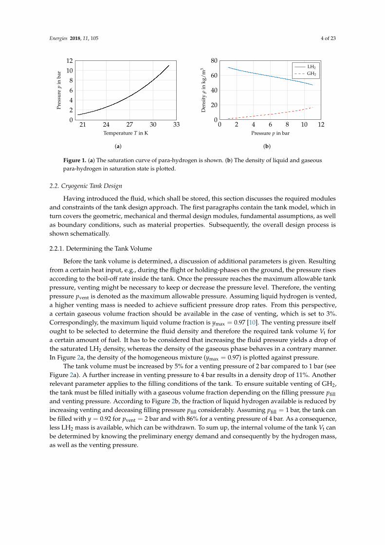
Before the tank volume is determined, a discussion of additional parameters is given. Resultingfrom a certain heat input, e.g., during the flight or holding-phases on the ground, the pressure risesaccording to the boil-off rate inside the tank. Once the pressure reaches the maximum allowable tankpressure, venting might be necessary to keep or decrease the pressure level. Therefore, the ventingpressure pvent is denoted as the maximum allowable pressure. Assuming liquid hydrogen is vented,a higher venting mass is needed to achieve sufficient pressure drop rates. From this perspective,a certain gaseous volume fraction should be available in the case of venting, which is set to 3%.Correspondingly, the maximum liquid volume fraction is ymax = 0.97 [10]. The venting pressure itselfought to be selected to determine the fluid density and therefore the required tank volume Vt fora certain amount of fuel. It has to be considered that increasing the fluid pressure yields a drop ofthe saturated LH2 density, whereas the density of the gaseous phase behaves in a contrary manner.In Figure 2a, the density of the homogeneous mixture (ymax = 0.97) is plotted against pressure.
The tank volume must be increased by 5% for a venting pressure of 2 bar compared to 1 bar (seeFigure 2a). A further increase in venting pressure to 4 bar results in a density drop of 11%. Anotherrelevant parameter applies to the filling conditions of the tank. To ensure suitable venting of GH2,the tank must be filled initially with a gaseous volume fraction depending on the filling pressure pfilland venting pressure. According to Figure 2b, the fraction of liquid hydrogen available is reduced byincreasing venting and deceasing filling pressure pfill considerably. Assuming pfill = 1 bar, the tank canbe filled with y = 0.92 for pvent = 2 bar and with 86% for a venting pressure of 4 bar. As a consequence,less LH2 mass is available, which can be withdrawn. To sum up, the internal volume of the tank Vt canbe determined by knowing the preliminary energy demand and consequently by the hydrogen mass,as well as the venting pressure.

Energies 2018, 11, 105 5 of 23
1 2 3 4 50.84
0.88
0.92
0.96
1
Pressure p in bar
Nor
m.m
ean
dens
ity
(a)
1 2 3 4 5 6 70.8
0.85
0.9
0.95
1 ymax = 0.97
Pressure p in bar
Liqu
idvo
lum
efr
acti
ony
pvent = 5 barpvent = 4 barpvent = 3 barpvent = 2 bar
(b)
Figure 2. (a) The mean storage density is shown against pressure for y = 0.97 for saturation conditions.(b) The liquid volume fraction is shown against tank pressure for various venting pressures withρ(p) = ρ(pvent) = const. (following [10]).
The pressure level, which is finally chosen, depends not exclusively on, e.g., efforts to reducethe volume. Operating the tank below atmospheric pressure, air would enter the tank leading to anexplosive mixture in the case of structural failure. Consequently, the minimum pressure should lieslightly higher than the maximum ambient pressure expected. In accordance to Verstraete [10], pmin, aswell as the filling pressure are set to 1.2 bar. The venting pressure equals the operating pressure derivedfrom Brewer [7] (pvent = 1.448 bar). From this preliminary analysis, the venting pressure should bereduced as much as possible in the investigated range leading to a minimum tank weight. Verstraetechose slightly higher venting pressures, which might result from differences in the modelling approach.
2.2.2. Tank Structure
For designing fuel storages or other components for aircraft, the principle topology and purposesmust be chosen. In the case of a cryogenic tank design, the arrangement of the tank wall, insulationand additional layers is focused on. This section briefly discusses the available options, as well asrestrictions and leads finally to the selected structure.
From the load perspective, two options in tank structure are available: integral and non-integralstructures of the airframe are provided. Integral tanks serve as a structurally-integrated part of theairframe and must be capable of withstanding loads to which the supporting structure is exposed.In contrast, non-integral tank structures are only loaded by fuel, internal pressure and dynamicloads inside the tank. According to Brewer [7], the integral tank is superior compared to thenon-integral one in terms of overall aircraft weight and more suitable accessibility of the components,e.g., for inspections. However, since this study mainly discusses a general approach in tank design,the non-integral tank is selected. The integral tank solution requires a defined airframe for every setof geometric parameters and airframe loads, which are not available or rather not included in thisstudy. From this perspective, the non-integral design offers the more suitable option to maintain theuniversal character of this paper.
Secondly, the arrangement of the components comprising the tank structure must be finalised,which covers the allocation of the insulation in this case. The insulation can be installed at the inner orouter surface of the tank wall. An installation at the inside simplifies the demands for the tank-wallmaterial itself, such as operating at ambient temperatures and enhanced accessibility. However,the stored hydrogen exposes the insulation and cripples its thermal performance, which might lead tocatastrophic failure of the insulation system. An external insulation otherwise ought to be imperviousto air, which is far easier to handle. Since maintaining the effectiveness of the insulation is most critical,the insulation is applied to the external tank wall in the following.

Energies 2018, 11, 105 6 of 23
2.2.3. Geometrical Design Description
A mathematical description of an ellipsoid ensures a most flexible geometric design, which coversellipsoidal heads and elliptical shells. Three dimensionless parameters characterise the shape of thetank by ratios of the geometric dimensions. Figure 3 shows the basic approach to describe tank shape.
c
b bls
lt
λ =lslt
φ =ac
ψ =bc
Side view Sectional view
LH2
GH2
f
a
Figure 3. Nomenclature describing the geometric tank design.
The parameters φ and ψ define the ratios between the ellipsoidal axes (see Figure 3). φ determinesthe shape of the shell, e.g., the tank shell is circular for φ = 1; whereas ψ represents the shape of thetank heads, which become hemispheres for ψ = 1. Furthermore, λ defines the ratio of the shell length lsand the overall tank length lt = ls + 2b. For λ = 0, the shell length equals zero; whereas ls → ∞ appliesfor λ → 1. With λ = 1, the system is under-constrained, because b, and therefore, ψ ought to equalzero. This results in an infinite number of solutions as long as a or c are not defined absolutely. For thisreason, λ < 1 is considered throughout the study. To sum up, these three dimensionless parametersenable a flexible tank design adaptable to predefined geometric constraints as shown exemplarily inFigure 4 for constant volume.
φ1
φ2
φ3
(a)
λ1
λ2
λ3
(b)
ψ1
ψ2
ψ3
(c)
Figure 4. (a) The tank design depends on φ with φ1 = 0.1, φ2 = 1.0, φ3 = 5.0 (λ = 0.5, ψ = 1.0).(b) The tank design depends on λ with λ1 = 0.0, λ2 = 0.5, λ3 = 0.75 (ψ = 1.0, φ = 1.0). (c) The tankdesign depends on ψ with ψ1 = 0.1, ψ2 = 1.0, ψ3 = 3.0 (λ = 0.5, φ = 1.0).
Each sub-figure in Figure 4 shows a variation in one geometric parameter while the others remainconstant. Figure 4a illustrates the dependency of the tank-shell design on φ, Figure 4b the dependencyof the tank length against λ and Figure 4c the change in tank-head shape against ψ.
To summarise the relations and procedures introduced in the previous paragraphs about thegeometric design, the flowchart in Figure 5 illustrates the input and output parameters and somesub-functions. The mechanical design is introduced in the next section.

Energies 2018, 11, 105 7 of 23
calculate tankvolume Vt
pvent pfill ymax
ρH2
EH2
mH2
calculate tankgeometry; 4 input
parameters required
φ, ψ, λ a, b, c, ls, lt
Vt
mechDesign()
geomDesign()
readInput()
Figure 5. Flow chart of the geometric design.
2.2.4. Mechanical Design
In the literature, numerous studies address materials for cryogenic applications, e.g., [4,7,17].Considering the low temperatures of saturated hydrogen and the risk of hydrogen permeation intothe tank-wall material, this choice is of crucial importance. In the case of aerospace applications,the material ought to be preferably light, as well to keep the fuel demand as low as possible. A materialdemanding in parallel a high strength, stiffness and fracture toughness is desirable. However,a material is not available today that combines all these properties satisfactorily. The followingparagraphs give firstly a brief overview about material options, before selecting the final tank-wallmaterial and discussing the tank-wall thickness calculation.
Tank-Wall Material
Mital et al. [4] performed a study comparing different materials including characteristics inallowable stress, density and critical crack size. In terms of cryogenic applications, the last twoconcerns have a significant effect on the performance of the storage system. Mital et al. [4] suggestmonolithic metals, continuous-fibre-reinforced polymer matrix composites (PMCs) and discontinuousreinforced metallic composites (DRXs) to be considered, if a practical application is applied. In general,the composite materials have issues with different coefficients of thermal expansion (CTE) andpermeation by hydrogen. Robinson [18] reported that the latter is not believed to be a technical barrierfor unlined composite tank walls, which would also enable significant weight savings compared totheir monolithic counterparts. In any case, in future aircraft applications, the performance of cryogenicstorage systems and therefore of the whole aircraft can be improved sufficiently by using tailoredcomposite materials. Because of less experience with composite materials in cryogenic pressurevessels and the resulting high safety factors, which might increase the tank-wall mass significantly,a monolithic metal is chosen in this work. These materials are well-characterised by their propertiesand well known for their characteristics throughout many applications. In a study by NASA [7],the aluminium alloy 2219 is considered as the tank material, which fulfils all requirements in the bestway compared to others investigated. This material properties offer at a cryogenic temperature of 20 Ka density of 2825 kg/m3 and a limited stress of K = 172.4 MPa under ultimate design conditions.
Calculation of Tank-Wall Thickness
In aircraft applications, one of the main objectives is to minimise weight. Because of the highdensity of the tank-wall material, the required wall thicknesses are predicted mostly in accordancewith official rules. The Guidelines in [19] provide equations determining the minimum requiredwall thickness sw induced by internal overpressure. Cylindrical shells are considered according toEquation (1):
sw =pp · di
v(2 K/S− pp
) + c1 + c2. (1)
The proof pressure pp is derived from the maximum overpressure p inside the tank by consideringa safety factor and, e.g., dynamic loads. Here, the burst pressure is applied as pp, which is defined by

Energies 2018, 11, 105 8 of 23
Brewer [7]. Further information about the weld efficiency v, the safety factor S and the allowancesc1 and c2 are provided by [19]. K is the limited stress of the material. Considering half the diameterin Equation (1), the minimum wall thickness of a sphere is obtained. Since a general tank design isapplied, the wall-thickness calculation of elliptical shells must be covered, as well. In [20], the meancircumferential stress of an elliptical shell is derived according to internal overpressure. This enables acalculation of the minimum required wall thickness for elliptical shells, which is solved iteratively.
KS≥ pp
[a + c2sw
(1 + 2
(1 + 3.6
pp
EY
(a + c2sw
)3)(
a− ca + c
))+
12
](2)
Finally, the flowchart of the mechanical design is schematically shown in Figure 6. The thermaldesign is introduced after the following paragraph.
calculate minimum wall thickness sw
material:K, EY, v, c1, c2
pvent
pp
tankgeometry
a, cthermalDesign()readInput()
mechDesign()
Figure 6. Flow chart of mechanical design.
Comparison of Tank-Wall Mass
A comparison between different shell designs is discussed qualitatively in this section. In Figure 7a,the tank-wall thickness is shown against the internal overpressure according to Equations (1) and(2) for φ = [1.0 1.2 2.0] and normalised on a spherical tank design to provide a general assertionindependent of the chosen material.
0 1 2 3 4 51
2
34
567
Internal tank overpressure in bar
Nor
m.w
allt
hick
ness φ = 1.0
φ = 1.2φ = 2.0
(a)
0 1 2 3 4 51
2
34
567
Internal tank overpressure in bar
Nor
m.t
ank-
wal
lvol
ume
φ = 1.0φ = 1.2φ = 2.0
(b)
Figure 7. (a) The minimum wall thickness is shown against the internal tank overpressure with λ = 0.7,ψ = 1.0, and Vt = 20 m3. (b) The normalised tank-wall volume is shown against the internal tankoverpressure with λ = 0.7, ψ = 1.0 and Vt = 20 m3.
Tank designs with increasing un-roundness (φ 6= 1) show a tank-wall thickness that is up tofive-times higher compared to the sphere (see Figure 7a). A cylindrical shape offers a normalisedtank-wall of about 1.1-times thicker. Since the wall thickness does not predict the tank-wall massdirectly, the tank-wall volume is evaluated additionally (see Figure 7b). The latter is proportionalto the tank-wall mass. The differences in tank-wall volume or mass are even greater, because thenon-spherical shapes offer an increased surface-area-to-volume ratio (AVR). From the mass perspective,elliptical tank designs should be avoided.

Energies 2018, 11, 105 9 of 23
2.2.5. Thermal Design
The choice of the insulation material or rather the insulation system is an essential factor for theperformance of the cryogenic storage system. A tank system that is not able to balance the pressurechange caused by heat entering from the environment and fuel consumption might operate at minimumor maximum tank pressure. Therefore, additional heating or venting is required. In aircraft applicationsgenerally, a light-weight insulation system is the favoured option, since the direct operating costsare strongly related to the aircraft weight. Finally, the insulation system ought to fulfil strict safetyrequirements, as well as the capability for comparatively easy maintenance. Before discussing theselection of the insulation system and the modelling approach, a brief overview is given about someavailable options concerning the insulation in general.
Insulation Materials
Mital et al. [4] give a review of state-of-the-art and key design challenges for insulations incryogenic environments. Various performance indices are defined to evaluate a wide range of materialsand to select the most promising insulation. One of the main issues is to design an insulation systemthat effectively prevents the air permeating into the insulation. Atmospheric gases would condensateor even solidify at the temperature of liquid hydrogen. To overcome this issue, a vacuum jacket or asystem purged by a non-condensable gas, such as helium, is necessary to displace the air. The formersolution requires maintaining a vacuum of at least 1.33× 10⁻³ bar to ensure sufficiently low thermalconductivities. Handling the CTE mismatch of the components poses another challenge. Besidesthese aspects, insulation materials ought to be ascertained, which fulfil the requirements for thermalconductivity λ, diffusivity a and expansion in the most suitable way possible. In aircraft applications,the insulation must additionally offer a density as low as possible to reduce the fuel demand andthe DOCs.
Screening λ and density properties, polymer foams and aerogels appear to be desirable.Multi-layer insulations (MLIs) provide a similar density compared to foams, while λ ≈ 10−3 W/mK,which is about two orders less compared to polymer foams. Additionally, polymer foams and aerogelsshow a low thermal diffusivity of 10−6 m2/s. MLIs exhibit a thermal diffusivity of approximately10−4 m2/s.
After additionally evaluating the thermal expansion of numerous materials, polymer foams,aerogels and MLI provide sufficient characteristics within the scope of aircraft applications [4]. In theNASA study [7], 15 candidates were screened including the aspects above and construction concepts.In terms of thermal performance and safety aspects, preferred candidates are insulation systems withrigid-cell foam for an integral and non-integral tank design. Furthermore, a hard-vacuum systemfor the non-integral tank and microspheres evacuated to 1.33× 10⁻³ bar are selected, as well [7].Verstraete [10] compares a selection of foams and MLIs for the case of a regional and long-rangeaircraft application. Accordingly, a Rohacell-foam-based insulation system is chosen providing asufficient advantage in terms of safety aspects ([7,21]) and yielding competitive tank masses comparedto MLIs [10]. The structure of the foam-based insulation system including material properties isderived from Brewer [7]. Figure 8 sketches the resulting tank-wall structure based on a non-integratedtank design.
Open-cell foam
Tank wall
MAAMF vapour barrier
Fairing
Figure 8. Non-integral structure of a foam-based insulation derived from Brewer [7].
The corresponding properties of the tank-wall material are summarised in Section 2.2.4. Rohacellfoam possesses a density of 35.24 kg/m3 and a thermal conductivity approximately between 5× 10⁻³

Energies 2018, 11, 105 10 of 23
and 35× 10−3 W/mK, which rises with increasing temperature. MAAMF is a multilayer sandwichconsisting out of a Mylar layer, followed by two aluminium foils series, another Mylar layer, and adacron or glass net fabric. The surface density of the MAAMF vapour barrier amounts to 0.225 kg/m2
and its thickness to 1.524× 10⁻⁵ m. Furthermore, a fairing is applied at the outer surface to preventthe insulation from external damage, which features a surface density of 1.304 kg/m2 and a thicknessof 1.57× 10⁻² m.
Thermal Modelling
While the temperature differs by about 300 K between the inner and outer tank wall, the significantenergy input by heat leakage leads to a considerable pressure rise. In this study, the one-dimensionaland steady-state heat equation is applied to quantify the heat flux. Convective heat transfer isconsidered at the inner and outer tank surface and thermal conduction through the insulation andtank wall. A resulting temperature distribution is shown schematically in Figure A1. In the followingparagraphs, the calculation of the heat transfer coefficient h is discussed. The heat flux is then calculatedby using the thermal resistance R obtained by the heat transfer coefficient h and the correspondingsurface area S:
R =1
h S. (3)
Internal Convection
Natural convection is applied to the internal tank surface, because a notable forced fuel-flowis not considered for the internal heat transfer. Furthermore, the natural convection is treateddifferently within the zones sketched in Figure 9.
Side view Sectional viewZone1
2
3
Figure 9. Geometric breakdown of the tank geometry.
In the listing below, the approach to calculate the Nusselt number, which is required fordetermining the heat transfer coefficient within each zone, is discussed.
Zone 1: The tank wall is heated, resulting in a generally stable boundary layer at its lowerside. Here, a correlation for the Nusselt number is applied by Raithby and Hollands [22].
Zone 2: In contrast to Zone 1, the boundary layer is destabilised at the upper side of theheated tank wall. This aspect is considered by Churchill and Chu [23] for the laminar andturbulent regime.
Zone 3: A correlation for vertical plates is proposed by Fujii and Imura [24].
Once the Nusselt number and heat transfer coefficient of the liquid phase are known within eachzone, the overall heat transfer coefficient hin,l of LH2 is calculated by
hin,l =1
Sw,l
3
∑i=1
hw,l,iSw,l,i. (4)
Sw is the wetted area of the liquid (index l) and gas (index g). To the gaseous phase,a constant Nusselt number is applied [7]. Therefore, a summation of the individual weightedcoefficients of the liquid and gaseous phase yields the total heat transfer coefficient hin of theinternal convection with

Energies 2018, 11, 105 11 of 23
hin =1
Sw
(hin,lSw,l + hin,gSw,g
). (5)
External Convection and Radiation
Considering forced convection to the outer tank surface, correlations for the Nusselt numberare given for the laminar regime by Pollhausen [25] and Kroujiline [26] and for the turbulentone by Gnielinski [27]. Additionally, heat transfer by radiation is considered, as well. A heattransfer coefficient is calculated according to Baehr and Stephan [28]. The sum of the radiativeand convective heat transfer coefficients yields the overall external heat transfer coefficient.
Thermal Conduction
The thermal conductivity of the foam depends on the foam temperature. Consequently, the foaminsulation is separated into several layers to gain reasonable results. The thermal conductivity ofthe tank-wall material remains constant.
Considering the heat transfer coefficients introduced in the previous paragraphs, the linearsystem of equations is established (see Equation (A1)). Though the heat transfer coefficients dependnon-linearly on the temperature, the unknown temperatures ought to be solved iteratively. A flowchartin Figure 10 shows the thermal design. Based on the tank geometry and the internal and externalconditions (hydrogen and air properties), the heat flux Q is determined. ~Tinit contains the temperaturesshown in Figure A1.
internal convection
pH2
cp, λ, ..
Pr, Ra
fill level
Sw, ..
thermal conduction
tankgeometry
sins, ..
material:ins., wall
λ(T)external convection
/ radiation
tankgeometry
Sex, ..
flightstate
Tair,pair,..
calculate Q iteratively byadjusting temperatures ~Tinit
~Tinit
Rin
~Tinit
Rconv
~Tinit
Rex
~Tinit
thermalDesign()
Q
~T
Figure 10. Flow chart of thermal design.
2.2.6. Internal Pressure Change
Throughout the flight, the pressure inside the tank may rise due to heat leakage. It might occur aswell that the pressure drops while the fuel is withdrawn. To predict the pressure change inside the tank,Lin et al. [29] introduce a homogeneous model assuming liquid-vapour content in homogeneous state.The model equations are obtained by applying the first law of thermodynamics and the conservationof mass. Furthermore, the internal energy u is a function of the density ρ and pressure p. Because thetank volume remains constant and refuelling is not considered during the flight, the pressure changeis given by
dpdt
=1Vt
[ρ
(∂u∂p
)ρ
]−1 [Q− mout∆hv (x + ρ∗)
](6)
with the density ratio ρ∗ defined by ρ∗ = ρg/(ρg − ρl).The derivation on the right hand side of Equation (6) yields the pressure change for a certain
amount of energy input per density. Q quantifies the power input by heat flux. Whereas energy iswithdrawn via venting or consumption in the fuel cell by the amount of mout with a certain vapourmass fraction x. In context of a phase equilibrium, the density and internal energy equal the mean

Energies 2018, 11, 105 12 of 23
properties of the fluid in two-phase conditions. Nevertheless, a homogeneous model under-predictsthe pressure change rate, because no degree of stratification is considered. For this reason, Lin et al. [29]used twice the pressure change rate provided by the homogeneous model in Equation (6), which alsoapplies to the model of this study.
The operation management is chosen according to Verstraete [10] allowing a fluctuating pressureduring the study mission. Depending on whether the pressure rise or the pressure drop prevails,the internal tank pressure might reach the maximum or minimum allowable value. If the systemoperates at maximum and venting pressure, respectively, gaseous hydrogen must be vented. In case ofoperating at minimum pressure, additional energy is necessary to boil off the liquid hydrogen andconsequently to keep the pressure from dropping further. The operation procedure regarding tankpressurisation is discussed more in detail in [7].
2.2.7. Study Mission
Determining the pressure change by use of Equation (6) requires information about the heat fluxQ and the hydrogen mass drawn from the tank mout. For this reason, a study mission is provided for amedium-haul flight including a 30-min hold period before departure and after landing. The heat fluxQ is obtained from the related altitude profile together with an atmospheric temperature model givingthe ambient temperatures and pressures. While the hydrogen is stored under cryogenic conditions,the pressure development inside the tank depends highly on the temperature outside of the tank.Therefore, extreme atmospheric conditions in terms of ambient temperature are assumed. By selectingthe Tropical Maximum Standard Atmosphere, the ground temperature at departure and arrival is setto 313.15 K with a temperature gradient of 0.0065 K/m. The troposphere commences not until 11,540 mand shows a constant temperature of 243.15 K. Compared to the International Standard Atmosphere(ISA) model, the ground temperature is exceeded by 15 K, and the temperature gradient remainsthe same.
A proton-exchange membrane fuel-cell (PEMFC) consumes hydrogen and converts its energyto supply the propulsion system with power. Based on the fuel flow of the conventional aircraft,the corresponding hydrogen mass flow is calculated for the same shaft power compared to theconventional case. In general, the current density of a PEMFC rises with the power delivered.The greater the current density increases, the more considerable is the cell voltage and efficiencydrop due to internal loss mechanisms. For this purpose, an analytical model is applied to cover thesecharacteristics. This chosen PEMFC model is as simple as possible while still covering all relevantprocesses in physically meaningful, macroscopic parameters [30]. Figure 11a shows the resultingelectric efficiency ν of the fuel cell in dependence of the normalised power. With the efficiency curveof the fuel cell and the shaft power of the medium-haul flight, the required chemical power PH2 canbe calculated (see Figure 11b). Dividing PH2 by the heat of combustion of hydrogen (see Table 1)determines the required hydrogen mass flow mout.

Energies 2018, 11, 105 13 of 23
0 0.2 0.4 0.6 0.8 10
0.2
0.4
0.6
0.8
1
Normalised electrical power P/Pmax
Elec
tric
effic
ienc
yν
(a)
0 1 2 3 40
20
40
60
80
100
Flight time t in h
Che
mic
alpo
wer
P H2
inM
W
(b)
Figure 11. (a) The electric fuel-cell efficiency is shown against normalised electrical power. (b) Therequired chemical power is illustrated against flight time.
2.2.8. Design Process
Combining the modules of geometric, mechanical and thermal design, as well as the transientpressure change model with an exemplary study mission, the hydrogen storage is dimensioned withregard to a set of input parameters. The flight profile determines the initial hydrogen mass mreq,which is required throughout the flight for propulsion. Additional fuel mass ought to be stored, if acertain mass is vented. Consequently, mf = mreq + mvent defines the fuel weight and rm = mreq/mfdenotes the ratio between required and total fuel mass. Since weight is an important measure in aircraftdesign, a mass-based evaluation parameter appears to be a suitable choice. To compare different tankdesigns, a dimensionless parameter η with
η =mf
mf + mt(7)
is suggested by Verstraete [10], which relates the fuel mass mf to the sum of fuel mass and tank massmt. The latter is defined as the sum of insulation mass mins and tank-wall mass mw. Here, a different,but more informative evaluation parameter is introduced in Equation (8) with
ηreq = η rm =mreq
mf + mtin
kgfuel,req
kgsys. (8)
Based on the required energy, the dimensionless storage density ηreq is used as a figure of meritenabling a suitable comparison between different tank designs. Basically, ηreq is the product fromη and rm. Especially, the parameter rm depends strongly on the insulation performance, because itindirectly provides the share of vented mass in total hydrogen mass. In general, an evaluation of thestorage energy density is addressed for various tank designs.
While this procedure is straight forward so far, an internal and external loop extends the designprocess. Figure 12 shows the flowchart of this tank modelling program. The internal loop adjuststhe tank volume, if the fuel mass changes in order to compensate venting losses. ε equals 1× 10⁻⁴,while the unit of Vt is m3. Proceeding from a given set of geometric parameters, the minimumrequired thickness of the insulation cannot be calculated analytically. During the design process,the maximiser sins is to be found in order to maximise ηreq, for which the outer loop is integrated.The MATLAB internal function fmincon serves as the solver to maximise ηreq. The step size tolerancefor the maximiser and the function tolerance of ηreq(sins) is set to 1× 10⁻⁵.

Energies 2018, 11, 105 14 of 23
start readInput()
geomDesign()
mechDesign()
thermalDesign() ∆Vt ≤ ε
Vt += ∆Vt
max(ηreq
)
adjust sins
end
no
yes
no
yes
Design process Internal loop External loop
Figure 12. Flow chart of the tank modelling program with the insulation thickness sins, change in tankvolume ∆Vt and tank-volume tolerance ε.
3. Results
In this section, the model is applied to, on the one hand, a parameter variation to gain generalinformation about the tank design. On the other hand, the hydrogen storage is split into a certainnumber of tanks to elaborate on the associated disadvantages. Whereas these results are obtainedby use of the mission profile given in Section 2.2.7, an additional variant of this scenario is analysed,which assumes changes in the mission parameters. Since the cryogenic tank design is most sensitiveto the duration of exposure to ambient temperatures, the hold time before the flight is shortenedand extended.
3.1. Geometrical Parameter Variation
In contrast to most of the previous studies on hydrogen storage, which discuss a dimensioningon particular aircraft geometries, our approach is a more fundamental one: here, the tank design isevaluated over a wide range of the dimensionless parameters φ, ψ and λ to draw general conclusionson the effect of shapes of tanks. With regard to the significant influence of φ on the tank-wall volume(as seen in Figure 7b), this parameter is varied between 0.5 and 1.5. Furthermore, the parameter λ isconsidered within a range of 0 ≤ λ ≤ 0.9. Finally, the parameter ψ = 1 completes the set.
3.1.1. Single Tank
Proceeding with the evaluation of this study for a single tank solution, Figure 13a shows thestorage density ηreq against φ and λ.
In total, a range in ηreq from 0.34 up to 0.7 is covered, which means that the required hydrogenmass has a maximum share of the total system mass of nearly 70%. This value applies for a sphericaltank showing a considerable advantage in wall volume. As indicated in Section 2.2.4, cylindrical shells(φ→ 1) exhibit superior storage densities compared to elliptical shapes. The former provide values forηreq above 0.6 for the complete range of λ. For slightly un-round shells, the storage density decreasesremarkably. Along the parameter λ, the sensitivity on the storage density is significantly smaller.
A qualitatively similar characteristic is shown in Figure 13b, which plots the tank mass, includinginsulation and wall mass, against the geometrical parameter φ and λ. Cylindrical shells offer a tankweight of about 103 kg, which rises significantly up to 3.5× 10³ kg for elliptical shells. The gradientsfrom cylindrical to elliptical shells, as well as for increasing shell length behave similar to theobservation in the previous paragraph. These sensitivities of the particular geometric parameters areinvestigated further in the next sections.

Energies 2018, 11, 105 15 of 23
0.5 0.75 1 1.25 1.50
0.3
0.6
0.9
Geometrical parameter φ in -
Geo
met
rica
lpar
amet
erλ
in-
0.34
0.4
0.5
0.6
0.7
Stor
age
dens
ity
ηre
qin
kgH
2,re
qkg
sys
(a)
0.5 0.75 1 1.25 1.50
0.3
0.6
0.9
Geometrical parameter φ in -
Geo
met
rica
lpar
amet
erλ
in-
1
2
3
Tank
mas
sm
tin
103
kg
(b)
Figure 13. (a) Storage density ηreq is shown against the design parameters φ and λ. (b) Tank mass mt isshown against the design parameters φ and λ.
Dependency of ηreq on φ
Figure 14a shows the storage density in dependence of φ for a selection of λ. For comparison,the sphere is added, which shows a discontinuity in tank-wall thickness and therefore in storagedensity (see Equation (1)). Changing the parameter φ ± 5% diminishes ηreq up to 23%. Slightlyelliptical shells (φ = 1.2) show a significant higher tank-wall mass compared to cylindrical ones (asseen in Figure 7). As a result, the wall thickness is highly responsible for this significant gradient.Increasing the un-roundness further the sensitivity on φ drops, which is also referable to the wallmass. Towards a greater un-roundness in general, the tanks are geometrical similar for φ and 1/φ.Differences in storage density are referable to the change rates in the wetted area of the gaseous andliquid hydrogen dependent on the filling level. Consequently, the pressure fluctuations obtain varioustemporal progresses leading to a different thermal design.
0.5 0.75 1 1.25 1.50.3
0.4
0.5
0.6
0.7sphere
Geometrical parameter φ in -
Stor
age
dens
ity
ηre
qin
kgH
2,re
qkg
sys
λ = 0.1λ = 0.5λ = 0.9
(a)
1 · 10−2 0.3 0.6 0.90.3
0.4
0.5
0.6
0.7sphere
Geometrical parameter λ in -
Stor
age
dens
ity
ηre
qin
kgH
2,re
qkg
sys
φ = 0.5φ = 1.0φ = 1.5
(b)
Figure 14. (a) The dependency of storage density on φ is shown. (b) The dependency of storage densityon λ is shown. ηreq of a sphere (φ = 1, λ = 0) represents a benchmark in both sub-figures.
Dependency of ηreq on λ
Figure 14b shows the storage density against λ for exemplary values of φ. In contrast to thesensitivity on φ, the parameter λ shows significantly less impact on ηreq. Starting from a cylindricalshell, the storage density differs by 10% over the range investigated, for φ = 0.5 by 8%, and φ = 1.5exhibits a deviation of 16% with regard to the maximum.
For a cylindrical shell (φ = 1), the optimum design lies within a flat maximum at λ ≈ 0.5.While increasing the un-roundness, the maximum shifts toward λ = 0.7 (φ = 0.5) and λ = 0.8(φ = 1.5), respectively. Picking up the motivation of this study, a particular range of λ is preferable,

Energies 2018, 11, 105 16 of 23
if the overall mass is the parameter to minimise. Although cylindrical shells are the most advantageousdesign option in terms of mass, the designs should feature a certain overall tank length.
Considering additionally Figure 15, it can be seen that designs with low lambda allow one todecrease the insulation mass that is needed (Figure 15b). This occurs despite that the tank diameterincreases for more compact tanks, resulting in thicker walls. Although, longer tanks (λ→ 1) provideslight differences in insulation thickness according to Figure 15a. Still, the insulation mass is far greatercompared to compact tanks, because of the considerable disadvantage in surface-area-to-volume ratio.Consequently, the impacts of insulation and wall mass possess opposite signs and lead to a lowersensitivity on λ compared to φ.
0.5 0.75 1 1.25 1.50
0.3
0.6
0.9
Geometrical parameter φ in -
Geo
met
rica
lpar
amet
erλ
in-
5.4
6
7
8In
s.th
ickn
ess
s ins
in10−
2m
(a)
0.5 0.75 1 1.25 1.50
0.3
0.6
0.9
Geometrical parameter φ in -G
eom
etri
calp
aram
eter
λin
-
0.3
0.4
0.5
Ins.
mas
sm
ins
in10
3kg
(b)
0.5 0.75 1 1.25 1.50
0.3
0.6
0.9
Geometrical parameter φ in -
Geo
met
rica
lpar
amet
erλ
in-
2
2.5
3
AV
Rin
m2 /
m3
(c)
0.5 0.75 1 1.25 1.50
0.3
0.6
0.9
Geometrical parameter φ in -
Geo
met
rica
lpar
amet
erλ
in-
0.1
0.2
0.3
Nor
m.i
ns.m
ass
(d)
Figure 15. (a) The insulation thickness is covered over the parameter variation. (b) The insulation massis investigated against φ and λ. (c) The surface-area-to-volume ratio is investigated over the parametervariation. (d) The normalised insulation mass is investigated against φ and λ.
Dependency of Geometric Parameters on sins
Larger insulation thicknesses can be observed for designs with decreasing λ and increasingun-roundness. Since designs of less λ provide greater wall thicknesses resulting from increaseddiameters (see Figure 4), the sensitivity on the overall mass is considerably high. Allowing a certainamount of venting, the wall mass would rise remarkable to the rise in volume. Furthermore,the density of the wall material (ρw = 35.24 kg/m3) exceeds the density of the insulations material(ρins = 2825 kg/m3) by two orders of magnitude. The point where the insulation thickness is the maindriver in storage density change lies towards thicker insulations rather than for designs providingsmaller tank diameters. The same applies for designs with a considerable un-roundness.
The insulation mass depends directly on the AVR (see Figure 15b,c). The overall change in AVR isgreater than change in sins, so that the absolute insulation mass is in favour of the AVR. Nonetheless,the tank mass is mainly driven by the wall mass as shown in Figure 15d. This is because, on theone hand, the insulation mass only amounts to 10%–35% of the tank mass. On the other hand,

Energies 2018, 11, 105 17 of 23
the qualitative characteristic of the normalised insulation mass is similar to the absolute insulationmass, since less insulation mass comes along with smaller shares of the total mass, but mainly drivenby the tank-wall mass.
Furthermore, compact geometries providing a superior AVR do not represent the best options interms of storage density (see Figure 15c). With regard to their comparatively thick walls resulting fromincreased diameter, they offer considerably lower storage densities. From this study, tank designs withλ between 0.6 and 0.8 are suggested in order to minimise the tank mass compared to the required fuelmass. The spherical design marks an exception according to a less thick wall and offers the higheststorage density. Generally, cylindrical shells show their advantage compared to elliptical ones.
Dependency of sins on Storage Density and Venting
As the top-down approach discussed the results of the parameter study only, a brief, morein depth view shows the dependency of the insulation thickness on the storage density with anexample. Figure 16 illustrates ηreq, η and rm over a certain range of the insulation thickness sins forselected parameters.
1 5 10 15 20 250.5
0.6
0.7
0.8
0.9
1
ηreq,max
sins in 10−2 m
Dim
ensi
onle
sspa
ram
eter
ηreq
η
rm
(a)
1 5 10 15 20 250.5
0.6
0.7
0.8
0.9
1
ηreq,max
sins in 10−2 m
Dim
ensi
onle
sspa
ram
eter
ηreq
η
rm
(b)
1 5 10 15 20 25
0.5
0.6
0.7
0.8
0.9
1
ηreq,max
sins in 10−2 m
Dim
ensi
onle
sspa
ram
eter
ηreq
η
rm
(c)
Figure 16. (a) The dependency of storage density on sins for λ = 0.1, φ = 1 is shown. (b) Thedependency of storage density on sins for λ = 0.5, φ = 1 is shown. (c) The dependency of storagedensity on sins for λ = 0.5, φ = 1.25 is shown.
Whenever fuel is vented, the ratio of fuel mass and total mass (η) is higher than ηreq (storagedensity), because the total hydrogen mass mf exceeds the required fuel mass mreq by the amount ofmvent. Furthermore, maximising the storage density is not essentially associated with mvent = 0 kg,if the boundary conditions basically allow a certain amount of venting. A share in the order of 1–5% ofthe vented losses in the total hydrogen mass leads to an optimum design regarding the storage density.As indicated in Figure 16, the curve is flat around the maximum characterises ηreq, which offers somescope in designing the insulation system. To illustrate this behaviour by some examples, Figure 16shows storage densities as a function of the insulation thickness for three parameter sets. The plots inFigure 16a,b differ in the value of λ, whereas Figure 16c shows an increased φ, but with the same λ asthe plot in Figure 16b.
Especially for greater φ, the maximum becomes even flatter, so that the tolerance in the outerdesign loop ought to be significantly less. Nonetheless, proceeding from the maximum, the ventedhydrogen mass rises significantly less towards thicker than thinner insulations. Consequently, highlyunder-estimated heat leakage might result in considerable boil-off losses, which decrease the availablefuel mass, as well, if the tank is designed close to this critical gradient.
Interim Conclusion
To sum up, introducing materials for the mechanical design superior in density and strength incryogenic environments promises great enhancement in tank weight due to noticeably high density andshares on the overall tank weight. Especially compact designs will gain the most benefit by improving

Energies 2018, 11, 105 18 of 23
the tank-wall material. Otherwise, longer tanks possess a greater share of the insulation mass inoverall tank weight. Cylinders offer a comparable high share of approximately 30% in insulationmass, because the wall thickness is less compared to elliptical shells. The latter otherwise show sharesbetween 10% and 20%. Improving the insulation system would lead to a considerable increase in ηreq
for those geometries.
3.1.2. Multiple Tanks
For geometrically-similar designs, a decrease in volume correlates with an increase in AVR ingeneral. Therefore, a higher share of insulation mass on tank mass is expected. A volume variationis performed to investigate this effect. The power profile (see Figure 11b) is multiplied by the factor1/2n with n = 0, 1, ..., 4. For constant n, each tank stores the same amount of energy, and the fuel iswithdrawn equally. Consequently, the ratio between volume and outlet mass-flow remains constant.For assessing the impact of multiple tanks, the storage density ηreq of the single tank (n = 0) in theprevious section can directly be compared to the multiple tank solution. Figure 17 addresses thecomparison of the single and multiple tank solution with regard to ηreq.
0.5 0.75 1 1.25 1.50.2
0.3
0.4
0.5
0.6
0.7
Geometrical parameter φ in -
ηre
q
n = 0n = 4
(a)
0 1 2 3 40.2
0.3
0.4
0.5
0.6
0.7
Tank splitting parameter n
ηre
q,m
ax
0.5
0.6
0.7
0.8
0.9
1
Nor
m.s
tora
gede
nsit
y
λ = 0.1λ = 0.5λ = 0.9
(b)
Figure 17. (a) The comparison between ηreq of single and multiple tank solution (n = 4) is shown forλ = 0.5. (b) The maximum storage density and change in storage density is investigated (φ = 1).
Figure 17a plots the storage density against φ. The loss in storage density is highest for cylindricalshells when storing the fuel in various tanks; this holds as well relatively. Since the reduction intank-wall mass is considerable less compared to elliptical tanks, this effect does not compensate thedisadvantage along with increasing AVR and accordingly in insulation mass. Nevertheless, φ = 1 isstill the favourable option. The density is lower at all φ for the split tank version, because the AVRgains increasingly more impact when reducing the overall tank size. Therefore, designs providinga higher AVR in general suffer the most with regard to the storage density (φ = const.). This trendis more clearly shown in Figure 17b, where the absolute maximum storage density and the changein maximum storage density normalised on ηreq(n = 0) are plotted and evaluated for different λ
and φ = 1. The advantage of longitudinal tanks compared to compact designs is outweighed by thedisadvantages associated with increasing n. While increasingly compact designs are affected less by atank splitting, the optimal value for λ shifts towards zero. Although the design with λ = 0.1 and n = 0shows less storage density than the tank with λ = 0.5, it provides the smallest change rate, leading toa more competitive design for increasingly smaller tanks.
Splitting or rather reducing the tank size decreases the storage density over the whole rangeof the screened parameters. Further investigations appear to be thinkable against the backgroundthat multiple tank solutions are feasible with regard to various operating strategies. For example,a different withdrawal of the fuel might be advantageous in terms of tank insulation design, balancingthe filling or the pressure levels, can be suitable as well. Though these hypotheses are not part of thepresent study, this should trigger further investigations.

Energies 2018, 11, 105 19 of 23
3.2. Hold Time
Since the pressure development inside the tank depends on the heat input, reducing the time onthe ground appears to be desirable. For this reason, the impact of the hold time before departure andafter arrival is investigated. Commencing with the time period before the flight, Figure 18a shows ηreq,η and rm against various times.
0 30 60 1200.6
0.62
0.64
0.66
0.68
Hold time before departure in min
ηre
q
ηreq
η
rm
0.93
0.94
0.95
0.96
0.97
r m
(a)
0 30 60 1200.52
0.54
0.56
0.58
0.6
0.62
0.64
0.66
Hold time before departure in min
ηre
qλ = 0.1λ = 0.5λ = 0.9
(b)
0 30 60 1200.52
0.54
0.56
0.58
0.6
0.62
0.64
0.66
Hold time after arrival in min
ηre
q
λ = 0.1λ = 0.5λ = 0.9
(c)
Figure 18. (a) The dependency of ηreq, η and rm on hold time before departure is shown (φ = 1, λ = 0.5).(b) The dependency of storage density on hold time before departure is shown for various λ (φ = 1).(c) The dependency of storage density on hold time after arrival is shown for various λ (φ = 1).
The curves drop approximately linearly over the time investigated. With longer hold times,rm decreases from 95.9%–94.4%. Therefore, a rising amount of venting is accepted as opposed toa further increase in insulation thickness, in order to maximise the storage density. Since morefuel mass is stored, η decreases as well. Combining η and rm, the storage density decreases from0.648–0.623 kgH2 /kgsys.
Figure 18b,c plots ηreq against the hold time before departure and after arrival, respectively.The design with λ = 0.9 shows the most significant drop in storage density, because it providesa comparatively high AVR. The other two curves behave equally, featuring a similar gradient.In addition, the hold time after arrival affects the storage density similar to the time before departure.Only the curve for λ = 0.1 shows a slightly higher gradient. Since the tank is almost empty, the vapourmass fraction is significantly greater than provided by a refuelled tank. The derivation ∂u/∂p(see Equation (6)) is less for gaseous hydrogen, meaning a smaller amount of energy is requiredfor a certain pressure rise compared to liquid.
This evaluation shows that reducing the hold time leads to less tank and fuel weight. Beside froman exclusive aircraft-related tank design, improving the turn-around time on ground is additionallydesirable from this perspective.
3.3. Comparison to Kerosene Tanks
To put the presented results in context, the liquid hydrogen tanks are compared to kerosenetanks in terms of energy density and mass. Based on the presented results, an exemplary cylindricalhydrogen tank (λ = 0.5) can achieve a storage density of around 0.64. This corresponds to a gravimetricenergy density of approximately 21 kWh/kg, which is significantly above 8.9 kWh/kg obtained bykerosene tanks. Although the tank reduces the effective energy density of hydrogen stronger comparedto kerosene tanks (η = 0.75), the storage density is still 2.35-times higher. Besides the advantage ingravimetric density of hydrogen, the fuel savings by applying a fuel cell must be taken into account, aswell. According to the mission profile in this study, the required hydrogen mass of 1912 kg is only28% of the required kerosene mass, which amounts to 6890 kg. Consequently, the mass of the storagesystem including mass of kerosene (9187 kg) is nearly three-times the mass of the LH2 system (2988 kg).Although further requirements, such as maintaining cryogenic temperatures inside the tank, safety

Energies 2018, 11, 105 20 of 23
periphery and heat exchangers, are not covered here, LH2 tanks are highly competitive with kerosenetanks. If future materials are applied, the gravimetric energy density improves further.
Comparing the densities of liquid hydrogen and kerosene, the volume of LH2 is 11.4-times thevolume of kerosene for the same mass. Applying the fuel mass, which is required for the exemplarymission, the factor is reduced to 3.34. Here, a mean density of 67.3 kg/m3 for hydrogen is chosenconsidering the gas fraction available for venting. The higher gravimetric energy density and theefficient fuel cell reduce the disadvantage in required hydrogen volume significantly. Although thevolume is still tripled compared to kerosene, this technical challenge is manageable while introducingnew airframe concepts.
4. Conclusions
In this study, a design tool for cryogenic hydrogen tanks is presented. Analysis of the sensitivityof the storage density shows the importance of using specific design missions for tank design andconsidering the hydrogen mass required for venting. Therefore, cryogenic hydrogen tanks ought to betailored to a specific application, including new aircraft designs, as well as flight missions. This applies,because the insulation design depends on the overall mission profile. Additionally, the tank weighthas a considerable share of the fuel weight.
Finding a universal solution in overall tank design is more challenging compared to kerosenetanks, because of the insulation design, which is influenced by numerous factors. This might resultin over-sizing the insulation system for some applications. Therefore, an important aspect for futureresearch is the investigation of tank structure integration into the airframe to reduce the disadvantagein unified thermal systems and increasing the energy density. Nonetheless, cryogenic hydrogen storageand a fuel cell-supplied propulsion system appear to be superior to the conventional system withregard to mass that has to be considered for storage. The disadvantage of liquid hydrogen comparedto kerosene with regard to volume ought to be investigated in the context of the whole aircraft design.Although the integration of hydrogen tanks into common aircraft appears to be challenging or eveninappropriate, future aircraft will be designed to accommodate new storage technologies. For thisreason, further investigations covering the whole propulsion system are highly suggested underconsideration of new design approaches.
Acknowledgments: We would like to acknowledge the support of the Ministry for Science and Culture of LowerSaxony (Grant No. VWZN3177) for funding the research project “Energy System Transformation in Aviation” inthe initiative “Niedersächsisches Vorab”. Further acknowledgements go to Bekir Yildiz for providing the authorswith the mission data.
Author Contributions: Christopher Winnefeld programmed the design tool, produced and analysed the resultsand wrote the main parts of the manuscript; Thomas Kadyk applied the analytic fuel cell model and wasinvolved in advising during the study. Boris Bensmann elaborated the story line and objectives of the studytogether with Christopher Winnefeld and contributed in a large part to critical discussions. Ulrike Krewer andRichard Hanke-Rauschenbach contributed by drafting and critical revisions.
Conflicts of Interest: The authors declare no conflict of interest.
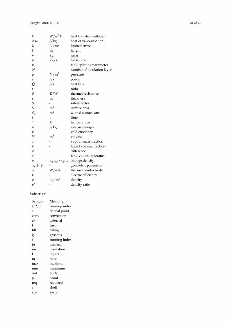
List of Symbols
The following symbols are used in this manuscript:
Variables
Symbol Unit Meaninga, b, c m ellipsoidal axisc1, c2 m allowanced m diameterE J energyEY N/m2 Young’s modulusf - relative filling level
Energies 2018, 11, 105 21 of 23
h W/m2K heat transfer coefficient∆hv J/kg heat of vapourisationK N/m2 limited stressl m lengthm kg massm kg/s mass flown - tank-splitting parameterN - number of insulation layerp N/m2 pressureP J/s powerQ J/s heat fluxr - ratioR K/W thermal resistances m thicknessS - safety factorS m2 surface areaSw m2 wetted surface areat s timeT K temperatureu J/kg internal energyv - veld efficiencyV m3 volumex - vapour mass fractiony - liquid volume fraction∆ - differenceε - tank-volume toleranceη kgfuel/kgsys storage densityλ, φ, ψ - geometric parameterλ W/mK thermal conductivityν - electric efficiencyρ kg/m3 densityρ∗ - density ratio
Subscripts
Symbol Meaning1, 2, 3 running indexc critical pointconv convectionex externalf fuelfill fillingg gaseousi running indexin internalins insulationl liquidm massmax maximummin minimumout outletp proofreq requireds shellsys system

Energies 2018, 11, 105 22 of 23
t tankvent ventingw wall
Abbreviations
Symbol MeaningAVR surface-area-to-volume ratioCTE coefficients of thermal expansionDOC direct operating costGH2 gaseous hydrogenISA international standard atmosphereLH2 liquid hydrogenMLI multi-layer insulationPEMFC proton-exchange membrane fuel-cell
Appendix A
In Figure A1, the layer arrangement of the tank structure and exemplary temperature distributionwithin the tank wall and insulation are shown. Furthermore, the different types of heat transfer areillustrated, i.e, the convective and conductive heat transfer.
sins,i sins,i sins,i sins,iTH2
TwTins,1
Tins,2
Tins,3Tins,N Tskin
Tair
sw sins
internalconvection thermal conduction
external convection/ radiation
T
x
Figure A1. Schematic layer arrangement and prior temperature distribution for N = 4.
In Equation (A1), the linear system of equations is shown to obtain the heat flux.
0 =
−1 1 0 · · · · · · · · · 0
0 −1 1 0. . . . . .
...... 0 −1 1
. . . . . ....
.... . . . . . . . . . . . 0
......
. . . . . . . . . −1 1 00 · · · · · · · · · 0 −1 1
TH2
Tw
Tins,iTins,i+1
...Tins,NTskinTair
−
Rin
Rw
Rins,iRins,i+1
...Rins,N
Rex
Q (A1)
References
1. Boeing. Current Market Outlook 2017–2036; Boeing: Chicago, IL, USA, 2017.2. Airbus. Global Market Forecast: Growing Horizons 2017–2036; Airbus: Toulouse, France, 2017.3. European Commission. Flightpath 2050: Europe’s Vision for Aviation; European Commission: Brussels,
Belgium, 2011.4. Mital, S.K.; Gyekenyesi, J.Z.; Arnold, S.M.; Sullivan, R.M.; Manderscheid, J.M.; Murthy, P.L.N. Review of
Current State of the Art and Key Design Issues with Potential Solutions for Liquid Hydrogen Cryogenic StorageTank Structures for Aircraft Applications; National Aeronautics and Space Administration: Cleveland,OH, USA, 2006.

Energies 2018, 11, 105 23 of 23
5. Colozza, A.J. Hydrogen Storage for Aircraft Applications Overview; NASA CR-2002-211867; National Aeronauticsand Space Administration: Cleveland, OH, USA, 2002.
6. Gong, A.; Verstraete, D. Fuel Cell Propulsion in Small Fixed-Wing Unmanned Aerial Vehicles: CurrentStatus and Research Needs Int. J. Hydrogen Energy 2017, 42, 21311–21333.
7. Brewer, G.D. Hydrogen Aircraft Technology, 1st ed.; CRC-Press: Boca Raton, FL, USA, 1991.8. Brewer, G.D.; Morris, R.E. Final Report: Study of LH2 Fueled Subsonic Passenger Transport Aircraft; NASA
CR-144935; National Aeronautics and Space Administration: Cleveland, OH, USA, 1976.9. Airbus. Liquid Hydrogen Fuelled Aircraft—System Analysis; Airbus: Toulouse, France, 2003.10. Verstraete, D. The Potential of Liquid Hydrogen for Long Range Aircraft Propulsion. Ph.D. Thesis, Cranfield
University, Cranfield, UK, 2009.11. Peters, R. Brennstoffzellensysteme in der Luftfahrt, 1st ed.; Springer: Berlin/Heidelberg, Germany, 2015.12. Heinze, W.; Hansen, L.U.; Werner-Spatz, C.; Horst, P. Gesamtentwurfsuntersuchungen zu BWB-
Frachtflugzeugen mit alternativen Treibstoffen. In Proceedings of the Deutscher Luft- und Raumfahrtkongress,Aachen, Germany, 8–10 September 2009.
13. Smith, H. Airframe Integration for an LH2 Hybrid-Electric Propulsion System. Aircr. Eng. Aerosp. Technol.Int. J. 2014, 86, 562–567.
14. NIST. Thermophysical Properties of Fluid Systems; National Institute of Standards and Technology:Gaithersburg, MD, USA, 2017.
15. Sehra, A.K.; Whitlow, W., Jr. Propulsion and Power for 21st Century Aviation. Prog. Aerosp. Sci. 2004, 40,199–235.
16. Leachman, J.W.; Jacobsen, R.T.; Penoncello, S.G.; Lemmon, E.W. Fundamental Equations of State forParahydrogen, Normal Hydrogen, and Orthohydrogen. J. Phys. Chem. Ref. Data 2009, 38, 721–748.
17. Züttel, A. Materials for Hydrogen Storage. Materialstoday 2003, 6, 24–33.18. Robinson, M.J.; Eichinger, J.D.; Johnson, S.E. Hydrogen Permeability Requirements and Testing for Reusable
Launch Vehicle Tanks. In Proceedings of the 43th AIAA/ASME/ASCE/AHS/ASC Structures, StructuralDynamics And Materials Conference, Denver, CO, USA, 22–25 April 2002.
19. Dampfkesselausschuss, D. Technische Regeln für Dampfkessel; Verband der TÜV e.V.: Berlin, Germany, 2010.20. Schwaigerer, S.; Mühlenbeck, G. Festigkeitsberechnung, 5th ed.; Springer: Berlin/Heidelberg, Germany, 1997.21. Anthony, F.M.; Colt, J.Z.; Helenbrook, R.G. Development and Validation of Cryogenic Foam Insulation for LH2
Subsonic Transports; National Aeronautics and Space Administration: Cleveland, OH, USA, 1981.22. Raithby, G.D.; Hollands, K.G.T. Natural Convection. In Handbook of Heat Transfer, 3rd ed.; Rohsenow, W.M.,
Hartnett, J.P., Cho, Y.I., Eds.; McGraw: New York, NY, USA, 1998; Chapter 4.23. Churchill, S.W.; Chu, H.H.S. Correlation Equations for Laminar and Turbulent Free Convection from a
Vertical Plate. Int. J. Heat Mass Transf. 1974, 18, 1323–1329.24. Fujii, T.; Imura, H. Natural-Convection Heat Transfer From a Plate with Arbitrary Inclination. Int. J. Heat
Mass Transf. 1972, 15, 755–767.25. Pollhausen, E. Der Wärmeaustausch zwischen festen Körpern und Flüssigkeiten mit kleiner Reibung und
kleiner Wärmeleitung. J. Appl. Math. Mech. 1921, 2, 115–121.26. Kroujiline, G. Investigation de la couche-limite thermique. Tech. Phys. USSR 1936, 3, 183–194.27. Gnielinski, V. Berechnung mittlerer Wärme- und Stoffübergangskoeffizienten an laminar und turbulent
überstömten Einzelkörpern mit Hilfe einer einheitlichen Gleichung. Forsch. Ingenieurwes. 1975, 41, 145–153.28. Baehr, H.D.; Stephan, K. Wärme- und Stoffübertragung, 9th ed.; Springer: Berlin/Heidelberg, Germany, 2016.29. Lin, C.S.; Van Dresar, N.T.; Hasan, M.M. A Pressure Control Analysis of Cryogenic Storage Systems.
J. Propuls. Power 1991, 20, 480–485.30. Kulikovsky, A.A. A Physically–Based Analytical Polarization Curve of a PEM Fuel Cell. J. Electrochem. Soc.
2014, 161, F263–F270.
c© 2018 by the authors. Licensee MDPI, Basel, Switzerland. This article is an open accessarticle distributed under the terms and conditions of the Creative Commons Attribution(CC BY) license (http://creativecommons.org/licenses/by/4.0/).