Voltage regulator for generators Instruction Manual V1.2.1
16
LX321 Voltage regulator for generators Instruction Manual V1.2.1 Product version V2.2.1.0
-
Upload
khangminh22 -
Category
Documents
-
view
7 -
download
0
Transcript of Voltage regulator for generators Instruction Manual V1.2.1

LX321 Voltage regulator for generators
Instruction Manual V1.2.1
Product version V2.2.1.0

Manual V1.2.1 Page 2 of 16
Warnings And Commissioning information
- Check the isolation of the generator windings before installation.
Poor isolation will cause damage to the AVR and dangerous situations for persons.
- The system should not be installed, operated, serviced or modified except by qualified personnel who understand the danger of electric shock hazards and have read and understood the user instructions.
- Never work on a LIVE generator. Unless there is another person present who can switch off the power supply or stop the engine.
- Dangerous voltages are present at the voltage regulator board. Accidental contact with live conductors could result in serious electrical shock or electrocution.
- Disconnect the power source before making repairs, connecting test instruments, or removing or making connections to the voltage regulator or generator.
- Defects in the generator or AVR may cause consequential loss. Precautions must be taken to prevent this from occurring.
- The unit should be installed with respect to the environmental specifications as well as the rules mentioned in the General installation information.
- For safety reasons the voltage level potentiometers are best turned completely counter clockwise in order to start at the lowest possible voltage.
- Never change the rotary switch or dipswitch settings during operation.- Never apply supply voltage when generator is not running, unless exciter field is disconnected.
HAZARDOUS VOLTAGES.
DO NOT OPERATE WHEN NOT FAMILIAR WITH GENERATORS.
Revision history
The manual does not cover all technical details of the product. Specifications may be modified by the manufacturer without notice. For further information, the manufacturer should be contacted.

Manual V1.2.1 Page 3 of 16
Table of contents
General description
The LX321 is designed as a replacement for the MX321, providing optimal flexibility and configurability as is reflected by the additional capabilities of the AVR. Nevertheless installation, maintenance and adjustment don’t require special application software. The AVR is protected from the environment by a PUR coating.

Manual V1.2.1 Page 4 of 16
Absolute maximum rating
Manual V1.2.1 Page 5 of 16
Modes of control I
UFRO 0,1,4,5,8,9Buildup (PMG)
Time Status
LED
Status
Contact
0V
Idle Voltage buildup Stable
200V195V
On
Off
On
Off(C-NO)
Buildup time is adjustable with advanced settings.
01
456
9
Se
nsin
g v
olt
ag
e
(6,7,8)
32
78
Se
nsin
g v
olt
ag
e
(6,7,8)
32
78
Ge
nera
tor
cu
rre
nt
Current Limit po
sition 2 (100
%)
Current S1-S2 (U)
Se
nsin
g v
olt
ag
e
(6,7,8)
32
78 3
2
78

Manual V1.2.1 Page 6 of 16
Modes of control II
Se
nsin
g v
olt
ag
e
(6,7,8)
32
78
Se
nsin
g v
olt
ag
e
(6,7,8)
32
78
Se
nsin
g v
olt
ag
e
(6,7,8)
32
78
Ge
ne
rato
r vo
lta
ge
Adv.
Setting
1,
,1
10,1
15,1
20,1
25,1
30,1
35,1
40,1
45
32
78
Ge
ne
rato
r c
urr
ren
t
Current S1-S2 (U)
32
78
32
78
Cu
rren
t
Ge
nera
tor
Vo
ltag
e
32
78

Manual V1.2.1 Page 7 of 16
Modes of control III
Co
sp
hi
Adv.
Setting
32
78
Se
ns
ing
vo
lta
ge
(6,7,8)
32
78
Adv.
Setting
Se
ns
ing
vo
lta
ge
(6,7,8)
32
78
Adv.
Setting
Min
imu
m e
xcit
ati
on
Adv.
Setting
32
78

Manual V1.2.1 Page 8 of 16
Quick reference I
UFRO
Constant voltage control
Constant voltage control
0-100% Voltage control with A1-A2
0-100% Current control with A1-A2
Constant voltage control
Constant voltage control
0-100% Voltage control with A1-A2
0-100% Current control with A1-A2
VPH (Volt per Hertz) control
8 V/Hz
16 V/Hz
-
8 V/Hz
8 V/Hz
16 V/Hz
-
8 V/Hz
8 V/Hz
VPH (Volt per Hertz) control 8 V/Hz
UFRO (Modes of control)(Page 5,6,7)
47 Hz
47 Hz
-
47 Hz
57 Hz
57 Hz
-
57 Hz
-
-
Underspeed0 1
3
4
2
56
78
9
Linked Open @ Unom=400V
SlopeTH1 – TH2
57Hz
57Hz
-
57Hz
47Hz
47Hz
-
47Hz
-
-
0
1
2
3
4
5
6
7
8
9
Voltage
Coarse Fine
-3V +3V150V 250V
Droop
0% 100%
Current Limit
0 = 60%1 = 80%2 = 100%3 = 125%4 = 150%
5 = 175%6 = 200%7 = 250%8 = 300%9 = Unlimited
Normal mode
0% 100% 0% 12.5%
Min. Exc.
at Cosphi
Trim Min. exc. φ
Trim / Min. exc. φ
% of AVR supply% of input A1-A2
Adv.
Setting
Cosphi / Steepness
Normal mode VPH mode
Cosphi Steepness
0.8Cap
0.6Ind
1
3V/Hz 17V/Hz
Adv.
SettingStatus Led
Error
Over voltage1
Over current2
Over excitation3
4 AVR over temperature
5
6
Generator over temperature
7
Phase loss or Phase sequence
Loss of current sensing during PF control
n
Idle
Voltage control
Current controlPF control
GreenBlink
GreenContinuous
OrangeBlink
OrangeContinuous
Buildup
Error: (n) numberof red blinks
Green withRed blink
Phase sequenceUnderspeed (<25Hz.)
RedContinuous
Factory settings
Link:
1-2, K1-K2, TH1-TH2, CAN1-CAN2
Control modeSensingUnderspeedDroopCurrent LimitExc. TripProp. GainInt. TimeTrimCosphi
: Constant voltage: 200V: 47Hz. (slope 8V/Hz.): 0V: Unlimited (Pos. 9): 6A: 50%: 50%: 0%: 1
Advanced settings
Status contact
Loss of excitation during PF control
8
0 1
3
4
2
56
78
9
Max. rating: 24Vdc/4Adc or 230Vac/10Aac
Minimum Rfield
Minimum field resistance
Formula
Supply input x √2 (VDC)Field resistance (Ω) ≥
20
200V
Exc. Trip
6A1A
PFC on/off
PF control
Temperature or Underspeed
KTY81-110.
Temp. sensor
(1k8..3kΩ)
Underspeed
selection
47/57 Hz.
Link
TH1
TH2
PF1
PF2
>3K
OPT2
OPT1Programming
(Page 10,11)
FaultIn operation
NONO
CC
NC NC
Adv.
Setting
Stability
Prop. Gain
Int. time
- +
- +
( x Loop gain)
( x Loop gain)
Adv.
Setting
Adv.
Setting
Fast Slow

Manual V1.2.1 Page 9 of 16
Quick reference II
Exciter
0 .. 3.7Adc
- +
Check Formula
Remote adjust
Max. value: 5KΩ
Digital input
20 .. 220Vac
PMG
AVR supply Sensing
0 .. 250Vac
U-V-W
clockwise
0 .. 4.7KΩ
Link
Max. rating: Intermitted 10A < 10s.
Max. rating: Field forcing 20A <1s.
CAN Interface
Analoque output
0 .. 10Vdc
(max. 20mAdc)
R > 500Ω
Can termination
Data-logger
USBRS232
AVRAssistant
Can
Can-USBinterface
Trip coil
R ≥120 Ω
Max. rating: 60Vdc / 0.7Adc
Accessories input
UFRO (Modes of control)
Constant voltage & VPH0..100% Voltage control0..100% Current control
Advanced settingsVoltage matchCosphi setpoint
Max. rating: -5V .. +10V
(-5V .. +5V)(0V .. +10V)(0V .. +10V)
(+6V .. +10V)(-5V .. +10V)
V+-
+ -
B0 B1
+
A1 A2
Current sensing
Droop & PFCurrent Limiting
S2S1
1AU phase
S2S1U W
0.5AW phase
-
1 2
Link
K2 K1
Excitation on/off
P2 P3 P4 6 7 8
(W) (V) (U)
XX X
Exciter field
1
46
9
1
46
9
Trim/ Min. exc. φ
Droop

Manual V1.2.1 Page 10 of 16
Advanced settings I
Advanced settings flowchart
Advanced settings can be adjusted according the flowchart.Advanced settings are available with firmware version 3.0, 5.0 and higher than 5.0.
Begin
Done
Moresettings?
(Generator stopped !)
Programming
Blink red(Stored)
Place Link for 2s.
Reconnect wires
AVR
supply
Remember settings
UFRO
Current
Limit
Start situation
Set back settings
UFRO
Current
Limit
Selection
Example: Voltage match enable
UFRO
Current
Limit
Position 7
(Example)
Position 1
(Example)
(Example)
(Example)
(Example)
(Example)
AVR
On/Off
0 1
3
4
2
56
78
9
0 1
3
4
2
56
78
9
0 1
3
4
2
56
78
9
0 1
3
4
2
56
78
9
0 1
3
4
2
56
78
9
0 1
3
4
2
56
78
9
OPT1
OPT2
18..30V+ -
Open S1
Selection example
Loopgain
(MULT)
0 1
3
4
2
56
78
9
UFRO
CurrentLimit
0.050
Loop gain (x 0.050)
0 1
3
4
2
56
78
9
Note
Change of setting
only take effect
after restart
Reset power supplyS1 S1
Enable power supply

Manual V1.2.1 Page 11 of 16
Advanced settings II
UFRO
Current
Limit
Description
Extra multiplication factor for proportional gain. Only applied during field flash.
Extra multiplicationfactor for proportional gain.
Buildup gain
(MULT)
Loopgain
(MULT)
Initial setpoint from wich the AVR ramps up after field flash.Setpoint in % of Unom.
Enable or disable the required protections.
The speed by which the AVR ramps from the minimum setpoint to the nominal setpoint.
Specialapplication
Enable or disable the required modes of operation
Initialvoltage,SE Mode.
Protections Buildup time
@ startup
Option output
Accessory input modes
Operation modes
Enable or disable the required modes of operation
0.1(slowest)
0.2
0.5
1
4
6
8
10
14(fastest)
1.000(fastest)
0.200
0.100
0.066
0.050
0.040
0.033
0.028
0.025
0.022(slowest)
2
0%
37.5%
15%
22.5%
30%
10%
45%
52.5%
60%
67.5%
Excitation loss
disabled
Phase loss disabled
Current loss
disabled
Excitation loss
enabled
Phase loss enabled
Current loss
enabled
Do not use *
Do not use *
Exc. stop after errorenabled
Exc. stop after errordisabled
1 sec.
3 sec.
7 sec.
10 sec.
20 sec.
30 sec.
45 sec.
60 sec.
Cosphi setpoint
0..255 sec.
5 sec.
Voltage matchdisabled
Inverted output disabled
Cosphi setpointdisabled
Do not use *
Voltage match ** enabled
Cosphi setpointenabled
Inverted output enabled
Advanced settings table
* Used only by manufacturer. Contact for more information.
Default factory settings are highlighted in table. By setting both UFRO and Current Limit at position 9 and placing the programming jumper, will reset the AVR to default factory settings.
VPH Modedisabled
Min. Exc.at Cosphidisabled
VPH Modeenabled
Min. Exc.at Cosphienabled
** LX_VMA unit required.
Do not use *
Do not use *
Do not use *
0 1
456
90 1
456
90 1
456
90 1
456
90 1
456
90 1
456
90 1
456
90 1
456
9
0 1
456
9
0 1
456
9
0 1
456
9
0 1
456
9
0 1
456
9
0 1
456
9
0 1
456
9
0 1
456
9
0 1
456
9
0 1
456
9
Manual V1.2.1 Page 12 of 16
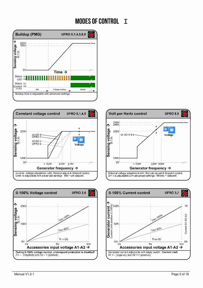
Wiring diagram I
AVR with half phase tap

Manual V1.2.1 Page 13 of 16
Wiring diagram II
AVR with sensing transformer

Manual V1.2.1 Page 14 of 16
Protections
When a fault condition is active for more than time T1, the status contact deactivates. When a fault condition is active for more than time T2, the fault is indicated by the status led with (N)umber of red blinks. When protection “Excitation stop” is enabled, the AVR stops field excitation due to a fault. To reset the fault , open contact K1-K2 for at least 10s, the AVR returns in idle mode
CAN Interface
Fault condition
Time
Status
LED
Status
Contact
<T1
Error Level
On
Off
OnOff
(C-NO)
Excitation stop after fault condition is default disabled!
For activation see Advanced settings.
Operation
value
T2
T1
<T2
T1 N
Excitation
stop
(Optional)
Adv.
Setting

Manual V1.2.1 Page 15 of 16
General installation information Absolute Maximum Ratings - The Absolute Maximum Ratings are those limits for the device that, if exceeded, will likely damage the device. Exceeding the
absolute maximum ratings voids any warranty and/or guarantee. Mounting
Mounting of the product should be done in such a way that: - the absolute maximum ambient temperature rating of the product will never be exceeded. - maximum cooling (direction of cooling ribs and direction of airflow) is achieved. - Mounting no humid air can flow through the product or condensation occurs. - dust or other materials or residue will not remain in or on the product. - the maximum vibration is not exceeded. - personal contact with persons is impossible. Wiring - Diameter size of the wiring should be enough to carry the expected current. Wire insulation should be enough to withstand
the expected operating voltages and temperatures. - To improve EMC emission and immunity, care should be taken for the lay out of the wiring. This in respect to all wiring in the
installation. - Keep current carrying wires as short as possible. - Keep wires carrying a total sum of zero Ampere close to each other, or in one single cable, E.g. U, V, W, or X (+) and XX (-),
or Phase and neutral, or 1 and 2. - Avoid current carrying conductors next to sensing or control wiring. Especially current controlled by SCR’s or PWM controlled
transistors. - If sensitive sensing signal cables need to be laid across distance along other cabling, shielded cable is preferred. Keep the
shield as long as possible and the wiring outside the shield as short as possible. Do not solder or shrink the shield to a regular wire. Connect the original shield to ground at one side with an as large as possible contact surface.
Additional installation information - When the product is supplied by means of a transformer, it should never be an auto-transformer. Auto-transformers react as
voltage sweep up coil and may cause high voltage peaks. - Standard fit capacitors or over-voltage suppressers across X (+) and XX (-), or exciter field terminals inside the generator
should be removed. - When the product is supplied by means of a transformer, it should be able to carry at least the maximum expected current.
Advisable is, to have a transformer which can carry twice the maximum expected current. Inductive loads make voltage sacks and peeks into the secondary voltage of a transformer, from which the device may malfunction.
- It is not recommended to apply switches in dc outputs. It is preferred to use switches in the ac supply inputs of devices. In case it is unavoidable to have switches in the dc output of a device, action must be taken to avoid over voltage damage to the device due to contact arcing. Use a voltage suppressor across the output.
- It is not recommended to apply switches or fuses in the sensing lines. Defects can cause high voltage situations due to over-excitation.
- When using a step down transformer in medium or high voltage generators, the transformer should be three phase (if three phase sensing), and the transformer should be suitable for acting as a sensing transformer. If the transformer is unloaded, connect a resistor to avoid voltage waveform distortion.
- The phase relation from the generator to the AVR is important. Also when voltage transformers and/ or current transformers are installed.
- When using a step down or insulation transformer in the droop circuit, phase relation from the generator to the AVR is important.
- CT’s wiring, connected to the AVR should never be grounded. - Always disconnect electronic products, circuits and people before checking the insulation resistance (Megger check). - Due to differences in generators impedance’s, EMC behavior is not predictable. Therefore the commissioner / installer should
be aware of proper and correct installation. - Large, highly inductive, exciter stator windings can cause destructive high voltage peaks. Adding a resistor from 10 to 20
times the exciter stator field resistance reduces voltage spikes. If necessary filter can be fitted additionally. (e.g. snubber, RC-network)
- Upon problems during commissioning, faulty behavior or defects in the generator, consult the fault finding manual at our web site
- Some advises may be overdone or seem extraordinary, but since the electrical rules are the same everywhere, these advises are given.

Manual V1.2.1 Page 16 of 16
Contact
EMRI Electronics B.V. Manufacturer Morsestraat 10 6716 AH, Ede, Netherlands Tel: +31 (0)318 620 427 Website: www.emri.nl E-mail: [email protected]
ICELAND, Hafnarfjordur Rafeining ehf Tel: +354 565 3049 Fax: +354 565 3048 Website: www.rafeining.is
E-mail: [email protected]
POLAND, Gdynia An-Elec Sp. z o.o. Tel: +48 58 668 44 00 Fax: +48 58 668 44 66 Website: http://an-elec.pl E-mail: [email protected]
INDIA, Faridabad
Power Solutions Tel: +91 9868907903 Fax:: +91 129 2431216 Website: www.psolindia.com E-mail: [email protected]
SOUTH AFRICA, Roodepoort
Yneldo Electronics Tel: +27(0)117637053 Fax: +27(0)117634212 Website: www.yneldo.com E-mail: [email protected]
POLAND, Szczecin-Mierzyn
Marel Serwis Tel: +48 91 48 58 388 Fax: +48 91 48 79 948 Website: www.marel.szczecin.pl E-mail: [email protected]
CHILE, Santiago Lucio Vicencio y CIA.LTDA Tel: +1-281-334-2904 Fax:: +1-832-221-5642 Website: www.luciovicencio.cl E-mail: [email protected]
NORWAY, Bergen Frydenbø Electric A/S Tel: +47 55 34 91 00 Fax: +47 55 34 91 10 Website: www.frydenbo.no
E-mail: [email protected]
SINGAPORE, Singapore Cyclect Electrical Engineering Tel: +65 6868 6013 Fax: +65 6863 6260 Website: www.cyclect.com.sg E-mail: [email protected]
THAILAND, Bang Lamung Semtec Maritime/Genetech Co.Ltd Tel: +66 38301262 Fax: +1-832-221-5642 Website: semtecmaritime.com/ Email: [email protected]
UNITED ARAB EMIRATES, Sharjah KDU Technical Services Tel: +971-6-5575480 Fax: +971-6-5575490 Website: www.kdutech.ae E-mail: [email protected]
SWEDEN, Kungälv Elektrisk Drivteknik EDT AB Tel: +46-705-28 20 60 Tel: +46-709-50 47 90 Website: www.edtab.se E-mail: [email protected]
GREECE, Piraeus Stavros Kassidiaris S.A. Tel: +30 210 4636000 Fax: +30 210 4624471 Website: www.kassidiaris.gr E-mail: [email protected]
CANARY ISLANDS, Las Palmas
Zamakona Yards Tel: +34 928467521 Fax: +34 928461233 Website: www.zamakonayards.com/ E-mail: [email protected]
UNITED KINGDOM, Stockton on Tees
MJR Controls Tel: +44 1642 762 151 Fax: +44 1642 762 502 Website: www.mjrcontrols.com Email: [email protected]
UNITED STATES, Kemah - Texas
Ramtec Marine Systems LLC Tel: +1-281-334-2904 Fax: +1-832-221-5642 Website: www.ramtec-marine.com Email: [email protected]
REPUBLIC OF PANAMA, Panama
PASRAS S.A. Tel: +507 3140095 Fax: +507 3140094 Website: www.pasras.com E-mail: [email protected]
ROMANIA, Constanta SAMTEC SRL Tel: +40 241 517 047 Fax: +40 241 517 047 Website: www.samtec.ro E-mail: [email protected]
UNITED KINGDOM, Cheadle Hulme
TGS Total Generator Solutions Ltd Tel: +44161 8188720 Fax: +447754677963 Website: http://totalgeneratorsolutions.com Email: [email protected]
POLAND, Szczecin MARCONTREL Tel: +48 91 4 888 474 Fax: +48 91 4 888 475 Website: www.marcontrel.com E-mail: [email protected]
TURKEY, Izmir INTEGRAL Tel: +90 (555) 211 55 75 Email: [email protected]