photoacid generators for catalytic decomposition ... - SMARTech
Upload
khangminh22Category
view
1download
0
4250 e
n -
201
0.1
0 /
b
PARTNER ALTERNATORLSA 40 - 4 POLE - 10 à 25 KVA - 400V
Technical data sheet

2
LSA 40 - 4 Pole
SPECIALLY ADAPTED TO APPLICATIONS
The LSA 40 alternator is designed to be suitable for typical generator applications, such as: backup,
marine applications, rental, telecommunications, etc.
COMPLIANT WITH INTERNATIONAL STANDARDS
The LSA 40 alternator conforms to the main international standards and regulations:
- IEC 60034, NEMA MG 1.22, ISO 8528/3, CSA, UL 1446, UL 1004B on request, marine regulations, etc.
It can be integrated into a CE marked generator.
The LSA 40 is designed, manufactured and marketed in an ISO 9001 environment.
TOP OF THE RANGE ELECTRICAL PERFORMANCE
● Class H insulation. ● Standard 12 wire re-connectable winding, 2/3 pitch, type no. 6. ● Voltage range: - 50 Hz: 220 V - 240 V and 380 V - 415 V (440 V) - 60 Hz: 208 V - 240 V and 380 V - 480 V ● High eficiency and motor starting capacity. ● Other voltages are possible with optional adapted windings: - 50 Hz: 440 V (no. 7), 500 V (no. 9), 690 V (no. 10 or 52) - 60 Hz: 380 V and 416 V (no. 8), 600 V (no. 9) ● Total harmonic distortion < 2% (full load). ● R 791 interference suppression conforming to standard EN 55011 group 1 class B standard for European zone (CE marking).
EXCITATION AND REGULATION SYSTEM SUITED TO THE APPLICATION
Excitation system Regulation options
Voltage regulator
(AVR)SHUNT AREP
C.T.Current transformer for
connecting modules in parallel
R 7313-phase sensing
PRemote voltage potentiometer
R 220 Std - - - -
R 438 Std √ √ √ AVR voltage accuracy ± 0.5% . √: possible adaptation.
PROTECTION SYSTEM SUITED TO THE ENVIRONMENT
● The LSA 40 is IP 23. ● Standard winding protection for clean environments with relative humidity ≤ 95%, including indoor marine environments. Options:
- Filters on air inlet and air outlet (IP 44). - Winding protection for harsh environments and relative humidity greater than 95%. - Space heaters.
- Thermal protection for stator windings.
REINFORCED MECHANICAL STRUCTURE USING FINITE ELEMENT MODELLING
● Compact rigid assembly to better withstand generator vibrations. ● Steel frame. ● Aluminium langes and shields. ● Two-bearing and single-bearing versions designed to be suitable for commercially-available heat engines. ● Half-key balancing. ● Permanently greased bearings. ● Direction of rotation : - for single bearing, clockwise only when looking at the drive end view, (anti-clockwise with derating, consult factory), - for two bearing, both clockwise and anti-clockwise when looking at the drive end view (without derating).
ACCESSIBLE TERMINAL BOX
● Easy access to the AVR and to the connections. ● 8 way terminal block for reconnecting the voltage. ● Predrilled holes for cable gland.
Copyright 2004: MOTEURS LEROY-SOMER
LEROY-SOMER reserves the right to modify the design, technical speciications and dimensions of the products shown in this document. The descriptions cannot in any way be considered contractual. The values indicated are typical values.

3
Phase 3 ph. 1 ph. 3 ph. 1 ph. 3 ph. 1 ph. 3 ph. 1 ph.
Y 380V 400V 415V 440V ∆∆ 380V 400V 415V 440V ∆∆ 380V 400V 415V 440V ∆∆ 380V 400V 415V 440V ∆∆∆ 220V 230V 240V 230V 220V 230V 240V 230V 220V 230V 240V 230V 220V 230V 240V 230V
YY 220V 220V 220V 220V
40 VS1 10 10 10 9 7 9 9 9 8 6.5 10.5 10.5 10.5 9 7.5 11 11 11 10 8
8 8 8 7.2 5.6 7.2 7.2 7.2 6.4 5.2 8.4 8.4 8.4 7.2 6 8.8 8.8 8.8 8 6.4
40 VS2 12.5 12.5 12.5 11 9 11.5 11.5 11.5 10 8 13.5 13.5 13.5 12 9.5 14 14 14 12.5 10
10 10 10 8.8 7.2 9.2 9.2 9.2 8 6.4 10.8 10.8 10.8 9.6 7.6 11.2 11.2 11.2 10 8
40 S3 15 15 15 13 10.5 14 14 14 12 10 16 16 16 14 11.5 16.5 16.5 16.5 15 12
12 12 12 10.4 8.4 11.2 11.2 11.2 9.6 8 12.8 12.8 12.8 11.2 9.2 13.2 13.2 13.2 12 9.6
40 S4 17.5 17.5 17.5 16 12.5 16 16 16 14 11.5 19 19 19 16.5 13.5 19.5 19.5 19.5 17 14
14 14 14 12.8 10 12.8 12.8 12.8 11.2 9.2 15.2 15.2 15.2 13.2 10.8 15.6 15.6 15.6 13.6 11.2
40 M5 20 20 20 18 14 18.5 18.5 18.5 16 13 21.5 21.5 21.5 19 15 22 22 22 20 15.5
16 16 16 14.4 11.2 14.8 14.8 14.8 12.8 10.4 17.2 17.2 17.2 15.2 12 17.6 17.6 17.6 16 12.4
40 L7 23 23 23 19 15 20 20 20 16 14 24 24 24 20 16 25 25 25 22 16.5
18.4 18.4 18.4 15.2 12 16 16 16 12.8 11.2 19.2 19.2 19.2 16 12.8 20 20 20 17.6 13.2
Phase 3 ph. 1 ph. 3 ph. 1 ph. 3 ph. 1 ph. 3 ph. 1 ph.
Y 380V 416V 440V 480V ∆∆ 380V 416V 440V 480V ∆∆ 380V 416V 440V 480V ∆∆ 380V 416V 440V 480V ∆∆∆ 220V 240V 240V 220V 240V 240V 220V 240V 240V 220V 240V 240V
YY 208V 220V 240V 208V 220V 240V 208V 220V 240V 208V 220V 240V
40 VS1 10 11 11,5 12,5 9 9,5 10,5 10,5 11,5 8,5 11 11,5 12,5 13,5 9,5 11,5 12 13 14 10
8,0 8,8 9,2 10,0 7,2 7,6 8,4 8,4 9,2 6,8 8,8 9,2 10 10,8 7,6 9,2 9,6 10,4 11,2 8
40 VS2 12,5 13,5 14,5 15,5 11,5 11,5 12,5 13,5 14,5 10,5 13,5 14,5 15,5 16,5 12 14 15 16 17 12,5
10,0 10,8 11,6 12,4 9,2 9,2 10 10,8 11,6 8,4 10,8 11,6 12,4 13,2 9,6 11,2 12 12,8 13,6 10
40 S3 15 16,5 17,5 19 13 14 15,5 16,5 17,5 12 16 18 19 20 13,5 17 18,5 19,5 21 14
12 13,2 14,0 15,2 10,4 11,2 12,4 13,2 14 9,6 12,8 14,4 15,2 16 10,8 13,6 14,8 15,6 16,8 11,2
40 S4 17,5 19 20 22 14,5 16,5 18 19 20,5 13 19 20,5 21,5 23,5 15 19,5 21 22 24,5 15,5
14,0 15,2 16,0 17,6 11,6 13,2 14,4 15,2 16,4 10,4 15,2 16,4 17,2 18,8 12 15,6 16,8 17,6 19,6 12,4
40 M5 20 22 23 25 16 18,5 20,5 21,5 23 15 21,5 23,5 25 27 17 22 24,5 26 27,5 17,516 17,6 18,4 20 12,8 14,8 16,4 17,2 18,4 12,0 17,2 18,8 20 21,6 13,6 17,6 19,6 20,8 22 14
40 L7 22 24,5 25,5 28 17,5 20,5 23 24 25 15,5 24 26 27,5 30 18,5 24,5 27 28,5 31 19,5
17,6 19,6 20,4 22,4 14 16,4 18,4 19,2 20 12,4 19,2 20,8 22 24 14,8 19,6 21,6 22,8 24,8 15,6
LSA 40 - 4 Pole
kVA / kW - P.F. = 0,8
Duty/T°C Continuous duty/40°C Continuous duty/40°C Stand-by/40°C Stand-by/27°CClass/T°K H/125°K F/105°K H/150°K H/163°K
General characteristics
Insulation class H Excitation system SHUNT AREPWinding pitch 2/3 (wdg 6) AVR type R 220 R 438Number of wires 12 Voltage regulation (*) ± 0.5% ± 0.5%Protection IP 23 Short-circuit current - 300% (3 IN): 10 sAltitude ≤ 1000 m Harmonic distortion (* *) TGH/THC no load < 3% - on load < 2%Overspeed 2250 min-1 Waveform: NEMA = TIF - (* *) < 50Air low 0.06 m3/s, 50 Hz - 0.072 m3/s, 60 Hz Waveform: IEC = FHT - (* *) < 2%(*) Steady state. (* *) Harmonic distortion between phases, no-load or on-load (non-distorting).
Ratings 60 Hz - 1800 R.P.M.
Ratings 50 Hz - 1500 R.P.M.
kVA / kW - P.F. = 0,8
Duty/T°C Continuous duty/40°C Continuous duty/40°C Stand-by/40°C Stand-by/27°CClass/T°K H/125°K F/105°K H/150°K H/163°K

4
95%
90
85
80
75
1 2 3 4 5 6 7 8 9 10 11 12 kVA
LSA 40 VS1
77.2
79.7
83.283.8
82.783
86.8
88.588.7
88.8
95%
90
85
80
75
2 3 4 5 6 7 8 9 10 11 12 13 14 kVA
LSA 40 VS2
79.1
81.5
84.7
85.384.384.5
8889.6
89.7
89.8
95%
90
85
80
75
2 4 6 8 10 12 14 16 18 kVA
LSA 40 S3
81
83.3
85.4
86.1 8585.7
8990.2 90.1
90.3
95%
90
85
80
75
2 4 6 8 10 12 14 16 18 20 kVA
LSA 40 S4
8284.1
86
86.7
85.5
86.4
89.590.7 90.5
90.6
95%
90
85
80
75
2 4 6 8 10 12 14 16 18 20 22 kVA
LSA 40 M5
82.884.7
87.187.7 86.787.2
9091.2 91.2
91.3
95%
90
85
80
75
4 6 8 10 12 14 16 18 20 22 24 26 kVA
LSA 40 L7
83.685.3
87.9
88.5 87.687.9
90.591.7 91.7
91.8
VS1 VS2 S3 S4 M5 L7
Kcc 0,72 0,69 0,62 0,62 0,63 0,63
Xd 167 174 190 195 193 192
Xq 100 104 114 117 116 115
T’do 780 858 909 953 1006 1072X’d 17,2 16,3 16,8 16,4 15,4 14,4
T’d 74 74 74 74 74 74X”d 8,6 8,1 8,4 8,2 7,7 7,2T”d 7 7 7 7 7 7X”q 16,1 15,9 16,8 16,8 16,2 15,6
Xo 0,1 0,1 0,1 0,1 0,1 0,1
X2 12,4 12,0 12,7 12,6 12,0 11,4
Ta 11 11 11 11 11 11
io (A) 0,8 0.8 0.8 0.8 0.8 0.7ic (A) 2,0 2 2.1 2.1 2 2
uc (V) 25 25 26 26 24 24
ms <300ms <300ms <300ms <300ms <300ms <300mskVA 25 29 36 44 52 62
kVA 25 29 36 44 52 62
% < 16% < 15.2% < 14.7% < 13.9% < 13.2% < 13.2%% < 16% < 15.2% < 14.7% < 13.9% < 13.2% < 13.2%W 460 520 550 600 660 730W 1610 1790 2040 2270 2360 2510
LSA 40 - 4 Pole
Reactances (%). Time constants (ms) - Class H/400 V
Short-circuit ratio
Direct-axis synchro. reactance unsaturatedQuadrature-axis synchro. reactance unsaturated
No-load transient time constant
Direct-axis transient reactance saturatedShort-circuit transient time constant
Direct-axis subtransient reactance saturatedSubtransient time constant
Quadrature-axis subtransient reactance saturated
Zero sequence reactance unsaturated
Negative sequence reactance saturated
Armature time constant
Other class H/400 V dataNo-load excitation current (SHUNT/AREP)On-load excitation current (SHUNT/AREP)On-load excitation voltage (SHUNT/AREP)Response time (∆U = 20% transient)Start (∆U = 20% cont. or (∆U = 30% trans.) SHUNTStart (∆U = 20% cont. or (∆U = 30% trans.) AREPTransient ∆U (on-load 4/4) SHUNT - P.F.: 0.8
LAG
Transient ∆U (on-load 4/4) AREP - P.F.: 0.8 LAG
No-load losses
Heat dissipation
Eficiencies 50 Hz (— P.F. : 0.8 ) ( ...... P.F. : 1 )

5
LSA 40 - 4 Pole
Transient voltage variation 400 V - 50 Hz
Example of calculation for a PF with a Ø other than 0.6: motor starting kVA calculated at PF Ø 0.4 = 20 kVA Sin Ø 0.4 = 0.9165 K = 1.145 corrected kVA = 22.9 kVA Corresponding voltage drop for L7 = 14%.
0 20 40 60 kVA
Phase loading (SHUNT or AREP system)
kVA at PF Ø 0.8
kVA at PF Ø 0.8
Volta
ge d
rop
30%
25
20
15
10
5
Load shedding (SHUNT or AREP system)
Volta
ge d
rop
Volta
ge d
rop
40%
30
20
10
Motor starting (SHUNT or AREP system)
40%
30
20
10
locked rotor kVA at PF Ø 0.6
1 ) For a PF with a Ø other than 0.6, multiply the kVA by K = Sin Ø/0.8
2 ) For a voltage U other than 400 V (Y), 230 V ( ) at 50 Hz , multiply the kVA by (400/U)2 or (230/U)2.
VS1 VS2 S3 S4 M5 L7
VS1 VS2 S3 S4 M5 L7
VS1 VS2 S3 S4 M5 L7
0 20 40 60 80 100 kVA
14%
22.9
0 20 40 60 kVA

6
VS1 VS2 S3 S4 M5 L7
Kcc 0,69 0,67 0,59 0,59 0,61 0,62
Xd 174 180 201 204 201 195
Xq 104 108 120 122 121 117T’do 780 858 909 953 1006 1072X’d 17,9 16,8 17,8 17,2 16,1 14,6
T’d 74 74 74 74 74 74X”d 8,9 8,4 8,9 8,6 8,0 7,3T”d 7 7 7 7 7 7X”q 16,7 16,4 17,8 17,6 16,9 15,9
Xo 0,1 0,1 0,1 0,1 0,1 0,1
X2 12,9 12,4 13,4 13,1 12,5 11,6
Ta 11 11 11 11 11 11
io (A) 0,8 0,8 0,8 0,8 0,8 0,7ic (A) 2,0 2,0 2,2 2,2 2,0 1,9
uc (V) 25 25 26 26 25 24
ms <300ms <300ms <300ms <300ms <300ms <300mskVA 30 35 43 53 62 74kVA 30 35 43 53 62 74% < 16.4% < 15.4% < 15.2% < 14.3% < 13.5% < 13.3%% < 16.4% < 15.4% < 15.2% < 14.3% < 13.5% < 13.3%W 650 730 770 840 920 1020
W 1880 2080 2420 2670 2780 2870
90%
85
80
75
70
2 3 4 5 6 7 8 9 10 11 12 13 14 kVA
LSA 40 VS1
76.3
78.4
84.1
84.3 83.883
86.2
88.489
89
95%
90
85
80
75
LSA 40 VS2
78.280.1
85.6
85.7 85.3
84.5
87.4
89.489.9
89.9
95%
90
85
80
75
2 4 6 8 10 12 14 16 18 kVA
LSA 40 S3
80.482.3
86.286.6 85.8
85.8
88.690.2 90.4
90.5
95%
90
85
80
75
LSA 40 S4
81.3
83.1
86.8
87.286.486.4
89.190.6 90.8
90.9
95%
90
85
80
75
LSA 40 M5
8283.6
87.7
88.187.487.2
89.691.1 91.4
91.4
95%
90
85
80
75
4 6 8 10 12 14 16 18 20 22 24 26 28 30 32 kVA
LSA 40 L7
82.583.9
88.6
88.8 88.387.7
89.991.5 91.8
91.8
2 4 6 8 10 12 14 16 18 20 kVA
4 6 8 10 12 14 16 18 20 22 24 26 kVA
4 6 8 10 12 14 16 18 20 22 24 26 28 kVA
LSA 40 - 4 Pole
Reactances (%). Time constants (ms) - Class H/480 V
Short-circuit ratio
Direct-axis synchro. reactance unsaturatedQuadrature-axis synchro. reactance unsaturated
No-load transient time constant
Direct-axis transient reactance saturatedShort-circuit transient time constant
Direct-axis subtransient reactance saturatedSubtransient time constant
Quadrature-axis subtransient reactance saturated
Zero sequence reactance unsaturated
Negative sequence reactance saturated
Armature time constant
Other class H/480 V dataNo-load excitation current (SHUNT/AREP)On-load excitation current (SHUNT/AREP)On-load excitation voltage (SHUNT/AREP)Response time (∆U = 20% transient)Start (∆U = 20% cont. or (∆U = 30% trans.) SHUNTStart (∆U = 20% cont. or (∆U = 30% trans.) AREPTransient ∆U (on-load 4/4) SHUNT - P.F.: 0.8
LAG
Transient ∆U (on-load 4/4) AREP - P.F.: 0.8 LAG
No-load losses
Heat dissipation
Eficiencies 60 Hz (— P.F. : 0.8 ) ( ...... P.F. : 1 )

7
LSA 40 - 4 Pole
Transient voltage variation 480 V - 60 Hz
Example of calculation for a PF with a Ø other than 0.6: motor starting kVA calculated at PF Ø 0.4 = 20 kVA Sin Ø 0.4 = 0.9165 K = 1.145 corrected kVA = 22.9 kVA Corresponding voltage drop for L12 = 10%.
0 20 40 60 80 kVA
0 20 40 60 80 kVA
Phase loading (SHUNT or AREP system)
kVA at PF Ø 0.8
kVA at PF Ø 0.8
Voltage d
rop
30%
25
20
15
10
5
Load shedding (SHUNT or AREP system)
Voltage d
rop
Voltage d
rop
40%
30
20
10
Motor starting (SHUNT or AREP system)
40%
30
20
10
locked rotor kVA at PF Ø 0.6
VS1 VS2 S3 S4 M5 L7
VS1 VS2 S3 S4 M5 L7
VS1 VS2 S3 S4 M5 L7
0 20 40 60 80 100 120 kVA
12%
22.9
2 ) For a voltage U other than 480 V (Y), 277 V ( ), 240 V (YY) at 60 Hz, multiply the kVA by (480/U)2 or (277/U)2 or (240/U)2.
1 ) For a PF with a Ø other than 0.6, multiply the kVA by K = Sin Ø/0.8

8
LSA 40 - 4 Pole
3-phase short-circuit curves at no load and rated speed (star connection Y)
AREP
SHUNT
LSA 40 S4
LSA 40 L7
Cu
rre
nt
(A)
Cu
rre
nt
(A)
Cu
rre
nt
(A)
1 10 100 1000 10000
1000
100
10
time (ms)
time (ms)
time (ms) 1 10 100 1000 10000
1000
100
10
SHUNT
LSA 40 M5
1 10 100 1000 10000
1000
100
10
SHUNT
AREP
AREP
Symmetrical
Asymmetrical
Symmetrical
Asymmetrical
Symmetrical
Asymmetrical
Inluence due to connectionCurves shown are for star (Y) connection.For other connections, use the following multiplication factors: - Series delta : Current value x 1.732 - Parallel star : Current value x 2

9
LSA 40 - 4 Pole
3-phase short-circuit curves at no load and rated speed (star connection Y)
Inluence due to short-circuitCurves are based on a three-phase short-circuit.
For other types of short-circuit, use the following multiplication factors:
3-phase 2-phase L/L 1-phase L/N
Instantaneous (max.) 1 0.87 1.3
Continuous 1 1.5 2.2
Maximum duration (AREP/PMG) 1.5
AREP
SHUNT
LSA 40 S4
LSA 40 L7
Cu
rre
nt
(A)
Cu
rre
nt
(A)
Cu
rre
nt
(A)
1 10 100 1000 10000
1000
100
10
time (ms)
time (ms)
time (ms) 1 10 100 1000 10000
1000
100
10
SHUNT
LSA 40 M5
1 10 100 1000 10000
1000
100
10
SHUNT
AREP
AREP
Symmetrical
Asymmetrical
Symmetrical
Asymmetrical
Symmetrical
Asymmetrical

10
L LB Xg 3 4 5LSA 40 VS1 467 405 186 73 H 160 180
LSA 40 VS2 467 405 196 80 11 1/2 x - -
LSA 40 S3 497 435 204 87 C 203 238 10 x x -
LSA 40 S4 497 435 221 92 C1 25 22 8 x x -
LSA 40 M5 517 455 221 102 A1 254 279 7 1/2 - x x
LSA 40 L7 547 485 236 112 A2 230 - 6 1/2 - x x
S.A.E. P N M XBG β° S.A.E. BX U X Y AH Z5 358 314.32 333.38 8 22°30 11 1/2 352.42 333.38 8 11 39.6 0
4 408 361.95 381 12 15° 10 314.32 295.28 8 11 53.8 0
3 460 409.58 428.62 12 15° 8 263.52 244.48 6 11 62 0
7 1/2 241.3 222.25 8 9 30.2 4.5
6 1/2 215.9 200.02 6 9 30.2 4.5
S.A.E. 6 1/2 S.A.E. 7 1/2 S.A.E. 8 S.A.E. 10 S.A.E. 11 1/2
Xr Lr M J Xr Lr M J Xr Lr M J Xr Lr M J Xr Lr M JLSA 40 VS1 211.7 428 25.54 0.0779 211.7 428 25.7 0.0802 243.5 428 26 0.0847 238.3 428 26.5 0.0964 221.1 428 27 0.1080
LSA 40 VS2 221.7 428 27.95 0.0867 221.7 428 28.11 0.0890 253.5 428 28.41 0.0935 248.3 428 28.91 0.1052 231.1 428 29.41 0.1168
LSA 40 S3 229.2 458 30.32 0.0936 229.2 458 30.48 0.0959 261 458 30.78 0.1004 255.8 458 31.28 0.1121 238.6 458 31.78 0.1237
LSA 40 S4 236.7 458 32.23 0.1004 236.7 458 32.39 0.1027 268.5 458 32.69 0.1072 263.3 458 33.19 0.1189 246.1 458 33.69 0.1305
LSA 40 M5 246.7 478 35.26 0.1102 246.7 478 35.42 0.1125 278.5 478 35.72 0.1170 273.3 478 36.22 0.1287 256.1 478 36.72 0.1403
LSA 40 L7 261.7 508 39.47 0.1237 261.7 508 39.63 0.1260 293.5 508 39.93 0.1305 288.3 508 40.43 0.1422 271.1 508 40.93 0.1538
Ø 5
5
Ø 5
2
Ø 4
1
Ø 2
5
Ø 5
0
Ø 1
8
Lr
Xr
LSA 40 - 4 Pole
Single bearing dimensions
Centre of gravity: Xr (mm), Rotor length: Lr (mm), Weight: M (kg), Moment of inertia: J (kgm2): (4J = MD2)
TYPE
Torsional analysis data
Ø B
X
Ø N
Ø P
AH
Z
C1
87.5
3
- 0.0
50
- 0.1
00
+ 0
- 0.1
27
5.5203 C
3
5.5 51
Ø 2
85
13
β°
AIR OUTLETAIR OUTLET
X Ø Y holes
equid. over Ø U
Ø 53 130
Ø B
X
Ø N
Ø P
- 0.0
50
- 0.1
00
+ 0
- 0.1
27
L L
LBLB
98
13
80
XgXg
212 47AH
Z 5081
123.5
AIR
INLET
349
H2
13
37
3
4+
1-3
A2
A1
282
Access to
terminals
and AVR
XBG Ø 11 holes equid. over Ø M
Cable
outlet
Detail of
S.A.E. 5
flange
Optional
H = 180
Frame dimensions (mm) Standard Optional Coupling
Weight (kg) Shaft height Flange
Flex plate
Feet length
Flange dimensions (mm) Flex plate dimensions (mm)
11
LB Xg
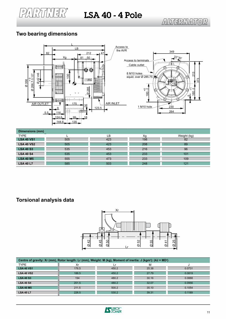
LSA 40 VS1 505 423 198 82
LSA 40 VS2 505 423 208 89
LSA 40 S3 535 453 216 96
LSA 40 S4 535 453 233 101
LSA 40 M5 555 473 233 109
LSA 40 L7 585 503 248 121
Xr Lr M J LSA 40 VS1 176.5 450.2 25.38 0.0731
LSA 40 VS2 186.5 450.2 27.79 0.0819
LSA 40 S3 194 480.2 30.16 0.0888
LSA 40 S4 201.5 480.2 32.07 0.0956
LSA 40 M5 211.5 500.2 35.10 0.1054
LSA 40 L7 226.5 530.2 39.31 0.1189
Ø 5
5
Ø 5
2
Lr
Xr
Ø 4
1
Ø 2
5
Ø 5
0
Ø 4
5
Ø 4
2
LSA 40 - 4 Pole
Dimensions (mm)
TYPE L Weight (kg)
Two bearing dimensions
Torsional analysis data
Centre of gravity: Xr (mm), Rotor length: Lr (mm), Weight: M (kg), Moment of inertia: J (kgm2): (4J = MD2)
TYPE
L
LB349
Xg
Ø 2
66.7
14
Ø 4
2 m
6
Ø 3
58 + 0
- 0.1
27
9
135
175
99 18
116
124.6
144.6
5.5
212 47
Ø 2
85
5081
82
160
213
22°30’
373
5
+1
-3
180 +
0-
2
230
264
AIR OUTLET
Access to terminals
8 M10 holes
equid. over Ø 285.75
1 M10 hole
Access to
the AVR
Cable outlet
12
8
45
130
123.5
AIR INLET

w w w . l e r o y - s o m e r . c o m
I n t e r n a t i o n a l n e t w o r k
ALGERIA
LEROY-SOMER International Division
AUSTRALIA
LEROY-SOMER PTY LTD
AUSTRIA
LEROY-SOMER ELEKTROMOTOREN
BELGIUM
LEROY-SOMER BELGIUM
BRAZIL
LEROY-SOMER DIVISION
EMERSON ELECTRIC DO BRASIL ltda.
CANADA
LEROY-SOMER / EMC
CHINA
LEROY-SOMER Division
CROATIA
Emerson Network Power Ltd
CZECH REPUBLIC
M.L.S. HOLICE S.R.O.
DENMARK
LEROY-SOMER DENMARK A/S
EGYPT
MOTEURS LEROY-SOMER
FRANCE
MOTEURS LEROY-SOMER
GERMANY
LEROY-SOMER Marbaise GmbH
GREECE
LEROY-SOMER Ltd
HUNGARY
LEROY-SOMER I.M.I.
INDIA
LEROY-SOMER C/O EMERSON ELECTRIC CO.
ITALIA
LEROY-SOMER
JAPAN
LEROY-SOMER DIVISION
EMERSON Japan Ltd.
KOREA
EMERSON ELECTRIC KOREA
MOROCCO
CARREFOUR INDUSTRIEL ET TECHNOLOGIQUE
NETHERLANDS
LEROY-SOMER NEDERLAND B.V
POLAND
FZN MARBAISE LS
ROMANIA
LEROY-SOMER REPRESENTATIVE OFFICE
RUSSIA
LEROY-SOMER DIVISION
SAUDI ARABIA
ABUNAYYAN TRADING CORPORATION
SINGAPORE
LEROY-SOMER SOUTHEAST ASIA Pte Ltd
SOUTH AFRICA
LEROY-SOMER PTY LTD
SPAIN
LEROY-SOMER IBERICA S.A.
SWEDEN
LEROY-SOMER NORDEN AB
SWITZERLAND
LEROY-SOMER SA
TAIWAN
LEROY-SOMER LIAISON OFFICE
THAILAND
LEROY-SOMER THAILAND
TUNISIA
ULYSSE SPARE PARTS
TURKEY
ELEKTROMEKANIK SISTEMLER
U.A.E.
LEROY-SOMER DIVISION
EMERSON FZE
UNITED KINGDOM
LEROY-SOMER LTD
USA
LEROY-SOMER POWER AND DRIVES
VENEZUELA
LEROY SOMER C/O EMERSON ELECTRIC CA
Copyright © 2022 FDOKUMEN