
Comparative Study of Permanent Magnet, Conventional, and ...
Upload
khangminh22Category
view
1download
0
energies
Article
Development of Automotive Permanent MagnetAlternator with Fully Controlled AC/DC Converter
Tareq S. El-Hasan ID
Electrical Engineering Department, Zarqa University, Zqrqa 13132, Jordan; [email protected];Tel.: +962-777-747-230
Received: 18 November 2017; Accepted: 9 January 2018; Published: 24 January 2018
Abstract: This paper proposes the design of a three-phase axial flux permanent magnet alternator(AFPMA) that is characterized with an air-cored stator and two-rotor (ACSTR) configuration.The AFPMA is harnessed with fully controlled AC/DC converter using six bridge Insulated GateBipolar Transistor (IGBTs) capable to deliver a constant DC output power as an attempt to replacethe Lundell alternator for automotive applications. First, the design methodology and analysis ofthe AFPMA is introduced. The most effective parameters, such as rotor diameter, magnet thickness,number of turns, and winding thickness are determined. A smart digital control which facilitatesthe comparison between the magnitudes of the three-phase input signals instead of finding the zerocrossing points is developed. Moreover, custom design comparators are specially designed anddeveloped to generate adaptive signals that are fed into an Arduino Uno microcontroller. Accordingly,the Arduino generates the timely precise pulses that are necessary to maintain the appropriatetriggering of the IGBTs. This technique allows the IGBTs to conduct in an adaptive manner toovercome the problem of asymmetrical voltage outputs from the AFPM alternator. The system isalso capable of handling the variation in the speed of the AFPMA via the rigor code in Arduino thatdetects the change in the supply frequency and voltages in a real time process. The system is firstanalyzed via simulations using MATLAB/Simulink and then experimentally validated at certainspeed and loading conditions. The preliminary tests results indicate that such system is capable toprovide an efficient solution to satisfy automotive electric power demands.
Keywords: automotive alternator; axial flux permanent magnet alternator; air cored stator alternator;fully controlled AC/DC converter
1. Introduction
When implementing electrical technology or components into vehicles, the size, weight, cost,performance, and efficiency are the major factors that need to be considered for successful integration.Steadily but surely, automobile manufacturers are looking to improve vehicle component performanceand increasing their power density. Among these components is the on-board electrical power chargingsystem which normally consists of the alternator, power converter, and battery. Such electrical systemsare pushed to their limits as more and more vehicle’s components are replaced by electrically poweredor electrically assisted items. In addition, the evolving customer demands, increasing car functionalities,and developing vehicle regulations and legislations have necessitated the development of the electricalpower generating system to satisfy the increasing demands of electrical power in automobiles.
For the last 50 years, the three-phase claw-pole alternators (or Lundell alternators) have been usedfor the generation of electric power in automotive applications. Until very recent years, this alternatorwas the most economic choice in vehicle technology due to its low manufacturing cost. However,Lundell alternators suffer from major drawbacks such as reduced efficiency, limited output power,and the need for continuous maintenance. This in turn has limited the utilization of such machines in
Energies 2018, 11, 274; doi:10.3390/en11020274 www.mdpi.com/journal/energies

Energies 2018, 11, 274 2 of 28
modern vehicles due to the challenges initiated by increased power demands. Hence, other alternativesfor electrical power generating systems have been considered to meet such challenges in motorvehicles [1–4].
To meet the increasing power demands in modern vehicles, automobile manufacturers haveexploited the distinguished merits offered by the rare earth, high power, permanent magnets (PM) inthe development of electrical power generator to replace the Lundell alternators.
Alternators utilizing PM offer numerous attractive features over other conventional types ofelectrical machines, including higher efficiency, higher power density, no maintenance, and betterreliability [5,6]. PMs can also improve the dynamic performance, and output quality of the machine.PMs are also becoming less expensive, which makes PM machines more prevalent. The recent advancesin power electronic devices have led to better, easier, and cost effective control of PM machines, with thetendency of operating the machine over a large range of speeds while maintaining a reasonableefficiency. Several types of PM machines have been constructed based on their magnetic field direction.For example, PM machines with axial, radial, or transverse configurations have found their way intomany applications, such as home appliances, industrial use, renewable energy, and automobiles [7–10].Other benefits such as short length, ease of manufacturing and assembly, and modularity are realizedby axial flux PM (AFPM) machines when compared to other configurations. Such machines havedemonstrated their relative fitness in applications that are limited with confined spaces or those whichrequire direct coupling of the machine with short overhang [11]. AFPM machines can be used forboth low speed [12,13] and high speed applications [14–16]. Moreover, AFPM machines with ACSTRconfigurations are characterized with extra advantages such as lower cogging torque, reduced eddycurrent losses, better output wave (sinusoidal-like) generation, and less harmonics [15] as compared toother types of PM machines with cored stator configurations. Hence they have potential for use inwind energy applications [17–19] as well as automotive applications [20–23].
This paper introduces the design and optimization methodology for an AFPM alternator (AFPMA)as part of the integrated battery charging system in automobiles. The proposed AFPMA, which isintended to work as a replacement for the Lundell alternator diverges from the high speed version thathas been previously developed for high speed applications [14–16]. The objective is to rebuild thatAFPMA with minimal design effort to make it suitable for vehicle applications. This is achieved byredesigning the stator windings within the existing geometrical constraints and without jeopardizingthe machine’s efficiency. To do so, the sizing equations for the machine are developed, and themachine performance is analysed using MATLAB/Simulink modelling. Moreover, a three-phase fullycontrolled AC/DC rectifier is developed and integrated with the AFPMA. The complete system isexperimentally tested and simulation results are validated and results obtained are presented in detailin this paper.
The ultimate goal is to design a suitable on-board electrical power system that can satisfy thefull requirement of increasing demand of modern automotive industry. The machine shall be capableof providing the car with the necessary power to charge the battery and to turn all electrical andelectronics loads whether the engine is running at idle speed or at full speed.
2. Description and Design Requirements of the AFPMA
The machine under investigation has an air-cored stator and two-rotor (ACSTR) system with noiron core in the stator coils. Originally, the machine was designed for high speed applications [14].Hence, the rotors were carefully designed to allow the machine to withstand high levels of centrifugalforces. The proposed AFPMA in this paper is depicted in Figure 1. To redesign the machine for low tomoderate speed applications, the rotor configuration and dimensions are kept the same except theretainment ring which encapsulates the rotor magnets are selected from lower cost aluminium alloyinstead of expensive, high strength maraging alloy. In addition, simpler manufacturing and assemblyprocesses are performed which in turn reduces the machine cost. However, the stator is completelyredesigned in order to achieve the automobile requirements. Still, the stator is air cored (ironless)

Energies 2018, 11, 274 3 of 28
in order to minimize weight, losses, and cogging torque. Figure 2 shows the main parameters thatare considered in the redesign process. These are: the outer radius of the coil which is similar to theouter radius of the PM disc, (Ro), inner radius of coil which is similar to the inner radius of PM disc(Ri), number of winding turns (Nt), axial air gab length (stator thickness), and mechanical speed (Nm).The target is to reconstruct a mathematical model that can be used to design the stator winding to fit forthe AFPMA to achieve the machine requirements presented in Table 1 within the existing constraints.
Energies 2018, 11, x FOR PEER REVIEW 3 of 30
redesigned in order to achieve the automobile requirements. Still, the stator is air cored (ironless) in order to minimize weight, losses, and cogging torque. Figure 2 shows the main parameters that are considered in the redesign process. These are: the outer radius of the coil which is similar to the outer radius of the PM disc, ( oR ), inner radius of coil which is similar to the inner radius of PM disc
( iR ), number of winding turns ( tN ), axial air gab length (stator thickness), and mechanical speed
( mN ). The target is to reconstruct a mathematical model that can be used to design the stator winding to fit for the AFPMA to achieve the machine requirements presented in Table 1 within the existing constraints.
(a) (b)
Figure 1. AFPMA under consideration: (a) 3D exploded view of ACSTR; (b) assembled AFPMA.
Figure 2. AFPMA rotor and stator main parameters.
Table 1. AFPMA Requirements.
AFPMA Set Parameters Value UnitRMS line–line voltage 17 V
Rated current 40 A Rated speed 5000 RPM
Rated power @ rated speed 1.2 kVA
3. Design Consideration and Sizing of the AFPMA
In order to facilitate the AFPMA for automobile applications, the machine shall be designed to fit for the gasoline engine speed. However, coupling the alternator directly to the automobile engine will require an increased number of stator winding turns to compensate for the low operating speed, thus increasing overall machine volume. Lundell alternators are therefore commonly run with a belt ratio of 3:1 to obtain a higher rotational speed. For the proposed AFPMA, a belt ratio of 5:1 is
Figure 1. AFPMA under consideration: (a) 3D exploded view of ACSTR; (b) assembled AFPMA.
Energies 2018, 11, x FOR PEER REVIEW 3 of 30
redesigned in order to achieve the automobile requirements. Still, the stator is air cored (ironless) in order to minimize weight, losses, and cogging torque. Figure 2 shows the main parameters that are considered in the redesign process. These are: the outer radius of the coil which is similar to the outer radius of the PM disc, ( oR ), inner radius of coil which is similar to the inner radius of PM disc
( iR ), number of winding turns ( tN ), axial air gab length (stator thickness), and mechanical speed
( mN ). The target is to reconstruct a mathematical model that can be used to design the stator winding to fit for the AFPMA to achieve the machine requirements presented in Table 1 within the existing constraints.
(a) (b)
Figure 1. AFPMA under consideration: (a) 3D exploded view of ACSTR; (b) assembled AFPMA.
Figure 2. AFPMA rotor and stator main parameters.
Table 1. AFPMA Requirements.
AFPMA Set Parameters Value UnitRMS line–line voltage 17 V
Rated current 40 A Rated speed 5000 RPM
Rated power @ rated speed 1.2 kVA
3. Design Consideration and Sizing of the AFPMA
In order to facilitate the AFPMA for automobile applications, the machine shall be designed to fit for the gasoline engine speed. However, coupling the alternator directly to the automobile engine will require an increased number of stator winding turns to compensate for the low operating speed, thus increasing overall machine volume. Lundell alternators are therefore commonly run with a belt ratio of 3:1 to obtain a higher rotational speed. For the proposed AFPMA, a belt ratio of 5:1 is
Figure 2. AFPMA rotor and stator main parameters.
Table 1. AFPMA Requirements.
AFPMA Set Parameters Value Unit
RMS line–line voltage 17 VRated current 40 ARated speed 5000 RPM
Rated power @ rated speed 1.2 kVA
3. Design Consideration and Sizing of the AFPMA
In order to facilitate the AFPMA for automobile applications, the machine shall be designedto fit for the gasoline engine speed. However, coupling the alternator directly to the automobileengine will require an increased number of stator winding turns to compensate for the low operatingspeed, thus increasing overall machine volume. Lundell alternators are therefore commonly run with

Energies 2018, 11, 274 4 of 28
a belt ratio of 3:1 to obtain a higher rotational speed. For the proposed AFPMA, a belt ratio of 5:1 isadopted to achieve higher rotational speed hence increasing the overall power density of the system.Accordingly the AFPMA shall be capable to operate in the range of 3750–15,000 rpm when coupledto an engine running in the range of idle speed of 750 rpm to the cruise speed of 3000 rpm. As faras the mechanical integrity is concerned, the AFPMA has its PMs encapsulated by a high strengthretainment ring that is shrunk fit on the rotor disc. Mechanical integrity tests showed safe operation ofthe machine at rotational speeds in the excess 25,000 [16]. However, in this paper, and for the purposeof laboratory testing, the proposed machine is driven by a three-phase electric motor with a belt ratioof 1.7:1 which will limit the machine maximum speed of the AFPMA to 5100 rpm.
Once the range of operating speed is known, it is possible to develop the necessary sizingequations and mathematical models that can be utilized for optimization purposes in order todetermine the machine’s parameters within the competing demands to meet the system requirements.
To derive the necessary equations, the induced voltage formula will be applied on the stationaryconductors in the presence of a rotating magnetic field. The rotating magnetic field in the proposedmachine is secured by the axially magnetized PM semicircular discs that are located alternately onboth rotor sides. The induced voltage in the conductor relies on the flux density, conductor length,and relative velocity. Calculation of the flux density in the middle of the air gap relies on severalparameters such as: magnet type/grade, magnet axial length Lm, magnet shape and air gap lengthXg between the two PM rotors. In automotive applications, components in the engine compartmentare fitted in confined spaces and often exposed to high ambient temperatures and insufficient cooling.Mounted near the engine, the alternator is exposed to high temperatures, thereby reducing itsperformance and lifetime. Therefore, PM alternators have to be designed with great care to avoidthe risk of PM demagnetization, especially for the NdFeB which has a lower Curie temperature andlower working temperature. In automotive applications, the under hood temperature may vary inthe range from 50 C to 80 C, adding more thermal stress on the PM alternator as it may increasethe risk of PM demagnetization. Therefore, selecting the type and the grade of PM is a vital issue inthe design process as one has to compromise between achieving higher power density and highertemperature operability. Among the recently developed PMs, comes the neodymium iron boron(NdFeB) magnet which has high remanence Br, high coercive force Hc, high energy production,and a high performance/cost ratio. As can be shown in Figure 3, NdFeB magnets with grade N52 havethe highest normalized energy product (with average remanence value of 1.45 T) which makes themthe most powerful magnets among other grades. However, such magnets have a limited operatingtemperature of 80 C which may degrade the performance of the proposed AFPM alternator whenused for automotive applications. In this stage of research, it was decided to choose the type and gradeof PM that provides the best magnetic characteristics in order to achieve the maximum possible powerdensity of the AFPM alternator to perform as an advanced development model (ADM). The objectiveis to prove that the AFPMA would perform according to the requirements and interface well with othersystems in terms of form, fit, and function (F3). Thanks to its simple shape and design, the ACSTRconfiguration of the proposed AFPMA allow for natural ventilation and heat removal with minimaleffort. The NdFeB magnets are held by an Alumec carrier which in turn plays a crucial role indissipating the heat that may transfer from the stator windings to the rotor surface. In addition,the rotating PM discs work as natural ventilators since they continuously expel the hot air surroundingtheir surfaces during rotation. Consequently, once the performance of the machine is experimentallyvalidated, the engineering development model (EDM) of the AFPMA will consider the intendedfinal materials and/or deployment of the necessary cooling arrangement to account for reliability,availability, and maintainability (RAM).

Energies 2018, 11, 274 5 of 28Energies 2018, 11, x FOR PEER REVIEW 5 of 30
(a) (b)
Figure 3. Normalized energy product vs. different grades of NdFeB at their corresponding maximum operating temperatures: (a) calculated at 20 °C; (b) calculated at 80 °C. Based on available information from China YY Magnetics (Zhejiang, China) [24].
To account for temperature effect on the energy product of the PMs hence on the machine performance, rB and cH are calculated respectively as [25]:
20
100120 PM
Brr TBB
(1)
20
100120 PM
Hcc THH
(2)
where 20rB and 20cH are the NdFeB grade 52 remanence and coercive force respectively given at
20 °C, B and H are the temperature coefficients for rB and cH and they are set to −0.12 and
−0.6 respectively, and PMT is the PM temperature which is set to the maximum operating temperature of 80 °C. Accordingly, the remanence value and energy product are calculated for N52 at the maximum operating temperature which showed a decrease in the normalized energy product by approximately 8%. The effect of temperature rise on the normalized energy product for several grades of NdFeB as compared to the energy product of N52 based on 20 °C is presented in Figure 4.
Figure 4. Degrading of the normalized energy product as a function of the temperature increase for several grades of NdFeB. Based on available information from e-magnets UK (Hertfordshire, UK) [26].
For simplification purposes, circular magnet shapes are considered to determine the magnetic flux density in the air gap between the two PM rotors. The full derivation of the sizing equation and other necessary equations for the AFPMA’s parameter determination and optimization purposes are shown in Appendix A.
Figure 3. Normalized energy product vs. different grades of NdFeB at their corresponding maximumoperating temperatures: (a) calculated at 20 C; (b) calculated at 80 C. Based on available informationfrom China YY Magnetics (Zhejiang, China) [24].
To account for temperature effect on the energy product of the PMs hence on the machineperformance, Br and Hc are calculated respectively as [25]:
Br = Br20
[1 +
αB100
(TPM − 20)]
(1)
Hc = Hc20
[1 +
αH100
(TPM − 20)]
(2)
where Br20 and Hc20 are the NdFeB grade 52 remanence and coercive force respectively given at20 C, αB and αH are the temperature coefficients for Br and Hc and they are set to −0.12 and−0.6 respectively, and TPM is the PM temperature which is set to the maximum operating temperatureof 80 C. Accordingly, the remanence value and energy product are calculated for N52 at the maximumoperating temperature which showed a decrease in the normalized energy product by approximately8%. The effect of temperature rise on the normalized energy product for several grades of NdFeB ascompared to the energy product of N52 based on 20 C is presented in Figure 4.
Energies 2018, 11, x FOR PEER REVIEW 5 of 30
(a) (b)
Figure 3. Normalized energy product vs. different grades of NdFeB at their corresponding maximum operating temperatures: (a) calculated at 20 °C; (b) calculated at 80 °C. Based on available information from China YY Magnetics (Zhejiang, China) [24].
To account for temperature effect on the energy product of the PMs hence on the machine performance, rB and cH are calculated respectively as [25]:
20
100120 PM
Brr TBB
(1)
20
100120 PM
Hcc THH
(2)
where 20rB and 20cH are the NdFeB grade 52 remanence and coercive force respectively given at
20 °C, B and H are the temperature coefficients for rB and cH and they are set to −0.12 and
−0.6 respectively, and PMT is the PM temperature which is set to the maximum operating temperature of 80 °C. Accordingly, the remanence value and energy product are calculated for N52 at the maximum operating temperature which showed a decrease in the normalized energy product by approximately 8%. The effect of temperature rise on the normalized energy product for several grades of NdFeB as compared to the energy product of N52 based on 20 °C is presented in Figure 4.
Figure 4. Degrading of the normalized energy product as a function of the temperature increase for several grades of NdFeB. Based on available information from e-magnets UK (Hertfordshire, UK) [26].
For simplification purposes, circular magnet shapes are considered to determine the magnetic flux density in the air gap between the two PM rotors. The full derivation of the sizing equation and other necessary equations for the AFPMA’s parameter determination and optimization purposes are shown in Appendix A.
Figure 4. Degrading of the normalized energy product as a function of the temperature increase forseveral grades of NdFeB. Based on available information from e-magnets UK (Hertfordshire, UK) [26].
For simplification purposes, circular magnet shapes are considered to determine the magneticflux density in the air gap between the two PM rotors. The full derivation of the sizing equation andother necessary equations for the AFPMA’s parameter determination and optimization purposes areshown in Appendix A.

Energies 2018, 11, 274 6 of 28
4. Optimization of the AFPMA
In order to optimize the machine design, two main characteristics will be investigated. These aremachine efficiency and machine internal power factor, as will be described in detail in thefollowing sections.
4.1. Machine Efficiency
To predict the machine efficiency, the losses that are affected by the redesign process of the statorwill be investigated. The two main losses that are seen to have major impact on the efficiency of theredesigned AFPMA these are the stator copper losses and the windage losses. The copper losses, Pcu,are calculated at the designed armature current, IA = 40 A as:
Pcu = 3I2ARW (3)
The windage losses of the machine is highly dependent on the rotor diameter and the rotationalspeed. If the rotor diameter is kept constant, then the only parameter that affects the windage losses isthe rotor speed as:
PW = 0.5NRC f ρairω3m
(R5
o − R5sh
)(4)
C f =3.87√
Re(5)
Re =ρairωmR2
oµair
(6)
where C f is the coefficient drag for turbulent flow, Re is Reynolds number, NR is number of rotatingdiscs, ρair is the specific density of the surrounding air = 1.18 kg/m3, µair is the coefficient of viscosityof the air = 1.98 × 10⁻⁵ kg/m·s, and Rsh is shaft radius.
Moreover, the amount of saving in windage losses is a critical aspect which may diversely affectthe overall performance of the machine if precautions are not considered during the design. Hence,for fixed rotor geometry, the windage losses will only vary as a function of the rotor speed as:
PW = Kwdgω2.5m (7)
The maximum windage losses PW,max are obtained at the maximum calculated speed,and minimum number of winding turns. i.e., at Nt= 2.
Accordingly, the saving in the windage losses PW,sav can be calculated as:
PW,sav =PW,max − PW
PW,max(8)
Assuming unity load power factor, and rated armature current of 40 A, the machine output powercan be calculated as:
Pout = 3Vϕ, f l IA (9)
Assuming the machine is operating at unity power factor, the full load phase voltage Vϕ, f l iscalculated as:
Vϕ, f l =√
E2ϕ,rms − (IAXW)2 − IARW (10)
Other losses, such as rotor eddy current losses, are not considered in the investigation since therotor geometry is not changed. Hence, the machine efficiency, η at the rated armature current andunity load power factor is calculated as:
η =Pout
Pout + Pcu + PW× 100% (11)
Energies 2018, 11, 274 7 of 28
4.2. Machine Internal Power Factor (cos ϕ)
The machine internal power factor (PFm) can be calculated as PFm = cos ϕ, where ϕ = tan−1(
XWRW
).
Also, the voltage regulation of the machine can be calculated as:
VR =Vϕ,nl −Vϕ, f l
Vϕ, f l· 100% (12)
The no load voltage Vnl equals the per phase internal generated voltage of the machine Eϕ,rms.Hence, Eϕ,rms =
17√3= 9.815 V.
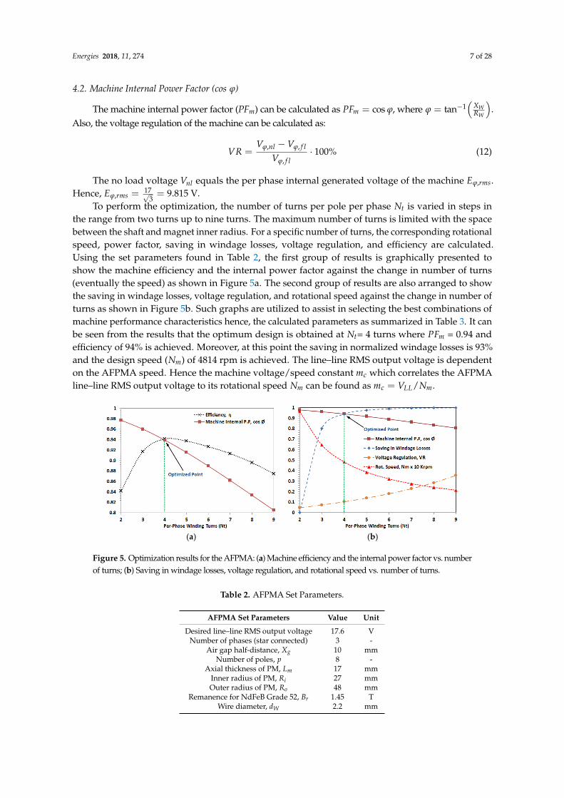
To perform the optimization, the number of turns per pole per phase Nt is varied in steps inthe range from two turns up to nine turns. The maximum number of turns is limited with the spacebetween the shaft and magnet inner radius. For a specific number of turns, the corresponding rotationalspeed, power factor, saving in windage losses, voltage regulation, and efficiency are calculated.Using the set parameters found in Table 2, the first group of results is graphically presented toshow the machine efficiency and the internal power factor against the change in number of turns(eventually the speed) as shown in Figure 5a. The second group of results are also arranged to showthe saving in windage losses, voltage regulation, and rotational speed against the change in number ofturns as shown in Figure 5b. Such graphs are utilized to assist in selecting the best combinations ofmachine performance characteristics hence, the calculated parameters as summarized in Table 3. It canbe seen from the results that the optimum design is obtained at Nt= 4 turns where PFm = 0.94 andefficiency of 94% is achieved. Moreover, at this point the saving in normalized windage losses is 93%and the design speed (Nm) of 4814 rpm is achieved. The line–line RMS output voltage is dependenton the AFPMA speed. Hence the machine voltage/speed constant mc which correlates the AFPMAline–line RMS output voltage to its rotational speed Nm can be found as mc = VLL/Nm.
Energies 2018, 11, x FOR PEER REVIEW 7 of 30
Other losses, such as rotor eddy current losses, are not considered in the investigation since the rotor geometry is not changed. Hence, the machine efficiency, at the rated armature current and unity load power factor is calculated as:
%100
Wcuout
out
PPP
P (11)
4.2. Machine Internal Power Factor (cos φ)
The machine internal power factor (PFm) can be calculated as cosmPF , where
W
W
R
X1tan . Also, the voltage regulation of the machine can be calculated as:
%100,
,,
fl
flnl
V
VVVR
(12)
The no load voltage nlV equals the per phase internal generated voltage of the machine rmsE , .
Hence, V815.93
17, rmsE .
To perform the optimization, the number of turns per pole per phase tN is varied in steps in the range from two turns up to nine turns. The maximum number of turns is limited with the space between the shaft and magnet inner radius. For a specific number of turns, the corresponding rotational speed, power factor, saving in windage losses, voltage regulation, and efficiency are calculated. Using the set parameters found in Table 2, the first group of results is graphically presented to show the machine efficiency and the internal power factor against the change in number of turns (eventually the speed) as shown in Figure 5a. The second group of results are also arranged to show the saving in windage losses, voltage regulation, and rotational speed against the change in number of turns as shown in Figure 5b. Such graphs are utilized to assist in selecting the best combinations of machine performance characteristics hence, the calculated parameters as summarized in Table 3. It can be seen from the results that the optimum design is obtained at
tN = 4 turns where
mPF = 0.94 and efficiency of 94% is achieved. Moreover, at this point the saving in normalized windage losses is 93% and the design speed (
mN ) of 4814 rpm is achieved. The line–line RMS output voltage is dependent on the AFPMA speed. Hence the machine voltage/speed constant
cm which correlates the AFPMA line–line RMS output voltage to its rotational speed mN can be
found as mLLc NVm / .
(a) (b)
Figure 5. Optimization results for the AFPMA: (a) Machine efficiency and the internal power factor vs. number of turns; (b) Saving in windage losses, voltage regulation, and rotational speed vs. number of turns.
Figure 5. Optimization results for the AFPMA: (a) Machine efficiency and the internal power factor vs. numberof turns; (b) Saving in windage losses, voltage regulation, and rotational speed vs. number of turns.
Table 2. AFPMA Set Parameters.
AFPMA Set Parameters Value Unit
Desired line–line RMS output voltage 17.6 VNumber of phases (star connected) 3 -
Air gap half-distance, Xg 10 mmNumber of poles, p 8 -
Axial thickness of PM, Lm 17 mmInner radius of PM, Ri 27 mmOuter radius of PM, Ro 48 mm
Remanence for NdFeB Grade 52, Br 1.45 TWire diameter, dW 2.2 mm

Energies 2018, 11, 274 8 of 28
Table 3. AFPMA Calculated Parameters.
AFPMA Calculated Parameters Value Unit
Number of winding turns per pole per phase, Nt 4 -Winding resistance per phase, RW 22.8 mΩWinding inductance per phase, LW 4.14 µH
Design speed, Nm 4814 RPMNo load machine voltage/speed constant, mc 3.537 × 10⁻³ V/RPM
Generated frequency, f 320 HzAir gap flux density, Bg 0.546 T
Voltage regulation, VR % 10.3 -Machine internal power factor (cos ϕ), PFm 0.94 -
Machine power angle, δ 2 DegEfficiency, η (%) 94 -
5. Modelling and Simulation of the AFPMA
The AFPMA under consideration has its magnet topology designed to produce a sinusoidal flux inits ironless stator. This implies that the induced voltages will be almost sinusoidal. MATLAB/SimulinkR2012a (Mathworks, Galway, Ireland) [27], has a block that is already defined in the SimPowerSystemswhich is called a permanent magnet synchronous machine (PMSM). This block is used to simulate theperformance of the AFPMA under consideration after setting the corresponding parameters as shownin Figure 6.
Energies 2018, 11, x FOR PEER REVIEW 9 of 30
Figure 6. AFPMA MATLAB/Simulink model and parameter configuration.
The AFPMA equivalent circuit is depicted in Figure 7, whereas the corresponding mathematical model of the machine in rotor reference frame (dq-axis) is summarized in Appendix B.
qqm iL
p
2
dd idt
dL
dV
dwiRdi
(a) (b)
Figure 7. AFPMA equivalent circuit: (a) d-axis model; (b) q-axis model.
Once the parameters of the AFPMA are defined, MATLAB/Simulink model can be used to predict the machine performance at several conditions which can be further analyzed after experimental validation. The expected line–line rms voltages of the machine at no load and for several rotational speeds are represented in Figure 8.
qqm iL
p
2
dd idt
dL
dwiRdi
rmp
2 qV
Figure 6. AFPMA MATLAB/Simulink model and parameter configuration.
The AFPMA equivalent circuit is depicted in Figure 7, whereas the corresponding mathematicalmodel of the machine in rotor reference frame (dq-axis) is summarized in Appendix B.

Energies 2018, 11, 274 9 of 28
Energies 2018, 11, x FOR PEER REVIEW 9 of 30
Figure 6. AFPMA MATLAB/Simulink model and parameter configuration.
The AFPMA equivalent circuit is depicted in Figure 7, whereas the corresponding mathematical model of the machine in rotor reference frame (dq-axis) is summarized in Appendix B.
qqm iL
p
2
dd idt
dL
dV
dwiRdi
(a) (b)
Figure 7. AFPMA equivalent circuit: (a) d-axis model; (b) q-axis model.
Once the parameters of the AFPMA are defined, MATLAB/Simulink model can be used to predict the machine performance at several conditions which can be further analyzed after experimental validation. The expected line–line rms voltages of the machine at no load and for several rotational speeds are represented in Figure 8.
qqm iL
p
2
dd idt
dL
dwiRdi
rmp
2 qV
Figure 7. AFPMA equivalent circuit: (a) d-axis model; (b) q-axis model.
Once the parameters of the AFPMA are defined, MATLAB/Simulink model can be used to predictthe machine performance at several conditions which can be further analyzed after experimentalvalidation. The expected line–line rms voltages of the machine at no load and for several rotationalspeeds are represented in Figure 8.Energies 2018, 11, x FOR PEER REVIEW 10 of 30
Figure 8. Expected AFPMA line–line rms voltages at no load for several operating speeds.
6. Development of the Controlled AC/DC Rectifier for the AFPMA
Regulation of the output voltage is a key issue in automotive alternator. The output voltage of the alternator shall be maintained at about 14 V DC, which is the nominal charging voltage of a 12 V lead–acid battery. The Lundell alternator regulates its output voltage by controlling the current supplied to the filed windings hence the magnetic flux inside the alternator. In PM machines where the flux is relatively constant, the back-emf is only proportional to the alternator’s speed. Therefore, driving the machine above the rated speed will generate a back-emf that is exceeding the rated output voltage. Accordingly, at top speed the power electronic components in the converter shall be capable to withstand both rated current and the considerable machine back-emf which may involve increased power electronics cost and complexity. This could be solved by employing a DC-to-DC or controlled AC-to-DC converter to maintain a constant output voltage. The separate converter can be mounted in a location where the temperatures and vibration levels are lower. When used together with an IGBT based AC/DC converter, the alternator can respond in a fast manner to provide the required charging current, at a stable voltage, over a large range of rotational speeds.
The regulation and control of alternator’s output has been described in a number of studies [28–31]. Most of this work relies on using the Pulse Width Modulation (PWM) and boost rectifier technique. Published research on the integration and implementation of fully controlled AC/DC converter to PM generators is still scarce. In this paper, the description of the development of three-phase full wave fully controlled rectifier system using six IGBT bridge will be demonstrated to regulate the output of the AFPMA. As shown in Figure 9, the proposed system will utilize smart digital control using specially designed comparators interfaced with Arduino Uno to generate the required pulses to the gate of the IGBTs. The proposed system shall be capable to operate under several conditions such as variable input voltage, variable input frequency, various loading conditions. The objective is to supply a regulated DC voltage to a vehicle’s battery and loads under varying alternator speeds.
Figure 8. Expected AFPMA line–line rms voltages at no load for several operating speeds.
6. Development of the Controlled AC/DC Rectifier for the AFPMA
Regulation of the output voltage is a key issue in automotive alternator. The output voltageof the alternator shall be maintained at about 14 V DC, which is the nominal charging voltage of a12 V lead–acid battery. The Lundell alternator regulates its output voltage by controlling the currentsupplied to the filed windings hence the magnetic flux inside the alternator. In PM machines wherethe flux is relatively constant, the back-emf is only proportional to the alternator’s speed. Therefore,driving the machine above the rated speed will generate a back-emf that is exceeding the rated outputvoltage. Accordingly, at top speed the power electronic components in the converter shall be capableto withstand both rated current and the considerable machine back-emf which may involve increasedpower electronics cost and complexity. This could be solved by employing a DC-to-DC or controlledAC-to-DC converter to maintain a constant output voltage. The separate converter can be mounted ina location where the temperatures and vibration levels are lower. When used together with an IGBTbased AC/DC converter, the alternator can respond in a fast manner to provide the required chargingcurrent, at a stable voltage, over a large range of rotational speeds.

Energies 2018, 11, 274 10 of 28
The regulation and control of alternator’s output has been described in a number of studies [28–31].Most of this work relies on using the Pulse Width Modulation (PWM) and boost rectifier technique.Published research on the integration and implementation of fully controlled AC/DC converter to PMgenerators is still scarce. In this paper, the description of the development of three-phase full wavefully controlled rectifier system using six IGBT bridge will be demonstrated to regulate the outputof the AFPMA. As shown in Figure 9, the proposed system will utilize smart digital control usingspecially designed comparators interfaced with Arduino Uno to generate the required pulses to thegate of the IGBTs. The proposed system shall be capable to operate under several conditions such asvariable input voltage, variable input frequency, various loading conditions. The objective is to supplya regulated DC voltage to a vehicle’s battery and loads under varying alternator speeds.Energies 2018, 11, x FOR PEER REVIEW 11 of 30
Figure 9. Proposed automotive electrical powering system using AFPMA harnessed with fully controlled AC/DC rectifier.
The following main components form the corner stones of the fully controlled AC/DC converter:
IGBT six-pack module (CM100TF-12H) Microcontroller (Arduino Uno) Comparator circuit (voltage sensing). LC filter.
6.1. Control Scheme
To obtain the required and regulated DC voltage, the IGBT switches have to be triggered at a proper time and sequence. The voltages of the three phases from the AFPMA are measured instantaneously to determine the most positive phase and the most negative phase using comparator circuitry that is shown in Figure 10. It compares two phases (AB, AC, BC) amplitudes and generates a pulse at the output if the phase at the non-inverting input is higher than the phase at the inverting input. The generated pulses are fed to Arduino via a special conditioning circuit and then a decision is made to trigger two specific switches of the IGBT. The switching scheme is based on a specific combination sequence as shown in Figure 11. To keep the output voltage at a specific (preset value) voltage, the DC output from the filter is then compared with the voltage set point and if the output voltage is lower than the set point, the rectifier will be activated accordingly.
Figure 9. Proposed automotive electrical powering system using AFPMA harnessed with fullycontrolled AC/DC rectifier.
The following main components form the corner stones of the fully controlled AC/DC converter:
• IGBT six-pack module (CM100TF-12H)• Microcontroller (Arduino Uno)• Comparator circuit (voltage sensing).• LC filter.
6.1. Control Scheme
To obtain the required and regulated DC voltage, the IGBT switches have to be triggered ata proper time and sequence. The voltages of the three phases from the AFPMA are measuredinstantaneously to determine the most positive phase and the most negative phase using comparatorcircuitry that is shown in Figure 10. It compares two phases (AB, AC, BC) amplitudes and generatesa pulse at the output if the phase at the non-inverting input is higher than the phase at the invertinginput. The generated pulses are fed to Arduino via a special conditioning circuit and then a decisionis made to trigger two specific switches of the IGBT. The switching scheme is based on a specificcombination sequence as shown in Figure 11. To keep the output voltage at a specific (preset value)voltage, the DC output from the filter is then compared with the voltage set point and if the outputvoltage is lower than the set point, the rectifier will be activated accordingly.

Energies 2018, 11, 274 11 of 28Energies 2018, 11, x FOR PEER REVIEW 12 of 30
Figure 10. Voltage measurement and comparator circuit.
Figure 11. IGBT switching sequence for controlled rectifier operation.
6.2. Controlled Rectifier Design Calculations
The three phase full wave fully controlled rectifier is implemented using six IGBTs connected in the form of a full wave bridge configuration. All the six IGBTs are controlled switches which are turned on at appropriate times by applying suitable gate trigger signals. The average output voltage
dcV of the rectifier can be calculated as [32]:
cos23 LLdc
VV (13)
where LLV is the rms line voltage from the three-phase AFPMA and is the firing angle applied to the IGBT gate.
The AFPMA output voltage is regulated by controlling the firing angle of the IGBTs. To obtain a constant output voltage, a feedback signal must be sent to the controller to compare it with the preset value of 14.3 V to allow for controlled battery charging operation. When the battery is fully charged, the controller keeps the firing angle at 90 degrees. When the battery charge goes below the preset level, then the controller triggers the IGBT with a firing angle below 90 degrees which is
741
3
2
4
7
6
51
Input voltage from alternator 3PH
741
3
2
4
7
6
51
VCC
VCC
741
3
2
4
7
6
51
VCC
Figure 10. Voltage measurement and comparator circuit.
Energies 2018, 11, x FOR PEER REVIEW 12 of 30
Figure 10. Voltage measurement and comparator circuit.
Figure 11. IGBT switching sequence for controlled rectifier operation.
6.2. Controlled Rectifier Design Calculations
The three phase full wave fully controlled rectifier is implemented using six IGBTs connected in the form of a full wave bridge configuration. All the six IGBTs are controlled switches which are turned on at appropriate times by applying suitable gate trigger signals. The average output voltage
dcV of the rectifier can be calculated as [32]:
cos23 LLdc
VV (13)
where LLV is the rms line voltage from the three-phase AFPMA and is the firing angle applied to the IGBT gate.
The AFPMA output voltage is regulated by controlling the firing angle of the IGBTs. To obtain a constant output voltage, a feedback signal must be sent to the controller to compare it with the preset value of 14.3 V to allow for controlled battery charging operation. When the battery is fully charged, the controller keeps the firing angle at 90 degrees. When the battery charge goes below the preset level, then the controller triggers the IGBT with a firing angle below 90 degrees which is
741
3
2
4
7
6
51
Input voltage from alternator 3PH
741
3
2
4
7
6
51
VCC
VCC
741
3
2
4
7
6
51
VCC
Figure 11. IGBT switching sequence for controlled rectifier operation.
6.2. Controlled Rectifier Design Calculations
The three phase full wave fully controlled rectifier is implemented using six IGBTs connectedin the form of a full wave bridge configuration. All the six IGBTs are controlled switches which areturned on at appropriate times by applying suitable gate trigger signals. The average output voltageVdc of the rectifier can be calculated as [32]:
Vdc =3√
2VLLπ
cos α (13)
where VLL is the rms line voltage from the three-phase AFPMA and α is the firing angle applied to theIGBT gate.
The AFPMA output voltage is regulated by controlling the firing angle of the IGBTs. To otbaina constant output voltage, a feedback signal must be sent to the controller to compare it with the presetvalue of 14.3 V to allow for controlled battery charging operation. When the battery is fully charged,the controller keeps the firing angle at 90 degrees. When the battery charge goes below the preset level,

Energies 2018, 11, 274 12 of 28
then the controller triggers the IGBT with a firing angle below 90 degrees which is proportional to thevoltage difference. The higher the voltage difference, the lower the firing angle will be.
The minim line–line RMS voltage VLL,min that is required to achieve the preset value of 14.3 V forthe battery charger at α = 0 degree can be determined from (13) as:
14.3 =3√
2VLL,min
π(14)
Rearranging for VLL,min
VLL,min =14.3π
3√
2= 10.58 V (15)
The minim speed of the AFPMA, Nm,min that keeps the output voltage at the preset value whileconsidering the machine constant value can be calculated as
Nm,min =VLL,min
mc=
10.583.537× 10−3 = 2997 RPM (16)
At the design speed, Nm = 4814RPM, the line–line RMS output voltage will be 17.6 V and theline-line peak output voltage, VLL,pk will be 24.89 V. Hence the maximum rectifier output voltage,Vdc at α = 0o will be 23.7 V. The predicted results for AFPMA voltage and rectifier voltage with respectto speed are summarized in Table 4.
Table 4. AFPMA and rectifier output voltages at no load vs. speed at α = 0o.
AFPMA Speed, Nm(RPM)
VLL,rms(V)
VLL,pk(V)
Vdc(V)
Design speed = 4814 17.6 24.89 23.7Minimum speed = 2997 10.6 14.9 14.3Maximum speed 5000 18.29 25.8 24.7
7. Overall System Simulation
The complete system that includes the AFPMA, integrated with the three-phase fully controlledAC/DC converter, LC filter, battery, load, and controller is modeled using MATLAB/Simulink asshown in Figure 12. The controller design relies on the measurement of the AFPMA output voltageswhere both most positive and negative phases are determined at a certain instant. Based on thefeedback signal from the battery side, the controller generates the necessary pulses to trigger the IGBTswitches accordingly. For simulation purposes, logic OR gates are used to implement the switchingsequence that was presented in Figure 8. The algorithm that is used to enable the controller is depictedin Figure 13. Whereas the controller output zero-one pulses are depicted in Figure 14.

Energies 2018, 11, 274 13 of 28Energies 2018, 11, x FOR PEER REVIEW 14 of 30
Figure 12. Complete system simulation using MATLAB/Simulink model.
Figure 13. Algorithm used to enable the controller for simulation purposes.
In practice, charging system in an automobile shall be capable to operate at various loads and various engine/alternator speed while supplying a regulated/fixed voltage to battery terminals and any loads connected across the terminals. In the following section, simulations for different scenarios are developed in order to predict the system behavior at various operating conditions.
Figure 12. Complete system simulation using MATLAB/Simulink model.
Energies 2018, 11, x FOR PEER REVIEW 14 of 30
Figure 12. Complete system simulation using MATLAB/Simulink model.
Figure 13. Algorithm used to enable the controller for simulation purposes.
In practice, charging system in an automobile shall be capable to operate at various loads and various engine/alternator speed while supplying a regulated/fixed voltage to battery terminals and any loads connected across the terminals. In the following section, simulations for different scenarios are developed in order to predict the system behavior at various operating conditions.
Figure 13. Algorithm used to enable the controller for simulation purposes.
In practice, charging system in an automobile shall be capable to operate at various loads andvarious engine/alternator speed while supplying a regulated/fixed voltage to battery terminals andany loads connected across the terminals. In the following section, simulations for different scenariosare developed in order to predict the system behavior at various operating conditions.

Energies 2018, 11, 274 14 of 28Energies 2018, 11, x FOR PEER REVIEW 15 of 30
Figure 14. Controller output pulses (zero–one).
7.1. System Simulation with Open Circuit
In this scenario, the AFPMA speed is set to 5000 RPM, the load and the battery are disconnected from the rectifier terminals, and the firing angle is set to zero. The six pulse rectified output as a result from the simulation is shown in Figure 15. The AFPMA line–line peak voltage is found to be 24.8 V, hence the rectifier output voltage dcV is found to be 23.7 V. Such initial simulation results are validated by comparing them to the analytical results that are presented earlier in Table 4. Hence other simulation scenarios can be conducted with more confidence.
Figure 14. Controller output pulses (zero–one).
7.1. System Simulation with Open Circuit
In this scenario, the AFPMA speed is set to 5000 RPM, the load and the battery are disconnectedfrom the rectifier terminals, and the firing angle α is set to zero. The six pulse rectified output asa result from the simulation is shown in Figure 15. The AFPMA line–line peak voltage is found to be24.8 V, hence the rectifier output voltage Vdc is found to be 23.7 V. Such initial simulation results arevalidated by comparing them to the analytical results that are presented earlier in Table 4. Hence othersimulation scenarios can be conducted with more confidence.

Energies 2018, 11, 274 15 of 28
Energies 2018, 11, x FOR PEER REVIEW 16 of 30
Figure 15. Simulation results for open circuit rectifier output voltage at 5000 rpm at firing angle = 0.
7.2. System Simulation with Constant Load and Variable Speed
In this scenario, a constant electrical load of 0.7 Ω is fitted across the battery terminals while the speed of AFPMA is ramped up from 3800 RPM to 5100 RPM through the simulation runtime. Simulation results are depicted in Figure 16 where battery terminal voltage (after filter), rectifier voltage (before filter), and load current are captured in response to speed variation with respect to time. The charging limit for the battery is set to 14.3 V.
Figure 16. Simulation results for constant electrical load and variable AFPMA speed.
Figure 15. Simulation results for open circuit rectifier output voltage at 5000 rpm at firing angle α = 0.
7.2. System Simulation with Constant Load and Variable Speed
In this scenario, a constant electrical load of 0.7 Ω is fitted across the battery terminals whilethe speed of AFPMA is ramped up from 3800 RPM to 5100 RPM through the simulation runtime.Simulation results are depicted in Figure 16 where battery terminal voltage (after filter), rectifiervoltage (before filter), and load current are captured in response to speed variation with respect totime. The charging limit for the battery is set to 14.3 V.
Energies 2018, 11, x FOR PEER REVIEW 16 of 30
Figure 15. Simulation results for open circuit rectifier output voltage at 5000 rpm at firing angle = 0.
7.2. System Simulation with Constant Load and Variable Speed
In this scenario, a constant electrical load of 0.7 Ω is fitted across the battery terminals while the speed of AFPMA is ramped up from 3800 RPM to 5100 RPM through the simulation runtime. Simulation results are depicted in Figure 16 where battery terminal voltage (after filter), rectifier voltage (before filter), and load current are captured in response to speed variation with respect to time. The charging limit for the battery is set to 14.3 V.
Figure 16. Simulation results for constant electrical load and variable AFPMA speed. Figure 16. Simulation results for constant electrical load and variable AFPMA speed.

Energies 2018, 11, 274 16 of 28
7.3. System Simulation with Constant Speed and Variable Load
In this scenario, the speed of AFPMA is set to 5100 RPM while the is electrical load connectedacross the battery terminal is decreased from 3 Ω to 0.7 Ω of through the simulation runtime from0 to 1.5 s. Simulation results are depicted in Figure 17 where battery terminal voltage (after filter),rectifier voltage (before filter), and load current are captured in response to electrical load variationwith respect to time. The charging limit for the battery is set to 14.3 V.
Energies 2018, 11, x FOR PEER REVIEW 17 of 30
7.3. System Simulation with Constant Speed and Variable Load
In this scenario, the speed of AFPMA is set to 5100 RPM while the is electrical load connected across the battery terminal is decreased from 3 Ω to 0.7 Ω of through the simulation runtime from 0 to 1.5 s. Simulation results are depicted in Figure 17 where battery terminal voltage (after filter), rectifier voltage (before filter), and load current are captured in response to electrical load variation with respect to time. The charging limit for the battery is set to 14.3 V.
Figure 17. Simulation results for constant speed and variable electrical load.
7.4. System Simulation with Variable Speed and Variable Load
In this scenario, both speed of AFPMA and electrical load are varied simultaneously. The speed is increased from 3800 RPM to 5100 RPM while the electrical load across the battery terminal is decreased from 3 Ω to 0.7 Ω of through the simulation runtime from 0 to 1.5 s. Simulation results are depicted in Figure 18 where battery terminal voltage (after filter), rectifier voltage (before filter), and load current are captured in response to electrical load variation with respect to time. The charging limit for the battery is set to 14.3 V.
Figure 17. Simulation results for constant speed and variable electrical load.
7.4. System Simulation with Variable Speed and Variable Load
In this scenario, both speed of AFPMA and electrical load are varied simultaneously. The speed isincreased from 3800 RPM to 5100 RPM while the electrical load across the battery terminal is decreasedfrom 3 Ω to 0.7 Ω of through the simulation runtime from 0 to 1.5 s. Simulation results are depicted inFigure 18 where battery terminal voltage (after filter), rectifier voltage (before filter), and load current

Energies 2018, 11, 274 17 of 28
are captured in response to electrical load variation with respect to time. The charging limit for thebattery is set to 14.3 V.Energies 2018, 11, x FOR PEER REVIEW 18 of 30
Figure 18. Simulation results for variable speed and variable electrical load.
8. Testing and Experimentation of the AFPMA
The AFPMA along with the controlled AC/DC converter are experimentally tested to obtain their performance characteristics as shown in Figure 19. As an alternative prime mover to the car engine, a three-phase electrical motor that is fed from three-phase variable power supply is used to drive the AFPMA at several speeds through pulleys and belt. A dummy resistive load is used to test the system under various loading conditions. The three-phase output from the AFPMA is fed to the electrical load through the IGBT which is fully controlled via the controller circuit. The controller circuit contains the comparator circuit, Arduino Uno, and the IGBT gate driver circuit. To demonstrate the system performance at several operating conditions, the following tests are performed as described below.
Figure 18. Simulation results for variable speed and variable electrical load.
8. Testing and Experimentation of the AFPMA
The AFPMA along with the controlled AC/DC converter are experimentally tested to obtain theirperformance characteristics as shown in Figure 19. As an alternative prime mover to the car engine,a three-phase electrical motor that is fed from three-phase variable power supply is used to drive theAFPMA at several speeds through pulleys and belt. A dummy resistive load is used to test the systemunder various loading conditions. The three-phase output from the AFPMA is fed to the electrical loadthrough the IGBT which is fully controlled via the controller circuit. The controller circuit containsthe comparator circuit, Arduino Uno, and the IGBT gate driver circuit. To demonstrate the systemperformance at several operating conditions, the following tests are performed as described below.

Energies 2018, 11, 274 18 of 28
Energies 2018, 11, x FOR PEER REVIEW 19 of 30
Figure 19. Experimental test rig; (1) Three-phase driving motor, (2) AFPMA, (3) controller circuit, (4) IGBT six-pack module CM100TF-12H, (5) three-phase power supply, (6) dummy resistive load, (3a) comparator circuit, (3b) Arduino Uno, (3c) IGBT gate driver circuit.
8.1. No Load Tests
In this section, the system is tested under no load condition with AFPMA initially is running at rated speed of 5000 RPM. The line–line output voltage from the AFPMA is captured and compared with the simulation results obtained from MATLAB as shown in Figure 20. Results obtained show a good match between the simulation and experimental results. The results of the three-phase line-neutral voltages are captured using PicoScope 3000 oscilloscope (Pico Technology, Cambridgeshire, UK) as depicted in Figure 21. The quality of the AFPMA voltage signal is also analyzed where the total harmonic distortion (THD) is found to be close to 2% as shown in Figure 22. The output from the rectifier at zero firing angle is also captured in Figure 23. It is shown from the results that the rectified output voltage is very close to the output obtained from the simulation results. It is also shown that phase C has its peak line–line voltage less than the other two phases by 1.5 volts. This is explained by the fact that the coil that is responsible for phase C is physically located between the other two phases in the middle of the air gap. Therefore, less magnetic flux density arrives from PM to that location, hence less induced voltage is produced in that coil. This makes the output voltage asymmetrical and special precautions have to be taken into consideration when designing the scheme for the controller of the converter.
Figure 20. AFPMA no load voltage (line-neutral) experimental results vs. simulation results at
mN = 5000 RPM.
Figure 19. Experimental test rig; (1) Three-phase driving motor, (2) AFPMA, (3) controller circuit,(4) IGBT six-pack module CM100TF-12H, (5) three-phase power supply, (6) dummy resistive load,(3a) comparator circuit, (3b) Arduino Uno, (3c) IGBT gate driver circuit.
8.1. No Load Tests
In this section, the system is tested under no load condition with AFPMA initially is running atrated speed of 5000 RPM. The line–line output voltage from the AFPMA is captured and compared withthe simulation results obtained from MATLAB as shown in Figure 20. Results obtained show a goodmatch between the simulation and experimental results. The results of the three-phase line-neutralvoltages are captured using PicoScope 3000 oscilloscope (Pico Technology, Cambridgeshire, UK) asdepicted in Figure 21. The quality of the AFPMA voltage signal is also analyzed where the totalharmonic distortion (THD) is found to be close to 2% as shown in Figure 22. The output from therectifier at zero firing angle is also captured in Figure 23. It is shown from the results that the rectifiedoutput voltage is very close to the output obtained from the simulation results. It is also shown thatphase C has its peak line–line voltage less than the other two phases by 1.5 volts. This is explained bythe fact that the coil that is responsible for phase C is physically located between the other two phasesin the middle of the air gap. Therefore, less magnetic flux density arrives from PM to that location,hence less induced voltage is produced in that coil. This makes the output voltage asymmetrical andspecial precautions have to be taken into consideration when designing the scheme for the controllerof the converter.
Energies 2018, 11, x FOR PEER REVIEW 19 of 30
Figure 19. Experimental test rig; (1) Three-phase driving motor, (2) AFPMA, (3) controller circuit, (4) IGBT six-pack module CM100TF-12H, (5) three-phase power supply, (6) dummy resistive load, (3a) comparator circuit, (3b) Arduino Uno, (3c) IGBT gate driver circuit.
8.1. No Load Tests
In this section, the system is tested under no load condition with AFPMA initially is running at rated speed of 5000 RPM. The line–line output voltage from the AFPMA is captured and compared with the simulation results obtained from MATLAB as shown in Figure 20. Results obtained show a good match between the simulation and experimental results. The results of the three-phase line-neutral voltages are captured using PicoScope 3000 oscilloscope (Pico Technology, Cambridgeshire, UK) as depicted in Figure 21. The quality of the AFPMA voltage signal is also analyzed where the total harmonic distortion (THD) is found to be close to 2% as shown in Figure 22. The output from the rectifier at zero firing angle is also captured in Figure 23. It is shown from the results that the rectified output voltage is very close to the output obtained from the simulation results. It is also shown that phase C has its peak line–line voltage less than the other two phases by 1.5 volts. This is explained by the fact that the coil that is responsible for phase C is physically located between the other two phases in the middle of the air gap. Therefore, less magnetic flux density arrives from PM to that location, hence less induced voltage is produced in that coil. This makes the output voltage asymmetrical and special precautions have to be taken into consideration when designing the scheme for the controller of the converter.
Figure 20. AFPMA no load voltage (line-neutral) experimental results vs. simulation results at
mN = 5000 RPM. Figure 20. AFPMA no load voltage (line-neutral) experimental results vs. simulation results atNm = 5000RPM.

Energies 2018, 11, 274 19 of 28
Energies 2018, 11, x FOR PEER REVIEW 20 of 30
Figure 21. AFPMA no load three-phase line-neutral voltages tested at mN = 5000 RPM.
Figure 22. AFPMA phase voltage THD % experimental result at mN = 5000 RPM.
Figure 23. Rectifier output voltage at zero firing angle at mN = 5000 RPM.
Figure 21. AFPMA no load three-phase line-neutral voltages tested at Nm = 5000RPM.
Energies 2018, 11, x FOR PEER REVIEW 20 of 30
Figure 21. AFPMA no load three-phase line-neutral voltages tested at mN = 5000 RPM.
Figure 22. AFPMA phase voltage THD % experimental result at mN = 5000 RPM.
Figure 23. Rectifier output voltage at zero firing angle at mN = 5000 RPM.
Figure 22. AFPMA phase voltage THD % experimental result at Nm = 5000RPM.
Energies 2018, 11, x FOR PEER REVIEW 20 of 30
Figure 21. AFPMA no load three-phase line-neutral voltages tested at mN = 5000 RPM.
Figure 22. AFPMA phase voltage THD % experimental result at mN = 5000 RPM.
Figure 23. Rectifier output voltage at zero firing angle at mN = 5000 RPM. Figure 23. Rectifier output voltage at zero firing angle at Nm = 5000RPM.

Energies 2018, 11, 274 20 of 28
The controller of the AC/DC converter is designed to deal with the voltages under asymmetricalconditions. It is the comparator that gives the controller the adaptively feature as it compares themost positive signal with the most negative one. Therefore, an adaptive pulse is generated from thecomparator that is proportional to the difference between the two consecutive phases. Even in anasymmetrical situation where the three phase voltages are not balanced, the comparator is capable tocreate the necessary pulse and send it to Arduino Uno to generate the necessary pulses for triggeringthe appropriate switches in the IGBT module. For example, Figure 24 shows the output from thecomparator for C and phases A. When C phase (blue color) is most positive than phase A (green color)the comparator generates the appropriate pulse (yellow color) throughout that interval. The resultsalso show that the peak value of phase A is higher than that for phase C. As a result, an adaptivepulse is generated from the comparator witnessed by an increase in the pulses width (yellow color).The output from the comparators are sent to Arduino Uno where the appropriate train of pules aregenerated and sent to IGBT gate driver circuit from which the IGBT switches are triggered accordingly.As can be shown from Figure 25, the six Arduino pulses have different widths to allow for adaptivecontrol of the AC/DC converter.
Energies 2018, 11, x FOR PEER REVIEW 21 of 30
The controller of the AC/DC converter is designed to deal with the voltages under asymmetrical conditions. It is the comparator that gives the controller the adaptively feature as it compares the most positive signal with the most negative one. Therefore, an adaptive pulse is generated from the comparator that is proportional to the difference between the two consecutive phases. Even in an asymmetrical situation where the three phase voltages are not balanced, the comparator is capable to create the necessary pulse and send it to Arduino Uno to generate the necessary pulses for triggering the appropriate switches in the IGBT module. For example, Figure 24 shows the output from the comparator for C and phases A. When C phase (blue color) is most positive than phase A (green color) the comparator generates the appropriate pulse (yellow color) throughout that interval. The results also show that the peak value of phase A is higher than that for phase C. As a result, an adaptive pulse is generated from the comparator witnessed by an increase in the pulses width (yellow color). The output from the comparators are sent to Arduino Uno where the appropriate train of pules are generated and sent to IGBT gate driver circuit from which the IGBT switches are triggered accordingly. As can be shown from Figure 25, the six Arduino pulses have different widths to allow for adaptive control of the AC/DC converter.
Figure 24. Phase C and A with adaptive pulse generated from the comparator at mN = 5000 RPM.
Figure 25. Arduino pulses with appropriate pulse widths to allow for adaptive control of AC/DC converter.
8.2. Load Tests
In this section, the AFPMA and the AC/DC converter are tested under load conditions as shown in Figure 26. First set of results is obtained when the system is connected to the battery only. The second set of results is obtained when the system is connected to the battery and a single head lamp. The third set of results is obtained when the system is connected battery and two head lamps. Results
Figure 24. Phase C and A with adaptive pulse generated from the comparator at Nm = 5000RPM.
Energies 2018, 11, x FOR PEER REVIEW 21 of 30
The controller of the AC/DC converter is designed to deal with the voltages under asymmetrical conditions. It is the comparator that gives the controller the adaptively feature as it compares the most positive signal with the most negative one. Therefore, an adaptive pulse is generated from the comparator that is proportional to the difference between the two consecutive phases. Even in an asymmetrical situation where the three phase voltages are not balanced, the comparator is capable to create the necessary pulse and send it to Arduino Uno to generate the necessary pulses for triggering the appropriate switches in the IGBT module. For example, Figure 24 shows the output from the comparator for C and phases A. When C phase (blue color) is most positive than phase A (green color) the comparator generates the appropriate pulse (yellow color) throughout that interval. The results also show that the peak value of phase A is higher than that for phase C. As a result, an adaptive pulse is generated from the comparator witnessed by an increase in the pulses width (yellow color). The output from the comparators are sent to Arduino Uno where the appropriate train of pules are generated and sent to IGBT gate driver circuit from which the IGBT switches are triggered accordingly. As can be shown from Figure 25, the six Arduino pulses have different widths to allow for adaptive control of the AC/DC converter.
Figure 24. Phase C and A with adaptive pulse generated from the comparator at mN = 5000 RPM.
Figure 25. Arduino pulses with appropriate pulse widths to allow for adaptive control of AC/DC converter.
8.2. Load Tests
In this section, the AFPMA and the AC/DC converter are tested under load conditions as shown in Figure 26. First set of results is obtained when the system is connected to the battery only. The second set of results is obtained when the system is connected to the battery and a single head lamp. The third set of results is obtained when the system is connected battery and two head lamps. Results
Figure 25. Arduino pulses with appropriate pulse widths to allow for adaptive control ofAC/DC converter.
8.2. Load Tests
In this section, the AFPMA and the AC/DC converter are tested under load conditions asshown in Figure 26. First set of results is obtained when the system is connected to the battery only.The second set of results is obtained when the system is connected to the battery and a single head

Energies 2018, 11, 274 21 of 28
lamp. The third set of results is obtained when the system is connected battery and two head lamps.Results obtained for the three loading conditions as compared to the no load condition are summarizedin Table 5. It is shown from the results that the controller was successful in maintaining almosta constant output voltage close to 14 V DC with an average decrease of 2.7% for a 30% increase inload current and 6.6% decrease in average output voltage for 60% increase in load current. Also,when analyzing the alternator’s output waveforms, it is noticed that the line–line voltage gets moredistorted as the controlled converter is processed to provide more charging current while the alternatorrunning is also decreased as can be shown in Figure 27.
Energies 2018, 11, x FOR PEER REVIEW 22 of 30
obtained for the three loading conditions as compared to the no load condition are summarized in Table 5. It is shown from the results that the controller was successful in maintaining almost a constant output voltage close to 14 V DC with an average decrease of 2.7% for a 30% increase in load current and 6.6% decrease in average output voltage for 60% increase in load current. Also, when analyzing the alternator’s output waveforms, it is noticed that the line–line voltage gets more distorted as the controlled converter is processed to provide more charging current while the alternator running is also decreased as can be shown in Figure 27.
Figure 26. Testing of AFPMA and AC/DC converter under charging process (battery and load connected).
(a) (b) (c)
Figure 27. Distorted line–line output voltages due to increased load current; (a) without rectifier and no load at 5085 rpm; (b) with rectifier and no load at 5032 rpm; (c) with rectifier and charging current of 11 A at 4740 rpm.
Table 5. AFPMA and AC/DC converter under loading conditions vs. no load condition
Test Condition Speed rmsLLV , dcV dcI
(RPM) (V) (V) (A) No load (rectifier only) 5032 18.41 24.15 0
Battery only 5020 18.01 14.53 2.85 Battery and one head lamp 4876 16.89 13.57 7.62
Battery and two head lamps 4740 16.05 13.21 11.04
9. Conclusions and Future Recommendations
This paper exhibited the design methodology and optimization of AFPMA having ACSTR configuration and its integration with three phase fully controlled AC/DC converter as part of the onboard battery charging system for use in automobile applications. The necessary sizing equations were developed, and optimization of the machine was performed based on parametric analysis. The number of winding turns, hence machine design speed, were optimized against the machine efficiency. Analytical results showed that the AFPMA having four turns per coil per phase is suitable
Figure 26. Testing of AFPMA and AC/DC converter under charging process (battery and loadconnected).
Energies 2018, 11, x FOR PEER REVIEW 22 of 30
obtained for the three loading conditions as compared to the no load condition are summarized in Table 5. It is shown from the results that the controller was successful in maintaining almost a constant output voltage close to 14 V DC with an average decrease of 2.7% for a 30% increase in load current and 6.6% decrease in average output voltage for 60% increase in load current. Also, when analyzing the alternator’s output waveforms, it is noticed that the line–line voltage gets more distorted as the controlled converter is processed to provide more charging current while the alternator running is also decreased as can be shown in Figure 27.
Figure 26. Testing of AFPMA and AC/DC converter under charging process (battery and load connected).
(a) (b) (c)
Figure 27. Distorted line–line output voltages due to increased load current; (a) without rectifier and no load at 5085 rpm; (b) with rectifier and no load at 5032 rpm; (c) with rectifier and charging current of 11 A at 4740 rpm.
Table 5. AFPMA and AC/DC converter under loading conditions vs. no load condition
Test Condition Speed rmsLLV , dcV dcI
(RPM) (V) (V) (A) No load (rectifier only) 5032 18.41 24.15 0
Battery only 5020 18.01 14.53 2.85 Battery and one head lamp 4876 16.89 13.57 7.62
Battery and two head lamps 4740 16.05 13.21 11.04
9. Conclusions and Future Recommendations
This paper exhibited the design methodology and optimization of AFPMA having ACSTR configuration and its integration with three phase fully controlled AC/DC converter as part of the onboard battery charging system for use in automobile applications. The necessary sizing equations were developed, and optimization of the machine was performed based on parametric analysis. The number of winding turns, hence machine design speed, were optimized against the machine efficiency. Analytical results showed that the AFPMA having four turns per coil per phase is suitable
Figure 27. Distorted line–line output voltages due to increased load current; (a) without rectifier andno load at 5085 rpm; (b) with rectifier and no load at 5032 rpm; (c) with rectifier and charging currentof 11 A at 4740 rpm.
Table 5. AFPMA and AC/DC converter under loading conditions vs. no load condition.
Test ConditionSpeed VLL,rms Vdc Idc
(RPM) (V) (V) (A)
No load (rectifier only) 5032 18.41 24.15 0Battery only 5020 18.01 14.53 2.85
Battery and one head lamp 4876 16.89 13.57 7.62Battery and two head lamps 4740 16.05 13.21 11.04
9. Conclusions and Future Recommendations
This paper exhibited the design methodology and optimization of AFPMA having ACSTRconfiguration and its integration with three phase fully controlled AC/DC converter as part of theonboard battery charging system for use in automobile applications. The necessary sizing equationswere developed, and optimization of the machine was performed based on parametric analysis.The number of winding turns, hence machine design speed, were optimized against the machineefficiency. Analytical results showed that the AFPMA having four turns per coil per phase is suitable to

Energies 2018, 11, 274 22 of 28
run at nearly 4800 rpm to achieve an power output of 1.2 kW at rated line voltage of 17 and rated currentof 40 A at an expected efficiency of 94%. The AFPMA was modeled using MATLAB/Simulink and theresults obtained were close to analytical solutions. The response of the AFPMA while operating witha three-phase controlled rectifier using six IGBT bridge is modeled and experimentally tested, formingthe basis for the design of a closed-loop controller to regulate the output voltage. The experimentalperformance of the closed-loop system is examined and evaluated. A custom design comparator circuitwas developed to produce the necessary pulses for Arduino Uno and was capable of dealing withasymmetrical output voltage conditions from the AFPMA. The Arduino was used as a controller thatgenerates the required pulses for triggering the IGBTs sequentially in a timely manner. The Arduinocustom code enabled the production of a regulated DC output voltage across the battery via controllingthe firing angle of the IGBT model in proportion to the amount of voltage difference between thebattery voltage preset value and the measured value. The overall system was experimentally testedunder partial loading conditions and results obtained showed the validity of the analytical as well asthe simulation results within acceptable level. Experimental results demonstrated that the closed-loopcontroller was successful in regulating the output voltage close to 14 V DC while the alternator wasoperating in the range of the rated speed. Measurements showed a 2.7% decrease in average outputvoltage for a 30% increase in load current. It is worth mentioning that some amount of the voltage dropcan be attributed to the drop in the alternator speed (approximately 2.9%) due to the increased loadtorque on the electrical motor that is driving the alternator. For accurate evaluation and assessmentof the system performance, it is recommended to use alternative prime movers that can provideconstant speed during load variations. Further investigations of the output power for the systemusing the controlled rectifier are also required at higher speed operation. Moreover, it was noticedthat during the loading tests, that the machine voltage/speed constant (mc) tends to change underhigh current loading. This can be explained by the flux weakening that occurs in the middle of theair gap due to armature reaction. More experimental results need to be conducted to determine theexact relationship and to account for this change in the MATLAB/Simulink model. Also, preliminarylaboratory tests showed a rise of 50 C in the temperature of the stator winding above ambienttemperature of 25 C when the full load current of 40 A is drawn from the machine for a periodof two hours without using integral fan. It is anticipated that the stator winding temperature mayrise in the range of 100–130 C when the AFPMA is tested in an engine compartment due to theelevated ambient temperature. This in turn may cause a temperature increase in the nearby magnetswhich may lead to demagnetization of the PMs. Therefore, the cooling aspect of the AFPMA needsto be considered in order to minimize the temperature rise by using an integral fan on the shaft orother methods of forced ventilation. More experimental tests are required to test the system underseveral full loading conditions. Using alternative grades of NdFeB can be decided once the machineis tested on-board of the vehicle at several loading conditions. In general, the preliminary resultsshowed the potential capabilities of the AFPMA for meeting increasing power demands in automotiveapplications. In addition, a scaled up system can be also made in the future to satisfy higher powerratings of automobiles.
Acknowledgments: The author acknowledges that this research is funded by the Deanship of Research andGraduate Studies at Zarqa University/Jordan. The author also would like to extend his gratitude to the laboratorysupervisor Eng. Mohammad Mosleh as well as to Eng. Basil Al Jamal and Eng. Yazan Shihab for their help inconducting the experimental work at the electrical engineering department of Zarqa University.
Conflicts of Interest: The author declares no conflict of interest.

Energies 2018, 11, 274 23 of 28
Nomenclature
Amg Air gap/magnet interface areaAw Winding cross sectional areaBg Air gap magnetic flux densityBr Magnetic remanenceC f Coefficient drag for turbulent flowCl Coil mean path lengthdW Wire diameterEind Induced voltage in a conductor
Eϕ,rmsPer phase internal generatedvoltage
f Electrical frequency of the voltageHc Magnetic coercive forceIA Armature currentId d-axis currentIq q-axis currentKg Machine geometrical constantKm Machine magnetic constantLc Conductor lengthLd d-axis inductanceLL Per phase leakage inductanceLm Magnet axial lengthLmg Total magnet air gap lengthLq q-axis inductanceLw Winding InductanceLZ Magnetization inductancemc Machine voltage/speed constantNm Mechanical speed
Nm,minMinim acceptable speed of theAFPMA
NR Number of rotating discsNt Number of winding turnsp Rotor number of polesPcu Copper lossesp f Wire packing factor
PFmInternal power factor for themachine
Pout Machine output powerPW Windage lossesPW,max Maximum windage lossesPW,sav Saving in the windage lossesr Average radius of conductorR Centre point of the PM discRe Reynolds number
ReqReluctance of the path of themagnetising flux
Ri Inner radius of the coilRo Outer radius of the coilRsh Shaft radiusRW Winding resistanceTe Electromagnetic torque→v Linear velocity vectorVd d-axis voltageVdc Rectifier average output voltageVLL RMS line voltage

Energies 2018, 11, 274 24 of 28
VLL,min Minim line-line RMS voltageVR Voltage regulation of the machineVq q-axis voltageVϕ, f l Full load phase voltageVϕ,nl No load phase voltageWl Total winding lengthXg Air gap half-distanceXW Winding reactanceα Rectifier firing angleαB Temperature coefficient for Br
αH Temperature coefficient for Hc
δ Machine power angelη Efficiency of the machineλr Peak flux reaching the stator windingsµair Coefficient of viscosity of the airρair Specific density of the surrounding airωm Mechanical angular velocity
Appendix A. Derivation of the Sizing Equations for the AFPMA
The magnetic flux density in the air gap between the two PM rotors (assuming circular PMs) is calculatedas [33–36]:
Bg = Br
Xg + Lm√R2 + (Xg + Lm)
2−
Xg√R2 + X2
g
(A1)
where R is center point of the PM disc which can be determined as:
R =Ro − Ri
2(A2)
Hence, the induced voltage in the conductors is given by:
Eind = (→v ×
→B g) · Lc (A3)
Since→v is perpendicular to
→B g, the magnitude of the induced voltage reduces to:
Eind = v · Bg · Lc (A4)
The tangential velocity of the conductor can be represented in terms of angular velocity ωm as:
v = ωm · r (A5)
where r is the average radius of the conductor (m), also called the magnet centerline and can be found as:
r =Ro + Ri
2(A6)
The angular velocity ωm can be expressed in terms of mechanical speed of the rotor Nm as:
ωm =2π
60Nm (A7)
The average effective length of the winding conductor, Lc can be calculated as
Lc = 2(Ro − Ri) (A8)
Substituting (A7) into (A5) and then into (A4)
Eind =π · Nm
30r · Bg · Lc (A9)

Energies 2018, 11, 274 25 of 28
For number of turns Nt per phase and for number of poles p, substituting (A6) and (A8) into (A9) can berepresented as:
Eind =π
30(R2
o − R2i ) · Bg · Nm · Nt · p (A10)
For three phase stator, the line-line rms induced voltage can be expressed as:
ELL =π√
330√
2(R2
o − R2i ) · Bg · Nm · Nt · p (A11)
Hence, the number of turns can be found as:
Nt =30√
2 · ELL
π√
3 · (R2o − R2
i ) · Bg · Nm · p(A12)
Bg = Br
(Xg + Lm)√
R2 + X2g − Xg
√R2 + (Xg + Lm)
2√R2 + (Xg + Lm)
2 ·√
R2 + X2g
(A13)
Nt =ELLNm
7.796p · Br
√
R2 + (Xg + Lm)2 ·√
R2 + X2g
R · r · [(Xg + Lm)√
R2 + X2g − Xg
√R2 + (Xg + Lm)
2]
(A14)
The above equation can be reduced to:
Nt =ELLNm· Km · Kg (A15)
where Km = 7.796p·Br
, and Kg =
[ √R2+(Xg+Lm)
2·√
R2+X2g
R·r·[(Xg+Lm)√
R2+X2g−Xg
√R2+(Xg+Lm)
2]
]are the machine magnetic constant and
geometric constant, respectively.
The frequency of the generated voltage is determined by:
f =p · Nm
120(A16)
The AFPMA under consideration has a non-salient rotor topography. Also the stator has an air-coredstructure which enables sinusoidal flux distribution. Hence, the inductance of the machine can be calculatedas [37]:
Lw = LL + LZ (A17)
The per phase leakage inductance can be calculated as:
LL = µopN3
t Cl12
(A18)
where Cl is the coil mean path length which can be determined based on the geometry of the coil as:
Cl =2π
pp f
[(Ro +
Ntdw
2
)+
(Ri −
Ntdw
2
)]+ 2(Ro − Ri + Ntdw) · p f (A19)
Cl =
[2Ro
(π
p+ 1)+ 2Ri
(π
p− 1)+ 2Ntdw
]· p f (A20)
Wl = p · Nt · Cl (A21)
The winding resistance can be calculated as:
RW =ρ ·Wl
Aw(A22)
where Wl is the total winding length, Aw is the winding cross sectional area, dw is the wire diameter, and p f isthe wire packing factor and it can be defined in the range between 1.2 and 1.3 depending on the wire diameter.

Energies 2018, 11, 274 26 of 28
By performing magnetic circuit analysis, the reluctance of the PM and the coil can be calculated, hence themagnetizing inductance can be determined as:
LZ =pN2
tReq
(A23)
where Req is total reluctance of the path of the magnetising flux and can be calculated as:
Req =Lmg
µo Amg(A24)
Lmg = 2Lm + 2Xg (A25)
Amg = π
(R2
o − R2i)
p(A26)
where Xg is the air gap (axial length) half-distance, Lmg is the total magnet air gap length, and Amg is the airgap/magnet interface area. The per-phase synchronous reactance of the stator windings are calculated as:
XW = 2π · f · L (A27)
Appendix B. Simulink Mathematical Model of the AFPMA in Rotor Reference Frame (dq-Axis)
Vd = −Rwid +pωm
2Lqiq − Ld
ddt
id (A28)
Vq = −Rwiq −pωm
2Ldid +
pωm
2λr − Lq
ddt
iq (A29)
The dq-axis currents can be described as
ddt
id =−Vd − Rwid + 0.5pωmLqiq
Ld(A30)
ddt
iq =−Vq − Rwiq − 0.5pωmLdid + 0.5pωmλr
Lq(A31)
The coreless (ironless) stator of the AFPMA implies that the stator inductance as referred to the dq-axis doesnot vary with rotor position, which makes Ld = Lq = Lw. Hence the electromagnetic torque of the machine can beexpressed as
Te =34
p(iqλr
)(A32)
References
1. Ivankovic, R.; Cros, J.; Kakhki, M.T.; Martins, C.A.; Viarouge, P. Power Electronic Solutions to Improve thePerformance of Lundell Automotive Alternators. In New Advances in Vehicular Technology and AutomotiveEngineering; InTech: London, UK, 2012; Chapter 6. [CrossRef]
2. Whaley, D.M.; Soong, W.L.; Ertugrul, N. Extracting More Power from the Lundell Car Alternator. In Proceedings of theAustralasian Universities Power Engineering Conference (AUPEC 2004), Brisbane, Australia, 26–29 September 2004.
3. Tang, S.C.; Otten, D.M.; Keim, T.A.; Perreault, D.J. Design and Evaluation of a 42-V Automotive Alternatorwith Integrated Switched-Mode Rectifier. IEEE Trans. Energy Convers. 2010, 25, 983–992. [CrossRef]
4. Perreault, D.J.; Caliskan, V. Automotive Power Generation and Control. IEEE Trans. Power Electron. 2004, 19,618–630. [CrossRef]
5. Wang, Q.; Niu, S.; Yang, L. Design Optimization and Comparative Study of Novel Dual-PM Excited Machines.IEEE Trans. Ind. Electron. 2017, 64, 9924–9933. [CrossRef]
6. Pop, A.C.; Gyselinck, J.J.; Pinto, D.E.; Vintiloiu, I. Optimization of Low-Power Brushless PM-Machines forAutomotive Applications with Focus on High-Volume Mass Production. IEEE Trans. Ind. Electron. 2017, 64,9767–9775. [CrossRef]

Energies 2018, 11, 274 27 of 28
7. Chen, A.; Nilssen, R.; Nysveen, A. Performance Comparisons among Radial-Flux, Multistage Axial-Flux,and Three-Phase Transverse-Flux PM Machines for Downhole Applications. IEEE Trans. Ind. Appl. 2010, 46,779–789. [CrossRef]
8. Cavagnino, A.; Lazzari, M.; Profumo, F.; Tenconi, A. A comparison between the axial flux and the radial fluxstructures for PM synchronous motors. IEEE Trans. Ind. Appl. 2002, 38, 1517–1524. [CrossRef]
9. Ishikawa, T.; Amada, S.; Segawa, K.; Kurita, N. Proposal of a Radial- and Axial-Flux Permanent-MagnetSynchronous Generator. IEEE Trans. Magn. 2017, 53. [CrossRef]
10. Pop, A.A.; Jurca, F.; Oprea, C.; Chirca, M.; Breban, S.; Radulescu, M.M. Axial-flux vs. radial-flux permanent-magnet synchronous generators for micro-wind turbine application. In Proceedings of the 15th Conferenceon Power Electronics and Applications (EPE’13 ECCE Europe), Lille, France, 3–5 September 2013.
11. Kahourzade, S.; Mahmoudi, A.; Ping, H.W.; Uddin, M.N. A Comprehensive Review of Axial-FluxPermanent-Magnet Machines. Can. J. Electr. Comput. Eng. 2014, 37, 19–33. [CrossRef]
12. Nguyen, T.D.; Tseng, K.J.; Zhang, S.; Nguyen, H.T. A Novel Axial Flux Permanent-Magnet Machine forFlywheel Energy Storage System: Design and Analysis. IEEE Trans. Ind. Electron. 2010, 58, 3784–3794.[CrossRef]
13. Chan, T.F.; Lai, L.L. An axial-flux permanent-magnet synchronous generator for a direct-coupledwind-turbine system. IEEE Trans. Energy Convers. 2007, 22, 86–94. [CrossRef]
14. El-Hasan, T.S.; Luk, P.C.; Bhinder, F.S.; Ebaid, M.S. Modular design of high-speed permanent-magnetaxial-flux generators. IEEE Trans. Magn. 2000, 36 Pt 1, 3558–3561. [CrossRef]
15. El-Hasan, T.S.; Luk, P.C. Magnet topology optimization to reduce harmonics in high-speed axial fluxGenerators. IEEE Trans. Magn. 2003, 39 Pt 2, 3340–3342. [CrossRef]
16. Fei, W.; Luk, P.C.K.; El-Hasan, T.S. Rotor Integrity Design for a High-Speed Modular Air-Cored Axial-FluxPermanent-Magnet Generator. IEEE Trans. Ind. Electron. 2011, 58, 3848–3858. [CrossRef]
17. Bumby, J.R.; Martin, R. Axial-Flux Permanent-Magnet Air-Cored Generator for Small-Scale Wind Turbines.IEE Proc. Electr. Power Appl. 2005, 152, 1065–1075. [CrossRef]
18. Ferreira, Â.P.; Costa, A.F. Direct Driven Axial Flux Permanent Magnet Generator for Small-Scale Wind PowerApplications. In Proceedings of the International Conference on Renewable Energies and Power Quality(ICREPQ’11), Las Palmas de Gran Canaria, Spain, 13–15 April 2010.
19. El-Hasan, T.S. Development of axial flux permanent magnet generator for direct driven micro wind turbine.In Proceedings of the IEEE International Conference on Renewable Energy Research and Applications(ICRERA 2016), Birmingham, UK, 20–23 November 2016.
20. Di Gerlando, A.; Foglia, G.M.; Iacchetti, M.F.; Perini, R. Sizing comparison of axial flux PM motors, forautomotive application. In Proceedings of the 2014 International Conference on Electrical Machines (ICEM),Berlin, Germany, 2–5 September 2014.
21. Bastiaens, K.; Jansen, J.W.; Jumayev, S.; Lomonova, E.A. Design of an axial-flux permanent magnet machinefor an in-wheel direct drive application. In Proceedings of the 2017 IEEE International Electric Machines andDrives Conference (IEMDC), Miami, FL, USA, 21–24 May 2017.
22. Javadi, S.; Mirsalim, M. Design and Analysis of 42-V Coreless Axial-Flux Permanent-Magnet Generators forAutomotive Applications. IEEE Trans. Magn. 2010, 46, 1015–1023. [CrossRef]
23. Javadi, S.; Mirsalim, M. A Coreless Axial-Flux Permanent-Magnet Generator for Automotive Applications.IEEE Trans. Magn. 2008, 44, 4591–4598. [CrossRef]
24. China YY Magnetics. Available online: http://www.smi-mag.com/Neodymiummagnets.html?gclid=EAIaIQobChMIhZ2C5qa32AIVJyjTCh0OUAYgEAAYASAAEgI7-_D_BwE (accessed on 6 January 2018).
25. Deeb, R.; Janda, M.; Makki, Z. Design of Cooling System of Permanent Magnet Servo Motor. In Proceedingsof the 14th International Scientific Conference Electric Power Engineering 2013; VSB—Technical University ofOstrava: Ostrava, Czech Republic, 2013; pp. 205–209. ISBN 978-80-248-2988-3.
26. E-Magnets UK Company. Available online: http://e-magnetsuk.com/neodymium_magnets/temperature_ratings.aspx (accessed on 6 January 2018).
27. MathWorks. Available online: https://www.mathworks.com/help/physmod/sps/powersys/ref/permanentmagnetsynchronousmachine.html (accessed on 5 March 2017).
28. Krah, J.O.; Holtz, J. High-Performance Current Regulation and Efficient PWM Implementation for LowInductance Servo Motors. IEEE Trans. Ind. Appl. 1999, 35, 1039–1049. [CrossRef]

Energies 2018, 11, 274 28 of 28
29. Krahenbuhl, D.; Zwyssig, C.; Kolar, J.W. Half-Controlled Boost Rectifier for Low-Power High-SpeedPermanent-Magnet Generators. IEEE Trans. Ind. Electron. 2011, 58, 5066–5075. [CrossRef]
30. Bai, H. Study of PWM Rectifier/Inverter for a High Speed Generator. In Proceedings of the Power andEnergy Engineering Conference, Chengdu, China, 28–31 March 2010.
31. El-Hasan, T.; Elnasser, E.M. Development of a Low Cost Sensored Control for High-Speed Axial FluxPermanent Magnet Machines. J. Innov. Syst. Des. Eng. 2014, 5, 7–16.
32. Hart, D.W. Power Electronics, 1st ed.; McGraw-Hill Education: New York, NY, USA, 2010; ISBN 10 0073380679.33. El-Hasan, T.S. Modelling, Simulation and Experimentation of PM Spring. Int. Rev. Model. Simul. 2016, 9,
56–63. [CrossRef]34. El-Hasan, T.S. Application of Permanent Magnets in Suspension and Recoil Buffer Systems. J. Innov. Syst. Des. Eng.
2015, 6, 1–14.35. Camacho, J.M.; Sosa, V. Alternative method to calculate the magnetic field of permanent magnets with
azimuthal symmetry. Rev. Mex. Fis. E 2013, 59, 8–17.36. Babic, S.I. Improvement in the Analytical Calculation of the Magnetic Field Produced by Permanent Magnets
ring. Prog. Electromagn. Res. C 2008, 5, 71–82.37. El-Hasan, T.S. Inductance Determination for Air-Cored Permanent Magnet Axial Flux Machine. In Proceedings of
the Global Summit on Electronics and Electrical Engineering, Valencia, Spain, 3–5 November 2015.
© 2018 by the author. Licensee MDPI, Basel, Switzerland. This article is an open accessarticle distributed under the terms and conditions of the Creative Commons Attribution(CC BY) license (http://creativecommons.org/licenses/by/4.0/).
Copyright © 2022 FDOKUMEN