Analytical Solution for Cogging Torque in Surface Permanent-Magnet Motors Using Conformal Mapping
14
52 IEEE TRANSACTIONS ON MAGNETICS, VOL. 44, NO. 1, JANUARY 2008 Analytical Solution for Cogging Torque in Surface Permanent-Magnet Motors Using Conformal Mapping Damir ˇ Zarko , Drago Ban , and Thomas A. Lipo , Fellow, IEEE Faculty of Electrical Engineering and Computing, Department of Electrical Machines, Drives and Automation, University of Zagreb, HR-10000 Zagreb, Croatia Department of Electrical and Computer Engineering, University of Wisconsin-Madison, Madison WI 53706-1691 USA We present an analytical method for the calculation of cogging torque in surface permanent-magnet (PM) motors. The cogging torque is calculated by integrating the Maxwell stress tensor inside the air gap. The principle of complex relative air-gap permeance derived from conformal transformation of the slot geometry is used to take into account the effect of slotting and to calculate the radial and tangential components of the air-gap flux density required for integration of the tangential component of the Maxwell stress tensor. We implemented the proposed analytical solution on a 7-kW four-pole surface PM motor and compared the results with finite-element solutions. We present an example of finding the optimal magnet angular span to yield minimum cogging torque as an example of the effectiveness of the method. Index Terms—Air-gap permeance, cogging torque, magnetic fields, permanent-magnet motors. I. INTRODUCTION T HE cogging torque is a well-known phenomenon which occurs in permanent-magnet motors. It is caused by the tendency of the rotor to line up with the stator in a particular direction where the permeance of the magnetic circuit seen by the permanent magnets is maximized. Together with the ripple torque caused by the mismatch between the back-electromo- tive force (back-EMF) and the current waveforms it represents torque pulsations which are highly undesirable in some applica- tions, such as servo drives or electric steering. A significant number of publications on cogging torque cal- culation and minimization can be found. Numerous methods, some of which are mentioned later in the paper, have been de- veloped for cogging torque minimization, and new ones are still emerging. Therefore, the ability to calculate the cogging torque and predict correctly the effect that cogging torque minimization techniques have on its waveform and magnitude is important. Although accurate field and torque calculations in electrical machines can be carried out using the finite-element method (FEM), numerical methods are, in general, more time con- suming and do not provide closed form solutions. Alternatively, analytical field solutions can be commonly expressed in the form of Fourier series which makes them more flexible as a design tool for predicting the motor performance. This is crucial when optimization is involved in motor design, because it requires numerous repetitive calculations before reaching the optimal solution, which can be very time-consuming. There are three basic approaches to the analytical calculation of cogging torque. One approach is to calculate the torque as a derivative of co-energy inside the air gap [1]–[7]. The second approach is to integrate the lateral forces along the slot sides Digital Object Identifier 10.1109/TMAG.2007.908652 Color versions of one or more of the figures in this paper are available at http://ieeexplore.ieee.org. [8]–[12]. The third approach, which is used in this paper, is to in- tegrate the tangential component of Maxwell stress tensor along a circular contour inside the air gap. The analytical solution of this type is difficult to find in the literature since it requires a knowledge of both the radial and tangential components of flux density inside the slotted air gap. The analytical field solutions, which can be found in the literature [3], [5], [9], [13], [14], are able to provide fairly good estimates of only the radial compo- nent of flux density and, therefore, are not suitable for cogging torque calculation using Maxwell stress approach. One of the exceptions is [15], where both flux density components in the slotted air gap were calculated analytically. The principle of complex relative air-gap permeance pre- sented in [11] allows one to calculate both radial and tangential components of the air-gap flux density and, hence, leads to the analytical closed-form solution for cogging torque presented in this paper, which is based on the integral of Maxwell stress tensor. The solution is given in the form of Fourier series. One of the drawbacks of the proposed solution is the fact that the calculation of the complex relative air-gap permeance requires numerical solution of a nonlinear equation, which does not make the overall cogging torque solution entirely analytical. There are certain artifacts of conformal mapping which lead to inaccuracies of this solution when compared to the finite-el- ement solution, the cause of which is discussed in detail. How- ever, the effectiveness of the proposed solution for the purpose of motor design has been shown on an example of cogging torque minimization by finding the optimal magnet-arc to pole- pitch ratio. II. AIR-GAP FIELD SOLUTION The fundamental requirement for cogging torque calculation using the Maxwell stress tensor is a knowledge of the radial and tangential components of the air-gap flux density. The principle of combining the closed form solution for the air-gap flux den- sity in a slotless surface PM motor, given by Howe and Zhu [16], and the complex relative air-gap permeance to calculate 0018-9464/$25.00 © 2007 IEEE
Transcript of Analytical Solution for Cogging Torque in Surface Permanent-Magnet Motors Using Conformal Mapping

52 IEEE TRANSACTIONS ON MAGNETICS, VOL. 44, NO. 1, JANUARY 2008
Analytical Solution for Cogging Torque in Surface Permanent-MagnetMotors Using Conformal Mapping
Damir Zarko1, Drago Ban1, and Thomas A. Lipo2, Fellow, IEEE
Faculty of Electrical Engineering and Computing, Department of Electrical Machines, Drives and Automation,University of Zagreb, HR-10000 Zagreb, Croatia
Department of Electrical and Computer Engineering, University of Wisconsin-Madison, Madison WI 53706-1691 USA
We present an analytical method for the calculation of cogging torque in surface permanent-magnet (PM) motors. The cogging torqueis calculated by integrating the Maxwell stress tensor inside the air gap. The principle of complex relative air-gap permeance derivedfrom conformal transformation of the slot geometry is used to take into account the effect of slotting and to calculate the radial andtangential components of the air-gap flux density required for integration of the tangential component of the Maxwell stress tensor.We implemented the proposed analytical solution on a 7-kW four-pole surface PM motor and compared the results with finite-elementsolutions. We present an example of finding the optimal magnet angular span to yield minimum cogging torque as an example of theeffectiveness of the method.
Index Terms—Air-gap permeance, cogging torque, magnetic fields, permanent-magnet motors.
I. INTRODUCTION
THE cogging torque is a well-known phenomenon whichoccurs in permanent-magnet motors. It is caused by the
tendency of the rotor to line up with the stator in a particulardirection where the permeance of the magnetic circuit seen bythe permanent magnets is maximized. Together with the rippletorque caused by the mismatch between the back-electromo-tive force (back-EMF) and the current waveforms it representstorque pulsations which are highly undesirable in some applica-tions, such as servo drives or electric steering.
A significant number of publications on cogging torque cal-culation and minimization can be found. Numerous methods,some of which are mentioned later in the paper, have been de-veloped for cogging torque minimization, and new ones are stillemerging. Therefore, the ability to calculate the cogging torqueand predict correctly the effect that cogging torque minimizationtechniques have on its waveform and magnitude is important.
Although accurate field and torque calculations in electricalmachines can be carried out using the finite-element method(FEM), numerical methods are, in general, more time con-suming and do not provide closed form solutions. Alternatively,analytical field solutions can be commonly expressed in theform of Fourier series which makes them more flexible asa design tool for predicting the motor performance. This iscrucial when optimization is involved in motor design, becauseit requires numerous repetitive calculations before reaching theoptimal solution, which can be very time-consuming.
There are three basic approaches to the analytical calculationof cogging torque. One approach is to calculate the torque as aderivative of co-energy inside the air gap [1]–[7]. The secondapproach is to integrate the lateral forces along the slot sides
Digital Object Identifier 10.1109/TMAG.2007.908652
Color versions of one or more of the figures in this paper are available athttp://ieeexplore.ieee.org.
[8]–[12]. The third approach, which is used in this paper, is to in-tegrate the tangential component of Maxwell stress tensor alonga circular contour inside the air gap. The analytical solution ofthis type is difficult to find in the literature since it requires aknowledge of both the radial and tangential components of fluxdensity inside the slotted air gap. The analytical field solutions,which can be found in the literature [3], [5], [9], [13], [14], areable to provide fairly good estimates of only the radial compo-nent of flux density and, therefore, are not suitable for coggingtorque calculation using Maxwell stress approach. One of theexceptions is [15], where both flux density components in theslotted air gap were calculated analytically.
The principle of complex relative air-gap permeance pre-sented in [11] allows one to calculate both radial and tangentialcomponents of the air-gap flux density and, hence, leads to theanalytical closed-form solution for cogging torque presentedin this paper, which is based on the integral of Maxwell stresstensor. The solution is given in the form of Fourier series. Oneof the drawbacks of the proposed solution is the fact that thecalculation of the complex relative air-gap permeance requiresnumerical solution of a nonlinear equation, which does notmake the overall cogging torque solution entirely analytical.
There are certain artifacts of conformal mapping which leadto inaccuracies of this solution when compared to the finite-el-ement solution, the cause of which is discussed in detail. How-ever, the effectiveness of the proposed solution for the purposeof motor design has been shown on an example of coggingtorque minimization by finding the optimal magnet-arc to pole-pitch ratio.
II. AIR-GAP FIELD SOLUTION
The fundamental requirement for cogging torque calculationusing the Maxwell stress tensor is a knowledge of the radial andtangential components of the air-gap flux density. The principleof combining the closed form solution for the air-gap flux den-sity in a slotless surface PM motor, given by Howe and Zhu[16], and the complex relative air-gap permeance to calculate
0018-9464/$25.00 © 2007 IEEE

ZARKO et al.: ANALYTICAL SOLUTION FOR COGGING TORQUE IN SURFACE PERMANENT-MAGNET MOTORS 53
the air-gap field in the slotted motor has been explained in de-tail in [11]. Hence, in this paper the air-gap field solution willbe given without detailed derivation of all the equations.
According to results presented in [11], the flux density in theslotted air gap of a surface PM motor can be written in the form
(1)
where and are the radial and tangential components ofthe flux density in the slotless air gap, and and are thereal and imaginary components of the complex relative air-gappermeance. The distribution of flux density and complex perme-ance along a circular arc inside the air gap can both be writtenin the form of Fourier series
(2)
where is the number of pole pairs, is the number of statorslots, is the radius inside the air gap, and is the angularposition of the rotor. The rotor position is equal to
(3)
where is the mechanical rotor speed in rad/s and is time.The Fourier coefficients and are calculated from [16]
(4)
(5)
Fig. 1. Basic steps required for finding the field solution in the slotted air gapbased on conformal mapping of the slot opening.
Fig. 2. Single infinitely deep slot opening in the S plane.
Fig. 3. Slot opening in the K plane (slotless air gap).
where is the magnet remanence, is the relative recoil per-meability, is the magnet-arc to pole-pitch ratio, is theradius at the magnet surface, is the radius at the stator innersurface, and is the radius at the rotor core outer surface.
The complex relative air-gap permeance is obtained by trans-forming the actual slotted air gap into a slotless air gap usingfour conformal transformations. This is shown in Fig. 1. The
plane contains the original slot geometry (Fig. 2), and theplane contains the slotless air gap (Fig. 3), while , , andplanes are used for intermediate transformations.
The individual transformations between the planes can bewritten in the form of partial differential equations [11]
(6)

54 IEEE TRANSACTIONS ON MAGNETICS, VOL. 44, NO. 1, JANUARY 2008
where
The coefficients and represent the values of at the cornerpoints of the slot (points 3 and 4 in Fig. 2). The meaning ofangles and is obvious from Fig. 2. The transformations ofcoordinates after solving (6) are given by
(7)
The link between flux density in the and planes is givenby
(8)
Substituting (6) into (8) yields
(9)
where represents the complex conjugate of the complex rela-tive air-gap permeance with and as its real and imaginaryparts. The flux density with its real and imaginary partsand represents the field solution in the slotless air gap givenby (2), (4), and (5). Since is a function of , which in turn isa function of , and is the known coordinate in the actual ge-ometry, which is also a function of , the complex permeanceis indirectly a nonlinear function of as well. For each knowncoordinate in the air gap of a motor given by radius and angle
, a value of can be found using (7)and (9). Unfortunately, transformation in (7) is a nonlinearequation. In order to calculate the complex permeance , thecoordinate must be calculated from using some numer-ical method for solving nonlinear equations. The Fourier coeffi-cients , , and in (2) are calculated from the real andimaginary parts of at geometric points along a circular arc atradius and an angular span of one slot-pitchusing the discrete Fourier transform.
Examples of the field solution in the middle of the air gapfor the four-pole surface PM motor (Fig. 4), with
parameters given in Table I, are shown in Figs. 5–7. The field so-lution is given for the case when the centerline of the magnet isaligned with the centerline of the slot opening. The analytically
Fig. 4. Cross section of the four-pole surface PM motor.
TABLE IPARAMETERS OF THE 24-SLOT FOUR-POLE SURFACE PM MOTOR WITH IEC
FRAME SIZE 112
calculated flux density shows good agreement with finite-ele-ment solution for both radial and tangential components.
III. COGGING TORQUE CALCULATION BASED ON MAXWELL
STRESS THEORY
According to Maxwell’s theory, it is possible to calculate thetotal force on a rigid body placed in the electromagnetic field byintegrating the magnetic stress on the closed surface around thebody. The magnetic stress vector, i.e., the force per unit surface,is given by [17]
(10)
where is the surface normal vector and is the flux densityvector on the surface of the body. It is clear from (10) that thestress vector consists of two components. One component ofthe vector is in the direction of the field and the other isperpendicular to the surface and directed towards it, as shownin Fig. 8.
The surface which encloses the rotor of a surface PM motoris in the shape of a cylinder placed entirely inside the air gap.

ZARKO et al.: ANALYTICAL SOLUTION FOR COGGING TORQUE IN SURFACE PERMANENT-MAGNET MOTORS 55
Fig. 5. Waveforms of the flux density in the middle of the air gap of a slotlesssurface PM motor. (a) Radial component. (b) Tangential component.
In that case the surface normal vector will be equal to the unitlength vector in the radial direction, i.e.,
(11)
The flux density vector will have radial and tangential com-ponents, and can be written in the form
(12)
Substituting (11) and (12) into (10) yields
(13)
Fig. 6. Waveforms of the complex relative air-gap permeance in the middle ofthe air gap of a slotted surface PM motor. (a) Real component. (b) Imaginarycomponent.
The tangential component of the magnetic stress vector is ofparticular interest for torque calculations. The total tangentialforce on the rotor is equal to the surface integral of the tangen-tial component of the stress vector. Hence, the motor torque isequal to the total force multiplied by the radius of the cylindricalintegration surface. If it is assumed that the field is uniform inthe axial direction, then the surface integral becomes a line in-tegral multiplied by the stack length of the machine. The torqueequation in the integral form can then be written as
(14)
where is the permeability of vacuum, is the stack length ofthe machine, is the radius of the integration surface, is theradial and is the tangential component of the flux density atradius .
The radius inside the air gap at which the integration surfaceis positioned is arbitrary, but for calculation purposes it can be

56 IEEE TRANSACTIONS ON MAGNETICS, VOL. 44, NO. 1, JANUARY 2008
Fig. 7. Waveforms of the flux density in the middle of the air gap of a slottedsurface PM motor. (a) Radial component. (b) Tangential component.
Fig. 8. Relationship between vectors ~n, ~B, and ~t .
problematic if the surface is placed too close to the stator innersurface. The problem occurs at the tooth tips because at thosepoints the complex relative air-gap permeability has an infinitevalue. For a simple slot opening, the tooth tips are located atthe points where and . It is apparent from (9)that at these points is infinite. To avoid numerical problems ofdealing with infinite numbers or with very large values of at a
radius very close to the stator surface, the analysis will be donein the middle of the air gap at the radius at whichthe complex permeance and the flux density distribution havebeen evaluated earlier.
At this point, the field solution in the air gap of a surface PMmotor at no-load operation is known. That field solution cannow be used to calculate the cogging torque by integrating theMaxwell stress vector according to (14).
According to (1) and (2), the radial and tangential compo-nents of the flux density in the slotted air gap can be written as
(15)
(16)
The integrand of (14) includes terms consisting of multiplesums. Using a different variable name for each sum in (15) and(16) and knowing that the Fourier coefficients in the expressionsfor the flux density and the complex permeance are calculatedat the radius , the cogging torque expressiontakes the form given by (17)

ZARKO et al.: ANALYTICAL SOLUTION FOR COGGING TORQUE IN SURFACE PERMANENT-MAGNET MOTORS 57
(17)
The integrals in (17) will yield a result different from zeroonly for certain values of , , , and . One of the terms from(17) is used below as an example to show for which combina-tions of , , , and the integral will be different fromzero. The integrands in (17) are expressed as the products ofsine and cosine functions. Before integration, they need to betransformed into sums of sine and cosine functions using basicidentities for trigonometric functions. For the second term in(17), one has
(18)
It is easy to show from (18) that when
the value of will be
(19)
Similarly, when
or
the value of will be
(20)
For all other combinations of , , and , is equal to zero. Thesame principle can be used for all other terms in (17). Hence,the final expression for cogging torque as a function of the rotorposition is given by (21), shown on the next page.
From (7), it is apparent that transformations of coordinatesbetween complex planes involve logarithmic functions. Thetransformation of the infinitely long slot sides in the planeinto a circular arc of finite length on the stator surface in theplane is achieved by logarithmic scaling of coordinates. Thistransformation inevitably deforms the local space around theslot opening since it condenses an infinite space into a finitespace. If the flux density needs to be calculated at a locationdefined by the coordinates in the plane, then thevalue of the flux density in the slotless air gap which is used in(9) needs to be evaluated at a point in the planeinto which the point is transformed. Note that the outline ofthe slot opening in Fig. 2 will be transformed into the outline ofthe slotless air gap in Fig. 3. However, the radial and the angularcoordinates of the points in the plane will not be exactlytransformed into the same coordinates of the points in theplane. For instance, if the field distribution in the slotted air gapneeds to be evaluated along a circular line with radius where
and , then the field distribution in theplane needs to be evaluated along a contour into which the
circular arc is transformed. For the previously used four-polesurface PM motor the circular arc located in the middle of theair gap, with the radius and an angular spanof one slot pitch, and the contour in the plane into whichthis arc is transformed have been compared in Fig. 9. If thepoints in the plane are given in the form andthe transformed points in the plane are given in the form
, then Fig. 9(a) shows the ratio of the radii

58 IEEE TRANSACTIONS ON MAGNETICS, VOL. 44, NO. 1, JANUARY 2008
(21)
and Fig. 9(b) shows the angular displacement . It isapparent that the transformed line in the plane is very closeto the circular arc in the plane. However, if the locations ofthe points in the plane at which the flux density is to becalculated were adjusted to compensate the difference betweenthe circular arc in the plane and the transformed curve inthe plane, then at each rotor position a new set of Fouriercoefficients for the field solution in the slotless air gap, givenby Howe and Zhu in [16], would have to be calculated. Hence,in order to simplify our solution, an approximation is made inwhich it is assumed that the transformed line in the plane is
also a circular arc with the same radial and angular coordinatesas the original arc in the plane
In addition, conformal mapping also slightly deforms theshape of the magnets in the plane. Therefore, a similarapproximation has also been made assuming that the magnetswill retain their original shape as in the plane to simplify thefield calculations. The attempt to compensate the deformationof the magnet shape and improve the accuracy of the coggingtorque solution would be very difficult, since the field solutionin the slotless air gap [16] assumes that magnet has a shape ofa circular arc. In addition, the deformation of the magnet shape

ZARKO et al.: ANALYTICAL SOLUTION FOR COGGING TORQUE IN SURFACE PERMANENT-MAGNET MOTORS 59
Fig. 9. Comparison of the circular arc in the middle of the air gap of a four-polesurface PM motor extending one slot pitch in the S plane and its transformedshape in the K plane. (a) Ratio r =r . (b) Angular displacement � � � .
due to conformal mapping is not stationary because magnetsrotate with respect to the slot openings and, hence, in each timeinstant different portions of the magnet surface are affected bythe presence of slot openings.
Since interaction between the magnet edges and the slotopening is crucial for cogging torque production, any errors inthe field solution in that sensitive area originating from spatialdeformations due to conformal mapping affect the coggingtorque solution as well. The negative influence of these spatialdeformations will become obvious from the comparison ofanalytical and numerical cogging torque solutions shown laterin the paper.
The cogging torque for the four-pole surface PM motor hasbeen calculated using (21) and using the finite-element method.Two major approximations mentioned earlier were used whensolving (21):
— a circular arc in the air gap in the plane is transformedinto an identical circular arc in the plane;
Fig. 10. Meshed finite-element model of the four pole motor.
Fig. 11. Enlarged detail of the finite-element mesh in the vicinity of the slotopening and the magnet edge.
— the shape of the magnet in the plane is identical to theactual shape of the magnet in the plane (arc-shaped withconstant thickness and radial magnetization).
For the FE solution, the time-stepping transient method withmoving air gap has been used. Since conformal mapping inher-ently assumes that the iron is infinitely permeable, for bettercomparison of analytical and numerical results the same as-sumption has been made in the FE simulation. In order to re-duce the size of the FE model and the computational effort,the infinitely permeable iron was replaced with the Neumannboundary condition. Fig. 10 shows the meshed FE model withsecond-order elements. Fig. 11 shows an enlarged detail of themesh in the vicinity of the slot opening, which is the regionthat requires fine discretization for cogging torque calculation.The mesh size has been adjusted using adaptive solver to reduceerrors in the critical areas, namely the tooth tips. The coggingtorque is evaluated at 60 consecutive rotor positions using vir-tual work method. The analytical and numerical solutions arecompared in Fig. 12.
An obvious problem with the analytical solution is that it re-sults in higher peak values of cogging torque, which is caused byspatial deformations and the approximations we used. To con-firm the consistency of such results, another comparison of ana-lytically and numerically calculated cogging torque waveforms

60 IEEE TRANSACTIONS ON MAGNETICS, VOL. 44, NO. 1, JANUARY 2008
Fig. 12. Comparison of cogging torque waveforms for the four-pole motor cal-culated analytically and numerically using FE method.
Fig. 13. Comparison of cogging torque waveforms for the four-pole motor cal-culated analytically and numerically for two different magnet-arc to pole-pitchratios.
has been made in Fig. 13 for two different values of magnetpole-arc to pole-pitch ratio ( , ).
The cogging torque waveform is also affected by the width ofthe slot opening with respect to the length of the air gap. In ourcase, the width of the slot opening is 2 mm, and the total air gaplength is 3.8 mm (air magnet). The cogging torque waveformshave also been calculated analytically and numerically for theslot opening widths of 1 and 4 mm. The results are compared inFig. 14. In this case, the difference in magnitude between ana-lytically and numerically calculated waveforms is also present.Nevertheless, both analytically calculated waveforms are prop-erly scaled, i.e., their relative deviations from the numerical re-sults are practically the same.
The cogging torque waveforms in Figs. 12–14 were calcu-lated using 64 terms in the Fourier series for the complex relativeair-gap permeance and 150 terms for the flux density in the slot-less air gap. However, the numbers of terms which are required
Fig. 14. Comparison of cogging torque waveforms for the four-pole motor cal-culated analytically and numerically for two different widths of the slot opening.
Fig. 15. Comparison of cogging torque waveforms calculated analytically for� = 0:9 with different numbers of terms used in the Fourier series for the rel-ative air-gap permeance (N ) and the flux density in the slotless air gap (N ).
to achieve acceptable accuracy can be significantly smaller, asindicated in Fig. 15.
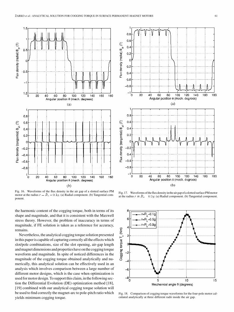
According to Maxwell stress theory, the same cogging torquewaveform should be calculated regardless of the location of theintegration contour as long as it is located inside the air gap.To show that our cogging torque solution is consistent with thistheory, the cogging torque has also been calculated at two otherradii, one closer to the stator surface andanother closer to the magnet surface . The radialand tangential components of the flux density in the slotted airgap at these two radii are shown in Figs. 16 and 17. The coggingtorque waveforms calculated at all three radii inside the air gapare compared in Fig. 18. It is apparent from Fig. 18 and Figs. 16and 17 that although the field solutions at these radii differ, thecogging torque waveforms are practically the same.
It is apparent from these results that the analytical solution isable to correctly predict the effect which motor geometry has on
ZARKO et al.: ANALYTICAL SOLUTION FOR COGGING TORQUE IN SURFACE PERMANENT-MAGNET MOTORS 61
Fig. 16. Waveforms of the flux density in the air gap of a slotted surface PMmotor at the radius r = R � 0:1g. (a) Radial component. (b) Tangential com-ponent.
the harmonic content of the cogging torque, both in terms of itsshape and magnitude, and that it is consistent with the Maxwellstress theory. However, the problem of inaccuracy in terms ofmagnitude, if FE solution is taken as a reference for accuracy,remains.
Nevertheless, the analytical cogging torque solution presentedin this paper is capable of capturing correctly all the effects whichslot/pole combinations, size of the slot opening, air-gap lengthandmagnetdimensionsandpropertieshaveonthecoggingtorquewaveform and magnitude. In spite of noticed differences in themagnitude of the cogging torque obtained analytically and nu-merically, this analytical solution can be effectively used in ananalysis which involves comparison between a large number ofdifferent motor designs, which is the case when optimization isused for motor design. To support this claim, in the following sec-tion the Differential Evolution (DE) optimization method [18],[19] combined with our analytical cogging torque solution willbe used to find correctly the magnet-arc to pole-pitch ratio whichyields minimum cogging torque.
Fig.17. Waveformsof thefluxdensity in theairgapofaslottedsurfacePMmotorat the radius r = R � 0:9g. (a) Radial component. (b) Tangential component.
Fig. 18. Comparison of cogging torque waveforms for the four-pole motor cal-culated analytically at three different radii inside the air gap.

62 IEEE TRANSACTIONS ON MAGNETICS, VOL. 44, NO. 1, JANUARY 2008
IV. EXAMPLE OF IMPLEMENTATION OF ANALYTICAL COGGING
TORQUE SOLUTION
There are many known cogging torque minimization tech-niques. Adjusting the magnet-arc to pole-pitch ratio is oneof the simplest methods which will be used here to show the ef-fectiveness of the presented analytical cogging torque solution.Zhu and Howe [20] showed that the optimum value of isgiven by
(22)
where is the least common multiple between the number ofslots and the number of poles , and is the factor whichtakes into account the fringing flux of the magnets and typicallyranges from 0.01 to 0.03 depending on the air-gap length. In ourcase, the goal is to show that the analytical cogging torque solu-tion presented in this paper can be successfully used to findwhich yields minimum cogging torque and falls into the rangeof values defined by (22). For that purpose, the Differential Evo-lution optimization method has been used.
A. Description of the Differential EvolutionOptimization Method
The Differential Evolution is an optimization technique ca-pable of solving global optimization problems subject to non-linear constraints. It operates on a population of candidate solu-tions and does not require a specific starting point. The popula-tion is of constant size . In each iteration, a new generationof solutions is created and compared to the population mem-bers of the previous generation. The process is repeated untilthe maximum number of generations is reached.
A nonlinear global optimization problem can be defined as:Find the vector of parameterssubject to inequality constraints and subject to boundaryconstraints which will minimize the function .
The population of the th generation can be written inthe form , .Each vector in PG contains real parameters
, ,The initial population is generated using random values
within the given boundaries which can be written in the form
(23)
where is the uniformly distributed random numberon the interval [0,1] which is chosen anew for each , whileand denote the upper and lower boundaries of the vectorparameters. In every generation, new candidate vectors are cre-ated by randomly sampling and combining the vectors from theprevious generation in the following manner:
ifor
otherwise
(24)
where and are DE control parame-ters which are kept constant during optimization,
, are randomly selected vectorsfrom the previous generation, different from each other and dif-ferent from the current vector with index , andis a randomly chosen index which insures that at least oneis different from .
The population for the new generation will be assembledfrom the vectors of the previous generation and the can-didate vectors according to the following selection scheme:
ifotherwise.
(25)
B. Definition of the Optimization Problem
The objective function which should be minimized is the peakvalue of cogging torque, i.e.,
mech. degrees (26)
The only design variable is , which is subject to constraints
(27)
All other geometric parameters of the motor are kept constant asdefined in Table I. The lowest value of 0.7 was selected to avoid
for , which according to (22) would fall in an interval. This magnet-arc would not be very
suitable for practical purposes since utilization of the availablespace for placing the magnet within one pole-pitch would bequite poor.
The population size in the DE algorithm is set to ,while control parameters are , .
C. Optimization Results
Since only one design variable is involved, the DE algorithmconverged after only one iteration to 99% of the final value of
. After 10 iterations, the optimal value of magnet-arc to pole-pitch ratio was reached which is
(28)
This result falls into the range of optimal values for givenby (22) when . The analytically and numerically calcu-lated cogging torque waveforms for this optimal value of arecompared in Fig. 19. It is apparent from (28) and Fig. 19 that theanalytical cogging torque solution presented in this paper can beused to accurately calculate for minimum cogging torque inspite of the noticed deviations from finite-element solutions.
D. Other Examples
It can also be shown in some similar examples that thismethod for calculation of cogging torque, which involvescomplex relative air-gap permeance and the flux density in theslotless air gap, can equally well capture the effects of otherknown methods for cogging torque minimization in surfacePM motors. Some of these methods are different slot/pole

ZARKO et al.: ANALYTICAL SOLUTION FOR COGGING TORQUE IN SURFACE PERMANENT-MAGNET MOTORS 63
Fig. 19. Comparison of cogging torque waveforms calculated analytically andnumerically for the optimal magnet-arc to pole-pitch ratio (� = 0:8452)which yields minimum cogging torque.
Fig. 20. Cross section of a part of the motor showing slots with shifted slotopenings and different tooth widths in the case of teeth pairing.
combinations including fractional slot windings [20]–[22],adjusting the slot opening width [20], [22], air-gap lengthand magnet thickness, using different types of magnetization(radial, parallel, etc.) [22], [23], shifting of permanent magnets[24]–[27], notches in the stator teeth [22], [24], [28], [29], teethpairing [4], [30], slot width pairing [31], magnet segmentation[32], stepped skewing of magnets [22], [24], etc. However, insome of these cases a new equation similar to (21) would haveto be derived for calculation of cogging torque.
For example, in the case of teeth pairing (see Fig. 20), theperiod of the complex relative air-gap permeance is two slotpitches and the widths of the adjacent teeth differ. The air-gappermeance can either be assembled point by point using the so-lution for a single slot opening presented in this paper, or a moreaccurate approach would be to calculate the permeance numeri-cally using MATLAB SC Toolbox [33]. The real and imaginaryparts of the air-gap permeance calculated using SC toolbox forthe case when the slot opening of each slot is shifted by 2 areshown in Fig. 21. The magnet-arc to pole-pitch ratio isand the width of the slot opening is mm. For calculationof cogging torque, the Fourier coefficients , , and
Fig. 21. Waveforms of the complex relative air-gap permeance in the middleof the air gap for two slot pitches in the case of teeth pairing with slot openingsshifted by 2 . (a) Real component. (b) Imaginary component.
have to be calculated from the waveforms in Fig. 21 using thediscrete Fourier transform, and in (21) the number of slotshas to replaced by . The analytically and numerically cal-culated cogging torque waveforms for the case of teeth pairingare compared in Fig. 22. The discrepancies between the wave-forms are consistent with the observations made earlier. TheDifferential Evolution can be used in this case as well to findthe optimum magnet-arc to pole-pitch ratio and the shift of theslot openings which yield minimum cogging torque.
V. CONCLUSION
An analytical solution of the integral of Maxwell stress tensorhas been developed for calculation of cogging torque in surfacePM motors. The solution is based on utilization of the principleof complex relative air-gap permeance derived from conformalmapping theory which takes into account the presence of slotsin the stator of the motor. The method takes into account per-manent magnet properties and all relevant geometric parametersof the motor (number of slots and poles, air-gap length, magnet

64 IEEE TRANSACTIONS ON MAGNETICS, VOL. 44, NO. 1, JANUARY 2008
Fig. 22. Comparison of cogging torque waveforms calculated analytically andnumerically for the case of teeth pairing with slot openings shifted by 2 .
dimensions, size and position of the slot openings, etc.) whichaffect the cogging torque waveform and magnitude.
In comparison with the finite-element solution, the analyt-ical solution yields higher peak values of cogging torque. Thisdiscrepancy is caused by spatial distortions due to the loga-rithmic nature of conformal transformations between complexplanes containing different air-gap geometries. Nevertheless, ithas been shown in an example that this analytical solution isable to correctly predict the optimal magnet-arc to pole-pitchratio which yields minimum cogging torque. Using the prin-ciple of complex relative air-gap permeance and the flux den-sity solution in the slotless air gap, similar solutions for coggingtorque can be derived when employing other methods of cog-ging torque minimization mentioned in the paper. An exampleis given for teeth pairing. A method for optimization, like Dif-ferential Evolution, combined with this type of cogging torquesolution can be used in the design stage to correctly determinethe motor geometry which yields minimum cogging torque.
REFERENCES
[1] J. D. L. Ree and N. Boules, “Torque production in permanent-magnetsynchronous motors,” IEEE Trans. Ind. Appl., vol. 25, no. 1, pp.107–112, Jan. 1989.
[2] K.-H. Kim, D.-J. Sim, and J.-S. Won, “Analysis of skew effects oncogging torque and BEMF for BLDCM,” in Conf. Rec. 1991 IEEE Ind.Applicat. Soc. Annu. Meeting, Dearborn, MI, 1991, vol. 1, pp. 191–197.
[3] B. Ackermann, J. H. H. Janssen, R. Sottek, and R. I. Van Steen, “Newtechnique for reducing cogging torque in a class of brushless DC mo-tors,” IEE Proc. B—Electr. Power Appl., vol. 139, no. 4, pp. 315–320,Jul. 1992.
[4] S. M. Hwang, J. B. Eom, G.-B. Hwang, W.-B. Jeong, and Y.-H.Yung, “Cogging torque and acoustic noise reduction in permanentmagnet motors by teeth pairing,” IEEE Trans. Magn., vol. 36, no. 5,pp. 3144–3146, Sep. 2000.
[5] J. F. Gieras, “Analytical approach to cogging torque calculation in PMbrushless motors,” in Int. Electr. Machines & Drives Conf., Madison,WI, Jun. 2003, vol. 2, pp. 815–819.
[6] C. S. Koh and J.-S. Seol, “New cogging-torque reduction method forbrushless permanent-magnet motors,” IEEE Trans. Magn., vol. 39, no.6, pp. 3503–3506, Nov. 2003.
[7] Y. Yang, X. Wang, R. Zhang, T. Ding, and R. Tang, “The optimizationof pole arc coefficient to reduce cogging torque in surface-mountedpermanent magnet motors,” IEEE Trans. Magn., vol. 42, no. 4, pp.1135–1138, Apr. 2006.
[8] Z. Q. Zhu and D. Howe, “Analytical prediction of the cogging torque inradial-field permanent magnet brushless motors,” IEEE Trans. Magn.,vol. 28, no. 2, pp. 1371–1374, Mar. 1992.
[9] A. B. Proca, A. Keyhani, A. El-Antably, W. Lu, and M. Dai, “Analyticalmodel for permanent magnet motors with surface mounted magnets,”IEEE Trans. Energy Convers., vol. 18, no. 3, pp. 386–391, Sep. 2003.
[10] M. Markovic, M. Jufer, and Y. Perriard, “Reducing the cogging torquein brushless DC motors by using conformal mappings,” IEEE Trans.Magn., vol. 40, no. 2, pp. 451–455, Mar. 2004.
[11] D. Zarko, D. Ban, and T. A. Lipo, “Analytical calculation of magneticfield distribution in the slotted air gap of a surface permanent-magnetmotor using complex relative air-gap permeance,” IEEE Trans. Magn.,vol. 42, no. 7, pp. 1828–1837, Jul. 2006.
[12] M. Markovic, M. Jufer, and Y. Perriard, “Determination of tooth cog-ging force in a hard-disk brushless DC motor,” IEEE Trans. Magn., vol.41, no. 12, pp. 4421–4426, Dec. 2005.
[13] Z. Q. Zhu and D. Howe, “Instantaneous magnetic field distribution inbrushless permanent magnet DC motors, part III: Effect of stator slot-ting,” IEEE Trans. Magn., vol. 29, no. 1, pp. 143–151, Jan. 1993.
[14] X. Wang, Q. Li, S. Wang, and Q. Li, “Analytical calculation of air-gapmagnetic field distribution and instantaneous characteristics of brush-less DC motors,” IEEE Trans. Energy Convers., vol. 18, no. 3, pp.424–432, Sep. 2003.
[15] U. Kim and D. K. Lieu, “Magnetic field calculation in permanentmagnet motors with rotor eccentricity: With slotting effect consid-ered,” IEEE Trans. Magn., vol. 34, no. 4, pp. 2253–2266, Jul. 1998.
[16] Z. Q. Zhu, D. Howe, E. Bolte, and B. Ackermann, “Instantaneous mag-netic field distribution in brushless permanent magnet dc motors, partI: Open-circuit field,” IEEE Trans. Magn., vol. 29, no. 1, pp. 124–135,Jan. 1993.
[17] Z. Haznadar and Z. Stih, Elektromagnetizam (in Croatian). Zagreb:Skolska knjiga, 1997, vol. I.
[18] J. Lampinen, “Multi-constrained nonlinear optimization by the differ-ential evolution algorithm,” presented at the 6th On-Line World Conf.Soft Comput. Ind. Applicat. (WSC6), Sep. 2001.
[19] D. Zarko, “A systematic approach to optimized design of permanentmagnet motors with reduced torque pulsations” Ph. D. dissertation,Univ. Wisconsin, Madison, Sep. 2004 [Online]. Available: http://www.esa.fer.hr/djelatnici/zarko_damirENG.htm
[20] Z. Q. Zhu and D. Howe, “Influence of design parameters on coggingtorque in permanent magnet machines,” IEEE Trans. Energy Convers.,vol. 15, no. 4, pp. 407–412, Dec. 2000.
[21] T. M. Jahns and W. Soong, “Pulsating torque minimization techniquesfor permanent magnet AC motor drives—A review,” IEEE Trans. Ind.Electron., vol. 43, no. 2, pp. 321–330, Apr. 1996.
[22] M. S. Islam, S. Mir, and T. Sebastian, “Issues in reducing the cog-ging torque of mass-produced permanent-magnet brushless DC motor,”IEEE Trans. Ind. Applicat., vol. 40, no. 3, May/Jun. 2004.
[23] Z. Q. Zhu, D. Howe, and C. C. Chan, “Improved analytical modelfor predicting the magnetic field distribution in brushless permanent-magnet machines,” IEEE Trans. Magn., vol. 38, no. 1, pp. 229–238,Jan. 2002.
[24] N. Bianchi and S. Bolognani, “Design techniques for reducing the cog-ging torque in surface-mounted PM motors,” IEEE Trans. Ind. Appl.,vol. 38, no. 5, pp. 1259–1265, Sep. 2002.
[25] C. Studer, A. Keyhani, T. Sebastian, and S. K. Murthy, “Study of cog-ging torque in permanent magnet machines,” in IAS ’97. Conf. Rec.1997 IEEE Ind. Applicat. Conf. Thirty-Second IAS Annu. Meeting, NewOrleans, LA, 1997, vol. 1, pp. 42–49.
[26] C. Breton, J. Bartolome, J. A. Benito, G. Tassinario, I. Flotats, C. W.Lu, and B. J. Chalmers, “Influence of machine symmetry on reduc-tion of cogging torque in permanent-magnet brushless motors,” IEEETrans. Magn., vol. 36, no. 5, pp. 3819–3823, Sep. 2000.
[27] C. A. Borghi, D. Casadei, A. Cristofolini, M. Fabbri, and G. Serra,“Application of a multiobjective minimization technique for reducingthe torque ripple in permanent-magnet motors,” IEEE Trans. Magn.,vol. 35, no. 5, pp. 4238–4246, Sep. 1999.
[28] S. Hwang and D. K. Lieu, “Design techniques for reduction of re-luctance torque in brushless permanent magnet motors,” IEEE Trans.Magn., vol. 30, no. 6, pp. 4287–4289, Nov. 1994.
[29] R. P. Deodhar, D. A. Staton, and T. J. E. Miller, “Modelling of skewusing the flux-mmf diagram,” in Proc. 1996 Int. Conf. Power Elec-tronics, Drives Energy Syst. For Ind. Growth, 1996, vol. 1, pp. 546–551.
[30] S. M. Hwang, J. B. Eom, Y. H. Jung, D. W. Lee, and B. S. Kang,“Various design techniques to reduce cogging torque by controllingenergy variation in permanent magnet motors,” IEEE Trans. Magn.,vol. 37, no. 4, pp. 2806–2809, Jul. 2001.

ZARKO et al.: ANALYTICAL SOLUTION FOR COGGING TORQUE IN SURFACE PERMANENT-MAGNET MOTORS 65
[31] Y. Yang, X. Wang, R. Zhang, C. Zhu, and T. Ding, “Research of cog-ging torque reduction by different slot width pairing permanent magnetmotors,” in Proc. 8th Int. Conf. Electr. Machines Syst., Nanjing, China,Sep. 27–29, 2005, vol. 1, pp. 367–370.
[32] R. Lateb, N. Takorabet, and F. Meibody-Tabar, “Effect of magnetsegmentation on the cogging torque in surface-mounted perma-nent-magnet motors,” IEEE Trans. Magn., vol. 42, no. 3, pp. 442–445,Mar. 2006.
[33] T. A. Driscoll, Schwarz Christoffel Toolbox Users Guide—Version 2.3Dept. Mathematical Sciences, Univ. Delaware. Newark, DE, 2002[Online]. Available: http://www.math.udel.edu/driscoll/SC
Manuscript received May 15, 2006; revised September 17, 2007. Corre-sponding author: D. Zarko (e-mail: [email protected]).
Damir Zarko (M’06) was born in Zagreb, Croatia. He received the B.S. andM.S. degrees in electrical engineering from the University of Zagreb in 1995and 1999, respectively, and the Ph.D. degree from the University of Wisconsin-Madison in 2004.
Currently, he is a Senior Assistant in the Department of Electrical Machines,Drives and Automation, Faculty of Electrical Engineering and Computing, Uni-versity of Zagreb, Croatia, where his research activities are related to design,modeling, analysis, and optimization of electrical machines.
Drago Ban (M’01) received the B.S., M.S., and Ph.D. degrees in electrical en-gineering from the Faculty of Electrical Engineering, University of Zagreb, Za-greb, Croatia, in 1965, 1975, and 1987, respectively.
From 1968 to 1989, he worked as a Development and Project Engineer atKONCAR-Electrical Industry, Zagreb, Croatia. He is currently a full Professorin the Department of Electrical Machines, Drives and Automation, Faculty ofElectrical Engineering and Computing, University of Zagreb, Croatia. His sci-entific and professional activities have been related to the field of electrical ma-chinery, electrical drives, and technical diagnostics.
Prof. Ban was the chairman of several international conferences on electricaldrives and power electronics: EDPE 1996, EDPE 1998, EDPE 2000, and EPE-PEMC 2002. He is a member of several international professional associations,and a member of the Croatian Academy of Engineering.
Thomas A. Lipo (M’64–SM’71–F’87) was born in Milwaukee, WI. He re-ceived the B.E.E. and M.S.E.E. degrees from Marquette University, Milwaukee,WI, in 1962 and 1964, and the Ph.D. degree in electrical engineering from theUniversity of Wisconsin in 1968.
From 1969 to 1979, he was an Electrical Engineer in the Power ElectronicsLaboratory of Cooperate Research and Development of the General ElectricCompany, Schenectady, NY. He became Professor of Electrical Engineeringat Purdue University, West Lafayette, IN, in 1979, and in 1981 he joined theUniversity of Wisconsin, Madison, in the same capacity, where he is presentlythe W. W. Grainger Professor for Power Electronics and Electrical Machines.
Dr. Lipo has received the Outstanding Achievement Award from the IEEEIndustry Applications Society, William E. Newell Award of the IEEE PowerElectronics, and the 1995 Nicola Tesla IEEE Field Award from the Power En-gineering Society for his work. He has served IEEE in various capacities, in-cluding President of Industrial Applications Society. He is a Fellow of IEE(London), a member of IEE (Japan), and a Fellow of the Royal Academy ofGreat Britain.