Power Quality Improvement of Synchronous Generators Using ...
11
Power Quality Improvement of Synchronous Generators Using an Active Power Filter Al-Hussein Abu-Jalala * , Tom Cox * , Chris Gerada * , Mohamed Rashed * , Tahar Hamiti † and Neil Brown ‡ * Power Electronics, Machines and Control Group Electrical and Electronic Engineering Department The University of Nottingham, UK [email protected] † Department of Vehicle Electrification VEDECOM Institute Versailles 78000, France [email protected] ‡ Cummins Power Generation Peterborough, PE1 5EL United Kingdom [email protected] Abstract—Active power filters (APF) are used to improve power quality and are commonly connected in parallel with the load at the point of common coupling (PCC). They are used to compensate for harmonics from nonlinear loads, for reactive power compensation and/or balancing mains currents. This paper will investigate the effect of using an APF to improve the output power quality of a simplified synchronous generator (SSG) with distorted back-EMF. A Matlab Simulink model for the SSG is built to simulate all the system, the APF and the proposed generator. Using an APF, simulation and experimental results show significant improvements in generator output current and reduced the THD in the system. Index Terms—Synchronous generator, Skewless generator, Ac- tive power filter, Four-leg converter. I. I NTRODUCTION Active power filters (APF) have been used to improve power quality since the 1980s [1]. They are connected in parallel with the load at the point of common coupling (PCC). The main functions of the APF are compensating harmonics from nonlinear loads, balancing source currents and reactive power compensation [2]. Shunt active power filter topologies and control algorithms have been widely discussed in the literature [3]–[6]. In [7]–[10] the APF is used in cases with distorted mains voltages and the results showed a high capability for the proposed control techniques in these papers to eliminate the harmonics in the source current and balance them, regardless of the load condition and source voltage. The APF is used with stand-alone generators to improve their dynamic performance, where in [11] the APF is used with an isolated synchronous generator feeding a nonlinear load to compensate current harmonics and regulate the generator terminal voltages. In addition, the APF is used to regulate the output voltage of a variable speed interior permanent magnet synchronous generator (IPMSG) with nonlinear load while controlling the reactive power and compensating any current harmonics [12]. The impact of harmonics on a synchronous generator will be apparent both mechanically and electrically. The mechanical effect will appear as vibration on the generator shaft with electromagnetic torque pulsation, and will shorten the lifetime of the generator. The electrical effect will result in distorted current and voltage waveforms in both stator and rotor wind- ings and this will cause excess heating and generator losses, lowering the efficiency of power conversion [13], [14]. The traditional methods to get a good sinusoidal back-emf waveform have been widely reported in literature, such as distributed windings, short-pitching winding, different pole- slot combinations and stator skewing [15], [16], however, these techniques increase generator design complexity and hence cost, and decrease the back-emf voltage. Synchronous generator stators are also commonly skewed to compensate for the slot harmonics, which complicates the manufacturing process. The purpose of this work is to develop and validate the use of active power filters specifically with simplified synchronous generators. The simplified generators described are less com- plex and so both faster and less expensive to produce. They permit a higher fundamental emf and so have the potential to produce more power, or to reduce excitation losses and so increase efficiency. However the simplified generator designs also produce significantly more harmonics and so an external method, in this case an APF will be used to mitigate these and ensure the level of harmonics seen at the load remains acceptable. The additional costs that would be introduced by adding the APF may be compensated by the practical benefits that can be gained. As well as the direct benefits of increased gener- ator capability and reduced construction cost and complexity outlined above, the APF also has established benefits in terms of improving the transient response of the generator [17] and its ride-through capability, as well as the potential to allow reduced power 3 phase output in fault conditions. In addition, it well known that the cost of semiconductor devices is a decreasing trend, for example, in traction drive systems (55 kW peak power for 18 sec; 30 kw continuous power), the cost of power electronics in 2010 was 7.9 $/kW and in 2020 This is estimated to drop to 3.3 $/kW , i.e. the cost will be 58% less in ten years [18]. The APF will be used to improve the power quality supplied to the load if the load is linear or compensate load harmonics and balance generator loading when the load is nonlinear. II. SYSTEM CONFIGURATION The proposed system is a three-phase four wire system consisting of a simplified synchronous generator (SSG), four leg active power filter (APF), interface L-filter and a load, which may be linear or nonlinear, and balanced or unbalanced as shown in Fig.1.
-
Upload
khangminh22 -
Category
Documents
-
view
1 -
download
0
Transcript of Power Quality Improvement of Synchronous Generators Using ...

Power Quality Improvement of SynchronousGenerators Using an Active Power Filter
Al-Hussein Abu-Jalala∗, Tom Cox∗, Chris Gerada∗, Mohamed Rashed∗, Tahar Hamiti† and Neil Brown‡∗Power Electronics, Machines and Control GroupElectrical and Electronic Engineering Department
The University of Nottingham, [email protected]
†Department of Vehicle ElectrificationVEDECOM Institute
Versailles 78000, [email protected]
‡Cummins Power GenerationPeterborough, PE1 5EL
United [email protected]
Abstract—Active power filters (APF) are used to improvepower quality and are commonly connected in parallel with theload at the point of common coupling (PCC). They are usedto compensate for harmonics from nonlinear loads, for reactivepower compensation and/or balancing mains currents. This paperwill investigate the effect of using an APF to improve the outputpower quality of a simplified synchronous generator (SSG) withdistorted back-EMF. A Matlab Simulink model for the SSGis built to simulate all the system, the APF and the proposedgenerator. Using an APF, simulation and experimental resultsshow significant improvements in generator output current andreduced the THD in the system.
Index Terms—Synchronous generator, Skewless generator, Ac-tive power filter, Four-leg converter.
I. INTRODUCTION
Active power filters (APF) have been used to improve powerquality since the 1980s [1]. They are connected in parallelwith the load at the point of common coupling (PCC). Themain functions of the APF are compensating harmonics fromnonlinear loads, balancing source currents and reactive powercompensation [2]. Shunt active power filter topologies andcontrol algorithms have been widely discussed in the literature[3]–[6]. In [7]–[10] the APF is used in cases with distortedmains voltages and the results showed a high capability for theproposed control techniques in these papers to eliminate theharmonics in the source current and balance them, regardlessof the load condition and source voltage.
The APF is used with stand-alone generators to improvetheir dynamic performance, where in [11] the APF is used withan isolated synchronous generator feeding a nonlinear loadto compensate current harmonics and regulate the generatorterminal voltages. In addition, the APF is used to regulate theoutput voltage of a variable speed interior permanent magnetsynchronous generator (IPMSG) with nonlinear load whilecontrolling the reactive power and compensating any currentharmonics [12].
The impact of harmonics on a synchronous generator will beapparent both mechanically and electrically. The mechanicaleffect will appear as vibration on the generator shaft withelectromagnetic torque pulsation, and will shorten the lifetimeof the generator. The electrical effect will result in distortedcurrent and voltage waveforms in both stator and rotor wind-ings and this will cause excess heating and generator losses,lowering the efficiency of power conversion [13], [14].
The traditional methods to get a good sinusoidal back-emfwaveform have been widely reported in literature, such asdistributed windings, short-pitching winding, different pole-slot combinations and stator skewing [15], [16], however,these techniques increase generator design complexity andhence cost, and decrease the back-emf voltage. Synchronousgenerator stators are also commonly skewed to compensatefor the slot harmonics, which complicates the manufacturingprocess.
The purpose of this work is to develop and validate the useof active power filters specifically with simplified synchronousgenerators. The simplified generators described are less com-plex and so both faster and less expensive to produce. Theypermit a higher fundamental emf and so have the potentialto produce more power, or to reduce excitation losses and soincrease efficiency. However the simplified generator designsalso produce significantly more harmonics and so an externalmethod, in this case an APF will be used to mitigate theseand ensure the level of harmonics seen at the load remainsacceptable.
The additional costs that would be introduced by adding theAPF may be compensated by the practical benefits that canbe gained. As well as the direct benefits of increased gener-ator capability and reduced construction cost and complexityoutlined above, the APF also has established benefits in termsof improving the transient response of the generator [17] andits ride-through capability, as well as the potential to allowreduced power 3 phase output in fault conditions.
In addition, it well known that the cost of semiconductordevices is a decreasing trend, for example, in traction drivesystems (55 kW peak power for 18 sec; 30 kw continuouspower), the cost of power electronics in 2010 was 7.9 $/kWand in 2020 This is estimated to drop to 3.3 $/kW , i.e. thecost will be 58% less in ten years [18].
The APF will be used to improve the power quality suppliedto the load if the load is linear or compensate load harmonicsand balance generator loading when the load is nonlinear.
II. SYSTEM CONFIGURATION
The proposed system is a three-phase four wire systemconsisting of a simplified synchronous generator (SSG), fourleg active power filter (APF), interface L-filter and a load,which may be linear or nonlinear, and balanced or unbalancedas shown in Fig.1.
UnbalancedLoad
Non-linearLoad
RLLinearLoad
SSG
APF
L-Filter
R
S
T
N
Fig. 1: The proposed system to test the simplified synchronousgenerator
A. The Proposed Generator
The proposed generator is based on a standard commercial72.5 KV A 4-pole wound field synchronous generator, withmodifications made to the stator in order to simplify themanufacturing process and increase the generator capacity.The commercial generator has a 2/3 pitch winding skewed byone slot pitch, which has 48 slots and a double layer winding,and each phase consists of four coils, with each two connectedin parallel and these two then connected in series.
The proposed generator has a skewless stator with a fullypitched winding with the same other parameters of the com-mercial generator, and is shown in Fig.2. In the proposedgenerator, the neutral wire is removed to prevent triplencurrent harmonics from reaching the load. A load side neutral
(a) (b)
A1 A3
A2 A4Phase-A
Phase-B
Phase-C
B1
B2 B4
B3
C1 C3
C2 C4
(c)
Fig. 2: Full pitch skewless generator (a)2D finite element analysis(FEA) model (b) Experimental prototype (the proposed generator) (c)Stator coil connection diagram
E
E
1s
1s
Esp
αα/2
α/2
E1s
Efp
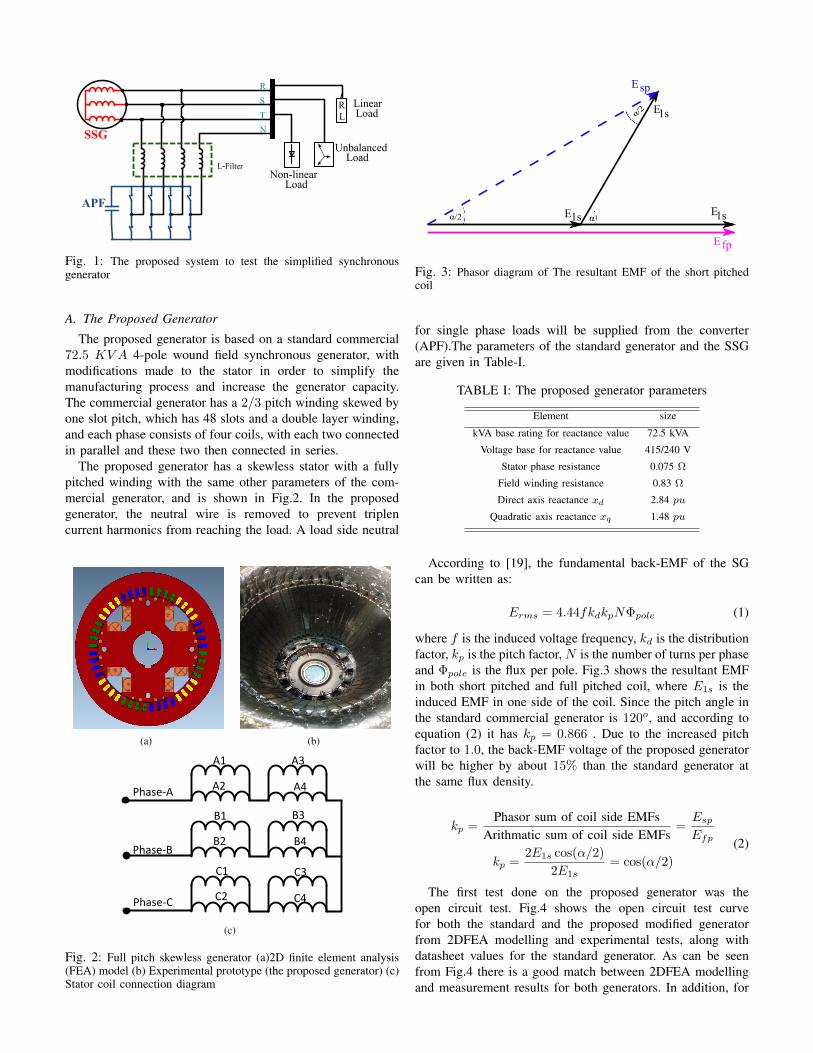
Fig. 3: Phasor diagram of The resultant EMF of the short pitchedcoil
for single phase loads will be supplied from the converter(APF).The parameters of the standard generator and the SSGare given in Table-I.
TABLE I: The proposed generator parameters
Element size
kVA base rating for reactance value 72.5 kVA
Voltage base for reactance value 415/240 V
Stator phase resistance 0.075 Ω
Field winding resistance 0.83 Ω
Direct axis reactance xd 2.84 pu
Quadratic axis reactance xq 1.48 pu
According to [19], the fundamental back-EMF of the SGcan be written as:
Erms = 4.44fkdkpNΦpole (1)
where f is the induced voltage frequency, kd is the distributionfactor, kp is the pitch factor, N is the number of turns per phaseand Φpole is the flux per pole. Fig.3 shows the resultant EMFin both short pitched and full pitched coil, where E1s is theinduced EMF in one side of the coil. Since the pitch angle inthe standard commercial generator is 120o, and according toequation (2) it has kp = 0.866 . Due to the increased pitchfactor to 1.0, the back-EMF voltage of the proposed generatorwill be higher by about 15% than the standard generator atthe same flux density.
kp =Phasor sum of coil side EMFs
Arithmatic sum of coil side EMFs=EspEfp
kp =2E1s cos(α/2)
2E1s= cos(α/2)
(2)
The first test done on the proposed generator was theopen circuit test. Fig.4 shows the open circuit test curvefor both the standard and the proposed modified generatorfrom 2DFEA modelling and experimental tests, along withdatasheet values for the standard generator. As can be seenfrom Fig.4 there is a good match between 2DFEA modellingand measurement results for both generators. In addition, for

the same fundamental output voltage the field current can bereduced from 15 A in the standard generator to 11.2 A in theproposed generator, if the power quality can be maintained.
0 10 20 30 40 50 600
100
200
300
400
500
600
Full Pitch FEA (Va1peak
)
2/3rd Pitch FEA (Va1peak
)
2/3rd Pitch data sheet (Va1peak
)
Full Pitch experimental (Va1peak
)
Fun
dam
enta
l Com
pone
nt o
fT
he b
ack-
EM
F (
V)
Field Current (A)
Fig. 4: Open circuit test for the proposed generator and the standardcommercial generator
B. Synchronous Generator Model
A Matlab Simulink based model was developed for theproposed generator as shown in Fig.5. This model is based onthe inductance matrix of the proposed generator at differentrotor positions taken from the 2DFEA model. The inductancematrix is a three dimensional matrix where each layer containsthe self and the mutual inductances of the generator coils (i.e.stator, field and damper windings) at one rotor position.
Lookuptable
ddt
Generator circuitLn×n
Ψn×1 En×1
Currentmeasurements
To the loadRotor
position
Fig. 5: Block diagram of the generator simulink matlab model
The flux linkage and the induced back-EMF is calculatedby (3) and (4) respectively.
Ψ[n×1] = L[n×n] × I[n×1] (3)
Eback−EMF [n×1] =dΨ[n×1]
dt(4)
In this model, the effects of saturation were neglectedand the field current was assumed to be constant during thesimulation time. In order to validate the Simulink model, itsperformance was first compared to results from both FEA andexperiment without the use of an active power filter. Fig.6shows the comparison between the back-EMF from 2DFEAand the Simulink model. It can be seen that these are in veryclose agreement between the two models.
In addition, a loaded generator test is done to compare theresults from the Matlab Simulink model with the experimentalresults of the proposed generator, the test is done for a linear
Vamatlab
Gen
erat
or B
ack-
EM
F (
V)
Time (sec)
450
300
150
0
-150
-300
-450
0 0.005 0.01 0.015
Vbmatlab
Vcmatlab
VcFEA
VaFEA
VaFEA
Fig. 6: Comparison between FEA and Matlab models of the proposedgenerator
35kW resistive load and nonlinear load i.e. three-phase diodebridge with RL load (R = 9.2Ω and L = 5.5mH).Fig.7. shows the simulation and experimental results for thebalanced linear load, the THD in the Simulink model was4.5%, while in experimental test was 4.1%, a small variationdue to the linearity of the simulation.
Time(sec)(a)Generator current from Matlab Simulink model
0 0.005 0.01 0.015 0.02 0.025 0.03 0.035 0.04
Cur
rent
(A
)
-50
0
50 Ia
Ib
Ic
Time(sec)(b)Generator current from experimental test
0 0.005 0.01 0.015 0.02 0.025 0.03 0.035 0.04
Cur
rent
(A
)
-50
0
50 Ia
Ib
Ic
Harmonic Order(c)FFt analysis for Simulink model and experimental results
1 5 7 11 13 17 19 23 25 29 31 35 37
% F
rom
the
Fund
ame
ntal
2
4 ExperimentalSimulink model
Fig. 7: The simulation and experimental results for balanced linearload (a) Matlab Simulink model (b) experimental result of theproposed generator (C) FFT analysis for simulation and experimentalresults
Furthermore, the nonlinear load test was done and the resultsare shown in Fig.8. This figure shows the simulation andexperimental results for balanced nonlinear load, as can beseen from the figure, the THD in the Simulink model was22.3% while in the experimental test this was 25%. As can beseen from Fig.7 and Fig.8 the synchronous generator Simulinkmodel showed a good agreement with the experimental result.

Time(sec)(a)Generator Current from Matlab Simulink model
0 0.005 0.01 0.015 0.02 0.025 0.03 0.035 0.04
Cur
rent
(A
)
-50
0
50 Ia
Ib
Ic
Time(sec)(b)Generator Current from experimental test
0 0.005 0.01 0.015 0.02 0.025 0.03 0.035 0.04
Cur
rent
(A
)
-50
0
50 Ia
Ib
Ic
Harmonic Order(c)FFt analysis for Simulink model and experimental results
1 5 7 11 13 17 19 23 25 29 31 35 37
% F
rom
the
Fun
dam
enta
l
0
10
20
30ExperimentalSimulink model
Fig. 8: The simulation and experimental results for balanced non-linear load (a) Matlab Simulink model (b) experimental result of theproposed generator (C) FFT analysis for simulation and experimentalresults
III. HARMONIC COMPENSATION
The APF is the power electronics part in the proposedsystem, and it is based on a Voltage Source Inverter (VSI).The function of the APF in this system is to compensatethe load or the generator current harmonics. This processcan be divided to three main steps, which are, phase anglecalculation, reference current calculation and APF control. TheAPF topology and all these steps will be covered in detail inthe following subsections.
A. Active Power Filter Topology
In three-phase four-wire system the converter topology canbe either a conventional three-phase inverter with DC-link splitcapacitor with midpoint connection for neutral wire, or a four-leg inverter where the neutral wire is connected to the fourthleg. In this paper the second configuration is chosen to reducethe DC-link size by reducing the rated current and voltageof the DC-link capacitor [20]. In addition, since there is onlyone capacitor in the four-leg topology, so there is only onevoltage to be controlled. However, in the split capacitor withmidpoint topology there are two voltages to be regulated andequal to each other, thereby making the control algorithm morecomplicated [21].
B. Synchronisation Method
An important factor in APF operation is calculating thevoltage phase angle at the point of common coupling (PCC),because the other two steps depend on the phase angle calcu-lation. A Phase Locked Loop (PLL) is used to calculate the
phase voltage angle. The conventional synchronous referenceframe PLL (SFR-PLL) is designed for ideal source voltageand does not give accurate tracking for the phase voltageunder non-ideal conditions [22], [23]. In [24] the authorsproposed a positive-sequence detector based on a new decou-pled double synchronous reference frame phase-locked loop(DDSRF-PLL), this technique is based on positive and nega-tive sequence transformation and detects the phase angle withexcellent accuracy when the source has unbalanced voltage.However under distorted voltage source this method still hassome error in the detected phase angle. For a good tracking ofthe phase voltage angle under distorted and unbalanced sourcea Dual Second order Generalised Integrator PLL (DSOGI-PLL) was proposed in [25]as shown in Fig.9.
abc
v
v
vv
qv
qvvvSOGI
-QSG
SOGI-QSG
DSOGI-QSG PSC
v
[T ]
0.5
v0.5
[T ]dq
vdq qv
d
PI
α
αα
α
α
β
β
β
β
β
αβ
ωref
ώ
ώ
∫ θ+'
SRF-PLL
qv =0
Fig. 9: Block diagram of the DSOGI-PLL
This technique is based on the instantaneous symmetricalcomponents (ISC) in the αβ coordinates method to detect thepositive sequence component.
Time(sec)(a)Source voltage
0.2 0.205 0.21 0.215 0.22 0.225 0.23 0.235 0.24
Pha
se V
olta
ge
(V)
-500
0
500
Va
Vb
Vc
Time(sec)(b)Phase angle (θ)
0.2 0.205 0.21 0.215 0.22 0.225 0.23 0.235 0.24
Pha
se a
ngle
(rad
)
0
2
4
6
DDSRF-PLLDSOGI-PLLSRF-PLL
Time(sec)(c)Phase angle error
0.2 0.205 0.21 0.215 0.22 0.225 0.23 0.235 0.24
Pha
se a
ngle
er
ror
(rad
)
-0.2
-0.1
0
0.1
0.2
DDSRF-PLLDSOGI-PLLSRF-PLL
Fig. 10: Simulation results for three different PLLs, (a) sourcevoltages (b) tracked phase angle (c) the error in the tracked angle
Fig.10 shows the simulation result for the different types ofPLL. As can be seen on Fig.10(c) there is a significant error inthe phase angle tracking in SRF-PLL and DDSFR-PLL while

DSOGI-PLL gives acceptable tracking even in highly distortedvoltage source as shown in Fig.10(a)
C. Current Reference Generation Technique
The second stage of APF operation is extracting the refer-ence currents, which are the currents that should be injected atthe PCC to compensate current harmonics and get sinusoidalsource currents.
The most two widely used methods in APF are Instan-taneous power theory (p-q theory) [26], and synchronousreference frame (SRF) d-q technique [27], [28]. SFR-dq isadopted in this paper as it is easier to implement and faster interms of computation time than the pq theory based techniqueDSOGI-PLL and gives a very accurate angle. In addition, thistechnique is considered the best choice amongst four othercompensation methods, p-q theory being one of them [28].The equations from equation (5) to equation (9) summariseSRF-dq technique. idiq
i0
= M
iaibic
(5)
Where M the transformation matrix (Park transformation)
M =
√2
3
cos(θ) cos(θ − 2π3 ) cos(θ + 2π
3 )− sin(θ) − sin(θ − 2π
3 ) − sin(θ + 2π3 )
1√2
1√2
1√2
(6)
Since the controller of the active filter in this system is justdealing with harmonic content, so both id and iq are passedthrough a high pass filter to get the ac content id and iq in thecurrents id and iq respectively.
idfilter−−−−→ id ⇒ i∗d (7)
iqfilter−−−−→ iq ⇒ i∗q (8)
i0 ⇒ i∗0 (9)
where i∗d, i∗q and i∗0 are the reference currents are thereference current in d-q axes respectively. To calculate thereference current in abc frame, the inverse Park transformationis used as it is shown in equation (10)i∗ai∗b
i∗c
=
√2
3
cos(θ) − sin(θ) 1√2
cos(θ − 2π3 ) − sin(θ − 2π
3 ) 1√2
cos(θ + 2π3 ) − sin(θ + 2π
3 ) 1√2
i∗di∗qi∗0
(10)
The neutral reference current is calculated from equation (11),and the reference voltage for the neutral leg is calculated fromequation (12).
i∗n = −(i∗a + i∗b + i∗c) (11)
v∗n = −(v∗a + v∗b + v∗c ) (12)
D. Current Control Technique
The function of the current controller is generating thevoltage reference for the VSI to produce a current equal tothe calculated reference current. Then this current is absorbedor injected from/into the PCC to eliminate the harmonics fromthe generator/load current.
The PI controller (SRF-PI) in the d-q reference frame givesgood results in DC values where it drives the steady state tozero. However, in this system the reference current is an ACwaveform so SRF-PI controller is not the optimum choice forthe controller.
For AC waveforms the proportional resonant current con-troller (PR) has been widely used due to its capability forregulating AC waveforms [29]. This controller is implementedin stationary reference frame (α− β) plane and it has a highperformance in tracking sinusoidal reference currents. Thetransfer function on non-ideal PR is given in equation (13)
GAC(s) = kp +2kiωcs
s2 + 2ωcs+ ω2(13)
Where kp is the proportional controller gain, ki is the integralcontroller gain and ωc is the cut-off frequency.
To include the harmonics in the controller, selective har-monic compensators can be cascaded with the PR controller,each harmonic has a resonant block and this block is tuned atthe harmonic frequency. The transfer function of the harmoniccompensator is given as:
Gh(s) =∑
h=5,7,11,...
2kihωcs
s2 + 2ωcs+ (hω)2(14)
The harmonics that need to be compensated in this system areh = 5, 7, 11, 13, 17, 19, 23 and 25, these being most dominantharmonics in the proposed generator. Fig.11 shows the blockdiagram of PR-HC current controller
++PR
-
*αv*βv
+
+ *av
*bv
*cv
αβ0
abc
*αi
*βi
HC5
HC25
PR+HC
-+
PR+HC
-+
*0i PR+HC
*0v
θ
i
i
i
α
β
0
Fig. 11: Block diagram of PR+HC current controller

IV. SIMULATION RESULTS
This simulation was carried out for the system in Fig.1with interface filter (4.2 mH) and three different load types:Linear, balanced nonlinear and unbalanced nonlinear load. Allthree tests used a constant excitation and generator speed.The switching frequency was 10kHz in all simulations andthe simulation time was 5 sec, with the APF enabled att = 2 sec to give a clear indication of system behaviour bothwith and without the APF. The PR+HC controller parametersthat were used in the simulation are given in Table-II. Thecurrent waveforms of the generator, load, and the APF wereanalysed.
TABLE II: The PR+HC controller parameters
Element Size
Kp 7
kI 250
kIh 250
A. Balanced Linear Load
In this simulation a linear load was connected to thegenerator (35 kW ) at rated voltage 415 V line to line. Theoutput generator current, load current and filter current areshow in Fig.12.With the APF in operation, the total harmonicdistortion (THD) of the load currents is reduced from 4.5% toaround 2.1%.
Time(sec)(a)Load and Genrator Currents for balanced linear load
before enabling the APF
1.8 1.81 1.82 1.83 1.84 1.85
Cur
rent
(A
)
-50
0
50 Ia
Ib
Ic
Time(sec)(b)Load Current for balanced linear load
after enabling the APF
2.36 2.37 2.38 2.39 2.4 2.41
Cur
rent
(A
)
-50
0
50 Ia
Ib
Ic
Time(sec)(c)Filter Current for balanced linear load
2.36 2.37 2.38 2.39 2.4 2.41
Cur
rent
(A
)
-20
0
20Ia
Ib
Ic
Fig. 12: Generator, load, and filter currents with linear balanced load
B. Balanced Non-Linear Load
To simulate a nonlinear balanced load a three phase diodebridge with RL load (L = 5.5 mH and R = 9.4 Ω) was
connected to the generator. When the APF was enabled, theTHD in the generator current decreased from 22.3% beforeswitching APF on to 3.43% after switching APF on. Fig.13shows the generator, the load and the filter current before andafter the compensation.
Time(sec)(a)Load and Genrator Currents for balanced nonlinear load
before enabling the APF
1.8 1.81 1.82 1.83 1.84 1.85
Cur
rent
(A
)
-50
0
50 Ia
Ib
Ic
Time(sec)(b)Genrator Current for balanced nonlinear load
after enabling the APF
2.36 2.37 2.38 2.39 2.4 2.41
Cur
rent
(A
)
-50
0
50 Ia
Ib
Ic
Time(sec)(c)Filter Current for balanced nonlinear load
2.36 2.37 2.38 2.39 2.4 2.41
Cur
rent
(A
)
-20
0
20 Ia
Ib
Ic
Fig. 13: Generator, load, and filter currents with nonlinear balancedload
C. Unbalanced Non-Linear LoadThe simulation was undertaken for two different types of
unbalanced load. In the first type the sum of the three phasecurrents is zero (Just negative sequence components). In thesecond type, the sum of the three phase current is not zeroi.e. there is a current in the neutral wire (negative and zerosequence components).
1) Unbalanced Non-Linear Load with Only Negative Se-quence Components (Type-1): To simulate the first type ofunbalance, (only negative sequence), a nonlinear load (fullbridge diode rectifier) is added to the circuit of subsectionIV-B and connected between phase-A and phase-B. The DCload was L = 5.5 mH and R = 27 Ω. The simulation resultsare shown in Fig.14, as can be seen from the figure, when theAPF is enabled the generator current became balanced and theTHD significantly improved. For example, the THD in phase-C drops from 20.1% to 3.8%. Table-III summarises the THDand the current values of the system before and after enablingthe APF.
2) Unbalanced Non-Linear Load with negative and zerosequence components (type-2): In this simulation a single-phase load is added to the simulation in subsection IV-B andconnected between phase A and the fourth leg of the converter(neutral point). As can be seen from Fig.15 the APF decreasedTHD in the generator current to 22.3% to 3.65% and suppliedthe single phase load when it was connected.

Time(sec)(a) Load and Generator Current for unbalanced nonlinear
1.8 1.81 1.82 1.83 1.84 1.85
Cur
rent
(A
)
-50
0
50 Ia
Ib
Ic
Time(sec)(b)Genrator Current for unbalanced nonlinear load (type-1)
after enabling the APF
2.36 2.37 2.38 2.39 2.4 2.41
Cur
rent
(A
)
-50
0
50 Ia
Ib
Ic
Time(sec)(c)Filter Current for unbalanced nonlinear load (type-1)
2.36 2.37 2.38 2.39 2.4 2.41
Cur
rent
(A
)
-40
-20
0
20
40Ia
Ib
Ic
load (type-1) before enabling the APF
Fig. 14: System currents after enabling the APF with nonlinear andunbalanced load type-1
TABLE III: The simulation results for the THD and currents valuesbefore and after enabling the APF for unbalanced nonlinear load withjust negative sequence
Before enablingthe APF After enabling the APF
load/generator Load GeneratorTHD% Amp THD% Amp THD% Amp
Phase-A 14.6 57.5 20.3 60.0 3.7 54.6Phase-B 15.4 56.5 19.7 58.9 3.3 52.9Phase-C 20.1 45.4 25.5 47.1 3.8 53.7
V. EXPERIMENTAL RESULTS
The test bed consists of a simplified synchronous generatorwith a skewless stator and a full pitch winding as shown inFig.2(b) coupled with a DC-motor driven by a EurothermDrive, a 590 Digital series with closed loop speed Control,(used to maintain a constant rotational speed) and an activepower filter as shown in Fig.16. For the excitation, the fieldwinding was fed directly by using an external DC sourcethrough slip rings on the rotor shaft.
The active power filter is shown in Fig.17, which is afour-leg IGBT converter constructed in the lab by using twocommercial three-phase SKAI modules, designed by Semikronfor automotive applications, (SKAI45A2GD12-W24DI) [30].These two converters are connected in parallel with oneDC-link capacitor, where only one leg was used from thesecond SKAI module. The APF circuit parameters are givenin Table-IV. The control platform that is used experimentallyto implement the active power filter controller is composed ofFPGA (Field Programmable Gate Array), DSP (Digital SignalProcessor) and DSK6713HPI daughtercard (TMS320C6713).The control algorithm is implemented in the DSP by usingCode Composer Studio, and this program calculates the refer-
Time(sec)2.36 2.37 2.38 2.39 2.4 2.41
Cur
rent
(A
)
-50
0
50 Ia
Ib
Ic
Time(sec)2.36 2.37 2.38 2.39 2.4 2.41
Cur
rent
(A
)
-50
0
50 Ia
Ib
Ic
Time(sec)2.36 2.37 2.38 2.39 2.4 2.41
Cur
rent
(A
)
-20
0
20 Ia
Ib
Ic
(a) Load current for unbalanced nonlinear load (type-2)after enabling the APF
(b) Generator current for unbalanced nonlinear load (type-2)after enabling the APF
(c) Filter current for unbalanced nonlinear load (type-2)
Fig. 15: System currents after enabling the APF with nonlinear andunbalanced load type-2
Fig. 16: The experimental test rig
ence signals for the APF. Then the FPGA takes these referencesignals and generate the gate pulses for the APF switches.
TABLE IV: The APF parameters
Element Size
Switching frequency 10 kHz
L-filter inductance 4.2 mH
DC-link capacitor 5 mF
DC-link voltage 730 V
A. Balanced Linear Load
In this test, a three-phase resistive load (35 kW) wasconnected to the generator and the load currents without andwith APF are shown in Fig.18(a) and Fig.18(b) respectively.As can be seen from the figure when the APF enabled theTHD in load current has decreased from (4.1%) to (1.9%).
B. Balanced Non-Linear Load
To represent the balanced and nonlinear load a three-phasediode rectifier connected to RL load (L = 5.5 mH and

Fig. 17: The active power filter and its accessories: L-filter, DC-linkcapacitor and chiller
Time(sec)(a) load current before enabling the APF
0 0.005 0.01 0.015 0.02 0.025 0.03 0.035 0.04
Cur
rent
(A
)
-50
0
50Ia
Ib
Ic
Time(sec)(b) load current after enabling the APF
0 0.005 0.01 0.015 0.02 0.025 0.03 0.035 0.04
Cur
rent
(A
)
-50
0
50Ia
Ib
Ic
Fig. 18: Load current with 35 kW resistive load in experimental test
R = 9.4 Ω) was used as a load. The aim of this test tosee to what extent the APF can improve the generator outputcurrent. Fig.19 shows the generator current before and afterenabling the APF. As can be seen from the figure the APFhad dramatically improved the generator current and the THDbecame (5%) instead of (24.7%)before it enabled.
C. Unbalanced Non-Linear Load-type(2)
The load was constructed from: A three-phase diode rectifierconnected to RL load (L = 5.5 mH and R = 9 Ω). A single-phase load (30Ω) connected between phase A and APF neutralleg. The total power was about 34.5Kw. When the generatorstarted the load was connected and the APF disabled. So thesingle phase-load is OFF because the neutral is disconnected(the neutral wire is supplied through the APF). The currentwaveforms for both the generator and the load are as shownin Fig.20. The phase currents are as given in Table-V andthe THD was (25%). When the APF is enabled, the single-
Time(sec)(a) Generator current before enabling the APF
0 0.005 0.01 0.015 0.02 0.025 0.03 0.035 0.04
Cur
rent
(A
)
-50
0
50Ia
Ib
Ic
0 0.005 0.01 0.015 0.02 0.025 0.03 0.035 0.04
Cur
rent
(A
)
-50
0
50Ia
Ib
Ic
Time(sec)(b) Generator current after enabling the APF
Fig. 19: Experimental result: generator currents before and afterenabling the APF
Time(sec)0 0.005 0.01 0.015 0.02 0.025 0.03 0.035 0.04
Cur
rent
(A
)
-80
-60
-40
-20
0
20
40
60
80Ia
Ib
Ic
Fig. 20: Generator/ load current before enabling the APF
TABLE V: Generator/load currents before the APF enabled
Phase-A Phase-B Phase-C47.4A 48.4A 46.7A
phase load is supplied and this gives unbalanced loading inthe load side, but in the generator side, the APF compensatedthe harmonics in the generator currents and balanced them.Fig.21 shows the load and the generator currents after enablingthe APF respectively. As can be seen from Fig.22 the THDin generator current has improved and decreased from (25%)before switching on the APF to about (5.8%) after switchingon the APF. Also, the APF decreased the unbalanced loadingin the generator current. Table-VI shows the difference inTHD and unbalanced loading in the generator and load currentbefore and after enabling the APF.

Time(sec)(a) Load current after enabling the APF
0 0.005 0.01 0.015 0.02 0.025 0.03 0.035 0.04
Cur
rent
(A
)
-50
0
50Ia
Ib
Ic
Time(sec)(b) Generator current after enabling the APF
0 0.005 0.01 0.015 0.02 0.025 0.03 0.035 0.04
Cur
rent
(A
)
-50
0
50Ia
Ib
Ic
Fig. 21: System currents after enabling the APF with nonlinear andunbalanced load
TABLE VI: The experimental results for the THD and currentsvalues before and after enabling the APF for unbalanced nonlinearload
Before enablingthe APF After enabling the APF
load/generator Load GeneratorTHD% Amp THD% Amp THD% Amp
Phase-A 25.1 47.4 22.8 57.4 5.7 51.6Phase-B 24.8 48.4 27 49.3 5.3 52.8Phase-C 25 46.7 26.8 47.5 5.9 50.2
Harmonic Order1 5 7 11 13 17 19 23 25
Pea
k va
lue
(V)
0
10
20
30
40
50
60
70
80Ia-generator
Ib-generator
Ic-generator
Ia-load
Ib-load
Ic-load
Fig. 22: FFT for generator and load currents after the APF enabledwith nonlinear and unbalanced load
VI. DISCUSSION
In the previous two sections the simulation and experimentalresults were presented, and the experimental results havesupported the simulation results in the three cases. For thefirst case, balanced linear load, the THD in the load current
TABLE VII: Comparison between the simulation results and theexperimental results for the THD in the load/generator current
Before APFenabled
After APFenabled
Sim. Exp. Sim. Exp.Balanced Linear load (Load) 4.5 % 4.1% 2.1 % 1.9%Balanced Nonlinear Load (Generator) 22.3% 25% 3.4% 5.0%Unbalanced Nonlinear Load (Generator) 22.3% 25% 3.6% 5.8%
after enabling the controller in the simulation was (2.1%) andit is close to the experimental result which was (1.9%) seeFig.12 and Fig.18 respectively. In the second case, balancednonlinear load, also the simulation results and experimentalresults had good agreement, where in the simulation the THDin the generator current was (3.4%), while in the experimentalresult was (5%), as can be seen from Fig.13 and Fig.19 .Finally in the third case, unbalanced nonlinear load (type-2),also the THD in the simulation result was (3.65%) and inthe experimental result was (5.8%) as shown in Fig.15 andFig.21 respectively, and the APF supplied the single-phaseload while maintaining the generator current balance as shownin Table-VI. Table-VII summarises the comparison betweenthe simulation results and experimental results in the threedifferent cases.
VII. CONCLUSIONS
The effect of using an active power filter to compensate forthe poor harmonic output of a simplified synchronous genera-tor has been investigated by both simulation and experiment.The experimental results have validated the simulation resultsand shown that the APF can be integrated with a simplifiedsynchronous generator to provide an acceptable level of powerquality to the load from a simple generator with a poorquality output waveform at the point of common coupling(PCC). While this system achieved a satisfactory level ofpower quality in terms of THD, for the systems that requiremore restricted THD values such as micro grids, the proposedsystem THD could be improved by using an LCL-interfacefilter instead of L-filter, increasing the switching frequencyabove 10kHz or the use of other types of controllers
The novelty of this work is the use of the APF to allowthe simplification of the design of the synchronous genera-tor, allowing the generator capacity and/or efficiency to beincreased, and further permitting a simplified design that isboth less expensive and faster to produce while maintainingan acceptable level of power quality at the load.
As well as the benefits defined above, the use of APFto compensate for poor generator output power quality isparticularly apt for the use of fractional slot concentratedwindings, allowing for decreased end winding length and fullyautomated coil winding and placement, while compensatingfor the windings natural high harmonic content. The APFmay also be used to improve transient response during suddenchanges in generator loading and improve fault ride-throughcapability.
ACKNOWLEDGEMENT
The authors gratefully acknowledge the support of theMinistry of Higher Education and Scientific Research - Libya,

the University of Nottingham, and Cummins Generator Tech-nologies in carrying out this research.
REFERENCES
[1] D. Chen and S. Xie, “Review of the control strategies applied toactive power filters,” in IEEE International Conference on Electric Util-ity Deregulation, Restructuring and Power Technologies. Proceedings,vol. 2, April 2004, pp. 666–670 Vol.2.
[2] H. Akagi, “New trends in active filters for power conditioning,” IEEETransactions on Industry Applications, vol. 32, no. 6, pp. 1312–1322,Nov 1996.
[3] M. El-Habrouk, M. K. Darwish, and P. Mehta, “Active power filters: areview,” IEE Proceedings - Electric Power Applications, vol. 147, no. 5,pp. 403–413, Sep 2000.
[4] H. L. Jou, K. D. Wu, J. C. Wu, C. H. Li, and M. S. Huang, “Novelpower converter topology for threephase four-wire hybrid power filter,”IET Power Electronics, vol. 1, no. 1, pp. 164–173, March 2008.
[5] M. I. M. Montero, E. R. Cadaval, and F. B. Gonzalez, “Comparison ofcontrol strategies for shunt active power filters in three-phase four-wiresystems,” IEEE Transactions on Power Electronics, vol. 22, no. 1, pp.229–236, Jan 2007.
[6] P. Dey and S. Mekhilef, “Current controllers of active power filter forpower quality improvement: A technical analysis,” Automatika–Journalfor Control, Measurement, Electronics, Computing and Communica-tions, vol. 56, no. 1, 2015.
[7] S.-J. Huang and J.-C. Wu, “A control algorithm for three-phase three-wired active power filters under nonideal mains voltages,” IEEE Trans-actions on Power Electronics, vol. 14, no. 4, pp. 753–760, Jul 1999.
[8] P. Salmeron and R. S. Herrera, “Distorted and unbalanced systemscompensation within instantaneous reactive power framework,” IEEETransactions on Power Delivery, vol. 21, no. 3, pp. 1655–1662, July2006.
[9] C.-C. Chen and Y.-Y. Hsu, “A novel approach to the design of ashunt active filter for an unbalanced three-phase four-wire systemunder nonsinusoidal conditions,” IEEE Transactions on Power Delivery,vol. 15, no. 4, pp. 1258–1264, Oct 2000.
[10] X. Yuan, W. Merk, H. Stemmler, and J. Allmeling, “Stationary-framegeneralized integrators for current control of active power filters withzero steady-state error for current harmonics of concern under un-balanced and distorted operating conditions,” IEEE Transactions onIndustry Applications, vol. 38, no. 2, pp. 523–532, Mar 2002.
[11] T. Surgevil and E. Akpinar, “Application of shunt active power filter toisolated synchronous generator system,” in 35th Annual Conference ofIEEE Industrial Electronics, Nov 2009, pp. 249–254.
[12] K. Nishida, T. Ahmed, and M. Nakaoka, “Advanced active power filtercontrolled permanent-magnet synchronous generator for automotiveapplications,” in IEEE Power Electronics Specialists Conference, June2007, pp. 1508–1514.
[13] J. q. Wang, P. c. Song, C. h. Cui, J. k. Li, and T. Yang, “Analysis ofoperation of synchronous generator under the distortion of harmoniccurrent,” in Asia-Pacific Power and Energy Engineering Conference,March 2012, pp. 1–4.
[14] W. Fan and Y. Liao, “Impacts of flickers, harmonics and faults onsynchronous generator operations,” in Proceedings of the 2012 44thSoutheastern Symposium on System Theory (SSST), March 2012, pp.220–225.
[15] D. A. Kocabas, “Novel winding and core design for maximum reductionof harmonic magnetomotive force in ac motors,” IEEE Transactions onMagnetics, vol. 45, no. 2, pp. 735–746, Feb 2009.
[16] H. Asgharpour-Alamdari, Y. Alinejad-Beromi, and H. Yaghobi, “Reduc-tion in distortion of the synchronous generator voltage waveform usinga new winding pattern,” IET Electric Power Applications, vol. 11, no. 2,pp. 233–241, 2017.
[17] A. Abu-Jalala, T. Cox, C. Gerada, M. Rashed, T. Hamiti, and N. Brown,“Performance improvement of simplified synchronous generators usingan active power filter,” in IEEE Energy Conversion Congress andExposition (ECCE), Oct 2017, pp. 1845–1849.
[18] “Vehicle technologies multi-year program plan 2011-2015; section2:2:1,” https://www1.eere.energy.gov/vehiclesandfuels/pdfs/program/vtmypp 2011-2015.pdf, accessed: 2018-03-01.
[19] C.-M. Ong, Dynamic Simulation of Electric Machinery Using Mat-lab/Simulink. Prentice Hall PTR Upper Saddle River, NJ, 1998.
[20] C. A. Quinn and N. Mohan, “Active filtering of harmonic currents inthree-phase, four-wire systems with three-phase and single-phase non-linear loads,” in Applied Power Electronics Conference and Exposition,1992. APEC ’92. Conference Proceedings 1992., Seventh Annual, Feb1992, pp. 829–836.
[21] C. A. Quinn, N. Mohan, and H. Mehta, “A four-wire, current-controlledconverter provides harmonic neutralization in three-phase, four-wiresystems,” in Proceedings Eighth Annual Applied Power ElectronicsConference and Exposition,, Mar 1993, pp. 841–846.
[22] V. Kaura and V. Blasko, “Operation of a phase locked loop systemunder distorted utility conditions,” IEEE Transactions on Industry Ap-plications, vol. 33, no. 1, pp. 58–63, Jan 1997.
[23] S.-K. Chung, “A phase tracking system for three phase utility interfaceinverters,” IEEE Transactions on Power Electronics, vol. 15, no. 3, pp.431–438, May 2000.
[24] P. Rodriguez, J. Pou, J. Bergas, J. I. Candela, R. P. Burgos, andD. Boroyevich, “Decoupled double synchronous reference frame pllfor power converters control,” IEEE Transactions on Power Electronics,vol. 22, no. 2, pp. 584–592, March 2007.
[25] P. Rodriguez, R. Teodorescu, I. Candela, A. V. Timbus, M. Liserre,and F. Blaabjerg, “New positive-sequence voltage detector for gridsynchronization of power converters under faulty grid conditions,” inPower Electronics Specialists Conference, 2006, pp. 1–7.
[26] H. Akagi, Y. Kanazawa, and A. Nabae, “Instantaneous reactive powercompensators comprising switching devices without energy storagecomponents,” IEEE Transactions on Industry Applications, vol. IA-20,no. 3, pp. 625–630, May 1984.
[27] P. Santiprapan and K. L. Areerak, “Performance improvement of har-monic detection using synchronous reference frame method,” in 2010International Conference on Advances in Energy Engineering, June2010, pp. 52–55.
[28] G. D. Marques, “A comparison of active power filter control methodsin unbalanced and non-sinusoidal conditions,” in Industrial ElectronicsSociety, 1998. IECON ’98. Proceedings of the 24th Annual Conferenceof the IEEE, vol. 1, Aug 1998, pp. 444–449 vol.1.
[29] R. Teodorescu, F. Blaabjerg, M. Liserre, and P. C. Loh, “Proportional-resonant controllers and filters for grid-connected voltage-source con-verters,” IEE Proceedings - Electric Power Applications, vol. 153, no. 5,pp. 750–762, September 2006.
[30] Semikron, Three-pase IGPT INverter SKAI 45A2GD12-W24DI, 2011.
Al-Hussein Abu-Jalala received the bachelor’s de-gree in electrical and electronic engineering in 1996from Omar Al-Mukhtar University, Al Bayda, Libya,and the M.Sc. degree in electrical engineering 2012from Misurata University, Misurata, Libya. He iscurrently working toward the Ph.D. degree at thePower Electronics, Machines and Control Group,Department of Electrical and Electronic Engineer-ing, The University of Nottingham, Nottingham,U.K.
His current research interests included analysisand design of salient-pole Synchronous generators and active power filters.
Tom Cox (M’09) received the Ph.D. degree inthe development of novel linear machines fromThe University of Bath, Bath, U.K., in 2009. Hesubsequently worked in industrial research and de-velopment on linear drive systems, electromagneticactuators, and electromagnetic launch systems foraircraft. In 2014, he was appointed as an AssistantProfessor of electrical machines at The Universityof Nottingham, Nottingham U.K. His main researchinterests include the design and development of elec-tromagnetic launch systems and actuators, integrated
machine and drive systems, and novel winding configurations.
Chris Gerada (M’05-SM’14) received the Ph.D.degree in numerical modeling of electrical machinesfrom The University of Nottingham, Nottingham,U.K., in 2005. He subsequently worked as a Re-searcher with the University of Nottingham on highperformance electrical drives and on the design andmodeling of electromagnetic actuators for aerospaceapplications. Since 2006, he has been the ProjectManager of the GE Aviation Strategic Partnership.In 2008, he was appointed as a Lecturer in electricalmachines; in 2011, as an Associate Professor; and
in 2013, as a Professor at The University of Nottingham. His main researchinterests include the design and modeling of high-performance electric drivesand machines.
Prof. Gerada serves as an Associate Editor of the IEEE TRANSACTIONSON INDUSTRY APPLICATIONS and is the Chair of the IEEE IndustrialElectronics Society Electrical Machines Committee.

Mohamed Rashed (M’07) received the Ph.D. de-gree in electrical motor drives from the University ofAberdeen, Aberdeen, U.K., in 2002. He was a Post-Doctoral Research Fellow with the Department ofEngineering, University of Aberdeen for the periods,from 2002 to 2005 and from 2007 to 2009. In 2005,he was appointed as an Assistant Professor withthe Department of Electrical Engineering, MansouraUniversity, Mansoura, Egypt, and then on leave from2007. In 2008, he was promoted to an AssociateProfessor in Mansoura University, Egypt. In 2009,
he joined the Power Electronics, Machines and Control Research Group,Department of Electrical and Electronic Engineering, The University ofNottingham, Nottingham, U.K., where he is currently a Senior ResearchFellow. His current research interests include the design and control ofelectrical motor drives and power systems for aerospace applications, powerelectronics for micro grids, renewable energy sources, and energy storagesystems.
Tahar Hamiti was born in Larbaa Nath Irathen,Algeria, in 1979. He received the Ingenieur d’Etatdegree in automatic control systems from the Uni-versity of Tizi-Ouzou, Tizi-Ouzou, Algeria, and thePh.D. degree in electrical engineering from the Uni-versity of Nancy I, Nancy, France. From 2010 to2015, he was a Research Fellow and subsequentlya Lecturer within the Power Electronics, Machinesand Control Group, The University of Nottingham,UK. In 2015 Dr Hamiti joined VEDECOM, a Frenchinstitute for energy transition to work on novel
electrical machines for electric and hybrid vehicles. His research interestsinclude modeling, optimal design, and control of high-performance electricalmachines for transportation applications and power generation.
Neil Brown received the graduate degree in elec-tric/electronic engineering from Nottingham TrentUniversity, Nottingham, U.K., in 1991, and thePh.D. degree in electrical machines from DurhamUniversity, Durham, U.K., in 2003. He is currentlya Visiting Professor with The University of Not-tingham, Nottingham. He joined Cummins in 1995,and is the Chief Engineer Stamford Products, Cum-mins Generator Technologies, Stamford, U.K. Whileat Cummins, he has held various roles, includingApplications Engineer, Electromagnetic Design En-
gineer, Research Manager, Chief Engineer for Stamford Products, ChiefEngineer Research and Technology, and the Director, Advanced ElectricalMachines, before returning to his role as a Chief Engineer Stamford Productsin 2016. Before his time at Cummins, he ran his own electrical business,was a College Lecturer, and worked for GEC on projects up to 100 MVA.He is the author of 80 publications, named inventor of 11 patents, and theco-inventor of the Haydock Brown Machine.
Dr. Brown is a certified Six Sigma Green Belt and Sponsor, a CharteredEngineer, in the U.K. and a Fellow of the Institution of Engineering andTechnology, U.K.