Professional Steam Bath Generators Cleo Total Installation ...
61
Professional Steam Bath Generators Cleo Total Installation, maintenance and operation Item no. 90576401 EN 2015/01 R05 EN
-
Upload
khangminh22 -
Category
Documents
-
view
1 -
download
0
Transcript of Professional Steam Bath Generators Cleo Total Installation ...
Professional Steam Bath Generators
Cleo Total
Installation, maintenance and operation
I tem no. 90576401 EN 2015/01 R05 EN
2
Cleopatra B.V. Oostzijde 295 1508 EN Zaandam The Netherlands www.cleopatra.nl
Copyright All information contained in this technical document, as well as the dr awings and technical descriptions made available by us, remain our property and may not be copied without our permission. We reserve the r ight to make changes in the interests of further development.
Current as of: 20/10/2014
3
Table of content Foreword 5 Safety 6 Function 11 Overview 12 Scope of delivery 13 Installation 14
Dimensions model 4 & 8 14 Dimensions model 15 & 23 15 Dimensions model 32 & 45 16 Installation in the technical space 17 Installation conditions 19 Connecting the water supply 20 Connecting the steam line 21 Connecting the temperature sensor 23 Connecting the electr ical power supply 24
Operation 26 Regulating the steam temperature 26 Methods of operation 27 Light operation for stand-by: 27
Options 28 Install ing the light 28 Fragrance pump 29 Turbo steam 30 Climate control 31 Remote control 32 Stand-by 33
Circuit diagram Cleo Total 422 34 Circuit diagram CleoTotal 834 & 1534 35 Circuit diagram Cleo Total 2364 & 3264 & 4564 36 Commissioning 37
Preparation 37 Steam operation 38 Operation 39 Manual operation 39 Using a timer switch (coin-operated switch) 39 The coin-operated automat 39 The fragrance pump 40 Turbo steam 40 The climate control 41 The cabin l ight 41 Operating messages 42 The internal counter 43
Maintenance 45 Cleaning or replacing the cylinder 45 Draining the steam cylinder 45 Cleaning or replacing the outlet valve 47 The outlet valve 47 Service parts 48 Service parts 49
4
Operating manual for the end user 50
Safety precautions 50 Preparation & steam operation 51 Operation using an external switch or coin -operated switch 52 Query operating values; perform settings 52 The “Display” menu 53 The “Service” menu 54 The “System data“ menu 55 The “adjustments” menu 56 Control Unit 58
Declaration of confomity 59
5
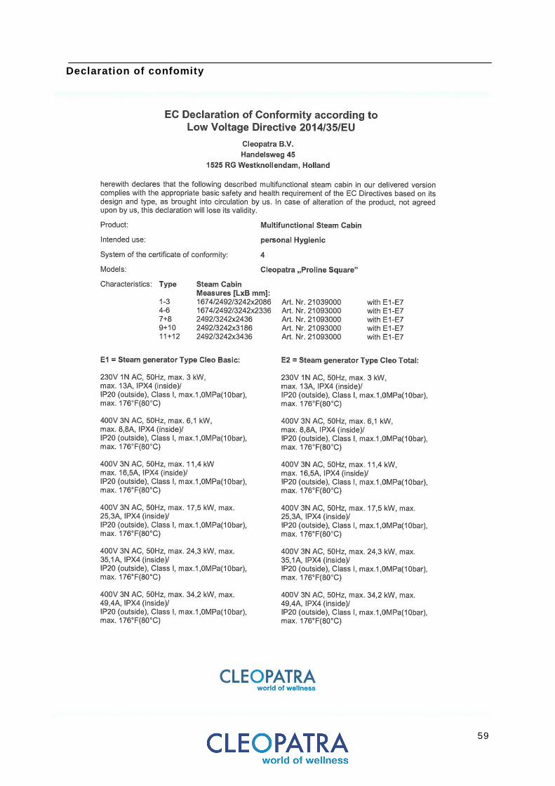
Foreword Thank you for buying the Cleopatra Cleo Total steam generator. Please read this manual carefully before performing any assembly or maintenance work and follow the instructions to ensure optimum performance of the Cleo Total. The Cleo Total Steam Bath Generator is manufactured according to the latest T ÜV requirements and meets the technical safety regulations. Inappropriate use can nevertheless represent danger to the user or a third party. The national and local regulations should be observed in addition to these safety instructions. Please contact your specialist dealer if you have any questions about the installation of this product. Appropriate use The Cleo Total Steam Bath Generator is specif ically and exclusively designed for generating steam in steam baths. Any other use is seen as inappropriate and is therefore undertaken at one's own risk. The manufacturer/supplier is not l iable for any damages made during installation. The steam bath generator and all technical components (except the cabin l ight and the temperature sensor ) may only be installed in a mechanical room. The steam bath generator and all associated components must be fastened in place using screws and plugs.
6
Safety Instructions Improper installation, service, maintenance or use can cause property damage, severe personal injury, or death as a result of electr ic shock, burns, and/or f ire. Read this manual carefully before beginning with the installation, operation or maintenance. Do not make any changes or modif ications to the device . Do not change the electr ical wir ing. Do not use parts or components made by other manufacturers. Do not connect external electr ical systems to the internal electr ic supply of the Cleo Total. Failure to comply with these instructions may result in improper operation and/or product failure. Humidif iers are units for a f ixed installation . Use the humidif ier only when it is correctly installed. The Cleo Total should not be installed outdoors. Only qualif ied personnel should perform f ield wir ing installation procedures and maintenance. Improper wir ing or contact with energized circuits may cause property damage, severe personal injury or cause death as a result of elec tr ic shock and/or f ire . External wir ing must be in accordance with the correct wir ing diagram, national and local electr ical codes. The coding switches are set ex work to def ine the size of the humidif ier, the electr ic connection and the number of phases of the electr ic supply system. Do not change the posit ion of these coding switches. Maintenance Regular maintenance and cleaning of the Cleo Total is necessary. When performing maintenance on the Cleo Total, disconnect all electr ical supply systems. Wait until the temperature of the steam cylinder drops to the ambient temperature. Close the installed supply shut-off valve. Regularly check all parts, valves and inspect the steam cylinder. The Cleo Total and its components should be checked every 500 hours of operation. Good knowledge of electrode humidif iers and air-conditioning is essential to establish diagnostics or take any measures.
7
Safety
Instructions These instructions are intended for the installer. Read all instructions carefully to famil iarize you with the product, components, known constructions and installation tips covered in this manual. This ensures a correct and safe installation. The Cleo Total should be installed by qualif ied and properly trained personnel. The Cleo Total complies with the applicable standards and regulations and therefore presents no hazards for the user providing the Cleo Total is installed and used according to the instructions included by the manufacturer. The electr ical and mechanical parts should be maintained for and kept fully operational. For this reason, these instructions are to be followed carefully. All information and instructions in this manual have been composed taking into account the applicable standards and regulations, the state of the art tec hnology and our many years of experience. Please check the product for possible damage which could have occurred during transport. After installation a claim for surface damage will not be accepted by Cleopatra. Any r ight to make a warranty claim is excluded if changes are made to the original product or parts of it. This operating manual should be kept close to the device, for rapid access to it when it is needed.
Use screws and plugs to attach Cleo Total to the wall . Walls that support the Cleo Total should be strong enough to carry the weight or should otherwise be reinforced. The plugs supplied are intended for use in concrete/solid stone walls. I f the walls are made of a different material use plugs suitable for this type of material. (Not in scope of delivery) Cleopatra accepts no liabil ity for damage caused by:
Non-observance of the manual
Incorrect use
The use of untrained personnel
Unauthorized modif ications
Technical changes
The use of unapproved spare parts Correct use: The Cleo Total may only be used indoors. Use in any other way is not permitted and is at the r isk of the user.
Don’t use the Cleo Total when it is not in perfect condition.
Do not use in abrasive environment.

8
Equipotential connection Indicates the pos it ion of equipotent ia l connect ion.
Symbols used on product
Symbols used on the product and parts of the product or packaging
Hazard identification symbols Indicates the possibil i ty of a hazard
Safety Symbols used in the instruction manual The symbols described below appear in the installation instructions and on the product itself . It is imperative to follow the safety instructions to avoid accidents, injuries and damages. Procedures marked with these symbols require special attention. Caution! Not following the correct procedure can damage the product or lead to malfunctions.
Attention, two people handling required Use ass istance when handl ing procedure. I f th is procedure is not observed, the product or objects wi th in i ts envi ronment may be damaged.
Pinch point hazard Caut ion hand injury. Watch your hands.
Hot surface hazard Don’t touch. Danger of scalding. The surrounding area, inc luding the f loor, can be hot .
Attention general hazard Informs the personnel concerned that the process described, unless performed in compl iance wi th the safety rules, bears the risk of injury.
High voltage hazard / Electr ic shock risk Procedures involving elect r ic i ty are dangerous. Al l instal lat ion and inspect ion works must be carr ied out by an approved elect ric ian.
Read before use Please read careful ly before using product or proceeding wi th instal lat ion.
Gloves required To prevent hand injury wear proper protect ive gear dur ing instal lat ion of the product.
Foot protection required To prevent foot injury wear proper protect ive gear dur ing instal lat ion of the product.
Eye protection required To prevent eye in jury wear safety glasses dur ing instal lat ion of the product.
Specific instructions or information Procedures marked wi th this symbol require spec ial attent ion.
Slippery when wet Floors and surfaces can be sl ippery when wet.
Steam outflow Indicates the pos it ion where steam exi ts the s team generator.
Disposal of parts, old electrical and electronic equipment This symbol on the product or on i ts packaging indicates that this product can’t be t reated as household waste.
Mandatory action
Indicates an action that should be taken to avoid a hazard
Water connection Indicates the pos it ion of the water inlet on the steam generator

9
Safety Measures
The device should only be installed, commissioned and maintained by suitably trained personnel / a specialized dealer. National and local regulations should be followed.
Set the product to the zero energy state prior to any cleaning and repair work, i.e. tr igger the RCCB protective switch. For electr ical insta llation, all applicable VDE, country-specif ic and EU regulations in their respectively valid versions must be observed. All installation and inspection works must be carried out by an approved electr ician and in accordance with VDE 0100 Part 701 / E IEC 60 364-7-701.
Sockets should be grounded. The complete power supply is connected via: • AC connection < 3.2kW = 230V 1N ~50Hz (L, N, PE) > 3.2kW = 400V 2N ~50Hz (L1, L2, N, PE) • A main switch for disconnection with 3 mm contact contactopening. Sockets must have earth terminals. The electr ical mains (230 VAC 50 Hz or 400 VAC 50 Hz) to which components are connected must have a 30 mA fault current protector (residual current circuit breaker) as demanded by DIN EN 60335-2-41/VDE 0700. If the electr ical connecting cable is damaged, replace it.
Non double isolated cables need to be laid inside a pipe or a cable conduit. Do not install cables for 230 / 400 V and 12 V inside the same pipe. Personal protective equipment Use safety shoes, safety glasses and safety gloves while install ing the Cleo Total
10
Safety Appropriate use The Cleo Total is manufactured according to the latest state-of-the-art technology and meets the requirements of the technical safety regulations. Inappropriat e use can nevertheless represent danger to the user or to third parties. The national and local regulations should be observed in addition to these safety instructions. Optimal operation of the product is secured when the following instructions are followe d. Please contact a specialized dealer if you have any questions about the installation of the Cleo Total. Steam bath generators of the type Cleo Total generate steam for heating steam bath cabins. Any other or similar use is seen as not appropriate and is therefore undertaken at one's own risk. The manufacturer / supplier is not l iable for any damages arising by inappropriate use. The Cleo Total should not to be used by persons (including children) with reduced physical, sensory or mental capabilit ies, or lack of experience and knowledge, unless they have been given supervision or instructions . Children not be allowed near the Cleo Total to ensure they do not play with the Cleo Total. Modification of the Cleo Total No other than original Cleopatra devices or components may be installed on the Cleo Total. Use of anything other than original Cleopatra spare parts will lead to l imitation or termination of the manufacturer's l iabil ity and warranty.
11
Function
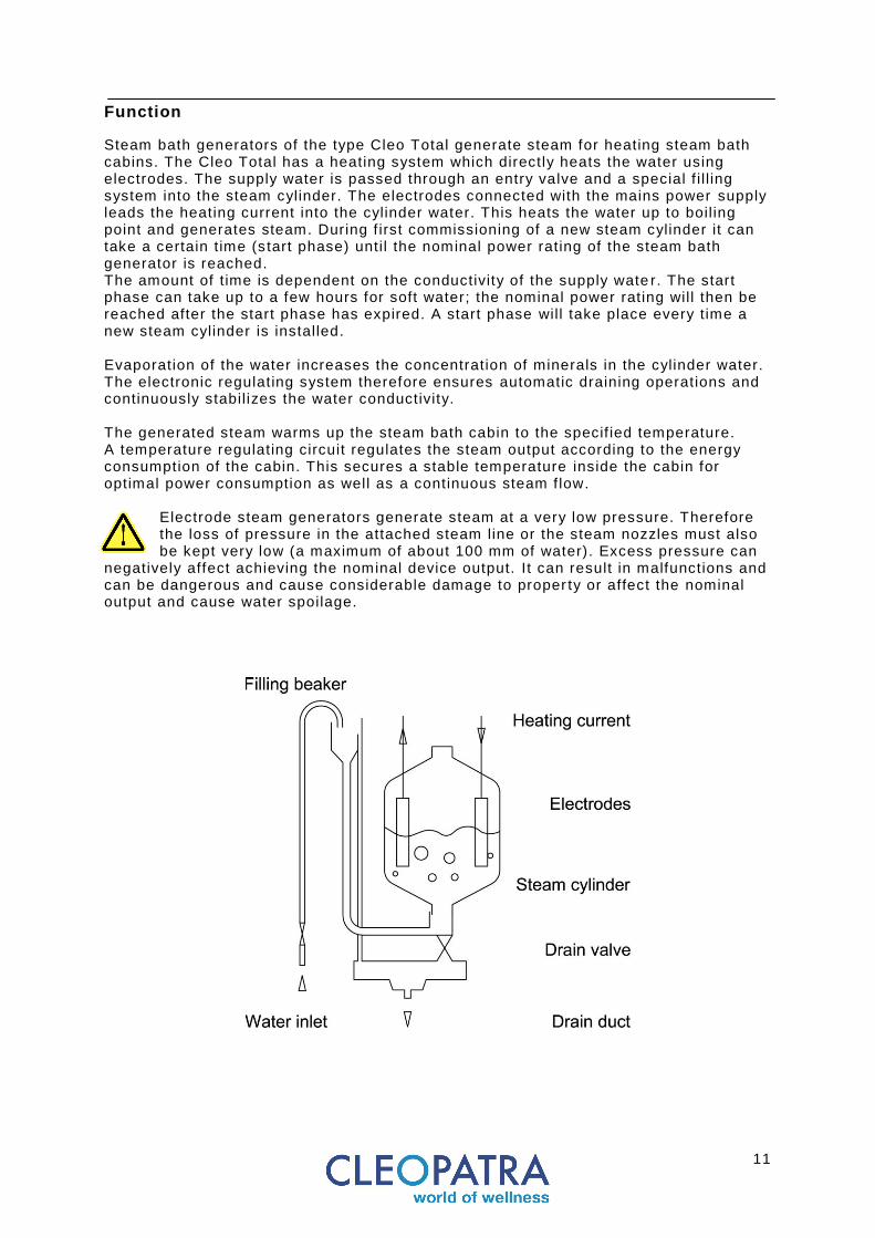
Steam bath generators of the type Cleo Total generate steam for heating steam bath cabins. The Cleo Total has a heating system which directly heats the water using electrodes. The supply water is passed through an entry valve and a special f i l l ing system into the steam cylinder. The electrodes connected with the mains power supply leads the heating current into the cylinder water. This heats the water up to boil ing point and generates steam. During f irst commissioning of a new steam cylinder it can take a certain t ime (s tart phase) until the nominal power rating of the steam bath generator is reached. The amount of t ime is dependent on the conductivity of the supply wate r. The start phase can take up to a few hours for soft water; the nominal power rating will then be reached after the start phase has expired. A start phase will take place every t ime a new steam cylinder is installed. Evaporation of the water increases the concentration of minerals in the cylinder water. The electronic regulating system therefore ensures automatic draining operations and continuously stabil izes the water conductivity. The generated steam warms up the steam bath cabin to the specif ied temperature. A temperature regulating circuit regulates the steam output according to the energy consumption of the cabin. This secures a stable temperature inside the cabin for optimal power consumption as well as a continuous steam f low.
Electrode steam generators generate steam at a very low pressure. Therefore the loss of pressure in the attached steam line or the steam nozzles must also be kept very low (a maximum of about 100 mm of water). Excess pressure can
negatively affect achieving the nominal device output. It can result in malfunctions and can be dangerous and cause considerable damage to proper ty or affect the nominal output and cause water spoilage.
12
Overview
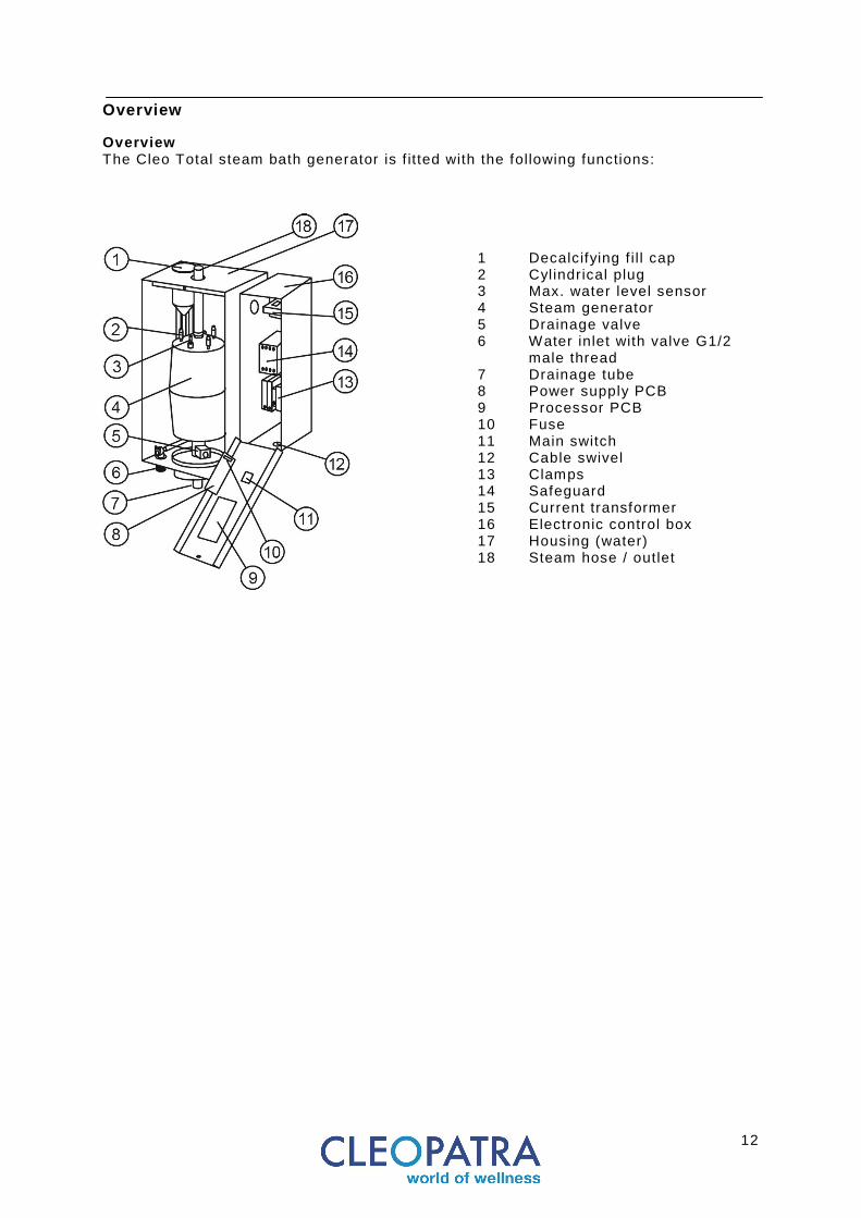
Overview The Cleo Total steam bath generator is f itted with the following functions:
1 Decalcifying f i l l cap 2 Cyl indrical plug 3 Max. water level sensor 4 Steam generator 5 Drainage valve 6 Water inlet with valve G1/2
male thread 7 Drainage tube 8 Power supply PCB 9 Processor PCB 10 Fuse 11 Main switch 12 Cable swivel 13 Clamps 14 Safeguard 15 Current transformer 16 Electronic control box 17 Housing (water) 18 Steam hose / outlet

13
Model 4 • Steam hose 215mm • Support tube 22X50 • Clamp 22mm
Scope of delivery
Model 8 • Steam hose 145mm • Support tube 22X50 • Clamp 22mm
Model 15 & 23 • Steam hose 140mm • Support tube 35X60 • Clamp 43mm
Model 32 • Steam hose 140mm • Support tube 35X60 • Clamp 43mm
Model 45 • Steam hose 140mm • Support tube 35X60 • Clamp 2x43mm
14
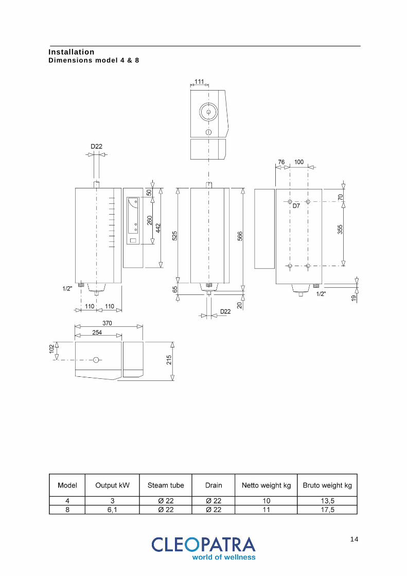
Installation Dimensions model 4 & 8

15
Installation Dimensions model 15 & 23
16
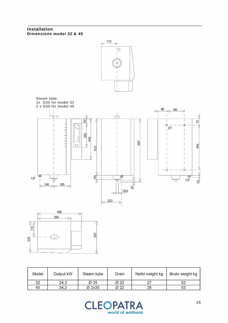
Installation Dimensions model 32 & 45
Steam tube: 1x D35 for model 32 2 x D35 for model 45
17
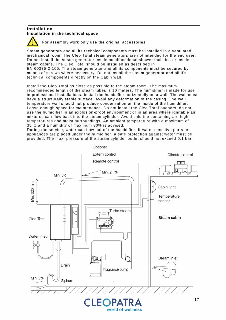
Installation Installation in the technical space
For assembly work only use the original accessories.
Steam generators and all its technical components must be installed in a ventilated mechanical room. The Cleo Total steam generators are not intended for the end user. Do not install the steam generator inside multifunctional shower facil it ies or inside steam cabins. The Cleo Total should be installed as described in EN 60335-2-105. The steam generator and all its components must be secured by means of screws where necassery. Do not install the steam generator and all it ‘s technical components directly on the Cabin wall. Install the Cleo Total as close as possible to the steam room. The maximum recommended length of the steam tubes is 10 meters . The humidif ier is made for use in professional installations. Install the humidif ier horizontally on a wall. The wall must have a structurally stable surface. Avoid any deformation of the casing. The wall temperature wall should not produce condensation on the inside of the humidif ier. Leave enough space for maintenance. Do not install the Cleo Total oudoors, do not use the humidif ier in an explosion-proof environment or in an area where ignitable air mixtures can f low back into the steam cylinder. Avoid chlorine containing air, high temperatures and moist surroundings. An ambient temperature with a maximum of 35°C and a humidity of maximum 80% is advised. During the service, water can f low out of the humidif ier. If water sensit ive parts or appliances are placed under the humidif ier, a safe protection against water must be provided. The max. pressure of the steam cylinder outlet should not exceed 0,1 bar.
18
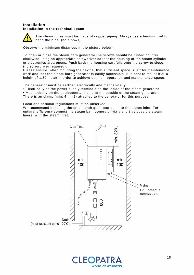
Installation Installation in the technical space
The steam tubes must be made of copper piping. Always use a bending rod to bend the pipe. (no elbows).
Observe the minimum distances in the picture below. To open or close the steam bath generator the screws should be turned counter clockwise using an appropriate screwdriver so that the housing of the steam cylinder or electronics area opens. Push back the housing carefully onto the screw to close. (no screwdriver required). Please ensure, when mounting the device, that suff icient space is lef t for maintenance work and that the steam bath generator is easily accessible. It is best to mount it at a height of 1.80 meter in order to achieve optimum operation and maintenance space. The generator must be earthed electr ically and mechanically; • Electr ically on the power supply terminals on the inside of the steam generator • Mechanically on the equipotential clamp at the outside of the steam generator. There is an clamp (min. 4 mm2) attached to the generator for this purpose Local and national regulations must be observed. We recommend install ing the steam bath generator close to the steam inlet. For optimal eff iciency connect the steam bath generator via a short as possible steam line(s) with the steam inlet .
Equipotential connection
19
Installation Installation conditions Installation values: Maximum ambient temperature: 35°C Minimum ambient temperature: 5°C Maximum ambient relative humidity: 80%, not condensing Mains voltage: depending on model: 230V or 400V (-8%+10%) Maximum pressure at the outlet of the steam cylinder: 0,1 bar Water conductivity: 125 to 1250 micro Siemens / cm Water quality: Cleo Total steam bath generators can be supplied with hard water; the best water is untreated tap water . The 16-bit processor automatically adjusts the operating conditions according to the water quality. Deionized water should not be used since the electr ical conductivity is too low. Softened water hardly provides any operational advantages and should not be used. A minimum hardness value of about 6°D (DH) is recommended. Water softeners that depend on ion exchangers can produce such water but the salt concentration can make it aggressive and cause corrosion on the electrodes. We therefore discourage use of water softeners. Electrical conductivity of the supply water : This should l ie within the limits of 125 to 1250 micro-Siemens / cm. Hardness range : measured in terms of the international unit - milimol of calcium and magnesium ions per l iter (previously the DH measure) Soft water: < 1,3 mmol/l - < 7° dh Medium hard water: 1,3 – 2,5 mmol/l - 7° - 14° dh Hard water: 2,5 – 3,8 mmol/l - 14° - 21° dh Very hard water: > 3,8 mmol/l - > 21° dh 1° dh corresponds: 1,05° American hardness
1,25° English hardness 1,79° French hardness 10,0 mg/l CaO 17,9 mg/l CaCO3 (ppm)
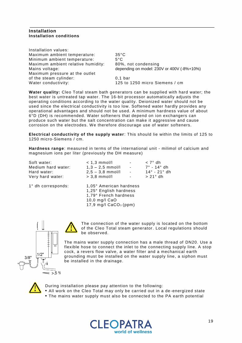
The connection of the water supply is located on the bottom of the Cleo Total steam generator . Local regulations should be observed.
The mains water supply connection has a male thread of DN20. Use a f lexible hose to connect the inlet to the connecting supply l ine. A stop cock, a revers f low valve, a water f i lter and a mechanical earth grounding must be installed on the water supply l ine, a siphon must be installed in the drainage.
During installation please pay attention to the following:
• All work on the Cleo Total may only be carried out in a de -energized state • The mains water supply must also be connected to the PA earth potential

20
Installation
Connecting the water supply
All assembly work should be performed by qualif ied and properly trained personnel. National and local regulations should be followed during installation. Only use normal tap water. It is important to contact the supplier of the steam bath generator before using treated or demineralised water.
Use either copper, iron or plastic pipes. Low quality p lastic or rubber can produce foam in the steam cylinder and affect the performance or expose people to serious dangers.
The water supply pressure should not be lower than 1 bar and not greater than 10 bar. If the pressure is < 1bar the inlet valve cannot open. For optimum operation use a pressure reducing valve which can be set to 4 bar. The supplied water should not exceed a temperature of max. 40 degrees. Flush the water supply l ines before installation to remove dirt particles, fat or residues. Clean the built- in pre-f ilter of the inlet valve after the f irst 100 hours of operation. The Cleo Total should be inspected regularly. All water l ines should be water t ight to prevent water leakage. Potential equalization must be mounted according to local regulations. When install ing the water drain leave enough space for cleaning and maintenance. Lead the drain pipe to the waste water pipe with an adequate downward slope . (at least 5%). Cleopatra recommends the installation of a f i lter near the cold water connection to prevent the sieve at the inlet valve from clogging up with sediments.
Connect the cold water supply to the Cleo Total using the f lexible hose contained in the scope of delivery. The water connection must be f itted with a reverse f low valve in accordance to EN1717. Attach the water drain hose (not supplied) using the hose clamp to the drain vessel. The water drain hose (40 mm) must be f itted with a siphon. The pressureless water drain can be led into an open funnel (slope). The hose must hang freely and should not touch the drain funnel / pipe. During normal service the waste water can reach 100°C for short t ime. When the steam cylinder is emptied by hand for maintenance the waste water can reach 100°C.
21
Installation
Connecting the steam line
Use the largest possible radii if straight pipe routing is not possible. Steam lines must be properly supported in order to avoid water sacks. Please take into account expansion and contraction of the copper piping when heated or cooled down. Min. 20 mm thick thermal insulation is recommended for copper pipes. The steam must be able to pass through the line unhindered: no barriers, no sagging, k inking or crushing etc. Counter-pressure or condensation can be caused through wrong routing. It can have a negative effect on the optimal steam process. When install ing the steam line one should ensure that condensation always f lows in the opposite direction as the steam.
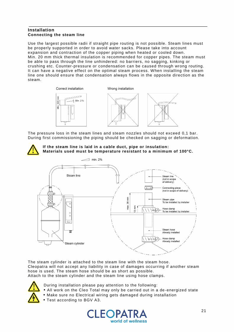
The pressure loss in the steam lines and steam nozzles should not exceed 0,1 bar. During f irst commissioning the piping should be checked on sagging or deformation.
If the steam line is laid in a cable duct, pipe or insulation: Materials used must be temperature resistant to a minimum of 100°C.
The steam cyl inder is attached to the steam line with the steam hose. Cleopatra will not accept any liabi l ity in case of damages occurring if another steam hose is used. The steam hose should be as short as possible. Attach to the steam cyl inder and the steam line using hose clamps.
During installation please pay attention to the following:
• All work on the Cleo Total may only be carried out in a de -energized state • Make sure no Electr ical wir ing gets damaged during installa tion
• Test according to BGV A3.
22
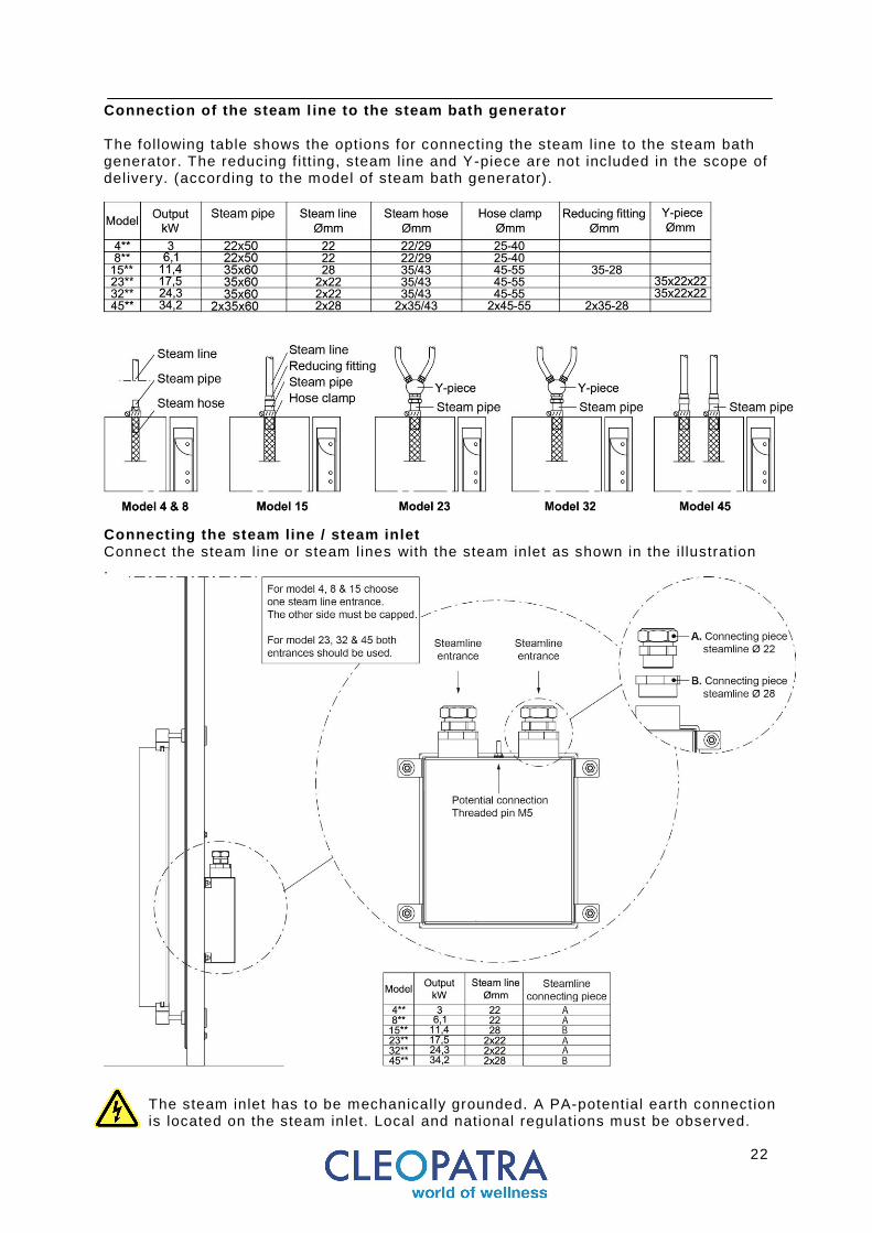
Connection of the steam l ine to the steam bath generator The following table shows the options for connecting the steam line to the steam bath generator. The reducing f itt ing, steam line and Y-piece are not included in the scope of delivery. (according to the model of steam bath generator).
Connecting the steam line / steam inlet Connect the steam line or steam lines with the steam inlet as shown in the il lustration .
The steam inlet has to be mechanically grounded. A PA-potential earth connection is located on the steam inlet. Local and national regulations must be observed.
23
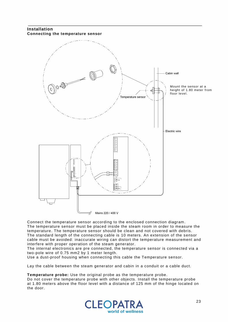
Installation Connecting the temperature sensor
Connect the temperature sensor according to the enclosed connection diagram. The temperature sensor must be placed inside the steam room in order to measure the temperature. The temperature sensor should be clean and not covered with debris. The standard length of the connecting cable is 10 meters. An extension of the sensor cable must be avoided: inaccurate wir ing can distort the temperature measurement and interfere with proper operation of the steam generator. The internal electronics are pre connected, the temperature sensor is connected via a two-pole wire of 0.75 mm2 by 1 meter length. Use a dust-proof housing when connecting this cable the Temperature sensor. Lay the cable between the steam generator and cabin in a conduit or a cable duct. Temperature probe: Use the original probe as the temperature probe. Do not cover the temperature probe with other objects. Install the temperature probe at 1.80 meters above the f loor level with a distance of 125 mm of the hinge located on the door.
Mount the sensor at a height of 1.80 meter f rom f loor level .

24
Installation Connecting the electrical power supply
All power circuits should be interrupted before and during work on a steam bath generator!
National and local regulations should be observed. Please note that the steam bath generator should be installed in the designated mechanical room. A circuit breaker which seperates the generators from the mains power supply must be installed during installation (not in the scope of delivery). The power supply must be f itted with a residual current circuit breake r (RCCB) with a maximum of 30 mA. Components whith a voltage greater than the safety voltage of 12V must not be reachable by persons. The steam bath generators are made according to Protection Class I (electr ical devices) and are designed to be connected to an earth leak switch. The steam bath generator , as well as all electronic apparatuses on which Protection Class I applies, should be installed according to Protection Measures Class I . The appropriate electr ical circuit diagram is included in this manual. Make all wir ing connections according to the circuit diagram. Pa terminal compensating connections must be arranged. There are earth terminals on the steam bath generator, the steam inlet and the Climate control . The circuit diagram shows maximum loading of the internal supply circuits. These loads should not be exceeded. There should be no alterations made to the original cabling. External components should only be connected to the installed external terminals.
After the completed installation of electronics, steam and water an electronic test should be performed according to VDE0100T01 / EN60335-2-105 and according to BGV A3. This test must be documented.
25
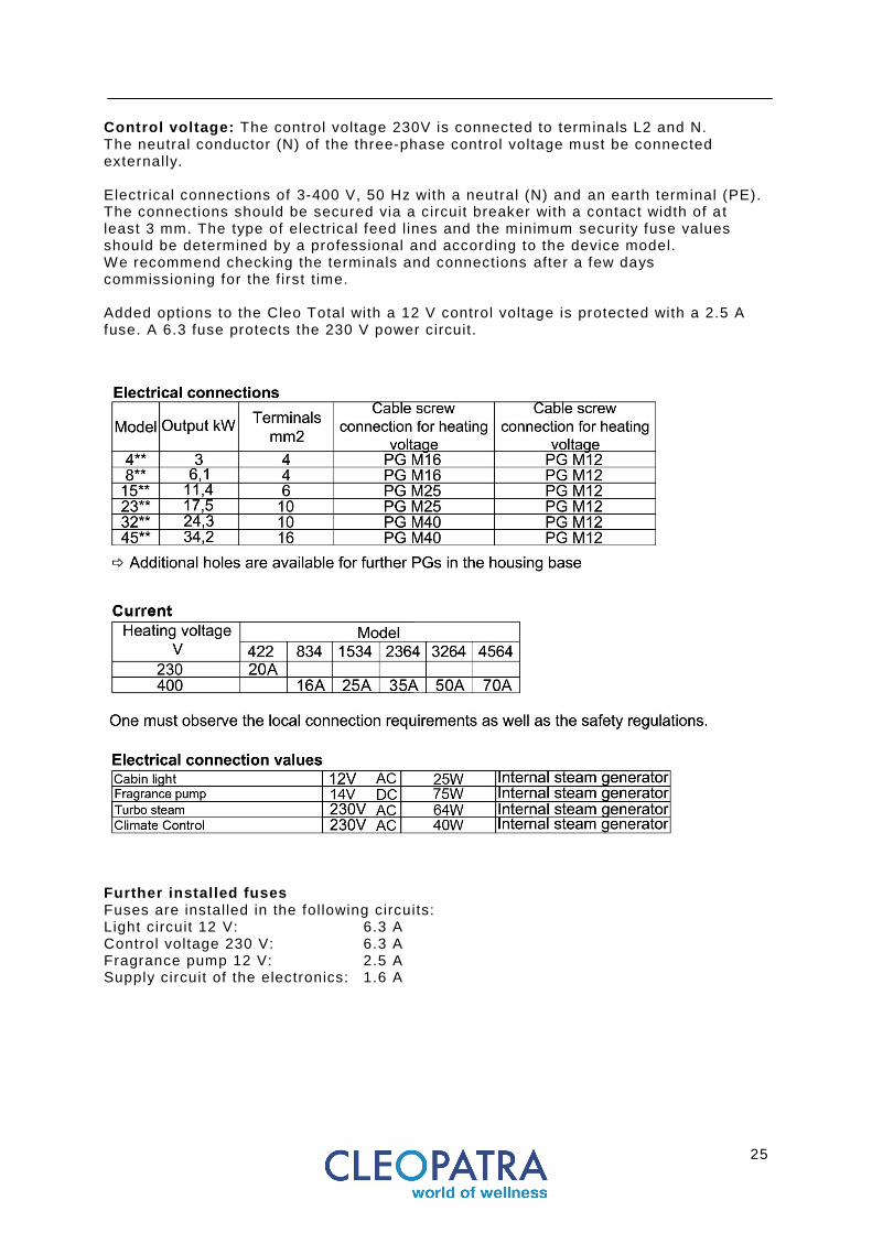
Control voltage: The control voltage 230V is connected to terminals L2 and N. The neutral conductor (N) of the three-phase control voltage must be connected externally. Electr ical connections of 3-400 V, 50 Hz with a neutral (N) and an earth terminal (PE). The connections should be secured via a circuit breaker with a contact width of a t least 3 mm. The type of electr ical feed lines and the minimum security fuse values should be determined by a professional and according to the device model. We recommend checking the terminals and connections after a few days commissioning for the first t ime. Added options to the Cleo Total with a 12 V control voltage is protected with a 2.5 A fuse. A 6.3 fuse protects the 230 V power circuit.
Further installed fuses Fuses are installed in the following circuits: Light circuit 12 V: 6.3 A Control voltage 230 V: 6.3 A Fragrance pump 12 V: 2.5 A Supply circuit of the electronics: 1.6 A
26
Operation Regulating the steam temperature The Cleo-Total steam bath generators regulate the temperature of the steam bath cabin automatically and according to the set nominal temperature. The amount of steam is determined by the energy needs of the steam bath cabin. This ensures optimum energy consumption. The factory settings are programmed to provide a good steam bath experience for most common use. The temperature regulation system is f itted with programmable parameters in order to provide different desired requirements. The programmable parameters are installed only to support further optimization of the steam bath and can only be altered by a specialist. Please read more about regulating the parameters in the commissioning chapter. There is a connection diagram supplied with the device. Please note: Only the original probe may be used as a temperature probe.
27
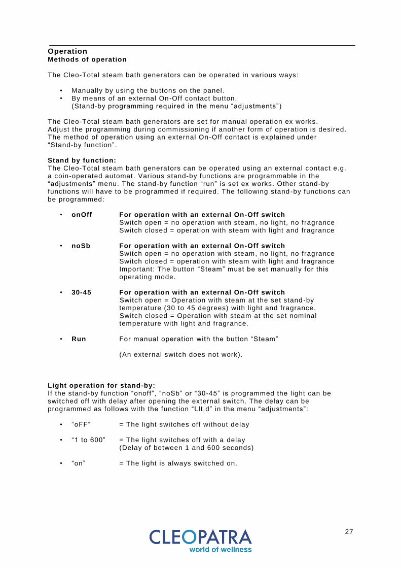
Operation Methods of operation The Cleo-Total steam bath generators can be operated in various ways:
• Manually by using the buttons on the panel. • By means of an external On-Off contact button.
(Stand-by programming required in the menu “adjustments”) The Cleo-Total steam bath generators are set for manual operation ex works. Adjust the programming during commissioning if another form of operation is desired. The method of operation using an external On-Off contact is explained under “Stand-by function”. Stand by function: The Cleo-Total steam bath generators can be operated using an external contact e.g. a coin-operated automat. Various stand-by functions are programmable in the “adjustments” menu. The stand-by function “run” is set ex works. Other stand-by functions will have to be programmed if required. The following stand -by functions can be programmed:
• onOff For operation with an external On-Off switch Switch open = no operation with steam, no light, no fragrance Switch closed = operation with steam with l ight and fragrance
• noSb For operation with an external On-Off switch Switch open = no operation with steam, no light, no fragrance Switch closed = operation with steam with l ight and fragrance Important: The button “Steam” must be set manually for this
operating mode.
• 30-45 For operation with an external On-Off switch Switch open = Operation with steam at the set stand -by temperature (30 to 45 degrees) with l ight and fragrance. Switch closed = Operation with steam at the set nominal temperature with l ight and fragrance.
• Run For manual operation with the button “Steam”
(An external switch does not work). Light operation for stand-by: If the stand-by function “onoff”, “noSb” or “30 -45” is programmed the l ight can be switched off with delay after opening the external switch. The delay can be programmed as follows with the function “Llt.d” in the menu “adjustments”:
• “oFF” = The light switches off without delay
• “1 to 600” = The light switches off with a delay (Delay of between 1 and 600 seconds)
• “on” = The light is always switched on.
28
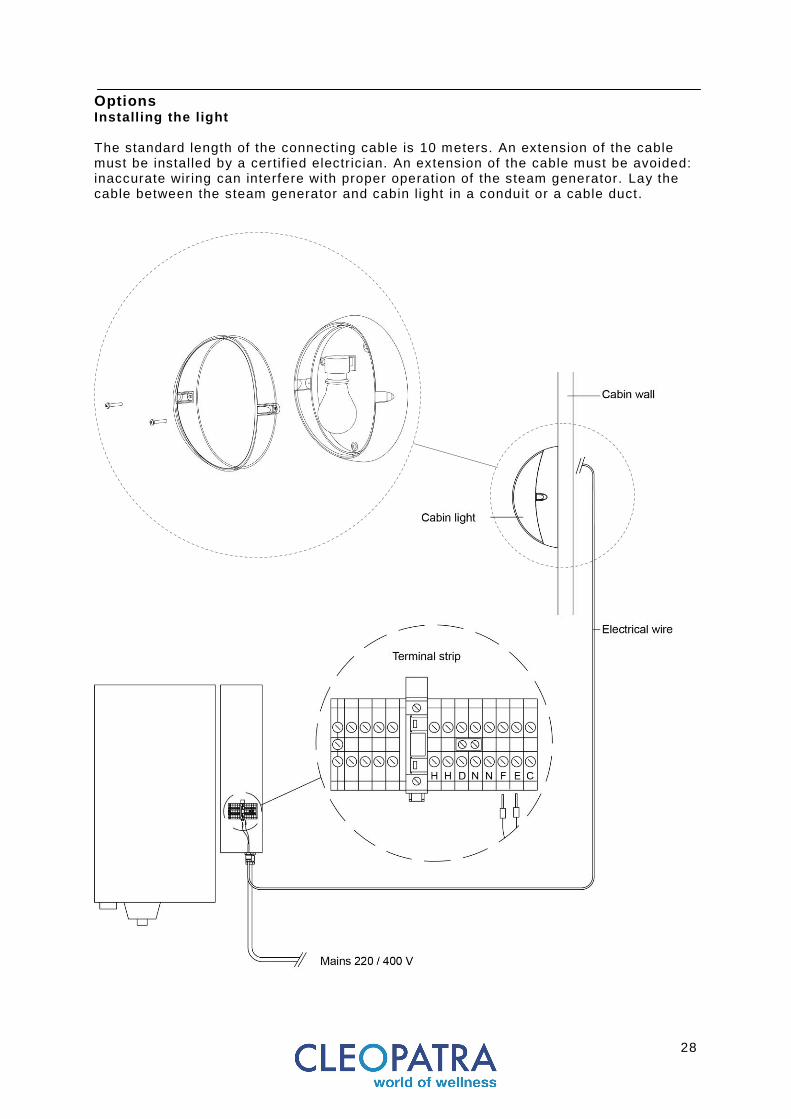
Options Installing the light The standard length of the connecting cable is 10 meters. An extension of the cable must be installed by a certif ied electr ician. An extension of the cable must be avoided: inaccurate wir ing can interfere with proper operation of the steam generator. Lay the cable between the steam generator and cabin l ight in a conduit or a cable duct.

29
Options
Fragrance pump Please look in the fragrance pump manual f or the correct way of installation . The standard length of the mains cable is 1,5 meters. Please observe minimum cable lengths between fragrance pump and steam generator. Lay the cable between the steam generator and fragrance pump in a conduit or a cable duct.
Connect the mains power cable to the terminal str ip in the Cleo Total steam bath generator. See circuit diagrams for the Cleo Total. There is an earth terminal element provided. Local and national regulations should be observed.
30
Options Turbo steam
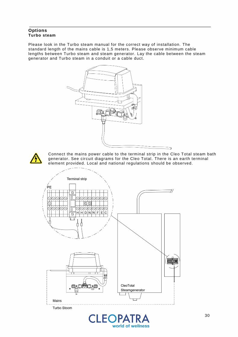
Please look in the Turbo steam manual for the correct way of installation. The standard length of the mains cable is 1,5 meters. Please observe minimum cable lengths between Turbo steam and steam generator. Lay the cable between the steam generator and Turbo steam in a conduit or a cable duct.
Connect the mains power cable to the terminal str ip in the Cleo Total steam bath generator. See circuit diagrams for the Cleo Total. There is an earth terminal element provided. Local and national regulations should be observed.

31
Options Climate control Please look at the enclosed Climate control manual included in the scope of delivery of the device for correct installation. Lay the cable between the steam generator and Climate control in a conduit or a cable duct.
Connect the ventilator cable (not in the scope of delivery , Cleopatra advises a maximum cable length of 10 meters) to the terminal str ip in the Cleo Total steam bath generator and Climate Control system control element. See circuit diagrams for the Cleo Total. There is an earth terminal element provided. Local and national regulations should be observed.
Terminal st rip
32
Options Remote control
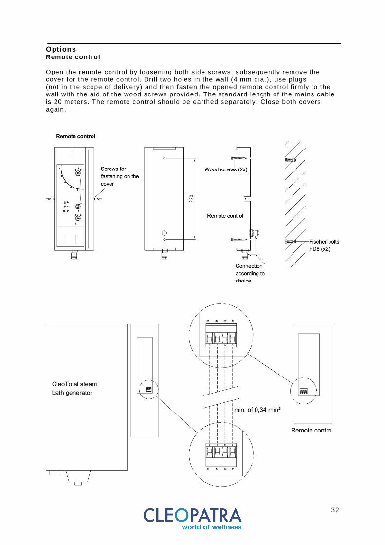
Open the remote control by loosening both side screws, s ubsequently remove the cover for the remote control. Dril l two holes in the wall (4 mm dia.), use plugs (not in the scope of delivery) and then fasten the opened remote control f irmly to the wall with the aid of the wood screws provided. The standard length of the mains cable is 20 meters. The remote control should be earthed separately. Close both covers again.
33
Options
Stand-by
The Cleo Total steam bath generator can be obtained with an optional stand-by function to, for example, be attached to a coin -operated automat. Lay the cable between the steam generator and coin machine in a conduit or a cable duct. Further information about this function can be found in the operating manual for the end user.
34
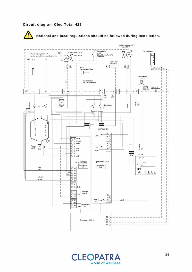
Circuit diagram Cleo Total 422
National and local regulations should be followed during installation.
35
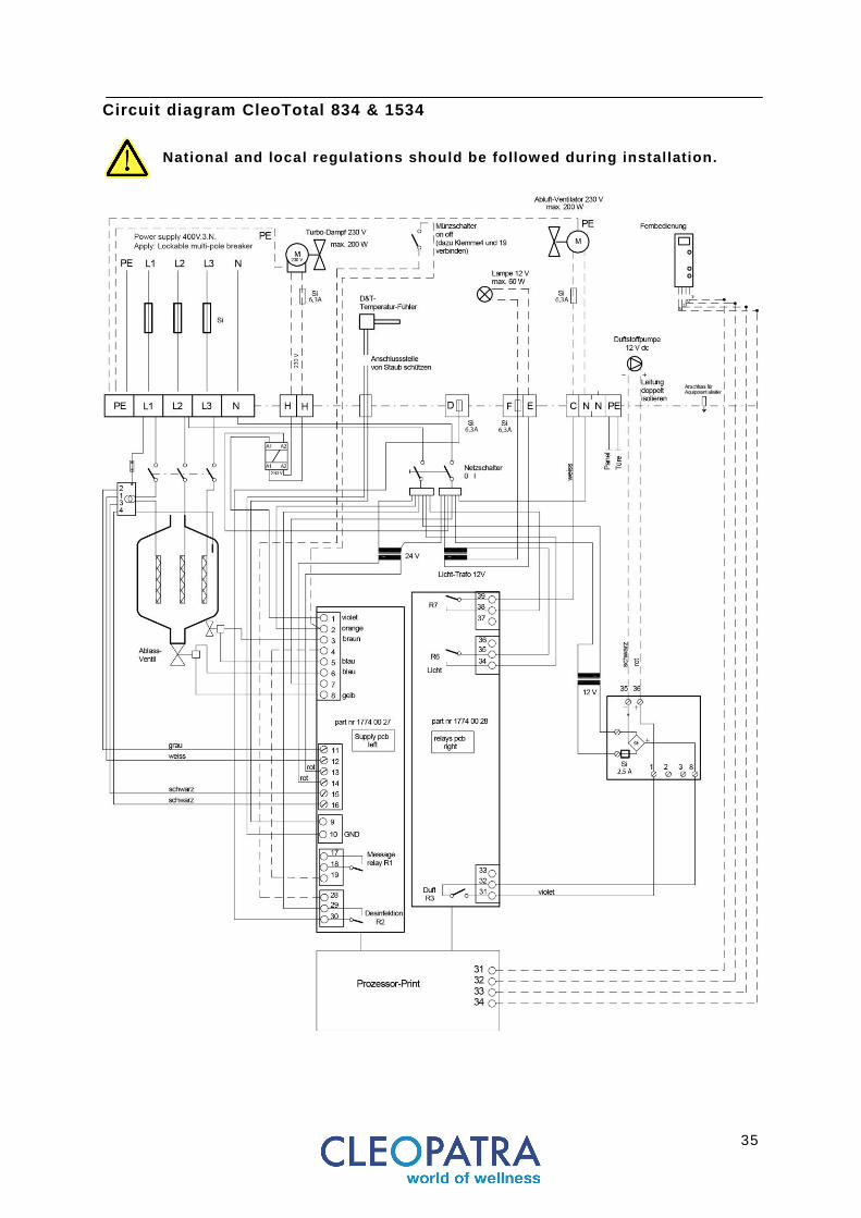
Circuit diagram CleoTotal 834 & 1534
National and local regulations should be followed during installation.

36
Circuit diagram Cleo Total 2364 & 3264 & 4564
National and local regulations should be followed during installation.

37
Commissioning
Preparation
Follow DIN VDE 0100 T560 and T610 and the instructions in this manual by Cleopatra. Safety Instructions Check: The safety instructions for the end user must be placed in sight while entering the cabin. (see: operating manual). Preparation for commissioning The water supply, piping and hoses, water drain, steam line and the electr ical cabling must be connected by trained experts according to usual local safety measures and the circuit diagram delivered with the device. Ensure that the desired stand-by function is set. Open the water supply and switch on the main switch. The cabin temperature is displayed on the steam bath generator digital indicator. The Cleo Total is now ready to be programmed.

38
Commissioning Steam operation Specif ic parameters of the steam generator can be programmed. The diffrent settings can be seen in the menu "System data". Parameters can be adjusted in the ‘program’ menu. The Menu "program" is secured with a code. Detailed information can be found in sperate documentation. For more information, contact your dealer. It is necessary to make the preparations as described above before undertaking a steam operation. Setting the temperature of the steam bath cabin:
• Push the “MODE” button until the left LED button f lashes. • Push the “SELECT” button and keep pressed down:
the symbols oSEL and the nominal temperature are shown on the display. • The nominal temperature can be set using the “SET” button. • Press the “MODE” button until the LED button stops blinking.
Automatic temperature-regulated steam operation can now be started either by programming manually, by using the “MODE” button, by using an external switch or using a remote control. Automatic operation Once the mode of operation and nominal temperature are set the steam bath generator is ready to start the steam cycle. By starting the automatic steam bath program the waterinlet and outlet valves are activated. The steam cyl inder is f i l led with water. The water reaches the electrodes, an electr ical current heats the water until steam is generated. At f irst commissioning the nominal takes time to reach it ’s full capacity. This is called the “ init ial phase”. After the init ial phase is completed the steam bath generator will reach its nominal output in it ’s normal t ime frame . A start phase is needed each time a new steam cylinder is installed.
39
Commissioning Operation Manual operation This program is a default factory setting. The MODE button is used for all programming or settings . Hold for 2 seconds until the left LED starts f lashing. The desired Menu can then be picked and programmed. By pressing the "MODE" button the Cleo Total wil l :
• Switch to steam production • Activate the fragrance pump for automatic fragrance dosage • Switch on the cabin l ight
The right LED on the "MODE" button lights up. To deactivate: Press the "MODE" button again. The fragrance pump has a default factory setting installed. For the interval and measure table please look at page 39. Note that the fragrance pump only works with a Cabin temperature of 30°C or higher. Press "SET / l ight", to turn the cabin l ight on and off. Using a timer switch (coin-operated switch) (this option is not offered by Cleopatra) Cleo Total steam bath generators can be switched on or off by means of an external t imer switch. There must be voltage-free contact available for a minimum of 230 VAC in order to operate with an external t imer switch. This contact can be used like a coin-operated switch. The appropriate setting of the function “StBy” . (Stand-by must be made on the steam bath generator.) The coin-operated automat The connection for a coin-operated automat or an external switch is available as standard. The “stand-by” function must be programmed in the menu “adjustments” to operate a coin-operated automat. (Stand-by) can be programmed accordingly. For the setting:
• Hold "MODE" button for 2 seconds until the left button LED f lashes. • Select Menu "adjustment" with the "MODE" button. • STBY function: select it using the "SELECT" button. • Desired stand-by function with the "SET" key to select .
40
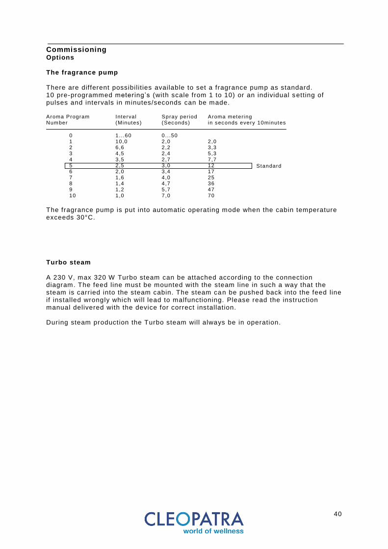
Commissioning Options The fragrance pump There are different possibil it ies available to set a fragrance pump as standard. 10 pre-programmed metering’s (with scale from 1 to 10) or an individual setting of pulses and intervals in minutes/seconds can be made. Aroma Program Interval Spray per iod Aroma metering Number (Minutes) (Seconds) in seconds every 10minutes
0 1.. .60 0.. .50
1 10,0 2,0 2,0 2 6,6 2,2 3,3 3 4,5 2,4 5,3 4 3,5 2,7 7,7 5 2,5 3,0 12 6 2,0 3,4 17 7 1,6 4,0 25 8 1,4 4,7 36 9 1,2 5,7 47 10 1,0 7,0 70
The fragrance pump is put into automatic operating mode when the cabin temperature exceeds 30°C. Turbo steam A 230 V, max 320 W Turbo steam can be attached according to the connection diagram. The feed line must be mounted with the steam line in such a way that the steam is carried into the steam cabin. The steam can be pushed back into the feed line if installed wrongly which will lead to malfunctioning. Please read the instruction manual delivered with the device for correct installation. During steam production the Turbo steam will always be in operation.
Standard

41
Commissioning Options The climate control The connection for the Climate control is installed as standard. The Climate control is automatically put into operation if the actual temperature exceeds the set nominal temperature. The Climate control can be f itted with the function “Fan.d” I t is programmed as follows in the menu “adjustments”:
• Off = The Climate control is not set to operate • On = The Climate control runs continuously
(after TActual > TNominal was reached). • 1-300 = Switching on delay for the Climate control
(1 to 300 seconds after TActual > TNominal was reached). If operation of the Climate control is programmed using switching on delay then its switching on period can be programmed using the function “Fan.S” to between 5 and 300 seconds. This operating period can be repeated using the function “Fan.M” according to programmable time intervals of between 10 and 300 seconds. The cabin light The connection for the cabin l ight of 12 V AC for a maximum of 60 W is available as standard. The light circuit is protected by a fuse. The light is switched on and off at the same time as manual steam operation is init iated using the “Steam” button. If any of the stand-by functions “on-oFF”, noSB or 30-45 is programmed then operation of the light can be programmed using the “Lit.d” function as follows:
• “On“ = the light is always switched on. • “oFF” = the light is switched off immediately if stand-by mode is switched off. • “1 to 600” = the l ight switches off after the programmed delay after stand -by
mode has been switched off. (Switching off delay of 1 to 600 seconds).
42
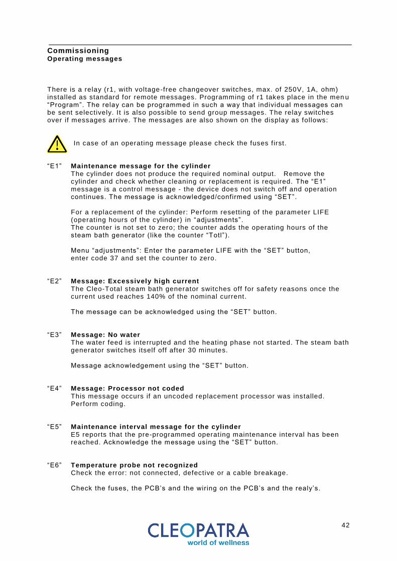
Commissioning Operating messages There is a relay (r1, with voltage-free changeover switches, max. of 250V, 1A, ohm) installed as standard for remote messages. Programming of r1 takes place in the men u “Program”. The relay can be programmed in such a way that individual messages can be sent selectively. It is also possible to send group messages. The relay switches over if messages arrive. The messages are also shown on the display as follows:
In case of an operating message please check the fuses f irst.
“E1” Maintenance message for the cylinder
The cylinder does not produce the required nominal output. Remove the cylinder and check whether cleaning or replacement is required. The “E1” message is a control message - the device does not switch off and operation continues. The message is acknowledged/confirmed using “SET”. For a replacement of the cylinder: Perform resetting of the parameter LIFE (operating hours of the cylinder) in “adjustments”. The counter is not set to zero; the counter adds the operating hours of the steam bath generator ( like the counter “Totl”). Menu “adjustments”: Enter the parameter LIFE with the “SET” button, enter code 37 and set the counter to zero.
“E2” Message: Excessively high current
The Cleo-Total steam bath generator switches off for safety reasons once the current used reaches 140% of the nominal current. The message can be acknowledged using the “SET” button.
“E3” Message: No water
The water feed is interrupted and the heating phase not started. The steam bath generator switches itself off after 30 minutes. Message acknowledgement using the “SET” button.
“E4” Message: Processor not coded This message occurs if an uncoded replacement p rocessor was installed. Perform coding. “E5” Maintenance interval message for the cylinder
E5 reports that the pre-programmed operating maintenance interval has been reached. Acknowledge the message using the “SET” button.
“E6” Temperature probe not recognized Check the error: not connected, defective or a cable breakage.
Check the fuses, the PCB’s and the wir ing on the PCB’s and the realy’s.
43
Commissioning The internal counter Cleo-Total steam bath generators have three internal counters:
• A counter for maintenance intervals: LFLI • A counter for the operating time of the steam cyl inder: LIFE • A total operating time counter for the steam bath generator: totL
LFLI The counter for maintenance intervals can be programmed in the menu
“adjustments”. This generates message E5 on the display if the programmed time period is reached. The message E5 can be recorded externally by a message relay and used, for example, to send an alarm to a monitoring system. The maintenance interval should be selected according to operatin g experience, according to the water hardness. We recommend setting a time of about 500 hours if there is no experience to fall back on. The status of the counter can be found in the menu ”System data”.
LIFE This counter can be used for recording the operating time of the steam cylinder;
in this case it should be set to zero when install ing a new steam cylinder. The operating time can found in the menu ”System data”. Zero setting takes place in the menu “adjustments” through entering the code 37. The stat us of the counter can be found in the menu ”System data”.
totL This counter counts the total operating time for the steam bath generator. The
status of the counter found in the menu ”System data”. The totL counter cannot be set to zero.

44
Maintenance Maintenance Maintenance may only be performed by suitably qualif ied engineers. All power supply circuits must be interrupted before conducting any work on the generator such as cleaning or replacing the cylinder. Valves, the water f i l l ing system, steam cyl inder and drain system require regular checking and must be cleaned if necessary. Check all other parts and clean them if necessary. The condition of the steam cylinder must be checked regularly if it must be replaced. After every 500 hours of operation the humidif ier must be checked for proper installation. The internal maintenance counter LFLI can be set to remind one of the maintenance schedules. Ensure that the electronics are clean or not covered in dust or damp through environmental inf luences. The steam bath generator should generally be kept and run in a clean condition. Keep a report log on all maintenance work performed.

45
Maintenance Cleaning or replacing the cylinder
All power supply circuits must be interrupted before conducting any work on the generator. Close the multi pole breaker and the f ield installed water shut -off valve. Danger of scalding. Wait until the steam cylinder has cooled down completely. Check the steam cylinder, drain systems and steam lines for leaks and, if necessary, clean or service the device. Use a damp cloth. Do not use any chemicals, acids, vinegar etc. to clean the device. Use of these products could lead to foam forming inside the cylinder which can negatively affect correct operation.
Draining the steam cylinder: 1. Follow the menu below to drain the s teamcylinder completely.
46
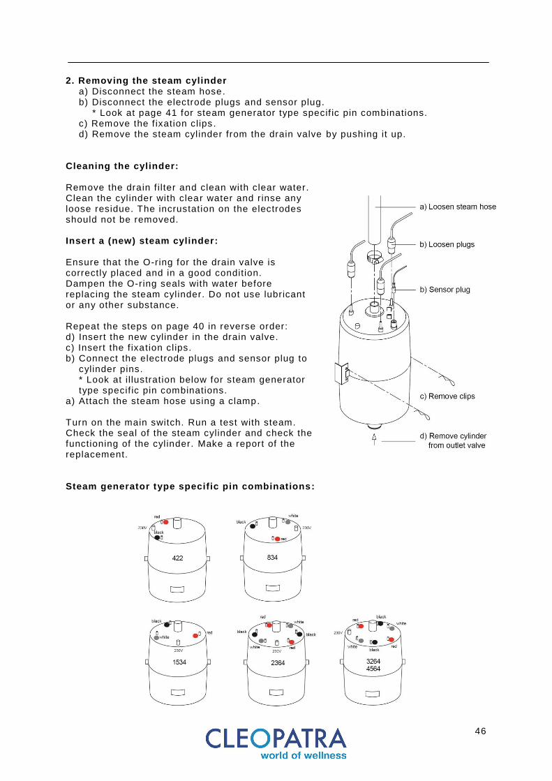
2. Removing the steam cylinder
a) Disconnect the steam hose. b) Disconnect the electrode plugs and sensor plug. * Look at page 41 for steam generator type specif ic pin combinations. c) Remove the f ixation clips . d) Remove the steam cyl inder from the drain valve by pushing it up.
Cleaning the cylinder: Remove the drain f i lter and clean with clear water. Clean the cyl inder with clear water and rinse any loose residue. The incrustation on the electrodes should not be removed. Insert a (new) steam cylinder: Ensure that the O-ring for the drain valve is correctly placed and in a good condition. Dampen the O-ring seals with water before replacing the steam cyl inder. Do not use lubricant or any other substance. Repeat the steps on page 40 in reverse order: d) Insert the new cylinder in the drain valve. c) Insert the f ixation cl ips. b) Connect the electrode plugs and sensor plug to
cylinder pins. * Look at i l lustration below for steam generator type specif ic pin combinations.
a) Attach the steam hose using a clamp. Turn on the main switch. Run a test with steam. Check the seal of the steam cylinder and check the functioning of the cyl inder. Make a report of the replacement. Steam generator type specific pin combinations:

47
Maintenance Cleaning or replacing the outlet valve
All power supply circuits must be interrupted before conducting any work on the generator. Close the f ield installed water shut -off valve. Danger of scalding. Wait until the steam cylinder has cooled down completely. Outlet valve, steam cylinder, drain systems and steam lines must be checked for leaks and must, if necessary, be cleaned or serviced. Use a damp cloth. Do not use any chemicals, acids, vinegar etc. to clean. Use of these products could lead to foaming in the cyl inder and could negatively e ffect correct operation.
The outlet valve The outlet valve is f itted with a pre-f i lter. The f i lter must always be kept clean so that water can f low through it unhindered. Cleaning the outlet valve: The outlet valve and the drainage can be removed after the mounting screws are loosened. Unscrew the magnet coil and clean all parts. Flush the water drainage pipe thoroughly. Inspect steam and condensate hoses and replace if necessary. Check that the screws on the hose clamps are tight. Replacing the outlet valve: Ensure that the O-ring for the drain valve is correctly placed and in a good condition. Dampen the O-ring seals with water before replacing the outlet valve. Do not use lubricant or any other substance. a) Unscrew the mounting screws. b) Disassemble the hose clamp. c) Take the new valve and connect the f i l l hose with the hose clamp d) Place the valve in the bottom hole and f ixate with 2 mounting screws. e) Start the steam generator to run a test and check the valve for leakage.

48
Maintenance Service parts
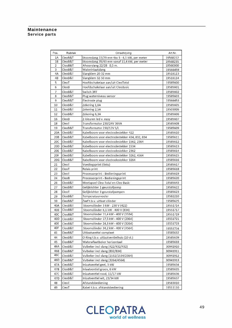
49
Maintenance Service parts
50
Operating manual for the end user Safety precautions Safety precautions
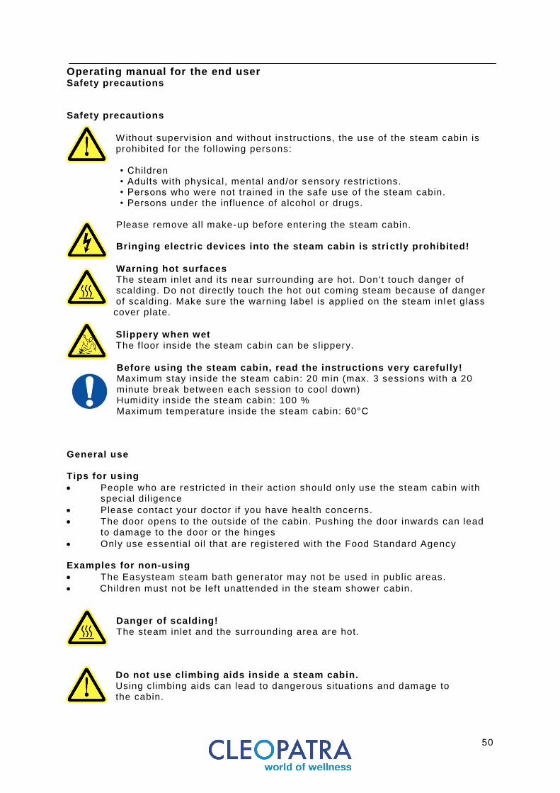
Without supervision and without instructions, the use of the steam cabin is prohibited for the following persons: • Children • Adults with physical, mental and/or sensory restr ictions. • Persons who were not trained in the safe use of the steam cabin. • Persons under the inf luence of alcohol or drugs.
Please remove all make-up before entering the steam cabin. Bringing electric devices into the steam cabin is stri ctly prohibited!
Warning hot surfaces The steam inlet and its near surrounding are hot. Don't touch danger of scalding. Do not directly touch the hot out coming steam because of danger of scalding. Make sure the warning label is applied on the steam inl et glass cover plate.
Slippery when wet The f loor inside the steam cabin can be slippery.
Before using the steam cabin, read the instructions very carefully! Maximum stay inside the steam cabin: 20 min (max. 3 sessions with a 20 minute break between each session to cool down) Humidity inside the steam cabin: 100 % Maximum temperature inside the steam cabin: 60°C
General use Tips for using
People who are restr icted in their action should only use the steam cabin with special dil igence
Please contact your doctor if you have health concerns.
The door opens to the outside of the cabin. Pushing the door inwards can lead to damage to the door or the hinges
Only use essential oil that are registered with the Food Standard Agency Examples for non-using
The Easysteam steam bath generator may not be used in public areas.
Children must not be left unattended in the steam shower cabin.
Danger of scalding! The steam inlet and the surrounding area are hot.
Do not use climbing aids inside a steam cabin. Using climbing aids can lead to dangerous situations and damage to the cabin.
51
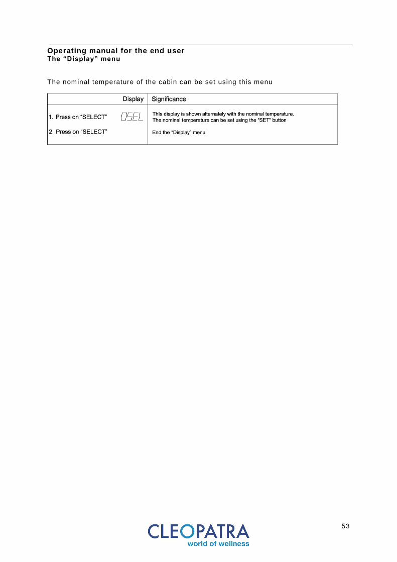
Operating manual for the end user Preparation & steam operation Follow DIN VDE 0100 T560 and T610 and the instructions in this manual by Cleopatra. All preparations according to the installation and maintenance manual must be performed before running the system with steam. Ensure that the installation engineer has done all of the work according to these instructions and that the steam bath generator has been correctly set and programmed for the desired operating mode. Open the water l ine and switch on the mains switch. Setting the temperature of the steam bath cabin: Select the menu “Display” as follows:
• Hold the “MODE” button pressed down until the left LED button f lashes. • Hold the “SELECT” button pressed down: the symbols oSEL and the nominal
temperature are displayed alternately on the display. • The nominal temperature can be set using the “SET” button. • Press the “MODE” button until the LED button goes out.
Automatic temperature-regulated steam operation can now be init iated according to programming manually using the “MODE” button or by using an external switch or using a remote control. Automatic operation Once the mode of operation and nominal temperature has been set up the steam bath generator is ready to be operated automatically. Init iating automatic steam bath operation switches on the protection and the inlet and outlet valves are actuated to supply the steam cyl inder automatically. The water eventually reaches the electrodes, electr ical current f lows and the water is heated until steam is generated. The nominal output is not reached immediately for f irst commissioning of a new steam cylinder according to the quality or electr ical conductivity of the supply water. T he steam bath generator requires a certain period of t ime operating before it reaches its nominal output. This t ime is called the “start phase”. It is only after the start phase is completed that the steam bath generator will reach its nominal output. The nominal output can then be reached again quite shortly once the start phase has been completed. A start phase is needed each time a new steam cyl inder is installed. Manual operation This operating mode is set ex works. Automatic operation of the steam bat h generator can be init iated manually by pressing the “Mode” button. Pressing the “Mode” button causes:
• steam production to be switched on • the aroma pump for automatic fragrance metering to be actuated • the cabin l ight is switched on
The right LED of the “MODE” button lights up. To switch off: Press the “MODE” button. The “MODE” button should be kept depressed for two seconds to make all adjustments or for programming until the left LED of the button f lashes. The desired menu for controll ing, making sett ings or programming can then be selected. If there is a fragrance pump attached then fragrance is automatically metered according to intervals set in the “adjustments”. Ensure that the fragrance pump is only started in automatic mode for a cabin temperature above 30°C. The pump is not actuated below a temperature of 30°C. The cabin l ight can be switched on and off manually using the “SET/light” button.

52
Operating manual for the end user Operating with steam
Operation using an external switch or coin -operated switch (this option is not offered by Cleopatra) The steam bath generator must f irst be programmed in the menu “adjustments” for the function “StBy” (stand-by”) for this operating mode. The external switch must also be attached properly. For making the setting: Hold the “MODE” button pressed down for two seconds until the left LED button f lashes. Select the function StBy using the “SELECT” button. The desired stand-by function can be set using the “SET” button (see also Stand-by function in the menu “adjustments”.) Query operating values; perform settings The Cleo-Total steam bath generator has individual menus for making settings, service work, making queries and programming which can be selected by operating personnel. To select these: Hold the “MODE steam” button pressed down for two seconds until the left LED button f lashes. The various menus can subsequently be selected by pressing the “MODE” button. The following menus are selectable: Menus: Purpose: “display” For setting the cabin nominal value temperature. “Service” For service and checking operations, e.g. manual draining. “System data” For information about the system settings
(Only queries are possible). “adjustments” For entry (programming) of operating values. “Program” For programming special functions and specif ic parameters Only the menus “display”, “System data” or “adjustments” are used for daily use of the steam bath generator. The menus “Service” and “Program” contain functions which can only be adjusted by a suitably trained engineer. These menus are described in the separate installation and maintenance manuals.
53
Operating manual for the end user The “Display” menu The nominal temperature of the cabin can be set using this menu

54
Operating manual for the end user The “Service” menu
Select the menu by pressing "MODE", "Service" button. The " Service" LED and the LED left of the "SELECT" button will f lash. The "Service Menu" is divided into two areas: In the f irst operating range values can be read during the operation. In the second f ield component of the steam generator to the check can be switched on and off manually. In this area the steam generator is automatically switched off so that the component can be operated individually.
55
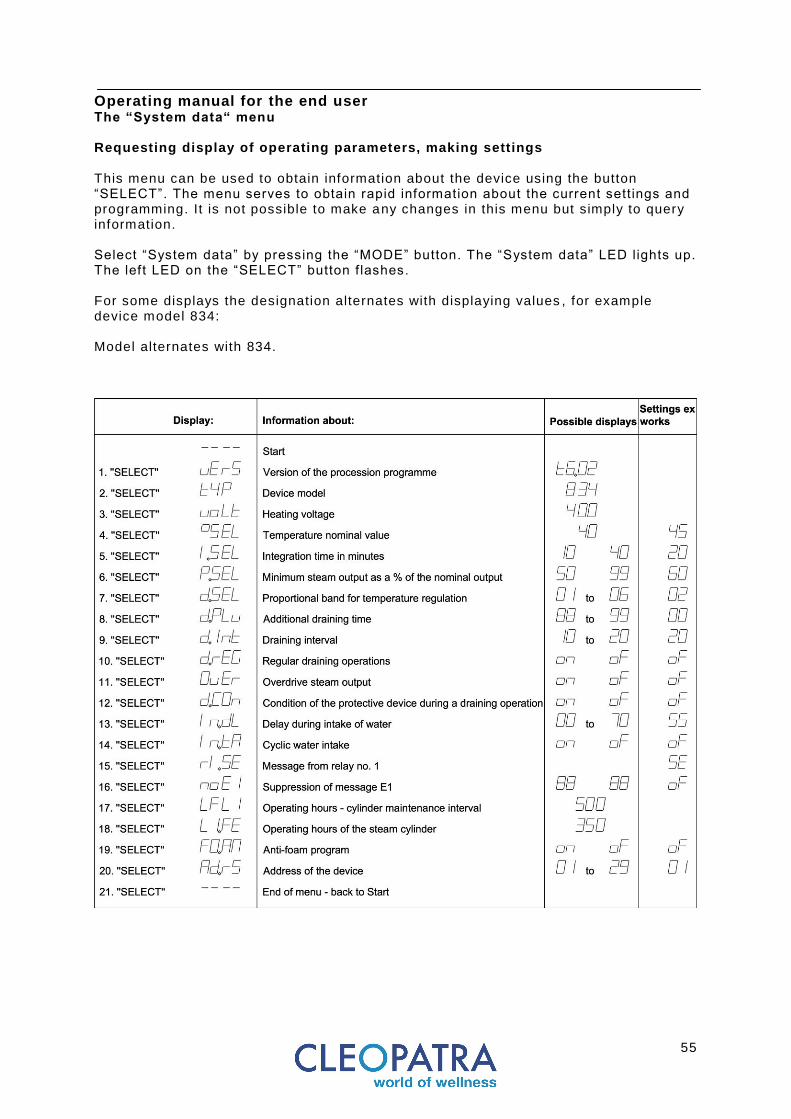
Operating manual for the end user The “System data“ menu Requesting display of operating parameters, making settings This menu can be used to obtain information about the device using the button “SELECT”. The menu serves to obtain rapid information about the current settings and programming. It is not possible to make any changes in this menu but simply to query information. Select “System data” by pressing the “MODE” button. The “System data” LED lights up. The left LED on the “SELECT” button f lashes. For some displays the designation alternates with displaying values , for example device model 834: Model alternates with 834.
56
Operating manual for the end user
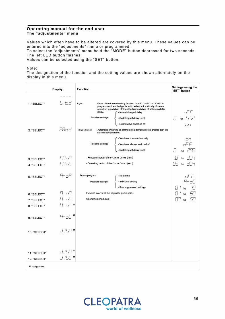
The “adjustments” menu Values which often have to be altered are covered by this menu. These values can be entered into the “adjustments” menu or programmed. To select the “adjustments” menu hold the “MODE” button depressed for two seconds. The left LED button f lashes. Values can be selected using the “SET” button. Note: The designation of the function and the setting values are shown alternately on the display in this menu.
57
Operating manual for the end user
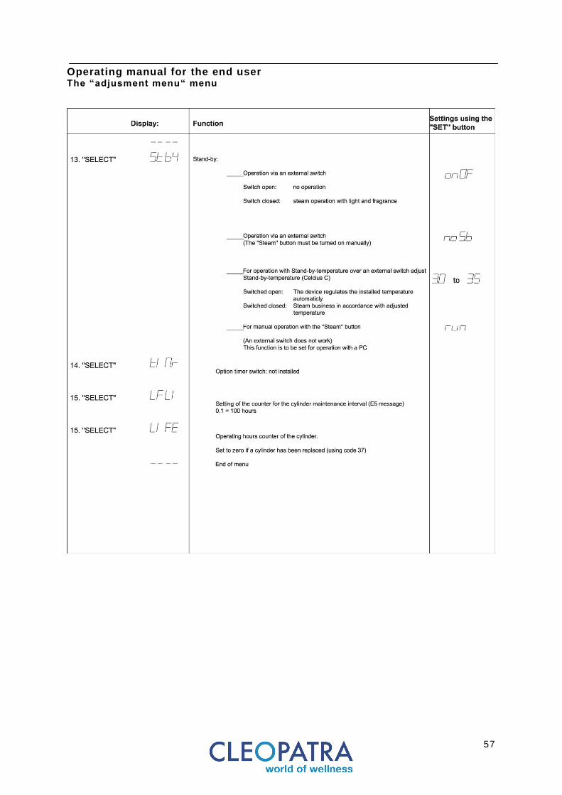
The “adjusment menu“ menu
58
Operating manual for the end user
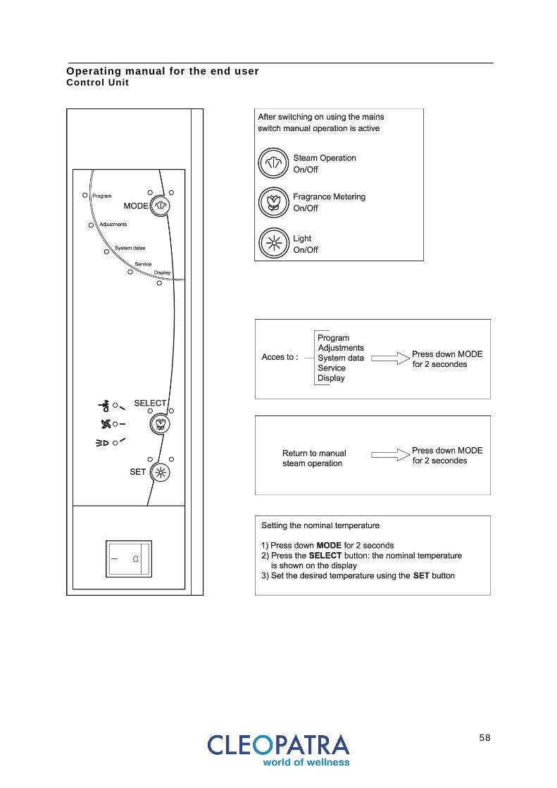
Control Unit
59
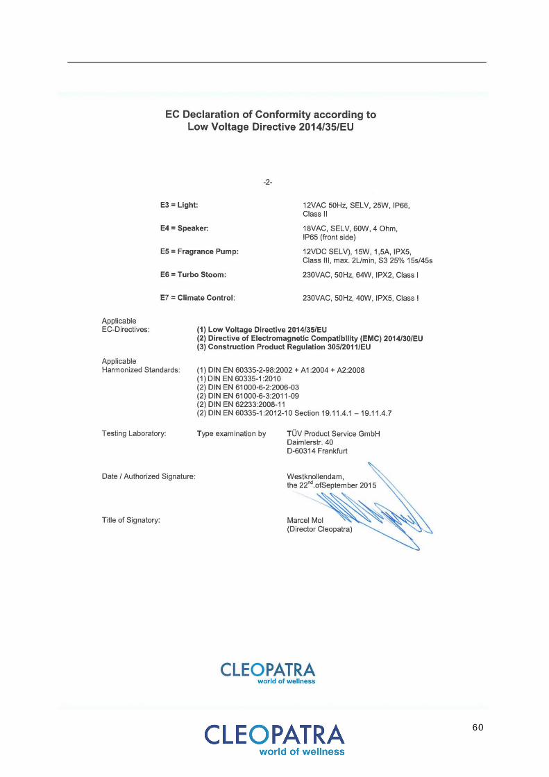
Declaration of confomity
60
61
I n s t a l l a t i on a nd o per at i on ma nu a l C le o To ta l . W e r es er ve t he r i g ht to ma k e te ch n i c a l ch an ge s an d pr i n t i n g - r e la te d co l our d e v ia t i on s .
I t e m no . 90 57 640 1 . Pr i nt ed i n Th e Ne th er l a nd s . 0 1 - 20 15
Cleopatra B.V. . Oostzijde 295
. 1508 EN Zaandam
Phone: +31 75-647 82 00 . [email protected]
.
www.cleopatra.nl