Visualization of asymmetric wetting ridges on soft solids with X-ray microscopy
7
ARTICLE Received 18 Dec 2013 | Accepted 10 Jun 2014 | Published 10 Jul 2014 Visualization of asymmetric wetting ridges on soft solids with X-ray microscopy Su Ji Park 1 , Byung Mook Weon 2 , Ji San Lee 1 , Junho Lee 1 , Jinkyung Kim 1 & Jung Ho Je 1 One of the most questionable issues in wetting is the force balance that includes the vertical component of liquid surface tension. On soft solids, the vertical component leads to a microscopic protrusion of the contact line, that is, a ‘wetting ridge’. The wetting principle determining the tip geometry of the ridge is at the heart of the issues over the past half century. Here we reveal a universal wetting principle from the ridge tips directly visualized with high spatio-temporal resolution of X-ray microscopy. We find that the cusp of the ridge is bent with an asymmetric tip, whose geometry is invariant during ridge growth or by surface softness. This singular asymmetry is deduced by linking the macroscopic and microscopic contact angles to Young and Neuman laws, respectively. Our finding shows that this dual-scale approach would be contributable to a general framework in elastowetting, and give hints to issues in cell-substrate interaction and elasto-capillary problems. DOI: 10.1038/ncomms5369 OPEN 1 X-ray Imaging Center, Department of Materials Science and Engineering, Pohang University of Science and Technology, San 31, Hyoja-dong, Pohang 790-784, South Korea. 2 School of Advanced Materials Science and Engineering, SKKU Advanced Institute of Nanotechnology (SAINT), Sungkyunkwan University, Suwon 440-746, South Korea. Correspondence and requests for materials should be addressed to J.H.J. (email: [email protected]). NATURE COMMUNICATIONS | 5:4369 | DOI: 10.1038/ncomms5369 | www.nature.com/naturecommunications 1 & 2014 Macmillan Publishers Limited. All rights reserved.
-
Upload
independent -
Category
Documents
-
view
0 -
download
0
Transcript of Visualization of asymmetric wetting ridges on soft solids with X-ray microscopy

ARTICLE
Received 18 Dec 2013 | Accepted 10 Jun 2014 | Published 10 Jul 2014
Visualization of asymmetric wetting ridgeson soft solids with X-ray microscopySu Ji Park1, Byung Mook Weon2, Ji San Lee1, Junho Lee1, Jinkyung Kim1 & Jung Ho Je1
One of the most questionable issues in wetting is the force balance that includes the vertical
component of liquid surface tension. On soft solids, the vertical component leads to a
microscopic protrusion of the contact line, that is, a ‘wetting ridge’. The wetting principle
determining the tip geometry of the ridge is at the heart of the issues over the past half
century. Here we reveal a universal wetting principle from the ridge tips directly visualized
with high spatio-temporal resolution of X-ray microscopy. We find that the cusp of the ridge
is bent with an asymmetric tip, whose geometry is invariant during ridge growth or by surface
softness. This singular asymmetry is deduced by linking the macroscopic and microscopic
contact angles to Young and Neuman laws, respectively. Our finding shows that this
dual-scale approach would be contributable to a general framework in elastowetting, and give
hints to issues in cell-substrate interaction and elasto-capillary problems.
DOI: 10.1038/ncomms5369 OPEN
1 X-ray Imaging Center, Department of Materials Science and Engineering, Pohang University of Science and Technology, San 31, Hyoja-dong, Pohang790-784, South Korea. 2 School of Advanced Materials Science and Engineering, SKKU Advanced Institute of Nanotechnology (SAINT), SungkyunkwanUniversity, Suwon 440-746, South Korea. Correspondence and requests for materials should be addressed to J.H.J. (email: [email protected]).
NATURE COMMUNICATIONS | 5:4369 | DOI: 10.1038/ncomms5369 | www.nature.com/naturecommunications 1
& 2014 Macmillan Publishers Limited. All rights reserved.
Many natural and synthetic materials are soft anddeformable owing to the nature as in rubbers or totheir structure as for thin films1–3 and fibres4–6.
Wetting behaviour of soft deformable solids, that is,elastowetting, is a very old subject and much attention has beenpaid over the past half century1–26 for various scientific issuesinvolved in soft tissues27–32 and polymer gels33, as well as forpractical applications such as inkjet printing34 and microfluidicdevices35. Recently, the interaction of the contact line with adeformable substrate, which causes a local microscopicdeformation, that is, the formation of a ‘wetting ridge’, hasbeen actively investigated7–25 since the pioneering work on thefirst measurement of the ridge by Carre et al.20
Wetting behaviours on solids have been explained by Younglaw (cosyL¼ (gSV–gSL)/gLV)36, based on a force balance ofinterfacial tensions (gLV, gSV and gSL of liquid–vapour, solid–vapour and solid–liquid interfaces, respectively) that determinesthe equilibrium contact angles (yS, yL and yV in solid, liquid andvapour, respectively) at the three-phase contact line.
On a soft solid, however, the vertical component ofliquid surface tension, which is not considered in Young law,has critical roles in the wetting behaviours, such as thewrinkling1,2 or folding3 of thin films and the bending offibres4–6. The vertical component, which is highly concentratedat the microscopic region of the three-phase contact line, inducesa local microscopic structure on the soft surface, that is, a ‘wettingridge’. Despite many theoretical7–16 and experimental7,17–25
studies over the past half century, the microscopic geometryof a wetting ridge, particularly, its ‘tip geometry’, still remainsunresolved.
The first measurement of the wetting ridge was achieved byusing white-light interferometry, which was limited to the dry
side of the ridge far from the tip20. Since then, many researchershave tried to find the tip using optical techniques such as confocalmicroscopy7,18,19 or optical profilometry21. However, directobservation of the tip for precise measurements of the contactangles is hardly achievable by optical imaging owing to limitedresolutions7,18–20. For instance, confocal microscopy18 failed todirectly visualize the vicinity of the contact line due to strong lightscattering over the detection limit by the steep slopes near thecontact line. Jerison et al.7 first measured triangular cusps byembedding fluorescence particles on the surface in confocalmicroscopy. The resolution of this approach, however, was nothigh enough to visualize the tip and precisely measure thegeometry of the cusp. Here we present the first, direct and real-time visualization of ridge tips with high spatial and temporalresolutions using X-ray microscopy, and discuss a generalframework of wetting on soft solids based on precisemeasurement of the geometry of the tips.
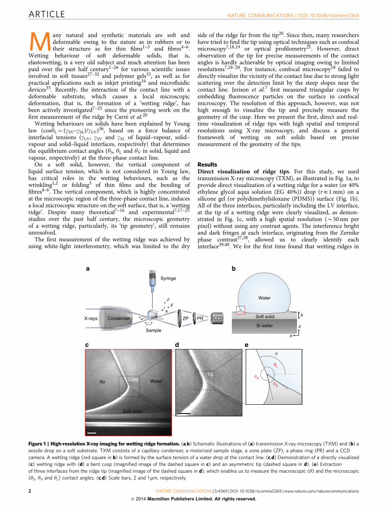
ResultsDirect visualization of ridge tips. For this study, we usedtransmission X-ray microscopy (TXM), as illustrated in Fig. 1a, toprovide direct visualization of a wetting ridge for a water (or 40%ethylene glycol aqua solution (EG 40%)) drop (rE1 mm) on asilicone gel (or polydimethylsiloxane (PDMS)) surface (Fig. 1b).All of the three interfaces, particularly including the LV interface,at the tip of a wetting ridge were clearly visualized, as demon-strated in Fig. 1c, with a high spatial resolution (B50 nm perpixel) without using any contrast agents. The interference brightand dark fringes at each interface, originating from the Zernikephase contrast37,38, allowed us to clearly identify eachinterface39,40. We for the first time found that wetting ridges in
Syringe
a b
c d e
zy
x
Water
Soft solidCCDPRZP
Sample
CondenserX-raysh
z
x
Si wafer
WaterAir
Soft solid
CuspTip �V
�L
�
�S
Figure 1 | High-resolution X-ray imaging for wetting ridge formation. (a,b) Schematic illustrations of (a) transmission X-ray microscopy (TXM) and (b) a
sessile drop on a soft substrate. TXM consists of a capillary condenser, a motorized sample stage, a zone plate (ZP), a phase ring (PR) and a CCD
camera. A wetting ridge (red square in b) is formed by the surface tension of a water drop at the contact line. (c,d) Demonstration of a directly visualized
(c) wetting ridge with (d) a bent cusp (magnified image of the dashed square in c) and an asymmetric tip (dashed square in d). (e) Extraction
of three interfaces from the ridge tip (magnified image of the dashed square in d), which enables us to measure the macroscopic (y) and the microscopic
(yS, yV and yL) contact angles. (c,d) Scale bars, 2 and 1mm, respectively.
ARTICLE NATURE COMMUNICATIONS | DOI: 10.1038/ncomms5369
2 NATURE COMMUNICATIONS | 5:4369 | DOI: 10.1038/ncomms5369 | www.nature.com/naturecommunications
& 2014 Macmillan Publishers Limited. All rights reserved.

large drops (rE1 mm) have bent cusps (Fig. 1d; dashed square ofFig. 1c) with the asymmetric tips rotated (Fig. 1e; dashed squareof Fig. 1d) towards the LV interfaces (Fig. 1d,e). The rotation ofthe tips observed here is different from the reported rotationof the whole ridges that is due to the substantial dimplegenerated under small droplets (roo250 mm) by large Laplacepressures19. High-resolved images of the tips of cusps enabledus to accurately measure the microscopic (yS, yL and yV) aswell as the macroscopic (y) contact angles (Fig. 1e; dashed squareof Fig. 1d).
Surface profiles. The direct visualization made it possible toaccurately extract the surface profiles uz(x) (vertical surface dis-placement at x) of wetting ridges (Supplementary Fig. 1), asdemonstrated for two surfaces with E (elasticity)¼ 3 and 16 kPain Fig. 2a,b. The two profiles (blue and red circles in Fig. 2b)clearly show asymmetric and bent cusps. Here the horizontalpeak position of each surface profile was set as x¼ 0. We tried tofit the following three linear elastic (LE) symmetrical models tothese profiles (Supplementary Fig. 2): (i) the model by de Gennesand Shanahan10,11,20 (dash-dotted lines) based on the classicalstress analysis of an elastic film by a concentrated normal force;(ii) the model by Limat12 (dashed lines) based on symmetricsurface energies (gSV¼ gSL¼ gS, that is, y¼ 90�); and (iii) themodel by Style and Dufresne7,8 (solid lines) based on symmetricsurface stresses (USL¼ USV¼US), where USL (USV) is the surfacestress of the SL (SV) interface. The best fits of the three modelsare displayed in Fig. 2b.
The surface profiles predicted by most of LE symmetricalmodels7–15,20 are not well matched with our experimental data(Fig. 2b and Supplementary Fig. 2), except the model by Style andDufresne8 in EG 40% (Supplementary Fig. 2f). In fact, thepredicted profiles themselves are quite different from each other.The heights of ridges predicted BgLVsiny/E are relatively in agood agreement with those measured in this study uz(0), though(Table 1).
The model by Shanahan and co-workers10,11,20 is inapplicableto predict the profiles in the cusp regions (w (ridge width) oo le(¼US/E, the elasto-capillary length)). Actually, the cusp regionsare inelastic regions (|x� x 0|te, where x 0 is the position of thecontact line and e is the cutoff distance10), based on the fact thatthe estimated e are comparable to le for our systems (Table 1).Of course, the model is relatively well matched in the elasticzone (|x� x 0|\e) the dash-dotted line (the green solid line) in|x|4B5 mm in Fig. 2b (Supplementary Fig. 2a), consistent withFig. 2 of ref. 20.
The surface profiles by Limat12, who included symmetricsurface energies (gSV¼ gSL¼ gS) in the Shanahan’s description ofsurface displacement10,11,20, are furthermore far from ourexperimental data (Supplementary Fig. 2c,d; the solid linesare from surface energies, gS¼ (gSVþ gSL)/2 and the dashedlines are from surface stresses, US¼ (USVþ USL)/2). The deviationis presumably due to oversimplification, in particular, by theassumptions of ySV(SL) oo1 and gLV oogS, which are in contrastto our case (ySV 441 and gLV (ULV)4gS (US)), where ySV(SL) is theslope of the SV (SL) interface.
0 5 10 15 20
–10
0
10
–5 0 5 100
5
10
15
20
a
b c
20
–2
0
–20
0
20
Air Water
E = 3 kPa
3 kPa16 kPa
Style’s
Limat’sShanahan’s
x (μm) E (kPa)
x (μm)
Δuz(
x) (
μm)
ΔK (
%)
ΔAng
le (
°)
Δ� Δ�S Δ�V Δ�L
u z (
x) (
μm)
E = 16 kPa
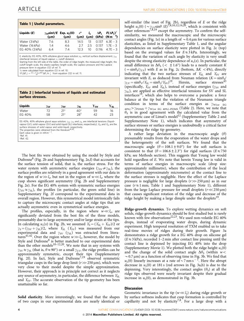
Figure 2 | Effect of surface elasticity on wetting ridge formation. (a) Representative X-ray images of wetting ridges on a silicone gel (EE3 kPa) and a
PDMS film (E16 kPa). Scale bars, 5 mm. (b) The surface profiles clearly show a strong E-dependence of the vertical displacement uz(x). The asymmetric
and bent cusps are compared with three LE symmetrical models by Style et al.8 (solid lines), Limat12 (dashed lines) and de Gennes and Shanahan10,11,20
(dash-dotted lines). For EE3 kPa, the model by Shanahan is invalid in the observed region here. The detailed fitting descriptions are in Supplementary
Fig. 2. (Inset) The cusps are identically superimposed by Duz(x)¼ uz(x)� uz(0) at woole. (c) (Top) The angular differences (DAngle) are plotted
with E, based on the average values for 3 kPa, for the macroscopic (y, black circle) and the microscopic (yS (blue circle), yV (blue square) and yL
(blue triangle)) angles measured at woB0.4mm. The error bars are s.d. from five sets of image data for 3 kPa, one set for 10 kPa and three sets for 16 kPa.
(Bottom) K is obtained with yS and gLV, that is, K¼ sinyS/gLV. The little difference of K (DKo4%), resulted from that of DyS (o ±1.6�), indicates
invariant surface stresses USL and USV at the tips.
NATURE COMMUNICATIONS | DOI: 10.1038/ncomms5369 ARTICLE
NATURE COMMUNICATIONS | 5:4369 | DOI: 10.1038/ncomms5369 | www.nature.com/naturecommunications 3
& 2014 Macmillan Publishers Limited. All rights reserved.
The best fits were obtained by using the model by Style andDufresne8 (Fig. 2b and Supplementary Fig. 2e,f) that accounts forthe surface tension of solid, that is, the surface stress. For thewater system with asymmetric surface energies (gSVagSL), thesurface profiles are relatively in a good agreement with our data inthe region of w44le, but not in the region of woole, where thecusp shows significant asymmetry (Fig. 2b and SupplementaryFig. 2e). For the EG 40% system with symmetric surface energies(gSVEgSL), the profiles (in particular, the green solid line) inSupplementary Fig. 2f correspond to the experimental data inoverall region. However, this symmetrical model intrinsically failsto capture the microscopic contact angles at ridge tips that areactually asymmetric even in symmetrical surface energies.
The profiles, especially, in the region where woole, aresignificantly deviated from the best fits of the three models,presumably due to large asymmetry and/or large strain at the tips.In calculating uz(x) in Fig. 2b, we assumed US¼ (USLþ USV)/2 orgS¼ (gSVþ gSL)/2, where USL (USV) was measured from ourexperimental data and gSV (gSL) was extracted from litera-tures41,42. Over the region where w44le, however, the model byStyle and Dufresne8 is better matched to our experimental datathan the other models10–12,20. We note that in any systems withgSVEgSL (that is, yE90�) or a small gLV, the ridge profiles can beapproximately symmetric, except their tips (SupplementaryFig. 2f). In fact, Style and Dufresne7,19 observed symmetrictriangular cusps in the large drop limit (r44250 mm), which werevery close to their model despite the simple approximation.However, their approach is in principle not correct as it neglectsany source of asymmetry, in particular, the difference between USL
and USV. The accurate observation of the tip geometry has beenunattainable so far.
Solid elasticity. More interestingly, we found that the shapesof two cusps in our experimental data are nearly identical or
self-similar (the inset of Fig. 2b), regardless of E or the ridgeheight uz(0) (BgLVsiny /E)7,8,10,12,14,20, which is consistent withother references7,8,19 except the asymmetry. To confirm the self-similarity, we measured the macroscopic and the microscopiccontact angles (Fig. 1e) in a length of B0.4 mm for various surfaceelasticities, as listed in Supplementary Table 1, and the angulardependencies on surface elasticity were plotted in Fig. 2c (top)based on the averaged values for EE3 kPa. Interestingly, wefound that the variation of each angle by elasticity is very smalldespite the strong elasticity dependence of uz(x). In particular, thesmall difference in DyS (o ±1.6�) leads to a nearly constant K(¼ sinyS/gLV) with E as in Fig. 2c (bottom, DK o4%), directlyindicating that the two surface stresses of USL and USV areinvariant with E, as deduced from Neuman relation (K¼ sinyS/gLV¼ sinyV/USL¼ sinyL/USV)19. Herein, surface stresses43
(specifically, USV and USL), instead of surface energies (gSV andgSL), are applied as effective interfacial tensions for SV and SLinterfaces19, which also helps to overcome a paradox: a forcebalance at the tip but the violation of the Neumann trianglecondition in terms of the surface energies as gW(or EG
40%)4gPDMSþ gW(or EG 40%)–PDMS (Table 2). Here, we note thatyS is in good agreement with the calculated value from theasymmetric case of Limat’s model12 (Supplementary Table 2 andSupplementary Note 1), which indicates that asymmetry ofsurface stresses or surface energies is undoubtedly a critical factordetermining the ridge tip geometry.
A rather large deviation in the macroscopic angle (y)presumably results from the evaporation of the water drops andthe heterogeneity of the soft surfaces. We found that themacroscopic angle (y¼ 108.1±9.0�) for the soft surfaces isconsistent to that (y¼ 106.6±2.3�) for rigid surfaces (EE750kPa; see Methods section). This suggests that Young law wouldhold regardless of E. We note that herein Young law is valid interms of surface energies in macroscopic scale (drop size:approximately millimetre), where the contribution of the localdeformation (approximately micrometre) at the contact line tothe surface stresses is negligible. Here the effect of the Laplacepressure is negligible for large droplets (r44250 mm) as in ourcase (rE1 mm; Table 1 and Supplementary Note 1), differentfrom the large Laplace pressure for small droplets (roo250 mm)that causes significant rotation of the ridge and decrease of theridge height by making a large dimple under the droplets19.
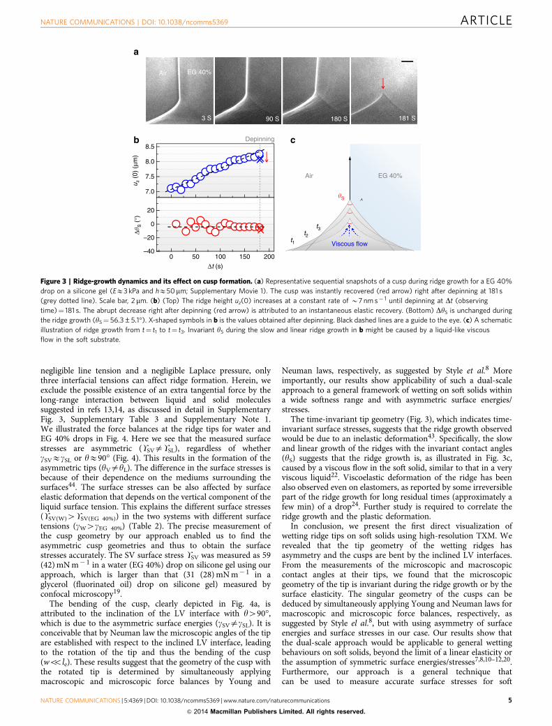
Ridge-growth dynamics. To explore wetting dynamics on softsolids, ridge-growth dynamics should be first studied but is rarelyknown with few observations22,23. We used non-volatile EG 40%drops, instead of evaporating water drops, during dynamicexperiment. High temporal resolution of TXM enabled us to takereal-time movies of ridges during their growth. Figure 3ademonstrates a ridge growth for a EG 40% drop on silicone gel(EE3 kPa), recorded 1–2 min after contact line pinning until thecontact line is depinned by injecting EG 40% into the drop(Supplementary Movie 1). We plotted both the ridge height uz(0)and the change of the solid contact angle DyS (within woB0.7 mm) as a function of observing time in Fig. 3b. We find thatuz(0) linearly increases at a rate ofB7 nm s� 1. Here the abruptdecrease in uz(0) at 181 s (red arrows in Fig. 3a,b) is due to thedepinning. Very interestingly, the contact angles (yS) at all theridge tips observed were nearly invariant despite their gradualincrease in uz(0), as demonstrated in Fig. 3b.
DiscussionGeometric invariance in the tip (woole) during ridge growth orby surface softness indicates that cusp formation is controlled bycapillarity and not by elasticity7,8. For a large drop with a
Table 1 | Useful parameters.
Liquids (E) cLVsinh/E(lm)
Exp. uz(0)(lm)
e*(lm)
le
(lm)DPL
(kPa)F(DPL)w
(N m� 1)
Water (3 kPa) 7.6 8.3 14.5 13 0.137 6.3E� 3Water (16 kPa) 1.4 4.6 2.7 2.5 0.137 1.7E� 3EG 40% (3 kPa) 6.4 7.4 12.3 10 0.116 4.7E� 3
E, elasticity; EG 40%, 40% ethylene glycol aqua solution; uz, vertical surface displacement; gLV,interfacial tension of liquid–vapour; e, cutoff distance.Starting from the left side of the table, the order of ridge height, the measured ridge height, thecutoff length scale, the elasto-capillary length scale, the Laplace pressure and the Laplacepressure term in equation (12) of ref. 11.*e were calculated from equation (5) in ref. 10.wFðDPLÞ ¼ 2ð1� v2 ÞgLV siny
pE DPL ln re
� �from equation (12) in ref. 11.
Table 2 | Interfacial tensions of liquids and estimatedsurface stresses.
Liquids cLV cSV cSL YSV YSL
Water 72 21* 40* 59 16EG 40% 58 21* 28w 42 23
EG 40%, 40% ethylene glycol aqua solution; gLV, gSV and gSL are interfacial tensions (liquid–vapour (LV), solid–vapour (SV) and solid–liquid (SL) interfaces, respectively); USV and USL are thesurface stresses of solid vapour and solid–liquid, respectively.The properties were obtained from the literature41,42.Each value is given in mN m� 1.*Ref. 41.wRef. 42.
ARTICLE NATURE COMMUNICATIONS | DOI: 10.1038/ncomms5369
4 NATURE COMMUNICATIONS | 5:4369 | DOI: 10.1038/ncomms5369 | www.nature.com/naturecommunications
& 2014 Macmillan Publishers Limited. All rights reserved.
negligible line tension and a negligible Laplace pressure, onlythree interfacial tensions can affect ridge formation. Herein, weexclude the possible existence of an extra tangential force by thelong-range interaction between liquid and solid moleculessuggested in refs 13,14, as discussed in detail in SupplementaryFig. 3, Supplementary Table 3 and Supplementary Note 1.We illustrated the force balances at the ridge tips for water andEG 40% drops in Fig. 4. Here we see that the measured surfacestresses are asymmetric (USVaUSL), regardless of whethergSVEgSL or yE90� (Fig. 4). This results in the formation of theasymmetric tips (yVayL). The difference in the surface stresses isbecause of their dependence on the mediums surrounding thesurfaces44. The surface stresses can be also affected by surfaceelastic deformation that depends on the vertical component of theliquid surface tension. This explains the different surface stresses(USV(W)4USV(EG 40%)) in the two systems with different surfacetensions (gW4gEG 40%) (Table 2). The precise measurement ofthe cusp geometry by our approach enabled us to find theasymmetric cusp geometries and thus to obtain the surfacestresses accurately. The SV surface stress USV was measured as 59(42) mN m� 1 in a water (EG 40%) drop on silicone gel using ourapproach, which is larger than that (31 (28) mN m� 1 in aglycerol (fluorinated oil) drop on silicone gel) measured byconfocal microscopy19.
The bending of the cusp, clearly depicted in Fig. 4a, isattributed to the inclination of the LV interface with y490�,which is due to the asymmetric surface energies (gSVagSL). It isconceivable that by Neuman law the microscopic angles of the tipare established with respect to the inclined LV interface, leadingto the rotation of the tip and thus the bending of the cusp(woole). These results suggest that the geometry of the cusp withthe rotated tip is determined by simultaneously applyingmacroscopic and microscopic force balances by Young and
Neuman laws, respectively, as suggested by Style et al.8 Moreimportantly, our results show applicability of such a dual-scaleapproach to a general framework of wetting on soft solids withina wide softness range and with asymmetric surface energies/stresses.
The time-invariant tip geometry (Fig. 3), which indicates time-invariant surface stresses, suggests that the ridge growth observedwould be due to an inelastic deformation43. Specifically, the slowand linear growth of the ridges with the invariant contact angles(yS) suggests that the ridge growth is, as illustrated in Fig. 3c,caused by a viscous flow in the soft solid, similar to that in a veryviscous liquid22. Viscoelastic deformation of the ridge has beenalso observed even on elastomers, as reported by some irreversiblepart of the ridge growth for long residual times (approximately afew min) of a drop24. Further study is required to correlate theridge growth and the plastic deformation.
In conclusion, we present the first direct visualization ofwetting ridge tips on soft solids using high-resolution TXM. Werevealed that the tip geometry of the wetting ridges hasasymmetry and the cusps are bent by the inclined LV interfaces.From the measurements of the microscopic and macroscopiccontact angles at their tips, we found that the microscopicgeometry of the tip is invariant during the ridge growth or by thesurface elasticity. The singular geometry of the cusps can bededuced by simultaneously applying Young and Neuman laws formacroscopic and microscopic force balances, respectively, assuggested by Style el al.8, but with using asymmetry of surfaceenergies and surface stresses in our case. Our results show thatthe dual-scale approach would be applicable to general wettingbehaviours on soft solids, beyond the limit of a linear elasticity orthe assumption of symmetric surface energies/stresses7,8,10–12,20.Furthermore, our approach is a general technique thatcan be used to measure accurate surface stresses for soft
7.0
7.5
8.0
8.5
a
b c
0 50 100 150 200–40
–20
0
20
Air EG 40%
3 S 90 S
Depinning
Air EG 40%
Viscous flow
180 S 181 S
t1t2
t3
�S
Δ�S (
°)u z
(0)
(μm
)
Δt (s)
Figure 3 | Ridge-growth dynamics and its effect on cusp formation. (a) Representative sequential snapshots of a cusp during ridge growth for a EG 40%
drop on a silicone gel (EE3 kPa and hE50mm; Supplementary Movie 1). The cusp was instantly recovered (red arrow) right after depinning at 181 s
(grey dotted line). Scale bar, 2 mm. (b) (Top) The ridge height uz(0) increases at a constant rate of B7 nm s� 1 until depinning at Dt (observing
time)¼ 181 s. The abrupt decrease right after depinning (red arrow) is attributed to an instantaneous elastic recovery. (Bottom) DyS is unchanged during
the ridge growth (yS¼ 56.3±5.1�). X-shaped symbols in b is the values obtained after depinning. Black dashed lines are a guide to the eye. (c) A schematic
illustration of ridge growth from t¼ t1 to t¼ t3. Invariant yS during the slow and linear ridge growth in b might be caused by a liquid-like viscous
flow in the soft substrate.
NATURE COMMUNICATIONS | DOI: 10.1038/ncomms5369 ARTICLE
NATURE COMMUNICATIONS | 5:4369 | DOI: 10.1038/ncomms5369 | www.nature.com/naturecommunications 5
& 2014 Macmillan Publishers Limited. All rights reserved.

materials within a wide stiffness range. This report would open anew subject in wetting on soft solids, especially regarding studyon asymmetric ridge tip. Broadly speaking, X-ray microscopywould be helpful to investigate characteristic wetting behaviourson soft solids associated with spreading20–22, contact anglehysteresis23–25 or evaporation23,25, and to study various elasto-capillary phenomena26.
In this report, we suggest an applicability of a simple approachapplying both Young and Neuman laws to dual-scale forcebalance and continuous surface deformation, which would bepotentially important, particularly, in biological systems. Forexample, cell–substrate interactions might be closely linked towetting behaviours on soft solids17; in fact, cells are known tosense and respond to the environment through small strains(3–4%) that are induced by their traction forces28. Indeed, themechanical microenvironment is, as seen in cancer progression inbreast epithelial cells30, critical to the normal development ofmost mammalian tissues and organs, which are soft visco-elastic materials (E¼ 10� 1 (for example, a brain) to 102 kPa(for example, a cartilage))27. In addition, our approach might bepractically applicable to estimating the cell traction force or theforce-induced strain29, as well as the surface stresses19.
MethodsMaterials and substrate fabrication. Pure water (Millipore) or EG 40%(Samchun Pure Chemical Co., Korea) drops of rE1 mm were generated by asyringe pump and gently put on a silicone gel (EE3 kPa; CY52-276A/B, DowCorning Toray) or a PDMS (EE10 or 16 kPa; Sylgard 184, Dow Corning Toray),spin coated with a controlled thickness (h¼ 50 mm) on a Si wafer (Fig. 1b). Detailedprotocols of preparing the substrates and their mechanical/rheological propertieshave been reported in refs 7,19,45–47. Si wafer as a solid support was used for thefine alignment of the samples to the X-ray beam, as confirmed by a mirror image ofa wetting ridge (Fig. 2a) below the critical angle (0.22�) of Si.
X-ray imaging. The experiment was conducted using TXM (Fig. 1a)37,38 at the32-ID-C beamline in the Advanced Photon Source of the Argonne NationalLaboratory. We used a focused monochromatic X-ray beam at the photon energyof 9 keV (depth of focus: B25mm). The high brightness yielded high spatialresolution (50 nm per pixel) in a short acquisition time (50 ms per frame), muchfaster than reported48–51. A Fresnel zone plate was used as an objective lens. Forphase-contrast enhancement, we used a Au Zernike phase ring, optimized for9 keV, which is very useful to imaging soft matters such as organic39,40 or biologicalsamples37,38 without any contrast agents. Image taking was started within 1–2 minafter contact line pinning, under controlled temperature (22.5 �C) and humidity(19.5%).
Data analysis. The contact angle y for a rigid PDMS (EE750 kPa) was, measuredfor five drops of water or EG 40% using optical microscopy, 106.6±2.3� or95.8±0.7�, respectively. To test Young and Neuman conditions, we used thesurface or interfacial tension of a liquid drop (PDMS oil or water (EG 40%)/PDMSoil) measured in the literatures41,42 (Table 2). Surface tension is the same as surfaceenergy in liquid. Effects of X-ray irradiation52 to interfacial tensions or surfacestresses are negligible, as confirmed by invariant contact angles. The surfaceprofiles were extracted from the images using MATLAB and Image Pro-Plus 6.0software (Supplementary Fig. 1). We calculated the surface profiles of the LEsymmetrical models using MATLAB with the code for the model by Style et al.8
(http://www.eng.yale.edu/softmatter/pubs.html). The surface profiles, calculated fordifferent elastic moduli, were plotted in Supplementary Fig. 2.
References1. Huang, J. et al. Capillary wrinkling of floating thin polymer films. Science 317,
650–653 (2007).2. Huang, J., Davidovitch, B., Santangelo, C. D., Russell, T. P. & Menon, N.
Smooth cascade of wrinkles at the edge of a floating elastic film. Phys. Rev. Lett.105, 038302 (2010).
3. Py, C. et al. Capillary prigami: spontaneous wrapping of a droplet with anelastic sheet. Phys. Rev. Lett. 98, 156103 (2007).
4. Bico, J., Roman, B., Moulin, L. & Boudaoud, A. Elastocapillary coalescence ionwet hair. Nature 432, 690 (2004).
5. Duprat, C., Protiere, S., Beebe, A. Y. & Stone, H. A. Wetting of flexible fibrearrays. Nature 482, 510–513 (2012).
6. Bonaccurso, E. & Butt, H.-J. Microdrops on atomic force microscopecantilevers: evaporation of water and spring constant calibration. J. Phys. Chem.B 109, 253–263 (2006).
7. Jerison, E. R., Xu, Y., Wilen, L. A. & Dufresne, E. R. Deformation of an elasticsubstrate by a three-phase contact line. Phys. Rev. Lett. 106, 186103 (2011).
8. Style, R. W. & Dufresne, E. R. Static wetting on deformable substrates, fromliquids to soft solids. Soft Matter 8, 7177–7184 (2012).
9. Lester, G. R. Contact angles of liquids at deformable solid surfaces. J. ColloidInterface Sci. 16, 315–326 (1961).
10. Shanahan, M. E. R. & de Gennes, P. G. Equilibrium of the Triple Line Solid/Liquid/Fluid of a Sessile Drop. Adhesion 11. (ed. Allen, K. W.) 71–81 (ElsevierApplied Science, 1987).
11. Shanahan, M. E. R. The influence of solid micro-deformation on contact angleequilibrium. J. Phys. D: Appl. Phys. 20, 945–950 (1987).
12. Limat, L. Straight contact lines on a soft, incompressible solid. Eur. Phys. J. ESoft Matter 35, 134 (2012).
13. Weijs, J. H., Andreotti, B. & Snoeijer, J. H. Elasto-capillarity at the nanoscale:on the coupling between elasticity and surface energy in soft solids. Soft Matter9, 8494 (2013).
14. Marchand, A., Das, S., Snoeijer, J. H. & Andreotti, B. Contact angles on a softsolid: From Young’s law to Neumann’s law. Phys. Rev. Lett. 109, 236101 (2012).
15. White, L. R. The contact angle on an elastic substrate. 1. The role of disjoiningpressure in the surface mechanics. J. Colloid Interface Sci. 258, 82–96 (2003).
16. Rusanov, A. I. Theory of wetting of elastically deformed bodies. I. Deformationwith a finite contact-angle. Colloid J. USSR 37, 614–622 (1975).
Air
a b
AirWater EG 40%
Silicone Silicone
�LV=72 �LV=58�=108.1° �=92.3°
�V=172.0° �V=160.5°�L=149.0° �L=143.2°
SL=16SL=23
SV=42SV=59
Figure 4 | Microscopic force balances at the asymmetric and bent tips. (a,b) The estimated force balances at the asymmetric and bent tips for (a) water
and (b) EG 40%, respectively. The liquid surface tension (gLV) and the surface stresses (USL and USV) are given in mN m� 1.
ARTICLE NATURE COMMUNICATIONS | DOI: 10.1038/ncomms5369
6 NATURE COMMUNICATIONS | 5:4369 | DOI: 10.1038/ncomms5369 | www.nature.com/naturecommunications
& 2014 Macmillan Publishers Limited. All rights reserved.

17. Style, R. W. et al. Patterning droplets with durotaxis. Proc. Natl Acad. Sci. USA110, 12541–12544 (2013).
18. Pericet-Camara, R. et al. Solid-supported thin elastomer films deformed bymicrodrops. Soft Matter 5, 3611–3617 (2009).
19. Style, R. W. et al. Universal deformation of soft substrates near a contact lineand the direct measurement of solid surface stresses. Phys. Rev. Lett. 110,066103 (2013).
20. Carre, A., Gastel, J.-C. & Shanahan, M. E. R. Viscoelastic effects in thespreading of liquids. Nature 379, 432–434 (1996).
21. Pu, G. & Severtson, S. J. Dependence of wetting behavior on the thickness ofhighly viscoelastic films. J. Phys. Chem. C 115, 18729–18735 (2011).
22. Kajiya, T. et al. Advancing liquid contact line on visco-elastic gel substrates:Stick-slip vs. continuous motions. Soft Matter 9, 454–461 (2013).
23. Pu, G. & Severtson, S. J. Water evaporation on highly viscoelastic polymersurfaces. Langmuir 28, 10007–10014 (2012).
24. Extrand, C. W. & Kumagai, Y. Contact angles and hysteresis on soft surfaces.J. Colloid Interface Sci. 184, 191–200 (1996).
25. Lopes, M. C. & Bonaccurso, E. Evaporation control of sessile water drops bysoft viscoelastic surfaces. Soft Matter 8, 7875–7881 (2012).
26. Roman, B. & Bico, J. Elasto-capillarity: Deforming an elastic structure with aliquid droplet. J. Phys. Condens. Matter 22, 493101 (2010).
27. Levental, I. et al. Soft biological materials and their impact on cell function. SoftMatter 3, 299–306 (2007).
28. Discher, D. E., Janmey, P. & Wang, Y. L. Tissue cells feel and respond to thestiffness of their substrate. Science 310, 1139–1143 (2005).
29. Hersen, P. & Ladoux, B. Biophysics: Push it, pull it. Nature 470, 340–341 (2011).30. Paszek, M. J. et al. Tensional homeostasis and the malignant phenotype. Cancer
Cell 8, 241–254.31. Engler, A. J., Sen, S., Sweeney, H. L. & Discher, D. E. Matrix elasticity directs
stem cell lineage specification. Cell 126, 677–689 (2006).32. Wells, R. G. The role of matrix stiffness in regulating cell behavior. Hepatology
47, 1394–1400 (2008).33. Geoghegan, M. Wetting at polymer surfaces and interfaces. Prog. Polym. Sci. 28,
261–302 (2003).34. de Gans, B. J. & Schubert, U. S. Inkjet printing of well-defined polymer dots and
arrays. Langmuir 20, 7789–7793 (2004).35. Bennett, M. R. & Hasty, J. Microfluidic devices for measuring gene network
dynamics in single cells. Nat. Rev. Genet. 10, 628–638 (2009).36. de Gennes, P.-G., Brochard-Wyart, F. & Quere, D. Capillarity and Wetting
Phenomena: Drops, Bubbles, Pearls, Waves (Springer, 2003).37. Chu, Y. S. et al. Hard-x-ray microscopy with Fresnel zone plates reaches 40 nm
Rayleigh resolution. Appl. Phys. Lett. 92, 103119 (2008).38. Chen, Y.-T. et al. Hard x-ray Zernike microscopy reaches 30 nm resolution.
Opt. Lett. 36, 1269–1271 (2011).39. Weon, B. M. et al. Colloid coalescence with focused x rays. Phys. Rev. Lett. 107,
018301 (2011).40. Weon, B. M., Lee, J. S., Kim, J. T., Pyo, J. & Je, J. H. Colloidal wettability probed
with X-ray microscopy. Curr. Opin. Colloid Interface Sci. 17, 388–395 (2012).41. Chen, D., Cai, S., Suo, Z. & Hayward, R. C. Surface energy as a barrier to
creasing of elastomer films: An elastic analogy to classical nucleation. Phys. Rev.Lett. 109, 038001 (2012).
42. Cabral, J. T. & Hudson, S. D. Microfluidic approach for rapid multicomponentinterfacial tensiometry. Lab. Chip 6, 427–436 (2006).
43. Shuttleworth, R. The surface tension of solids. Proc. Phys. Soc. A 63, 444–457(1950).
44. Butt, H.–J. A sensitive method to measure changes in the surface stress ofsolids. J. Colloid Interface Sci. 180, 251–260 (1996).
45. Style, R. W. et al. Traction force microscopy in physics and biology. Soft Matter10, 4047–4055 (2014).
46. Ochsner, M. et al. Micro-well arrays for 3D shape control and high resolutionanalysis of single cells. Lab. Chip 7, 1074–1077 (2007).
47. Cesa, C. M. et al. Micropatterned silicone elastomer substrates for highresolution analysis of cellular force patterns. Rev. Sci. Instrum. 78, 034301 (2007).
48. Andrews, J. C. et al. A high resolution, hard x-ray bio-imaging facility at SSRL.Synchrotron Radiat. News 21, 17–26 (2008).
49. Pereiro, E., Nicolas, J., Ferrer, S. & Howells, M. R. A soft X-ray beamline fortransmission X-ray microscopy at ALBA. J. Synchrotron Radiat. 16, 505–512(2009).
50. Carrascosa, J. L. et al. Cryo-X-ray tomography of vaccinia virus membranesand inner compartments. J. Struct. Biol. 168, 234–239 (2009).
51. Rexnikova, E. et al. Transmission hard X-ray microscope with increased viewfield using planer refractive objectives and condensers made of SU-8 polymer.J. Phys. Conf. Ser. 186, 012070 (2009).
52. Weon, B. M. et al. Ablation and deposition of poly(dimethylsiloxane) withx-rays. Chemphyschem. 11, 115–118 (2010).
AcknowledgementsWe thank Eric R. Dufresne and Robert W. Style for their helpful comments about thiswork. We also thank Guy K. German for preparing soft substrates. This research wasfinancially supported by the Creative Research Initiatives (Functional X-ray Imaging) ofMEST/NRF. Use of the Advanced Photon Source, an Office of Science User Facilityoperated for the US Department of Energy (DOE) Office of Science by Argonne NationalLaboratory, was supported by the US DOE under contract no. DE-AC02-06CH11357.
Author contributionsS.J.P., B.M.W. and J.H.J. designed the research; S.J.P., J.S.L., J.H.L. and J.K. performed thewetting experiments; S.J.P., B.M.W. and J.H.J. analysed the data; J.H.J. managed theproject; S.J.P., B.M.W. and J.H.J. wrote the initial manuscript; and all authors discussedthe results and commented for the final manuscript.
Additional informationSupplementary Information accompanies this paper at http://www.nature.com/naturecommunications
Competing financial interests: The authors declare no competing financial interests.
Reprints and permission information is available online at http://www.nature.com/reprints/index.html.
How to cite this article: Park, S. J. et al. Visualization of asymmetric wetting ridges onsoft solids with X-ray microscopy. Nat. Commun. 5:4369 doi: 10.1038/ncomms5369(2014).
This work is licensed under a Creative Commons Attribution 4.0International License. The images or other third party material in this
article are included in the article’s Creative Commons license, unless indicated otherwisein the credit line; if the material is not included under the Creative Commons license,users will need to obtain permission from the license holder to reproduce the material.To view a copy of this license, visit http://creativecommons.org/licenses/by/4.0/
NATURE COMMUNICATIONS | DOI: 10.1038/ncomms5369 ARTICLE
NATURE COMMUNICATIONS | 5:4369 | DOI: 10.1038/ncomms5369 | www.nature.com/naturecommunications 7
& 2014 Macmillan Publishers Limited. All rights reserved.


![chapter – 21 solids [surface area and volume of 3-d solids]](https://static.fdokumen.com/doc/165x107/632737f8051fac18490e22eb/chapter-21-solids-surface-area-and-volume-of-3-d-solids.jpg)