Regimes of thermocapillary migration of droplets under partial wetting conditions
18
J. Fluid Mech. (2010), vol. 647, pp. 125–142. c Cambridge University Press 2010 doi:10.1017/S0022112010000078 125 Regimes of thermocapillary migration of droplets under partial wetting conditions J. M. GOMBA† AND G. M. HOMSY Department of Mechanical Engineering, University of California, Santa Barbara, California 93106-5070, USA (Received 24 June 2009; revised 18 December 2009; accepted 28 December 2009) We study the thermocapillary migration of two-dimensional droplets of partially wetting liquids on a non-uniform heated substrate. An equation for the thickness profile of the droplet is derived by employing lubrication approximations. The model includes the effect of a non-zero contact angle introduced through a disjoining– conjoining pressure term. Instead of assuming a fixed shape for the droplet, as in previous works, here we allow the droplet to change its profile with time. We identify and describe three different regimes of behaviour. For small contact angles, the droplet spreads into a long film profile with a capillary ridge near the leading edge, a behaviour that resembles the experiments on Marangoni films reported by Ludviksson & Lightfoot (Am. Inst. Chem. Eng. J., vol. 17, 1971, pp. 1166). For large contact angles, the droplet moves as a single entity, weakly distorted from its static shape. This regime is the usual one reported in experiments on thermocapillary migration of droplets. We also show some intriguing morphologies that appear in the transition between these two regimes. The occurrence of these three regimes and their dependence on various parameters is analysed. 1. Introduction The spreading of liquids on rigid surfaces and inside channels is of interest in a variety of applications such as coating processes and microfluidic devices (Oron, Davis & Bankoff 1997; Stone, Stroock & Ajdari 2004; Darhuber & Troian 2005). Coating processes are usually performed by the application of a body force, such as gravity or centrifugal force, or by using external thermal gradients (Huppert 1982; Cazabat et al. 1990; Ehrhard & Davis 1991; Sur, Witelski & Behringer 2004; Gomba et al. 2005). In microfluidic devices, the actuation of very small droplets can be accomplished in many different ways such as pneumatic pumping, centrifugation, thermocapillarity and electrowetting, and these have been used successfully to drive flows both in closed channels and on open surfaces (Ho & Tai 1998; Gallardo et al. 1999; Sammarco & Burns 1999; Pollack, Fair & Shenderov 2000; Darhuber et al. 2003; Sur, Bertozzi & Behringer 2003; Valentino et al. 2003). These forces also play a key role in the control of bubbles and droplets in a large number of experiments aboard spacecraft, where the effect of gravity is negligible (Subramanian & Balasubramanian 2001). † Present address: Instituto de F´ ısica Arroyo Seco, UNCPBA and CONICET, 7000 Tandil, Argentina. Email address for correspondence: [email protected]
Transcript of Regimes of thermocapillary migration of droplets under partial wetting conditions

J. Fluid Mech. (2010), vol. 647, pp. 125–142. c© Cambridge University Press 2010
doi:10.1017/S0022112010000078
125
Regimes of thermocapillary migration ofdroplets under partial wetting conditions
J. M. GOMBA† AND G. M. HOMSYDepartment of Mechanical Engineering, University of California, Santa Barbara,
California 93106-5070, USA
(Received 24 June 2009; revised 18 December 2009; accepted 28 December 2009)
We study the thermocapillary migration of two-dimensional droplets of partiallywetting liquids on a non-uniform heated substrate. An equation for the thicknessprofile of the droplet is derived by employing lubrication approximations. The modelincludes the effect of a non-zero contact angle introduced through a disjoining–conjoining pressure term. Instead of assuming a fixed shape for the droplet, asin previous works, here we allow the droplet to change its profile with time. Weidentify and describe three different regimes of behaviour. For small contact angles,the droplet spreads into a long film profile with a capillary ridge near the leadingedge, a behaviour that resembles the experiments on Marangoni films reportedby Ludviksson & Lightfoot (Am. Inst. Chem. Eng. J., vol. 17, 1971, pp. 1166). Forlarge contact angles, the droplet moves as a single entity, weakly distorted from itsstatic shape. This regime is the usual one reported in experiments on thermocapillarymigration of droplets. We also show some intriguing morphologies that appear in thetransition between these two regimes. The occurrence of these three regimes and theirdependence on various parameters is analysed.
1. IntroductionThe spreading of liquids on rigid surfaces and inside channels is of interest in
a variety of applications such as coating processes and microfluidic devices (Oron,Davis & Bankoff 1997; Stone, Stroock & Ajdari 2004; Darhuber & Troian 2005).Coating processes are usually performed by the application of a body force, such asgravity or centrifugal force, or by using external thermal gradients (Huppert 1982;Cazabat et al. 1990; Ehrhard & Davis 1991; Sur, Witelski & Behringer 2004; Gombaet al. 2005). In microfluidic devices, the actuation of very small droplets can beaccomplished in many different ways such as pneumatic pumping, centrifugation,thermocapillarity and electrowetting, and these have been used successfully to driveflows both in closed channels and on open surfaces (Ho & Tai 1998; Gallardo et al.1999; Sammarco & Burns 1999; Pollack, Fair & Shenderov 2000; Darhuber et al. 2003;Sur, Bertozzi & Behringer 2003; Valentino et al. 2003). These forces also play a keyrole in the control of bubbles and droplets in a large number of experiments aboardspacecraft, where the effect of gravity is negligible (Subramanian & Balasubramanian2001).
† Present address: Instituto de Fısica Arroyo Seco, UNCPBA and CONICET, 7000 Tandil,Argentina. Email address for correspondence: [email protected]

126 J. M. Gomba and G. M. Homsy
Here we will focus on the thermocapillary actuation of liquids on horizontalsurfaces. A temperature gradient in the substrate produces, in turn, a temperaturegradient at the liquid–air surface, inducing a surface tension gradient that exerts ahydrodynamic force that moves the droplet from warmer to colder regions. Followingthe pioneering work of Bouasse (1924), who made drops climb a tilted wire byheating its lower end, many authors have studied the thermocapillary migration ofdroplets. The experimental studies of Brzoska, Brochard-Wyart & Rondelez (1993)and Chen et al. (2005) are relevant here. Both sets of experiments study the motionof droplets on horizontal silicon surfaces. The set-up employed assures a constanttemperature gradient at the substrate and a constant stress at the liquid–air interface.Interestingly, in these experiments the droplets move with a constant velocity anda fixed shape. Brzoska et al. (1993) employ polydimethylsiloxane (PDMS) on ahydrophobic surface, with measured contact angles 11◦ � θ � 13◦. The dependence ofthe contact angle with temperature T is experimentally found to be negligible, typically(1/θ)(dθ/dT ) ≈ 10−2K−1. They conclude that contact angle hysteresis is responsiblefor the droplet pinning when the thermal gradient imposed on the substrate is belowa threshold, as predicted by Ford & Nadim (1994). Above this critical value, thevelocity of the droplet is proportional to the temperature gradient and inverselyproportional to the viscosity. This suggests that the capillary number, considered as adimensionless speed, is constant, as is appropriate to Stokes flow. Chen et al. (2005)employ organic liquids and also check that, for a given volume of fluid, there is acritical temperature gradient below which the droplet does not move. They comparethe experimental results with the predictions from a theoretical expression derivedfollowing Ford & Nadim (1994) and find that the fitting of the experimental valuesis more sensitive to contact angle hysteresis than to the magnitude of the slip length.
Recently, Pratap, Moumen & Subramanian (2008) reported experiments of decanedroplets on a PDMS-coated surface. In contrast with previous experimental works,here the contact angle is very sensitive to the temperature, changing from 3◦ to 8◦
when the temperature is changed from 15◦ to 50◦C. Furthermore, evaporation is notnegligible in their experiments, resulting in a loss of mass that reduces the velocityof the droplet with time. These two effects, the dependence of the contact angle withtemperature and evaporation, are not considered in our work and so our results willnot be applicable to these experiments.
Marangoni wetting films climbing a plate against gravity by thermally inducedsurface-tension gradients constitute another example of thermocapillary actuation offluid (Ludviksson & Lightfoot 1971; Teletzke, Davis & Scriven 1987; Kataoka &Troian 1998; Schwartz 2001). The main difference between this and the ‘constant-volume’ droplet problem is that in Marangoni films there is a continuous pumpingof fluid from a container towards the advancing front. The typical liquid profile ischaracterized by a long film connecting the bulk of fluid with a capillary ridge formedat the leading edge. Ludviksson & Lightfoot (1971) studied the evolution of thesefilms and found that the substrate is coated at a constant rate. The discrepanciesbetween the calculated velocity and experimental values, by up to 40 % in one case,were analysed by Teletzke et al. (1987) and Kataoka & Troian (1998), who developeda lubrication model to predict both the velocity and shape of the film. Schwartz (2001)extended these studies by including the effect of partial wetting in order to predict thecritical contact angle that stops the flow. As we shall see, these Marangoni film-typeprofiles will be relevant to the drop migration problem in certain parameter ranges.
These experiments can lead one to conclude falsely that the only difference betweenthe dynamics of droplet and Marangoni films flows is that the former conserves the
Regimes of thermocapillary migration of droplets 127
mass while the latter does not. However, the fact that the experiments in Marangonifilm flows are performed using wetting fluids while the actuation of droplets istypically carried out for partially wetting liquids suggests that wettability may playan important role. In order to examine this point, we present results on the studyof the effect of non-zero contact angle θ (partial wettability) on the thermocapillaryactuation of droplets. In particular, we discover important differences in flows withlow and high contact angle.
Many authors have studied thermocapillary flows involving droplets on solidstheoretically. The problem is usually simplified to the study of a two-dimensionaldroplet under the influence of a shear stress at the liquid–air interface, the flow beingsolved within the lubrication theory. Steve Davis and his collaborators have donemuch to develop this approach and to use it to understand fundamental aspectsof liquids spreading on isothermal and non-isothermal substrates. Ehrhard & Davis(1991) studied the spreading of liquids driven by a mismatch between the initialand equilibrium contact angles. Using lubrication theory, they were able to accountfor a variety of physical effects, including thermocapillarity which is of interest inthis paper. They considered the spreading of a droplet when the temperature of thesubstrate, Tw , is higher, the same or lower than the temperature of the surrounding air,T∞. Assuming a finite thermal resistance at the air–liquid interface, they found thatfor Tw >T∞ the Marangoni stress slows the spreading when compared with the caseTw = T∞, and vice versa for Tw <T∞. Since there is no overall temperature gradient,the Marangoni stresses do not migrate the droplet, which is our interest here. A laterstudy by Anderson & Davis (1995) extended these concepts to the case of symmetricspreading due to a combination of thermocapillarity and evaporation.
Models of thermocapillary migration of droplets have been developed by Brochard(1989), Ford & Nadim (1994) and Smith (1995). Brochard (1989) analyses the motionof droplets on solid surfaces when the displacement of the fluid is achieved by eitherchemical or thermal gradients. She assumes a negligible deformation of the shape ofthe droplet, which is further approximated as a wedge. These hypotheses allow her tocompute the force exerted on the droplet and, from that, the velocity of displacement.In order to avoid the divergent stress at the contact line, the integration of the forceis done up to a point close, but not all the way, to the contact line. Ford & Nadim(1994) generalize the work of Brochard (1989) to droplets with any arbitrary (fixed)shape and allow different contact angles at the leading and rear fronts. The divergenceof the stress is avoided by allowing slip at the contact line. The velocity is assumed tobe constant and the derived analytical expression predicts that the difference betweenthe rear and leading contact angle is responsible for the existence of a thresholddepinning force. Smith (1995) also treats the thermocapillary migration of a two-dimensional droplet assuming a Navier slip condition but, in addition, he applies adynamic boundary condition that relates the actual contact angle with the contactline speed (Dussan 1979). Considering flows in the limit of zero capillary numbers,he identifies two steady-state solutions: one corresponding to a pinned droplet witha circulation flow and the other consisting of a droplet translating with constantvelocity and shape.
Our objectives are to understand the effect of contact angle and Marangoni numberon the regimes of behaviour for migration of drops, and to establish the connection,if any, between Marangoni films and drop migration.
The article is organized as follows. In § 2 we explain the assumptions used in themodelling and derive a general evolution equation for the thickness h. Some detailsof the numerical procedure employed to solve the equation are given in a subsection.

128 J. M. Gomba and G. M. Homsy
Thot Tcold
θ
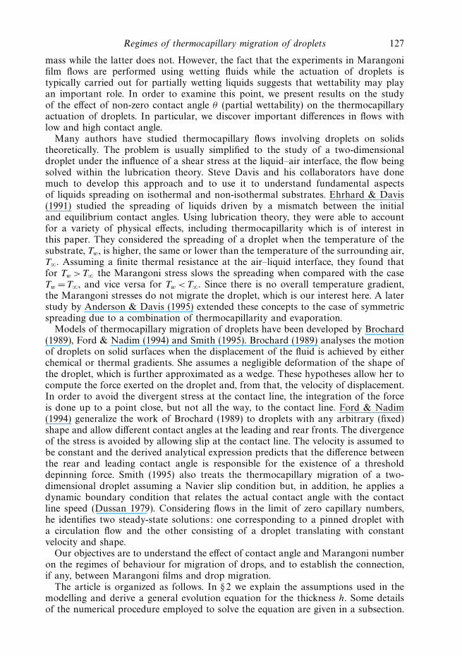
Figure 1. Scheme of a two-dimensional droplet on a substrate. The temperature on thesubstrate linearly decreases from left to right.
An improvement on previous theoretical analyses is that here, instead of consideringa droplet moving with a constant velocity and a steady shape as usually assumed, wesolve an initial value problem for the thickness h and motion of the droplet, imposingrestrictions neither on the velocity of both the contact lines and the drop nor on thedrop shape. In § 3 we describe the regime for small contact angles, characterized by acontinuous elongation reminiscent of Marangoni films. A self-similar solution for theshape of the droplet is presented and compared with the profile obtained by solvingthe full equation for h. In § 4 we find a second regime for large contact angles in whichthe droplet keeps a steady shape. In this regime, the droplet velocity is constant andthe dependence with the various parameters of the flow is explored. The behaviourof the droplet for intermediate values of contact angle is presented in § 5. Section 6concerns the dependence of the regime maps on the droplet size and the temperaturegradient.
2. FormulationWe use standard lubrication theory which reduces the Navier–Stokes equations to
a single evolution equation for the thickness h(x, t). Although strictly valid for smallslope (vanishing contact angles), lubrication theory has proved to be qualitatively,and in some cases, quantitatively correct well outside its formal region of validity.Comparisons between full Stokes flow simulations and lubrication theory, togetherwith discussions of its use for partial wetting conditions, can be found in Mitlin &Petviashvili (1994); Schwartz (1998); Schwartz & Eley (1998); Perazzo & Gratton(2004); Chen et al. (2005); Gotkis et al. (2006); Diez & Kondic (2007). Thus, in spiteof the approximations of lubrication theory, it remains the convenient method ofchoice for an exploration of the qualitative nature of solutions.
Consider a two-dimensional droplet deposited on a horizontal substrate which issubject to a constant temperature gradient, as shown in figure 1. The velocity u(x, z, t)

Regimes of thermocapillary migration of droplets 129
in the x direction is related to the pressure p by
∂p
∂x= μ
∂2u
∂z2, (2.1)
where μ is the viscosity of the liquid and p is given by
p = −γd2h
dx2− �. (2.2)
Here, γ is the surface tension and � is the disjoining–conjoining pressure defined by
� = κ
[(h∗
h
)n
−(
h∗
h
)m], (2.3)
where
κ =S(m − 1)(n − 1)
(n − m)h∗, (2.4)
h∗ is the thickness of the energetically favoured molecular film (Churaev & Sobolev1995; Glasner & Witelski 2003; Gomba & Homsy 2009) and S is the spreadingparameter. The use of a disjoining–conjoining model for the molecular interactionsbetween fluid and substrate has been discussed by Mitlin & Petviashvili (1994)and Schwartz & Eley (1998). Its use here has several advantages over previous studiesof drop migration, the most important of which are as follows: (i) elimination ofthe need to model the dynamic contact angle and the singularity with the no-slipcondition due to the presence of a precursor film (as a result of the favourableinteraction) and (ii) the ability of the model to prescribe an apparent contact angle asan independent parameter. The spreading parameter S can be related to the contactangle θ via the Laplace–Young condition as S = γ (1 − cos θ) (Schwartz & Eley 1998).
In the usual fashion, the surface tension γ is taken to be linear in the temperatureT at the air–liquid interface
γ = γ0 − σ (T − T0), (2.5)
with γ0 being the surface tension at T = T0 and σ being a positive constant.The velocity u(x, z, t) is subject to the boundary conditions of no slip and the
tangential stress condition, respectively:
u(x, 0, t) = 0, (2.6)
μ∂u
∂z
∣∣∣∣∣z=h
=dγ
dx≡ dγ
dT
dT
dx
∣∣∣∣∣z=h
. (2.7)
In order to relate the unknown temperature T at the interface to the knowntemperature profile at the substrate, Ts , we adopt two common assumptions (Brochard1989; Ford & Nadim 1994). The first is that conduction is the main heat transfermechanism within the drop, i.e. the Peclet number, Pe = hcU/α, is small. Under thisassumption the temperature profile inside the droplet is linear in z (Ehrhard & Davis1991) and the temperature at the surface is given by
T (x, h) =Ts(x)
1 + Bih. (2.8)
Here, Bi = qshc/kl is the Biot number, where qs is the surface heat transfer coefficientat the air–liquid interface and kl is the conductivity coefficient of the liquid. The secondassumption is that Bi h � 1, which is realistic for most experiments (Cazabat et al.

130 J. M. Gomba and G. M. Homsy
1990; Brzoska et al. 1993; Sur et al. 2003, 2004; Chen et al. 2005): for example,values of Bi are estimated by Chen et al. (2005) to be between 0.02 and 0.06 for theirexperiments. Thus, T (x, h) = Ts(x). Consistent with the experiments of Brzoska et al.(1993) and Chen et al. (2005), we prescribe a linear dependence of Ts with x, and sothe boundary condition (2.7) becomes
μ∂u
∂z
∣∣∣∣∣z=h
= τ, (2.9)
where τ = (dγ /dTs)(dTs/dx) is a constant.Determining the velocity u by integrating (2.1) subject to the boundary conditions
(2.6) and (2.7) and applying conservation of mass results in the following standardequation for the thickness h:
∂h
∂t+
γ
3μ
∂
∂x
(h3 ∂3h
∂x3
)κ
3μ
∂
∂x
(h3 ∂
∂x
[(h∗
h
)n
−(
h∗
h
)m])+
τ
2μ
∂h2
∂x= 0. (2.10)
This is the generic thin film equation for flow driven by a constant shear stressτ (Eres, Schwartz & Roy 2000). Defining the dimensionless variables x = x/xc,h =h/hc and t = t/tc with tc = 3μx4
c /(γ h3c) and taking (n, m) = (3, 2) (Glasner &
Witelski 2003; Diez & Kondic 2007), (2.10) becomes
∂h
∂t+
∂
∂x
(h3 ∂3h
∂x3
)+ K
∂
∂x
(h3 ∂
∂x
[(h∗
h
)3
−(
h∗
h
)2])
+ B∂h2
∂x= 0, (2.11)
where we have dropped the hats for simplicity. The parameters K and B are definedas
K =2(1 − cos θ)
h∗
x2c
h2c
,
B =3τ
2γ0
x3c
h2c
,
⎫⎪⎪⎬⎪⎪⎭ (2.12)
with h∗ in units of hc. At this point we have some freedom to choose the length scaleshc and xc. While there appears to be three parameters, K, B and h∗, by using theintrinsic scales employed by Schwartz, Roux & Cooper-White (2005) (in a slightlydifferent context), or those of Gomba & Homsy (2009), it is possible to reducethe number of dimensionless parameters to two. But for ease of comparison withexperimental data, we define hc = xc = a, where a =
√γ0/ρg is the capillary length.
We mention the simplifications associated with using intrinsic scales below whenappropriate.
2.1. Computational issues
We discretize (2.11) in space using regular centred finite differences except forthe fourth-order term, for which central differencing does not necessarily preservethe positivity of the solution, i.e. h can evolve from positive to negative values(Bernis, Peletier & Williams 1992; Beretta, Berstch & Passo 1995). Accordingly, weimplement a ‘positivity preserving scheme’ proposed by Zhornitskaya & Bertozzi(2000). The resulting system of equations are evolved in time by employing asynchronized marching Crank–Nicholson scheme combined with an adaptive timestepping procedure (Gomba et al. 2007). The corresponding pentadiagonal matrix issolved by using routines extracted from Press et al. (1992; the routines used in this

Regimes of thermocapillary migration of droplets 131
work are ‘bandec’ and ‘banbks’), and the boundary conditions at both extremes ofthe domain, x = 0 and x = L, are
dh
dx
∣∣∣∣∣x=0,L
=dh3
dx3
∣∣∣∣∣x=0,L
= 0. (2.13)
We note that any attempt to quantitatively reproduce experimental conditionsrequires the choice of an appropriate value for the dimensional molecular filmthickness, h∗hc, which typically is of the order of 10 nm. On the other hand, it iswell known that the space step �x must be of the same order of h∗ (Schwartz &Eley 1998; Diez & Kondic 2001). If the length of the domain is about 10 cm, themesh would consist of 108 collocation points. This large number results in long time-consuming calculations even when carried out on fast workstations. As an example ofthe computing times, a case with dimensionless cross-sectional area A= 10, h∗ = 0.005,θ =30◦ and �x = 0.01 in a domain of dimensionless length L =100 required 4 days tobe solved on an Intel Xeon CPU 3.60 GHz processor. The time increases even morefor lower values of h∗ or larger values of θ . With the aim of spending reasonablecomputing times, most cases were solved with h∗ � 5 × 10⁻³, and �x = 0.01. Eventhough this range of h∗ is not a realistic value, we will show that it allows us toreproduce the features reported in experiments. We also did a modest parameterstudy to find that the dependence of the results on h∗ is much weaker than that ofother parameters.
In order to establish relevant values of the parameter B , we recall the experimentalconditions reported by Brzoska et al. (1993) and Chen et al. (2005). In thoseexperiments, the ranges of values for the quantities involved in the definition ofB are: 20 × 10−3 Nm−1 � γ � 30 × 10−3 Nm−1, 0.05 × 10⁻³ Nm−1 ◦C � dγ /dT � 0.1 ×10⁻³ Nm−1 ◦C and 3.5◦C cm−1 � dTs/dx � 36◦Ccm−1. Thus, the parameter B can beconsidered to be in the interval (0.002 − 0.03).
We also estimate the cross-sectional area of the ‘three-dimensional’ droplets in theexperiments of Brzoska et al. (1993) and Chen et al. (2005) by considering the sectionat the symmetry plane that crosses the point of maximum thickness. This gives usan idea of the cross-sectional area to use in our ‘two-dimensional’ problem. For athree-dimensional droplet with a radius R, measured at the liquid–substrate interface,this area is given by
A = R2 (θ/ sin θ − cos θ) / sin θ. (2.14)
Accordingly, the dimensionless cross-sectional area in the experiments of Brzoskaet al. (1993) can be estimated to be within the range 0.18 � A � 6.3. The experimentsof Chen et al. (2005) also fall within that range, typically 0.34 � A � 0.4.
In the next three sections, we describe the different regimes we observe by firstfixing all dimensionless parameters but θ at the following values: A= 10, B = 0.01and h∗ = 0.01. The initial condition always corresponds to the shape of a static dropletof area A when the temperature gradient is zero (Gomba & Homsy 2009), and wethen follow the evolution after a step increase in the value of B .
3. Film regime: small contact angleFigure 2 presents the numerical solution of (2.11) for a small contact angle, θ =5◦,
which shows that the leading front moves faster than the rear one, thus the widthincreases with time. Interestingly, after a transient stage, the bulk region exhibitsa linear profile with a slope that decreases in time, and the leading edge shows a

132 J. M. Gomba and G. M. Homsy
50 100 150 200x
0
0.1
0.2
0.3
0.4
0.5
h
A = 10B = 0.01; θ = 5°
t = 0t = 1 × 10⁴
t = 3 × 10⁴
t = 5 × 10⁴
t = 7 × 10⁴
Figure 2. Evolution of the thickness profile obtained by solving (2.11) (solid lines) and theasymptotic profiles given by (3.5) (dashed lines). The profiles correspond to the case withθ = 5◦, A = 10, B = 0.01 and h∗ = 0.01.
characteristic capillary ridge. Such behaviour is similar to what is seen in Marangonifilms:hence we refer to this as the film regime.
The behaviour away from the leading and trailing edges can be captured by asimple self-similar solution. On the one hand, the small value of θ suggests thatthe disjoining–conjoining pressure is negligible. On the other hand, the numericalsolution shows that the curvature in the bulk region is small and therefore thecapillary pressure term is also negligible. Dropping both terms, (2.11) becomes
∂h
∂t+ B
∂(h2)
∂x= 0. (3.1)
We seek a self-similar solution of the following form (Barenblatt 1996)
h = tpH (ζ ), (3.2)
x = ζ xN, (3.3)
where xN = tq is the position of the leading front and p, q are constants. Requiringthat time enters only in the form given in (3.2) and (3.3) and that the volume remainsconstant, the power law exponents are found to be q = − p = 1/2. As a consequence,(3.1) becomes
−(
H + ζdH
dζ
)+ 2B
dH 2
dζ= 0. (3.4)
Integrating, applying the condition H (0) = 0, and recovering the original variables,we find:
h =x
2Btfor xR � x � xA. (3.5)
Here the positions for the rear and advancing fronts, xR and xA, are given by
xR = x0 + 2hfilmBt,
xA = xR +√
4ABt.
}(3.6)

Regimes of thermocapillary migration of droplets 133
100
w/(
4AB
)1/2
B0.010.010.050.05
A0.1810
0.1818
θ3°5°3°7°
1 101 102 103 104 105
t
103
104
105
x R/(
2Bh R
)
t1/2
t
(a)
(b)
| | | | |
| | | | |
Figure 3. Evolution of (a) w and (b) xR for different combinations of B , A and θ . The greylines represent the asymptotic power law predicted by (3.8) and (3.6), respectively.
Considering that the area A of the droplet is given by the area of the triangle definedin (3.5) and introducing the notation hA = xA/2Bt and hR = xR/2Bt , it is possible towrite
A =w(hA − hR)
2=
w2
4Bt, (3.7)
from where the width w = xA − xR of the droplet is given by
w = (4ABt)1/2. (3.8)
Figure 2 shows the comparison of the complete profile with the asymptotic profiledefined by (3.5) and (3.6). There is a reasonably good prediction of the slope ofthe profile in the bulk region away from the capillary ridge. Despite the fact thatthe experimental literature does not report cases with this particular contact angle,experiments carried out by Sur et al. (2003) for Marangoni films of wetting liquidshave shown, at least in one case, a linear profile connecting the advancing ridge withthe fluid in the container (see figure 5 in Sur et al. 2003).
In figure 3(a,b) we show the evolution of w and xR for different values of A andθ . Notice that, in general, w reaches the asymptotic law given in (3.6) faster than xR .The delay in xR in approaching the asymptotic behaviour is due to the fact that closeto the contact line neither the curvature nor the disjoining pressure is completelynegligible.
Summarizing, it is found that for small contact angles, the droplet increases its widthwith time and a linear profile is developed as a result of the competition betweenMarangoni and viscous stresses. Only the rear contact line advances asymptoticallywith a constant velocity.

134 J. M. Gomba and G. M. Homsy
0
0.5
1.0
1.5
h
0 50 100 150 200x
0.0098
0.0100
0.0102
0.0104
h
A = 10B = 0.01; θ = 30°
t = 0 t = 30 × 103
(a)
(b)
Figure 4. Evolution of the droplet profile with θ = 30◦, A = 10, B =0.01 and h∗ = 0.01. (a):Quasi-steady droplet motion with constant velocity shown at equal time intervals. The solidline represents the last profile for t = 30×103. (b): A zoom of the region close to the substrate.
4. Droplet regime: large contact angleFigure 4(a) shows the displacementof a droplet with θ = 30◦. Contrary to what
we observed for small contact angles, the droplet moves as a whole to a goodapproximation keeping its original steady shape. Hence we refer to this as the dropletregime. Here the effect of the disjoining–conjoining pressure is stronger than in theprevious case and the Marangoni stress induced at the liquid–air interface cannotchange the shape of the droplet. Interestingly, when we observe the region close tothe substrate in detail, we detect that the droplet leaves a constant-thickness thinfilm behind the rear front. An example is shown in figure 4(b), which is a zoom ofthe region close to the substrate. In this case, the film behind the advancing dropletattains a thickness of ≈0.01038. The height of this film decreases when either θ or A
is increased.One of the main features in this regime is that both front and rear move with the
same ‘constant’ velocity. The natural question is how this velocity depends on theparameters A, B , θ and h∗. On the face of it, five-‘dimensional’ parameters determinethe flow in the droplet regime: μ, τ , h∗,dim , Adim and Udim . However, as mentionedabove, the use of intrinsic scales reduces the number of dimensionless parametersby two. Thus guided by the form of the constant κ , the natural scales of the steadyproblem (Gomba & Homsy 2009), and dimensional analysis, two � groups can beconstructed that lead to the following relationship,
Udimμ
τh∗,dim
= f
(Adim
√2(1 − cos θ)
h2∗,dim
). (4.1)
This expression can be easily rewritten in terms of the ‘dimensionless’ parameters A,B , θ and h∗, leading to the following equation:
U
Bh∗= f ′
(A
√2(1 − cos θ)
h2∗
). (4.2)

Regimes of thermocapillary migration of droplets 135
AAA
103 104 105 106 107
A (2[1–cos θ])1/2/h*2
10
100U
/(B
h *)
U/(Bh*) ∝(A (2[1–cos θ])1/2/h*2)0.4
Figure 5. Dependence of U on the problem parameters A, B , θ and h∗. The pointsrepresent 39 different combinations of the parameters, whose values are A = 0.18; 10; 18,B = 0.002; 0.01; 0.05; θ =30◦; 40◦; 50◦ and h∗ =0.001; 0.005; 0.01; 0.05.
Figure 5 shows the dependence of U on the dimensionless parameterA
√2(1 − cos θ)/h2
∗ for several different combinations of the parameters involved.The plot shows that there is a power law dependence between these quantities givenby
U ∝ Bh∗
(A
√2(1 − cos θ)
h2∗
)0.4
. (4.3)
We currently do not have any theoretical explanation for the power law exponent,but further research into travelling wave solutions for small B may be instructive onthis point.
Figure 6(a, b) shows the dependence on B of the contact angles at the rear and theadvancing fronts, θR and θA, for two different areas (the contact angles are normalizedto the value they would have for B = 0). For B = 0.002, both θR and θA show a slightincrease from the value corresponding to B = 0. For larger values of B , θA increaseswhile θR decreases. Notice that for A= 10 (figure 6a), the percentage change of thecontact angle with B is higher than for A= 0.18 (figure 6b).
Concluding this section, for large contact angles the droplet moves at constant speedwhile to a good approximation keeping its initial shape, indicating the dominance ofthe disjoining–conjoining pressure of the distortion due to the Marangoni flow. Atthe same time, a thin constant-thickness film is left behind the droplet. The dropletmoves with a constant velocity which is proportional to B and inversely proportionalto the viscosity, in agreement with experimental results of Brzoska et al. (1993) andChen et al. (2005).
5. The transition regimeThis regime pertains to intermediate values of θ . In the previous two sections we
show that the thickness profile for small values of θ is determined by Marangonistresses while, in the opposite limit of large θ , the disjoining–conjoining pressure

136 J. M. Gomba and G. M. Homsy
0.8
0.9
1.0
1.1
1.2
θ A; θ
Rθ A
; θR
θ = 40°
θ = 50°
0 0.020.01 0.03 0.04 0.060.05
B
1.0
1.02
1.04
θA
θR
θA
θR
A = 10
A = 0.18
(a)
(b)
θ = 40°
θ = 50°
Figure 6. Contact angles at the rear and advancing fronts, θR and θA, respectively, normalizedto the value of the contact angle for B =0, for two different areas: (a) A = 10 and (b) A = 0.18.
term is responsible for maintaining the initial droplet shape. Intermediate values ofθ correspond to a regime where both Marangoni term and disjoining–conjoiningpressure compete and, accordingly, the behaviour is transient and complex. Figure 7shows the evolution of the profile for θ = 10◦. The droplet first develops a linearprofile but at a time close to t = 4 × 10⁴, small droplets detach from the rear front.At the same time, the region connecting the bulk and the front ridge decreases itsthickness, which ultimately produces a break-up at the leading edge. At the end ofthe computation, we have a large number of very small droplets in the rear region,the bulk of the original droplet and a large droplet at the front. It is clear that, inthis regime, the Marangoni and disjoining–conjoining terms compete, the first tryingto keep a straight profile and the second inducing a rupture into smaller cylindricaldroplets.
Figure 8 shows another behaviour, here observed for θ = 16◦, for which the strengthκ of the disjoining–conjoining pressure increases. The droplet immediately breaks upinto two droplets which then travel with nearly constant shape. The rear dropletadopts a cylindrical shape while the leading one adopts a non-standard shape. Aftera transient, the rear droplet travels faster than the leading one.
The occurrence of non-cylindrical shapes does not necessarily appear after a break-up process. For example, for A= 18 and θ = 18◦, the break-up does not occur, asshown in figure 9. At the beginning, the droplet seems to evolve toward a break-upinto two droplets, but it ultimately adopts a non-standard shape (with three localmaxima) that travels with a constant velocity.
To summarize, we find that the thermocapillary migration for intermediate contactangles is very complex and difficult to characterize in a simple fashion. Most of thecases studied did not yield a steady state or a simple spreading behaviour, but ratherexhibited complicated time dependence and a tendency toward film rupture. As wewill show below, most of the experiments are not in the range of parameters thatresults in the intermediate regime. Additionally, there may be differences betweenbreak-ups in two and three dimensions. For these reasons, we leave a detailed study

Regimes of thermocapillary migration of droplets 137
0
0.2
0.4
0.6
0.8
1.0
h 0
0.2
0.4
0.6
0.8
1.0
0
0.2
0.4
0.6
0.8
1.0
50 100 150 200
x0 50 100 150 200
x0
0.2
0.4
0.6
0.8
1.0
A = 10B = 0.01; θ = 10°
t = 5 × 10³
t = 20 × 103
t = 40 × 103t = 30 × 103
t = 60 × 103 t = 70 × 103
t = 10 × 103
t = 0
Figure 7. Evolution of the droplet profile for θ =10◦ (A =10, B = 0.01 and h∗ = 0.01).
of the break-up for the future when experiments with relatively non-wetting liquidsmight justify it.
6. Regime mapsHaving discovered and characterized the different regimes,we now study how the
parameters, A, B and h∗, affect which regime may occur. We do this by representingthe different regimes in the θ–A plane, with B as a parameter. Figure 10 shows one ofthese maps for B = 0.01. Notice that all three regimes—film, droplet and transition—can be observed for the range of A studied. Interestingly, due to the fact that theintegral effect of the disjoining pressure on the whole volume is more importantfor smaller droplets than for larger ones, the values of θ at which we observe thetransition from film to transition regimes and from transition to droplet regimes arelower for the smaller values of A. For example, for A= 0.18, the values of the contactangles which define the boundary between the film–transition and transition–dropletregimes are θFT ≈ 5◦ and θT D ≈ 7◦, respectively, while the corresponding contact anglesfor A= 18 are θFT ≈ 9◦ and θT D ≈ 20◦.
These maps help explain why the droplet regime is the only one reported to date.The experiments of Chen et al. (2005), for which B ≈ 0.01, A ≈ 0.37, are indicated infigure 10. This study observed only the droplet regime, in agreement with our regime

138 J. M. Gomba and G. M. Homsy
0
0.2
0.4
0.6
0.8
1.0
h
0
0.2
0.4
0.6
0.8
1.0
0
0.2
0.4
0.6
0.8
1.0
h
0
0.2
0.4
0.6
0.8
1.0
A = 10B = 0.01; θ = 16°
t = 0 t = 1 × 10⁴
t = 3 × 10⁴t = 5.5 × 10⁴
50 100 150 200
x50 100 150 200
x
Figure 8. Evolution of the droplet profile for θ =16◦ (A =10, B = 0.01 and h∗ = 0.01). Thedroplet breaks into two smaller droplets.
map. Figure 10 also suggests that the highest values of A in experiments of Brzoskaet al. (1993) fall in thetransition regime, but those experiments were performed withsmaller values of B: the more relevant comparison is with figure 11.
Figure 11(a, b) presents the same diagram but for B = 0.05 and B =0.002,respectively. We can observe that when the value of B is decreased (increased), thecontact angles θFT and θT D reduce (increase) their values. The results for B = 0.002bring the theory and the experiments of Brzoska et al. (1993) into agreement: thefilm regime disappears for small values of A, a result that is consistent with theseexperiments (for which 0.002 � B � 0.007), all of which fall in the droplet regime.
We also explored the effect of h∗, solving all the same cases presented in figure 10 butusing h∗ = 0.005. Only for the transition regime do we observe differences (basically inthe number and shape of the detached droplets), and we do not detect any importantchange in the values of the contact angles, θFT and θT D , respectively, that define theboundaries of the film–transition and transition–droplet regimes. We conclude thatin spite of the fact that our numerical values of h∗ are larger than appropriate to afilm of molecular thickness, the simulations capture the different regime maps in aqualitative way and that they depend more strongly on the other parameters of theproblem.
7. ConclusionsIn this paper, we have considered the thermocapillary migration of droplets on
horizontal surfaces. We employed lubrication theory to derive an equation for thedroplet profile that includes the effect of the disjoining–conjoining pressure. The formof the chosen disjoining–conjoining pressure term admits a non-zero contact angle atthe contact line region. One of the main differences with previous works is that we do

Regimes of thermocapillary migration of droplets 139
0
0.2
0.4
0.6
0.8
1.0
1.2
1.4
h
0.010
0.011
0.012
h
A = 18B = 0.01; θ = 18°
t = 3 × 10⁴
t = 1 × 10⁴
t = 4.3 × 10⁴t = 2 × 10⁴
(a)
(b)
0 50 100 150 200x
Figure 9. (a) Evolution of the droplet profile for θ =18◦ and A = 18 (B = 0.01 and h∗ =0.01).After a short transient, the droplet travels with a constant velocity, but with a non-standardshape. (b) Zoom of the thickness profile close to the substrate. A thin constant-thickness filmof approximate thickness 0.012 is left behind the droplet.
0 5 10 15 20
A
0
10
20
30
40
50
60
θ
Droplet
Transition
Film
Chen et al.
Brzoska et al.
B = 0.01h* = 0.01
Figure 10. Map of the film, droplet and transition regimes in the θ–A space. The experimentaldata corresponds to the experiments reported in Brzoska et al. (1993) and Chen et al. (2005).Note that in Brzoska’s experiments 0.002 � B � 0.007, i.e. a value of B lower than that of thesesimulations.
not assume a constant spreading velocity, but rather we allow the droplet to evolveits shape in time.
We find that for small contact angles,the droplet continuously increases its width.The droplet adopts a linear shape in an outer region, a profile that is captured by aself-similar solution. Expressions for the positions of the rear and leading edges arederived via a mass balance. In this regime, Marangoni stresses are responsible for the

140 J. M. Gomba and G. M. Homsy
0
10
20
30
40
50
60
θ
Drop + FilmTransitionMarangoniChen et al.Brzoska et al.
0
10
20
30
40
50
60
θ
B = 0.002h* = 0.01
B = 0.05h* = 0.01
(a)
(b)
0 5 10 15 20
A
Figure 11. Effect of B in the distribution of the flow regimes on the θ–A plane.
linear shape of the thickness profile, the effect of the disjoining–conjoining pressurebeing negligible.
In contrast, when the contact angle is relatively large, the droplet approximatelykeeps its steady initial shape and moves at a constant velocity. Combining dimensionalanalysis and numerical simulations, we find that the velocity follows a power law indimensionless variables combining the parameters A, B , h∗ and θ . The expressionfor the velocity, given by (4.3), predicts that the droplet speed is proportional tothe temperature gradient imposed on the substrate and inversely proportional tothe viscosity, in agreement with experimental results of Brzoska et al. (1993) andChen et al. (2005). It also predicts that the velocity increases with A, as observedin experiments. Notice that while experiments of Brzoska et al. (1993) present alinear dependence with R, the experiments of Chen et al. (2005) show a dependencethat goes with R , with < 1 indeterminate (see figure 4 in Chen et al. 2005). If weconsider a cylindrical cap, in our case the velocity is proportional to R0.8. We thinkthat the dependence with R varies with the particular fluid employed, so differentdisjoining–conjoining pressure models may lead to a different dependence with R, θ
and h∗. In this regime, the values of the apparent contact angles at the contact leadingand rear fronts are found to be dependent on the temperature gradient imposed atthe substrate, that is, with the dimensionless parameter B . For small B , we observethat both contact angles increase while for larger B , the rear contact angle decreaseswhile the leading contact angle increases. The relative change is larger for largerdroplets. The Marangoni stress moves the droplet from warmer to colder regions,but it does not have any important effect on the shape of the thickness profile: thedisjoining–conjoining pressure effect is strong enough to keep the shape of the dropletfixed.
For intermediate values of contact angle, we observe a transition regime in whichthe dynamics are complicated. Marangoni and disjoining pressure effects compete anda wide number of possible morphologies appear. In this regime, we observe break-upprocesses, droplets moving with non-standard shapes and also coalescence. A deeperstudy of this regime is needed in order to answer some open questions, for example,

Regimes of thermocapillary migration of droplets 141
the conditions under which the break-up occurs and how the volumes of the resultingdroplets are selected.
The occurrence of the three regimes is very sensitive to the values of A and B .We display our results in a map in the θ–A plane and find that, for a given B , thelimiting contact angle that separates the film-transition and transition-droplet regimesare smaller for smaller A. Employing the same diagram, but for a lower value ofB , we observe that these limiting contact angles decrease, and the film regime doesnot occur even for the smallest contact angle analysed. For large B , the limits movetoward higher values of θ . In spite of the relative simplicity of the model, all thesetrends are in agreement with available experiments.
This work was supported by the US DOE through grant number DE-FG02-05ER15692. JMG gratefully acknowledges the Fulbright Foundation and CONICETfor partial support.
REFERENCES
Anderson, D. M. & Davis, S. H. 1995 The spreading of volatile liquid droplets on heated surfaces.Phys. Fluids 7 (2), 248–265.
Barenblatt, G. I. 1996 Scaling, Self-similarity, and Intermediate Asymptotics . Cambridge UniversityPress.
Beretta, E., Berstch, M. & Passo, R. D. 1995 Nonnegative solutions of a fourth order nonlineardegenerate parabolic equation. Arch. Ration. Mech. Anal. 129, 175.
Bernis, F., Peletier, L. A. & Williams, S. M. 1992 Source type solutions of a fourth ordernonlinear degenerate parabolic equation. Nonlinear Anal. Theory Methods Appl. 18, 217.
Bouasse, H. 1924 Capillarite phenomenes superficiels . Librairie Delgrave.
Brochard, F. 1989 Motions of droplets on solid surfaces induced by chemical or thermal gradients.Langmuir 5 (2), 432–438.
Brzoska, J. B., Brochard-Wyart, F. & Rondelez, F. 1993 Motions of droplets on hydrophobicmodel surfaces induced by thermal gradients. Langmuir 9 (8), 2220–2224.
Cazabat, A. M., Heslot, F., Troian, S. M. & Carles, P. 1990 Fingering instability of thin spreadingfilms driven by temperature gradients. Nature 346, 824.
Chen, J. Z., Troian, S. M., Darhuber, A. A. & Wagner, S. 2005 Effect of contact angle hysteresison thermocapillary droplet actuation. J. Appl. Phys. 97 (1), 014906.
Churaev, N. V. & Sobolev, V. D. 1995 Prediction of contact angles on the basis of the Frumkin–Derjaguin approach. Adv. Colloid Interface Sci. 61, 1–16.
Darhuber, A. A. & Troian, S. M. 2005 Principles of microfluidic actuation by modulation ofsurface stresses. Annu. Rev. Fluid Mech. 37, 425.
Darhuber, A. A., Valentino, J. P., Davis, J. M., Troian, S. M. & Wagner, S. 2003 Microfluidicactuation by modulation of surface stresses. Appl. Phys. Lett. 82 (4), 657–659.
Diez, J. A. & Kondic, L. 2001 Contact line instabilities of thin liquid films. Phys. Rev. Lett. 86,632.
Diez, J. A. & Kondic, L. 2007 On the breakup of fluid films of finite and infinite extent. Phys.Fluids 19 (7), 072107.
Dussan, V. E. B. 1979 On the spreading of liquids on solid surfaces: static and dynamic contactlines. Annu. Rev. Fluid Mech. 11, 317.
Ehrhard, P. & Davis, S. H. 1991 Non-isothermal spreading of liquid drops on horizontal plates.J. Fluid Mech. 229, 365.
Eres, M. H., Schwartz, L. W. & Roy, R. V. 2000 Fingering phenomena for driven coating films.Phys. Fluids 12, 1278.
Ford, M. L. & Nadim, A. 1994 Thermocapillary migration of an attached drop on a solid surface.Phys. Fluids 6, 3183.
Gallardo, B. S., Gupta, V. K., Eagerton, F. D., Jong, L. I., Craig, V. S., Shah, R. R. & Abbott,
N. L. 1999 Electrochemical principles for active control of liquids on submillimeter scales.Science 283 (5398), 57–60.

142 J. M. Gomba and G. M. Homsy
Glasner, K. B. & Witelski, T. P. 2003 Coarsening dynamics of dewetting films. Phys. Rev. E 67,016302.
Gomba, J., Diez, J., Gonzalez, A. G. & Gratton, R. 2005 Spreading of a micrometric fluid stripdown a plane under controlled initial conditions. Phys. Rev. E 71, 016304.
Gomba, J. M., Diez, J., Gratton, R., Gonzalez, A. G. & Kondic, L. 2007 Stability study of aconstant-volume thin film flow. Phys. Rev. E 76 (4), 046308.
Gomba, J. M. & Homsy, G. M. 2009 Analytical solutions for partially wetting two-dimensionaldroplets. Langmuir 25 (10), 5684–5691.
Gotkis, Y., Ivanov, I., Murisic, N. & Kondic, L. 2006 Dynamic structure formation at the frontsof volatile liquid drops. Phys. Rev. Lett. 97 (18), 186101.
Ho, C.-M. & Tai, Y.-C. 1998 Micro-electro-mechanical systems (MEMS) and fluid flows. Annu. Rev.Fluid Mech. 30, 579.
Huppert, H. 1982 Flow and instability of a viscous current down a slope. Nature 300, 427.
Kataoka, D. E. & Troian, S. M. 1998 Stabilizing the advancing front of thermally driven climbingfilms. J. Colloid Interface Sci. 203, 335.
Ludviksson, V. & Lightfoot, E. N. 1971 The dynamics of thin liquid films in the presence ofsurface-tension gradients. Am. Inst. Chem. Eng. J. 17, 1166.
Mitlin, V. S. & Petviashvili, N. V. 1994 Nonlinear dynamics of dewetting: kinetically stablestructures. Phys. Lett. A 192, 323–326.
Oron, A., Davis, S. H. & Bankoff, S. G. 1997 Long-scale evolution of thin liquid films. Rev. Mod.Phys. 69, 931.
Perazzo, C. A. & Gratton, J. 2004 Navier–Stokes solutions for parallel flow in rivulets on aninclined plane. J. Fluid Mech. 507, 367–379.
Pollack, M. G., Fair, R. B. & Shenderov, A. D. 2000 Electrowetting-based actuation of liquiddroplets for microfluidic applications. Appl. Phys. Lett. 77, 1725.
Pratap, V., Moumen, N. & Subramanian, R. S. 2008 Thermocapillary motion of a liquid drop ona horizontal solid surface. Langmuir 24 (9), 5185–5193.
Press, W. H., Teukolsky, S. A., Vetterling, W. T. & Flannery, B. P. 1992 Numerical Recipes inFortran 77 . Cambridge University Press.
Sammarco, T. S. & Burns, M. A. 1999 Thermocapillary pumping of discrete drops in microfabricatedanalysis devices. AIChE J. 45 (2), 350–366.
Schwartz, L. W. 1998 Hysteretic effects in droplet motions on heterogenous substrates: directnumerical simulations. Langmuir 14, 3440.
Schwartz, L. W. 2001 On the asymptotic analysis of surface-stress-driven thin-layer flow. J. EngngMath. 39, 171.
Schwartz, L. W. & Eley, R. R. 1998 Simulation of droplet motion of low-energy and heterogenoussurfaces. J. Colloid Interface Sci. 202, 173.
Schwartz, L. W., Roux, D. & Cooper-White, J. J. 2005 On the shapes of droplets that are slidingon a vertical wall. Physica D 209, 236–244.
Smith, M. K. 1995 Thermocapillary migration of a two-dimensional liquid droplet on a solidsurface. J. Fluid Mech. Digit. Arch. 294, 209–230.
Stone, H. A., Stroock, A. D. & Ajdari, A. 2004 Engineering flows in small devices: microfluidicstoward lab-on-a-chip. Annu. Rev. Fluid Mech. 36, 381.
Subramanian, R. S. & Balasubramanian, R. 2001 The Motion of Bubbles and Drops in ReducedGravity . Cambridge University Press.
Sur, J., Bertozzi, A. L. & Behringer, R. P. 2003 Reverse undercompressive shock structures indriven thin film flow. Phys. Rev. Lett. 90, 126105.
Sur, J., Witelski, T. P. & Behringer, R. P. 2004 Steady-profile fingering flows in Marangoni driventhin films. Phys. Rev. Lett. 93 (24), 247803.
Teletzke, G. F., Davis, H. T. & Scriven, L. E. 1987 How liquids spread on solids. Chem. Eng.Comm. 55, 41–82.
Valentino, J. P., Darhuber, A. A., Troian, S. M. & Wagner, S. 2003 Thermocapillary actuation ofliquids using patterned microheater arrays. Mater. Res. Soc. Symp. Proc. 773, N10.3.1–N10.3.5.
Zhornitskaya, L. & Bertozzi, A. L. 2000 Positivity preserving numerical schemes for lubrication-type equations. SIAM J. Numer. Anal. 37, 523.