Visible to Near-Infrared Light Harvesting in TiO2Nanotube Array-P3HT Based Heterojunction Solar...
8
Visible to Near-Infrared Light Harvesting in TiO 2 Nanotube Array-P3HT Based Heterojunction Solar Cells Gopal K. Mor, Sanghoon Kim, Maggie Paulose, Oomman K. Varghese, Karthik Shankar, † James Basham, and Craig A. Grimes* Department of Electrical Engineering, The Materials Research Institute, and Center for Solar Nanomaterials, The PennsylVania State UniVersity, UniVersity Park, PennsylVania 16802 Received July 31, 2009; Revised Manuscript Received September 11, 2009 ABSTRACT The development of high-efficiency solid-state excitonic photovoltaic solar cells compatible with solution processing techniques is a research area of intense interest, with the poor optical harvesting in the red and near-IR (NIR) portion of the solar spectrum a significant limitation to device performance. Herein we present a solid-state solar cell design, consisting of TiO 2 nanotube arrays vertically oriented from the FTO- coated glass substrate, sensitized with unsymmetrical squaraine dye (SQ-1) that absorbs in the red and NIR portion of solar spectrum, and which are uniformly infiltrated with p-type regioregular poly(3-hexylthiophene-2,5-diyl) (P3HT) that absorbs higher energy photons. Our solid- state solar cells exhibit broad, near-UV to NIR, spectral response with external quantum yields of up to 65%. Under UV filtered AM 1.5G of 90 mW/cm 2 intensity we achieve typical device photoconversion efficiencies of 3.2%, with champion device efficiencies of 3.8%. The best performing bulk heterojunction solar cells (η ∼ 6%) employ an optimized blend of a polymeric donor and a fullerene acceptor. 1,2 The fullerene acceptor absorbs very little light and is primarily used in blends to provide an efficient interface for exciton dissociation. Various efforts toward efficiency improvement in these devices are directed toward the development of low band gap polymers to absorb a broad swathe of the solar spectrum, 3-6 lowering the molecular energy levels of the semiconducting polymer to enhance the open circuit voltage of the organic solar cells, 1,7 and the control of the blended film morphology for enhanced exciton harvesting. 8-12 In the best performing solid-state dye- sensitized solar cells (SS-DSSCs), η ∼ 5%, the only photon absorber is a dye, while the electron and hole transport functions are performed, respectively, by a disordered nanoparticulate TiO 2 network and a transparent small molecule spiro-OMeTAD. 13-16 To achieve higher efficiency devices, research efforts have focused on improved pore- filling by the hole transporter, the use of higher mobility hole transporters and the synthesis of dyes with a broader and more-intense absorption spectrum. Red/NIR radiation (650-1000 nm) accounts for ap- proximately 33% of the solar energy arriving at the surface of the Earth, while UV-visible radiation (350-650 nm) accounts for about 40%. Hence a key issue toward achieving higher efficiency organic solar cells is in the development of red and NIR absorbing molecules to utilize more of the solar spectrum. As an approach for efficiently utilizing visible to NIR solar radiation, herein we describe an inorganic-organic hybrid solar cell, see Figure 1a, where electron transporting TiO 2 nanotube arrays, sensitized with red and NIR light absorbing organic dye, are used in combination with hole transporting and visible light absorbing regioregular P3HT. 17-19 It should be noted that this low band gap organic dye should not block transmission of the high-energy photons of near-UV-visible range passing through it; that is, the organic dye should have minimum spectral absorption overlap with that of the P3HT. As shown in Figure 1b, the position of the highest occupied molecular orbital (HOMO) and the lowest unoccupied molecular orbital (LUMO) levels for both organic dye and P3HT polymer should be such that electron injection is favorable toward TiO 2 while hole transport is directed toward the gold electrode. In our device, excited states generated in the dye find themselves in close proximity to two interfaces for dissociation: the TiO 2 -dye interface and the dye-P3HT interface. For excitons generated in the P3HT, the P3HT-dye interface is the closest available for splitting and the largest distance the excitons need to diffuse to reach this interface corresponds to the radius of the nanotube pore. After exciton splitting, electrons are injected into the TiO 2 , while hole-polarons travel through the P3HT layer to the PEDOT: PSS hole collection contact. The open circuit voltage V oc is * Corresponding author, [email protected]. † Current address: Department of Electrical and Computer Engineering, The University of Alberta, Edmonton, Alberta T6G 2 V4, Canada. NANO LETTERS XXXX Vol. xx, No. x - 10.1021/nl9024853 CCC: $40.75 XXXX American Chemical Society Downloaded by GWANGJU INST SCI & TECH on September 24, 2009 | http://pubs.acs.org Publication Date (Web): September 23, 2009 | doi: 10.1021/nl9024853
Transcript of Visible to Near-Infrared Light Harvesting in TiO2Nanotube Array-P3HT Based Heterojunction Solar...

Visible to Near-Infrared Light Harvestingin TiO2 Nanotube Array-P3HT BasedHeterojunction Solar CellsGopal K. Mor, Sanghoon Kim, Maggie Paulose, Oomman K. Varghese,Karthik Shankar,† James Basham, and Craig A. Grimes*
Department of Electrical Engineering, The Materials Research Institute, and Centerfor Solar Nanomaterials, The PennsylVania State UniVersity, UniVersity Park,PennsylVania 16802
Received July 31, 2009; Revised Manuscript Received September 11, 2009
ABSTRACT
The development of high-efficiency solid-state excitonic photovoltaic solar cells compatible with solution processing techniques is a researcharea of intense interest, with the poor optical harvesting in the red and near-IR (NIR) portion of the solar spectrum a significant limitation todevice performance. Herein we present a solid-state solar cell design, consisting of TiO2 nanotube arrays vertically oriented from the FTO-coated glass substrate, sensitized with unsymmetrical squaraine dye (SQ-1) that absorbs in the red and NIR portion of solar spectrum, andwhich are uniformly infiltrated with p-type regioregular poly(3-hexylthiophene-2,5-diyl) (P3HT) that absorbs higher energy photons. Our solid-state solar cells exhibit broad, near-UV to NIR, spectral response with external quantum yields of up to 65%. Under UV filtered AM 1.5G of 90mW/cm2 intensity we achieve typical device photoconversion efficiencies of 3.2%, with champion device efficiencies of 3.8%.
The best performing bulk heterojunction solar cells (η ∼ 6%)employ an optimized blend of a polymeric donor and afullerene acceptor.1,2 The fullerene acceptor absorbs very littlelight and is primarily used in blends to provide an efficientinterface for exciton dissociation. Various efforts towardefficiency improvement in these devices are directed towardthe development of low band gap polymers to absorb a broadswathe of the solar spectrum,3-6 lowering the molecularenergy levels of the semiconducting polymer to enhance theopen circuit voltage of the organic solar cells,1,7 and thecontrol of the blended film morphology for enhanced excitonharvesting.8-12 In the best performing solid-state dye-sensitized solar cells (SS-DSSCs), η ∼ 5%, the only photonabsorber is a dye, while the electron and hole transportfunctions are performed, respectively, by a disorderednanoparticulate TiO2 network and a transparent smallmolecule spiro-OMeTAD.13-16 To achieve higher efficiencydevices, research efforts have focused on improved pore-filling by the hole transporter, the use of higher mobility holetransporters and the synthesis of dyes with a broader andmore-intense absorption spectrum.
Red/NIR radiation (650-1000 nm) accounts for ap-proximately 33% of the solar energy arriving at the surfaceof the Earth, while UV-visible radiation (350-650 nm)accounts for about 40%. Hence a key issue toward achieving
higher efficiency organic solar cells is in the development ofred and NIR absorbing molecules to utilize more of the solarspectrum. As an approach for efficiently utilizing visible to NIRsolar radiation, herein we describe an inorganic-organic hybridsolar cell, see Figure 1a, where electron transporting TiO2
nanotube arrays, sensitized with red and NIR light absorbingorganic dye, are used in combination with hole transportingand visible light absorbing regioregular P3HT.17-19 It shouldbe noted that this low band gap organic dye should not blocktransmission of the high-energy photons of near-UV-visiblerange passing through it; that is, the organic dye should haveminimum spectral absorption overlap with that of the P3HT.As shown in Figure 1b, the position of the highest occupiedmolecular orbital (HOMO) and the lowest unoccupiedmolecular orbital (LUMO) levels for both organic dye andP3HT polymer should be such that electron injection isfavorable toward TiO2 while hole transport is directed towardthe gold electrode. In our device, excited states generated inthe dye find themselves in close proximity to two interfacesfor dissociation: the TiO2-dye interface and the dye-P3HTinterface. For excitons generated in the P3HT, the P3HT-dyeinterface is the closest available for splitting and the largestdistance the excitons need to diffuse to reach this interfacecorresponds to the radius of the nanotube pore. After excitonsplitting, electrons are injected into the TiO2, whilehole-polarons travel through the P3HT layer to the PEDOT:PSS hole collection contact. The open circuit voltage Voc is
* Corresponding author, [email protected].† Current address: Department of Electrical and Computer Engineering,
The University of Alberta, Edmonton, Alberta T6G 2 V4, Canada.
NANOLETTERS
XXXXVol. xx, No. x
-
10.1021/nl9024853 CCC: $40.75 XXXX American Chemical Society
Dow
nloa
ded
by G
WA
NG
JU I
NST
SC
I &
TE
CH
on
Sept
embe
r 24
, 200
9 | h
ttp://
pubs
.acs
.org
P
ublic
atio
n D
ate
(Web
): S
epte
mbe
r 23
, 200
9 | d
oi: 1
0.10
21/n
l902
4853

determined by the TiO2 quasi-Fermi level and the P3HTHOMO level. The TiO2 nanotube array pore size, 20-35nm, was selected such that P3HT chains can infiltrate intothe pores but also allow photogenerated excitons in the P3HTto readily diffuse to the exciton splitting interface.
Our SS-DSSC configuration has the following keyadvantages: (i) The ordered heterojunction architectureprovides percolation paths for both types of charge carri-ers.12,20,21 (ii) The vertically oriented nanotube array archi-tecture decouples exciton diffusion from light absorption.22
(iii) There are two complementary photon absorbers thatprovide broad-spectrum absorption, namely, the dye mol-ecules anchored to the nanotube walls and the organicsemiconductor, in our case P3HT, within the nanotubes.High-quality organic-inorganic interfaces are typically dif-ficult to achieve since inorganic materials, in our case TiO2,are hydrophilic whereas commonly used semiconducting
polymers, for example P3HT, with its large alkyl groups anduncharged backbone are hydrophobic. Likewise, the ap-propriate matching of the energy levels of a three-componentsystem (inorganic n-type backbone, dye, hole transportmaterial) and the creation of embedded exciton splittinginterfaces is not trivial. Due to these difficulties, previousefforts by a number of researchers have focused on modify-ing the inorganic metal oxide surface by binding to it variousorganic molecules and ruthenium-based dyes that, in com-bination with hole transporting conjugated polymers, resultin photovoltaic devices with photoconversion efficiencieswell below 1%.23-31 Here, we successfully demonstrate adevice structure comprised of TiO2 nanotube arrays/organic-dye/P3HT, with the vertically oriented TiO2 nanotube arraysof small pore size providing a large interfacial surface areafor dye adsorption and a large interfacial area between theorganic dye monolayer and the P3HT. The successfulinfiltration of P3HT into the nanotube arrays is demonstrated.
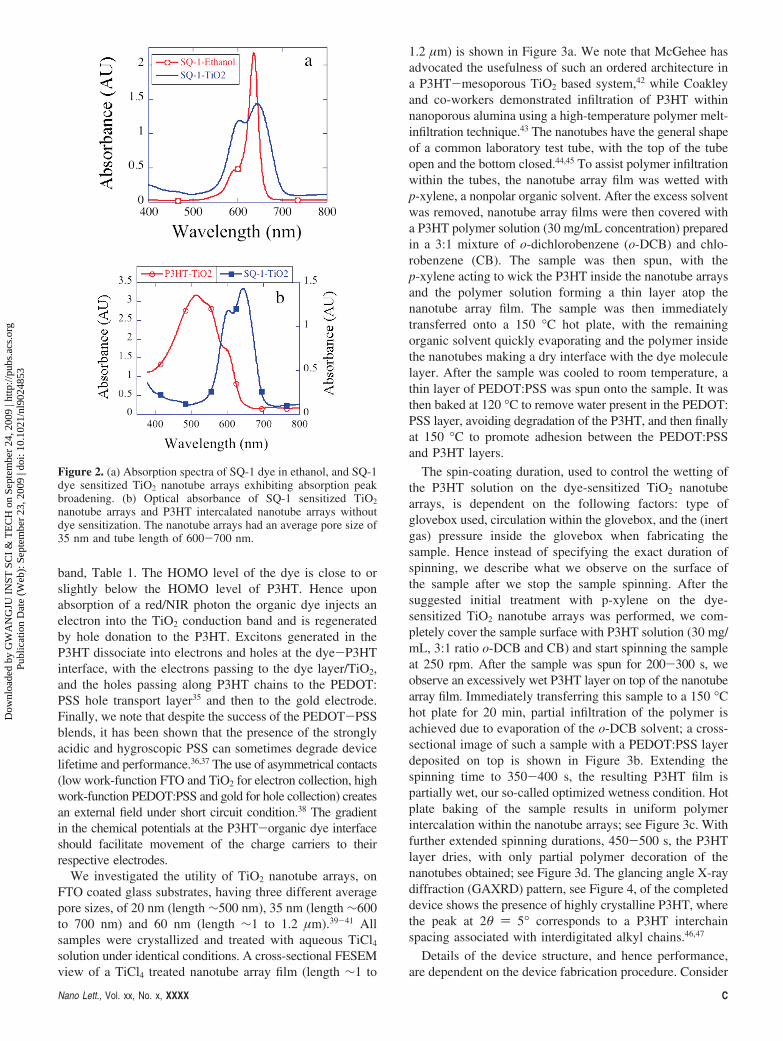
We consider application of the organic dye, 5-carboxyl-2-[[3-[(1,3-dihydro-3,3-dimethyl-1-ethyl-2H-indol-2-ylidene)-methyl]-2-hydroxy-4-oxo-2-cyclobuten-1-ylidene] methyl]-3,3-trimethyl-1-octyl-3H-indolium (unsymmetrical squaraine,SQ-1).32 The molecular structures of the SQ-1 dye and P3HTpolymer are shown in Figure 1c. Synthesis details of SQ-1are found in ref 32. The molecular design of dye SQ-1 issuch that the carboxylic acid group is part of the conjugatedπ-system of the dye providing strong electronic coupling tothe TiO2 conduction band while the asymmetry created bythe octyl chain prevents surface aggregation and limits self-quenching of the excited state.33 The dye provides strongconjugation across the chromophore and anchoring group,enabling electronic coupling between the LUMO of the dyeand TiO2 conduction band. The absorption spectra of 0.1mM SQ-1 dye dissolved in ethanol solution, see Figure 2a,indicates that SQ-1 absorbs from 500 to 700 nm with anextinction coefficient of 159700 M-1 cm-1 at λmax of 637nm corresponding to π-π* charge transfer transitions.
As shown in Figure 2b the absorption bands of SQ-1 dyeand P3HT complement each other making the two materialsappropriate for an extended spectrum solar cell, with the TiO2
nanotubes, band gap 3.2 eV, absorbing the UV portion ofthe solar spectrum. The SQ-1 absorption peak observed inethanol solution broadens with sensitization, 2 mM ethanoldye solution, on the TiO2 nanotube arrays, Figure 2a. Thereis a small red shift of 9 nm in the peak position for SQ-1suggesting J-type aggregation, which can further extend thephoton absorption into the NIR region. P3HT coverage ofthe TiO2 nanotube arrays shows no shift in the absorptionpeak position compared to that of neat P3HT films,34
indicating a high degree of π-π stacking of the polymerchains within the nanotubes. The spectral properties of theSQ-1 dye in ethanol solution and cyclic voltammetrydetermined electrochemical properties of the sensitizers uponthe TiO2 nanotube arrays are summarized in Table 1.
Electron-hole transfer processes occurring within the hybridsolid-state solar cell are depicted in Figure 1b. The LUMOlevel of the organic dye is more negative than the P3HTLUMO level and less negative than the TiO2 conduction
Figure 1. (a) Depiction of hybrid solid-state solar cell describedherein. Dye sensitization and polymer intercalation between thenanotubes is not shown to maintain clarity of the drawing. (b)Depiction of energy level positions and charge transfer processesof the constituent layers of the described hybrid solar cell. (c)Molecular structure of SQ-1 dye and P3HT polymer.
B Nano Lett., Vol. xx, No. x, XXXX
Dow
nloa
ded
by G
WA
NG
JU I
NST
SC
I &
TE
CH
on
Sept
embe
r 24
, 200
9 | h
ttp://
pubs
.acs
.org
P
ublic
atio
n D
ate
(Web
): S
epte
mbe
r 23
, 200
9 | d
oi: 1
0.10
21/n
l902
4853
band, Table 1. The HOMO level of the dye is close to orslightly below the HOMO level of P3HT. Hence uponabsorption of a red/NIR photon the organic dye injects anelectron into the TiO2 conduction band and is regeneratedby hole donation to the P3HT. Excitons generated in theP3HT dissociate into electrons and holes at the dye-P3HTinterface, with the electrons passing to the dye layer/TiO2,and the holes passing along P3HT chains to the PEDOT:PSS hole transport layer35 and then to the gold electrode.Finally, we note that despite the success of the PEDOT-PSSblends, it has been shown that the presence of the stronglyacidic and hygroscopic PSS can sometimes degrade devicelifetime and performance.36,37 The use of asymmetrical contacts(low work-function FTO and TiO2 for electron collection, highwork-function PEDOT:PSS and gold for hole collection) createsan external field under short circuit condition.38 The gradientin the chemical potentials at the P3HT-organic dye interfaceshould facilitate movement of the charge carriers to theirrespective electrodes.
We investigated the utility of TiO2 nanotube arrays, onFTO coated glass substrates, having three different averagepore sizes, of 20 nm (length ∼500 nm), 35 nm (length ∼600to 700 nm) and 60 nm (length ∼1 to 1.2 µm).39-41 Allsamples were crystallized and treated with aqueous TiCl4
solution under identical conditions. A cross-sectional FESEMview of a TiCl4 treated nanotube array film (length ∼1 to
1.2 µm) is shown in Figure 3a. We note that McGehee hasadvocated the usefulness of such an ordered architecture ina P3HT-mesoporous TiO2 based system,42 while Coakleyand co-workers demonstrated infiltration of P3HT withinnanoporous alumina using a high-temperature polymer melt-infiltration technique.43 The nanotubes have the general shapeof a common laboratory test tube, with the top of the tubeopen and the bottom closed.44,45 To assist polymer infiltrationwithin the tubes, the nanotube array film was wetted withp-xylene, a nonpolar organic solvent. After the excess solventwas removed, nanotube array films were then covered witha P3HT polymer solution (30 mg/mL concentration) preparedin a 3:1 mixture of o-dichlorobenzene (o-DCB) and chlo-robenzene (CB). The sample was then spun, with thep-xylene acting to wick the P3HT inside the nanotube arraysand the polymer solution forming a thin layer atop thenanotube array film. The sample was then immediatelytransferred onto a 150 °C hot plate, with the remainingorganic solvent quickly evaporating and the polymer insidethe nanotubes making a dry interface with the dye moleculelayer. After the sample was cooled to room temperature, athin layer of PEDOT:PSS was spun onto the sample. It wasthen baked at 120 °C to remove water present in the PEDOT:PSS layer, avoiding degradation of the P3HT, and then finallyat 150 °C to promote adhesion between the PEDOT:PSSand P3HT layers.
The spin-coating duration, used to control the wetting ofthe P3HT solution on the dye-sensitized TiO2 nanotubearrays, is dependent on the following factors: type ofglovebox used, circulation within the glovebox, and the (inertgas) pressure inside the glovebox when fabricating thesample. Hence instead of specifying the exact duration ofspinning, we describe what we observe on the surface ofthe sample after we stop the sample spinning. After thesuggested initial treatment with p-xylene on the dye-sensitized TiO2 nanotube arrays was performed, we com-pletely cover the sample surface with P3HT solution (30 mg/mL, 3:1 ratio o-DCB and CB) and start spinning the sampleat 250 rpm. After the sample was spun for 200-300 s, weobserve an excessively wet P3HT layer on top of the nanotubearray film. Immediately transferring this sample to a 150 °Chot plate for 20 min, partial infiltration of the polymer isachieved due to evaporation of the o-DCB solvent; a cross-sectional image of such a sample with a PEDOT:PSS layerdeposited on top is shown in Figure 3b. Extending thespinning time to 350-400 s, the resulting P3HT film ispartially wet, our so-called optimized wetness condition. Hotplate baking of the sample results in uniform polymerintercalation within the nanotube arrays; see Figure 3c. Withfurther extended spinning durations, 450-500 s, the P3HTlayer dries, with only partial polymer decoration of thenanotubes obtained; see Figure 3d. The glancing angle X-raydiffraction (GAXRD) pattern, see Figure 4, of the completeddevice shows the presence of highly crystalline P3HT, wherethe peak at 2θ ) 5° corresponds to a P3HT interchainspacing associated with interdigitated alkyl chains.46,47
Details of the device structure, and hence performance,are dependent on the device fabrication procedure. Consider
Figure 2. (a) Absorption spectra of SQ-1 dye in ethanol, and SQ-1dye sensitized TiO2 nanotube arrays exhibiting absorption peakbroadening. (b) Optical absorbance of SQ-1 sensitized TiO2
nanotube arrays and P3HT intercalated nanotube arrays withoutdye sensitization. The nanotube arrays had an average pore size of35 nm and tube length of 600-700 nm.
Nano Lett., Vol. xx, No. x, XXXX C
Dow
nloa
ded
by G
WA
NG
JU I
NST
SC
I &
TE
CH
on
Sept
embe
r 24
, 200
9 | h
ttp://
pubs
.acs
.org
P
ublic
atio
n D
ate
(Web
): S
epte
mbe
r 23
, 200
9 | d
oi: 1
0.10
21/n
l902
4853

as an illustration the incident photon to collected electronefficiency (IPCE) of three of the described P3HT/dye-sensitized TiO2 nanotube array devices, see Figure 5, withthe P3HT solution (30 mg/mL, prepared using a 3:1 ratio ofo-DCB and CB) applied in varying degrees of sample surfacewetting as discussed in the preceding paragraph. Optimalsamples exhibit an IPCE of 50-65% between 420 and 680nm. The resulting samples appear reddish with a light violettinge. Due to significant overlap between the emissionspectrum of RR-P3HT and the absorption spectrum of theSQ-1 dye, exciton transfer from P3HT to the dye by Forster-type resonance energy transfer (FRET) is possible.48-53 Uponcalculating the spectral overlap integral from the normalizedphotoluminescence (of P3HT on a very thin TiO2 film)50 andabsorption (of SQ-1 dye ethanolic solution) spectra, consid-ering an emission quantum efficiency of 1% for P3HT,51 andassuming random orientation of the donor and acceptormolecules and the effective refractive index of P3HT-TiO2
film of 1.6, we calculate a Forster radius48 of 2.58 nm whichcould result in an effective exciton diffusion length in therange 14-18 nm.52,53 On the basis of exciton harvestingcalculations given by Scully and co-workers,53 it was foundthat about 65-75% of the excitons generated in P3HTinfiltrated inside 35 nm pore size TiO2 nanotube arrays canbe harvested. The coexistence of resonance energy transfermay account for the high charge transfer efficiencies in thissystem as inferred from external quantum yield measure-ments. A detailed analysis of the energy transfer efficiencyand of the relative contributions of exciton transfer andexciton quenching at the dye-P3HT interface is in progress.
We initially investigated the utility of three different TiO2
nanotube array morphologies having dimensions: (i) pore size∼20 nm and length ∼500 nm; (ii) pore size ∼35 nm andlength 600-700 nm; (iii) pore size 60 nm and length ∼1-1.2µm. Figure 6a shows the UV-vis-NIR absorption spectraof SQ-1 dye sensitized nanotube arrays, with significantlygreater absorption seen for the nanotubes of 35 and 60 nmpore diameters. Figure 6b shows the UV-vis-NIR opticalabsorption spectra of typical TiO2 nanotube (35 nm pore,600-700 nm length)/SQ-1 dye/ P3HT/PEDOT:PSS photo-voltaic device fabricated under optimized wetting condition.The absorption peak corresponding to P3HT indicates a highdegree of π-π polymer chain stacking. We have seen noshift in the P3HT absorption peak position as a function ofnanotube pore size. The J-V characteristics of three TiO2
nanotube/SQ-1/P3HT/PEDOT:PSS devices, variable nano-tube array dimensions, are shown in Figure 7a. As antici-pated, the 20 and 35 nm pore size nanotubes give larger fillfactors and higher current values, while it was significantlyeasier to infiltrate P3HT within the 35 and 60 nm pore
nanotubes. On the basis of the amount of SQ-1 dye adsorbedby the three different samples, Figure 6a, and the saturatedphotocurrent values, Figure 7a, the 35 nm pore size nanotubearrays appeared optimal for device fabrication.
We further improved the fill factor and open-circuit voltageof the SQ-1 dye based solar cells by wetting the SQ-1sensitized nanotube array films (pore size ∼35 nm, tubelength 600-700 nm) with 0.05-0.1 M tert-butyl pyridinein p-xylene solution (instead of pure p-xylene), spin coatingthe P3HT and PEDOT:PSS layers, depositing the goldelectrode, and then baking the device at 120 °C for 1 min inair. The performance of a typical device is shown in Figure7b, with Jsc ) 10.75 mA/cm2, Voc ) 0.55 V, FF ) 0.55.and η ) 3.2%. tert-Butylpyridine is known to increase theopen circuit voltage by upward shifting the TiO2 bandedge54,55 and by physically sealing molecular scale voids atthe interface. The efficiency of our champion device wasfound to be 3.8% (Jsc ) 11 mA/cm2, Voc ) 0.6 V, FF )0.58). If we account for the transmittance loss of 10% acrossthe visible range due to the UV filter in the light source(necessary since UV light rapidly degrades the SQ-1 dye),an efficiency of ≈ 4.2% can be expected.
Figure 7b also shows the performance of a typical TiO2
nanotube array/P3HT (no organic dye) solar cell, having keydevice parameters Jsc ) 1.8 mA/cm2, Voc ) 0.41 V, FF )0.46, and η ) 0.34%. With use of the organic dye layer thephotoconversion efficiency of a typical device increases from0.34% to 3.2%, with the open circuit voltage increasing from0.41 to 0.55 V. Acid-base interactions arising from car-boxylic group anchoring of the organic dye affect the TiO2
band edge by protonating it. As reported by Goh and co-workers,28 the magnitude of this shift is about 0.2 eV forRu(II) dyes. We note that extensive TiCl4 treatment of thenanotubes was found to increase the open-circuit voltage to0.67 V but resulted in considerably lower photocurrents. TheJ-V and IPCE measurements of our devices were performedin air. Though we did not perform any long-term stabilitytests, the photovoltaic results were consistent for a numberof runs made over several days. The cell surface area isdefined by removal of the PEDOT:PSS layer around thecircular gold electrode before all electrical measurements,thereby exposing the underlying P3HT polymer to ambientair; hence it is not appropriate to comment on the long-termstability of these samples.
Ordered heterojunction solar cells based on TiO2 nanotubearrays sensitized by a red/NIR absorbing organic dye incombination with a hole transporting organic semiconductoris an exciting photovoltaic design since it combines theattractive features of both solid-state dye-sensitized solar cellsand bulk heterojunction solar cells, while overcoming some
Table 1. Absorption, Emission, and Electrochemical Properties of SQ-1 Dye and P3HT Polymerdye/polymer λabs
a, nm (ε, M-1 cm-1) λema, nm Eox
b/[V vs Fc/Fc+] E0-0c (eV) EHOMO
d (eV) ELUMOd (eV)
SQ-1 dye 637 (159700) 652 0.38 1.93 5.18 3.25P3HT polymere 443 568 1.9 5.1 3.2a Absorption and emission spectra were measured in ethanol solution. b A silver wire was used as a pseudoreference electrode and was calibrated with
a ferrocene/ferrocinium (Fc/Fc+) redox couple. The electrochemical experiments were measured in CH3CN with 0.1 M (n-C4H9)4NPF6 with a scan rate of100 mV s-1. c E0-0 was determined from intersection of absorption and emission spectra in ethanol. d The energy levels of the HOMO and LUMO weredetermined using the following equations: EHOMO (eV) ) Eox - E FC/FC+ + 4.8 eV; ELUMO (eV) ) EHOMO - E0-0. e P3HT polymer (average molecular weight∼50000 Mw) was dissolved in toluene for absorption and emission spectra, values given in the product information from Sigma Aldrich.
D Nano Lett., Vol. xx, No. x, XXXX
Dow
nloa
ded
by G
WA
NG
JU I
NST
SC
I &
TE
CH
on
Sept
embe
r 24
, 200
9 | h
ttp://
pubs
.acs
.org
P
ublic
atio
n D
ate
(Web
): S
epte
mbe
r 23
, 200
9 | d
oi: 1
0.10
21/n
l902
4853

of the limitations of the established configurations. Wedemonstrate that this device structure offers a potentiallyviable means for achieving high efficiency low cost solid-state solar cells. Our devices achieve high photocurrents dueto the contribution of two photoactive layers, the organicdye monolayer and P3HT polymer. Moreover, the conjugatedpolymer chains infiltrated inside the vertically oriented TiO2
nanotube arrays appear to be aligned, see Figure 4, resultingin enhanced carrier mobilities.43 Our device architecturesuggests further opportunities exist for extended lightharvesting, and improvement in the open circuit voltage, bytailoring the TiO2 surface to raise the conduction bandposition or using other p-type polymers where the HOMOlevel positions appear to be more negative with respect tothat of P3HT but still sufficient for regeneration of theorganic dye.
Figure 3. (a) Typical cross-sectional view of 60 nm pore size,1-1.2 µm length TiO2 nanotube array film after TiCl4 treatment.Cross-sectional FESEM image of TiO2 nanotube (≈35 nm poresize, ≈600-700 nm nanotube length)/SQ-1 dye/P3HT/PEDOT:PSSphotovoltaic devices showing: (b) nanotubes partially infiltrated withpolymer, fabricated under the condition of excess wetness; (c) fullyinfiltrated nanotubes fabricated under optimized wetness condition;and (d) partial infiltration of the P3HT polymer within thenanotubes, fabricated under dry condition.
Figure 4. GAXRD pattern of the actual completed device, FTO/TiO2 nanotube array/SQ-1 dye/P3HT/PEDOT:PSS. The peak at 2θ) 5° corresponds to a P3HT interchain spacing associated withinterdigitated alkyl chains, the peak at 2θ ) 25.2° arises fromanatase phase of TiO2, and the peak at 2θ ) 26.4° is from theFTO coating. We could not find a peak corresponding to PEDOT:PSS due to its small thickness.
Figure 5. IPCE of a FTO/TiO2 nanotube array/SQ-1 dye/P3HT/PEDOT:PSS/Au solar cell, where the P3HT layer was preparedwith different degrees of surface wetness prior to a 150 °C postbake.Excess wetness, where the film was still wet entering the postbake;optimized, where upon just visually drying the device was im-mediately removed from the spinner and exposed to the postbake;dry, indicating where the film had dried on the spinner prior topostbake. The dye sensitization and PEDOT:PSS layer are identicalin all the three samples. Nanotube array films of 35 nm averagepore diameter and 600-700 nm length were used.
Nano Lett., Vol. xx, No. x, XXXX E
Dow
nloa
ded
by G
WA
NG
JU I
NST
SC
I &
TE
CH
on
Sept
embe
r 24
, 200
9 | h
ttp://
pubs
.acs
.org
P
ublic
atio
n D
ate
(Web
): S
epte
mbe
r 23
, 200
9 | d
oi: 1
0.10
21/n
l902
4853

Methods. DeWice Fabrication. Details on fabrication ofthe transparent nanotube array films are given elsewhere.39
In short, Ti films were deposited using rf or dc magnetronsputtering of titanium targets on Pilkington TEC 15 glass(sheet resistance 15 Ω/square) substrates in argon atmo-sphere. No external heating was applied to the substrates.The films were anodized in an electrolyte consisting ofdimethyl sulfoxide (DMSO), 2-4% hydrofluoric acid (HF),and 4% water at voltages from 8 to 17 V until transparencywas achieved. The films were washed in isopropanol anddried in a nitrogen stream. The samples were subjected toheat treatment in an oxygen atmosphere at 400 °C for 4 hand then at 450 °C for 2 h with a ramp-up and ramp-downrate of 1 °C/min. The films were then immersed in 0.05 MTiCl4 aqueous solution for 6 h, then rinsed with ethanol anddistilled water, dried in air, and then annealed at 450 °C for30 min in oxygen. After the samples had cooled to 80 °C,they were immersed in 2.0 mM SQ-1 dye solution preparedin ethanol.
The dye-sensitized samples were transferred into a nitrogen-filled glovebox (MBraun, MB 150M) where they were bakedat 120 °C for 10 min and then upon cooling transferred ontothe spin coater. To assist polymer infiltration within the tubes,the nanotube array film was wetted with p-xylene with excesssolvent removed by sample rotation on a spin coater.Immediately following, the nanotube array surface wascovered with a P3HT polymer (Rieke Metals, Inc.) solution(30 mg/mL concentration) prepared in a 3:1 mixture ofo-dichlorobenzene (o-DCB, boiling point ∼180.5 °C) andchlorobenzene (CB, boiling point ∼131 °C). The sample wasthen spun at 250 rpm, with the p-xylene facilitating intercala-tion of the P3HT inside the nanotube arrays and the polymersolution forming a thin layer atop the nanotube array film.Spinning was stopped just before the polymer layer over thesurface of the nanotubes dried, typically about 10 min. Thesample was then immediately transferred onto a 150 °C hotplate for 20 min. After the sample was allowed to cool toroom temperature, a thin layer of PEDOT:PSS (1.2-1.7 wt
Figure 6. (a) UV-vis-NIR optical absorption spectra of SQ-1 dyesensitized TiO2 nanotube arrays of three different morphologies (Pdenotes pore diameter, L denotes nanotubes length). The absorptionpeak magnitude corresponding to SQ-1 dye is nearly the same forthe 35 and 60 nm pore size nanotubes, which is much higher thanthat of the 20 nm pore size nanotubes. (b) UV-vis-NIR opticalabsorption spectra of typical TiO2 nanotube/SQ-1 dye/ P3HT/PEDOT:PSS photovoltaic device fabricated under optimized wettingcondition. The absorption peak corresponding to P3HT indicates ahigh degree of π-π polymer chain stacking. We have seen no shiftin the P3HT absorption peak position as a function of nanotubepore size.
Figure 7. (a) Photocurrent density-voltage (J-V) characteristicsof FTO/TiO2 nanotube array/SQ-1 dye /P3HT/PEDOT:PSS/Auhybrid solar cells using nanotube arrays of three different mor-phologies: 20 nm pore and ≈500 nm length; 35 nm pore and≈600-700 nm length; 60 nm pore and ≈1-1.2 µm length. The35 nm pore nanotube arrays were found to give optimal solar cellperformance. (b) J-V curves showing the improved performanceof a FTO/35 nm pore, 600-700 nm length TiO2 nanotube array/SQ-1 dye/P3HT/PEDOT:PSS/Au hybrid solar cell where the dye-sensitized nanotube array surface, prior to application of the P3HTlayer, is wetted with 0.05-0.1 M tert-butyl pyridine in p-xylene.Also shown is the performance of an otherwise identical cell lackingthe SQ-1 dye layer. L denotes measurement under AM 1.5G light,D denotes measurement in the dark.
F Nano Lett., Vol. xx, No. x, XXXX
Dow
nloa
ded
by G
WA
NG
JU I
NST
SC
I &
TE
CH
on
Sept
embe
r 24
, 200
9 | h
ttp://
pubs
.acs
.org
P
ublic
atio
n D
ate
(Web
): S
epte
mbe
r 23
, 200
9 | d
oi: 1
0.10
21/n
l902
4853

% dispersion in water, Sigma Aldrich) was spun onto thesample at 4000 rpm. After this, the samples were baked at120 °C for 6 min and then at 150 °C for 3 min. Finally, acircular gold electrode was dc sputter deposited onto thePEDOT:PSS film through a mask containing 2 mm diametercircular openings, followed by a final baking of the sampleat 120 °C for 1 min in covered glass Petri dish. The PEDOT:PSS layer around the gold electrode was cut away prior toany electrical measurements.
Electrical Characterization. Device efficiencies weremeasured with a 500 W Spectra Physics light source fittedwith Oriel AM 1.5G filter. The solar simulator was calibratedfor AM 1.5G illumination using an NREL calibrated siliconsolar cell fitted with a KG-5 filter (Newport M465440). Theirradiance spectrum was verified using an optical spectrom-eter (Newport, OSM2-400DUV-U). After calibration, a UVfilter (Edmund optics, NT54) was installed that removed lightbelow 380 nm and reduced the light intensity from 400 to800 nm by about 10% to 90 mW/cm2. A scanning poten-tiostat (CH Instruments, CHI 600C) was used to measurephotocurrents at a scan rate of 10 mV/s. J-V measurementswere not corrected for any of this optical intensity loss. IPCEspectra measurements were performed using a 300 W xenonlamp (Spectra physics), integrated with a parabolic reflector,and computer-controlled monochromator (Oriel Cornerstone130, 1/8 monochromator). The source power spectrum wasmeasured using an Oriel calibrated silicon photodiode (model71580). The photocurrent measurement scan was from lowerto higher wavelengths.
Optical, Structural, and Morphology Characterization. UV-vis absorption spectra and photoluminescence spectra ofSQ-1 dye in ethanol were measured, respectively, on aUV-vis spectrophotometer (Varian Cary 100) and Fluorolog3-21 spectrophotometer (Horiba Jobin Yvon, Edison, NJ).Illustrative cross-sectional and top views of polymer infil-trated TiO2 nanotubes and TiCl4 treated nanotubes were takenusing a field emission scanning electron microscope (LEO1530 FESEM). GAXRD analysis was performed using aScintag X2 diffractometer (Scintag Inc., CA).
Electrochemistry. All electrochemical measurements wereperformed in acetonitrile with 1.0 mM tetra-n-butylammo-nium hexafluorophosphate (n-Bu4NPF6, Aldrich, ∼99%), assupporting electrolyte. Cyclic voltammetry experiments wereperformed using a potentiostat (CH Instruments, model CHI600C) with a standard three-electrode arrangement. Theworking electrode consisted of SQ-1 dye sensitized TiO2
nanotube array films. A silver wire served as a pseudoref-erence electrode. Ferrocene was added to the solution at theend of each experiment as an internal standard, and then aglassy carbon disk (1 mm diameter, ESA Biosciences) wasused as the working electrode. All the electrochemicalpotentials were referenced to its redox couple (Fc/Fc+). Thecounter electrode employed was a platinum wire.
Acknowledgment. Support of this work through theDepartment of Energy, Grant Number DE-FG36-08GO18074,is gratefully acknowledged, as is the help of ThomasLaTempa with the GAXRD measurements.
References(1) Park, S. H.; Roy, A.; Beaupre, S.; Cho, S.; Coates, N.; Moon, J. S.;
Moses, D.; Leclerc, M.; Lee, K.; Heeger, A. J. Nat. Photonics 2009,3, 297–303.
(2) Liang, Y.; Feng, D.; Wu, Y.; Tsai, S. T.; Li, G.; Ray, C.; Yu, L. J. Am.Chem. Soc. 2009, 131, 7792–7799.
(3) Tamayo, A. B.; Dang, X. D.; Walker, B.; Seo, J.; Kent, T.; Nguyen,T. Q. Appl. Phys. Lett. 2009, 94, 103301.
(4) Liang, Y.; Wu, Y.; Feng, D.; Tsai, S. T.; Son, H. J.; Li, G.; Yu, L.J. Am. Chem. Soc. 2009, 131, 56–57.
(5) Cho, S.; Seo, J. H.; Kim, S. H.; Song, S.; Jin, Y.; Lee, K.; Suh, H.;Heeger, A. J. Appl. Phys. Lett. 2008, 93, 263301.
(6) Wang, X.; Perzon, E.; Delgado, J. L.; de la Cruz, P. Appl. Phys. Lett.2004, 85, 5081–5083.
(7) Blouin, N.; Michaud, A.; Gendron, D.; Wakim, S.; Blair, E.; Neagu-Plesu, R.; Belletete, M.; Durocher, G.; Tao, Y.; Leclerc, M. J. Am.Chem. Soc. 2008, 130, 732–742.
(8) Moule, A. J.; Meerholz, K. AdV. Mater. 2008, 20, 240–245.(9) Vanlaeke, P.; Vanhoyland, G.; Aernouts, T.; Cheyns, D.; Deibel, C.;
Manca, J.; Heremans, P.; Poortmans, J. Thin Solid Films 2006, 511-512, 358–361.
(10) Watkins, P. K.; Walker, A. B.; Verschoor, G. L. B. Nano Lett. 2005,5, 1814–1818.
(11) Hoppe, H.; Niggemann, M.; Winder, C.; Kraut, J.; Hiesgen, R.; Hinsch,A.; Meissner, D.; Sariciftci, N. S. AdV. Funct. Mater. 2004, 14, 1005–1011.
(12) Mor, G. K.; Shankar, K.; Paulose, M.; Varghese, O. K.; Grimes, C. A.Appl. Phys. Lett. 2007, 91, 152111.
(13) Snaith, H. J.; Petrozza, A.; Ito, S.; Miura, H.; Gratzel, M. AdV. Funct.Mater. 2009, 19, 1810–1818.
(14) Snaith, H. J.; Humphry-Baker, R.; Chen, P.; Cesar, I.; Zakeeruddin,S. M.; Gratzel, M. Nanotechnology 2008, 19, 424003.
(15) Snaith, H. J.; Moule, A. J.; Klein, C.; Meerholz, K.; Friend, R. H.;Gratzel, M. Nano Lett. 2007, 7, 3372–3376.
(16) Campbell, W. M.; Jolley, K. W.; Wagner, P.; Wagner, K.; Walsh,P. J.; Gordon, K. C.; Schmidt-Mende, L.; Nazeeruddin, M. K.; Wang,Q.; Gratzel, M.; Officer, D. L. J. Phys. Chem. C 2007, 111, 11760–11762.
(17) Parkinson, P.; Hughes, J. L.; Johnston, M. B.; Herz, L. M. Phys. ReV.B 2008, 78, 115321.
(18) Sirringhaus, H.; Brown, P. J.; Friend, R. H.; Nielsen, M. M.;Bechgaard, K.; Langeveld-Voss, B. M. W.; Spiering, A. J. H.; Janssen,R. A. J.; Meijer, E. W.; Herwig, P.; de Leeuw, D. M. Nature 1999,401, 685–688.
(19) Sirringhaus, H.; Tessler, N.; Friend, R. H. Science 1998, 280, 1741–1744.
(20) Shankar, K.; Bandara, J.; Paulose, M.; Wietasch, H.; Varghese, O. K.;Mor, G. K.; LaTempa, T. J.; Thelakkat, M.; Grimes, C. A. Nano Lett.2008, 8, 1654–1659.
(21) Mor, G. K.; Shankar, K.; Paulose, M.; Varghese, O. K.; Grimes, C. A.Nano Lett. 2006, 6, 215–218.
(22) Ong, K. G.; Varghese, O. K.; Mor, G. K.; Shankar, K.; Grimes, C. A.Sol. Energy Mater. Sol. Cells 2007, 91, 250–257.
(23) Gebeyehu, D.; Brabec, C. J.; Sariciftci, N. S.; Vangeneugden, D.;Kiebooms, R.; Vanderzande, D.; Kienberger, F.; Schindler, H. Synth.Met. 2002, 125, 279–287.
(24) Sicot, L.; Fiorini, C.; Lorin, A.; Nunzi, J. M.; Raimond, P.; Sentein,C. Synth. Met. 1999, 102, 991–992.
(25) Beltran, E. L.; Prene, P.; Boscher, C.; Belleville, P.; Buvat, P.; Lambert,S.; Guillet, F.; Marcel, C.; Sanchez, C. Eur. J. Inorg. Chem. 2008,903–910.
(26) Zafer, C.; Karapire, C.; Sariciftci, N. S.; Icli, S. Sol. Energy Mater.Sol. Cells 2005, 88, 11–21.
(27) Li, B.; Wang, L.; Kang, B.; Wang, P.; Qiu, Y. J. Photochem.Photobiol., A 2005, 172, 135–139.
(28) Goh, C.; Scully, S. R.; McGehee, M. D. J. Appl. Phys. 2007, 101,114503.
(29) Williams, S. S.; Hampton, M. J.; Gowrishankar, V.; Ding, I. K.;Templeton, J. L.; Samulski, E. T.; DeSimone, J. M.; McGehee, M. D.Chem. Mater. 2008, 20, 5229–5234.
(30) Murakoshi, K.; Kogure, R.; Wada, Y.; Yanagida, S. Sol. Energy Mater.Sol. Cells 1998, 55, 113–125.
(31) Kitamura, T.; Maitani, M.; Matsuda, M.; Wada, Y.; Yanagida, S. Chem.Lett. 2001, 1054–1055.
(32) Yum, J. H.; Walter, P.; Huber, S.; Rentsch, D.; Geiger, T.; Nuesch,F.; Angelis, F. D.; Gratzel, M.; Nazeeruddin, M. K. J. Am. Chem.Soc. 2007, 129, 10320–10321.
Nano Lett., Vol. xx, No. x, XXXX G
Dow
nloa
ded
by G
WA
NG
JU I
NST
SC
I &
TE
CH
on
Sept
embe
r 24
, 200
9 | h
ttp://
pubs
.acs
.org
P
ublic
atio
n D
ate
(Web
): S
epte
mbe
r 23
, 200
9 | d
oi: 1
0.10
21/n
l902
4853
(33) Ooyama, Y.; Harima, Y. Eur. J. Org. Chem. 2009, 2903–2934.(34) Coakley, K. M.; McGehee, M. D.Chem. Mater. 2004, 16, 4533–
4542.(35) Groenendaal, L.; Dhaen, J.; Manca, J.; Van Luppen, J.; Verdonck,
E.; Louwet, F.; Leenders, L. Synth. Met. 2003, 135-136, 115–117.(36) Kawano, K.; Pacios, R.; Poplavskyy, D.; Nelson, J.; Bradley, D.;
Durrant, J. R. Sol. Energy Mater. Sol. Cells 2006, 90, 3520–3530.(37) Danier Van Der Gon, A. W.; Birgerson, J.; Fahlman, M.; Salaneck,
W. R. Org. Electrochem. 2002, 3, 111–118.(38) Parker, I. D. J. Appl. Phys. 1994, 75, 1656–1666.(39) Varghese, O. K.; Paulose, M.; Grimes, C. A. Nat. Nanotechnol. 2009,
4, 592–597.(40) Mor, G. K.; Varghese, O. K.; Paulose, M.; Grimes, C. A. AdV. Funct.
Mater. 2005, 15, 1291–1296.(41) Mor, G. K.; Varghese, O. K.; Paulose, M.; Ong, K. G.; Grimes, C. A.
Thin Solid Films 2006, 496, 42–48.(42) McGehee, M. D. MRS Bull. 2009, 34, 95–100.(43) Coakley, K. M.; Srinivasan, B. S.; Ziebarth, J. M.; Goh, C.; Liu, Y.;
McGehee, M. D. AdV. Funct. Mater. 2005, 15, 1927–1932.(44) Mor, G. K.; Varghese, O. K.; Paulose, M.; Shankar, K.; Grimes, C. A.
Sol. Energy Mater. Sol. Cells 2006, 90, 2011–2075.
(45) Grimes, C. A.; Mor, G. K. TiO2 Nanotube Arrays: Synthesis,Properties, and Applications; Springer: Berlin, 2009.
(46) Chen, T. A.; Wu, X.; Rieke, R. D. J. Am. Chem. Soc. 1995, 117,233–244.
(47) Ma, W.; Yang, C.; Gong, X.; Lee, K.; Heeger, A. J. AdV. Funct. Mater.2005, 15, 1617–1622.
(48) Forster, T. Discuss. Faraday Soc. 1959, 27, 7–17.(49) Shankar, K.; Feng, X.; Grimes, C. A. ACS Nano 2009, 3, 788–794.(50) Liu, Y.; Summers, M. A.; Edder, C.; Frechet, J. M. J.; McGehee, M. D.
AdV. Mater. 2005, 17, 2960–2964.(51) Sheng, C. X.; Tong, M.; Singh, S.; Vardeny, Z. V. Phys. ReV. B 2007,
75, 085206.(52) Scully, S. R.; McGehee, M. D. J. Appl. Phys. 2006, 100, 034907.(53) Scully, S. R.; Armstrong, P. B.; Edder, C.; Frechet, J. M. J.; McGehee,
M. D. AdV. Mater. 2007, 19, 2961–2966.(54) Haque, S. A.; Tachibana, Y.; Willis, R. L.; Moser, J. E.; Gratzel, M.;
Klug, D. R.; Durrant, J. R. J. Phys. Chem. B 2000, 104, 538–547.(55) Zhu, R.; Jiang, C. Y.; Liu, B.; Ramakrishna, S. AdV. Mater. 2009, 21,
994–1000.
NL9024853
H Nano Lett., Vol. xx, No. x, XXXX
Dow
nloa
ded
by G
WA
NG
JU I
NST
SC
I &
TE
CH
on
Sept
embe
r 24
, 200
9 | h
ttp://
pubs
.acs
.org
P
ublic
atio
n D
ate
(Web
): S
epte
mbe
r 23
, 200
9 | d
oi: 1
0.10
21/n
l902
4853