
Energy Harvesting Technologies for Structural Health ... - MDPI
57
sensors Review Energy Harvesting Technologies for Structural Health Monitoring of Airplane Components—A Review Saša Zelenika 1,2, * , Zdenek Hadas 3, * , Sebastian Bader 4 , Thomas Becker 5 , Petar Gljuš´ ci´ c 1,2 , Jiri Hlinka 3 , Ludek Janak 3 , Ervin Kamenar 1,2 , Filip Ksica 3 , Theodora Kyratsi 6 , Loucas Louca 6 , Miroslav Mrlik 7 , Adnan Osmanovi´ c 8 , Vikram Pakrashi 9 , Ondrej Rubes 3 , Oldˇ rich Ševeˇ cek 3 , José P.B. Silva 10 , Pavel Tofel 11 , Bojan Trkulja 12 , Runar Unnthorsson 13 , Jasmin Velagi´ c 8 and Željko Vrcan 1 1 University of Rijeka, Faculty of Engineering, Vukovarska 58, 51000 Rijeka, Croatia; [email protected] (P.G.); [email protected] (E.K.); [email protected] (Ž.V.) 2 University of Rijeka, Centre for Micro- and Nanosciences and Technologies, Radmile Matejˇ ci´ c 2, 51000 Rijeka, Croatia 3 Faculty of Mechanical Engineering, Brno University of Technology, Technická 2896/2, 61669 Brno, Czech Republic; [email protected] (J.H.); [email protected] (L.J.); [email protected] (F.K.); [email protected] (O.R.); [email protected] (O.Š.) 4 Department of Electronics Design, Mid Sweden University, Holmgatan 10, 85170 Sundsvall, Sweden; [email protected] 5 Thobecore Consulting & Research, 27711 Osterholz-Scharmbeck, Germany; [email protected] 6 Department of Mechanical and Manufacturing Engineering, University of Cyprus, 1 Panepistimiou Ave, 2109 Nicosia, Cyprus; [email protected] (T.K.); [email protected] (L.L.) 7 Centre of Polymer Systems, Tomas Bata University in Zlín, 76001 Zlín, Czech Republic; [email protected] 8 Faculty of Electrical Engineering, University of Sarajevo, Zmaja od Bosne bb, 71000 Sarajevo, Bosnia and Herzegovina; [email protected] (A.O.); [email protected] (J.V.) 9 Dynamical Systems and Risk Laboratory, School of Mechanical and Materials Engineering, Engineering Building Belfield, University College Dublin, Dublin 4, Ireland; [email protected] 10 Centre of Physics of University of Minho and Porto (CF-UM-UP), Campus de Gualtar, 4710-057 Braga, Portugal; josesilva@fisica.uminho.pt 11 Faculty of Electrical Engineering and Communications, Brno University of Technology, Technická 3058/10, 61600 Brno, Czech Republic; [email protected] 12 Faculty of Electrical Engineering and Computing, University of Zagreb, Unska 3, 10000 Zagreb, Croatia; [email protected] 13 Faculty of Industrial Engineering, Mechanical Engineering and Computer Science, School of Engineering and Natural Sciences, University of Iceland, Saemundargotu 2, 102 Reykjavik, Iceland; [email protected] * Correspondence: [email protected] or [email protected] (S.Z.); [email protected] (Z.H.); Tel.: +385-51-651-538 or +385-51-406-517 (S.Z.); +420-54-114-2893 (Z.H.) Received: 18 October 2020; Accepted: 19 November 2020; Published: 22 November 2020 Abstract: With the aim of increasing the efficiency of maintenance and fuel usage in airplanes, structural health monitoring (SHM) of critical composite structures is increasingly expected and required. The optimized usage of this concept is subject of intensive work in the framework of the EU COST Action CA18203 “Optimising Design for Inspection” (ODIN). In this context, a thorough review of a broad range of energy harvesting (EH) technologies to be potentially used as power sources for the acoustic emission and guided wave propagation sensors of the considered SHM systems, as well as for the respective data elaboration and wireless communication modules, is provided in this work. EH devices based on the usage of kinetic energy, thermal gradients, solar radiation, airflow, and other viable energy sources, proposed so far in the literature, are thus described with a critical review of the respective specific power levels, of their potential placement on airplanes, as well as the consequently necessary power management architectures. The guidelines provided for the selection of the most Sensors 2020, 20, 6685; doi:10.3390/s20226685 www.mdpi.com/journal/sensors
-
Upload
khangminh22 -
Category
Documents
-
view
7 -
download
0
Transcript of Energy Harvesting Technologies for Structural Health ... - MDPI

sensors
Review
Energy Harvesting Technologies for Structural HealthMonitoring of Airplane Components—A Review
Saša Zelenika 1,2,* , Zdenek Hadas 3,* , Sebastian Bader 4 , Thomas Becker 5 ,Petar Gljušcic 1,2 , Jiri Hlinka 3, Ludek Janak 3, Ervin Kamenar 1,2 , Filip Ksica 3 ,Theodora Kyratsi 6, Loucas Louca 6 , Miroslav Mrlik 7 , Adnan Osmanovic 8,Vikram Pakrashi 9 , Ondrej Rubes 3 , Oldrich Ševecek 3, José P.B. Silva 10 , Pavel Tofel 11,Bojan Trkulja 12, Runar Unnthorsson 13 , Jasmin Velagic 8 and Željko Vrcan 1
1 University of Rijeka, Faculty of Engineering, Vukovarska 58, 51000 Rijeka, Croatia; [email protected] (P.G.);[email protected] (E.K.); [email protected] (Ž.V.)
2 University of Rijeka, Centre for Micro- and Nanosciences and Technologies, Radmile Matejcic 2,51000 Rijeka, Croatia
3 Faculty of Mechanical Engineering, Brno University of Technology, Technická 2896/2, 61669 Brno,Czech Republic; [email protected] (J.H.); [email protected] (L.J.); [email protected] (F.K.);[email protected] (O.R.); [email protected] (O.Š.)
4 Department of Electronics Design, Mid Sweden University, Holmgatan 10, 85170 Sundsvall, Sweden;[email protected]
5 Thobecore Consulting & Research, 27711 Osterholz-Scharmbeck, Germany; [email protected] Department of Mechanical and Manufacturing Engineering, University of Cyprus, 1 Panepistimiou Ave,
2109 Nicosia, Cyprus; [email protected] (T.K.); [email protected] (L.L.)7 Centre of Polymer Systems, Tomas Bata University in Zlín, 76001 Zlín, Czech Republic; [email protected] Faculty of Electrical Engineering, University of Sarajevo, Zmaja od Bosne bb, 71000 Sarajevo,
Bosnia and Herzegovina; [email protected] (A.O.); [email protected] (J.V.)9 Dynamical Systems and Risk Laboratory, School of Mechanical and Materials Engineering,
Engineering Building Belfield, University College Dublin, Dublin 4, Ireland; [email protected] Centre of Physics of University of Minho and Porto (CF-UM-UP), Campus de Gualtar, 4710-057 Braga,
Portugal; [email protected] Faculty of Electrical Engineering and Communications, Brno University of Technology, Technická 3058/10,
61600 Brno, Czech Republic; [email protected] Faculty of Electrical Engineering and Computing, University of Zagreb, Unska 3, 10000 Zagreb, Croatia;
[email protected] Faculty of Industrial Engineering, Mechanical Engineering and Computer Science, School of Engineering
and Natural Sciences, University of Iceland, Saemundargotu 2, 102 Reykjavik, Iceland; [email protected]* Correspondence: [email protected] or [email protected] (S.Z.); [email protected] (Z.H.);
Tel.: +385-51-651-538 or +385-51-406-517 (S.Z.); +420-54-114-2893 (Z.H.)
Received: 18 October 2020; Accepted: 19 November 2020; Published: 22 November 2020
Abstract: With the aim of increasing the efficiency of maintenance and fuel usage in airplanes,structural health monitoring (SHM) of critical composite structures is increasingly expected andrequired. The optimized usage of this concept is subject of intensive work in the framework of the EUCOST Action CA18203 “Optimising Design for Inspection” (ODIN). In this context, a thorough reviewof a broad range of energy harvesting (EH) technologies to be potentially used as power sources forthe acoustic emission and guided wave propagation sensors of the considered SHM systems, as wellas for the respective data elaboration and wireless communication modules, is provided in this work.EH devices based on the usage of kinetic energy, thermal gradients, solar radiation, airflow, and otherviable energy sources, proposed so far in the literature, are thus described with a critical review of therespective specific power levels, of their potential placement on airplanes, as well as the consequentlynecessary power management architectures. The guidelines provided for the selection of the most
Sensors 2020, 20, 6685; doi:10.3390/s20226685 www.mdpi.com/journal/sensors
Sensors 2020, 20, 6685 2 of 57
appropriate EH and power management technologies create the preconditions to develop a new classof autonomous sensor nodes for the in-process, non-destructive SHM of airplane components.
Keywords: energy harvesting; airplane; non-destructive evaluation; kinetic; thermoelectric; solar;smart skin; power management
1. Introduction
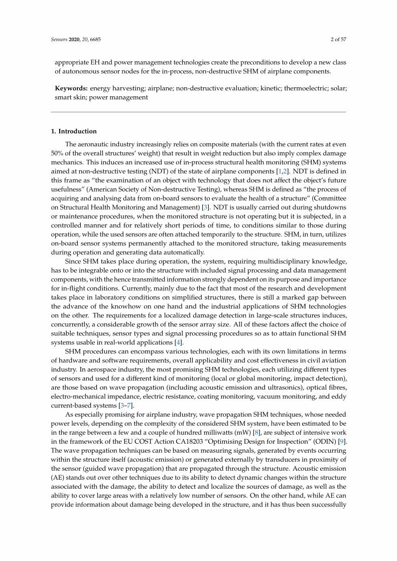
The aeronautic industry increasingly relies on composite materials (with the current rates at even50% of the overall structures’ weight) that result in weight reduction but also imply complex damagemechanics. This induces an increased use of in-process structural health monitoring (SHM) systemsaimed at non-destructive testing (NDT) of the state of airplane components [1,2]. NDT is defined inthis frame as “the examination of an object with technology that does not affect the object’s futureusefulness” (American Society of Non-destructive Testing), whereas SHM is defined as “the process ofacquiring and analysing data from on-board sensors to evaluate the health of a structure” (Committeeon Structural Health Monitoring and Management) [3]. NDT is usually carried out during shutdownsor maintenance procedures, when the monitored structure is not operating but it is subjected, in acontrolled manner and for relatively short periods of time, to conditions similar to those duringoperation, while the used sensors are often attached temporarily to the structure. SHM, in turn, utilizeson-board sensor systems permanently attached to the monitored structure, taking measurementsduring operation and generating data automatically.
Since SHM takes place during operation, the system, requiring multidisciplinary knowledge,has to be integrable onto or into the structure with included signal processing and data managementcomponents, with the hence transmitted information strongly dependent on its purpose and importancefor in-flight conditions. Currently, mainly due to the fact that most of the research and developmenttakes place in laboratory conditions on simplified structures, there is still a marked gap betweenthe advance of the knowhow on one hand and the industrial applications of SHM technologieson the other. The requirements for a localized damage detection in large-scale structures induces,concurrently, a considerable growth of the sensor array size. All of these factors affect the choice ofsuitable techniques, sensor types and signal processing procedures so as to attain functional SHMsystems usable in real-world applications [4].
SHM procedures can encompass various technologies, each with its own limitations in termsof hardware and software requirements, overall applicability and cost effectiveness in civil aviationindustry. In aerospace industry, the most promising SHM technologies, each utilizing different typesof sensors and used for a different kind of monitoring (local or global monitoring, impact detection),are those based on wave propagation (including acoustic emission and ultrasonics), optical fibres,electro-mechanical impedance, electric resistance, coating monitoring, vacuum monitoring, and eddycurrent-based systems [3–7].
As especially promising for airplane industry, wave propagation SHM techniques, whose neededpower levels, depending on the complexity of the considered SHM system, have been estimated to bein the range between a few and a couple of hundred milliwatts (mW) [8], are subject of intensive workin the framework of the EU COST Action CA18203 “Optimising Design for Inspection” (ODIN) [9].The wave propagation techniques can be based on measuring signals, generated by events occurringwithin the structure itself (acoustic emission) or generated externally by transducers in proximity ofthe sensor (guided wave propagation) that are propagated through the structure. Acoustic emission(AE) stands out over other techniques due to its ability to detect dynamic changes within the structureassociated with the damage, the ability to detect and localize the sources of damage, as well as theability to cover large areas with a relatively low number of sensors. On the other hand, while AE canprovide information about damage being developed in the structure, and it has thus been successfully

Sensors 2020, 20, 6685 3 of 57
used in civil engineering, wind turbines, and in aerospace developments [10–12], it cannot generallydo so for the damage currently present in the structure. The guided wave propagation techniquerelies, in turn, on the usage of an external source of ultrasonic elastic waves that propagate through thestructure, and it can be used to detect the damage already present within the structure, such as theairplane wing [13]. Piezoelectric materials are commonly used in this frame as both signal generatingelements as well as sensors [14,15]. Guided waves are widely used for on-site or laboratory testing andthe inspection of composite structures [16,17], as well as for the detection of crack initiation and growthin metallic structures of airplanes [18]. However, this method usually requires, a specific arrangementof the sensor array [19] and there are significant challenges in terms of the respective signal processingand extraction. In fact, the detection of real-world degradation initiated by microscopic defects requiresthe extraction of complex nonlinear features of the waves, hence increasing significantly the processingtime [20].
Viable alternative SHM techniques, whose potential usage in the monitoring of aeronauticcomponents is being studied, include optical fibres-based systems [21–26], systems founded on themeasurement of impedance, based on piezoelectric patches attached to the structure acting, again,simultaneously as actuators and sensors [27,28], systems based on the direct measurement of structuralvibrations and the respective modal parameters of the studied structure, which is especially common inresearch concerning autonomous sensor nodes using the wireless transmission of data [29], and smartskin systems based on lightweight and highly stretchable piezoelectric sensor networks used for highaccuracy monitoring of impacts on the aircraft [30,31].
The addressed SHM sensors then have to be coupled to suitable data elaboration (signal processingand data logging) modules, whose power requirements can be estimated to be in the range from a fewmW [32] to, depending on the foreseen requirements, a couple of hundred mW, as well as (increasinglywireless) communication systems. In fact, the usage of wireless in-process SHM systems could havea huge impact on the reduction of the weight of wiring (currently an A380 airplane has 530 km ofwiring) and thus on the efficiency of fuel consumption [9]. This approach would also allow enhancingsystem safety by means of dissimilar redundancy (wired and wireless), as well as by providing thepossibility to wirelessly access some sensors that cannot be otherwise connected (e.g., on moving parts).The adoption of such a methodology contributes concurrently to increasing the safety and reliability ofairplanes by reducing, via predictive maintenance—a crucial process in determining the probability offailure while providing recommendations on the necessary maintenance frequency with respect to thestate of the structure—, the operational costs [8].
From the technological point of view, two wireless communication options can be distinguished:the wireless avionics intra-communication (WAIC), used for radio-communication of safety andregularity of flight-related applications on board of a single aircraft, or the industrial, scientific,and medical (ISM) radio bands, whose use is generally limited to other applications. The AerospaceVehicle Systems Institute (AVSI) project WAIC was formed in this frame to harmonise the regulationsfor on-board wireless communications. Based on an International Telecommunication Union (ITU)decision, a dedicated frequency band reserved for this purposed is in the 4.2–4.4 GHz range, to beoperated in accordance with the recognized international aeronautical standards. It is based onshort-range radio technology (<100 m) and maximum transmission power levels of 10 mW forlow data rate, and 50 mW for high data rate applications [33,34]. Efforts are currently ongoing tomake appropriate components commercially available for future applications. The ISM radio bandsare, in turn, based on well-defined standards such as the IEEE 802.15.1 (Bluetooth), IEEE 802.15.4(ZigBee) or IEEE802.11 (WiFi), where related COTS (Commercial of the Shelf) components are available.To demonstrate their feasibility, several SHM applications have been set up based on both thesestandards. As an example, autonomous SHM sensor nodes operating in the 2.4 GHz IEEE 802.15.4 ISMband have been developed for strain gauge applications, resulting in an average power consumptionof 2.9 mW and a peak power of 49.3 mW in transmission mode [1]. Hence, considering the overall
Sensors 2020, 20, 6685 4 of 57
efficiency of the antenna with the transmitter, the peak power required for the low-power wirelessconnectivity can be estimated to be tens to hundreds of mW.
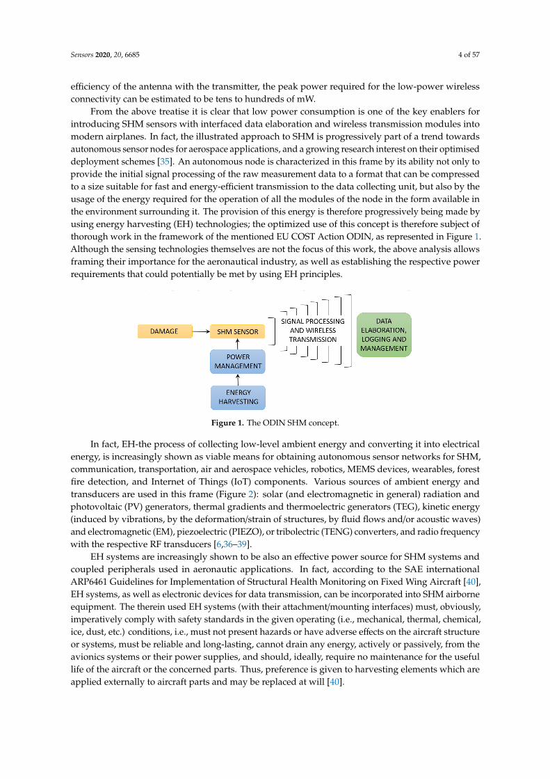
From the above treatise it is clear that low power consumption is one of the key enablers forintroducing SHM sensors with interfaced data elaboration and wireless transmission modules intomodern airplanes. In fact, the illustrated approach to SHM is progressively part of a trend towardsautonomous sensor nodes for aerospace applications, and a growing research interest on their optimiseddeployment schemes [35]. An autonomous node is characterized in this frame by its ability not only toprovide the initial signal processing of the raw measurement data to a format that can be compressedto a size suitable for fast and energy-efficient transmission to the data collecting unit, but also by theusage of the energy required for the operation of all the modules of the node in the form available inthe environment surrounding it. The provision of this energy is therefore progressively being made byusing energy harvesting (EH) technologies; the optimized use of this concept is therefore subject ofthorough work in the framework of the mentioned EU COST Action ODIN, as represented in Figure 1.Although the sensing technologies themselves are not the focus of this work, the above analysis allowsframing their importance for the aeronautical industry, as well as establishing the respective powerrequirements that could potentially be met by using EH principles.
Sensors 2020, 20, x FOR PEER REVIEW 4 of 58
autonomous sensor nodes for aerospace applications, and a growing research interest on their optimised deployment schemes [35]. An autonomous node is characterized in this frame by its ability not only to provide the initial signal processing of the raw measurement data to a format that can be compressed to a size suitable for fast and energy-efficient transmission to the data collecting unit, but also by the usage of the energy required for the operation of all the modules of the node in the form available in the environment surrounding it. The provision of this energy is therefore progressively being made by using energy harvesting (EH) technologies; the optimized use of this concept is therefore subject of thorough work in the framework of the mentioned EU COST Action ODIN, as represented in Figure 1. Although the sensing technologies themselves are not the focus of this work, the above analysis allows framing their importance for the aeronautical industry, as well as establishing the respective power requirements that could potentially be met by using EH principles.
Figure 1. The ODIN SHM concept.
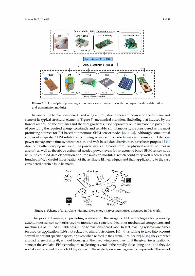
In fact, EH-the process of collecting low-level ambient energy and converting it into electrical energy, is increasingly shown as viable means for obtaining autonomous sensor networks for SHM, communication, transportation, air and aerospace vehicles, robotics, MEMS devices, wearables, forest fire detection, and Internet of Things (IoT) components. Various sources of ambient energy and transducers are used in this frame (Figure 2): solar (and electromagnetic in general) radiation and photovoltaic (PV) generators, thermal gradients and thermoelectric generators (TEG), kinetic energy (induced by vibrations, by the deformation/strain of structures, by fluid flows and/or acoustic waves) and electromagnetic (EM), piezoelectric (PIEZO), or tribolectric (TENG) converters, and radio frequency with the respective RF transducers [6,36–39].
EH systems are increasingly shown to be also an effective power source for SHM systems and coupled peripherals used in aeronautic applications. In fact, according to the SAE international ARP6461 Guidelines for Implementation of Structural Health Monitoring on Fixed Wing Aircraft [40], EH systems, as well as electronic devices for data transmission, can be incorporated into SHM airborne equipment. The therein used EH systems (with their attachment/mounting interfaces) must, obviously, imperatively comply with safety standards in the given operating (i.e., mechanical, thermal, chemical, ice, dust, etc.) conditions, i.e., must not present hazards or have adverse effects on the aircraft structure or systems, must be reliable and long-lasting, cannot drain any energy, actively or passively, from the avionics systems or their power supplies, and should, ideally, require no maintenance for the useful life of the aircraft or the concerned parts. Thus, preference is given to harvesting elements which are applied externally to aircraft parts and may be replaced at will [40].
In case of the herein considered fixed wing aircraft, due to their abundance on the airplane and some of its typical structural elements (Figure 3), mechanical vibrations (including that induced by the flow of air around the airplane) and thermal gradients, used separately or, to increase the possibility of providing the required energy constantly and reliably, simultaneously, are considered as the most promising sources for EH-based autonomous SHM sensor nodes [8,41–43]. Although some initial studies of integrated SHM solutions, combining advanced microelectronics with sensors, EH devices, power management, time synchronization, and web-based data distribution, have been
Figure 1. The ODIN SHM concept.
In fact, EH-the process of collecting low-level ambient energy and converting it into electricalenergy, is increasingly shown as viable means for obtaining autonomous sensor networks for SHM,communication, transportation, air and aerospace vehicles, robotics, MEMS devices, wearables, forestfire detection, and Internet of Things (IoT) components. Various sources of ambient energy andtransducers are used in this frame (Figure 2): solar (and electromagnetic in general) radiation andphotovoltaic (PV) generators, thermal gradients and thermoelectric generators (TEG), kinetic energy(induced by vibrations, by the deformation/strain of structures, by fluid flows and/or acoustic waves)and electromagnetic (EM), piezoelectric (PIEZO), or tribolectric (TENG) converters, and radio frequencywith the respective RF transducers [6,36–39].
EH systems are increasingly shown to be also an effective power source for SHM systems andcoupled peripherals used in aeronautic applications. In fact, according to the SAE internationalARP6461 Guidelines for Implementation of Structural Health Monitoring on Fixed Wing Aircraft [40],EH systems, as well as electronic devices for data transmission, can be incorporated into SHM airborneequipment. The therein used EH systems (with their attachment/mounting interfaces) must, obviously,imperatively comply with safety standards in the given operating (i.e., mechanical, thermal, chemical,ice, dust, etc.) conditions, i.e., must not present hazards or have adverse effects on the aircraft structureor systems, must be reliable and long-lasting, cannot drain any energy, actively or passively, from theavionics systems or their power supplies, and should, ideally, require no maintenance for the usefullife of the aircraft or the concerned parts. Thus, preference is given to harvesting elements which areapplied externally to aircraft parts and may be replaced at will [40].
Sensors 2020, 20, 6685 5 of 57
Sensors 2020, 20, x FOR PEER REVIEW 5 of 58
proposed [44], due to the often varying nature of the power levels attainable from the physical energy sources in aircraft, as well as the above estimated needed power levels for an acoustic-based SHM sensor node with the coupled data elaboration and transmission modules, which could very well reach several hundred mW, a careful investigation of the available EH techniques and their applicability to the case considered herein has to be made.
Figure 2. EH principle of powering autonomous sensor networks with the respective data elaboration and transmission modules.
Figure 3. Scheme of an airplane with indicated energy harvesting sources discussed in this work.
The prior art aiming at providing a review of the usage of EH technologies for powering autonomous sensor networks used to monitor the structural health of mechanical components and machines is of limited suitableness in the herein considered case. In fact, existing reviews are either focused on application fields not related to aircraft structures [45], thus failing to take into account several important specific aspects, or, even when related to the aeronautical sector [42,46], they embrace a broad range of aircraft, without focusing on the fixed wing ones, they limit the given investigation to some of the available EH technologies, neglecting several of the rapidly developing ones, and they do not take into account the whole EH system with the related power management components. The aim of this work, carried out in the framework of the mentioned EU COST Action CA18203 ODIN [9], is hence to advance and broaden considerably the current state-of-the-art on the potential of all the diverse EH principles that could be used to power autonomous in-process SHM
Figure 2. EH principle of powering autonomous sensor networks with the respective data elaborationand transmission modules.
In case of the herein considered fixed wing aircraft, due to their abundance on the airplane andsome of its typical structural elements (Figure 3), mechanical vibrations (including that induced by theflow of air around the airplane) and thermal gradients, used separately or, to increase the possibilityof providing the required energy constantly and reliably, simultaneously, are considered as the mostpromising sources for EH-based autonomous SHM sensor nodes [8,41–43]. Although some initialstudies of integrated SHM solutions, combining advanced microelectronics with sensors, EH devices,power management, time synchronization, and web-based data distribution, have been proposed [44],due to the often varying nature of the power levels attainable from the physical energy sources inaircraft, as well as the above estimated needed power levels for an acoustic-based SHM sensor nodewith the coupled data elaboration and transmission modules, which could very well reach severalhundred mW, a careful investigation of the available EH techniques and their applicability to the caseconsidered herein has to be made.
Sensors 2020, 20, x FOR PEER REVIEW 5 of 58
proposed [44], due to the often varying nature of the power levels attainable from the physical energy sources in aircraft, as well as the above estimated needed power levels for an acoustic-based SHM sensor node with the coupled data elaboration and transmission modules, which could very well reach several hundred mW, a careful investigation of the available EH techniques and their applicability to the case considered herein has to be made.
Figure 2. EH principle of powering autonomous sensor networks with the respective data elaboration and transmission modules.
Figure 3. Scheme of an airplane with indicated energy harvesting sources discussed in this work.
The prior art aiming at providing a review of the usage of EH technologies for powering autonomous sensor networks used to monitor the structural health of mechanical components and machines is of limited suitableness in the herein considered case. In fact, existing reviews are either focused on application fields not related to aircraft structures [45], thus failing to take into account several important specific aspects, or, even when related to the aeronautical sector [42,46], they embrace a broad range of aircraft, without focusing on the fixed wing ones, they limit the given investigation to some of the available EH technologies, neglecting several of the rapidly developing ones, and they do not take into account the whole EH system with the related power management components. The aim of this work, carried out in the framework of the mentioned EU COST Action CA18203 ODIN [9], is hence to advance and broaden considerably the current state-of-the-art on the potential of all the diverse EH principles that could be used to power autonomous in-process SHM
Figure 3. Scheme of an airplane with indicated energy harvesting sources discussed in this work.
The prior art aiming at providing a review of the usage of EH technologies for poweringautonomous sensor networks used to monitor the structural health of mechanical components andmachines is of limited suitableness in the herein considered case. In fact, existing reviews are eitherfocused on application fields not related to aircraft structures [45], thus failing to take into accountseveral important specific aspects, or, even when related to the aeronautical sector [42,46], they embracea broad range of aircraft, without focusing on the fixed wing ones, they limit the given investigation tosome of the available EH technologies, neglecting several of the rapidly developing ones, and they donot take into account the whole EH system with the related power management components. The aim of

Sensors 2020, 20, 6685 6 of 57
this work, carried out in the framework of the mentioned EU COST Action CA18203 ODIN [9], is henceto advance and broaden considerably the current state-of-the-art on the potential of all the diverse EHprinciples that could be used to power autonomous in-process SHM sensor nodes in the specific fieldof composite airplane components, updating it with the comprehensive review of the newest studiesand principles suggested in literature. A careful analysis of the specific power outputs of the possiblesolutions, i.e., of the thus needed areas/volumes as well as of the excitation conditions (e.g., frequencyor temperature ranges) is hence provided. What is more, a critical consideration of the needed powermanagement and energy storage systems that would provide a stable power source for the consideredSHM sensors and peripherals, in the presence of the dynamically changing excitation conditions,and/or while concurrently using several EH principles, is also provided. The other components ofthe ODIN COST Action will concurrently actively work on the optimization of the placement of thesensors, the minimization of the respective power consumption, and the optimization of the neededsignal processing protocols as well as data transmission rates, which should all contribute towardsdecreasing the necessary power generation levels. The design guidelines derived in this work createthus an important element in determining the preconditions towards a strategic approach to integratethe outlined SHM principles already in the design inception phase of the airplane, thus considerablyraising the technology readiness level (TRL) for a new class of autonomous sensor nodes for in-serviceSHM inspection of airplane components. These will then be materialized in the prosecution of the workon the ODIN EU COST Action CA18203, prospectively enabling the first generation of self-sensingaircraft capable of accurate structural prognosis [9].
In Sections 2–6 of this paper, a thorough review of the EH technologies to be potentially used topower autonomous SHM systems in airplanes will thus be given. The prospective usage of kinetic(vibration and strain—Section 2), TEG (Section 3), PV (Section 4), airflow and acoustic (Section 5),and RF EH systems (Section 6) will hence be comprehensively considered. The potential arrangementsof state-of-the-art suitable power management electronics circuitry will be thoroughly reviewed inSection 7. Section 8 sums up the main findings of the investigation performed. The very broad listof the most recent references provided at the end of the paper gives to the prospective readers thepossibility to deepen their understanding of all the aspects of the treated topics.
2. Kinetic Energy Harvesting Systems
Aircraft structures are subject to substantial dynamical effects during operation [38,47]. The thusexited vibrations are induced by both internal and external sources. The primary internal source ofvibrations is the engine system, while air turbulence is the major external source of dynamical excitationof the airplane structure. The resulting kinetic energy is a viable source that can be transformed,by using energy harvesting devices, into useful electrical energy. This is generally achieved viathe physical principles of electromechanical conversions, mainly electromagnetic induction, and thepiezoelectric effect. Magnetostrictive devices, which use is associated with non-negligible cost andsignificant technological issues, have been subject to less attention, most often outside of aeronautic(i.e., higher frequencies) applications. Other EH principles proposed for kinetic environmental energysources, such as electrostatic conversion [48], result in lower power outputs suitable more for MEMSand similar application fields, while their scaling up to the herein studied power magnitudes could beassociated with considerable costs and technological challenges. The latter can be said also for therecently (last 10 years or so) proposed triboelectric nanogenerators [49], whose technological readinessis generally not yet on the levels required by the aircraft industry. These two classes of EH devices willthus be only shortly touched upon at the end of the treatise in Section 2.2 below.
The kinetic energy of dynamical excitation on airplanes could then be harvested by using eithervibration EH devices, or by using the strain induced in the hosted structure [50]. In fact, the firststudy on the usage of vibration EH can be traced as back as to 1996 [51]. The main disadvantage ofsuch an EH system, as will be further elaborated below, is that its optimal usage is generally limitedto operating conditions in close proximity to one of its eigenfrequencies [32,52]. On the other hand,
Sensors 2020, 20, 6685 7 of 57
the potential for strain EH could be given by the large area of aircraft structures such as airplanewings [53]. The position and design of the EH devices are, in any case, crucial in obtaining efficientpower generation. A series of vibration piezoelectric EH devices could, e.g., be optimally positionedon the airplane wing panel [47], whereas strain piezoelectric EH, referred to as multimodal smart skin,could be positioned in the area near the airplane window, providing a very interesting localized energysource for SHM applications [54].
2.1. Physical Principles of Electromechanical Conversion
As pointed out above, the most efficient and common kinetic EH devices are based on either thepiezoelectric or the electromagnetic energy conversion principles.
In fact, in both vibration- and strain-based EH devices, the conversion of mechanical energy intoelectricity can be effectively achieved by making use of the piezoelectric effect, i.e.,
• In vibration energy harvesters the piezoelectric material is integrated onto an additional mechanicalstructure in the form of a mechanical resonator, thus inducing the strain of the piezoelectric material.
• In the case of strain energy harvesters, the piezoelectric material is, in turn, integrated onto the partof the airplane structure that during operation is subject to vibrations, varied loads, and similardynamical excitation, inducing mechanical strain of the structure itself and of the piezoelectricmaterial affixed onto it.
Electromagnetic energy transducers can, on the other hand, be used only as vibration EHresonators, as could maybe potentially also be the magnetostrictive EH devices.
2.1.1. The Piezoelectric Effect and Operational Modes
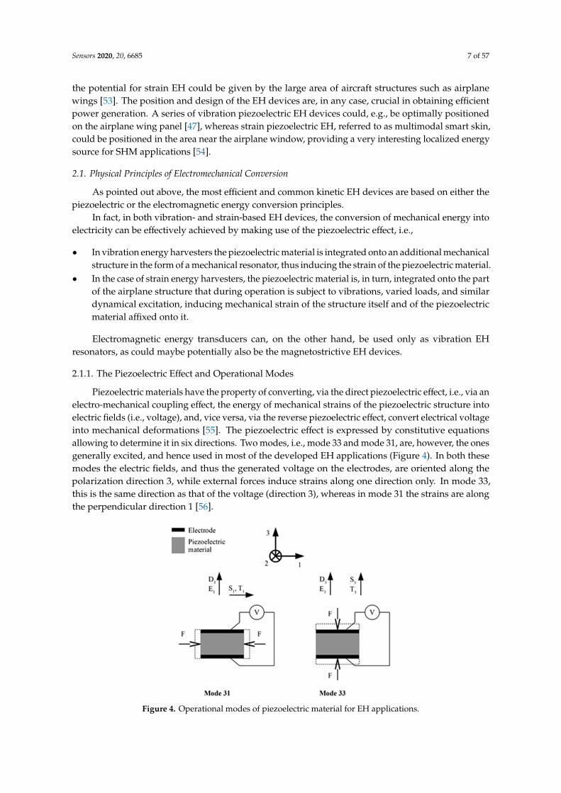
Piezoelectric materials have the property of converting, via the direct piezoelectric effect, i.e., via anelectro-mechanical coupling effect, the energy of mechanical strains of the piezoelectric structure intoelectric fields (i.e., voltage), and, vice versa, via the reverse piezoelectric effect, convert electrical voltageinto mechanical deformations [55]. The piezoelectric effect is expressed by constitutive equationsallowing to determine it in six directions. Two modes, i.e., mode 33 and mode 31, are, however, the onesgenerally excited, and hence used in most of the developed EH applications (Figure 4). In both thesemodes the electric fields, and thus the generated voltage on the electrodes, are oriented along thepolarization direction 3, while external forces induce strains along one direction only. In mode 33,this is the same direction as that of the voltage (direction 3), whereas in mode 31 the strains are alongthe perpendicular direction 1 [56].
Sensors 2020, 20, x FOR PEER REVIEW 7 of 58
airplane wing panel [47], whereas strain piezoelectric EH, referred to as multimodal smart skin, could be positioned in the area near the airplane window, providing a very interesting localized energy source for SHM applications [54].
2.1. Physical Principles of Electromechanical Conversion
As pointed out above, the most efficient and common kinetic EH devices are based on either the piezoelectric or the electromagnetic energy conversion principles.
In fact, in both vibration- and strain-based EH devices, the conversion of mechanical energy into electricity can be effectively achieved by making use of the piezoelectric effect, i.e.,
• In vibration energy harvesters the piezoelectric material is integrated onto an additional mechanical structure in the form of a mechanical resonator, thus inducing the strain of the piezoelectric material.
• In the case of strain energy harvesters, the piezoelectric material is, in turn, integrated onto the part of the airplane structure that during operation is subject to vibrations, varied loads, and similar dynamical excitation, inducing mechanical strain of the structure itself and of the piezoelectric material affixed onto it.
Electromagnetic energy transducers can, on the other hand, be used only as vibration EH resonators, as could maybe potentially also be the magnetostrictive EH devices.
2.1.1. The Piezoelectric Effect and Operational Modes
Piezoelectric materials have the property of converting, via the direct piezoelectric effect, i.e., via an electro-mechanical coupling effect, the energy of mechanical strains of the piezoelectric structure into electric fields (i.e., voltage), and, vice versa, via the reverse piezoelectric effect, convert electrical voltage into mechanical deformations [55]. The piezoelectric effect is expressed by constitutive equations allowing to determine it in six directions. Two modes, i.e., mode 33 and mode 31, are, however, the ones generally excited, and hence used in most of the developed EH applications (Figure 4). In both these modes the electric fields, and thus the generated voltage on the electrodes, are oriented along the polarization direction 3, while external forces induce strains along one direction only. In mode 33, this is the same direction as that of the voltage (direction 3), whereas in mode 31 the strains are along the perpendicular direction 1 [56].
Figure 4. Operational modes of piezoelectric material for EH applications. Figure 4. Operational modes of piezoelectric material for EH applications.
Sensors 2020, 20, 6685 8 of 57
2.1.2. Electromagnetic Conversion
Electromagnetic induction, described by Faraday’s induction law, is the production of anelectromotive force (EMF), i.e., of voltage across an electrical conductor in a changing magneticfield—the phenomenon that constitutes the foundation of electrical generators. When a permanentmagnet is moved relative to a conductor, or vice versa, an EMF is created with the thus inducedvoltage being proportional to the strength of the magnetic field, the velocity of relative motion andthe number of turns of the conductor coil. If the conductor is connected to an electrical load, currentwill flow, thus generating electrical energy, i.e., converting kinetic (motion) into electrical energy.This system is often proposed as effective means to attain kinetic EH systems, where the relativedisplacement of the permanent magnet with respect to the coil, caused by vibrations, is at the basis ofthe thus obtained kinetic EH transduction mechanism. A seminal work in developing autonomousmonitoring and sensing in dynamically excited environments by using this principle is that of Jamesand co-authors [57].
2.1.3. The Magnetostrictive Effect
Physically somewhat similar to the piezoelectric effect, the characteristic property of magnetostrictive(often referred to also as ‘smart’) materials is that magneto-elastic coupling induces mechanicalelongations if they are subjected to a magnetic field, while, inversely, their magnetization will changedue to changes in applied mechanical stresses. The latter outcome, often indicated as the Villarieffect, can be used in EH devices, where, however, an additional coil is necessarily used to obtain,via electromagnetic induction, electrical energy.
2.2. Vibration Energy Harvesting
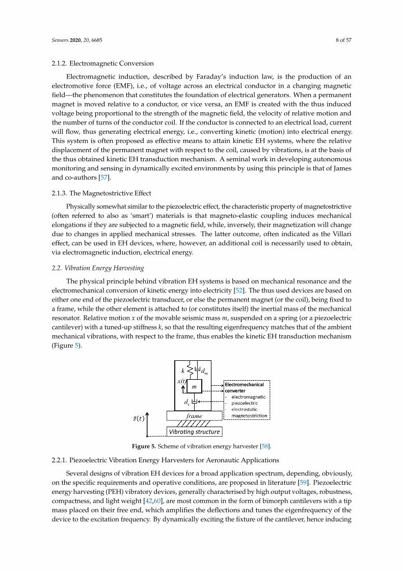
The physical principle behind vibration EH systems is based on mechanical resonance and theelectromechanical conversion of kinetic energy into electricity [52]. The thus used devices are based oneither one end of the piezoelectric transducer, or else the permanent magnet (or the coil), being fixed toa frame, while the other element is attached to (or constitutes itself) the inertial mass of the mechanicalresonator. Relative motion x of the movable seismic mass m, suspended on a spring (or a piezoelectriccantilever) with a tuned-up stiffness k, so that the resulting eigenfrequency matches that of the ambientmechanical vibrations, with respect to the frame, thus enables the kinetic EH transduction mechanism(Figure 5).
Sensors 2020, 20, x FOR PEER REVIEW 8 of 58
2.1.2. Electromagnetic Conversion
Electromagnetic induction, described by Faraday's induction law, is the production of an electromotive force (EMF), i.e., of voltage across an electrical conductor in a changing magnetic field—the phenomenon that constitutes the foundation of electrical generators. When a permanent magnet is moved relative to a conductor, or vice versa, an EMF is created with the thus induced voltage being proportional to the strength of the magnetic field, the velocity of relative motion and the number of turns of the conductor coil. If the conductor is connected to an electrical load, current will flow, thus generating electrical energy, i.e., converting kinetic (motion) into electrical energy. This system is often proposed as effective means to attain kinetic EH systems, where the relative displacement of the permanent magnet with respect to the coil, caused by vibrations, is at the basis of the thus obtained kinetic EH transduction mechanism. A seminal work in developing autonomous monitoring and sensing in dynamically excited environments by using this principle is that of James and co-authors [57].
2.1.3. The Magnetostrictive Effect
Physically somewhat similar to the piezoelectric effect, the characteristic property of magnetostrictive (often referred to also as ‘smart’) materials is that magneto-elastic coupling induces mechanical elongations if they are subjected to a magnetic field, while, inversely, their magnetization will change due to changes in applied mechanical stresses. The latter outcome, often indicated as the Villari effect, can be used in EH devices, where, however, an additional coil is necessarily used to obtain, via electromagnetic induction, electrical energy. 2.2. Vibration Energy Harvesting
The physical principle behind vibration EH systems is based on mechanical resonance and the electromechanical conversion of kinetic energy into electricity [52]. The thus used devices are based on either one end of the piezoelectric transducer, or else the permanent magnet (or the coil), being fixed to a frame, while the other element is attached to (or constitutes itself) the inertial mass of the mechanical resonator. Relative motion x of the movable seismic mass m, suspended on a spring (or a piezoelectric cantilever) with a tuned-up stiffness k, so that the resulting eigenfrequency matches that of the ambient mechanical vibrations, with respect to the frame, thus enables the kinetic EH transduction mechanism (Figure 5).
Figure 5. Scheme of vibration energy harvester [58].
2.2.1. Piezoelectric Vibration Energy Harvesters for Aeronautic Applications
Several designs of vibration EH devices for a broad application spectrum, depending, obviously, on the specific requirements and operative conditions, are proposed in literature [59]. Piezoelectric energy harvesting (PEH) vibratory devices, generally characterised by high output voltages, robustness, compactness, and light weight [42,60], are most common in the form of bimorph cantilevers with a tip mass placed on their free end, which amplifies the deflections and tunes the eigenfrequency of the device to the excitation frequency. By dynamically exciting the fixture of the
Figure 5. Scheme of vibration energy harvester [58].
2.2.1. Piezoelectric Vibration Energy Harvesters for Aeronautic Applications
Several designs of vibration EH devices for a broad application spectrum, depending, obviously,on the specific requirements and operative conditions, are proposed in literature [59]. Piezoelectricenergy harvesting (PEH) vibratory devices, generally characterised by high output voltages, robustness,compactness, and light weight [42,60], are most common in the form of bimorph cantilevers with a tipmass placed on their free end, which amplifies the deflections and tunes the eigenfrequency of thedevice to the excitation frequency. By dynamically exciting the fixture of the cantilever, hence inducing
Sensors 2020, 20, 6685 9 of 57
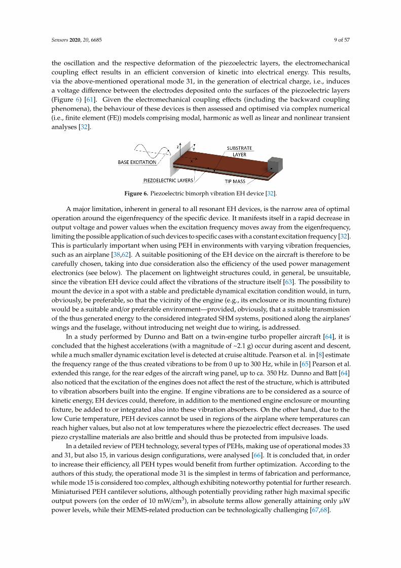
the oscillation and the respective deformation of the piezoelectric layers, the electromechanicalcoupling effect results in an efficient conversion of kinetic into electrical energy. This results,via the above-mentioned operational mode 31, in the generation of electrical charge, i.e., inducesa voltage difference between the electrodes deposited onto the surfaces of the piezoelectric layers(Figure 6) [61]. Given the electromechanical coupling effects (including the backward couplingphenomena), the behaviour of these devices is then assessed and optimised via complex numerical(i.e., finite element (FE)) models comprising modal, harmonic as well as linear and nonlinear transientanalyses [32].
Sensors 2020, 20, x FOR PEER REVIEW 9 of 58
cantilever, hence inducing the oscillation and the respective deformation of the piezoelectric layers, the electromechanical coupling effect results in an efficient conversion of kinetic into electrical energy. This results, via the above-mentioned operational mode 31, in the generation of electrical charge, i.e., induces a voltage difference between the electrodes deposited onto the surfaces of the piezoelectric layers (Figure 6) [61]. Given the electromechanical coupling effects (including the backward coupling phenomena), the behaviour of these devices is then assessed and optimised via complex numerical (i.e., finite element (FE)) models comprising modal, harmonic as well as linear and nonlinear transient analyses [32].
Figure 6. Piezoelectric bimorph vibration EH device [32].
A major limitation, inherent in general to all resonant EH devices, is the narrow area of optimal operation around the eigenfrequency of the specific device. It manifests itself in a rapid decrease in output voltage and power values when the excitation frequency moves away from the eigenfrequency, limiting the possible application of such devices to specific cases with a constant excitation frequency [32]. This is particularly important when using PEH in environments with varying vibration frequencies, such as an airplane [38,62]. A suitable positioning of the EH device on the aircraft is therefore to be carefully chosen, taking into due consideration also the efficiency of the used power management electronics (see below). The placement on lightweight structures could, in general, be unsuitable, since the vibration EH device could affect the vibrations of the structure itself [63]. The possibility to mount the device in a spot with a stable and predictable dynamical excitation condition would, in turn, obviously, be preferable, so that the vicinity of the engine (e.g., its enclosure or its mounting fixture) would be a suitable and/or preferable environment—provided, obviously, that a suitable transmission of the thus generated energy to the considered integrated SHM systems, positioned along the airplanes’ wings and the fuselage, without introducing net weight due to wiring, is addressed.
In a study performed by Dunno and Batt on a twin-engine turbo propeller aircraft [64], it is concluded that the highest accelerations (with a magnitude of ~2.1 g) occur during ascent and descent, while a much smaller dynamic excitation level is detected at cruise altitude. Pearson et al. in [8] estimate the frequency range of the thus created vibrations to be from 0 up to 300 Hz, while in [65] Pearson et al. extended this range, for the rear edges of the aircraft wing panel, up to ca. 350 Hz. Dunno and Batt [64] also noticed that the excitation of the engines does not affect the rest of the structure, which is attributed to vibration absorbers built into the engine. If engine vibrations are to be considered as a source of kinetic energy, EH devices could, therefore, in addition to the mentioned engine enclosure or mounting fixture, be added to or integrated also into these vibration absorbers. On the other hand, due to the low Curie temperature, PEH devices cannot be used in regions of the airplane where temperatures can reach higher values, but also not at low temperatures where the piezoelectric effect decreases. The used piezo crystalline materials are also brittle and should thus be protected from impulsive loads.
In a detailed review of PEH technology, several types of PEHs, making use of operational modes 33 and 31, but also 15, in various design configurations, were analysed [66]. It is concluded that, in order to increase their efficiency, all PEH types would benefit from further optimization. According to the authors of this study, the operational mode 31 is the simplest in terms of fabrication and performance, while mode 15 is considered too complex, although exhibiting noteworthy potential for further research. Miniaturised PEH cantilever solutions, although potentially providing rather high maximal specific output powers (on the order of 10 mW/cm3), in absolute terms allow generally
Figure 6. Piezoelectric bimorph vibration EH device [32].
A major limitation, inherent in general to all resonant EH devices, is the narrow area of optimaloperation around the eigenfrequency of the specific device. It manifests itself in a rapid decrease inoutput voltage and power values when the excitation frequency moves away from the eigenfrequency,limiting the possible application of such devices to specific cases with a constant excitation frequency [32].This is particularly important when using PEH in environments with varying vibration frequencies,such as an airplane [38,62]. A suitable positioning of the EH device on the aircraft is therefore to becarefully chosen, taking into due consideration also the efficiency of the used power managementelectronics (see below). The placement on lightweight structures could, in general, be unsuitable,since the vibration EH device could affect the vibrations of the structure itself [63]. The possibility tomount the device in a spot with a stable and predictable dynamical excitation condition would, in turn,obviously, be preferable, so that the vicinity of the engine (e.g., its enclosure or its mounting fixture)would be a suitable and/or preferable environment—provided, obviously, that a suitable transmissionof the thus generated energy to the considered integrated SHM systems, positioned along the airplanes’wings and the fuselage, without introducing net weight due to wiring, is addressed.
In a study performed by Dunno and Batt on a twin-engine turbo propeller aircraft [64], it isconcluded that the highest accelerations (with a magnitude of ~2.1 g) occur during ascent and descent,while a much smaller dynamic excitation level is detected at cruise altitude. Pearson et al. in [8] estimatethe frequency range of the thus created vibrations to be from 0 up to 300 Hz, while in [65] Pearson et al.extended this range, for the rear edges of the aircraft wing panel, up to ca. 350 Hz. Dunno and Batt [64]also noticed that the excitation of the engines does not affect the rest of the structure, which is attributedto vibration absorbers built into the engine. If engine vibrations are to be considered as a source ofkinetic energy, EH devices could, therefore, in addition to the mentioned engine enclosure or mountingfixture, be added to or integrated also into these vibration absorbers. On the other hand, due to thelow Curie temperature, PEH devices cannot be used in regions of the airplane where temperatures canreach higher values, but also not at low temperatures where the piezoelectric effect decreases. The usedpiezo crystalline materials are also brittle and should thus be protected from impulsive loads.
In a detailed review of PEH technology, several types of PEHs, making use of operational modes 33and 31, but also 15, in various design configurations, were analysed [66]. It is concluded that, in orderto increase their efficiency, all PEH types would benefit from further optimization. According to theauthors of this study, the operational mode 31 is the simplest in terms of fabrication and performance,while mode 15 is considered too complex, although exhibiting noteworthy potential for further research.Miniaturised PEH cantilever solutions, although potentially providing rather high maximal specificoutput powers (on the order of 10 mW/cm3), in absolute terms allow generally attaining only µWpower levels, while their MEMS-related production can be technologically challenging [67,68].
Sensors 2020, 20, 6685 10 of 57
In any case, several approaches to overcome the above evidenced limitation related to thebandwidth of operation, by broadening the optimal frequency spectrum, have been suggested in recentliterature, the most promising being [32]:
• Changing the conditions around the cantilever free end (e.g., via damping control or active tuning),often inducing and/or combined with features inducing the nonlinear response of the PEH device.
• Changing the geometry of the PEH cantilever, herein including complex geometries with bistableconfigurations, or employing a large number of differently sized (i.e., tuned) cantilevers.
• Using a frequency up-conversion mechanisms, e.g., by plucking the free end of the piezoelectriccantilever and letting it oscillate at its eigenfrequency.
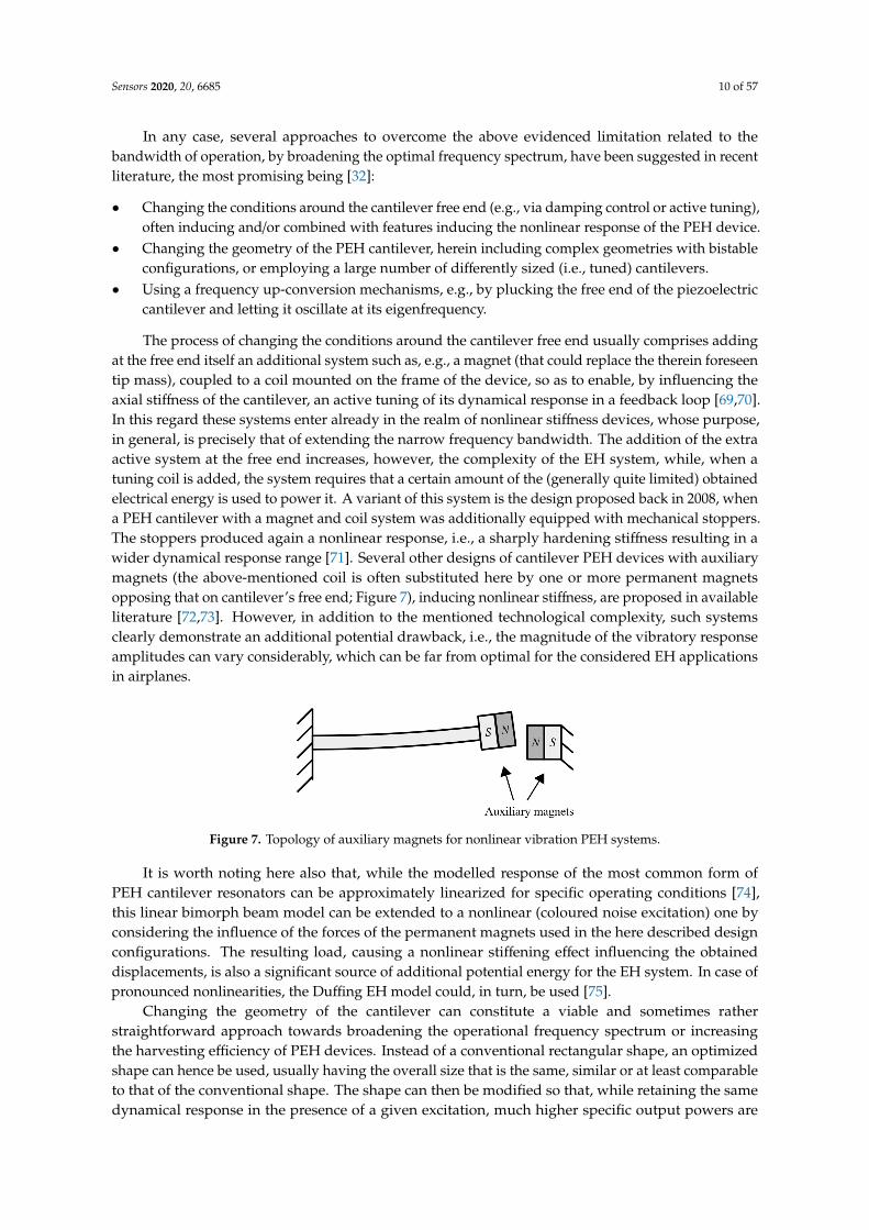
The process of changing the conditions around the cantilever free end usually comprises addingat the free end itself an additional system such as, e.g., a magnet (that could replace the therein foreseentip mass), coupled to a coil mounted on the frame of the device, so as to enable, by influencing theaxial stiffness of the cantilever, an active tuning of its dynamical response in a feedback loop [69,70].In this regard these systems enter already in the realm of nonlinear stiffness devices, whose purpose,in general, is precisely that of extending the narrow frequency bandwidth. The addition of the extraactive system at the free end increases, however, the complexity of the EH system, while, when atuning coil is added, the system requires that a certain amount of the (generally quite limited) obtainedelectrical energy is used to power it. A variant of this system is the design proposed back in 2008, whena PEH cantilever with a magnet and coil system was additionally equipped with mechanical stoppers.The stoppers produced again a nonlinear response, i.e., a sharply hardening stiffness resulting in awider dynamical response range [71]. Several other designs of cantilever PEH devices with auxiliarymagnets (the above-mentioned coil is often substituted here by one or more permanent magnetsopposing that on cantilever’s free end; Figure 7), inducing nonlinear stiffness, are proposed in availableliterature [72,73]. However, in addition to the mentioned technological complexity, such systemsclearly demonstrate an additional potential drawback, i.e., the magnitude of the vibratory responseamplitudes can vary considerably, which can be far from optimal for the considered EH applicationsin airplanes.
Sensors 2020, 20, x FOR PEER REVIEW 10 of 58
attaining only μW power levels, while their MEMS-related production can be technologically challenging [67,68].
In any case, several approaches to overcome the above evidenced limitation related to the bandwidth of operation, by broadening the optimal frequency spectrum, have been suggested in recent literature, the most promising being [32]:
• Changing the conditions around the cantilever free end (e.g., via damping control or active tuning), often inducing and/or combined with features inducing the nonlinear response of the PEH device.
• Changing the geometry of the PEH cantilever, herein including complex geometries with bistable configurations, or employing a large number of differently sized (i.e., tuned) cantilevers.
• Using a frequency up-conversion mechanisms, e.g., by plucking the free end of the piezoelectric cantilever and letting it oscillate at its eigenfrequency.
The process of changing the conditions around the cantilever free end usually comprises adding at the free end itself an additional system such as, e.g., a magnet (that could replace the therein foreseen tip mass), coupled to a coil mounted on the frame of the device, so as to enable, by influencing the axial stiffness of the cantilever, an active tuning of its dynamical response in a feedback loop [69,70]. In this regard these systems enter already in the realm of nonlinear stiffness devices, whose purpose, in general, is precisely that of extending the narrow frequency bandwidth. The addition of the extra active system at the free end increases, however, the complexity of the EH system, while, when a tuning coil is added, the system requires that a certain amount of the (generally quite limited) obtained electrical energy is used to power it. A variant of this system is the design proposed back in 2008, when a PEH cantilever with a magnet and coil system was additionally equipped with mechanical stoppers. The stoppers produced again a nonlinear response, i.e., a sharply hardening stiffness resulting in a wider dynamical response range [71]. Several other designs of cantilever PEH devices with auxiliary magnets (the above-mentioned coil is often substituted here by one or more permanent magnets opposing that on cantilever’s free end; Figure 7), inducing nonlinear stiffness, are proposed in available literature [72,73]. However, in addition to the mentioned technological complexity, such systems clearly demonstrate an additional potential drawback, i.e., the magnitude of the vibratory response amplitudes can vary considerably, which can be far from optimal for the considered EH applications in airplanes.
Figure 7. Topology of auxiliary magnets for nonlinear vibration PEH systems.
It is worth noting here also that, while the modelled response of the most common form of PEH cantilever resonators can be approximately linearized for specific operating conditions [74], this linear bimorph beam model can be extended to a nonlinear (coloured noise excitation) one by considering the influence of the forces of the permanent magnets used in the here described design configurations. The resulting load, causing a nonlinear stiffening effect influencing the obtained displacements, is also a significant source of additional potential energy for the EH system. In case of pronounced nonlinearities, the Duffing EH model could, in turn, be used [75].
Changing the geometry of the cantilever can constitute a viable and sometimes rather straightforward approach towards broadening the operational frequency spectrum or increasing the harvesting efficiency of PEH devices. Instead of a conventional rectangular shape, an optimized shape can hence be used, usually having the overall size that is the same, similar or at least comparable to that of the conventional shape. The shape can then be modified so that, while retaining
Figure 7. Topology of auxiliary magnets for nonlinear vibration PEH systems.
It is worth noting here also that, while the modelled response of the most common form ofPEH cantilever resonators can be approximately linearized for specific operating conditions [74],this linear bimorph beam model can be extended to a nonlinear (coloured noise excitation) one byconsidering the influence of the forces of the permanent magnets used in the here described designconfigurations. The resulting load, causing a nonlinear stiffening effect influencing the obtaineddisplacements, is also a significant source of additional potential energy for the EH system. In case ofpronounced nonlinearities, the Duffing EH model could, in turn, be used [75].
Changing the geometry of the cantilever can constitute a viable and sometimes ratherstraightforward approach towards broadening the operational frequency spectrum or increasingthe harvesting efficiency of PEH devices. Instead of a conventional rectangular shape, an optimizedshape can hence be used, usually having the overall size that is the same, similar or at least comparableto that of the conventional shape. The shape can then be modified so that, while retaining the samedynamical response in the presence of a given excitation, much higher specific output powers are

Sensors 2020, 20, 6685 11 of 57
obtained by optimizing the strain (i.e., charge accumulation) in the piezoelectric layers (Figure 8a) [76].The conventional shape can, alternatively, be segmented to comprise multiple PEH cantileversoptimized for specific electrical loads and possibly having a different eigenfrequency each, whichcan be tuned further by the proper choice of the respective tip masses (Figure 8b) [32,77]. The chargeaccumulation of these segmented PEH bimorphs can be enhanced further by ingeniously introducingstress concentrators or other ‘smart’ geometrical features [78]. These approaches do not requireadditional systems or excitation mechanisms, making them particularly suitable for the hereinconsidered SHM applications, allowing to attain, in the optimal conditions, several mW (i.e., of theorder of tens of mW/cm3) of output power.
Sensors 2020, 20, x FOR PEER REVIEW 11 of 58
the same dynamical response in the presence of a given excitation, much higher specific output powers are obtained by optimizing the strain (i.e., charge accumulation) in the piezoelectric layers (Figure 8a) [76]. The conventional shape can, alternatively, be segmented to comprise multiple PEH cantilevers optimized for specific electrical loads and possibly having a different eigenfrequency each, which can be tuned further by the proper choice of the respective tip masses (Figure 8b) [32,77]. The charge accumulation of these segmented PEH bimorphs can be enhanced further by ingeniously introducing stress concentrators or other ‘smart’ geometrical features [78]. These approaches do not require additional systems or excitation mechanisms, making them particularly suitable for the herein considered SHM applications, allowing to attain, in the optimal conditions, several mW (i.e., of the order of tens of mW/cm3) of output power.
(a) (b)
Figure 8. PEH geometry variations: optimized shape bimorphs proposed in [76]-reprinted by permission from Springer Nature (a) and segmented PEH geometry proposed in [32] (b).
Arc-shaped cantilever PEHs, having one or two semi-circular sections, have also been recently proposed [79]. For experimental purposes, these are compared to a standard flat harvester having either the same volume of the used piezoelectric material or the same length. It has been shown that, under an acceleration of 3g, the configuration with one semi-circular section provides more than 2.5 times higher output powers (i.e., >1 mW/cm3) than its flat counterpart, while the design with two arc-shaped sections provides even 3–4 timed higher output powers. It can thus be concluded that curved PEH cantilevers provide a significant increase in power output, at the expense, however, of the space (height) required for the installation of the elements. It is to be noted here that specific power equations, where generally the normalization is expressed in terms of the used harvesters’ material, do not consider the height required for the semi-circular elements.
Multiple stable states can, in turn, be achieved by using again complex PEH cantilever geometries or, as mentioned above, by employing magnets at the free end combined with stationary or additional oscillating magnets on the base of the device, resulting, once more, in a nonlinear PEH response. In the last 10 years or so, several studies on bistable and/or multistable piezoelectric cantilever beams with auxiliary magnets have thus been performed [80–84]. Although a wider frequency spectrum is indeed attained, potentially leading to higher power outputs, there is a conspicuous increase in the analytical complexity of the resulting strongly chaotic oscillations with large amplitudes, as well as a substantial increase of the volume of the resulting devices [85–87].
Frequency up-conversion mechanisms (also referred to as impact driven mechanisms) allow, finally, the PEH cantilevers to always oscillate at their eigenfrequency, thus maximizing the output power regardless of the excitation frequency. The hence needed excitation can be provided by plucking the free end of the piezoelectric bimorph with a single plectrum or multiple plectra mounted on a flywheel or a moving mass (e.g., a moving ball or a mass on a spring), thus inducing the production of electrical energy during the ensuing mechanical vibrations (Figure 9). The principle was indeed proposed for an application in aircraft [88], although it is also applicable in other fields [32,89]. Such an approach requires, however, the addition of a separate mechanical excitation system, which can have a significant influence on the volume and complexity of the resulting EH devices, as well its price [90,91].
Figure 8. PEH geometry variations: optimized shape bimorphs proposed in [76]-reprinted bypermission from Springer Nature (a) and segmented PEH geometry proposed in [32] (b).
Arc-shaped cantilever PEHs, having one or two semi-circular sections, have also been recentlyproposed [79]. For experimental purposes, these are compared to a standard flat harvester havingeither the same volume of the used piezoelectric material or the same length. It has been shownthat, under an acceleration of 3g, the configuration with one semi-circular section provides more than2.5 times higher output powers (i.e., >1 mW/cm3) than its flat counterpart, while the design with twoarc-shaped sections provides even 3–4 timed higher output powers. It can thus be concluded thatcurved PEH cantilevers provide a significant increase in power output, at the expense, however, of thespace (height) required for the installation of the elements. It is to be noted here that specific powerequations, where generally the normalization is expressed in terms of the used harvesters’ material,do not consider the height required for the semi-circular elements.
Multiple stable states can, in turn, be achieved by using again complex PEH cantilever geometriesor, as mentioned above, by employing magnets at the free end combined with stationary or additionaloscillating magnets on the base of the device, resulting, once more, in a nonlinear PEH response. In thelast 10 years or so, several studies on bistable and/or multistable piezoelectric cantilever beams withauxiliary magnets have thus been performed [80–84]. Although a wider frequency spectrum is indeedattained, potentially leading to higher power outputs, there is a conspicuous increase in the analyticalcomplexity of the resulting strongly chaotic oscillations with large amplitudes, as well as a substantialincrease of the volume of the resulting devices [85–87].
Frequency up-conversion mechanisms (also referred to as impact driven mechanisms) allow,finally, the PEH cantilevers to always oscillate at their eigenfrequency, thus maximizing the outputpower regardless of the excitation frequency. The hence needed excitation can be provided by pluckingthe free end of the piezoelectric bimorph with a single plectrum or multiple plectra mounted on aflywheel or a moving mass (e.g., a moving ball or a mass on a spring), thus inducing the productionof electrical energy during the ensuing mechanical vibrations (Figure 9). The principle was indeedproposed for an application in aircraft [88], although it is also applicable in other fields [32,89]. Such anapproach requires, however, the addition of a separate mechanical excitation system, which can have asignificant influence on the volume and complexity of the resulting EH devices, as well its price [90,91].

Sensors 2020, 20, 6685 12 of 57
Sensors 2020, 20, x FOR PEER REVIEW 12 of 58
Some of the proposed design configurations of vibration PEH devices are based, instead on using bimorph cantilevers, on piezostacks and on amplifying the stroke of excited oscillations of a seismic mass suspended via ingenious leverage mechanisms at the eigenfrequency of the resulting dynamical system, thus considerably enhancing the deformations of the stacks themselves. An example of such devices, available as off-the-shelf microgenerators, already certified for aeronautical applications, are those developed by CEDRAT Technologies [38,42], as shown in Figure 10. The generator, with a volume of 50 × 32 × 22 mm, exhibits a stroke of several centimetres, generating at 100 Hz, with a motion of the excitation mass of only 35 μm, 50 mW (i.e., 1.42 mW/cm3) of output power. Such modules can be combined to form larger stacks, preventing excessive voltage build-up, and installed, for example, inside the lag damper rods at the interconnection of the rotorcraft main rotor blades with the respective hubs (or the here considered aircraft’s engine vibration absorbers).
(a) (b)
Figure 9. Scheme of the frequency up-conversion principle induced by plucking [92]-reprinted by permission from Springer Nature (a) and one of the thus proposed EH devices [32] (b).
Figure 10. CEDRAT APA400M amplified piezoelectric stack (courtesy of Cedrat Technologies [93]).
A much simpler PEH stack solution of this type, aimed originally at automotive suspensions but, with small adjustments, could also be applied to absorbers on aircraft engines, and comprising 3 piezoelectric stacks affixed to the base of a vibration damper (shock absorber), generated up to 85 mW of output power in laboratory settings [94].
Nonlinear PEH designs, also based on stroke amplification, but by employing piezoelectric plates or cantilevers between bow (cymbal)-shaped diaphragms with affixed seismic masses, were recently also proposed as a way to broaden the optimal frequency spectrum of operation [95,96]. Although generating rather large specific power outputs, these solutions are, however, quite complex and not yet considered as a viable solution for aircraft applications.
2.2.2. Electromagnetic Resonators for Aeronautic Applications
Pioneering work in the development of vibration EH with an effective electromagnetic circuit was performed by Beeby and co-authors in 2007 [97]. The thus proposed small (0.15 cm3) EH device, operating optimally at 52 Hz, allowed attaining a power output of 46 μW (a specific power output of 307 μW/cm3) (Figure 11a). A 50 x 32 x 28 mm electromagnetic power generator, that makes use of an aluminium alloy spring with NdFeB magnets, and produces 8 mW (0.18 mW/cm3) of power at 34.5 Hz and a 0.8g acceleration is, in turn, proposed [98]. This device was also rearranged, based on the
Figure 9. Scheme of the frequency up-conversion principle induced by plucking [92]-reprinted bypermission from Springer Nature (a) and one of the thus proposed EH devices [32] (b).
Some of the proposed design configurations of vibration PEH devices are based, instead on usingbimorph cantilevers, on piezostacks and on amplifying the stroke of excited oscillations of a seismicmass suspended via ingenious leverage mechanisms at the eigenfrequency of the resulting dynamicalsystem, thus considerably enhancing the deformations of the stacks themselves. An example of suchdevices, available as off-the-shelf microgenerators, already certified for aeronautical applications,are those developed by CEDRAT Technologies [38,42], as shown in Figure 10. The generator, with avolume of 50 × 32 × 22 mm, exhibits a stroke of several centimetres, generating at 100 Hz, with a motionof the excitation mass of only 35 µm, 50 mW (i.e., 1.42 mW/cm3) of output power. Such modules can becombined to form larger stacks, preventing excessive voltage build-up, and installed, for example,inside the lag damper rods at the interconnection of the rotorcraft main rotor blades with the respectivehubs (or the here considered aircraft’s engine vibration absorbers).
Sensors 2020, 20, x FOR PEER REVIEW 12 of 58
Some of the proposed design configurations of vibration PEH devices are based, instead on using bimorph cantilevers, on piezostacks and on amplifying the stroke of excited oscillations of a seismic mass suspended via ingenious leverage mechanisms at the eigenfrequency of the resulting dynamical system, thus considerably enhancing the deformations of the stacks themselves. An example of such devices, available as off-the-shelf microgenerators, already certified for aeronautical applications, are those developed by CEDRAT Technologies [38,42], as shown in Figure 10. The generator, with a volume of 50 × 32 × 22 mm, exhibits a stroke of several centimetres, generating at 100 Hz, with a motion of the excitation mass of only 35 μm, 50 mW (i.e., 1.42 mW/cm3) of output power. Such modules can be combined to form larger stacks, preventing excessive voltage build-up, and installed, for example, inside the lag damper rods at the interconnection of the rotorcraft main rotor blades with the respective hubs (or the here considered aircraft’s engine vibration absorbers).
(a) (b)
Figure 9. Scheme of the frequency up-conversion principle induced by plucking [92]-reprinted by permission from Springer Nature (a) and one of the thus proposed EH devices [32] (b).
Figure 10. CEDRAT APA400M amplified piezoelectric stack (courtesy of Cedrat Technologies [93]).
A much simpler PEH stack solution of this type, aimed originally at automotive suspensions but, with small adjustments, could also be applied to absorbers on aircraft engines, and comprising 3 piezoelectric stacks affixed to the base of a vibration damper (shock absorber), generated up to 85 mW of output power in laboratory settings [94].
Nonlinear PEH designs, also based on stroke amplification, but by employing piezoelectric plates or cantilevers between bow (cymbal)-shaped diaphragms with affixed seismic masses, were recently also proposed as a way to broaden the optimal frequency spectrum of operation [95,96]. Although generating rather large specific power outputs, these solutions are, however, quite complex and not yet considered as a viable solution for aircraft applications.
2.2.2. Electromagnetic Resonators for Aeronautic Applications
Pioneering work in the development of vibration EH with an effective electromagnetic circuit was performed by Beeby and co-authors in 2007 [97]. The thus proposed small (0.15 cm3) EH device, operating optimally at 52 Hz, allowed attaining a power output of 46 μW (a specific power output of 307 μW/cm3) (Figure 11a). A 50 x 32 x 28 mm electromagnetic power generator, that makes use of an aluminium alloy spring with NdFeB magnets, and produces 8 mW (0.18 mW/cm3) of power at 34.5 Hz and a 0.8g acceleration is, in turn, proposed [98]. This device was also rearranged, based on the
Figure 10. CEDRAT APA400M amplified piezoelectric stack (courtesy of Cedrat Technologies [93]).
A much simpler PEH stack solution of this type, aimed originally at automotive suspensionsbut, with small adjustments, could also be applied to absorbers on aircraft engines, and comprising 3piezoelectric stacks affixed to the base of a vibration damper (shock absorber), generated up to 85 mWof output power in laboratory settings [94].
Nonlinear PEH designs, also based on stroke amplification, but by employing piezoelectric platesor cantilevers between bow (cymbal)-shaped diaphragms with affixed seismic masses, were recentlyalso proposed as a way to broaden the optimal frequency spectrum of operation [95,96]. Althoughgenerating rather large specific power outputs, these solutions are, however, quite complex and notyet considered as a viable solution for aircraft applications.
2.2.2. Electromagnetic Resonators for Aeronautic Applications
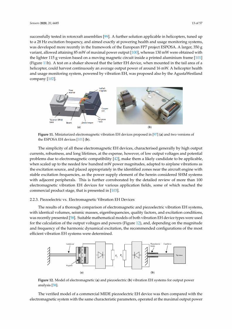
Pioneering work in the development of vibration EH with an effective electromagnetic circuitwas performed by Beeby and co-authors in 2007 [97]. The thus proposed small (0.15 cm3) EH device,operating optimally at 52 Hz, allowed attaining a power output of 46 µW (a specific power output of307 µW/cm3) (Figure 11a). A 50 x 32 x 28 mm electromagnetic power generator, that makes use of analuminium alloy spring with NdFeB magnets, and produces 8 mW (0.18 mW/cm3) of power at 34.5 Hzand a 0.8 g acceleration is, in turn, proposed [98]. This device was also rearranged, based on the rapidprototyping design of the respective plastic frame, for a lower operational frequency of 17 Hz and,weighting only 120 g in a 120 cm3 envelope and generating a maximal power of 30 mW, has been
Sensors 2020, 20, 6685 13 of 57
successfully tested in rotorcraft assemblies [99]. A further solution applicable in helicopters, tuned upto a 28 Hz excitation frequency, and aimed exactly at powering health and usage monitoring systems,was developed more recently in the framework of the European FP7 project ESPOSA. A larger, 350 gvariant, allowed attaining 85 mW of maximal power output [100], whereas 130 mW were obtained withthe lighter 115 g version based on a moving magnetic circuit inside a printed aluminium frame [101](Figure 11b). A test on a shaker showed that the latter EH device, when mounted in the tail area of ahelicopter, could harvest continuously an average output power of around 16 mW. A helicopter healthand usage monitoring system, powered by vibration EH, was proposed also by the AgustaWestlandcompany [102].
Sensors 2020, 20, x FOR PEER REVIEW 13 of 58
rapid prototyping design of the respective plastic frame, for a lower operational frequency of 17 Hz and, weighting only 120 g in a 120 cm3 envelope and generating a maximal power of 30 mW, has been successfully tested in rotorcraft assemblies [99]. A further solution applicable in helicopters, tuned up to a 28 Hz excitation frequency, and aimed exactly at powering health and usage monitoring systems, was developed more recently in the framework of the European FP7 project ESPOSA. A larger, 350 g variant, allowed attaining 85 mW of maximal power output [100], whereas 130 mW were obtained with the lighter 115 g version based on a moving magnetic circuit inside a printed aluminium frame [101] (Figure 11b). A test on a shaker showed that the latter EH device, when mounted in the tail area of a helicopter, could harvest continuously an average output power of around 16 mW. A helicopter health and usage monitoring system, powered by vibration EH, was proposed also by the AgustaWestland company [102].
(a) (b)
Figure 11. Miniaturized electromagnetic vibration EH devices proposed in [97] (a) and two versions of the ESPOSA EH devices [101] (b).
The simplicity of all these electromagnetic EH devices, characterised generally by high output currents, robustness, and long lifetimes, at the expense, however, of low output voltages and potential problems due to electromagnetic compatibility [42], make them a likely candidate to be applicable, when scaled up to the needed few hundred mW power magnitudes, adapted to airplane vibrations as the excitation source, and placed appropriately in the identified zones near the aircraft engine with stable excitation frequencies, as the power supply element of the herein considered SHM systems with adjacent peripherals. This is further corroborated by the detailed review of more than 100 electromagnetic vibration EH devices for various application fields, some of which reached the commercial product stage, that is presented in [103].
2.2.3. Piezoelectric vs. Electromagnetic Vibration EH Devices
The results of a thorough comparison of electromagnetic and piezoelectric vibration EH systems, with identical volumes, seismic masses, eigenfrequencies, quality factors, and excitation conditions, was recently presented [58]. Suitable mathematical models of both vibration EH device types were used for the calculation of the output voltages and powers (Figure 12), and, depending on the magnitude and frequency of the harmonic dynamical excitation, the recommended configurations of the most efficient vibration EH systems were determined.
(a) (b)
Figure 12. Model of electromagnetic (a) and piezoelectric (b) vibration EH systems for output power analysis [58].
Figure 11. Miniaturized electromagnetic vibration EH devices proposed in [97] (a) and two versions ofthe ESPOSA EH devices [101] (b).
The simplicity of all these electromagnetic EH devices, characterised generally by high outputcurrents, robustness, and long lifetimes, at the expense, however, of low output voltages and potentialproblems due to electromagnetic compatibility [42], make them a likely candidate to be applicable,when scaled up to the needed few hundred mW power magnitudes, adapted to airplane vibrations asthe excitation source, and placed appropriately in the identified zones near the aircraft engine withstable excitation frequencies, as the power supply element of the herein considered SHM systemswith adjacent peripherals. This is further corroborated by the detailed review of more than 100electromagnetic vibration EH devices for various application fields, some of which reached thecommercial product stage, that is presented in [103].
2.2.3. Piezoelectric vs. Electromagnetic Vibration EH Devices
The results of a thorough comparison of electromagnetic and piezoelectric vibration EH systems,with identical volumes, seismic masses, eigenfrequencies, quality factors, and excitation conditions,was recently presented [58]. Suitable mathematical models of both vibration EH device types were usedfor the calculation of the output voltages and powers (Figure 12), and, depending on the magnitudeand frequency of the harmonic dynamical excitation, the recommended configurations of the mostefficient vibration EH systems were determined.
Sensors 2020, 20, x FOR PEER REVIEW 13 of 58
rapid prototyping design of the respective plastic frame, for a lower operational frequency of 17 Hz and, weighting only 120 g in a 120 cm3 envelope and generating a maximal power of 30 mW, has been successfully tested in rotorcraft assemblies [99]. A further solution applicable in helicopters, tuned up to a 28 Hz excitation frequency, and aimed exactly at powering health and usage monitoring systems, was developed more recently in the framework of the European FP7 project ESPOSA. A larger, 350 g variant, allowed attaining 85 mW of maximal power output [100], whereas 130 mW were obtained with the lighter 115 g version based on a moving magnetic circuit inside a printed aluminium frame [101] (Figure 11b). A test on a shaker showed that the latter EH device, when mounted in the tail area of a helicopter, could harvest continuously an average output power of around 16 mW. A helicopter health and usage monitoring system, powered by vibration EH, was proposed also by the AgustaWestland company [102].
(a) (b)
Figure 11. Miniaturized electromagnetic vibration EH devices proposed in [97] (a) and two versions of the ESPOSA EH devices [101] (b).
The simplicity of all these electromagnetic EH devices, characterised generally by high output currents, robustness, and long lifetimes, at the expense, however, of low output voltages and potential problems due to electromagnetic compatibility [42], make them a likely candidate to be applicable, when scaled up to the needed few hundred mW power magnitudes, adapted to airplane vibrations as the excitation source, and placed appropriately in the identified zones near the aircraft engine with stable excitation frequencies, as the power supply element of the herein considered SHM systems with adjacent peripherals. This is further corroborated by the detailed review of more than 100 electromagnetic vibration EH devices for various application fields, some of which reached the commercial product stage, that is presented in [103].
2.2.3. Piezoelectric vs. Electromagnetic Vibration EH Devices
The results of a thorough comparison of electromagnetic and piezoelectric vibration EH systems, with identical volumes, seismic masses, eigenfrequencies, quality factors, and excitation conditions, was recently presented [58]. Suitable mathematical models of both vibration EH device types were used for the calculation of the output voltages and powers (Figure 12), and, depending on the magnitude and frequency of the harmonic dynamical excitation, the recommended configurations of the most efficient vibration EH systems were determined.
(a) (b)
Figure 12. Model of electromagnetic (a) and piezoelectric (b) vibration EH systems for output power analysis [58].
Figure 12. Model of electromagnetic (a) and piezoelectric (b) vibration EH systems for output poweranalysis [58].
The verified model of a commercial MIDE piezoelectric EH device was then compared with theelectromagnetic system with the same characteristic parameters, operated at the maximal output power
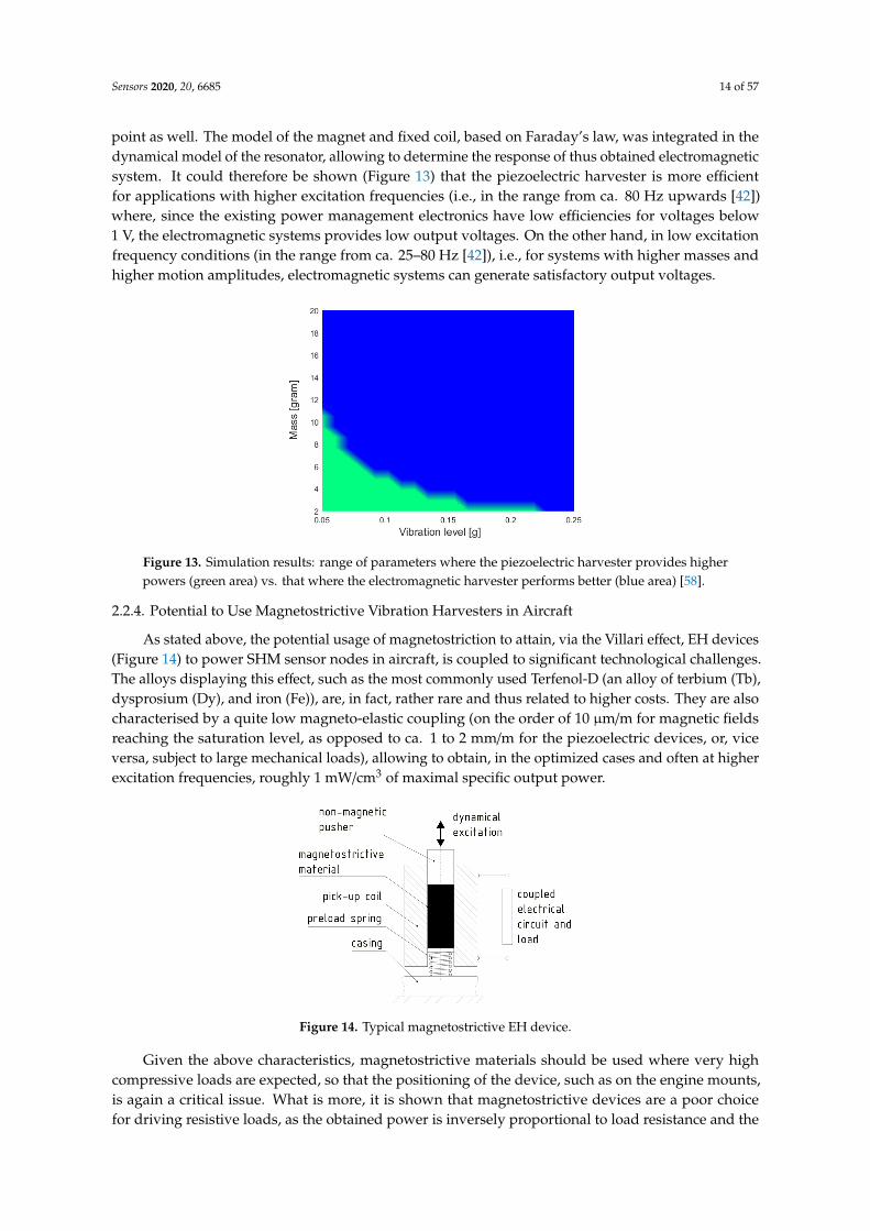
Sensors 2020, 20, 6685 14 of 57
point as well. The model of the magnet and fixed coil, based on Faraday’s law, was integrated in thedynamical model of the resonator, allowing to determine the response of thus obtained electromagneticsystem. It could therefore be shown (Figure 13) that the piezoelectric harvester is more efficientfor applications with higher excitation frequencies (i.e., in the range from ca. 80 Hz upwards [42])where, since the existing power management electronics have low efficiencies for voltages below1 V, the electromagnetic systems provides low output voltages. On the other hand, in low excitationfrequency conditions (in the range from ca. 25–80 Hz [42]), i.e., for systems with higher masses andhigher motion amplitudes, electromagnetic systems can generate satisfactory output voltages.
Sensors 2020, 20, x FOR PEER REVIEW 14 of 58
The verified model of a commercial MIDE piezoelectric EH device was then compared with the electromagnetic system with the same characteristic parameters, operated at the maximal output power point as well. The model of the magnet and fixed coil, based on Faraday’s law, was integrated in the dynamical model of the resonator, allowing to determine the response of thus obtained electromagnetic system. It could therefore be shown (Figure 13) that the piezoelectric harvester is more efficient for applications with higher excitation frequencies (i.e., in the range from ca. 80 Hz upwards [42]) where, since the existing power management electronics have low efficiencies for voltages below 1 V, the electromagnetic systems provides low output voltages. On the other hand, in low excitation frequency conditions (in the range from ca. 25–80 Hz [42]), i.e., for systems with higher masses and higher motion amplitudes, electromagnetic systems can generate satisfactory output voltages.
Figure 13. Simulation results: range of parameters where the piezoelectric harvester provides higher powers (green area) vs. that where the electromagnetic harvester performs better (blue area) [58].
2.2.4. Potential to Use Magnetostrictive Vibration Harvesters in Aircraft
As stated above, the potential usage of magnetostriction to attain, via the Villari effect, EH devices (Figure 14) to power SHM sensor nodes in aircraft, is coupled to significant technological challenges. The alloys displaying this effect, such as the most commonly used Terfenol-D (an alloy of terbium (Tb), dysprosium (Dy), and iron (Fe)), are, in fact, rather rare and thus related to higher costs. They are also characterised by a quite low magneto-elastic coupling (on the order of 10 μm/m for magnetic fields reaching the saturation level, as opposed to ca. 1 to 2 mm/m for the piezoelectric devices, or, vice versa, subject to large mechanical loads), allowing to obtain, in the optimized cases and often at higher excitation frequencies, roughly 1 mW/cm3 of maximal specific output power.
Figure 14. Typical magnetostrictive EH device.
Figure 13. Simulation results: range of parameters where the piezoelectric harvester provides higherpowers (green area) vs. that where the electromagnetic harvester performs better (blue area) [58].
2.2.4. Potential to Use Magnetostrictive Vibration Harvesters in Aircraft
As stated above, the potential usage of magnetostriction to attain, via the Villari effect, EH devices(Figure 14) to power SHM sensor nodes in aircraft, is coupled to significant technological challenges.The alloys displaying this effect, such as the most commonly used Terfenol-D (an alloy of terbium (Tb),dysprosium (Dy), and iron (Fe)), are, in fact, rather rare and thus related to higher costs. They are alsocharacterised by a quite low magneto-elastic coupling (on the order of 10 µm/m for magnetic fieldsreaching the saturation level, as opposed to ca. 1 to 2 mm/m for the piezoelectric devices, or, viceversa, subject to large mechanical loads), allowing to obtain, in the optimized cases and often at higherexcitation frequencies, roughly 1 mW/cm3 of maximal specific output power.
Sensors 2020, 20, x FOR PEER REVIEW 14 of 58
The verified model of a commercial MIDE piezoelectric EH device was then compared with the electromagnetic system with the same characteristic parameters, operated at the maximal output power point as well. The model of the magnet and fixed coil, based on Faraday’s law, was integrated in the dynamical model of the resonator, allowing to determine the response of thus obtained electromagnetic system. It could therefore be shown (Figure 13) that the piezoelectric harvester is more efficient for applications with higher excitation frequencies (i.e., in the range from ca. 80 Hz upwards [42]) where, since the existing power management electronics have low efficiencies for voltages below 1 V, the electromagnetic systems provides low output voltages. On the other hand, in low excitation frequency conditions (in the range from ca. 25–80 Hz [42]), i.e., for systems with higher masses and higher motion amplitudes, electromagnetic systems can generate satisfactory output voltages.
Figure 13. Simulation results: range of parameters where the piezoelectric harvester provides higher powers (green area) vs. that where the electromagnetic harvester performs better (blue area) [58].
2.2.4. Potential to Use Magnetostrictive Vibration Harvesters in Aircraft
As stated above, the potential usage of magnetostriction to attain, via the Villari effect, EH devices (Figure 14) to power SHM sensor nodes in aircraft, is coupled to significant technological challenges. The alloys displaying this effect, such as the most commonly used Terfenol-D (an alloy of terbium (Tb), dysprosium (Dy), and iron (Fe)), are, in fact, rather rare and thus related to higher costs. They are also characterised by a quite low magneto-elastic coupling (on the order of 10 μm/m for magnetic fields reaching the saturation level, as opposed to ca. 1 to 2 mm/m for the piezoelectric devices, or, vice versa, subject to large mechanical loads), allowing to obtain, in the optimized cases and often at higher excitation frequencies, roughly 1 mW/cm3 of maximal specific output power.
Figure 14. Typical magnetostrictive EH device. Figure 14. Typical magnetostrictive EH device.
Given the above characteristics, magnetostrictive materials should be used where very highcompressive loads are expected, so that the positioning of the device, such as on the engine mounts,is again a critical issue. What is more, it is shown that magnetostrictive devices are a poor choicefor driving resistive loads, as the obtained power is inversely proportional to load resistance and the
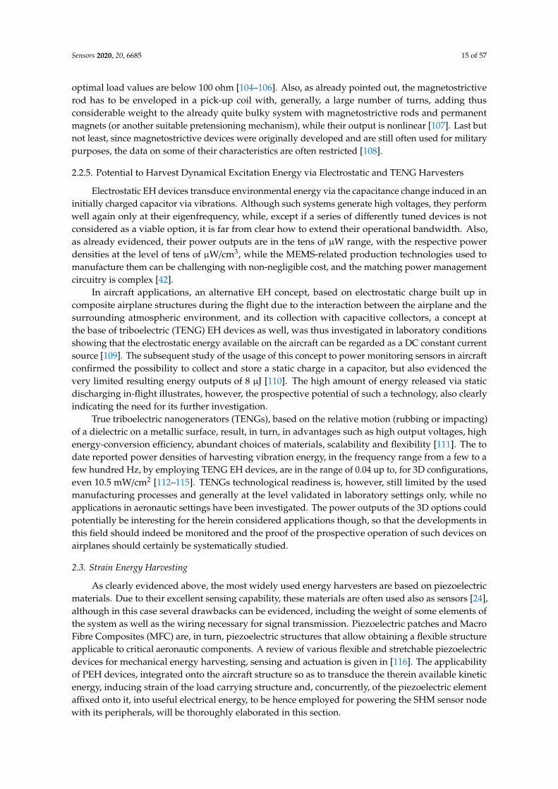
Sensors 2020, 20, 6685 15 of 57
optimal load values are below 100 ohm [104–106]. Also, as already pointed out, the magnetostrictiverod has to be enveloped in a pick-up coil with, generally, a large number of turns, adding thusconsiderable weight to the already quite bulky system with magnetostrictive rods and permanentmagnets (or another suitable pretensioning mechanism), while their output is nonlinear [107]. Last butnot least, since magnetostrictive devices were originally developed and are still often used for militarypurposes, the data on some of their characteristics are often restricted [108].
2.2.5. Potential to Harvest Dynamical Excitation Energy via Electrostatic and TENG Harvesters
Electrostatic EH devices transduce environmental energy via the capacitance change induced in aninitially charged capacitor via vibrations. Although such systems generate high voltages, they performwell again only at their eigenfrequency, while, except if a series of differently tuned devices is notconsidered as a viable option, it is far from clear how to extend their operational bandwidth. Also,as already evidenced, their power outputs are in the tens of µW range, with the respective powerdensities at the level of tens of µW/cm3, while the MEMS-related production technologies used tomanufacture them can be challenging with non-negligible cost, and the matching power managementcircuitry is complex [42].
In aircraft applications, an alternative EH concept, based on electrostatic charge built up incomposite airplane structures during the flight due to the interaction between the airplane and thesurrounding atmospheric environment, and its collection with capacitive collectors, a concept atthe base of triboelectric (TENG) EH devices as well, was thus investigated in laboratory conditionsshowing that the electrostatic energy available on the aircraft can be regarded as a DC constant currentsource [109]. The subsequent study of the usage of this concept to power monitoring sensors in aircraftconfirmed the possibility to collect and store a static charge in a capacitor, but also evidenced thevery limited resulting energy outputs of 8 µJ [110]. The high amount of energy released via staticdischarging in-flight illustrates, however, the prospective potential of such a technology, also clearlyindicating the need for its further investigation.
True triboelectric nanogenerators (TENGs), based on the relative motion (rubbing or impacting)of a dielectric on a metallic surface, result, in turn, in advantages such as high output voltages, highenergy-conversion efficiency, abundant choices of materials, scalability and flexibility [111]. The todate reported power densities of harvesting vibration energy, in the frequency range from a few to afew hundred Hz, by employing TENG EH devices, are in the range of 0.04 up to, for 3D configurations,even 10.5 mW/cm2 [112–115]. TENGs technological readiness is, however, still limited by the usedmanufacturing processes and generally at the level validated in laboratory settings only, while noapplications in aeronautic settings have been investigated. The power outputs of the 3D options couldpotentially be interesting for the herein considered applications though, so that the developments inthis field should indeed be monitored and the proof of the prospective operation of such devices onairplanes should certainly be systematically studied.
2.3. Strain Energy Harvesting
As clearly evidenced above, the most widely used energy harvesters are based on piezoelectricmaterials. Due to their excellent sensing capability, these materials are often used also as sensors [24],although in this case several drawbacks can be evidenced, including the weight of some elements ofthe system as well as the wiring necessary for signal transmission. Piezoelectric patches and MacroFibre Composites (MFC) are, in turn, piezoelectric structures that allow obtaining a flexible structureapplicable to critical aeronautic components. A review of various flexible and stretchable piezoelectricdevices for mechanical energy harvesting, sensing and actuation is given in [116]. The applicabilityof PEH devices, integrated onto the aircraft structure so as to transduce the therein available kineticenergy, inducing strain of the load carrying structure and, concurrently, of the piezoelectric elementaffixed onto it, into useful electrical energy, to be hence employed for powering the SHM sensor nodewith its peripherals, will be thoroughly elaborated in this section.
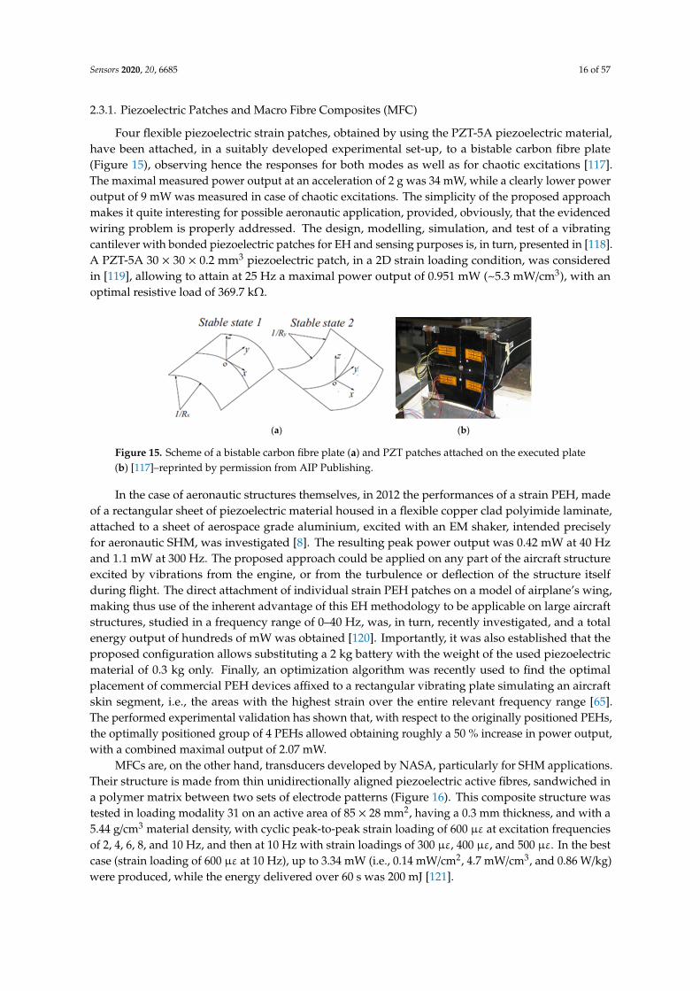
Sensors 2020, 20, 6685 16 of 57
2.3.1. Piezoelectric Patches and Macro Fibre Composites (MFC)
Four flexible piezoelectric strain patches, obtained by using the PZT-5A piezoelectric material,have been attached, in a suitably developed experimental set-up, to a bistable carbon fibre plate(Figure 15), observing hence the responses for both modes as well as for chaotic excitations [117].The maximal measured power output at an acceleration of 2 g was 34 mW, while a clearly lower poweroutput of 9 mW was measured in case of chaotic excitations. The simplicity of the proposed approachmakes it quite interesting for possible aeronautic application, provided, obviously, that the evidencedwiring problem is properly addressed. The design, modelling, simulation, and test of a vibratingcantilever with bonded piezoelectric patches for EH and sensing purposes is, in turn, presented in [118].A PZT-5A 30 × 30 × 0.2 mm3 piezoelectric patch, in a 2D strain loading condition, was consideredin [119], allowing to attain at 25 Hz a maximal power output of 0.951 mW (~5.3 mW/cm3), with anoptimal resistive load of 369.7 kΩ.
Sensors 2020, 20, x FOR PEER REVIEW 16 of 58
piezoelectric element affixed onto it, into useful electrical energy, to be hence employed for powering the SHM sensor node with its peripherals, will be thoroughly elaborated in this section.
2.3.1. Piezoelectric Patches and Macro Fibre Composites (MFC)
Four flexible piezoelectric strain patches, obtained by using the PZT-5A piezoelectric material, have been attached, in a suitably developed experimental set-up, to a bistable carbon fibre plate (Figure 15), observing hence the responses for both modes as well as for chaotic excitations [117]. The maximal measured power output at an acceleration of 2 g was 34 mW, while a clearly lower power output of 9 mW was measured in case of chaotic excitations. The simplicity of the proposed approach makes it quite interesting for possible aeronautic application, provided, obviously, that the evidenced wiring problem is properly addressed. The design, modelling, simulation, and test of a vibrating cantilever with bonded piezoelectric patches for EH and sensing purposes is, in turn, presented in [118]. A PZT-5A 30 × 30 × 0.2 mm3 piezoelectric patch, in a 2D strain loading condition, was considered in [119], allowing to attain at 25 Hz a maximal power output of 0.951 mW (~5.3 mW/cm3), with an optimal resistive load of 369.7 kΩ.
(a) (b)
Figure 15. Scheme of a bistable carbon fibre plate (a) and PZT patches attached on the executed plate (b) [117]–reprinted by permission from AIP Publishing.
In the case of aeronautic structures themselves, in 2012 the performances of a strain PEH, made of a rectangular sheet of piezoelectric material housed in a flexible copper clad polyimide laminate, attached to a sheet of aerospace grade aluminium, excited with an EM shaker, intended precisely for aeronautic SHM, was investigated [8]. The resulting peak power output was 0.42 mW at 40 Hz and 1.1 mW at 300 Hz. The proposed approach could be applied on any part of the aircraft structure excited by vibrations from the engine, or from the turbulence or deflection of the structure itself during flight. The direct attachment of individual strain PEH patches on a model of airplane’s wing, making thus use of the inherent advantage of this EH methodology to be applicable on large aircraft structures, studied in a frequency range of 0–40 Hz, was, in turn, recently investigated, and a total energy output of hundreds of mW was obtained [120]. Importantly, it was also established that the proposed configuration allows substituting a 2 kg battery with the weight of the used piezoelectric material of 0.3 kg only. Finally, an optimization algorithm was recently used to find the optimal placement of commercial PEH devices affixed to a rectangular vibrating plate simulating an aircraft skin segment, i.e., the areas with the highest strain over the entire relevant frequency range [65]. The performed experimental validation has shown that, with respect to the originally positioned PEHs, the optimally positioned group of 4 PEHs allowed obtaining roughly a 50 % increase in power output, with a combined maximal output of 2.07 mW.
MFCs are, on the other hand, transducers developed by NASA, particularly for SHM applications. Their structure is made from thin unidirectionally aligned piezoelectric active fibres, sandwiched in a polymer matrix between two sets of electrode patterns (Figure 16). This composite structure was tested in loading modality 31 on an active area of 85 × 28 mm2, having a 0.3 mm thickness, and with a 5.44 g/cm3 material density, with cyclic peak-to-peak strain loading of 600 με at excitation frequencies of 2, 4, 6, 8, and 10 Hz, and then at 10 Hz with strain loadings of 300 με, 400
Figure 15. Scheme of a bistable carbon fibre plate (a) and PZT patches attached on the executed plate(b) [117]–reprinted by permission from AIP Publishing.
In the case of aeronautic structures themselves, in 2012 the performances of a strain PEH, madeof a rectangular sheet of piezoelectric material housed in a flexible copper clad polyimide laminate,attached to a sheet of aerospace grade aluminium, excited with an EM shaker, intended preciselyfor aeronautic SHM, was investigated [8]. The resulting peak power output was 0.42 mW at 40 Hzand 1.1 mW at 300 Hz. The proposed approach could be applied on any part of the aircraft structureexcited by vibrations from the engine, or from the turbulence or deflection of the structure itselfduring flight. The direct attachment of individual strain PEH patches on a model of airplane’s wing,making thus use of the inherent advantage of this EH methodology to be applicable on large aircraftstructures, studied in a frequency range of 0–40 Hz, was, in turn, recently investigated, and a totalenergy output of hundreds of mW was obtained [120]. Importantly, it was also established that theproposed configuration allows substituting a 2 kg battery with the weight of the used piezoelectricmaterial of 0.3 kg only. Finally, an optimization algorithm was recently used to find the optimalplacement of commercial PEH devices affixed to a rectangular vibrating plate simulating an aircraftskin segment, i.e., the areas with the highest strain over the entire relevant frequency range [65].The performed experimental validation has shown that, with respect to the originally positioned PEHs,the optimally positioned group of 4 PEHs allowed obtaining roughly a 50 % increase in power output,with a combined maximal output of 2.07 mW.
MFCs are, on the other hand, transducers developed by NASA, particularly for SHM applications.Their structure is made from thin unidirectionally aligned piezoelectric active fibres, sandwiched ina polymer matrix between two sets of electrode patterns (Figure 16). This composite structure wastested in loading modality 31 on an active area of 85 × 28 mm2, having a 0.3 mm thickness, and with a5.44 g/cm3 material density, with cyclic peak-to-peak strain loading of 600 µε at excitation frequenciesof 2, 4, 6, 8, and 10 Hz, and then at 10 Hz with strain loadings of 300 µε, 400 µε, and 500 µε. In the bestcase (strain loading of 600 µε at 10 Hz), up to 3.34 mW (i.e., 0.14 mW/cm2, 4.7 mW/cm3, and 0.86 W/kg)were produced, while the energy delivered over 60 s was 200 mJ [121].
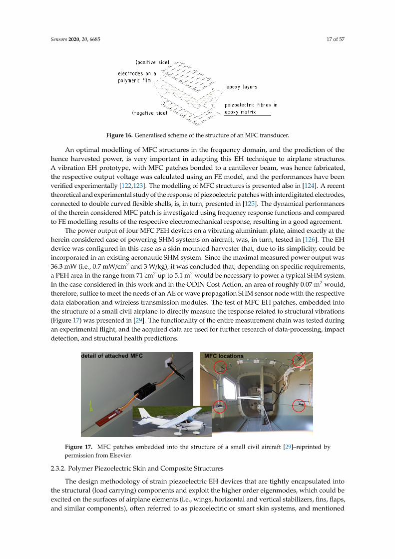
Sensors 2020, 20, 6685 17 of 57
Sensors 2020, 20, x FOR PEER REVIEW 17 of 58
με, and 500 με. In the best case (strain loading of 600 με at 10 Hz), up to 3.34 mW (i.e., 0.14 mW/cm2, 4.7 mW/cm3, and 0.86 W/kg) were produced, while the energy delivered over 60 s was 200 mJ [121].
An optimal modelling of MFC structures in the frequency domain, and the prediction of the hence harvested power, is very important in adapting this EH technique to airplane structures. A vibration EH prototype, with MFC patches bonded to a cantilever beam, was hence fabricated, the respective output voltage was calculated using an FE model, and the performances have been verified experimentally [122,123]. The modelling of MFC structures is presented also in [124]. A recent theoretical and experimental study of the response of piezoelectric patches with interdigitated electrodes, connected to double curved flexible shells, is, in turn, presented in [125]. The dynamical performances of the therein considered MFC patch is investigated using frequency response functions and compared to FE modelling results of the respective electromechanical response, resulting in a good agreement.
Figure 16. Generalised scheme of the structure of an MFC transducer.
The power output of four MFC PEH devices on a vibrating aluminium plate, aimed exactly at the herein considered case of powering SHM systems on aircraft, was, in turn, tested in [126]. The EH device was configured in this case as a skin mounted harvester that, due to its simplicity, could be incorporated in an existing aeronautic SHM system. Since the maximal measured power output was 36.3 mW (i.e., 0.7 mW/cm2 and 3 W/kg), it was concluded that, depending on specific requirements, a PEH area in the range from 71 cm2 up to 5.1 m2 would be necessary to power a typical SHM system. In the case considered in this work and in the ODIN Cost Action, an area of roughly 0.07 m2 would, therefore, suffice to meet the needs of an AE or wave propagation SHM sensor node with the respective data elaboration and wireless transmission modules. The test of MFC EH patches, embedded into the structure of a small civil airplane to directly measure the response related to structural vibrations (Figure 17) was presented in [29]. The functionality of the entire measurement chain was tested during an experimental flight, and the acquired data are used for further research of data-processing, impact detection, and structural health predictions.
Figure 17. MFC patches embedded into the structure of a small civil aircraft [29]–reprinted by permission from Elsevier.
Figure 16. Generalised scheme of the structure of an MFC transducer.
An optimal modelling of MFC structures in the frequency domain, and the prediction of thehence harvested power, is very important in adapting this EH technique to airplane structures.A vibration EH prototype, with MFC patches bonded to a cantilever beam, was hence fabricated,the respective output voltage was calculated using an FE model, and the performances have beenverified experimentally [122,123]. The modelling of MFC structures is presented also in [124]. A recenttheoretical and experimental study of the response of piezoelectric patches with interdigitated electrodes,connected to double curved flexible shells, is, in turn, presented in [125]. The dynamical performancesof the therein considered MFC patch is investigated using frequency response functions and comparedto FE modelling results of the respective electromechanical response, resulting in a good agreement.
The power output of four MFC PEH devices on a vibrating aluminium plate, aimed exactly at theherein considered case of powering SHM systems on aircraft, was, in turn, tested in [126]. The EHdevice was configured in this case as a skin mounted harvester that, due to its simplicity, could beincorporated in an existing aeronautic SHM system. Since the maximal measured power output was36.3 mW (i.e., 0.7 mW/cm2 and 3 W/kg), it was concluded that, depending on specific requirements,a PEH area in the range from 71 cm2 up to 5.1 m2 would be necessary to power a typical SHM system.In the case considered in this work and in the ODIN Cost Action, an area of roughly 0.07 m2 would,therefore, suffice to meet the needs of an AE or wave propagation SHM sensor node with the respectivedata elaboration and wireless transmission modules. The test of MFC EH patches, embedded intothe structure of a small civil airplane to directly measure the response related to structural vibrations(Figure 17) was presented in [29]. The functionality of the entire measurement chain was tested duringan experimental flight, and the acquired data are used for further research of data-processing, impactdetection, and structural health predictions.
Sensors 2020, 20, x FOR PEER REVIEW 17 of 58
με, and 500 με. In the best case (strain loading of 600 με at 10 Hz), up to 3.34 mW (i.e., 0.14 mW/cm2, 4.7 mW/cm3, and 0.86 W/kg) were produced, while the energy delivered over 60 s was 200 mJ [121].
An optimal modelling of MFC structures in the frequency domain, and the prediction of the hence harvested power, is very important in adapting this EH technique to airplane structures. A vibration EH prototype, with MFC patches bonded to a cantilever beam, was hence fabricated, the respective output voltage was calculated using an FE model, and the performances have been verified experimentally [122,123]. The modelling of MFC structures is presented also in [124]. A recent theoretical and experimental study of the response of piezoelectric patches with interdigitated electrodes, connected to double curved flexible shells, is, in turn, presented in [125]. The dynamical performances of the therein considered MFC patch is investigated using frequency response functions and compared to FE modelling results of the respective electromechanical response, resulting in a good agreement.
Figure 16. Generalised scheme of the structure of an MFC transducer.
The power output of four MFC PEH devices on a vibrating aluminium plate, aimed exactly at the herein considered case of powering SHM systems on aircraft, was, in turn, tested in [126]. The EH device was configured in this case as a skin mounted harvester that, due to its simplicity, could be incorporated in an existing aeronautic SHM system. Since the maximal measured power output was 36.3 mW (i.e., 0.7 mW/cm2 and 3 W/kg), it was concluded that, depending on specific requirements, a PEH area in the range from 71 cm2 up to 5.1 m2 would be necessary to power a typical SHM system. In the case considered in this work and in the ODIN Cost Action, an area of roughly 0.07 m2 would, therefore, suffice to meet the needs of an AE or wave propagation SHM sensor node with the respective data elaboration and wireless transmission modules. The test of MFC EH patches, embedded into the structure of a small civil airplane to directly measure the response related to structural vibrations (Figure 17) was presented in [29]. The functionality of the entire measurement chain was tested during an experimental flight, and the acquired data are used for further research of data-processing, impact detection, and structural health predictions.
Figure 17. MFC patches embedded into the structure of a small civil aircraft [29]–reprinted by permission from Elsevier.
Figure 17. MFC patches embedded into the structure of a small civil aircraft [29]–reprinted bypermission from Elsevier.
2.3.2. Polymer Piezoelectric Skin and Composite Structures
The design methodology of strain piezoelectric EH devices that are tightly encapsulated intothe structural (load carrying) components and exploit the higher order eigenmodes, which could beexcited on the surfaces of airplane elements (i.e., wings, horizontal and vertical stabilizers, fins, flaps,and similar components), often referred to as piezoelectric or smart skin systems, and mentioned

Sensors 2020, 20, 6685 18 of 57
already in the Introduction of this work as means of achieving SHM [30,31], is described in [127]. Thesesystems could, hence, act synergistically and concurrently as both SHM sensors and EH sources usedto power them [53,54].
In order to further reduce the weight and size of PEH skin systems in airplanes, thus minimizingtheir influence on the aerodynamics [30], piezoelectric polymers and porous polymer systems [128]are increasingly considered as a very promising approach to the herein foreseen purposes. From theEH perspective, among these materials, those showing the most promising electromechanicalcoupling performances when subjected to dynamical excitations, are thin polymer sheets basedon poly(vinylidene fluoride) (PVDF) [129] and polypropylene (PP) [130]. These sheets can be obtainedby large-scale fabrication techniques, such as extrusion or blown sheet extrusion, allowing ratherthick (ca. 100 mm) structures, advantageous from the practical point of view, to be obtained. Despitehaving more favourable characteristics than other piezoelectric polymers and allowing to attainhigh output voltages [92], pure PVDF is also characterized by low electromechanical coupling [131].To improve the overall efficiency of the PVDF PEH systems in direct applications as part of airplanewings, composite structures comprising an active filler, with an overall density below 2.5 g/cm3,could, thus, be a promising approach. AlO-rGO systems could be used in this framework since,due to their strong dielectric characteristics, they provide additional dipoles, potentially, hence,doubling piezoelectric coupling [132]. There are indications that the modification of graphene oxide inPVDF formation, by using poly(methyl methacrylate) (PMMA) atom transfer radical polymerization,could also significantly improve the energy harvesting capabilities, although generating a relativelyhigh-weight structure [133]. In other recent studies, alternative possibilities to enhance the harvestingefficiency of PVDF-based PEHs, based on advances in the nanotechnologies, are thus investigated.Using electrospinning to obtain PVDF nanofibers, modified with PMMA and single-walled carbonnanotubes (SW CNT), permit thus attaining a high porosity (lightweight) structure allowing, at anexcitation frequency of 50 Hz, an electrical output of 3.11 V (four times larger than that of an equivalentstructure in PVDF alone) [134]. On the other hand, a promising concept could also be the employmentof a PVDF composite foam obtained via a physical foaming agent and using a multiwalled (MW) CNTpiezo-active crystalline phase, resulting, for a 1.5 wt. % of MW CNTs, in output voltages of 6.5 V(ca. 6 times higher than that of an equivalent structure in PVDF alone) [135]. The possibility to usepolyethylene (PE) PEH films to convert strain energy, induced by gusts (air turbulence) vibrations ofaircraft wings, into electricity was, in turn, investigated in [88], showing that specific power outputs ofthe order of 1 mW/m2 can be obtained.
A strain wireless sensor node, powered by using MFC EH patches attached onto a carbon fibrecomposite material that emulates a section of the aircraft skin, and aimed at SHM, was alternativelyproposed in [136]. An EH application for aircraft composite structures, using MFC principles,was studied also in [137], where the developed co-curing, used to integrate the EH elements into thecarbon-fibre composite airframe structures, offered, if compared to those obtained by direct bondingmethods, harvested powers higher by up to 23%, with maximal attained power values, for lowfrequency excitations (1-100 Hz), between 0.16 and 42.1 mW. An overview of the key elements ofvarious manufacturing techniques, of the respective work-flow steps, as well as of the factors impactingthe performances of the final products, all used to obtain smart composite structures with embeddedpiezoelectric transducers was recently provided in [138].
2.4. Summary of Findings on Kinetic Energy Harvesting
Based on the above lengthy analysis of kinetic EH devices, it is clear that vibration energyharvesters could very well be used as part of the airplane engines’ enclosures and respective mountingfixtures, be tuned to the respective operational frequencies for maximum efficiency, and result in ratherhigh specific output powers, thus efficiently powering the herein considered SHM systems with theadjacent peripherals. The performed analysis, as well as the already mentioned SAE internationalARP6461 Guidelines [40], allow also evidencing that, due to their power density, simplicity and
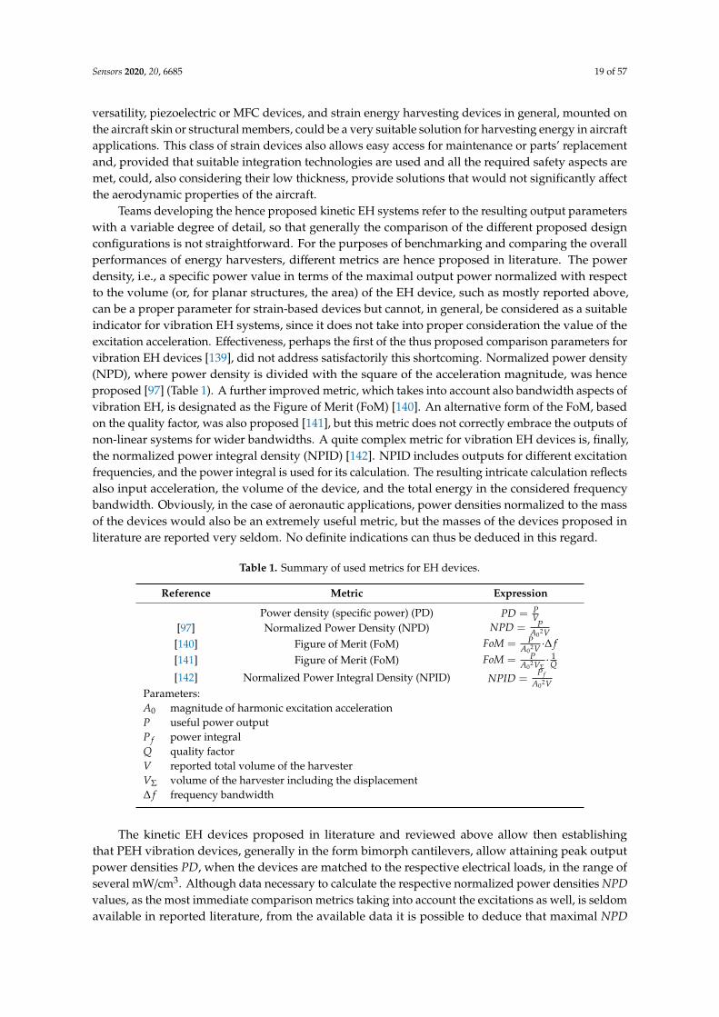
Sensors 2020, 20, 6685 19 of 57
versatility, piezoelectric or MFC devices, and strain energy harvesting devices in general, mounted onthe aircraft skin or structural members, could be a very suitable solution for harvesting energy in aircraftapplications. This class of strain devices also allows easy access for maintenance or parts’ replacementand, provided that suitable integration technologies are used and all the required safety aspects aremet, could, also considering their low thickness, provide solutions that would not significantly affectthe aerodynamic properties of the aircraft.
Teams developing the hence proposed kinetic EH systems refer to the resulting output parameterswith a variable degree of detail, so that generally the comparison of the different proposed designconfigurations is not straightforward. For the purposes of benchmarking and comparing the overallperformances of energy harvesters, different metrics are hence proposed in literature. The powerdensity, i.e., a specific power value in terms of the maximal output power normalized with respectto the volume (or, for planar structures, the area) of the EH device, such as mostly reported above,can be a proper parameter for strain-based devices but cannot, in general, be considered as a suitableindicator for vibration EH systems, since it does not take into proper consideration the value of theexcitation acceleration. Effectiveness, perhaps the first of the thus proposed comparison parameters forvibration EH devices [139], did not address satisfactorily this shortcoming. Normalized power density(NPD), where power density is divided with the square of the acceleration magnitude, was henceproposed [97] (Table 1). A further improved metric, which takes into account also bandwidth aspects ofvibration EH, is designated as the Figure of Merit (FoM) [140]. An alternative form of the FoM, basedon the quality factor, was also proposed [141], but this metric does not correctly embrace the outputs ofnon-linear systems for wider bandwidths. A quite complex metric for vibration EH devices is, finally,the normalized power integral density (NPID) [142]. NPID includes outputs for different excitationfrequencies, and the power integral is used for its calculation. The resulting intricate calculation reflectsalso input acceleration, the volume of the device, and the total energy in the considered frequencybandwidth. Obviously, in the case of aeronautic applications, power densities normalized to the massof the devices would also be an extremely useful metric, but the masses of the devices proposed inliterature are reported very seldom. No definite indications can thus be deduced in this regard.
Table 1. Summary of used metrics for EH devices.
Reference Metric Expression
Power density (specific power) (PD) PD = PV
[97] Normalized Power Density (NPD) NPD = PA0
2V[140] Figure of Merit (FoM) FoM = P
A02V ·∆ f
[141] Figure of Merit (FoM) FoM = PA0
2VΣ·
1Q
[142] Normalized Power Integral Density (NPID) NPID =P f
A02V
Parameters:A0 magnitude of harmonic excitation accelerationP useful power outputP f power integralQ quality factorV reported total volume of the harvesterVΣ volume of the harvester including the displacement∆ f frequency bandwidth
The kinetic EH devices proposed in literature and reviewed above allow then establishingthat PEH vibration devices, generally in the form bimorph cantilevers, allow attaining peak outputpower densities PD, when the devices are matched to the respective electrical loads, in the range ofseveral mW/cm3. Although data necessary to calculate the respective normalized power densities NPDvalues, as the most immediate comparison metrics taking into account the excitations as well, is seldomavailable in reported literature, from the available data it is possible to deduce that maximal NPD

Sensors 2020, 20, 6685 20 of 57
of roughly 0.07 mW/(cm3·m·s−2) can be obtained with this class of devices. The respective maximal
specific power levels normalised to the mass of the device could, very roughly, be estimated to be inthe 0.3 mW/g range. The advantage of PEHs is the already broad spectrum of proposed solutionsallowing to extend the frequency bandwidth of operation, although some of them via quite complexconfigurations. Configurations with larger bandwidths would, in turn, allow to use the PEHs not onlyin the vicinity of the airplane engine, but also in other dynamically excited components such as thewings, the horizontal and vertical stabilizers, the fins, the flaps, and similar components. PEHs arealso characterized by high output voltages, robustness, compactness, light weight, and suitability forhigher excitation frequencies.
In the case of electromagnetic resonators, peak PD values of several hundred µW/cm3 can beachieved, implying that rather big respective device volumes (and resulting masses) are needed for theSHM airplane applications considered in this work. This class of EH devices allows, in turn, to attainmaximal NPD values by an order of magnitude higher than that of PEHs, making them the preferredchoice for applications where low frequency and high amplitude vibrations at higher excitation levelsare expected, while the space constrains are not so stringent. What is more, they are characterised bysimplicity, high output currents, robustness, and long lifetimes, at the expense, however, of low outputvoltages and potential problems due to electromagnetic compatibility.
Magnetostrictive devices, although also allowing peak PD values in the mW/cm3 range,are characterised by maximal NPDs by an order of magnitude lower than that of the PEH devices,as well as by the evidenced significant technological challenges. The technological issues are limitingthe applicability of electrostatic and TENG EH devices as well, while they allow attaining PDs of,respectively, tens of µW/cm3 (with the corresponding NPD of roughly a µW/(cm3
·m·s−2)) and from0.04 up to, for 3D TENG configurations, 10 mW/cm2. What is more, the internal impedance of TENGsis very high, which is generally hard to match with most of the commercially available electronicscharacterised by low impedance.
In the case of all the considered kinetic EH principles based on dynamic excitations, fatiguelifetime considerations have to be also carefully considered so as to achieve a reasonable mean timebetween failures (MTBF).
The strain EH devices, piezoelectric patches and MFC solutions are shown to be potentiallyattractive since they could be placed on large areas of composite aircraft structures themselves, such asthe airplane wings or the mentioned other dynamically excited structural airplane components,but also because they could be concurrently used both as EH solutions and as SHM sensing elements.These devices allow obtaining again maximal PD values of several mW/cm3, whereas polymerpiezoelectric skin solutions enable attaining maximal PDs of the order of only 0.1 µW/cm2.
3. Thermoelectric Energy Harvesting Systems
As already evidenced in the Introduction of this work, next to mechanical (kinetic) energy,reviewed at length in chapter 2, thermal gradients are also a very abundant energy source and thusoften considered as a viable and valued possibility to develop EH systems in airplanes. Althoughthermoelectric energy generation based on radioisotope thermoelectric generators (RTGs) is wellknown in aerospace applications on spacecraft for decades, thermoelectric energy harvesting on aircraftrelies generally on exploiting precisely the spatial and/or temporal thermal gradients. In order toconvert thermal into electrical energy, thermoelectric generators (TEGs), that exploit the availabletemperature differences between two surfaces, are hence frequently considered in the herein studiedframework. Test flights have proven the potential of TEGs in providing viable power outputs coupledto long-term stability, but further research work is needed to achieve higher TRLs for their factualintegration in aircraft. In the following the respective state-of-the-art is thus thoroughly reviewed.
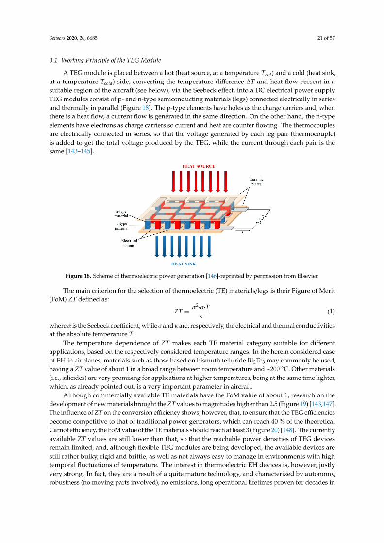
Sensors 2020, 20, 6685 21 of 57
3.1. Working Principle of the TEG Module
A TEG module is placed between a hot (heat source, at a temperature Thot) and a cold (heat sink,at a temperature Tcold) side, converting the temperature difference ∆T and heat flow present in asuitable region of the aircraft (see below), via the Seebeck effect, into a DC electrical power supply.TEG modules consist of p- and n-type semiconducting materials (legs) connected electrically in seriesand thermally in parallel (Figure 18). The p-type elements have holes as the charge carriers and, whenthere is a heat flow, a current flow is generated in the same direction. On the other hand, the n-typeelements have electrons as charge carriers so current and heat are counter flowing. The thermocouplesare electrically connected in series, so that the voltage generated by each leg pair (thermocouple)is added to get the total voltage produced by the TEG, while the current through each pair is thesame [143–145].
Sensors 2020, 20, x FOR PEER REVIEW 21 of 58
to long-term stability, but further research work is needed to achieve higher TRLs for their factual integration in aircraft. In the following the respective state-of-the-art is thus thoroughly reviewed.
3.1. Working Principle of the TEG Module
A TEG module is placed between a hot (heat source, at a temperature 𝑇 ) and a cold (heat sink, at a temperature 𝑇 ) side, converting the temperature difference Δ𝑇 and heat flow present in a suitable region of the aircraft (see below), via the Seebeck effect, into a DC electrical power supply. TEG modules consist of p- and n-type semiconducting materials (legs) connected electrically in series and thermally in parallel (Figure 18). The p-type elements have holes as the charge carriers and, when there is a heat flow, a current flow is generated in the same direction. On the other hand, the n-type elements have electrons as charge carriers so current and heat are counter flowing. The thermocouples are electrically connected in series, so that the voltage generated by each leg pair (thermocouple) is added to get the total voltage produced by the TEG, while the current through each pair is the same [143–145].
Figure 18. Scheme of thermoelectric power generation [146]-reprinted by permission from Elsevier.
The main criterion for the selection of thermoelectric (TE) materials/legs is their Figure of Merit (FoM) ZT defined as: 𝑍𝑇 = 𝛼 ∙ ∙ 𝑇
(1)
where α is the Seebeck coefficient, while σ and κ are, respectively, the electrical and thermal conductivities at the absolute temperature T.
The temperature dependence of ZT makes each TE material category suitable for different applications, based on the respectively considered temperature ranges. In the herein considered case of EH in airplanes, materials such as those based on bismuth telluride Bi2Te3 may commonly be used, having a ZT value of about 1 in a broad range between room temperature and ~200 °C. Other materials (i.e., silicides) are very promising for applications at higher temperatures, being at the same time lighter, which, as already pointed out, is a very important parameter in aircraft.
Although commercially available TE materials have the FoM value of about 1, research on the development of new materials brought the ZT values to magnitudes higher than 2.5 (Figure 19) [143,147]. The influence of ZT on the conversion efficiency shows, however, that, to ensure that the TEG efficiencies become competitive to that of traditional power generators, which can reach 40 % of the theoretical Carnot efficiency, the FoM value of the TE materials should reach at least 3 (Figure 20) [148]. The currently available ZT values are still lower than that, so that the reachable power densities of TEG devices remain limited, and, although flexible TEG modules are being developed, the
Figure 18. Scheme of thermoelectric power generation [146]-reprinted by permission from Elsevier.
The main criterion for the selection of thermoelectric (TE) materials/legs is their Figure of Merit(FoM) ZT defined as:
ZT =α2·σ·Tκ
(1)
whereα is the Seebeck coefficient, whileσ andκ are, respectively, the electrical and thermal conductivitiesat the absolute temperature T.
The temperature dependence of ZT makes each TE material category suitable for differentapplications, based on the respectively considered temperature ranges. In the herein considered caseof EH in airplanes, materials such as those based on bismuth telluride Bi2Te3 may commonly be used,having a ZT value of about 1 in a broad range between room temperature and ~200 C. Other materials(i.e., silicides) are very promising for applications at higher temperatures, being at the same time lighter,which, as already pointed out, is a very important parameter in aircraft.
Although commercially available TE materials have the FoM value of about 1, research on thedevelopment of new materials brought the ZT values to magnitudes higher than 2.5 (Figure 19) [143,147].The influence of ZT on the conversion efficiency shows, however, that, to ensure that the TEG efficienciesbecome competitive to that of traditional power generators, which can reach 40 % of the theoreticalCarnot efficiency, the FoM value of the TE materials should reach at least 3 (Figure 20) [148]. The currentlyavailable ZT values are still lower than that, so that the reachable power densities of TEG devicesremain limited, and, although flexible TEG modules are being developed, the available devices arestill rather bulky, rigid and brittle, as well as not always easy to manage in environments with hightemporal fluctuations of temperature. The interest in thermoelectric EH devices is, however, justlyvery strong. In fact, they are a result of a quite mature technology, and characterized by autonomy,robustness (no moving parts involved), no emissions, long operational lifetimes proven for decades in
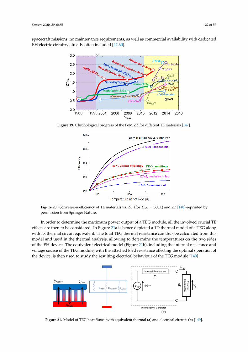
Sensors 2020, 20, 6685 22 of 57
spacecraft missions, no maintenance requirements, as well as commercial availability with dedicatedEH electric circuitry already often included [42,60].
Sensors 2020, 20, x FOR PEER REVIEW 22 of 58
available devices are still rather bulky, rigid and brittle, as well as not always easy to manage in environments with high temporal fluctuations of temperature. The interest in thermoelectric EH devices is, however, justly very strong. In fact, they are a result of a quite mature technology, and characterized by autonomy, robustness (no moving parts involved), no emissions, long operational lifetimes proven for decades in spacecraft missions, no maintenance requirements, as well as commercial availability with dedicated EH electric circuitry already often included [42,60].
Figure 19. Chronological progress of the FoM ZT for different TE materials [147].
Figure 20. Conversion efficiency of TE materials vs. Δ𝑇 (for 𝑇 = 300𝐾) and ZT [148]-reprinted by permission from Springer Nature.
In order to determine the maximum power output of a TEG module, all the involved crucial TE effects are then to be considered. In Figure 21a is hence depicted a 1D thermal model of a TEG along with its thermal circuit equivalent. The total TEG thermal resistance can thus be calculated from this model and used in the thermal analysis, allowing to determine the temperatures on the two sides of the EH device. The equivalent electrical model (Figure 21b), including the internal resistance and voltage source of the TEG module, with the attached load resistance affecting the optimal operation of the device, is then used to study the resulting electrical behaviour of the TEG module [149].
The electrical power output is calculated as the product of the current 𝐼 through the load resistance 𝑅 and the respective voltage 𝑉 :
Figure 19. Chronological progress of the FoM ZT for different TE materials [147].
Sensors 2020, 20, x FOR PEER REVIEW 22 of 58
available devices are still rather bulky, rigid and brittle, as well as not always easy to manage in environments with high temporal fluctuations of temperature. The interest in thermoelectric EH devices is, however, justly very strong. In fact, they are a result of a quite mature technology, and characterized by autonomy, robustness (no moving parts involved), no emissions, long operational lifetimes proven for decades in spacecraft missions, no maintenance requirements, as well as commercial availability with dedicated EH electric circuitry already often included [42,60].
Figure 19. Chronological progress of the FoM ZT for different TE materials [147].
Figure 20. Conversion efficiency of TE materials vs. Δ𝑇 (for 𝑇 = 300𝐾) and ZT [148]-reprinted by permission from Springer Nature.
In order to determine the maximum power output of a TEG module, all the involved crucial TE effects are then to be considered. In Figure 21a is hence depicted a 1D thermal model of a TEG along with its thermal circuit equivalent. The total TEG thermal resistance can thus be calculated from this model and used in the thermal analysis, allowing to determine the temperatures on the two sides of the EH device. The equivalent electrical model (Figure 21b), including the internal resistance and voltage source of the TEG module, with the attached load resistance affecting the optimal operation of the device, is then used to study the resulting electrical behaviour of the TEG module [149].
The electrical power output is calculated as the product of the current 𝐼 through the load resistance 𝑅 and the respective voltage 𝑉 :
Figure 20. Conversion efficiency of TE materials vs. ∆T (for Tcold = 300K) and ZT [148]-reprinted bypermission from Springer Nature.
In order to determine the maximum power output of a TEG module, all the involved crucial TEeffects are then to be considered. In Figure 21a is hence depicted a 1D thermal model of a TEG alongwith its thermal circuit equivalent. The total TEG thermal resistance can thus be calculated from thismodel and used in the thermal analysis, allowing to determine the temperatures on the two sidesof the EH device. The equivalent electrical model (Figure 21b), including the internal resistance andvoltage source of the TEG module, with the attached load resistance affecting the optimal operation ofthe device, is then used to study the resulting electrical behaviour of the TEG module [149].
Sensors 2020, 20, x FOR PEER REVIEW 23 of 58
𝑃 = 𝑉 ∙ 𝐼 = 𝐼 ∙ 𝑅 (2)
The voltage source and the total resistance determine the current flowing through the circuit: 𝐼 = 𝑉𝑅 = 𝛼(𝑇) ∙ Δ𝑇𝑅 + 𝑅 (3)
where 𝑉 = 𝛼(𝑇) ∙ Δ𝑇 is the open circuit (Seebeck) voltage, α(T) is the Seebeck coefficient, while 𝑅 is the internal resistance. Then, substituting Equation (3) into (2), the resulting expression for the electrical power output 𝑃 is thus obtained: 𝑃 = (𝛼(𝑇) ∙ Δ𝑇)(𝑅 + 𝑅 ) ∙ 𝑅 (4)
Maximizing the temperature difference Δ𝑇 across the TEG is, therefore, the key element for maximizing the respective electrical power output of a TEG. The maximal TEG efficiency is then defined as [143,150]: 𝜂(Δ𝑇) = Δ𝑇𝑇 ∙ √1 + 𝑍𝑇 − 1√1 + 𝑍𝑇 + 𝑇 𝑇 (5)
Due to the limits of the currently attainable ZT values evidenced above, a single TEG module cannot produce sufficient electric power for the herein considered SHM sensor node with the adjacent data elaboration and wireless transmission peripherals. Several modules are, therefore, used in order to achieve the necessary output power levels. TEGs are hence connected electrically in series/parallel in order to reach the required voltages and currents. This setup, along with suitable heat sinks and thermal connections, thus creates a thermoelectric generator system that, given a certain temperature difference Δ𝑇 between its two sides, can deliver the required electrical power to the load.
(a) (b)
Figure 21. Model of TEG heat fluxes with equivalent thermal (a) and electrical circuits (b) [149].
3.2. Thermoelectric Energy Harvesting in Airplanes
EH systems based on the usage of TEG systems in airplanes offer significant cost benefits for both manufactures and airline companies. In fact, as already evidenced above, the reduction in manufacturing cost is the result of reduced cabling of autonomous remote wireless sensors or passenger accessories, which, in turn, reduces airplane weight and thus lowers fuel consumption, which is a benefit for the airlines [151,152].
In an airplane during flight, different ranges of temperature differences can be found at different locations. Depending on the thus available Δ𝑇, the potential of energy harvesting, as well as the power output ranges, vary considerably. The magnitude of Δ𝑇 can, therefore, be used to group TEG EH modalities in three main categories, which are systematically described in the following subsections.
Figure 21. Model of TEG heat fluxes with equivalent thermal (a) and electrical circuits (b) [149].

Sensors 2020, 20, 6685 23 of 57
The electrical power output is calculated as the product of the current IL through the load resistanceRL and the respective voltage VL:
Pel = VL·IL = I2L·RL (2)
The voltage source and the total resistance determine the current flowing through the circuit:
IL =VOC
R=α(T)·∆TRi + RL
(3)
where VOC = α(T)·∆T is the open circuit (Seebeck) voltage, α(T) is the Seebeck coefficient, while Riis the internal resistance. Then, substituting Equation (3) into (2), the resulting expression for theelectrical power output Pel is thus obtained:
Pel =(α(T)·∆T)2
(RL + Ri)2 ·RL (4)
Maximizing the temperature difference ∆T across the TEG is, therefore, the key element formaximizing the respective electrical power output of a TEG. The maximal TEG efficiency is thendefined as [143,150]:
η(∆T) =∆TThot·
√1 + ZT − 1
√1 + ZT +
TcoldThot
(5)
Due to the limits of the currently attainable ZT values evidenced above, a single TEG modulecannot produce sufficient electric power for the herein considered SHM sensor node with the adjacentdata elaboration and wireless transmission peripherals. Several modules are, therefore, used in orderto achieve the necessary output power levels. TEGs are hence connected electrically in series/parallelin order to reach the required voltages and currents. This setup, along with suitable heat sinks andthermal connections, thus creates a thermoelectric generator system that, given a certain temperaturedifference ∆T between its two sides, can deliver the required electrical power to the load.
3.2. Thermoelectric Energy Harvesting in Airplanes
EH systems based on the usage of TEG systems in airplanes offer significant cost benefits forboth manufactures and airline companies. In fact, as already evidenced above, the reduction inmanufacturing cost is the result of reduced cabling of autonomous remote wireless sensors or passengeraccessories, which, in turn, reduces airplane weight and thus lowers fuel consumption, which is abenefit for the airlines [151,152].
In an airplane during flight, different ranges of temperature differences can be found at differentlocations. Depending on the thus available ∆T, the potential of energy harvesting, as well as the poweroutput ranges, vary considerably. The magnitude of ∆T can, therefore, be used to group TEG EHmodalities in three main categories, which are systematically described in the following subsections.
3.2.1. High Temperature Difference Applications of TEGs in Airplanes
Modern airplane jet engines are becoming more energy efficient, although there is certainly roomfor further improvement. The generation of electric power by using TEG modules, that can be installedon the hot surfaces of a jet engine nozzle, is certainly part of this efforts. In fact, the gases in thenozzle reach temperatures exceeding 620 K, while the temperature of the bypass flow around thenozzle can be as low as 240 K. A recent study demonstrated through modelling and simulation thatthe implementation of a larger number TEGs in these conditions can produce an electric power ashigh as ca. 1.65 kW per engine. With higher nozzle surface coverage and improved heat sink design,the obtained power output could be increased to even 3 kW [153]. An approach where exhaust gaseswere used to increase the temperature of the hot side of the TEG module was recently experimentallyinvestigated on a jet engine as well [154].

Sensors 2020, 20, 6685 24 of 57
The potential of using TEGs in aircraft jet engines in positions close to components such asthe high-pressure turbine, the low-pressure turbine, the nozzle or one of the exhaust ducts, wheretemperature gradients are high enough for the most efficient TEG functioning, was studied also in [155].A reference aircraft model with an advanced technology level for an entry-into-service in 2030 wasdefined, with a geared turbo fan with an unmixed nozzle designed for it and set as a reference engine.Starting from a conservative and standardly achievable TEG efficiency (η = 8 %), first calculations,based on the temperature profiles obtained from the simulations of the turbine (Figure 22), have beenperformed in combination with analytical and FE-based performance analyses for the TEGs. Given thatthe available temperature gradients and power densities vary significantly along the engine, there aremultiple locations that could then be used for positioning the TEGs. During airplane’s cruising, TEGoperation allows hence attaining promising results so that, using heat pipes for thermal transport,specific powers from about 1 kW/m2 at the nozzle to ca. 9 kW/m2 at the high-pressure turbine, could beobtained. Due to the limited available space and other installation constrains, the deployment of theTEG at the nozzle seems, however, to be a technically more viable solution. The performed analysesconfirm, in any case, that, under the given geometrical conditions, the specific power requirementcould be fulfilled on the module-level, and TEGs might therefore be used to at least support theconventional generator.
Sensors 2020, 20, x FOR PEER REVIEW 24 of 58
3.2.1. High Temperature Difference Applications of TEGs in Airplanes
Modern airplane jet engines are becoming more energy efficient, although there is certainly room for further improvement. The generation of electric power by using TEG modules, that can be installed on the hot surfaces of a jet engine nozzle, is certainly part of this efforts. In fact, the gases in the nozzle reach temperatures exceeding 620 K, while the temperature of the bypass flow around the nozzle can be as low as 240 K. A recent study demonstrated through modelling and simulation that the implementation of a larger number TEGs in these conditions can produce an electric power as high as ca. 1.65 kW per engine. With higher nozzle surface coverage and improved heat sink design, the obtained power output could be increased to even 3 kW [153]. An approach where exhaust gases were used to increase the temperature of the hot side of the TEG module was recently experimentally investigated on a jet engine as well [154].
The potential of using TEGs in aircraft jet engines in positions close to components such as the high-pressure turbine, the low-pressure turbine, the nozzle or one of the exhaust ducts, where temperature gradients are high enough for the most efficient TEG functioning, was studied also in [155]. A reference aircraft model with an advanced technology level for an entry-into-service in 2030 was defined, with a geared turbo fan with an unmixed nozzle designed for it and set as a reference engine. Starting from a conservative and standardly achievable TEG efficiency (η = 8 %), first calculations, based on the temperature profiles obtained from the simulations of the turbine (Figure 22), have been performed in combination with analytical and FE-based performance analyses for the TEGs. Given that the available temperature gradients and power densities vary significantly along the engine, there are multiple locations that could then be used for positioning the TEGs. During airplane’s cruising, TEG operation allows hence attaining promising results so that, using heat pipes for thermal transport, specific powers from about 1 kW/m2 at the nozzle to ca. 9 kW/m2 at the high-pressure turbine, could be obtained. Due to the limited available space and other installation constrains, the deployment of the TEG at the nozzle seems, however, to be a technically more viable solution. The performed analyses confirm, in any case, that, under the given geometrical conditions, the specific power requirement could be fulfilled on the module-level, and TEGs might therefore be used to at least support the conventional generator.
Figure 22. Typical casing temperature profile along an aeroengine with high bypass ratio [155].
An autonomous SHM system based on crack sensor is, in turn, described in [156]. In this case, the power is supplied by using a dynamic TEG harvester at temperatures of up to 200 °C with Eythritol as the phase change material (PCM). Energy outputs of about 40 J were thus attained, which was proven sufficient for assuring the monitoring of cracks that could be induced in the aft pylon fairing area by hot gases exiting the jet engine. A concept of a backup TEG for aeronautic applications was then tested on a proof-of-concept technology demonstrator on a small airplane turboshaft engine TS100 (Figure 23). It was thus shown that the backup electrical power source, based on a MEMS TEG module with suitable power management, power conditioning and energy storage elements, might be used only in the failure state of onboard power lines of the aircraft, providing the needed electrical
Figure 22. Typical casing temperature profile along an aeroengine with high bypass ratio [155].
An autonomous SHM system based on crack sensor is, in turn, described in [156]. In this case,the power is supplied by using a dynamic TEG harvester at temperatures of up to 200 C with Eythritolas the phase change material (PCM). Energy outputs of about 40 J were thus attained, which wasproven sufficient for assuring the monitoring of cracks that could be induced in the aft pylon fairingarea by hot gases exiting the jet engine. A concept of a backup TEG for aeronautic applications wasthen tested on a proof-of-concept technology demonstrator on a small airplane turboshaft engine TS100(Figure 23). It was thus shown that the backup electrical power source, based on a MEMS TEG modulewith suitable power management, power conditioning and energy storage elements, might be usedonly in the failure state of onboard power lines of the aircraft, providing the needed electrical power forvarious low-power systems [157]. High temperature differences can also be achieved at the nose tips ofsupersonic aircraft, where the airflow around the tip can significantly increase the temperature. Usingcomputational fluid dynamics and the thermal conduction theory, it was hence shown that ∆T valuesof up to 757 K are developed for supersonic flights at Mach 4.5 [158]. Small Unmanned Aerial Vehicles(UAVs) are, in turn, typically powered by two-stroke internal combustion engines characterized bya high power-to-weight ratio. These engines have, however, a low chemical-to-mechanical energyconversion efficiency of about 12%, so that a significant amount of energy is generally wasted viathe exhaust gases. Part of this energy can, thus, be harvested by using TEG modules installed ona canister-like modified engine muffler mounted outside the UAV, while the hot side of the TEGsis suitably interfaced with the high temperature exhaust gases. After a design optimization phase,more than 40 W of net electric power was hence obtained from the 455 K exhaust gases of a Bat4UAV [159].
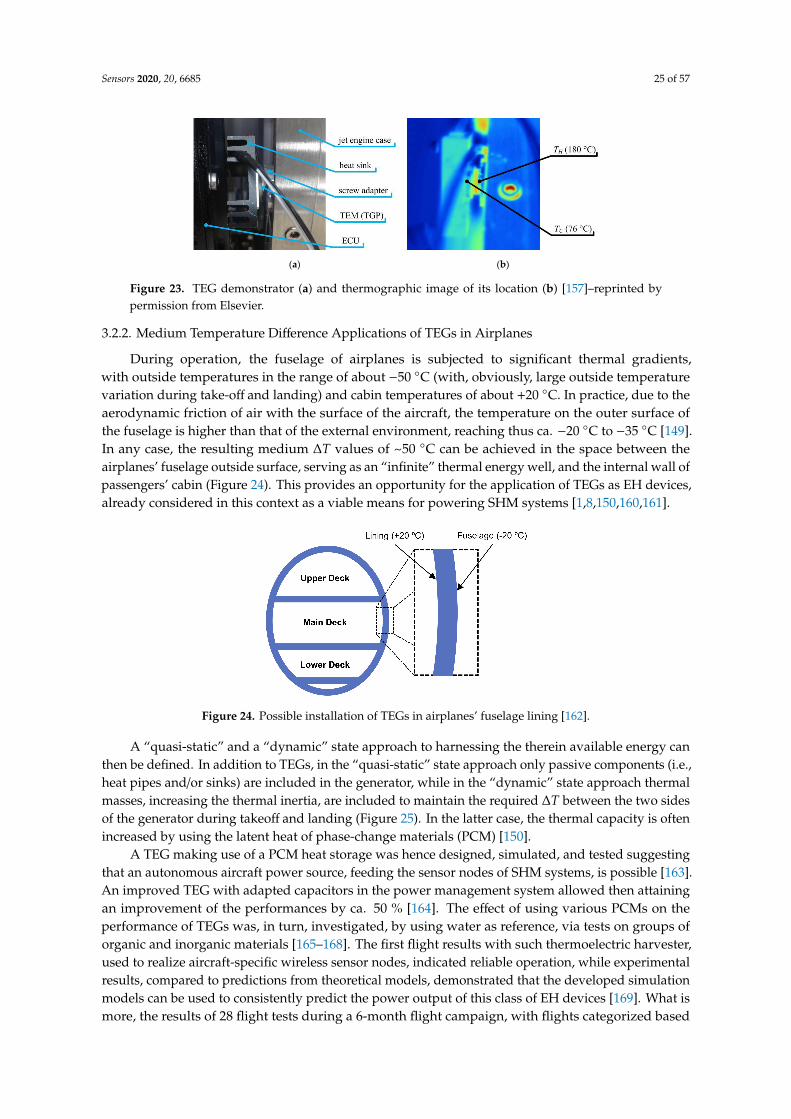
Sensors 2020, 20, 6685 25 of 57
Sensors 2020, 20, x FOR PEER REVIEW 25 of 58
power for various low-power systems [157]. High temperature differences can also be achieved at the nose tips of supersonic aircraft, where the airflow around the tip can significantly increase the temperature. Using computational fluid dynamics and the thermal conduction theory, it was hence shown that Δ𝑇 values of up to 757 K are developed for supersonic flights at Mach 4.5 [158]. Small Unmanned Aerial Vehicles (UAVs) are, in turn, typically powered by two-stroke internal combustion engines characterized by a high power-to-weight ratio. These engines have, however, a low chemical-to-mechanical energy conversion efficiency of about 12%, so that a significant amount of energy is generally wasted via the exhaust gases. Part of this energy can, thus, be harvested by using TEG modules installed on a canister-like modified engine muffler mounted outside the UAV, while the hot side of the TEGs is suitably interfaced with the high temperature exhaust gases. After a design optimization phase, more than 40 W of net electric power was hence obtained from the 455 K exhaust gases of a Bat4 UAV [159].
(a) (b)
Figure 23. TEG demonstrator (a) and thermographic image of its location (b) [157]–reprinted by permission from Elsevier.
3.2.2. Medium Temperature Difference Applications of TEGs in Airplanes
During operation, the fuselage of airplanes is subjected to significant thermal gradients, with outside temperatures in the range of about −50 °C (with, obviously, large outside temperature variation during take-off and landing) and cabin temperatures of about +20 °C. In practice, due to the aerodynamic friction of air with the surface of the aircraft, the temperature on the outer surface of the fuselage is higher than that of the external environment, reaching thus ca. −20 °C to −35 °C [149]. In any case, the resulting medium Δ𝑇 values of ∼50 °C can be achieved in the space between the airplanes’ fuselage outside surface, serving as an “infinite” thermal energy well, and the internal wall of passengers’ cabin (Figure 24). This provides an opportunity for the application of TEGs as EH devices, already considered in this context as a viable means for powering SHM systems [1,8,150,160,161].
Figure 24. Possible installation of TEGs in airplanes’ fuselage lining [162].
Figure 23. TEG demonstrator (a) and thermographic image of its location (b) [157]–reprinted bypermission from Elsevier.
3.2.2. Medium Temperature Difference Applications of TEGs in Airplanes
During operation, the fuselage of airplanes is subjected to significant thermal gradients,with outside temperatures in the range of about −50 C (with, obviously, large outside temperaturevariation during take-off and landing) and cabin temperatures of about +20 C. In practice, due to theaerodynamic friction of air with the surface of the aircraft, the temperature on the outer surface ofthe fuselage is higher than that of the external environment, reaching thus ca. −20 C to −35 C [149].In any case, the resulting medium ∆T values of ~50 C can be achieved in the space between theairplanes’ fuselage outside surface, serving as an “infinite” thermal energy well, and the internal wall ofpassengers’ cabin (Figure 24). This provides an opportunity for the application of TEGs as EH devices,already considered in this context as a viable means for powering SHM systems [1,8,150,160,161].
Sensors 2020, 20, x FOR PEER REVIEW 25 of 58
power for various low-power systems [157]. High temperature differences can also be achieved at the nose tips of supersonic aircraft, where the airflow around the tip can significantly increase the temperature. Using computational fluid dynamics and the thermal conduction theory, it was hence shown that Δ𝑇 values of up to 757 K are developed for supersonic flights at Mach 4.5 [158]. Small Unmanned Aerial Vehicles (UAVs) are, in turn, typically powered by two-stroke internal combustion engines characterized by a high power-to-weight ratio. These engines have, however, a low chemical-to-mechanical energy conversion efficiency of about 12%, so that a significant amount of energy is generally wasted via the exhaust gases. Part of this energy can, thus, be harvested by using TEG modules installed on a canister-like modified engine muffler mounted outside the UAV, while the hot side of the TEGs is suitably interfaced with the high temperature exhaust gases. After a design optimization phase, more than 40 W of net electric power was hence obtained from the 455 K exhaust gases of a Bat4 UAV [159].
(a) (b)
Figure 23. TEG demonstrator (a) and thermographic image of its location (b) [157]–reprinted by permission from Elsevier.
3.2.2. Medium Temperature Difference Applications of TEGs in Airplanes
During operation, the fuselage of airplanes is subjected to significant thermal gradients, with outside temperatures in the range of about −50 °C (with, obviously, large outside temperature variation during take-off and landing) and cabin temperatures of about +20 °C. In practice, due to the aerodynamic friction of air with the surface of the aircraft, the temperature on the outer surface of the fuselage is higher than that of the external environment, reaching thus ca. −20 °C to −35 °C [149]. In any case, the resulting medium Δ𝑇 values of ∼50 °C can be achieved in the space between the airplanes’ fuselage outside surface, serving as an “infinite” thermal energy well, and the internal wall of passengers’ cabin (Figure 24). This provides an opportunity for the application of TEGs as EH devices, already considered in this context as a viable means for powering SHM systems [1,8,150,160,161].
Figure 24. Possible installation of TEGs in airplanes’ fuselage lining [162]. Figure 24. Possible installation of TEGs in airplanes’ fuselage lining [162].
A “quasi-static” and a “dynamic” state approach to harnessing the therein available energy canthen be defined. In addition to TEGs, in the “quasi-static” state approach only passive components (i.e.,heat pipes and/or sinks) are included in the generator, while in the “dynamic” state approach thermalmasses, increasing the thermal inertia, are included to maintain the required ∆T between the two sidesof the generator during takeoff and landing (Figure 25). In the latter case, the thermal capacity is oftenincreased by using the latent heat of phase-change materials (PCM) [150].
A TEG making use of a PCM heat storage was hence designed, simulated, and tested suggestingthat an autonomous aircraft power source, feeding the sensor nodes of SHM systems, is possible [163].An improved TEG with adapted capacitors in the power management system allowed then attainingan improvement of the performances by ca. 50 % [164]. The effect of using various PCMs on theperformance of TEGs was, in turn, investigated, by using water as reference, via tests on groups oforganic and inorganic materials [165–168]. The first flight results with such thermoelectric harvester,used to realize aircraft-specific wireless sensor nodes, indicated reliable operation, while experimentalresults, compared to predictions from theoretical models, demonstrated that the developed simulationmodels can be used to consistently predict the power output of this class of EH devices [169]. What ismore, the results of 28 flight tests during a 6-month flight campaign, with flights categorized based
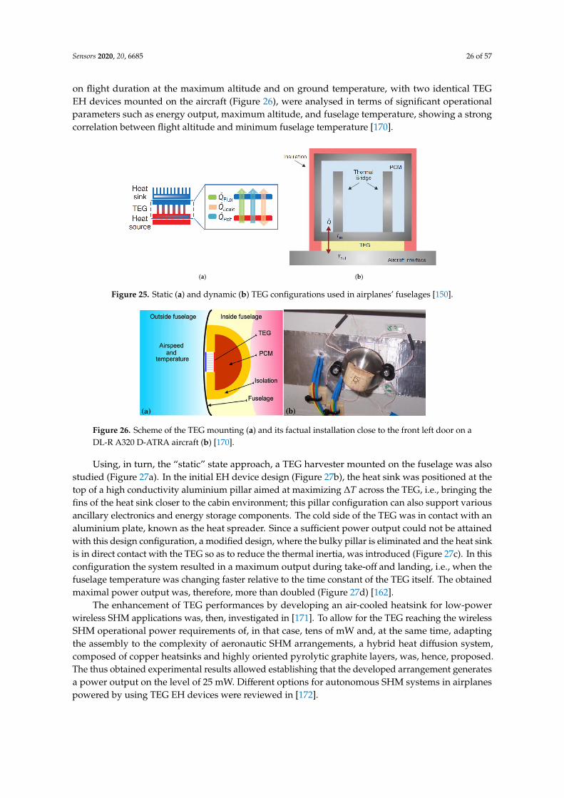
Sensors 2020, 20, 6685 26 of 57
on flight duration at the maximum altitude and on ground temperature, with two identical TEGEH devices mounted on the aircraft (Figure 26), were analysed in terms of significant operationalparameters such as energy output, maximum altitude, and fuselage temperature, showing a strongcorrelation between flight altitude and minimum fuselage temperature [170].
Sensors 2020, 20, x FOR PEER REVIEW 26 of 58
A “quasi-static” and a “dynamic” state approach to harnessing the therein available energy can then be defined. In addition to TEGs, in the “quasi-static” state approach only passive components (i.e., heat pipes and/or sinks) are included in the generator, while in the “dynamic” state approach thermal masses, increasing the thermal inertia, are included to maintain the required Δ𝑇 between the two sides of the generator during takeoff and landing (Figure 25). In the latter case, the thermal capacity is often increased by using the latent heat of phase-change materials (PCM) [150].
(a) (b)
Figure 25. Static (a) and dynamic (b) TEG configurations used in airplanes’ fuselages [150].
A TEG making use of a PCM heat storage was hence designed, simulated, and tested suggesting that an autonomous aircraft power source, feeding the sensor nodes of SHM systems, is possible [163]. An improved TEG with adapted capacitors in the power management system allowed then attaining an improvement of the performances by ca. 50 % [164]. The effect of using various PCMs on the performance of TEGs was, in turn, investigated, by using water as reference, via tests on groups of organic and inorganic materials [165–168]. The first flight results with such thermoelectric harvester, used to realize aircraft-specific wireless sensor nodes, indicated reliable operation, while experimental results, compared to predictions from theoretical models, demonstrated that the developed simulation models can be used to consistently predict the power output of this class of EH devices [169]. What is more, the results of 28 flight tests during a 6-month flight campaign, with flights categorized based on flight duration at the maximum altitude and on ground temperature, with two identical TEG EH devices mounted on the aircraft (Figure 26), were analysed in terms of significant operational parameters such as energy output, maximum altitude, and fuselage temperature, showing a strong correlation between flight altitude and minimum fuselage temperature [170].
Figure 26. Scheme of the TEG mounting (a) and its factual installation close to the front left door on a DL-R A320 D-ATRA aircraft (b) [170].
Figure 25. Static (a) and dynamic (b) TEG configurations used in airplanes’ fuselages [150].
Sensors 2020, 20, x FOR PEER REVIEW 26 of 58
A “quasi-static” and a “dynamic” state approach to harnessing the therein available energy can then be defined. In addition to TEGs, in the “quasi-static” state approach only passive components (i.e., heat pipes and/or sinks) are included in the generator, while in the “dynamic” state approach thermal masses, increasing the thermal inertia, are included to maintain the required Δ𝑇 between the two sides of the generator during takeoff and landing (Figure 25). In the latter case, the thermal capacity is often increased by using the latent heat of phase-change materials (PCM) [150].
(a) (b)
Figure 25. Static (a) and dynamic (b) TEG configurations used in airplanes’ fuselages [150].
A TEG making use of a PCM heat storage was hence designed, simulated, and tested suggesting that an autonomous aircraft power source, feeding the sensor nodes of SHM systems, is possible [163]. An improved TEG with adapted capacitors in the power management system allowed then attaining an improvement of the performances by ca. 50 % [164]. The effect of using various PCMs on the performance of TEGs was, in turn, investigated, by using water as reference, via tests on groups of organic and inorganic materials [165–168]. The first flight results with such thermoelectric harvester, used to realize aircraft-specific wireless sensor nodes, indicated reliable operation, while experimental results, compared to predictions from theoretical models, demonstrated that the developed simulation models can be used to consistently predict the power output of this class of EH devices [169]. What is more, the results of 28 flight tests during a 6-month flight campaign, with flights categorized based on flight duration at the maximum altitude and on ground temperature, with two identical TEG EH devices mounted on the aircraft (Figure 26), were analysed in terms of significant operational parameters such as energy output, maximum altitude, and fuselage temperature, showing a strong correlation between flight altitude and minimum fuselage temperature [170].
Figure 26. Scheme of the TEG mounting (a) and its factual installation close to the front left door on a DL-R A320 D-ATRA aircraft (b) [170].
Figure 26. Scheme of the TEG mounting (a) and its factual installation close to the front left door on aDL-R A320 D-ATRA aircraft (b) [170].
Using, in turn, the “static” state approach, a TEG harvester mounted on the fuselage was alsostudied (Figure 27a). In the initial EH device design (Figure 27b), the heat sink was positioned at thetop of a high conductivity aluminium pillar aimed at maximizing ∆T across the TEG, i.e., bringing thefins of the heat sink closer to the cabin environment; this pillar configuration can also support variousancillary electronics and energy storage components. The cold side of the TEG was in contact with analuminium plate, known as the heat spreader. Since a sufficient power output could not be attainedwith this design configuration, a modified design, where the bulky pillar is eliminated and the heat sinkis in direct contact with the TEG so as to reduce the thermal inertia, was introduced (Figure 27c). In thisconfiguration the system resulted in a maximum output during take-off and landing, i.e., when thefuselage temperature was changing faster relative to the time constant of the TEG itself. The obtainedmaximal power output was, therefore, more than doubled (Figure 27d) [162].
The enhancement of TEG performances by developing an air-cooled heatsink for low-powerwireless SHM applications was, then, investigated in [171]. To allow for the TEG reaching the wirelessSHM operational power requirements of, in that case, tens of mW and, at the same time, adaptingthe assembly to the complexity of aeronautic SHM arrangements, a hybrid heat diffusion system,composed of copper heatsinks and highly oriented pyrolytic graphite layers, was, hence, proposed.The thus obtained experimental results allowed establishing that the developed arrangement generatesa power output on the level of 25 mW. Different options for autonomous SHM systems in airplanespowered by using TEG EH devices were reviewed in [172].

Sensors 2020, 20, 6685 27 of 57
Sensors 2020, 20, x FOR PEER REVIEW 27 of 58
Using, in turn, the “static” state approach, a TEG harvester mounted on the fuselage was also studied (Figure 27a). In the initial EH device design (Figure 27b), the heat sink was positioned at the top of a high conductivity aluminium pillar aimed at maximizing Δ𝑇 across the TEG, i.e., bringing the fins of the heat sink closer to the cabin environment; this pillar configuration can also support various ancillary electronics and energy storage components. The cold side of the TEG was in contact with an aluminium plate, known as the heat spreader. Since a sufficient power output could not be attained with this design configuration, a modified design, where the bulky pillar is eliminated and the heat sink is in direct contact with the TEG so as to reduce the thermal inertia, was introduced (Figure 27c). In this configuration the system resulted in a maximum output during take-off and landing, i.e., when the fuselage temperature was changing faster relative to the time constant of the TEG itself. The obtained maximal power output was, therefore, more than doubled (Figure 27d) [162].
The enhancement of TEG performances by developing an air-cooled heatsink for low-power wireless SHM applications was, then, investigated in [171]. To allow for the TEG reaching the wireless SHM operational power requirements of, in that case, tens of mW and, at the same time, adapting the assembly to the complexity of aeronautic SHM arrangements, a hybrid heat diffusion system, composed of copper heatsinks and highly oriented pyrolytic graphite layers, was, hence, proposed. The thus obtained experimental results allowed establishing that the developed arrangement generates a power output on the level of 25 mW. Different options for autonomous SHM systems in airplanes powered by using TEG EH devices were reviewed in [172].
(a) (b)
(c) (d)
Figure 27. Scheme of the TEG mounting on the fuselage (a), initial harvester design (b), modified harvester design (c) and output power obtained for both design configurations (d) [162].
3.2.3. Low Temperature Difference TEGs on Airplanes
Energy harvesting from passengers’ bodies is one of the main ideas behind the employment of low temperature difference TEGs in airplanes. Although the power output is low, the potential for self-sufficient operation of low power wireless devices, as an alternative to onboard power sources, is an attractive perspective. The integration of TE devices in airplane seats was, hence, suggested in this framework as means to supply the power required by wireless sensors embedded in the seats themselves. In fact, infrared images of airplanes seats allowed clearly revealing hot spots
Figure 27. Scheme of the TEG mounting on the fuselage (a), initial harvester design (b), modifiedharvester design (c) and output power obtained for both design configurations (d) [162].
3.2.3. Low Temperature Difference TEGs on Airplanes
Energy harvesting from passengers’ bodies is one of the main ideas behind the employment oflow temperature difference TEGs in airplanes. Although the power output is low, the potential forself-sufficient operation of low power wireless devices, as an alternative to onboard power sources,is an attractive perspective. The integration of TE devices in airplane seats was, hence, suggested inthis framework as means to supply the power required by wireless sensors embedded in the seatsthemselves. In fact, infrared images of airplanes seats allowed clearly revealing hot spots correspondingto the thigh and kidney/back area. The resulting heat was then used via TEGs to achieve the targetpower value of 1 mW necessary for operating a wireless sensor system in a demonstrator, thus enablingan automatized reporting of information on chair occupancy, armrest or tray table position etc. [173].
Very recently, further experimental studies of similar arrangements showed that the averagemaximal temperature produced from passenger’s body can reach 35.5 C. A resulting temperaturedifference ∆T of 15.5 C is therefore obtained, so that, by using a standard TEG, maximal power outputsat the level of 10 mW are generated [174]. A factorial study aimed at determining the influence ofcharacteristics such as passengers’ age, gender, weight, and height was also performed using statisticalmodels, showing that these factors do not have a significant effect on the obtained ∆T values, whereasthe ambient temperature is, obviously, found to be influential [175]. Similar ∆T values as in the lattercase can be consistently expected also on the hydraulic pipelines along the fuselage of the airplaneor on the wastewater system, allowing to attain, by using Micropelt high-tech thin film TEGs, peakoutput powers of up to 8 mW. A single TEG of the same type, positioned on the cargo skin (where∆T ≈ 40 K), generated, in turn, up to 34 mW of maximal power output and average power outputs ofca. 22.6 mW [8]. It is important to note in this regard, especially in the case of the herein consideredlow output harvesting applications, that the obtained maximal powers correspond to load resistancevalues RL that match the internal resistance of the TEG itself, i.e., that a careful matching of the TEGsand the foreseen electrical loads is imperative. What is more, the output power will be relatively highin a narrow area around this peak, decreasing rapidly for both higher and lower RL values, althoughthe decrease is more rapid for RL values lower than TEG’s internal resistance [176].
Last but not least, novel integrated concepts of using concurrently several TEG EH systems invarious applications and temperature difference ranges in aircraft are being considered by BAE SystemsMilitary Aircraft and Information (MAI) at Warton. These applications could include aircrew clothingwith integral novel TE materials/devices within the fabric, supplementary electrical power generation
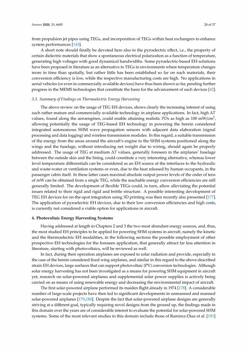
Sensors 2020, 20, 6685 28 of 57
from propulsion jet pipes using TEGs, and incorporation of TEGs within heat exchangers to enhancesystem performances [143].
A short note should finally be devoted here also to the pyroelectric effect, i.e., the property ofcertain dielectric materials that show a spontaneous electrical polarization as a function of temperature,generating high voltages with good dynamical bandwidths. Some pyroelectric-based EH solutionshave been proposed in literature as an alternative to TEGs in environments where temperature changesmore in time than spatially, but rather little has been established so far on such materials, theirconversion efficiency is low, while the respective manufacturing costs are high. No applications inaerial vehicles (or even in commercially available devices) have thus been shown so far, pending furtherprogress in the MEMS technologies that constitute the basis for the advancement of such devices [42].
3.3. Summary of Findings on Thermoelectric Energy Harvesting
The above review on the usage of TEG EH devices, shows clearly the increasing interest of usingsuch rather mature and commercially available technology in airplane applications. In fact, high ∆Tvalues, found along the aeroengines, could enable attaining realistic PDs as high as 100 mW/cm2,allowing potentially the usage of TEG-based EH technology in powering the herein consideredintegrated autonomous SHM wave propagation sensors with adjacent data elaboration (signalprocessing and data logging) and wireless transmission modules. In this regard, a suitable transmissionof the energy from the areas around the aircraft’s engine to the SHM systems positioned along thewings and the fuselage, without introducing net weight due to wiring, should again be properlyaddressed. The usage of TEG at medium ∆T values, generally foreseen in the airplanes’ fuselagebetween the outside skin and the lining, could constitute a very interesting alternative, whereas lowerlevel temperature differentials can be considered as an EH source at the interfaces to the hydraulicand waste-water or ventilation systems or even, due to the heat released by human occupants, in thepassenger cabin itself. In these latter cases maximal absolute output power levels of the order of tensof mW can be obtained from a single TEG, while the reachable energy conversion efficiencies are stillgenerally limited. The development of flexible TEGs could, in turn, allow alleviating the potentialissues related to their rigid and rigid and brittle structure. A possible interesting development ofTEG EH devices for on-the-spot integration using 3D printing was then recently also presented [177].The application of pyroelectric EH devices, due to their low conversion efficiencies and high costs,is currently not considered a viable option for applications in aircraft.
4. Photovoltaic Energy Harvesting Systems
Having addressed at length in Chapters 2 and 3 the two most abundant energy sources, and, thus,the most studied EH principles to be applied for powering SHM systems in aircraft, namely the kineticand the thermoelectric EH modalities, in the following sections the possible employment of otherprospective EH technologies for the foreseen application, that generally attract far less attention inliterature, starting with photovoltaics, will be reviewed as well.
In fact, during their operation airplanes are exposed to solar radiation and provide, especially inthe case of the herein considered fixed wing airplanes, and similar in this regard to the above-describedstrain EH devices, large surfaces that can support photovoltaic (PV) conversion technologies. Althoughsolar energy harvesting has not been investigated as a means for powering SHM equipment in aircraftyet, research on solar-powered airplanes and supplemental solar power supplies is actively beingcarried on as means of using renewable energy and decreasing the environmental impact of aircraft.
The first solar-powered airplane performed its maiden flight already in 1974 [178]. A considerablenumber of large-scale projects have then led to significant developments in unmanned and mannedsolar-powered airplanes [179,180]. Despite the fact that solar-powered airplane designs are generallystriving at a different goal, typically requiring novel designs from the ground up, the findings made inthis domain over the years are of considerable interest to evaluate the potential for solar-powered SHMsystems. Some of the most relevant studies in this domain include those of Ramirez-Diaz et al. [181]
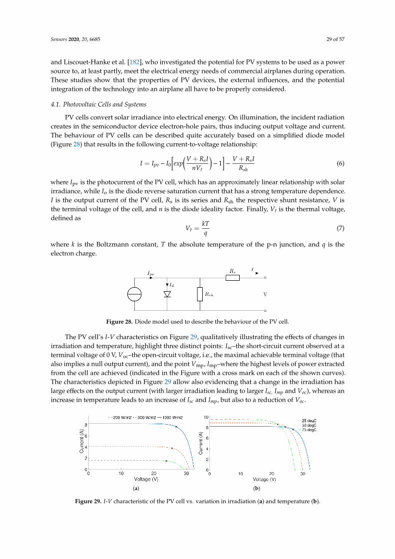
Sensors 2020, 20, 6685 29 of 57
and Liscouet-Hanke et al. [182], who investigated the potential for PV systems to be used as a powersource to, at least partly, meet the electrical energy needs of commercial airplanes during operation.These studies show that the properties of PV devices, the external influences, and the potentialintegration of the technology into an airplane all have to be properly considered.
4.1. Photovoltaic Cells and Systems
PV cells convert solar irradiance into electrical energy. On illumination, the incident radiationcreates in the semiconductor device electron-hole pairs, thus inducing output voltage and current.The behaviour of PV cells can be described quite accurately based on a simplified diode model(Figure 28) that results in the following current-to-voltage relationship:
I = Ipv − I0
[exp
(V + RsInVt
)− 1
]−
V + RsIRsh
(6)
where Ipv is the photocurrent of the PV cell, which has an approximately linear relationship with solarirradiance, while Io is the diode reverse saturation current that has a strong temperature dependence.I is the output current of the PV cell, Rs is its series and Rsh the respective shunt resistance, V isthe terminal voltage of the cell, and n is the diode ideality factor. Finally, Vt is the thermal voltage,defined as
Vt =kTq
(7)
where k is the Boltzmann constant, T the absolute temperature of the p-n junction, and q is theelectron charge.Sensors 2020, 20, x FOR PEER REVIEW 30 of 58
Figure 28. Diode model used to describe the behaviour of the PV cell.
The PV cell’s I-V characteristics on Figure 29, qualitatively illustrating the effects of changes in irradiation and temperature, highlight three distinct points: Isc–the short-circuit current observed at a terminal voltage of 0 V, Voc–the open-circuit voltage, i.e., the maximal achievable terminal voltage (that also implies a null output current), and the point Vmp, Imp–where the highest levels of power extracted from the cell are achieved (indicated in the Figure with a cross mark on each of the shown curves). The characteristics depicted in Figure 29 allow also evidencing that a change in the irradiation has large effects on the output current (with larger irradiation leading to larger Isc, Imp and Voc), whereas an increase in temperature leads to an increase of Isc and Imp, but also to a reduction of Voc.
(a) (b)
Figure 29. I-V characteristic of the PV cell vs. variation in irradiation (a) and temperature (b).
Based on the used PV technology, different PV cells demonstrate varying conversion efficiencies. The conversion efficiency may thus vary from a few percent for thin-film PV cells, up to even 45 % for recent multi-junction technologies (Figure 30). Besides conversion efficiency, in the selection of the technology appropriate for a determined application, cost issues and the weight of the substrate need however, to be considered as well. The PV technology mostly utilized up to date in commercial systems is crystalline silicon, demonstrating conversion efficiencies of approximately 20–25 %. In order for PV devices to result in feasible output voltages and currents, for the majority of applications, multiple PV cells need to be combined in a panel. Series connection of cells results here in an increase in voltage, whereas parallel connection induces an increase of the output current. Besides the PV panel, a PV system contains also an output regulator, that provides a stable power output to the load, and, to enable the operation of the PV panel as close as possible to the point of maximum power output, it often integrates a maximum power point tracker. Next to energy management electronics, and due to the intermittent availability of the energy source, in most application scenarios, an energy storage device is essential to provide a buffer for shorter or longer periods of low/absent solar radiation (see also Section 7 below).
Figure 28. Diode model used to describe the behaviour of the PV cell.
The PV cell’s I-V characteristics on Figure 29, qualitatively illustrating the effects of changes inirradiation and temperature, highlight three distinct points: Isc–the short-circuit current observed at aterminal voltage of 0 V, Voc–the open-circuit voltage, i.e., the maximal achievable terminal voltage (thatalso implies a null output current), and the point Vmp, Imp–where the highest levels of power extractedfrom the cell are achieved (indicated in the Figure with a cross mark on each of the shown curves).The characteristics depicted in Figure 29 allow also evidencing that a change in the irradiation haslarge effects on the output current (with larger irradiation leading to larger Isc, Imp and Voc), whereas anincrease in temperature leads to an increase of Isc and Imp, but also to a reduction of Voc.
Sensors 2020, 20, x FOR PEER REVIEW 30 of 58
Figure 28. Diode model used to describe the behaviour of the PV cell.
The PV cell’s I-V characteristics on Figure 29, qualitatively illustrating the effects of changes in irradiation and temperature, highlight three distinct points: Isc–the short-circuit current observed at a terminal voltage of 0 V, Voc–the open-circuit voltage, i.e., the maximal achievable terminal voltage (that also implies a null output current), and the point Vmp, Imp–where the highest levels of power extracted from the cell are achieved (indicated in the Figure with a cross mark on each of the shown curves). The characteristics depicted in Figure 29 allow also evidencing that a change in the irradiation has large effects on the output current (with larger irradiation leading to larger Isc, Imp and Voc), whereas an increase in temperature leads to an increase of Isc and Imp, but also to a reduction of Voc.
(a) (b)
Figure 29. I-V characteristic of the PV cell vs. variation in irradiation (a) and temperature (b).
Based on the used PV technology, different PV cells demonstrate varying conversion efficiencies. The conversion efficiency may thus vary from a few percent for thin-film PV cells, up to even 45 % for recent multi-junction technologies (Figure 30). Besides conversion efficiency, in the selection of the technology appropriate for a determined application, cost issues and the weight of the substrate need however, to be considered as well. The PV technology mostly utilized up to date in commercial systems is crystalline silicon, demonstrating conversion efficiencies of approximately 20–25 %. In order for PV devices to result in feasible output voltages and currents, for the majority of applications, multiple PV cells need to be combined in a panel. Series connection of cells results here in an increase in voltage, whereas parallel connection induces an increase of the output current. Besides the PV panel, a PV system contains also an output regulator, that provides a stable power output to the load, and, to enable the operation of the PV panel as close as possible to the point of maximum power output, it often integrates a maximum power point tracker. Next to energy management electronics, and due to the intermittent availability of the energy source, in most application scenarios, an energy storage device is essential to provide a buffer for shorter or longer periods of low/absent solar radiation (see also Section 7 below).
Figure 29. I-V characteristic of the PV cell vs. variation in irradiation (a) and temperature (b).

Sensors 2020, 20, 6685 30 of 57
Based on the used PV technology, different PV cells demonstrate varying conversion efficiencies.The conversion efficiency may thus vary from a few percent for thin-film PV cells, up to even 45 %for recent multi-junction technologies (Figure 30). Besides conversion efficiency, in the selection ofthe technology appropriate for a determined application, cost issues and the weight of the substrateneed however, to be considered as well. The PV technology mostly utilized up to date in commercialsystems is crystalline silicon, demonstrating conversion efficiencies of approximately 20–25 %. In orderfor PV devices to result in feasible output voltages and currents, for the majority of applications,multiple PV cells need to be combined in a panel. Series connection of cells results here in an increasein voltage, whereas parallel connection induces an increase of the output current. Besides the PV panel,a PV system contains also an output regulator, that provides a stable power output to the load, and,to enable the operation of the PV panel as close as possible to the point of maximum power output,it often integrates a maximum power point tracker. Next to energy management electronics, and dueto the intermittent availability of the energy source, in most application scenarios, an energy storagedevice is essential to provide a buffer for shorter or longer periods of low/absent solar radiation (seealso Section 7 below).
Sensors 2020, 20, x FOR PEER REVIEW 31 of 58
Figure 30. NREL chart of highest confirmed conversion efficiencies for research PV cells (courtesy of the National Renewable Energy Laboratory, Golden, Co. [183]).
4.2. External Influences
In most applications, including aircraft, a challenge concerning the usage of PV systems is the dependency of their performance on many external parameters [184,185]. In fact, the expected output power is dependent on environmental factors, such as temperature, humidity, wind, and cloud coverage, as well as operational parameters such as geographical location, time of the day, day of the year, direction, and tilt. Although a number of these parameters can be considered, with more or less effort, in mission planning [181,182], an uncertainty and mission dependency remains. A potential PV system to be used for powering SHM sensor nodes in airplanes will, consequently, likely need to be over-dimensioned, particularly for most application scenarios in commercial flights.
One fundamental uncertainty is the estimation of available solar radiation, which is the basis for the assessment of the available energy during the flight. Aglietti et al. in [186] present a model for the estimation of solar radiation at different altitudes, based on the fact that at higher altitudes the sunbeam crosses a thinner atmospheric layer, while pressure levels are lower and cloud coverage can be expected to be significantly smaller. It is demonstrated that, at altitudes between 6 and 12 km above sea level, 5–10 times more annual irradiation can be expected with respect to that at ground level. The study is, however, limited to one geographic location and does not consider the motion of the airplane.
A number of studies [181,182,187,188] make, in turn, use of models that take into account the movement of the airplane, and estimate the solar radiation on a surface of the airplane during a given mission. To evaluate the amount of energy that can be harvested under realistic conditions, a number of scenarios can then be evaluated, including flight and parking at different geographical locations and on different days. The obtained results demonstrate that energy levels of the same order of magnitude as that required by onboard electronics can be harvested by using a PV system [181,182]. These studies are, however, limited to rather long flights, and specific routes or locations. What is more, for the energy balance to be successful, large areas of the airplanes need to be covered by PV cells, while economical or engineering aspects of their integration are generally not investigated.
Although it is clear that temperature has a significant effect on the performances of PV devices (see also Figure 29b above), and that the efficiency of a PV cell drops with increasing temperature, due to the involved complexity [184], the effects of temperature on the performance of PV devices in aircraft are neglected in many of the available studies. In fact, the estimation of the PV cell temperature is quite a challenge since it will raise due to the incident solar irradiance, but at the same time the surrounding air temperature can be assumed to be cold and additional convective cooling
Figure 30. NREL chart of highest confirmed conversion efficiencies for research PV cells (courtesy ofthe National Renewable Energy Laboratory, Golden, Co. [183]).
4.2. External Influences
In most applications, including aircraft, a challenge concerning the usage of PV systems is thedependency of their performance on many external parameters [184,185]. In fact, the expected outputpower is dependent on environmental factors, such as temperature, humidity, wind, and cloudcoverage, as well as operational parameters such as geographical location, time of the day, day of theyear, direction, and tilt. Although a number of these parameters can be considered, with more or lesseffort, in mission planning [181,182], an uncertainty and mission dependency remains. A potential PVsystem to be used for powering SHM sensor nodes in airplanes will, consequently, likely need to beover-dimensioned, particularly for most application scenarios in commercial flights.
One fundamental uncertainty is the estimation of available solar radiation, which is the basisfor the assessment of the available energy during the flight. Aglietti et al. in [186] present a modelfor the estimation of solar radiation at different altitudes, based on the fact that at higher altitudesthe sunbeam crosses a thinner atmospheric layer, while pressure levels are lower and cloud coveragecan be expected to be significantly smaller. It is demonstrated that, at altitudes between 6 and 12 kmabove sea level, 5–10 times more annual irradiation can be expected with respect to that at groundlevel. The study is, however, limited to one geographic location and does not consider the motion ofthe airplane.
A number of studies [181,182,187,188] make, in turn, use of models that take into account themovement of the airplane, and estimate the solar radiation on a surface of the airplane during a given
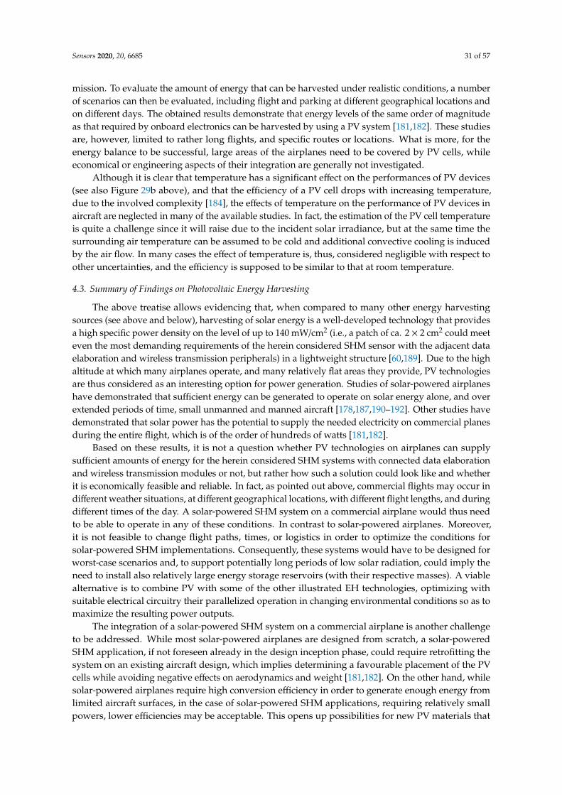
Sensors 2020, 20, 6685 31 of 57
mission. To evaluate the amount of energy that can be harvested under realistic conditions, a numberof scenarios can then be evaluated, including flight and parking at different geographical locations andon different days. The obtained results demonstrate that energy levels of the same order of magnitudeas that required by onboard electronics can be harvested by using a PV system [181,182]. These studiesare, however, limited to rather long flights, and specific routes or locations. What is more, for theenergy balance to be successful, large areas of the airplanes need to be covered by PV cells, whileeconomical or engineering aspects of their integration are generally not investigated.
Although it is clear that temperature has a significant effect on the performances of PV devices(see also Figure 29b above), and that the efficiency of a PV cell drops with increasing temperature,due to the involved complexity [184], the effects of temperature on the performance of PV devices inaircraft are neglected in many of the available studies. In fact, the estimation of the PV cell temperatureis quite a challenge since it will raise due to the incident solar irradiance, but at the same time thesurrounding air temperature can be assumed to be cold and additional convective cooling is inducedby the air flow. In many cases the effect of temperature is, thus, considered negligible with respect toother uncertainties, and the efficiency is supposed to be similar to that at room temperature.
4.3. Summary of Findings on Photovoltaic Energy Harvesting
The above treatise allows evidencing that, when compared to many other energy harvestingsources (see above and below), harvesting of solar energy is a well-developed technology that providesa high specific power density on the level of up to 140 mW/cm2 (i.e., a patch of ca. 2 × 2 cm2 could meeteven the most demanding requirements of the herein considered SHM sensor with the adjacent dataelaboration and wireless transmission peripherals) in a lightweight structure [60,189]. Due to the highaltitude at which many airplanes operate, and many relatively flat areas they provide, PV technologiesare thus considered as an interesting option for power generation. Studies of solar-powered airplaneshave demonstrated that sufficient energy can be generated to operate on solar energy alone, and overextended periods of time, small unmanned and manned aircraft [178,187,190–192]. Other studies havedemonstrated that solar power has the potential to supply the needed electricity on commercial planesduring the entire flight, which is of the order of hundreds of watts [181,182].
Based on these results, it is not a question whether PV technologies on airplanes can supplysufficient amounts of energy for the herein considered SHM systems with connected data elaborationand wireless transmission modules or not, but rather how such a solution could look like and whetherit is economically feasible and reliable. In fact, as pointed out above, commercial flights may occur indifferent weather situations, at different geographical locations, with different flight lengths, and duringdifferent times of the day. A solar-powered SHM system on a commercial airplane would thus needto be able to operate in any of these conditions. In contrast to solar-powered airplanes. Moreover,it is not feasible to change flight paths, times, or logistics in order to optimize the conditions forsolar-powered SHM implementations. Consequently, these systems would have to be designed forworst-case scenarios and, to support potentially long periods of low solar radiation, could imply theneed to install also relatively large energy storage reservoirs (with their respective masses). A viablealternative is to combine PV with some of the other illustrated EH technologies, optimizing withsuitable electrical circuitry their parallelized operation in changing environmental conditions so as tomaximize the resulting power outputs.
The integration of a solar-powered SHM system on a commercial airplane is another challengeto be addressed. While most solar-powered airplanes are designed from scratch, a solar-poweredSHM application, if not foreseen already in the design inception phase, could require retrofitting thesystem on an existing aircraft design, which implies determining a favourable placement of the PVcells while avoiding negative effects on aerodynamics and weight [181,182]. On the other hand, whilesolar-powered airplanes require high conversion efficiency in order to generate enough energy fromlimited aircraft surfaces, in the case of solar-powered SHM applications, requiring relatively smallpowers, lower efficiencies may be acceptable. This opens up possibilities for new PV materials that

Sensors 2020, 20, 6685 32 of 57
may be integrated more easily, or even combined solutions with the used aerofoils [193]. In any case,specific research aimed at gaining a better insight into the opportunities and challenges of solar-powerintegrated SHM systems in airplanes is yet to be conducted.
5. Airflow and Acoustic Energy Harvesting Systems
The energy of the air flowing around the airplane is also a practically unlimited well ofenvironmental energy to be transduced, via EH technologies, in useful electrical energy. Its effectswere in principle already considered in the above Section 2 dealing with kinetic environmental energy,especially in the case of strain EH system whose excitations are mostly induced by deformations ofairplane structures induced by the dynamical effects caused by airflow. Two other EH principlesbased on using airflow energy, increasingly investigated in literature very recently (i.e., in the last ca.five years or so), will, in turn, be considered in this section as potential power supply sources for theautonomous airplane SHM nodes and the adjacent peripherals. In the first case, airflow EH devicesformed by separate bodies will be reviewed. The first and most intuitive EH modality in this case is arotary micro-turbine which converts mechanical rotation, via electromagnetic induction, into usableelectrical energy [92]. The second EH modality utilizes airflow-induced fluttering and converts theresulting mechanical into electrical energy by using, in most cases, piezoelectric devices, althoughelectromagnetic and electrostatic transducers can be employed in this frame as well [41,92,194,195].The second EH principle that will be considered here are acoustic EH systems based on particulardesign arrangements on aircraft (cavities and similar), inducing sound wave effects [196,197].
5.1. Rotary Micro-Turbines
Although the rotary turbine principle can ensure a very stable power source, and it is commonlyused in larger realisations in modern aircraft, i.e., as an emergency power source for the case ofpotential failures of the main system [198], when it comes to the miniaturization of the overall designso as to create practical EH devices for SHM power supply purposes, the efficiency of such devices,whose application in river flows, in the form of a propeller suitably coupled to a miniaturised DCgenerator, was recently successfully demonstrated [92], could be lower. In order to roughly estimate,then, the size of the key element (propeller) of such a system enabling the attainment of the requiredharvested power levels, simulations based on the simplified first-order mathematical formulation [198]are performed in the MATLAB® environment, considering also that it is not possible to convert allavailable airflow energy into mechanical work [199]. The output power of the micro-turbine can thusbe calculated as:
P =18·Cp·ρ·d2
·π·v3 (8)
where Cp is the power coefficient defining the fraction of wind power that is efficiently converted tothe rotation of the propeller, limited by a theoretical upper limit of 0.593 (the so called Lanchester–Betzlimit) [199], ρ is the air density, d the diameter of the propeller, and v is the airflow velocity.
The electrical power that will be generated at the output of the micro-turbine can finally becalculated by multiplying the generated mechanical power of Equation (8) by the efficiency η of theelectrical generator. Supposing, then, that the required output electrical power in the herein consideredcase is 0.5 W, and for aircraft velocities ranging from 300 to 900 km/h, in Figure 31a is depicted theresulting dependence of the propeller diameter on air density (i.e., flight altitude and temperature).Figure 31b shows the respective dependence of the generated power on a propeller’s diameter, againfor different airflow velocities.
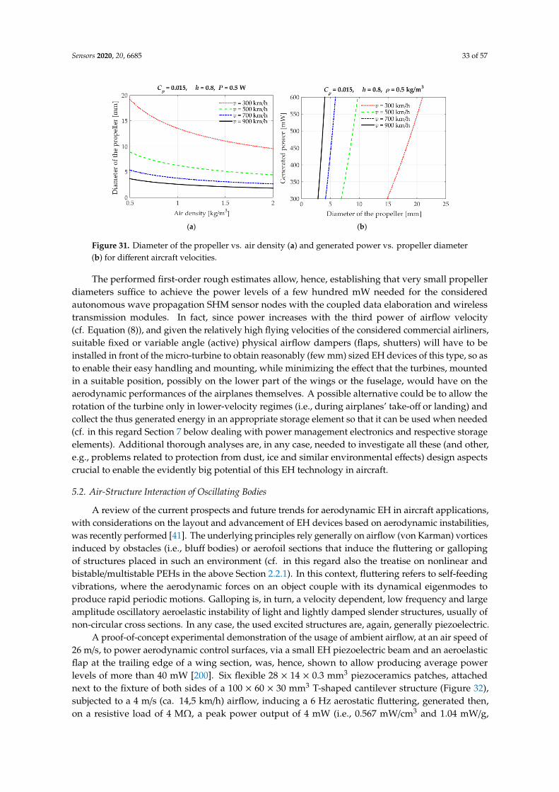
Sensors 2020, 20, 6685 33 of 57
Sensors 2020, 20, x FOR PEER REVIEW 33 of 58
modality in this case is a rotary micro-turbine which converts mechanical rotation, via electromagnetic induction, into usable electrical energy [92]. The second EH modality utilizes airflow-induced fluttering and converts the resulting mechanical into electrical energy by using, in most cases, piezoelectric devices, although electromagnetic and electrostatic transducers can be employed in this frame as well [41,92,194,195]. The second EH principle that will be considered here are acoustic EH systems based on particular design arrangements on aircraft (cavities and similar), inducing sound wave effects [196,197].
5.1. Rotary Micro-Turbines
Although the rotary turbine principle can ensure a very stable power source, and it is commonly used in larger realisations in modern aircraft, i.e., as an emergency power source for the case of potential failures of the main system [198], when it comes to the miniaturization of the overall design so as to create practical EH devices for SHM power supply purposes, the efficiency of such devices, whose application in river flows, in the form of a propeller suitably coupled to a miniaturised DC generator, was recently successfully demonstrated [92], could be lower. In order to roughly estimate, then, the size of the key element (propeller) of such a system enabling the attainment of the required harvested power levels, simulations based on the simplified first-order mathematical formulation [198] are performed in the MATLAB® environment, considering also that it is not possible to convert all available airflow energy into mechanical work [199]. The output power of the micro-turbine can thus be calculated as: 𝑃 = 18 ∙ 𝐶 ∙ 𝜌 ∙ 𝑑 ∙ 𝜋 ∙ 𝑣 (8)
where 𝐶 is the power coefficient defining the fraction of wind power that is efficiently converted to the rotation of the propeller, limited by a theoretical upper limit of 0.593 (the so called Lanchester–Betz limit) [199], 𝜌 is the air density, d the diameter of the propeller, and v is the airflow velocity.
The electrical power that will be generated at the output of the micro-turbine can finally be calculated by multiplying the generated mechanical power of Equation (8) by the efficiency η of the electrical generator. Supposing, then, that the required output electrical power in the herein considered case is 0.5 W, and for aircraft velocities ranging from 300 to 900 km/h, in Figure 31a is depicted the resulting dependence of the propeller diameter on air density (i.e., flight altitude and temperature). Figure 31b shows the respective dependence of the generated power on a propeller’s diameter, again for different airflow velocities.
(a) (b)
Figure 31. Diameter of the propeller vs. air density (a) and generated power vs. propeller diameter (b) for different aircraft velocities.
The performed first-order rough estimates allow, hence, establishing that very small propeller diameters suffice to achieve the power levels of a few hundred mW needed for the considered
Figure 31. Diameter of the propeller vs. air density (a) and generated power vs. propeller diameter(b) for different aircraft velocities.
The performed first-order rough estimates allow, hence, establishing that very small propellerdiameters suffice to achieve the power levels of a few hundred mW needed for the consideredautonomous wave propagation SHM sensor nodes with the coupled data elaboration and wirelesstransmission modules. In fact, since power increases with the third power of airflow velocity(cf. Equation (8)), and given the relatively high flying velocities of the considered commercial airliners,suitable fixed or variable angle (active) physical airflow dampers (flaps, shutters) will have to beinstalled in front of the micro-turbine to obtain reasonably (few mm) sized EH devices of this type, so asto enable their easy handling and mounting, while minimizing the effect that the turbines, mountedin a suitable position, possibly on the lower part of the wings or the fuselage, would have on theaerodynamic performances of the airplanes themselves. A possible alternative could be to allow therotation of the turbine only in lower-velocity regimes (i.e., during airplanes’ take-off or landing) andcollect the thus generated energy in an appropriate storage element so that it can be used when needed(cf. in this regard Section 7 below dealing with power management electronics and respective storageelements). Additional thorough analyses are, in any case, needed to investigate all these (and other,e.g., problems related to protection from dust, ice and similar environmental effects) design aspectscrucial to enable the evidently big potential of this EH technology in aircraft.
5.2. Air-Structure Interaction of Oscillating Bodies
A review of the current prospects and future trends for aerodynamic EH in aircraft applications,with considerations on the layout and advancement of EH devices based on aerodynamic instabilities,was recently performed [41]. The underlying principles rely generally on airflow (von Karman) vorticesinduced by obstacles (i.e., bluff bodies) or aerofoil sections that induce the fluttering or gallopingof structures placed in such an environment (cf. in this regard also the treatise on nonlinear andbistable/multistable PEHs in the above Section 2.2.1). In this context, fluttering refers to self-feedingvibrations, where the aerodynamic forces on an object couple with its dynamical eigenmodes toproduce rapid periodic motions. Galloping is, in turn, a velocity dependent, low frequency and largeamplitude oscillatory aeroelastic instability of light and lightly damped slender structures, usually ofnon-circular cross sections. In any case, the used excited structures are, again, generally piezoelectric.
A proof-of-concept experimental demonstration of the usage of ambient airflow, at an air speed of26 m/s, to power aerodynamic control surfaces, via a small EH piezoelectric beam and an aeroelasticflap at the trailing edge of a wing section, was, hence, shown to allow producing average powerlevels of more than 40 mW [200]. Six flexible 28 × 14 × 0.3 mm3 piezoceramics patches, attachednext to the fixture of both sides of a 100 × 60 × 30 mm3 T-shaped cantilever structure (Figure 32),subjected to a 4 m/s (ca. 14,5 km/h) airflow, inducing a 6 Hz aerostatic fluttering, generated then,on a resistive load of 4 MΩ, a peak power output of 4 mW (i.e., 0.567 mW/cm3 and 1.04 mW/g,

Sensors 2020, 20, 6685 34 of 57
respectively) [201]. A promising but quite complex design configuration, involving additional magnets,is that of a Y-shaped bistable EH device with piezoelectric patches aimed at low-speed (3 to 7 m/s)airflows that was experimentally shown to generate noteworthy voltage outputs [202].
Sensors 2020, 20, x FOR PEER REVIEW 34 of 58
autonomous wave propagation SHM sensor nodes with the coupled data elaboration and wireless transmission modules. In fact, since power increases with the third power of airflow velocity (cf. Equation (8)), and given the relatively high flying velocities of the considered commercial airliners, suitable fixed or variable angle (active) physical airflow dampers (flaps, shutters) will have to be installed in front of the micro-turbine to obtain reasonably (few mm) sized EH devices of this type, so as to enable their easy handling and mounting, while minimizing the effect that the turbines, mounted in a suitable position, possibly on the lower part of the wings or the fuselage, would have on the aerodynamic performances of the airplanes themselves. A possible alternative could be to allow the rotation of the turbine only in lower-velocity regimes (i.e., during airplanes’ take-off or landing) and collect the thus generated energy in an appropriate storage element so that it can be used when needed (cf. in this regard Section 7 below dealing with power management electronics and respective storage elements). Additional thorough analyses are, in any case, needed to investigate all these (and other, e.g., problems related to protection from dust, ice and similar environmental effects) design aspects crucial to enable the evidently big potential of this EH technology in aircraft.
5.2. Air-Structure Interaction of Oscillating Bodies
A review of the current prospects and future trends for aerodynamic EH in aircraft applications, with considerations on the layout and advancement of EH devices based on aerodynamic instabilities, was recently performed [41]. The underlying principles rely generally on airflow (von Karman) vortices induced by obstacles (i.e., bluff bodies) or aerofoil sections that induce the fluttering or galloping of structures placed in such an environment (cf. in this regard also the treatise on nonlinear and bistable/multistable PEHs in the above Section 2.2.1). In this context, fluttering refers to self-feeding vibrations, where the aerodynamic forces on an object couple with its dynamical eigenmodes to produce rapid periodic motions. Galloping is, in turn, a velocity dependent, low frequency and large amplitude oscillatory aeroelastic instability of light and lightly damped slender structures, usually of non-circular cross sections. In any case, the used excited structures are, again, generally piezoelectric.
A proof-of-concept experimental demonstration of the usage of ambient airflow, at an air speed of 26 m/s, to power aerodynamic control surfaces, via a small EH piezoelectric beam and an aeroelastic flap at the trailing edge of a wing section, was, hence, shown to allow producing average power levels of more than 40 mW [200]. Six flexible 28 × 14 × 0.3 mm3 piezoceramics patches, attached next to the fixture of both sides of a 100 × 60 × 30 mm3 T-shaped cantilever structure (Figure 32), subjected to a 4 m/s (ca. 14,5 km/h) airflow, inducing a 6 Hz aerostatic fluttering, generated then, on a resistive load of 4 MΩ, a peak power output of 4 mW (i.e., 0.567 mW/cm3 and 1.04 mW/g, respectively) [201]. A promising but quite complex design configuration, involving additional magnets, is that of a Y-shaped bistable EH device with piezoelectric patches aimed at low-speed (3 to 7 m/s) airflows that was experimentally shown to generate noteworthy voltage outputs [202].
Figure 32. T-shaped airflow fluttering PEH [201]. Figure 32. T-shaped airflow fluttering PEH [201].
The design and characterization of a novel airflow EH device, based on jet-edge flow oscillations(Figure 33), proposed in [194], allows, in turn, attaining, via the oscillations of a polymeric (PVDF)piezoelectric structure (cf. above Section 2.3.2), in absolute terms only several tens of µW of maximaloutput power. The respective normalised power densities are, however, high, while the structure israther simple.
Sensors 2020, 20, x FOR PEER REVIEW 35 of 58
The design and characterization of a novel airflow EH device, based on jet-edge flow oscillations (Figure 33), proposed in [194], allows, in turn, attaining, via the oscillations of a polymeric (PVDF) piezoelectric structure (cf. above Section 2.3.2), in absolute terms only several tens of μW of maximal output power. The respective normalised power densities are, however, high, while the structure is rather simple.
Figure 33. Scheme of jet-edge EH device in an aerofoil [194]-licensed under a Creative Commons Attribution (CC BY).
Several configurations that in the future could potentially enable the use of PVDF EH systems as structures on an airplane wing or the aircraft construction in general, were also investigated. A systematic experimental study of the influence of geometrical parameters on the behaviour and power output of a PVDF EH ‘inverted flag’ (Figure 34; In literature referred to as ‘piezoelectric eel’ [88]) allowed, then, to establish that, at an airflow velocity of 9 m/s, maximal power outputs of up to ∼5 mW/cm3 can be obtained [195]. One of the ingenious design configurations used in this context is based on an air amplifier (i.e., an airflow directing nozzle in front of the EH device) aimed at increasing the flow of air and the resulting energy conversion efficiency of a PVDF EH device with an additional aerofoil baffle at its free end. With a constant airflow of 200 l/min, such a system provided on a 7 MΩ resistor a maximal power output of 13 mW [203].
Figure 34. Principle of the PVDF EH generator based on an ‘inverted flag’ [195].
Curved panels (already widely used in unmanned or micro aerial vehicles), with different portions of the semi-circular copper structure covered by segmented PVDF active piezoelectric layers, to be considered as part of aerofoil aircraft structures, have finally been used in a flutter-induced vibration EH device (Figure 35). Based on FE calculations and experimental tests performed in a wind tunnel, it was hence shown that, for an airflow of 25 m/s (90 km/h), a maximal harvested power of barely 0.42 μW (corresponding to a power density of 0.032 mW/cm3) can be obtained on a 10 MΩ resistance [204].
Figure 33. Scheme of jet-edge EH device in an aerofoil [194]-licensed under a Creative CommonsAttribution (CC BY).
Several configurations that in the future could potentially enable the use of PVDF EH systemsas structures on an airplane wing or the aircraft construction in general, were also investigated.A systematic experimental study of the influence of geometrical parameters on the behaviour andpower output of a PVDF EH ‘inverted flag’ (Figure 34; In literature referred to as ‘piezoelectric eel’ [88])allowed, then, to establish that, at an airflow velocity of 9 m/s, maximal power outputs of up to~5 mW/cm3 can be obtained [195]. One of the ingenious design configurations used in this context isbased on an air amplifier (i.e., an airflow directing nozzle in front of the EH device) aimed at increasingthe flow of air and the resulting energy conversion efficiency of a PVDF EH device with an additionalaerofoil baffle at its free end. With a constant airflow of 200 l/min, such a system provided on a 7 MΩresistor a maximal power output of 13 mW [203].
Sensors 2020, 20, x FOR PEER REVIEW 35 of 58
The design and characterization of a novel airflow EH device, based on jet-edge flow oscillations (Figure 33), proposed in [194], allows, in turn, attaining, via the oscillations of a polymeric (PVDF) piezoelectric structure (cf. above Section 2.3.2), in absolute terms only several tens of μW of maximal output power. The respective normalised power densities are, however, high, while the structure is rather simple.
Figure 33. Scheme of jet-edge EH device in an aerofoil [194]-licensed under a Creative Commons Attribution (CC BY).
Several configurations that in the future could potentially enable the use of PVDF EH systems as structures on an airplane wing or the aircraft construction in general, were also investigated. A systematic experimental study of the influence of geometrical parameters on the behaviour and power output of a PVDF EH ‘inverted flag’ (Figure 34; In literature referred to as ‘piezoelectric eel’ [88]) allowed, then, to establish that, at an airflow velocity of 9 m/s, maximal power outputs of up to ∼5 mW/cm3 can be obtained [195]. One of the ingenious design configurations used in this context is based on an air amplifier (i.e., an airflow directing nozzle in front of the EH device) aimed at increasing the flow of air and the resulting energy conversion efficiency of a PVDF EH device with an additional aerofoil baffle at its free end. With a constant airflow of 200 l/min, such a system provided on a 7 MΩ resistor a maximal power output of 13 mW [203].
Figure 34. Principle of the PVDF EH generator based on an ‘inverted flag’ [195].
Curved panels (already widely used in unmanned or micro aerial vehicles), with different portions of the semi-circular copper structure covered by segmented PVDF active piezoelectric layers, to be considered as part of aerofoil aircraft structures, have finally been used in a flutter-induced vibration EH device (Figure 35). Based on FE calculations and experimental tests performed in a wind tunnel, it was hence shown that, for an airflow of 25 m/s (90 km/h), a maximal harvested power of barely 0.42 μW (corresponding to a power density of 0.032 mW/cm3) can be obtained on a 10 MΩ resistance [204].
Figure 34. Principle of the PVDF EH generator based on an ‘inverted flag’ [195].

Sensors 2020, 20, 6685 35 of 57
Curved panels (already widely used in unmanned or micro aerial vehicles), with different portionsof the semi-circular copper structure covered by segmented PVDF active piezoelectric layers, to beconsidered as part of aerofoil aircraft structures, have finally been used in a flutter-induced vibration EHdevice (Figure 35). Based on FE calculations and experimental tests performed in a wind tunnel, it washence shown that, for an airflow of 25 m/s (90 km/h), a maximal harvested power of barely 0.42 µW(corresponding to a power density of 0.032 mW/cm3) can be obtained on a 10 MΩ resistance [204].Sensors 2020, 20, x FOR PEER REVIEW 36 of 58
Figure 35. Scheme of the curved panel EH device concept [204].
5.3. Acoustic Energy Harvesting
Acoustic waves have been considered in aircraft structures mainly as viable means of performing SHM tasks [205]. Only very recently the concept of acoustic EH systems (AEHS) for wireless sensor networks, often based on Helmholtz cavities (producing resonance effects equivalent to those when blowing through the neck of an empty bottle) and piezoelectric elements (Figure 36–although the used oscillating structure could also be based on electromagnetic conversion), has been systematically reviewed [197]. However, even by using loud (pain threshold) ambient acoustic sources on the level of 130 dB (i.e., on the noise level of jet airplanes), AEHS of this type allow attaining limited absolute (with peak values on the order of 1 mW), and very limited specific power outputs (in the range of tens of μW/cm3) [196,197]. Such EH systems have thus been so far proposed only for an application in large surface noise barriers for high-speed railways [206].
A different, low-frequency broadband AEHS concept, is that of placing PEH devices in quarter-wavelength resonator tubes, i.e., those where, by adapting the length of the tube to the quarter-wavelength of the external sound wave, the incident sound pressure is amplified, i.e., a resonant standing wave is generated. The resulting maximal output powers are still, however, in the <1 mW range [197]. When a nonlinear restoring force is introduced into such a system via permanent magnets (Figure 37-cf. also the above Section 2.2.1), it is possible to tune the resonance of the bimorph PEH device to that of the cavity, despite its changes induced by temperature variations, thus optimising the performances of the device [207].
A novel AEHS approach based on acoustic metamaterials, such as sonic crystals or layered acoustic metamaterials (LAM–Figure 38), allowing to attain sound focusing or amplification, thus contributing to the weight vs. EH efficiency potential that is critical, especially in airplanes, could provide further interesting development potentials [197], although with the reached maximal power outputs of only a few μW and power densities on the level of 0.5 μW/cm3 at best [208,209].
Figure 36. Helmholtz cavity-based AEHS with piezoelectric EH transduction [197].
Figure 35. Scheme of the curved panel EH device concept [204].
5.3. Acoustic Energy Harvesting
Acoustic waves have been considered in aircraft structures mainly as viable means of performingSHM tasks [205]. Only very recently the concept of acoustic EH systems (AEHS) for wireless sensornetworks, often based on Helmholtz cavities (producing resonance effects equivalent to those whenblowing through the neck of an empty bottle) and piezoelectric elements (Figure 36–although theused oscillating structure could also be based on electromagnetic conversion), has been systematicallyreviewed [197]. However, even by using loud (pain threshold) ambient acoustic sources on the levelof 130 dB (i.e., on the noise level of jet airplanes), AEHS of this type allow attaining limited absolute(with peak values on the order of 1 mW), and very limited specific power outputs (in the range oftens of µW/cm3) [196,197]. Such EH systems have thus been so far proposed only for an application inlarge surface noise barriers for high-speed railways [206].
Sensors 2020, 20, x FOR PEER REVIEW 36 of 58
Figure 35. Scheme of the curved panel EH device concept [204].
5.3. Acoustic Energy Harvesting
Acoustic waves have been considered in aircraft structures mainly as viable means of performing SHM tasks [205]. Only very recently the concept of acoustic EH systems (AEHS) for wireless sensor networks, often based on Helmholtz cavities (producing resonance effects equivalent to those when blowing through the neck of an empty bottle) and piezoelectric elements (Figure 36–although the used oscillating structure could also be based on electromagnetic conversion), has been systematically reviewed [197]. However, even by using loud (pain threshold) ambient acoustic sources on the level of 130 dB (i.e., on the noise level of jet airplanes), AEHS of this type allow attaining limited absolute (with peak values on the order of 1 mW), and very limited specific power outputs (in the range of tens of μW/cm3) [196,197]. Such EH systems have thus been so far proposed only for an application in large surface noise barriers for high-speed railways [206].
A different, low-frequency broadband AEHS concept, is that of placing PEH devices in quarter-wavelength resonator tubes, i.e., those where, by adapting the length of the tube to the quarter-wavelength of the external sound wave, the incident sound pressure is amplified, i.e., a resonant standing wave is generated. The resulting maximal output powers are still, however, in the <1 mW range [197]. When a nonlinear restoring force is introduced into such a system via permanent magnets (Figure 37-cf. also the above Section 2.2.1), it is possible to tune the resonance of the bimorph PEH device to that of the cavity, despite its changes induced by temperature variations, thus optimising the performances of the device [207].
A novel AEHS approach based on acoustic metamaterials, such as sonic crystals or layered acoustic metamaterials (LAM–Figure 38), allowing to attain sound focusing or amplification, thus contributing to the weight vs. EH efficiency potential that is critical, especially in airplanes, could provide further interesting development potentials [197], although with the reached maximal power outputs of only a few μW and power densities on the level of 0.5 μW/cm3 at best [208,209].
Figure 36. Helmholtz cavity-based AEHS with piezoelectric EH transduction [197]. Figure 36. Helmholtz cavity-based AEHS with piezoelectric EH transduction [197].
A different, low-frequency broadband AEHS concept, is that of placing PEH devices inquarter-wavelength resonator tubes, i.e., those where, by adapting the length of the tube to thequarter-wavelength of the external sound wave, the incident sound pressure is amplified, i.e., a resonantstanding wave is generated. The resulting maximal output powers are still, however, in the <1 mWrange [197]. When a nonlinear restoring force is introduced into such a system via permanent magnets(Figure 37-cf. also the above Section 2.2.1), it is possible to tune the resonance of the bimorph PEHdevice to that of the cavity, despite its changes induced by temperature variations, thus optimising theperformances of the device [207].

Sensors 2020, 20, 6685 36 of 57Sensors 2020, 20, x FOR PEER REVIEW 37 of 58
Figure 37. Quarter-wavelength tube AEHS concept with nonlinear restoring force arrangement.
Figure 38. Scheme of an LAM-based AEH system [208].
In any case, although conceptually interesting, AEHS are still generally at the proof-of-concept technology level and allow attaining very small power output densities, so that their actual applications for the herein considered autonomous SHM systems in airplanes are yet to be developed.
5.4. Summary of Findings on Airflow and Acoustic Energy Harvesting
In the above paragraphs it is shown that airflow EH devices, based on a practically unlimited energy well, show interesting potentials in providing the powers needed by the autonomous wave propagation SHM sensors nodes with the coupled data elaboration and wireless transmission modules. In fact, the fluttering/galloping EH devices, mostly based again on piezoelectric materials, allow attaining several mW/cm3 already at very modest airflow speeds of only a few tens of km/h, which makes them, despite the rather complex design configurations and issues related to aerodynamic resistance, an interesting prospective solution. If problems related to de-icing, the influence of dust particles or the high dynamics of the moving parts are thoroughly investigated, micro-turbines with propellers of only a few millimetres in diameter, protected by airflow dampers and properly positioned on the airplane, could certainly provide the need powers as well. Acoustic EH devices, although being a subject matter of rather intense recent investigations, enable, in turn, obtaining, even in the best cases, only very limited peak power densities (tens of μW/cm3), while their technology readiness levels are still low.
Figure 37. Quarter-wavelength tube AEHS concept with nonlinear restoring force arrangement.
A novel AEHS approach based on acoustic metamaterials, such as sonic crystals or layeredacoustic metamaterials (LAM–Figure 38), allowing to attain sound focusing or amplification, thuscontributing to the weight vs. EH efficiency potential that is critical, especially in airplanes, couldprovide further interesting development potentials [197], although with the reached maximal poweroutputs of only a few µW and power densities on the level of 0.5 µW/cm3 at best [208,209].
Sensors 2020, 20, x FOR PEER REVIEW 37 of 58
Figure 37. Quarter-wavelength tube AEHS concept with nonlinear restoring force arrangement.
Figure 38. Scheme of an LAM-based AEH system [208].
In any case, although conceptually interesting, AEHS are still generally at the proof-of-concept technology level and allow attaining very small power output densities, so that their actual applications for the herein considered autonomous SHM systems in airplanes are yet to be developed.
5.4. Summary of Findings on Airflow and Acoustic Energy Harvesting
In the above paragraphs it is shown that airflow EH devices, based on a practically unlimited energy well, show interesting potentials in providing the powers needed by the autonomous wave propagation SHM sensors nodes with the coupled data elaboration and wireless transmission modules. In fact, the fluttering/galloping EH devices, mostly based again on piezoelectric materials, allow attaining several mW/cm3 already at very modest airflow speeds of only a few tens of km/h, which makes them, despite the rather complex design configurations and issues related to aerodynamic resistance, an interesting prospective solution. If problems related to de-icing, the influence of dust particles or the high dynamics of the moving parts are thoroughly investigated, micro-turbines with propellers of only a few millimetres in diameter, protected by airflow dampers and properly positioned on the airplane, could certainly provide the need powers as well. Acoustic EH devices, although being a subject matter of rather intense recent investigations, enable, in turn, obtaining, even in the best cases, only very limited peak power densities (tens of μW/cm3), while their technology readiness levels are still low.
Figure 38. Scheme of an LAM-based AEH system [208].
In any case, although conceptually interesting, AEHS are still generally at the proof-of-concepttechnology level and allow attaining very small power output densities, so that their actual applicationsfor the herein considered autonomous SHM systems in airplanes are yet to be developed.
5.4. Summary of Findings on Airflow and Acoustic Energy Harvesting
In the above paragraphs it is shown that airflow EH devices, based on a practically unlimited energywell, show interesting potentials in providing the powers needed by the autonomous wave propagationSHM sensors nodes with the coupled data elaboration and wireless transmission modules. In fact,the fluttering/galloping EH devices, mostly based again on piezoelectric materials, allow attainingseveral mW/cm3 already at very modest airflow speeds of only a few tens of km/h, which makesthem, despite the rather complex design configurations and issues related to aerodynamic resistance,an interesting prospective solution. If problems related to de-icing, the influence of dust particles or thehigh dynamics of the moving parts are thoroughly investigated, micro-turbines with propellers of onlya few millimetres in diameter, protected by airflow dampers and properly positioned on the airplane,could certainly provide the need powers as well. Acoustic EH devices, although being a subject matterof rather intense recent investigations, enable, in turn, obtaining, even in the best cases, only verylimited peak power densities (tens of µW/cm3), while their technology readiness levels are still low.
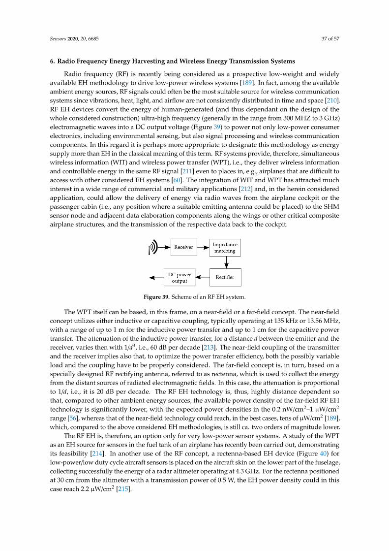
Sensors 2020, 20, 6685 37 of 57
6. Radio Frequency Energy Harvesting and Wireless Energy Transmission Systems
Radio frequency (RF) is recently being considered as a prospective low-weight and widelyavailable EH methodology to drive low-power wireless systems [189]. In fact, among the availableambient energy sources, RF signals could often be the most suitable source for wireless communicationsystems since vibrations, heat, light, and airflow are not consistently distributed in time and space [210].RF EH devices convert the energy of human-generated (and thus dependant on the design of thewhole considered construction) ultra-high frequency (generally in the range from 300 MHZ to 3 GHz)electromagnetic waves into a DC output voltage (Figure 39) to power not only low-power consumerelectronics, including environmental sensing, but also signal processing and wireless communicationcomponents. In this regard it is perhaps more appropriate to designate this methodology as energysupply more than EH in the classical meaning of this term. RF systems provide, therefore, simultaneouswireless information (WIT) and wireless power transfer (WPT), i.e., they deliver wireless informationand controllable energy in the same RF signal [211] even to places in, e.g., airplanes that are difficult toaccess with other considered EH systems [60]. The integration of WIT and WPT has attracted muchinterest in a wide range of commercial and military applications [212] and, in the herein consideredapplication, could allow the delivery of energy via radio waves from the airplane cockpit or thepassenger cabin (i.e., any position where a suitable emitting antenna could be placed) to the SHMsensor node and adjacent data elaboration components along the wings or other critical compositeairplane structures, and the transmission of the respective data back to the cockpit.
Sensors 2020, 20, x FOR PEER REVIEW 38 of 58
6. Radio Frequency Energy Harvesting and Wireless Energy Transmission Systems
Radio frequency (RF) is recently being considered as a prospective low-weight and widely available EH methodology to drive low-power wireless systems [189]. In fact, among the available ambient energy sources, RF signals could often be the most suitable source for wireless communication systems since vibrations, heat, light, and airflow are not consistently distributed in time and space [210]. RF EH devices convert the energy of human-generated (and thus dependant on the design of the whole considered construction) ultra-high frequency (generally in the range from 300 MHZ to 3 GHz) electromagnetic waves into a DC output voltage (Figure 39) to power not only low-power consumer electronics, including environmental sensing, but also signal processing and wireless communication components. In this regard it is perhaps more appropriate to designate this methodology as energy supply more than EH in the classical meaning of this term. RF systems provide, therefore, simultaneous wireless information (WIT) and wireless power transfer (WPT), i.e., they deliver wireless information and controllable energy in the same RF signal [211] even to places in, e.g., airplanes that are difficult to access with other considered EH systems [60]. The integration of WIT and WPT has attracted much interest in a wide range of commercial and military applications [212] and, in the herein considered application, could allow the delivery of energy via radio waves from the airplane cockpit or the passenger cabin (i.e., any position where a suitable emitting antenna could be placed) to the SHM sensor node and adjacent data elaboration components along the wings or other critical composite airplane structures, and the transmission of the respective data back to the cockpit.
The WPT itself can be based, in this frame, on a near-field or a far-field concept. The near-field concept utilizes either inductive or capacitive coupling, typically operating at 135 kHz or 13.56 MHz, with a range of up to 1 m for the inductive power transfer and up to 1 cm for the capacitive power transfer. The attenuation of the inductive power transfer, for a distance d between the emitter and the receiver, varies then with 1/d3, i.e., 60 dB per decade [213]. The near-field coupling of the transmitter and the receiver implies also that, to optimize the power transfer efficiency, both the possibly variable load and the coupling have to be properly considered. The far-field concept is, in turn, based on a specially designed RF rectifying antenna, referred to as rectenna, which is used to collect the energy from the distant sources of radiated electromagnetic fields. In this case, the attenuation is proportional to 1/d, i.e., it is 20 dB per decade. The RF EH technology is, thus, highly distance dependent so that, compared to other ambient energy sources, the available power density of the far-field RF EH technology is significantly lower, with the expected power densities in the 0.2 nW/cm2–1 μW/cm2 range [56], whereas that of the near-field technology could reach, in the best cases, tens of μW/cm2 [189], which, compared to the above considered EH methodologies, is still ca. two orders of magnitude lower.
The RF EH is, therefore, an option only for very low-power sensor systems. A study of the WPT as an EH source for sensors in the fuel tank of an airplane has recently been carried out, demonstrating its feasibility [214]. In another use of the RF concept, a rectenna-based EH device (Figure 40) for low-power/low duty cycle aircraft sensors is placed on the aircraft skin on the lower part of the fuselage, collecting successfully the energy of a radar altimeter operating at 4.3 GHz. For the rectenna positioned at 30 cm from the altimeter with a transmission power of 0.5 W, the EH power density could in this case reach 2.2 μW/cm2 [215].
Figure 39. Scheme of an RF EH system. Figure 39. Scheme of an RF EH system.
The WPT itself can be based, in this frame, on a near-field or a far-field concept. The near-fieldconcept utilizes either inductive or capacitive coupling, typically operating at 135 kHz or 13.56 MHz,with a range of up to 1 m for the inductive power transfer and up to 1 cm for the capacitive powertransfer. The attenuation of the inductive power transfer, for a distance d between the emitter and thereceiver, varies then with 1/d3, i.e., 60 dB per decade [213]. The near-field coupling of the transmitterand the receiver implies also that, to optimize the power transfer efficiency, both the possibly variableload and the coupling have to be properly considered. The far-field concept is, in turn, based on aspecially designed RF rectifying antenna, referred to as rectenna, which is used to collect the energyfrom the distant sources of radiated electromagnetic fields. In this case, the attenuation is proportionalto 1/d, i.e., it is 20 dB per decade. The RF EH technology is, thus, highly distance dependent sothat, compared to other ambient energy sources, the available power density of the far-field RF EHtechnology is significantly lower, with the expected power densities in the 0.2 nW/cm2–1 µW/cm2
range [56], whereas that of the near-field technology could reach, in the best cases, tens of µW/cm2 [189],which, compared to the above considered EH methodologies, is still ca. two orders of magnitude lower.
The RF EH is, therefore, an option only for very low-power sensor systems. A study of the WPTas an EH source for sensors in the fuel tank of an airplane has recently been carried out, demonstratingits feasibility [214]. In another use of the RF concept, a rectenna-based EH device (Figure 40) forlow-power/low duty cycle aircraft sensors is placed on the aircraft skin on the lower part of the fuselage,collecting successfully the energy of a radar altimeter operating at 4.3 GHz. For the rectenna positionedat 30 cm from the altimeter with a transmission power of 0.5 W, the EH power density could in thiscase reach 2.2 µW/cm2 [215].

Sensors 2020, 20, 6685 38 of 57Sensors 2020, 20, x FOR PEER REVIEW 39 of 58
Figure 40. Low-power/low duty cycle rectenna RF EH device powered by a nearby aircraft altimeter radar [215].
An experimental approach to RF energy harvesting in the far-field was, in turn, demonstrated by using a commercial Powercast Lifetime Power P2110 rectenna operated at 900 MHz mounted on an AgustaWestland AW139 helicopter landing gear compartment (Figure 41), allowing a DC power output of 70.42 μW to be transmitted from a 76 m distant GSM base-station to an accelerometer sensor node in the helicopter [216].
Figure 41. RF collector and wireless sensor in the landing gear unit of an AW139 helicopter [216].
The potential of supplying power for SHM aircraft sensors via a microwave (915 MHz) RF signal has been experimentally explored in [217], where 200 μW were successfully delivered over 1 m to two linear-pattern resistive strain gauge sensors, also assuring the transmission of the respective data back to the base station. The microwave energy was captured in this case by two kinds of receiving antennas (dipole and patch), evaluated by impedance matching and peak received powers, transformed into DC power by a rectifying circuit, and stored in a supercapacitor to provide the energy required by the wireless sensor nodes (cf. Section 7 below) to be potentially located in structures such as wing skin, airplane engine, stiffener, or similar (Figure 42).
The above examples therefore clearly show the potential of RF wireless energy and data transmission systems, especially for sensors placed in locations that are difficult to access with other considered EH devices, although they are not an immediate solution for the wave propagation SHM sensors nodes with the data elaboration and transmission modules described in the introduction of this work, which still require far higher power levels. As pointed out, the other components of the ODIN EU COST Action are actively working on the optimization of the placement of the sensors, the minimization of the respective power consumption, and the optimization of the signal processing protocols, as well as data transmission rates, which could all contribute to decrease the needed power levels, thus possibly enabling the usage of some of the currently not usable EH modalities.
In any case, this concludes the thorough review of the currently available EH technologies but, to incorporate them in the foreseen autonomous in-process SHM systems in airplanes, the respective power management and energy storage elements have to be carefully considered as well. The review of the current state-of-the-art of the latter will thus be carried out in the following section.
Figure 40. Low-power/low duty cycle rectenna RF EH device powered by a nearby aircraft altimeterradar [215].
An experimental approach to RF energy harvesting in the far-field was, in turn, demonstratedby using a commercial Powercast Lifetime Power P2110 rectenna operated at 900 MHz mounted onan AgustaWestland AW139 helicopter landing gear compartment (Figure 41), allowing a DC poweroutput of 70.42 µW to be transmitted from a 76 m distant GSM base-station to an accelerometer sensornode in the helicopter [216].
Sensors 2020, 20, x FOR PEER REVIEW 39 of 58
Figure 40. Low-power/low duty cycle rectenna RF EH device powered by a nearby aircraft altimeter radar [215].
An experimental approach to RF energy harvesting in the far-field was, in turn, demonstrated by using a commercial Powercast Lifetime Power P2110 rectenna operated at 900 MHz mounted on an AgustaWestland AW139 helicopter landing gear compartment (Figure 41), allowing a DC power output of 70.42 μW to be transmitted from a 76 m distant GSM base-station to an accelerometer sensor node in the helicopter [216].
Figure 41. RF collector and wireless sensor in the landing gear unit of an AW139 helicopter [216].
The potential of supplying power for SHM aircraft sensors via a microwave (915 MHz) RF signal has been experimentally explored in [217], where 200 μW were successfully delivered over 1 m to two linear-pattern resistive strain gauge sensors, also assuring the transmission of the respective data back to the base station. The microwave energy was captured in this case by two kinds of receiving antennas (dipole and patch), evaluated by impedance matching and peak received powers, transformed into DC power by a rectifying circuit, and stored in a supercapacitor to provide the energy required by the wireless sensor nodes (cf. Section 7 below) to be potentially located in structures such as wing skin, airplane engine, stiffener, or similar (Figure 42).
The above examples therefore clearly show the potential of RF wireless energy and data transmission systems, especially for sensors placed in locations that are difficult to access with other considered EH devices, although they are not an immediate solution for the wave propagation SHM sensors nodes with the data elaboration and transmission modules described in the introduction of this work, which still require far higher power levels. As pointed out, the other components of the ODIN EU COST Action are actively working on the optimization of the placement of the sensors, the minimization of the respective power consumption, and the optimization of the signal processing protocols, as well as data transmission rates, which could all contribute to decrease the needed power levels, thus possibly enabling the usage of some of the currently not usable EH modalities.
In any case, this concludes the thorough review of the currently available EH technologies but, to incorporate them in the foreseen autonomous in-process SHM systems in airplanes, the respective power management and energy storage elements have to be carefully considered as well. The review of the current state-of-the-art of the latter will thus be carried out in the following section.
Figure 41. RF collector and wireless sensor in the landing gear unit of an AW139 helicopter [216].
The potential of supplying power for SHM aircraft sensors via a microwave (915 MHz) RF signalhas been experimentally explored in [217], where 200 µW were successfully delivered over 1 m to twolinear-pattern resistive strain gauge sensors, also assuring the transmission of the respective data backto the base station. The microwave energy was captured in this case by two kinds of receiving antennas(dipole and patch), evaluated by impedance matching and peak received powers, transformed into DCpower by a rectifying circuit, and stored in a supercapacitor to provide the energy required by thewireless sensor nodes (cf. Section 7 below) to be potentially located in structures such as wing skin,airplane engine, stiffener, or similar (Figure 42).Sensors 2020, 20, x FOR PEER REVIEW 40 of 58
Figure 42. Block diagram of an RF-powered wireless sensor node with the data transmission system.
7. Power Management Electronics and Energy Storage Elements
As evidence above, depending on the used EH modalities and the environmental conditions, the produced output voltages can vary considerably in amplitude (for both AC (kinetic, RF and most of the airflow EH devices) and DC (TEG, PV and the micro-turbine EH modalities) sources) and frequency (for AC sources). In order to feed the energy to the foreseen electrical load (in the case considered in this work the SHM sensor node with its peripheral components), an appropriate management electronics is, therefore, necessary. Power management devices coupled to EH systems have, thus, several functions. Firstly, they enable the adjustment or matching of the voltage from the EH transducer to that of the load which is being powered–typically ranging from 2 to 5 V with currents of up to 100 mA [32]. A further task is the regulation of the supply voltage, i.e., keeping it as much as possible constant and independent of the source’s or load’s fluctuations. Last but not least, the power management electronics assures an efficient energy delivery from the EH device, i.e., the generator, to the SHM system (the load), as well as the storage of the surplus harvested energy on an appropriate storage device and its management [2,66]. The key solution in this regard is, hence, tailoring as much is possible the power management electronics towards the EH device and its operation while aiming at obtaining the maximum power transfer (i.e., at minimizing the energy consumption on the electronics itself). Efficient adaptive electronics can, for example, be designed with the capability of an effective power transfer with a wide range of attached loads (Figure 43) [218].
(a) (b)
Figure 42. Block diagram of an RF-powered wireless sensor node with the data transmission system.

Sensors 2020, 20, 6685 39 of 57
The above examples therefore clearly show the potential of RF wireless energy and datatransmission systems, especially for sensors placed in locations that are difficult to access withother considered EH devices, although they are not an immediate solution for the wave propagationSHM sensors nodes with the data elaboration and transmission modules described in the introductionof this work, which still require far higher power levels. As pointed out, the other components ofthe ODIN EU COST Action are actively working on the optimization of the placement of the sensors,the minimization of the respective power consumption, and the optimization of the signal processingprotocols, as well as data transmission rates, which could all contribute to decrease the needed powerlevels, thus possibly enabling the usage of some of the currently not usable EH modalities.
In any case, this concludes the thorough review of the currently available EH technologies but,to incorporate them in the foreseen autonomous in-process SHM systems in airplanes, the respectivepower management and energy storage elements have to be carefully considered as well. The reviewof the current state-of-the-art of the latter will thus be carried out in the following section.
7. Power Management Electronics and Energy Storage Elements
As evidence above, depending on the used EH modalities and the environmental conditions,the produced output voltages can vary considerably in amplitude (for both AC (kinetic, RF andmost of the airflow EH devices) and DC (TEG, PV and the micro-turbine EH modalities) sources)and frequency (for AC sources). In order to feed the energy to the foreseen electrical load (in thecase considered in this work the SHM sensor node with its peripheral components), an appropriatemanagement electronics is, therefore, necessary. Power management devices coupled to EH systemshave, thus, several functions. Firstly, they enable the adjustment or matching of the voltage from theEH transducer to that of the load which is being powered–typically ranging from 2 to 5 V with currentsof up to 100 mA [32]. A further task is the regulation of the supply voltage, i.e., keeping it as much aspossible constant and independent of the source’s or load’s fluctuations. Last but not least, the powermanagement electronics assures an efficient energy delivery from the EH device, i.e., the generator,to the SHM system (the load), as well as the storage of the surplus harvested energy on an appropriatestorage device and its management [2,66]. The key solution in this regard is, hence, tailoring as muchis possible the power management electronics towards the EH device and its operation while aiming atobtaining the maximum power transfer (i.e., at minimizing the energy consumption on the electronicsitself). Efficient adaptive electronics can, for example, be designed with the capability of an effectivepower transfer with a wide range of attached loads (Figure 43) [218].
Sensors 2020, 20, x FOR PEER REVIEW 40 of 58
Figure 42. Block diagram of an RF-powered wireless sensor node with the data transmission system.
7. Power Management Electronics and Energy Storage Elements
As evidence above, depending on the used EH modalities and the environmental conditions, the produced output voltages can vary considerably in amplitude (for both AC (kinetic, RF and most of the airflow EH devices) and DC (TEG, PV and the micro-turbine EH modalities) sources) and frequency (for AC sources). In order to feed the energy to the foreseen electrical load (in the case considered in this work the SHM sensor node with its peripheral components), an appropriate management electronics is, therefore, necessary. Power management devices coupled to EH systems have, thus, several functions. Firstly, they enable the adjustment or matching of the voltage from the EH transducer to that of the load which is being powered–typically ranging from 2 to 5 V with currents of up to 100 mA [32]. A further task is the regulation of the supply voltage, i.e., keeping it as much as possible constant and independent of the source’s or load’s fluctuations. Last but not least, the power management electronics assures an efficient energy delivery from the EH device, i.e., the generator, to the SHM system (the load), as well as the storage of the surplus harvested energy on an appropriate storage device and its management [2,66]. The key solution in this regard is, hence, tailoring as much is possible the power management electronics towards the EH device and its operation while aiming at obtaining the maximum power transfer (i.e., at minimizing the energy consumption on the electronics itself). Efficient adaptive electronics can, for example, be designed with the capability of an effective power transfer with a wide range of attached loads (Figure 43) [218].
(a) (b)
Figure 43. Normalized power obtained in experimental results for a PEH with different attached loadswithout (a) and with (b) an adaptive power management circuitry [218].
Power management devices typically encompass therefore the following main components:
• A highly efficient DC-to-DC converter used to adjust the voltage amplitude to the neededlevel as well as for impedance matching (i.e., adapting the input impedance to the maximum

Sensors 2020, 20, 6685 40 of 57
power point of the harvester) [66]. DC-to-DC converters also often have the function of boostconverters (multipliers).
• The power management circuity that often integrates a low-loss (i.e., with a voltage drop ofbarely 0.7 V) full-wave bridge rectifier for the conversion of AC to DC voltage (for EH devicesproducing AC output voltage), the maximum power point tracking (MPPT) unit (setting therequired input voltage value, thus allowing to extract the maximum available energy that an EHgenerator can produce), and the ’cold start’ circuitry (used, rarely, to initialise the operation ofthe EH device) [2,219,220]. Several commercially available solutions of this type are available asoff-the-shelf products [32]. Examples of circuitry that can be used in specific applications are alsostate-of-charge (SoC) monitoring devices that are used to control the load based on the availableenergy so that it is operated only when the harvester generates appropriate energy levels.
• An energy storage device in the form of a polarized capacitor, a super-capacitor, a battery or ahybrid solution [219].
The design of DC-to-DC boost converters with very low (below few hundred mV) start-up voltagesis still quite challenging. There are then two types of DC-to-DC boost converters commonly used withEH devices having low-voltage DC outputs: a charge pump or an inductor-based boost converter [221].The charge pump (or switched capacitor) converter utilizes diodes (or diode-connected transistors)and capacitors to transfer the charges through the charging and discharging phases. In Figure 44 ishence depicted the Dickson charge pump voltage doubler topology [222]. The advantage of the chargepump is that it can provide an integrated solution in a small volume, since the capacitors can be fullyintegrated in an on-chip configuration. The efficiency of this boost converter type is, however, limiteddue to the inherent energy losses when a charge is transferred from one capacitor to another, which arepresent even when all the components of the circuit are ideal [223].
Sensors 2020, 20, x FOR PEER REVIEW 41 of 58
Figure 43. Normalized power obtained in experimental results for a PEH with different attached loads without (a) and with (b) an adaptive power management circuitry [218].
Power management devices typically encompass therefore the following main components:
• A highly efficient DC-to-DC converter used to adjust the voltage amplitude to the needed level as well as for impedance matching (i.e., adapting the input impedance to the maximum power point of the harvester) [66]. DC-to-DC converters also often have the function of boost converters (multipliers).
• The power management circuity that often integrates a low-loss (i.e., with a voltage drop of barely 0.7 V) full-wave bridge rectifier for the conversion of AC to DC voltage (for EH devices producing AC output voltage), the maximum power point tracking (MPPT) unit (setting the required input voltage value, thus allowing to extract the maximum available energy that an EH generator can produce), and the ’cold start’ circuitry (used, rarely, to initialise the operation of the EH device) [2,219,220]. Several commercially available solutions of this type are available as off-the-shelf products [32]. Examples of circuitry that can be used in specific applications are also state-of-charge (SoC) monitoring devices that are used to control the load based on the available energy so that it is operated only when the harvester generates appropriate energy levels.
• An energy storage device in the form of a polarized capacitor, a super-capacitor, a battery or a hybrid solution [219].
The design of DC-to-DC boost converters with very low (below few hundred mV) start-up voltages is still quite challenging. There are then two types of DC-to-DC boost converters commonly used with EH devices having low-voltage DC outputs: a charge pump or an inductor-based boost converter [221]. The charge pump (or switched capacitor) converter utilizes diodes (or diode-connected transistors) and capacitors to transfer the charges through the charging and discharging phases. In Figure 44 is hence depicted the Dickson charge pump voltage doubler topology [222]. The advantage of the charge pump is that it can provide an integrated solution in a small volume, since the capacitors can be fully integrated in an on-chip configuration. The efficiency of this boost converter type is, however, limited due to the inherent energy losses when a charge is transferred from one capacitor to another, which are present even when all the components of the circuit are ideal [223].
The inductor-based boost converter in turn utilizes switches and an inductor to store the energy and transfer it to the load, and is generally used in applications with wide input voltage ranges. Theoretically, this configuration can achieve a 100 % power efficiency and it provides a high boost ratio. It is, therefore, widely used e.g., in TEG-based EH applications [224]. The factual efficiency of the inductor-based boost converter depends on the quality factor of the inductor, the control power losses, and the employed technology [225]. The efficiency is limited also for very low input voltages, when the converter needs additional cold-start circuitry [219,220]. What is more, the inductor cannot in this case be integrated in an on-chip configuration, since its design requires an inductor’s value in the μH range. There is, therefore, a trade-off between the respective integration potential and power efficiency.
Figure 44. A Dickson charge pump.
Two types of inductor-based boost converter can then be distinguished, based also on the required duty cycle of the foreseen load (i.e., the respective times of operation of the load and the times spent in the switch-off state): the asynchronous and the synchronous boost converters.
Figure 44. A Dickson charge pump.
The inductor-based boost converter in turn utilizes switches and an inductor to store the energyand transfer it to the load, and is generally used in applications with wide input voltage ranges.Theoretically, this configuration can achieve a 100 % power efficiency and it provides a high boost ratio.It is, therefore, widely used e.g., in TEG-based EH applications [224]. The factual efficiency of theinductor-based boost converter depends on the quality factor of the inductor, the control power losses,and the employed technology [225]. The efficiency is limited also for very low input voltages, when theconverter needs additional cold-start circuitry [219,220]. What is more, the inductor cannot in this casebe integrated in an on-chip configuration, since its design requires an inductor’s value in the µH range.There is, therefore, a trade-off between the respective integration potential and power efficiency.
Two types of inductor-based boost converter can then be distinguished, based also on the requiredduty cycle of the foreseen load (i.e., the respective times of operation of the load and the times spent inthe switch-off state): the asynchronous and the synchronous boost converters.
The asynchronous boost converter is shown in Figure 45a. The respective output voltage dependson the duty cycle D of the switch M1, i.e., of clk1, so that [225]:
Vout =Vin
1−D(9)
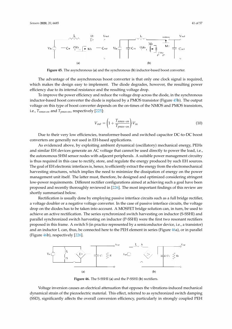
Sensors 2020, 20, 6685 41 of 57
Sensors 2020, 20, x FOR PEER REVIEW 42 of 58
The asynchronous boost converter is shown in Figure 45a. The respective output voltage depends on the duty cycle D of the switch M1, i.e., of clk1, so that [225]: 𝑉 = 𝑉1 − 𝐷 (9)
The advantage of the asynchronous boost converter is that only one clock signal is required, which makes the design easy to implement. The diode degrades, however, the resulting power efficiency due to its internal resistance and the resulting voltage drop.
To improve the power efficiency and reduce the voltage drop across the diode, in the synchronous inductor-based boost converter the diode is replaced by a PMOS transistor (Figure 45b). The output voltage on this type of boost converter depends on the on-times of the NMOS and PMOS transistors, i.e., Tnmos-on and Tpmos-on, respectively [225]: 𝑉 = 1 + 𝑇𝑇 ∙ 𝑉 (10)
Due to their very low efficiencies, transformer-based and switched capacitor DC-to-DC boost converters are generally not used in EH-based applications.
(a) (b)
Figure 45. The asynchronous (a) and the synchronous (b) inductor-based boost converter.
As evidenced above, by exploiting ambient dynamical (oscillatory) mechanical energy, PEHs and similar EH devices generate an AC voltage that cannot be used directly to power the load, i.e., the autonomous SHM sensor nodes with adjacent peripherals. A suitable power management circuitry is thus required in this case to rectify, store, and regulate the energy produced by such EH sources. The goal of EH electronic interfaces is, hence, to efficiently extract the energy from the electromechanical harvesting structures, which implies the need to minimize the dissipation of energy on the power management unit itself. The latter must, therefore, be designed and optimized considering stringent low-power requirements. Different rectifier configurations aimed at achieving such a goal have been proposed and recently thoroughly reviewed in [226]. The most important findings of this review are shortly summarised below.
Rectification is usually done by employing passive interface circuits such as a full bridge rectifier, a voltage doubler or a negative voltage converter. In the case of passive interface circuits, the voltage drop on the diodes has to be taken into account. A MOSFET bridge solution can, in turn, be used to achieve an active rectification. The series synchronized switch harvesting on inductor (S-SSHI) and parallel synchronized switch harvesting on inductor (P-SSHI) were the first two resonant rectifiers proposed in this frame. A switch S (in practice represented by a semiconductor device, i.e., a transistor) and an inductor L can, thus, be connected here to the PEH element in series (Figure 46a), or in parallel (Figure 46b), respectively [226].
(a) (b)
Figure 45. The asynchronous (a) and the synchronous (b) inductor-based boost converter.
The advantage of the asynchronous boost converter is that only one clock signal is required,which makes the design easy to implement. The diode degrades, however, the resulting powerefficiency due to its internal resistance and the resulting voltage drop.
To improve the power efficiency and reduce the voltage drop across the diode, in the synchronousinductor-based boost converter the diode is replaced by a PMOS transistor (Figure 45b). The outputvoltage on this type of boost converter depends on the on-times of the NMOS and PMOS transistors,i.e., Tnmos-on and Tpmos-on, respectively [225]:
Vout =
(1 +
Tnmos−on
Tpmos−on
)·Vin (10)
Due to their very low efficiencies, transformer-based and switched capacitor DC-to-DC boostconverters are generally not used in EH-based applications.
As evidenced above, by exploiting ambient dynamical (oscillatory) mechanical energy, PEHsand similar EH devices generate an AC voltage that cannot be used directly to power the load, i.e.,the autonomous SHM sensor nodes with adjacent peripherals. A suitable power management circuitryis thus required in this case to rectify, store, and regulate the energy produced by such EH sources.The goal of EH electronic interfaces is, hence, to efficiently extract the energy from the electromechanicalharvesting structures, which implies the need to minimize the dissipation of energy on the powermanagement unit itself. The latter must, therefore, be designed and optimized considering stringentlow-power requirements. Different rectifier configurations aimed at achieving such a goal have beenproposed and recently thoroughly reviewed in [226]. The most important findings of this review areshortly summarised below.
Rectification is usually done by employing passive interface circuits such as a full bridge rectifier,a voltage doubler or a negative voltage converter. In the case of passive interface circuits, the voltagedrop on the diodes has to be taken into account. A MOSFET bridge solution can, in turn, be used toachieve an active rectification. The series synchronized switch harvesting on inductor (S-SSHI) andparallel synchronized switch harvesting on inductor (P-SSHI) were the first two resonant rectifiersproposed in this frame. A switch S (in practice represented by a semiconductor device, i.e., a transistor)and an inductor L can, thus, be connected here to the PEH element in series (Figure 46a), or in parallel(Figure 46b), respectively [226].
Sensors 2020, 20, x FOR PEER REVIEW 42 of 58
The asynchronous boost converter is shown in Figure 45a. The respective output voltage depends on the duty cycle D of the switch M1, i.e., of clk1, so that [225]: 𝑉 = 𝑉1 − 𝐷 (9)
The advantage of the asynchronous boost converter is that only one clock signal is required, which makes the design easy to implement. The diode degrades, however, the resulting power efficiency due to its internal resistance and the resulting voltage drop.
To improve the power efficiency and reduce the voltage drop across the diode, in the synchronous inductor-based boost converter the diode is replaced by a PMOS transistor (Figure 45b). The output voltage on this type of boost converter depends on the on-times of the NMOS and PMOS transistors, i.e., Tnmos-on and Tpmos-on, respectively [225]: 𝑉 = 1 + 𝑇𝑇 ∙ 𝑉 (10)
Due to their very low efficiencies, transformer-based and switched capacitor DC-to-DC boost converters are generally not used in EH-based applications.
(a) (b)
Figure 45. The asynchronous (a) and the synchronous (b) inductor-based boost converter.
As evidenced above, by exploiting ambient dynamical (oscillatory) mechanical energy, PEHs and similar EH devices generate an AC voltage that cannot be used directly to power the load, i.e., the autonomous SHM sensor nodes with adjacent peripherals. A suitable power management circuitry is thus required in this case to rectify, store, and regulate the energy produced by such EH sources. The goal of EH electronic interfaces is, hence, to efficiently extract the energy from the electromechanical harvesting structures, which implies the need to minimize the dissipation of energy on the power management unit itself. The latter must, therefore, be designed and optimized considering stringent low-power requirements. Different rectifier configurations aimed at achieving such a goal have been proposed and recently thoroughly reviewed in [226]. The most important findings of this review are shortly summarised below.
Rectification is usually done by employing passive interface circuits such as a full bridge rectifier, a voltage doubler or a negative voltage converter. In the case of passive interface circuits, the voltage drop on the diodes has to be taken into account. A MOSFET bridge solution can, in turn, be used to achieve an active rectification. The series synchronized switch harvesting on inductor (S-SSHI) and parallel synchronized switch harvesting on inductor (P-SSHI) were the first two resonant rectifiers proposed in this frame. A switch S (in practice represented by a semiconductor device, i.e., a transistor) and an inductor L can, thus, be connected here to the PEH element in series (Figure 46a), or in parallel (Figure 46b), respectively [226].
(a) (b)
Figure 46. The S-SSHI (a) and the P-SSHI (b) rectifiers.
Voltage inversion causes an electrical attenuation that opposes the vibrations-induced mechanicaldynamical strain of the piezoelectric material. This effect, referred to as synchronized switch damping(SSD), significantly affects the overall conversion efficiency, particularly in strongly coupled PEH

Sensors 2020, 20, 6685 42 of 57
transducers. Due to the direct connection of the switched components to the PEH transducer,the SSD effect is indeed one of the main problems of both the S-SSHI and the P-SSHI rectifiers. In thesynchronized switching and discharging to a storage capacitor through an inductor (SSDCI) rectifier,the diode bridge rectifier is, in turn, directly connected to the PEH (Figure 47), thus preventing thecurrent flow that causes the evidenced electrical attenuation [226].
Sensors 2020, 20, x FOR PEER REVIEW 43 of 58
Figure 46. The S-SSHI (a) and the P-SSHI (b) rectifiers.
Voltage inversion causes an electrical attenuation that opposes the vibrations-induced mechanical dynamical strain of the piezoelectric material. This effect, referred to as synchronized switch damping (SSD), significantly affects the overall conversion efficiency, particularly in strongly coupled PEH transducers. Due to the direct connection of the switched components to the PEH transducer, the SSD effect is indeed one of the main problems of both the S-SSHI and the P-SSHI rectifiers. In the synchronized switching and discharging to a storage capacitor through an inductor (SSDCI) rectifier, the diode bridge rectifier is, in turn, directly connected to the PEH (Figure 47), thus preventing the current flow that causes the evidenced electrical attenuation [226].
Figure 47. The SSDCI rectifier circuit.
The synchronous electric charge extraction (SECE) technique is, on the other hand, a rectifier configuration similar to that of a buck–boost power converter, but with a different switch control (Figure 48). The SECE technique is intrinsically self-adaptive to the environment even in the case of random vibrations, and it is less sensitive to changes in the load, which makes it particularly attractive in the applications considered in this work [226].
Figure 48. The SECE rectifier circuit.
Using the SECE technique, the regulation of the trade-off among power extraction and the damping effect is, however, still unattainable. To overcome this limitation, the phase shift synchronous electric charge extraction (PS-SECE) rectifier was proposed. In the synchronized switch harvesting on inductor magnetic rectifier (MR-SSHI) the switching inductor is replaced by a step-up transformer that electrically decouples the storage capacitor from the PEH (Figure 49), and, since its coupling factor is chosen to be >1, it reduces the diode voltage drop reflected back to the PEH, increasing thus the value of the EH device’s voltage. The MR-SSHI rectifier configuration is, therefore, particularly suited to extract the energy in the case of very low input power levels [226].
Figure 49. The MR-SSHI rectifier circuit.
The hybrid SSHI rectifier (Figure 50) is a configuration derived combining the MR-SSHI rectifier, mostly effective for high load values, and the P-SSHI rectifier, mainly effective for middle load values.
Figure 47. The SSDCI rectifier circuit.
The synchronous electric charge extraction (SECE) technique is, on the other hand, a rectifierconfiguration similar to that of a buck–boost power converter, but with a different switch control(Figure 48). The SECE technique is intrinsically self-adaptive to the environment even in the case ofrandom vibrations, and it is less sensitive to changes in the load, which makes it particularly attractivein the applications considered in this work [226].
Sensors 2020, 20, x FOR PEER REVIEW 43 of 58
Figure 46. The S-SSHI (a) and the P-SSHI (b) rectifiers.
Voltage inversion causes an electrical attenuation that opposes the vibrations-induced mechanical dynamical strain of the piezoelectric material. This effect, referred to as synchronized switch damping (SSD), significantly affects the overall conversion efficiency, particularly in strongly coupled PEH transducers. Due to the direct connection of the switched components to the PEH transducer, the SSD effect is indeed one of the main problems of both the S-SSHI and the P-SSHI rectifiers. In the synchronized switching and discharging to a storage capacitor through an inductor (SSDCI) rectifier, the diode bridge rectifier is, in turn, directly connected to the PEH (Figure 47), thus preventing the current flow that causes the evidenced electrical attenuation [226].
Figure 47. The SSDCI rectifier circuit.
The synchronous electric charge extraction (SECE) technique is, on the other hand, a rectifier configuration similar to that of a buck–boost power converter, but with a different switch control (Figure 48). The SECE technique is intrinsically self-adaptive to the environment even in the case of random vibrations, and it is less sensitive to changes in the load, which makes it particularly attractive in the applications considered in this work [226].
Figure 48. The SECE rectifier circuit.
Using the SECE technique, the regulation of the trade-off among power extraction and the damping effect is, however, still unattainable. To overcome this limitation, the phase shift synchronous electric charge extraction (PS-SECE) rectifier was proposed. In the synchronized switch harvesting on inductor magnetic rectifier (MR-SSHI) the switching inductor is replaced by a step-up transformer that electrically decouples the storage capacitor from the PEH (Figure 49), and, since its coupling factor is chosen to be >1, it reduces the diode voltage drop reflected back to the PEH, increasing thus the value of the EH device’s voltage. The MR-SSHI rectifier configuration is, therefore, particularly suited to extract the energy in the case of very low input power levels [226].
Figure 49. The MR-SSHI rectifier circuit.
The hybrid SSHI rectifier (Figure 50) is a configuration derived combining the MR-SSHI rectifier, mostly effective for high load values, and the P-SSHI rectifier, mainly effective for middle load values.
Figure 48. The SECE rectifier circuit.
Using the SECE technique, the regulation of the trade-off among power extraction and thedamping effect is, however, still unattainable. To overcome this limitation, the phase shift synchronouselectric charge extraction (PS-SECE) rectifier was proposed. In the synchronized switch harvesting oninductor magnetic rectifier (MR-SSHI) the switching inductor is replaced by a step-up transformer thatelectrically decouples the storage capacitor from the PEH (Figure 49), and, since its coupling factor ischosen to be >1, it reduces the diode voltage drop reflected back to the PEH, increasing thus the valueof the EH device’s voltage. The MR-SSHI rectifier configuration is, therefore, particularly suited toextract the energy in the case of very low input power levels [226].
Sensors 2020, 20, x FOR PEER REVIEW 43 of 58
Figure 46. The S-SSHI (a) and the P-SSHI (b) rectifiers.
Voltage inversion causes an electrical attenuation that opposes the vibrations-induced mechanical dynamical strain of the piezoelectric material. This effect, referred to as synchronized switch damping (SSD), significantly affects the overall conversion efficiency, particularly in strongly coupled PEH transducers. Due to the direct connection of the switched components to the PEH transducer, the SSD effect is indeed one of the main problems of both the S-SSHI and the P-SSHI rectifiers. In the synchronized switching and discharging to a storage capacitor through an inductor (SSDCI) rectifier, the diode bridge rectifier is, in turn, directly connected to the PEH (Figure 47), thus preventing the current flow that causes the evidenced electrical attenuation [226].
Figure 47. The SSDCI rectifier circuit.
The synchronous electric charge extraction (SECE) technique is, on the other hand, a rectifier configuration similar to that of a buck–boost power converter, but with a different switch control (Figure 48). The SECE technique is intrinsically self-adaptive to the environment even in the case of random vibrations, and it is less sensitive to changes in the load, which makes it particularly attractive in the applications considered in this work [226].
Figure 48. The SECE rectifier circuit.
Using the SECE technique, the regulation of the trade-off among power extraction and the damping effect is, however, still unattainable. To overcome this limitation, the phase shift synchronous electric charge extraction (PS-SECE) rectifier was proposed. In the synchronized switch harvesting on inductor magnetic rectifier (MR-SSHI) the switching inductor is replaced by a step-up transformer that electrically decouples the storage capacitor from the PEH (Figure 49), and, since its coupling factor is chosen to be >1, it reduces the diode voltage drop reflected back to the PEH, increasing thus the value of the EH device’s voltage. The MR-SSHI rectifier configuration is, therefore, particularly suited to extract the energy in the case of very low input power levels [226].
Figure 49. The MR-SSHI rectifier circuit.
The hybrid SSHI rectifier (Figure 50) is a configuration derived combining the MR-SSHI rectifier, mostly effective for high load values, and the P-SSHI rectifier, mainly effective for middle load values.
Figure 49. The MR-SSHI rectifier circuit.
The hybrid SSHI rectifier (Figure 50) is a configuration derived combining the MR-SSHI rectifier,mostly effective for high load values, and the P-SSHI rectifier, mainly effective for middle load values.In fact, by coalescing these two approaches it is possible to extract energy in both the inversion and theconduction phases. The hybrid SSHI circuit does not improve conversion efficiency, but, due to thedoubled harvesting rate, it allows widening the attained load bandwidth [226].
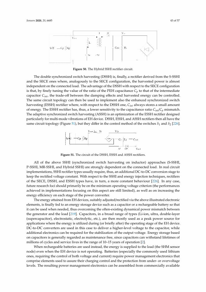
Sensors 2020, 20, 6685 43 of 57
Sensors 2020, 20, x FOR PEER REVIEW 44 of 58
In fact, by coalescing these two approaches it is possible to extract energy in both the inversion and the conduction phases. The hybrid SSHI circuit does not improve conversion efficiency, but, due to the doubled harvesting rate, it allows widening the attained load bandwidth [226].
Figure 50. The Hybrid SSHI rectifier circuit.
The double synchronized switch harvesting (DSSH) is, finally, a rectifier derived from the S-SSHI and the SECE ones where, analogously to the SECE configuration, the harvested power is almost independent on the connected load. The advantage of the DSSH with respect to the SECE configuration is that, by finely tuning the value of the ratio of the PEH capacitance Cp to that of the intermediate capacitor Cint, the trade-off between the damping effects and harvested energy can be controlled. The same circuit topology can then be used to implement also the enhanced synchronized switch harvesting (ESSH) rectifier where, with respect to the DSSH one, Cint always stores a small amount of energy. The ESSH rectifier has, thus, a lower sensitivity to the capacitance ratio Cint/Cp mismatch. The adaptive synchronized switch harvesting (ASSH) is an optimization of the ESSH rectifier designed particularly for multi-mode vibrations of EH device. DSSH, ESSH, and ASSH rectifiers then all have the same circuit topology (Figure 51), but they differ in the control method of the switches S1 and S2 [226].
Figure 51. The circuit of the DSSH, ESSH and ASSH rectifiers.
All of the above SSHI (synchronized switch harvesting on inductor) approaches (S-SSHI, P-SSHI, MR-SSHI, and Hybrid SSHI) are strongly dependent on the connected load. In real circuit implementations, SSHI rectifier types usually require, thus, an additional DC-to-DC conversion stage to keep the rectified voltage constant. With respect to the SSHI and energy injection techniques, rectifiers of the SECE, DSSH, and ESSH types have, in turn, a more constant behaviour [226]. In any case, future research foci should primarily be on the minimum operating voltage criterion (the performances achieved in implementations focusing on this aspect are still limited), as well as on increasing the energy efficiency on each stage of the power converter.
The energy attained from EH devices, suitably adjusted/rectified via the above illustrated electronic elements, is finally fed to an energy storage device such as a capacitor or a rechargeable battery so that it can be used when needed, thus overcoming the often-existing dynamical power mismatch between the generator and the load [219]. Capacitors, in a broad range of types (Li-ion, ultra, double-layer (supercapacitor), electrostatic, electrolytic, etc.), are then mostly used as a peak power source for applications where the energy is utilized during (or briefly after) the operating stage of the EH device. DC-to-DC converters are used in this case to deliver a higher-level voltage to the capacitor, while additional electronics can be required for the stabilization of the output voltage.
Figure 50. The Hybrid SSHI rectifier circuit.
The double synchronized switch harvesting (DSSH) is, finally, a rectifier derived from the S-SSHIand the SECE ones where, analogously to the SECE configuration, the harvested power is almostindependent on the connected load. The advantage of the DSSH with respect to the SECE configurationis that, by finely tuning the value of the ratio of the PEH capacitance Cp to that of the intermediatecapacitor Cint, the trade-off between the damping effects and harvested energy can be controlled.The same circuit topology can then be used to implement also the enhanced synchronized switchharvesting (ESSH) rectifier where, with respect to the DSSH one, Cint always stores a small amountof energy. The ESSH rectifier has, thus, a lower sensitivity to the capacitance ratio Cint/Cp mismatch.The adaptive synchronized switch harvesting (ASSH) is an optimization of the ESSH rectifier designedparticularly for multi-mode vibrations of EH device. DSSH, ESSH, and ASSH rectifiers then all have thesame circuit topology (Figure 51), but they differ in the control method of the switches S1 and S2 [226].
Sensors 2020, 20, x FOR PEER REVIEW 44 of 58
In fact, by coalescing these two approaches it is possible to extract energy in both the inversion and the conduction phases. The hybrid SSHI circuit does not improve conversion efficiency, but, due to the doubled harvesting rate, it allows widening the attained load bandwidth [226].
Figure 50. The Hybrid SSHI rectifier circuit.
The double synchronized switch harvesting (DSSH) is, finally, a rectifier derived from the S-SSHI and the SECE ones where, analogously to the SECE configuration, the harvested power is almost independent on the connected load. The advantage of the DSSH with respect to the SECE configuration is that, by finely tuning the value of the ratio of the PEH capacitance Cp to that of the intermediate capacitor Cint, the trade-off between the damping effects and harvested energy can be controlled. The same circuit topology can then be used to implement also the enhanced synchronized switch harvesting (ESSH) rectifier where, with respect to the DSSH one, Cint always stores a small amount of energy. The ESSH rectifier has, thus, a lower sensitivity to the capacitance ratio Cint/Cp mismatch. The adaptive synchronized switch harvesting (ASSH) is an optimization of the ESSH rectifier designed particularly for multi-mode vibrations of EH device. DSSH, ESSH, and ASSH rectifiers then all have the same circuit topology (Figure 51), but they differ in the control method of the switches S1 and S2 [226].
Figure 51. The circuit of the DSSH, ESSH and ASSH rectifiers.
All of the above SSHI (synchronized switch harvesting on inductor) approaches (S-SSHI, P-SSHI, MR-SSHI, and Hybrid SSHI) are strongly dependent on the connected load. In real circuit implementations, SSHI rectifier types usually require, thus, an additional DC-to-DC conversion stage to keep the rectified voltage constant. With respect to the SSHI and energy injection techniques, rectifiers of the SECE, DSSH, and ESSH types have, in turn, a more constant behaviour [226]. In any case, future research foci should primarily be on the minimum operating voltage criterion (the performances achieved in implementations focusing on this aspect are still limited), as well as on increasing the energy efficiency on each stage of the power converter.
The energy attained from EH devices, suitably adjusted/rectified via the above illustrated electronic elements, is finally fed to an energy storage device such as a capacitor or a rechargeable battery so that it can be used when needed, thus overcoming the often-existing dynamical power mismatch between the generator and the load [219]. Capacitors, in a broad range of types (Li-ion, ultra, double-layer (supercapacitor), electrostatic, electrolytic, etc.), are then mostly used as a peak power source for applications where the energy is utilized during (or briefly after) the operating stage of the EH device. DC-to-DC converters are used in this case to deliver a higher-level voltage to the capacitor, while additional electronics can be required for the stabilization of the output voltage.
Figure 51. The circuit of the DSSH, ESSH and ASSH rectifiers.
All of the above SSHI (synchronized switch harvesting on inductor) approaches (S-SSHI,P-SSHI, MR-SSHI, and Hybrid SSHI) are strongly dependent on the connected load. In real circuitimplementations, SSHI rectifier types usually require, thus, an additional DC-to-DC conversion stage tokeep the rectified voltage constant. With respect to the SSHI and energy injection techniques, rectifiersof the SECE, DSSH, and ESSH types have, in turn, a more constant behaviour [226]. In any case,future research foci should primarily be on the minimum operating voltage criterion (the performancesachieved in implementations focusing on this aspect are still limited), as well as on increasing theenergy efficiency on each stage of the power converter.
The energy attained from EH devices, suitably adjusted/rectified via the above illustrated electronicelements, is finally fed to an energy storage device such as a capacitor or a rechargeable battery so thatit can be used when needed, thus overcoming the often-existing dynamical power mismatch betweenthe generator and the load [219]. Capacitors, in a broad range of types (Li-ion, ultra, double-layer(supercapacitor), electrostatic, electrolytic, etc.), are then mostly used as a peak power source forapplications where the energy is utilized during (or briefly after) the operating stage of the EH device.DC-to-DC converters are used in this case to deliver a higher-level voltage to the capacitor, whileadditional electronics can be required for the stabilization of the output voltage. Energy storage basedon capacitors is generally regarded as maintenance free, since capacitors can withstand lifetimes ofmillions of cycles and service lives in the range of 10–15 years of operation [2].
When rechargeable batteries are used instead, the energy is supplied to the load (the SHM sensornode) even when the EH device is not operating. Batteries (especially the commonly used lithiumones, requiring the control of both voltage and current) require power management electronics thatcomprise elements used to assure their charging control and the protection from under- or overvoltagelevels. The resulting power management electronics can be assembled from commercially available
Sensors 2020, 20, 6685 44 of 57
components (which is generally the case for high-power applications–at the level of tens of W andhigher), or, for lower power levels, it can be purchased as a specific ‘surface-mount technology device’(SMD), with all the electronics elements integrated onto the surface of a printed circuit board (PCB).Batteries, which can generally be in the form of Li-ion, Li-ion-polymer, lead-acid, Ni-MH or Ni-Cdones, require maintenance as well [2]. The batteries considered appropriate for energy storage inEH-based applications have a capacity range typically from 1 to 4 Ah (i.e., approximately from 3.5 to14 Wh) [1]. If a constant power of 100 mW would, thus, be required in a specific SHM applicationon an aircraft, a fully charged battery with a 10 Wh capacity would, therefore, theoretically last forfour days. This confirms once more the evidenced importance of carefully considering the optimalduty cycle of operation of the SHM sensor nodes and the respective data elaboration and wirelesstransmission modules.
It has to be noted in this context also that the temperature range of operation is a very importantaspect in choosing the appropriate storage device to be used in aeronautic applications as well. In fact,although Li-ion rechargeable batteries that are characterised by a high energy density and a lowself-discharge rate, are commonly used, their operational temperature range is limited from ca. −20 Cto ca. + 60 C. Besides a lower energy density and high self-discharge rate, Ni-MH batteries havean even more limited temperature range (0 to + 60 C). Compared to batteries, supercapacitors arecharacterised by a smaller energy density and higher self-discharge rates, but their lower operationaltemperature limit is down to −40 C, so that they might be a more appropriate solution for aircraftapplications [1].
One of the disadvantages of commercially available supercapacitors is, however, their voltagerating, which, due to leakage currents and resulting discharging characteristics, is lower for highercapacities (they are usually rated at 2.5 V). This implies that several supercapacitors have to be connectedin series to obtain suitable voltage levels for the applications considered in this work [227]. A possiblesolution for energy storage that is sometimes considered is, thus, a hybrid solution, where a battery anda supercapacitor are combined, usually in a parallel connection. Since supercapacitors are characterizedby low energy density, while batteries suffer from low power density, their connection, with respect toa single element, leads to a system with higher energy and power densities. An important advantageof hybrid systems is also that the battery does not power the load directly, so there are no suddenbattery voltage drops associated with short-term higher current needs [2].
The most important elements and the respective main characteristics of the power managementelectronics and the corresponding storage devices, used in EH-based devices and systems, have,thus, also been reviewed. The above treatise shows, hence, that in this context the respective criticalelements, are the DC-to-DC boost converters, with the advantages of inductor-based synchronousboost converters clearly evidenced, and low-loss AC-to-DC rectifiers, where it is shown that the SECEand DSSH-related rectifier configurations could be particularly suitable for the applications in SHMairplane systems considered in this work. Concerning the energy storage elements, it is, in turn, shownthat capacitors, to be used as peak power sources, are a maintenance free long-life solution that can beused at low temperatures-a very important aspect in applications in airplanes, but are characterised bylimited energy densities. Batteries, can, in turn, be used even when the EH device is not operating,but they require additional electronics, need maintenance, can be used in limited temperature rangesand are characterised by lower power densities. Hybrid solutions are thus sometimes considered as anappropriate solution, while developments in the ongoing research on high capacity and fast chargingbatteries are also to be monitored.
The readers have therefore now been provided with a complete overview of the most importantfeatures of all the components considered in this work. The resulting conclusions can hence be drawn.
8. Conclusions and Outlook
A detailed review of the prospective EH technologies to be used for powering integrated SHMsystems in airplanes (especially their composite components), thus enabling a weight reduction and

Sensors 2020, 20, 6685 45 of 57
an increased fuel consumption efficiency, while reducing the MRO (maintenance, repair, overhaul)costs of aircraft via predictive maintenance, is given in this work as part of the activities carriedon in the framework of the EU COST Action CA18203 “Optimising Design for Inspection” (ODIN).A description of the hence used SHM technologies, with an estimate of the needed power levels for awave propagation autonomous in-process SHM sensor node with the coupled data elaboration andwireless data transfer modules, is thus given first, allowing to determine that in this case powers onthe level of several hundred mW would be needed. EH devices investigated in the most up-to-dateliterature that could provide viable means for satisfying these requirements in the given operationalconditions are therefore thoroughly reviewed next. The broad study of all the main potential EHmodalities to be used for powering the autonomous SHM sensor nodes in airplanes with theirperipherals, allowed hence establishing clear guidelines for the selection of the most appropriate onesin specific applications, evidencing at the same time their inherent advantages but also some limitations.The large number of presented state-of-the-art design configurations also provides a stimulus andinspiration for further innovations in this field.
It is hence shown that, due to abundance of dynamical excitations on airplanes, kinetic EHdevices, usually based on piezoelectric or electromagnetic transduction, are a very attractive andbroadly investigated solution, provided that their inherent advantages and drawbacks, summarisedin the above Section 2.4., are duly considered and the devices are mounted in the vicinity (enclosureor mounting fixture) of the airplane engine, i.e., in locations with stable and predictable dynamicalexcitation conditions. Magnetostrictive, electrostatic, and TENG devices have, in turn, their inherentlimitations and their technology readiness is not yet at the level required by the aeronautic industry.
Due to the presence of significant thermal gradients on-board of an aircraft, especially along theaeroengines, TEG devices, a rather mature technology proven on test flights, are shown to be alsoan attractive EH solution in airplanes, allowing potentially high power densities to be achieved (cf.Section 3.3.). Due to low conversion efficiencies, their usage in areas where medium or low temperaturedifferentials are present could be interesting only when coupled to low-power electronics, providedfurther research work to reach higher TRLs for aircraft integration is carried on.
PV technology, with the large airplane surfaces where it can be used, has been proven as efficientmeans to power whole specially designed airplanes, while its usage for specific energy needs incommercial airplanes is matter of recent investigations only. In fact, although the efficiency of eventualPV EH applications in aircraft is highly dependent on the used PV cells and on uncontrollableenvironmental influences during flight, the very high attainable maximal power densities make thepotentials of PV EH devices very interesting for much wider systematic investigations.
Airflow EH devices, based on a practically unlimited energy well, show interesting potentials.With a proper consideration of aerodynamic resistance issues and other design constrains relatedto their potential usage in factual aeronautical applications, oscillating bodies and, in perspective,micro-turbines, could thus possibly offer, promising possibilities, while acoustic devices allow attainingonly very limited specific powers and their technology readiness is low.
The RF devices offer, finally, a means to deliver wirelessly the energy to SHM sensor nodes inlocations that are difficult to access, but also assure the feedback on their operation. They allow,however, obtaining power densities at the level of only tens of µW/cm3, i.e., far lower than the otherconsidered EH methodologies.
Provided, then, that the evident potentials of the vibration PEH and electromagnetic resonatordevices, as well as of the high temperature gradient TEGs, are proven in the specific applicationsconsidered in this work, while the technology readiness of PV and some of the airflow (micro-turbineand, perhaps, fluttering/galloping devices) is improved, and taking into account the temporallychanging ranges of optimal operation of these technologies, most probably the best solution couldbe the combined use of several of these EH devices so as to provide reliably and with sufficientsafety margins the needed power levels of hundreds of mW even in the worst foreseeable operatingconditions. However, this makes the task of selecting the most appropriate power management

Sensors 2020, 20, 6685 46 of 57
electronics configurations and the choice of the respective energy storage elements even more criticalthan what is the case when only a single EH device and/or EH technology is considered.
The review of the power management architectures provided in Section 8 shows hence theimportance and relevance of inductor-based synchronous boost converters and of the synchronouselectric charge extraction and the double synchronized switch harvesting AC-to-DC rectifiers in theherein considered application field. Capacitors are, then, to be used as peak power sources in lowtemperature conditions, batteries can be used when the EH device is not operating, while hybridsolutions, offering, concurrently, high energy and high power densities, are increasingly considered asa viable integrated solution.
The guidelines for the choice of the power management electronics and of the energy storageelements, when coupled to the provided guidelines on the EH devices themselves, as well as to theresults of the active work of the other components of the ODIN EU COST Action on the optimizationof the placement of the sensors, the minimization of the respective power consumption, and theoptimization of the signal processing protocols as well as data transmission rates, create in perspectivethe preconditions for the development of a new class of autonomous sensor nodes for in-processnon-destructive SHM of composite airplane components. The very broad list of the most recentbibliographical references provided at the end of the paper provides the perspective readers, in anycase, the possibility to further deepen their understanding of all the aspects of the topics treated inthis work.
Author Contributions: Conceptualization and methodology, Z.H. and S.Z.; writing—original draft preparation,Z.H., S.Z., S.B., T.B., P.G., J.H., L.J., E.K., F.K., T.K., L.L., M.M., A.O., V.P., O.R., O.Š., J.P.B.S., P.T., B.T., R.U., J.V.,and Ž.V.; writing—review and editing, S.Z. and Z.H. All authors have read and agreed to the published version ofthe manuscript.
Funding: This research is funded, and the APC of its publication are covered, by the COST (European Cooperationin Science and Technology) Action CA18203 “Optimising Design for Inspection” (ODIN) under the EU Horizon2020 Framework Programme.
Acknowledgments: The work of S. Zelenika, P. Gljušcic, E. Kamenar and Ž. Vrcan is partly enabled by usingthe equipment funded via the EU European Regional Development Fund (ERDF) project no. RC.2.2.06-0001:“Research Infrastructure for Campus-based Laboratories at the University of Rijeka (RISK)” and partly supportedby the University of Rijeka, Croatia, project uniri-tehnic-18-32 „Advanced mechatronics devices for smarttechnological solutions“. Z. Hadas, P. Tofel and O. Ševecek acknowledge the support provided via the CzechScience Foundation project GA19-17457S „Manufacturing and analysis of flexible piezoelectric layers for smartengineering”. J. Hlinka, F. Ksica and O. Rubes gratefully acknowledge the financial support provided by theESIF, EU Operational Programme Research, Development and Education within the research project Center ofAdvanced Aerospace Technology (Reg. No.: CZ.02.1.01/0.0/0.0/16_019/0000826) at the Faculty of MechanicalEngineering, Brno University of Technology. V. Pakrashi would like to acknowledge UCD Energy Institute, Marineand Renewable Energy Ireland (MaREI) centre Ireland, Strengthening Infrastructure Risk Assessment in theAtlantic Area (SIRMA) Grant No. EAPA\826/2018, EU INTERREG Atlantic Area and Aquaculture Operations withReliable Flexible Shielding Technologies for Prevention of Infestation in Offshore and Coastal Areas (FLEXAQUA),MarTera Era-Net cofund PBA/BIO/18/02 projects. The work of J.P.B. Silva is partially supported by the PortugueseFoundation for Science and Technology (FCT) in the framework of the Strategic Funding UIDB/FIS/04650/2020.M. Mrlik gratefully acknowledges the support of the Ministry of Education, Youth and Sports of the CzechRepublic-DKRVO (RP/CPS/2020/003).
Conflicts of Interest: The authors declare no conflict of interest. The funders had no role in the design of thestudy; in the collection, analyses, or interpretation of data; in the writing of the manuscript, or in the decision topublish the results.
References
1. Becker, T.; Kluge, M.; Schalk, J.; Tiplady, K.; Paget, C.; Hilleringmann, U.; Otterpohl, T. Autonomous SensorNodes for Aircraft Structural Health Monitoring. IEEE Sens. J. 2009, 9, 1589–1595. [CrossRef]
2. Thangaraj, K. Development of efficient energy storage and power management for autonomous aircraftstructural health monitoring system. Ph.D. Thesis, Cardiff University, Cardiff, UK, November 2017.

Sensors 2020, 20, 6685 47 of 57
3. Ross, R.W. Integrated vehicle health management in aerospace structures. In Structural Health Monitoring(SHM) in Aerospace Structures; Yuan, F.-G., Ed.; Elsevier: Amsterdam, The Netherlands, 2016; pp. 3–31.[CrossRef]
4. Cawley, P. Structural health monitoring: Closing the gap between research and industrial deployment.Struct. Health Monit. 2018, 17, 1225–1244. [CrossRef]
5. Abbas, S.; Li, F.; Qiu, J. A Review on SHM Techniques and Current Challenges for Characteristic Investigationof Damage in Composite Material Components of Aviation Industry. Mater. Perform. Charact. 2018, 7,20170167. [CrossRef]
6. Qing, X.; Li, W.; Wang, Y.; Sun, H. Piezoelectric transducer-based structural health monitoring for aircraftapplications. Sensors 2019, 19, 545. [CrossRef]
7. Dong, T.; Kim, N.H. Cost-effectiveness of structural health monitoring in fuselage maintenance of the civilaviation industry. Aerospace 2018, 5, 87. [CrossRef]
8. Pearson, M.R.; Eaton, M.J.; Pullin, R.; Featherston, C.A.; Holford, K.M. Energy Harvesting for AerospaceStructural Health Monitoring Systems. J. Phys. Conf. Ser. 2012, 382, 012025. [CrossRef]
9. Memorandum of Understanding for the Implementation of the COST Action “Optimising Design for Inspection”(ODIN) CA 18203; COST Association: Brussels, Belgium, 2019. Available online: http://odin-cost.com/
(accessed on 22 September 2020).10. Papasalouros, D.; Tsopelas, N.; Anastasopoulos, A.; Kourosis, D.; Lekou, D.J.; Mouzakis, F. Acoustic Emission
Monitoring of Composite Blade of NM48 / 750 NEG—MICON Wind Turbine. J. Acoust. Emiss. 2013, 31,36–49.
11. Hill, E.; Rovik, C. In-Flight Fatigue Crack Growth Monitoring in a Cessna T-303 Crusader Vertical Tail.J. Acoust. Emiss. 2013, 31, 19–35.
12. Holford, K.M.; Pullin, R.; Evans, S.L.; Eaton, M.J.; Hensman, J.; Worden, K. Acoustic emission for monitoringaircraft structures. Proc. Inst. Mech. Eng. Part G J. Aerosp. Eng. 2009, 223, 525–532. [CrossRef]
13. Zhao, X.; Gao, H.; Zhang, G.; Ayhan, B.; Yan, F.; Kwan, C.; Rose, J.L. Active health monitoring of an aircraftwing with embedded piezoelectric sensor/actuator network: I. Defect detection, localization and growthmonitoring. Smart Mater. Struct. 2007, 16, 1208–1217. [CrossRef]
14. Mei, H.; Haider, M.F.; Joseph, R.; Migot, A.; Giurgiutiu, V. Recent advances in piezoelectric wafer activesensors for structural health monitoring applications. Sensors 2019, 19, 383. [CrossRef]
15. Ren, B.; Lissenden, C.J. PVDF multielement lamb wave sensor for structural health monitoring. IEEE Trans.Ultrason. Ferroelectr. Freq. Control 2016, 63, 178–185. [CrossRef]
16. Holst, C.A.; Lohweg, V.; Röckemann, K.; Steinmetz, A. Lamb Wave-based Quality Inspection of RepairedCarbon Fibre Reinforced Polymers for On-Site Aircraft Maintenance. In Proceedings of the IEEE InternationalConference on Emerging Technologies and Factory Automation, Zaragoza, Spain, 10–13 September 2019;pp. 1643–1646. [CrossRef]
17. Memmolo, V.; Monaco, E.; Boffa, N.D.; Maio, L.; Ricci, F. Guided wave propagation and scattering forstructural health monitoring of stiffened composites. Compos. Struct. 2018, 184, 568–580. [CrossRef]
18. Derriso, M.M.; McCurry, C.D.; Schubert Kabban, C.M. A novel approach for implementing structural healthmonitoring systems for aerospace structures. In Structural Health Monitoring (SHM) in Aerospace Structures;Yuan, F.-G., Ed.; Elsevier: Amsterdam, The Netherlands, 2016; pp. 33–56. [CrossRef]
19. Yu, L.; Tian, Z. Phased array techniques for damage detection in aerospace structures. In Structural HealthMonitoring (SHM) in Aerospace Structures; Yuan, F.-G., Ed.; Elsevier: Amsterdam, The Netherlands, 2016;pp. 285–306. [CrossRef]
20. Su, Z.; Hong, M. Nonlinear ultrasonics for health monitoring of aerospace structures using active sparsesensor networks. In Structural Health Monitoring (SHM) in Aerospace Structures; Yuan, F.-G., Ed.; Elsevier:Amsterdam, The Netherlands, 2016; pp. 353–392. [CrossRef]
21. Hill, K.O.; Meltz, G. Fiber Bragg grating technology fundamentals and overview. J. Lightwave Technol. 1997,15, 1263–1276. [CrossRef]
22. Kahandawa, G.C.; Epaarachchi, J.; Wang, H.; Lau, K.T. Use of FBG sensors for SHM in aerospace structures.Photonic Sens. 2012, 2, 203–214. [CrossRef]
23. Cusano, A.; Capoluongo, P.; Campopiano, S.; Cutolo, A.; Giordano, M.; Felli, F.; Paolazzi, A.; Caponero, M.Experimental modal analysis of an aircraft model wing by embedded fiber Bragg grating sensors. IEEE Sens. J.2006, 6, 67–77. [CrossRef]

Sensors 2020, 20, 6685 48 of 57
24. Gao, Z.; Zhu, X.; Fang, Y.; Zhang, H. Active monitoring and vibration control of smart structure aircraftbased on FBG sensors and PZT actuators. Aerosp. Sci. Technol. 2017, 63, 101–109. [CrossRef]
25. Choi, Y.; Abbas, S.H.; Lee, J.-R. Aircraft integrated structural health monitoring using lasers, piezoelectricity,and fiber optics. Measurement 2018, 125, 294–302. [CrossRef]
26. Di Sante, R. Fibre Optic Sensors for Structural Health Monitoring of Aircraft Composite Structures: RecentAdvances and Applications. Sensors 2015, 15, 18666–18713. [CrossRef]
27. Na, W.S.; Baek, J. Piezoelectric impedance-based non-destructive testing method for possible identificationof composite debonding depth. Micromachines 2019, 10, 621. [CrossRef]
28. Soh, C.K.; Lim, Y.Y. Fatigue damage diagnosis and prognosis using electromechanical impedance technique.In Structural Health Monitoring (SHM) in Aerospace Structures; Yuan, F.-G., Ed.; Elsevier: Amsterdam,The Netherlands, 2016; pp. 429–446. [CrossRef]
29. Ksica, F.; Hadas, Z.; Hlinka, J. Integration and test of piezocomposite sensors for structure health monitoringin aerospace. Measurement 2019, 147, 106861. [CrossRef]
30. Qiu, L.; Deng, X.; Yuan, S.; Huang, Y.; Ren, Y. Impact Monitoring for Aircraft Smart Composite Skins Basedon a Lightweight Sensor Network and Characteristic Digital Sequences. Sensors 2018, 18, 2218. [CrossRef]
31. Wang, Y.; Qiu, L.; Luo, Y.; Ding, R. A stretchable and large-scale guided wave sensor network for aircraftsmart skin of structural health monitoring. Struct. Health Monit. 2019. [CrossRef]
32. Gljušcic, P.; Zelenika, S.; Blaževic, D.; Kamenar, E. Kinetic Energy Harvesting for Wearable Medical Sensors.Sensors 2019, 19, 4922. [CrossRef]
33. Technical Characteristics and Spectrum Requirements of Wireless Avionics Intra-Communications System to Supporttheir Safe Operation—M Series: Mobile, Radiodetermination, Amateur and Related satellite Services; ReportITU-R M.2283-0; International Telecommunication Union—Radiocommunication Sector (ITU-R): Geneva,Switzerland, 2014.
34. SC-236 Standards for Wireless Avionics Intra-Communication System (WAIC) within 4200-4400 MHz.Available online: https://www.rtca.org/content/sc-236 (accessed on 26 July 2020).
35. Fang, K.; Liu, C.; Teng, J. Cluster-based optimal wireless sensor deployment for structural health monitoring.Struct. Health Monit. 2018, 17, 266–278. [CrossRef]
36. Kazmierski, T.J.; Beeby, S. (Eds.) Energy Harvesting Systems: Principles Modeling and Applications; Springer:New York, NY, USA, 2011; ISBN 978-1-4419-7565-2. [CrossRef]
37. Priya, S.; Inman, D.J. (Eds.) Energy Harvesting Technologies; Springer: New York, NY, USA, 2009;ISBN 978-0-387-76463-4. [CrossRef]
38. Somà, A.; De Pasquale, G. Electro-mechanical coupled design of self-powered sensing systems andperformances comparison through experiments. Frattura ed Integrità Strutturale 2013, 23, 94–102. [CrossRef]
39. Tan, Y.K. Energy Harvesting Autonomous Sensor Systems: Design, Analysis, and Practical Implementation; CRCPress: Boca Raton, IL, USA, 2013; ISBN 978-1-4398-9273-2.
40. Guidelines for Implementation of Structural Health Monitoring on Fixed Wing Aircraft. Aerospace IndustrySteering Committee on Structural Health; SAE International: Warrendale, PA, USA, 2013. [CrossRef]
41. Bashir, M.; Rajendran, P.; Khan, S.A. Energy Harvesting from Aerodynamic Instabilities: Current Prospectand Future Trends. IOP Conf. Ser. Mat. Sci. 2018, 290, 012054. [CrossRef]
42. Le, M.Q.; Capsal, J.-F.; Lallart, M.; Hebrard, Y.; Van Der Ham, A.; Reffe, N.; Geynet, L.; Cottinet, P.-J. Reviewon energy harvesting for structural health monitoring in aeronautical applications. Progr. Aerosp. Sci. 2015,79, 147–157. [CrossRef]
43. Vankecke, C.; Assouère, L.; Wang, A.; Durand-Estèbe, P.; Caignet, F.; Dilhac, J.M.; Bafleur, M. Multisourceand battery-free energy harvesting architecture for aeronautics applications. IEEE Trans. Power Electron.2015, 30, 3215–3227. [CrossRef]
44. Arms, S.W.; Galbreath, J.H.; Townsend, C.P.; Churchill, D.L.; Corneau, B.; Ketcham, R.P.; Phan, N. Energyharvesting wireless sensors and networked timing synchronization for aircraft structural health monitoring.In Proceedings of the 1st International Conference on Wireless Communication, Vehicular Technology,Information Theory and Aerospace & Electronic Systems Technology, Aalborg, Denmark, 17–20 May 2009.[CrossRef]
45. Tang, X.; Wang, X.; Cattley, R.; Gu, F.; Ball, A.D. Energy Harvesting Technologies for Achieving Self-PoweredWireless Sensor Networks in Machine Condition Monitoring: A Review. Sensors 2018, 18, 4113. [CrossRef]

Sensors 2020, 20, 6685 49 of 57
46. Sundriyal, P.; Bhattacharya, S. Energy harvesting techniques for powering wireless sensor networks in aircraftapplications: A review. In Sensors for Automotive and Aerospace Applications; Bhattacharya, S., Agarwal, A.,Prakash, O., Singh, S., Eds.; Springer: Berlin, Germany, 2019; pp. 55–76. [CrossRef]
47. Wood, O.J.; Featherston, C.A.; Kennedy, D.; Eaton, M.; Pullin, R. Optimised Vibration Energy Harvesting forAerospace Applications. Key Eng. Mater. 2012, 518, 246–260. [CrossRef]
48. Boisseau, S.; Despesse, G.; Seddik, B.A. Electrostatic Conversion for Vibration Energy Harvesting.In Small-Scale Energy Harvesting; Lallart, M., Ed.; InTech: London, UK, 2012. [CrossRef]
49. Wang, Z.; Lin, L.; Chen, J.; Niu, S.; Zi, Y. Triboelectric Nanogenerators; Springer Nature: Cham, Switzerland, 2016.[CrossRef]
50. Wei, C.; Jing, X. A comprehensive review on vibration energy harvesting: Modelling and realization.Renew. Sustain. Energy Rev. 2017, 74, 1–18. [CrossRef]
51. Williams, C.B.; Yates, R.B. Analysis of a micro-electric generator for microsystems. Sens. Actuators A-Phys.1996, 52, 8–11. [CrossRef]
52. Hadas, Z.; Ondrusek, C.; Singule, V. Power sensitivity of vibration energy harvester. Microsyst. Tecnol. 2010,16, 691–702. [CrossRef]
53. Akbar, M.; Curiel-Sosa, J.L. Piezoelectric energy harvester composite under dynamic bending withimplementation to aircraft wingbox structure. Compos. Struct. 2016, 153, 193–203. [CrossRef]
54. Lee, S.; Youn, B.D. A new piezoelectric energy harvesting design concept: Multimodal energy harvestingskin. IEEE Trans. Ultrason. Ferroelectr. Freq. Control 2011, 58, 629–645. [CrossRef]
55. Bowen, C.R.; Kim, H.A.; Weaver, P.M.; Dunn, S. Piezoelectric and ferroelectric materials and structures forenergy harvesting applications. Energy Environ. Sci. 2014, 7, 25–44. [CrossRef]
56. Ambrosio, R.; Jimenez, A.; Mireles, J.; Moreno, M.; Monfil, K.; Heredia, H. Study of Piezoelectric EnergyHarvesting System Based on PZT. Integr. Ferroelectr. 2011, 126, 77–86. [CrossRef]
57. James, E.P.; Tudor, M.J.; Beeby, S.P.; Harris, N.R.; Glynne-Jones, P.; Ross, J.N.; White, N.M. An investigationof self-powered systems for condition monitoring applications. Sens. Actuators A-Phys. 2004, 110, 171–176.[CrossRef]
58. Hadas, Z.; Smilek, J.; Rubes, O. Analyses of electromagnetic and piezoelectric systems for efficient vibrationenergy harvesting. In Smart Sensors, Actuators, and MEMS VIII, Proc SPIE Microtechnologies; Fonseca, L.,Prunnila, M., Peiner, E., Eds.; SPIE: Bellingham, WA, USA, 2017. [CrossRef]
59. Khaligh, A. Kinetic Energy Harvesting Using Piezoelectric and Electromagnetic Technologies—State of theArt. IEEE Trans. Ind. Electron. 2010, 57, 850–860. [CrossRef]
60. Kim, S.; Vyas, R.; Bito, J.; Niotaki, K.; Collado, A.; Georgiadis, A.; Tentzeris, M.M. Ambient RFEnergy-Harvesting Technologies for Self-Sustainable Standalone Wireless Sensor Platforms. Proc. IEEE 2014,102, 1649–1666. [CrossRef]
61. Beeby, S.; White, N. (Eds.) Energy Harvesting for Autonomous Systems; Artech House: Norwood, MA, USA,2010; ISBN 978-1-59693-718-5.
62. Basseville, M.; Benveniste, A.; Goursat, M.; Meve, L. In-Flight Vibration Monitoring of Aeronautical Structures.IEEE Control Syst. Mag. 2007, 27, 27–42. [CrossRef]
63. Hadas, Z.; Vetiska, V.; Vetiska, J.; Krejsa, J. Analysis and efficiency measurement of electromagnetic vibrationenergy harvesting system. Microsyst. Technol. 2016, 22, 1767–1779. [CrossRef]
64. Dunno, K.; Batt, G. Analysis of in-flight vibration of a twin-engine turbo propeller aircraft. Packag. Technol. Sci.2009, 22, 479–485. [CrossRef]
65. Pearson, M.; Featherston, C.A.; Pullin, R.; Holford, K.M. Optimized Placement of Parasitic Vibration EnergyHarvesters for Autonomous Structural Health Monitoring. J. Intell. Mater. Syst. Struct. 2020, 31, 1403–1415.[CrossRef]
66. Caliò, R.; Rongala, U.B.; Camboni, D.; Milazzo, M.; Stefanini, C.; De Petris, G.; Oddo, C.M. PiezoelectricEnergy Harvesting Solutions. Sensors 2014, 14, 4755–4790. [CrossRef]
67. Dhakar, L.; Liu, H.; Tay, F.E.H.; Lee, C. A new energy harvester design for high power output at lowfrequencies. Sens. Actuators A Phys. 2013, 199, 344–352. [CrossRef]
68. Du, S.; Jia, Y.; Zhao, C.; Amaratunga, G.A.J.; Seshia, A.A. A Nail-size Piezoelectric Energy Harvesting SystemIntegrating a MEMS Transducer and a CMOS Interface Circuit. IEEE Sens. J. 2020, 20, 277–285. [CrossRef]
69. Aboulfotoh, N.A.; Arafa, M.H.; Megahed, S.M. A self-tuning resonator for vibration energy harvesting.Sens. Actuators A Phys. 2013, 201, 328–334. [CrossRef]

Sensors 2020, 20, 6685 50 of 57
70. Xu, Z.; Shan, X.; Chen, D.; Xie, T. A Novel Tunable Multi-Frequency Hybrid Vibration Energy HarvesterUsing Piezoelectric and Electromagnetic Conversion Mechanisms. Appl. Sci. 2016, 6, 10. [CrossRef]
71. Soliman, M.S.M.; Abdel-Rahman, E.M.; El-Saadany, E.F.; Mansour, R.R. A wideband vibration-based energyharvester. J. Micromech. Microeng. 2008, 18, 115021. [CrossRef]
72. Barton, D.A.W.; Burrow, S.G.; Clare, L.R. Energy Harvesting From Vibrations with a Nonlinear Oscillator.J. Vib. Acoust. 2010, 132, 021009. [CrossRef]
73. Cottone, F.; Vocca, H.; Gammaitoni, L. Nonlinear Energy Harvesting. Phys. Rev. Lett. 2009, 102, 080601.[CrossRef] [PubMed]
74. Rubes, O.; Brablc, M.; Hadas, Z. Verified nonlinear model of piezoelectric energy harvester. In Proceedingsof the 14th International Conference on Vibration Engineering and Technology of Machinery (VETOMACXIV), Lisbon, Portugal, 10–13 September 2018. [CrossRef]
75. Sebald, G.; Kuwano, H.; Guyomar, D.; Ducharne, B. Experimental Duffing oscillator for broadbandpiezoelectric energy harvesting. Smart Mater. Struct. 2011, 20, 075022. [CrossRef]
76. Benasciutti, D.; Moro, L.; Zelenika, S.; Brusa, E. Vibration energy scavenging via piezoelectric bimorphs ofoptimized shapes. Microsyst. Technol. 2009, 16, 657–668. [CrossRef]
77. Shahruz, S.M. Limits of performance of mechanical band-pass filters used in energy scavenging. J. Sound. Vib.2006, 293, 449–461. [CrossRef]
78. Gljušcic, P.; Zelenika, S. Assessment of performances of optimized piezoelectric energy harvesters forwearables. In Proceedings of the 20th EUSPEN International Conference, Geneva, Switzerland, 8–11 June2020; pp. 49–52.
79. Yang, Z.; Wang, Y.Q.; Zuo, L.; Zu, J. Introducing arc-shaped piezoelectric elements into energy harvesters.Energy Convers. Manag. 2017, 148, 260–266. [CrossRef]
80. Erturk, A.; Inman, D.J. Broadband piezoelectric power generation on high-energy orbits of the bistableDuffing oscillator with electromechanical coupling. J. Sound. Vib. 2011, 330, 2339–2353. [CrossRef]
81. Harne, R.L.; Wang, K.W. A review of the recent research on vibration energy harvesting via bistable systems.Smart Mater. Struct. 2013, 22, 023001. [CrossRef]
82. Pellegrini, S.P.; Tolou, N.; Schenk, M.; Herder, J.L. Bistable vibration energy harvesters: A review. J. Intell.Mat. Syst. Str. 2013, 24, 1303–1312. [CrossRef]
83. Vocca, H.; Neri, I.; Travasso, F.; Gammaitoni, L. Kinetic energy harvesting with bistable oscillators. Appl. Energy2012, 97, 771–776. [CrossRef]
84. Zheng, R.; Nakano, K.; Hu, H.; Su, D.; Cartmell, M.P. An application of stochastic resonance for energyharvesting in a bistable vibrating system. J. Sound. Vib. 2014, 333, 2568–2587. [CrossRef]
85. Leng, Y.G.; Gao, Y.J.; Tan, D.; Fan, S.B.; Lai, Z.H. An elastic-support model for enhanced bistable piezoelectricenergy harvesting from random vibrations. J. Appl. Phys. 2015, 117, 064901. [CrossRef]
86. Rubes, O.; Hadas, Z. Design and Simulation of Bistable Piezoceramic Cantilever for Energy Harvesting fromSlow Swinging Movement. In Proceedings of the IEEE 18th International Power Electronics and MotionControl Conference, Budapest, Hungary, 26–30 August 2018; pp. 663–668. [CrossRef]
87. Stanton, S.C.; McGehee, C.C.; Mann, B.P. Nonlinear dynamics for broadband energy harvesting: Investigationof a bistable piezoelectric inertial generator. Phys. D 2010, 239, 640–653. [CrossRef]
88. Pozzi, M.; Guo, S.; Zhu, M. Harvesting energy from the dynamic deformation of an aircraft wing under gustloading. In Proceedings of the SPIE 8348: Health Monitoring of Structural and Biological Systems, San Diego,CA, USA, 12–15 April 2012; 834831. [CrossRef]
89. Pozzi, M.; Almond, H.J.A.; Leighton, G.J.T.; Moriarty, R.J. Low-profile and wearable energy harvester basedon plucked piezoelectric cantilevers. In Proceedings of the SPIE 9517: Smart Sensors, Actuators, and MEMSand Cyber Physical Systems, Barcelona, Spain, 21 May 2015; 951706. [CrossRef]
90. Cavallier, B.; Berthelot, P.; Nouira, H.; Foltete, E.; Hirsinger, L.; Ballandras, S. Energy harvesting usingvibrating structures excited by shock. In Proceedings of the IEEE Ultrasonics Symposium, Piscataway, NJ,USA, 18–21 September 2005; Volume 2, pp. 943–945. [CrossRef]
91. Kuang, Y.; Zhu, M. Design study of a mechanically plucked piezoelectric energy harvester using validatedfinite element modelling. Sens. Actuators A-Phys. 2017, 263, 510–520. [CrossRef]
92. Kamenar, E.; Zelenika, S.; Blaževic, D.; Macešic, S.; Gregov, G.; Markovic, K.; Glažar, V. Harvesting of riverflow energy for wireless sensor network technology. Microsyst. Technol. 2016, 22, 1557–1574. [CrossRef]

Sensors 2020, 20, 6685 51 of 57
93. CEDRAT TECHNOLOGIES: Amplified Piezo Actuators. Available online: https://www.cedrat-technologies.com/en/products/actuators/amplified-piezo-actuators.html (accessed on 5 August 2020).
94. Jiang, X.; Li, Y.; Li, J.; Wang, J.; Yao, J. Piezoelectric energy harvesting from traffic-induced pavementvibrations. J. Renew. Sustain. Energy 2014, 6, 043110. [CrossRef]
95. Xu, C.; Ren, B.; Di, W.; Liang, Z.; Jiao, J.; Li, L.; Zhao, X.; Luo, H.; Wang, D. Cantilever driving lowfrequency piezoelectric energy harvester using single crystal material 0.71Pb(Mg1/3 Nb2/3)O3-0.29PbTiO3.Appl. Phys. Lett. 2012, 101, 033502. [CrossRef]
96. Yang, Z.; Zu, J.; Luo, J.; Peng, Y. Modeling and parametric study of a force-amplified compressive-modepiezoelectric energy harvester. J. Intell. Mater. Syst. Struct. 2017, 28, 357–366. [CrossRef]
97. Beeby, S.P.; Torah, R.N.; Tudor, M.J.; Glynne-Jones, P.; O’Donnell, T.; Saha, C.R.; Roy, S. A micro electromagneticgenerator for vibration energy harvesting. J. Micromech. Microeng. 2007, 17, 1257. [CrossRef]
98. Hadas, Z.; Kluge, M.; Singule, V.; Ondrusek, C. Electromagnetic Vibration Power Generator. In Proceedingsof the IEEE Int Sym Diagnostics for Electric Machines, Power Electronics and Drives, Cracow, Poland,6–8 September 2007; pp. 451–455. [CrossRef]
99. Hadas, Z.; Zouhar, J.; Singule, V.; Ondrusek, C. Design of energy harvesting generator base on rapidprototyping parts. In Proceedings of the IEEE 13th International Power Electronics and Motion ControlConference, Poznan, Poland, 1–3 September 2008; pp. 1665–1669. [CrossRef]
100. Hadas, Z.; Vetiska, V.; Huzlik, R.; Singule, V. Model-based design and test of vibration energy harvester foraircraft application. Microsyst. Tecnol. 2014, 20, 831–843. [CrossRef]
101. Rubes, O.; Smilek, J.; Hadas, Z. Development of vibration energy harvester fabricated by rapid prototypingtechnology. In Proceedings of the IEEE 16th International Conference on Mechatronics—Mechatronika, Brno,Czech Republic, 3–5 December 2014; pp. 178–182. [CrossRef]
102. Churchill, D.L.; DiStasi, S.; Frattini, T.; Wells, D.M. Development of a helicopter on-rotor hum systempowered by vibration energy harvesting. In Proceedings of the IEEE 40th European Rotorcraft Forum,Southampton, UK, 2–5 September 2014; Volume 2, pp. 988–1001.
103. Cepnik, C.; Lausecker, R.; Wallrabe, U. Review on Electrodynamic Energy Harvesters—A ClassificationApproach. Micromachines 2013, 4, 168–196. [CrossRef]
104. Kaleta, J.; Kot, K.; Mech, R.; Wiewiorski, P. The Use of Magnetostrictive Cores for the Vibrations Generationand Energy Harvesting from Vibration, in the Selected Frequencies of Work. Key Eng. Mater. 2014, 598, 75–80.[CrossRef]
105. Wang, L.; Yuan, F.G. Vibration energy harvesting by magnetostrictive material. Smart Mater. Struct. 2008,17, 045009. [CrossRef]
106. Zucca, M.; Bottauscio, O. Hysteretic Modeling of Electrical Micro-Power Generators Based on Villari Effect.IEEE Trans. Magn. 2012, 48, 3092–3095. [CrossRef]
107. Davino, D.; Giustiniani, A.; Visone, C.; Adly, A. Experimental analysis of vibrations damping due tomagnetostrictive based energy harvesting. J. Appl. Phys. 2011, 109, 07E509. [CrossRef]
108. Ueno, T.; Yamada, S. Performance of Energy Harvester Using Iron–Gallium Alloy in Free Vibration.IEEE Trans. Magn. 2011, 47, 2407–2409. [CrossRef]
109. Xie, H.; Huang, Z.; Guo, S.; Torru, E. Feasibility of an Electrostatic Energy Harvesting Device for CFCsAircraft. Procedia Eng. 2015, 99, 1213–1222. [CrossRef]
110. Kiziroglou, M.E.; Becker, T.; Yeatman, E.M.; Schmid, U.; Evans, J.W.; Wright, P.K. Comparison of methodsfor static charge energy harvesting on aircraft. In Smart Sensors, Actuators, and MEMS VIII, Proc SPIEMicrotechnologies; Fonseca, L., Prunnila, M., Peiner, E., Eds.; SPIE: Bellingham, WA, USA, 2017. [CrossRef]
111. Zi, Y.; Niu, S.; Wang, J.; Wen, Z.; Tang, W.; Wang, Z.L. Standards and figure-of-merits for quantifying theperformance of triboelectric nanogenerators. Nat. Commun. 2015, 6, 8376. [CrossRef]
112. Chen, J.; Zhu, G.; Yang, W.; Jing, Q.; Bai, P.; Yang, Y.; Hou, T.-C.; Wang, Z.L. Harmonic-Resonator-BasedTriboelectric Nanogenerator as a Sustainable Power Source and a Self-Powered Active Vibration Sensor.Adv. Mater. 2013, 25, 6094–6099. [CrossRef]
113. Wen, X.; Yang, W.; Jing, Q.; Wang, Z.L. Harvesting Broadband Kinetic Impact Energy from MechanicalTriggering/Vibration and Water Waves. ACS Nano 2014, 8, 7405–7412. [CrossRef] [PubMed]
114. Yang, W.; Chen, J.; Jing, Q.; Yang, J.; Wen, X.; Su, Y.; Zhu, G.; Bai, P.; Wang, Z.L. 3D Stack IntegratedTriboelectric Nanogenerator for Harvesting Vibration Energy. Adv. Funct. Mater. 2014, 24, 4090–4096.[CrossRef]

Sensors 2020, 20, 6685 52 of 57
115. Zhang, L.; Jin, L.; Zhang, B.; Deng, W.; Pan, H.; Tang, J.; Zhu, M.; Yang, W. Multifunctional triboelectricnanogenerator based on porous micro-nickel foam to harvest mechanical energy. Nano Energy 2015, 16,516–523. [CrossRef]
116. Dagdeviren, C.; Joe, P.; Tuzman, O.L.; Park, K.-I.; Lee, K.J.; Shi, Y.; Huang, Y.; Rogers, J.A. Recent progressin flexible and stretchable piezoelectric devices for mechanical energy harvesting, sensing and actuation.Extrem Mech. Lett. 2016, 9, 269–281. [CrossRef]
117. Arrieta, A.F.; Hagedorn, P.; Erturk, A.; Inman, D.J. A piezoelectric bistable plate for nonlinear broadbandenergy harvesting. Appl. Phys. Lett. 2010, 97, 104102. [CrossRef]
118. Hadas, Z.; Ksica, F.; Rubes, O. Piezoceramic patches for energy harvesting and sensing purposes. Eur. Phys.J. Spec. Top. 2019, 228, 1589–1604. [CrossRef]
119. Erturk, A. Piezoelectric energy harvesting for civil infrastructure system applications: Moving loads andsurface strain fluctuations. J. Intell. Mater. Syst. Struct. 2011, 22, 1959–1973. [CrossRef]
120. Saporito, M.; Da Ronch, A. Aeroelastic energy harvesting from statistically representative gust encounters.J. Fluids Struct. 2020, 94, 102869. [CrossRef]
121. Matt, H.M.; di Scalea, F.L. Macro-fiber composite piezoelectric rosettes for acoustic source location in complexstructures. Smart Mater. Struct. 2007, 16, 1489–1499. [CrossRef]
122. Kovalovs, A.; Barkanov, E.; Gluhihs, S. Active control of structures using macro-fiber composite (MFC).J. Phys. Conf. Ser. 2007, 93, 012034. [CrossRef]
123. Yang, Y.; Tang, L.; Li, H. Vibration energy harvesting using macro-fiber composites. Smart Mater. Struct.2009, 18, 115025. [CrossRef]
124. Ksica, F.; Behal, J.; Rubes, O.; Hadas, Z. Homogenized Model of Piezoelectric Composite Structure for SensingPurposes. In Advances in Intelligent Systems and Computing—Vol. 1044, Proc Mechatronics 2019: Recent Advancestowards Industry 4.0; Szewczyk, R., Krejsa, J., Nowicki, M., Ostaszewska-Lizewska, A., Eds.; Springer Nature:London, UK, 2020; pp. 358–365. [CrossRef]
125. Nielsen, B.B.; Nielsen, M.S.; Santos, I.F. A layered shell containing patches of piezoelectric fibers andinterdigitated electrodes: Finite element modeling and experimental validation. J. Intell. Mater. Syst. Struct.2017, 28, 78–96. [CrossRef]
126. Featherston, C.A.; Holford, K.M.; Greaves, B. Harvesting Vibration Energy for Structural Health Monitoringin Aircraft. Key Eng. Mater. 2009, 413–414, 439–446. [CrossRef]
127. Takezawa, A.; Kitamura, M.; Vatanabe, S.L.; Silva, E.C.N. Design methodology of piezoelectricenergy-harvesting skin using topology optimization. Struct. Multidiscip. Optim. 2014, 49, 281–297.[CrossRef]
128. Sappati, K.K.; Bhadra, S. Piezoelectric polymer and paper substrates: A review. Sensors 2018, 18, 3605.[CrossRef]
129. Fan, F.R.; Tang, W.; Wang, Z.L. Flexible Nanogenerators for Energy Harvesting and Self-Powered Electronics.Adv. Mater. 2016, 28, 4283–4305. [CrossRef]
130. Zhang, X.; Wu, L.; Sessler, G.M. Energy harvesting from vibration with cross-linked polypropylenepiezoelectrets. AIP Adv. 2015, 5, 077185. [CrossRef]
131. Mrlík, M.; Leadenham, S.; AlMaadeed, M.A.; Erturk, A. Figure of merit comparison of PP-based electret andPVDF-based piezoelectric polymer energy harvesters. In Proceedings of the SPIE 9799: Active and PassiveSmart Structures and Integrated Systems, Las Vegas, NE, USA, 20–24 March 2016. 979923. [CrossRef]
132. Karan, S.K.; Bera, R.; Paria, S.; Das, A.K.; Maiti, S.; Maitra, A.; Khatua, B. An Approach to Design HighlyDurable Piezoelectric Nanogenerator Based on Self-Poled PVDF/AlO-rGO Flexible Nanocomposite withHigh Power Density and Energy Conversion Efficiency. Adv. Energy Mater. 2016, 6, 1601016. [CrossRef]
133. Layek, R.K.; Samanta, S.; Chatterjee, D.P.; Nandi, A.K. Physical and mechanical properties ofpoly(methyl methacrylate) -functionalized graphene/poly(vinylidine fluoride) nanocomposites: Piezoelectricβ polymorph formation. Polymer 2010, 51, 5846–5856. [CrossRef]
134. Fang, K.Y.; Fang, F.; Wang, S.W.; Yang, W.; Sun, W.; Li, J.F. Hybridizing CNT/PMMA/PVDF towardshigh-performance piezoelectric nanofibers. J. Phys. D Appl. Phys. 2018, 51, 265305. [CrossRef]
135. Xu, D.; Zhang, H.; Pu, L.; Li, L. Fabrication of Poly(vinylidene fluoride)/Multiwalled carbon nanotubenanocomposite foam via supercritical fluid carbon dioxide: Synergistic enhancement of piezoelectric andmechanical properties. Compos. Sci. Technol. 2020, 192, 108108. [CrossRef]

Sensors 2020, 20, 6685 53 of 57
136. Chew, Z.J.; Ruan, T.; Zhu, M. Strain Energy Harvesting Powered Wireless Sensor Node for Aircraft StructuralHealth Monitoring. Procedia Eng. 2016, 168, 1717–1720. [CrossRef]
137. Shi, Y.; Hallett, S.R.; Zhu, M. Energy harvesting behaviour for aircraft composites structures using macro-fibrecomposite: Part I—Integration and experiment. Compos. Struct. 2017, 160, 1279–1286. [CrossRef]
138. Meyer, Y.; Lachat, R.; Akhras, G. A review of manufacturing techniques of smart composite structures withembedded bulk piezoelectric transducers. Smart. Mater. Struct. 2019, 28, 053001. [CrossRef]
139. Roundy, S. On the Effectiveness of Vibration-based Energy Harvesting. J. Intell. Mater. Syst. Struct. 2005, 16,809–823. [CrossRef]
140. Najafi, K.; Galchev, T.; Aktakka, E.E.; Peterson, R.L.; McCullagh, J. Microsystems for energy harvesting.In Proceedings of the 16th International Solid-State Sensors, Actuators and Microsystems Conference(TRANSDUCERS’11), Beijing, China, 5–9 June 2011; pp. 1845–1850. [CrossRef]
141. Ruan, J.J.; Lockhart, R.A.; Janphuang, P.; Quintero, A.V.; Briand, D.; De Rooij, N. An automatic test bench forcomplete characterization of vibration-energy harvesters. IEEE Trans. Instrum. Meas. 2013, 62, 2966–2973.[CrossRef]
142. Mallick, D.; Amann, A.; Roy, S. Interplay between electrical and mechanical domains in a high performancenonlinear energy harvester. Smart Mater. Struct. 2015, 24, 122001. [CrossRef]
143. Freer, R.; Powell, A.V. Realising the potential of thermoelectric technology: A Roadmap. J. Mater. Chem. C2020, 8, 441–463. [CrossRef]
144. Rowe, D.M. (Ed.) CRC Handbook of Thermoelectrics; CRC Press: Boca Raton, FL, USA, 1995;ISBN 978-1-315-21969-1.
145. Snyder, G.J.; Toberer, E.S. Complex thermoelectric materials. Nat. Mater. 2008, 7, 105–114. [CrossRef]146. El-Desouky, A.; Carter, M.; Mahmoudi, M.; Elwany, A.; LeBlanc, S. Influences of energy density on
microstructure and consolidation of selective laser melted bismuth telluride thermoelectric powder.J. Manuf. Process 2017, 25, 411–417. [CrossRef]
147. Zhang, X.; Zhao, L.-D. Thermoelectric materials: Energy conversion between heat and electricity. J. Mater.2015, 1, 92–105. [CrossRef]
148. Han, C.; Li, Z.; Dou, S. Recent progress in thermoelectric materials. Chin. Sci. Bull. 2014, 59, 2073–2091.[CrossRef]
149. Elefsiniotis, A. Energy Harvesting Modules for Aircraft Specific Wireless Sensor Nodes. Doctoral Dissertation,Vienna University of Technology, Vienna, Austria, 2015.
150. Becker, T.; Elefsiniotis, A.; Kiziroglou, M.E. Thermoelectric Energy Harvesting in Aircraft. In Micro EnergyHarvesting; Briand, D., Yeatman, E., Roundy, S., Eds.; Wiley-VCH Verlag: Weinheim, Germany, 2015;pp. 415–434. [CrossRef]
151. González, C.; Homero, J. Conduction of Profitability Analyses in Research and Development Projects.Master’s Thesis, Technical University of Hamburg, Hamburg, Germany, 2013.
152. Kowalewski, P. Cost-Benefit Analysis of Wireless Sensor Networks and Energy Harvesting. Master’s Thesis,Fachhochschule Wedel, Wedel, Germany, 2012.
153. Ziolkowski, P.; Zabrocki, K.; Müller, E. TEG Design for Waste Heat Recovery at an Aviation Jet Engine Nozzle.Appl. Sci. 2018, 8, 2637. [CrossRef]
154. Ahmidina, S.S.A.; Sakri, F.M.; Sarip, A.R.M. Harvesting Energy from an Exhaust System using HighTemperature Thermoelectric Material. Test. Eng. Manag. 2020, 82, 1997–2002.
155. Bode, C.; Friedrichs, J.; Somdalen, R.; Köhler, J.; Büchter, K.-D.; Falter, C.; Kling, U.; Ziolkowski, P.; Zabrocki, K.;Müller, E.; et al. Potential of future thermoelectric energy recuperation for aviation. J. Eng. Gas. Turb. Power2017, 139, 101201. [CrossRef]
156. Elefsiniotis, A.; Kokorakis, N.; Becker, T.; Schmid, U. A Novel High-temperature Aircraft-specific EnergyHarvester Using PCMs and State of the art TEGs. Mater. Today-Proc. 2015, 2, 814–822. [CrossRef]
157. Janak, L.; Ancik, Z.; Vetiska, J.; Hadas, Z. Thermoelectric Generator Based on MEMS Module as an ElectricPower Backup in Aerospace Applications. Mater. Today 2015, 2, 865–870. [CrossRef]
158. Han, X.-Y.; Wang, J.; Cheng, H.-F. Investigation of thermoelectric SiC ceramics for energy harvestingapplications on supersonic vehicles leading-edges. Bull. Mater. Sci. 2014, 37, 127–132. [CrossRef]
159. Langley, J.; Taylor, M.; Wagner, G.; Morris, S. Thermoelectric Energy Harvesting from Small Aircraft Engines.SAE Int. Tech. Paper 2009. [CrossRef]

Sensors 2020, 20, 6685 54 of 57
160. Becker, T.; Kluge, M.; Schalk, J.; Otterpohl, T.; Hilleringmann, U. Power Management for Thermal EnergyHarvesting in Aircrafts. In Proceedings of the IEEE Sensors Conference, Lecce, Italy, 26–29 October 2008;pp. 681–684. [CrossRef]
161. Featherston, C.A.; Holford, K.M.; Waring, G. Thermoelectric Energy Harvesting for Wireless Sensor Systemsin Aircraft. Key Eng. Mater. 2009, 413–414, 487–494. [CrossRef]
162. Lyras, M.; Zymaride, L.; Kyratsi, T.; Louca, L.S.; Becker, T. Simulation based design of a thermoelectric energyharvesting device for aircraft applications. In Proceedings of the ASME 2017 Dynamic Systems and ControlConf, Tysons, VA, USA, 11–13 October 2017. [CrossRef]
163. Samson, D.; Otterpohl, T.; Kluge, M.; Schmid, U.; Becker, T. Aircraft-Specific Thermoelectric GeneratorModule. J. Electron. Mater. 2010, 39, 2092–2095. [CrossRef]
164. Samson, D.; Kluge, M.; Becker, T.; Schmid, U. Energy Harvesting for Autonomous Wireless Sensor Nodes inAircraft. Procedia Eng. 2010, 5, 1160–1163. [CrossRef]
165. Elefsiniotis, A.; Kiziroglou, M.E.; Wright, S.W.; Toh, T.T.; Mitcheson, P.D.; Becker, T.; Yeatman, E.M.; Schmid, U.Performance evaluation of a thermoelectric energy harvesting device using various phase change materials.J. Phy. Conf. Ser. 2013, 476, 012020. [CrossRef]
166. Elefsiniotis, A.; Kokorakis, N.; Becker, T.; Schmid, U. Performance of a low temperature energy harvestingdevice for powering wireless sensor nodes in aircrafts applications. In Proceedings of the Transducers andEurosensors XXVII: 17th International Conference on Solid-State Sensors, Actuators and Microsystems,Barcelona, Spain, 16–20 June 2013; pp. 2276–2279. [CrossRef]
167. Elefsiniotis, A.; Kokorakis, N.; Becker, T.; Schmid, U. A thermoelectric-based energy harvesting modulewith extended operational temperature range for powering autonomous wireless sensor nodes in aircraft.Sens. Actuators A-Phys 2014, 206, 159–164. [CrossRef]
168. Kiziroglou, M.E.; Elefsiniotis, A.; Wright, S.W.; Toh, T.T.; Mitcheson, P.D.; Becker, T.; Yeatman, E.M.Performance of phase change materials for heat storage thermoelectric harvesting. Appl. Phys. Lett. 2013,103, 193902. [CrossRef]
169. Samson, D.; Kluge, M.; Fuss, T.; Schmid, U.; Becker, T. Flight Test Results of a Thermoelectric EnergyHarvester for Aircraft. J. Electron. Mater. 2012, 41, 1134–1137. [CrossRef]
170. Elefsiniotis, A.; Samson, D.; Becker, T.; Schmid, U. Investigation of the Performance of Thermoelectric EnergyHarvesters Under Real Flight Conditions. J. Electron. Mater. 2013, 42, 2301–2305. [CrossRef]
171. Boccardi, S.; Iervolino, O.; Loisi, G.; Ciampa, F.; Meo, M. A novel heatsink for thermo-electric powerharvesting of structural health monitoring systems. In Proceedings of the 11th International Workshop onStructural Health Monitoring 2017: Real-Time Material State Awareness and Data-Driven Safety Assurance,Stanford, CA, USA, 12–14 September 2017; pp. 504–511.
172. Dilhac, J.-M.; Monthéard, R.; Bafleur, M.; Boitier, V.; Durand-Estebe, P.; Tounsi, P. Implementation ofThermoelectric Generators in Airliners for Powering Battery-Free Wireless Sensor Networks. J. Electron. Mater.2014, 43, 2444–2451. [CrossRef]
173. Samson, D.; Kluge, M.; Becker, T.; Schmid, U. Energy harvesting for remote monitoring of aircraft seats.Sens. Lett. 2010, 8, 328–335. [CrossRef]
174. Romli, F.I.; Salim, S.M. Preliminary Study of Passengers’ Body Heat Harvesting Potential in CommercialTransport Aircraft. Int. J. Eng. Appl. 2020, 8, 32–40. [CrossRef]
175. Romli, F.I.; Salim, S.M. Factorial Study on Seated Aircraft Passengers’ Body Heat Harvesting. Int. J. Emerg.Trends Eng. Res. 2020, 8, 1309–1314. [CrossRef]
176. Gljušcic, P.; Zelenika, S.; Kamenar, E. Characterisation of Performances of Thermoelectric Generators forEnergy Harvesting Applications. In Proceedings of the 29th DAAAM International Symposium, Zadar,Croatia, 19–22 October 2018; pp. 25–30. [CrossRef]
177. Kiziroglou, M.E.; Becker, T.; Wright, S.W.; Yeatman, E.M.; Evans, J.W.; Wright, P.K. 3D Printed Insulationfor Dynamic Thermoelectric Harvesters with Encapsulated Phase Change Materials. IEEE Sens. Lett. 2017,1, 5500404. [CrossRef]
178. Boucher, J.R. Sunrise, the World’s First Solar-Powered Airplane. J. Aircr. 1985, 22, 840–846. [CrossRef]179. Zhu, X.; Guo, Z.; Hou, Z. Solar-powered airplanes: A historical perspective and future challenges.
Prog. Aeorsp. Sci. 2014, 71, 36–53. [CrossRef]180. Solar Impulse Foundation: Historic Flight. Available online: https://aroundtheworld.solarimpulse.com/
(accessed on 23 July 2020).

Sensors 2020, 20, 6685 55 of 57
181. Ramirez-Diaz, G.; Nadal-Mora, V.; Piechocki, J. Descriptive analysis of viability of fuel saving in commercialaircraft through the application of photovoltaic cells. Renew. Sustain. Energy Rev. 2015, 51, 138–152.[CrossRef]
182. Liscouet-Hanke, S.; Shafiei, A.; Lopes, L.; Williamson, S. Proof-of-concept analysis of a supplemental solarpower system for aircraft. Aircr. Eng. Aerosp. Technol. 2018, 90, 1295–1304. [CrossRef]
183. National Renewable Energy Laboratory (NREL). Chart of the highest confirmed conversion efficiencies forresearch cells for a range of photovoltaic technologies, plotted from 1976 to the present. Available online:https://www.nrel.gov/pv/cell-efficiency.html (accessed on 27 July 2020).
184. Fazelpour, F.; Vafaeipour, M.; Rahbari, O.; Shirmohammadi, R. Considerable parameters of using PV cells forsolar-powered aircrafts. Renew. Sustain. Energy Rev. 2013, 22, 81–91. [CrossRef]
185. Zhu, X.; Guo, Z.; Hou, Z.; Gao, X.; Zhang, J. Parameter’s sensitivity analysis and design optimization ofsolar-powered airplanes. Aircr. Eng. Aerosp. Technol. 2016, 88, 550–560. [CrossRef]
186. Aglietti, G.S.; Redi, S.; Tantall, A.R.; Makvart, T. High Altitude Electrical Power Generation. WSEAS Trans.Environ. Dev. 2008, 4, 1067–1077.
187. Leutenegger, S.; Jabas, M.; Siegwart, R.Y. Solar Airplane Conceptual Design and Performance Estimation.J. Intell. Robot. Syst. 2011, 545–561. [CrossRef]
188. Rajendran, P.; Smith, H.; Hazim bih Masral, M. Modeling and Simulation of Solar Irradiance and DaylightDuration for a High-Power-Output Solar Module System. Appl. Mech. Mater. 2014, 629, 475–480. [CrossRef]
189. Soyata, T.; Copeland, L.; Heinzelman, W. RF Energy Harvesting for Embedded Systems: A Survey ofTradeoffs and Methodology. IEEE Circ. Syst. Mag. 2016, 16, 22–57. [CrossRef]
190. Garcia, M.; Grano, C.; Fermi Guerrero, J.; Ambrosio, R.C.; Moreno, M.; Fermin Guerrero, W.; Mino, G.;Gonzales, V.R. Modeling and simulation of a photovoltaic array for a fixed-wing unmanned aerial vehicle.In Proceedings of the IEEE 43rd Photovoltaic Specialists Conference, Portland, OR, USA, 5–10 June 2016;pp. 2682–2687. [CrossRef]
191. Lou, B.; Wang, G.; Huang, Z.; Ye, S. Preliminary design and performance analysis of a solar-poweredunmanned seaplane. Proc. Inst. Mech. Eng. Part G J. Aerosp. Eng. 2019, 233, 5606–5617. [CrossRef]
192. Morton, S.; D’Sa, R.; Papanikolopoulos, N. Solar powered UAV: Design and experiments. In Proceedingsof the IEEE/RSJ International Conference on Intelligent Robots and Systems, Hamburg, Germany,28 September–2 October 2015; pp. 2460–2466. [CrossRef]
193. Nagata, M.; Baldwin, E.; Kim, S.; Taya, M. Design of dye-sensitized solar cells integrated in composite panelsubjected to bending. J. Compos. Mater. 2012, 47, 27–32. [CrossRef]
194. Chen, X.; Sun, B.; Dai, C.; Wang, X. Wind energy harvesting using jet-edge flow oscillations. AIP Adv. 2018,8, 095018. [CrossRef]
195. Orrego, S.; Shoele, K.; Ruas, A.; Doran, K.; Caggiano, B.; Mittal, R.; Kang, S.H. Harvesting ambient windenergy with an inverted piezoelectric flag. Appl. Energy 2017, 194, 212–222. [CrossRef]
196. Ahmad, I.; Hassan, A.; Anjum, M.U.; Malik, S.; Ali, T. Ambient Acoustic Energy Harvesting using TwoConnected Resonators with Piezoelement for Wireless Distributed Sensor Network. Acoust. Phys. 2019, 65,471–475. [CrossRef]
197. Yuan, M.; Cao, Z.; Luo, J.; Chou, X. Recent Developments of Acoustic Energy Harvesting: A Review.Micromachines 2019, 10, 48. [CrossRef]
198. Saad, M.M.M.; Mohd, S.B.; Zulkafli, M.F. A Survey on the Use of Ram Air Turbine in Aircraft. AIP Conf. Proc.2017, 1831, 020048. [CrossRef]
199. Burton, T.; Jenkins, N.; Sharpe, D.; Bossanyi, E. Wind Energy Handbook, 2nd ed.; John Wiley & Sons, Ltd.:Chichester, UK, 2011; ISBN 978-0-470-69975-1.
200. Bryant, M.; Pizzonia, M.; Mehallow, M.; Garcia, E. Energy harvesting for self-powered aerostructureactuation. In Proceedings of the SPIE Smart Structures and Materials & Nondestructive Evaluation andHealth Monitoring, Proc SPIE 9057: Active and Passive Smart Structures and Integrated Systems, San Diengo,CA, USA, 9–13 April 2014. 90570E. [CrossRef]
201. Kwon, S.-D. A T-shaped piezoelectric cantilever for fluid energy harvesting. Appl. Phys. Lett. 2010, 97,164102. [CrossRef]
202. Zhou, Z.; Qin, W.; Zhu, P.; Shang, S. Scavenging wind energy by a Y-shaped bi-stable energy harvester withcurved wings. Energy 2018, 153, 400–412. [CrossRef]

Sensors 2020, 20, 6685 56 of 57
203. Cheng, T.; Fu, X.; Liu, W.; Lu, X.; Chen, X.; Wang, Y.; Bao, G. Airfoil-based cantilevered polyvinylidene fluoridelayer generator for translating amplified air-flow energy. Renew. Energy 2019, 135, 399–407. [CrossRef]
204. Shan, X.; Tian, H.; Chen, D.; Xie, T. A curved panel energy harvester for aeroelastic vibration. Appl. Energy2019, 249, 58–66. [CrossRef]
205. Tang, X.; Sameer, M.; Mandal, S. Acoustic Wireless Power and Data Telemetry for Structural HealthMonitoring. In Proceedings of the 2018 IEEE Sensors Conference, New Delhi, India, 28–31 October 2018.[CrossRef]
206. Wang, Y.; Zhu, X.; Zhang, T.; Bano, S.; Pan, H.; Qi, L.; Zhang, Z.; Yuan, Y. A renewable low-frequency acousticenergy harvesting noise barrier for high-speed railways using a Helmholtz resonator and a PVDF film.Appl. Energy 2018, 230, 52–61. [CrossRef]
207. Rezaei, M.; Talebitooti, R.; Friswell, M.I. Efficient acoustic harvesting by deploying magnetic restoring force.Smart Mater. Struct. 2019, 28, 105037. [CrossRef]
208. Wang, X.; Xu, J.; Ding, J.; Zhao, C.; Huang, Z. A compact and low-frequency acoustic energy harvester usinglayered acoustic metamaterials. Smart Mater. Struct. 2019, 28, 025035. [CrossRef]
209. Qi, S.; Oudich, M.; Li, Y.; Assouar, B. Acoustic energy harvesting based on a planar acoustic metamaterial.Appl. Phys. Lett. 2016, 108, 263501. [CrossRef]
210. Ali, M.; Albasha, L.; Qaddoumi, N. RF energy harvesting for autonomous wireless sensor networks.In Proceedings of the 8th International Conference Design & Technology of Integrated Systems in NanoscaleEra, Abu Dhabi, UAE, 26–28 March 2013; pp. 78–81. [CrossRef]
211. Luo, Y.; Pu, L.; Wang, G.; Zhao, Y. RF Energy Harvesting Wireless Communications: RF Environment, DeviceHardware and Practical Issues. Sensors 2019, 19, 3010. [CrossRef]
212. Yin, S.; Qu, Z. Rate-Optimal Coding Design in Joint Transfer of Energy and Information. IEEE Commun. Lett.2015, 19, 715–728. [CrossRef]
213. Penella-López, M.T.; Gasulla-Forner, M. Radiofrequency Energy Harvesting. In Powering Autonomous Sensors;Springer: Dordrecht, The Netherlands, 2011; ISBN 978-94-007-1572-1. [CrossRef]
214. Srinaga, N.N.; Vinoy, K.J. Design of a compact dual-band antenna for RF power transfer in an aircraftfuel tank. In Proceedings of the 2015 IEEE Applied Electromagnetics Conference, Guwahati, India, 18–21December 2015; pp. 1–2. [CrossRef]
215. Estrada, J.; Ramos, I.; Narayan, A.; Keith, A.; Popovic, Z. RF energy harvester in the proximity of an aircraftradar altimeter. In Proceedings of the 2016 IEEE Wireless Power Transfer Conference, Aveiro, Portugal,6 May 2016; pp. 1–4. [CrossRef]
216. Sergiou, C.; Vassiliou, V.; Christou, K. RF Energy Harvesting in Wireless Sensor Networks for Critical AircraftSystems—An Experimental approach. In Proceedings of the 2016 IEEE Conference on Wireless for Spaceand Extreme Environments, Aachen, Germany, 26–59 September 2016; pp. 173–183. [CrossRef]
217. Liu, G.; Mrad, N.; Xiao, G.; Li, Z.; Ban, B. RF-based Power Transmission for Wireless Sensors Nodes.In Proceedings of the Smart Materials, Structures & NDT in Aerospace, Montreal, QC, Canada, 2–4 November2011.
218. Álvarez-Carulla, A.; Calomer-Farrarons, J.; López-Sánchez, J.; Miribel-Catalá, P. Piezoelectric Harvester-BasedStructural Health Monitoring that Uses a Self-Powered Adaptive Circuit. In Proceedings of the 2015 IEEEMetrology for Aerospace, Benevento, Italy, 3–5 June 2015; pp. 531–535. [CrossRef]
219. Newell, D.; Duffy, M. Review of Power Conversion and Energy Management for Low-Power, Low-VoltageEnergy Harvesting Powered Wireless Sensors. IEEE Trans. Power Electron. 2019, 34, 9794–9805. [CrossRef]
220. Richelli, A.; Colalongo, L.; Kovacs-Vajna, Z. A Review of DC/DC converters for Ultra Low Voltage EnergyHarvesting. J. Low Power Electron. 2016, 12, 138–149. [CrossRef]
221. Kilani, D.; Mohammad, B.; Alhawari, M.; Saleh, H.; Ismail, M. Power Management for Wearable ElectronicDevices; Springer Nature: London, UK, 2020; ISBN 978-3-030-37883-7. [CrossRef]
222. Dickson, J.F. On-Chip High-Voltage Generation in MNOS Integrated Circuits Using an Improved VoltageMultiplier Technique. IEEE J. Solid-State Circuits 1976, 11, 374–378. [CrossRef]
223. Tse, C.K.; Wong, S.C.; Chow, M.H.L. On Lossless Switched-Capacitor Power Converters. IEEE Trans.Power Electron. 1995, 10, 286–291. [CrossRef]
224. Carreon-Bautista, S.; Eladawy, A.; Mohieldin, A.N.; Sánchez-Sinencio, E. Boost Converter with DynamicInput Impedance Matching for Energy Harvesting with Multi-Array Thermoelectric Generators. IEEE Trans.Ind. Electron. 2014, 61, 5345–5353. [CrossRef]

Sensors 2020, 20, 6685 57 of 57
225. Alhawari, M.; Mohammad, B.; Saleh, H.; Ismail, M. Energy Harvesting for Self-Powered Wearable Devices;Springer: Cham, Switzerland, 2018; ISBN 978-3-319-62577-5. [CrossRef]
226. Dell’Anna, F.; Dong, T.; Li, P.; Wen, Y.; Yang, Z.; Casu, M.R.; Azadmehr, M.; Berg, Y. State-of-the-Art PowerManagement Circuits for Piezoelectric Energy Harvesters. IEEE Circ. Syst. Mag. 2018, 18, 27–48. [CrossRef]
227. Prasad, R.V.; Devasenapathy, S.; Rao, V.S.; Vazifehdan, J. Reincarnation in the ambiance: Devices andNetworks with Energy Harvesting. IEEE Commun. Surv. Tutor. 2014, 16, 195–213. [CrossRef]
Publisher’s Note: MDPI stays neutral with regard to jurisdictional claims in published maps and institutionalaffiliations.
© 2020 by the authors. Licensee MDPI, Basel, Switzerland. This article is an open accessarticle distributed under the terms and conditions of the Creative Commons Attribution(CC BY) license (http://creativecommons.org/licenses/by/4.0/).