HARVESTING AND STORAGE OF VIBRATION ENERGY ...
7
International Research Journal of Engineering and Technology (IRJET) e-ISSN: 2395-0056 Volume: 07 Issue: 11 | Nov 2020 www.irjet.net p-ISSN: 2395-0072 © 2020, IRJET | Impact Factor value: 7.529 | ISO 9001:2008 Certified Journal | Page 1000 HARVESTING AND STORAGE OF VIBRATION ENERGY LOSSES OCCURS IN AUTOMOBILE OPERATIONS Bhupander 1 , Navin Singh 2 , Navpreet Singh Sarao 3 , Yatindra Mohan Mehta 4 , Avinash Gorle 5, Arpit Thakur 6 1-5 Student, School of Mechanical Engineering, Lovely Professional University, Punjab, India 6 Assistant Professor, School of Mechanical Engineering, Lovely Professional University, Punjab, India ---------------------------------------------------------------------***---------------------------------------------------------------------- Abstract - The Vibrational energy of any vehicle loses in the form of heat which gets wasted. So, to reduce this wastage of energy regenerative shock absorbers came into the picture to regenerate useful energy from the vibrations generated in the shock absorber. Integration of a regenerative shock absorber system with the suspension can give us power output due to the relative motion between the vehicle and its wheels. These regenerative shock absorbers are being more researched in recent years for reducing the vibrations and regenerating the energy along with the absorption of shocks. There are piezoelectric and electromagnetic regenerative shock absorber systems which convert the mechanical energy into electrical energy which can be stored in accumulators and can be used to low wattage power appliances, various models of these systems are discussed in this paper. Key Words: regenerative shock absorber, piezoelectric shock absorber, electromagnetic shock absorber, helical gear shock absorber, regenerative energy systems, harvesting vibrational energy 1. INTRODUCTION In this modern time when we are surrounded with the technology and many energy sources, we can see that efficiency of energy sources is very less and loses of energy is very high and when we talk about the vehicles only 30%- 50%[1] of the total fuel energy is used to move the vehicle and the other energy is being loosed in in thermodynamic and friction losses of engine and transmission. Now it becomes a big challenge for the industries to increase the efficiency and reduce the losses in the vehicles. For this there are various technologies came up with the concept of regenerating power from the different parts of the vehicle. The two main concepts based on the regenerative energy are: 1. Regenerative Shock Absorber 2. Regenerative Braking In the Report we are going to discuss about the Regenerative Shock Absorber, its types, various methods of designing and a brief comparison among various regenerative shock absorbers. REGENERATIVE SHOCK ABSORBER Regenerative shock absorber is electromagnetic or piezoelectric based device designed to produce some amount of current from the shock impulses as shown in the figure below. It is being integrated with the shock absorber in the vehicle. Figure 1: Layout of Regenerative Shock Absorber[6] These systems are broadly classified into two categories: 1. Direct drive shock absorber 2. Indirect drive shock absorber The system in which regenerative setup is directly attached which the vehicle and suspension assembly and work without any motion converter mechanism is the Direct drive mechanism. As in electromagnetic direct drive regenerative shock absorbers, the magnet and the coil are directly attached to the vehicle and wheel assembly respectively. Hence the speed of the magnet with respect to the coil is dependent on the rate of movement of suspension with respect to the time. And the rate of suspension movement
-
Upload
khangminh22 -
Category
Documents
-
view
1 -
download
0
Transcript of HARVESTING AND STORAGE OF VIBRATION ENERGY ...

International Research Journal of Engineering and Technology (IRJET) e-ISSN: 2395-0056
Volume: 07 Issue: 11 | Nov 2020 www.irjet.net p-ISSN: 2395-0072
© 2020, IRJET | Impact Factor value: 7.529 | ISO 9001:2008 Certified Journal | Page 1000
HARVESTING AND STORAGE OF VIBRATION ENERGY LOSSES OCCURS IN
AUTOMOBILE OPERATIONS
Bhupander1, Navin Singh2, Navpreet Singh Sarao3, Yatindra Mohan Mehta4, Avinash Gorle5,
Arpit Thakur6
1-5Student, School of Mechanical Engineering, Lovely Professional University, Punjab, India 6Assistant Professor, School of Mechanical Engineering, Lovely Professional University, Punjab, India
---------------------------------------------------------------------***----------------------------------------------------------------------Abstract - The Vibrational energy of any vehicle loses in the form of heat which gets wasted. So, to reduce this wastage of energy regenerative shock absorbers came into the picture to regenerate useful energy from the vibrations generated in the shock absorber.
Integration of a regenerative shock absorber system with the suspension can give us power output due to the relative motion between the vehicle and its wheels. These regenerative shock absorbers are being more researched in recent years for reducing the vibrations and regenerating the energy along with the absorption of shocks. There are piezoelectric and electromagnetic regenerative shock absorber systems which convert the mechanical energy into electrical energy which can be stored in accumulators and can be used to low wattage power appliances, various models of these systems are discussed in this paper.
Key Words: regenerative shock absorber, piezoelectric shock absorber, electromagnetic shock absorber, helical gear shock absorber, regenerative energy systems, harvesting vibrational energy
1. INTRODUCTION
In this modern time when we are surrounded with the technology and many energy sources, we can see that efficiency of energy sources is very less and loses of energy is very high and when we talk about the vehicles only 30%-50%[1] of the total fuel energy is used to move the vehicle and the other energy is being loosed in in thermodynamic and friction losses of engine and transmission.
Now it becomes a big challenge for the industries to increase the efficiency and reduce the losses in the vehicles. For this there are various technologies came up with the concept of regenerating power from the different parts of the vehicle.
The two main concepts based on the regenerative energy are:
1. Regenerative Shock Absorber 2. Regenerative Braking
In the Report we are going to discuss about the Regenerative Shock Absorber, its types, various methods of designing and
a brief comparison among various regenerative shock absorbers.
REGENERATIVE SHOCK ABSORBER
Regenerative shock absorber is electromagnetic or piezoelectric based device designed to produce some amount of current from the shock impulses as shown in the figure below.
It is being integrated with the shock absorber in the vehicle.
Figure 1: Layout of Regenerative Shock Absorber[6]
These systems are broadly classified into two categories:
1. Direct drive shock absorber
2. Indirect drive shock absorber
The system in which regenerative setup is directly attached which the vehicle and suspension assembly and work without any motion converter mechanism is the Direct drive mechanism. As in electromagnetic direct drive regenerative shock absorbers, the magnet and the coil are directly attached to the vehicle and wheel assembly respectively.
Hence the speed of the magnet with respect to the coil is dependent on the rate of movement of suspension with respect to the time. And the rate of suspension movement
International Research Journal of Engineering and Technology (IRJET) e-ISSN: 2395-0056
Volume: 07 Issue: 11 | Nov 2020 www.irjet.net p-ISSN: 2395-0072
© 2020, IRJET | Impact Factor value: 7.529 | ISO 9001:2008 Certified Journal | Page 1001
depends on the speed of the vehicle and irregularities of the road.
Therefore, to increase the efficiency of the system the only thing we can control is electromagnetic constant [2].
But there is a limit up to which we can increase the electromagnetic constant therefore the need for an indirect drive system comes into the picture.
In indirect drive, the relative motion of magnet and coil is caused by the compression and expansion of the damper due to road unevenness and there is a transmission module which converts the linear motion of suspension to rotatory motion and transmits it to the motor and also increases the speed of rotation with the help of mechanism i.e. rack and pinion, ball bearing, planetary gear mechanism, hydraulic mechanism, pneumatic mechanism, and their variants.
2. DIRECT DRIVE REGENERATIVE SHOCK ABSORBER
2.1 Piezoelectric Regenerative Shock Absorber
Principle: This regenerative shock absorber works on the principle of the piezoelectric effect, which is the ability of some material to produce an electric current when it undergoes some mechanical stresses.
Figure 2: Schematic of piezoelectric disk
The main idea is to produce electric charges when piezoelectric material undergoes compressive force. Those charges are produced as piezoelectricity. It can be characterized as the electrical polarization produced by a mechanical strain. The rate of charge is proportional to the rate of progress of force. As the charge produced is exceptionally low, a charge amplifier is required to create an output voltage sufficiently large.
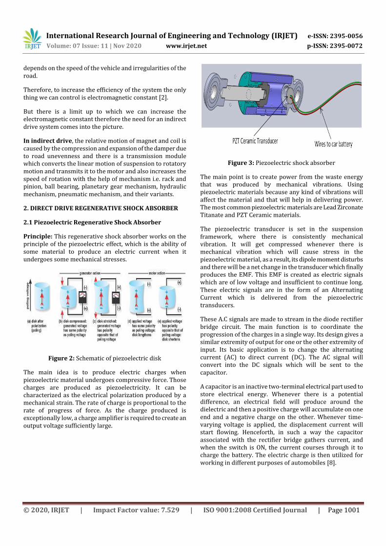
Figure 3: Piezoelectric shock absorber
The main point is to create power from the waste energy that was produced by mechanical vibrations. Using piezoelectric materials because any kind of vibrations will affect the material and that will help in delivering power. The most common piezoelectric materials are Lead Zirconate Titanate and PZT Ceramic materials.
The piezoelectric transducer is set in the suspension framework, where there is consistently mechanical vibration. It will get compressed whenever there is mechanical vibration which will cause stress in the piezoelectric material, as a result, its dipole moment disturbs and there will be a net change in the transducer which finally produces the EMF. This EMF is created as electric signals which are of low voltage and insufficient to continue long. These electric signals are in the form of an Alternating Current which is delivered from the piezoelectric transducers.
These A.C signals are made to stream in the diode rectifier bridge circuit. The main function is to coordinate the progression of the charges in a single way. Its design gives a similar extremity of output for one or the other extremity of input. Its basic application is to change the alternating current (AC) to direct current (DC). The AC signal will convert into the DC signals which will be sent to the capacitor.
A capacitor is an inactive two-terminal electrical part used to store electrical energy. Whenever there is a potential difference, an electrical field will produce around the dielectric and then a positive charge will accumulate on one end and a negative charge on the other. Whenever time-varying voltage is applied, the displacement current will start flowing. Henceforth, in such a way the capacitor associated with the rectifier bridge gathers current, and when the switch is ON, the current courses through it to charge the battery. The electric charge is then utilized for working in different purposes of automobiles [8].

International Research Journal of Engineering and Technology (IRJET) e-ISSN: 2395-0056
Volume: 07 Issue: 11 | Nov 2020 www.irjet.net p-ISSN: 2395-0072
© 2020, IRJET | Impact Factor value: 7.529 | ISO 9001:2008 Certified Journal | Page 1002
Figure 4: Input and output chart of shock absorber
Whenever a car meets with vibrations it will compress the PZT transducer which outputs the power and it will be sent to the car’s battery. A CPU monitoring subsystem is placed to provide a value of energy produced by the PZT transducer.
Figure 5: Electrical connections of piezoelectric regenerative system
The electrical energy produced will travel through the wiring system to the car battery which will be used to charge the battery.
Advantages
• It has Simple structure and No external voltage sources • Compatible with MEMS [7] • It gives us current of high voltage • No mechanical transmission or generator needed • Wide frequency range
Disadvantages
• Thin films have poor coupling [7] • High output impedance • Charge leakage • Low output current
2.2 Linear electromagnetic regenerative shock absorber
The system in which linear motion is transmitted from the shock absorber to the permanent magnet directly by which the magnet oscillates in the coil due to which voltage is induced in the ends of the coil.
Principle:
Figure 6: Faraday's law of Induction [2]
The electromagnetic regenerative system is based on Faraday's law of induction which states “whenever there is a change in the magnetic field across the coil there will be voltage induced at the ends of it”.
Working:
In this type of system, there is a shock absorber having casings A and B. A permanent magnet and wire coil are attached to the casings A and B respectively as shown below in figure (7).
Figure 7: Linear regenerative shock absorber
Whenever the vehicle will move over any breaker or any other irregularities of road, the suspension will compress and expand. During this compression and expansion, there

International Research Journal of Engineering and Technology (IRJET) e-ISSN: 2395-0056
Volume: 07 Issue: 11 | Nov 2020 www.irjet.net p-ISSN: 2395-0072
© 2020, IRJET | Impact Factor value: 7.529 | ISO 9001:2008 Certified Journal | Page 1003
will be a relative motion between casing A and casing B of the damper.
As the permanent magnet is attached with casing A and the wire coil is over casing B, due to the relative motion between the permanent magnet and coil, the voltage will be produced across the ends of the coil.
The voltage induced is directly proportional to the rate of change of magnetic flux through the coil, Length of conductor coil, and magnetic flux [2].
The voltage induced in the circuit is given by:
V=BvL,
Where
B is Magnetic field
v is Relative velocity
L is the length of the conductor coil.
The current produced in the coil is dependent on the electrical conductivity of the coil σ, the relative velocity v, radial magnetic field Br, and the area of cross-section of the wire A.
I=σvBrA.
The length of the conductor coil is directly proportional to the no. of turns, the average diameter of the coil.
L=πND,
Where
N is no. of turns and
D is the diameter of the coil.
Figure 8: Circuit Diagram of direct electromagnetic shock absorber
The current produced from the whole setup will go to the rectification and control circuit, where the bidirectional current will be rectified to unidirectional.
Then current goes to the regulator which regulates its voltage to a constant value, generally, the output voltage from the regulator is less than the input voltage so-called these regulators as step-down converters.
Then at last the current will be stored in the battery.
We can increase induced voltage by:
Increasing the relative velocity.
Increasing length of conductor.
Increasing magnetic field passes through the coil.
We can increase induced current by:
Increasing the no. of turns.
Increasing the cross-section area of the coil.
Increasing the conductivity of the coil.
Note: Both no. of turns and cross-section area of wire cannot be increased at the same time, so we must balance in between to get the maximum current.
Advantages:
Very easy to install in shock absorbers [3].
No Transmission Required.
Get power on both compression and expansion strokes.
Can generate power for small velocities.
Disadvantages:
Relative velocity is limited
Due to continuous change in direction of current, the efficiency is low.

International Research Journal of Engineering and Technology (IRJET) e-ISSN: 2395-0056
Volume: 07 Issue: 11 | Nov 2020 www.irjet.net p-ISSN: 2395-0072
© 2020, IRJET | Impact Factor value: 7.529 | ISO 9001:2008 Certified Journal | Page 1004
3. INDIRECT DRIVE ELECTROMAGNETIC REGENERATIVE SHOCK ABSORBER
3.1 Hydraulic Electromagnetic regenerative shock absorber
Figure 9: Hydraulic regenerative shock absorber
This system consists of:
1. Magnet
2. Upper mount
3. Coil
4. Rotor
5. Piston rod
6. Blade
7. Oil
8. Base valve
9. Lower mount
As shown in the figure (9) above.
Working principle: Hydraulic Electromagnetic regenerative suspension system works on the principle of electromagnetic induction.
Working:
When the suspension system undergoes compression due to uneven road/ breakers the flow of fluid goes upward, it
exerts a force on the blade of the rotor. Due to the design of the blades, the rotor starts rotating by the force exerted by the fluid. And the rotation of the rotor results in changing magnetic flux in the coil hence emf is induced in the loop and the resulting current will be stored in the battery.
This fluid pressure makes the rotor flow in one-directional only as it exerts pressure only when going up, so it helps us to get unidirectional current without using a rectifier and the flow of rotor is very smooth [2] in this system which results in the long life of the system.
Figure 10: Circuit diagram of indirect electromagnetic shock absorber
Advantages:
Can be used for huge force impact (i.e. heavy vehicles) [3].
Long life compared to other systems [3].
Can be used in four set of absorbers with same power generation module.
Disadvantages:
The only drawback of hydraulic regenerative systems is that response time is a little long due to the rate of flow and its compressibility [2].
3.2 Helical regenerative shock absorber
It consists of:
Helical Shaft
Helical gear
Guide cylinder
DC motor
This helical shaft is attached to the lower member of the damper with the help of bearing so that it can rotate easily

International Research Journal of Engineering and Technology (IRJET) e-ISSN: 2395-0056
Volume: 07 Issue: 11 | Nov 2020 www.irjet.net p-ISSN: 2395-0072
© 2020, IRJET | Impact Factor value: 7.529 | ISO 9001:2008 Certified Journal | Page 1005
when any force will be applied to it then it goes through the helical gear and is attached with the DC motor placed in the upper member.
This is one of the methods which can help in powering low wattage vehicle appliances.
Figure 11: Helical regenerative shock absorber
Working:
When the vehicle moves on an uneven road it will actuate the shock absorber, as the helical shaft is attached to the lower member of the absorber this will start moving linearly and the helical gear will convert this linear motion to the rotatory. This rotatory motion will then be transferred to the DC motor to generate electricity.
Figure 12: Layout of helical regenerative shock absorber [5]
In a helical regenerative shock absorber system, whenever there is a vibration, a linear motion is sent to the absorber's cylinder and the energy is generated with the help of transmission and generator.
The transmission used in this converts two-way linear motion to one-way rotatory motion with the help of helical gears and tapered roller clutches [5].
In general case, the frequency and amplitude of vibrations generated in shock absorber is highly change with the change in road profile and driving speed. So, any sudden change in any of the above factor can affect the rotatory motion of the generator results in unstable current, which is not good for storage devices. A solution to this problem is proposed by Zhang, Z. [4] in which a super capacitor for rapid charging with a high-power density which is suitable for the rapid storage of a pulse-like current. And a voltage regulator is also used to control the voltage in a constant way as shown in figure 12 below.
Figure 13: Circuit diagram of helical regenerative system [5]
Advantages:
High mechanical efficiency with low friction loses [3].
More durable than rack and pinion.
Can hold large forces [3]
Disadvantages:
High cost of designing
Risk of buckling in helical shaft
4. FUTURE SCOPE
Regenerative shock absorber is one of the best methods to generate electrical energy from the shock absorbers which can be used in all type of vehicles. As the world is moving towards electrical vehicles, these regenerative shock absorbers will be very useful for them to charge their

International Research Journal of Engineering and Technology (IRJET) e-ISSN: 2395-0056
Volume: 07 Issue: 11 | Nov 2020 www.irjet.net p-ISSN: 2395-0072
© 2020, IRJET | Impact Factor value: 7.529 | ISO 9001:2008 Certified Journal | Page 1006
batteries without any external source and reduce energy losses.
5. CONCLUSIONS
In current times the power loses in any automotive is high which results in the low efficiency and more consumption of fossil fuels. Automobile sector has taken some initiatives to reduce these loses, still the loses are high but there are some ways by which we can regenerate some energy from various parts of the automotive with the help of regenerative systems.
In this study the shock absorber based regenerative system is explained, which can harvest the vibration energy of the suspension and store it in the form of electrical energy and also can absorb shocks for smooth riding.
The various methods of designing the regenerative shock absorbers is considered which can be installed in the vehicles to reduce energy wastes and can improve overall efficiency.
We have discussed and compiled previous studies related to energy harvesting methods and these methods can be recover up to 50% [9] of energy.
REFERENCES
[1] Abdelkareem, M. A., Xu, L., Ali, M. K., El-Daly, A. B., Hassan, M. A., Elagouz, A., & Bo, Y. (2019). Analysis of the prospective vibrational energy harvesting of heavy-duty truck suspensions: A simulation approach. Energy, 173, 332-351. doi:10.1016/j.energy.2019.02.060
[2] Zhang, R., Wang, X., & John, S. (2018). A Comprehensive Review of the Techniques on Regenerative Shock Absorber Systems. doi:10.20944/preprints201803.0239.v1
[3] G., P., G., D. V., Kannan, V., M., S., & M., B. (2018). REGENERATIVE SUSPENSION. Imperial International Journal of Eco-Friendly Technologies (IIJET), 3(1), 33-43.
[4] Zhang, Z., Zhang, X., Chen, W., Rasim, Y., Salman, W., Pan, H., . . . Wang, C. (2019). Corrigendum to “A high-efficiency energy regenerative shock absorber using supercapacitors for renewable energy applications in range extended electric vehicle” [Appl. Energy 178 (2016) 177–188]. Applied Energy, 254, 113634. doi:10.1016/j.apenergy.2019.113634
[5] Qi, L., Salman, W., Zhu, X., Pan, H., Zhang, X., Bano, S., . . . Yuan, Y. (2020). A high-efficiency energy regenerative shock absorber using helical gears for powering low-wattage electrical device of electric vehicles. doi:10.46855/2020.05.01.14.04.371775
[6] Abdelkareem, M. A., Xu, L., Ali, M. K., Elagouz, A., Mi, J., Guo, S., . . . Zuo, L. (2018). Vibration energy harvesting in automotive suspension system: A detailed review. Applied Energy, 229, 672-699. doi:10.1016/j.apenergy.2018.08.030
[7] Aljadiri, R. T., Taha, L. Y., & Ivey, P. (2017). Electrostatic Energy Harvesting Systems: A Better Understanding of Their Sustainability Electrostatic Energy Harvesting Systems: A Better Understanding of Their Sustainability. Journal of Clean Energy Technologies, 5(5), 409-416. doi:10.18178/jocet.2017.5.5.407
[8] Bhatt, A., Nagar, C., Bhansar, V., & Shah, Y. (2017). Electricity Generation through Piezoelectric Material in Automobile. SSRG International Journal of Mechanical Engineering (SSRG - IJME), 4(1). doi:10.1109/4.668982
[9] Lv, X., Ji, Y., Zhao, H., Zhang, J., Zhang, G., & Zhang, L. (2020). Research Review of a Vehicle Energy-Regenerative Suspension System. Energies, 13(2), 441. doi:10.3390/en13020441