Virtual Torsional Spring Based Bilateral Control System for Soft Manipulation
7
2013 Inteational Conference on Circuits, Power and Computing Technologies [ICCPCT-2013] Virtual Torsional Spring Based Bilateral Control System for Soſt Manipulation M K Madawala, A.M Harsha S Abeykoon, B.G.C.Mihiran, D. C. Mohottige, R. G. U 1 Meththananda, MBranesh Pillai Department of Electrical Engineering Universi of Moratuwa, Katubedda 10400 Moratuwa, Sri Lanka. mihirimadawala@gmail. com, harsha@elect. mrt. ac.lk, [email protected], cdushantha@gmail. com, udithametha@yahoo. com, [email protected]. ac.lk Abstract- In recent years, although there are many researches on bilateral control, there is only little research on improvement of operationality. It will be so effective for operators to improve the operationality of the bilateral control system. In a bilateral control system, the law of action and reaction between master system which the operator manipulates, and the slave system which has contact with the environment is realized. Obj ective of this research is to eliminate the chattering and to reduce the impact on human operator at contact motion and to introduce controlling force to the slave manipulator to provide more comfort at the human operator's end. In this paper, a new method of improving the operationality which is based on a virtual torsional spring between master and slave system is discussed. Disturbance observer is used as the disturbance compensation tool and also to improve the system robustness. Then proposed method is applied by altering the bilateral control system. Finally the experimental results show the viability of the proposed method. Kwords-Bilateral Control, Soſt Handling, Disturbance Observer, Reaction Torque Observer, Viual Model I. INTRODUCTION The prefix 'tele' om Greek origin means "at a distance" and teleoperation naturally indicates operating at a distance. Teleoperation extends the human capability to manipulate objects remotely by providing the operator with similar conditions as those at the remote location. This is achieved via installing a similar robot manipulator called the master, at the human's end that provides motion commands to the slave which is performing the actual task. [I] The human imposes a force on the master manipulator which in tu results in a displacement that is transmitted to the slave that mimics the motion. If the slave possess a force sensor, it can transmit or reflect back the reaction forces om the task being performed to the master, which input torque of the master, and the teleoperator is said to be conolled bilaterally. [2] [3] Human x" Teleoperation x, Environment operator system Fig.! Broader overview of bilateral teleoperation 978-1-4673-4922-2/13/$31.00 ©2013 IEEE 337 The principle of bilateral teleoperation is depicted in fig.I. To allow force feedback, position and/or force measurements must be made at the slave and sent back to the master. The master is provided with actuators to be able to exert forces on the user. The actuated master is also called a haptic interface where the term 'haptic' refers to the sense of touch [4]. Basically the sense of touch is made of the components: the sensation, position and the force acting on them. This information is gathered by different sensors. Some researchers have ied to introduce added nctionalities to the conventional bilateral control systems to be used where one to one conol is not preferable [1]. The idea had been to implement different tool sensations virtually which can be widely used in medical surgeries. In conventional bilateral conol systems where the sampling equency is less and the encoder accuracies are low, system tends to have high level of chattering in the contact motion. One of the objectives of this research is to embed a spring feeling to the operator especially in the contact motion which reduces the chattering problem. By incoorating the virtual spring sensation to the master- slave system, the operator can exert the conolled force to the remote object which could be felt by the master manipulator. When the slave manipulator hits an object, its impact is reflected to the master operator in the conventional bilateral conol system. However by incorporating a virtual spring in between the master-slave, the impact sensation could not be felt as it is at the operator's end. In simple terms the proposed method promotes operationality. This is done at the expense of the transparency [5], and it should be used in applications where one to one bilateral control is not desired. In this paper a novel concept of "soſt manipulation" is introduced. 11. MODELING AND ANALYSIS A. Virtual Torsional Spring Model The proposed concept is built by considering a simple torsional spring, damper and two masses which are interconnected as shown in fig. 2.
Transcript of Virtual Torsional Spring Based Bilateral Control System for Soft Manipulation
2013 International Conference on Circuits, Power and Computing Technologies [ICCPCT-2013]
Virtual Torsional Spring Based Bilateral Control System for Soft Manipulation
M K. Madawala, A.M Harsha S. Abeykoon, B.G.C.Mihiran,
D. C. Mohottige, R. G. U 1 Meththananda, MBranesh Pillai
Department of Electrical Engineering University of Moratuwa, Katubedda 10400
Moratuwa, Sri Lanka. mihirimadawala@gmail. com, harsha@elect. mrt. ac.lk, cmihiran@elect. mrt.ac.lk,
cdushantha@gmail. com, udithametha@yahoo. com, pillaibranesh@elect. mrt. ac. lk
Abstract- In recent years, although there are many researches on bilateral control, there is only little research on improvement of operationality. It will be so effective for operators to improve the operationality of the bilateral control system. In a bilateral control system, the law of action and reaction between master system which the operator manipulates, and the slave system which has contact with the environment is realized. Objective of this research is to eliminate the chattering and to reduce the impact on human operator at contact motion and to introduce controlling force to the slave manipulator to provide more comfort at the human operator's end. In this paper, a new method of improving the operationality which is based on a virtual torsional spring between master and slave system is discussed. Disturbance observer is used as the disturbance compensation tool and also to improve the system robustness. Then proposed method is applied by altering the bilateral control system. Finally the experimental results show the viability of the proposed method.
Keywords-Bilateral Control, Soft Handling, Disturbance
Observer, Reaction Torque Observer, Virtual Model
I. INTRODUCTION
The prefix 'tele' from Greek origin means "at a distance" and teleoperation naturally indicates operating at a distance. Teleoperation extends the human capability to manipulate objects remotely by providing the operator with similar conditions as those at the remote location. This is achieved via installing a similar robot manipulator called the master, at the human's end that provides motion commands to the slave which is performing the actual task. [I]
The human imposes a force on the master manipulator which in turn results in a displacement that is transmitted to the slave that mimics the motion. If the slave possess a force sensor, it can transmit or reflect back the reaction forces from the task being performed to the master, which input torque of the master, and the teleoperator is said to be controlled bilaterally. [2] [3]
---+ +-Human x" Teleoperation x,
Environment operator ---+
F;, system +-
F; Fig.! Broader overview of bilateral teleoperation
978-1-4673-4922-2/13/$31.00 ©2013 IEEE 337
The principle of bilateral teleoperation is depicted in fig. I. To allow force feedback, position and/or force measurements must be made at the slave and sent back to the master. The master is provided with actuators to be able to exert forces on the user. The actuated master is also called a haptic interface where the term 'haptic' refers to the sense of touch [4]. Basically the sense of touch is made of the components: the sensation, position and the force acting on them. This information is gathered by different sensors.
Some researchers have tried to introduce added functionalities to the conventional bilateral control systems to be used where one to one control is not preferable [1]. The idea had been to implement different tool sensations virtually which can be widely used in medical surgeries. In conventional bilateral control systems where the sampling frequency is less and the encoder accuracies are low, system tends to have high level of chattering in the contact motion. One of the objectives of this research is to embed a spring feeling to the operator especially in the contact motion which reduces the chattering problem.
By incorporating the virtual spring sensation to the masterslave system, the operator can exert the controlled force to the remote object which could be felt by the master manipulator. When the slave manipulator hits an object, its impact is reflected to the master operator in the conventional bilateral control system. However by incorporating a virtual spring in between the master-slave, the impact sensation could not be felt as it is at the operator's end. In simple terms the proposed method promotes operationality. This is done at the expense of the transparency [5], and it should be used in applications where one to one bilateral control is not desired. In this paper a novel concept of "soft manipulation" is introduced.
11. MODELING AND ANALYSIS
A. Virtual Torsional Spring Model
The proposed concept is built by considering a simple torsional spring, damper and two masses which are interconnected as shown in fig. 2.
2013 International Conference on Circuits, Power and Computing Technologies [ICCPCT-2013]
Master
(Operator Side)"-..
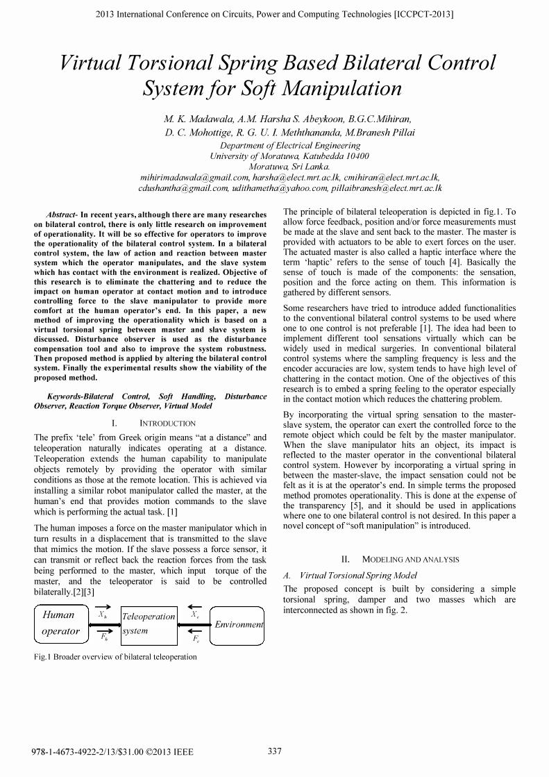
Fig.2. Analysis model of the experimental system
m and s suffixes refer to the master and slave sides. B is the
angular displacement and the 7/ is the external torque on the
manipulators by the torsional spring. J refers to the inertia
where k and c refer to the spring constant and the viscous
coefficient of the virtual torsional spring respectively. 7 m and
7s are the external torques acting on the given system.
Practically this torques are given by "master" and "slave" motors where these two manipulators are kept away and teleoperated, equal and opposite torques are applied from the human operator and environment.
For master motor applying Newton's Law,
JmBm = Tm -TT JmBm =rm -[k(Bm -Bs)+c(Bm -Bs)]
For slave manipulator,
J,B., = TT -T., .. . .
J,Bs = [k(Bm -B,.)+c(Bm -Bs)]-7,.
(1)
(2)
The equations (1) and (2) can be rewritten as equations (3) and (4), to implement in the control block diagram.
For master,
(Jms2 +cs+k)Bm =rm +(k+cs)rs (3)
For slave,
(J,s2 + CS + kWs = (k + CS)Tm -T., (4)
Where; s: Lap/ace operator
338
Ill. BILATERAL CONTROL
In bilateral control, the law of action and reaction between the
operator and the environment is realized. In the system the
operator's action on the environment is realized by two
functionally related systems (devices). The operator is in
contact with one of the devices (master device), and another
device (slave device) is in contact with the environment [6].
By manipulating the master device the operator defines the
task to be assigned to the slave device. The master device in
addition to acquiring motion data from the operator is able to
exert reaction force on the operator. The slave device
replicates the operation motion at the remote center, haptic
interactions with the environment and transmits information of
its motion and interaction force to the master device and the
operator. In bilateral system there are four players: (i)
operator, (ii) master side device (robot), (iii) slave side device
(robot) and (iv) object to be manipulated. All of these players
have their own dynamic properties. The inputs to the system
are operator's force and motion and the force generated due to
the interaction of the slave side and the object to be
manipulated [7][8].
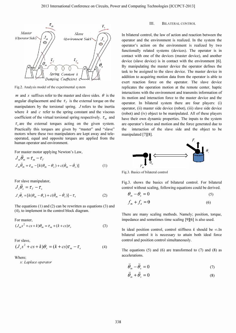
Fig.3. Basics of bilateral control
Fig.3. shows the basics of bilateral control. For bilateral
control without scaling, following equations could be derived.
Bm -B., = 0 (5)
(6)
There are many scaling methods. Namely; position, torque,
impedance and sometimes time scaling [9][6] is also used.
In ideal position control, control stiffness k should be oo.ln
bilateral control it is necessary to attain both ideal force
control and position control simultaneously.
The equations (5) and (6) are transformed to (7) and (8) as
accelerations.
Bm -B, = 0
Bm + B., = 0
(7)
(8)
2013 International Conference on Circuits, Power and Computing Technologies [ICCPCT-2013]
Since disturbance observer is used as force sensor in the bilateral control, sampling time should be small enough. The relationship of force represented in (7) is called the common mode between the master and slave system. The equation (8) which represents the position relationship is called as the differential mode. This can be attributed to the sign of the equations. Therefore, it is possible to realize both force control and position control independently to the bilateral control. Equation (7) and (8) can be transformed into the following equations based on the optimal goal of bilateral control.
. . . . . . Bm -Bs = Bc()m � 0
.. .. .. Bm + B., = Bdlt � 0
(9)
(10)
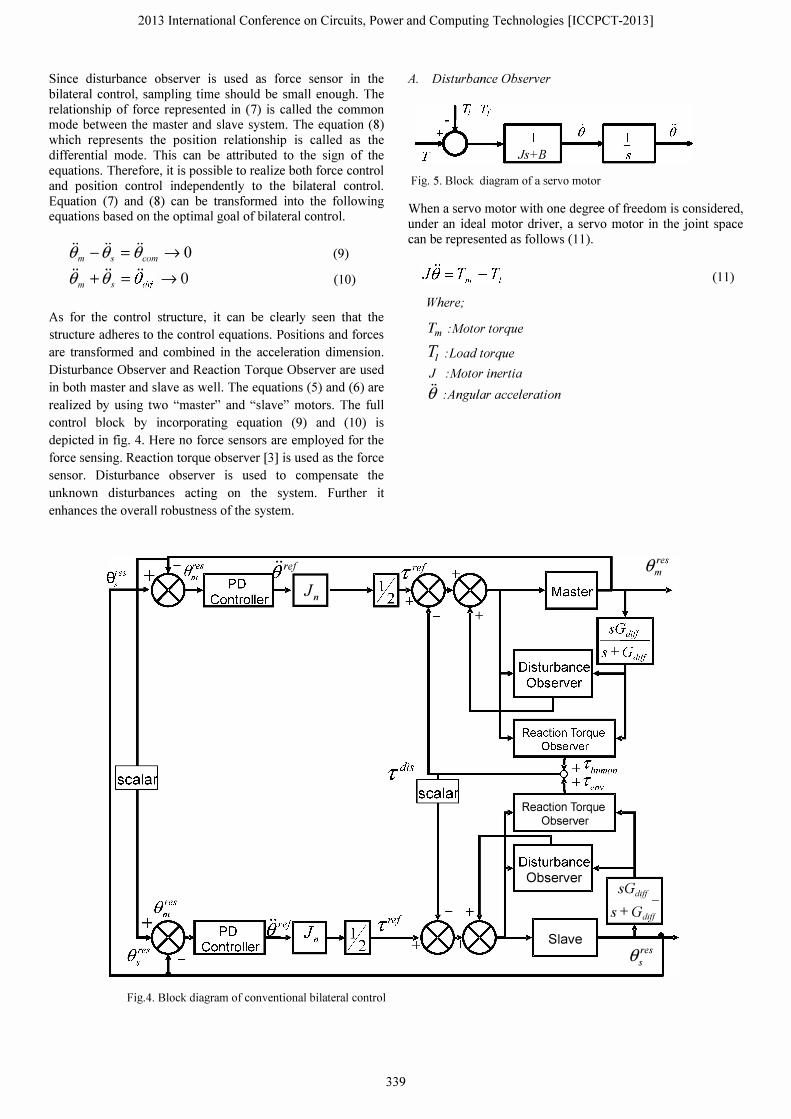
As for the control structure, it can be clearly seen that the
structure adheres to the control equations. Positions and forces
are transformed and combined in the acceleration dimension.
Disturbance Observer and Reaction Torque Observer are used
in both master and slave as well. The equations (5) and (6) are
realized by using two "master" and "slave" motors. The full
control block by incorporating equation (9) and (10) is
depicted in fig. 4. Here no force sensors are employed for the
force sensing. Reaction torque observer [3] is used as the force
sensor. Disturbance observer is used to compensate the
unknown disturbances acting on the system. Further it
enhances the overall robustness of the system.
eres s ··reI
�-----n � ____ �
Fig.4. Block diagram of conventional bilateral control
339
A. Disturbance Observer
�_' T Js+B
Fig. 5. Block diagram of a servo motor
When a servo motor with one degree of freedom is considered, under an ideal motor driver, a servo motor in the joint space can be represented as follows (11).
Where;
Tm :Motor torque
1; :Load torque
J :Motor inertia
B :Angular acceleration
+
Reaction Torque Observer
eres m
Disturbance.-__ -I
Observer
Slave
SGdiff S + Gditf
eres s
(11)
2013 International Conference on Circuits, Power and Computing Technologies [ICCPCT-2013]
The load torque is considered as,
� = T,nt + Texl + (Tt + BB) (12)
TIn! the inertial torque, derived from the Lagrange motion equations, consists of inertia torque and gravity effect. Text consists of the torque external to the system. Friction term is the sum of coulomb and viscosity terms. For a high gain current controller, input current can be assumed as the reference current [10]. Therefore for a DC servo motor,
(13)
Above equation has two parameters namely inertia and torque constant. Inertia can be changed due to the mechanical configuration of the system.
(14)
Similarly parameter Kt may also change.
(15)
Where In and Kin are nominal inertia and the nominal torque constant of the motor respectively.
Disturbance torque Tdis is represented as,
Tdis = Tz +MB-M/re!
Dynamic equation yields,
(J n + M)B = (Kin + MI )1 ret -Tz
By rearranging,
JnB = Klnlref - Tdis Thus Tdis can be calculated as follows.
re! .. Tdis=Ktnla -JnB
(16)
(17)
(18)
(19)
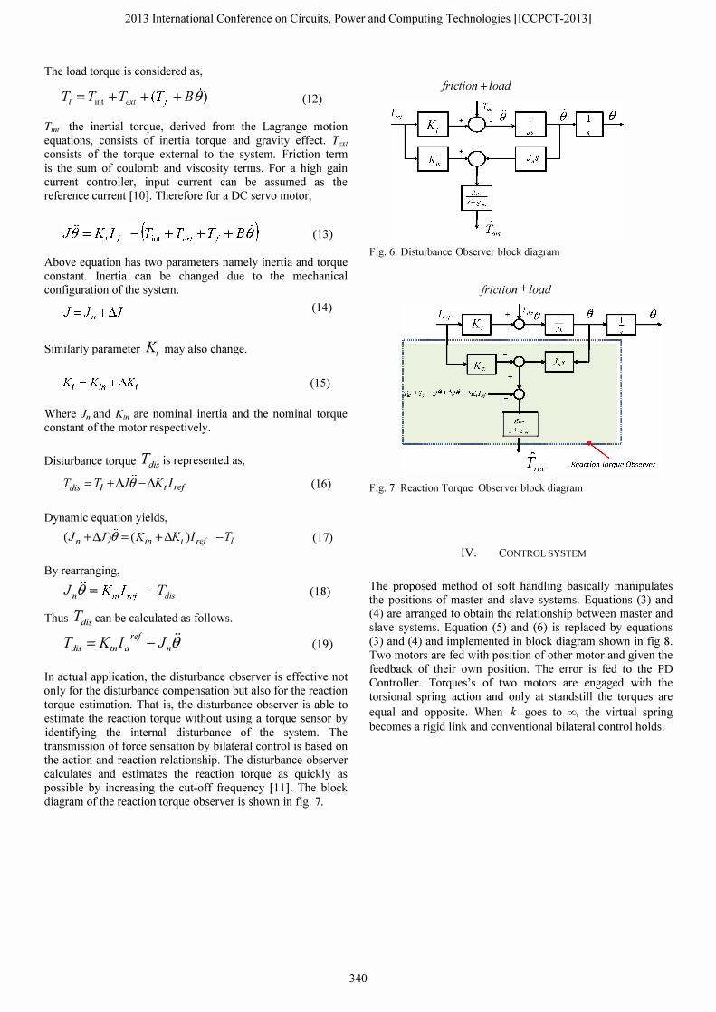
In actual application, the disturbance observer is effective not only for the disturbance compensation but also for the reaction torque estimation. That is, the disturbance observer is able to estimate the reaction torque without using a torque sensor by identifying the internal disturbance of the system. The transmission of force sensation by bilateral control is based on the action and reaction relationship. The disturbance observer calculates and estimates the reaction torque as quickly as possible by increasing the cut-off frequency [11]. The block diagram of the reaction torque observer is shown in fig. 7.
340
friction + load
Fig. 6. Disturbance Observer block diagram
friction + load
Fig. 7. Reaction Torque Observer block diagram
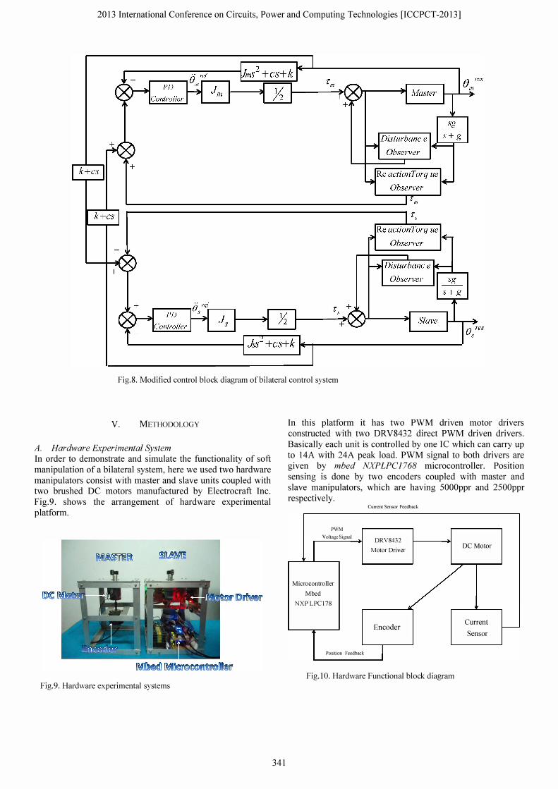
IV. CONTROL SYSTEM
The proposed method of soft handling basically manipulates the positions of master and slave systems. Equations (3) and (4) are arranged to obtain the relationship between master and slave systems. Equation (5) and (6) is replaced by equations (3) and (4) and implemented in block diagram shown in fig 8. Two motors are fed with position of other motor and given the feedback of their own position. The error is fed to the PO Controller. Torques's of two motors are engaged with the torsional spring action and only at standstill the torques are
equal and opposite. When k goes to 00, the virtual spring
becomes a rigid link and conventional bilateral control holds.
2013 International Conference on Circuits, Power and Computing Technologies [ICCPCT-2013]
Fig.8. Modified control block diagram of bilateral control system
V. METHODOLOGY
A. Hardware Experimental System In order to demonstrate and simulate the functionality of soft manipulation of a bilateral system, here we used two hardware manipulators consist with master and slave units coupled with two brushed DC motors manufactured by Electrocraft Inc. Fig.9. shows the arrangement of hardware experimental platform.
Fig.9. Hardware experimental systems
341
In this platform it has two PWM driven motor drivers constructed with two DRV8432 direct PWM driven drivers. Basically each unit is controlled by one IC which can carry up to 14A with 24A peak load. PWM signal to both drivers are given by mbed NXPLPC1768 microcontroller. Position sensing is done by two encoders coupled with master and slave manipulators, which are having 5000ppr and 2500ppr respectively.
Current Sensor Feedback
PWM Voltage Signal
DRV8432
Motor Dtiver DC Motor
Microcontroller Mbed
NXPLPC178
Encoder Current -Sensor
Position Feedback I
Fig.IO. Hardware Functional block diagram
2013 International Conference on Circuits, Power and Computing Technologies [ICCPCT-2013]
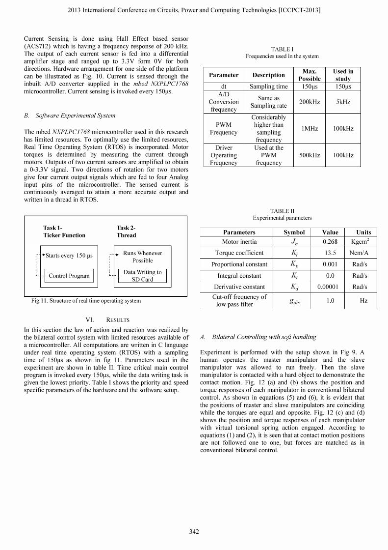
Current Sensing is done using Hall Effect based sensor (ACS712) which is having a frequency response of 200 kHz. The output of each current sensor is fed into a differential amplifier stage and ranged up to 3.3V form OV for both directions. Hardware arrangement for one side of the platform can be illustrated as Fig. 10. Current is sensed through the inbuilt AID converter supplied in the mbed NXPLPC1768 microcontroller. Current sensing is invoked every ISOI-ts.
B. Software Experimental System
The mbed NXPLPC1768 microcontroller used in this research has limited resources. To optimally use the limited resources, Real Time Operating System (RTOS) is incorporated. Motor torques is determined by measuring the current through motors. Outputs of two current sensors are amplified to obtain a 0-3.3V signal. Two directions of rotation for two motors give four current output signals which are fed to four Analog input pins of the microcontroller. The sensed current is continuously averaged to attain a more accurate output and written in a thread in RTOS.
Task 1-Ticker Function
:- "Stmis every ISO !is
�--� Control Program
Task 2-Thread
.- .. Runs Whenever
Possible
, c __ Data Writing to I SO Card
Fig.ll. Structure of real time operating system
VI. RESULTS
In this section the law of action and reaction was realized by the bilateral control system with limited resources available of a microcontroller. All computations are written in C language under real time operating system (RTOS) with a sampling time of IS0I-ts as shown in fig 1l. Parameters used in the experiment are shown in table 11. Time critical main control program is invoked every ISOI-ts, while the data writing task is given the lowest priority. Table I shows the priority and speed specific parameters of the hardware and the software setup.
342
Parameter
dt AID
Conversion frequency
PWM Frequency
Driver Operating Frequency
TABLE I Frequencies used in the system
Description Max. Possible
Sampling time ISOI-ts
Same as Sampling rate
200kHz
Considerably higher than
IMHz sampling frequency
Used at the PWM SOOkHz
frequency
TABLE Il Experimental parameters
Parameters Symbol Motor inertia In
Torque coefficient Kt Proportional constant Kp
Integral constant K;
Used in study IS0I-ts
SkHz
100kHz
100kHz
Value Units 0.268 Kgcm2
13.S Ncm/A
0.001 Rad/s
0.0 Rad/s
Derivative constant Kd 0.00001 Rad/s
Cut-off frequency of gdis low pass filter
A. Bilateral Controlling with soft handling
1.0 Hz
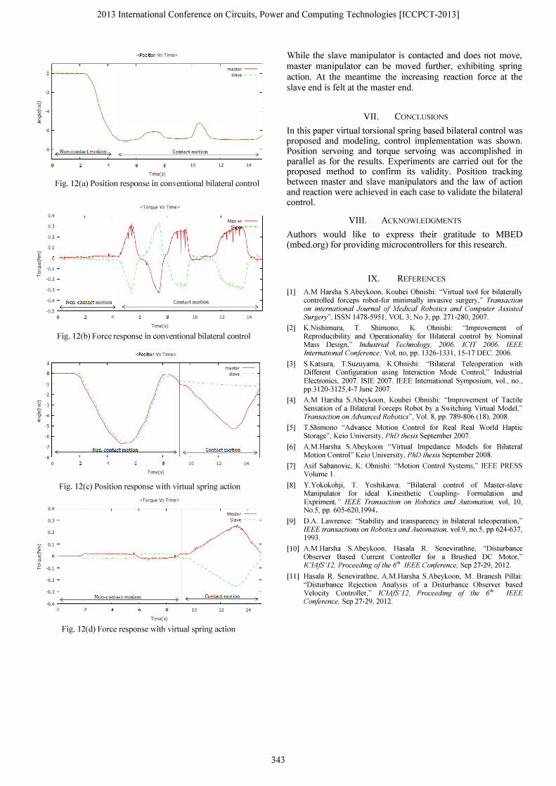
Experiment is performed with the setup shown in Fig 9. A human operates the master manipulator and the slave manipulator was allowed to run freely. Then the slave manipulator is contacted with a hard object to demonstrate the contact motion. Fig. 12 (a) and (b) shows the position and torque responses of each manipulator in conventional bilateral control. As shown in equations (S) and (6), it is evident that the positions of master and slave manipulators are coinciding while the torques are equal and opposite. Fig. 12 (c) and (d) shows the position and torque responses of each manipulator with virtual torsional spring action engaged. According to equations (1) and (2), it is seen that at contact motion positions are not followed one to one, but forces are matched as in conventional bilateral control.
2013 International Conference on Circuits, Power and Computing Technologies [ICCPCT-2013]
-2
� -4 g. ..
-6
<Position Vs Time>
master -slave - - -
-8 ( Non-contact motion) Contact motion
0.4
0.3
0.2
0.1 E % B- -0.1 �
-0.2
-0.3
-0.4
-0.5
-1
-2
� -3 � � -4
-5
-6
10 12 14
Time(s)
Fig. l2(a) Position response in conventional bilateral control
,
Non- contact motion ) (
• l '" ,
<Torque Vs Time>
Contact motion
10
Time(s)
12
Mllster -,
14
Fig. l2(b) Force response in conventional bilateral control
<Position Vs Time>
master -slave - - -
-7 L:===�===N= o= n-=co�n=
b=ct=m=o= ti� on==== ==��)��(=====
co= n=b=ct=m=o= ti= on===� -B
o 10 12 14
Time(s)
Fig. 12(c) Position response with virtual spring action
<Torque Vs Time>
0.4 �--�--�--�--�---;--�--�--��
0.3
0.2
� 0.1 f � � -0.1
-0.2
-0.3
Master -Slave - - -
Non-contact motion Contact motion -0.4 �===============�===�=:::::;:�
10 12 14
Time(s)
Fig. 12(d) Force response with virtual spring action
343
While the slave manipulator is contacted and does not move, master manipulator can be moved further, exhibiting spring action. At the meantime the increasing reaction force at the slave end is felt at the master end.
VII. CONCLUSIONS
In this paper virtual torsional spring based bilateral control was proposed and mode ling, control implementation was shown. Position servoing and torque servoing was accomplished in parallel as for the results. Experiments are carried out for the proposed method to conflrm its validity. Position tracking between master and slave manipulators and the law of action and reaction were achieved in each case to validate the bilateral control.
VIII. ACKNOWLEDGMENTS
Authors would like to express their gratitude to MBED (mbed.org) for providing microcontrollers for this research.
[I]
[2]
IX. REFERENCES
AM Harsha S.Abeykoon, Kouhei Ohnishi: "Virtual tool for bilaterally controlled forceps robot-for minimally invasive surgery," Transaction on international Journal of Medical Robotics and Computer Assisted Surgery", ISSN 1478-5951, VOL 3; No 3, pp. 271-280, 2007.
K.Nishimura, T. Shimono, K. Ohnishi: "Improvement of Reproducibility and Operationality for Bilateral control by Nominal Mass Design," Industrial Technology, 2006. ICIT 2006, IEEE International Conference; Vol, no, pp. 1326-1331, 15-17 DEC. 2006.
[3] S.Katsura, T.Suzuyama, K.Ohnishi: "Bilateral Teleoperation with Different Configuration using Interaction Mode Control," Industrial Electronics, 2007. ISlE 2007. IEEE International Symposium, vol., no., pp.3120-3125,4-7 June 2007.
[4] AM Harsha S.Abeykoon, Kouhei Ohnishi: "Improvement of Tactile Sensation of a Bilateral Forceps Robot by a Switching Virtual Model," Transaction on Advanced Robotics", Vol. 8, pp. 789-806 (18), 2008.
[5] T.Shimono "Advance Motion Control for Real Real World Haptic Storage", Keio University, PhD thesis September 2007.
[6]
[7]
[8]
[9]
AM.Harsha S.Abeykoon "Virtual Impedance Models for Bilateral Motion Control" Keio University, PhD thesis September 2008.
Asif Sabanovic, K. Ohnishi: "Motion Control Systems," IEEE PRESS Volume I.
Y.Yokokohji, T. Yoshikawa: "Bilateral control of Master-slave Manipulator for ideal Kinesthetic Coupling- Formulation and Expriment" IEEE Transaction on Robotics and Automation, vol, 10, No.5, pp. 605-620,1994.
D.A Lawrence: "Stability and transparency in bilateral teleoperation," IEEE transactions on Robotics and Automation, vo1.9, no.5, pp 624-637, 1993.
[10] AM.Harsha S.Abeykoon, Hasala R. Senevirathne, "Disturbance Observer Based Current Controller for a Brushed DC Motor," ICIAjS'12, Proceeding of the 6th IEEE Conference, Sep 27-29, 2012.
[11] Hasala R. Senevirathne, AM.Harsha S.Abeykoon, M. Branesh Pillai: "Disturbance Rejection Analysis of a Disturbance Observer based Velocity Controller," ICIAjS'12, Proceeding of the 6'h IEEE Conference, Sep 27-29, 2012.