Manipulation Planning with Probabilistic Roadmaps
19
http://ijr.sagepub.com Robotics Research The International Journal of DOI: 10.1177/0278364904045471 2004; 23; 729 The International Journal of Robotics Research Thierry Siméon, Jean-Paul Laumond, Juan Cortés and Anis Sahbani Manipulation Planning with Probabilistic Roadmaps http://ijr.sagepub.com/cgi/content/abstract/23/7-8/729 The online version of this article can be found at: Published by: http://www.sagepublications.com On behalf of: Multimedia Archives can be found at: The International Journal of Robotics Research Additional services and information for http://ijr.sagepub.com/cgi/alerts Email Alerts: http://ijr.sagepub.com/subscriptions Subscriptions: http://www.sagepub.com/journalsReprints.nav Reprints: http://www.sagepub.com/journalsPermissions.nav Permissions: http://ijr.sagepub.com/cgi/content/refs/23/7-8/729 SAGE Journals Online and HighWire Press platforms): (this article cites 4 articles hosted on the Citations © 2004 SAGE Publications. All rights reserved. Not for commercial use or unauthorized distribution. at Stanford University on October 5, 2007 http://ijr.sagepub.com Downloaded from
Transcript of Manipulation Planning with Probabilistic Roadmaps

http://ijr.sagepub.comRobotics Research
The International Journal of
DOI: 10.1177/0278364904045471 2004; 23; 729 The International Journal of Robotics Research
Thierry Siméon, Jean-Paul Laumond, Juan Cortés and Anis Sahbani Manipulation Planning with Probabilistic Roadmaps
http://ijr.sagepub.com/cgi/content/abstract/23/7-8/729 The online version of this article can be found at:
Published by:
http://www.sagepublications.com
On behalf of:
Multimedia Archives
can be found at:The International Journal of Robotics Research Additional services and information for
http://ijr.sagepub.com/cgi/alerts Email Alerts:
http://ijr.sagepub.com/subscriptions Subscriptions:
http://www.sagepub.com/journalsReprints.navReprints:
http://www.sagepub.com/journalsPermissions.navPermissions:
http://ijr.sagepub.com/cgi/content/refs/23/7-8/729SAGE Journals Online and HighWire Press platforms):
(this article cites 4 articles hosted on the Citations
© 2004 SAGE Publications. All rights reserved. Not for commercial use or unauthorized distribution. at Stanford University on October 5, 2007 http://ijr.sagepub.comDownloaded from

Thierry SiméonJean-Paul LaumondJuan CortésAnis SahbaniLAAS-CNRSToulouse, France
Manipulation Planningwith ProbabilisticRoadmaps
Abstract
This paper deals with motion planning for robots manipulating mov-able objects among obstacles. We propose a general manipulationplanning approach capable of addressing continuous sets for model-ing both the possible grasps and the stable placements of the movableobject, rather than discrete sets generally assumed by the previousapproaches. The proposed algorithm relies on a topological prop-erty that characterizes the existence of solutions in the subspace ofconfigurations where the robot grasps the object placed at a stableposition. It allows us to devise a manipulation planner that capturesin a probabilistic roadmap the connectivity of sub-dimensional man-ifolds of the composite configuration space. Experiments conductedwith the planner in simulated environments demonstrate its efficacyto solve complex manipulation problems.
KEY WORDS—manipulation task planning, path planning,probabilistic roadmaps
1. Introduction
Manipulation planning concerns the automatic generation ofrobot motion sequences allowing the manipulation of mov-able objects among obstacles. The presence of movable ob-jects, i.e., objects that can only move when grasped by a robot,leads to a more general and computationally complex versionof the classical motion planning problem (Latombe 1991).Indeed, the robot has the ability to modify the structure ofits configuration space depending on how the movable objectis grasped and where it is released in the environment. Also,movable objects cannot move by themselves; either they aretransported by robots or they must lie at some stable place-ment. Motion planning in this context appears as a constrainedinstance of the coordinated motion planning problem. The so-lution of a manipulation planning problem (see, for example,Alami, Siméon, and Laumond 1989; Latombe 1991) consists
The International Journal of Robotics ResearchVol. 23, No. 7–8, July–August 2004, pp. 729-746,DOI: 10.1177/0278364904045471©2004 Sage Publications
in a sequence of subpaths satisfying these motion restrictions.Motions of the robot holding the object at a fixed grasp arecalled “transfer paths”, and motions of the robot while theobject stays at a stable placement are called “transit paths”.
Let us consider the manipulation planning example illus-trated by Figure 1. The manipulator arm has to get a movableobject (the bar) out of the cage, and place it on the other side ofthe environment. Solving this problem requires the automaticproduction of the sequence of transfer/transit paths separatedby grasps/ungrasps operations, allowing one extremity of thebar out of the cage; the manipulator can then re-grasp theobject by the extremity that was made accessible by the pre-vious motions, perform a transfer path to extract the bar fromthe cage, and finally reach the specified goal position. In par-ticular, the motion shown on the second image illustrating thesolution requires itself four re-grasping operations to obtain asufficient sliding motion of the bar. This example shows thata manipulation task possibly leads to a complex sequence ofmotions including several re-grasping operations.A challeng-ing aspect of manipulation planning is to consider the auto-matic task decomposition into such elementary collision-freemotions.
Most existing algorithms (e.g., Ahuactzin, Gupta, andMazer 1998;Alami, Siméon, and Laumond 1989; Barraquandand Ferbach 1994; Koga and Latombe 1994; Nielsen andKavraki 2000) assume that a finite set of stable placementsand of possible grasps of the movable object are given in thedefinition of the problem. Consequently, a part of the task de-composition is thus solved by the user since the initial knowl-edge provided with these finite sets has to contain the graspsand the intermediate placements required to solve the prob-lem. Referring back to the example, getting the bar out of thecage would require a large number of grasps and placementsto be given as input data.
In this paper, we describe a general approach based onrecent results presented in Siméon et al. (2002) and Sah-bani, Cortés, and Siméon (2002). We propose a manipulationplanner that automatically generates grasps and intermediateplacements solving complicated manipulation problems suchas illustrated in Figure 1.The main contribution is the ability to
729
© 2004 SAGE Publications. All rights reserved. Not for commercial use or unauthorized distribution. at Stanford University on October 5, 2007 http://ijr.sagepub.comDownloaded from

730 THE INTERNATIONAL JOURNAL OF ROBOTICS RESEARCH / July–August 2004
Fig. 1. How can we manipulate the bar from its initial position (top left) to the goal (bottom left)? The solution (right) requiresseveral pick and place operations.
deal with continuous sets in the definition of the manipulationproblem, while covering the scope of the previous proposedapproaches (Section 2). The approach relies on a topologi-cal property first established in Alami, Laumond, and Siméon(1994) and recalled in Section 3. This property allows us toreduce the problem by characterizing the existence of a so-lution in the lower-dimensional subspace of configurationswhere the robot grasps the movable object placed at a stableposition.
Section 4 describes the proposed approach and shows howthe connected components of this subspace can be captured ina probabilistic roadmap (PRM) computed for a virtual closed-chain system. Section 5 details the planning techniques devel-oped to implement the approach. Using theVisibility-PRM al-gorithm (Siméon, Laumond, and Nissoux 2000) extended todeal with such closed systems (Cortés, Siméon, and Laumond2002), we first capture the connectivity of the search space
into a small roadmap composed of a low number of connectedcomponents (Section 5.1). Connections between these com-ponents using transit or transfer motions are then computedby solving a limited number of point-to-point path planningproblems (Section 5.2). The details of an implemented plan-ner interleaving both stages in an efficient way are describedin Section 5.3. Finally, Sections 6 and 7 presents some exper-iments and comments on the performance of the planner.
2. Related Work
One of the challenging issues of manipulation planning isto integrate the additional difficulty of planning the grasp-ing and re-grasping operations to the path planning problem.This interdependency between path planning and grasp plan-ning was first touched upon by work done in the 1980s for
© 2004 SAGE Publications. All rights reserved. Not for commercial use or unauthorized distribution. at Stanford University on October 5, 2007 http://ijr.sagepub.comDownloaded from

Siméon et al. / Probabilistic Roadmaps 731
the development of automatic robot programming systems.In particular, the Handey system (Lozano-Pérez et al. 1992)integrated both planning levels and was capable to plan simplepick-and-place operations including some re-grasping capa-bilities. The geometric formulation of manipulation planning(Alami, Siméon, and Laumond 1989; Latombe 1991), seenas an instance of the motion planning problem extended bythe presence of movable objects, provided a unified frame-work allowing us to better tackle the interdependency issuesbetween both planning levels.
Motion planning in the presence of movable objects is firstaddressed as such inWilfong (1988). In this work, an exact celldecomposition algorithm is proposed for the particular caseof a polygonal robot and of one movable object translatingin a polygonal workspace, assuming a finite grasp set of themovable object.
The manipulation graph concept is introduced in Alami,Siméon, and Laumond (1989) for the case of one robot andseveral movable objects manipulated with discrete grasps andplacements. In this case, the nodes of the manipulation graphcorrespond to discrete configurations and the edges are con-structed by searching for transfer (or transit) paths betweennodes sharing the same grasp (or placement) of the movableobject(s). Following this general framework, the approach wasimplemented for a translating polygon (Alami, Siméon, andLaumond 1989) and a three-degrees-of-freedom (3-DoF) pla-nar manipulator (Laumond andAlami 1989).An exact cell de-composition algorithm is also proposed in Alami, Laumond,and Siméon (1994) for the specific case of a translating polyg-onal robot capable of manipulating one movable polygon withan infinite set of grasps.
The manipulation planning framework is extended in Kogaand Latombe (1992, 1994) to multi-arm manipulation whereseveral robots cooperate to carry a single movable objectamong obstacles. In this work, the number of legal graspsof the objects is finite and the movable object has to be held atleast by one robot at any time during a re-grasp operation. Theplanner proposed in Koga and Latombe (1994) first plans themotions of the movable object using an adapted version of arandomized potential field planner (Barraquand and Latombe1991), and then finds the sequence of re-grasp operations ofthe arms to move the object along the computed path. Thisplanner relies on several simplifications, but it can deal withcomplex and realistic problems.
Another heuristic planning approach proposed in Bar-raquand and Ferbach (1994) is to iteratively deform a co-ordinated path first generated in the composite configurationspace using a variational dynamic programming techniquethat progressively enforces the manipulation constraints.
Variants of the manipulation planning problem have beeninvestigated. In Lynch and Mason (1994), grasping is replacedby pushing and the space of stable pushing directions imposesa set of non-holonomic constraints that introduce some con-trollability issues to the problem. The heuristic algorithm de-
scribed in Chen and Hwang (1991) considers a problem whereall the obstacles can be moved by a circular robot in order tofind its way to the goal.
Two other contributions extend recent planning techniquesto manipulation planning. In Ahuactzin, Gupta, and Mazer(1998), the Ariadne’s Clew algorithm (Bessiere et al. 1993)is applied to a redundant robot manipulating a single objectin a three-dimensional (3D) workspace. The method assumesdiscrete grasps of the movable object; it is, however, capablein realistic situations of dealing with redundant manipulators(Ahuactzin and Gupta 1999) for which each grasp possiblycorresponds to an infinite number of robot configurations. Fi-nally, Nielsen and Kavraki (2000) propose a practical manipu-lation planner based on the extension of the PRM framework(Kavraki and Latombe 1994; Overmars and Švestka 1994).The planner constructs a manipulation graph between dis-crete configurations; connections are computed using a fuzzyPRM planner that builds a roadmap with edges annotated by aprobability of collision-freeness. Computing such roadmapsimproves the efficiency of the planner for solving the possiblyhigh number of path planning queries (in changing environ-ments) required to compute the connections.
2.1. Contribution
The manipulation planning techniques described abovemostly address the discrete instance of the problem. Onlythe algorithms in Alami, Laumond, and Siméon (1994) andAhuactzin, Gupta, and Mazer (1998) consider more difficultinstances for which the nodes of the manipulation graph (i.e.,the places where the connections between the feasible transitand transfer paths have to be searched) correspond to a col-lection of submanifolds of the composite configuration space,as opposed to discrete configurations. Such manifolds arisewhen considering infinite grasps and continuous placementsof the object. This continuous formulation is only addressedin Alami, Laumond, and Siméon (1994) for the specific caseof a translating robot in a polygonal world. Manifolds alsoarise in Ahuactzin, Gupta, and Mazer (1998) because of theredundancy of the robot although the planner assumes a setof predefined discrete grasps.
In this paper, we propose a general approach for dealingwith such continuous settings of the manipulation planningproblem. Our planning approach considers continuous place-ments and grasps, and it is also able to handle redundantrobots. It relies on a structuring of the search space allowingus to efficiently capture the connectivity of the submanifoldsin a probabilistic roadmap computed for virtual closed-chainmechanisms. The resulting planner is general and practicalfor solving complicated manipulation planning problems inconstrained 3D environments.
For example, one can describe the set of stable placementsby constraining the movable object to be placed on top ofsome horizontal faces of the static obstacles. Such placement
© 2004 SAGE Publications. All rights reserved. Not for commercial use or unauthorized distribution. at Stanford University on October 5, 2007 http://ijr.sagepub.comDownloaded from

732 THE INTERNATIONAL JOURNAL OF ROBOTICS RESEARCH / July–August 2004
constraints define a 3D submanifold of the object’s configu-ration space (two translations in the horizontal plane and onerotation around the vertical axis). Also, one can consider setsof continuous grasping domains such that the jaws of a paral-lel gripper have a contact with two given faces of the object.Such grasp constraints also define a 3D domain (two transla-tions parallel to the grasped faces and one rotation around theaxis perpendicular to the faces).
3. Manipulation Planning
3.1. Notations
We consider a 3D workspace with a robotR and a mov-able objectM moving among static obstacles. The robot hasn DoF andM is a rigid object with six DoF that can onlymove when it is grasped by the robot. LetCSrob andCSobj
be the configuration spaces of the robot and the object, re-spectively. The composite configuration space of the systemis CS = CSrob × CSobj and we callCSf ree the subset inCS
of all admissible configurations, i.e., configurations where themoving bodies do not intersect together or with the static ob-stacles. The domain inCS corresponding to valid placementsof M (i.e., stable placements where the object can rest whenungrasped by the robot) is denoted byCP . The domain inCS corresponding to valid grasps configurations ofM bythe robotR is denoted byCG. Both CP andCG are sub-dimensional manifolds inCS.
3.2. Manipulation Constraints
A solution to a manipulation planning problem correspondsto a constrained path inCSf ree. Such a solution path is analternate sequence of two types of subpaths verifying the spe-cific constraints of the manipulation problem, and separatedby grasp/ungrasp operations.
• Transit paths where the robot moves alone while theobjectM remains stationary in a stable position. Theconfiguration parameters ofM remain constant alonga transit path. Such motions allow us to place the robotat a configuration where it can grasp the object. Theyare also involved when changing the grasp of the ob-ject. Transit paths lie inCP . However, a path inCP
is not generally a transit path since such a path hasto belong to the submanifold corresponding to a fixedplacement ofM. Transit paths induce a foliation1 ofCP (Figure 2(a)).
1. A foliation (Ito 1987) of ann-dimensional manifoldM is an indexed fam-ily Lα of arc-wise connectedm-dimensional submanifolds (m < n), calledleaves of M, such that
– Lα ∩ Lα′ = ∅ if α �= α′– ∪αLα = M
– every point inM has a local coordinate system such thatn−m coor-dinates are constant
• Transfer paths where the robot moves while holdingM with the same grasp. Along a transfer path, the con-figuration ofM changes according to the grasp map-ping induced by the forward kinematics of the robot:qobj = G(qrob). Transfer paths lie inCG. They inducea foliation ofCG (Figure 2(b)).
3.3. Problem
Consider the two sets of constraints defining the stable place-ments and feasible grasps. A manipulation planning problemis to find a manipulation path (i.e., an alternate sequence oftransit and transfer paths) connecting two given configura-tionsqi andqf in CG∪CP (Figure 2(c)). Manipulation plan-ning then consists of searching for transit and transfer pathsin a collection of submanifolds corresponding to particulargrasps or stable placements of the movable object. Note thatthe intersectionCG∩CP between the submanifolds2 definesthe places where transit paths and transfer paths should beconnected. The manipulation planning problem appears as aconstrained path planning problem inside and between thevarious connected components ofCG ∩ CP (Figure 2(d)).
3.4. Reduction Property
Two foliation structures are defined inCG ∩ CP : the firstis induced by the transit paths; the second is induced by thetransfer paths. As a consequence, any path lying in a con-nected component ofCG ∩ CP can be transformed into afinite sequence of transit and transfer paths (the proof of thisproperty3 appears in Alami, Laumond, and Siméon 1994).Therefore, two configurations which are in a same connectedcomponent ofCG∩CP can be connected by a manipulationpath.
It is then sufficient to study theCG ∩ CP component’sconnectivity by transit and transfer paths. Let us consider atransit (or transfer) path whose endpoints belong to two dis-tinct connected components(CG∩CP)i and(CG∩CP)j ofCG ∩ CP . From the reduction property above one may de-duce that any configuration in(CG∩CP)i can be connectedto any configuration in(CG ∩ CP)j along a manipulationpath.
3.5. Manipulation Graph
It is then possible to build a graphMG whose nodes are thevarious connected components ofCG ∩ CP while an edgebetween two nodes(CG ∩ CP)i and (CG ∩ CP)j indi-cates the existence of a transit (or transfer) path whose end-points belong respectively to(CG∩CP)i and(CG∩CP)j .
2. The intersectionCG ∩ CP is also a submanifold. Note, however, thatCG ∪ P is not a submanifold.3. Note that this property holds for a single movable object under the hypoth-esis that the robot does not touch the static obstacles.
© 2004 SAGE Publications. All rights reserved. Not for commercial use or unauthorized distribution. at Stanford University on October 5, 2007 http://ijr.sagepub.comDownloaded from

Siméon et al. / Probabilistic Roadmaps 733
(a) (b)
(c) (d)
Fig. 2. Moving along transit (tranfer) paths induces a foliation of the placement (grasp) space. Both foliations intersectthemselves inCG ∩ CP . (a) The placement spaceCP ; (b) the grasp spaceCG; (c) CG ∪ CP ; (d) CG ∩ CP has fiveconnected components.
Figure 3 illustrates the graph structure for the example intro-duced in Figure 2. Examples of manipulation paths are shownin the bottom-left picture;q1 is not a valid configuration forthe manipulation problem (it does not belong toCP ∪ CG).Configurationq6 is inCG; nevertheless it cannot escape fromits leaf inCG. A manipulation path exists betweenq3 andq5
and betweenq2 andq4. No manipulation path exists betweenq5 andq4.
Let qi andqf be two configurations inCG ∪ CP . Thereexists a manipulation path betweenqi andqf iff there existtwo nodes(CG∩CP)i and(CG∩CP)f in MG, called themanipulation graph, such as:
• there exists a transit (or transfer) path fromqi to somepoint in (CG ∩ CP)i ;
• there exists a transit (or transfer) path from some pointin (CG ∩ CP)f to qf ;
• (CG ∩ CP)i and (CG ∩ CP)f belong to a sameconnected component ofMG.
3.6. Combinatorial Issues
How can we capture the connected components ofCG∩CP ?How can we capture their adjacency by transit and trans-fer paths? These are the two key issues in manipulation taskplanning. All the techniques overviewed above fall into thisgeneral framework.
4. A General Approach to ManipulationPlanning
We now describe our approach for solving manipulation prob-lems in the general setting of continuous grasp and placementconstraints. The proposed approach relies on the structure of
© 2004 SAGE Publications. All rights reserved. Not for commercial use or unauthorized distribution. at Stanford University on October 5, 2007 http://ijr.sagepub.comDownloaded from

734 THE INTERNATIONAL JOURNAL OF ROBOTICS RESEARCH / July–August 2004
(a) (b)
(c) (d)
���
���
��������
��������
q2
q5
q3
q4
q6
q1
��������
��������
���
���
������
������
������
������
���
���
(e) (f)
Fig. 3. The topology ofCS induced by the manipulation problem constraints can be captured by a so-called manipulationgraph. (a) Set of configurations reachable by a transit path starting at a configuration inCG ∩ CP . (b) Adjacency ofCG ∩ CP components via transit paths. (c) Set of configurations reachable by a transfer path starting at a configuration inCG∩CP . (d)Adjacency ofCG∩CP components via transfer paths. (e) Examples of manipulation paths. (f) The manipulationgraph.
© 2004 SAGE Publications. All rights reserved. Not for commercial use or unauthorized distribution. at Stanford University on October 5, 2007 http://ijr.sagepub.comDownloaded from

Siméon et al. / Probabilistic Roadmaps 735
����
����
����
��������
����
����
��������
��������
��������
����
��
����
����
��������
����
����
��������
��������
����
��������
��������
����
1 1(g , p )
2 2(g , p )
(g , p )2 1
(g , p )1 2
Fig. 4. A probabilistic roadmap as a manipulation graph; nodes belong toCG ∩ CP while edges model paths belonging toeitherCG∩CP , CP or CG. Two types of adjacency are considered: directCG∩CP paths (plain segments) or elementarysequences of transit–transfer (or transfer–transit) paths (dashed segments).
CG ∩ CP discussed in the previous section. The main ideais to exploit the reduction property of Section to decomposethe construction of the manipulation graph at two levels:
• compute the connected components ofCG ∩ CP ;
• determine the connectivity ofCG ∩ CP componentsusing transit and transfer paths.
4.1. A Two-Level Probabilistic Manipulation Roadmap
The manipulation graph is computed as in Nielsen andKavraki (2000) using a probabilistic technique (Kavraki andLatombe 1994; Overmars and Švestka 1994), but our con-struction of the manipulation roadmap integrates a specificstep allowing us to directly capture the connectivity of thesubmanifoldCG ∩ CP inside the roadmap. The structure ofa manipulation roadmap computed using this approach is il-lustrated by Figure 4.
The roadmap is composed by a small number of nodes (theconnected components ofCG∩CP ) connected together withtransit or transfer paths. EachCG∩CP component is capturedinto a subroadmap computed using a local planner that gener-ates feasibleCG∩CP motions (the black edges in Figure 4)between nodes (in black) randomly sampled inCG ∩ CP .These subroadmaps are connected via transit and transferpaths (the dotted edges) using some intermediate nodes (inwhite). The intermediate nodes are defined as follows. Con-sider two configurations inCG ∩ CP that cannot be directly
connected by a collision-free path inCG∩CP (i.e., configu-rations that do not belong to the same connected component ofCG ∩ CP ). These configurations correspond to fixed graspsand placements of the movable object, noted(gi, pi)i=1,2. Us-ing motions outsideCG ∩ CP , they can only be connectedby following the particular leaves ofCP andCG issued fromboth configurations. We then define the intermediate nodes as(g1, p2) and(g2, p1). An edge between(g1, p1) and(g2, p2)
is added if at least one of the intermediate nodes(g1, p2) and(g2, p1) belongs toCG∩CP and the node is reachable from(g1, p1) and(g2, p2) by a collision-free transit/transfer path.The connection between two randomly sampled configura-tions ofCG∩CP is then possible if one of the three types ofadjacency (Figure 4) exists:
• Type1—a direct path from(g1, p1) to (g2, p2) lyinginsideCG ∩ CP is collision-free;
• Type2a—a transfer path from(g1, p1) to (g1, p2) fol-lowed by a transit path from(g1, p2) to (g2, p2) are bothcollision-free;
• Type2b—a transit path from(g1, p1) to (g2, p1) fol-lowed by a transfer path from(g2, p1) to (g2, p2) areboth collision-free.
Once the manipulation roadmap is computed, queriesare solved by searching for a path insideMG. The ob-tained solution alternates elementary manipulation paths (i.e.,
© 2004 SAGE Publications. All rights reserved. Not for commercial use or unauthorized distribution. at Stanford University on October 5, 2007 http://ijr.sagepub.comDownloaded from

736 THE INTERNATIONAL JOURNAL OF ROBOTICS RESEARCH / July–August 2004
Z
M
R
��
qplace
qgrasp
Fig. 5. Closed-chain system (right) formed inCG ∩ CP bythe robot and the movable object (left).
transfer/transit paths computed when traversing edges ofMG
usingType2 adjacencies) withCG ∩ CP paths (i.e., pathscomputed inside the nodes ofMG usingType1 adjacencies).Note that the directCG ∩ CP paths correspond to simul-taneous changes of grasp and placement; they are thereforenot feasible from the manipulation point of view. However,thanks to the reduction property, any suchType1paths can betransformed in a post-processing stage into a finite sequenceof Type2 transit and transfer paths.
4.2. Capturing CG ∩ CP Topology via Closed-ChainSystems
The main critical issue of the approach is to capture into aprobabilistic roadmap the topology ofCG ∩ CP which isa submanifold of the global configuration spaceCS with alower dimension. The idea here is to exploreCG ∩ CP assuch. For this, we consider thatCG∩CP is the configurationspace of a single system consisting of the robot together withthe movable object placed at a stable position. Maintainingthe stable placement while the object is grasped by the robotinduces a closed chain for the global system (Figure 5).
We now explain how the closed chain used for the explo-ration ofCG ∩ CP is defined. A fixed grasp of the movableobject corresponds to a transformation matrixTg position-ing the end-frame of the robot with respect to the coordinateframe of the object. The set of continuous grasps can then bedefined by a transform matrixTg(qgrasp) whereqgrasp denotesa set of varying parameters. TheCG subspace correspondsto the set of free configurations(qrob, qobj ) for which the con-figurationqobj of M changes according to the grasp mappinginduced by the forward kinematics of the robot and by thegrasp of the object:qobj = G(qrob, qgrasp). CG is thereforeparametrized by the configuration vector(qrob, qgrasp) associ-ated with a composite robot obtained by adding virtual jointsinduced byqgrasp between the last link ofR and the objectM. On the other hand, the set of stable placements is de-fined by a transformation matrixTp(qplace) relating the ob-ject’s frame to the world frame, whereqplace denotes the set ofvarying placements parameters. TheCP submanifold corre-sponds to configurations whereqobj changes according to the
mappingqobj = P(qplace). Then, theCG ∩ CP space can beparametrized as the set of configurations(qrob, qgrasp, qplace)
satisfying the closure constraintsG(qrob, qgrasp) = P(qplace).Facing such sub-dimensional manifolds is a challenging
problem for motion planning. In particular, applying a purelyrandomized PRM framework (Kavraki and Latombe 1994;Overmars and Švestka 1994) to closed-chain mechanisms isprohibited by the fact that the probability to choose a configu-ration at random on a given sub-dimensional manifold is null(LaValle, Yakey, and Kavraki 1999). However, several recentcontributions (LaValle, Yakey, and Kavraki 1999; Han andAmato 2001; Cortés, Siméon, and Laumond 2002) have ex-tended the PRM framework to face this issue. In Section 5 wedescribe the planning technique used in our implementation.
4.3. Connections with Transit and Transfer Paths
Computing such connections requires that we solve multi-ple point-to-point path planning problems, as for the case ofdiscrete grasps and placements. Here, the issue is to provideefficient solutions for searching such collision-free transit (ortransfer) paths in the various leaves ofCP (or CG). For ex-ample, the fuzzy roadmap technique (Nielsen and Kavraki2000) could be used to gain efficiency by limiting the numberof collision tests performed when solving the queries. Ourimplemented planner, however, uses another kind of speed-up. It relies on a simple technique sharing a similar idea withthe kinematic roadmaps (Han and Amato 2001). It exploitsthe fact that each planning problem has to be performed in apartially modified environment to re-use a precomputed staticroadmap that is dynamically updated when solving the plan-ning queries. This planning technique is also further explainedin the section below.
5. Planning Techniques
We now detail the planning techniques developed to imple-ment the approach. The two basic primitives required for com-puting theType1 andType2 motions are respectively de-scribed in Sections 5.1 and 5.2. Then, we explain how bothprimitives are combined by the algorithm used to build themanipulation roadmap.
5.1. Closed-Chain Planner for Type1 Motions
As explained above, our approach requires the application ofplanning techniques for closed-chain systems in order to cap-ture the topology ofCG ∩ CP . Several recent contributionsextended the PRM framework to deal with closure constraints(LaValle, Yakey, and Kavraki 1999; Han and Amato 2001;Cortés, Siméon, and Laumond 2002). In particular, we use theRandom Loop Generator (RLG) algorithm (Cortés, Siméon,and Laumond 2002) that demonstrates good performance on
© 2004 SAGE Publications. All rights reserved. Not for commercial use or unauthorized distribution. at Stanford University on October 5, 2007 http://ijr.sagepub.comDownloaded from

Siméon et al. / Probabilistic Roadmaps 737
complex 3D closed chains involving more than 20 DoF.As ini-tially proposed in Han and Amato (2001), the loop is brokeninto two open subchains, called the active and passive sub-chains. Using the RLG algorithm, the random closure config-urations (i.e., valid nodes) are obtained by combining randomsampling techniques with simple geometrical operations thatcompute approximated reachable workspaces of various sub-chains to iteratively generate the configuration for the activechain. Then, it performs inverse kinematics for the remainingpassive part of the loop in order to force the closure constraint.The advantage of the RLG algorithm is to produce randomsamples for the active chain that have a high probability tobe reachable by the passive part. This significantly decreasesthe cost of computing and connecting closure configurations.The roadmap edges are computed using a local planner lim-ited to act on the active joints, while the passive part of theloop follows the motion of the rest of the chain. The practicalefficacy of our approach results from the good performancereached today by these closed-chain extensions of the PRMframework.
TheCG∩CP roadmap is then computed using Visibility-PRM (Laumond and Siméon 2000; Siméon, Laumond, andNissoux 2000). This technique keeps the roadmap as small aspossible by only adding two types of useful samples: guardsthat correspond to samples not already “seen” by the currentroadmap, and connectors allowing to merge several connectedcomponents. Its interest is first to control the quality of theroadmap in term of coverage and, second, to capture the con-nectivity of possibly complex spaces into a small data struc-ture. We believe that the small size of the visibility roadmaps,combined with the proposed structuring ofCG ∩ CP , con-tributes to the overall efficiency of our approach by limitingthe number of costly path planning queries to be performedduring the second stage, when searching the connections withcollision-free transfer or transit paths.
Figure 6 shows the closed-chain system formed by the6-DoF arm manipulating the long bar for the manipulationexample of Figure 1. The bar moves in contact with the floorwhile sliding within the gripper. The sliding motion of thegripper results from the additional DoFqgrasp introduced inthe system to characterize the infinite set of grasps. In this ex-ample,qgrasp is chosen to allow a translation of the parallel jawgripper along the bar. Similarly, the set of stable placementscorresponds to the planar motions parametrized by a 3D vec-tor qplace (two horizontal translations and a vertical rotation),that maintain the contact of the bar with the floor. The motionshown in the right image of Figure 6 is a feasible motion inCG ∩ CP . It is not admissible from the manipulation prob-lem point of view. However, thanks to the reduction propertyit can be transformed into a finite sequence of feasible transitand transfer paths.
Figure 7 shows the visibility roadmap computed by thealgorithm inCG ∩ CP for the example of Figure 1. Whilethe collision-free configuration space of the arm alone is con-
nected,CG ∩ CP is not. The computed roadmap has fourconnected components: two main components separated bythe long static obstacle, and two other small components thatcorrespond to placements of the movable object inside thecage obstacle while it is grasped by the arm through the openpassage in the middle of the cage. These two small compo-nents (inside the dashed circle of the left image) correspondto the same position of the bar with two different orientations180◦ apart. The associated placement of the system is shownin the top-right image. The bottom-right image correspondsto a node of the main component with the bar placed at thesame position, but using a different grasp. Connecting thisnode to the small component is not possible because of thecage obstacle that limits the continuous change of grasp. Suchre-grasping requires the computation of collision-free pathsoutsideCG ∩ CP as explained below.
5.2. Connection Planner for Type2 Motions
ComputingType2 connections requires a basic routine tofind elementary collision-free transit and transfer paths. Eachof the planning problems corresponds to a particular grasp orplacement of the movable object. Then, the queries have to beperformed in a partially modified environment. The motiva-tion of the two-stage method used by the connection planner issimply to reduce the cost of dealing with such partial changesby re-using at each query some of the paths pre-computedduring the first stage regardless of the movable object.
First, we compute a roadmap for the robot and the staticobstacles, without considering the presence of the movableobject. Then, before solving a given (transit or transfer) pathquery, the roadmap is updated by checking whether each edgeis collision-free in respect with the current position of themovable object. Colliding edges are labeled as blocked in theroadmap.
The search for a given path is then performed within thelabeled roadmap.As illustrated by Figure 8, three cases possi-bly occur. When the search fails, this means that no path existseven in the absence of the movable object; the problem has nosolution. Similarly, when the computed path does not containany blocked edge (dashed edges in Figure 8) then a solution isfound. Now let us consider the intermediate situation wherethe solution path necessarily contains blocked edges. In suchcase, the algorithm tries to solve the problem locally using arapidly-exploring random tree planner (Kuffner and LaValle2000) to connect the endpoints of the blocked edges. The prin-ciple of the bidirectional RRT-Connect algorithm (see Kuffnerand LaValle 2000) used in our connection planner consists inincrementally building two random trees rooted at the startand goal configurations, such that both trees explore the spacearound them and advance toward each other through the use ofa simple heuristic. This algorithm was originally designed toefficiently process single-query path planning problems. Themain interest of RRT is to perform well locally. Its complexity
© 2004 SAGE Publications. All rights reserved. Not for commercial use or unauthorized distribution. at Stanford University on October 5, 2007 http://ijr.sagepub.comDownloaded from

738 THE INTERNATIONAL JOURNAL OF ROBOTICS RESEARCH / July–August 2004
qqplace
grasp
y
θ
x
Fig. 6. Virtual closed-chain system and a feasibleCG∩CP motion (the bar moves on the floor while sliding into the gripper’sjaws).
Fig. 7. A visibility roadmap computed inCG ∩ CP (left) and two placements of the system inside two different connectedcomponents ofCG ∩ CP (right).
© 2004 SAGE Publications. All rights reserved. Not for commercial use or unauthorized distribution. at Stanford University on October 5, 2007 http://ijr.sagepub.comDownloaded from

Siméon et al. / Probabilistic Roadmaps 739
(a)
init
goal
(b)
goal
init
(c)
goal
init
(d)
Fig. 8. (a) A static roadmap is computed in the configurationspace of the robot. During queries, it is labeled according tocollisions withM. If the query fails, there is no solution (b).Otherwise, either there exists a solution path in the roadmapavoiding labeled edges (c) or not (d). In the latter case, thecolliding part of the path is locally updated using an RRT-liketechnique.
depends on the length of the solution path. This means thatthe approach quickly finds easy solutions. It may be viewedas a dynamic updating of the roadmaps.
Figure 9 shows the connecting paths computed by theplanner for linking the connected components of theCG ∩CP roadmap shown in Figure 7.The transfer path (left) is usedto connect the two main components ofCG∩CP , while thetransit path connects the small component (inside the dashedcircle of Figure 7) to the main one.
5.3. Manipulation Planning Algorithm
The algorithm incrementally constructs the manipulationroadmapMG by interleaving the two steps of the approach:computingCG ∩ CP connected components (Type1 adja-cency) and linking them (Type2a-badjacencies). Followingthe principle ofVisibility-PRM, the algorithm stops when it isnot able to expand the graph after a given number of tries. Thisnumber of failures is related to an estimated coverage of thesearch space (Siméon, Laumond, and Nissoux 2000; in ourcase, theCG ∩ CP space). The functionEXPAND_GRAPHperforms one expansion step ofMG. Candidate nodes are firstsampled inCG ∩ CP and the different types of connectionsto the graph are then tested.
EXPAND_MANIP_GRAPH(MG)q ← NEW_CONFIG(MG)Type ←ADJACENCY_CHOICE(MG)nlinked comp. ← TEST_CONNECTIONS(MG, q, Type)if nlinked comp. �= 1 then
ADD_NODE(q, MG, Type)UPDATE_GRAPH(MG)return TRUE
elsereturn FALSE
5.3.1. Node Generation
Our algorithm possibly considers several classes of contin-uous grasps (placements), each defined by a transformationmatrix Tgi
(qgrasp) (Tpj(qplace)) with qgrasp (qplace) as varying
parameters. Therefore, each couple(Tgi, Tpj
) induces a par-ticular closed-chain system. A candidate node is generated asfollows by the functionNEW_CONFIG; it first randomly se-lects one couple(i, j) of grasps and placement classes. Thegrasp and the stable placement of the movable object is thenchosen by randomly sampling the parameters of vectorsqgrasp
andqplace inside their variation interval. The candidate nodeN is generated when the sampled grasp and placement arecollision-free and feasible for the virtual closed system in-duced by the couple(Tgi
, Tpj).
5.3.2. Adjacency Selection
Following the discussion in Section 4.2, the desired behaviorof the roadmap builder is to start by constructing portions of
© 2004 SAGE Publications. All rights reserved. Not for commercial use or unauthorized distribution. at Stanford University on October 5, 2007 http://ijr.sagepub.comDownloaded from

740 THE INTERNATIONAL JOURNAL OF ROBOTICS RESEARCH / July–August 2004
Fig. 9. The transfer path (left) and the transit path (right) computed for connectingCG∩CP components shown in Figure 7.
the roadmap insideCG ∩CP components usingType1 ad-jacency, and then to determine connections of the componentsusingType2 adjacencies. Rather than considering separatelythe two stages, the algorithm uses a more sophisticated way tointerleave both phases. FunctionADJACENCY_CHOICEper-forms a biased random choice {Type1,Type2} that de-pends on the evolution of the size ofMG: the first expansionsteps start with a low probability to return aType2 choice;when the roadmap grows, this probability increases as the per-centage of the coveragecov estimated by the fraction(1− 1
ntry)
(see Siméon, Laumond, and Nissoux 2000 for details).A tuning parameterα ∈ [0, 1[ is used to put more or
less weight between expanding theCG ∩ CP componentsand connecting them using transit/transfer paths: the prob-ability of choosing theCG ∩ CP expansion is determinedby Prob(Type1) = α.(1 − cov) and Prob(Type2) =1− Prob(Type1). With α set to zero, the roadmap builderonly considers connections ofMG nodes with transit/transferpaths. Whenα tends toward 1, the algorithm rarely selectssuch Type2 connections before a sufficient coverage ofCG ∩ CP has been reached. The effect ofα on the perfor-mance of the algorithm when solving the manipulation prob-lem of Figure 1 is further discussed in Section 6.
TEST_CONNECTIONS(MG, q, Type)nlinked comp. ← 0for k = 1 to N_COMP(MG) doif LINKED_TO_COMP(q, Ck, Type) then
nlinked comp. = nlinked comp. + 1return nlinked comp.
5.3.3. Edge Generation
The functionTEST_CONNECTIONSchecks the connectionbetween the candidate node and each connected componentCk of MG using the type of adjacency selected by functionADJACENCY_CHOICE.When the expansion step is performedusingType1 motions, connections are computed using theclosed-chain planner of Section 5.1. In this case, it can benoted that the connection of the candidate node to the roadmapis only possible with nodes computed for the same classesof grasps and placements(Tgi
, Tpj). For each componentCk,
nodes with such characteristics are tested until a connectionis found feasible for the closed-chain mechanism induced by(Tgi
, Tpj). When the expansion is performed usingType2
motions, functionTEST_CONNECTIONSstops checking thecomponentCk as soon as valid connection is found using theplanning technique of Section 5.2. Following the visibilityprinciple, the candidate node is added to the graph only if therandom sampleq was linked to none or to more than one con-nected component. In the second case, the linked componentsare merged.
5.3.4. Solving Manipulation Queries
Once the manipulation roadmap is built, queries can beperformed using the three following steps. First, the startand goal configurations are connected toMG using theTEST_CONNECTIONSfunction called with aType2 adja-cency choice, and the manipulation graph is searched for apath between both configurations. The second step is neces-sary to transformCG∩CP portions of the solution path intoa finite sequence of transfer/transit paths. This is done by a
© 2004 SAGE Publications. All rights reserved. Not for commercial use or unauthorized distribution. at Stanford University on October 5, 2007 http://ijr.sagepub.comDownloaded from

Siméon et al. / Probabilistic Roadmaps 741
dichotomic procedure that iteratively splits theCG∩CP pathsinto pieces whose endpoints can be connected by a composi-tion of two collision-free transit/transfer paths. The operationof the algorithm is very simple. It begins by computing theType2a path and theType2b path which connect the initialand final configurations of theType1 portion (see Figure 4).If one of the paths is collision-free, the algorithm stops andreturns the collision-free path. If both paths are colliding, theconfiguration halfway along theCG∩CP portion is generatedand the algorithm is recursively applied to two subpaths con-necting this intermediate configuration to the initial and thefinal ones.When all the necessary subdivisions are completed,the concatenation of all elementary subpaths is collision-freeand respects the manipulation constraints.The process is guar-anteed to converge. Finally, the solution is smoothed by aprocedure that eliminates unnecessary motions.
6. Performance Analysis
6.1. Performance of the Approach
The purpose of the proposed approach is first to reduce thecomplexity of the problem since theCG ∩ CP submanifoldis a lower-dimensional space compared to the leaves of theplacements and grasps spaces. Let us illustrate this by detail-ing the dimension of the various spaces for the problem ofFigure 1. Here, we havedim(CSrob) = 6, dim(CSobj ) = 6anddim(CS) = 12. Placements of the object are allowed onlywhen the bar is placed on the table (three DoF). For a fixedplacement of the bar, the robot can freely move its six DoF.Then, the dimension of the placement space isdim(CP ) = 9.The bar is grasped by the robot by allowing a (one DoF) trans-lating motion along its length; we then havedim(CG) = 7. Inthis example, the leaves in bothCP andCG have dimension6 whiledim(CG ∩ CP) = 4.
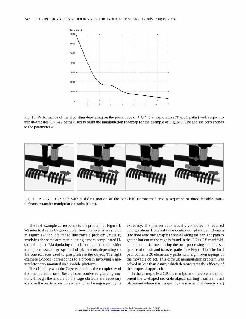
The other rationale is also to enlarge the size of the solu-tion space when searching insideCG∩CP . Once a solutionpath (includingType1 sliding motions) is found, it is alwayspossible to approximate it by a feasible manipulation path.Such an additional transformation step is preferable to otherapproaches that would directly take into account the manipu-lation constraints during the search. In particular, for solvingthe problem of Figure 1, the sliding motion allowing us toget the bar out the cage (see Figure 11) is obtained muchmore easily insideCG ∩ CP than the resulting sequence oftransit/transfer paths that would be computed by the existingplanners (e.g., Ahuactzin, Gupta, and Mazer 1998; Nielsenand Kavraki 2000) after discretizing the continuous graspsand placements.
6.2. Influence of the α Parameter
Let us now discuss the performance of the planner accord-ing to α which is the major parameter of our planner. The
curve displayed in Figure 10 plots the time4 spent by the al-gorithm to build the manipulation roadmap allowing to solvethe illustrative problem of Figure 1. As explained above, therole of the parameterα is to control the rate of connectionssearched insideCG∩CP (Type1 adjacencies) compared toconnections searched outsideCG ∩ CP along the leaves oftheCG andCP spaces (Type2 adjacencies). Whenα = 0,the roadmap builder only considers collision-free transit andtransfer paths to connect the random samples generated inCG ∩ CP . In this case the algorithm behaves as the discreteapproaches.
Increasingα allows us to favor the construction of theCG ∩ CP connected components usingType1 adjacenciesbefore trying possible connections along leaves withType2adjacencies. The curve shows that the computation time sig-nificantly decreases for runs performed with higher values ofα. This increased performance can be explained by the factthat many searches of collision-free motions along the leavesof CP andCG are avoided thanks to the direct exploration oftheCG∩CP submanifold. Note, however, that whenα tendstowards 1, the probability of selectingType2 adjacencies re-mains very low until a sufficient coverage ofCG ∩ CP withType1 adjacencies has been reached. SinceType2 adjacen-cies are required to link theCG∩CP connected components,the performance decreases again whenα → 1. The reasonis that the algorithm spares time to reach such good cover-age insideCG ∩ CP instead of trying connections outsideCG∩CP . In all the experiments performed with the planner,this degradation of performance was observed to become sig-nificant for values ofα closed to 1. The experimental studyconducted on the difficult manipulation problem of Figure 1tends to show that when the problem is rather constrained, it isqualitatively advantageous to spend time on the connectivityof theCG ∩ CP submanifold before checking connectionswith feasible manipulation paths. As shown by the curve, thegain can be very important in such constrained situations. It ishowever observed to be less significant on simpler problemslike the two other examples presented in the next section. Asoften with the probabilistic methods, the choice of the bestvalue for this parameter remains an issue that would need tobe further investigated. In our experiments with the planner,runs are generally performed with a value ofα set to.9.
7. Experimental Results
The manipulation planner was implemented within the soft-ware platform Move3D (Siméon et al. 2001) developed at theLaboratory forAnalysis andArchitecture of Systems (LAAS).Several environments have been used as test-bed of the plan-ner. In this section, we present the results obtained with threeof them. The computation times correspond to experimentsconducted on a 330 MHz Sparc Ultra 10 workstation.
4. Each time value was averaged over ten runs performed using differentseeds to initialize the random generator.
© 2004 SAGE Publications. All rights reserved. Not for commercial use or unauthorized distribution. at Stanford University on October 5, 2007 http://ijr.sagepub.comDownloaded from
742 THE INTERNATIONAL JOURNAL OF ROBOTICS RESEARCH / July–August 2004
0
1000
2000
3000
4000
5000
6000
7000
10 20 30 40 50 60 70 80 90
Tem
ps C
PU
(se
c.)
Expansion dans vs. en dehors de Grasp inter Placement (%)
Time (sec)
.1 .2 .3 .4 .5 .6 .7 .8 .9
Fig. 10. Performance of the algorithm depending on the percentage ofCG ∩ CP exploration (Type1 paths) with respect totransit–transfer (Type2 paths) used to build the manipulation roadmap for the example of Figure 1. The abcissa correspondsto the parameterα.
Fig. 11. A CG ∩ CP path with a sliding motion of the bar (left) transformed into a sequence of three feasible trans-fer/transit/transfer manipulation paths (right).
The first example corresponds to the problem of Figure 1.We refer to it as the Cage example.Two other scenes are shownin Figure 12: the left image illustrates a problem (MulGP)involving the same arm manipulating a more complicated U-shaped object. Manipulating this object requires to considermultiple classes of grasps and of placements depending onthe contact faces used to grasp/release the object. The rightexample (MobM) corresponds to a problem involving a ma-nipulator arm mounted on a mobile platform.
The difficulty with the Cage example is the complexity ofthe manipulation task. Several consecutive re-grasping mo-tions through the middle of the cage obstacle are necessaryto move the bar to a position where it can be regrasped by its
extremity. The planner automatically computes the requiredconfigurations from only one continuous placement domain(the floor) and one grasping zone all along the bar. The path toget the bar out of the cage is found in theCG∩CP manifold,and then transformed during the post-processing step in a se-quence of transit and transfer paths (see Figure 11). The finalpath contains 20 elementary paths with eight re-graspings ofthe movable object. This difficult manipulation problem wassolved in less than 2 min, which demonstrates the efficacy ofthe proposed approach.
In the example MulGP, the manipulation problem is to re-orient the U-shaped movable object, starting from an initialplacement where it is trapped by the mechanical device lying
© 2004 SAGE Publications. All rights reserved. Not for commercial use or unauthorized distribution. at Stanford University on October 5, 2007 http://ijr.sagepub.comDownloaded from

Siméon et al. / Probabilistic Roadmaps 743
Fig. 12. Scenes and start/goal positions for the MulGP and MobM examples.
at the left of the workplan.This problem was solved by consid-ering eight grasp classes, each corresponding to a continuousgrasp along one of the eight thin faces defined by the U-shapedform of the object. Also, the set of stable placements corre-sponds to positions where one of the three large faces contactwith the workplan. We then consider three classes of place-ments according to the orientation of the movable object whenplaced on the table. Figure 13 shows the manipulation solu-tion computed by the planner. Here, the presence of severalgrasp/placements classes, and the larger size of the movableobject (which results in more RRT calls during the connectionstage) increase the overall cost of manipulation planner (seeTable 1).
In the example MobM, the mobile manipulator (nine DoF)can only pass from one side of the scene to the other sidethrough the passage under the X-shaped obstacle. However,this passage is too narrow for the movable object (the squareframe). A continuous grasping set is defined all around thisobject. The frame can be placed on the central obstacles. Fig-ure 14 shows the manipulation solution computed by the plan-ner. Here, the manipulation task is simpler compared to theprevious examples; fewer re-graspings are needed to solvethe problem. The difficulty illustrated by the example is todeal with a redundant system. An infinite set of solutions ex-ists to achieve the same grasp. Redundancy is a challenge
Table 1. Numerical ResultsExamples
Cage MulGR RobM
Total time 96 s 330 s 293 sComputingCG ∩ CP 23 s 10 s 6 sTransit/transfer paths 70 s 306 s 284 s
Total collision checks 43,518 187,342 102,241LocalCG ∩ CP paths 3689 1104 190Transit/transfer paths 54 168 147Dynamic updates 15 91 17
No. of manipulation nodes 32 36 21No. of manipulation paths 29 30 21
when treating closed-chain mechanisms. The exploration ofthe CG ∩ CP manifold for such systems is efficiently per-formed using the RLG-based closed-chain planner (Cortés,Siméon, and Laumond 2002).
Table 1 shows, for the three examples, numerical resultsthat illustrate the good performance of the planner. All prob-lems were solved withα = 0.9 after less than 5 min ofcomputation. Most of the computation time is spent check-ing connections with transit and transfer paths; this shows the
© 2004 SAGE Publications. All rights reserved. Not for commercial use or unauthorized distribution. at Stanford University on October 5, 2007 http://ijr.sagepub.comDownloaded from

744 THE INTERNATIONAL JOURNAL OF ROBOTICS RESEARCH / July–August 2004
Fig. 13. Manipulation path computed for the MulGP problem.
© 2004 SAGE Publications. All rights reserved. Not for commercial use or unauthorized distribution. at Stanford University on October 5, 2007 http://ijr.sagepub.comDownloaded from

Siméon et al. / Probabilistic Roadmaps 745
Fig. 14. Manipulation path computed for the MobM problem.
advantage of the proposed approach which limits the numberof such connection tests by first computing connected compo-nents insideCG∩CP .Also, the use of the visibility techniqueis the reason for the small size of the manipulation roadmaps;such small roadmaps also reduce the number of connectionsto be tested.
8. Conclusion
We have presented a new approach to manipulation planning.Its power lies in the fact that it can deal with a continuous for-mulation of the manipulation problem. It is based on structur-ing the search space to directly capture the connectivity of thesubmanifolds that correspond to the places where transit andtransfer paths can be connected. This structure is expressedin a probabilistic roadmap and allows us to design a manipu-lation planner that automatically generates, inside continuousdomains, the grasps and placements that make the problemsolvable. Simulation results show the approach’s effective-ness for solving complex manipulation problems.
There remain several possible improvements. For example,it is important to improve the performance of the connectionplanner which remains the most costly operation. This re-lates to the efficiency of PRM planners when facing dynamicchanges of the environment. Although the approach has thepotential to handle general models of the grasp and placements
spaces, the planner is currently implemented for the particu-lar case of planning pick-and-place operations for polyhedralobjects. One could, however, imagine applications requiringother models. Finally, the manipulation planner is currentlyrestricted to a single movable object manipulated by a sin-gle robot. The case of multiple movable objects and robotsrequires studying the conditions under which the reductionproperty can be extended to such situations. We also beganto investigate a more general approach (Gravot, Alami, andSiméon 2002) combining a symbolic task planning level withthe geometric manipulation planner in order to solve problemsof higher complexity with multiple objects and robots.
Acknowledgment
This work has been partly supported by the IST EuropeanProject 39250 MOVIE.
References
Ahuactzin, J. M., Gupta, K., and Mazer, E. 1998. Manipulationplanning for redundant robots: a practical approach.Inter-national Journal of Robotics Research 17(7):731–747.
Ahuactzin, J. M., and Gupta, K. 1999.The kinematic roadmap:a motion planning based global approach for inverse kine-matics of redundant robots.IEEE Transactions on Roboticsand Automation 15(4):653–670.
© 2004 SAGE Publications. All rights reserved. Not for commercial use or unauthorized distribution. at Stanford University on October 5, 2007 http://ijr.sagepub.comDownloaded from

746 THE INTERNATIONAL JOURNAL OF ROBOTICS RESEARCH / July–August 2004
Alami, R., Siméon,T., and Laumond, J. P. 1989.A geometricalapproach to planning manipulation tasks. The case of dis-crete placements and grasps.5th International Symposiumon Robotics Research, Tokyo, Japan.
Alami, R., Laumond, J. P., and Siméon, T. 1994. Two manip-ulation planning algorithms.Algorithmic Foundations ofRobotics (WAFR94), Stanford, CA.
Barraquand, J., and Ferbach, P. 1994. A penalty functionmethod for constrained motion planning.Proceedings ofthe IEEE International Conference on Robotics and Au-tomation (ICRA), San Diego, CA.
Barraquand, J., and Latombe, J.-C. 1991. Robot motion plan-ning: a distributed representation approach.InternationalJournal of Robotics Research 10(6):628–649.
Bessiere, P.,Ahuactzin, J., El-Ghazali, T., and Mazer, E. 1993.The “Ariadne’s Clew” algorithm: global planning with lo-cal methods.Proceedings of the IEEE/RSJ InternationalConference on Intelligent Robots and Systems (IROS),Yokohama, Japan, July 26–30.
Chen, P. C., and Hwang, Y. K. 1991. Practical path plan-ning among movable obstacles. InProceedings of theIEEE International Conference on Robotics and Automa-tion (ICRA), Sacramento, CA.
Cortés, J., Siméon, T., and Laumond, J. P. 2002. A ran-dom loop generator for planning the motions of closedkinematic chains with PRM methods.Proceedings ofthe IEEE/RSJ International Conference on IntelligentRobots and Systems (IROS), EPFL, Lausanne, Switzerland,September 30–October 4.
Ito, K. (ed). 1987.Encyclopedic Dictionary of Mathematics,MIT Press, Cambridge, MA.
Gravot, F., Alami, R., and Siméon, T. 2002. Playing withseveral roadmaps to solve manipulation problems.Pro-ceedings of the IEEE/RSJ International Conference onIntelligent Robots and Systems (IROS), EPFL, Lausanne,Switzerland, September 30–October 4.
Han, L., and Amato, N. 2000. A kinematics-based probabilis-tic roadmap method for closed kinematic chains.Algo-rithmic and Computational Robotics (WAFR00), Hanover,NH.
Kavraki, L., and Latombe, J.-C. 1994. Randomized prepro-cessing of configuration space for fast path planning.Pro-ceedings of the IEEE International Conference on Roboticsand Automation (ICRA), San Diego, CA.
Koga, Y., and Latombe, J.-C. 1992. Experiments in dual-armmanipulation planning.Proceedings of the IEEE Interna-tional Conference on Robotics and Automation (ICRA),Nice, France.
Koga, Y., and Latombe, J.-C. 1994. On multi-arm manipula-tion planning.Proceedings of the IEEE International Con-ference on Robotics and Automation (ICRA), San Diego,CA.
Kuffner, J., and Lavalle, S. 2000. RRT-Connect: an efficient
approach to single-query path planning.Proceedings of theIEEE International Conference on Robotics and Automa-tion (ICRA), San Francisco, CA, April 24–28.
Latombe, J.-C. 1991.Robot Motion Planning, Kluwer,Dordrecht.
Laumond, J. P., and Alami, R. 1989. A geometrical approachto planning manipulation tasks in robotics. LAAS Techni-cal Report No. 89261.
Laumond, J. P., and Siméon, T. 2000. Notes on visibilityroadmaps for motion planning.Algorithmic and Compu-tational Robotics (WAFR00), Hanover, NH.
LaValle, S., Yakey, J.H., and Kavraki, L. 1999. A probabilis-tic roadmap approach for systems with closed kinematicchains.Proceedings of the IEEE International Conferenceon Robotics and Automation (ICRA), Detroit, MI.
Lozano-Pérez, T., Jones, J.L., Mazer, E., and O’Donnell, P.A.1992.Handey: A Robot Task Planner, MIT Press, Cam-bridge, MA.
Lynch, K., and Mason, M. T. 1994. Stable pushing: mechan-ics, controllability and planning.Algorithmic Foundationsof Robotics (WAFR94), Stanford, CA.
Nielsen, Ch., and Kavraki, L. 2000. A two-level fuzzyPRM for manipulation planning.IEEE Proceedings ofthe IEEE/RSJ International Conference on IntelligentRobots and Systems (IROS), Takamatsu, Japan, October30–November 5.
Overmars, M., and Švestka, P. 1994. A probabilistic learningapproach to motion planning.Algorithmic Foundations ofRobotics (WAFR94), Stanford, CA.
Sahbani, A., Cortés, J., and Siméon, T. 2002. A probabilis-tic algorithm for manipulation planning under continu-ous grasps and placements.Proceedings of the IEEE/RSJInternational Conference on Intelligent Robots and Sys-tems (IROS), EPFL, Lausanne, Switzerland, September30–October 4.
Siméon, T., Laumond, J.P., and Nissoux, C. 2000. Visibility-based probabilistic roadmaps for motion planning.Ad-vanced Robotics 14(6):477–494. (A short version appearedin Proceedings of the 1999 IEEE/RSJ International Con-ference on Intelligent Robots and Systems).
Siméon, T., Laumond, J.P., van Geem, C., and Cortés, J. 2001.Computer Aided Motion: Move3D within MOLOG.Pro-ceedings of the IEEE International Conference on Roboticsand Automation (ICRA), Seoul, Korea, May 21–26.
Siméon, T., Cortés, J., Sahbani, A., and Laumond, J.P. 2002.A manipulation planner for pick and place operations un-der continuous grasps and placements.Proceedings of theIEEE International Conference on Robotics and Automa-tion (ICRA), Washington, DC, May 11–15.
Wilfong, G. 1988. Motion planning in the presence of mov-able obstacles.Proceedings of the 4th ACM Symposium onComputational Geometry, Urbana-Champaign, IL, June6–8.
© 2004 SAGE Publications. All rights reserved. Not for commercial use or unauthorized distribution. at Stanford University on October 5, 2007 http://ijr.sagepub.comDownloaded from