Generic Merging of Structure from Motion Maps with a Low ...
Upload
independentCategory
view
4download
0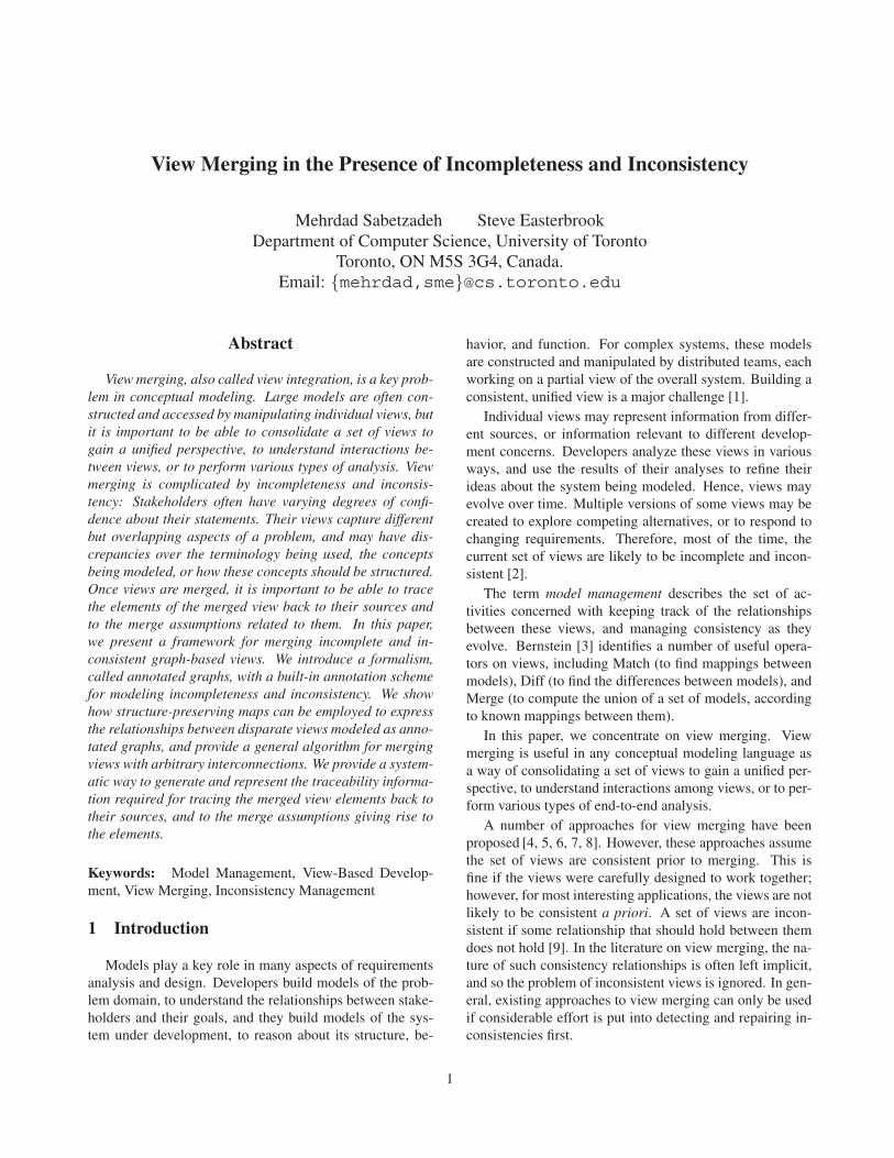
View Merging in the Presence of Incompleteness and Inconsistency
Mehrdad Sabetzadeh Steve EasterbrookDepartment of Computer Science, University of Toronto
Toronto, ON M5S 3G4, Canada.Email: {mehrdad,sme}@cs.toronto.edu
Abstract
View merging, also called view integration, is a key prob-lem in conceptual modeling. Large models are often con-structed and accessed by manipulating individual views, butit is important to be able to consolidate a set of views togain a unified perspective, to understand interactions be-tween views, or to perform various types of analysis. Viewmerging is complicated by incompleteness and inconsis-tency: Stakeholders often have varying degrees of confi-dence about their statements. Their views capture differentbut overlapping aspects of a problem, and may have dis-crepancies over the terminology being used, the conceptsbeing modeled, or how these concepts should be structured.Once views are merged, it is important to be able to tracethe elements of the merged view back to their sources andto the merge assumptions related to them. In this paper,we present a framework for merging incomplete and in-consistent graph-based views. We introduce a formalism,called annotated graphs, with a built-in annotation schemefor modeling incompleteness and inconsistency. We showhow structure-preserving maps can be employed to expressthe relationships between disparate views modeled as anno-tated graphs, and provide a general algorithm for mergingviews with arbitrary interconnections. We provide a system-atic way to generate and represent the traceability informa-tion required for tracing the merged view elements back totheir sources, and to the merge assumptions giving rise tothe elements.
Keywords: Model Management, View-Based Develop-ment, View Merging, Inconsistency Management
1 Introduction
Models play a key role in many aspects of requirementsanalysis and design. Developers build models of the prob-lem domain, to understand the relationships between stake-holders and their goals, and they build models of the sys-tem under development, to reason about its structure, be-
havior, and function. For complex systems, these modelsare constructed and manipulated by distributed teams, eachworking on a partial view of the overall system. Building aconsistent, unified view is a major challenge [1].
Individual views may represent information from differ-ent sources, or information relevant to different develop-ment concerns. Developers analyze these views in variousways, and use the results of their analyses to refine theirideas about the system being modeled. Hence, views mayevolve over time. Multiple versions of some views may becreated to explore competing alternatives, or to respond tochanging requirements. Therefore, most of the time, thecurrent set of views are likely to be incomplete and incon-sistent [2].
The term model management describes the set of ac-tivities concerned with keeping track of the relationshipsbetween these views, and managing consistency as theyevolve. Bernstein [3] identifies a number of useful opera-tors on views, including Match (to find mappings betweenmodels), Diff (to find the differences between models), andMerge (to compute the union of a set of models, accordingto known mappings between them).
In this paper, we concentrate on view merging. Viewmerging is useful in any conceptual modeling language asa way of consolidating a set of views to gain a unified per-spective, to understand interactions among views, or to per-form various types of end-to-end analysis.
A number of approaches for view merging have beenproposed [4, 5, 6, 7, 8]. However, these approaches assumethe set of views are consistent prior to merging. This isfine if the views were carefully designed to work together;however, for most interesting applications, the views are notlikely to be consistent a priori. A set of views are incon-sistent if some relationship that should hold between themdoes not hold [9]. In the literature on view merging, the na-ture of such consistency relationships is often left implicit,and so the problem of inconsistent views is ignored. In gen-eral, existing approaches to view merging can only be usedif considerable effort is put into detecting and repairing in-consistencies first.
1

Recent work on inconsistency management tools [10]helps in this respect but does not entirely address the prob-lem because, as we will argue, it is not possible to deter-mine whether a set of views are entirely consistent until allthe decisions are made about exactly how they are to bemerged. The intended relationships between the views mustbe stated precisely.
In this paper, we present a framework for merging mul-tiple views that tolerates inconsistency between the views.The framework can be adapted to any graph-based mod-eling language, as it treats the mappings between viewsin terms of mappings between nodes and edges in the un-derlying graphs. We will demonstrate the application ofthe framework to the early requirements modeling languagei∗ [11] and to entity-relationship models. In ongoing workwe are exploring application to the various modeling nota-tions of UML.
Our approach to view merging is based on the observa-tion that in exploratory modeling, one can never be entirelysure how concepts expressed in different views should re-late to one another. Each attempt to merge a set of viewscan be seen as a hypothesis about how to put the views to-gether, in which choices have to be made about which con-cepts overlap, and how the terms used in different views arerelated. If a particular set of choices yields an unaccept-able result, it may be because we misunderstood the natureof the relationships between the views, or because there isa real disagreement between the views over either the con-cepts being modeled, or how they are best represented. Inany of these cases, it is better to perform the merge and an-alyze the resulting inconsistencies, rather than restrict theavailable merge choices.
We use category theory [12] as a theoretical basis for ourmerge framework. We treat views as structured objects,and the intended relationships between them as structure-preserving mappings. To model incompleteness and in-consistency, we annotate view elements with labels denot-ing the amount of knowledge available about them. Toensure proper evolution of annotations, we constrain howthese labels can be treated in the mappings that interrelateviews. We provide a mathematically rigorous merge algo-rithm based on an algebraic concept called colimit. Thistreatment offers both scalability to arbitrary numbers ofviews, and adaptability to different conceptual modelinglanguages.
After computing a merge, we may need to know howthe original views and the defined mappings between themparticipated in producing the result. Our framework pro-vides the ability to trace the elements of the merged viewback to the originating views, to the contributing stakehold-ers, and to the view interrelationship assumptions related tothe elements. We discuss how the information required foraddressing each of these traceability concerns can be gener-
meetingSchedule
be obtainedAvailable dates Agreeable
slot be foundEmail requeststo participants
Mary
Efficient Planmeeting
Send request letters resultsConsolidate
be gatheredResponses
Bob
meetingSchedule
Agreeableslot be found
Available datesbe obtained
Consolidateresults
Meeting requestsbe sent
by emailSend requestsSend requests
by snail mail
Efficient
Merged View
+
(i) (ii)
(iii)
Figure 1. Merging i∗ views
ated and represented in our framework.Parts of this paper have previously been published in a
research paper at the 13th IEEE International RequirementsEngineering Conference (RE’05) [13], in a demo paper atthe same conference [14], and in a workshop paper at the3rd International Workshop on Traceability in EmergingForms of Software Engineering (TEFSE ’05) [15]. This pa-per brings together the ideas described in these earlier pa-pers, to provide a definitive treatment of our merge frame-work.
2 Motivating Examples
We will use two working examples throughout the paper,one involving goal models represented in the i∗ notation,and another involving database schemata captured by en-tity relationship diagrams. Through these applications, wedemonstrate how the ideas presented in this paper can beused for the management of requirements elicitation arti-facts, and to support the exploratory view merging process.This section briefly explains these examples, and uses themto illustrate the main challenges in view merging.
2.1 Merging i∗ Models
A requirements analyst, Sam, is developing a goal modelfor a meeting scheduler [16], based on interviews with twostakeholders, Bob and Mary. To ensure he adequatelycaptures both contributions, Sam first models each stake-holder’s view separately, using the i∗ notation. He thenmerges the views to study how well their goals fit together.
Figures 1(i) and 1(ii) show the initial views of Maryand Bob. At first sight, there appears to be no overlap, asMary and Bob use different terminologies. However, Samsuspects there are some straight-forward correspondences:
2
Schedule meeting in Mary’s view is probably the same taskas Plan meeting in Bob’s. Mary’s Available dates be obtained
may be the same goal as Bob’s Responses be gathered. Samalso thinks it makes sense to treat Mary’s Email requests to
participants and Bob’s Send request letters as alternative waysof satisfying an unstated goal, Meeting requests be sent. Bob’sConsolidate results task appears to make sense as a subtask ofMary’s Agreeable slot be found goal. Finally, after seeing bothviews, Mary points out that Bob’s positive contribution linkfrom Send request letters to the Efficient soft-goal is inappro-priate, although she believes the Efficient soft-goal itself isimportant.
For a problem of this size, Sam would likely just do anad-hoc merge with a result such as Figure 1(iii), and showthis to Bob and Mary for validation. This (ad-hoc) mergehas a number of drawbacks:
• There is no separation between hypothesizing a rela-tionship between the original views, and generating amerged version based on that relationship. Hence, itis hard for Sam to test out alternative hypotheses, andit will be very hard for Bob and Mary to check Sam’sassumptions individually.
• In an ad-hoc merge, Sam will naturally tend to repairinconsistencies implicitly and align the stakeholders’views with his own vision of the merge. Hence, welose the opportunities to analyze inconsistencies thatarise with a particular choice of merge.
• We have lost the ability to trace conceptual contribu-tions. If it is important to capture stakeholders’ con-tributions in individual views, then it must be equallyimportant to keep track of how these contributions getadapted into the merged view.
2.2 Merging Entity Relationship Models
In the i∗ view merging example in Section 2.1, themerged view (Figure 1(iii)) would most likely turn out to beagreeable to both Bob and Mary. However, in a more realis-tic elicitation problem, arriving at a viable consolidation isseldom as easy: View merging is an iterative and evolution-ary process where stakeholders constantly refine their per-spectives as a result of gaining more knowledge about theproblem, and looking back at previous merges and studyinghow their views affect and are affected by other parties’ in-tentions. To illustrate this, consider the following example:Suppose Sam, the analyst, now wants to develop a databaseschema for a payroll system based on Bob’s and Mary’s per-spectives. Views are described using Entity RelationshipDiagrams (ERDs).
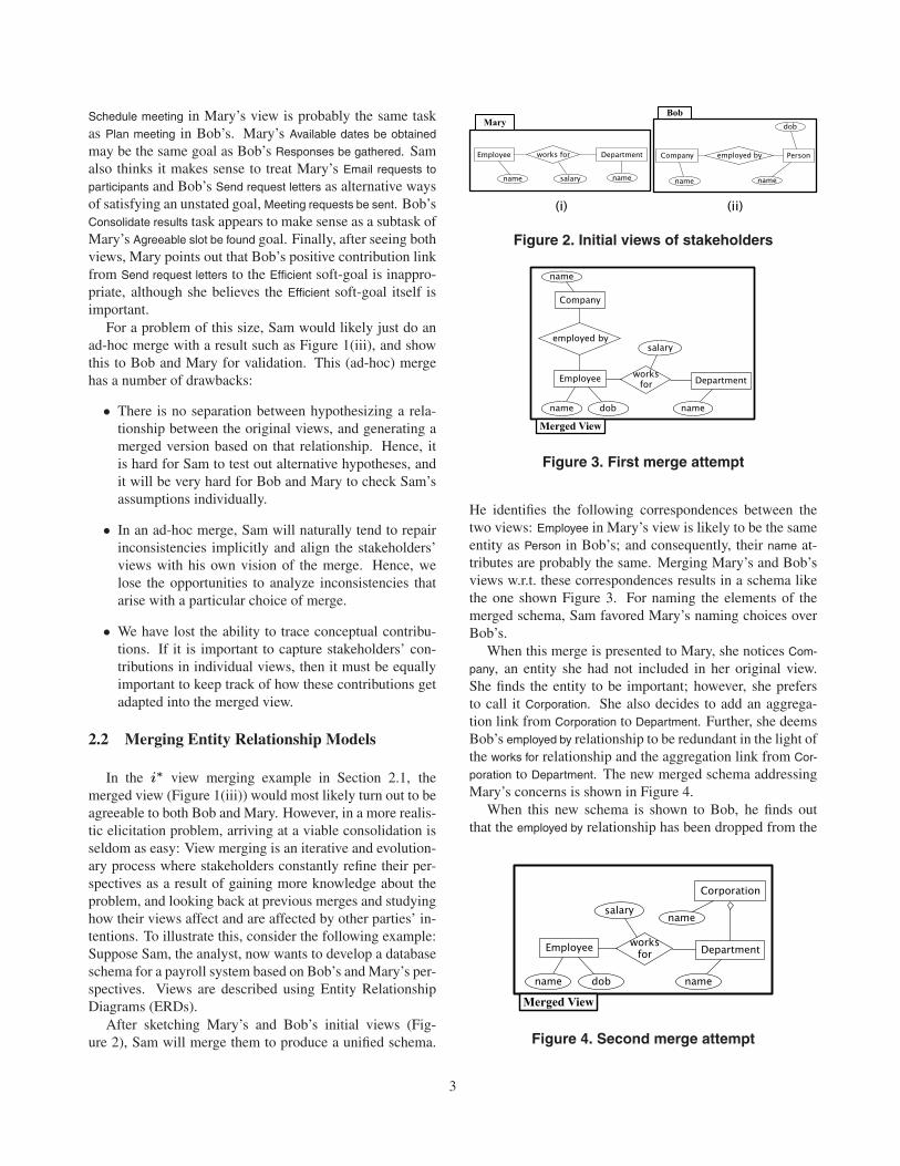
After sketching Mary’s and Bob’s initial views (Fig-ure 2), Sam will merge them to produce a unified schema.
Figure 2. Initial views of stakeholders
Figure 3. First merge attempt
He identifies the following correspondences between thetwo views: Employee in Mary’s view is likely to be the sameentity as Person in Bob’s; and consequently, their name at-tributes are probably the same. Merging Mary’s and Bob’sviews w.r.t. these correspondences results in a schema likethe one shown Figure 3. For naming the elements of themerged schema, Sam favored Mary’s naming choices overBob’s.
When this merge is presented to Mary, she notices Com-
pany, an entity she had not included in her original view.She finds the entity to be important; however, she prefersto call it Corporation. She also decides to add an aggrega-tion link from Corporation to Department. Further, she deemsBob’s employed by relationship to be redundant in the light ofthe works for relationship and the aggregation link from Cor-
poration to Department. The new merged schema addressingMary’s concerns is shown in Figure 4.
When this new schema is shown to Bob, he finds outthat the employed by relationship has been dropped from the
Figure 4. Second merge attempt
3

merge; however, he argues that there is no redundancy, asit is possible for some employees not to be attached to aparticular department. Therefore, he insists that the rela-tionship be added back to the merge!
An ad-hoc merge, or even a structured one computed in aclassical framework would fail in at least two respects whenfaced with a problem such as the one described above:
• It is not possible to describe how sure stakeholders areabout elements of their views, and how their beliefsevolve over time. If we later need to know how flexiblea stakeholder is w.r.t. a certain functionality, we haveno way of discovering how strongly the stakeholderargued for (or against) the functionality.
• Disagreements between stakeholders would need to beresolved immediately after being identified because wehave no means to model such disagreements explicitly.This is unsatisfactory – previous work suggests thattoleration of inconsistencies and disagreements, andbeing able to delay their resolution is basis for flexi-ble development [9].
The view merging framework that we present in this pa-per addresses all the problems motivated by the examples inSections 2.1 and 2.2.
3 View Merging as an Abstract Operation
The view merging framework presented in this paper isbased on a category-theoretic concept called colimit [12].In this paper, we will not provide a formal introduction tocolimits, but rather will explain the intuitions that motivateour use of category theory. A formal treatment of the mainconstructs of our approach can be found in [17].
Intuitively, a category is an algebraic structure consistingof a collection of objects together with a collection of map-pings (also known as arrows or morphisms). Each mappingconnects a pair of objects, known as its source and destina-tion. Typically, the objects will have some internal struc-ture, and the mappings express ways in which the structureof one object maps onto that of another. For example, ifthe objects are geometric shapes, then the mappings couldbe transformations that preserve shape, such as rotation andscaling. This gives rise to a number of familiar constructs– for example, if a mapping between two objects has an in-verse, then we say the two objects are isomorphic, i.e. theobjects have the same structure.
The appeal of category theory is that it provides a for-mal foundation for manipulating collections of objects andtheir mappings. In our case, the objects are views, and themappings are known or hypothesized relationships betweenthem. We can express a hypothesis about how a group ofobjects are related using an interconnection diagram. An
interconnection diagram is a set of objects of a particularcategory and a subset of possible mappings between them1.
The colimit of an interconnection diagram is a new ob-ject, called the colimiting object, together with a family ofmappings, one from each object in the diagram onto thecolimiting object2. Since each mapping expresses how theinternal structure of its source object is mapped onto thatof its destination object, the colimit expresses the merge ofall the objects in the interconnection diagram. Furthermore,the colimit respects the mappings in the diagram: The intu-ition here is that the image of each object in the colimit isthe same, no matter which path through the mappings in thediagram you follow. By definition, the colimit is also min-imal – it merges the objects in the diagram without addinganything essentially new [18].
To merge a set of views, we first express how they arerelated in an interconnection diagram, and then compute thecolimit. For example, if we want to merge two views, A andB, that overlap in some way, we can express the overlap asa third view, C, with mappings from C to each of A and B:
C
A B
......................
......................
......................
......................
......................
......................
......................
..............................
f........................................................................................................................................................................................
g
In this interconnection diagram, the two mappings f andg specify how the common part, C, is represented in eachof A and B. The colimit of this diagram is a new view, P ,expressing the union of A and B, such that their overlap, C,is included only once. This simple interconnection patternis known as a three-way merge.
The reason why we hypothesize merges explicitly anddefine the merge operation in terms of specific intercon-nection diagrams, rather than in terms of all given viewsand mappings is because, from time to time, we may wantto create merges using only a subset of the existing views.We therefore need to be able to specify which views areinvolved in each merge. Further, we may have several com-peting versions of mappings between any two participatingviews making it necessary also to specify which mappingsare to be used for computing a particular merge.
In practice, interconnection diagrams often have morecomplex patterns than that of three-way merge. Figure 5shows two examples used later in this paper: 5(i) is usedfor capturing the relationships between the i∗ meta-modelfragments in Figure 10, and 5(ii) is used for capturing therelationships between the views in Figure 13.
1The notion of interconnection diagram in category theory is more generalthan this (cf. e.g. [12]), but the extra generality is unnecessary here.
2In the remainder of the paper, with a slight abuse of terminology, we use theterm “colimit” to refer to the colimiting object for a given interconnectiondiagram.
4

• •
• • •
• • •
..................................................
..................................................
........................................................................................ ............
........
........
........
..............
..............................................................
........
........
........
..............
............
(i)
•• •
• ••.....................................................
......................................... ............
..................................................
..................................................
......................................................... ....................
.....................................
(ii)
Figure 5. Examples of interconnection patterns
It can be shown that each of the merge algorithms givenin this paper corresponds to colimit computation in an ap-propriate category. Further details about the correspon-dence between colimits and the algorithms given herein canbe found in a technical report [19] where the mathematicalunderpinnings of our work have been documented.
4 Interconnecting and Merging Graphs
In our framework, we assume that the underlying syn-tactic structure of each view can be treated as a graph. Thissection introduces graphs, and describes how they can beinterconnected and merged. Further, it explains how graphscan be equipped with a typing mechanism. The merge al-gorithm for graphs is built upon that for sets; therefore, webegin with a discussion of how sets can be merged.
4.1 Merging Sets
A system of interconnected sets is given by an intercon-nection diagram whose objects are sets and whose map-pings are (total) functions. Rather than treating functionsas general mapping rules between arbitrary sets, we con-sider each function to be a map with a unique domain anda unique codomain. Each function can be thought of as anembedding: each element of the domain set is mapped to acorresponding element in the codomain set. For example,in a three-way merge, the mappings would show how theset C is embedded in each of A and B.
To describe the algorithm for merging sets, we needto introduce the concept of disjoint union: The disjointunion of a given family of sets S1, S2, . . . , Sn, denotedS1 � S2 � . . . � Sn, is (isomorphic to) the following:S1 × {1} ∪ S2 × {2} ∪ . . . ∪ Sn × {n}. For concise-ness, we construct the disjoint union by subscripting theelements of each given set with the name of the set andthen taking the union. For example, if S1 = {x, y} andS2 = {x, t}, we write S1 � S2 as {xS1 , yS1 , xS2 , tS2} in-stead of {(x, 1), (y, 1), (x, 2), (t, 2)}.
To merge a system of interconnected sets, we start withthe disjoint union as the largest possible merged set, andrefine it by grouping together elements that get unified by
SET-MERGE (S1, . . . , Sn, f1, . . . , fk):
� Let U be an initially discrete graph with node-set S1 � . . . � Sn;� For every function fi (1 ≤ i ≤ k):� For every element a in the domain of fi:
� Add to U an undirected edge between the elementscorresponding to a and fi(a);
� Let P be the set of the connected components of U ;� Return P as the result of the merge operation.
Figure 6. Algorithm for merging sets
(i)
(ii)
(iii)
g
{z, w}
{x, y, t}{x, y, w}
C =
A = B =
f
xA yA yB
zC
wC
wA
P ={{xA, yB, zC}, {yA}, {wA, tB, wC}, {xB}
}
tBxB
Figure 7. Three-way merge example for sets
the interconnections. To identify which elements should beunified, we construct a unification graph U , a graphical rep-resentation of the symmetric binary relation induced on theelements of the disjoint union by the interconnections. Wethen combine the elements that fall in the same connectedcomponent of U . Figure 6 shows the merge algorithm for aninterconnection diagram whose objects are sets S1, . . . , Sn
and whose mappings are functions f1, . . . , fk.Figure 7 shows an example of three-way merge for sets:
7(i) shows the interconnection diagram; 7(ii) shows the in-duced unification graph and its connected components; and7(iii) shows the merged set. The example shows that simplytaking the union of two sets A and B might not be the rightway to merge them as this may cause name-clashes (e.g. ac-cording to the interconnections, the y elements in A and Bare not the same although they share the same name), or du-plicates for equivalent but distinctly-named elements (e.g.according to the interconnections, w in A and t in B are thesame despite having distinct names).
5
In the above set-merging example, the elements of eachset were uniquely identifiable by their names within the set.This is not necessarily the case in general because we mayhave unnamed or identically-named, but distinct elements.For example, in Sections 2.1 and 2.2, most edges in theviews were unnamed; and in Section 2.2, the name node ap-peared more than once in Bob’s and Mary’s views as wellas the merges. To avoid ambiguity, our implementation ofthe merge framework (discussed in Section 7) uses GlobalIdentifiers (GId’s) instead of names to distinguish betweenview elements.
Name Mapping
To assign a name to each element of the merged set in Fig-ure 7, we combined the names of all the elements in A, B,and C that are mapped to it. For example, “{xA, yB , zC}”indicates an element that represents x of A, y of B, and zof C. A better way to name the elements of the mergedset is assigning naming priorities to the input sets. For ex-ample, in three-way merge, it makes sense to give prior-ity to the element names in the connector, C, and write themerged set in our example as P = {zC , yA, wC , xB}. Inthis particular example, there are no name-clashes in themerged set, so we could drop the element subscripts andwrite P = {z, y, w, x}; however, in general, the subscriptsare needed to avoid name clashes that arise when stakehold-ers use the same terms to describe different concepts.
This naming convention is of no theoretical significance,but it provides a natural solution to the name mapping prob-lem: in most cases, we would like the choice of names inconnector objects, i.e. objects solely used to describe therelationships between other objects, to have precedence indetermining the element names in the merged object. Wewill use this convention in the rest of this paper.
4.2 Graphs and Graph Merging
The notion of graph as introduced below is a specifickind of directed graph used in algebraic approaches tograph-based modeling and transformation [20], and hasbeen successfully applied to capture various graphical for-malisms including UML, Entity-Relationship Diagrams,and Petri Nets [21].
Definition 4.1 (graph) A (directed) graph is a tupleG = (N,E, src, tgt) where N is a set of nodes, E is a setof edges, and src, tgt : E → N are functions respectivelygiving the source and the target of each edge.
To interconnect graphs, a notion of mapping needs tobe defined. A natural choice of mapping between graphsis homomorphism – a structure-preserving map describinghow a graph is embedded into another:
Definition 4.2 (homomorphism) Let G = (N,E, src, tgt)and G′ = (N ′, E′, src′, tgt′) be graphs. A (graph)homomorphism h : G → G′ is a pair of functions〈hnode : N → N ′, hedge : E → E′〉 such that for alledges e ∈ E, if hedge maps e to e′ then hnode respectivelymaps the source and the target of e to the source andthe target of e′; that is: src′(hedge(e)) = hnode(src(e))and tgt′(hedge(e)) = hnode(tgt(e)). We call hnode thenode-map function, and hedge the edge-map function of h.
A system of interconnected graphs is given by aninterconnection diagram whose objects are graphs andwhose mappings are homomorphisms. Merging is donecomponent-wise for nodes and edges. For a graph inter-connection diagram with objects G1, . . . , Gn and mappingsh1, . . . , hk, the merged object P is computed as follows:The node-set (resp. edge-set) of P is the result of merg-ing the node-sets (resp. edge-sets) of G1, . . . , Gn w.r.t. thenode-map (resp. edge-map) functions of h1, . . . , hk.
To determine the source (resp. target) of each edge ein the edge-set of the merged graph P , we pick, amongG1, . . . , Gn, some graph Gi that has an edge q which isrepresented by e. Let s (resp. t) denote the source (resp.target) of q in Gi; and let s′ (resp. t′) denote the node thatrepresents s (resp. t) in the node-set of P . We set the source(resp. target) of e in P to s′ (resp. t′). Notice that an edgein the merged graph may represent edges from several in-put graphs. In a category-theoretic setting, it can be shownthat the source and the target of each edge in the mergedgraph are uniquely determined irrespective of which Gi wepick [22].
Figure 8 shows an example of three-way merge forgraphs. In the figure, each homomorphism has been visu-alized by a set of directed dashed lines. In addition to thehomomorphisms of the interconnection diagram, i.e. f andg, we have shown the homomorphisms δA and δB specify-ing how A and B are represented in P . The homomorphismfrom C to P is implied and has not been shown.
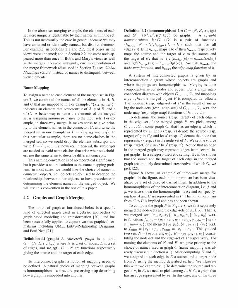
To compute the graph P in Figure 8, we first separatelymerged the node-sets and the edge-sets of A,B,C. That is,we merged sets {x1, x2, x3}, {n1, n2, n3}, {u1, u2} w.r.t.to functions fnode = {u1 �→ x1, u2 �→ x2}, gnode = {u1 �→n1, u2 �→n2}; and merged {p1, p2}, {e1, e2, e3}, {v1} w.r.t.to fedge = {v1 �→ p1}, gedge = {v1 �→ e1}. This yieldedtwo sets N = {u1, u2, x3, n3}, E = {v1, p2, e2, e3} consti-tuting the node-set and the edge-set of P respectively. Fornaming the elements of N and E, we gave priority to thechoice of names used in graph C (name mapping was al-ready discussed in Section 4.1). After computing N and E,we assigned to each edge in E a source and a target nodefrom N using the method described earlier. We illustratethis with two examples: 1) To determine the source and tar-get of v1 in E, we need to pick, among A,B,C, a graph thathas an edge represented by v1. In this case, any of the three
6

e3
e2
n1 n3n2
x1 x3
x2
fg
p1
p2
e1
e3 n3
e2
p2
x3
δA δB
u1
u2
v1
u1v1 u2
A
C
B
P
Figure 8. Three-way merge example for graphs
graphs will do because v1 has a pre-image in each of them– the edge represents p1 of A, e1 of B, and v1 of C. Re-gardless of which graph we pick, the computed source andtarget will be the same. Suppose we pick A. Edge p1 has x1
as source and x2 as target. The two nodes are represented inN by u1 and u2 respectively; therefore, v1 is assigned u1 assource and u2 as target. 2) Now, consider e3 in E. The edgehas a pre-image in graph B only. Thus, we pick B. Edgee3 in B has n2 as source and n3 as target. Nodes n2 and n3
are respectively represented by u2 and n3 in N . Thus, e3 inE is assigned u2 as source and n3 as target.
Enforcement of Types
Graph-based modeling languages typically have typednodes and edges. The definitions of graph and homomor-phism given earlier do not support types; therefore, we needto extend them for typed graphs. We can then restrict theadmissible mappings to those that preserve types.
In [23], a powerful typing mechanism for graphs hasbeen proposed using the relation between the models andthe meta-model for the language. Assuming that the meta-model for the language of interest is given by a graph M,every model is described by a pair 〈G, t : G → M〉 whereG is a graph and t is a homomorphism, called the typingmap, assigning a type to every element in G. Notice thata typing map is a homomorphism, offering more structurethan an arbitrary pair of functions assigning types to nodes
ClassInterface
Class2Class1Interface1
implements
extends extends
Class1 Class2Interface1
(i) (ii)
G
M
t
Figure 9. Example of typed graphs
and edges. A typed homomorphism h : 〈G, t〉 → 〈G′, t′〉 issimply a homomorphism h : G → G′ that preserves types,i.e. t′(h(x)) = t(x) for every element x in G. This typ-ing mechanism is illustrated in Figure 9: 9(i) shows a Javaclass diagram in UML notation and 9(ii) shows how it canbe represented using a typed graph. The graph M in 9(ii) isthe extends–implements fragment of the meta-model forJava class diagrams.
The meta-model for a graph-based language can be muchmore complex than that of Figure 9. Figure 10 showssome fragments of the i∗ meta-model extracted from thevisual syntax description of i∗’s successor GRL [24]. In-stead of showing the whole meta-model in one graph, wehave broken it into a number of views, each of which rep-resents a particular type of relationship (means-ends, de-composition, etc.). Our graph merging framework allowsus to describe the meta-model without having to show itmonolithically: the i∗ meta-model, Mi∗ , is the result ofmerging the interconnection diagram in Figure 10. To de-scribe the relations between the meta-model fragments, anumber of connector graphs (shaded gray) have been used.Each mapping (shown by a thick solid line) is a homomor-phism giving the obvious mapping. Notice that the con-nector graphs are discrete (i.e. do not have any edges) asno two meta-model fragments share common edges of thesame type. The ∧- and ∨-contribution structures in i∗ con-vey a relationship between a group of edges. To capturethis, we introduced helper nodes (shown as small rectangu-lar boxes) in the meta-model to group edges that should berelated by ∧ or ∨. Figure 11(i) shows how we normallydraw an ∨-contribution structure in an i∗ model and Fig-ure 11(ii) shows the adaptation of the structure to typedgraphs. Structures conveying relationships between a com-bination of nodes and edges can be modeled similarly.
The merge operation for typed graphs is the same as thatfor untyped graphs. The only additional step required isassigning types to the elements of the merged graph: eachelement in the merged graph inherits its type from the ele-ments it represents. In a category-theoretic setting, it can beproven that every element of the merged graph is assigneda unique type in this way and that a typing map can be es-
7

Task Goal
GoalSoft Resource
Task
Goal Resource
Actor
ResourceGoalSoft
Task GoalGoalSoft
Task
GoalSoft
Task
ResourceGoal
Task GoalTask
GoalSoft Resource
Task
GoalSoft
Contributions
Contributions
Dependency
Means−EndsDecomposition
∧∨
+−
− +
+•
+•
∨, ∧
+, −,+•
Figure 10. Some meta-model fragments of i∗
(i) (ii)
∨
. . .. . .
Figure 11. Adaptation of ∨-contribution
tablished from the merged graph to the meta-model [23].
5 Merging Requirements Views
The merge framework of the previous section providessufficient machinery for merging graph-based views that arefree from incompleteness and inconsistency. However, aswe argued earlier, for most interesting applications that in-volve multiple stakeholders, the views are unlikely to beeither conclusive or consistent. Therefore, it is crucial to beable to tolerate incompleteness and inconsistency. In thissection, we show how incompleteness and inconsistencycan be modeled by an appropriate choice of annotation forview elements. Using the motivating examples in Section 2,we demonstrate how incomplete and inconsistent views canbe represented, interconnected, and merged.
!
✘ ✔
�
���
���
���
���
Figure 12. Belnap’s knowledge order variant
5.1 Annotated Views
The classical approach discussed in Section 4 is capa-ble of describing view correspondences; however, it pro-vides no means to express the stakeholders’ beliefs aboutthe fitness of view elements, and the possible ways in whichthese beliefs can evolve. Consequently, we cannot describehow sure stakeholders are about each of the decisions theymake. Further, we cannot express inconsistencies and dis-agreements that arise due to discrepancies between stake-holders’ decisions about either the structure or the contentsof views.
To model stakeholders’ beliefs, we attach to each viewelement an annotation denoting the degree of knowledgeavailable about the element. We formalize knowledge de-grees using knowledge orders. A knowledge order is apartially ordered set [25] specifying the different levels ofknowledge that can be associated to view elements, and thepossible ways in which this knowledge can grow. The ideaof knowledge orders was first introduced by Belnap [26],and later generalized by Ginsberg [27].
One of the simplest and most useful knowledge orders isBelnap’s four-valued knowledge order [26]. The knowledgeorder K shown in Figure 12 is a variant of this: assigning! to an element means that the element has been proposedbut it is not known if the element is indeed well-conceived;✘ means that the element is known to be ill-conceived andhence repudiated; ✔ means that the element is known tobe well-conceived and hence affirmed; and � means thereis conflict as to whether the element is well-conceived, i.e.the element is disputed 3.
An upward move in a knowledge order denotes a growthin the amount of knowledge, i.e. an evolution of speci-ficity. In K, the value ! denotes uncertainty; ✘ and ✔ de-note the conclusive amounts of knowledge; and � denotesa disagreement, i.e. too much knowledge – we can infersomething is both ill-conceived and well-conceived.
To augment graph-based views with the above-describedannotation scheme, the definitions of graph and homomor-phism are extended as follows. Let K be a knowledge order:
3Belnap’s original lattice refers to ! as maybe, ✘ as false, ✔ as true, and� as disagreement.
8
Definition 5.1 (annotated graph) A K-annotated graphG is a graph each of whose nodes and edges has been anno-tated with an element drawn from K.
Definition 5.2 (annotation-respecting homomorphism)Let G and G′ be K-annotated graphs. A K-respectinghomomorphism h : G → G′ is a homomorphism subjectto the following condition: For every element (i.e. node oredge) x in G, the image of x under h has an annotationwhich is larger than or equal to the annotation of x.
The condition in Definition 5.2 ensures that knowledgeis preserved as we traverse a mapping between annotatedviews. For example, if we have already decided an elementin a view is affirmed, it cannot be embedded in another viewsuch that it is reduced to just proposed, or is changed to avalue not comparable to affirmed (i.e. repudiated).
For a fixed knowledge order K, the merge operation overan interconnection diagram whose objects G1, . . . ,Gn areK-annotated graphs and whose mappings h1, . . . ,hk areK-respecting homomorphisms, yields a merged object Pcomputed as follows: First, disregard the annotations ofG1, . . . ,Gn and merge the resulting graphs w.r.t. h1, . . . ,hk
to get a graph P . Then, to construct P, attach an annotationto every element x in P by taking the least upper bound [25]of the annotations of all the elements that x represents.
Intuitively, the least upper bound of a set of knowledgedegrees S ⊆ K is the least specific knowledge degree thatrefines (i.e. is more specific than) all the members of S. Toensure that the least upper bound exists for any subset of K,we assume K to be a complete lattice [25]. The knowledgeorder K in Figure 12 is an example of a complete lattice.
As an example, suppose the graphs in Figure 8 wereannotated with K in such a way that the homomorphismsf and g satisfied the condition in Definition 5.2. Assum-ing that the nodes u1 of C, x1 of A, n1 of B are respec-tively annotated with !, ✔, and ✘, the annotation for thenode u1 of P , which represents the aforementioned threenodes, is calculated by taking the least upper bound of theset S = {!, ✔, ✘} resulting in the value �.
Incorporating types into annotated graphs is independentof the annotations and is done in exactly the same manneras described in Section 4. In [19], we provide a completeversion of the definitions for typed annotated graphs.
5.2 Example I: Merging i∗ Views
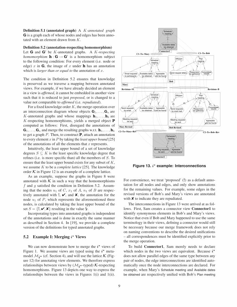
We can now demonstrate how to merge the i∗ views ofFigure 1. We assume views are typed using the i∗ meta-model Mi∗ (cf. Section 4), and will use the lattice K (Fig-ure 12) for annotating view elements. We therefore expressrelationships between views by (Mi∗-typed) K-respectinghomomorphisms. Figure 13 depicts one way to express therelationships between the views in Figures 1(i) and 1(ii).
MaryBob
Bob Revised
Efficient Planmeeting
Responsesbe gathered
resultsConsolidate
Agreeableslot be found
Meeting requestsbe sent
Send requestsby snail mail
+
meetingSchedule
Available datesbe obtained
Agreeableslot be found
meetingSchedule
Meeting requestsbe sent
Email requeststo participants be obtained
Available dates Agreeableslot be found
meetingSchedule
Mary Revised
be obtainedAvailable dates Agreeable
slot be found
meetingSchedule
Meeting requestsbe sent
by emailSend requests
Planmeeting
Send request letters Responsesbe gathered results
Consolidate
Efficient
+
Connector1
Connector2
C1−To−Bob
C2−To−Mary−Rev
Revisions−M Revisions−B
C2−To−Bob−Rev
C1−To−Mary
✘✘
✘
✘
Figure 13. i∗ example: Interconnections
For convenience, we treat ‘proposed’ (!) as a default anno-tation for all nodes and edges, and only show annotationsfor the remaining values. For example, some edges in therevised versions of Bob’s and Mary’s views are annotatedwith ✘ to indicate they are repudiated.
The interconnections in Figure 13 were arrived at as fol-lows. First, Sam creates a connector view Connector1 toidentify synonymous elements in Bob’s and Mary’s views.Notice that even if Bob and Mary happened to use the sameterminology in their views, defining a connector would stillbe necessary because our merge framework does not relyon naming conventions to describe the desired unifications– all correspondences must be identified explicitly prior tothe merge operation.
To build Connector1, Sam merely needs to declarewhich nodes in the two views are equivalent. Because i∗
does not allow parallel edges of the same type between anypair of nodes, the edge interconnections are identified auto-matically once the node interconnections are declared. Forexample, when Mary’s Schedule meeting and Available dates
be obtained are respectively unified with Bob’s Plan meeting
9

Meeting requestsbe sent
Consolidateresults
meetingSchedule
by emailSend requestsSend requests
by snail mail
Efficient
Agreeableslot be found
Available datesbe obtained
Merged View
+✘
✘
✘ ✘
Figure 14. i∗ example: The merged view
and Responses be gathered, the decomposition links betweenthem in the two views should also be unified.
Next, Sam elaborates each of Bob’s and Mary’s viewsto obtain Mary Revised and Bob Revised. In these views,Sam has repudiated the elements he wants to replace, andproposed additional elements that he needs to complete themerge. Sam could, of course, affirm all the remaining el-ements of the original views, but he preferred not to do sobecause the models are in very early stages of elicitation.Finally, Sam keeps track of cases where the same elementwas added to more than one view using another connectorview, Connector2.
With these interconnections, the views in Figure 13 canbe automatically merged, to obtain the view shown in Fig-ure 14. To name the elements of the merged view priorityhas been given to Sam’s choice of names. For presentation,we may want to mask the elements annotated with ✘. Thiswould result in the view shown in Figure 1(iii).
In the above scenario, we treated the original elementsof Mary’s and Bob’s views as being at the proposed level,allowing further decisions to be freely made about any ofthe corresponding elements in the revised views. At anytime, Mary or Bob may wish to insist upon or change theirminds about any elements in their views. They can do thisby elaborating their original views, affirming (or repudiat-ing) some elements. In this case, we simply add the newelaborated views to the merge hypothesis with the appropri-ate mappings from Mary’s or Bob’s original views. Whenwe recompute the merge, the new annotations may result indisagreements. We illustrate this in Section 5.3.
5.3 Example II: Merging ER Views
To merge the ER views of Figure 2, we assume themto be typed by a meta-model MER. We chose to omit thismeta-model in the paper because the process of constructingit is similar to that described in Section 4 for constructingMi∗ . As in the previous example, the lattice K (Figure 12)will be used to annotate view elements, and ‘proposed’ (!)
Figure 15. ER example: Interconnections(Part I)
Figure 16. ER example: Interconnections(Part II)
will be treated as a default annotation. Relationships be-tween views will be expressed by K-respecting homomor-phisms.
First attempt: In the first iteration, Sam describes the cor-respondences between Bob’s and Mary’s views using a con-nector view, Connector1 (Figure 15), and two mappingsC1-To-Bob and C1-To-Mary. Merging the interconnec-tion diagram made up of views Bob, Mary and Connec-tor1, and mappings C1-To-Bob and C1-To-Mary yieldsthe schema shown in Figure 3.
Second attempt: In the second iteration, Mary evolves heroriginal view, to obtain Mary Evolved (Figure 16), address-ing the concerns that occurred to her after the first merge at-tempt. With Sam’s help, she establishes the required inter-relationships between her evolved view and Bob’s originalview through a new connector, Connector2 (Figure 16). If
10
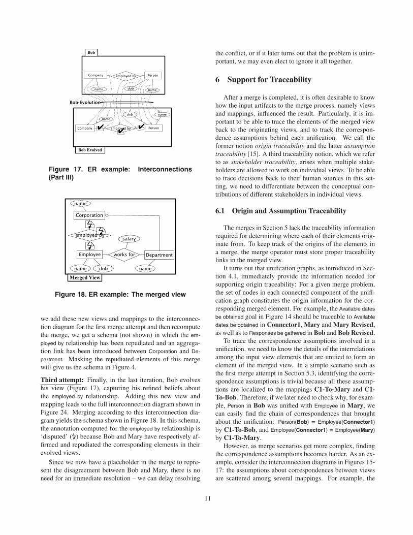
Figure 17. ER example: Interconnections(Part III)
Figure 18. ER example: The merged view
we add these new views and mappings to the interconnec-tion diagram for the first merge attempt and then recomputethe merge, we get a schema (not shown) in which the em-
ployed by relationship has been repudiated and an aggrega-tion link has been introduced between Corporation and De-
partment. Masking the repudiated elements of this mergewill give us the schema in Figure 4.
Third attempt: Finally, in the last iteration, Bob evolveshis view (Figure 17), capturing his refined beliefs aboutthe employed by relationship. Adding this new view andmapping leads to the full interconnection diagram shown inFigure 24. Merging according to this interconnection dia-gram yields the schema shown in Figure 18. In this schema,the annotation computed for the employed by relationship is‘disputed’ (�) because Bob and Mary have respectively af-firmed and repudiated the corresponding elements in theirevolved views.
Since we now have a placeholder in the merge to repre-sent the disagreement between Bob and Mary, there is noneed for an immediate resolution – we can delay resolving
the conflict, or if it later turns out that the problem is unim-portant, we may even elect to ignore it all together.
6 Support for Traceability
After a merge is completed, it is often desirable to knowhow the input artifacts to the merge process, namely viewsand mappings, influenced the result. Particularly, it is im-portant to be able to trace the elements of the merged viewback to the originating views, and to track the correspon-dence assumptions behind each unification. We call theformer notion origin traceability and the latter assumptiontraceability [15]. A third traceability notion, which we referto as stakeholder traceability, arises when multiple stake-holders are allowed to work on individual views. To be ableto trace decisions back to their human sources in this set-ting, we need to differentiate between the conceptual con-tributions of different stakeholders in individual views.
6.1 Origin and Assumption Traceability
The merges in Section 5 lack the traceability informationrequired for determining where each of their elements orig-inate from. To keep track of the origins of the elements ina merge, the merge operator must store proper traceabilitylinks in the merged view.
It turns out that unification graphs, as introduced in Sec-tion 4.1, immediately provide the information needed forsupporting origin traceability: For a given merge problem,the set of nodes in each connected component of the unifi-cation graph constitutes the origin information for the cor-responding merged element. For example, the Available dates
be obtained goal in Figure 14 should be traceable to Available
dates be obtained in Connector1, Mary and Mary Revised,as well as to Responses be gathered in Bob and Bob Revised.
To trace the correspondence assumptions involved in aunification, we need to know the details of the interrelationsamong the input view elements that are unified to form anelement of the merged view. In a simple scenario such asthe first merge attempt in Section 5.3, identifying the corre-spondence assumptions is trivial because all these assump-tions are localized to the mappings C1-To-Mary and C1-To-Bob. Therefore, if we later need to check why, for exam-ple, Person in Bob was unified with Employee in Mary, wecan easily find the chain of correspondences that broughtabout the unification: Person(Bob) = Employee(Connector1)
by C1-To-Bob, and Employee(Connector1) = Employee(Mary)
by C1-To-Mary.However, as merge scenarios get more complex, finding
the correspondence assumptions becomes harder. As an ex-ample, consider the interconnection diagrams in Figures 15-17: the assumptions about correspondences between viewsare scattered among several mappings. For example, the
11
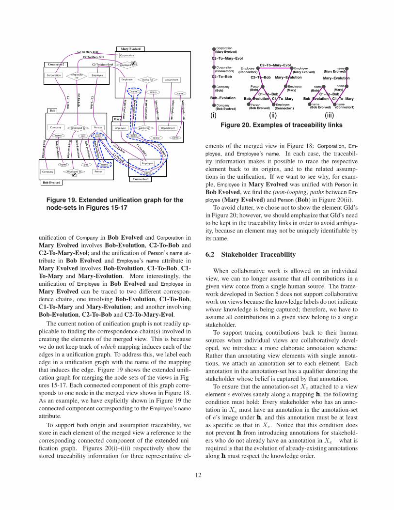
Figure 19. Extended unification graph for thenode-sets in Figures 15-17
unification of Company in Bob Evolved and Corporation inMary Evolved involves Bob-Evolution, C2-To-Bob andC2-To-Mary-Evol; and the unification of Person’s name at-tribute in Bob Evolved and Employee’s name attribute inMary Evolved involves Bob-Evolution, C1-To-Bob, C1-To-Mary and Mary-Evolution. More interestingly, theunification of Employee in Bob Evolved and Employee inMary Evolved can be traced to two different correspon-dence chains, one involving Bob-Evolution, C1-To-Bob,C1-To-Mary and Mary-Evolution; and another involvingBob-Evolution, C2-To-Bob and C2-To-Mary-Evol.
The current notion of unification graph is not readily ap-plicable to finding the correspondence chain(s) involved increating the elements of the merged view. This is becausewe do not keep track of which mapping induces each of theedges in a unification graph. To address this, we label eachedge in a unification graph with the name of the mappingthat induces the edge. Figure 19 shows the extended unifi-cation graph for merging the node-sets of the views in Fig-ures 15-17. Each connected component of this graph corre-sponds to one node in the merged view shown in Figure 18.As an example, we have explicitly shown in Figure 19 theconnected component corresponding to the Employee’s name
attribute.
To support both origin and assumption traceability, westore in each element of the merged view a reference to thecorresponding connected component of the extended uni-fication graph. Figures 20(i)–(iii) respectively show thestored traceability information for three representative el-
Corporation
Company
Corporation(Connector2)
(Mary Evolved)
(Bob)
Company(Bob Evolved)
Person Employee
Employee
Employee
(Mary Evolved)
(Mary)
(Connector1)
(Connector2)Employee
Person(Bob Evolved)
(Bob)
name
name(Mary)
name(Bob)
name(Bob Evolved)
name(Connector1)
(Mary Evolved)
(iii)(ii)(i)
C2−To−Mary−Evol
C2−To−Bob
Bob−EvolutionC1−To−Bob
C1−To−MaryBob−Evolution
Mary−EvolutionC2−To−Bob
C2−To−Mary−Evol
C1−To−Bob
Mary−Evolution
C1−To−MaryBob−Evolution
Figure 20. Examples of traceability links
ements of the merged view in Figure 18: Corporation, Em-
ployee, and Employee’s name. In each case, the traceabil-ity information makes it possible to trace the respectiveelement back to its origins, and to the related assump-tions in the unification. If we want to see why, for exam-ple, Employee in Mary Evolved was unified with Person inBob Evolved, we find the (non-looping) paths between Em-
ployee (Mary Evolved) and Person (Bob) in Figure 20(ii).To avoid clutter, we chose not to show the element GId’s
in Figure 20; however, we should emphasize that GId’s needto be kept in the traceability links in order to avoid ambigu-ity, because an element may not be uniquely identifiable byits name.
6.2 Stakeholder Traceability
When collaborative work is allowed on an individualview, we can no longer assume that all contributions in agiven view come from a single human source. The frame-work developed in Section 5 does not support collaborativework on views because the knowledge labels do not indicatewhose knowledge is being captured; therefore, we have toassume all contributions in a given view belong to a singlestakeholder.
To support tracing contributions back to their humansources when individual views are collaboratively devel-oped, we introduce a more elaborate annotation scheme:Rather than annotating view elements with single annota-tions, we attach an annotation-set to each element. Eachannotation in the annotation-set has a qualifier denoting thestakeholder whose belief is captured by that annotation.
To ensure that the annotation-set Xe attached to a viewelement e evolves sanely along a mapping h, the followingcondition must hold: Every stakeholder who has an anno-tation in Xe must have an annotation in the annotation-setof e’s image under h, and this annotation must be at leastas specific as that in Xe. Notice that this condition doesnot prevent h from introducing annotations for stakehold-ers who do not already have an annotation in Xe – what isrequired is that the evolution of already-existing annotationsalong h must respect the knowledge order.
12

Connector
Agreeableslot be found
Mary + Revisions
be obtainedAvailable dates
meetingSchedule
Meeting requestsbe sent
by emailSend requests
Agreeableslot be found
Bob + Revisions
Responsesbe gathered
Agreeableslot be found
Send requestsby snail mail
Meeting requestsbe sent
Efficient
resultsConsolidate
Planmeeting
+
meetingSchedule
Meeting requestsbe sent be obtained
Available dates
B:!;S:✘
B:!;S:✘
∅
∅
∅∅ ∅∅∅
M:!
M:!
M:!
M:!
M:!
M:!;S:✘S:!
S:!
S:!
M:!
S:!
S:!
S:!
S:!
S:!
B:!
B:!
B:!
B:!B:!
B:!
S:!
B:!;S:✘
Figure 21. New view interconnections
Meeting requestsbe sent
Consolidateresults
meetingSchedule
by emailSend requestsSend requests
by snail mail
Agreeableslot be found
Efficient
Merged View
Available datesbe obtained
+
B:!;S:✘
M:!;S:!
M:!;S:!
M:!;B:!
M:!;B:!
B:!;S:✘
B:!;S:✘
M:!;B:!
B:!
B:! M:!
S:! S:!
S:!
S:!M:!;S:✘
B:!
S:!
Figure 22. Merged view with detailed annotations
To illustrate the new annotation scheme consider the i∗
merging example: Sam, Mary, and Bob can now manipu-late each others’ views without compromising traceability.This is because the annotations can keep track of the con-tributions of individual parties. The new system of inter-connected views is shown in Figure 21. We use a concisenotation to represent the annotation-set for each element.For example, M:!;B:! means that both Mary and Bob pro-posed the element; B:!;S:✘ means Bob proposed the ele-ment and Sam repudiated it. Note that in the Connectorview in Figure 21, the elements have no stakeholder anno-tations, indicated using ∅. If we were interested in trackingthe revisions Sam makes to Bob’s and Mary’s vocabularies,we would need to use the same interconnection pattern asthat in Figure 13, but the view elements would be annotatedwith annotation-sets instead of single knowledge degrees.
Merging the interconnected views in Figure 21 yields theview shown in Figure 22. The annotation-set for each viewelement e in the figure is computed by first unioning thestakeholders that have contributed to the elements repre-
sented by e; and then, for every stakeholder s in the union,taking the least upper bound of s’s contributions to these el-ements. In [19], we provide a lattice-theoretic characteriza-tion of the computation of annotation-sets using the conceptof annotated powerset lattices.
The annotation for each element of the merged view inFigure 22 reflects the decisions made about the element bythe involved stakeholders. Note that when stakeholders donot work on input views collaboratively, origin traceabilitysubsumes stakeholder traceability; that is, we can producemerges with annotations like those in Figure 22 based onorigin traceability information.
7 Tool Support
We have implemented a Java tool, iVuBlender [14], formerging requirements views. The tool consists of two com-ponents: (1) a generic merge library for annotated graphs;and (2) a Swing-based front-end that allows users to graphi-cally express their views, specify the view relationships, andhypothesize and compute merges. We have used the mergelibrary for merging i∗ models, ERDs, and state-machines.Currently, the front-end only supports ERDs and simplestate-machines, and is restricted to just the knowledge or-der in Figure 12 for annotating view elements. For futureversions, we plan to develop a larger collection of graphi-cal widgets to capture the visual syntax of richer modelingformalisms such as i∗, and provide support for defining ar-bitrary knowledge orders.
iVuBlender is not bound to a particular process model formerging. Views, mappings, and interconnection diagramscan be conceived and declared in any order with the obvi-ous constraint that a mapping cannot be specified fully un-less its source and target views have been fully elaborated.Since our tool can work with partial mappings, this con-straint does not mean that a mapping cannot be specifiedpiece-by-piece or that it cannot co-evolve with its two ends.In fact, it is only when we want to compute the merge of aninterconnection diagram that it becomes necessary to ensurethe mappings referenced in the diagram are fully specified.
Although iVuBlender may be used in many differentways for merging views, we have found the process modelin Figure 23 to be very effective for exploratory modelingproblems. In such problems, we usually start by defininga set of disparate views capturing the initial perspectives ofthe stakeholders. We then declare a merge hypothesis usingan interconnection diagram. The hypothesis may referencea number of connector views for describing the correspon-dences between the stakeholders’ views. We define theseconnectors and follow it by specifying the mappings refer-enced in the hypothesis. When we compute the merge forthe hypothesis, we get a view combining the set of viewsreferenced in the hypothesis w.r.t. their (hypothesized) re-
13

Evolve Views
Specify Connectors
Specify Mappings
Analyze Results
Identify New Interrelationships
(Re)hypothesize a Merge
Compute the Merge
Capture Initial Views
Figure 23. An exploratory merge process
lationships. We may analyze this merged view in variousways. Our analyses often trigger the evolution of views andlead to the discovery of new interrelationships. To incor-porate these refinements, we initiate a new iteration of theprocess by first revising our existing merge hypothesis (orcreating a new one) and following the subsequent activities.
Figures 24 and 25 show two screenshots of iVuBlender:The former is a screenshot of the interconnection diagramfrom Figures 15-17, and the latter is a screenshot of themerged view in Figure 18. To ensure that computed mergesare laid out properly, the tool applies a fully automatic lay-out algorithm to them before presenting them to the user. Torepresent the annotations, we have used a color scheme inthe tool: The default color represents proposed (!), blue andmagenta respectively represent affirmed (✔) and repudiated(✘), and red represents disputed (�).
8 Discussion
In this section, we discuss some practical considerationsconcerning our merge framework.
8.1 Sanity Checks
The typing mechanism discussed in Section 4 can cap-ture many classes of constraints which we may need to en-force; however, it has some limitations. Most notably, itcannot capture constraints whose articulation involves the
Figure 24. Screenshot of an interconnectiondiagram
Figure 25. Screenshot of a (merged) view
semantics of the modeling language being used. In the classdiagram example in Figure 9, we could not express the con-straint that a Java class is not allowed to have multiple par-
14
ent classes, or that a class cannot extend its subclasses: inboth cases, a typing map could be established even thoughthe resulting class diagrams were unsound. To express theformer constraint, we would have to require that the classinheritance hierarchy be a many-to-one relation; and to ex-press the latter, we would have to require that the inheri-tance hierarchy be acyclic.
Since such constraints cannot be expressed in our frame-work, a number of sanity checks may be needed both onthe input views and on the merge to ensure their soundnessw.r.t. a desired set of semantics. Even if the input viewsare sound w.r.t. these semantics, this does not imply thatthe merge is sound too, because the interconnections do notnecessarily preserve semantics. Semantics-dependent san-ity checks are formalism-specific. An exposition of suchchecks for database schema merging can be found in [28].
Another facet to sanity checks in our framework is de-tecting the potential anomalies caused by annotations. Forexample, in Section 5, it was possible for a view to have anon-repudiated edge with a repudiated end. In such a case,we would be left with dangling edges if we mask repudiatedelements. The detection of such anomalies depends on theinterpretation of the annotations being used.
8.2 Identification of Interconnections
Our focus in this paper was devising a framework for de-scribing the relationships between incomplete and inconsis-tent views and merging them once the interconnections arespecified. In the examples of Section 5, the interconnectionswere identified manually by an analyst. The natural ques-tion to ask now is to what extent we can automate the rolethat the analyst plays in establishing the interconnections.The answer to this question has a significant impact on howour framework scales to realistically large problems.
To our knowledge, little work has been done in Re-quirements Engineering on automating the identification ofview interconnections, even in cases where inconsistencyhas not been an issue. However, the subject has attractedconsiderable attention in the Database community for ex-ploring relationships between schemata. There, the identifi-cation of interconnections is referred to as schema match-ing [29, 30, 31]. We are performing a number of case-studies on some popular graph-based formalisms includ-ing conceptual modeling languages such as i∗ and (thedeclaration-level graphical syntax of) KAOS [32], state-machines, and UML to investigate how schema matchingtechniques can be generalized to graph-based structuresother than ERDs.
a
b
x
zy q r
sp
A B
q r
spx
zy
A B
a
b
C
(ii)(i)
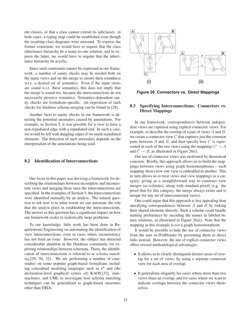
Figure 26. Connectors vs. Direct Mappings
8.3 Specifying Interconnections: Connectors vs.Direct Mappings
In our framework, correspondences between indepen-dent views are captured using explicit connector views. Forexample, to describe the overlap of a pair of views A and B,we create a connector view C that captures just the commonparts between A and B, and then specify how C is repre-sented in each of the two views using the mappings C → Aand C → B, as illustrated in Figure 26(i).
Our use of connector views was motivated by theoreticalconcerns. Briefly, this approach allows us to build the map-pings between views using graph homomorphisms – eachmapping shows how one view is embedded in another. Thisin turn allows us to treat views and view mappings as a cat-egory, giving us a straightforward way to construct viewmerges (as colimits), along with standard proofs (e.g. theproof that for this category, the merge always exists and isunique for any set of interconnected views).
One could argue that this approach is less appealing thanspecifying correspondences between A and B by linkingtheir shared elements directly. Such a scheme could handlenaming preferences by encoding the names in labeled bi-nary relations, as illustrated in Figure 26(ii). Note that themapping in this example is not a graph homomorphism.
It would be possible to hide the use of connector viewsfrom the user in iVuBlender by presenting them as directlinks instead. However, the use of explicit connector viewsoffers several methodological advantages:
• It allows us to clearly distinguish distinct areas of over-lap for a set of views, by using a separate connectorview for each area of overlap.
• It generalizes elegantly for cases where more than twoviews share an overlap, and for cases where we want toindicate overlaps between the connector views them-selves.
15
• It provides a more flexible platform for incorporatingvarious types of preferences into the merge process[7]. A simple example are layout preferences: we maywant to choose a certain layout for the parts that are incommon between a set of views and preserve that lay-out in the merge. Layout preferences require explicitmodels for the shared parts.
• Connectors can be used as requirements baselineswhen the scope of the elicitation process widens. Forexample, if the elicitation process starts with twostakeholders and a new stakeholder emerges later on,it is natural for the third stakeholder to use the connec-tors between the views of the first two stakeholders asbaselines for further elaboration of his/her own views.
8.4 Beyond Equality Relationships
To have a flexible view exploration process, we mayneed to express certain kinds of non-equality relationshipsbetween view elements. A notable example of such re-lationships is similarity stating that two or more elementsare similar in some respects but not equivalent. Express-ing non-equality relationships can be made possible by ex-tending the formalism of interest with new modeling con-structs. ERDs, for example, have been extended with a spe-cial notation for denoting similarities between schema ele-ments [7]. Incorporating such constructs into merge scenar-ios is straight-forward. For example, in Figure 13, we couldelect to introduce a similarity node instead of the Meeting
request be sent goal node to state that Send request by email
and Send request by snail mail are conceptually similar with-out providing details about the nature of the similarity.
9 Related Work
Over the years, the term “view” (or “viewpoint”) hasappeared in the literature with several different mean-ings. Views have been used to mean different classes ofusers [33], the contexts in which different roles are per-formed [34], to distinguish between stakeholder terminolo-gies [35], and to encapsulate knowledge about a system intoloosely-coupled objects [36]. A survey and comparison ofthe existing view-based approaches can be found in [37].Our interpretation of views falls closely in line with theemerging trends in model management where views are em-ployed to capture conceptual data gathered from disparatesources into independent but interrelated units. To describeview interrelationships, explicit mappings must be definedbetween them [3].
Inconsistency management has become an importanttopic in Requirements Engineering due to its central rolein model management. A number of approaches to incon-sistency management have been proposed, in general based
on the success of the ViewPoints framework [2, 9, 10]. Themain questions in this work center on appropriate notationsfor expressing consistency rules, and automated support forresolving inconsistencies. In much of this work, view merg-ing is treated as an entirely separate problem, because of thedesire to maintain views as loosely-coupled distributed ob-jects [2].
The use of multi-valued logics for merging incompleteand inconsistent views was first proposed in [38] and waslater generalized in [17]. The latter work, which serves asa precursor to this paper, suggested category theory as aunified means for formalizing incompleteness and inconsis-tency and characterizing the merge operation. However, thework was conceived primarily as part of a framework forsupporting automated reasoning over state-machines. Thispaper instead focuses on using the same algebraic principlesfor devising a model management framework for require-ments elicitation.
Schema merging [4, 7, 8] is an important operation indatabase design for combining disparate schemata, and hasbeen identified as one of the core activities in metadatamanagement [3, 39]. Our framework extends the syntac-tic aspects of the state-of-the-art on schema merging inseveral respects: Firstly, the existing schema merging ap-proaches only support the three-way merge pattern whereasour framework can handle arbitrary interconnection pat-terns. Secondly, our framework can explicitly model in-consistencies and allows for the deferral of their resolution.This is in contrast to the above-cited work where inconsis-tencies are not tolerated and need to be resolved as soonas discovered. Thirdly, our framework is parameterized bya meta-model and can hence be applied to various model-ing formalisms; but, schema merging is, to a great extent,tailored to entity relationship diagrams or similar schemamodeling notations.
In [40], a combination of natural language processingand formal concept analysis techniques has been employedfor formalizing and visualizing requirements extracted frommultiple use case descriptions. Reconciliation is donethrough defining a thesaurus for unifying the vocabulariesof the extracted concepts. The work also attempts to strate-gize handling of inconsistencies; but, it does not supportexplicit modeling of stakeholders’ beliefs; and further, fallsshort of accounting for requirements evolution and describ-ing its impacts on the management of inconsistencies.
The closest work to ours in the area of Requirements En-gineering is the merging framework of [5]. In this work,views are described by graph transformation systems andcolimits are used to merge them. However, the work cannothandle inconsistent views.
Recently, a framework has been proposed for mergingpartial behavioral models [41]. There, stakeholders’ mod-els are described by partial state transition systems and are
16
merged based on the process-algebraic refinement relationsbetween them. The work supports incompleteness and canalso detect inconsistencies; however, the merge operationfails when the models are inconsistent. Another differ-ence between our approach and the work is that they donot explicitly describe view correspondences and rely onbi-similarity relations to give the relationships between thestates of different views. This can make it difficult for re-quirements analysts to guide the merge process as they can-not directly hypothesize the merge alternatives.
Annotated graphs bear similarity to fuzzy graphs [42].The work on fuzzy graphs is focused on the analysis of iso-lated models using graph-theoretic techniques, whereas inour work, the focus is on describing the structural relation-ships between models using algebraic techniques.
The ability to trace requirements back to their humansources is cited as one of the most important traceabilityconcerns in software development [43]. To this end, contri-bution structures [44] have been proposed as a way to facil-itate cooperative work among teams and to ensure that thecontributions of involved parties are properly accounted forthroughout the entire development life-cycle. The notionsof origin and stakeholder traceability in our work try to ad-dress a similar problem in the context of view merging.
The importance of establishing traceability links be-tween artifacts and the assumptions involved in creatingthem has been emphasized in design rationale [45, 46] anddesign traceability [47]. However, the focus of that workhas been mainly on assumptions that relate upstream anddownstream artifacts. Our work, instead, focuses on re-quirements elicitation which is an entirely upstream activity.We discuss the nature of the relationships between viewsproduced during elicitation, and provide an approach forkeeping track of how each assumption made about view in-terrelations affects the merge.
10 Conclusions and Future Work
We have presented a flexible and mathematically rig-orous framework for merging incomplete and inconsistentviews. Our merge framework is general and can be appliedto a variety of graphical modeling languages. In this paper,we presented the core algorithms for computing merges,showed how the framework can handle typing constraints,and how to trace contributions in the merged view back totheir sources and to the relevant merge assumptions. Wehave implemented the algorithms described in the paper,and used the implementation to merge views in a numberof different notations.
An advantage of our framework is the explicit identifica-tion of interconnections between views prior to the mergeoperation rather than relying on naming conventions to givethe desired unification. We believe this offers a powerful
tool for exploring inconsistency during exploratory model-ing, as it allows an analyst to hypothesize possible intercon-nections for a set of views, compute the resulting mergedviews, and trace between the source views and the mergedviews to analyze these results.
The work reported here can be continued in many direc-tions. Automating the identification of potential intercon-nections between views is a major part of our ongoing workand is a step toward applying the work to large-scale con-ceptual modeling. We are also investigating possible waysfor adding a semantics-aware component to the frameworkfor sanity-checking the merges. Another interesting venueis studying whether our framework can be used for relatingthe behaviors of models. The interconnections used in ourapproach are based on homomorphisms and the fact thathomomorphisms have been employed in various abstrac-tion frameworks [48] for relating behaviors of models posesmany interesting questions as to what logical properties canbe preserved when models are merged. Adding support forhierarchical structures is yet another thing that can be stud-ied. We also plan to develop a more usable version of thetool to investigate how well it supports cooperative concep-tual modeling, and especially stakeholder negotiation dur-ing requirements analysis.
Acknowledgments. We thank John Mylopoulos, ReneeMiller, Pamela Zave, Sotirios Liaskos, Yijun Yu, Linda Liu,Faye Baron, and Shiva Nejati for helpful discussions. Wethank the members of the Formal Methods, Database, andEarlyRE groups at the University of Toronto, as well as theanonymous reviewers of the RE’05 Conference and the REJournal for their insightful comments. Financial supportwas provided by NSERC, MITACS, and BUL.
References
[1] S. Easterbrook, E. Yu, J. Aranda, Y. Fan, J. Horkoff,M. Leica, and R. Qadir. Do viewpoints lead to betterconceptual models? an exploratory case study. In Pro-ceedings of the 13th International Requirements Engi-neering Conference, pages 199–208, 2005.
[2] A. Finkelstein, D. Gabbay, A. Hunter, J. Kramer,and B. Nuseibeh. Inconsistency handling in multi-perspective specifications. IEEE Transactions on Soft-ware Engineering, 20(8):569–578, 1994.
[3] P. Bernstein. Applying model management to clas-sical meta data problems. In Proceedings of the 1stBiennial Conference on Innovative Data Systems Re-search, pages 209–220, 2003.
[4] P. Buneman, S. Davidson, and A. Kosky. Theoreti-cal aspects of schema merging. In Proceedings of the
17
3rd International Conference on Extending DatabaseTechnology, pages 152–167, 1992.
[5] H. Ehrig, G. Engels, R. Heckel, and G. Taentzer.A combined reference model- and view-based ap-proach to system specification. International Journalof Software Engineering and Knowledge Engineering,7(4):457–477, 1997.
[6] S. Castano and V. De Antonellis. Deriving global con-ceptual views from multiple information sources. InConceptual Modeling – Current Issues and Future Di-rections, volume 1565 of Lecture Notes in ComputerScience, pages 44–55. Springer, 1999.
[7] R. Pottinger and P. Bernstein. Merging models basedon given correspondences. In Proceedings of 29thInternational Conference on Very Large Data Bases,pages 862–873., 2003.
[8] S. Melnik, E. Rahm, and P. Bernstein. Rondo: a pro-gramming platform for generic model management. InSIGMOD Conference, pages 193–204, 2003.
[9] S. Easterbrook and B. Nuseibeh. Using viewpointsfor inconsistency management. Software EngineeringJournal, 11(1):31–43, 1996.
[10] C. Nentwich, W. Emmerich, A. Finkelstein, andE. Ellmer. Flexible consistency checking. ACM Trans-actions on Software Engineering and Methodology,12(1):28–63, 2003.
[11] E. Yu. Towards modeling and reasoning support forearly-phase requirements engineering. In Proceedingsof the 3rd International Symposium on RequirementsEngineering, pages 226–235, 1997.
[12] M. Barr and C. Wells. Category Theory for ComputingScience. Les Publications CRM Montreal, Montreal,Canada, third edition, 1999.
[13] M. Sabetzadeh and S. Easterbrook. An algebraicframework for merging incomplete and inconsistentviews. In Proceedings of the 13th International Re-quirements Engineering Conference, pages 306–315,2005.
[14] M. Sabetzadeh and S. Easterbrook. iVuBlender: Atool for merging incomplete and inconsistent views.In Proceedings of the 13th International RequirementsEngineering Conference, pages 453–454, 2005. ToolDemo Paper.
[15] M. Sabetzadeh and S. Easterbrook. Traceability inviewpoint merging: A model management perspec-tive. In Proceedings of the 3rd International Work-shop on Traceability in Emerging Forms of SoftwareEngineering, November 2005. To appear.
[16] A. van Lamsweerde, R. Darimont, and P. Massonet.The meeting scheduler system – problem statement.ftp://ftp.info.ucl.ac.be/pub/publi/92.
[17] M. Sabetzadeh and S. Easterbrook. Analysis of in-consistency in graph-based viewpoints: A category-theoretic approach. In Proceedings of the 18th In-ternational Conference on Automated Software Engi-neering, pages 12–21, 2003.
[18] J. Goguen. A categorical manifesto. MathematicalStructures in Computer Science, 1(1):49–67, 1991.
[19] M. Sabetzadeh and S. Easterbrook. An algebraicframework for merging incomplete and inconsistentviews. Technical Report CSRG-496, University ofToronto, 2004.
[20] H. Ehrig and G. Taentzer. Computing by graphtransformation, a survey and annotated bibliography.Bulletin of the European Association for TheoreticalComputer Science, 59:182–226, 1996.
[21] G. Rozenberg, editor. Handbook of graph gram-mars and computing by graph transformation: Foun-dations, volume 1. World Scientific, River Edge, NJ,USA, 1997.
[22] D. Rydeheard and R. Burstall. Computational Cate-gory Theory. Prentice Hall, Hertfordshire, UK, 1988.
[23] A. Corradini, U. Montanari, and F. Rossi. Graph pro-cesses. Fundamenta Informaticae, 26(3–4):241–265,1996.
[24] The goal-oriented requirement language (GRL).http://www.cs.toronto.edu/km/GRL.
[25] B. Davey and H. Priestley. Introduction to Latticesand Order. Cambridge University Press, Cambridge,UK, second edition, 2002.
[26] N. Belnap. A useful four-valued logic. In G. Epsteinand J. Dunn, editors, Modern Uses of Multiple-ValuedLogic, pages 5–37. Reidel, Dordrecht, Netherlands,1977.
[27] M. Ginsberg. Bilattices and modal operators. In Pro-ceedings of the 3rd Conference on Theoretical Aspectsof Reasoning about Knowledge, pages 273–287, 1990.
[28] C. Batini, M. Lenzerini, and S. Navathe. A compar-ative analysis of methodologies for database schemaintegration. ACM Computing Surveys, 18(4):323–364,1986.
[29] E. Rahm and P. Bernstein. A survey of approachesto automatic schema matching. The VLDB Journal,10(4):334–350, 2001.
18
[30] J. Madhavan, P. Bernstein, and E. Rahm. Genericschema matching with cupid. In Proceedings of 27thInternational Conference on Very Large Data Bases,pages 49–58, 2001.
[31] S. Melnik, H. Garcia-Molina, and Erhard Rahm. Sim-ilarity flooding: A versatile graph matching algorithmand its application to schema matching. In Proceed-ings of the 18th International Conference on Data En-gineering, pages 117–128, 2002.
[32] A. van Lamsweerde, R. Darimont, and P. Massonet.Goal-directed elaboration of requirements for a meet-ing scheduler: Problems and lessons learnt. In Pro-ceedings of the 2nd International Symposium on Re-quirements Engineering, pages 194–203, 1995.
[33] D. Ross. Applications and extensions of SADT. IEEEComputer, 18(4):25–34, 1985.
[34] S. Easterbrook. Domain modeling with hierarchies ofalternative viewpoints. In Proceedings of the 1st In-ternational Symposium on Requirements Engineering,pages 65–72, 1993.
[35] R. Stamper. Social norms in requirements analysis: anoutline of MEASUR. In M. Jirotka and J. Goguen, ed-itors, Requirements engineering: social and technicalissues, pages 107–139. Academic Press, London, UK,1994.
[36] A. Finkelsetin, J. Kramer, B. Nuseibeh, L. Finkel-stein, and M. Goedicke. Viewpoints: A framework forintegrating multiple perspectives in system develop-ment. International Journal of Software Engineeringand Knowledge Engineering, 2(1):31–58, 1992.
[37] P. Darke and G. Shanks. Stakeholder viewpoints inrequirements definition: A framework for understand-ing viewpoint development approaches. RequirementsEngineering, 1(2):88–105, 1996.
[38] S. Easterbrook and M. Chechik. A framework formulti-valued reasoning over inconsistent viewpoints.In Proceedings of the 23rd International Conferenceon Software Engineering, pages 411–420, 2001.
[39] S. Melnik. Generic Model Management: Conceptsand Algorithms, volume 2967 of LNCS. Springer,Berlin, Germany, 2004.
[40] D. Richards. Merging individual conceptual models ofrequirements. Requirements Engineering, 8(4):195–205, 2003.
[41] S. Uchitel and M. Chechik. Merging partial be-havioural models. In Proceedings of the 12th Inter-national Symposium on Foundations of Software En-gineering, pages 43–52, 2004.
[42] J. Mordeson and P. Nair. Fuzzy Graphs and FuzzyHypergraphs. Physica-Verlag, Heidelberg, Germany,2000.
[43] O. Gotel and A. Finkelstein. Extended requirementstraceability: results of an industrial case study. In Pro-ceedings of the 3rd International Symposium on Re-quirements Engineering, pages 169–178, 1997.
[44] O. Gotel and A. Finkelstein. Contribution structures(requirements artifacts). In Proceedings of the 2nd In-ternational Symposium on Requirements Engineering,pages 100–107, 1995.
[45] G. Fischer, A. Lemke, R. McCall, and A. Morch.Making argumentation serve design. In T. Moran andJ. Carroll, editors, Design rationale: concepts, tech-niques, and use, pages 267–293. Lawrence ErlbaumAssociates, Mahwah, NJ, USA, 1996.
[46] T. Gruber and D. Russell. Generative design rationale:beyond the record and replay paradigm. In T. Moranand J. Carroll, editors, Design rationale: concepts,techniques, and use, pages 323–349. Lawrence Erl-baum Associates, Mahwah, NJ, USA, 1996.
[47] A. Egyed. A scenario-driven approach to traceability.In Proceedings of the 23rd International Conferenceon Software Engineering, pages 123–132, 2001.
[48] Edmund M. Clarke, Orna Grumberg, and David E.Long. Model checking and abstraction. ACM Trans-actions on Programming Languages and Systems,19(2):1512–1542, 1994.
19
Copyright © 2022 FDOKUMEN