Merging Unit and Process Bus solution
51
Merging Unit and Process Bus solution siemens.com/processbus Unrestricted © Siemens 2020
-
Upload
khangminh22 -
Category
Documents
-
view
0 -
download
0
Transcript of Merging Unit and Process Bus solution

Merging Unit and Process Bus
solution
siemens.com/processbusUnrestricted © Siemens 2020

Unrestricted © Siemens 2020
January 21Page 2 Smart Infrastructure | Digital Grid
Content
General Information1
Merging Unit2
Process Bus Client3
Applications4
Sample Synchronization (IEEE 1588v2/PTP and PPS)5
Network architectures6
Definitions7

Unrestricted © Siemens 2020
January 21Page 3 Smart Infrastructure | Digital Grid
Content
Merging Unit2
Process Bus Client3
Applications4
Sample Synchronization (IEEE 1588v2/PTP and PPS)5
Network architectures6
Definitions7
General Information1

Unrestricted © Siemens 2020
January 21Page 4 Smart Infrastructure | Digital Grid
Conventional solution

Unrestricted © Siemens 2020
January 21Page 5 Smart Infrastructure | Digital Grid
Conventional Technology
Unrestricted © Siemens 2020
January 21Page 6 Smart Infrastructure | Digital Grid
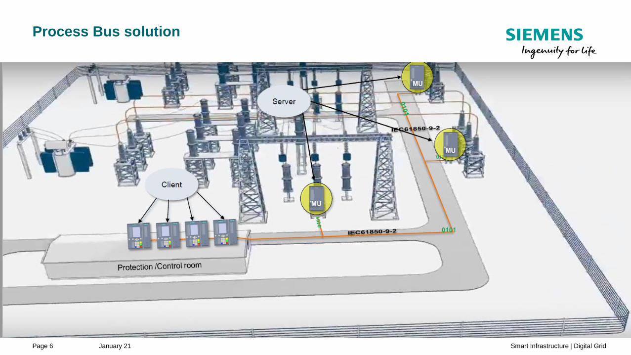
Process Bus solution

Unrestricted © Siemens 2020
January 21Page 7 Smart Infrastructure | Digital Grid
Process Bus Technology
Unrestricted © Siemens 2020
January 21Page 8 Smart Infrastructure | Digital Grid
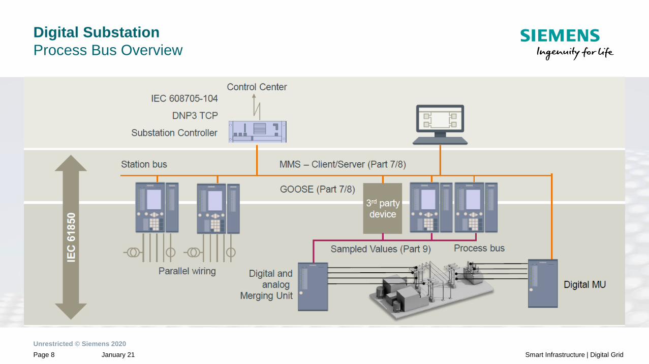
Digital Substation
Process Bus Overview

Unrestricted © Siemens 2020
January 21Page 9 Smart Infrastructure | Digital Grid
Principle and benefits of process bus
Process bus
Protection devices
Merging units
6MU85 6MU85 6MU85

Unrestricted © Siemens 2020
January 21Page 10 Smart Infrastructure | Digital Grid
Content
General Information1
Merging Unit2
Applications4
Sample Synchronization (IEEE 1588v2/PTP and PPS)5
Network architectures6
Definitions7
Process Bus Client3

Unrestricted © Siemens 2020
January 21Page 11 Smart Infrastructure | Digital Grid
SIPROTEC Merging Unit
One base module adapts to all sensor types
Principle of a Process Bus• Stand-Alone merging unit
• Copper wires via short distances
• Digital interface for instrument transformers IEC 61869-9
• Merging unit as part of switchgear
• Low power stand alone current,
voltage and combined sensors
• IEC 61869-10 and 11
LPIT
LPIT
LPIT
Rogowski coil
Optical
current sensor’
Conventional
C divider
R divider*
RC divider*
Process bus
FO Ethernet
IEC 61850-9-2
IEC 61869
IEC 61850-8-1
HSR* or PRP Network
Unrestricted © Siemens 2020
January 21Page 13 Smart Infrastructure | Digital Grid
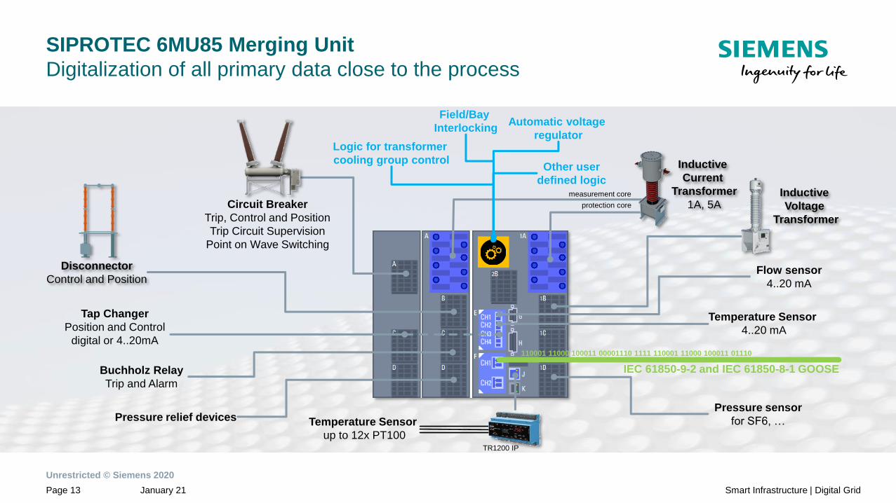
SIPROTEC 6MU85 Merging Unit
Digitalization of all primary data close to the process
Logic for transformer
cooling group control
Flow sensor
4..20 mA
Pressure sensor
for SF6, …
Temperature Sensor
4..20 mA
TR1200 IP
Buchholz Relay
Trip and Alarm
Automatic voltage
regulator
Tap Changer
Position and Control
digital or 4..20mA
Pressure relief devices
Circuit Breaker
Trip, Control and Position
Trip Circuit Supervision
Point on Wave Switching
Disconnector
Control and Position
measurement core
protection core
110001 11000 100011 00001110 1111 110001 11000 100011 01110
IEC 61850-9-2 and IEC 61850-8-1 GOOSE
Field/Bay
Interlocking
Temperature Sensor
up to 12x PT100
Other user
defined logicInductive
Voltage
Transformer
Inductive
Current
Transformer
1A, 5A

Unrestricted © Siemens 2020
January 21Page 14 Smart Infrastructure | Digital Grid
Merging Unit – SIPROTEC 6MU85
Up to 4 plug-in communication modules to enable connection to:
Process bus communication
• SMV: IEC 61850-9-2 / IEC 61850-9-2 LE / IEC 61869-9,
GOOSE, MMS: IEC 61850-8-1
Scada communication
• IEC 61850-8-1 MMS & GOOSE, DNP3, IEC 60870-5-104, Modbus IP, Profinet IO
Redundant communication
• IEC 62439-3.4 PRP, IEC 62439-3.5 HSR, RSTP, dual homing (Scada)
• IEC 62439-3.4 PRP, dual homing (process bus)
PMU Data Concentrator
• Synchrophasor (IEEE C37.118)
Time synchronization
• IEEE 1588V2 IEC 61850-9-3 and IEEE C37.238:2017 (redundant with IEC 62439-3.4 PRP
and dual homing)
Additional applications
• Slave Unit Protocol for external temperature or 4-20 mA measuring devices
• Arc sensors for arc flash protection

Unrestricted © Siemens 2020
January 21Page 15 Smart Infrastructure | Digital Grid
Merging Unit – SIPROTEC 6MU85
Benefits
• Long-term flexibility even
after shipping
• Simple exchangeability
and retrofitting
• Adding and removing
functions throughout the
entire life cycle
• Reduced number of device
versions due to flexibility
• Minimization of space
requirements
• Agile adaptation to future
requirements
• Investment security
SIPROTEC 6MU85 DIGSI 5
25
* Function points might be required
27 38 47
50 51 50N 51N
50HS 50BF 50RS 59
59N 67 67N 74TC
79 86 90V PoW
PMU ARC CFC CTR
CB DISC ExTr …CB CFC
CTRDISC
ExTr
Drag & Drop *

Unrestricted © Siemens 2020
January 21Page 16 Smart Infrastructure | Digital Grid
SIPROTEC 6MU85 Merging Unit
Protection Functions
ANSI Function Abbr.
POW Point on Wave Switching POW
PMUSynchrophasor measurement (1 PMU can be used for max. 8
voltages and 8 currents)PMU
AFD Arc-protection (only with plug-in module ARC-CD-3FO)
Measured values, standard
Measured values, extended: Min, Max, Avg
Switching statistic counters
Circuit breaker wear monitoring ΣIx, I²t, 2P
CFC (Standard, Control)
CFC arithmetic
Switching sequences function
Inrush current detection
External trip initiation
Control
Fault recording of analog and binary signals
Monitoring and supervision
Protection interface, serial
Circuit Breaker
Disconnector
ANSI Function Abbr.
Protection functions for 1 and 3-pole tripping 3-pole
Hardware quantity structure expandable I/O
25 Synchrocheck, synchronizing function Sync
27Undervoltage protection: "3-phase" or "pos.seq. V1" or
"universal Vx"V<
38 Temperature Supervision θ>
47 Overvoltage protection, negative-sequence system V2>
50/51 TD Overcurrent protection, phases I>
50N/ 51N TD Overcurrent protection, ground IN>
Instantaneous tripping at switch onto fault SOTF
50HS High speed instantaneous overcurrent protection I>>>
50BF Circuit-breaker failure protection, 3-pole CBFP
50RS Circuit-breaker restrike protection CBRS
59, 59NOvervoltage protection: "3-phase" or "zero seq. V0" or
"pos.seq. V1" or "universal Vx"V>
67 Directional overcurrent protection, phases I>, ∠(V,I)
67N Directional overcurrent protection, ground IN>, ∠(V,I)
74TC Trip circuit supervision TCS
79 Automatic reclosing, 3-pole AR
86 Lockout
90V Automatic voltage control for 2 winding transformer
90VAutomatic voltage control for 2 winding transformer
with parallel operation
90V Automatic voltage control for 3 winding transformer
90V Automatic voltage control for grid coupling transformer
Unrestricted © Siemens 2020
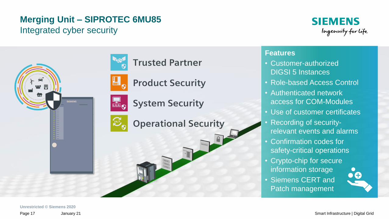
January 21Page 17 Smart Infrastructure | Digital Grid
Merging Unit – SIPROTEC 6MU85
Integrated cyber security
Features
• Customer-authorized
DIGSI 5 Instances
• Role-based Access Control
• Authenticated network
access for COM-Modules
• Use of customer certificates
• Recording of security-
relevant events and alarms
• Confirmation codes for
safety-critical operations
• Crypto-chip for secure
information storage
• Siemens CERT and
Patch management

Unrestricted © Siemens 2020
January 21Page 18 Smart Infrastructure | Digital Grid
Cyber Security
Customer CA to sign the DIGSI 5 client certificates
Client authorization: Customer-issued
Client certificate in the Windows User
account
Confirmation codes for safety-critical operations
Recording of security-relevant events and alarms
over Syslog and in non-volatile security log in device
Device-side support for role-based access control including
central user management and emergency access
Mutually authenticated and encrypted communication
between DIGSI 5 and the SIPROTEC 5 device
Only DIGSI 5 installations that connect using certificates
signed by customer’s CA are permitted
SIPROTEC 5
Bay level
Customer CA and
certificates can be
issued using
SICAM GridPass
Other Windows users with DIGSI 5
without customer-issued certificates

Unrestricted © Siemens 2020
January 21Page 19 Smart Infrastructure | Digital Grid
Merging Unit – SIPROTEC 6MU85
Redundant power supply
Station Battery 2 Station Battery 1
PS 201:
Main PS
PS 204:
Redundant PS
PS = Power Supply

Unrestricted © Siemens 2020
January 21Page 20 Smart Infrastructure | Digital Grid
Merging Unit – SIPROTEC 6MU85
Easy, fast and secure access to device with Web Browser
Monitoring of• Measurements
• Logs
• Settings
• Device information
Download of
• Logs as CSV or COMFEDE file
(log dependent)
Secure
• https connection
• Access defined per port
• Controlled by RBAC

Unrestricted © Siemens 2020
January 21Page 21 Smart Infrastructure | Digital Grid
Merging Unit – SIPROTEC 6MU85
Easy, fast and secure access to device with Web Browser
Recording• Download, Delete and Trigger of
Fault Records
Parameterization
• Change of settings within an
active setting-group
Display all signal state
• Indication of all information
• Centralized view on warnings,
alarms and inactive functions

Unrestricted © Siemens 2020
January 21Page 22 Smart Infrastructure | Digital Grid
Merging Unit – SIPROTEC 6MU85
Diagnosis homepage of ETH-BD-2FO module
Easy and fast access to detailed communication status

Unrestricted © Siemens 2020
January 21Page 23 Smart Infrastructure | Digital Grid
Intuitive setting of Merging Unit functionality, redundancy
and synchronization with DIGSI 5
Click on the properties of the ETH-BD-2FO in
“hardware configuration”:
• Enable the Merging Unit functionality
• Select the type of redundancy
• Enable the IEEE 1588 synchronization
Unrestricted © Siemens 2020
January 21Page 24 Smart Infrastructure | Digital Grid
Content
General Information1
Applications2
Merging Unit3
Sample Synchronization (IEEE 1588v2/PTP and PPS)5
Network architectures6
Definitions7
Process Bus Client4

Unrestricted © Siemens 2020
January 21Page 25 Smart Infrastructure | Digital Grid
Process Bus Client functionality is available in every SIPROTEC 5 device except 7ST85,
6MD89 and non-modular devices (7SJ81, 7Sx82)
• Ethernet communication module ETH-BD-2FO necessary
• Up to 40 (80)1 channels per SIPROTEC5 (7SS85) Client using 2x ETH-BD-2FO
• 3x ETH-BD-2FO modules with PB client supported,
up to 64 analogue values per module
• Up to 16 streams per ETH-BD-2FO accepted
• Support of IEC 61850-9-2 LE streams
• Support of IEC 61869 flexible streams
• IEC 61850-8-1 GOOSE, MMS and Process Bus Client protocol on the same module
• Supported protection functions 87B, 87L, 87T, 21, 67/67N, 50/50N, 51/51N, … 2)
• Support of IEEE C37.118 (PMU) sourced by sampled measured values
1) Limitations: network bandwidth of 100 Mbit/s and device specific limit of 40 analog values per SIPROTEC 5 device (except 7SS85 limit of 80 values)
2) 87L supports two terminals
SIPROTEC 5
Process Bus Client (1/2)

Unrestricted © Siemens 2020
January 21Page 26 Smart Infrastructure | Digital Grid
SIPROTEC 5
Process Bus Client (2/2)
Process Bus Client functionality is available in every SIPROTEC 5 device except 7ST85,
6MD89 and non-modular devices (7SJ81, 7Sx82)
• Acceptance of SMV with 4,0 / 4,8 / 12,8 / 14,4 / 15,36 kHz sampling frequency
according to IEC 61869-9 (see details at merging unit chapter)
• Synchronization via IEEE 1588v2/PTP
• Interoperability with multivendor merging units 1)
• Mixed configurations of direct connected instrument transformers and SMV
• LSVS diagnosis support (Sampled value supervision)
• Support for Edition 2.1 SynchSrcIdentity attribute
• Test- and simulation bit support
1) Interoperability is regulated in IEC 61850-9-2 Edition 2.1, use of 3rd party MU must be coordinated with DG SA&P headquarter

Unrestricted © Siemens 2020
January 21Page 27 Smart Infrastructure | Digital Grid
Content
General Information1
Process Bus Client3
Applications4
Sample Synchronization (IEEE 1588v2/PTP and PPS)5
Network architectures6
Definitions7
Merging Unit2
Unrestricted © Siemens 2020
January 21Page 28 Smart Infrastructure | Digital Grid
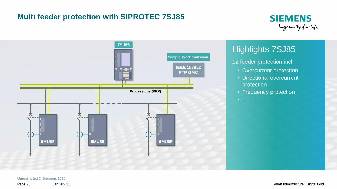
Multi feeder protection with SIPROTEC 7SJ85
Process bus (PRP)
6MU85 6MU85 6MU85
7SJ85
Highlights 7SJ85
12 feeder protection incl.
• Overcurrent protection
• Directional overcurrent
protection
• Frequency protection
• …
7SJ85
IEEE 1588v2
PTP GMC
Sample synchronization

Unrestricted © Siemens 2020
January 21Page 29 Smart Infrastructure | Digital Grid
Central protection of small substations –
Mix of analog measurements and SMVs
Highlights 7UT8
Transformer protection
Line protection
Feeder protection
• Overcurrent protection
• Directional overcurrent
protection
• Frequency protection
• ….
7UT8
*for simplification the required IEEE 1588v2/PTP master clock is not shown

Unrestricted © Siemens 2020
January 21Page 30 Smart Infrastructure | Digital Grid
Central protection of small substations –
Back-up protection in the merging units
7UT8
*for simplification the required IEEE 1588v2/PTP master clock is not shown

Unrestricted © Siemens 2020
January 21Page 31 Smart Infrastructure | Digital Grid
Transformer protection with dedicated merging unit per
transformer side
7UT87UT8
*for simplification the required IEEE 1588v2/PTP master clock is not shown
Unrestricted © Siemens 2020
January 21Page 32 Smart Infrastructure | Digital Grid
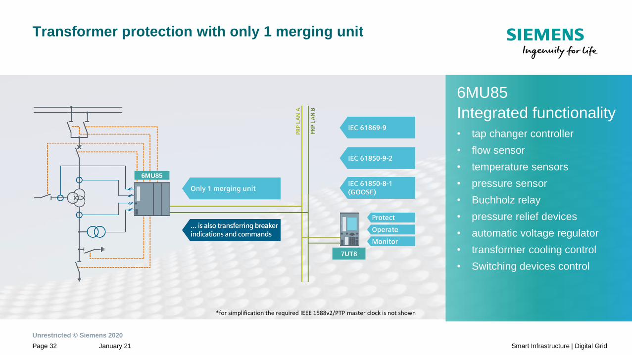
Transformer protection with only 1 merging unit
7UT8
6MU85
*for simplification the required IEEE 1588v2/PTP master clock is not shown
6MU85
Integrated functionality
• tap changer controller
• flow sensor
• temperature sensors
• pressure sensor
• Buchholz relay
• pressure relief devices
• automatic voltage regulator
• transformer cooling control
• Switching devices control

Unrestricted © Siemens 2020
January 21Page 33 Smart Infrastructure | Digital Grid
Line differential protection –
SMVs at both line ends
PIFO
PI
Substation A
Substation B
6MU85
Process bus (PRP)
IEEE 1588v2
PTP GMC
Process bus (PRP)
6MU85
IEEE 1588v2
PTP GMC
Unrestricted © Siemens 2020
January 21Page 34 Smart Infrastructure | Digital Grid
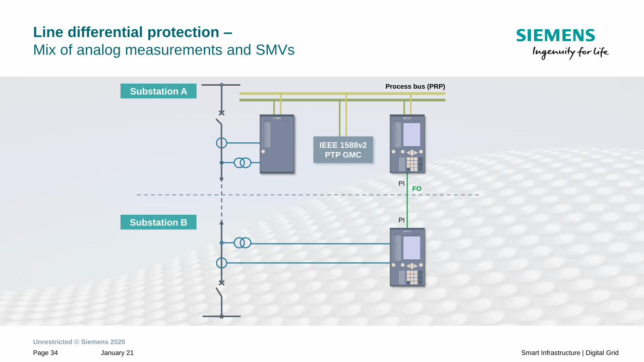
Line differential protection –
Mix of analog measurements and SMVs
PIFO
PI
6MU85
Process bus (PRP)
IEEE 1588v2
PTP GMC
Substation A
Substation B

Unrestricted © Siemens 2020
January 21Page 35 Smart Infrastructure | Digital Grid
Distributed busbar protection –
Using SIPROTEC 5 protection devices as bay unit
*for simplification the required IEEE 1588v2/PTP master clock is not shown
Unrestricted © Siemens 2020
January 21Page 36 Smart Infrastructure | Digital Grid
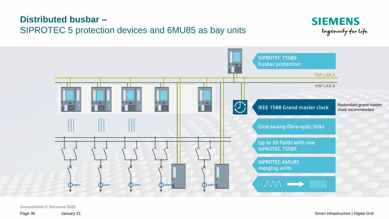
Distributed busbar –
SIPROTEC 5 protection devices and 6MU85 as bay units
Redundant grand master
clock recommended

Unrestricted © Siemens 2020
January 21Page 37 Smart Infrastructure | Digital Grid
IEC 61850
Full digital Energy Automation System
6MU85
Process Bus PRP
6MU85 Main 1
6MU85
7UT85
Main 1
7UT85
Main 2
7SL86
Main 1
7SL86
Main 2 6MD85 7KE85 7SS85
SICAM PAS
SICAM SCC
Main 1
SICAM PAS
SICAM SCC
Main 2
Control Center Control Center
Station Bus RSTP/HSR/PRP
6MD85
PDI
7UT85
Main 1
7UT85
Main 2
7SL86
Main 1
7SL86
Main 2 6MD85 6MD85
6MU85 Main 2
6MU85 Main 1
6MU85 Main 2
6MU85 Main 1
6MU85 Main 2
6MU85 Main 1
6MU85 Main 2
PDI PDI PDI
IEE
E1588
GM
C
SIEMENSSIEMENS SIEMENS SIEMENSSIEMENS SIEMENSSIEMENS SIEMENSSIEMENS
IEE
E1588
GM
C

Unrestricted © Siemens 2020
January 21Page 38 Smart Infrastructure | Digital Grid
Content
General Information1
Merging Unit2
Process Bus Client3
Applications4
Network architectures6
Definitions7
Sample Synchronization (IEEE 1588v2/PTP and PPS)5
Unrestricted © Siemens 2020
January 21Page 39 Smart Infrastructure | Digital Grid
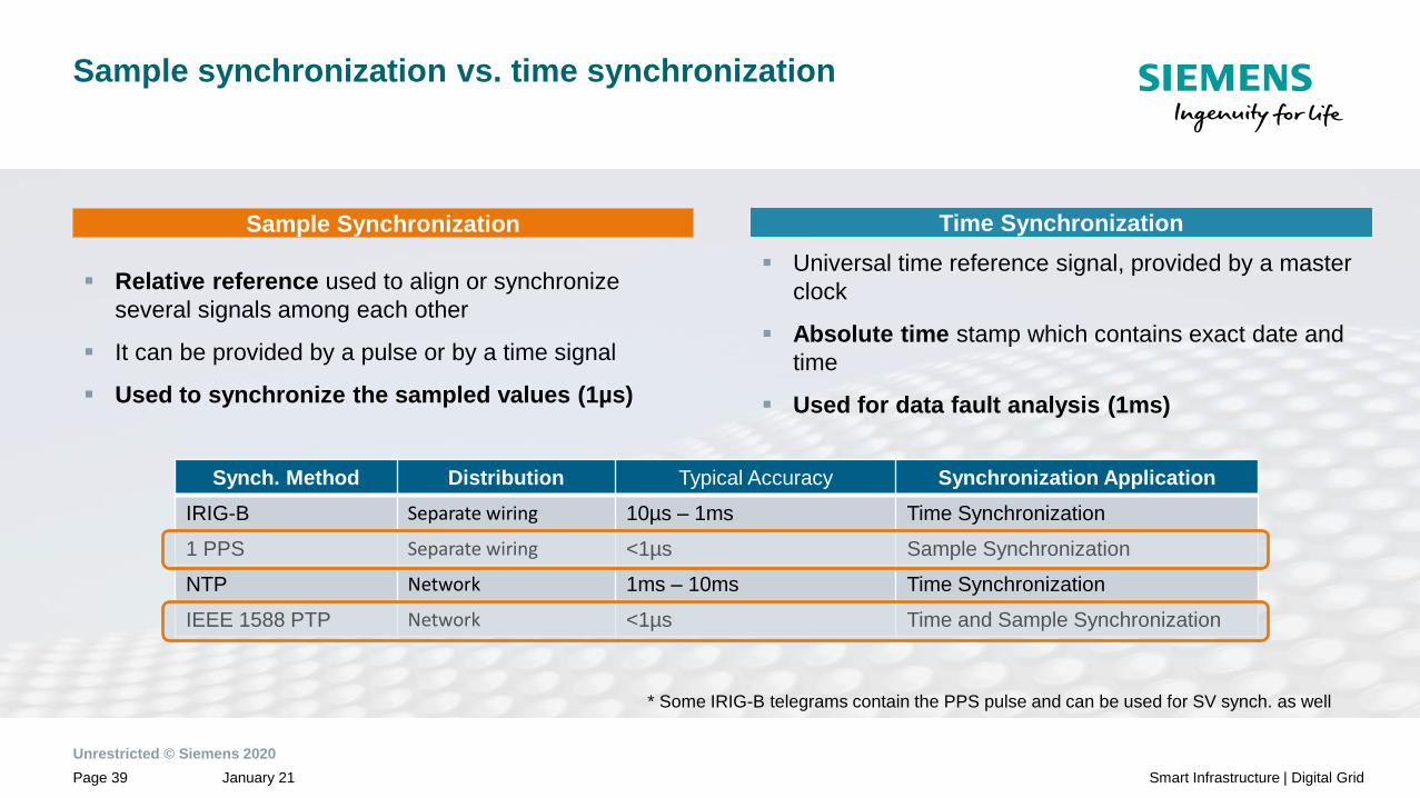
Sample synchronization vs. time synchronization
▪ Universal time reference signal, provided by a master
clock
▪ Absolute time stamp which contains exact date and
time
▪ Used for data fault analysis (1ms)
▪ Relative reference used to align or synchronize
several signals among each other
▪ It can be provided by a pulse or by a time signal
▪ Used to synchronize the sampled values (1µs)
Sample Synchronization Time Synchronization
Synch. Method Distribution Typical Accuracy Synchronization Application
IRIG-B Separate wiring 10µs – 1ms Time Synchronization
1 PPS Separate wiring <1µs Sample Synchronization
NTP Network 1ms – 10ms Time Synchronization
IEEE 1588 PTP Network <1µs Time and Sample Synchronization
* Some IRIG-B telegrams contain the PPS pulse and can be used for SV synch. as well

Unrestricted © Siemens 2020
January 21Page 40 Smart Infrastructure | Digital Grid
Unrestricted © Siemens 2020
January 21Page 41 Smart Infrastructure | Digital Grid

Unrestricted © Siemens 2020
January 21Page 42 Smart Infrastructure | Digital Grid
IEEE 1588 – Master Clock

Unrestricted © Siemens 2020
January 21Page 43 Smart Infrastructure | Digital Grid
Content
General Information1
Merging Unit2
Process Bus Client3
Applications4
Sample Synchronization (IEEE 1588v2/PTP and PPS)5
Definitions7
Network architectures6

Unrestricted © Siemens 2020
January 21Page 44 Smart Infrastructure | Digital Grid
Network architectures
Network redundancy for process bus
New on ETH-BD-2FO module:
HSR* ring with clients and server connected to PRP LANs
Sample synchronization for HSR must be realized with PPS
PR
P L
AN
A
Red
Bo
x
Red
Bo
x
PRP redundancy with clients and server
for station and process bus
PRP LAN A
PRP LAN B
PR
P L
AN
B* Support of IEEE 1588v2/PTP (transparent clock) in preparation
max. 5x IED in HSR Ring for Process Bus

Unrestricted © Siemens 2020
January 21Page 45 Smart Infrastructure | Digital Grid
Network architectures
Physically network segregation
Network 5:
Feeder CT values
Network 1
CT, VT values
Network 6:
Bus VT values
6MU85 6MU85 6MU85 6MU85 6MU85
Simplify complexityUse of more than one redundant
process bus network reduces the
network engineering
Increase the bandwidth with
additional Ethernet interfaces
Efficient use of network bandwidth
with customization of the analog
values per SMV streams
(not only IEC 61850-9-2LE data
set)
Feeder 1 Feeder 2 Feeder 3 Feeder 4 Bus VT’s
Network 2
CT, VT values
Network 3
CT, VT values
Network 4
CT, VT values
Note: Seamless networks redundancy recommended
7SJ85
Overcurrent
Protection
7SA86
Distance
Protection
7SD86
Line
Differential
Protection
7UT86
Transformer
Differential
Protection
7SS85
Busbar
Differential
Protection
7KE85
Fault
Recorder
Unrestricted © Siemens 2020
January 21Page 46 Smart Infrastructure | Digital Grid
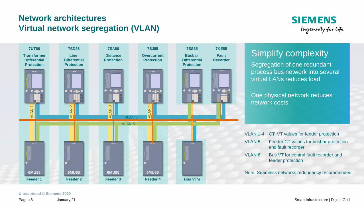
Network architectures
Virtual network segregation (VLAN)
Simplify complexitySegregation of one redundant
process bus network into several
virtual LANs reduces load
One physical network reduces
network costs
VLAN 1-4: CT, VT values for feeder protection
VLAN 5: Feeder CT values for busbar protection
and fault recorder
VLAN 6: Bus VT for central fault recorder and
feeder protection
Note: Seamless networks redundancy recommended
7SJ85
Overcurrent
Protection
7SA86
Distance
Protection
7SD86
Line
Differential
Protection
7UT86
Transformer
Differential
Protection
7SS85
Busbar
Differential
Protection
Feeder 1 Feeder 2 Feeder 3 Feeder 4 Bus VT’s
7KE85
Fault
Recorder
VLA
N 1
VLAN 6VLA
N 2
VLA
N 3
VLA
N 4
VLAN 5
6MU85 6MU85 6MU85 6MU85 6MU85

Unrestricted © Siemens 2020
January 21Page 47 Smart Infrastructure | Digital Grid
PRP LAN B
PRP LAN A
3rd
party
MU
IEEE1588v2
PTP GMC
6MU85 6MU85 6MU85 6MU85
Station Bus
CT 1..14 (VLAN ID 1) CT 15..24 (VLAN ID 2)
CT 1..14 (VLAN ID 1)
CT 15..24 (VLAN ID 2)
SIPROTEC 5SIPROTEC 5
7SS85
Network architectures
Example: VLAN for busbar protection with 24 bays
• For more than 14 bays a
second ETH-BD-2FO is
required
• Segmentation to each ETH-BD-
2FO module via VLAN
SIEMENS SIEMENSSIEMENS SIEMENS
Unrestricted © Siemens 2020
January 21Page 48 Smart Infrastructure | Digital Grid

Unrestricted © Siemens 2020
January 21Page 49 Smart Infrastructure | Digital Grid
Content
General Information1
Merging Unit2
Process Bus Client3
Applications4
Sample Synchronization (IEEE 1588v2/PTP and PPS)5
Network architectures6
Definitions7
Unrestricted © Siemens 2020
January 21Page 50 Smart Infrastructure | Digital Grid
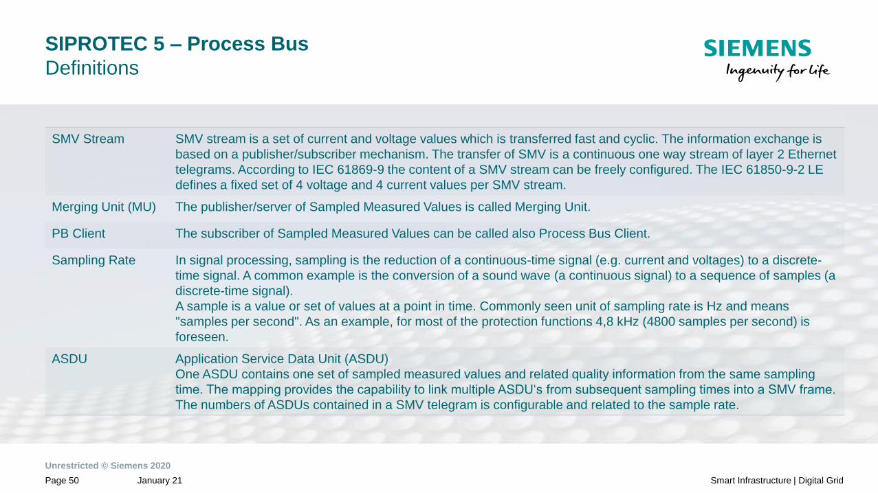
SIPROTEC 5 – Process Bus
Definitions
SMV Stream SMV stream is a set of current and voltage values which is transferred fast and cyclic. The information exchange is
based on a publisher/subscriber mechanism. The transfer of SMV is a continuous one way stream of layer 2 Ethernet
telegrams. According to IEC 61869-9 the content of a SMV stream can be freely configured. The IEC 61850-9-2 LE
defines a fixed set of 4 voltage and 4 current values per SMV stream.
Merging Unit (MU) The publisher/server of Sampled Measured Values is called Merging Unit.
PB Client The subscriber of Sampled Measured Values can be called also Process Bus Client.
Sampling Rate In signal processing, sampling is the reduction of a continuous-time signal (e.g. current and voltages) to a discrete-
time signal. A common example is the conversion of a sound wave (a continuous signal) to a sequence of samples (a
discrete-time signal).
A sample is a value or set of values at a point in time. Commonly seen unit of sampling rate is Hz and means
"samples per second". As an example, for most of the protection functions 4,8 kHz (4800 samples per second) is
foreseen.
ASDU Application Service Data Unit (ASDU)
One ASDU contains one set of sampled measured values and related quality information from the same sampling
time. The mapping provides the capability to link multiple ASDU‘s from subsequent sampling times into a SMV frame.
The numbers of ASDUs contained in a SMV telegram is configurable and related to the sample rate.
Unrestricted © Siemens 2020
January 21Page 51 Smart Infrastructure | Digital Grid
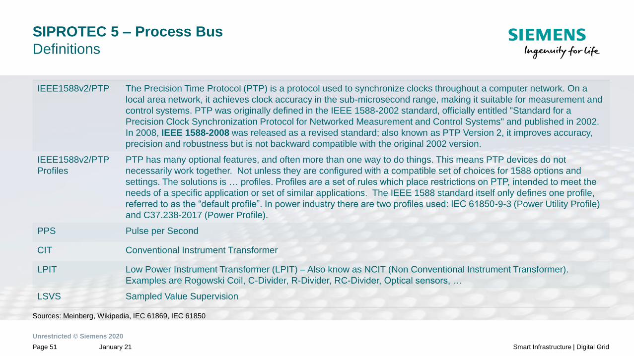
SIPROTEC 5 – Process Bus
Definitions
IEEE1588v2/PTP The Precision Time Protocol (PTP) is a protocol used to synchronize clocks throughout a computer network. On a
local area network, it achieves clock accuracy in the sub-microsecond range, making it suitable for measurement and
control systems. PTP was originally defined in the IEEE 1588-2002 standard, officially entitled "Standard for a
Precision Clock Synchronization Protocol for Networked Measurement and Control Systems" and published in 2002.
In 2008, IEEE 1588-2008 was released as a revised standard; also known as PTP Version 2, it improves accuracy,
precision and robustness but is not backward compatible with the original 2002 version.
IEEE1588v2/PTP
Profiles
PTP has many optional features, and often more than one way to do things. This means PTP devices do not
necessarily work together. Not unless they are configured with a compatible set of choices for 1588 options and
settings. The solutions is … profiles. Profiles are a set of rules which place restrictions on PTP, intended to meet the
needs of a specific application or set of similar applications. The IEEE 1588 standard itself only defines one profile,
referred to as the “default profile”. In power industry there are two profiles used: IEC 61850-9-3 (Power Utility Profile)
and C37.238-2017 (Power Profile).
PPS Pulse per Second
CIT Conventional Instrument Transformer
LPIT Low Power Instrument Transformer (LPIT) – Also know as NCIT (Non Conventional Instrument Transformer).
Examples are Rogowski Coil, C-Divider, R-Divider, RC-Divider, Optical sensors, …
LSVS Sampled Value Supervision
Sources: Meinberg, Wikipedia, IEC 61869, IEC 61850

Unrestricted © Siemens 2020
July 2020Page 52 Smart Infrastructure | Digital Grid
© Siemens 2020
February 2020Page 52
Disclaimer:
Subject to changes and errors. The information given in this document only contains general
descriptions and/or performance features which may not always specifically reflect those
described, or which may undergo modification in the course of further development of the products.
The requested performance features are binding only when they are expressly agreed upon in the
concluded contract.
All product designations, product names, etc. may contain trademarks or other rights of Siemens
AG, its affiliated companies or third parties. Their unauthorized use may infringe the rights of the
respective owner.
Evandro de Oliveira
RC-US EM EA PRO ENG
7000 Siemens Road
Wendell – NC - 27591
Phone: (919) 670-8234
E-mail: [email protected]
Contact