UWQ-12/20-T48 Series | Datasheet | Murata Power Solutions
29
The UWQ series offers high output current (up to 20 Amps) in an industry standard “quarter brick” package requiring no heat sink for most applications. The UWQ series delivers fixed DC output voltages up to 240 Watts (12V @ 20A) for printed circuit board mounting. Wide range inputs of 18 to 60 Volts DC (48 Volts nominal) are ideal for datacom and telecom systems. The UWQ-12/20-T48xS offers a load sharing option for paralleling up to three modules in the most demanding, power hungry applications. The UWQ-12/20-T48xT is trimmable from 10.8Vout to 13.2Vout and includes Sense pins to compensate for voltage drops at the load. Advanced automated surface mount assembly and planar magnetics deliver galvanic isolation rated at 2250 Vdc for basic insulation. To power digital sys- tems, the outputs offer fast settling to current steps and tolerance of higher capacitive loads. Excellent ripple and noise specifications assure compatibility to CPUs, ASICs, programmable logic and FPGAs. No minimum load is required. For systems needing controlled startup/shutdown, an external remote On/ Off control may use either positive or negative logic. A wealth of self-protection features include input undervoltage lockout and overtemperature shutdown using an on-board temperature sensor; overcurrent protection using the “hiccup” autorestart technique, provides indefinite short-circuit protection, along with output OVP. The synchronous rectifier topology offers high efficiency for minimal heat generation and “no heat sink” operation. The UWQ series is certified to safety standards UL/IEC/CSA 60950-1, 2nd edition. It meets class B EMI conducted emission compliance to EN55022, CISPR22 with an external filter. PRODUCT OVERVIEW APPLICATIONS Embedded systems, datacom and telecom installa- tions, wireless base stations Disk farms, data centers and cellular repeater sites Remote sensor systems, dedicated controllers Instrumentation systems, R&D platforms, auto- mated test fixtures Data concentrators, voice forwarding and speech processing systems FEATURES Fixed DC outputs, 12V @ 20A Industry standard quarter brick 2.3” x 1.45” x 0.46” open frame package Wide range 18 to 60 Vdc input voltages with 2250 Volt Basic isolation Remote ON/Off enable control DOSA-compatible pinouts and form factor High efficiency synchronous rectifier topology Multiple-unit parallel operation for increased current Stable no-load operation Monotonic startup into pre-bias output condition Certified to UL/60950-1, CSA-C22.2 No. 60950- 1, 2nd edition safety approvals Extensive self-protection, OVP, input undervoltage, current limiting and thermal shutdown Trimmable output from 10.8V to 13.2V F1 External DC Power Source Reference and Error Amplifier -Vout (4) +Vout (8) Trim (6) On/Off Control (2) -Vin (3) +Vin (1) Controller and Power Barrier Figure 1. Connection Diagram Typical topology is shown. Murata Power Solutions recommends an external fuse. UWQ-12/20-T48 Series Wide Input, Isolated DOSA Quarter Brick DC-DC Converters MDC_UWQ-12/20-T48 Series.A04 Page 1 of 29 www.murata-ps.com www.murata-ps.com/support For full details go to www.murata-ps.com/rohs Typical unit
-
Upload
khangminh22 -
Category
Documents
-
view
1 -
download
0
Transcript of UWQ-12/20-T48 Series | Datasheet | Murata Power Solutions
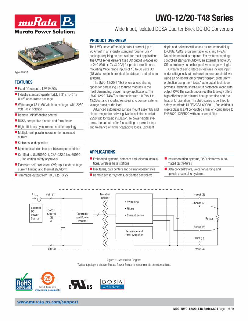
The UWQ series offers high output current (up to 20 Amps) in an industry standard “quarter brick” package requiring no heat sink for most applications. The UWQ series delivers fixed DC output voltages up to 240 Watts (12V @ 20A) for printed circuit board mounting. Wide range inputs of 18 to 60 Volts DC (48 Volts nominal) are ideal for datacom and telecom systems.
The UWQ-12/20-T48xS offers a load sharing option for paralleling up to three modules in the most demanding, power hungry applications. The UWQ-12/20-T48xT is trimmable from 10.8Vout to 13.2Vout and includes Sense pins to compensate for voltage drops at the load.
Advanced automated surface mount assembly and planar magnetics deliver galvanic isolation rated at 2250 Vdc for basic insulation. To power digital sys-tems, the outputs offer fast settling to current steps and tolerance of higher capacitive loads. Excellent
ripple and noise specifications assure compatibility to CPUs, ASICs, programmable logic and FPGAs. No minimum load is required. For systems needing controlled startup/shutdown, an external remote On/Off control may use either positive or negative logic.
A wealth of self-protection features include input undervoltage lockout and overtemperature shutdown using an on-board temperature sensor; overcurrent protection using the “hiccup” auto restart technique, provides indefinite short-circuit protection, along with output OVP. The synchronous rectifier topology offers high efficiency for minimal heat generation and “no heat sink” operation. The UWQ series is certified to safety standards UL/IEC/CSA 60950-1, 2nd edition. It meets class B EMI conducted emission compliance to EN55022, CISPR22 with an external filter.
PRODUCT OVERVIEW
APPLICATIONS Embedded systems, datacom and telecom installa-tions, wireless base stations
Disk farms, data centers and cellular repeater sites
Remote sensor systems, dedicated controllers
Instrumentation systems, R&D platforms, auto-mated test fixtures
Data concentrators, voice forwarding and speech processing systems
FEATURES Fixed DC outputs, 12V @ 20A
Industry standard quarter brick 2.3” x 1.45” x 0.46” open frame package
Wide range 18 to 60 Vdc input voltages with 2250 Volt Basic isolation
Remote ON/Off enable control
DOSA-compatible pinouts and form factor
High efficiency synchronous rectifier topology
Multiple-unit parallel operation for increased current
Stable no-load operation
Monotonic startup into pre-bias output condition
Certified to UL/60950-1, CSA-C22.2 No. 60950-1, 2nd edition safety approvals
Extensive self-protection, OVP, input undervoltage, current limiting and thermal shutdown
Trimmable output from 10.8V to 13.2V
F1
ExternalDC PowerSource
Reference andError Amplifier
-Vout (4)
+Vout (8)
Trim (6)
On/OffControl
(2)
-Vin (3)
+Vin (1)
Controllerand Power
Barrier
Figure 1. Connection Diagram
Typical topology is shown. Murata Power Solutions recommends an external fuse.
UWQ-12/20-T48 SeriesWide Input, Isolated DOSA Quarter Brick DC-DC Converters
MDC_UWQ-12/20-T48 Series.A04 Page 1 of 29
www.murata-ps.com
www.murata-ps.com/support
For full details go towww.murata-ps.com/rohs
Typical unit
➀ Please refer to the part number structure for additional ordering information and options.➁ All specifications are typical at nominal line voltage and full load, +25°C unless otherwise noted. See
detailed specifications. Output capacitors are 1 µF || 10 µF with a 22µF input capacitor. These caps are necessary for our test equipment and may not be needed for your application.
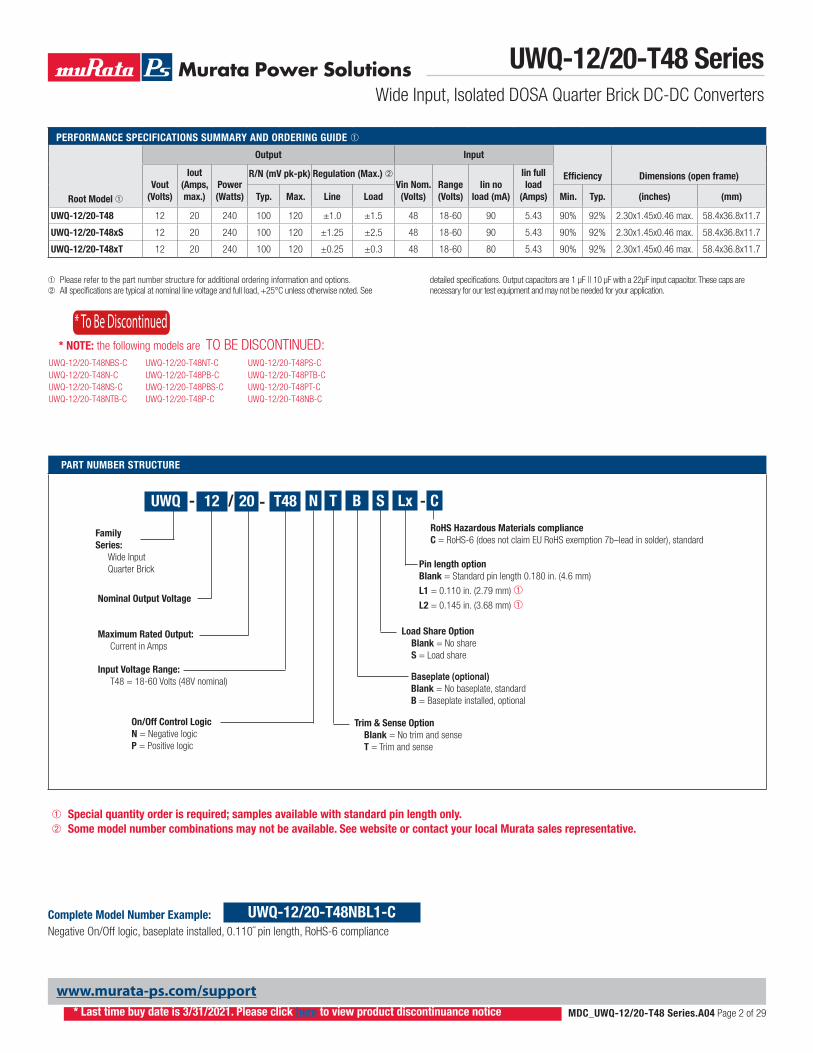
PART NUMBER STRUCTURE
Pin length option Blank = Standard pin length 0.180 in. (4.6 mm)
L1 = 0.110 in. (2.79 mm) ➀
L2 = 0.145 in. (3.68 mm) ➀
LxT48
Input Voltage Range: T48 = 18-60 Volts (48V nominal)
/
Nominal Output Voltage
12 20
Maximum Rated Output: Current in Amps
- N
On/Off Control LogicN = Negative logic P = Positive logic
-UWQ
Family Series: Wide Input Quarter Brick
Baseplate (optional)Blank = No baseplate, standard B = Baseplate installed, optional
B
RoHS Hazardous Materials compliance C = RoHS-6 (does not claim EU RoHS exemption 7b–lead in solder), standard
- C
Complete Model Number Example:Negative On/Off logic, baseplate installed, 0.110˝ pin length, RoHS-6 compliance
UWQ-12/20-T48NBL1-C
S
Load Share Option Blank = No share S = Load share
T
Trim & Sense Option Blank = No trim and sense T = Trim and sense
➀ Special quantity order is required; samples available with standard pin length only.➁ Some model number combinations may not be available. See website or contact your local Murata sales representative.
UWQ-12/20-T48 SeriesWide Input, Isolated DOSA Quarter Brick DC-DC Converters
MDC_UWQ-12/20-T48 Series.A04 Page 2 of 29
www.murata-ps.com/support
* To Be Discontinued
UWQ-12/20-T48NBS-C UWQ-12/20-T48NT-C UWQ-12/20-T48PS-CUWQ-12/20-T48N-C UWQ-12/20-T48PB-C UWQ-12/20-T48PTB-CUWQ-12/20-T48NS-C UWQ-12/20-T48PBS-C UWQ-12/20-T48PT-CUWQ-12/20-T48NTB-C UWQ-12/20-T48P-C UWQ-12/20-T48NB-C
* NOTE: the following models are TO BE DISCONTINUED:
* Last time buy date is 3/31/2021. Please click here to view product discontinuance notice
PERFORMANCE SPECIFICATIONS SUMMARY AND ORDERING GUIDE ➀
Root Model ➀
Output Input
Efficiency Dimensions (open frame)Vout
(Volts)
Iout (Amps, max.)
Power (Watts)
R/N (mV pk-pk) Regulation (Max.) ➁Vin Nom.
(Volts)Range (Volts)
Iin no load (mA)
Iin full load
(Amps)Typ. Max. Line Load Min. Typ. (inches) (mm)
UWQ-12/20-T48 12 20 240 100 120 ±1.0 ±1.5 48 18-60 90 5.43 90% 92% 2.30x1.45x0.46 max. 58.4x36.8x11.7
UWQ-12/20-T48xS 12 20 240 100 120 ±1.25 ±2.5 48 18-60 90 5.43 90% 92% 2.30x1.45x0.46 max. 58.4x36.8x11.7
UWQ-12/20-T48xT 12 20 240 100 120 ±0.25 ±0.3 48 18-60 80 5.43 90% 92% 2.30x1.45x0.46 max. 58.4x36.8x11.7
UWQ-12/20-T48 SeriesWide Input, Isolated DOSA Quarter Brick DC-DC Converters
MDC_UWQ-12/20-T48 Series.A04 Page 3 of 29
www.murata-ps.com/support
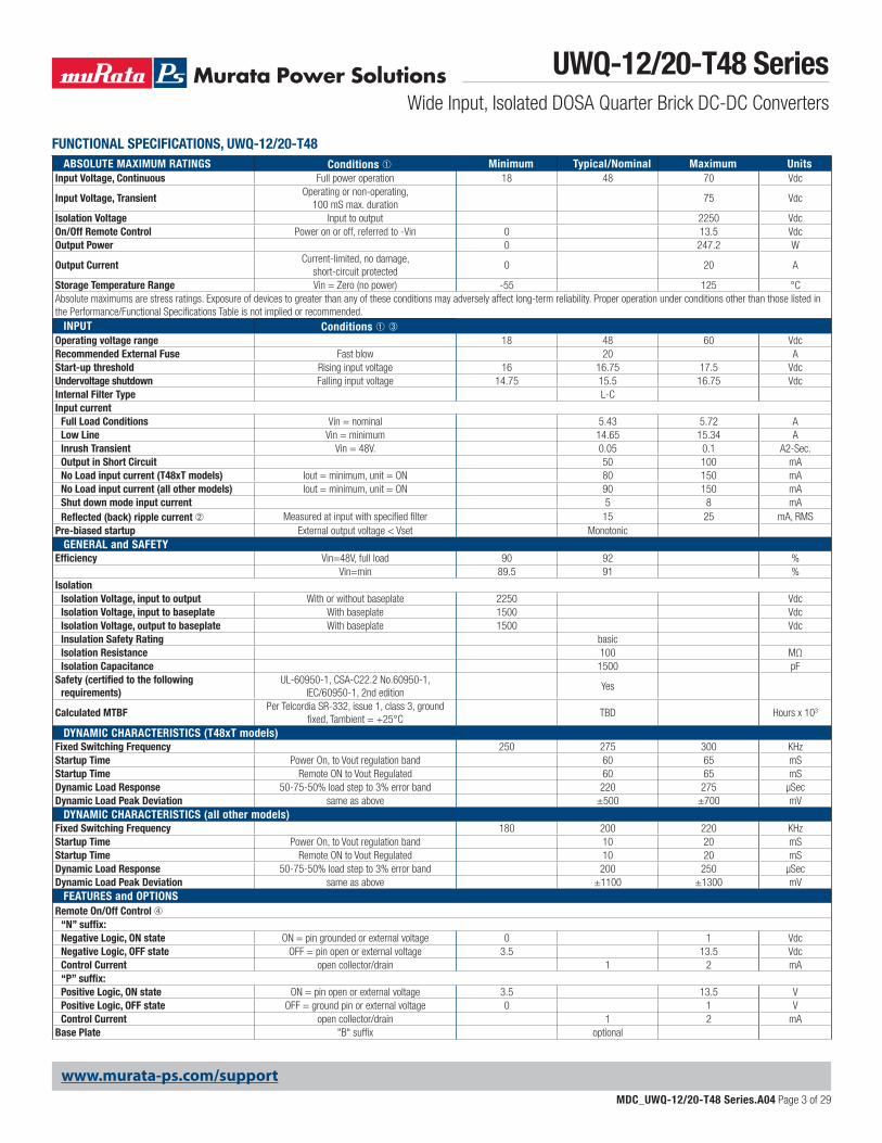
FUNCTIONAL SPECIFICATIONS, UWQ-12/20-T48ABSOLUTE MAXIMUM RATINGS Conditions ➀ Minimum Typical/Nominal Maximum Units
Input Voltage, Continuous Full power operation 18 48 70 Vdc
Input Voltage, TransientOperating or non-operating,
100 mS max. duration75 Vdc
Isolation Voltage Input to output 2250 VdcOn/Off Remote Control Power on or off, referred to -Vin 0 13.5 VdcOutput Power 0 247.2 W
Output CurrentCurrent-limited, no damage,
short-circuit protected0 20 A
Storage Temperature Range Vin = Zero (no power) -55 125 °CAbsolute maximums are stress ratings. Exposure of devices to greater than any of these conditions may adversely affect long-term reliability. Proper operation under conditions other than those listed in the Performance/Functional Specifications Table is not implied or recommended.
INPUT Conditions ➀➂Operating voltage range 18 48 60 VdcRecommended External Fuse Fast blow 20 AStart-up threshold Rising input voltage 16 16.75 17.5 VdcUndervoltage shutdown Falling input voltage 14.75 15.5 16.75 VdcInternal Filter Type L-CInput current
Full Load Conditions Vin = nominal 5.43 5.72 ALow Line Vin = minimum 14.65 15.34 AInrush Transient Vin = 48V. 0.05 0.1 A2-Sec.Output in Short Circuit 50 100 mANo Load input current (T48xT models) Iout = minimum, unit = ON 80 150 mANo Load input current (all other models) Iout = minimum, unit = ON 90 150 mAShut down mode input current 5 8 mAReflected (back) ripple current ➁ Measured at input with specified filter 15 25 mA, RMS
Pre-biased startup External output voltage < Vset MonotonicGENERAL and SAFETY
Efficiency Vin=48V, full load 90 92 %Vin=min 89.5 91 %
IsolationIsolation Voltage, input to output With or without baseplate 2250 VdcIsolation Voltage, input to baseplate With baseplate 1500 VdcIsolation Voltage, output to baseplate With baseplate 1500 VdcInsulation Safety Rating basicIsolation Resistance 100 MΩIsolation Capacitance 1500 pF
Safety (certified to the following requirements)
UL-60950-1, CSA-C22.2 No.60950-1, IEC/60950-1, 2nd edition
Yes
Calculated MTBFPer Telcordia SR-332, issue 1, class 3, ground
fixed, Tambient = +25°CTBD Hours x 103
DYNAMIC CHARACTERISTICS (T48xT models)Fixed Switching Frequency 250 275 300 KHzStartup Time Power On, to Vout regulation band 60 65 mSStartup Time Remote ON to Vout Regulated 60 65 mSDynamic Load Response 50-75-50% load step to 3% error band 220 275 µSecDynamic Load Peak Deviation same as above ±500 ±700 mV
DYNAMIC CHARACTERISTICS (all other models)Fixed Switching Frequency 180 200 220 KHzStartup Time Power On, to Vout regulation band 10 20 mSStartup Time Remote ON to Vout Regulated 10 20 mSDynamic Load Response 50-75-50% load step to 3% error band 200 250 µSecDynamic Load Peak Deviation same as above ±1100 ±1300 mV
FEATURES and OPTIONSRemote On/Off Control ➃
“N” suffix:Negative Logic, ON state ON = pin grounded or external voltage 0 1 VdcNegative Logic, OFF state OFF = pin open or external voltage 3.5 13.5 VdcControl Current open collector/drain 1 2 mA“P” suffix:Positive Logic, ON state ON = pin open or external voltage 3.5 13.5 VPositive Logic, OFF state OFF = ground pin or external voltage 0 1 VControl Current open collector/drain 1 2 mA
Base Plate "B" suffix optional
UWQ-12/20-T48 SeriesWide Input, Isolated DOSA Quarter Brick DC-DC Converters
MDC_UWQ-12/20-T48 Series.A04 Page 4 of 29
www.murata-ps.com/support
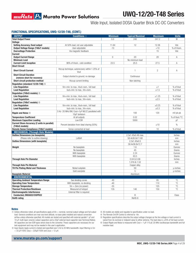
OUTPUT Conditions ➀ Minimum Typical/Nominal Maximum UnitsTotal Output Power 0.0 240 247.2 WVoltage
Setting Accuracy, fixed output At 50% load, not user adjustable 11.64 12 12.36 VdcOutput Voltage Range (T48xT models) User-adjustable -10 +10 % of Vnom.Overvoltage Protection Via magnetic feedback 15 Vdc
CurrentOutput Current Range 0 20 20 AMinimum Load No minimum loadCurrent Limit Inception 96% of Vnom., cold condition 23.5 25.5 27.5 A
Short Circuit
Short Circuit CurrentHiccup technique, autorecovery within 1.25% of
Vout1 2 A
Short Circuit Duration (remove short for recovery)
Output shorted to ground, no damage Continuous
Short circuit protection method Hiccup current limiting Non-latchingRegulation (standard 12/20-T48) ➄
Line Regulation Vin=min. to max., Vout=nom., full load ±1 % of VoutLoad Regulation Iout=min. to max., Vin=nom. ±1.5 % of Vout
Regulation (T48xS models) ➄Line Regulation Vin=min. to max., Vout=nom., full load ±1.25 % of VoutLoad Regulation Iout=min. to max., Vin=nom. ±2.5 % of Vout
Regulation (T48xT models) ➄Line Regulation Vin=min. to max., Vout=nom., full load ±0.25 % of VoutLoad Regulation Iout=min. to max., Vin=nom. ±0.3 % of Vout
Ripple and Noise ➅5 Hz- 20 MHz BW, Cout=1µF MLCC paralleled with
10µF tantalum100 120 mV pk-pk
Temperature Coefficient At all outputs 0.02 % of Vout./°CMaximum Capacitive Loading Low ESR 5000 μFCurrent Share Accuracy (2 units in parallel)
(T48xS models)Percent deviation from ideal sharing (50%) ±10 %
Remote Sense Compliance (T48xT models) Sense connected at load 10 % of VoutMECHANICAL (Through Hole Models)
Outline Dimensions (no baseplate) 2.3x1.45x0.46 max. Inches(Please refer to outline drawing) LxWxH 58.4x36.8x11.68 mm
Outline Dimensions (with baseplate) 2.3x1.45x0.5 Inches58.4x36.8x12.7 mm
Weight No baseplate 1.6 OuncesNo baseplate 45 Grams
With baseplate 2.24 OuncesWith baseplate 63.5 Grams
Through Hole Pin Diameter 0.04 & 0.06 Inches1.016 & 1.52 mm
Through Hole Pin Material Copper alloyTH Pin Plating Metal and Thickness Nickel subplate 50 µ-inches
Gold overplate 5 µ-inchesBaseplate Material Aluminum
ENVIRONMENTALOperating Ambient Temperature Range See derating curves -40 85 °COperating Case Temperature With baseplate, no derating -40 110 °CStorage Temperature Vin = Zero (no power) -55 125 °CThermal Protection/Shutdown Measured at hotspot 135 140 150 °CElectromagnetic Interference External filter is required
Conducted, EN55022/CISPR22 B ClassRoHS rating RoHS-6
FUNCTIONAL SPECIFICATIONS, UWQ-12/20-T48, (CONT.)
Notes➀ Unless otherwise noted, all specifications apply at Vin = nominal, nominal output voltage and full output
load. General conditions are near sea level altitude, no base plate installed and natural convection airflow unless otherwise specified. All models are tested and specified with external parallel 1 μF and 10 μF multi-layer ceramic output capacitors and a 22µF external input capacitor (see Technical Notes). All capacitors are low-ESR types wired close to the converter. These capacitors are necessary for our test equipment and may not be needed in the user’s application.
➁ Input (back) ripple current is tested and specified over 5 Hz to 20 MHz bandwidth. Input filtering is Cin = 33 µF/100V, Cbus = 220µF/100V and Lbus = 12 µH.
➂ All models are stable and regulate to specification under no load.➃ The Remote On/Off Control is referred to -Vin.➄ Regulation specifications describe the output voltage changes as the line voltage or load current is
varied from its nominal or midpoint value to either extreme. The load step is ±25% of full load current.➅ Output Ripple and Noise is measured with Cout = 1 µF || 10 µF, 20 MHz oscilloscope bandwidth and full
resistive load.
UWQ-12/20-T48 SeriesWide Input, Isolated DOSA Quarter Brick DC-DC Converters
MDC_UWQ-12/20-T48 Series.A04 Page 5 of 29
www.murata-ps.com/support
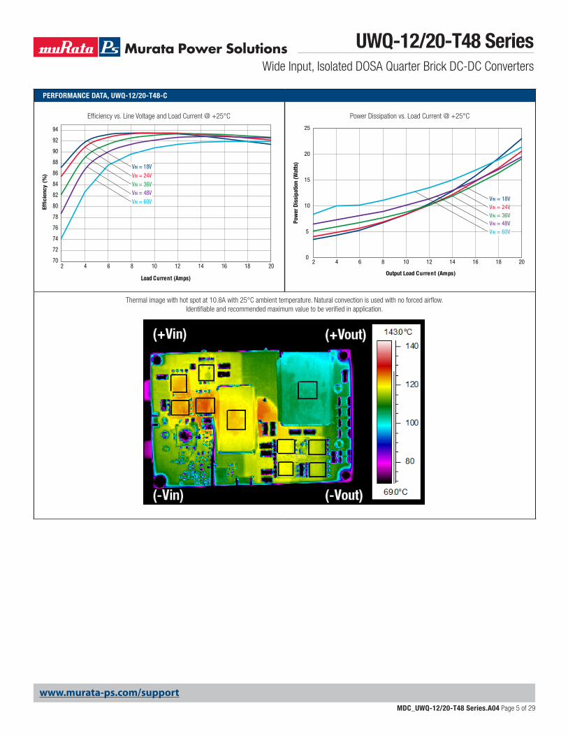
PERFORMANCE DATA, UWQ-12/20-T48-C
Power Dissipation vs. Load Current @ +25°C
0
5
10
15
20
25
2 4 6 8 10 12 14 16 18 20
Output Load Current (Amps)
Pow
er D
issi
patio
n (W
atts
)
VIN = 18VVIN = 24VVIN = 36VVIN = 48VVIN = 60V
Efficiency vs. Line Voltage and Load Current @ +25°C
70
72
74
76
78
80
82
84
86
88
90
92
94
2 4 6 8 10 12 14 16 18 20
Load Current (Amps)
Effi
cien
cy (
%)
VIN = 18VVIN = 24VVIN = 36VVIN = 48VVIN = 60V
Thermal image with hot spot at 10.8A with 25°C ambient temperature. Natural convection is used with no forced airflow. Identifiable and recommended maximum value to be verified in application.
UWQ-12/20-T48 SeriesWide Input, Isolated DOSA Quarter Brick DC-DC Converters
MDC_UWQ-12/20-T48 Series.A04 Page 6 of 29
www.murata-ps.com/support
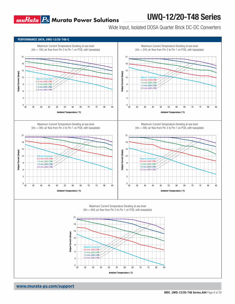
PERFORMANCE DATA, UWQ-12/20-T48-C
Maximum Current Temperature Derating at sea level (Vin = 24V, air flow from Pin 3 to Pin 1 on PCB, with baseplate)
Maximum Current Temperature Derating at sea level (Vin = 18V, air flow from Pin 3 to Pin 1 on PCB, with baseplate)
Maximum Current Temperature Derating at sea level (Vin = 60V, air flow from Pin 3 to Pin 1 on PCB, with baseplate)
Maximum Current Temperature Derating at sea level (Vin = 48V, air flow from Pin 3 to Pin 1 on PCB, with baseplate)
Maximum Current Temperature Derating at sea level (Vin = 36V, air flow from Pin 3 to Pin 1 on PCB, with baseplate)
0
3
6
9
12
15
18
21
30 35 40 45 50 55 60 65 70 75 80 85
Outp
ut C
urre
nt (A
mps
)
Ambient Temperature (°C)
0.5 m/s (100 LFM)1.0 m/s (200 LFM)1.5 m/s (300 LFM)2.0 m/s (400 LFM)
Natural Convection
0
3
6
9
12
15
18
21
30 35 40 45 50 55 60 65 70 75 80 85
Outp
ut C
urre
nt (A
mps
)
Ambient Temperature (°C)
0.5 m/s (100 LFM)1.0 m/s (200 LFM)1.5 m/s (300 LFM)2.0 m/s (400 LFM)
Natural Convection
0
3
6
9
12
15
18
21
30 35 40 45 50 55 60 65 70 75 80 85
Outp
ut C
urre
nt (A
mps
)
Ambient Temperature (°C)
0.5 m/s (100 LFM)1.0 m/s (200 LFM)1.5 m/s (300 LFM)2.0 m/s (400 LFM)
Natural Convection
0
3
6
9
12
15
18
21
30 35 40 45 50 55 60 65 70 75 80 85
Outp
ut C
urre
nt (A
mps
)
Ambient Temperature (°C)
0.5 m/s (100 LFM)1.0 m/s (200 LFM)1.5 m/s (300 LFM)2.0 m/s (400 LFM)
Natural Convection
0
3
6
9
12
15
18
21
30 35 40 45 50 55 60 65 70 75 80 85
Outp
ut C
urre
nt (A
mps
)
Ambient Temperature (°C)
0.5 m/s (100 LFM)1.0 m/s (200 LFM)1.5 m/s (300 LFM)2.0 m/s (400 LFM)
Natural Convection
UWQ-12/20-T48 SeriesWide Input, Isolated DOSA Quarter Brick DC-DC Converters
MDC_UWQ-12/20-T48 Series.A04 Page 7 of 29
www.murata-ps.com/support
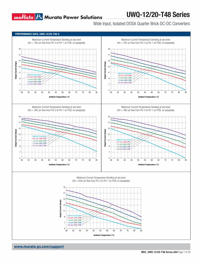
PERFORMANCE DATA, UWQ-12/20-T48-C
Maximum Current Temperature Derating at sea level (Vin = 24V, air flow from Pin 3 to Pin 1 on PCB, no baseplate)
Maximum Current Temperature Derating at sea level (Vin = 18V, air flow from Pin 3 to Pin 1 on PCB, no baseplate)
Maximum Current Temperature Derating at sea level (Vin = 60V, air flow from Pin 3 to Pin 1 on PCB, no baseplate)
Maximum Current Temperature Derating at sea level (Vin = 48V, air flow from Pin 3 to Pin 1 on PCB, no baseplate)
Maximum Current Temperature Derating at sea level (Vin = 36V, air flow from Pin 3 to Pin 1 on PCB, no baseplate)
5
7
9
11
13
15
17
19
30 35 40 45 50 55 60 65 70 75 80 85
Outp
ut C
urre
nt (A
mps
)
Ambient Temperature (°C)
0.5 m/s (100 LFM)1.0 m/s (200 LFM)1.5 m/s (300 LFM)2.0 m/s (400 LFM)
Natural Convection
5
7
9
11
13
15
17
19
30 35 40 45 50 55 60 65 70 75 80 85
Outp
ut C
urre
nt (A
mps
)
Ambient Temperature (°C)
0.5 m/s (100 LFM)1.0 m/s (200 LFM)1.5 m/s (300 LFM)2.0 m/s (400 LFM)
Natural Convection
5
7
9
11
13
15
17
19
30 35 40 45 50 55 60 65 70 75 80 85
Outp
ut C
urre
nt (A
mps
)
Ambient Temperature (°C)
0.5 m/s (100 LFM)1.0 m/s (200 LFM)1.5 m/s (300 LFM)2.0 m/s (400 LFM)
Natural Convection
5
7
9
11
13
15
17
19
30 35 40 45 50 55 60 65 70 75 80 85
Outp
ut C
urre
nt (A
mps
)
Ambient Temperature (°C)
0.5 m/s (100 LFM)1.0 m/s (200 LFM)1.5 m/s (300 LFM)2.0 m/s (400 LFM)
Natural Convection
5
7
9
11
13
15
17
19
30 35 40 45 50 55 60 65 70 75 80 85
Outp
ut C
urre
nt (A
mps
)
Ambient Temperature (°C)
0.5 m/s (100 LFM)1.0 m/s (200 LFM)1.5 m/s (300 LFM)2.0 m/s (400 LFM)
Natural Convection
UWQ-12/20-T48 SeriesWide Input, Isolated DOSA Quarter Brick DC-DC Converters
MDC_UWQ-12/20-T48 Series.A04 Page 8 of 29
www.murata-ps.com/support
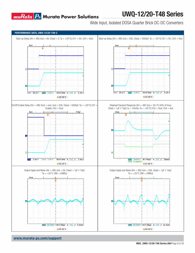
PERFORMANCE DATA, UWQ-12/20-T48-C
On/Off Enable Delay (Vin = 48V, Vout = nom, Iout = 20A, Cload = 5000μF, Ta = +25°C) Ch1 = Enable, Ch2 = Vout.
Start-up Delay (Vin = 48V, Iout = 0A, Cload = 0, Ta = +25°C) Ch1 = Vin, Ch2 = Vout
Output ripple and Noise (Vin = 48V, Iout = 0A, Cload = 1μF || 10μF, Ta = +25°C, BW = 20Mhz)
Stepload Transient Response (Vin = 48V, Iout = 50-75-50% of Imax, Cload = 1μF || 10μF, Io = 10A/div, Ta = +25°C) Ch2 = Vout, Ch4 = Iout
Start-up Delay (Vin = 48V, Iout = 20A, Cload = 5000µF, Ta = +25°C) Ch1 = Vin, Ch2 = Vout
Output ripple and Noise (Vin = 48V, Iout = 20A, Cload = 1μF || 10μF, Ta = +25°C, BW = 20Mhz)
UWQ-12/20-T48 SeriesWide Input, Isolated DOSA Quarter Brick DC-DC Converters
MDC_UWQ-12/20-T48 Series.A04 Page 9 of 29
www.murata-ps.com/support
PERFORMANCE DATA, UWQ-12/20-T48xS
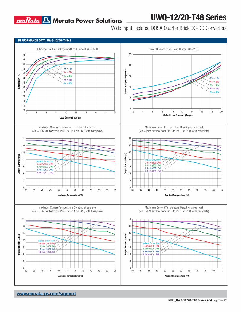
Power Dissipation vs. Load Current @ +25°C
0
5
10
15
20
25
2 4 6 8 10 12 14 16 18 20
Output Load Current (Amps)
Pow
er D
issi
patio
n (W
atts
)
VIN = 18VVIN = 24VVIN = 36VVIN = 48VVIN = 60V
Efficiency vs. Line Voltage and Load Current @ +25°C
70
72
74
76
78
80
82
84
86
88
90
92
94
2 4 6 8 10 12 14 16 18 20
Load Current (Amps)
Effi
cien
cy (
%)
VIN = 18VVIN = 24VVIN = 36VVIN = 48VVIN = 60V
Maximum Current Temperature Derating at sea level (Vin = 24V, air flow from Pin 3 to Pin 1 on PCB, with baseplate)
Maximum Current Temperature Derating at sea level (Vin = 18V, air flow from Pin 3 to Pin 1 on PCB, with baseplate)
Maximum Current Temperature Derating at sea level (Vin = 48V, air flow from Pin 3 to Pin 1 on PCB, with baseplate)
Maximum Current Temperature Derating at sea level (Vin = 36V, air flow from Pin 3 to Pin 1 on PCB, with baseplate)
0
3
6
9
12
15
18
21
30 35 40 45 50 55 60 65 70 75 80 85
Outp
ut C
urre
nt (A
mps
)
Ambient Temperature (°C)
0.5 m/s (100 LFM)1.0 m/s (200 LFM)1.5 m/s (300 LFM)2.0 m/s (400 LFM)
Natural Convection
0
3
6
9
12
15
18
21
30 35 40 45 50 55 60 65 70 75 80 85
Outp
ut C
urre
nt (A
mps
)
Ambient Temperature (°C)
0.5 m/s (100 LFM)1.0 m/s (200 LFM)1.5 m/s (300 LFM)2.0 m/s (400 LFM)
Natural Convection
0
3
6
9
12
15
18
21
30 35 40 45 50 55 60 65 70 75 80 85
Outp
ut C
urre
nt (A
mps
)
Ambient Temperature (°C)
0.5 m/s (100 LFM)1.0 m/s (200 LFM)1.5 m/s (300 LFM)2.0 m/s (400 LFM)
Natural Convection
0
3
6
9
12
15
18
21
30 35 40 45 50 55 60 65 70 75 80 85
Outp
ut C
urre
nt (A
mps
)
Ambient Temperature (°C)
0.5 m/s (100 LFM)1.0 m/s (200 LFM)1.5 m/s (300 LFM)2.0 m/s (400 LFM)
Natural Convection
UWQ-12/20-T48 SeriesWide Input, Isolated DOSA Quarter Brick DC-DC Converters
MDC_UWQ-12/20-T48 Series.A04 Page 10 of 29
www.murata-ps.com/support
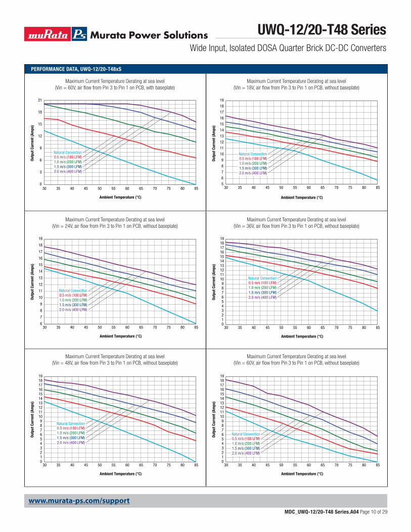
PERFORMANCE DATA, UWQ-12/20-T48xS
Maximum Current Temperature Derating at sea level (Vin = 36V, air flow from Pin 3 to Pin 1 on PCB, without baseplate)
Maximum Current Temperature Derating at sea level (Vin = 18V, air flow from Pin 3 to Pin 1 on PCB, without baseplate)
Maximum Current Temperature Derating at sea level (Vin = 24V, air flow from Pin 3 to Pin 1 on PCB, without baseplate)
Maximum Current Temperature Derating at sea level (Vin = 60V, air flow from Pin 3 to Pin 1 on PCB, with baseplate)
Maximum Current Temperature Derating at sea level (Vin = 60V, air flow from Pin 3 to Pin 1 on PCB, without baseplate)
Maximum Current Temperature Derating at sea level (Vin = 48V, air flow from Pin 3 to Pin 1 on PCB, without baseplate)
6
7
8
9
10
11
12
13
14
15
16
17
18
19
30 35 40 45 50 55 60 65 70 75 80 85
Outp
ut C
urre
nt (A
mps
)
Ambient Temperature (°C)
0.5 m/s (100 LFM)1.0 m/s (200 LFM)1.5 m/s (300 LFM)2.0 m/s (400 LFM)
Natural Convection
0
3
6
9
12
15
18
21
30 35 40 45 50 55 60 65 70 75 80 85
Outp
ut C
urre
nt (A
mps
)
Ambient Temperature (°C)
0.5 m/s (100 LFM)1.0 m/s (200 LFM)1.5 m/s (300 LFM)2.0 m/s (400 LFM)
Natural Convection
0123456789
10111213141516171819
30 35 40 45 50 55 60 65 70 75 80 85
Outp
ut C
urre
nt (A
mps
)
Ambient Temperature (°C)
0.5 m/s (100 LFM)1.0 m/s (200 LFM)1.5 m/s (300 LFM)2.0 m/s (400 LFM)
Natural Convection
0123456789
10111213141516171819
30 35 40 45 50 55 60 65 70 75 80 85
Outp
ut C
urre
nt (A
mps
)
Ambient Temperature (°C)
0.5 m/s (100 LFM)1.0 m/s (200 LFM)1.5 m/s (300 LFM)2.0 m/s (400 LFM)
Natural Convection
0123456789
10111213141516171819
30 35 40 45 50 55 60 65 70 75 80 85
Outp
ut C
urre
nt (A
mps
)
Ambient Temperature (°C)
0.5 m/s (100 LFM)1.0 m/s (200 LFM)1.5 m/s (300 LFM)2.0 m/s (400 LFM)
Natural Convection
5
6
7
8
9
10
11
12
13
14
15
16
17
18
19
30 35 40 45 50 55 60 65 70 75 80 85
Outp
ut C
urre
nt (A
mps
)
Ambient Temperature (°C)
0.5 m/s (100 LFM)1.0 m/s (200 LFM)1.5 m/s (300 LFM)2.0 m/s (400 LFM)
Natural Convection
UWQ-12/20-T48 SeriesWide Input, Isolated DOSA Quarter Brick DC-DC Converters
MDC_UWQ-12/20-T48 Series.A04 Page 11 of 29
www.murata-ps.com/support
PERFORMANCE DATA, UWQ-12/20-T48xS
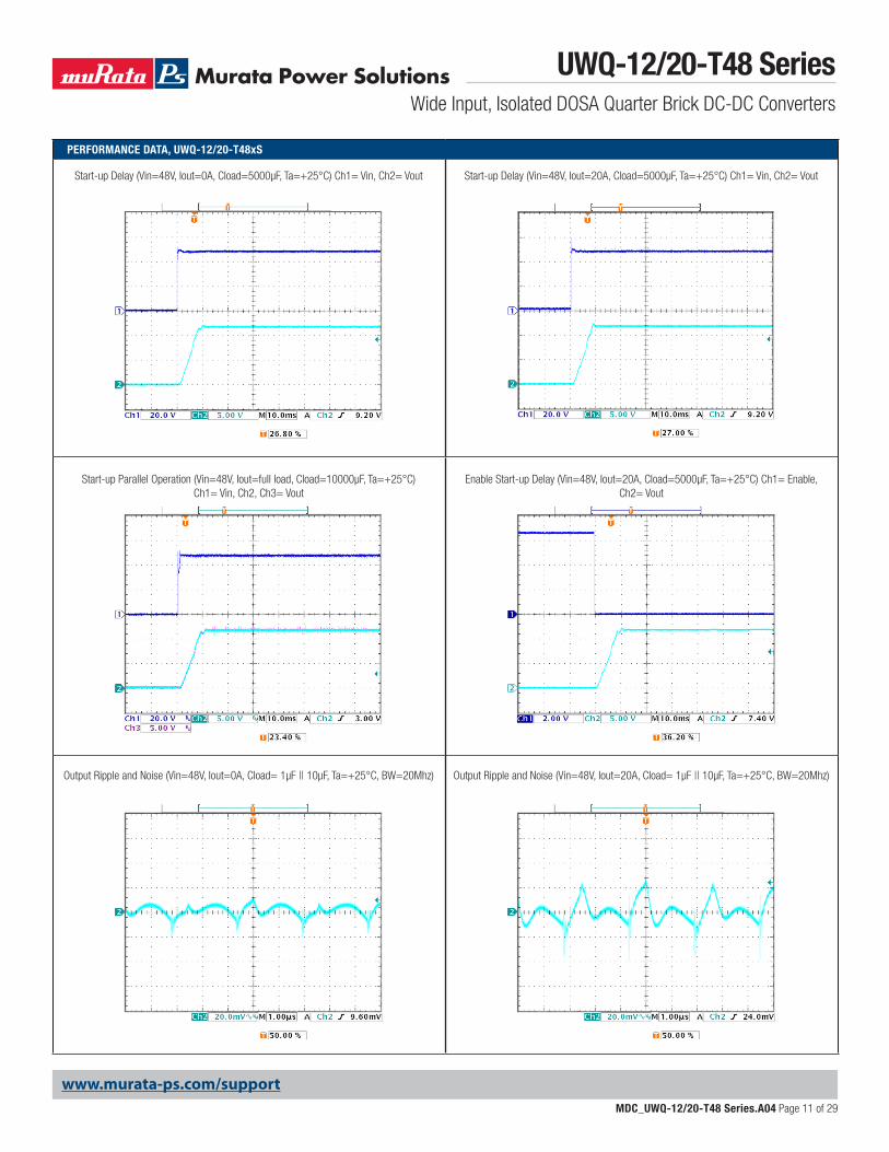
Start-up Parallel Operation (Vin=48V, Iout=full load, Cload=10000µF, Ta=+25°C) Ch1= Vin, Ch2, Ch3= Vout
Start-up Delay (Vin=48V, Iout=0A, Cload=5000µF, Ta=+25°C) Ch1= Vin, Ch2= Vout
Output Ripple and Noise (Vin=48V, Iout=0A, Cload= 1μF || 10μF, Ta=+25°C, BW=20Mhz)
Enable Start-up Delay (Vin=48V, Iout=20A, Cload=5000µF, Ta=+25°C) Ch1= Enable, Ch2= Vout
Start-up Delay (Vin=48V, Iout=20A, Cload=5000µF, Ta=+25°C) Ch1= Vin, Ch2= Vout
Output Ripple and Noise (Vin=48V, Iout=20A, Cload= 1μF || 10μF, Ta=+25°C, BW=20Mhz)
UWQ-12/20-T48 SeriesWide Input, Isolated DOSA Quarter Brick DC-DC Converters
MDC_UWQ-12/20-T48 Series.A04 Page 12 of 29
www.murata-ps.com/support
PERFORMANCE DATA, UWQ-12/20-T48xS
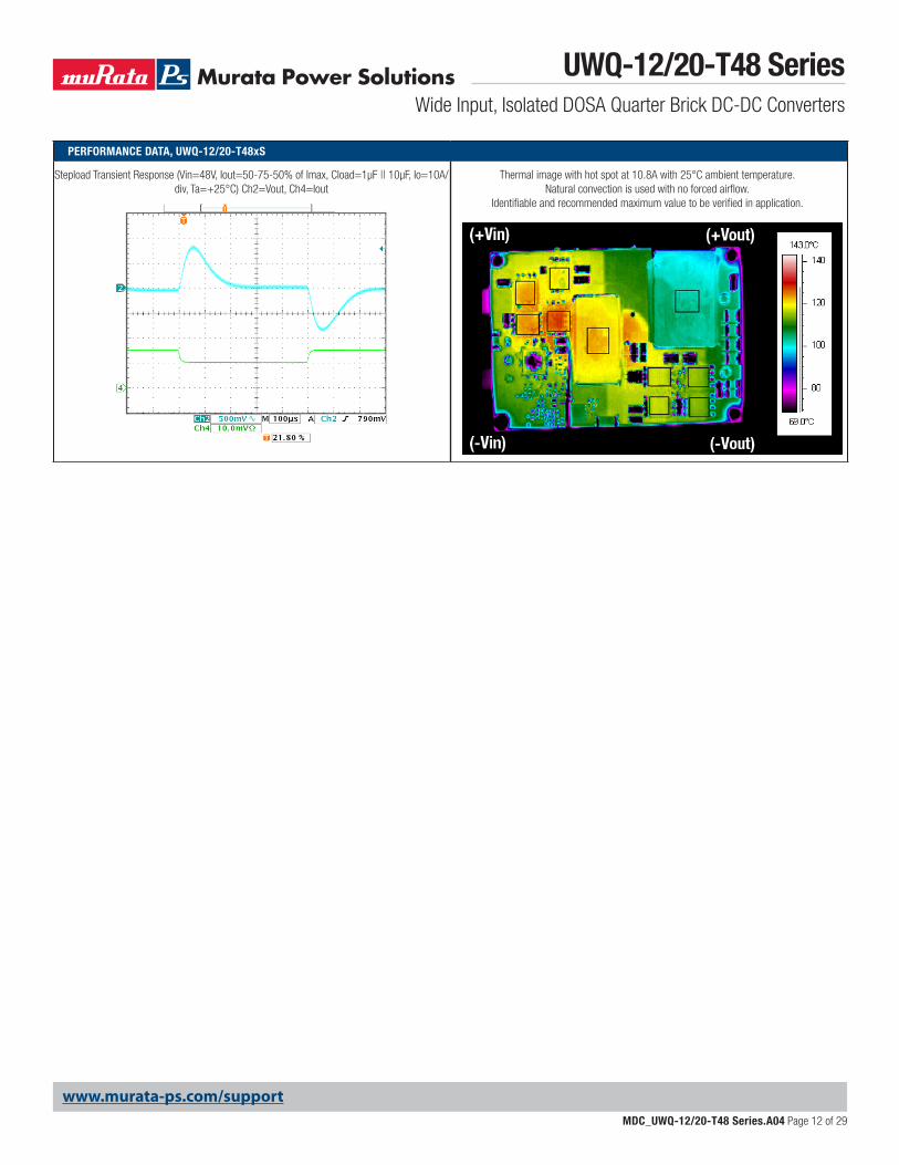
Stepload Transient Response (Vin=48V, Iout=50-75-50% of Imax, Cload=1μF || 10μF, Io=10A/div, Ta=+25°C) Ch2=Vout, Ch4=Iout
Thermal image with hot spot at 10.8A with 25°C ambient temperature. Natural convection is used with no forced airflow.
Identifiable and recommended maximum value to be verified in application.
UWQ-12/20-T48 SeriesWide Input, Isolated DOSA Quarter Brick DC-DC Converters
MDC_UWQ-12/20-T48 Series.A04 Page 13 of 29
www.murata-ps.com/support
PERFORMANCE DATA, UWQ-12/20-T48xT
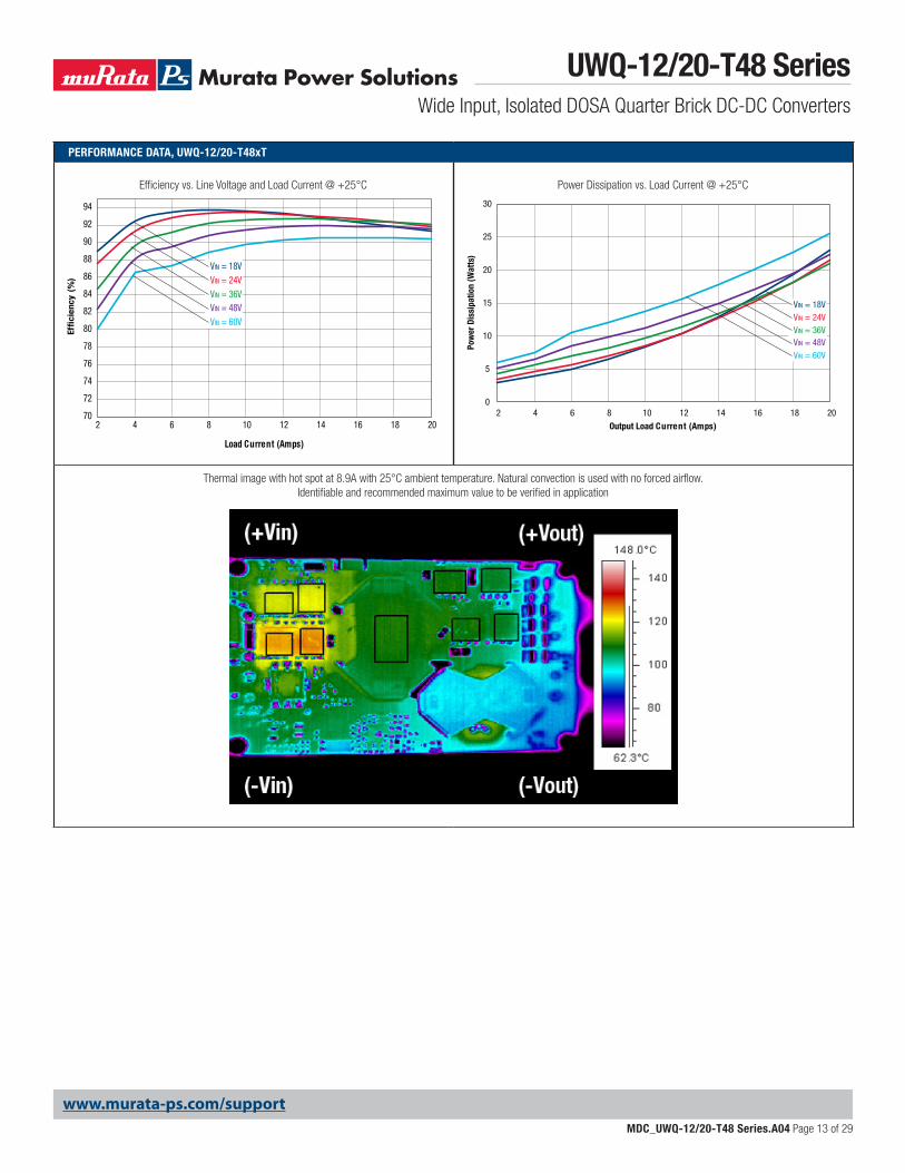
Power Dissipation vs. Load Current @ +25°C
0
5
10
15
20
25
30
2 4 6 8 10 12 14 16 18 20
Output Load Current (Amps)
Pow
er D
issi
patio
n (W
atts
)
VIN = 18VVIN = 24VVIN = 36VVIN = 48VVIN = 60V
Efficiency vs. Line Voltage and Load Current @ +25°C
70
72
74
76
78
80
82
84
86
88
90
92
94
2 4 6 8 10 12 14 16 18 20
Load Current (Amps)
Effi
cien
cy (
%)
VIN = 18VVIN = 24VVIN = 36VVIN = 48VVIN = 60V
Thermal image with hot spot at 8.9A with 25°C ambient temperature. Natural convection is used with no forced airflow. Identifiable and recommended maximum value to be verified in application
UWQ-12/20-T48 SeriesWide Input, Isolated DOSA Quarter Brick DC-DC Converters
MDC_UWQ-12/20-T48 Series.A04 Page 14 of 29
www.murata-ps.com/support
PERFORMANCE DATA, UWQ-12/20-T48xT
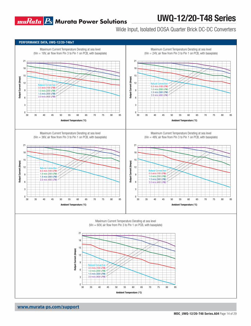
Maximum Current Temperature Derating at sea level (Vin = 24V, air flow from Pin 3 to Pin 1 on PCB, with baseplate)
Maximum Current Temperature Derating at sea level (Vin = 18V, air flow from Pin 3 to Pin 1 on PCB, with baseplate)
Maximum Current Temperature Derating at sea level (Vin = 60V, air flow from Pin 3 to Pin 1 on PCB, with baseplate)
Maximum Current Temperature Derating at sea level (Vin = 48V, air flow from Pin 3 to Pin 1 on PCB, with baseplate)
Maximum Current Temperature Derating at sea level (Vin = 36V, air flow from Pin 3 to Pin 1 on PCB, with baseplate)
0
3
6
9
12
15
18
21
30 35 40 45 50 55 60 65 70 75 80 85
Outp
ut C
urre
nt (A
mps
)
Ambient Temperature (°C)
0.5 m/s (100 LFM)1.0 m/s (200 LFM)1.5 m/s (300 LFM)2.0 m/s (400 LFM)
Natural Convection
0
3
6
9
12
15
18
21
30 35 40 45 50 55 60 65 70 75 80 85
Outp
ut C
urre
nt (A
mps
)
Ambient Temperature (°C)
0.5 m/s (100 LFM)1.0 m/s (200 LFM)1.5 m/s (300 LFM)2.0 m/s (400 LFM)
Natural Convection
0
3
6
9
12
15
18
21
30 35 40 45 50 55 60 65 70 75 80 85
Outp
ut C
urre
nt (A
mps
)
Ambient Temperature (°C)
0.5 m/s (100 LFM)1.0 m/s (200 LFM)1.5 m/s (300 LFM)2.0 m/s (400 LFM)
Natural Convection
0
3
6
9
12
15
18
21
30 35 40 45 50 55 60 65 70 75 80 85
Outp
ut C
urre
nt (A
mps
)
Ambient Temperature (°C)
0.5 m/s (100 LFM)1.0 m/s (200 LFM)1.5 m/s (300 LFM)2.0 m/s (400 LFM)
Natural Convection
0
3
6
9
12
15
18
21
30 35 40 45 50 55 60 65 70 75 80 85
Outp
ut C
urre
nt (A
mps
)
Ambient Temperature (°C)
0.5 m/s (100 LFM)1.0 m/s (200 LFM)1.5 m/s (300 LFM)2.0 m/s (400 LFM)
Natural Convection
UWQ-12/20-T48 SeriesWide Input, Isolated DOSA Quarter Brick DC-DC Converters
MDC_UWQ-12/20-T48 Series.A04 Page 15 of 29
www.murata-ps.com/support
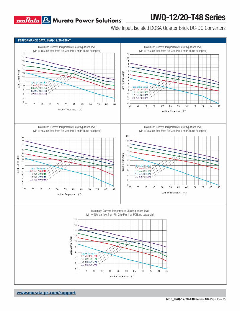
PERFORMANCE DATA, UWQ-12/20-T48xT
Maximum Current Temperature Derating at sea level (Vin = 24V, air flow from Pin 3 to Pin 1 on PCB, no baseplate)
Maximum Current Temperature Derating at sea level (Vin = 18V, air flow from Pin 3 to Pin 1 on PCB, no baseplate)
Maximum Current Temperature Derating at sea level (Vin = 60V, air flow from Pin 3 to Pin 1 on PCB, no baseplate)
Maximum Current Temperature Derating at sea level (Vin = 48V, air flow from Pin 3 to Pin 1 on PCB, no baseplate)
Maximum Current Temperature Derating at sea level (Vin = 36V, air flow from Pin 3 to Pin 1 on PCB, no baseplate)
UWQ-12/20-T48 SeriesWide Input, Isolated DOSA Quarter Brick DC-DC Converters
MDC_UWQ-12/20-T48 Series.A04 Page 16 of 29
www.murata-ps.com/support
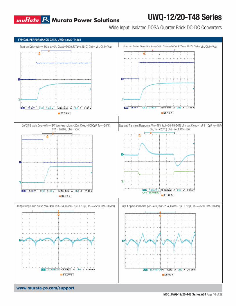
TYPICAL PERFORMANCE DATA, UWQ-12/20-T48xT
On/Off Enable Delay (Vin=48V, Vout=nom, Iout=20A, Cload=5000μF, Ta=+25°C) Ch1= Enable, Ch2= Vout.
Output ripple and Noise (Vin=48V, Iout=0A, Cload= 1μF || 10μF, Ta=+25°C, BW=20Mhz)
Stepload Transient Response (Vin=48V, Iout=50-75-50% of Imax, Cload=1μF || 10μF, Io=10A/div, Ta=+25°C) Ch2=Vout, Ch4=Iout
Output ripple and Noise (Vin=48V, Iout=20A, Cload= 1μF || 10μF, Ta=+25°C, BW=20Mhz)
Start-up Delay (Vin=48V, Iout=0A, Cload=5000µF, Ta=+25°C) Ch1= Vin, Ch2= Vout Start-up Delay (Vin=48V, Iout=20A, Cload=5000µF, Ta=+25°C) Ch1= Vin, Ch2= Vout
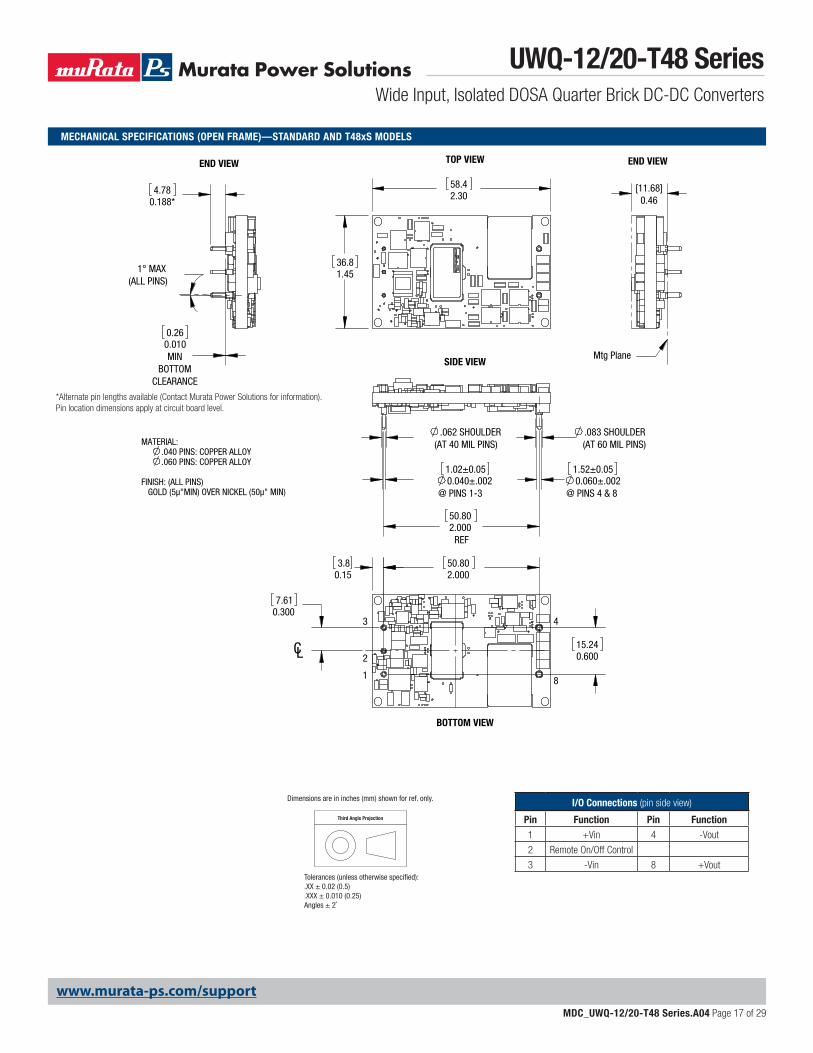
1° MAX(ALL PINS)
CL
TOP VIEW
END VIEW
SIDE VIEW
8
43
2
1
BOTTOM VIEW
END VIEW
Mtg Plane
4.78
0.188*[11.68]
0.46
7.61
0.300
58.4 2.30
36.81.45
0.260.010MIN
BOTTOMCLEARANCE
3.8 0.15 2.000
50.80
15.240.600
.083 SHOULDER(AT 60 MIL PINS)
0.060±.002@ PINS 4 & 8
REF2.00050.80
@ PINS 1-30.040±.0021.02±0.05 1.52±0.05
.062 SHOULDER(AT 40 MIL PINS)
GOLD (5µ"MIN) OVER NICKEL (50µ" MIN)FINISH: (ALL PINS)
.060 PINS: COPPER ALLOY
MATERIAL:
.040 PINS: COPPER ALLOY
I/O Connections (pin side view)
Pin Function Pin Function1 +Vin 4 -Vout
2 Remote On/Off Control
3 -Vin 8 +Vout
Third Angle Projection
Dimensions are in inches (mm) shown for ref. only.
Tolerances (unless otherwise specified):.XX ± 0.02 (0.5).XXX ± 0.010 (0.25)Angles ± 2˚
*Alternate pin lengths available (Contact Murata Power Solutions for information).Pin location dimensions apply at circuit board level.
MECHANICAL SPECIFICATIONS (OPEN FRAME)—STANDARD AND T48xS MODELS
UWQ-12/20-T48 SeriesWide Input, Isolated DOSA Quarter Brick DC-DC Converters
MDC_UWQ-12/20-T48 Series.A04 Page 17 of 29
www.murata-ps.com/support
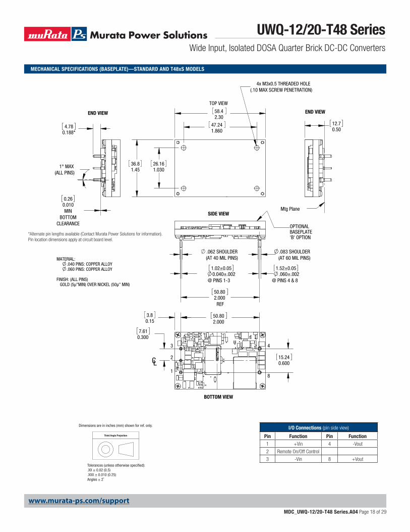
1° MAX(ALL PINS)
CL
43
18
2
BOTTOM VIEW
3.8 0.15
TOP VIEW
(.10 MAX SCREW PENETRATION)
36.81.45
4x M3x0.5 THREADED HOLE
47.241.860
2.3058.4
26.161.030
END VIEW END VIEW
Mtg Plane
OPTIONAL
'B' OPTION
SIDE VIEW
BASEPLATE
(AT 40 MIL PINS).062 SHOULDER
4.78
0.188 *
7.61
0.300
0.260.010MIN
BOTTOMCLEARANCE
50.802.000
15.240.600
50.802.000
REF
1.02±0.050.040±.002
@ PINS 1-3
1.52±0.05.060±.002
@ PINS 4 & 8
.083 SHOULDER(AT 60 MIL PINS)
12.70.50
GOLD (5µ"MIN) OVER NICKEL (50µ" MIN)FINISH: (ALL PINS)
.060 PINS: COPPER ALLOY
MATERIAL:
.040 PINS: COPPER ALLOY
Third Angle Projection
Dimensions are in inches (mm) shown for ref. only.
Tolerances (unless otherwise specified):.XX ± 0.02 (0.5).XXX ± 0.010 (0.25)Angles ± 2˚
MECHANICAL SPECIFICATIONS (BASEPLATE)—STANDARD AND T48xS MODELS
*Alternate pin lengths available (Contact Murata Power Solutions for information).Pin location dimensions apply at circuit board level.
I/O Connections (pin side view)
Pin Function Pin Function1 +Vin 4 -Vout
2 Remote On/Off Control
3 -Vin 8 +Vout
UWQ-12/20-T48 SeriesWide Input, Isolated DOSA Quarter Brick DC-DC Converters
MDC_UWQ-12/20-T48 Series.A04 Page 18 of 29
www.murata-ps.com/support
1.4737.3
2.00050.80
1.0025.4
0.100 MIN@ 1-4, 8
FOR PINSHOULDERS
0.3007.62
2.3258.9
0.3007.62
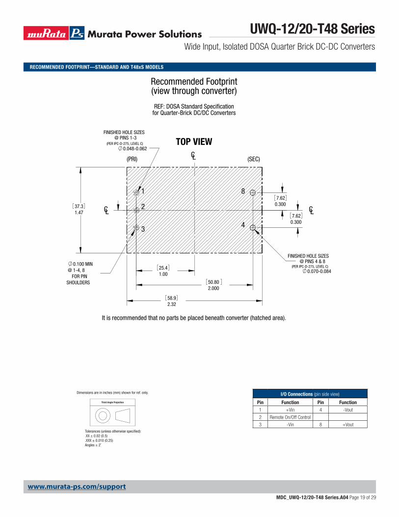
It is recommended that no parts be placed beneath converter (hatched area).
REF: DOSA Standard Specificationfor Quarter-Brick DC/DC Converters
Recommended Footprint(view through converter)
1
2
3 4
8
CL
FINISHED HOLE SIZES@ PINS 4 & 8
(PER IPC-D-275, LEVEL C)0.070-0.084
(SEC)
CL
(PRI)
CL
TOP VIEWFINISHED HOLE SIZES
@ PINS 1-3(PER IPC-D-275, LEVEL C)
0.048-0.062
RECOMMENDED FOOTPRINT—STANDARD AND T48xS MODELS
Third Angle Projection
Dimensions are in inches (mm) shown for ref. only.
Tolerances (unless otherwise specified):.XX ± 0.02 (0.5).XXX ± 0.010 (0.25)Angles ± 2˚
I/O Connections (pin side view)
Pin Function Pin Function1 +Vin 4 -Vout
2 Remote On/Off Control
3 -Vin 8 +Vout
UWQ-12/20-T48 SeriesWide Input, Isolated DOSA Quarter Brick DC-DC Converters
MDC_UWQ-12/20-T48 Series.A04 Page 19 of 29
www.murata-ps.com/support
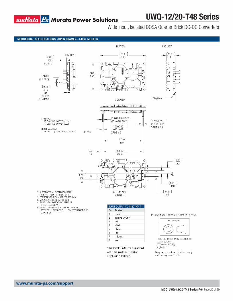
MECHANICAL SPECIFICATIONS (OPEN FRAME)—T48xT MODELS
UWQ-12/20-T48 SeriesWide Input, Isolated DOSA Quarter Brick DC-DC Converters
MDC_UWQ-12/20-T48 Series.A04 Page 20 of 29
www.murata-ps.com/support
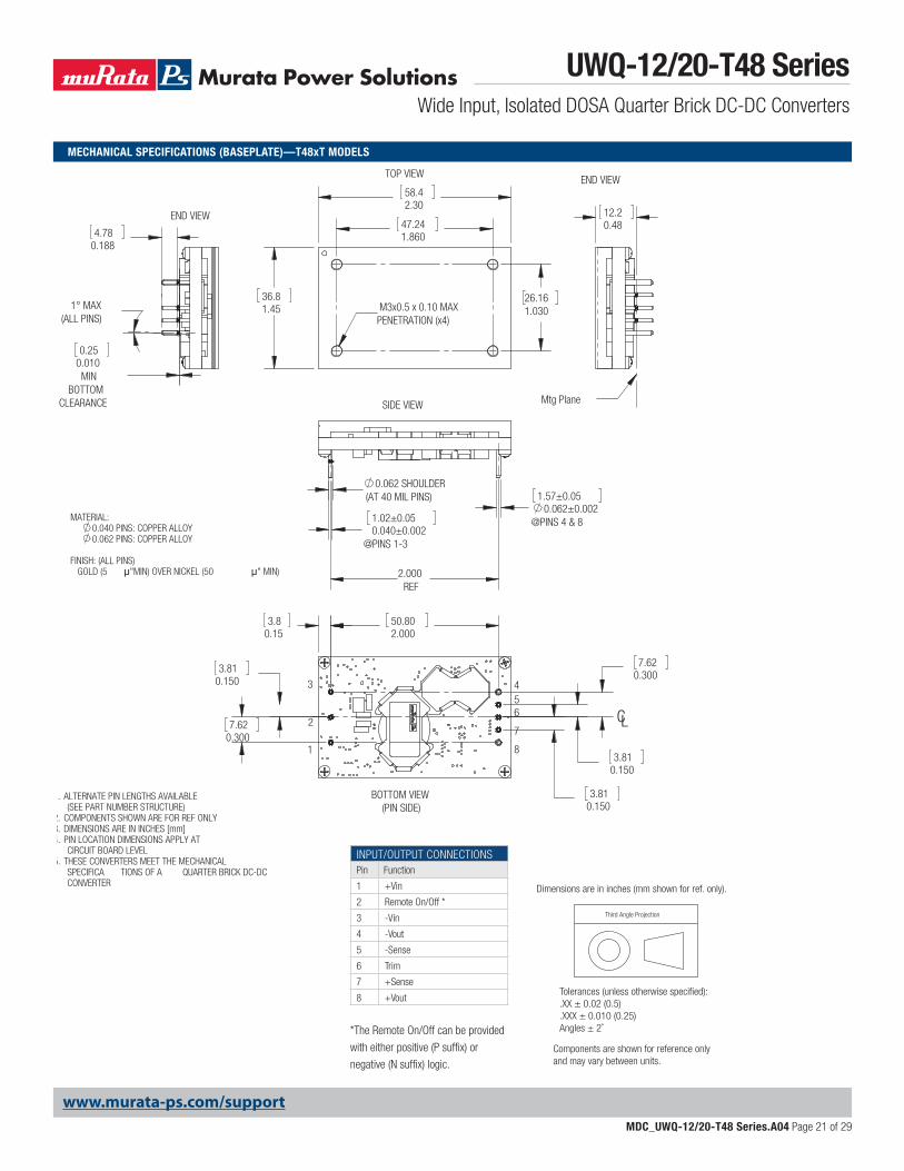
MECHANICAL SPECIFICATIONS (BASEPLATE)—T48xT MODELS
Third Angle Projection
Dimensions are in inches (mm shown for ref. only).
Components are shown for reference onlyand may vary between units.
Tolerances (unless otherwise specified):.XX ± 0.02 (0.5).XXX ± 0.010 (0.25)Angles ± 2˚
INPUT/OUTPUT CONNECTIONSPin Function
1 +Vin
2 Remote On/Off *
3 -Vin
4 -Vout
5 -Sense
6 Trim
7 +Sense
8 +Vout
*The Remote On/Off can be provided
with either positive (P suffi x) or
negative (N suffi x) logic.
4.780.188
1° MAX(ALL PINS)
0.062 SHOULDER(AT 40 MIL PINS)
2.000REF
12.20.48
CL
MATERIAL:0.040 PINS: COPPER ALLOY0.062 PINS: COPPER ALLOY
FINISH: (ALL PINS) GOLD (5 "MIN) OVER NICKEL (50 " MIN)
1. ALTERNATE PIN LENGTHS AVAILABLE(SEE PART NUMBER STRUCTURE)
2. COMPONENTS SHOWN ARE FOR REF ONLY3. DIMENSIONS ARE IN INCHES [mm]4. PIN LOCATION DIMENSIONS APPLY AT
CIRCUIT BOARD LEVEL5. THESE CONVERTERS MEET THE MECHANICAL
SPECIFICA TIONS OF A QUARTER BRICK DC-DCCONVERTER
END VIEW
0.250.010MIN
BOTTOMCLEARANCE
TOP VIEW
58.4
1.4536.8
2.30
47.241.860
26.161.030 M3x0.5 x 0.10 MAX
PENETRATION (x4)
7
8
4
1
2
3
BOTTOM VIEW(PIN SIDE)
65
3.810.150
0.1503.81
2.00050.80
0.3007.62
0.3007.62
3.810.150
3.80.15
SIDE VIEW
1.02±0.050.040±0.002
@PINS 1-3
1.57±0.050.062±0.002
@PINS 4 & 8
END VIEW
Mtg Plane
UWQ-12/20-T48 SeriesWide Input, Isolated DOSA Quarter Brick DC-DC Converters
MDC_UWQ-12/20-T48 Series.A04 Page 21 of 29
www.murata-ps.com/support
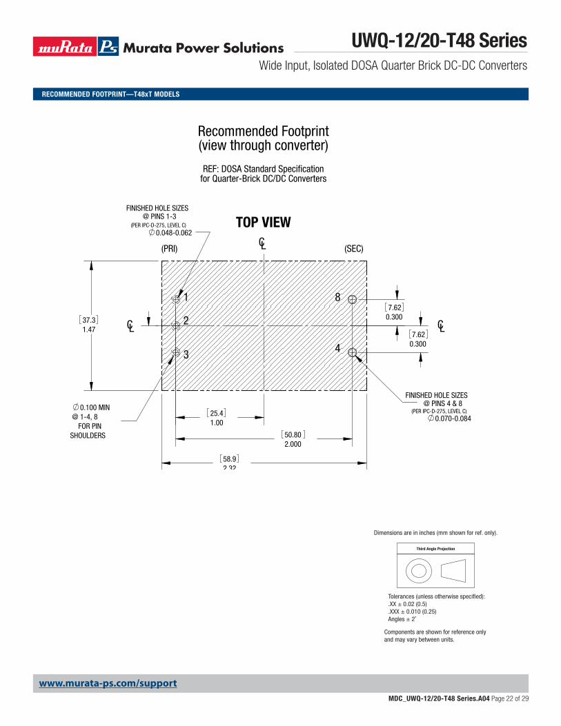
RECOMMENDED FOOTPRINT—T48xT MODELS
Third Angle Projection
Dimensions are in inches (mm shown for ref. only).
Components are shown for reference onlyand may vary between units.
Tolerances (unless otherwise specified):.XX ± 0.02 (0.5).XXX ± 0.010 (0.25)Angles ± 2˚
1.4737.3
2.00050.80
1.0025.4
0.100 MIN@ 1-4, 8
FOR PINSHOULDERS
0.3007.62
2.3258.9
0.3007.62
It is recommended that no parts be placed beneath converter (hatched area).
REF: DOSA Standard Specificationfor Quarter-Brick DC/DC Converters
Recommended Footprint(view through converter)
1
2
3 4
8
CL
FINISHED HOLE SIZES@ PINS 4 & 8
(PER IPC-D-275, LEVEL C)0.070-0.084
(SEC)
CL
(PRI)
CL
TOP VIEWFINISHED HOLE SIZES
@ PINS 1-3(PER IPC-D-275, LEVEL C)
0.048-0.062
UWQ-12/20-T48 SeriesWide Input, Isolated DOSA Quarter Brick DC-DC Converters
MDC_UWQ-12/20-T48 Series.A04 Page 22 of 29
www.murata-ps.com/support
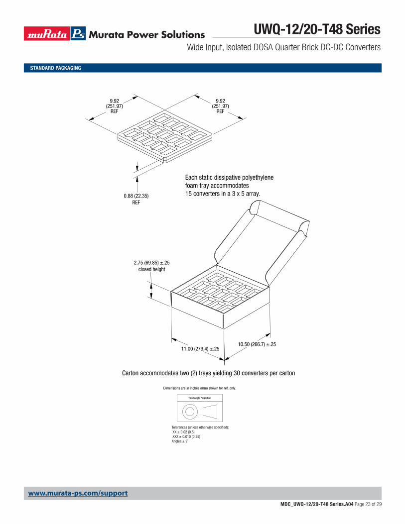
BASEPLATE VERSION HEATSINK VERSION
Carton accommodates two (2) trays yielding 30 converters per carton
10.50 (266.7) ±.2511.00 (279.4) ±.25
Carton accommodates two (2) trays yielding 24 converters per carton
10.0 (254) ±.2510.0 (254) ±.25
2.75 (69.85) ±.25closed height
4.25 (108) ±.25closed height
0.88 (22.35)REF
Each static dissipative polyethylene foam tray accommodates 15 converters in a 3 x 5 array.
Each static dissipative polyethylene foam tray accommodates 12 converters in a 3 x 4 array.
9.92(251.97)
REF
9.92(251.97)
REF
STANDARD PACKAGING
Third Angle Projection
Dimensions are in inches (mm) shown for ref. only.
Tolerances (unless otherwise specified):.XX ± 0.02 (0.5).XXX ± 0.010 (0.25)Angles ± 2˚
UWQ-12/20-T48 SeriesWide Input, Isolated DOSA Quarter Brick DC-DC Converters
MDC_UWQ-12/20-T48 Series.A04 Page 23 of 29
www.murata-ps.com/support
UWQ-12/20-T48 SeriesWide Input, Isolated DOSA Quarter Brick DC-DC Converters
MDC_UWQ-12/20-T48 Series.A04 Page 24 of 29
www.murata-ps.com/support
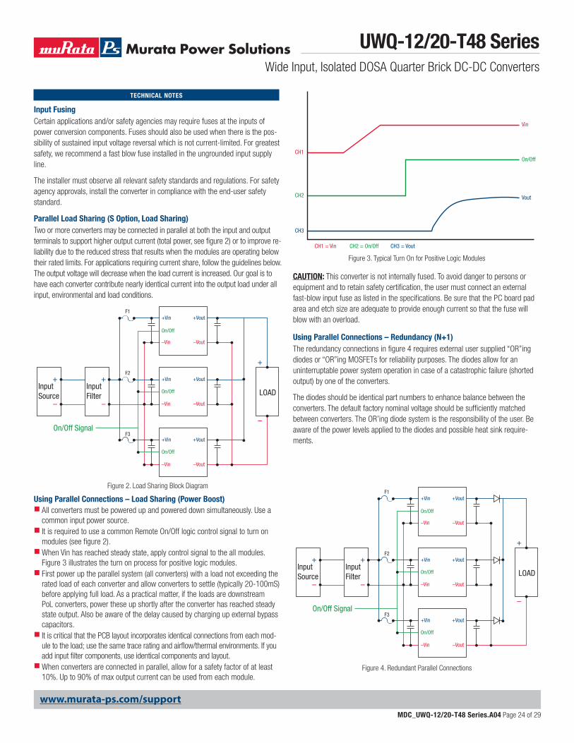
Input FusingCertain applications and/or safety agencies may require fuses at the inputs of power conversion components. Fuses should also be used when there is the pos-sibility of sustained input voltage reversal which is not current-limited. For greatest safety, we recommend a fast blow fuse installed in the ungrounded input supply line.
The installer must observe all relevant safety standards and regulations. For safety agency approvals, install the converter in compliance with the end-user safety standard.
Parallel Load Sharing (S Option, Load Sharing)Two or more converters may be connected in parallel at both the input and output terminals to support higher output current (total power, see figure 2) or to improve re-liability due to the reduced stress that results when the modules are operating below their rated limits. For applications requiring current share, follow the guidelines below. The output voltage will decrease when the load current is increased. Our goal is to have each converter contribute nearly identical current into the output load under all input, environmental and load conditions.
Using Parallel Connections – Load Sharing (Power Boost) All converters must be powered up and powered down simultaneously. Use a common input power source. It is required to use a common Remote On/Off logic control signal to turn on modules (see figure 2).When Vin has reached steady state, apply control signal to the all modules. Figure 3 illustrates the turn on process for positive logic modules. First power up the parallel system (all converters) with a load not exceeding the rated load of each converter and allow converters to settle (typically 20-100mS) before applying full load. As a practical matter, if the loads are downstream PoL converters, power these up shortly after the converter has reached steady state output. Also be aware of the delay caused by charging up external bypass capacitors. It is critical that the PCB layout incorporates identical connections from each mod-ule to the load; use the same trace rating and airflow/thermal environments. If you add input filter components, use identical components and layout.When converters are connected in parallel, allow for a safety factor of at least 10%. Up to 90% of max output current can be used from each module.
TECHNICAL NOTES
CAUTION: This converter is not internally fused. To avoid danger to persons or equipment and to retain safety certification, the user must connect an external fast-blow input fuse as listed in the specifications. Be sure that the PC board pad area and etch size are adequate to provide enough current so that the fuse will blow with an overload.
Using Parallel Connections – Redundancy (N+1)The redundancy connections in figure 4 requires external user supplied “OR”ing diodes or “OR”ing MOSFETs for reliability purposes. The diodes allow for an uninterruptable power system operation in case of a catastrophic failure (shorted output) by one of the converters.
The diodes should be identical part numbers to enhance balance between the converters. The default factory nominal voltage should be sufficiently matched between converters. The OR’ing diode system is the responsibility of the user. Be aware of the power levels applied to the diodes and possible heat sink require-ments.
Figure 2. Load Sharing Block Diagram
On/Off
On/Off
On/Off
F1
F2
F3
+
+
–
–
+
–
+Vin +Vout
–Vin –Vout
–Vin –Vout
–Vin –Vout
+Vin +Vout
+Vin +Vout
LOADInputSource
On/Off Signal
InputFilter
On/Off
Vout
Vin
CH2
CH2 = On/Off
CH3
CH3 = Vout
CH1
CH1 = Vin
Figure 3. Typical Turn On for Positive Logic Modules
Figure 4. Redundant Parallel Connections
On/Off
On/Off
On/Off
F1
F2
F3
+
+
–
–
+
–
+Vin +Vout
–Vin –Vout
–Vin –Vout
–Vin –Vout
+Vin +Vout
+Vin +Vout
LOADInputSource
On/Off Signal
InputFilter
UWQ-12/20-T48 SeriesWide Input, Isolated DOSA Quarter Brick DC-DC Converters
MDC_UWQ-12/20-T48 Series.A04 Page 25 of 29
www.murata-ps.com/support
Schottky power diodes with approximately 0.3V drops or “OR”ing MOSFETs may be suitable in the loop whereas 0.7 V silicon power diodes may not be advisable. In the event of an internal device fault or failure of the mains power modules on the primary side, the other devices automatically take over the entire supply of the loads. In the basic N+1 power system, the “N” equals the number of modules required to fully power the system and “+1” equals one back-up module that will take over for a failed module. If the system consists of two power modules, each providing 50% of the total load power under normal operation and one module fails, another one delivers full power to the load. This means you can use smaller and less expensive power converters as the redundant elements, while achieving the goal of increased availability.
Input Under-Voltage Shutdown and Start-Up ThresholdUnder normal start-up conditions, converters will not begin to regulate properly until the rising input voltage exceeds and remains at the Start-Up Threshold Volt-age (see Specifications). Once operating, converters will not turn off until the input voltage drops below the Under-Voltage Shutdown Limit. Subsequent restart will not occur until the input voltage rises again above the Start-Up Threshold. This built-in hysteresis prevents any unstable on/off operation at a single input voltage.
Users should be aware however of input sources near the Under-Voltage Shutdown whose voltage decays as input current is consumed (such as capacitor inputs), the converter shuts off and then restarts as the external capacitor recharges. Such situ-ations could oscillate. To prevent this, make sure the operating input voltage is well above the UV Shutdown voltage AT ALL TIMES.
Start-Up DelayAssuming that the output current is set at the rated maximum, the Vin to Vout Start-Up Delay (see Specifications) is the time interval between the point when the rising input voltage crosses the Start-Up Threshold and the fully loaded regulated output voltage enters and remains within its specified regulation band. Actual measured times will vary with input source impedance, external input capacitance, input voltage slew rate and final value of the input voltage as it appears at the converter.
These converters include a soft start circuit to moderate the duty cycle of the PWM controller at power up, thereby limiting the input inrush current.
The On/Off Remote Control interval from inception to Vout regulated assumes that the converter already has its input voltage stabilized above the Start-Up Threshold before the On command. The interval is measured from the On command until the output enters and remains within its specified regulation band. The specification assumes that the output is fully loaded at maximum rated current.
Input Source ImpedanceThese converters will operate to specifications without external components, assuming that the source voltage has very low impedance and reasonable input voltage regulation. Since real-world voltage sources have finite impedance, perfor-mance is improved by adding external filter components. Sometimes only a small ceramic capacitor is sufficient. Since it is difficult to totally characterize all applica-tions, some experimentation may be needed. Note that external input capacitors must accept high speed switching currents.
Because of the switching nature of DC-DC converters, the input of these convert-ers must be driven from a source with both low AC impedance and adequate DC input regulation. Performance will degrade with increasing input inductance. Excessive input inductance may inhibit operation. The DC input regulation specifies that the input voltage, once operating, must never degrade below the Shut-Down
Threshold under all load conditions. Be sure to use adequate trace sizes and mount components close to the converter.
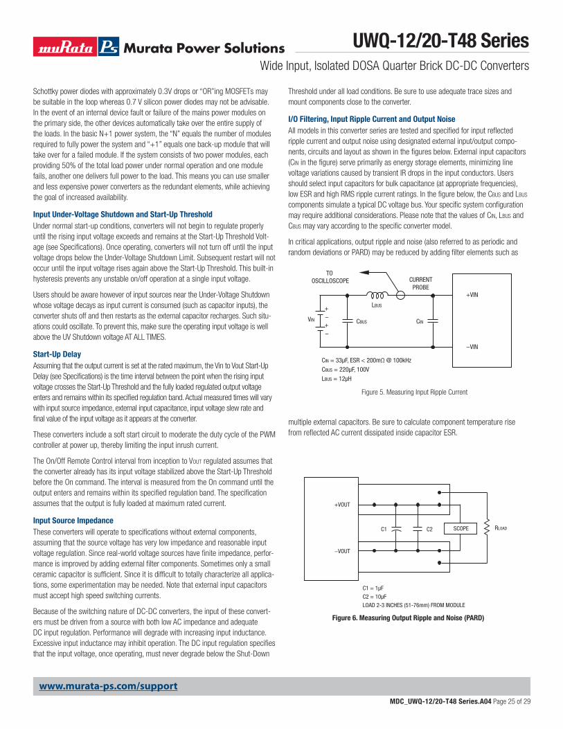
I/O Filtering, Input Ripple Current and Output NoiseAll models in this converter series are tested and specified for input reflected ripple current and output noise using designated external input/output compo-nents, circuits and layout as shown in the figures below. External input capacitors (Cin in the figure) serve primarily as energy storage elements, minimizing line voltage variations caused by transient IR drops in the input conductors. Users should select input capacitors for bulk capacitance (at appropriate frequencies), low ESR and high RMS ripple current ratings. In the figure below, the Cbus and Lbus components simulate a typical DC voltage bus. Your specific system configuration may require additional considerations. Please note that the values of Cin, Lbus and Cbus may vary according to the specific converter model.
In critical applications, output ripple and noise (also referred to as periodic and random deviations or PARD) may be reduced by adding filter elements such as
multiple external capacitors. Be sure to calculate component temperature rise from reflected AC current dissipated inside capacitor ESR.
Figure 6. Measuring Output Ripple and Noise (PARD)
C1
C1 = 1µF
C2 = 10µF
LOAD 2-3 INCHES (51-76mm) FROM MODULE
C2 RLOADSCOPE
+VOUT
−VOUT
CINVIN CBUS
LBUS
CIN = 33µF, ESR < 200mΩ @ 100kHz
CBUS = 220µF, 100V
LBUS = 12µH
+VIN
−VIN
CURRENTPROBE
TO OSCILLOSCOPE
+–+–
Figure 5. Measuring Input Ripple Current
UWQ-12/20-T48 SeriesWide Input, Isolated DOSA Quarter Brick DC-DC Converters
MDC_UWQ-12/20-T48 Series.A04 Page 26 of 29
www.murata-ps.com/support
Floating OutputsSince these are isolated DC-DC converters, their outputs are “floating” with respect to their input. The essential feature of such isolation is ideal ZERO CURRENT FLOW between input and output. Real-world converters however do exhibit tiny leakage currents between input and output (see Specifications). These leakages consist of both an AC stray capacitance coupling component and a DC leakage resistance. When using the isolation feature, do not allow the isolation voltage to exceed specifications. Otherwise the converter may be damaged. Designers will normally use the negative output (-Output) as the ground return of the load circuit. You can however use the positive output (+Output) as the ground return to effectively reverse the output polarity.
Minimum Output Loading RequirementsThese converters employ a synchronous rectifier design topology. All models regulate within specification and are stable under no load to full load conditions. Operation under no load might however slightly increase output ripple and noise.
Thermal ShutdownTo protect against thermal over-stress, these converters include thermal shutdown circuitry. If environmental conditions cause the temperature of the DC-DC’s to rise above the Operating Temperature Range up to the shutdown temperature, an on-board electronic temperature sensor will power down the unit. When the temperature decreases below the turn-on threshold, the converter will automati-cally restart. There is a small amount of hysteresis to prevent rapid on/off cycling. CAUTION: If you operate too close to the thermal limits, the converter may shut down suddenly without warning. Be sure to thoroughly test your application to avoid unplanned thermal shutdown.
Temperature Derating CurvesThe graphs in this data sheet illustrate typical operation under a variety of conditions. The Derating curves show the maximum continuous ambient air temperature and decreasing maximum output current which is acceptable under increasing forced airflow measured in Linear Feet per Minute (“LFM”). Note that these are AVERAGE measure-ments. The converter will accept brief increases in temperature and/or current or reduced airflow as long as the average is not exceeded.
Note that the temperatures are of the ambient airflow, not the converter itself which is obviously running at higher temperature than the outside air. Also note that “natural convection” is defined as very low flow rates which are not using fan-forced airflow. Depending on the application, “natural convection” is usually about 30-65 LFM but is not equal to still air (0 LFM).
Murata Power Solutions makes Characterization measurements in a closed cycle wind tunnel with calibrated airflow. We use both thermocouples and an infrared camera system to observe thermal performance. As a practical matter, it is quite difficult to insert an anemometer to precisely measure airflow in most applica-tions. Sometimes it is possible to estimate the effective airflow if you thoroughly understand the enclosure geometry, entry/exit orifice areas and the fan flowrate specifications.
CAUTION: If you exceed these Derating guidelines, the converter may have an unplanned Over Temperature shut down. Also, these graphs are all collected near Sea Level altitude. Be sure to reduce the derating for higher altitude.
Output Overvoltage Protection (OVP)This converter monitors its output voltage for an over-voltage condition using an on-board electronic comparator. The signal is optically coupled to the primary side PWM controller. If the output exceeds OVP limits, the sensing circuit will power
down the unit, and the output voltage will decrease. After a time-out period, the PWM will automatically attempt to restart, causing the output voltage to ramp up to its rated value. It is not necessary to power down and reset the converter for this automatic OVP-recovery restart.
If the fault condition persists and the output voltage climbs to excessive levels, the OVP circuitry will initiate another shutdown cycle. This on/off cycling is referred to as “hiccup” mode.
Output FusingThe converter is extensively protected against current, voltage and temperature extremes. However, your application circuit may need additional protection. In the extremely unlikely event of output circuit failure, excessive voltage could be applied to your circuit. Consider using an appropriate external protection.
Current Limiting (Power limit with current mode control)As power demand increases on the output and enters the specified “limit inception range” (current in voltage mode and power in current mode) limiting circuitry activates in the DC-DC converter to limit/restrict the maximum current or total power available. In voltage mode, current limit can have a “constant or foldback” characteristic. In current mode, once the current reaches a certain range the output voltage will start to decrease while the output current continues to increase, thereby maintaining constant power, until a maximum peak current is reached and the converter enters a “hiccup” (on off cycling) mode of operation until the load is reduced below the threshold level, whereupon it will return to a normal mode of operation. Current limit inception is defined as the point where the output voltage has decreased by a pre-specified percentage (usually a 2% decrease from nominal).
Short Circuit Condition (Current mode control)The short circuit condition is an extension of the “Current Limiting” condition. When the monitored peak current signal reaches a certain range, the PWM controller’s outputs are shut off thereby turning the converter “off.” This is followed by an extended time out period. This period can vary depending on other conditions such as the input voltage level. Following this time out period, the PWM controller will attempt to re-start the converter by initiating a “normal start cycle” which includes softstart. If the “fault condition” persists, another “hiccup” cycle is initiated. This “cycle” can and will continue indefinitely until such time as the “fault condition” is removed, at which time the converter will resume “normal operation.” Operating in the “hiccup” mode during a fault condition is advantageous in that average input and output power levels are held low preventing excessive internal increases in temperature.
Remote On/Off ControlOn the input side, a remote On/Off Control can be specified with either positive or negative logic as follows:
Positive: Models equipped with positive logic are enabled when the On/Off pin is left open or is pulled high to +13.5Vdc with respect to –Vin. An internal bias cur-rent causes the open pin to rise to +Vin. Positive-logic devices are disabled when the On/Off is grounded or brought to within a low voltage (see Specifications) with respect to –Vin.
Negative: Models with negative logic are on (enabled) when the On/Off is grounded or brought to within a low voltage (see Specifications) with respect to –Vin. The device is off (disabled) when the On/Off is left open or is pulled high to +13.5Vdc Max. with respect to –Vin.
UWQ-12/20-T48 SeriesWide Input, Isolated DOSA Quarter Brick DC-DC Converters
MDC_UWQ-12/20-T48 Series.A04 Page 27 of 29
www.murata-ps.com/support
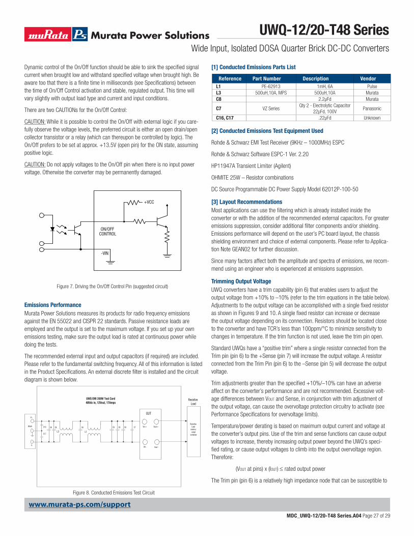
Dynamic control of the On/Off function should be able to sink the specified signal current when brought low and withstand specified voltage when brought high. Be aware too that there is a finite time in milliseconds (see Specifications) between the time of On/Off Control activation and stable, regulated output. This time will vary slightly with output load type and current and input conditions.
There are two CAUTIONs for the On/Off Control:
CAUTION: While it is possible to control the On/Off with external logic if you care-fully observe the voltage levels, the preferred circuit is either an open drain/open collector transistor or a relay (which can thereupon be controlled by logic). The On/Off prefers to be set at approx. +13.5V (open pin) for the ON state, assuming positive logic.
CAUTION: Do not apply voltages to the On/Off pin when there is no input power voltage. Otherwise the converter may be permanently damaged.
Figure 7. Driving the On/Off Control Pin (suggested circuit)
ON/OFFCONTROL
-VIN
+VCC
Emissions PerformanceMurata Power Solutions measures its products for radio frequency emissions against the EN 55022 and CISPR 22 standards. Passive resistance loads are employed and the output is set to the maximum voltage. If you set up your own emissions testing, make sure the output load is rated at continuous power while doing the tests.
The recommended external input and output capacitors (if required) are included. Please refer to the fundamental switching frequency. All of this information is listed in the Product Specifications. An external discrete filter is installed and the circuit diagram is shown below.
Reference Part Number Description VendorL1 PE-62913 1mH, 6A PulseL3 500uH,10A, MPS 500uH,10A MurataC8 2.2µFd Murata
C7 VZ Series Qty 2 - Electrolytic Capacitor
22µFd, 100V Panasonic
C16, C17 .22µFd Unknown
UWQ EMI 200W Test Card48Vdc in, 12Vout, 17Amps
V+
V-
Black
Vin - Vout -
Vout +Vin +
Resistive Load
UUT
Resistive Load
inside a metal
containerL1L3
C7C16
C17
C8C8 C8C8C8C8
Figure 8. Conducted Emissions Test Circuit
[1] Conducted Emissions Parts List
[2] Conducted Emissions Test Equipment Used
Rohde & Schwarz EMI Test Receiver (9KHz – 1000MHz) ESPC
Rohde & Schwarz Software ESPC-1 Ver. 2.20
HP11947A Transient Limiter (Agilent)
OHMITE 25W – Resistor combinations
DC Source Programmable DC Power Supply Model 62012P-100-50
[3] Layout RecommendationsMost applications can use the filtering which is already installed inside the converter or with the addition of the recommended external capacitors. For greater emissions suppression, consider additional filter components and/or shielding. Emissions performance will depend on the user’s PC board layout, the chassis shielding environment and choice of external components. Please refer to Applica-tion Note GEAN02 for further discussion.
Since many factors affect both the amplitude and spectra of emissions, we recom-mend using an engineer who is experienced at emissions suppression.
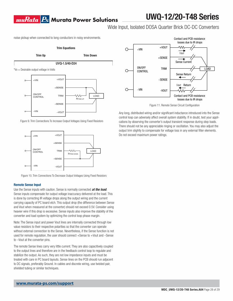
Trimming Output VoltageUWQ converters have a trim capability (pin 6) that enables users to adjust the output voltage from +10% to –10% (refer to the trim equations in the table below). Adjustments to the output voltage can be accomplished with a single fixed resistor as shown in Figures 9 and 10. A single fixed resistor can increase or decrease the output voltage depending on its connection. Resistors should be located close to the converter and have TCR’s less than 100ppm/°C to minimize sensitivity to changes in temperature. If the trim function is not used, leave the trim pin open.
Standard UWQs have a “positive trim” where a single resistor connected from the Trim pin (pin 6) to the +Sense (pin 7) will increase the output voltage. A resistor connected from the Trim Pin (pin 6) to the –Sense (pin 5) will decrease the output voltage.
Trim adjustments greater than the specified +10%/–10% can have an adverse affect on the converter’s performance and are not recommended. Excessive volt-age differences between VOUT and Sense, in conjunction with trim adjustment of the output voltage, can cause the overvoltage protection circuitry to activate (see Performance Specifications for overvoltage limits).
Temperature/power derating is based on maximum output current and voltage at the converter’s output pins. Use of the trim and sense functions can cause output voltages to increase, thereby increasing output power beyond the UWQ’s speci-fied rating, or cause output voltages to climb into the output overvoltage region. Therefore:
(VOUT at pins) x (IOUT) ≤ rated output power
The Trim pin (pin 6) is a relatively high impedance node that can be susceptible to
UWQ-12/20-T48 SeriesWide Input, Isolated DOSA Quarter Brick DC-DC Converters
MDC_UWQ-12/20-T48 Series.A04 Page 28 of 29
www.murata-ps.com/support
noise pickup when connected to long conductors in noisy environments.
Remote Sense Input Use the Sense inputs with caution. Sense is normally connected at the load. Sense inputs compensate for output voltage inaccuracy delivered at the load. This is done by correcting IR voltage drops along the output wiring and the current carrying capacity of PC board etch. This output drop (the difference between Sense and Vout when measured at the converter) should not exceed 0.5V. Consider using heavier wire if this drop is excessive. Sense inputs also improve the stability of the converter and load system by optimizing the control loop phase margin.
Note: The Sense input and power Vout lines are internally connected through low value resistors to their respective polarities so that the converter can operate without external connection to the Sense. Nevertheless, if the Sense function is not used for remote regulation, the user should connect +Sense to +Vout and –Sense to –Vout at the converter pins.
The remote Sense lines carry very little current. They are also capacitively coupled to the output lines and therefore are in the feedback control loop to regulate and stabilize the output. As such, they are not low impedance inputs and must be treated with care in PC board layouts. Sense lines on the PCB should run adjacent to DC signals, preferably Ground. In cables and discrete wiring, use twisted pair, shielded tubing or similar techniques.
Any long, distributed wiring and/or significant inductance introduced into the Sense control loop can adversely affect overall system stability. If in doubt, test your appli-cations by observing the converter’s output transient response during step loads. There should not be any appreciable ringing or oscillation. You may also adjust the output trim slightly to compensate for voltage loss in any external filter elements. Do not exceed maximum power ratings.
Figure 11. Remote Sense Circuit Configuration
LOAD
Contact and PCB resistance losses due to IR drops
Contact and PCB resistance losses due to IR drops
+VOUT
+SENSE
TRIM
−SENSE
-VOUT
+VIN
ON/OFFCONTROL
–VIN
Sense Current
I OUT
Sense Return
I OUT Return
LOADRTRIM UP
+VOUT+VIN
–VIN
ON/OFFCONTROL TRIM
+SENSE
–VOUT
–SENSE
Figure 9. Trim Connections To Increase Output Voltages Using Fixed Resistors
LOADRTRIM DOWN
+VOUT+VIN
–VIN
ON/OFFCONTROL TRIM
+SENSE
–VOUT
–SENSE
Figure 10. Trim Connections To Decrease Output Voltages Using Fixed Resistors
UP VO – 3.3RT (kΩ) = –10.2
13.3(VO – 1.226)
3.3 – VO RT (kΩ) = –10.2
16.31DOWN
UP VO – 5RT (kΩ) = –10.2
20.4(VO – 1.226)5 – VO
RT (kΩ) = –10.225.01
DOWN
UP VO – 12RT (kΩ) = –10.2
49.6(VO – 1.226)
12 – VO RT (kΩ) = –10.2
60.45DOWN
UP VO – 15RT (kΩ) = –10.2
62.9(VO – 1.226)15 – VO
RT (kΩ) = –10.276.56
DOWN
UP VO – 18RT (kΩ) = –10.2
75.5(VO – 1.226)18 – VO
RT (kΩ) = –10.292.9
DOWN
UVQ-3.3/35-D48
UVQ-5/25-D24, UVQ-5/20-D48
UVQ-12/8-D24, -12/10-D48
UVQ-15/7-D24, -D48
UVQ-18/5.6-D24, -18/6-D48
UP VO – 2.5RT (kΩ) = –10.2
10(VO – 1.226)
2.5 – VO RT (kΩ) = –10.2
12.26DOWN
UVQ-2.5/40-D48, UVQ-2.5/35-D24
UVQ-1.5/40-D24
UP VO – 1.5RT (kΩ) = –10.2
6.23(VO – 1.226)
1.5 – VO RT (kΩ) = –10.2
7.64DOWN
101(VO – 1.226)UP VO – 24
RT (kΩ) = –10.224 – VO
RT (kΩ) = –10.2124.2
DOWN
UVQ-24/4.5-D24, -D48
210.75(VO – 1.226)UP VO – 48
RT (kΩ) = –10.248 – VO
RT (kΩ) = –10.2250
DOWN
UVQ-48/2.5-D24, -D48
Trim Up Trim Down
Trim Equations
*Vo = Desirable output voltage in Volts
Soldering Guidelines
Murata Power Solutions recommends the specifications below when installing these converters. These specifications vary depending on the solder type. Exceeding these specifications may
cause damage to the product. Your production environment may differ; therefore please thoroughly review these guidelines with your process engineers.
Wave Solder Operations for through-hole mounted products (THMT)
For Sn/Ag/Cu based solders: For Sn/Pb based solders:
Maximum Preheat Temperature 115° C. Maximum Preheat Temperature 105° C.
Maximum Pot Temperature 270° C. Maximum Pot Temperature 250° C.
Maximum Solder Dwell Time 7 seconds Maximum Solder Dwell Time 6 seconds
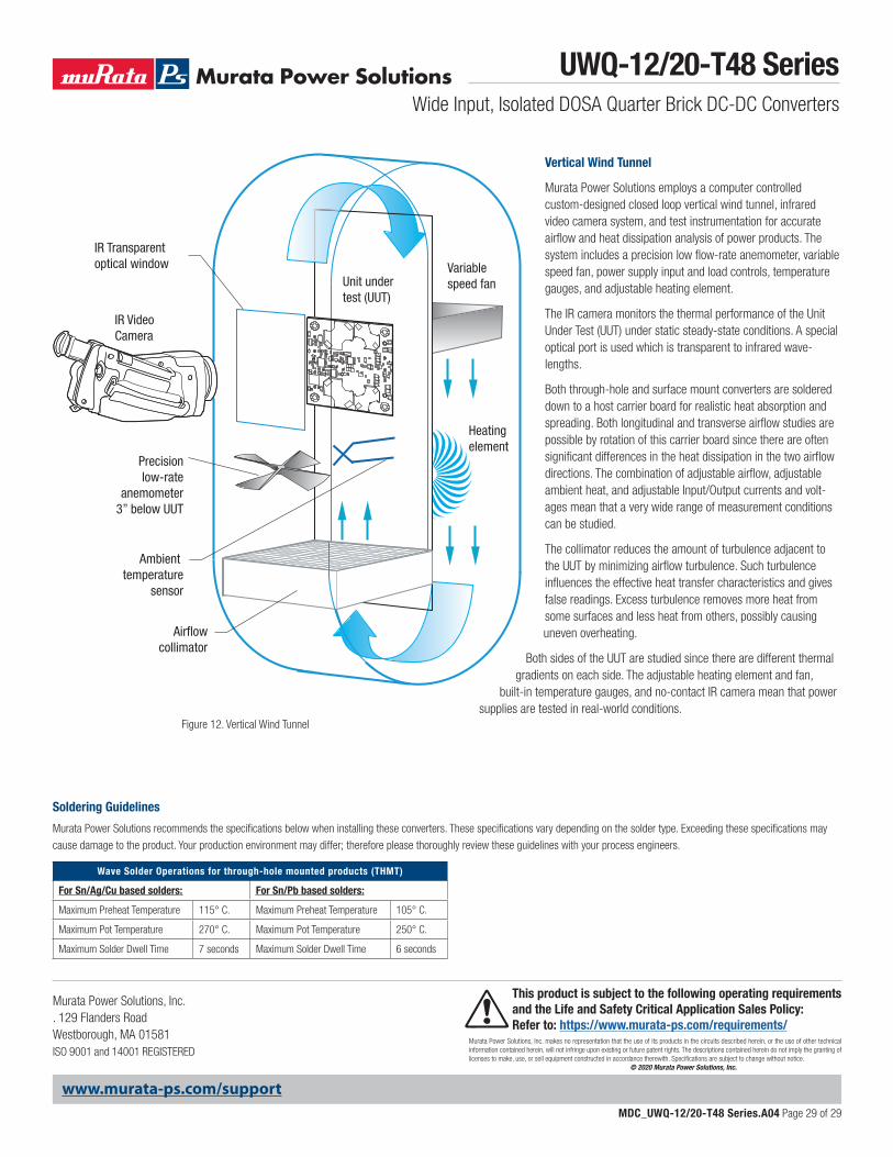
Figure 12. Vertical Wind Tunnel
IR Video Camera
IR Transparentoptical window Variable
speed fan
Heating element
Ambient temperature
sensor
Airflowcollimator
Precisionlow-rate
anemometer3” below UUT
Unit undertest (UUT)
Vertical Wind Tunnel
Murata Power Solutions employs a computer controlled custom-designed closed loop vertical wind tunnel, infrared video camera system, and test instrumentation for accurate airflow and heat dissipation analysis of power products. The system includes a precision low flow-rate anemometer, variable speed fan, power supply input and load controls, temperature gauges, and adjustable heating element.
The IR camera monitors the thermal performance of the Unit Under Test (UUT) under static steady-state conditions. A special optical port is used which is transparent to infrared wave-lengths.
Both through-hole and surface mount converters are soldered down to a host carrier board for realistic heat absorption and spreading. Both longitudinal and transverse airflow studies are possible by rotation of this carrier board since there are often significant differences in the heat dissipation in the two airflow directions. The combination of adjustable airflow, adjustable ambient heat, and adjustable Input/Output currents and volt-ages mean that a very wide range of measurement conditions can be studied.
The collimator reduces the amount of turbulence adjacent to the UUT by minimizing airflow turbulence. Such turbulence influences the effective heat transfer characteristics and gives false readings. Excess turbulence removes more heat from some surfaces and less heat from others, possibly causing uneven overheating.
Both sides of the UUT are studied since there are different thermal gradients on each side. The adjustable heating element and fan,
built-in temperature gauges, and no-contact IR camera mean that power supplies are tested in real-world conditions.
UWQ-12/20-T48 SeriesWide Input, Isolated DOSA Quarter Brick DC-DC Converters
MDC_UWQ-12/20-T48 Series.A04 Page 29 of 29
www.murata-ps.com/support
Murata Power Solutions, Inc. makes no representation that the use of its products in the circuits described herein, or the use of other technical information contained herein, will not infringe upon existing or future patent rights. The descriptions contained herein do not imply the granting of licenses to make, use, or sell equipment constructed in accordance therewith. Specifications are subject to change without notice. © 2020 Murata Power Solutions, Inc.
Murata Power Solutions, Inc. . 129 Flanders RoadWestborough, MA 01581 ISO 9001 and 14001 REGISTERED
This product is subject to the following operating requirements and the Life and Safety Critical Application Sales Policy: Refer to: https://www.murata-ps.com/requirements/