Using infrared based relative navigation for active debris ...
18
City, University of London Institutional Repository Citation: Yilmaz, O., Aouf, N. ORCID: 0000-0001-9291-4077, Majewski, L., Sanchez- Gestido, M. and Ortega, G. (2017). Using infrared based relative navigation for active debris removal. Paper presented at the 10th International ESA Conference on Guidance, Navigation and Control Systems, 29 May - 02 Jun 2017, Salzburg, Austria. This is the published version of the paper. This version of the publication may differ from the final published version. Permanent repository link: https://openaccess.city.ac.uk/id/eprint/22093/ Link to published version: Copyright: City Research Online aims to make research outputs of City, University of London available to a wider audience. Copyright and Moral Rights remain with the author(s) and/or copyright holders. URLs from City Research Online may be freely distributed and linked to. Reuse: Copies of full items can be used for personal research or study, educational, or not-for-profit purposes without prior permission or charge. Provided that the authors, title and full bibliographic details are credited, a hyperlink and/or URL is given for the original metadata page and the content is not changed in any way. City Research Online
-
Upload
khangminh22 -
Category
Documents
-
view
1 -
download
0
Transcript of Using infrared based relative navigation for active debris ...

City, University of London Institutional Repository
Citation: Yilmaz, O., Aouf, N. ORCID: 0000-0001-9291-4077, Majewski, L., Sanchez-Gestido, M. and Ortega, G. (2017). Using infrared based relative navigation for active debris removal. Paper presented at the 10th International ESA Conference on Guidance, Navigation and Control Systems, 29 May - 02 Jun 2017, Salzburg, Austria.
This is the published version of the paper.
This version of the publication may differ from the final published version.
Permanent repository link: https://openaccess.city.ac.uk/id/eprint/22093/
Link to published version:
Copyright: City Research Online aims to make research outputs of City, University of London available to a wider audience. Copyright and Moral Rights remain with the author(s) and/or copyright holders. URLs from City Research Online may be freely distributed and linked to.
Reuse: Copies of full items can be used for personal research or study, educational, or not-for-profit purposes without prior permission or charge. Provided that the authors, title and full bibliographic details are credited, a hyperlink and/or URL is given for the original metadata page and the content is not changed in any way.
City Research Online

City Research Online: http://openaccess.city.ac.uk/ [email protected]

USING INFRARED BASED RELATIVE NAVIGATION FOR ACTIVE DEBRIS REMOVAL
Ozgun Yılmaz(1), Nabil Aouf(1), Laurent Majewski(2), Manuel Sanchez-Gestido(3), GuillermoOrtega(3)
(1) Cranfield University, Shrivenham United Kingdom, {o.yilmaz,n.aouf}@cranfield.ac.uk(2) SODERN, Limeil-Brevannes France, Email: [email protected]
(3) European Space Agency, Noordwijk The Netherlands, Email: [email protected]
ABSTRACT
A debris-free space environment is becoming a necessity for current and future missions and ac-tivities planned in the coming years. The only means of sustaining the orbital environment at asafe level for strategic orbits (in particular Sun Synchronous Orbits, SSO) in the long term is bycarrying out Active Debris Removal (ADR) at the rate of a few removals per year.
Infrared (IR) technology has been used for a long time in Earth Observations but its use fornavigation and guidance has not been subject of research and technology development so farin Europe. The ATV-5 LIRIS experiment in 2014 carrying a Commercial-of-The-Shelf (COTS)infrared sensor was a first step in de-risking the use of IR technology for objects detection inspace. In this context, Cranfield University, SODERN and ESA are collaborating on a researchto investigate the potential of IR-based relative navigation for debris removal systems. This paperreports the findings and developments in this field till date and the contributions from the threepartners in this research.
1 INTRODUCTION
The precise relative navigation of a chaser spacecraft towards a dead satellite is one of the most dif-ficult tasks to accomplish within an ADR mission, due to the fact that target is uncooperative and ingeneral in an unknown state [1]. The current Guidance Navigation & Control (GNC) systems technol-ogy can handle cooperative rendezvous, but for an ADR mission the number of unknowns is greaterthan an ordinary mission and further developments are needed [2].
Since there are more uncertainties in the navigation function of an ADR mission, it is favourable tohave continuous measurements which would require sensors working in all environmental conditionspossible [3]. The vision-based cameras, which are already suffering from poor illumination condi-tions even in cooperative rendezvous with 3-axis stabilized target holding fiducial markers, cannotmatch the IR cameras that can perform in all possible illumination conditions of ADR. An infraredcamera can overcome the illumination problem by providing information without any discontinuityas it does not depend on external light source but the emitted radiation.
ESA GNC 2017 – O. Yılmaz 1

Figure 1: Infrared image of International Space Station from LIRIS experiment (courtesy ofSODERN) [5]
Long wave infrared (LWIR) imaging techniques offer many potential benefits when applied to theremote sensing of space debris. Imaging space objects in the LWIR band has the inherent advantageof not being dependent upon constant Solar or Earth illumination which makes the observations andmeasurements possible even when observed objects are in eclipse. This fact had been confirmed byATV-5 LIRIS experiment data [4][5] in which International Space Station (ISS) could be observed inany illumination conditions (Figure 1).
The appearance of objects under Sun direct illumination is expected to be smoother in infrared whencompared to the reflection of visible light on reflecting surfaces like multi-layer insulation. Imagingspace objects in the LWIR band may also allow for the imaging of objects looking at with the Sun inthe field of view without saturation of the imaging system and also without permanent damage. Sochallenges in terms of illumination changes could be dealt with using an infrared-based rendezvoussensor providing navigation data for flexible relative navigation and guidance to targets.
2 ACTIVE DEBRIS REMOVAL CONCEPT
The Active Debris Removal missions can be considered as a variant of Rendezvous and Docking(RvD) missions where the target is uncooperative meaning that there are no fiducial markers on targetand relative orientation of target cannot be known [6]. Furthermore, the targets would be most likelyold satellites where available geometrical model may not fit to actual orbiting body due to changes inits configuration at time of its launch or target may have experienced a collision which changed itsgeometry. In broad context, such mission would consist of seven phases: rendezvous, inspection, fly-around, final approach, capture, stabilisation and de-orbiting ([7]). A representative mission profileup to capture had been depicted in Figure2 however reader shall be aware that it is just for visualisa-tion purposes in order to ease the text and an actual mission could have a slightly different trajectorydepending on target attributes.
In the rendezvous phase, chaser spacecraft transfers to target orbit and phases with the target object.In the beginning of this phase, the chaser spacecraft would use the absolute navigation system whichwould be handed over to a relative navigation system towards the end. Considering the uncooperative
ESA GNC 2017 – O. Yılmaz 2

[A]
[B]
[E][D]
[C][H]
Chaser Space Debris
[G] [F]
[I]
Figure 2: Graphical representation of Active Debris Removal at close proximity operations
nature of the target, the chaser would only be able to use active sensors like LIDAR which has morelimitations on target range or passive sensors like camera [8] in the relative navigation part. At theend of this, the chaser would be at holding point-[A] (Figure2).
In the inspection phase, the chaser could observe space debris for the required amount of time togather enough information to enable the planning of the further steps of the ADR. At this stage, nav-igation algorithm is expected to provide relative position and velocity of the chaser in target LocalVertical Local Horizontal (LVLH) frame and could benefit from infrared based techniques. This phasecould involve some sort of approach like depicted as phase-[B] (Figure2) to allow better inspection ifthe navigation solution require such.
The fly around phase is to verify the information gathered in the inspection phase. It is most likely tohappen in the same orbital plane in order to keep fuel consumption at minimum. The fly-around phaseis used to determine the attitude rate of the target and match it [9][10][11]. This phase is needed toidentify the best possible place to initiate the capture and could benefit from infrared based techniquesto accurately and autonomously determine the best capture pose. In order to do so, the chaser couldstay in a hold point-[C] at the end of fly around phase if the navigation algorithm required to do so.
The final approach and capture depends on the estimated motion of the target as the chaser needs to bealigned with the target. Even though the accuracy of the alignment depends on the target attitude, thispart is one of the most challenging part of the mission for the cases where the targe tumbles and the
ESA GNC 2017 – O. Yılmaz 3
measurement updates play a crucial role for Guidance, Navigation and Control (GNC) perspective.In Figure2, this phase is depicted as phase-[H] and phase-[I]. In this sample trajectory, the target istumbling around H-bar of LVLH frame and therefore approach could be in plane. However, suchconditions would be the best case of ADR for final approach and also the least likely to happen inreality.
In the stabilisation and de-orbiting case, the chaser aims to damp the tumbling motion of the target inorder to control the target to de-orbit by provided de-orbiting mechanism (e.g. solar sailing, electrictether) of the ADR mission.
3 CHASER NAVIGATION
The proposed chaser sensing suite used in this research activity has been classified into long range,medium range, and close range sensors. For an ADR mission, the ESA proposed sensing suite se-lected is composed of two star trackers (STR), two Inertial Measurement Units (IMU), two infraredcameras (IRCAM), two Light Detection And Ranging (LIDAR) units, and one Global PositioningService (GPS) receiver. Except the GPS which can only provide information about absolute position-ing, all other equipments are provided with their redundancy for the safety of the mission. Therefore,navigation algorithms shall be designed only for single equipment meaning that stereo vision wouldnot be applicable for the study. Sun acquisition is obtained by the mounting of Digital Sun Sensors(DSS).
The algorithms can be embedded in smart sensors providing the navigation data expected from theirsensing. This is already the case for star trackers and smart cameras embedding image processing upto 6 DoF pose measurement are expected in near future.
The IMU and the STR would provide classic absolute navigation as well as redundancy for the phas-ing part of the rendezvous and the fly around part. These sensors will also provide a navigationsolution during the capture and during the de-orbiting part. The objective of the GPS receiver is tomeasure the absolute position during phasing and shall act as long-range sensor. The LIDAR providesthe measurements of the relative distance with the target at close range. On the other hand, infraredand visual cameras support the navigation solution from rendezvous until the capture phase.
The infrared sensor used in this research is similar to the ones flown on the ESA-Airbus-SODERN-JenaOptronik experiment called LIRIS [4]. LIRIS was a test of European sensors technology in spaceto improve the autonomous rendezvous and docking that ATVs have performed five times since 2008for future noncooperative rendezvous. The experiment had one LIDAR provided by JenaOptronikfrom Germany, one visual camera and two infrared cameras provided by SODERN from France.
4 TARGET ILLUMINATION
Target illumination is an important constraint for visual navigation in space applications. There aretwo different cases where visual navigation systems fails: certain chaser-target-sun geometries and
ESA GNC 2017 – O. Yılmaz 4

Figure 3: Unfavourable illumination condition effects in visual camera
eclipse/shadowing. Some space surface coatings have specular reflection properties, combining withdirect solar illumination they can saturate the visual detectors depending on the chaser-target-sungeometry such as one envisaged in Figure3. This unavoidable case causes problems for visual navi-gation which looks for visual cues.
In the study of [12] which is a navigation algorithm for partially cooperative targets, it had been shownthat the accuracy varies by three folds in close range depending on the target illumination conditionand was suggested to be more for farther targets. In the case of eclipse/shadowing, target is either par-tially or fully not observable therefore there is not enough visual cues to be used in navigation filter.Shadowing can be due to the geometry of the target by self obstruction or in close range to chaser’sshadow on the target due to chaser-target-sun geometry. For certain cases, this lack of measurementcan be somehow tolerated depending on its duration. However, the navigation filter would be lesstolerant to the uncertainties in the modelling of the orbital dynamics. Considering the dynamics ofrelative navigation, such confidence in process model is not actually viable to rely on it.
Unfortunately, the target illumination conditions of an ADR scenario are more challenging than an or-dinary cooperative rendezvous mission because avoiding such geometries by mission planning cannotbe enforced for various reasons. There are more uncertainties in the system as the target is uncooper-ative and our knowledge about the target is limited. In the absence of measurement, risk of collisionincreases with time and employing mission abort algorithms shall be implemented [13]. [14] sug-gests that the chaser shall keep free drift or hold on points and do not start any new trajectory whenthe measurements are not available. The constraints on ADR for close approach trajectory due tosolar illumination had been briefly discussed in [3] [14] where the chaser shadowing on target hadbeen one of the concerns. However, [3] also underlines that the chaser’s Guidance, Navigation andControl (GNC) system is required to be operational with good performance in all illumination con-ditions since the favourable illumination conditions cannot be guaranteed for ADR targets. Such
ESA GNC 2017 – O. Yılmaz 5

unfavourable conditions during the approach are due to the trajectory design which depends on thetarget attitude profile. [14] suggests that only one fourth of the orbit for Low Earth Orbiting (LEO)ADR targets would have favourable illumination conditions. Considering other constraints on GNCsystem, it is very much desired to relax the navigation algorithm from illumination conditions pointof view.
5 INFRARED IMAGING FACTS
Depending on the temperature, all objects above absolute zero temperature emit electromagnetic ra-diation in their corresponding spectrum and thermal infrared imagers converts this radiation to imageintensity values.
There are two major types of sensing tools for thermal/infrared radiation: thermal detectors and pho-todetectors. In the case of thermal detectors, responsive elements are sensitive to temperature changesto measure the radiative fluctuations (e.g. bolometers, thermocouples . . . etc) whereas photodetec-tors respond to variations in the number of incident photons (e.g. HgCdTe photodetectors) [15].Among all, uncooled microbolometers which measure the resistive changes due to thermal radiationare known to be widely used in terrestrial applications since they could provide sufficient sensitivityat low-cost [16]. By considering the cost effectiveness and its promising use in space applications [4][17], this study focuses on performance of uncooled microbolometer technology.
For infrared imagery, [18] defined four main challenges for working with Infrared images such as”Low SNR-Low Resolution”, ”Infrared Reflection”, ”Halo Effect/Saturation” and ”History Effects”.As it is described ”Halo Effect/Saturation” occurs around the objects with high contrast and could bedifficult not to associate with the object but this applies to ferroelectric sensors, not microbolometers.The other most important challenge is the ”History Effects” which potentially disqualify the use ofbrightness constancy concept used in optical flow algorithm.
In the context of ADR applications, Infrared imageries also encounter different thermal dynamicscompared to their terrestrial counterparts. The targets Space Debris change their temperature pro-file over an orbit (with duration down to 90 minutes) as their geometry with Sun varies over time.Moreover, the man-made materials covering the debris surface also show different response charac-teristics throughout these quasi-cyclic thermal profiles which makes the thermal scene quite dynamicand unique.
6 INFRARED BASED ADR
In space, thermal environment changes very fast and depends on many parameters which we cannotknow perfectly for ADR targets [19]. Even though ADR target exact thermal signature cannot beknown, calculations and flown experiments [17][4] suggest that we can observe spacecraft with in-frared cameras. However, we have to keep in mind the thermal environment challenges to design aproper navigation system. In our study, we addressed this challenge by assuming the target infrared
ESA GNC 2017 – O. Yılmaz 6
appearance model is not available to the navigation algorithm.
Even though the target infrared appearance model is not available, [19] showed that the point featurescan still be used for target tracking and possibly for recognition purposes. This lead us to a differentapproach than the earlier model based tracking approaches [20].
Simultaneous Localisation and Mapping (SLAM) is a concept in which the map and the relative po-sition of the observer with respect to this map are estimated at the same time. In relative navigationof chaser for ADR scenario, the map would be infrared features that are detected on the target surfaceto which chaser would like to know the relative position. We follow the Bayesian filtering approachfor the estimation purposes.
The problem had been described by the state vector of 6 +N parameters as in Equ-1 with 6 mo-tion parameters (Tx, Ty, Tz, ωz, ωx, ωy, ωz, ) and N structure parameters (α1
w, α2w, . . . , α
Nw ) where the
global rotation and the 2D points of reference frame (i.e. first frame) has been kept outside the estima-tion. In order to account the effect of camera focal length on the sensitivity of the image plane motionto camera motion along Tz, the estimation of translation has been performed by Tzβ parametrisation.
x = (Tx, Ty, Tzβ, ωz, ωx, ωy, ωz, α1w, α
2w, . . . , α
Nw ) (1)
Due to the unexpected dynamics of space debris, the process model has been considered as identitymatrix and the inter-frame motion has been modelled with process noise for motion parameters whilethe landmarks has been kept static as they are part of the space debris rigid body.
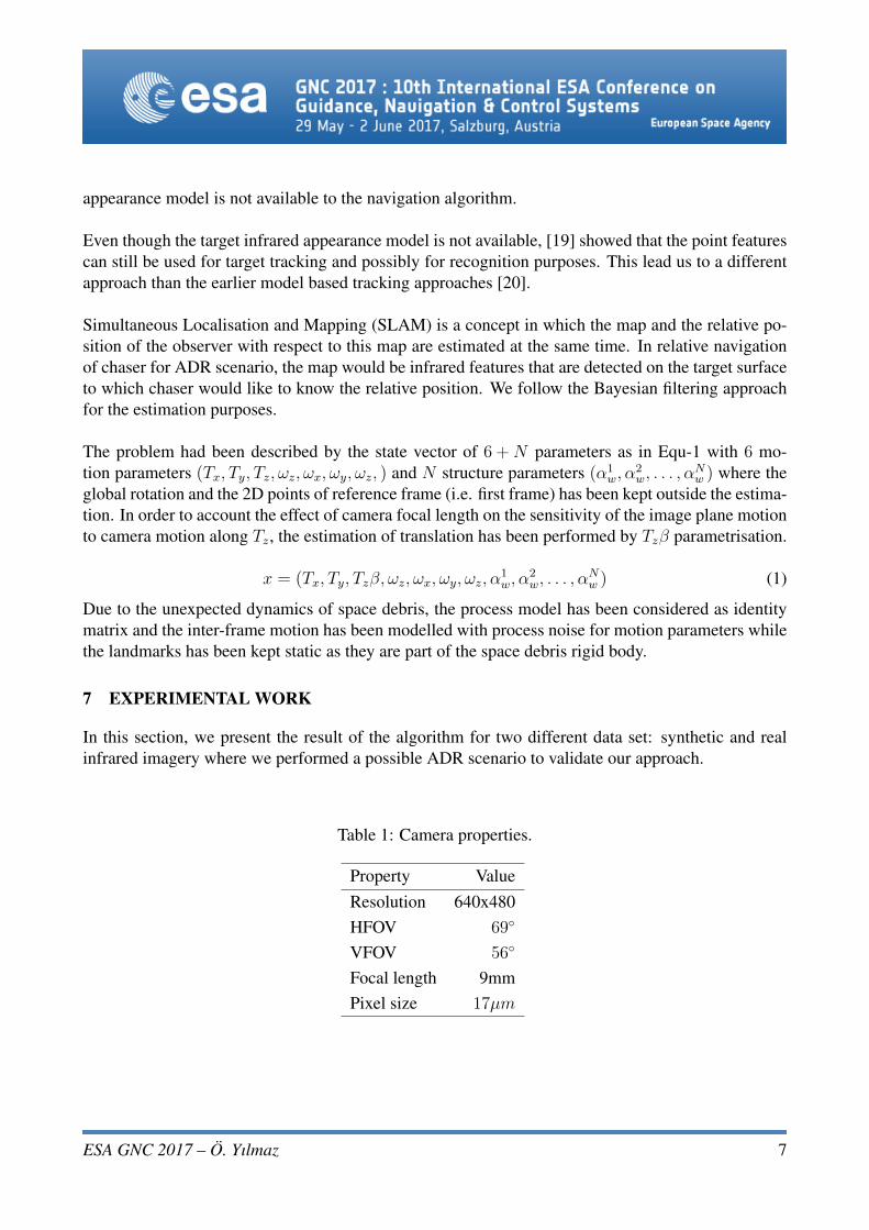
7 EXPERIMENTAL WORK
In this section, we present the result of the algorithm for two different data set: synthetic and realinfrared imagery where we performed a possible ADR scenario to validate our approach.
Table 1: Camera properties.
Property ValueResolution 640x480HFOV 69◦
VFOV 56◦
Focal length 9mmPixel size 17µm
ESA GNC 2017 – O. Yılmaz 7

0 1000 2000 3000 4000 5000 6000 7000 8000
time step
-16
-14
-12
-10
-8
-6
-4
-2
0
2
4
[m]
X
Y
Z
Ground Truth
Figure 4: Translational motion of the chaser respect to camera position at first frame
7.1 Synthetic Dataset
This scenario simulates forced translation manoeuvres of the close proximity phase including eightcorrection manoeuvres which were reflected in 2D projections by sudden changes at the directionof the features’ motion fields. In Figure5, only five of these manoeuvres could be observed as weonly plotted a limited number of chaser positions for clarity reasons. These manoeuvres would beexpected in real scenario due to the close loop control nature of the chaser GNC system. Simulationtarget range starts from 20 meters and continues until four meter to target.
In order to have a controlled environment in our analysis, we had generated nine synthetic 3D pointsand then projected them into 2D image points for a camera with properties given in Table-3. To ac-count for the feature tracking errors, the pixel noise N (0, σ2) had been added into the 2D projectionwhere σ = 0.15pixel. In order to be more realistic in our simulations we had also pre-processed thegenerated 2D points such that features occasionally disappeared from the virtual image for a certainperiod of time. This modification imitated a quite possible problem of feature tracking algorithms:loosing the feature during the tracking. During this process, we had assumed to know the data asso-ciation between the filter states and the projected features in the virtual frame.
Figure4 and Figure5 show the translational motion of the chaser with respect to world coordinateframe. The ground truth in all axes is represented with the black line. As it would be expected frommonocular camera estimations, some error accumulation along the Z-axis had been observed overtime. In earlier time steps, one can also observe the small erroneous fluctuations along the Z-axis.This is due to relation between erroneous measurements with their range as the error would be ampli-fied for farther distances due to camera projection geometry.
ESA GNC 2017 – O. Yılmaz 8

Figure 5: Estimated translational motion of the chaser with respect to camera position at first frame(world frame) in 3D
Between time steps 4000 and 7000, the error along the X-axis had been increased. At the time step4000, all disappeared features re-appeared again. Therefore, the error along the Y-axis could be linkedto the increased uncertainty on those features which were not updated for a while with the relevantmeasurements. As these features started to disappear from the image, the filter started to be influencedby states which were observed for a longer duration leading to recover the error along the Y-axis.
Figure6 shows the estimation of the feature depths which are represented by different colours andblack is the ground truth. At the end of the sequence, all feature depths had error of approximately
Figure 6: Feature depths with respect to world frame. Each colour represent one feature.
ESA GNC 2017 – O. Yılmaz 9

Table 2: Robotic arm properties.
Property ValueReach 850mm
Payload ≤ 5kg
Repeatability ±0.1mm
0.2 meters which is aligned with the error in translational motion estimation along the Z-axis. How-ever, one can clearly see that the ratio between the depths of features were also somehow kept forthe estimations. This finding was also expected since the scene can be recovered only up to scale byusing monocular camera [21].
7.2 Real Infrared Imagery Dataset
To verify and validate some of the concepts of this research, some experiments have been conductedat the ESTEC GNC Testing Facilities located in Noordwijk, the Netherlands. Our experimental set-upconsists of a collaborative robotic arm (Table 2) that is hang on a static robotic arm, thermally repre-sentative target placed on a stand, a LWIR camera (Table 3) and a laptop to store our data (Figure 7).Currently the TCP/IP connection of the camera is used at the hardware laboratory of ESTEC to linkit with a PC containing the Xeneth Software for camera usage. In order to collect precise positioningof the robotic arm which is holding the camera, we have used the Vicon Motion Capture System (VI-CON) 1 which consist of seven near infrared cameras and small balls with reflective coating to trackthe camera and our target. These balls were not affecting our algorithm since our infrared camerais passive however VICON system required very delicate calibration due to optical properties of ourtarget coatings.
Since we had performed our analysis in air, we had achieved the required contrast by heating thetarget which is a rectangular prism (192× 111× 61mm) (Figure8). The target holds surface coat-ing with different emissivity values which provided sufficient contrast at higher temperatures. Wedemonstrated the performance of the algorithm for the scaled version of phase-[H] (Figure2) whichcould typically run for 15-20 minutes. Considering the limitations of the facility such trajectory hadbeen scaled to an experimental run by 1 : 25 which is completed in ≈ 150s and every fifth frame wasconsidered as the measurement. As a result, our scaled set-up would correspond to the measurementrate of ≈ 1Hz in orbital case.
Figure9 and Figure10 show the translational motion of the chaser with respect to world coordinateframe. The ground truth in all axes is represented with the black line. As it would be expected from
1https://www.vicon.com/
ESA GNC 2017 – O. Yılmaz 10
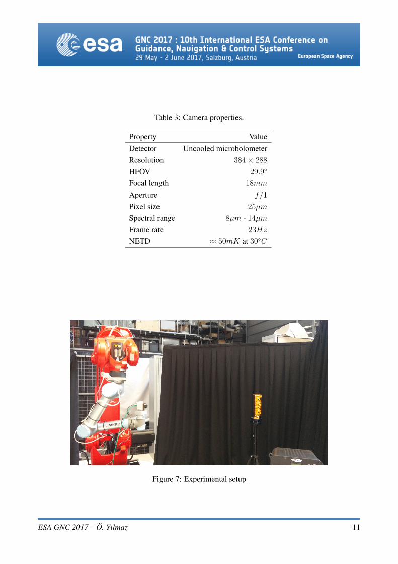
Table 3: Camera properties.
Property ValueDetector Uncooled microbolometerResolution 384× 288
HFOV 29.9◦
Focal length 18mm
Aperture f/1
Pixel size 25µm
Spectral range 8µm - 14µmFrame rate 23Hz
NETD ≈ 50mK at 30◦C
Figure 7: Experimental setup
ESA GNC 2017 – O. Yılmaz 11

Figure 8: Target in visual (right) and infrared with contrast enhancement of the image acquisitionsoftware(left)
monocular camera estimations, some error accumulation along the Z-axis had been observed overtime. For camera systems, the accuracy of the system increases as the sensor gets closer to the targettherefore the initial estimation errors along X-axis and Y-axis decrease over time.
However, the contribution of the poor resolution and wide pixel size factor of the infrared camerathat was used during the experiment (384× 288pixel) shall not be forgotten as the error sources. Inthese kinds of low pixel resolution images the error in image extraction algorithm would have moreimpact comparing to images of finer detectors. Generally speaking, visual cameras that are used invision community would most likely have better resolution (e.g. 1024× 1024pixel and 6µm) whichwould also provide more accurate results. Furthermore, used camera had a very shallow depth of fieldin which the target was in focus for only certain period of time during the trajectory. Since we hadimplemented the variations in state parameters as noise which includes focal length, focus adjustmentduring the course of this experiment would have other complications in the algorithm. To deal withknown error sources, we kept the focusing adjustment for 1.1m range which corresponds to last 50sof the trajectory. The performance of feature detection algorithms decreases with the amount of blur.In our case, initial frames are the most blurred ones therefore the measurements are more misleading.Considering that monocular vision cannot resolve the depth information, poor recovery of depth wasexpected since the estimated depth at the time of focused images would be erroneous.
8 CONCLUSIONS AND FUTURE WORK
The paper showed the review of the state of the art literature in all areas relating to the problem withADR scenarios, applications, and missions. Then the current ADR proposed missions and the roleof Infrared-based navigation for them were explained. The paper explained that the appearance ofobjects under Sun direct illumination is expected to be smoother in infrared when compared to thereflection of visible light on reflecting surfaces like multi-layer insulation.
ESA GNC 2017 – O. Yılmaz 12

Figure 9: Translational motion of the chaser with respect to camera position at first frame for realinfrared imagery
Figure 10: Estimated translational motion of the chaser with respect to camera position at first frame(world frame) in 3D for real infrared imagery
ESA GNC 2017 – O. Yılmaz 13

In such cases, thermal imagery has advantages over visual sensors. It can provide continuous informa-tion without getting affected by the illumination conditions like eclipse, partial illumination and solarglare. Infrared imagery acquires information about thermal appearance of the target and can providecontinuous measurement. This is very beneficial for cases especially like in ADR where there aremore unknowns then many different types of rendezvous.
In this study, we have seen that infrared imagery could provide sufficient information for relativenavigation purposes in ADR. However, it is very important to have more real space imagery dataespecially from real space debris to verify developed algorithms. LIRIS experimental data shall beanalysed with care as the subject of interest is not actually a space debris and may have more op-timistic conditions. We have also shown that the SLAM based approach are suitable for infraredimagery where the target appearance model cannot be provided due several reasons. Therefore, it isconsidered to be more tolerant to the unknowns of ADR and infrared based ADR. The initialisationof this approach would be faster and computationally less heavy than model based approaches sinceit will use all available data.
The current state of the algorithm being developed can perform for relative translational motionsbetween chaser and target for a rotationally static target with any relative orientation with respect tothe chaser. As future work, the approach will be developed further for the cases where the target istumbling in order to encapsulate wider range of target attitude .
9 ACKNOWLEDGEMENT
The study has been funded and supported by European Space Agency and Sodern under NetworkPartnership Initiative program with grant number NPI 342-2014.
Authors would like to thank Shubham Vyas and Jan Smissek for their support during the experimentalset-up.
REFERENCES
[1] C. Bonnal, J.-M. M. Ruault, and M.-C. C. Desjean, “Active debris removal: Recent progressand current trends,” Acta Astronautica, vol. 85, pp. 51–60, apr 2013. [Online]. Available:http://www.sciencedirect.com/science/article/pii/S0094576512004602
[2] K. Wormnes, R. L. Letty, L. Summerer, R. Schonenborg, E. Luraschi, A. Cropp, H. Krag, andJ. Delaval, “ESA Technologies For Space Debris Remediation,” in Proceedings of the 6th IAASSConference: Safety is Not an Option, 2006.
[3] J. A. F. Deloo and E. Mooij, “Active debris removal : Aspects of trajectories , communicationand illumination during final approach,” Acta Astronautica, vol. 117, pp. 277–295, 2015.[Online]. Available: http://dx.doi.org/10.1016/j.actaastro.2015.08.001
ESA GNC 2017 – O. Yılmaz 14
[4] B. Cavrois, A. Vergnol, A. Donnard, P. Casiez, U. Southivong, O. Mongrard, F. Ankersen,C. Pezant, P. Bretecher, F. Kolb, and M. Windmuller, “LIRIS demonstrator on ATV5 : a stepbeyond for European non cooperative navigation system,” in AIAA Guidance, Navigation, andControl Conference, 2015.
[5] L. Infrared, “Space In Images,” 2014. [Online]. Available: http://www.esa.int/spaceinimages/Images/2014/12/LIRIS{\ }infrared
[6] D. Kucharski, G. Kirchner, F. Koidl, C. Fan, R. Carman, C. Moore, A. Dmytrotsa, M. Ploner,G. Bianco, M. Medvedskij, A. Makeyev, G. Appleby, M. Suzuki, J. M. Torre, Z. Zhongping,L. Grunwaldt, and Q. Feng, “Attitude and spin period of space debris envisat measured bysatellite laser ranging,” IEEE Transactions on Geoscience and Remote Sensing, vol. 52, no. 12,pp. 7651–7657, 2014.
[7] S.-i. Nishida, S. Kawamoto, Y. Okawa, F. Terui, and S. Kitamura, “Space debris removal systemusing a small satellite,” Acta Astronautica, vol. 65, pp. 95–102, 2009.
[8] W. Fehse, Automated Rendezvous and Docking of Spacecarft, 1st ed. Cambridge: CambridgeUniversity Press, 2003.
[9] S. Nakasuka and T. Fujiwara, “New method of capturing tumbling object in space and its controlaspects,” in IEEE International Conference on Control Applications, no. 1, 1999.
[10] S.-i. Nishida and S. Kawamoto, “Strategy for capturing of a tumbling space debris,”Acta Astronautica, vol. 68, no. 1-2, pp. 113–120, 2011. [Online]. Available: http://dx.doi.org/10.1016/j.actaastro.2010.06.045
[11] F. Terui, H. Kamimura, and S. ichiro Nishida, “Motion Estimation to a Failed Satellite on Or-bit using Stereo Vision and 3D Model Matching,” in 9th International Conference on Control,Automation, Robotics and Vision, 2006, pp. 1–8.
[12] N. W. Oumer, G. Panin, Q. Mulbauer, and A. Tseneklidou, “Vision-based localization foron-orbit servicing of a partially cooperative satellite,” Acta Astronautica, vol. 117, pp. 19–37,2015. [Online]. Available: http://linkinghub.elsevier.com/retrieve/pii/S0094576515003069
[13] G. M. Hoffmann, D. Gorinevsky, R. W. Mah, C. J. Tomlin, and J. D. Mitchell, “Fault TolerantRelative Navigation using Inertial and Relative Sensors,” in AIAA Guidance, Navigation andControl Conference and Exhibit, no. August, 2007, pp. 1–18.
[14] W. Fehse, “Rendezvous With and Capture / Removal of Non-cooperative Bodies in Orbit TheTechnical Challenges,” Journal of Space Safety Engineering, vol. 1, no. 1, pp. 17 – 27, 2014.
[15] W. L. Wolfe, “Detectors,” in Handb. Mil. Infrared Technol., 1965, pp. 458–519.
[16] L. J. Kozlowski and W. F. Kosonocky, “Infrared Detector Arrays,” in Handbook ofOptics Volume 2, 1995, ch. 33. [Online]. Available: http://www.mhprofessional.com/handbookofoptics/pdf/Handbook{\ }of{\ }Optics{\ }vol2{\ }ch33.pdf
ESA GNC 2017 – O. Yılmaz 15

[17] S. Ruel, T. Luu, and A. Berube, “Space shuttle testing of the TriDAR 3D rendezvous and dockingsensor,” Journal of Field Robotics, pp. 535–553, 2012.
[18] K. Hajebi and J. S. Zelek, “Structure from Infrared Stereo Images,” 2008 CanadianConference on Computer and Robot Vision, pp. 105–112, 2008. [Online]. Available:http://ieeexplore.ieee.org/lpdocs/epic03/wrapper.htm?arnumber=4562100
[19] O. Yilmaz, N. Aouf, L. Majewski, and M. Sanchez-Gestido, “Evaluation of Feature Detectorsfor Infrared Imaging In View of Active Debris Removal,” in 7th European Conference on SpaceDebris, 2017.
[20] A. Petit, E. Marchand, and K. Kanani, “Tracking complex targets for space rendezvous anddebris removal applications,” in Intelligent Robots and Systems (IROS), 2012.
[21] R. Hartley and A. Zisserman, Multiple View Geometry in Computer Vision, 2nd ed., 2004.
ESA GNC 2017 – O. Yılmaz 16