Using holographic optical tweezers to measure forces with AFM-like probes
6
Using holographic optical tweezers to measure forces with SPM-like probes J.A. Grieve 1 , D.M. Carberry 1 , L. Ikin 1 , G.M. Gibson 2 , M.J. Padgett 2 , M.J. Miles 1 1 H. H. Wills Physics Laboratories, University of Bristol, Bristol, United Kingdom 2 SUPA, Department of Physics and Astronomy, University of Glasgow, Glasgow, United Kingdom ABSTRACT Holographic optical tweezers are used to assemble and control probes made from high aspect-ratio CdS and SiO 2 nanorods and SiO 2 microspheres. Analysis of the probe position allows for the measurement of forces experienced by the tip in a man- ner analogous to existing scanning probe microscopy (SPM) techniques. INTRODUCTION Since the first demonstration of scanning tunnelling microscopy in 1982 1 , the field of scanning probe microscopy (SPM) has grown to include myriad techniques geared towards the nanoscale imaging, measurement and manipulation of surfaces and surface-adhered specimens. Now a rich and established field of research, technologies such as the atomic force microscope (AFM) have evolved into powerful and versatile tools in labs across the world. Notable uses have included sub-nanometre resolution imaging 2 , and the characterisation of various cells 3, 4 and molecules 5, 6 , including recent high-speed studies 7, 8 . However, despite the maturity of such techniques SPM is subject to a number of limitations. Notably, the sample must be ad- hered or otherwise immobilised onto a surface prior to investigation, with mechanical access required for the introduction of the probe. Forces are measured in a single axis perpendicular or parallel to the probe, and only a single plane is scanned at any given time. Optical trapping is a technique of similar age, which focuses on the manipulation of small particles utilising the gradient forces associated with tightly focussed laser light. First demonstrated in 1986 9 optical tweezers offer the capacity for delicate, nanometre-scale positioning of samples in three dimensions and can operate in diverse environments. Particularly effective in a liquid sample, optical tweezers have been used to investigate the elastic properties of DNA 10 , manipulate organelles within cells 11 , assemble photonic crystal templates 12, 13 , enable the measurement of Raman spectra of trapped samples 14 and probe the mechanotransduction of live cell cultures 15 . The ability to interact with a system while causing minimal disruption, coupled with the extremely sensitive force measurement that can be achieved has enabled studies in the area of fluctuation theorems 16- 18 and other colloid-based systems 19 , as well as the detailed study of single-molecule biological motors 20-24 . The advent of a variety of beam-steering techniques that produce multiple optical traps such as time-shared optical trapping, holographic optical trapping (HOT) 25 and generalised phase contrast (GPC) 26 extend the original optical tweezers design, allowing the control of multiple traps in three dimensions. With this recent advance in versatility, optical trapping has been used to manipulate structures produced by photopolymerisation 27, 28 or constructed using the optical tweezers themselves 29 . Recent work in trapping rod-like samples 30, 31 has led to some pioneering work on their potential use as probes 32-34 . Optically actuated SPM-like probes offer many advantages over more conventional microsphere-based assays, extending force feed- back into regions too sensitive for direct optical manipulation and decreasing the contact area of the probe. When compared to conventional SPM techniques, they offer the prospect of true three dimensional force measurement, in environments where mechanical access would prove problematic. The potential to manipulate multiple probes simultaneously further extends this, enabling three dimensional force measurement in numerous locations. EQUIPMENT Our system 35 is based around a commercially available inverted microscope (Axiovert 200, Zeiss), a 1.3 NA 100x Plan- Neufluor objective (Zeiss), and a motorised xyz translation stage (MS-2000, ASI). The optical traps are powered by a tita- Optical Trapping and Optical Micromanipulation VI, edited by Kishan Dholakia, Gabriel C. Spalding, Proc. of SPIE Vol. 7400, 74001X · © 2009 SPIE · CCC code: 0277-786X/09/$18 · doi: 10.1117/12.826027 Proc. of SPIE Vol. 7400 74001X-1 Downloaded From: http://spiedigitallibrary.org/ on 04/15/2014 Terms of Use: http://spiedl.org/terms
Transcript of Using holographic optical tweezers to measure forces with AFM-like probes
Using holographic optical tweezers to measure forces with SPM-like probes
J.A. Grieve1, D.M. Carberry1, L. Ikin1, G.M. Gibson2, M.J. Padgett2, M.J. Miles1
1 H. H. Wills Physics Laboratories, University of Bristol, Bristol, United Kingdom 2 SUPA, Department of Physics and Astronomy, University of Glasgow, Glasgow, United Kingdom
ABSTRACT Holographic optical tweezers are used to assemble and control probes made from high aspect-ratio CdS and SiO2 nanorods and SiO2 microspheres. Analysis of the probe position allows for the measurement of forces experienced by the tip in a man-ner analogous to existing scanning probe microscopy (SPM) techniques.
INTRODUCTION Since the first demonstration of scanning tunnelling microscopy in 19821, the field of scanning probe microscopy (SPM) has grown to include myriad techniques geared towards the nanoscale imaging, measurement and manipulation of surfaces and surface-adhered specimens. Now a rich and established field of research, technologies such as the atomic force microscope (AFM) have evolved into powerful and versatile tools in labs across the world. Notable uses have included sub-nanometre resolution imaging2, and the characterisation of various cells3, 4 and molecules5, 6, including recent high-speed studies7, 8. However, despite the maturity of such techniques SPM is subject to a number of limitations. Notably, the sample must be ad-hered or otherwise immobilised onto a surface prior to investigation, with mechanical access required for the introduction of the probe. Forces are measured in a single axis perpendicular or parallel to the probe, and only a single plane is scanned at any given time.
Optical trapping is a technique of similar age, which focuses on the manipulation of small particles utilising the gradient forces associated with tightly focussed laser light. First demonstrated in 19869 optical tweezers offer the capacity for delicate, nanometre-scale positioning of samples in three dimensions and can operate in diverse environments. Particularly effective in a liquid sample, optical tweezers have been used to investigate the elastic properties of DNA10, manipulate organelles within cells11, assemble photonic crystal templates12, 13, enable the measurement of Raman spectra of trapped samples14 and probe the mechanotransduction of live cell cultures15. The ability to interact with a system while causing minimal disruption, coupled with the extremely sensitive force measurement that can be achieved has enabled studies in the area of fluctuation theorems16-
18 and other colloid-based systems19, as well as the detailed study of single-molecule biological motors20-24.
The advent of a variety of beam-steering techniques that produce multiple optical traps such as time-shared optical trapping, holographic optical trapping (HOT)25 and generalised phase contrast (GPC)26 extend the original optical tweezers design, allowing the control of multiple traps in three dimensions. With this recent advance in versatility, optical trapping has been used to manipulate structures produced by photopolymerisation27, 28or constructed using the optical tweezers themselves29. Recent work in trapping rod-like samples30, 31 has led to some pioneering work on their potential use as probes32-34. Optically actuated SPM-like probes offer many advantages over more conventional microsphere-based assays, extending force feed-back into regions too sensitive for direct optical manipulation and decreasing the contact area of the probe. When compared to conventional SPM techniques, they offer the prospect of true three dimensional force measurement, in environments where mechanical access would prove problematic. The potential to manipulate multiple probes simultaneously further extends this, enabling three dimensional force measurement in numerous locations.
EQUIPMENT Our system35 is based around a commercially available inverted microscope (Axiovert 200, Zeiss), a 1.3 NA 100x Plan-Neufluor objective (Zeiss), and a motorised xyz translation stage (MS-2000, ASI). The optical traps are powered by a tita-
Optical Trapping and Optical Micromanipulation VI, edited by Kishan Dholakia, Gabriel C. Spalding, Proc. of SPIE Vol. 7400, 74001X · © 2009 SPIE · CCC code: 0277-786X/09/$18 · doi: 10.1117/12.826027
Proc. of SPIE Vol. 7400 74001X-1
Downloaded From: http://spiedigitallibrary.org/ on 04/15/2014 Terms of Use: http://spiedl.org/terms
nium-sapphire laser (Coherent 899), producing 4 W at 800 nm, which is pumped by a solid-state laser (Verdi-V18, Coherent). The wavefront is shaped by an optically-addressed spatial light modulator (X8267-14DB, Hamamatsu).
Visual feedback is achieved using a CMOS camera (Prosilica), with position measurement of multiple particles provided by a high-speed CMOS camera (Durham Smart Imaging)36, 37. The system is controlled by an interface implemented in LabVIEW (National Instruments), with optional multitouch control (using a custom-built system38) or haptic feedback39.
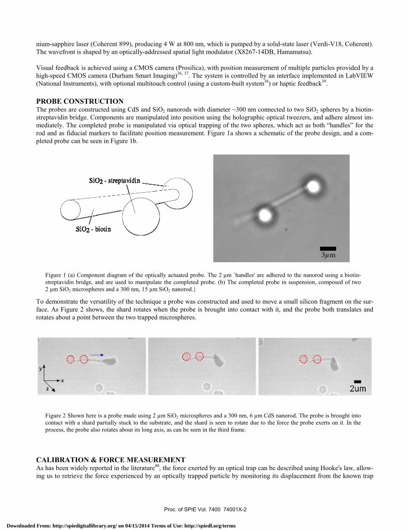
PROBE CONSTRUCTION The probes are constructed using CdS and SiO2 nanorods with diameter ~300 nm connected to two SiO2 spheres by a biotin-streptavidin bridge. Components are manipulated into position using the holographic optical tweezers, and adhere almost im-mediately. The completed probe is manipulated via optical trapping of the two spheres, which act as both “handles” for the rod and as fiducial markers to facilitate position measurement. Figure 1a shows a schematic of the probe design, and a com-pleted probe can be seen in Figure 1b.
Figure 1 (a) Component diagram of the optically actuated probe. The 2 µm `handles' are adhered to the nanorod using a biotin-streptavidin bridge, and are used to manipulate the completed probe. (b) The completed probe in suspension, composed of two 2 µm SiO2 microspheres and a 300 nm, 15 µm SiO2 nanorod.}
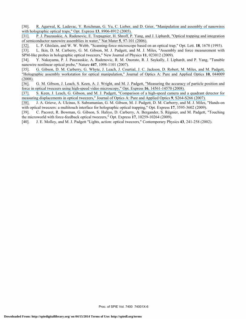
To demonstrate the versatility of the technique a probe was constructed and used to move a small silicon fragment on the sur-face. As Figure 2 shows, the shard rotates when the probe is brought into contact with it, and the probe both translates and rotates about a point between the two trapped microspheres.
Figure 2 Shown here is a probe made using 2 µm SiO2 microspheres and a 300 nm, 6 µm CdS nanorod. The probe is brought into contact with a shard partially stuck to the substrate, and the shard is seen to rotate due to the force the probe exerts on it. In the process, the probe also rotates about its long axis, as can be seen in the third frame.
CALIBRATION & FORCE MEASUREMENT As has been widely reported in the literature40, the force exerted by an optical trap can be described using Hooke's law, allow-ing us to retrieve the force experienced by an optically trapped particle by monitoring its displacement from the known trap
Proc. of SPIE Vol. 7400 74001X-2
Downloaded From: http://spiedigitallibrary.org/ on 04/15/2014 Terms of Use: http://spiedl.org/terms

centre. The trap stiffness, k, is measured using the equipartition method, as the probe's shape complicates analysis by power spectral density (PSD). Figure 3 shows the x and y positions of the two microsphere “handles” plotted to illustrate their corre-lation. A strong correlation of 0.97 is observed in the x-axis data for the probe oriented parallel to the x axis, illustrating that inference of the tip position by monitoring the handle locations is viable.
In this work, we measure the trap stiffness of the two microspheres before adhesion to the nanorod (Figure 3), obtaining k0 ≡ (k0,x,, k0,y) = (4.72, 4.58) pN/µm and k1 = (4.77, 5.16) pN/µm. These values were confirmed with the Stokes drag method. With the stage translated at a constant velocity of 12.75µm.s-1, an average force of ~2.25 pN was recorded, agreeing to within 10% of the predicted value. We estimate a sensitivity of 50 fN, 20 times more sensitive than typical AFM tech-niques.
Figure 3 Position correlation data for a probe oriented parallel to the x axis. (a) shows no significant correlation in the y direction, while (b) shows a strong correlation factor of 0.97 in the x axis. From this, we can infer a rigid adhesion of the beads to the nano-rod, enabling us to monitor the position of the probe tip via analysis of the x,y position of the microsphere handles.
We demonstrate the ability of the probe to apply forces by bringing it into contact with a shard of silicon adhered to the sur-face of the sample chamber. Contact between the probe and the silicon shard is achieved by translating the xyz stage and keep-ing the hologram displayed on the SLM constant (see Figure 4). The force data retrieved is shown in Figure 5, with forces in excess of 100 pN parallel to the probe direction, observed by summation of the two force traces. Small forces of around 10 pN are observed in the perpendicular axis, demonstrating this techniques ability to observe forces in two dimensions simul-taneously. For more detail, see Ikin et al.33.
Figure 4 An optically trapped probe is brought into contact with a surface-adhered silicon shard. The sample chamber is translated at 12.75 µm s-1 using the xyz stage, with a constant hologram displayed on the SLM, and the positions p0 and p1 are monitored with a position-tracking camera. Using this technique, force data can be retrieved as shown in Figure 5.
Proc. of SPIE Vol. 7400 74001X-3
Downloaded From: http://spiedigitallibrary.org/ on 04/15/2014 Terms of Use: http://spiedl.org/terms

Figure 5 Force data in the (a) x and (b) y directions retrieved from a probe translated parallel to the x axis (see Figure 4) using the xyz stage. At points 1 through 6 the probe makes contact with a silicon shard adhered to the surface, with forces in excess of 100 pN recorded by summing the forces on the two microspheres. At point 6 the force applied to the shard was sufficient to push the probe out of the optical traps, as can be seen by the sudden increase in the force data.
CONCLUSIONS
We have demonstrated the assembly of SPM-like probes from streptavidin-coated SiO2 microspheres and biotin-coated high aspect-ratio CdS and SiO2 nanorods. The tips of these nanorods may be functionalised in the future. The probes are controlled optically, with feedback via high-speed position measurement of the SiO2 microsphere `handles'. In this manner, the forces experienced at the probe tip may be measured. Forces as small as 50 fN have been recorded, and we have demonstrated the application of forces in excess of 100 pN.
In the future, probes such as these could be used to characterise cells in true environmental conditions. Multiple probes with distinct functionalities could be used to extract three dimensional information simultaneously, providing a powerful toolkit for investigative cell biology.
ACKNOWLEDGEMENTS This project is funded by the Research Councils of the United Kingdom and the IRC in Nanotechnology. The authors wish to thank Martin Steinhart and Yong Wang of the Max Planck Institute, Halle, Germany for providing the SiO2 nanorods.
REFERENCES [1]. G. Binnig, H. Rohrer, C. Gerber, and E. Weibel, "Surface studies by scanning tunneling microscopy," Physical Re-view Letters 49, 57--61 (1982). [2]. A. A. Baker, W. Helbert, J. Sugiyama, and M. J. Miles, "High-Resolution Atomic Force Microscopy of Native Va-lonia Cellulose I Microcrystals," Journal of Structural Biology 119, 129--138 (1997). [3]. L. A. Chtcheglova, J. Waschke, L. Wildling, D. Drenckhahn, and P. Hinterdorfer, "Nano-scale dynamic recognition imaging on vascular endothelial cells," Biophysical journal 93, 11--13 (2007). [4]. M. Grandbois, W. Dettmann, M. Benoit, and H. E. Gaub, "Affinity imaging of red blood cells using an atomic force microscope," Journal of Histochemistry and Cytochemistry 48, 719 (2000).
Proc. of SPIE Vol. 7400 74001X-4
Downloaded From: http://spiedigitallibrary.org/ on 04/15/2014 Terms of Use: http://spiedl.org/terms

[5]. E. Florin, V. Moy, and H. Gaub, "Adhesion forces between individual ligand-receptor pairs," Science 264, 415 (1994). [6]. A. Humphris, J. Tamayo, and M. Miles, "Active quality factor control in liquids for force spectroscopy," Langmuir 16, 7891--7894 (2000). [7]. L. Picco, L. Bozec, A. Ulcinas, D. Engledew, M. Antognozzi, M. Horton, and M. Miles, "Breaking the speed limit with atomic force microscopy," Nanotechnology 18, 44030 (2007). [8]. L. Picco, P. Dunton, A. Ulcinas, D. Engledew, O. Hoshi, T. Ushiki, and M. Miles, "High-speed AFM of human chromosomes in liquid," Nanotechnology 19, 384018 (2008). [9]. A. Ashkin, J. M. Dziedzic, J. E. Bjorkholm, and S. Chu, "Observation of a single-beam gradient force optical trap for dielectric particles," Opt. Lett. 11, 288 (1986). [10]. S. B. Smith, Y. J. Cui, and C. Bustamante, "Overstretching B-DNA: The elastic response of individual double-stranded and single-stranded DNA molecules," Science 271, 795--799 (1996). [11]. A. Ashkin, and J. M. Dziedzic, "Internal cell manipulation using infrared laser traps," Proceedings of the National Academy of Sciences of the United States of America 86, 7914-7918 (1989). [12]. D. C. Benito, D. M. Carberry, S. H. Simpson, G. M. Gibson, M. J. Padgett, J. G. Rarity, M. J. Miles, and S. Hanna, "Constructing 3D crystal templates for photonic band gap materials using holographic optical tweezers," Opt. Express 16, 13005-13015 (2008). [13]. D. C. Benito, E. Edwards, J. Hildmann, D. M. Carberry, G. M. Gibson, M. J. Padgett, M. Kuball, M. J. Miles, and S. Hanna, "Fabrication of structures using holographic optical tweezers and adhesion via entropic attraction," in SPIE Optics and Photonics(San Diego, USA, 2008). [14]. P. Jordan, J. Cooper, G. McNay, F. Docherty, D. Graham, W. Smith, G. Sinclair, and M. Padgett, "Surface-enhanced resonance Raman scattering in optical tweezers using co-axial second harmonic generation," Opt. Express 13, 4148-4153 (2005). [15]. Y. Wang, E. L. Botvinick, Y. Zhao, M. W. Berns, S. Usami, R. Y. Tsien, and S. Chien, "Visualizing the mechanical activation of Src," Nature 434, 1040-1045 (2005). [16]. D. M. Carberry, M. A. B. Baker, G. M. Wang, E. M. Sevick, and D. J. Evans, "An optical trap experiment to demon-strate fluctuation theorems in viscoelastic media," Journal of Optics A: Pure and Applied Optics 9, S204-S214 (2007). [17]. D. M. Carberry, S. R. Williams, G. M. Wang, E. M. Sevick, and D. J. Evans, "The Kawasaki identity and the Fluc-tuation Theorem," Journal of Chemical Physics 121, 8179 (2004). [18]. G. M. Wang, D. M. Carberry, J. C. Reid, E. M. Sevick, and D. J. Evans, "Demonstration of the steady-state fluctua-tion theorem from a single trajectory," Journal of Physics: Condensed Matter 17, S3239-S3244 (2005). [19]. R. Di Leonardo, S. Keen, J. Leach, C. D. Saunter, G. D. Love, G. Ruocco, and M. J. Padgett, "Eigenmodes of a hy-drodynamically coupled micron-size multiple-particle ring," Physical Review E (Statistical, Nonlinear, and Soft Matter Phys-ics) 76, 061402-061404 (2007). [20]. C. M. Coppin, D. W. Pierce, L. Hsu, and R. D. Vale, "The Load Dependence of Kinesin's Mechanical Cycle," Pro-ceedings of the National Academy of Sciences of the United States of America 94, 8539--8544 (1997). [21]. J. A. Dantzig, T. Y. Liu, and Y. E. Goldman, "Functional studies of individual myosin molecules," in Annals of The New York Academy Of Sciences(2006), pp. 1--18. [22]. M. J. Lang, C. L. Asbury, J. W. Shaevitz, and S. M. Block, "An automated two-dimensional optical force clamp for single molecule studies," Biophysical Journal 83, 491--501 (2002). [23]. K. Svoboda, C. F. Schmidt, B. J. Schnapp, and S. M. Block, "Direct observation of kinesin stepping by optical trap-ping interferometry," Nature 365, 721--727 (1993). [24]. H. Yin, M. D. Wang, K. Svoboda, R. Landick, S. M. Block, and J. Gelles, "Transcription against an applied force," Science 270, 1653--1657 (1995). [25]. J. E. Curtis, B. A. Koss, and D. G. Grier, "Dynamic holographic optical tweezers," Optics Communications 207, 169-175 (2002). [26]. P. J. Rodrigo, V. R. Daria, and J. Gluckstad, "Four-dimensional optical manipulation of colloidal particles," Applied Physics Letters 86, 074103-074103 (2005). [27]. M. E. J. Friese, H. Rubinsztein-Dunlop, J. Gold, P. Hagberg, and D. Hanstorp, "Optically driven micromachine ele-ments," Applied Physics Letters 78, 547-549 (2001). [28]. P. J. Rodrigo, L. Gammelgaard, P. Bøggild, I. Perch-Nielsen, and J. Glückstad, "Actuation of microfabricated tools using multiple GPC-based counterpropagating-beam traps," Opt. Express 13, 6899-6904 (2005). [29]. L. Ikin, D. M. Carberry, J. A. Grieve, G. M. Gibson, M. J. Padgett, and M. J. Miles, "Construction and Manipulation of Structures using Optical Tweezers," in SPIE Optics and Photonics(San Diego, USA, 2008), p. 795109.
Proc. of SPIE Vol. 7400 74001X-5
Downloaded From: http://spiedigitallibrary.org/ on 04/15/2014 Terms of Use: http://spiedl.org/terms
[30]. R. Agarwal, K. Ladavac, Y. Roichman, G. Yu, C. Lieber, and D. Grier, "Manipulation and assembly of nanowires with holographic optical traps," Opt. Express 13, 8906-8912 (2005). [31]. P. J. Pauzauskie, A. Radenovic, E. Trepagnier, H. Shroff, P. Yang, and J. Liphardt, "Optical trapping and integration of semiconductor nanowire assemblies in water," Nat Mater 5, 97-101 (2006). [32]. L. P. Ghislain, and W. W. Webb, "Scanning-force microscope based on an optical trap," Opt. Lett. 18, 1678 (1993). [33]. L. Ikin, D. M. Carberry, G. M. Gibson, M. J. Padgett, and M. J. Miles, "Assembly and force measurement with SPM-like probes in holographic optical tweezers," New Journal of Physics 11, 023012 (2009). [34]. Y. Nakayama, P. J. Pauzauskie, A. Radenovic, R. M. Onorato, R. J. Saykally, J. Liphardt, and P. Yang, "Tunable nanowire nonlinear optical probe," Nature 447, 1098-1101 (2007). [35]. G. Gibson, D. M. Carberry, G. Whyte, J. Leach, J. Courtial, J. C. Jackson, D. Robert, M. Miles, and M. Padgett, "Holographic assembly workstation for optical manipulation," Journal of Optics A: Pure and Applied Optics 10, 044009 (2008). [36]. G. M. Gibson, J. Leach, S. Keen, A. J. Wright, and M. J. Padgett, "Measuring the accuracy of particle position and force in optical tweezers using high-speed video microscopy," Opt. Express 16, 14561-14570 (2008). [37]. S. Keen, J. Leach, G. Gibson, and M. J. Padgett, "Comparison of a high-speed camera and a quadrant detector for measuring displacements in optical tweezers," Journal of Optics A: Pure and Applied Optics 9, S264-S266 (2007). [38]. J. A. Grieve, A. Ulcinas, S. Subramanian, G. M. Gibson, M. J. Padgett, D. M. Carberry, and M. J. Miles, "Hands-on with optical tweezers: a multitouch interface for holographic optical trapping," Opt. Express 17, 3595-3602 (2009). [39]. C. Pacoret, R. Bowman, G. Gibson, S. Haliyo, D. Carberry, A. Bergander, S. Régnier, and M. Padgett, "Touching the microworld with force-feedback optical tweezers," Opt. Express 17, 10259-10264 (2009). [40]. J. E. Molloy, and M. J. Padgett "Lights, action: optical tweezers," Contemporary Physics 43, 241-258 (2002).
Proc. of SPIE Vol. 7400 74001X-6
Downloaded From: http://spiedigitallibrary.org/ on 04/15/2014 Terms of Use: http://spiedl.org/terms