UOKIDATION ENGINEERING MANUAL - IRC Wash
101
2 5 7 7 2 F L UOKIDATION ENGINEERING MANUAL ENVIRONMENTAL PROTECTION AGENCY WATER SUPPLY PROGRAMS DIVISION \25VWi
-
Upload
khangminh22 -
Category
Documents
-
view
0 -
download
0
Transcript of UOKIDATION ENGINEERING MANUAL - IRC Wash

2 5 7
7 2 F L
UOKIDATION ENGINEERING MANUAL
ENVIRONMENTAL PROTECTION AGENCY
WATER SUPPLY PROGRAMS DIVISION
\25VWi
1 92.PL
Fluoridation Engineering Manual
by
Ervin Be lack
ENVIRONMENTAL PROTECTION AGENCY
Office of Water Programs
Water Supply Programs Division
1972
Preface
The fluoridation of water supplies has been termed one of the most significant health advances in recent years. This manual is intended to assist local and state engineers in designing fluoridation installations, and water plant personnel in operating them, so that the fullest advantage of the benefits of fluoridation can be achieved.
No matter how well a fluoridation installation is designed, it is ultimately the "man at the water plant" who insures its successful operation by his awareness of the importance of his task and by his conscientious adherence to the principles of good water plant practice. This manual is particularly dedicated to his assistance.
The addition of fluorides to water supplies involves, more than the addition of other chemicals, particular emphasis on accurate feed rates. The philosophy, "if a little is good, more will be better," or the false economy in feeding less than the optimum amount, have no place in the practice of fluoridation. The optimum concentrations have been arrived at by countless studies involving millions of people, and these same studies have shown that failure to conform to the optimum concentration defeats the whole purpose of "controlled" fluoridation. It is hoped that this manual will not only place the desired stress on this aspect, but will provide assistance to the operator in maintaining that optimum concentration.
The planner of a fluoridation installation should carefully consider the options open to him, among them the choice of chemical and thus the choice of equipment. The quantity of water pumped may affect these choices, as will considerations of economy, convenience, and location. While it is the intention of this manual to provide information on the criteria governing the selection of an optimal system, there is no intent to take the place of expert advice where such is needed.
Ervin Bellack Chemist Water Supply Programs Division Office of Water Programs Environmental Protection Agency
ui

Contents
I INTRODUCTION 1 Natural Fluoridation 1 Blending 2 Controlled Fluoridation 3
II COMPOUNDS USED IN CONTROLLED FLUORIDATION . . . 4 Sodium Fluoride 4 Fluosilicic Acid 5 Sodium Silicofluoride 6 Other Fluoride Chemicals 7
III FEEDERS USED FOR ADDING FLUORIDES 9 Solution Feeders 9 Dry Feeders 12 Testing Procedures for Dry Feeders 18 Checking Particle Size 19 Auxiliary Equipment 19 Meters 20 Scales 20 Softeners 21 Mixers 21 Dissolving Tanks 22 Flow Meters 24 Day Tanks 24 Bag Loaders 25 Dust Collectors and Wet Scrubbers 25 Alarms 25 Vacuum Breakers 25 Hoppers 26 Weight Recorders 26 Controllers 27 Eductors 27 Pumps 27 Timers 28 Hopper Agitators 28 Flow-Splitters 28
IV PREPARATION OF FLUORIDE SOLUTIONS 31 Manual Technique 31
v
Automatic Devices 33 Calculations Involving Solutions . . . . . . . . . . . . 42
V SELECTING THE OPTIMAL FLUORIDATION SYSTEM . . . 47 Location of Feeder ... . . : . . 47 Fluoride Injection Point 50 Type of Feeder and Chemical . . . . . . . . . . . . . . . . . . . 51 Chemical Availability . ; . . . . . : . . . . . 54 Chemical Storage and Handling 56 Cross-Connection Considerations . . . . . . . . . . . . . . . . . 57 Automatic Proportioning (Pacing) 57 Installation 59 Solution Feeder Installations 59 Dry Feeder Installations 59 Valves and Meters . . . . . . . : . . . . . . 60 Installation Plans 60
VI CONTROL AND SURVEILLANCE . . . . . . . . . . . . . . . . . . . . 63 Analytical Procedures . . . . . . 63 The Standard Methods 63 Alizarin Visual Method 64 SPADNS Method 64 Electrode Method 65 Test Kits 66 Sampling 66 Calculations and Record-Keeping 66 Monitors 68 Trouble-Shooting • •• • 72 Low Fluoride Readings 73 High Fluoride Readings 73 Varying Fluoride Readings 74 Other Problems 75
VII MAINTENANCE . 77 Cleaning and Lubrication 77 Spare Parts 77 Inspection and Re-Calibration .: 77 Leaks 78 Precipitates 78 Storage Area . . . . . . . . . . . 79 Laboratory . . : . 79
VIII SAFETY AND HAZARDS IN HANDLING FLUORIDE CHEMICALS 81
Safety Equipment and Chemical Handling . . . . . . . . . . . 81 Ingestion 81 Inhalation 81 Safety Precautions 82 Acid Handling . . . . 82
vi

First Aid 82 Fluoride Exposure Symptoms . . 82 Treatment 83
IX TECHNICAL PROBLEMS ATTRIBUTED TO FLUORIDATION 85
Corrosion •. . . 85 Encrustations 85 Fluoride Losses 86 Compatibility f 86 Tastes and Odors 87 Industrial Processes 87 Environmental Effects 87
X REFERENCES AND SUGGESTED READING 89
APPENDIX ABBREVIATIONS 93
vn
Illustrations
Figure Page
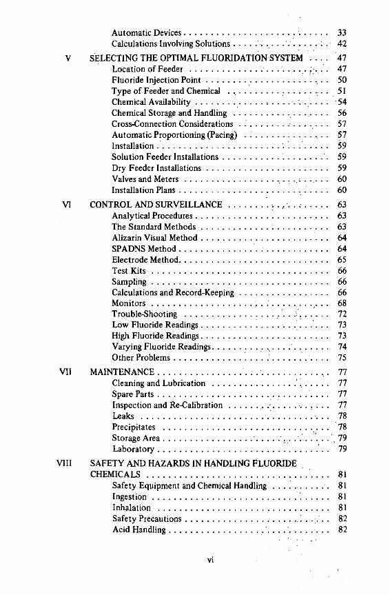
1 Positive-displacement Solution Feeders 10 2 Screw-Type Volumetric Dry Feeder 13 3 Roll-Type Volumetric Dry Feeder 14 4 Belt-Type Gravimetric Dry Feeder . 16 5 Gravimetric Dry Feeder — "Loss-iri-Weight" Type . . . . . . . 17 6 Typical Arrangements of Fluoride Feeders and
Auxiliary Components . 29 7 Typical Arrangement of Dry Feed Hoppers and
Dust Collectors . 3 0 8 BIF Downflow Saturator 35 9 W & T Downflow Saturator 36
10 Precision Upflow Saturator 37 11 Checking Delivery Rate of a Solution Feeder 44 12 Fluoridation Check-List 48 13 Acid Feed Installation 51 14 Solution Feed Installation 52 15 Diluted Acid Feed System 53 16 Dry Feed Installation with Volumetric Feeder 54 17 Dry Feed Installation with Gravimetric Feeder . . . . . . . . . 55 18 Fluoridation Nomograph 70 19 Fluoridation Alignment Chart 71
Table
1 Characteristics of Fluoride Compounds , 8 2 Detention Time of Sodium Silicofluoride in Dissolving Tanks 23 3 Preparation of Solutions of Sodium Fluoride . . . . . . . . . . 34 4 Recommended Maximum Feed Rates for Downflow Sodium
Fluoride Saturator 38 5 Specific Gravity of Fluosilicic Acid Solutions at 17.5°C . . . 45 6 Fluoride Calculation Factors 69
viii
Chapter I
INTRODUCTION Although the dental profession can claim the credit for first ascribing
dental mottling to some unknown constituent of drinking water, it was a water plant chemist who first implicated the element fluorine. Initially, it was thought that if fluorine was indeed the element responsible in some way for tooth discoloration, it was a deficiency rather than an excess which brought about the mottling. As analytical techniques were refined and data began to accumulate, the true role of fluoride in water was revealed. Now we know that a deficiency of fluoride can lead to extensive tooth decay, and that an excess is the cause of mottling, or as it is now known, dental fluorosis.
The element, fluorine, ranks thirteenth in abundance in the earth's crust, and twelfth in the oceans. It is also thirteenth in abundance in the human body, and although the concentrations vary widely, it is found in every water supply used by man for drinking purposes. Because of the wide distribution of the element, the difficulty in attempting to grow plants or animals without it and its role in the formation of human bones and teeth, fluorine (as the fluoride ion) is now considered to be essential to the normal growth and development of man.
Fluorine, like chlorine a gaseous halogen, is never found in the free state but always occurs in combination with other elements as fluoride compounds. In water solution, these compounds dissociate into ions, and it is these fluoride ions which are analytically determined and are the form in which fluorine is assimilated by man. The fluoride compounds most commonly found in the earth's crust are fluorspar and apatite, calcium fluoride and a complex calcium fluoride-phosphate, respectively. However, in water only the fluoride ion (F") can be detected without more than an educated guess as to the nature of the compound from which the ion was derived. Thus, since there is no way one fluoride ion can be distinguished from another, there is no difference between fluoride ions dissolved from the earth's crust and fluoride ions occurring in water due to the deliberate addition of fluoride compounds by man.
NATURAL FLUORIDATION
After the cause of dental fluorosis was ascertained, and the concomitant observation was made that dental caries was relatively absent in the presence of fluorosis, it followed logically that these observations should be verified by examining the teeth of children in many areas and analyzing the drinking water supplies in those areas. The examination of the teeth of many thousands of children, and the fluoride analysis of hundreds of water supplies showed a
1
remarkable relationship between the concentration of waterborne fluoride and the incidence of dental caries. The relationship, or actually three distinct relationships, are as follows:
1. When the fluoride level exceeds about 1.5 ppm, any further increase does not significantly decrease the incidence of decayed, missing or filled teeth, but does increase the occurrence and severity of mottling.
2. At a fluoride level of approximately 1.0 ppm, the optimum occurs-maximum. reduction in caries with no aesthetically significant mottling.
3. At fluoride levels below 1.0 ppm some benefits occur, but caries reduction'is not so great and gradually decreases as the fluoride levels decrease until, as zero fluoride'is approached, no observable improvement occurs.
Since, as noted above, all water supplies contain measurable amounts of fluoride, it can be said that all water supplies are fluoridated. However, since only those water supplies containing fluoride concentrations in excess of 0.7 ppm (in the continental United States) have appreciable dental significance, ordinarily these are the ones we refer to as being naturally fluoridated.
Thus, fluoridation is not something new, as many people suppose, but is actually a process performed by nature for many centuries. What we now refer to as "controlled fluoridation" is only man's attempt to overcome the vagaries of nature in her random and sometimes inefficient process of putting fluoride ions in our drinking water.
BLENDING It was actually many years after the role of fluoride in water was first
determined thai the idea of imitating the natural process was first suggested, and the onset of World War II resulted in another delay before the first demonstration project could begin! During the interval, hundreds of studies were undertaken for the purpose of verifying the fluoride-caries relationships and for determining the validity of proposed experimental controlled fluoridation of municipal water supplies.
Although it is generally accepted that the first controlled fluoridation projects began in 1945 in the cities of Grand Rapids, Michigan, Newburgh, New York, and Brantford, Ontario, it was several years earlier that at least one city, without attendant fanfare, began efforts'to adjust the fluoride content of its water supply in order to bring the level to the optimum for dental benefits. The feat was accomplished by blending the water from two sources — one providing water with a natural fluoride content above the optimum, the other providing water deficient in natural fluoride content. Since then, other cities have adopted the blending process, either for raising the fluoride level in the major source of water by adding water from a high-fluoride well, or for reducing the overall fluoride level by adding water from a low-fluoride source to an existing high-fluoride well supply. Unfortunately, the achievement of controlled fluoridation by the blending of water from two sources is limited to those areas where high-fluoride waters occur. When blending is possible, the
2

water consumers gain more than dental benefits and economic advantages — they also conserve the supply of drinking water by making use of quantities of water which otherwise would not be considered acceptable.
CONTROLLED FLUORIDATION The third type of fluoridation, in addition to natural and that achieved
by blending, is the one in which the fluoride content of a water supply is adjusted by the deliberate addition of a chemical compound which provides fluoride ions in water solution. This type of fluoridation, beginning with the three cities mentioned above, is now practiced in approximately 5,000 communities serving over 80 million persons. With the residents of almost 3,000 additional communities consuming water containing at least 0.7 ppm fluoride from natural sources, this means that 56% of the nation's population on public water supplies (90 million persons) had access to water with a dentally significant concentration of fluoride as of 1970.
The graduation of controlled fluoridation from an experimental procedure into an established water plant practice has not been without problems. Few, if any, of these problems were of an engineering nature, for the controlled addition of a chemical to a water supply can hardly be considered something new. For the most part, adding fluoride is just like adding any of several different chemicals commonly added as part of the usual water plant practices. The feeding equipment is in general the same equipment used for feeding alum, soda ash, lime, or other chemicals. Only the nature of the chemical and the purpose for which it is added are different, and therein lies the problem.
For some reason, fluoridation has aroused a controversy out of all proportion to the simple premise of adjusting the concentration of a mineral in which a particular water is deficient. Even the premise is not new — waters which are deficient in alkalinity or hardness are often supplemented with appropriate compounds at the water plant and no one seems to mind. Apparently, it is just the word, "fluoride," which has stirred the imagination of so many concerned citizens. The confusion with the word, "fluorine," is understandable for fluoridation was originally termed, "fluorination," and fluorine, of course, is a toxic and highly reactive gas. But the controversy goes beyond this, to such areas as mass medication, legal rights, and a host of others too numerous to mention. It may be of interest to point out that chlorination received a similar reception, and that resistance to this type of water treatment still exists today.
As far as the water plant operator or engineer need be concerned, the addition of fluoride to a water supply is well within his province, and it is his duty to follow the directives of the health officials and governing body of his community in not just adding fluorides, but in doing the job right.
3
Chapter II Compounds LJsed In
Controlled Fluoridation SODIUM FLUORIDE
Theoretically, any compound which forms fluoride ions in water solution can be used for adjusting upward the fluoride content of a water supply. However, there are several practical considerations involved in selecting compounds. First, the compound must have sufficient solubility to permit its use in routine water plant practice. Second, the cation to which the fluoride ion is attached must not have any undesirable characteristics. Third, the material should be relatively inexpensive, and readily available in grades of size and purity which are suitable for the intended use.
The first fluoride compound used in controlled fluoridation was sodium fluoride, selected not only on the basis of the above criteria, but also because its toxicity and physiological effects had been so thoroughly studied. In addition, sodium fluoride is the reference standard used in measuring fluoride concentration. Once fluoridation became an established practice, other compounds came into use, but sodium fluoride, because of its unique physical characteristics in addition to its other advantages in some situations, is still one of the most widely used chemicals.
Sodium fluoride is a white, odorless material available either as a powder or in the form of crystals of various sizes. Its formula weight is 42.00, specific gravity 2.79, and its solubility practically constant at 4.0 grams per 100 milliliters of water at temperatures generally encountered in water-treatment practice. The pH (hydrogen-ion concentration) of solution varies with the type and amount of impurities, but solutions prepared from the usual grades of sodium fluoride exhibit pH's near neutrality. It is available in purities ranging from 90 to over 98 percent, the impurities consisting of water, free acid or alkali, sodium silicofluoride, sulfites and iron, plus traces of other substances.
Powdered sodium fluoride is produced in different densities, the light grade weighing less than 65 pounds per cubic foot and the heavy grade weighing about 90 pounds per cubic foot. A typical sieve analysis of powdered sodium fluoride shows 99 percent through 200 mesh and 97 percent through 325 mesh. Crystalline sodium fluoride is produced in various size ranges, usually designated as coarse, fine and extra-fine, but some manufacturers can furnish lots in specific mesh sizes. The crystalline type is preferred when manual handling is involved, since the absence of fine powder results in a minimum of dust.
4

Sodium fluoride is manufactured by Allied Chemical Corporation, Industrial Chemicals Division; J.T. Baker Chemical Company; Chemtech Corporation; and Olin Chemicals, but is usually sold through distributors who are located in most cities. In 1970, sodium fluoride sold for 18 to 25 cents per pound, F.O.B. point of manufacture, the price depending largely on the quantity purchased. Normal packing is in 100 lb. multi-ply paper bags or fiber drums holding up to 400 pounds.
Sodium fluoride has a number of other industrial uses, one of which requires that the material be tinted a blue color. Some state regulations specify that only tinted sodium fluoride be used in order to distinguish it from other water-treatment chemicals.
FLUOSILICIC ACID Fluosilicic Acid, also known as hydrofluosilicic, hexafluosilicic, silicofluoric,
or even "silly" acid, is a 20 to 35% aqueous solution of H2SiF6 with a formula weight of 144.08. It is a colorless (when pure), transparent, fuming, corrosive liquid having a pungent odor and an irritating action on the skin. Upon vaporizing, the acid decomposes to form hydrofluoric acid and silicon tetra-fluoride, and under conditions where an equilibrium between the fluosilicic acid and its decomposition products exist, such as at the surface of strong solutions, etching of glass will occur. All solutions of fluosilicic acid exhibit a low pH, and even at a concentration low enough to produce 1 ppm of fluoride ion there can be a significant depression of the pH of poorly buffered waters. (Example: Water containing 30 ppm TDS, pH 6.5. After H2SiF6 was added to produce 1 ppm F, pH dropped to 6.2.)
Fluosilicic acid is manufactured by two different processes, resulting in products having differing characteristics. The largest proportion of the acid is a by-product of phosphate fertilizer manufacture, and this type is relatively impure and seldom exceeds 30% strength. A smaller amount of acid is prepared from hydrofluoric acid and silica, resulting in a purer product at a slightly higher strength. Acid prepared from phosphate rock contains colloidal silica in varying amounts, and while this is of little consequence when the acid is used as received, dilution results in the formation of a visible precipitate of the silica. Some suppliers of fluosilicic acid sell a "fortified" acid, which has had a small amount of hydrofluoric acid added to it to prevent the formation of the precipitate. Acid prepared from hydrofluoric acid and silica does not normally form a precipitate when it is diluted.
Fluosilicic acid is produced by many fertilizer manufacturers, but only a limited number of these recover the acid for sale as such. Among the latter group are Stauffer Chemical Company, Fertilizer Division; U.S. Industrial Chemicals Company, Division of National Distillers and Chemical Corporation (through Conservation Chemical Company of Illinois); USS Agri-Chemicals Division of U.S. Steel Corporation; Agrico Chemical Company, Division of Continental Oil Company; W.R. Grace, Agricultural Products Division; Sobin Chemicals, Inc.; and Kerr-McGee Chemical Corporation. Harshaw Chemical Company, Division of Kewanee Oil Company, produces acid made by the hydrofluoric acid-silica process.
5

Since fluosilicic acid contains a high proportion of water, shipping large quantities can be quite expensive. Larger users can purchase the acid directly from the manufacturers in bulk (tank car or tank truck) lots, but smaller users must obtain the acid from distributors who usually pack it in drums or polyethylene carboys. In 1970, fluosilicic acid in bulk sold for $51.00 to $58.00 per ton, 23% basis, F.O.B. point of manufacture. Smaller quantities sold for 8 to 15 cents per pound, 30% basis. This method of pricing comes about due to the variable characteristics of the acid as it comes from fertilizer plants. Rather than attempt to adjust the acid strength to some uniform figure, producers sell the acid as it comes, and the price is adjusted to compensate for acid strength above or below the quoted figure. Note that the "23% basis" type of pricing applies only to bulk quantities. It is the usual practice for the supplier to furnish assay reports of the acid strength of each lot.
Like other fluoride compounds, fluosilicic acid has a number of industrial uses, one of which is in the manufacture of hydrofluoric acid, and thus in an indirect way, other fluoride compounds.
SODIUM SILICOFLUORIDE
Fluosilicic acid can readily be converted into various salts, and one of these, sodium silicofluoride, is the most widely used chemical for water fluoridation. Undoubtedly, the principal reason for the popularity is one of economics, for sodium silicofluoride is the cheapest of the compounds currently in use. The conversion of fluosilicic acid, essentially a low-cost by-product which contains too much water to permit economical shipping, to a dry material containing a high percentage of available fluoride, results in a compound having most of the advantages of the acid with few of its disadvantages. Once it was shown that silicofluorides form fluoride ions in water solution as readily as do simple fluoride compounds, and that there is no difference in physiological effects, the silicofluorides (and fluosilicic acid) were rapidly accepted for water fluoridation, and in some cases displaced the use of sodium fluoride.
Sodium silicofluoride is a white, odorless crystalline powder. Its molecular weight is 188.06 and its specific gravity is 2.679. Its solubility varies from 0.44 grams per 100 milliliters of water at 0° Centigrade to 2.45 grams per 100 milliliters at 100°C. The pH's of solutions are definitely on the acid side, saturated solutions usually exhibiting a pH between 3.0 and 4.0. Sodium silicofluoride is available in purities of 98% or better, the principal impurities being water, chlorides and silica.
Sodium silicofluoride is sold in two commercial forms — regular and fluffy. The former has a density of about 85 pounds per cubic foot while the latter has a density of about 65 pounds per cubic foot. A typical sieve analysis of the regular grade shows more than 99% through a 200-mesh sieve and more than 10% through a 325-mesh sieve. For best feeding characteristics, other size specifications may be selected, experience having shown that a low moisture content plus a relatively narrow size distribution results in a material which is handled better by dry feeders.
6

Sodium silicofluoride is manufactured by Agrico Chemical Company, Division of Continental Oil Company; Kerr-McGee Chemical Corporation; Olin Chemicals; Tennessee Corporation, (Cities Service), Industrial Marketing Division, and possibly other manufacturers of fluosilicic acid. Considerable quantities of the material are imported, and numerous distributors handle it. In 1970, prices ranged from 8 to 10 cents per pound F.O.B. point of manufacture. Sodium silicofluoride is normally packed in bags and drums similar to those used for sodium fluoride. Blue-tinted material is sometimes available.
OTHER FLUORIDE COMPOUNDS Ammonium silicofluoride, magnesium silicofluoride, potassium fluoride and
calcium fluoride (fluorspar) either are being or have been used for water fluoridation, and at one time hydrofluoric acid was also used. Each has particular properties which make the material desirable in a specific application, but none of these have wide-spread application.
Ammonium silicofluoride has the peculiar advantage of supplying all or part of the ammonium ion necessary for the production of chloramines when this form of disinfectant is preferred to chlorine in a particular situation.
Magnesium silicofluoride and potassium fluoride have the advantage of extremely high solubility, of particular importance in such applications as school fluoridation when infrequent refills of the solution container are desired. In addition, potassium fluoride is quite compatible with potassium hypochlorite, so a mixture of the two solutions can be used for simultaneous fluoridatiorrand chlorination. —
Calcium fluoride (fluorspar) is the cheapest of the compounds ever used for fluoridation but it is also the least soluble. It has been successfully fed by first dissolving it in alum solution, and then utilizing the resultant solution to supply both the alum needed for coagulation and the fluoride ion. Some attempts have been made to feed fluorspar directly in the form of ultra-fine powder, on the premise that the powder would eventually dissolve or at least remain in suspension until consumed.
Hydrofluoric acid, although low in cost, presents too much of a safety and corrosion hazard to be acceptable for water fluoridation, although it has been used in a specially designed installation.
A number of other fluoride compounds have been suggested for use in water fluoridation, among them ammonium and sodium bifluoride. These latter materials have advantages of solubility and cost, but their potential corrosive-ness has hindered acceptance.
The chemical and physical characteristics, costs, shipping containers, storage requirements, etc., of the three commonly-used fluoride compounds are summarized in Table 1. The selection of a compound for a particular application can be based at least in part on the information in this table, but such intangible factors as personal preference often influence the ultimate decision.
7
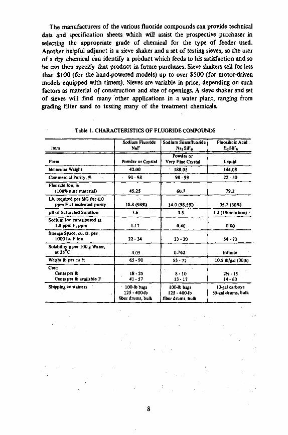
The manufacturers of the various fluoride compounds can provide technical data and specification sheets which will assist the prospective purchaser in selecting the appropriate grade of chemical for the type of feeder used. Another helpful adjunct is a sieve shaker and a set of testing sieves, so the user of a dry chemical can identify a product which feeds to his satisfaction and so he can then specify that product in future purchases. Sieve shakers sell for less than $100 (for the hand-powered models) up to over $500 (for motor-driven models equipped with timers). Sieves are variable in price, depending on such factors as material of construction and size of openings. A sieve shaker and set of sieves will find many other applications in a water plant, ranging from grading filter sand to testing many of the treatment chemicals.
Table 1. CHARACTERISTICS OF FLUORIDE COMPOUNDS
Item
Form
Molecular Weight
Commercial Purity, %
Fluoride Ion, % (100% pure material)
Lb. required per MG for 1.0 ppm F at indicated purity
pH of Saturated Solution
Sodium Ion contributed at 1.0 ppm F, ppm
Storage Space, cu. ft. per 1000 lb. F ion
Solubility g per 100 g Water, at 25°C
Weight lb per cu ft
Cost: Cents per lb Cent* per lb available F
Shipping containers
Sodium Fluoride NaF
Powder or Crystal
42.00
90-98
45.25
18.8 (98%)
7.6
1.17
22-34
4.05
65 -90
18-25 41 -57
' 100-Ibbags 125-400-lb
fiber drums, bulk
Sodium Silicofluoride NajSiF*
Powder or Very Fine Crystal
188.05
98 -99
60.7
14.0 (98.5%)
3.5
0.40
23 -30
0.762
55-72
8 - 1 0 13-17
100-lb bags 125-400-lb
fiber drums, bulk
Fluosilicic Acid . H2SiF»
Liquid
144.08
22 -30
79.2
35.2 (30%)
1.2 (1% solution)
0.00
54 -73
infinite
10.5 lb/gal (30%)
2*4-15 14-63
13-gal carboys 55-gal drums, bulk
8
Chapter III Feeders Used For Adding Fluorides
A chemical feeder, such as the type used for adding fluorides or other substances to a water supply, is a mechanical device which measures out quantities of the chemical and administers them to the water at the pre-set rate. Feeders are designated as either solution or dry types, depending on whether the chemical is measured as volumes of solution or as volumes or weights of dry chemical. In either case, the chemical is in the form of a solution when it is introduced into the water. Dry feeders are further sub-divided into two categories, volumetric and gravimetric, depending on whether the chemical is measured by volume or weight. It should be again noted that fluoride feeders are not something new, but are the same as feeders which have been used for many years for measuring and administering chemicals not only in water plants, but also in many industrial applications.
SOLUTION FEEDERS In general, a solution feeder is nothing more than a small pump, of which
there are almost unlimited varieties. For feeding fluoride solutions, almost every type which has ever been used for feeding other water treatment chemicals has found application, with at most only minor modification in construction details.
If there is indeed any requirement for a fluoride solution feeder which distinguishes it from feeders for other purposes, it is accuracy and constancy of delivery, for the optimum fluoride level has been prescribed between very narrow limits and thus requires that the fluoride be added in precise proportion to the quantity of water being treated. This requirement favors the so-called positive-displacement pump or feeder, defined as a feeder which delivers a specific volume of liquid for each stroke of a piston or rotation of an impeller. Of course, very few feeders deliver replicate volumes under all conditions, for such factors as pressure and viscosity can affect the volume displaced by the driving member of the pump. However, by using fluoride solutions of fixed strength and by feeding against a fixed pressure, the positive displacement feeder has shown sufficient reliability for this purpose.
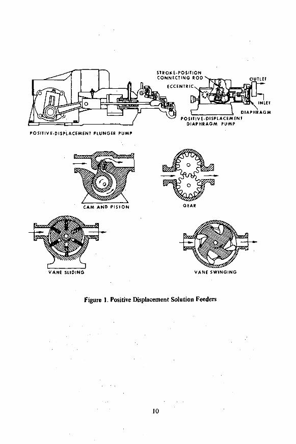
For delivery against pressure, there are two general types of solution feeders - the piston feeder and the diaphragm feeder. In the former type, a reciprocating piston alternately forces solution out of a chamber and then, on its return stroke, refills the chamber by pulling solution from a reservoir. In the latter type, a flexible diaphragm driven either directly or indirectly by a
9
STROKE-POSITION CONNECTING ROD
ECCENTRIC OUTLET
DIAPHRAGM POSITIVE-DISPLACEMENT
DIAPHRAGM PUMP
POSITIVE-DISPLACEMENT PLUNGER PUMP
GEAR
VANE SLIDING VANE SWINGING
Figure 1. Positive Displacement Solution Feeders
10
mechanical linkage performs a similar function. When the mechanical drive for the feeder is an electric motor, a gear box or system of belts and pulleys determines the number of strokes in a given time interval. Pneumatic or hydraulic drives are also available, and these permit the use of a meter contactor to provide stroking which is in direct proportion to water flow instead of being at a fixed rate.
For gravity feed, there are several types of solution feeders which operate on the paddle-wheel principle. A rotating wheel equipped with small buckets dips solution from a constant-head tank and discharges the solution into the water to be treated. Rate of feed can be varied by changing the size of the buckets or their number, by changing the rate of rotation of the wheel, or by varying the proportion of the bucket contents which is emptied.
Ordinarily, such solution feeding devices as centrifugal pumps, pot feeders, or head tank and orifice are not used for fluoridation because of their relative inaccuracy. However, in addition to the piston and diaphragm feeders mentioned above, there are several types of rotary pumps which qualify as positive-displacement feeders. These include gear, swinging-vane, sliding-vane, oscillating screw, eccentric and cam pumps and various modifications of these. Figure 1 illustrates various types of solution feeders.
The criteria used in selecting a feeder are capacity, corrosion resistance, pressure capability, and of course accuracy and durability. A point to consider is that most feeders perform most accurately near mid-range of both stroke length and stroking frequency and should be selected accordingly. At the extremely low feed rates required by small installations, the diaphragm feeders are superior to the piston types. Most feeders come equipped with plastic heads and resilient check-valves, both of which are satisfactory for fluoride solutions unless the pressure is over 100#/sq. in. For higher pressures, corrosion-resistant alloys, such as 316 stainless steel or Carpenter 20 alloy, are required for feeder head construction.
Since most solution feeders are adjustable both for stroke length, which determines the volume of liquid delivered per stroke, and stroke frequency, usually expressed in strokes-per-minute (SPM), both factors should be considered in selecting the size of feeder for a particular application. An example of feeder selection follows:
Problem: Select a solution feeder for the following application: Water flow - 200 gpm @ 75 psi Fluoride source - saturator (produces a 4% sodium fluoride solution,
18,000 ppm as F")
Desired fluoride level —1.0 ppm
Calculated solution feed rate: Ri X C! = R2 X C2
where Ri = water rate, in gal/min
Ci = fluoride level, in ppm R2 = solution feed rate, in gal/min (the unknown quantity, in this
case)
C2 = solution strength, in ppm
11
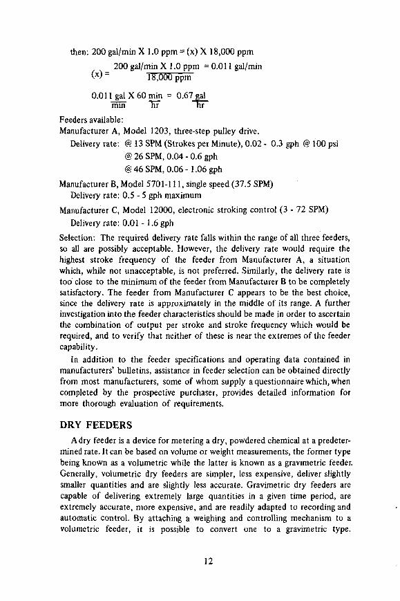
then: 200 gal/min X 1.0 ppm = (x) X 18,000 ppm
_ 200 gal/min X 1.0 ppm = 0.011 gal/min (*)~ 18,000 ppm
0.011_gdX60min = 0.67 gal mm ~HF nr
Feeders available: Manufacturer A, Model 1203, three-step pulley drive.
Delivery rate: @ 13 SPM (Strokes per Minute), 0.02 - 0.3 gph @ 100 psi @ 26 SPM, 0.04 - 0.6 gph @ 46 SPM, 0.06 - 1 . 0 6 gph
Manufacturer B, Model 5701-111, single speed (37.5 SPM) Delivery rate: 0.5 - 5 gph maximum
Manufacturer C, Model 12000, electronic stroking control (3 - 72 SPM)
Delivery rate: 0.01 - 1.6 gph
Selection: The required delivery rate falls within the range of all three feeders, so all are possibly acceptable. However, the delivery rate would require the highest stroke frequency of the feeder from Manufacturer A, a situation which, while not unacceptable, is not preferred. Similarly, the delivery rate is too close to the minimum of the feeder from Manufacturer B to be completely satisfactory. The feeder from Manufacturer C appears to be the best choice, since the delivery rate is approximately in the middle of its range. A further investigation into the feeder characteristics should be made in order to ascertain the combination of output per stroke and stroke frequency which would be required, and to verify that neither of these is near the extremes of the feeder capability.
In addition to the feeder specifications and operating data contained in manufacturers' bulletins, assistance in feeder selection can be obtained directly from most manufacturers, some of whom supply a questionnaire which, when completed by the prospective purchaser, provides detailed information for more thorough evaluation of requirements.
DRY FEEDERS
A dry feeder is a device for metering a dry, powdered chemical at a predetermined rate. It can be based on volume or weight measurements, the former type being known as a volumetric while the latter is known as a gravimetric feeder. Generally, volumetric dry feeders are simpler, less expensive, deliver slightly smaller quantities and are slightly less accurate. Gravimetric dry feeders are capable of delivering extremely large quantities in a given time period, are extremely accurate, more expensive, and are readily adapted to recording and automatic control . By attaching a weighing and controlling mechanism to a volumetric feeder, it is possible to convert one to a gravimetric type.
12

M O T O R
G E A R REDUCER
FEED RATE
REGISTER A N D FEED
A D J U S T I N G K N O B
S O L U T I O N
C H A M B E R
H O P P E R
R O T A T I N G A N D
R E C I P R O C A T I N G
FEED SCREW
V A C U U M BREAKER
WATER INLET
JET M I X E R
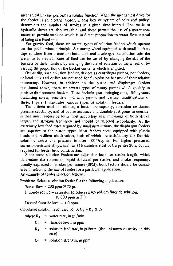
Figure 2. Screw-Type Volumetric Dry Feeder
MOTOR-DRIVEN
AGITATOR
TO DISSOLVING CHAMBER
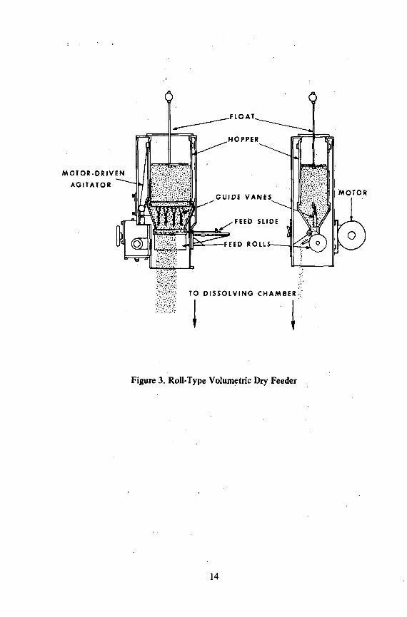
Figure 3. Roll-Type Volumetric Dry Feeder
14

Volumetric dry feeders are available in several types, distinguished by the means used for measuring and delivering the dry chemical. Among the types are the rotating roller, rotating disc, rotating and/or reciprocating screw, star wheel, moving belt, vibratory pan, oscillating hopper and combinations of these principles. See Figures 2 & 3 for illustrations of some of the types of volumetric dry feeders.
There are two general types of gravimetric dry feeders - those based on loss-in-weight of the feeder hopper and those which are based on the weight of material on a section of moving belt. Many gravimetric dry feeders also incorporate some of the features of volumetric feeders, in that they have a rotary feed mechanism between the hopper and the weighing section or use a mechanical vibrator to move chemicals out of the hopper. Since ultimately it is the weight of material per unit of time that is measured and regulated, such variables as material density or consistency have no effect on feed rate. This accounts for the extreme accuracy of which these feeders are capable. Gravimetric dry feeders are illustrated in Figures 4 and 5.
The stream or ribbon of dry material which is discharged from a dry feeder falls into a dissolving chamber where it is dissolved in water (see the section on Auxiliary Equipment). The solution thus prepared either falls by gravity into an open flume or clear well, or is transferred by a continuously-running pump or eductor into a pressure main.
The choice between a volumetric or gravimetric feeder is largely governed by size and economics. The gravimetrics are more expensive but have greater capacity, and are also basically more accurate. The selection of one of the types of volumetric feeders involves several factors, among them size, cost, accuracy, and personal preference.
Dry feeders are designed to handle powdered materials, but not all such materials are handled with equal ease. For example, material which is too fine will flow like a liquid right through the measuring mechanism ("flooding"). Some materials will form an arch in the hopper and when the arch collapses, emit a cloud of dust and then flood the feeder. Other powders, either hydroscopic by nature (water-attracters) or produced with a significant moisture content, tend to form lumps which will affect the feed rate or not be fed at all. For most consistent feeding, a narrow size distribution and a low moisture content is the best. A study of feeding problems with sodium silicofluoride resulted in the development of a "feedability index" (F):
F = 100-(A+B+ IOC), where A is the percentage retained on a 100-mesh sieve, B is the percentage passing through a 325-mesh sieve, and C is the percentage of moisture.
In almost every case, a feedability index below 80 proved to be unsatisfactory, 80 - 90 good, 90-100 excellent.
Examples: A shipment of sodium silicofluoride was sampled and subjected to particle-size analysis (see the section on particle size testing) with the following results: 3% retained on 100-mesh sieve, 9% passed through the
15
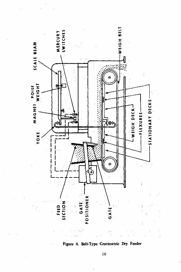
Figure 4. Belt-Type Gravimetric Dry Feeder
16
TRANSITION. HOPPER
HELIX TYPE -FEEDER MECH. VARIABLE RATE-SPEED SET FROM PHOTOCELL
CONTROL PANEL
RATE SETTER
-SCALE BEAM
VARIABLE SPEED FEEDER MOTOR
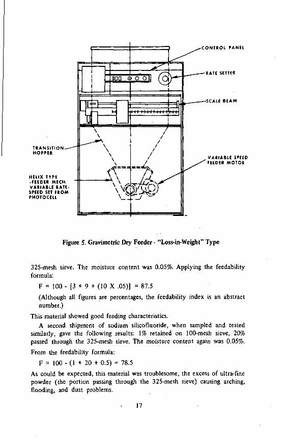
Figure 5. Gravimetric Dry Feeder - "Loss-in-Weight" Type
325-mesh sieve. The moisture content was 0.05%. Applying the feedability formula:
F = 100 - [3 + 9 + (10 X .05)] = 87.5
(Although all figures are percentages, the feedability index is an abstract number.)
This material showed good feeding characteristics. A second shipment of sodium silicofluoride, when sampled and tested
similarly, gave the following results: 1% retained on 100-mesh sieve, 20% passed through the 325-mesh sieve. The moisture content again was 0.05%.
From the feedability formula:
F = 100 - (1 + 20 + 0.5) = 78.5
As could be expected, this material was troublesome, the excess of ultra-fine powder (the portion passing through the 325-mesh sieve) causing arching, flooding, and dust problems.
17

The AWWA Standards for Sodium Silicofluoride (and Sodium Fluoride) limit the moisture content of these materials, and although the particle sizes are not precisely defined, the statement is made that the materials "shall be suitable for feeding with a conventional dry-feed machine as used in water treatment." In many cases, individual water plants have devised size specifications which assist them in purchasing chemicals handled adequately by.the feeders on hand. Ordinarily, chemicals specified as meeting AWWA Standards produce minimal feeding problems, but such is not the case with some nonstandard or imported chemicals.
Other problems related to the operation of a dry feeder are mentioned in the sections on auxiliary equipment and maintenance. As with solution feeders, manufacturers' bulletins and direct technical assistance can be utilized in the selection of appropriate equipment for a particular application. The criterion used in selecting the size of a dry feeder is similar to that used in selecting a solution feeder — they both operate most reliably when the delivery rate is near mid-range. All too often, dry feeders are used on water supplies which are so small that the feeder is operating at dead minimum or even below this rate, this latter feat being accomplished by equipping the feeder with a cycle timer. Obviously, accurate and uniform fluoride feed rates cannot be expected under these conditions.
TESTING PROCEDURES FOR DRY FEEDERS To determine the accuracy and reliability of a dry feeder, a small balance
or scales and a stop-watch, or a watch with a sweep-second hand, are required. Insert a shallow pan or sheet of cardboard between the measuring mechanism and dissolving chamber of the feeder while the feeder is operating, making sure that all the chemical which feeds through will be collected. Collect the chemical which is fed in several short periods, for example, five periods of five minutes each. Weigh each of the amounts collected and the total. Provided the weighings and timings are accurate, the individual samples will indicate the uniformity of feed, and the total will indicate the accuracy of feed rate.
Example: Weights of sodium silicofluoride collected in 5-minute periods: 35 grams 35 34 36 35
Total: 175 grams Average: 35 grams/minute
Uniformity: 35 ± 1 gram in 5 minutes (about 3% variation).
F d 35 grams X, 60 min = 420 grams/hr or 0.925 lbs/hr 5 min hr
The uniformity of feed in this case would be acceptable. If fluoride levels are to be maintained within 10%, the feeder delivery rate should certainly be maintained at the highest accuracy possible. Repeating ap test, as above, but with longer sampling periods, would tend to show smaller percentage of variation, provided, of course, the feeder is in good order.
18
CHECKING PARTICLE SIZE
Dry chemicals are often furnished in specified particle sizes, and to insure freedom from handling or feeding problems, it can be helpful to determine the degree of adherence to specifications. For example, crystalline sodium fluoride for use in a down-flow saturator should be in the 20-60 mesh range, and sodium silicofluoride should be relatively free from extremely coarse or extremely fine particles for best feeding characteristics.
The size of particles is usually determined with a set of standard sieves, the size designation then referring to the range of sieve sizes which best describes those particles. For example, a 20-60 specification means that most particles pass through a size 20 sieve but are retained by a size 60 sieve (the larger the sieve number, the smaller the openings).
The testing procedure is determined somewhat by the apparatus used, but generally a set of standard testing sieves is stacked, coarsest on top and progressively finer toward the bottom, above a collecting pan. A weighed amount of material is placed in the uppermost sieve, the set of sieves shaken gently (mechanically) for about five minutes, and then the portion collected by each sieve and the pan weighed separately.
Example: 100 grams of sodium silicofluoride, sieves: 100, 140, 200, 325, and pan.
Results: On 100 mesh 10 grams on 140 25 on 200 30 on 325 30 in pan 5
Assuming the moisture content of this particular material was 0.05% or less, applying the feedability formula would give the following results:
F= 100-(10+5+ 0.5) = 87.5 This result would indicate that the material should feed satisfactorily through a dry feeder.
AUXILIARY EQUIPMENT
For the simplest system, one involving a manually prepared fluoride solution and a proportioning pump feeding the solution into a water supply flowing at a fixed rate, the requirements for auxiliary equipment are minimal. A dissolving tank, either a paddle or electric mixer for stirring, a platform scale and the feeder itself are all the equipment needed. A vacuum breaker, to prevent pulling un-metered quantities of fluoride solution into the system in the event of a low-pressure situation, can be incorporated into the design of the feeder. Extras could include an alarm system for detecting and reporting low solution levels, a softener for removing hardness constituents from the solution water, a small meter for measuring the amount of water used in solution preparation, etc. As the size and complexity of the fluoridation system grows, the number and complexity of these pieces of auxiliary equipment increases, and their desirability becomes transformed to necessity.
19
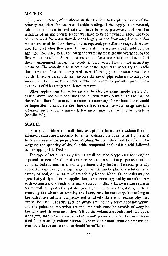
METERS
The water meter, often absent in the smallest water plants, is one of the primary requisites for accurate fluoride feeding. If the supply is un-metered, calculation of fluoride feed rate will have to be by guesswork, and even the selection of an appropriate feeder will have to be somewhat chancy. The type of meter used for water flow depends largely on the flow rate; disc or piston meters are used for low flows, and compound, propeller or magnetic meters used for the higher flow rates. Unfortunately, meters are usually sold by pipe size, not flow rate, so all too often the water meter is grossly oversized for the flow rate through it. Since most meters are least accurate at the low end of their measurement range, the result is that water flow is not accurately measured. The remedy is to select a meter no larger than necessary to handle the maximum flow rates expected, even if the pipe and meter sizes don't match. In some cases this may involve the use of pipe reducers to adapt the water main to the meter, a practice which is acceptable provided pressure loss as a result of this arrangement is not excessive.
Other applications for water meters, besides the main supply meters discussed above, are on supply lines for solution make-up water. In the case of the sodium fluoride saturator, a meter is a necessity, for without one it would be impossible to calculate the fluoride feed rate. Since water usage rate in a saturator installation is minimal, the meter must be the smallest available (usually V4").
SCALES
In any fluoridation installation, except one based on a sodium fluoride saturator, scales are a necessity for either weighing the quantity of dry material to be used in solution preparation, weighing the quantity of solution fed, or for weighing the quantity of dry fluoride compound or fluosilicic acid delivered by the appropriate feeder.
The type of scales can vary from a small household-type used for weighing a pound or two of sodium fluoride to be used in solution preparation to the complex built-in mechanism of a gravimetric dry feeder. The most generally applicable type is the platform scale, on which can be placed a solution tank, carboy of acid, or an entire volumetric dry feeder. Although the scales may be specifically designed for the application, as are those supplied by manufacturers with volumetric dry feeders, in many cases an ordinary hardware store type of scales will be perfectly satisfactory. Some minor modifications, such as removing the wheels or rotating the beam, may be necessary, but as long as the scales have sufficient capacity and sensitivity there is no reason why they cannot be used. Capacity and sensitivity are the only serious considerations, and the points to remember are that the scale must be capable of weighing the tank and its contents when full or the volumetric feeder and its hopper when full, with measurements to the nearest pound or better. For small scales used for measuring sodium fluoride to be used in manual solution preparation, sensitivity to the nearest ounce should be sufficient.
20

No particular problems should be encountered when mounting equipment on platform scales, except when there is connection to a water line, or the discharge line from the dissolving chamber of a volumetric dry feeder is fixed in place. It should be remembered that this dissolving chamber, or solution pot, is also mounted on the scale platform and thus all connections to it must be flexible enough to permit the scale to operate.
SOFTENERS
When a fluoridation system involving the use of sodium fluoride solutions is being considered, it should be remembered that, while sodium fluoride is quite soluble, the fluorides of calcium and magnesium are not. Thus, the fluoride ions in solution will combine with calcium and magnesium ions in the make-up water and form a precipitate which can clog the feeder, the injection port, the feeder suction line, the saturator bed, etc. For this reason, water used for sodium fluoride dissolution should be softened whenever the hardness exceeds 75 ppm, or even if the hardness is less than this figure but the amount of labor involved in clearing stoppages or removing scale is objectionable. Remember, the entire water supply need not be softened — only the water used for solution preparation.
Two types of softening treatment are available — ion exchange and the use of polyphosphates (calgon, micromet, etc.). Since the volume of water to be softened is usually quite small, a household type of zeolite water softener is usually adequate. This type of softener operates on the ion-exchange principle, and can be installed directly in the pipeline used for solution make-up. When softening capacity is exhausted, the zeolite (or synthetic resin) can be regenerated with brine made from common salt.
Polyphosphates can be used for sequestering (keeping in solution) calcium and magnesium, the amount required usually amounting to 7 to 15 mg/1. The polyphosphate may be added directly into the solution tank, but if an eductor is used both the eductor water and the dissolving water should be treated. (See the section on eductors.) In the latter case, some type of feeder will be required for adding the polyphosphate.
MIXERS
Whenever solutions are prepared, whether it be manual preparation of sodium fluoride solutions, dilution of fluosilicic acid, or the dissolution of the output of dry feeder, it is particularly important that the solution be homogeneous. Slurries must not be tolerated in the feeding of fluorides, since undissolved fluoride compound can go into solution subsequently, causing a higher-than-optimum situation, or if the fluoride compound remains undissolved, a lower-than-optimum situation will result. Undissolved material can also result in the clogging of feeders and other devices having smail openings, and if allowed to accumulate, results in considerable waste.
In the manual preparation of solutions, thorough mixing is a must. Even when a solution is being diluted, as in the preparation of fluosilicic acid
21

dilutions, the two liquids must be thoroughly mixed, since liquids of differing specific gravities tend to stratify, and such stratification could result in feeding a solution too concentrated, or at the other extreme, plain water. Sodium fluoride is quite soluble, but even the preparation of the most dilute solutions requires sufficient agitation. Undissolved material will remain in the bottom of the dissolving tank while a too-dilute solution is being fed, and even if it gradually dissolves, the strong solution formed at the bottom of the tank will tend to remain in its own stratum.
While a paddle, accompanied by sufficient "elbow grease," (manual mixing) will suffice for the preparation of the dilute solution, a mechanical mixer is preferred. Mixers come in various sizes, with shafts and propellers made of various materials. A fractional horse-power mixer with a stainless-steel shaft and propeller will be satisfactory for sodium fluoride solutions, and a similar mixer with a corrosion-resistant alloy or plastic-coated shaft and propeller will handle fluosilicic acid.
The dissolution of sodium silicofluoride in the solution pot of a dry feeder can be accomplished by a jet mixer, but again a mechanical mixer is preferred. Because of the low solubility of sodium silicofluoride, particularly in cold water, and the limited retention time available for dissolution, violent agitation is a must to prevent the discharge of a slurry. Preferred materials of construction are 316 stainless steel or plastic-coated steel.
DISSOLVING TANKS
The dry material discharged from a volumetric or gravimetric feeder is continuously dissolved in a chamber beneath the feeder, from whence the clear solution falls or is pumped into the water to be treated. This chamber, variously referred to as the solution pot, dissolver tank, solution tank, or dissolving chamber, may be a part of the feeder or a separate entity. While some chemicals can be fed directly into flumes or basins without using a dissolving tank, the fluorides are not among them. The necessity for accurate feed rates will not permit the possibility of slurry feed or the formation of build-ups of undissolved dry material.
Dissolving tanks come in sizes from 5 gallons up, the size often determined by the size of the feeder under which they are mounted. If there is a choice, the largest size available should be used for fluoride compounds. Mixing of the chemical with water is accomplished by a system of baffles, and agitation can be provided by a paddle driven by jets of water, or, as mentioned above, a mechanical mixer. Experience has shown that the jet mixer is not nearly so dependable as a good mechanical mixer, even under ideal conditions.
The failure to produce a clear, homogeneous solution discharge from the dissolving tank of a dry feeder indicates that (1) the dissolving chamber is too small, (2) the detention time is too short, (3) too little solution water is being provided, (4) agitation is insufficient, or (5) dry chemical is short-circuiting and is not being adequately mixed with the water.
22
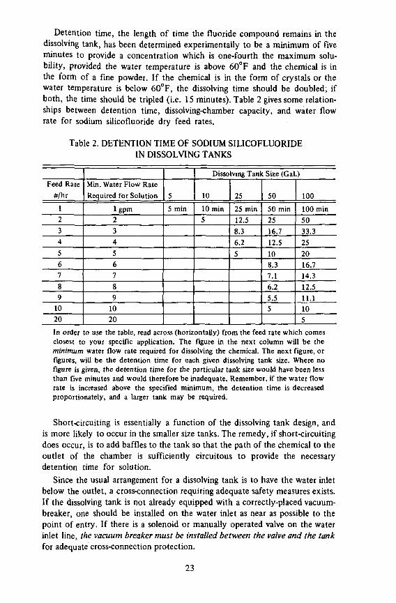
Detention time, the length of time the fluoride compound remains in the dissolving tank, has been determined experimentally to be a minimum of five minutes to provide a concentration which is one-fourth the maximum solubility, provided the water temperature is above 60°F and the chemical is in the form of a fine powder. If the chemical is in the form of crystals or the water temperature is below 60°F, the dissolving time should be doubled; if both, the time should be tripled (i.e. 15 minutes). Table 2 gives some relationships between detention time, dissolving-chamber capacity, and water flow rate for sodium silicofluoride dry feed rates.
Table 2. DETENTION TIME OF SODIUM SILICOFLUORIDE IN DISSOLVING TANKS
Feed Rate
#/hr
1
2
3
4
5
6
7
8
9
10
20
Min. Water Flow Rate
Required for Solution
lgpm 2
3
4
5
6
7
8
9
10
20
5
5 min
Dissolving Tank Size (Gal.)
10
10 min
5
25
25 min
12.5
8.3
6.2
5
50
50 min
25
16.7
12.5
10
8.3
7.1
6.2
5.5 5
100
100 min
50
33.3
25
20
16.7
14.3
12.5
11.1 10
5
In order to use the table, read across (horizontally) from the feed rate which comes closest to your specific application. The figure in the next column will be the minimum water flow rate required for dissolving the chemical. The next figure, or figures, will be the detention time for each given dissolving tank size. Where no figure is given, the detention time for the particular tank size would have been less than five minutes and would therefore be inadequate. Remember, if the water flow rate is increased above the specified minimum, the detention time is decreased proportionately, and a larger tank may be required.
Short-circuiting is essentially a function of the dissolving tank design, and is more likely to occur in the smaller size tanks. The remedy, if short-circuiting does occur, is to add baffles to the tank so that the path of the chemical to the outlet of the chamber is sufficiently circuitous to provide the necessary detention time for solution.
Since the usual arrangement for a dissolving tank is to have the water inlet below the outlet, a cross-connection requiring adequate safety measures exists. If the dissolving tank is not already equipped with a correctly-placed vacuum-breaker, one should be installed on the water inlet as near as possible to the point of entry. If there is a solenoid or manually operated valve on the water inlet line, the vacuum breaker must be installed between the valve and the tank for adequate cross-connection protection.
23
FLOW METERS
A flow meter, in contrast to an ordinary water meter, measures rate of flow rather than volume of flow. While those used for measuring flow rates in large pipelines operate on various differential-pressure principles, the flow meters applicable to small flows are usually based on the lifting of a spherical or cylindrical "float" by the hydraulic action of a flowing fluid in a vertical tube.
In a water plant where the water output is variable, as in cases where more than one pump is used, a flow-meter on the main serves two purposes: it will indicate the flow rates on which the fluoride feeder or feeders must operate, and if so designed, will provide an electrical, pneumatic or hydraulic signal which can be used to adjust the feeder output to correspond to changes in water flow rate. This type of flow meter is discussed further in the section on system selection.
The flow meter used in small pipelines, often known as a rotameter, finds application on the water supply to the dissolving chamber of a dry feeder. Since, as mentioned above, detention time is a function of water flow rate, among other things, the flow must be regulated and maintained at the prescribed figure.
The flow meter must be selected on the basis of pipe size, nature of fluid (water) and particularly, the range of flows expected. For greatest accuracy, the range of the flow meter should coincide with the range of flows which will be encountered in the particular installation.
DAY TANKS
A day tank is just what the name implies - a tank which holds a day's supply of a particular water treatment chemical. It is a convenient, and often necessary, means for isolating the supply of fluoride solution which will be fed during one day or shift at the water plant.
The day tank is a necessity when feeding fluosilicic acid, particularly if the acid is received and stored in a large tank. In order to provide a record of the weight of acid fed, a small quantity of the acid is pumped or siphoned into a small tank mounted on a platform scale, and it is from this day tank that the fluosilicic acid is fed into the water system. A similar arrangement can be used for sodium fluoride solutions or fluosilicic acid dilutions. A large batch of the solution or dilution can be prepared, and a smaller amount transferred to the day tank mounted on the platform scale. This system reduces the amount of labor for preparing solutions or dilutions, and is an additional safeguard against over-feeding.
Materials of construction for day tanks are determined by the chemical being used, but plastics such as polyethylene are generally applicable. The tank can be provided with graduations or some sort of gauge so that approximate volume measurements can be used. Commercial mixing tanks are available with the day tank mounted on the cover, a convenient means for preparing fluosilicic acid dilutions, but this arrangement does not permit weighing the acid, so volume measurements must be relied upon.
24
BAG LOADERS
When the hopper of a dry feeder is directly above the feeder, that is, when the operator has to lift the chemical to a considerable height in order to fill the hopper, a bag loader is more a necessity than a convenience. A bag loader is essentially a hopper extension large enough to hold a single 100-pound bag of chemical. The front of the loader is hinged so that it will swing down to a more accessible height. The operator places a bag in the hinged section, opens the bag and then swings the section back into position. This device not only lessens the labor required to empty a bag, but also eliminates a good part of the dust resulting from bag emptying.
DUST COLLECTORS AND WET SCRUBBERS
The handling of powdered dry chemicals invariably results in the generation of various quantities of dust. When the quantities of fluoride compounds being handled are small, ordinary care will minimize the dust problem, and good housekeeping plus an exhaust fan will keep the storage and loading area relatively dust-free. However, when larger quantities (i.e., more than one bag at a time) are handled, dust prevention and collection facilities should be provided.
A dust canopy, completely enclosing the hopper-filling area, and provided with an exhaust fan, will prevent the dissemination of dust throughout the loading area. To prevent the escape of dust into the atmosphere and thence into the area surrounding the water plant, dust filters can be incorporated into the exhaust system.
Dust collectors and exhaust fans are sometimes incorporated into the hoppers of the larger dry feeders.
Wet scrubbers are a means for removing dust from exhausted air. The air flows through a chamber in which there is a continuous water spray. The air is thus "scrubbed" clean and the erstwhile dust particles are dissolved or carried down the drain by water.
ALARMS
To prevent underfeeding or even loss of feed, alarm systems can be included in either solution or dry feed systems. The alarm will serve to alert the operator to the fact that the level of solution in the day tank is low, or that it is time to add another bag of dry chemical to a hopper. An alarm can also notify the operator that the water supply to a saturator or to a dissolving tank has either stopped or diminished.
The alarms are based on level switches, flow switches, pressure switches, etc.
VACUUM BREAKERS
Any time there is a water connection to a chemical solution there is the possibility of a cross-connection. This can be in the supply line to a saturator or dissolving tank, or in the discharge from either of these or any solution feeder.
25

The simplest method for preventing a potential siphonage situation is to provide an air-gap in the line. When pressure is high enough to make an air-gap impractical, (as in the supply line to a dissolving chamber) a device known as a vacuum-breaker must.be used. A vacuum-breaker is essentially a valve which is kept closed by water pressure, but when the water pressure fails, the valve opens to atmosphere allowing air to be drawn into the system rather than potentially hazardous solutions.
For utmost safety, the vacuum breaker should be installed as close to the chemical solution as possible, and especially must be elevated above the lip of the tank and on the discharge side of the last control valve.
In those States where mechanical vacuum breakers are not permitted, potential siphonage hazards can be eliminated by other means. See the section on cross-connections.
HOPPERS
Most dry feeders come equipped with a hopper, but for larger installations additional hopper capacity is often desired. Quite often this entails extension of the existing hopper up to the floor above, not only increasing hopper capacity but making it easier to fill. If at all feasible, the chemical storage should be on the floor above the feeder. If the extension hopper reaches to about 12" above the floor of the storage room the edge of the hopper can serve as a fulcrum point as an aid to upending drums or barrels.
In small plants, it is desirable to have the chemical hopper large enough to hold slightly more than the entire shipping container of chemical. Thus the hopper will not be completely empty before there is enough room in it for the contents of a fresh bag or drum. By loading an entire container in this manner, there will be less handling of chemical and a saving of time. There will be less dusting, with improved working conditions. There will be less chance of spillage, with consequent saving of chemical. By not allowing the hopper to become completely empty, there will be less chance of arching and flooding, and also less chance for an interruption in feed.
Hoppers, whether those supplied with the feeder or those constructed at the plant, may require vibrators to insure uniform feed. A rotary valve can be installed between the hopper and the feeder to prevent flooding, and a gate can be installed in the extension hopper to limit the amount of material falling to the feeder hopper at any given time.
WEIGHT RECORDERS
Whenever a platform scale is used to measure the amount of dry chemical or solution fed during a given period, a recorder can be attached so that a record of the weight of chemical fed can be obtained. Many volumetric dry feeders have such recorders available as an accessory (along with the scales) so that the loss-of-weight feature makes the feeder somewhat equivalent to a gravimetric dry feeder.
26
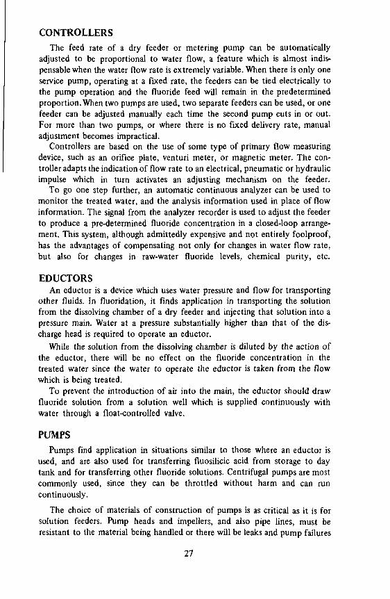
CONTROLLERS
The feed rate of a dry feeder or metering pump can be automatically adjusted to be proportional to water flow, a feature which is almost indispensable when the water flow rate is extremely variable. When there is only one service pump, operating at a fixed rate, the feeders can be tied electrically to the pump operation and the fluoride feed will remain in the predetermined proportion. When two pumps are used, two separate feeders can be used, or one feeder can be adjusted manually each time the second pump cuts in or out. For more than two pumps, or where there is no fixed delivery rate, manual adjustment becomes impractical.
Controllers are based on the use of some type of primary flow measuring device, such as an orifice plate, venturi meter, or magnetic meter. The controller adapts the indication of flow rate to an electrical, pneumatic or hydraulic impulse which in turn activates an adjusting mechanism on the feeder.
To go one step further, an automatic continuous analyzer can be used to monitor the treated water, and the analysis information used in place of flow information. The signal from the analyzer recorder is used to adjust the feeder to produce a pre-determined fluoride concentration in a closed-loop arrangement. This system, although admittedly expensive and not entirely foolproof, has the advantages of compensating not only for changes in water flow rate, but also for changes in raw-water fluoride levels, chemical purity, etc.
EDUCTORS An eductor is a device which uses water pressure and flow for transporting
other fluids. In fluoridation, it finds application in transporting the solution from the dissolving chamber of a dry feeder and injecting that solution into a pressure main. Water at a pressure substantially higher than that of the discharge head is required to operate an eductor.
While the solution from the dissolving chamber is diluted by the action of the eductor, there will be no effect on the fluoride concentration in the treated water since the water to operate the eductor is taken from the flow which is being treated.
To prevent the introduction of air into the main, the eductor should draw fluoride solution from a solution well which is supplied continuously with water through a float-controlled valve.
PUMPS
Pumps find application in situations similar to those where an eductor is used, and are also used for transferring fluosilicic acid from storage to day tank and for transferring other fluoride solutions. Centrifugal pumps are most commonly used, since they can be throttled without harm and can run continuously.
The choice of materials of construction of pumps is as critical as it is for solution feeders. Pump heads and impellers, and also pipe lines, must be resistant to the material being handled or there will be leaks and pump failures
27
to contend with. The avoidance of slurry transfer is important, also, since slurries tend to be abrasive and can damage pump heads, impellers and packing.
TIMERS An interval timer is basically a clock mechanism, usually electric, which
closes or opens an electric switch upon receipt of a signal, holds the switch in position for the pre-set time interval and then reverses the switch position. Timers are frequently used in conjunction with water meter contactors to operate solution feeders. When the contact is made in the water meter, the timer is energized and the feeder will run for the period selected. The momentary contact made by the meter contactor, while sufficient to produce a stroke of a solenoid-operated feeder, is too short to operate an electric-motor operated feeder. Thus, the timer serves to extend the impulse received from the contactor.
Another application of a timer is for those installations where the minimum reliable feeder setting is still too high for the water flow. In these cases, the timer can be set to provide a proportion of the full-time feed rate. For example, by setting the timer to operate the feeder at 75% of each 1-minute period, the feed rate will only be 75% of that obtained without the use of the timer.
A word of caution: Using a proportional timer at low percentages, and particularly for long interval settings, can result in cyclic fluoride levels. If there is insufficient detention time in clear wells or pipelines before water reaches the consumers, the on-off action of the feeder will be apparent in alternately too-high and too-low fluoride readings. The remedy is, other than using a smaller feeder, to make the proportioned time interval as short as possible.
HOPPER AGITATORS
To promote the smooth and even flow of dry material in a hopper, some sort of agitation is helpful. The hopper agitator may take the form of a device which imparts vibration magnetically or mechanically to the outside of the hopper, or may be a rotating member inside the hopper.
Many dry feeders incorporate a hopper agitator into their construction.
FLOW-SPLITTERS When the effluent from the dissolving chamber of a dry feeder is to be
used for more than one point of fluoride application, the effluent can be divided with a flow-splitter. This device is nothing more than a movable baffle in the dissolving chamber which can be adjusted to vary the proportion of solution flowing out of two outlets.
An example of an application involving a flow-splitter would be when two water sources, with no common point for fluoride injection, are to be fluoridated with a single dry feeder. By adjusting the splitter so that the right proportion of fluoride is fed to each source, the cost of an additional feeder is saved.
It should be noted that a flow-splitter is grossly inaccurate and should not be used except when no other alternative is available.
28
(?) VARIABLE SPEED CONTIOl UNIT
, . 110 VOlI___f=k<
now ® fown —=i r METEI SUPPLY I I
T - r - ' . IOW HOW | A * " ^ CUTOFF HELAY
POWII r = . = | | Q | F ~ - J J " ~ ~ / ' - * ' I t PP.OPOKTIONINO / - \
JUPPIY lrT\l (ar~ 'u«p V5> no VOLT | | w
HYOHOFLUOSIIICIC ACID
sronAOi TANK
MOOBl 304 FILL LINE
CHEMICAL 8AC
0 SAO LOADING HOPPEH-.
(5) LOSS OF WEIGH! P.ECOHDINQ SCALE
POWEK SUPPLY-
Q M E L I X FEEDER MODEL 2S
,POWE« SUPPLY
r ^ f f M ' c M A S i r » r M i l S S > ^ IIF KEOUIHfO)
m © o.sso
PACING SIGNAL
(3) MEIfK INSFHUMfNT MODEL 304
^ VAIEU SUPPLY' /T \ , ' D U , I O , )LENOID VALVE & ! D " l ° " ,
IIF P.EOUIP.EDI INFLUENT £
- POWEP. SUPPLY
is
IIF HEOUIP.EDI y
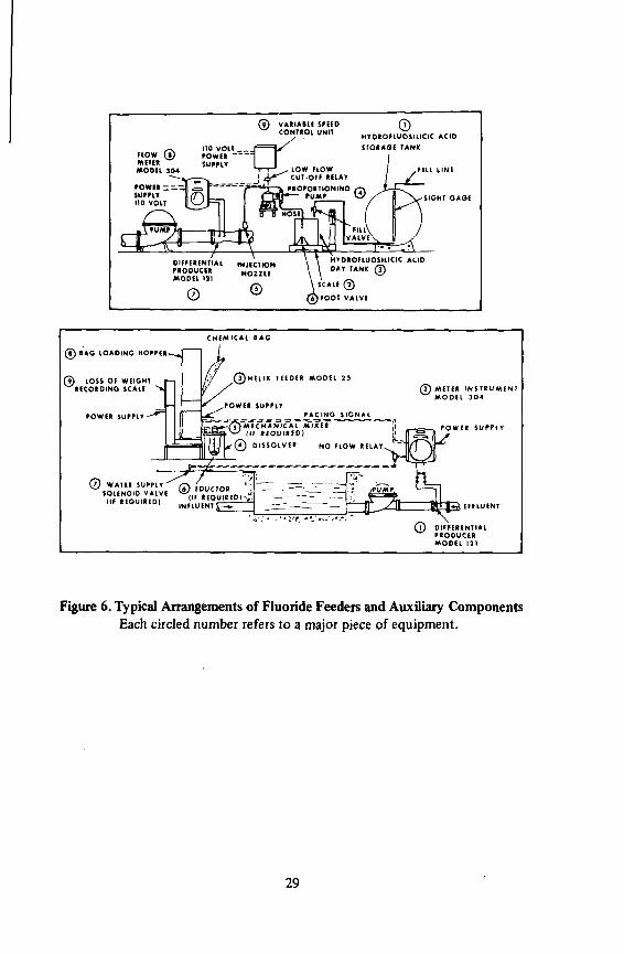
(T) DIFFERENTIAL PRODUCER MODEL 131
Figure 6. Typical Arrangements of Fluoride Feeders and Auxiliary Components Each circled number refers to a major piece of equipment.
29

DUST COLLECTOR
HOPPER COVER
HOPPER SCREEN
FLOOR FLANGE
HOPPER RETAINER
VIBRATOR (OPTIONAL
HELIX FEEDER MODEL 25 -04
WEIGH SCALE —,
FEEDER BASE
APPROX. 10 FT.
DRAIN
Figure 7. Typical Arrangement of Dry Feed Hoppers and Dust Collectors
Figures 6 and 7, and Figures 13 through 17 illustrate the use and arrangement of various pieces of auxiliary equipment in fluoridation installations.
30
Chapter IV Preparation Of Fluoride Solutions
MANUAL TECHNIQUE
The most basic fluoridation system, involving the least expenditure for equipment, is one involving the proportional feeding of a fluoride solution into a water flow in a pipeline. The only requirements are the preparation of a fluoride solution of known concentration, and then pumping that solution into the water so that the desired fluoride concentration in the water is achieved. Of the most commonly used fluoride compounds, sodium fluoride and fluosil-icic acid are of sufficient solubility for preparation of solutions of fixed strength which then can be fed with a metering pump.
Fluosilicic acid, already a solution as purchased, can be fed directly from the shipping container, from an intermediate storage tank (day tank), or can be diluted and fed as a solution considerably weaker than the 22 - 30% acid solution originally purchased. Dilution is necessary in small water plants, where the water flow to be treated is so low that the smallest proportioning pump cannot be adjusted to a low enough feed-rate setting for undiluted acid, or where the feeder cannot be expected to operate reliably at the extremely low setting required. As pointed out in the section on Feeders, extremes in feed-rate range should be avoided, and even the smallest feeder will not deliver a fraction of a drop per stroke with any degree of reliability.
Example: Data known: Water flow rate - 100 gpm Cone, of fluosilicic acid - 25% Concentration of F wanted - 1.0 ppm Specific gravity of acid- 1.22
Problem: Find volume of acid to be fed per minute, and the volume of acid to be delivered per stroke of a feeder which operates at 46 strokes per minute.
Calculations: Ri X C] = R2 X C2, where: R! = water flow rate in gal/min
C) = desired F level in ppm R2 = feed rate C2 = solution strength as F
31

then: 100 gal/min X 3785 ml/gal X 1.0 ppm = (x) X 25% X 79%
. _ 100 gal/min X 3785 ml/gal X 1.0 ppm W 25% X 79% X 1.22 (specific gravity)
By expressing percentages as decimals, and ppm as the fraction 1/1,000,000, units will cancel to give:
(x) = 1.6 ml/rnin, and * ' 6 m l / f m i n = 0.035 ml/stroke v ' 46 strokes/mm
Obviously, the above volume per stroke is too small (a drop is usually considered to be 0.05 ml) to be handled by even the smallest feeder, so dilution of the acid is mandatory for reliable feed. If the acid were diluted at the ratio of one gallon to nine gallons of water (resulting in acid of 2.5% strength), the volume of acid to be fed per minute would be:
1001 gal/min X 3785 ml/gal 0.025 X 0.79 X 1.02 (sp. gr.) X V1'000'000 0 PPm)
= 19ml/min 19 ml/min . ., .. t . . , ' ,—, . =0.41 ml/stroke 46 Strokes/min
The above volume is well within the capability of a small solution feeder, for example, one which has a delivery range of 0.1 to 1.0 ml/stroke. Note that, while decreasing the stroke frequency would permit larger volumes to be handled per stroke, such practice also has its limitations, since infrequent stroking results in cyclic variations in fluoride levels in the water.
The dilution of fluosilicic acid should be made by carefully pouring the measured volume (or weight) of acid into a measured volume of water. (While adding water to acid would not be particularly hazardous in this case, because of the low strength of commercial acid, it is always good practice to add acid to water rather than the reverse.) All containers used for handling even dilute acid must be made of a material resistant to the corrosive effects of the acid (plastic or hard rubber are suitable) and the solution should be thoroughly mixed with a plastic or wooden paddle. Avoid splashing or spilling, wear protective gloves and clothing, and mop up all spills with a solution of soda ash or other alkaline material followed by several clear water rinses. The solution tank should be kept on a platform scales, and records kept of the weights or volumes of acid and water used in each batch of solution prepared, and particularly of the weight of solution fed.
Precaution: Dilution of fluosilicic acid can result in the formation of a precipitate (silica) when the dilution is in the range of ten to twenty parts of water to one of acid. Such precipitation, which can result in clogged feeders, valves and orifices, can be avoided by using fortified acid (acid to which a small amount of hydrofluoric acid has been added by the supplier) or by using acid manufactured from hydrofluoric acid rather than from phosphate rock.
Sodium Fluoride, being soluble up to 4% (4 pounds in 100 pounds of water) can be fed as a solution by dissolving a weighed amount of the dry material in a
32

measured volume of water. By usual means, a 4% solution is difficult to attain, so for practical purposes, solution strength should be limited to about 2%.
Example: Data known:
Water flow rate - 100 gpm Sodium fluoride solution - 8 lbs of 99% pure NaF dissolved in 50 gal. of
water
Problem:
Find volume of solution to be fed per minute to produce a concentration of 1.0 ppm F in the water.
Calculations: R, XC! = R2 XC2; R2 = R, XC t where R, = water flow rate in
C2 gal/min Ci = desired F level in ppm R2 = feed rate C2 - solution strength as F
100 gal/min X 1.0 ppm . . . 0~* —Tc T T T ^ = 0.012 gal/min 8300 ppm (from Table 3) ° 0.012 gal/min X 3785 ml/gal = 46 ml/min At the relatively low concentrations used in sodium fluoride solutions, the
specific gravity is so close to 1.0 that volume measurements instead of weight may be used in calculations of feed rate.
Although sodium fluoride solutions are not particularly corrosive, a plastic container is preferred for preparation of solutions. The mixture may be stirred with a paddle until the sodium fluoride is completely dissolved, or a small mechanical mixer may be used. Table 3 gives quantities of sodium fluoride and water to be used for various solution strengths.
AUTOMATIC DEVICES
Because sodium fluoride has a maximum solubility of around 4% (18,000 ppm as F), regardless of substantial variations in water temperature, devices for automatically preparing saturated solutions can be used. The use of these devices eliminates the need for weighing sodium fluoride, measuring solution water volume, and for stirring to insure dissolution.
The principle of a saturator, as these devices are called, is that a saturated solution will result if water is allowed to trickle through a bed containing a large excess of sodium fluoride. There are two general types of saturators - upflow and downflow. In the latter type, the solid sodium fluoride is isolated from the prepared solution by a plastic cone or a pipe manifold. A filtration barrier is provided by layers of sand and gravel to prevent particles of undissolved sodium fluoride from infiltrating the solution area under the cone or within the pipe manifold (Figs. 8, 9, & 10). In the upflow type, no barrier is used, since the water comes up through the bed of sodium fluoride and the specific
33

Table 3. PREPARATION OF SOLUTIONS OF SODIUM FLUORIDE
Pounds of
NaF
(98% pure)
1
2
3
4
5
6
7
8
9
10
11
12
13
14
15
16
17
GALLONS OF WATER
10
1.2
5200
2.3
10300
20
0.6
2600
1.2
5200
1.75.
7750
2.3
10300
30
0.4
1750
0.8
3500
1.2
5200
1.55
7000
2.0
8600
40
0.3
1300
0.6
2600
0.9
3900
1.2
5200
1.5
6500
1.8
7800
2.0
9000
50
0.5
2100
0.7
3100
1.0
4200
1.2
5200
1.4
6200
1.65
7300
1.9
8300
2.1
9300
60
0.4
1750
0.6
2600
0.8
3500
1.0
4350
1.2
5200
1.4
6000
1.6
6900
1.75
7800
1.95
8600
2.15
9450
70
0.3
1500
0.5
2250
0.7
3000
0.85
3700
1.0
4300
1.2
5200
1.35
6000
1.5
6700
1.7
7400
1.85
8200
2.0
8900
80
0.45
1950
0.6
2000
0.75
3300
0.9
3900
1.0
4600
1.15
5100
1.3
5850
1.5
6500
1.6
7200
1.8
7800
1.9
8400
2.1
9100
90
0.4
1750
0.5
2300
0.7
2900
0.8
3500
0.9
4000
1.05
4650
1.2
5200
1.3
5800
1.45
6400
1.6
6900
1.7
7500
1.8
8100
1.95
8600
2.0
9000
100
0.4
1600
0.5
2100
0.6
2600
0.7
3150
0.8
3650
0.95
4200
1.1
4700
1.2
5200
1.3
5750
1.4
6250
1.5
6750
1.65
7300
1.8
7800
1.9
8300
2.0
8800
The above table gives strengths of solutions prepared by dissolving the given weights of sodium fluoride in various volumes of water. The upper figures represent approximate solution strength in percent sodium fluoride, while the lower figures represent approximate solution concentration in ppm F. Example: If 2 lbs of NaF are dissolved in 50 gallons of water, what is the solution strength? Reading across (horizontally) from 2 lbs to the 50 gal. column gives 0.5% NaF and 2100 ppm F.
The absence of figures in a column indicates that the preparation of the particular solution would be impractical or impossible.
34
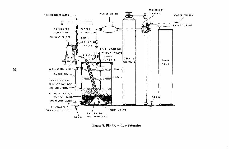
LINE BEING TREATED- W ATER METER
MULTIPORT
VALVE
SATURATED
S O L U T I O N ~
CHEM-O-FEEDER
WATER
SUPPLY
A N T I -
WATER SUPPLY
WALL MTD
OVERFLC
GRANULAR
M I N OF 10
47. SOLUTIC
4 TO 6 OF
TO 1/4
(TORPEDO
2 COARSE
GRAVEL (1 TO 2
BRINE TUBING
FOOT VALVE
SATURATED SOLUTION NoF
o.
BRINE
TANK
D R A I N
~T
Figure 8. BIF Downflow Saturator

LIQUID
Figure 9. W & T Downflow Saturator
gravity of the solid material keeps it from rising into the area of clear solution above. In the downflow type, the feeder takes suction from within the cone or manifold, while in the upflow type, the feeder suction intake floats on the solution in order to avoid withdrawal of undissolved sodium fluoride.
When a downflow-type saturator is in operation, water is admitted at the top of the saturator tank (there is an air gap to avoid the possibility of a cross-connection) and the level is regulated with a float-operated controller. The water then trickles down through the bed of sodium fluoride, the solution is clarified in the sand and gravel filter bed and ends up as a clear, saturated solution at the bottom of the tank where it is withdrawn by the feeder. The feeder adds the prepared solution, at the desired rate, to the water system. The only operator attention required is to see that an adequate quantity of sodium fluoride is kept in the saturator and that the saturator is kept in a reasonably clean condition (See Table 4).
36

TO POINT OF APPLICATION
ANTI-SIPHON VALVE ,?• PCPC S000 SERI
FLUORIDE PUA RIES V j j M P ^ ft.--* -
PCPC L I O U I D ^ * \ J LEVEL SWITCH
3 / 4 " NPT OVERFLOW
PVC BALL V A L V E ( O P T I O N A L ) 3 / 4 * NPT DRAIN
Figure 10. Precision Up-Flow Saturator

Table 4. RECOMMENDED MAXIMUM FEED RATES FOR DOWNFLOW SODIUM FLUORIDE SATURATOR
Bed Depth
6"
6W
7"
7W
8"
8#"
9"
9)4"
10"
60°F
950 gpm 200 ml/min
1065 gpm 225 ml/min
1190 gpm 250 ml/min
1300 gpm 275 ml/min
1425 gpm 300 ml/min
1550 gpm 325 ml/min
1660 gpm 350 ml/min
1780 gpm 375 ml/min
1900 gpm 400 ml/min
Water Temperature 50°F
830 gpm 175 ml/min
950 gpm 200 ml/min
1065 gpm 225 ml/min
1190gpm 250 ml/min
1300gpm 275 ml/min
1425 gpm 300 ml/min
1550 gpm 325 ml/min
1660 gpm 350 ml/min
1780gpm 375 ml/min
40°F
710 gpm 150 ml/min
830 gpm 175 ml/min
950 gpm 200 ml/min
1065 gpm 225 ml/min
1190 gpm 250 ml/min
1300gpm 275 ml/min
1425 gpm 300 ml/min
1550 gpm 325 ml/min
1660 gpm 350 ml/min
In the above table, the lower figures represent the maximum feed rate (or withdrawal rate) of saturated sodium fluoride solution for each given bed depth of sodium fluoride at each of three saturator water supply temperatures. The upper figures represent the water flow rate which can be fluoridated to a level of 1.0 ppm F for each respective solution feed rate, assuming there is less than 0.1 ppm natural fluoride content in the water. Higher flow rates can be fluoridated if there is a higher natural fluoride content or if the desired level is less than 1.0 ppm F.
To prepare a downflow saturator for use:
1. With the manifold (W & T) or cone (BIF) in place, carefully place by hand a 2 - 3" layer of coarse, clean gravel ( 1 - 2 " size) in the saturator tank, around the manifold or cone and over the manifold or over the lower edge of the cone. Then place another 2 - 3" layer of finer gravel QA - 1" size) over the coarse gravel.
38

2. Place a 4 - 6" layer of clean, sharp filter sand over the gravel. (Do not use beach sand, clayey sand or ordinary soil.) Level the sand surface. (A 12" bed of 1/8" to 1/4" filter gravel can be substituted for the sand and coarse gravel layers.)
3. Add 200 lbs of coarse crystalline sodium fluoride (Olin 20 - 60 mesh, Allied coarse crystal, or similar. Do not use powdered NaF or fine crystal.) Add water to keep down the dust and to assist in leveling the fluoride surface.
4. Check to see if the float has room to operate. If necessary make a depression in the fluoride surface to provide clearance for the float and float-rod.
5. If you have not already done so, connect a cold-water supply line to the water intake of the saturator. The line should contain a small water meter (1/2") for use in calculating feed rate, and there should be a shut-off valve between the meter and the saturator.
6. Turn on the water supply and adjust the float position if necessary. The low-water-level should be no less than 2" above the fluoride surface, and the high-water level should be just below the overflow outlet.
7. Insert the feeder suction line into the pipe leading to the inner cone or manifold as the case may be. Adjust the length of suction line so that the foot-valve and strainer are 2 - 3" above the bottom of the saturator tank. The saturator is now ready for use.
8. By looking through the translucent wall of the saturator tank you should be able to distinguish the layers of fluoride, sand and gravel. When the thickness of the fluoride layer decreases to 6", add another 100# quantity of fluoride. It would be wise to add the fluoride when the water level is at its lowest level, or if necessary, to shut off the water temporarily until there is enough room for the fluoride without causing water to come out of the overflow opening.
9. If the saturator is being used at a high rate, that is, if more than 1000 gpm of water are being treated, fluoride should be added daily in sufficient amounts to keep the fluoride layer at a thickness of at least 10". The same daily additions of fluoride should be made if the make-up water temperature is below 60°F, even if less than 1000 gpm of water are being treated.
10. Before more fluoride is added to the saturator, the surface of the fluoride layer in the saturator should be scraped free of accumulated dirt, insoluble material or the slimy film of fine particles that sometimes forms. Such routine maintenance permits better percolation of water through the fluoride layer and extends the length of time between clean-outs.
11. At regular intervals, depending on severity of use, the saturator will have to be cleaned out. A typical schedule calls for a clean-out every three months when the quantity of water being treated is in the 100 gpm area
39
and the accumulation of dirt in the saturator is moderate. The clean-out procedure is as follows: a. Continue using the saturator until the level of sodium fluoride is as low
as practicable. Shut off the water supply to permit the level of water to drop down to the fluoride layer. This step minimizes the wastage of chemical and decreases the amount of material which will have to be removed.
b. Scoop out the remaining sodium fluoride, the sand and gravel. If the sand and gravel are to be re-used, place them in separate buckets. If fresh sand and gravel are available, bury the dirty material. The old sodium fluoride can be flushed down a drain or buried.
c. Remove the inner cone or manifold assembly and clean the inside of the saturator tank. Replace the cleaned cone or manifold.
d. If the old sand and gravel are to be re-used, wash them repeatedly with water until all traces of fluoride and dirt are removed. Then reconstruct the filter bed of sand and gravel as before with either the cleaned or fresh material.
e. Add sodium fluoride as before and return the saturator to normal operation. (Don't forget to turn on the water supply again.)
12. If the water supplied to the saturator is hard (more than 75 ppm hardness), a household-type water softener in the line will minimize the amount of insoluble material accumulating in the saturator and thus increase the interval between clean-outs.
13. Use the readings of the water meter on the saturator supply line to calculate the amount of fluoride fed. A 4% solution of sodium fluoride is equivalent to 18,000 ppm F. Thus:
Gallons of water supplied to saturator . , , n nr. _ „ •pr-r. c — : ^—~A X 18,000 = ppm F Gallons of water pumped r
(See Page 43 for example problem.) In an upflow saturator, undissolved sodium fluoride forms its own bed,
below which water is forced upward under pressure. A spider type water distributor located at the bottom of the tank contains hundreds of very small slits. Water, forced under pressure through these slits, flows upwards through the sodium fluoride bed at a controlled rate to assure the desired 4% solution. The water pressure requirements are 20 psi minimum to 125 psi maximum, and the flow is regulated at 4 gpm. Since introduction of water to the bottom of the saturator constitutes a definite cross-connection, a mechanical syphon-breaker is incorporated into the water line. Where such devices are not permitted, the saturator can be factory-modified to include an air-gap and a water feedpump.
To prepare an upflow saturator for use:
1. With the distributor tubes in place, and the floating suction device removed, add 200 to 300 pounds of sodium fluoride directly to the tank. (Any type of sodium fluoride can be used, from coarse crystal to fine
40

powder, but fine crystal will produce less dust than powder and will dissolve better than coarse material.)
2. Connect the solenoid water valve to an electric outlet and turn on the water supply. The water level should be slightly below the overflow; if it is not, the liquid level switch should be adjusted.
3. Replace the intake float and connect it to the feeder intake line. The saturator is now ready for use.
4. By looking through the translucent wall of the saturator tank you should be able to see the level of undissolved sodium fluoride. Whenever the level is low enough, add another 100# quantity of fluoride.
5. The water distributor slits are supposed to be essentially self-cleaning, and the accumulation of insolubles and precipitates does not constitute as serious a problem as it does in a downflow saturator. However, periodic cleaning is still required. Frequency of cleaning is dictated by the severity of use and the rate of accumulation of debris.
6. Because of the thicker bed of sodium fluoride attainable in an upflow saturator, higher withdrawal rates are possible. With 300# of sodium fluoride in the saturator tank, more than 1000 ml/min of saturated solution can be fed, a rate sufficient to treat about 5000 gpm of water to a fluoride level of 1.0 ppm.
7. Precautions regarding hard water apply similarly to both types of saturators.
8. Method for calculating the amount of fluoride fed is the same for both types of saturators. The fixed water inlet rate of 4 gpm should register satisfactorily on a M." meter.
The preparation of solutions of fluoride compounds, whether performed manually or automatically, requires a certain amount of care. The sources of possible error in the dilution of fluosilicic acid are:
1. Incorrect volume or weight of acid.
2. Incorrect volume or weight of water. 3. Incomplete mixing.
4. Miscalculation of acid strength as received. 5. Miscalculation of fluoride concentration in dilution.
In the manual preparation of sodium fluoride solutions, the sources of possible error are:
1. Incorrect weight of sodium fluoride.
2. Incorrect weight or volume of water. 3. Incomplete dissolution. 4. Incomplete mixing. 5. Attempting concentration above 2%.
6. Miscalculation of fluoride concentration in the sodium fluoride.
41

7. Miscalculation of fluoride concentration of the solution.
The proper function of a device for automatically preparing solutions (saturator) can be adversely affected by the following:
1. Insufficient quantity of sodium fluoride. 2. Water too cold for feed rate used.
3. Withdrawal rate too high. 4. Sifting of sodium fluoride through sand and gravel (downflow type). 5. Lifting of sodium fluoride (upflow type). 6. Wrong crystal size (downflow type). 7. Failure to scrape surface (downflow type). 8. Short-circuiting (downflow type). 9. Insufficient water supply (stoppage or valve closing).
CALCULATIONS INVOLVING SOLUTIONS
As in the examples above, the equation, Ri X C! = R2 X C2 (water flow rate times fluoride level desired equals solution feed rate times fluoride concentration of the solution), should be used to calculate the theoretical mean fluoride concentration for a given time interval. Obviously, accurate figures for weights or volumes of materials used are necessary for accurate calculations. The use of appropriate units (which can be cancelled arithmetically) will produce a calculated result in the desired units and will verify the proper insertion of figures into the equation. For instance, with Ri in gallons, C! in ppm, and C2 in ppm, R2 will be in gallons. A calculated result in any other units would indicate an error.
Some examples of typical calculations are given below.
Example 1: A water plant pumps 300,000 gallons of water in one day. Sodium fluoride solution, prepared by dissolving 8# of 98% NaF in 50 gallons of water, is the fluoride source. The solution tank is mounted on scales, and the scales indicate that 250# of solution was fed. What is the calculated fluoride level in the treated water?
Calculations: R. * C, = R2 X C2; C, = I ^ X C , Ri
(R] in lbs, R2 in lbs, C2 in ppm)
_ 250 lbs X 8300 ppm (from Table 3) n DO
Ci = £*•—* ' = 0.83 ppm 300,000 gal X 8.34 lb/gal
Example 2: If 250,000 gallons of water are pumped, and 150 lbs of a fluosilicic acid solution containing 25% acid diluted at the rate of 1 gallon to 9 gallons of water are fed, what is the theoretical fluoride level?
K.2 X C2
Calculations: Ci =—5 (Ri in lbs, R2 in lbs, C2 in %)
42
_ 150 lbs X 0.025 (acid strength) X 0.79 (available F) 1 250,000 gal X 8.34 lb/gal
= 0.000142% or 1.42 ppm
Example 3: In a saturator installation, the saturator supply meter shows that 12 gallons of water were admitted, while the master meter indicated that 200,000 gallons of water were pumped. What is the calculated fluoride concentration?
R X C Calculations: C i = — -5 —
Ki (R2 in gallons, R! in gallons, C2 in ppm)
_ 12 gal X 18,000 ppm (F cone, of saturated solution of NaF) 1 200,000 gal.
= 1.08 ppm
If there is an appreciable natural fluoride level in the untreated water, that amount should be added to the calculated level based on fluoride added. Similarly, when calculating feed rates, the natural fluoride concentration should be subtracted from the desired level in order to determine the quantity to be added.
In order to verify the delivery rate of a solution feeder, for example when starting up a solution feed fluoride installation or when making adjustments to a feed rate that is too high or too low, some simple procedures are available. Simply measuring the output from the discharge outlet of the feeder is unsatisfactory, since even the output of so-called positive-displacement feeders varies with pressure. One acceptable way is to measure a volume of the liquid being pumped, preferably in a graduated cylinder. Then carefully insert the suction tube of the feeder into the cylinder (without losing prime or spilling any solution). Feed for a timed interval, withdraw the suction tube and note the volume of solution remaining. The difference will represent the volume fed during the measured interval. Another way is to equip the solution tank with a calibrated sight glass. By closing the valve between the sight glass and tank, while the feeder is operating normally, solution will be withdrawn from the sight glass only, and the volume fed over a timed interval can be calculated. This system has the advantage of freedom from interruption of fluoride addition. After the measurement, opening the valve will be all that is necessary to do to resume normal feed (Fig. 11).
Solution strength can also be verified, either by chemical analysis or by specific gravity measurement. The extreme dilution required for chemical analysis introduces possibility for considerable error, and specific gravity measurements are at best only an approximation, but either of these procedures will suffice to detect gross errors in solution preparation. The care with which the dilutions and measurements are made will determine the degree to which the results can be relied upon.
43
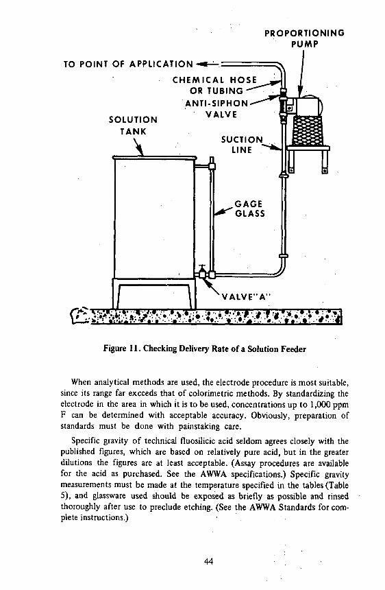
PROPORTIONING PUMP
TO POINT OF APPLICATION
SOLUTION TANK
CHEMICAL HOSE OR TUBING
ANTI-SIPHON VALVE
(^»^>»^*?A*t:.^:',ril Figure 11. Checking Delivery Rate of a Solution Feeder
When analytical methods are used, the electrode procedure is most suitable, since its range far exceeds that of colorimetric methods. By standardizing the electrode in the area in which it is to be used, concentrations up to 1,000 ppm F can be determined with acceptable accuracy. Obviously, preparation of standards must be done with painstaking care.
Specific gravity of technical fluosilicic acid seldom agrees closely with the published figures, which are based on relatively pure acid, but in the greater dilutions the figures are at least acceptable. (Assay procedures are available for the acid as purchased. See the AWWA specifications.) Specific gravity measurements must be made at the temperature specified in the tables (Table 5), and glassware used should be exposed as briefly as possible and rinsed thoroughly after use to preclude etching. (See the AWWA Standards for complete instructions.)
44
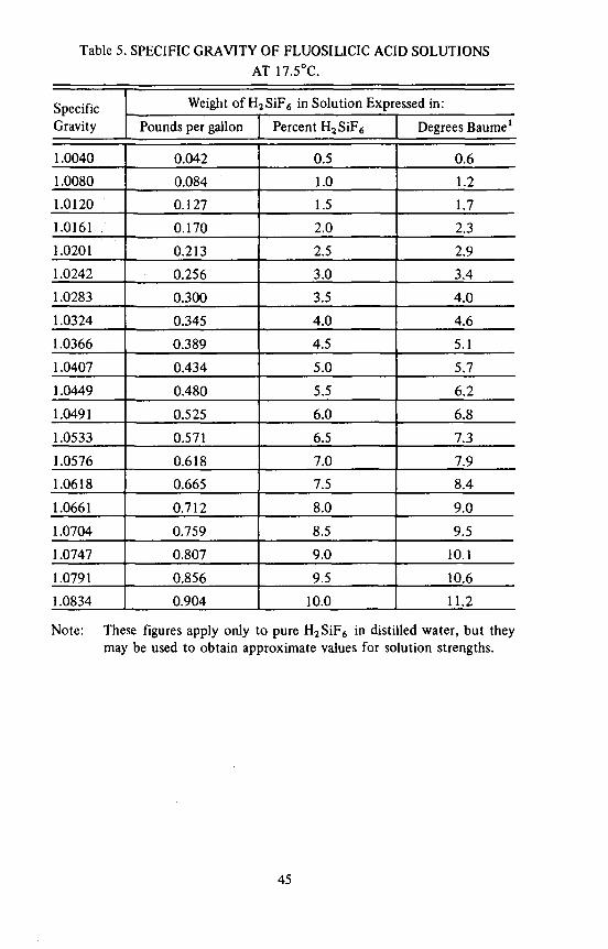
Table 5. SPECIFIC GRAVITY OF FLUOSILICIC ACID SOLUTIONS AT 17.5°C.
Specific Gravity
1.0040
1.0080
1.0120
1.0161 .
1.0201
1.0242
1.0283
1.0324
1.0366
1.0407
1.0449
1.0491
1.0533
1.0576
1.0618
1.0661
1.0704
1.0747
1.0791
1.0834
Weight of H2SiF6 in Solution Expressed in:
Pounds per gallon
0.042
0.084
0.127
0.170
0.213
0.256
0.300
0.345
0.389
0.434
0.480
0.525
0.571
0.618
0.665
0.712
0.759
0.807
0.856
0.904
Percent H2SiF6
0.5
1.0
1.5
2.0
2.5
3.0
3.5
4.0
4.5
5.0
5.5
6.0
6.5
7.0
7.5
8.0
8.5
9.0
9.5
10.0
Degrees Baume1
0.6
1.2
1.7
2.3
2.9
3.4
4.0
4.6
5.1
5.7
6.2
6.8
7.3
7.9
8.4
9.0
9.5
10.1
10.6
11.2
Note: These figures apply only to pure H2SiF6 in distilled water, but they may be used to obtain approximate values for solution strengths.
45

Chapter V Selecting The Optimal Fluoridation System
Among the considerations in choosing the right fluoridation system for a particular situation are: population served (or water usage rate), chemical availability, cost, type of operating personnel available, and just plain personal preference on the part of the person or persons making the decision. While there is no one specific type of fluoridation system which is solely applicable, to a specific situation, there are some general limitations imposed by the size and type of water facility. For example, a large metropolitan water plant would hardly be likely to consider a fluoridation installation involving the manual preparation of batches of solution, any more than would a small facility consisting of a number of unattended wells consider the appropriate number of gravimetric dry feeder installations.
Figure 12 is a check-list, based essentially on water pumping rates, which can be used as a rough guide in differentiating between the various types of fluoridation installation. Obviously, the population divisions; are flexible, at least within limits, so considerable overlap can be expected. Other considerations, such as the water plant lay-out and personal preference can be expected to influence a choice which does not necessarily fall within the selected limits.
For the smallest water plant, some type of solution feed is almost always selected. There is almost no lower limit to the ranges of the smallest metering pumps, and even if the feed rate for solution were unpractically low, a more dilute solution would solve the problem. Conversely, there is almost no upper limit to the capacity of gravimetric dry feeders, or to pumps, for that matter, so the largest water plants can select either dry feed with sodium silicofluoride or direct feed of fluosilicic acid. For all those water plants in between, there will be a choice, modified only by individual circumstances. Assistance can be obtained from SHD Engineers, manufacturer's representatives, or consultants.
LOCATION OF FEEDER
Before a type of feeder can be selected, sufficient and appropriate space for its installation must be provided. If there is an existing water plant, where other water treatment chemicals are being fed, usually space for an additional feeder is no problem. If there is no treatment plant, as is often the case with well supplies, then there may be a well house, or perhaps even some type of
47
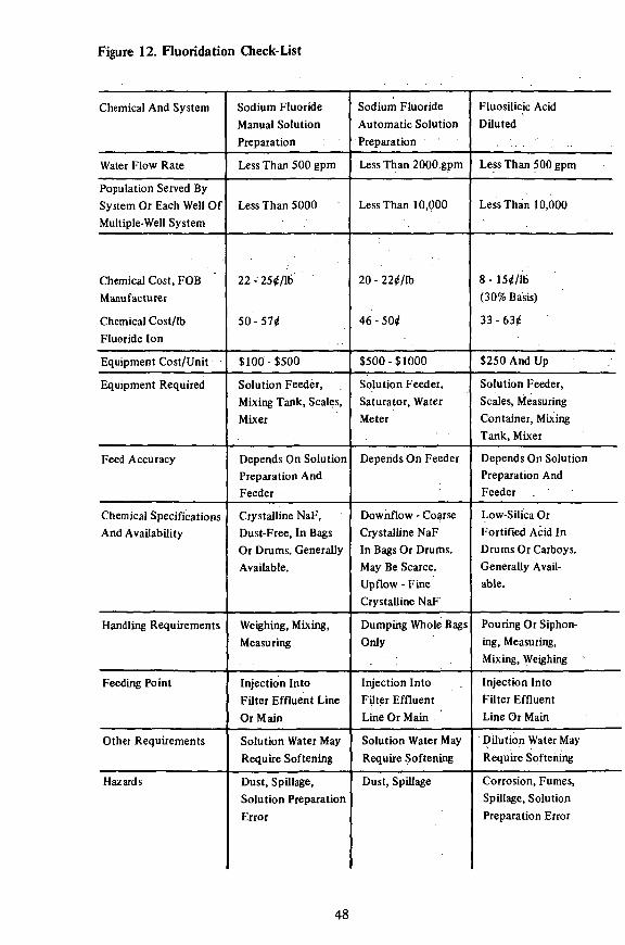
Figure 12. Fluoridation Check-List
Chemical And System
Water Flow Rate
Chemical Cost, FOB Manufacturer
Chemical Cost/lb Fluoride Ion
Equipment Cost/Unit
Equipment Required
Feed Accuracy
Chemical Specifications And Availability
Handling Requirements
Feeding Point
Other Requirements
Hazards
Sodium Fluoride Manual Solution Preparation
Less Than 500 gpm
22-'25*/lb
50-57*
$100-$500
Solution Feeder, Mixing Tank, Scales, Mixer
Depends On Solution Preparation And Feeder
Crystalline NaF, Dust-Free, In Bags Or Drums. Generally Available.
Weighing, Mixing, Measuring
Injection Into Filter Effluent Line Or Main
Solution Water May Require Softening
Dust, Spillage, Solution Preparation Error
Sodium Fluoride Automatic Solution Preparation
Less Than 2000 gpm
Less Than 10,000
20 - 22*/Ib
46 - 50*
$500-$1000
Solution Feeder, Saturator, Water Meter
Depends On Feeder
Downflow - Coarse Crystalline NaF In Bags Or Drums. May Be Scarce. Upflow - Fine Crystalline NaF
Dumping Whole Bags Only
Injection Into Filter Effluent Line Or Main
Solution Water May Require Softening
Dust, Spillage
Fluosilicic Acid Diluted
Less Than 500 gpm
Less Than 10,000
8 - 15*/lb (30% Basis)
33-63*
$250 And Up
Solution Feeder, Scales, Measuring Container, Mixing Tank, Mixer
Depends On Solution Preparation And Feeder
Low-Silica Or Fortified Acid In Drums Or Carboys. Generally Available.
Pouring Or Siphoning, Measuring, Mixing, Weighing
Injection Into Filter Effluent Line Or Main
Dilution Water May Require Softening
Corrosion, Fumes, Spillage, Solution Preparation Error
Population Served By System Or Each Well Of Multiple-Well System
Less Than 5000
48

Fluosilicic Acid 23 - 30%
More Than 500 gpm
More Than 10,000
$51-$58/ton
(23% Basis)
14 -16*
$500 And Up
Solution Feeder, Day
Tank, Scales, Transfer
Pump
Depends On Feeder
Bulk Acid In Tank Cars
Or Trucks. Available
On Contract
All Handling By Pump
Injection Into Filter
Effluent Line Or Main
Acid-Proof Storage
Tank, Piping, Etc.
Corrosion, Fumes,
Leakage
Sodium Silicofluoride Or Sodium Fluoride
Dry Feed
More Than 100 gpm More Than 2 MGD
More Than 10,000 More Than 50,000
Sodium
SUicofl.
9 -104/ lb
15 -17*
Sodium
Fluoride
18 - 20*/lb
41 - 46*
$1,000 And Up
Volumetric Dry Feeder,
Scales, Hopper,
Dissolving Chamber
Usually Within 3%
Sodium
SUicofl.
8 - 9*/lb
13-15*
Sodium
Fluoride
18-20*/lb
4 1 - 4 6 *
$3000 And Up
Gravimetric Dry Feeder, Hopper, Dissolving Chamber
Usually Within 1%
Powder In Bags, Drums Or Bulk. Generally Available.
Bag Loaders Or Bulk Handling Equipment Required
Gravity Feed From Dissolving Chamber Into Open Flume
Or Clear-Well, Pressure Feed Into Filter Effluent Line
Or Main
Dry Storage Area, Dust Collectors, Dissolving-Chamber
Mixers, Hopper Agitators, Eductors, Etc.
Dust, Spillage :, Arching And Flooding In Feeder And Hopper
49
shelter near an elevated storage tank. The feeder must be placed in a dry, sheltered area, near to the point of fluoride injection, and preferably in a place which has storage space for chemicals. There must be electrical power available, in most cases, and a water line for solution preparation unless undiluted fluosilicic acid will be used. The location must be accessible for chemical replenishment and maintenance. Other than these basic requirements, consideration should be given to the desirability for isolation of chemical storage from other materials, for adequate ventilation and for general convenience.
FLUORIDE INJECTION POINT
The first and most important consideration in selecting the fluoride injection point is that it must be a point through which all the water to be treated passes. In a water plant, this can be in a channel where the other water treatment chemicals are added, it can be in a main coming from the filters, or it can be in the clear well. In a well-pump system, it can be in the discharge line of a pump, if there is only one, or if there is more than one pump it can be in the line leading to the elevated tank or other storage facility. If there is a combination of facilities, say a treatment plant for surface water plus supplemental wells, it must be a point where all water from all sources passes. If there is no such common point, it means that separate fluoride feeding installations will have to be made for each water facility. If at all possible, a point through which all the water passes at a fixed rate or rates should be selected. For example, the water from one or more well pumps is being discharged into a main leading to an elevated storage tank. Water from the storage tank passes through a point which might seem to be acceptable. In the latter case, flow can vary from that of maximum demand on the system to that of minimum demand, making the adjustment of the fluoride feed rate more difficult than it would be if it were based on the fixed delivery rate of the pump or pumps. Thus, a better choice would be to inject fluoride into the main leading to the storage tank, where the flow rates are those of the pump deliveries.
Another consideration in selecting a fluoride injection point is the question of fluoride losses in filters. Whenever possible, fluoride should be added after filtration to avoid the substantial losses which can occur, particularly with heavy alum doses or when magnesium is present and the lime-soda-ash softening process is being used. On rare occasions it may be more practical to add fluoride before filtering, such as in the case where the clear well is inaccessible or so far away from the plant that moving chemicals would be uneconomical.
When other chemicals are being fed, the question of chemical compatibility must be considered. If any of these other chemicals contain calcium, the fluoride injection point should be as far away as possible in order to minimize loss of fluoride by precipitation. For example, if lime (for pH control) is being added to the main leading from the filters, fluoride can be added to the same main but at another point, or it can be added to the clear well. If the lime is
50
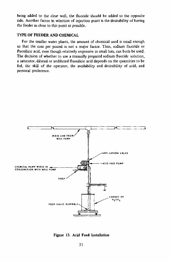
being added to the clear well, the fluoride should be added to the opposite side. Another factor in selection of injection point is the desirability of having the feeder as close to this point as possible.
TYPE OF FEEDER AND CHEMICAL
For the smaller water plants, the amount of chemical used is small enough so that the cost per pound is not a major factor. Thus, sodium fluoride or fluosilicic acid, even though relatively expensive in small lots, can both be used. The decision of whether to use a manually prepared sodium fluoride solution, a saturator, diluted or undiluted fluosilicic acid depends on the quantities to be fed, the skill of the operator, the availability and desirability of acid, and personal preference.
M A I N LINE F R O M '
CHEMICAL PUMP WIRED IN - ^ C O N J U N C T I O N WITH WELL PUMP
ZHI
A N T I S I P H O N VALVE
— ACID FEED PUMP
CARBOY OF
FOOT VALVE ASSEMBLY
Figure 13. Acid Feed Installation
51
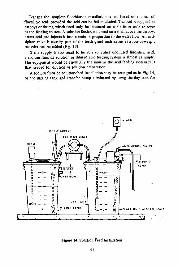
Perhaps the simplest fluoridation installation is one based on the use of fluosilicic acid, provided the acid can be fed undiluted. The acid is supplied in carboys or drums, which need only be mounted on a platform scale to serve as the feeding source. A solution feeder, mounted on a shelf above the carboy, draws acid and injects it into a main in proportion to the water flow. An anti-siphon valve is usually part of the feeder, and such extras as a loss-of-weight recorder can be added (Fig. 13).
If the supply is too small to be able to utilize undiluted fluosilicic acid, a sodium fluoride solution or diluted acid feeding system is almost as simple. The equipment would be essentially the same as the acid feeding system plus that needed for dilution or solution preparation.
A sodium fluoride solution-feed installation may be arranged as in Fig. 14, or the mixing tank and transfer pump eliminated by using the day tank for
Figure 14. Solution Feed Installation
. 52
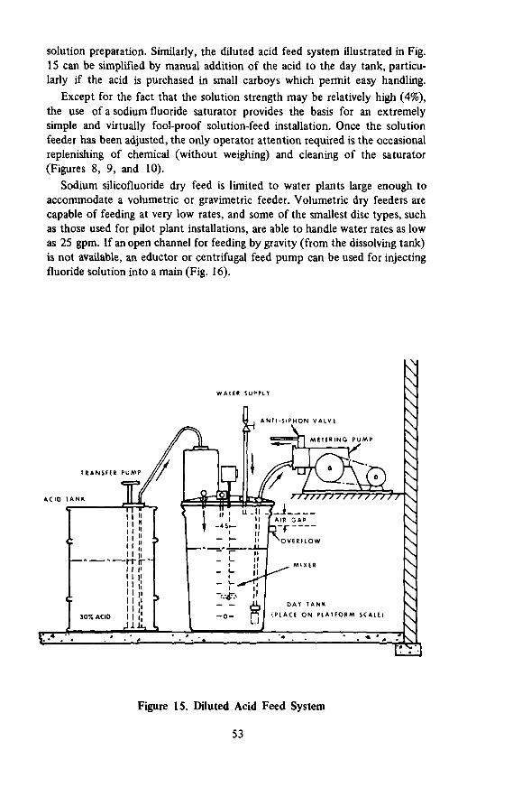
solution preparation. Similarly, the diluted acid feed system illustrated in Fig. 15 can be simplified by manual addition of the acid to the day tank, particularly if the acid is purchased in small carboys which permit easy handling.
Except for the fact that the solution strength may be relatively high (4%), the use of a sodium fluoride saturator provides the basis for an extremely simple and virtually fool-proof solution-feed installation. Once the solution feeder has been adjusted, the only operator attention required is the occasional replenishing of chemical (without weighing) and cleaning of the saturator (Figures 8, 9, and 10).
Sodium silicofluoride dry feed is limited to water plants large enough to accommodate a volumetric or gravimetric feeder. Volumetric dry feeders are capable of feeding at very low rates, and some of the smallest disc types, such as those used for pilot plant installations, are able to handle water rates as low as 25 gpm. If an open channel for feeding by gravity (from the dissolving tank) is not available, an eductor or centrifugal feed pump can be used for injecting fluoride solution into a main (Fig. 16).
TRANSFER PUMP
ACID TANK
WATER SUPPLY
T I S I P H O N VALVE
METERING PUMP
/ / / / / / / / / / ' / / / / / • /
AL I DAY TANK
f^l (PLACE O N PLATFORM SCALE
1 \ \ \ \ \
\ F-T-
OTJ
Figure 15. Diluted Acid Feed System
53

o
s WATER S U P P I Y
V O L U M E T R I C FEEDER
n . V A C U U M
BREAKER
c o L O S S - O F - W E I G H T RECORDER
* I •-SOLUTION TANK
RM SCALE ^ lU-PLATFOR
H
Figure 16. Dry Feed Installation with Volumetric Feeder
The roll-type and screw-type volumetric dry feeders are capable of handling flow rates from less than 100 gpm to several MGD. Gravimetric dry feeders are applicable to flows from about 2 MGD up to the largest water usage encountered (Fig. 17). Of course, any of the dry feeders can be used for sodium fluoride as well as sodium silicofluoride.
CHEMICAL AVAILABILITY
Fluoride chemicals are plentiful, but having the right one in the right place at the right time may not be as simple as it might seem. The availability of compounds derived from phosphate fertilizer production, fluosilicic acid and sodium silicofluoride, is tied in with fertilizer sales, so if there is a decline in
54
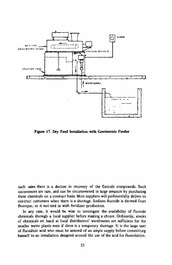
B i l l I T P i
G R A V I M E T R I C H I D E S
S O L U T I O N T A N K
Figure 17. Dry Feed Installation with Gravimetric Feeder
such sales there is a decline in recovery of the fluoride compounds. Such occurrences are rare, and can be circumvented in large measure by purchasing these chemicals on a contract basis. Most suppliers will preferentially deliver to contract customers when there is a shortage. Sodium fluoride is derived from fluorspar, so it not tied in with fertilizer production.
In any case, it would be wise to investigate the availability of fluoride chemicals through a local supplier before making a choice. Ordinarily, stocks of chemicals on hand at local distributors' warehouses are sufficient for the smaller water plants even if there is a temporary shortage. It is the large user of fluosilicic acid who must be assured of an ample supply before committing himself to an installation designed around the use of the acid for fluoridation.
55

Planned usage of a saturator installation hinges on the availability of coarse crystalline sodium fluoride, at least for the down-flow types. There are only a limited number of manufacturers who produce this grade, so. not all distributors will routinely carry it in stock. Planning for two different chemicals will allow continued operation in the event of a shortage of qne of them.
CHEMICAL STORAGE AND HANDLING
There are a number of criteria governing the selection of a storage site for fluoridation chemicals. The dry chemicals must be kept dry, they1 must be convenient to the hopper in ..which they will be loaded, they should preferably be isolated from other water treatment chemicals to preclude accidental intermixing; the storage area must be clean and well ventilated, and should be equipped with running water and a floor drain for ease in cleaning up spills. Fluosilicic acid presents particular problems in storage, for the vapors are corrosive and will even etch glass. Containers must be kept tightly closed, or vented to the outdoors when the container is being fed from. Large quantities of acid can be stored in underground or enclosed tanks equipped with outside vents.
Sufficient area for storage of bagged chemicals should be provided, since piling bags too high can cause compacting and "massing" of crystals, resulting in lumps and irregular feeding characteristics. Similar conditions can result from long periods of storage, so an over-supply of chemicals should be avoided.
For dry-feed chemicals, particularly if considerable quantities are to be handled, it is preferable to have a storage area on the floor above the feeding equipment. This arrangement allows dumping bags or drums directly into extension hoppers without extensive lifting.
Bags, fiber drums and steel drums should be stored on pallets so that air can circulate beneath them. Dry chemicals will cake if allowed to get damp, and steel drums will rust.
The disposal of empty fluoride containers has always been a problem. The temptation to re-use fiber drums is difficult to overcome, since the drums are convenient and sturdy. Paper bags are dusty and could cause a hazard if they are burned, and empty acid drums could contain enough acid to cause contamination or even injury. The best approach is to rinse all empty containers with plenty of water - even the paper bags are strong enough to withstand repeated rinses. After all traces of fluoride are removed, the bags can be buried or burned (if an incinerator is available). Even supposedly well-rinsed drums should never be used for purposes where traces of fluoride could present a hazard.
If possible, the storage area should be kept locked and not used for any other purpose. Particularly, workers should be warned against eating in a fluoride storage area.
A smooth, impervious floor will be easier to keep clean. A concrete floor laid directly on the ground tends to be damp and should be avoided. An exhaust fan, dust collector and/or wet scrubber should be used to keep the air
56

relatively dust-free. Respirators, goggles, gloves, aprons and other protective clothing should be available for workers.
The quantity of chemical to be kept in storage depends on individual circumstances. Unless a delay or shortage is anticipated, no more than is necessary should be kept on hand. Dry chemicals tend to cake and get lumpy on long storage, and large quantities of acid present a hazard. The exception to the latter is when it is economical to purchase acid in tank-truck lots, in which case an enclosed or underground storage tank with adequate venting and precautions against accidents must be provided. (Note: The storage tank may be located outdoors if no other space is available. Fluosilicic acid, being mostly water, is subject to freezing. The freezing point of a 22% solution is about 4°F.)
For relative space requirements for storage of chemicals, see Table 1.
CROSS-CONNECTION CONSIDERATIONS
As mentioned in the section on feeders, water inlets to solution tanks, dissolving chambers, etc., often constitute a cross-connection when the inlet is below the level of solution. Whenever possible, the inlet line should have an air gap as a positive safety precaution. In cases where pressure is too high to make an air gap practical, a vacuum breaker must be installed at an elevated location between all other restrictive devices (such as valves) and the point of entry into the solution container.
Checks for possible cross-connections should be made not only when the fluoridation installation is in the design stage, but also when later modifications occur.
AUTOMATIC PROPORTIONING (PACING)
When water flows at a fixed rate, the fluoridation installation is relatively simple since the fluoride feed rate, once adjusted to the proper ratio need not be changed unless there is a change in pump delivery, feeder delivery or chemical purity. However, when the flow is variable, such as when there are multiple pumps or when pump delivery varies with demand, a variable fluoride feed rate also becomes necessary. In some cases, such as when there are two or three pumps, each with a fixed delivery rate, it is possible to use separate fluoride feeders, each tied electrically to the individual pump operation, and each adjusted to feed fluoride in the correct ratio to the water delivered by that pump. In other cases, such as when the changes in water flow are predictable and infrequent, it may be possible to manually adjust the feeder to a predetermined setting which corresponds to the new water flow rate. If neither of the above apply, or are impractical or inconvenient, some means for automatically adjusting the fluoride feed rate to the water flow rate must be provided. This automatic adjustment is called "pacing."
For smaller water plants, particularly those using a solution feed system, a water meter contactor, with or without an interval timer, can be used to pace the feeder. Essentially, a water meter contactor is a switch which is geared to
57
the water meter movement so that it will make contact at specified gallonage intervals. Thus, the impulse from the water meter contactor, when related to the feeder motor, will energize the feeder in proportion to the meter's response to flow. In cases where the duration of impulse is too short (momentary switch contact) to activate the feeder motor, an interval timer, connected between the contactor and motor, can be set for appropriate time durations. To preclude extensive cycling and resultant wide variations in fluoride concentration, the contacts should be as close together as possible, and if a timer is used, the durations of timed feeder operation should be as long as possible, just short of possible overlap at the maximum flow rate. (Some small solution feeders, usually solenoid operated, are particularly adapted to meter-contactor operation.)
Larger water plants, already equipped with flow meters and/or recorders, can utilize the signal from these devices to adjust feeder delivery electrically, pneumatically, or hydraulically. If this type of pacing is contemplated, feeders which have adjusting mechanisms compatible with the type of flow-meter signal available must be specified.
If the plant does not have flow meters which are readily adaptable to pacing the fluoride feeders, or no flow meters at all, various types of meters can be installed specifically for the purpose. For example, an orifice plate assembly with a D/P cell transmitter will furnish an electrical signal which can be used for control of feeders.
Another device providing an electrical signal is a magnetic flowmeter. A signal converter will adapt the signal from one of these to a form which can be used for adjusting some types of feeders. Other types of flowmeters require the use of recorder-controllers which modify a pneumatic or hydraulic pressure line flow so that the pressure thus modified will adjust the delivery rate of either a dry or solution feeder equipped for the purpose. On solution feeders, the adjustment is made to the stroke length; on dry feeders, the adjustment can be made through a variable-speed drive, a poise-positioner, etc. The pneumatic or hydraulic signals adjust variable-speed drives mechanically, while electrical signals accomplish the same purpose through a silicon-controlled rectifier (SCR).
Another type of paced fluoride feed can be accomplished without the use of remote flow-meter signals. In this case, a solution feeder is operated directly (hydraulically) by a special water meter which diverts water under pressure to the feeder's driving piston in proportion to the rate of water flow in the main. (See also controllers)
As stated earlier, while there is no one specific type of fluoridation installation which is solely applicable to a specific situation, there is usually one which is preferable. The best installation is one that has the best combination of the following factors:
1. Minimum cost of equipment, consistent with good performance. 2. Simple mechanical feeding device, either liquid or dry. 3. A simple piping and injection system. 4. Minimum handling of chemicals.
58
5. Minimum labor operations. 6. Minimum maintenance. 7. Means for maintaining reliable and permanent records. 8. Minimum chemical cost, consistent with water plant size.
INSTALLATION
The illustrations (Figs 13 to 17) show the general arrangement of equipment in typical fluoridation installations. Some factors to consider are proximity to fluoride application point, proximity to chemical storage, availability of solution water and accessibility for operation and maintenance.
SOLUTION FEEDER INSTALLATIONS
A solution feeder should be placed above the solution container if at all possible to lessen the chances for siphoning. The suction line should be as short and straight as possible, and there should be a foot-valve and strainer at its terminus. If the suction line tends to curl or float in the solution, it may be necessary to weight it. Weights usually furnished with solution feeders are made of porcelain, but any heavy material which is resistant to the solution may be used.
The discharge line from the feeder should also be as short and straight as possible, but circumstances may sometimes require that a long discharge line be used. If such is the case, try to avoid sharp curves or loops in the line which could provide sites for precipitation buildup and subsequent blockage. If the solution is being injected into a pipeline, the injection fitting should be installed preferably at the bottom or underside of the pipe. Injecting solution into the top of a pipe should be avoided since air collects there and can work its way into the injection check valve or the discharge line and cause air-binding. There should be a check valve and an anti-siphon valve at the injection point.
Most solution feeders come equipped with, or have available as an accessory, an anti-siphon discharge valve. This may be mounted directly on the feeder head, or at the injection point as above. In addition, particularly if solution is to be fed into an open channel or a low-pressure pipeline, a "loaded" discharge valve should be used. This is a spring-loaded check or diaphragm valve which will not open until the feeder discharge pressure exceeds a certain fixed value. A common setting is about 15 psi.
When mounting a solution feeder on a shelf or platform above the solution container, it is advisable to off-set it sufficiently to permit access to the container (or saturator) for filling and cleaning.
DRY FEEDER INSTALLATIONS
When installing a dry feeder, placement should be such that solution from the dissolving chamber can fall directly into the chemical feed channel if possible. If other considerations dictate that the feeder be placed some distance from the point of application, the drain line should be as direct as possible,
59

with adequate slope and of sufficient size to preclude precipitation build-ups and subsequent stoppages.
Obviously, the dry feeder installation must be on a firm, level foundation if the scales are expected to perform satisfactorily. If there is a small hopper on the feeder, it must be readily accessible for filling, and if an extension hopper is used, it should extend vertically upward to the filling area without angles which could trap material. For the water supply line to a volumetric feeder, there must be a section of flexible hose between the dissolving chamber and the water pipe to permit free movement of the feeder and scale platform.
The water supply line to a dry feeder must be equipped with an air-gap or mechanical vacuum-breaker, or some other type of anti-siphon device. The air gap is the simplest and most positive protection against the dangers of a cross-connection. If water pressure is too high to permit the use of an air gap, one of the other devices may be used, but in any case the vacuum-breaker must be placed between the point of entry to the feeder dissolving chamber and any restrictive device in the pipeline, and must be installed in an elevated location.
VALVES AND METERS
Shut-off valves are sometimes installed where solution is fed under pressure. Their use permits repairs to the feeder or discharge line, but they also are a hazard. Attempting to feed solution when the valve is closed can result in ruptured diaphragms or discharge lines, or even severely damaged feeders. If there is to be a shut-off valve at the injection point, always make sure it is kept in the fully-open position.
The use of a sodium fluoride saturator requires that a water meter be placed in the water supply line. A shut-off valve in this line is a necessity to permit dismantling and cleaning the saturator. The valve must be placed between the water meter and the saturator inlet so that the meter chamber will remain filled with water and thus will register properly.
No water supply can be properly fluoridated unless the water flow rate in the main is known, and calculated fluoride levels cannot be made unless a record of total flow is available. Thus, a master water meter on the main is a prerequisite for fluoridation. While flow requirements may dictate the type of water meter to install where none now exists, some thought should be given to utilizing a meter signal for pacing a fluoride feeder.
INSTALLATION PLANS
Planning a fluoridation installation usually must be done with the concurrence or approval of State Health Departments. However, before deciding on a specific design, the sections on chemicals, feeders and auxiliary equipment should be scanned for possible alternatives or inclusions. The installation design can then be submitted for approval. Some examples of preliminary planning of a fluoridation installation follow.
60
Example 1. A small water supply consists of an unattended well pump, pumping into an elevated storage tank. The pump operation is controlled by an altitude switch on the elevated tank. There is no other water treatment, and the only building is a small shed at the well site. Water pumping rate is about 250 gpm.
Plan: Provided the shed at the well site is large enough and of reasonably sound construction, a saturator and solution feeder can be placed inside. The solution feeder can be tied electrically to the operation of the well pump so that feeding cycles will coincide with the on-off operation of the well pump. The fluoride injection will be directly into the pump discharge line. If there is enough room in the shed, and the building is weather-tight and can be locked, a few bags of sodium fluoride can also be stored inside (off the floor). A water meter ought to be installed in the main, if there is none at present, and a hypo-chlorinator added as soon as possible.
Example 2. A water treatment plant is presently feeding chlorine, alum, soda ash and carbon to a surface supply. There is an open channel in the plant where post-filtration chemicals are added. The service pumping rate is 3000 gpm, and water is pumped directly from the clear well to the mains.
Plan: Since bulk fluosilicic acid is currently available nearby, the economics of acid use appear favorable. The acid storage tank can be placed outdoors, with a day tank and feed pump located at the site of post-filtration chemical feed. An alternative system, for feeding sodium silicofluoride, will be provided. This will consist of a gravimetric dry feeder with the dissolving chamber discharge falling into the post-filtration feed channel. Chemical storage will be on the floor above the feeder, where there is a separate area provided for fluoride chemicals. An extension hopper from the feeder to the storage floor facilitates loading. Either feed system will be controlled by electrical signals from a rate-of-flow transmitter on the main.
Example 3. A city's water supply consists of eight wells, all of which pump directly into the mains. There is an elevated storage tank, but it rides on the water system and there is no point in the system where all the water can be treated. Pumping rates vary from 200 to 500 gpm, with the operation of each well pump controlled by pressure switches on the mains.
Plan: Since there is no central point where all the water can be fluoridated with a single feed system, each well pump will have to be considered as an individual water supply. The most economical approach would be to use a solution feeder and fluosilicic acid at each pump location. The acid would be purchased in carboys and platform scales will be provided at each location. Operation of feeders will be controlled by well pump operation. Meters and hypochlorinators will also be installed at each location.
61

Chapter VI Control And Surveillance
ANALYTICAL PROCEDURES The ability to detect and measure accurately trace amounts of fluoride ion
was the key to the discovery of both the benefits and hazards of fluoride in water. Now that fluoride is being deliberately added to water, it is perhaps even more essential that the quantities present be measured accurately. Not only must the fluoride concentration of the untreated water be determined, so that one will know how much to add, but also the fluoride concentration of the treated water must be determined as confirmation that the correct amount of chemical is being added.
Because the quantity of fluoride ion being measured is so small (usually about 1 part fluoride ion to 1 million parts water, or 1 milligram in a liter of water), the analytical method must be adapted to the measurement of these quantities and the accuracy of measurement must be well within the limits established as the maximum permissible variation from the optimum concentration. Thus, if a concentration of 0.9 to 1.1 (1.0±0.1) ppm is considered optimal for a certain area, the analysis must be accurate to 0.1 ppm or better in order that one is assured the actual concentration succeeds or fails to fall within these limits.
It should be remembered that all fluoride analysis concerns the determination of the quantity of fluoride ion in solution, irrespective of the source of that ion. It may come from fluoride compounds occurring naturally in the water, or from fluoride or silicofluoride compounds added to the water. There is no method for distinguishing one fluoride ion from another, nor is there any method for determining to which metallic ion the fluoride ion was originally attached.
THE STANDARD METHODS
The generally-accepted analytical methods are outlined in detail in the latest edition of "Standard Methods for the Examination of Water and Wastewater." The Thirteenth Edition (1971) lists three methods: the Alizarin Visual (Scott-Sanchis), the Photometric (SPADNS) and the Electrode Methods. There are additional methods available, mostly based on colorimetric principles similar to those used in the first two methods above, and there are modifications of the Standard Methods which adapt them to the use of simplified equipment and
63
procedures, that is, the co-called "test kits." "Standard Methods" also describes a preliminary distillation procedure, a step necessary when substances present in the water interfere with the accurate determination of the fluoride ion. As with the analytical methods themselves, other preliminary procedures are available, but, just as with the unlisted analytical methods, these procedures are regarded as inferior to the one listed in "Standard Methods."
ALIZARIN VISUAL METHOD
The basis for the alizarin visual method is the zirconium-alizarin reaction, in which a red lake (a deep color) is produced by the combination of alizarin and zirconium. Any fluoride present in the water sample or standard solution removes zirconium from the reaction, thus decreasing the intensity of color present. In water samples which are high in fluoride, the only color apparent is the yellow color of the unreacted dye. (Alizarin is sensitive to pH and its color will vary from purple in alkaline solutions to yellow in acid.) Conversely, in low fluoride samples, the color approaches the deep red of the zirconium alizarin lake. Intermediate fluoride concentrations give colors which are intermediate between these two. The reaction is not an immediate one, but progresses with time. After one hour, the reaction rate is extremely slow, and for this reason, the time interval between adding reagent and making the measurement has been selected as 60 minutes.
The color comparisons are made in 100-ml Nessler tubes - tall glass cylindrical tubes with flat bottoms. Usually, these are held in a rack with a reflector below the tubes so that light is reflected up through the longitudinal axis of the tubes to the eye of the observer. In practice, a number of tubes containing standard fluoride solutions at fixed concentration intervals are prepared in addition to the tubes containing the unknown samples. Fluoride reagent is added to both standards and samples, and after the one-hour color development time, the unknown samples are compared visually with the standards and a determination made by matching the colors. Sometimes, this involves interpolation. For example, if the color of the unknown sample appears to be midway between that of an 0.8 ppm standard and a 1.0 ppm standard, the unknown sample is determined to have a fluoride concentration of 0.9 ppm. Obviously, the smaller the interval between standards, the greater the likelihood of attaining a close match between color of sample and that of one of the standards.
SPADNS METHOD
The photometric method is based on a reaction similar to the one used for the alizarin visual determination - a dye lake is formed with zirconium and SPADNS dye, and any fluoride present has the effect of decreasing the intensity of color. However, the colors produced by different concentrations of fluoride are all shades of red, making it almost impossible to detect these differences by eye and making the use of a photometer imperative.
64

A photometer is an instrument for detecting differences in color, and consists of a light source, a means for producing monochromatic light, and a photocell for measuring the intensity of the light transmitted through the sample. There are two general types of photometer; the filter photometer which produces monochromatic light by the use of a colored glass filter, and the spectrophotometer which achieves the same end by the use of a prism or diffraction grating.
The operating procedure for the use of the photometer in the SPADNS method for fluoride analysis depends on the particular instrument used, but in general the determination consists of adding a measured volume of reagent to a measured volume of sample, placing a portion of the mixture in a cell or cuvette, placing the cell in the instrument and taking the absorbance reading. The absorbance reading is then converted to fluoride concentration by consulting a curve prepared by plotting the absorbance of known standard solutions against their concentrations. Unlike the visual method, the photometric method involves a reaction which is instantaneous, permitting completion of the analysis within seconds after the reagent is added.
ELECTRODE METHOD
The electrode method is based on the use of a specific-ion electrode, resembling somewhat the electrodes used for pH determinations. In the case of the fluoride electrode, the key element is a laser-type doped single crystal through which only fluoride ions can move. When the electrode is immersed in a solution containing fluoride ions, an electrical potential is set up between the solution and a standard fluoride solution within the electrode. This potential, expressed in millivolts, can be either positive or negative depending on whether the fluoride concentrations of the sample is lower or higher than that of the internal solution.
Since only fluoride ions can move through the crystal, the electrode is essentially specific for fluoride. A buffer is added to the sample to eliminate potential interferences and to insure uniform electrode response despite variations in total ionic concentrations in the sample.
In addition to the fluoride electrode itself, the equipment needed for fluoride determinations includes a reference electrode and a meter for reading the millivolt potential. As with the photometric method, the fluoride electrode method requires that a standard curve be prepared using solutions of known fluoride concentration.
Except for the electrode method, none of the fluoride analytical methods are entirely specific for fluoride, and can be subject to error caused by other substances in the water. To avoid the effect of these interferring substances, the water sample can be distilled from a solution of sulfuric acid. The acid converts the fluoride to a volatile compound which is distilled over by the application of heat, leavip" *"!hind most other mineral constituents of the water.
65
TEST KITS
Test kits based on the standard methods include color comparators, portable colorimeters, and portable ion-meters. The color comparators, based on the alizarin visual method, use a set of permanently colored standards with which the reagent-treated sample is compared. These standards take the form of colored glass or colored liquids in glass vials, and eliminate.the necessity of preparing standards each time a water sample is to be analyzed. The portable colorimeters, based on the SPADNS method, are small photometers which are pre-calibrated so that the fluoride concentration in a reagent-treated sample can be read directly from a scale or chart without the necessity of preparing standards or a standard curve. The portable electrode meter is similar, in that the scale of the meter is essentially pre-calibrated so that fluoride concentrations are read directly instead of being converted from millivolt readings.
SAMPLING
Surveillance of fluoridation, based on these analytical methods, is absolutely necessary for control of the process. While state health departments may require only occasional tests, a minimum sampling of once per day is recommended. Sampling should include both the plant tap and some point in the distribution system, and if the water source is a surface supply, a raw water sample as well.
When fluoridation is just starting, sampling should be more frequent, and should include a representative number of points in the distribution system. The fluoride ion, being a stable and persistent substance, provides an excellent indicator of flow patterns, and distribution system analyses will show how long it takes for fluoridated water to reach the ends of mains and whether or not untreated water is entering the system. One possibility of the latter occurring is when a reservoir or standpipe is merely "riding" on the system, contributing unfluoridated water during periods of low or no pumping. Eventually, the water in such storage facilities is replaced with fluoridated water, but in some instances, the exchange is so slight that a considerable amount of time elapses after fluoridation begins before the full fluoride level is reached. Other possibilities include infiltration and cross-connections.
CALCULATIONS AND RECORD-KEEPING
Besides analytical determinations of fluoride concentration in the water, daily records of weight of chemical fed and volume of water treated will provide a record of the theoretical fluoride concentration for that day and will furnish an additional check on the adequacy of the treatment process. Most states require that records be kept for both analytically determined and calculated fluoride concentrations.
The calculations are simple, using the same formula previously used for dosage calculations, etc.:
66

R! X C t = R2 X C2, where Ri is the rate or quantity of water being treated in gpm or gallons,
Ct is the fluoride concentration in the water in ppm,
R2 is the rate or quantity of fluoride compound added in lbs/min or lbs,
C2 is the fluoride concentration in the compound used, in percent or lbs/100 lbs.
So, the calculated fluoride concentration (not including any fluoride already present in the water) is:
R2 X C 2
Ri By converting gallons to pounds, and cancelling units, the results will be in pounds per million pounds, or ppm. Examples:
1. A plant is using sodium fluoride solution, 2% strength (7 lbs dissolved in 40 gal. of water. See Table 3), and fed 100 gallons in one day. During that day, 1 million gallons of water were pumped. What is the calculated fluoride concentration (disregarding any natural fluoride content)?
= R2 X C2 = 100 gal. X 7 lbs/40 gallons X 0.45 X 0.98
' " R, ~ 8.33 lbs/gal X 1,000,000 gal (0.45 is the fraction of sodium fluoride which is fluoride ion, 0.98 is the commercial purity)
C, = 0.92 lbs/million lbs, or 0.92 ppm
2. When 50 lbs of 23% fluosilicic acid are added to 1 million gallons of water how much fluoride has been added (in ppm)?
_ SO lbs X 0.23 X 0.79 1 ~ 1,000,000 gal X 8.33 lbs/gal
(0.23 is the acid strength, 0.79 is the fraction of H2SiF6 which is fluoride ion.)
= 1.09 lbs/million lbs, or 1.09 ppm 3. A dry feeder record indicated a loss in weight of 26 pounds of sodium
silicofluoride in one day. During that time, 1.8 million gallons of water were treated. The commercial purity of the sodium silicofluoride was 98%. Calculate the concentration of fluoride added.
26 lbs X 0.607 X 0.98 1 " 1,800,000 gal X 8.33 lbs/gal
(0.607 is the fraction of Na2SiF6 which is fluoride ion, 0.98 is the commercial purity.)
= 1.03 ppm
67

In calculating the pounds of fluoride ion added, both the fraction of fluoride ion in the pure compound and the purity of the chemical must be taken into account, as in the above examples. Note that these calculations give the amount of fluoride added. If there is a measurable concentration of fluoride in the water before this addition, it must be taken into account in order to find the total theoretical fluoride concentration. For example, if the raw water in (1.) above had 0.5 ppm F before treatment, and 0.2 ppm after flocculation and filtering, the total F concentration would be 0.2 plus 0.92 or 1.12 ppm. Note again that raw water fluoride can be reduced by filtration, and only that natural fluoride present at the point of fluoride compound addition may be included in the calculations.
Calculations can be simplified by using charts or tables, such as Tables 3 and 6. Examples:
1. Given the same conditions as in No. 1. above, calculate the fluoride concentration using Table 3.
_ _ 100 gal. X 9000 ppm C l 1,000,000 v = a 9 p p m
(Note that using tables will give approximations only.) 2. Using information from Table 6, calculate Example (2.) above. If 45.7
lbs of 23% acid will add 1.0 ppm F to 1 million gallons of water, 50 lbs. would add: 50/45.7 or 1.09 ppm.
3. Using information from Table 6, calculate Example (3.) above.
Calculation: The table gives pounds of chemical for 1 million gallons. For 1.8 million gallons, the quantity to produce 1.0 ppm would be: 1.8 X 14 lbs. Since 26 pounds were actually used, the fluoride concentration would be:
26 lbs 1.8 X 14 lbs. X 1 - 0 PPm =1-03 ppm
Another device often used to simplify calculations is the nomograph, or alignment chart (Figs. 18 & 19). Nomographs are available for specific compounds, or for several different materials as in the illustrations. They may take into account the purity of the chemical, or may not. In any case, they are not likely to be very accurate, but are useful for at least getting rough estimates of chemical requirements or, by working backwards, for estimating the theoretical fluoride concentration achieved.
MONITORS
A monitor is a device for automatically providing a continuous record of analyses: in this case, for providing a continuous record of fluoride concentration. The advantage of a continuous record over a spot-check, such as a daily fluoride analysis, is that the continuous record will show the fluoride concentration at any given time rather than only at the one time the daily sample was taken. This type of record could prove helpful in answering complaints regarding under- or over-feeding, as well as in detecting variations in fluoride
68
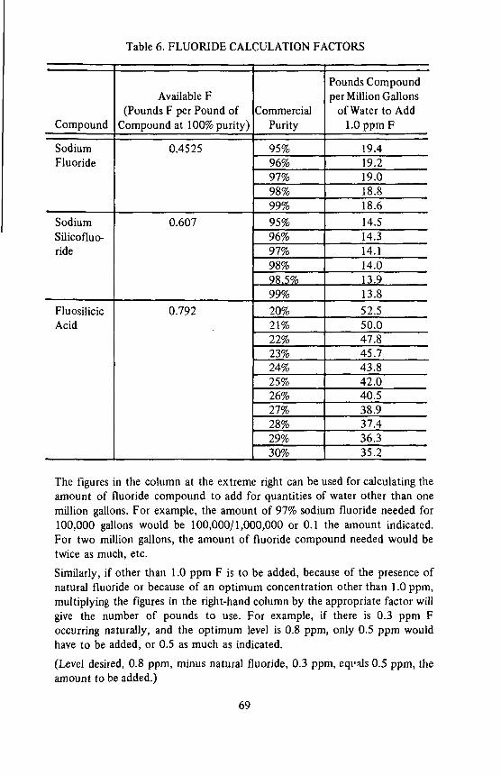
Table 6. FLUORIDE CALCULATION FACTORS
Compound
Sodium Fluoride
Sodium Silicofluo-ride
Fluosilicic Acid
Available F (Pounds F per Pound of
Compound at 100% purity)
0.4525
0.607
0.792
Commercial Purity
95% 96% 97% 98% 99% 95% 96% 97% 98% 98.5% 99%
20% 21% 22% 23% 24% 25% 26% 27% 28% 29% 30%
Pounds Compound per Million Gallons
of Water to Add 1.0 ppm F
19.4 19.2 19.0 18.8 18.6 14.5 14.3 14.1 14.0 13.9 13.8 52.5 50.0 47.8 45.7 43.8 42.0 40.5 38.9 37.4 36.3 35.2
The figures in the column at the extreme right can be used for calculating the amount of fluoride compound to add for quantities of water other than one million gallons. For example, the amount of 97% sodium fluoride needed for 100,000 gallons would be 100,000/1,000,000 or 0.1 the amount indicated. For two million gallons, the amount of fluoride compound needed would be twice as much, etc.
Similarly, if other than 1.0 ppm F is to be added, because of the presence of natural fluoride or because of an optimum concentration other than 1.0 ppm, multiplying the figures in the right-hand column by the appropriate factor will give the number of pounds to use. For example, if there is 0.3 ppm F occurring naturally, and the optimum level is 0.8 ppm, only 0.5 ppm would have to be added, or 0.5 as much as indicated.
(Level desired, 0.8 ppm, minus natural fluoride, 0.3 ppm, eqi-als 0.5 ppm, the amount to be added.)
69

100-
6 0 0 -
700
2 0 ° - - 0 . 3
3 0 0 -
400
5 0 0 -
INSTRUCTIONS
1. Substract the natural level from the desired level to get the fluoride treatment figure (ppm fluoride ion added).
2. Draw a line from the flow figure straight through the fluoride treatment figure to the fluoride ion line. The intersection will show the pounds of fluoride ion per day required.
3. This weight of fluoride ion may be obtained from any of the chemicals listed. Starting at the pounds of fluoride ion per day required.
draw a horizontal line to the right and read the weight of dry chemical or volume of liquid chemical required.
4. Thus in the example, a flow of 600 gpm requiring 0. 9 ppm fluoride ion added requires 6. 45 pounds of fluoride ion per day. This can be obtained from 14. 8 lb per day of sodium fluoride, 11. 0 per day of sodium silicofluoride, 2. 55 gal per day of 30% fluosilicic acid, or 44. 2 gal per day of saturated sodium fluoride solution.
Figure 18. Fluoridation Nomograph
70
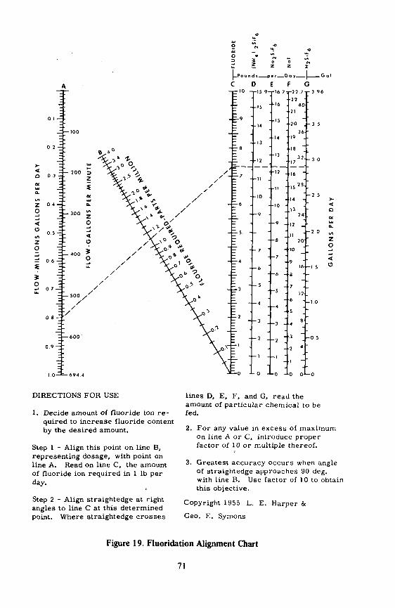
| _ P o u n d i per Doy | G a l
C D E F G - r r 1 0 -T .5 9-1-16 7-r27 7T-3 96
< o
z o
<
DIRECTIONS FOR USE
1. Decide amount of fluoride ion re quired to increase fluoride content by the desired amount.
Step 1 - Align this point on line B, representing dosage, with point on line A. Read on line C, the amount of fluoride ion required in 1 lb per day.
Step 2 - Align straightedge at right angles to line C at this determined point. Where straightedge crosses
lines D, E, F, and G, read the amount of particular chemical to be fed.
2. For any value in excess of maximum on line A or C, introduce proper factor of 10 or multiple thereof.
3. Greatest accuracy occurs when angle of straightedge approaches 90 deg. with line B. Use factor of 10 to obtain this objective.
Copyright 1955 L. E. Harper &
Geo. E. Symons
Figure 19. Fluoridation Alignment Chart
71
concentration for unexplained reasons. If the monitor is equipped with an alarm system, it can alert the operator to feeder malfunctions or other problems affecting fluoride level.
Most monitors are actually continuous or semi-continuous analyzers, performing colorimetric or electrical analyses on a flowing sample stream or on discrete water samples taken at close time intervals. Some monitors use the SPADNS procedure, metering out reagent in proportion to sample flow and then passing the treated sample through a photometer. A recorder converts absorbance readings of the photometer to concentration figures which then appear on a recorder chart. Other monitors use the electrode procedure, either with or without the addition of buffer. When no buffer is used, the fluoride and reference electrodes are immersed in the water sample stream and an appropriate recorder converts millivolts of potential to parts per million of fluoride. Obviously, the absence of buffer may render this type of monitor unreliable when there is a change in water quality. When buffer is used, the monitor record is definitely more reliable. A monitor using buffer is necessarily more complicated, since metering pumps must be used for both water sample and buffer to insure maintenance of the correct ratio of volumes of each. Still another monitor uses a different type of electrode and buffer, and is based on an analytical procedure adapted specifically to flowing sample streams.
There are other types of monitors which are not analyzers, for example, the one based on conductivity measurements. The differences in conductivity between untreated water and water after fluoride has been added can be interpreted to give the amount of fluoride added, but here again we have a system which may be unreliable when a change in water quality occurs, especially if that change involves a change in the raw water fluoride content.
Some water plants employ monitors on both the raw water and the treated water, the former being used to alert the plant operator to changes in raw water fluoride level. If the treated-water monitor is equipped as a controller, it can be used to automatically adjust the fluoride feeder to deliver fluoride compound so that the final fluoride concentration is maintained within pre-set limits, i
It should be pointed out that a monitor, even one used as a controller, does not relieve water plant personnel from the necessity for making the prescribed fluoride analyses at the prescribed intervals. If for no other reason, the regular spot-checks will serve to verify the proper functioning and accuracy of the monitor.
TROUBLE-SHOOTING
The ideal situation occurs when the fluoride feed rate is accurately calculated, the water flow rate does not vary, and once set, the fluoride feeder operates merrily day after day, providing exactly the desired concentration of fluoride in the water without the slightest variation and with no attention from the operator other> than the occasional refilling of a hopper. There may be such situations, but even if they exist, the water plant personnel ought to know about the potential difficulties and how to overcome them.
72
LOW FLUORIDE READINGS
When the fluoride concentration determined by analysis is consistently lower than that determined by calculation, there are a number of possible explanations. Presuming that the calculations are correct, and are based on accurate weight and flow figures, the first logical suspect is the analysis. If alum is used for flocculation, traces of aluminum in the finished water can interfere markedly with colorimetric analysis, always influencing the readings negatively. A high iron content can do the same thing if the SPADNS method is used. In rare cases, chloride and alkalinity can interfere also, but the concentrations of these would have to be extremely high. The analysis of a distilled sample, or conversion to the electrode analytical method can confirm or rule out this potential error.
If the analysis can be verified as accurate, the next suspect would be chemical purity. Fluosilicic acid has the most variable purity, and can be anywhere from over 30 down to 20% pure. Ordinarily, the manufacturer specifies the purity of a given batch, but if there is some doubt, the acid should be analyzed according to directions given in AWWA Specifications. Sodium fluoride and sodium silicofluoride usually exhibit less variation in purity, but occasionally a relatively impure lot is found. The AWWA specifications give procedures for determining purity of these materials also.
If sodium fluosilicate is being used, the possibility of incomplete solution should be explored next. An examination of the feeder dissolving chamber and the area near where the solution is being fed should reveal deposits of undissolved chemical if detention time is insufficient, solution water flow rate wrong, or baffling of the dissolving chamber ineffective.
In the case where manually prepared solutions are used, incomplete mixing can be at fault, as can be the measurement of both chemical and water.
If none of the above possibilities prove to be the source of error, and all measurements and calculations have been checked out, it may be advisable to check out the water system to find out if unfluoridated water is entering at some point and is thus diluting the water being fluoridated at the plant.
HIGH FLUORIDE READINGS
When fluoride concentration determined by analysis is consistently higher than that determined by calculation, analysis, and chemical purity can also be the sources of error. The presence of Calgon or other polyphosphate is the usual cause of analytical error in the positive direction. Failure to eliminate chlorine from the water sample can also lead to high results in colorimetric analysis.
Failure to take into account the fluoride content of the raw water may result in adding more fluoride than is needed, and surface supplies, which can show considerable variability, should be analyzed daily in order that the correct dose can be calculated. If the water supply comes from wells, the
73

variability is much less, but in the case of a higher-than-calculated fluoride concentration the possibility of a contribution' from a high-fluoride well should be investigated.
VARYING FLUORIDE READINGS
The most difficult type of problem to solve is the situation when the fluoride concentration is variable even • though calculations show that the fluoride feed rate is in the desired proportion to water flow rate. One possibility which can be readily eliminated is the fluoride feeder. A check on the delivery rate, with weight measurements at short-intervals, will reveal whether or not the feeder delivery rate is constant.
Almost all ofthe factors which can produce consistently low or consistently high fluoride analyses can also produce variable errors, if the analytical interference,1 the chemical purity, the raw-water fluoride or the completeness of chemical solution are variable conditions. In the latter case, undissolved sodium silicofluoride can eventually go into solution after a quantity of undissolved material accumulates at some point, and a solution feeder can begin drawing from a concentrated stratum after feeding from a dilute stratum in an improperly mixed solution tank.
One of the causes of varying fluoride content in a treated water system is the intrusion, on an intermittent basis, of uh-fluoridated water into the system. This can be from an outside water source, such as a well or a connection to another system, or can be from a storage reservoir which is part of .the system. The latter situation occurs usually when fluoridation is just beginning, and no attempt has been made to fluoridate the reservoir separately. What happens then is that during periods when no water is being pumped; or the pumping rate is less than the demand, water flows into the system from the reservoir, and since this water has not yet been fluoridated, low-fluoride readings will result, particularly at the sampling points nearest the reservoir. Eventually, what with flow pattern reversals as the pumps operate intermittently, the reservoir contents will become displaced by fluoridated water, but there have been cases, involving a large reservoir at the end of the water system, when it has taken years before there was a complete turn-over of the reservoir contents. The obvious solution to this type of problem is, of course, to fluoridate the reservoir separately at the time fluoridation of the system begins, if such is possible.
A similar situation occurs when an elevated tank or other storage facility merely "rides" on the system, and its contents rarely enter the system or at best there is only slight intermixing. Sampling points near the tank will have varying fluoride concentrations - normal when there is pumping, and low when water is being drawn from the tank. The solution here is to allow the tank contents to drain into the system before fluoridation begins and then not refill the tank until the entire system is up to the optimum fluoride level.
74

Cyclic fluoride levels can result when the feeder is operated intermittently, such as when capacity is reduced by the use of a cycle timer, and there is insufficient storage capacity between the feeder and the consumers. Detention time in mains or storage facility between feed point and first consumer is an important factor in providing homogeneous fluoridated water.
OTHER PROBLEMS
There are undoubtedly many other possible causes for fluoride levels which aren't exactly what they are supposed to be, but one thing is certain -fluoride doesn't "disappear" in the pipelines, nor is it likely that fluoride will concentrate at points or become leached out of incrustations in the mains. Unlike chlorine, fluoride does not have the ability to dissipate, and even though trace amounts are incorporated into tubercles in pipelines, the extreme insolubility of these formations precludes subsequent dissolution. When there is an unexplained difference between the calculated and observed fluoride concentration, more often than not, the calculations are at fault. If they are not, and none of the above possibilities apply or they can otherwise be eliminated, common sense and a knowledge of the individual system should enable the operator to locate and correct the cause of trouble.
It should be noted that over- or under-feeding for short periods, for example a variation of 0.2 or 0.3 ppm for two or three days, actually is of no serious consequence, but such variations should be investigated since they may be indications of potential problems of a more serious nature.
Erratic feed rates or failure to feed are usually due to problems which are discussed in the chapter entitled, "Maintenance." Saturator problems are discussed in the chapter on solution preparation, and other potential troubles are mentioned in the chapter on "Selecting the Optimal Fluoridation System."
75


Chapter VII
Maintenance
To insure uninterrupted and unvarying fluoride feed, proper maintenance of equipment is required. This includes maintaining not only the fluoride feeder, but also all the appurtenances, feed lines and the laboratory testing equipment as well.
CLEANING AND LUBRICATION
Like any other mechanical device, fluoride feeders must be kept clean and lubricated if they are expected to perform their function efficiently. A regular program of maintenance will also minimize costly break-downs and insure long life for the equipment. Electric motors usually come with a prescribed schedule for lubrication - the right type, amount and frequency of lubrication are all important. Gear boxes must be kept filled to the prescribed level with the proper lubricant, and all moving parts and unpainted metal surfaces should be kept clean and rust-free. If there are grease fittings, the proper grade, quantity and frequency of greasing should be observed.
SPARE PARTS
Fluoride feeders and related equipment, when purchased, usually are accompanied by an instruction booklet and/or parts list. The instruction book will contain information on maintenance and repairs, and the parts list will enable the operator to select replacement parts when needed.
If these papers have been lost, a call or letter to the manufacturer of the equipment or his representative will suffice for replacement. The equipment man will also be happy to suggest a list of spare parts to be kept on hand. Having parts available can greatly minimize the length of shut-downs due to equipment failure. In the larger water plants, having an entire spare feeder available may prove to be prudent.
INSPECTION AND RE-CALIBRATION
The best fluoride feeders will feed as intended only if the measuring mechanism is kept clean and operative. Thus, the diaphragms or pistons of solution feeders, the rolls, belts, discs or screws of dry feeders and associated mechanisms of both types should be regularly inspected for signs of wear or damage and repairs or replacements made before the machine actually breaks
77

down. Even with all parts in the best mechanical condition, fluoride delivery can be affected by leaks, spillages, build-ups of precipitates from solutions or accumulations of dry chemicals on or around measuring mechanisms. Occasional re-calibration of the feeder will reveal evidence of potential malfunction, and is generally a good idea for insuring accurate feed rates.
LEAKS
Leaks in and around the discharge line of a solution feeder are more than an annoyance — they can materially affect the quantity of solution delivered and thus result in low fluoride levels. Leaks are always somewhat corrosive, ranging from the salt effect of sodium fluoride solutions to the acid corrosion of fluosilicic acid. Even the smallest leak can result in damage to the feeder, appurtenances or surroundings is left unattended. Leaks of strong solutions result in the formation of crystalline deposits which, if allowed to build up, make subsequent cleaning difficult. A leak in the suction line of a solution feeder, while not immediately apparent, will adversely affect delivery and can eventually lead to air-binding and cessation of feed. Air-binding can also be caused by injecting fluoride solution at the top of a main, where air can collect.
Leaks in a dry feeder installation cause a dust problem, and if there is a leak in the feeding mechanisms, for example around the rollers of a volumetric feeder, there will be an error in feed rate. The dust represents, in addition to an economic loss, a hazard to equipment and personnel.
Leaks in equipment not related to fluoride feed can present problems nonetheless. For example, a water leak can result in dampness and subsequent caking of dry chemicals. A leak in a chlorine gas system can result in damage to feeders and associated equipment, etc. Leaks in other dry feed equipment can result in dust contamination of the fluoridation installation.
PRECIPITATES
Anytime strong solutions are used, the possibility of precipitation build-up is present. In a solution feed system, precipitates in the feeder pumping chamber or on the check-valves will affect delivery rate or even stop the feeder entirely. Deposits in suction or feed lines can build up until flow stops, and a coating of insoluble matter on a saturator bed can prevent water from percolating through. If the deposits are the result of water hardness, softening the make-up water will eliminate the problem. If softening is impractical, frequent inspection and removal of the deposits is a necessity. Even when the water is soft, impurities in the chemical used and other mineral constituents in the water can build up to the point where small openings are clogged and feed is impaired or stopped.
Dissolving chambers of dry feed installations are a vulnerable point for precipitation build-ups. Frequent inspection and cleaning again are the best approach.
78
Tanks in which solutions are prepared invariably show precipitates of the insoluble impurities from the chemical used or of insoluble compounds formed by the reaction of the chemical with mineral constituents of the water. If a separate tank is used for solution preparation, and the clear supernatant layer transferred to a day tank, problems will be minimized, but not necessarily completely eliminated.
A regular schedule for cleaning out a saturator should be established, the time interval between cleanings depending on the amount of usage and the accumulation of impurities in the saturator. The cleaning operation is described in the chapter on solution preparation.
STORAGE AREA
Storage areas, while not necessarily a major factor in maintaining accurate feed of fluoride, need also to be kept in an orderly and clean condition. Bags of dry chemicals should be piled neatly on pallets, with empty bags rinsed out and disposed of promptly. Whenever possible, whole bags should be emptied into hoppers, since partially empty bags present a spillage hazard and are a nuisance to store. Metal drums should be kept off the floor and kept tightly closed. The storage area for fluoride chemicals should be well isolated from areas used to store other chemicals to preclude mix-ups, and all extraneous material, such as lubricating oil and cleaning equipment, should be kept out of the area. Both the stored chemicals and the general area should be kept free of dust, not only from the chemicals used in fluoridation but from other chemicals stored or used nearby. In general, a neat and clean storage area is an indicator of good water plant practice and maintenance.
LABORATORY
The laboratory or fluoride testing area calls for special precautions in cleanliness. The merest hint of fluoride dust on glassware can result in gross analytical errors. Dirty pipets or other measuring glassware can produce errors in volume measurements, and proper drainage is hindered, resulting in carryover of solutions from one sample to the next. In colorimetric analysis, dirty glassware prevents accurate color determination whether the method is visual or photometric. Permanent standards for colorimetric test kits, since they are difficult to clean, should be kept covered when not in use. Reagent bottles, buffers and standard solutions should all be kept tightly closed when not in use. Evaporation ruins not only the reagents, but acid fumes from them can damage objects nearby. Analytical instruments should always be covered when not in use, since fumes and dust can corrode electrical connections, cloud mirrors, and result in expensive repairs or replacement.
The use of phosphate-based detergents for cleaning glassware presents a hazard because of potential interference of phosphates in colorimetric analysis. Since tap water contains fluoride, it is imperative that all glassware be thoroughly rinsed in distilled water of good quality.
79
The quality of distilled water is best verified by conductivity measurements, but when equipment for this procedure is lacking, help can often be obtained from State Health Departments. This help can take the form of checking a water plant's distilled water or of furnishing a sample of good quality distilled water for comparison. Comparing fluoride analyses of the plant's distilled water vs. that furnished by the State will reveal contamination, if any. (Many State Health Department laboratories will furnish a standard fluoride solution for check purposes, also.)
80
Chapter VIII Safety And Hazards
In Handling Fluoride Chemicals
SAFETY EQUIPMENT AND CHEMICAL HANDLING
Admittedly, fluoride chemicals, in the large quantities likely to be present in a water plant, present a health hazard to plant personnel. While fluorides in water, at the recommended concentration of about 1.0 ppm, have been exhaustively studied and have been firmly established as safe beyond question, the fluoride levels to which a water plant operator can be exposed are at least potentially much higher. Since the operator is presumably already drinking water containing the optimum level of fluoride, any additional contact with fluorides constitutes overexposure. Obviously, the best safety measure is the prevention of unnecessary hazards, and this implies the proper handling of fluoride chemicals and the use of adequate safety equipment.
INGESTION
Overexposure to fluoride chemicals can be the result of ingestion, inhalation, or bodily contact with spills. The most likely source of oral exposure would be the contamination of food or drink, either by accident (such as if the fluoride chemical were mistaken for sugar or salt) or through carelessness (such as if meals were eaten in areas where fluorides were stored or applied).
INHALATION
Perhaps the greatest chance for overexposure to fluoride chemicals comes from the accidental inhalation of dust. While the use of masks and other protective devices is commendable, everything possible should be done to minimize the production of dust. Logically, if fluoride sacks are moved carelessly or if the bags are emptied too quickly, the concentration of fluoride dust in the air will rise. Cautious handling will help a great deal in keeping the concentration of fluoride dust at a safe level. As examples: bags should not be dropped; bags should be opened with an even slit at the top to avoid tearing down the side; and the contents of bags should be poured gently into hoppers. The use of crystalline chemicals and installation of bag-loading hoppers are other ways for reducing the production of dust in the air. Good ventilation is absolutely necessary in work areas, even if there is no visible dust and masks are worn.
81

SAFETY PRECAUTIONS
The recommended safety equipment for handling fluoride chemicals includes goggles, gloves, aprons, boots, dust masks, respirators, exhaust fans, dust collectors, etc. While the use of this equipment will minimize an individual's contact with the chemicals, additional safeguards should be applied. First, meals and snacks should be eaten in non-work areas in order to avoid contact with fluoride powders and dust. If there are no cafeterias or spare rooms, then going outdoors should be considered whenever possible. If it is necessary to eat in a work area, then person should be additionally cautious in avoiding contamination of food. (Blue-tinted sodium fluoride and sodium silicofluoride will prevent mistaking fluoride for food, and will also give clues as to the dispersion of fluorides in the work area.)
Second, the use of properly labeled fluoride containers will minimize the danger of mistaken identity, or the inherent danger of a container which has no label at all. It is best to keep fluoride chemicals in their original containers, but if this is not always practical, these chemicals should be kept in labeled containers restricted to fluoride chemicals only. A further precaution, required in some States, is to keep fluoride chemicals in a separate, locked, storage area.
ACID HANDLING
Fluosilicic acid requires special precautions in handling. Spilling on the skin, splashing in the eyes and inhaling vapors are all serious hazards. The absorption of fluoride through the skin is negligible, but the acid is corrosive and it is this characteristic which constitutes a hazard in skin contact. Careful handling, quick rinsing of spills or splashes, the use of respirators, and especially ventilation are the best safety measures.
FIRSTAID
There is no record of any water plant operator ever being seriously injured in the handling of fluoride chemicals, but knowledge of first-aid measures for treatment of accidental fluoride over-exposure is a good thing to have.
FLUORIDE EXPOSURE SYMPTOMS
It is important to be able to detect if someone is suffering from overexposure to fluorides, so that treatment can be initiated early, thereby increasing the patient's chances for complete recovery. In acute poisoning, generally the first symptoms to appear are vomiting, stomach cramps and diarrhea. If the poisoning is due to the igestion of large amounts of fluorides, the vomitus may be white or colored, depending on whether the fluoride contains dye. The appearance of the vomitus may be important in determining whether fluoride is indeed the toxic agent. Illness could be due to something else. Usually the patient becomes very weak, has difficulty in speaking, is thirsty, and has disturbed color vision.
82
The signs of acute poisoning by inhalation consist of sharp biting, pains in the nose followed by a nasal discharge or nosebleed. The most likely response to an acid spill or splash is a tingling or burning sensation, or if the eyes are involved, severe eye irritation.
TREATMENT
The importance of rapid treatment cannot be over-emphasized. Once acute poisoning by fluoride is apparent, treatment should be initiated while awaiting proper medical assistance. The treatment is as follows:
1. Remove the patient from exposure and keep him warm. 2. Administer 3 teaspoonsful of table salt in a glass of warm water. 3. Induce vomiting by irritating the back of the throat with a spoon. 4. Administer a glass of milk.
5. Repeat the salt and vomiting procedure several times.
Treatment for the individual suffering from nosebleed after inhalation of a high concentration of fluoride consists of the following:
1. Remove the patient from exposure. 2. Place the patient's head back while placing absorbent material inside
the nasal passages. Change the material often.
3. Take the individual to a physician.
Treatment for an individual suffering from acid exposure consists of rapid and thorough rinsing of the affected area with copious quantities of water. Further treatment, if necessary, should be performed by a physician.
In summary, the first goal in fluoride handling safety is to prevent poisoning resulting from overexposure; this means, use safety equipment and avoid unnecessary contact. Next, be alert to the early signs of fluoride-related illness in yourself and your co-workers. Should illness from fluoride occur, react quickly with the proper treatment for the patient.
Remember, no water plant personnel have ever been seriously injured by fluorides. Do you want to be the first?
83

Chapter DC Technical Problems
Attributed To Fluoridation As stated earlier, feeding fluorides is essentially the same as feeding other
water treatment chemicals, and problems can be expected just as they can be with other chemicals. However, due to the controversial nature of the fluoridation process, many of the problems attributed to fluoridation are more imagined than real.
CORROSION
One of the first objections to the feeding of fluorides was that the chemicals were thought to be extremely corrosive and would cause disintegration of the pipelines. Part of this erroneous conception can be traced to the confusion over fluoride versus fluorine, and the association of fluoride with hydrofluoric acid. It is well known that fluorine is a violently reactive gas, and especially that hydrofluoric acid is strong enough to eat glass. What is added to the water is an essentially neutral salt of hydrofluoric acid, or fluosilicic acid or one of its salts, not fluorine or hydrofluoric acid. Fluorine could not be used, since it is too hazardous and too expensive, and hydrofluoric acid has been used in only one fluoridation installation. But even if they were used, the important thing to remember is that the amount being put in the water is usually around one part per million as the fluoride ion, and one part per million of the most corrosive substance would have little or no effect at this dilution. Fluosilicic acid and its salts exhibit a low pH in solution, the depression of pH being most apparent in poorly buffered waters, but there is no indication that such waters have their corrosivity increased by the addition of fluoride. There has been no reported instance of pipeline corrosion traceable to the fluoride content of the water.
ENCRUSTATIONS
The analysis of tubercles and other pipeline encrustations has in some cases revealed an extremely high fluoride concentration, even in places where fluoridation was not practiced! This revelation has given rise to fears that fluoride will be absorbed in the pipeline, then released at dangerously high concentrations at some future time. Again, these fears are groundless. The deposition of fluoride in pipeline precipitates is so gradual that the quantity lost from the water cannot be detected by the best analytical means, and
85
studies have shown that feed-back from such postulated sources as pipe coatings, tuberculation, treatment sludges and storage-reservoir sediments does not occur. On the contrary, these studies show that to achieve undesirable fluoride ion concentrations from such additions would require suspensions of the coating, sludge, or rust in quantities so great as to render the water non-potable and unfit for use. Even hydrant flushings with water clearly unacceptable for normal use have not produced concentrations of fluoride above the optimum recommended in the U.S.P.H.S. Drinking Water Standards. In another study, the use of a cold-chisel was required to dislodge the fluoride-containing tubercles and even this extreme means failed to produce an appreciable increase in the fluoride concentration.
A related fear is that it is impossible to maintain a constant fluoride "residual" in a long pipeline. Part of this fear is based on the deposition of fluoride in tubercles or other encrustations, as mentioned above, and part is based on experience with chlorine. But fluoride is an ion, not a gas or unstable entity as are chlorine or the hypochlorite radical, and the term, "residual," does not apply here. Fluoride is not dissipated by organic materials, as is chlorine, and there is no "demand" to be satisfied before the amount added can be detected in the water. In other words, the fluoride added to the water can be fully accounted for by analysis immediately or at any subsequent time. A study has proved that neither the length of line, period of flow, age of pipe, nor materials to which the water is exposed affect significantly the average fluoride ion content in distribution systems.
FLUORIDE LOSSES
There is one situation which does result in the loss of fluoride, and that is when the fluoride is added before coagulation and filtering, or before softening by the lime-soda ash process. In either of these processes fluoride is lost by precipitation or absorption on floe, and the amount of loss is predictable. (At a dosage rate of 100 ppm alum, fluoride loss will be about 30%. Loss of fluoride in the softening process is directly proportional to the concentration of magnesium in the water or the lime.) In most cases such losses can be avoided by merely changing the fluoride addition point to a pipeline leading from the filters or to the clearwell itself.
COMPATIBILITY
The question of compatibility of fluoridation with chlorination or any other water treatment process has been raised, but aside from the processes mentioned above, there does not appear to be any significant conflict. One possible exception to this occurs when calcium-containing compounds, such as lime or calcium hypochlorite, are used. If the calcium-containing chemical and fluoride are injected in close proximity, a precipitate of calcium fluoride will form, the amount of precipitate depending on the concentrations of the respective solutions. The obvious preventive measure is to space the respective injection points as far apart as possible.
86
TASTES AND ODORS
Objectionable tastes or odors of the water have been attributed to fluoride, but one can surmise that this imaginary response can be attributed to a mental association of fluoride with chlorine. Taste panels have verified that the fluoride ion is both tasteless and odorless, even at much higher concentrations than those employed in water treatment.
INDUSTRIAL PROCESSES
When fluoridation first began, there were fears that fluoridated water would adversely affect many industrial processes which use the water. Some of the processes investigated included baking, brewing, ice-making, and the manufacture of chemicals, porcelain enamel and frit, drugs, soap, porcelain insulators, food, beverages, etc. The effects of fluoridated water on steam generation and sewage treatment have also been investigated. In only two cases has there been any problem, and one of these is still not fully understood. The first case involved the manufacture of baby food, in which the long cooking process could possibly result in the concentration of fluoride as the water evaporated. The Food and Drug Administration has ruled that the facts in each particular case will be controlling, or in other words, there will be an objection only if there is a significant concentration of fluoride in a particular case. In such a case, defluoridated water will have to be used. The other problem involved the manufacture of ice, in which an increased number of cracked ice blocks was found after fluoridation began. While this phenomenon has never been explained, the cracking of ice blocks can be corrected by the use of a commercial additive commonly used by ice manufacturers long before fluoridation began.
ENVIRONMENTAL EFFECTS
Recently, as part of the increased interest in the environment, there have been fears that the waste water from municipalities which practice fluoridation will be a detriment to the body of water which receives it, and that the fluoride concentration in such bodies of water will continually build up as a result. Experts agree that fluoride, in the concentrations usually found in municipal wastewater, is not in any way harmful to fish or other aquatic life. Actually, since all bodies of water naturally contain some quantities of fluoride, there is very little change in the fluoride concentration of the water in these bodies, due to the diluting effect of rain and run-off. As for the oceans and seas, these naturally contain about 1.4 ppm fluoride, so the addition of municipal waste water results in a localized lessening of the fluoride concentration. Fluoride will not concentrate in a river any more than it will in a pipeline, and the blending of fluoridated wastewater with the normal flow again results in dilution.
87

Chapter X References And Suggested Reading
The following list of books, articles, and manufacturers' bulletins contains much helpful information on fluoridation practice in general and on specific installations and pieces of equipment. The books are usually available in the larger libraries, and engineering reference libraries will probably have the technical journals in which the articles appeared. Manufacturers' bulletins can be obtained from company representatives or from the company itself. (Company addresses are given the first time the company name appears in the list.)
1. Manual of Water Fluoridation Practice, by F.J. Maier. McGraw-Hill Book Company, Inc., New York ($8.50)
2. Fluoridation of Water Supplies, Ref. 2-SIC 49-2, B.I.F., a unit of General Signal Corporation, Providence, Rhode Island 02901. (Free copies on request)
3. Fluoridation Systems, Wallace & Tiernan Division, Belleville, New Jersey 07109. (Free copies on request)
4. Fluoridation Systems Designed for Hydrofluosilicic Acid, Precision Control Products Corporation, Waltham, Massachusetts 02154. (Free copies on request)
5. Fluorides (Water Fluoridation with Sodium Fluoride), Allied Chemical Corporation, Morristown, New Jersey 07960. (Free copies on request)
6. AWWA Standards for Sodium Fluoride, Sodium Silicofluoride and Fluosilicic Acid. AWWA, January 1971 and June 1971. ($1.00 each for Members, $2.00 each for Non-Members)
7. Standard Methods for the Examination of Water and Wastewater, (13th Edition) APHA, New York. ($22.50 for Non-members, $16.50 for Members of APHA, AWWA, or APCF)
8. Fluoridation Chemicals - The Supply Picture, by E. Bellack and R.J. Baker, JAWWA, April 1970. (Free copies from the authors) 9. Fluoridation in Major Cities of the United States, by W.T. Ingram and
G.W. Moore, JAWWA, September 1959. 10. Upflow Saturator, Precision Control Products Corporation, Information Letter No. 49. 11. B.I.F. Sodium Fluoride Saturator, BIF Specification Data Sheet 1210. 201-2.
89
12. W & T Fluoride Saturator, W & T Brochure 60.510.. . . 13. Water Meter Operated Feeder, W & T Brochure 80.110.
14. W & T Loss-of-Weight Recorder, W & T Brochure 370.120.
15. W & T Volumetric Dry Feeders, W & T Brochures 320.100.& 320.120. 16. W & T Gravimetric Dry Feeder, Brochure 310.100.
17. W&TSolutionFeeders,W&TBrochures80.120and80.135.
18. Precision Solution Feeders, Precision Control Bulletin 132. 19. The Art of Feeding Fluoride, BIF 2.20-3.
20. Water Fluoridation with Fluosilicic Acid, Technical Bulletin F-l-670, Grace Agricultural Products Division, Baltimore, Maryland 21203. 21. Guidelines to Automatic Proportional Chemical Feeding, Precision Bulletin 960-357. 22. Continuous Analysis and Control of Fluoride, by R.J. Walker and R.R. Smith, JAWWA, April 1971. 23. Anafluor Continuous Fluoride Analyzer, Fischer & Porter Specification 17S4000 & 17S4400, Fischer & Porter Co., Warminster, Pa. 18974. 24. Chemonitor pF Fluoride Analyzer, Calgon Bulletin No. B-5-054. Calgon Corp., Pittsburgh, Pa. 15230. 25. Practical Automation of Water Treatment Monitoring and Control Systems, by H.M. Rivers & G.W. Sweitzer, Calgon Corporation.
26. Fluoride Automatic, Continuous Analyzer/Controller, Delta Scientific Specification Sheet 8030, Delta Scientific Corp., Lindenhurst, N.Y. 11757. 27. Foxboro Model 32FMS - A Fluoride Measuring System for Potable Water, General Specification Sheet GS 6-1A2 A, The Foxboro Co., Foxboro, Mass. 02035.
28. A Selective Ion Electrode System for Fluoride Analysis, by R.H. Babcock & K.A. Johnson, The Foxboro Company. 29. Automatic Fluoride Monitor, Advance Information Bulletin, E.I.L. (Electronic Instruments Limited) England. (Cambridge Instrument Company, Ossining, New York 10562).
30. Technicon CSM-6 Water Monitor, Technicon Instruments Corporation, Tarry town, New York 10591.
31. Beckman Fluoride Ion Analyzer, Beckman Bulletin 4102, Beckman Instruments, Inc., Fullerton, Calif. 92634.
32. Water Analysis Instrumentation, Hach Series CR-2 Bulletin, Hach Chemical Co., Ames, Iowa 50010.
33. AES Series 1400 Process Analyzers, Automated Environmental Systems, Inc., Woodbury, L.I., New York 11797. 34. Safe Handling of Water Works Chemicals, by R.W. Ockershausen, JAWWA Vol. 63, June 1971.
35. W &T Fluoride Analyzer, W &T Cat. File 810.030. 36. Automatic Control for Precision Chemical Metering Pumps, Precision Bulletin 240.
90
37. Omega Gravimetric Dry Feeder, BIF Ref. No. 31-12.201-1.
38. Omega Volumetric Dry Feeder, BIF Ref. No. 25-04.201-1. 39. BIF Diaphtagm Pumps. BIF Ref. 1210-201-1. 40. BIF Rotodip Feeder. BIF Ref. No. 65.201-1. 41. Manual or Automatic Fluoridator, Fischer & Porter Specification 70D1100.
42. Cabinet-Mounted Fluo-chlorinator. Fischer & Porter Specification 70F3400.
43. Chemical Feed Pump. W & T Cat. File 940.100. 44. Water Fluoridation. Olin Chemicals, Stamford, Conn. 06904, Product Application Bulletin CD-169-1070. 45. Sodium Fluoride; Chemtech, St. Louis, Mo. 63143, Product Data Sheet, July 1970.
46. Polyethylene Tanks for Precision Chemical Metering Pumps, Precision Bulletin 960386. 47. Fiberglas Tanks. Owens-Corning Fiberglas Corp., Toledo, Ohio 43601, Pub. No. 1-PE-3578-F. 48. mRoy Controlled Volume Pumps. Milton Roy Co., St. Petersburg, Fla. 33733, Bulletin No. 15.001. 49. mRoy Packaged Chemical Feed Systems, Milton Roy Co., Bulletin 15.002. 50. Corrosive Chemical Feeding, BIF Ref. 1200.20-1. 51. Metering Pumps Series 1700, BIF Ref. 1700.20-1.
52. Dry Material Feeders, BIF Ref. 25.20-1. 53. Fluoridation Equipment for Potable Water Supplies, BIF Ref. No. 2-SIC 494.2. 54. Chemicals Used in Treatment of Water and Wastewater, BIF Ref. No. 1.21-15. 55. Application of Fluorides to Water, by W.T. Ingram, Water & Sewage Works, May 1961.
91


Appendix
The following symbols and abbreviations are employed throughout this manual.
Abbreviation
APHA
AWWA
°C
cm
cone
cuft
°F
ft
g
gal
gph
gpm
hr
in
JAWWA
1
lb
m
mg
MGD
mg/1
min
ml
mm
Referent
American Public Health Association
American Water Works Association
degree (s) Centigrade
centimeter(s)
concentrated
cubic foot (feet)
degree (s) Fahrenheit
foot (feet)
gram(s)
gallon (s)
gallons per hour
gallons per minute
hour(s)
inch(es)
Journal of the American Water Works Association
liter(s)
pound(s)
meter(s)
milligram (s)
million (s) of gallons per day
milligrams per liter (sometimes used interchange
ably with ppm)
minute (s)
milliliter(s)
millimeter(s)
93

Abbreviations Referent
mV millivolt(s)
m/i millimicron (s)
pH Hydrogen ion potential (a measure of the acidity or alkalinity of a solution. A pH of 7.0 indicates neutrality; below 7.0 indicates acidity and above 7.0 indicates alkalinity)
ppm parts per million (pounds of fluoride ion per
million pounds of water, etc.)
psi pounds per square inch (water pressure)
rpm revolutions per minute
sec second (s)
sp gr specific gravity
SPM strokes per minute (of a solution feed pump)
sqcm square centimeter (s)
sq ft square foot (feet)
sq in square inch(es)
sq mm square millimeter(s)
TDS total dissolved solids (in water)
WPCF Water Pollution Control Federation
"U.S. GOVERNMENT PRINTING OFFICE: 1972-759-897/U21
94