WASH Technology Information Packages - SSWM.info
194
WASH Technology Information Packages – for UNICEF WASH Programme and Supply Personnel
-
Upload
khangminh22 -
Category
Documents
-
view
2 -
download
0
Transcript of WASH Technology Information Packages - SSWM.info

WASH Technology Information Packages– for UNICEF WASH Programme and Supply Personnel

First edition 2010
Authors Erich Baumann, Skat, Switzerland Agnes Montangero, Skat, Switzerland Sally Sutton, SWL Consultants, England Karl Erpf, Skat, Switzerland
Published by UNICEF Supply Division, Copenhagen UNICEF Programme Division/WASH/ NY Skat, Swiss Resource Centre and Consultancies for Development
Copyright UNICEF
Editing Machamba Consultants Inc
Graphic Design, Layout and Production Phoenix Design Aid A/S, www.phoenixdesignaid.com
Comments Please send any comments concerning this publication to:
UNICEFSupply DivisionUNICEF Plads, FreeportDK-2100 CopenhagenDenmark
Telephone +45 3527 35 27Facsimile + 45 3526 94 21 Email: [email protected]

WASH Technology Information Packages– for UNICEF WASH Programme and Supply Personnel

Introduction . . . . . . . . . . . . . . . . . . . . . . . . . . . . . . . . . . . . . . . . . . . . . . . . . . . . . . . . . . . . . 1
TIP 1 Handpumps for Drinking Water – Introduction . . . . . . . . . . . . . . . . . . . . . . . . . . . . . . . . . 4 1 .1 Selection Criteria for Handpumps . . . . . . . . . . . . . . . . . . . . . . . . . . . . . . . . . . . . . . . . 7 1 .2 Pumping Methods . . . . . . . . . . . . . . . . . . . . . . . . . . . . . . . . . . . . . . . . . . . . . . . . . . 10 1 .3 Handpump Information Sheets . . . . . . . . . . . . . . . . . . . . . . . . . . . . . . . . . . . . . . . . . 17 1 .3 .1 Suction Pumps and Rope Pumps . . . . . . . . . . . . . . . . . . . . . . . . . . . . . . . . . . . 19 1 .3 .2 Direct Action Pumps . . . . . . . . . . . . . . . . . . . . . . . . . . . . . . . . . . . . . . . . . . . . 25 1 .3 .3 Lever Action Pumps Medium Deep . . . . . . . . . . . . . . . . . . . . . . . . . . . . . . . . . . 33 1 .3 .4 Deep Well Pumps: Afridev and Derivatives . . . . . . . . . . . . . . . . . . . . . . . . . . . . 39 1 .3 .5 Deep Well Pumps: India Mark II and III Types . . . . . . . . . . . . . . . . . . . . . . . . . . 47 1 .3 .6 Extra Deep Well Pumps . . . . . . . . . . . . . . . . . . . . . . . . . . . . . . . . . . . . . . . . . . 62 1 .4 Handpump Selection Tool . . . . . . . . . . . . . . . . . . . . . . . . . . . . . . . . . . . . . . . . . . . . . 70
TIP 2 Boreholes and Drilling Equipment for Rural Water Supply – Introduction . . . . . . . . . . . . 73 2 .1 Basic Definitions and Drilling Techniques . . . . . . . . . . . . . . . . . . . . . . . . . . . . . . . . . . 75 2 .2 Borehole Types . . . . . . . . . . . . . . . . . . . . . . . . . . . . . . . . . . . . . . . . . . . . . . . . . . . . . 92 2 .3 Borehole Design . . . . . . . . . . . . . . . . . . . . . . . . . . . . . . . . . . . . . . . . . . . . . . . . . . . . 96 2 .4 Drilling Rigs and Tools . . . . . . . . . . . . . . . . . . . . . . . . . . . . . . . . . . . . . . . . . . . . . . 107
TIP 3 Solar Powered Pumping – Introduction . . . . . . . . . . . . . . . . . . . . . . . . . . . . . . . . . . . . 112 3 .1 Photovoltaic Water Pumping . . . . . . . . . . . . . . . . . . . . . . . . . . . . . . . . . . . . . . . . . . 114 3 .2 Solar Pump Subsystems . . . . . . . . . . . . . . . . . . . . . . . . . . . . . . . . . . . . . . . . . . . . . 119 3 .3 Sizing a Solar Pumping System . . . . . . . . . . . . . . . . . . . . . . . . . . . . . . . . . . . . . . . . 125 TIP 4 Motorized and Small Piped Systems – Introduction . . . . . . . . . . . . . . . . . . . . . . . . . . . 132
4 .1 Small Motorized Systems: Choice of Technology . . . . . . . . . . . . . . . . . . . . . . . . . . . 134 4 .2 Technology Selection Tool . . . . . . . . . . . . . . . . . . . . . . . . . . . . . . . . . . . . . . . . . . . . 139 4 .3 Power Sources and Motorized Pumps . . . . . . . . . . . . . . . . . . . . . . . . . . . . . . . . . . . 140 4 .4 Water Distribution . . . . . . . . . . . . . . . . . . . . . . . . . . . . . . . . . . . . . . . . . . . . . . . . . 148
TIP 5 Faecal Sludge Emptying Equipment . . . . . . . . . . . . . . . . . . . . . . . . . . . . . . . . . . . . . 184
WASH Technology Information Packages for UNICEF WASH Programme and Supply Personnel

: 001
UNICEF Water, Sanitation and Hygiene (WASH) programmes facilitate the provision of safe water and sanitation to the poor through the utilization of appropriate technologies. In the context of the development, promotion and use of technologies, UNICEF WASH programmes aim to:
• maximizetheimpactofinvestmentthroughsuccessfulapplication of cost-effective technologies;
• institutionalizetechnologyselectionandstandardizationinademand-responsive environment – by matching appropriate technologies with communities’ perceptions of their needs and their willingness and ability to pay;
• addressinstitutionalaspectsofcooperationbetweenallstakeholders, including government and the private sector;
• improvesustainabilityofexistingwatersupplyandsanitation facilities through support to robust supply chains for spare parts;
• uselocalprivatesectorforproductionandoperationandmaintenance (O&M) services, helping to create jobs and fight poverty;
• placespecialemphasisonqualitycontrolmechanisms.
Technologies are considered appropriate for UNICEF-supported WASH programmes only when they meet a set of strict criteria. Technologies should be:
• cost-effective(includingaffordabilityofoperationandmaintenance, as well as of capital costs);
• technicallyfeasible;• sociallyacceptableinthecommunitieswheretheywillbe
deployed;• chosenbytargetcommunities(wheneverpossible,users
should have the final choice from a range of technically feasible options);
• sustainable(withintheprogrammingcontexttheyaremeantto be used);
• easilymaintained;• acceptedandsupportedwithinthenationalinstitutional
environment (with special reference to national standards); and
• environmentallyfriendly.
The purpose of the Technology Information Packages
The Technology Information Packages (TIPs) provide technology selection guidelines for UNICEF WASH programme officers and
Introduction
partner organizations, enabling them to better help communities make informed choices about water and sanitation technology.
The TIPs describe in detail selected technologies and indicate how a programme using these technologies could be implemented. In addition, they indicate the supervisory services necessarytoensurethatthequalityofworkissatisfactoryandthat contractors adhere to standards and specifications.
Identification of options with the potential to meet community demandsrequiresanin-depthanalysisofpeople’sobjectivesand their attitudes towards the improved WASH services. It isnotsimplyaquestionof“knowingthetechnology”butofunderstanding the factors that are likely to influence people’s decisions,thevariousinputsrequiredtouseandsustainanoption, and the wider implications for the environment and for other people living in the area. The TIPs offer information about the characteristics, costs, benefits and risks associated with each option covered.
The TIPs provide detailed information about how to specify the equipment,whichitishopedwillleadtoclearercommunicationandquickerprocessingofequipmentsuppliesaswellasabetter understanding between the officers in Supply Division and Supply Sections and programme officers.
The technologies described in the TIPs are those most used in UNICEF country programmes around the world, with some exceptions. The technology component of most UNICEF-supported sanitation and hygiene promotion is fairly small, with an emphasis on local designs and materials, so neither sanitation nor hygiene is included in these packages. However, there is one area in which imported and/or specialized technology continues to be a key part of UNICEF sanitation programming – the removal of sludge from septic systems in peri-urban and poor urban areas and for institutions such as schoolsandhealthposts.Thereforesludge-emptyingequipmentis included in the TIPs. Rainwater harvesting is not included in the TIPs because of wide variation and the local nature of the technologies involved, while household water treatment is not included because it is well covered elsewhere. See the box at the end of this chapter for a comprehensive listing of additional references for use by UNICEF staff and partners in the technology definition process.
UNICEF WASH TIPS

: 002
The structure of the TIPs
The TIPs are divided into five packages. Each of the packages contains at least one and sometimes several chapters. Navigation between the chapters is facilitated by hyperlinks. Users can click on the symbols to go directly to a particular TIP or to chapters within a TIP. Links between the chapters allow users to switch from one chapter to another without going back to the entry page.
Using the TIPs for training
The structure of the TIPs makes them easily adapted to training sessions. Trainers can prioritize the technologies that are most relevanttolocalconditionsandrequirements.Thefollowingaresuggestions for using TIPs effectively for training:
• AknowledgeableUNICEFprogrammeofficerwithmanyyears of WASH experience passes on the information to other colleagues.
• Inaclassroomsessionafacilitatorgoesthroughthedocument,explainsthetopicandanswersquestions.Heor she also puts the subject into the local context (e.g. in Bangladesh it would not be relevant to spend much time discussing hard rock drilling, but it would be useful to focus on hand-operated drilling).
• ThetrainingsessiontouchesontherelationshipbetweenProgramme and Supply, since a better understanding of the technology should lead to correctly formulated specifications and to a discussion of the procurement procedures. For example, should it be off-shore or local procurement?ShouldUNICEFbeprovidingequipmentto build facilities or actually buying the facilities? Can userspurchasetheequipmentthemselvesorshoulditbeprovidedthroughaprogramme?Allofthesequestionshave implications for the successful implementation of a programme.
• Thesessionindicateswhenandwhereadditionaltechnicalassistanceisrequiredandwhenplanningandexecutionshould be done by professional experts.
• UseaspecificTIPasareferencewithinanexistingUNICEFWASH training module. UNICEF training modules exist or are being developed for Hygiene Promotion; WASH-in-Schools; Household Water Treatment and Safe Storage; and Environment, Climate Change and WASH.
Abbreviations and acronyms
AC alternating currentaggressive water pH value < 6.5BSP British Standard PipeCdTe cadmium telluridecm centimetresCIS copper indium disellenide DC direct currentØ diameter$ US dollarsEPBT Energy Pay Back Time ES extractable systemFRP fibre glass reinforced plasticg/kWh gallons per kilowatt hourGI galvanized ironHDPE high density polyethyleneHz hertzHP horsepowerkW kilowattLDPE low density polyethyleneMPPT Maximum Power Point TrackingISO International Organization for Standardisation ITDG Intermediate Technology Development Groupm metresmm millimetresMS mild steelNES non extractable systemNTU nephelometric turbidity unitsO&M operation and maintenanceOTC open-top cylinderPVC polyvinyl chloridePVC-HI polyvinyl chloride – high impactPV system photovoltaic systemrpm revolutions per minuteRWSN Rural Water Supply NetworkSS stainless steelUPVC unplasticized polyvinyl chloride V voltsVLOM village level operation and maintenance
References and further reading
These references provide additional information on the programming context of technology areas covered in this package. Key references are also included for areas not comprehensively covered here, but that represent important programming areas for UNICEF, including: hygiene, sanitation, waterquality,householdwatertreatmentandsafestorage,manual drilling and WASH-in-schools.
UNICEF WASH TIPS

: 003
WASH and UNICEF
UNICEF. 2008. Soap, Toilets and Taps: A Foundation for Healthy Children, How UNICEF Supports Water, Sanitation, Hygiene. http://www.unicef.org/wash/files/26351FINALLayoutEn1(1).pdf
UNICEF Water, Sanitation and Hygiene Strategies for 2006-2015. New York: United Nations Economic and Social Council (E/ICEF/2006/6). http://www.unicef.org/about/execboard/files/06-6_WASH_final_ODS.pdf
Hygiene and Sanitation
UNICEF. 2008. More than Soap and Water: Taking Handwashing with Soap to Scale. UNICEF Training Module (available from PD/WASH in NYHQ)
UNICEF and other agencies. 2005. Sanitation and Hygiene Promotion: Programming Guidance. http://www.who.int/water_sanitation_health/hygiene/sanhygpromo.pdf
WHO. 1992. Guide to the Development of On-site Sanitation. http://www.who.int/water_sanitation_health/hygiene/envsan/onsitesan/en/
Water Supply
UNICEF. 1998. UNICEF Water Handbook. http://www.unicef.org/wash/files/Wat_e.pdf
UNICEF with Practica and Enterprise Works/VITA, 2009. Technical Notes Series on Manual Drilling (selected).
The Case for Manual Drilling in Africa. http://www.unicef.org/wash/files/1_case_EN.pdf
Selection of Well Construction Methods; http://www.unicef.org/wash/files/3_case_EN_June09.pdf
Manual Drilling Techniques http://www.unicef.org/wash/files/4_case_EN_June09.pdf
Water Quality
UNICEF. 2008 UNICEF Handbook on Water Quality. http://www.unicef.org/wash/files/WQ_Handbook_final_signed_16_April_2008.pdf
Household Water Treatment and Safe Storage
Clasen,T.2009.“ScalingUpHouseholdWaterTreatmentAmongLow-IncomePopulations.”WHO. http://www.who.int/household_water/research/household_water_treatment/en/
UNICEF. 2009. Going to Scale with Household Water Treatment and Safe Storage (HWTS). UNICEF Training Module (available from PD/WASH in NYHQ)
WASH-in-Schools
UNICEF and IRC. 2007. Towards Effective Programming for WASH in Schools: A manual on scaling up programmes for water, sanitation and hygiene in schools. http://www.unicef.org/wash/files/TP_48_WASH_Schools_07.pdf
WHO and UNICEF. 2009. Water, Sanitation and Hygiene Standards for Schools in Low-cost Settings. http://www.unicef.org/wash/files/WASH_in_schools_manual.pdf
UNICEF WASH TIPS
Handpumps for Drinking Water : 004
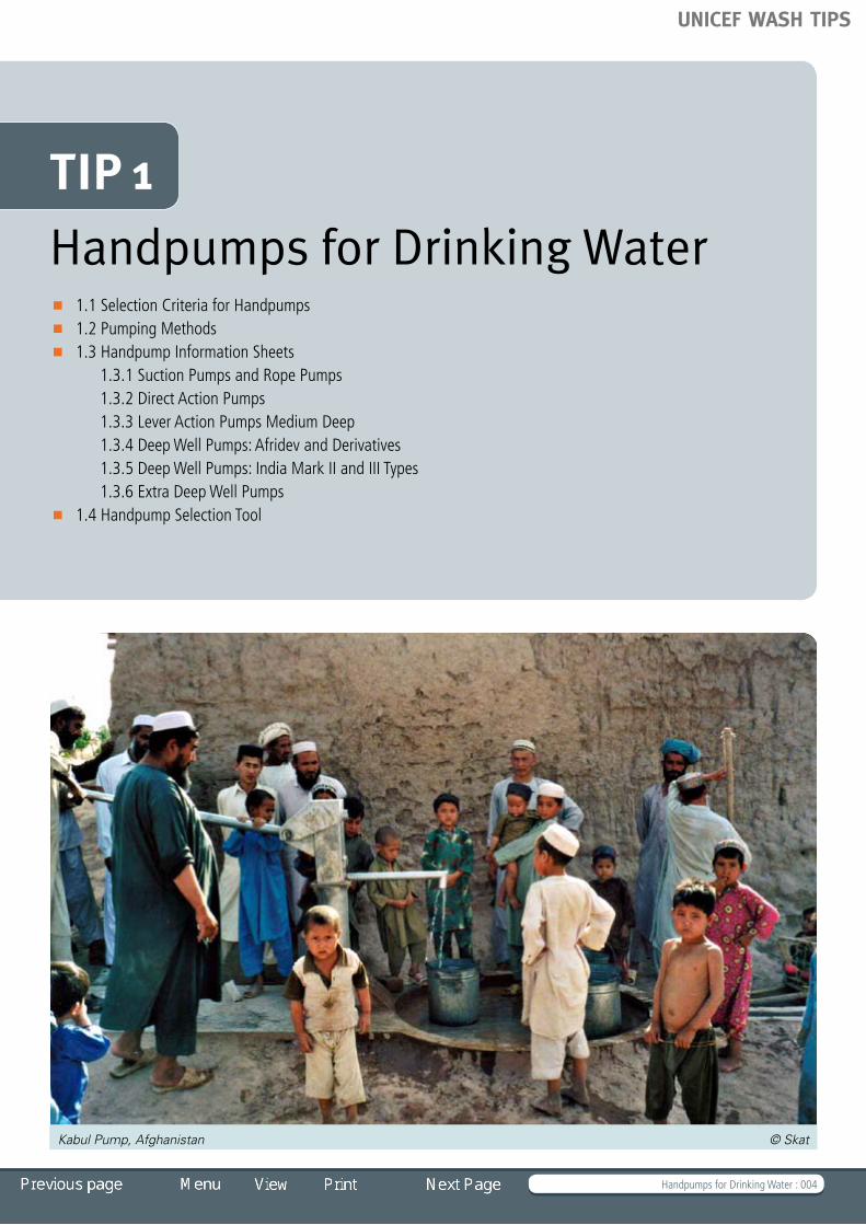
Handpumps for Drinking Water 1 .1 Selection Criteria for Handpumps 1 .2 Pumping Methods 1 .3 Handpump Information Sheets
1 .3 .1 Suction Pumps and Rope Pumps 1 .3 .2 Direct Action Pumps 1 .3 .3 Lever Action Pumps Medium Deep 1 .3 .4 Deep Well Pumps: Afridev and Derivatives 1 .3 .5 Deep Well Pumps: India Mark II and III Types 1 .3 .6 Extra Deep Well Pumps 1 .4 Handpump Selection Tool
TIP 1
Kabul Pump, Afghanistan © Skat
UNICEF WASH TIPS
Handpumps for Drinking Water : 005
Introduction
Several hundred different types of handpumps are built and used worldwide. UNICEF has followed a strict policy of handpump standardization. This has led to the use of a relatively small set of public domain handpumps within UNICEF programmes, whose manufacture in developing countries is encouraged by UNICEF.
Governments, project planners and decision-makers should be aware that their selection of technology options must fit within the prevailing policy. The beneficial effects of standardization (familiarity, availability of spare parts, backup through trained mechanics) often outweigh any negative aspects. A familiar, established technology supported by efficient after-sales and repair services is often a better choice than the optimal – or least expensive – technology.
TIP 1 covers the most common pumps with standard specifications from the Rural Water Supply Network (RWSN), plus a few proprietary designs that are used in large numbers. Many pumps that might be of local importance are not included because of space. A huge variety of handpumps – especially suction and low-lift pumps – are produced in small workshops. Their designs depend on the local availability of materials and are constantly changing. These pumps serve an important role in households that have not been reached with community water supply. However, since very little information on these designs is available they are not mentioned here.
For those pumps with standard RWSN specifications, TIP 1 enables users to specify the exact pump they have chosen, with all available options, and to fill in the corresponding BOQ.
TIP 1.1 deals with the general selection criteria for handpumps. Itincludesamatrixthatgivesaquickoverviewofthepresentedpumps.
TIP 1.2 provides an overview of pumping methods, the mechanical principles that can lift water. Pumps may use one or sometimes a combination of these principles.
TIP 1.3 is a set of Handpump Information Sheets that deals with these handpump types:
• No.6Handpump• RopePump,NicaraguaandMadagascar• MaldaPump• NiraAF85Pump• TaraPump• JibonPump• WalimiPump• IndiaMarkII• IndiaMarkIII• U3MPump
• Afridev• Indus,Kabul,Pamir• BushPump• VolantaPump• VergnetHyrdopumpHPV60/HPV100
Please note that updated information on handpumps is available on the RWSN website at www.rwsn.ch.
TIP 1.4 provides the Handpump Selection Tool. This Excel-based toolallowsuserstogetaquickideaofwhichpumpwouldbestsuit their service conditions by entering their situation-specific parameters.
References and Further Reading
RWSN Afridev Handpump Injection Moulding Manual, Rev. 1-1999RWSN Afridev Handpump Quality Control Guidelines, Rev. 1-2000RWSN Afridev Handpump Specification, Rev. 5-2007RWSN Afridev Handpump with Bottom Support System,(update 03-2007)
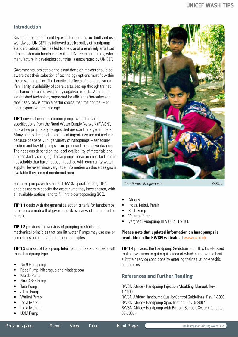
Tara Pump, Bangladesh © Skat
UNICEF WASH TIPS

Handpumps for Drinking Water : 006
RWSN Afridev Installation and Maintenance Manual, Rev. 2-2007RWSN Afridev Manuel d’Installation (French, Edition 1995)RWSN Afridev Mould Drawings for Rubber Components, Edition 2003RWSN Afridev Packaging Guidelines, Edition 1992RWSN Bush Pump Specification, SAZ 881:2004, Edition 2004RWSN Handpump Specification, CD, Edition June 2007
RWSN India Mark II, III Pump and India Mark II Extra Deep-well Pump Specification, Rev. 2-2007RWSN Indus, Kabul, Pamir Handpump Specification, Rev. 1-2006RWSN Indus, Kabul, Pamir Quality Control Guidelines, Rev. 1-2006RWSN Installation and Maintenance Manual for Extra-deep India MARK II Pump, Skat 2007RWSN Jibon Deep-set Pump Specification, Rev. 1-2005RWSN Malda Handpump DocumentsRWSN Malda Handpump Specification, Rev. 2-2005RWSN Malda Installation and Maintenance Manual, Edition 2003RWSN Rope Pump Concept (English, French and Portuguese), Edition 2004RWSN Tara Handpump Specification, Edition 2005RWSN U3M (Uganda 3-Modified) Handpump Specification, Edition 2001 RWSN Walimi Handpump Hand Book for Water Users, Edition 2003RWSN Walimi Handpump Specification, Edition 2003RWSN Walimi Handpump Manufacturing Guidelines, Edition 2003
Websites
www.rwsn.chwww.ropepump.com
Vergnet, Burkina Faso © Skat
India Mark, Sudan © Skat
UNICEF WASH TIPS

Selection Criteria for Handpumps : 007
Eritrea ©Skat
TIP 1.1 Selection Criteria for Handpumps Aspects to consider in selecting handpumps
– Corrosion resistance – User group – Pumping lift – Ease of repair – User preference, yield Handpump Selection Tool
– Economic aspects – Family wells – Village handpumps – Small towns Matrix for handpump utilization
UNICEF WASH TIPS

Selection Criteria for Handpumps : 008
Aspects to consider in selecting handpumps
A great variety of handpumps for water lifting are available, but the feasible technology options are usually limited. Hydro-geological conditions, strategic decisions at national level, project execution policies and government decisions to standardize all may restrict the choice. The final choice of technology should rest with communities themselves, since they are normally responsible for the management of their water supply system.
A simplified rule of thumb states that the stress on a pump is a function of the number of users to the power of 2 multiplied by the pumping lift to the power of 2.
Stress ≈ ƒx[(Nos. of users)2 x (Pumping lift)2 ]
This means that the number of users and the pumping lift are the most important factors.
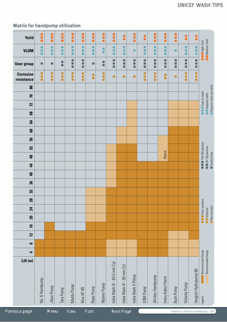
Corrosion resistanceIn areas with aggressive groundwater (i.e. with a pH value < 6.5), it is essential to ensure that pumps are corrosion-resistant. Pumps that corrode are generally not acceptable, because they produce iron-tainted water that tastes bad and stains food and clothing.
User groupSome pumps were designed as family pumps to serve small user groups. These pumps are generally simple and cheap. However, they are not robust enough to serve large user groups. When the user groups are large (> 100) it is essential to use community pumps designed for large groups of people.
Pumping liftShallow well applications allow simple suction pumps, which can only be used to a pumping lift of a maximum of 7 metres (m) or direct action pumps, which can be used to a pumping lift of a maximum of 15 m (that is, the depth of the wells must be less than 7 m and 15 m respectively).
Deep-well pumps can cover the complete range of installations, but they are an unnecessary and very expensive option for shallow sources.
Ease of repair The simplicity of making the most common repairs (replacing seals, replacing fulcrum and handle bearings, removal of piston and footvalve) affects the ease of repair. Village-level operation and maintenance (VLOM) is possible in cases where handpumpsrequireonlyafewlow-costtools,andwherethatmaintenance and repair can be carried out by village mechanics or communities themselves. Heavy and complex tooling makes motorized central maintenance teams necessary. This affects the cost of repairs and the time that the pump is out of service.
An open-top cylinder (OTC) design allows the retrieval of piston and foot valve without the need for lifting the rising mains. This makes this type of pump more suitable for repairs by the community.
User preference, yield Users prefer pumps that have a high yield. In addition, the look and feel of a pump can affect its acceptability. In some cases, cultural aspects like pumping position are important factors in user preference.
Handpump Selection Tool
A handpump selection tool is provided to help you make the right choice of technology. For guidance and access to the document, go to TIP 1.4.
Economic aspectsFamily wellsLow-cost lifting devices such as a bucket and rope, windlasses or simple handpumps on shallow dug wells are sufficient and sustainable sources for small communities or single households. In some cases the wells may not be perennial and may need to be supplemented by communal sources.
Village handpumpsFor small communities of up to about 1,000 inhabitants, properly constructed hand-dug wells – which provide a safe water supply allyearround,equippedwithsimplebutreliableandeasilymaintainable direct action handpumps – are a good option. If wells cannot be dug by hand because water tables are too deep or for other reasons, boreholes may have to be drilled. In such casesgoodqualityboreholesequippedwithreliableandrobusthandpumps, which can be easily maintained, are the most cost-effective community choice. The number of users per pump should be 200 to 300.
Small townsThe investment cost per capita is lower for communities of between 1,000 and 5,000 inhabitants if small piped systems with pumps powered by electricity from the grid or diesel engines are installed instead of handpumps. Only one or two high-yieldwellswillberequired.Inthesizerangeof1,000to 2,000 inhabitants, piped systems with solar pumps are attractive, especially if the pumping lifts are low. Contrary to grid or diesel-powered systems, solar pump systems have no energy costs, but their application can be limited due to the high cost of photovoltaic panels – thus the number of panels needed is a determining cost factor. (See TIP 3 Solar Powered Pumping and TIP 4 Motorized and Small Pipe Systems.)
UNICEF WASH TIPS
Selection Criteria for Handpumps : 009
Matrix for handpump utilization
Lift (m)
48
1216
2024
2832
3640
4448
5256
6064
6872
7680
Corrosion resistance
User group
VLOM
YeildN
o. 6
Han
dpum
p
Jibo
n Pu
mp
Tara
Pum
p
Mal
da P
ump
Nira
AF-
85
Rope
Pum
p
Wal
imi P
ump
Indi
a M
ark
III -
63.5
mm
Cyl
Indi
a M
ark
III -
50 m
m C
yl
Indi
a M
ark
II PU
mp
U3M
Pum
p
Afrid
ev H
andp
ump
Indu
s Ka
bul P
amir
Pam
ir
Bush
Pum
p
Vola
nta
Pum
p
Verg
net H
ydro
pum
p 60
Lege
nd:
Rec
omm
ende
d Ra
nge
Ful
ly re
sist
ant
150
-300
per
sons
E
asy
to re
pair
Hig
h Yi
eld
R
ecom
men
ded
Rang
e
Affe
cted
50-
150
pers
ons
Requiresskills
M
ediu
m Y
ield
Not
resi
stan
t F
amily
Pum
p Requirestoolsandskills
UNICEF WASH TIPS

Pumping Methods : 010
TIP 1.2 Pumping Methods Pumping principles Reciprocating handpumps
– Suction pumps – Direct action pumps – Lever action pumps Rotary pumps
– Rope pump Progressive cavity pumps Diaphragm pumps
Burkina Faso © Skat
UNICEF WASH TIPS

Pumping Methods : 011
Pumping principles
Any one of the following mechanical principles can lift water. Pumps may use one or sometimes a combination of these principles.
Direct lift: Water is physically lifted in a container. Typical examples are: rope and bucket, bailer, Persian wheel.
Displacement: Water cannot be easily compressed but it can be pushed or displaced. Typical examples are: piston pumps, progressive cavity pumps and diaphragm pumps.
Creating a velocity head: Water can be propelled to a high speed. The momentum produced can be used either to create a pressure or a flow. Typical examples are: propeller pumps, centrifugal pumps, rebound inertia pumps, jet pumps.
Using the buoyancy of a gas: Air that is blown into water bubbles upward. It will lift a proportion of the water that it flows through. Typical examples are: air lift.
Gravity: Energy of a media (water) that flows downward under gravity is used to lift water. Typical examples are: siphons.
Most handpumps use the water displacement principle for pumping.
Reciprocating handpumps
The majority of handpump types used worldwide belong to the group of reciprocating pumps. The water is lifted by a piston that is raised and lowered inside a cylinder that has a footvalve. The piston (or plunger) is moved by a pump rod connected directly to a T-handle or a lever handle at the pump head. In some pump types, a flywheel with crankshaft is used to create the reciprocating movement of the piston.
Included in the group of reciprocating handpumps are:
a) suction pumpsb) direct action pumpsc) lever action pumps
The function of the reciprocating pumps is based on the principle that water flows from areas of high pressure to areas of low pressure. The reciprocating pump creates an area of sufficiently low pressure above the body of water, causing it to flow upward.
A reciprocating piston pump consists essentially of a long vertical pipe, called a rising main. The rising main extends into the cylinder (the area in which the piston/plunger moves up and down). Near the bottom of the cylinder, a non-return valve,
called a footvalve, is fitted. The footvalve allows the water to flow from the lower part of the pump into the cylinder, but prevents it from flowing back into the well. A second non-return valve is situated in the piston/plunger. The piston/plunger and the footvalve alternatively divide the pump into an upper part and a lower part (see Fig. 1.3). The lower part of the pump always extends into the water body of the well.
When the operator lowers the piston, the atmospheric pressure actsequallyonallwatersurfaces.Thefootvalvestaysclosed,preventing water from being pushed back into the well. The piston presses down onto the water until the non-return piston valve opens, allowing water to flow through the piston. At the lowest point of the stroke, the movement of the piston is reversed. The weight of the water column above the piston causes the piston valve to close. This results in two things:
1. The water above the piston starts rising. It cannot flow backwards and will move up in the rising main until it reaches the top of the pump, flowing out by the spout.
2. Because the piston moves up, the pressure in the lower part of the cylinder drops; a vacuum is created. The water in the well is still under atmospheric pressure and will push its way past the footvalve into the cylinder.
Fig. 1.1 Reciprocating handpump cylinder
UNICEF WASH TIPS

Pumping Methods : 012
This cycle is repeated with every stroke.
Suction pumpsIn a suction pump, the cylinder is above the water table, usually near the top of the pump head. The rising main extends below the water table. When the pump is operated, during the upwardsstrokeitappearsthatwatergets“suckedup”throughthe rising main into the cylinder.
In fact, the atmospheric pressure forces the water into the area of low pressure underneath the piston. The theoretical limit to which the atmospheric pressure can push up water is 10 metres (m). In practice, suction pumps can be used to lift water up to about 7 or 8 m.
A suction pump needs to be full of water before it can be operated. That means the pump needs to be primed: water is poured into the pump head by the operator. This is necessary every time the pump is emptied by a leaking footvalve (in practice all footvalves leak a little, especially in inexpensive suction pumps – so the pump may need to be primed every morning, or even several times a day). Thus, the danger exists that the well can be contaminated through polluted water used for priming.
The advantage of suction pumps is that the cylinder is normally above ground, and thus easily accessible. Maintenance involves replacement of seals and valves, operations that can be easily performed with few tools.
Direct action pumpsIn most direct action handpump designs, the up-and-down movement of the piston is made by a T-handle directly connected to the upper end of the pump rod (hence the name).
Fig. 1.2 Suction pump Fig. 1.3 Direct action pump
UNICEF WASH TIPS

Pumping Methods : 013
The pump rod consists of plastic pipes, which are connected by threads, and each pipe length is sealed airtight. With this system, the pump rod pipes are buoyant in the water of the rising main and therefore reduce the force needed on the up-stroke.
Because of the relatively large volume of the hollow pump rods and the narrow clearance in the annulus between the pump rod and rising main (6 to 10 mm); the pump rod displaces water during the down-stroke. This results in the delivery of water during both the up-stroke and the down-stroke.
Unlike suction pumps, direct action pumps have down-the-hole components that need to be accessed periodically for maintenance and repair. However, these operations are relatively easy for direct action pumps. Once the riser pipes and pump rod pipes are connected, disconnection for maintenance isnotrequiredbecausethesepipesareflexibleenoughtobepulled from the well or borehole in a continuous length without undoing the joints. This operation allows access to the down-the-hole components.
The down-the-hole components are made mainly of plastic (with a few rubber parts). This makes handling and installation of the pump easy (lightweight). It also means the pump is highly corrosion-resistant, even in aggressive waters.
Lever action pumpsMost deep-well handpumps are of the lever action type. The increasedlengthofthewatercolumnindeepboreholesrequiresmore effort to draw water and the lever of the handle makes the operation easier. Besides the conventional handle, there are also pump designs, which use a flywheel to operate a crankshaft for transforming the rotation into an up-and-down movement.
Lever action pumps consist of
1. above-ground components like pump head, pump stand and handle, which are usually made of welded mild steel components, preferably with a corrosion protection of hot-dip-galvanized zinc layer
2. down-the-hole components like rising main, pump rods with plunger, cylinder and footvalve.
The configuration of the down-the-hole components can include an open-top cylinder. The plunger and the footvalve can be removed from the cylinder without dismantling the rising main. Or they can feature the conventional configuration with a small diameter rising main and a bigger cylinder diameter, which requiresdismantlingoftherisingmainforrepairsonplungerorfootvalve.
Riser pipes are made of galvanized iron (GI) pipes, UPVC (unplasticized polyvinyl chloride) or stainless steel.
Pump rods are made of mild steel, stainless steel or fibre reinforced plastic rods (FRP).
Joining of pump rods is preferably made with threaded connections.
Some pump components, such as the plunger and footvalve, are made of brass or engineered plastics.
Fig. 1.4 Lever action pump
UNICEF WASH TIPS

Pumping Methods : 014
Rotary pumps
The most commonly used rotary handpumps are the rope pump and the progressive cavity pump. Note that although some reciprocating pumps use a circular action mechanism to drive the pistons, they are not categorized as rotary.
Rope pumpThe rope pump is based on the principle of the ancient Chinese water-lifting technology, the chain and washer pump. The development of this easy, cost-effective and successful technology for water lifting took place mainly in Nicaragua.
The rope pump is not defined by a specific design but by a concept. Worldwide many different rope pump designs, adapted to their local conditions, are produced locally in small workshops near to the users. The producers need to study the potential market and economic viability carefully. Areas with a high density of dug wells usually have a big potential for rope pumps.
Ropepumps,beingmainlyfamilypumps,requireanadaptedprocurement and supply mechanism. The users themselves should select and purchase their handpumps and take over full ownership. Marketing of the product and its application (they are used for small-scale irrigation as well as for domestic water supply) should be left to the producer and the producer’s sales organization. The rope pump should be sold directly to the users.
Fig. 1.5 Rope pump
Fig. 1.6 Rope pump installation
UNICEF WASH TIPS

Pumping Methods : 015
Fig. 1.7 Progressive cavity pump
The rope pump principleAropeloopwithattachedpistons,equallyspaced,ispulledthrough a pipe, which is immersed in water at its lower end. The pistons entering the rising main pipe transport the water upwards until it reaches the spout through which it escapes.
A pulley wheel (made of a car tire) pulls the rope with the pistons through the rising main pipe. The pulley wheel is operated by a crank handle, which also acts as the wheel axle. A guide near the bottom of the well leads the rope with the pistons smoothly into the rising main.
Hand-operated rope pumps are mostly used for drawing water from dug wells with depths of 0 to 20 m. However, this pump can also be installed on boreholes (0 to 40 m depth), provided there is an attachment for leading the rope into the borehole and a smaller guide that fits into the borehole casing.
The simplicity of this low-cost pump makes it easy to operate. It is also easy to maintain and repair with a few simple tools.
Progressive cavity pumps
Unlike most rotary pumps, progressive cavity pumps can be used in small diameter boreholes.
The progressive cavity pump consists of a single helix rotor. The rotor is made to a high finish, using chromium plated steel or polished stainless steel (SS). It is circular in cross section so that it fits exactly into one of the two helices of the hard rubber stator (the stationary part of a rotor system).
As a result, the empty second helix of the stator is divided into a number of separated voids. When the rotor is turned, these voids are screwed along the axis of rotation. In the well, water will be trapped in the voids and when the rotor is rotated these volumes are pushed upwards and discharged into the rising main.
Progressive cavity pumps need to be driven at a relatively high speed; therefore, handpumps are often fitted with a gearbox. This makes this type of pump relatively complicated and costly.
UNICEF WASH TIPS
Pumping Methods : 016
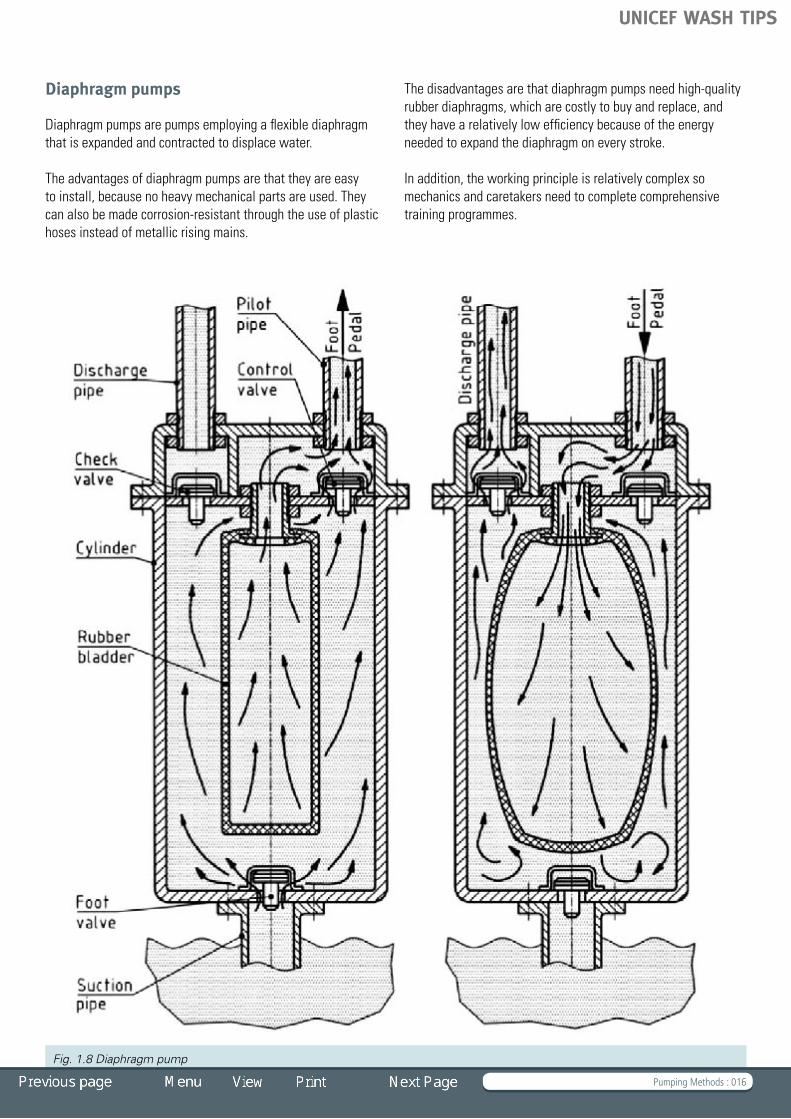
Diaphragm pumps
Diaphragm pumps are pumps employing a flexible diaphragm that is expanded and contracted to displace water.
The advantages of diaphragm pumps are that they are easy to install, because no heavy mechanical parts are used. They can also be made corrosion-resistant through the use of plastic hoses instead of metallic rising mains.
Fig. 1.8 Diaphragm pump
Thedisadvantagesarethatdiaphragmpumpsneedhigh-qualityrubber diaphragms, which are costly to buy and replace, and they have a relatively low efficiency because of the energy needed to expand the diaphragm on every stroke.
In addition, the working principle is relatively complex so mechanics and caretakers need to complete comprehensive training programmes.
UNICEF WASH TIPS

Handpump Information Sheets : 017
TIP 1.3 Handpump Information Sheets Tip 1.3.1 Suction Pumps and Rope Pumps
– No. 6 handpump – Nicaragua rope pump – Madagascar rope pump Tip 1.3.2 Direct Action Pumps
– Tara pump – Malda pump – NIRA AF-85 pump Tip 1.3.3 Lever Action Pumps Medium Deep
– Jibon pump – Walimi pump Tip 1.3.4 Deep Well Pumps: Afridev and Derivatives
– Afridev handpump – Indus, Kabul, Pamir handpumps Tip 1.3.5 Deep Well Pumps: India Mark II and III Types
– India Mark II pump – India Mark III pump – U3M handpump Tip 1.3.6 Extra Deep Well Pumps
– Bush pump, Zimbabwe – Volanta pump – Vergnet Hydropump
India MKII, Eritrea © Skat
UNICEF WASH TIPS

Handpump Information Sheets : 018
Background
UNICEF Supply Division has developed guidelines for specifying handpumps that are consistent with current handpump standards. The approach provides the flexibility to select pumps withthequantityandtypeofconnectingrods/riserpipessuitable to a particular water type and well depth. Though the approachisgooditrequirestherequisitionertohaveacleartechnical understanding of handpump technology. Otherwise, therequisitionerislikelytoselectthewrongcombinationofcomponents to make a complete handpump package.
To assist in the selection of the pump and for easy specification and procurement, an approach using a complete handpump package for a particular well depth is recommended. TIP 1.3.4 and TIP1.3.5 contain samples of recommended packages for handpumps of the India Mark II and Afridev families.
Format for handpump specificationA handpump specification should always be broken down into a general description of the pump package with a listing of the specific components. This is illustrated in the example below for the procurement of a Standard Deep Well Pump (SDWP). otherwise known as the India Mark II.
General Description SDWP complete, (as per IS 15500:2004 of the Bureau of Indian Standards) or India Mark II (as per RWSN/SKAT specifications Rev. 2, 2007 ) with 30 metres of galvanized iron riser pipe and connecting rods (additional riser pipes and connecting rods can be ordered separately for deeper installations up to a recommended maximum depth of 39 m).
Supplied with: 1 No. Head assembly (with Handle assembly).1 No. Water Tank – Standard1 No. Third Plate 1 No. Telescopic Stand* – Standard1 No. Cylinder assembly – Standard10 Nos. Connecting rods (mild steel, electro-galvanized, 12
mm diameter, 3 m long, with M12 threaded ends and couplers)
10 Nos. Riser pipes (MS, hot dipped galvanized, 32 mm ND,** 3 m long)
1 set Spare part kit sufficient for 2 years of operation (optional)
* For installation on bore wells of 150 mm diameter, the Telescopic Stand – Standard should be used. The Normal Stand – Standard is suited for wells in the range of 100 mm to 125 mm diameter casing pipe. ** nominal diameter
In addition to the basic pump specification, it is recommended thatanadequatenumberofinstallationandmaintenancemanuals, standard tool sets and special tool sets be ordered for the installation and maintenance of this handpump (which in the case of this example is defined in Annex D, Clause 1.3 of Part 8,TableD1,ofthestandardIS15500:2004).Theactualquantityordered will depend on the density of handpumps in a given area, the installation and maintenance infrastructure and other local conditions. The number of manuals and tool sets ordered may vary from one set for every 50 pumps to one set for every 250 pumps.
Similarly,anadequatequantityoffishingtoolsets(forretrievingdropped below-ground components), platform shuttering sets and masonry tool sets (for constructing concrete pump platforms and aprons) should be ordered based on local conditions.
UNICEF WASH TIPS

Suction Pumps and Rope Pumps : 019
TIP 1.3.1 Suction Pumps and Rope Pumps Suction pumps
– No . 6 handpump – Components – Bill of Quantities Rope pumps
– Nicaragua rope pump – Madagascar rope pump – Bill of Quantities
Fig. 1.9 Canzee pump, Madagascar © Skat
UNICEF WASH TIPS

Suction Pumps and Rope Pumps : 020
Suction pumps
Most of the many locally produced suction pumps are family pumps. Unlike community pumps, most family pumps are not standardized. Their design and functioning is largely dependent on the materials that are locally available and on user preference.
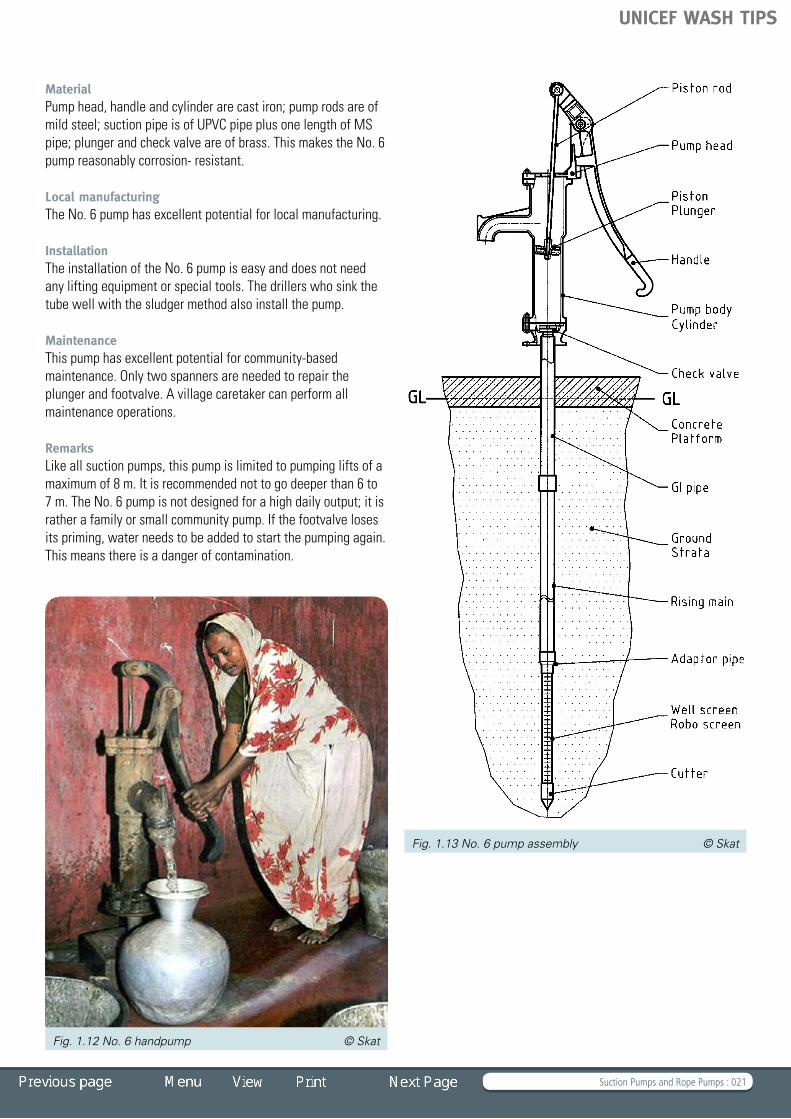
No. 6 handpumpDescriptionThe No. 6 pump is a lever-operated suction handpump. Typically, No. 6 pumps are installed in collapsible tubewells with the screenextendingtothecoarsesandaquifer.
Technical dataRecommended depths: from 0 to 6 mCylinder diameter: 89.0 mmMaximum stroke: 215 mmApproximate discharge(75 watt input, at 5 m head) 4.5 m³/hourPumping lift: 0 to 7 mPopulation served: 50 to 100 peopleHouseholds: 5 to 10 Water consumption: 20 to 25 l/per capitaType of well: collapsible tubewell or dug well
Fig. 1.10 No. 6 derivative, Vietnam © Skat Fig. 1.11 EMAS pump, Bolivia © EMAS
No 6, Bangladesh © Skat
UNICEF WASH TIPS
Suction Pumps and Rope Pumps : 021
MaterialPump head, handle and cylinder are cast iron; pump rods are of mild steel; suction pipe is of UPVC pipe plus one length of MS pipe; plunger and check valve are of brass. This makes the No. 6 pump reasonably corrosion- resistant.
Local manufacturingThe No. 6 pump has excellent potential for local manufacturing.
InstallationThe installation of the No. 6 pump is easy and does not need anyliftingequipmentorspecialtools.Thedrillerswhosinkthetube well with the sludger method also install the pump.
MaintenanceThis pump has excellent potential for community-based maintenance. Only two spanners are needed to repair the plunger and footvalve. A village caretaker can perform all maintenance operations.
RemarksLike all suction pumps, this pump is limited to pumping lifts of a maximum of 8 m. It is recommended not to go deeper than 6 to 7 m. The No. 6 pump is not designed for a high daily output; it is rather a family or small community pump. If the footvalve loses its priming, water needs to be added to start the pumping again. This means there is a danger of contamination.
Fig. 1.12 No. 6 handpump © Skat
Fig. 1.13 No. 6 pump assembly © Skat
UNICEF WASH TIPS

Suction Pumps and Rope Pumps : 022
ComponentsThe No. 6 pump is normally only available with the following components:
Pump head type Cast-iron pump head cover and handle
Pump stand type Cast-iron pump body with base plate
Rising main arrangement
GI pipe (1.5 m long) rising main and roboscreen of UPVC
Cylinder arrangement
Inside pump body(suction pump)
Pump rod arrangement
MS- Pump rod with UPVC cup seal
GI galvanized ironMS mild steelUPVC unplasticized polyvinyl chloride
Bill of Quantities
Click on the BoQ to open an Excel Sheet
Rope pumps
Bill of Quantities (No.6 Handpump)
Fig. 1.14 Nicaragua rope pump © Skat
Fig. 1.15 Madagascar rope pump © Skat
UNICEF WASH TIPS

Suction Pumps and Rope Pumps : 023
Nicaragua rope pumpDescriptionThe Nicaragua rope pump features a design in which small plastic pistons are lined up on a rope. The distance between the pistons is approximately 1 m. The drive wheel is crank operated and pulls the rope through a plastic rising pipe. The drive wheel consists of cut old tires. A ceramic guide box leads the rope with the pistons into the rising pipe.
Technical dataPistonnominaldiameter: 1”,¾”,½”Approximate discharge (75 watt input) at 10 m head: 1.4 m³/hour at 15 m head: 1.1 m³/hour at 20 m head: 0.7 m³/hourPumping lift: 0 to 30 mPopulation served: 70 peopleHouseholds: 3 to10 Water consumption: 15 to 20 l/per capitaType of well: dug well or borehole
MaterialThe pump stand is made of painted steel rods; the crank of painted steel pipe; the cover of galvanized and painted MS sheet; the drive pulley of rubber and mild steel; the pistons of plastic; the guide box of ceramic, concrete and PVC; and the rising main of PVC pipe. The Nicaragua rope pump is reasonably corrosion-resistant.
Local manufacturingThe Nicaragua rope pump has an excellent potential for local manufacturing.
InstallationThe installation of the Nicaragua rope pump is easy. It can be done by trained area mechanics. No lifting tackle and no special tools are needed.
MaintenanceThe Nicaragua rope pump has excellent community management potential. Torn or broken ropes can be replaced without any special tools. A village caretaker can perform all maintenance operations.
RemarksThe Nicaragua rope pump is usually installed in dug wells. Even though it is not limited in pumping lifts, the major application range is up to 15 m. The rope pump is not designed for a high daily output, but rather for a family or small community pump. Models exist for family use as well as for community use.
Distribution: ~30,000 Nicaragua
Fig. 1.16 Nicaragua rope pump assembly © Skat
UNICEF WASH TIPS

Suction Pumps and Rope Pumps : 024
Madagascar rope pumpDescriptionThe Madagascar rope pump features a design in which small plastic pistons are lined up on a rope. The distance between the pistons is approximately 1 m.
The drive wheel is crank operated and pulls the rope through a plastic rising pipe. The drive wheel consists of cut old tires. A concrete guide box with a glass bottle leads the rope with the pistons into the rising main.
Technical dataPistonnominaldiameter: 1”,¾”,½”Approx. discharge (75 watt input) at 10 m head: 1.4 m³/hour at 15 m head: 1.1 m³/hour at 20 m head: 0.7 m³/hourPumping lift: 0 to 30 mPopulation served: 70 peopleHouseholds: 3 to 10 Water consumption: 15 to 20 l/per capitaType of well: dug well or borehole
MaterialThe pump stand and crank are made of painted steel pipe, the cover of galvanized and painted plate, the drive pulley of rubber and mild steel, the pistons of plastic, the guide box of concrete, PVC and glass, and the rising main of PVC pipe. The Madagascar rope pump is reasonably corrosion- resistant.
Local manufacturingThe Madagascar rope pump has excellent potential for local manufacturing.
InstallationThe installation of the Madagascar rope pump is easy. It can be done by trained area mechanics. No lifting tackle and no special tools are needed.
MaintenanceThe Madagascar rope pump has excellent community management potential. Torn or broken ropes can be replaced without any special tools. A village caretaker can perform all maintenance operations.
RemarksThe Madagascar rope pump is usually installed in dug wells. Even though it is not limited in pumping lifts, the major application range is up to 15 m. The rope pump is not designed for a high daily output, but rather for a family or small community.
Distribution: < 1,000 Madagascar
Fig. 1.17 Madagascar rope pump assembly © Skat
Bill of Quantities
Click on the BoQ to open an Excel Sheet
Bill of Quantities (Rope Pumps - Nicaragua/Madagascar)
UNICEF WASH TIPS

Direct Action Pumps : 025
TIP 1.3.2 Direct Action Pumps Tara pump
– Guide for specifying options for the Tara pump – UNICEF Recommended Package – Bill of Quantities Malda pump
– Guide for specifying options for the Malda pump – Bill of Quantities Nira AF-85 pump
– Guide for specifying options for the Nira AF-85 pump – Bill of Quantities
Malawi © Skat
UNICEF WASH TIPS

Direct Action Pumps : 026
Tara pump
DescriptionAs a direct action handpump, the Tara is based on a buoyant pump rod that is directly articulated by the user, discharging water at the up- and down-stroke. Typically, Tara pumps are installed in collapsible tubewells with the screen extending to thecoarsesandaquifer.
Technical dataRecommended depths: 0 to 15 mCylinder diameter: 54.2 mmMaximum stroke: 600 mmApproximate discharge (75 watt input)at 5 m head: 3.5 m³/hourat 10 m head: 1.8 m³/hourat 14 m head: 1.2 m³/hourPumping lift: 1 to 15 mPopulation served: up to 100 peopleHouseholds: 10 Water consumption: 15 to 20 l/per capitaType of well: borehole or dug well
MaterialPump head and handle are made of galvanized steel. The pump rods, rising main and cylinder are made of UPVC pipe. The plunger and footvalve are made of various materials. The Tara pump is corrosion-resistant.
Local manufacturingThe Tara pump has excellent potential for local manufacturing.
InstallationThe installation of the Tara pump is easy and does not need anyliftingequipmentorspecialtools.Drillerswhosinkthetubewells with the sludger method also install the pumps.
MaintenanceThe Tara has an excellent community management potential. Only simple tools are needed to pull out the entire pumping element and the footvalve. A village caretaker can perform all maintenance operations.
RemarksThe Tara, like most of the direct action pumps, is limited to pumping lifts of a maximum of 15 m. It is recommended not to go deeper than 12 m.
The Tara pump is not designed for a high daily output, but rather as a family or small community pump.
Distribution: >100,000 India and Bangladesh
Guide for specifying options for the Tara pumpList of options available for this pump type:
Options A B
Pump stand type
Pump stand with handle and pedestal
–
Rising main arrangement
UPVC rising main with upper and lower well casing
UPVC rising main with lower well casing
Cylinder arrangement
UPVC cylinder UPVC / SS plunger and footvalve
–
Pump rod arrangement
UPVC pump rod pipes with union connectors
–
UPVC unplasticized polyvinyl chlorideSS stainless steel
Fig. 1.18 Tara pump, India © Skat
UNICEF WASH TIPS

Direct Action Pumps : 027
ExamplePossible composition of a selected Tara pump: Pump stand type A Rising main arrangement B Cylinder arrangement A Pump rod arrangement AFor clarification, see Fig. 1.19a and 1.19b.
Tara (RWSN/SKAT: Rev0-2005) or Direct Action Deep Handpump - DA (IS:14106) installation depth range 9 m to 15 m
UNICEF Recommended Package
Conditions Well depth up to 15 m, recommended for corrosive and acidic water
Catalogue description with threaded riser main and threaded pump rod, 12 m ( Lao Version)
Specification IS 14106 RWSN/Skat Rev0-2005
Pump Head with handle cone & cone plate Normal, SS Handle
Pump Stand Normal
Riser Main PVC threaded and cemented ; 5 length x 3 m
Cylinder PVC with plastic plunger and footvalve
Pump Rod PVC threaded joint cemented ; 5 nos.
UNICEF Catalogue Nos.
UNICEF WASH TIPS

Direct Action Pumps : 028
Fig. 1.19a Options for the Tara pump
Fig. 1.19b Options for the Tara pump
Bill of Quantities
Click on the BoQ to open an Excel Sheet
Bill of Quantities (Tara Pump)
UNICEF WASH TIPS

Direct Action Pumps : 029
Malda pump
DescriptionAs a direct action pump, the Malda is based on a buoyant pump rod that is directly articulated by the user, discharging water during the up- and down-stroke.
Technical dataRecommended depths: 0 to 15 m Cylinder diameter: 50 mmMaximum stroke: 410 mmApproximate discharge (75 watt input)at 5 m head: 3 m³/hourat 10 m head: 1.8 m³/hourat 15 m head: 1.2 m³/hourPumping lift: 1 to 15 mPopulation served: 300 peopleHouseholds: 30 to 50 Water consumption: 15 to 20 l/per capitaType of well: borehole or dug well
MaterialPump stand, standing plate and handle are made of galvanized steel, wearing sleeve of stainless steel, pump rods and rising main of HDPE pipe; and plunger and footvalve are also made of HDPE.
This makes the Malda pump completely corrosion-resistant.
Local manufacturingThe Malda pump is specially designed for production in developing countries.
InstallationThe installation of the Malda pump is very easy and does not needanyliftingequipmentorspecialtools.Therisingmainwithfootvalve and pump head as well as the pump rod with handle and plunger can be assembled on the ground. When laid next to each other, the correct length of each can be easily verified.
Maintenance The Malda has excellent community management potential. Only simple tools are needed to pull out the entire pumping element as well as footvalve and rising main.
RemarksThis pump, like most of the direct action pumps, is limited to pumping lifts of a maximum of 15 m. It is recommended it not be used deeper than 12 m.
Fig. 1.20 Malda pump, Malwai © Skat Fig. 1.21 Malda pump assembly
Handle
Pump stand
Standing plate
Cement/Platform
Ground
Rising main
Pumprod
Plunger
Bobbin
Footvalve
Footvalve
O-Ring
Flange ring
Socket
Suction pipe
Suction pipe
Scale 1:5
Split ring
GLGL
Spout
Pedestal
Socket
Pumprod
Plunger
Casing pipe
Rising main
UNICEF WASH TIPS

Direct Action Pumps : 030
Distribution: > 1,000 Malawi
Guide for specifying options for the Malda pumpList of options available for this pump type:
Pump stand type
Pump stand with handle and pedestal drawing NO. A5002
Rising main arrangement
HDPE – rising main with threaded Sockets
Cylinder arrangement
Cylinder with plunger and footvalve in HDPE drawing No. A5004
Pump rod arrangement
Threaded pump rod pipes in HDPE drawing No. A5006
HDPE high density polyethylene
Fig. 1.22a Options for the Malda pump
Bill of Quantities
Click on the BoQ to open an Excel Sheet
Fig. 1.22b Options for the Malda pump
Bill of Quantities (Malda Pump)
UNICEF WASH TIPS

Direct Action Pumps : 031
Nira AF-85 pump
DescriptionThe Nira AF-85 direct action handpump is based on a buoyant pump rod that is directly articulated by the user, discharging water at the up- and down-stroke. The Nira AF-85 pump is completely corrosion-resistant.
Technical dataRecommended depths: 0 to 15 m Cylinder diameter: 50 mmMaximum stroke: 410 mmApproximate discharge (75 watt input)at 5 m head: 3 m³/hourat 10 m head: 1.8 m³/hourat 15 m head: 1.2 m³/hourPumping lift: 1 to 15 mPopulation served: 300 peopleHouseholds: 30 Water consumption: 15 to 20 l/per capitaType of well: borehole or dug well
MaterialThe pump head and standing plate are made of mild steel or painted with epoxy paint. The entire handle is made of stainless steel. Pump rods and rising main are made of HDPE pipe, and the plunger and footvalve of HDPE material. This makes the Nira AF-85 pump completely corrosion- resistant.
Local manufacturingThe Nira AF-85 pump is a protected product and is not intended for local production. Besides the main production company in Finland, there is one branch in Ghana (Ghanira) and one in Tanzania (Tanira) producing this pump.
InstallationThe installation of the Nira AF-85 pump is easy and does not needanyliftingequipmentorspecialtools.
MaintenanceThis pump has excellent community management potential. Only simple tools are needed to pull out the entire pumping element as well as the footvalve and rising main. This pump is reliable and popular with communities.
RemarksThis pump, like most of the direct action pumps, is limited to pumping lifts of a maximum of 15 m. It is recommended not to go deeper than 12 m.
Distribution: >10,000Tanzania,Ghana,Mozambique
Guide for specifying options for the Nira AF-85 pumpNo guide for specifying options is available. It is necessary to contact the manufacturer or the local representative to define the pump specification.
Fig. 1.23 Nara pump, Ghana © Skat
UNICEF WASH TIPS

Direct Action Pumps : 032
Fig. 1.24 Nira AF-85 pump assembly
Bill of Quantities
Click on the BoQ to open an Excel Sheet
Bill of Quantities (Nira AF-85 Pump)
UNICEF WASH TIPS

Lever Action Pumps Medium Deep : 033
TIP 1.3.3 Lever Action Pumps Medium Deep Jibon pump
– Guide for specifying options for the Jibon pump – Bill of Quantities Walimi pump
– Guide for specifying options for the Walimi pump – Bill of Quantities
Tanzania © Skat
UNICEF WASH TIPS

Lever Action Pumps Medium Deep : 034
Jibon pump
DescriptionThe Jibon pump is a lever-operated deep-set pump. Typically, Jibon pumps are installed in collapsible tubewells with the screenextendingtothecoarsesandaquifer.
Technical dataRecommended depths: 0 to 18 m Cylinder diameter: 54.0 mmMaximum stroke: 215 mmApproximate discharge (75 watt input)at 5 m head: 3.0 m³/hourat 10 m head: 1.8 m³/hourat 15 m head: 1.2 m³/hourPumping lift: 1 to 15 mPopulation served: 50 to 100 peopleHouseholds: 5 to 10 Water consumption: 20 to 25 l/per capitaType of well: borehole or dug well
MaterialThe pump head and handle are made of cast iron; pump rods are of FRP material (fibre glass reinforced plastic); rising main and suction pipe and robo screen are of UPVC pipe; plunger and footvalve are of PVC, stainless steel and rubber. This makes this pump reasonably corrosion-resistant.
Local manufacturingThe Jibon pump has excellent potential for local manufacturing.
InstallationThe installation of the Jibon pump is easy and does not need anyliftingequipmentorspecialtools.Thedrillerswhosinkthetubewells with the sludger method also install the pumps.
MaintenanceThis pump has excellent community management potential. Only two spanners are needed to repair the plunger and the footvalve. All maintenance operations can be performed by a village caretaker.
RemarksThis pump is limited to pumping lifts to a maximum of 20 m. It is recommended not to go deeper than 15 m.
The Jibon pump is not designed for a high daily output; rather it is designed for a family or a small community.
Distribution: > 10,000 Bangladesh
Fig. 1.25 Jibon pump, Bangladesh © Skat Fig. 1.26 Jibon pump assembly
UNICEF WASH TIPS

Lever Action Pumps Medium Deep : 035
Guide for specifying options for the Jibon pumpList of options available for this pump type:
Options A B C
Pump head type Cast-iron pump head cover and handle
– –
Pump stand type Cast-iron pump body with welded flange assembly
– –
Rising main arrangement
UPVCrisingmainfor2”cylinderand lower well assembly
Cylinder arrangement
Upper well assembly with piston and footvalve drawing No. A5820
Pump rod arrangement
FRP-pump rods with brass connectors drawing No. A5889
MS-pump rods with threaded connectors drawing No. A5804
–
not recommended when PH value is < 6.5UPVC unplasticized polyvinyl chloride MS mild steelFRP fibre reinforced plastic
UNICEF WASH TIPS
Lever Action Pumps Medium Deep : 036
Bill of Quantities
Click on the BoQ to open an Excel Sheet
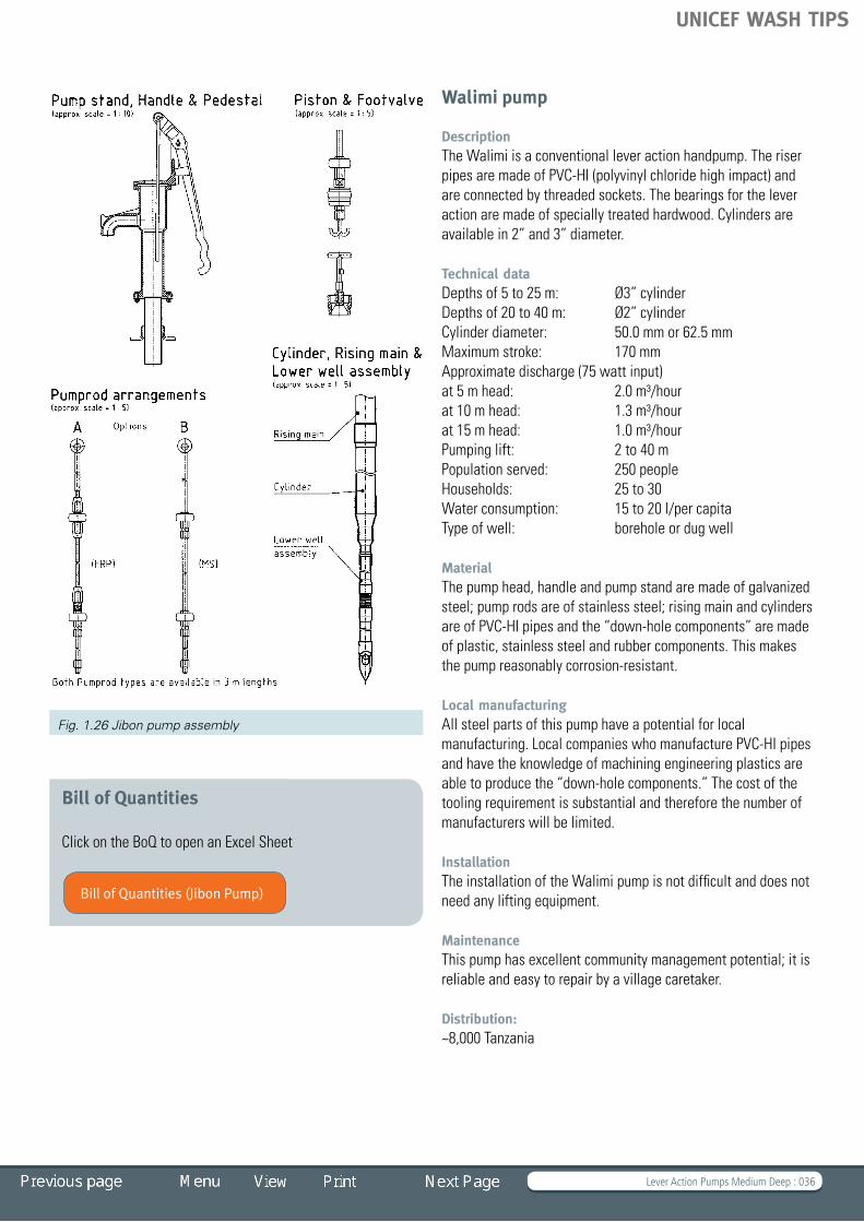
Walimi pump
DescriptionThe Walimi is a conventional lever action handpump. The riser pipes are made of PVC-HI (polyvinyl chloride high impact) and are connected by threaded sockets. The bearings for the lever action are made of specially treated hardwood. Cylinders are availablein2”and3”diameter.
Technical dataDepthsof5to25m: Ø3”cylinderDepthsof20to40m: Ø2”cylinderCylinder diameter: 50.0 mm or 62.5 mmMaximum stroke: 170 mmApproximate discharge (75 watt input)at 5 m head: 2.0 m³/hourat 10 m head: 1.3 m³/hourat 15 m head: 1.0 m³/hourPumping lift: 2 to 40 mPopulation served: 250 peopleHouseholds: 25 to 30 Water consumption: 15 to 20 l/per capitaType of well: borehole or dug well
MaterialThe pump head, handle and pump stand are made of galvanized steel; pump rods are of stainless steel; rising main and cylinders areofPVC-HIpipesandthe“down-holecomponents”aremadeof plastic, stainless steel and rubber components. This makes the pump reasonably corrosion-resistant.
Local manufacturingAll steel parts of this pump have a potential for local manufacturing. Local companies who manufacture PVC-HI pipes and have the knowledge of machining engineering plastics are abletoproducethe“down-holecomponents.”Thecostofthetoolingrequirementissubstantialandthereforethenumberofmanufacturers will be limited.
InstallationThe installation of the Walimi pump is not difficult and does not needanyliftingequipment.
MaintenanceThis pump has excellent community management potential; it is reliable and easy to repair by a village caretaker.
Distribution: ~8,000 Tanzania
Fig. 1.26 Jibon pump assembly
Bill of Quantities (Jibon Pump)
UNICEF WASH TIPS

Lever Action Pumps Medium Deep : 037
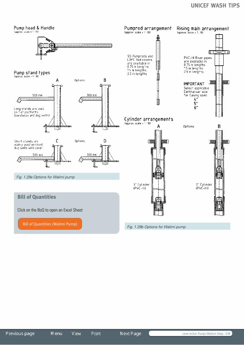
Guide for specifying options for the Walimi pumpList of options available for this pump type:
Options A B C D
Pump head type Pump head assembly with handle drawing No. A3002
– – –
Pump stand type Long stand with long spout and bottom flange drawing No. A3030
Long stand with short spout and bottom flange drawing No. A3030
Short stand with long spout and bottom flange drawing No. A3110
Short stand with short spout and bottom flange drawing No. A3110
Rising main arrangement
PVC-HI rising main with ”sockets”drawingNo.A3079
– – –
Cylinder arrangement
PVC-HICylinder(3”)and plunger/foot valve drawing No. A3050
PVC-HICylinder(2”)and plunger/foot valve drawing No. A3095
– –
Pump rod arrangement
SS-Pump rods with threaded connectors drawing No. A3040
– – –
PVC-HI polyvinyl chloride (high impact)SS stainless steel
ExamplePossible composition of a selected Walimi Handpump: Pump head type A Pump stand type D Rising main arrangement A Cylinder arrangement B Pump rod arrangement A
Fig. 1.28 Walimi pump, Tanzania © Skat
UNICEF WASH TIPS
Lever Action Pumps Medium Deep : 038
Bill of Quantities
Click on the BoQ to open an Excel Sheet
Fig. 1.29a Options for Walimi pump
Fig. 1.29b Options for Walimi pumpBill of Quantities (Walimi Pump)
UNICEF WASH TIPS

Deep Well Pumps: Afridev and Derivatives : 039
TIP 1.3.4 Deep Well Pumps: Afridev and Derivatives
Afridev handpump – Guide for specifying options for the Afridev pump – UNICEF recommended package and variants – Bill of Quantities Indus, Kabul and Pamir handpumps
– Guide for specifying options for the Indus, Kabul and Pamir pumps – Bill of Quantities
India © Skat
UNICEF WASH TIPS

Deep Well Pumps: Afridev and Derivatives : 040
Afridev handpump
DescriptionThe Afridev is a conventional lever action handpump. The configuration includes an open- top cylinder: the piston can be removed from the cylinder without dismantling the rising main. The footvalve is retractable with a fishing tool.
Technical dataRecommended depths: 10 to 45 m Cylinder diameter: 50.0 mmMaximum stroke: 225 mmApproximate discharge (75 watt input)at 10 m head: 1.4 m³/hourat 15 m head: 1.1 m³/hourat 20 m head: 0.9 m³/hourat 30 m head: 0.7 m³/hourPumping lift: 10 to 45 mPopulation served: 300 peopleHouseholds: 30 to 50 Water consumption: 15 to 20 l/per capitaType of well: borehole or dug well
MaterialThe pump head, handle and pump stand are made of galvanized steel; pump rods of stainless steel or of FRP rods (fibre glass reinforced plastic); rising main of UPVC pipe (diameter 63 mm); cylinder of UPVC pipe with brass liner (diameter 50 mm); plunger and footvalve are of brass or plastic. This pump is fully corrosion-resistant.
Local manufacturingAll steel parts of this pump have potential for local manufacturing. Local companies who manufacture UPVC pipes and have the knowledge of processing engineering plastics are abletoproducethe“down-holecomponents.”Thecostofthetooling is high and therefore the number of manufacturers will be limited.
InstallationThe installation of the Afridev pump is not difficult and does notneedanyliftingequipment.Itis,however,recommendedto employ a well-trained crew with the necessary skills for the installation.
MaintenanceThis pump has excellent community management potential. It is reliable, easy to repair by a village caretaker and popular with communities.
RemarksIn Pakistan and Afghanistan derivatives of the Afridev called Indus, Kabul and Pamir have been developed. Distribution: many thousands all over Africa
Fig. 1.30 Afridev, Ghana © Skat Fig. 1.31 Afridev handpump assembly
Cement/Platform
Bottom flange
Pump stand
Top flange
Handle
Pump head
Spout
GLGL
Ground
Rising main
Pumprod
Plunger
Footvalve
FootvalveCentraliser
Brass liner
Cylinder pipe
Reducer
Suction pipe
Suction pipe
Scale 1:5
Cylinder
Pumprod
Plunger
Casing pipe
UNICEF WASH TIPS

Deep Well Pumps: Afridev and Derivatives : 041
Guide for specifying options for the Afridev pumpList of options available for this pump type:
Options A B C D
Pump head type Pump head with short spout (30 cm) drawing No. B2003
Pump head with long spout (58 cm) drawing No. B2003
– –
Pump stand type Pump stand with 3 legs drawing No. B2050
Pump stand with bottom flange drawing No. B2055
– –
Rising main arrangement
UPVC Rising main with ”sockets”drawingNo.A2119
UPVC Rising main with “bellends”drawingNo.A2099
– –
Cylinder arrangement
Brass plunger and brass footvalve drawing No. A2296
Brass plunger and plastic footvalve drawing No. A2257
Plastic plunger and plastic footvalve drawing No . A2070
–
Pump rod arrangement
MS-Pump rods, threaded connectors drawing No. A2206
SS-Pump rods, threaded connectors drawing No. A2209
SS-Pump rods, “hook and eye” connectors drawing No . A2110
FRP-Pump rods, brass connectors drawing No. A5889
no longer recommended not recommended when PH value is < 6.5
ISO International Standard OrganizationUPVC unplasticized polyvinyl chloride MS mild steelSS stainless steelFRP fibre reinforced plastic
ExamplePossible composition of a selected Afridev handpump: Pump head type B Pump stand type C Rising main arrangement A Cylinder arrangement A Pump rod arrangement C
UNICEF WASH TIPS
Deep Well Pumps: Afridev and Derivatives : 042
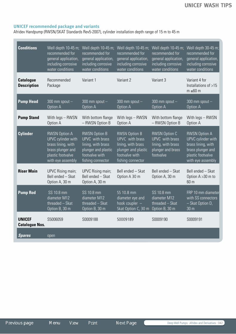
UNICEF recommended package and variants Afridev Handpump (RWSN/SKAT Standards Rev5-2007), cylinder installation depth range of 15 m to 45 m
Conditions Well depth 10-45 m; recommended for general application, including corrosive water conditions
Well depth 10-45 m; recommended for general application, including corrosive water conditions
Well depth 10-45 m; recommended for general application, including corrosive water conditions
Well depth 10-45 m; recommended for general application, including corrosive water conditions
Well depth 30-45 m; recommended for general application, including corrosive water conditions
Catalogue Description
Recommended Package
Variant 1 Variant 2 Variant 3 Variant 4 for Installations of >15 m ≤60 m
Pump Head 300 mm spout – Option A
300 mm spout – Option A
300 mm spout – Option A
300 mm spout – Option A
300 mm spout – Option A
Pump Stand With legs – RWSN Option A
With bottom flange – RWSN Option B
With legs – RWSN Option A
With bottom flange – RWSN Option B
With legs – RWSN Option A
Cylinder RWSN Option A UPVC cylinder with brass lining, with brass plunger and plastic footvalve with eye assembly
RWSN Option B UPVC with brass lining, with brass plunger and plastic footvalve with fishing connector
RWSN Option B UPVC with brass lining, with brass plunger and plastic footvalve with fishing connector
RWSN Option C UPVC with brass lining, with brass plunger and brass footvalve
RWSN Option A UPVC cylinder with brass lining, with brass plunger and plastic footvalve with eye assembly
Riser Main UPVC Rising main; Bell ended – Skat Option A, 30 m
UPVC Rising main; Bell ended – Skat Option A, 30 m
Bell ended – Skat Option A 30 m
Bell ended – Skat Option A, 30 m
Bell ended – Skat Option A >30 m to 60 m
Pump Rod SS 10.8 mm diameter M12 threaded – Skat Option B, 30 m
SS 10.8 mm diameter M12 threaded – Skat Option B, 30 m
SS 10 .8 mm diameter eye and hook coupler – Skat Option C, 30 m
SS 10.8 mm diameter M12 threaded – Skat Option B, 30 m
FRP 10 mm diameter with SS connectors – Skat Option D, 30 m
UNICEF Catalogue Nos.
S5006059 S0009188 S0009189 S0009190 S0009191
Spares open
UNICEF WASH TIPS

Deep Well Pumps: Afridev and Derivatives : 043
Bill of Quantities
Click on the BoQ to open an Excel Sheet
Fig. 1.32a Options for the Afridev
Fig. 1.32c Options for the Afridev
Fig. 1.32b Options for the Afridev
Bill of Quantities (Afridev Handump)
UNICEF WASH TIPS

Deep Well Pumps: Afridev and Derivatives : 044
Indus, Kabul and Pamir handpumps
DescriptionThe Indus, Kabul and Pamir pumps are conventional lever action handpumps. The configuration includes an open-top cylinder: the piston can be removed from the cylinder without dismantling the rising main. The footvalve is retractable with a fishing tool.
Technical dataRecommended depths: 10 to 60 m Cylinder diameter: 50.0 mmMaximum stroke: 225 mmApproximate discharge (75 watt input)at 10 m head: 1.4 m³/hourat 15 m head: 1.1 m³/hourat 20 m head: 0.9 m³/hourat 30 m head: 0.7 m³/hourPumping lift: 10 to 45 mPopulation served: 300 peopleHouseholds: 30 to 50 Water consumption: 15 to 20 l/per capitaType of well: borehole or dug well
MaterialThe pump head, handle and pump stand are made of galvanized steel, pump rods of mild steel, rising main of UPVC pipe (63
mm diameter), cylinder of UPVC pipe with brass liner (50 mm diameter), plunger and footvalve of plastic. These pumps are not fully corrosion-resistant; the rods are subject to corrosion.
Local manufacturingAll parts of these pumps have potential for local manufacturing in Afghanistan and Pakistan. Local companies who manufacture UPVC pipes and have the knowledge of processing engineering plastics are able to produce the down-hole components. The cost of the tooling is high and therefore the number of manufacturers will be limited.
InstallationThe installation of the Indus pump is not difficult and does not needanyliftingequipment.Itis,however,recommendedthata well-trained crew with the necessary skills performs the installation.
MaintenanceThis pump has excellent community management potential. It is reliable, easy to repair by a village caretaker and popular with communities.
Fig. 1.33 Lever action pump, Pakistan © Skat Fig. 1.34 Kabul handpump assembly
Pump platform
Man hole
Short stand
Well cover
Handle
Pump head
Spout
GL
Ground
Rising main
Iron clamp
Rope
Pumprod
Plunger
Footvalve
Well lining
Brass liner
Cylinder pipe
Reducer
Suction pipe
UNICEF WASH TIPS

Deep Well Pumps: Afridev and Derivatives : 045
RemarksIn Pakistan and Afghanistan, the use of stainless steel components is not common; therefore, these pumps should not be used as substitutes for Afridevs.
Distribution: many thousands in Pakistan and Afghanistan
Guide for specifying options for the Indus, Kabul and Pamir pumpsList of options available for these pump types:
Options A B C
Pump head type Kabul
Pump head with short spout (30 cm) drawing No. B7137
Pump head with long spout (58 cm) drawing No. B7137
–
Pump stand type Indus, Pamir
Pump head with short spout (30 cm) drawing No. B7003
Pump head with long spout (58 cm) drawing No. B7003
–
Pump stand type Pump stand with 3 legs drawing No. B7050
Pump stand for dug wells cover drawing No. B7055
Pump stand for concrete platform drawing No. B7060
Rising main arrangement
UPVCRisingmainwith“bellends”drawingNo.A7080
– –
Cylinder arrangement
Plastic plunger and plastic footvalve drawing No. A7070
Brass plunger, Nitrile seal drawing No. A7100
Brass plunger leather seal drawing No. 7100
Pump rod arrangement
MS-Pump rods, hook and eye connectors drawing No. A7098
MS-Pump rods, double hook and eye connectors drawing No . A7250
not recommended when PH value is < 6.5ISO International Standard OrganizationUPVC unplasticized polyvinyl chloride MS mild steelSS stainless steel
ExamplePossible composition of a selected Indus handpump: Pump head type B Pump stand type C Rising main arrangement A Cylinder arrangement A Pump rod arrangement C
UNICEF WASH TIPS

Deep Well Pumps: Afridev and Derivatives : 046
Bill of Quantities
Click on the BoQ to open an Excel Sheet
short spout long spout
platformConcrete
D9075
Concreteplatform
Dugwell cover (concrete)
Scale 1 : 10
Scale 1 : 10
short spout long spout
Scale 1 : 10
580±10300±10
540±
10
540
160
300±10 580±10
Pump head options (Indus and Pamir Pumps)
Pump stand options for all pump types
Pump head options for Kabul Pumps
Centraliser options
Suction pipe options
Plunger options for all pump types
Pumprod options forIndus and Kabul Pumps Pamir Pumps
Pumprod options for
for all pump typesFootvalve fitting optionsfor all pump types
D9076for boreholes for dugwells
Scale 1 : 5
Scale 1 : 5
Scale 1 : 5
Scale 1 : 10
Nitrile Rubber U-sealPlastic plunger,
Brass plunger,with Leather
Cup sealCup sealNitrile RubberBrass plunger,
Carbon- or Stainless Steel
(used for borehole installations only)
Carbon- or Stainless Steel
Scale 1 : 10
Centraliser 8"Centraliser 6"Centraliser 4" Centraliser 4.5" Centraliser 5"
Scale 1 : 2
Carbon- or Stainless Steel
Ø10 Ø10
Fig. 1.35a Options for Indus, Kabul and Pamir pumps Fig. 1.35b Options for Indus, Kabul and Pamir pumps
Bill of Quantities (Indus, Kabul, Pamir Handpumps)
UNICEF WASH TIPS

Deep Well Pumps: India Mark II and III Types : 047
TIP 1.3.5 Deep Well Pumps: India Mark II and III Types
India Mark II pump – Guide for specifying options for the India Mark II pump – UNICEF recommended package and variants – Standard deepwell handpump – Extra deep handpump – Bill of Quantities India Mark III pump
– Guide for specifying options for the India Mark III pump – UNICEF recommended package and variants – VLOM-65 handpump – VLOM-50 handpump – Bill of Quantities U3M pump
– Guide for specifying options for the U3M pump – UNICEF recommended package and variants – Deepwell non-corrodible U3M handpump – Bill of Quantities
India © Skat
UNICEF WASH TIPS

Deep Well Pumps: India Mark II and III Types : 048
India Mark II pump
DescriptionThe INDIA Mark II is a conventional lever action handpump and is subject to Indian Standard IS 15500 and RWSN specification, Edition 2004. The down-hole components consist of a brass-lined cast iron cylinder and a brass plunger with a double nitrile rubber cup seal. The rising main is of 32 mm GI pipe and the pump rods are of galvanized steel with threaded connectors.
Technical dataRecommended depths: 10 to 50 mCylinder diameter: 63.5 mmMaximum stroke: 125 mmApproximate discharge (75 watt input)at 10 m head: 1.8 m³/hourat 15 m head: 1.3 m³/hourat 20 m head: 1.0 m³/hourat 25 m head: 0.9 m³/hourat 30 m head: 0.8 m³/hourPumping lift: 10 to 50 mPopulation served: Up to 300 peopleHouseholds: 30 to 50 Water consumption: 15 to 20 l/per capitaType of well: borehole or dug well
MaterialThe pump head, handle, water tank, pump stand and pump rods are made of galvanized steel; the rising main of galvanized GI pipe; the pump cylinder is cast of iron/brass; the plunger and footvalve are made of brass. This pump is not corrosion-resistant and should not be used in areas with aggressive water (pH value < 6.5).
Local manufacturingAll above-ground components have a potential for local manufacturing.Allotherpartsneedahighdegreeofqualitycontrol to ensure a reliable operation. The cost of the tooling
requirementissubstantialandthereforethenumberofmanufacturers will be limited.
InstallationThe installation of the INDIA Mark II pump needs well-trained area mechanics or a mobile team with lifting tackle and a comprehensive tool kit.
MaintenanceThis pump has limited community management potential, but it is reliable and popular with communities. To service the India Mark II pump, skills and tools are needed that exceed the ability of a village-level caretaker. However, trained local mechanics can successfully maintain the pump.
Distribution: 3.5 million in India, many thousands in Africa
Fig. 1.36 India Mark II, India © Skat Fig. 1.37 India Mark II pump assembly
UNICEF WASH TIPS

Deep Well Pumps: India Mark II and III Types : 049
Guide for specifying options for the India Mark II pumpList of options available for this pump type:
Options A B C
Pump head type Pump head with standard handle and water tank
– –
Pump stand type Pump stand with 3 legs (NB 150 mm) drawing No. B2348
Pump stand with 3 legs (NB 150/175) drawing No. B2347
Pump stand with bottom plate drawing No. B2055
Rising main arrangement
Galvanized GI pipe with sockets(1¼”medium)
– –
Cylinder arrangement
Cast-iron cylinder, brass plunger and footvalve drawing No. A2350
– –
Pump rod arrangement
MS-Pump rods with threaded connectors drawing No . A2370
– –
should not be used in aggressive watersNB nominal boreGI galvanized ironMS mild steel
ExamplePossible composition of a selected India Mark II Pump: Pump head type A Pump stand type B Rising main arrangement A Cylinder arrangement A Pump rod arrangement A
UNICEF WASH TIPS

Deep Well Pumps: India Mark II and III Types : 050
Fig. 1.38a Options for the India Mark II
Fig. 1.38b Options for the India Mark II
UNICEF WASH TIPS

Deep Well Pumps: India Mark II and III Types : 051
UNICEF recommended package and variants Standard deepwell handpumpSDWP (IS:15500-2004) or India Mark II (RWSN/SKAT Rev2-2007) 63.5 mm cylinder installation, depth range of 30 m to 45 m
Conditions 30 m, suitable for well diameter up to 150 mm; soft water
30 m, suitable for well diameter 100-125 mm; soft water
30 m, suitable for well diameter 100-125 and 150mm; soft water
Catalogue Description
Recommended Package – with Telescopic Stand, 32 mm GI Pipe
Variant 1 - with Normal Stand, 32 mm GI Pipe
Variant 2 – with Telescopic/ Normal Stand and 32 mm GI pipe
Pump Head and Handle
Normal Normal Normal
Water Tank with 32 mm pipe holder with 32 mm pipe holder with 32 mm pipe holder
Pump Stand Telescopic Normal Telescopic/ Normal
Riser Main 32 mm GI, 30 m 32 mm GI, 30 m 32 mm GI, >30 m up to ≤ 45 m
Cylinder SDWP 63.5 mm SDWP 63.5 mm SDWP 63 .5 mm
Pump Rod MS – 12 Ø Electroplated, M12 couplers, 30 m
MS – 12 Ø Electroplated, M12 couplers, 30 m
MS – 12 Ø Electroplated, M12 couplers, 30 m
UNICEF Catalogue Nos.
S5006058 S0009179 S0009181
Rods, Risers S0009185
Tools installation
S0009186
Tools, fishing and masonry
S0009187
Spares S0009180
UNICEF WASH TIPS

Deep Well Pumps: India Mark II and III Types : 052
Extra deep handpumpEDWP (IS:15500-2004) or India Mark II-EDW (RWSN/SKAT Rev2-2007) EDW cylinder, installation depth range of 40 m to 90 m, IS:15500-2004
Conditions Well depth 45 m; not recommended for corrosive water. If water is acidic (low PH)
Well depth 40 m - 90 m; not recommended for corrosive water. If water is acidic (low PH)
Well depth 48 m – 90 m; not recommended for corrosive water. If water is acidic (low PH)
Catalogue Recommended Package – with Telescopic Stand, 32 mm GI Pipe
Variant 1 - with Normal Stand, 32 mm GI Pipe
Variant 2 – with Telescopic/ Normal Stand and 32 mm GI pipe
description Recommended Package – with Telescopic Stand and 45 m length of 32 mm GI pipe
Variant 1 – with Normal Stand and 45 m length of 32 mm GI pipe
Variant 2 – with Telescopic/ Normal Stand and 32 mm GI pipe, 48 m to 90 m
Pump Head with Handle
Normal – EDWP Normal – EDWP Normal – EDWP
Handle Counter-weights
None None One/ Two/ Three
Water Tank Normal with 32 mm pipe holder Normal with 32 mm pipe holder Normal with 32 mm pipe holder
Pump Stand Telescopic - EDWP Normal - EDWP Telescopic - EDWP/ Normal - EDWP
Riser Main 32 mm GI, 45 m 32 mm GI, 45 m 32 mm GI, >45 m up to ≤ 90 m
Cylinder EDWP EDWP EDWP
Pump Rod MS – 12 Ø Electroplated, M12 couplers, 45 m
MS – 12 Ø Electroplated, M12 couplers, 45 m
MS – 12 Ø Electroplated, M12 couplers, >45 m up to ≤ 90 m
UNICEF Catalogue Nos.
S0009310 S0009311 S0009312
Spares S0009313
Rods, Risers S0009312
Bill of Quantities
Click on the BoQ to open an Excel Sheet
Bill of Quantities (India Mark II Pump)
UNICEF WASH TIPS

Deep Well Pumps: India Mark II and III Types : 053
India Mark III pump
DescriptionThe India Mark III Pump is a conventional lever action handpump and is subject to Indian Standard IS 13056 and RWSN specification. This pump has a similar configuration to the India Mark II, only the down-hole components were changed in order to improve village level maintenance. The most important improvement is the open-top cylinder, which makes it possible to remove the plunger and the footvalve without lifting the cylinder and the rising main (diameter 65 GI pipe). Cylinders are available in 50 mm and 62.5 mm diameter.
Technical dataRecommended depths: 10 to 30 m 63.5 mm cylinder 10 to 50 m 50 mm cylinder Maximum stroke: 125 mmApproximate discharge (75 watt input, 63.5 mm cyl) at 10 m head: 1.8 m³/hourat 15 m head: 1.3 m³/hourat 20 m head: 1.0 m³/hourat 25 m head: 0.9 m³/hourat 30 m head: 0.8 m³/hourPumping lift: 10 to 50 mPopulation served: 300 peopleHouseholds: 30 to 50 Water consumption: 15 to 20 l/per capitaType of well: borehole or dug well
MaterialThe pump head, handle, water tank, pump stand and pump rods are made of galvanized steel; rising main is made of galvanized GI pipe; pump cylinder is cast in iron/brass; plunger and footvalve are of brass. This pump is not corrosion-resistant and should not be used in aggressive water (pH value < 6.5).
Local manufacturingAll above-ground components have a potential for local manufacturing.Theotherpartsneedahighdegreeofqualitycontrol to ensure a reliable operation. The cost of the tooling requirementissubstantialandthereforethenumberofmanufacturers will be limited.
InstallationThe installation of the India Mark III pump needs well-trained area mechanics or a mobile team with lifting tackle and a comprehensive tool kit. Pump cylinder settings of more than 30 m are difficult, because of the weight of the rising main.
MaintenanceThis pump has better community management potential than the India Mark II, because the open-top cylinder allows simpler maintenance and involves fewer tools.
Fig. 1.39 India Mark III, India © Skat Fig. 1.40 India Mark III assembly
UNICEF WASH TIPS

Deep Well Pumps: India Mark II and III Types : 054
Guide for specifying options for the India Mark III pumpList of options available for this pump type:
Options A B C
Pump head type Pump head with handle and watertankfor2”riserspipes
Pump head with handle and watertankfor2½”riserspipes
–
Pump stand type Pump stand with 3 legs (NB 150 mm) drawing No. B2348
Pump stand with 3 legs (NB 150/175) drawing No. B2347
Pump stand with bottom flange drawing No. B2055
Rising main arrangement
Galvanized GI pipe with sockets for 2” risers pipes
Galvanized GI pipe with sockets for 2½” risers pipes
–
Cylinder arrangement
Cast-iron cylinder with brass liner for Ø50 mm, plunger and footvalve: drawing No. A2651
Cast-iron cylinder with brass liner for Ø63.5 mm, plunger and footvalve
–
Pump rod arrangement
MS-Pump rods with threaded connectors drawing No . A2206
– –
should not be used in aggressive watersNB nominal boreGI galvanized ironMS mild steelØ diameter
ExamplePossible composition of a selected India Mark III pump: Pump head type B Pump stand type A Rising main arrangement B Cylinder arrangement B Pump rod arrangement A
UNICEF WASH TIPS

Deep Well Pumps: India Mark II and III Types : 055
UNICEF recommended package and variantsVLOM-65 handpump(IS:15500-2004) or India Mark III (RWSN/SKAT Rev2-2007), 65 mm cylinder installation depth of 30 m
Conditions Well depth 30 m; not recommended for corrosive water. If water is acidic (low PH)
Well depth 30 m recommended for corrosive water. If water is acidic (low PH)
Well depth 30 m; not recommended for corrosive water. If water is acidic (low PH)
Well depth 30 m recommended for corrosive water. If water is acidic (low PH)
Catalogue Recommended Package – with Telescopic Stand, 32 mm GI Pipe
Variant 1 - with Normal Stand, 32 mm GI Pipe
Variant 2 – with Telescopic/ Normal Stand and 32 mm GI pipe
Description Recommended Package – with Telescopic Stand and 65 mm GI Pipe
Variant 1 - with Telescopic Stand and 65 mm PVC Pipe with SS Couplers
Variant 2 – with Normal Stand and 65 mm GI with
Variant 3 – with Normal Stand and 65 mm PVC-SS
Pump Head Normal Normal Normal Normal
Water Tank with 65 mm pipe holder, with cone and cone plate
with 65 mm pipe holder, without cone and cone plate
with 65 mm pipe holder, with cone and cone plate
with 65 mm pipe holder, without cone and cone plate
Pump Stand Telescopic Telescopic Normal Normal
Riser Main 65 mm GI, 30 m 65 mm PVC-SS couplers, 30 m
65 mm GI, 30 m 65 mm PVC-SS, 30 m
Cylinder VLOM 65 VLOM 65 VLOM 65 VLOM 65
Pump Rod MS – 12 Ø Electroplated, M12 couplers, 30 m
SS – 10.8 Ø M12 with centralizers, 30 m
MS – 12 Ø Electroplated, M12 couplers, 30 m
SS – 10 .8 Ø M12 with centralizers, 30 m
UNICEF Catalogue Nos.
S0009300 S0009301 S0009302 S0009303
Spares S0009310
UNICEF WASH TIPS

Deep Well Pumps: India Mark II and III Types : 056
VLOM-50 handpump (IS:15500-2004) or India Mark III-50 (RWSN/SKAT Rev2-2007), IM III-50 mm cylinder, installation depth of 30 m - 50 m with GI Riser pipes
Conditions Well depth 30 m; not recommended for corrosive water. If water is acidic (low PH)
Well depth 30m; not recommended for corrosive water. If water is acidic (low PH)
Well depth 48m; not recommended for corrosive water. If water is acidic (low PH)
Catalogue Recommended Package – with Telescopic Stand, 32 mm GI Pipe
Variant 1 - with Normal Stand, 32 mm GI Pipe
Variant 2 – with Telescopic/ Normal Stand and 32 mm GI pipe
Description Recommended Package – with Telescopic Stand and 50 mm GI Pipe
Variant 1: Normal Stand and 50 mm GI with
Variant 2: with Telescopic Stand and 50 mm GI Pipe
Pump Head Normal Normal Normal
Water Tank with 50 mm holder, with cone and cone plate
with 50 mm holder, with cone and cone plate
with 50 mm holder, with cone and cone plate
Pump Stand Telescopic Normal Telescopic/ Normal
Riser Main 50 mm GI, 30 m 50 mm GI, 30 m 50 mm GI, 33 m to 48 m
Cylinder VLOM 50 VLOM 50 VLOM 50
Pump Rod MS – 12 Ø Electroplated, M12 couplers, 30 m
MS – 12 Ø Electroplated, M12 couplers, 30 m
MS – 12 Ø Electroplated, M12 couplers, 33 m to 48 m
Spares
UNICEF Catalogue Nos.
UNICEF WASH TIPS

Deep Well Pumps: India Mark II and III Types : 057
Fig. 1.41a Options for the India Mark III
Fig. 1.41b Options for the India Mark III
Bill of Quantities
Click on the BoQ to open an Excel Sheet
Bill of Quantities (India Mark III Pump)
UNICEF WASH TIPS

Deep Well Pumps: India Mark II and III Types : 058
U3M pump
DescriptionThe U3M pump is a conventional lever action handpump. The configuration includes an open-top cylinder; the piston can be removed from the cylinder without dismantling the rising main. The footvalve is retractable with a fishing tool. The pump head has similar configurations to the India Mark III pump and the down-hole components are similar to the Afridev components. The cylinder follows the Afridev pump configuration. The plunger uses the 50 mm open-top India Mark III brass design.
Technical dataRecommended depths: 10 to 45 m Cylinder diameter: 50.0 mmMaximum stroke: 125 mmApproximate discharge (75 watt input)at 10 m head: 1.2 m³/hourat 15 m head: 1.0 m³/hourat 20 m head: 0.8 m³/hourat 30 m head: 0.6 m³/hourPumping lift: 10 to 45 mPopulation served: 300 peopleHouseholds: 30 to 50 Water consumption: 15 to 20 l/per capitaType of well: borehole or dug well
MaterialThe pump head, handle, water tank and pump stand are made of galvanized steel, the pump rods of stainless steel or of FRP rods (fibre glass reinforced plastic), the rising main of UPVC pipe (Ø63 mm), the cylinder of UPVC pipe with brass liner (Ø50 mm), and the plunger and footvalve are of brass or plastic. This pump is fully corrosion- resistant.
Local manufacturingAll above-ground components and steel parts of this pump have potential for local manufacturing. The other parts need ahighdegreeofqualitycontroltoensurereliableproduction.Local companies who manufacture UPVC pipes are able to producetherisingmain.Thecostofthetoolingrequirementissubstantial and therefore the number of manufacturers will be limited.
InstallationThe installation of the U3M pump is not difficult and does not needanyliftingequipment.
MaintenanceThis pump has excellent community management potential. It is reliable, easy to repair by a village caretaker and popular with communities. Few tools are needed for all repairs.
Distribution: Uganda
Fig. 1.42 U3M pump, Uganda © Skat Fig. 1.43 U3M pump assembly
UNICEF WASH TIPS

Deep Well Pumps: India Mark II and III Types : 059
Guide for specifying options for the U3M pumpList of options available for this pump type:
Options A B C D
Pump head type Pump head with lightweight handle drawing No. B2276
Pump head with heavy handle drawing No. B2279
– –
Pump stand type Pump stand with bottom flange drawing No. B2287
Pump stand with 3 legs (NB 150 mm) drawing No. B2281
Pump stand with 3 legs (NB 150/175) drawing No. B2284
Pump stand with bottom flange drawing No. B2055
Rising main arrangement
UPVC Rising main with “sockets”drawingNo.A2119
UPVC Rising main with “bellends”drawingNo.A2099
– –
Cylinder arrangement
Brass plunger with brass footvalve drawing No. A2296
Brass plunger with plastic footvalve drawing No. A2257
– –
Pump rod arrangement
SS-Pump rods with threaded connectors drawing No . A2224
FRP-Pump rods with brass connectors drawing No. A5889
– –
Abbreviations:UPVC unplasticized polyvinyl chlorideSS stainless steelFRP fibre reinforced plastic
ExamplePossible composition of a selected U3M pump: Pump head type A Pump stand type C Rising main arrangement B Cylinder arrangement B Pump rod arrangement A
UNICEF WASH TIPS
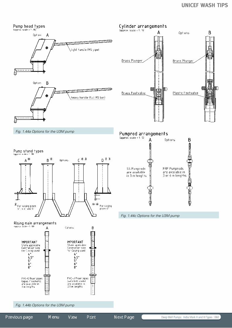
Deep Well Pumps: India Mark II and III Types : 060
Fig. 1.44a Options for the U3M pump
Fig. 1.44c Options for the U3M pump
Fig. 1.44b Options for the U3M pump
UNICEF WASH TIPS

Deep Well Pumps: India Mark II and III Types : 061
UNICEF recommended package and variants Deepwell non-corrodible U3M handpump(RWSN/SKAT Rev0-2001) or VLOM-50 PVC, 50mm cylinder, installation depth range 30 m to 45 m
Conditions Well depth up to 45 m, suitable for installation on borehole casing sizes from 100 mm to 200 mm internal diameter, recommended for corrosive and acidic water
Well depth up to 45 m, suitable for installation on borehole casing sizes from 100 mm to 200 mm internal diameter, recommended for corrosive and acidic water
Catalogue description
U3M-50 mm PVC Pipe with standard handle Variant 2: VLOM-50 PVC with PVC three-piece couplers and cylinder depth of 30 m
Pump Head Solid handle 175 mm stroke
Water Tank with cone and cone plate with cone and cone plate
Pump Stand Option B (RWSN Afridev 5-2007) Normal option A (RWSN Afridev 5-2007)
Riser Main PVC cemented 50 mm PVC
Cylinder 50 mm PVC, brass lined with gun-metal components
Pump Rod SS-10.8 Ø M12 with centralizers SS-10.8 Ø M12 with centralizers
UNICEF Catalogue Nos.
S0009320 S0009321
Note: For installations depth <12 m a pipe handle can be used instead of the solid handle
Bill of Quantities
Click on the BoQ to open an Excel Sheet
Bill of Quantities (U3M Pump)
UNICEF WASH TIPS

Extra Deep Well Pumps : 062
TIP 1.3.6 Extra Deep Well Pumps Bush pump, Zimbabwe
– Guide for specifying options for the Bush pump, Zimbabwe – Bill of Quantities Volanta pump
– Guide for specifying options for the Volanta pump – Bill of Quantities Vergnet Hydropump
– Guide for specifying options for the Vergnet Hydropump HPV 60/100 – Bill of Quantities
Mali © Skat
UNICEF WASH TIPS

Extra Deep Well Pumps : 063
Bush pump, Zimbabwe
DescriptionThe BUSH pump is a conventional lever action handpump. The typicalfeatureofthispumpisthe“hardwoodblock”thatactsas both bearing and lever mechanism. The pump is designed so that the stand can be directly bolted to the protruding steel casing of the borehole (diameter 150 mm nominal bore).
Technical dataFor depths from 3 to 25 m: Ø75 mm cylinder For depths from 20 to 45 m: Ø63.5 mm cylinder For depths from 40 to 80 m: Ø50 mm cylinderMaximum stroke: 200 to 250 mmApproximate discharge (75 watt input, 63.5 mm cylinder)at 10 m head: 1.4 m³/hourat 15 m head: 1.1 m³/hourat 25 m head: 0.8 m³/hourat 30 m head: 0.7 m³/hourPumping lift: 5 to 80 mPopulation served: 300 peopleHouseholds: 30 to 50 Water consumption: 15 to 20 l/per capitaType of well: borehole or dug well
MaterialThe pump stand is made of mild steel painted; the handle and riser pipes are made of galvanized GI pipe; the pump rods are made of galvanized steel; the cylinder is made of brass; the bearing block is made of hardwood and the plunger and foot valve is made of bronze or brass. This pump is not corrosion-resistant and should not be used in areas with aggressive water (pH value < 6.5).
Local manufacturingThe Bush pump has excellent potential for local manufacturing and is produced by different companies in Zimbabwe.
InstallationThe installation of the Bush pump needs well-trained area mechanics. Lifting tackle is only used for deep applications and for large-size open-top cylinders. No special tools are needed.
MaintenanceThe pump with the standard configuration has limited community management potential, but it is very reliable and popular with communities. The open-top cylinder version makes simpler maintenance possible (see Remarks).
Fig. 1.45 Bush pump © Skat Fig. 1.46 Bush pump assembly
UNICEF WASH TIPS

Extra Deep Well Pumps : 064
RemarksBesides the standard configuration, there is an open-top cylinder version with different cylinder diameters (50 mm, 63.5 mm and 75 mm). To make maintenance easy, pump rods with case-hardened hook and eye connectors are also available.
Distribution: > 30,000 Zimbabwe
Guide for specifying options for the Bush pump, ZimbabweList of options available for this pump type:
Options AØ50 mm ES
BØ63.5 mm ES
CØ75 mm ES
DØ75 mm NES
Pump stand type Pump stand, handle and discharge assembly drawing No. A3202
sameas“A” sameas“A” sameas“A”
Discharge type Discharge assembly for 2”riserpipesdrawingNo. A3301
Discharge assembly for 21/2”riserpipesdrawing No. A3218
Discharge assembly for 3”riserpipesdrawingNo. A3331
Discharge assembly for 2”riserpipesdrawingNo. A3301
Rising main pipe GIriserpipe(2”)and”sockets”drawingNo.C3309/04
GIriserpipe(21/2”)and”sockets”drawingNo.C3274/73
GIriserpipe(3”)and“sockets”drawingNo.C3349/37
GIriserpipe(2”)and“sockets”drawingNo.C3309/04
Cylinder arrangement
Cylinder, plunger and footvalve of brass drawing No. A3305
Cylinder, plunger and footvalve of brass drawing No. A3262
Cylinder, plunger and footvalve of brass drawing No . A3338
Cylinder, plunger and footvalve of brass drawing No. A3361
Pump rod arrangement
Pump rods, with hook and eye connectors drawing No . A3247
sameas“A”or“D” same as “A” or “D” Pump rods with threaded connectors: drawing No. A3350
The Ø50 mm cylinder is mostly used for deep or extra deep wells.Note: This pump type is not recommended for aggressive waters.GI galvanized ironES extractable systemNES non extractable system
ExamplePossible composition of a selected Bush pump: Pump stand type A Rising main pipe B Pump rod arrangement D Discharge type B Cylinder arrangement B
UNICEF WASH TIPS

Extra Deep Well Pumps : 065
Fig. 1. 47a Options for Bush pump
Fig. 1.47b Options for Bush pumpBill of Quantities
Click on the BoQ to open an Excel Sheet
Bill of Quantities (Bush Pump)
UNICEF WASH TIPS
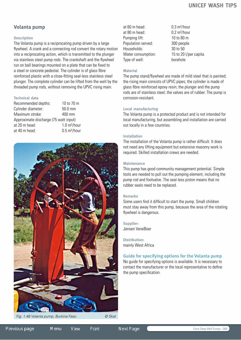
Extra Deep Well Pumps : 066
Volanta pump
DescriptionThe Volanta pump is a reciprocating pump driven by a large flywheel. A crank and a connecting rod convert the rotary motion into a reciprocating action, which is transmitted to the plunger via stainless steel pump rods. The crankshaft and the flywheel run on ball bearings mounted on a plate that can be fixed to a steel or concrete pedestal. The cylinder is of glass fibre reinforced plastic with a close-fitting seal-less stainless steel plunger. The complete cylinder can be lifted from the well by the threaded pump rods, without removing the UPVC rising main.
Technical dataRecommended depths: 10 to 70 m Cylinder diameter: 50.0 mmMaximum stroke: 400 mmApproximate discharge (75 watt input)at 20 m head: 1.0 m³/hourat 40 m head: 0.5 m³/hour
at 60 m head: 0.3 m³/hourat 80 m head: 0.2 m³/hourPumping lift: 10 to 80 mPopulation served: 300 peopleHouseholds: 30 to 50 Water consumption: 15 to 20 l/per capitaType of well: borehole
MaterialThe pump stand/flywheel are made of mild steel that is painted; the rising main consists of UPVC pipes; the cylinder is made of glass fibre reinforced epoxy resin; the plunger and the pump rods are of stainless steel; the valves are of rubber. The pump is corrosion-resistant.
Local manufacturingThe Volanta pump is a protected product and is not intended for local manufacturing, but assembling and installation are carried out locally in a few countries.
InstallationThe installation of the Volanta pump is rather difficult. It does notneedanyliftingequipmentbutextensivemasonryworkisrequired.Skilledinstallationcrewsareneeded.
MaintenanceThis pump has good community management potential. Simple tools are needed to pull out the pumping element, including the pump rod and footvalve. The seal-less piston means that no rubber seals need to be replaced.
RemarksSome users find it difficult to start the pump. Small children must stay away from this pump, because the area of the rotating flywheel is dangerous.
Supplier: Jensen VeneBoer
Distribution: mainly West Africa
Guide for specifying options for the Volanta pumpNo guide for specifying options is available. It is necessary to contact the manufacturer or the local representative to define the pump specification.
Fig. 1.48 Volanta pump, Burkina Faso © Skat
UNICEF WASH TIPS

Extra Deep Well Pumps : 067
Bill of Quantities
Click on the BoQ to open an Excel Sheet
Fig. 1.49 Volanta pump assembly
Bill of Quantities (Volanta Pump)
UNICEF WASH TIPS

Extra Deep Well Pumps : 068
Vergnet Hydropump
DescriptionThe Vergnet Hydropump HPV 60/100 has unconventional design features. It is operated by foot with a pedal. The displacement of the piston located at ground level is hydraulically transmitted to a rubber diaphragm down in a stainless steel cylinder. The expansion and the contraction of the diaphragm deliver the water to the surface. The top cylinder is connected to the pumping element on the bottom via a flexible hose.
Technical dataCylinder diameter: not applicableMaximum stroke: 200 mmApproximate discharge (75 watt input)at 10 m head: 1.0 m³/hourat 15 m head: 0.9 m³/hourat 20 m head: 0.75 m³/hourat 30 m head: 0.65 m³/hourPumping lift: 10 to 60 mPopulation served: 300 peopleHouseholds: 30 to 50 Water consumption: 15 to 20 l/per capitaType of well: borehole
Material The pump stand is made of galvanized steel painted, the foot pedal of mild steel, the pipes of flexible low density polyethylene (LDPE) hose, the top and bottom cylinder of stainless steel, the pumping element of a rubber diaphragm and the valves of brass. This pump is corrosion-resistant.
Local manufacturing The Vergnet Hydropump is a protected product and is not intended for local manufacturing. Only the steel parts of the pump stand have a potential for local manufacturing.
Installation The installation of the Vergnet Hydropump is very simple and doesnotneedanyliftingequipment.
Maintenance This pump has good community management potential. The above-ground components allow interventions by the village caretaker, but the below-ground components are difficult to repair.Thediaphragmrequiresfrequentcleaning.
Remarks The replacement of a diaphragm is expensive. The pump requiresconsiderableefforttooperate.Althoughfullbodyweight can be applied to the pedal, children and small users sometimes find it hard to operate the pump. If the yield of the borehole allows and the water demand is high, two pumps can be installed in one borehole.
Distribution: mainly West Africa > 100,000
Supplier: Vergnet SA France
Guide for specifying options for the Vergnet Hydro-pump HPV 60/100No guide for specifying options is available. It is necessary to contact the manufacturer or the local representative to define the pump specification.
To make the pumps readily accepted by local populations, Vergnet has adapted the various pumping interfaces villagers were accustomed to into its hydraulic transmission principle. Therefore, Vergnet pumps have several different above-ground appearances. They may be foot pumps (the traditional Vergnet Hydropump), wheel pumps (the Hydrovolanta) or handpumps (HydroIndia).
Fig. 1.50 Vergnet Hydropump, Burkina Faso © Skat
UNICEF WASH TIPS

Extra Deep Well Pumps : 069
Fig. 1.51 Vergnet Hydropump assembly
Bill of Quantities
Click on the BoQ to open an Excel Sheet
Bill of Quantities (Vergnet Hydropump)
UNICEF WASH TIPS
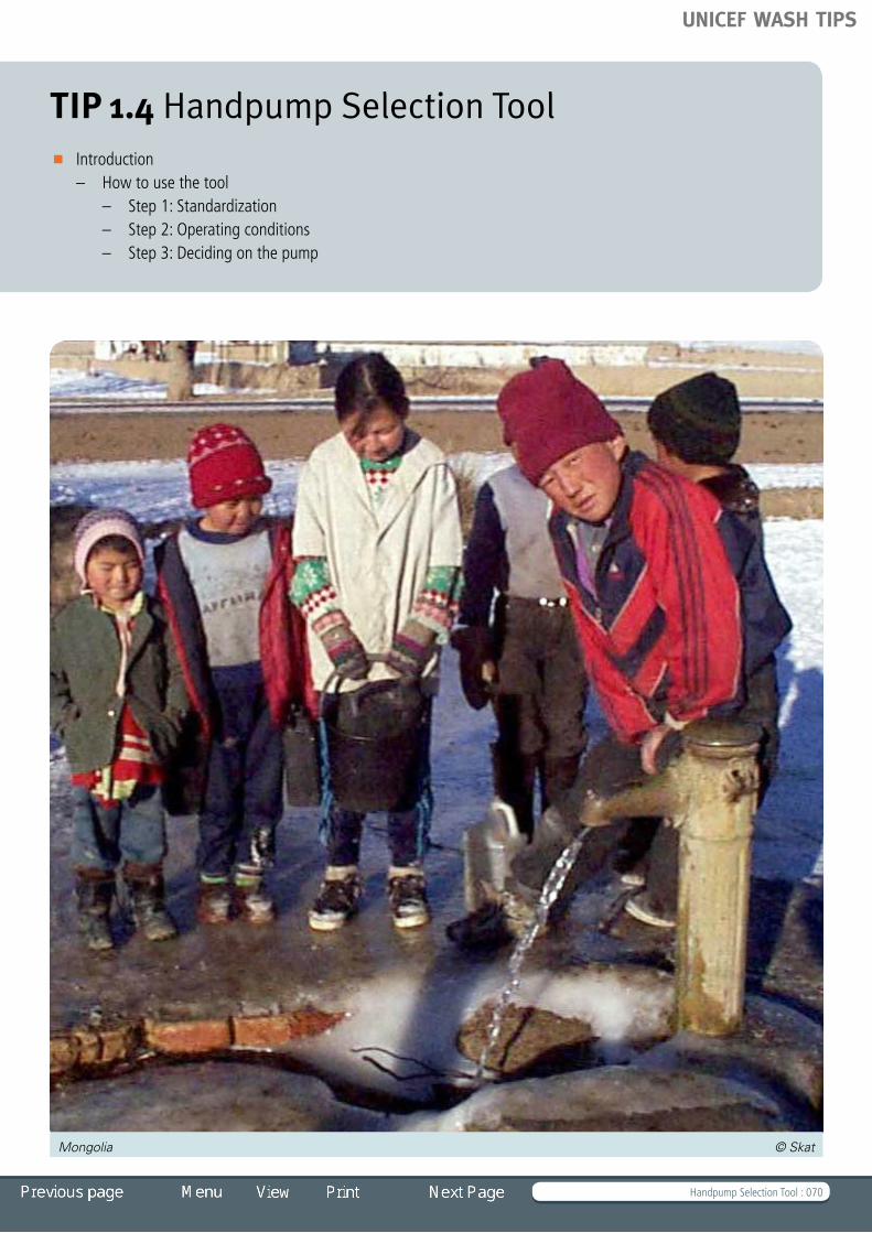
Handpump Selection Tool : 070
TIP 1.4 Handpump Selection Tool Introduction
– How to use the tool – Step 1: Standardization – Step 2: Operating conditions – Step 3: Deciding on the pump
Mongolia © Skat
UNICEF WASH TIPS

Handpump Selection Tool : 071
Introduction
The handpump selection tool is an aid to help you to make an appropriate technology choice. It aims to determine the optimal handpump for a set of service conditions. The results are displayed in a graph. The height of the bars indicates the appropriateness of each pump. The higher the bar, the better the pump will match the selected set of service conditions.
The tool does not relieve you from making a well-judged decision about which pump to choose in accordance with the particular operating conditions and the situation in the country. It might, however, help you to avoid costly mistakes, because it automatically excludes pumps that are not suitable for the conditions. Pumps that do not fulfil the criteria are not shown.
The tool also respects country decisions to standardize on certain type of pumps. If there is no standardization policy all handpumps that are listed are possible. If a country hasastandardizationpolicyclickon:“Yes,thecountryhasastandardizationpolicy”andindicatewhichpumpsarestandardized for use in the country. The tool will exclude those types that are not eligible under the policy and only the standardized pumps appear in the graph.
How to use the tool
Step 1: StandardizationUse the selection button to indicate whether your country has a policy of standardization on one or a few handpumps.
Choose either: Country has a Standardization Policy or Country has NO Standardization Policy
If you selected:
“Yes,thecountryhasastandardizationpolicy,”youneedtoindicate which pump types are standardized by ticking the selected pumps.
Only these types will be taken into account.
If you selected:
“No,thecountryhasNOStandardizationPolicy,”all pumps are eligible and will be assessed.
Step 2: Operating conditionsThe tool lets you select the most relevant service conditions for the pumps:
1. Lift 2. Size of User Group
3. Corrosion Resistance 4. Ease of Repair5. Yield 6. Price
There are six pull-down boxes where you can enter the major working conditions or some of the specific features a pump should have.
Based on these entries, the programme will calculate which pumps are most suitable for the given service condition. The suitability is indicated with a bar that appears on the graph. The higher the bar, the better the pump is matched to the service conditions. If a pump type is not suitable it does not appear in the graph.
Indicate Pumping Lift
Select Size of User Group
Indicate Water Quality
Select if Community Management needed
Indicate Water Quantity
Cost of Pump and Spares
Service ConditionThe handpump should meet the following requirements
Lift:
Size of User Group:
Corrosion Resistance:
Ease of Repair:
Yield:
Price:
- 30m
>100
Non-aggressive Water
Select if Community Management needed
High Yield req’d
Low cost
Service ConditionThe handpump should meet the following requirements
Lift:
Size of User Group:
Corrosion Resistance:
Ease of Repair:
Yield:
Price:
0 0 0 0 0 0 0 Ind
ia M
ark
III -
63.
5mm
Ind
ia M
ark
III -
50m
m
Ind
ia M
ark
II P
ump
U3M
Pum
p
Afr
idev
Han
dp
ump
Ind
us K
abul
Pam
ir
Bus
h P
ump
Vola
nta
Pum
p
Verg
ent
Hyd
rop
ump
60
Conditions not selected
Conditions selected
UNICEF WASH TIPS

Handpump Selection Tool : 072
Start the Handpump Selection Tool as an Excel File
Step 3: Deciding on the pumpOnce the assessment is done, you should make your own well-considered choice. The height of the bar indicates the optimal choice. However, this should be taken just as an indicator and not as a binding recommendation. For instance, if in one country or project area there are a large number of pump A and a small number of pump B it might be better to choose pump A, even if the graph indicates that pump B scores higher and is more appropriate. Aspects such as familiarity and existing services (spare part supplies or trained mechanics) often outweigh advantages like better price or higher yield.
The tool is meant to support you in making your decision. It should not dictate what you decide. You must also use common sense.
UNICEF WASH TIPS

Boreholes and Drilling Equipment for Rural Water Supply : 073
Boreholes and Drilling Equipmentfor Rural Water Supply
2 .1 Basic Definitions and Drilling Techniques 2 .2 Borehole Types 2 .3 Borehole Design 2 .4 Drilling Rigs and Tools
TIP 2
Nigeria © Skat
UNICEF WASH TIPS

Boreholes and Drilling Equipment for Rural Water Supply : 074
Introduction
In rural water supply, especially in Africa, boreholes fitted with handpumps are the most common technology serving rural communities. In the past, drilling was predominately done either by large, private (often offshore) companies or by state-owned drilling agencies. Donors, including UNICEF, used to supply drilling rigs to the governments. This practice has not always been successful, because many governments do not have the capacity or the resources to operate these rigs effectively.
In recent times the drilling and construction of boreholes has become more and more the job of small local drilling companies. Taking this development into account, TIP 2 provides a broad overview of the different types of boreholes and the conditions under which they are used.
Drilling is a complex task that involves many highly technical activities–fromthesitingofwater-bearingaquifers,thedrillingoftheborehole,thehydro-geologicalsurveyoftheaquifer,the design and installation of the water-lifting mechanisms used to pump the water from the borehole – to record-keeping and consideration of environmental aspects. In addition, the institutional aspects – ownership of the facilities and the organization of operation and maintenance – need to be taken into consideration.
The TIPs do not provide Bills of Quantity for the procurement of drillingrigsorgeophysicalequipment.Theyarealsonotdrillingmanuals. They instead provide guidance and Bills of Quantity for equipmentandsuppliesrequiredforcontractswithsmalldrillingcompanies and entrepreneurs. They also offer some guidance on how to keep proper borehole records.
References and Further Reading*
Ball, Peter. 2001. Drilled Wells. Skat
MacDonald A., Davies J., Calow R., Chilton, J. 2005. Developing Groundwater. ITDG
Misstear B., Banks D., Clark, L. 2006. Water Wells and Boreholes. Wiley
Rowles, Raymond. 1990. Drilling for Water. Cranfield Press
Wurzel, Peter. 2001. Drilling Boreholes for Handpumps. Skat
*Note that TIP 2.1 also has a list of References and Further Readings.
Tanzania © Skat
UNICEF WASH TIPS

Basic Definitions and Drilling Techniques : 075
TIP 2.1 Basic Definitions and Drilling Techniques
Pakistan © Skat
Basic definitions – Boreholes and wells – Aquifers – Unconsolidated sediments – Sedimentary rocks – Crystalline rock – Borehole siting Well drilling
– Drilling methods – Well jetting – Auger drilling – Cable tool drilling (percussion) – Mud drilling – Compressed air drilling – Rotary percussion drilling (down-the-hole
hammer – DTH) – Rarely used methods
Hand drilling – Overview – Hand drilling family tree – Hand augering – Hand percussion – Stonehammer drilling – Driven wells – Hand sludging – Baptist drilling – Rota sludge – Well jetting, washboring or hand turning – EMAS drilling References and Further Reading
UNICEF WASH TIPS

Basic Definitions and Drilling Techniques : 076
Basic definitions
Boreholes and wellsGroundwater is mainly tapped through boreholes (also referred to as wells or tubewells – see below), which are vertical shafts orholesthatpenetratetheaquifer(s)(water-bearingformations).
Hand-dug wells tend to be shallower and wider than boreholes. Hand-dug wells are usually lined with concrete rings or bricks, whereas boreholes are lined with casing pipes made of PVC, steel or stainless steel. Dug wells usually have a diameter of 0.8 to1.5 metres (m) while the kind of boreholes for use with handpumps or low-yielding submersible pumps have a diameter of 100 to 150 millimetres (mm).
In Asia boreholes are often referred to as tubewells, and in the United States, simply as wells. In some cases drilling professionals also refer to the unlined hole as a borehole and the finished (lined) hole as a tubewell.
For rural water supply, boreholes are generally drilled to a depth of between 20 and 100 m, although in some situations wheretheaquifersareveryshalloworverydeeptheycanlieoutside this range. For drinking water purposes, they are usually between 100 and 300 mm in diameter.
AquifersAnaquiferisaformationthatstoresandtransmitswater.Groundwaterinaquifersisoftenatatmosphericpressure,andwhen the borehole taps the water, the water level remains unchanged.Ifanaquiferisconfinedbyanoverlyinglayerofimpervious material (such as clay or shale) the groundwater may be under pressure, causing the water level in the borehole to rise above the level at which the water was encountered. On rare occasions it may be under so much pressure that water will gush from the borehole at the surface, in which case it is called an artesian well.
Unconsolidated sediments Unconsolidated deposits in major alluvial and coastal basins formsomeofthemostimportantaquifersintheworld,inwhichvery large volumes of groundwater are stored. The material is loose and therefore easily excavated. It is likely to collapse if it is not supported. Particles vary in size from the finest (clays) through silts and sands, to coarse gravels and pebbles. Groundwater is stored in the pores (stored water is typically around 5 to10% of the total volume) and transmitted between the particles.
Transmission of water is easiest where particles are biggest (e.g.gravels),andisquitelowinfinesands/siltsdespitethere being much water stored. Shallow alluvial (material depositedbyrivers)aquifersareeasiestandcheapesttoexploit but vulnerable to pollution. Groundwater flow patterns are commonly affected by variation in horizontal and vertical permeability,andtheyieldofsuchaquiferstendstobemorevulnerable to drought, especially if the formation is thin.
Sedimentary rocks When alluvial deposits become compacted and cemented they form hard rocks with high storage in the pores. The transmission of water is mainly through fissures.
Fig. 2.1 Aquifer © ITDG Fig. 2.3 Sedimentary rock © ITDG
Fig. 2.2 Unconsolidated sediment © ITDG
UNICEF WASH TIPS

Basic Definitions and Drilling Techniques : 077
Sedimentary rocks can be comprised of sandstone, limestone, siltstone and mudstone: rocks formed from fragments of pre-existingmaterial.Themostproductiveaquifersarefoundwithinsandstones and limestones. Mudstones are a less productive group but unfortunately, they make up more than half of all sedimentary rock formations.
Younger sandstones usually retain high levels of porosity (the pore spaces between sand grains). These formations contain richgroundwaterresources–theyareexcellentaquifers.
Limestonesarewidespreadandcanbeprolificaquifers.Theygenerally have little usable primary porosity: water is stored and transmitted through fractures. Because they are soluble, many of the fractures are enlarged by dissolution to form large water passageways that are centimetres or even metres across. Limestones are unpredictable environments to work in. Boreholes drilled several metres apart may have very different yields. Also, borehole yields can vary considerably throughout the year. Water drawn from limestone formations tends to be hard (hard water is water that has a high mineral content).
Crystalline rock Crystalline rock is a solid, dense rock where groundwater is stored entirely in joints, crevices, fissures and cracks. Significant aquifersdevelopwithintheweatheredzoneoverthebedrock.Hard crystalline basement rocks are present over large parts ofAfricaandAsia.Useablequantitiesofwateraremostlyonlyfound in the fissures of the weathered zone, which overlies solid bedrock, and in association with faults which break up solid rockorinterruptflow.Tolocategoodsitesforboreholesrequiresmeasurement of weathered zone thickness and identification of fault zones, through a variety of geophysical surveying techniques.
Borehole siting Especially in crystalline basement rocks, it is necessary to identifyfissurezonestoensureareliableandadequatesupply.In coastal areas, it is also necessary to differentiate between salineandfreshwateraquifers.Geophysicalmethodsforlocating water-bearing formations/zones rely on bouncing various types of signals through the ground and looking at the speed and direction with which they return. Waves may be sound (seismic), electric (resistivity/ conductivity), electromagnetic or radar. Seismic surveys and radar cannot give indications of salinity, but the other methods can be used to do so. Much depends on the skill of the interpreter of the data for the success of the predictions. Geophysical surveys are often included in drilling contracts so that responsibility for results lieswiththedriller,whosecostsareaffectedbythequalityofthe survey. To combine the responsibility in one contract avoids situations of passing off blame to others for unsuccessful boreholes.
Fig. 2.4 Crystalline rock © ITDG
UNICEF WASH TIPS

Basic Definitions and Drilling Techniques : 078
Well drilling
Boreholes can be drilled in several different ways, depending on thetypeofgroundconditions,thedepthanddiameterrequired,easeofaccess,speedofcompletionrequired,andbudget.Theoverall principle is to break or drill through the rock and other material, and to bring the waste cuttings to the surface. This alwaysrequiressomekindoffluid(water,air,foamormud),except if an auger is used. It is essential that the borehole be
kept as straight as possible. Sand, gravel and some other soft formationsrequiretemporaryorpermanentcasingduringdrillingto prevent collapse.
Hand-dug wells are not referred to in detail in this chapter, but should be considered alongside drilling options when designing rural water supply interventions. Table 2.1 outlines the drilling techniquesusedindifferentgeologicalconditionsanddepths.
Table 2.1 Drilling techniques
Method
Man
ual
digg
ing
Han
d au
ger
Jetti
ng
Slud
ging
Perc
ussi
on
drill
ing
(s
mal
l rig
s)
Rota
ry fl
ush
(mud
+ a
ir)
Rota
ry
perc
ussi
on
(DTH
) ai
r/fo
am
Geology
Gravel
Sand
Clay s s s s s
Silt s s
Sand/gravel/pebbles
Sandstone vs mc
Limestone s
Igneous/metamorphic vs s
Rock with voids s mc mc mc
Practical maximum depth
30 m some to 100m+
40m 20m 50m some to 100m+
50m, deeper if not taking out casing
200+ 200m
= Possible = Not possible
s = Slow
vs = Very slow
mc = Care is needed to maintain circulation
UNICEF WASH TIPS

Basic Definitions and Drilling Techniques : 079
Table 2.2 Advantages and disadvantages of drilling/digging techniques
Technique Advantages Disadvantages
Well digging Simple tools, local technology, large diameter so well is usable even if pump is broken, cheap to excavate and copes with gravel, pebbles and small boulders.Noroadaccesstositerequired.
Limited depth, slow to construct, open to contamination, large diameter, expensive to line, construction slowed or stopped by hard rock and big boulders.
Hand augering Simple tools, cheaper than with mechanized rig. No roadaccesstositerequired.
Limited depth, slow, cannot cope with gravels, pebbles, boulders.
Jetting Fastinsands,cheap,simpleequipment.Noroadaccesstositerequired.
Only suitable in unconsolidated sands and silts, requireslargevolumesofwater.Needsaccesswhere pick-up can reach.
Sludging Cheap, local materials and skills . No road access to site required .
Like jetting, limited by ground conditions, needs water for circulation of cuttings.
Simple percussion
Rigs are relatively simple to operate and maintain . Suitable for most ground conditions (can be slow in harder formations), generally cheap operation costs . Access where small truck can reach .
Difficult to keep hole straight, much energy lost in drill string, need water above water table, temporary casing may get stuck.
Rotary /mud/airflush
Copes with all ground conditions and depths, and can be very fast .
Mudneedscarefulcontrolnottoblockaquifer,development can be long and expensive, rigs complicated. Needs a good access road suitable for large vehicles (except for specially designed all-terrain rigs and support trucks).
Rotary percussion
Even faster than rotary, down-the-hole (DTH) hammer action at base of hole for improved efficiency and hole verticality . Especially good in hard rock .
Needs large compressor, hammers are expensive, and rigs difficult to operate and maintain. Usually needs good access roads.
UNICEF WASH TIPS

Basic Definitions and Drilling Techniques : 080
Drilling methodsManytechniqueshavebeendevelopedforreachingthegroundwater. Depending on the material that covers the water-bearinglayersandtheaquiferitself,thedrillingtechniquesdiffer considerably.
Well jettingWell jetting is a method in which a high-velocity stream of water is used for excavating a hole, mainly in soft sands. Well jetting is commonly used in alluvial or deltaic formations, such as in eastern India and Bangladesh. Water is pumped under high pressure through a pipe and drive head (usually including a screen), which is pushed into the ground. Material like soil and sand that has been loosened by the water stream is then washed up the outside of the pipe (i.e. in the annulus between the pipe and the hole) to the surface. Usually a small pond is built nearby to allow sand to settle out, so that the water can be reused for jetting.
Thistechniqueisnotsuitableingravelsandclaysormoreconsolidated ground formations. Achievable diameters and depths depend on the availability of water and capacity of the water pump used. Jetting larger than 75 to100 mm diameter holesrequiresahigh-capacitypump.Toavoidtheselargerdiameters handpump riser pipes and screens are often jetted in directly, rather than first jetting a larger diameter hole, casing it
and then installing the handpump pipes. As in some other types of boreholes, a gravel pack can be added to improve pumping rates.
Auger drillingAuger drilling is done with a helical screw, which is rotated into the ground; the cuttings are lifted with the blade of the screw. Hollow-stem auger drilling is used for environmental drilling, geotechnical drilling, soil engineering and geochemistry reconnaissance work in exploration for mineral deposits. Auger drilling is restricted to soft, unconsolidated material or weak weathered rock. It is cheap and fast.
Cable tool drilling (percussion) Cable tool rigs are a traditional way of drilling water wells. Although this drilling method has largely been replaced in recent yearsbyother,fasterdrillingtechniques,itisstillapracticalmethodforsmallruralwaterwells.Theequipmentissimpleand may be mechanized, but at the smallest scale can be done manually with an A-frame or tripod and pulley, or by direct lifting and dropping the drill string (see below) manually.
The drill string is lifted, dropped and rotated to pulverize the subsurface materials finely. The drill string is comprised of the upperdrillrods,asetof“jars”(heavysteellinksthathelponthe up-stroke) and a drill bit (which, with a mechanized rig are connected to the motor winch by a cable and pulley). The drill bit, which does the actual drilling, is essentially a chisel. It can weigh from one to two tons. The profile of the bit depends on the rock formation that needs to be drilled.
During the drilling process, the drill string is periodically removed from the borehole and a bailer is lowered to collect the drill cuttings. The bailer is a bucket-like tool with a flap valve in the base. If the borehole is dry, water is added so that the drill cuttings will flow into the bailer. When lifted, the bailer flap closes and the cuttings are then raised and removed.
Fig. 2.5 Well jetting, Madagascar © Skat
Fig. 2.6 Auger drilling © Skat
UNICEF WASH TIPS

Basic Definitions and Drilling Techniques : 081
The upper, less consolidated ground should always be cased to avoid collapse. Temporary casing is installed down to any level needing support during construction. It is usually made of steel, to withstand blows from the drill string and the forces necessary to remove it. It is expensive and so is usually removed and replaced with cheaper plastic casing upon completion.
Since cable tool drilling does not use air to eject the drilling chips, technically there is no limitation on depth. Normally percussion rigs are able to drill holes of diameter 100 to 400 mm. Speed is reduced significantly with larger diameters, greater depths and harder rocks.
Mud drillingThistechniquecanbeusedinthewidestvarietyofgroundconditions, and is extensively used in rural water supply drilling programmes. Mud drilling utilizes a three-cone roller or drag bit to wear away at the cutting face. Additional force is provided by heavy drill collars above the bit, which help to keep the hole straight and increase penetration rates. These are joined to the steel drill pipes which are either connected to a heavier, shaped drillrod(the“kelly”),whichisturnedfromarotarytablefixedneargroundlevel,orconnecteddirectlytoamovable“topdrive,”whichslides up and down along the rig derrick.
Pre-mixed (sometimes polymer- or bentonite-impregnated) drilling mud is forced down through the hollow drill pipe and out of the bit to lubricate, cool and clean the drilling bit. The mud travels to the surface in the annulus between the drilling rods and the hole and carries the broken rock fragments (cuttings) to the surface, depositing them into a settling tank or pond. The mud also supports the borehole wall, prevents it from collapsing and minimizes the fluidlossintotheaquifer.Therefore,casingsarerarelyneededduring the drilling operation. Mud properties (density and viscosity) needcarefulmonitoringtoavoidpermanentlycloggingtheaquiferand blocking off the water flow into the hole.
Examining rock chips extracted from the mud is known as logging.
After installing the casing pipes and placing the gravel pack (if needed), the mud needs to be replaced with water and the borehole needs to be cleaned (developed) to maximize its yield.
Fig. 2.7 Cable tool drilling, Pakistan © Skat
Fig. 2.9 Mud drilling, Tanzania © Skat
Fig. 2.8 Drill bits for augering, rotary drilling and down-the-hole hammer © thewaterexperts
UNICEF WASH TIPS

Basic Definitions and Drilling Techniques : 082
Compressed air drillingRotary drill method: Compressed air drilling and related methods use hardened steel or tungsten bits to bore a hole into rock. The drill bit has three blades arranged around the bit head, which cuts the rock. As in mud drilling, the rods are hollow. The drill cuttings are removed by injection of compressed air into the hole via the hollow inner rod. The cuttings travel back to the surface via the annulus.
This drilling method is used to drill weathered regolith (a layer of loose rock resting on bedrock), because a drill rig with steel or tungsten blades cannot penetrate fresh rock. The performance of large rotary drill rigs is similar to the percussion drill rigs, but thistechniqueismorecomplexandthereforetheequipmentisexpensive and difficult to operate.
Rotary percussion drilling (down-the-hole hammer – DTH) Thistechnique,developedabout30yearsago,isacombinationof rotary drilling with percussion drilling. Along with mud drilling, it is one of the most common drilling methods used for rural water supply drilling programmes.
Rotary percussion drilling uses a pneumatic reciprocating piston delivering 10 to 15 impacts per second to the down-the-hole hammer situated directly above the bit. The DTH drill bit is made fromhollow,solidsteelandhastungsten/carbide“buttons”protruding from the head, which break the hardest rocks into small cuttings. The cuttings are blown up the outside of the rods and collected at the surface. Compressed air or a combination of air and foam (detergent plus polymer) are used to lift the cuttings.
Very fast penetration rates are achieved with this method because the percussion is generated by the separate air compressor, and the vertical force is applied directly above the bit. The depths that can be achieved depend on the capacity of the compressor and the diameter of the hole. DTH drilling rarely achieves more than 150 m in depth. The main limitation is air pressure. Air must be delivered to the piston at sufficient pressure to activate the reciprocating action, and to drive the head into the rock with sufficient strength to fracture and pulverize it. If water is encountered the air inside the rod string must be pressurized enough to overcome this water pressure at the bit face. Finally the air must be able to carry the rock fragments to the surface. The use of multiple stage high-powered air compressors, which push large volumes of air at high pressure down the hole, allows deeper drilling.
Rarely used methods Reverse circulation drilling: Reverse circulation drilling uses a pneumatic reciprocating piston known as a hammer driving a tungsten-steel drill bit. The drill cuttings are returned to surface through the inner tube, which is inside each rod. This method is slow and expensive and hardly ever used for water well drilling.
Diamond core drilling: Diamond core drilling utilizes an annular diamond-impregnated drill bit attached to the end of hollow drill rods to cut a cylindrical core of solid rock. This method is mostly used for exploration drilling.
Fig. 2.10 Rotary drilling, Ethiopia © Skat
Fig. 2.11 Down-the-hole hammer drilling © Skat
UNICEF WASH TIPS

Basic Definitions and Drilling Techniques : 083
Cased Hole Self
Jette
d W
ells
cree
ns
EMAS
Open Hole
Jetting/Washboring
TraditionalPounder Rig Ro
ta sl
udge
Slud
ging
Baptist
Stonehamm
er
Perc
ussi
on
Driven Wells
Hand Drilling
Auger
Improved
Simple Auger
Other Tripod Augers
Tripod
AugerVonder Rig
Sim
ple
Auge
r
Stand
ard P
ercu
ssio
n
(with
/with
out C
asin
g)Sonic (vibratory) drilling: A sonic drill head works by sending highfrequencyresonantvibrationsdownthedrillstringtothedrillbit,whiletheoperatorcontrolsthesefrequenciestosuitthespecific conditions of the soil/rock geology.
Direct push rigs: Direct push technology includes several types ofdrillingrigsanddrillingequipment.Directpushrigsadvancea drill string by pushing or hammering without rotating the drill string. Larger pipes are usually driven by air, steam or hydraulic-operated strikers. Rather than hammering, direct push can also be combined with sonic (vibratory) methods to increase drill efficiency.
Hand drilling
This chapter is exerpted from the RWSN Hand Drilling Directory by K. Danert (2009). See also the UNICEF publication Technical Notes: Professionalising Manual Drilling in Africa, http://www.unicef.org/wash/files/2_case_EN_June09.pdf.
OverviewHandormanualdrillingcomprisestechniquesthatrelyprimarilyon human energy to undertake the three aspects of 1) breaking the formation; 2) removing the loose material and 3) supporting thehole.Asaconsequence,manualdrillingisconstrainedby the limits of human energy. Breaking the formation and removingthespoil(drillcuttings)requiresconsiderableenergyand there are thus limits as to what human-powered drilling can achieve. Minimizing drilled diameters is one way to reduce energyrequirements.Doublingthediameterofadrilledwellincreases the volume of material to be broken and removed by a factor of four.
Thedifferenttechniquesareonlyviableincertainhydro-geological formations. In cases where the formation is too hard, or the water bearing formation too deep, conventional drilling is the preferred option.
Hand drilling family treeThe tree is an attempt to classify the various hand drilling technologies. There are four distinct types of manual drilling: auger, percussion, sludging and jetting.
The auger method involves penetrating the ground with a small-diameter borehole with a cylindrical or helical soil auger. This method can penetrate certain sands and silts and some clay formations.
Hand percussion and stonehammer drilling involve the lifting and dropping of a cutting tool suspended at the end of a rope. Theyaredrytechniques,onlyaddingalittlewaterinordertoremove the spoil.
In contrast to the above, the jetting and sludging methods use considerable amounts of water to wash out the spoil. Jetting (also known as washboring) and the EMAS technology inject water down and out the bottom of a drilling pipe to wash the spoil up to the surface. Self-jetted well-screens are animprovementontheoriginaljettingtechnique.Theuseofa cutting point when jetting enables more compact materials tobedrilled.Atripod(orderrick)enablesthetechniquetopenetratedeeper.TheEMAStechniqueusesapercussionactioncoupled with back and forth rotation of the drill bit to break the formation, whereas jetting is designed to penetrate mainly sands and silts with the force of the jetted water.
Sludging and its more recent modifications (Baptist, Rota sludge) are all continuous drilling methods that allow the drilling fluid to flow down the annulus (i.e. the gap between the drill pipe and the drilled hole) and carry the cuttings up through the drill pipe. The Baptist method, Pounder rig and Rota sludge have all tried to penetrate harder formations, with varying success. The Pounder rig places more emphasis on the drilling of averticalhole,whereastheBaptistandRotasludgetechniquesemphasize very low-cost wells. The Baptist and Rota sludge techniquescanbecombinedwithstonehammerdrillingtopenetrate harder formations (e.g. laterite) whereas the Pounder rig is already designed for this.
Carter (2005) and Koegel (1985) provide good overviews of hand-drilling technologies. Table 2.3 sets out the main digging and drillingtechniques.
Fig. 2.12 Hand drilling family tree
UNICEF WASH TIPS

Basic Definitions and Drilling Techniques : 084
Table 2.3 Key aspects of digging and drilling techniques
Method Ground breaking Hole cleaning Hole support Diameter (Ø) and Depth
Hand-augering
Hand-rotated cutting tool (auger) on end of solid steel rod or steel pipe.
Periodic removal of auger with drill rods/pipes.
Sometimes temporary plastic or steel casing is used.
Ø = 50 to 150mm; Depth = 20m
Hand percussion
Human-powered lifting and dropping of tools suspended at the end of a rope.
Periodic removal of the cutting tools; e.g. with a bailer to gather spoil as slurry.
Temporary steel casing if required.
Ø = 50 to 200 mm Depth = 15 m (20 to 30 m ifnocasingrequired)
Stonehammer
Sludging (S) Reciprocating action of steel pipe, by lever .
Pumping action of water down annulus and up drill pipe.
Relyondrillingliquidfor sufficient hydrostatic pressure for support.
(S) Ø = 50 to 100 mm Depth = 30 m (P) Ø = 100 mm Depth = 30 m (R) Ø = 100 mm Depth = 30 mi
(B) Ø = 32 - 150 mm
Rota sludge (R)
Baptist drilling (B)
Reciprocating action of PVC pipe with a bottom valve . The bottom 3m pipe is iron or galvanized iron .
Jetting (washboring)
Washing action of pumped water jet .
Flushing action of water pumped down drill pipe, flowing up annulus.
Hydrostatic pressure of water is usually sufficient. In running sand, permanent or temporary casing can be installed.
Ø = 100 to 150 mm Depth = 6 - 10mii
EMAS drilling Reciprocating action of steel pipe, by lever .
Mainly flushing action of water pumped down drill pipe, flowing up annulus. Sometimes pumping action of water down annulus and up drill pipe.
Hydrostatic pressure of water is usually sufficient.
Ø = 50 mm Depth = 30m
i Thereareclaimsbythoseinvolvedinthedevelopmentofthesetechniquesthattheyhavedrilleddeeper.ii Depths of 30m have been recorded when drilling through silt.
UNICEF WASH TIPS

Basic Definitions and Drilling Techniques : 085
Hand augeringDescriptionHand augering can be undertaken with a heavy tripod and winch.Alternatively,verylightequipmentcanalsobeutilized.Common to both of these rigs are the auger bits. A bailer can be used to remove the spoil from the hole in the form of a slurry. Drilling is undertaken by rotating the auger into the ground, and adding additional drill pipe as the hole deepens.
CapabilityHand auger drilling can be undertaken in a limited range of unconsolidated formations such as non-collapsing sands and silts and some clays. Stiff clay, gravels and hard materials cannotbedrilledunlessthetechniqueiscombinedwithpercussion drilling. Temporary casing can be utilized with some equipment.Thedepthlimitforhandaugeringisabout20m.Diameters range from 50 to 200 mm.
Hand percussionDescriptionPercussion (also known as cable tool) drilling refers to the alternate breaking of the formation and cleaning the hole. Percussion drilling is often undertaken with different tools – e.g. a chisel to break followed by a bailer to remove the spoil. There are also clay-cutting tools available that can both cut and remove the spoil. The drilling tools and weights are suspended from a rope or steel cable and reciprocated through a stroke of 1 to 3 m. Small amounts of water are usually added to the hole to help loosen the formation. It is often necessary to line the hole with temporary steel casing to prevent collapse.
Fig. 2.14. Light hand auger equipment
Fig. 2.15 Auger bits
Fig. 2.13 Vonder rig
Fig. 2.16 Hand percussion rig in action
UNICEF WASH TIPS

Basic Definitions and Drilling Techniques : 086
CapabilityIn principle, percussion drilling can deal with most ground conditions but progress can be very slow in hard rock. Due to the limited energy inputs of hand percussion, progress is considerably slower than for conventional (mechanized)
percussion drilling. If temporary casing is used, considerable time and suitable tools are needed to drive it into the ground and remove it. Depths of 20 to 30 m are possible if there is no temporarycasingrequired,otherwisethelimitisabout15m.
Stonehammer drillingDescriptionThistechniqueisavariationofhandpercussiondrilling.A60cmlong cutting tool is fitted to the base of a drill pipe. A 70 kg steel weight (or hammer) is lowered into the drill pipe. This hammer is raised and dropped onto the cutting tool, forcing it to penetrate the formation, before being lifted out carrying the cuttings.
CapabilityThe stone hammer drilling method can penetrate reasonably hard formation, but progress is slow.
Driven wellsDescriptionA driven well refers to driving a well point and well screen directly into the ground using a hammering tool. The material isforcedasideratherthanexcavatedbythistechnique.Thistechniqueissometimesusedinconjunctionwithhandaugering.
CapabilityKoegel (1985) states that 25 to 30 m is probably the maximum depth for a driven well. The depth depends on the build-up of friction between the pipe and the formation drilled and the driving force available. A hand-driven well can generally only penetrate about 1 to 2 m into course sands due to resistance. Use of machinery can enable greater depths to be reached.
Fig. 2.17. Schematic of hand percussion rig Fig. 2.19 Stonehammer drilling in action
Fig. 2.18 Stonehammer drill
Open cut bit.
UNICEF WASH TIPS

Basic Definitions and Drilling Techniques : 087
Hand sludgingDescriptionHandsludgingisatraditionaltechniqueusedinNepal,India,Bangladesh and Vietnam. It involves lifting and dropping a steel pipe (of 25 to 40 mm diameter) vertically in a shallow pit, which is kept full of water. The reciprocating action is achieved by a lever, which is attached to a bamboo frame. One operator operates the lever while the other uses his or her hand over the top like a flap valve. On the up-stroke the hand covers the pipe, while on the down-stroke it lifts off. This action enables the
cuttings to be carried up through the drill pipe and exit at the top.
The water in the pit flows back down the drilled hole and then up the inside of the pipe, carrying the cuttings. This provides a continuous circulation of water for the removal of the spoil asasludge(hencethenameofthetechnique).Thickenersor stabilizers can be added to the water in the pit to prevent collapse of the hole and reduce lost circulation.
CapabilityHand sludging is an excellent method for drilling silts, sands and certain clays. Hard layers can reduce speed of penetration or halt progress completely. Some clays can block the sludging pipe. Coarse gravels and sands can result in lost circulation and thus failure to remove spoil from the hole. Depths of up to 15 m are common.
Baptist drillingDescriptionBaptist drilling is a hybrid between sludging and percussion drilling. The main difference is that while hand sludging relies on a person’s hand at the top of the drill pipe as a valve, the Baptist method uses a valve incorporated into the bit at the bottom of the drill stem.
The drill pipe and bit are normally not removed from the borehole until drilling is finished. Drill cuttings are suspended in the drilling fluid (mud) and pumped to the surface. The percussion action is performed by lifting the drill stem using a rope and pulley attached to a simple (wood or bamboo) derrick. Drilling diameter is kept as small as possible with standarddrillbitsmadefrom1¼”(32mm)internaldiameteriron plumbing accessories. With reamer bits the hole diameter can be increased to 150 mm. The drill pipe is iron or galvanized iron for the bottom 3 m, with PVC pipe extensions to keep the equipmentlight.Thedrillisliftedwitharopeandpulleyandthedrill can be rotated some 90 degrees.
Fig. 2.20 Well driving device
Fig. 2.21 Drive points and screen
Fig. 2.22 Sludging equipment
Fig. 2.23 Sludging in West Bengal
UNICEF WASH TIPS

Basic Definitions and Drilling Techniques : 088
CapabilityThistechniqueworksbestinsand,loam,smallgravelandlightrock. It will not penetrate hard rock or boulders. The standard drill bits work through sticky and even consolidated clays. Optimum results in varying conditions are obtained with an array of different bits, including those without a valve. In layers of pure clay or gravel, progress is slow compared to sludging, since the clay has to be pounded into suspension and stones have to
be ground to small pieces to pass through the footvalve. With the Shipo version of the Baptist as used in Tanzania, stones smaller than 3 cm can be lifted in one piece because of the use of an open drill bit combined with sludging. Drilling speed is variable with different soil conditions and crews, but over 15 m per day have been obtained in favourable conditions.
Rota sludgeDescriptionTherotasludgetechniqueissimilartohandsludging.Thedifference is that a handle is clamped to the drill pipe. This allows rotation of the drill pipe, which assists to scrape and breaktheformation.Thestone-hammertechniqueisusedinconjunctionwiththerotasludgetechniquetopenetratehardformation.
CapabilityRota sludge drilling is capable of penetrating soft, sandy formations. Gravel and small stones within such formations canbelifted.Thetechniquecanbeusedtodrillthroughmorecohesive sandy formations and most clay. When very stiff clay, layers of hard rock or boulders are encountered, these are broken using the stone-hammer attachment. However, due to
Fig. 2.24 Reaming of a Baptist drilled hole by sludging
Fig. 2.25 Drill bit with footvalve above
Fig. 2.26 Rota sludge drilling
Fig. 2.27 Settling pit Fig. 2.28 Drill bit
UNICEF WASH TIPS

Basic Definitions and Drilling Techniques : 089
the limits of human energy, progress through such formations can be slow.
Well jetting, washboring or hand turningDescriptionWell jetting, also known as washboring, is considered to be a manual drilling technology, even though it utilizes a small pump.Thetechniqueinvolvespumpingwater(withahandormotorized pump) down the drill pipe, which is held vertically in the hole. The water passes through the bottom, open end of the pipe and carries the drilling spoil up the annulus. The drill pipe is held vertically and slightly rotated and/or reciprocated. It is the washing action of the water that forms the hole. The drill pipe is usually up to 50 mm in diameter, while the hole is 100 to 150mm.Theequipmentcomprisesacentrifugalpump,suctionhose, flexible delivery hose, elbow and swivel and jetting pipes. Temporarycasingcanbeused,butatechniquewhichenablesthe self jetting of wellscreens has also been developed. In cases where the ground is very compact, a special jetting point is used.
CapabilityWell jetting can be undertaken in weakly cohesive sands and silts but cannot be used in hard formations. Clay can only be penetrated very slowly; and gravels and other highly permeable formations will result in lost circulation. Given the right ground conditions,jettingisaveryfastdrillingtechnique.Normaldepths are 6 to 10 m, but depths of 30 m (drilling through silt) have been recorded.
EMAS drillingDescriptionEMAS drilling, developed in Bolivia, combines jetting with a percussion action. Drilling mud is pumped down through the drill stem using a hand-operated pump. The mud flows back up around the drill stem, carrying up the drill cuttings. Sand and small stones are decanted, and the drilling mud is recycled through the pump. A percussion action is performed by lifting and dropping the drill using a lever, mounted on a drilling tower. In addition, the drill stem is rotated in half-turns in both directions, enhancing the grinding action of the bit. The drilled diameterisabout2”andwellsarecasedwithcheap1½”(39mm) PVC pipe.
CapabilityEMAS drilling can penetrate loose soils, as well as consolidated materials and light rock but not hard rock or boulders. In coarse sands, progress may be slow, as sand may sink faster than it can be lifted out with the drilling fluid. In such conditions, a temporaryswitchismadetoasludgingtechnique:anopen-ended drill bit is installed, and a valve is fitted on top of the drillstem.Thetechniquedrillsto30m.Theentiredrillstemismetallic so deeper drilling becomes heavy and several operators are needed to operate the lever.
Fig. 2.29 Well jetting in action
Fig. 2.30 Jetting point
UNICEF WASH TIPS

Basic Definitions and Drilling Techniques : 090
Fig. 2.31 EMAS drilling Fig. 2.32 EMAS drill bit Fig. 2.33 Hand-operated mud pump
UNICEF WASH TIPS
Basic Definitions and Drilling Techniques : 091
References and Further Reading
Adekile, D. and O. Olabode. 2009. Hand Drilling in Nigeria. UNICEF/RWSN Field Note 2009-1. http://www.rwsn.ch/documentation/skatdocumentation.2009-02-27.7138623246
Ball, P. and K. Danert. 1999. Hand Sludging: A Report from North West Bengal. Cranfield University, UK. http://www.rwsn.ch/documentation/skatdocumentation.2005-11-15.7306798097
Baptist Well Drilling Technology. 2009. http://www.arrakis.nl/view_more.php?page=baptist_well_drilling_technology
Blankwaardt. 1984. Hand Drilled Wells. Dar Es Salaam, Tanzania: Rwegarilia Water Resources Institute, PO Box 35059
Carter, R.C. 2005. Human-Powered Drilling Technologies – An Overview of Human-Powered Drilling Technologies for Shallow Small Diameter Well Construction, for Domestic and Agricultural Water Supply. Cranfield University, UK. http://www.rwsn.ch/documentation/skatdocumentation.2005-11-15.5533687184
Carter, R.C. 1985. “Groundwater Development Using Jetted Boreholes,” Waterlines 3:3 (January)
Cloesen, P. 2008. Baptist Well Drilling: Motorised. http://www.youtube.com/watch?v=W6SIRaoVQZ4&NR=1
Cloesen, P. 2007a. Baptist Drilling. http://www.rwsn.ch/documentation/skatdocumentation.2008-05-28.2809675686
Cloesen, P. 2007b. EMAS Drilling. http://www.rwsn.ch/documentation/skatdocumentation.2008-05-28.6936214484
Danert, K. 2006. A Brief History of Hand Drilled Wells in Niger: Only the Beginning. RWSN/WSP Field Note. http://www.rwsn.ch/documentation/skatdocumentation.2007-06-04.6706724248 and http://www.rwsn.ch/documentation/skatdocumentation.2007-06-05.5454259082
DHV. 1979. Shallow Wells. Development Corporation Information Department, DHV Consulting Engineers, PO Box 85, Amersfoort, the Netherlands. http://www.dhv.nl
Drinking Water Project. 2005. http://emas-international.de/english/index_e.htm
EMAS has produced a set of DVDs that cover EMAS drilling and other low-cost water supply techniques. Contact Wolfgang Buchner at [email protected] to order a copy.
Fitzgerald, C. 2007. Low Cost Manual Well Drilling – Applicability throughout the World. Paper, Geological Society of America Abstracts with Programs, Vol. 39, No. 6, p. 522
FRAG. 1999. Guía Técnica, Perforación Manual de Pozos 1, Fortalecimiento en Riego Agricola ([email protected])
Jose, J. 1988. Studies and Design Improvements of Low Cost Well Jetting. M.Sc Thesis, Cranfield University, UK
Knight, J. 1995. Low Cost Drilling Methods: Improvements to Sludging to Penetrate Hard Layers. M.Sc Thesis, Cranfield University, UK
Koegel, R. 1985. Self Help Wells. FAO Irrigation and Drainage Paper. Rome: FAO. http://www.fao.org/docrep/x5567e/x5567e00.htm
Missen, C. 2007. Wellspring Africa. http://www.wellspringafrica.org/
Naugle, J. 1996. Hand Augered Garden Wells. Third edition. Lutheran World Relief. http://www.enterpriseworks.org/pubs/Hand%20Augered%20Wells-color.pdf
Practicafoundation. 2008. Rota sludge drilling Madagascar. http://www.youtube.com/user/practicafoundation
Sonou, M. 1995. Low-Cost Shallow Tube Well Construction in West Africa. Food and Agriculture Organization. http://www.fao.org/docrep/W7314E/w7314e0v.htm
Stocker, Joseph. 2007. www.waterforallinternational.org http://www.youtube.com/watch?v=U229vv-McNw&NR=1
The SWS Well-Jetting Technique 2001. http://www.swsfilt.co.uk/tech/tech3.htm
Van Herwijnen, A. 2005a. Rota Sludge and Stone Hammer Drilling – Part 1 Drilling Manual. Practica Foundation & ETC Energy. Maerten Trompstraat 31, 2628 RC Delft, the Netherlands
Van Herwijnen, A. 2005b. Rota Sludge and Stone Hammer Drilling – Part 2 Production Manual. Practica Foundation & ETC Energy. Maerten Trompstraat 31, 2628 RC Delft, the Netherlands
Waller, T. 2009. Bolivian Baptist Well Drilling. http://waterforallinternational.org/Documents/WFA%20Bolivian%20Baptist%20Drilling%20System.mht!WFABolivianBaptistDrillingSystem_files/frame.htm
Water for All. 2005 http://www.un.org/Pubs/chronicle/2005/issue2/0205p20.html
UNICEF WASH TIPS

Borehole Types : 092
TIP 2.2 Borehole Types Boreholes in unconsolidated formation
– Characteristics and application – Borehole in unconsolidated formation with casing – Borehole naturally developed in unconsolidated formation Boreholes in consolidated formation
– Characteristics and application – Open hole in consolidated formation – Cased borehole in consolidated formation with risk of collapse
Zambia © Skat
UNICEF WASH TIPS

Borehole Types : 093
Boreholes in unconsolidated formation
Characteristics and application Drillingonsiteswithunconsolidatedgeologyrequiressupportfromcollapse.Thedrillerhastoensureanadequateflowoffluidcreatinga“hydrostatichead”topreventtheboreholefromcollapse.Thedrillermaybeusing“centrifugal”impellerpumps,piston pumps or progressive cavity pumps as fluid circulating pumps. Fluid – plain water or water with additives or air with additives – is forced by a pump down the centre of the drill pipe through the drill bit and back in the annular space formed between the drill bit and the drill pipe to the surface into a mud-settling pit.
The fluid fills the drilled hole and exerts water pressure (a hydrostatic head) on the sides of the hole. This will prevent even the softest, finest sand from collapsing into a drilled well. As the fluid flows out of the drill bit it picks up loose debris cut by the drill bit and carries it to the surface.
Adequatesettlingpitsneedtobeprovidedtoenablethedebristo settle out so that the fluid can be re-circulated.
Drilling performance can be much improved by using additives mixed with water. Two main types of additives are used: bentonite and polymers. The support given by the drilling fluid
is related to its density and viscosity. Since these also affect its ability to block off water inflow in the long term, they need to be carefully controlled.
The contractor needs to monitor mud properties and identify and report accurately the ground formation by taking samples. A borehole log needs to be produced to record the details of the hole drilled. The log needs to be submitted to the authorities for inclusion in the databases.
Borehole in unconsolidated formation with casing Boreholes drilled in unconsolidated sediment deposits, such as river alluvium, are completely cased, from the surface down toandthroughtheaquifer.Withintheaquifer,theboreholeis“screened”(slottedcasing–“screens”–areinstalledtoallowtheentryofwaterfromtheaquifer).Thegrainsizeoftheaquiferdetermines the correct slot size of the screen. In most cases, a gravel pack is set around the screens to act as a filter. Above the gravel first a small section is filled with sand and then the borehole is sealed with cement grout (see below) or bentonite.
Fig. 2.34 Boreholes in unconsolidated soil © Skat Fig. 2.35 Cased borehole in unconsolidated formation © ITDG
WATER TABLE
AqUIFIER
3 m Headminimum Fluid head exers sufficient !hydro-static”headtoprevent hole from collaps
UNICEF WASH TIPS
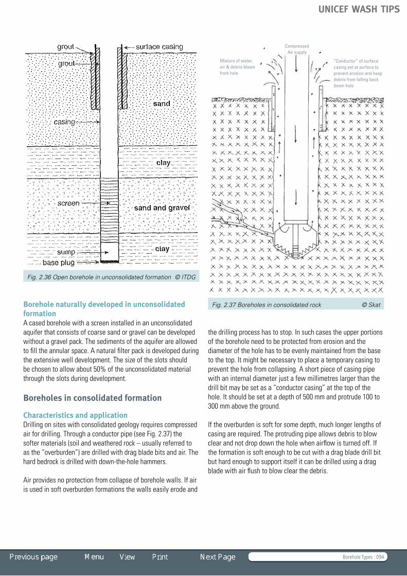
Borehole Types : 094
Borehole naturally developed in unconsolidated formationA cased borehole with a screen installed in an unconsolidated aquiferthatconsistsofcoarsesandorgravelcanbedevelopedwithoutagravelpack.Thesedimentsoftheaquiferareallowedto fill the annular space. A natural filter pack is developed during the extensive well development. The size of the slots should be chosen to allow about 50% of the unconsolidated material through the slots during development.
Boreholes in consolidated formation
Characteristics and applicationDrillingonsiteswithconsolidatedgeologyrequirescompressedair for drilling. Through a conductor pipe (see Fig. 2.37) the softer materials (soil and weathered rock – usually referred to asthe“overburden”)aredrilledwithdragbladebitsandair.Thehard bedrock is drilled with down-the-hole hammers.
Air provides no protection from collapse of borehole walls. If air is used in soft overburden formations the walls easily erode and
the drilling process has to stop. In such cases the upper portions of the borehole need to be protected from erosion and the diameter of the hole has to be evenly maintained from the base to the top. It might be necessary to place a temporary casing to prevent the hole from collapsing. A short piece of casing pipe with an internal diameter just a few millimetres larger than the drillbitmaybesetasa“conductorcasing”atthetopofthehole. It should be set at a depth of 500 mm and protrude 100 to 300 mm above the ground.
If the overburden is soft for some depth, much longer lengths of casingarerequired.Theprotrudingpipeallowsdebristoblowclear and not drop down the hole when airflow is turned off. If the formation is soft enough to be cut with a drag blade drill bit but hard enough to support itself it can be drilled using a drag blade with air flush to blow clear the debris.
Fig. 2.36 Open borehole in unconsolidated formation © ITDG
Fig. 2.37 Boreholes in consolidated rock © Skat
“Conductor” of surface casing set at surface to prevent erosion and keep debris from falling back down hole
Mixture of water,air & debris blownfrom hole
Compressed Air supply
UNICEF WASH TIPS

Borehole Types : 095
Open hole in consolidated formation This design applies to consolidated formation in hard rock where the hole will not collapse. First the surface casing is set through the overburden and sealed by pressure grouting. The remainder of the borehole is drilled and left open. This design is cost-effectiveandquicktoconstruct.
Cased borehole in consolidated formation with risk of collapseThisboreholedesignisusedwherethebedrockortheaquiferisunstable. After the surface casing is set through the overburden and sealed by pressure grouting (a cement slurry is normally
Fig. 2.38 Open hole in consolidated formation © ITDG
Fig. 2.39 Cased borehole in consolidated formation
with risk of collapse © ITDG
used for this sealing or grouting process), the remainder of the borehole is drilled and a casing and screen is set. A gravel packing is used to stabilize the screen and a formation stabilizer is used along the casing. Above the gravel pack, a small section is filled with sand and then the borehole is sealed with grout or bentonite. The annular space to the top is backfilled with cuttings.
UNICEF WASH TIPS

Borehole Design : 096
TIP 2.3 Borehole Design Elements of borehole design
– Casings and screens – Casings – Screens – Selecting the proper slot size – Gravel packs – Grouting and sealing – Well development – Pumping test – Rock sampling/mud logging Installing the handpump
– Casting the platform – Bill of Quantities – Equipment needed for drilling – Materials and consumables for platform construction (borehole) – Recommended masonry tools for platform construction – Construction requirement
Handpump IndiaMKII
Sump SectionPVC 2-6m long
Borehole in unconsolidated material, naturally developed- Lined with 4” (113 x 103 mm) PVC Casing and Screen
Naturally developed
Well Screen113x103mm
Slot size: 0.2mm to 2.0mm
Pump Cylinder
Rising main
Backfill
PVC Casing Pipe113x103mm
Concrete Apron
Casing Point
Development
Coarse SandAquiter
Cement-BentoniteSeal
Clay and Silttypically
Drilled 100mmDragbit with Mudflush
OverburdenSoil
UNICEF WASH TIPS

Borehole Design : 097
Elements of borehole design
Boreholes should be designed and constructed to meet the following criteria:
• Theefficiencyshouldbemaximized,thatis,theboreholeshouldbematchedtothepumpingdeviceandtheaquifercharacteristics
• Sandinflowtotheboreholeshouldbeminimalandnotaccumulate in the screen
• Thequalityofthematerialshouldguaranteealifespanof25 years
• Thewaterqualityshouldbemaintained• Boreholedesignsaresite-specificbutgeneraldesign
principles can be applied.
Important to all designs is that the soft weathered zone is sealed off to avoid contamination through ingress of polluted groundwater from pit latrines nearby.
Casings and screens Properwellconstructionmaterialsandtechniquesareessentialto providing both a long-term and safe supply of groundwater for household use. Therefore, boreholes in unstable ground and soil need to be secured from collapsing by casing.
CasingsSteel and PVC casing are the standard choices for casing drilled wells. Each has its advantages and disadvantages as shown in Table 2.4 but steel is now rarely used because of its cost, susceptibility to corrosion and weight. PVC is now the material of choice for the vast majority of rural water supply programmes. However, in some cases the stabilizing chemicals used in PVC have some toxicity, and this should be checked before using.
Whichever casing type you choose, the inside diameter of the casing should be 4 to 6 inches (see Table 2.4) for handpumps. The casing and screen diameters must be large enough to safely house the pump cylinder and the rising main, and should protrude at least 300 mm above ground level.
Table 2.4 Advantages and disadvantages of PVC and steel casings
PVC Casings
Advantages Disadvantages
Corrosion resistance Lower relative strength
Light weight Lower compressive strength
Ease of installation Flexible (to be centred in borehole)
Resistant to acid clean-outs
Steel Casings
Advantages Disadvantages
High relative strength High corrosion potential
High compressive strenth
Heavy in weight
Rigid pipe Relatively high cost
Scale build-up
It is customary to label casings in inch sizes. However, pipe manufacturers do not always adhere to the international standards and dimensions vary. It is therefore important always
Fig. 2.40 Casings and screens © Skat Fig. 2.41 Joints © Skat
Glued Bell-end Flush
UNICEF WASH TIPS

Borehole Design : 098
tospecifythepipesinmillimetresbyquotingoutsidediameterand inside diameter.
Table 2.5 Sizes of UPVC casing pipe for boreholes for installation down to 100 m
Inch Nominal Diameter
Outer Diameter
Inner Diameter
Wall
mm mm mm mm
4” 100 113 103 5
4.5” 115 125 113 5
5” 125 140 127 6 .5
6” 150 165 150 7 .5
The joints between casing pipes and between casings and screensareacriticalcomponent–poorqualityjointsareacommon cause of borehole failure in the field. Joints should thus becarefullyspecifiedandsubjecttoqualitycontrol.Themostcommon type of joints are flush joints with trapezoidal threads, as per DIN 4925. Other types of joints should be procured and used only if clearly specified (see Fig. 2.41).
Although standards like DIN 4925 exist, threads can vary from manufacturer to manufacturer. It is therefore recommended not to mix casing pipes from different suppliers.
It is normal to place a length of blank casing at the base of the borehole to act as a sump into which silt can settle (and thus not clog the water-bearing portion of the borehole).The sump should have a blank end (a cap) to prevent sediment entering the well from the base.
ScreensScreens are usually the same diameter and material as the casing, but with openings to allow inflow of water. They should
be installed next to the water-producing horizons except in hard rock, where sometimes the screen can be omitted. It is important to make sure that the screen is in the right place. If a blank casing is placed at the point where the water enters the borehole the well might be sealed.
Screens used by drillers include continuous slot stainless steel and PVC, slotted PVC screens, and perforated plain steel, which is rarely used. The open area of continuous slot screens is 10 to 30% for slotted screens, 5 to 10% (slightly higher for vertical than horizontal cut) and for perforated screens, as low as 2%. Higher open-area screens are more expensive but are needed wheretheaquiferisoflimitedthickness.
Continuous slot screens have the highest open area of all. They are therefore usually the best choice for use in thin granular unconsolidatedsandandgravelaquifers.Theyaremostusefulin well jetting and at great depth where more pressure is put on the screen. They are manufactured by winding and attaching a triangular strand of stainless steel wire or PVC around a set of vertical rods.
Robo screens are a type of continuous slot screen with ribs on the inside, and a continuous slot cut on the outside. They are a cost-effective option for small diameter PVC pipes, and are thus widely used in rural water supply programmes and small scale irrigation.
Slotted screens are machine or hand-constructed by cutting slots into casing pipe (either PVC or steel). Hand cutting results in a smaller open area and may jeopardize the strength of the pipe, and are thus normally avoided in UNICEF-supported programmes. The main advantages of using hand-slotted screens are the low cost and avoiding the need to procure screens as well as casing.
PVC screens may be ribbed on the outside, to keep granular aquifermaterialawayfromtheslot,andsomaintainahigheropen area.
Selecting the proper slot sizeOnce the need for a screen has been established, it is necessary to select the proper slot size and screen length. The slot size is determined by examining and analyzing the particle size of unconsolidated cuttings recovered from the borehole. In coarse sands and gravels a slot size is then selected which allows water to freely enter the well while holding back some 50% oftheaquifermaterialandallowingdevelopmentofanaturalgravel pack.
In finer sands, the slot size is dictated by the gravel pack grain sizes, being a size through which some 10% of the pack can pass.
Fig. 2.42 Slotted screens © Skat
Continuous Slot
Machine Slotted Perforated
UNICEF WASH TIPS

Borehole Design : 099
The velocity of the water flowing through the screen should be lessthan0.03m/s.Thus,therequiredyieldandtheopenareaper metre define the length of screen needed to keep flow below this velocity.
The minimum necessary open area of the screen can be calculated with the formula: A = Q/30 (A = open area in m2 calculated from the total area per metre of pipe times the percentage of open area times the length of screen and Q = flow in l/s). If a handpump is fitted to the borehole, the open area of the screens is normally not critical. However, it is important to make sure the pump cylinder is not installed within the screened section of the borehole. It should be installed within a blank casing zone where inflow water velocity is not too high.
Gravel packsThe installation of gravel pack allows the use of larger screen slot sizes while minimizing the ingress of most sands into the borehole.
The gravel pack is somewhat of a misnomer as it looks more like coarse sand than gravel. The pack is composed of graded particles, that is, not all of the same size. The best gravel pack is hard, washed, well-rounded silicate (non-calcareous) gravel, usually obtained from an alluvial source: for example, a dry river bed or lakeshore.
A gravel pack should consist of mixed grain sizes, with less than 10% of the particles smaller than the screen slot size. A properly designed gravel pack also takes into account the particle sizes in theaquifer.
The gravel pack should have a minimum thickness of 5 to 7cm. Tomakesurethatitisofequalthicknessallroundthescreen,centralizers should be fitted to the screen to make an even space between the screen and the borehole wall.
Beforestartinggravelplacement,thecorrectvolumerequiredhas to be calculated to cover the length of the screen.
Volume = (cross sectional area of hole – cross-sectional area of the screen) times [(the length of screened section) plus (the distance from borehole base to the bottom of the screen plus 2 m)]. Above this pack and below the sanitary seal, cuttings can be used to backfill the annular space. Gravel pack should becarefullyinstalledtoavoid“bridging”–leavinglengthsofscreen with no pack protection.
Gravel packs are essential in fine-grained unconsolidated formations. When they are missing or poorly designed the borehole will fill with sand, or inflow will be blocked. Cleaning out a borehole that fills with sand is of limited value, since each timethescreenwillfillmorequicklywithmoresand.Insuchcases the only answer is to screen and pack again inside the
first screen, but there is seldom sufficient diameter to do this. The only practical solution, usually, is to drill a new borehole and improve the design.
To minimize drilling diameter and where gravel is difficult to obtain, screens with in situ gravel pack are available. This requirespriorknowledgeofaquifergradingforappropriatespecification.
In cases where backfilling with cuttings is not possible, a formation stabilizer is used to fill the space between casing and borehole wall to avoid caving in of silts and clays. Its specification is usually less rigorous than the gravel pack.
Grouting and sealingAll borehole designs should have a sanitary seal to stop contaminated water from flowing into the well. The sanitary seal is usually made from cement (2 parts sand and 1 part cement) or bentonite.
Grouting of permanent casing is done at the end of the drilling process with cement and bentonite seals applied to a depth of at least 1.5 metres.
Fig. 2.43 Placing the gravel pack, Zambia © S. Sutton
UNICEF WASH TIPS

Borehole Design : 100
The casing protrudes about 300 mm above ground level and the well is then capped temporarily with lockable cap until the pump is installed. This is a very important step in rural water supply programmes: improperly sealed boreholes are easily damaged or destroyed.
Well developmentWell development involves removing unwanted materials and improvingtheflowofthesurroundingaquifertothewell.
Well development addresses well yield reductions caused by:
• mudorbentonite,whichcanclogtheboreholewall,resulting in a dramatic fall in permeability
• airforcedintofissuresorporesduringairdrilling• fine-grainedmaterialinthegravelpackorintheadjacent
aquifer.
Toobtainhighyields,boreholedevelopmentisrequiredtoeliminate the skin effect (cake) from the borehole wall and extract the mud from the blocked fissures. Developing the boreholereducesthedamagecausedtotheaquiferduringdrilling and improves long-term performance. Development also ensures the accelerated removal of sand or fine material fromtheaquifersothatresistancetoflowintotheboreholeisminimized. Borehole development in unconsolidated formations normally takes one to two days.
If a borehole is not developed, the pumped water can contain sand or silt that may damage seals and valves of handpumps. Sand and silt can also accumulate in the borehole, blocking the open area so that inflow velocities increase. This can increase the rates of sanding until the pump becomes blocked.
Of the several well-development methods in use, three of the most effective are over-pumping, surging and jetting. Wells that are properly screened and developed are more efficient, last longer, have fewer problems, and are easier to clean out than wells without screens.
Airlift – blowingThe drill pipe is lowered to the bottom of the completed borehole and compressed air is injected to blow out water and muck. The drill pipe can be moved up and down along the screen. This is simply a crude method for cleaning of the borehole; it can badly disturb the gravel pack and force air into fissures. It is not recommended for unconsolidated formations.
Over-pumpingOver-pumping consists of pumping the well at a higher rate than the normal everyday pumping rate. While this procedure is sometimes effective in removing sand from inside the drilled hole, often only the uppermost section of the screened interval is developed, leaving the majority of the screen undeveloped and underutilized. However, in high-yielding boreholes used for handpump programmes, it can be sufficient.
Surging (preferred option)Surging involves the mechanical action of a plunger within the casingtoforcewaterbackthroughthescreenintotheaquifer.Surging is a process that sets up a washing action by forcing the water backwards and forwards through the material to be cleaned(screen,gravelpackandaquifer).Fig. 2.44 Gravel pack before and after development © Skat
Fig. 2.45 Water pumped before development © Skat
Fig. 2.46 Water pumped after development © Skat
UNICEF WASH TIPS
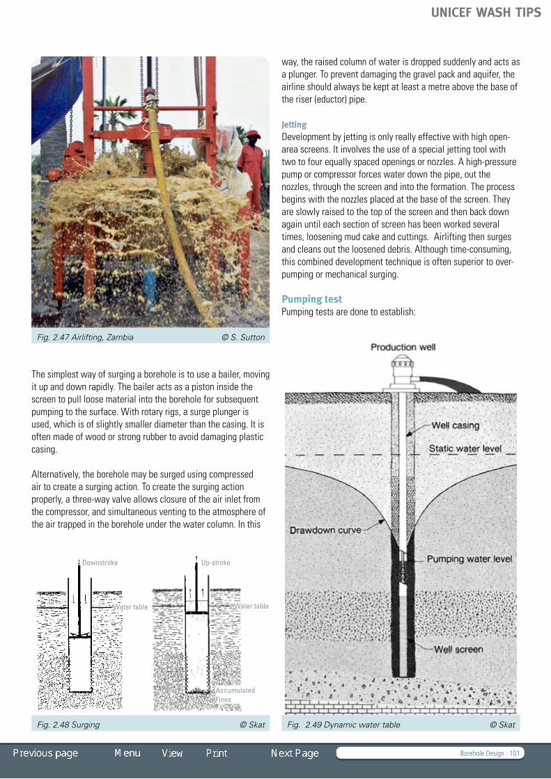
Borehole Design : 101
The simplest way of surging a borehole is to use a bailer, moving it up and down rapidly. The bailer acts as a piston inside the screentopullloosematerialintotheboreholeforsubsequentpumping to the surface. With rotary rigs, a surge plunger is used, which is of slightly smaller diameter than the casing. It is often made of wood or strong rubber to avoid damaging plastic casing.
Alternatively, the borehole may be surged using compressed air to create a surging action. To create the surging action properly, a three-way valve allows closure of the air inlet from the compressor, and simultaneous venting to the atmosphere of the air trapped in the borehole under the water column. In this
way, the raised column of water is dropped suddenly and acts as aplunger.Topreventdamagingthegravelpackandaquifer,theairline should always be kept at least a metre above the base of the riser (eductor) pipe.
JettingDevelopment by jetting is only really effective with high open-area screens. It involves the use of a special jetting tool with twotofourequallyspacedopeningsornozzles.Ahigh-pressurepump or compressor forces water down the pipe, out the nozzles, through the screen and into the formation. The process begins with the nozzles placed at the base of the screen. They are slowly raised to the top of the screen and then back down again until each section of screen has been worked several times, loosening mud cake and cuttings. Airlifting then surges and cleans out the loosened debris. Although time-consuming, thiscombineddevelopmenttechniqueisoftensuperiortoover-pumping or mechanical surging.
Pumping test Pumping tests are done to establish:
Fig. 2.47 Airlifting, Zambia © S. Sutton
Fig. 2.48 Surging © Skat Fig. 2.49 Dynamic water table © Skat
Downstroke Up-stroke
AccumulatedFines
Water table Water table
UNICEF WASH TIPS

Borehole Design : 102
• Istheboreholesuccessful?• Howmanypeoplecanitserve?• Isitsustainable?• Didthecontractordoagoodjob?
Once a well has been developed free of any accumulated fines, it can be properly evaluated to determine the amount of wateritwillyieldandtomeasuretheaquifercharacteristicsofstorability and permeability.
In a pumping test, boreholes are pumped for extended periods, with water discharged far enough away to stop it returning to theaquifer.Thedrawdown(thedropinthewatercolumnwithinthe borehole) is measured over logarithmic time, thus enabling assessmentofwellperformanceandaquifercharacteristics.
Electric submersible pumps powered by generators make excellent tools for carrying out a basic pump test, but airlifting can provide an indication of yield if no pump is available.
For a handpump programme, the pumping test is used simply to determine whether or not the borehole has sufficient yield for the handpump: 1 to 2 m3/hr.
Pump test results are most valid in unconsolidated aquifers,whicharegenerallylarge;inhardrocktheyareanapproximation at best, as upper fissures may eventually go dry.
Rock sampling/mud loggingDuring drilling, samples are taken in order to identify the layers being penetrated and predict when water will be struck. If greatdetailisrequired,samplingmaybeofsolidcoresofrock(requiringspecialbits).Butnormallyforwaterwelldrilling,rockcuttings from the drilling process are collected and used for this purpose. These are taken from the bailer or from the return of circulated fluids. Care is taken to avoid confusion of layers by cleaning the hole (circulating fluid or air without drilling) before drilling for sample collection, and samples are washed and bagged or stored in clear plastic containers. Sampling is usually every 3 m and/or at each change of formation.
The production of a borehole log records the details of a hole drilled. The importance of undertaking proper logging and measurement of hole depth cannot be overstated. Information about depth to water table, well yield and materials used to line the well need to be recorded with accuracy and consistency.
The final records should also include the results from the water qualityanalysisofawatersampleforbacteriological,physicaland chemical contamination.
Fig. 2.50 Pump testing, Mozambique © Skat Fig. 2.52 Rock samples, Tanzania © Skat
Fig. 2.51 Mud samples, Tanzania © Skat
UNICEF WASH TIPS

Borehole Design : 103
Cylinder
Water tank
Spout
Head flange
Pumprod
Rising main
Top flange
Pump head
Pump stand
Ground
Cement/Platform
Suction pipe
Footvalv e
Rising main
Pumprod
Cylinder
Plunger
Scale 1 : 5
Casing pipe
Socket
Reducer cap
Suction pipe
Handle
Plunger
Footvalv e
Reducer cap
Pedestal for BoreholeGI Rising main (1 1/4")(Scale 1 : 10)
GL GL
(standard)India Mark II Pump
D9170
Installing the handpump
A platform (or slab) is constructed at the well head to prevent the area around a well from becoming dirty. The platform and the drain also prevent waste and stagnant water accumulating around the well head. The trench for the foundation has to be carefully dug to a depth of 40 cm. The pump stand is placed absolutely vertical over the protruding casing pipe at the correct height. Grouting is done with a concrete mix of 1:2:3 (1 volume of cement, 2 volumes of sand and 3 volumes of gravel).
Casting the platformCasting of the well platform is done by filling the platform with a concrete layer of 12 cm and compacting it by tamping. After initial curing, the bricks for the ring of the platform are placed and the drainage channel is cast. The platform needs a curing time of at least one week. The platform and drainage channel should be covered (e.g. with thorn bush) and kept watered, so that it never dries out while curing.
Note: Various types of handpumps can be used on such boreholes. See TIP 1, Handpumps for Drinking Water.
Fig. 2.53 Mould for the platform, Tanzania © UNICEF Fig. 2.56 Typical handpump © Skat
Fig. 2.54 Handpump platform © Skat
Fig. 2.55 Platform © Skat
UNICEF WASH TIPS

Borehole Design : 104
Fig. 2.57 Typical design drawing of borehole in
unconsolidated formation with casing
Fig. 2.59 Typical design drawing of lined borehole in
consolidated formation with risk of collapse
Fig. 2.58 Typical design drawing of borehole in
unconsolidated formation with gravel pack
Fig. 2.60 Typical design drawing of regolith borehole
Handpump IndiaMKII
Weathered Rock
Sand or soil
Silt and clay
Weathered Rockpermeable
Fissuresstoring water
Hard Rock
Hard Rock
Drilled 150mmDTH Hammer
Drill 200 mmDragbit, air or foam
Drill 200 mmDragbit, air or foam
PVC Casing Pipe113x103mm
Cement BentoniteSeal
Pump Cylinder
Pump Cylinder
Gravel Pack
Gravel Pack
Sump SectionPVC 2-6mm long
Sump SectionPVC 2-6mm long
Casing Point
Casing Point
Well Screen113x103mm
Slot size: 0.2mmto 2.0mm
Well Screen113x103mm
Slot size: 0.2mmto 2.0mm
PVC Casing Pipe140x126mm(Temporary)
PVC Casing Pipe140x126mm
Borehole in unconsolidated material, naturally developed- Lined with 4” (113 x 103 mm) PVC Casing and Screen
Borehole in unconsolidated material, Gravel Pack- Lined with 4” (113 x 103 mm) PVC Casing and Screen
Lined Borehole in consolidated material with risk of collapse- Lined with 4” (113 x 103 mm) PVC Casing and Screen
Regolith Borehole: lined 4” 100mm Dia,- Lined with 4” (113 x 103 mm) PVC Casing and Screen
Sump SectionPVC 2-6m long
Sump SectionPVC 2-6m long
Naturally developed
Gravel pack
Well Screen113x103mm
Slot size: 0.2mm to 2.0mm
Well Screen113x103mm
Slot size: 0.2mm to 2.0mm
Pump Cylinder
Pump Cylinder
Rising main
Rising main
Backfill
Backfill
PVC Casing Pipe113x103mm
PVC Casing Pipe113x103mm
Concrete Apron
Casing Point
Casing Point
Development
Development
Coarse SandAquiter
Coarse SandAquiter
Cement-BentoniteSeal
Cement-BentoniteSeal
Clay and Silttypically
Clay and Silttypically
Drilled 100mmDragbit with Mudflush
Drilled 165mmDragbit with Mudflush
OverburdenSoil
OverburdenSoil
UNICEF WASH TIPS

Borehole Design : 105
Bill of Quantities
Click on the BoQ to open an Excel Sheet
Materials needed See Bill of Quantities.
Equipment needed for drilling • Lightrotarydrillrigwithmudpumpandcompressor400
CFM 12bar• Lightsupporttruck(possibly4x4)capableofcarryingpipes
of 4 m length• Petrolwaterpump• Submersiblepumpforwelldevelopment• Generatorsetforwelldevelopment• Watercarriageandstoragefacilities
Materials and consumables for platform construction (borehole)
Item Approximate quantity
Washed sand (without too much mud content)
2 cubic metres
Gravel (approximately Ø20 mm) 4 cubic metres
Cement (bags of 50 kg) 8 bags x 50 kg
Burnedbricks(3”x4.5”x9”) 100 nos .
Wire netting for platforms (50 x 50 x Ø3 mm)
1 .7 x 1 .7 m
Binding wire for connecting reinforcement bars
10 m
Hessian cloth for curing of platform to cover platform
Pump stand (for stand with 3 legs) 1 no .
Wooden board (protection against contamination)
1 no . (bolted on flange)
Recommended masonry tools for platform construction
Item Approximate quantity
Shovel /scoop 3 nos.
Spade 1 no.
Pick or crow bar 2 nos .
Mason’s trowel 2 nos .
Levelling plank (0.5 and 2 m) 1 each
Rubber bucket (for concrete) 4 nos .
Steel bucket (for water) 2 nos .
Measuring tape (3 m) 1 no .
Spirit level 1 no .
Platform shuttering (steel form or wooden material)
1 no .
Tamper sticks (for removing trapped air) 1 no .
Construction requirement The JobTo drill, construct and complete water supply boreholes that provide clean water supplies adhering to standard designs and construction methods as specified and described in the attached Bill of Quantities.
Thebiddingcontractormaybidalternativestosuitequipmentand material available with the specification of work together with an applicable unit rate being appended to the offer.
Equipment and MaterialsAbiddingcontractoristoprepareanitemizedlistofequipmentthat will be mobilized to site to undertake the work. For major plant, state the manufacturer, model number, specification summary and year of manufacture to assist in contract bid evaluation.
Intheeventofequipmentrequiringtobefreightedbyairorseaacross international borders full weight and dimensions may be needed to be added to the basic list.
List of incidentals for mud sampling, sieve analysis, well developmentandwaterqualityshouldalsobeprovided.
Bill of Quantities (Boreholes and Drilling)
UNICEF WASH TIPS

Borehole Design : 106
Equipment and Services Provided by the ProjectGenerally, the purchaser or the project can be expected to provide the following facilities at a borehole site.
A drill site prepared and fenced nominally measuring 50 x 50 m with 24-hour security personnel in attendance.
Suitable roads will be constructed for heavy truck access to site –heavytowingequipmentprovidedifrequiredtogainaccesstosites with particular problems.
Free Issued Materials.UNICEFmightprovidecertainmaterialsandequipmenttoassistthe contractor in the execution of the Works.
Thecontractorwillberequiredtostore,keeprecordsofusageandmaintainthisequipmentandmaterialinaccordancewithinstructions agreed with the supervising engineer.
SecurityEquipmentLossorDamageLiability:Thecontractorisliableforalllossesanddamagetoequipmentmaterialandstaff.
Personal Security and Site Hours: The contractor’s staff will be subject to full security procedures as defined by UNICEF. This will affect contractor personnel’s conduct inside and outside site working hours.
Supervision and PaymentAllworkswillbesupervisedbyanominated“Engineer”whowillrequirefreeaccesstothedrillsitetofullymonitorconstruction.
All claims for payment must be itemized as per the Bill of Quantities and submitted to the engineer for approval. (Suitable “proforma”blanksofthebillcanbeprovidedonpaperordisktoassist the contractor.)
Claimsforpaymentcanbemadeatafrequencyasagreedwith the engineer – this does not include claims for partially completed boreholes.
Contractor SelectionUNICEF will endeavour to appoint a contractor who can demonstrate experience and expertise to undertake the specifiedjobwithsound,reliableequipmentandresourcesforafair price.
Contractors are encouraged to submit a succinct written brief with completed offers giving details of satisfied clients, completed works and any other pertinent information that would assist UNICEF with contractor selection.
Operation and Maintenance RequirementsBoreholes need little maintenance; however the yield might be reduced after some years due to silting up or the deposition of iron bacteria. In such a case, it will be necessary to redevelop the borehole. This has to be done by cleaning the well with airlifting and pump testing.
The aspects of handpump maintenance are addressed in TIP 1, Handpumps for Drinking Water.
Potential for Using Local Private Sector Wherever possible local private sector drilling companies should be used. The aspect of supervision is of major importance. If the supervision is done by inexperienced engineers, the cost of drillingmaygoupandthequalityofworkisnotensured.
UNICEF WASH TIPS

Drilling Rigs and Tools : 107
TIP 2.4 Drilling Rigs and Tools Drilling rigs
– Mobile drilling rigs – Drilling rig classification – Cost-saving considerations Drilling tools and equipment
– Compressors – Mud pumps – Drill bits and down-the-hole hammer
Sudan © Skat
UNICEF WASH TIPS

Drilling Rigs and Tools : 108
Drilling rigs
A drilling rig is a general term used to describe a wide variety of machines that penetrate the ground for blasting, water abstraction and monitoring and geological sampling. The drillingequipmentcanbemobile–mountedonapickup,atrailer, a tractor, or on a small or large lorry – or static, that is, constructed on site (especially for very deep holes).
Drilling rigs can be massive machines or they can be small enough to be moved manually by one person.
Mobile drilling rigsMobiledrillingrigsarearequirementforruralwatersupplyprogrammes. They range from small ultra-portable units to expensive, custom-built machines.
In rural water supply, most boreholes fitted with handpumps donotrequirehighyields(theyareoftenlessthan60mdeepand not more than 8 inches in diameter); therefore small borehole diameters can be chosen, and smaller rigs can be used to drill them. The flexible transport and the easy operation of a lightweight rotary rig mounted on a small truck or a trailer reduce the cost for a borehole considerably without
compromisingthequality.LightweightequipmentlikePVCcasings instead of steel casings can reduce the transport cost even further.
Theequipmentassociatedwitharigsetupistosomeextentdependent on the type of rig. Typically it includes at least a support vehicle and an auxiliary vehicle, as well as the rig itself. The support vehicle, normally a truck, holds diesel and water tanks for re-supplying the rig, as well as transporting consumables like casing and screens. It also holds other supplies needed for maintenance of the rig. Often a stand-alone air compressor, which may be towed by one of the vehicles, is part of the setup. The auxiliary vehicle is used for transporting other consumables and the crew.
Drilling rig classification The drilling rigs outlined below differ mechanically in terms of the machinery used, but also in terms of the method by which drill cuttings are removed from the cutting face of the drill and returned to the surface.
There are many different types and designs of drilling rigs. Many drilling rigs are capable of switching or combining different drilling technologies as needed. Drilling rigs can be described using any of the following attributes:
- the power used• electric–electricity,usuallyproducedbyitsown
generators, is used for electric motors to drive individual components (rarely used for rural water supply rigs)
• mechanical–therigusestorqueconverters,clutchesandtransmissions powered by its own engines, usually diesel
• hydraulic–therigprimarilyuseshydraulicpower• pneumatic–therigisprimarilypoweredbypressurizedair
- the drilling string used• cable–acableisusedtoraiseanddropthedrillbitordrill
string • conventional–usesmetaldrillpipeofvaryingtypes• coiltubing–usesagiantcoiloftubeandadownhole
drilling motor Fig. 2.61 Small rig with petrol engine drive, Tanzania © Skat
Fig. 2.62 Large hydraulic rotary rig, Ghana © Skat
UNICEF WASH TIPS

Drilling Rigs and Tools : 109
- the method of rotation or drilling• norotation–includesdirectpushrigs,cabletoolrigsand
most service rigs • rotarytable(tabledrive)–rotationisachievedbyturninga
squareorhexagonalpipe(thekelly)atdrillfloorlevel• top-drive–rotationandcirculationisdoneatthetopofthe
drill string, on a motor that moves along the derrick • sonic–usesprimarilyvibratoryenergytoadvancethedrill
string
Suitability of drilling rigs for a specific job depends on a variety of criteria, including the depths to be drilled, the diameter of boreholesrequired,andthepull-downandpull-backcapacitiesof the rig (which affect the ability of the rig to apply enough pressure for efficient drilling and for pulling drill strings from depth).
Cost-saving considerationsSeveral basic limiting factors determine the depth to which a borehole can be sunk.
A borehole is defined by its diameter and depth, that is, the volume that is removed. The larger the volume, the more work is needed for drilling, and the larger and more powerful the drilling rigs needed. Matching the borehole design to the pumping device leads to considerable cost savings because smaller diameter boreholes can be drilled by smaller machines.
Friction caused by the rods turning in the ground is a function of depth and diameter. A larger diameter hole and greater depth requirestrongermachines.Indown-the-holedrillingthecuttingsare cleared out by blowing compressed air up the borehole in the space between the drill pipe and the drilled hole. The air must blow out by the compressor with a speed high enough to carry the cuttings upwards. This means that there is a direct ratio between the compressed air flow and the borehole diameter. Similar to fluid or mud drilling, the mud pump has to carry the rock chips up to the surface.
In rural water supply programmes, there is no need for large diameterboreholes.Thesearerequiredonlywhenlargerdiameterelectricsubmersiblepumpsarerequired(e.g.foracitywater supply system). There is also no proportional relationship between yield and borehole diameter: increasing diameter from 4 to 8 inches has a minimal effect on yield in most cases. And in anycase,onlylowyieldsarerequiredforhandpumps.
Another key consideration is that drilling campaign management, transport and logistics are expensive. A significant portion of the cost of rural water supply drilling programmes comes from transport and logistics. Packaging drilling contracts according to location of the sites and the sequenceofworkkeepscostsdownbyreducingmobilizationdistances and logistics problems. Planning drilling schedules
and routes logically to reduce total travel and maintain efficient supply lines can result in significant cost savings. However, this is sometimes difficult to achieve in practice due to political considerations (e.g. when it is necessary to drill a few boreholes in each district, rather than complete all boreholes in one district before moving to another).
Drilling tools and equipment
CompressorsAir compressors are used in drilling to inject air down through the centre of the drill pipe and up through the annular space formed between the larger drill bit diameter and smaller drill pipe diameter. This flushes the bit clean and carries borehole debris to the surface. The rising column of air also lifts out water during well cleaning/development. For down-the-hole hammer drilling the compressed air provides the power to the hammer.
The size of the air compressor is linked to the borehole diameter. It is essential to the drilling process that the air travels up the borehole fast enough to carry debris with it. Note that the speed requiredisconsiderablyfasterthanwater/fluidcirculationbecause air has less capacity to support material than water. Air volume is specified by compressor manufacturers in units of free air delivered: m3/min (cubic metres delivered per minute), ft3/min (cubic feet per minute) or l/sec (litres per second). All these are units of flow or volume, not pressure or force: it is the air volume that cleans the hole and is the most essential requirementofadrillingcompressor.
The other attribute specified for compressors is the pressure a unitcandevelopinbarorpsi(poundspersquareinch).Mostindustrial units will develop a minimum of 6 bar (100 psi). Multiple stage units are able to develop pressures of 20 bar (300 psi). Pressure allows more energy to be delivered to the piston of a down-the-hole hammer – thus imparting more energy to
Fig. 2.63 Trailer mounted compressor, Nigeria © Skat
UNICEF WASH TIPS
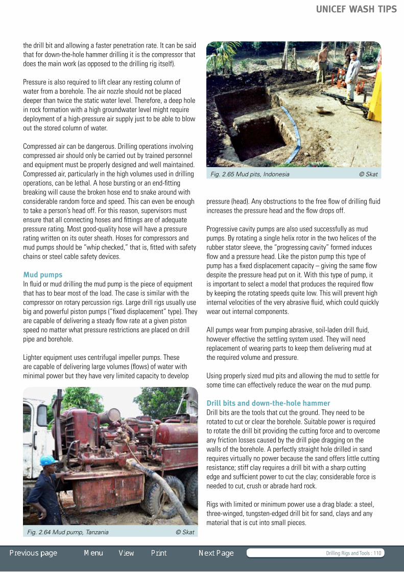
Drilling Rigs and Tools : 110
the drill bit and allowing a faster penetration rate. It can be said that for down-the-hole hammer drilling it is the compressor that does the main work (as opposed to the drilling rig itself).
Pressureisalsorequiredtoliftclearanyrestingcolumnofwater from a borehole. The air nozzle should not be placed deeper than twice the static water level. Therefore, a deep hole inrockformationwithahighgroundwaterlevelmightrequiredeployment of a high-pressure air supply just to be able to blow out the stored column of water.
Compressed air can be dangerous. Drilling operations involving compressed air should only be carried out by trained personnel andequipmentmustbeproperlydesignedandwellmaintained.Compressed air, particularly in the high volumes used in drilling operations, can be lethal. A hose bursting or an end-fitting breaking will cause the broken hose end to snake around with considerable random force and speed. This can even be enough to take a person’s head off. For this reason, supervisors must ensurethatallconnectinghosesandfittingsareofadequatepressurerating.Mostgood-qualityhosewillhaveapressurerating written on its outer sheath. Hoses for compressors and mudpumpsshouldbe“whipchecked,”thatis,fittedwithsafetychains or steel cable safety devices.
Mud pumpsInfluidormuddrillingthemudpumpisthepieceofequipmentthat has to bear most of the load. The case is similar with the compressor on rotary percussion rigs. Large drill rigs usually use bigandpowerfulpistonpumps(“fixeddisplacement”type).Theyare capable of delivering a steady flow rate at a given piston speed no matter what pressure restrictions are placed on drill pipe and borehole.
Lighterequipmentusescentrifugalimpellerpumps.Theseare capable of delivering large volumes (flows) of water with minimal power but they have very limited capacity to develop
pressure (head). Any obstructions to the free flow of drilling fluid increases the pressure head and the flow drops off.
Progressive cavity pumps are also used successfully as mud pumps. By rotating a single helix rotor in the two helices of the rubberstatorsleeve,the“progressingcavity”formedinducesflow and a pressure head. Like the piston pump this type of pump has a fixed displacement capacity – giving the same flow despite the pressure head put on it. With this type of pump, it isimportanttoselectamodelthatproducestherequiredflowbykeepingtherotatingspeedsquitelow.Thiswillpreventhighinternalvelocitiesoftheveryabrasivefluid,whichcouldquicklywear out internal components.
All pumps wear from pumping abrasive, soil-laden drill fluid, however effective the settling system used. They will need replacement of wearing parts to keep them delivering mud at therequiredvolumeandpressure.
Using properly sized mud pits and allowing the mud to settle for some time can effectively reduce the wear on the mud pump.
Drill bits and down-the-hole hammerDrill bits are the tools that cut the ground. They need to be rotatedtocutorcleartheborehole.Suitablepowerisrequiredto rotate the drill bit providing the cutting force and to overcome any friction losses caused by the drill pipe dragging on the walls of the borehole. A perfectly straight hole drilled in sand requiresvirtuallynopowerbecausethesandofferslittlecuttingresistance;stiffclayrequiresadrillbitwithasharpcuttingedge and sufficient power to cut the clay; considerable force is needed to cut, crush or abrade hard rock.
Rigs with limited or minimum power use a drag blade: a steel, three-winged, tungsten-edged drill bit for sand, clays and any material that is cut into small pieces.
Fig. 2.64 Mud pump, Tanzania © Skat
Fig. 2.65 Mud pits, Indonesia © Skat
UNICEF WASH TIPS

Drilling Rigs and Tools : 111
Little or no down force is placed on the drill bit; material is removed through cutting action. The cutting edges of a drag blade are normally formed with a brazed tungsten carbide tip. Itshouldhavea“positivecuttingrake”soonlytheleadedgeofthe carbide scrapes the ground. It is often necessary to maintain bits in the field by grinding away metal behind the cutting carbide to recreate the clearance behind the edge. Note that any steel angle grinder is suitable. However, standard abrasive wheels will only cut the steel of the bit body, not the tungsten carbide.
ODEX bits are eccentric bits that allow casing to advance with the drilling. The bits can pass down through casing and then drill
at a slightly larger diameter, allowing the casing to be pushed down. They are especially useful where hard and soft layers alternate or where there are large cobbles or boulders in an unconsolidated formation or in the overburden.
The casing stops any deviation in alignment, and prevents collapse within the soft layers. It should be welded steel, not threaded or PVC, to ensure it can withstand the jarring it will receive.
Harder materials are more easily drilled with a down-the-hole hammer. This tool is operated with an air compressor and works by hammering a heavy steel piston on to a slowly rotating “button”percussiondrillbit.
The drill bit is hardened steel set with tungsten carbide buttons,whichrequireregularsharpeningwithspecialgrinders.Passages let the compressed air out to flush debris. Using a down-the-hole hammer means that the rig needs to apply only a nominal downward force on the hammer and rotate it at a low speed. The compressed air energy powers the hammer in such a way that the tungsten buttons strike across the entire hole base and thus penetrate even the hardest rock. The higher the compressor pressure, the faster the piston will be thrown on to the bit and the more energy will be delivered to the drill bit.
To stop the action of the piston hitting the percussive drill bit, the hammer is lifted off the rock face. The drill bit slides out of the hammer body, changing the air ports. The piston remains stationary and the compressed air is discharged continuously through the drill bit, allowing the borehole to be flushed.
Fig. 2.66 Drag blade © Skat
Fig. 2.67 Rock roller bit © Cranfield Fig. 2.68 Down-the-hole hammer © Cranfield
UNICEF WASH TIPS

Solar Powered Pumping : 112
Solar Powered Pumping 3 .1 Photovoltaic Water Pumping 3 .2 Solar Pump Subsystems 3 .3 Sizing a Solar Pumping System
TIP 3
Eritrea © Skat
UNICEF WASH TIPS

Solar Powered Pumping : 113
Introduction
Solar powered systems are an ecological solution in a time of dwindling fuel supplies and climate change. TIP 3 describes the technical aspects of solar power and photovoltaic conversion of solar radiation into electrical power. New electronic devices to harness solar power allow the use of pumps with higher efficiency and smaller diameter, thus fitting into smaller diameter boreholes.
Photovoltaic pumps normally run for several years without maintenance, so they are well suited for installations in remote areas. However, because most users will be unable to make the repairs themselves a functioning repair service is important.
References and Further Reading
Fraenkel, Peter and Jeremy Thake. 2006. Water Lifting Devices: A Handbook for Users and Choosers Food and Agriculture Organization
UNICEF WASH TIPS
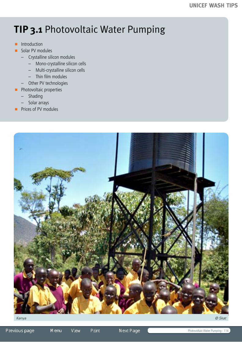
Photovoltaic Water Pumping : 114
TIP 3.1 Photovoltaic Water Pumping Introduction Solar PV modules
– Crystalline silicon modules – Mono-crystalline silicon cells – Multi-crystalline silicon cells – Thin film modules – Other PV technologies Photovoltaic properties
– Shading – Solar arrays Prices of PV modules
Kenya © Skat
UNICEF WASH TIPS

Photovoltaic Water Pumping : 115
Introduction
Many regions in the developing world have isolated rural areas that pose problems to rural energy management and development because of poor road links with urban centres and remoteness from the national electrical transmission grid. Development of renewable energy sources, therefore, has a vast potential.
The climate in many countries in the developing world is suitable for solar pumping. Solar energy is a valid option for small-scale water pumping in rural areas where the demand is regular, such as for drinking water, but it may also be used for irrigation. Applications of solar systems are growing at steady rate.
Photovoltaics (PV) is a technology that converts sunlight directly into electricity. It was discovered in 1839 by the French scientistAntoineHenriBecquerel.About50yearsago,thespace programmes provided an incentive for the development of crystalline silicon solar cells. The production of PV modules began.
Today, PV systems have become a commonly applied source of energy in rural areas. They can provide the power for drinking water pumping. With the global drive to reduce carbon dioxide emissions, PV technology is increasingly used as a mainstream form of electricity generation. Many thousands of systems are presently in use and the vast potential for PV as an energy source has not yet been utilized.
PV modules provide an independent, reliable electrical power source at the point of use, making them particularly suited to remote locations. PV systems are technically viable and with more commercial applications the technology is developing fast and prices are coming down, making PV more and more economically feasible for rural water supplies.
Solar radiation arrives on the surface of the earth at a maximum powerdensityofabout1kilowattpermetresquared(1kW/m2). The actual usable radiation component varies, depending on geographical location, cloud cover, hours of sunlight each day, etc. In rural water supply applications, the water demand is normally less during days with rainfall; therefore the reduced output of PV pumping systems on cloudy days is not so significant.
Solar PV modules
A photovoltaic module is a packaged interconnected assembly of photovoltaic cells, also known as solar cells. Current is created when light falls onto the active surface. The electrons in the solar cell become energized by the radiated energy of the sunlight. When the energy exceeds a certain level, a potential difference is established in the semi-conductive material of the solar cells. This potential can be used to create a current that flows through an external load.
Photovoltaiccellsrequireprotectionfromtheenvironment.Normally a number of cells are connected electrically and packaged into a photovoltaic module. These modules, designed as easily installable units, are known as photovoltaic panels or simply solar panels. They are mechanically fastened together, wired and have a glass cover. The frame and back plate are made of metal, plastic or fibreglass.
Solarpanelsareaveryreliablepieceofequipmentandmanymanufacturers sell the panels with a guarantee of 25 years. It should be noted that such a warranty can only be honoured if the supplier is still in business in 25 years. Therefore, it is advisable to select reliable suppliers rather than to choose the cheapest source.
Solar PV modules are normally specified by Watt-peak. Watt-peak or Wp is the measure of power output of photovoltaic solarenergy.Theyareverycostlypiecesofequipment.A50Wp module costs several hundred dollars and has a good resale value in many countries. Theft is already a problem in some areas.
There are three main types of cells on the market: mono-crystalline silicon, multi-crystalline silicon, and amorphous silicon.
New, non-silicon types such as cadmium telluride (CdTe) and copper indium disellenide (CIS) have recently become available.
Crystalline silicon modulesCells made from crystalline-silicon wafers represent the majority of the modules sold, they are the most efficient, and they have a proven track record. The different types are classified on the basis of the different manufacturing methods.Fig. 3.1 Solar pump in Eritrea © Skat
UNICEF WASH TIPS

Photovoltaic Water Pumping : 116
Mono-crystalline silicon cellsMono-crystalline silicon cells are made by growing a crystal of purified silicon (usually 100 to150 mm diameter) and slicing it into wafer-thin slices. A metal film is added to the back, and a pattern of conductors to the front, to collect the current. An anti-reflection glass is put on the front. Light falling on the cells produces a potential voltage across the cell. Each cell can only develop about 0.4 volts when under load (0.6 V on open circuit). The cells are connected together in series to produce a more useful voltage, typically 14 to16 V. Individual cells are delicate and expensive and need to be protected, so they are housed in a sealed module. The overall assembly is also sealed to prevent the ingress of water.
Mono-crystalline cells achieve efficiency in energy conversion of about 16%, the highest efficiency of any commercially available cell.
Mono-crystalline modules have a distinctive appearance, being made up of bluish grey individual cells. The production process is complicated, involving many stages, and the costs are high. Goodqualitymono-crystallinepanelsareveryreliable,withlivesof over 25 years, and are even sold with 25-year guarantees. This type of panel is the most expensive on the market.
Multi-crystalline silicon cells Multi-crystalline silicon cells are produced in a similar way to mono-crystalline cells, but a cast block of silicon is used instead of a single crystal. The cells look different, having a patchy appearance arising from the different crystal areas within them. Multi-crystalline cells are cheaper than mono-crystalline, but their efficiency is lower, about 13%. Characteristics and reliability are similar. Overall, they have similar cost-effectiveness to mono-crystalline cells.
Thin film modulesThe thin film modules are made by depositing a thin layer or film of silicon onto another material. Thin film technologies have the potential of providing mass-produced, low-cost modules.
Amorphous silicon modules are made up of thin layers of silicon deposited onto a glass or clear plastic sheet with a backing plate. The semi-conductors are divided into dark strips that run the length of the module.
Amorphoussiliconhasasunlightconversionrateof5-9%,quitea bit lower than crystalline silicon. In addition, performance degrades over the first few months of operation. After 3 months, the voltage produced by the module can be 30-50% less than the initial production voltage. Sizing should be done taking this into account. Amorphous silicon modules are cheaper but becauseoflowefficiencieslargerpanelareasarerequiredtogenerate the same power.
Fig. 3.2 Mono-crystalline silicon cells © Skat
Fig. 3.3 Multi-crystalline silicon cells © Skat
UNICEF WASH TIPS

Photovoltaic Water Pumping : 117
Other PV technologiesVarious other types of cells have been developed that use non-silicon semi-conductors. Two that have recently become commercially available are cadmium telluride (CdTe) and copper indium disellenide (CIS). CdTe modules have stabilized efficiencies of around 6%.
It should be noted that PV technology is developing fast and efficiencies stated today might be outdated tomorrow.
Photovoltaic properties
The output of a PV module varies with the amount of light available. Modules are tested under standard conditions, which include a maximum power density of 1 kW/m2 and a cell temperature of 25 degrees C. This light strength is about the maximum value of sunlight found on the surface of the earth. The voltage and power measured under these conditions are called peak volts or peak watts, Vp and Wp, respectively.
The actual useable radiation varies, depending on the geographical location, the cloud cover, smog and the hours of sunlight per day. In reality, the annual solar power varies between250and2,500kWh/m.2Neartheequatorandindesert areas this value is the highest. In Europe, the total
radiation consists of about 40% direct radiation and 60% diffuse radiation. Both direct and diffuse radiation are converted into electricity by solar cells.
A typical performance characteristic of individual mono-crystalline solar cells is shown in Fig.3.6. The efficiency of energy conversion is just over 15%. This means that sunlight power of 1 kW/m2 at 25°C will yield about 150 W/m2 of electrical output. This is a low conversion rate, turning a reasonable power density into a rather modest amount of useful energy. Unfortunately, the efficiency of solar cells decreases when they get hotter. Most solar cells reach temperatures in the range of 50 to 70°C in full sunlight. They therefore never achieve their rated output. Sizing methodologies have to take this into account. The rule-of-thumb is that it takes 20% more radiation (1.2 kW/m2) to produce the rated power at normal working temperatures.
Fig.3.7 shows the voltage-current characteristics of a solar cell. If the cell is short-circuited (at zero voltage) it can get a maximum current of about 36 mA/cm2 of cell. If the current is zero, it reaches a voltage of about 0.6 V per cell (regardless of its size). PV cells have a single operating point where the values of the current (I) and voltage (V) of the cell result in a maximum poweroutput.Themaximumpoweroutputisatthe“knee”ofthe V-I curve, at around
0.48 V per cell. Maximum power point trackers (see below) utilize control circuits or logic to search for this point and thus allow the converter circuit to extract the maximum power available from a cell.
The power output is roughly linearly proportional to the intensity of the radiation. If the level of radiation is reduced, the current declines correspondingly; however, the voltage characteristic stays more or less the same. Because of this characteristic, PV
Fig. 3.4 Thin film modules © Skat Fig. 3.6 Performance of mono-crystalline silicon cells © Skat
Fig. 3.5 Solar radiation © Skat
UNICEF WASH TIPS

Photovoltaic Water Pumping : 118
systems can function in low levels of sunlight, depending on the threshold power for starting the pump.
Shading PV modules are very sensitive to shading. Shading obstructions aredefinedas“soft”or”hard.”Softobstructionsareobjectssuch as tree branches or chimneys that shade the panel from a distance. Soft obstructions reduce the total amount of light reaching the cell by creating shadows containing diffuse light.
Hard obstructions are defined as objects that stop light from reaching the cell altogether, such as objects sitting directly on the glass (e.g. bird droppings, leaves). Even if only one cell is “hardshaded,”thevoltageofthemodulewilldroptohalfofitsun-shaded value. It is therefore important to avoid hard shading by ensuring that panels are regularly cleaned.
Solar arrays Modules are usually mounted as arrays on a frame facing the sun at a fixed angle, which for maximum output is normally the angleoflatitudeofthelocation.However,neartheequatoraminimum angle of 15o should be kept for rainwater runoff to keep the panels clean.
Tracking systems that follow the sun have been developed, but their application is generally not worthwhile because of the complicated technical arrangements which make the tracking system expensive.
Prices of PV modules
The prices of PV modules have fluctuated a lot over the last decade, but in 2009 there was a sharp fall in prices. These developments are influenced by raw material prices and the market situation. Fig. 3.10 shows the changes in price from 2001 to 2009. It is advisable to check for up-to-date price information at http://www.solarbuzz.com/Moduleprices.htm.
Fig. 3.7 Voltage-current characteristics of a solar cell © Skat
Fig. 3.9 Solar array, Eritrea © Skat
Fig. 3.8 Effects of shading © Skat Fig. 3.10 Solar module retail prices © Solarbuzz
UNICEF WASH TIPS

Solar Pump Subsystems : 119
TIP 3.2 Solar Pump Subsystems Introduction Centrifugal pumps Positive displacement pumps Losses Economic aspects
– Limits of solar systems – Cost savings Environment
– Environmental impact compared to diesel Security aspects Maintenance
Sudan © Grundfos
UNICEF WASH TIPS

Solar Pump Subsystems : 120
Introduction
The output and effectiveness of a solar pumping system is strongly dependent on an intelligent system design based on accurate site and demand data. It is therefore essential that correct assumptions be made regarding the water demand (daily hydraulic output) and the water availability, that is, the yield of the borehole and the expected drawdown.
Several water source parameters need to be taken into account and measured, where possible. These are the static water level below ground, the height of the storage tank or water outlet point above ground level and seasonal variations in water level. For boreholes, the drawdown due to pumping also needs to be considered. The drawdown depends on the ratio between pumping rate and the recovery rate of the borehole.
PV pumping systems are most commonly used as stand-alone applications. The simplest arrangements consist of a solar array and an electric motor powering a pump. For drinking water supplies, a submersible pump is usually used.
In village water supply there is a reasonably constant water demand throughout the year. With solar water systems the
water is pumped during the peak sunshine hours of the day. It can be stored in a tank, and therefore it is not necessary to use batteries. The storage tank can be sized to provide some reserve during cloudy or rainy days. In sub-Saharan Africa the typical storage is about 3 to 5 days of water demand. In environments where rainy seasons occur, rainwater harvesting can offset the reduced output of the solar pump during this period.
This configuration (an array, a pump, but no batteries) allows the design of systems that need no operator attention. The pump will start and stop automatically – all that is required is periodic maintenance involving the occasional cleaning of the panels and the pump site.
Because the output from an array is DC (direct current), either the pump needs to be fitted with DC electric motor, or alternatively an inverter is used to convert DC to AC (alternating current). This allows the use of standard, mass-produced, low-cost, AC electric motors. However, over the last few years, brushless, maintenance-free, DC motors appeared on the market, which have electronic circuitry to perform the same function as a commutator and brushes. This type of motor is becoming increasingly popular for solar pumping applications.
A PV array will give the best output if it is used with voltage and current as close as possible to the “knee” of the module characteristic. Pump-motor units will also have an optimum speed and load for a given current and voltage level.
Fig. 3.11 Solar pumping system
Fig. 3.11a Solar pumping system
UNICEF WASH TIPS

Solar Pump Subsystems : 121
The aim of a solar pump system design is to match the motor-pump characteristics as closely as possible to the solar array characteristics, so that both are operating under optimal conditions.
The most common solution to matching arrays and motor-pump units is to use electronic Maximum Power Point Tracking (MPPT). An MPPT is a high efficiency DC-to-DC converter which functions as an optimal electrical load for a solar panel or array, adjusting the voltage and current in such a way that the array is
working at its maximum power point. The MPPT then takes the electrical power output and converts it to the optimum voltage, current and frequency for the pump motor. This is all done electronically, with a microprocessor controlling the matching.
The benefits of MPPT regulators are greatest on cloudy or hazy days.
An MPPT in a PV pumping system will increase the annual pumped output by about 30 to 40%, particularly with positive displacement pumps. MPPT converters are quickly becoming more affordable and are more in use now than ever before.
Centrifugal pumps
In the past, it was common to use centrifugal pumps with solar pumping systems. Centrifugal pumps are rotodynamic pumps, which convert mechanical energy into hydraulic energy by centripetal force on the liquid. A rotating impeller increases the velocity of the fluid. The casing of the pump then converts this increased velocity into an increase in pressure.
Fig. 3.11b Solar pumping system
Fig.3 .12 Submersible pumps and motors © dsn Fig. 3.13 Centrifugal pump © Grundfos
UNICEF WASH TIPS

Solar Pump Subsystems : 122
Centrifugal pumps can easily be matched with PV module output and do not need electronic controllers. Centrifugal pumps also have a low threshold for starting torques, so they start pumping at low levels of sunlight.
On the other hand, centrifugal pumps are not energy-efficient, especially in the smaller size ranges (that are most common for rural water supply applications). Centrifugal pumps are still used for solar pumping but as electronics have become cheaper and more sophisticated, progressive cavity pumps have become more common.
It is not unusual for a centrifugal pump to be found to be over-sized, having been poorly selected for its intended duty. This causes a significant waste of energy.
Positive displacement pumps
Positive displacement or progressive cavity pumps cause the water to move through the pump by trapping a fixed amount of
fluid and forcing that trapped volume into the discharge pipe. The pump consists of a single helix rotor inserted into a double helix stator. When the rotor is turned, these voids are screwed along the axis of rotation. In the well, water will be trapped in the voids and when the rotor is rotated water is pushed upwards and discharged into the rising main, producing a continuous flow.
The rotor helix is made to a high finish; normally chromium-plated steel or polished stainless steel (SS). It is circular in cross section so that it fits exactly into one of the two helices of the stator.
These pumps are considerably more efficient in the small sizes suitable for solar pumping in boreholes than are centrifugal pumps. However, they do have a high starting torque, but this can be overcome with the use of electronic controllers.
Progressive cavity pumps can be used in small diameter boreholes.
Losses
Energy produced by a PV array is relatively expensive; therefore, the design of a pumping system should aim at minimizing energy losses. Every component in a PV pumping system causes some losses and because of this, the typical overall efficiency of a system is around 9% of the sun energy. The power flow through a typical PV pumping system is shown in Fig. 3.15.
Newer DC motor and pump units have wire-to-water efficiencies of about 70%. Centrifugal pumps with inverters and AC motors have efficiencies of 20 to 40%. This shows that the choice of the pumping system is important, as the differences in efficiency can be significant.
Losses in the electrical cable sizing and in the pipe work can be considerable. The hydraulic losses in the pipe work can be kept to a minimum by selecting the correct size pipes. To further reduce overall energy losses, it is vital to keep the elevation of the water tank and its distance from the borehole to a minimum.
Solar pumps can be procured as complete packages that include the panels. The designer of the system can, together with the supplier, select the matching hardware that achieves high efficiency. Attention to this point is important, because the cheapest option is not always cost-effective. Consulting with the system manufacturer and studying the specifications carefully will help users to make a well-informed choice.
Fig. 3.14 Positive displacement pump © Grundfos
UNICEF WASH TIPS

Solar Pump Subsystems : 123
Economic aspects
Limits of solar systems The biggest disadvantage of PV systems is their high initial capital cost, which can be four to five times higher than a diesel installation. This high cost can be attributed to PV panels. The investment cost of solar systems depends largely on the power requirement per litre of water that needs to be pumped – thus it is proportional to the total pumping head and the water flow. Sometimes the product of output and head is expressed in metres4/day (m3/d x m).
The point at which PV systems become economically viable is geographic- and application-specific. This depends on factors such as fuel availability and subsidization, interest rates, import duties, infrastructure and institutional capacity. For application of less than 200 m4/d handpumps are the more economically viable option.
Experience from projects in Africa has shown that for heads of up to 50 m and about 800 m4/d, solar systems are viable. From the economic point of view, large solar systems are less advantageous. PV systems become costly compared to diesel systems at a range of 2,000 to 4,000 m4/d.
In areas served by an established electricity grid, the use of that electricity to power the motor is generally more economically feasible.
Cost savingsExamples from the field show that the high initial costs of PV solar pumping systems can be recouped over a five-year period, due to savings on fuel.
Since it is unlikely that fuel costs will decrease (and it is likely that capital costs of solar arrays will go down), the period should be even shorter in the future, making solar pumping an increasingly viable option.
Environment
During normal operation, PV power systems do not emit substances that may threaten human health or the environment. In fact, through the savings in conventional electricity production, they can lead to significant emission reductions.
There are, however, several indirect environmental impacts related to PV power systems that require consideration. The production of present generation PV power systems is relatively energy-intensive, and involves the use of large quantities of bulk materials and (smaller) quantities of substances that are scarce and/or toxic. During operation, damaged modules or a fire may lead to the release of hazardous substances. Finally, at the end of their useful lifetime PV power systems have to be decommissioned, and resulting waste flows have to be managed.
Environmental Life Cycle Assessment studies on PV power systems show that emissions are dominated by energy use (electricity in particular) during PV production. The Energy Pay
Fig. 3.15 Power flow in a solar pumping system
Fig. 3.16 Spillage from a diesel pump
Solar Power Received100%
Useful output9.1%
16% Conversionefficiency
Conversion losses 84% 16.0%
Arraylosses 1.6%
Controllerlosses 0.3%
Controller
Motorlosses 1.4%
Pumplosses 2.5%
Pipeworklosses 1.1%
14.4%
14.1%
12.7%
10.2%
98%
90%
90%
80%
UNICEF WASH TIPS

Solar Pump Subsystems : 124
Back Time (EPBT) of a PV system is the time (in years) in which the energy input during the module life cycle is compensated by the electricity generated with the PV module. The EPBT depends on several factors, including cell technology, PV system application and irradiation. It is important to note that the potential for energy-efficient improvements is large and the EPBT for PV systems has been decreasing constantly.
The operation of PV power plants does not involve the combustion of carbon-containing fuels and can therefore lead to a significant CO2 mitigation potential. Indirect emissions of CO2 occur in other stages of the life-cycle of PV power systems but these are significantly lower than the avoided CO2 emissions.
Environmental impact compared to diesel These environment problems are small compared to pollution from diesel systems. The maintenance of diesel engines requires regular oil changing. It is inevitable that small oil spills pollute the surrounding of the pump bases. Noise pollution and airborne emissions from diesel motors pose environmental threats and sometimes serious hazards.
Handling and storage of diesel fuel presents an environmental risk. The main environmental problem with diesel use is related to fuel and waste oil handling and disposal. Safe disposal of the waste oil is difficult in remote areas. However, it should be noted that the operation of small, diesel-powered pumps is a safe and environmentally sound way of supplying water to a rural village as long as certain procedures and standards are maintained. Numerous remote area water and power supply systems around the world are being powered by diesel motors of all sizes.
Security aspects
Theft and vandalism of solar photovoltaic modules poses perhaps the greatest threat to solar PV systems. To reduce this risk, it is imperative for the community to be fully involved in any PV installation project and to have complete ownership upon completion. This ownership should include the responsibility for maintenance, operation and replacement costs of damaged or stolen components.
Theft prevention normally includes fencing. For fences to be effective they should be 2 metres high, with barbed wire, and have gates with proper locks. Communities may also decide to employ a night guard and allocate money from their budget for security staff salaries.
Maintenance
Community operation and maintenance is limited to cleaning panels and keeping the water points clean.
For further maintenance and repairs, it is useful for the community to sign a maintenance contract with the supplier or with an organization employed by the supplier to provide the necessary technical backup. This must include the supply of spare parts for the whole system. Since PV systems have a long life-span of up to 25 years, it is crucial to choose a reputable, well-established company. A maintenance contract should be endorsed and regulated by the government department in charge.
UNICEF WASH TIPS
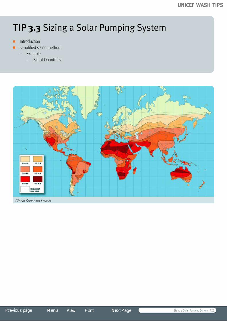
Sizing a Solar Pumping System : 125
TIP 3.3 Sizing a Solar Pumping System Introduction Simplified sizing method
– Example – Bill of Quantities
Global Sunshine Levels
UNICEF WASH TIPS

Sizing a Solar Pumping System : 126
Introduction
The mean daily water demand and the mean daily solar irradiation during the least sunny month need to be determined as the starting point for sizing a solar pump. Fig. 3.17 provides a quickindicationofpowerrequirements.Itshouldbenotedthatthe result is only an estimate and the graph should not be used for final sizing of the system
Simplified sizing method
Fraenkel and Thake give a simplified method for calculating the size of a solar system in their book Water Lifting Devices.1
The method provided here is an adaptation of their method that facilitatesaquickcalculationofthesolararray.
Sources such as the World Meteorological Organization publish irradiation figures for the whole world. Maps that cover large areas or whole regions can be used to make a reasonably accurate judgement of the irradiation for a particular location.
1 Peter Fraenkel and Jeremy Thake, Water Lifting Devices: A Handbook for Users and Choosers (Food and Agriculture Organization, 2006).
Solar Pumping
SqFLEX SolarThe Solar pump performance curves are based on:• Irradiation on a tilted surface• Ht = 6 kWh/m² per day• 20° tilt angle• Ambient temperature at 30°C• 20° northern latitude• 120V DC
Fig. 3.17 Solar pumping performance curves © Grundfos
UNICEF WASH TIPS

Sizing a Solar Pumping System : 127
Fig. 3.18 Sun hours map, Africa © Kyocera Inc
UNICEF WASH TIPS

Sizing a Solar Pumping System : 128
Fig. 3.19 Sun hours map, South America © Kyocera Inc
UNICEF WASH TIPS

Sizing a Solar Pumping System : 129
Fig. 3.20 Sun hours map, Asia © Kyocera Inc
UNICEF WASH TIPS
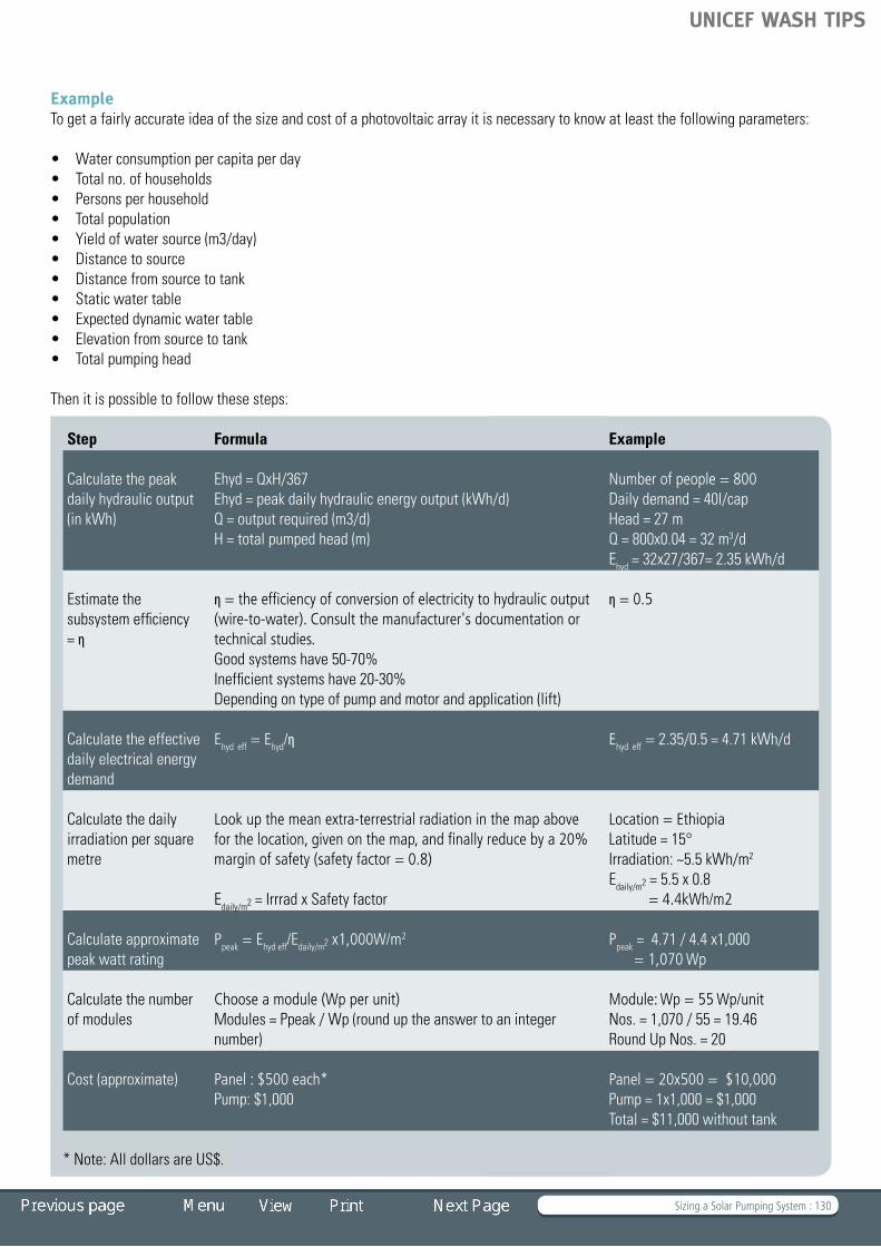
Sizing a Solar Pumping System : 130
ExampleTo get a fairly accurate idea of the size and cost of a photovoltaic array it is necessary to know at least the following parameters:
• Waterconsumptionpercapitaperday• Totalno.ofhouseholds• Personsperhousehold• Totalpopulation• Yieldofwatersource(m3/day)• Distancetosource• Distancefromsourcetotank• Staticwatertable• Expecteddynamicwatertable• Elevationfromsourcetotank• Totalpumpinghead
Then it is possible to follow these steps:
Step Formula Example
Calculate the peak daily hydraulic output (in kWh)
Ehyd = QxH/367Ehyd = peak daily hydraulic energy output (kWh/d)Q=outputrequired(m3/d)H = total pumped head (m)
Number of people = 800Daily demand = 40l/capHead = 27 mQ = 800x0.04 = 32 m3/dEhyd = 32x27/367= 2.35 kWh/d
Estimate the subsystem efficiency = η
η = the efficiency of conversion of electricity to hydraulic output (wire-to-water) . Consult the manufacturer's documentation or technical studies . Good systems have 50-70%Inefficient systems have 20-30%Depending on type of pump and motor and application (lift)
η = 0 .5
Calculate the effective daily electrical energy demand
Ehyd eff = Ehyd/η Ehyd eff = 2.35/0.5 = 4.71 kWh/d
Calculate the daily irradiationpersquaremetre
Look up the mean extra-terrestrial radiation in the map above for the location, given on the map, and finally reduce by a 20% margin of safety (safety factor = 0 .8)
Edaily/m2 = Irrrad x Safety factor
Location = EthiopiaLatitude = 15°Irradiation: ~5.5 kWh/m2
Edaily/m2 = 5.5 x 0.8 = 4 .4kWh/m2
Calculate approximate peak watt rating
Ppeak = Ehyd eff/Edaily/m2 x1,000W/m2 Ppeak = 4.71 / 4.4 x1,000 = 1,070 Wp
Calculate the number of modules
Choose a module (Wp per unit) Modules = Ppeak / Wp (round up the answer to an integer number)
Module: Wp = 55 Wp/unitNos. = 1,070 / 55 = 19.46Round Up Nos. = 20
Cost (approximate) Panel : $500 each*Pump: $1,000
Panel = 20x500 = $10,000Pump = 1x1,000 = $1,000Total = $11,000 without tank
* Note: All dollars are US$.
UNICEF WASH TIPS

Sizing a Solar Pumping System : 131
Many suppliers provide computer-based sizing tools that calculate the size of the system and recommend the system components that should be used. It is important to work with the designers or suppliers so they can customize the system according to the actual conditions. They can select the optimal pump for the application and the best-suited solar panels. PV pumping systems are often sold as complete packages, includingthepanels,sobuyingasystemisoftena“one-stop-shop”situation.
Bill of Quantities
Click on the BoQ to open an Excel Sheet
Bill of Quantities (Solar Pumping)
UNICEF WASH TIPS

Motorized and Small Piped Systems : 132
Motorized and Small Piped Systems 4 .1 Small Motorized Systems: Choice of Technology 4 .2 Technology Selection Tool 4 .3 Power Sources and Motorized Pumps 4 .4 Water Distribution
TIP 4
Guinea Bissau © Skat
UNICEF WASH TIPS

Motorized and Small Piped Systems : 133
Introduction
Small towns or groups of villages sometimes can be served more effectively by small motorized systems than by handpumps. A report by CREPA (Centre Régional pour l’Eau Potable et l’Assainissement à faible coût – Regional Centre for Potable Water and Low-cost Sanitation) in Burkina Faso shows that at 15 metres lift, handpumps provide cheaper water than motorized systems, for user groups up to about 1,000. The motorized systems become more economical at 40 metres lift, even with as few as 200 users. Although these calculations are dependent on the particular situation in Burkina Faso, they indicate that handpump installations can become less cost-effective with deep installations and large user groups.
Motorized SystemsInTIPStheterm“motorizedsystem”referstoasimplesystem that uses a pump powered by a diesel engine or electric motor to lift water, usually from a borehole. This is distinctfroma“smallpipedsystem,”whichalsoincludesamore complex piped distribution system. In some countries, motorizedsystemsarereferredtoasa“mechanizedsystems.”
There are many different ways of designing a motorized system, depending on the place where water is available, the depth, the population density and housing pattern, and many other aspects. It is therefore not possible to specify a standard system or even a standard approach. TIP 4 provides a general overview of the most common options.
This TIP contains an Excel-based spreadsheet to help in the choice of technology for motorized and small piped systems. It requiresspecificinformationaboutthekeyparametersofthevillage being served. This data would be compiled during a participatory assessment of the village. Using the technology selection tool, the typical results (cost indicators) for investment costs and operation and maintenance costs can be immediately calculated and discussed with the community. Thus, the community has a good indication of the cost implications and can make an informed decision on technology choice.
References and Further Reading
Hofkes, E.H., ed. 1981. Small Community Water Supply. The Hague: International Reference Centre for Community Water Supply and Sanitation
Skinner, Brian. 2003. Small Scale Water Supply, A Review of Technologies. WEDC/LSHTM
Smet, Jo and Christine van Wijk, eds. 2002. Small Community Water Supplies: Technology, People and Partnership. Delft: IRC
UNICEF. 2009. UNICEF Training Module on Household Water Treatment and Safe Storage (HWTS). UNICEF
UNICEF. 2008. UNICEF Handbook on Water Quality. New York: UNICEF
Water Transmission and Distribution, Third Edition. 2003. Denver, CO: American Water Works Association
WSP and RWSN. 2006. Ten-step Guide Towards Cost-effective Boreholes: Case Study of Drilling Costs in Ethiopia. http://www.rwsn.ch/documentation/skatdocumentation.2007-06-04.3136351385/file
Wurzel, Peter. 2001. Drilling Boreholes for Handpumps. Skat
Websites
Geographic Information System (Modelling Software). http://opengis.net/gml/01-029/GML2.html
Water Supply and Sanitation in Emergency Situations. http://www.irc.nl/page/10524
Types of Fluid Flow Meters. http://www.engineeringtoolbox.com/fluid-flow-meters-t_49.html
UNICEF WASH TIPS

Small Motorized Systems: Choice of Technology : 134
TIP 4.1 Small Motorized Systems:Choice of Technology
System design options Groundwater-based systems Typical cost for small water supply systems
– Hand-dug wells, hand-drilled boreholes – Machine-drilled boreholes (high- or low-yielding, small or large diameter) Rules of thumb for choice of technology
– Handpumps – Electrical pumps powered from the grid – Diesel pumps – Solar pumps – Bill of Quantities
Eritrea © Skat
UNICEF WASH TIPS

Small Motorized Systems: Choice of Technology : 135
System design options
Under a demand-responsive approach, all options are open and communities have the opportunity to choose from the lowest levels of service up to the highest levels of service. Technology selection needs to be carried out carefully. Many examples of failed and abandoned water sources are attributable to an improperchoiceoftechnology.Similarly,frequentbreakdownsofequipmentduetotechnicalandfinancialresourcesnotmatchingthemaintenancerequirementscannegativelyaffectsustainability.
Identification of options with the potential to meet community demandrequiresanin-depthanalysisofpeople’sobjectivesandexpectations. This should involve communities themselves.
In theory there are many design options for water supply systems using a wide range of technologies. In practice, the feasible technology options available to communities are limited. Local hydro-geological conditions, strategic decisions at national level (including standardization rules), project execution policies and cost considerations restrict the choice. Often communities have only one or two options to choose from. However, even with limited options, communities should make the final choice, with external support to ensure that this choice is an informed one. The support agencies that work with the
communities during the extension phase (NGOs, CSOs, district authorities, etc.), need to explain the available options that are technically feasible, and build up an understanding of the characteristics and implications of the technologies to facilitate decision-making.
Resource constraints make cost considerations an important factor in many developing countries. Appropriate and effective low-cost technologies and approaches should be given priority to ensure that basic levels of services are provided to all, including both the rural and urban poor.
Where geological conditions permit, professionally constructed hand-dug wells or hand-drilled boreholes that remain operational in the dry season are in many instances the lowest cost option for small rural communities. However, in many areas the hydro-geological conditions do not allow hand digging or drilling and the more expensive option of machine-drilled boreholes will be necessary. In many cases, handpumps remain the most viable option available to communities. However, in some cases hand-dug wells and machine-drilled boreholes can be fitted with a variety of motorized water-lifting devices, some of which are discussed below. The matching of the water source (borehole/well) and the pumping device is often a determining factor for the success of an installation.
Groundwater-based systems
Only the most common systems used in small rural water supply systems are described in this TIP. All of these systems are based on groundwater extraction. These options are described in the form of packages of system compenents.
A piped system has more components and is thus more sophisticated than a handpump/borehole system (which consists of only two components). A piped system can have several main
Fig. 4.1 Drawing water, Uganda © Skat Fig. 4.2 The water supply ladder © RWSN, Skat
90% subsidised community supplies
Larger contractors
Local artisans
Sub-contracting services
0% subsidised household supplies
End user affordable steps
Donor dependent step
Water supply ladder
UNICEF WASH TIPS
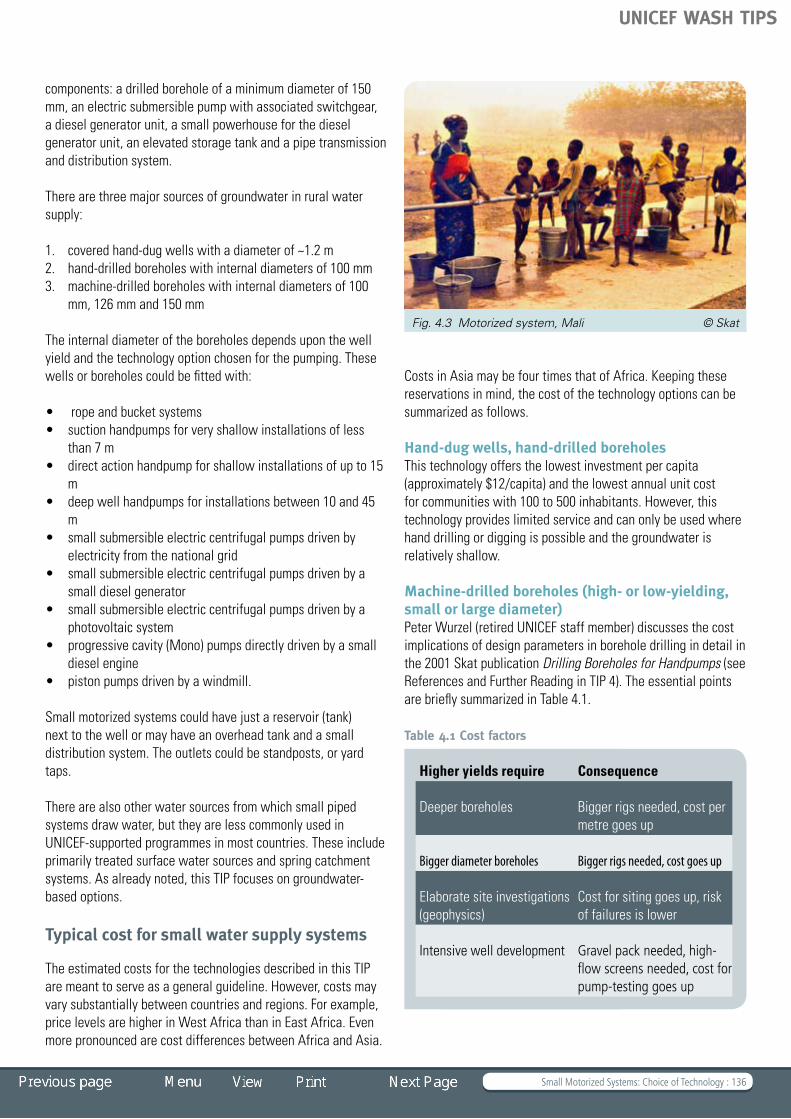
Small Motorized Systems: Choice of Technology : 136
components: a drilled borehole of a minimum diameter of 150 mm, an electric submersible pump with associated switchgear, a diesel generator unit, a small powerhouse for the diesel generator unit, an elevated storage tank and a pipe transmission and distribution system.
There are three major sources of groundwater in rural water supply:
1. covered hand-dug wells with a diameter of ~1.2 m2. hand-drilled boreholes with internal diameters of 100 mm 3. machine-drilled boreholes with internal diameters of 100
mm, 126 mm and 150 mm
The internal diameter of the boreholes depends upon the well yield and the technology option chosen for the pumping. These wells or boreholes could be fitted with:
• ropeandbucketsystems• suctionhandpumpsforveryshallowinstallationsofless
than 7 m • directactionhandpumpforshallowinstallationsofupto15
m• deepwellhandpumpsforinstallationsbetween10and45
m • smallsubmersibleelectriccentrifugalpumpsdrivenby
electricity from the national grid• smallsubmersibleelectriccentrifugalpumpsdrivenbya
small diesel generator • smallsubmersibleelectriccentrifugalpumpsdrivenbya
photovoltaic system • progressivecavity(Mono)pumpsdirectlydrivenbyasmall
diesel engine• pistonpumpsdrivenbyawindmill.
Small motorized systems could have just a reservoir (tank) next to the well or may have an overhead tank and a small distribution system. The outlets could be standposts, or yard taps.
There are also other water sources from which small piped systems draw water, but they are less commonly used in UNICEF-supported programmes in most countries. These include primarily treated surface water sources and spring catchment systems. As already noted, this TIP focuses on groundwater-based options.
Typical cost for small water supply systems
The estimated costs for the technologies described in this TIP are meant to serve as a general guideline. However, costs may vary substantially between countries and regions. For example, price levels are higher in West Africa than in East Africa. Even more pronounced are cost differences between Africa and Asia.
Costs in Asia may be four times that of Africa. Keeping these reservations in mind, the cost of the technology options can be summarized as follows.
Hand-dug wells, hand-drilled boreholes This technology offers the lowest investment per capita (approximately $12/capita) and the lowest annual unit cost for communities with 100 to 500 inhabitants. However, this technology provides limited service and can only be used where hand drilling or digging is possible and the groundwater is relatively shallow.
Machine-drilled boreholes (high- or low-yielding, small or large diameter)Peter Wurzel (retired UNICEF staff member) discusses the cost implications of design parameters in borehole drilling in detail in the 2001 Skat publication Drilling Boreholes for Handpumps (see References and Further Reading in TIP 4). The essential points are briefly summarized in Table 4.1.
Table 4.1 Cost factors
Higher yields require Consequence
Deeper boreholes Bigger rigs needed, cost per metre goes up
Bigger diameter boreholes Bigger rigs needed, cost goes up
Elaborate site investigations (geophysics)
Cost for siting goes up, risk of failures is lower
Intensive well development Gravel pack needed, high-flow screens needed, cost for pump-testing goes up
Fig. 4.3 Motorized system, Mali © Skat
UNICEF WASH TIPS

Small Motorized Systems: Choice of Technology : 137
The sufficient well yield for a handpump is about 1 m3/h. This allows a simplified specification for the borehole, which can reduce cost considerably. This type of simplified borehole can not be fitted with a motorized pumping system, however, and it can only serve up to 500 persons.
Thus, when yields of 5-10 m3/h are needed (to serve larger communities) more sophisticated drilling technologies are used, and boreholes are fitted with a motorized pump. Such a system can serve 1,000 to 2,000 or more people.
Peter Wurzel argues that if a mismatch is specified between the pumping device and the borehole (i.e. a handpump fitted on an over-specified borehole), the cost of the water source can easily be twice as high as necessary. This issue is also discussed in the WSP/RWSN publication Ten-step Guide Towards Cost-effective Boreholes (see References and Further Reading in TIP 4).
It is thus clear that larger boreholes should only be drilled when it is economically and technically feasible to install motorized systems, and when communities are willing and able to pay the higher operation and maintenance costs inherent in motorized systems. The challenge for water supply programmes is in managing a realistic mix of technologies that are cost-effective, fulfil the demands of the users, and ensure that the poor are also served.
Rules of thumb for choice of technology
Note that these observations are general and need to be verified under local conditions.
HandpumpsAs a rule, for smaller communities with 50 to1,000 inhabitants, point sources with handpumps are the most economical choice and should be preferred. For larger communities with a population exceeding 1,000 inhabitants, motorized systems with either standposts or yard taps might be feasible.
Electric pumps powered from the gridWhere reliable power is supplied from the grid, boreholes with electric submersible shaft-driven pumps become economically feasible (both in terms of investment per capita and the cost per m3 of water pumped) for communities of 2,500 and larger. The cost will decrease for larger communities due to economies of scale.
However such systems are less economically viable in situations where there are long distances from the grid to the pump site, where the community is far away from the pump site, or where population densities are low. Under these conditions, handpumps, a diesel generator, or a solar pump system may be more cost-effective, even for larger communities.
Diesel pumps For a community with 1,000 to 2,500 inhabitants, the investment cost of a motorized pump powered by a diesel would be almost identical to the cost of a system with electricity supply from a grid, because the extra cost for the diesel generator is greatly offset by the cost of the power line. However, the annual running cost would be about 20 to 25% higher for the system with the diesel generator. The electricity from the grid normally costs far less than the fuel for the diesel generator. A diesel generatorrequiresincreasedservicingandmaintenanceandmayrequireafull-timeoperator.Dieselgeneratorsystemshavethe advantage that they are independent from a grid, which may be some distance away from the well site, and may provide low voltage or intermittent electricity.
Solar pumpsSolar pumps have a high potential for communities with between 1,000 and 2,000 inhabitants, especially when the pumping head is low (shallow- to medium-depth boreholes, and the use of ground-level reservoirs). At present small solar systems with up to about 1,600 Wp (watt-peak) panel size are of interest, because of their acceptable cost and proven reliability. However“acceptablecost”isarelativeterm:photovoltaicsolarpanelsarestillquiteexpensive,whichresultsinhighcapitalcosts that continue to be a deterrent for solar pumping systems.
Fig. 4.4 Ten-step Guide Towards Cost-effective Boreholes
UNICEF WASH TIPS

Small Motorized Systems: Choice of Technology : 138
Solarpumpsystemsaresensitivetothepowerrequirementsfor high pumping heads. At a daily irradiation of 4.5 to 5.0 kwh/m2/day, the output of a 1,600 Wp plant when pumping against a head of 35 metres would be about 25 m3/day, supplying 1,200 people. And when pumping against 20 metres total head, about 45 m3/day can be expected, supplying 2,000 people. The lower pumping head would decrease the investment cost by nearly 50%.
For communities with 1,200 inhabitants, the solar-pump option can be lower in annual cost than both diesel generator and handpump systems; it would even be competitive with grid systems. (See TIP 3 for a complete description of solar pumping systems.)
Bill of Quantities
Click on the BoQ to open an Excel Sheet
Bill of Quantities (Small Piped Systems)
UNICEF WASH TIPS

Technology Selection Tool : 139
TIP 4.2 Technology Selection Tool
Computer-supported Cost Calculation Programme
This TIP contains an Excel-based spreadsheet to help in the choice of technology for motorized and small piped systems. Itrequiresspecificinformationaboutthekeyparametersof the community being served. The data can be compiled during a participatory assessment of the community. Using the technology selection tool, the typical results (cost indicators) for investment costs and operation and maintenance costs can
be immediately calculated and discussed with the community. Thus, the community has a good indication of the cost implications and can make an informed decision on technology choice.
Should you decide that handpumps are the most effective option, refer to TIP 1 Handpumps for Drinking Water. If motorized pumps are the more likely options, read more about them in TIP 4.1 and TIP 4.3.
UNICEF WASH TIPS

Power Sources and Motorized Pumps : 140
TIP 4.3 Power Sources and Motorized Pumps Power sources for pumps
– AC mains power – Internal combustion engines – Windmills Motorized pumps (for boreholes)
– Submersible pumps (for boreholes) – Jet pumps – Wind-powered pumps Common diesel pump configurations
– Diesel engine with progressive cavity (Mono) pump – Diesel engine with submersible pump – Diesel engine with centrifugal pump
Motorized Pump © Skat
UNICEF WASH TIPS

Power Sources and Motorized Pumps : 141
Power sources for pumps
AC mains powerFor low power connections up to 10 kilowatts (kW), mains electricity is normally supplied as single phase alternating current(AC)eitherat220volts(V)and50hertz(Hz)frequency(Europe, Africa and Asia) or at 110 V and 60 Hz (North America). For high power connections over 10 kW, three-phase power is usually supplied at 380 V.
Small electric motors in the 100 to 200 W range are widely available and used in large numbers. Most areas have people who can repair (rewind) an electric motor. The motors run onafixedspeed,dependingontheelectricfrequency(1500revolutions per minute, rpm, at 50 Hz or 1800 rpm at 60 Hz). Often, the motor is directly coupled to the pump, which is specifically designed to run optimally at the predetermined speed of the motor. Energy efficiency is about 75% for small motors and 90% for large motors.
Electricity is potentially lethal; therefore electrical installations need to be professionally carried out with the appropriate protectionequipment,suchasfuses,armouredcables,earthed(grounded) and splash-proof switches.
As discussed in TIP 4.1, if there is a reliable power supply from the AC grid to the community, and the community has a population of about 1,200 the investment costs per capita are inthesamerangeasboreholesequippedwithhandpumps.Forlarger communities the cost will sharply decrease. However, the borehole yield must be sufficient to serve the larger user group.
Internal combustion engines The two main types of engines are diesel and petrol. For rural water supply applications, petrol engines have several disadvantages. The fuel is highly flammable and explosive fumes can develop. The reliability and efficiency of petrol
engines is also lower than that of diesel. The reason petrol engines are so common in vehicles is because they are generally lighter than diesel engines, but this is not significant in the stationary applications of water supply.
Diesel engines draw air into the cylinder and compress the air during the up-stroke of the piston. This heats the air to about 450º C. The fuel is injected as highly atomized spray when the piston reaches the top dead centre. The diesel fuel ignites spontaneously at this temperature; therefore no ignition systems with electrically controlled spark plugs are needed.
Typical diesel engines for stationary applications run at about 1,200 to 1,400 rpm. Engines for pumping applications should run at about 70 to 80% of their rated power. If a 5 kW engine is used, the safe continuous power output is in the range of 3.5 to 4 kW.
Fig 4.5 Big electrical pumps, Indonesia © Skat
Fig 4.6 Diesel generator © Skat Fig. 4.7 Petrol generator © Briggs and Stratton
UNICEF WASH TIPS

Power Sources and Motorized Pumps : 142
Both four-stroke and two-stroke engines exist; however, diesel engines for pumping purposes predominantly use the four-stroke cycle. The cooling system is very important in diesel engines, and both air- and water-cooling systems are common. A safety device can be installed to automatically cut off the fuel supply when the engine is overheating.
Dieselenginesforwatersupplyneedtobeofgoodquality.The private sector offers a wide range of engines and pumps ofvariablequalitylevels.Thecostfora6HPdieselenginerangesfrom$300toabout$1,000.Accordingly,thequalityandthe reliability of these systems are diverse. A good engine runs for about 8,000 to 10,000 hours if all the necessary service and maintenance has been carried out.
Themaintenancerequirementsaresignificant;oillevelchecksneed to be done daily. Changing the engine oil, fuel and oil filters must be done at regular intervals. The increased servicing andmaintenancedemandsforadieselengineoftenrequireafull-time operator. And someone must ensure that enough fuel and lubricants are always available. Diesel fuel is normally more expensive than electricity from the grid. Overall, the annual cost when using a diesel engine is about 25% higher than when using an AC mains system.
Diesel-driven pumps have the advantage that they are independent from a grid, which may be far away from the well site, or may supply irregular, unreliable electricity. In these situations, the investment cost for a community with 1,200 inhabitants would be almost identical with the cost for the systems with electricity supply from the grid – the extra cost for the diesel generator being offset by the cost for the power line. However, the higher running cost and the need to set up a regular supply of consumables are disadvantages.
WindmillsA windmill is a machine that converts the energy of the wind into more useful forms using rotating blades. The rotor is normally fitted on a tower to reach a level where wind speed is notreducedbytrees,buildingsorotherobstacles.Goodqualityand reliable windmills are available. Many installations serve farms in Australia and South Africa, for example. Windmills are often manufactured in small local shops, but many of these “appropriatetechnology”designsdonotwithstandthehighforces of stormy weather.
A windmill system offers little advantage in terms of capital costs. However, for medium-size communities, it can provide a basic service, zero fuel costs and generally low operational cost.
Sufficientdataonlocalannualwindspeedpatternsisrequiredbefore a windmill can be considered. Windmill pumping systems alsorequirealargestoragetanktoensurereliabilityofwatersupplies in periods with no wind.
Motorized pumps (for boreholes)
There are three main types of motorized pumps that are suitable for boreholes:
1. Submersible pumps2. Line shaft pumps3. Jet pumps
The standard power sources possible for these three pump types are:
a) Electric AC mains from the gridb) Diesel enginesc) Petrol engines d) Solar-powered pumpse) Wind-powered pumps
Fig. 4.8 Windmill © Skat
UNICEF WASH TIPS

Power Sources and Motorized Pumps : 143
Submersible pumps (for boreholes)A submersible pump is designed so that it can be inserted into the well casing and lowered to the bottom of the well. These pumps have a hermetically sealed motor that is directly attached to the pump body. The whole assembly is submerged in the water.
The key advantage of this type of pump is that because it operates from inside the borehole, it is not limited by suction head constraints (a maximum of 7 m at sea level, less at higher elevations), and thus can lift water from deep boreholes into tall overhead tanks. For this reason, submersible pumps are very common.
This pump type is mainly used where electric power is available, including within a solar pumping system.
Fig 4.9 Submersible pumps and motors © Skat
Fig. 4.10 Submersible pump © Skat
The down-the-hole part of a submersible pump is comprised of an electric motor hermetically enclosed in a stainless steel sleeve coupled with either a centrifugal pump or a progressive cavity pump (see below). Water is pumped either through a rising main made of galvanized iron (GI) or stainless steel pipes or through a plastic (PVC-HI) hose. The pump is suspended in the well on the rising main itself, or in the case of a plastic hose arrangement, by a stainless steel cable. Submersible pumps alsorequireanelectricalcableforconnectingthemotortothepower source, and a starting panel.
Centrifugal pumps are“rotodynamic”pumps,whichusearotating impeller to convert mechanical energy into hydraulic energy. The impeller increases the velocity of the fluid and the vanes in the casing of the pump, and then convert this velocity into a rise in pressure. The pumps usually have multiple
UNICEF WASH TIPS

Power Sources and Motorized Pumps : 144
impellers. Pump size selection is important: significant energy is wasted if the pumps are operated outside of their optimal running range.
Progressive cavity pumps cause the water to move through the pump by trapping a fixed amount of fluid and forcing that trapped volume into the discharge pipe. The pump consists of a single helix rotor inserted into a double helix stator. When the rotor is turned, these voids are moved along the axis of rotation through a screwing action. The water is contained in the voids and when the rotor turns water is pushed upwards and discharged into the rising main. The rotor helix is made of chromium plated steel or polished stainless steel. It is circular in cross section so that it fits exactly into one of the two helices of the stator.
Progressive cavity pumps produce a constant flow and the small diameter pumps used in boreholes are considerably more efficient than centrifugal pumps. For solar systems, it is important to note that progressive cavity pumps have high startingtorque.
Various sizes of submersible pumps are available, which can beinstalledincasingswithdiametersof3”,4”,6”,8”,10”and12”.
Line shaft pumpsLine shaft pumps have an above-ground motor or engine attachedtoadown-the-holepumpwitharotating“lineshaft.”The speed of the motor is directly applied to the pumping element by the line shaft. Gearboxes or V-belt drives can be used for speed adjustments. Various motor types can be used
to drive the pumping element (e.g. diesel engine, petrol engine, electric motor).
Line shaft pumps can be combined with various drive configurations:
Electrical motorsa) can be placed directly on top of the drive head b) can be attached at the side and connected with a V-beltc) can be connected directly with a right angle gear, placed on
top of the drive head.
Diesel or petrol enginesa) can be placed next to the drive head and connected with a
V-belt Fig. 4.12 Line shaft pump with diesel engine © Skat
Fig. 4.11 Line shaft pump © Skat
UNICEF WASH TIPS

Power Sources and Motorized Pumps : 145
b) can be connected directly with a right angle gear, placed on top of the drive head.
Various types of pumping elements can also be used, but most common are:
a) Vertical turbine pumps similar to the submersible pumpsb) Positive displacement unit, progressive cavity pumps
(Mono).
Jet pumpsA jet pump is a type of an impeller-diffuser pump. About half of the drawn water is split in the diffuser and sent back to the well with high pressure through the pressure pipe. At the end of the pressure pipe, the water is accelerated through the cone-shaped nozzle and guided through the mixing chamber with high speed (using the Venturi principle).The pinched section of the mixing chamber causes a pressure drop, which sucks in more water
from the ejector body and intake. The water goes up the return pipe and through the impeller into the diffuser, where one part is sent back to the jet nozzle and the other part is directed into the delivery pipe.
Jet pumps are relatively inefficient but can tolerate a wide range of operating conditions, including abrasive fluids such as water with high sand contents. This robustness makes them quitepopularinsomecountries.Jetpumpsdonothavemanyworking parts and therefore are easy to operate and maintain.
Wind-powered pumpsWind power has been used for many centuries to pump water. In the past, most wind turbines were mechanically coupled directly to the water pump. Most wind pumps for water pumping have a multi-bladed rotor on a horizontal axis, which must be oriented to face into the wind to extract power.
The rotation of the rotor is transformed to a reciprocating movement, which can be connected to a piston located in the pump cylinder at the bottom of the borehole or well.
Fig. 4.13 Jet pump with electric motor © Skat Fig. 4.14 Jet arrangement © Skat
UNICEF WASH TIPS

Power Sources and Motorized Pumps : 146
In some cases, the horizontal rotation can also be reduced and changed into vertical rotation by a gearbox, which drives a line shaft that is directly connected to a displacement unit at the bottom of the borehole.
Wind-driven pumps for water pumping are often applied at high heads, typically 10 to 100 metres.
Alargewaterstoragetankisrequiredtoensurewatersupplyduring times when the pump is not running due to low winds.
Common diesel pump configurations
Diesel engine with progressive cavity (Mono) pumpProgressive cavity pumps are often referred to by the manufacturers’ name; such as Mono pump, Moyno pump and Nemo pump. This configuration is the most common system of motorized pumps used in the water sector for small systems. Mono pumps are often sold in a pump-set including a Lister diesel engine. This configuration is generally considered to be robust and reliable, with generally low maintenance requirements.
However, because a line shaft is used, these pump-sets can only be used on straight (vertical) boreholes. Lister engines have a good reputation for use in tropical climates and are very familiar to local mechanics. And because they are purely mechanical devices,noelectricalexpertiseisrequired.Themaintenanceofthe diesel engines is well within the capacity of operators.
Diesel engine with submersible pump In this configuration, diesel engines power a generator to produce electicity to run the submersible pump. The engine-generator unit is called a gen-set.This system is both versatile and efficient: it works on all types of boreholes and can be highly optimized for maximum efficiencies. Gen-sets used in rural water applications are of various origins. Lombardini, Lister and VM are common brands. The most commonly used submersible pump brand is Grundfos.
The small portable diesel generators for rural water supply gen-sets range from about 1kVA to 10kVA, while the larger industrial generators can range up to 2000kVA.
Fig. 4.15 Windmill pump © Skat Fig. 4.16 Progressive cavity pump, Eritrea © Skat
UNICEF WASH TIPS

Power Sources and Motorized Pumps : 147
The performance of the diesel gen-set/submersible pump configuration is good, provided the operation and maintenance of the diesel engine is carried out properly. Submersible pumps themselvesrequireverylittlemaintenance.
Diesel engine with centrifugal pumpCentrifugal pumps driven by a diesel engine are often used on open dug wells. Most irrigation pumps are of this variety. This
Fig. 4.17 Generator for submersible pump, Eritrea © Skat Fig. 4.18 Centrifugal pump, diesel driven © WSK
type of pump is not suitable for use in boreholes. The maximum lift of these pumps is restricted to the maximum suction lift of approximately 7 metres. However, they can be used for pumping water up from an open well or river to high-level reservoirs.
If not fitted properly over an open well, the risk of contamination by oil spills entering the well is considerable.
UNICEF WASH TIPS

Water Distribution : 148
TIP 4.4 Water Distribution Water distribution
– Components for a supply network – Gravity supply – Technical feasibility – Surveying – Design of the system – Canals – Free-flow pipelines – Pressure pipelines – Flow rate design considerations – Pressure – Hydraulic design and calculations
of a pressure pipeline – Pumped supply – Water demand – Water reservoirs – Distribution systems – Branched system – Looped system – House and yard connections – Public standposts – Bill of Quantities
Annex: Components and Fittings – Pipes and fittings – GI pipes, galvanized – GI fittings – UPVC pipes – HDPE pipes – Valves – Taps – Water meters Installation
– Information on jointing UPVC pipes and fittings – Solvent cementing – Information on jointing HDPE pipes and fittings – Fusion jointing – GI pipes, galvanized – GI fittings – UPVC pipes – UPVC fittings – HDPE pipes – HDPE fittings (made of polypropylene) – Valves – Taps – Other components – Booster pumps
Uganda © Skat
UNICEF WASH TIPS

Water Distribution : 149
Water distribution
Components for a supply networkThe design components of a supply network consist of the following:
Source: The water may be from surface water (river or lake) or groundwater (spring or borehole). It is important to prevent pollution at source or during transport in order to reduce the amount of treatment needed later.
Intake: Some simple treatment may take place at the intake, such as coarse screens or aeration. In some cases this may include storing the water in a tank or reservoir for a period of time, allowing solids to settle to the bottom and scum to float to the top. This process can be enhanced by mixing a coagulant into the water to make small solids settle faster.
Water transmission (mains pipes): In a supply network, the water is conveyed from the intake to the area of distribution throughatransmissionlineor“mains.”Inmostcases,waterisconveyed to a reservoir, from which it enters a treatment plant and/or the distribution network. Depending on the topographic situation and local conditions, the transmission of water will be either by gravity or by pumping. In gravity schemes, water flows naturally from the higher elevation intake to the lower point of use. If the intake is at a lower elevation than the reservoir, the water has to be pumped.
The conveyance of water through the mains is either through free-flowing conduits (an open canal or a free-flow pipeline) or through pressurized pipes, the latter being more common for drinking-water systems. Relatively short gravity transmission mains are the norm for most small community water supply systems in developing countries: costs are often prohibitive when there are long distances between the intake and the consumer,andwhenpumpingisrequired.
Water treatment: Surface water normally needs treatment sinceitisseldomofdrinking-waterquality.Treatingsystemsinvolve several components including various types of filtration, chemical or ultraviolet (UV) disinifection and possibly other stages.Waterqualitygenerallyandwatertreatmentspecificallyare not covered in the TIP. For more information, see the UNICEF Handbook on Water Quality and IRC’s Small Community Water Supplies listed in the References and Further Reading in TIP 4.
Storage: Water storage allows the system to handle water demand fluctuation and provides water for use in emergencies, such as fire fighting or short interruptions of the supply due to pump breakdown or overhaul.
Distribution: In small-piped water systems water is conveyed from the storage tank/reservior to community standpipes or
household taps through a distributution network consisting of pipes and fittings laid in trenches. The distribution network can also include various types of control valves, pressure release devices, water meters and other fittings.
Gravity supplySmall community water supplies often use gravity to convey water from the intake to consumers, either through free-flow conduits or pressure pipelines.
Free-flow conduits can be open channels or pipes that are not completely filled with water. They must be constructed in such a way that the slope follows the hydraulic grade line (see Fig. 4.22).
For pressure pipelines, the hydraulic gradient (static pressure minus friction head) determines the water flow and the design of the pipeline. Within certain limits pressure pipelines do not have to follow the hydraulic grade line; they can run both uphill and downhill, as long there is sufficient head (pressure) to maintainadequateflow.
Pressure pipelines are the most common solution for water transmission,buttheyusuallyrequireaconsiderablecapitalinvestment. Careful review of all potential alternatives and technical options and weighing up their costs is necessary when choosing the best option in a particular case.
Technical feasibility Likeallwatersystems,gravitysystemsrequireacommunityevaluation and feasibility study. These planning steps consist of a population survey, review of current water sources, and the investigation of the potential sources (springs, small streams and rivers). Key technical parameters to determine are safe yield and maximum flow. Safe yield is the minimum flow during the dry season while maximum flow is the maximum. Both
Fig. 4.19 Water transmission © Skat
UNICEF WASH TIPS

Water Distribution : 150
parametersarerequiredtodeterminepipelineandreservoirdesign, structural protection measurements and overflow requirements.
Thewaterqualityofthesourceneedstobecarefullychecked,taking into account seasonal changes. If the source is contaminated (or the water is turbid), suitable water treatment schemes will have to be introduced.
Finally, water rights need to be resolved to ensure that the rights of all people who are depending on the source water are taken into account.
SurveyingA topographic survey must be carried out along the proposed pipeline route. Such a survey can be done using a theodolite, barometric altimeters or Abney hand levels (and, in some cases, GPS-based instruments). Surveying also includes observations on ground conditions, keeping in mind the need to dig trenches.
Design of the systemOnce the profile of the gravity flow system has been plotted and the final pipeline sizing has been determined, the detailed design of system components takes place. These components may consist of the following: intake structures (including sedimentation tanks), reservoir tanks, break pressure tanks, valve boxes, control valves, air vents, special components (such as suspended crossings over gullies), and tap stands. The design should include: lists of all materials needed (including locallyprovidedsupplies),listsoftoolsandequpmentneededfor construction, logistics arrangement for on-site delivery of materialsandequipment,andestimatedlabourrequirements.The total system cost budget is calculated based on this information.
CanalsCanals are often used to transport water for irrigation. However, for drinking water supply open flow canals should only be considered when no other options are available due to susceptibility to contamination. In cases where canals are used for transmission, they should only be used for the conveyance of raw water before entering the treatment system.
Free flow channels should have a uniform slope following a gentle grade line. If the water flows too fast it may erode the embankments, especially of unlined canals.
Free-flow pipelinesFree-flow pipelines are unpressurized like canals, but offer much better protection against pollution.
The other main advantage of free-flow pipelines is that unlike with pressure mains, pipes can be made from simple materials like sheet metal, inexpensive types of plastic, glazed clay pipes, or concrete. These pipelines must closely follow the hydraulic grade line.
Fig. 4.20 System layout
Source no.1 Source no.2
Tap no.4Tap no.1
Tap no.2Tap no.3 Tap no.5
School
Tap no.6
Collection tank
Reservoir
Police post
Branchline valvebox
Stream crossing
Fig. 4.21 Open channel © Elena Vieques
UNICEF WASH TIPS

Water Distribution : 151
Pressure pipelinesIn a pressure pipeline a positive pressure is maintained, and pipes can run uphill within certain limits. This allows a design in which the pipeline can follow the general level of the terrain, making it far easier to construct (see Fig. 4.21). The other key advantage of a pressure pipeline is that the water is protected from contamination. Because of the pressure involved, these pipelines must be constructed with more expensive pressure-rated pipes and the design often includes special fittings including pressure relief valves or tanks, air valves, and drain valves. This increases the cost of the pipeline.
Flow rate design considerationsNormally water is stored in a reservoir or storage tank before it is released into the distribution network. The tank is necessary to maintain water availability even though the demand varies a great deal during the day with peaks in the mornings and the evenings.
The reservoir is supplied from the transmission main. It is placed on an elevated position or on top of a tower to allow it to supply the distribution system by gravity. The transmission main is dimensioned so that the water flows at a constant rate. The design flow rate is calculated based on average demand per hour, but it must be sufficient to supply the tank with enough water to meet peak period demands. The reservoir must be large enough to provide water security for 1 to 2 days to allow for service interruptions, maintenance and repair (this is especially important for pump-based systems, but also true for gravity systems).
PressureThe hydraulic grade line indicates the water pressure in the pipeline under operating conditions. Over the full length of the pipeline the hydraulic grade line should always be above the pipeline. To ensure constant flow the operating head of water in the pipeline should never be less than 4 to 5 m above the hydraulic grade line (see Fig. 4.24).
As long as the water is flowing the pressure in the transmission pipe can be kept at a relatively low level. However, if the pipeline is shut the static pressure will reach the maximum at the lowest level of the pipeline. Thus the designed maximum static pressure must be limited to the pressure rating of the pipe.
Break-pressure tanks can be used to limit the pressure (see Fig. 4.23). These tanks are small reservoirs that have a surface open to the air (i.e. unpressurized). Thus the pressure in the pipe above the break-pressure tank is limited to the elevation between the source and the tank. To prevent overflowing of the tank the inflow can be reduced.
Significant pressure peaks occur when the flow in the pipe suddenly stops (rapid closure of a valve) or suddenly increases (sudden start of the pump in non-gravity systems). This pressure surgeiscalled“waterhammer.”Itcancausewavesofover-orunder-pressure far above or below the design pressure. Water hammer can be so severe that it can damage the pipeline. Water hammer can be dealt with within the design through the use of break-pressure tanks as well as special surge chambers (that usecompressedairto“cushion”peakpressuresinpipelines).Inaddition, valves in the mains should be designed in such a way that rapid closure and opening is not possible.
Hydraulic design and calculations of a pressure pipelineThe design of pressure pipelines is complex. Specialized firms orqualifiedinvidivualsshouldbecontractedfortheoveralldesign and for calculating all details of a pressure pipeline (e.g. hydraulic grade line, head loss, position of air valves, break-pressure tanks, pipe sizes). A variety of design software is available for designing and calculating pressure pipelines, as well as distribution systems.
Fig. 4.23 Pressure pipeline © Skat
Fig. 4.24 Minimum pressure gradient © Skat
Fig. 4.22 Free flow pipeline © Skat
UNICEF WASH TIPS

Water Distribution : 152
Pumped supplyAlthough TIP 4 is primarily concerned with gravity systems, there are instances where UNICEF programmes are involved in pump-based systems. In some cases hybrid systems use both gravity and pumping at different points of the system.
The key design consideration for pumped systems is that when water is pumped to a higher elevation the pumping effort requiredisthetotalheadplusthefrictionheadlossinthepipeline. The friction head loss for a given flow rate can be calculated based on the diameter(s) of the pipes used (smaller pipes create higher losses than bigger pipes because the water speed is greater), the type of pipe material (different materials have different friction coefficients) and the number and types of fittings used (fittings also introduce friction losses to a system). The pump is chosen based on the design flow and pressure requirement,takingintoaccountoverallfrictionheadloss.
Water demandAlthough design software is used for carrying out water demand calculations, the key elements are described briefly below.
The daily water demand in a community area varies during the year due to such things as seasonal climate patterns, national norms and standards, seasonal variations in water use (e.g. during harvest), and cultural and religious occasions.
The maximum daily demand is usually estimated by adding 10 to30%totheaveragedailywaterdemand.Thisgivesa“peakfactor”(k1)forthedailywaterdemandof1.1to1.3.
The hourly variation in the water demand during the day is normally much greater than variations from one day to the next. Generally, two peak periods can be observed, one in the morning and one in late afternoon (see Fig. 4.26).
The peak hour demand can be expressed as the average hourly demand multiplied by the hourly peak factor (k2).
For a particular distribution area this factor depends on the size and character of the community served. The hourly peak factor tends to be high for small rural villages; it is usually lower for larger communities and small towns.
Where household roof tanks or other home water storage vessels are common, the hourly peak factor will be further reduced. Usually the hourly peak factor (k2) is chosen in the 1.5 to 2 range.
A water distribution system typically is designed to cater to the maximum hourly demand. This peak hour demand may be computed as k1 x k2 x average hourly demand.
Water reservoirsWtihout some means of storing water within the water supply system, the water source (and the water treatment plant) must be sufficient to meet all fluctuations of the water demand of the community served. This is generally not economical, and often not even technically feasible. Thus most systems use water reservoirs (usually built in-ground or on the ground) or tanks (usually elevated) in one or more places within the system.
The service reservoir is provided to balance the (constant) supply rate from the water source or treatment plant with the fluctuating water demand in the distribution area. The storage volume should be large enough to accommodate the cumulative difference between water supply and demand.
A service reservoir with a storage volume of 20 to 40% of thepeakdailywaterdemandshouldgenerallybeadequate.However, a larger reservoir may be called for in situations where any interruption of the water supply would be particularly critical.
The reservoir should be situated as close as possible to the distribution area. However, to avoid the use of pumps, the reservoir should be at a higher elevation than the distribution area. If an appropriate elevated site is available only at some distance, then the reservoir should be placed there (see possible arrangements in Fig. 4.29).
In flat areas where no suitable hill sites or other high points for ground reservoirs are available, water towers or elevated tanks must be used. In principle, such towers or tanks should
Fig. 4.25 Pressure in pipe © Skat
Fig. 4.26 Water demand fluctuation
UNICEF WASH TIPS

Water Distribution : 153
have the same storage volume as a ground reservoir. In practice, however, water towers and elevated tanks have relatively small volumes because they are much more costly to construct than an in-ground reservoir.
Larger reservoirs are normally constructed of reinforced concrete; smaller ones can be made of unreinforced concrete (“massconcrete”)orbrickmasonry.
Elevated tanks are made with steel, reinforced concrete or brickwork on concrete columns. Steel or plastic tanks are mostly placed on a steel or wooden support framework.
Distribution systemsSmall-pipeddistributionsystemsarerequiredforeithergravity-flow systems or motorized pumping systems. In rural areas normally two types of distribution systems are used: branched or looped. Generally, the distribution system of a small community water supply is designed to cater to domestic and other residentialwaterrequirements(nottoindustrialrequirementsorlargeinstitutionalrequirements).
Water in distribution systems is under pressure to ensure adequateflowtoallpointswhereconsumersdrawwater.It is also necessary to maintain a sufficient pressure in the distribution system in order to protect it against contamination by the ingress of polluted seepage water. For small community supplies, a minimum pressure of 6 m head of water should be adequateinmostinstances.
Branched systemIn a branched system, the piped system is laid out like a tree, inwhichthe“trunk”isthemainpipelineandthe“branches”are the service pipes. Branched systems are only used for small-capacity community supplies, delivering the water mostly through public standpipes and possibly a few house connections.
Branched systems have the advantage that their design is straightforward and the direction of the water flow in all pipes and the flow rate can be readily determined.
For larger distribution systems, looped network grids are more common.
Looped systemThe looped system is based on a grid of interconnected delivery pipes. The main pipeline is feeding branch pipelines, which are connected in a loop, so that all service pipes are fed from two sides. This system is more complicated to design and more costly, but has a number of advantages, particularly in more densely populated areas. These advantages generally include more stable water pressure for users, despite the use of smaller pipe diameters, and the ease with which small sections of the system can be isolated for repairs without affecting the overall
Fig. 4.28 Plastic water tank, India © Skat
Fig. 4.27 Masonry groundwater tank, Lesotho © Skat Fig 4.29 Distribution system © Skat
UNICEF WASH TIPS

Water Distribution : 154
system. Computer software is used to facilitate the design of looped systems.
House and yard connectionsA house connection is a water service pipe connected to in-house plumbing with one or more taps, for example in the kitchen and bathroom (see Fig 4.32).
Usually, 3/8 inch (9 mm) and 1/2 inch (12 mm) taps are used.
The service pipe is connected to the distribution main by means ofa“T”(onsmalldiameterpipes),oraspecialinsertpiece(“ferrule”)ora“saddle”onlarger-sizedistributionmainpipes.
A yard connection is similar to a house connection, the only difference being that the tap(s) are placed in the yard outside of thehouse.Noin-housepipingandfixturesarerequired.
Plastic pipes (PVC or HDPE), cast iron and galvanized steel pipes (GI-pipes) are used for both house connections and yard connections.
House and yard connections offer the possibility of charging a metered water tariff directly to the users.
Public standpostsPublic standposts (also known as standpipes) are the best option for water distribution at minimum cost to a large number of people who cannot afford the much higher costs of house or yard connections. These costs include running costs as well the substantial capital for a water distribution system with house connections. Costs also include the systems necessary for the disposal of the considerable amount of waste water generated by house connections. Finally, in many parts of the developing world, house connections are actually not possible because houses are not suitably constructed to allow the installation ofinternalplumbing.Consequently,publicstandpostsystems
are often the only realistic option and the principal concern of designers should be to lessen their inherent shortcomings as much as possible.
Each standpost should be situated at a suitable point within the community in order to limit the distance the water users have to go to collect their water. The walking distance for the farthest user should be, whenever possible, limited to 200 m; in sparsely populated rural areas, 500 m may be acceptable. (Note that most countries have national standards for distances between houses and water points, and these standards should be designers’ first point of reference.)
Therequireddischargecapacityofastandpostnormallyisabout 14 to 18 litres/minute at each outlet. A single tap stand should preferably be used by not more than 40 to 70 people (approximately 10 families); a multiple tap stand may provide a reasonable service for 250 to 300 persons, but in no case should the number of users dependent on one standpost exceed 500.
Public standposts can operate at a low pressure. Distribution systems that serve only standposts may, therefore, use low-
Fig. 4.31 Looped network © Skat
Fig. 4.30 Branched distribution system © Skat Fig. 4.33 Yard tap © IRC
Fig 4.32 House connection © IRC
UNICEF WASH TIPS

Water Distribution : 155
pressure piping (at considerable cost savings). Pipes for distribution systems with house connections generally have to be of a higher pressure class.
Wastage of water from standposts, especially when taps are not turned off or are damaged, can be a serious problem. Poor drainage of spilled water may cause stagnant pools of dirty water with the associated health hazards.
Clean water fetched from a public standpost is often contaminated during transport and/or storage in the home (see the UNICEF training module on Household Water Treatment and Safe Storage listed in TIP 4 for additional information).
Water consumption from public standposts generally is not more than 20 to 30 litres per person per day. The water use for other purposes than drinking and cooking is likely to be curtailed when the water has to be fetched from a standpost. Yard and house connections will usually encourage a more generous water use for personal hygiene, cleaning and other purposes.
Public standposts can have one or more taps. Single- and double-tap standposts are the most common types in rural areas. They are usually made of brickwork, masonry or concrete. Standposts may have platforms at different levels, making it easy for adults and children to use them with containers of different sizes (see Fig. 4.35).
Standposts can be operated as private- or community-run water kiosks – that is,the users come to the water point and pay directly for the water to the kiosk keeper.
Bill of Quantities
Click on the BoQ to open an Excel Sheet
Fig. 4.34 Public standpost © Skat
Fig. 4.35 Public standpost © Skat, Uganda
Bill of Quantities (Small Piped Systems)
UNICEF WASH TIPS

Water Distribution : 156
Annex: Components and Fittings
Pipes and fittingsPipes now used in small water distribution systems are made of galvanized steel (GI Pipes) or of plastics (UPVC and HDPE); pipes made of cast iron and asbestos cement are no longer used for new systems.
Factors influencing the choice of pipe material are:
• thecostandavailabilityofdifferenttypesofpipes,• thedesignpressureinthedistributionsystem,• thecorrosivenessofthewaterandofthesoilinwhichthe
pipes are to be laid, and• theconditionssuchastrafficoverload,proximitytosewer
lines and crowded residential areas.
GI pipes, galvanizedGI pipes are made of cold rolled and welded steel or hot rolled seamless steel, and then made corrosion-resistant through a hot dip galvanized zinc coating process.
GI fittingsFittings used for GI pipes are mostly made of malleable cast iron and have threaded connections. Pipe sizes and fittings used can be found below.
UPVC pipesPressure pipes made of UPVC (unplasticized polyvinyl chloride) are totally corrosion-resistant, light in weight and therefore easy to handle.
Jointing is done either with plug-in flanges (that have rubber ring joints) or by solvent cementing (which results in un-detachable connections). Pipe types, sizes and fittings used for connecting UPVC pipes, including instructions for correct solvent cementing, are detailed below.
HDPE pipesPressure pipes made of HDPE (high density polyethylene) are totally corrosion-resistant, light in weight, quiteflexibleandeasytohandle.
Connections are mostly done by heat jointing (un-detachable connection) or can also be done by threading.
Pipe types, sizes and fittings used for connecting HDPE pipes, including instructions for heat jointing, are detailed below.
ValvesVarious types of valves are used in the transmission of water.
In pressure transmission line systems, the pipeline will normally follow the terrain, and thus provision must be made for the release of trapped air at high points and for flushing out deposits at low points. Air-release valves should be provided at all high points on the pipeline and may alsoberequiredatintermediatepositions along long lengths of even gradient.
At the lowest points of the pipeline, discharge or drain valves must be installed to facilitate emptying or scouring the pipeline.
In long pipelines, gate valves should be installed to enable sections of the pipeline to be isolated for inspections and repair purposes.
Gate valves perform their function either fully opened or completely closed. For pipe diameters of 350 mm and less, a single valve might be used. For larger diameters, a small-diameter bypass with a second valve will be needed because otherwise the closing of the large-diameter valve can be very difficult.
In those cases where the flow of water has to be throttled by means of a valve, butterfly valves should be used.
Butterfly valves may also be used instead of gate valves but their cost is usually higher.
There are numerous places in a water distribution system where unsafe water may be drawn into the potable water mains if a temporary vacuum should occur in the system.
Air-release valve
Gate valve
Gate valve
Drain valve
Check valve
Gland followerGland packing
Bonnet
BodyWedge shaped gate
Body/bonnetconnection
Seat
Seat ring
Handwheel
Stem
CONNECT TO SYSTEM
LOWER HOUSING
POPPET
O-RING
UNION NUT
ELASTOMER SEATUPPER HOUSING
VENT
UNICEF WASH TIPS

Water Distribution : 157
In addition, contaminated water from a higher pressure source can be forced through a water system connection that is not properly controlled.
Several specialized types of check valves are available for installation wherever there is a risk that backflow of this type might occur.
For small pipe diameters (i.e. in house connections), ball valves or globe valves are used.
All types and sizes of valves commonly used in piped water supply (for connecting GI, UPVC and HDPE pipes) are detailed below.
TapsFor household and yard connections, the most common tap types are brass taps (faucets), which are simple in construction, robust and can be maintained easily.
Connecting threads are usually 3/8 inch (9 mm) and 1/2 inch (12 mm).
Community standpost tapThe community standpost tap is a self-closing valve, which is operated easily by pushing the handle upwards. This type of tap is wear-resistant and designed for easy maintenance by the caretaker or area mechanic.
The self-closing design helps to reduce water loss.
A water meter measures the volume of water used in a household or a public standpost. In places where the users have to pay for water, the readings from the water meter directly determine the amount due.
The water meter can also be a valuable tool for detecting and measuring leaks or measuring the amount of water used by specific activities or appliances.
Water meters are usually placed in a meter pit outside of the house (accessible to the water authorities) or in a vault built into standposts.
Globe valve
Water tap Water tap with hose connection
Ball valve
Water metersSelf-closing tap
UNICEF WASH TIPS

Water Distribution : 158
Installation
Eachpipeandfittingtyperequiresdifferenthandlingandspecificinstallationtechniques.Forexample,GIpipesandfittings are connected by BSP(British Standard Pipe) threads, flanges or special joints; UPVC pipes and fittings are connected by solvent cementing or plug-in sockets; and HDPE pipes and fittings are connected by heat-jointing (and in some cases by threading).
Information on jointing UPVC pipes and fittingsSolvent cementingSolvent cement jointing of UPVC pipes is a fast and simple way of constructing high-integrity, leak-free joints. Correctly made joints are actually stronger than the pipe itself. The solvent cement operates by chemically softening the outside of the pipe end (spigot) and the inside of the bell-end (socket). Joint integrity is greatly reduced if these surfaces are not absolutely clean or properly prepared. Thus, solvent cement jointingrequiresadequatetechnicalknowledge,cleanworkingconditions and careful preparation procedures. The jointing instructions below are intended to assist all those who are using thistechniquefortheinstallationofUPVCpipesandfittings.
Clean working condition: A clean working environment is necessary for producing strong and leak-free pipe joints. This includes placing UPVC pipes on logs for preparing/cleaning of joints (in a shady place), and keeping the cleaning material (cleaning fluid and tissue paper) and jointing material (solvent cement, bowl and brushes) in a shady, clean and dry place.
Organized working: Since it is of great importance that each jointing process be completed within a short period (recommended maximum is 1 minute), the installation tasks must be systematized. In order to have sufficient time, it is advisable that the application of solvent cement is made by two persons, one for the outside diameter of the pipe end and one for the inside diameter of the bell end. In addition, 3 to 4 people arerequiredtofirmlyandsmoothlypushthepipestogether.One person is responsible for the monitoring time; he/she gives the command for starting the solvent cement application, for pushingthepipestogetherandformaintainingtherequiredcuring time.
Excessive applications of solvent cement: Do not use excessive solvent cement when preparing a new joint. Too thick a layer of solvent cement will be scraped from the surface when the pipes are pushed together and will lead to a deposit inside the bell ends. Large deposits inside the bell-ends must be avoided as these can weaken the wall of the pipe and ultimately restrict water flow.
Curing time: For every new pipe joint made during installation acuringtimeofatleast5minutesisrequiredbeforethenext
joint can be started. During curing, the pipe is jointed on the ground and the newly completed joints can not be put under tensile stress. It is essential that the whole pipe assembly be allowed to cure for at least 12 hours until the maximum load applied can be taken by the joints.
Detailed instructions for solvent cementingMark each pipe end with a pencil or permanent marker at the requiredjointdepth.Thismarkmakes it possible to check whether the pipe has been inserted to the full extent of the bell-end.
If one of the pipes needs to be cut to fit, mark the exact position (a line around the whole pipe) and cut along the line with a hacksaw. Remove the burrs with a knife.
Both inside and outside chamfers (bevellededges)arerequiredonthe pipes to prevent the layer of solvent cement from being stripped off during the jointing process. The chamfer should be at a 15 to 20 degree angle and 3 to 5 mm long (both for the outside of the plain pipe end and the inside of the bell-end), with all sharp edges rounded. New pipes should be manufactured with proper chamfers, but this should be checked in the field. For cut pipes, make chamfers with a rasp or coarse file.
All pipe ends (outside) up to the marked line and all bell-ends (inside) should be slightly roughened with sandpaper until the surface loses its sheen (until it has a matte appearance).
Next, the roughened surfaces are thoroughly cleaned with the cleaning fluid and white tissue paper to ensure that they are completely free from oil or grease (the fluid-soaked tissue paper should be replaced as soon as any dirt becomes visible). After cleaning, let the surfaces dry for approximately 5 minutes and make sure that nobody touches the prepared surfaces with their hands.
Note that the bell-ends of standard pipes are slightly tapered and designed so that the pipe cannot be inserted dry into the bell-end. Insertion is only possible once the cement has been applied. This property is used to check for correct dimensional
UNICEF WASH TIPS

Water Distribution : 159
tolerances of pipes in the field. Before starting the solvent cementingprocess,eachpipeendshouldbe“dry-fitted”intothe bell-end – if it slides fully into the bell-end, dimensions tolerances are incorrect. This is an indication that the cemented joint would fail and thus the pipe should not be used.
Information on jointing HDPE pipes and fittingsFusion jointingThis system for connecting HDPE pipes and fittings is called fusion jointing and is widely used.
A heating element is used to heat the contact faces of the components to the fusion temperature and after a clearly defined heating time (see Table 4.2) the joint is pressed together and held for approximately the same length of time as the heating time.
This procedure results in a homogeneous joint, composed of the material of the pipe itself.
A special thermostatic controlled heating element is used in this process. It should be at a setting of between 250° and 270° Celsius.
Table 4.2 Fusion jointing heating times
Pipe outside diameter (mm)
HDPE: PN 10minimal wall-thickness
(mm)
Heating time (seconds)
HDPE: PN 10minimal wall-thickness
(mm)
Heating time (seconds)
20 2.0 5
25 2.3 7
32 3.0 8
40 3.7 12
50 4.6 18
63 5.8 24 3.6 10
75 6.9 30 4.3 15
90 8.2 40 5.1 22
110 10.0 50 6.3 30
125 11.4 60 7.1 35
Please note: the temperature and heating time must be strictly observed.PN = Nominal pressure rating
Fusion Jointing Procedure
Heatingspigot
Heatingelement
Heatingbush
Individual parts
Heating
Finished joint
Fitting
Pipe
UNICEF WASH TIPS
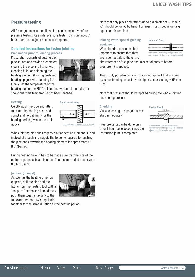
Water Distribution : 160
Pressure testing
All fusion joints must be allowed to cool completely before pressure testing. As a rule, pressure testing can start about 1 hour after the last joint has been completed.
Detailed instructions for fusion jointingPreparation prior to jointing processPreparation consists of cutting the pipesquareandmakingachamfer;cleaning the pipe and fitting with cleaning fluid; and cleaning the heating element (heating bush and heating spigot) with cleaning fluid. Finally set the temperature of the heating element to 260° Celsius and wait until the indicator shows that this temperature has been reached.
HeatingQuickly push the pipe and fitting fully into the heating bush and spigot and hold it firmly for the heating period given in the table above.
When jointing pipe ends together, a flat heating element is used insteadofabushandspigot.Theforce(F)requiredforpushingthe pipe ends towards the heating element is approximately 0.01N/mm².
During heating time, it has to be made sure that the size of the moltenpipeends(bead)isequal.Therecommendedbeadsizeis0.5 to 1.5 mm.
Jointing (manual)As soon as the heating time has elapsed, pull the pipe and the fitting from the heating tool with a “snap-off”actionandimmediatelypush them together axially to the full extent without twisting. Hold together for the same duration as the heating period.
Note that only pipes and fittings up to a diameter of 65 mm (2 ½”)shouldbejoinedbyhand.Forlargersizes,specialguidingequipmentisrequired.
Jointing (with special guiding equipment)When jointing pipe ends, it is important to ensure that they are in contact along the entire circumference of the pipe and in exact alignment before pressure (F) is applied.
Thisisonlypossiblebyusingspecialequipmentthatensuresexact positioning, especially for pipe sizes exceeding Ø 65 mm (2½”).
Note that pressure should be applied during the whole jointing and cooling process.
CheckingVisual checking of pipe joints can start immediately,
Pressure tests can be done only after 1 hour has elapsed since the last fusion joint is completed.
Equalization time: until a bead is formed
Equalize and Heat!
Leave parts in the fusion jointing machine at fu-sion pressure until the end of the cooling period!
Joint and Cool!
A bead should form around the entire circumference of the pipe. K in the diagram above should always be positive.
Fusion Check
UNICEF WASH TIPS

Water Distribution : 161
GI pipes, galvanizedGI pipes are made of cold rolled and welded steel or hot rolled seamless steel. GI pipes are delivered with a hot dip galvanized zinc coating.
Pipe Ø (ND) Pipe length Pressure rating
½” 5 .8 m 50 Bar
¾” 5.8 m 50 Bar
1” 5.8 m 50 Bar
1¼” 5.8 m 50 Bar
1½” 5.8 m 50 Bar
2” 5.8 m 50 Bar
2½” 5.8 m 50 Bar
3” 5.8 m 50 Bar
4” 5.8 m 50 Bar
6” 5.8 m 50 Bar
GI fittingsGI fittings are mainly made of malleable cast iron (threaded). Fittings include the following:
A) Socket,equalØ,female threads
Thread size Pressure rating
G½” 14 Bar
G¾” 14 Bar
G1” 14 Bar
G1¼” 14 Bar
G1½” 14 Bar
G2” 14 Bar
G2½” 14 Bar
G3” 14 Bar
4” 14 Bar
B) Socket,equalØ,male threads
Thread size Pressure rating
G½” 14 Bar
G¾” 14 Bar
G1” 14 Bar
G1¼” 14 Bar
G1½” 14 Bar
G2” 14 Bar
G2½” 14 Bar
G3” 14 Bar
4” 14 Bar
UNICEF WASH TIPS

Water Distribution : 162
C) Socket, reduction, female threads
Thread size Reduction size Pressure rating
G¾” G½” 14 Bar
G1” G½” 14 Bar
G1½” G½” 14 Bar
G1” G¾” 14 Bar
G1½” G¾” 14 Bar
G2” G¾” 14 Bar
G1½” G1” 14 Bar
G2” G1” 14 Bar
G2½” G1” 14 Bar
G2½” G1¼” 14 Bar
G3” G1¼” 14 Bar
D) Bend90°,equalØ female threads
Thread size Pressure rating
G½” 14 Bar
G¾” 14 Bar
G1” 14 Bar
G1¼” 14 Bar
G1½” 14 Bar
G2” 14 Bar
G2½” 14 Bar
G3” 14 Bar
4” 14 Bar
E) Elbow90°,equalØ female threads
Thread size Pressure rating
G½” 14 Bar
G¾” 14 Bar
G1” 14 Bar
G1¼” 14 Bar
G1½” 14 Bar
G2” 14 Bar
G2½” 14 Bar
G3” 14 Bar
4” 14 Bar
UNICEF WASH TIPS

Water Distribution : 163
F) End caps, female threads
Thread size Pressure rating
G½” 14 Bar
G¾” 14 Bar
G1” 14 Bar
G1¼” 14 Bar
G1½” 14 Bar
G2” 14 Bar
G2½” 14 Bar
G3” 14 Bar
4” 14 Bar
G) Plug hollow, male threads
Thread size Pressure rating
G½” 14 Bar
G¾” 14 Bar
G1” 14 Bar
G1¼” 14 Bar
G1½” 14 Bar
G2” 14 Bar
G2½” 14 Bar
G3” 14 Bar
4” 14 Bar
H) Tee90°,equalfemale threads
Thread size Pressure rating
G½” 14 Bar
G¾” 14 Bar
G1” 14 Bar
G1¼” 14 Bar
G1½” 14 Bar
G2” 14 Bar
G2½” 14 Bar
G3” 14 Bar
4” 14 Bar
UNICEF WASH TIPS

Water Distribution : 164
I) Tee 90°, with reduction, female threads, galvanized
Thread size Reduction size Pressure rating
G2½” G1” 14 Bar
G2½” G1¼” 14 Bar
G2½” G1½” 14 Bar
G2½” G2” 14 Bar
G3” G1” 14 Bar
G3” G1¼” 14 Bar
G3” G1½” 14 Bar
G3” G 2 14 Bar
G3” G2½” 14 Bar
G4” G¾” 14 Bar
G4” G1” 14 Bar
G4” G1½” 14 Bar
G4” G2” 14 Bar
G4” G2½” 14 Bar
G4” G3” 14 Bar
J) Cross,equalfemale threads
Thread size Pressure rating
G½” 14 Bar
G¾” 14 Bar
G1” 14 Bar
G1¼” 14 Bar
G1½” 14 Bar
G2” 14 Bar
G2½” 14 Bar
G3” 14 Bar
4” 14 Bar
UNICEF WASH TIPS
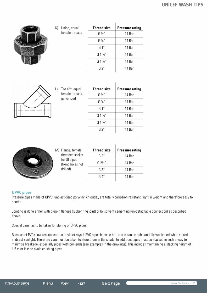
Water Distribution : 165
K) Union,equalfemale threads
Thread size Pressure rating
G½” 14 Bar
G¾” 14 Bar
G1” 14 Bar
G1¼” 14 Bar
G1½” 14 Bar
G2” 14 Bar
L) Tee45°,equalfemale threads, galvanized
Thread size Pressure rating
G½” 14 Bar
G¾” 14 Bar
G1” 14 Bar
G1¼” 14 Bar
G1½” 14 Bar
G2” 14 Bar
M) Flange, female threaded socket for GI pipes (fixing holes not drilled)
Thread size Pressure rating
G2” 14 Bar
G2½” 14 Bar
G3” 14 Bar
G4” 14 Bar
UPVC pipesPressure pipes made of UPVC (unplasticized polyvinyl chloride), are totally corrosion-resistant, light in weight and therefore easy to handle.
Jointing is done either with plug-in flanges (rubber ring joint) or by solvent cementing (un-detachable connection) as described above.
Special care has to be taken for storing of UPVC pipes.
Because of PVC’s low resistance to ultraviolet rays, UPVC pipes become brittle and can be substantially weakened when stored in direct sunlight. Therefore care must be taken to store them in the shade. In addition, pipes must be stacked in such a way to minimize breakage, especially pipes with bell-ends (see examples in the drawings). This includes maintaining a stacking height of 1.5 m or less to avoid crushing pipes.
UNICEF WASH TIPS

Water Distribution : 166
UNICEF WASH TIPS
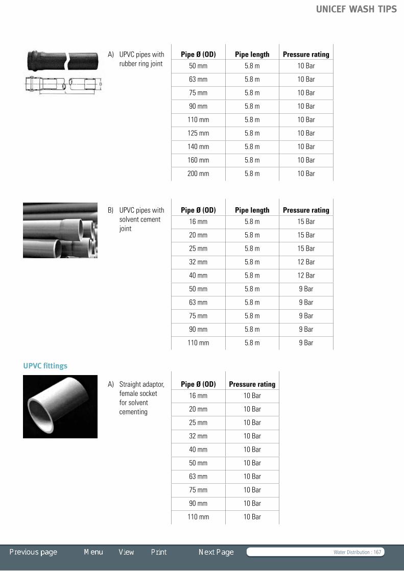
Water Distribution : 167
A) UPVC pipes with rubber ring joint
Pipe Ø (OD) Pipe length Pressure rating
50 mm 5.8 m 10 Bar
63 mm 5.8 m 10 Bar
75 mm 5.8 m 10 Bar
90 mm 5.8 m 10 Bar
110 mm 5.8 m 10 Bar
125 mm 5.8 m 10 Bar
140 mm 5.8 m 10 Bar
160 mm 5.8 m 10 Bar
200 mm 5.8 m 10 Bar
B) UPVC pipes with solvent cement joint
Pipe Ø (OD) Pipe length Pressure rating
16 mm 5.8 m 15 Bar
20 mm 5.8 m 15 Bar
25 mm 5.8 m 15 Bar
32 mm 5.8 m 12 Bar
40 mm 5.8 m 12 Bar
50 mm 5.8 m 9 Bar
63 mm 5.8 m 9 Bar
75 mm 5.8 m 9 Bar
90 mm 5.8 m 9 Bar
110 mm 5.8 m 9 Bar
UPVC fittings
A) Straight adaptor, female socket for solvent cementing
Pipe Ø (OD) Pressure rating
16 mm 10 Bar
20 mm 10 Bar
25 mm 10 Bar
32 mm 10 Bar
40 mm 10 Bar
50 mm 10 Bar
63 mm 10 Bar
75 mm 10 Bar
90 mm 10 Bar
110 mm 10 Bar
UNICEF WASH TIPS

Water Distribution : 168
B) Straight adaptor, female socket with rubber ring joints
Pipe Ø (OD) Pressure rating
50 mm 10 Bar
63 mm 10 Bar
75 mm 10 Bar
90 mm 10 Bar
110 mm 10 Bar
125 mm 10 Bar
140 mm 10 Bar
160 mm 10 Bar
200 mm 10 Bar
C) Reduction coupler, female sockets with rubber ring joints
Pipe Ø (OD) Reduction Ø Pressure rating
63 mm 50 mm 10 Bar
75 mm 63 mm 10 Bar
90 mm 75 mm 10 Bar
110 mm 90 mm 10 Bar
125 mm 110 mm 10 Bar
140 mm 125 mm 10 Bar
160 mm 140 mm 10 Bar
200 mm 160 mm 10 Bar
D) Flanged coupling, female socket with rubber ring joint and flange for GI fittings
Pipe Ø (OD) Thread size Pressure rating
50 mm G2” 10 Bar
63 mm G2½” 10 Bar
75 mm G3” 10 Bar
110 mm G4” 10 Bar
E) Flanged coupling, socket for solvent cement jointing and flange for GI fittings
Pipe Ø (OD) Thread size Pressure rating
50 mm G1½” 10 Bar
50 mm G2” 10 Bar
63 mm G2” 10 Bar
75 mm G2½” 10 Bar
90 mm G3” 10 Bar
90 mm G4” 10 Bar
110 mm G4” 10 Bar
UNICEF WASH TIPS

Water Distribution : 169
F) End cap, female, for solvent cementing to pipe ends
Pipe Ø (OD) Pressure rating
32 mm 10 Bar
40 mm 10 Bar
50 mm 10 Bar
63 mm 10 Bar
75 mm 10 Bar
90 mm 10 Bar
110 mm 10 Bar
G) Straight adaptor, female sockets (1 x for solvent cementing and 1 x for threading)
Pipe Ø (OD) Thread size Pressure rating
16 mm G3/8” 10 Bar
20 mm G½” 10 Bar
25 mm G¾” 10 Bar
32 mm G1” 10 Bar
40 mm G1¼” 10 Bar
50 mm G1½” 10 Bar
63 mm G2” 10 Bar
75 mm G2½” 10 Bar
90 mm G3” 10 Bar
110 mm G4” 10 Bar
H) Straight adaptor, female socket for solvent cementing with male socket for threading
Pipe Ø (OD) Thread size Pressure rating
16 mm G3/8” 10 Bar
20 mm G½” 10 Bar
25 mm G¾” 10 Bar
32 mm G1” 10 Bar
40 mm G1¼” 10 Bar
50 mm G1½” 10 Bar
63 mm G2” 10 Bar
75 mm G2½” 10 Bar
90 mm G3” 10 Bar
110 mm G4” 10 Bar
UNICEF WASH TIPS

Water Distribution : 170
I) Reduction coupler, female sockets for solvent cementing
Pipe Ø (OD) Thread size Pressure rating
20 mm 16 mm 10 Bar
25 mm 20 mm 10 Bar
32 mm 25 mm 10 Bar
40 mm 32 mm 10 Bar
50 mm 40 mm 10 Bar
63 mm 50 mm 10 Bar
75 mm 63 mm 10 Bar
90 mm 75 mm 10 Bar
110 mm 90 mm 10 Bar
J) Elbow 90°, female sockets for rubber ring joints
Pipe Ø (OD) Pressure rating
50 mm 10 Bar
63 mm 10 Bar
75 mm 10 Bar
90 mm 10 Bar
110 mm 10 Bar
125 mm 10 Bar
140 mm 10 Bar
160 mm 10 Bar
200 mm 10 Bar
K) Elbow90°,equalfemale sockets for solvent cementing
Pipe Ø (OD) Pressure rating
32 mm 10 Bar
40 mm 10 Bar
50 mm 10 Bar
63 mm 10 Bar
75 mm 10 Bar
90 mm 10 Bar
110 mm 10 Bar
UNICEF WASH TIPS

Water Distribution : 171
L) Elbow 90°, female sockets (1 end for solvent cementing 1 end for threading)
Pipe Ø (OD) Thread size Pressure rating
32 mm G1” 10 Bar
40 mm G1¼” 10 Bar
50 mm G1½” 10 Bar
63 mm G2” 10 Bar
75 mm G2½” 10 Bar
90 mm G3” 10 Bar
110 mm G4” 10 Bar
M) Tee90°,equalfemale sockets with rubber ring joint
Pipe Ø (OD) Pressure rating
50 mm 10 Bar
63 mm 10 Bar
75 mm 10 Bar
90 mm 10 Bar
110 mm 10 Bar
125 mm 10 Bar
140 mm 10 Bar
160 mm 10 Bar
200 mm 10 Bar
N) Tee90°,equalfemale sockets for solvent cementing
Pipe Ø (OD) Pressure rating
50 mm 10 Bar
63 mm 10 Bar
75 mm 10 Bar
90 mm 10 Bar
110 mm 10 Bar
125 mm 10 Bar
140 mm 10 Bar
160 mm 10 Bar
200 mm 10 Bar
UNICEF WASH TIPS

Water Distribution : 172
O) Tee 90°, female reduction sockets for solvent cementing
Pipe Ø (OD) Thread size Pressure rating
25 mm 20 mm 10 Bar
32 mm 25 mm 10 Bar
40 mm 32 mm 10 Bar
50 mm 40 mm 10 Bar
63 mm 50 mm 10 Bar
75 mm 63 mm 10 Bar
90 mm 75 mm 10 Bar
110 mm 90 mm 10 Bar
P) Tee 90°, female sockets for solvent cementing and 1 x threaded for GI pipe end
Pipe Ø (OD) Thread size Pressure rating
20 mm G1½” 10 Bar
25 mm G¾” 10 Bar
32 mm G1” 10 Bar
40 mm G1¼” 10 Bar
50 mm G1½” 10 Bar
63 mm G2” 10 Bar
75 mm G2½” 10 Bar
90 mm G3” 10 Bar
110 mm G4” 10 Bar
Q) Union,equalfemale sockets for solvent cementing
Pipe Ø (OD) Pressure rating
32 mm 10 Bar
40 mm 10 Bar
50 mm 10 Bar
63 mm 10 Bar
75 mm 10 Bar
90 mm 10 Bar
110 mm 10 Bar
UNICEF WASH TIPS

Water Distribution : 173
HDPE pipes
Pressure pipes made of HDPE (high density polyethylene) are totally corrosion-resistant, light in weight, highly flexible and easy to handle. Pipes are transported and stored either in continous coils (mainly for smaller diameter pipes) or in straight lengths. Pipe-to-pipe connections are mostly done by heat jointing (un-detachable connection, see instructions above) for small water supply systems. Other connections can be done by threading or through the use of compression fittings.
Pipe Ø (OD) Pipe length Pressure rating
25 mm coiled 10 Bar
32 mm coiled 10 Bar
40 mm coiled 10 Bar
50 mm coiled 10 Bar
63 mm coiled 10 Bar
75 mm coiled 10 Bar
90 mm coiled 10 Bar
110 mm 6 or 12 m 10 Bar
Care has to be taken for storing of HDPE pipes. While HDPE pipes are not as prone to damage from ultraviolet rays as UPVC pipes, a shady storage place is still advisable. Coiled HDPE pipes will eventually straighten after un-rolling, but the straightness is not sufficient to be used as riser pipes forhandpumps.StraightHDPEpipesrequireaflatandshadystorageplace.AsisthecaseforUPVCpipes, careful stacking is important and the stack should not be too high (see stacking instructions under UPVC Pipes).
HDPE fittings (made of polypropylene)
A) Straight adaptor, equalfemalecompression fittings
Pipe Ø (OD) Pressure rating
16 mm 10 Bar
20 mm 10 Bar
25 mm 10 Bar
32 mm 10 Bar
40 mm 10 Bar
50 mm 10 Bar
63 mm 10 Bar
75 mm 10 Bar
90 mm 10 Bar
110 mm 10 Bar
UNICEF WASH TIPS

Water Distribution : 174
B) Compression fitting, female (1 x compression coupler and 1 x threaded for GI-pipes)
Pipe Ø (OD) Thread size Pressure rating
25 mm G1” 10 Bar
32 mm G1” 10 Bar
32 mm G1¼” 10 Bar
40 mm G1” 10 Bar
40 mm G1¼” 10 Bar
40 mm G1½” 10 Bar
50 mm G1½” 10 Bar
50 mm G2” 10 Bar
63 mm G2” 10 Bar
75 mm G2” 10 Bar
75 mm G2½” 10 Bar
90 mm G2” 10 Bar
90 mm G3” 10 Bar
90 mm G4” 10 Bar
110 mm G3” 10 Bar
110 mm G4” 10 Bar
C) End cap, female compression fitting
Pipe Ø (OD) Pressure rating
25 mm 10 Bar
32 mm 10 Bar
40 mm 10 Bar
50 mm 10 Bar
63 mm 10 Bar
75 mm 10 Bar
90 mm 10 Bar
110 mm 10 Bar
UNICEF WASH TIPS

Water Distribution : 175
D) Compression fitting, (1 x female compression coupler and 1 x male thread for GI-pipes)
Pipe Ø (OD) Thread size Pressure rating
25 mm G1” 10 Bar
32 mm G1” 10 Bar
32 mm G1¼” 10 Bar
40 mm G1” 10 Bar
40 mm G1¼” 10 Bar
40 mm G1½” 10 Bar
50 mm G1½” 10 Bar
50 mm G2” 10 Bar
63 mm G2” 10 Bar
75 mm G2” 10 Bar
75 mm G2½” 10 Bar
90 mm G2” 10 Bar
90 mm G3” 10 Bar
90 mm G4” 10 Bar
110 mm G3” 10 Bar
110 mm G4” 10 Bar
E) Reduction coupler, female compression couplers
Pipe Ø (OD) Thread size Pressure rating
32 mm 25 mm 10 Bar
40 mm 25 mm 10 Bar
25 mm 10 Bar 10 Bar
40 mm 32 mm 10 Bar
50 mm 25 mm 10 Bar
50 mm 32 mm 10 Bar
50 mm 40 mm 10 Bar
63 mm 32 mm 10 Bar
63 mm 40 mm 10 Bar
63 mm 50 mm 10 Bar
75 mm 50 mm 10 Bar
75 mm 63 mm 10 Bar
90 mm 63 mm 10 Bar
90 mm 75 mm 10 Bar
110 mm 90 mm 10 Bar
UNICEF WASH TIPS

Water Distribution : 176
F) Flanged female couplers (1 x compression coupler and 1 x threaded for GI-pipes)
Pipe Ø (OD) Thread size Pressure rating
50 mm G1½” 10 Bar
50 mm G2” 10 Bar
63 mm G2” 10 Bar
75 mm G2½” 10 Bar
90 mm G3” 10 Bar
90 mm G4” 10 Bar
110 mm G4” 10 Bar
G) Elbow 90°, equalfemalecompression couplers
Pipe Ø (OD) Pressure rating
25 mm 10 Bar
32 mm 10 Bar
40 mm 10 Bar
50 mm 10 Bar
63 mm 10 Bar
75 mm 10 Bar
90 mm 10 Bar
110 mm 10 Bar
H) Elbow 90°, female sockets (1 x compression socket 1 x threaded for GI-pipes)
Pipe Ø (OD) Thread size Pressure rating
25 mm G1” 10 Bar
32 mm G1” 10 Bar
32 mm G1¼” 10 Bar
40 mm G1” 10 Bar
40 mm G1¼” 10 Bar
40 mm G1½” 10 Bar
50 mm G1½” 10 Bar
50 mm G2” 10 Bar
63 mm G1½” 10 Bar
63 mm G2” 10 Bar
63 mm G2½” 10 Bar
75 mm G2½” 10 Bar
75 mm G3” 10 Bar
90 mm G3” 10 Bar
90 mm G4” 10 Bar
110 mm G4” 10 Bar
UNICEF WASH TIPS
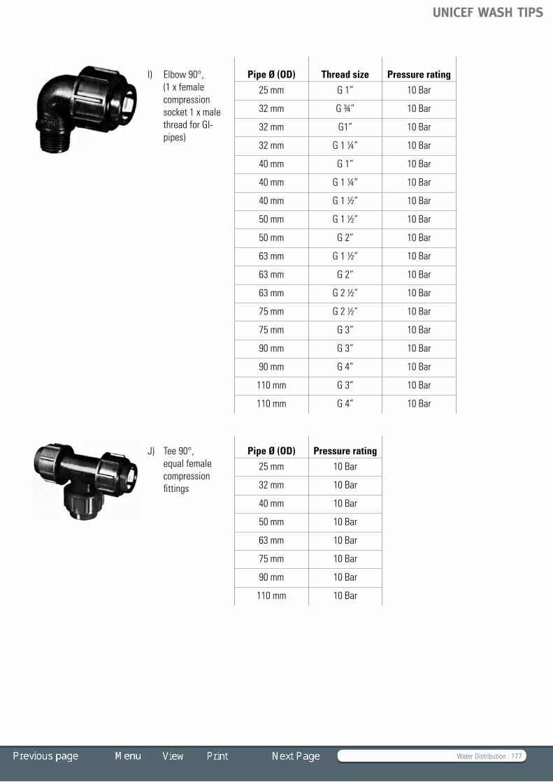
Water Distribution : 177
I) Elbow 90°, (1 x female compression socket 1 x male thread for GI-pipes)
Pipe Ø (OD) Thread size Pressure rating
25 mm G1” 10 Bar
32 mm G¾” 10 Bar
32 mm G1” 10 Bar
32 mm G1¼” 10 Bar
40 mm G1” 10 Bar
40 mm G1¼” 10 Bar
40 mm G1½” 10 Bar
50 mm G1½” 10 Bar
50 mm G2” 10 Bar
63 mm G1½” 10 Bar
63 mm G2” 10 Bar
63 mm G2½” 10 Bar
75 mm G2½” 10 Bar
75 mm G3” 10 Bar
90 mm G3” 10 Bar
90 mm G4” 10 Bar
110 mm G3” 10 Bar
110 mm G4” 10 Bar
J) Tee 90°, equalfemalecompression fittings
Pipe Ø (OD) Pressure rating
25 mm 10 Bar
32 mm 10 Bar
40 mm 10 Bar
50 mm 10 Bar
63 mm 10 Bar
75 mm 10 Bar
90 mm 10 Bar
110 mm 10 Bar
UNICEF WASH TIPS

Water Distribution : 178
K) Tee 90°, female compression fittings with reduction
Pipe Ø (OD) Thread size Pressure rating
25 mm 20 mm 10 Bar
32 mm 25 mm 10 Bar
40 mm 32 mm 10 Bar
50 mm 40 mm 10 Bar
63 mm 50 mm 10 Bar
75 mm 63 mm 10 Bar
90 mm 75 mm 10 Bar
110 mm 90 mm 10 Bar
L) Tee 90° (2 x female compression fittings and 1 x threaded female socket for GI-pipes)
Pipe Ø (OD) Thread size Pressure rating
25 mm G1” 10 Bar
32 mm G1” 10 Bar
32 mm G1¼” 10 Bar
40 mm G1” 10 Bar
40 mm G1¼” 10 Bar
40 mm G1½” 10 Bar
50 mm G1¼” 10 Bar
50 mm G1½” 10 Bar
50 mm G2” 10 Bar
63 mm G1½” 10 Bar
63 mm G2” 10 Bar
63 mm G2½” 10 Bar
75 mm G2” 10 Bar
75 mm G2½” 10 Bar
75 mm G3” 10 Bar
90 mm G2½” 10 Bar
90 mm G3” 10 Bar
110 mm G3” 10 Bar
110 mm G4” 10 Bar
UNICEF WASH TIPS

Water Distribution : 179
M) Tee 90° (2 x female compression fittings and 1 x threaded male socket for GI-pipes)
Pipe Ø (OD) Thread size Pressure rating
25 mm G1” 10 Bar
32 mm G1” 10 Bar
32 mm G1¼” 10 Bar
32 mm G1½” 10 Bar
40 mm G1” 10 Bar
40 mm G1¼” 10 Bar
40 mm G1½” 10 Bar
50 mm G1¼” 10 Bar
50 mm G1½” 10 Bar
50 mm G2” 10 Bar
63 mm G1½” 10 Bar
63 mm G2” 10 Bar
63 mm G2½” 10 Bar
75 mm G2½” 10 Bar
75 mm G3” 10 Bar
90 mm G3” 10 Bar
90 mm G4” 10 Bar
110 mm G4” 10 Bar
UNICEF WASH TIPS
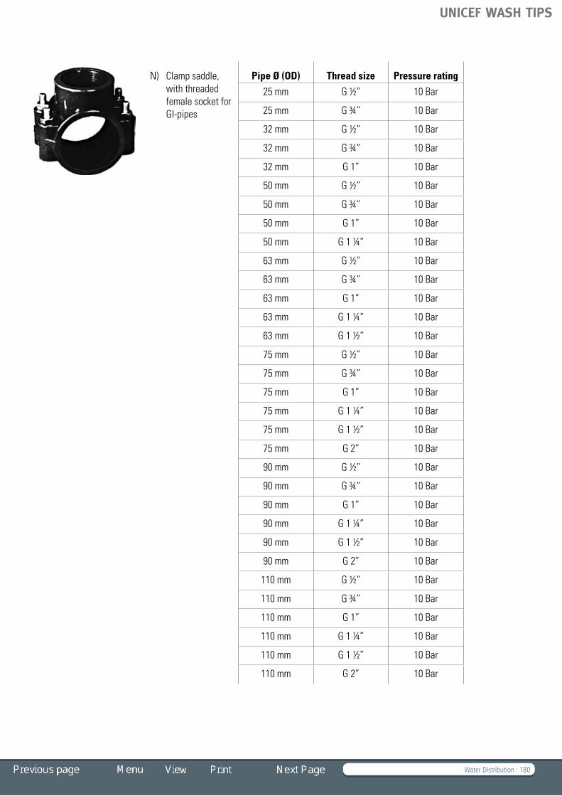
Water Distribution : 180
N) Clamp saddle, with threaded female socket for GI-pipes
Pipe Ø (OD) Thread size Pressure rating
25 mm G½” 10 Bar
25 mm G¾” 10 Bar
32 mm G½” 10 Bar
32 mm G¾” 10 Bar
32 mm G1” 10 Bar
50 mm G½” 10 Bar
50 mm G¾” 10 Bar
50 mm G1” 10 Bar
50 mm G1¼” 10 Bar
63 mm G½” 10 Bar
63 mm G¾” 10 Bar
63 mm G1” 10 Bar
63 mm G1¼” 10 Bar
63 mm G1½” 10 Bar
75 mm G½” 10 Bar
75 mm G¾” 10 Bar
75 mm G1” 10 Bar
75 mm G1¼” 10 Bar
75 mm G1½” 10 Bar
75 mm G2” 10 Bar
90 mm G½” 10 Bar
90 mm G¾” 10 Bar
90 mm G1” 10 Bar
90 mm G1¼” 10 Bar
90 mm G1½” 10 Bar
90 mm G2” 10 Bar
110 mm G½” 10 Bar
110 mm G¾” 10 Bar
110 mm G1” 10 Bar
110 mm G1¼” 10 Bar
110 mm G1½” 10 Bar
110 mm G2” 10 Bar
UNICEF WASH TIPS

Water Distribution : 181
Valves
A) Ball valve, bronze, female connection thread for GI-pipes
Thread size Pressure rating
G½” 10 Bar
G¾” 10 Bar
G1” 10 Bar
G1½” 10 Bar
G2” 10 Bar
B) Butterfly valve, duct iron, female connection thread for GI-pipes
Thread size Pressure rating
G2” 10 Bar
G3” 10 Bar
G4” 10 Bar
C) Check valve, cast iron, female connection thread for GI-pipes
Thread size Pressure rating
G2” 10 Bar
G3” 10 Bar
G4” 10 Bar
D) Gate valve, brass, female connection thread for GI-pipes
Thread size Pressure rating
G½” 10 Bar
G¾” 10 Bar
G1” 10 Bar
G1¼” 10 Bar
G1½” 10 Bar
G2” 10 Bar
UNICEF WASH TIPS

Water Distribution : 182
E) Gate valve, brass, for GI-pipes with connecting flanges
Thread size Pressure rating
3” 10 Bar
4” 10 Bar
F) Globe valve, brass, female connection threads for GI-pipes
Thread size Pressure rating
G¾” 10 Bar
G1” 10 Bar
G1½” 10 Bar
G2” 10 Bar
G) Gate valve, PVC, for UPVC pipes with rubber ring socket
Pipe Ø (ND) Pressure rating
25 mm 10 Bar
40 mm 10 Bar
50 mm 10 Bar
Taps
A) Tap, brass with threaded male connection for GI-pipes
Thread size Pressure rating
G½” 10 Bar
G¾” 10 Bar
B) Tap, brass, threaded male connection for GI-pipes and hose connection
Thread size Pressure rating
G½” 10 Bar
G¾” 10 Bar
UNICEF WASH TIPS

Water Distribution : 183
C) Tap, brass, self closing with threaded female connection for GI-pipe
Thread size Pressure rating
G¾” 10 Bar
Other components
A) Pressure relieve valve, threaded male connection for GI or UPVC pipe
B) Water meter, with threaded male connection for GI-pipe
C) Water meter, with connection flanges
Booster pumps
Booster pumps are mainly used in distribution networks where the normal system pressure is low and needs to be increased.
They also are used for transporting water for long distances, to overcome elevations between the water source and the distribution network or for pumping water up into storage tanks.
Booster pumps for water supply usually consist of an electric motor or diesel engine driving a centrifugal pump placed on the motor shaft. See above in this TIP for more information on pump types.
UNICEF WASH TIPS

Faecal Sludge Emptying Equipment : 184
Faecal Sludge Emptying Equipment Introduction Background Manual pit latrine emptying technology (MAPET)
– Equipment – Operation and maintenance – Costs – Advantages – Disadvantages Mechanical pumping Vacutug
– Equipment – Operation and maintenance – Costs – Advantages – Disadvantages
TIP 5
The Vietnamese pit emptying model – Equipment – Operation and maintenance – Costs – Advantages – Disdvantages Tractor-drawn trailer-mounted vacuum tanker
– Equipment – Costs Management of sludges from pit latrines and
septic tanks – Bill of Quantities – References and Further Reading
Sandec/Eawag
UNICEF WASH TIPS

Faecal Sludge Emptying Equipment : 185
Introduction
The excreta of most urban dwellers in developing countries is disposed of through on-site sanitation systems such as private andpubliclatrines,aquapriviesandseptictanks.Thisisincontrast to industrialized countries, where excreta is disposed of via flush toilets, sewerage systems and central wastewater treatment works.
A major problem in slum areas is that the collection of faecal sludge from on-site sanitation installations is often not possible with conventional vacuum tankers. They are just too big for the very narrow streets in many informal settlements. The technologies described here were developed for use in these situations in highly populated slum dwellings.
Another aspect is that the collected sludge is commonly disposed of untreated. Haulage distances to outlying treatment or disposal sites are excessive. Land within city boundaries is usually highly valued and might not be available for waste treatment. The sludge is therefore often dumped untreated at the shortest possible distance – on open grounds, into drainage ditches, lakes, rivers, or into the sea.
Growing urbanization leads to increasing faecal sludge quantitiestobedisposedofand,hence,toincreasingenvironmental pollution and health risks. The application ofsludgeemptyingequipmentshouldgohandinhandwithappropriate means and ways to treat, use and dispose of sludge.
Background
Collection and disposal of human excreta in urban and peri-urban areas of developing countries is a serious problem. When a latrine pit is full, another one is usually dug and a new latrine built. However, in densely populated areas, this practice is unfeasible.
TIP 5 provides information on different types of faecal sludge emptyingequipments.
Basically, on-site sanitation facilities can be emptied manually or by mechanical pumping. However, emptying a pit by hand poses a serious health risk. Fresh excreta contain high amounts of pathogens; by digging, one can be infected with worms, for example. The excavated sludge can attract flies, which can infect people nearby. Moreover, unlined pits can collapse during emptying. Manual pit emptying should thus be avoided, except when a pit has been unused for a long period of time (as in the case of correctly operated double-pit latrines).
Mechanicalsludgeemptyingequipment–alsocalledasludgegulper or gully sucker or more poetically, a honey sucker – has the following components:
• acontainerforthesludge(ranginginsizefromapproximately 200 litres up to 10 m3)
• avacuumorhand-operatedpumpmountedonthecontainer• ahosefromthecontainertoberolledtothepit/tank• atruck,tractorordonkeytotrailtheequipment.
Mechanical emptying helps avoid direct contact with faecal matter and thus reduces health risks. However, vehicles with powerful pumps are expensive and spare parts may be difficult to find. Besides, large vehicles cannot access pits located in narrow streets. The following are some examples of affordable sludgeemptyingequipment.
Manual pit latrine emptying technology (MAPET)
The manual pit latrine emptying technology (MAPET) project wasinitiatedin1988byWASTEattherequestoftheDares Salaam Sewerage and Sanitation Department (DSSD) in Tanzania. Characteristics of the MAPET described here are based on Müller and Rijnsburger (1994), WASTE (1997), and Brikké and Bredero (2003).
EquipmentTheMAPETequipmentconsistsofapistonhandpumpmountedon a pushcart; a 200-litre vacuum tank mounted on a pushcart; a¾-inchairhosepipebetweenpumpandtank,anda4-inchsludge hosepipe of 4 metre length to drain the sludge from the pit; and auxiliaries such as a sludge mixing rod, spade, hook and hoe. The different components can be locally constructed by using detailed drawings and specifications.
Fig. 5.1 Manual pit emptying © P. Blunier
UNICEF WASH TIPS

Faecal Sludge Emptying Equipment : 186
Operation and maintenanceThe Dar es Salaam municipality manages the service, takes care of repair and maintenance and provides training. Trained persons obtain a licence to operate the service and may use theequipmentfreeofcharge.Thelicenceiswithdrawniftheperformance of the operator is below standards.
In order to facilitate pumping, water is sometimes added and the sludge/water mixture stirred. Filling up the 200-litre tank takes between 5 and 20 minutes, depending on the sludge’s viscosity and pumping head. When the tank is full, hosepipes are disconnected and the tank is transported to the disposal site (usually a large hole dug in the vicinity). The tank is then tipped over in discharge position, a pressure relieve valve is opened and the sludge flows into the hole. The tank is then put back in its original position and the operation is repeated until the requiredamountofsludgehasbeenemptied.Thedisposalholeis covered with soil immediately after pit emptying and again one day later once the sludge has settled.
Finally,theequipmentiscleanedandreturnedtotheneighbourhood parking place. As on-site disposal is practiced (burying the sludge and covering it with a layer of soil), it only takes place when the water table is low and when there is sufficientspace.Theequipmentcanbepushedoveradistanceof 2 km at most, because of its weight.
Minor repairs such as tire punctures or small welding jobs must be performed regularly. The handpump and the wheels must be repaired or replaced occasionally (Brikké and Bredero, 2003).
CostsRunning costs were estimated at $2.50 per tankload of 200 litres (Müller and Rijnsburger, 1994). This revenue did, in the case of Dar es Salaam, not cover the running costs (at least at the actual service level, which is only 15% of the optimal service level). However, the municipality covers part of the running costs (WASTE, 1997).
AdvantagesThemainadvantageisthatMAPETusessmallequipment,which is able to provide service in high-density areas where conventional tankers have no access.
DisadvantagesThis sludge disposal practice is only feasible if the water table is low and space is available. Moreover, MAPET entrepreneurs depend on subsidies. However, increasing service level, for example by establishing working agreements with communities, could improve the financial situation of the MAPET system.
Mechanical pumping
Mechanical emptying systems are mainly large conventional vacuum tankers that can empty latrine pits and septic tanks. The technology is well proven and the tankers are technically and financially viable. They are normally operated by local sewage operators in the formal areas of towns and cities. The large tankers find it difficult to work in the often very confined spaces in informal areas and slums. To address the challenge
Fig. 5.3 The MAPET system © Brikké and Bredero, 2003
Fig. 5.2 MAPET in narrow street in Tanzania © WASTE
Tank
Piston handpump
UNICEF WASH TIPS

Faecal Sludge Emptying Equipment : 187
of providing mechanized pit emptying services small, low-cost technical tankers were developed.
Portable and easy manoeuvrable, these small tankers are often trailer mounted (see Fig. 5.4) or part of a small vehicle that can reach into narrow streets.
Mechanicalpumpingrequiresafullylinedpit,astheemptyingofsemi-liquidsludgecanmakeunlinedpitscollapse.
Vacutug
The UN Centre for Human Settlements (Habitat) Vacutug was developed by Manus Coffey and Associates in 1997. It was first tested for Habitat in a low-income settlement in Nairobi, Kenya by a local NGO. Based on this trial phase, a second version of the Vacutug was produced and is now used in Kenya, Tanzania, Mozambique,Senegal,SouthAfrica,IndiaandBangladesh.Thedescription of the Vacutug here is based on Wegelin-Schuringa and Coffey (2000) and Issaias (2006).
EquipmentThe vacutug consists of:
A vacuum tanker made of mild steel with a volume of 500 litres. The tank is fitted with a check valve, two sight glasses and two 75 mm ports for sludge inlet and discharge. The assembly is mounted on a steel frame fitted with secondhand car wheels and axles with a width of 1.0 metres, which can be reduced to 0.8 metres when necessary.
A tug with an engine and vacuum pump. The tug has a width of 0.6 metres and comprises a small frame-mounted 4.1 kW petrol engine with a belt drive to connect it to either a sliding vane vacuum pump or a friction roller to drive the vehicle. In traction mode, the engine can propel the vehicle
at speeds of up to 5 km/h. When connected to the vacuum pump, it is capable of exhausting at 1,700 litres airflow/minute with vacuum heads up to 0.9 bar. The pump can be reversed to pressurize the tank to assist the discharge of sludge to the sewer or to raise it to discharge into a transfer tank. The engine is mounted on a hinged plate with a rod linkage to apply tension to the belt drive. The vehicle is fitted with a motorcycle throttle and braking system and has two secondhand car wheels and hubs.
A drawbar is used for towing and manoeuvring. The unit is equippedwith3”diameterPVChosesconnectedtothetankwithaluminiumquickreleasecouplings.Asecondarycombinedtrap and siphon protects the pump from sludge carryover into theairstreamwhile“gulping.”
Operation and maintenanceThe Vacutug trial in Nairobi employed two operators – one management staff (part time) and one night watchman. The managementstaffreceivedrequestsforde-sludgingandarranged the schedule, the customers paid the number of loads requiredandgotareceiptfortheamountpaid.InNairobi,collected sludge was disposed of in the sewers. However, sludge could also be loaded on a truck and transported to an official disposal/treatment site.
Maintenancerequiresapart-timemechanicforaweeklycheck-up and for when it breaks down. However, the technology of the Vacutug is maintainable using local spare parts and skills. The local manufacturer of the Vacutug should keep a minimum stock of wearing parts and other parts which may suffer damage (e.g. sight glasses, hose couplings) in stock at all times.
CostsCapital costs amount to $5,100 (Issaias 2006). Operating costs amount to $3 to $5 per 500 litres. During the trial period in Kenya, the revenue generated by the Vacutug was sufficient
Fig. 5.4 Trailer mounted pit emptier © Well Fig. 5.5 Vacutug
UNICEF WASH TIPS

Faecal Sludge Emptying Equipment : 188
to pay for the operators and maintenance. In Bangladesh, the Vacutug is financially viable: in Dhaka operators recovered their costs over a three-month period and made a 14% profit.
AdvantagesSpare parts are available and obtainable and the technology sufficiently simple for an informal sector mechanic to maintain. It can reach narrow streets.
DisadvantagesThe machine may not be produced locally.
The Vietnamese pit emptying model
The Sewer and Drainage Company of Haiphong (Vietnam), a public utility enterprise, is responsible for the collection of sludge from septic tanks. The emptying system used by this company and described here is based on Klingel (2001), Strauss and Montangero (2002).
EquipmentCollection is carried out with a combination of larger vacuum tankers and small vacuum tugs (width about 70 cm) for areas difficult to access. These are used together with intermediate storage tanks (5 m3) mounted on a hook-lift truck. The mini-vacuum tugs were developed by the company in collaboration with a local manufacturer. They have a capacity of 350 litres. Thecombinationoflargeandsmallequipmentissuccessful,covering almost 100% of the houses.
Operation and maintenanceTheequipmentismaintainedbyamunicipalunit,usinglocallytrained staff.
In Haiphong, sludge is usually disposed of on the landfill.
CostsCapital costs amount to $4,000. It is estimated that about $6/m3 covers operation, maintenance and salary costs.
AdvantagesThe system combines a small hand-pushed tank that enables it to empty pits located in narrow streets with larger tanks that canbetransportedoverlongdistances.Theequipmentissimpleto operate and maintain and is produced locally.
DisdvantagesA disadvantage is dependence on the availability of petrol (gasoline). Moreover, the Sewer and Drainage Company of Haiphong sometimes lacks the necessary financial means to cover the costs of repair.
Tractor-drawn trailer-mounted vacuum tanker
This section is based on information about the tractor-drawn trailer-mounted vacuum tanker (or gully sucker) used by UNICEF in Sri Lanka.
EquipmentThe UNICEF Sri Lankan vacuum tank has a capacity of approximately 2.2 m3. It is made of mild steel and coated with an epoxy layer. It is mounted on a trailer pulled by a Massey Ferguson tractor (MF240, 45 HP).
Accessories include:
• Agullypump(4HPengine)• Acleaningpump(3HPenginedrivenwaterpump)• Anengine-drivencompressor• Adeliveryandsuctionhosemountedonhosereel• A40-footsuctionanddeliveryhoseprovidedwithquick
coupling accessories for sewage pump and a 50- foot suction and delivery hose attached with coupling set for cleaning pump
• Atoolboxconsistingofalltherequiredtools
Fig. 5.6 Mini tug and storage tank, which can be hook-lifted
and hauled away © Sandec
Fig. 5.7 The Sri Lankan tractor-drawn trailer-mounted vacuum
tanker © UNICEF Sri Lanka
UNICEF WASH TIPS

Faecal Sludge Emptying Equipment : 189
• Bowsercap,helmet,pairofglovesandgumboots• A2m-longjamcleaningsteelrod• Asparewheel.
CostsCapital costs amount to 1,680,000 Sri Lankan rupees (about $16,800).
Management of sludges from pit latrines and septic tanks
Sludge emptying is only one piece of the entire faecal sludge management system.
Very often, collected sludge is discharged indiscriminately into lanes or drainage ditches, creating health risks. Efficient management and in particular sound financing mechanisms must be put in place to create incentives for sludge emptiers to avoid indiscriminate disposal. In Ouagadougou, Burkina Faso, for example, sludge-emptying truck drivers are paid only when they discharge their sludge at the sewage treatment plant.
If there are no sewage treatment plants, collected sludge should be treated in order to avoid health risks, especially before reusing as soil conditioner. Strauss and Montangero (2002) discuss several low-cost options.
Because sludge-emptying companies often face difficulties covering their costs, creating favourable conditions for such companies – by lowering their tax or facilitating multiple uses of the emptying vehicles – helps guarantee sustainable emptying services.
Bill of Quantities
Click on the below BoQ to open an Excel file
Fig. 5.8 Components of the Sri Lankan tractor-drawn trailer-
mounted vacuum tanker © UNICEF Sri Lanka
Fig. 5.11 Sludge discharge in a pond, Vietnam © Sandec
Fig. 5.9 Front, top and end view of the Sri Lankan tractor-
drawn trailer-mounted vacuum tanker © UNICEF Sri Lanka
Bill of Quantities (Sludge Emptying Equipment)
UNICEF WASH TIPS

Faecal Sludge Emptying Equipment : 190
References and Further Reading
Brikké, F. and M. Bredero. 2003. Linking Technology Choice with Operation and Maintenance in the Context of Community Water Supply and Sanitation: A Reference Document for Planners and Project Staff. Geneva: World Health Organization and IRC Water and Sanitation Centre. http://www.who.int/water_sanitation_health/hygiene/om/en/wsh9241562153.pdf
Issaias, I. 2006. UN-HABITAT Vacutug. Presentation prepared for the Faecal Sludge Management Symposium, 11-16 May. http://siteresources.worldbank.org/EXTWAT/Resources/4602122-1215104787836/FSM_UNHabitat.pdf
Klingel, F. 2001. Nam Dinh Septage Management Study. Report prepared by EAWAG/COLENCO within the Nam Dinh Urban Development Project. http://www.eawag.ch/organisation/abteilungen/sandec/publikationen/publications_ewm/downloads_ewm/ND_septage_management_study.pdf
Montangero, A. and M. Strauss. 2002. “Faecal Sludge Treatment.” Lecture Notes, IHE Delft, February. http://www.eawag.ch/organisation/abteilungen/sandec/publikationen/publications_ewm/downloads_ewm/IHE_lecture_notes.pdf
Muller, M. and J. Rijnsburger. 1994. MAPET Manual Pit-Latrine Emptying Technology Project: Development and Pilot Implementation of a Neighbourhood-based Pit-emptying Service with Locally Manufactured Handpump Equipment in Dar Es Salaam, Tanzania, 1998–1992: Final Report. Gouda (Netherlands), WASTE Consultants
Strauss, M. and A. Montangero. 2002. Faecal Sludge Management – Review of Practices, Problems and Initiatives. Report prepared for GHK/DFID, ENGKAR Project No. R80056, Capacity Building for Effective Decentralised Wastewater
UNICEF WASH TIPS