The crystal structure of unmodified tRNAPhe from Escherichia coli
Upload
independentCategory
view
0download
0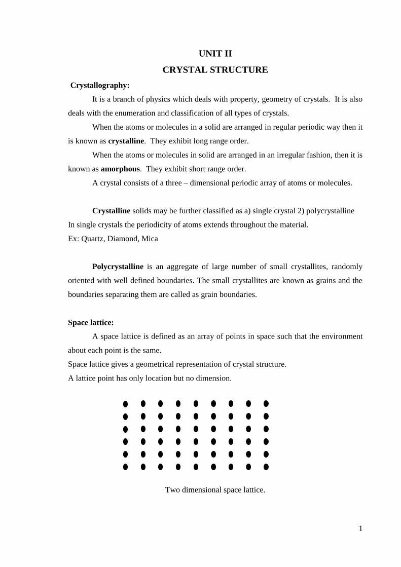
1
UNIT II
CRYSTAL STRUCTURE
Crystallography:
It is a branch of physics which deals with property, geometry of crystals. It is also
deals with the enumeration and classification of all types of crystals.
When the atoms or molecules in a solid are arranged in regular periodic way then it
is known as crystalline. They exhibit long range order.
When the atoms or molecules in solid are arranged in an irregular fashion, then it is
known as amorphous. They exhibit short range order.
A crystal consists of a three – dimensional periodic array of atoms or molecules.
Crystalline solids may be further classified as a) single crystal 2) polycrystalline
In single crystals the periodicity of atoms extends throughout the material.
Ex: Quartz, Diamond, Mica
Polycrystalline is an aggregate of large number of small crystallites, randomly
oriented with well defined boundaries. The small crystallites are known as grains and the
boundaries separating them are called as grain boundaries.
Space lattice:
A space lattice is defined as an array of points in space such that the environment
about each point is the same.
Space lattice gives a geometrical representation of crystal structure.
A lattice point has only location but no dimension.
Two dimensional space lattice.

2
Bravis lattice:
For a lattice if each lattice point substitutes for an identical set of one or more
atoms, then the lattice points become equivalent and the lattice is called Bravis lattice.
Thus in a Bravis lattice all the atoms in the crystal will be of same type.
Non Bravis lattice:
For a crystal lattice, if each lattice point is replaced by two or more set of different
atoms, then the resulting lattice is called Non – Bravis lattice.
Consider individual points A B C…….which constitutes a Bravis lattices. Similarly the set
A' B' C' ……….constitutes another Bravis lattice. Thus a non – Bravis lattice could be
considered as a superposition of two or more different and interpenetrating Bravis lattices.
Non Bravais lattice
Basis:
The atom or the group of atoms which are correlated to a lattice point as a set is
called basis.
Basis
If a basis is substituted for the corresponding lattice points in a crystal lattice.
Then the resulting structure is called crystal structure. Thus
Space Lattice + Basis = crystal structure
In crystals like aluminium and barium the basis is single atom, in NaCl, KCl etc.
the basis is diatomic whereas in crystals like CaF2 the basis is triatomic.
3
Basic vectors:
A coordinate system is employed to represent the position of the lattice points in a
space lattice. All the lattice points in the space lattice can be generated by translating the
coordinate vectors.
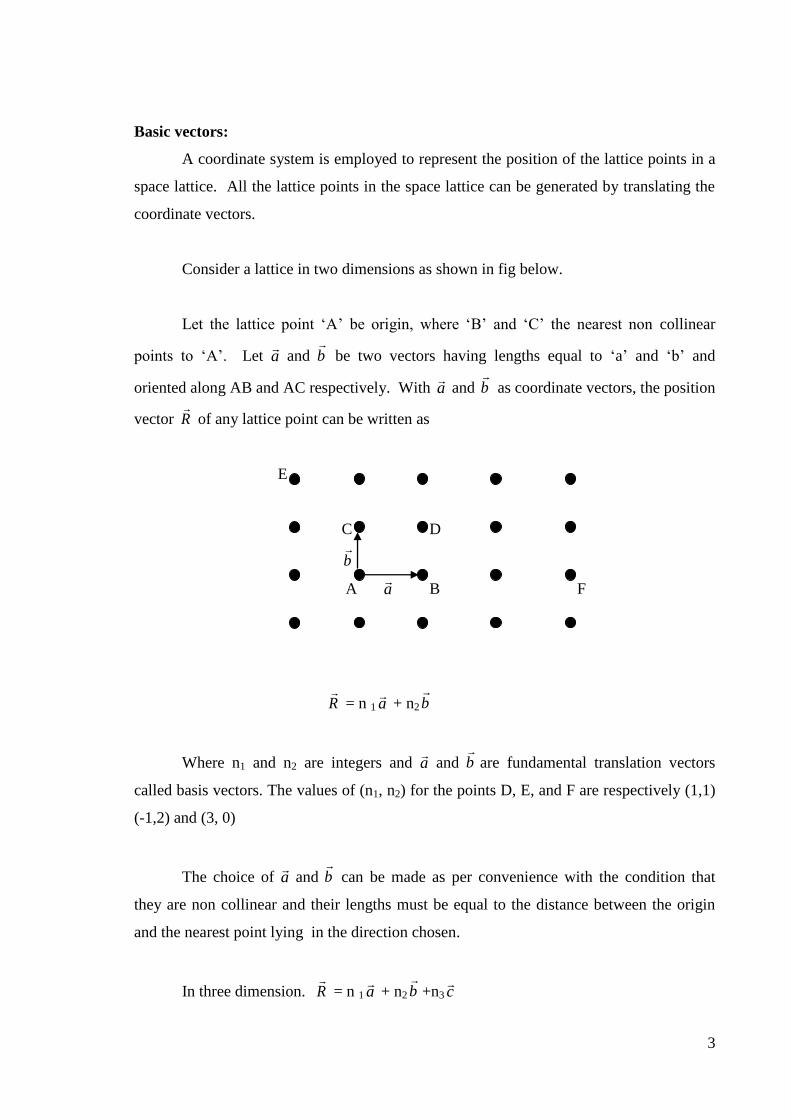
Consider a lattice in two dimensions as shown in fig below.
Let the lattice point ‘A’ be origin, where ‘B’ and ‘C’ the nearest non collinear
points to ‘A’. Let a
and b
be two vectors having lengths equal to ‘a’ and ‘b’ and
oriented along AB and AC respectively. With a
and b
as coordinate vectors, the position
vector R
of any lattice point can be written as
E
C D
b
A a
B F
R
= n 1 a
+ n2 b
Where n1 and n2 are integers and a
and b
are fundamental translation vectors
called basis vectors. The values of (n1, n2) for the points D, E, and F are respectively (1,1)
(-1,2) and (3, 0)
The choice of a
and b
can be made as per convenience with the condition that
they are non collinear and their lengths must be equal to the distance between the origin
and the nearest point lying in the direction chosen.
In three dimension. R
= n 1 a
+ n2 b
+n3 c
4
Here a
, b
and c
are the three vectors called lattice vectors or unit vectors or basis
vectors joining the origin to the nearest, non co-linear lattice points and n1,n2 and n3 are
integers.
Primitive translation vectors:
Translation vectors which produce the translation operation containing integral
coefficients are called as primitive translation vectors.
Non – primitive translation vectors:
Translation vectors which produce a translation operation containing non – integral
coefficients are called non – primitive translation vectors.
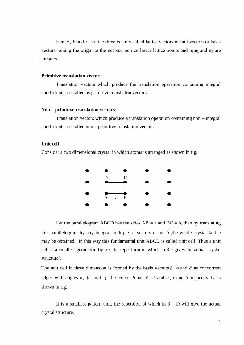
Unit cell
Consider a two dimensional crystal in which atoms is arranged as shown in fig.
D C
A a B
Let the parallelogram ABCD has the sides AB = a and BC = b, then by translating
this parallelogram by any integral multiple of vectors a
and b
,the whole crystal lattice
may be obtained. In this way this fundamental unit ABCD is called unit cell. Thus a unit
cell is a smallest geometric figure, the repeat ion of which in 3D gives the actual crystal
structure’.
The unit cell in three dimension is formed by the basis vectors a
, b
and c
as concurrent
edges with angles α, β and γ between b
and c
, c
and a
, a
and b
respectively as
shown in fig.
It is a smallest pattern unit, the repetition of which in 3 – D will give the actual
crystal structure.

5
Z
X
Y
Thus in general, a unit cell may be defined as that volume of a solid from which
the entire crystal may be constructed by translational repetition in three dimensions.
Primitive unit cell:
Unit cell which contains only one lattice point (or atom) is called Primitive unit
cell
Non primitive unit cell:
Unit cell which contains more than one lattice points (or atoms) is called Non
Primitive unit cell.
Bravis space lattices:
In 1848, Bravis showed that there are only 14 ways of arranging points in space, so
that the environment look the same from each point. In case of cubic system, there are 3
bravices lattices each of which has the same collection of symmetry element at the lattice
points.
i) Simple cubic or primitive cubic (SC):
There is one lattice point at each of the eight corners of the unit cell.

6
ii) Face centered cubic (FCC):
There is one lattice point at each of the eight corners and one lattice point at the centers of
the six faces each.
iii) Body Centered Cubic (BCC):
There is one lattice point at each of the eight corners and one lattice point at the centre
of each cell.
Crystal systems:

7
On the basis of the lengths and directions of the axis of symmetry all the crystals
may be classified into 7 systems as follows.
1. Cubic
2. Tetragonal
3. Orthorhombic
4. Monoclinic
5. Triclinic
6. Hexagonal
7. Trigonal (Rhombohedral)
1. Cubic
The repetition intervals along all the three axes are of equal length and the crystal
axes are perpendicular to each other. The geometrical configuration is, a = b = c and α =
β = γ = 90°. Cubic lattices are of three types namely simple, body centered (BCC) and
face centered (FCC).
Simple cubic (SC) Body-centered cubic (BCC) Face centered cubic (FCC)
a = b = c and α = β = γ = 900
2. Tetragonal
Here two of the axes have repetition intervals of equal length but all the three axes
are perpendicular to each other. The geometrical configuration is, a = b ≠c and α = β =
γ = 90°. There are two types of tetragonal lattice namely simple and body centered.

8
Simple Body-centered
a = b ≠c and α = β = γ = 90°.
3. Orthorhombic
Here all the three axes have unequal lengths but they are perpendicular to each
other. The geometrical configuration is a≠b≠c and α = β = γ = 90°. There are four
different types in this category. They are simple, face centered, body centered and base
centered.
Simple Base-centered Body-centered Face-centered
a≠b≠c and α = β = γ = 90°.
4. Monoclinic:
The three axes are of unequal lengths. Two of them are perpendicular to each
other, but third one is not perpendicular remaining ones. The geometrical configuration is
a≠b≠c and α = β = 90° ≠ γ. Monoclinic lattices are simple or base – centered.

9
Simple Base centered
a≠b≠c and α = β = 90° ≠ γ.
5. Triclinic:
None of the axes are either equal to or perpendicular to any of the other. The
geometrical configuration is a≠b≠c and α ≠ β ≠ γ ≠ 90° .
a≠b≠c and α ≠ β ≠ γ ≠ 90°
6. Hexagonal:
Two of the axes have equal length between which there is an angle of 120°. The third
axis is orientated at 90° to the former two axes. The geometrical configuration is
a = b≠c and α = β = 90°, γ =120°
a = b≠c and α = β = 90°, γ =120°
7. Trigonal (Rhombohedral):

10
All the three axes have equal lengths, and they are oriented to each other at equal
angles, but not equal to 90°. The geometrical configuration is a = b =c and α = β = γ ≠
90°.
a = b =c and α = β = γ ≠ 90°.
Crystal Directions and planes:
It is necessary to use some convention to specify directions and planes in a crystal. For
this purpose the system devised by Miller known as Miller indices is widely used.
Z Ex:
A
b R
O a
X
[ 210]
Y
Consider a cubic lattice in which a straight line is passing through the lattice points ‘o’
and ‘A’ on this point ‘o’ is chosen as origin. Then the vector R
which joins ‘o’ to any
other lattice point on the line such as ‘A’ can be represented as
cnbnanR
321
The direction of the vector R
is depends purely on the integers n1, n2 and n3. since a
,
b
and c
are constants. Here the component of R
along the axis are n 1 =1, n2 =1 and n3
=1. Then the crystal direction is denoted by ‘R’ is written as [111] in Miller notation, with
square brackets enclosing the indices.

11
A family of directions is obtained by all possible combinations of the indices, both
positive and negative. Ex. If we consider the direction [1,0,0], then it has 5 more
directions which are equivalent to it expressed as [0 0 1], [1 0 0 ], [0 1 0] [0 0 1] and
[0 1 0 ] is represented by <1 0 0 > where pointed bracket of the type < > denote the entire
family.
Crystal planes:
The crystal lattice may be regarded as made up of an aggregate of a set of parallel
equidistant planes passing through the lattice points which are known as lattice planes.
For a given lattice, the lattice planes can be chosen in different number of ways. For
example, (a), (b), (c) and (d) as shown in figure below.
a) b)
c) d)
The problem is that how to designate a plane in the crystal.
Miller Indices:
Miller evolved a method to designate a plane in a crystal by three numbers (h k l)
know as miller indices. The position of a crystal plane can be specified in terms of these
three integers.
The rules for finding the Miller indices,
i) Determine the intercepts of plane on three coordinate axis.
ii) Take reciprocals of the intercepts.
iii) Reduce reciprocals into whole numbers; this can be done by multiplying each
reciprocal by LCM of denominator.
iv) Enclose in parentheses.

12
Example: Let us consider a plane which cuts three axis at intercepts 2, 3 and 4 units, then
Miller indices can be found as follows. Y
i) intercepts are 2 ,3, 4
ii) reciprocals of these are 4
1,
3
1,
2
1 Z
iii) LCM of the denominator is 12.
Hence multiply by 12, we get 6, 4, 3 X
iv) Enclose in parenthesis (6 4 3)
Ex: 1. Draw the following planes in a cubic unit cell (1 0 0), (1 1 0) and (1 1 1)
Solution Case 1: (1 0 0) plane, 0
1,
0
1,
1
1 (1∞∞). Hence the plane must be drawn
such that it intercepts the x – axis at 1 unit distance and stands parallel to Y and Z axis.
(100) Plane
Case 2: ( 1 1 0) plane, 0
1,
1
1,
1
1 (1 1 ∞). Hence the plane must be drawn such that it
intercepts the x and y axis at unit distances and stands parallel to z – axis.
(110) Plane
Case 3: ( 1 1 1) plane, 1
1,
1
1,
1
1 (111) Hence the plane must be drawn such that it
intercepts x, y and z axis at unit distances.

13
(111) Plane
2. Draw the following planes in a cubic unit cell
(1 0 0), (0 1 0), (0 0 1) and (1 0 0), ( 0 1 0), ( 0 0 1), ( 1 1 0), ( 1 0 1), (0 1 1) and (1 1 0),
( 1 0 1), ( 0 1 1), ( 1 11), (1 1 1) and (2 0 0), ( 1 1 2), ( 1 2 1)
3. Draw the following planes in the cubic unit cell (0 1 1) (1 0 1) (1 1 0) (1 1 0) (0 1 1) (1
0 1) ( 2 0 0) ( 1 1 2) (1 2 1)
Miller Indices definition: Miller indices is a set of 3 lowest possible integers whose ratio
is taken in order is the same as that of the reciprocals of the intercepts of the planes to the
corresponding axes in the same order.
Expression for inter planar spacing in terms of Miller indices
Y
B
A X
C
Z
Let us consider a plane ABC in a cubic lattice whose Miller indices are (h k l). it
intersects x, y and z axes at a distance pa, qb and rc units from origin

14
Let α, β and γ be the angles made by the normal ON with X, Y and Z axes respctively.
And distance ON = d.
Here a = b = c (∵ cubic lattice)
From fig. ap
d
OA
ON
.cos ---------------(1)
aq
d
OB
ON
.cos ---------------(2)
ar
d
OC
ON
.cos ------------------(3)
Squaring and adding (1) (2) and (3) we get
22
2
22
2
22
2222
r
d
q
d
p
d cos cos cos
aaa ---------------------------(4)
But we know that lr
andkq
hp
11
,1
∵Reciprocals of intercepts is nothing but Miller Indices,
Equation (4) becomes 2
2
22
2
22
2
2222 ddd
cos cos cos la
ka
ha
----------(5)
For Cartesian coordination, we may prove that
1 cos cos cos 222
222
222
2
2
1][lkh
adorlkh
a
d
This gives the expression for interplanar spacing interms of Miller indices.
Expression for angle between Crystal directions
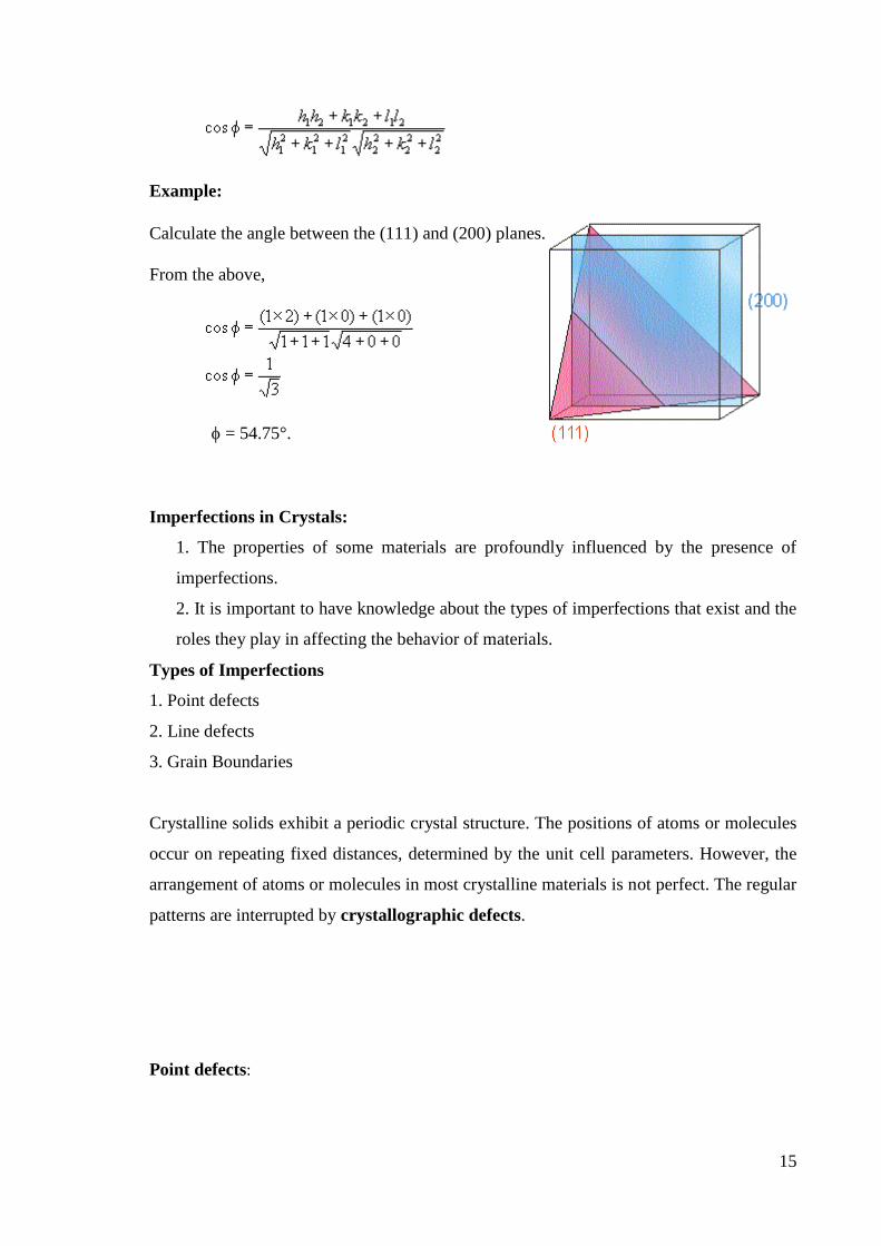
For cubic crystals, the angle, between two planes, (h1 k1 l1) and (h2 k2 l2) is given by:
15
Example:
Calculate the angle between the (111) and (200) planes.
From the above,
= 54.75°.
Imperfections in Crystals:
1. The properties of some materials are profoundly influenced by the presence of
imperfections.
2. It is important to have knowledge about the types of imperfections that exist and the
roles they play in affecting the behavior of materials.
Types of Imperfections
1. Point defects
2. Line defects
3. Grain Boundaries
Crystalline solids exhibit a periodic crystal structure. The positions of atoms or molecules
occur on repeating fixed distances, determined by the unit cell parameters. However, the
arrangement of atoms or molecules in most crystalline materials is not perfect. The regular
patterns are interrupted by crystallographic defects.
Point defects:

16
Point defects are defects that occur only at or around a single lattice point. They are not
extended in space in any dimension. Strict limits for how small a point defect is are
generally not defined explicitly, typically, however, these defects involve at most a few
extra or missing atoms. Larger defects in an ordered structure are usually considered
dislocation loops. For historical reasons, many point defects, especially in ionic crystals,
are called centers: for example a vacancy in many ionic solids is called a luminescence
center, a color center, or F-center. These dislocations permit ionic transport through
crystals leading to electrochemical reactions.
Schottky defect
A Schottky defect is a type of point defect in a crystal lattice named after Walter H.
Schottky. In non-ionic crystals it means a lattice vacancy defect.
The defect-free NaCl structure
Schottky defects within the NaCl structure
17
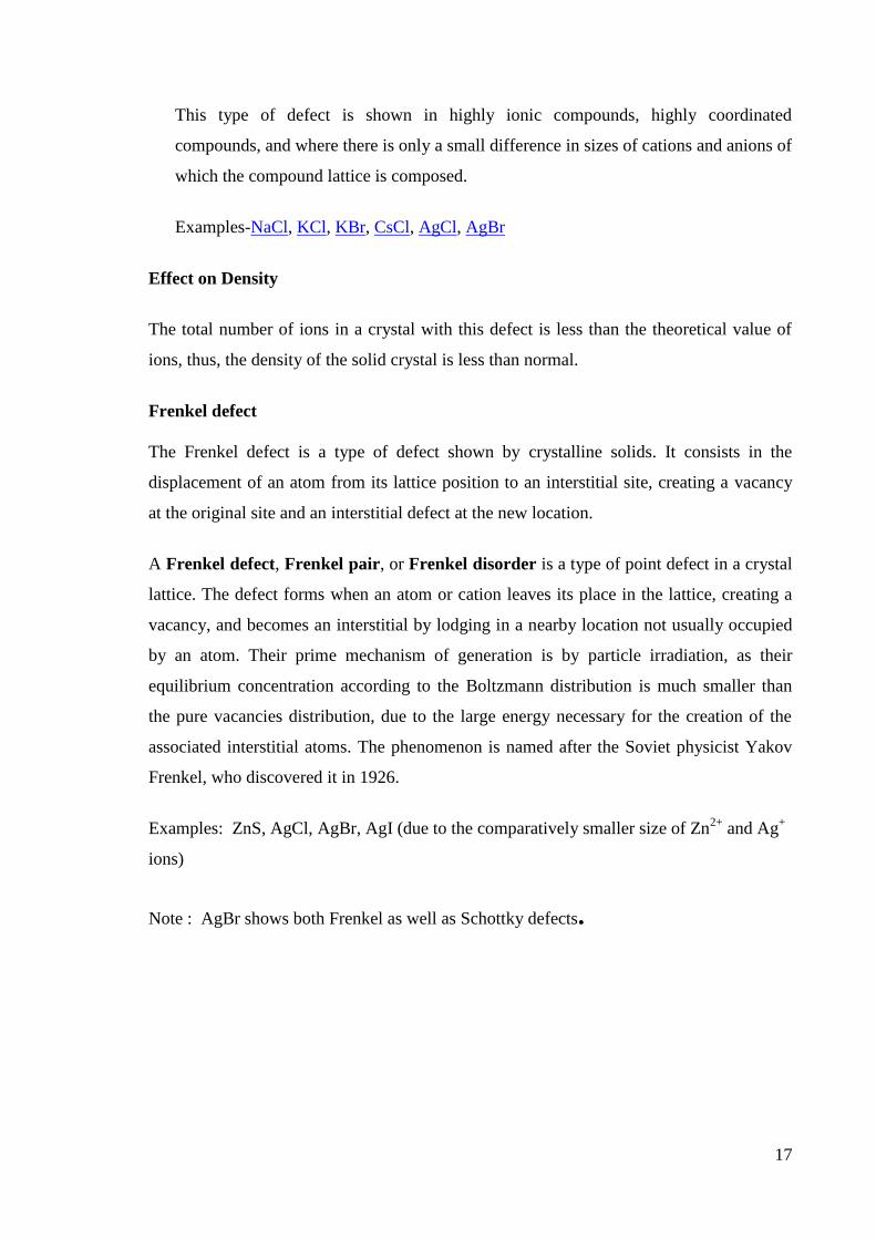
This type of defect is shown in highly ionic compounds, highly coordinated
compounds, and where there is only a small difference in sizes of cations and anions of
which the compound lattice is composed.
Examples-NaCl, KCl, KBr, CsCl, AgCl, AgBr
Effect on Density
The total number of ions in a crystal with this defect is less than the theoretical value of
ions, thus, the density of the solid crystal is less than normal.
Frenkel defect
The Frenkel defect is a type of defect shown by crystalline solids. It consists in the
displacement of an atom from its lattice position to an interstitial site, creating a vacancy
at the original site and an interstitial defect at the new location.
A Frenkel defect, Frenkel pair, or Frenkel disorder is a type of point defect in a crystal
lattice. The defect forms when an atom or cation leaves its place in the lattice, creating a
vacancy, and becomes an interstitial by lodging in a nearby location not usually occupied
by an atom. Their prime mechanism of generation is by particle irradiation, as their
equilibrium concentration according to the Boltzmann distribution is much smaller than
the pure vacancies distribution, due to the large energy necessary for the creation of the
associated interstitial atoms. The phenomenon is named after the Soviet physicist Yakov
Frenkel, who discovered it in 1926.
Examples: ZnS, AgCl, AgBr, AgI (due to the comparatively smaller size of Zn2+
and Ag+
ions)
Note : AgBr shows both Frenkel as well as Schottky defects.
18
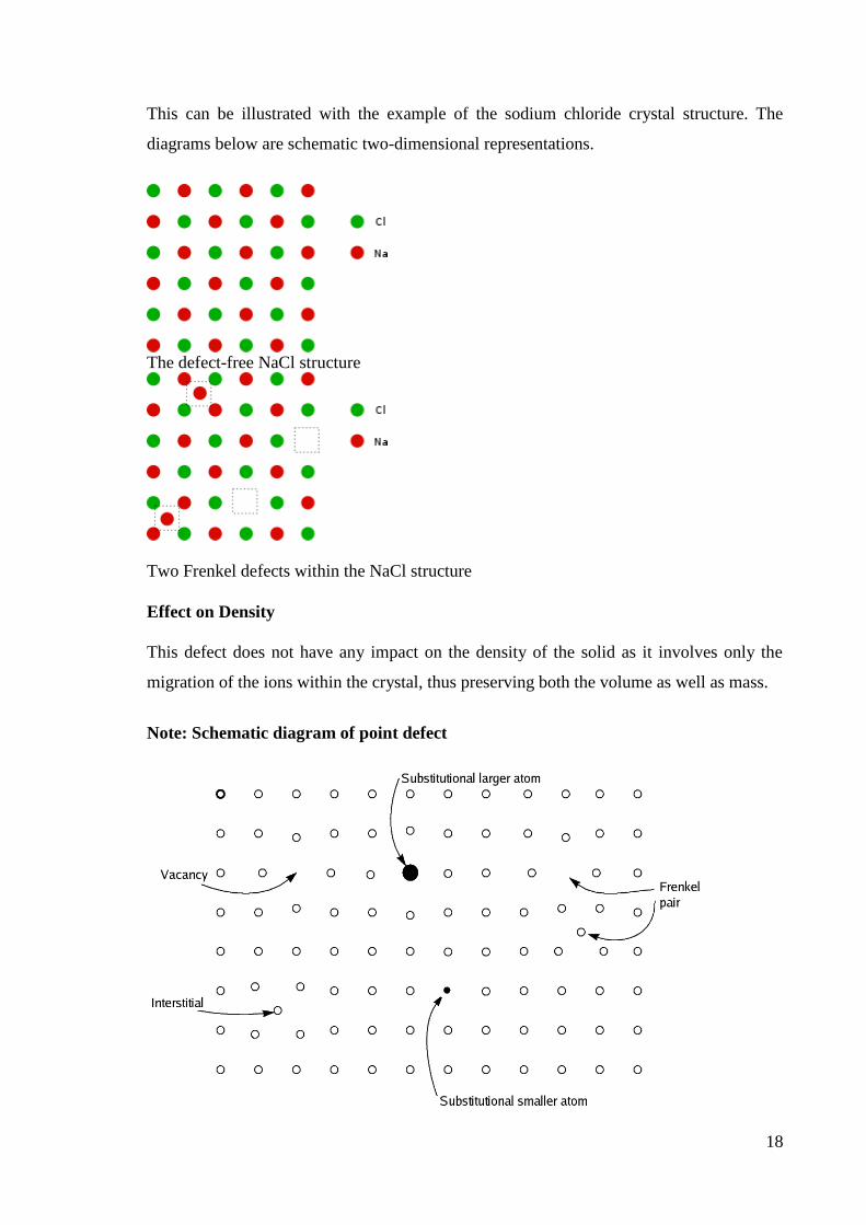
This can be illustrated with the example of the sodium chloride crystal structure. The
diagrams below are schematic two-dimensional representations.
The defect-free NaCl structure
Two Frenkel defects within the NaCl structure
Effect on Density
This defect does not have any impact on the density of the solid as it involves only the
migration of the ions within the crystal, thus preserving both the volume as well as mass.
Note: Schematic diagram of point defect

19
Line defects
Line defects can be described by gauge theories.
Dislocations are linear defects around which some of the atoms of the crystal lattice are
misaligned.
There are two basic types of dislocations-
1.The edge dislocation
2.The screw dislocation
Edge dislocations are caused by the termination of a plane of atoms in the middle of a
crystal. In such a case, the adjacent planes are not straight, but instead bend around the
edge of the terminating plane so that the crystal structure is perfectly ordered on either
side.
An edge dislocation is a defect where an extra half-plane of atoms is introduced mid way
through the crystal, distorting nearby planes of atoms. When enough force is applied from
one side of the crystal structure, this extra plane passes through planes of atoms breaking
and joining bonds with them until it reaches the grain boundary. Figure 1 represents the
"extra half-plane" concept of an edge type dislocation. The dislocation has two properties,
a line direction, which is the direction running along the bottom of the extra half plane,
and the Burgers vector which describes the magnitude and direction of distortion to the
lattice. In an edge dislocation, the Burgers vector is perpendicular to the line direction.
Figure 1 : An edge dislocation is shown. The dislocation line is presented in blue, the
Burgers vector b in black.
20
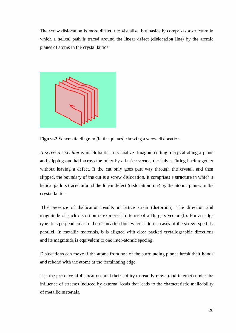
The screw dislocation is more difficult to visualise, but basically comprises a structure in
which a helical path is traced around the linear defect (dislocation line) by the atomic
planes of atoms in the crystal lattice.
Figure-2 Schematic diagram (lattice planes) showing a screw dislocation.
A screw dislocation is much harder to visualize. Imagine cutting a crystal along a plane
and slipping one half across the other by a lattice vector, the halves fitting back together
without leaving a defect. If the cut only goes part way through the crystal, and then
slipped, the boundary of the cut is a screw dislocation. It comprises a structure in which a
helical path is traced around the linear defect (dislocation line) by the atomic planes in the
crystal lattice
The presence of dislocation results in lattice strain (distortion). The direction and
magnitude of such distortion is expressed in terms of a Burgers vector (b). For an edge
type, b is perpendicular to the dislocation line, whereas in the cases of the screw type it is
parallel. In metallic materials, b is aligned with close-packed crytallographic directions
and its magnitude is equivalent to one inter-atomic spacing.
Dislocations can move if the atoms from one of the surrounding planes break their bonds
and rebond with the atoms at the terminating edge.
It is the presence of dislocations and their ability to readily move (and interact) under the
influence of stresses induced by external loads that leads to the characteristic malleability
of metallic materials.

21
Note: Dislocations can be observed using transmission electron microscopy, field ion
microscopy and atom probe techniques. Deep level transient spectroscopy has been used
for studying the electrical activity of dislocations in semiconductors, mainly silicon.
Braggs diffraction:
X-rays form a part of electromagnetic spectrum. Like visible light x-rays undergo
diffraction. Since the wavelength of x-rays is of the order of 1 Å, one needs a grating with
line spacing comparable to this dimension in order to diffract them. Crystals have regular
arrangement of atoms in three dimension at intervals of a few Å. It was suggested by
German physicist Laue that crystals would act as grating for x-ray diffraction. Subsequent
experiments provided the x-ray diffraction pattern us crystals as grating. X-ray diffraction
pattern depends on the arrangement of atoms in the crystal and hence gives information
about the structure of the material.
Bragg considered crystal in terms of planes in which; a regularity in the
distribution of atoms could be identified. It is possible to identify different family of
planes and are called Bragg planes. Bragg considered an x – ray beam of wavelength λ
incident in a direction at an angle θ to a family of Bragg planes with inteplanar spacidng
‘d’ and showed that constructive interference takes place between the rays scattered by the
22
atoms in different Bragg planes, when the condition 2dsinθ = nλ is obeyed. Wehre ‘n’ is
an integer, the above condition is known as Bragg’s law.
To verify the Bragg’s law, crystal is mounted at an angle θ to the incident direction
of x – rays and detected the scattered radiations. The detector shows peak for only those
angles which satisfy the Bragg’s law.
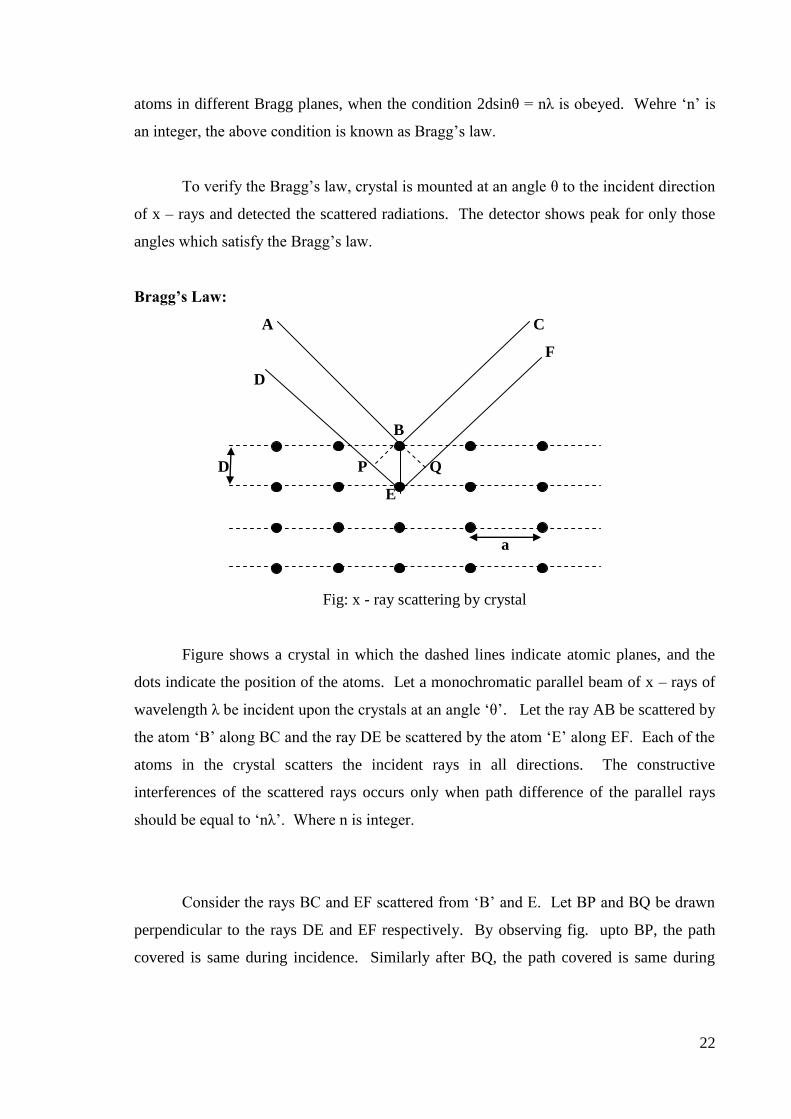
Bragg’s Law:
A C
F
D
B
D P Q
E
a
Fig: x - ray scattering by crystal
Figure shows a crystal in which the dashed lines indicate atomic planes, and the
dots indicate the position of the atoms. Let a monochromatic parallel beam of x – rays of
wavelength λ be incident upon the crystals at an angle ‘θ’. Let the ray AB be scattered by
the atom ‘B’ along BC and the ray DE be scattered by the atom ‘E’ along EF. Each of the
atoms in the crystal scatters the incident rays in all directions. The constructive
interferences of the scattered rays occurs only when path difference of the parallel rays
should be equal to ‘nλ’. Where n is integer.
Consider the rays BC and EF scattered from ‘B’ and E. Let BP and BQ be drawn
perpendicular to the rays DE and EF respectively. By observing fig. upto BP, the path
covered is same during incidence. Similarly after BQ, the path covered is same during

23
scattering. Hence the excess from ‘δ’ travelled by the ray DEF over that along ABC cam
be written as δ=PE + E Q
But SinBE
PE in Triangle PBE and
SinBE
EQ in Triangle BEQ
δ= BE Sinθ + BE sinθ
but BE is the interplanar spacing, denoted by ‘ d’
δ= 2d sinθ
constructive interference takesplace if δ= nλ where n = 1, 2, 3,..........., i.e, if
2d sinθ = nλ
This is called Bragg’s law and θ is called glancing angle.
Powder diffraction method:
The Laue and Bragg’s techniques can be applied only to single crystals. In general
it is difficult to obtain large crystals without defects. The need for large crystal is
overcome in the powder diffraction method. In this technique, the specimen is ground into
a fine powder and is contained in a thin glass capsule. Monochromatic collimated x-ray
beam falls on the powdered specimen. The specimen mounted vertically on the axis of a
cylindrical camera. The photographic film is mounted on the inner surface of the camera,
covering the entire surface.
The powdered sample consists of a large number of randomly oriented tiny
crystals. These tiny crystals present all values of glancing angle to the incident beam. For a
given wavelength λ and interplanar spacing d, there can only be one θ which satisfies the

24
equation n 2dsin where n is an integer > 0. The scattered beams emanate as conical
waves and intercept the film resulting in arcs.
Let R be the radius of the camera. The direct beam strikes the film at O. Suppose
the spectrum with diffraction angle θ is formed at A, with a distance S from O. Then
2 R S
This gives, S
2R
Using θ in Bragg’s law, knowing λ, d can be determined. The powder diffraction is
useful in analyzing microcrystalline materials like metals, alloys, carbon, fluorescent
powders and other forms where single crystals are not available.
The impressions on the film
Copyright © 2022 FDOKUMEN