Unimotor FM Brochure 05.indd - Nidec Motor Corporation
28
075 to 250 Frames 1.4 Nm to 136 Nm (408 Nm Peak) SERVO MOTOR SERIES UNIMOTOR FM AC brushless servo motor
-
Upload
khangminh22 -
Category
Documents
-
view
0 -
download
0
Transcript of Unimotor FM Brochure 05.indd - Nidec Motor Corporation
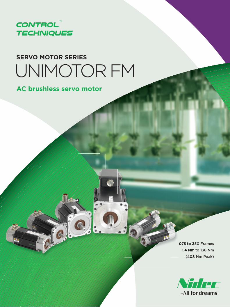
075 to 250 Frames
1.4 Nm to 136 Nm
(408 Nm Peak)
075 to 250 Frames
1.4 Nm to 136 Nm
(408 Nm Peak)
SERVO MOTOR SERIES
UNIMOTOR FMAC brushless servo motor

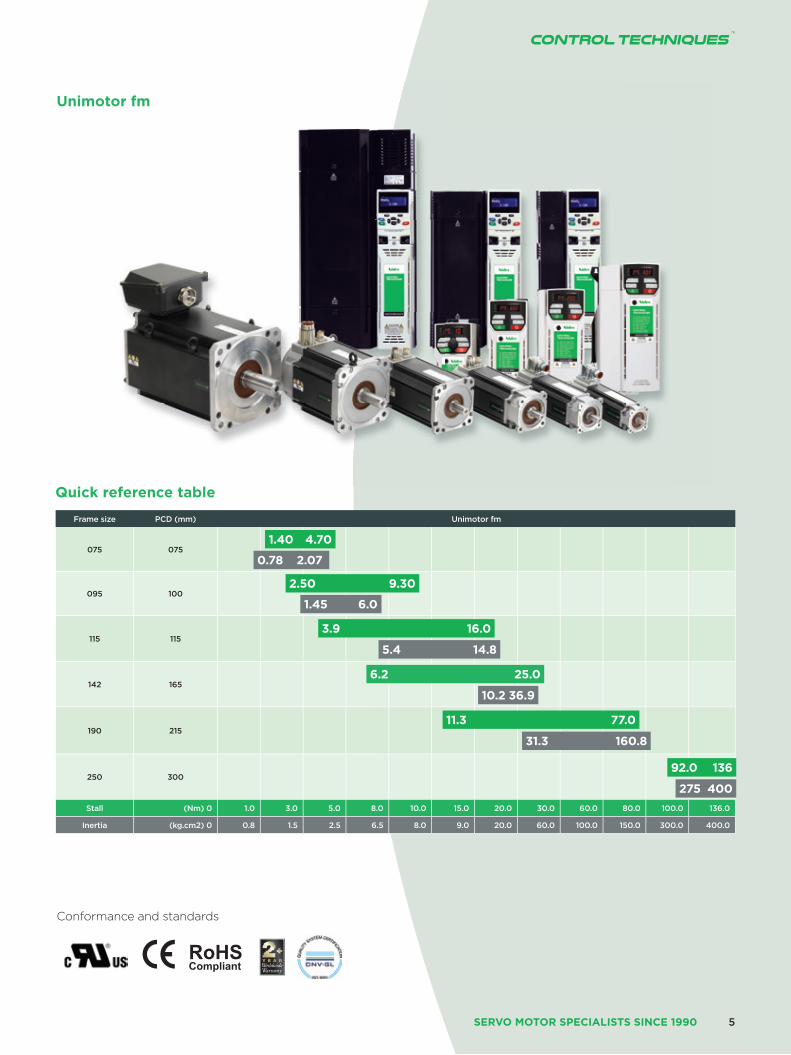
Unimotor fmUnimotor fm is a high performance brushless AC servo motor range designed for use in demanding continuous duty applications. The motors are available in six frame sizes with various mounting arrangements and motor lengths.
Accuracy and resolution to suit your application requirements
Choosing the right feedback device for your application is critical in getting optimum performance. Unimotor fm has a range of feedback options that off er diff erent levels of accuracy and resolution to suit most applications:
• Resolver: robust for extreme applications and conditions – low accuracy, medium resolution
• Incremental encoder: high accuracy, medium resolution
• Inductive/capacitive SinCos/Absolute: medium accuracy, high resolution
• Optical/SinCos/Absolute: high accuracy, high resolution
• Single turn and multi-turn: Hiperface and EnDat protocols supported
Ideal for retrofit
Unimotor fm is an ideal retrofi t choice with features to ensure it can integrate easily with your existing servo motor applications. Unimotor fm has been designed so that existing Unimotor customers can easily migrate to the new platform. All connector interface types and mounting dimensions remain the same. If you are planning to retrofi t your system, Unimotor fm is the obvious choice.
Reliability and innovation
Unimotor fm is designed using a proven development process that prioritizes innovation and reliability. This process has resulted in a market leading reputation for both performance and quality.
Matched motor and drive combinations
Drives and motors from Control Techniques are designed to function as an optimized system. Unimotor fm is the perfect partner for Unidrive M and Digitax ST.
Faster set-up, optimizedperformance
When a Control Techniques servo drive is connected to a Unimotor fm fi tted with a SinCos or Absolute encoder, it can recognize and communicate with the motor to obtain the “electronic nameplate” data. This motor data can then be used to automatically optimize the drive settings. This feature simplifi es commissioning and maintenance, ensures consistent performance and saves time.
www.controltechniques.com2
SERVO MOTOR SERIES
SERVO MOTOR SPECIALISTS SINCE 1990
Features
Unimotor fm is suitable for a wide range of industrial applications, due to it’s extensive range of features:
• • Torque range from 1.4 Nm to 136 Nm
• • High energy parking brakes
• • Numerous connector variants, including: vertical, 90° low profi le, 90° rotatable and hybrid box on frame size 250
• • Variety of fl ange possibilities (IEC/NEMA)
• • Various shaft diameters; keyed or plain
• • IP65 conformance; sealed against water spray and dust when mounted and connected
• • Low inertia for high dynamic performance; high inertia option available
• • World class performance
• • Winding voltages for inverter supply of 400 V and 220 V
• • Rated speeds from 1,000 to 6,000 rpm and others available
• • Thermal protection by PTC thermistor/optional KTY84.130 sensor
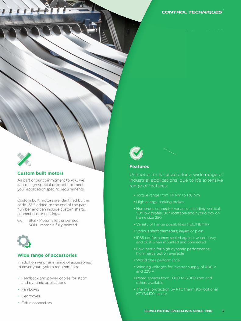
Custom built motors
As part of our commitment to you, we can design special products to meetyour application specifi c requirements.
Custom built motors are identifi ed by the code -S*** added to the end of the part number and can include custom shafts, connections or coatings.
e.g. SPZ - Motor is left unpainted SON - Motor is fully painted
Wide range of accessories
In addition we off er a range of accessories to cover your system requirements:
• Feedback and power cables for static and dynamic applications
• Fan boxes
• Gearboxes
• Cable connectors
3

www.controltechniques.com4
SERVO MOTOR SERIES
SERVO MOTOR SPECIALISTS SINCE 1990
Conformance and standards
Unimotor fm
Quick reference table
Frame size PCD (mm) Unimotor fm
075 075
095 100
115 115
142 165
190 215
250 300
Stall (Nm) 0 1.0 3.0 5.0 8.0 10.0 15.0 20.0 30.0 60.0 80.0 100.0 136.0
Inertia (kg.cm2) 0 0.8 1.5 2.5 6.5 8.0 9.0 20.0 60.0 100.0 150.0 300.0 400.0
1.40 4.70
0.78 2.07
1.45 6.0
5.4 14.8
10.2 36.9
31.3 160.8
275 400
2.50 9.30
3.9 16.0
6.2 25.0
11.3 77.0
92.0 136
5
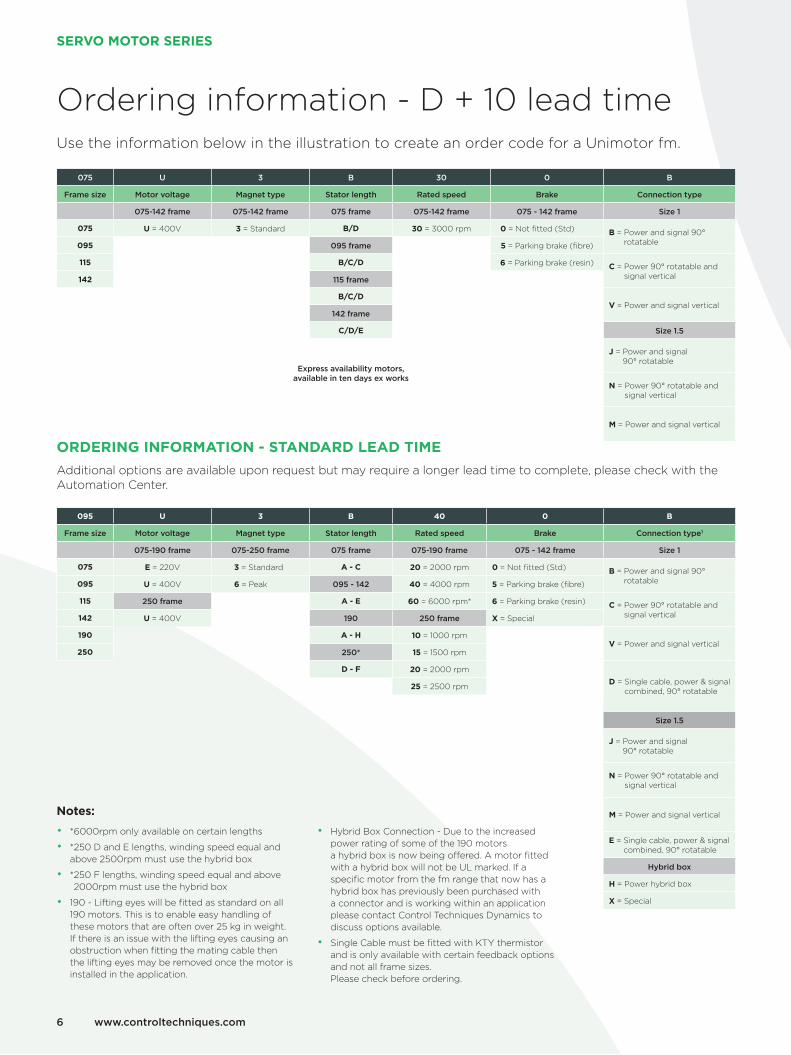
ORDERING INFORMATION - STANDARD LEAD TIME
Additional options are available upon request but may require a longer lead time to complete, please check with the Automation Center.
095 U 3 B 40 0 B
Frame size Motor voltage Magnet type Stator length Rated speed Brake Connection type1
075-190 frame 075-250 frame 075 frame 075-190 frame 075 - 142 frame Size 1
075 E = 220V 3 = Standard A - C 20 = 2000 rpm 0 = Not fitted (Std) B = Power and signal 90° rotatable095 U = 400V 6 = Peak 095 - 142 40 = 4000 rpm 5 = Parking brake (fibre)
115 250 frame A - E 60 = 6000 rpm* 6 = Parking brake (resin) C = Power 90° rotatable and signal vertical142 U = 400V 190 250 frame X = Special
190 A - H 10 = 1000 rpmV = Power and signal vertical
250 250* 15 = 1500 rpm
D - F 20 = 2000 rpm
D = Single cable, power & signal combined, 90° rotatable25 = 2500 rpm
Size 1.5
J = Power and signal 90° rotatable
N = Power 90° rotatable and signal vertical
M = Power and signal vertical
E = Single cable, power & signal combined, 90° rotatable
Hybrid box
H = Power hybrid box
X = Special
Ordering information - D + 10 lead timeUse the information below in the illustration to create an order code for a Unimotor fm.
075 U 3 B 30 0 B
Frame size Motor voltage Magnet type Stator length Rated speed Brake Connection type
075-142 frame 075-142 frame 075 frame 075-142 frame 075 - 142 frame Size 1
075 U = 400V 3 = Standard B/D 30 = 3000 rpm 0 = Not fitted (Std) B = Power and signal 90° rotatable095 095 frame 5 = Parking brake (fibre)
115 B/C/D 6 = Parking brake (resin) C = Power 90° rotatable and signal vertical142 115 frame
B/C/DV = Power and signal vertical
142 frame
C/D/E Size 1.5
J = Power and signal 90° rotatable
Express availability motors, available in ten days ex works
N = Power 90° rotatable and signal vertical
M = Power and signal vertical
Notes:
• *6000rpm only available on certain lengths
• *250 D and E lengths, winding speed equal and above 2500rpm must use the hybrid box
• * 250 F lengths, winding speed equal and above 2000rpm must use the hybrid box
• 190 - Lifting eyes will be fitted as standard on all 190 motors. This is to enable easy handling of these motors that are often over 25 kg in weight. If there is an issue with the lifting eyes causing an obstruction when fitting the mating cable then the lifting eyes may be removed once the motor is installed in the application.
• Hybrid Box Connection - Due to the increased power rating of some of the 190 motors a hybrid box is now being offered. A motor fitted with a hybrid box will not be UL marked. If a specific motor from the fm range that now has a hybrid box has previously been purchased with a connector and is working within an application please contact Control Techniques Dynamics to discuss options available.
• Single Cable must be fitted with KTY thermistor and is only available with certain feedback options and not all frame sizes. Please check before ordering.
www.controltechniques.com6
SERVO MOTOR SERIES
SERVO MOTOR SPECIALISTS SINCE 1990
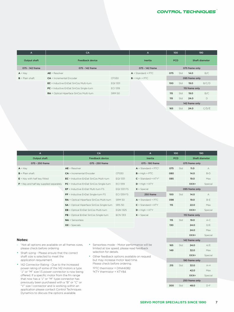
A CA A 100 190
Output shaft Feedback device Inertia PCD Shaft diameter
075 - 142 frame 075 - 142 frame 075 - 142 frame 075 frame only
A = Key AE = Resolver A = Standard + PTC 075 Std 14.0 B/C
B = Plain shaft CA = Incremental Encoder CFS50 B = High + PTC 095 frame only
EC = Inductive EnDat SinCos Multi-turn EQI 1331 100 Std 19.0 B/C/D
FC = Inductive EnDat SinCos Single-turn ECI 1319 115 frame only
RA = Optical Hiperface SinCos Multi-turn SRM 50 115 Std 19.0 B/C
115 Std 24.0 D
142 frame only
165 Std 24.0 C/D/E
A CA A 100 190
Output shaft Feedback device Inertia PCD Shaft diameter
075 - 250 frame 075 - 250 frame 075 - 190 frame 075 frame only
A = Key AE = Resolver A = Standard + PTC2 075 Std 11.0 A
B = Plain shaft CA = Incremental Encoder CFS50 B = High + PTC 080 14.0 B-D
E = Key with half key fitted EC = Inductive EnDat SinCos Multi-turn EQI 1331 C = Standard + KTY3 085 19.0 Max
F = Key and half key supplied separately FC = Inductive EnDat SinCos Single-turn ECI 1319 D = High + KTY XXX= Special
EF = Inductive EnDat Multi-turn FS EQI 1331 FS X = Special 095 frame only
FF = Inductive EnDat Single-turn FS ECI 1319 FS 250 frame 100 Std 14.0 A
RA = Optical Hiperface SinCos Multi-turn SRM 50 A = Standard + PTC 098 19.0 B-E
SA = Optical Hiperface SinCos Single-turn SRS 50 C = Standard + KTY 115 22.0 Max
EB = Optical EnDat SinCos Multi-turn EQN 1325 D = High + KTY XXX= Special
FB = Optical EnDat SinCos Single-turn ECN 1313 X = Special 115 frame only
NA = Sensorless 115 Std 19.0 A-C
XX = Specials 130 24.0 D/E
24.0 Max
XXX= Special
142 frame only
165 Std 24.0 A/E
149 32.0 Max
XXX= Special
190 frame only
215 Std 32.0 A-H
42.0 Max
XXX= Special
250 frame only
300 Std 48.0 D-F
Notes:• 1 Not all options are available on all frames sizes,
please check before ordering
• Shaft sizing - Please ensure that the correct shaft size is selected to meet the application requirement.
• 142 Connector Rating - Due to the increased power rating of some of the 142 motors a type “J” or “M” size 1.5 power connector is now being offered. If a specific motor from the fm range that now has a “J” or “M” type connector has previously been purchased with a “B” or “C” or “V” size 1 connector and is working within an application please contact Control Techniques Dynamics to discuss the options available.
• Sensorless mode - Motor performance will be limited at low speed, please read feedback selection for details.
• Other feedback options available on request but may increase motor lead time. Please check before ordering.
2PTC thermistor = DIN44082 3KTY thermistor = KTY84
7

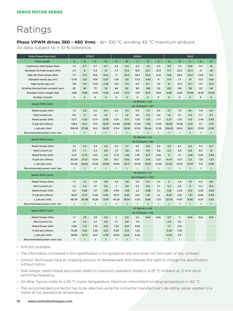
Ratings3 Phase VPWM drives 200-240Vrms - ∆t= 100°C winding 40°C maximum ambient. All data subject to +/-10% tolerance
• N/A Not available
• The information contained in this specification is for guidance only and does not form part of any contract.
• Control Techniques have an ongoing process of development and reserves the right to change the specification without notice.
• Stall torque, rated torque and power relate to maximum operation tested in a 20 °C ambient at 12 kHz drive switching frequency.
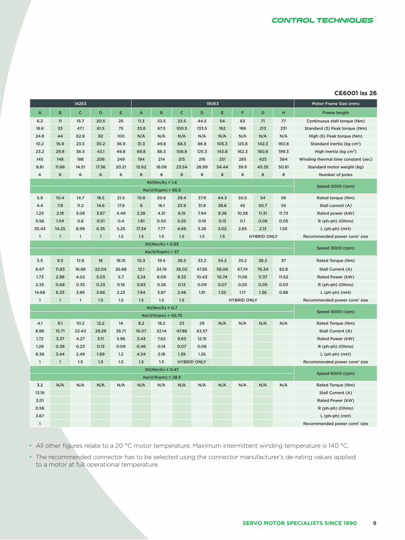
Motor Frame Size (mm) 075E3 095E3 115E3 142E3 190E3 Motor Frame Size (mm)
Frame length A B C D A B C D E A B C D E A B C D E A B C D E F G H Frame length
Continuous stall torque (Nm) 1.4 2.7 3.7 4.7 2.5 4.5 6.3 7.9 9.3 3.9 7.4 10.8 13.7 16 6.2 11 15.7 20.5 25 11.3 22.5 33.5 44.5 54 63 71 77 Continuous stall torque (Nm)
Standard (3) Peak torque (Nm) 4.3 8 11.2 14 7.4 13.5 18.9 23.7 27.8 11.7 22.2 32.4 41 48 18.6 33 47.1 61.5 75 33.8 67.5 100.5 133.5 162 189 213 231 Standard (3) Peak torque (Nm)
High (6) Peak torque (Nm) 7.2 13.3 18.6 23.4 11 20.3 28.4 35.6 41.6 15.6 29.6 43.2 54.6 64 24.8 44 62.8 82 100 N/A N/A N/A N/A N/A N/A N/A N/A High (6) Peak torque (Nm)
Standard inertia (kg cm2) 0.78 1.22 1.64 2.07 1.45 2.6 3.72 4.83 6 5.4 7.7 10 12.5 14.8 10.2 16.9 23.5 30.2 36.9 31.3 49.8 68.3 86.8 105.3 123.8 142.3 160.8 Standard inertia (kg cm2)
High Inertia (kg cm²) 1.18 1.61 2.03 2.46 3.31 4.5 5.6 6.7 7.8 10 12.3 14.7 17.1 19.4 23.2 29.8 36.5 43.1 49.8 69.8 88.3 106.8 125.3 143.8 162.3 180.8 199.3 High Inertia (kg cm²)
Winding thermal time constant (sec) 63 58 73 78 84 82 90 108 112 103 109 116 127 141 145 148 188 206 249 194 214 215 216 251 285 425 564 Winding thermal time constant (sec)
Standard motor weight (kg) 2.88 3.68 4.48 5.28 4.49 5.75 7.01 8.27 9.53 6.88 8.68 10.48 12.28 14.08 8.81 11.66 14.51 17.36 20.21 12.62 18.08 23.54 28.99 34.44 39.9 45.35 50.81 Standard motor weight (kg)
Number of poles 6 6 6 6 6 6 6 6 6 6 6 6 6 6 6 6 6 6 6 8 8 8 8 8 8 8 8 Number of poles
Speed 2000 (rpm)Kt(Nm/A) = 1.4 Kt(Nm/A) = 1.4
Speed 2000 (rpm) Ke(V/Krpm) = 85.5 Ke(V/Krpm) = 85.5
Rated torque (Nm) 1.3 2.5 3.5 4.5 2.4 4.3 5.9 7.3 8.5 3.7 7.3 10.1 11.9 14.1 5.9 10.4 14.7 18.5 21.5 10.8 20.6 29.4 37.9 44.3 50.5 54 56 Rated torque (Nm)
Stall current (A) 1 1.9 2.7 3.3 1.8 3.2 4.5 5.6 6.6 2.8 5.3 7.7 9.8 11.4 4.4 7.9 11.2 14.6 17.9 8 16.1 23.9 31.8 38.6 45 50.7 55 Stall current (A)
Rated power (kW) 0.27 0.52 0.73 0.93 0.51 0.9 1.23 1.53 1.77 0.77 1.53 2.12 2.49 2.95 1.23 2.18 3.08 3.87 4.49 2.26 4.31 6.15 7.94 9.28 10.58 11.31 11.73 Rated power (kW)
R (ph-ph) (Ohms) 48.24 16.32 8.96 6.22 20.69 6.78 3.79 2.42 1.92 10.65 3.43 1.82 1.81 1.34 5.56 1.54 0.8 0.51 0.4 1.81 0.50 0.25 0.19 0.13 0.1 0.08 0.05 R (ph-ph) (Ohms)
L (ph-ph) (mH) 87.47 39.77 24.68 19.15 57.78 26.10 16.36 11.83 9.75 55.83 19.43 12.31 9.50 7.68 35.43 14.25 8.99 6.35 5.25 17.34 7.77 4.66 3.26 3.02 2.65 2.13 1.55 L (ph-ph) (mH)
Recommended power conn' size 1 1 1 1 1 1 1 1 1 1 1 1 1 1 1 1 1 1 1.5 1.5 1.5 1.5 1.5 1.5 HYBRID ONLY Recommended power conn' size
Speed 3000 (rpm)Kt(Nm/A) = 0.93 Kt(Nm/A) = 0.93
Speed 3000 (rpm)Ke(V/Krpm) = 57 Ke(V/Krpm) = 57
Rated Torque (Nm) 1.3 2.3 3.3 4.2 2.33 4.1 5.6 6.9 8.15 3.5 6.7 9.5 11.2 12.7 5.5 9.5 12.8 16 18.15 10.3 19.4 26.5 33.2 34.2 35.2 36.2 37 Rated Torque (Nm)
Stall Current (A) 1.55 2.85 4 5.02 2.63 4.84 6.77 8.49 9.95 4.19 7.96 11.61 14.68 17.2 6.67 11.83 16.88 22.04 26.88 12.1 24.19 36.02 47.85 58.06 67.74 76.34 82.8 Stall Current (A)
Rated Power (kW) 0.41 0.72 1.04 1.31 0.73 1.29 1.76 2.17 2.56 1.1 2.1 2.98 3.52 3.99 1.73 2.98 4.02 5.03 5.7 3.24 6.09 8.33 10.43 10.74 11.06 11.37 11.62 Rated Power (kW)
R (ph-ph) (Ohms) 19.80 6.69 3.71 2.72 9.62 2.99 1.64 1.07 0.86 4.91 1.52 0.81 0.57 0.43 2.25 0.68 0.35 0.23 0.16 0.83 0.26 0.13 0.09 0.07 0.05 0.05 0.03 R (ph-ph) (Ohms)
L (ph-ph) (mH) 37.20 16.8 10.69 8.27 26.29 11.47 7.15 5.16 4.35 20.26 8.63 5.47 4.35 3.41 14.68 6.33 3.89 3.66 2.23 7.94 3.87 2.46 1.81 1.55 1.17 1.36 0.88 L (ph-ph) (mH)
Recommended power conn’ size 1 1 1 1 1 1 1 1 1 1 1 1 1 HYBRID 1 1 1 1.5 1.5 1.5 1.5 1.5 HYBRID ONLY Recommended power conn’ size
Speed 4000 (rpm)Kt(Nm/A) = 0.7 Kt(Nm/A) = 0.7
Speed 4000 (rpm) Ke(V/Krpm) = 42.75 Ke(V/Krpm) = 42.75
Rated Torque (Nm) 1.2 2.1 2.8 3.8 2.3 3.8 5.3 6.4 7.4 3 5.8 7.5 8.3 8.8 4.1 8.1 10.2 12.2 14 8.2 18.2 23 29 N/A N/A N/A N/A Rated Torque (Nm)
Stall Current (A) 2.06 3.79 5.31 6.67 3.5 6.43 9 11.29 13.21 5.57 10.57 15.43 19.5 22.86 8.86 15.71 22.43 29.29 35.71 16.07 32.14 47.86 63.57 Stall Current (A)
Rated Power (kW) 0.5 0.86 1.17 1.59 0.94 1.59 2.2 2.68 3.1 1.26 2.43 3.12 3.46 3.69 1.72 3.37 4.27 5.11 5.86 3.43 7.62 9.63 12.15 Rated Power (kW)
R (ph-ph) (Ohms) 12.44 4.01 2.26 1.53 5.26 1.76 1.04 0.74 0.48 3.05 0.93 0.49 0.3 0.27 1.29 0.38 0.23 0.13 0.09 0.46 0.14 0.07 0.06 R (ph-ph) (Ohms)
L (ph-ph) (mH) 23.35 9.62 6.32 4.63 14.94 6.67 4.52 3.53 2.44 12.44 5.13 3.34 2.25 2.18 8.39 3.44 2.49 1.99 1.2 4.34 2.18 1.39 1.26 L (ph-ph) (mH)
Recommended power conn’ size 1 1 1 1 1 1 1 1 1 1 1 1 1 HYBRID 1 1 1.5 1.5 1.5 1.5 1.5 HYBRID ONLY Recommended power conn’ size
Speed 6000 (rpm)Kt(Nm/A) = 0.47 Kt(Nm/A) = 0.47
Speed 6000 (rpm)Ke(V/Krpm) = 28.5 Ke(V/Krpm) = 28.5
Rated Torque (Nm) 1.1 1.9 2.8 3.4 1.98 3.2 4.2 N/A N/A 2.7 5 3.2 N/A N/A N/A N/A N/A N/A N/A N/A N/A N/A N/A N/A Rated Torque (Nm)
Stall Current (A) 3.06 5.64 7.91 9.94 5.21 9.57 13.4 8.3 15.74 13.19 Stall Current (A)
Rated Power (kW) 0.68 1.21 1.73 2.14 1.24 2.01 2.64 1.7 3.14 2.01 Rated Power (kW)
R (ph-ph) (Ohms) 5.37 1.81 1.02 0.68 2.33 0.73 0.46 1.5 0.41 0.56 R (ph-ph) (Ohms)
L (ph-ph) (mH) 9.8 4.42 2.88 2.06 6.57 2.77 2.07 6.08 2.34 3.67 L (ph-ph) (mH)
Recommended power conn’ size 1 1 1 1 1 1 1 1 1 1 Recommended power conn’ size
www.controltechniques.com8
SERVO MOTOR SERIES
SERVO MOTOR SPECIALISTS SINCE 1990
• All other figures relate to a 20 °C motor temperature. Maximum intermittent winding temperature is 140 °C.
• The recommended connector has to be selected using the connector manufacturer’s de-rating values applied to a motor at full operational temperature.
Motor Frame Size (mm) 075E3 095E3 115E3 142E3 190E3 Motor Frame Size (mm)
Frame length A B C D A B C D E A B C D E A B C D E A B C D E F G H Frame length
Continuous stall torque (Nm) 1.4 2.7 3.7 4.7 2.5 4.5 6.3 7.9 9.3 3.9 7.4 10.8 13.7 16 6.2 11 15.7 20.5 25 11.3 22.5 33.5 44.5 54 63 71 77 Continuous stall torque (Nm)
Standard (3) Peak torque (Nm) 4.3 8 11.2 14 7.4 13.5 18.9 23.7 27.8 11.7 22.2 32.4 41 48 18.6 33 47.1 61.5 75 33.8 67.5 100.5 133.5 162 189 213 231 Standard (3) Peak torque (Nm)
High (6) Peak torque (Nm) 7.2 13.3 18.6 23.4 11 20.3 28.4 35.6 41.6 15.6 29.6 43.2 54.6 64 24.8 44 62.8 82 100 N/A N/A N/A N/A N/A N/A N/A N/A High (6) Peak torque (Nm)
Standard inertia (kg cm2) 0.78 1.22 1.64 2.07 1.45 2.6 3.72 4.83 6 5.4 7.7 10 12.5 14.8 10.2 16.9 23.5 30.2 36.9 31.3 49.8 68.3 86.8 105.3 123.8 142.3 160.8 Standard inertia (kg cm2)
High Inertia (kg cm²) 1.18 1.61 2.03 2.46 3.31 4.5 5.6 6.7 7.8 10 12.3 14.7 17.1 19.4 23.2 29.8 36.5 43.1 49.8 69.8 88.3 106.8 125.3 143.8 162.3 180.8 199.3 High Inertia (kg cm²)
Winding thermal time constant (sec) 63 58 73 78 84 82 90 108 112 103 109 116 127 141 145 148 188 206 249 194 214 215 216 251 285 425 564 Winding thermal time constant (sec)
Standard motor weight (kg) 2.88 3.68 4.48 5.28 4.49 5.75 7.01 8.27 9.53 6.88 8.68 10.48 12.28 14.08 8.81 11.66 14.51 17.36 20.21 12.62 18.08 23.54 28.99 34.44 39.9 45.35 50.81 Standard motor weight (kg)
Number of poles 6 6 6 6 6 6 6 6 6 6 6 6 6 6 6 6 6 6 6 8 8 8 8 8 8 8 8 Number of poles
Speed 2000 (rpm)Kt(Nm/A) = 1.4 Kt(Nm/A) = 1.4
Speed 2000 (rpm) Ke(V/Krpm) = 85.5 Ke(V/Krpm) = 85.5
Rated torque (Nm) 1.3 2.5 3.5 4.5 2.4 4.3 5.9 7.3 8.5 3.7 7.3 10.1 11.9 14.1 5.9 10.4 14.7 18.5 21.5 10.8 20.6 29.4 37.9 44.3 50.5 54 56 Rated torque (Nm)
Stall current (A) 1 1.9 2.7 3.3 1.8 3.2 4.5 5.6 6.6 2.8 5.3 7.7 9.8 11.4 4.4 7.9 11.2 14.6 17.9 8 16.1 23.9 31.8 38.6 45 50.7 55 Stall current (A)
Rated power (kW) 0.27 0.52 0.73 0.93 0.51 0.9 1.23 1.53 1.77 0.77 1.53 2.12 2.49 2.95 1.23 2.18 3.08 3.87 4.49 2.26 4.31 6.15 7.94 9.28 10.58 11.31 11.73 Rated power (kW)
R (ph-ph) (Ohms) 48.24 16.32 8.96 6.22 20.69 6.78 3.79 2.42 1.92 10.65 3.43 1.82 1.81 1.34 5.56 1.54 0.8 0.51 0.4 1.81 0.50 0.25 0.19 0.13 0.1 0.08 0.05 R (ph-ph) (Ohms)
L (ph-ph) (mH) 87.47 39.77 24.68 19.15 57.78 26.10 16.36 11.83 9.75 55.83 19.43 12.31 9.50 7.68 35.43 14.25 8.99 6.35 5.25 17.34 7.77 4.66 3.26 3.02 2.65 2.13 1.55 L (ph-ph) (mH)
Recommended power conn' size 1 1 1 1 1 1 1 1 1 1 1 1 1 1 1 1 1 1 1.5 1.5 1.5 1.5 1.5 1.5 HYBRID ONLY Recommended power conn' size
Speed 3000 (rpm)Kt(Nm/A) = 0.93 Kt(Nm/A) = 0.93
Speed 3000 (rpm)Ke(V/Krpm) = 57 Ke(V/Krpm) = 57
Rated Torque (Nm) 1.3 2.3 3.3 4.2 2.33 4.1 5.6 6.9 8.15 3.5 6.7 9.5 11.2 12.7 5.5 9.5 12.8 16 18.15 10.3 19.4 26.5 33.2 34.2 35.2 36.2 37 Rated Torque (Nm)
Stall Current (A) 1.55 2.85 4 5.02 2.63 4.84 6.77 8.49 9.95 4.19 7.96 11.61 14.68 17.2 6.67 11.83 16.88 22.04 26.88 12.1 24.19 36.02 47.85 58.06 67.74 76.34 82.8 Stall Current (A)
Rated Power (kW) 0.41 0.72 1.04 1.31 0.73 1.29 1.76 2.17 2.56 1.1 2.1 2.98 3.52 3.99 1.73 2.98 4.02 5.03 5.7 3.24 6.09 8.33 10.43 10.74 11.06 11.37 11.62 Rated Power (kW)
R (ph-ph) (Ohms) 19.80 6.69 3.71 2.72 9.62 2.99 1.64 1.07 0.86 4.91 1.52 0.81 0.57 0.43 2.25 0.68 0.35 0.23 0.16 0.83 0.26 0.13 0.09 0.07 0.05 0.05 0.03 R (ph-ph) (Ohms)
L (ph-ph) (mH) 37.20 16.8 10.69 8.27 26.29 11.47 7.15 5.16 4.35 20.26 8.63 5.47 4.35 3.41 14.68 6.33 3.89 3.66 2.23 7.94 3.87 2.46 1.81 1.55 1.17 1.36 0.88 L (ph-ph) (mH)
Recommended power conn’ size 1 1 1 1 1 1 1 1 1 1 1 1 1 HYBRID 1 1 1 1.5 1.5 1.5 1.5 1.5 HYBRID ONLY Recommended power conn’ size
Speed 4000 (rpm)Kt(Nm/A) = 0.7 Kt(Nm/A) = 0.7
Speed 4000 (rpm) Ke(V/Krpm) = 42.75 Ke(V/Krpm) = 42.75
Rated Torque (Nm) 1.2 2.1 2.8 3.8 2.3 3.8 5.3 6.4 7.4 3 5.8 7.5 8.3 8.8 4.1 8.1 10.2 12.2 14 8.2 18.2 23 29 N/A N/A N/A N/A Rated Torque (Nm)
Stall Current (A) 2.06 3.79 5.31 6.67 3.5 6.43 9 11.29 13.21 5.57 10.57 15.43 19.5 22.86 8.86 15.71 22.43 29.29 35.71 16.07 32.14 47.86 63.57 Stall Current (A)
Rated Power (kW) 0.5 0.86 1.17 1.59 0.94 1.59 2.2 2.68 3.1 1.26 2.43 3.12 3.46 3.69 1.72 3.37 4.27 5.11 5.86 3.43 7.62 9.63 12.15 Rated Power (kW)
R (ph-ph) (Ohms) 12.44 4.01 2.26 1.53 5.26 1.76 1.04 0.74 0.48 3.05 0.93 0.49 0.3 0.27 1.29 0.38 0.23 0.13 0.09 0.46 0.14 0.07 0.06 R (ph-ph) (Ohms)
L (ph-ph) (mH) 23.35 9.62 6.32 4.63 14.94 6.67 4.52 3.53 2.44 12.44 5.13 3.34 2.25 2.18 8.39 3.44 2.49 1.99 1.2 4.34 2.18 1.39 1.26 L (ph-ph) (mH)
Recommended power conn’ size 1 1 1 1 1 1 1 1 1 1 1 1 1 HYBRID 1 1 1.5 1.5 1.5 1.5 1.5 HYBRID ONLY Recommended power conn’ size
Speed 6000 (rpm)Kt(Nm/A) = 0.47 Kt(Nm/A) = 0.47
Speed 6000 (rpm)Ke(V/Krpm) = 28.5 Ke(V/Krpm) = 28.5
Rated Torque (Nm) 1.1 1.9 2.8 3.4 1.98 3.2 4.2 N/A N/A 2.7 5 3.2 N/A N/A N/A N/A N/A N/A N/A N/A N/A N/A N/A N/A Rated Torque (Nm)
Stall Current (A) 3.06 5.64 7.91 9.94 5.21 9.57 13.4 8.3 15.74 13.19 Stall Current (A)
Rated Power (kW) 0.68 1.21 1.73 2.14 1.24 2.01 2.64 1.7 3.14 2.01 Rated Power (kW)
R (ph-ph) (Ohms) 5.37 1.81 1.02 0.68 2.33 0.73 0.46 1.5 0.41 0.56 R (ph-ph) (Ohms)
L (ph-ph) (mH) 9.8 4.42 2.88 2.06 6.57 2.77 2.07 6.08 2.34 3.67 L (ph-ph) (mH)
Recommended power conn’ size 1 1 1 1 1 1 1 1 1 1 Recommended power conn’ size
CE6001 iss 26
9
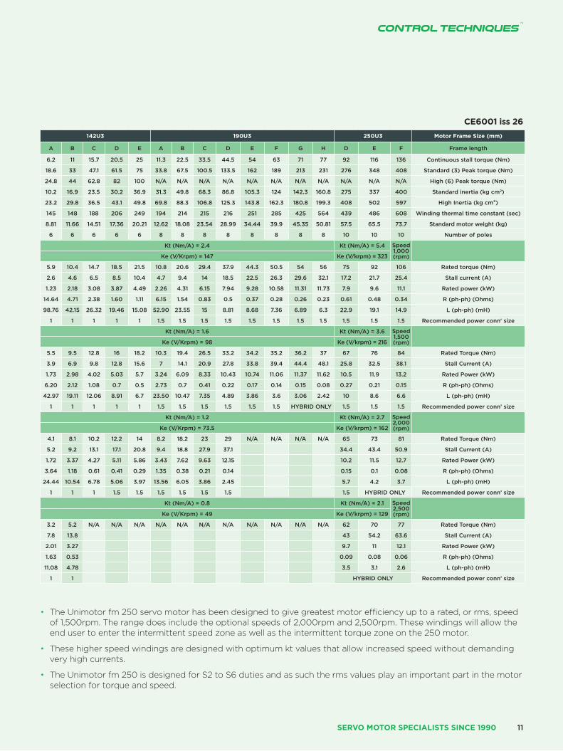
Motor Frame Size (mm) 075U3 095U3 115U3 142U3 190U3 250U3 Motor Frame Size (mm)
Frame length A B C D A B C D E A B C D E A B C D E A B C D E F G H D E F Frame length
Continuous stall torque (Nm) 1.4 2.7 3.7 4.7 2.5 4.5 6.3 7.9 9.3 3.9 7.4 10.8 13.7 16 6.2 11 15.7 20.5 25 11.3 22.5 33.5 44.5 54 63 71 77 92 116 136 Continuous stall torque (Nm)
Standard (3) Peak torque (Nm) 4.3 8 11.2 14 7.4 13.5 18.9 23.7 27.8 11.7 22.2 32.4 41 48 18.6 33 47.1 61.5 75 33.8 67.5 100.5 133.5 162 189 213 231 276 348 408 Standard (3) Peak torque (Nm)
High (6) Peak torque (Nm) 7.2 13.3 18.6 23.4 11 20.3 28.4 35.6 41.6 15.6 29.6 43.2 54.6 64 24.8 44 62.8 82 100 N/A N/A N/A N/A N/A N/A N/A N/A N/A N/A N/A High (6) Peak torque (Nm)
Standard inertia (kg cm2) 0.78 1.22 1.64 2.07 1.45 2.6 3.72 4.83 6 5.4 7.7 10 12.5 14.8 10.2 16.9 23.5 30.2 36.9 31.3 49.8 68.3 86.8 105.3 124 142.3 160.8 275 337 400 Standard inertia (kg cm2)
High Inertia (kg cm²) 1.18 1.61 2.03 2.46 3.31 4.5 5.6 6.7 7.8 10 12.3 14.7 17.1 19.4 23.2 29.8 36.5 43.1 49.8 69.8 88.3 106.8 125.3 143.8 162.3 180.8 199.3 408 502 597 High Inertia (kg cm²)
Winding thermal time constant (sec) 63 58 73 78 84 82 90 108 112 103 109 116 127 141 145 148 188 206 249 194 214 215 216 251 285 425 564 439 486 608 Winding thermal time constant (sec)
Standard motor weight (kg) 2.88 3.68 4.48 5.28 4.49 5.75 7.01 8.27 9.53 6.88 8.68 10.48 12.28 14.08 8.81 11.66 14.51 17.36 20.21 12.62 18.08 23.54 28.99 34.44 39.9 45.35 50.81 57.5 65.5 73.7 Standard motor weight (kg)
Number of poles 6 6 6 6 6 6 6 6 6 6 6 6 6 6 6 6 6 6 6 8 8 8 8 8 8 8 8 10 10 10 Number of poles
Speed 2000 (rpm)Kt (Nm/A) = 2.4 Kt (Nm/A) = 2.4 Kt (Nm/A) = 5.4 Speed
1,000 (rpm)Ke (V/Krpm) = 147 Ke (V/Krpm) = 147 Ke (V/krpm) = 323
Rated torque (Nm) 1.3 2.5 3.5 4.5 2.4 4.3 5.9 7.3 8.5 3.7 7.3 10.1 11.9 14.1 5.9 10.4 14.7 18.5 21.5 10.8 20.6 29.4 37.9 44.3 50.5 54 56 75 92 106 Rated torque (Nm)
Stall current (A) 0.6 1.1 1.6 1.9 1 1.9 2.6 3.3 3.9 1.6 3.1 4.5 5.7 6.7 2.6 4.6 6.5 8.5 10.4 4.7 9.4 14 18.5 22.5 26.3 29.6 32.1 17.2 21.7 25.4 Stall current (A)
Rated power (kW) 0.27 0.52 0.73 0.93 0.51 0.9 1.23 1.53 1.77 0.77 1.53 2.12 2.49 2.95 1.23 2.18 3.08 3.87 4.49 2.26 4.31 6.15 7.94 9.28 10.58 11.31 11.73 7.9 9.6 11.1 Rated power (kW)
R (ph-ph) (Ohms) 148.5 52.2 27.3 19.97 64.08 20.88 10.46 7.46 5.09 32.92 10.68 5.25 3.7 2.75 14.64 4.71 2.38 1.60 1.11 6.15 1.54 0.83 0.5 0.37 0.28 0.26 0.23 0.61 0.48 0.34 R (ph-ph) (Ohms)
L (ph-ph) (mH) 258.36 117.28 74.2 56.97 173.4 78.16 47.02 35.44 27.18 139.43 59.51 35.9 27.63 21.87 98.76 42.15 26.32 19.46 15.08 52.90 23.55 15 8.81 8.68 7.36 6.89 6.3 22.9 19.1 14.9 L (ph-ph) (mH)
Recommended power conn' size 1 1 1 1 1 1 1 1 1 1 1 1 1 1 1 1 1 1 1 1.5 1.5 1.5 1.5 1.5 1.5 1.5 1.5 1.5 1.5 1.5 Recommended power conn' size
Speed 3000 (rpm) Kt (Nm/A) = 1.6 Kt (Nm/A) = 1.6 Kt (Nm/A) = 3.6 Speed
1,500 (rpm)Ke (V/Krpm) = 98 Ke (V/Krpm) = 98 Ke (V/krpm) = 216
Rated Torque (Nm) 1.3 2.3 3.3 4.2 2.3 4.1 5.6 6.9 8.2 3.5 6.7 9.5 11.2 12.7 5.5 9.5 12.8 16 18.2 10.3 19.4 26.5 33.2 34.2 35.2 36.2 37 67 76 84 Rated Torque (Nm)
Stall Current (A) 0.9 1.7 2.3 2.9 1.5 2.8 3.9 4.9 5.8 2.4 4.6 6.8 8.5 10 3.9 6.9 9.8 12.8 15.6 7 14.1 20.9 27.8 33.8 39.4 44.4 48.1 25.8 32.5 38.1 Stall Current (A)
Rated Power (kW) 0.41 0.72 1.04 1.31 0.73 1.29 1.76 2.17 2.56 1.1 2.1 2.98 3.52 3.99 1.73 2.98 4.02 5.03 5.7 3.24 6.09 8.33 10.43 10.74 11.06 11.37 11.62 10.5 11.9 13.2 Rated Power (kW)
R (ph-ph) (Ohms) 62.08 21.07 12.54 7.81 26.7 8.63 4.67 3.16 2.27 14.74 4.37 2.3 1.53 1.23 6.20 2.12 1.08 0.7 0.5 2.73 0.7 0.41 0.22 0.17 0.14 0.15 0.08 0.27 0.21 0.15 R (ph-ph) (Ohms)
L (ph-ph) (mH) 114.59 52.65 34.18 23.89 76.65 33.71 21.09 15.95 12.06 57.29 25.19 15.57 11.6 9.89 42.97 19.11 12.06 8.91 6.7 23.50 10.47 7.35 4.89 3.86 3.6 3.06 2.42 10 8.6 6.6 L (ph-ph) (mH)
Recommended power conn’ size 1 1 1 1 1 1 1 1 1 1 1 1 1 1 1 1 1 1 1 1.5 1.5 1.5 1.5 1.5 1.5 HYBRID ONLY 1.5 1.5 1.5 Recommended power conn’ size
Speed 4000 (rpm)Kt (Nm/A) = 1.2 Kt (Nm/A) = 1.2 Kt (Nm/A) = 2.7 Speed
2,000 (rpm)Ke (V/Krpm) = 73.5 Ke (V/Krpm) = 73.5 Ke (V/krpm) = 162
Rated Torque (Nm) 1.2 2.1 2.8 3.8 2.3 3.8 5.3 6.4 7.4 3 5.8 7.5 8.3 8.8 4.1 8.1 10.2 12.2 14 8.2 18.2 23 29 N/A N/A N/A N/A 65 73 81 Rated Torque (Nm)
Stall Current (A) 1.2 2.2 3.1 3.9 2 3.8 5.3 6.6 7.7 3.3 6.2 9 11.4 13.3 5.2 9.2 13.1 17.1 20.8 9.4 18.8 27.9 37.1 34.4 43.4 50.9 Stall Current (A)
Rated Power (kW) 0.5 0.86 1.17 1.59 0.94 1.59 2.2 2.68 3.1 1.26 2.43 3.12 3.46 3.69 1.72 3.37 4.27 5.11 5.86 3.43 7.62 9.63 12.15 10.2 11.5 12.7 Rated Power (kW)
R (ph-ph) (Ohms) 38.01 12.71 6.49 4.94 16.14 5.22 2.61 1.81 1.4 8.49 2.61 1.31 0.84 0.66 3.64 1.18 0.61 0.41 0.29 1.35 0.38 0.21 0.14 0.15 0.1 0.08 R (ph-ph) (Ohms)
L (ph-ph) (mH) 68.39 30.46 18.28 13.97 44.25 19.54 11.75 8.86 7.25 33.79 14.87 8.98 6.27 5.35 24.44 10.54 6.78 5.06 3.97 13.56 6.05 3.86 2.45 5.7 4.2 3.7 L (ph-ph) (mH)
Recommended power conn’ size 1 1 1 1 1 1 1 1 1 1 1 1 1 1 1 1 1 1.5 1.5 1.5 1.5 1.5 1.5 1.5 HYBRID ONLY Recommended power conn’ size
Speed 6000 (rpm)Kt (Nm/A) = 0.8 Kt (Nm/A) = 0.8 Kt (Nm/A) = 2.1 Speed
2,500 (rpm)Ke (V/Krpm) = 49 Ke (V/Krpm) = 49 Ke (V/krpm) = 129
Rated Torque (Nm) 1.1 1.9 2.8 3.4 2 3.2 4.2 N/A N/A 2.7 5 N/A N/A N/A 3.2 5.2 N/A N/A N/A N/A N/A N/A N/A N/A N/A N/A N/A 62 70 77 Rated Torque (Nm)
Stall Current (A) 1.8 3.3 4.7 5.8 3.1 5.6 7.9 4.9 9.3 7.8 13.8 43 54.2 63.6 Stall Current (A)
Rated Power (kW) 0.68 1.21 1.73 2.14 1.24 2.01 2.64 1.7 3.14 2.01 3.27 9.7 11 12.1 Rated Power (kW)
R (ph-ph) (Ohms) 15.48 5.19 2.86 2.12 6.59 2.13 1.22 3.48 1.09 1.63 0.53 0.09 0.08 0.06 R (ph-ph) (Ohms)
L (ph-ph) (mH) 28.66 12.77 8.01 6.33 18.62 8.24 5.44 14.31 6.3 11.08 4.78 3.5 3.1 2.6 L (ph-ph) (mH)
Recommended power conn’ size 1 1 1 1 1 1 1 1 1 1 1 HYBRID ONLY Recommended power conn’ size
RatingsPhase VPWM drives 380 - 480 Vrms - ∆t= 100 °C winding 40 °C maximum ambient. All data subject to ± 10 % tolerance
• N/A Not available
• The information contained in this specification is for guidance only and does not form part of any contract.
• Control Techniques have an ongoing process of development and reserves the right to change the specification without notice.
• Stall torque, rated torque and power relate to maximum operation tested in a 20 °C ambient at 12 kHz drive switching frequency.
• All other figures relate to a 20 °C motor temperature. Maximum intermittent winding temperature is 140 °C.
• The recommended connector has to be selected using the connector manufacturer’s de-rating values applied to a motor at full operational temperature.
www.controltechniques.com10
SERVO MOTOR SERIES
Motor Frame Size (mm) 075U3 095U3 115U3 142U3 190U3 250U3 Motor Frame Size (mm)
Frame length A B C D A B C D E A B C D E A B C D E A B C D E F G H D E F Frame length
Continuous stall torque (Nm) 1.4 2.7 3.7 4.7 2.5 4.5 6.3 7.9 9.3 3.9 7.4 10.8 13.7 16 6.2 11 15.7 20.5 25 11.3 22.5 33.5 44.5 54 63 71 77 92 116 136 Continuous stall torque (Nm)
Standard (3) Peak torque (Nm) 4.3 8 11.2 14 7.4 13.5 18.9 23.7 27.8 11.7 22.2 32.4 41 48 18.6 33 47.1 61.5 75 33.8 67.5 100.5 133.5 162 189 213 231 276 348 408 Standard (3) Peak torque (Nm)
High (6) Peak torque (Nm) 7.2 13.3 18.6 23.4 11 20.3 28.4 35.6 41.6 15.6 29.6 43.2 54.6 64 24.8 44 62.8 82 100 N/A N/A N/A N/A N/A N/A N/A N/A N/A N/A N/A High (6) Peak torque (Nm)
Standard inertia (kg cm2) 0.78 1.22 1.64 2.07 1.45 2.6 3.72 4.83 6 5.4 7.7 10 12.5 14.8 10.2 16.9 23.5 30.2 36.9 31.3 49.8 68.3 86.8 105.3 124 142.3 160.8 275 337 400 Standard inertia (kg cm2)
High Inertia (kg cm²) 1.18 1.61 2.03 2.46 3.31 4.5 5.6 6.7 7.8 10 12.3 14.7 17.1 19.4 23.2 29.8 36.5 43.1 49.8 69.8 88.3 106.8 125.3 143.8 162.3 180.8 199.3 408 502 597 High Inertia (kg cm²)
Winding thermal time constant (sec) 63 58 73 78 84 82 90 108 112 103 109 116 127 141 145 148 188 206 249 194 214 215 216 251 285 425 564 439 486 608 Winding thermal time constant (sec)
Standard motor weight (kg) 2.88 3.68 4.48 5.28 4.49 5.75 7.01 8.27 9.53 6.88 8.68 10.48 12.28 14.08 8.81 11.66 14.51 17.36 20.21 12.62 18.08 23.54 28.99 34.44 39.9 45.35 50.81 57.5 65.5 73.7 Standard motor weight (kg)
Number of poles 6 6 6 6 6 6 6 6 6 6 6 6 6 6 6 6 6 6 6 8 8 8 8 8 8 8 8 10 10 10 Number of poles
Speed 2000 (rpm)Kt (Nm/A) = 2.4 Kt (Nm/A) = 2.4 Kt (Nm/A) = 5.4 Speed
1,000 (rpm)Ke (V/Krpm) = 147 Ke (V/Krpm) = 147 Ke (V/krpm) = 323
Rated torque (Nm) 1.3 2.5 3.5 4.5 2.4 4.3 5.9 7.3 8.5 3.7 7.3 10.1 11.9 14.1 5.9 10.4 14.7 18.5 21.5 10.8 20.6 29.4 37.9 44.3 50.5 54 56 75 92 106 Rated torque (Nm)
Stall current (A) 0.6 1.1 1.6 1.9 1 1.9 2.6 3.3 3.9 1.6 3.1 4.5 5.7 6.7 2.6 4.6 6.5 8.5 10.4 4.7 9.4 14 18.5 22.5 26.3 29.6 32.1 17.2 21.7 25.4 Stall current (A)
Rated power (kW) 0.27 0.52 0.73 0.93 0.51 0.9 1.23 1.53 1.77 0.77 1.53 2.12 2.49 2.95 1.23 2.18 3.08 3.87 4.49 2.26 4.31 6.15 7.94 9.28 10.58 11.31 11.73 7.9 9.6 11.1 Rated power (kW)
R (ph-ph) (Ohms) 148.5 52.2 27.3 19.97 64.08 20.88 10.46 7.46 5.09 32.92 10.68 5.25 3.7 2.75 14.64 4.71 2.38 1.60 1.11 6.15 1.54 0.83 0.5 0.37 0.28 0.26 0.23 0.61 0.48 0.34 R (ph-ph) (Ohms)
L (ph-ph) (mH) 258.36 117.28 74.2 56.97 173.4 78.16 47.02 35.44 27.18 139.43 59.51 35.9 27.63 21.87 98.76 42.15 26.32 19.46 15.08 52.90 23.55 15 8.81 8.68 7.36 6.89 6.3 22.9 19.1 14.9 L (ph-ph) (mH)
Recommended power conn' size 1 1 1 1 1 1 1 1 1 1 1 1 1 1 1 1 1 1 1 1.5 1.5 1.5 1.5 1.5 1.5 1.5 1.5 1.5 1.5 1.5 Recommended power conn' size
Speed 3000 (rpm) Kt (Nm/A) = 1.6 Kt (Nm/A) = 1.6 Kt (Nm/A) = 3.6 Speed
1,500 (rpm)Ke (V/Krpm) = 98 Ke (V/Krpm) = 98 Ke (V/krpm) = 216
Rated Torque (Nm) 1.3 2.3 3.3 4.2 2.3 4.1 5.6 6.9 8.2 3.5 6.7 9.5 11.2 12.7 5.5 9.5 12.8 16 18.2 10.3 19.4 26.5 33.2 34.2 35.2 36.2 37 67 76 84 Rated Torque (Nm)
Stall Current (A) 0.9 1.7 2.3 2.9 1.5 2.8 3.9 4.9 5.8 2.4 4.6 6.8 8.5 10 3.9 6.9 9.8 12.8 15.6 7 14.1 20.9 27.8 33.8 39.4 44.4 48.1 25.8 32.5 38.1 Stall Current (A)
Rated Power (kW) 0.41 0.72 1.04 1.31 0.73 1.29 1.76 2.17 2.56 1.1 2.1 2.98 3.52 3.99 1.73 2.98 4.02 5.03 5.7 3.24 6.09 8.33 10.43 10.74 11.06 11.37 11.62 10.5 11.9 13.2 Rated Power (kW)
R (ph-ph) (Ohms) 62.08 21.07 12.54 7.81 26.7 8.63 4.67 3.16 2.27 14.74 4.37 2.3 1.53 1.23 6.20 2.12 1.08 0.7 0.5 2.73 0.7 0.41 0.22 0.17 0.14 0.15 0.08 0.27 0.21 0.15 R (ph-ph) (Ohms)
L (ph-ph) (mH) 114.59 52.65 34.18 23.89 76.65 33.71 21.09 15.95 12.06 57.29 25.19 15.57 11.6 9.89 42.97 19.11 12.06 8.91 6.7 23.50 10.47 7.35 4.89 3.86 3.6 3.06 2.42 10 8.6 6.6 L (ph-ph) (mH)
Recommended power conn’ size 1 1 1 1 1 1 1 1 1 1 1 1 1 1 1 1 1 1 1 1.5 1.5 1.5 1.5 1.5 1.5 HYBRID ONLY 1.5 1.5 1.5 Recommended power conn’ size
Speed 4000 (rpm)Kt (Nm/A) = 1.2 Kt (Nm/A) = 1.2 Kt (Nm/A) = 2.7 Speed
2,000 (rpm)Ke (V/Krpm) = 73.5 Ke (V/Krpm) = 73.5 Ke (V/krpm) = 162
Rated Torque (Nm) 1.2 2.1 2.8 3.8 2.3 3.8 5.3 6.4 7.4 3 5.8 7.5 8.3 8.8 4.1 8.1 10.2 12.2 14 8.2 18.2 23 29 N/A N/A N/A N/A 65 73 81 Rated Torque (Nm)
Stall Current (A) 1.2 2.2 3.1 3.9 2 3.8 5.3 6.6 7.7 3.3 6.2 9 11.4 13.3 5.2 9.2 13.1 17.1 20.8 9.4 18.8 27.9 37.1 34.4 43.4 50.9 Stall Current (A)
Rated Power (kW) 0.5 0.86 1.17 1.59 0.94 1.59 2.2 2.68 3.1 1.26 2.43 3.12 3.46 3.69 1.72 3.37 4.27 5.11 5.86 3.43 7.62 9.63 12.15 10.2 11.5 12.7 Rated Power (kW)
R (ph-ph) (Ohms) 38.01 12.71 6.49 4.94 16.14 5.22 2.61 1.81 1.4 8.49 2.61 1.31 0.84 0.66 3.64 1.18 0.61 0.41 0.29 1.35 0.38 0.21 0.14 0.15 0.1 0.08 R (ph-ph) (Ohms)
L (ph-ph) (mH) 68.39 30.46 18.28 13.97 44.25 19.54 11.75 8.86 7.25 33.79 14.87 8.98 6.27 5.35 24.44 10.54 6.78 5.06 3.97 13.56 6.05 3.86 2.45 5.7 4.2 3.7 L (ph-ph) (mH)
Recommended power conn’ size 1 1 1 1 1 1 1 1 1 1 1 1 1 1 1 1 1 1.5 1.5 1.5 1.5 1.5 1.5 1.5 HYBRID ONLY Recommended power conn’ size
Speed 6000 (rpm)Kt (Nm/A) = 0.8 Kt (Nm/A) = 0.8 Kt (Nm/A) = 2.1 Speed
2,500 (rpm)Ke (V/Krpm) = 49 Ke (V/Krpm) = 49 Ke (V/krpm) = 129
Rated Torque (Nm) 1.1 1.9 2.8 3.4 2 3.2 4.2 N/A N/A 2.7 5 N/A N/A N/A 3.2 5.2 N/A N/A N/A N/A N/A N/A N/A N/A N/A N/A N/A 62 70 77 Rated Torque (Nm)
Stall Current (A) 1.8 3.3 4.7 5.8 3.1 5.6 7.9 4.9 9.3 7.8 13.8 43 54.2 63.6 Stall Current (A)
Rated Power (kW) 0.68 1.21 1.73 2.14 1.24 2.01 2.64 1.7 3.14 2.01 3.27 9.7 11 12.1 Rated Power (kW)
R (ph-ph) (Ohms) 15.48 5.19 2.86 2.12 6.59 2.13 1.22 3.48 1.09 1.63 0.53 0.09 0.08 0.06 R (ph-ph) (Ohms)
L (ph-ph) (mH) 28.66 12.77 8.01 6.33 18.62 8.24 5.44 14.31 6.3 11.08 4.78 3.5 3.1 2.6 L (ph-ph) (mH)
Recommended power conn’ size 1 1 1 1 1 1 1 1 1 1 1 HYBRID ONLY Recommended power conn’ size
CE6001 iss 26
• The Unimotor fm 250 servo motor has been designed to give greatest motor efficiency up to a rated, or rms, speed of 1,500rpm. The range does include the optional speeds of 2,000rpm and 2,500rpm. These windings will allow the end user to enter the intermittent speed zone as well as the intermittent torque zone on the 250 motor.
• These higher speed windings are designed with optimum kt values that allow increased speed without demanding very high currents.
• The Unimotor fm 250 is designed for S2 to S6 duties and as such the rms values play an important part in the motor selection for torque and speed.
SERVO MOTOR SPECIALISTS SINCE 1990 11
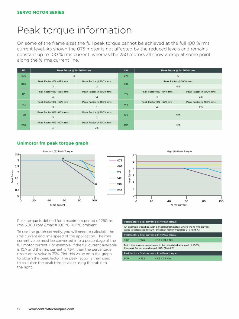
Peak torque information On some of the frame sizes the full peak torque cannot be achieved at the full 100 % rms current level. As shown the 075 motor is not aff ected by the reduced levels and remains constant up to 100 % rms current, whereas the 250 motors all show a drop at some point along the % rms current line.
U3 Peak factor @ 0 - 100% rms U6 Peak factor @ 0 - 100% rms
075 3 075 5
095Peak Factor 0% - 88% rms Peak Factor @ 100% rms
095Peak Factor @ 100% rms
3 2 4.5
115Peak Factor 0% - 86% rms Peak Factor @ 100% rms
115Peak Factor 0% - 84% rms Peak Factor @ 100% rms
3 1.5 4 3.5
142Peak Factor 0% - 57% rms Peak Factor @ 100% rms
142Peak Factor 0% - 57% rms Peak Factor @ 100% rms
3 1 4 2.5
190Peak Factor 0% - 60% rms Peak Factor @ 100% rms
190 N/A3 2
250Peak Factor 0% - 80% rms Peak Factor @ 100% rms
250 N/A3 2.5
Peak torque is defi ned for a maximum period of 250ms, rms 3,000 rpm ∆max = 100 °C, 40 °C ambient.
To use the graph correctly, you will need to calculate the rms current and rms speed of the application. The rms current value must be converted into a percentage of the full motor current. For example, if the full current available is 10A and the rms current is 7.5A, then the percentage rms current value is 75%. Plot this value onto the graph to obtain the peak factor. The peak factor is then used to calculate the peak torque value using the table to the right.
Peak factor x Stall current x kt = Peak torque
An example would be with a 142U3E300 motor, where the % rms current value is calculated to 50%, the peak factor would be 3. (Point A)
Peak factor x Stall current x kt = Peak torque
3.00 x 15.6 x 1.6 = 74.9 Nm
But if the % rms current were to be calculated at a level of 100%, the peak factor would equal 1.00. (Point B)
Peak factor x Stall current x kt = Peak torque
1.00 x 15.6 x 1.6 = 25 Nm
Unimotor fm peak torque graph
0 20 40 60 80 100 0 20 40 60 80 100
250
3.5
3
1.5
1
2.5
2
075
095
115
142
190
A
B
0.5
0
6
5
4
3
2
1
0
Standard (3) Peak Torque High (6) Peak Torque
% ms current % ms current
Pea
k fa
ctor
Pea
k fa
ctor
www.controltechniques.com12
SERVO MOTOR SERIES
SERVO MOTOR SPECIALISTS SINCE 1990 13
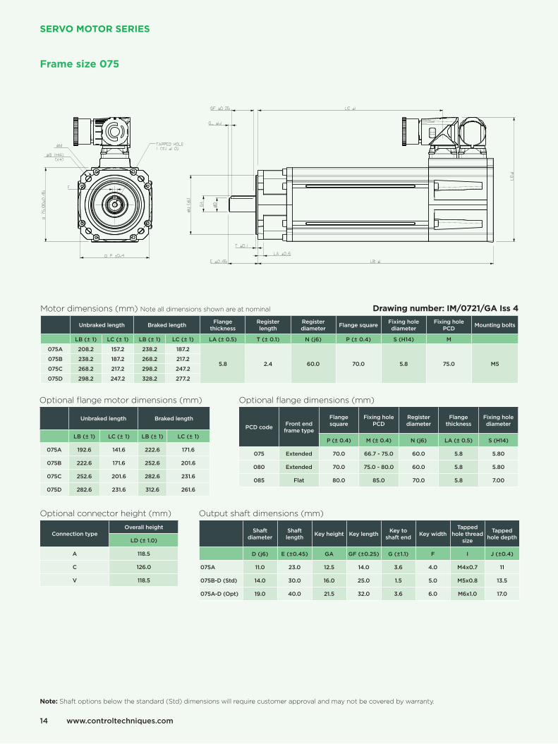
Frame size 075
Note: Shaft options below the standard (Std) dimensions will require customer approval and may not be covered by warranty.
Motor dimensions (mm) Note all dimensions shown are at nominal
Unbraked length Braked length Flange thickness
Register length
Register diameter Flange square Fixing hole
diameterFixing hole
PCD Mounting bolts
LB (± 1) LC (± 1) LB (± 1) LC (± 1) LA (± 0.5) T (± 0.1) N (j6) P (± 0.4) S (H14) M
075A 208.2 157.2 238.2 187.2
5.8 2.4 60.0 70.0 5.8 75.0 M5075B 238.2 187.2 268.2 217.2
075C 268.2 217.2 298.2 247.2
075D 298.2 247.2 328.2 277.2
Optional flange motor dimensions (mm)
Unbraked length Braked length
LB (± 1) LC (± 1) LB (± 1) LC (± 1)
075A 192.6 141.6 222.6 171.6
075B 222.6 171.6 252.6 201.6
075C 252.6 201.6 282.6 231.6
075D 282.6 231.6 312.6 261.6
Optional flange dimensions (mm)
PCD code Front end frame type
Flange square
Fixing hole PCD
Register diameter
Flange thickness
Fixing hole diameter
P (± 0.4) M (± 0.4) N (j6) LA (± 0.5) S (H14)
075 Extended 70.0 66.7 - 75.0 60.0 5.8 5.80
080 Extended 70.0 75.0 - 80.0 60.0 5.8 5.80
085 Flat 80.0 85.0 70.0 5.8 7.00
Optional connector height (mm)
Connection typeOverall height
LD (± 1.0)
A 118.5
C 126.0
V 118.5
Output shaft dimensions (mm)
Shaft diameter
Shaft length Key height Key length Key to
shaft end Key widthTapped
hole thread size
Tapped hole depth
D (j6) E (±0.45) GA GF (±0.25) G (±1.1) F I J (±0.4)
075A 11.0 23.0 12.5 14.0 3.6 4.0 M4x0.7 11
075B-D (Std) 14.0 30.0 16.0 25.0 1.5 5.0 M5x0.8 13.5
075A-D (Opt) 19.0 40.0 21.5 32.0 3.6 6.0 M6x1.0 17.0
Drawing number: IM/0721/GA Iss 4
www.controltechniques.com14
SERVO MOTOR SERIES
Note: Shaft options below the standard (Std) dimensions will require customer approval and may not be covered by warranty.
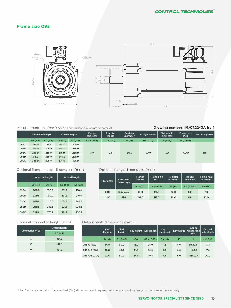
Frame size 095
Drawing number: IM/0722/GA Iss 4Motor dimensions (mm) Note all dimensions shown are at nominal
Unbraked length Braked length Flange thickness
Register length
Register diameter Flange square Fixing hole
diameterFixing hole
PCD Mounting bolts
LB (± 1) LC (± 1) LB (± 1) LC (± 1) LA (± 0.5) T (± 0.1) N (j6) P (± 0.4) S (H14) M (± 0.4)
095A 226.9 175.9 256.9 205.9
5.9 2.8 80.0 90.0 7.0 100.0 M6
095B 256.9 205.9 286.9 235.9
095C 286.9 235.9 316.9 265.9
095D 316.9 265.9 346.9 295.9
095E 346.9 295.9 376.9 325.9
Optional flange motor dimensions (mm)
Unbraked length Braked length
LB (± 1) LC (± 1) LB (± 1) LC (± 1)
095A 201.8 150.8 231.8 180.8
095B 231.8 180.8 261.8 210.8
095C 261.8 210.8 291.8 240.8
095D 291.8 240.8 321.8 270.8
095E 321.8 270.8 351.8 300.8
Optional flange dimensions (mm)
PCD code Front end frame type
Flange square
Fixing hole PCD
Register diameter
Flange thickness
Fixing hole diameter
P (± 0.4) M (± 0.4) N (j6) LA (± 0.5) S (H14)
098 Extended 90.0 98.4 73.0 5.9 7.0
115.0 Flat 105.0 115.0 95.0 6.8 10.0
Optional connector height (mm)
Connection typeOverall height
LD (± 1)
A 131.5
C 139.0
V 131.5
Output shaft dimensions (mm)
Shaft diameter
Shaft length Key height Key length Key to
shaft end Key widthTapped
hole thread size
Tapped hole depth
D (j6) E (±0.45) GA GF (±0.25) G (±1.1) F I J (±0.4)
095 A (Std) 14.0 30.0 16.0 25.0 1.5 5.0 M5x0.8 13.5
095 B-E (Std) 19.0 40.0 21.5 32.0 3.6 6.0 M6x1.0 17.0
095 A-E (Opt) 22.0 50.0 24.5 40.0 4.6 6.0 M8x1.25 20.0
SERVO MOTOR SPECIALISTS SINCE 1990 15
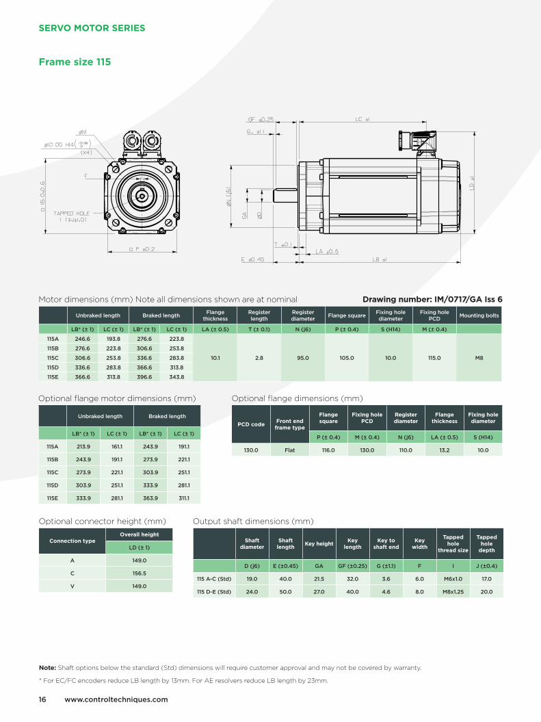
Frame size 115
Drawing number: IM/0717/GA Iss 6
Optional connector height (mm)
Connection typeOverall height
LD (± 1)
A 149.0
C 156.5
V 149.0
Output shaft dimensions (mm)
Shaft diameter
Shaft length
Key heightKey
lengthKey to
shaft endKey
width
Tapped hole
thread size
Tapped hole
depth
D (j6) E (±0.45) GA GF (±0.25) G (±1.1) F I J (±0.4)
115 A-C (Std) 19.0 40.0 21.5 32.0 3.6 6.0 M6x1.0 17.0
115 D-E (Std) 24.0 50.0 27.0 40.0 4.6 8.0 M8x1.25 20.0
Motor dimensions (mm) Note all dimensions shown are at nominal
Unbraked length Braked length Flange thickness
Register length
Register diameter Flange square Fixing hole
diameterFixing hole
PCD Mounting bolts
LB* (± 1) LC (± 1) LB* (± 1) LC (± 1) LA (± 0.5) T (± 0.1) N (j6) P (± 0.4) S (H14) M (± 0.4)
115A 246.6 193.8 276.6 223.8
10.1 2.8 95.0 105.0 10.0 115.0 M8
115B 276.6 223.8 306.6 253.8
115C 306.6 253.8 336.6 283.8
115D 336.6 283.8 366.6 313.8
115E 366.6 313.8 396.6 343.8
Optional flange dimensions (mm)
PCD codeFront end frame type
Flange square
Fixing hole PCD
Register diameter
Flange thickness
Fixing hole diameter
P (± 0.4) M (± 0.4) N (j6) LA (± 0.5) S (H14)
130.0 Flat 116.0 130.0 110.0 13.2 10.0
Optional flange motor dimensions (mm)
Unbraked length Braked length
LB* (± 1) LC (± 1) LB* (± 1) LC (± 1)
115A 213.9 161.1 243.9 191.1
115B 243.9 191.1 273.9 221.1
115C 273.9 221.1 303.9 251.1
115D 303.9 251.1 333.9 281.1
115E 333.9 281.1 363.9 311.1
Note: Shaft options below the standard (Std) dimensions will require customer approval and may not be covered by warranty.
* For EC/FC encoders reduce LB length by 13mm. For AE resolvers reduce LB length by 23mm.
www.controltechniques.com16
SERVO MOTOR SERIES
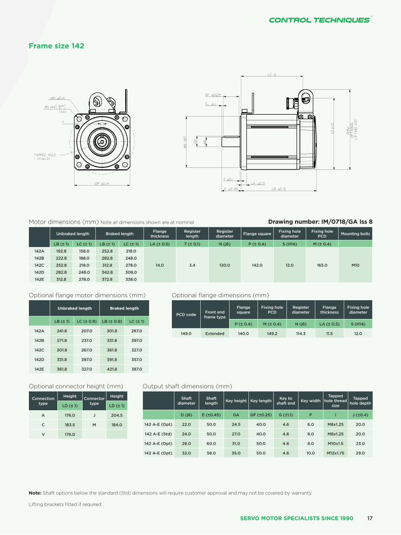
Note: Shaft options below the standard (Std) dimensions will require customer approval and may not be covered by warranty. Lifting brackets fitted if required.
Frame size 142
Optional flange motor dimensions (mm)
Unbraked length Braked length
LB (± 1) LC (± 0.9) LB (± 0.9) LC (± 1)
142A 241.8 207.0 301.8 267.0
142B 271.8 237.0 331.8 397.0
142C 301.8 267.0 361.8 327.0
142D 331.8 397.0 391.8 357.0
142E 361.8 327.0 421.8 387.0
Optional flange dimensions (mm)
PCD code Front end frame type
Flange square
Fixing hole PCD
Register diameter
Flange thickness
Fixing hole diameter
P (± 0.4) M (± 0.4) N (j6) LA (± 0.5) S (H14)
149.0 Extended 140.0 149.2 114.3 11.5 12.0
Optional connector height (mm)
Connection type
Height Connector type
Height
LD (± 1) LD (± 1)
A 176.0 J 204.5
C 183.5 M 184.0
V 176.0
Output shaft dimensions (mm)
Shaft diameter
Shaft length Key height Key length Key to
shaft end Key widthTapped
hole thread size
Tapped hole depth
D (j6) E (±0.45) GA GF (±0.25) G (±1.1) F I J (±0.4)
142 A-E (Opt) 22.0 50.0 24.5 40.0 4.6 6.0 M8x1.25 20.0
142 A-E (Std) 24.0 50.0 27.0 40.0 4.6 8.0 M8x1.25 20.0
142 A-E (Opt) 28.0 60.0 31.0 50.0 4.6 8.0 M10x1.5 23.0
142 A-E (Opt) 32.0 58.0 35.0 50.0 4.6 10.0 M12x1.75 29.0
Motor dimensions (mm) Note all dimensions shown are at nominal
Unbraked length Braked length Flange thickness
Register length
Register diameter Flange square Fixing hole
diameterFixing hole
PCD Mounting bolts
LB (± 1) LC (± 1) LB (± 1) LC (± 1) LA (± 0.5) T (± 0.1) N (j6) P (± 0.4) S (H14) M (± 0.4)
142A 192.8 158.0 252.8 218.0
14.0 3.4 130.0 142.0 12.0 165.0 M10
142B 222.8 188.0 282.8 248.0
142C 252.8 218.0 312.8 278.0
142D 282.8 248.0 342.8 308.0
142E 312.8 278.0 372.8 338.0
Drawing number: IM/0718/GA Iss 8
SERVO MOTOR SPECIALISTS SINCE 1990 17

Motor dimensions (mm) Note all dimensions shown are at nominal
Unbraked length Braked length Flange thickness
Register length
Register diameter Flange square Fixing hole
diameterFixing hole
PCD Mounting bolts
LB (± 1) LC (± 1) LB (± 1) LC (± 1) LA (± 0.5) T (± 0.1) N (j6) P (± 0.4) S (H14) M (± 0.4)
190A 199.4 169.6 289.4 259.6
18.5 3.9 180.0 190.3 14.5 215.0 M12
190B 229.4 199.6 319.4 289.6
190C 259.4 229.6 349.4 319.6
190D 289.4 259.6 379.4 349.6
190E 319.4 289.6 409.4 379.6
190F 349.4 319.6 439.4 409.6
190G 379.4 349.6 469.4 439.6
190H 409.4 379.6 499.4 469.6
Optional connector height (mm)
Connection typeOverall height
LD (± 1)
M 232.0
N 252.5
H (<40 Amp) 287.0
H (<60 Amp) 323.0
Output shaft dimensions (mm)
Shaft diameter Shaft length Key height Key length Key to shaft end Key width Tapped hole
thread sizeTapped hole
depth
D (j6) E (±0.45) GA GF (±0.25) G (±1.1) F I J (±0.4)
190 A-H (Opt) 28.0 60.0 31.0 50.0 4.6 8.0 M10x1.5 23.0
190 A-H (Std) 32.0 58.0 35.0 50.0 4.6 10.0 M12x1.75 29.0
190 A-H (Opt) 38.0 58.0 41.0 50.0 4.6 10.0 M12x1.75 29.0
190 A-H (Opt) 42.0 110.0 45.0 100.0 4.6 12.0 M16x2.0 37.0
Note: Shaft options below the standard (Std) dimensions will require customer approval and may not be covered by warranty.
Frame size 190
Drawing number: IM/0723/GA Iss 4
www.controltechniques.com18
SERVO MOTOR SERIES

Frame size 250
Motor dimensions (mm) Note: all dimensions shown are at nominal
Motor Length Flange thickness
Register length
Register diameter
Overall height
Flange square
Fixing hole
diameter
Fixing hole PCD
Motor housing
Hybrid box
width
Signal connector
height
Mounting bolts
LB (± 1.3)
LB1 (± 2.0)
LJ (± 1.0)
LA (± 0.1) T (± 0.1) N (j6) LD
(± 1.0) P (± 0.6) S (H14) M (± 0.4) PH (± 1.0) U (± 0.4) LD1
(± 1.0)
Unbraked motor
20.0 4.5 250.0 363.5 256.0 18.5 300.0 250.0 186.0 228.5 M16
250D 375.7 406.1 179.7
250E 405.7 436.1 209.7
250F 435.7 466.1 239.7
Braked motor
250D 447.5 477.9 251.5
250E 477.5 507.9 281.5
250F 507.5 537.9 311.5
Note: For Heidenhain feedback devices please add 15mm to LB length
Optional connector height (mm)
Connection type
Overall height Signal overall height
LD (± 1) LD1 (± 1)
M 291.5 221.0
N 312.5 221.0
J 312.5 221.0
Output shaft dimensions (mm)
Shaft diameter Shaft length Key height Key length Key to shaft end Key width Tapped hole thread size
Tapped hole depth
D (j6) E (±0.45) GA (IEC 72-1) GF (±0.25) G (±1.1) F (H9) I J (±1.0)
38.0 (Opt) 38.0 80.0 41.0 70.0 4.6 10.0 M12x1.75 29.0
42.0 (Opt) 42.0 110.0 45.0 100.0 6.0 12.0 M16x2.0 37.0
48.0 D-F (Std) 48.0 110.0 51.5 100.0 6.0 14.0 M16x2.0 37.0 Note: Shaft options below the standard (Std) dimensions will require customer approval and may not be covered by warranty.
Drawing number: IM/0672/GA Iss 5
SERVO MOTOR SPECIALISTS SINCE 1990 19
www.controltechniques.com20
SERVO MOTOR SERIES
SERVO MOTOR SPECIALISTS SINCE 1990
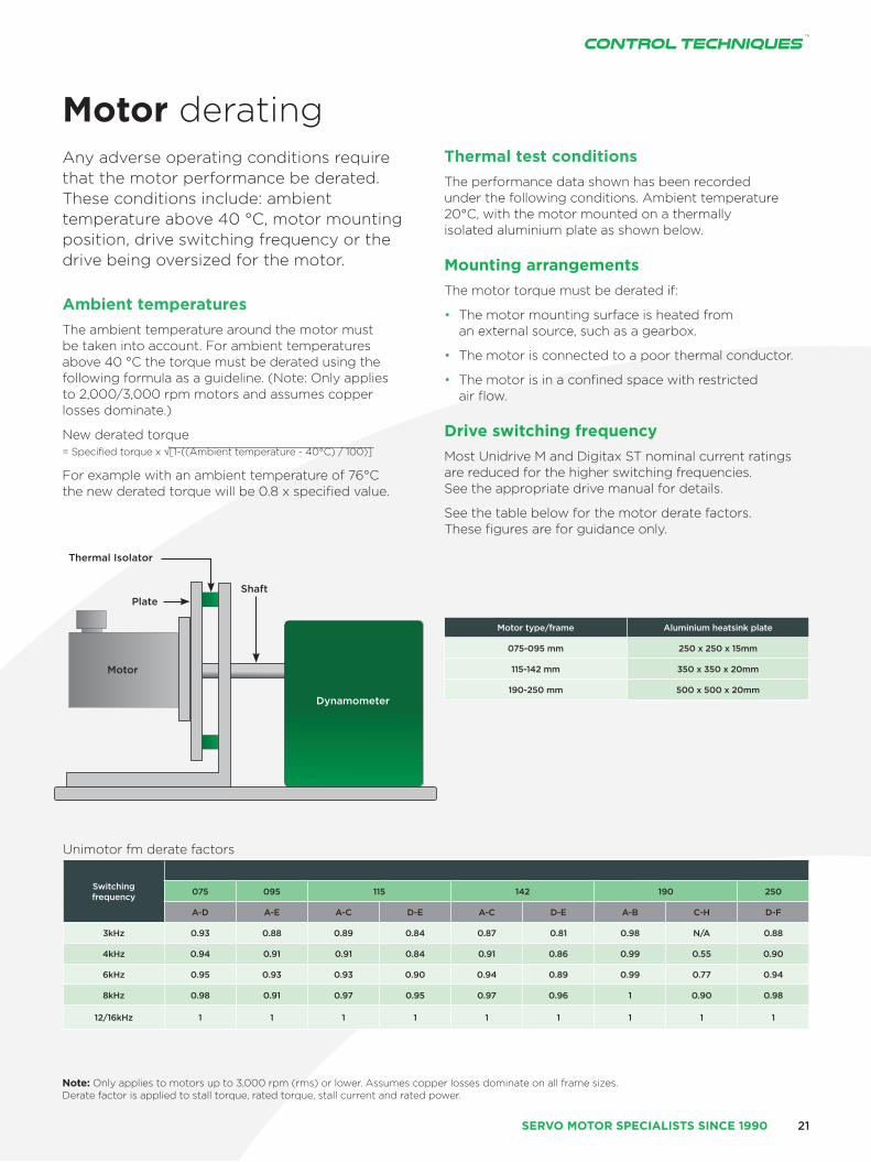
Thermal Isolator
PlateShaft
Motor
Dynamometer
Motor type/frame Aluminium heatsink plate
075-095 mm 250 x 250 x 15mm
115-142 mm 350 x 350 x 20mm
190-250 mm 500 x 500 x 20mm
Unimotor fm derate factors
Switching frequency 075 095 115 142 190 250
A-D A-E A-C D-E A-C D-E A-B C-H D-F
3kHz 0.93 0.88 0.89 0.84 0.87 0.81 0.98 N/A 0.88
4kHz 0.94 0.91 0.91 0.84 0.91 0.86 0.99 0.55 0.90
6kHz 0.95 0.93 0.93 0.90 0.94 0.89 0.99 0.77 0.94
8kHz 0.98 0.91 0.97 0.95 0.97 0.96 1 0.90 0.98
12/16kHz 1 1 1 1 1 1 1 1 1
Motor derating Any adverse operating conditions require that the motor performance be derated. These conditions include: ambient temperature above 40 °C, motor mounting position, drive switching frequency or the drive being oversized for the motor.
Ambient temperatures
The ambient temperature around the motor must be taken into account. For ambient temperatures above 40 °C the torque must be derated using the following formula as a guideline. (Note: Only applies to 2,000/3,000 rpm motors and assumes copper losses dominate.)
New derated torque = Specified torque x √[1-((Ambient temperature - 40°C) / 100)]
For example with an ambient temperature of 76°C the new derated torque will be 0.8 x specified value.
Thermal test conditions
The performance data shown has been recorded under the following conditions. Ambient temperature 20°C, with the motor mounted on a thermally isolated aluminium plate as shown below.
Mounting arrangements
The motor torque must be derated if:
• The motor mounting surface is heated from an external source, such as a gearbox.
• The motor is connected to a poor thermal conductor.
• The motor is in a confined space with restricted air flow.
Drive switching frequency
Most Unidrive M and Digitax ST nominal current ratings are reduced for the higher switching frequencies. See the appropriate drive manual for details.
See the table below for the motor derate factors. These figures are for guidance only.
Note: Only applies to motors up to 3,000 rpm (rms) or lower. Assumes copper losses dominate on all frame sizes. Derate factor is applied to stall torque, rated torque, stall current and rated power.
21
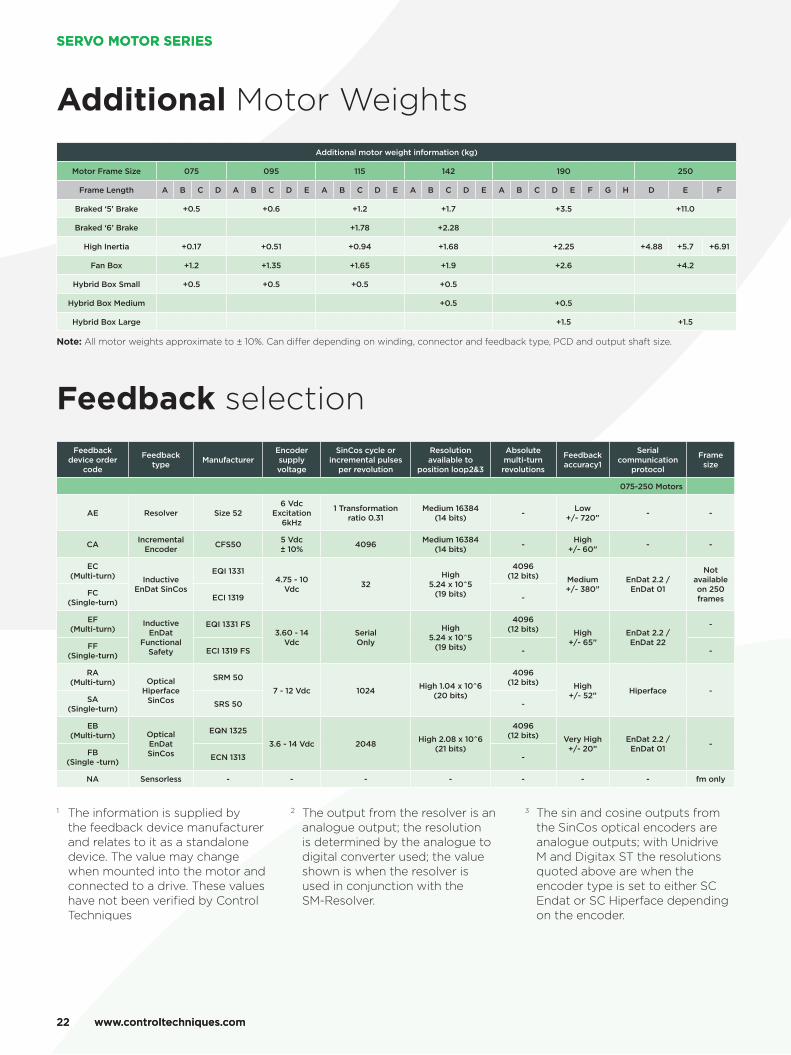
1 The information is supplied by the feedback device manufacturer and relates to it as a standalone device. The value may change when mounted into the motor and connected to a drive. These values have not been verified by Control Techniques
2 The output from the resolver is an analogue output; the resolution is determined by the analogue to digital converter used; the value shown is when the resolver is used in conjunction with the SM-Resolver.
3 The sin and cosine outputs from the SinCos optical encoders are analogue outputs; with Unidrive M and Digitax ST the resolutions quoted above are when the encoder type is set to either SC Endat or SC Hiperface depending on the encoder.
Feedback selectionFeedback
device order code
Feedback type Manufacturer
Encoder supply voltage
SinCos cycle or incremental pulses
per revolution
Resolution available to
position loop2&3
Absolute multi-turn revolutions
Feedback accuracy1
Serial communication
protocol
Frame size
075-250 Motors
AE Resolver Size 526 Vdc
Excitation 6kHz
1 Transformation ratio 0.31
Medium 16384 (14 bits) - Low
+/- 720” - -
CA Incremental Encoder CFS50 5 Vdc
± 10% 4096 Medium 16384 (14 bits) - High
+/- 60” - -
EC (Multi-turn) Inductive
EnDat SinCos
EQI 13314.75 - 10
Vdc 32High
5.24 x 10^5 (19 bits)
4096 (12 bits) Medium
+/- 380”EnDat 2.2 / EnDat 01
Not available on 250 frames
FC (Single-turn) ECI 1319 -
EF (Multi-turn)
Inductive EnDat
Functional Safety
EQI 1331 FS3.60 - 14
VdcSerial Only
High 5.24 x 10^5
(19 bits)
4096 (12 bits) High
+/- 65”EnDat 2.2 / EnDat 22
-
FF (Single-turn) ECI 1319 FS - -
RA (Multi-turn) Optical
Hiperface SinCos
SRM 50
7 - 12 Vdc 1024 High 1.04 x 10^6 (20 bits)
4096 (12 bits) High
+/- 52” Hiperface -SA
(Single-turn) SRS 50 -
EB (Multi-turn) Optical
EnDat SinCos
EQN 1325
3.6 - 14 Vdc 2048 High 2.08 x 10^6 (21 bits)
4096 (12 bits) Very High
+/- 20”EnDat 2.2 / EnDat 01 -
FB (Single -turn) ECN 1313 -
NA Sensorless - - - - - - - fm only
Additional Motor WeightsAdditional motor weight information (kg)
Motor Frame Size 075 095 115 142 190 250
Frame Length A B C D A B C D E A B C D E A B C D E A B C D E F G H D E F
Braked ‘5’ Brake +0.5 +0.6 +1.2 +1.7 +3.5 +11.0
Braked ‘6’ Brake +1.78 +2.28
High Inertia +0.17 +0.51 +0.94 +1.68 +2.25 +4.88 +5.7 +6.91
Fan Box +1.2 +1.35 +1.65 +1.9 +2.6 +4.2
Hybrid Box Small +0.5 +0.5 +0.5 +0.5
Hybrid Box Medium +0.5 +0.5
Hybrid Box Large +1.5 +1.5
Note: All motor weights approximate to ± 10%. Can differ depending on winding, connector and feedback type, PCD and output shaft size.
www.controltechniques.com22
SERVO MOTOR SERIES
www.controltechniques.com22
SERVO MOTOR SERIES

SERVO MOTOR SPECIALISTS SINCE 1990
Feedback terminologyResolverA passive wound device consisting of a stator and rotor elements excited from an external source, such as an SM-Resolver, the resolver produces two output signals that correspond to the Sine and CoSine angle of the motor shaft. This is a robust absolute device of low accuracy, capable of withstanding high temperature and high levels of vibration. Positional information is absolute within one turn - i.e. position is not lost when the drive is powered down.
Incremental encoderAn electronic device using an optical disc. The position is determined by counting steps or pulses. Two sequences of pulses in quadrature are used so the direction sensing may be determined and 4x (pulses per rev) may be used for resolution in the drive. A marker pulse occurs once per revolution and is used to zero the position count. The encoder also provides commutation signals, which are required to determine the absolute position during the motor phasing test. This device is available in 4096, 2048 and 1024 ppr versions. Positional information is non absolute - i.e. position is lost when the drive is powered down.
SinCos / absolute encodersTypes available are: Optical or Inductive - which can be single or multi-turn.
1) Optical An electronic device using an optical disc. An absolute encoder with high resolution that employs a combination of absolute information, transmitted via a serial link, and Sine/CoSine signals with incremental techniques.
2) Inductive / Capacitive An electronic device using inductively coupled PCBs. An absolute encoder with medium resolution the employs a combination of absolute information, transmitted via a serial link, and Sine/CoSine signals with incremental techniques. This encoder can be operated with the drive using either Sine/CoSine or absolute (serial) values only. Positional information is absolute within 4096 turns - i.e. position is not lost when the drive is powered down.
Multi-turnAs previous but with extra gear wheels included so that the output is unique for each shaft position and the encoder has the additional ability to count complete turns of the motor shaft up to 4096 revolutions
SensorlessSynchronous Rotor Flux Control. Recommended for use on the fm motor range. The motor performance will be limited when operating at low speed when using high frequency injection mode. When using closed loop vector mode the motor performance will be as stated in the ratings tables.
EnvironmentThe environment is the external conditions that physically surround the Feedback device. The main factors that affect the feedback device are temperature and mechanical shock and vibration.
Motors are designed to allow the feedback devices to be within their operational temperature limits. Generally it is assumed that there is free air movement around the motor. If the motor is positioned where there is little or no airflow or it is connected to a heat source such as a gearbox, it can cause the air temperature around the feedback device to be operating outside its recommended operating temperature and can lead to problems.
Mechanical shock and vibration tends to be transmitted from the load through the motor shaft and into the feedback device. This should be considered when the motor and feedback device are being specified for the application.
PositionThe defined position is the location in a coordinate system which is usually in two or more dimensions.
For a rotary feedback device this is defined as the location within one revolution. If it is a multi-turn device it is the location within one revolution plus the location within a number of rotations.
For a linear feedback device this is defined as the distance from a known point.
ResolutionThe resolution of a feedback device is the smallest change in position or angle that it can detect in the quantity that it is measuring.
Feedback resolution of the system is a function of the type of feedback device used and drive receiving the information.
Generally, as the resolution of the feedback device increases the level of control that can be used in the servo system increases.
As with accuracy, as the resolution of the device increases the cost increases.
AccuracyAccuracy is the measure of the difference between the expected position and actual measured value. Rotary feedback accuracy is usually given as an angle representing the maximum deviation from the expected position. Linear feedback accuracy is usually given as a distance representing the maximum deviation from the expected.
Generally, as the accuracy increases the cost of the feedback device increases.
2323
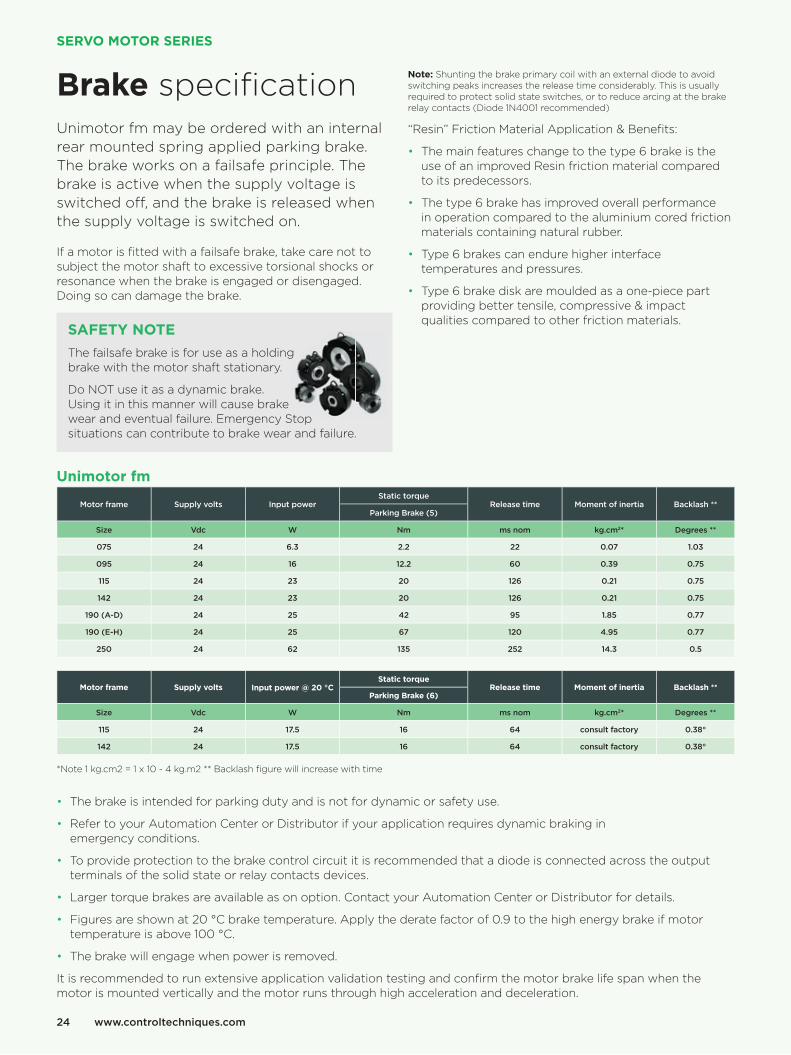
Brake specifi cationUnimotor fm may be ordered with an internal rear mounted spring applied parking brake. The brake works on a failsafe principle. The brake is active when the supply voltage is switched off , and the brake is released when the supply voltage is switched on.
If a motor is fi tted with a failsafe brake, take care not to subject the motor shaft to excessive torsional shocks or resonance when the brake is engaged or disengaged. Doing so can damage the brake.
SAFETY NOTE
The failsafe brake is for use as a holding brake with the motor shaft stationary.
Do NOT use it as a dynamic brake. Using it in this manner will cause brake wear and eventual failure. Emergency Stop situations can contribute to brake wear and failure.
Note: Shunting the brake primary coil with an external diode to avoid switching peaks increases the release time considerably. This is usually required to protect solid state switches, or to reduce arcing at the brake relay contacts (Diode 1N4001 recommended)
“Resin” Friction Material Application & Benefi ts:
• The main features change to the type 6 brake is the use of an improved Resin friction material compared to its predecessors.
• The type 6 brake has improved overall performance in operation compared to the aluminium cored friction materials containing natural rubber.
• Type 6 brakes can endure higher interface temperatures and pressures.
• Type 6 brake disk are moulded as a one-piece part providing better tensile, compressive & impact qualities compared to other friction materials.
wear and eventual failure. Emergency Stop
Unimotor fm
Motor frame Supply volts Input powerStatic torque
Release time Moment of inertia Backlash **Parking Brake (5)
Size Vdc W Nm ms nom kg.cm2* Degrees **
075 24 6.3 2.2 22 0.07 1.03
095 24 16 12.2 60 0.39 0.75
115 24 23 20 126 0.21 0.75
142 24 23 20 126 0.21 0.75
190 (A-D) 24 25 42 95 1.85 0.77
190 (E-H) 24 25 67 120 4.95 0.77
250 24 62 135 252 14.3 0.5
Motor frame Supply volts Input power @ 20 °CStatic torque
Release time Moment of inertia Backlash **Parking Brake (6)
Size Vdc W Nm ms nom kg.cm2* Degrees **
115 24 17.5 16 64 consult factory 0.38°
142 24 17.5 16 64 consult factory 0.38°
*Note 1 kg.cm2 = 1 x 10 - 4 kg.m2 ** Backlash fi gure will increase with time
• The brake is intended for parking duty and is not for dynamic or safety use.
• Refer to your Automation Center or Distributor if your application requires dynamic braking in emergency conditions.
• To provide protection to the brake control circuit it is recommended that a diode is connected across the output terminals of the solid state or relay contacts devices.
• Larger torque brakes are available as on option. Contact your Automation Center or Distributor for details.
• Figures are shown at 20 °C brake temperature. Apply the derate factor of 0.9 to the high energy brake if motor temperature is above 100 °C.
• The brake will engage when power is removed.
It is recommended to run extensive application validation testing and confi rm the motor brake life span when the motor is mounted vertically and the motor runs through high acceleration and deceleration.
www.controltechniques.com24
SERVO MOTOR SERIES

Power plug
1 5
642
3
u
v- +
w
Size 1 With brake Without brake Size 1.5 With brake Without brake
Pin Function Function Pin Function Function
1 Phase U (R) Phase U (R) U Phase U (R) Phase U (R)
2 Phase V (S) Phase V (S) V Phase V (S) Phase V (S)
3 Ground Ground
u
v- +
w
Ground Ground
4 Phase W (T) Phase W (T) W Phase W (T) Phase W (T)
5 Brake + Brake
6 Brake - Brake
Shell Screen Screen Shell Screen Screen
Signal plug
1
10
9
8
12
13
1415
1617
7 65
11
4
3
2 1
10
98
127
6
511
43
2
Incremental encoder (CA, MA)
Heidenhain Sincos absolute encoders
(EM, FM, EC, FC, EF, FF, EB, FB)Resolver (AE) SICK Sin/Cos encoders (RA, SA)
Pin Function Function Function Function
1 Thermistor Thermistor Excitation High REF Cos
2 Thermistor Thermistor Excitation Low + Data
3 Screen (Optical only) Cos High - Data
4 S1 Cos Low + Cos
5 S1 Inverse Sin High + Sin
6 S2 Sin Low REF Sin
7 S2 Inverse Thermistor Thermistor
8 S3 + Clock Thermistor Thermistor
9 S3 Inverse - Clock Screen
10 Channel A + Cos 0 Volts
11 Index + Data -
12 Index Inverse - Data + V
13 Channel A Inverse - Cos
14 Channel B + Sin
15 Channel B Inverse - Sin
16 + V + V
17 0 Volts 0 Volts
Body Screen Screen Screen
SERVO MOTOR SPECIALISTS SINCE 1990 25

Notes:
www.controltechniques.com26
SERVO MOTOR SERIES

SERVO MOTOR SPECIALISTS SINCE 1990
Notes:
27

www.controltechniques.com
Connect with us at:
© 2018 Nidec Control Techniques Limited. The information contained in this brochure is for guidance only and does not form part of any contract. The accuracy cannot be guaranteed as Nidec Control Techniques Ltd have an ongoing process of development and reserve the right to change the specifi cation of their products without notice.Nidec Control Techniques Limited. Registered Offi ce: The Gro, Newtown, Powys SY16 3BE. Registered in England and Wales. Company Reg. No. 01236886.
P.N. 0702-0032-11 07/18


![48216 Baack Final Proof [FM]](https://static.fdokumen.com/doc/165x107/631bfe5b3e8acd997705b218/48216-baack-final-proof-fm.jpg)