Advanced User Guide - Mentor MP - Nidec Netherlands
216
Advanced User Guide Mentor MP High performance DC drive 25A to 7400A, 480V to 690V Two or four quadrant operation Part Number: 0476-0002-05 Issue: 5
-
Upload
khangminh22 -
Category
Documents
-
view
0 -
download
0
Transcript of Advanced User Guide - Mentor MP - Nidec Netherlands

Advanced User Guide
Mentor MP
High performance DC drive25A to 7400A, 480V to 690VTwo or four quadrant operation
Part Number: 0476-0002-05Issue: 5

Original InstructionsFor the purposes of compliance with the EU Machinery Directive 2006/42/EC, the English version of this manual is the Original Instructions. Manuals
in other languages are Translations of the Original Instructions.
DocumentationManuals are available to download from the following locations: http://www.drive-setup.com/ctdownloads
The information contained in this manual is believed to be correct at the time of printing and does not form part of any contract. The manufacturer reserves the right to change the specification of the product and its performance, and the contents of the manual, without notice.
Warranty and LiabilityIn no event and under no circumstances shall the manufacturer be liable for damages and failures due to misuse, abuse, improper installation, or abnormal conditions of temperature, dust, or corrosion, or failures due to operation outside the published ratings. The manufacturer is not liable for consequential and incidental damages. Contact the supplier of the dive for full details of the warranty terms.
Environmental policyControl Techniques Ltd operates an Environmental Management System (EMS) that conforms to the International Standard ISO 14001.
Further information on our Environmental Policy can be found at: http://www.drive-setup.com/environment
Restriction of Hazardous Substances (RoHS)The products covered by this manual comply with European and International regulations on the Restriction of Hazardous Substances including EU directive 2011/65/EU and the Chinese Administrative Measures for Restriction of Hazardous Substances in Electrical and Electronic Products.
Disposal and Recycling (WEEE)
REACH legislationEC Regulation 1907/2006 on the Registration, Evaluation, Authorisation and restriction of Chemicals (REACH) requires the supplier of an article to inform the recipient if it contains more than a specified proportion of any substance which is considered by the European Chemicals Agency (ECHA) to be a Substance of Very High Concern (SVHC) and is therefore listed by them as a candidate for compulsory authorisation.
Further information on our compliance with REACH can be found at: http://www.drive-setup.com/reach
Registered Office
Nidec Control Techniques LtdThe GroNewtownPowysSY16 3BEUKRegistered in England and Wales. Company Reg. No. 01236886.
CopyrightThe contents of this publication are believed to be correct at the time of printing. In the interests of a commitment to a policy of continuous development and improvement, the manufacturer reserves the right to change the specification of the product or its performance, or the contents of the guide, without notice. All rights reserved. No parts of this guide may be reproduced or transmitted in any form or by any means, electrical or mechanical including photocopying, recording or by an information storage or retrieval system, without permission in writing from the publisher.
Copyright © November 2017 Nidec Control Techniques Ltd
When electronic products reach the end of their useful life, they must not be disposed of along with domestic waste but should be recycled by a specialist recycler of electronic equipment. Control Techniques products are designed to be easily dismantled into their major component parts for efficient recycling. The majority of materials used in the product are suitable for recycling.
Product packaging is of good quality and can be re-used. Large products are packed in wooden crates. Smaller products are packaged in strong cardboard cartons which have a high recycled fibre content. Cartons can be re-used and recycled. Polythene, used in protective film and bags for wrapping the product, can be recycled. When preparing to recycle or dispose of any product or packaging, please observe local legislation and best practice.
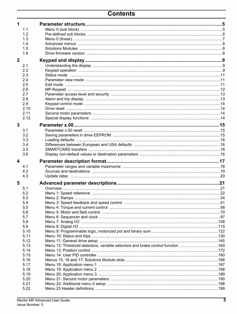
Contents1 Parameter structure.......................................................................................................5
1.1 Menu 0 (sub block) ................................................................................................................................51.2 Pre-defined sub blocks ..........................................................................................................................61.3 Menu 0 (linear) .......................................................................................................................................71.4 Advanced menus ...................................................................................................................................81.5 Solutions Modules .................................................................................................................................81.6 Drive firmware version ...........................................................................................................................8
2 Keypad and display .......................................................................................................92.1 Understanding the display .....................................................................................................................92.2 Keypad operation ..................................................................................................................................92.3 Status mode ........................................................................................................................................112.4 Parameter view mode ..........................................................................................................................112.5 Edit mode ............................................................................................................................................112.6 MP-Keypad ..........................................................................................................................................122.7 Parameter access level and security ...................................................................................................132.8 Alarm and trip display ..........................................................................................................................132.9 Keypad control mode ...........................................................................................................................142.10 Drive reset ...........................................................................................................................................142.11 Second motor parameters ...................................................................................................................142.12 Special display functions .....................................................................................................................14
3 Parameter x.00 .............................................................................................................153.1 Parameter x.00 reset ...........................................................................................................................153.2 Saving parameters in drive EEPROM .................................................................................................153.3 Loading defaults ..................................................................................................................................163.4 Differences between European and USA defaults ..............................................................................163.5 SMARTCARD transfers .......................................................................................................................163.6 Display non-default values or destination parameters .........................................................................16
4 Parameter description format.....................................................................................174.1 Parameter ranges and variable maximums: ........................................................................................184.2 Sources and destinations ....................................................................................................................194.3 Update rates ........................................................................................................................................20
5 Advanced parameter descriptions.............................................................................215.1 Overview ..............................................................................................................................................215.2 Menu 1: Speed reference ....................................................................................................................225.3 Menu 2: Ramps ...................................................................................................................................345.4 Menu 3: Speed feedback and speed control .......................................................................................415.5 Menu 4: Torque and current control ....................................................................................................585.6 Menu 5: Motor and field control ...........................................................................................................705.7 Menu 6: Sequencer and clock .............................................................................................................975.8 Menu 7: Analog I/O ............................................................................................................................1085.9 Menu 8: Digital I/O .............................................................................................................................1155.10 Menu 9: Programmable logic, motorized pot and binary sum ...........................................................1225.11 Menu 10: Status and trips ..................................................................................................................1305.12 Menu 11: General drive setup ...........................................................................................................1455.13 Menu 12: Threshold detectors, variable selectors and brake control function ...................................1605.14 Menu 13: Position control ..................................................................................................................1725.15 Menu 14: User PID controller ............................................................................................................1805.16 Menus 15, 16 and 17: Solutions Module slots ...................................................................................1865.17 Menu 18: Application menu 1 ............................................................................................................1875.18 Menu 19: Application menu 2 ............................................................................................................1885.19 Menu 20: Application menu 3 ............................................................................................................1895.20 Menu 21: Second motor parameters .................................................................................................1905.21 Menu 22: Additional menu 0 setup ....................................................................................................1985.22 Menu 23 Header definitions ...............................................................................................................199
Mentor MP Advanced User Guide 3Issue Number: 5

5.23 Pre-Defined Sub Blocks .................................................................................................................... 2015.24 Menu 0 (linear) .................................................................................................................................. 2025.25 Menu structure .................................................................................................................................. 2025.26 32 bit parameters .............................................................................................................................. 203
6 Serial communications protocol ............................................................................. 2046.1 ANSI communications protocol ......................................................................................................... 2046.2 CT Modbus RTU specification .......................................................................................................... 206
7 Performance .............................................................................................................. 2117.1 Digital speed reference ..................................................................................................................... 2117.2 Analog reference .............................................................................................................................. 2117.3 Analog outputs .................................................................................................................................. 2117.4 Digital inputs and outputs ................................................................................................................. 2117.5 Current feedback .............................................................................................................................. 2117.6 Bandwidth ......................................................................................................................................... 211
4 Mentor MP Advanced User Guide Issue Number: 5
Parameter structure Keypad and display Parameter x.00 Parameter description format
Advanced parameter descriptions
Serial comms protocol Performance
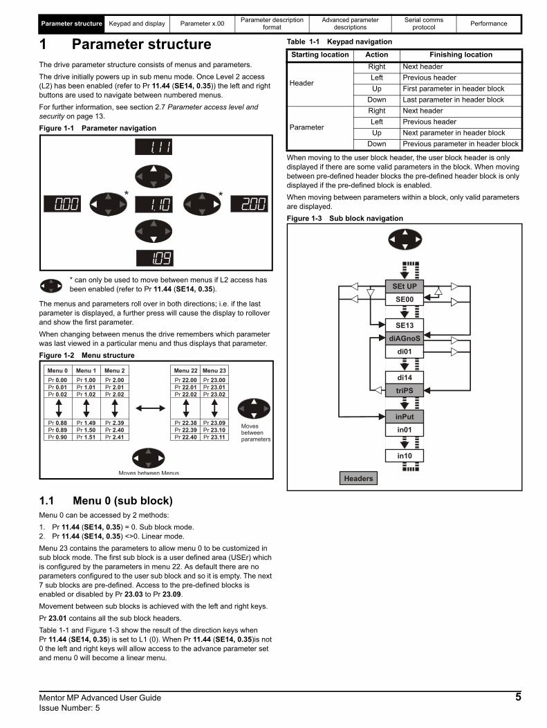
1 Parameter structureThe drive parameter structure consists of menus and parameters.The drive initially powers up in sub menu mode. Once Level 2 access (L2) has been enabled (refer to Pr 11.44 (SE14, 0.35)) the left and right buttons are used to navigate between numbered menus. For further information, see section 2.7 Parameter access level and security on page 13.Figure 1-1 Parameter navigation
* can only be used to move between menus if L2 access has been enabled (refer to Pr 11.44 (SE14, 0.35).
The menus and parameters roll over in both directions; i.e. if the last parameter is displayed, a further press will cause the display to rollover and show the first parameter.When changing between menus the drive remembers which parameter was last viewed in a particular menu and thus displays that parameter.Figure 1-2 Menu structure
1.1 Menu 0 (sub block)Menu 0 can be accessed by 2 methods:1. Pr 11.44 (SE14, 0.35) = 0. Sub block mode.2. Pr 11.44 (SE14, 0.35) <>0. Linear mode.Menu 23 contains the parameters to allow menu 0 to be customized in sub block mode. The first sub block is a user defined area (USEr) which is configured by the parameters in menu 22. As default there are no parameters configured to the user sub block and so it is empty. The next 7 sub blocks are pre-defined. Access to the pre-defined blocks is enabled or disabled by Pr 23.03 to Pr 23.09. Movement between sub blocks is achieved with the left and right keys. Pr 23.01 contains all the sub block headers.Table 1-1 and Figure 1-3 show the result of the direction keys when Pr 11.44 (SE14, 0.35) is set to L1 (0). When Pr 11.44 (SE14, 0.35)is not 0 the left and right keys will allow access to the advance parameter set and menu 0 will become a linear menu.
Table 1-1 Keypad navigation
When moving to the user block header, the user block header is only displayed if there are some valid parameters in the block. When moving between pre-defined header blocks the pre-defined header block is only displayed if the pre-defined block is enabled.When moving between parameters within a block, only valid parameters are displayed.Figure 1-3 Sub block navigation
* *
Menu 22 Menu 23Menu 0 Menu 1 Menu 2Pr 22.00 Pr 23.00Pr 0.00 Pr 1.00 Pr 2.00Pr 22.01 Pr 23.01Pr 0.01 Pr 1.01 Pr 2.01Pr 22.02 Pr 23.02Pr 0.02 Pr 1.02 Pr 2.02
Pr 22.38 Pr 23.09Pr 0.88 Pr 1.49 Pr 2.39Pr 22.39 Pr 23.10Pr 0.89 Pr 1.50 Pr 2.40Pr 22.40 Pr 23.11Pr 0.90 Pr 1.51 Pr 2.41
Movesbetweenparameters
Moves between Menus
Starting location Action Finishing location
Header
Right Next headerLeft Previous headerUp First parameter in header block
Down Last parameter in header block
Parameter
Right Next headerLeft Previous headerUp Next parameter in header block
Down Previous parameter in header block
SEt UP
diAGnoS
inPut
Headers
triPS
SE00
SE13
di01
di14
in01
in10
Mentor MP Advanced User Guide 5Issue Number: 5
Parameter structure Keypad and display Parameter x.00 Parameter description format
Advanced parameter descriptions
Serial comms protocol Performance
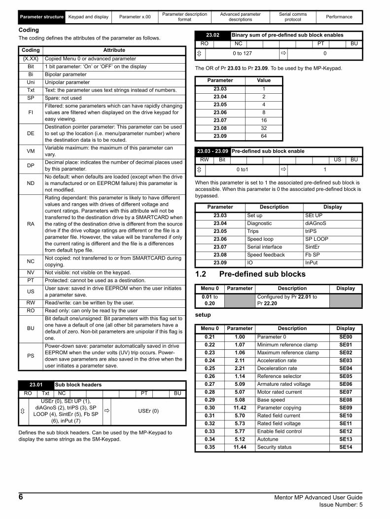
CodingThe coding defines the attributes of the parameter as follows.
Defines the sub block headers. Can be used by the MP-Keypad to display the same strings as the SM-Keypad.
The OR of Pr 23.03 to Pr 23.09. To be used by the MP-Keypad.
When this parameter is set to 1 the associated pre-defined sub block is accessible. When this parameter is 0 the associated pre-defined block is bypassed.
1.2 Pre-defined sub blocks
setup
Coding Attribute{X.XX} Copied Menu 0 or advanced parameter
Bit 1 bit parameter: ‘On’ or ‘OFF’ on the displayBi Bipolar parameter
Uni Unipolar parameterTxt Text: the parameter uses text strings instead of numbers.SP Spare: not used
FIFiltered: some parameters which can have rapidly changing values are filtered when displayed on the drive keypad for easy viewing.
DEDestination pointer parameter: This parameter can be used to set up the location (i.e. menu/parameter number) where the destination data is to be routed.
VM Variable maximum: the maximum of this parameter can vary.
DP Decimal place: indicates the number of decimal places used by this parameter.
NDNo default: when defaults are loaded (except when the drive is manufactured or on EEPROM failure) this parameter is not modified.
RA
Rating dependant: this parameter is likely to have different values and ranges with drives of different voltage and current ratings. Parameters with this attribute will not be transferred to the destination drive by a SMARTCARD when the rating of the destination drive is different from the source drive if the drive voltage ratings are different or the file is a parameter file. However, the value will be transferred if only the current rating is different and the file is a differences from default type file.
NC Not copied: not transferred to or from SMARTCARD during copying.
NV Not visible: not visible on the keypad.PT Protected: cannot be used as a destination.
US User save: saved in drive EEPROM when the user initiates a parameter save.
RW Read/write: can be written by the user.RO Read only: can only be read by the user
BU
Bit default one/unsigned: Bit parameters with this flag set to one have a default of one (all other bit parameters have a default of zero. Non-bit parameters are unipolar if this flag is one.
PS
Power-down save: parameter automatically saved in drive EEPROM when the under volts (UV) trip occurs. Power-down save parameters are also saved in the drive when the user initiates a parameter save.
23.01 Sub block headersRO Txt NC PT BU
USEr (0), SEt UP (1),diAGnoS (2), triPS (3), SP
LOOP (4), SintEr (5), Fb SP(6), inPut (7)
USEr (0)
23.02 Binary sum of pre-defined sub block enablesRO NC PT BU
0 to 127 0
Parameter Value23.03 123.04 223.05 423.06 823.07 1623.08 3223.09 64
23.03 - 23.09 Pre-defined sub block enableRW Bit US BU
0 to1 1
Parameter Description Display23.03 Set up SEt UP23.04 Diagnostic diAGnoS23.05 Trips triPS23.06 Speed loop SP LOOP23.07 Serial interface SintEr23.08 Speed feedback Fb SP23.09 IO InPut
Menu 0 Parameter Description Display0.01 to
0.20Configured by Pr 22.01 to Pr 22.20
Menu 0 Parameter Description Display0.21 1.00 Parameter 0 SE000.22 1.07 Minimum reference clamp SE010.23 1.06 Maximum reference clamp SE020.24 2.11 Acceleration rate SE030.25 2.21 Deceleration rate SE040.26 1.14 Reference selector SE050.27 5.09 Armature rated voltage SE060.28 5.07 Motor rated current SE070.29 5.08 Base speed SE080.30 11.42 Parameter copying SE090.31 5.70 Rated field current SE100.32 5.73 Rated field voltage SE110.33 5.77 Enable field control SE120.34 5.12 Autotune SE130.35 11.44 Security status SE14
6 Mentor MP Advanced User Guide Issue Number: 5
Parameter structure Keypad and display Parameter x.00 Parameter description format
Advanced parameter descriptions
Serial comms protocol Performance
Diagnostic
Trips
Speed loop
Serial interface
Speed feedback
IO
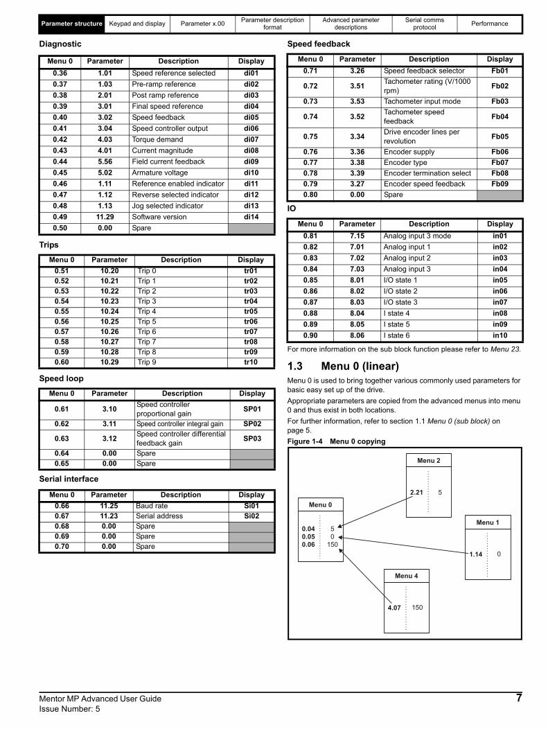
For more information on the sub block function please refer to Menu 23.
1.3 Menu 0 (linear)Menu 0 is used to bring together various commonly used parameters for basic easy set up of the drive.Appropriate parameters are copied from the advanced menus into menu 0 and thus exist in both locations.For further information, refer to section 1.1 Menu 0 (sub block) on page 5.Figure 1-4 Menu 0 copying
Menu 0 Parameter Description Display0.36 1.01 Speed reference selected di010.37 1.03 Pre-ramp reference di020.38 2.01 Post ramp reference di030.39 3.01 Final speed reference di040.40 3.02 Speed feedback di050.41 3.04 Speed controller output di060.42 4.03 Torque demand di070.43 4.01 Current magnitude di080.44 5.56 Field current feedback di090.45 5.02 Armature voltage di100.46 1.11 Reference enabled indicator di110.47 1.12 Reverse selected indicator di120.48 1.13 Jog selected indicator di130.49 11.29 Software version di140.50 0.00 Spare
Menu 0 Parameter Description Display0.51 10.20 Trip 0 tr010.52 10.21 Trip 1 tr020.53 10.22 Trip 2 tr030.54 10.23 Trip 3 tr040.55 10.24 Trip 4 tr050.56 10.25 Trip 5 tr060.57 10.26 Trip 6 tr070.58 10.27 Trip 7 tr080.59 10.28 Trip 8 tr090.60 10.29 Trip 9 tr10
Menu 0 Parameter Description Display
0.61 3.10 Speed controller proportional gain SP01
0.62 3.11 Speed controller integral gain SP02
0.63 3.12 Speed controller differential feedback gain SP03
0.64 0.00 Spare0.65 0.00 Spare
Menu 0 Parameter Description Display0.66 11.25 Baud rate Si010.67 11.23 Serial address Si020.68 0.00 Spare0.69 0.00 Spare0.70 0.00 Spare
Menu 0 Parameter Description Display0.71 3.26 Speed feedback selector Fb01
0.72 3.51 Tachometer rating (V/1000 rpm) Fb02
0.73 3.53 Tachometer input mode Fb03
0.74 3.52 Tachometer speed feedback Fb04
0.75 3.34 Drive encoder lines per revolution Fb05
0.76 3.36 Encoder supply Fb060.77 3.38 Encoder type Fb070.78 3.39 Encoder termination select Fb080.79 3.27 Encoder speed feedback Fb090.80 0.00 Spare
Menu 0 Parameter Description Display0.81 7.15 Analog input 3 mode in010.82 7.01 Analog input 1 in020.83 7.02 Analog input 2 in030.84 7.03 Analog input 3 in040.85 8.01 I/O state 1 in050.86 8.02 I/O state 2 in060.87 8.03 I/O state 3 in070.88 8.04 I state 4 in080.89 8.05 I state 5 in090.90 8.06 I state 6 in10
Menu 0
0.040.050.06
Menu 2
2.21
Menu 1
1.14
Menu 4
4.07
50
1500
150
5
Mentor MP Advanced User Guide 7Issue Number: 5

Parameter structure Keypad and display Parameter x.00 Parameter description format
Advanced parameter descriptions
Serial comms protocol Performance
1.4 Advanced menusThe advanced menus consist of groups of parameters appropriate to a specific function or feature of the drive. Menus 0 to 23 can be viewed on both keypads. Menus 40 and 41 are specific to the MP-Keypad (LCD). Menus 70 to 91 can be viewed with an MP-Keypad (LCD) only when an SM-Applications module is installed.Table 1-2 Advanced menu descriptions
1.5 Solutions ModulesAny Solutions Module type is recognised with all drive types in any slots. The relevant template is used to define menu 15 for the module type installed in slot 1, menu 16 for slot 2, and menu 17 for slot 3.
1.6 Drive firmware versionThis product is supplied with the latest firmware versions. If this drive is to be connected to an existing system or machine, all drive firmware versions should be verified to confirm the same functionality as drives of the same model already present. This may also apply to drives returned from a Control Techniques Service Centre or Repair Centre. If there is any doubt please contact the supplier of the product. This drive contains two firmware versions which can be checked by looking at Pr 11.29 (di14/0.49) and Pr 11.34. This takes the form of xx.yy.zz where Pr 11.29 (di14/0.49) displays xx.yy and Pr 11.34 displays zz for the user firmware.Power firmware is displayed at Pr 11.56 and takes the form of xx.yy. (e.g. for firmware version 01.06.00,Pr 11.29 (di14/0.49) = 1.06 and Pr 11.34 displays 0 which is compatible with power firmware version 01.09, Pr 11.56 = 1.09)
Menu Description LED LCD
0 Commonly used basic set up parameters for quick / easy programming
1 Speed reference2 Ramps3 Speed feedback and speed control4 Torque and current control5 Motor control including field regulator6 Sequencer and clock7 Analog I/O8 Digital I/O
9 Programmable logic, motorized pot and binary sum
10 Status and trips11 General drive setup12 Threshold detectors and variable selectors13 Position control14 User PID controller15 Solutions Module setup16 Solutions Module setup17 Solutions Module setup18 Application menu 119 Application menu 220 Application menu 321 Second motor parameters22 Menu 0 setup - user area23 Menu 0 sub block control40 Keypad configuration menu X41 User filter menu X70 PLC registers X71 PLC registers X72 PLC registers X73 PLC registers X74 PLC registers X75 PLC registers X85 Timer function parameters X86 Digital I/O parameters X88 Status parameters X90 General parameters X91 Fast access parameters X
Key: = AvailableX = Not available
8 Mentor MP Advanced User Guide Issue Number: 5
Parameter structure Keypad and display Parameter x.00 Parameter description format
Advanced parameter descriptions
Serial comms protocol Performance
2 Keypad and display
The red stop button is also used to reset the drive.
The SM-Keypad and the MP-Keypad can indicate when a SMARTCARD access is taking place or when the second motor map is active (menu 21). These are indicated on the displays as follows:
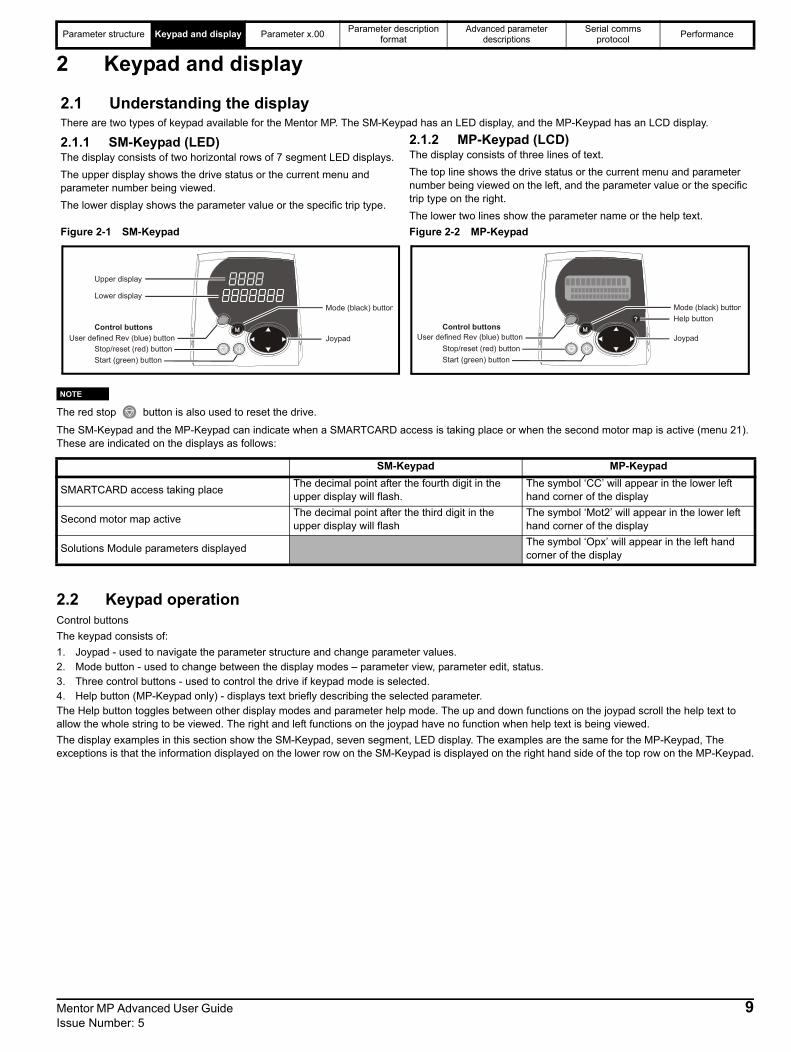
2.2 Keypad operationControl buttonsThe keypad consists of: 1. Joypad - used to navigate the parameter structure and change parameter values.2. Mode button - used to change between the display modes – parameter view, parameter edit, status.3. Three control buttons - used to control the drive if keypad mode is selected. 4. Help button (MP-Keypad only) - displays text briefly describing the selected parameter.The Help button toggles between other display modes and parameter help mode. The up and down functions on the joypad scroll the help text to allow the whole string to be viewed. The right and left functions on the joypad have no function when help text is being viewed.The display examples in this section show the SM-Keypad, seven segment, LED display. The examples are the same for the MP-Keypad, The exceptions is that the information displayed on the lower row on the SM-Keypad is displayed on the right hand side of the top row on the MP-Keypad.
2.1 Understanding the displayThere are two types of keypad available for the Mentor MP. The SM-Keypad has an LED display, and the MP-Keypad has an LCD display.
2.1.1 SM-Keypad (LED)The display consists of two horizontal rows of 7 segment LED displays.The upper display shows the drive status or the current menu and parameter number being viewed.The lower display shows the parameter value or the specific trip type.
2.1.2 MP-Keypad (LCD)The display consists of three lines of text.The top line shows the drive status or the current menu and parameter number being viewed on the left, and the parameter value or the specific trip type on the right.The lower two lines show the parameter name or the help text.
Figure 2-1 SM-Keypad Figure 2-2 MP-Keypad
Upper display
Lower displayMode (black) button
JoypadUser defined Rev (blue) buttonStop/reset (red) buttonStart (green) button
Control buttons
Mode (black) button
JoypadStop/reset (red) buttonStart (green) button
Control buttonsHelp button
User defined Rev (blue) button
SM-Keypad MP-Keypad
SMARTCARD access taking place The decimal point after the fourth digit in theupper display will flash.
The symbol ‘CC’ will appear in the lower lefthand corner of the display
Second motor map active The decimal point after the third digit in theupper display will flash
The symbol ‘Mot2’ will appear in the lower lefthand corner of the display
Solutions Module parameters displayed The symbol ‘Opx’ will appear in the left handcorner of the display
NOTE
Mentor MP Advanced User Guide 9Issue Number: 5
Parameter structure Keypad and display Parameter x.00 Parameter description format
Advanced parameter descriptions
Serial comms protocol Performance
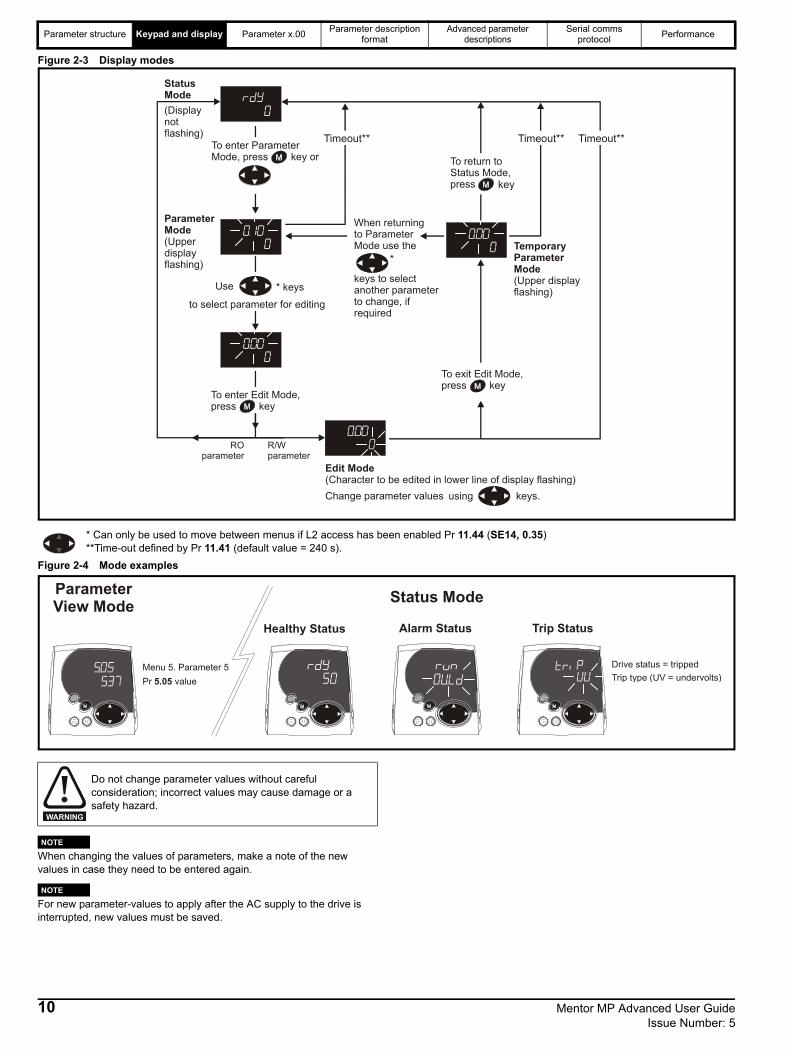
Figure 2-3 Display modes
Figure 2-4 Mode examples
When changing the values of parameters, make a note of the new values in case they need to be entered again.
For new parameter-values to apply after the AC supply to the drive is interrupted, new values must be saved.
Use * keys
to select parameter for editing
To enter Edit Mode, press key
StatusMode(Displaynot flashing)
ParameterMode(Upper display flashing)
Edit Mode(Character to be edited in lower line of display flashing)Change parameter values using keys.
When returningto ParameterMode use the
keys to selectanother parameterto change, ifrequired
To exit Edit Mode, press key
To enter Parameter Mode, press key or
*Temporary ParameterMode(Upper displayflashing)
Timeout** Timeout**Timeout**
To return toStatus Mode,press key
RO parameter
R/W parameter
* Can only be used to move between menus if L2 access has been enabled Pr 11.44 (SE14, 0.35)**Time-out defined by Pr 11.41 (default value = 240 s).
Pr value5.05Menu 5. Parameter 5
Trip type (UV = undervolts)Drive status = tripped
Trip StatusAlarm Status
Parameter View Mode
Healthy Status
Status Mode
Do not change parameter values without careful consideration; incorrect values may cause damage or a safety hazard.
WARNING
NOTE
NOTE
10 Mentor MP Advanced User Guide Issue Number: 5
Parameter structure Keypad and display Parameter x.00 Parameter description format
Advanced parameter descriptions
Serial comms protocol Performance
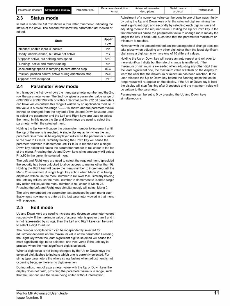
2.3 Status modeIn status mode the 1st row shows a four letter mnemonic indicating the status of the drive. The second row show the parameter last viewed or edited.
2.4 Parameter view modeIn this mode the 1st row shows the menu.parameter number and the 2nd row the parameter value. The 2nd row gives a parameter value range of -999,999 to 9,999,999 with or without decimal points. (32 bit parameters can have values outside this range if written by an application module. If the value is outside this range “-------“is shown and the parameter value cannot be changed from the keypad.) The Up and Down keys are used to select the parameter and the Left and Right keys are used to select the menu. In this mode the Up and Down keys are used to select the parameter within the selected menu. Holding the Up key will cause the parameter number to increment until the top of the menu is reached. A single Up key action when the last parameter in a menu is being displayed will cause the parameter number to roll over to Pr x.00. Similarly holding the Down key will cause the parameter number to decrement until Pr x.00 is reached and a single Down key action will cause the parameter number to roll under to the top of the menu. Pressing the Up and Down keys simultaneously will select Pr x.00 in the currently selected menu.The Left and Right keys are used to select the required menu (provided the security has been unlocked to allow access to menus other than 0). Holding the Right key will cause the menu number to increment until the Menu 23 is reached. A single Right key action when Menu 23 is being displayed will cause the menu number to roll over to 0. Similarly holding the Left key will cause the menu number to decrement to 0 and a single key action will cause the menu number to roll under to Menu 23. Pressing the Left and Right keys simultaneously will select Menu 0.The drive remembers the parameter last accessed in each menu such that when a new menu is entered the last parameter viewed in that menu will re-appear.
2.5 Edit modeUp and Down keys are used to increase and decrease parameter values respectively. If the maximum value of a parameter is greater than 9 and it is not represented by strings, then the Left and Right keys can be used to select a digit to adjust. The number of digits which can be independently selected for adjustment depends on the maximum value of the parameter. Pressing the Right key when the least significant digit is selected will cause the most significant digit to be selected, and vice-versa if the Left key is pressed when the most significant digit is selected. When a digit value is not being changed by the Up or Down keys the selected digit flashes to indicate which one is currently selected. For string type parameters the whole string flashes when adjustment is not occurring because there is no digit selection.During adjustment of a parameter value with the Up or Down keys the display does not flash, providing the parameter value is in range, such that the user can see the value being edited without interruption.
Adjustment of a numerical value can be done in one of two ways; firstly by using the Up and Down keys only, the selected digit remaining the least significant digit; and secondly by selecting each digit in turn and adjusting them to the required value. Holding the Up or Down key in the first method will cause the parameters value to change more rapidly the longer the key is held, until such time that the parameters maximum or minimum is reached. However,with the second method, an increasing rate of change does not take place when adjusting any other digit other than the least significant digit since a digit can only have one of 10 different values. Holding the Up or Down key will cause an auto repeat and roll over to more significant digits but the rate of change is unaltered. If the maximum or minimum is exceeded when adjusting any other digit than the least significant one, the maximum value will flash on the display to warn the user that the maximum or minimum has been reached. If the user releases the Up or Down key before the flashing stops the last in range value will re-appear on the display. If the Up or Down key is held the display will stop flashing after 3 seconds and the maximum value will be written to the parameter. Parameters can be set to 0 by pressing the Up and Down keys simultaneously.
State Upper row
Inhibited: enable input is inactive inhReady: enable closed, but drive not active rdYStopped: active, but holding zero speed StoPRunning: active and motor running runDecelerating: speed is ramping to zero after a stop dECPosition: position control active during orientation stop POSTripped: drive is tripped triP
Mentor MP Advanced User Guide 11Issue Number: 5
Parameter structure Keypad and display Parameter x.00 Parameter description format
Advanced parameter descriptions
Serial comms protocol Performance
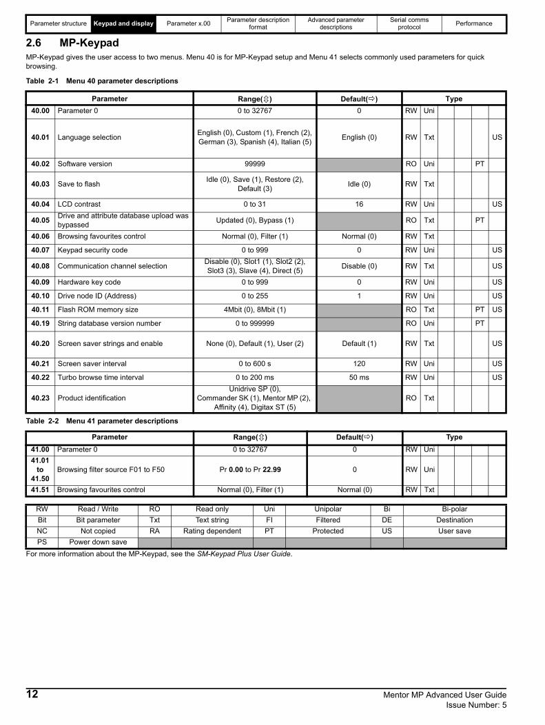
2.6 MP-KeypadMP-Keypad gives the user access to two menus. Menu 40 is for MP-Keypad setup and Menu 41 selects commonly used parameters for quick browsing.
Table 2-1 Menu 40 parameter descriptions
Table 2-2 Menu 41 parameter descriptions
For more information about the MP-Keypad, see the SM-Keypad Plus User Guide.
Parameter Range( ) Default( ) Type40.00 Parameter 0 0 to 32767 0 RW Uni
40.01 Language selection English (0), Custom (1), French (2), German (3), Spanish (4), Italian (5) English (0) RW Txt US
40.02 Software version 99999 RO Uni PT
40.03 Save to flash Idle (0), Save (1), Restore (2), Default (3) Idle (0) RW Txt
40.04 LCD contrast 0 to 31 16 RW Uni US
40.05 Drive and attribute database upload was bypassed Updated (0), Bypass (1) RO Txt PT
40.06 Browsing favourites control Normal (0), Filter (1) Normal (0) RW Txt
40.07 Keypad security code 0 to 999 0 RW Uni US
40.08 Communication channel selection Disable (0), Slot1 (1), Slot2 (2), Slot3 (3), Slave (4), Direct (5) Disable (0) RW Txt US
40.09 Hardware key code 0 to 999 0 RW Uni US
40.10 Drive node ID (Address) 0 to 255 1 RW Uni US
40.11 Flash ROM memory size 4Mbit (0), 8Mbit (1) RO Txt PT US
40.19 String database version number 0 to 999999 RO Uni PT
40.20 Screen saver strings and enable None (0), Default (1), User (2) Default (1) RW Txt US
40.21 Screen saver interval 0 to 600 s 120 RW Uni US
40.22 Turbo browse time interval 0 to 200 ms 50 ms RW Uni US
40.23 Product identificationUnidrive SP (0),
Commander SK (1), Mentor MP (2), Affinity (4), Digitax ST (5)
RO Txt
Parameter Range( ) Default( ) Type41.00 Parameter 0 0 to 32767 0 RW Uni41.01
to 41.50
Browsing filter source F01 to F50 Pr 0.00 to Pr 22.99 0 RW Uni
41.51 Browsing favourites control Normal (0), Filter (1) Normal (0) RW Txt
RW Read / Write RO Read only Uni Unipolar Bi Bi-polarBit Bit parameter Txt Text string FI Filtered DE DestinationNC Not copied RA Rating dependent PT Protected US User savePS Power down save
12 Mentor MP Advanced User Guide Issue Number: 5

Parameter structure Keypad and display Parameter x.00 Parameter description format
Advanced parameter descriptions
Serial comms protocol Performance
2.7 Parameter access level and securityThe parameter access levels determine whether the user has access to Menu 0 (in sub block mode) only or to all of the advanced menus (Menus 1 to 23), in addition to Menu 0 (in linear mode).The user security determines whether the access to the user is read only or read write.The user security and the parameter access level can operate independently of each other as shown in Table 2-3 .
Table 2-3 User security and parameter access levels
RW = Read / write access RO = Read only accessThe default settings of the drive are parameter access level L1 and User Security Open, i.e. read / write access to Menu 0 with the advanced menus, not visible
2.7.1 User securityThe user security, when set, prevents write access to any of the parameters (other than Pr 11.44 (SE14, 0.35) Access Level) in any menu.Figure 2-5 User security open
2.7.2 Setting user securityEnter a value between 1 and 999 in Pr 11.30 and press the button; the security code has now been set to this value. To activate the security, the access level must be set to Loc in Pr 11.44 (SE14, 0.35). When the drive is reset, the security code will have been activated and the drive returns to access level L1. The value of Pr 11.30 will return to 0 in order to hide the security code. At this point, the only parameter that can be changed by the user is the access level Pr 11.44 (SE14, 0.35).
2.7.3 Unlocking user securitySelect a read write parameter to be edited and press the button; the upper display will now show CodE.
Use the arrow buttons to set the security code and press the button. With the correct security code entered, the display will revert to the parameter selected in edit mode. If an incorrect security code is entered the display will revert to parameter view mode. To lock the user security again, set Pr 11.44 (SE14, 0.35) to Loc and press the reset button.
2.7.4 Disabling user securityUnlock the previously set security code as detailed above. Set Pr 11.30 to 0 and press the button. The user security has now been disabled, and will not have to be unlocked each time the drive is powered up to allow read / write access to the parameters.
2.8 Alarm and trip displayAn alarm can flash alternately with the data displayed on the 2nd row when one of the following conditions occur. If action is not taken to eliminate the alarms except "Auto tune" and "PLC", the drive may eventually trip. Alarms flash once every 640 ms except "PLC" which flashes once every 10 s. Alarms are not displayed when a parameter is being edited.
When a trip occurs the drive switches to status mode and "tr" or "trip" is shown on the 1st row and the trip string flashes on the 2nd row. The read only parameters listed below are frozen with any trip except UV trip until the trip is cleared. For a list of the possible trip strings see Pr 10.20 {tr01, 0.51}. Pressing any of the parameter keys changes the mode to the parameter view mode. If the trip is HF01 to HF16 then no key action is recognized.
Parameter access level User security Menu 0 status Advanced
menus statusL1 Open Sub block RW Not visibleL1 Closed Sub block RO Not visibleL2 Open Linear RW RWL2 Closed Linear RO RO
Pr 0.00Pr 0.01Pr 0.02Pr 0.03
Pr 0.90
Pr 1.00Pr 1.01Pr 1.02Pr 1.03
Pr 1.50Pr 1.51
............
............
............
............
............
............
............
............
Pr 0.00Pr 0.01Pr 0.02Pr 0.03
Pr 0.89Pr 0.90
Pr 1.00Pr 1.01Pr 1.02Pr 1.03
Pr 1.50Pr 1.51
Pr 23.00Pr 23.01Pr 23.02Pr 23.03
Pr 23.10Pr 23.11
............
............
............
............
............
............
............
............
User security open - All parameters: Read / Write access
User security closed - All parameters: Read Only access (except Pr ( )11.44 SE14, 0.35
Pr 23.00Pr 23.01Pr 23.02Pr 23.03
Pr 23.10Pr 23.11
Pr 0.49
Pr 22.00Pr 22.01Pr 22.02Pr 22.03
Pr 22.39Pr 22.40
Pr 22.00Pr 22.01Pr 22.02Pr 22.03
Pr 22.39Pr 22.40
Alarm string Alarm condition
OVLd Motor overload (Pr 4.19 > 75 % and the drive output current > Pr 5.07 {SE07, 0.28})
hot Heatsink alarm is activeAutotune Autotune in progress
PLC On-board application lite program is runningCLt Current limit active
S.OVThe suppressor voltage is with in 30 volts of the HF18 trip level. User needs to fit an external suppressor resistor.
S.rS External suppressor overload. Active when Pr 11.56 is greater than 75 %.
ESt SPd Estimated speed selected
Menu 0 Parameter Description Display0.36 1.01 Speed reference selected di01
1.02 Pre-skip filter reference0.37 1.03 Pre-ramp reference di020.38 2.01 Post ramp reference di030.39 3.01 Final speed reference di040.40 3.02 Speed feedback di05
3.03 Speed error0.41 3.04 Speed controller output di060.43 4.01 Current magnitude di08
5.01 Armature firing angle0.45 5.02 Armature voltage di10
5.03 Output power5.04 Estimated speed5.05 Line voltage5.58 Field firing angle
0.82 7.01 Analog input 1 in020.83 7.02 Analog input 2 in030.84 7.03 Analog input 3 in04
10.77 Input frequency
Mentor MP Advanced User Guide 13Issue Number: 5

Parameter structure Keypad and display Parameter x.00 Parameter description format
Advanced parameter descriptions
Serial comms protocol Performance
2.9 Keypad control modeThe drive can be controlled from the keypad if Pr 1.14 (SE05, 0.26) is set to 4. The Stop and Run keys automatically become active (the Reverse key may be optionally enabled with Pr 6.13). The speed reference is defined by Pr 1.17. This is a read only parameter that can only be adjusted in status mode by pressing the Up or Down keys. If keypad control mode is selected, then pressing the Up or Down keys in status mode will cause the drive to automatically display the keypad reference and adjust it in the relevant direction. This can be done whether the drive is disabled or running. If the Up or Down keys are held the rate of change of keypad reference increases with time.
2.10 Drive resetA drive reset is required to: reset the drive from a trip (except some “Hfxx” trips which cannot be reset); and other functions as defined in Chapter 3 Parameter x.00 on page 15. A reset can be performed in four ways:1. Stop key: If the drive has been set up such that the stop key is not
operative then the key has a drive reset function only. When the stop function of the stop key is enabled, a reset is initiated while the drive is running by holding the Run key and then pressing the Stop key. When the drive is not running the Stop key will always reset the drive.
2. The drive resets after a 0 to 1 transition of the drive reset parameter (Pr 10.33). A digital input can be programmed to change this parameter.
3. Serial comms, fieldbus or applications Solutions Module: Drive reset is triggered by a value of 100 being written to the User trip parameter (Pr 10.38).
If the drive trips EEF (internal EEPROM error) then it is not possible to reset the drive using the normal reset methods described above. 1233 or 1244 must be entered into Pr x.00 before the drive can be reset. Default parameters are loaded after an EEF trip, and so the parameters should be reprogrammed as required and saved in EEPROM.If the drive is reset after a trip from any source other than the Stop key, the drive restarts immediately, if:1. A non-latching sequencer is used with the enable active and one of
run forward, run reverse or run active2. A latching sequencer is used if the enable and stop\ are active and
one of run forward, run reverse or run is active.If the drive is reset with the Stop key the drive does not restart until a not active to active edge occurs on run forward, run reverse or run.
2.11 Second motor parametersAn alternative set of motor parameters are held in menu 21 which can be selected by Pr 11.45. When the alternative parameter set is being used by the drive the decimal point after the right hand digit in the 1st row is on.
2.12 Special display functionsThe following special display functions are used.1. If the second motor map is being used the decimal point second
from the right of the first row is on.2. When parameters are saved to a SMARTCARD the right-most
decimal point on the first row flashes for 2 seconds.
During power up one or more of the following actions may be required. Each action may take several seconds, and so special display strings are shown.
Display string Action
bootIf a SMARTCARD is present with Pr 11.42 (SE09, 0.30) set to boot the parameters from the card must be transferred to the drive EEPROM.
cardIf the drive is in auto or boot mode Pr 11.42 (SE09, 0.30 set to 3 or 4) the drive ensures that the data on the card is consistent with the drive by writing to the card.
loading
It may be necessary for a Solutions Module to transfer parameter information from the drive. This is only carried out if the parameter information held by the Solutions Module is for a different drive software version. The drive allows up to 5 seconds for this process.
nOAct No Action
14 Mentor MP Advanced User Guide Issue Number: 5
Parameter structure Keypad and display Parameter x.00 Parameter description format
Advanced parameter descriptions
Serial comms protocol Performance
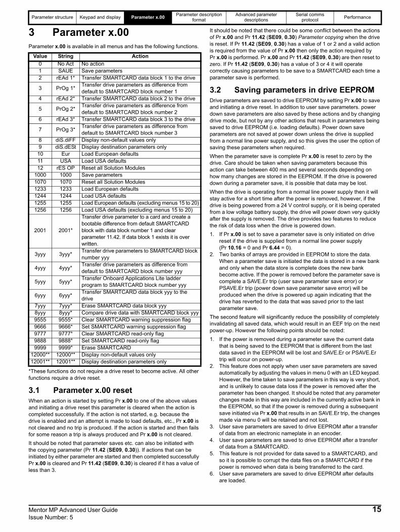
3 Parameter x.00Parameter x.00 is available in all menus and has the following functions.
*These functions do not require a drive reset to become active. All other functions require a drive reset.
3.1 Parameter x.00 resetWhen an action is started by setting Pr x.00 to one of the above values and initiating a drive reset this parameter is cleared when the action is completed successfully. If the action is not started, e.g. because the drive is enabled and an attempt is made to load defaults, etc., Pr x.00 is not cleared and no trip is produced. If the action is started and then fails for some reason a trip is always produced and Pr x.00 is not cleared. It should be noted that parameter saves etc. can also be initiated with the copying parameter (Pr 11.42 (SE09, 0.30)). If actions that can be initiated by either parameter are started and then completed successfully Pr x.00 is cleared and Pr 11.42 (SE09, 0.30) is cleared if it has a value of less than 3.
It should be noted that there could be some conflict between the actions of Pr x.00 and Pr 11.42 (SE09, 0.30) Parameter copying when the drive is reset. If Pr 11.42 (SE09, 0.30) has a value of 1 or 2 and a valid action is required from the value of Pr x.00 then only the action required by Pr x.00 is performed. Pr x.00 and Pr 11.42 (SE09, 0.30) are then reset to zero. If Pr 11.42 (SE09, 0.30) has a value of 3 or 4 it will operate correctly causing parameters to be save to a SMARTCARD each time a parameter save is performed.
3.2 Saving parameters in drive EEPROMDrive parameters are saved to drive EEPROM by setting Pr x.00 to save and initiating a drive reset. In addition to user save parameters. power down save parameters are also saved by these actions and by changing drive mode, but not by any other actions that result in parameters being saved to drive EEPROM (i.e. loading defaults). Power down save parameters are not saved at power down unless the drive is supplied from a normal line power supply, and so this gives the user the option of saving these parameters when required. When the parameter save is complete Pr x.00 is reset to zero by the drive. Care should be taken when saving parameters because this action can take between 400 ms and several seconds depending on how many changes are stored in the EEPROM. If the drive is powered down during a parameter save, it is possible that data may be lost. When the drive is operating from a normal line power supply then it will stay active for a short time after the power is removed, however, if the drive is being powered from a 24 V control supply, or it is being operated from a low voltage battery supply, the drive will power down very quickly after the supply is removed. The drive provides two features to reduce the risk of data loss when the drive is powered down.1. If Pr x.00 is set to save a parameter save is only initiated on drive
reset if the drive is supplied from a normal line power supply (Pr 10.16 = 0 and Pr 6.44 = 0).
2. Two banks of arrays are provided in EEPROM to store the data. When a parameter save is initiated the data is stored in a new bank and only when the data store is complete does the new bank become active. If the power is removed before the parameter save is complete a SAVE.Er trip (user save parameter save error) or PSAVE.Er trip (power down save parameter save error) will be produced when the drive is powered up again indicating that the drive has reverted to the data that was saved prior to the last parameter save.
The second feature will significantly reduce the possibility of completely invalidating all saved data, which would result in an EEF trip on the next power-up. However the following points should be noted:1. If the power is removed during a parameter save the current data
that is being saved to the EEPROM that is different from the last data saved in the EEPROM will be lost and SAVE.Er or PSAVE.Er trip will occur on power-up.
2. This feature does not apply when user save parameters are saved automatically by adjusting the values in menu 0 with an LED keypad. However, the time taken to save parameters in this way is very short, and is unlikely to cause data loss if the power is removed after the parameter has been changed. It should be noted that any parameter changes made in this way are included in the currently active bank in the EEPROM, so that if the power is removed during a subsequent save initiated via Pr x.00 that results in an SAVE.Er trip, the changes made via menu 0 will be retained and not lost.
3. User save parameters are saved to drive EEPROM after a transfer of data from an electronic nameplate in an encoder.
4. User save parameters are saved to drive EEPROM after a transfer of data from a SMARTCARD.
5. This feature is not provided for data saved to a SMARTCARD, and so it is possible to corrupt the data files on a SMARTCARD if the power is removed when data is being transferred to the card.
6. User save parameters are saved to drive EEPROM after defaults are loaded.
Value String Action0 No Act No action1 SAUE Save parameters2 rEAd 1* Transfer SMARTCARD data block 1 to the drive
3 PrOg 1* Transfer drive parameters as difference from default to SMARTCARD block number 1
4 rEAd 2* Transfer SMARTCARD data block 2 to the drive
5 PrOg 2* Transfer drive parameters as difference from default to SMARTCARD block number 2
6 rEAd 3* Transfer SMARTCARD data block 3 to the drive
7 PrOg 3* Transfer drive parameters as difference from default to SMARTCARD block number 3
8 diS.diFF Display non-default values only9 diS.dESt Display destination parameters only
10 Eur Load European defaults11 USA Load USA defaults12 rES OP Reset all Solution Modules
1000 1000 Save parameters1070 1070 Reset all Solution Modules1233 1233 Load European defaults1244 1244 Load USA defaults1255 1255 Load European defaults (excluding menus 15 to 20)1256 1256 Load USA defaults (excluding menus 15 to 20)
2001 2001*
Transfer drive parameter to a card and create a bootable difference from default SMARTCARD block with data block number 1 and clear parameter 11.42. If data block 1 exists it is over written.
3yyy 3yyy* Transfer drive parameters to SMARTCARD block number yyy
4yyy 4yyy* Transfer drive parameters as difference from default to SMARTCARD block number yyy
5yyy 5yyy* Transfer Onboard Applications Lite ladder program to SMARTCARD block number yyy
6yyy 6yyy* Transfer SMARTCARD data block yyy to the drive
7yyy 7yyy* Erase SMARTCARD data block yyy8yyy 8yyy* Compare drive data with SMARTCARD block yyy9555 9555* Clear SMARTCARD warning suppression flag9666 9666* Set SMARTCARD warning suppression flag9777 9777* Clear SMARTCARD read-only flag9888 9888* Set SMARTCARD read-only flag9999 9999* Erase SMARTCARD
12000** 12000** Display non-default values only12001** 12001** Display destination parameters only
Mentor MP Advanced User Guide 15Issue Number: 5

Parameter structure Keypad and display Parameter x.00 Parameter description format
Advanced parameter descriptions
Serial comms protocol Performance
7. When the drive mode is changed all data in the EEPROM is deleted and then restored with the defaults for the new mode. If the power is removed during a change of drive mode, an EEF trip is likely to occur on the next power-up. After a change of drive mode the power down save parameters are also saved. As these parameters are not saved if the power is removed unless the drive is supplied with a normal line power supply, this ensures that the power down save parameters are always stored correctly for the new drive mode. The first time parameters are saved after the change of drive mode the save will take slightly longer than a normal parameter save.
8. When an Solutions Module is changed for a different type in a slot, or a module is inserted when one was not present previously or a module is removed the EEPROM is forced to re-initialise itself on the next parameter saves. On the first parameter save one bank is cleared and then written and on the next parameter save the other bank is cleared and rewritten. Each of these parameter saves takes slightly longer than a normal parameter save.
3.3 Loading defaultsWhen defaults are loaded the user save parameters are automatically saved to the drive EEPROM in all modes. Standard defaults are loaded by setting Eur or USA in Pr x.00 performing a drive reset. When the drive is a single quadrant drive the following parameters are different from European defaults.
3.4 Differences between European and USA defaults
3.5 SMARTCARD transfersDrive parameters, setup macros and internal ladder programs can be transferred to/from SMARTCARDs. See Pr 11.36 to Pr 11.40.
3.6 Display non-default values or destination parameters
If a diS.diFF is selected in Pr x.00, then only parameters that are different from the last defaults loaded and Pr x.00 are displayed. If diS.dESt is selected in Pr x.00, then only destination parameters are displayed. This function is provided to aid locating destination clashes if a dESt trip occurs.
Pr Description Default1.10 Bipolar reference enable 05.22 Quadrant 2 enable 05.24 Quadrant 4 enable 0
Pr Description Default2.06 S ramp enable Eur: OFF (0), USA: On (1)
3.51 Tachometer voltage rating (Fb02, 0.72) Eur: 60.00, USA: 50.00
5.09, 21.09
Armature rated voltage (SE06, 0.27)
480 V drive Eur: 440, USA:500
5.28 Field weakening compensation disable Eur: OFF (0), USA On (1)
5.59, 21.08 Back emf set point 480 V drive Eur: 440,
USA:5005.65 Economy timeout Eur: OFF (0), USA: On (1)
5.70, 21.24
Rated field current (SE10, 0.31)
Size 1: Eur: 2.00, USA: 8.00 Size 2A & B Eur: 3.00, USA: 20.00 Size 2C & D Eur: 5.00, USA 20.00
5.73, 21.23
Rated field voltage (SE11, 0.32) Eur: 360, USA: 300
5.75 Field voltage mode Eur: OFF (0), USA: On (1)
7.15 Analog input 3 mode(in01, 0.81) Eur: th (8), USA: VOLt (6)
16 Mentor MP Advanced User Guide Issue Number: 5

Parameter structure Keypad and display Parameter x.00 Parameter description format
Advanced parameter descriptions
Serial comms protocol Performance
4 Parameter description formatThe following sections provide descriptions for the advanced parameter set. Each parameter displays the following information block as shown below.Typical example parameter
The top row gives the menu.parameter number and the parameter name. The other rows give the following information.
Coding
This guide will show all bit parameters (with the Bit coding), as having a parameter range of "0 to 1", and a default value of either "0" or "1". This reflects the value seen through serial communications. The bit parameters will be displayed on the SM-Keypad or SM-Keypad Plus (if used) as being "OFF" or "On" ("OFF"= 0, "On" = 1).The coding defines the attributes of the parameter as follows:
1.14 Reference selector
CodingBit SP FI DE Txt VM DP ND RA NC NV PT US RW BU PS
1 1 1 1Range 0 to 6
Default 0 (A1.A2)
Second motor parameter Pr 21.03
Update rate 4 ms read
Coding AttributeBit 1 bit parameterSP Spare: not used
FI Filtered: some parameters which can have rapidly changing values are filtered when displayed on the drive keypad for easy viewing.
DE Destination: indicates that this parameter can be a destination parameter.Txt Text: the parameter uses text strings instead of numbers.VM Variable maximum: the maximum of this parameter can vary.DP Decimal place: indicates the number of decimal places used by this parameter.
ND No default: when defaults are loaded (except when the drive is manufactured or on EEPROM failure) this parameter is not modified.
RA
Rating dependent: this parameter is likely to have different values and ranges with drives of different voltage and current ratings. Parameters with this attribute will not be transferred to the destination drive by SMARTCARDs when the rating of the destination drive is different from the source drive and the file is a parameter file.
NC Not copied: not transferred to or from SMARTCARDs during copying.NV Not visible: not visible on the keypad.PT Protected: cannot be used as a destination.US User save: saved in drive EEPROM when the user initiates a parameter save.RW Read/write: can be written by the user.
BU Bit default one/unsigned: Bit parameters with this flag set to one have a default of one (all other bit parameters have a default of zero. Non-bit parameters are unipolar if this flag is one.
PS Power-down save: parameter automatically saved in driveEEPROM when the under volts (UV) trip occurs.
NOTE
Mentor MP Advanced User Guide 17Issue Number: 5

Parameter structure Keypad and display Parameter x.00 Parameter description format
Advanced parameter descriptions
Serial comms protocol Performance
4.1 Parameter ranges and variable maximums:The two values provided define the minimum and maximum values for the given parameter. In some cases the parameter range is variable and dependant on either:• other parameters,• the drive rating,• or a combination of these.The values given in Table 4-1 are the variable maximums used in the drive.
Table 4-1 Definition of parameter ranges & variable maximumsMaximum Definition
MAX_SPEED_REF[10000.0 rpm]
Maximum speed referenceIf Pr 1.08 = 0: MAX_SPEED_REF = Pr 1.06 (SE02, 0.23)If Pr 1.08 = 1: MAX_SPEED_REF is Pr 1.06 (SE02, 0.23) or – Pr 1.07 (SE01, 0.22) whichever is the largest(If the second motor map is selected Pr 21.01 is used instead of Pr 1.06 (SE02, 0.23) and Pr 21.02 instead of Pr 1.07 (SE01, 0.22))
SPEED_LIMIT_MAX[10000.0 rpm]
Maximum applied to speed reference limitsA maximum limit may be applied to the speed reference to prevent the nominal encoder frequency from exceeding 500 kHz. The maximum is defined bySPEED_LIMIT_MAX (in rpm) = 500 kHz x 60 / ELPR = 3.0 x 10⁷ / ELPR subject to an absolute maximum of 10,000 rpm.ELPR is equivalent encoder lines per revolution and is the number of lines that would be produced by a quadrature encoder. Quadrature encoder ELPR = number of lines per revolutionF and D encoder ELPR = number of lines per revolution / 2This maximum is defined by the device selected with the speed feedback selector (Pr 3.26 (Fb01, 0.71)) and the ELPR set for the position feedback device.
SPEED_MAX[10000.0 rpm]
Maximum speedThis maximum is used for some speed related parameters in menu 3. To allow headroom for overshoot etc. the maximum speed is twice the maximum speed reference.SPEED_MAX = 2 x MAX_SPEED_REF
MAX_RAMP_RATEMAX_RAMP_RATE_M2[3200.000]
Maximum ramp rateIf (Pr 1.06 (SE02, 0.23) [Pr 21.01] >= 1000 and Pr 2.39 = 0) or Pr 2.39 >= 1000 then
MAX_RAMP_RATE = 3200.000Else if Pr 2.39 = 0
MAX_RAMP_RATE = 3200 * Pr 1.06 (SE02, 0.23) [Pr 21.01] / 1000.0Else
MAX_RAMP_RATE = 3200 * Pr 2.39 / 1000.0End if
RATED_CURRENT_MAX[9999.99 A]
Maximum motor rated current
DRIVE_CURRENT_MAX[9999.99 A]
Maximum drive current The maximum drive current is the current at the over current trip level and is given by: DRIVE_CURRENT_MAX = RATED_CURRENT_MAX x 2
MOTOR1_CURRENT_LIMIT_MAX[1000.0 %]
Maximum current limit settings for motor map 1This maximum current limit setting is the maximum applied to the current limit parameters in motor map 1. See introduction to Menu 4 for the definition.
MOTOR2_CURRENT_LIMIT_MAX[1000.0 %]
Maximum current limit settings for motor map 2This maximum current limit setting is the maximum applied to the current limit parameters in motor map 2. See introduction to Menu 4 for the definition.
TORQUE_PROD_CURRENT_MAX[1000.0 %]
Maximum torque producing currentThis is used as a maximum for torque and torque producing current parameters. It is MOTOR1_CURRENT_LIMIT_MAX or MOTOR2_CURRENT_LIMIT_MAX depending on which motor map is currently active.
USER_CURRENT_MAX[1000.0 %]
Current parameter limit selected by the userThe user can select a maximum for Pr 4.08 (torque reference) and Pr 4.20 (percentage load) to give suitable scaling for analog I/O with Pr 4.24. This maximum is subject to a limit of CURRENT_LIMIT_MAX. USER_CURRENT_MAX = Pr 4.24
ARMATURE_VOLTAGE_MAX[1025]
Maximum armature voltage Vac x (√2 x 3 / π)480 +10 % drive: 720 575 +10 % drive: 860690 +10 % drive: 1025
For 4 quadrant drives maximum armature voltage = Vac x 1.15NOTE
18 Mentor MP Advanced User Guide Issue Number: 5

Parameter structure Keypad and display Parameter x.00 Parameter description format
Advanced parameter descriptions
Serial comms protocol Performance
4.1.1 DefaultThe default values given are the standard drive defaults which are loaded after a drive reset with Eur or USA in Pr x.00.
4.1.2 Second motor parameterSome parameters have an equivalent second motor value that can be used as an alternative when the second motor is selected with Pr 11.45. Menu 21 contains all the second motor parameters. In this menu the parameter specifications include the location of the normal motor parameter which is being duplicated.
4.1.3 Update rateDefines the rate at which the parameter data is written by the drive (write) or read and acted upon by the drive (read). Where background update rate is specified, the update time depends on the drive processor load. Generally the update time is between 2 ms and 30 ms, however, the update time is significantly extended when loading defaults, changing drive mode, transferring data to/from a SMARTCARD, or transferring blocks of parameters or large CMP data blocks to/from the drive (not a Solutions Module) via the drive serial comms port.
4.2 Sources and destinations4.2.1 SourcesSome functions have source pointer parameters, i.e. drive outputs, PID controller etc. The source pointer parameter range is Pr 0.00 to Pr 22.99 The source pointer is set up to point to a parameter, which supplies the information to control the source and this is referred to as the source data parameter. For example, Pr 7.19 is the source pointer parameter for analog output 1. If Pr 7.19 is set to a value of 18.11, then Pr 18.11 is the source data parameter, and as the value of Pr 18.11 is modified the analog output level is changed.
1. If the parameter number in the source pointer parameter does not exist the input is taken as zero.
2. If the source is not a bit type source (i.e. not a digital output etc.) then the source level is defined by (source data value x 100 %) / source data parameter maximum. Generally the result is rounded down to the nearest unit, but other rounding effects may occur depending on the internal scaling of the particular source function.
3. If the source is a bit, i.e. a digital output, and the source data parameter is a bit parameter then the input to the source function follows the value of the source data parameter.
4. If the source is a bit, i.e. a digital output, and the source data parameter is not a bit parameter the source input is zero if the source data value is less than source data parameter maximum / 2 rounded down to the nearest unit. The source input is one if the source data value is greater than or equal to source data parameter maximum / 2 rounded down to the nearest unit. For example if the source pointer parameter is set to 18.11, which has a maximum of 32767, the source input is zero if the source data value is less than 16383 and one if it is greater than this.
4.2.2 DestinationsSome functions have destination pointer parameters, i.e. drive inputs, etc. The destination pointer parameter range is P 0.00 to Pr 22.99. The destination pointer parameter is set up to point to a parameter, which receives information from the function referred to as the destination parameter.
1. If the parameter number in the destination pointer parameter does not exist then the output value has no effect.
2. If the destination parameter is protected then the output value has no effect.
3. If the function output is a bit value (i.e. a digital input) the destination parameter value does not operate in the same way as a source described above, but is always either 0 or 1 depending on the state of the function output whether the destination parameter is a bit parameter or not.
4. If the function output is not a bit value (i.e. analog input) and the destination parameter is not a bit parameter, the destination value is given by (function output x destination parameter maximum) / 100 %. Generally the result is rounded down to the nearest unit, but other rounding effects may occur depending on the internal scaling of the particular source function (rounded down to nearest unit). Pr 1.36 and Pr 1.37 are a special case. The scaling shown in the description of parameter Pr 1.08 is used when any non-bit type quantity is routed to these parameters.
5. If the function output is not a bit value and the destination parameter is a bit value, the destination value is 0 if the function output is less than 50 % of its maximum value, otherwise it is 1.
6. If more than one destination selector is routed to the same destination, the value of the destination parameter is undefined. The drive checks for this condition where the destinations are defined in any menu except menus 15 to 17. If a conflict occurs a dESt trip occurs that cannot be reset until the conflict is resolved.
4.2.3 Sources and destinations1. Bit and non-bit parameters may be connected to each other as
sources or destinations. The scaling is as described previously.2. All new source and destination routing only changes to new setup
locations when the drive is reset. 3. When a destination pointer parameter within the drive or a dumb
Solutions Module (SM-Resolver, SM-Encoder Plus, SM-I/O plus) is changed the old destination is written to zero, unless the destination change is the result of loading defaults or transferring parameters from a SMARTCARD. When defaults are loaded the old destination is set to its default value. When parameters are loaded from a SMARTCARD the old destination retains its old value unless a SMARTCARD value is written to it.
QUADRANT_MAXQuadrant maximum0 for a 2 quadrant drive. 1 for a 4 quadrant drive.
POWER_MAX[9999.99 kW]
Maximum power in kWThe maximum power has been chosen to allow for the maximum power that can be output by the drive with maximum DC output voltage and maximum controlled current. Therefore:
POWER_MAX = ARMATURE_VOLTAGE_MAX x DRIVE_CURRENT_MAX
FIELD_CURRENT_SET_MAXMaximum field currentSize 1 =8 A.Size 2 = 20 A.
The values given in square brackets indicate the absolute maximum value allowed for the variable maximum.
Maximum Definition
Mentor MP Advanced User Guide 19Issue Number: 5

Parameter structure Keypad and display Parameter x.00 Parameter description format
Advanced parameter descriptions
Serial comms protocol Performance
4.3 Update ratesUpdate rates are given for every parameter in the header table as shown below:
Some parameters have an increased update in special circumstances.
4.3.1 Speed reference update rateThe normal update rate for the speed references (via menu 1) is 4 ms, however it is possible to reduce the sample time to 250 μs by selecting the reference from particular sources. The fast update rate is only possible provided the conditions given below are met. (Note: high speed updating is not provided for speed references).Analog input references (not including I/O expansion Solutions Module)1. The reference must be derived via Pr 1.36 or Pr 1.372. The analog inputs must be in voltage mode with zero offset3. Bipolar mode must be used or unipolar mode with the minimum
speed (Pr 1.07 {SE01, 0.22}) set to zero4. No skip bands are enabled, i.e. Pr 1.29, Pr 1.31 and Pr 1.33 must be
zero.5. The jog and velocity feed-forward references must not be enabled.Applications and fieldbus Solutions Modules Pr 91.02 must be used to define the speed reference (this parameter is only visible from the Solutions Modules). Any value written to Pr 91.02 should be automatically mapped into preset Pr 1.21 by the Solutions Module. When fast updating is used the scaling is performed by a simple multiplication. The scale factor used for the multiplication cannot exactly duplicate the scaling for the two stage conversion (i.e. conversion in menu 7 to a percentage of full scale, and conversion to 0.1 rpm units) used when high speed updating is not in operation. Therefore the absolute scaling of the analog inputs varies slightly between normal and high speed updating. The amount of difference depends on the maximum speed, user scaling in menu 7, and the analog input 1 the filter time. The worst case difference for analog input 1 is 0.12 % of full scale, and for analog inputs 2 and 3 the difference is less than 0.12 % with a maximum speed of 50 rpm or more. Typical differences (1500 rpm maximum speed, menu 7 scaling of 1.000, analog input 1 filter of 4 ms) are 0.015 % for analog input 1 and 0.004 % for analog inputs 2 and 3.
4.3.2 Hard speed reference update rateThe normal update rate for the hard speed reference is 4 ms, however it is possible to reduce the sample time to 250 μs by selecting the reference from particular sources. The fast update rate is only possible provided the conditions given below are met.Analog inputs (not including I/O expansion Solutions Module)The analog inputs must be in voltage mode with zero offsetLimitations are the same as for the references via menu 1 described above.Applications and fieldbus Solutions Modules For faster update rate Pr 91.03 must be used (this parameter is only visible from the Solutions Modules). Any value written to Pr 91.03 is automatically mapped into the hard speed reference Pr 3.22.
Encoder referenceIt is possible to use the drive encoder as the source for the hard speed reference. To do this the drive encoder reference destination (Pr 3.46) should be routed to the hard speed reference parameter. If, and only if, the maximum drive encoder reference (Pr 3.43) is set to the same value as the maximum reference value (MAX_SPEED_REF), and the scaling (Pr 3.44) is 1.000, the drive takes the encoder pulses directly. This gives a form of reference slaving where the integral term in the speed controller accumulates all pulses from the reference and tries to match them to the feedback from the motor encoder. Pulses are lost if the reference reaches a minimum or maximum limit including zero speed in unipolar mode. The reference is sampled every 250 μs. It is possible to apply scaling even in this high speed update mode by changing the number of encoder lines per revolution. It is also possible to use this high speed update mode with some position feedback category Solutions Modules (see description for the appropriate Solutions Module.)
4.3.3 Torque reference update rateThe normal update rate for the torque reference (Pr 4.08) is 4 ms, however it is possible to reduce the sample time to 250 μs by selecting the reference from particular sources.The fast update rate is only possible provided the conditions given below are met.Analog inputs 2 or 3 on the driveThe analog inputs must be in voltage mode with zero offset.
3.03 Speed error
CodingBit SP FI DE Txt VM DP ND RA NC NV PT US RW BU PS
1 1 1 1 1 1Range ±SPEED_MAX rpm
Update rate 4 ms write
20 Mentor MP Advanced User Guide Issue Number: 5

Parameter structure Keypad and display Parameter x.00 Parameter description format
Advanced parameter descriptions
Serial comms protocol Performance
Mentor MP Advanced User Guide 21Issue Number: 5
5 Advanced parameter descriptions
5.1 OverviewTable 5-1 Menu descriptions
Default abbreviations:Eur> European default valueUSA> USA default value
Parameter numbers shown in brackets {...} are the equivalent sub block/Menu 0 parameters. In some cases, the function or range of a parameter is affected by the setting of another parameter; the information in the lists relates to the default condition of such parameters.
Table 5-2 gives a full key of the coding which appears in the following parameter tables.
Table 5-2 Key to parameter coding
Menu Function1 Speed reference selection, limits and filters2 Ramps3 Speed feedback and speed control4 Torque and current control5 Motor and field control6 Sequencer and clock7 Analog I/O8 Digital I/O9 Programmable logic and motorized pot
10 Drive status and trip information11 General drive setup
12 Threshold detectors, variable selectors and brake control function
13 Position control14 User PID controller15 Slot 1 Solutions Module menu16 Slot 2 Solutions Module menu17 Slot 3 Solutions Module menu18 User application menu 1 (saved in drive EEPROM)19 User application menu 2 (saved in drive EEPROM)20 User application menu 3 (not saved in drive EEPROM)21 Second motor parameters22 Additional Menu 0 set up23 Header selections
NOTE
Coding Attribute{X.XX} Copied Menu 0 or advanced parameter
Bit 1 bit parameter: ‘On’ or ‘OFF’ on the displayBi Bipolar parameter
Uni Unipolar parameterTxt Text: the parameter uses text strings instead of numbers.SP Spare: not used
FIFiltered: some parameters which can have rapidly changing values are filtered when displayed on the drive keypad for easy viewing.
DEDestination pointer parameter: This parameter can be used to set up the location (i.e. menu/parameter number) where the destination data is to be routed.
VM Variable maximum: the maximum of this parameter can vary.
DP Decimal place: indicates the number of decimal places used by this parameter.
NDNo default: when defaults are loaded (except when the drive is manufactured or on EEPROM failure) this parameter is not modified.
RA
Rating dependant: this parameter is likely to have different values and ranges with drives of different voltage and current ratings. Parameters with this attribute will not be transferred to the destination drive by a SMARTCARD when the rating of the destination drive is different from the source drive if the drive voltage ratings are different or the file is a parameter file. However, the value will be transferred if only the current rating is different and the file is a differences from default type file.
NC Not copied: not transferred to or from SMARTCARD during copying.
NV Not visible: not visible on the keypad.PT Protected: cannot be used as a destination.
US User save: saved in drive EEPROM when the user initiates a parameter save.
RW Read/write: can be written by the user.RO Read only: can only be read by the user
BU
Bit default one/unsigned: Bit parameters with this flag set to one have a default of one (all other bit parameters have a default of zero. Non-bit parameters are unipolar if this flag is one.
PS
Power-down save: parameter automatically saved in drive EEPROM when the under volts (UV) trip occurs. Power-down save parameters are also saved in the drive when the user initiates a parameter save.

Menu 1 Parameter structure
Keypad and display Parameter x.00 Parameter description
formatAdvanced parameter
descriptionsSerial comms
protocol Performance
5.2 Menu 1: Speed referenceMenu 1 controls the main reference selection.
*Refer to Pr 1.14 (SE05, 0.26) on page 27.
Preset re ference*selector
P reset r eference s can time
KeypadReference P recision r eference Prec ision-reference upd ate disable
Ana log refe rence 1
Ana log refe rence 2 Analog refer ence 2 select
Preset referen ce select bits 1 ~ 3
Pr eset reference
Sc an-timer reset
Analog input 1
Analog input 2
Memory
M enu 71. 361. 37 1.4 1
1.161.48
1.15
1.17
1 .201.18P recision r eference trim1.19
Preset refer ence selectKeypad refe rence selectPrecision ref erence select
LOCAL/RE MOTEMenu 8
Level of referenceselectedReference offset Re ference offs et mode sel ect
R eference*se lector Refe rence selected indica tor1.4 91.14
1 .091.04R eference pe rcentage tri m1.38 1.01
Ana log referenc e
Pres et reference
Key pad referenc e
Prec ision refere nce
+ +
0.XX0.XXKey Read-write (RW ) parameterRead-only (RO ) parameterInputtermina lsOutputtermina lsThe parameters are a ll shown in their default settings
1.51Powe r-up keypadcontr ol moderefere nce
1.20Prese t refere nce selec ted indica tor
Preset references 1 to 8 1.21 ~ 1.28Scan timer
1.471.46 1.45 1.4 41.4 31.4 2
Pr s et to greater t han 11.501.50 Pr 1.4911223456
Pr 1.501>11>1xxxx
Reference bei ng used 1.501.50Analog referen ce 1Preset referen ce defined by Pr Analog referen ce 2Preset referen ce defined by Pr Keypad referen cePrecision refer enceKeypad referen ce onlyPreset referen ce defined by Pr 1.50
Keypad onlyselect 1.5 2
Preset reference*selector
Preset reference scan time
KeypadReference
Precision reference
Precision-reference update disable
Analog reference 1
Analog
reference 2
Analog reference 2 select
Preset reference select bits 1 ~ 3
Preset reference
Scan-timer reset
Analog input 1
Analog input 2
Memory
Menu 7
1.36
1.37
1.41
1.16
1.48
1.15
1.17
1.20
1.18
Precision reference trim
1.19
Preset reference select
Keypad reference select
Precision reference select
LOCAL/REMOTE
Menu 8
Level of referenceselected
Reference offset
Reference offset mode select
Reference*selector
Reference selected indicator
1.49
1.14
1.09
1.04
Reference percentage trim
1.38 1.01
Analog reference
Preset reference
Keypad reference
Precision reference
+
+
0.XX
0.XX
Key
Read-write (RW) parameter
Read-only (RO) parameter
Inputterminals
Outputterminals
The parameters are all shown in their default settings
1.51Power-up keypadcontrol modereference
1.20Preset reference selected indicator
Preset references 1 to 8
1.21 ~ 1.28
Scan timer
1.47 1.46 1.451.44
1.43
1.42
Pr set to greater than 1
1.501.50
Pr 1.4911223456
Pr 1.501
>11
>1xxxx
Reference being used
1.50
1.50
Analog reference 1Preset reference defined by Pr Analog reference 2Preset reference defined by Pr
Keypad referencePrecision referenceKeypad reference only
Preset reference defined by Pr 1.50
Keypad onlyselect 1.52
Figure 5-1 Menu 1 logic diagram
22 Mentor MP Advanced User Guide Issue Number: 5

Parameter structure
Keypad and display Parameter x.00 Parameter description
formatAdvanced parameter
descriptionsSerial comms
protocol Performance Menu 1
Jog reference
Bipolar reference select
Jog selected indicator
Menu 6Sequencer
1.10
1.05
1.13
Pre-filter reference
Pre-ramp reference
Maximum speed "clamp"
Minimum speed "clamp"
(Maximum reverse
speed)
Negative minimum speed select
Reference enabled indicator
Reverse selected indicator
Skip speed 1
Reference in skip speed band indicator
Velocity feed-forward reference
Feed-forward selected indicator
1.12
x(-1)
1.39
1.40
1.08
[1.06][1.07]
[1.07][1.06]
[1.06]
[1.06]
[1.06]
[1.07]
1.06
1.07
1.11
Sequencer (Menu 6)
1.02 1.03
Menu 2
Skip speed 2
Skip speed 3
Skipspeed band 1
Skipspeed band 2
Skipspeed band 3
1.29
1.30
1.31
1.32
1.33
1.34
1.35
Menu 8
JOG RUN FORWARD RUN REVERSE
Menu 13Position control
Mentor MP Advanced User Guide 23Issue Number: 5
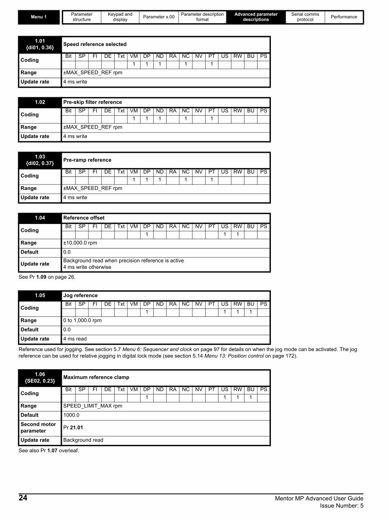
Menu 1 Parameter structure
Keypad and display Parameter x.00 Parameter description
formatAdvanced parameter
descriptionsSerial comms
protocol Performance
See Pr 1.09 on page 26.
Reference used for jogging. See section 5.7 Menu 6: Sequencer and clock on page 97 for details on when the jog mode can be activated. The jog reference can be used for relative jogging in digital lock mode (see section 5.14 Menu 13: Position control on page 172).
See also Pr 1.07 overleaf.
1.01 {di01, 0.36} Speed reference selected
CodingBit SP FI DE Txt VM DP ND RA NC NV PT US RW BU PS
1 1 1 1 1Range ±MAX_SPEED_REF rpm
Update rate 4 ms write
1.02 Pre-skip filter reference
CodingBit SP FI DE Txt VM DP ND RA NC NV PT US RW BU PS
1 1 1 1 1Range ±MAX_SPEED_REF rpm
Update rate 4 ms write
1.03{di02, 0.37} Pre-ramp reference
CodingBit SP FI DE Txt VM DP ND RA NC NV PT US RW BU PS
1 1 1 1 1Range ±MAX_SPEED_REF rpm
Update rate 4 ms write
1.04 Reference offset
CodingBit SP FI DE Txt VM DP ND RA NC NV PT US RW BU PS
1 1 1Range ±10,000.0 rpm
Default 0.0
Update rate Background read when precision reference is active4 ms write otherwise
1.05 Jog reference
CodingBit SP FI DE Txt VM DP ND RA NC NV PT US RW BU PS
1 1 1 1Range 0 to 1,000.0 rpm
Default 0.0
Update rate 4 ms read
1.06{SE02, 0.23} Maximum reference clamp
CodingBit SP FI DE Txt VM DP ND RA NC NV PT US RW BU PS
1 1 1 1Range SPEED_LIMIT_MAX rpm
Default 1000.0
Second motor parameter Pr 21.01
Update rate Background read
24 Mentor MP Advanced User Guide Issue Number: 5
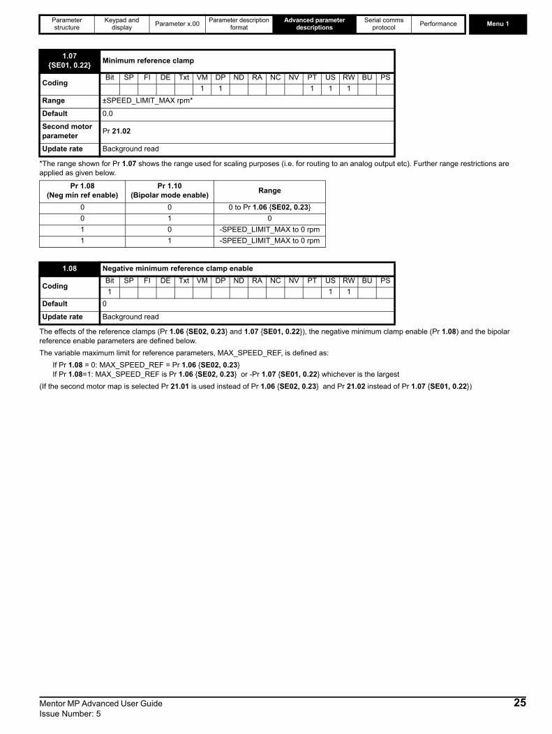
Parameter structure
Keypad and display Parameter x.00 Parameter description
formatAdvanced parameter
descriptionsSerial comms
protocol Performance Menu 1
*The range shown for Pr 1.07 shows the range used for scaling purposes (i.e. for routing to an analog output etc). Further range restrictions are applied as given below.
The effects of the reference clamps (Pr 1.06 {SE02, 0.23} and 1.07 {SE01, 0.22}), the negative minimum clamp enable (Pr 1.08) and the bipolar reference enable parameters are defined below.The variable maximum limit for reference parameters, MAX_SPEED_REF, is defined as:
If Pr 1.08 = 0: MAX_SPEED_REF = Pr 1.06 {SE02, 0.23} If Pr 1.08=1: MAX_SPEED_REF is Pr 1.06 {SE02, 0.23} or -Pr 1.07 {SE01, 0.22} whichever is the largest
(If the second motor map is selected Pr 21.01 is used instead of Pr 1.06 {SE02, 0.23} and Pr 21.02 instead of Pr 1.07 {SE01, 0.22})
1.07{SE01, 0.22} Minimum reference clamp
CodingBit SP FI DE Txt VM DP ND RA NC NV PT US RW BU PS
1 1 1 1 1Range ±SPEED_LIMIT_MAX rpm*
Default 0.0
Second motor parameter Pr 21.02
Update rate Background read
Pr 1.08(Neg min ref enable)
Pr 1.10(Bipolar mode enable) Range
0 0 0 to Pr 1.06 {SE02, 0.23}0 1 01 0 -SPEED_LIMIT_MAX to 0 rpm1 1 -SPEED_LIMIT_MAX to 0 rpm
1.08 Negative minimum reference clamp enable
CodingBit SP FI DE Txt VM DP ND RA NC NV PT US RW BU PS1 1 1
Default 0
Update rate Background read
Mentor MP Advanced User Guide 25Issue Number: 5

Menu 1 Parameter structure
Keypad and display Parameter x.00 Parameter description
formatAdvanced parameter
descriptionsSerial comms
protocol Performance
Analog input scalingThe following diagrams show the scaling applied when analog inputs are used to define the reference and are routed via Pr 1.36 or Pr 1.37.
Reference limitsWith reference to the block diagram for Menu 1 (Figure 5-1 on page 22) the following table shows the limits applied to the reference by various blocks in the reference system. It should be noted that the minimum limit in the main reference limits block changes when either the jog reference or velocity feed forward references are active. When one of these is active: if Pr 1.08 = 0 the minimum = -Pr 1.06 {SE02, 0.23} [-Pr 21.01 for motor map2], if Pr 1.08 = 1 the minimum = -Pr 1.07 {SE01, 0.22} [-Pr 21.02 for motor map 2].
When this parameter is 0 the reference is given byPr 1.01 {di01, 0.36} = selected reference x (100 + Pr 1.38) / 100
and when this parameter is 1 the reference is given by Pr 1.01 {di01, 0.36} = selected reference + Pr 1.04
Minimum Maximum
Keypad control reference (Pr 1.17)Unipolar mode: Pr 1.07 {SE01, 0.22},
or 0 if Pr 1.07 {SE01, 0.22} < 0Bipolar mode: -MAX_SPEED_REF
MAX_SPEED_REF
Bipolar/unipolar selector Unipolar mode: Pr 1.07 {SE01, 0.22},
or 0 if Pr 1.07 {SE01, 0.22} < 0Bipolar mode: no limit applied
No maximum limit applied
Main reference limits Neg minimum ref disabled: -Pr 1.06 {SE02, 0.23}Neg minimum ref enabled: Pr 1.07 {SE01, 0.22} Pr 1.06 {SE02, 0.23}
1.09 Reference offset select
CodingBit SP FI DE Txt VM DP ND RA NC NV PT US RW BU PS1 1 1
Default 0
Update rate Background read when precision reference is active4 ms read otherwise
Pr 1.07
Pr =0 (1.10 unipolar mode)Pr =0 (1.08 neg min ref disabled)
-100% 100%
SPEED_MAX
SPEED_MAX
-100% 100%
-SPEED_MAX
SPEED_MAX
-100% 100%
-SPEED_MAX
Pr =1 (bipolar mode)1.10Pr =0 (1.08 neg min ref disabled)
-100% 100%
SPEED_MAX
Pr =0 (1.10 unipolar mode)Pr =1 (1.08 neg min ref enabled)
Pr =1 (bipolar mode)1.10Pr =1 (1.08 neg min ref enabled)
26 Mentor MP Advanced User Guide Issue Number: 5
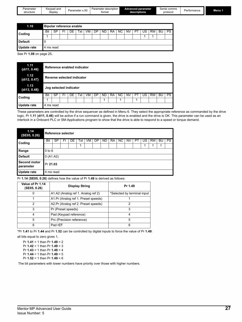
Parameter structure
Keypad and display Parameter x.00 Parameter description
formatAdvanced parameter
descriptionsSerial comms
protocol Performance Menu 1
See Pr 1.08 on page 25.
These parameters are controlled by the drive sequencer as defined in Menu 6. They select the appropriate reference as commanded by the drive logic. Pr 1.11 {di11, 0.46} will be active if a run command is given, the drive is enabled and the drive is OK. This parameter can be used as an interlock in a Onboard PLC or SM-Applications program to show that the drive is able to respond to a speed or torque demand.
Pr 1.14 {SE05, 0.26} defines how the value of Pr 1.49 is derived as follows:
*Pr 1.41 to Pr 1.44 and Pr 1.52 can be controlled by digital inputs to force the value of Pr 1.49: all bits equal to zero gives 1,
Pr 1.41 = 1 then Pr 1.49 = 2 Pr 1.42 = 1 then Pr 1.49 = 3Pr 1.43 = 1 then Pr 1.49 = 4Pr 1.44 = 1 then Pr 1.49 = 5Pr 1.52 = 1 then Pr 1.49 = 6
The bit parameters with lower numbers have priority over those with higher numbers.
1.10 Bipolar reference enable
CodingBit SP FI DE Txt VM DP ND RA NC NV PT US RW BU PS1 1 1
Default 0
Update rate 4 ms read
1.11{di11, 0.46} Reference enabled indicator
1.12{di12, 0.47} Reverse selected indicator
1.13{di13, 0.48} Jog selected indicator
CodingBit SP FI DE Txt VM DP ND RA NC NV PT US RW BU PS1 1 1 1
Update rate 4 ms read
1.14{SE05, 0.26} Reference selector
CodingBit SP FI DE Txt VM DP ND RA NC NV PT US RW BU PS
1 1 1 1Range 0 to 6
Default 0 (A1.A2)
Second motor parameter Pr 21.03
Update rate 4 ms read
Value of Pr 1.14 {SE05, 0.26} Display String Pr 1.49
0 A1.A2 (Analog ref 1. Analog ref 2) *Selected by terminal input1 A1.Pr (Analog ref 1. Preset speeds) 12 A2.Pr (Analog ref 2. Preset speeds) 23 Pr (Preset speeds) 34 Pad (Keypad reference) 45 Prc (Precision reference) 56 Pad rEF 6
Mentor MP Advanced User Guide 27Issue Number: 5

Menu 1 Parameter structure
Keypad and display Parameter x.00 Parameter description
formatAdvanced parameter
descriptionsSerial comms
protocol Performance
Pr 1.49 and Pr 1.50 then define the reference as follows:
x = any valueKeypad referenceIf Keypad reference is selected the drive sequencer is controlled directly by the keypad keys and the keypad reference parameter (Pr 1.17) is selected. The sequencing bits, Pr 6.30 to Pr 6.34, have no effect and jog is disabled.
Pr 1.15 defines how the value of Pr 1.50 is derived as follows:
*Pr 1.45 to Pr 1.47 can be controlled by digital inputs to define the value of Pr 1.50 as follows:**The presets are selected automatically in turn. Pr 1.16 defines the time between each change.
Pr 1.49 and Pr 1.50 then define the reference as follows:
Pr 1.49 Pr 1.50 Reference1 1 Analog reference 1 (Pr 1.36)1 >1 Preset defined by Pr 1.50 (Pr 1.21 to Pr 1.28)2 1 Analog reference 2 (Pr 1.37)2 >1 Preset defined by Pr 1.50 (Pr 1.21 to Pr 1.28)3 x Preset defined by Pr 1.50 (Pr 1.21 to Pr 1.28)4 x Keypad reference (Pr 1.17)5 x Precision reference (Pr 1.18 and Pr 1.19)6 x Keypad reference only
1.15 Preset selector
CodingBit SP FI DE Txt VM DP ND RA NC NV PT US RW BU PS
1 1 1Range 0 to 9
Default 0
Update rate 4 ms read
Value of Pr 1.15 Pr 1.500 Selected by terminal input*1 12 23 34 45 56 67 78 89 Selected by timer**
Pr 1.47 Pr 1.46 Pr 1.45 Pr 1.500 0 0 10 0 1 20 1 0 30 1 1 41 0 0 51 0 1 61 1 0 71 1 1 8
Pr 1.49 Pr 1.50 Reference1 1 Analog reference 1 (Pr 1.36)1 >1 Preset defined by Pr 1.50 (Pr 1.21 to Pr 1.28)2 1 Analog reference 2 (Pr 1.37)2 >1 Preset defined by Pr 1.50 (Pr 1.21 to Pr 1.28)3 x Preset defined by Pr 1.50 (Pr 1.21 to Pr 1.28)4 x Keypad reference (Pr 1.17)5 x Precision reference (Pr 1.18 and Pr 1.19)6 x Keypad reference only
28 Mentor MP Advanced User Guide Issue Number: 5
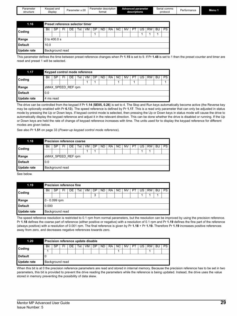
Parameter structure
Keypad and display Parameter x.00 Parameter description
formatAdvanced parameter
descriptionsSerial comms
protocol Performance Menu 1
This parameter defines the time between preset reference changes when Pr 1.15 is set to 9. If Pr 1.48 is set to 1 then the preset counter and timer are reset and preset 1 will be selected.
The drive can be controlled from the keypad if Pr 1.14 {SE05, 0.26} is set to 4. The Stop and Run keys automatically become active (the Reverse key may be optionally enabled with Pr 6.13). The speed reference is defined by Pr 1.17. This is a read only parameter that can only be adjusted in status mode by pressing the Up or Down keys. If keypad control mode is selected, then pressing the Up or Down keys in status mode will cause the drive to automatically display the keypad reference and adjust it in the relevant direction. This can be done whether the drive is disabled or running. If the Up or Down keys are held the rate of change of keypad reference increases with time. The units used for to display the keypad reference for different modes are given below.See also Pr 1.51 on page 33 (Power-up keypad control mode reference).
See below.
The speed reference resolution is restricted to 0.1 rpm from normal parameters, but the resolution can be improved by using the precision reference. Pr 1.18 defines the coarse part of reference (either positive or negative) with a resolution of 0.1 rpm and Pr 1.19 defines the fine part of the reference (always positive) with a resolution of 0.001 rpm. The final reference is given by Pr 1.18 + Pr 1.19. Therefore Pr 1.19 increases positive references away from zero, and decreases negative references towards zero.
When this bit is at 0 the precision reference parameters are read and stored in internal memory. Because the precision reference has to be set in two parameters, this bit is provided to prevent the drive reading the parameters while the reference is being updated. Instead, the drive uses the value stored in memory preventing the possibility of data skew.
1.16 Preset reference selector timer
CodingBit SP FI DE Txt VM DP ND RA NC NV PT US RW BU PS
1 1 1 1Range 0 to 400.0 s
Default 10.0
Update rate Background read
1.17 Keypad control mode reference
CodingBit SP FI DE Txt VM DP ND RA NC NV PT US RW BU PS
1 1 1 1 1Range ±MAX_SPEED_REF rpm
Default 0.0
Update rate 4 ms read
1.18 Precision reference coarse
CodingBit SP FI DE Txt VM DP ND RA NC NV PT US RW BU PS
1 1 1 1Range ±MAX_SPEED_REF rpm
Default 0.0
Update rate Background read
1.19 Precision reference fine
CodingBit SP FI DE Txt VM DP ND RA NC NV PT US RW BU PS
3 1 1 1Range 0 - 0.099 rpm
Default 0.000
Update rate Background read
1.20 Precision reference update disable
CodingBit SP FI DE Txt VM DP ND RA NC NV PT US RW BU PS1 1 1
Default 0
Update rate Background read
Mentor MP Advanced User Guide 29Issue Number: 5

Menu 1 Parameter structure
Keypad and display Parameter x.00 Parameter description
formatAdvanced parameter
descriptionsSerial comms
protocol Performance
See below.
Three skip references are available to prevent continuous operation at a speed that would cause mechanical resonance. When a skip reference parameter is set to 0 that filter is disabled. The skip reference band parameters define the speed range either side of the programmed skip reference, over which references are rejected. The actual reject band is therefore twice that programmed in these parameters, the skip reference parameters defining the centre of the band. When the selected reference is within a band the lower limit of the band is passed through to the ramps such that reference is always less than demanded.
This parameter indicates that the selected reference is within one of the skip reference zones such that the motor speed is not as demanded.
1.21 Preset reference 1
1.22 Preset reference 2
1.23 Preset reference 3
1.24 Preset reference 4
1.25 Preset reference 5
1.26 Preset reference 6
1.27 Preset reference 7
1.28 Preset reference 8
CodingBit SP FI DE Txt VM DP ND RA NC NV PT US RW BU PS
1 1 1 1Range ±MAX_SPEED_REF rpm
Default 0.0
Update rate 4 ms read
1.29 Skip reference 1
1.31 Skip reference 2
1.33 Skip reference 3
CodingBit SP FI DE Txt VM DP ND RA NC NV PT US RW BU PS
1 1 1Range 0 to 10,000 rpm
Default 0.0
Update rate Background read
1.30 Skip reference band 1
1.32 Skip reference band 2
1.34 Skip reference band 3
CodingBit SP FI DE Txt VM DP ND RA NC NV PT US RW BU PS
1 1 1Range 0 to 250 rpm
Default 5
Update rate Background read
1.35 Reference in rejection zone
CodingBit SP FI DE Txt VM DP ND RA NC NV PT US RW BU PS1 1 1 1
Update rate 4 ms write
30 Mentor MP Advanced User Guide Issue Number: 5

Parameter structure
Keypad and display Parameter x.00 Parameter description
formatAdvanced parameter
descriptionsSerial comms
protocol Performance Menu 1
Although most parameters can be controlled from analog inputs, these two parameters are a special case in that if an analog input is directed to one of these parameters, the scan rate of that analog input is increased.
These are special parameters when a non-bit type quantity uses these parameters as a destination (not just from analog inputs). The scaling and limiting applied is as described with Pr 1.08 on page 25.
See Pr 1.09 on page 26.
This parameter indicates the velocity feed forward reference when position control is used (see section 5.14 Menu 13: Position control on page 172).
This bit indicates that the position controller has selected the velocity feed forward as a reference for the drive
1.36 Analog reference 1
1.37 Analog reference 2
CodingBit SP FI DE Txt VM DP ND RA NC NV PT US RW BU PS
1 1 1 1Range ±MAX_SPEED_REF rpm
Default 0
Update rate 4 ms write
1.38 Percentage trim
CodingBit SP FI DE Txt VM DP ND RA NC NV PT US RW BU PS
2 1 1Range ±100.00 %
Default 0.00
Update rate 4 ms read
1.39 Velocity feed-forward reference
CodingBit SP FI DE Txt VM DP ND RA NC NV PT US RW BU PS
1 1 1 1Range ±10,000.0 rpm
Update rate 4 ms read
1.40 Feed-forward selected
CodingBit SP FI DE Txt VM DP ND RA NC NV PT US RW BU PS1 1 1 1
Update rate 4 ms write
Mentor MP Advanced User Guide 31Issue Number: 5
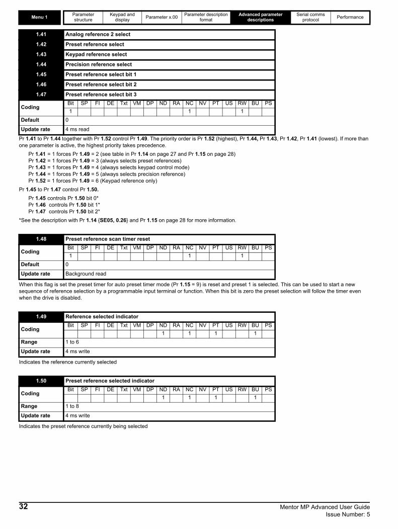
Menu 1 Parameter structure
Keypad and display Parameter x.00 Parameter description
formatAdvanced parameter
descriptionsSerial comms
protocol Performance
Pr 1.41 to Pr 1.44 together with Pr 1.52 control Pr 1.49. The priority order is Pr 1.52 (highest), Pr 1.44, Pr 1.43, Pr 1.42, Pr 1.41 (lowest). If more than one parameter is active, the highest priority takes precedence.
Pr 1.41 = 1 forces Pr 1.49 = 2 (see table in Pr 1.14 on page 27 and Pr 1.15 on page 28)Pr 1.42 = 1 forces Pr 1.49 = 3 (always selects preset references)Pr 1.43 = 1 forces Pr 1.49 = 4 (always selects keypad control mode)Pr 1.44 = 1 forces Pr 1.49 = 5 (always selects precision reference)Pr 1.52 = 1 forces Pr 1.49 = 6 (Keypad reference only)
Pr 1.45 to Pr 1.47 control Pr 1.50.Pr 1.45 controls Pr 1.50 bit 0*Pr 1.46 controls Pr 1.50 bit 1*Pr 1.47 controls Pr 1.50 bit 2*
*See the description with Pr 1.14 {SE05, 0.26} and Pr 1.15 on page 28 for more information.
When this flag is set the preset timer for auto preset timer mode (Pr 1.15 = 9) is reset and preset 1 is selected. This can be used to start a new sequence of reference selection by a programmable input terminal or function. When this bit is zero the preset selection will follow the timer even when the drive is disabled.
Indicates the reference currently selected
Indicates the preset reference currently being selected
1.41 Analog reference 2 select
1.42 Preset reference select
1.43 Keypad reference select
1.44 Precision reference select
1.45 Preset reference select bit 1
1.46 Preset reference select bit 2
1.47 Preset reference select bit 3
CodingBit SP FI DE Txt VM DP ND RA NC NV PT US RW BU PS1 1 1
Default 0
Update rate 4 ms read
1.48 Preset reference scan timer reset
CodingBit SP FI DE Txt VM DP ND RA NC NV PT US RW BU PS1 1 1
Default 0
Update rate Background read
1.49 Reference selected indicator
CodingBit SP FI DE Txt VM DP ND RA NC NV PT US RW BU PS
1 1 1 1Range 1 to 6
Update rate 4 ms write
1.50 Preset reference selected indicator
CodingBit SP FI DE Txt VM DP ND RA NC NV PT US RW BU PS
1 1 1 1Range 1 to 8
Update rate 4 ms write
32 Mentor MP Advanced User Guide Issue Number: 5
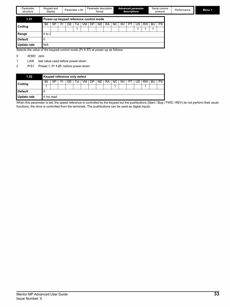
Parameter structure
Keypad and display Parameter x.00 Parameter description
formatAdvanced parameter
descriptionsSerial comms
protocol Performance Menu 1
Selects the value of the keypad control mode (Pr 1.17) at power-up as follows:
0 rESEt zero1 LASt last value used before power-down2 PrS1 Preset 1, Pr 1.21, before power-down
When this parameter is set, the speed reference is controlled by the keypad but the pushbuttons (Start / Stop / FWD / REV) do not perform their usual functions, the drive is controlled from the terminals. The pushbuttons can be used as digital inputs.
1.51 Power-up keypad reference control mode
CodingBit SP FI DE Txt VM DP ND RA NC NV PT US RW BU PS
1 1 1 1Range 0 to 2
Default 0
Update rate N/A
1.52 Keypad reference only select
CodingBit SP FI DE Txt VM DP ND RA NC NV PT US RW BU PS1 1 1
Default 0
Update rate 4 ms read
Mentor MP Advanced User Guide 33Issue Number: 5
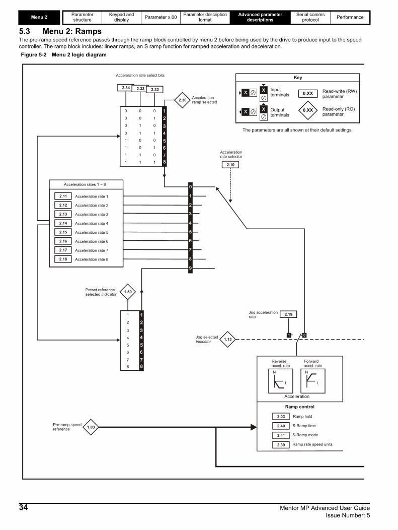
Menu 2 Parameter structure
Keypad and display Parameter x.00 Parameter description
formatAdvanced parameter
descriptionsSerial comms
protocol Performance
5.3 Menu 2: RampsThe pre-ramp speed reference passes through the ramp block controlled by menu 2 before being used by the drive to produce input to the speed controller. The ramp block includes: linear ramps, an S ramp function for ramped acceleration and deceleration.
0 0 0
0 0 1
0 1 0
0 1 1
1 0 0
1 0 1
1 1 0
1 1 1
Acceleration rate select bits
2.11 Acceleration rate 1
2.12 Acceleration rate 2
2.13 Acceleration rate 3
2.14 Acceleration rate 4
2.15 Acceleration rate 5
2.16 Acceleration rate 6
2.17 Acceleration rate 7
2.18 Acceleration rate 8
Acceleration rates 1 ~ 8
1.50
3
4
1
2
7
5
6
Preset referenceselected indicator
2.19Jog acceleration rate
1.13Jog selectedindicator
1.03Pre-ramp speedreference
2.03 Ramp hold
N
t
N
t
Acceleration
Reverse accel. rate
Forward accel. rate
Ramp control
2.10
Accelerationrate selector
2.34 2.322.33 2.32
0.XX
0.XX
Key
Read-write (RW) parameter
Read-only (RO) parameter
Inputterminals
Outputterminals
The parameters are all shown at their default settings
8
2.40
2.41
S-Ramp time
S-Ramp mode
2.39 Ramp rate speed units
2.30 Acceleration ramp selected
Figure 5-2 Menu 2 logic diagram
34 Mentor MP Advanced User Guide Issue Number: 5

Parameter structure
Keypad and display Parameter x.00 Parameter description
formatAdvanced parameter
descriptionsSerial comms
protocol Performance Menu 2
**For more information refer to Chapter 11.22 Advanced Features in the Mentor MP User Guide.
2.06 S-Ramp enable**
2.07 S-Ramp acceleration limit
Ramp control
N
t
N
t
Deceleration
Forward Decel. rate
Reverse Decel. rate
2.02 Ramp enable
Deceleration rate select bits
2.37
1.50 Preset referenceselected indicator
2.29 Jog deceleration rate
1.13 Jog selectedindicator
2.38
Inertia compensationtorque
d/dt
2.20
Decelerationrate selector
2.36 2.35
Pr = Motor and load inertiaPr =
3.185.32 Motor torque per amp
Post-rampreference
2.01
2.05
Ramp outputselector
Menu 3
2.31Deceleration ramp selected
Mentor MP Advanced User Guide 35Issue Number: 5
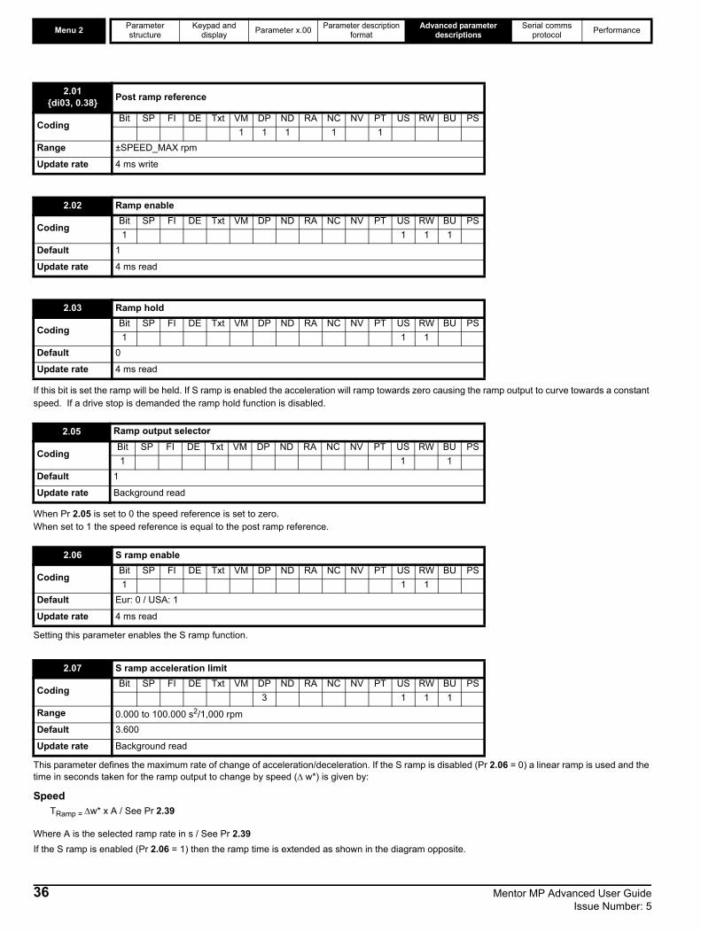
Menu 2 Parameter structure
Keypad and display Parameter x.00 Parameter description
formatAdvanced parameter
descriptionsSerial comms
protocol Performance
If this bit is set the ramp will be held. If S ramp is enabled the acceleration will ramp towards zero causing the ramp output to curve towards a constant speed. If a drive stop is demanded the ramp hold function is disabled.
When Pr 2.05 is set to 0 the speed reference is set to zero.When set to 1 the speed reference is equal to the post ramp reference.
Setting this parameter enables the S ramp function.
This parameter defines the maximum rate of change of acceleration/deceleration. If the S ramp is disabled (Pr 2.06 = 0) a linear ramp is used and the time in seconds taken for the ramp output to change by speed (Δ w*) is given by:
Speed TRamp = Δw* x A / See Pr 2.39
Where A is the selected ramp rate in s / See Pr 2.39If the S ramp is enabled (Pr 2.06 = 1) then the ramp time is extended as shown in the diagram opposite.
2.01{di03, 0.38} Post ramp reference
CodingBit SP FI DE Txt VM DP ND RA NC NV PT US RW BU PS
1 1 1 1 1Range ±SPEED_MAX rpm
Update rate 4 ms write
2.02 Ramp enable
CodingBit SP FI DE Txt VM DP ND RA NC NV PT US RW BU PS1 1 1 1
Default 1
Update rate 4 ms read
2.03 Ramp hold
CodingBit SP FI DE Txt VM DP ND RA NC NV PT US RW BU PS1 1 1
Default 0
Update rate 4 ms read
2.05 Ramp output selector
CodingBit SP FI DE Txt VM DP ND RA NC NV PT US RW BU PS1 1 1
Default 1
Update rate Background read
2.06 S ramp enable
CodingBit SP FI DE Txt VM DP ND RA NC NV PT US RW BU PS1 1 1
Default Eur: 0 / USA: 1
Update rate 4 ms read
2.07 S ramp acceleration limit
CodingBit SP FI DE Txt VM DP ND RA NC NV PT US RW BU PS
3 1 1 1Range 0.000 to 100.000 s2/1,000 rpmDefault 3.600
Update rate Background read
36 Mentor MP Advanced User Guide Issue Number: 5

Parameter structure
Keypad and display Parameter x.00 Parameter description
formatAdvanced parameter
descriptionsSerial comms
protocol Performance Menu 2
The time taken in seconds for the ramp output to change by speed (Δw*) is given below. Two cases are given because the total ramp time must be calculated with a different equation depending on whether the acceleration is able to reach the selected ramp rate (A1) or not. If the required change is small the selected ramp rate is not reached and the ramp does not include the central linear ramp region. If the required change is larger the ramp does include the central linear region as shown in the diagram above.
Speed Δw*linear = 1000 x J / A12
where:A = selected ramp rateJ = Pr 2.07If the required change is less than Δw*linear then TRamp1 should be used, but if the speed change is greater or equal to Δw*linear TRamp2 should be used.
TRamp1 = 2 √ (Δw* x Pr 2.07 / 1000)TRamp2 = (Δw* x A / 1000) + (Pr 2.07 / A)
The default values for the ramp rate and S ramp acceleration limit have been chosen such that for the default maximum speed, the curved parts of the S ramp are 25 % of the original ramp if S ramp is enabled. Therefore the ramp time is increased by a factor of 1.5.
The acceleration rate is selected as follows.0 Ramp rate selection by terminal input1 - 8 Ramp rate defined by parameter number, i.e. 1 = Pr 2.11 {SE03, 0.24}, 2 = Pr 2.12, etc.9 Ramp rate selection by Pr 1.50
When Pr 2.10 is set to 0 the acceleration ramp rate selected depends on the state of bit Pr 2.32 to Pr 2.34. These bits are for control by digital inputs such that ramp rates can be selected by external control. The ramp rate selected depends on the binary code generated by these bits as follows:
When Pr 2.10 is set to 9 the appropriate acceleration rate is automatically selected depending on the value of Pr 1.50, and so an acceleration rate can be programmed to operate with each reference. Since the new ramp rate is selected with the new reference, the acceleration applies towards the selected preset if the motor needs to accelerate to reach the preset.
2.10 Acceleration rate selector
CodingBit SP FI DE Txt VM DP ND RA NC NV PT US RW BU PS
1 1 1Range 0 to 9
Default 0
Update rate 4 ms read
Pr 2.34 Pr 2.33 Pr 2.32 Ramp defined by0 0 0 Pr 2.11 {SE03, 0.24}0 0 1 Pr 2.12 0 1 0 Pr 2.130 1 1 Pr 2.141 0 0 Pr 2.151 0 1 Pr 2.161 1 0 Pr 2.171 1 1 Pr 2.18
Mentor MP Advanced User Guide 37Issue Number: 5
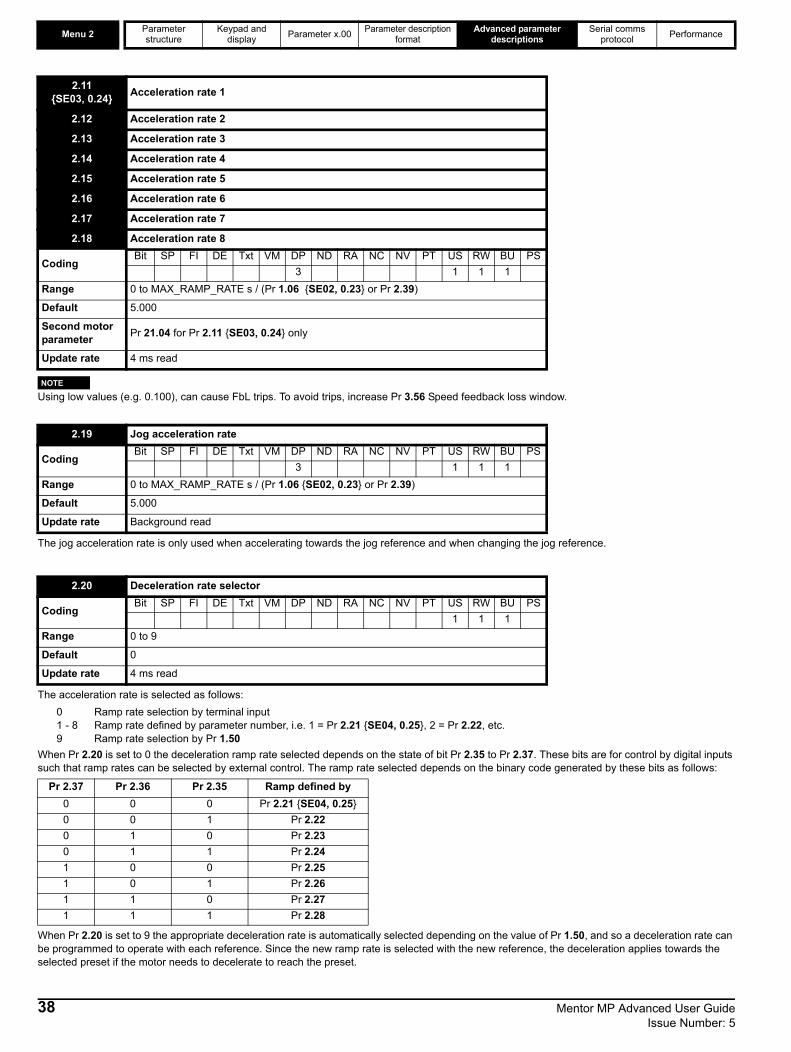
Menu 2 Parameter structure
Keypad and display Parameter x.00 Parameter description
formatAdvanced parameter
descriptionsSerial comms
protocol Performance
Using low values (e.g. 0.100), can cause FbL trips. To avoid trips, increase Pr 3.56 Speed feedback loss window.
The jog acceleration rate is only used when accelerating towards the jog reference and when changing the jog reference.
The acceleration rate is selected as follows:0 Ramp rate selection by terminal input1 - 8 Ramp rate defined by parameter number, i.e. 1 = Pr 2.21 {SE04, 0.25}, 2 = Pr 2.22, etc.9 Ramp rate selection by Pr 1.50
When Pr 2.20 is set to 0 the deceleration ramp rate selected depends on the state of bit Pr 2.35 to Pr 2.37. These bits are for control by digital inputs such that ramp rates can be selected by external control. The ramp rate selected depends on the binary code generated by these bits as follows:
When Pr 2.20 is set to 9 the appropriate deceleration rate is automatically selected depending on the value of Pr 1.50, and so a deceleration rate can be programmed to operate with each reference. Since the new ramp rate is selected with the new reference, the deceleration applies towards the selected preset if the motor needs to decelerate to reach the preset.
2.11{SE03, 0.24} Acceleration rate 1
2.12 Acceleration rate 2
2.13 Acceleration rate 3
2.14 Acceleration rate 4
2.15 Acceleration rate 5
2.16 Acceleration rate 6
2.17 Acceleration rate 7
2.18 Acceleration rate 8
CodingBit SP FI DE Txt VM DP ND RA NC NV PT US RW BU PS
3 1 1 1Range 0 to MAX_RAMP_RATE s / (Pr 1.06 {SE02, 0.23} or Pr 2.39)
Default 5.000
Second motor parameter Pr 21.04 for Pr 2.11 {SE03, 0.24} only
Update rate 4 ms read
2.19 Jog acceleration rate
CodingBit SP FI DE Txt VM DP ND RA NC NV PT US RW BU PS
3 1 1 1Range 0 to MAX_RAMP_RATE s / (Pr 1.06 {SE02, 0.23} or Pr 2.39)
Default 5.000
Update rate Background read
2.20 Deceleration rate selector
CodingBit SP FI DE Txt VM DP ND RA NC NV PT US RW BU PS
1 1 1Range 0 to 9
Default 0
Update rate 4 ms read
Pr 2.37 Pr 2.36 Pr 2.35 Ramp defined by0 0 0 Pr 2.21 {SE04, 0.25}0 0 1 Pr 2.220 1 0 Pr 2.230 1 1 Pr 2.241 0 0 Pr 2.251 0 1 Pr 2.261 1 0 Pr 2.271 1 1 Pr 2.28
NOTE
38 Mentor MP Advanced User Guide Issue Number: 5
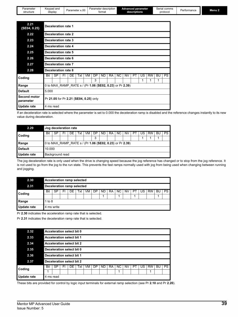
Parameter structure
Keypad and display Parameter x.00 Parameter description
formatAdvanced parameter
descriptionsSerial comms
protocol Performance Menu 2
If an deceleration rate is selected where the parameter is set to 0.000 the deceleration ramp is disabled and the reference changes instantly to its new value during deceleration.
The jog deceleration rate is only used when the drive is changing speed because the jog reference has changed or to stop from the jog reference. It is not used to go from the jog to the run state. This prevents the fast ramps normally used with jog from being used when changing between running and jogging.
Pr 2.30 indicates the acceleration ramp rate that is selected.Pr 2.31 indicates the deceleration ramp rate that is selected.
These bits are provided for control by logic input terminals for external ramp selection (see Pr 2.10 and Pr 2.20).
2.21{SE04, 0.25} Deceleration rate 1
2.22 Deceleration rate 2
2.23 Deceleration rate 3
2.24 Deceleration rate 4
2.25 Deceleration rate 5
2.26 Deceleration rate 6
2.27 Deceleration rate 7
2.28 Deceleration rate 8
CodingBit SP FI DE Txt VM DP ND RA NC NV PT US RW BU PS
3 1 1 1Range 0 to MAX_RAMP_RATE s / (Pr 1.06 {SE02, 0.23} or Pr 2.39)
Default 5.000
Second motor parameter Pr 21.05 for Pr 2.21 {SE04, 0.25} only
Update rate 4 ms read
2.29 Jog deceleration rate
CodingBit SP FI DE Txt VM DP ND RA NC NV PT US RW BU PS
3 1 1 1Range 0 to MAX_RAMP_RATE s / (Pr 1.06 {SE02, 0.23} or Pr 2.39)
Default 10.000
Update rate Background read
2.30 Acceleration ramp selected
2.31 Deceleration ramp selected
CodingBit SP FI DE Txt VM DP ND RA NC NV PT US RW BU PS
1 1 1 1Range 1 to 8
Update rate 4 ms write
2.32 Acceleration select bit 0
2.33 Acceleration select bit 1
2.34 Acceleration select bit 2
2.35 Deceleration select bit 0
2.36 Deceleration select bit 1
2.37 Deceleration select bit 2
CodingBit SP FI DE Txt VM DP ND RA NC NV PT US RW BU PS1 1 1
Update rate 4 ms read
Mentor MP Advanced User Guide 39Issue Number: 5

Menu 2 Parameter structure
Keypad and display Parameter x.00 Parameter description
formatAdvanced parameter
descriptionsSerial comms
protocol Performance
The motor and load inertia (Pr 3.18), motor torque per amp (Pr 5.32) and the rate of change of the ramp output (Pr 2.01 {di03, 0.38}) are used to produce a torque feed forward value that will accelerate or decelerate the load at the required rate. This value can be used as a feed forward term that is added to the speed controller output if Pr 4.22 is set to one. Pr 2.38 shows the torque value as a percentage of rated active current.
When this parameter is 0 the ramp rates will be the time to reach the maximum speed (Pr 1.06 {SE02, 0.23}), for example if Pr 2.39 = 0 and Pr 1.06 {SE02, 0.23} = 1500 rpm and Pr 2.11 {SE03, 0.24} = 10 s then the drive will take 10 s to accelerate from 0 rpm to 1500 rpm. When this parameter is not 0 the ramp times will be the time from 0 rpm to the value in Pr 2.39, for example setting Pr 2.39 = 1000 rpm and Pr 2.11 {SE03, 0.24} = 5 s the drive will take 5 s to accelerate from 0 rpm to 1000 rpm.
When the S ramp is enabled this parameter defines the time in each curved part of the S ramp. The total ramp time will be normal ramp rate time plus this parameter when Pr 2.40 is less than or equal the linear ramp time set by Pr 2.11 {SE03, 0.24}. When Pr 2.40 is greater than the linear ramp time the total ramp time will be J = (Pr 2.11 {SE03, 0.24} x Pr 2.40 x 1000) / Pr 1.06 {SE02, 0.23}
J can then be used in equation in parameter description for Pr 2.07.
Only Pr 2.11 {SE03, 0.24} is used in conjunction with this parameter to set the time.
When this parameter is 1 (default) and the S ramp is enabled then Pr 2.40 is used to define the S ramp time. When this parameter is 0 and the S ramp is enabled then Pr 2.07 is used to define the S ramp limit.
2.38 Inertia compensation torque
CodingBit SP FI DE Txt VM DP ND RA NC NV PT US RW BU PS
1 1 1 1Range ±1,000.0 %
Update rate 4 ms write
2.39 Ramp rate speed units
CodingBit SP FI DE Txt VM DP ND RA NC NV PT US RW BU PS
1 1 1Range 0 to 10,000 rpm
Default 0
Update rate Background read
2.40 Time of S ramp
CodingBit SP FI DE Txt VM DP ND RA NC NV PT US RW BU PS
3 1 1 1Range 0.000 to 100.000 s
Default 1.250
Update rate Background read
Pr 1.06{SE02, 0.23} Pr 2.06 Pr 2.07 Pr 2.11
{SE03, 0.24} Pr 2.39 Pr 2.40 Pr 2.41 Total ramp time (s)
1750.0 Off 3.6 5.000 0 1.250 On 5.001750.0 On 3,6 5.000 0 1.250 On 6.251750.0 On 3.6 5.000 0 10.000 On 14.14
2.41 S ramp mode
CodingBit SP FI DE Txt VM DP ND RA NC NV PT US RW BU PS1 1 1 1
Default 1
Update rate Background read
40 Mentor MP Advanced User Guide Issue Number: 5

Parameter structure
Keypad and display Parameter x.00 Parameter description
formatAdvanced parameter
descriptionsSerial comms
protocol Performance Menu 3
5.4 Menu 3: Speed feedback and speed controlSpeed accuracy and resolutionDigital reference resolutionWhen a preset speed is used the reference resolution is 0.1 rpm. Improved resolution can be obtained by using the precision reference (0.001 rpm). Analog reference resolutionThe analog input has a maximum resolution of 14bits plus sign. The resolution of the reference from analog inputs 2 or 3 is 10bits plus sign. Analog feedback resolutionThe resolution for both Armature voltage and tachometer feedback is 10bit plus sign.AccuracyWith encoder feedback the absolute speed accuracy depends on the accuracy of the crystal used with the drive microprocessor. The accuracy of the crystal is 100ppm, and so the absolute speed accuracy is 100ppm (0.01 %) of the reference, when a preset speed is used. If an analog input is used the absolute accuracy is further limited by the absolute accuracy and non-linearity of the analog input. If analog feedback is used the accuracy is even further limited.
Mentor MP Advanced User Guide 41Issue Number: 5

Menu 3 Parameter structure
Keypad and display Parameter x.00 Parameter description
formatAdvanced parameter
descriptionsSerial comms
protocol Performance
Parameter descriptions: Figure 5-3 Menu 3 logic diagram
* If Pr 5.28 (Field weakening compensation disable) is set to ‘OFF (0)’ a multiplication factor is applied to the speed loop gains when the flux is below 100 %.
3.35 Drive encoder markermode
3.36 Drive encodersupply voltage
3.38 Drive encoder type
3.39 Drive encodertermination select
Encoder interface
15.03Speed feedbackfrom option module in slot 1
16.03
17.03
Speed feedbackfrom option module in slot 2
Speed feedbackfrom option module in slot 3
Feedback from the option modules set-up in Menus 15, 16 and 17
3.27
Drive encoderspeed feedback
Speed feedbackselector
3.43Maximum driveencoder reference (rpm)
3.05
Speed feedback
3.02
3.31 Drive encoder markerposition reset disable
3.32 Drive encoder markerflag
3.33 Drive encoder turns
3.34 Drive encoder linesper revolution
3.47 Re-initialise positionfeedback
Position feedbackinitialised
3.49Full motor objectelectronic nameplatetransfer
3.54 Encoder direction
3.40 Drive encoder errordetection level
3.42 Drive encoder filter
3.48
3.52Tacho speed
5.04Estimated speed
3.51 Tachometervoltage rating
3.53 Tachometer inputmode
Drivetachometerinput
3.45 3.44
Any unprotectedvariable parameter
??.??
??.??
3.46
Drive encoder reference Drive encoder
reference scaling
Drive encoderreference destination
Speed feedbackpercentage
3.58
3.28
3.29
Drive encoderrevolution counter
Drive encoderposition
Zero speed
3.06 ‘At speed’lower limit
3.07 ‘At speed’upper limit
3.08 Overspeedthreshold
3.09 Absolute ‘atspeed’ detect
Speed detector threshold levels
Zero speed
Speed detector flags
10.03
Running ator belowminimumspeed
10.04
Below setspeed10.05
At speed10.06
Above setspeed10.07
0.XX
0.XX
Key
Read-write (RW) parameter
Read-only (RO) parameter
Inputterminals
Outputterminals
The parameters are all shown at their default settings
+
Final speed reference+
3.23
1.11
Hard speed reference selector
Reference enabledindicator
3.22Hard speed reference
3.21 Damping factor
Speed controller set-up
3.16 Speed controller gainselect
3.17 Speed controllerset-up method
3.18 Motor and load inertia
3.20 Bandwidth
3.03
Speed error
Speed loop gains*
3.04
Speed controlleroutput
3.10
3.11 (Ki1)
(Kp1)
3.13
3.14 (Ki2)
(Kp2)+
_
+
_3.01Menu 2
x-1
Speed controller differential feedback gains
(Kd1)
3.15
3.12
(Kd2)
3.55Select estimated speed on feedbackloss
3.56 Speed feedbackloss window
3.57
Estimated speed has been
automaticallyselected
3.26
5.86
Speed errorinvert
Held at 0 when indirect firing angle
42 Mentor MP Advanced User Guide Issue Number: 5
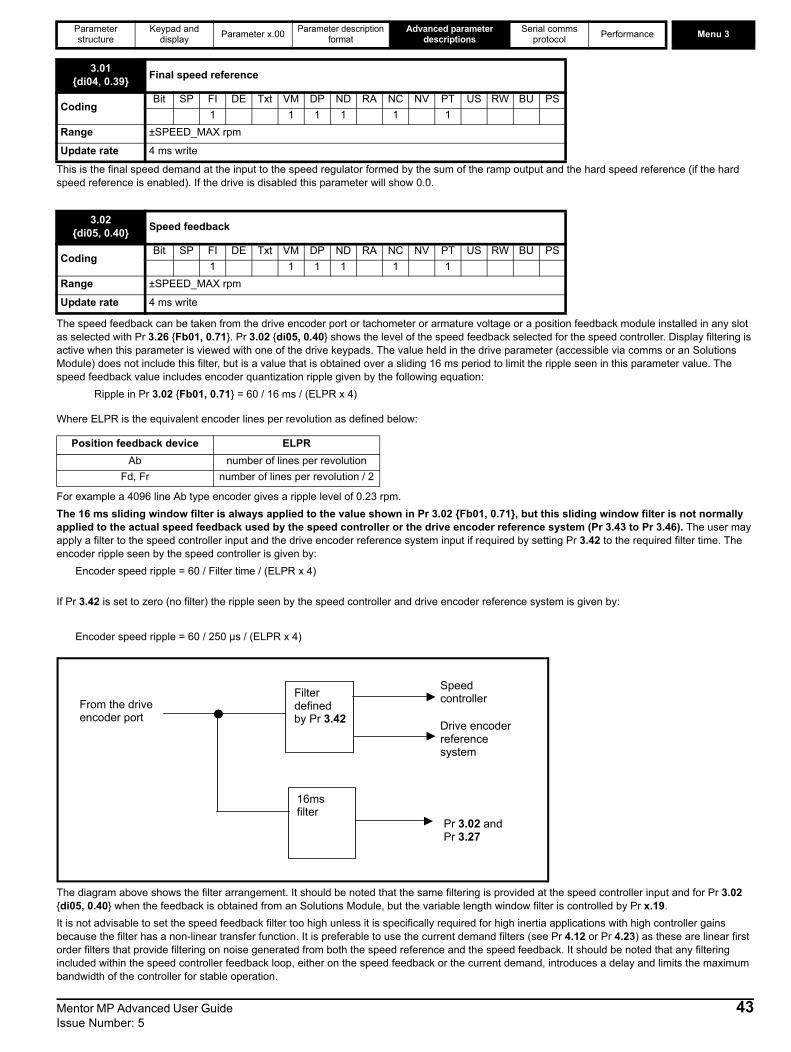
Parameter structure
Keypad and display Parameter x.00 Parameter description
formatAdvanced parameter
descriptionsSerial comms
protocol Performance Menu 3
This is the final speed demand at the input to the speed regulator formed by the sum of the ramp output and the hard speed reference (if the hard speed reference is enabled). If the drive is disabled this parameter will show 0.0.
The speed feedback can be taken from the drive encoder port or tachometer or armature voltage or a position feedback module installed in any slot as selected with Pr 3.26 {Fb01, 0.71}. Pr 3.02 {di05, 0.40} shows the level of the speed feedback selected for the speed controller. Display filtering is active when this parameter is viewed with one of the drive keypads. The value held in the drive parameter (accessible via comms or an Solutions Module) does not include this filter, but is a value that is obtained over a sliding 16 ms period to limit the ripple seen in this parameter value. The speed feedback value includes encoder quantization ripple given by the following equation:
Ripple in Pr 3.02 {Fb01, 0.71} = 60 / 16 ms / (ELPR x 4)
Where ELPR is the equivalent encoder lines per revolution as defined below:
For example a 4096 line Ab type encoder gives a ripple level of 0.23 rpm. The 16 ms sliding window filter is always applied to the value shown in Pr 3.02 {Fb01, 0.71}, but this sliding window filter is not normally applied to the actual speed feedback used by the speed controller or the drive encoder reference system (Pr 3.43 to Pr 3.46). The user may apply a filter to the speed controller input and the drive encoder reference system input if required by setting Pr 3.42 to the required filter time. The encoder ripple seen by the speed controller is given by:
Encoder speed ripple = 60 / Filter time / (ELPR x 4)
If Pr 3.42 is set to zero (no filter) the ripple seen by the speed controller and drive encoder reference system is given by:
Encoder speed ripple = 60 / 250 µs / (ELPR x 4)
The diagram above shows the filter arrangement. It should be noted that the same filtering is provided at the speed controller input and for Pr 3.02 {di05, 0.40} when the feedback is obtained from an Solutions Module, but the variable length window filter is controlled by Pr x.19.It is not advisable to set the speed feedback filter too high unless it is specifically required for high inertia applications with high controller gains because the filter has a non-linear transfer function. It is preferable to use the current demand filters (see Pr 4.12 or Pr 4.23) as these are linear first order filters that provide filtering on noise generated from both the speed reference and the speed feedback. It should be noted that any filtering included within the speed controller feedback loop, either on the speed feedback or the current demand, introduces a delay and limits the maximum bandwidth of the controller for stable operation.
3.01{di04, 0.39} Final speed reference
CodingBit SP FI DE Txt VM DP ND RA NC NV PT US RW BU PS
1 1 1 1 1 1Range ±SPEED_MAX rpm
Update rate 4 ms write
3.02{di05, 0.40} Speed feedback
CodingBit SP FI DE Txt VM DP ND RA NC NV PT US RW BU PS
1 1 1 1 1 1Range ±SPEED_MAX rpm
Update rate 4 ms write
Position feedback device ELPRAb number of lines per revolution
Fd, Fr number of lines per revolution / 2
Filter defined by Pr 3.42
16ms filter
From the drive encoder port
Pr and 3.02Pr 3.27
Speed controller
Drive encoder reference system
Mentor MP Advanced User Guide 43Issue Number: 5

Menu 3 Parameter structure
Keypad and display Parameter x.00 Parameter description
formatAdvanced parameter
descriptionsSerial comms
protocol Performance
The speed ripple can be quite high, for example with a 4096 line encoder the speed ripple is 14.6 rpm, but this does not define the resolution of the speed feedback which is normally much better and depends on the length of the measuring period used to obtain the feedback. This is shown in the improved resolution of the value accessible in Pr 3.02 {di05, 0.40} which is measured over 16 ms, i.e. a resolution of 0.23 rpm with a 4096 line encoder. The speed controller itself accumulates all pulses from the encoder, and so the speed controller resolution is not limited by the feedback, but by the resolution of the speed reference.If a SINCOS encoder is used from an option, the encoder speed ripple is reduced by a factor of 2(2-Interpolation bits). For example, with the nominal 10 bits of interpolation information, the speed ripple is reduced by a factor of 256. This shows how a SINCOS encoder can reduce noise caused by encoder quantization without any filtering in the speed feedback or the current demand, so that high gains may be used to give high dynamic performance and a very stiff system.
The speed error is the difference between the final speed demand and the speed feedback in rpm. This does not include the effect of the D term in the speed controller feedback branch.
The output of the speed regulator is a torque demand given as a percentage of rated motor torque. This is then modified to account for changes in motor flux if field weakening is active, and then used as the torque producing current reference.
If the speed feedback (Pr 3.02 {di05, 0.40}) is at or below the level defined by this parameter in either direction the Zero speed flag (Pr 10.03) is 1, otherwise the flag is 0.
3.03 Speed error
CodingBit SP FI DE Txt VM DP ND RA NC NV PT US RW BU PS
1 1 1 1 1 1Range ±SPEED_MAX rpm
Update rate 4 ms write
3.04{di06, 0.41} Speed controller output
CodingBit SP FI DE Txt VM DP ND RA NC NV PT US RW BU PS
1 1 1 1 1 1Range ±TORQUE_PRODUCT_CURRENT_MAX %
Update rate 4 ms write
3.05 Zero speed threshold
CodingBit SP FI DE Txt VM DP ND RA NC NV PT US RW BU PS
1 1 1Range 0 to 200 rpm
Default 30
Update rate Background read
3.06 At speed lower limit
CodingBit SP FI DE Txt VM DP ND RA NC NV PT US RW BU PS
1 1 1Range 0 to 10,000 rpm
Default 5
Update rate Background read
3.07 At speed upper limit
CodingBit SP FI DE Txt VM DP ND RA NC NV PT US RW BU PS
1 1 1Range 0 to 10,000 rpm
Default 5
Update rate Background read
44 Mentor MP Advanced User Guide Issue Number: 5

Parameter structure
Keypad and display Parameter x.00 Parameter description
formatAdvanced parameter
descriptionsSerial comms
protocol Performance Menu 3
If the speed feedback (Pr 3.02 {di05, 0.40}) exceeds this level in either direction an overspeed trip is produced. If this parameter is set to zero, the overspeed threshold is automatically set to 1.2 x SPEED_MAX.
"At speed" flag (Pr 10.06) is set if the speed feedback (Pr 3.02 {di05, 0.40}) is on the boundaries or within the at speed window. Flags Pr 10.07 and Pr 10.05 are set if the reference is above or below the window respectively.If Pr 3.09 = 0 reference window mode is used and the "at speed" condition is true if
(|Pr 1.03 {di02, 0.37}| - Pr 3.06) ≤ |Pr 3.02 {di05, 0.40}| ≤ (|Pr 1.03 {di02, 0.37}| + Pr 3.07)(If the lower limit is less than zero then zero is used as the lower limit.)
If Pr 3.09 = 1 absolute window mode is used and the "at speed" condition is true ifPr 3.06 ≤ |Pr 3.02 {di05, 0.40}| ≤ Pr 3.07
See the description under Pr 3.16.
See the description under Pr 3.16
3.08 Overspeed threshold
CodingBit SP FI DE Txt VM DP ND RA NC NV PT US RW BU PS
1 1 1Range 0 to 10,000 rpm
Default 0
Update rate Background read
3.09 Absolute “at speed” select
CodingBit SP FI DE Txt VM DP ND RA NC NV PT US RW BU PS1 1 1
Default 0
Update rate Background read
3.10{SP01, 0.61} (Kp1) Speed controller proportional gains
(Kp2)3.13
CodingBit SP FI DE Txt VM DP ND RA NC NV PT US RW BU PS
4 1 1 1Range 0.0000 to 6.5535 (1 / (rad/s))
Default 0.0300
Second motor parameter Pr 21.17 (3.10)
Update rate Background read
3.11{SP02, 0.62} (Ki1) Speed controller integral gains
(Ki2)3.14
CodingBit SP FI DE Txt VM DP ND RA NC NV PT US RW BU PS
2 1 1 1Range 0.00 to 655.35 (s / (rad/s))
Default 0.10
Second motor parameter Pr 21.18 (3.11)
Update rate Background read
Mentor MP Advanced User Guide 45Issue Number: 5

Menu 3 Parameter structure
Keypad and display Parameter x.00 Parameter description
formatAdvanced parameter
descriptionsSerial comms
protocol Performance
See the description under Pr 3.16.
The diagram below shows a generalized representation of the speed controller. The controller includes proportional, (Kp) and integral, (Ki) feed forward terms, and a differential, (Kd) feedback term. The drive holds two sets of these gains and either set may be selected for use by the speed controller with Pr 3.16. If Pr 3.16 = 0 then gains Kp1, Ki1 and Kd1 are used, if Pr 3.16 = 1 then gains Kp2, Ki2 and Kd2 are used. Pr 3.16 may be changed when the drive is enabled or disabled.
Proportional gain (Kp)If Kp has a value and Ki is set to zero the controller will only have a proportional term, and there must be a speed error to produce a torque reference. Therefore as the motor load increases there will be a difference between the reference and actual speeds. This effect, called regulation, depends on the level of the proportional gain, the higher the gain the smaller the speed error for a given load. If the proportional gain is too high either the acoustic noise produced by speed feedback quantization (using digital encoders, resolvers, etc.) becomes unacceptable, or the closed-loop stability limit is reached (using SINCOS encoders).Integral gain (Ki)The integral gain is provided to prevent speed regulation. The error is accumulated over a period of time and used to produce the necessary torque demand without any speed error. Increasing the integral gain reduces the time taken for the speed to reach the correct level and increases the stiffness of the system, i.e. it reduces the positional displacement produced by applying a load torque to the motor. Unfortunately increasing the integral gain also reduces the system damping giving overshoot after a transient. For a given integral gain the damping can be improved by increasing the proportional gain. A compromise must be reached where the system response, stiffness and damping are all adequate for the application. The integral term is implemented in the form of ∑(Ki x error), and so the integral gain can be changed when the controller is active without causing large torque demand transients.Differential gain (Kd)The differential gain is provided in the feedback of the speed controller to give additional damping. The differential term is implemented in a way that does not introduce excessive noise normally associated with this type of function. Increasing the differential term reduces the overshoot produced by under-damping, however, for most applications the proportional and integral gains alone are sufficient. It should be noted that the differential term is limited internally so that it is ineffective if speed in rpm x Kd x Ki is greater than 170.
3.12{SP03, 0.63} (Kd1) Speed controller differential feedback gains
(Kd2)3.15
CodingBit SP FI DE Txt VM DP ND RA NC NV PT US RW BU PS
5 1 1 1Range 0.00000 to 0.65535(1/s / (rad/s))
Default 0.00000
Second motor parameter Pr 21.19 (Pr 3.12 {SP03, 0.63})
Update rate Background read
3.16 Speed controller gain select
CodingBit SP FI DE Txt VM DP ND RA NC NV PT US RW BU PS1 1 1
Default 0
Update rate 4 ms read
Kp
Ki
Kd
Speedreference (wr*)
Speedfeedback (wr)
Torquereference (Te*)
-
+
+
+
+
+
46 Mentor MP Advanced User Guide Issue Number: 5
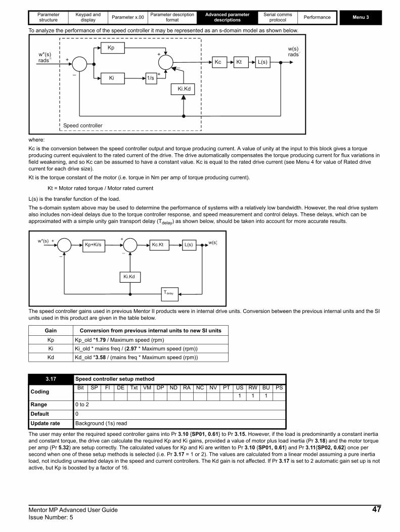
Parameter structure
Keypad and display Parameter x.00 Parameter description
formatAdvanced parameter
descriptionsSerial comms
protocol Performance Menu 3
To analyze the performance of the speed controller it may be represented as an s-domain model as shown below.
where:Kc is the conversion between the speed controller output and torque producing current. A value of unity at the input to this block gives a torque producing current equivalent to the rated current of the drive. The drive automatically compensates the torque producing current for flux variations in field weakening, and so Kc can be assumed to have a constant value. Kc is equal to the rated drive current (see Menu 4 for value of Rated drive current for each drive size).Kt is the torque constant of the motor (i.e. torque in Nm per amp of torque producing current).
Kt = Motor rated torque / Motor rated current
L(s) is the transfer function of the load.The s-domain system above may be used to determine the performance of systems with a relatively low bandwidth. However, the real drive system also includes non-ideal delays due to the torque controller response, and speed measurement and control delays. These delays, which can be approximated with a simple unity gain transport delay (Tdelay) as shown below, should be taken into account for more accurate results.
The speed controller gains used in previous Mentor II products were in internal drive units. Conversion between the previous internal units and the SI units used in this product are given in the table below.
The user may enter the required speed controller gains into Pr 3.10 {SP01, 0.61} to Pr 3.15. However, if the load is predominantly a constant inertia and constant torque, the drive can calculate the required Kp and Ki gains, provided a value of motor plus load inertia (Pr 3.18) and the motor torque per amp (Pr 5.32) are setup correctly. The calculated values for Kp and Ki are written to Pr 3.10 {SP01, 0.61} and Pr 3.11{SP02, 0.62} once per second when one of these setup methods is selected (i.e. Pr 3.17 = 1 or 2). The values are calculated from a linear model assuming a pure inertia load, not including unwanted delays in the speed and current controllers. The Kd gain is not affected. If Pr 3.17 is set to 2 automatic gain set up is not active, but Kp is boosted by a factor of 16.
Gain Conversion from previous internal units to new SI units
Kp Kp_old *1.79 / Maximum speed (rpm)Ki Ki_old * mains freq / (2.97 * Maximum speed (rpm))Kd Kd_old *3.58 / (mains freq * Maximum speed (rpm))
3.17 Speed controller setup method
CodingBit SP FI DE Txt VM DP ND RA NC NV PT US RW BU PS
1 1 1Range 0 to 2
Default 0
Update rate Background (1s) read
Kp
Ki 1/s
Kc Kt L(s)+
_
+
+
w*(s)rads-1
w(s)
Speed controller
Ki.Kd
_
rads-1
Kp+Ki/s
Ki.Kd
Kc.Kt L(s)+
_
+
_
w*(s) w(s)
Tdelay
Mentor MP Advanced User Guide 47Issue Number: 5

Menu 3 Parameter structure
Keypad and display Parameter x.00 Parameter description
formatAdvanced parameter
descriptionsSerial comms
protocol Performance
0: user setupWith the default value the user should enter the required speed controller gains.1: Bandwidth setupIf bandwidth based setup is required the following parameters must be set correctly: Pr 3.20 = required bandwidth, Pr 3.21 = required damping factor, Pr 3.18 = motor + load inertia (it is possible to measure the load inertia as part of the auto-tuning process, see Pr 5.12 on page 75), Pr 5.32 = motor torque per amp.
Ki = J / (Kc x Kt) x (2π x Bandwidth / Kbw)2 = Pr 3.18 / (rated drive current x Pr 5.32) x (2π x Pr 3.20 / Kbw)2
Where: Kbw = √[ (2ξ2 + 1) +√((2ξ2 + 1)2 + 1) ]Kp = 2 ξ √ [(Ki x J) / (Kc x Kt)] = 2 ξ √ [(Pr 3.11 {SP02, 0.62} x Pr 3.18) / (rated drive current x Pr 5.32)]
2: Kp gain times 16If this parameter is set to 2 the Kp gain (from whichever source) is multiplied by 16. This is intended to boost the range of Kp for applications with very high inertia. It should be noted that if high values of Kp are used it is likely that the speed controller output will need to be filtered (see Pr 4.12) or the speed feedback will need to be filtered (see Pr 3.42). If the feedback is not filtered it is possible the output of the speed controller will be a square wave that changes between the current limits causing the integral term saturation system to malfunction.
The motor and load inertia represents the total inertia driven by the motor. This is used to set the speed controller gains (see Pr 3.13) and to provide torque feed-forward terms during acceleration when required (see Pr 4.11). It is possible to measure the inertia as part of the autotune process, see Pr 5.12 {SE13, 0.34}.
The bandwidth is defined as the theoretical 3dB point on the closed-loop gain characteristic of the speed controller as a second order system. At this point the phase shift is approximately 60°. This parameter is used to define the bandwidth used for setting up the speed loop gain parameters automatically when Pr 3.17 = 1.
This is the damping factor related to the response of the system to a torque transient, and so if the damping factor is unity the response to a load torque transient is critically damped. The step response of the speed controller gives approximately 10 % overshoot with unity damping factor.
3.18 Motor and load inertia
CodingBit SP FI DE Txt VM DP ND RA NC NV PT US RW BU PS
5 1 1 1Range 0.00000 to 90.00000 kg m2
Default 0.00000
Update rate Background (1s) read
3.20 Bandwidth
CodingBit SP FI DE Txt VM DP ND RA NC NV PT US RW BU PS
1 1 1Range 0 to 50 Hz
Default 1 Hz
Update rate Background (1s) read
3.21 Damping factor
CodingBit SP FI DE Txt VM DP ND RA NC NV PT US RW BU PS
1 1 1 1Range 0.0 to 10.0
Default 1.0
Update rate Background (1s) read
3.22 Hard speed reference
CodingBit SP FI DE Txt VM DP ND RA NC NV PT US RW BU PS
1 1 1 1Range ±MAX_SPEED_REF rpm
Default 0.0
Update rate 4 ms read
48 Mentor MP Advanced User Guide Issue Number: 5

Parameter structure
Keypad and display Parameter x.00 Parameter description
formatAdvanced parameter
descriptionsSerial comms
protocol Performance Menu 3
The hard speed reference is a reference value which does not pass through the ramp system (Menu 2). It is added to the normal post ramp speed reference. Its value may be written from the keypad, via serial comms, from an analog input or from an encoder input. This parameter can also be used by the position controller (Menu 13) as the speed reference input. The hard speed reference is selected when Pr 3.23 = 1.
0, drv: Drive encoderThe position feedback from the encoder connected to the drive itself is used to derive the speed feedback for the speed controller.
1, Slot1: Solutions Module in slot 1The position feedback from the option module in option module slot 1 is used to derive the speed feedback for the speed controller. If a position feedback category option module is not installed in slot 1 the drive produces an Enc9 trip if the drive is active.
2, Slot2: Solutions Module in slot 23, Slot3: Solutions Module in slot 34, tACHO: Tachometer5, ESt.SPEED: Estimated speed
Provided the setup parameters for the drive encoder are correct this parameter shows the encoder speed in rpm.It should be noted that the value shown by this parameter is measured over a 16 ms sliding window period (in the same way as Pr 3.02 {di05, 0.40}), and so the ripple in this parameter accessible via comms or by an Solutions Module is as defined for Pr 3.02 {di05, 0.40}. The FI attribute for this parameter is set, and so further filtering is applied when this parameter is viewed with one of the drive keypads.
This is used in conjunction with Pr 3.29. See the description under Pr 3.29 overleaf.
3.23 Hard speed reference selector
CodingBit SP FI DE Txt VM DP ND RA NC NV PT US RW BU PS1 1 1
Default 0
Update rate 4 ms read
3.26{Fb01, 0.71} Speed feedback selector
CodingBit SP FI DE Txt VM DP ND RA NC NV PT US RW BU PS
1 1 1 1Range 0 to 5
Default 5
Second motor parameter Pr 21.21
Update rate Background read (Only has any effect when the drive is disabled)
3.27{Fb09, 0.79} Drive encoder speed feedback
CodingBit SP FI DE Txt VM DP ND RA NC NV PT US RW BU PS
1 1 1 1 1Range ±10,000.0 rpm
Update rate 4 ms write
3.28 Drive encoder revolution counter
CodingBit SP FI DE Txt VM DP ND RA NC NV PT US RW BU PS
1 1 1 1Range ±32,678 revolutions
Update rate 4 ms write
Mentor MP Advanced User Guide 49Issue Number: 5
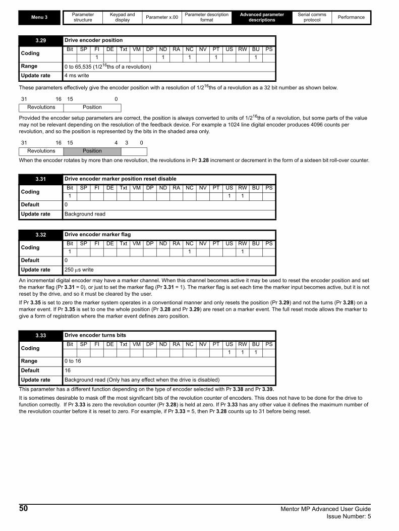
Menu 3 Parameter structure
Keypad and display Parameter x.00 Parameter description
formatAdvanced parameter
descriptionsSerial comms
protocol Performance
These parameters effectively give the encoder position with a resolution of 1/216ths of a revolution as a 32 bit number as shown below.
Provided the encoder setup parameters are correct, the position is always converted to units of 1/216ths of a revolution, but some parts of the value may not be relevant depending on the resolution of the feedback device. For example a 1024 line digital encoder produces 4096 counts per revolution, and so the position is represented by the bits in the shaded area only.
When the encoder rotates by more than one revolution, the revolutions in Pr 3.28 increment or decrement in the form of a sixteen bit roll-over counter.
An incremental digital encoder may have a marker channel. When this channel becomes active it may be used to reset the encoder position and set the marker flag (Pr 3.31 = 0), or just to set the marker flag (Pr 3.31 = 1). The marker flag is set each time the marker input becomes active, but it is not reset by the drive, and so it must be cleared by the user.If Pr 3.35 is set to zero the marker system operates in a conventional manner and only resets the position (Pr 3.29) and not the turns (Pr 3.28) on a marker event. If Pr 3.35 is set to one the whole position (Pr 3.28 and Pr 3.29) are reset on a marker event. The full reset mode allows the marker to give a form of registration where the marker event defines zero position.
This parameter has a different function depending on the type of encoder selected with Pr 3.38 and Pr 3.39.It is sometimes desirable to mask off the most significant bits of the revolution counter of encoders. This does not have to be done for the drive to function correctly. If Pr 3.33 is zero the revolution counter (Pr 3.28) is held at zero. If Pr 3.33 has any other value it defines the maximum number of the revolution counter before it is reset to zero. For example, if Pr 3.33 = 5, then Pr 3.28 counts up to 31 before being reset.
3.29 Drive encoder position
CodingBit SP FI DE Txt VM DP ND RA NC NV PT US RW BU PS
1 1 1 1 1Range 0 to 65,535 (1/216ths of a revolution)Update rate 4 ms write
31 16 15 0 Revolutions Position
31 16 15 4 3 0 Revolutions Position
3.31 Drive encoder marker position reset disable
CodingBit SP FI DE Txt VM DP ND RA NC NV PT US RW BU PS1 1 1
Default 0
Update rate Background read
3.32 Drive encoder marker flag
CodingBit SP FI DE Txt VM DP ND RA NC NV PT US RW BU PS1 1 1
Default 0
Update rate 250 μs write
3.33 Drive encoder turns bits
CodingBit SP FI DE Txt VM DP ND RA NC NV PT US RW BU PS
1 1 1Range 0 to 16
Default 16
Update rate Background read (Only has any effect when the drive is disabled)
50 Mentor MP Advanced User Guide Issue Number: 5
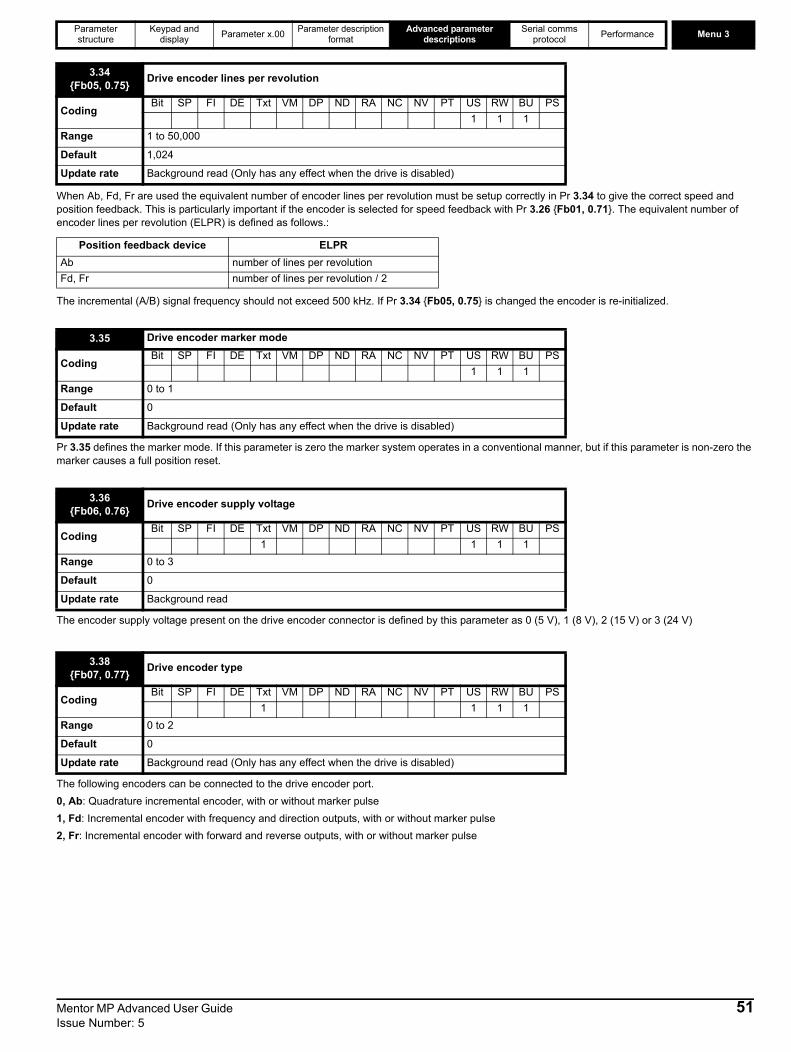
Parameter structure
Keypad and display Parameter x.00 Parameter description
formatAdvanced parameter
descriptionsSerial comms
protocol Performance Menu 3
When Ab, Fd, Fr are used the equivalent number of encoder lines per revolution must be setup correctly in Pr 3.34 to give the correct speed and position feedback. This is particularly important if the encoder is selected for speed feedback with Pr 3.26 {Fb01, 0.71}. The equivalent number of encoder lines per revolution (ELPR) is defined as follows.:
The incremental (A/B) signal frequency should not exceed 500 kHz. If Pr 3.34 {Fb05, 0.75} is changed the encoder is re-initialized.
Pr 3.35 defines the marker mode. If this parameter is zero the marker system operates in a conventional manner, but if this parameter is non-zero the marker causes a full position reset.
The encoder supply voltage present on the drive encoder connector is defined by this parameter as 0 (5 V), 1 (8 V), 2 (15 V) or 3 (24 V)
The following encoders can be connected to the drive encoder port.0, Ab: Quadrature incremental encoder, with or without marker pulse1, Fd: Incremental encoder with frequency and direction outputs, with or without marker pulse2, Fr: Incremental encoder with forward and reverse outputs, with or without marker pulse
3.34{Fb05, 0.75} Drive encoder lines per revolution
CodingBit SP FI DE Txt VM DP ND RA NC NV PT US RW BU PS
1 1 1Range 1 to 50,000
Default 1,024
Update rate Background read (Only has any effect when the drive is disabled)
Position feedback device ELPRAb number of lines per revolutionFd, Fr number of lines per revolution / 2
3.35 Drive encoder marker mode
CodingBit SP FI DE Txt VM DP ND RA NC NV PT US RW BU PS
1 1 1Range 0 to 1
Default 0
Update rate Background read (Only has any effect when the drive is disabled)
3.36{Fb06, 0.76} Drive encoder supply voltage
CodingBit SP FI DE Txt VM DP ND RA NC NV PT US RW BU PS
1 1 1 1Range 0 to 3
Default 0
Update rate Background read
3.38{Fb07, 0.77} Drive encoder type
CodingBit SP FI DE Txt VM DP ND RA NC NV PT US RW BU PS
1 1 1 1Range 0 to 2
Default 0
Update rate Background read (Only has any effect when the drive is disabled)
Mentor MP Advanced User Guide 51Issue Number: 5

Menu 3 Parameter structure
Keypad and display Parameter x.00 Parameter description
formatAdvanced parameter
descriptionsSerial comms
protocol Performance
The terminations may be enabled/disabled by this parameter as follows:
Trips can be enabled/disabled using Pr 3.40 as follows:
Encoder tripsThe following table shows trips that can be initiated that are related to the drive encoder feedback and whether they can be enabled and disabled by Pr 3.40.
+These trips can be enabled/disabled by Pr 3.401. If the terminations are not enabled on the A, B or Z inputs the wire break system will not operate (5 V or 8 V only). (Note that as default the Z
input terminations are disabled to disable wire break detection on this input.)Wire-break detectionIt may be important to detect a break in the connections between the drive and the position feedback device. This feature is provided for most encoder types either directly or indirectly as listed below.
Power supply short circuit or overload on drive encoder terminalsThere is an overload or short circuit on the drive encoder terminals.Power supply short circuit or overload on option encoder supplyThere is an overload or short circuit on the option encoder power supply. Both the above trips can over ride trip Enc2 so if there is a wire break trip and then a power supply trip the drive will store both trips in the trip log. Both the above trips turn the terminal encoder supply off.
3.39{Fb08, 0.78} Drive encoder termination select
CodingBit SP FI DE Txt VM DP ND RA NC NV PT US RW BU PS
1 1Range 0 to 2
Default 1
Update rate Background read
Encoder input Pr 3.39=0 Pr 3.39=1 Pr 3.39=2A-A\ Disabled Enabled EnabledB-B\ Disabled Enabled EnabledZ-Z\ Disabled Disabled Enabled
3.40 Drive encoder error detection level
CodingBit SP FI DE Txt VM DP ND RA NC NV PT US RW BU PS
1 1 1Range 0 to 2
Default 0
Update rate Background read
Bit Function0 Wire break detect disabled1 Wire break detect on A and B (need termination enabled for 5 V and 8 V)2 Wire break detect on A, B and Z (need termination enabled for 5 V signals)
Reason for error Drive trip Power supply short circuit or overload on drive encoder terminals Enc1
+Hardware wire-break detect on A, B and Z inputs(1) Enc2Power supply short circuit or overload on option encoder supply Enc3Speed feedback selected from an option slot that does not have a position feedback category Solutions Module installed Enc9
Termination Overload Enc10
Device Detection method Drive TripAb, Fd, Fr Hardware detectors on the A(F), B(D,R) and Z signal detect a wire break Enc2
52 Mentor MP Advanced User Guide Issue Number: 5
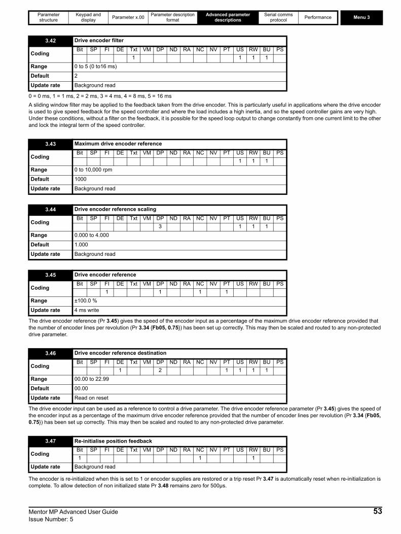
Parameter structure
Keypad and display Parameter x.00 Parameter description
formatAdvanced parameter
descriptionsSerial comms
protocol Performance Menu 3
0 = 0 ms, 1 = 1 ms, 2 = 2 ms, 3 = 4 ms, 4 = 8 ms, 5 = 16 msA sliding window filter may be applied to the feedback taken from the drive encoder. This is particularly useful in applications where the drive encoder is used to give speed feedback for the speed controller and where the load includes a high inertia, and so the speed controller gains are very high. Under these conditions, without a filter on the feedback, it is possible for the speed loop output to change constantly from one current limit to the other and lock the integral term of the speed controller.
The drive encoder reference (Pr 3.45) gives the speed of the encoder input as a percentage of the maximum drive encoder reference provided that the number of encoder lines per revolution (Pr 3.34 {Fb05, 0.75}) has been set up correctly. This may then be scaled and routed to any non-protected drive parameter.
The drive encoder input can be used as a reference to control a drive parameter. The drive encoder reference parameter (Pr 3.45) gives the speed of the encoder input as a percentage of the maximum drive encoder reference provided that the number of encoder lines per revolution (Pr 3.34 {Fb05, 0.75}) has been set up correctly. This may then be scaled and routed to any non-protected drive parameter.
The encoder is re-initialized when this is set to 1 or encoder supplies are restored or a trip reset Pr 3.47 is automatically reset when re-initialization is complete. To allow detection of non initialized state Pr 3.48 remains zero for 500µs.
3.42 Drive encoder filter
CodingBit SP FI DE Txt VM DP ND RA NC NV PT US RW BU PS
1 1 1 1Range 0 to 5 (0 to16 ms)
Default 2
Update rate Background read
3.43 Maximum drive encoder reference
CodingBit SP FI DE Txt VM DP ND RA NC NV PT US RW BU PS
1 1 1Range 0 to 10,000 rpm
Default 1000
Update rate Background read
3.44 Drive encoder reference scaling
CodingBit SP FI DE Txt VM DP ND RA NC NV PT US RW BU PS
3 1 1 1Range 0.000 to 4.000
Default 1.000
Update rate Background read
3.45 Drive encoder reference
CodingBit SP FI DE Txt VM DP ND RA NC NV PT US RW BU PS
1 1 1 1Range ±100.0 %
Update rate 4 ms write
3.46 Drive encoder reference destination
CodingBit SP FI DE Txt VM DP ND RA NC NV PT US RW BU PS
1 2 1 1 1 1Range 00.00 to 22.99
Default 00.00
Update rate Read on reset
3.47 Re-initialise position feedback
CodingBit SP FI DE Txt VM DP ND RA NC NV PT US RW BU PS1 1 1
Update rate Background read
Mentor MP Advanced User Guide 53Issue Number: 5
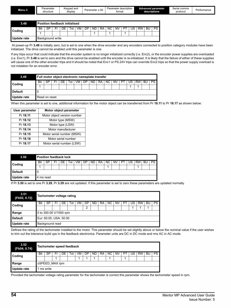
Menu 3 Parameter structure
Keypad and display Parameter x.00 Parameter description
formatAdvanced parameter
descriptionsSerial comms
protocol Performance
At power-up Pr 3.48 is initially zero, but is set to one when the drive encoder and any encoders connected to position category modules have been initialized. The drive cannot be enabled until this parameter is one.If any trips occur that could indicate that the encoder system is no longer initialized correctly (i.e. Enc2), or the encoder power supplies are overloaded (i.e. Enc1), Pr 3.48 is set to zero and the drive cannot be enabled until the encoder is re-initialized. It is likely that the failure of either of these supplies will cause one of the other encoder trips and it should be noted that Enc1 or PS.24V trips can override Enc2 trips so that the power supply overload is not mistaken for an encoder error.
When this parameter is set to one, additional information for the motor object can be transferred from Pr 18.11 to Pr 18.17 as shown below:
If Pr 3.50 is set to one Pr 3.28, Pr 3.29 are not updated. If this parameter is set to zero these parameters are updated normally.
Defines the rating of the tachometer installed to the motor. This parameter should be set slightly above or below the nominal value if the user wishes to trim out the tolerance build ups in the feedback electronics. Parameter units are DC in DC mode and rms AC in AC mode.
Provided the tachometer voltage rating parameter for the tachometer is correct this parameter shows the tachometer speed in rpm.
3.48 Position feedback initialised
CodingBit SP FI DE Txt VM DP ND RA NC NV PT US RW BU PS1 1 1 1
Update rate Background write
3.49 Full motor object electronic nameplate transfer
CodingBit SP FI DE Txt VM DP ND RA NC NV PT US RW BU PS1 1 1
Default 0
Update rate Read on reset
User parameter Motor object parameterPr 18.11 Motor object version numberPr 18.12 Motor type (MSW)Pr 18.13 Motor type (LSW)Pr 18.14 Motor manufacturerPr 18.15 Motor serial number (MSW)Pr 18.16 Motor serial numberPr 18.17 Motor serial number (LSW)
3.50 Position feedback lock
CodingBit SP FI DE Txt VM DP ND RA NC NV PT US RW BU PS1 1 1
Default 0
Update rate 4 ms read
3.51{Fb02, 0.72} Tachometer voltage rating
CodingBit SP FI DE Txt VM DP ND RA NC NV PT US RW BU PS
2 1 1 1Range 0 to 300.00 V/1000 rpm
Default Eur: 60.00, USA: 50.00
Update rate Background read
3.52{Fb04, 0.74} Tachometer speed feedback
CodingBit SP FI DE Txt VM DP ND RA NC NV PT US RW BU PS
1 1 1 1 1 1Range ±SPEED_MAX rpm
Update rate 1 ms write
54 Mentor MP Advanced User Guide Issue Number: 5

Parameter structure
Keypad and display Parameter x.00 Parameter description
formatAdvanced parameter
descriptionsSerial comms
protocol Performance Menu 3
The input electronics for the tachometer input can be configured in 3 ways.
If the encoder has been incorrectly wired this bit can be used to correct the encoder feedback.0 - Clockwise1 - Anti clockwise
When this bit is set the speed feedback source is automatically changed to estimated speed feedback when the selected speed feedback is lost.
3.53{Fb03, 0.73} Tachometer input mode
CodingBit SP FI DE Txt VM DP ND RA NC NV PT US RW BU PS
1 1 1Range 0 to 2
Default 0 (DC)
Update rate Background read
Value Text Action0 DC DC tachometer1 DC Filt DC tachometer with input filter2 AC AC tachometer
3.54 Encoder direction
CodingBit SP FI DE Txt VM DP ND RA NC NV PT US RW BU PS1 1 1
Default 0
Update rate Background read
3.55 Select estimated speed on feedback loss
CodingBit SP FI DE Txt VM DP ND RA NC NV PT US RW BU PS1 1 1
Default 0
Update rate Background read
Mentor MP Advanced User Guide 55Issue Number: 5
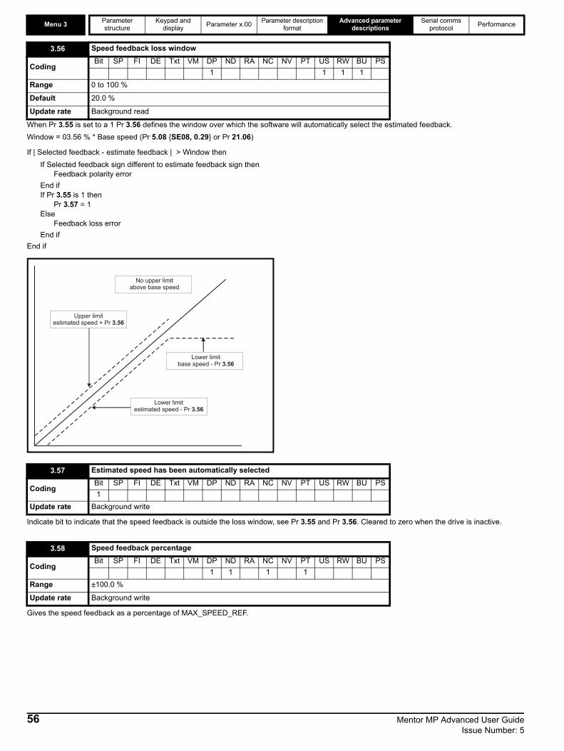
Menu 3 Parameter structure
Keypad and display Parameter x.00 Parameter description
formatAdvanced parameter
descriptionsSerial comms
protocol Performance
When Pr 3.55 is set to a 1 Pr 3.56 defines the window over which the software will automatically select the estimated feedback. Window = 03.56 % * Base speed (Pr 5.08 {SE08, 0.29} or Pr 21.06)
If | Selected feedback - estimate feedback | > Window thenIf Selected feedback sign different to estimate feedback sign then
Feedback polarity errorEnd if If Pr 3.55 is 1 then
Pr 3.57 = 1Else
Feedback loss errorEnd if
End if
Indicate bit to indicate that the speed feedback is outside the loss window, see Pr 3.55 and Pr 3.56. Cleared to zero when the drive is inactive.
Gives the speed feedback as a percentage of MAX_SPEED_REF.
3.56 Speed feedback loss window
CodingBit SP FI DE Txt VM DP ND RA NC NV PT US RW BU PS
1 1 1 1Range 0 to 100 %
Default 20.0 %
Update rate Background read
3.57 Estimated speed has been automatically selected
CodingBit SP FI DE Txt VM DP ND RA NC NV PT US RW BU PS1
Update rate Background write
3.58 Speed feedback percentage
CodingBit SP FI DE Txt VM DP ND RA NC NV PT US RW BU PS
1 1 1 1Range ±100.0 %
Update rate Background write
Upper limitestimated speed + Pr 3.56
No upper limitabove base speed
Lower limitbase speed - Pr 3.56
Lower limitestimated speed - Pr 3.56
56 Mentor MP Advanced User Guide Issue Number: 5

Parameter structure
Keypad and display Parameter x.00 Parameter description
formatAdvanced parameter
descriptionsSerial comms
protocol Performance Menu 4
Mentor MP Advanced User Guide 57Issue Number: 5
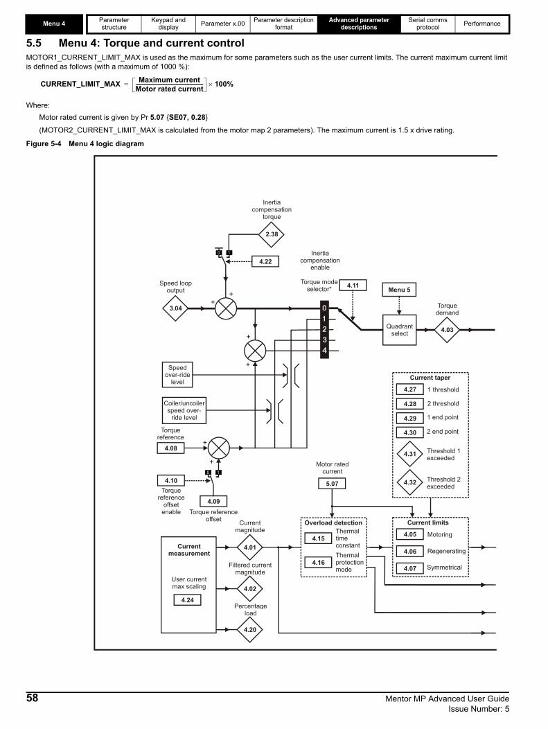
Menu 4 Parameter structure
Keypad and display Parameter x.00 Parameter description
formatAdvanced parameter
descriptionsSerial comms
protocol Performance
5.5 Menu 4: Torque and current controlMOTOR1_CURRENT_LIMIT_MAX is used as the maximum for some parameters such as the user current limits. The current maximum current limit is defined as follows (with a maximum of 1000 %):
Where:Motor rated current is given by Pr 5.07 {SE07, 0.28}
(MOTOR2_CURRENT_LIMIT_MAX is calculated from the motor map 2 parameters). The maximum current is 1.5 x drive rating.
Figure 5-4 Menu 4 logic diagram
CURRENT_LIMIT_MAX Maximum currentMotor rated current------------------------------------------------------- 100%×=
3.04
4.08
4.09
5.07
4.05 Motoring
Regenerating
Current limits
Symmetrical
Motor rated current
Speed loop output
Torque referenceoffset
Torque reference
Speed over-ride
level
Coiler/uncoilerspeed over-
ride level
+
4.01
Torque modeselector* 4.11
4.10Torque
referenceoffset
enable
+
+
+
4.03
Torquedemand
4.24
User current max scaling
+
4.22
2.38
Inertia compensation
enable
+
Inertia compensation
torque
Menu 5
Quadrantselect
Currentmeasurement
4.02
4.20
Percentageload
Filtered currentmagnitude
Currentmagnitude
4.15Thermal timeconstantThermalprotectionmode
Overload detection
4.27 1 threshold
2 threshold
Current taper
1 end point
2 end point
4.31
4.32
Threshold 1exceeded
Threshold 2exceeded
58 Mentor MP Advanced User Guide Issue Number: 5
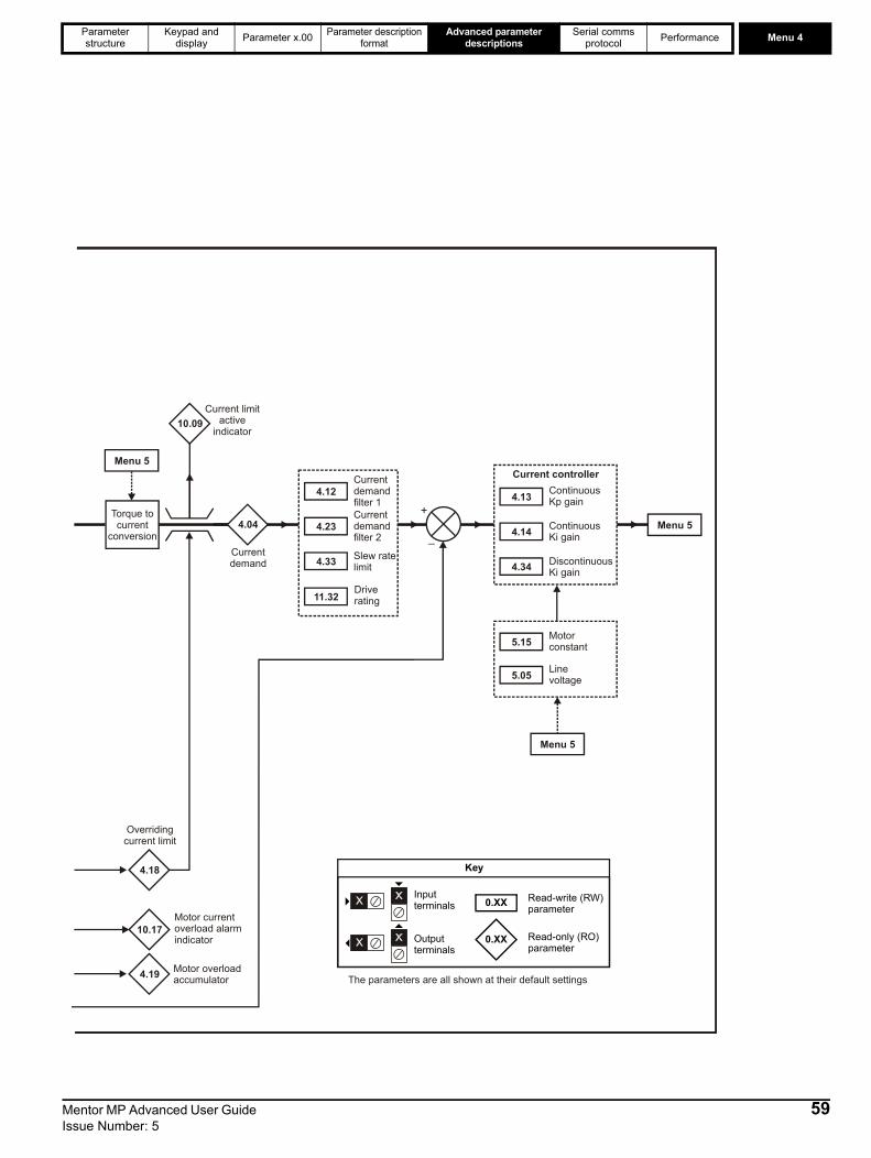
Parameter structure
Keypad and display Parameter x.00 Parameter description
formatAdvanced parameter
descriptionsSerial comms
protocol Performance Menu 4
4.04
Currentdemand
+
_
10.09Current limit
activeindicator
Menu 5
0.XX
0.XX
Key
Read-write (RW) parameter
Read-only (RO) parameter
Inputterminals
Outputterminals
The parameters are all shown at their default settings
Torque tocurrent
conversion
Currentdemandfilter 1
4.12
Currentdemandfilter 2
4.23
Slew ratelimit4.33
ContinuousKp gain4.13
ContinuousKi gain4.14
Discontinuous Ki gain4.34
Current controller
Menu 5
Menu 5
4.18
10.17
4.19 Motor overloadaccumulator
Motor currentoverload alarmindicator
Overridingcurrent limit
Motorconstant5.15
Linevoltage5.05
Driverating11.32
Mentor MP Advanced User Guide 59Issue Number: 5
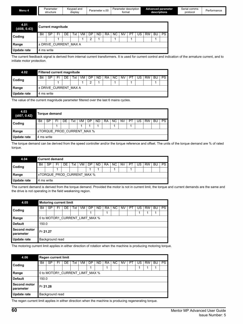
Menu 4 Parameter structure
Keypad and display Parameter x.00 Parameter description
formatAdvanced parameter
descriptionsSerial comms
protocol Performance
The current feedback signal is derived from internal current transformers. It is used for current control and indication of the armature current, and to initiate motor protection.
The value of the current magnitude parameter filtered over the last 6 mains cycles.
The torque demand can be derived from the speed controller and/or the torque reference and offset. The units of the torque demand are % of rated torque.
The current demand is derived from the torque demand. Provided the motor is not in current limit, the torque and current demands are the same and the drive is not operating in the field weakening region.
The motoring current limit applies in either direction of rotation when the machine is producing motoring torque.
The regen current limit applies in either direction when the machine is producing regenerating torque.
4.01{di08, 0.43} Current magnitude
CodingBit SP FI DE Txt VM DP ND RA NC NV PT US RW BU PS
1 1 2 1 1 1 1Range ± DRIVE_CURRENT_MAX A
Update rate 4 ms write
4.02 Filtered current magnitude
CodingBit SP FI DE Txt VM DP ND RA NC NV PT US RW BU PS
1 1 2 1 1 1 1Range ± DRIVE_CURRENT_MAX A
Update rate 4 ms write
4.03{di07, 0.42} Torque demand
CodingBit SP FI DE Txt VM DP ND RA NC NV PT US RW BU PS
1 1 1 1 1 1Range ±TORQUE_PROD_CURRENT_MAX %
Update rate 4 ms write
4.04 Current demand
CodingBit SP FI DE Txt VM DP ND RA NC NV PT US RW BU PS
1 1 1 1 1Range ±TORQUE_PROD_CURRENT_MAX %
Update rate 4 ms write
4.05 Motoring current limit
CodingBit SP FI DE Txt VM DP ND RA NC NV PT US RW BU PS
1 1 1 1 1Range 0 to MOTOR1_CURRENT_LIMIT_MAX %
Default 150.0
Second motor parameter Pr 21.27
Update rate Background read
4.06 Regen current limit
CodingBit SP FI DE Txt VM DP ND RA NC NV PT US RW BU PS
1 1 1 1 1Range 0 to MOTOR1_CURRENT_LIMIT_MAX %
Default 150.0
Second motor parameter Pr 21.28
Update rate Background read
60 Mentor MP Advanced User Guide Issue Number: 5
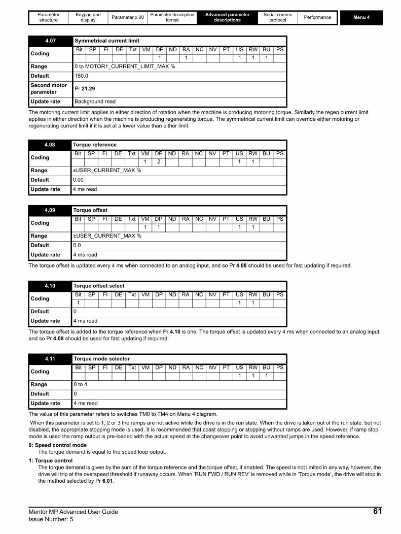
Parameter structure
Keypad and display Parameter x.00 Parameter description
formatAdvanced parameter
descriptionsSerial comms
protocol Performance Menu 4
The motoring current limit applies in either direction of rotation when the machine is producing motoring torque. Similarly the regen current limit applies in either direction when the machine is producing regenerating torque. The symmetrical current limit can override either motoring or regenerating current limit if it is set at a lower value than either limit.
The torque offset is updated every 4 ms when connected to an analog input, and so Pr 4.08 should be used for fast updating if required.
The torque offset is added to the torque reference when Pr 4.10 is one. The torque offset is updated every 4 ms when connected to an analog input, and so Pr 4.08 should be used for fast updating if required.
The value of this parameter refers to switches TM0 to TM4 on Menu 4 diagram. When this parameter is set to 1, 2 or 3 the ramps are not active while the drive is in the run state. When the drive is taken out of the run state, but not disabled, the appropriate stopping mode is used. It is recommended that coast stopping or stopping without ramps are used. However, if ramp stop mode is used the ramp output is pre-loaded with the actual speed at the changeover point to avoid unwanted jumps in the speed reference.0: Speed control mode
The torque demand is equal to the speed loop output.1: Torque control
The torque demand is given by the sum of the torque reference and the torque offset, if enabled. The speed is not limited in any way, however, the drive will trip at the overspeed threshold if runaway occurs. When ‘RUN FWD / RUN REV’ is removed while in ‘Torque mode’, the drive will stop in the method selected by Pr 6.01.
4.07 Symmetrical current limit
CodingBit SP FI DE Txt VM DP ND RA NC NV PT US RW BU PS
1 1 1 1 1Range 0 to MOTOR1_CURRENT_LIMIT_MAX %
Default 150.0
Second motor parameter Pr 21.29
Update rate Background read
4.08 Torque reference
CodingBit SP FI DE Txt VM DP ND RA NC NV PT US RW BU PS
1 2 1 1Range ±USER_CURRENT_MAX %
Default 0.00
Update rate 4 ms read
4.09 Torque offset
CodingBit SP FI DE Txt VM DP ND RA NC NV PT US RW BU PS
1 1 1 1Range ±USER_CURRENT_MAX %
Default 0.0
Update rate 4 ms read
4.10 Torque offset select
CodingBit SP FI DE Txt VM DP ND RA NC NV PT US RW BU PS1 1 1
Default 0
Update rate 4 ms read
4.11 Torque mode selector
CodingBit SP FI DE Txt VM DP ND RA NC NV PT US RW BU PS
1 1 1Range 0 to 4
Default 0
Update rate 4 ms read
Mentor MP Advanced User Guide 61Issue Number: 5
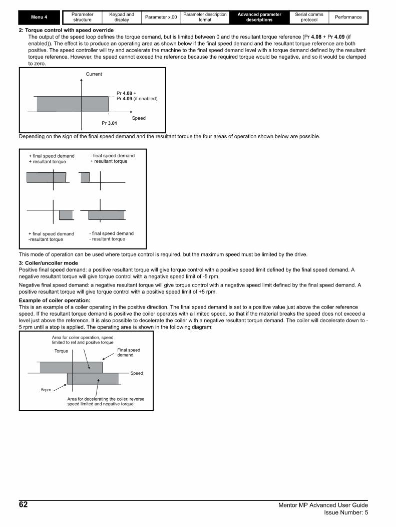
Menu 4 Parameter structure
Keypad and display Parameter x.00 Parameter description
formatAdvanced parameter
descriptionsSerial comms
protocol Performance
2: Torque control with speed overrideThe output of the speed loop defines the torque demand, but is limited between 0 and the resultant torque reference (Pr 4.08 + Pr 4.09 (if enabled)). The effect is to produce an operating area as shown below if the final speed demand and the resultant torque reference are both positive. The speed controller will try and accelerate the machine to the final speed demand level with a torque demand defined by the resultant torque reference. However, the speed cannot exceed the reference because the required torque would be negative, and so it would be clamped to zero.
Depending on the sign of the final speed demand and the resultant torque the four areas of operation shown below are possible.
This mode of operation can be used where torque control is required, but the maximum speed must be limited by the drive.3: Coiler/uncoiler modePositive final speed demand: a positive resultant torque will give torque control with a positive speed limit defined by the final speed demand. A negative resultant torque will give torque control with a negative speed limit of -5 rpm. Negative final speed demand: a negative resultant torque will give torque control with a negative speed limit defined by the final speed demand. A positive resultant torque will give torque control with a positive speed limit of +5 rpm. Example of coiler operation:This is an example of a coiler operating in the positive direction. The final speed demand is set to a positive value just above the coiler reference speed. If the resultant torque demand is positive the coiler operates with a limited speed, so that if the material breaks the speed does not exceed a level just above the reference. It is also possible to decelerate the coiler with a negative resultant torque demand. The coiler will decelerate down to -5 rpm until a stop is applied. The operating area is shown in the following diagram:
Pr +4.08Pr (if enabled)4.09
Pr 3.01Speed
Current
+ final speed demand+ resultant torque
- final speed demand+ resultant torque
+ final speed demand-resultant torque
- final speed demand- resultant torque
Final speeddemand
Area for coiler operation, speedlimited to ref and positve torque
Area for decelerating the coiler, reversespeed limited and negative torque
-5rpm
Speed
Torque
62 Mentor MP Advanced User Guide Issue Number: 5

Parameter structure
Keypad and display Parameter x.00 Parameter description
formatAdvanced parameter
descriptionsSerial comms
protocol Performance Menu 4
Example of uncoiler operation:This is an example for an uncoiler operating in the positive direction. The final speed demand should be set to a level just above the maximum normal speed. When the resultant torque demand is negative the uncoiler will apply tension and try and rotate at 5 rpm in reverse, and so take up any slack. The uncoiler can operate at any positive speed applying tension. If it is necessary to accelerate the uncoiler a positive resultant torque demand is used. The speed will be limited to the final speed demand. The operating area is the same as that for the coiler and is shown below:
4: Speed control with torque feed-forwardThe drive operates under speed control, but a torque value may be added to the output of the speed controller. This can be used to improve the regulation of systems where the speed loop gains need to be low for stability.
A first order filter, with a filter defined by this parameter, is provided on the current demand to reduce acoustic noise and vibration produced as a result of position feedback quantization noise. The filter introduces a lag in the speed loop, and so the speed loop gains may need to be reduced to maintain stability as the filter is increased. Alternative filters can be selected depending on the value of the speed controller gain selector (Pr 3.16). If Pr 3.16 = 0 Pr 4.12 is used, if Pr 3.16 = 1 Pr 4.23 is used.
The proportional gain Kp (Pr 4.13) is the most critical value in controlling the performance of the current controllers. This value can be set using the auto-tuning feature (see Pr 5.12 {SE13, 0.34}).It is possible to increase the proportional gain (Kp) to reduce the response time of the current controllers. If Kp is increased by a factor of 1.5 then the response to a step change of reference will give 12.5 % overshoot. It is recommended that Ki be increased in preference to Kp.The gain values that are calculated by the autotune system should give the best response with minimal overshoot. If required the gains can be adjusted to improve performance.Pr 4.13 = 3393 x L x f x Imax / V rmsWhere :L is the load inductance in HenriesR is the load resistance in ohmsf is the supply frequency in HertzImax is the peak load current (including any overload) in ampsV rms is the line-to-line supply voltage in volts.
4.12 Current demand filter 1
CodingBit SP FI DE Txt VM DP ND RA NC NV PT US RW BU PS
1 1 1 1Range 0.0 to 25.0 ms
Default 6.0
Update rate Background read
4.13 Continuous current controller Kp gain
CodingBit SP FI DE Txt VM DP ND RA NC NV PT US RW BU PS
1 1 1 1Range 0 to 4000
Default 100
Second motor parameter Pr 21.13
Update rate Background read
-5rpm Area for normal uncoileroperation: negative torque,limited to low speed in reverse
Speed reference
Area for acceleratinguncoiler: positive torque,limited speed
Speed
Torque
Mentor MP Advanced User Guide 63Issue Number: 5

Menu 4 Parameter structure
Keypad and display Parameter x.00 Parameter description
formatAdvanced parameter
descriptionsSerial comms
protocol Performance
The proportional gain Kp (Pr 4.13) is the most critical value in controlling the performance of the current controllers. The value can be set by auto-tuning (see Pr 5.12 {SE13, 0.34}).Pr 4.14 = 1697 x L x f x Imax / V rmsWhere :L is the load inductance in HenriesR is the load resistance in ohmsf is the supply frequency in HertzImax is the peak load current (including any overload) in ampsV rms is the line-to-line supply voltage in volts.The gain values that are calculated by the autotune system give the best response with minimal overshoot. If required the gains can be adjusted to improve performance as follows:
1. The integral gain (Ki) can be used to improve the performance of the current controllers by reducing the effects of non-linearity. These effects will be more significant for drives with higher current ratings and higher voltage ratings. If Ki is increased by a factor of 4 it is possible to get up to 10 % overshoot in response to a step change of current reference. For high performance applications, it is recommended that Ki is increased by a factor of 4 from the autotuned values.
2. It is possible to increase the proportional gain (Kp) to reduce the response time of the current controllers. If Kp is increased by a factor of 1.5 then the response to a step change of reference will give 12.5 % overshoot. It is recommended that Ki is increased in preference to Kp.
Pr 4.16 = 0 - Drive trips when estimated motor temperature reaches 100 %.Pr 4.16 = 1 - Drive current limit is limited to 100 % when estimated motor temperature reaches 100 %.Pr 4.16 = 2 - Drive trips when estimated motor temperature reaches 100 % and accumulator is reset at power-up.Pr 4.16 = 3 - Drive current limit is limited to 100 % when estimated motor temperature reaches 100 % and accumulator is reset at power-up.The motor is modelled thermally in a way that is equivalent to the electrical circuit shown as follows.
The temperature of the motor as a percentage of maximum temperature, with a constant current magnitude of I, and constant value of motor rated current (set by Pr 5.07 {SE07, 0.28} or Pr 21.07) after time t is given by
Temp = [I2 / (1.05 x Motor rated current)2] (1 - e-t/τ) x 100 %
4.14 Continuous current controller Ki gain
CodingBit SP FI DE Txt VM DP ND RA NC NV PT US RW BU PS
1 1 1 1Range 0 to 4000
Default 50
Second motor parameter Pr 21.14
Update rate Background read
4.15 Thermal filter
CodingBit SP FI DE Txt VM DP ND RA NC NV PT US RW BU PS
1 1 1Range 0.0 to 3000.0
Default 89.0
Second motor parameter Pr 21.16
Update rate Background read
4.16 Thermal protection mode
CodingBit SP FI DE Txt VM DP ND RA NC NV PT US RW BU PS1 1 1 1
Range 0 to 3
Default 0
Update rate Background read
I /(1.05*Motor Rated Current)2 2
TempC R
64 Mentor MP Advanced User Guide Issue Number: 5

Parameter structure
Keypad and display Parameter x.00 Parameter description
formatAdvanced parameter
descriptionsSerial comms
protocol Performance Menu 4
This assumes that the maximum allowed motor temperature is produced by 1.05 x Motor rated current and that τ is the thermal filter of the point in the motor that reaches its maximum allowed temperature first. τ is defined by Pr 4.15. The estimated motor temperature is given by Pr 4.19 as a percentage of maximum temperature. If Pr 4.15 has a value between 0.0 and 1.0 the thermal filter is taken as 1.0.
When the estimated temperature reaches 100 % the drive takes some action depending on the setting of Pr 4.16. If Pr 4.16 is 0, the drive trips when the threshold is reached. If Pr 4.16 is 1, the current limit is reduced to 100 % when the temperature is 100 %. The current limit is set back to the user defined level when the temperature falls below 95 %.The time for some action to be taken by the drive from cold with constant motor current is given by:
Ttrip = -(Pr 4.15) x ln(1 - (1.05 x Pr 5.07 {SE07, 0.28} / Pr 4.01 {di08, 0.43})2)
Alternatively the thermal filter can be calculated from the trip time with a given current from:
Pr 4.15 = -Ttrip / ln(1 - (1.05 / Overload)2)
For example, if the drive should trip after supplying 150 % overload for 60 seconds then
Pr 4.15 = -60 / ln(1 - (1.05 / 1.50)2) = 89Each time the rated current defined by Pr 5.07 {SE07, 0.28} or Pr 21.07 (depending on the motor selected) is altered, the accumulator is reset to zero.
With Pr 4.16 set to 1 or 3 when in slave mode Pr 5.43 = 8 (P.Slave) has no effect on the drive thermal protection.
The current limit applied at any time depends on whether the drive is motoring or regenerating and also on the level of the symmetrical current limit. Pr 4.18 gives the limit level that applies at any instant.
See Pr 4.16 on page 64.
This parameter displays the current magnitude (Pr 4.01 {di08, 0.43}) as a percentage of rated active current. Positive values indicate motoring and negative values indicate regenerating.
If this parameter is set to one, the drive calculates a torque reference from the motor and load inertia (Pr 3.18) and the rate of change of speed reference. The torque reference is added to the speed controller output to provide inertia compensation. This can be used in speed or torque control applications to produce the torque required to accelerate or decelerate the load inertia.
4.18 Overriding current limit
CodingBit SP FI DE Txt VM DP ND RA NC NV PT US RW BU PS
1 1 1 1 1 1Range 0 to TORQUE_PROD_CURRENT_MAX %
Update rate Background write
4.19 Overload accumulator
CodingBit SP FI DE Txt VM DP ND RA NC NV PT US RW BU PS
1 1 1 1 1 1Range 0 to 100.0 %
Update rate Background write
4.20 Percentage load
CodingBit SP FI DE Txt VM DP ND RA NC NV PT US RW BU PS
1 1 1 1 1 1Range ±USER_CURRENT_MAX %
Update rate Background write
4.22 Inertia compensation enable
CodingBit SP FI DE Txt VM DP ND RA NC NV PT US RW BU PS1 1 1
Default 0
Update rate Background read
NOTE
Mentor MP Advanced User Guide 65Issue Number: 5

Menu 4 Parameter structure
Keypad and display Parameter x.00 Parameter description
formatAdvanced parameter
descriptionsSerial comms
protocol Performance
The current demand filter filter is defined by this parameter if the speed gain select (Pr 3.16) is one.
The maximum for Pr 4.08 and Pr 4.20 is defined by this parameter
Sets a threshold value of speed feedback, beyond which Pr 4.31 changes to 1 to indicate that the threshold has been exceeded, and is the starting point for taper 1. The current limit reduces, as a function of speed, to an end point defined by Pr 4.29.The output of the taper block controls Pr 4.18.If only 1 taper is used, it must be Taper 1. If both are used, Taper 1 must be first. Refer to the diagrams under Pr 4.32.
Sets a threshold value of speed feedback, beyond which Pr 4.32 changes to 1 to indicate that the threshold has been exceeded, and is the starting point for taper 2. The current limit reduces, as a function of speed, to an end point defined by Pr 4.30.The output of the taper block controls Pr 4.18.If only 1 taper is used, it must be Taper 1. If both are used, Taper 1 must be first. Refer to the diagrams under Pr 4.32.
Defines the current at the end of taper 1.
4.23 Current demand filter 2
CodingBit SP FI DE Txt VM DP ND RA NC NV PT US RW BU PS
1 1 1 1Range 0.0 to 25.0 ms
Default 6.0
Update rate Background read
4.24 User current maximum scaling
CodingBit SP FI DE Txt VM DP ND RA NC NV PT US RW BU PS
1 1 1 1 1 1Range 0.0 to TORQUE_PROD_CURRENT_MAX %
Default 150.0
Update rate Background read
4.27 Current taper 1 threshold
CodingBit SP FI DE Txt VM DP ND RA NC NV PT US RW BU PS
1 1 1 1 1Range 0.0 to 10,000.0 rpm
Default 10,000 rpm
Update rate Background read
4.28 Current taper 2 threshold
CodingBit SP FI DE Txt VM DP ND RA NC NV PT US RW BU PS
1 1 1 1 1Range 0.0 to 10,000 rpm
Default 10,000 rpm
Update rate Background read
4.29 Current taper 1 end point
CodingBit SP FI DE Txt VM DP ND RA NC NV PT US RW BU PS
1 1 1 1Range 0 to 1000.0 %
Default 1000.0 %
Update rate Background read
66 Mentor MP Advanced User Guide Issue Number: 5

Parameter structure
Keypad and display Parameter x.00 Parameter description
formatAdvanced parameter
descriptionsSerial comms
protocol Performance Menu 4
Defines the current at the end of taper 2.
Indicates when speed feedback has exceeded threshold 1.
Indicates when speed feedback has exceeded threshold 2.
Applies a slew rate limit to the output of the current demand filter. This will then limit the maximum rate of change of current demand. Older types of motor, especially if of non-laminated construction, may have a tendency to flash over if the rate of change of current is too high for the inherent lag of the interpole winding.Pr 4.33 is defined as allowed per unit change per second.
Slew rate in amps s-1 = Pr 4.33 x DRIVE_CURRENT_MAX
4.30 Current taper 2 end point
CodingBit SP FI DE Txt VM DP ND RA NC NV PT US RW BU PS
1 1 1 1Range 0 to 1000.0 %
Default 1000.0 %
Update rate Background read
4.31 Taper threshold 1 exceeded
CodingBit SP FI DE Txt VM DP ND RA NC NV PT US RW BU PS1
Update rate Background read
4.32 Taper threshold 2 exceeded
CodingBit SP FI DE Txt VM DP ND RA NC NV PT US RW BU PS1
Update rate Background write
4.33 Slew rate limit
CodingBit SP FI DE Txt VM DP ND RA NC NV PT US RW BU PS
1 1 1Range 0 to 60000 %s-1
Default 7000
Update rate Background read
Pr 4.07
Pr 4.29
Pr 4
.27
Pr 1
.06
One taper
Pr 4.07
Pr 4.29
Pr 4
.27
Two tapers
Pr 4
.28
Pr 1
.06
Pr 4.30
Current limit versus speedTaper 1
Taper 2
Mentor MP Advanced User Guide 67Issue Number: 5
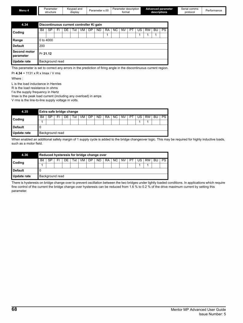
Menu 4 Parameter structure
Keypad and display Parameter x.00 Parameter description
formatAdvanced parameter
descriptionsSerial comms
protocol Performance
This parameter is set to correct any errors in the prediction of firing angle in the discontinuous current region.Pr 4.34 = 1131 x R x Imax / V rmsWhere :L is the load inductance in HenriesR is the load resistance in ohmsf is the supply frequency in HertzImax is the peak load current (including any overload) in ampsV rms is the line-to-line supply voltage in volts.
When enabled an additional safety margin of 1 supply cycle is added to the bridge changeover logic. This may be required for highly inductive loads, such as a motor field.
There is hysteresis on bridge change over to prevent oscillation between the two bridges under lightly loaded conditions. In applications which require fine control of the current the bridge change over hysteresis can be reduced from 1.6 % to 0.2 % of the drive maximum current by setting this parameter.
4.34 Discontinuous current controller Ki gain
CodingBit SP FI DE Txt VM DP ND RA NC NV PT US RW BU PS
1 1 1 1Range 0 to 4000
Default 200
Second motor parameter Pr 21.12
Update rate Background read
4.35 Extra safe bridge change
CodingBit SP FI DE Txt VM DP ND RA NC NV PT US RW BU PS1 1 1
Default 0
Update rate Background read
4.36 Reduced hysteresis for bridge change over
CodingBit SP FI DE Txt VM DP ND RA NC NV PT US RW BU PS1 1 1
Default 0
Update rate Background read
68 Mentor MP Advanced User Guide Issue Number: 5

Parameter Keypad and Parameter x.00 Parameter Advanced parameter descriptions
Serial comms Performance Menu 5
structure display description format protocolMentor MP Advanced User Guide 69Issue Number: 5

Menu 5Parameter Keypad and Parameter x.00 Parameter Advanced parameter
descriptionsSerial comms Performance
structure display description format protocol5.6 Menu 5: Motor and field controlFigure 5-5 Menu 5 field control logic diagram
5.59
Back emf set-point
Armaturevoltage
5.52IR
drop
5.61 Armatureresistance
4.02Filteredcurrentmagnitude
5.53 Backemf
5.59Back emfset point
15.08
Basespeed
Voltage errorto % error
conversion
3.02Speed
feedback
5.68
5.69Minimum flux/ Voltage limit
Maximum flux/ Voltage limit
0.XX
0.XX
Key
Read-write (RW) parameter
Read-only (RO) parameter
Inputterminals
Outputterminals
Compensationfactor
6.55Contactorenable
DCcontactor
5.14
A1 A2
MA1 MA2
A1 A2
MA1 MA2
5.16
Armaturevoltage select
5.08 Basespeed
5.09Armature
rated voltage5.04
Estimatedspeed
( 5.07 X 5.61 )Irated Ra
100%
5.64
Field weakeningenable
5.62P gain
5.63I gain
Fieldweakening
voltageloop
100%
5.77
Enablefield control
100%
5.06Machinearmaturevoltage
5.88
X
5.02
5.87
Armature IRcompensation
Field IRcompensation
70 Mentor MP Advanced User Guide Issue Number: 5

Parameter Keypad and Parameter x.00 Parameter Advanced parameter descriptions
Serial comms Performance Menu 5
structure display description format protocol5.73Ratedfield
voltage
Voltage to firing angle conversion
5.76
Fieldcontroller
supply
5.58
5.73
5.58
Field firingangle
+
_
5.71P gain
5.72I gain
Flux loop
5.54 Fluxfeedback
5.56 Field currentfeedback
Rated fieldcompensation factor
5.29 Motor saturationbreakpoint 1
5.30 Motor saturationbreakpoint 2
5.74
Flux calculator
5.81 Field thermaltime constant
5.82 Field overloadaccumulator
Field overload calculation
100
Fluxfeedback5.54
Percentagevoltagedemand
5.57
5.67
Fieldeconomy
level
Menu 6
-1
5.75
Field voltage mode select
5.65
Enable fieldeconomy timeout
5.80Field economy
level select
5.55
Flux / Voltagedemand
5.79
Fieldeconomy
active
OR
&Sequencer
run
5.66Field
economy timeouttime
Power-up
Drive reset
10.02
Driveactive
Field ratedcurrent5.70
5.585.60
Field outputvoltage
Fieldvoltagemode
5.78
5.89
5.48
External fluxfeedback
External fluxfeedback select
Mentor MP Advanced User Guide 71Issue Number: 5
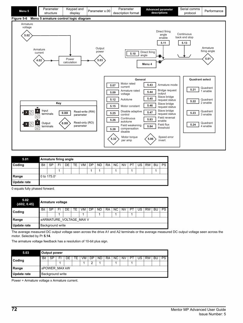
Menu 5Parameter Keypad and Parameter x.00 Parameter Advanced parameter
descriptionsSerial comms Performance
structure display description format protocolFigure 5-6 Menu 5 armature control logic diagram
0 equals fully phased forward.
The average measured DC output voltage seen across the drive A1 and A2 terminals or the average measured DC output voltage seen across the motor. Selected by Pr 5.14.The armature voltage feedback has a resolution of 10-bit plus sign.
Power = Armature voltage x Armature current.
5.01 Armature firing angle
Coding Bit SP FI DE TE VM DP ND RA NC NV PT US RW BU PS
1 1 1 1 1 1
Range 0 to 175.0°
Update rate
5.02{di02, 0.45} Armature voltage
CodingBit SP FI DE TE VM DP ND RA NC NV PT US RW BU PS
1 1 1 1 1Range ±ARMATURE_VOLTAGE_MAX V
Update rate Background write
5.03 Output power
CodingBit SP FI DE TE VM DP ND RA NC NV PT US RW BU PS
1 1 2 1 1 1Range ±POWER_MAX kW
Update rate Background write
5.03
Outputpower
5.02
Armaturevoltage
5.13
Continuousback end stop
5.01
Armaturefiring angle
5.11
Direct firingangle enable
Menu 4
5.10 Direct firingangle
Powercalculation
4.02
Armaturecurrent
5.15 Motor constant
5.25 Disable adaptivecontrol
5.26 Continuousautotune
5.32 Motor torqueper amp
General
5.07 Motor ratedcurrent
5.09 Armature ratedvoltage
5.12 Autotune 5.45 Slave bridgerequest status
5.43 Armature mode
5.44 Bridge requestoutput
5.46 Slave bridgerequest status
5.47 Slave bridgerequest status
Quadrant select
5.21 Quadrant1 enable
5.22 Quadrant2 enable
5.23 Quadrant3 enable
5.24 Quadrant4 enable
0.XX
0.XX
Key
Read-write (RW) parameter
Read-only (RO) parameter
Inputterminals
Outputterminals
5.28Field weakeningcompensationdisable
5.83 Field reversalenable
5.84 Field fluxthreshold
5.86 Speed errorinvert
72 Mentor MP Advanced User Guide Issue Number: 5

Parameter Keypad and Parameter x.00 Parameter Advanced parameter descriptions
Serial comms Performance Menu 5
structure display description format protocolThe software uses the following model to estimate the speed of the motor. If both the internal and external field controllers are disabled, for example when a separately supplied field is used, then the flux feedback is assumed to be 100 %.
Where:Pr 5.04 = estimated speedPr 5.53 = back emfPr 5.08 = base speedPr 5.09 = rated voltagePr 5.07 = motor rated currentPr 5.61 = armature resistancePr 5.54 = flux feedback
The voltage measured at the L1, L2 and L3 terminals.
The average measured DC output voltage seen across the motor, as read from the Machine feedback terminals (MA1 and MA2).
The rated current should be set at the motor nameplate value for rated current. The value of this parameter is used in the following:Current limitsMotor thermal protection
5.04 Estimated speed
CodingBit SP FI DE TE VM DP ND RA NC NV PT US RW BU PS
1 1 1 1 1 1Range -SPEED_MAX to SPEED_MAX rpm
Update rate Background write
5.05 Line voltage
CodingBit SP FI DE TE VM DP ND RA NC NV PT US RW BU PS
1 1 1 1 1Range 0 to 1000 V rms AC
Update rate Background write
5.06 Machine armature voltage
CodingBit SP FI DE TE VM DP ND RA NC NV PT US RW BU PS
1 1 1 1 1Range ±ARMATURE_VOLTAGE_MAX V
Update rate Background write
5.07{SE07, 0.28} Motor rated current
CodingBit SP FI DE TE VM DP ND RA NC NV PT US RW BU PS
1 1 1 1 1 1Range 0 to RATED_CURRENT_MAX A
Default RATED_CURRENT_MAX
Second motor parameter Pr 21.07
Update rate Background read
Pr 5.04 Pr 5.53 100 Pr 5.08××Pr 5.09 Pr 5.07 Pr 5.61×( )–[ ] Pr 5.54×
-----------------------------------------------------------------------------------------------------------=
Mentor MP Advanced User Guide 73Issue Number: 5

Menu 5Parameter Keypad and Parameter x.00 Parameter Advanced parameter
descriptionsSerial comms Performance
structure display description format protocolThe rated speed defines the base speed of the motor. It is also used for:1. The calculation of 'estimated speed'.2. Used by the rotating autotune function to determine the speed levels for measuring the field saturation breakpoints.3. Used to determine the speed used in the auto tuning inertia test (see Pr 5.12 {SE13, 0.34}).
This parameter is set to 165.0° at power-up.
A value of 165° corresponds to the fully phased back condition and therefore zero output voltage.
When enabled, the firing angle Pr 5.01 is controlled by Pr 5.10. This mode is valuable for system diagnosis, particularly where instability is present, since it allows the drive to operate without the influence of either the speed loop or the current loop, thereby eliminating their effect upon the system.
5.08{SE08, 0.29} Base speed
CodingBit SP FI DE TE VM DP ND RA NC NV PT US RW BU PS
1 1 1 1Range 0.0 to 10,000.0 rpm
Default 1000
Second motor parameter Pr 21.06
Update rate Background read
5.09{SE06, 0.27} Armature rated voltage
CodingBit SP FI DE TE VM DP ND RA NC NV PT US RW BU PS
1 1 1 1 1Range 0 to ARMATURE_VOLTAGE_MAX Vdc
DefaultFor 480 V Drive: Eur: 440, USA 500For 575 V Drive: Eur: 630, USA 630For 690 V Drive: Eur: 760, USA 760
Second motor parameter Pr 21.09
Update rate Background read
5.10 Direct firing angle
CodingBit SP FI DE TE VM DP ND RA NC NV PT US RW BU PS
1 1 1Range 0 to 165.0°
Default 165.0
Update rate 6 times mains frequency
A value of 0 in the firing angle Pr 5.10 corresponds to fully phased forward and therefore maximum output voltage.
5.11 Direct firing angle enable
CodingBit SP FI DE TE VM DP ND RA NC NV PT US RW BU PS1 1 1
Default 0
Update rate Background read
This parameter must be used with caution. When the firing angle is controlled directly by Pr 5.10 there is no protection against excessive acceleration, output voltage or current other than the instantaneous over current trip. Also take care to reset Pr 5.11 to 0 after the completion of tests.
WARNING
WARNING
74 Mentor MP Advanced User Guide Issue Number: 5

Parameter Keypad and Parameter x.00 Parameter Advanced parameter descriptions
Serial comms Performance Menu 5
structure display description format protocolRotating Autotune (Pr 5.12 = 2, 3 or 4) is only available when tacho or encoder feedback are selected.If this parameter is set to a non-zero value, the drive is enabled and a run command is applied in either direction the drive performs an autotune test. All tests that rotate the motor are carried out in the forward direction if Pr 1.12 {di12, 0.47} = 0 or the reverse direction if Pr 1.12 {di12, 0.47} = 1. For example, if the test is initiated by applying run reverse (Pr 6.32 = 1) the test is performed in the reverse direction. The test will not start unless the drive is disabled before the test is initiated by applying the enable or run, i.e. it will not start if the drive is in the stop state. It is not possible to go into the stop state if Pr 5.12 {SE13, 0.34} has a non-zero value.When the test is completed successfully the drive is disabled and will enter the inhibit state. The motor can only be restarted if the enable is removed either from the enable input, or Pr 6.15 is set to zero or from the control word (Pr 6.42) if it is active.
Static autotune for current loop gainsWhen this operation is performed, the drive will estimate the following, with respect to the selected motor map, and store the values:
Motor constant (Pr 5.15)Continuous proportional gain (Pr 4.13)Continuous integral gain (Pr 4.14)Discontinuous integral gain (Pr 4.34)Back EMF set point (Pr 5.59)Armature resistance (Pr 5.61)Flux loop P gain (Pr 5.71)Flux loop I gain (Pr 5.72)
Spinning autotune for rated field compensation factor and motor saturation break pointsWhen this operation is performed, the drive will estimate the following, with respect to the selected motor map, and store the values:
Motor saturation break points (Pr 5.29, Pr 5.30), and Rated field compensation factor (Pr 5.74) by spinning the motor at 25 % of it’s Base speed (Pr 5.08 {SE08, 0.29})
Spinning autotune for inertia measurement• The drive attempts to accelerate the motor in the forward direction up to 3 /4 x rated load rpm and then back to standstill. Several attempts may
be made, starting with rated torque/16, and then increasing the torque progressively to x 1/8, x 1/4, x 1/2 and x 1 rated torque if the motor cannot be accelerated to the required speed. 5s acceleration time is allowed during the first four attempts and 60 s on the final attempt. If the required speed is not achieved on the final attempt the test is aborted and a tuNE1 trip is initiated. If the test is successful the acceleration and deceleration times are used to calculate the motor and load inertia which is written to Pr 3.18.
• Pr 3.18 is saved to EEPROM. The calculated value of inertia is dependant on the value of the motor torque per amp (Pr 5.32). If the inertia is used for automatic speed loop gain setup the calculated gains will not be affected because Kt is also used in these calculations and any inaccuracy cancels out.The test algorithm attempts to remove the effect of any load on the motor other than the torque required to accelerate and decelerate the motor, i.e. friction and windage losses, static torque load etc. Provided the average torque during acceleration and the average torque during deceleration are the same the effect of the additional torque is removed and the inertia value is calculated correctly.Spinning autotune for motor saturation break pointsWhen this operation is performed the drive will perform an estimation of Motor saturation break points (Pr 5.29, Pr 5.30) by spinning the motor at 25 % of its Base speed (Pr 5.08) with respect to the selected motor map and store the values.
5.12{SE13, 0.34} Autotune
CodingBit SP FI DE TE VM DP ND RA NC NV PT US RW BU PS
1 1 1Range 0 to 4
Default 0
Update rate Background read
Value Autotune function
0 None1 Static autotune for current loop gains
2 Spinning autotune for rated field compensation factor and motor satura-tion break points
3 Spinning autotune for inertia measurement
4 Spinning autotune for motor saturation break points
NOTE
Mentor MP Advanced User Guide 75Issue Number: 5
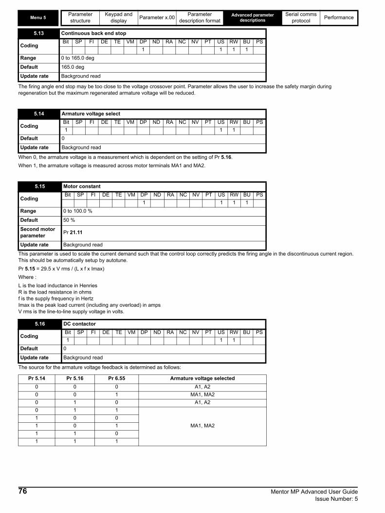
Menu 5Parameter Keypad and Parameter x.00 Parameter Advanced parameter
descriptionsSerial comms Performance
structure display description format protocolThe firing angle end stop may be too close to the voltage crossover point. Parameter allows the user to increase the safety margin during regeneration but the maximum regenerated armature voltage will be reduced.
When 0, the armature voltage is a measurement which is dependent on the setting of Pr 5.16.When 1, the armature voltage is measured across motor terminals MA1 and MA2.
This parameter is used to scale the current demand such that the control loop correctly predicts the firing angle in the discontinuous current region.This should be automatically setup by autotune.Pr 5.15 = 29.5 x V rms / (L x f x Imax)Where :L is the load inductance in HenriesR is the load resistance in ohmsf is the supply frequency in HertzImax is the peak load current (including any overload) in ampsV rms is the line-to-line supply voltage in volts.
The source for the armature voltage feedback is determined as follows:
5.13 Continuous back end stop
CodingBit SP FI DE TE VM DP ND RA NC NV PT US RW BU PS
1 1 1 1Range 0 to 165.0 deg
Default 165.0 deg
Update rate Background read
5.14 Armature voltage select
CodingBit SP FI DE TE VM DP ND RA NC NV PT US RW BU PS1 1 1
Default 0
Update rate Background read
5.15 Motor constant
CodingBit SP FI DE TE VM DP ND RA NC NV PT US RW BU PS
1 1 1 1Range 0 to 100.0 %
Default 50 %
Second motor parameter Pr 21.11
Update rate Background read
5.16 DC contactor
CodingBit SP FI DE TE VM DP ND RA NC NV PT US RW BU PS1 1 1
Default 0
Update rate Background read
Pr 5.14 Pr 5.16 Pr 6.55 Armature voltage selected0 0 0 A1, A20 0 1 MA1, MA20 1 0 A1, A20 1 1
MA1, MA21 0 01 0 11 1 01 1 1
76 Mentor MP Advanced User Guide Issue Number: 5

Parameter Keypad and Parameter x.00 Parameter Advanced parameter descriptions
Serial comms Performance Menu 5
structure display description format protocolQuadrant 1 operation is defined as motoring in the forward direction, speed and torque both having positive values.
Operation in quadrant 2 is defined as regenerating in the reverse direction, where speed will be negative and torque positive.
Quadrant 3 operation is defined as motoring in the reverse direction, speed and torque both having negative values.
Operation in quadrant 4 is defined as regenerating in the forward direction, where speed will be positive and torque negative.
When adaptive control is enabled, which is the default status, the current loop employs two different algorithms, one of which applies high gain in the discontinuous current region. This is unsuitable for some applications, such as non-motor loads, for which adaptive control should be disabled.
When set, enables the continuous auto tune which continuously monitors the motor ripple and adjusts Motor constant (Pr 5.15), Continuous proportional gain (Pr 4.13) and Discontinuous integral gain (Pr 4.34) for optimum performance. The commissioning / start-up autotune should still be carried out because Continuous integral gain (Pr 4.14) is not set by the continuous autotune.Calculation of the gains is suspended when the voltage field weakening voltage loop becomes active so that the gains are not increased when the field is weakened.
5.21 Quadrant 1 Enable
CodingBit SP FI DE TE VM DP ND RA NC NV PT US RW BU PS
1 1 1Default 1
Update rate Background read
5.22 Quadrant 2 Enable
CodingBit SP FI DE TE VM DP ND RA NC NV PT US RW BU PS
1 1 1Default 1
Update rate Background read
5.23 Quadrant 3 Enable
CodingBit SP FI DE TE VM DP ND RA NC NV PT US RW BU PS
1 1 1 1 1Range 0 to QUADRANT_MAX
Default 1
Update rate Background read
5.24 Quadrant 4 Enable
Coding Bit SP FI DE TE VM DP ND RA NC NV PT US RW BU PS
1 1 1 1 1
Range 0 to QUADRANT_MAX
Default 1
Update rate Background read
5.25 Disable adaptive control
CodingBit SP FI DE TE VM DP ND RA NC NV PT US RW BU PS1 1 1
Default 0
Update rate Background read
5.26 Continuous autotune
CodingBit SP FI DE TE VM DP ND RA NC NV PT US RW BU PS1 1 1
Default 0
Update rate Background read
Mentor MP Advanced User Guide 77Issue Number: 5

Menu 5Parameter Keypad and Parameter x.00 Parameter Advanced parameter
descriptionsSerial comms Performance
structure display description format protocolWhen the flux in the motor is reduced below its rated level the level of torque producing current required for a given amount of shaft torque is higher than the rated level. In speed control the compensation prevents gain reduction at higher speeds. In torque control the compensation maintains the torque at the correct level for a given torque demand. In some applications using speed control it may be desirable to have a reduction of gain as the motor flux is reduced to maintain stability. If this is required, Pr 5.28 should be set to one.
See Pr 5.30 for description.
When the motor is operated in the field weakening voltage region, the relationship between field current and the level of flux can be non-linear.The drive can include the effects of saturation by representing the flux producing current to flux characteristic as a series of three lines as shown below:
If Pr 5.29 and Pr 5.30 have their default values of 50 and 75, the characteristic becomes one line and there will be a linear relationship between the drive estimate of flux and the flux producing current. If Pr 5.29 and Pr 5.30 are increased above 50 and 75 the drive estimate of flux can include the effect of non-linearity. It is unlikely that information will be available to set up these parameters, and so the values are determined during the rotating autotune test.
5.28 Field weakening compensation disable
CodingBit SP FI DE TE VM DP ND RA NC NV PT US RW BU PS1 1 1
Default Eur 0, USA 1
Update rate Background read
5.29 Motor saturation breakpoint 1
CodingBit SP FI DE TE VM DP ND RA NC NV PT US RW BU PS
1 1 1Range 0 to 100 % of rated flux
Default 50
Second motor parameter Pr 21.25
Update rate Background read
5.30 Motor saturation breakpoint 2
CodingBit SP FI DE TE VM DP ND RA NC NV PT US RW BU PS
1 1 1Range 0 to 100 % of rated flux
Default 75
Second motor parameter Pr 21.26
Update rate Background read
Fieldcurrent (%)
flux (%)
50 75 100
100%Pr 5.30
Pr 5.29
Linear characteristic(i.e. no saturation)
78 Mentor MP Advanced User Guide Issue Number: 5

Parameter Keypad and Parameter x.00 Parameter Advanced parameter descriptions
Serial comms Performance Menu 5
structure display description format protocolThis parameter shows the motor torque per amp used to calculate the speed controller gains when the automatic setup methods are active (i.e. Pr 3.17 = 1 or 2).The drive calculates the motor torque per amp using the motor parameters as shown.
Parameter that contains the nine armature modes. This function is only available from firmware version V01.06.00 user and V01.09 power.
5.32 Motor torque per amp (Kt)
Coding Bit SP FI DE TE VM DP ND RA NC NV PT US RW BU PS
3 1 1
Range 0.00 to 50.000 N m A-1
Update rate Background (1s) write
Kt = VArated - IArated x Ra Rated speed (rad/s)
5.43 Armature mode
Coding Bit SP FI DE TE VM DP ND RA NC NV PT US RW BU PS
1 1 1 1
Range 0 to 8
Default 0
Update rate Read on reset. Only implemented when drive is inactive.
Number Text Description0 Std Normal (1Q or 4Q)
1 P.1br Parallel - 1 bridge. Current loop gains reduced by half. No bridge lock-out.
2 P.2br12P Parallel - 2 bridge - 12 pulse 3 P.2br24P Parallel - 2 bridge - 24 pulse4 FrEE Not used5 Not used6 Not used7 P.cont Parallel 6P master8 P.SLAuE Parallel 6P slave
Mentor MP Advanced User Guide 79Issue Number: 5

Menu 5Parameter Keypad and Parameter x.00 Parameter Advanced parameter
descriptionsSerial comms Performance
structure display description format protocolFigure 5-7 Parallel 12 Pulse
*For fuse information please refer to section 4.6 in the Mentor MP User Guide.To configure the drives for use in a parallel 12 pulse speed control system, they should be programmed so that the master drive is set up in speed control mode (Pr 4.11 = 0), and the slave drive is programmed in torque control mode (Pr 4.11 = 1). The final current demand (Pr 4.04) on the master drive has to be fed in to the slave drive torque reference (Pr 4.08). This current demand signal can be transferred between the drives using either an analog input / output, communication module or by using CT Sync. Additional bridge interlocking signals are shared between the two modules, when a four quadrant system is required to ensure that the same bridge on both drives is firing and also that the current has reached zero on both drives before current reversal is attempted.
Only terminals relevant to 12 pulse operation have been shown.
Master drive Slave drive
Motor fieldwinding
Motorarmature
Interbridgereactor
E1 E3 F+ F- E1 E3 F+ F-
Three phase transformer
Fuses*
NOTE
80 Mentor MP Advanced User Guide Issue Number: 5
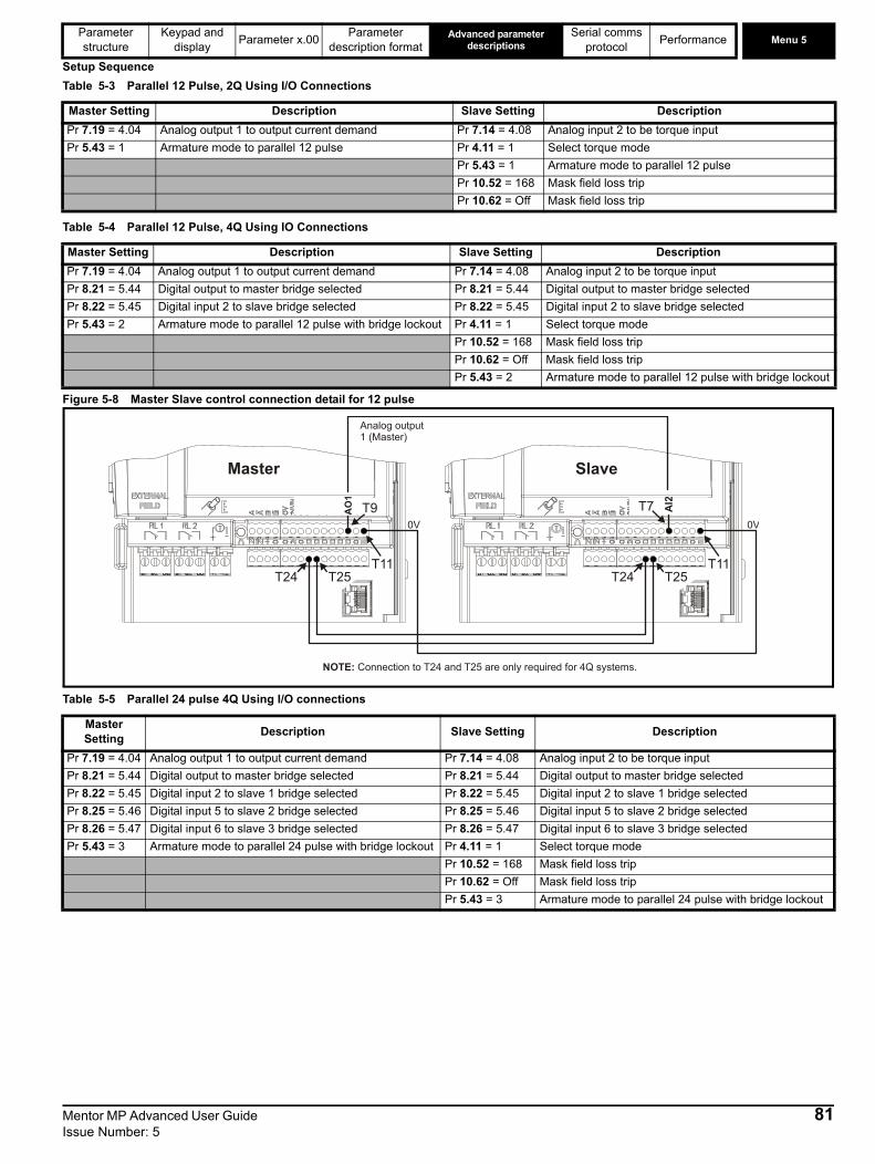
Parameter Keypad and Parameter x.00 Parameter Advanced parameter descriptions
Serial comms Performance Menu 5
structure display description format protocolSetup SequenceTable 5-3 Parallel 12 Pulse, 2Q Using I/O Connections
Table 5-4 Parallel 12 Pulse, 4Q Using IO Connections
Figure 5-8 Master Slave control connection detail for 12 pulse
Table 5-5 Parallel 24 pulse 4Q Using I/O connections
Master Setting Description Slave Setting DescriptionPr 7.19 = 4.04 Analog output 1 to output current demand Pr 7.14 = 4.08 Analog input 2 to be torque input Pr 5.43 = 1 Armature mode to parallel 12 pulse Pr 4.11 = 1 Select torque mode
Pr 5.43 = 1 Armature mode to parallel 12 pulsePr 10.52 = 168 Mask field loss tripPr 10.62 = Off Mask field loss trip
Master Setting Description Slave Setting DescriptionPr 7.19 = 4.04 Analog output 1 to output current demand Pr 7.14 = 4.08 Analog input 2 to be torque input Pr 8.21 = 5.44 Digital output to master bridge selected Pr 8.21 = 5.44 Digital output to master bridge selectedPr 8.22 = 5.45 Digital input 2 to slave bridge selected Pr 8.22 = 5.45 Digital input 2 to slave bridge selectedPr 5.43 = 2 Armature mode to parallel 12 pulse with bridge lockout Pr 4.11 = 1 Select torque mode
Pr 10.52 = 168 Mask field loss tripPr 10.62 = Off Mask field loss tripPr 5.43 = 2 Armature mode to parallel 12 pulse with bridge lockout
Master Setting Description Slave Setting Description
Pr 7.19 = 4.04 Analog output 1 to output current demand Pr 7.14 = 4.08 Analog input 2 to be torque input Pr 8.21 = 5.44 Digital output to master bridge selected Pr 8.21 = 5.44 Digital output to master bridge selectedPr 8.22 = 5.45 Digital input 2 to slave 1 bridge selected Pr 8.22 = 5.45 Digital input 2 to slave 1 bridge selectedPr 8.25 = 5.46 Digital input 5 to slave 2 bridge selected Pr 8.25 = 5.46 Digital input 5 to slave 2 bridge selectedPr 8.26 = 5.47 Digital input 6 to slave 3 bridge selected Pr 8.26 = 5.47 Digital input 6 to slave 3 bridge selectedPr 5.43 = 3 Armature mode to parallel 24 pulse with bridge lockout Pr 4.11 = 1 Select torque mode
Pr 10.52 = 168 Mask field loss tripPr 10.62 = Off Mask field loss tripPr 5.43 = 3 Armature mode to parallel 24 pulse with bridge lockout
Analog output1 (Master)
AI2
AO
2
Master Slave
T24 T25 T24 T25
NOTE: Connection to T24 and T25 are only required for 4Q systems.
T9 AI2T7A
O1
0V
T11
0V
T11
Mentor MP Advanced User Guide 81Issue Number: 5

Menu 5Parameter Keypad and Parameter x.00 Parameter Advanced parameter
descriptionsSerial comms Performance
structure display description format protocolFigure 5-9 Master / Slave control connections for 24 pulse
Auto Tune procedure1. Set Pr 5.25 = 1 on Slave drives.2. Set Pr 5.12 = 1 on Master drive.3. Enable the system. When auto tune has finished, transfer the values of Pr 5.15, Pr 4.13, Pr 4.14 and Pr 4.34 from the master to each of the slave
drives. 4. Re start auto tune by setting Pr 5.12 to 1 on the master drive only. 5. Enable the system. 6. When auto tune has finished, transfer the values of Pr 5.15, Pr 4.13, Pr 4.14 and Pr 4.34 from the master to the slave.7. Set Pr 5.25 = 0 on Slave drives Auto tune is now complete.Figure 5-10 6 Pulse parallel operation 2 drives
*For fuse information please refer to section 4.6 in the Mentor MP User Guide.
1 119 1 117 1 117
21 24 25 28 29
1 117
21 3124 25 28 2921 3124 25 28 2921 3124 25 28 29
AI2
AO
2
Master drive
AI2
AO
2
Slave drive
AI2
AO
2
Slave drive
AI2
AO
2
Slave drive
Master drive Slave drive
Choke / inductor
Fuses*
RJ 45
L1L2L3
A2A1
RJ 45
82 Mentor MP Advanced User Guide Issue Number: 5

Parameter Keypad and Parameter x.00 Parameter Advanced parameter descriptions
Serial comms Performance Menu 5
structure display description format protocolFigure 5-11 6 Pulse parallel operation 4 drives
*For fuse information please refer to section 4.6 in the Mentor MP User Guide.Master Drive in 6 pulse parallel systemSlave HealthyThe master drive must know the state of health of the slave (or slaves), in a 6 pulse parallel system. This can be achieved using digital IO or a communication module. Where there are multiple slave drives, the master can be setup to use 1 bit to check the health of the slave or multiple bits.Figure 5-12 Single Slave
Set Pr 8.22 to Pr 5.45.
Slave drive
Choke / inductor
Fuses*
RJ 45 parallel comms
Choke / inductor
Fuses*
Choke / inductor
Fuses*
Master drive Slave drive Slave drive
Choke / inductor
Fuses*
RJ 45
L1L2L3
A1A2
Master Slave
51 52 53
NC
51 52 53
NC2225
RJ 45 parallel commsRJ 45 parallel comms
Mentor MP Advanced User Guide 83Issue Number: 5
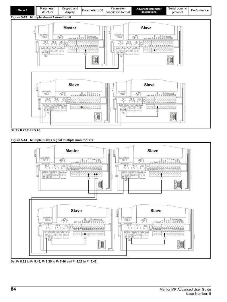
Menu 5Parameter Keypad and Parameter x.00 Parameter Advanced parameter
descriptionsSerial comms Performance
structure display description format protocolFigure 5-13 Multiple slaves 1 monitor bit
Set Pr 8.22 to Pr 5.45.
Figure 5-14 Multiple Slaves signal multiple monitor Bits
Set Pr 8.22 to Pr 5.45, Pr 8.25 to Pr 5.46 and Pr 8.26 to Pr 5.47.
Slave
51 52 53
NC
Master
51 52 53
NC25
Slave
51 52 53
NC
Slave
51 52 53
NC22
Slave
51 52 53
NC
Master
51 52 5325
Slave
51 52 53
NC
Slave
51 52 53
NC22
22
22
2829
84 Mentor MP Advanced User Guide Issue Number: 5
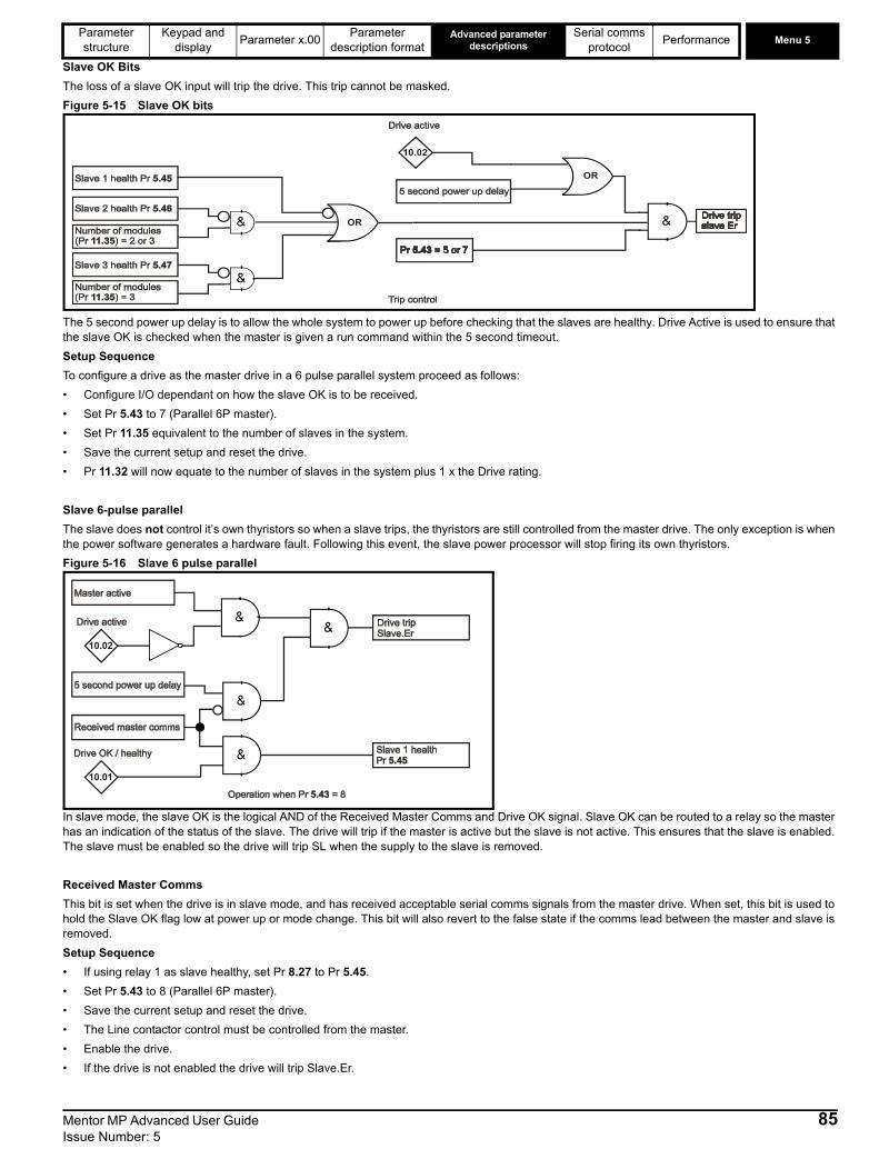
Parameter Keypad and Parameter x.00 Parameter Advanced parameter descriptions
Serial comms Performance Menu 5
structure display description format protocolSlave OK BitsThe loss of a slave OK input will trip the drive. This trip cannot be masked.Figure 5-15 Slave OK bits
The 5 second power up delay is to allow the whole system to power up before checking that the slaves are healthy. Drive Active is used to ensure that the slave OK is checked when the master is given a run command within the 5 second timeout.Setup SequenceTo configure a drive as the master drive in a 6 pulse parallel system proceed as follows:• Configure I/O dependant on how the slave OK is to be received.• Set Pr 5.43 to 7 (Parallel 6P master).• Set Pr 11.35 equivalent to the number of slaves in the system. • Save the current setup and reset the drive. • Pr 11.32 will now equate to the number of slaves in the system plus 1 x the Drive rating.
Slave 6-pulse parallelThe slave does not control it’s own thyristors so when a slave trips, the thyristors are still controlled from the master drive. The only exception is when the power software generates a hardware fault. Following this event, the slave power processor will stop firing its own thyristors.Figure 5-16 Slave 6 pulse parallel
In slave mode, the slave OK is the logical AND of the Received Master Comms and Drive OK signal. Slave OK can be routed to a relay so the master has an indication of the status of the slave. The drive will trip if the master is active but the slave is not active. This ensures that the slave is enabled. The slave must be enabled so the drive will trip SL when the supply to the slave is removed.
Received Master CommsThis bit is set when the drive is in slave mode, and has received acceptable serial comms signals from the master drive. When set, this bit is used to hold the Slave OK flag low at power up or mode change. This bit will also revert to the false state if the comms lead between the master and slave is removed.Setup Sequence• If using relay 1 as slave healthy, set Pr 8.27 to Pr 5.45.• Set Pr 5.43 to 8 (Parallel 6P master). • Save the current setup and reset the drive. • The Line contactor control must be controlled from the master. • Enable the drive. • If the drive is not enabled the drive will trip Slave.Er.
OR
OR
10.02
10.02
10.01
Mentor MP Advanced User Guide 85Issue Number: 5

Menu 5Parameter Keypad and Parameter x.00 Parameter Advanced parameter
descriptionsSerial comms Performance
structure display description format protocolIndicates which bridge in a 12 or 24 parallel system has been requested. This has to be sent via digital I/O or field bus.
The bridge status of the other drives in a 12 or 24 parallel system have to be sent, via digital I/O or field bus, to these parameters. When digital I/O is setup to use Pr 5.45 to Pr 5.47 the software reads and writes to the I/O at 1 ms.
When this parameter is set, the flux feedback is taken from Pr 5.89. This has been made available where the field flux is provided by an independent external controller (not FXMP25).
The value resulting from the application of Pr 5.61 to the filtered current.
The calculated motor back emf based on armature voltage minus the IR drop (Pr 5.52).
Flux feedback after the current to flux converter, see motor saturation breakpoints (Pr 5.29 and Pr 5.30).
05.44 Bridge request output
Coding Bit SP FI DE TE VM DP ND RA NC NV PT US RW BU PS
1 1
Range 0 to 1
Update rate 1 ms write
05.45 05.46 05.47 Slave bridge request status
Coding Bit SP FI DE TE VM DP ND RA NC NV PT US RW BU PS
1
Range 0 to 1
Update rate 1 ms read
5.48 External flux feedback select
CodingBit SP FI DE TE VM DP ND RA NC NV PT US RW BU PS1 1 1
Default 0
Second motor parameter Pr 21.38
Update rate 1 ms read
5.52 IR drop
CodingBit SP FI DE TE VM DP ND RA NC NV PT US RW BU PS
1 1 1 1 1Range +/- ARMATURE_VOLTAGE_MAX Vdc
Update rate Background write
5.53 Back emf
CodingBit SP FI DE TE VM DP ND RA NC NV PT US RW BU PS
1 1 1 1 1Range +/- ARMATURE_VOLTAGE_MAX Vdc
Update rate Background write
5.54 Flux feedback
CodingBit SP FI DE TE VM DP ND RA NC NV PT US RW BU PS
1 1 1 1 1Range ±150.0 %
Update rate Background write
86 Mentor MP Advanced User Guide Issue Number: 5

Parameter Keypad and Parameter x.00 Parameter Advanced parameter descriptions
Serial comms Performance Menu 5
structure display description format protocolWhen in current mode the flux demand from the field weakening voltage loop, subject to the limits of Pr 5.68 and Pr 5.69. When in voltage mode [Pr 5.75=On (1)] the voltage demand is subject to the limits of Pr 5.68 and Pr 5.69.
Indicates the field current feedback in 0.01 amps.
The range is 0 to 150 % in half control mode for the internal field controller.
0° equals fully phased forward.
The programmable value of the armature back emf, in volts, at which the field begins to weaken. Defined as the voltage at which base speed is reached.
The calculated voltage being generated on the field output terminals.
5.55 Flux / Voltage demand
CodingBit SP FI DE TE VM DP ND RA NC NV PT US RW BU PS
1 1 1 1 1Range ±120.0 %
Update rate Mains period / 6 ms
5.56{di09, 0.44} Field current feedback
CodingBit SP FI DE TE VM DP ND RA NC NV PT US RW BU PS
1 2 1 1 1Range ±50.00A
Update rate Background write
5.57 Percentage voltage demand
CodingBit SP FI DE TE VM DP ND RA NC NV PT US RW BU PS
1 1 1 1 1Range ±150.0 %
Update rate Background write
5.58 Field Firing angle
CodingBit SP FI DE TE VM DP ND RA NC NV PT US RW BU PS
1 1 1 1 1 1Range 0 to 180 o
Update rate Background write
5.59 Back emf set point
CodingBit SP FI DE TE VM DP ND RA NC NV PT US RW BU PS
1 1 1 1Range 0 to ARMATURE_VOLTAGE_MAX Vdc
DefaultFor 480V Drive: Eur: 440, USA 500For 575V Drive: Eur: 630, USA 630For 690V Drive: Eur: 760, USA 760
Second motor parameter Pr 21.08
Update rate Background read
5.60 Field output voltage
CodingBit SP FI DE TE VM DP ND RA NC NV PT US RW BU PS
1 1 1 1Range 0 to 500 Vdc
Update rate Background write
Mentor MP Advanced User Guide 87Issue Number: 5

Menu 5Parameter Keypad and Parameter x.00 Parameter Advanced parameter
descriptionsSerial comms Performance
structure display description format protocolThis is used to calculate the armature IR voltage drop that is used as a correction to the measured armature voltage, to allow the back emf to be computed.
This is the proportional voltage loop gain used during field weakening. If this parameter is set too high then instability during field weakening can occur. When this is set too low the armature voltage may overshoot when base speed is reached. An increase in this gain increases the rate at which the field weakens.
This is the integral voltage loop gain used during field weakening. If this parameter is set too high then instability during field weakening can occur. When this is set too low the armature voltage may overshoot when base speed is reached. An increase in this gain increases the rate at which the field weakens.
When this parameter is 0 the field weakening voltage loop does not run and the estimated speed is based on the field flux being 100 %. When this parameter is 1 the field weakening voltage is enabled which allows the field to be weakened.
Permits the field current to be configured to the field economy level (Pr 5.67) automatically after the drive has been disabled for a period of time (Pr 5.66). This is used to prevent the motor windings from overheating if the drive is stopped and the motor ventilation is switched off. This can also be used to prevent condensation in the motor when it is not in use.
5.61 Armature Resistance
CodingBit SP FI DE TE VM DP ND RA NC NV PT US RW BU PS
4 1 1 1Range 0 to 6.0000 Ω
Default 0
Second motor parameter Pr 21.10
Update rate Background read
5.62 Field weakening voltage loop P gain
CodingBit SP FI DE TE VM DP ND RA NC NV PT US RW BU PS
2 1 1 1Range 0 to 300.00
Default 0.40
Second motor parameter Pr 21.33
Update rate Background read
5.63 Field weakening voltage loop I gain
CodingBit SP FI DE TE VM DP ND RA NC NV PT US RW BU PS
2 1 1 1Range 0 to 300.00
Default 5.00
Second motor parameter Pr 21.34
Update rate Background read
5.64 Field weakening enable
CodingBit SP FI DE TE VM DP ND RA NC NV PT US RW BU PS1 1 1
Range 0 to 1
Default 0
Update rate Background read
5.65 Enable field economy timeout
CodingBit SP FI DE TE VM DP ND RA NC NV PT US RW BU PS1 1 1
Range 0 to 1
Update rate Eur 0, USA 1
88 Mentor MP Advanced User Guide Issue Number: 5

Parameter Keypad and Parameter x.00 Parameter Advanced parameter descriptions
Serial comms Performance Menu 5
structure display description format protocolDefine the time in seconds, after the field goes into economy mode after1. The drive becomes inactive
or 2. At power up
or 3. After the drive has been reset. The time out is selected by Pr 5.65.
Sets the reduced field current level used when the field economy function is used.
Figure 5-17 Time diagram when economy timeout selected (Pr 5.65 = 1)
5.66 Field economy timeout time
CodingBit SP FI DE TE VM DP ND RA NC NV PT US RW BU PS
1 1 1Range 0 to 255s
Default 30 s
Update rate Background read
5.67 Field economy level
CodingBit SP FI DE TE VM DP ND RA NC NV PT US RW BU PS
1 1 1 1Range 0 to 120.0 %
Default 25 %
Update rate Background read
Power on
Field current
Sequencer run
Disable
Drive active
Speed
Stop command
Field economy Active
Reset
Reset action
100ms100ms
Pr 5.66
Pr 6.54
Pr 5.66 Pr 5.66 Pr 5.66
Pr 6.54
Mentor MP Advanced User Guide 89Issue Number: 5

Menu 5Parameter Keypad and Parameter x.00 Parameter Advanced parameter
descriptionsSerial comms Performance
structure display description format protocolWhen in current mode [Pr 5.75 = OFF (0)] this is the maximum flux limit of the field weakening voltage loop. The maximum value of this parameter depends upon the setting of the rated current Pr 5.70 {SE10, 0.31}.
MAX_FIELD_FLUX = 100 x 25 / Pr 5.70 {SE10, 0.31}. For values of Pr 5.70 {SE10, 0.31} less than 20.8A the MAX_FIELD_FLUX will be limited to 120 %.This parameter becomes the maximum voltage demand when field voltage mode is selected Pr 5.75 = On (1).
When in current mode [Pr 5.75 = OFF (0)] this is the minimum value of flux demand to prevent excessive field weakening and hence over speeding. This parameter becomes the minimum voltage demand when field voltage mode is selected Pr 5.75 = On (1).
If Flux feedback is selected from Pr 5.89 and the value falls below that of the value set in Pr 5.69, then no action can be taken by the drive as it does not control the Flux demand.
This parameter will be set to the field current of the motor and will define the 100 % point for the field controller.
Increasing this parameter will allow the loop to track the current demand more closely. Setting the value too high will result in instability.
5.68 Maximum flux / Voltage limit
CodingBit SP FI DE TE VM DP ND RA NC NV PT US RW BU PS
1 1 1 1 1Range 0 to MAX_FIELD_FLUX %
Default 100 %
Update rate Background read
5.69 Minimum flux / Voltage limit
CodingBit SP FI DE TE VM DP ND RA NC NV PT US RW BU PS
1 1 1 1Range 0 to 120.0 %
Default 50 %
Update rate Background read
5.70{SE10, 0.31} Rated field current
CodingBit SP FI DE TE VM DP ND RA NC NV PT US RW BU PS
1 2 1 1 1 1 1Range 0 to FIELD_CURRENT_SET_MAX
DefaultSize 1 - Eur: 2A, USA: 8ASize 2A&B - Eur: 3A, USA: 20ASize 2C&D - Eur: 5A, USA: 20A
Second motor parameter Pr 21.24
Update rate Background read
5.71 Flux loop P gain
CodingBit SP FI DE TE VM DP ND RA NC NV PT US RW BU PS
2 1 1 1Range 0 to 30.00
Default 3
Second motor parameter Pr 21.31
Update rate Background read
NOTE
90 Mentor MP Advanced User Guide Issue Number: 5
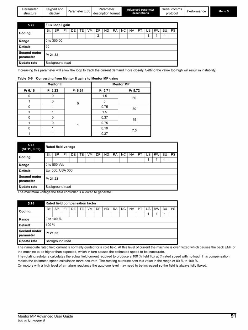
Parameter Keypad and Parameter x.00 Parameter Advanced parameter descriptions
Serial comms Performance Menu 5
structure display description format protocolIncreasing this parameter will allow the loop to track the current demand more closely. Setting the value too high will result in instability.
Table 5-6 Converting from Mentor II gains to Mentor MP gains
The maximum voltage the field controller is allowed to generate.
The nameplate rated field current is normally quoted for a cold field. At this level of current the machine is over fluxed which causes the back EMF of the machine to be higher than expected, which in turn causes the estimated speed to be inaccurate.The rotating autotune calculates the actual field current required to produce a 100 % field flux at ¼ rated speed with no load. This compensation makes the estimated speed calculation more accurate. The rotating autotune sets this value in the range of 80 % to 100 %. On motors with a high level of armature reactance the autotune level may need to be increased so the field is always fully fluxed.
5.72 Flux loop I gain
CodingBit SP FI DE TE VM DP ND RA NC NV PT US RW BU PS
2 1 1 1Range 0 to 300.00
Default 60
Second motor parameter Pr 21.32
Update rate Background read
Mentor II Mentor MP
Pr 6.16 Pr 6.23 Pr 6.24 Pr 5.71 Pr 5.720 0
0
1.5 601 0 30 1 0.75 301 1 1.50 0
1
0.37 151 0 0.750 1 0.19 7.51 1 0.37
5.73{SE11, 0.32} Rated field voltage
CodingBit SP FI DE TE VM DP ND RA NC NV PT US RW BU PS
1 1 1Range 0 to 500 Vdc
Default Eur 360, USA 300
Second motor parameter Pr 21.23
Update rate Background read
5.74 Rated field compensation factor
CodingBit SP FI DE TE VM DP ND RA NC NV PT US RW BU PS
1 1 1Range 0 to 100 %
Default 100 %
Second motor parameter Pr 21.35
Update rate Background read
Mentor MP Advanced User Guide 91Issue Number: 5

Menu 5Parameter Keypad and Parameter x.00 Parameter Advanced parameter
descriptionsSerial comms Performance
structure display description format protocolWhen set to 1 the field controller becomes a voltage controller which controls the voltage applied to the field winding.When set to 0 field controller operates as a current controller.
This parameter indicates the average rms voltage across the E1 E3 input terminals. Filtered by a 100 ms first order filter.
When this parameter is set to 0 the internal and external field controllers are disabled. Setting the parameter to 1 enables the internal or external field controller. If using a Permanent Magnet motor or external field regulators, it is necessary to mask the FdL trip. Refer to Pr 10.52 to Pr 10.61 (Trip masks).
When the parameter is set to internal (IntrnL) the internal field controller is used. Pr 5.54, Pr 5.56 {di09, 0.44}, Pr 5.57, Pr 5.58 and Pr 5.60 are con-trolled by the internal field controller. When the parameter is set to external half control (EtrnL) or external in full control (E FULL) the drive will use the external field controller. Pr 5.54, Pr 5.56 {di09, 0.44}, Pr 5.57, Pr 5.58 and Pr 5.60 will now be controlled by the external field controller. If no signal is received from the external field controller the drive will trip field loss.
When this bit is set the economy timeout feature is selected.
When set to 1 the field economy level is selected. When set to 0 field economy is controlled by the field economy timeout function.
5.75 Field voltage mode select
CodingBit SP FI DE TE VM DP ND RA NC NV PT US RW BU PS1 1 1
Range 0 to 1
Default Eur 0, USA 1
Update rate Background read
5.76 Field controller supply
CodingBit SP FI DE TE VM DP ND RA NC NV PT US RW BU PS
1 1 1 1 1Range 0 to 550 rms Vac
Update rate Background write
5.77{SE12, 0.33} Enable field control
CodingBit SP FI DE TE VM DP ND RA NC NV PT US RW BU PS1 1 1
Range 0 to 1Default 0
Update rate Mains period / 6 ms
5.78 Field mode
CodingBit SP FI DE TE VM DP ND RA NC NV PT US RW BU PS
1 1 1 1Range 0 to 2 (IntrnL (0), EtrnL (1) and E FULL (2))
Default 0
Update rate Background read
5.79 Field economy active
CodingBit SP FI DE TE VM DP ND RA NC NV PT US RW BU PS1 1
Range 0 to 1Default 0
Update rate Background read
5.80 Field economy level select
CodingBit SP FI DE TE VM DP ND RA NC NV PT US RW BU PS1 1 1
Range 0 to 1Default 0
Update rate Background read
92 Mentor MP Advanced User Guide Issue Number: 5

Parameter Keypad and Parameter x.00 Parameter Advanced parameter descriptions
Serial comms Performance Menu 5
structure display description format protocolThe motor is modelled thermally in a way that is equivalent to the electrical circuit shown below.
The temperature of the field as a percentage of maximum temperature, with a constant current magnitude of I and constant value of field rated current (set by Pr 5.70 {SE10, 0.31} or Pr 21.24) after time t is given by
Temp = [I2 / (1.20*Field rated current)2] (1 - e-t/τ) x 100 %
This assumes that the maximum allowed field temperature is produced by 1.20 x field rated current and that τ is the thermal filter of the point in the motor that reaches it maximum allowed temperature first. τ is defined by Pr 5.81. The estimated motor temperature is given by Pr 5.82 as a percent-age of maximum temperature. If the Pr 5.81 has a value between 0.0 and 1.0 the thermal filter is taken as 1.0. When the estimated temperature reaches 100 % the drive stops the motor and then trips on F.OVL.
The time for some action to be taken by the drive from cold with constant field current is given by:
Ttrip = -(Pr 5.81) x ln(1 - (1.20 x Pr 5.70 {SE10, 0.31} / Pr 5.56 {di09, 0.44})2)
Alternatively the thermal filter can be calculated from the trip time with a given current from
Pr 5.81 = -Ttrip / ln(1 - (1.20 / Overload)2)
For example, if the drive should trip after supplying 125 % overload for 60 seconds then
Pr 5.81 = -60 / ln(1 - (1.20 / 1.25)2) = 24
The thermal model temperature accumulator is reset to zero at power-up and accumulates the temperature of the field while the drive remains pow-ered-up. Each time Pr 11.45 is changed to select a new motor, or the rated current defined by Pr 5.70 {SE10, 0.31} or Pr 21.24 (depending on the motor selected) is altered, the accumulator is reset to zero.
See Pr 5.81.
With a 2Q drive, the motor can be driven in both the forward and reverse directions by changing the polarity of voltage applied to the field. This mode of operation can be achieved using a 2Q drive and an external field controller. The flux in the field cannot be reduced until the motor has stopped. The time taken for the motor direction to change, will depend on how quickly the field flux can be reversed. Figure 5-18 and Figure illustrate the sequence of events during a forward to reverse and reverse to forward change of direction.
5.81 Field thermal filter
CodingBit SP FI DE TE VM DP ND RA NC NV PT US RW BU PS
1 1 1 1Range 0.0 to 3000.0
Default 24.0
Second motor parameter
Pr 21.30
Update rate Background read
5.82 Field overload accumulator
CodingBit SP FI DE TE VM DP ND RA NC NV PT US RW BU PS
1 1 1 1 1Range 0 to 100.0 %
Update rate Background write
5.83 Field reversal enable
CodingBit SP FI DE TE VM DP ND RA NC NV PT US RW BU PS
1 1 1 1 1Range 0 to ONLY_2_QUADRANT
Default 0
Update rate Background read
I2 /(1.20 x Field Rated Current)2
τ = RC
R Temp
C
Mentor MP Advanced User Guide 93Issue Number: 5

Menu 5Parameter Keypad and Parameter x.00 Parameter Advanced parameter
descriptionsSerial comms Performance
structure display description format protocolFigure 5-18 Field reversal
Figure 5-19 Field reversal state machine
Armature voltage Q2
Field Flux
Forward Reverse
Zero speed flag
Final Speed Reference
Speed Controller Output
Invert Flux Demand
Forward
Invert Speed Error
Ref n
egati
ve
Zero
spee
dde
tect
ed
Flux <-thr eshold
Ref>0
Zero
spee
dde
tect
ed
Flux > thresholdRef p
ositiv
e
Refpo
sitive
Ref neg
ative
Refneg
a tive
Wait for negative flux level
Entry / Set flux invert
Wait for positive flux level
Entry / Clear flux invert
Running Forward
Entry / Clear invert speed error
Running Reverse
Entry / Set invert speed error
Wait for Zero Speed forward
Wait for Zero Speed reverse
94 Mentor MP Advanced User Guide Issue Number: 5
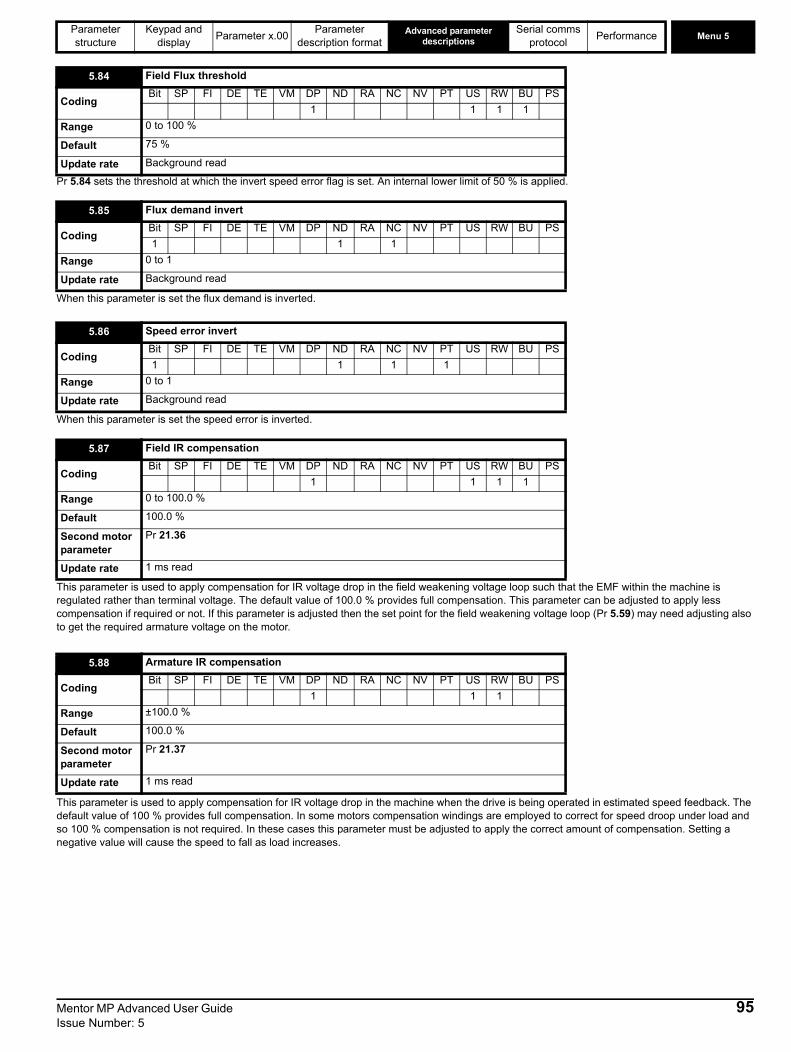
Parameter Keypad and Parameter x.00 Parameter Advanced parameter descriptions
Serial comms Performance Menu 5
structure display description format protocolPr 5.84 sets the threshold at which the invert speed error flag is set. An internal lower limit of 50 % is applied.
When this parameter is set the flux demand is inverted.
When this parameter is set the speed error is inverted.
This parameter is used to apply compensation for IR voltage drop in the field weakening voltage loop such that the EMF within the machine is regulated rather than terminal voltage. The default value of 100.0 % provides full compensation. This parameter can be adjusted to apply less compensation if required or not. If this parameter is adjusted then the set point for the field weakening voltage loop (Pr 5.59) may need adjusting also to get the required armature voltage on the motor.
This parameter is used to apply compensation for IR voltage drop in the machine when the drive is being operated in estimated speed feedback. The default value of 100 % provides full compensation. In some motors compensation windings are employed to correct for speed droop under load and so 100 % compensation is not required. In these cases this parameter must be adjusted to apply the correct amount of compensation. Setting a negative value will cause the speed to fall as load increases.
5.84 Field Flux threshold
CodingBit SP FI DE TE VM DP ND RA NC NV PT US RW BU PS
1 1 1 1Range 0 to 100 %
Default 75 %
Update rate Background read
5.85 Flux demand invert
CodingBit SP FI DE TE VM DP ND RA NC NV PT US RW BU PS1 1 1
Range 0 to 1
Update rate Background read
5.86 Speed error invert
CodingBit SP FI DE TE VM DP ND RA NC NV PT US RW BU PS1 1 1 1
Range 0 to 1
Update rate Background read
5.87 Field IR compensation
CodingBit SP FI DE TE VM DP ND RA NC NV PT US RW BU PS
1 1 1 1Range 0 to 100.0 %
Default 100.0 %
Second motor parameter
Pr 21.36
Update rate 1 ms read
5.88 Armature IR compensation
CodingBit SP FI DE TE VM DP ND RA NC NV PT US RW BU PS
1 1 1Range ±100.0 %
Default 100.0 %
Second motor parameter
Pr 21.37
Update rate 1 ms read
Mentor MP Advanced User Guide 95Issue Number: 5

Menu 5Parameter Keypad and Parameter x.00 Parameter Advanced parameter
descriptionsSerial comms Performance
structure display description format protocolThis parameter allows the flux feedback to come from an external field current controller (not FXMP25). This can be done via either an analog input or by a high speed fieldbus. When Pr 5.48 is set to 1 this parameter is used as the flux feedback.
5.89 External flux feedback
CodingBit SP FI DE TE VM DP ND RA NC NV PT US RW BU PS
1 1 1 1 1Range 0 to 100.0 %
Update rate 1 ms read
96 Mentor MP Advanced User Guide Issue Number: 5

Parameter structure
Keypad and display Parameter x.00 Parameter description
formatAdvanced parameter
descriptionsSerial comms
protocol Performance Menu 6
5.7 Menu 6: Sequencer and clockFigure 5-20 Menu 6 logic diagram
6.15
6.30
6.31
6.32
6.33
6.42
6.34
6.37
Logic 1
6.12
Keypad STOP key enable
6.13
Keypad reverse key function
2.02 Ramp enable/disable
3.23 Hard speedreference disable
13.10 Position control
RUN
STOP/ RESET
User defined
RESET
1.49
Reference selected indicator
Logic 1
6.17 Power consumption meter reset
6.18 Time interval betweenfilter changes
6.19 Filter change required/done
6.28 Select clock for triplog time stamp
6.16 Electricity costper kWh
Clock control
6.246.25 Power meter
6.26 Running cost
6.27 Time before filter change due
Enable 6.15
6.206.21
Power-up time
6.226.23
Run-time
5.03Motorpower
0.XX
0.XX
Key
Read-write (RW) parameter
Read-only (RO) parameter
Inputterminals
Outputterminals The parameters are all shown at their default settings
6.43
0 1
Jog reverse
Run
Forward / Reverse
Run reverse
Jog forward
Run forward
Drive enable
Control word
Control word enable
6.35
6.36Limit switch 2
Limit switch 1
6.29Hardwareenable
Menu 8
6.04
Stop / Startselect Sequencer
6.01
6.03
6.08
6.09
6.40
Stop modeselector
Mains loss modeHold zero speed enableCatch a spinning motorEnable sequencerlatching
T25 digital I/O 2
T26 digital I/O 3
T27 digital input 4
6.39Not stop
6.04
6.52
Start/stop logicselect
Zero referenceinterlock
6.54
6.55
Run risingedge delay
Contactor active
6.56 Drive active fallingedge delay
1.11 Reference enabled indicator
1.12 Reverse selected indicator
1.13 Jog selected indicator
13.18 Relative jogenable
13.19 Relative jog reverse select
Speed error invert
Flux demand invertPr = 4?1.49
Yes
No
Mentor MP Advanced User Guide 97Issue Number: 5
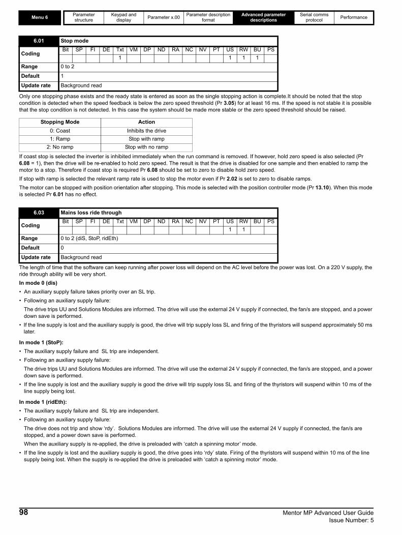
Menu 6 Parameter structure
Keypad and display Parameter x.00 Parameter description
formatAdvanced parameter
descriptionsSerial comms
protocol Performance
Only one stopping phase exists and the ready state is entered as soon as the single stopping action is complete.It should be noted that the stop condition is detected when the speed feedback is below the zero speed threshold (Pr 3.05) for at least 16 ms. If the speed is not stable it is possible that the stop condition is not detected. In this case the system should be made more stable or the zero speed threshold should be raised.
If coast stop is selected the inverter is inhibited immediately when the run command is removed. If however, hold zero speed is also selected (Pr 6.08 = 1), then the drive will be re-enabled to hold zero speed. The result is that the drive is disabled for one sample and then enabled to ramp the motor to a stop. Therefore if coast stop is required Pr 6.08 should be set to zero to disable hold zero speed.If stop with ramp is selected the relevant ramp rate is used to stop the motor even if Pr 2.02 is set to zero to disable ramps.The motor can be stopped with position orientation after stopping. This mode is selected with the position controller mode (Pr 13.10). When this mode is selected Pr 6.01 has no effect.
The length of time that the software can keep running after power loss will depend on the AC level before the power was lost. On a 220 V supply, the ride through ability will be very short. In mode 0 (dis) • An auxiliary supply failure takes priority over an SL trip. • Following an auxiliary supply failure:
The drive trips UU and Solutions Modules are informed. The drive will use the external 24 V supply if connected, the fan/s are stopped, and a power down save is performed.
• If the line supply is lost and the auxiliary supply is good, the drive will trip supply loss SL and firing of the thyristors will suspend approximately 50 ms later.
In mode 1 (StoP): • The auxiliary supply failure and SL trip are independent. • Following an auxiliary supply failure:
The drive trips UU and Solutions Modules are informed. The drive will use the external 24 V supply if connected, the fan/s are stopped, and a power down save is performed.
• If the line supply is lost and the auxiliary supply is good the drive will trip supply loss SL and firing of the thyristors will suspend within 10 ms of the line supply being lost.
In mode 1 (ridEth): • The auxiliary supply failure and SL trip are independent. • Following an auxiliary supply failure:
The drive does not trip and show ‘rdy’. Solutions Modules are informed. The drive will use the external 24 V supply if connected, the fan/s are stopped, and a power down save is performed. When the auxiliary supply is re-applied, the drive is preloaded with ‘catch a spinning motor’ mode.
• If the line supply is lost and the auxiliary supply is good, the drive goes into ‘rdy’ state. Firing of the thyristors will suspend within 10 ms of the line supply being lost. When the supply is re-applied the drive is preloaded with ‘catch a spinning motor’ mode.
6.01 Stop mode
CodingBit SP FI DE Txt VM DP ND RA NC NV PT US RW BU PS
1 1 1 1Range 0 to 2
Default 1
Update rate Background read
Stopping Mode Action0: Coast Inhibits the drive1: Ramp Stop with ramp
2: No ramp Stop with no ramp
6.03 Mains loss ride through
CodingBit SP FI DE Txt VM DP ND RA NC NV PT US RW BU PS
1 1Range 0 to 2 (diS, StoP, ridEth)
Default 0
Update rate Background read
98 Mentor MP Advanced User Guide Issue Number: 5

Parameter structure
Keypad and display Parameter x.00 Parameter description
formatAdvanced parameter
descriptionsSerial comms
protocol Performance Menu 6
This parameter is provided to allow the user to select several predefined digital input routing macros to control the sequencer. When a value between 0 and 3 is selected the drive processor continuously updates the destination parameters for T25 digital I/O 2, T26 digital I/O 3 and T27 digital input 4 and the “enable sequencer latching bit” (Pr 6.40). When a value of 4 is selected the destination parameters for these digital I/O and Pr 6.40 can be modified by the user. (Note any changes made to the destination parameters only become active after a drive reset.)
Figure 5-21 Digital input connections when Pr 6.04 is set between 0 - 3
When this bit is set the drive remains active even when the run command has been removed and the motor has reached standstill. The drive goes to the 'StoP' state instead of the 'rdy' state.
6.04 Start/stop logic select
CodingBit SP FI DE Txt VM DP ND RA NC NV PT US RW BU PS
1 1 1Range 0 to 4
Default 4
Update rate Background read
Pr 6.04 T25 digital I/O 2 T26 digital I/O 3 T27 digital input 4 Pr 6.400 Pr 6.29 Hardware Enable Pr 6.30 Run Forward Pr 6.32 Run Reverse 0 (non latching)1 Pr 6.39 Not stop Pr 6.30 Run Forward Pr 6.32 Run Reverse 1 (latching)2 Pr 6.29 Hardware Enable Pr 6.34 Run Pr 6.33 Fwd /Rev 0 (non latching)3 Pr 6.39 Not stop Pr 6.34 Run Pr 6.33 Fwd/Rev 1 (latching)4 User prog User prog User prog User prog
6.08 Hold zero speed
CodingBit SP FI DE Txt VM DP ND RA NC NV PT US RW BU PS1 1 1
Default 0
Update rate 4 ms read
30
31
28
29
26
27
24
25
23
21
22+24V
Run Fwd
Run Rev
Pr 6.04 is set to 0
30
31
28
29
26
27
24
25
23
21
22+24V
Run Fwd
Run Rev
Pr 6.04 is set to 1
Run Permit
30
31
28
29
26
27
24
25
23
21
22+24V
Run
Fwd/Rev
Pr 6.04 is set to 2
30
31
28
29
26
27
24
25
23
21
22+24V
Run
Fwd/Rev
Pr 6.04 is set to 3
Run Permit
Momentary contact
Continuous contact
Key
Mentor MP Advanced User Guide 99Issue Number: 5

Menu 6 Parameter structure
Keypad and display Parameter x.00 Parameter description
formatAdvanced parameter
descriptionsSerial comms
protocol Performance
When the drive is enabled with this parameter at zero, the post ramp reference (Pr 2.01 = {di03, 0.38}) starts at zero and ramps to the required reference. When the drive is enabled with this parameter at one, the post ramp reference is set to the motor speed.
This parameter permanently enables the Stop key on the drive such that the drive will always stop when the Stop key is pressed. If keypad mode is selected this has no effect because the Stop key is automatically enabled. The sequencer logic has been designed so that pressing the Stop key, whether the Stop key is enabled or not, does not make the drive change from a stopped to a running condition. As the Stop key is also used to reset trips this means that if the Stop key is pressed when the drive is tripped, the trip will be reset, but the drive does not start. Preventing the drive from starting when the stop key is pressed is implemented as follows.
Sequencer latching not enabled (Pr 6.40=0) If the Stop key is pressed when the Stop key is enabled (Pr 6.12=1) or when the drive is tripped the sequencer run is removed, and so the drive stops or remains stopped respectively. The sequencer run can only then be reapplied after at least one of the following conditions occurs. 1. Run forward, Run reverse and Run sequencing bits all zero2. OR the drive is disabled via Pr 6.15 or Pr 6.293. OR Run forward and Run reverse are both active and have been for 60 ms. The drive can be re-started by activating the necessary bits to give a normal start.
Sequencer latching enabled (Pr 6.40=1)If the Stop key is pressed when the stop key is enabled (Pr 6.12=1) or when the drive is tripped the sequencer run is removed, and so the drive stops or remains stopped respectively. The sequencer run can only then be reapplied after at least one of the following conditions occurs. 1. Run forward, Run reverse and Run sequencing bits all zero after the latches2. OR Not stop sequencing bit is zero3. OR the drive is disabled via Pr 6.15 or Pr 6.294. OR Run forward and Run reverse are both active and have been for 60 ms.The drive can then be re-started by activating the necessary bits to give a normal start. Note that applying the Run forward and Run reverse together will reset the stop key condition, but the latches associated with Run forward and Run reverse must then be reset before the drive can be re-started. It should be noted holding the Run key and pressing the Stop key to reset the drive without stopping does not apply unless keypad reference mode is selected.
This parameter controls the action of the Fwd/Rev key on the drive in keypad mode.
6.09 Catch a spinning motor
CodingBit SP FI DE Txt VM DP ND RA NC NV PT US RW BU PS1 1 1 1
Range 0 to 1
Default 1
Update rate Background read
6.12 Enable stop key
CodingBit SP FI DE Txt VM DP ND RA NC NV PT US RW BU PS1 1 1
Default 0
Update rate Background read
6.13 Enable forward/reverse key
CodingBit SP FI DE Txt VM DP ND RA NC NV PT US RW BU PS
1 1Range 0 to 2
Default 0
Update rate Background read
Pr 6.13 Action of Fwd/Rev key0 None1 Reverse select is toggled every time the button is pressed2 Drive runs in reverse direction
100 Mentor MP Advanced User Guide Issue Number: 5

Parameter structure
Keypad and display Parameter x.00 Parameter description
formatAdvanced parameter
descriptionsSerial comms
protocol Performance Menu 6
Setting this parameter to 0 will disable the drive. It must be at 1 for the drive to run.
When this parameter is set up correctly for the local currency, Pr 6.26 will give an instantaneous read out of running cost.
If this parameter is one the energy meter (Pr 6.24 and Pr 6.25) is reset and held at zero.
To enable the feature that indicates to the user when a filter change is due Pr 6.18 should be set to the time between filter changes.
When the drive is running, Pr 6.27 is reduced each time the runtime timer hour increments (Pr 6.23) until Pr 6.27 reaches 0, at which point Pr 6.19 is set to 1 to inform the user that a filter change is required. When the user has changed the filter, resetting Pr 6.19 to 0 will indicate to the drive that the change has been done and Pr 6.27 will be reloaded with the value of Pr 6.18. Pr 6.27 can be updated with the value of Pr 6.18 at any time by setting and clearing this parameter manually.
The powered-up clock always starts at zero each time the drive is powered-up. The user can change the time from the keypad, serial comms or an application module. If the data is not written with the various parts in the correct range (i.e. minutes are greater than 59, etc.) the clock is set to zero on the next minute. This clock may be used for time stamping the trip log if Pr 6.28 = 0. This parameter is used in conjunction with Pr 6.21.
6.15 Drive enable
CodingBit SP FI DE Txt VM DP ND RA NC NV PT US RW BU PS1 1 1 1
Default 1
Update rate 4 ms read
6.16 Electricity cost per kWh
CodingBit SP FI DE Txt VM DP ND RA NC NV PT US RW BU PS
1 1 1 1Range 0.0 to 600.0 currency units per kWhDefault 0.0Update rate Background read
6.17 Reset energy meter
CodingBit SP FI DE Txt VM DP ND RA NC NV PT US RW BU PS1 1 1
Default 0
Update rate Background read
6.18 Time between filter changes
CodingBit SP FI DE Txt VM DP ND RA NC NV PT US RW BU PS
1 1 1
Range 0 to 30,000 hrs
Default 0
Update rate Background read
6.19 Filter change required / change done
CodingBit SP FI DE Txt VM DP ND RA NC NV PT US RW BU PS1 1 1
Default 0
Update rate Background read/write
6.20 Powered-up time: years.days
CodingBit SP FI DE Txt VM DP ND RA NC NV PT US RW BU PS
3 1 1 1 1 1Range 0 to 9.364 Years.Days
Update rate Background write
Mentor MP Advanced User Guide 101Issue Number: 5

Menu 6 Parameter structure
Keypad and display Parameter x.00 Parameter description
formatAdvanced parameter
descriptionsSerial comms
protocol Performance
See description for Pr 6.20.
The run time clock increments when the drive output stage is active to indicate the number of minutes that the drive has been running since leaving the manufacturing plant. This clock may be used for time stamping the trip log if Pr 6.28 = 1.This parameter is used in conjunction with Pr 6.23.
See description for Pr 6.22.
Pr 6.24 and Pr 6.25 form the energy meter that indicates energy supplied to/from the drive in MWh and kWh.For motor control modes a positive value indicates net transfer of energy from the drive to the motor. The energy meter is reset and held at zero when Pr 6.17 is one.This parameter is used in conjunction with Pr 6.25.
See description for Pr 6.24.
Instantaneous read out of the cost/hour of running the drive. This requires Pr 6.16 to be set up correctly.
6.21 Powered-up time: hours.minutes
CodingBit SP FI DE Txt VM DP ND RA NC NV PT US RW BU PS
2 1 1 1 1 1Range 0 to 23.59 Hours.Minutes
Update rate Background write
6.22 Run time: years.days
CodingBit SP FI DE Txt VM DP ND RA NC NV PT US RW BU PS
3 1 1 1 1 1Range 0 to 9.364 Years.Days
Update rate Background write
6.23 Run time: hours.minutes
CodingBit SP FI DE Txt VM DP ND RA NC NV PT US RW BU PS
2 1 1 1 1 1Range 0 to 23.59 Hours.Minutes
Update rate Background write
6.24 Energy meter: MWh
CodingBit SP FI DE Txt VM DP ND RA NC NV PT US RW BU PS
1 1 1 1 1Range ±9999 MWh
Update rate Background write
6.25 Energy meter: kWh
CodingBit SP FI DE Txt VM DP ND RA NC NV PT US RW BU PS
2 1 1 1 1Range ±999 kWh
Update rate Background write
6.26 Running cost
CodingBit SP FI DE Txt VM DP ND RA NC NV PT US RW BU PS
1 1 1 1Range ±32,000
Update rate Background write
102 Mentor MP Advanced User Guide Issue Number: 5
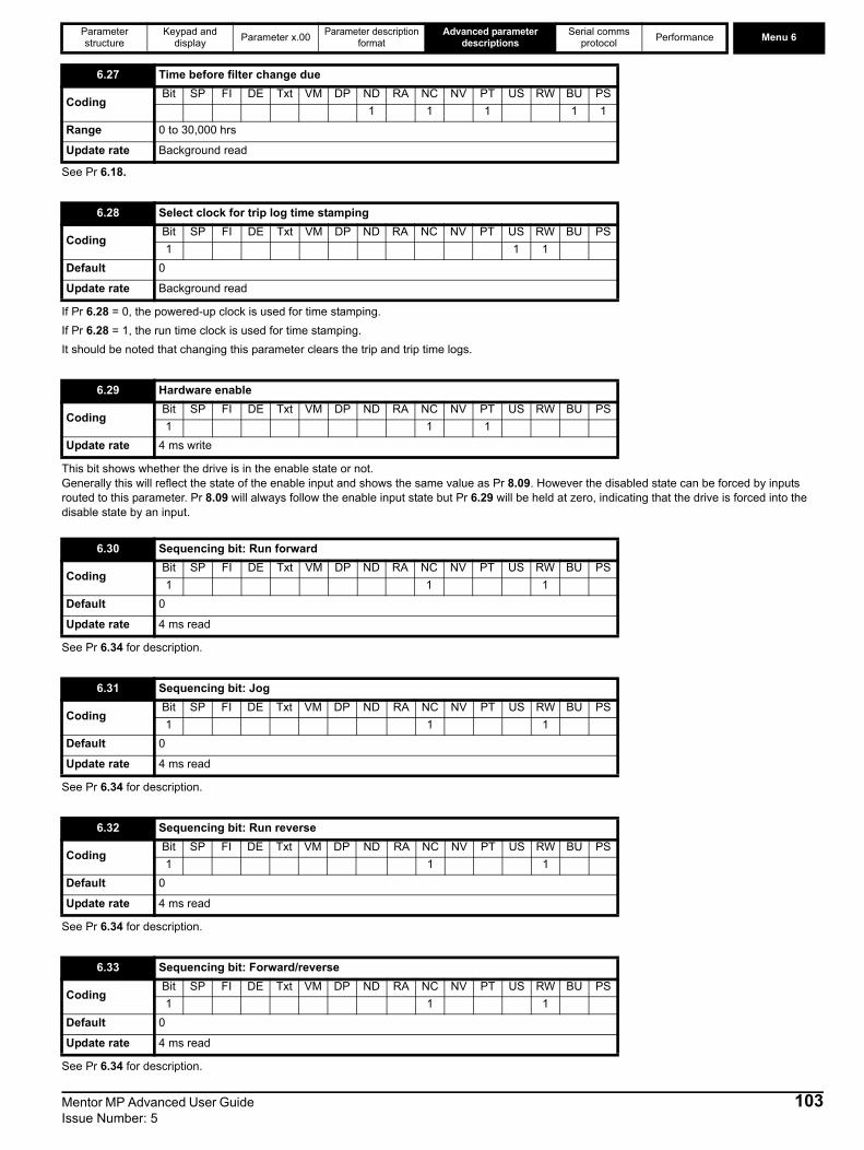
Parameter structure
Keypad and display Parameter x.00 Parameter description
formatAdvanced parameter
descriptionsSerial comms
protocol Performance Menu 6
See Pr 6.18.
If Pr 6.28 = 0, the powered-up clock is used for time stamping. If Pr 6.28 = 1, the run time clock is used for time stamping. It should be noted that changing this parameter clears the trip and trip time logs.
This bit shows whether the drive is in the enable state or not.Generally this will reflect the state of the enable input and shows the same value as Pr 8.09. However the disabled state can be forced by inputs routed to this parameter. Pr 8.09 will always follow the enable input state but Pr 6.29 will be held at zero, indicating that the drive is forced into the disable state by an input.
See Pr 6.34 for description.
See Pr 6.34 for description.
See Pr 6.34 for description.
See Pr 6.34 for description.
6.27 Time before filter change due
CodingBit SP FI DE Txt VM DP ND RA NC NV PT US RW BU PS
1 1 1 1 1Range 0 to 30,000 hrs
Update rate Background read
6.28 Select clock for trip log time stamping
CodingBit SP FI DE Txt VM DP ND RA NC NV PT US RW BU PS1 1 1
Default 0
Update rate Background read
6.29 Hardware enable
CodingBit SP FI DE Txt VM DP ND RA NC NV PT US RW BU PS1 1 1
Update rate 4 ms write
6.30 Sequencing bit: Run forward
CodingBit SP FI DE Txt VM DP ND RA NC NV PT US RW BU PS1 1 1
Default 0
Update rate 4 ms read
6.31 Sequencing bit: Jog
CodingBit SP FI DE Txt VM DP ND RA NC NV PT US RW BU PS1 1 1
Default 0
Update rate 4 ms read
6.32 Sequencing bit: Run reverse
CodingBit SP FI DE Txt VM DP ND RA NC NV PT US RW BU PS1 1 1
Default 0
Update rate 4 ms read
6.33 Sequencing bit: Forward/reverse
CodingBit SP FI DE Txt VM DP ND RA NC NV PT US RW BU PS1 1 1
Default 0
Update rate 4 ms read
Mentor MP Advanced User Guide 103Issue Number: 5

Menu 6 Parameter structure
Keypad and display Parameter x.00 Parameter description
formatAdvanced parameter
descriptionsSerial comms
protocol Performance
In normal operation the sequencer has been designed to operate with Run forward / Run reverse controls, or with a Run control and a forward reverse selector. If Run forwards / Run reverse control is required then bits Pr 6.30 and Pr 6.32 should be used to control the drive (digital inputs should not be routed to bits Pr 6.33 and Pr 6.34). If Run control with a forward reverse selector is required then bits Pr 6.33 and Pr 6.34 should be used to control the drive (digital inputs should not be routed to bits Pr 6.30 and Pr 6.32). The Run forward and Run reverse bits can be made latching by setting bit Pr 6.40. The Not stop bit (Pr 6.39) should be one to allow the sequencing bit to be latched. If the Not stop bit is zero all latches are cleared and held at zero. The jog or jog reverse sequencing bits can also cause the drive to run provided the motor is stopped when these bits are activated and the normal run sequencing bits are not providing a run signal.
Digital inputs connected to limit switches should be routed to these parameters if fast stopping is required at a limit. The drive will respond in 750 μs (500 μs digital input filter delay + 250 μs software delay) and stop the motor with a zero deceleration ramp rate (i.e. in current limit).The limit switches are direction dependant so that the motor can rotate in a direction that allows the system to move away from the limit switch. Pre-ramp reference+hard speed reference > 0 rpm Forward limit switch activePre-ramp reference+hard speed reference < 0 rpm Reverse limit switch activePre-ramp reference+hard speed reference = 0 rpm Both limit switches active
6.34 Sequencing bit: Run
CodingBit SP FI DE Txt VM DP ND RA NC NV PT US RW BU PS1 1 1
Default 0
Update rate 4 ms read
6.35 Forward limit switch
CodingBit SP FI DE Txt VM DP ND RA NC NV PT US RW BU PS1 1 1
Default 0
Update rate 250 μs read
6.36 Reverse limit switch
CodingBit SP FI DE Txt VM DP ND RA NC NV PT US RW BU PS1 1 1
Default 0
Update rate 250 μs read
6.37 Sequencing bit: Jog reverse
CodingBit SP FI DE Txt VM DP ND RA NC NV PT US RW BU PS1 1 1
Default 0
Update rate 4 ms read
6.39 Sequencing bit: Not stop
CodingBit SP FI DE Txt VM DP ND RA NC NV PT US RW BU PS1 1 1
Default 0
Update rate 4 ms read
6.40 Enable sequencer latching
CodingBit SP FI DE Txt VM DP ND RA NC NV PT US RW BU PS1 1 1
Default 0
Update rate 4 ms read
104 Mentor MP Advanced User Guide Issue Number: 5
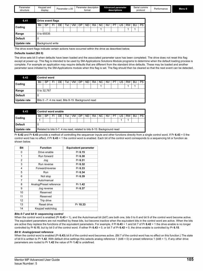
Parameter structure
Keypad and display Parameter x.00 Parameter description
formatAdvanced parameter
descriptionsSerial comms
protocol Performance Menu 6
The drive event flags indicate certain actions have occurred within the drive as described below.Defaults loaded (Bit 0)The drive sets bit 0 when defaults have been loaded and the associated parameter save has been completed. The drive does not reset this flag except at power-up. This flag is intended to be used by SM-Applications Solutions Module programs to determine when the default loading process is complete. For example an application may require defaults that are different from the standard drive defaults. These may be loaded and another parameter save initiated by the SM-Applications module when this flag is set. The flag should then be cleared so that the next event can be detected.
Pr 6.42 and Pr 6.43 provide a method of controlling the sequencer inputs and other functions directly from a single control word. If Pr 6.43 = 0 the control word has no effect, if Pr 6.43 = 1 the control word is enabled. Each bit of the control word corresponds to a sequencing bit or function as shown below.
Bits 0-7 and bit 9: sequencing controlWhen the control word is enabled (Pr 6.43 = 1), and the Auto/manual bit (bit7) are both one, bits 0 to 6 and bit 9 of the control word become active. The equivalent parameters are not modified by these bits, but become inactive when the equivalent bits in the control word are active. When the bits are active they replace the functions of the equivalent parameters. For example, if Pr 6.43 = 1 and bit 7 of Pr 6.42 = 1 the drive enable is no longer controlled by Pr 6.15, but by bit 0 of the control word. If either Pr 6.43 = 0, or bit 7 of Pr 6.42 = 0, the drive enable is controlled by Pr 6.15.Bit 8: Analog/preset referenceWhen the control word is enabled (Pr 6.43) bit 8 of the control word becomes active. (Bit 7 of the control word has no effect on this function.) The state of bit 8 is written to Pr 1.42. With default drive settings this selects analog reference 1 (bit8 = 0) or preset reference 1 (bit8 = 1). If any other drive parameters are routed to Pr 1.42 the value of Pr 1.42 is undefined.
6.41 Drive event flags
CodingBit SP FI DE Txt VM DP ND RA NC NV PT US RW BU PS
1 1 1Range 0 to 65535
Default 0
Update rate Background write
6.42 Control word
CodingBit SP FI DE Txt VM DP ND RA NC NV PT US RW BU PS
1 1 1Range 0 to 32,767
Default 0
Update rate Bits 0 –7: 4 ms read, Bits 8-15: Background read
6.43 Control word enable
CodingBit SP FI DE Txt VM DP ND RA NC NV PT US RW BU PS1 1 1
Default 0
Update rate Related to bits 0-7: 4 ms read, related to bits 8-15: Background read
Bit Function Equivalent parameter0 Drive enable Pr 6.151 Run forward Pr 6.302 Jog Pr 6.313 Run reverse Pr 6.324 Forward/reverse Pr 6.335 Run Pr 6.346 Not stop Pr 6.397 Auto/manual8 Analog/Preset reference Pr 1.429 Jog reverse Pr 6.37
10 Reserved11 Reserved12 Trip drive13 Reset drive Pr 10.3314 Keypad watchdog
Mentor MP Advanced User Guide 105Issue Number: 5

Menu 6 Parameter structure
Keypad and display Parameter x.00 Parameter description
formatAdvanced parameter
descriptionsSerial comms
protocol Performance
Bit12: Trip driveWhen the control word is enabled (Pr 6.43) bit 12 of the control word becomes active. (Bit 7 of the control word has no effect on this function.) When bit 12 is set to one a CL.bit trip is initiated. The trip cannot be cleared until the bit is set to zeroBit 13: Reset driveWhen the control word is enabled (Pr 6.43) bit 13 of the control word becomes active. (Bit 7 of the control word has no effect on this function.) When bit 13 is changed from 0 to 1 the drive is reset. This bit does not modify the equivalent parameter (Pr 10.33).Bit 14: Keypad watchdogWhen the control word is enabled (Pr 6.43) bit 14 of the control word becomes active. (Bit 7 of the control word has no effect on this function.) A watchdog is provided for an external keypad or other device where a break in the communication link must be detected. The watchdog system can be enabled and/or serviced if bit 14 of the control word is changed from zero to one with the control word enabled. Once the watchdog is enabled it must be serviced at least once every second or an "SCL" trip occurs. The watchdog is disabled when an "SCL" trip occurs, and so it must be re-enabled when the trip is reset.
The drive thermal model system normally controls the fan speed, however the fan can be forced to operate at full speed if this parameter is set to 1. When this is set to 1 the fan remains at full speed until 10 s after this parameter is set to zero. Note when the drive is in the UU state, the fan always runs at minimum speed.
The drive comms system 128 bytes buffer used with ANSI or Modbus rtu protocols via the 485 connector can be controlled by a Solutions Module under certain circumstances. This parameter shows which node has control of the buffer (0 (drv) = drive, 1 (Slot1) = Solutions Module in slot 1, etc. If a Solutions Module has control of the buffer the drive will use an alternative buffer for 485 comms and the following restrictions will apply:1. Comms messages via the 485 port are limited to a maximum of 32 bytes2. The 6 pin keypad port will operate correctly with an LED keypad, but it will no longer operate with an LCD keypad3. Modbus messages using the CMP protocol can only route messages to nodes within the drive. It will not be possible for these to be routed further,
i.e. via CT Net on an SM Applications module.
When this parameter is 1 the reference has to be below 0.8 % of full speed before the sequencer can go to the run state.
When using the contactor logic the run command has to be delayed to allow time for the contactor to change before allowing the firing pulses.
This parameter can be used to control an external contactor.
6.45 Force cooling fan to run at full speed
CodingBit SP FI DE Txt VM DP ND RA NC NV PT US RW BU PS1 1 1
Default 0
Update rate Background read
6.50 Drive comms state
CodingBit SP FI DE Txt VM DP ND RA NC NV PT US RW BU PS
1 1 1 1 1Default 0 to 3
Update rate Background write
6.52 Zero reference interlock
CodingBit SP FI DE Txt VM DP ND RA NC NV PT US RW BU PS1 1 1
Default 0
Update rate Background read
6.54 Run rising edge delay
CodingBit SP FI DE Txt VM DP ND RA NC NV PT US RW BU PS
1 1 1Range 0 to 25.0 s
Default 0.3
Update rate Background read
6.55 Contactor active
CodingBit SP FI DE Txt VM DP ND RA NC NV PT US RW BU PS1 1 1 1
Update rate Background write
106 Mentor MP Advanced User Guide Issue Number: 5

Parameter structure
Keypad and display Parameter x.00 Parameter description
formatAdvanced parameter
descriptionsSerial comms
protocol Performance Menu 6
This parameter provides a delay on a falling edge of the drive active flag.Figure 5-22 Contactor logic
6.56 Drive active falling edge delay
CodingBit SP FI DE Txt VM DP ND RA NC NV PT US RW BU PS
1 1 1Range 0 to 255 s
Default 0 s
Update rate Background read
Contactor active
Drive active
Sequencer run
Sequencer enableDrive trip
Hold zerospeed
100ms
Drive disable
Sequencer enable before delay
Sequencer enable
Power on
Sequencer run
Sequencer run delayed
Contactor active
Drive active
Motor Speed
Stop command
Hold zero speed
6.546.56
6.54Run rise
edge delayRun rise
edge delayDrive activefalling edge delay
6.55
6.08
10.02
Drive activefalling edge decay
6.15
6.30Drive run 6.56
OR
31 6.29
Mentor MP Advanced User Guide 107Issue Number: 5
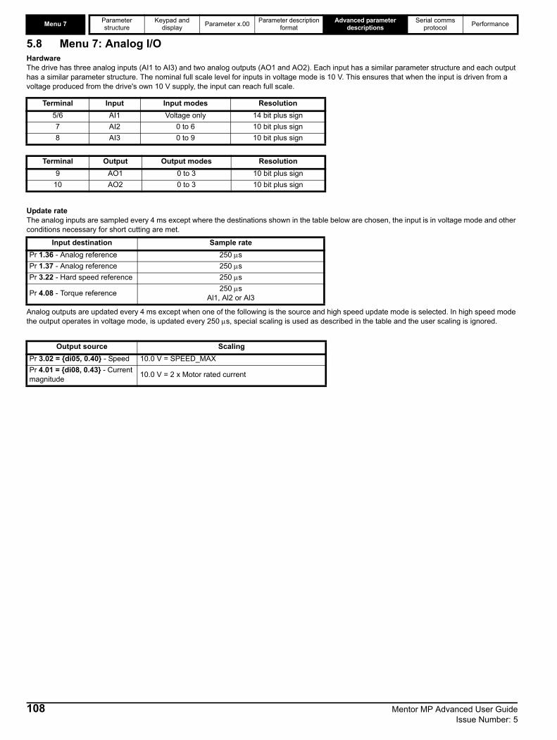
Menu 7 Parameter structure
Keypad and display Parameter x.00 Parameter description
formatAdvanced parameter
descriptionsSerial comms
protocol Performance
5.8 Menu 7: Analog I/OHardwareThe drive has three analog inputs (AI1 to AI3) and two analog outputs (AO1 and AO2). Each input has a similar parameter structure and each output has a similar parameter structure. The nominal full scale level for inputs in voltage mode is 10 V. This ensures that when the input is driven from a voltage produced from the drive's own 10 V supply, the input can reach full scale.
Update rateThe analog inputs are sampled every 4 ms except where the destinations shown in the table below are chosen, the input is in voltage mode and other conditions necessary for short cutting are met.
Analog outputs are updated every 4 ms except when one of the following is the source and high speed update mode is selected. In high speed mode the output operates in voltage mode, is updated every 250 μs, special scaling is used as described in the table and the user scaling is ignored.
Terminal Input Input modes Resolution5/6 AI1 Voltage only 14 bit plus sign7 AI2 0 to 6 10 bit plus sign8 AI3 0 to 9 10 bit plus sign
Terminal Output Output modes Resolution9 AO1 0 to 3 10 bit plus sign
10 AO2 0 to 3 10 bit plus sign
Input destination Sample ratePr 1.36 - Analog reference 250 μsPr 1.37 - Analog reference 250 μsPr 3.22 - Hard speed reference 250 μs
Pr 4.08 - Torque reference 250 μsAl1, Al2 or Al3
Output source ScalingPr 3.02 = {di05, 0.40} - Speed 10.0 V = SPEED_MAXPr 4.01 = {di08, 0.43} - Current magnitude 10.0 V = 2 x Motor rated current
108 Mentor MP Advanced User Guide Issue Number: 5
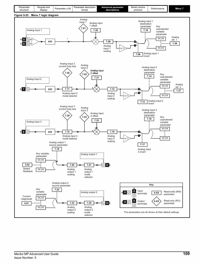
Parameter structure
Keypad and display Parameter x.00 Parameter description
formatAdvanced parameter
descriptionsSerial comms
protocol Performance Menu 7
Figure 5-23 Menu 7 logic diagram
Analog input 2
A/D 7.11
Analog input 2 mode selector
7.12
Analog input 2 scaling
??.??
Any unprotected variable parameter
??.??
7.14
7.08
Analog input 1 scaling
??.??
Any unprotected variable parameter
??.??
7.10
Analog input 1destinationparameter
x(-1)
Analog input 1
Analog input 3
A/D 7.15
Analog input 3 mode selector
7.16
Analog input 3 scaling
??.??
Any unprotected variable parameter
??.??
7.18
??.??
Any variable parameter
??.??
7.19
Analog output 1source parameter
7.20
Analog output 1 scaling
7.21
Analog output 1 mode selector
Analog output 1
??.??
Any variable parameter
??.??
7.22
Analog output 2 source parameter
7.23
Analog output 2 scaling
7.24
Analog output 2 mode selector
7.09 Analog input 1 invert
x(-1)
7.01
Analoginput 1
7.02
Analoginput 2
x(-1)
7.17
Analog input 3 invert
7.13 Analog input 2 invert
Analog output 2
1.36
Analogref. 1
1.37
Analogref. 2
3.02Speedfeedback
4.01
Currentmagnitude
0.XX
0.XX
Key
Read-write (RW) parameter
Read-only (RO) parameter
Inputterminals
Outputterminals
The parameters are all shown at their default settings
++
7.30
Analog input1 offset
7.28
Analog input 2current loop loss
++
7.31
Analog input2 offset
++
7.31
Analog input2 offset
++
7.31
++
7.32
Analog input3 offset7.29
Analog input 3current loop loss
Analog input 2destinationparameter
Analog input 3destinationparameter
7.03
Analoginput 3
A/D
Mentor MP Advanced User Guide 109Issue Number: 5

Menu 7 Parameter structure
Keypad and display Parameter x.00 Parameter description
formatAdvanced parameter
descriptionsSerial comms
protocol Performance
When analog input 3 is in thermistor mode the display indicates the resistance of the thermistor as a percentage of 10k Ω
If the temperature displayed in Pr 7.04 exceeds the trip threshold for the parameter an Oht2 trip is initiated. This trip can only be reset if the parameter that has caused the trip falls below the trip reset level. If the temperature exceeds the alarm level, a "hot" alarm is displayed. If the temperature for any of these monitoring points is outside the range -20ο C to 150ο C, it is assumed that the monitoring thermistor has failed and a hardware fault trip is initiated (HF27), details are given in the following table.
Power stage temperature 1 (Pr 7.04) in ο C.
7.01{in02, 0.82} T5/6 analog input 1
CodingBit SP FI DE TE VM DP ND RA NC NV PT US RW BU PS
2 1 1 1Range ±100.00 %
Update rate 4 ms write
7.02{in03, 0.83} T7 analog input 2
7.03{in04, 0.84} T8 analog input 3
CodingBit SP FI DE TE VM DP ND RA NC NV PT US RW BU PS
1 1 1 1Range ±100.0 %
Update rate 4 ms write
7.04 Power circuit temperature
CodingBit SP FI DE TE VM DP ND RA NC NV PT US RW BU PS
1 1 1Range -128 to 127ο CUpdate rate Background write
Drive O.ht2 Trip temperature Release from O.ht2 Warning temperatureMP25A4(R)
100 95 90MP45A4(R)MP75A4(R)
MP105A4(R)MP155A4(R)MP210A4(R) 94 90 85MP25A5(R)
100 95 90MP45A5(R)
MP105A5(R)MP155A5(R)MP210A5(R) 94 90 85MP350A4(R)
105 100 95MP420A4(R)MP550A4(R) 100 95 90MP700A4(R)
105 100 95MP825A4(R)MP900A4(R) 100 95 90
MP1200A4(R)110 100 95
MP1850A4(R)MP350A5(R) 100 95 90MP470A5(R) 81 75 70MP700A5(R) 100 95 90MP825A5(R) 94 90 85
MP1200A5(R)110 100 95
MP1850A5(R)MP350A6(R) 100 95 90MP470A6(R) 81 75 70
110 Mentor MP Advanced User Guide Issue Number: 5
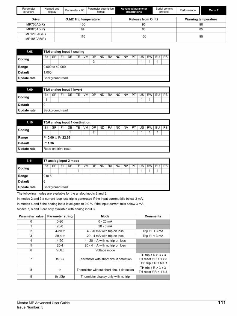
Parameter structure
Keypad and display Parameter x.00 Parameter description
formatAdvanced parameter
descriptionsSerial comms
protocol Performance Menu 7
The following modes are available for the analog inputs 2 and 3. In modes 2 and 3 a current loop loss trip is generated if the input current falls below 3 mA. In modes 4 and 5 the analog input level goes to 0.0 % if the input current falls below 3 mA.Modes 7, 8 and 9 are only available with analog input 3.
MP700A6(R) 100 95 90MP825A6(R) 94 90 85
MP1200A6(R)110 100 95
MP1850A6(R)
7.08 T5/6 analog input 1 scaling
CodingBit SP FI DE TE VM DP ND RA NC NV PT US RW BU PS
3 1 1 1Range 0.000 to 40.000
Default 1.000
Update rate Background read
7.09 T5/6 analog input 1 invert
CodingBit SP FI DE TE VM DP ND RA NC NV PT US RW BU PS1 1 1
Default 0
Update rate Background read
7.10 T5/6 analog input 1 destination
CodingBit SP FI DE TE VM DP ND RA NC NV PT US RW BU PS
1 2 1 1 1 1Range Pr 0.00 to Pr 22.99
Default Pr 1.36
Update rate Read on drive reset
7.11 T7 analog input 2 mode
CodingBit SP FI DE TE VM DP ND RA NC NV PT US RW BU PS
1 1 1 1Range 0 to 6
Default 6
Update rate Background read
Parameter value Parameter string Mode Comments0 0-20 0 - 20 mA1 20-0 20 - 0 mA2 4-20.tr 4 - 20 mA with trip on loss Trip if I < 3 mA3 20-4.tr 20 - 4 mA with trip on loss Trip if I < 3 mA4 4-20 4 - 20 mA with no trip on loss 5 20-4 20 - 4 mA with no trip on loss6 VOLt Voltage mode
7 th.SC Thermistor with short circuit detectionTH trip if R > 3 k 3
TH reset if R < 1 k 8THS trip if R < 50 R
8 th Thermistor without short circuit detection TH trip if R > 3 k 3TH reset if R < 1 k 8
9 th diSp Thermistor display only with no trip
Drive O.ht2 Trip temperature Release from O.ht2 Warning temperature
Mentor MP Advanced User Guide 111Issue Number: 5

Menu 7 Parameter structure
Keypad and display Parameter x.00 Parameter description
formatAdvanced parameter
descriptionsSerial comms
protocol Performance
See Pr 7.11 for a description
7.12 T7 analog input 2 scaling
CodingBit SP FI DE TE VM DP ND RA NC NV PT US RW BU PS
3 1 1 1Range 0.000 to 40.000
Default 1.000
Update rate Background read
7.13 T7 analog input 2 invert
CodingBit SP FI DE TE VM DP ND RA NC NV PT US RW BU PS1 1 1
Default 0
Update rate Background read
7.14 T7 analog input 2 destination
CodingBit SP FI DE TE VM DP ND RA NC NV PT US RW BU PS
1 2 1 1 1 1Range Pr 0.00 to Pr 22.99
Default Pr 1.37
Update rate Read on drive reset
7.15{in01, 0.81} T8 analog input 3 mode
CodingBit SP FI DE TE VM DP ND RA NC NV PT US RW BU PS
1 1 1 1Range 0 to 9
Default Eur: 8, USA: 6
Update rate Background read
7.16 T8 analog input 3 scaling
CodingBit SP FI DE TE VM DP ND RA NC NV PT US RW BU PS
3 1 1 1Range 0.000 to 40.000
Default 1.000
Update rate Background read
7.17 T8 analog input 3 invert
CodingBit SP FI DE TE VM DP ND RA NC NV PT US RW BU PS1 1 1
Default 0
Update rate Background read
7.18 T8 analog input 3 destination
CodingBit SP FI DE TE VM DP ND RA NC NV PT US RW BU PS
1 2 1 1 1 1Range Pr 0.00 to Pr 22.99
Default Pr 0.00
Update rate Read on drive reset
112 Mentor MP Advanced User Guide Issue Number: 5
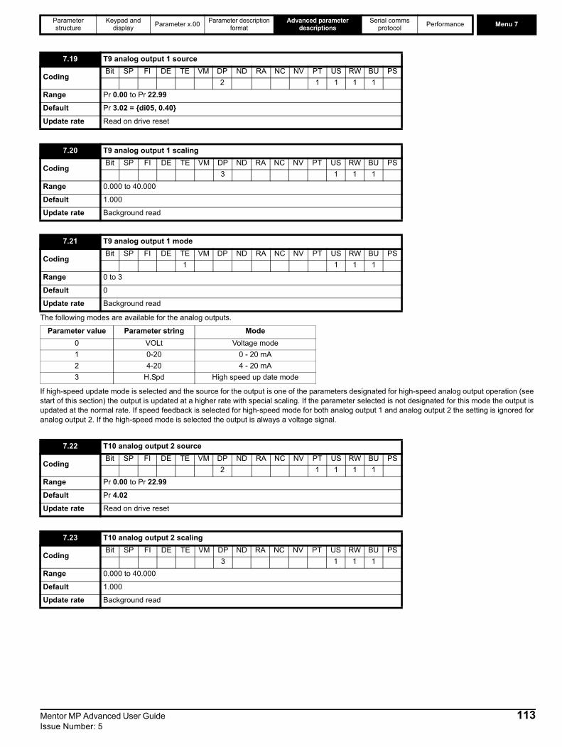
Parameter structure
Keypad and display Parameter x.00 Parameter description
formatAdvanced parameter
descriptionsSerial comms
protocol Performance Menu 7
The following modes are available for the analog outputs.
If high-speed update mode is selected and the source for the output is one of the parameters designated for high-speed analog output operation (see start of this section) the output is updated at a higher rate with special scaling. If the parameter selected is not designated for this mode the output is updated at the normal rate. If speed feedback is selected for high-speed mode for both analog output 1 and analog output 2 the setting is ignored for analog output 2. If the high-speed mode is selected the output is always a voltage signal.
7.19 T9 analog output 1 source
CodingBit SP FI DE TE VM DP ND RA NC NV PT US RW BU PS
2 1 1 1 1Range Pr 0.00 to Pr 22.99
Default Pr 3.02 = {di05, 0.40}
Update rate Read on drive reset
7.20 T9 analog output 1 scaling
CodingBit SP FI DE TE VM DP ND RA NC NV PT US RW BU PS
3 1 1 1Range 0.000 to 40.000
Default 1.000
Update rate Background read
7.21 T9 analog output 1 mode
CodingBit SP FI DE TE VM DP ND RA NC NV PT US RW BU PS
1 1 1 1Range 0 to 3
Default 0
Update rate Background read
Parameter value Parameter string Mode0 VOLt Voltage mode1 0-20 0 - 20 mA2 4-20 4 - 20 mA3 H.Spd High speed up date mode
7.22 T10 analog output 2 source
CodingBit SP FI DE TE VM DP ND RA NC NV PT US RW BU PS
2 1 1 1 1Range Pr 0.00 to Pr 22.99
Default Pr 4.02
Update rate Read on drive reset
7.23 T10 analog output 2 scaling
CodingBit SP FI DE TE VM DP ND RA NC NV PT US RW BU PS
3 1 1 1Range 0.000 to 40.000
Default 1.000
Update rate Background read
Mentor MP Advanced User Guide 113Issue Number: 5

Menu 7 Parameter structure
Keypad and display Parameter x.00 Parameter description
formatAdvanced parameter
descriptionsSerial comms
protocol Performance
See Pr 7.21 description.
If an analog input is used with 4-20 mA or 20-4 mA current loop modes the respective bit (Pr 7.28 - analog input 2 and Pr 7.29 -analog input 3) is set to one if the current falls below 3 mA. If the current is above 3 mA with these modes or another mode is selected the respective bit is set to zero.
An offset can be added to each analog input with a range from -100 % to 100 %. If the sum of the input and the offset exceeds ±100 % the results is limited to ±100 %.
This parameter is an estimate of the SCR / thyristor junction temperature. If the value rises above 120 oC, the drive will trip O.ht1.
7.24 T10 analog output 2 mode
CodingBit SP FI DE TE VM DP ND RA NC NV PT US RW BU PS
1 1 1 1Range 0 to 3
Default 0
Update rate Background read
7.28 T7 analog input current loop loss 2
7.29 T8 analog input current loop loss 3
CodingBit SP FI DE TE VM DP ND RA NC NV PT US RW BU PS1 1 1 1
Update rate Background write
7.30 T5/6 analog input 1 offset
CodingBit SP FI DE TE VM DP ND RA NC NV PT US RW BU PS
2 1 1Range ±100.00 %
Default 0.00
Update rate Background read
7.31 T7 analog input 2 offset
7.32 T8 analog input 3 offset
CodingBit SP FI DE TE VM DP ND RA NC NV PT US RW BU PS
1 1 1Range ±100.0 %
Default 0.0
Update rate Background read
7.34 SCR / thyristor junction temperature
CodingBit SP FI DE TE VM DP ND RA NC NV PT US RW BU PS
1 1 1 1Range 0 to 150oCUpdate rate Background read
114 Mentor MP Advanced User Guide Issue Number: 5
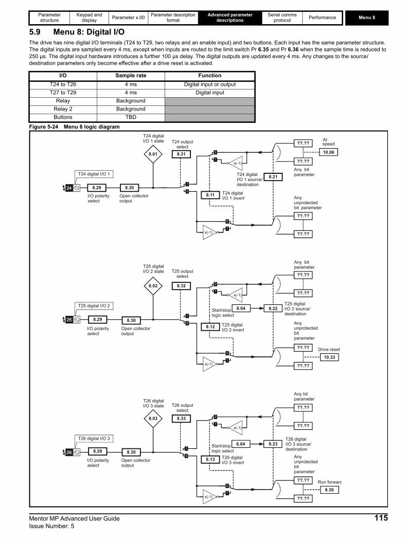
Parameter structure
Keypad and display Parameter x.00 Parameter description
formatAdvanced parameter
descriptionsSerial comms
protocol Performance Menu 8
5.9 Menu 8: Digital I/OThe drive has nine digital I/O terminals (T24 to T29, two relays and an enable input) and two buttons. Each input has the same parameter structure. The digital inputs are sampled every 4 ms, except when inputs are routed to the limit switch Pr 6.35 and Pr 6.36 when the sample time is reduced to 250 µs. The digital input hardware introduces a further 100 µs delay. The digital outputs are updated every 4 ms. Any changes to the source/destination parameters only become effective after a drive reset is activated.
Figure 5-24 Menu 8 logic diagram
I/O Sample rate FunctionT24 to T26 4 ms Digital input or output T27 to T29 4 ms Digital input
Relay BackgroundRelay 2 BackgroundButtons TBD
T25 digital I/O 2
8.32
??.??
Any unprotected bit parameter
??.??
??.??
??.??
Any bit parameter
8.22
x(-1)
x(-1)
8.12
8.02
T26 digital I/O 3
8.33
??.??
Any unprotected bit parameter
??.??
??.??
Any bit parameter
??.??
8.23
x(-1)
x(-1)
8.13
8.03
8.29
Open collector output
8.30
8.29
Open collector output
8.30
10.33Drive reset
6.30Run forward
I/O polarityselect
I/O polarityselect
T24 digital I/O 1
T24 digital I/O 1 state
8.31
T24 outputselect
??.??
??.??
Any unprotected bit parameter
??.??
??.??
Any bit parameter8.21T24 digital
I/O 1 source/destination
x(-1)
x(-1)
8.11 T24 digital I/O 1 invert
8.01
8.29
I/O polarityselect
Open collector output
8.30
10.06
At speed
T25 digital I/O 2 state T25 output
select
T25 digital I/O 2 source/destination
T25 digital I/O 2 invert
T26 digital I/O 3 state T26 output
select
T26 digital I/O 3 source/destination
T26 digital I/O 3 invert
6.04Start/stoplogic select
6.04Start/stoplogic select
Mentor MP Advanced User Guide 115Issue Number: 5
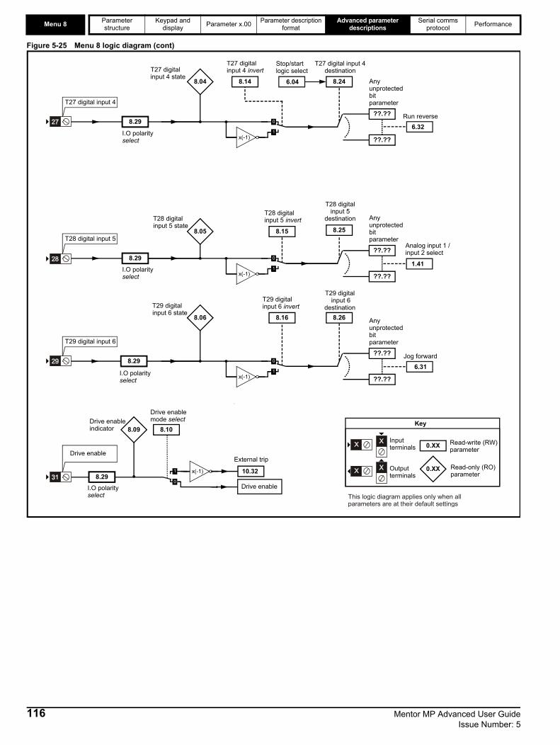
Menu 8 Parameter structure
Keypad and display Parameter x.00 Parameter description
formatAdvanced parameter
descriptionsSerial comms
protocol Performance
Figure 5-25 Menu 8 logic diagram (cont)
T29 digital input 6
??.??
Any
unprotected
bit
parameter
??.??
8.26
T29 digital input 6
destination
x(-1)
8.16
T29 digitalinput 6 invert
T29 digitalinput 6 state
8.06
8.29 6.31Jog forward
I.O polarityselect
0.XX
0.XX
Key
Read-write (RW)
parameter
Read-only (RO)
parameter
Inputterminals
Outputterminals
This logic diagram applies only when allparameters are at their default settings
8.25
T28 digital input 5
destination
??.??
Any
unprotected
bit
parameter
??.??x(-1)
8.15
T28 digitalinput 5 invert
T28 digitalinput 5 state
8.05
8.291.41
Analog input 1 / input 2 select
I.O polarityselect
T28 digital input 5
8.10
Drive enable mode select
Drive enable
10.32
External trip
Drive enable
Drive enable indicator 8.09
x(-1)
T27 digital input 4
??.??
Anyunprotectedbitparameter
??.??
8.24
T27 digital input 4destination
x(-1)
8.14
T27 digitalinput 4 invertT27 digital
input 4 state8.04
8.29
I.O polarityselect
6.32
Run reverse
Stop/startlogic select
6.04
8.29 I.O polarityselect
116 Mentor MP Advanced User Guide Issue Number: 5
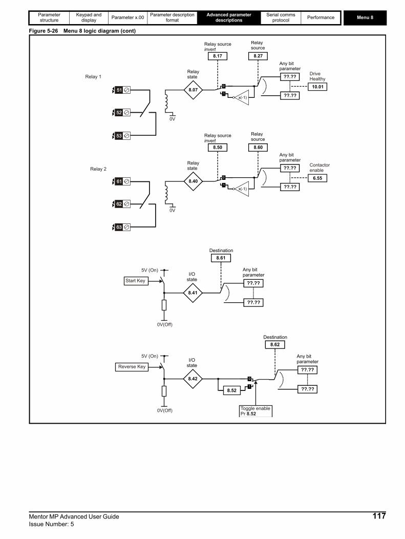
Parameter structure
Keypad and display Parameter x.00 Parameter description
formatAdvanced parameter
descriptionsSerial comms
protocol Performance Menu 8
Figure 5-26 Menu 8 logic diagram (cont)
Destination
Any bitparameterI/O
stateStart Key
5V (On)
Destination
Any bitparameterI/O
stateReverse Key
5V (On)
Toggle enablePr 8.52
8.27
Relaysource
Relay source invert
Any bitparameter
x(-1)
Relay state
DriveHealthy
8.60
Relaysource
Relay source invert
Any bitparameter
x(-1)
Relay state
Contactorenable
Relay 1
Relay 2
Mentor MP Advanced User Guide 117Issue Number: 5

Menu 8 Parameter structure
Keypad and display Parameter x.00 Parameter description
formatAdvanced parameter
descriptionsSerial comms
protocol Performance
Table 5-7 Digital inputs / outputs
OFF (0) = Terminal inactive
ON (1) = Terminal active
Terminal + typeI/O state Invert Source / destination Output select
Pr Pr Default Pr Default Pr Default
T24 input / output 1 Pr 8.01= {in05, 0.85} Pr 8.11 0 Pr 8.21 Pr 10.06 - At speed Pr 8.31 1
T25 input / output 2 Pr 8.02= {in06, 0.86} Pr 8.12 0 Pr 8.22 Pr 10.33 - Drive reset Pr 8.32 0
T26 input / output 3 Pr 8.03= {in07, 0.87} Pr 8.13 0 Pr 8.23 Pr 6.30 - Run forward Pr 8.33 0
T27 input 4 Pr 8.04= {in08, 0.88} Pr 8.14 0 Pr 8.24 Pr 6.32 - Run reverse
T28 input 5 Pr 8.05= {in09, 0.89} Pr 8.15 0 Pr 8.25 Pr 1.41 - Local/remote
T29 input 6 Pr 8.06= {in10, 0.90} Pr 8.16 0 Pr 8.26 Pr 6.31 - Jog
T51, T52, T53 relay state Pr 8.07 Pr 8.17 0 Pr 8.27 Pr 10.01 - Drive OK
T31 Enable Pr 8.09
T61, T62, T63 relay state Pr 8.40 Pr 8.50 0 Pr 8.60 Pr 6.55 - Contactor enable
Start button Pr 8.41 Pr 8.61 Pr 0.00
Forward / Reverse button Pr 8.42 Pr 8.52(toggle) 0 Pr 8.62 Pr 0.00
24 V Input Pr 8.48
8.01{in05, 0.85}
T24 digital I/O 1 state
8.02{in06, 0.86}
T25 digital I/O 2 state
8.03{in07, 0.87}
T26 digital I/O 3 state
8.04{in08, 0.88}
T27 digital input 4 state
8.05{in09, 0.89}
T28 digital input 5 state
8.06{in10, 0.90}
T29 digital input 6 state
8.07 T51, T52, T53 relay state
8.09 T31 drive enable state
CodingBit SP FI DE Txt VM DP ND RA NC NV PT US RW BU PS1 1 1 1
Default See Table 5-7
Update rate 4 ms write
118 Mentor MP Advanced User Guide Issue Number: 5

Parameter structure
Keypad and display Parameter x.00 Parameter description
formatAdvanced parameter
descriptionsSerial comms
protocol Performance Menu 8
As default (Pr 8.10 = 0) the drive is in the inhibit mode when the enable is inactive. Setting this parameter to one causes the enable to behave as an Et trip input. When the input becomes inactive an Et trip is initiated. This does not affect Pr 10.32 (Et trip parameter), therefore an Et trip can be initiated in this mode either by making the enable inactive or setting Pr 10.32 to one. When this is two, a 0 to 1 change on the terminal will cause a reset.
OFF (0) = Non-invertedOn (1) = Inverted
This word is used to determine the status of the digital I/O by reading one parameter. The bits in this word reflect the state of Pr 8.01 = {in05, 0.85} to Pr 8.07, 8.09, and Pr 8.40 to Pr 8.42.
8.10 Enable mode select
Coding Bit SP FI DE Txt VM DP ND RA NC NV PT US RW BU PS
1 1
Range 0 to 2
Default 0
Update rate Background read
8.11 T24 digital I/O 1 invert
8.12 T25 digital I/O 2 invert
8.13 T26 digital I/O 3 invert
8.14 T27 digital input 4 invert
8.15 T28 digital input 5 invert
8.16 T29 digital input 6 invert
8.17 T51, T52, T53 relay invert
CodingBit SP FI DE Txt VM DP ND RA NC NV PT US RW BU PS1 1 1
Default Pr 8.11 to Pr 8.17 = OFF (0)
Update rate 4 ms read
8.20 Digital I/O read word
CodingBit SP FI DE Txt VM DP ND RA NC NV PT US RW BU PS
1 1 1 1Range 0 to 4095
Update rate Background write
Bit Digital I/O0 T24 input / output 11 T25 input / output 22 T26 input / output 33 T27 input 44 T28 input 55 T29 input 66 Relay 178 Enable9 Relay 2
10 Start button11 Forward / Reverse button
Mentor MP Advanced User Guide 119Issue Number: 5
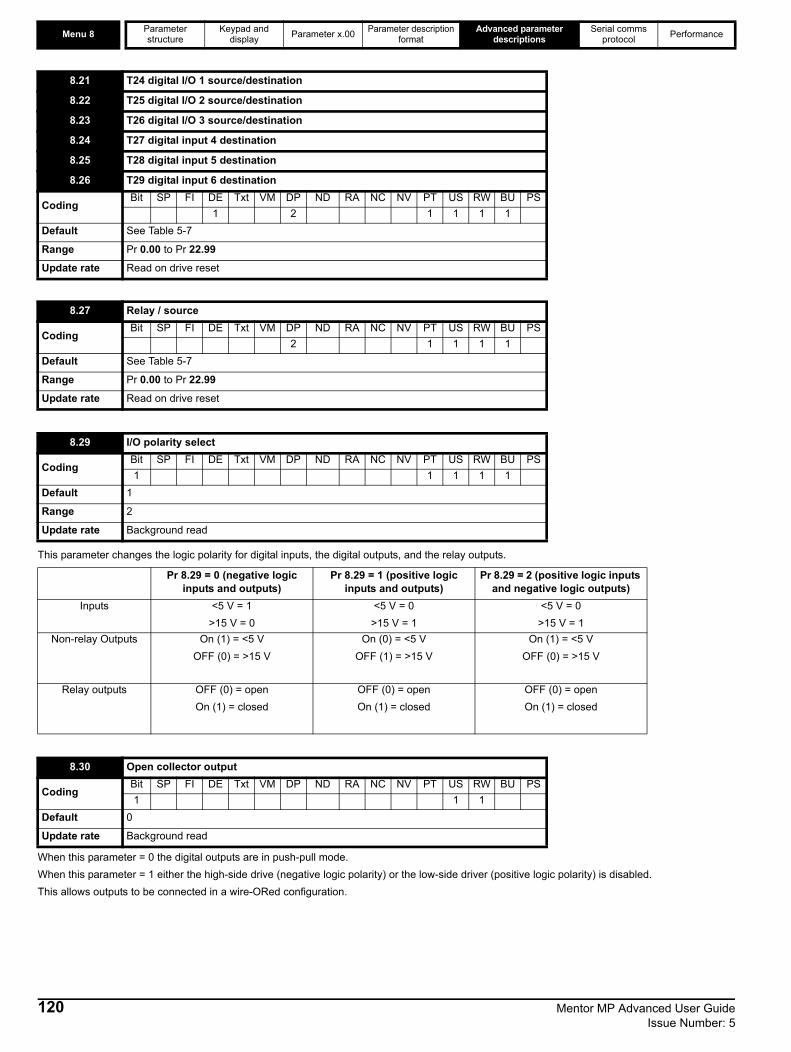
Menu 8 Parameter structure
Keypad and display Parameter x.00 Parameter description
formatAdvanced parameter
descriptionsSerial comms
protocol Performance
This parameter changes the logic polarity for digital inputs, the digital outputs, and the relay outputs.
When this parameter = 0 the digital outputs are in push-pull mode. When this parameter = 1 either the high-side drive (negative logic polarity) or the low-side driver (positive logic polarity) is disabled. This allows outputs to be connected in a wire-ORed configuration.
8.21 T24 digital I/O 1 source/destination
8.22 T25 digital I/O 2 source/destination
8.23 T26 digital I/O 3 source/destination
8.24 T27 digital input 4 destination
8.25 T28 digital input 5 destination
8.26 T29 digital input 6 destination
CodingBit SP FI DE Txt VM DP ND RA NC NV PT US RW BU PS
1 2 1 1 1 1Default See Table 5-7
Range Pr 0.00 to Pr 22.99
Update rate Read on drive reset
8.27 Relay / source
CodingBit SP FI DE Txt VM DP ND RA NC NV PT US RW BU PS
2 1 1 1 1Default See Table 5-7
Range Pr 0.00 to Pr 22.99
Update rate Read on drive reset
8.29 I/O polarity select
CodingBit SP FI DE Txt VM DP ND RA NC NV PT US RW BU PS1 1 1 1 1
Default 1
Range 2
Update rate Background read
Pr 8.29 = 0 (negative logic inputs and outputs)
Pr 8.29 = 1 (positive logic inputs and outputs)
Pr 8.29 = 2 (positive logic inputs and negative logic outputs)
Inputs <5 V = 1>15 V = 0
<5 V = 0>15 V = 1
<5 V = 0>15 V = 1
Non-relay Outputs On (1) = <5 VOFF (0) = >15 V
On (0) = <5 VOFF (1) = >15 V
On (1) = <5 VOFF (0) = >15 V
Relay outputs OFF (0) = openOn (1) = closed
OFF (0) = openOn (1) = closed
OFF (0) = openOn (1) = closed
8.30 Open collector output
CodingBit SP FI DE Txt VM DP ND RA NC NV PT US RW BU PS1 1 1
Default 0
Update rate Background read
120 Mentor MP Advanced User Guide Issue Number: 5

Parameter structure
Keypad and display Parameter x.00 Parameter description
formatAdvanced parameter
descriptionsSerial comms
protocol Performance Menu 8
OFF (0) = Terminal is an inputOn (1) = Terminal is an output
When the 24 V input terminal is above 21.6 V, this parameter is 1.
When this parameter is 1 the output changes state on each non-active to active change on the key.
8.31 T24 digital I/O 1 output select
8.32 T25 digital I/O 2 output select
8.33 T26 digital I/O 3 output select
CodingBit SP FI DE Txt VM DP ND RA NC NV PT US RW BU PS1 1 1
Default See Table 5-7
Update rate Background read
8.40 T61, T62, T63 relay state
8.41 Start button state
8.42 Forward / Reverse button state
CodingBit SP FI DE Txt VM DP ND RA NC NV PT US RW BU PS1 1 1 1
Default See Table 5-7
Update rate 4 ms write
8.48 24V input state
CodingBit SP FI DE Txt VM DP ND RA NC NV PT US RW BU PS1 1 1 1
Update rate Background write
8.50 T61, T62, T63 relay invert
CodingBit SP FI DE Txt VM DP ND RA NC NV PT US RW BU PS1 1 1
Default 0
Update rate 4 ms write
8.52 Toggle enable
CodingBit SP FI DE Txt VM DP ND RA NC NV PT US RW BU PS1 1 1
Default 0
Update rate Background read
8.60 T61, T62, T63 relay source
8.61 Start button destination
8.62 Forward / Reverse button destination
CodingBit SP FI DE Txt VM DP ND RA NC NV PT US RW BU PS
2 1 1 1 1Default See Table 5-7
Range Pr 0.00 to Pr 22.99
Update rate Read on drive reset
Mentor MP Advanced User Guide 121Issue Number: 5

Menu 9 Parameter structure
Keypad and display Parameter x.00 Parameter description
formatAdvanced parameter
descriptionsSerial comms
protocol Performance
5.10 Menu 9: Programmable logic, motorized pot and binary sumFigure 5-27 Menu 9 logic diagram
??.??
Any unprotected bit parameter
??.??
9.10
Function-1 destination parameter
??.??
Any bit parameter
??.?? x(-1)
9.04 Function-1 input-1 source parameter
9.05Function-1 input-1 invert
??.??
Any bit parameter
??.?? x(-1)
9.06 Function-1 input-2 source parameter
9.07Function-1 input-2 invert
9.08
Function-1 output invert
9.09
Function-1 delay
x(-1)
Function-1 output indicator
9.01
??.??
Any unprotected bit parameter
??.??
9.20
Function-2 destination parameter
??.??
Any bit parameter
??.?? x(-1)
9.14 Function-2 input-1 source parameter
9.15Function-2 input-1 invert
??.??
Any bit parameter
??.?? x(-1)
9.16 Function-2 input-2 source parameter
9.17Function-2 input-2 invert
9.18
Function-2 output invert
9.19
Function-2 delay
x(-1)
Function-2 output indicator
9.02
0.XX
0.XX
Key
Read-write (RW) parameter
Read-only (RO) parameter
Inputterminals
Outputterminals
The parameters are all shown at their default settings
9.37
Function 1mode
9.38
Function 2mode
122 Mentor MP Advanced User Guide Issue Number: 5
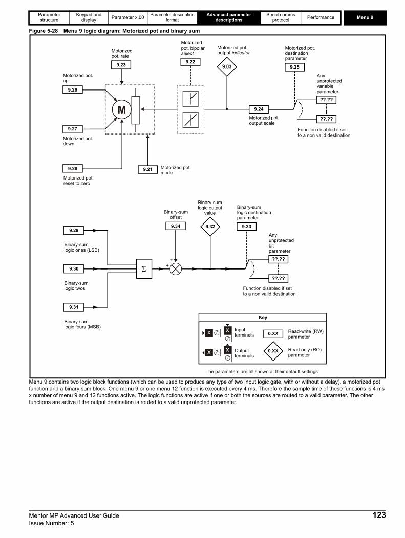
Parameter structure
Keypad and display Parameter x.00 Parameter description
formatAdvanced parameter
descriptionsSerial comms
protocol Performance Menu 9
Figure 5-28 Menu 9 logic diagram: Motorized pot and binary sum
Menu 9 contains two logic block functions (which can be used to produce any type of two input logic gate, with or without a delay), a motorized pot function and a binary sum block. One menu 9 or one menu 12 function is executed every 4 ms. Therefore the sample time of these functions is 4 ms x number of menu 9 and 12 functions active. The logic functions are active if one or both the sources are routed to a valid parameter. The other functions are active if the output destination is routed to a valid unprotected parameter.
9.30
Binary-sum logic twos
9.29
Binary-sum logic ones (LSB)
9.31
Binary-sum logic fours (MSB)
9.32
Binary-sumlogic output
value
??.??
Any unprotected bit parameter
??.??
9.33
Binary-sum logic destination parameter
Σ
9.24
Motorized pot. output scale
9.25
Motorized pot. destination parameter
9.23
Motorized pot. rate
??.??
Any unprotected variable parameter
??.??
9.27
Motorized pot. down
9.26
Motorized pot. up
M
9.03
Motorized pot. output indicator
9.22
Motorized pot. bipolar select
9.219.28
Motorized pot.reset to zero
Motorized pot.mode
++
9.34
Binary-sumoffset
0.XX
0.XX
Key
Read-write (RW) parameter
Read-only (RO) parameter
Inputterminals
Outputterminals
The parameters are all shown at their default settings
Function disabled if set to a non valid destination
Function disabled if set to a non valid destination
Mentor MP Advanced User Guide 123Issue Number: 5

Menu 9 Parameter structure
Keypad and display Parameter x.00 Parameter description
formatAdvanced parameter
descriptionsSerial comms
protocol Performance
Indicates the level of the motorized pot prior to scaling. If Pr 9.21 is set to 0 or 2 this parameter is set to 0 at power-up, otherwise it retains its value at the last power-down.
9.01 Logic function 1 output
9.02 Logic function 2 output
CodingBit SP FI DE Txt VM DP ND RA NC NV PT US RW BU PS1 1 1 1
Update rate 4 ms x number of menu 9 or 12 functions active write
9.03 Motorized pot output
CodingBit SP FI DE Txt VM DP ND RA NC NV PT US RW BU PS
2 1 1 1 1Range ±100.00 %
Update rate 4 ms x number of menu 9 or 12 functions active write
9.04 Logic function 1 source 1
9.14 Logic function 2 source 1
CodingBit SP FI DE Txt VM DP ND RA NC NV PT US RW BU PS
2 1 1 1 1Range Pr 0.00 to Pr 22.99
Default Pr 0.00
Update rate Read on reset
9.05 Logic function 1 source 1 invert
9.15 Logic function 2 source 1 invert
CodingBit SP FI DE Txt VM DP ND RA NC NV PT US RW BU PS1 1 1
Default 0
Update rate 4 ms x number of menu 9 or 12 functions active read
9.06 Logic function 1 source 2
9.16 Logic function 2 source 2
CodingBit SP FI DE Txt VM DP ND RA NC NV PT US RW BU PS
2 1 1 1 1Range Pr 0.00 to Pr 22.99
Default Pr 0.00
Update rate Read on reset
9.07 Logic function 1 source 2 invert
9.17 Logic function 2 source 2 invert
CodingBit SP FI DE Txt VM DP ND RA NC NV PT US RW BU PS1 1 1
Default 0
Update rate 4 ms x number of menu 9 or 12 functions active read
124 Mentor MP Advanced User Guide Issue Number: 5

Parameter structure
Keypad and display Parameter x.00 Parameter description
formatAdvanced parameter
descriptionsSerial comms
protocol Performance Menu 9
If the delay parameter is positive, the delay ensures that the output does not become active until an active condition has been present at the input for the delay time as shown below.
If the delay parameter is negative, the delay holds the output active for the delay period after the active condition has been removed as shown below. Therefore an active input that lasts for 4 ms or more will produce an output that lasts at least as long as the delay time.
The motorized pot modes are given in the following table:
9.08 Logic function 1 output invert
9.18 Logic function 2 output invert
CodingBit SP FI DE Txt VM DP ND RA NC NV PT US RW BU PS1 1 1
Default 0
Update rate 4 ms x number of menu 9 or 12 functions active read
9.09 Logic function 1 delay
9.19 Logic function 2 delay
CodingBit SP FI DE Txt VM DP ND RA NC NV PT US RW BU PS
1 1 1Range ±25.0 s
Default 0.0
Update rate 4 ms x number of menu 9 or 12 functions active read
9.10 Logic function 1 destination
9.20 Logic function 2 destination
CodingBit SP FI DE Txt VM DP ND RA NC NV PT US RW BU PS
1 2 1 1 1 1Range Pr 0.00 to Pr 22.99
Default Pr 0.00
Update rate Read on reset
9.21 Motorized pot mode
CodingBit SP FI DE Txt VM DP ND RA NC NV PT US RW BU PS
1 1 1Range 0 to 3
Default 2
Update rate Background read
Delay
Input
Output
Delay
Input
Output
Mentor MP Advanced User Guide 125Issue Number: 5
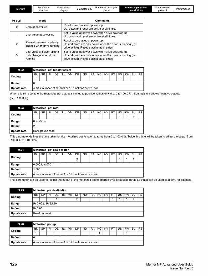
Menu 9 Parameter structure
Keypad and display Parameter x.00 Parameter description
formatAdvanced parameter
descriptionsSerial comms
protocol Performance
When this bit is set to 0 the motorized pot output is limited to positive values only (i.e. 0 to 100.0 %). Setting it to 1 allows negative outputs (i.e. ±100.0 %).
This parameter defines the time taken for the motorized pot function to ramp from 0 to 100.0 %. Twice this time will be taken to adjust the output from -100.0 % to +100.0 %.
This parameter can be used to restrict the output of the motorized pot to operate over a reduced range so that it can be used as a trim, for example.
Pr 9.21 Mode Comments
0 Zero at power-up Reset to zero at each power-up.Up, down and reset are active at all times.
1 Last value at power-up Set to value at power-down when drive powered-up.Up, down and reset are active at all times.
2 Zero at power-up and only change when drive running
Reset to zero at each power-up.Up and down are only active when the drive is running (i.e. drive active). Reset is active at all times.
3Last value at power-up and only change when drive running
Set to value at power-down when drive powered-up.Up and down are only active when the drive is running (i.e. drive active). Reset is active at all times.
9.22 Motorized pot bipolar select
CodingBit SP FI DE Txt VM DP ND RA NC NV PT US RW BU PS1 1 1
Default 0
Update rate 4 ms x number of menu 9 or 12 functions active read
9.23 Motorized pot rate
CodingBit SP FI DE Txt VM DP ND RA NC NV PT US RW BU PS
1 1 1Range 0 to 250 s
Default 20
Update rate Background read
9.24 Motorized pot scale factor
CodingBit SP FI DE Txt VM DP ND RA NC NV PT US RW BU PS
3 1 1 1
Range 0.000 to 4.000
Default 1.000
Update rate 4 ms x number of menu 9 or 12 functions active read
9.25 Motorized pot destination
CodingBit SP FI DE Txt VM DP ND RA NC NV PT US RW BU PS
1 2 1 1 1 1Range Pr 0.00 to Pr 22.99
Default Pr 0.00
Update rate Read on reset
9.26 Motorized pot up
CodingBit SP FI DE Txt VM DP ND RA NC NV PT US RW BU PS1 1 1
Default 0
Update rate 4 ms x number of menu 9 or 12 functions active read
126 Mentor MP Advanced User Guide Issue Number: 5
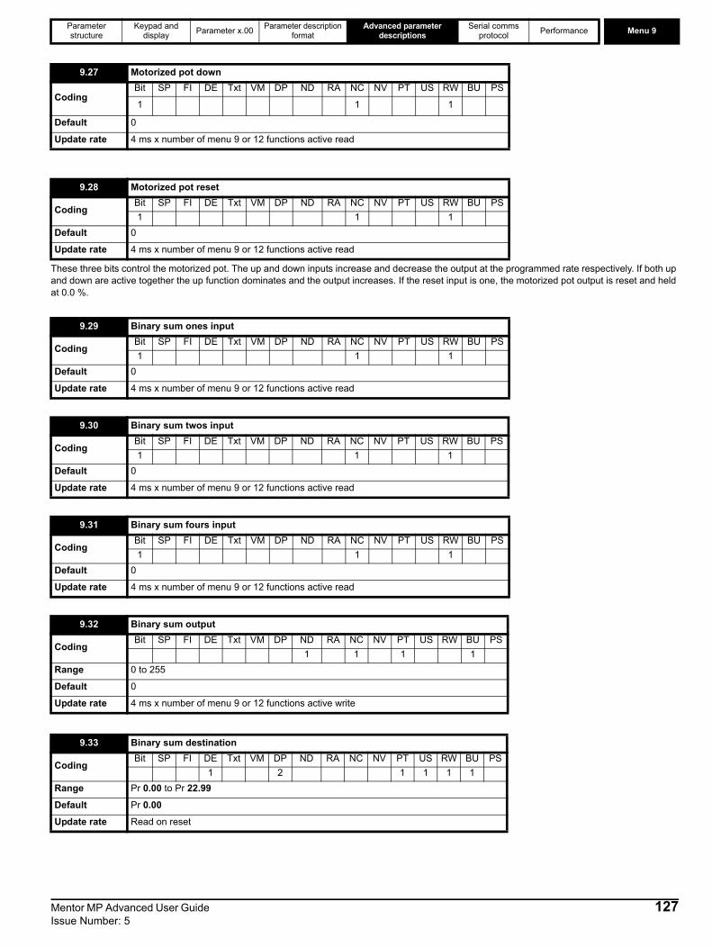
Parameter structure
Keypad and display Parameter x.00 Parameter description
formatAdvanced parameter
descriptionsSerial comms
protocol Performance Menu 9
These three bits control the motorized pot. The up and down inputs increase and decrease the output at the programmed rate respectively. If both up and down are active together the up function dominates and the output increases. If the reset input is one, the motorized pot output is reset and held at 0.0 %.
9.27 Motorized pot down
CodingBit SP FI DE Txt VM DP ND RA NC NV PT US RW BU PS
1 1 1
Default 0
Update rate 4 ms x number of menu 9 or 12 functions active read
9.28 Motorized pot reset
CodingBit SP FI DE Txt VM DP ND RA NC NV PT US RW BU PS1 1 1
Default 0
Update rate 4 ms x number of menu 9 or 12 functions active read
9.29 Binary sum ones input
CodingBit SP FI DE Txt VM DP ND RA NC NV PT US RW BU PS1 1 1
Default 0
Update rate 4 ms x number of menu 9 or 12 functions active read
9.30 Binary sum twos input
CodingBit SP FI DE Txt VM DP ND RA NC NV PT US RW BU PS1 1 1
Default 0
Update rate 4 ms x number of menu 9 or 12 functions active read
9.31 Binary sum fours input
CodingBit SP FI DE Txt VM DP ND RA NC NV PT US RW BU PS1 1 1
Default 0
Update rate 4 ms x number of menu 9 or 12 functions active read
9.32 Binary sum output
CodingBit SP FI DE Txt VM DP ND RA NC NV PT US RW BU PS
1 1 1 1Range 0 to 255
Default 0
Update rate 4 ms x number of menu 9 or 12 functions active write
9.33 Binary sum destination
CodingBit SP FI DE Txt VM DP ND RA NC NV PT US RW BU PS
1 2 1 1 1 1Range Pr 0.00 to Pr 22.99
Default Pr 0.00
Update rate Read on reset
Mentor MP Advanced User Guide 127Issue Number: 5

Menu 9 Parameter structure
Keypad and display Parameter x.00 Parameter description
formatAdvanced parameter
descriptionsSerial comms
protocol Performance
The binary sum output is given by: Offset + ones input + (2 x twos input) + (4 x fours input)
The value written to the destination parameter is defined as follows:If destination parameter maximum ≤ (7 + Offset):
Destination parameter = Binary sum outputIf destination parameter maximum > (7 + Offset):
Destination parameter = Destination parameter maximum x Binary sum output / (7 + Offset)
This parameter allows up and down buttons to be disabled under a defined condition, e.g. when the drive is in current limit.
When this is set to 1, the condition to disable the up and down buttons is inverted.
ANDThe output is the logic AND of the 2 inputs. ORThe output is the logic OR of the 2 inputs.Exclusive ORThe output is the exclusive OR of the 2 inputs.
9.34 Binary sum offset
CodingBit SP FI DE Txt VM DP ND RA NC NV PT US RW BU PS
1 2 1 1 1 1Range 0 to 248
Default 0
Update rate 4 ms read
9.35 Up down disable source
CodingBit SP FI DE Txt VM DP ND RA NC NV PT US RW BU PS
2 1 1 1 1Range Pr 0.00 to Pr 22.99
Default Pr 0.00
Update rate Read on reset
9.36 Up down disable invert
CodingBit SP FI DE Txt VM DP ND RA NC NV PT US RW BU PS1 1 1
Default 0
Update rate 4 ms read
9.37 Logic block 1 mode
9.38 Logic block 2 mode
CodingBit SP FI DE Txt VM DP ND RA NC NV PT US RW BU PS
1 1 1Range 0 to 4
Default 0
Update rate 4 ms read
Mode value Action Result0 AND Output = input1 AND input21 OR Output = input1 OR input22 XOr Output = input1 XOR input23 RS flip flop Input1 – set input2 – reset4 D type flip flop Input1 – data input2 - clock
128 Mentor MP Advanced User Guide Issue Number: 5
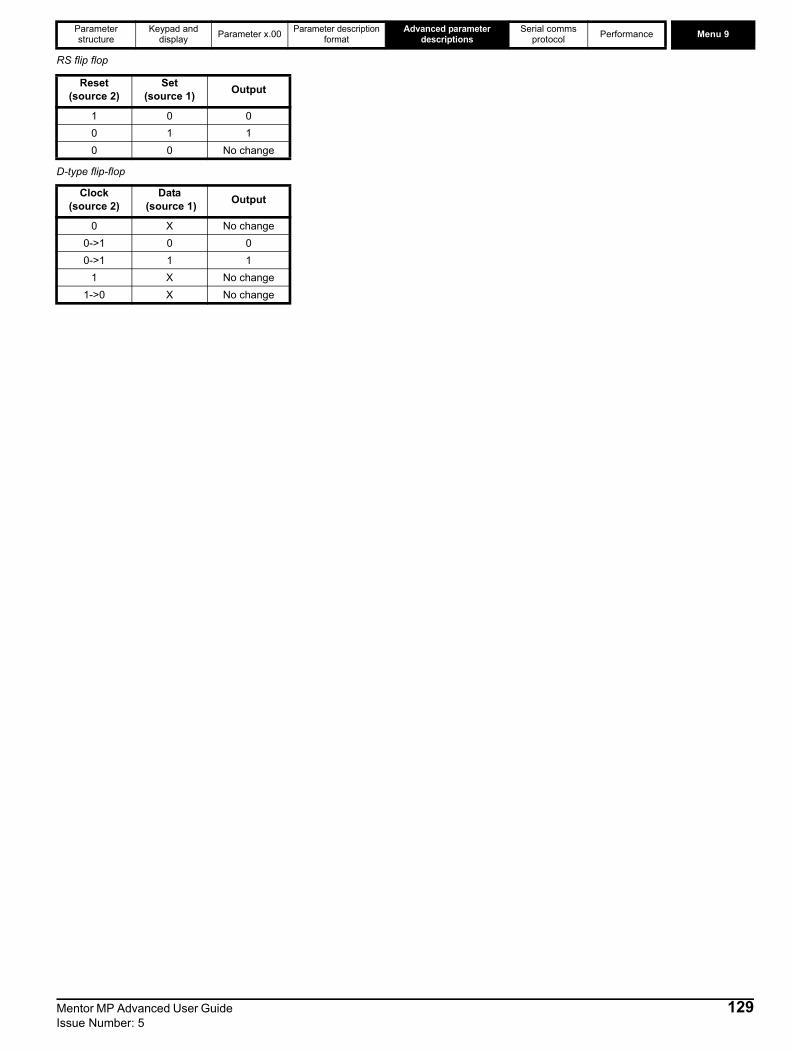
Parameter structure
Keypad and display Parameter x.00 Parameter description
formatAdvanced parameter
descriptionsSerial comms
protocol Performance Menu 9
RS flip flop
D-type flip-flop
Reset (source 2)
Set(source 1) Output
1 0 00 1 10 0 No change
Clock (source 2)
Data (source 1) Output
0 X No change0->1 0 00->1 1 1
1 X No change1->0 X No change
Mentor MP Advanced User Guide 129Issue Number: 5
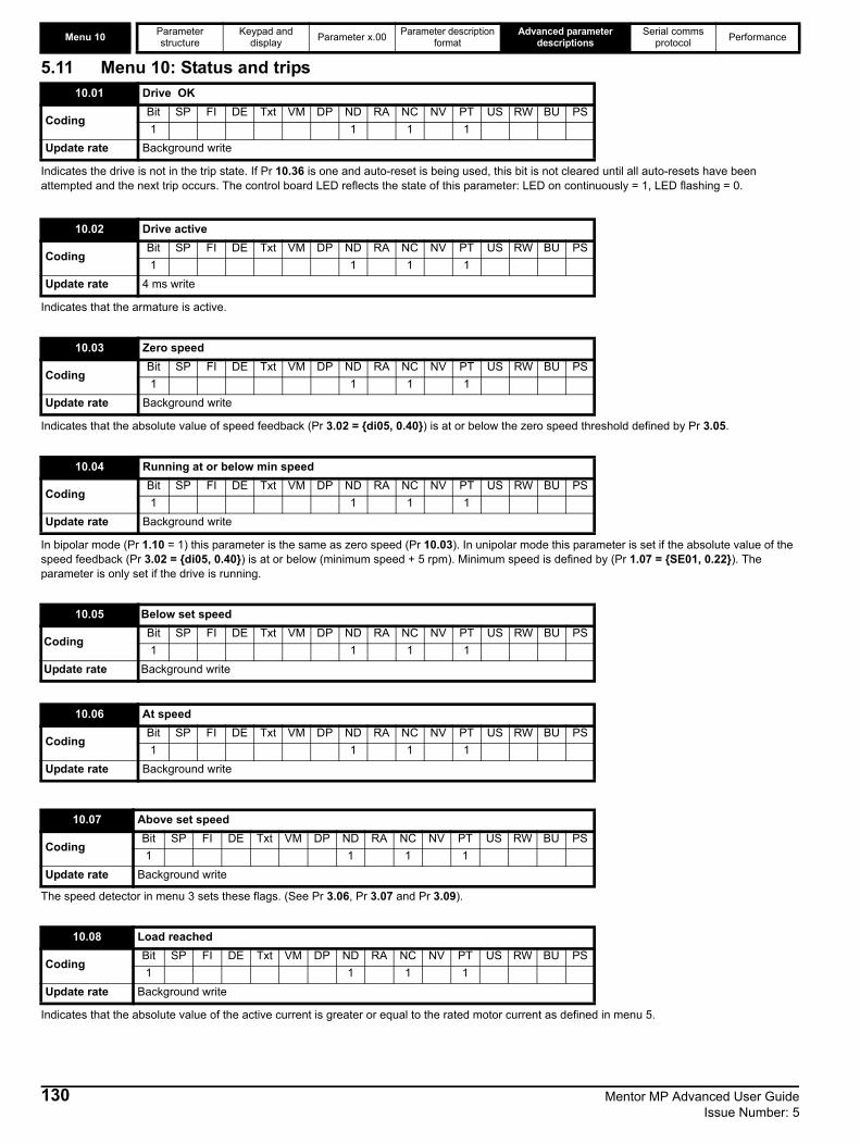
Menu 10 Parameter structure
Keypad and display Parameter x.00 Parameter description
formatAdvanced parameter
descriptionsSerial comms
protocol Performance
5.11 Menu 10: Status and trips
Indicates the drive is not in the trip state. If Pr 10.36 is one and auto-reset is being used, this bit is not cleared until all auto-resets have been attempted and the next trip occurs. The control board LED reflects the state of this parameter: LED on continuously = 1, LED flashing = 0.
Indicates that the armature is active.
Indicates that the absolute value of speed feedback (Pr 3.02 = {di05, 0.40}) is at or below the zero speed threshold defined by Pr 3.05.
In bipolar mode (Pr 1.10 = 1) this parameter is the same as zero speed (Pr 10.03). In unipolar mode this parameter is set if the absolute value of the speed feedback (Pr 3.02 = {di05, 0.40}) is at or below (minimum speed + 5 rpm). Minimum speed is defined by (Pr 1.07 = {SE01, 0.22}). The parameter is only set if the drive is running.
The speed detector in menu 3 sets these flags. (See Pr 3.06, Pr 3.07 and Pr 3.09).
Indicates that the absolute value of the active current is greater or equal to the rated motor current as defined in menu 5.
10.01 Drive OK
CodingBit SP FI DE Txt VM DP ND RA NC NV PT US RW BU PS1 1 1 1
Update rate Background write
10.02 Drive active
CodingBit SP FI DE Txt VM DP ND RA NC NV PT US RW BU PS1 1 1 1
Update rate 4 ms write
10.03 Zero speed
CodingBit SP FI DE Txt VM DP ND RA NC NV PT US RW BU PS1 1 1 1
Update rate Background write
10.04 Running at or below min speed
CodingBit SP FI DE Txt VM DP ND RA NC NV PT US RW BU PS1 1 1 1
Update rate Background write
10.05 Below set speed
CodingBit SP FI DE Txt VM DP ND RA NC NV PT US RW BU PS1 1 1 1
Update rate Background write
10.06 At speed
CodingBit SP FI DE Txt VM DP ND RA NC NV PT US RW BU PS1 1 1 1
Update rate Background write
10.07 Above set speed
CodingBit SP FI DE Txt VM DP ND RA NC NV PT US RW BU PS1 1 1 1
Update rate Background write
10.08 Load reached
CodingBit SP FI DE Txt VM DP ND RA NC NV PT US RW BU PS1 1 1 1
Update rate Background write
130 Mentor MP Advanced User Guide Issue Number: 5
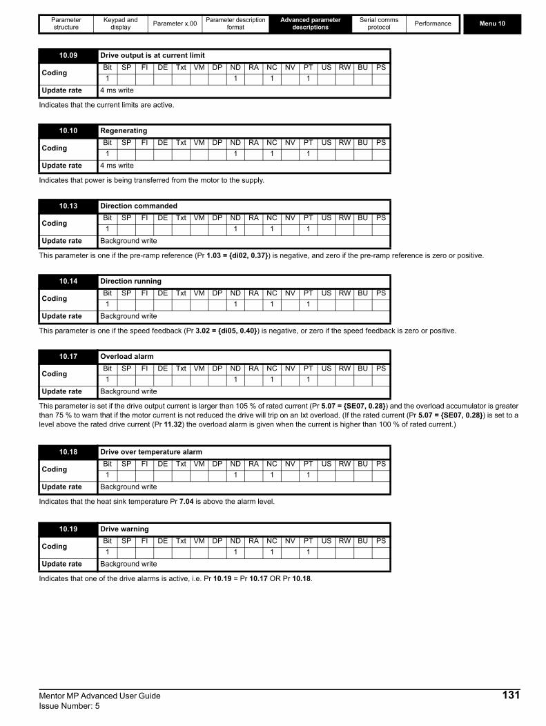
Parameter structure
Keypad and display Parameter x.00 Parameter description
formatAdvanced parameter
descriptionsSerial comms
protocol Performance Menu 10
Indicates that the current limits are active.
Indicates that power is being transferred from the motor to the supply.
This parameter is one if the pre-ramp reference (Pr 1.03 = {di02, 0.37}) is negative, and zero if the pre-ramp reference is zero or positive.
This parameter is one if the speed feedback (Pr 3.02 = {di05, 0.40}) is negative, or zero if the speed feedback is zero or positive.
This parameter is set if the drive output current is larger than 105 % of rated current (Pr 5.07 = {SE07, 0.28}) and the overload accumulator is greater than 75 % to warn that if the motor current is not reduced the drive will trip on an Ixt overload. (If the rated current (Pr 5.07 = {SE07, 0.28}) is set to a level above the rated drive current (Pr 11.32) the overload alarm is given when the current is higher than 100 % of rated current.)
Indicates that the heat sink temperature Pr 7.04 is above the alarm level.
Indicates that one of the drive alarms is active, i.e. Pr 10.19 = Pr 10.17 OR Pr 10.18.
10.09 Drive output is at current limit
CodingBit SP FI DE Txt VM DP ND RA NC NV PT US RW BU PS1 1 1 1
Update rate 4 ms write
10.10 Regenerating
CodingBit SP FI DE Txt VM DP ND RA NC NV PT US RW BU PS1 1 1 1
Update rate 4 ms write
10.13 Direction commanded
CodingBit SP FI DE Txt VM DP ND RA NC NV PT US RW BU PS1 1 1 1
Update rate Background write
10.14 Direction running
CodingBit SP FI DE Txt VM DP ND RA NC NV PT US RW BU PS1 1 1 1
Update rate Background write
10.17 Overload alarm
CodingBit SP FI DE Txt VM DP ND RA NC NV PT US RW BU PS1 1 1 1
Update rate Background write
10.18 Drive over temperature alarm
CodingBit SP FI DE Txt VM DP ND RA NC NV PT US RW BU PS1 1 1 1
Update rate Background write
10.19 Drive warning
CodingBit SP FI DE Txt VM DP ND RA NC NV PT US RW BU PS1 1 1 1
Update rate Background write
Mentor MP Advanced User Guide 131Issue Number: 5

Menu 10 Parameter structure
Keypad and display Parameter x.00 Parameter description
formatAdvanced parameter
descriptionsSerial comms
protocol Performance
Contains the last 10 drive trips. (Pr 10.20 = {tr01, 0.51}) is the most recent trip and (Pr 10.29 = {tr10, 0.60}) the oldest. When a new trip occurs all the parameters move down one, the current trip is put in (Pr 10.20 = {tr01, 0.51}) and the oldest trip is lost from the bottom of the log. Descriptions of the trips are given in Table 5-8 below. All trips are stored, including HF trips numbered from 20 to 29. (HF trips with numbers from 1 to 16 are not stored in the trip log.) Any trip can be initiated by the actions described, or by writing the relevant trip number to Pr 10.38. If any trips shown as user trips are initiated, the trip string is "txxx", where xxx is the trip number.
Table 5-8 Trip indications
10.20{tr01, 0.51} Trip 0
10.21{tr02, 0.52} Trip 1
10.22{tr03, 0.53} Trip 2
10.23{tr04, 0.54}
Trip 3
10.24{tr05, 0.55}
Trip 4
10.25{tr06, 0.56}
Trip 5
10.26{tr07, 0.57}
Trip 6
10.27{tr08, 0.58}
Trip 7
10.28{tr09, 0.59}
Trip 8
10.29{tr10, 0.60}
Trip 9
CodingBit SP FI DE Txt VM DP ND RA NC NV PT US RW BU PS
1 1 1 1 1 1
Range 0 to 229
Update rate Background write
Trip Diagnosis
AOC Instantaneous output over current detected: Peak current greater than 225 %
3Check for short circuit on armature cablingCheck integrity of motor insulationCheck current loop stability
AOP Voltage has been applied to the armature but no current feedback has been detected
158 Check the armature circuit
AtL.Err Power processor armature timing loop cannot operate with the current PLL synchronisation and the firing angle demand
161 This can occur if the PLL is in the process of losing synchronization but has not yet asserted a PLL Err (trip 174).
C.Acc SMARTCARD trip: SMARTCARD Read / Write fail
185Check SMARTCARD is installed / located correctlyEnsure SMARTCARD is not writing data to data location 500 to 999Replace SMARTCARD
C.boot SMARTCARD trip: The menu 0 parameter modification cannot be saved to the SMARTCARD because the necessary file has not been created on the SMARTCARD
177
A write to a menu 0 parameter has been initiated via the keypad with Pr 11.42 (SE09, 0.30) set to auto(3) or boot(4), but the necessary file on the SMARTCARD has not been created.Ensure that Pr 11.42 (SE09, 0.30) is correctly set and reset the drive to create the necessary file on the SMARTCARDRe-attempt the parameter write to the menu 0 parameter
C.bUSY SMARTCARD trip: SMARTCARD can not perform the required function as it is being accessed by a Solutions Module
178 Wait for the Solutions Module to finish accessing the SMARTCARD and then re-attempt the required function
132 Mentor MP Advanced User Guide Issue Number: 5

Parameter structure
Keypad and display Parameter x.00 Parameter description
formatAdvanced parameter
descriptionsSerial comms
protocol Performance Menu 10
C.Chg SMARTCARD trip: Data location already contains data
179 Erase data in data locationWrite data to an alternative data location
C.cPr SMARTCARD trip: The values stored in the drive and the values in the data block on the SMARTCARD are different
188 Press the red reset button
C.dAt SMARTCARD trip: Data location specified does not contain any data
183 Ensure data block number is correct
C.Err SMARTCARD trip: SMARTCARD data is corrupted
182Ensure the card is located correctlyErase data and retryReplace SMARTCARD
C.Full SMARTCARD trip: SMARTCARD full
184 Delete a data block or use different SMARTCARD
cL2 Analog input 2 current loss (current mode)
28 Check analog input 2 (terminal 7) current signal is present (4-20 mA, 20-4 mA)
cL3 Analog input 3 current loss (current mode)
29 Check analog input 3 (terminal 8) current signal is present (4-20 mA, 20-4 mA)
CL.bit Trip initiated from the control word (Pr 6.42)
35 Disable the control word by setting Pr 6.43 to 0 or check setting of Pr 6.42
C.OPtn SMARTCARD trip: Solutions Modules installed are different between source drive and destination drive
180Ensure correct Solutions Modules are installed Ensure Solutions Modules are in the same Solutions Module slotPress the red reset button
C.Prod SMARTCARD trip: The data blocks on the SMARTCARD are not compatible with this product
175 Erase all data on the SMARTCARD by setting Pr xx.00 to 9999 and pressing the red reset buttonReplace SMARTCARD
C.rdo SMARTCARD trip: SMARTCARD has the Read Only bit set
181 Enter 9777 in Pr xx.00 to allow SMARTCARD Read / Write access Ensure the drive is not writing to data locations 500 to 999 on the card
C.rtg SMARTCARD trip: The voltage and/or current rating of the source and destination drives are different
186
Parameter data or default difference data is being transferred from a SMART card to the drive, but the current and /or voltage ratings are different between source and destination drives. This trip does not stop the data transfer, but is a warning that the data for the Solution Modules that are different will be set to the default values and not the values from the card.This trip also applies if a compare is attempted between the data block and the drive.
C.TyP SMARTCARD trip: SMARTCARD parameter set not compatible with drive
187 Press the reset buttonEnsure destination drive type is the same as the source parameter file drive type
dESt Two or more parameters are writing to the same destination parameter
199 Set Pr xx.00 = 12001 check all visible parameters in the menus for duplication
EEF EEPROM data corrupted - Drive mode becomes open loop and serial comms will timeout with remote keypad on the drive RS485 comms port.
31 This trip can only be cleared by loading default parameters and saving parameters
EnC1 Drive encoder trip: Encoder power supply overload
189 Check encoder power supply wiring and encoder current requirementMaximum current = 200 mA @ 15 V, or 300 mA @ 8 V and 5 V
EnC2 Drive encoder trip: Wire break
190
Check cable continuityCheck wiring of feedback signals is correctCheck encoder power supply is set correctly in Pr 3.36 (Fb06, 0.76)Replace feedback deviceIf wire break detection on the main drive encoder input is not required, set Pr 3.40 = 0 to disable the Enc2 trip
EnC3 Drive encoder trip: Overload
191 Overload
Trip Diagnosis
Mentor MP Advanced User Guide 133Issue Number: 5

Menu 10 Parameter structure
Keypad and display Parameter x.00 Parameter description
formatAdvanced parameter
descriptionsSerial comms
protocol Performance
EnC9 Drive encoder trip: Position feedback is selected from a Solutions Module slot which does not have a speed / position feedback Solutions Module installed
197 Check setting of Pr 3.26 (Fb01, 0.71) (or Pr 21.21 if the second motor parameters have been enabled)
EnC10 Drive encoder trip: Termination overload
198 If the voltage from the encoder is >5 V, then the termination resistors must be disabled (Pr 3.39 to 0)
Et External trip
6
Check terminal 31 signalCheck value of Pr 10.32Enter 12001 in Pr xx.00 and check for parameter controlling Pr 10.32Ensure Pr 10.32 or Pr 10.38 (=6) are not being controlled by serial comms
FbL No feedback from the tachometer or encoder
159
If the difference between the estimated speed (Pr 5.04) and the actual speed feedback (Pr 3.02 (di05, 0.40)) exceeds the value set in the speed feedback loss window (Pr 3.56) the drive will trip Feedback loss. With fast acceleration rates in applications with low load intertia estimated speed (Pr 5.04) may not track the actual speed feedback (Pr 3.02 (di05, 0.40)) fast enough and the speed feedback loss window (Pr 3.56) may need to be increased.Check the feedback device is connected correctlyCheck motor name plate values have been entered into the drive correctlyCheck the speed feedback in estimated speed mode - refer to running a motor section checking speed feedbackCarry out a rotating autotune
Fbr The polarity of the feedback tachometer or encoder is incorrect
160 Check that the feedback devices are connected correctly
FdL No current in the field supply circuit
168Check that the field controller (Pr 5.77 (SE12, 0.33)) is enabled.For the internal field controller check terminals L11, L12 are closedCheck internal auxiliary fuses.
FOC Excess current detected in field current feedback
169
Maximum current feedback is presentCheck Field rated current (Pr 5.70 (SE10, 0.31)) and Field rated voltage (Pr 5.73 (SE11, 0.32)) are set correct to motor nameplateCheck for short circuit on field circuit cablingCheck integrity of motor insulation
F.OVL Field I2t overload
157 See Pr 5.81 and Pr 5.82
HF01 Data processing error: CPU address error
Hardware fault - return drive to supplier
HF02 Data processing error: DMAC address error
Hardware fault - return drive to supplier
HF03 Data processing error: Illegal instruction
Hardware fault - return drive to supplier
HF04 Data processing error: Illegal slot instruction
Hardware fault - return drive to supplier
HF05 Data processing error: Undefined exception
Hardware fault - return drive to supplier
HF06 Data processing error: Reserved exception
Hardware fault - return drive to supplier
HF07 Data processing error: Watchdog failure
Hardware fault - return drive to supplier
HF08 Data processing error: Level 4 crash
Hardware fault - return drive to supplier
HF09 Data processing error: Heap overflow
Hardware fault - return drive to supplier
HF10 Data processing error: Router error
Hardware fault - return drive to supplier
Trip Diagnosis
134 Mentor MP Advanced User Guide Issue Number: 5
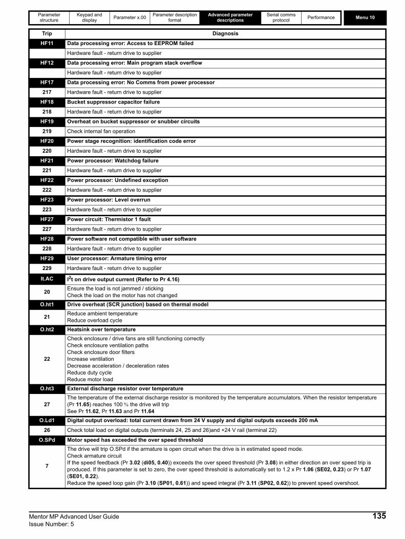
Parameter structure
Keypad and display Parameter x.00 Parameter description
formatAdvanced parameter
descriptionsSerial comms
protocol Performance Menu 10
HF11 Data processing error: Access to EEPROM failed
Hardware fault - return drive to supplier
HF12 Data processing error: Main program stack overflow
Hardware fault - return drive to supplier
HF17 Data processing error: No Comms from power processor
217 Hardware fault - return drive to supplier
HF18 Bucket suppressor capacitor failure
218 Hardware fault - return drive to supplier
HF19 Overheat on bucket suppressor or snubber circuits
219 Check internal fan operation
HF20 Power stage recognition: identification code error
220 Hardware fault - return drive to supplier
HF21 Power processor: Watchdog failure
221 Hardware fault - return drive to supplier
HF22 Power processor: Undefined exception
222 Hardware fault - return drive to supplier
HF23 Power processor: Level overrun
223 Hardware fault - return drive to supplier
HF27 Power circuit: Thermistor 1 fault
227 Hardware fault - return drive to supplier
HF28 Power software not compatible with user software
228 Hardware fault - return drive to supplier
HF29 User processor: Armature timing error
229 Hardware fault - return drive to supplier
It.AC I2t on drive output current (Refer to Pr 4.16)
20 Ensure the load is not jammed / stickingCheck the load on the motor has not changed
O.ht1 Drive overheat (SCR junction) based on thermal model
21 Reduce ambient temperatureReduce overload cycle
O.ht2 Heatsink over temperature
22
Check enclosure / drive fans are still functioning correctlyCheck enclosure ventilation paths Check enclosure door filtersIncrease ventilationDecrease acceleration / deceleration ratesReduce duty cycleReduce motor load
O.ht3 External discharge resistor over temperature
27The temperature of the external discharge resistor is monitored by the temperature accumulators. When the resistor temperature (Pr 11.65) reaches 100 % the drive will tripSee Pr 11.62, Pr 11.63 and Pr 11.64
O.Ld1 Digital output overload: total current drawn from 24 V supply and digital outputs exceeds 200 mA
26 Check total load on digital outputs (terminals 24, 25 and 26)and +24 V rail (terminal 22)
O.SPd Motor speed has exceeded the over speed threshold
7
The drive will trip O.SPd if the armature is open circuit when the drive is in estimated speed mode.Check armature circuitIf the speed feedback (Pr 3.02 (di05, 0.40)) exceeds the over speed threshold (Pr 3.08) in either direction an over speed trip is produced. If this parameter is set to zero, the over speed threshold is automatically set to 1.2 x Pr 1.06 (SE02, 0.23) or Pr 1.07 (SE01, 0.22). Reduce the speed loop gain (Pr 3.10 (SP01, 0.61)) and speed integral (Pr 3.11 (SP02, 0.62)) to prevent speed overshoot.
Trip Diagnosis
Mentor MP Advanced User Guide 135Issue Number: 5
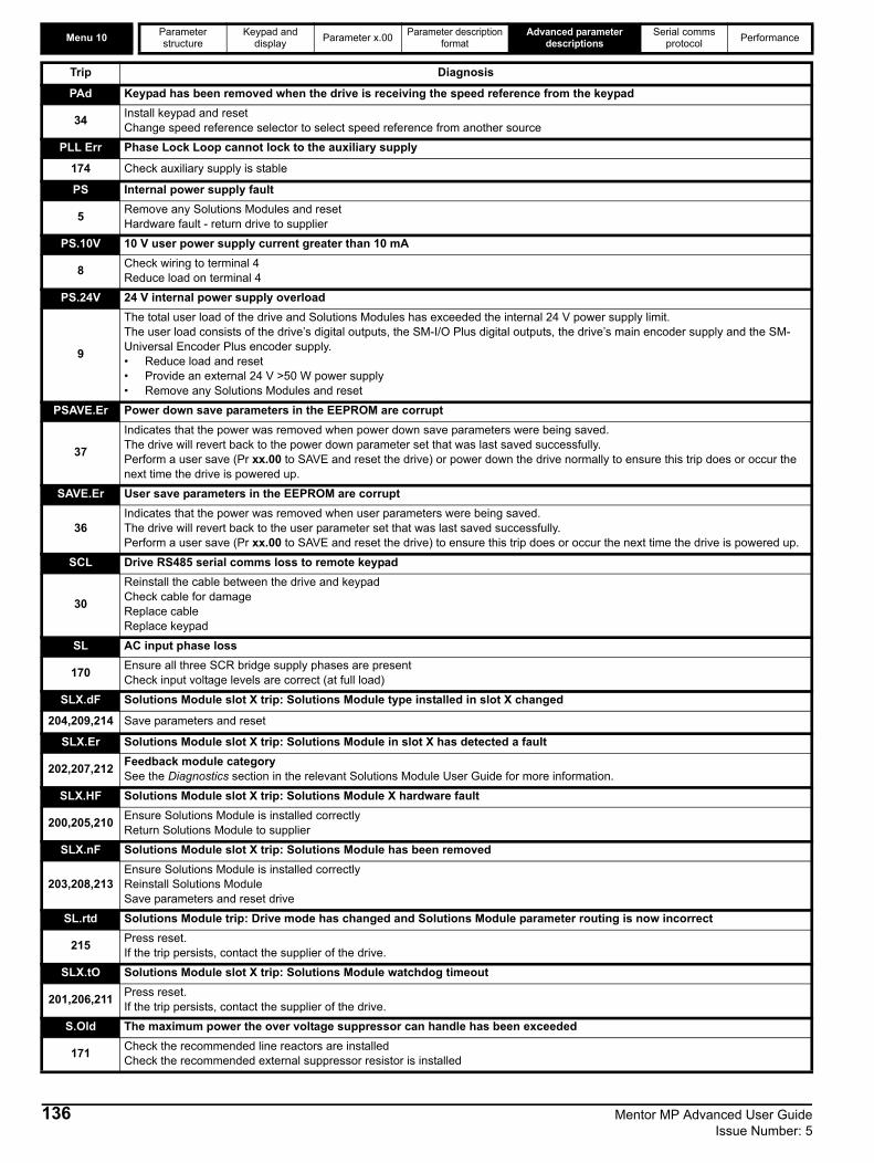
Menu 10 Parameter structure
Keypad and display Parameter x.00 Parameter description
formatAdvanced parameter
descriptionsSerial comms
protocol Performance
PAd Keypad has been removed when the drive is receiving the speed reference from the keypad
34 Install keypad and resetChange speed reference selector to select speed reference from another source
PLL Err Phase Lock Loop cannot lock to the auxiliary supply
174 Check auxiliary supply is stable
PS Internal power supply fault
5 Remove any Solutions Modules and reset Hardware fault - return drive to supplier
PS.10V 10 V user power supply current greater than 10 mA
8 Check wiring to terminal 4Reduce load on terminal 4
PS.24V 24 V internal power supply overload
9
The total user load of the drive and Solutions Modules has exceeded the internal 24 V power supply limit.The user load consists of the drive’s digital outputs, the SM-I/O Plus digital outputs, the drive’s main encoder supply and the SM-Universal Encoder Plus encoder supply. • Reduce load and reset• Provide an external 24 V >50 W power supply • Remove any Solutions Modules and reset
PSAVE.Er Power down save parameters in the EEPROM are corrupt
37
Indicates that the power was removed when power down save parameters were being saved.The drive will revert back to the power down parameter set that was last saved successfully.Perform a user save (Pr xx.00 to SAVE and reset the drive) or power down the drive normally to ensure this trip does or occur the next time the drive is powered up.
SAVE.Er User save parameters in the EEPROM are corrupt
36Indicates that the power was removed when user parameters were being saved.The drive will revert back to the user parameter set that was last saved successfully.Perform a user save (Pr xx.00 to SAVE and reset the drive) to ensure this trip does or occur the next time the drive is powered up.
SCL Drive RS485 serial comms loss to remote keypad
30
Reinstall the cable between the drive and keypadCheck cable for damageReplace cableReplace keypad
SL AC input phase loss
170 Ensure all three SCR bridge supply phases are presentCheck input voltage levels are correct (at full load)
SLX.dF Solutions Module slot X trip: Solutions Module type installed in slot X changed
204,209,214 Save parameters and reset
SLX.Er Solutions Module slot X trip: Solutions Module in slot X has detected a fault
202,207,212 Feedback module categorySee the Diagnostics section in the relevant Solutions Module User Guide for more information.
SLX.HF Solutions Module slot X trip: Solutions Module X hardware fault
200,205,210 Ensure Solutions Module is installed correctlyReturn Solutions Module to supplier
SLX.nF Solutions Module slot X trip: Solutions Module has been removed
203,208,213Ensure Solutions Module is installed correctlyReinstall Solutions ModuleSave parameters and reset drive
SL.rtd Solutions Module trip: Drive mode has changed and Solutions Module parameter routing is now incorrect
215 Press reset.If the trip persists, contact the supplier of the drive.
SLX.tO Solutions Module slot X trip: Solutions Module watchdog timeout
201,206,211 Press reset.If the trip persists, contact the supplier of the drive.
S.Old The maximum power the over voltage suppressor can handle has been exceeded
171 Check the recommended line reactors are installedCheck the recommended external suppressor resistor is installed
Trip Diagnosis
136 Mentor MP Advanced User Guide Issue Number: 5
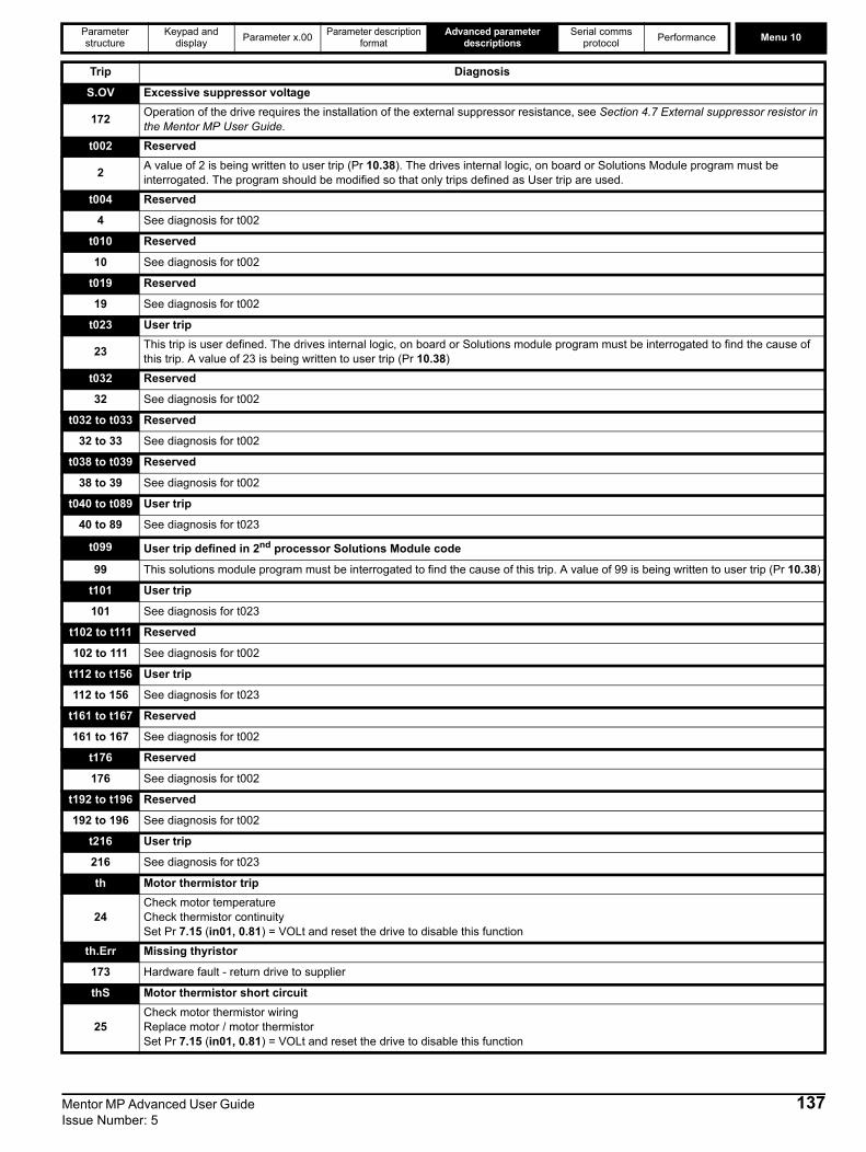
Parameter structure
Keypad and display Parameter x.00 Parameter description
formatAdvanced parameter
descriptionsSerial comms
protocol Performance Menu 10
S.OV Excessive suppressor voltage
172 Operation of the drive requires the installation of the external suppressor resistance, see Section 4.7 External suppressor resistor in the Mentor MP User Guide.
t002 Reserved
2 A value of 2 is being written to user trip (Pr 10.38). The drives internal logic, on board or Solutions Module program must be interrogated. The program should be modified so that only trips defined as User trip are used.
t004 Reserved
4 See diagnosis for t002
t010 Reserved
10 See diagnosis for t002
t019 Reserved
19 See diagnosis for t002
t023 User trip
23 This trip is user defined. The drives internal logic, on board or Solutions module program must be interrogated to find the cause of this trip. A value of 23 is being written to user trip (Pr 10.38)
t032 Reserved
32 See diagnosis for t002
t032 to t033 Reserved
32 to 33 See diagnosis for t002
t038 to t039 Reserved
38 to 39 See diagnosis for t002
t040 to t089 User trip
40 to 89 See diagnosis for t023
t099 User trip defined in 2nd processor Solutions Module code
99 This solutions module program must be interrogated to find the cause of this trip. A value of 99 is being written to user trip (Pr 10.38)
t101 User trip
101 See diagnosis for t023
t102 to t111 Reserved
102 to 111 See diagnosis for t002
t112 to t156 User trip
112 to 156 See diagnosis for t023
t161 to t167 Reserved
161 to 167 See diagnosis for t002
t176 Reserved
176 See diagnosis for t002
t192 to t196 Reserved
192 to 196 See diagnosis for t002
t216 User trip
216 See diagnosis for t023
th Motor thermistor trip
24Check motor temperatureCheck thermistor continuitySet Pr 7.15 (in01, 0.81) = VOLt and reset the drive to disable this function
th.Err Missing thyristor
173 Hardware fault - return drive to supplier
thS Motor thermistor short circuit
25Check motor thermistor wiringReplace motor / motor thermistorSet Pr 7.15 (in01, 0.81) = VOLt and reset the drive to disable this function
Trip Diagnosis
Mentor MP Advanced User Guide 137Issue Number: 5

Menu 10 Parameter structure
Keypad and display Parameter x.00 Parameter description
formatAdvanced parameter
descriptionsSerial comms
protocol Performance
* If a tunE through tunE 7 trip occurs, then after the drive is reset the drive cannot be made to run unless it is disabled via the drive enable parameter (Pr 6.15) or the control word (Pr 6.42).
tunE Autotune stopped before completion
18 The drive has tripped out during the autotuneThe red stop key has been pressed during the autotune
tunE1* The position feedback did not change or required speed could not be reached during the inertia test (see Pr 5.12 (SE13, 0.34))
11
Ensure the motor is free to turn i.e. brake was releasedEnsure Pr 3.26 and Pr 3.38 are set correctlyCheck feedback device wiring is correctCheck feedback device coupling to motor
tunE2* Position feedback direction incorrect or motor could not be stopped during the inertia test (See Pr 5.12 (SE13, 0.34))
12 Check motor cable wiring is correctCheck feedback device wiring is correct
tunE3* Field flux has not decayed to zero during autotune
13 Contact the supplier of the drive
tunE4* Back emf detected during autotune
14 Check that the motor is not spinning when a static autotune is carried out
tunE5* No field current detected during autotune
15 Reset Pr 5.70 (SE10, 0.31) to nameplate value and re-autotune motor
tunE6* Cannot achieve ¼ rated back emf during autotune
16 Reset Pr 5.70 (SE10, 0.31) to nameplate value and re-autotune motor
tunE7* Rotating autotune initiated with Estimated speed selected
17 Connect a feedback device to carry out a rotating autotune
UP ACC Onboard PLC program: cannot access Onboard PLC program file on drive
98 Disable drive - write access is not allowed when the drive is enabledAnother source is already accessing Onboard PLC program - retry once other action is complete
UP div0 Onboard PLC program attempted divide by zero
90 Check program
UP OFL Onboard PLC program variables and function block calls using more than the allowed RAM space (stack overflow)
95 Check program
UP ovr Onboard PLC program attempted out of range parameter write
94 Check program
UP PAr Onboard PLC program attempted access to a non-existent parameter
91 Check program
UP ro Onboard PLC program attempted write to a read-only parameter
92 Check program
UP So Onboard PLC program attempted read of a write-only parameter
93 Check program
UP udF Onboard PLC program un-defined trip
97 Check program
UP uSEr Onboard PLC program requested a trip
96 Check program
UV The drive is running from the external 24 V supply
1 The drive is running from the external 24 V supply
Trip Diagnosis
138 Mentor MP Advanced User Guide Issue Number: 5
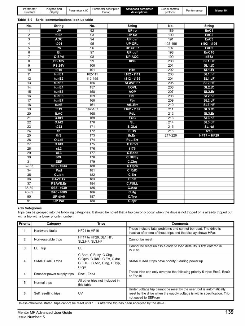
Parameter structure
Keypad and display Parameter x.00 Parameter description
formatAdvanced parameter
descriptionsSerial comms
protocol Performance Menu 10
Table 5-9 Serial communications look-up table
Trip CategoriesTrips can be grouped into the following categories. It should be noted that a trip can only occur when the drive is not tripped or is already tripped but with a trip with a lower priority number.
Unless otherwise stated, trips cannot be reset until 1.0 s after the trip has been accepted by the drive.
No. String No. String No. String1 UV 92 UP ro 189 EnC12 t002 93 UP So 190 EnC23 AOC 94 UP ovr 191 EnC34 t004 95 UP OFL 192-196 t192 - t1965 PS 96 UP uSEr 197 EnC96 Et 97 UP udf 198 EnC107 O.SPd 98 UP ACC 199 dESt8 PS.10V 99 t099 200 SL1.HF9 PS.24V 100 201 SL1.tO
10 t010 101 t101 202 SL1.Er11 tunE1 102-111 t102 - t111 203 SL1.nF12 tunE2 112-155 t112 - t155 204 SL1.dF13 tunE3 156 SLAVE.Er 205 SL2.HF14 tunE4 157 F.OVL 206 SL2.tO15 tunE5 158 AOP 207 SL2.Er16 tunE6 159 FbL 208 SL2.nF17 tunE7 160 Fbr 209 SL2.dF18 tunE 161 AtL.Err 210 SL3.HF19 t019 162-167 t162 - t167 211 SL3.tO20 It.AC 168 FdL 212 SL3.Er21 O.ht1 169 FOC 213 SL3.nF22 O.ht2 170 SL 214 SL3.dF23 t023 171 S.OLd 215 SL.rtd24 th 172 S.OV 216 t21625 thS 173 th.Err 217-229 HF17 – HF2926 O.Ld1 174 PLL Err27 O.ht3 175 C.Prod28 cL2 176 t17629 cL3 177 C.Boot30 SCL 178 C.BUSy31 EEF 179 C.Chg
32-33 t032 - t033 180 C.Optn34 Pad 181 C.RdO35 CL.bit 182 C.Err36 SAVE.Er 183 C.dat37 PSAVE.Er 184 C.FULL
38-39 t038 - t039 185 C.Acc40-89 t040 - t089 186 C.rtg
90 UP div0 187 C.Typ91 UP Par 188 C.cpr
Priority Category Trips Comments
1 Hardware faults HF01 to HF16 These indicate fatal problems and cannot be reset. The drive is inactive after one of these trips and the display shows HFxx
2 Non-resetable trips HF17 to HF29, SL1.HF, SL2.HF, SL3.HF Cannot be reset
3 EEF trip EEF Cannot be reset unless a code to load defaults is first entered in Pr x.00
4 SMARTCARD trips
C.Boot, C.Busy, C.Chg, C.Optn, C.RdO, C.Err, C.dat, C.FULL, C.Acc, C.rtg, C.Typ, C.cpr
SMARTCARD trips have priority 5 during power up
4 Encoder power supply trips Enc1, Enc3 These trips can only override the following priority 5 trips: Enc2, Enc9 or Enc10
5 Normal trips All other trips not included in this table
6 Self resetting trips UVUnder voltage trip cannot be reset by the user, but is automatically reset by the drive when the supply voltage is within specification. Trip not saved to EEProm
Mentor MP Advanced User Guide 139Issue Number: 5

Menu 10 Parameter structure
Keypad and display Parameter x.00 Parameter description
formatAdvanced parameter
descriptionsSerial comms
protocol Performance
Hardware fault trips
If this flag is set to one then the drive will trip (Et). If an external trip function is required, a digital input should be programmed to control this bit.
A zero to one change in this parameter will cause a drive reset. If a drive reset terminal is required on the drive the required terminal must be programmed to control this bit.
See also Pr 10.35 overleaf
HF fault code Reason for trip01 CPU address error02 DMAC address error03 Illegal instruction04 Illegal slot instruction05 Undefined exception06 Reserved exception07 Watchdog failure08 Level 4 crash09 Heap overflow10 Router error11 Access to the EEPROM failed or incorrect EEPROMs installed12 Main program stack overflow
13 - 16 Not used17 No comms from power processor18 Bucket suppressor capacitor failure19 Over heat on bucket suppressor or snubber circuits. Check internal fan operation 20 Power circuit - identification code error21 Power processor - Watchdog failure22 Power processor - Undefined exception23 Power processor - Level overrun24 Power processor - Spare25 Power processor - Spare26 Power processor - Spare27 Power circuit thermistor 1 fault28 Power software not compatible with user software29 User processor - Armature timing error
10.32 External trip
CodingBit SP FI DE Txt VM DP ND RA NC NV PT US RW BU PS1 1 1
Default 0
Update rate Background read
10.33 Drive reset
CodingBit SP FI DE Txt VM DP ND RA NC NV PT US RW BU PS1 1 1
Default 0
Update rate Background read
10.34 No. of auto-reset attempts
CodingBit SP FI DE Txt VM DP ND RA NC NV PT US RW BU PS
1 1 1Range 0 to 5
Default 0
Update rate Background read
140 Mentor MP Advanced User Guide Issue Number: 5
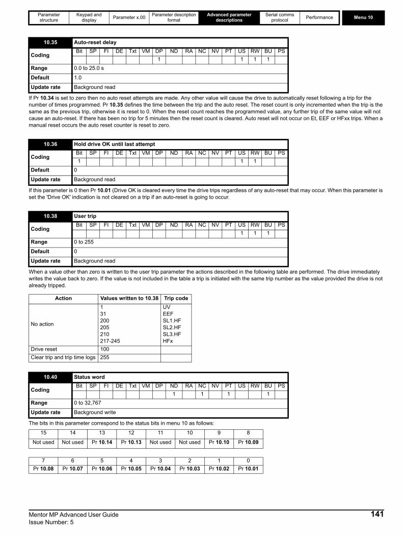
Parameter structure
Keypad and display Parameter x.00 Parameter description
formatAdvanced parameter
descriptionsSerial comms
protocol Performance Menu 10
If Pr 10.34 is set to zero then no auto reset attempts are made. Any other value will cause the drive to automatically reset following a trip for the number of times programmed. Pr 10.35 defines the time between the trip and the auto reset. The reset count is only incremented when the trip is the same as the previous trip, otherwise it is reset to 0. When the reset count reaches the programmed value, any further trip of the same value will not cause an auto-reset. If there has been no trip for 5 minutes then the reset count is cleared. Auto reset will not occur on Et, EEF or HFxx trips. When a manual reset occurs the auto reset counter is reset to zero.
If this parameter is 0 then Pr 10.01 (Drive OK is cleared every time the drive trips regardless of any auto-reset that may occur. When this parameter is set the 'Drive OK' indication is not cleared on a trip if an auto-reset is going to occur.
When a value other than zero is written to the user trip parameter the actions described in the following table are performed. The drive immediately writes the value back to zero. If the value is not included in the table a trip is initiated with the same trip number as the value provided the drive is not already tripped.
The bits in this parameter correspond to the status bits in menu 10 as follows:
10.35 Auto-reset delay
CodingBit SP FI DE Txt VM DP ND RA NC NV PT US RW BU PS
1 1 1 1Range 0.0 to 25.0 s
Default 1.0
Update rate Background read
10.36 Hold drive OK until last attempt
CodingBit SP FI DE Txt VM DP ND RA NC NV PT US RW BU PS1 1 1
Default 0
Update rate Background read
10.38 User trip
CodingBit SP FI DE Txt VM DP ND RA NC NV PT US RW BU PS
1 1 1Range 0 to 255
Default 0
Update rate Background read
Action Values written to 10.38 Trip code
No action
131200205210217-245
UVEEFSL1.HFSL2.HFSL3.HFHFx
Drive reset 100Clear trip and trip time logs 255
10.40 Status word
CodingBit SP FI DE Txt VM DP ND RA NC NV PT US RW BU PS
1 1 1 1Range 0 to 32,767
Update rate Background write
15 14 13 12 11 10 9 8
Not used Not used Pr 10.14 Pr 10.13 Not used Not used Pr 10.10 Pr 10.09
7 6 5 4 3 2 1 0Pr 10.08 Pr 10.07 Pr 10.06 Pr 10.05 Pr 10.04 Pr 10.03 Pr 10.02 Pr 10.01
Mentor MP Advanced User Guide 141Issue Number: 5

Menu 10 Parameter structure
Keypad and display Parameter x.00 Parameter description
formatAdvanced parameter
descriptionsSerial comms
protocol Performance
When a trip occurs the reason for the trip is put into the top location in the trip log (Pr 10.20 = {tr01, 0.51}). At the same time either the time from the powered-up clock (if Pr 6.28 = 0) or from the run time clock (if Pr 6.28 = 1) is put into Trip 0 time (Pr 10.41 and Pr 10.42). The times for earlier trips (Trip 1 to 9) are moved to the next parameter in the same way that trips move down the trip log. The time for Trips 1 to 9 are stored as the time difference between when Trip 0 occurred and the relevant trip in hours and minutes. The maximum time difference that can be stored is 600 hours. If this time is exceeded the value stored is 600.00.If the powered-up clock is used as the source for this function all the times in the log are reset to zero at power-up because they were related to the time since the drive was powered-up last time. If the runtime clock is used the times are saved at power-down and then retained when the drive powers up again. If Pr 6.28, which defines the clock source, is changed by the user the whole trip and trip time logs are cleared. It should be noted that the powered-up time can be modified by the user at any time. If this is done the values in the trip time log remain unchanged until a trip occurs. The new values put in the log for earlier trips (Trip 1 to 9) will become the time difference between the value of the power-up clock when the trip occurred and the value of the powered-up clock when the latest trip occurred. It is possible that this time difference may be negative, in which case the value will be zero.
The user can mask some of the trips from tripping the drive. The trip can be completely masked (do nothing in the event of the selected trip) by setting the trip number into the parameter.
10.41 Trip 0 time: years.days
CodingBit SP FI DE Txt VM DP ND RA NC NV PT US RW BU PS
3 1 1 1 1 1Range 0.000 to 9.364 Years.Days
Update rate Background write
10.42 Trip 0 time: hours.minutes
CodingBit SP FI DE Txt VM DP ND RA NC NV PT US RW BU PS
1 2 1 1 1 1 1Range 00.00 to 23.59 Hours.Minutes
Update rate Background write
10.43 Trip 1 time
10.44 Trip 2 time
10.45 Trip 3 time
10.46 Trip 4 time
10.47 Trip 5 time
10.48 Trip 6 time
10.49 Trip 7 time
10.50 Trip 8 time
10.51 Trip 9 time
CodingBit SP FI DE Txt VM DP ND RA NC NV PT US RW BU PS
2 1 1 1 1 1
Range 0 to 600.00 Hours.Minutes
Update rate Background write
10.52 - 10.61 Trip Masks
CodingBit SP FI DE Txt VM DP ND RA NC NV PT US RW BU PS
1 1 1Range 0 to 216
Default 0
Update rate Background read
142 Mentor MP Advanced User Guide Issue Number: 5

Parameter structure
Keypad and display Parameter x.00 Parameter description
formatAdvanced parameter
descriptionsSerial comms
protocol Performance Menu 10
The user can mask some of the trips from tripping the drive. The trip can be completely masked (do nothing in the event of the selected trip) by setting the trip number into the parameter. The trip can be made to stop the drive and then trip, by enabling the associated bit parameter.Trips that cannot be masked are UV, AOC, AtL.Err, PS, O.SPd, FOC, O.ht1, O.ht2, O.ht3, EEF, SLX.HF, S.OV, PLL Err, Enc9, SLAVE.Er and HF17 to HF29.Example 1.The user wants the drive to not trip when there is current loss on analog input 2. Enter 28 into Pr 10.52 and set Pr 10.62 to 0.Example 2.The user wants the drive to stop and then trip when there is current loss on analog input 2. Enter 28 into Pr 10.52 to achieve this.
Set to 1 when a trip is being masked.
This parameter will indicate which bridge is on. "__ "No bridge"_1 "Bridge 1 active"2_ "Bridge 2 activeWhere _ is a blank.
When 0 the firing pulses not phased back. When 1 the firing pulses are phased back or the drive disabled.
Sets to 1 when the armature voltage clamp is activated. Prevents the voltage from increasing further.When the armature voltage exceeds 1.15 times the supply voltage the armature voltage clamp is activated to prevent the voltage rising. SCR firing is inhibited until the voltage has fallen.
10.62 - 10.71 Stop on Trip Masks
CodingBit SP FI DE Txt VM DP ND RA NC NV PT US RW BU PS1 1 1
Default On (1)
Update rate Background read
10.72 Trip Mask Active
CodingBit SP FI DE Txt VM DP ND RA NC NV PT US RW BU PS1 1 1
Range 0 to 1
Default 0
Update rate Background write
10.73 Bridge Active
CodingBit SP FI DE Txt VM DP ND RA NC NV PT US RW BU PS
1 1 1 1Range 0 to 2
Default 0
Update rate Background write
10.74 Electrical phase back
CodingBit SP FI DE Txt VM DP ND RA NC NV PT US RW BU PS1 1 1
Range 0 to 1
Update rate Background read
10.75 Armature voltage clamp active
CodingBit SP FI DE Txt VM DP ND RA NC NV PT US RW BU PS1 1 1
Range 0 to 1
Update rate Background read
Mentor MP Advanced User Guide 143Issue Number: 5

Menu 10 Parameter structure
Keypad and display Parameter x.00 Parameter description
formatAdvanced parameter
descriptionsSerial comms
protocol Performance
This parameter gives the phase rotation of the L1, L2 and L3 terminals, with relation to E1 and E3 when voltage is first detected on L1, L2 and L3.A supply loss trip will result if a phase is missing.ExampleL123 E21 phase rotation on L1, L2, L3 is clockwise, terminal E1 is connected to the same phase as L2 terminal, terminal E3 is connected to the same phase as L1 terminal.
The input frequency measured on the auxiliary terminals.
10.76 Phase rotation
CodingBit SP FI DE Txt VM DP ND RA NC NV PT US RW BU PS
1 1 1Range 0 to 15 (see table below)
Update rate Background read
Pr 10.76 Text Comment0 No L123 No voltage detected on L1, L2, L31 L123 E13 L1, L2, L3 clockwise2 L123 E12 L1, L2, L3 clockwise3 L123 E32 L1, L2, L3 clockwise4 L123 E31 L1, L2, L3 clockwise5 L123 E21 L1, L2, L3 clockwise6 L123 E23 L1, L2, L3 clockwise7 L321 E13 L1, L2, L3 anticlockwise8 L321 E23 L1, L2, L3 anticlockwise9 L321 E21 L1, L2, L3 anticlockwise
10 L321 E31 L1, L2, L3 anticlockwise11 L321 E32 L1, L2, L3 anticlockwise12 L321 E12 L1, L2, L3 anticlockwise13 L120 L3 missing14 L103 L2 missing15 L023 L1 missing
10.77 Input frequency
CodingBit SP FI DE Txt VM DP ND RA NC NV PT US RW BU PS
2 1 1 1Range 0 to 100.00
Update rate Background read
144 Mentor MP Advanced User Guide Issue Number: 5
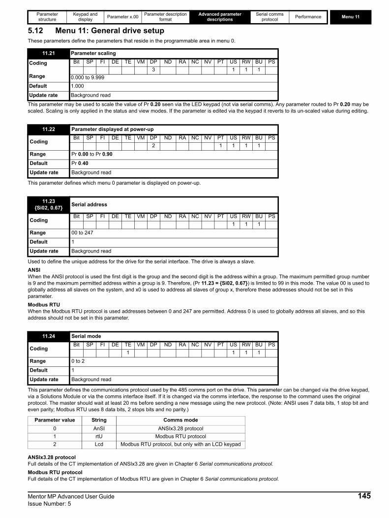
Parameter structure
Keypad and display Parameter x.00 Parameter description
formatAdvanced parameter
descriptionsSerial comms
protocol Performance Menu 11
5.12 Menu 11: General drive setupThese parameters define the parameters that reside in the programmable area in menu 0.
This parameter may be used to scale the value of Pr 0.20 seen via the LED keypad (not via serial comms). Any parameter routed to Pr 0.20 may be scaled. Scaling is only applied in the status and view modes. If the parameter is edited via the keypad it reverts to its un-scaled value during editing.
This parameter defines which menu 0 parameter is displayed on power-up.
Used to define the unique address for the drive for the serial interface. The drive is always a slave. ANSIWhen the ANSI protocol is used the first digit is the group and the second digit is the address within a group. The maximum permitted group number is 9 and the maximum permitted address within a group is 9. Therefore, (Pr 11.23 = {Si02, 0.67}) is limited to 99 in this mode. The value 00 is used to globally address all slaves on the system, and x0 is used to address all slaves of group x, therefore these addresses should not be set in this parameter. Modbus RTU When the Modbus RTU protocol is used addresses between 0 and 247 are permitted. Address 0 is used to globally address all slaves, and so this address should not be set in this parameter.
This parameter defines the communications protocol used by the 485 comms port on the drive. This parameter can be changed via the drive keypad, via a Solutions Module or via the comms interface itself. If it is changed via the comms interface, the response to the command uses the original protocol. The master should wait at least 20 ms before sending a new message using the new protocol. (Note: ANSI uses 7 data bits, 1 stop bit and even parity; Modbus RTU uses 8 data bits, 2 stops bits and no parity.)
ANSIx3.28 protocolFull details of the CT implementation of ANSIx3.28 are given in Chapter 6 Serial communications protocol.Modbus RTU protocolFull details of the CT implementation of Modbus RTU are given in Chapter 6 Serial communications protocol.
11.21 Parameter scaling
Coding
Range
Bit SP FI DE TE VM DP ND RA NC NV PT US RW BU PS3 1 1 1
0.000 to 9.999Default 1.000
Update rate Background read
11.22 Parameter displayed at power-up
CodingBit SP FI DE TE VM DP ND RA NC NV PT US RW BU PS
2 1 1 1 1Range Pr 0.00 to Pr 0.90
Default Pr 0.40
Update rate Background read
11.23{Si02, 0.67} Serial address
CodingBit SP FI DE TE VM DP ND RA NC NV PT US RW BU PS
1 1 1Range 00 to 247
Default 1
Update rate Background read
11.24 Serial mode
CodingBit SP FI DE TE VM DP ND RA NC NV PT US RW BU PS
1 1 1 1Range 0 to 2
Default 1
Update rate Background read
Parameter value String Comms mode0 AnSI ANSIx3.28 protocol1 rtU Modbus RTU protocol2 Lcd Modbus RTU protocol, but only with an LCD keypad
Mentor MP Advanced User Guide 145Issue Number: 5

Menu 11 Parameter structure
Keypad and display Parameter x.00 Parameter description
formatAdvanced parameter
descriptionsSerial comms
protocol Performance
The protocol provides the following facilities:• Drive parameter access with basic Modbus RTU• Drive parameter access via CMP extensions• Solutions Module internal parameter access via CMP extensions• Access via a Solutions Module onto a network via CMP extensions (see specific Solutions Module specifications for details)• Drive parameter database upload via CMP extensions• Drive Onboard Application Lite Ladder program upload/download via CMP extensions• The protocol supports access to 32 bit floating point parameters
The following product specific limitations apply:• Maximum slave response time when accessing the drive is 100 ms• Maximum slave response time when accessing Solutions Module internal parameters or via a Solutions Module to a network may be longer than
100 ms (see specific Solutions Module specifications for details)• Maximum number of 16 bit registers that can be written to, or read from, the drive itself is limited to 16• Maximum number of 16 bit registers that can be written to, or read from, a Solutions Module or via a Solutions Module - see specific Solutions
Module specification• The communications buffer can hold a maximum of 128bytesModbus RTU is also supported via the keypad synchronous serial interface. This is covered in a separate specification related to the keypad port.
Modbus RTU protocol, but with LCD keypad onlyWhen this mode is selected it is only possible to read or write parameters in menu 99 within the drive and only using Modbus rtu (excluding FC40). Also Pr 99.29 is set to one by the drive. If Pr 99.29 is set to zero full communications is enabled for 5 seconds, after which Pr 99.29 is reset to one by the drive. This feature is provided so that users can restrict the use of the 485 comms port to the LCD keypad only. When this mode is selected access to the restricted menu 99 is only applied to the RS485 port and not the keypad port.
Used in all comms modes to define the baud rate.
*Modbus RTU onlyThis parameter can be changed via the drive keypad, via a Solutions Module or via the comms interface itself. If it is changed via the comms interface, the response to the command uses the original baud rate. The master should wait at least 20 ms before sending a new message using the new baud rate.
There will always be a finite delay between the end of a message from the host (master) and the time at which the host is ready to receive the response from the drive (slave). The drive does not respond until at least 1 ms after the message has been received from the host allowing 1 ms for the host to change from transmit to receive mode. This initial delay can be extended using Pr 11.26 if required for both ANSI and Modbus RTU protocols.
11.25{Si01, 0.66} Baud rate
CodingBit SP FI DE TE VM DP ND RA NC NV PT US RW BU PS
1 1 1 1Range 0 to 9
Default 6
Update rate Background read
Parameter value String/baud rate0 3001 6002 12003 24004 48005 96006 192007 384008* 576009* 115200
11.26 Minimum comms transmit delay
CodingBit SP FI DE TE VM DP ND RA NC NV PT US RW BU PS
1 1 1Range 0 to 250 ms
Default 2
Update rate Background read
146 Mentor MP Advanced User Guide Issue Number: 5

Parameter structure
Keypad and display Parameter x.00 Parameter description
formatAdvanced parameter
descriptionsSerial comms
protocol Performance Menu 11
Note that the drive holds its own transmitters active for up to 1 ms after it has transmitted data before switching to the receive mode, the host should not send any data during this time.Modbus RTU uses a silent period detection system to detect the end of a message. This silent period is either the length of time for 3.5 characters at the present baud rate or the length of time set in Pr 11.26, whichever is the longest.
The drive software version consists of three numbers, xx.yy.zz. Pr 11.29 = {di14, 0.49}) displays xx.yy and zz is displayed in Pr 11.34. Where:xx specifies a change that affects hardware compatibility yy specifies a change that affects product documentationzz specifies a change that does not affect the product documentation.
If any number other than 0 is programmed into this parameter user security is applied so that no parameters except (Pr 11.44 = {SE14, 0.35}) can be adjusted with the LED keypad. When this parameter is read via an LED keypad and security is locked it appears as zero. The security code can be modified via serial comms etc. by setting this parameter to the required value, setting (Pr 11.44 = {SE14, 0.35}) to 2 and initiating a reset by setting Pr 10.38 to 100. However security can only be cleared via the LED keypad.
This parameter indicates the continuous current rating of the drive. See Pr 11.55 for more details.
This parameter has three possible values (480 V, 575 V, 690 V) and indicates the voltage rating of the drive.
Pr 11.26 Action0 The transmit buffers are turned on and data transmission begins immediately1 The transmit buffers are turned on and data transmission begins after 1 ms
2 or more The transmit buffers are turned on after an additional delay of (Pr 11.26 -1) ms and data transmission begins after a further 1 ms delay
11.29{di14, 0.49} Software version
CodingBit SP FI DE TE VM DP ND RA NC NV PT US RW BU PS
2 1 1 1 1
Range 1.00 to 99.99
Update rate Write at power-up
11.30 User security code
CodingBit SP FI DE TE VM DP ND RA NC NV PT US RW BU PS
1 1 1 1 1 1Range 0 to 999
Default 0
Update rate Background read
11.32 Current rating
CodingBit SP FI DE TE VM DP ND RA NC NV PT US RW BU PS
1 1 1 1 1Range 0.00 to 10000.0 A
Update rate Write at power-up
11.33 Drive voltage rating
Coding Bit SP FI DE TE VM DP ND RA NC NV PT US RW BU PS
1 1 1 1 1
Range 0 (480 V) , 1 (575 V), 2 (690 V)
Update rate Write at power-up
Mentor MP Advanced User Guide 147Issue Number: 5
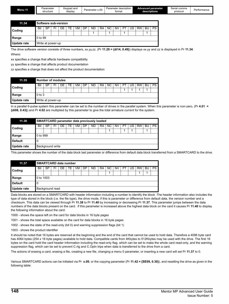
Menu 11 Parameter structure
Keypad and display Parameter x.00 Parameter description
formatAdvanced parameter
descriptionsSerial comms
protocol Performance
The drive software version consists of three numbers, xx.yy.zz. (Pr 11.29 = {di14, 0.49}) displays xx.yy and zz is displayed in Pr 11.34. Where:xx specifies a change that affects hardware compatibility yy specifies a change that affects product documentationzz specifies a change that does not affect the product documentation
In a parallel 6-pulse system this parameter can be set to the number of drives in the parallel system. When this parameter is non-zero, (Pr 4.01 = {di08, 0.43}) and Pr 4.02 are multiplied by this parameter to give the total armature current for the system.
This parameter shows the number of the data block last parameter or difference from default data block transferred from a SMARTCARD to the drive.
Data blocks are stored on a SMARTCARD with header information including a number to identify the block .The header information also includes the type of data stored in the block (i.e. the file type), the drive mode, if this is parameter or difference from default data, the version number and a checksum. This data can be viewed through Pr 11.38 to Pr 11.40 by increasing or decreasing Pr 11.37. This parameter jumps between the data numbers of the data blocks present on the card. If this parameter is increased above the highest data block on the card it causes Pr 11.40 to display the following information about the card:1000 - shows the space left on the card for data blocks in 16 byte pages 1001 - shows the total space available on the card for data blocks in 16 byte pages1002 - shows the state of the read-only (bit 0) and warning suppression flags (bit 1)1003 - shows the product identifierIt should be noted that 16 bytes are reserved at the beginning and the end of the card that cannot be used to hold data. Therefore a 4096 byte card has 4064 bytes (254 x 16 byte pages) available to hold data. Compatible cards from 4Kbytes to 512Kbytes may be used with the drive. The first 16 bytes on the card hold the card header information including the read-only flag, which can be set to make the whole card read-only, and the warning suppression flag, which can be set to prevent C.rtg and C.Optn trips when data is transferred to the drive from a card. The actions of erasing a card, erasing a file, creating a new file, changing a menu 0 parameter, or inserting a new card will set Pr 11.37 to 0.
Various SMARTCARD actions can be initiated via Pr x.00, or the copying parameter (Pr 11.42 = {SE09, 0.30}), and resetting the drive as given in the following table:
11.34 Software sub-version
CodingBit SP FI DE TE VM DP ND RA NC NV PT US RW BU PS
1 1 1 1Range 0 to 99
Update rate Write at power-up
11.35 Number of modules
CodingBit SP FI DE TE VM DP ND RA NC NV PT US RW BU PS
1 1 1 1Range 0 to 3
Update rate Write at power-up
11.36 SMARTCARD parameter data previously loaded
CodingBit SP FI DE TE VM DP ND RA NC NV PT US RW BU PS
1 1 1 1Range 0 to 999
Default 0
Update rate Background write
11.37 SMARTCARD data number
CodingBit SP FI DE TE VM DP ND RA NC NV PT US RW BU PS
1 1 1Range 0 to 1003
Default 0
Update rate Background read
148 Mentor MP Advanced User Guide Issue Number: 5
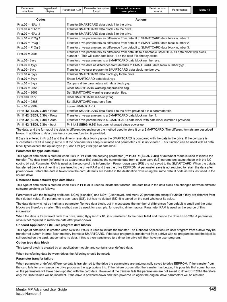
Parameter structure
Keypad and display Parameter x.00 Parameter description
formatAdvanced parameter
descriptionsSerial comms
protocol Performance Menu 11
The data, and the format of the data, is different depending on the method used to store it on a SMARTCARD. The different formats are described below. In addition to data transfers a compare function is provided.If 8yyy is entered in Pr x.00 and the drive is reset data block yyy on the SMARTCARD is compared with the data in the drive. If the compare is successful Pr x.00 is simply set to 0. If the compare fails a trip is initiated and parameter x.00 is not cleared. This function can be used with all data block types except the option type (18) and Opt.prg (19) type of data block.Parameter file type data blockThis type of data block is created when 3xxx in Pr x.00, the copying parameter (Pr 11.42 = {SE09, 0.30}) or auto/boot mode is used to initiate the transfer. The data block (referred to as a parameter file) contains the complete data from all user save (US) parameters except those with the NC coding bit set. Parameter RAM is used as the source of this information. Power-down save (PS) are not saved to the SMARTCARD. When the data is transferred back to a drive, it is transferred to the drive RAM and then the drive EEPROM. A parameter save is not required to retain the data after power-down. Before the data is taken from the card, defaults are loaded in the destination drive using the same default code as was last used in the source drive.Difference from defaults type data block This type of data block is created when 4xxx in Pr x.00 is used to initiate the transfer. The data held in the data block has changed between different software versions as follows:
Parameters with the following attributes: NC=0 (clonable) and US=1 (user save), and menu 20 parameters except Pr 20.00 if they are different from their default value. If a parameter is user save (US), but has no default (ND) it is saved on the card whatever its value.The data density is not as high as a parameter file type data block, but in most cases the number of differences from default is small and the data blocks are therefore smaller. This method can be used, for example, for creating drive macros. Parameter RAM is used as the source of this information.When the data is transferred back to a drive, using 6yyy in Pr x.00, it is transferred to the drive RAM and then to the drive EEPROM. A parameter save is not required to retain the data after power-down. Onboard Application Lite user program data blocks This type of data block is created when 5xxx in Pr x.00 is used to initiate the transfer. The Onboard Application Lite user program from a drive may be transferred to/from internal flash memory from/to a SMARTCARD. If the user program is transferred from a drive with no program loaded the block is still created on the card, but contains no data. If this is then transferred to a drive the drive will then have no user program. Option type data blockThis type of block is created by an application module, and contains user defined data.
When transferring data between drives the following should be noted:Parameter transfer failureWhen parameter or default difference data is transferred to the drive the parameters are automatically saved to drive EEPROM. If the transfer from the card fails for any reason the drive produces the appropriate trip. If the failure occurs after the transfer has begun, it is possible that some, but not all the parameters will have been updated with the card data. However, if the transfer fails the parameters are not saved to drive EEPROM, therefore only the RAM values will be incorrect. If the drive is powered down and then powered up again the original drive parameters will be restored.
Codes ActionsPr x.00 = rEAd 1 Transfer SMARTCARD data block 1 to the drive.Pr x.00 = rEAd 2 Transfer SMARTCARD data block 2 to the drive.Pr x.00 = rEAd 3 Transfer SMARTCARD data block 3 to the drive.Pr x.00 = PrOg 1 Transfer drive parameters as difference from default to SMARTCARD data block number 1.Pr x.00 = PrOg 2 Transfer drive parameters as difference from default to SMARTCARD data block number 2.Pr x.00 = PrOg 3 Transfer drive parameters as difference from default to SMARTCARD data block number 3.
Pr x.00 = 2001 Transfer drive parameters as difference from defaults to a bootable SMARTCARD data block with block number 1. This will clear data block 1 on the card if it already exists.
Pr x.00= 3yyy Transfer drive parameters to a SMARTCARD data block number yyy.Pr x.00 = 4yyy Transfer drive data as difference from defaults to SMARTCARD data block number yyy.Pr x.00= 5yyy Transfer drive user program to SMARTCARD data block number yyy.Pr x.00 = 6yyy Transfer SMARTCARD data block yyy to the drive.Pr x.00 = 7yyy Erase SMARTCARD data block yyy.Pr x.00 = 8yyy Compare drive parameters with data block yyy.Pr x.00 = 9555 Clear SMARTCARD warning suppression flag.Pr x.00 = 9666 Set SMARTCARD warning suppression flag.Pr x.00= 9777 Clear SMARTCARD read-only flag.Pr x.00 = 9888 Set SMARTCARD read-only flag.Pr x.00 = 9999 Erase SMARTCARD.Pr 11.42 (SE09, 0.30) = Read Transfer SMARTCARD data block 1 to the drive provided it is a parameter file.Pr 11.42 (SE09, 0.30) = Prog Transfer drive parameters to a SMARTCARD data block number 1.Pr 11.42 (SE09, 0.30) = Auto Transfer drive parameters to a SMARTCARD data block with data block number 1 provided.Pr 11.42 (SE09, 0.30) = boot Pr 11.42 (SE09, 0.30) has been changed since power-up.
Mentor MP Advanced User Guide 149Issue Number: 5
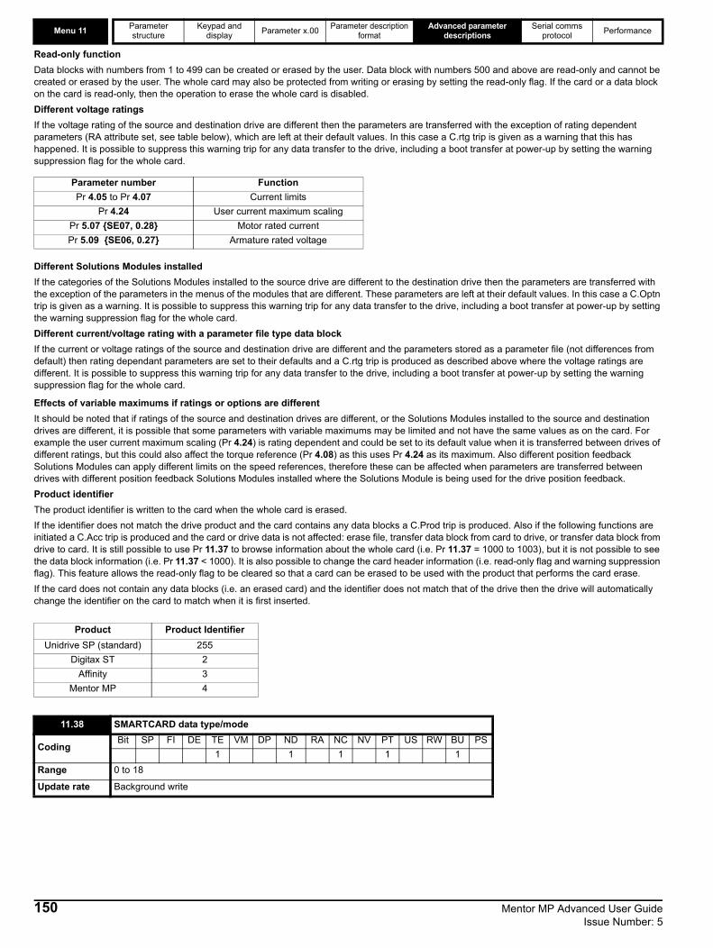
Menu 11 Parameter structure
Keypad and display Parameter x.00 Parameter description
formatAdvanced parameter
descriptionsSerial comms
protocol Performance
Read-only functionData blocks with numbers from 1 to 499 can be created or erased by the user. Data block with numbers 500 and above are read-only and cannot be created or erased by the user. The whole card may also be protected from writing or erasing by setting the read-only flag. If the card or a data block on the card is read-only, then the operation to erase the whole card is disabled.Different voltage ratingsIf the voltage rating of the source and destination drive are different then the parameters are transferred with the exception of rating dependent parameters (RA attribute set, see table below), which are left at their default values. In this case a C.rtg trip is given as a warning that this has happened. It is possible to suppress this warning trip for any data transfer to the drive, including a boot transfer at power-up by setting the warning suppression flag for the whole card.
Different Solutions Modules installedIf the categories of the Solutions Modules installed to the source drive are different to the destination drive then the parameters are transferred with the exception of the parameters in the menus of the modules that are different. These parameters are left at their default values. In this case a C.Optn trip is given as a warning. It is possible to suppress this warning trip for any data transfer to the drive, including a boot transfer at power-up by setting the warning suppression flag for the whole card.Different current/voltage rating with a parameter file type data blockIf the current or voltage ratings of the source and destination drive are different and the parameters stored as a parameter file (not differences from default) then rating dependant parameters are set to their defaults and a C.rtg trip is produced as described above where the voltage ratings are different. It is possible to suppress this warning trip for any data transfer to the drive, including a boot transfer at power-up by setting the warning suppression flag for the whole card.
Effects of variable maximums if ratings or options are differentIt should be noted that if ratings of the source and destination drives are different, or the Solutions Modules installed to the source and destination drives are different, it is possible that some parameters with variable maximums may be limited and not have the same values as on the card. For example the user current maximum scaling (Pr 4.24) is rating dependent and could be set to its default value when it is transferred between drives of different ratings, but this could also affect the torque reference (Pr 4.08) as this uses Pr 4.24 as its maximum. Also different position feedback Solutions Modules can apply different limits on the speed references, therefore these can be affected when parameters are transferred between drives with different position feedback Solutions Modules installed where the Solutions Module is being used for the drive position feedback.Product identifierThe product identifier is written to the card when the whole card is erased.If the identifier does not match the drive product and the card contains any data blocks a C.Prod trip is produced. Also if the following functions are initiated a C.Acc trip is produced and the card or drive data is not affected: erase file, transfer data block from card to drive, or transfer data block from drive to card. It is still possible to use Pr 11.37 to browse information about the whole card (i.e. Pr 11.37 = 1000 to 1003), but it is not possible to see the data block information (i.e. Pr 11.37 < 1000). It is also possible to change the card header information (i.e. read-only flag and warning suppression flag). This feature allows the read-only flag to be cleared so that a card can be erased to be used with the product that performs the card erase. If the card does not contain any data blocks (i.e. an erased card) and the identifier does not match that of the drive then the drive will automatically change the identifier on the card to match when it is first inserted.
Parameter number FunctionPr 4.05 to Pr 4.07 Current limits
Pr 4.24 User current maximum scalingPr 5.07 {SE07, 0.28} Motor rated currentPr 5.09 {SE06, 0.27} Armature rated voltage
Product Product IdentifierUnidrive SP (standard) 255
Digitax ST 2Affinity 3
Mentor MP 4
11.38 SMARTCARD data type/mode
CodingBit SP FI DE TE VM DP ND RA NC NV PT US RW BU PS
1 1 1 1 1Range 0 to 18
Update rate Background write
150 Mentor MP Advanced User Guide Issue Number: 5
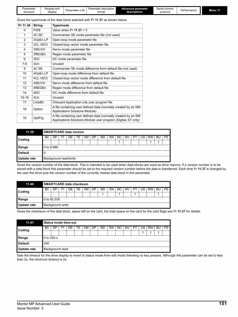
Parameter structure
Keypad and display Parameter x.00 Parameter description
formatAdvanced parameter
descriptionsSerial comms
protocol Performance Menu 11
Gives the type/mode of the data block selected with Pr 11.37 as shown below:
Gives the version number of the data block. This is intended to be used when data blocks are used as drive macros. If a version number is to be stored with a data block this parameter should be set to the required version number before the data is transferred. Each time Pr 11.37 is changed by the user the drive puts the version number of the currently viewed data block in this parameter.
Gives the checksum of the data block, space left on the card, the total space on the card for the card flags see Pr 11.37 for details.
Sets the timeout for the drive display to revert to status mode from edit mode following no key presses. Although this parameter can be set to less than 2s, the minimum timeout is 2s.
Pr 11.38 String Type/mode0 FrEE Value when Pr 11.37 = 01 3C.SE Commander SE mode parameter file (not used)2 3OpEn.LP Open-loop mode parameter file3 3CL.VECt Closed-loop vector mode parameter file4 3SErVO Servo mode parameter file5 3REGEn Regen mode parameter file6 3DC DC mode parameter file
7-8 3Un Unused9 4C.SE Commander SE mode difference from default file (not used)
10 4OpEn.LP Open-loop mode difference from default file11 4CL.VECt Closed-loop vector mode difference from default file12 4SErVO Servo mode difference from default file13 4REGEn Regen mode difference from default file14 4DC DC mode difference from default file
15-16 4Un Unused17 LAddEr Onboard Application Lite user program file
18 Option A file containing user defined data (normally created by an SM-Applications Solutions Module)
19 OptPrg A file containing user defined data (normally created by an SM-Applications Solutions Module user program (Digitax ST only)
11.39 SMARTCARD data version
CodingBit SP FI DE TE VM DP ND RA NC NV PT US RW BU PS
1 1 1Range 0 to 9,999
Default 0
Update rate Background read/write
11.40 SMARTCARD data checksum
CodingBit SP FI DE TE VM DP ND RA NC NV PT US RW BU PS
1 1 1 1Range 0 to 65,335
Update rate Background write
11.41 Status mode time-out
CodingBit SP FI DE TE VM DP ND RA NC NV PT US RW BU PS
1 1 1Range 0 to 250 s
Default 240
Update rate Background read
Mentor MP Advanced User Guide 151Issue Number: 5
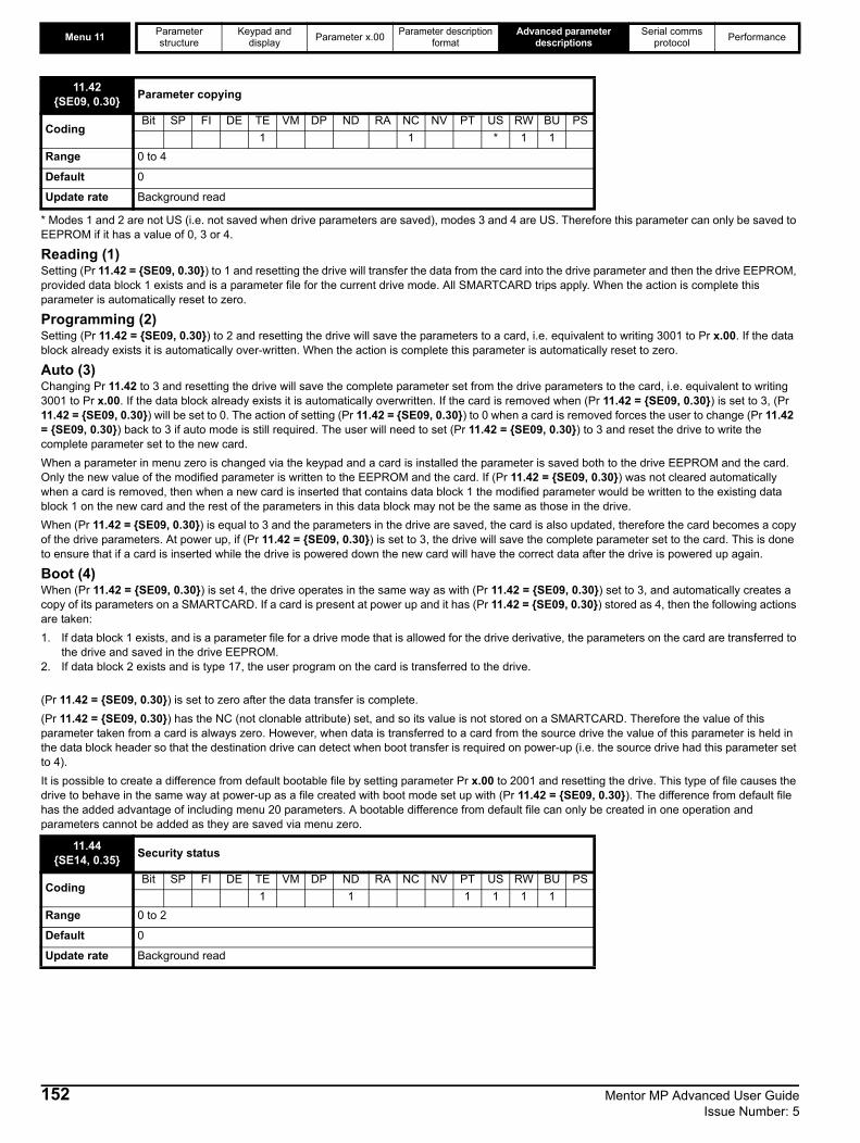
Menu 11 Parameter structure
Keypad and display Parameter x.00 Parameter description
formatAdvanced parameter
descriptionsSerial comms
protocol Performance
* Modes 1 and 2 are not US (i.e. not saved when drive parameters are saved), modes 3 and 4 are US. Therefore this parameter can only be saved to EEPROM if it has a value of 0, 3 or 4.
Reading (1)Setting (Pr 11.42 = {SE09, 0.30}) to 1 and resetting the drive will transfer the data from the card into the drive parameter and then the drive EEPROM, provided data block 1 exists and is a parameter file for the current drive mode. All SMARTCARD trips apply. When the action is complete this parameter is automatically reset to zero.
Programming (2)Setting (Pr 11.42 = {SE09, 0.30}) to 2 and resetting the drive will save the parameters to a card, i.e. equivalent to writing 3001 to Pr x.00. If the data block already exists it is automatically over-written. When the action is complete this parameter is automatically reset to zero.
Auto (3)Changing Pr 11.42 to 3 and resetting the drive will save the complete parameter set from the drive parameters to the card, i.e. equivalent to writing 3001 to Pr x.00. If the data block already exists it is automatically overwritten. If the card is removed when (Pr 11.42 = {SE09, 0.30}) is set to 3, (Pr 11.42 = {SE09, 0.30}) will be set to 0. The action of setting (Pr 11.42 = {SE09, 0.30}) to 0 when a card is removed forces the user to change (Pr 11.42 = {SE09, 0.30}) back to 3 if auto mode is still required. The user will need to set (Pr 11.42 = {SE09, 0.30}) to 3 and reset the drive to write the complete parameter set to the new card. When a parameter in menu zero is changed via the keypad and a card is installed the parameter is saved both to the drive EEPROM and the card. Only the new value of the modified parameter is written to the EEPROM and the card. If (Pr 11.42 = {SE09, 0.30}) was not cleared automatically when a card is removed, then when a new card is inserted that contains data block 1 the modified parameter would be written to the existing data block 1 on the new card and the rest of the parameters in this data block may not be the same as those in the drive.When (Pr 11.42 = {SE09, 0.30}) is equal to 3 and the parameters in the drive are saved, the card is also updated, therefore the card becomes a copy of the drive parameters. At power up, if (Pr 11.42 = {SE09, 0.30}) is set to 3, the drive will save the complete parameter set to the card. This is done to ensure that if a card is inserted while the drive is powered down the new card will have the correct data after the drive is powered up again.
Boot (4)When (Pr 11.42 = {SE09, 0.30}) is set 4, the drive operates in the same way as with (Pr 11.42 = {SE09, 0.30}) set to 3, and automatically creates a copy of its parameters on a SMARTCARD. If a card is present at power up and it has (Pr 11.42 = {SE09, 0.30}) stored as 4, then the following actions are taken:1. If data block 1 exists, and is a parameter file for a drive mode that is allowed for the drive derivative, the parameters on the card are transferred to
the drive and saved in the drive EEPROM.2. If data block 2 exists and is type 17, the user program on the card is transferred to the drive.
(Pr 11.42 = {SE09, 0.30}) is set to zero after the data transfer is complete.(Pr 11.42 = {SE09, 0.30}) has the NC (not clonable attribute) set, and so its value is not stored on a SMARTCARD. Therefore the value of this parameter taken from a card is always zero. However, when data is transferred to a card from the source drive the value of this parameter is held in the data block header so that the destination drive can detect when boot transfer is required on power-up (i.e. the source drive had this parameter set to 4).It is possible to create a difference from default bootable file by setting parameter Pr x.00 to 2001 and resetting the drive. This type of file causes the drive to behave in the same way at power-up as a file created with boot mode set up with (Pr 11.42 = {SE09, 0.30}). The difference from default file has the added advantage of including menu 20 parameters. A bootable difference from default file can only be created in one operation and parameters cannot be added as they are saved via menu zero.
11.42{SE09, 0.30} Parameter copying
CodingBit SP FI DE TE VM DP ND RA NC NV PT US RW BU PS
1 1 * 1 1Range 0 to 4
Default 0
Update rate Background read
11.44{SE14, 0.35} Security status
CodingBit SP FI DE TE VM DP ND RA NC NV PT US RW BU PS
1 1 1 1 1 1Range 0 to 2
Default 0
Update rate Background read
152 Mentor MP Advanced User Guide Issue Number: 5
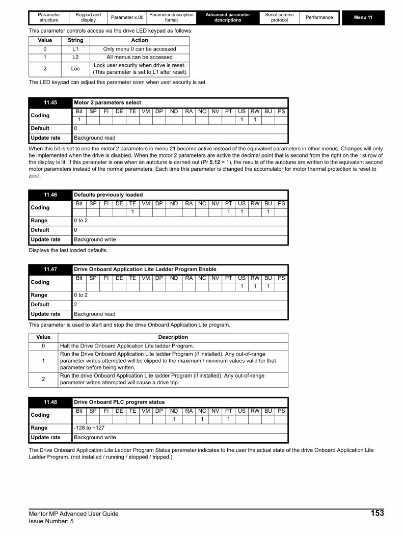
Parameter structure
Keypad and display Parameter x.00 Parameter description
formatAdvanced parameter
descriptionsSerial comms
protocol Performance Menu 11
This parameter controls access via the drive LED keypad as follows:
The LED keypad can adjust this parameter even when user security is set.
When this bit is set to one the motor 2 parameters in menu 21 become active instead of the equivalent parameters in other menus. Changes will only be implemented when the drive is disabled. When the motor 2 parameters are active the decimal point that is second from the right on the 1st row of the display is lit. If this parameter is one when an autotune is carried out (Pr 5.12 = 1), the results of the autotune are written to the equivalent second motor parameters instead of the normal parameters. Each time this parameter is changed the accumulator for motor thermal protection is reset to zero.
Displays the last loaded defaults.
This parameter is used to start and stop the drive Onboard Application Lite program.
The Drive Onboard Application Lite Ladder Program Status parameter indicates to the user the actual state of the drive Onboard Application Lite Ladder Program. (not installed / running / stopped / tripped.)
Value String Action0 L1 Only menu 0 can be accessed1 L2 All menus can be accessed
2 Loc Lock user security when drive is reset. (This parameter is set to L1 after reset)
11.45 Motor 2 parameters select
CodingBit SP FI DE TE VM DP ND RA NC NV PT US RW BU PS1 1 1
Default 0
Update rate Background read
11.46 Defaults previously loaded
CodingBit SP FI DE TE VM DP ND RA NC NV PT US RW BU PS
1 1 1 1Range 0 to 2
Default 0
Update rate Background write
11.47 Drive Onboard Application Lite Ladder Program Enable
CodingBit SP FI DE TE VM DP ND RA NC NV PT US RW BU PS
1 1 1Range 0 to 2
Default 2
Update rate Background read
Value Description0 Halt the Drive Onboard Application Lite ladder Program.
1Run the Drive Onboard Application Lite ladder Program (if installed). Any out-of-range parameter writes attempted will be clipped to the maximum / minimum values valid for that parameter before being written.
2 Run the drive Onboard Application Lite ladder Program (if installed). Any out-of-range parameter writes attempted will cause a drive trip.
11.48 Drive Onboard PLC program status
CodingBit SP FI DE TE VM DP ND RA NC NV PT US RW BU PS
1 1 1Range -128 to +127
Update rate Background write
Mentor MP Advanced User Guide 153Issue Number: 5

Menu 11 Parameter structure
Keypad and display Parameter x.00 Parameter description
formatAdvanced parameter
descriptionsSerial comms
protocol Performance
The Drive Onboard Application Lite Ladder Programming Events parameter holds the number of times a Onboard Application Lite Ladder program download has taken place and is 0 on dispatch from the factory. If the Drive Onboard Application Lite Ladder Programming Events is greater than the maximum value which may be represented by this parameter the value will be clipped to the maximum value. This parameter is not altered when defaults are loaded.
The Onboard Application Lite Ladder Program Maximum Scan Time parameter gives the longest scan time within the last ten scans of the drive Onboard Application Lite Ladder Program. If the scan time is greater than the maximum value that may be represented by this parameter the value will be clipped to the maximum value.
The Drive Onboard Application Lite Ladder Program first run parameter is set for the duration of the first ladder diagram scan from the ladder diagram stopped state. This enables the user to perform any required initialization every time the ladder diagram is run. This parameter is set every time the ladder is stopped.
Pr 11.52 and Pr 11.53 give a unique drive serial number for the drive.Digits 876 543 210
Format
Value Description
-n Onboard Application Lite Ladder Program caused a drive trip due to an error condition while running rung n. Note that the rung number is shown on the display as a negative number.
0 Onboard Application Lite Ladder Program is not installed.1 Onboard Application Lite Ladder Program is installed but stopped.2 Onboard Application Lite Ladder Program is installed and running.
11.49 Drive Onboard application lite ladder programming events
CodingBit SP FI DE TE VM DP ND RA NC NV PT US RW BU PS
1 1 1 1 1Range 0 to 65,535
Update rate Background write
11.50 Drive Onboard Application Lite Ladder Program Average Scan Time
CodingBit SP FI DE TE VM DP ND RA NC NV PT US RW BU PS
1 1 1 1Range 0 to 65,535 ms
Update rate Onboard Application Lite Ladder program execution period
11.51 Drive Onboard Application Lite Ladder Program first run
CodingBit SP FI DE TE VM DP ND RA NC NV PT US RW BU PS1 1 1 1
Range 0 or 1
Update rate Onboard Application Lite Ladder program execution period
11.52 Drive serial number
CodingBit SP FI DE TE VM DP ND RA NC NV PT US RW BU PS
1 1 1Range 0 to 999 999 999
Update rate Background read
11.53 Build location
CodingBit SP FI DE TE VM DP ND RA NC NV PT US RW BU PS
1 1 1Range 0 to 255
Update rate Background read
Parameter Digits Description Range11.53 All Build location 0-25511.52 8-3 Works order number 0-99999911.52 2-0 Number 0-999
154 Mentor MP Advanced User Guide Issue Number: 5
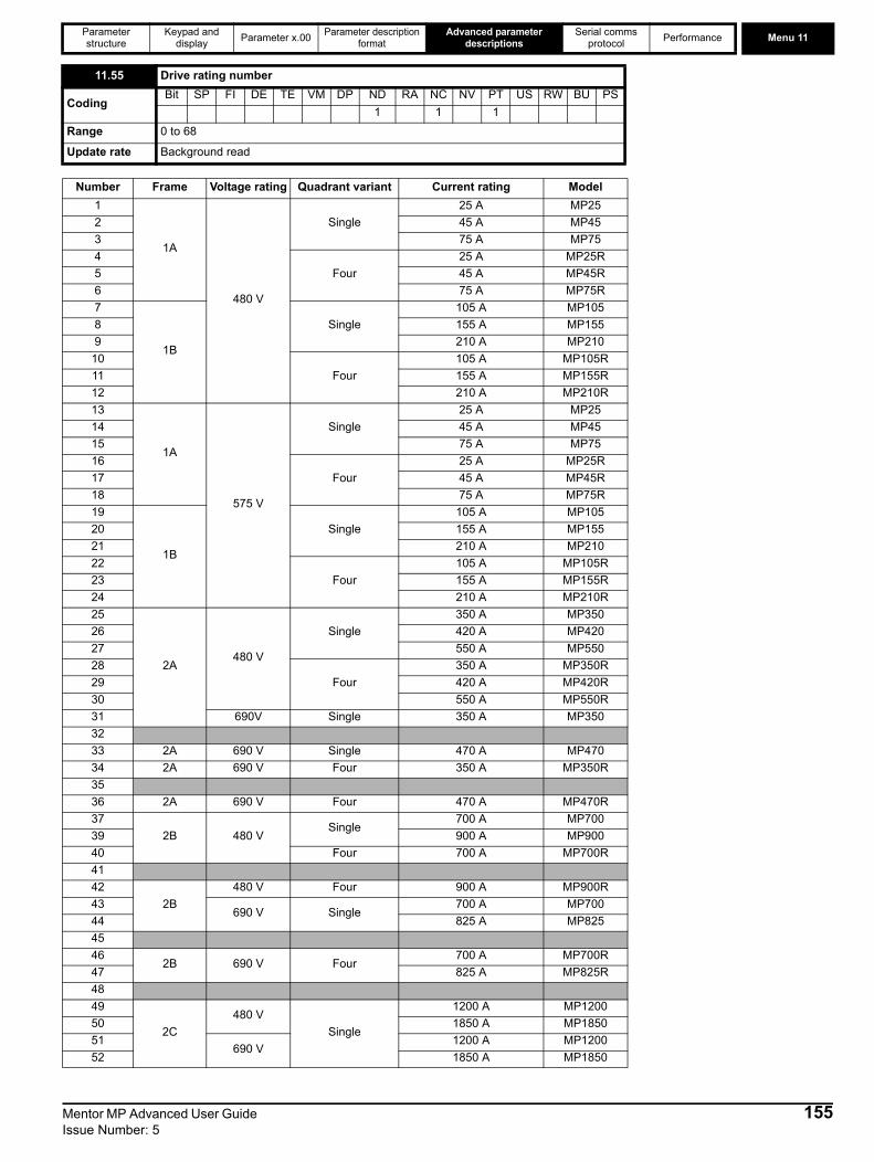
Parameter structure
Keypad and display Parameter x.00 Parameter description
formatAdvanced parameter
descriptionsSerial comms
protocol Performance Menu 11
11.55 Drive rating number
CodingBit SP FI DE TE VM DP ND RA NC NV PT US RW BU PS
1 1 1Range 0 to 68
Update rate Background read
Number Frame Voltage rating Quadrant variant Current rating Model1
1A
480 V
Single25 A MP25
2 45 A MP453 75 A MP754
Four25 A MP25R
5 45 A MP45R6 75 A MP75R7
1B
Single105 A MP105
8 155 A MP1559 210 A MP210
10Four
105 A MP105R11 155 A MP155R12 210 A MP210R13
1A
575 V
Single25 A MP25
14 45 A MP4515 75 A MP7516
Four25 A MP25R
17 45 A MP45R18 75 A MP75R19
1B
Single105 A MP105
20 155 A MP15521 210 A MP21022
Four105 A MP105R
23 155 A MP155R24 210 A MP210R25
2A480 V
Single350 A MP350
26 420 A MP42027 550 A MP55028
Four350 A MP350R
29 420 A MP420R30 550 A MP550R31 690V Single 350 A MP3503233 2A 690 V Single 470 A MP47034 2A 690 V Four 350 A MP350R3536 2A 690 V Four 470 A MP470R37
2B 480 VSingle
700 A MP70039 900 A MP90040 Four 700 A MP700R4142
2B480 V Four 900 A MP900R
43690 V Single
700 A MP70044 825 A MP8254546
2B 690 V Four700 A MP700R
47 825 A MP825R4849
2C480 V
Single
1200 A MP120050 1850 A MP185051
690 V1200 A MP1200
52 1850 A MP1850
Mentor MP Advanced User Guide 155Issue Number: 5

Menu 11 Parameter structure
Keypad and display Parameter x.00 Parameter description
formatAdvanced parameter
descriptionsSerial comms
protocol Performance
The power PCB software version consists of two numbers xx.yy. xx.yy is displayed in this parameter. Where xx specifies a change that affects hardware compatibility, yy specifies a change that affects product documentation.
Defines an output parameter or input parameter when input or output serial mode is selected by serial mode parameter in the application menu. Intended for use by Solutions Modules.
Scales the input data in input serial mode. Intended for use by Solutions Modules.
This parameter allows the EIA (RS) -485 communications port of the specified Solutions Module slot to emulate an MD29 or Mentor 2.The module in the specified slot will if capable, perform parameter mappings and conversions so that the module “looks like” an MD29 or Mentor 2. For example :An ANSI master device transmits a parameter read message to a number of Mentor 2 drives over EIA (RS) -485.
53
2D480 V
Four
1200 A MP1200R54 1850 A MP1850R55
690 V1200 A MP1200R
56 1850 A MP1850R57
2A
575 V
Two350 A MP350A5
58 470 A MP470A559
Four350 A MP350A5R
60 470 A MP470A5R61
2BTwo
700 A MP700A562 825 A MP825A563
Four700 A MP700A5R
64 825 A MP825A5R65
2C Two1200 A MP1200A5
66 1850 A MP1850A567
2D Four1200 A MP1200A5R
68 1850 A MP1850A5R
11.56 Power PCB software version
CodingBit SP FI DE TE VM DP ND RA NC NV PT US RW BU PS
2 1 1 1 1Range 1.00 to 99.99
Update rate Write at power-up
11.57 Serial programmable source
CodingBit SP FI DE TE VM DP ND RA NC NV PT US RW BU PS
1 2 1 1 1 1Range Pr 0.00 to Pr 22.99
Default 00.00
Update rate Background
11.58 Serial scaling
CodingBit SP FI DE TE VM DP ND RA NC NV PT US RW BU PS
1 1 1Range 0 to 1999
Default 1000
Update rate Background
11.59 Mentor 2 parameter emulator module control
CodingBit SP FI DE TE VM DP ND RA NC NV PT US RW BU PS
1 1 1Range 0 to 3
Default 0
Update rate Background
Number Frame Voltage rating Quadrant variant Current rating Model
156 Mentor MP Advanced User Guide Issue Number: 5
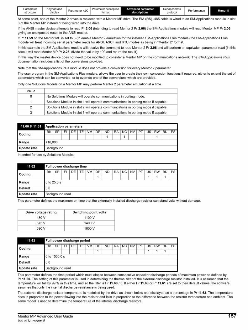
Parameter structure
Keypad and display Parameter x.00 Parameter description
formatAdvanced parameter
descriptionsSerial comms
protocol Performance Menu 11
At some point, one of the Mentor 2 drives is replaced with a Mentor MP drive. The EIA (RS) -485 cable is wired to an SM-Applications module in slot 3 of the Mentor MP instead of being wired into the drive.If the ANSI master device attempts to read Pr 2.06 (intending to read Mentor 2 Pr 2.06) the SM-Applications module will read Mentor MP Pr 2.06 giving an unexpected result to the ANSI master. If Pr 11.59 on the Mentor MP is set to 3 (to enable Mentor 2 emulation for the installed SM-Applications Plus module) the SM-Applications Plus module will treat incoming serial parameter reads for ANSI, ASCII and RTU modes as being in “Mentor 2” format. In this example the SM-Applications module will receive the command to read Mentor 2 Pr 2.06 and will perform an equivalent parameter read (in this case it will read Mentor MP Pr 2.25, divide the value by 100 and return the result). In this way the master device does not need to be modified to consider a Mentor MP on the communications network. The SM-Applications Plus documentation includes a list of the conversions provided.
Note that the SM-Applications Plus module does not provide a conversion for every Mentor 2 parameterThe user program in the SM-Applications Plus module, allows the user to create their own conversion functions if required, either to extend the set of parameters which can be converted, or to override one of the conversions which are provided.
Only one Solutions Module on a Mentor MP may perform Mentor 2 parameter emulation at a time.
Intended for use by Solutions Modules.
This parameter defines the maximum on-time that the externally installed discharge resistor can stand volts without damage.
This parameter defines the time period which must elapse between consecutive capacitor discharge periods of maximum power as defined by Pr 11.60. The setting of this parameter is used in determining the thermal filter of the external discharge resistor installed. It is assumed that the temperature will fall by 99 % in this time, and so the filter is Pr 11.60 / 5. If either Pr 11.60 or Pr 11.61 are set to their default values, the software assumes that only the internal discharge resistance is being used. The external discharge resistor temperature is modelled by the drive as shown below and displayed as a percentage in Pr 11.63. The temperature rises in proportion to the power flowing into the resistor and falls in proportion to the difference between the resistor temperature and ambient. The same model is used to determine the temperature of the internal discharge resistors.
Value0 No Solutions Module will operate communications in porting mode.1 Solutions Module in slot 1 will operate communications in porting mode if capable.2 Solutions Module in slot 2 will operate communications in porting mode if capable.3 Solutions Module in slot 3 will operate communications in porting mode if capable.
11.60 & 11.61 Application parameters
CodingBit SP FI DE TE VM DP ND RA NC NV PT US RW BU PS
1 1 1Range ±16,000
Update rate Background
11.62 Full power discharge time
CodingBit SP FI DE TE VM DP ND RA NC NV PT US RW BU PS
1 1 1 1Range 0 to 25.0 s
Default 0.0
Update rate Background read
Drive voltage rating Switching point volts480 V 1100 V575 V 1400 V690 V 1600 V
11.63 Full power discharge period
CodingBit SP FI DE TE VM DP ND RA NC NV PT US RW BU PS
1 1 1 1Range 0 to 1500.0 s
Default 0.0
Update rate Background read
Mentor MP Advanced User Guide 157Issue Number: 5

Menu 11 Parameter structure
Keypad and display Parameter x.00 Parameter description
formatAdvanced parameter
descriptionsSerial comms
protocol Performance
Assuming that the full power discharge time is much shorter than the full power discharge period (which is normally the case) the values for Pr 11.60 and Pr 11.61 can be calculated as follows:
Full power discharge time (Pr 11.62)
Where Energy is the total energy that can be absorbed by the external resistor when its initial temperature is ambient temperature.
⇒
If the cycle shown in the diagram above is followed repeatedly, where the external resistor is heated to its maximum temperature and then cools to ambient:
The average power in the resistor
where Tp is the full power discharge period (Pr 11.63)
⇒
⇒
⇒
The temperature of the external resistor is monitored by the temperature accumulators (Pr 11.63). When parameter Pr 11.62 reaches 100 % the drive will trip ‘O.ht3’.
This parameter defines the external resistance installed to the drive by the user. This parameter is used in calculating the power dissipated and modelling the temperature of the resistor.
If this is not entered correctly the power dissipated, and therefore the thermal protection model for the resistor will be incorrect. This could lead to the resistor being operated beyond its thermal limits.
11.64 External discharge resistance
CodingBit SP FI DE TE VM DP ND RA NC NV PT US RW BU PS
1 1 1Range 0 to 9999 Ω
Default 0
Update rate Background read
0
100
%
t Pr 11.62
ExternalresistortemperaturePr 11.65
Pr 11.63
Power SuppressorVolts( )2Pr11.64
---------------------------------------------------------------=
TonEnergyPower----------------------=
Disch eTime Pr11.62( )Targ on Energy Pr 11.64SuppesorVolts----------------------------×=
Paverage Disch ePowerargTonTp---------× Disch ePowerarg Pr 11.62
Pr 11.63---------------×= =
Disch ePowerarg EnergyTon Pr11.62-------------------------------------=
AveragePower EnergyTp Pr11.63( )-----------------------------------=
Disch ePower Pr11.63 Tparg EnergyAveragePower----------------------------------------------=
NOTE
158 Mentor MP Advanced User Guide Issue Number: 5
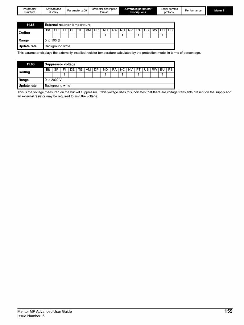
Parameter structure
Keypad and display Parameter x.00 Parameter description
formatAdvanced parameter
descriptionsSerial comms
protocol Performance Menu 11
This parameter displays the externally installed resistor temperature calculated by the protection model in terms of percentage.
This is the voltage measured on the bucket suppressor. If this voltage rises this indicates that there are voltage transients present on the supply and an external resistor may be required to limit the voltage.
11.65 External resistor temperature
CodingBit SP FI DE TE VM DP ND RA NC NV PT US RW BU PS
1 1 1 1Range 0 to 100 %
Update rate Background write
11.66 Suppressor voltage
CodingBit SP FI DE TE VM DP ND RA NC NV PT US RW BU PS
1 1 1 1 1Range 0 to 2000 V
Update rate Background write
Mentor MP Advanced User Guide 159Issue Number: 5

Menu 12 Parameter structure
Keypad and display Parameter x.00 Parameter description
formatAdvanced parameter
descriptionsSerial comms
protocol Performance
5.13 Menu 12: Threshold detectors, variable selectors and brake control function5.13.1 Threshold detectors functionMenu 12 includes two threshold detectors which produce logic signals depending on the level of a variable value with respect to a threshold, and two variable selectors which allow two input parameters to be selected or combined to produce a variable output. One menu 9 or one menu 12 function is executed every 4 ms. Therefore the sample time of these functions is 4 ms x number of menu 9 and 12 functions active. A function is active if one or more sources are routed to a valid parameter.Figure 5-29 Menu 12 logic diagram (Threshold detectors)
12.01 Threshold detector 1 output
12.02 Threshold detector 2 output
CodingBit SP FI DE Txt VM DP ND RA NC NV PT US RW BU PS1 1 1 1
Update rate 4 ms x number of menu 9 or 12 functions active write
12.03 Threshold detector 1 source
12.23 Threshold detector 2 source
CodingBit SP FI DE Txt VM DP ND RA NC NV PT US RW BU PS
2 1 1 1 1Range Pr 0.00 to Pr 22.99
Default Pr 0.00
Update rate Read on reset
??.??
Any variable parameter
??.??
12.03Threshold Detector 1
input source
12.04
Threshold Detector 1
threshold level
Threshold Detector 1
Threshold Detector 1
x(-1)
12.06ThresholdDetector 1
output invert
12.01
Threshold Detector 1
output indicator
12.05Threshold Detector 1 hysteresis
??.??
Any unprotected
bit parameter
??.??
12.07
ThresholdDetector
outputdestinationparameter
1
??.??
Any variable parameter
??.??
12.23Threshold Detector 2
input source
12.24
Threshold Detector 2
threshold level
Threshold Detector 2
Threshold Detector 2
x(-1)
12.26ThresholdDetector 2
output invert
12.02
Threshold Detector 2
output indicator
12.25Threshold Detector 2 hysteresis
??.??
??.??
12.27
ThresholdDetector
outputdestinationparameter
2
All parameters are shown at their default setting
0.XX
0.XX
Key
Read-write (RW) parameter
Read-only (RO) parameter
Inputterminals
Outputterminals
HysteresisThreshold
level
Thresholdoutput
t
t
Any unprotected
bit parameter
160 Mentor MP Advanced User Guide Issue Number: 5

Parameter structure
Keypad and display Parameter x.00 Parameter description
formatAdvanced parameter
descriptionsSerial comms
protocol Performance Menu 12
The threshold detector compares the absolute value of the source input value (defined by Pr 12.03, Pr 12.23), converted to a percentage of its maximum value, with the threshold level (Pr 12.04, Pr 12.24). If the value is greater or equal to the threshold plus half the hysteresis band (Pr 12.05, Pr 12.25) the output becomes active, or if the value is less than the threshold minus half the hysteresis band the output becomes inactive. The output may be inverted if required by setting the invert flag (Pr 12.06, Pr 12.26). The result is routed to the destination (defined by Pr 12.07, Pr 12.27).
12.04 Threshold detector 1 level
12.24 Threshold detector 2 level
CodingBit SP FI DE Txt VM DP ND RA NC NV PT US RW BU PS
2 1 1 1Range 0.00 to 100.00 %
Default 0.00
Update rate 4 ms x number of menu 9 or 12 functions active read
12.05 Threshold detector 1 hysteresis
12.25 Threshold detector 2 hysteresis
CodingBit SP FI DE Txt VM DP ND RA NC NV PT US RW BU PS
2 1 1 1Range 0.00 to 25.00 %
Default 0.00
Update rate 4 ms x number of menu 9 or 12 functions active read
12.06 Threshold detector 1 output invert
12.26 Threshold detector 2 output invert
CodingBit SP FI DE Txt VM DP ND RA NC NV PT US RW BU PS1 1 1
Default 0
Update rate 4 ms x number of menu 9 or 12 functions active read
12.07 Threshold detector 1 destination
12.27 Threshold detector 2 destination
CodingBit SP FI DE Txt VM DP ND RA NC NV PT US RW BU PS
1 2 1 1 1 1Range Pr 0.00 to Pr 22.99
Default Pr 0.00
Update rate Read on reset
Mentor MP Advanced User Guide 161Issue Number: 5

Menu 12 Parameter structure
Keypad and display Parameter x.00 Parameter description
formatAdvanced parameter
descriptionsSerial comms
protocol Performance
5.13.2 Variable selectors functionFigure 5-30 Menu 12 Logic diagram (Variable selectors)
12.08 Variable selector 1 source 1
12.28 Variable selector 2 source 1
CodingBit SP FI DE Txt VM DP ND RA NC NV PT US RW BU PS
2 1 1 1 1Range Pr 0.00 to Pr 22.99
Default Pr 0.00
Update rate Read on reset
12.09 Variable selector 1 source 2
12.29 Variable selector 2 source 2
CodingBit SP FI DE Txt VM DP ND RA NC NV PT US RW BU PS
2 1 1 1 1Range Pr 0.00 to Pr 22.99
Default Pr 0.00
Update rate Read on reset
12.32
??.??
??.??
12.31
Variable Selector 2
Variable selector 2mode
Variable selector 2control
12.30
12.35
??.??
??.??
12.28
12.33
Variable selector 2input 1 source
Variable selector 2input 1 scaling
??.??
??.??
12.29
12.34
Variable selector 2input 2 source
Variable selector 2input 2 scaling
Variable selector 2output indicator
Variable selector 2output destination
12.12
??.??
??.??
12.11
Variable Selector 1
Variable selector 1mode
Variable selector 1control
12.10
12.15
??.??
Any variableparameter
??.??
12.08
12.13
Variable selector 1input 1 source
Variable selector 1input 1 scaling
??.??
??.??
12.09
12.14
Variable selector 1input 2 source
Variable selector 1input 2 scaling
Variable selector 1output indicator
Variable selector 1output destination
Any variableparameter
Any variableparameter
Any variableparameter
Any unprotectedvariableparameter
Any unprotectedvariableparameter
0.XX
0.XX
Key
Read-write (RW) parameter
Read-only (RO) parameter
Inputterminals
Outputterminals
162 Mentor MP Advanced User Guide Issue Number: 5
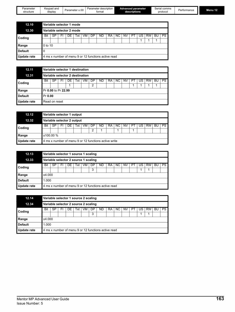
Parameter structure
Keypad and display Parameter x.00 Parameter description
formatAdvanced parameter
descriptionsSerial comms
protocol Performance Menu 12
12.10 Variable selector 1 mode
12.30 Variable selector 2 mode
CodingBit SP FI DE Txt VM DP ND RA NC NV PT US RW BU PS
1 1 1Range 0 to 10
Default 0
Update rate 4 ms x number of menu 9 or 12 functions active read
12.11 Variable selector 1 destination
12.31 Variable selector 2 destination
CodingBit SP FI DE Txt VM DP ND RA NC NV PT US RW BU PS
1 2 1 1 1 1Range Pr 0.00 to Pr 22.99
Default Pr 0.00
Update rate Read on reset
12.12 Variable selector 1 output
12.32 Variable selector 2 output
CodingBit SP FI DE Txt VM DP ND RA NC NV PT US RW BU PS
2 1 1 1Range ±100.00 %
Update rate 4 ms x number of menu 9 or 12 functions active write
12.13 Variable selector 1 source 1 scaling
12.33 Variable selector 2 source 1 scaling
CodingBit SP FI DE Txt VM DP ND RA NC NV PT US RW BU PS
3 1 1Range ±4.000
Default 1.000
Update rate 4 ms x number of menu 9 or 12 functions active read
12.14 Variable selector 1 source 2 scaling
12.34 Variable selector 2 source 2 scaling
CodingBit SP FI DE Txt VM DP ND RA NC NV PT US RW BU PS
3 1 1Range ±4.000
Default 1.000
Update rate 4 ms x number of menu 9 or 12 functions active read
Mentor MP Advanced User Guide 163Issue Number: 5

Menu 12 Parameter structure
Keypad and display Parameter x.00 Parameter description
formatAdvanced parameter
descriptionsSerial comms
protocol Performance
The variable selectors allow two source values (defined by Pr 12.08, Pr 12.28 and Pr 12.09, Pr 12.29) to be combined as defined by the mode (Pr 12.10, Pr 12.30) to produce an output (Pr 12.12, Pr 12.32) which can be routed to the destination parameter (defined by Pr 12.11, Pr 12.31). The actions of the variable selector are defined by the mode parameter as given below. If the mode parameter is changed or the variable selector is disabled because neither source is routed to a valid parameter all the internal state variables (i.e. filter accumulator, etc.) within the selector are reset. When the Sectional control mode is selected the function is also reset, and the output is held at zero, when the control (Pr 12.15 or Pr 12.35) is zero. It is active when the control has a non-zero value.
Sectional controlThe sectional control function is intended to apply scaling and a speed offset to a 16 bit position value to generate a new 16 bit position value. The output can be used as an input to the position controller (menu 13) or to generate an encoder simulation output via the SM-Universal encoder plus module. This function can be selected for either variable selector, but the description below relates to variable selector 1.
The position input can be derived from any parameter, however it is intended to be used with a position value that has a range from 0 to 65535. The input is scaled so that as Pr 12.13 is varied between -4.000 and 4.000 the proportion of the input position change added to the accumulator varies from 0.000 to 2.000 (i.e. the change of position input value is added without scaling if Pr 12.13 is 0.000). The remainder from the scaling division is stored and then added at the next sample to maintain an exact ratio between the position input and the position output, provided the speed input is zero. The controller only takes the change of position from the input source parameter, and not the absolute value, so that when the controller is first made active the output does not jump to the source position, but only moves with any changes of source position after that point in time.The range of the output of the accumulator is 0.00 % and 100.00 %. Unlike other functions the value is not simply limited, but rolls under or over respectively. Although the output destination can be any parameter it is intended to be used with a position value that has a range from 0 to 65535.The speed input defines a speed offset with a resolution of 0.1 rpm. Full scale of the source parameter corresponds to 1000.0 rpm. Scaling may be applied using Pr 12.14 to give a full scale value of 4000.0 rpm. The speed input is added to the accumulator to move the output position forwards or backwards with respect to the position input.
12.15 Variable selector 1 control
12.35 Variable selector 2 control
CodingBit SP FI DE Txt VM DP ND RA NC NV PT US RW BU PS
2 1 1 1Range 0.00 to 100.00
Default 0.00
Update rate Background
Mode value Action Result0 Select input 1 output = input11 Select input 2 output = input22 Add output = input1 + input23 Subtract output = input1 - input 24 Multiply output = (input1 x input2) / 100.05 Divide output = (input1 x 100.0) / input26 filter output = input1 / ((control param)s + 1)
7 Linear ramp output = input1 via a ramp with a ramp time of (control param) seconds from 0 to 100 %
8 Modulus output = | input1 |
9 Powerscontrol = 0.02: output = input12 / 100.0control = 0.03: output = input13 / 100.02
control has any other value: output = input1
10 Sectional control control = 0.00: disabled, accumulator reset and output zero control <> 0.00: output as defined below
%
4.000 + 12.13 4.000
12.14
Σ
Position input
Position output
Speed input
d/dt
Accumulator
164 Mentor MP Advanced User Guide Issue Number: 5
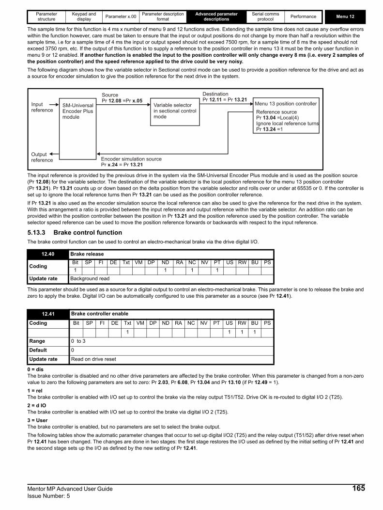
Parameter structure
Keypad and display Parameter x.00 Parameter description
formatAdvanced parameter
descriptionsSerial comms
protocol Performance Menu 12
The sample time for this function is 4 ms x number of menu 9 and 12 functions active. Extending the sample time does not cause any overflow errors within the function however, care must be taken to ensure that the input or output positions do not change by more than half a revolution within the sample time, i.e for a sample time of 4 ms the input or output speed should not exceed 7500 rpm, for a sample time of 8 ms the speed should not exceed 3750 rpm, etc. If the output of this function is to supply a reference to the position controller in menu 13 it must be the only user function in menu 9 or 12 enabled. If another function is enabled the input to the position controller will only change every 8 ms (i.e. every 2 samples of the position controller) and the speed reference applied to the drive could be very noisy.The following diagram shows how the variable selector in Sectional control mode can be used to provide a position reference for the drive and act as a source for encoder simulation to give the position reference for the next drive in the system.
The input reference is provided by the previous drive in the system via the SM-Universal Encoder Plus module and is used as the position source (Pr 12.08) for the variable selector. The destination of the variable selector is the local position reference for the menu 13 position controller (Pr 13.21). Pr 13.21 counts up or down based on the delta position from the variable selector and rolls over or under at 65535 or 0. If the controller is set up to ignore the local reference turns then Pr 13.21 can be used as the position controller reference. If Pr 13.21 is also used as the encoder simulation source the local reference can also be used to give the reference for the next drive in the system. With this arrangement a ratio is provided between the input reference and output reference within the variable selector. An addition ratio can be provided within the position controller between the position in Pr 13.21 and the position reference used by the position controller. The variable selector speed reference can be used to move the position reference forwards or backwards with respect to the input reference.
5.13.3 Brake control functionThe brake control function can be used to control an electro-mechanical brake via the drive digital I/O.
This parameter should be used as a source for a digital output to control an electro-mechanical brake. This parameter is one to release the brake and zero to apply the brake. Digital I/O can be automatically configured to use this parameter as a source (see Pr 12.41).
0 = dis The brake controller is disabled and no other drive parameters are affected by the brake controller. When this parameter is changed from a non-zero value to zero the following parameters are set to zero: Pr 2.03, Pr 6.08, Pr 13.04 and Pr 13.10 (if Pr 12.49 = 1). 1 = rel The brake controller is enabled with I/O set up to control the brake via the relay output T51/T52. Drive OK is re-routed to digital I/O 2 (T25).2 = d IO The brake controller is enabled with I/O set up to control the brake via digital I/O 2 (T25).3 = User The brake controller is enabled, but no parameters are set to select the brake output.The following tables show the automatic parameter changes that occur to set up digital I/O2 (T25) and the relay output (T51/52) after drive reset when Pr 12.41 has been changed. The changes are done in two stages: the first stage restores the I/O used as defined by the initial setting of Pr 12.41 and the second stage sets up the I/O as defined by the new setting of Pr 12.41.
12.40 Brake release
CodingBit SP FI DE Txt VM DP ND RA NC NV PT US RW BU PS1 1 1 1
Update rate Background read
12.41 Brake controller enable
Coding Bit SP FI DE Txt VM DP ND RA NC NV PT US RW BU PS
1 1 1 1
Range 0 to 3
Default 0
Update rate Read on drive reset
Inputreference
Outputreference
SM-UniversalEncoder Plusmodule
SourcePr =Pr 12.08 x.05
Variable selectorin sectional control mode
Destination Pr = Pr 12.11 13.21
Menu 13 position controllerReference source Pr =Local(4)Ignore local reference turnsPr =1
13.04
13.24
Encoder simulation sourcePr = Pr x.24 13.21
Mentor MP Advanced User Guide 165Issue Number: 5
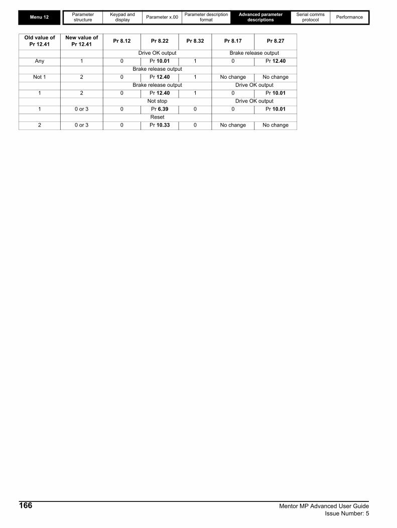
Menu 12 Parameter structure
Keypad and display Parameter x.00 Parameter description
formatAdvanced parameter
descriptionsSerial comms
protocol Performance
Old value ofPr 12.41
New value ofPr 12.41 Pr 8.12 Pr 8.22 Pr 8.32 Pr 8.17 Pr 8.27
Drive OK output Brake release outputAny 1 0 Pr 10.01 1 0 Pr 12.40
Brake release outputNot 1 2 0 Pr 12.40 1 No change No change
Brake release output Drive OK output1 2 0 Pr 12.40 1 0 Pr 10.01
Not stop Drive OK output1 0 or 3 0 Pr 6.39 0 0 Pr 10.01
Reset2 0 or 3 0 Pr 10.33 0 No change No change
166 Mentor MP Advanced User Guide Issue Number: 5
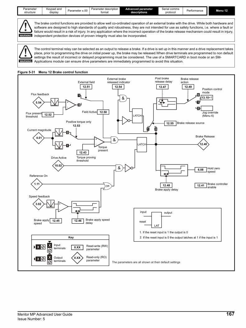
Parameter structure
Keypad and display Parameter x.00 Parameter description
formatAdvanced parameter
descriptionsSerial comms
protocol Performance Menu 12
Figure 5-31 Menu 12 Brake control function
The brake control functions are provided to allow well co-ordinated operation of an external brake with the drive. While both hardware and software are designed to high standards of quality and robustness, they are not intended for use as safety functions, i.e. where a fault or failure would result in a risk of injury. In any application where the incorrect operation of the brake release mechanism could result in injury, independent protection devices of proven integrity must also be incorporated.
The control terminal relay can be selected as an output to release a brake. If a drive is set up in this manner and a drive replacement takes place, prior to programming the drive on initial power up, the brake may be released.When drive terminals are programmed to non default settings the result of incorrect or delayed programming must be considered. The use of a SMARTCARD in boot mode or an SM-Applications module can ensure drive parameters are immediately programmed to avoid this situation.
WARNING
WARNING
input
LAT
output
reset
1. If the reset input is 1 the output is 0
2. If the reset input is 0 the output latches at 1 if the input is 1
Reference On
4.01
Current magnitude
+
Torque provingthreshold
+5.54
Flux feedback
External field
LATCH
Drive Active
Speed feedback
+
Brake applyspeed
Brake apply speeddelay
Post brakerelease delay
12.40
Brake Release
Jog override(Menu 6)
Brake apply delay
Brake controllerenable
Brake release source
External brake released indicator
Torquepresent
Flux present threshold
Positive torque only
Field Active
0.XX
0.XX
Key
Read-write (RW) parameter
Read-only (RO) parameter
Inputterminals
Outputterminals The parameters are all shown at their default settings
10.02
1.11
3.02
-
-
-
12.53
12.50
12.54
Brake releaseaction
Position controlmode
Hold zerospeed
LATCH
12.51
12.52
12.4912.47
13.10=1
12.43
12.45 12.46
12.48 12.41
6.08
0
1
0
1
12.55
0
2
1
1 0
Mentor MP Advanced User Guide 167Issue Number: 5

Menu 12 Parameter structure
Keypad and display Parameter x.00 Parameter description
formatAdvanced parameter
descriptionsSerial comms
protocol Performance
Figure 5-32 Brake sequence
This parameter should be set to a level that is required to hold a load when the brake is released.
When stopping, the drive reference can be removed (i.e. Pr 1.11 = 0), but the brake will remain energized (open), until the motor has remained at a speed below the brake apply speed for the delay defined by Pr 12.46. The delay prevents rapid activation and de-activation of the brake when fine control of a motor is required close to zero speed.
See Pr 12.45 for more information.
12.43 Torque proving threshold
Coding Bit SP FI DE Txt VM DP ND RA NC NV PT US RW BU PS
1 1 1
Range 0 to 150 %
Default 10
Update rate Background read
12.45 Brake apply speed
Coding Bit SP FI DE Txt VM DP ND RA NC NV PT US RW BU PS
1 1 1
Range 0 to 200 rpm
Default 5 rpm
Update rate Background read
12.46 Brake apply speed delay
Coding Bit SP FI DE Txt VM DP ND RA NC NV PT US RW BU PS
1 1 1
Range 0.0 to 25.0 s
Default 1.0 s
Update rate Background read
1 2 3 5 4
Pr Motor Speed3.02
Pr Reference on 1.11
Pr Brake release12.40
Pr Ramp hold 2.03 Pr Position control mode13.10
Pr Drive active10.02
Torque present
1. Wait for armature current and fully fluxed machine 2. Post-brake release delay 3. Wait for speed threshold 4. Wait for brake apply speed delay 5. Brake apply delay
Pr Hold zero speed6.08
Pr Speed threshold 12.45
Pr 12.47 Pr Pr 12.46 12.48
168 Mentor MP Advanced User Guide Issue Number: 5
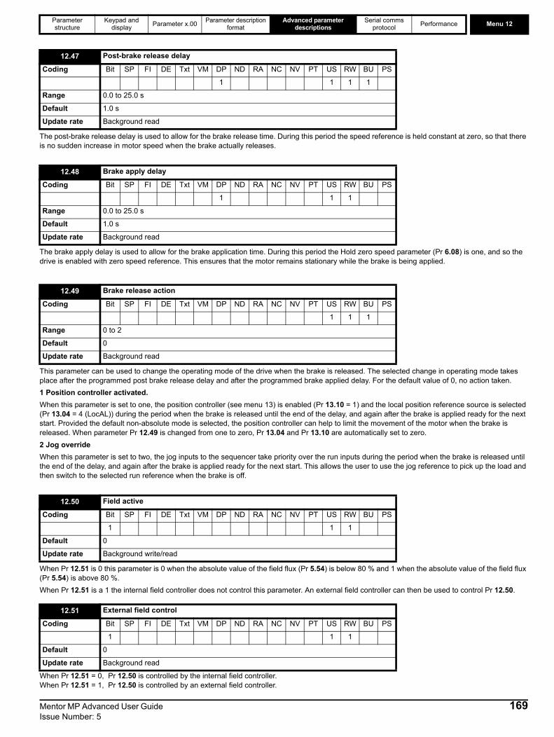
Parameter structure
Keypad and display Parameter x.00 Parameter description
formatAdvanced parameter
descriptionsSerial comms
protocol Performance Menu 12
The post-brake release delay is used to allow for the brake release time. During this period the speed reference is held constant at zero, so that there is no sudden increase in motor speed when the brake actually releases.
The brake apply delay is used to allow for the brake application time. During this period the Hold zero speed parameter (Pr 6.08) is one, and so the drive is enabled with zero speed reference. This ensures that the motor remains stationary while the brake is being applied.
This parameter can be used to change the operating mode of the drive when the brake is released. The selected change in operating mode takes place after the programmed post brake release delay and after the programmed brake applied delay. For the default value of 0, no action taken.1 Position controller activated.When this parameter is set to one, the position controller (see menu 13) is enabled (Pr 13.10 = 1) and the local position reference source is selected (Pr 13.04 = 4 (LocAL)) during the period when the brake is released until the end of the delay, and again after the brake is applied ready for the next start. Provided the default non-absolute mode is selected, the position controller can help to limit the movement of the motor when the brake is released. When parameter Pr 12.49 is changed from one to zero, Pr 13.04 and Pr 13.10 are automatically set to zero.2 Jog overrideWhen this parameter is set to two, the jog inputs to the sequencer take priority over the run inputs during the period when the brake is released until the end of the delay, and again after the brake is applied ready for the next start. This allows the user to use the jog reference to pick up the load and then switch to the selected run reference when the brake is off.
When Pr 12.51 is 0 this parameter is 0 when the absolute value of the field flux (Pr 5.54) is below 80 % and 1 when the absolute value of the field flux (Pr 5.54) is above 80 %. When Pr 12.51 is a 1 the internal field controller does not control this parameter. An external field controller can then be used to control Pr 12.50.
When Pr 12.51 = 0, Pr 12.50 is controlled by the internal field controller. When Pr 12.51 = 1, Pr 12.50 is controlled by an external field controller.
12.47 Post-brake release delay
Coding Bit SP FI DE Txt VM DP ND RA NC NV PT US RW BU PS
1 1 1 1
Range 0.0 to 25.0 s
Default 1.0 s
Update rate Background read
12.48 Brake apply delay
Coding Bit SP FI DE Txt VM DP ND RA NC NV PT US RW BU PS
1 1 1
Range 0.0 to 25.0 s
Default 1.0 s
Update rate Background read
12.49 Brake release action
Coding Bit SP FI DE Txt VM DP ND RA NC NV PT US RW BU PS
1 1 1
Range 0 to 2
Default 0
Update rate Background read
12.50 Field active
Coding Bit SP FI DE Txt VM DP ND RA NC NV PT US RW BU PS
1 1 1
Default 0
Update rate Background write/read
12.51 External field control
Coding Bit SP FI DE Txt VM DP ND RA NC NV PT US RW BU PS
1 1 1
Default 0
Update rate Background read
Mentor MP Advanced User Guide 169Issue Number: 5
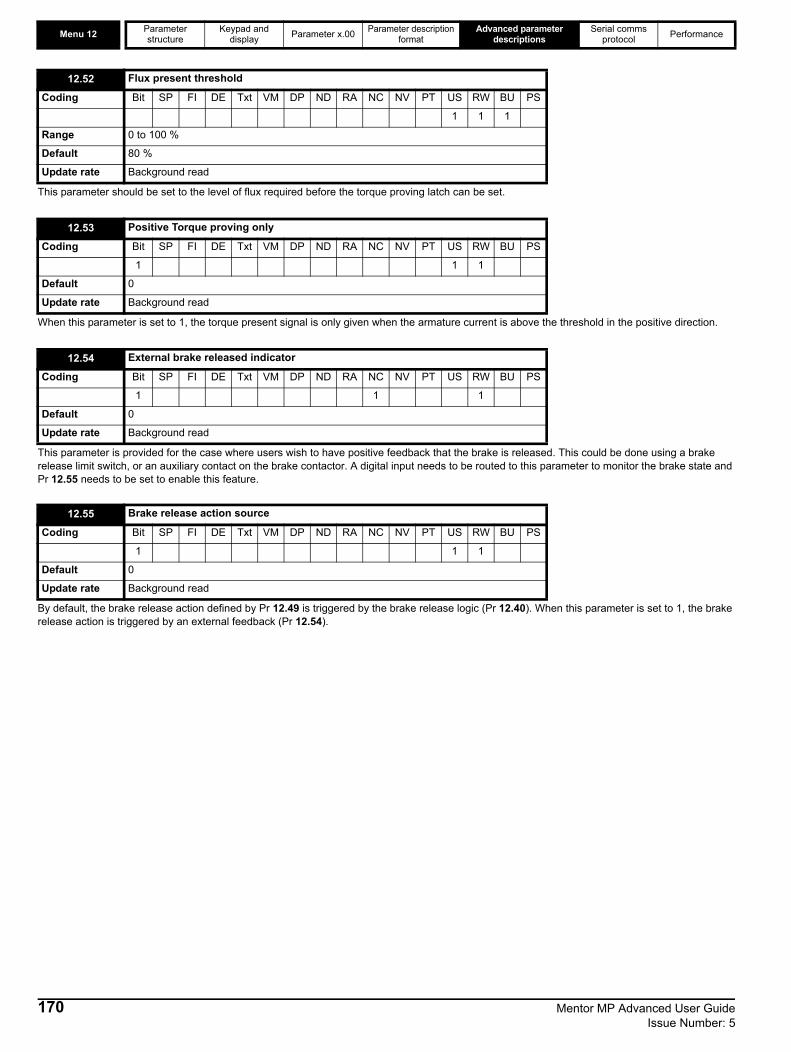
Menu 12 Parameter structure
Keypad and display Parameter x.00 Parameter description
formatAdvanced parameter
descriptionsSerial comms
protocol Performance
This parameter should be set to the level of flux required before the torque proving latch can be set.
When this parameter is set to 1, the torque present signal is only given when the armature current is above the threshold in the positive direction.
This parameter is provided for the case where users wish to have positive feedback that the brake is released. This could be done using a brake release limit switch, or an auxiliary contact on the brake contactor. A digital input needs to be routed to this parameter to monitor the brake state and Pr 12.55 needs to be set to enable this feature.
By default, the brake release action defined by Pr 12.49 is triggered by the brake release logic (Pr 12.40). When this parameter is set to 1, the brake release action is triggered by an external feedback (Pr 12.54).
12.52 Flux present threshold
Coding Bit SP FI DE Txt VM DP ND RA NC NV PT US RW BU PS
1 1 1
Range 0 to 100 %
Default 80 %
Update rate Background read
12.53 Positive Torque proving only
Coding Bit SP FI DE Txt VM DP ND RA NC NV PT US RW BU PS
1 1 1
Default 0
Update rate Background read
12.54 External brake released indicator
Coding Bit SP FI DE Txt VM DP ND RA NC NV PT US RW BU PS
1 1 1
Default 0
Update rate Background read
12.55 Brake release action source
Coding Bit SP FI DE Txt VM DP ND RA NC NV PT US RW BU PS
1 1 1
Default 0
Update rate Background read
170 Mentor MP Advanced User Guide Issue Number: 5

Parameter structure
Keypad and display Parameter x.00 Parameter description
formatAdvanced parameter
descriptionsSerial comms
protocol Performance Menu 13
Mentor MP Advanced User Guide 171Issue Number: 5

Menu 13 Parameter structure
Keypad and display Parameter x.00 Parameter description
formatAdvanced parameter
descriptionsSerial comms
protocol Performance
5.14 Menu 13: Position controlMenu 13 provides a position control system for the drive. The position reference can be taken from the drive encoder, from a position feedback module or from a local reference defined in this menu. The reference includes a relative jog function that can be used to advance or retard the position reference at a defined speed and a ratio that can scale the reference. The feedback position can be taken from the drive encoder or from a position feedback module. As well as giving position control the controller can provide shaft orientation within one revolution in conjunction with the drive sequencer (see Menu 6). The sample time for the position controller is 4 ms and the output is supplied to the speed reference every 4 ms.
Figure 5-33 Menu 13 logic diagram
3.28 3.29
Revolutioncounter Position
DriveEncoder
15.04 15.05 15.06Slot 1
16.04 16.05 16.06Slot 2
17.04 17.05 17.06Slot 3
13.20 13.21 13.22Localreference
13.23Localreference disable
13.04
Position controllerreference
source
x(-1)
13.06
Positionreference
invert
13.0713.08
Ratio
++
x(-1)
13.19
Relativejog reverse
13.18
Relativejog enable
13.17
Relativejog reference
Δ Position
+
_
∫
13.16Positionerror reset
13.05
Δ Position
Positioncontrollerfeedbacksource
+
_
13.13Orientationpositionreference
Position control reference position
3.28 3.29
Revolutioncounter Position
DriveEncoder
15.04 15.05 15.06Slot 1
16.04 16.05 16.06Slot 2
17.04 17.05 17.06Slot 3
Position control feedback position
13.24Ignore localreference turns
∫
Limited to± / 1
2 rev
172 Mentor MP Advanced User Guide Issue Number: 5
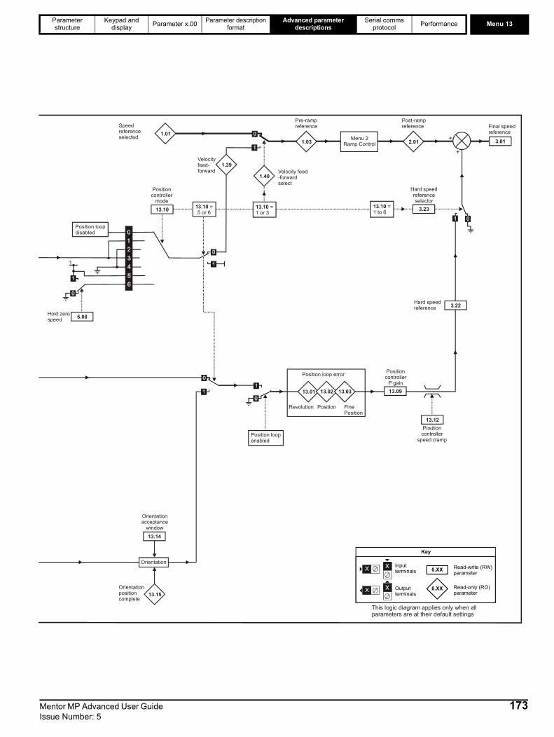
Parameter structure
Keypad and display Parameter x.00 Parameter description
formatAdvanced parameter
descriptionsSerial comms
protocol Performance Menu 13
0.XX
0.XX
Key
Read-write (RW) parameter
Read-only (RO) parameter
Inputterminals
Outputterminals
Orientation
13.14
13.15
Orientationacceptance
window
Orientationpositioncomplete
13.01 13.02 13.03
Position loop error
Position loopenabled
1
6.08Hold zerospeed
13.10
Positioncontroller
mode
1.01
1.39
Speedreference selected
Velocityfeed-forward
1.40Velocity feed-forwardselect
1.03
Pre-rampreference
Menu 2Ramp Control 2.01
Post-rampreference
+
13.09
Position controller
P gain
13.12Position
controllerspeed clamp
3.22Hard speedreference
+
3.23
Hard speedreferenceselector
3.01
Final speedreference
Position loopdisabled
Revolution Position FinePosition
13.10 = 5 or 6
13.10 = 1 or 3
13.10 =1 to 6
This logic diagram applies only when allparameters are at their default settings
Mentor MP Advanced User Guide 173Issue Number: 5
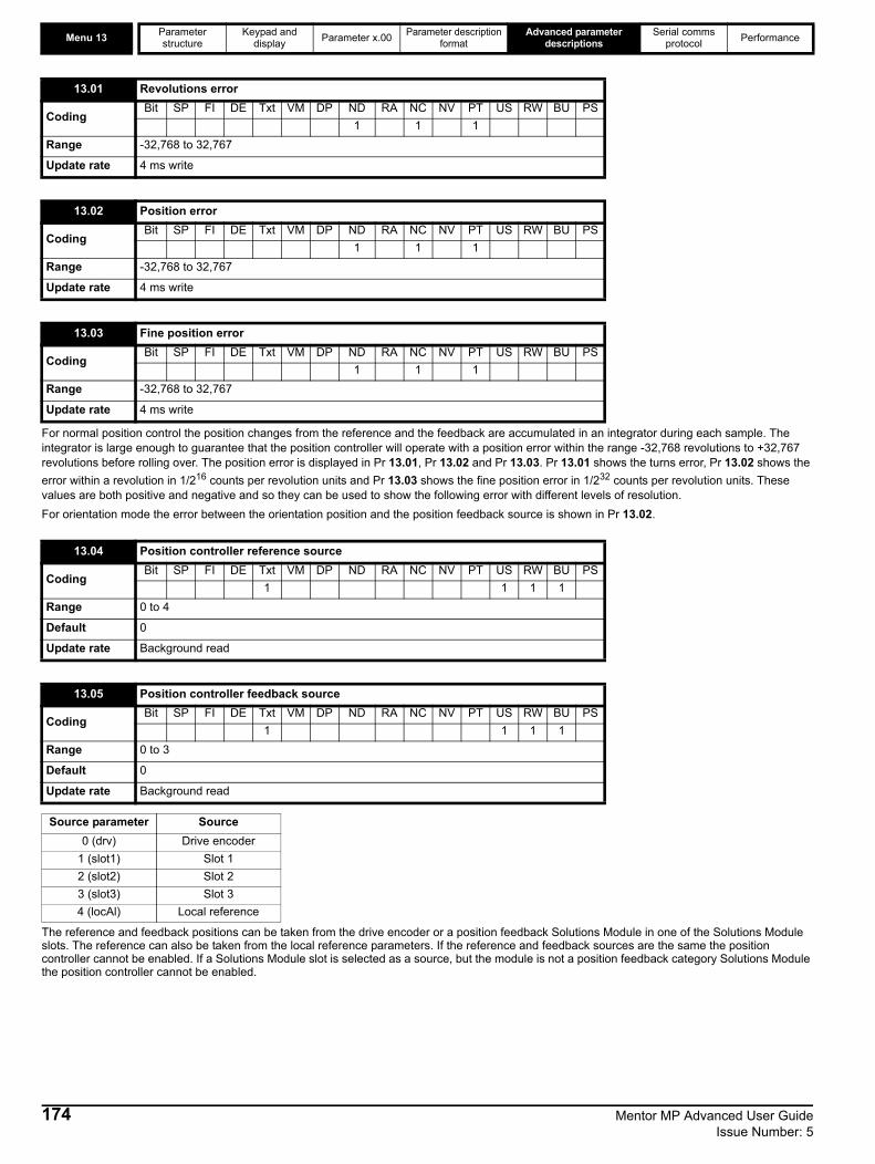
Menu 13 Parameter structure
Keypad and display Parameter x.00 Parameter description
formatAdvanced parameter
descriptionsSerial comms
protocol Performance
For normal position control the position changes from the reference and the feedback are accumulated in an integrator during each sample. The integrator is large enough to guarantee that the position controller will operate with a position error within the range -32,768 revolutions to +32,767 revolutions before rolling over. The position error is displayed in Pr 13.01, Pr 13.02 and Pr 13.03. Pr 13.01 shows the turns error, Pr 13.02 shows the error within a revolution in 1/216 counts per revolution units and Pr 13.03 shows the fine position error in 1/232 counts per revolution units. These values are both positive and negative and so they can be used to show the following error with different levels of resolution.For orientation mode the error between the orientation position and the position feedback source is shown in Pr 13.02.
The reference and feedback positions can be taken from the drive encoder or a position feedback Solutions Module in one of the Solutions Module slots. The reference can also be taken from the local reference parameters. If the reference and feedback sources are the same the position controller cannot be enabled. If a Solutions Module slot is selected as a source, but the module is not a position feedback category Solutions Module the position controller cannot be enabled.
13.01 Revolutions error
CodingBit SP FI DE Txt VM DP ND RA NC NV PT US RW BU PS
1 1 1Range -32,768 to 32,767
Update rate 4 ms write
13.02 Position error
CodingBit SP FI DE Txt VM DP ND RA NC NV PT US RW BU PS
1 1 1Range -32,768 to 32,767
Update rate 4 ms write
13.03 Fine position error
CodingBit SP FI DE Txt VM DP ND RA NC NV PT US RW BU PS
1 1 1Range -32,768 to 32,767
Update rate 4 ms write
13.04 Position controller reference source
CodingBit SP FI DE Txt VM DP ND RA NC NV PT US RW BU PS
1 1 1 1Range 0 to 4
Default 0
Update rate Background read
13.05 Position controller feedback source
CodingBit SP FI DE Txt VM DP ND RA NC NV PT US RW BU PS
1 1 1 1Range 0 to 3
Default 0
Update rate Background read
Source parameter Source0 (drv) Drive encoder
1 (slot1) Slot 12 (slot2) Slot 23 (slot3) Slot 34 (locAl) Local reference
174 Mentor MP Advanced User Guide Issue Number: 5

Parameter structure
Keypad and display Parameter x.00 Parameter description
formatAdvanced parameter
descriptionsSerial comms
protocol Performance Menu 13
An exact ratio can be applied to the position reference with these two parameters. The ratio cannot be changed when the drive is enabled without causing abrupt changes of position. Although it is possible to set up ratios with a high gain or even with a denominator of zero, the drive limits the resultant gain of the ratio block to 4.000.
The gain of the position controller is controlled with this parameter. The standard units within the drive for position are in 232 counts per revolution and the standard units for speed are 0.1 rpm, however the position controller gain is given in rads-1/rad. These units are consistent with units such as mms-1/mm or ms-1/m often used for linear control applications. An error of 1 radian (10430 counts in the position error (Pr 13.02)) gives a speed reference of 1rads-1 (9.5 rpm) when this gain is 1.00.
This parameter is used to set the position controller mode as shown in the following table.
13.06 Position reference invert
CodingBit SP FI DE Txt VM DP ND RA NC NV PT US RW BU PS1 1 1
Default 0
Update rate Background read
13.07 Ratio numerator
CodingBit SP FI DE Txt VM DP ND RA NC NV PT US RW BU PS
3 1 1 1Range 0.000 to 4.000
Default 1.000
Update rate Background read
13.08 Ratio denominator
CodingBit SP FI DE Txt VM DP ND RA NC NV PT US RW BU PS
3 1 1 1Range 0.000 to 1.000
Default 1.000
Update rate Background read
13.09 Position controller P gain
CodingBit SP FI DE Txt VM DP ND RA NC NV PT US RW BU PS
2 1 1 1Range 0.00 to 100.00 rads -1/radDefault 25.00
Update rate Background read
13.10 Position controller mode
CodingBit SP FI DE Txt VM DP ND RA NC NV PT US RW BU PS
1 1 1Range 0 to 6
Default 0
Update rate Background read
Parameter value Mode Feed forward
active0 Position controller disabled1 Rigid position control Yes2 Rigid position control 3 Non-rigid position control Yes4 Non-rigid position control 5 Orientation on stop6 Orientation on stop and when drive enabled
Mentor MP Advanced User Guide 175Issue Number: 5
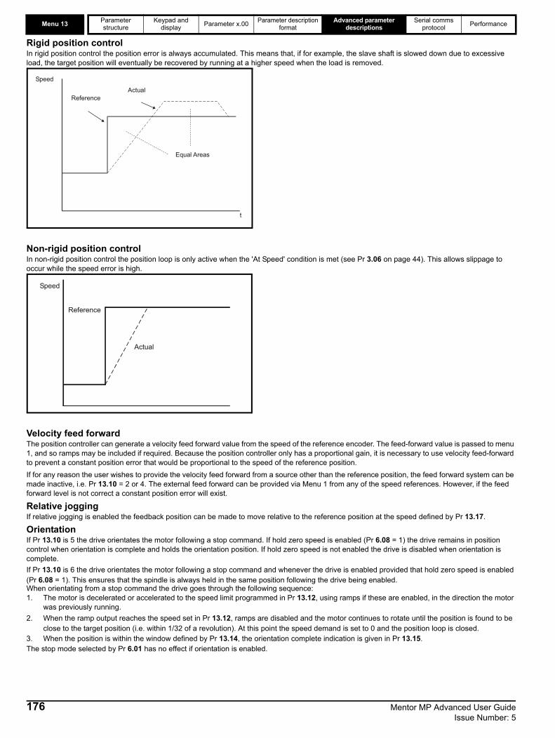
Menu 13 Parameter structure
Keypad and display Parameter x.00 Parameter description
formatAdvanced parameter
descriptionsSerial comms
protocol Performance
Rigid position controlIn rigid position control the position error is always accumulated. This means that, if for example, the slave shaft is slowed down due to excessive load, the target position will eventually be recovered by running at a higher speed when the load is removed.
Non-rigid position controlIn non-rigid position control the position loop is only active when the 'At Speed' condition is met (see Pr 3.06 on page 44). This allows slippage to occur while the speed error is high.
Velocity feed forwardThe position controller can generate a velocity feed forward value from the speed of the reference encoder. The feed-forward value is passed to menu 1, and so ramps may be included if required. Because the position controller only has a proportional gain, it is necessary to use velocity feed-forward to prevent a constant position error that would be proportional to the speed of the reference position.If for any reason the user wishes to provide the velocity feed forward from a source other than the reference position, the feed forward system can be made inactive, i.e. Pr 13.10 = 2 or 4. The external feed forward can be provided via Menu 1 from any of the speed references. However, if the feed forward level is not correct a constant position error will exist.
Relative joggingIf relative jogging is enabled the feedback position can be made to move relative to the reference position at the speed defined by Pr 13.17.
OrientationIf Pr 13.10 is 5 the drive orientates the motor following a stop command. If hold zero speed is enabled (Pr 6.08 = 1) the drive remains in position control when orientation is complete and holds the orientation position. If hold zero speed is not enabled the drive is disabled when orientation is complete. If Pr 13.10 is 6 the drive orientates the motor following a stop command and whenever the drive is enabled provided that hold zero speed is enabled (Pr 6.08 = 1). This ensures that the spindle is always held in the same position following the drive being enabled.When orientating from a stop command the drive goes through the following sequence:1. The motor is decelerated or accelerated to the speed limit programmed in Pr 13.12, using ramps if these are enabled, in the direction the motor
was previously running.2. When the ramp output reaches the speed set in Pr 13.12, ramps are disabled and the motor continues to rotate until the position is found to be
close to the target position (i.e. within 1/32 of a revolution). At this point the speed demand is set to 0 and the position loop is closed.3. When the position is within the window defined by Pr 13.14, the orientation complete indication is given in Pr 13.15.The stop mode selected by Pr 6.01 has no effect if orientation is enabled.
Speed
t
ReferenceActual
Equal Areas
Reference
Actual
Speed
176 Mentor MP Advanced User Guide Issue Number: 5
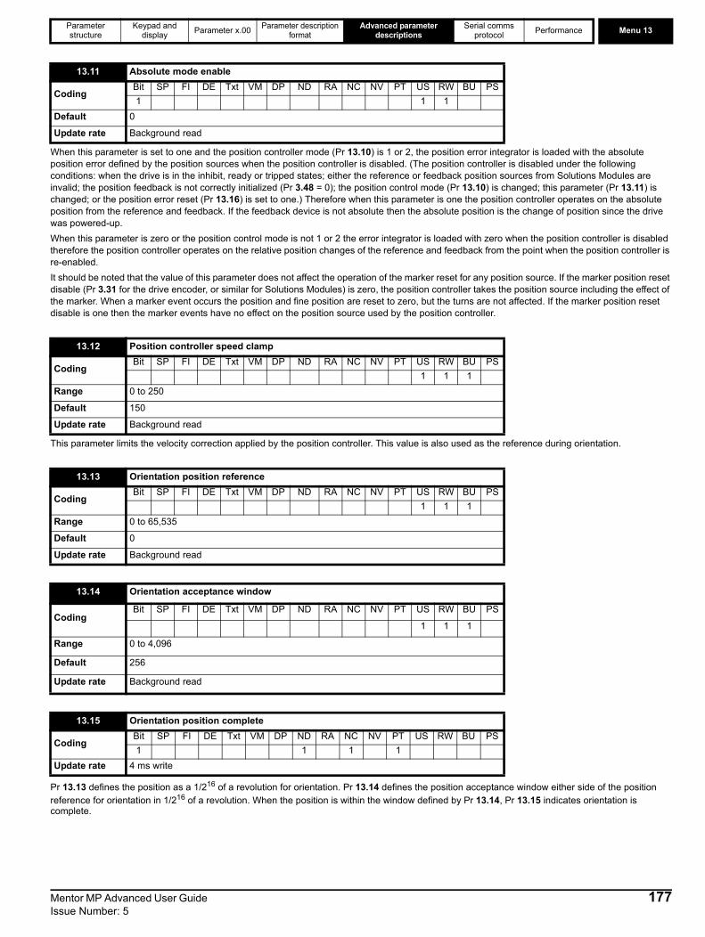
Parameter structure
Keypad and display Parameter x.00 Parameter description
formatAdvanced parameter
descriptionsSerial comms
protocol Performance Menu 13
When this parameter is set to one and the position controller mode (Pr 13.10) is 1 or 2, the position error integrator is loaded with the absolute position error defined by the position sources when the position controller is disabled. (The position controller is disabled under the following conditions: when the drive is in the inhibit, ready or tripped states; either the reference or feedback position sources from Solutions Modules are invalid; the position feedback is not correctly initialized (Pr 3.48 = 0); the position control mode (Pr 13.10) is changed; this parameter (Pr 13.11) is changed; or the position error reset (Pr 13.16) is set to one.) Therefore when this parameter is one the position controller operates on the absolute position from the reference and feedback. If the feedback device is not absolute then the absolute position is the change of position since the drive was powered-up. When this parameter is zero or the position control mode is not 1 or 2 the error integrator is loaded with zero when the position controller is disabled therefore the position controller operates on the relative position changes of the reference and feedback from the point when the position controller is re-enabled.It should be noted that the value of this parameter does not affect the operation of the marker reset for any position source. If the marker position reset disable (Pr 3.31 for the drive encoder, or similar for Solutions Modules) is zero, the position controller takes the position source including the effect of the marker. When a marker event occurs the position and fine position are reset to zero, but the turns are not affected. If the marker position reset disable is one then the marker events have no effect on the position source used by the position controller.
This parameter limits the velocity correction applied by the position controller. This value is also used as the reference during orientation.
Pr 13.13 defines the position as a 1/216 of a revolution for orientation. Pr 13.14 defines the position acceptance window either side of the position reference for orientation in 1/216 of a revolution. When the position is within the window defined by Pr 13.14, Pr 13.15 indicates orientation is complete.
13.11 Absolute mode enable
CodingBit SP FI DE Txt VM DP ND RA NC NV PT US RW BU PS1 1 1
Default 0
Update rate Background read
13.12 Position controller speed clamp
CodingBit SP FI DE Txt VM DP ND RA NC NV PT US RW BU PS
1 1 1Range 0 to 250
Default 150
Update rate Background read
13.13 Orientation position reference
CodingBit SP FI DE Txt VM DP ND RA NC NV PT US RW BU PS
1 1 1Range 0 to 65,535
Default 0
Update rate Background read
13.14 Orientation acceptance window
CodingBit SP FI DE Txt VM DP ND RA NC NV PT US RW BU PS
1 1 1
Range 0 to 4,096
Default 256
Update rate Background read
13.15 Orientation position complete
CodingBit SP FI DE Txt VM DP ND RA NC NV PT US RW BU PS1 1 1 1
Update rate 4 ms write
Mentor MP Advanced User Guide 177Issue Number: 5
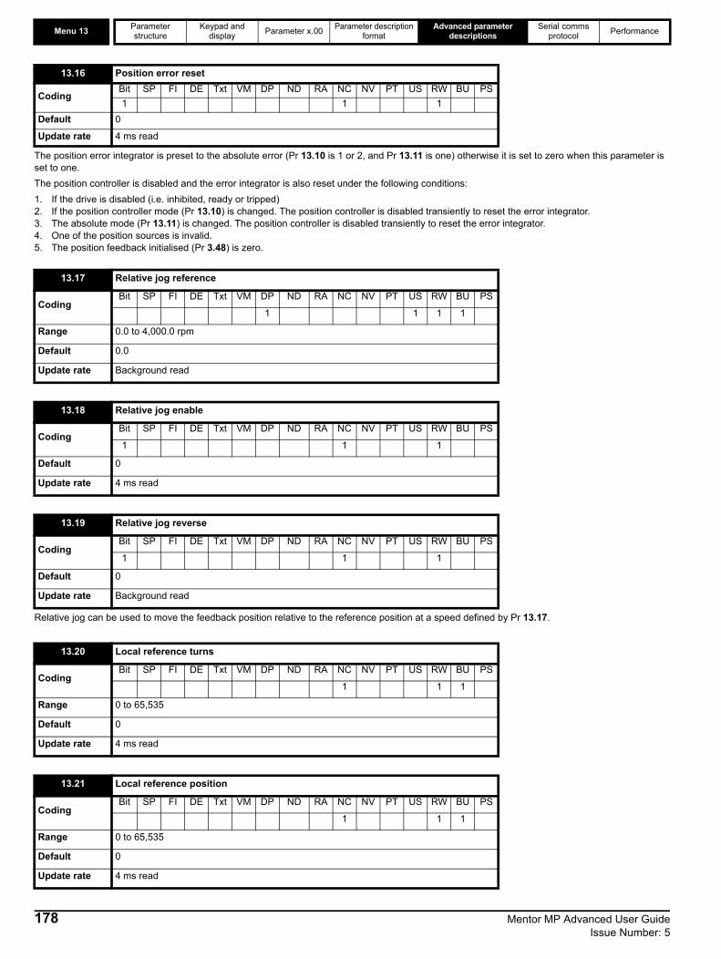
Menu 13 Parameter structure
Keypad and display Parameter x.00 Parameter description
formatAdvanced parameter
descriptionsSerial comms
protocol Performance
The position error integrator is preset to the absolute error (Pr 13.10 is 1 or 2, and Pr 13.11 is one) otherwise it is set to zero when this parameter is set to one.The position controller is disabled and the error integrator is also reset under the following conditions:1. If the drive is disabled (i.e. inhibited, ready or tripped)2. If the position controller mode (Pr 13.10) is changed. The position controller is disabled transiently to reset the error integrator.3. The absolute mode (Pr 13.11) is changed. The position controller is disabled transiently to reset the error integrator.4. One of the position sources is invalid.5. The position feedback initialised (Pr 3.48) is zero.
Relative jog can be used to move the feedback position relative to the reference position at a speed defined by Pr 13.17.
13.16 Position error reset
CodingBit SP FI DE Txt VM DP ND RA NC NV PT US RW BU PS1 1 1
Default 0
Update rate 4 ms read
13.17 Relative jog reference
CodingBit SP FI DE Txt VM DP ND RA NC NV PT US RW BU PS
1 1 1 1
Range 0.0 to 4,000.0 rpm
Default 0.0
Update rate Background read
13.18 Relative jog enable
CodingBit SP FI DE Txt VM DP ND RA NC NV PT US RW BU PS
1 1 1
Default 0
Update rate 4 ms read
13.19 Relative jog reverse
CodingBit SP FI DE Txt VM DP ND RA NC NV PT US RW BU PS
1 1 1
Default 0
Update rate Background read
13.20 Local reference turns
CodingBit SP FI DE Txt VM DP ND RA NC NV PT US RW BU PS
1 1 1
Range 0 to 65,535
Default 0
Update rate 4 ms read
13.21 Local reference position
CodingBit SP FI DE Txt VM DP ND RA NC NV PT US RW BU PS
1 1 1
Range 0 to 65,535
Default 0
Update rate 4 ms read
178 Mentor MP Advanced User Guide Issue Number: 5

Parameter structure
Keypad and display Parameter x.00 Parameter description
formatAdvanced parameter
descriptionsSerial comms
protocol Performance Menu 13
The local reference can be used to control the position of the motor shaft. If the local reference disable parameter is one the previously written value is used. This allows all three parts of the local reference position to be changed without data skew problems.
The local reference consists of a turns, a position and a fine position value. When Pr 13.24 is zero the reference is a 48bit position made from these three values. If Pr 13.24 is set to one the local reference is a 32bit position made from the position and fine position values. The position delta, used as the input to the position controller, is calculated correctly even when the turns are ignored as the 32bit position is treated as a roll-over/roll-under counter. This feature can be used, for example, with the local reference when only the position (and not the turns or fine position) is available. This feature is not available when absolute mode is selected (Pr 13.11 = 1).
13.22 Local reference fine position
CodingBit SP FI DE Txt VM DP ND RA NC NV PT US RW BU PS
1 1 1
Range 0 to 65,535
Default 0
Update rate 4 ms read
13.23 Local reference disable
CodingBit SP FI DE Txt VM DP ND RA NC NV PT US RW BU PS
1 1 1
Default 0
Update rate 4 ms read
13.24 Ignore local reference turns
CodingBit SP FI DE Txt VM DP ND RA NC NV PT US RW BU PS
1 1 1
Default 0
Update rate 4 ms read
Mentor MP Advanced User Guide 179Issue Number: 5

Menu 14 Parameter structure
Keypad and display Parameter x.00 Parameter description
formatAdvanced parameter
descriptionsSerial comms
protocol Performance
5.15 Menu 14: User PID controllerThis menu contains a PID controller which has programmable reference and feedback inputs, programmable enable bit, reference slew rate limiting, variable clamp levels and programmable destination. The sample rate of the PID controller is 4 ms. Figure 5-34 Menu 14 logic diagram
180 Mentor MP Advanced User Guide Issue Number: 5
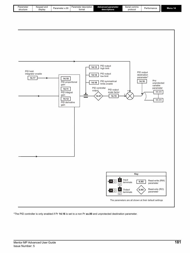
Parameter structure
Keypad and display Parameter x.00 Parameter description
formatAdvanced parameter
descriptionsSerial comms
protocol Performance Menu 14
*The PID controller is only enabled if Pr 14.16 is set to a non Pr xx.00 and unprotected destination parameter.
14.10
14.11
14.12
14.17
14.13
14.14
14.18
14.01 14.15+
+
14.16
??.??
??.??
Any unprotectedvariable parameter
PID derivativegain
PID integralgain
PID proportionalgain
PID hold integrator enable
PID outputhigh limit
PID outputlow limit
PID symmetricallimits enable
PID controlleroutput PID output
scale factor
PID outputdestinationparameter*
0.XX
0.XX
Key
Read-write (RW) parameter
Read-only (RO) parameter
Inputterminals
Outputterminals
The parameters are all shown at their default settings
Mentor MP Advanced User Guide 181Issue Number: 5

Menu 14 Parameter structure
Keypad and display Parameter x.00 Parameter description
formatAdvanced parameter
descriptionsSerial comms
protocol Performance
Subject to the limits the PID controller output is given by
output = error x [P + I/s + Ds/(0.064s + 1)]Where:
error = reference - feedbackP = proportional gain = Pr 14.10I = integral gain = Pr 14.11D = differential gain = Pr 14.12
Therefore with an error of 100 % and P = 1.000 the output produced by the proportional term is 100 %. With an error of 100 % and I = 1.000 the output produced by the integral term will increase linearly by 100 % every second. With an error that is increasing by 100 % per second and D = 1.000 the output produced by the D term will be 100 %.
This parameter defines the time taken for the reference input to ramp from 0 to 100.0 % following a 0 to 100 % step change in input.
14.01 PID output
CodingBit SP FI DE Txt VM DP ND RA NC NV PT US RW BU PS
2 1 1 1Range ±100.00 %
Update rate 4 ms write
14.02 PID main reference source
14.03 PID reference source
14.04 PID feedback source
CodingBit SP FI DE Txt VM DP ND RA NC NV PT US RW BU PS
2 1 1 1 1Range Pr 0.00 to Pr 22.99
Default Pr 0.00
Update rate Read on reset
14.05 PID reference source invert
14.06 PID feedback source invert
CodingBit SP FI DE Txt VM DP ND RA NC NV PT US RW BU PS1 1 1
Default 0
Update rate 4 ms read
14.07 PID reference slew rate limit
CodingBit SP FI DE Txt VM DP ND RA NC NV PT US RW BU PS
1 1 1 1Range 0.0 to 3,200.0 s
Default 0.0
Update rate Background read
14.08 PID enable
CodingBit SP FI DE Txt VM DP ND RA NC NV PT US RW BU PS1 1 1
Default 0
Update rate 4 ms read
182 Mentor MP Advanced User Guide Issue Number: 5

Parameter structure
Keypad and display Parameter x.00 Parameter description
formatAdvanced parameter
descriptionsSerial comms
protocol Performance Menu 14
To enable the PID controller the drive must be OK (Pr 10.01 = 1) and the PID enable (Pr 14.08) must be one. If the option enable source (Pr 14.09) is 00.00 or routed to a non-existent parameter the PID controller is still enabled provided Pr 10.01 = 1 and Pr 14.08 = 1. If the optional enable source (Pr 14.09) is routed to an existing parameter the source parameter must be one before the PID controller can be enabled. If the PID controller is disabled the output is zero and the integrator is set to zero.
If Pr 14.18 = 0, the upper limit (Pr 14.13) defines the maximum positive output for the PID controller and the lower limit (Pr 14.14) defines the minimum positive or maximum negative output. If Pr 14.18 = 1, the upper limit defines the maximum positive or negative magnitude for the PID controller output. When any of the limits are active the integrator is held.
14.09 PID optional enable source
CodingBit SP FI DE Txt VM DP ND RA NC NV PT US RW BU PS
2 1 1 1 1Range Pr 0.00 to Pr 22.99
Default Pr 0.00
Update rate Read on reset
14.10 PID P gain
CodingBit SP FI DE Txt VM DP ND RA NC NV PT US RW BU PS
3 1 1 1Range 0.000 to 4.000
Default 1.000
Update rate Background read
14.11 PID I gain
CodingBit SP FI DE Txt VM DP ND RA NC NV PT US RW BU PS
3 1 1 1Range 0.000 to 4.000
Default 0.500
Update rate Background read
14.12 PID D gain
CodingBit SP FI DE Txt VM DP ND RA NC NV PT US RW BU PS
3 1 1 1Range 0.000 to 4.000
Default 0.000
Update rate Background read
14.13 PID upper limit
CodingBit SP FI DE Txt VM DP ND RA NC NV PT US RW BU PS
2 1 1 1Range 0.00 to 100.00 %
Default 100.00
Update rate Background read
14.14 PID lower limit
CodingBit SP FI DE Txt VM DP ND RA NC NV PT US RW BU PS
2 1 1Range ±100.00 %
Default -100.00
Update rate Background read
Mentor MP Advanced User Guide 183Issue Number: 5

Menu 14 Parameter structure
Keypad and display Parameter x.00 Parameter description
formatAdvanced parameter
descriptionsSerial comms
protocol Performance
The value written to the destination parameter is (PID controller output x scaling) + PID main reference.
When this parameter is set to 0 the integrator operates normally. Setting this parameter to 1 will cause the integrator value to be held. Setting this parameter does not prevent the integrator from being reset to zero if the PID controller is disabled.
See Pr 14.13 and Pr 14.14.
14.15 PID scaling
CodingBit SP FI DE Txt VM DP ND RA NC NV PT US RW BU PS
3 1 1 1Range 0.000 to 4.000
Default 1.000
Update rate 4 ms read
14.16 PID destination
CodingBit SP FI DE Txt VM DP ND RA NC NV PT US RW BU PS
1 2 1 1 1 1Range Pr 0.00 to Pr 22.99
Default Pr 0.00
Update rate Read on reset
14.17 PID hold integrator
CodingBit SP FI DE Txt VM DP ND RA NC NV PT US RW BU PS1 1 1
Default 0
Update rate 4 ms read
14.18 PID symmetrical limit enable
CodingBit SP FI DE Txt VM DP ND RA NC NV PT US RW BU PS1 1 1
Default 0
Update rate Background read
14.19 PID main reference
Coding Bit SP FI DE Txt VM DP ND RA NC NV PT US RW BU PS
2 1 1 1
Range ±100.00 %
Update rate 4 ms write
14.20 PID reference
Coding Bit SP FI DE Txt VM DP ND RA NC NV PT US RW BU PS
2 1 1 1
Range ±100.00 %
Update rate 4 ms write
14.21 PID feedback
Coding Bit SP FI DE Txt VM DP ND RA NC NV PT US RW BU PS
2 1 1 1
Range ±100.00 %
Update rate 4 ms write
184 Mentor MP Advanced User Guide Issue Number: 5

Parameter structure
Keypad and display Parameter x.00 Parameter description
formatAdvanced parameter
descriptionsSerial comms
protocol Performance Menu 14
14.22 PID error
Coding Bit SP FI DE Txt VM DP ND RA NC NV PT US RW BU PS
2 1 1 1
Range ±100.00 %
Update rate 4 ms write
Mentor MP Advanced User Guide 185Issue Number: 5

Menus 15 to 17 Parameter structure
Keypad and display Parameter x.00 Parameter description
formatAdvanced parameter
descriptionsSerial comms
protocol Performance
186 Mentor MP Advanced User Guide Issue Number: 5
5.16 Menus 15, 16 and 17: Solutions Module slotsPr x.00 and Pr x.01 are always present in menus 15, 16 and 17. Pr x.01 indicates which type of module is present (0 = no module installed). When a module is installed the drive provides the relevant menu (menu 15 for slot 1, 16 for slot 2 and 17 for slot 3) depending on the Solutions Module installed. The possible categories are shown below.
Refer to the specific Solutions Module User Guide for more information.Most modules include a processor and parameters are updated by the processor in the Solutions Module. However, dumb modules do not contain a processor and all parameters are updated by the drive processor.Dumb Solutions Module parameters are read/written by the drive background task or at the combined update time for time critical parameters. The combined update time depends on the number and type of dumb Solutions Modules installed to the drive. For each Solutions Module the update rate of these parameters is specified as 4 ms, 8 ms, etc. The combined update time is the total of the update times for all dumb Solutions Modules installed. For example, if a module with 4 ms update time and a module with 8 ms are installed to the drive, then the combined update time for the time critical parameters of each module is 12 ms.In the parameter tables the update time added by the type of module is given, for example 4 ms for the SM-Encoder Plus or 8 ms for the SM-I/O Plus.When parameters are saved by the user in the drive EEPROM the option code of the currently installed module is saved in EEPROM. If the drive is subsequently powered-up with a different module installed, or no module installed where a module was previously installed, the drive gives a Slot.dF trip. The menu for the relevant slot appears for the new module category with the default parameter values for the new category. The new parameters values are not stored in EEPROM until the user performs a parameter save.
Parameters common to all categories
Solutions Module ID Module Category
0 No module installed102 SM-Universal Encoder Plus
Feedback104 SM-Encoder Plus and SM-
Encoder Output Plus201 SM-I/O Plus
Automation(I/O Expansion)
203 SM-I/O Timer204 SM-I/O PELV205 SM-I/O24V Protected206 SM-I/O120V207 SM-I/O Lite208 SM-I/O 32304 SM-Applications Plus
Automation(Applications)305 SM-Applications Lite V2
306 SM-Register403 SM-PROFIBUS DP-V1
Fieldbus
404 SM-INTERBUS407 SM-DeviceNet408 SM-CANopen410 SM-Ethernet421 SM-EtherCAT
Parameter Range Default Typex.01 Solutions Module ID 0 to 599 RO Uni PT USx.50 Solutions Module error status 0 to 255 RO Uni NC PT
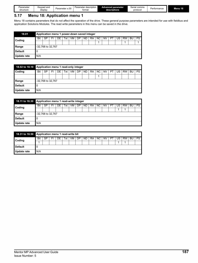
Parameter structure
Keypad and display Parameter x.00 Parameter description
formatAdvanced parameter
descriptionsSerial comms
protocol Performance Menu 18
Mentor MP Advanced User Guide 187Issue Number: 5
5.17 Menu 18: Application menu 1Menu 18 contains parameters that do not affect the operation of the drive. These general purpose parameters are intended for use with fieldbus and application Solutions Modules. The read write parameters in this menu can be saved in the drive.
18.01 Application menu 1 power-down saved integer
CodingBit SP FI DE Txt VM DP ND RA NC NV PT US RW BU PS
1 1 1Range -32,768 to 32,767
Default 0
Update rate N/A
18.02 to 18.10 Application menu 1 read-only integer
Coding Bit SP FI DE Txt VM DP ND RA NC NV PT US RW BU PS
1
Range -32,768 to 32,767
Default 0
Update rate N/A
18.11 to 18.30 Application menu 1 read-write integer
CodingBit SP FI DE Txt VM DP ND RA NC NV PT US RW BU PS
1 1Range -32,768 to 32,767
Default 0
Update rate N/A
18.31 to 18.50 Application menu 1 read-write bit
CodingBit SP FI DE Txt VM DP ND RA NC NV PT US RW BU PS1 1 1
Default 0
Update rate N/A
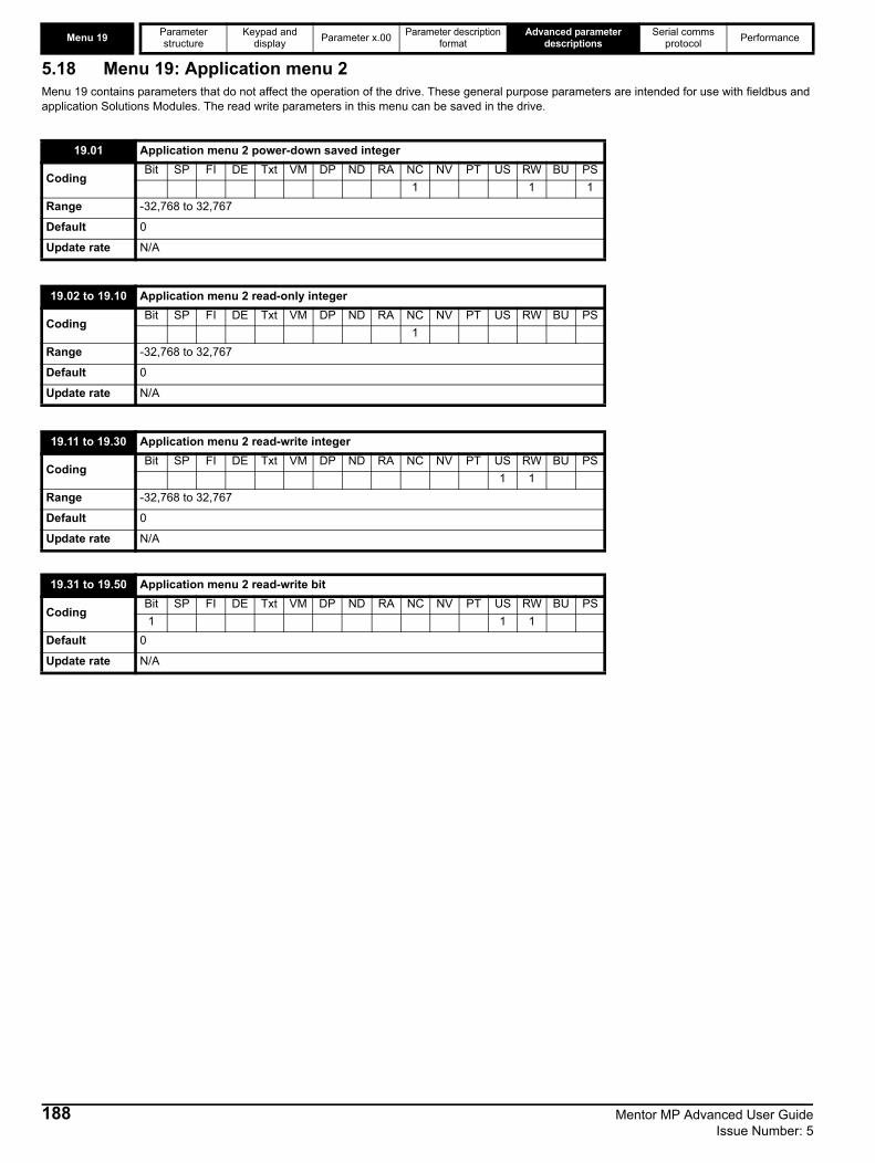
Menu 19 Parameter structure
Keypad and display Parameter x.00 Parameter description
formatAdvanced parameter
descriptionsSerial comms
protocol Performance
188 Mentor MP Advanced User Guide Issue Number: 5
5.18 Menu 19: Application menu 2Menu 19 contains parameters that do not affect the operation of the drive. These general purpose parameters are intended for use with fieldbus and application Solutions Modules. The read write parameters in this menu can be saved in the drive.
19.01 Application menu 2 power-down saved integer
CodingBit SP FI DE Txt VM DP ND RA NC NV PT US RW BU PS
1 1 1Range -32,768 to 32,767
Default 0
Update rate N/A
19.02 to 19.10 Application menu 2 read-only integer
CodingBit SP FI DE Txt VM DP ND RA NC NV PT US RW BU PS
1Range -32,768 to 32,767
Default 0
Update rate N/A
19.11 to 19.30 Application menu 2 read-write integer
CodingBit SP FI DE Txt VM DP ND RA NC NV PT US RW BU PS
1 1Range -32,768 to 32,767
Default 0
Update rate N/A
19.31 to 19.50 Application menu 2 read-write bit
CodingBit SP FI DE Txt VM DP ND RA NC NV PT US RW BU PS1 1 1
Default 0
Update rate N/A

Parameter structure
Keypad and display Parameter x.00 Parameter description
formatAdvanced parameter
descriptionsSerial comms
protocol Performance Menu 20
Mentor MP Advanced User Guide 189Issue Number: 5
5.19 Menu 20: Application menu 3Menu 20 contains parameters that do not affect the operation of the drive. These general purpose parameters are intended for use with fieldbus and application Solutions Modules. The read write parameters in this menu cannot be saved in the drive.
20.01 to 20.20 Application menu 3 read-write integer
CodingBit SP FI DE Txt VM DP ND RA NC NV PT US RW BU PS
1 1Range -32,768 to 32,767
Default 0
Update rate N/A
20.21 to 20.40 Application menu 3 read-write long integer
CodingBit SP FI DE Txt VM DP ND RA NC NV PT US RW BU PS
1 1
Range -231 to 231-1
Default 0
Update rate N/A

Menu 21 Parameter structure
Keypad and display Parameter x.00 Parameter description
formatAdvanced parameter
descriptionsSerial comms
protocol Performance
5.20 Menu 21: Second motor parametersThe following parameters are used instead of the normal motor setup parameters when Pr 11.45 = 1.When the alternative parameter set is being used by the drive, the decimal point second from the right in the first row is on.For more information about a particular parameter, see the equivalent normal motor map 1 parameter.
* The range shown for Pr 21.02 shows the range used for scaling purposes (i.e. for routing to an analog output etc.). Further range restrictions are applied as shown below:
Unlike the motor 1 (Pr 1.14= {SE05, 0.26}) this parameter is not used for T28 and T29 digital input auto-selection (see Pr 8.52 on page 121).Pr 21.03 defines how the value of Pr 1.49 is derived as follows:
21.01 Maximum reference clamp
CodingBit SP FI DE Txt VM DP ND RA NC NV PT US RW BU PS
1 1 1 1Range SPEED_LIMIT_MAX rpm
Default 1000
Normal parameter Pr 1.06 = {SE02, 0.23}
Update rate Background read
21.02 Minimum reference clamp
CodingBit SP FI DE Txt VM DP ND RA NC NV PT US RW BU PS
1 1 1 1Range -SPEED_LIMIT_MAX to SPEED_LIMIT_MAX rpm*
Default 0.0
Normal parameter Pr 1.07 = {SE01, 0.22}
Update rate Background read
Pr 1.08(Neg min ref enable)
Pr 1.10(Bipolar mode enable) Range
0 0 0 to 21.010 1 01 0 -SPEED_LIMIT_MAX to 0 rpm1 1 -SPEED_LIMIT_MAX to 0 rpm
21.03 Reference selector
CodingBit SP FI DE Txt VM DP ND RA NC NV PT US RW BU PS
1 1 1 1Range 0 to 6
Default 0 (A1.A2)
Normal parameter Pr 1.14= {SE05, 0.26}
Update rate 4 ms read
Value of Pr 21.03 Display String Pr 1.49
0 A1.A2 *Selected by terminal input
1 A1.Pr 1
2 A2.Pr 2
3 Pr 3
4 Pad 4
5 Prc 5
6 Keypad ref only 6
190 Mentor MP Advanced User Guide Issue Number: 5

Parameter structure
Keypad and display Parameter x.00 Parameter description
formatAdvanced parameter
descriptionsSerial comms
protocol Performance Menu 21
*The bit Pr 1.41 to Pr 1.44 and Pr 1.52 can be controlled to force the value of Pr 1.49, as follows:
all bits equal to zero gives 1, Pr 1.41 = 1 then Pr 1.49 = 2 Pr 1.42 = 1 then Pr 1.49 = 3Pr 1.43 = 1 then Pr 1.49 = 4Pr 1.44 = 1 then Pr 1.49 = 5Pr 1.52 = 1 then Pr 1.49 = 6
The bit parameters with lower numbers have priority over those with higher numbers.Pr 1.49 and Pr 1.50 then define the reference as follows:
Keypad referenceIf Keypad reference is selected the drive sequencer is controlled directly by the keypad keys and the keypad reference parameter (Pr 1.17) is selected. The sequencing bits, Pr 6.30 to Pr 6.34, have no effect and jog is disabled.Reference selected by timerThe presets are selected automatically in turn. Pr 1.16 defines the time between each change.
Pr 1.49 Pr 1.50 Reference1 1 Analog reference 11 >1 Preset defined by Pr 1.502 1 Analog reference 22 >1 Preset defined by Pr 1.503 x Preset defined by Pr 1.504 x Keypad reference5 x Precision reference6 x Pad reference only
21.04 Acceleration rate
CodingBit SP FI DE Txt VM DP ND RA NC NV PT US RW BU PS
1 3 1 1 1Range 0 to MAX_RAMP_RATE_M2
Default 5.000
Normal parameter Pr 2.11 = {SE03, 0.24}
Update rate Background read
21.05 Deceleration rate
CodingBit SP FI DE Txt VM DP ND RA NC NV PT US RW BU PS
1 1 1 1 1Range 0 to MAX_RAMP_RATE_M2
Default 5.000
Normal parameter Pr 2.21 = {SE04, 0.25}
Update rate Background read
21.06 Base speed
CodingBit SP FI DE Txt VM DP ND RA NC NV PT US RW BU PS
1 1 1 1Range 0 to 10000.0 rpm
Default 1000
Normal parameter Pr 5.08 = {SE08, 0.29}
Update rate Background read
Mentor MP Advanced User Guide 191Issue Number: 5
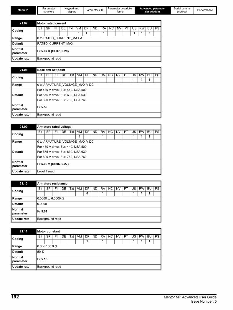
Menu 21 Parameter structure
Keypad and display Parameter x.00 Parameter description
formatAdvanced parameter
descriptionsSerial comms
protocol Performance
21.07 Motor rated current
CodingBit SP FI DE Txt VM DP ND RA NC NV PT US RW BU PS
1 1 1 1 1 1Range 0 to RATED_CURRENT_MAX A
Default RATED_CURRENT_MAX
Normal parameter Pr 5.07 = {SE07, 0.28}
Update rate Background read
21.08 Back emf set point
CodingBit SP FI DE Txt VM DP ND RA NC NV PT US RW BU PS
1 1 1Range 0 to ARMATURE_VOLTAGE_MAX V DC
DefaultFor 480 V drive: Eur: 440, USA 500For 575 V drive: Eur: 630, USA 630For 690 V drive: Eur: 760, USA 760
Normal parameter Pr 5.59
Update rate Background read
21.09 Armature rated voltage
CodingBit SP FI DE Txt VM DP ND RA NC NV PT US RW BU PS
1 1 1 1 1Range 0 to ARMATURE_VOLTAGE_MAX V DC
DefaultFor 480 V drive: Eur: 440, USA 500For 575 V drive: Eur: 630, USA 630For 690 V drive: Eur: 760, USA 760
Normal parameter Pr 5.09 = {SE06, 0.27}
Update rate Level 4 read
21.10 Armature resistance
CodingBit SP FI DE Txt VM DP ND RA NC NV PT US RW BU PS
4 1 1 1 1Range 0.0000 to 6.0000 Ω
Default 0.0000
Normal parameter Pr 5.61
Update rate Background read
21.11 Motor constant
CodingBit SP FI DE Txt VM DP ND RA NC NV PT US RW BU PS
1 1 1 1 1Range 0.0 to 100.0 %
Default 50 %
Normal parameter Pr 5.15
Update rate Background read
192 Mentor MP Advanced User Guide Issue Number: 5

Parameter structure
Keypad and display Parameter x.00 Parameter description
formatAdvanced parameter
descriptionsSerial comms
protocol Performance Menu 21
Pr 21.15 does not have an equivalent normal motor parameter, but shows when motor 2 is active.
21.12 Discontinuous current controller Ki gain
CodingBit SP FI DE Txt VM DP ND RA NC NV PT US RW BU PS
1 1 1 1Range 0 to 4000
Default 200
Normal parameter Pr 4.34
Update rate Background read
21.13 Continuous current controller Kp gain
CodingBit SP FI DE Txt VM DP ND RA NC NV PT US RW BU PS
1 1 1 1Range 0 to 4000
Default 100
Normal parameter Pr 4.13
Update rate Background read
21.14 Continuous current controller Ki gain
CodingBit SP FI DE Txt VM DP ND RA NC NV PT US RW BU PS
1 1 1 1Range 0 to 4000
Default 50
Normal parameter Pr 4.14
Update rate Background read
21.15 Motor 2 active
CodingBit SP FI DE Txt VM DP ND RA NC NV PT US RW BU PS1 1 1 1
Normal motor parameter Pr 21.15
Update rate Background write
21.16 Thermal filter
CodingBit SP FI DE Txt VM DP ND RA NC NV PT US RW BU PS
1 1 1 1Range 0.0 to 3000.0
Default 89.0
Normal motor parameter Pr 4.15
Update rate Background read
Mentor MP Advanced User Guide 193Issue Number: 5

Menu 21 Parameter structure
Keypad and display Parameter x.00 Parameter description
formatAdvanced parameter
descriptionsSerial comms
protocol Performance
When the second motor is selected the gains defined in Pr 21.17 to Pr 21.19 are used directly by the speed controller. The speed controller setup method defined by Pr 3.13 is ignored.
0, drv: Drive encoderThe position feedback from the encoder connected to the drive itself is used to derive the speed feedback for the speed controller and to calculate the motor rotor flux position.1, Slot1: Solutions Module in slot 1The position feedback from the Solutions Module in Solutions Module slot 1 is used to derive the speed feedback for the speed controller and to calculate the motor rotor flux position. If a position feedback category Solutions Module is not installed in slot 1 the drive produces an EnC9 trip.2, Slot2: Solutions Module in slot 23, Slot3: Solutions Module in slot 34, tacho5, Est speed
21.17 Speed controller Kp gain
CodingBit SP FI DE Txt VM DP ND RA NC NV PT US RW BU PS
4 1 1 1Range 0.00 to 6.5535(1 / (rad/s))
Default 0.0300
Normal motor parameter Pr 3.10 = {SP01, 0.61}
Update rate Background read
21.18 Speed controller Ki gain
CodingBit SP FI DE Txt VM DP ND RA NC NV PT US RW BU PS
2 1 1 1Range 0.00 to 655.35 s/rad s-1
Default 0.10
Normal motor parameter Pr 3.11 = {SP02, 0.62}
Update rate Background read
21.19 Speed controller Kd gain
CodingBit SP FI DE Txt VM DP ND RA NC NV PT US RW BU PS
5 1 1 1Range 0.00000 to 0.65535(1/s / (rad/s))
Default 0.00000
Normal motor parameter Pr 3.12 = {SP03, 0.63}
Update rate Background read
21.21 Speed feedback selector
CodingBit SP FI DE Txt VM DP ND RA NC NV PT US RW BU PS
1 1 1 1Range 0 to 5
Default 5
Normal motor parameter Pr 3.26 = {Fb01, 0.71}
Update rate Background read
194 Mentor MP Advanced User Guide Issue Number: 5
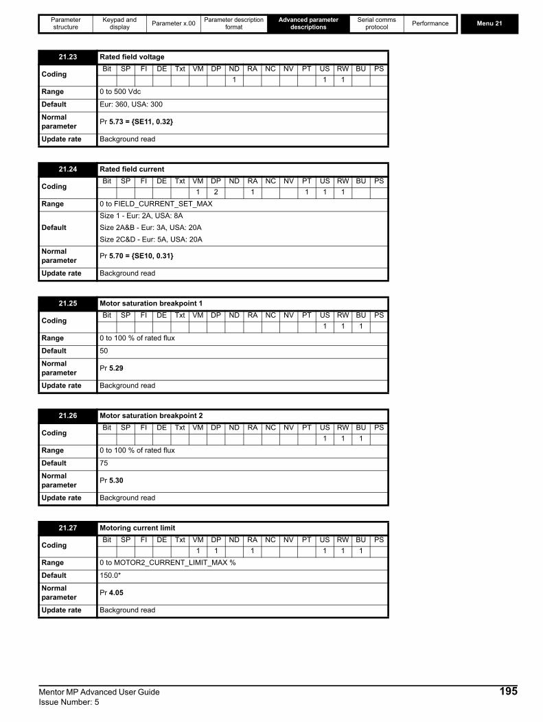
Parameter structure
Keypad and display Parameter x.00 Parameter description
formatAdvanced parameter
descriptionsSerial comms
protocol Performance Menu 21
21.23 Rated field voltage
CodingBit SP FI DE Txt VM DP ND RA NC NV PT US RW BU PS
1 1 1Range 0 to 500 Vdc
Default Eur: 360, USA: 300
Normal parameter Pr 5.73 = {SE11, 0.32}
Update rate Background read
21.24 Rated field current
CodingBit SP FI DE Txt VM DP ND RA NC NV PT US RW BU PS
1 2 1 1 1 1Range 0 to FIELD_CURRENT_SET_MAX
DefaultSize 1 - Eur: 2A, USA: 8ASize 2A&B - Eur: 3A, USA: 20ASize 2C&D - Eur: 5A, USA: 20A
Normal parameter Pr 5.70 = {SE10, 0.31}
Update rate Background read
21.25 Motor saturation breakpoint 1
CodingBit SP FI DE Txt VM DP ND RA NC NV PT US RW BU PS
1 1 1Range 0 to 100 % of rated flux
Default 50
Normal parameter Pr 5.29
Update rate Background read
21.26 Motor saturation breakpoint 2
CodingBit SP FI DE Txt VM DP ND RA NC NV PT US RW BU PS
1 1 1Range 0 to 100 % of rated flux
Default 75
Normal parameter Pr 5.30
Update rate Background read
21.27 Motoring current limit
CodingBit SP FI DE Txt VM DP ND RA NC NV PT US RW BU PS
1 1 1 1 1 1Range 0 to MOTOR2_CURRENT_LIMIT_MAX %
Default 150.0*
Normal parameter Pr 4.05
Update rate Background read
Mentor MP Advanced User Guide 195Issue Number: 5

Menu 21 Parameter structure
Keypad and display Parameter x.00 Parameter description
formatAdvanced parameter
descriptionsSerial comms
protocol Performance
*These are the maximum default values. If the variable maximum of this parameter (MOTOR2_CURRENT_LIMIT_MAX) gives a lower value with the default value of Motor rated current (Pr 21.07) the default of this parameter is at the lower value.
Field current control loop proportional gain.
Field current control loop integral gain.
21.28 Regen current limit
CodingBit SP FI DE Txt VM DP ND RA NC NV PT US RW BU PS
1 1 1 1 1 1Range 0 to MOTOR2_CURRENT_LIMIT_MAX %
Default 150.0*
Normal parameter Pr 4.06
Update rate Background read
21.29 Symmetrical current limit
CodingBit SP FI DE Txt VM DP ND RA NC NV PT US RW BU PS
1 1 1 1 1 1Range 0 to MOTOR2_CURRENT_LIMIT_MAX %
Default 150.0*
Normal parameter Pr 4.07
Update rate Background read
21.30 Field thermal filter
CodingBit SP FI DE Txt VM DP ND RA NC NV PT US RW BU PS
1 1 1 1Range 0 to 3000.0
Default 24.0
Normal parameter Pr 5.81
Update rate Background read
21.31 Flux loop P gain
CodingBit SP FI DE Txt VM DP ND RA NC NV PT US RW BU PS
2 1 1 1Range 0 to 30.0
Default 3
Normal parameter Pr 5.71
Update rate Background read
21.32 Flux loop I gain
CodingBit SP FI DE Txt VM DP ND RA NC NV PT US RW BU PS
2 1 1 1Range 0 to 300.0
Default 60
Normal parameter Pr 5.72
Update rate Background read
196 Mentor MP Advanced User Guide Issue Number: 5
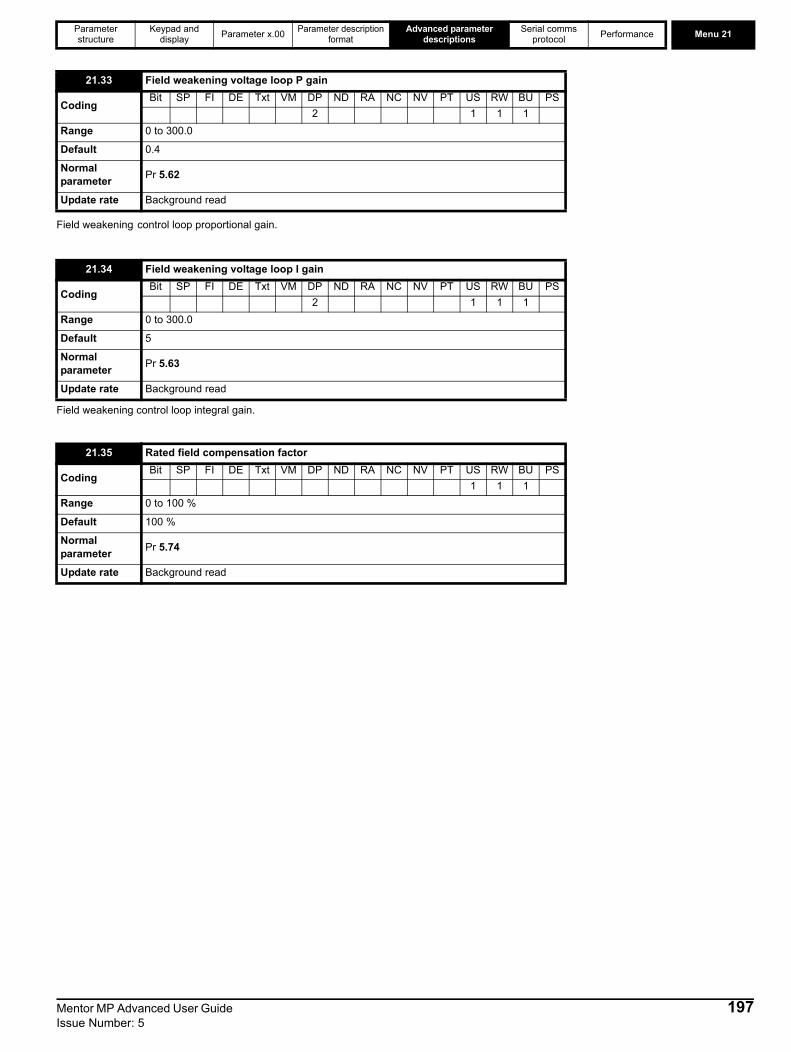
Parameter structure
Keypad and display Parameter x.00 Parameter description
formatAdvanced parameter
descriptionsSerial comms
protocol Performance Menu 21
Field weakening control loop proportional gain.
Field weakening control loop integral gain.
21.33 Field weakening voltage loop P gain
CodingBit SP FI DE Txt VM DP ND RA NC NV PT US RW BU PS
2 1 1 1Range 0 to 300.0
Default 0.4
Normal parameter Pr 5.62
Update rate Background read
21.34 Field weakening voltage loop I gain
CodingBit SP FI DE Txt VM DP ND RA NC NV PT US RW BU PS
2 1 1 1Range 0 to 300.0
Default 5
Normal parameter Pr 5.63
Update rate Background read
21.35 Rated field compensation factor
CodingBit SP FI DE Txt VM DP ND RA NC NV PT US RW BU PS
1 1 1Range 0 to 100 %
Default 100 %
Normal parameter Pr 5.74
Update rate Background read
Mentor MP Advanced User Guide 197Issue Number: 5

Menu 22 Parameter structure
Keypad and display Parameter x.00 Parameter description
formatAdvanced parameter
descriptionsSerial comms
protocol Performance
198 Mentor MP Advanced User Guide Issue Number: 5
5.21 Menu 22: Additional menu 0 setupMenu 22 contains parameters that are used to set up the source parameters for the first 20 parameters in Menu 0.
These parameters define the parameters that reside in the programmable area in menu 0.
22.01 to 22.20 Parameter 00.xy setup
CodingBit SP FI DE Txt VM DP ND RA NC NV PT US RW BU PS
2 1 1 1 1Range Pr 0.00 to Pr 22.99
Default 0.00
Update rate Background read

Parameter structure
Keypad and display Parameter x.00 Parameter description
formatAdvanced parameter
descriptionsSerial comms
protocol Performance Menu 23
5.22 Menu 23 Header definitions Menu 23 contains parameters that define the header parameter for Menu 0. Menu 0 can be accessed by 2 methods:1. Pr 11.44 (SE14, 0.35) = 0. Sub block mode.2. Pr 11.44 (SE14, 0.35) <>0. Linear mode.
Menu 23 Menu 0 CustomizationMenu 23 contains the parameters to allow menu 0 to be customized in sub block mode. The first sub block is a user defined area (USEr) which is configured by the parameters in menu 22. The next 7 sub blocks are pre-defined. Access to the pre-defined blocks is enabled or disabled by Pr 23.03 to Pr 23.09. Movement between sub blocks is achieved with the left and right keys. Pr 23.01 contains all the sub block headers.
Table 5-10 and Figure 5-35 show the result of the direction keys when Pr 11.44 (SE14, 0.35) is set to L1 (0). When Pr 11.44 (SE14, 0.35) is not 0 the left and right keys will allow access to the advance parameter set and menu 0 will become a linear menu. Table 5-10 Keypad navigation
When moving between the user block headers the user block header is only displayed if the length of the user block is not zero and there are some valid parameters in the block. When moving between pre-defined header blocks the pre defined header block is only displayed if the pre defined block is enabled.When moving between parameters within a block only valid parameters are displayed.Figure 5-35 Sub block navigation
Starting location Action Finishing location
Header
Right Next headerLeft Previous headerUp First parameter in header block
Down Last parameter in header block
Parameter
Right Next headerLeft Previous headerUp Next parameter in header block
Down Previous parameter in header block
SEt UP
diAGnoS
inPut
Headers
triPS
SE00
SE13
di01
di14
in01
in10
Mentor MP Advanced User Guide 199Issue Number: 5
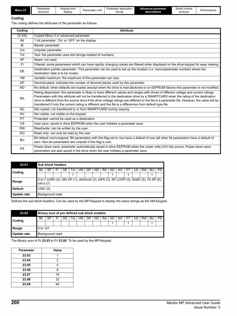
Menu 23 Parameter structure
Keypad and display Parameter x.00 Parameter description
formatAdvanced parameter
descriptionsSerial comms
protocol Performance
CodingThe coding defines the attributes of the parameter as follows.
Defines the sub block headers. Can be used by the MP-Keypad to display the same strings as the SM-Keypad.
The Binary sum of Pr 23.03 to Pr 23.09. To be used by the MP-Keypad.
Coding Attribute{X.XX} Copied Menu 0 or advanced parameter
Bit 1 bit parameter: ‘On’ or ‘OFF’ on the displayBi Bipolar parameter
Uni Unipolar parameterTxt Text: the parameter uses text strings instead of numbers.SP Spare: not usedFI Filtered: some parameters which can have rapidly changing values are filtered when displayed on the drive keypad for easy viewing.
DE Destination pointer parameter: This parameter can be used to set up the location (i.e. menu/parameter number) where the destination data is to be routed.
VM Variable maximum: the maximum of this parameter can vary.DP Decimal place: indicates the number of decimal places used by this parameter.ND No default: when defaults are loaded (except when the drive is manufactured or on EEPROM failure) this parameter is not modified.
RA
Rating dependant: this parameter is likely to have different values and ranges with drives of different voltage and current ratings. Parameters with this attribute will not be transferred to the destination drive by a SMARTCARD when the rating of the destination drive is different from the source drive if the drive voltage ratings are different or the file is a parameter file. However, the value will be transferred if only the current rating is different and the file is a differences from default type file.
NC Not copied: not transferred to or from SMARTCARD during copying.NV Not visible: not visible on the keypad.PT Protected: cannot be used as a destination.US User save: saved in drive EEPROM when the user initiates a parameter save.RW Read/write: can be written by the user.RO Read only: can only be read by the user
BU Bit default one/unsigned: Bit parameters with this flag set to one have a default of one (all other bit parameters have a default of zero. Non-bit parameters are unipolar if this flag is one.
PS Power-down save: parameter automatically saved in drive EEPROM when the under volts (UV) trip occurs. Power-down save parameters are also saved in the drive when the user initiates a parameter save.
23.01 Sub block headers
CodingBit SP FI DE Txt VM DP ND RA NC NV PT US RW BU PS
1 1 1 1
Range 0 to 7 (USEr (0), SEt UP (1), diAGnoS (2), triPS (3), SP LOOP (4), SintEr (5), Fb SP (6), inPut (7)
Default USEr (0)
Update rate Background read
23.02 Binary sum of pre defined sub block enables
CodingBit SP FI DE Txt VM DP ND RA NC NV PT US RW BU PS
1 1 1Range 0 to 127
Update rate Background read
Parameter Value23.03 123.04 223.05 423.06 823.07 1623.08 3223.09 64
200 Mentor MP Advanced User Guide Issue Number: 5
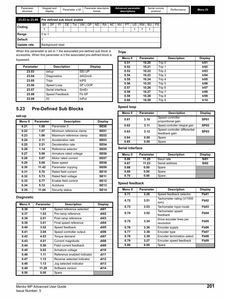
Parameter structure
Keypad and display Parameter x.00 Parameter description
formatAdvanced parameter
descriptionsSerial comms
protocol Performance Menu 23
When this parameter is set to 1 the associated pre-defined sub block is accessible. When this parameter is 0 the associated pre-defined block is bypassed.
5.23 Pre-Defined Sub Blocksset-up
Diagnostic
Trips
Speed loop
Serial interface
Speed feedback
23.03 to 23.09 Pre defined sub block enable
CodingBit SP FI DE Txt VM DP ND RA NC NV PT US RW BU PS1 1 1 1
Range 0 to 1
Default 1
Update rate Background read
Parameter Description Display23.03 setup SEt UP23.04 Diagnostics diAGnoS23.05 Trips triPS23.06 Speed Loop SP LOOP23.07 Serial interface SintEr23.08 Speed Feedback Fb SP23.09 IO InPut
Menu 0 Parameter Description Display0.21 1.00 Parameter 0 SE000.22 1.07 Minimum reference clamp SE010.23 1.06 Maximum reference clamp SE020.24 2.11 Acceleration rate SE030.25 2.21 Deceleration rate SE040.26 1.14 Reference selector SE050.27 5.09 Armature rated voltage SE060.28 5.07 Motor rated current SE070.29 5.08 Base speed SE080.30 11.42 Parameter copying SE090.31 5.70 Rated field current SE100.32 5.73 Rated field voltage SE110.33 5.77 Enable field control SE120.34 5.12 Autotune SE130.35 11.44 Security status SE14
Menu 0 Parameter Description Display0.36 1.01 Speed reference selected di010.37 1.03 Pre-ramp reference di020.38 2.01 Post ramp reference di030.39 3.01 Final speed reference di040.40 3.02 Speed feedback di050.41 3.04 Speed controller output di060.42 4.03 Torque demand di070.43 4.01 Current magnitude di080.44 5.56 Field current feedback di090.45 5.02 Armature voltage di100.46 1.11 Reference enabled indicator di110.47 1.12 Reverse selected indicator di120.48 1.13 Jog selected indicator di130.49 11.29 Software version di140.50 0.00 Spare
Menu 0 Parameter Description Display0.51 10.20 Trip 0 tr010.52 10.21 Trip 1 tr020.53 10.22 Trip 2 tr030.54 10.23 Trip 3 tr040.55 10.24 Trip 4 tr050.56 10.25 Trip 5 tr060.57 10.26 Trip 6 tr070.58 10.27 Trip 7 tr080.59 10.28 Trip 8 tr090.60 10.29 Trip 9 tr10
Menu 0 Parameter Description Display
0.61 3.10 Speed controller proportional gain SP01
0.62 3.11 Speed controller integral gain SP02
0.63 3.12 Speed controller differential feedback gain SP03
0.64 0.00 Spare0.65 0.00 Spare
Menu 0 Parameter Description Display0.66 11.25 Baud rate Si010.67 11.23 Serial address Si020.68 0.00 Spare0.69 0.00 Spare0.70 0.00 Spare
Menu 0 Parameter Description Display0.71 3.26 Speed feedback selector Fb01
0.72 3.51 Tachometer rating (V/1000 rpm) Fb02
0.73 3.53 Tachometer input mode Fb03
0.74 3.52 Tachometer speed feedback Fb04
0.75 3.34 Drive encoder lines per revolution Fb05
0.76 3.36 Encoder supply Fb060.77 3.38 Encoder type Fb070.78 3.39 Encoder termination select Fb080.79 3.27 Encoder speed feedback Fb090.80 0.00 Spare
Mentor MP Advanced User Guide 201Issue Number: 5

Menu 23 Parameter structure
Keypad and display Parameter x.00 Parameter description
formatAdvanced parameter
descriptionsSerial comms
protocol Performance
IO
5.24 Menu 0 (linear)Menu 0 is used to bring together various commonly used parameters for basic easy set up of the drive.Appropriate parameters are copied from the advanced menus into menu 0 and thus exist in both locations.For further information, refer to section 5.22 Menu 23 Header definitions on page 199.Figure 5-36 Menu 0 copying
5.25 Menu structureThe drive parameter structure consists of menus and parameters.The drive initially powers up in sub menu mode. Once Level 2 access (L2) has been enabled (refer to Pr 11.44 (SE14, 0.35) the left and right buttons are used to navigate between numbered menus.For further information, refer to section 2.7 Parameter access level and security on page 13.
Figure 5-37 Menu structure
The menus and parameters roll over in both directions. For example:• If the last parameter is displayed, a further press will cause the
display to roll-over and show the first parameter.When changing between menus the drive remembers which parameter was last viewed in a particular menu and will display that parameter. The menus and parameters roll over in both directions.
Menu 0 Parameter Description Display0.81 7.15 Analog input 3 mode in010.82 7.01 Analog input 1 in020.83 7.02 Analog input 2 in030.84 7.03 Analog input 3 in040.85 8.01 I/O state 1 in050.86 8.02 I/O state 2 in060.87 8.03 I/O state 3 in070.88 8.04 I state 4 in080.89 8.05 I state 5 in090.90 8.06 I state 6 in10
Menu 0
0.040.050.06
Menu 2
2.21
Menu 1
1.14
Menu 4
4.07
50
1500
150
5
Menu 22 Menu 23Menu 0 Menu 1 Menu 2Pr 22.00 Pr 23.00Pr 0.00 Pr 1.00 Pr 2.00Pr 22.01 Pr 23.01Pr 0.01 Pr 1.01 Pr 2.01Pr 22.02 Pr 23.02Pr 0.02 Pr 1.02 Pr 2.02
Pr 22.38 Pr 23.09Pr 0.88 Pr 1.49 Pr 2.39Pr 22.39 Pr 23.10Pr 0.89 Pr 1.50 Pr 2.40Pr 22.40 Pr 23.11Pr 0.90 Pr 1.51 Pr 2.41
Movesbetweenparameters
Moves between Menus
202 Mentor MP Advanced User Guide Issue Number: 5

Parameter structure
Keypad and display Parameter x.00 Parameter description
formatAdvanced parameter
descriptionsSerial comms
protocol Performance 32 bit parameters
Mentor MP Advanced User Guide 203Issue Number: 5
5.26 32 bit parametersAll parameters in the drive are 1 bit, 16 bit or 32 bit. This section identifies all the 32 bit parameters in the drive and Solution Modules.
5.26.1 Drive parametersThe table below contains all the 32 bit parameters present in the drive.
Table 5-11 32 bit drive parameters
Some of the parameters listed above are only 32 bit parameters in certain modes.
5.26.2 Solutions Module parametersSome Solutions Modules contain 32 bit parameters. Below is a table listing these parameters and the modules in which they are 32 bit parameters
Table 5-12 32 bit Solution Module parameters
Table 5-13 32 bit SM-Applications Plus, SM-Applications and SM-Applications Lite parameters
Menu 32-bit parameters
Menu 1
Pr 1.01 = {di01, 0.36} Pr 1.02 Pr 1.03 =
{di02, 0.37} Pr 1.04 Pr 1.06 = {SE02, 0.23}
Pr 1.07 = {SE01, 0.22} Pr 1.17 Pr 1.18
Pr 1.21 Pr 1.22 Pr 1.23 Pr 1.24 Pr 1.25 Pr 1.26 Pr 1.27 Pr 1.28Pr 1.36 Pr 1.37 Pr 1.39
Menu 2
Pr 2.01 = {di03, 0.08} Pr 2.07 Pr 2.11
{SE04, 0.25} Pr 2.12 Pr 2.13 Pr 2.14 Pr 2.15 Pr 2.16
Pr 2.17 Pr 2.18 Pr 2.19 Pr 2.21 Pr 2.22 Pr 2.23 Pr 2.24 Pr 2.25Pr 2.26 Pr 2.27 Pr 2.28 Pr 2.29
Menu 3 Pr 3.01 = {di04, 0.39}
Pr 3.02 = {di05, 0.40} Pr 3.03 Pr 3.10 =
{SP01, 0.61} Pr 3.18 Pr 3.22 Pr 3.27 = {Fb09, 0.79}
Menu 4 Pr 4.01 = {di08, 0.43} Pr 4.02 Pr 4.08 Pr 4.17
Menu 5 Pr 5.01 Pr 5.03 Pr 5.04 Pr 5.07 = {SE07, 0.28}
Pr 5.08 = {SE08, 0.29} Pr 5.24 Pr 5.25
Menu 11 Pr 11.32
Menu 20Pr 20.21 Pr 20.22 Pr 20.23 Pr 20.24 Pr 20.25 Pr 20.26 Pr 20.27 Pr 20.28Pr 20.29 Pr 20.30 Pr 20.31 Pr 20.32 Pr 20.33 Pr 20.34 Pr 20.35 Pr 20.36Pr 20.37 Pr 20.38 Pr 20.39 Pr 20.40
Menu 21 Pr 21.01 Pr 21.02 Pr 21.04 Pr 21.05 Pr 21.07 Pr 21.08 Pr 21.14 Pr 21.24
Parameter Solutions modules in which the parameter is 32 bitPr x.03 SM-Universal Encoder PlusPr x.20 SM-Universal Encoder PlusPr x.35 All Fieldbus modulesPr x.48 SM-Applications Plus
Menu 32-bit parametersMenu 70
to Menu 75
Pr 70.00 to
Pr 70.99
Pr 71.00 to
Pr 71.99
Pr 72.00 to
Pr 72.99
Pr 73.00 to
Pr 73.99
Pr 74.00 to
Pr 74.99
Pr 75.00 to
Pr 75.99
Menu 90Pr 90.01 Pr 90.03 Pr 90.19 Pr 90.25 Pr 90.29 Pr 90.31 Pr 90.32 Pr 90.33Pr 90.34 Pr 90.35 Pr 90.37 Pr 90.38 Pr 90.49
Menu 91Pr 91.02 Pr 91.03 Pr 91.04 Pr 91.05 Pr 91.06 Pr 91.17 Pr 91.18 Pr 91.19Pr 91.20
Menu 100 to
Menu 105
Pr 100.00 to Pr 100.99
Pr 101.00 to Pr 101.99
Pr 102.00 to Pr 102.99
Pr 103.00 to Pr 103.99
Pr 104.00 to Pr 104.99
Pr 105.00 to Pr 105.99
Menu 130 to
Menu 135
Pr 130.00 to
Pr 130.99
Pr 131.00 to Pr 131.99
Pr 132.00 to Pr 132.99
Pr 133.00 to Pr 133.99
Pr 134.00 to Pr 134.99
Pr 135.00 to Pr 135.99
Menu 160 to
Menu 165
Pr 160.00 toPr 160.99
Pr 161.00 to Pr 161.99
Pr 162.00 to Pr 162.99
Pr 163.00 to Pr 163.99
Pr 164.00 to Pr 164.99
Pr 165.00 to Pr 165.99

Parameter structure Keypad and display Parameter x.00 Parameter description format
Advanced parameter descriptions
Serial comms protocol Performance
6 Serial communications protocol
6.1 ANSI communications protocol6.1.1 IntroductionMentor MP supports an ANSIx3.28 type comms protocol as supported by previous Control Techniques products with some modification to allow access to 32 bit parameters. This chapter describes the implementation of the protocol for Mentor MP.
6.1.2 Physical layer and UART
6.1.3 Reading a parameterThe command to read a parameter is:
If the message is correct and the parameter exists the response is:
The length of the data field varies depending on the number of significant digits required to represent the value of the parameter. The maximum length is 12 digits including the sign and decimal point if present. The data field always starts with a sign, minus sign for negative numbers, or a plus sign for zero and positive numbers. The field may contain a decimal point, but this will not be before all the numbers in the field or after all the numbers in the field. The following examples demonstrate some possible data fields.
If the parameter to be read does not exist the End of transmission character (Ctl D) is returned.The checksum is derived by exclusive ORing the message byte together excluding the STX and the checksum, i.e. Checksum = M1 ^ M2 ^ P1^ P2 ^ D1 ^ D2 ^ ...... Dn ^ ETX. The checksum is an unsigned 8 bit value and if the checksum is less than 32 then 32 is added to the calculated checksum.
6.1.4 Writing to a parameterThe command to write to a parameter is:
The following rules apply to the data field:1. The maximum length is 12 characters.2. The field may contain leading spaces, but not after any other
character.3. A sign character is optional. No sign indicates positive.4. A decimal point is optional. This can appear at any point in the data
field, but not before the sign or before 10 numbers (i.e. the value written should not have more than 9 decimal places). If the decimal point is not in the same position as used by the parameter some accuracy may be lost or extra decimal places added (i.e. if +1.2345 is written to a parameter with one decimal place the result is +1.2, if +1.2 is written to a parameter with three decimal places the result is +1.200). It should be noted that parameters can only have 0, 1, 2, 3, 4, 5, or 6 decimal places.
5. The data field can contain up to 10 numbers, but the value even ignoring decimal points must not exceed the range –231 to 231-1.
If the parameter is written successfully an Acknowledge character (Ctl F) is returned. If the parameter does not exist, the value written exceeds the allowed parameter range or the data field rules are not obeyed an Not acknowledge character (Ctl U) is returned.The checksum is derived by exclusive ORing the message byte together excluding the STX and the checksum, i.e. Checksum = M1 ^ M2 ^ P1^ P2 ^ D1 ^ D2 ^ ...... Dn ^ ETX. The checksum is an unsigned 8 bit value and if the checksum is less than 32 then 32 is added to the calculated checksum.
Attribute DescriptionPhysical layer 2 wire EIA485
Bit stream Standard UART asynchronous symbols with Non Return to Zero (NRZ)
Symbol
Each symbol consists of:1 start bit7 data bits (ASCII)1 parity bit (even parity)1 stop bit
Baud rates 300, 600, 1200, 2400, 4800, 9600, 19200, 38400
EOT End of transmission (Ctl D)A1 Drive address: 1st digitA1 Drive address: 1st digitA2 Drive address: 2nd digitA2 Drive address: 2nd digitM1 Menu number: 1st digitM2 Menu number: 2nd digitP1 Parameter number: 1st digitP2 Parameter number: 2nd digit
ENQ Enquiry (Ctl E)
STX Start of text (Ctl B)M1 Menu number: 1st digitM2 Menu number: 2nd digitP1 Parameter number: 1st digitP2 Parameter number: 2nd digitD1 Data: 1st digit D2 Data: 2nd digit - -
Dn Data: nth digitETX End of text (Ctl C)
Checksum
Value Data field0 +0 (parameter with no decimal places)0 +0.00 (parameter with 2 decimal places)
1.2 +1.2-345.78 -345.78123456 +123456
EOT End of transmission (Ctl D)A1 Drive address: 1st digitA1 Drive address: 1st digitA2 Drive address: 2nd digitA2 Drive address: 2nd digit
STX Start of text (Ctl B)M1 Menu number: 1st digitM2 Menu number: 2nd digitP1 Parameter number: 1st digitP2 Parameter number: 2nd digitD1 Data: 1st digitD2 Data: 2nd digit - -
Dn Data: nth digitETX End of text (Ctl C)
Checksum
204 Mentor MP Advanced User Guide Issue Number: 5

Parameter structure Keypad and display Parameter x.00 Parameter description format
Advanced parameter descriptions
Serial comms protocol Performance
6.1.5 Drive addressThe drive only acts on messages received that contain a drive address if the whole drive address or drive group address match the whole address or the group address in the message, or if the address in the message is 0 (i.e. a global message). Global or group addressing allows data to be written to more than one drive with one command. The drive does not give a response to a global or group write message. Although it is possible to perform a global or group read, this would result in messages crashing if more than one drive responds to the command.
6.1.6 Short commandsThe following short commands can be used:
This is the same as requesting the value of the last parameter to be read or written to. The response is the same as for a normal read.
This is the same as requesting the value of the parameter after the last parameter to be read or written to. The response is the same as for a normal read.
This is the same as requesting the value of the parameter before the last parameter to be read or written to. The response is the same as for a normal read.
Writes to the specified parameter at the same drive address as used by the last read or write.All the short commands will only read from the drive or write to the drive if a valid address has already been sent to the drive in a previous command. The address is registered as being valid once a read or write command has been completed provide the address was valid for the drive even if the parameter does not exist. The valid address is cancelled if a message is received for a non-valid address or one of the following occurs: 1. The command is aborted because a non-numerical value is received
in the drive address, menu or parameter numbers.
2. The command is aborted because the two digits for drive address 1st digit, drive address 2nd digit, menu number or parameter number are not the same as each other.
3. EOT is received.4. A character other than NAK, ACK, BS or STX is sent as a short
command.5. A character other than ENQ is sent at the end of a read command.
6.1.7 Summary of control characters
Drive address Message address Command Action
7.8 7.8 Read Read7.8 7.8 Write Write7.8 7.0 Read Read
7.8 7.0 Write Write with no response
7.8 0.0 Read Read
7.8 0.0 Write Write with no response
NAK Not acknowledge (Ctl U)
ACK Acknowledge (Ctl F)
BS Back space (Ctl H)
STX Start of text (Ctl B)M1 Menu number: 1st digitM2 Menu number: 2nd digitP1 Parameter number: 1st digitP2 Parameter number: 2nd digitD1 Data: 1st digitD2 Data: 2nd digit - -
Dn Data: nth digitETX End of text (Ctl C)
Checksum
ASCII code Ctl codeSTX Start of text 02 BETX End of text 03 CEOT End of transmission 04 DENQ Enquiry 05 EACK Acknowledge 06 FBS Back space 08 H
NAK Not acknowledge 15 U
Mentor MP Advanced User Guide 205Issue Number: 5

Parameter structure Keypad and display Parameter x.00 Parameter description format
Advanced parameter descriptions
Serial comms protocol Performance
6.2 CT Modbus RTU specificationThis section describes the adaptation of the MODBUS RTU protocol offered on Control Techniques' products. The portable software class which implements this protocol is also defined.MODBUS RTU is a master slave system with half-duplex message exchange. The Control Techniques (CT) implementation supports the core function codes to read and write registers. A scheme to map between MODBUS registers and CT parameters is defined. The CT implementation also defines a 32bit extension to the standard 16bit register data format.
6.2.1 MODBUS RTUPhysical layer
RTU framingThe frame has the following basic format
The frame is terminated with a minimum silent period of 3.5 character times (for example, at 19200 baud the minimum silent period is 2 ms). Nodes use the terminating silence period to detect the end of frame and begin frame processing. All frames must therefore be transmitted as a continuous stream without any gaps greater or equal to the silence period. If an erroneous gap is inserted then receiving nodes may start frame processing early in which case the CRC will fail and the frame will be discarded.MODBUS RTU is a master slave system. All master requests, except broadcast requests, will lead to a response from an individual slave. The slave will respond (i.e. start transmitting the response) within the quoted maximum slave response time (this time is quoted in the data sheet for all Control Techniques products). The minimum slave response time is also quoted but will never be less that the minimum silent period defined by 3.5 character times.If the master request was a broadcast request then the master may transmit a new request once the maximum slave response time has expired.The master must implement a message time out to handle transmission errors. This time out period must be set to the maximum slave response time + transmission time for the response.
Attribute DescriptionNormal physical layer for multi-drop operation EIA485 2 wireBit stream Standard UART asynchronous symbols with Non Return to Zero (NRZ)
Symbol
Each symbol consists of:-1 start bit8 data bits (transmitted least significant bit first)2 stop bits
Baud rates 300, 600, 1200,2400,4800, 9600, 19200, 38400, 57600, 115200
Message data
SLAVEADDRESS 16bit CRCmessage dataFUNCTION
CODESilent
interval
Master request
Time
frame detect Slave frameprocessing Slave response
Slave response time
Master request
New master requestcan start here
minimum silenceperiod
minimum silenceperiod
206 Mentor MP Advanced User Guide Issue Number: 5

Parameter structure Keypad and display Parameter x.00 Parameter description format
Advanced parameter descriptions
Serial comms protocol Performance
6.2.2 Slave addressThe first byte of the frame is the slave node address. Valid slave node addresses are 1 through 247 decimal. In the master request this byte indicates the target slave node; in the slave response this byte indicates the address of the slave sending the response.
Global addressingAddress zero addresses all slave nodes on the network. Slave nodes suppress the response messages for broadcast requests.
6.2.3 MODBUS registersThe MODBUS register address range is 16bit (65536 registers) which at the protocol level is represented by indexes 0 through 65535.
PLC registersModicon PLCs typically define 4 register 'files' each containing 65536 registers. Traditionally, the registers are referenced 1 through 65536 rather than 0 through 65535. The register address is therefore decremented on the master device before passing to the protocol.
The register file type code is NOT transmitted by MODBUS and all register files can be considered to map onto a single register address space. However, specific function codes are defined in MODBUS to support access to the "coil" registers.All standard CT drive parameters are mapped to register file '4' and the coil function codes are not required.
CT parameter mappingAll CT products are parameterized using the #menu.param notation. Indexes 'menu' and 'param' are in the range 0 through 99. The #menu.param is mapped into the MODBUS register space as menu*100 + param. To correctly map the parameters at the application layer, the slave device increments the received register address. The consequence of this behavior is that #0.0 cannot be accessed.
Data typesThe MODBUS protocol specification defines registers as 16bit signed integers. All CT devices support this data size.Refer to the section 6.2.7 Extended data types on page 208 for detail on accessing 32bit register data.
6.2.4 Data consistencyAll CT devices support a minimum data consistency of one parameter (16bit or 32bit data). Some devices support consistency for a complete multiple register transaction.
6.2.5 Data encodingMODBUS RTU uses a 'big-endian' representation for addresses and data items (except the CRC, which is 'little-endian'). This means that when a numerical quantity larger than a single byte is transmitted, the MOST significant byte is sent first. So for example16 - bits 0x1234 would be 0x12 0x3432 - bits 0x12345678 would be 0x12 0x34 0x56 0x78
6.2.6 Function codesThe function code determines the context and format of the message data. Bit 7 of the function code is used in the slave response to indicate an exception.The following function codes are supported:
FC03 Read multipleRead a contiguous array of registers. The slave imposes an upper limit on the number of registers, which can be read. If this is exceeded the slave will issue an exception code 2.
Table 6-1 Master request
Table 6-2 Slave response
FC06 Write single registerWrites a value to a single 16bit register. The normal response is an echo of the request, returned after the register contents have been written. The register address can correspond to a 32bit parameter but only 16 bits of data can be sent.
Table 6-3 Master request
File type Description1 Read only bits ("coil")2 Read / write bits ("coil")3 Read only 16bit register4 Read / write 16bit register
CT parameter
MODBUS PLC register
Register address(protocol level) Comments
#X.Y 40000 + X x 100 + Y X x 100 + Y - 1 #0.0 cannot be accessed
Examples:#1.2 40102 101#1.0 40100 99#0.1 40001 0#70.0 47000 6999
Code Description3 Read multiple 16bit registers6 Write single register
16 Write multiple 16bit registers23 Read and write multiple 16bit registers
Byte Description
0 Slave destination node address 1 through 247, 0 is global
1 Function code 0x032 Start register address MSB3 Start register address LSB4 Number of 16bit registers MSB5 Number of 16bit registers LSB6 CRC LSB7 CRC MSB
Byte Description0 Slave source node address1 Function code 0x032 Length of register data in read block (in bytes)3 Register data 0 MSB4 Register data 0 LSB
3+byte count CRC LSB4+byte count CRC MSB
Byte Description0 Slave node address 1 through 247 0 is global1 Function code 0x062 Register address MSB3 Register address LSB4 Register data MSB5 Register data LSB6 CRC LSB7 CRC MSB
Mentor MP Advanced User Guide 207Issue Number: 5

Parameter structure Keypad and display Parameter x.00 Parameter description format
Advanced parameter descriptions
Serial comms protocol Performance
Table 6-4 Slave response
FC16 Write multipleWrites a contiguous array of registers. The slave imposes an upper limit on the number of registers which can be written. If this is exceeded the slave will discard the request and the master will time out.
Table 6-5 Master request
Table 6-6 Slave response
FC23 Read/Write multipleWrites and reads two contiguous arrays of registers. The slave imposes an upper limit on the number of registers which can be written. If this is exceeded the slave will discard the request and the master will time out.
Table 6-7 Master request
Table 6-8 Slave response
6.2.7 Extended data typesStandard MODBUS registers are 16bit and the standard mapping maps a single #X.Y parameter to a single MODBUS register. To support 32bit data types (integer and float) the MODBUS multiple read and write services are used to transfer a contiguous array of 16bit registers. Slave devices typically contain a mixed set of 16bit and 32bit registers. To permit the master to select the desired 16bit or 32bit access the top two bits of the register address are used to indicate the selected data type.
The selection is applied for the whole block access.
Byte Description0 Slave source node address1 Function code 0x062 Register address MSB3 Register address LSB4 Register data MSB5 Register data LSB6 CRC LSB7 CRC MSB
Byte Description
0 Slave node address 1 through 247,0 is global
1 Function code 0x102 Start register address MSB3 Start register address LSB4 Number of 16bit registers MSB5 Number of 16bit registers LSB6 Length of register data to write (in bytes)7 Register data 0 MSB8 Register data 0 LSB
7+byte count CRC LSB8+byte count CRC MSB
Byte Description0 Slave source node address1 Function code 0x102 Start register address MSB3 Start register address LSB4 Number of 16bit registers written MSB5 Number of 16bit registers written LSB6 CRC LSB7 CRC MSB
Byte Description
0 Slave node address 1 through 2470 is global
1 Function code 0x172 Start register address to read MSB3 Start register address to read LSB4 Number of 16bit registers to read MSB5 Number of 16bit registers to read LSB6 Start register address to write MSB7 Start register address to write LSB8 Number of 16bit registers to write MSB9 Number of 16bit registers to write LSB
10 Length of register data to write (in bytes)11 Register data 0 MSB12 Register data 0 LSB
11+byte count CRC LSB12+byte
count CRC MSB
Byte Description0 Slave source node address1 Function code 0x172 Length of register data in read block (in bytes)3 Register data 0 MSB4 Register data 0 LSB
3+byte count CRC LSB4+byte count CRC MSB
NOTE
bit 15TYP1 bits 0 - 13
Type select Parameter addressX x 100+Y-1
bit 14TYP0
208 Mentor MP Advanced User Guide Issue Number: 5

Parameter structure Keypad and display Parameter x.00 Parameter description format
Advanced parameter descriptions
Serial comms protocol Performance
The 2bit type field selects the data type according to the table below:
If a 32bit data type is selected then the slave uses two consecutive 16bit MODBUS registers (in 'big endian'). The master must also set the correct 'number of 16bit registers'. Example, read #20.21 through #20.24 as 32bit parameters using FC03 from node 8:
Table 6-9 Master request
Table 6-10 Slave response
Reads when actual parameter type is different from selectedThe slave will send the least significant word of a 32 bit parameter if that parameter is read as part of a 16 bit access.The slave will sign extend the least significant word if a 16 bit parameter is accessed as a 32 bit parameter. The number of 16 bit registers must be even during a 32 bit access.Example, If #1.28 is a 32 bit parameter with a value of 0x12345678, #1.29 is a signed 16 bit parameter with a value of 0xABCD, and #1.30 is a signed 16 bit parameter with a value of 0x0123.
Writes when actual parameter type is different from selectedThe slave will allow writing a 32 bit value to a 16 bit parameter as long as the 32 bit value is within the normal range of the 16 bit parameter.The slave will allow a 16 bit write to a 32 bit parameter. The slave will sign extend the written value, therefore, the effective range of this type of write will be ±32767. Examples, if #1.28 has a range of ±100000, and #1.29 has a range of ±10000.
6.2.8 ExceptionsThe slave will respond with an exception response if an error is detected in the master request. If a message is corrupted and the frame is not received or the CRC fails then the slave will not issue an exception. In this case the master device will time out. If a write multiple (FC16 or FC23) request exceeds the slave maximum buffer size then the slave will discard the message. No exception will be transmitted in this case and the master will time out.
Type fieldbits 15-14
Selected data type Comments
00 INT16 backward compatible01 INT32
10 Float32 IEEE754 standardNot supported on all slaves
11 Reserved
Byte Value Description0 0x08 Slave destination node address1 0x03 FC03 multiple read2 0x47 Start register address #20.21
(16384 + 2021 - 1) = 18404 = 0x47E43 0xE44 0x00 Number of 16bit registers to read
#20.21 through #20.24 is 4x32bit registers = 8x16bit registers5 0x08
6 CRC LSB
7 CRC MSB
Byte Value Description0 0x08 Slave destination node address1 0x03 FC03 multiple read
2 0x10 Length of data (bytes) = 4x32bit registers = 16bytes
3-6 #20.21 data7-10 #20.22 data11-14 #20.23 data15-18 #20.24 data
19 CRC LSB20 CRC MSB
ReadStart
register address
Number of 16bit
registersResponse Comments
#1.28 127 1 0x5678
Standard 16 bit access to a 32bit register will return low 16bit word of truncated data
#1.28 16511 2 0x12345678 Full 32bit access
#1.28 16511 1 Exception 2 Number of words must be even for 32bit access
#1.29 128 1 0xABCD
Standard 16 bit access to a 32bit register will return low 16bit word of data
#1.29 16512 2 0xFFFFABCD32bit access to a 16bit register will return 32bit sign extended data
#1.30 16513 2 0x0000012332bit access to a 16bit register will return 32bit sign extended data
#1.28 -
#1.29127 2 0x5678,
0xABCD
Standard 16 bit access to a 32bit register will return low 16bit word of truncated data
#1.28 -
#1.29 16511 4 0x12345678,
0xFFFFABCD Full 32bit access
WriteStart
register address
Number of 16bit
registersData Comments
#1.28 127 1 0x1234Standard 16 bit write to a 32bit register. Value written = 0x00001234
#1.28 127 1 0xABCDStandard 16 bit write to a 32bit register. Value written = 0xFFFFABCD
#1.28 16511 2 0x00001234 Value written = 0x00001234
#1.29 128 1 0x0123 Value written = 0x0123
#1.29 16512 2 0x00000123 Value written = 0x00000123
Mentor MP Advanced User Guide 209Issue Number: 5
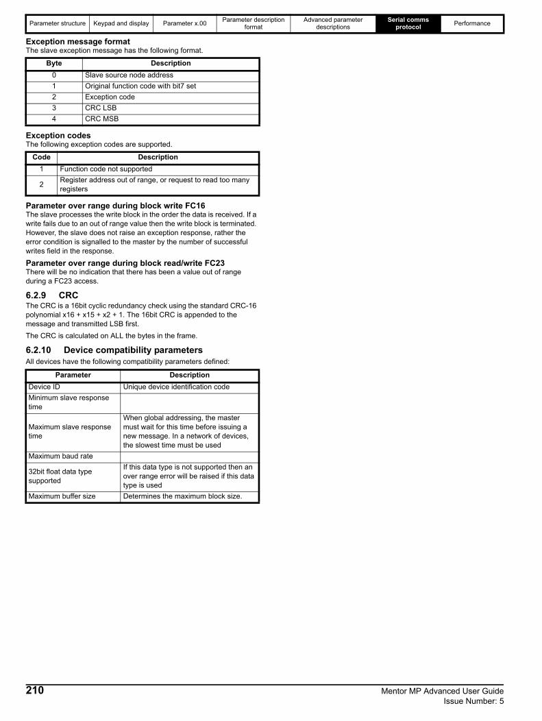
Parameter structure Keypad and display Parameter x.00 Parameter description format
Advanced parameter descriptions
Serial comms protocol Performance
Exception message formatThe slave exception message has the following format.
Exception codesThe following exception codes are supported.
Parameter over range during block write FC16The slave processes the write block in the order the data is received. If a write fails due to an out of range value then the write block is terminated. However, the slave does not raise an exception response, rather the error condition is signalled to the master by the number of successful writes field in the response.
Parameter over range during block read/write FC23There will be no indication that there has been a value out of range during a FC23 access.
6.2.9 CRCThe CRC is a 16bit cyclic redundancy check using the standard CRC-16 polynomial x16 + x15 + x2 + 1. The 16bit CRC is appended to the message and transmitted LSB first.The CRC is calculated on ALL the bytes in the frame.
6.2.10 Device compatibility parametersAll devices have the following compatibility parameters defined:
Byte Description0 Slave source node address1 Original function code with bit7 set2 Exception code3 CRC LSB4 CRC MSB
Code Description1 Function code not supported
2 Register address out of range, or request to read too many registers
Parameter DescriptionDevice ID Unique device identification codeMinimum slave response time
Maximum slave response time
When global addressing, the master must wait for this time before issuing a new message. In a network of devices, the slowest time must be used
Maximum baud rate
32bit float data type supported
If this data type is not supported then an over range error will be raised if this data type is used
Maximum buffer size Determines the maximum block size.
210 Mentor MP Advanced User Guide Issue Number: 5
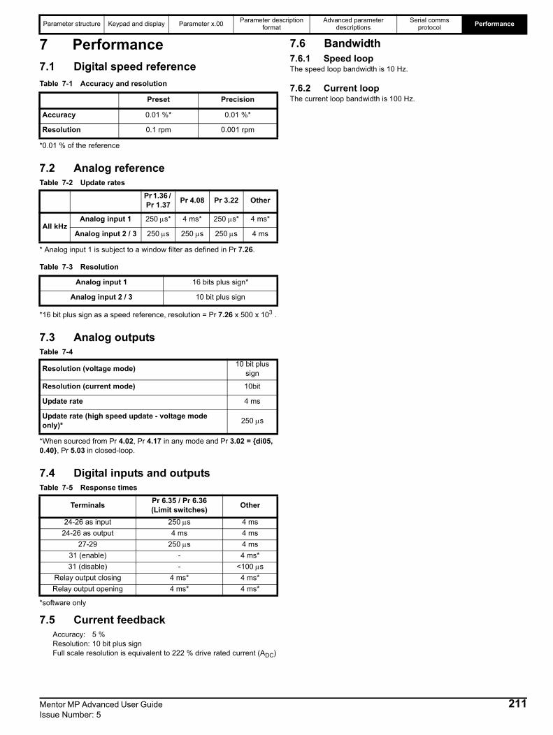
Parameter structure Keypad and display Parameter x.00 Parameter description format
Advanced parameter descriptions
Serial comms protocol Performance
Mentor MP Advanced User Guide 211Issue Number: 5
7 Performance7.1 Digital speed referenceTable 7-1 Accuracy and resolution
*0.01 % of the reference
7.2 Analog referenceTable 7-2 Update rates
* Analog input 1 is subject to a window filter as defined in Pr 7.26.
Table 7-3 Resolution
*16 bit plus sign as a speed reference, resolution = Pr 7.26 x 500 x 103 .
7.3 Analog outputsTable 7-4
*When sourced from Pr 4.02, Pr 4.17 in any mode and Pr 3.02 = {di05, 0.40}, Pr 5.03 in closed-loop.
7.4 Digital inputs and outputsTable 7-5 Response times
*software only
7.5 Current feedbackAccuracy: 5 %Resolution: 10 bit plus sign Full scale resolution is equivalent to 222 % drive rated current (ADC)
7.6 Bandwidth7.6.1 Speed loopThe speed loop bandwidth is 10 Hz.
7.6.2 Current loopThe current loop bandwidth is 100 Hz.Preset Precision
Accuracy 0.01 %* 0.01 %*
Resolution 0.1 rpm 0.001 rpm
Pr 1.36 / Pr 1.37 Pr 4.08 Pr 3.22 Other
All kHzAnalog input 1 250 μs* 4 ms* 250 μs* 4 ms*
Analog input 2 / 3 250 μs 250 μs 250 μs 4 ms
Analog input 1 16 bits plus sign*
Analog input 2 / 3 10 bit plus sign
Resolution (voltage mode) 10 bit plus sign
Resolution (current mode) 10bit
Update rate 4 ms
Update rate (high speed update - voltage mode only)* 250 μs
Terminals Pr 6.35 / Pr 6.36(Limit switches) Other
24-26 as input 250 μs 4 ms24-26 as output 4 ms 4 ms
27-29 250 μs 4 ms31 (enable) - 4 ms*31 (disable) - <100 μs
Relay output closing 4 ms* 4 ms*Relay output opening 4 ms* 4 ms*
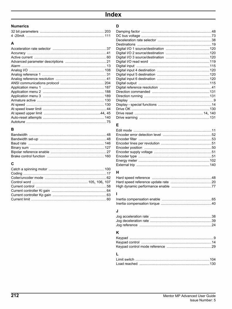
IndexNumerics32 bit parameters ..................................................................2034 -20mA ................................................................................111
AAcceleration rate selector ....................................................... 37Accuracy ................................................................................. 41Active current .......................................................................... 60Advanced parameter descriptions .......................................... 21Alarm ....................................................................................... 13Analog I/O .............................................................................108Analog reference 1 .................................................................. 31Analog reference resolution .................................................... 41ANSI communications protocol .............................................204Application menu 1 ...............................................................187Application menu 2 ...............................................................188Application menu 3 ...............................................................189Armature active .....................................................................130At speed ................................................................................130At speed lower limit ................................................................. 44At speed upper limit ..........................................................44, 45Auto-reset attempts ...............................................................140Autotune .................................................................................. 75
BBandwidth ............................................................................... 48Bandwidth set-up .................................................................... 48Baud rate ..............................................................................146Binary sum ............................................................................127Bipolar reference enable ......................................................... 27Brake control function ...........................................................160
CCatch a spinning motor .........................................................100Coding ..................................................................................... 17Coiler/uncoiler mode ............................................................... 62Control word ......................................................... 105, 106, 107Current control ........................................................................ 58Current controller Ki gain ........................................................ 64Current controller Kp gain ....................................................... 63Current limit ............................................................................. 60
DDamping factor ........................................................................48DC bus voltage ........................................................................73Deceleration rate selector .......................................................38Destinations ............................................................................19Digital I/O 1 source/destination .............................................120Digital I/O 2 source/destination .............................................120Digital I/O 3 source/destination .............................................120Digital I/O read word .............................................................119Digital input ...........................................................................115Digital input 4 destination ......................................................120Digital input 5 destination ......................................................120Digital input 6 destination ......................................................120Digital output .........................................................................115Digital reference resolution .....................................................41Direction commanded ...........................................................131Direction running ...................................................................131Display ......................................................................................9Display - special functions .......................................................14Drive OK ................................................................................130Drive reset ...................................................................... 14, 140Drive warning ........................................................................131
EEdit mode ................................................................................11Encoder error detection level ..................................................52Encoder filter ...........................................................................53Encoder lines per revolution ....................................................51Encoder position .....................................................................50Encoder supply voltage ...........................................................51Encoder type ...........................................................................51Energy meter .........................................................................102External trip ...........................................................................140
HHard speed reference .............................................................48Hard speed reference update rate ..........................................20High dynamic performance enable .........................................77
IInertia compensation enable ...................................................65Inertia compensation torque ....................................................40
JJog acceleration rate ...............................................................38Jog deceleration rate ...............................................................39Jog reference ..........................................................................24
KKeypad ......................................................................................9Keypad control ........................................................................14Keypad control mode reference ..............................................29
LLimit switch ............................................................................104Load reached ........................................................................130
212 Mentor MP Advanced User Guide Issue Number: 5

MMaximum reference clamp ......................................................24Menu 0 ..................................................................................145Menu 0 (linear) ..........................................................................7Menu 0 copying .........................................................................7Menu 01 - Speed reference ....................................................22Menu 02 - Ramps ....................................................................34Menu 03 - Slave frequency, speed feedback, speed control ..41Menu 04 - Torque and current control .....................................58Menu 05 - Motor control ..........................................................70Menu 06 - Sequencer and clock .............................................97Menu 07 - Analog I/O ............................................................108Menu 08 - Digital I/O .............................................................115Menu 09 - Programmable logic, motorised pot and binary sum .......................................................................122Menu 10 - Status and trips ....................................................130Menu 11 - General drive set-up .............................................145Menu 12 - Threshold detectors and variable selectors .........160Menu 13 - Position control ....................................................172Menu 14 - User PID controller ...............................................180Menu 15, 16 and 17 - Solutions Module slots .......................186Menu 18 - Application menu 1 ..............................................187Menu 19 - Application menu 2 ..............................................188Menu 20 - Application menu 3 ..............................................189Menu 21 - Second motor parameters ....................................190Menu 22 - Additional menu 0 set up .....................................198Menu structure ..........................................................................5Minimum reference clamp .......................................................25Motor 2 parameters select .....................................................153Motor control ...........................................................................70Motor object electronic nameplate transfer .............................54Motor rated current ..................................................................73Motor rpm ................................................................................73Motor saturation breakpoint ....................................................78Motor torque per amp (Kt) .......................................................79Motorised pot ........................................................................124
NNon-rigid position control .......................................................175Number of motor poles ............................................................74
OOpen collector output ............................................................120Orientation on stop ................................................................175Output power ...........................................................................72Output voltage .........................................................................72Overload accumulator .............................................................65Overload alarm ......................................................................131
PParameter - description format ................................................17Parameter navigation ................................................................5Parameter structure ..................................................................5Parameter view mode .............................................................11Parameter x.00 ........................................................................15PID controller ........................................................................180Position controller ..................................................................174Position controller mode ........................................................175Position controller P gain ......................................................175Powered-up time ...................................................................101Precision reference .................................................................29Preset reference selected indicator .........................................32Preset selector ........................................................................28Programmable logic ..............................................................122
RRamp enable .......................................................................... 36Ramps .................................................................................... 34Ranges ................................................................................... 18Rated frequency ..................................................................... 74Rated voltage ......................................................................... 74Reference offset ..................................................................... 24Reference selected indicator .................................................. 32Reference selector ................................................................. 27Regenerating ........................................................................ 131Relative jogging .................................................................... 176Relay source ......................................................................... 120Resolution ............................................................................... 41Revolution counter .................................................................. 49Rigid position control ............................................................ 175Run time ............................................................................... 102Running cost ......................................................................... 102
SS ramp .................................................................................... 36Second motor parameters .............................................. 14, 190Security code ........................................................................ 147Security status ...................................................................... 152Sequencer .............................................................................. 97Sequencing bit ...................................................................... 103Serial communications protocol ............................................ 204Serial mode .......................................................................... 145Skip reference 1 ..................................................................... 30SMARTCARD ....................................................................... 148Software sub-version ............................................................ 148Software version ................................................................... 147Solutions Module ID codes ................................................... 186Solutions Module slots .......................................................... 186Sources .................................................................................. 19Speed feedback selector ........................................................ 49Speed reference ..................................................................... 22Stator inductance .................................................................... 77Status mode ........................................................................... 11Status word ........................................................................... 141Stop mode .............................................................................. 98Sub blocks ................................................................................ 6
TThermal protection mode ........................................................ 64Thermal time constant ............................................................ 64Threshold detector 1 ............................................................. 160Threshold detector 2 ............................................................. 160Threshold detectors .............................................................. 160Torque control ........................................................................ 61Torque control with speed override ........................................ 62Torque demand ...................................................................... 60Torque feed-forward ............................................................... 63Torque mode selector ............................................................. 61Torque offset .......................................................................... 61Torque reference .................................................................... 61Torque reference update ........................................................ 20Transient inductance .............................................................. 77
UUpdate rate ............................................................................. 19US defaults ............................................................................. 16
Mentor MP Advanced User Guide 213Issue Number: 5

VVariable maximums ................................................................ 18Variable selector 1 ................................................................162Variable selector 2 ................................................................162Variable selectors .................................................................160Velocity feed forward ............................................................176Velocity feed-forward reference .............................................. 31Voltage mode select ............................................................... 76Voltage rating ........................................................................147
WWire break detect .................................................................... 52
ZZero speed ............................................................................130Zero speed threshold .............................................................. 44
214 Mentor MP Advanced User Guide Issue Number: 5


0476-0002-05