MP System Hardware Guide
446
MP System Hardware Guide Check BIOPAC.COM > Support > Manuals for updates Visit BIOPAC’s new Tutorial section at: www.biopac.com/Videos for instructional overviews The MP Hardware Guide describes how to connect and set up various signal conditioning and amplifier modules for use with an MP150, MP100, MP36 or MP45 System, and details applications and uses for the MP System. To use this guide, navigate to specific pages using the page thumbnail images and bookmark links (left) or type an entry of interest into the ‘Find’ box. All specifications are subject to change without notice. BIOPAC Systems, Inc. 42 Aero Camino, Goleta, CA 93117 Tel (805) 685-0066 | Fax (805) 685-0067 www.biopac.com 03.11.2015
-
Upload
khangminh22 -
Category
Documents
-
view
3 -
download
0
Transcript of MP System Hardware Guide

MP System Hardware Guide
Check BIOPAC.COM > Support > Manuals for updates Visit BIOPAC’s new Tutorial section at: www.biopac.com/Videos for instructional overviews
The MP Hardware Guide describes how to connect and set up various signal conditioning and amplifier modules for use with an MP150, MP100, MP36 or MP45 System, and details applications and uses for the MP System. To use this guide, navigate to specific pages using the page thumbnail images and bookmark links (left) or type an entry of interest into the ‘Find’ box.
All specifications are subject to change without notice.
BIOPAC Systems, Inc. 42 Aero Camino, Goleta, CA 93117
Tel (805) 685-0066 | Fax (805) 685-0067 www.biopac.com
03.11.2015

[email protected] [email protected] www.biopac.com
MP Research System | MP System Applications | Page 1 - 2 Updated: 7.25.2012
MP SYSTEM APPLICATIONS
Features With proper hardware selection and setup, the MP System with AcqKnowledge software can be used for a wide array of application features. See the AcqKnowledge Software Guide or BIOPAC.COM for descriptions of the following features. For additional support, or for help with an unlisted application, please contact the BIOPAC Technical Support Division — an Applications Specialist will be glad to help.
Active Electrodes Allergies Amplitude Histogram Anaerobic Threshold Animal studies Auditory Evoked Response (AER) Automate Acquisition Protocols Automated Data Analysis Automatic Data Reduction Autonomic Nervous System Studies Biomechanics Measurements Blood Flow / Blood Pressure /Blood Volume Body Composition Analysis Breath-By-Breath Respiratory Gas Analysis Cardiac Output Cardiology Research Cell Transport Cerebral Blood Flow Chaos Plots Common Interface Connections Connect to MP Systems Control Pumps and Valves Cross- and Auto-correlation Current Clamping Defibrillation & Electrocautery Dividing EEG into Specific Epochs ECG Analysis ECG Recordings, 12-Lead ECG Recordings, 6-Lead EEG Spectral Analysis Einthoven’s Triangle EMG and Force EMG Power Spectrum Analysis End-tidal CO2 Episode Counting Ergonomics Evaluation Event-related Potentials Evoked Response Exercise Physiology External equipment, controlling
Extra-cellular Spike Recording Facial EMG FFT & Histograms FFT for Frequency Analysis Field Potential Measurements Fine Wire EMG Forced Expiratory Flow & Volume Gait Analysis Gastric Myoelectric Activity Gastric Slow Wave Propagation Gastrointestinal Motility Analysis Hardware Flexibility Heart Rate Variability Heart Sounds Histogram Analysis Imaging Equipment, Interfacing Indirect Blood Pressure Recordings Integrated (RMS) EMG Interface with Existing Equipment Interface with Third-party transducer Invasive Electrode Measurements Ion-selective Micro-electrode Interfacing Iontophoresis Irritants & Inflammation Isolated Inputs & Outputs Isolated Lung Studies Isometric Contraction Isotonic Contraction Jewett Sequence Langendorff Heart Preparations Laser Doppler Flowmetry Left Cardiac Work Long-term Monitoring Lung Volume Measurement LVP Median & Mean Frequency Analysis Micro-electrode signal amplification
Migrating Myoelectric Complex Motor Unit Action Potential Movement Analysis MRI Applications Multi-Channel Sleep Recording Nerve Conduction Studies Neurology Research Noninvasive Cardiac Output Noninvasive Electrode Measurements Nystagmus Investigation Oculomotor Research Off-line ECG Averaging On-line Analysis On-line ECG Analysis Orthostatic Testing Peripheral Blood Flow Peristaltic (Slow Wave) Propagation Planted Tissue Pressure Volume Loops Psychophysiology Pulsatile Tissue Studies Pulse Rate Measurement Pulse Transit Time Range of Motion Real-time EEG Filtering Real-time EEG Filtering Recurrent Patterns Regional Blood Flow Relative BP Measurement Remote Monitoring Respiration Monitoring Respiratory Exchange Ratio Rheumatology Saccadic Eye Movements Sexual Arousal Studies Signal Averaging Simultaneous Monitoring Single Channel Analysis Single-fiber EMG Software-controlled Stimulator Somatosensory Evoked Response Spectral Analysis Spike Counting SpO2 Analysis
HARDWARE GUIDE

[email protected] [email protected] www.biopac.com
MP Research System | MP System Applications | Page 2 - 2 Updated: 7.25.2012
Stand Alone Amplifiers Standard Operating Procedures Startle Eye Blink Tests Startle Response Stimulator, software-controlled Systemic Vascular Resistance Template Analysis
Tissue Bath Monitoring Tissue Conductance Measurement Tissue Magnitude & Phase Modeling Tissue Resistance & Reactance Ussing Chamber Measurements Ventricular Late Potentials
Vestibular Function Video Capture, Synchronous Visual Attention Visual Evoked Response VO2 Consumption Volume/Flow Loop Relationships Working Heart Preparations
HARDWARE GUIDE

[email protected] [email protected] www.biopac.com
MP Research System | Application Notes | Page 1 - 1 Updated: 7.25.2012
APPLICATION NOTES BIOPAC has prepared a wide variety of application notes as a useful source of information concerning certain operations and procedures. The notes are static pages that provide detailed technical information about either a product or application. A partial list of Application Notes follows. View or print application notes directly from the “Support” section of the BIOPAC web site www.biopac.com.
Recording Hardware 004 - MP150 Firmware Compatibility 218 - Hardware API 223 - Physiological Measurement in MRI Systems 230 - Connections for Physiological Signals in an MRI 234 - Virtual Reality / Immersive Environment 235 - Zygomaticus Measures with Pressure Pad vs. EMG in MRI or fMRI 239 - Send to AcqKnowledge from Vizard via parallel port 240 - Measurement Computing card setup 241 - Recording EMG data in an fMRI 242 - Recording ECG Data in an fMRI 243 - Gated Analysis for Data Recorded in an MRI Amplifiers 102 - Biopotential Amplifier Testing With CBLCAL 103 - Remote Monitoring System - TEL100 109 - 3-, 6-, and 12-Lead ECG 110 - Amplifier Baseline Offset Adjustment 126 - Wireless Remote Monitoring - TEL100C-RF 136 - Battery Pack Instructions - BAT100 149 - O2100C Module Setup for the MP System 151 - CO2100C Module Setup for the MP System 154 - High Level Transducer Connections - HLT100C 160 - Gas Analysis Module Response Time 162 - Stimulation Features of MP150/100 Systems 170 - Laser Doppler Flow Module - LDF100C 175 - Stimulus Isolator Guidelines - STMISOC 184 - Interfacing Millar Mikro-Tip Catheters with MP150/100 185 - iMac and G3 Compatibility Issues 187 - Electrodermal Response Guidelines - GSR100C 190 - Micro-Electrode Amplifier Guidelines - MCE100C 195 - MP System Data Sampling Reference 196 - Cardiac Output Measurement - EBI100C 206 - Continuous 12-Lead ECG 207, 208, 209 - UDP Install 215 - Noninvasive Cardiac Ouput - NICO100C and LEAD130 224 - Noninvasive Blood Pressure NIBP100A Calibration 231 - Noninvasive Blood Pressure NIBP100B-R Calibration Transducers 101 - Transducer Calibration and Signal Re-Scaling 114/b - Pneumotach Transducer - TSD107A /TSD107B* 127 - Precision Force Transducers 130 - Noninvasive Blood Pressure Measurement - TSD120 132 - Variable Force Transducer- TSD105A 135 - Pneumotach Transducer - TSD117
140 - Goniometers: Angular Measurements - TSD130 series 141 - Tri-axial Accelerometer Calib - TSD109 series/SS26/27 144 - Hand Dynamometer Calibration - TSD121C 145 - Respiratory Effort Transducer - TSD101B 153 - Physiological Sounds Microphone - TSD108 159 - Hand Switch and Foot Switch - TSD116 Series 186 - Variable Assessment Transducer - TSD115 Software 105 - Auditory Brainstem Response (ABR) Testing 105b - ABR Testing for Jewett Sequence 108 - Data Reduction of Large Files 111 - Nerve Conduction Velocity 113 - Troubleshooting AcqKnowledge for Windows 115 - Hemodynamic Measurements 117 - Pulse Transit Time and Velocity Calculation 118 - EMG Frequency Signal Analysis 120 - X/Y Loop Area Analysis 121 - Waveform Data Reduction 122 - Power Spectrum Analysis 129 - Heart Rate Variability 131 - Averaging Mode in the MP System 148 - Automated ECG Analysis 150 - O2100C Module for Oxygen Consumption 152 - CO2100C Module for End-Tidal CO2 155 - AcqKnowledge File Formats for Mac OS 156 - AcqKnowledge File Formats for Windows OS 158 - Analyzing Inspired & Expired Lung Volume 161 - Automated Tissue Bath Analysis 168 - Analyzing Intraventricular Pressure Wave Data (LVP Analysis) 169 - Speech Motor Control 177 - ECG Analysis Using the Offline Averaging Mode 182 - Analysis of Blood Flow Data 183 - VO2 and RER Measurement 191 - Digital I/O Channels 198 - Prepulse Inhibition of Startle 199 - Impedance Cardiography and Pre-ejection Period 200 - Creating Arbitrary Waveforms for Stimulators 201 - SuperLab with AcqKnowledge 211 - EEG Analysis with AcqKnowledge 214 - EMG Startle Scoring for Prepulse Inhibition 216 - Electrodermal Activity (GSR) Scoring Methods 221 - Simplified VO2 Measurement (without CO2 Values) 222 - Pseudorandom Stimuli after Stim Presentation 226 - BIOPAC Software on Mac-Intel Core Duo Cmpt. 232 - EMG: Normalize to Max Voluntary Contraction 233 - Heart Rate Variability - Preparing Data 238 - Controlling the SDS100 Scent Delivery System
HARDWARE GUIDE

[email protected] [email protected] www.biopac.com
BIOPAC Hardware | Quick Starts | Page 1 - 1 Updated: 8.22.2014
ACQKNOWLEDGE QUICK STARTS “Quick Start” template files were installed to the Sample folder of the BIOPAC Program folder. Use a Quick Start template to establish the hardware and software settings required for a particular application or as a good starting point for customized applications.
Q## Application(s) Feature 1 EEG Real-time EEG Filtering Sleep Studies Real-time EEG Filtering 2 EEG Evoked Responses 3 EEG Event-related Potentials Evoked Response Event-related Potentials 4 Evoked Response Nerve Conduction Studies 5 Evoked Response Auditory Evoked response & Jewett Sequence 6 Evoked Response Visual Evoked Response 7 Evoked Response Somatosensory Evoked Response 9 Evoked Response Extra-cellular Spike Recording 10 Pyschophysiology Autonomic Nervous System Studies 12 Pyschophysiology Sexual Arousal Studies 13 EBI Cardiac Output Cardiovasc. Hemodynamics Noninvasive Cardiac Output Measurement Exercise Physiology Noninvasive Cardiac Output 15 EOG Nystagmus Investigation 16 EOG Saccadic Eye Movements 17 Plethsymography Indirect Blood Pressure Recordings 19 Sleep Studies Multiple-channel Sleep Recording 20 Sleep Studies Cardiovasc. Hemodynamics ECG On-line ECG Analysis ECG Analysis On-line ECG Analysis 21 Sleep Studies SpO2 Analysis 22 ECG Einthoven’s Triangle & 6-lead ECG 23 ECG 12-lead ECG Recordings 24 ECG Heart Sounds 25 Cardiovasc. Hemodynamics On-line Analysis 26 Cardiovasc. Hemodynamics Blood Pressure 27 Cardiovasc. Hemodynamics Blood Flow 28 Cardiovasc. Hemodynamics LVP 31 NIBP Pyschophysiology 32 In vitro Pharmacology Tissue Bath Monitoring 33 In vitro Pharmacology Pulsatile Tissue Studies 34 In vitro Pharmacology Langendorff & Working Heart Preparations 35 In vitro Pharmacology Pulmonary Function Isolated Lung Studies Animal Studies 38 Pulmonary Function Lung Volume Measurement 39 Exercise Physiology Respiratory Exchange Ratio 40 EMG Integrated (RMS) EMG 41 EMG EMG and Force 42 Biomechanics Gait Analysis 43 Remote Monitoring Biomechanics Measurements 44 Biomechanics Range of Motion 45 Vibromyography Muscle Activity
HARDWARE GUIDE

[email protected] [email protected] www.biopac.com
MP Research System | External Trigger Inputs | Page 1 - 1 Updated: 7.25.2012
EXTERNAL TRIGGER INPUTS—MP150/100/36R MP system external trigger inputs are TTL compatible—this means that one needs to send the external trigger input 0 volts for a TTL low and 5 volts for a TTL high. The external trigger inputs are equipped with internal pull-up resistors—this means that they automatically sit at TTL high, if left unattached.
This is a common and helpful implementation, because all one requires to implement an external trigger is to pull the external trigger input low.
This implementation is typically performed with an external switch placed between the external trigger input and ground.
o When the switch is closed the external trigger input is pulled to TTL low.
o When the switch is opened the external trigger input is pulled back (by the internal pull-up resistor) to TTL high.
To sync several MP systems together, so that one external trigger can start all the MP systems simultaneously:
1. Connect all the MP systems grounds together.
2. Connect all the MP systems external trigger inputs together.
3. Place a switch between any MP system external trigger input and ground.
When the switch is pressed, all the MP systems that are connected together will be triggered simultaneously.
HARDWARE GUIDE

[email protected] [email protected] www.biopac.com
BIOPAC Hardware | MP150 Systems | Page 1 - 9 Updated: 2.25.2015
MP150 SYSTEMS AVAILABLE MP150 STARTER SYSTEMS
MP150 Licensed Systems – See corresponding license page for more information:
System Windows Part # Mac Part #
MP150 MP150WSW MP150WS
MP150 plus Scripting MP150-WSW-BAS MP150-WS-BAS
MP150 plus Network Data Transfer MP150WSW-NDT MP150WS-NDT
MP150 plus Pressure Volume Loop Analysis MP150WSW-PVL MP150WS-PVL
MP150 GLP MP150WSW-G MP150WS-G
MP150 plus Developer Bundle MP150WSW-ENT N/A
MP150 plus 2-channel Vibromyography VMG102WSW VMG102WS
MP150 plus 4-channel Vibromyography VMG104WSW VMG104WS
MP150 System plus Baroreflex MP150WSW-BRS MP150WS-BRS
MP150 System plus Actigraphy MP150WSW-ACT MP150WS-ACT
System Upgrade – MP100 to MP150 MP150U-W MP150OU-M
The MP150 high-speed data acquisition system utilizes the very latest in Ethernet technology. The MP150 is compliant with any Ethernet (UDP) ready PC running Windows or Macintosh. This next generation product takes full advantage of cutting edge technology. Access multiple MP150 devices located on a local area network and record data to any computer connected to the same LAN. Record multiple channels with variable sample rates to maximize storage efficiency. Record at speeds up to 400 kHz (aggregate).
MP150 System includes:
Data acquisition unit: MP150A-CE
Universal interface module: UIM100C
AcqKnowledge® software CD
License key (iLok USB) for AcqKnowledge 4.3+
Software Guide (PDF)
Ethernet Connection
ETHUSB Ethernet adapter and Crossover Cable: CBLETH2
Power Supply: AC150A
See also: MP150 Specifications
Recommended MP150 configuration
For the best possible performance connect the MP System directly to the ETHUSB Ethernet USB adapter, via the CBLETH2 Ethernet crossover cable supplied with the system. This allows users to continue using an existing Ethernet card for accessing the Internet and local area network while using the MP System.
If a computer does not require simultaneous connection to the network, standard crossover Ethernet cable can be used to connect the MP System to a computer.
HARDWARE GUIDE

[email protected] [email protected] www.biopac.com
BIOPAC Hardware | MP150 Systems | Page 2 - 9 Updated: 2.25.2015
MP150 SYSTEM SPECIFICATIONS
Analog Inputs
Number of Channels: 16
Absolute Maximum Input: ±15 V Application Programming Interfaces options:
Hardware Interface BHAPI
Software Interface ACKAPI
Operational Input Voltage: ±10 V
A/D Resolution: 16 Bits
Accuracy (% of FSR): ±0.003
Input impedance: 1.0 M
Analog Outputs
Number of Channels: 2
Max output with acquisition: 2 channels
Output Voltage Range: ±10 V
D/A Resolution: 16 bits
Accuracy (% of FSR): ±0.003
Output Drive Current: ±5 mA (max)
Output Impedance: 100
Digital I/O
Number of Channels: 16
Voltage Levels: TTL, CMOS
Digital I/O Logic Type: CMOS
Input Voltage Range: -0.5 V to 5.5 V (max)
Input Clamp Current: ±20 mA (max)
Output Drive Current: ±20 mA (max)
External Trigger Input: TTL, CMOS compatible - See also: External Trigger Inputs
Logic Level Thresholds:
Input Low Voltage: 1.50 V (max)
Input High Voltage: 3.45 V (min)
Time Base
Min Sample Rate: 2 samples/hour
Trigger Options: Internal, External or Signal Level
Power
Amplifier Module Isolation: Provided by the MP unit, isolated clean power
CE Marking: EC Low Voltage and EMC Directives
Leakage current: <8 µA (Normal), <400 µA (Single Fault)
Fuse: 2 A (fast blow)
Device specs MP150
Max Sample Rate
MP Internal Memory:
200 K samples/sec (400 K aggregate)
PC Memory/Disk: 200 K samples/sec (400 K aggregate)
Internal Buffer: 6 M samples
HARDWARE GUIDE

[email protected] [email protected] www.biopac.com
BIOPAC Hardware | MP150 Systems | Page 3 - 9 Updated: 2.25.2015
Device specs MP150
Waveform Output Buffer: 500 K samples
Serial Interface Type/Rate: Ethernet: UDP (10M bits/sec)
Transmission Type: Ethernet
Maximum cable length: 100 meters (Ethernet cable)
Power Requirements: 12 VDC @ 2 amp (uses AC150A)
Dimensions: 10 cm x 11 cm x 19 cm
Weight: 1.0 kg
Operating Temperature Range: 0-70 C
Operating Humidity Range: 0-95%
OS Compatibility
Ethernet Interface
Windows
Mac
USB Interface
Windows
Mac
Windows XP, Vista, 7, 8
OS X
Not supported
Not supported
ISOLATION
Designed to satisfy the following Medical Safety Test Standards affiliated with IEC601-1:
Creepage and Air Clearance
Dielectric Strength
Patient Leakage Current
Contact BIOPAC for additional details.
SIGNAL CONDITIONING MODULE COMPATIBILITY
CO2100C EGG100C HLT100C PPG100C
DA100C EMG100C LDF100C RSP100C
EBI100C EOG100C MCE100C SKT100C
ECG100C ERS100C O2100C STM100C
EEG100C GSR100C OXY100C/E TEL100C
CLEANING PROCEDURES
Be sure to unplug the power supply from the MP150 before cleaning. To clean the MP150, use a damp, soft cloth. Abrasive cleaners are not recommended as they might damage the housing. Do not immerse the MP150 or any of its components, as this can damage the system. Let the unit air-dry until it is safe to reconnect the power supply.
AC150/100A POWER SUPPLIES
The 12-volt in-line switching transformer connects the MP unit to the AC mains wall outlet. One transformer is included with each MP System; replacements can be ordered separately. These transformers are specified to satisfy IEC60601-1 requirements and will accommodate 120-240 VAC (50/60 Hz) mains input.
HARDWARE GUIDE

[email protected] [email protected] www.biopac.com
BIOPAC Hardware | MP150 Systems | Page 4 - 9 Updated: 2.25.2015
MP150 SYMBOLOGY
Front panel See “Light Status” section for functionality details.
POWER Green light Indicates MP150 Power status. ACTIVITY Amber light Indicates data traffic to or from MP150— similar to
Hard Disk activity light on any personal computer. BUSY Green light Indicates MP150 data acquisition.
Back panel
Power ON Push in to power up the MP150
OFF Pop out to cut the flow of power to the MP150
IMPORTANT! The MP150 does not have a “Hardware Reset” switch like a personal computer does. To reset the MP150 for any reason, turn the MP150 off, wait a few seconds, and then turn it back on.
Fuse 2A 2 Amp fast-blow fuse holder; the maximum capacity of the fuse is 2 Amps.
To remove the fuse, use a screwdriver to remove the fuse cover, which is located below the word Fuse.
DC Input Use the DC Input to connect a battery, AC/DC converter or other power supply to the MP150.
The MP150 requires 12 VDC @ 1 Amp (minimum), 2 Amp (nominal)
The receptacle can accept a “+” (positive) input in the center of the connector and a “” (negative) input on the connector housing.
Ethernet The MP150 connects to the computer via the Ethernet port, located just to the right of the word Ethernet.
Uses a standard RJ-Ethernet connector (10 base T).
Side panel
Module connections
The two connector inputs are designed to connect directly to the UIM100C.
Analog signals are transmitted through the 37-pin connector (upper right side)
Digital signals are transmitted through the 25-pin connector (lower-right side)
Bottom
Firmware Rollback Switch
IMPORTANT! This is NOT A RESET SWITCH The Firmware Rollback Switch is located on the bottom of the MP150 unit and is
recessed to prevent accidental activation—it is NOT A RESET for the MP150 unit. Warning! Activation of the Firmware Rollback Switch will cause the MP150 unit to operate under the previous version of firmware loaded into the unit. Refer to Appendix F of the AcqKnowledge Software Guide for procedural details.
HARDWARE GUIDE

[email protected] [email protected] www.biopac.com
BIOPAC Hardware | MP150 Systems | Page 5 - 9 Updated: 2.25.2015
ACTIVITY BUSY MODE LIGHT STATUS DESCRIPTION
A Bright B Bright
Self-Test
Work
Error
ACTIVITY and BUSY be bright for the duration of the self-test and setup process. This may take 3 – 10 seconds, depending on MP150 internal memory.
During data acquisition, ACTIVITY reflects command/data traffic (for acquisition speeds of 1000 Hz or more, ACTIVITY will be permanently bright or blink at a high frequency) and BUSY will be bright. It is normal for both lights to be on—this does not indicate a problem unless an Error Message is generated on the computer screen.
ERROR: In rare cases, a serious problem may prevent a self-test and the lights may be erratic: both on, both off, or any other static combination.
A Bright B Blink
Error The MP150 enters the Error Mode if a fatal error occurs during the Self-test Mode. In the Error Mode, ACTIVITY is bright and BUSY is blinking at a frequency of 5 Hz.
A Blink B Bright
Error If the self-test fails or setup fails, the Error mode is initiated and ACTIVITY will blink at about 5 Hz rate and BUSY will remain bright.
A Blink B off
Idle-1 Idle-2
ACTIVITY blinks twice with approximately 1.5-2 second interval and BUSY is OFF. Double blink means:
- MP150 may be disconnected from LAN or, - MP150 is connected to LAN but did not receive IP address from network’s
DHCP server and default 169.254.xxx.xxx address is self-assigned to MP150. This is the standard state for MP150 connected to NIC through crossover network cable.
It means the MP150 is in working condition and ready for acquisition. AcqKnowledge may communicate with the MP150 through a serial cable or through a network by using 169.254.xxx.xxx address and/or crossover cable. ACTIVITY blinks once with approximately 1.5-2 second interval and BUSY is OFF. Single blink means:
- MP150 is connected to LAN and received IP address from network’s DHCP server.
It means the MP150 is in working condition and ready for acquisition.
A off
B off
Self-Test
Wait
Error
ACTIVITY and BUSY will go dark for less than 1 second at the end of the self-test before proceeding to the Idle mode.
Under some conditions, such as when a dialog box is open, AcqKnowledge cannot send commands to the MP150. When command flow from the workstation stops, the MP150 acts as if there is an open dialog and enters the Wait Mode to wait for a command from the workstation it is “locked” to—commands from any other work station will be ignored. When it receives a command, the MP150 return to the Work mode. After five minutes with no command communication, the MP150 will revert to the Idle mode.
ERROR: In rare cases, a serious problem may prevent a self-test and the lights may be erratic: both on, both off, or a static combination.
HARDWARE GUIDE

[email protected] [email protected] www.biopac.com
BIOPAC Hardware | MP150 Systems | Page 6 - 9 Updated: 2.25.2015
MP150 STATUS LIGHT PATHS
Idle MP150 is waiting for any command/request from AcqKnoweldge or any workstation or any interface. [See Note 1]
Error The MP150 enters the Error Mode if a fatal error occurs during the Self-test Mode.
Startup (Power ON) > Self-test When the MP150 is turned ON, ACTIVITY and BUSY will shine for the duration of the self-test and setup process. This may take 3 – 10 seconds, depending on MP150 internal memory.
Work MP150 receives/sends commands/data to/from AcqKnowledge. [See Note 2]
Work MP150 receives/sends commands/data to/from AcqKnowledge. [See Note 2]
Wait MP150 cannot receive command due to software condition (i.e., dialog box open). [See Note 3]
NOTES 1. IDLE—Both light patterns are normal and indicate that the MP150 is waiting for a command—
neither indicates a problem with the MP150. The MP150 can switch between Idle-1 and Idle-2. Idle-1 or Idle-2 pattern indicates which IP address the MP150 is using:
Idle-1: self-assigned address in 169.254.xxx.xxx network Idle-2: address from DHCP server).
2. WORK — When the MP150 receives any command from any workstation, it locks on to that workstation and communicates with it exclusively. The MP150 “remembers” the active workstation and will ignore commands from any other workstation. The MP150 usually remains in the Working Mode until the AcqKnowledge software program is closed.
3. WAIT — Under some conditions, such as when a dialog box is open, AcqKnowledge cannot send commands to the MP150. When command flow from the workstation stops, the MP150 acts as if there is an open dialog and enters the Wait Mode to wait for a command from the workstation it is “locked” to—commands from any other work station will be ignored. When it receives a command, the MP150 enters the Work mode; if the MP150 does not receive a command within five minutes, it reverts to Idle.
HARDWARE GUIDE

[email protected] [email protected] www.biopac.com
BIOPAC Hardware | MP150 Systems | Page 7 - 9 Updated: 2.25.2015
MP150A-CE DATA ACQUISITION UNIT BLOCK DIAGRAM
The MP150 has an internal microprocessor to control the data acquisition and communication with the computer. There are 16 analog input channels, two analog output channels, 16 digital channels that can be used for either input or output, and an external trigger input. The digital lines can be programmed as either inputs or outputs and function in 8 channel blocks. Block 1 (I/O lines 0 through 7) can be programmed as either all inputs or all outputs, independently of block 2 (I/O lines 8 through 15).
MP150A-CE block diagram
See also: MP150 Specifications
HARDWARE GUIDE

[email protected] [email protected] www.biopac.com
BIOPAC Hardware | MP150 Systems | Page 8 - 9 Updated: 2.25.2015
MP SYSTEM PIN-OUTS — FOR MP150
Digital DSUB 25 (male) Pin-outs
17 18 19
1 2 3 4 5
23 24 25
10 11 12 136 7 8 9
14 15 16 20 21 22
DIGITAL Pin Description Pin Description 1 I/O 0 14 I/O 4 2 I/O 1 15 I/O 5 3 I/O 2 16 I/O 6 4 I/O 3 17 I/O 7 5 GND D 18 GND A 6 GND D 19 Out 1 7 EXT T 20 Out 0 8 +5 VD 21 GND A 9 +5 VD 22 I/O 12
10 I/O 8 23 I/O 13 11 I/O 9 24 I/O 14 12 I/O 10 25 I/O 15 13 I/O 11
Analog DSUB 37 (male) Pin-outs
29 30 31
1 2 3 4 5 6 7 8 9 10 11 12 13 14 15 16 17 18 19
26 27 28 20 21 22 23 24 25 32 33 34 35 36 37
ANALOG Pin Description Pin Description
1 GND A 20 CH 1 2 GND A 21 CH 2 3 GND A 22 CH 3 4 GND A 23 CH 4 5 GND A 24 CH 5 6 GND A 25 CH 6 7 GND A 26 CH 7 8 GND A 27 CH 8 9 +12 V 28 +12 V
10 GND A 29 - 12 V 11 -12 V 30 CH 9 12 GND A 31 CH 10 13 GND A 32 CH 11 14 GND A 33 CH 12 15 GND A 34 CH 13 16 GND A 35 CH 14 17 GND A 36 CH 15 18 GND A 37 CH 16 19 GND A
HARDWARE GUIDE

[email protected] [email protected] www.biopac.com
BIOPAC Hardware | MP150 Systems | Page 9 - 9 Updated: 2.25.2015
ETHERNET CONNECTOR PIN-OUTS (FOR MODEL MP150 ONLY)
Pin Description
1 TXD+
2 TXD-
3 RXD+
4 No Connection
5 No Connection
6 RXD-
7 No Connection
8 No Connection
HARDWARE GUIDE

[email protected] [email protected] www.biopac.com
BIOPAC Hardware | ETHUSB | Page 1 - 1 Updated: 12.12.2013
ETHUSB USB 2.0 ETHERNET ADAPTER ETHUSB is included in MP150 Systems, upgrades to MP150, and VR Systems. Use to connect to a 10/100 Mbps network through a USB port—no need to open up your computer case to add an internal Ethernet card. The adapter's compliance with USB 2.0 (480 Mbps) ensures true 10/100 Mbps network speed without any compromise. Adapter is compact and USB bus-powered; no external power adapter required.
Key Features Instantly connect to a 10/100 Mbps network through a USB port—no need to open up your computer case
to add an internal Ethernet card
Compliant with USB 2.0 and USB 1.1 specifications
Compliant with IEEE 802.3 (10Base-T) and 802.3u (100Base-TX) standards
Powered by USB port—no external power adapter required
Supports both full-duplex and half-duplex operations
Supports suspend mode and remote wakeup via link-up and magic packet
Equipped with diagnostic LEDs
System Requirements IBM compatible Pentium-233 MHz or faster PC or Mac
64 MB RAM or more
One available USB port
Windows 8, 7, Vista, XO, and 2000; Mac OS X 10.x
Package Includes USB 2.0 to 10/100 Ethernet Adapter
CD (Driver & User Manual)
Quick Install Guide
Specifications Cable Type: USB Dimensions: 6.60 cm x 2.27 cm x 1.52 cm [ 2.60" x 0.90" x 0.60" ] Weight: 0.03 kg [ 0.06 lbs. ]
Connector A: USB A (male)
Connector B: RJ45 (female) Certifications: 802.3; 802.3u; USB 1.1; USB 2.0
HARDWARE GUIDE

[email protected] [email protected] www.biopac.com
BIOPAC Hardware | Ethernet Accessories | Page 1 - 1 Updated: 12.12.2013
ETHERNET ACCESSORIES
CBLETH1/2 – Ethernet Cables CBLETH1 is a 2-meter Ethernet patch cable.
Use one CBLETH1 to connect the MP150 to an Ethernet Switch and one CBLETH1 to connect the Switch to a local area network (LAN).
CBLETH2 is a 2-meter Ethernet crossover cable.
MP150 Systems include one CBLETH2.
Use the CBLETH2 to connect the MP150 to an Ethernet interface (such as the ETHUSB interface shipped with your MP System).
HARDWARE GUIDE

[email protected] [email protected] www.biopac.com
BIOPAC Hardware | MP36R Systems | Page 1 - 5 Updated: 9.9.2014
MP36R SYSTEMS MP36R Licensed Systems – See corresponding license page for more information:
System Windows Part # Mac Part # MP36R MP36RWSW MP36RWS
MP36R with Basic Scripting MP36RWSW-BAS MP36RWS-BAS
MP36R plus Network Data Transfer MP36RWSW-NDT MP36RWS-NDT
MP36R Enterprise System MP36RWSW-ENT N/A
MP36R with 2-channel Vibromyography VMG36R2WSW VMG36R2WS
MP36R with 4-channel Vibromyography VMG36R4WSW VMG36R4WS
The MP36R data acquisition unit has an internal microprocessor to control data acquisition and communication with the computer. The MP36R unit takes incoming signals and converts them into digital signals that can be processed with the computer. There are four analog input channels, one of which can be used as a trigger input. To record signals, connect the MP36R unit to the computer and connect electrodes, transducers, and I/O devices to the MP36R unit.
MP36R Symbology
Symbol Description Explanation
Type BF Equipment Classification
Attention Consult accompanying documents
On (partial) Turns MP36/35 on assuming AC300A power
adapter is powered by the mains
Off (partial) Turns MP36/35 off if but AC300A power adapter remains powered by the mains
Direct current Direct current output
USB USB port
COMPLIANCE SAFETY
The MP36R satisfies the Medical Safety Test Standards affiliated with IEC60601-1 and is designated as Class I Type BF medical equipment
EMC The MP36R satisfies the Medical Electromagnetic Compatibility (EMC) Test Standards affiliated with IEC60601-1-2.
Types of Input Devices
There are three types of devices that connect to the MP36R: electrodes, transducers, and I/O devices.
Electrodes are relatively simple instruments that attach to the surface of the skin and pick up electrical signals in the body.
Transducers, on the other hand, convert a physical signal into a proportional electrical signal.
Input/Output devices (I/O for short) are specialized devices like pushbutton switches and headphones.
HARDWARE GUIDE

[email protected] [email protected] www.biopac.com
BIOPAC Hardware | MP36R Systems | Page 2 - 5 Updated: 9.9.2014
Simple Sensor Connectors
Regardless of the type of device connected, every sensor or I/O device connects to the MP36R using a “Simple Sensor” connector. Simple Sensor connectors are designed to plug only one way into the MP36R—it’s not possible to plug items in upside down or into the wrong socket.
Electrodes, transducers, and the pushbutton switch all connect to the channel input ports on the front panel of the MP36R.
Headphones and the stimulator connect to the “Analog out” port on the back panel of the MP36R. (There is also a 3.5mm headphone jack for headphones with a mini-connector.)
Digital devices connect to the “I/O Port” on the back panel.
Trigger devices connect to the “Trigger” port on the back panel.
MP36R Front Panel
The front panel of the MP36R has an electrode check port, four analog input ports, and two status indicators.
Electrode Check
The Electrode Check port is a diagnostic tool used with AcqKnowledge 4.1 software to determine if the electrodes are properly attached to the subject.
Input Ports: CH 1, CH 2, CH 3, and CH 4
The four 9-pin female analog input ports on the MP36R acquisition unit are referred to as Channels.
Status Indicators
Busy—indicator is activated when the MP36R is acquiring data and also during the first few seconds after the MP3X is powered on to indicate that a self-test is in progress. (When the MP3X passes the power-on test, the Busy light will turn off.)
Power—status indicator is illuminated when the MP36R is turned on.
MP36R Back Panel
The back panel of the MP36R has an analog output port, a USB port, an I/O Port, a Trigger Port, a DC input, a fuse holder, and a power switch, and the unit’s serial number.
Analog Out Port – Low Voltage Stimulator
There is one 9-pin male “D” analog output port on the back of the MP36R that allows signals to be amplified and sent out to devices such as headphones. On the MP36, Analog Out is built-in low voltage stimulator.
HARDWARE GUIDE

[email protected] [email protected] www.biopac.com
BIOPAC Hardware | MP36R Systems | Page 3 - 5 Updated: 9.9.2014
USB Connection
The MP36R connects to the computer via a USB Port, located just below the word USB.
Uses a standard USB connector. Should only be used to connect the MP36R to a PC or Macintosh.
Headphone Output
Accepts a standard (1/4” or 6.3mm) stereo headphone jack.
I/O Port Accepts a DB 25 Female connector. Input/Output port used to connect digital devices to the MP36R.
Trigger Input
Accepts a male BNC connector. Input port used to send trigger signals from another device to the MP36R. See External Trigger Inputs.
DC Input
Use the DC Input to connect a battery, AC/DC converter or other power supply to the MP36R.
The power supply requirements for the MP36R are 12 VDC @ 1 Amp. Only use the AC300A power adapter with the MP36R. The AC300A is a 12 VDC @ 1.25 Amp power supply adapter that can connect to any mains rated as 100-250 VAC @ 50/60Hz, 40VA.
The receptacle is configured to accept a “+” (positive) input in the center of the connector and a “-” (negative) input on the connector housing.
Fuse Holder
The fuse holder contains a fast-blow fuse that helps protect the MP3X from shorts on its power, analog, and digital I/O lines. The MP36R uses a 1.0 amp fast-blow fuse.
To remove the fuse, use a screwdriver to remove the fuse cover located below the word Fuse.
Power Switch
ON position — powers up the MP Unit OFF position — cuts the flow of power
Fixed Hardware Low Pass Filters
To provide for anti-aliasing for the digital IIR filters and to reduce high frequency noise, the MP36R employs a low pass filter. These filtering options are incorporated into each MP unit channel: The low pass filter is set at approximately 20 KHz.
Fixed Hardware High Pass Filters
To accommodate the DC offsets associated with a range of biopotential and transducer signals, the MP36R employs a switchable bank of single pole high pass filters. These filtering options are incorporated into each MP unit channel: The high pass filter options are DC (HP filter off), 0.05 Hz, 0.5 Hz and 5 Hz.
MP36R Cleaning Procedures
Before cleaning, be sure to unplug the power supply from the MP36R. To clean the MP36R, use a damp, soft cloth. Abrasive cleaners are not recommended as they might damage the housing. Do not immerse the MP36R or any of its components in water (or any other fluid) or expose to extreme temperatures as this can damage the unit.
HARDWARE GUIDE

[email protected] [email protected] www.biopac.com
BIOPAC Hardware | MP36R Systems | Page 4 - 5 Updated: 9.9.2014
MP36R Specifications Electrode Check Resistance Range: 0-1 MΩ (Vin+ and Vin- to GND)
Analog inputs: 4 isolated channels (front panel CH 1–CH 4)
Sample rate: Max
Min
4 CH @ 100K s/second
1 sample/second
Trigger Input: Analog CH1-CH4 or Digital D1-D8
Threshold: Adjustable threshold level with Positive or Negative Trigger
A/D resolution:
24-bit (before digital filtering)
Signal to noise ratio:
> 89 dB min Tested at lowest Gain at 1,000 s/s with grounded front end
Voltage resolution: Gain dependent: 2.38 microvolts /bit (Gain 5) to 0.024 nanovolts /bit (Gain 50,000)
Storage buffer: 512 K
Input voltage range: Gain dependent: 400 microvolts to 4.0 Volts p-p
Input noise voltage: 9 nV rms /sqrt(Hz) and 0.1 uV rms noise (0.1 Hz to 35 Hz) - nominal
Input noise current: 100 fA rms /sqrt(Hz) and 10 pA p-p noise (0.1 Hz to 10 Hz) - nominal
Input protection: ± 1 mA/V current limited
Maximum input voltage: 4 V p-p (between Vin+ and Vin-)
Differential input impedance: 2 MΩ (between Vin+ and Vin-)
Software Filters: Three programmable digital (IIR) filters; automatic or user-adjustable
Hardware Filters: Fixed hardware low pass – 20 KHz
Fixed hardware high pass – switchable DC, 0.05 Hz, 0.5 Hz, 5 Hz
Common mode input impedance:
DC
AC (50/60 Hz)
(between Vin+/Vin- and GND) 11 MΩ
1,000 MΩ
CMRR: 110 dB minimum at 50/60 Hz
Gain ranges: 5 – 50,000 (automatic preset or user adjustable)
Baseline adjustment:
Gain (automatic or user adjustable) 5, 10, 20, 50: ±100 mV
100, 200, 500: ±10 mV
1,000 to 50,000: ±4 mV
Electrode offset potential tolerance:
Gain 5, 10, 20, 50: ±2 V
100, 200, 500: ±200 mV
1,000 to 50,000: ±80 mV
Analog Output
Number of channels:
D/A resolution:
Accuracy:
Headphones
Output impedance:
Output voltage:
Output drive current:
1
16 bits
±0.01% of FSR
50 Ω
-10 V to +10 V
5 mA max
Serial interface: USB, Type 2.0 high speed
Headphone: Drives 16-32 Ω standard stereo headphones
I/O port: 8 TTL compatible inputs and 8 TTL compatible outputs
Trigger: TTL compatible input and synchronization port – see External Trigger Inputs.
DC input: Power input; requires 12 VDC @ 1 Amp. Use the AC300A 12 VDC @ 1.25 Amp power supply adapter to connect to any mains rated as 100-250 VAC @ 50/60Hz, 40VA.
Fuse: 1.0 amp fast-blow fuse
Dimensions & Weight: 7 cm x 29 cm x 25 cm, 1.4 Kg
HARDWARE GUIDE

[email protected] [email protected] www.biopac.com
BIOPAC Hardware | MP36R Systems | Page 5 - 5 Updated: 9.9.2014
Mains Power Disconnection To completely disconnect the MP36R unit and the AC300A power adapter from all poles of the supply mains, extract the power cord plug from the mains outlet. Please note that the power switch on the back of the MP36R unit turns power ON and OFF to the MP36R unit only.
Extract the plug by grasping the plastic shell of the plug and pull firmly away from the mains outlet in a direction perpendicular to the face of the mains outlet. Take care not to touch the metal blades associated with the plug. This procedure will fully power down (de-energize) the MP36R unit and AC300A power adapter.
MP36R Unit Pin-outs
Electrode Check
9-PIN FEMALE DSUB
2 Vin+ Electrode connection 3 GND 4 Vin- Electrode connection
CH Input
9 PIN FEMALE DSUB
(1 of 4)
1 Shield drive2 Vin+ 3 GND 4 Vin 5 Shield drive
6 +5 V (100 mA max aggregate) 7 ID resistor lead 1; I2C SCL 8 ID resistor lead 2; I2C SDA 9 5 V (100 mA max aggregate)
Analog Output
9 PIN MALE DSUB
1 Buffered analog or pulse output A.C. coupled (1,000 uF) Analog range: +/- 2.048 V Pulse range: 0 to 2.048 V 2 Low voltage stimulator Buffered, D.C. coupled Z out = 50 Ω Range: -10 V to +10 V 3 GND
4 +5 V (100mA max.) 5 Buffered pulse output Z out = 1 kΩ Range: 0 to 5 V 6 +12 V (100 mA max) 7 I2C SCL – Do not connect 8 I2C SDA 9 Monitor – Do not connect
Connector
USB 1 +5 2 -Data 3 Data + 4 GND
5 n/a 6 n/a 7 n/a 8 n/a
I/O Port DSUB 25 (male)
17 18 19
1 2 3 4 5
23 24 25
10 11 12 136 7 8 9
14 15 16 20 21 22
† Digital Input are 0-5 V with 100 K ohm pullups to 5 V on board
1 Digital Output 1 0-5 V 8 ma 15 Digital Output 6 2 Digital Output 2 0-5 V 8 ma 16 Digital Output 7 3 Digital Output 3 0-5 V 8 ma 17 Digital Output 8 4 Digital Output 4 0-5 V 8 ma 18 Analog Input, Right 5 GND Unisolated 1 VRMS, centered at 0 V 6 GND Unisolated 19 Analog Input, Left 7 RS-232-RX 1 VRMS, centered at 0 V 8 +5 V Unisolated/fused 20 RS-232-TX 0-5 V 9 I2C-SDA 3.3. V 21 I2C-SCL 3.3 V 10 Digital Input 1† 0-5 V 22 Digital Input 5 11 Digital Input 2† 0-5 V 23 Digital Input 6 12 Digital Input 3† 0-5 V 24 Digital Input 7 13 Digital Input 4† 0-5 V 25 Digital Input 8 14 Digital Output 5
HARDWARE GUIDE

[email protected] [email protected] www.biopac.com
BIOPAC Hardware | MP36R Transducers | Page 1 - 1 Updated: 1.6.2014
MP36R TRANSDUCERS Transducers listed below are for use with the MP36R four-channel data acquisition unit.
SS1LA Shielded Electrode Adapter SS2L Electrode Lead Set SS3LA EDA (Electrodermal Activity) SS4LA Pulse Plethysmograph SS5LB Respiratory Effort SS6L Fast Response Temperature SS7L Waterproof Probe Temperature SS8L Liquid Immersion Probe Temperature SS18L Digit Surface Temperature SS9LA Unisolated BNC Input Adapter SS70L Isolated BNC Input Adapter SS10L Pushbutton Hand Switch SS11LA Airflow SS12LA Variable Range Force SS13L Pressure SS14L Displacement SS17L Physiological Sounds Microphone SS19L or SS19LA Blood Pressure Cuff SS20L-21L Twin Axis Goniometer SS22L-23L Single Axis Torsiometer SS24L Single Axis Finger Goniometer SS25LA Hand Dynamometer
SS26LA Tri Axial Accelerometer (±5 g) SS27LB Tri Axial Accelerometer (±50 g) SS28LA Heel-toe Strike SS29L Multi-lead ECG Cable SS30L Electronic Stethoscope SS31L Non-invasive Cardiac Output Sensor SS36L Reflex Hammer SS39L Breadboard SS40L-42L Differential Pressure SS43L Variable Assessment (Psych) SS45L-52L Airflow Pneumotach Series SS53L-55L Digital Switch Series SS56L Hand Clench Force Bulb SS57L EDA Lead for Disposable Setups SS60L Signal Cable for SS39L Breadboard SS61L Finger Twitch SS62L Speech Frequency Microphone SS63L-66L Force Series SS67L Pressure Pad/Respiration SS68L PH Probe SS69L Dissolved Oxygen Probe
HARDWARE GUIDE

[email protected] [email protected] www.biopac.com
BSL Education | SS1LA | Page 1 - 1 Updated: 12.13.2012
SS1LA SHIELDED ELECTRODE ADAPTER The fully-shielded electrode interface cable permits high resolution recording of biopotential signals. The 3-meter adapter cable accepts standard Touchproof connectors. Use this lead adapter with:
LEAD120 for EL120 contact post electrodes or
EL250 series reusable Ag-AgCl electrodes or
EL450 series needle electrodes or
LEAD110 series shielded and unshielded leads
SS1LA SPECIFICATIONS Cable length 3-meter Termination standard Touchproof connectors
Note: The SS1L is a 3-meter electrode adapter for older style 2 mm pin connections. To convert 2 mm pin connections to Touchproof 1.5 mm connections, use CBL201.
HARDWARE GUIDE

[email protected] [email protected] www.biopac.com
Biopac Hardware | SS2L | Page 1 - 1 Updated: 12.19.2013
SS2L ELECTRODE LEAD SET “SS2L” is used to reference SS2L, SS2LA, or SS2LB lead sets;
SS2LB is recognized by current release BSL Lessons. This fully shielded cable assembly permits high-resolution recording of biopotentials. Each lead set has three pinch leads designed to snap directly onto standard disposable electrodes (such as the EL500 series electrodes). Each pinch lead is 1 meter long and terminates in a yoke connected to a 2-meter cable.
This is the general-purpose electrode cable used for almost all applications requiring the use of electrodes. These cables are used to connect the disposable electrodes that are placed on the surface of the skin to the MP3X/4X unit. Depending on where electrodes are placed, they can measure muscle contraction, heartbeats, or even brainwaves.
One end of the SS2L cable has a Smart Sensor connector on it that connects to the MP3X/4X and the other end splits into three smaller cables. Each end of the smaller cables is fitted with a pinch connector that clamps onto electrodes.
SS2L and SS2LA are discontinued products. SS2LB is the current product offering.
SS2L SPECIFICATIONS Cable Length: 2 meters Connector Type: 9 Pin DIN
HARDWARE GUIDE
[email protected] [email protected] www.biopac.com
BIOPAC Hardware | SS3LA | Page 1 - 2 Updated: 8.26.2014
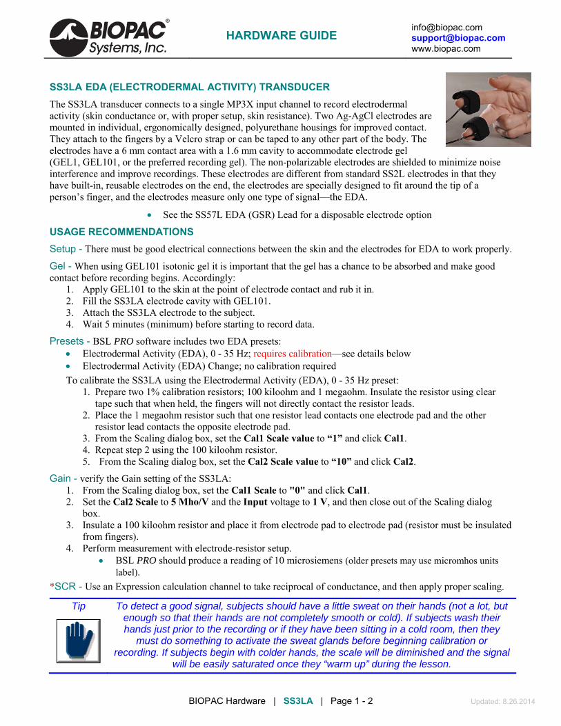
SS3LA EDA (ELECTRODERMAL ACTIVITY) TRANSDUCER The SS3LA transducer connects to a single MP3X input channel to record electrodermal activity (skin conductance or, with proper setup, skin resistance). Two Ag-AgCl electrodes are mounted in individual, ergonomically designed, polyurethane housings for improved contact. They attach to the fingers by a Velcro strap or can be taped to any other part of the body. The electrodes have a 6 mm contact area with a 1.6 mm cavity to accommodate electrode gel (GEL1, GEL101, or the preferred recording gel). The non-polarizable electrodes are shielded to minimize noise interference and improve recordings. These electrodes are different from standard SS2L electrodes in that they have built-in, reusable electrodes on the end, the electrodes are specially designed to fit around the tip of a person’s finger, and the electrodes measure only one type of signal—the EDA.
• See the SS57L EDA (GSR) Lead for a disposable electrode option
USAGE RECOMMENDATIONS Setup - There must be good electrical connections between the skin and the electrodes for EDA to work properly.
Gel - When using GEL101 isotonic gel it is important that the gel has a chance to be absorbed and make good contact before recording begins. Accordingly:
1. Apply GEL101 to the skin at the point of electrode contact and rub it in. 2. Fill the SS3LA electrode cavity with GEL101. 3. Attach the SS3LA electrode to the subject. 4. Wait 5 minutes (minimum) before starting to record data.
Presets - BSL PRO software includes two EDA presets: • Electrodermal Activity (EDA), 0 - 35 Hz; requires calibration—see details below • Electrodermal Activity (EDA) Change; no calibration required To calibrate the SS3LA using the Electrodermal Activity (EDA), 0 - 35 Hz preset:
1. Prepare two 1% calibration resistors; 100 kiloohm and 1 megaohm. Insulate the resistor using clear tape such that when held, the fingers will not directly contact the resistor leads.
2. Place the 1 megaohm resistor such that one resistor lead contacts one electrode pad and the other resistor lead contacts the opposite electrode pad.
3. From the Scaling dialog box, set the Cal1 Scale value to “1” and click Cal1. 4. Repeat step 2 using the 100 kiloohm resistor. 5. From the Scaling dialog box, set the Cal2 Scale value to “10” and click Cal2.
Gain - verify the Gain setting of the SS3LA: 1. From the Scaling dialog box, set the Cal1 Scale to "0" and click Cal1. 2. Set the Cal2 Scale to 5 Mho/V and the Input voltage to 1 V, and then close out of the Scaling dialog
box. 3. Insulate a 100 kiloohm resistor and place it from electrode pad to electrode pad (resistor must be insulated
from fingers). 4. Perform measurement with electrode-resistor setup.
• BSL PRO should produce a reading of 10 microsiemens (older presets may use micromhos units label).
*SCR - Use an Expression calculation channel to take reciprocal of conductance, and then apply proper scaling.
Tip
To detect a good signal, subjects should have a little sweat on their hands (not a lot, but enough so that their hands are not completely smooth or cold). If subjects wash their hands just prior to the recording or if they have been sitting in a cold room, then they
must do something to activate the sweat glands before beginning calibration or recording. If subjects begin with colder hands, the scale will be diminished and the signal
will be easily saturated once they “warm up” during the lesson.
HARDWARE GUIDE

[email protected] [email protected] www.biopac.com
BIOPAC Hardware | SS3LA | Page 2 - 2 Updated: 8.26.2014
SS3LA SPECIFICATIONS Electrode Type: Ag/AgCl, shielded Weight: 4.5 grams Range: .1 – 100 µsiemens (normal human range is 1 – 20 µsiemens) Cable Length: 2 meters Surface Area: 6 mm contact area Connector Type: 9 Pin DIN Gel Cavity Area 1.66 mm Sterilizable: Yes (contact BIOPAC) Dimensions: 16 mm (long) × 17 mm (wide) × 8 mm (high)
CLEANING THE SS3LA TRANSDUCER
• Do not leave GEL in the cavity after use. The electrode cavity must be left clean and dry. If GEL is left in the cavity, it will act as insulation preventing electrical contact with the skin, and the Ag-AgCl electrode disk could degrade quickly with time because the electrode surface is somewhat porous to promote good conductivity to the GEL.
• To clean the reusable SS3LA, use a cotton swab or toothbrush with tap water.
• Use any lab cleaner with pumice (such as Ajax) with a cotton swab or toothbrush to remove any dark residue from the electrode surface.
• Use Hydrogen Peroxide solution (2-3%) to brighten electrode surface (optional) or to sterilize the electrode. Do not place the electrode in solution, but simply clean the electrode surface using a cotton swab. Dry the electrode off completely before storage.
HARDWARE GUIDE

[email protected] [email protected] www.biopac.com
BIOPAC Hardware | SS5LB | Page 1 - 1 Updated: 8.22.2014
SS5LB RESPIRATORY EFFORT TRANSDUCER
The SS5LB transducer is used to record respiration via chest or abdomen expansion and contraction. This transducer is useful for determining how deeply someone is breathing and for calculating the person’s breathing rate or respiration rate. The transducer is a strain assembly that measures the change in thoracic or abdominal circumference. The strap presents minimal resistance to movement and is extremely unobtrusive. Due to its novel construction, the SS5LB can measure extremely slow respiration patterns with no loss in signal amplitude while maintaining excellent linearity and minimal hysteresis. The respiratory effort transducer has a 2-meter flexible lightweight cable. The center plastic housing protects the delicate sensor within. The transducer is attached by a fully adjustable nylon strap, which allows the transducer to fit almost any circumference. To attach the nylon belt to the transducer, thread the strap through the corresponding slots on the sensor assembly. Place the transducer around the body at the level of maximum respiratory expansion (generally about 5cm below the armpits). At maximum expiration, adjust the strap so there is slight tension to hold the strap around the chest.
SS5LB SPECIFICATIONS Response: True DC Circumference Range: 9 cm – 130 cm (Can be increased with a longer nylon strap) Dimensions: 95 mm (long) × 47mm (wide) × 15mm (thick) Weight: 9 grams Sterilizable: Yes (contact BIOPAC for details) Variable Resistance Output: 50-150 K Cable Length: 2 meters (flexible, lightweight) Connector Type: 9 Pin DIN
HARDWARE GUIDE

[email protected] [email protected] www.biopac.com
BIOPAC Hardware | SS6L – SS18L | Page 1 - 2 Updated: 8.26.2014
TEMPERATURE TRANSDUCERS SS6L: Fast Response SS7L: Waterproof Probe SS8L: Liquid Immersion Probe SS18L Digit Surface
SS6L TEMPERATURE TRANSDUCER The SS6L is a small fast-response thermistor used to measure small variations in temperature, either on the skin surface or in exhaled airflow. The recorded temperature changes during breathing can be used to indicate respiration rate. Attach the SS6L to the skin surface with Surgical Tape (TAPE1).
RX202A Sensor (white) shown at right with transducer connector (black); ships as sensor only. This is a replacement sensor for
• TSD202A for MP research systems • SS6L for BSL education systems • SS6 for telemetry/wireless systems
The sensor snaps onto the "SS" transducer connector for connection to a BIOPAC data acquisition system.
SS6L SPECIFICATIONS Response time: 0.6 sec Nominal resistance: 2252 Ω @ 25° C Maximum operating temperature: 100° C Accuracy and Interchangeability: ±0.1° C Connector Type: 9 Pin DIN Compatibility: YSI® series 400 temperature probes Cable Length: 2 meters (flexible, lightweight) Sterilizable: Yes (contact BIOPAC for details)
Dimensions: 5 m x 1.7 m
SS7L WATERPROOF PROBE Use this vinyl probe for core (oral/rectal) temperature recordings.
SS7L SPECIFICATIONS Response time: 1.1 sec Max operating temp: 60° C Accuracy & Interchangeability: ±0.2° C Compatibility: YSI(r) series 400 Dimensions: 9.8 mm x 3.3 mm Cable: 3 meters
HARDWARE GUIDE

[email protected] [email protected] www.biopac.com
BIOPAC Hardware | SS6L – SS18L | Page 2 - 2 Updated: 8.26.2014
SS8L LIQUID IMMERSION PROBE Use this stainless steel probe for dry or wet bath temperature measurements.
SS8L SPECIFICATIONS Response time: 3.6 sec Max operating temp: 60° C Accuracy & Interchangeability: ±0.2° C Compatibility: YSI(r) series 400 Dimensions: 4 mm x 115 mm Cable: 3 meters
SS18LA DIGIT SURFACE TEMPERATURE TRANSDUCER The SS18LA is designed to record skin temperature of the fingers or toes. The probe contains a surface temperature sensing element encased in a polyurethane housing that conforms to curved skin surfaces and includes a Velcro strap for easy attachment.
SS18L SPECIFICATIONS Response time: 1.1 sec Size with housing: 16 mm (long) x 17 mm (wide) x 8 mm (high) sensor only: 10 mm sensing diameter, 1.4 mm sensor thickness Interface: MP3X Nominal Resistance: 2252 ohms at 25° C (sensor only) Maximum operating temperature: 60° C (when used with MP3X) Accuracy and Interchangeability: 0.2° C (after calibration) Cable Length: 3 meters Compatibility: YSI series 400 temperature probes (sensor only) Sterilizable: Yes (contact BIOPAC for details)
HARDWARE GUIDE

[email protected] [email protected] www.biopac.com
BIOPAC Hardware | BNC INPUT ADAPTERS | Page 1 - 1 Updated: 2.18.2015
INPUT ADAPTERS SS9LA Unisolated BNC Input Adapter SS70L Isolated BNC Input Adapter SS71L Isolated BNC Input Adapter – MP30 See also: OUT2 BNC Output Adapter
SS9LA Unisolated BNC Input Adapter This unisolated input adapter is for MP36, MP36R, MP35, and MP45 Systems only. Use to send signals from other devices (other chart recorders, amplifiers and signal generators) to be recorded by a Biopac Student Lab System or a Research System with AcqKnowledge. SS9LA has a built-in divide by 10 attenuation which provides a ±20 V input range on MP36, MP36R and MP45, a ±10 V input range on MP35. The 2-meter cable terminates in a male BNC for easy connections.
SS9LA Specifications Cable length: 2 meter Connector type: BNC Signal range: ±20 V (MP36/MP36R/MP45) ±10 V (MP35)
WARNING! Never connect the SS9LA BNC Input Adapter to an MP3X unit if electrodes from other channels are connected to human subjects – this may void the electrical isolation (one un-isolated channel input voids the isolation of all channel inputs).
This cable replaces the SS9L, effective January 2014.
SS70L Isolated BNC Input Adapter for MP36/MP35
This BNC adapter is required when connecting un-isolated third party devices (i.e. amplifiers, chart recorders or signal generators), while electrodes, attached to human Subjects are connected to other input channels. Connector Type: BNC Signal range: ±20 V (MP36/MP36R/MP45) ±10 V (MP35)
SS71L Isolated BNC Input Adapter for MP30
This BNC adapter is required when connecting un-isolated third party devices (i.e. amplifiers, chart recorders or signal generators), while electrodes, attached to human Subjects are connected to other input channels. Connector Type: BNC Signal range: ±10 V
WARNING! Since all MP inputs share a common isolated ground, connecting an un-isolated device to any channel voids the isolation for all channels and exposes the Subject to possible shock hazards.
HARDWARE GUIDE

[email protected] [email protected] www.biopac.com
BIOPAC Hardware | SS10L | Page 1 - 1 Updated: 7.1.2013
SS10L PUSHBUTTON HAND SWITCH The SS10L pushbutton hand switch is used for remote event marking or for psychophysiological response tests. This easy to hold pushbutton switch is very rugged and reliable, and makes it simple to mark events during recording. When data from the button is displayed on the screen, it normally reads 0 Volts, and when the button is pressed it reads +5 mV.
SS10L SPECIFICATIONS Cable Length: 2 meters Connector Type: 9 Pin DIN to MP36/35 front panel input
HARDWARE GUIDE

[email protected] [email protected] www.biopac.com
BIOPAC Hardware | SS12LA | Page 1 - 3 Updated: 8.22.2014
See also: Force Transducer Tension Adjuster (HDW100A)
SS12LA VARIABLE RANGE FORCE TRANSDUCER
SS12LA Sample Setup
SS12LA Variable Range Force Transducer
Force transducers are devices capable of transforming a force into a proportional electrical signal. The SS12LA variable range force transducer element is a cantilever beam load cell incorporating a thin-film strain gauge. Because the strain elements have been photolithographically etched directly on the strain beam, these transducers are rugged while maintaining low non-linearity and hysteresis. Drift with time and temperature is also minimized, because the strain elements track extremely well, due to the deposition method and the elements’ close physical proximity. The SS12LA also incorporates impact and drop shock protection to insure against rough laboratory handling. Forces are transmitted back to the beam via a lever arm to insure accurate force measurements. Changing the attachment point changes the full scale range of the force transducer from 50 g to 1000 g. The beam and lever arm are mounted in a sealed aluminum enclosure that includes a 3/8" diameter mounting rod for holding the transducer in a large variety of orientations. The SS12LA comes equipped with a 2-meter cable and plugs directly into the MP3X module. The SS12LA mounting rod can be screwed into the transducer body in three different locations, two on the top and one on the end surfaces of the transducer. The mounting rod can be placed in any angle relative to the transducer orientation. The SS12LA can be used in any axis and can be easily mounted in any standard measurement fixture, including pharmacological setups, muscle tissue baths and organ chambers. The SS12LA has 5 different attachment points that determine the effective range of the force transducer. These ranges are 50 g, 100 g, 200 g, 500 g and 1,000 g. The point closest to the end is the 50 g attachment point, while the point closest to the middle is the 1,000 g attachment point.
Two S-hooks are provided with the SS12LA; one has a .032" diameter wire and the other has a .051" diameter wire. The smaller hook is to be used for the 50 g, 100 g and 200 g ranges. The larger hook is intended for the 500 g and 1000 g ranges. The larger hook is intentionally a tight fit to generate a downward pull vector. To further increase proper readings, keep the unit level and align anything that hangs off the hook straight beneath it rather than at a sideways angle.
SS12LA S-hooks
HARDWARE GUIDE

[email protected] [email protected] www.biopac.com
BIOPAC Hardware | SS12LA | Page 2 - 3 Updated: 8.22.2014
SS12LA SPECIFICATIONS* Lever Arm Position (hook ring)
Full Scale Range (FSR)
10Hz Noise 1Hz Noise
50 grams 50 grams 2.5 mg 1 mg 100 grams 100 grams 5 mg 2 mg 200 grams 200 grams 10 mg 4 mg 500 grams 500 grams 25 mg 10 mg 1000 grams 1000 grams 50 mg 20 mg Sensitivity 1 mV/V (for 5 V excitation, output is 5 mV at full scale) Temperature Range -10° C to 70° C Thermal Zero Shift* <±0.03% FSR/° C Thermal Range Shift* <0.03% Reading/° C Excitation Voltage 5 VDC Nonlinearity* <±0.025% FSR* Hysteresis* <±0.05% FSR* Non-repeatability* <±0.05% FSR* 30-Minute Creep* <±0.05% FSR* Dimensions 19 mm (wide) × 25 mm (thick) × 190 mm (long) Weight (with mounting rod) 300 g Cable length 3 meters Materials Aluminum: hook rings
Anodized aluminum: housing Stainless Steel: attachment arm
* These parameters assume the transducer is set for a 50 g range. For all other range settings, force measurements from 10% to 90% full scale are linear to ±1.0%.
CALIBRATION The SS12LA is easily calibrated using weights of known mass. Ideally, calibration should be performed with weights that encompass the range of the forces expected during measurement and should cover at least 20% of the full scale range of the transducer. When calibrating for maximum range on the force transducer, use weights that correspond to 10% and 90% of the full scale range for best overall performance.
FORCE TRANSDUCER CALIBRATION Calibrating a force transducer is a two step process. The first step involves finding the optimal Gain setting for the transducer and the second step is the actual calibration. 1) To find the optimal Gain setting:
a) Start with the software Preset for the force range desired. • To set the Presets: MP3X menu > Setup Channels > Analog Presets > “Force (range)”
b) Load the transducer with the maximum expected weight. c) Collect data for a few seconds at these settings. d) Inspect the sample data; look for data that is “railed” or “clipped.” This occurs when the input signal
(times the gain setting) is too large relative to the maximum input range. An example of clipped data follows.
HARDWARE GUIDE

[email protected] [email protected] www.biopac.com
BIOPAC Hardware | SS12LA | Page 3 - 3 Updated: 8.22.2014
Gain set too high — Clipped Force data
e) If the signal is clipped, decrease the Gain setting by one step (e.g., from x5000 to x2500) and collect new data at the lower gain setting.
• To access the Gain setting: MP3X menu > Setup Channels > Force preset channel > View/Change Parameters icon > Gain pull-down menu
f) Repeat this procedure until the signal no longer appears “clipped.” Once an optimal gain setting for the transducer has been established, this same gain setting can be used for other similar transducers and similar measurements.
2) The next step is to actually calibrate the transducer, which means mapping the input signal to more meaningful units (such as grams). To do this:
a) Access the Channel scaling dialog box (MP3X menu > Setup Channels > Force preset channel > View/Change Parameters icon > Scaling button).
Note: In this sample dialog, a weight of 5 grams was placed on the transducer and the Cal 1 button was pressed. The transducer weight was then removed and Cal 2 was pressed.
b) Place the maximum expected weight or force on the transducer. c) Click on the Cal 1 button in the Channel scaling window.
• A voltage value will be automatically entered in the corresponding Input value box. d) Remove all weight or force from the transducer. e) Click on the Cal 2 button in the same scaling window.
• A voltage value will be automatically entered in the corresponding Input value box. The transducer will be calibrated to the set values the next time an acquisition is started.
HARDWARE GUIDE

[email protected] [email protected] www.biopac.com
BIOPAC Hardware | SS13L – RX104A | Page 1 - 3 Updated: 8.26.2014
SS13L PRESSURE TRANSDUCER The SS13L pressure transducer is used to measure direct arterial or venous blood pressure in animals or to record pressure changes within a closed system such as an organ or tissue bath system. Connect to the tubing via the standard rotating Luer-lok fittings. This assembly consists of a disposable transducer with a 30 cm cable that attaches to a reusable 3-meter cable that is designed to interface with the MP3X. The transducer is supplied non-sterile but can be cold sterilized.
Note: The SS13L Pressure transducer is not intended for use with humans. Typical software settings for the blood pressure transducer are described in the table below:
Filter 1 Filter 2 Filter 3 Hardware filter Gain Coupling Low pass 66.5 Hz Q = 0.5
Low pass 38.5 Hz Q = 1.0
Band Stop 60 Hz Q = 5
1 KHz
100 (preset)
DC
These settings are automatically applied when the Pressure preset is selected, but settings can be adjusted if necessary.
PRESSURE TRANSDUCER CALIBRATION Calibrating a blood pressure transducer is a two step process. The first step involves finding the optimal gain setting for the transducer and the second step is the actual calibration.
1) To find the optimal gain setting:
a) Start with the software Presets (in this case, a gain of 100) • To set the Presets: MP3X menu > Setup channels > Analog Presets > select “Pressure”
b) Bring the transducer to the approximate maximum and minimum expected pressures.
c) Collect data for a few seconds at these settings. d) Inspect the sample data; look for data that is
“railed” or “clipped.” This occurs when the input signal (times the gain setting) is too large relative to the maximum input range. An example of clipped data is shown at right.
e) If the signal is clipped, decrease the gain setting by one step (e.g., from x5000 to x2500) and collect new data at the lower gain setting. • To access the Gain setting: MP3X menu >
Setup channels > Pressure preset channel > View/Change Parameters icon > Gain pull-down menu
f) Repeat this procedure until the signal no longer appears “clipped.”
Once an optimal gain setting for the transducer has been established, this same gain setting can be used for other similar transducers and similar measurements.
2) The next step is to actually calibrate the transducer, which means mapping the input signal to more meaningful units (such as mmHg). To do this: a) Access the Channel scaling dialog box (MP3X menu > Setup Channels > Pressure Preset channel >
View/Change Parameters icon > Scaling button).
Gain set too high — Clipped BP data
HARDWARE GUIDE

[email protected] [email protected] www.biopac.com
BIOPAC Hardware | SS13L – RX104A | Page 2 - 3 Updated: 8.26.2014
Note: In this sample dialog, the transducer was brought to a pressure of 50 mmHg and the Cal 1 button was pressed. The transducer was then brought to a pressure of 180 mmHg, and Cal 2 was pressed.
b) Bring the transducer to the lowest expected pressure. c) Click on the Cal 1 button in the Channel scaling window.
• A voltage value will be automatically entered in the corresponding Input value box. d) Bring the transducer to the highest expected pressure. e) Click on the Cal 2 button in the same scaling window.
• A voltage value will be automatically entered in the corresponding Input value box. The software will now interpolate between these two calibration points to give accurate measurements in mmHg.
SS13L PRESSURE TRANSDUCER SPECIFICATIONS Operational pressure: -50 mmHg to +300 mmHg Overpressure: -500 mmHg to + 4000 mmHg Sensitivity: 25 V/VmmHg (at 5 VDC excitation) Accuracy: ± 1.5% of reading or ± 1.0 mmHg (whichever is greater) Operating temperature: 10° C to 40° C Storage temperature: -30° C to +60° C Volume displacement: 0.04 mm per 100 mmHg Leakage current: 10 A RMS @ 115 VAC 50 Hz Dynamic response: 100 Hz Unbalance: 50 mmHg max Connection Ports: male Luer and female Luer
(sensors shipped prior to summer 2010 were male Luer on both sides) Eight-hour drift: 1 mmHg after 5-minute warm-up Isolation: <= 5 leakage at 120 VAC/60 Hz Defibrillation: Withstands 5 charges of 400 joules in 5 minutes across a load Combined effects of sensitivity, linearity and hysteresis: 1 mmHg (nominal) Transducer cable: 30 cm Interface cable: 3 meters Transducer dimensions: 67 mm long X 25 mm wide Weight: 11.5 grams
HARDWARE GUIDE

[email protected] [email protected] www.biopac.com
BIOPAC Hardware | SS13L – RX104A | Page 3 - 3 Updated: 8.26.2014
RX104A REPLACEMENT ELEMENT The RX104A is a replacement element for the SS13L Pressure Transducer. It does not include the Smart Sensor connector and cable.
HARDWARE GUIDE

[email protected] [email protected] www.biopac.com
BIOPAC Hardware | SS14L | Page 1 - 1 Updated: 8.26.2014
See also: Tension Adjuster (HDW100A)
SS14L DISPLACEMENT TRANSDUCER For use in recording very slight movements in a range of physiological preparations, the SS14L incorporates a semi-isotonic strain gauge and a stainless steel lever that can be mounted in any position.
SS14L SPECIFICATIONS Sensitivity Range: 1 mm to 100 mm Strain Gauge: 500 ohm silicon Lever Length: 27 cm Support Rod Length: 15 cm Cable Length: 3 meters Interface: MP3X
HARDWARE GUIDE

[email protected] [email protected] www.biopac.com
BIOPAC Hardware | SS25LA | Page 1 - 1 Updated: 3.6.2015
SS25LA HAND DYNAMOMETER Use the hand dynamometer to measure grip force—use in isolation or combine with EMG recordings for in-depth studies of muscular activity. The lightweight, ergonomically designed transducer provides direct readings in kilograms or pounds. The simple calibration procedure makes this device easy to use for precise force measurements, and the isometric design improves experiment repeatability and accuracy. The SS25LA is a basic unit, designed for student lessons; it can also be used in the MRI, with proper module setup, since it employs plastics in the spring constant. The highest performance dynamometer is TSD121C, which employs a four terminal, laser-trimmed, Wheatstone bridge built onto metal elements. Hardware Setup Connect the SS25LA Simple Sensor to a CH input on the front panel of an MP3X/45 unit.
Proper grip: Place the palm across the shorter bar and wrap fingers to center the force.
Scaling — Software Setup 1) Select Set Up Channels under the MP menu and enable
one analog channel. 2) Select the desired Clench Force Preset (kg or lbs, the example to
the right is shown in units of kg.) 3) Click the Setup button. 4) Click the Scaling button to activate a dialog box similar to the one
shown at right. 5) In the Map value column, note the default scaling of “0” for Cal2
and “100” for Cal1. These represent 0 and 100 kilograms, respectively.
6) Place the SS25LA on a flat surface. 7) Click the Cal2 button to obtain an initial calibration reading. A value similar to the above example “0.7556”
will appear. 8) To obtain the Cal1 input value, add the Cal2 input value to the default Cal1 3.5 mV per 100 kg value.
(In this example, this value would be 0.7556 mV + 3.5 mV = 4.2556 mV.) Note: The above instructions are for BSL 4 and higher. In BSL 3.7.7 and earlier, placement of the CAL1 and
CAL2 scale values are reversed. Optional Calibration Confirmation
a) Click “Start” to begin data acquisition. b) Place the SS25LA on a flat surface and then place a known
weight on the uppermost portion of the grip. c) Review the data to confirm that the known weight is reflected
accurately in the data (sample at right). d) Adjust the Scaling parameters and repeat steps a-c as
necessary. SS25LA Specifications
Clench Force Range: 0-90 kgf Nominal Output: 13.2 µV/kgf Linearity: 8% Sensitivity: 0.75 kg Weight: 323 grams Cable Length: 3 meters Dimensions: 17.78 cm (long) x 5.59 cm (wide) x 2.59 cm (thick)
HARDWARE GUIDE

HARDWARE GUIDE [email protected] [email protected] www.biopac.com
BIOPAC Hardware | SS25LB | Page 1 - 1 Updated: 3.6.2015
SS25LB HAND DYNAMOMETER Use the hand dynamometer to measure grip force—use in isolation or combine with EMG recordings for in-depth studies of muscular activity. The lightweight, ergonomically designed transducer provides direct readings in kilograms or pounds. The simple calibration procedure makes this device easy to use for precise force measurements, and the isometric design improves experiment repeatability and accuracy. The SS25LB is a basic unit, designed for student lessons; it can also be used in the MRI, with proper module setup, since it employs plastics in the spring constant.
The highest performance dynamometer is TSD121C, which employs a four terminal, laser-trimmed, wheatstone bridge built onto metal elements.
Hardware Setup
Connect the SS25LB Simple Sensor to a CH input on the front panel of an MP36/36R/35/45 unit.
Proper grip: Place the palm across the shorter bar and wrap fingers to center the force.
Scaling—Software Setup for the MP36/MP36R/MP35/MP45
Note: When using with Biopac Student Lab, the SS25LB is compatible with versions 4.1 and higher only.
1) Select Set Up Data Acquisition > Channels under the MP menu and enable one analog channel.
2) Select the desired Clench Force (SS25LB) Preset in units of kg, lbs, or N. (Example above is units of kg.)
3) Click the Setup button.
4) Click the Scaling button to activate a dialog box similar to the one shown at right.
5) In the Map value column, note the default scaling of “0” for Cal 2 and “1.58757” for Cal 1. These represent 0 and 1.58757 kilograms, respectively. The MAP values must not be altered.
6) Place the SS25LB on a flat surface.
7) Click the Cal 2 button to obtain an initial calibration reading. A value similar to the above example will appear.
8) To obtain the Cal 1 input value, add the Cal 2 input value to the default Cal 1 10 mV per 1.58757 kg value. (In the above example, this value would be 0.567636 mV + 10 mV = 10.567636 mV.)
Optional Calibration Confirmation
a) Make sure the SS25LB is connected to the same channel as enabled in Step 1 above.
b) Click “Start” to begin data acquisition.
c) Place the SS25LB on a flat surface and then place a known weight on the uppermost portion of the grip.
d) Review the data to confirm that the known weight is reflected accurately in the data (sample above).
e) Adjust the Scaling parameters and repeat steps a-c as necessary.
SS25LB Specifications
Clench Force Range: 0-50 kgf
Nominal Output: 6.299 mV/kgf
Linearity: 6%
Sensitivity: 20 grams
Weight: 323 grams
Cable Length: 3 meters
Dimensions: 17.78 cm (long) x 5.59 cm (wide) x 2.59 cm (thick)
[email protected] [email protected] www.biopac.com
BSL Education | SS29L | Page 1 - 1 Updated: 7.16.2012
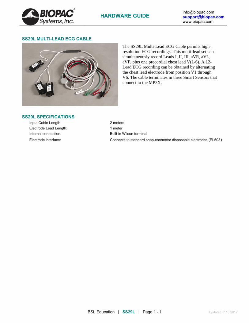
SS29L MULTI-LEAD ECG CABLE The SS29L Multi-Lead ECG Cable permits high-resolution ECG recordings. This multi-lead set can simultaneously record Leads I, II, III, aVR, aVL, aVF, plus one precordial chest lead V(1-6). A 12-Lead ECG recording can be obtained by alternating the chest lead electrode from position V1 through V6. The cable terminates in three Smart Sensors that connect to the MP3X.
SS29L SPECIFICATIONS Input Cable Length: 2 meters Electrode Lead Length: 1 meter Internal connection: Built-in Wilson terminal
Electrode interface: Connects to standard snap-connector disposable electrodes (EL503)
HARDWARE GUIDE

[email protected] [email protected] www.biopac.com
BSL Education | SS30L | Page 1 - 1 Updated: 7.16.2012
SS30L ELECTRONIC STETHOSCOPE TRANSDUCER The SS30L stethoscope was developed to teach the standard procedure for listening to heart sounds and Korotkoff sounds with a “normal” stethoscope, and record simultaneous sound data. A microphone in the SS30L records sound as it is heard and the BSL software displays the sound wave during and after recording (a variety of acoustical signals can be recorded). If ECG is also recorded, the timing of the heart sounds with the ECG can be correlated. The SS30L can be used with the SS19L Blood Pressure Cuff to record Korotkoff sounds for easy determination of systolic and diastolic blood pressure. With this combination, it is easy to obtain very accurate and repeatable results — usually within 10% of those determined by direct measurement.
No calibration required, just select a Stethoscope Preset (Heart or Korotkoff Sounds)
See also: Biopac Student Lab Lesson 16 Blood Pressure and Lesson 17 Heart Sounds.
SS30L SPECIFICATIONS Microphone Bandwidth: 20-100 Hz (does not impact acoustical bandwidth, used for data viewing) Stethoscope Length: From Y to acoustic sensor point: 57 cm From Y to ears: 21 cm Microphone Cable length: 3 meters
HARDWARE GUIDE

[email protected] [email protected] www.biopac.com
BIOPAC Hardware | SS31L | Page 1 - 1 Updated: 6.13.2014
SS31L NONINVASIVE CARDIAC OUTPUT SENSOR The SS31L records the thoracic impedance parameters associated with Cardiac Output measurements. The SS31L incorporates a precision high-frequency current source, which injects a very small (400µA rms) current through the measurement tissue volume defined by the placement of a set of current source electrodes. A separate set of monitoring electrodes then measures the voltage developed across the tissue volume. Because the current is constant, the voltage measured is proportional to the characteristics of the biological impedance of the tissue volume. The SS31L outputs impedance (Z) and derivative of impedance (dZ) in real time. Best used with BIOPAC’s EL506 Bioimpedance strip electrode.
• Use the SS31L to measure changes in Cardiac Output under a variety of conditions: laying down, sitting up, standing up, and post-exercise.
• Use on stationary subjects; the SS31L is sensitive to motion artifact. • See BSL PRO Lesson H21 Impedance Cardiography for sample SS31L setup and data.
Specifications Outputs: Impedance (Z) (50 mV = 100 Ω) Derivative Impedance (dZ) (5 mV = 2 Ω/sec) Operational Frequency: 100 KHz sine wave Current Level: 400 µA (rms) Bandwidth: (can limit in BSL PRO software) Z: DC – 100 Hz dZ: DC – 100 Hz Dimensions: 14 cm (long) x 9.1 cm (wide) x 2.9 cm (high) Weight: 400 grams Electrode clip connects to standard snap electrode (EL506 recommended)
HARDWARE GUIDE

[email protected] [email protected] www.biopac.com
BSL Education | SS36L | Page 1 - 1 Updated: 7.17.2012
SS36L REFLEX HAMMER
This is a classic reflex hammer with a transducer attached to perform reflex measurements. It uses a Taylor Hammer—the most common type of reflex hammer used by doctors and nurses—and incorporates electronics to record the time and the relative strength of the impact. Being able to measure the strength of impact allows students to take threshold measurements; that is, they can measure how much of an impact is needed to elicit a response. The hammer only sends a response when contact is made with the subject. See Lessons L20, H16, H28.
HARDWARE GUIDE

[email protected] [email protected] www.biopac.com
BIOPAC Hardware | SS39L | Page 1 - 1 Updated: 2.27.2013
SS39L BREADBOARD The Bioengineering Breadboard Lab consists of circuitry hardware and eight projects (with schematics and design notes) that demonstrate a very important subset of circuit design for recording and processing physiological signals. Students will use the MP36/35 and BSL PRO software to evaluate their designs. See Lessons H25, H26.
Circuitry Hardware
Breadboard Signal/Power Cable
o 3 x Power Plugs: Green -5 V, Black GND, Red +5 V o 2 x Signal Wires: White – Signal, Black – GND o Built-in automatically resettable fuse
Signal Cable (SS60L) o 2 x Signal Wires: Red – Signal, Black – GND
Electrode Lead Interface o BSL-TC122: SS2L to SS39L
Accessory Kit (BSL-BMEACC) o Capacitors, diodes, resistors, jumper wires, and other circuit-building components
Project Book includes schematics for:
Lab 1: Square Wave Oscillator Lab 2: Instrumentation Amplifier Lab 3: High Pass Active Filter Lab 4: Active Gain Block and Low Pass Filter Lab 5: Notch Filter for 50/60 Hz Rejection Lab 6: QRS Detection: Band Pass Filter Lab 7: QRS Detection: Absolute Value Circuit Lab 8: QRS Detection: Low Pass Filter and Overall System Test
HARDWARE GUIDE
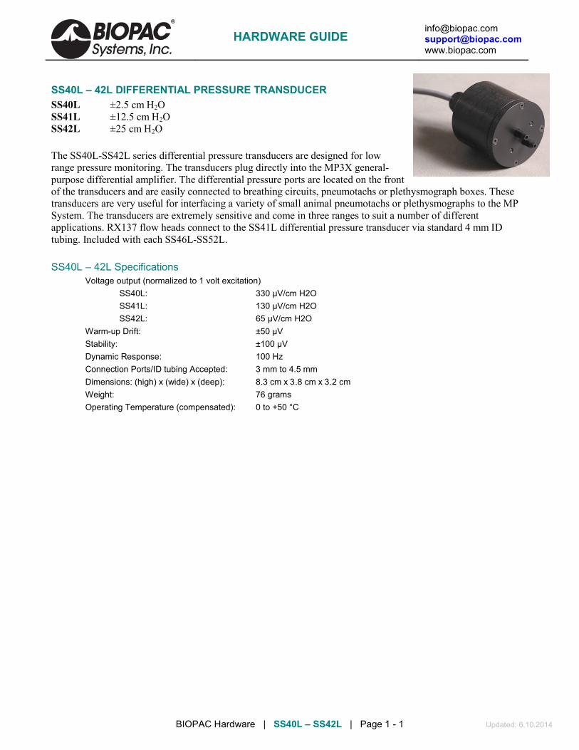
[email protected] [email protected] www.biopac.com
BIOPAC Hardware | SS40L – SS42L | Page 1 - 1 Updated: 6.10.2014
SS40L – 42L DIFFERENTIAL PRESSURE TRANSDUCER SS40L ±2.5 cm H2O SS41L ±12.5 cm H2O SS42L ±25 cm H2O The SS40L-SS42L series differential pressure transducers are designed for low range pressure monitoring. The transducers plug directly into the MP3X general-purpose differential amplifier. The differential pressure ports are located on the front of the transducers and are easily connected to breathing circuits, pneumotachs or plethysmograph boxes. These transducers are very useful for interfacing a variety of small animal pneumotachs or plethysmographs to the MP System. The transducers are extremely sensitive and come in three ranges to suit a number of different applications. RX137 flow heads connect to the SS41L differential pressure transducer via standard 4 mm ID tubing. Included with each SS46L-SS52L.
SS40L – 42L Specifications Voltage output (normalized to 1 volt excitation)
SS40L: 330 µV/cm H2O SS41L: 130 µV/cm H2O SS42L: 65 µV/cm H2O
Warm-up Drift: ±50 µV Stability: ±100 µV Dynamic Response: 100 Hz Connection Ports/ID tubing Accepted: 3 mm to 4.5 mm Dimensions: (high) x (wide) x (deep): 8.3 cm x 3.8 cm x 3.2 cm Weight: 76 grams Operating Temperature (compensated): 0 to +50 °C
HARDWARE GUIDE

[email protected] [email protected] www.biopac.com
BIOPAC Hardware | SS43L | Page 1 - 1 Updated: 8.26.2014
SS43L VARIABLE ASSESSMENT (PSYCH) TRANSDUCER Use this handheld, slide control transducer to record subjective responses to a variety of different stimuli. Use multiple transducers to allow several people to simultaneously answer the same question or otherwise respond to stimuli. Easily customize the response scale by inserting the parameters into the scale sleeve on the front of the unit.
SS43L Specifications Scale Output Range: 0-5 V Scale Resolution: Infinitely adjustable Slide Control Length: 10 cm Dimensions: 4 cm (high) x 11 cm (deep) x 19 cm (wide) Weight: 230 grams Cable Length: 7.6 meters
HARDWARE GUIDE

[email protected] [email protected] www.biopac.com
BIOPAC Hardware | SS53L – SS55L | Page 1 - 1 Updated: 8.26.2014
SS53L – SS55L DIGITAL SWITCH SERIES
Use for remote even marking or to externally trigger data acquisition for psychophysiological response tests Monitor switch data as a digital input channel. Connects to the digital input on the MP36/35 only. SS53L Hand switch See Lessons H11, H16, H24, H27, H30. SS54L Foot switch See Lessons H11, H16, H24, H27, H30.
Switch Type: Pushbutton: ON - OFF Dimensions: 69 mm (wide), 90 mm (long), 26 mm (high) Cable Length: 1.8 meters Connector Type: DSUB 25f
SS55L Eight-channel Marker Box See Lessons H11, H16, H24, H27, H30. Independently mark events, or provide responses, on up to eight channels simultaneously. Assign separate digital channels as event markers for individual analog input channels. Easily customize the response scale by inserting the parameters into the scale sleeve on the front of the unit.
Switch Type: Pushbutton: ON - OFF Dimensions: 19 cm (wide), 11 cm (deep), 4 cm (high) Cable Length: 3 meters Connector Type: DSUB 25f
HARDWARE GUIDE

[email protected] [email protected] www.biopac.com
BIOPAC Hardware | SS56L | Page 1 - 1 Updated: 8.26.2014
SS56L HAND CLENCH FORCE BULB
SS56L measures proportionality of bulb pressure to clench force in “kgf/m^2” units (a pressure unit). This measure is accurate for the relative measures recorded in BSL Lesson 2 Electromyography (EMG) II. SS56L is recognized by current release BSL Lessons.
Specifications
Pressure Range: BSL: 0 to 10,546 Kgf/m^2 AcqKnowledge: 0 to 1.0546 Kg-f/cm^2 0 to 15 psi
Accuracy: ±3%
Output: BSL: 0.58 mV/100 Kgf/m^2 AcqKnowledge: 0.58 mV/0.01 Kg-f/cm^2 4.1 mV/psi
Bulb Diameter: 5.8 cm Bulb Length: 11.1 cm Tubing Length: 3 meters Weight: 108 g
Optional BSL PRO Presets:
• Clench Force - kpa (SS56L) - input value 20.48 mV scales to 34.47 kpa • Clench Force - psi (SS56L) - input value 61.44 mV scales to 15 psi
HARDWARE GUIDE

[email protected] [email protected] www.biopac.com
BIOPAC Hardware | SS57L | Page 1 - 1 Updated: 1.31.2013
SS57L EDA LEAD FOR DISPOSABLE SETUPS
Snaps to two EL507 disposable EDA (isotonic gel) electrodes. This disposable setup is an alternative to the reusable SS3LA EDA (GSR) Transducer. Range: 0.1-100 µMho (normal human range is 1-20 µMho) Excitation: 0.5 V DC Pinch Leads: Red (+), Black (GND)
HARDWARE GUIDE

[email protected] [email protected] www.biopac.com
BSL Education | SS60L | Page 1 - 1 Updated: 7.17.2012
SS60L SIGNAL CABLE FOR SS39L BREADBOARD
Use this signal cable to add signal inputs to the SS39L Signal Processing Breadboard, which ships with one combination power/signal cable.
HARDWARE GUIDE

[email protected] [email protected] www.biopac.com
BIOPAC Hardware | SS61L | Page 1 - 1 Updated: 2.12.2013
SS61L FINGER TWITCH TRANSDUCER
Palmar attachment recommended: “UP” label facing out “UP” label toward skin for posterior (dorsal) attachment
Use this transducer to record finger twitch responses from human subjects receiving electrical stimulation (using the HSTM01). The transducer conforms to the shape of the finger and attaches via a Velcro® strap and tape.
SPECIFICATIONS Transducer Dimensions: 14.6 cm (long), 0.50 cm (wide) Weight: 6 grams Maximum Bend: 180 (can be fully curled)
HARDWARE GUIDE

[email protected] [email protected] www.biopac.com
BSL Education | SS62L | Page 1 - 1 Updated: 7.17.2012
SS62L SPEECH FREQUENCY MICROPHONE
Use this precision microphone for speech frequency analysis and other acoustic studies. For use with the MP36/35 only, requires continuous high-speed sample rate.
HARDWARE GUIDE

[email protected] [email protected] www.biopac.com
BIOPAC Hardware | SS63L – SS66L | Page 1 - 1 Updated: 8.26.2014
SS63L – SS66L FORCE TRANSDUCER SERIES
SS63L Force Transducer - 50 g SS64L Force Transducer - 100 g SS65L Force Transducer – 200 g SS66L Force Transducer - 500 g
SS63L – SS66L Specifications Noise: with 10 Hz LP filter: 2.5 mg
with 1 Hz LP Filter: 1.0 mg Temperature: -10° C to 70° C Mounting rod: 9.5 mm (diameter), variable orientation Weight: 250 g Dimensions (L x W x Thick): 100 mm x 19 mm x 25 mm
HARDWARE GUIDE

[email protected] [email protected] www.biopac.com
BIOPAC Hardware | SS67L – RX110 | Page 1 - 1 Updated: 1.31.2013
SS67L PRESSURE PAD/RESPIRATION TRANSDUCER
The SS67L consists of an SS41L differential pressure transducer, RX110 pressure pad, and tubing.
The multipurpose pressure pad/respiration transducer can be used to:
1. Noninvasively measure respiration—from a small mouse to a human.
2. Measure small pressing forces (like pinching fingers together) for Parkinson's evaluations.
3. Measure human smiling (with the sensor on the cheekbone).
4. Measure pulse when placed close to the heart.
5. Measure spacing and pressure between teeth coming together.
See RX110 for sensor specifications.
See also: MRI Compatibility Notes
RX110 PRESSURE PAD The RX110 is a self-inflating pressure pad connected to tubing terminating in a Luer male connector. The RX110 pressure pad is included with the SS67L Pressure Pad/Respiration Transducer. The RX110 sensor can be used many times, but may eventually need to be replaced because it is a sensitive pressure pad and may become damaged with rough use. Use TAPE1 or other single-sided adhesive to affix to the subject.
RX110 SPECIFICATIONS Sensor Pad Diameter: 20 mm Sensor Pad Thickness: 3.18 mm Sensor Tubing Diameter: 2.2 mm Sensor Tubing Length: 1 m use BIOPAC tubing M106 for extra length Sensor Tubing ID: 1.6 mm Tubing Termination: Luer male
HARDWARE GUIDE

[email protected] [email protected] www.biopac.com
BIOPAC Hardware | SS68L | Page 1 - 1 Updated: 8.26.2014
SS68L PH PROBE TRANSDUCER
The SS68L probe transducer can measure pH within the range of 0-14.
The electrode provides approximately a single digit pH value change for every 5 mV change in the electrode reading, either positive or negative depending on whether the pH is above 7 or below it.
• A neutral buffer solution of pH 7 will read about 0 mV.
• A solution with a pH of 10 will read about –15 mV.
• A solution with a pH of 3 will read about 20 mV.
The SS68L pH Transducer includes a double-junction pH Probe and an interface to the Biopac Student Lab MP unit.
• Order probe only as RXPROBE01 • To use the BSL with an existing (BNC terminated) pH probe, order the interface only as BSL-TCI21.
SS68L SPECIFICATIONS Type: Double junction Refillable: Yes Body: Glass Length: 3.25 m Weight: 3.5 ounces Diameter: 1.2 cm
HARDWARE GUIDE

[email protected] [email protected] www.biopac.com
BIOPAC Hardware | SS69L | Page 1 - 4 Updated: 8.27.2014
SS69L DISSOLVED OXYGEN PROBE TRANSDUCER
SS69L Components
Order probe only as RXPROBE02
Order interface only as BSL-TCI16
The SS69L transducer measures dissolved oxygen. The SS69L includes a dissolved oxygen probe and an interface to the BSL MP36/MP35 or MP30 unit.
See BSL PRO Lesson #A07 Fish Respiration and Q10.
Components Dissolved O2 probe Sodium Sulfate calibration standard (2.0 M Na2SO3)
Replacement membrane cap Dissolved O2 electrode filling solution
Calibration bottle & pipette Polishing strips
Interface Use with BIOPAC BSL-TCI16 Transducer Connector to record with a BIOPAC data acquisition unit.
Usage There are four steps to using the Dissolved O2 probe:
1. Setup
2. Warm-up
3. Calibration — optional
4. Recording
1. Setup
a. Remove and discard the blue protective cap from the tip of the probe.
b. Unscrew the membrane cap from the tip of the probe. c. Use a pipette to fill the membrane cap with 1 mL of the Electrode
Filling Solution. d. Carefully thread the membrane cap back onto the electrode. e. Place the probe into a beaker filled with about 100 mL of distilled
water. 2. Warm-up
a. Insert the BT connector on the RXPROBEO2 into the BSL-TCI16 transducer connector.
b. Connect the BSL-TCI16 transducer connector to the MP data acquisition unit. c. Turn the MP unit ON and wait 10 minutes for the probe to warm up.
The probe must stay connected to the interface at all times to keep it warmed up. If the probe is disconnected for more than a few minutes, the warm-up routine will need to be repeated.
HARDWARE GUIDE

[email protected] [email protected] www.biopac.com
BIOPAC Hardware | SS69L | Page 2 - 4 Updated: 8.27.2014
3. Calibration — optional
Calibration is optional. To measure relative change, probe calibration is not essential. To improve accuracy for discrete measurements, probe calibration is recommended.
a. Zero-Oxygen (CAL 1) i) Launch the BIOPAC software and generate the scaling dialog for the probe channel.
(Select MP menu > Set Up Channels > View/Change Parameters > Scaling Button.) ii) Enter 0 for CAL 1 Scale value. iii) Remove the probe from the water and place the tip of the probe into the Sodium Sulfite
calibration solution. IMPORTANT: No air bubbles can be trapped below the tip of the probe or the calibration will be distorted. If the voltage does not rapidly decrease, tap the side of the bottle with the probe to dislodge any bubbles.
iv) When the voltage stabilizes (~1 minute), press the CAL 1 button. The Input value result should be in the 0.2 - 0.5 mV range.
b. Saturated Dissolved O2 (CAL 2) i) Rinse the probe with distilled water and gently blot dry. ii) Unscrew the lid of the calibration bottle and slide the grommet approx. 12 mm (1/2”) onto the
probe body. iii) Add water to the bottle to the depth of about 6 mm (1/4”) and screw the bottle into the cap.
IMPORTANT: Do not touch the membrane or get it wet during this step. iv) Keep the probe in the position for about one minute and then press the CAL 2 button. The
Input value result should be above 2 mV. v) Enter a Saturated Dissolved O2 value (in units of mg/L) from Table 1 as the CAL 2 scale
value, based on the current barometric pressure and air pressure values. If necessary, use Table 2 to estimate the air pressure at the altitude. (To calibrate and monitor using Percent Saturation, use the conversion formula on the next page.)
HARDWARE GUIDE

[email protected] [email protected] www.biopac.com
BIOPAC Hardware | SS69L | Page 3 - 4 Updated: 8.27.2014
TABLE 1 Dissolved O2 (mg/L) in air-saturated distilled water (at various temp. & pressure)
770 mm
760 mm
750 mm
740 mm
730mm
720mm
710mm
700mm
690mm
680mm
670 mm
660 mm
650mm
0C 14.76 14.59 14.38 14.19 13.00 13.80 13.61 13.42 13.23 13.04 12.84 12.65 12.46 1C 14.38 14.19 14.00 13.82 13.63 13.44 13.26 13.07 12.88 12.70 12.51 12.32 12.14 2C 14.01 13.82 13.64 13.46 13.28 13.10 12.92 12.73 12.55 12.37 12.19 12.01 11.82 3C 13.65 13.47 13.29 13.12 12.94 12.76 12.59 12.41 12.23 12.05 11.88 11.70 11.52 4C 13.31 13.13 12.96 12.79 12.61 12.44 12.27 12.10 11.92 11.75 11.58 11.40 11.23 5C 12.97 12.81 12.64 12.47 12.30 12.13 11.96 11.80 11.63 11.46 11.29 11.12 10.95 6C 12.66 12.49 12.33 12.16 12.00 11.83 11.67 11.51 11.34 11.18 11.01 10.85 10.68 7C 12.35 12.19 12.03 11.87 11.71 11.55 11.39 11.23 11.07 10.91 10.75 10.59 10.42 8C 12.05 11.90 11.74 11.58 11.43 11.27 11.11 10.96 10.80 10.65 10.49 10.33 10.18 9C 11.77 11.62 11.46 11.31 11.16 11.01 10.85 10.70 10.55 10.39 10.24 10.09 9.94
10C 11.50 11.35 11.20 11.05 10.90 10.75 10.60 10.45 10.30 10.15 10.00 9.86 9.71 11C 11.24 11.09 10.94 10.80 10.65 10.51 10.36 10.21 10.07 9.92 9.78 9.63 9.48 12C 10.98 10.84 10.70 10.56 10.41 10.27 10.13 9.99 9.84 9.70 9.56 9.41 9.27 13C 10.74 10.60 10.46 10.32 10.18 10.04 9.90 9.77 9.63 9.49 9.35 9.21 9.07 14C 10.51 10.37 10.24 10.10 9.96 9.83 9.69 9.55 9.42 9.28 9.14 9.01 8.87 15C 10.29 10.15 10.02 9.88 9.75 9.62 9.48 9.35 9.22 9.08 8.95 8.82 8.68 16C 10.07 9.94 9.81 9.68 9.55 9.42 9.29 9.15 9.02 8.89 8.76 8.63 8.50 17C 9.86 9.74 9.61 9.48 9.35 9.22 9.10 8.97 8.84 8.71 8.58 8.45 8.33 18C 9.67 9.54 9.41 9.29 9.16 9.04 8.91 8.79 8.66 8.54 8.41 8.28 8.16 19C 9.47 9.35 9.23 9.11 8.98 8.86 8.74 8.61 8.49 8.37 8.24 8.12 8.00 20C 9.29 9.17 9.05 8.93 8.81 8.69 8.57 8.45 8.33 8.20 8.08 7.96 7.84 21C 9.11 9.00 8.88 8.76 8.64 8.52 8.40 8.28 8.17 8.05 7.93 7.81 7.69 22C 8.94 8.83 8.71 8.59 8.48 8.36 8.25 8.13 8.01 7.90 7.78 7.67 7.55 23C 8.78 8.66 8.55 8.44 8.32 8.21 8.09 7.98 7.87 7.75 7.64 7.52 7.41 24C 8.62 8.51 8.40 8.28 8.17 8.06 7.95 7.84 7.72 7.61 7.50 7.39 7.28 25C 8.47 8.36 8.25 8.14 8.03 7.92 7.81 7.70 7.59 7.48 7.37 7.26 7.15 26C 8.32 8.21 8.10 7.99 7.78 7.78 7.67 7.56 7.45 7.35 7.24 7.13 7.02 27C 8.17 8.07 7.96 7.86 7.75 7.64 7.54 7.43 7.33 7.22 7.11 7.01 6.90 28C 8.04 7.93 7.83 7.72 7.62 7.51 7.41 7.30 7.20 7.10 6.99 6.89 6.78 29C 7.90 7.80 7.69 7.59 7.49 7.39 7.28 7.18 7.08 6.98 6.87 6.77 6.67 30C 7.77 7.67 7.57 7.47 7.36 7.26 7.16 7.06 6.96 6.86 6.76 6.66 6.56 31C 7.64 7.54 7.44 7.34 7.24 7.14 7.04 6.94 6.85 6.75 6.65 6.55 6.45 32C 7.51 7.42 7.32 7.22 7.12 7.03 6.93 6.83 6.73 6.63 6.54 6.44 6.34 33C 7.39 7.29 7.20 7.10 7.01 6.91 6.81 6.72 6.62 6.53 6.43 6.33 6.24 34C 7.27 7.17 7.08 6.98 6.89 6.80 6.70 6.61 6.51 6.42 6.32 6.23 6.13 35C 7.15 7.05 6.96 6.87 6.78 6.68 6.59 6.50 6.40 6.31 6.22 6.13 6.03
TABLE 2 Elevation barometric pressure (based on barometric air pressure of 760 mmHg at sea level)
Elev. (feet)
Pressure (mmHg)
Elev. (feet)
Pressure (mmHg)
Elev. (feet)
Pressure (mmHg)
Elev. (feet)
Pressure (mmHg)
0 760 1500 720 3000 683 4500 647 250 753 1750 714 3250 677 4750 641 500 746 2000 708 3500 671 5000 635 750 739 2250 702 3750 665 5250 629
1000 733 2500 695 4000 659 5500 624 1250 727 2750 689 4250 653 5750 618
HARDWARE GUIDE

[email protected] [email protected] www.biopac.com
BIOPAC Hardware | SS69L | Page 4 - 4 Updated: 8.27.2014
CONVERSION FORMULA FOR % SATURATION Set CAL 1 Input to 0% and CAL 2 Input to 100%, and then use the following formula to enter the Values: % Saturation = (actual DO2 result / Saturated DO2 value from Table 1) x 100
For example, if the probe result is 6.1 mg/L at a temperature of 20ºC and a pressure of 740 mmHg, the corresponding Table 1 value is 8.93 mg/L, so % Saturation = ( 6.1 / 8.93) x 100 = 68%
Recording c. Place the tip of the probe into the sample to be measured. Submerge the tip about 4-6 cm (2”). d. Gently stir the probe in the sample. IMPORTANT: Keep stirring the probe in the sample—water
must always be flowing past the probe tip for accurate measurements. As the probe measures the concentration of dissolved oxygen, it removes oxygen from the water at the junction of the probe membrane. If the probe is left still in calm water, reported dissolved O2 measurements will appear to be dropping.
Storage
< 24 hours: Store the probe with the membrane end submerged in about 3 cm (1”) cm of distilled water
> 24 hours: Remove the membrane cap, rinse the inside and outside of the cap with distilled water, and then shake the membrane cap dry. Rinse the exposed anode and cathode inner elements, and then blot dry with a lab wipe. Reinstall the membrane cap loosely onto the electrode body for storage—do not tighten.
Polishing The anode or cathode inner elements become discolored or appear corroded, use the polishing strips provided (once a year is generally sufficient). Contact BIOPAC for polishing details if necessary.
HARDWARE GUIDE

[email protected] [email protected] www.biopac.com
BIOPAC Hardware | STIMULATORS MP3X | Page 1 - 9 Updated: 8.27.2014
BSL STIMULATORS Modular Stimulators (0-100 V): Low Voltage Stimulator/Adapter:
BSLSTMB for MP36/36R/35 OUT3 Output Adapter for built-in Stimulator (MP36 only) BSLSTMA for MP30 SS58L Low Voltage Stimulator (MP35 only)
See also: HSTM01, ELSTM1, ELSTM2, EL300S and EL400 electrodes.
BSLSTMB
BSLSTMA
Lab set up note Placing the BSLSTMA/B unit too close to MP3X hardware can result in data distortion of the BSLSTMA/B pulse width signal; the distortion is more apparent at higher sampling rates.
NEVER set the BSLSTMA/B atop an MP3X
Position the BSLSTMA/B away from the MP3X to reduce the signal distortion
Note The older “BSLSTM” uses dial reading and a flip range switch. The same guidelines and cautions described here apply, except when noted.
The BSLSTM Stimulator works in conjunction with the Biopac Student Lab System to allow precise stimulus pulse outputting. Use the BSLSTM and the BSL PRO to perform a wide array of measurements, such as:
Twitch sub-threshold & threshold Muscle tension/length vs. force Fatigue
Maximum twitch responses Tetanic contraction Velocity
Single twitch, summation Nerve conduction
STIMULATOR PULSE DEFINITIONS
Pulse width The time that the pulse is in the non-zero or active state.
Delay before first pulse The initial delay from the start of acquisition to the start of the first pulse.
Repetition period The time between pulses, as measured from the start of one pulse to the start of the next pulse. This is the inverse of the Pulse rate.
Pulse rate The number of pulses that occur in a one-second interval, expressed in Hz. The Pulse rate relates to the Pulse period as follows:
HARDWARE GUIDE

[email protected] [email protected] www.biopac.com
BIOPAC Hardware | STIMULATORS MP3X | Page 2 - 9 Updated: 8.27.2014
Also called — Pulse frequency Repetition rate Events per second
Pulse rate (Hz) = 1000 / Repetition period (milliseconds)
Pulse Repetition Use when referring to either Pulse rate or Pulse period.
Pulse level The amplitude of the pulse, expressed in Volts. The output of the BSLSTM is 0 Volts when the pulse is not active.
Number of pulses The number of successive pulses that will be sent out at the selected Pulse Width, Pulse Rate, or Pulse Period, and Pulse Level.
FRONT PANEL TERMINOLOGY BSLSTMA/B — Digital Display & Keyed Switch BSLSTM — Dial Reading & Flip Switch
Range control Establishes the stimulus pulse output level range in Volts (0-10 Volts or 0-100 Volts).
BSLSTMA/B key control: Turn right to select a range of 0-10 Volts. Turn left to select a range of 0-100 Volts. Remove the key for added safety and control. BSLSTM switch control: Flip down to select a range of 0-10 Volts. Flip up to select a range of 0-100 Volts.
If the Range is changed before recording begins, the Preset must also be changed (under the “Setup channels” option of the MP3X menu) in order to maintain direct Level recordings.
If the Range is changed during recording, the user should manually enter a software marker to note the change (by holding down F9 on a PC or Esc key on a Mac). The pulse Level could then be determined by (mentally) moving the decimal place to the right or left, depending on how the Range was changed.
Reference BSLSTMA/B only: Refers to the pulse width of the signal on the Reference Output (on the back panel).
Actual reflects the actual output width.
Fixed (15 ms) establishes a pulse width of 15 ms, regardless of the actual pulse width.
The Reference control only affects the pulse width; in either case, the pulse level reflects the actual output level.
Level Level is used in conjunction with Range to set the stimulus pulse output level. BSLSTMA/B digital display: Turn the Level control (right to increase, left to decrease)
to establish the desired Level, as indicated on the digital display. BSLSTM knob dial: The Level knob has a “Major scale” and a “Minor scale” which
indicate the voltage level as shown below: Range switch Major scale Minor scale 0-10 V Volts Volt / 10 0-100 V Volts x 10 Volts
Turning the Level knob clockwise increases the voltage level, and turning it counterclockwise decreases the voltage. In the following close-up of the Level knob, the
HARDWARE GUIDE

[email protected] [email protected] www.biopac.com
BIOPAC Hardware | STIMULATORS MP3X | Page 3 - 9 Updated: 8.27.2014
level reads 5.1 Volts (Range 0-10 V) or 51 Volts (Range 0-100 V). As shown in the following diagram, the indicator mark is between the two dials.
Close-up of “Level” adjustment knob
Stimulus output Stimulus pulse output for connection to external electrodes or other devices. This is a standard BNC style connector.
Pulse indicator LED flashes when the stimulus pulse is active: BSLSTMA/B = red. BSLSTM = green.
Power indicator Activated when the DC adapter is plugged in and the power switch on the back panel is turned ON. BSLSTMA/B: The LCD display is activated. BSLSTM: LED indicator lights green
BACK PANEL TERMINOLOGY
Power switch Rocker switch for turning the BSLSTM power ON and OFF.
Fuse holder If the fuse blows and must be replaced, use a screwdriver to open (counterclockwise) and close (clockwise) the fuse cap.
DC Input Socket for BIOPAC DC adapter.
Trigger cable Connects to the Analog Out connector on the back of the MP3X acquisition unit. The MP3X sends the Pulse width and Pulse rate information via this cable.
Manual Test button
Used to diagnose problems with the BSLSTM stimulator unit. When the Trigger and Reference Output cables are disconnected from the MP3X , the Manual Test button can be used to initiate a stimulus with a fixed pulse width of 2.5 milliseconds.
Reference Output Cable
The stimulus marker output is labeled Reference Output on the back panel of the BSLSTM. This output cable connects to any of the four channel inputs (CH1, CH 2, CH 3, or CH 4) on the front of the MP3X acquisition unit. The output cable carries the stimulator marker pulse to the MP3X. The marker pulse has a fixed pulse width 15 ms and is generated each time the stimulator generates a pulse.
BSLSTMA/B: Use the front panel Reference switch to select Actual or Fixed. BSLSTM has a fixed pulse width of 15 ms, selected so that the MP30 can capture
the pulse with a sample rate as low as 100 samples per second. If the BSL PRO software has been setup correctly, the amplitude of this marker will reflect the Level knob setting on the BSLSTM. See the Range switch section for information on how this reading can be affected.
HARDWARE GUIDE

[email protected] [email protected] www.biopac.com
BIOPAC Hardware | STIMULATORS MP3X | Page 4 - 9 Updated: 8.27.2014
Calibration The “Reference Output” signal from the BSLSTM must be calibrated to ensure accurate results.
1. Choose the correct Preset (via MP3X menu > Setup Channels).
For example, if using the BSLSTMA/B, don’t choose a “BSLSTM...” Preset. Also, make sure the Preset matches the Voltage Range that will be used (0-10 V, or 0-100 V).
2. With stimulator connected and ON, turn the Level control counter-clockwise until the display reads 0 (or as close to 0 as possible).
3. Get into the Scaling window for the Reference Output channel (via MP3X menu
> Setup Channels > > ). 4. Press the Cal1 button to get the signal representing 0 V out of the stimulator.
5. Add the Input value found with Cal1 to the Input Value displayed for Cal2.
For example, if “Cal1” is pressed and provides an Input Value of .255 mV, add the number .255 mV to the existing 50 mV and manually enter the total value of 50.255 mV for Cal2 Input Value.
Note: Even if the Cal1 Input Value is negative, it must still be “added” to the number for Cal2 (which essentially subtracts it) to arrive at the proper value.
6. Click OK to close out of the Scaling window and then close out of the Setup Channel window. The system is now ready to record.
7. Optional: Save the setup as a Graph Template to save these new scale settings. As long as neither the MP3X nor stimulator changes, the calibration should not need to be repeated.
HARDWARE GUIDE

[email protected] [email protected] www.biopac.com
BIOPAC Hardware | STIMULATORS MP3X | Page 5 - 9 Updated: 8.27.2014
CONNECTING THE BSLSTM TO THE MP3X 1) Turn the MP3X unit OFF.
2) Confirm that Power switch on the back of the BSLSTM is in the OFF position.
3) Set the Range on the front of the BSLSTM to 0-10 V.
4) Set the Level to 1 Volt.
BSLSTM: 1 Volt is set when the Major Scale (top number) is 1 and the Minor Scale (lower number) is 0.
5) Plug the Trigger cable (female DB9 connector) from the back of the BSLSTM into the Analog Out port (DB9 Male connector) on the back of the MP3X.
6) Plug the Reference Output cable (Male DB9 connector) from the back of the BSLSTM into an open channel input port (DB9 female connectors: CH 1, CH 2, CH 3, or CH 4) on the front of the MP3X.
7) Plug the 12 Volt DC adapter into the wall.
8) Mate the DC output connector on the end of the adapter cable to the DC Input socket on the back of the BSLSTM.
Make sure the connector is pressed in completely.
9) Plug the stimulator electrode assembly into the BNC connector on the front of the stimulator, labeled Output on the BSLSTMA/B and Stimulus Output on the BSLSTM.
10) Place the BSLSTMA/B unit away from the MP3X. Placing the BSLSTMA/B too close to MP3X hardware can result in data distortion of the BSLSTMA/B pulse width signal; the distortion is more apparent at higher sampling rates.
NEVER set the BSLSTMA/B atop an MP3X.
Position the BSLSTMA/B away from the MP3X to reduce the signal distortion.
HARDWARE GUIDE

[email protected] [email protected] www.biopac.com
BIOPAC Hardware | STIMULATORS MP3X | Page 6 - 9 Updated: 8.27.2014
BSLSTMA/B SPECIFICATIONS (This new unit uses digital display and a keyed range switch) Pulse width
Controlled by: Computer, with lockable width limit Range: .049 – 100 milliseconds Resolution: 2 microseconds Accuracy: 5% (Can be improved to better than 2% using the “Correction factor” in the
“Stimulator Preferences’ window.) Correction factor Range: 0 - 150 microseconds
Average value: 60 microseconds Pulse Repetition
Controlled by: Computer Pattern: Selectable (1-254 pulses) or continuous Range—No Load: 5 seconds - .499 milliseconds Period (.2 - 3,333 Hz Rate) Range—Load: 2 K Ohm load
0 - 10 Volt Range: 5 seconds to the following minimum repetition period: 100 ms P.W. 300 ms 10 ms P.W. 30 ms 1 ms P.W. 3 ms 0 - 100 Volt Range: 5 seconds to the following minimum repetition period: 100 ms P.W. 100 Volts: 1 second 50 Volts: 300 ms 10 ms P.W. 100 Volts: 400 ms 50 Volts: 30 ms 1 ms P.W. 100 Volts: 4 ms 50 Volts: 3 ms
Limits: User adjustable lower and upper rate limits Resolution: 2 microseconds Accuracy: Better than 2%
Initial Pulse Delay Time range: None or .5 - 100 milliseconds Resolution: 2 microseconds
Pulse level Control: Manual (10 turn potentiometer) Range (selectable with KeSwitch):
Range 1: .025 - 10 Volts Range 2: .12 - 100 Volts Infinite (potentiometer adjustable) range
Accuracy: 5% accuracy to digital readout Reference Output Correlates to actual pulse output (Requires Calibration)
Pulse width: Fixed (15 millisecond) or Direct (follows actual pulse output) Amplitude: 0 - 50 mV correlates to 0 – 10 V actual output or 0 – 100 V actual output.
Manual Test Pulse (Button on back panel) Note: Will only function when “Trigger” cable is not connected to the MP3X.
Pulse Width: 1 millisecond Stimulator isolation
Volts: 2,000 Volts DC (HI POT test) Capacitance coupling: 60 pF
Power requirements 12 Volts DC adapter (included), 1 Amp Fuse 250 V, 2 A, fast blow
Fuse Dimensions: 1.25” length .25” diameter Module Weight 610 grams Module Dimensions 16 cm x 16 cm x 5 cm
HARDWARE GUIDE

[email protected] [email protected] www.biopac.com
BIOPAC Hardware | STIMULATORS MP3X | Page 7 - 9 Updated: 8.27.2014
BSLSTM SPECIFICATIONS (This older unit uses dial reading and a flip range switch) Pulse width
Controlled by: Computer, with lockable width limit Range: .2 – 100 milliseconds Resolution: 2 microseconds Accuracy: 5% (Can be improved to better than 2% using the “Correction factor” in the
“Stimulator Preferences’ window.) Correction factor Range: 0 - 150 microseconds
Average value: 110 microseconds Pulse Repetition
Controlled by: Computer Pattern: Selectable (1-254 pulses) or continuous Range—No Load: 5 seconds - .3 milliseconds Period (.2 - 3,333 Hz Rate) Range—Load: 2 K Ohm load
0 - 10 Volt Range: 5 seconds to the following minimum repetition period: 100 ms P.W. 150 ms 10 ms P.W. 10.1 ms 1 ms P.W. 1.1 ms 0 - 100 Volt Range: 5 seconds to the following minimum repetition period: 100 ms P.W. 100 Volts: beyond functional limits 50 Volts: 250 ms 10 ms P.W. 100 Volts: 200 ms 50 Volts: 150 ms 1 ms P.W. 100 Volts: 20 ms 50 Volts: 2.5 ms
Limits: User adjustable lower and upper rate limits Resolution: 2 microseconds Accuracy: Better than 2%
Initial Pulse Delay Time range: None or .5 - 100 milliseconds Resolution: 2 microseconds
Pulse level Controlled by: Manually (10 turn potentiometer) Range (switchable): Range 1: .025 - 10 Volts
Range 2: .15 - 100 Volts Infinite (potentiometer adjustable) range
Accuracy: 5% accuracy to dial indicator Reference Output Correlates to actual pulse output (Requires Calibration)
Pulse width: 15 millisecond fixed pulse width Amplitude: 0 - 10 mV correlates to 0 – 10 V actual output or 0 – 100 V actual output
Manual Test Pulse (Button on back panel) Note: Will only function when “Trigger” cable is not connected to the MP3X.
Pulse Width: 2.5 - 3 milliseconds Stimulator isolation
Volts: 2,000 Volts DC (HI POT test) Capacitance coupling:
60 pF
Power requirements 12 Volts DC adapter (included), 1 Amp Fuse 250 V, 2 A, fast blow
Dimensions: 1.25” length .25” diameter Module Weight 610 grams Module Dimensions 16 cm x 16 cm x 5 cm
HARDWARE GUIDE

[email protected] [email protected] www.biopac.com
BIOPAC Hardware | STIMULATORS MP3X | Page 8 - 9 Updated: 8.27.2014
LOW VOLTAGE STIMULATOR
OUT3 The MP36 includes a built-in low voltage stimulator—just use the Analog Out port.
For connection to BIOPAC electrodes, add the OUT3 BNC Adapter.
SS58L The MP35 uses the SS58L Low Voltage Stimulator to the Analog Out port.
Connect any electrode or lead with a BNC connector (such as needle electrodes or clip leads) for direct stimulation of animal or tissue preps. Control the stimulus with the Output Control option of the BSL PRO software. Output can be monitored directly on the computer without any external cable.
Interface options: Nerve chambers — use BSLCBL3A or BSLCBL4B
Stimulation electrodes — use ELSTM2
Clip leads — use BSLCBL7, BSLCBL11, or BSLCBL12
Pulse level: -10 V to + 10 V, software adjustable in 5 mV increments
Pulse width: 0.05-100 milliseconds
Pulse repetition: 5 seconds-0.1 millisecond (0.2-10,000 Hz)
Power: No additional power required
HARDWARE GUIDE

[email protected] [email protected] www.biopac.com
BIOPAC Hardware | STIMULATORS MP3X | Page 9 - 9 Updated: 8.27.2014
STIMULATOR ELECTRODE GUIDELINES — PLEASE READ —
It is very important to follow the electrode placement guidelines when connecting stimulator electrodes from the BSLSTM to a subject.
The BSLSTM can output lethal levels of energy! Always set the Level to “0” Volts prior to connecting the stimulator electrodes to the subject.
Increase the Level adjustment slowly until a response is noted.
Never increase the Level more than necessary to obtain the desired response.
The BSLSTM should only be used under direct supervision of an Instructor. Never place any stimulator leads in the mouth or any other body orifice.
To prevent a “Ground loop,” the Ground of the stimulator electrode and the Ground of the measuring electrode(s) must always be connected to the same location.
Use the HSTM01 Human Stimulation Electrode for human stimulation.
To prevent a current path that goes across or through the heart, the stimulator electrodes and the measuring electrodes should always be in close proximity.
For example, if making measurements on an arm, the stimulator electrodes and measuring electrodes — including the ground electrodes — must be on the same arm. Any other electrodes or transducers that make electrical contact with the body should not be connected while the stimulator is connected.
HARDWARE GUIDE

[email protected] [email protected] www.biopac.com
BIOPAC Hardware | Cleaning & Disinfecting | Page 1 - 1 Updated: 8.27.2014
CLEANING & DISINFECTING BIOPAC COMPONENTS The following disinfectants are recommended for LIQUID “COLD” sterilization of BIOPAC transducers:
Cidex® OPA Disinfectant Solution, Johnson & Johnson Always follow the manufacturer’s directions. Perform® Powder Disinfectant Concentrate, Schülke & Mayr
Terralin®, Liquid Disinfectant Concentrate, Schülke & Mayr
AFT25 FACEMASK
See detailed guide shipped with the product; also available at www.biopac.com.
EL250 SERIES ELECTRODES
Store electrodes in clean, dry area. After use, clean electrode with cold to tepid water DO NOT use hot water. Cotton swabs are suggested. Let the electrode dry completely before storing it. DO NOT allow the electrodes to come in contact with each other during storage. Electrodes may form a brown coating if they have not been used regularly. To remove the coating, gently
polish the surface of the electrode element with non-metallic material or wipe it with mild ammonium hydroxide. Rinse with water and store the electrode in a clean, dry container.
GASSYS2
See detailed guide shipped with the product; also available at www.biopac.com.
PROBES
Immersion temperature probes can be cleaned using standard liquid disinfectant methods, with direct immersion for the recommended period.
Non-immersion probes can be wiped down with liquid disinfectant or alcohol.
RX137 SERIES AIRFLOW HEADS
Thorough cleaning retains precise measurements. Disinfecting is only useful on a previously cleaned apparatus. Using a gas for disinfecting does not provide cleaning. An appropriate disinfectant solution can clean and disinfect simultaneously.
1. Immerse the apparatus in the liquid. It can be completely immersed since the electrical part is waterproof; a 30- to 60-minute bath is usually sufficient to detach or dissolve the dirt.
2. Rinse under a strong tap. 3. Rinse with distilled or demineralized water. 4. Use air or another compressed gas to dry the apparatus. Blow through the screen and in each
pressure tube; a pressure of 5 to 6 bars is acceptable. 5. Finish drying with atmospheric air or with a warm blow dryer (hair dryer).
WARNING! Do not use organic solvents Dilute the disinfectant (as for hand washing) Do not heat the apparatus above 50º C Never touch the screen with a tool
Examples of liquids that may be used: Cidex, Glutaral, Glutaraldéhyde Example of gas that may be used: Ethylene oxide
TSD130 SERIES GONIOMOTERS & TORSIOMETERS
Important: Disconnect sensors from instrumentation before cleaning or disinfecting. Cleaning: Wipe the sensors with a damp cloth, or a cloth moistened with soapy water. Do not use
solvents, strong alkaline or acidic materials to clean the sensors. Disinfection: Wipe the sensors with a cloth moistened with disinfectant. See detailed cleaning procedures for LDF and TSD140 series in LDF section.
HARDWARE GUIDE

[email protected] [email protected] www.biopac.com
BIOPAC Hardware | UIM100C | Page 1 - 5 Updated:8.27.2014
INTERFACE MODULES
HLT100C UIM100C
When connecting the analog output sourcing from external devices to the MP100 or MP150, channel contention must be considered. To connect external device outputs to the MP100 or MP150:
Non-human subjects or only collecting data from external devices—If the MP System is only collecting signals from non-human subjects (via MP system amplifier modules) or if the MP System is only collecting data from external devices:
o Connect external device output signal to an unused UIM100C input channel (1-16)
Human subjects—If the MP System is collecting signals from human subjects (via MP system amplifier modules), it's important to isolate the external device output signal from the MP System input.
o Connect external device output signal to an unused HLT100C input channel (1-16) via INISO.
Channel contention issues
1. If an analog channel is used on the UIM100C or HLT100C, make certain that two external devices do not use the same analog channel.
2. If amplifier modules are connected to the MP System then those amplifier modules must be set to a channel which is not used by external devices plugged into the UIM100C or HLT100C.
For example: Two external device outputs are connected to the MP150 system. Device one is a Noninvasive Blood Pressure (NIBP) monitor and device two is an Electronic Scale. In addition, an ECG100C module is attached to the MP150 System and is being used to measure the electrocardiogram. All devices are connected to a human subject. In this case, to fully isolate the human subject:
Both the NIBP monitor and the Electronic scale outputs should be connected to the MP150 inputs via the HLT100C, using one INISO for each input channel.
The ECG100C should be snapped directly to the MP150 System and connected directly to the subject with the appropriate leads and electrodes.
Assuming the NIBP is connected via INISO to HLT100C channel 1 and the Electronic Scale is connected via INISO to HLT100C channel 2, then the ECG100C amplifier must be set to a channel between 3-16.
o The ECG100C can’t use Channels 1 and 2 because both of these channels are being used by other devices.
If additional instruction or a special cable is required to connect the MP System to the device, please contact a BIOPAC Systems, Inc. applications engineer at [email protected].
HARDWARE GUIDE

[email protected] [email protected] www.biopac.com
BIOPAC Hardware | UIM100C | Page 2 - 5 Updated:8.27.2014
UIM100C UNIVERSAL INTERFACE MODULE The UIM100C Universal Interface Module is the interface between the MP150/100 and external devices. Typically, the UIM100C is used to input pre-amplified signals (usually greater than +/ 0.1 volt peak-peak) and/or digital signals to the MP150/100 acquisition unit. Other signals (e.g., those from electrodes or transducers) connect to various signal-conditioning modules.
The Universal Interface Module (UIM100C) is designed to serve as a general-purpose interface to most types of laboratory equipment. The UIM100C consists of sixteen 3.5 mm mini-phone jack connectors for analog inputs, two 3.5 mm mini-phone jack connectors for analog outputs, and screw terminals for the 16 digital lines, external trigger, and supply voltages.
The UIM100C is typically used alone to connect polygraph and chart recorder analog outputs to the MP System. BIOPAC Systems, Inc. offers a series of cables that permit the UIM100C to connect directly to a number of standard analog signal connectors. Most chart recorders or polygraphs have analog signal outputs, which can be connected directly to the UIM100C.
The UIM100C allows access to 16 analog inputs and 2 analog outputs on one side, and 16 digital input/output lines, an external trigger, and supply voltages on the other side. The UIM100C is designed to be compatible with a variety of different input devices, including the BIOPAC series of signal conditioning amplifiers (such as the ECG100C).
Connecting the UIM100C to the MP System
MP150: Snap the UIM100C onto the right side of the MP150.
MP100: Connect the UIM100C to the MP100 acquisition unit via two included 0.6-meter cables:
o 37-pin connector for analog signals
o 25-pin connector for digital signals
When using the Universal Interface Module (UIM100C) with other 100-Series modules, the UIM100C is usually the first module cascaded in the chain. If using the STM100C, OXY100C or HLT100C, the module must be plugged in on the left of the UIM100C. Up to seventeen modules (including the UIM100C) can be snapped together, as illustrated in the following diagrams:
POWER BUSY
1
2
3
4
5
6
7
8
9
10
12
13
14
15
16
11
0
1
BIOPACSystems
ZEROADJ
GAIN500100020005000
ONFILTEROFF
SHIELD
VIN+
SHIELD
VIN-
GND
MP100 to UIM100C and amplifier moduleSTM10right 0C and UIM100C and amplifier modules
HARDWARE GUIDE

[email protected] [email protected] www.biopac.com
BIOPAC Hardware | UIM100C | Page 3 - 5 Updated:8.27.2014
1
2
3
4
5
6
7
8
9
10
12
13
14
15
16
11
0
1
BIOPACSystems
Chart recorderwith phone jack,RCA jack, or BNCconnector for analogoutput
Analog connection cable(CBL100, 101, or 102)
Typical UIM100C to polygraph interface
When using the UIM100C, be careful not to short the “analog output” terminals together, and not to short across any of the connectors on the “Digital” (back) side of the module.
IMPORTANT USAGE NOTE
Mains powered external laboratory equipment should be connected to an MP System through signal isolators when the system also connects to electrodes attached to humans.
To couple external equipment to an MP System, use:
For analog signals — INISO or OUTISO isolator (with HLT100C)
For digital signals — STP100C (with UIM100C)
Contact BIOPAC for details.
ANALOG CONNECTIONS See also: Setup notes for external devices and channel contention issues.
As noted, the UIM100C requires cables equipped with standard 3.5mm mini-phone plugs to connect to analog signal sources. This type of connector is commonly available with many different mating ends. BIOPAC Systems, Inc. carries several different types, including BNC and phone plugs. Since the MP150/100 analog inputs are single-ended, the tip of the mini-phone plug is the input and the base (shield) of the mini-phone plug is the ground (or common).
NOTE: Make sure the cable that is routed into the UIM100C is a mono 3.5 mm phone plug.
To connect to existing equipment (such as polygraphs or chart recorders), run a cable from the analog output terminal of the external device to the UIM100C. Since there are so many different devices that can connect to the MP150/100 it’s impossible to cover them all.
HARDWARE GUIDE
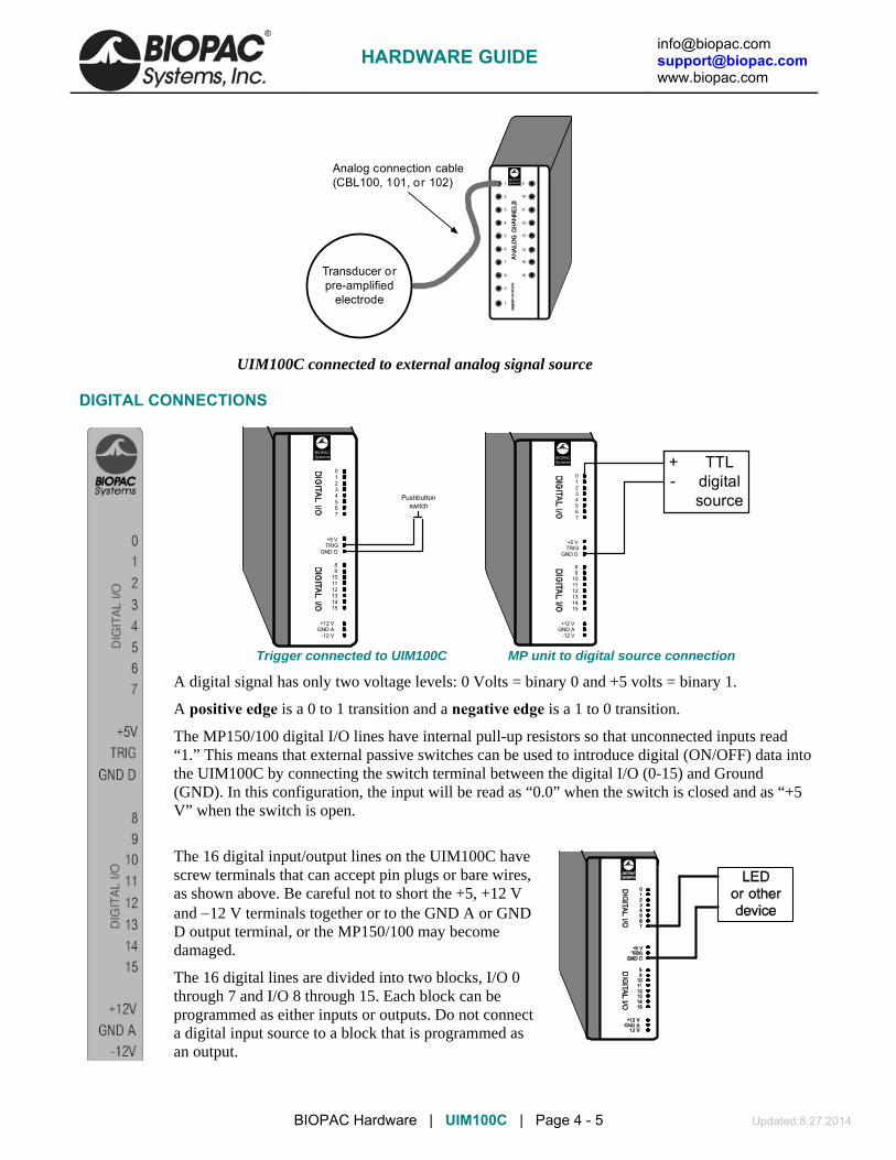
[email protected] [email protected] www.biopac.com
BIOPAC Hardware | UIM100C | Page 4 - 5 Updated:8.27.2014
1
2
3
4
5
6
7
8
9
10
12
13
14
15
16
11
0
1
BIOPACSystems
Transducer orpre-amplified
electrode
Analog connection cable(CBL100, 101, or 102)
UIM100C connected to external analog signal source
DIGITAL CONNECTIONS
BIOPACSystems
GND A+12 V
-12 V
89
101112131415
TRIG+5 V
GND D
1234567
0
Pushbuttonswitch
BIOPACSystems
GND A+12 V
-12 V
89
101112131415
TRIG+5 V
GND D
1234567
0
TTLdigitalsource
+-
Trigger connected to UIM100C MP unit to digital source connection
A digital signal has only two voltage levels: 0 Volts = binary 0 and +5 volts = binary 1.
A positive edge is a 0 to 1 transition and a negative edge is a 1 to 0 transition.
The MP150/100 digital I/O lines have internal pull-up resistors so that unconnected inputs read “1.” This means that external passive switches can be used to introduce digital (ON/OFF) data into the UIM100C by connecting the switch terminal between the digital I/O (0-15) and Ground (GND). In this configuration, the input will be read as “0.0” when the switch is closed and as “+5 V” when the switch is open.
The 16 digital input/output lines on the UIM100C have screw terminals that can accept pin plugs or bare wires, as shown above. Be careful not to short the +5, +12 V and 12 V terminals together or to the GND A or GND D output terminal, or the MP150/100 may become damaged.
The 16 digital lines are divided into two blocks, I/O 0 through 7 and I/O 8 through 15. Each block can be programmed as either inputs or outputs. Do not connect a digital input source to a block that is programmed as an output.
HARDWARE GUIDE

[email protected] [email protected] www.biopac.com
BIOPAC Hardware | UIM100C | Page 5 - 5 Updated:8.27.2014
Output devices (such as leads or an LED) can be connected to the digital side of the UIM100C. Outputs can be connected so that they are “ON” either when a signal output from the UIM100C reads 0 Volts or when a +5 V signal is being output.
When connecting to an LED, be sure to use a current-limiting resistor (typically 330 ) in series with the LED.
To connect an LED so that it defaults to “OFF” (i.e., the digital I/O reads 0), attach one lead of the output device to the GND D terminal on the UIM100C and connect the other lead to one of the digital I/O lines (I/O 7, for example). When configured this way, the device will be “OFF” when I/O 7 reads 0, and “ON” when I/O 7 reads a digital “1” (+5 Volts).
Alternatively, connect one of the device leads to the +5 V terminal on the UIM100C and leave the other lead connected to the digital line (e.g., I/O 7). With this setup, the device will be “ON” when the I/O line (in this case digital I/O 7) reads 0, and “OFF” when the I/O reads a digital “1” (+5 Volts).
UIM100C SPECIFICATIONS Analog I/O: 16 channels (front panel) – 3.5 mm phone jacks D/A Outputs: 2 channels (front panel) – 3.5 mm phone jacks Digital I/O: 16 channels (back panel) – screw terminals External Trigger: 1 channel (back panel) – screw terminal Isolated Power: ±12 V, +5 V @ 100 ma (back panel) – screw terminals Weight: 520 g Dimensions: 7 cm (wide) x 11 cm (deep) x 19 cm (high)
HARDWARE GUIDE
[email protected] [email protected] www.biopac.com
BIOPAC Hardware | HLT100C | Page 1 - 2 Updated: 6.27.2014
HLT100C HIGH LEVEL TRANSDUCER INTERFACE MODULE The HLT100C module is used to interface all high level output transducers to the MP System. The HLT100C module provides 16 input and 2 output channels. The HLT100C is similar in function to the UIM100C Universal Interface Module, but it also provides power to the transducer when making a connection. High level output transducers and adapters connect to the HLT100C via standard 6 pin RJ11 type connectors. Transducers and adapters that presently require the HLT100C module are:
TSD109 C/F: Tri-axial Accelerometers TSD111A Heel/Toe Strike Transducer TSD115 Variable Assessment Transducer TSD116 A/B/C: Switches and Markers TSD150 A/B: Active Electrodes INISO Input Signal Isolator OUTISO Output Signal Isolator DTU100 Digital Trigger Unit (MRI Synchronization) NIBP-MRI Noninvasive Blood Pressure for MR
Alternatively, the HLT100C module can be used to connect mains powered external equipment to the MP System when the system also connects to electrodes attached to humans.
IMPORTANT USAGE NOTE To provide the maximum in subject safety and isolation, use electrically isolated signal adapters to connect mains powered external equipment (i.e., chart recorders, oscilloscopes, etc.) to the MP System. Use the INISO adapter to connect to MP analog system inputs and the OUTISO adapter to connect to analog system outputs.
HARDWARE SETUP • See also: setup notes for external devices and channel contention issues.
Connect the Digital and Analog cables from the MP150 directly to the HLT100C, then connect the UIM100C to the HLT100C. The HLT100C module must be connected on the left side of the UIM100C module. This allows the use of other amplifier modules with the UIM100C while the HLT100C is connected.
High level output transducers (e.g., TSD109 Tri-Axial Accelerometer) or active electrodes (e.g., TSD150A Active Electrode) connect via the 16 analog RJ11 jacks on the front of the HLT100C. Up to 16 analog channels can be used at the same time, as long as there are no other analog channels in use by the UIM100C module or by other BIOPAC modules.
NOTE: If active electrodes are used, it may be necessary to attach a single ground lead to the UIM100C via the GND A terminal on the back of the module.
IMPORTANT!
If contention exists, the channel data will be corrupted. For example, if four channels [Ch.1-4] were in use by the UIM100C, then only 12 channels [Ch. 5-16] could be used by the HLT100C.
HARDWARE GUIDE

[email protected] [email protected] www.biopac.com
BIOPAC Hardware | HLT100C | Page 2 - 2 Updated: 6.27.2014
HLT100C SPECIFICATIONS Transducer Inputs: 16 channels (front panel) – RJ11 jacks System D/A Outputs: 2 channels (front panel) – RJ11 jacks Isolated Power Access: ±12 V, +5 V @ 100 ma (via all RJ11 jacks) Weight: 540 grams Dimensions: 7 cm (wide) x 11 cm (deep) x 19 cm (high) Pin-outs:
HARDWARE GUIDE

[email protected] [email protected] www.biopac.com
MP Research System | Signal Isolators | Page 1 - 1 Updated: 7.12.2012
SIGNAL ISOLATORS
INISO and OUTISO shown with HLT100C
These analog signal isolators are used to connect mains powered external laboratory equipment to the MP System when it also connects to electrodes attached to humans. Each signal isolator comes with an RJ11 cable for connection to the HLT100C module.
For digital (TTL compatible) isolation to the MP digital I/O ports, use the STP100C optical interface.
If the MP System does not electrically connect to human subjects, signal connections to external equipment can be made through the UIM100C module and the respective analog or digital connection cable.
INISO INPUT SIGNAL ISOLATED ADAPTER Use the INISO to connect external equipment outputs to MP analog input channels. The INISO plugs directly into any of the 16 input channels on the HLT100C module and incorporates a 3.5mm phone jack for signal input connections. Select the appropriate analog connection cable to connect to the external equipment’s output.
See also: Setup notes for external devices and channel contention issues.
OUTISO OUTPUT SIGNAL ISOLATED ADAPTER Use the OUTISO to connect MP analog signal outputs (amplifier and D/A) to external equipment inputs. The OUTISO plugs directly into any of the 16 signal output channels, plus the two D/A outputs, on the HLT100C module and incorporates a 3.5 mm phone jack for signal output connections. The OUTISO is very useful when the biopotential amplifier output signal requires routing to external equipment while being sampled by the MP System. Select the appropriate analog connection cable to connect to the external equipment’s input.
INISO AND OUTISO SPECIFICATIONS Isolator Type: Analog Bandwidth: DC to 50 kHz Input/Output Range: ±10 V Input Resistance: 200K Ω Output Resistance: 120 Ω Output Current: ±5 mA Offset Voltage: ±20 mV (nominal) Temperature Drift: 200 µV/°C (nominal) Noise: 2.5 mV (rms)
Isolation Voltage: 1500 VDC Isolation Capacitance: 30 pF Connector: 3.5 mm mono phone jack Weight: 50 g Dimensions: 2.6 cm (high) x 2.6 cm (wide) x 7.6 cm
(long) Included Cable: 2.1 m (straight through, M/M, 6 pin,
RJ11) Interface: HLT100C
HARDWARE GUIDE

[email protected] [email protected] www.biopac.com
BIOPAC Hardware | MOBITA-W | Page 1 - 3 Updated: 6.27.2014
MOBITA-W MOBILE BIOPOTENTIAL SYSTEM MOBITA-EEG-W 32-Channel Mobile EEG System
MB-CAP Series: MB32-EEG-CAP-A, MB 12+20-CAP, MB-20EEG-CAP-B
Mobita Overview • The flexible Mobita® system is fully integrated
with AcqKnowledge, records up to 32 channels of EEG data at up to 2K s/s, is battery operated, and fits in the palm of your hand.
• Stream data live into AcqKnowledge or log data for later upload.
Mobita® is a new wearable physiological signal amplifier system that can record up to 32 channels of high-fidelity wireless biopotential data, including: ECG, EEG, EGG, EMG and EOG data. The system includes the Mobita hardware and electrode leads and is fully integrated with AcqKnowledge software. The system can either telemeter data back to a computer running AcqKnowledge for real-time display and analysis of the signals, or record it locally for later download. Easily switch between live or logging modes to suit your research protocol. Mobita® is uniquely suited to record biopotentials for a variety of applications, such as exercise physiology) gait and movement analysis), brain-computer interfacing, psychology, neuromarketing, sports, ambulatory testing, and many more.
Mobita® can record many different signal types. Quickly change the electrode configuration or signal type by swapping out the ConfiCapTM. ConfiCapTM allows you to quickly change the configurations of the inputs for specific applications (i.e. 32-ch EEG, EMG, or combinations of ECG/EMG/EEG, etc.), customize your own design or create research protocol driven configurations. Simply disconnect one header and snap on a new configuration for a completely different application. Each channel is single-ended and AcqKnowledge is easily configured to create unique montages and combinations of signals. Record a 12-lead ECG while recording EEG and EMG data all with the same device. With AcqKnowledge and Mobita®, the system is quickly configured to do the work of multiple systems without the added cost of multiple amplifiers. Mobita® is battery operated, rechargeable and its compact size, integrated WiFi connectivity and impressive flexibility combine to create the ultimate solution in a mobile physiologic measurement device. Rugged construction makes the Mobita® system well suited for tough and demanding measurement situations like sports, movement analysis, brain-computer interfacing, home-based ambulatory testing and more!
System Options MOBITA-W Mobile Biopotential System Complete system includes the Mobita hardware unit and one ConfiCap configuration of user’s choosing (MB-32EEG-CAP-A, MB-12+20-CAP, or MB-20EEG-CAP-B), along with AcqKnowledge software and accessories.
MOBITA-EEG-W 32-Channel Mobile Biopotential System The system includes the Mobita hardware unit and one ConfiCap with medium 32-channel EEG cap and water electrodes – no gel required (MB-20EEG-CAP-A) along with AcqKnowledge software and accessories – other cap sizes available.
The device includes a trigger channel that can be used to synchronize the system with other devices or data streams. When the onboard accelerometer is used with AcqKnowledge’s Actigraphy feature, it is possible to evaluate a subject’s activity levels.
HARDWARE GUIDE

[email protected] [email protected] www.biopac.com
BIOPAC Hardware | MOBITA-W | Page 2 - 3 Updated: 6.27.2014
ConfiCap™ Options
Mobita ConfiCap Connection
EEG 32 Channel ConfiCap – MB-32EEG-CAP-A The MB-32EEG-CAP-A is a complete assembly for the Mobita wearable biopotential system that interfaces with a 32-channel electrode cap. This particular EEG cap uses water electrodes, which eliminates the need for gel. The assembly also includes a trigger connector for synchronization with other devices. The Mobita supports TTL trigger inputs from third-party hardware. The electrodes terminate in a Mobita conf-cap connector. Snap the assembly to the Mobita unit and attach the cap to a subject to record 32 channels of data for either in laboratory telemetry or remote data logging applications. 12 Surface Electrodes + 20 TP Adapters – MB-12+20-CAP The MB-12+20-CAP is a complete assembly for the Mobita wearable biopotential system that interfaces with 12 snap fit electrode leads and 20 touch proof sockets. Record 32 channels of biopotential data using a variety of electrode configurations including both disposable and reusable options. Connect to the Mobita and the subject and record 32 channels of data for either in laboratory telemetry or remote data logging applications. Snap the assembly to the Mobita unit and attach the cap to a subject to record 32 channels of data for either in laboratory telemetry or remote data logging applications. EEG 10/20 + 13 TP Adapters – MB-20EEG-CAP-B The MB-20EEG-CAP-B is a complete assembly for the Mobita wearable biopotential system that interfaces with a 10/20 electrode cap and Touchproof sockets for adding additional signals.
This combination interface allows for a full 10/20 EEG, plus optional biopotential signals for EOG, EMG, and ECG. Snap the assembly to the Mobita unit and attach the cap to a subject to record 32 channels of data for either in laboratory telemetry or remote data logging applications.
The EEG cap connects via a dSub connector for the quick connection of different size caps. Ships with medium cap; other sizes available. Additional electrodes are interfaced via the standard Touchproof sockets.
Breakout boxes are available. Contact BIOPAC for more information.
Analyze with AcqKnowledge • Powerful automated analysis routines for ECG, HRV, EEG, EMG, EGG, and many more! • Intuitive user interface with fully customizable display • Video Tutorials on key features and analysis routines • Guided channel and acquisition setup with presets and quickstarts
Featured Applications 32 channels of biopotential data with 3D accelerometer and trigger channel for:
• Psychophysiology • Neuroscience • Exercise Physiology • Gait Analysis
• Brain Computer Interface • Sleep Studies • Ambulatory Monitoring
HARDWARE GUIDE

[email protected] [email protected] www.biopac.com
BIOPAC Hardware | MOBITA-W | Page 3 - 3 Updated: 6.27.2014
Key Features • Up to 32 channels of wireless biopotential
data • Fully-integrated in AcqKnowledge®
software • No cable movement artifacts • True DC recording • 24 bit data resolution • Flash disk recording (up to 16 GB) for data
back-up and holter applications
• Built-in WiFi telemetry (range typical > 10 m indoors)
• Rechargeable Li-Po battery • Rugged construction: sturdy, dustproof enclosure • Built-in 3D accelerometer for position information • No filtering (including Notch filter) for true
unadulterated signal quality
Computer Requirements Computer should be running Windows 7 64-bit or Windows 8 64-bit with a Core i5 or a Core i7 processor. No support is provided for any operating systems older than Windows 7.NOTE: Slower computers may be able to use WiFi mode with the Mobita, but it may not be possible to transfer
or import the logged data.
Specifications Sampling Resolution: 24.414 nV/bit, referred to input Sampling rate: 2000, 1000, 500, 250 Hz Channel bandwidth: DC up to 0.2 x sample frequency Inputs Input signal difference: 409.6 mVpp Input common mode range: -2.0 V – +2.0 V Gain factor: 10 Noise: < 0.4 µV RMS @ 0.1 – 10 Hz Input Impedance: >10 GΩ CMRR: > 100 dB typical # of channels: Up to 32 analog Power supply: Battery Li-Polymer with protection circuit Filtering Filter: No filtering within channel bandwidth Connectors: Individually shielded inputs Type: Unipolar, bipolar (user configurable from unipolar inputs) Trigger: Either trigger (TTL) or generic (e.g. RS232 compatible) digital inputs possible
through custom designed ConfiCap Accelerometer Range: ± 16 g Resolution: 13 bit Sensitivity: 3.9 mg/bit Dimensions: 150 x 70 x 25 mm (with ConfiCap attached)
HARDWARE GUIDE

[email protected] [email protected] www.biopac.com
BIOPAC Hardware | BioNomadix Series | Page 1 - 24 Updated: 3.11.2015
BIONOMADIX SERIES
The BioNomadix system is a wireless, multi-channel physiological recording platform. Its untethered design allows for nearly unlimited freedom of movement and unsurpassed comfort, enabling subjects to easily relax into their protocol. There are twelve different BioNomadix modules sets, each consisting of a matched transmitter and receiver specifically optimized for desired physiological signals. Multiple BioNomadix module sets (typically eight maximum) can be used to create a customized BioNomadix system.
Each BioNomadix module set is capable of recording of two independent channels, with the exception of the Accelerometer module, which records three channels.
BIONOMADIX TRANSMITTER AND RECEIVER SETS BN-ACCL3 BioNomadix Accelerometer BN-ECG2 BioNomadix 2-Channel ECG BN-EEG2 BioNomadix 2-Channel EEG BN- EGG2 BioNomadix 2-Channel EGG BN- EMG2 BioNomadix 2-Channel EMG BN- PPGED BioNomadix PPG and EDA BN-GONIO BioNomadix 2-Channel Goniometry
BN-DYNEMG BioNomadix Dynamometry and EMG BN- EOG2 BioNomadix 2-Channel EOG BN-NICO BioNomadix Cardiac Output
BN-RSP2 BioNomadix 2-Channel Respiration BN-RSPEC BioNomadix RSP and ECG BN-SKT2 BioNomadix 2-Channel Skin Temp
BN-STRIKE BioNomadix 2-Channel Heel/Toe Strike
BioNomadix BN-GYRO-75 and BN-GYRO-300 Angular Rate Sensors are discontinued items.
BIONOMADIX TRANSMITTER ONLY BN-ACCL3-T Accelerometer BN-ECG2-T 2-Channel ECG BN-EEG2-T 2-Channel EEG BN- EGG2-T 2-Channel EGG BN- EMG2-T 2-Channel EMG BN- PPGED-T PPG and EDA BN-GONIO-T Goniometry
BN-DYNEMG-T Dynamometry and EMG BN- EOG2-T 2-Channel EOG BN-NICO-T Cardiac Output BN-RSP2-T 2-Channel Respiration BN-RSPEC-T RSP and ECG BN-SKT2-T 2-Channel Skin Temp BN-STRIKE-T 2-Channel Heel/Toe Strike
BIONOMADIX LOGGER (BN-LOGGER)
BioNomadix Loggers wirelessly record physiological data from up to three dual-channel wearable BioNomadix Transmitters* plus a built-in accelerometer, as subjects freely and naturally live their lives. Get the real-world data your application demands. The compact Logger device provides a color display for visual feedback, speaker for auditory feedback, vibration for haptic feedback, voice journal for participant comments, event markers, and alarms.
Sync Transmitters to the Logger for data logging mode or telemeter live data back to a computer running AcqKnowledge software. Sync the BioNomadix Logger with GPS for a correlation between physiological and location data.
Use as a stand-alone system with AcqKnowledge or combine with BioNomadix wireless Receiver sets. Includes micro-USB to USB cable for charging/data transfer, AC Charger and belt case.
*Existing BioNomadix devices require a firmware upgrade to be compatible with Loggers—please contact BIOPAC for details.
BioNomadix Logger Specifications Weight: 121.2 grams Transmitter: Ultra-low power 2.4 GHz bi-directional digital RF transmitter
Dimensions: 9.42 cm x 5.76 cm x 2.3 cm Rate: 2 kHz, maximum
Screen: Color, 6 cm diagonal Operational range: 1 meter (line of sight, approx.)
Memory: 8 GB Charger: Integrated USB charger with AC wall adapter BN-LOG-CHRG
Battery: 1800 mAh Lithium-ion
Operating time: 24 hours (recording)
Compliance: FC, CE, IC, VCCI -FCC Part 15 B FCC ID: ZWIBNXT1, IC: 9901A-BNXT1
HARDWARE GUIDE

[email protected] [email protected] www.biopac.com
BIOPAC Hardware | BioNomadix Series | Page 2 - 24 Updated: 3.11.2015
BIONOMADIX ELECTRODE LEAD SET BN-EL15-LEAD2 Electrode Lead 2 x 15 cm to BioNomadix BN-EL15-LEAD3 Electrode Lead 3 x 15 cm to BioNomadix BN-EL30-LEAD2 Electrode Lead 2 x 30 cm to BioNomadix BN-EL30-LEAD3 Electrode Lead 3 x 30 cm to BioNomadix BN-EL45-LEAD2 Electrode Lead 2 x 45 cm to BioNomadix BN-EL45-LEAD3 Electrode Lead 3 x 45 cm to BioNomadix BN-EL50-LEAD2 Electrode Lead 2 x 50 cm to BioNomadix BN-NICO BN-EL50-LEAD4 Electrode Lead 4 x 50 cm to BioNomadix BN-NICO BN-EDA-LEAD2 EDA Electrode Lead to BioNomadix BN-PPGED BN-ADAPT-2 Adapter 2 x 10 cm for connecting Touchproof leads to BN Transmitter BN-ADAPT-3 Adapter 3 x 10 cm for connecting Touchproof leads to BN Transmitter
BIONOMADIX TRANSDUCERS BN-PULSE-XDCR Pulse Transducer for BioNomadix BN-PPGED BN-PULSEEAR-XDR Pulse Earclip Transducer for BioNomadix BN-PPGED BN-RESP-XDCR Respiration Transducer for BioNomadix BN-RSP2 or BN-RSPEC BN-TEMP-A-XDCR Skin Temp Skin Transducer for BioNomadix BN-SKT2 BN-TEMP-B-XDCR Fast-Response Temp Transducer for BioNomadix BN-SKT2 BN-STRIKE-XDCR Heel-Toe Strike Transducer for BioNomadix BN-STRIKE BN-GON-110-XDCR Twin-axis Goniometer Transducer for BioNomadix BN-GONIO BN-GON-150-XDCR Twin-axis Goniometer Transducer for BioNomadix BN-GONIO BN-TOR-110-XDCR Single-axis Torsiometer Transducer for BioNomadix BN-GONIO BN-TOR-150-XDCR Single-axis Torsiometer Transducer for BioNomadix BN-GONIO BN-GON-F-XDCR Single-axis Goniometer Transducer for BioNomadix BN-GONIO
BIONOMADIX ACCESSORIES
Shirts BN-SHIRT-XS BioNomadix Shirt - XS BN-SHIRT-S BioNomadix Shirt - Small BN-SHIRT-M BioNomadix Shirt - Medium
BN-SHIRT-L BioNomadix Shirt - Large BN-SHIRT-XL BioNomadix Shirt - XL
Straps RXSTRAPBN-20 BioNomadix Strap 20 cm x 25.4 mm RXSTRAPBN-33 BioNomadix Strap 33 cm x 25.4 mm RXSTRAPBN-76 BioNomadix Strap 76 cm x 25.4 mm RXSTRAPBN-137 BioNomadix Strap 137 cm x 25.4 mm
EEG Caps (for BN-EEG2) BN-EEGCAP-SYS BioNomadix 10/20 EEG Cap System BN-CAP-SMALL BioNomadix EEG Cap – Small (50-54 cm) BN-CAP-MEDIUM BioNomadix EEG Cap – Medium (54-58 cm) BN-CAP-LARGE BioNomadix EEG Cap – Large (58-62 cm)
Charger
BN-BAT-CHRG BioNomadix Battery Charger – full charge lasts approx. 72 hours, Transmitter batteries will last 500 charge/discharge cycles—or approximately 35,000 hours!
HARDWARE GUIDE

[email protected] [email protected] www.biopac.com
BIOPAC Hardware | BioNomadix Series | Page 3 - 24 Updated: 3.11.2015
SETUP OVERVIEW
1. Setup the BioNomadix transmitter with subject.
2. Setup the BioNomadix receiver.
3. Setup the software.
HARDWARE SETUP
Transmitter and Receiver units are shipped as a matched pair and must always be used as a pair (see serial number and ID sync options). Up to 16 channels per BioNomadix system can be monitored simultaneously, returning data quality equal to standard BIOPAC MP modules. Normal operating range between transmitter and receiver is 10 meters line of sight in standard laboratory environments. For additional guidelines, see BioNomadix Operational Range and Characteristics on page 10.
BIONOMADIX TRANSMITTER
Setup
1. Connect the electrode lead set or transducer to the BioNomadix Transmitter module inputs. Squeeze lock connector and push until it clicks into place. CH A and CH B require an appropriate lead set or transducer based on signal type.
2. Attach electrodes and electrode leads or transducer to the Subject Position.
3. Secure the Transmitter module on Subject, (i.e. with a strap, or inside a BioNomadix shirt pocket).
For optimum results, the BioNomadix Custom Sport Shirt is recommended. This specially-designed shirt is made of a lightweight material with numerous “pockets” for housing multiple transmitters. The BioNomadix shirt incorporates zippered openings for positioning electrode leads properly.
4. Set the power switch on the BioNomadix Transmitter to ON. The Status light will flash sequences based upon connectivity and battery life.
5. Double blinks occurring every two seconds indicate successful pairing and normal operation between transmitter and receiver.
CONTROLS
ID: Press to illuminate Status light of matching Receiver unit.
On/Off: Power switch for the transmitter. The transmitter power must be turned OFF for charging.
Status: Solid amber when battery power is low. Approximately one hour of operation remains after light turns amber, full-charge with BN-BAT-CGR battery charger typically requires one hour.
Channels: Connect the electrode leads to the matched BioNomadix Transmitter module inputs. (Squeeze lock connector and push until it clicks into place).
BIONOMADIX RECEIVER BEFORE BEGINNING:
Decide whether one or both available channels will be used. (If using only one channel, set “A” to ON and “B” to OFF.)
Decide which channel bank will be used and select “X” or “Y.”
Set channel slider to correct position.
Attach Receiver unit to the right side of the MP150 unit, or the left side of the IPS100C. The Status light will turn green when communicating with transmitter. As with standard BIOPAC hardware, additional modules can be attached to the receiver.
Set desired channel options on the Receiver module.
HARDWARE GUIDE

[email protected] [email protected] www.biopac.com
BIOPAC Hardware | BioNomadix Series | Page 4 - 24 Updated: 3.11.2015
The RSPEC Receiver unit is depicted, but controls operate similarly for all units.
Wireless antenna input Receiver LED: Steady green when paired with transmitter. Blinks amber once per second when communication is interrupted.
Input Signals: A = B = “A” Assigns the input signals for channels 1-8. “B” Assigns the input signals for channels 9-16.
On/Off Enables or disables module channels: “A” channels 1-8 “B” channels 9-16.
X/Y channel banks Selects between “X” channel bank or “Y” channel bank. “A” X bank is 1-4, Y bank is 5-8. “B” X bank is 9-12, Y bank 13-16. NOTE: “A” or “B” banks that are turned off will free up those associated Analog channels for use by other signal types.
Cal: Recessed Calibration button. NOTE: Calibration is not required, most users can use factory presets. Calibration is an advanced procedure.
TRANSMITTER BATTERY LIFE Transmitter battery life is described below as a change of color in the sequence of LED flashes.
LED Color Pattern Charge %
green green green green 75% - 100% yellow green green green 50% - 75% yellow yellow green green 25% - 50% yellow yellow yellow green 5% - 25% yellow yellow yellow yellow < 5%
IMPORTANT: If the transmitter is to be stored for prolonged periods, it is strongly recommended that the battery be fully charged and the transmitter turned off prior to storage. Failure to do so may result in permanent damage to the battery.
SOFTWARE SETUP Recording data with AcqKnowledge software
After completing setup, click Start in the AcqKnowledge software to begin recording data.
If the paired signal is interrupted due to electrical interference or a subject wandering out of range, the most recently-acquired data point will be retained, with normal acquisition continuing once communication is reestablished. See also: BioNomadix Operational Range and Transmission Characteristics.
HARDWARE GUIDE

[email protected] [email protected] www.biopac.com
BIOPAC Hardware | BioNomadix Series | Page 5 - 24 Updated: 3.11.2015
FULL BIONOMADIX MODULE SPECS Table 1: BioNomadix Dual Biopotential Pairs – See Table 2 for Transducer or Combo, and Table 3 for Accelerometer
BioNomadix Pair BN-ECG2 BN-EEG2 BN-EGG2 BN-EMG2 BN-EOG2
Signal type: Dual Channel ECG Dual Channel EEG Dual Channel EGG Dual Channel EMG Dual Channel EOG
Bandlimits Max:
Factory preset:
Filter options:
Alternative signal:
0.05 Hz to 150 Hz
1 Hz to 35 Hz
0.05 or 1 Hz HP, 35 or 150 Hz LP
Heart Rate Mode
0.1 Hz to 100 Hz
0.5 Hz to 35 Hz
0.1 or 0.5 Hz HP, 35 or 100 Hz LP
Delta, Theta, Alpha, Beta
0.005 Hz to 1.0 Hz
0.005 Hz to 1.0 Hz
0.005 Hz HP, 1 Hz LP
5 Hz to 500 Hz
10 Hz to 500 Hz
5 or 10 Hz HP, 250 or 500 Hz LP
Envelope Detection Mode
0.005 Hz to 100 Hz
0.005 Hz to 35 Hz
0.005 or 1 Hz HP, 35 or 100 Hz LP
Derivative Mode
Notch filter: 50/60 Hz user-controlled switch; typically not required—factory preset OFF. See Appendix for more hardware-specific output options.
Noise Voltage (shorted inputs):
0.9 µV rms (bandwidth of 0.05 Hz to 150 Hz)
0.2 µV rms (bandwidth of 0.10 Hz to 100 Hz)
0.5 µV rms (bandwidth of 0.005 Hz to 1 Hz)
1.5 µV rms (bandwidth of 1.0 Hz to 500 Hz)
0.9 µV rms (bandwidth of 0.005 Hz to 100 Hz)
Input Voltage Range: up to 10 mV P-P up to 2 mV P-P up to 10 mV P-P up to 10 mV P-P up to 10 mV P-P
Output Voltage Range: ±10 V (receiver output)
CMRR 110 dB typical at 50/60Hz; 90dB minimum for ECG, EEG, EMG, and EOG, 100 db minimum for EGG
CMII 1000 MΩ (50/60 Hz)
Fixed Gain: 2,000 10,000 2,000 2,000 2,000
Operating Time: 72-90 hours
Included strap: 137 cm - BN-STRAP137 76 cm - BN-STRAP76 137 cm - BN-STRAP137 33 cm - BN-STRAP33 76 cm – BN-STRAP76
Size & Weight: Transmitter (approx.): 6 cm x 4 cm x 2 cm; 54 grams; Receiver (approx).: 4 cm x 11 cm x 19 cm; 380 grams
Input: See BioNomadix electrode lead cable options (BN-ELxx-LEADx). Each biopotential transmitter requires at least one GND. To eliminate redundant biopotential GND, use a 3-lead electrode lead cable for one input (CH A or B) and a 2-lead electrode lead cable for the other input (CH A or B) on each BioNomadix transmitter.
HARDWARE GUIDE

[email protected] [email protected] www.biopac.com
BIOPAC Hardware | BioNomadix Series | Page 6 - 24 Updated: 3.11.2015
Table 2: BioNomadix Dual Transducer – See Table 1 for Biopotentials, and Table 3 for Accelerometer
BioNomadix BN-SKT2 BN-RSP2 BN-GONIO BN-STRIKE
Signal type: Dual Channel SKT temp Dual Channel RSP resp Dual Channel Goniometry Dual Channel Strike Data
BandlimitsMax: Factory preset: Filter Options:
DC to 10 Hz DC to 1 Hz DC, 0.5 Hz HP, 1 or 10 Hz LP
DC to 10 Hz DC to 1 Hz DC, 0.5 Hz HP, 1 or 10 Hz LP
DC to 100 Hz DC to 10 Hz DC, 3 Hz or 100 Hz LP
DC to 100 Hz DC to 10 Hz DC, 3 Hz or 100 Hz LP
Notch filter: 50/60 Hz user-controlled switch; typically not required—factory preset OFF. See Appendix for additional hardware-specific output options.
50/60 Hz user-controlled switch – factory preset OFF
Resolution: 0.01° C (rms) FSR/4096; (4.88 mV) 0.1 rotation (rms) N/A
Signal range: 13 to 51° C ± 10 V (at output) ± 180 ± 10 V (at output)
Output Voltage range: ± 10 V (receiver output)
Operating time: 72-90 hours
Included strap: 137 cm - BN-STRAP-137 137 cm - BN-STRAP-137 76 cm - BN-STRAP-76 & BN-STRAP-33
33 cm - BN-STRAP-33
Input: BN-TEMP-A/B-XDCR BN-RESP-XDCR BN-GON-110-XDCR BN-GON-150-XDCR BN-GON-F-XDCR BN-TOR-100-XDCR BN-TOR-150-XDCR
BN-STRIKE-XDCR
HARDWARE GUIDE

[email protected] [email protected] www.biopac.com
BIOPAC Hardware | BioNomadix Series | Page 7 - 24 Updated: 3.11.2015
Table 3: BioNomadix Combo Pairs – See Table 1 for Biopotentials, Table 2 for Dual Transducer and Table 4 for Accelerometer
BioNomadix BN-RSPEC BN-PPGED BN-NICO BN-DYNEMG
Signal type: RSP plus ECG PPG plus EDA Z and dZ/dt Dynamometry plus EMG
BandlimitsMax: Factory preset: Filter Options:
Respiration (CH A): see BN-RSP2 spec ECG (CH B) : see BN-ECG2 spec
Both: DC to 10 Hz: PPG: 0.5 Hz to 3 Hz EDA: DC to 3 Hz Both: DC, 0.5 Hz HP, 3 or 10 Hz LP EDA: 1 Hz LP
Both: DC to 10 Hz Both: DC to 10 Hz DC, 1, 3, 5, 10 Hz LP
Dyn: DC 100 Hz Dyn: DC to 10 Hz Dyn: DC, 3 Hz, 10 Hz, or 100 Hz LP EMG: see BN-EMG2 specs
Notch filter: 50/60 Hz user-controlled switch; typically not required—factory preset OFF. See Appendix for additional hardware-specific output options.
Resolution: see BN-RSP2 and BN-ECG2
specs
PPG: FSR/4096; (4.88 mV) EDA: 0.012 µS (min step)
Z: nominally ~0.05 Ω (rms) at 10 Hz BW dZ/dt: ~0.01 Ω/sec (rms) at 10 Hz BW
Dyn: 35 micro kg-f/cm2 (0.0005 psi) (rms) EMG: see BN-EMG specs
Signal range: see BN-RSP2 and BN-ECG2 specs
PPG: ±10 V (at output) EDA: 0 to 50 µS; excitation: 0.5 V constant V
Z: 5 to 100 Ω (mag) dZ/dt: ±10 Ω/sec
Dyn: 0 – 1.055 kg-f/cm2 EMG: up to 10 mV P-P
Output Voltage range: ± 10 V (receiver output)
Operating time: 72-90 hours 24 hours 24 hours 75 hours
Included strap: 137 cm - BN-STRAP137 33 cm - BN-STRAP33 137 cm - BN-STRAP137 33 cm - BN-STRAP-33
Input: CH A: BN-RESP-XDCR CH B: BN-ELxx-LEAD3
CH A: BN-PULSE-XDCR CH B: BN-EDA-LEAD2
2 x BN-EL50-LEAD4 (or 2 x BN-EL50-LEAD2)
CH A: BN-CLENCH-XDCR CH B: BN-ELxx-LEAD3
HARDWARE GUIDE

[email protected] [email protected] www.biopac.com
BIOPAC Hardware | BioNomadix Series | Page 8 - 24 Updated: 3.11.2015
Table 4: BioNomadix Accelerometer– See Table 1-2 for Biopotentials and Table 3 for Transducer or Combo BioNomadix BN-ACCL3
Signal type: G (X, Y, Z)
Bandlimits Max: Factory preset: Filter Options: Alternative signal:
±2, ±4, ±8 or ±16 G ± 16 G at 400 Hz LP DC to 3.13 Hz LP up to 400 Hz LP (in power of 2 steps) Tap Event Mark Mode (replaces G)
Resolution: X: 5 mg rms, Y: 6 mg rms, Z: 9 mg (rms) (±2 G scale at 400 Hz LP)
Signal range: Selectable: ±2, ±4, ±8 or ±16 G
Output Voltage range: ±10 V (receiver output)
Operating time: 72-90 hours
Included strap: 33 cm - BN-STRAP33
Input: Attach BioNomadix transmitter to subject – no additional hardware input required; sensor is internal to transmitter.
Operational Range: 10 meters (line-of-sight) typical in standard laboratory setups. See also: Operational Range and Characteristics.
Delay: Large fixed component (12.5 ms) and small variable component (±0.5 ms)
Operating Temp & Humidity: Temperature: 5-45 C Humidity: 95% non-condensing
Size & Weight: Transmitter: (approx.): 6 cm x 4 cm x 2 cm: 54 grams Receiver: (approx.): 4 cm x 11 cm x 19 cm: 380 grams
Transmitter: Type: Ultra-low power, 2.4 GHz bi-directional digital RF transmitter Rate: 2,000 Hz (between transmitter and receiver)
Receiver Power: Use with an MP Research System or with isolated power supply IPS100C for 3rd-party data acquisition system.
Battery & Charger: BioNomadix transmitters use an L-ion battery: full charge takes approx. 1 hour to provide maximum operating time. A battery charger is included with each module pair. See BN-CHARGER for charge time and recharge cycle details.
Compliance: FCC, , IC, - FCC Part 15 B - FCC ID: receiver: ZWIBNXR1, transmitter ZWIBNXT1 IC: receiver: 9901A-BNXR1, transmitter: 9901A-BNXT1
Table 5: Common Specs
HARDWARE GUIDE

[email protected] [email protected] www.biopac.com
BIOPAC Hardware | BioNomadix Series | Page 9 - 24 Updated: 3.11.2015
BIONOMADIX ELECTRODE LEADS All BioNomadix electrode leads use lightweight, insulated tinsel wire 1.25 mm OD with female mini-pinch clips and squeeze lock connectors
2-LEAD BIONOMADIX ELECTRODES LEADS
Lead wires: 2 (red and white)
Electrode clips: 2
Length: BN-EL15-LEAD2: 15 cm, BN-EL30-LEAD2; 30 cm, BN-EL45-LEAD2; 45 cm
Interface: Secondary channel lead for the following BioNomadix Transmitters: BN-ECG2, BN-EEG2, BN-EGG2, BN-EMG2, BN-EOG2, (first channel lead should be a BN-ELxx-LEAD3 three lead set to establish ground). Do not use for EDA or NICO!
2-LEAD FOR NICO – BN-EL50-LEAD2
Lead wires: 2 (insulated leads black)
Electrode clips: 2 (alligator clips with teeth)
Length: 50 cm
Interface: NICO CH A or CH B
To eliminate redundant ground leads for biopotentials, use 3-lead for primary input and 2-lead for secondary input for each BioNomadix unit.
3-LEAD BIONOMADIX ELECTRODES LEADS
Lead wires: 3 (red, white and black)
Electrode clips: 3
Length: BN-EL15-LEAD3; 15 cm, BN-EL30-LEAD3; 30 cm, BN-EL45-LEAD3; 45 cm
Interface: Primary and secondary channel lead for the following BioNomadix Transmitters: BN-ECG2, BN-EEG2, BN-EGG2, BN-EMG2, BN-EOG2. Do not use for EDA or NICO!
4-LEAD BIONOMADIX ELECTRODE LEADS
Leads: 4 (red x 2 and white x 2)
Electrode clips: 4
Length: BN-EL50-LEAD4; 50 cm
Interface: designed for BN-NICO: CH A or CH B (can be used with other BioNomadix biopotential transmitters)
Sample connection for BN-EL50-LEAD4 leads and EL500 paired spot electrodes (right).
EDA BIONOMADIX ELECTRODE LEADS
Leads: 2 (red and black)
Electrode clips: 2
Length: BN-EDA-LEAD2; 30 cm
Interface: Only use in CH B EDA on wireless BioNomadix Transmitter BN-PPGED
BIONOMADIX TO TOUCHPROOF ADAPTERS
Leads: 2 (red and white, BN-ADAPT-2) or 3 (red, white and black, BN-ADAPT-3)
Electrode clips: 2 (BN-ADAPT-2) or 3 (BN-ADAPT-3)
Length: 10 cm
Interface: Us these adapters to connect Touchproof electrodes to a BioNomadix transmitter.
HARDWARE GUIDE

[email protected] [email protected] www.biopac.com
BIOPAC Hardware | BioNomadix Series | Page 10 - 24 Updated: 3.11.2015
BIONOMADIX OPERATIONAL RANGE AND TRANSMISSION CHARACTERISTICS
The BioNomadix system is a very low power transmission system designed for physiological measurements in a laboratory setting. In this explanation, a BioNomadix transmitter is referred to as series BN-Tx and a BioNomadix receiver as series BN-Rx.
Primary design objectives for the BioNomadix system: 1) BN-Tx and BN-Rx units to emulate operation, as if
“attached by cable” 2) Transmission effects not to disturb physiological source 3) Classification subject to class B digital device pursuant to
FCC part 15 4) Long BN-Tx operational time, after recharge
5) Quick recharge time, under one hour 6) Bn-Tx units to be as lightweight, rugged
and small as possible 7) Minimal user setup required, simply
power up and start collecting data
BioNomadix Operational Range and Characteristics
A primary objective of the BioNomadix System is that it can not behave in a fashion that would permit any arbitrary time delay between transmitter and receiver. This objective is critical for the BioNomadix System because it insures robust time synchronization between any BN-Tx units and external hardware. Because of the requirement to “behave as though a cable connects BN-Tx and BN-Rx”, the BioNomadix System required a special and optimized protocol to insure the best possible attempts to send data, within a limited (10 sample) time frame. If data could not be sent within this time frame, then data would be replaced with the last data value sent for a short time period (for up to about one second) thereafter until finally, assuming a reconnect was not possible, the transmitted data (not received) will be identified as null (zero) values.
The BioNomadix System operational transmission range is 10 meters line-of-sight, typical, in standard laboratory environments. Operational range can vary depending on factors such as presence of electromagnetic interference, multi-path, or radio frequency signal blocking. In the event of a communications failure, BioNomadix Tx and Rx modules will attempt to re-establish communications until such communications can be re-established.
BioNomadix Tx are purposely kept at very low power so as not to disrupt the sensitive biophysical parameter measured, to enhance battery life, and to satisfy the relevant FCC regulations. If a BN-Tx and BN-Rx pair is used outside of the laboratory (without the benefit of multi-path) and if the BN-Tx is line-of-sight blocked from the BN-Rx, then communication dropouts are increasingly likely. A functional solution is to keep the BN-Tx and BN-Rx in constant line-of-site view.
BioNomadix signal performance is best with “line-of-sight” connection from transmitter unit to receiver unit. Signal dropouts happen when a conductive surface (metal or human body) is placed between the transmitter and receiver unit. If this happens, and there are no other radio frequency reflective surfaces in the room, then the radio waves can’t get from transmitter unit to receiver. This phenomenon is referred to as “body-blocking.” The solution is to place the transmitter and receiver units closer together and to eliminate potential for body-blocking. Case studies
Case 1: Multiple people wearing BioNomadix Tx units are walking around in a room and the BN-Rx units are placed in a nearby room. Periodically, when body blocking occurs, short signal dropouts are noted. Solution 1: Place the BN-Rx units, with MP150, directly above the subjects in the room. This will greatly minimize the potential for body-blocking, from Tx unit to Rx unit, as subjects move around.
Case 2: Multiple people wearing BioNomadix Tx units are sitting in a room with a central table. The BioNomadix Rx units are placed in a nearby room. Periodically, when body blocking occurs, short signal dropouts are noted. Solution 2: Mount the receiver (BN-Rx) units, with MP150, underneath the center of the table, around which the subjects are sitting. Mount a platform to the underside of the table and rest the receiver with MP150 on it. This situation places the receivers just one or two meters away from the transmitters attached to the subjects.
Case 3: Body-blocking can't be prevented. Solution 3: Consider using BIOPAC's TEL100C Telemetry System instead of the BioNomadix wireless system. The TEL100C comes standard with a 10-meter (extendable to 60 meters), thin, lightweight signal transmission cable and will not exhibit any body-blocking issues because the data is transmitted via shielded coaxial cable and is immune to any RF signal interference.
HARDWARE GUIDE

[email protected] [email protected] www.biopac.com
BIOPAC Hardware | BioNomadix Series | Page 11 - 24 Updated: 3.11.2015
BioNomadix Transducers
Pulse BioNomadix Transducer BN-PULSE-XDCR
Emitter/Detector Wavelength: 860 nm ± 60 nm
Optical LP Filter Cutoff: 800 nm
The operational range of the emitter and detector falls within the wavelength range of 800 nm to 920 nm. The filter is placed over the receiver; the filter of 800 nm is an optical lowpass, so wavelengths longer than 800 nm will pass thru.
Nominal Output: 20 mV (peak-peak)
Power: 10 mA drive current
Sterilizable: Yes (contact BIOPAC for details)
Dimensions (L x W x H): 16 mm x 17 mm x 8 mm
Transducer Weight: 4.5 grams Cable: 45 cm
Interface: only use in CH A PPG on the BioNomadix BN-PPGED
Pulse Earclip Transducer BN-PULSEEAR-XDR
Emitter/Detector Wavelength: 890 nm (nominal maximum)
Optical Low Pass Filter Cutoff ambient visible light filter
The transducer operates with the BioNomadix Pulse Transmitter (BN-PPGED) and consists of a matched infrared emitter and photo-diode, which transmits changes in infrared reflectance resulting from varying blood flow.
Wavelength: 800-1,000 nm (70% spectral response)
Nominal Output: 20 mV (peak-peak)
Power: 10 mA drive current
Sterilizable: Yes (contact BIOPAC for details)
Dimensions (L x W x H): 16 mm x 17 mm x 8 mm
Transducer Weight: 4.5 grams Cable length: 80 cm
Interface: only use in CH A PPG on the BioNomadix BN-PPGED
Respiration Transducer BN-RESP-XDCR Response: True DC
Circumference Range: 15 cm x 150 cm (increase with a longer strap)
Dimensions: 66 mm (long) x 40 mm (wide) x 15mm (thick)
Weight: 18 grams
Sterilizable: YES: use standard gas sterilization techniques [i.e., Ethylene Oxide (EtO)]
Variable Resistance Output: 5 - 125 KOhm
Cable: 30 cm
Interface: BN-RSP2 CH A RSP or CHB RSP, or BN-RSPEC CHA RSP
HARDWARE GUIDE

[email protected] [email protected] www.biopac.com
BIOPAC Hardware | BioNomadix Series | Page 12 - 24 Updated: 3.11.2015
Clench Force Transducer BN-CLENCH-XDCR Pressure Range: 0 to 1.0546 Kg-f/cm^2 (0 to 15 psi)
Error Band: ± 2% full scale
Accuracy: ±25% full scale – best fit straight line
Output: 25 mV/0.01 Kgf/cm^2 (0.176 V/psi)
Bulb Diameter: 5.8 cm
Bulb Length: 11.1 cm
Weight: 108 grams
Cable Length: 45 cm
Interface: Use with the BN-DYNEMG Dynamometer and EMG module
Heel-Toe Strike Transducer BN-STRIKE-XDCR Nominal Output Range: -1 to +1 Volt
Nominal Contact Force: 200 g to indicate heel-toe strike
Attachment: TAPE 1, TAPE 2, vinyl electrical or duct tape
FSR Dimensions: 18.3 mm (dia) x 0.36 mm (thick) and 30 cm pigtail lead
FSR Active Area: 12.7 mm diameter
Interface: BN-STRIKE transmitter (STRK A, STRK B)
Skin Temperature Transducer BN-TEMP-A-XDCR Nominal Resistance: 2252 ohm at 25° C
Maximum operating temperature: 60° C
Accuracy and Interchangeability: 0.2° C
Response Time: 1.1 sec (attached to skin)
Compatibility: YSI series 400 temperature probes
Sterilizable: YES (contact BIOPAC for details)
Cable: 30 cm
Dimensions: 9.8 mm (diameter) x 3.3 mm (high)
Interface: BN-SKT2 only: CH A SKT and/or CH B SKT
Skin Temperature Transducer BN-TEMP-B-XDCR (Fast Response) Nominal resistance: 2252 ohm @ 25° C
Maximum operating temperature: 60° C (when used with BN-SKT2)
Accuracy and Interchangeability: 0.2° C
Response Time: 0.6 sec (in air)
Compatibility: YSI series 400 temperature probes
Sterilizable: YES (contact BIOPAC for details)
Cable: 30 cm
Dimensions: 1.7 mm (diameter) x 5 mm (long)
Interface: BN-SKT2 only: CH A SKT and/or CH B SKT
HARDWARE GUIDE

[email protected] [email protected] www.biopac.com
BIOPAC Hardware | BioNomadix Series | Page 13 - 24 Updated: 3.11.2015
Goniometer & Torsiometer Transducers BN-GON-XDCR, BN-TOR-XDCR, BN-GON-F-XDCR
Use with BN-GONIO Goniometry Module.
HARDWARE GUIDE

[email protected] [email protected] www.biopac.com
BIOPAC Hardware | BioNomadix Series | Page 14 - 24 Updated: 3.11.2015
BIONOMADIX ACCESSORIES
BioNomadix Shirt
Attachment Features: 22 pockets: 2 neck front, 2 neck back, 4 chest center, 4 back center, 2 hip front, 2 hip back, 3 left arm, 3 right arm
4 zippers: right front from arm to hip, left back from shoulder to hip, right and left under arm from neck front to neck back
4 strap bands: 4 rows of strap bands (2 loops front, 2 loops back) for RSP transducer strap
Materials: Black 6 oz. eyelet mesh 88% Polyester / 12% Spandex; metal zippers
Sizes: BN-SHIRT-XS extra small BN-SHIRT-L large BN-SHIRT-S small BN-SHIRT-XL extra large BN-SHIRT-M medium
Care instructions: Machine Wash, Warm / Line Dry
BioNomadix Strap
Dimensions: Length 20 cm, 33 cm, 76, cm, 137 cm (all widths 2.5 cm) Material: stretch Velcro® - hook/loop type Use with: BioNomadix Transmitters Length: RXSTRAP-BN-20; 20 cm RX-STRAP-BN-33; 33 cm RXSTRAP-BN-76; 76 cm RXSTRAP-BN-137; 137 cm
BioNomadix 10/20 EEG Cap System
Attachment: Ribbon cable (25 cm) from cap to 19 Touchproof sockets Material: Lycra Use with: BN-EEG2 Lead adapters: BN-ADAPT-TP2 or BN-ADAPT-TP3 depending on sites to be recorded Sizes: BN-CAP-SMALL (50-54 cm,) BN-CAP-MEDIUM (54-58 cm,) BN-CAP-LARGE (58-62 cm) Components: 1 x medium cap with 19-pin ribbon cable 1 x mating cable with Touchproof connectors 2 x earclip reference electrodes 1 x blunt-tipped syringe 1 x EEG recording gel 1 x chest harness (holds cap in place) 1 x liquid soap (to wash cap after use)
WHITE TIP WIRE COLOR RED TIP Fp1 Brown Fp2 F3 Red F4 C3 Orange C4 P3 Yellow P4 01 Green 02 F7 Blue F8 T3 Violet T4 T5 Gray T6 Gnd White Cz Fz Black Pz
HARDWARE GUIDE

[email protected] [email protected] www.biopac.com
BIOPAC Hardware | BioNomadix Series | Page 15 - 24 Updated: 3.11.2015
BioNomadix Battery Charger: BN-BAT-CHRG
To charge, the BioNomadix Transmitter must be in the OFF position and have no electrode leads or transducers attached.
Connector: DC polarized squeeze-clip plug to mate with all BioNomadix Transmitters Number of cells: 1 L-ion Charger current 1000 mA (660 mA for IB-16800 Current tolerance: +10% Voltage limit: Preset Voltage limit tolerance: +0.2% Operating temperature: 0° C to 40° C Input voltage: 90 VAC to 240 VAC Frequency 50 Hz to 60 Hz Wall plug: ships with US blades; adapters available for Euro, China or Australia Output cable length: 1.7 meter (~6 feet) Connector DC polarized squeeze-clip plug to mate with all BioNomadix Transmitters Weight: 142 grams (5 oz.) Dimensions: 75 mm x 51 mm x 40 mm Lithium Ion Chemistry Termination algorithm: CCCV Termination indicated Current falls to limit value/5 Top-off charge: 1 hour or current falls to limit value/10 Restart threshold: 7/8 of termination voltage or every 2 hours Maintenance charge: N/A Charge voltage limit: Preset to 4.20 V (one L-ion cell) Override timer: None
IMPORTANT: If the transmitter is to be stored for prolonged periods, it is strongly recommended that the battery be fully charged and the transmitter turned off prior to storage. Failure to do so may result in permanent damage to the battery.
HARDWARE GUIDE

[email protected] [email protected] www.biopac.com
BIOPAC Hardware | BioNomadix Series | Page 16 - 24 Updated: 3.11.2015
BIONOMADIX COMPLIANCE STATEMENT
This device complies with part 15 of the FCC Rules. Operation is subject to the following two conditions: (1) This device may not cause harmful interference, and (2) this device must accept any interference received, including interference that may cause undesired operation.
INDUSTRY CANADA INFORMATION
Under Industry Canada regulations, this radio transmitter may only operate using an antenna of a type and maximum (or lesser) gain approved for the transmitter by Industry Canada. To reduce potential radio interference to other users, the antenna type and its gain should be so chosen that the equivalent isotropically radiated power (e.i.r.p.) is not more than that necessary for successful communication.
This radio transmitter (IC: 9901A-BNXR1) has been approved by Industry Canada to operate with the antenna types listed below with the maximum permissible gain and required antenna impedance for each antenna type indicated. Antenna types not included in this list, having a gain greater than the maximum gain indicated for that type, are strictly prohibited for use with this device.
WLAN antenna, maximum gain 1.5 dBi, 50 ohm
This device complies with Industry Canada licence-exempt RSS standard(s). Operation is subject
to the following two conditions: (1) this device may not cause interference, and (2) this device
must accept any interference, including interference that may cause undesired operation of the device.
Conformément à la réglementation d'Industrie Canada, le présent émetteur radio peut
fonctionner avec une antenne d'un type et d'un gain maximal (ou inférieur) approuvé pour
l'émetteur par Industrie Canada. Dans le but de réduire les risques de brouillage radioélectrique
à l'intention des autres utilisateurs, il faut choisir le type d'antenne et son gain de sorte que la
puissance isotrope rayonnée équivalente (p.i.r.e.) ne dépasse pas l'intensité nécessaire à
l'établissement d'une communication satisfaisante.
Le présent émetteur radio (IC: 9901A-BNXR1) de modèle s'il fait partie du matériel de catégorieI) a été approuvé par Industrie Canada pour fonctionner avec les types d'antenne énumérés ci-dessous et ayant un gain admissible maximal et l'impédance requise pour chaque type d'antenne. Les types d'antenne non inclus dans cette liste, ou dont le gain est supérieur au gain maximal indiqué, sont strictement interdits pour l'exploitation de l'émetteur.
réseau local sans fil antenne, le gain max 1.5 dBi, 50 ohm
Le présent appareil est conforme aux CNR d'Industrie Canada applicables aux appareils radio
exempts de licence. L'exploitation est autorisée aux deux conditions suivantes : (1) l'appareil ne
doit pas produire de brouillage, et (2) l'utilisateur de l'appareil doit accepter tout brouillage
radioélectrique subi, même si le brouillage est susceptible d'en compromettre le fonctionnement.
CLASS A ITE
この装置は、クラスA情報技術装置です。この装置を家庭環境で使用すると
電波妨害を引き起こすことがあります。この場合には使用者が適切な対策を
講ずるよう要求されることがあります。VCCI-A
HARDWARE GUIDE

[email protected] [email protected] www.biopac.com
BIOPAC Hardware | BioNomadix Series | Page 17 - 24 Updated: 3.11.2015
BIONOMADIX—OPTIONAL CALIBRATION
Isolated Power Supply
To use BioNomadix with the Isolated Power Supply (IPS100C), use CBL102S cable to connect the IPS100C to the Receiver output channel. This is accessible via the front panel of the IPS100C.
Signal Validation
BioNomadix units are factory calibrated, but if user-calibration is desired for measurement verification, the following steps may be used. Please see the appropriate section for BioNomadix calibration guidelines.
BN-ECG, BN-EEG, BN-EGG, BN-EMG, BN-EOG
BN-SKT
BN-GON and BN-TOR BN-EDA BN-STRIKE BN-NICO BN-DYNEMG BN-PPG and BN-RSP BN-ACCL
BN-ECG, BN-EEG, BN-EGG, BN-EMG, BN-EOG BIOPOTENTIAL CALIBRATION
Three alligator clips will be required to calibrate a Biopotential Transmitter/Receiver set.
1) Attach alligator clip to LEAD side of electrode pinch clip (see figure on right).
2) Connect black and white pinch clips together (this combination is attached to signal generator ground).
3) Connect red pinch clip to signal generator output for the Transmitter/Receiver set.
ECG, EGG, EMG, EOG
The signal generator should be set to 1 mV peak to peak sine wave in the appropriate signal frequency range for the Transmitter/Receiver set. The total gain of the Transmitter/Receiver set is 2,000. The measured output voltage from the Receiver should be 1 mV p-p * 2000 or 2 V p-p. The maximum input signal is 10 mV p-p.
EEG
The signal generator should be set to 1 mV peak to peak in the appropriate signal frequency range for the Transmitter/Receiver set. The total gain of the Transmitter/Receiver set is 10,000. The measured output voltage from the Receiver should be 1 mV p-p * 10,000 or 10 V p-p. The maximum input signal is 2 mV p-p.
HARDWARE GUIDE

[email protected] [email protected] www.biopac.com
BIOPAC Hardware | BioNomadix Series | Page 18 - 24 Updated: 3.11.2015
BN-EDA ELECTRODERMAL CALIBRATION
Transmitter/Receiver set can be calibrated by applying a known resistance (conductance) to the EDA electrode pinch connectors via alligator clips. Suggested values of conductance would be 0 µSiemens (infinite ohms – no connection) and 10 µSiemens (100 K ohms). The EDA Transmitter/Receiver set outputs +10 V for a 50 µS measured conductance. The EDA Transmitter/Receiver set will output approximately +2 V for a 10 µS measured conductance.
BN-NICO CALIBRATION
Mapping for Z: 0.8 V to 10 ohms 9 V to 100 ohms
The calibration values for Z are approximate. For a more exact calibration for Z, introduce a 10 ohm resistor between the paired leads (Iout, Vin+) and (Vin-, Iin) to simulate a 10 ohm impedance magnitude. Use a 100 ohm resistor to simulate a 100 ohm impedance magnitude. See figure at right for details: For the most accurate calibrations, use known impedances (resistances) that bracket the expected high and low values being recorded. For conventional noninvasive cardiac output measurements, optimal low impedance is 15 ohms and optimal high impedance is 40 ohms.
Mapping for dZ/dt: 0 V to 0 ohms/sec 10 V to 10 ohms/sec
The calibration values for dZ/dt can be accomplished by introducing a known and varying resistance that can be precisely set to a specific rate of change. For calibration related to cardiac output measurements, a varying resistance of ±1 ohms/seconds to ±5 ohms/second is ideal. A photonically-isolated voltage controlled resistance can be used for this calibration. A cadmium sulfide cell in parallel with a resistance of 25 ohms can be employed in conjunction with a signal generator driven LED to provide a varying light intensity to modulate the resistance of the cadmium sulfide cell.
BN-PPG AND BN-RSP PULSE AND RESPIRATION CALIBRATION
User-calibration not recommended, as the measurements performed are essentially dimensionless. However, it’s possible to calibrate the PPG Transmitter/Receiver set by introducing a variable gray-scale density pattern to the PPG probe in a dark environment. The RSP Transmitter/Receiver set can be calibrated by applying differing amounts of force to the RSP transducer/belt combination to stretch the belt over different distances.
BN-SKT SKIN TEMPERATURE CALIBRATION
Insert probe into temperature well set to the appropriate temperature. As an alternative, replace the thermistor with known temperature(s) that reflects the specific temperature(s) simulated. The temperature probe specifications are equivalent to YSI@ 400 series probes. The temperature range for the SKT Transmitter/Receiver set is 13 to 51 degrees C. Using the specified temperature probe: 13 degrees provides a -10 V output and 51 degrees provides a +10 V output.
HARDWARE GUIDE

[email protected] [email protected] www.biopac.com
BIOPAC Hardware | BioNomadix Series | Page 19 - 24 Updated: 3.11.2015
BN-GON, BN-TOR GONIOMETER CALIBRATION
This is general calibration information for all BIOPAC Goniometers and Torsiometers:
When using all goniometers and torsiometers, the minimum value of bend radius must be observed at all times, particularly when attaching and removing the sensors from the subject. Failure to do this will result in reduced unit life or failure.
The sensors have been designed to be as light as possible and the operating force to be a minimum. This permits free movement of the joint without influence by the sensors. The sensors measure the angle subtended between the endblocks. Use the software calibration features (under Setup Channels) to calibrate any of the BIOPAC series goniometers.
Each goniometer requires a DA100C amplifier, BN-GONIO, or MP3X/45 analog input per rotational axis. Accordingly, the twin axis goniometers will need two DA100C amplifiers, one BN-GONIO or two MP3X/45 analog channels to simultaneously measure both rotational axes.
Excitation voltages are factory preset for the various data acquisition platforms, however excitation voltages are user-adjustable on the DA100C. Recommended excitation is +5VDC.
1. Place goniometer with care to verify that limb/joint/torso attachment will not result in over stretch at the limits of limb/joint/torso movement
2. Put body in the first position, which brackets one end of range of movement. Press CAL 1.
3. Put body in the second position, which brackets The other end of range of movement. Press CAL 2.
BN-STRIKE HEEL-TOE STRIKE CALIBRATION
BN-Strike requires no calibration.
BN-DYNEMG CALIBRATION
The BN-DYNEMG needs consideration for calibration on pressure bulb.
The pressure bulb transducer measures applied hand grip strength, via pressure changes manifesting in the bulb, during squeezing. The units of pressure are force per unit area. The pressure bulb transducer configuration determines the factory preset scaling, typically in units of kg/m*m or kg/cm*cm. If another or different calibration required, the following method can be used.
To calibrate:
1. Place bulb on flat, stable, drawing surface
2. Press CAL 1 - enter 0 kg/unit area
3. Place known weight on bulb (X- kg)
4. Use pencil to outline flattened portion of bulb on table, then slide bulb weight to the IDE to measure flattened area outline, record this value as area "A"
5. Press CAL 2 - enter X/A kg/unit area
HARDWARE GUIDE

[email protected] [email protected] www.biopac.com
BIOPAC Hardware | BioNomadix Series | Page 20 - 24 Updated: 3.11.2015
BN-ACCL ACCELEROMETER CALIBRATION
Orient Transmitter unit in the X, Y, and Z directions with respect to Earth’s gravity. This action will introduce 1 G in positive axis direction and -1 G in the negative axis direction. The accelerometer Transmitter/Receiver set has user-selectable ranges: ±2, ±4, ±8 or ±16 G. The maximum value of each range selection provides a +10 V output and the minimum value of each range selection provides a -10 V output. When using the ±2 G range, a + 1 G input will provide a +5 V output and a -1 G input will provide a -5 V output, when properly scaled.
The BN-ACCL has a factory default of ±16 G. Use the DIP switches on the side of the BN-ACCL Receiver Module to set the Transmitter to the desired range. If the range needs to be set to something other than ±16 G, perform the following steps prior to calibration using Earth’s gravity, as described in the previous paragraph.
1. In AcqKnowledge, select “Set Up Data Acquisition > Channels.”
2. Select “View by Modules...” and add new module “ACCL3-R,” assuming not yet added.
3. Select the desired X, Y and Z channels and click OK (see right).
4. Then select “View by Channels...”. Click the “Setup” button.
5. Click “Yes” to the channel scaling modification prompt.
6. Set desired Scaling as shown in the following table and click OK:
±16 G Range ±8 G Range
±4 G Range ±2 G Range
HARDWARE GUIDE

[email protected] [email protected] www.biopac.com
BIOPAC Hardware | BioNomadix Series | Page 21 - 24 Updated: 3.11.2015
Switches are on the back of the BioNomadix receiver. Adjust switch position with a small tipped screwdriver.
Switch positions: “UP” = ON, DOWN” = OFF
NOTE: If the switch settings are modified, preset MP150 module setup cannot be used and and channels must be configured manually.
Mains Notch Filter All modules except ACCL3 and
NICO Notch Filter SW1 SW2 60 Hz UP DOWN 50 Hz UP UP OFF DOWN* DOWN or UP
*indicates Factory Preset
FILTER OPTION SWITCH GUIDE
BioNomadix Receiver Switches SW3 is ignored if Alternative Signal is enabled (UP)
ECG2-R BioNomadix Receiver EMG2-R BioNomadix Receiver Filter Option Switch Number Filter Option Switch Number High Pass SW3 High Pass SW3 0.05 Hz HP DOWN 5 Hz HP DOWN 1 Hz HP UP* 10 Hz HP UP* Low Pass SW4 Low Pass SW4 35 Hz LP UP* 250 Hz LP UP 150 Hz LP DOWN
* indicates Factory Preset
500 Hz LP DOWN*
EEG2-R BioNomadix Receiver EOG2-R BioNomadix Receiver Filter Option Switch Number Filter Option Switch Number High Pass SW3 High Pass SW3 0.1 Hz HP DOWN 0.005 HP DOWN* 0.5 Hz HP UP* 1 Hz HP UP Low Pass SW4 Low Pass SW4 35 Hz LP UP* 35 Hz LP UP* 100 Hz LP DOWN
100 Hz LP DOWN
EGG2-R BioNomadix Receiver SKT2-R BioNomadix Receiver Filter Option Switch Number Filter Option CH A CH B Low Pass SW3 Low Pass SW3 SW5
1 Hz HP UP* 10 Hz LP DOWN DOWN Disabled DOWN
1 Hz LP UP** UP*
HARDWARE GUIDE

[email protected] [email protected] www.biopac.com
BIOPAC Hardware | BioNomadix Series | Page 22 - 24 Updated: 3.11.2015
RSP2-R BioNomadix Receiver PPGED-R BioNomadix Receiver
Filter Option CH A CH B Filter Option PPG CH A EDA CH B Low Pass SW3 SW5 Low Pass SW3 SW5
10 Hz LP DOWN DOWN 3 Hz LP UP* UP* 1 Hz LP UP* UP* 10 Hz LP DOWN DOWN
High Pass SW4 SW6 High Pass SW4 SW6 0.5 Hz HP UP UP 0.5 Hz HP UP* UP
DC DOWN* DOWN*
* indicates Factory Preset
DC DOWN DOWN*
RSPEC-R BioNomadix Receiver Filter Option RESP CH A ECG CH B
SW6 SW4 1 Hz LP UP* 35 Hz LP UP* Low Pass
10 Hz LP DOWN 150 Hz LP DOWN
SW7 SW3 0.5 Hz HP UP 1 Hz HP UP* High Pass
DC DOWN* 0.05 Hz HP DOWN NICO-R BioNomadix Receiver
Filter Option Switch Number
Low Pass SW1 (Z CH) SW2 (dZ CH)
5 Hz LP UP UP
Low Pass SW3 (Z CH) SW4 (dZ CH)
3 Hz LP UP UP
Low Pass SW5 (ZCH) SW6 (dZ CH)
1 Hz LP UP UP
DC to 10 Hz DOWN for all switches*
HARDWARE GUIDE

[email protected] [email protected] www.biopac.com
BIOPAC Hardware | BioNomadix Series | Page 23 - 24 Updated: 3.11.2015
ACCL3-R BioNomadix Receiver
Filter Option Switch Number Nyquist Rate SW1 SW2 SW3
3.13 Hz 6.25 Hz UP UP UP
6.25 Hz 12.5 Hz DOWN UP UP
12.5 Hz 25 Hz UP DOWN UP
25 Hz 50 Hz DOWN DOWN UP
50 Hz 100 Hz UP UP DOWN
100 Hz 200 Hz DOWN UP DOWN
200 Hz 400 Hz UP DOWN DOWN
400 Hz 800 Hz DOWN* DOWN* DOWN*
Range SW4 SW5 2 G UP UP 4 G DOWN UP 8 G UP DOWN
G-M
ode
16 G DOWN* DOWN*
ALTERNATIVE SIGNAL SWITCH GUIDE
Warning: Alternative signal replaces the raw signal. To display raw and processed signal alternative(s), use AcqKnowledge calculation channels.
ECG2-R and RSPEC-R BioNomadix Receivers EOG2-R BioNomadix Receiver
Signal Output SW5 Signal Output SW5
ECG – Factory Preset DOWN EOG – Factory Preset DOWN
Heart Rate – Alternative Signal UP
Derivative – Alternative Signal UP
EEG2-R BioNomadix Receiver Signal Output SW5 SW6 SW7 SW8 EEG – Factory Preset DOWN DOWN DOWN DOWN Delta – Alternative Signal UP DOWN DOWN DOWN Theta – Alternative Signal -- UP DOWN DOWN Alpha – Alternative Signal -- -- UP DOWN Beta – Alternative Signal -- -- -- UP
EMG2-R BioNomadix Receiver Signal Output SW5 EMG – Factory Preset DOWN Integrated RMS Alternative Signal (Envelope Detection Mode)
UP
HARDWARE GUIDE

[email protected] [email protected] www.biopac.com
BIOPAC Hardware | BioNomadix Series | Page 24 - 24 Updated: 3.11.2015
ACCL3-R BioNomadix
Receiver
G – Factory Preset
DOWN
Tap (Event Mark) –
Alternative Signal
UP
Signal Output
SW6
G-Mode DOWN
Tap Mode UP
ACCL3-R switch settings for Alternative Signal TAP
Filter Option Switch Number
Rate (G-Mode) or Duration
(Tap Mode)
SW1 SW2 SW3
5000 μS UP UP UP
4375 μS DOWN UP UP
3750 μS UP DOWN UP
3125 μS DOWN DOWN UP
2500 μS UP UP DOWN
1875 μS DOWN UP DOWN
1875 μS UP DOWN DOWN
625 μS DOWN DOWN DOWN
Range (G-Mode) or Threshold
(Tap Mode)
SW4 SW5
2 G UP UP 4 G DOWN UP 6 G UP DOWN
Tap
-Mod
e
8 G DOWN DOWN
HARDWARE GUIDE

[email protected] [email protected] www.biopac.com
BIOPAC Hardware | Accelerometers | Page 1 - 4 Updated: 1.23.2015
Tri-axial accelerometer uses 3 channel inputs
TRI-AXIAL ACCELEROMETERS SS26LB, TSD109C2 and TSD109C2-MRI (±5 g) SS27L and TSD109F (±50 g) BN-ACCL3 Tri-Axial Accelerometers connect directly to BIOPAC hardware and require no additional amplification. They provide three outputs, each simultaneously measuring acceleration in the X, Y, and Z directions. They are the same size and can be used on any part of the body or on external equipment.
• ±5 g accelerometers are optimal for measuring accelerations when performing slow movements, such as walking.
• ±50 g accelerometers are optimal for measuring quick movements, such as swinging a tennis racket. The transducers can be used on any part of the body or attached to external equipment. The pliable and unobtrusive design conforms readily to body contours and includes a Velcro® strap for easy attachment. For the TSD109C2-MRI: Strap the accelerometer on finger, wrist, toe, or foot. To minimize artifact associated with cable tugging, during movement activities, tape the sensor securely in place using TAPE1. The sensor cabling can be secured to the subject via a thermally insulating sleeve, such as nylon wire loom. The loom will permit the cable to travel freely during subject motion. The frequency response extends from DC to 500 Hz. The accelerometers are extremely accurate and can easily be calibrated by simply changing their orientation in three-dimensional space, so that gravity (G=1) acts only upon the desired axis. Trace metallic parts do not make contact to the subject; must be used with MECMRI-7 cables provided. MRI Use (TSD109C2-MRI): MR Conditional to 3T Note: Use with provided MECMRI-7 cable and MRIRFIF filter. Conductive parts of transducer are
electrically and thermally isolated from subject. Equipment
• The SS26LB/SS27L accelerometers connect to the MP36/35 Data Acquisition Unit. • The TSD109 series accelerometers connect to the HLT100C High Level Transducer module. • The TSD109C2-MRI is intended for MRI use and ships with a longer (10 m) cable, plus an MECMRI-
HLT (2 m) interface cable and filter set (MRIFIF). Accelerometer Specifications (SSL/TSD)
SS26LB / TSD109C2 / TSD109C2-MRI SS27L / TSD109F Range (Output): ±5 G ±50 G Noise: 0.5 mG/SQRT[Hz] (rms) 6.6 mG/SQRT[Hz] (rms) Interface: MP36/35 Data Acquisition Unit (SS26LB, SS27L)
MP150/HLT100C High Level Transducer Module (TSD109F, TSD109C2, TSD109C2-MRI) Bandwidth: DC-500 Hz (-3 dB) Nonlinearity: 0.2% of Full Scale Transverse axis sensitivity:
±2%
Alignment error: ±1° Package: Compliant silicone housing Dimensions: 33 mm (long) x 28 mm (wide, at base) x 19 mm (high) Weight: 17 grams Power: +5 V @ 25 mA Sterilizable: Yes (contact BIOPAC for details) Cable length: 3 meters (10 meters for TSD109C2-MRI) Operational Temp: 0-50° C Operational Humidity: 0-95% non-condensing
NOTE: The SS26LA was discontinued in September of 2013.
HARDWARE GUIDE

[email protected] [email protected] www.biopac.com
BIOPAC Hardware | Accelerometers | Page 2 - 4 Updated: 1.23.2015
Gain Constant and Offset Specifications (SSL/TSD) Type Gain Constant Offset @ 0 G (Typical)
SS26LB 125 mV/G 1 V
TSD109C2 / TSD109C2-MRI 200 mV/G 1.5 V
TSD109F 40 mV/G 2.5 V
SS27L 0.1 mV/G 6.25 mV
Hardware Setup The accelerometers have three output connectors, one each for the X, Y, and Z axes. Each output connector must be connected to an MP3X input channel (SS26LB/SS27L,) or to the appropriate HLT100C input channel (TSD109 series). For example, connect the X-axis to channel 1, Y-axis to channel 2, and Z-axis to channel 3.
IMPORTANT Make sure the selected channel is not already assigned to any other BIOPAC module; up to 5 Accelerometers can be used with a single MP System. If contention exists, the channel data will be corrupted.
See also: Setup notes for external devices and channel contention issues.
Software Setup SS26LB/SS27L: a) Select MP3X > Set Up Channels > Setup and enable three analog
channels, one for each axis
b) For each channel, select the appropriate Accelerometer Preset (5 g or 50 g) from the Preset list.
c) Click on Setup and then click on Scaling:
d) In the Scale value fields, enter the scaling factors required, 1 for Cal1 and –1 for Cal2.
e) Enter “g” for the Units label, as shown. (This unit should appear by default in Accelerometer presets.)
f) Take the accelerometer and rest it in the upright position on the tabletop.
g) Calibrate the device by rotating it through 180° and taking a calibration reading at each point.
h) To calibrate the Y-axis, start with the transducer sitting on the table, face up, and click CAL1. Rotate the transducer 180°, so that it is now sitting upside down, and click the CAL2 button. This procedure must be followed for each axis. A label on the front of the transducer displays the X- and Y-axes. The Z-axis rotates from the end with the label and the end with the cable.
TSD109 Series: a) Select MP150 > Set Up Channels > Add New Module.
b) Choose HLT100C-A1 from the module type list and click “Add”.
c) Choose TSD109C (5 g) or TSD109F (50 g) from the transducer list and click “OK”.
d) Follow the onscreen calibration dialogs.
e) Repeat steps a-d for channels A2 (Y-Axis) and A3 (Z-axis).
HARDWARE GUIDE

[email protected] [email protected] www.biopac.com
BIOPAC Hardware | Accelerometers | Page 3 - 4 Updated: 1.23.2015
Testing Calibration To see if the calibration is correct:
a) Start acquiring data (for the test procedure, a sample rate of 50 samples per second should be used)
b) Rotate the accelerometer 180° through each axis.
c) Set the vertical scale to 1 and the midpoint to 0 for all channels.
d) Repeat the calibration procedure (by rotating the transducer 180°) through each axis.
e) Visually confirm the correct calibration.
The screen shot above shows a tri-axial accelerometer being rotated through each axis. Channel 1 (X-axis) shows the signal moving from 1 g to -1 g as the transducer is rotated. Likewise, Channel 2 (Y-axis) shows the same phenomenon as previously described. Finally, Channel 3 (Z-axis) has also been tested and the calibration confirmed.
HARDWARE GUIDE

[email protected] [email protected] www.biopac.com
BIOPAC Hardware | Accelerometers | Page 4 - 4 Updated: 1.23.2015
BIONOMADIX WIRELESS ACCELEROMETER The BioNomadix wireless Tri-axial Accelerometer (BN-ACCL3) is a broad spectrum acceleration measurement system. The transmitter can be attached to any part of the subject's body to measure three-axis acceleration associated with movement in that particular location.
The system comes factory preset to support an operational range of ±16 G, with a maximum system bandwidth of 400 Hz. Ranges can be set to as low as ±2 G with bandwidths as low as 3 Hz.
The system can also be configured to act as a "tap detector," detect either single or double taps. In this mode, the system can act as an event recorder for self-report. When "double-tapped," for example, the system will output a pulse to precisely mark the time location of the observed event.
In Acceleration measurement mode, the BN-ACCL3 will output X, Y and Z acceleration values on three associated channels. The system is very well suited for mobile applications. The system can measure the acceleration of gravity (static) for tilt-sensing and can also measure very fast-changing, dynamic acceleration resulting from rapid movement or impact. BN-ACCL3 Specifications
See also: Tri-Axial Accelerometer Data Analysis – App Note 266
BioNomadix BN-ACCL3 Signal type: G (X, Y, Z) Bandlimits Max: Factory preset: Filter Options: Alternative signal:
±2, ±4, ±8 or ±16 G ± 16 G at 400 Hz LP DC to 3.13 Hz LP up to 400 Hz LP (in power of 2 steps) Tap Event Mark Mode (replaces G)
Resolution: X: 5 mg (rms), Y: 6 mg (rms), Z: 9 mg (rms) (±2 G scale at 400 Hz LP) Signal range: Selectable: ±2, ±4, ±8 or ±16 G Output Voltage range: ±10 V (receiver output) Transmitter type & rate Type: Ultra-low power, 2.4 GHz bi-directional digital RF transmitter
Rate: 2,000 Hz (between transmitter and receiver)
Delay: Large fixed component (12.5 ms) and small variable component (±0.5 ms) Operational range: 10 meters (line-of-sight) typical in standard laboratory setups. See also: Operational Range and
Characteristics. Operational temp: 5-45° C Operational humidity: 0-95% non-condensing
Transmitter Battery: Charger:
BioNomadix transmitters use an L-ion battery: full charge takes approx. 1 hour to provide maximum operating time. A battery charger is included with each module pair. See BN-CHARGER for charge time and recharge cycle details.
Operating time: 72-90 hours Receiver Power: Use with an MP Research System or with isolated power supply IPS100C for 3rd-party data
acquisition system.
Included strap: 33 cm - BN-STRAP33
Size & Weight: Transmitter (approx.): 6 cm x 4 cm x 2 cm; 54 grams; Receiver (approx.): 4 cm x 11 cm x 19 cm; 380 grams
Input: Attach BioNomadix transmitter to subject – no additional hardware input required; sensor is internal to transmitter.
HARDWARE GUIDE

[email protected] [email protected] www.biopac.com
BIOPAC Hardware | Contact Microphones | Page 1 - 1 Updated: 8.28.2014
TSD108 AND SS17L PHYSIOLOGICAL SOUNDS TRANSDUCER (CONTACT MICROPHONE)
The physiological sounds transducer connects to the DA100C amplifier (TSD108) or the MP3x/4x hardware (SS17L). The transducer can be used with the Noninvasive Blood Pressure Cuff or as a stand-alone device. If used with the cuff, Korotkoff sounds can be recorded for easy determination of systolic and diastolic blood pressure. When used on its own, it can record a variety of acoustical signals, including heart sounds and sounds associated with rubbing or grinding (e.g., Bruxism). The acoustical transducer element is a Piezo-electric ceramic disk that is bonded to the interior of a circular metallic housing.
Grounding Note When using this transducer with the EBI100C module, do not connect the GROUND pin of the TSD108 to the DA100C module. Doing so will cause inaccurate impedance measures, because the TSD108 contact surface is tied to the isolated ground. An alternative is to insulate the TSD108 from the skin surface by using a latex balloon or some other non-conductive barrier. If the latter procedure is followed, the GROUND pin may be attached to the DA100 module.
TSD108: Korotkoff signal is recorded by a DA100C amplifier set to AC, 5000 Hz LP and a gain of 50 to 200.
SS17L: To record the Korotkoff signal, select SS17L preset from MP3x/MP4x > Set Up Channels menu.
The signal for the physiological sounds transducer is usually further conditioned by the software. In a calculation channel, the signal can be bandpass filtered from 50 to 200 Hz. The sampling rate for the entire recording needs to be about 500 Hz, assuming the physiological sounds transducer is used.
TSD108/SS17L SPECIFICATIONS Frequency Response: 35 Hz to 3500 Hz Housing: Stainless Steel Sterilizable: Yes (contact BIOPAC for details) Noise: 5 µV rms – (500 Hz - 3500 Hz) Output: 2 V (p-p) maximum Weight: 9 g Dimensions: 29 mm diameter, 6 mm thick Cable Length: 3 m Interface: DA100C (TSD108), MP3x (SS17L) Calibration: N one required TEL100C Compatibility: SS17
HARDWARE GUIDE

[email protected] [email protected] www.biopac.com
BIOPAC Hardware | Heel-Toe Strike Transducer | Page 1 - 1 Updated: 10.21.2014
HEEL-TOE STRIKE TRANSDUCERS SS28LA TSD111A SS28A BN-STRIKE-XDCR Use this transducer to record heel and toe strike activity as the subject walks. The heel/toe strike data is recorded on two analog channels; One channel records heel strike and the other, toe strike. Strikes are indicated by positive deflections on the graph. Two force sensitive resistors (FSR) attach to the sole of a shoe; use two transducers to record from both feet.
HEEL-TOE STRIKE SPECIFICATIONS
Nominal Output Range: (after amplification) 0 to +10 V Nominal Contact Force: 200 g to indicate heel/toe strike Attachment: TAPE1, TAPE2, Vinyl Electrical or Duct Tape FSR Dimensions: 18.3 mm (dia) x 0.36 mm (thick) and 30 cm pigtail lead FSR Active Area: 12.7 mm (dia) Cable Length: 7.6 meters Cable Length – BN-STRIKE-XDCR: 30 cm Interface: SS28LA MP36/35 System TSD111A HLT100C/MP150/100 System SS28A TEL100C/MP150/100 System BN-STRIKE-XDCR BN-STRIKE/MP150/100 System
HEEL-TOE STRIKE CALIBRATION BN-STRIKE, TSD111A, SS28LA or SS28A do not require calibration. Registered impulses on each channel simply reflect the timing marks associated with heel/toe strike contact during gait. The amplitude of each impulse is indicative of force measured at the time of strike. Although this amplitude value does not have an exact linear relationship to force, it is monotonically related. As force increases, amplitude increases. If precise force measurements are required, then weights could be sequentially applied to each sensor to perform a rough calibration within a narrow operational range. Furthermore, an expression channel could be used in AcqKnowledge (TSD111A) or BSL PRO (SS28LA) software to linearize a heel/toe strike sensor over a wide operational range. RX111 REPLACEMENT HEEL-TOE STRIKE SENSOR Replacement strike sensor for Heel/Toe Strike transducers.
Note: Heel/Toe Strike Transducers without the "A" suffix in the part number (SS28L/TSD111) do not
have a replaceable sensor. Check the part number or check the cable for a removable sensor connector before ordering this replacement.
HARDWARE GUIDE

[email protected] [email protected] www.biopac.com
BIOPAC Hardware | TSD115 | Page 1 - 2 Updated: 1.13.2015
TSD115 VARIABLE ASSESSMENT TRANSDUCER
The TSD115 incorporates a slide control with graduated scale that allows the user to gauge their subjective response to a variety of different stimuli. Multiple TSD115 transducers can be used simultaneously allowing several people to answer the same question or otherwise respond to stimuli. The transducer is lightweight and fits easily into the subject’s hand or lap. The TSD115 comes equipped with a 7.6-meter cable and is designed for direct connection to the HLT100C module.
This graph shows a measurement that identifies the responses (on a scale from 0 to 9) of the four clients to a particular question. In this case, at 23.08 seconds into the recording, the responses to question four were:
Client 1: 3.225 Client 3: 7.590 Client 2: 8.036 Client 4: 8.989
TSD115-MRI VARIABLE ASSESSMENT TRANSDUCER FOR MRI The TSD115-MRI comes equipped with an 8-meter cable and is designed for connection to the HLT100C via the MECMRI-HLT cable-filter set. Trace conductive parts (metallic parts) of transducer do not make contact to the subject. MRI Use: MR Conditional to 3T Note: Conductive parts of transducer are electrically and thermally isolated from subject.
TSD115-MRI Components: Polyvinyl chloride (PVC) Plastic Acrylonitrate Butadiene Styrene (ABS) Thermo-molded, Plastic Polymer thick film device (rigid substrate, printed semi-conductor) Copper clad fiberglass lamination (PCB material) Stainless steel screws/nuts Tinned copper wire Silicone elastomer
HARDWARE GUIDE

[email protected] [email protected] www.biopac.com
BIOPAC Hardware | TSD115 | Page 2 - 2 Updated: 1.13.2015
TSD115 Calibration 1. Generate the Scaling dialog for the first selected channel. 2. Slide the horizontal indicator all the way to the right side of the
TSD115. (This reports the highest output for the TSD115, a value close to +5.0 volts.)
3. Click on the Cal1 button to assign this value to “9.” (This directs the system to collect the exact value output by the TSD115 when it’s set to any specific indicator position.)
4. Slide the horizontal indicator all the way to the left on the TSD115. (This reports the lowest output for the TSD115, a value close to 0.0 volts.)
5. Click on the Cal2 button to assign this value to “0.” 6. Select the next channel and repeat this procedure for the remaining channels.
TSD115 Specifications TSD115 TSD115-MRI Cable Length: 7.6 m 8 m Interface: HLT100C MECMRI-HLT to HLT100C Scale Output Range: 0-5 V DC Scale Resolution: Infinitely adjustable Slide Control Length: 10 cm Dimensions: 4 cm (high) x 11 cm (deep) x 19 cm (wide) Weight: 230 g See also: Application Note #AH186 – Psychological Assessment (TSD115)
HARDWARE GUIDE

[email protected] [email protected] www.biopac.com
BIOPAC Hardware | TSD116 Series | Page 1 - 1 Updated: 8.28.2014
TSD116 SERIES SWITCHES AND MARKERS
The TSD116 series is used for externally triggering data acquisition, remote event marking, or psychophysiological response tests. The switches connect to the UIM100C digital I/O ports and can be monitored as input channels. The TSD116 series incorporate momentary ON operation (switch is ON only when pressed).
TSD116A — single channel hand switch
TSD116B — single channel foot switch
TSD116C — compact 8-channel digital marker
The TSD116C allows the user to independently mark events, or provide responses, on up to eight channels simultaneously. Because digital channels can be interleaved with analog channels, when using AcqKnowledge, it’s easy to assign separate digital channels as event markers for individual analog input channels.
TSD116 SERIES SPECIFICATIONS Switch Type: Pushbutton: (ON) – OFF Dimensions TSD116A: 19 mm (dia) x 63 mm (long) TSD116B: 69 mm (wide) x 90 mm (long) x 26 mm (high) TSD116C: 19 cm (wide) x 11 cm (deep) x 4 cm (high) Cable Length TSD116A: 1.8 meters TSD116B: 1.8 meters TSD116C: 3 meters Connector Type TSD116A: 2 mm pin plugs TSD116B: 2 mm pin plugs TSD116C: Stripped and tinned wires Interface: UIM100C TEL100C Compatibility: SS10 Hand switch
HARDWARE GUIDE

[email protected] [email protected] www.biopac.com
BIOPAC Hardware | TSD150 | Page 1 - 2 Updated: 8.28.2014
TSD150 SERIES ACTIVE ELECTRODE
TSD150A — 35 mm spacing TSD150B — 20 mm spacing
TSD150 Active Electrodes are available in three configurations; the difference is the spacing between the stainless steel pads of the surface electrode. The surface electrode pads of the TSD150A and TSD150B have a diameter of 11.4 mm.
Note: GROUND MUST BE USED — Unlike most active electrodes, TSD150 series active electrodes have only two stainless steel disks attached to an electrode case. The third disk, commonly centered between the two, is not necessary. In place of this third disk, a separate ground electrode is used. The LEAD110A is typically used as the ground electrode, and is inserted into the GND A terminal at the rear of the UIM100C. If one or more active electrodes are used on a single subject, only one Ground lead (LEAD110A) is required to act as Ground reference for all the active electrodes.
TSD150A/B ACTIVE ELECTRODES –35 MM, 20 MM TSD150A and TSD150B may be used as a surface electrode or as a fine wire electrode. Conversion of the surface to fine wire electrode is easily accomplished by replacing the stainless steel pads with screw-springs that connect to the internal amplifier.
CONVERSION FROM SURFACE ELECTRODE TO FINE WIRE ELECTRODE SYSTEM To convert the active electrode from a surface electrode to a fine wire electrode system, the stainless steel pads of the surface electrode must be unscrewed from the active electrode case. To accomplish this task:
1) Grasp the stainless steel pads and rotate them counterclockwise until they are disconnected from the case.
2) Screw the screw-spring combinations (fine wire electrode attachment) into the holes left by the removal of the stainless steel pads.
3) Attach the active electrode case (using tape or an elastic strap) to the limb of the subject, near the insertion site of the fine wire electrodes.
4) Gently bend the springs and place one fine wire electrode in the gap formed by bending the spring. Allow the spring to return to its upright position.
5) Repeat this procedure for the other fine wire electrode.
Note: If the wire-spring contact does not provide a good EMG signal, it may be necessary to rub the fine wire electrode with an emery cloth to remove the insulation prior to placing the wire in the spring.
To convert the system back to a surface electrode system, simply unscrew the screw-spring combinations, place them in a secure place and re-screw the stainless steel electrode pads into the electrode case.
HARDWARE GUIDE

[email protected] [email protected] www.biopac.com
BIOPAC Hardware | TSD150 | Page 2 - 2 Updated: 8.28.2014
TSD150 OPERATION 1) Attach the active electrode to the subject, with pads to the skin surface; use surgical tape (TAPE1) or an
elastic strap. The active electrode requires good skin surface contact, so to obtain the best readings; select an area where skin surface is free of hair and/or lesions and abrade the skin slightly with the ELPAD.
2) Plug the active electrode into the desired channel (1-16) of the HLT100C module.
IMPORTANT! Make sure that the chosen channel is not already assigned to any other BIOPAC module; up to 16 active electrodes can be used with a single MP System. If contention exists, the channel data will be corrupted.
3) After inserting the active electrode into the HLT100C module and attaching the active electrode to the subject, a Ground electrode will still need to be attached to the subject if no other ground is provided via another biopotential amplifer. The Ground electrode will act as reference for 1 to 16 active electrodes. The LEAD110A, 3-meter, unshielded electrode lead is recommended for this purpose. The LEAD110A will connect directly to any standard snap surface electrode (like the EL503). The surface electrode can be placed at any point on the subject, and performance is optimal when the electrode makes good contact with the skin surface.
4) The free end of the LEAD110A is inserted directly to the GND A terminal on the back of the UIM100C. To insert the LEAD110A into the GND A terminal, use a small screwdriver to back out the terminal locking screw, insert the LEAD110A 2 mm pin plug into the terminal opening and then tighten down the locking screw.
5) At this point, the active electrode is ready for data collection. Set up the active electrode Scaling in AcqKnowledge, by setting the MAP values to a factor of the default value divided by 330. See the AcqKnowledge Software Guide for more information on channel scaling. The recommended sampling rate for the MP System is 2000 Hz on each active electrode channel.
TSD150A/B CALIBRATION The TSD150 series does not require calibration.
TSD150A/B ACTIVE ELECTRODE SPECIFICATIONS Recommended Sample Rate: Best: 2000 Hz, Minimum: 1000 Hz Gain: 330 (nominal) Input Impedance: 100 M CMRR: 95 dB (Nominal) 3 dB Bandwidth: 12 Hz – 500 Hz Noise Voltage: 2 µv rms (bandwidth of 12-500 Hz) Cable: 3 meters, lightweight, shielded Electrode Spacing TSD150A: Wide — 35 mm TSD150B: Narrow — 20 mm Stainless steel disk diameter: 11.4 mm Fine Wire Attachment: Screw springs Ground Lead: Requires LEAD110A for proper operation (one per subject) Dimensions: 17.4 mm wide x 51 mm long x 6.4 mm thick Weight: 9.5 grams Interface: HLT1 00C—
See also: LEAD110A, TAPE1 / TAPE2
HARDWARE GUIDE

[email protected] [email protected] www.biopac.com
BIOPAC Hardware | IPS100C | Page 1 - 1 Updated: 7.1.2014
IPS100C ISOLATED POWER SUPPLY MODULE
The IPS100C is used to operate 100-series amplifier modules independent of an MP data acquisition unit. The IPS100C module couples the 100-series amplifier outputs directly to any other data acquisition system, oscilloscope or chart recorder. Amplifier modules snap onto the side of the IPS100C to receive the necessary isolated power and to direct the modules’ output to the front panel of the IPS100C. The IPS100C allows users to operate up to 16 amplifiers on a stand-alone basis. The analog channel outputs are provided via 3.5 mm phone jacks on the front panel. The IPS100C is generally used with animal or tissue preparations. When collecting data from electrodes attached to humans, use the HLT100C module with INISO and OUTISO adapters to couple signals to external equipment. Includes In-line Transformer (AC300A) and USA or EURO power cord.
IMPORTANT USAGE NOTE Do not use the IPS100C with an MP based system. For a fully isolated recording system using the IPS100C, couple signal inputs and outputs through the HLT100C module and INISO and OUTISO adapters, respectively. Contact BIOPAC for details.
IPS100C SPECIFICATIONS Amplifier Output Access: 16 channels (front panel) – 3.5 mm phone jacks Isolated Power Access: ±12 V, +5 V @ 100 ma (back panel) – screw terminals Weight: 610 grams Dimensions: 7 cm (wide) x 11 cm (deep) x 19 cm (high) Power Source: 12 VDC @ 1 amp (uses AC300A transformer)
HARDWARE GUIDE

[email protected] [email protected] www.biopac.com
BIOPAC Hardware | DA100C | Page 1 - 5 Updated: 2.23.2015
DA100C – DIFFERENTIAL AMPLIFIER MODULE
ZEROADJ
GAIN500100020005000
ONFILTEROFF
SHIELD
VIN+
SHIELD
VIN-
GND
AC
DC
VREF1
VREF2
DA100
REFADJ
BRIDGE
V-
V+
The differential amplifier module (DA100C) is a general purpose, single channel, differential amplifier. The DA100C is designed for use in the following measurement applications:
Blood pressure (hemodynamics) Physiological sounds
Displacement (linear or angular) Temperature
Muscle strain or force (pharmacology) Humidity
The DA100C has one differential input linear amplifier with adjustable offset and gain. The DA100C is used to amplify low-level signals from a variety of sources. The DA100C has built-in excitation capability, so it can work directly with many different types of transducers, such as:
Pressure transducers Piezo sensors
Strain gauges Wheatstone bridges
Accelerometers Photocells
Microphones Thermistors
Electrogoniometers
Compatible BIOPAC Transducers are:
TRANSDUCER TYPE TRANSDUCER TYPE
TSD104A Precision Pressure TSD121C Hand Dynamometer
TSD105A Variable Range Force TSD125 Series Fixed Range Force
TSD107B High Flow Pneumotach TSD127 Low Flow Pneumotach
TSD108 Physiological Microphone TSD130 Series Goniometers & Torsiometers
TSD117 Medium Flow Pneumotach TSD137 Series Very Low Flow Pneumotach
TSD120 Noninvasive BP cuff TSD160 Series Differential Pressure
If the input signal is applied differentially between the VIN+ and VIN- inputs, the Input Signal Range can be centered on any voltage from -10 V to +10 V with respect to GND. If the signal is applied to a single input (with the other input grounded), then that signal can range over the selected Input Signal (pk- pk) with respect to GND.
The DA100C can be used to directly connect existing transducers. The DA100C can be outfitted with connector assemblies for easy interfacing to a variety of “off the shelf” pressure transducers, force gauges, and strain gauges.
HARDWARE GUIDE

[email protected] [email protected] www.biopac.com
BIOPAC Hardware | DA100C | Page 2 - 5 Updated: 2.23.2015
TRANSDUCER CONNECTOR INTERFACES
These transducer connector interfaces (TCIs) have pin plugs on one side and the transducer mating connector on the other. The following TCIs are available. Or the TCI Kit can be used to make a custom adapter.
TCI100 Grass/Astromed transducers – 6 pin
TCI101 Beckman transducers – 5 pin
TCI102 World Precision Instrument transducers – 8 pin
TCI103 Lafayette Instrument transducers – 9 pin
TCI104 Honeywell transducers – 6 pin
TCI105 Modular phone jack connector – 4 pin
TCI106 Beckman transducers – 12 pin
TCI107 Nihon Koden transducers – 5 pin
TCI108 Narco transducers – 7 pin
TCI109 Fukuda transducers – 8 pin
TCI110 Gould transducers – 12 pin: Discontinued use Fogg Cable and an available BIOPAC TCI
TCI111A Liquid metal transducers – 1.5 mm Touchproof male plugs (two)
TCI112 Hokanson transducers – 4 pin
TCI113 Hugo Sachs/Harvard Apparatus — 6 pin
TCI114 “SS” Series Transducers Important Notes when using TCI114
Set REF ADJ pot. On the DA100C: VREF1 to +5V, VREF2 to –5V
The following SS Series Transducers require multiple channel inputs and therefore require a corresponding number of TCI114 with a DA100C each:
o SS20L and SS21L Twin-axis Goniometers (2 channels)
o SS26L and SS27L Tri-Axial Accelerometers (3 channels)
o SS31L Noninvasive Cardiac Output Sensor (2 channels)
The TCI114 interface is designed for SS Series Transducers only
o SS1L, SS1LA, SS2L, or SS29L Electrode Leads and Adapters – not recommended: signal may be obtained but quality may be impaired.
o SS53L, SS54L, and SS55L Digital Switches – not supported: digital interface required; use TSD116 Series Switches & Markers.
o SS58L Low-Voltage Stimulator – not supported.
o OUT1 Headphones – not supported.
TCI115 Interface XLR Microphone The TCI115 will operate with a balanced (differential output) or unbalanced (single-ended output) XLR microphone. Interface all standard XLR microphones to the BIOPAC DA100C for use with a Research System. Accommodates a six meter XLR microphone cable. Input signal level maximum is 400 mv (p-p).
Microphones must be dynamic or have battery-powered condenser (the MP system does not provide 48 V phantom powering).
TCIPPG1 Geer to PPG100C only — 7 pin
HARDWARE GUIDE

[email protected] [email protected] www.biopac.com
BIOPAC Hardware | DA100C | Page 3 - 5 Updated: 2.23.2015
DA100C VOLTAGE REFERENCES
The DA100C has two adjustable voltage sources (VREF1 and VREF2) for activating passive sensors like pressure transducers, strain gauges, thermistors and photocells. The references can be set anywhere from -5.0 to +5.0 V. GND is at 0 V. VREF1 and VREF2 track each other with opposite polarity, thus a maximum differential of 10 V is obtainable for driving external transducers. For example, if VREF1 is set to +1.0 V (with respect to GND), then VREF2 will automatically be set to –1.0 V.
The references can be adjusted using the REF ADJ potentiometer near the bottom of the module. The voltage references can handle up to 20 mA sourcing or sinking to each other or GND. Pay close attention to the sensor drive requirements so as to minimize overall current consumption.
FREQUENCY RESPONSE CHARACTERISTICS
Use the 10 Hz LP lowpass filter for connecting the DA100C to most pressure, force, and strain transducers (i.e., TSD104A, TSD105A, TSD120, TSD121C, TSD125 Series, and TSD130 Series).
Use the 300 Hz LP lowpass filter for connecting the DA100C to devices with higher frequency output signals (i.e., TSD107B, TSD108, TSD117).
Use the 5,000 Hz LP lowpass filter for connecting the DA100C to devices with the highest frequency signals, such as microphones and clamp signals (patch, voltage or current).
See also: the sample frequency response plots. 10 Hz LP, 300 Hz LP, 5000 Hz LP
DA100C CALIBRATION
A. Reference calibration
B. Amplifier gain calibration
C. Transducer calibration if applying physical variable
D. Transducer calibration if not applying physical variable
A. Reference Calibration
The REFCAL is used to check the reference voltage of the DA100C. The ref voltage is used to provide excitation to passive transducers.
B. Amplifier Gain Calibration
Use the CBLCAL.
C. Transducer Calibration if applying physical variable
1. Plug transducer it into the DA100C.
2. Set the gain switch on the DA100C to the desired level.
3. Apply the physical variable to the transducer on the low end of the expected range.
4. Press on Cal 1 in the scaling window in AcqKnowledge.
5. Apply the physical variable to the transducer on the high end of the expected range.
6. Press on Cal 2 in the scaling window in AcqKnowledge.
7. Review the Input Voltage differential (provided in the scaling window as a consequence of pressing CAL1 and CAL2) and adjust if necessary.
If the Input Voltage differential signal is less than +/- 50 mV it may be appropriate to increase the gain setting on the DA100C.
If either Input Voltage differential signal is higher than 9.9 V or less than –9.9 V, then reduce the gain setting on the DA100C.
NOTE: If the Gain switch setting on the DA100C is adjusted, steps 3-7 will need to be repeated.
HARDWARE GUIDE

[email protected] [email protected] www.biopac.com
BIOPAC Hardware | DA100C | Page 4 - 5 Updated: 2.23.2015
The physical variable for calibration varies based on the transducer type. See the appropriate transducer specification for details:
TRANSDUCER TYPE TRANSDUCER TYPE
TSD104A Precision Pressure TSD121C Hand Dynamometer
TSD105A Variable Range Force TSD125 Series Fixed Range Force
TSD107B High Flow Pneumotach TSD127 Low Flow Pneumotach
TSD108 Physiological Microphone TSD130 Series Goniometers & Torsiometers
TSD117 Medium Flow Pneumotach TSD137 Series Very Low Flow Pneumotach
TSD120 Noninvasive BP cuff TSD160 Series Differential Pressure
D. Transducer Calibration if not applying physical variable
Use this procedure to calibrate the transducer if the required physical variable changes can’t easily be generated.
1. Calculate the de-normalized voltage calibration factor, VY.
a) Note the factory calibration constant “K” (generally listed as “Output” in the transducer specifications), expressed in the form of voltage/physical variable per volt excitation ((V/P)/V),
b) Multiply K ((V/P)/V) by the reference voltage (RV) of the DA100C (2 V factory preset).
c) Multiply the result [K((V/P)/V)* RV] = VY by the Gain switch setting value on the DA100C.
2. Plug the transducer into the DA100C.
3. Place the transducer in the ambient or zero state.
4. Press CAL1 …this will generate a value Vzero in the Input Voltage box
5. Enter the ambient or zero physical value in the Cal 1 Map/Scale window
6. Enter CAL2 Input Voltage as Vzero +VY
7. Enter the ambient + delta physical value in the Cal 2 Map/Scale window
HARDWARE GUIDE

[email protected] [email protected] www.biopac.com
BIOPAC Hardware | DA100C | Page 5 - 5 Updated: 2.23.2015
DA100C SPECIFICATIONS Gain: 50, 200, 1000, 5000
Output Range: ±10 V (analog)
Frequency Response Maximum bandwidth (DC-5,000 Hz)
Low Pass Filter: 10 Hz, 300 Hz, 5000 Hz
High Pass Filter: DC, 0.05 Hz
Input Voltage (max): ±200 mV (protected)
Noise Voltage: 0.11 µV rms – (0.05-10 Hz)
Temperature Drift: 0.3 µV/°C
Z (Differential input): 2 MΩ
CMRR: 90 dB min
CMIV—referenced to
Amplifier ground: ±10 V
Mains ground: ±1500 VDC
Voltage Reference: variable: up to ±5 V excitation (10 V delta) maximum @ 20 MA (max)
(preset to 2 volts excitation)
Signal Source: Variety of transducers
Input Voltage Range Gain Vin (mV)
50 ±200
200 ±50
1000 ±10
5000 ±2
Weight: 350 grams
Dimensions: 4 cm (wide) x 11 cm (deep) x 19 cm (high)
Input Connectors: Seven 2 mm female sockets: (Vin+, Ground, Vin-, 2 of shield, 2 of signal excitation)
HARDWARE GUIDE

[email protected] [email protected] www.biopac.com
BIOPAC Hardware | TSD110 | Page 1 - 1 Updated: 5.8.2014
TSD110 PRESSURE PAD/RESPIRATION TRANSDUCER TSD110-MRI PRESSURE PAD/RESPIRATION TRANSDUCER The multipurpose Pressure Pad/Respiration (pneumogram) transducer can be used to:
Noninvasively measure respiration—from a small mouse to a human.*
Measure small pressing forces (like pinching fingers together) for Parkinson’s evaluations.
Measure human smiling (with the sensor on the cheekbone).
Measure pulse when placed close to the heart.
Measure spacing and pressure between teeth coming together.
*TSD110-MRI is intended for animal respiration studies only. Not recommended for human respiration.
TSD110 consists of a TSD160B differential pressure transducer, RX110 pressure pad, and tubing.
TSD110-MRI consists of a TSD160A differential pressure transducer, RX110 pressure pad, and two (2) AFT30-XL tubing.
To control for ambient pressure changes that may occur between the MRI Control Room and the MRI Chamber Room (such as if the control room door is opened), run the second AFT30-XL from the TSD160A through the wave guide into the MRI chamber room. The AFT30-XL tubing will add less than 50 msec to the sensing of the waveform peak.
MRI Use: MR Safe
TSD110 Transducer Components – MRI Chamber room only: Tubing: Polyethylene (polymerized urethane), RX110 Sensor: Plastic with Polyethylene foam
Specifications Sensor: Type: Self-inflating pressure pad Pad: Diameter 20 mm, Thickness 3.18 mm Tubing: 1.6 mm ID, 2.2 mm Diameter, Length 1 m, Luer male Termination TSD11 0 TSD11 0-MRI Transducer: TSD16 0B TSD160A Tubing: 1.6 m 11 m Interface: DA100 C MECMRI-DA to DA100C
RX110 PRESSURE PAD
The RX110 pressure pad can be used many times, but may eventually need to be replaced because it is a sensitive sensor and may become damaged with rough use. This item is sensor pad only, without tubing or transducer.
HARDWARE GUIDE

[email protected] [email protected] www.biopac.com
BIOPAC Hardware | Cable Calibrators | Page 1 - 3 Updated: 7.8.2013
CABLE CALIBRATORS FOR BIOPOTENTIAL AMPLIFIERS
CBLCALC Calibration Cable for 100C-series Biopotential Amplifiers.
CBLCAL Calibration Cable for 100B-series Biopotential Amplifiers. Use the CBLCAL to verify the signal calibration of the DA100C.
REFCAL Used to check the reference voltage of the DA100C.
Use CBLCAL/C to verify the calibration of the any of the Biopotential amplifiers. The cable (1.8m) connects between the amplifier input and the UIM100C D/A output 0 or 1. To verify the amplifier’s frequency response and gain settings, create a stimulus signal using AcqKnowledge and monitor the output of the amplifier connected to the Calibration Cable. The Calibration Cable incorporates a precision 1/1000 signal attenuator.
Amplifier specification tests are performed at the factory before shipping, but a Calibration Cable can ensure users peace of mind by permitting precise frequency response and gain calibrations for exact measurements.
CBLCAL/C CALIBRATION Hardware Setup
1. Connect the MP150/100, UIM100C and biopotential amplifiers as normal.
2. Connect the CBLCAL/C between the selected amplifier and the UIM100C, inserting the single 3.5mm plug into the Analog Output “0” port on the UIM100C.
3. Connect the end containing several 2mm pins into the corresponding holes on the face of the biopotential amplifier.
4. Select a Gain setting of 1,000 for DA, ECG, EGG, EMG, and EOG, or 5,000 for EEG and ERS.
5. Turn all filters to the desired position.
6. Select an appropriate channel on the top of the amplifier being tested (usually channel one, as this is the default setup in the software).
Software Setup
1. Under Channel Setup, insure that the default is set to analog channel one (A1).
2. Under Acquisition Setup
a) Choose a sampling rate of 2000 Hz (or higher).
b) Choose an acquisition period of at least 5 seconds.
c) Choose Record Last mode.
3. Under Stimulator Setup (see figure below)
HARDWARE GUIDE

[email protected] [email protected] www.biopac.com
BIOPAC Hardware | Cable Calibrators | Page 2 - 3 Updated: 7.8.2013
a) Select the sine wave for the shape of the output signal.
b) Set the “Seg. #1 Width’ to zero. This means that the signal will be transmitted continuously starting at time-point zero.
c) Set “Seg. #2 Width” to 1,000 msec (one second). This is the length of the output signal.
d) Select “Analog Output: 0.”
e) Select “Output continuously.”
f) The most important settings are the signal magnitude and frequency. Set the magnitude to 5 Volts (i.e., 10 V p-p) if the module gain setting is 1,000. If the lowest module gain setting available is 5,000, choose 1 Volt.
g) Set the frequency to 10 Hz to check the gain calibration (on a sinusoidal signal, this setting is appropriate for all biopotential amplifiers).
CALIBRATION PROCEDURE AcqKnowledge is now set-up to check for the proper calibration of biopotential amplifiers.
1. Start the acquisition. Theoretically, since record last mode is enabled signal output is continuous, AcqKnowledge could acquire data forever.
2. Stop the acquisition when the waveform has stabilized.
3. Use the “I-beam” cursor to select the latter part of the record.
4. Perform all the calibration measurements on the latter part of the collected record.
a) Scale the waveform into some semblance of the one in the following figure.
b) Select the Pk-Pk (peak to peak) measurement to determine amplitude. The measured voltage depends on the voltage input and the gain setting on the amplifier. Use the following formula to determine this number.
Measured Voltage = (Stimulator Input Voltage) * (1/1,000) * (Biopotential Amplifier Gain Setting)
HARDWARE GUIDE

[email protected] [email protected] www.biopac.com
BIOPAC Hardware | Cable Calibrators | Page 3 - 3 Updated: 7.8.2013
If the amplifier gain setting is 1,000, it will cancel the CBLCAL/C attenuation (1/1,000). Therefore, the measured voltage will equal the stimulator input voltage. In this example, assuming a gain setting of 1,000 and a stimulator input of 10 V (pk-pk), the expected signal will be very close to 10 V (p-p).
c) It is important to measure the amplitude of the acquired waveform correctly. Highlight several peaks with the “I-beam” cursor.
d) Click the “peak detection” icon at the top of the graph window twice. This will precisely highlight one of the many peak-to-peak amplitudes.
e) Open one of the pop-up measurement, windows and select “p-p” to measure the amplitude of the waveform. This result indicates the vertical distance of the waveform between the two selected peaks (see figure above).
f) To verify the consistency of the difference in peak-to peak values, click the “peak detection” icon again. This will move the cursor to the next available peak below.
g) Repeat this several times to verify the subsequent peak heights. If the measured peak-to-peak height is 10.04 Volts, the acquired signal can be ascertained as ±5.02 Volts. If the stimulator outputs a 5 Volt magnitude signal, then measuring 5.02 Volts (0-pk) is considered accurate for any biopotential amplifier (the analog output stimulator is accurate to within ± .5%). To best determine the accuracy of the amplifier, consider an average of measurements.
REFCAL REFERENCE CALIBRATOR FOR THE DA100C
The REFCAL is used to check the reference voltage of the DA100C. It connects to the DA100C and displays the reference voltage as an analog input signal. This makes it very easy to adjust the reference voltage of the DA100C to suit the transducer.
The REFCAL connects the VREF1 and VREF2 voltage reference outputs directly to the DA100C inputs via a precision attenuator of value (1/50). When using the REFCAL to set the DA100C references, the DA100C should be set to DC with a gain of 50.
The voltage output on the selected channel of the DA100C will be the voltage difference between VREF1 and VRREF2:
VOUT = VREF1 – VREF2
HARDWARE GUIDE
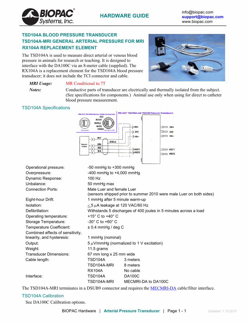
[email protected] [email protected] www.biopac.com
BIOPAC Hardware | Arterial Pressure Transducer | Page 1 - 1 Updated: 1.13.2015
TSD104A BLOOD PRESSURE TRANSDUCER TSD104A-MRI GENERAL ARTERIAL PRESSURE FOR MRI RX104A REPLACEMENT ELEMENT The TSD104A is used to measure direct arterial or venous blood pressure in animals for research or teaching. It is designed to interface with the DA100C via an 8-meter cable (supplied). The RX104A is a replacement element for the TSD104A blood pressure transducer; it does not include the TCI connector and cable.
MRI Usage: MR Conditional to 7T Notes: Conductive parts of transducer are electrically and thermally isolated from the subject.
(See specifications for components.) Animal use only when using for direct to catheter blood pressure measurement.
TSD104A Specifications
Operational pressure: -50 mmHg to +300 mmHg Overpressure: -400 mmHg to +4,000 mmHg Dynamic Response: 100 Hz Unbalance: 50 mmHg max Connection Ports: Male Luer and female Luer
(sensors shipped prior to summer 2010 were male Luer on both sides) Eight-hour Drift: 1 mmHg after 5 minute warm-up Isolation: < 5 µA leakage at 120 VAC/60 Hz Defibrillation: Withstands 5 discharges of 400 joules in 5 minutes across a load Operating temperature: +15° C to +40° C Storage Temperature: -30° C to +60° C Temperature Coefficient: ± 0.4 mmHg / deg C Combined effects of sensitivity, linearity, and hysteresis: 1 mmHg (nominal) Output: 5 µV/mmHg (normalized to 1 V excitation) Weight: 11.5 grams Transducer Dimensions: 67 mm long x 25 mm wide Cable length: TSD104A 3 meters TSD104A-MRI 8 meters RX104A No cable Interface: TSD104A DA100C TSD104A-MRI MECMRI-DA to DA100C
The TSD104A-MRI terminates in a DSUB9 connector and requires the MECMRI-DA cable/filter interface. TSD104A Calibration
See DA100C Calibration options.
HARDWARE GUIDE
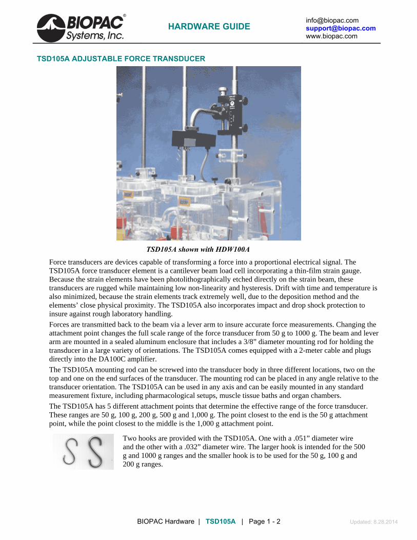
[email protected] [email protected] www.biopac.com
BIOPAC Hardware | TSD105A | Page 1 - 2 Updated: 8.28.2014
TSD105A ADJUSTABLE FORCE TRANSDUCER
TSD105A shown with HDW100A
Force transducers are devices capable of transforming a force into a proportional electrical signal. The TSD105A force transducer element is a cantilever beam load cell incorporating a thin-film strain gauge. Because the strain elements have been photolithographically etched directly on the strain beam, these transducers are rugged while maintaining low non-linearity and hysteresis. Drift with time and temperature is also minimized, because the strain elements track extremely well, due to the deposition method and the elements’ close physical proximity. The TSD105A also incorporates impact and drop shock protection to insure against rough laboratory handling.
Forces are transmitted back to the beam via a lever arm to insure accurate force measurements. Changing the attachment point changes the full scale range of the force transducer from 50 g to 1000 g. The beam and lever arm are mounted in a sealed aluminum enclosure that includes a 3/8” diameter mounting rod for holding the transducer in a large variety of orientations. The TSD105A comes equipped with a 2-meter cable and plugs directly into the DA100C amplifier.
The TSD105A mounting rod can be screwed into the transducer body in three different locations, two on the top and one on the end surfaces of the transducer. The mounting rod can be placed in any angle relative to the transducer orientation. The TSD105A can be used in any axis and can be easily mounted in any standard measurement fixture, including pharmacological setups, muscle tissue baths and organ chambers.
The TSD105A has 5 different attachment points that determine the effective range of the force transducer. These ranges are 50 g, 100 g, 200 g, 500 g and 1,000 g. The point closest to the end is the 50 g attachment point, while the point closest to the middle is the 1,000 g attachment point.
Two hooks are provided with the TSD105A. One with a .051” diameter wire and the other with a .032” diameter wire. The larger hook is intended for the 500 g and 1000 g ranges and the smaller hook is to be used for the 50 g, 100 g and 200 g ranges.
HARDWARE GUIDE

[email protected] [email protected] www.biopac.com
BIOPAC Hardware | TSD105A | Page 2 - 2 Updated: 8.28.2014
TSD105A CALIBRATION
The TSD105A is easily calibrated using weights of known mass. Ideally, calibration should be performed with weights that encompass the range of the forces expected during measurement and should cover at least 20% of the full scale range of the transducer. When calibrating for maximum range on the force transducer, use weights that correspond to 10% and 90% of the full scale range for best overall performance.
See also: DA100C Calibration options.
TSD105A SPECIFICATIONS Rated Output: 1 mV/V (normalized to 1 V excitation) Ranges: 50, 100, 200, 500, 1000 grams Noise (rms): (Range/50) mg @ 10 volts excitation, 1 Hz bandwidth Nonlinearity: <±0.025% FSR Hysteresis: <±0.05% FSR Nonrepeatability: <±0.05% FSR 30 minute creep: <±0.05% FSR Temperature Range: -10° C to 70° C Thermal Zero Shift: <±0.03% FSR/° C Thermal Range Shift: <0.03% Reading/° C Maximum Excitation: 10 VDC Mounting Rod: 9.5 mm (dia) – variable orientation Weight: 300 g (with mounting rod) Length: 19 mm (wide), 25 mm (thick), 190 mm (long) Cable Length: 3 meters Interface: DA100C
HARDWARE GUIDE

[email protected] [email protected] www.biopac.com
BIOPAC Hardware | TSD107B | Page 1 - 3 Updated: 9.4.2014
TSD107B HIGH-FLOW PNEUMOTACH TRANSDUCER
The TSD107B is a highly linear, wide range, airflow transducer. Using the TSD107B and a DA100C amplifier with the MP System, a variety of tests relating to airflow and lung volume can be performed. With the equipment listed below and the proper software parameters, precise lung volume measurements can be obtained.
EQUIPMENT • MP System for data acquisition
• DA100C general purpose amplifier
• TSD107B pneumotach transducer
HARDWARE SETUP 1. Select DA100C module for Channel 1.
2. Set Gain at 1000.
3. Set the high frequency response to 10 Hz (300 Hz in some cases).
4. Set the low frequency response to DC.
5. Set VREF1 to +1.0 Volts (default) with a Volt/ohm meter or with BIOPAC REFCAL (VREF2 will track VREF1 with opposite polarity).
6. Plug the TCI connector into DA100C.
7. Insert the airflow tube between the bacterial filter and the airflow transducer.
8. Place the mouthpiece on the free end of the bacterial filter.
HARDWARE GUIDE

[email protected] [email protected] www.biopac.com
BIOPAC Hardware | TSD107B | Page 2 - 3 Updated: 9.4.2014
SOFTWARE SETUP 1. Under Setup Channels select channel 1 and click on the scaling button.
2. Complete the scaling dialog box as shown here:
3. Under Setup Acquisition set
a) Storage: Disk
b) Sample rate: 50 samples per second
c) Acquisition length: 30 seconds.
RECORDING PROCEDURE
1. Start breathing normally through the mouthpiece.
2. After several normal breaths, inspire as deeply as possible (just once) and then return to normal breathing for several seconds
3. Expire as completely as possible.
4. Return to normal breathing for the remainder of the recording.
The recorded wave should look something like the top wave in the following graph. Normal Tidal Volume can vary quite a bit, even over a 30-second period. Note that in Wave 4 – adj volume, the starting tidal volume is almost a liter, then, as the test progresses, the tidal volume drops to about 0.5 liters. This level of variation is somewhat expected, since respiratory effort has a strong voluntary component.
ANALYSIS — ACQKNOWLEDGE 1. Duplicate the recorded data.
2. Subtract the mean value of the entire record from the duplicated data to create the Mean Adjusted Flow (madj). This procedure will simply remove any DC bias from the airflow signal.
3. Duplicate madj.
4. Integrate the duplicated madj channel. This process results in the third wave, which is the volume (in liters), which correlates to the airflow.
5. To correct for the proper residual volume in the lungs (estimated at about 1 liter), add a constant to the third wave to create a new adjusted volume (adj volume). The minimum point on this curve should be the estimated residual lung volume (1 liter).
HARDWARE GUIDE

[email protected] [email protected] www.biopac.com
BIOPAC Hardware | TSD107B | Page 3 - 3 Updated: 9.4.2014
TSD107B CALIBRATION The TSD107B is factory calibrated to nominally satisfy the scaling factor:
1 mVolt output = 11.1 liters/sec flow rate When connected to the DA100C with Gain =1,000, the calibration factor is:
1 Volt = 11.1 liters/sec This graph illustrates how a calibration check is performed.
1. Insert a three-liter calibration syringe into the free end of the airflow tube.
2. Push three liters of air through the airflow transducer, first one direction, then the other.
3. Subtract the mean value of the first wave from the second wave, to correct for DC bias.
4. Integrate the second wave; the result will be placed in the third channel (volume).
As air is forced back and forth through the transducer, the expected volume would be from 0 to 3 liters. As air goes one way the volume climbs to 3 liters, and as that same air is then pulled the other direction through the transducer, the volume signal should head back to 0. As shown in the sample graph, the volume measurement is independent of the rate of flow, as would be expected for a linear airflow measurement transducer.
See also: DA100C Calibration options.
TSD107B SPECIFICATIONS Pneumotach type: Hans Rudolf® #4813 with integral differential pressure transducer Voltage excitation: +/- 5 volts (10 volts pk-pk) maximum Nominal Output: 45 µV/[liters/sec] (normalized to 1 V excitation) Calibration factor: 90 micro-volts/(liters/second) – normalized to 2 VDC excitation Calibrated flow range: ±800 Liters/min Dead space volume: 87.8 ml Back pressure: 2.8 cm H2O/400 liters/min Flow bore (Ports): 35 mm OD Weight: 690 grams Dimensions: 4 cm (deep) x 11 cm (high) x 19 cm (wide)
Cable: 3 meters Interface: DA100C
HARDWARE GUIDE

[email protected] [email protected] www.biopac.com
BIOPAC Hardware | SS11LA & TSD117 | Page 1 - 7 Updated: 12.8.2014
MEDIUM-FLOW PNEUMOTACH TRANSDUCER • SS11LA for MP3X and MP45 System • TSD117 & TSD117-MRI for MP150/MP100 System • RX117 Replacement Airflow Head • See also: AFT series of accessories for airflow and gas analysis
These medium-flow airflow transducers are designed to measure human subject respiratory, bi-directional airflow (liters/sec) and can be used to measure respiratory flow in a wide range of tests and conditions relating to airflow and lung volume. Volume measurements are obtained by integrating the airflow signal. The airflow transducer is lightweight, easily held in one hand, and has a removable head for sterilization and replacement. For reasons of hygiene, it is important that only one person use each disposable mouthpiece and disposable filter.
The SS11LA/TSD117 airflow transducers include an optically clear detachable flow head (RX117) for easy cleaning and inspection. As the detachable flow head is snapped into the transducer handle, the flow head plugs directly into an integral, precision low-differential pressure transducer. Accordingly, the transducers will output an electrical signal proportional to respiratory flow. Use with the AFT22 Non-Rebreathing “T” valve for low dead space requirements.
The transducers connect to industry standard bacteriological filter AFT1 with disposable mouthpiece AFT2 or AFT13 filter and mouthpiece with AFT11H coupler. The RX117 detachable flow head can be cold sterilized, autoclaved (220° F max), or placed in a dishwasher.
• For airflow and lung volume measurements, use the airflow transducer with the AFT2 mouthpiece and the AFT1 bacterial filter.
• For measurements of expired gases, use the airflow transducer with the AFT22 non-rebreathing T valve with AFT10 facemask and the AFT15A or AFT15B mixing chambers.
All connections can be performed with AFT12 (22 mm ID) tubing and AFT11 series couplers.
Please note the following:
a) The bacterial filter and mouthpiece are disposable and are “one per person” items. Please use a new disposable filter and mouthpiece each time a different person is to be breathing through the airflow transducer.
b) For more effective calibration, use a bacterial filter between the calibration syringe and the airflow transducer.
Normal Measurement Connections • SSLA plugs directly into the MP3X or MP45 unit • TSD117 plugs directly into the DA100C amplifier module • TSD117-MRI plugs into MECMRI-DA cable to DA100C amplifier module
Air Flow TransducerMouthpiece and Bacterial Filter
Vertical Orientation
For the most accurate lung volume recording, be sure to use a noseclip to prevent airflow through the nose. Also, be sure not to remove the airflow transducer assembly from the mouth during the recording. All air leaving or entering the lungs must pass through the airflow transducer during the lung volume measurement.
SS11LA needs 5-10 minutes to warm up; during this time, the baseline offset changes slightly.
HARDWARE GUIDE

[email protected] [email protected] www.biopac.com
BIOPAC Hardware | SS11LA & TSD117 | Page 2 - 7 Updated: 12.8.2014
Use the following measurement procedure for determining lung volume:
1. Breathe normally for 3 cycles (start on inspire) 2. Inspire as deeply as possible 3. Return to normal breathing for 3 cycles 4. Expire as deeply as possible 5. Return to normal breathing (end on expire)
Data Processing When integrating the collected data to determine lung volume, it’s important to integrate from the starting point of the first inspire, to the end point of the last expire. Before integration, the mean of the selected (airflow) data must be determined and then subtracted from the record. This process insures that the integral will have the same starting and ending point.
Calibration For Medium-Flow Pneumotachs
1. Syringe Calibration
Calibration Syringe
Air Flow Transducer
Vertical Orientation
Bacterial Filter
After the calibration process, please remove the calibration syringe and attach a new bacterial filter and mouthpiece to the airflow transducer.
It’s very important that each individual use his/her own mouthpiece and bacterial filter.
Place the narrow end of the bacterial filter and mouthpiece assembly into either side of the airflow transducer. Airflow data can now be recorded. For best results, hold the airflow transducer vertically.
2. Mathematical Calibration The transducer can be roughly calibrated without using the calibration syringe. Using the transducer’s nominal output of 60 µV per liter/sec (normalized to 1 volt excitation), the following calibration factors can be entered in the software Scaling window.
Scaling Factors for Rough Calibration of the airflow transducer
The following equation illustrates why 0.12 volts maps to 1.00 liter/sec:
Calibration Constant • Amp Gain • Amp Excitation = Scale Factor
Thus
60 µV/[liter/sec] • 1000 • 2 Volts = 0.12 V / [liter/sec]
Data can now be collected directly. Prior to analyzing the data, remember that there will always be some offset recorded in the case of zero flow.
Note: With the TSD117 and MP150/100 system, it’s possible to largely trim this offset out, using the ZERO potentiometer on the DA100 amplifier, but some residual will always remain.
HARDWARE GUIDE

[email protected] [email protected] www.biopac.com
BIOPAC Hardware | SS11LA & TSD117 | Page 3 - 7 Updated: 12.8.2014
To remove residual offset after the flow data has been collected, select a portion of the baseline (zero flow reading) and calculate the mean value using the popup measurements. Subtract this mean value from the raw data to obtain a mean corrected flow signal.
Now, the integral of the mean can be calculated as shown in this graph
In this case, a 600 ml-calibration syringe was used to check the rough calibration of the airflow transducer. The rough calibration indicates a syringe volume of about 550 ml, so this method may only be expected to be accurate within ±10% of the real reading.
Flow Measurement and Volume Calculation
To achieve a more exact calibration, start with the above scaling factors and then boost or drop them slightly as indicated by the rough calibration. In this case, if the map value correlating to 0.12 volts were boosted about 10% to 1.10 (from 1.0 liters/sec), the resulting calibration would be fairly accurate.
See also: DA100C Calibration options.
>>> All Instructions also apply to the older airflow transducer — model SS11L with non-removable head <<<
SS11LA To MP3X Connection 1. Make sure the BIOPAC MP3X unit is
turned OFF. Note: Turn the MP3X power off even if the software is running.
Note: SS11LA to MP connection instructions also apply to 2-channel MP45 hardware.
2. The airflow transducer (SS11LA) can be plugged into any input channel on the MP3X.
3. After the transducer is plugged in securely, turn the MP3X power ON.
SS11LA to MP3X connection
Rough Calibration (MP3X) 1. Pull down the MP3X menu. 2. Click Setup channels. 3. Select the Analog channel that the
SS11LA transducer is plugged into and activate it by clicking in the Acquire, Plot and Values boxes.
The SS11LA can be roughly calibrated without using the AFT6 calibration syringe. The SS11LA has a nominal output of 60 µV per liter/sec, which is then scaled to account for the amplifier excitation. For the MP3X, this is factory set to 5 Volts. Therefore:
60 µV/[liter/sec] · 5 = 300 µV / [liter/sec].
HARDWARE GUIDE

[email protected] [email protected] www.biopac.com
BIOPAC Hardware | SS11LA & TSD117 | Page 4 - 7 Updated: 12.8.2014
4. Pull down the Presets pop-up menu and select Airflow.
5. Click on the View/Change Parameters button.
6. Click on the Scaling button. 7. Click on Cal1: Leave the Input value
reading and enter 0 for the Scale value. 8. For Cal2 Input Value, add 300 µV (or
.3 mV) to the Cal1 Input Value. For Cal2 Scale value, enter 1.
9. Click OK for each window to exit Channel Setup.
Note: Add 300µV to the Cal1 Input Value for Cal2.
Using the Calibration Syringe 1. Place a filter onto the end of the
calibration syringe. The filter is necessary for calibration because it forces the air to move smoothly through the transducer. This assembly can be left connected for future use. The filter only needs to be replaced if the paper inside the filter tears.
2. Insert the Calibration Syringe/Filter Assembly into the airflow transducer.
IMPORTANT!
Always insert on the side labeled “Inlet.”
Calibration Syringe into airflow transducer
Insert syringe assembly so that the transducer cable exits on the left, as shown above. • If using an older SS11L transducer with non-removable
head, insert syringe assembly into the larger diameter port. IMPORTANT: If the lab sterilizes the airflow heads after each use, make sure a clean head is installed now.
Never hold onto the airflow transducer handle when using the Calibration Syringe or the syringe tip may break.
The Airflow Transducer is sensitive to gravity so it needs to be held upright throughout the calibration and recording.
HARDWARE GUIDE

[email protected] [email protected] www.biopac.com
BIOPAC Hardware | SS11LA & TSD117 | Page 5 - 7 Updated: 12.8.2014
Proper handling of the Calibration Syringe Assembly
3. Pump the plunger several times before the recording. Always pull and push the plunger all the way until it stops when using the syringe. This assures that the full volume of air (0.6 liter) flows in and out of the airflow transducer.
Recording with the Airflow Transducer 1) Attach the appropriate filter and
mouthpiece on the side labeled Inlet.
WARNING The bacterial filter and mouthpiece are disposable and are “one per person” items. Please use a new disposable filter and mouthpiece each time a different person is to be breathing through the airflow transducer.
If using SS11LA transducer and not sterilizing the head after each use, insert a filter and mouthpiece into the airflow transducer on the side labeled “Inlet.”
SS11LA with unsterilized head
If using SS11LA transducer and sterilizing the head after each use, insert a disposable mouthpiece (BIOPAC AFT2) or a sterilizable mouthpiece (BIOPAC AFT8) into the airflow transducer on the side labeled “Inlet.”
SS11LA with sterilized head
HARDWARE GUIDE

[email protected] [email protected] www.biopac.com
BIOPAC Hardware | SS11LA & TSD117 | Page 6 - 7 Updated: 12.8.2014
2) Breathe through the airflow
transducer, following the proper procedure defined to the right.
Hints for obtaining optimal data: a) Keep the Airflow Transducer upright at all times.
b) Always insert on and breathe through the side of the
SS11LA airflow transducer labeled “Inlet.” c) Always use a nose clip when breathing through the
airflow transducer and secure a tight seal with the mouth so that air can only escape through the airflow transducer.
d) Always begin breathing normally through the airflow transducer prior to the beginning of the recording and continue past the end of the recording.
e) If starting the recording on an inhale, try to end on an exhale, and vice-versa. This is not absolutely critical, but will increase the accuracy of Airflow to Volume calculations.
f) The Subject must try to expand the thoracic cavity to its largest volume during maximal inspiratory efforts. (The Subject should wear loose clothing so clothing does not inhibit chest expansion.)
g) During recording of FEV, the Subject should attempt to exhale as quickly as possible into the mouthpiece.
h) During recording of MVV, the Subject should attempt to exhale and inhale as quickly and deeply as possible. Breathing rates should be faster than 60 breaths/minute or greater than 1 breath/second for the best results. The breathing needs to be maintained for 12-15 seconds.
HARDWARE GUIDE
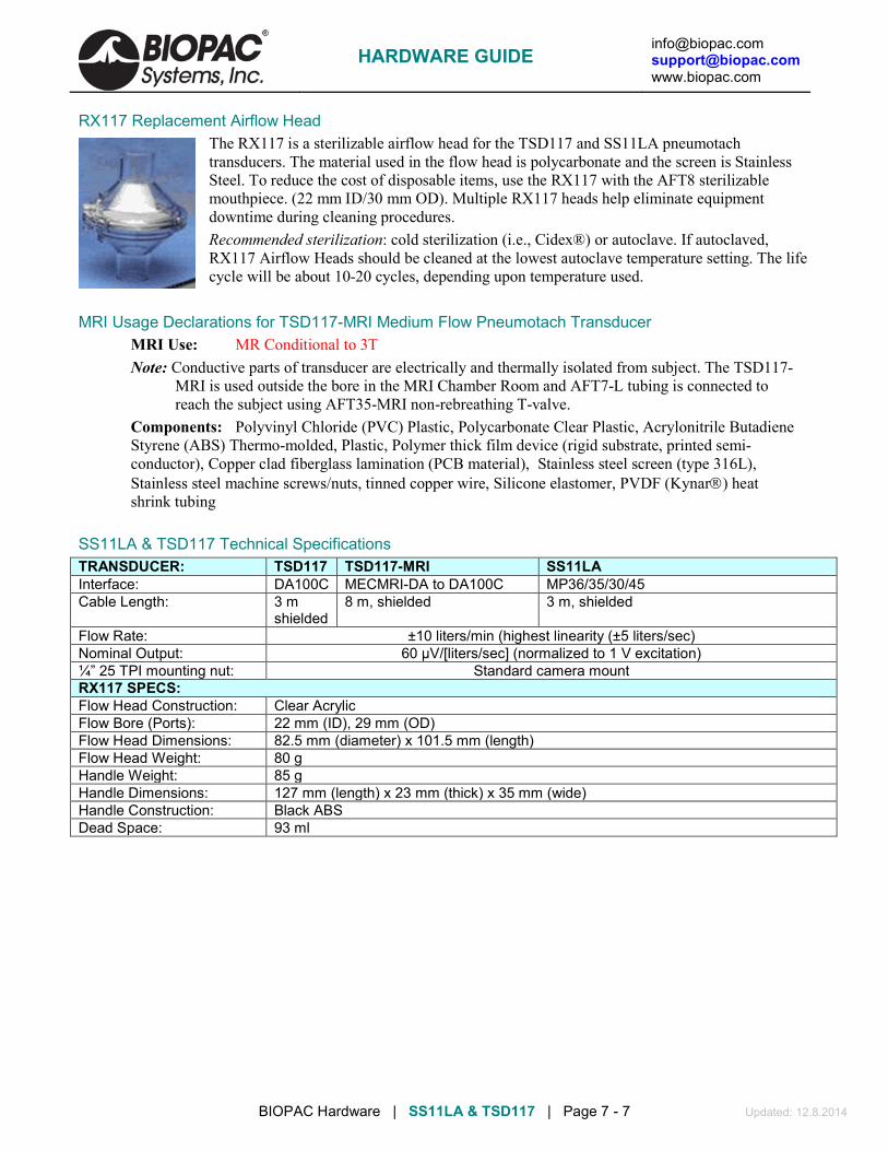
[email protected] [email protected] www.biopac.com
BIOPAC Hardware | SS11LA & TSD117 | Page 7 - 7 Updated: 12.8.2014
RX117 Replacement Airflow Head The RX117 is a sterilizable airflow head for the TSD117 and SS11LA pneumotach transducers. The material used in the flow head is polycarbonate and the screen is Stainless Steel. To reduce the cost of disposable items, use the RX117 with the AFT8 sterilizable mouthpiece. (22 mm ID/30 mm OD). Multiple RX117 heads help eliminate equipment downtime during cleaning procedures. Recommended sterilization: cold sterilization (i.e., Cidex®) or autoclave. If autoclaved, RX117 Airflow Heads should be cleaned at the lowest autoclave temperature setting. The life cycle will be about 10-20 cycles, depending upon temperature used.
MRI Usage Declarations for TSD117-MRI Medium Flow Pneumotach Transducer
MRI Use: MR Conditional to 3T Note: Conductive parts of transducer are electrically and thermally isolated from subject. The TSD117-
MRI is used outside the bore in the MRI Chamber Room and AFT7-L tubing is connected to reach the subject using AFT35-MRI non-rebreathing T-valve.
Components: Polyvinyl Chloride (PVC) Plastic, Polycarbonate Clear Plastic, Acrylonitrile Butadiene Styrene (ABS) Thermo-molded, Plastic, Polymer thick film device (rigid substrate, printed semi-conductor), Copper clad fiberglass lamination (PCB material), Stainless steel screen (type 316L), Stainless steel machine screws/nuts, tinned copper wire, Silicone elastomer, PVDF (Kynar) heat shrink tubing
SS11LA & TSD117 Technical Specifications TRANSDUCER: TSD117 TSD117-MRI SS11LA Interface: DA100C MECMRI-DA to DA100C MP36/35/30/45 Cable Length: 3 m
shielded 8 m, shielded 3 m, shielded
Flow Rate: ±10 liters/min (highest linearity (±5 liters/sec) Nominal Output: 60 µV/[liters/sec] (normalized to 1 V excitation) ¼” 25 TPI mounting nut: Standard camera mount RX117 SPECS: Flow Head Construction: Clear Acrylic Flow Bore (Ports): 22 mm (ID), 29 mm (OD) Flow Head Dimensions: 82.5 mm (diameter) x 101.5 mm (length) Flow Head Weight: 80 g Handle Weight: 85 g Handle Dimensions: 127 mm (length) x 23 mm (thick) x 35 mm (wide) Handle Construction: Black ABS Dead Space: 93 ml
HARDWARE GUIDE

[email protected] [email protected] www.biopac.com
BIOPAC Hardware | Pneumotach Low Flow | Page 1 - 1 Updated: 3.19.2014
TSD127 PNEUMOTACH AIRFLOW TRANSDUCER
RX127
TSD160
TSD127
The TSD127 can perform a variety of pulmonary measurements relating to airflow, lung volume and expired gas analysis. The TSD127 is intended for animal and human use and consists of a pneumotach airflow head (RX127) coupled to a precision, highly sensitive, differential pressure transducer (TSD160A). The TSD127 will connect directly to a breathing circuit or plethysmogram chamber. The detachable flow head (RX127) makes cleaning and sterilization easy.
For airflow and lung volume measurements, connect a short airflow cannula to the TSD127.
For measurements of expired gases, use the TSD127 with the AFT22 non-rebreathing valve.
All connections can be performed with AFT11 series couplers.
TSD127 CALIBRATION Follow the procedure for TSD117 but move the calibration syringe plunger at a reduced velocity due to the higher sensitivity to flow of the TSD127.
See also: DA100C Calibration options.
TSD127 SPECIFICATIONS Range: ± 90 liters/min (±1.5 liters/sec) Nominal Output: 500 µV/[liters/sec] (normalized to 1 V excitation) Dead Space: 11 cc Weight: 11 grams – airflow head
Dimensions: 5.7 cm (long) – airflow head Ports: 15 mm OD / 11 mm ID Tubing Length: 1.8 meters (to DA100C) Interface: DA100
RX127 REPLACEMENT AIRFLOW HEAD The RX127 is a low airflow head for the TSD127 pneumotach transducer. Multiple RX127 heads help eliminate equipment downtime during cleaning procedures. (11 mm ID/15 mm OD)
HARDWARE GUIDE

[email protected] [email protected] www.biopac.com
BIOPAC Hardware | Pneumotach 100 Series | Page 1 - 2 Updated: 3.24.2014
PNEUMOTACH AIRFLOW TRANSDUCERS TSD137 SERIES FOR MP150/MP100 SYSTEM SS46L-SS52L SERIES FOR MP3X AND MP45 SYSTEM RX137 SERIES REPLACEMENT FLOW HEADS
The TSD137/SS46L-SS52L series pneumotachs can be used to perform a variety of small animal and human pulmonary measurements relating to airflow, lung volume and expired gas analysis. These pneumotach transducers consist of a low flow, pneumotach airflow head (RX137B through RX137H and SS46L through SS52L) coupled to a precision, highly sensitive, differential pressure transducer (TSD160A or SS40L) via RX137 tubing. The pneumotachs will connect directly to a
breathing circuit or plethysmogram chamber. For airflow and lung volume measurements, connect a short airflow cannula to the RX137 series flow head. All pneumotachs are equipped with an internal heating element and AC137A 6-volt power supply.
RX137 Series
RX137A TSD160 Series
To DSUB9 connector for MP3X
SS40L
MRI Use (TSD137): MR Conditional Condition: Tested to 3T: Contains ferrous material – must be clamped down in the safe MRI
operating area. Components: Brass, stainless steel, copper
See also: DA100C Calibration options.
RX137 Series Replacement Airflow Heads (SHOWN ABOVE) For TSD137 & SS46L-SS52L Series Pneumotachs
The RX137 series are airflow heads for the TSD137 and SS46L-52L series pneumotach transducers. The RX137 heads can be mixed and matched with any of the TSD137 and SS46L-SS52L series pneumotachs. Switching one head for another when using a single pneumotach can accommodate a wide range in flows. RX137 heads connect to the TSD160A or SS40L differential pressure transducer via standard 3 mm or 4 mm ID tubing. Multiple RX137 heads help eliminate equipment downtime during cleaning procedures.
Pneumotach Airflow Transducer Calibration Connect tubing between the calibration syringe and the transducer, then follow the procedure for TSD117/SS11LA but move the calibration syringe plunger at a reduced velocity due to the very high sensitivity to flow of the TSD137/SS46L-SS52L series. Each of the TSD137/SS46L-SS52L series is factory calibrated to a known flow level, as indicated on the transducer.
Flow Head Cleaning & Disinfection IMPORTANT:
RX137 series airflow heads are manufactured with a very thin layer of synthetic resin, so they should never be cleaned with an organic solvent. We recommend cleaners such as Hydro-Merfen at the concentration used for medical material, or Gluterex.
Before using the airflow head, be sure it is dry. Never heat the airflow head higher than 50 C.
1. Submerge the airflow head in a disinfectant solution for approximately one hour. 2. Rinse the airflow head with distilled or de-mineralized water. 3. Use compressed air or another compressed gas [pressure up to 5 kg / cm2 (5 bar)] to drive any
remaining water out of the airflow head. 4. Allow the airflow head to dry completely in ambient air (or continue using compressed air if time
requires it).
HARDWARE GUIDE

[email protected] [email protected] www.biopac.com
BIOPAC Hardware | Pneumotach 100 Series | Page 2 - 2 Updated: 3.24.2014
TSD/RX137 & SS46L-SS52L Series Specifications Part# DA100C TSD16 0/SS40L MP36/35/30/ 45
TSD137B RX137B1
SS46L
TSD137C RX137C1
SS47L
TSD137D RX137D1
SS48L
TSD137E RX137E1
SS49L
TSD137F RX137F1
SS50L
TSD137G RX137G1
SS51L
TSD137H RX137H1
SS52L
Range (ml/sec): ±50 ±83 ±166 ±583 ±1565 ±2666 ±13333
Dead Space (cc): 0.8 0.9 2.0 4.0 18.15 13.87 80.0
Nominal Output (µV [ml/sec]):
15.40 5.78 2.10 0.924 1.155 0.4815 0.1925
Flow Ports ID/OD (mm): 6.0 - 7.0 6.0 - 7.0 9.0 - 10.0 10.0 - 11.0 17.0 - 22.0 14.0 - 24.6 43.0 - 45.0
RX Head Length (mm): 75 75 75 60 60 60 60
RX Head Weight (grams):
90 90 100 60 100 150 250
Approx. Size: Mouse Rat/Guinea Pig Cat/Rabbit Small Dog Medium Dog Large Dog Adult Human
Approx. Weight: 50 g 350 g 750 g 5.5 kg 15 kg 25 kg --
Nominal Output: TSD137B, C, H = normalized to 1 V excitation TSD137D, E, F, G & SS46L-52L = normalized to 5 V excitation
Tubing Length: 1.8 m (to TSD160A/SS40L)
HARDWARE GUIDE

[email protected] [email protected] www.biopac.com
BIOPAC Hardware | Pneumotach 200 Series | Page 1 - 1 Updated: 2.5.2015
PNEUMOTACH 200 SERIES AIRFLOW TRANSDUCERS
These flow transducers are designed for humans and animals ranging in size from mice to medium-sized dogs. They include a detachable flow head (RX237B through H) and a differential pressure transducer (TSD160A or SS40L).
Available Flow Rates
17 ml/sec Mouse/Rat
167 ml/sec Cat/Rabbit
1.67 L/sec Medium Dog
16.7 L/sec Human
Lightweight and robust
Linear and direction sensitive
Twin, non kink silicone tubing
Economical, sensitive and robust
Easily cleaned, disinfected or sterilized
For cleaning instructions, see the Cleaning Guidelines.
MRI Usage: MR Conditional
Condition: Animal use only. Contains ferrous material – must be clamped down in the safe MRI operating area.
Components: Brass, stainless steel, copper
RX237 SERIES REPLACEMENT AIRFLOW HEADS
For TSD237 and SSLA Series Pneumotachs
Detachable flow heads in are machined from acetal to give good stability with low weight and have found application in pediatrics and in the respiration measurement of animals such as dogs, cats, rats and mice.
TSD/SSLA/RX237 Series Specifications
BIOPAC Part #
Transducer Flowhead
Flowhead
Type
Dead Space
(ml)
Linear Range L/min
Approx. Flow for 10 mm
H2O
Tube (OD mm)
Length (mm)
Weight (gm)
TSD237B/SS46LA RX237B F1L 0.6 ± 1 1.2 L/min 5 40 14
TSD237D/SS48LA RX237D F10L 2 ± 10 12 L/min 8 54 22
TSD237F/SS50LA RX237F F100L 9 ± 100 90 L/min 16 54 38
TSD237H RX237H F1000L 320 ± 1000 550 L/min 29.5 198 230
Note: One of the problems historically encountered with pneumotachographs is condensation from expired air. This can be prevented by fitting a non-return valve and measuring only inspiration or alternatively by heating the flowhead, but viscosity errors may arise (from which in the first few breaths especially) preheat the inspired air most uncomfortably. In this range of flow heads, the problem is approached from a fresh angle. By mounting fine stainless steel gauze in plastic rings, thermal inertia is greatly reduced. The gauze therefore rapidly equilibrates in temperature with passing air and condensation is minimal.
HARDWARE GUIDE

[email protected] [email protected] www.biopac.com
BIOPAC Hardware | Blood Pressure Cuff | Page 1 - 4 Updated: 12.22.2014
BLOOD PRESSURE CUFF AND TRANSDUCER
TSD120 for MP150/MP100 System RX120 Series Cuff for TSD120 SS19L/LA/LB for MP3x & MP45 System
TSD120 RX120A and RX120F cuff options
BLOOD PRESSURE MEASUREMENT
The most common form of indirect blood pressure measurement employs a pressure cuff, pump and pressure transducer. This complete assembly is commonly referred to as a sphygmomanometer.
Typically, the cuff is wrapped around the upper arm and is inflated to a pressure exceeding that of the brachial artery. This amount of pressure collapses the artery and stops the flow of blood to the arm. The pressure of the cuff is slowly reduced as the pressure transducer monitors the pressure in the cuff. As the pressure drops, it will eventually match the systolic (peak) arterial pressure. At this point, the blood is able to “squirt” through the brachial artery. This squirting results in turbulence that creates the Korotkoff sounds. The cuff pressure continues to drop, and the pressure eventually matches the diastolic pressure of the artery. At that point, the Korotkoff sounds stop completely, because the blood is now flowing unrestricted through the artery.
SETUP
The graph at right illustrates a typical recording using the TSD120/SS19L.
TSD120: Pressure signal is recorded via a DA100C amplifier set to DC, 10Hz LP and a gain of 200.
SS19L/LA/LB: To record the pressure signal, Select SS19L/LA/LB preset from the MP3x/MP4x > Set Up Channels menu.
RECORDING As the cuff is wrapped around the upper arm of the subject, be sure to place the physiological sounds transducer underneath the blood pressure cuff, directly over the brachial artery. Transducer placement is very important to get the best possible recordings of Korotkoff sounds. Finish wrapping the cuff around the upper arm and secure it with the Velcro® seal. Now, start inflating the cuff with the pump bulb.
The pressure trace shows the hand pump driving the cuff pressure up to about 150 mmHg. Then the cuff pressure is slowly released by adjusting the pump bulb deflation orifice. Notice that the Korotkoff sounds begin appearing when the cuff pressure drops to about 125 mmHg (bottom trace). As the pressure continues to drop, the Korotkoff sounds eventually disappear, at about 85 mmHg. The systolic pressure would be identified at 125 mmHg and the diastolic pressure would be 85 mmHg.
HARDWARE GUIDE

[email protected] [email protected] www.biopac.com
BIOPAC Hardware | Blood Pressure Cuff | Page 2 - 4 Updated: 12.22.2014
CALIBRATION
A) TSD120 The TSD120’s built-in pressure transducer will require an initial calibration prior to use. To calibrate the transducer, wrap the cuff into a roll and begin to inflate the cuff slowly with the pump bulb. The pressure change will be noticeable on the mechanical indicator. Set the cuff pressure to one lower pressure (typically 20 mmHg) and then one higher pressure (typically 100 mmHg). In this manner the pressure transducer can be calibrated using the standard procedure in the SCALING dialog (in AcqKnowledge). To use the cuff at a future date, simply save the calibration settings in a stored file.
See also: DA100C Calibration options.
B) SS19L
The built-in pressure transducer of the SS19L/LA/LB requires an initial calibration prior to use. To calibrate the transducer, wrap the cuff into a roll and begin to inflate the cuff slowly with the pump bulb. Notice the pressure change on the mechanical indicator. Set the cuff pressure to one lower pressure (typically 20 mmHg) and then one higher pressure (typically 100 mmHg). In this manner the pressure transducer can be calibrated using the standard procedure in the Scaling dialog box of the BSL PRO software. To use the cuff at a future date, simply save the calibration settings as a New Channel Preset or in a graph template or data file.
C) SS19LA/LB SS19LA/LB uses an on-screen gauge display only and does not include a gauge. Gauge color can be set under Lesson Preferences.
NOTE: The SS19LA/LB is not compatible with MP45 Systems (USB chip conflict). Use SS19L
with MP45 Systems.
BSL 3.7.7
1. With cuff deflated, connect the SS19LA to the desired MP unit input channel.
2. Set the input channel preset to Blood Pressure Cuff SS19LA/LB (MP > Set Up Channels > SS19LA/LB preset)
3. Click on “View/Change Parameters” > “Scaling”. 4. Click the CAL 1 button 5. Add the CAL 1 input value to the CAL 2 input value. 6. Click OK and close dialogs.
BSL 4
1. Repeat steps 1 and 2 from above. 2. Click “Setup” > “Scaling”. 3. Click the CAL 2 button 4. Add the CAL 2 input value to the CAL 1 input value and click OK.
HARDWARE GUIDE

[email protected] [email protected] www.biopac.com
BIOPAC Hardware | Blood Pressure Cuff | Page 3 - 4 Updated: 12.22.2014
Example in BSL 4 – initial scaling dialog (SS19LA):
Clicking CAL 2 results in an Input value of 0.071 mV.
Adding 0.071 to the initial value of 61.44 results in an adjusted CAL 1 value of 61.51 mV. (Your result may vary slightly from the example).
NOTE: For the SS19LB, the default initial scaling values are: CAL1 = 40.96, Map value = 258.57
IMPORTANT: CAL 1 and CAL 2 values are reversed between BSL 3.7.7 and BSL 4.
BLOOD PRESSURE CUFF SPECIFICATIONS
Pressure range: 20 mmHg to 300 mmHg Manometer accuracy: ±3 mmHg Output: 5 µV/mmHg (normalized to 1 V excitation) Cuff circumference range: 25.4 cm to 40.6 cm (as shipped with RX120 d; cuff is switchable) Cuff Dimensions: 14.5 cm (wide) x 54 cm (long) Weight: 350 grams Cable Length: 3 meters, shielded Interface: TSD12 0 DA100C SS19L/LA/LB MP3x/4x
HARDWARE GUIDE
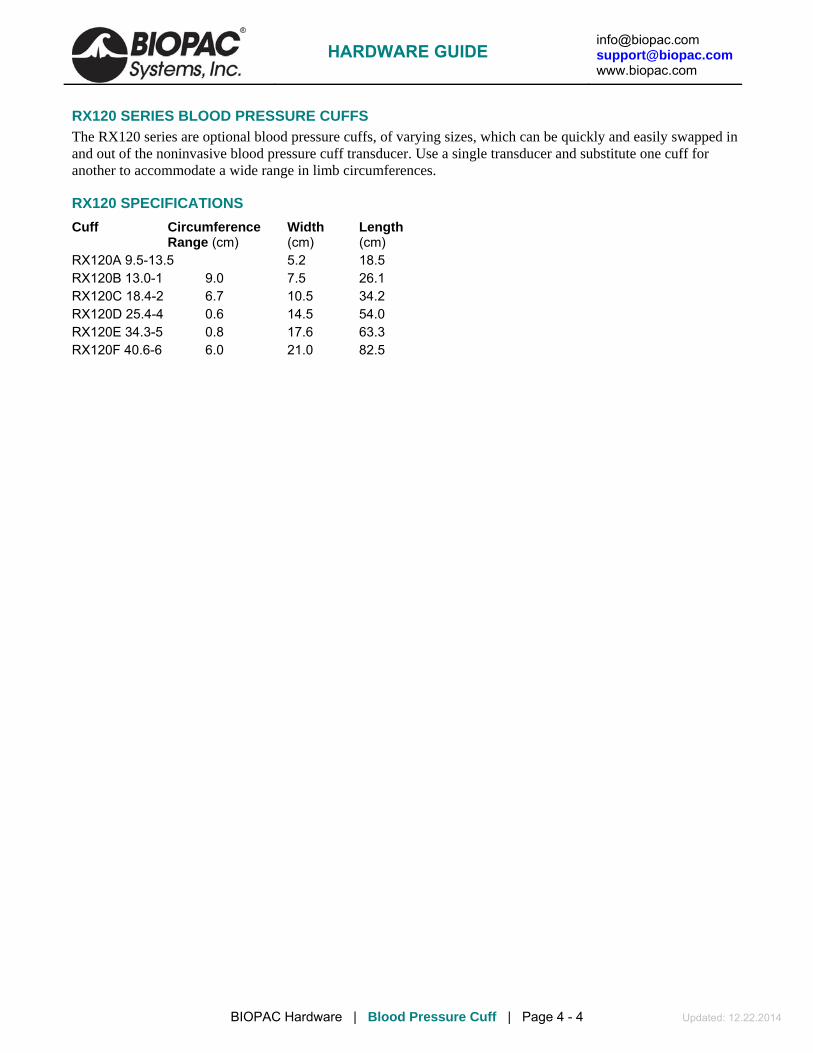
[email protected] [email protected] www.biopac.com
BIOPAC Hardware | Blood Pressure Cuff | Page 4 - 4 Updated: 12.22.2014
RX120 SERIES BLOOD PRESSURE CUFFS
The RX120 series are optional blood pressure cuffs, of varying sizes, which can be quickly and easily swapped in and out of the noninvasive blood pressure cuff transducer. Use a single transducer and substitute one cuff for another to accommodate a wide range in limb circumferences.
RX120 SPECIFICATIONS
Cuff Circumference Width Length Range (cm) (cm) (cm)
RX120A 9.5-13.5 5.2 18.5 RX120B 13.0-1 9.0 7.5 26.1 RX120C 18.4-2 6.7 10.5 34.2 RX120D 25.4-4 0.6 14.5 54.0 RX120E 34.3-5 0.8 17.6 63.3 RX120F 40.6-6 6.0 21.0 82.5
HARDWARE GUIDE

[email protected] [email protected] www.biopac.com
BIOPAC Hardware | TSD121C | Page 1 - 2 Updated:8.28.2014
TSD121C HAND DYNAMOMETER
The TSD121C is an isometric dynamometer that measures gripping (compression) or pulling (tension) forces associated with a wide variety of muscle groups. The isometric design improves experiment repeatability and accuracy. Forces are easily recorded in pounds, grams, kilograms force or in Newtons.
The TSD121C can be used for both compression (gripping) and tension (pulling) muscle strength studies under isometric constraint.
For compression measurements, simply squeeze the handle of the transducer. This simple operation makes for very simple and quick hand strength measurements.
For tension measurements, the attached sturdy metal eye loops can be threaded using rope or chain. In this configuration, arm curling, leg lifting and digit activation forces can be measured. For these measurements, one loop is clamped securely and the other loop is attached, via cabling, to the appropriate body location under test.
The TSD121C has a 3-meter cable terminated in a connector that interfaces with the DA100C general-purpose transducer amplifier. The ergonomic soft handle design and simple calibration procedure make this device very easy to use.
For in-depth studies of muscular activity, combine TSD121C force recordings with EMG recordings; see the EMG100C amplifier for more information.
TSD121C CALIBRATION With the proper equipment and correct scaling techniques described below, precise force measurements can be obtained.
EQUIPMENT TSD121C Hand Dynamometer
MP System and DA100C General Purpose Transducer Amplifier
SS25 Simple Sensor Hand Dynamometer
MP System and TEL100C Remote Monitoring Module Set
HARDWARE SETUP Connect the TSD121C to the DA100C, or the SS25 to the TEL100C. When using this type of transducer, proper hand placement is at the uppermost portion of the foam grip, directly below the dynagrip connections.
SOFTWARE SETUP 1. Select Setup Channels under the MP menu
and enable one analog channel; make sure to correlate this with the Analog Output Channel selected on the DA100C module.
2. Select Scaling. A dialog similar to the one shown here will be generated.
3. In the Map value column, enter the scaling factors of 0 and 1, respectively. These represent 0 and 1 kilograms.
HARDWARE GUIDE

[email protected] [email protected] www.biopac.com
BIOPAC Hardware | TSD121C | Page 2 - 2 Updated:8.28.2014
4. Enter “Kg” for the Units label, as shown.
5. Take the TSD121C and rest it on the table.
6. Click on the Cal 1 button with the mouse to get a calibration reading.
To obtain a value for the Cal 2 box, add 13.15 V per volt of excitation (Vex) to the value from the Cal 1 box. Currently, the DA100C is factory set to 2 V (1 V) of excitation. If the amplifier has been set to another level of excitation, use the following equation wherein V = volts of excitation per 1 kg and G = gain setting on the DA100C or TEL100C module:
(13.15 V*G * Vex) + Cal 1 = Cal 2
TESTING CALIBRATION
To see if the calibration is correct for the MP System:
1. Start acquiring data.
2. Place the hand dynamometer on a flat surface.
3. Place a known weight on the uppermost portion of the grip.
4. Check the data — the weight should be reflected accurately in the data acquired.
Sample Data
See also: DA100C Calibration options.
TSD121C SPECIFICATIONS Isometric Range: 0-100 Kg Nominal Output: 13.2 µV/kg (normalized to 1 V excitation) Linearity: < ±0.03% of rated output Nonrepeatability: < ±0.02% of rated output Creep after 30 minutes: < 0.05% of rated output Hysteresis: < ±0.02% of rated output (compression only or tension only) Sensitivity: 2.2 grams rms (5 V excitation, DC-10 Hz) Weight: 315 g Dimensions: 185 mm (long) x 42 mm (wide) x 30 mm (thick) Cable Length: 3 m Interface: DA100C TEL100C compatibility: SS25
HARDWARE GUIDE

[email protected] [email protected] www.biopac.com
BIOPAC Hardware | TSD125 Series | Page 1 - 3 Updated: 8.28.2014
TSD125 SERIES PRECISION FORCE TRANSDUCERS TSD125B (20 g)
TSD125C (50 g)
TSD125D (100 g)
TSD125E (200 g)
TSD125F (500 g)
TSD125 shown with HDW100A
Force transducers are devices capable of transforming a force into a proportional electrical signal. The TSD125 series force transducer elements are cantilever beam load cells incorporating thin-film strain gauges. Because the strain elements have been photolithographically etched directly on the strain beam, these transducers are rugged while maintaining low non-linearity and hysteresis. Drift with time and temperature is also minimized, because the strain elements track extremely well, due to the deposition method and the elements close physical proximity. Forces are transmitted back to the beam via a self-centering pull-pin to insure accurate force measurements. The cantilever beam is mounted in a sealed aluminum enclosure that includes a 3/8” diameter mounting rod for holding the transducer in a large variety of orientations.
HARDWARE GUIDE

[email protected] [email protected] www.biopac.com
BIOPAC Hardware | TSD125 Series | Page 2 - 3 Updated: 8.28.2014
TSD125 SERIES CALIBRATION
The following graphs illustrate actual data taken with the TSD125C (50 gram force transducer) and TSD125F (500 gram force transducer). The force transducers were connected directly to a DA100C amplifier with the excitation set to ±5 Volts. The DA100C gain was set to 1,000. The RMS noise output was determined by calculating the standard deviation of the amplified and calibrated signal over a period of time.
The RMS noise of each force transducer was determined in three different settings.
1) Channel 1 RMS Noise at DA100C output
2) Channel 41 RMS Noise after 10 Hz Low Pass IIR real time filtering
3) Channel 40 RMS Noise after 1Hz Low Pass IIR real time filtering
RMS NOISE PERFORMANCE OF TSD125F FOR DIFFERENT BANDWIDTHS
RMS NOISE PERFORMANCE OF TSD125C FOR DIFFERENT BANDWIDTHS
See also: DA100C Calibration options.
HARDWARE GUIDE

[email protected] [email protected] www.biopac.com
BIOPAC Hardware | TSD125 Series | Page 3 - 3 Updated: 8.28.2014
TSD125 SERIES SPECIFICATIONS Device Full Scale Range RMS Noise [10 volts Excitation]
(FSR) 10 Hz 1 Hz
TSD125B: 20 gram 1.0 mg RMS .04 mg RMS
TSD125C: 50 gram 2.5 mg RMS 1 mg RMS
TSD125D: 100 gram 5 mg RMS 2 mg RMS
TSD125E: 200 gram 10 mg RMS 4 mg RMS
TSD125F: 500 gram 25 mg RMS 10 mg RMS
Nonlinearity: <±0.025% FSR
Hysteresis: <±0.05% FSR
Nonrepeatability: <±0.05% FSR
30-Minute Creep: <±0.05% FSR
Temperature Range: -10°C to 70°C
Thermal Zero Shift: <±0.03% FSR/°C
Thermal Range Shift: <0.03% Reading/°C
Maximum Excitation: 10 VDC
Full Scale Output: 1 mV/V (normalized to 1 V excitation)
Weight: 250 grams
Dimensions: 100 mm (long) x 19 mm (wide) x 25 mm (high)
Mounting Rod: 9.5 mm (dia) – variable orientation
Cable Length: 3 meters
Interface: DA100C
HARDWARE GUIDE

[email protected] [email protected] www.biopac.com
BIOPAC Hardware | TENSION ADJUSTERS | Page 1 - 1 Updated: 8.28.2014
TENSION ADJUSTERS HDW100A TENSION ADJUSTER HDW200A 3RD-PARTY TENSION ADJUSTER ADAPTER
HDW100A and TSD125/SS12LA
The HDW100A tension adjuster operates with the TSD105A, TSD125, SS12LA force transducers and SS14L displacement transducer. The rugged design and stability of the mounting allow for fine position control. The position adjuster is located on the top for easy access and smooth operation. Vertical scales are provided for both metric and standard units. The HDW100A slides directly onto vertical rod laboratory stands and force transducers are clamped into the unit horizontally.
HDW100A SPECIFICATIONS Travel Range: 25 mm Resolution: 0.0025 mm per degree rotation Stand Clamp: 13.25 mm ID Transducer Clamp 11 mm ID Weight: 140 grams Dimensions: 93 mm (high) x 19 mm (thick) x 74 mm (deep)
HDW200 ADAPTER FOR 3RD-PARTY TENSION ADJUSTERS
This adapter allows 3rd-party tension adjusters to interface with BIOPAC Force Transducers.
Fits any tension adjuster with an arm diameter of 6.35 mm (1/4") or less, such as “riser” style tension adjusters from Lafayette and Wards.
HARDWARE GUIDE

[email protected] [email protected] www.biopac.com
BIOPAC Hardware | Gonio-Torsio | Page 1 - 9 Updated: 10.21.2014
Goniometers & Torsiometers • TSD130 Series • BN-GON-XDCR Series • SS20L-SS24L • BN-TOR-XDCR Series • SS20-SS24 • BN-GON-F-XDCR
In the example above, the TSD130A was connected directly to a DA100C amplifier,
the DA100C gain was set to 1,000, and AcqKnowledge was used to calibrate the signal to provide angular measurements from approximately +90° to -90°.
Transducer MP1XX (DA100C) MP3X/MP45 TEL100C Twin-axis Goniometer 110 TSD130A SS20L SS20 BN-GON-110-XDCR
BN-GONIO
Twin-axis Goniometer 150 TSD130B SS21L SS21 BN-GON-150-XDCR Torsiometer 110 TSD130C SS22L SS22 BN-TOR-110-XDCR Torsiometer 150 TSD130D SS23L SS23 BN-TOR-150-XDCR Single-axis Goniometer 35 TSD130E SS24L SS24 BN-GON-F-XDCR
BIOPAC Goniometers and Torsiometers are designed for the measurement of limb angular movement. Goniometers transform angular position into a proportional electrical signal. Goniometers incorporate gauge elements that measure bending strain along or around a particular axis. BIOPAC goniometers are unobtrusive and lightweight, and can be attached to the body surface using double-sided surgical tape (and can be further secured with single sided tape). The goniometers have a telescopic endblock that compensates for changes in distance between the two mounting points as the limb moves. The gauge mechanism allows for accurate measurement of polycentric joints. All sensors connect directly to the BIOPAC Acquisition Unit as part of an MP or BSL System. Activity data can be displayed and recorded, leaving the subject to move freely in the normal environment. The bending strain is proportional to the sum total angular shift along the axis. Because the bending force is extremely small, the output signal is uniquely a proportional function of the angular shift.
Twin-axis Goniometers
—wrist or ankle use TSD130A/SS20L/SS20/BN-GON-110-XDCR
Dual output devices that can measure angular rotation about two orthogonal planes simultaneously. Goniometers provide outputs to simultaneously measure around two orthogonally rotational axes (e.g. wrist flexion/extension and radial/ulnar deviations).
—elbow, knee or shoulder use TSD130B/SS21L/SS21/BN-GON-150-XDCR
Torsiometers
—neck use TSD130C/SS22L/SS22/BN-TOR-110-XDCR
Measure angular twisting (as on the torso, spine or neck) as opposed to bending. Torsiometers measure rotation about a single axis (e.g. forearm pronation/supination).
—along the torso or spine use TSD130D/SS23L/SS23/BN-TOR-150-XDCR
Single-axis Goniometer—fingers, thumb or toes use TSD130E/SS24L/SS24/BN-GON-F-XDCR
Measures the angle in one plane only; designed to measure digit joint movement.
HARDWARE GUIDE

[email protected] [email protected] www.biopac.com
BIOPAC Hardware | Gonio-Torsio | Page 2 - 9 Updated: 10.21.2014
ATTACHMENT TO THE SUBJECT Various combinations of display and recording instrumentation have been carefully developed fulfilling the requirements of specific research applications. Due to the wide range of applications, one method of attachment cannot be recommended. Experience has proven that standard medical adhesive tape is an excellent adhesion method in the majority of cases. Single-sided and double-sided medical tape (such as BIOPAC TAPE1 or TAPE2) should be used for the best results.
1. Attach pieces of double-sided tape to the underside of the goniometer endblocks.
2. Stick the tape to the subject and allow for the telescoping of the goniometer. The goniometer should be fully extended when the joint is fully flexed.
3. Press the two endblocks firmly onto the subject and ensure that the goniometer is lying over the top of the joint. When the joint is extended, the goniometer may present an “oxbow.”
4. For additional security, pass a single wrap of single-sided medical tape around each endblock.
5. Secure the cable and connector leaving the goniometer with tape to ensure that they do not pull and detach the goniometer.
For accurate results from long recordings
Employ double-sided adhesive between the endblocks and skin, and place single-sided adhesive tape over the top of the endblocks. No tape should come into contact with the spring. The connection lead should also be taped down near the goniometer.
For applications where quick or rapid movements are involved
Fit a “sock” bandage over the whole sensor and interconnect lead. This does not apply to the finger goniometer (TSD130E/SS24L/SS24/BN-GON-F-XDCR), which has a different working mechanism.
When the goniometer is mounted across the joint, the center of rotation of the sensor measuring element may not coincide with the center of rotation of the joint (for example, when measuring flexion /extension of the wrist). As the joint moves through a determined angle, the relative linear distance between the two mounting positions will change.
To compensate for this, all sensors are fitted with a telescopic endblock that permits changes in linear displacement between the two endblocks along axis ZZ without the measuring element becoming over-stretched or buckled.
In the free or unstretched position, the distance between the two endblocks is L1.
If a light force is applied, pushing the endblocks away from each other, this length will increase to a maximum of L2.
When the light force is removed, the distance between the two endblocks will automatically return to L1.
This creates several advantages: accuracy is improved; sensors can be worn comfortably and undetected under normal clothing; the tendency for the position of the sensors to move relative to the underlying skeletal structure is reduced.
HARDWARE GUIDE

[email protected] [email protected] www.biopac.com
BIOPAC Hardware | Gonio-Torsio | Page 3 - 9 Updated: 10.21.2014
If a light force is now applied, pushing the two endblocks linearly towards each other, the only way the distance L1 can decrease in length is if the measuring element buckles.
• Buckling is detrimental to the accuracy of the goniometer and torsiometer sensors, so attachment instructions are provided for the most commonly measured joints (on page 8), to ensure that it does not occur in practice.
There is no universal rule governing which size of sensor is most suitable for a particular joint; this depends on the size of the subject. In general, the sensor must be capable of reaching across the joint so that the two endblocks can be mounted where the least movement occurs between the skin and the underlying skeletal structure. In certain circumstances, more than one size of sensor will be appropriate. WARNINGS
1. Take care to handle the goniometer and torsiometer sensors as instructed. Mishandling may result in inaccurate data, reduced equipment life, or even failure.
2. Observe the minimum bend radius value for each goniometer and torsiometer at all times, particularly when attaching and removing the sensors from the subject. Failure to do this will result in reduced equipment life or failure.
3. Never remove the goniometer from the subject by pulling on the measurement element and/or protective spring. Remove the endblocks individually and carefully, making sure not to exceed the minimum permissible bend radius, particularly where the measuring element enters the endblocks.
4. Take care when mounting goniometers to ensure that the measurement element always forms a “simple” bend shape. Accuracy will be reduced if an “oxbow” shape occurs in the element.
5. Do not bend the finger goniometer more than ±20° in the Y-Y Plane or reduced equipment life and/or failure may result.
6. Do not exceed rotations of ± 90° about ZZ. Exceeding the torsiometer range may result in a reduction of the life of the unit or failure.
7. Disconnect the transducers from the BIOPAC Acquisition Unit before cleaning or disinfecting goniometers and torsiometers.
MAINTENANCE & SERVICE No periodic maintenance is required to ensure the correct functioning of the sensors. The sensors contain no user serviceable components. If the sensor fails, it should be returned to BIOPAC Systems, Inc.
• Please request a Return Merchandise Authorization (RMA) number before returning the sensor and include a description of what has been observed and what instrumentation was in use at the time of sensor failure in the return package.
Calibration When using all goniometers and torsiometers, the minimum value of bend radius must be observed at all times, particularly when attaching and removing the sensors from the subject. Failure to do this will result in reduced unit life or failure. The sensors have been designed to be as light as possible and the operating force to be a minimum. This permits free movement of the joint without influence by the sensors. The sensors measure the angle subtended between the endblocks. Use the software calibration features (under Setup Channels) to calibrate any of the BIOPAC series goniometers. Each goniometer requires a DA100C amplifier, BN-GONIO or MP3X/45 analog input per rotational axis. Accordingly, the twin axis goniometers will need two DA100C amplifiers, one BN-GONIO or two MP3X/45 analog channels to simultaneously measure both rotational axes. The recommended excitation voltage is +5 VDC.
1. Place goniometer with care to verify that limb/joint/torso attachment will not result in over stretch at the limits of limb/joint/torso movement.
2. Put body in the first position, which brackets one end of range of movement. Press CAL 1. 3. Put body in the second position, which brackets the other end of range of movement. Press CAL 2.
HARDWARE GUIDE

[email protected] [email protected] www.biopac.com
BIOPAC Hardware | Gonio-Torsio | Page 4 - 9 Updated: 10.21.2014
Specifications
Part # MP1XX via DA100C TSD130A TSD130B TSD130C TSD130D TSD130E Telemetry TEL100C SS20 SS21 SS22 SS23 SS24 MP36/36R/35/30/45 SS20L SS21L SS22L SS23L SS24L BioNomadix via BN-GONIO BN-GON-110-
XDCR BN-GON-150-XDCR
BN-TOR-110-XDCR
BN-TOR-150-XDCR
BN-GON-F-XDCR
Number of channels 2 2 1 1 1 Measuring range (degrees) ±150 ±150 ±150 ±150 ±150 Dimensions mm
A. Maximum 110 150 110 170 35 A. Minimum 70 100 70 115 30
B. 60 70 60 70 18 C. 18 18 18 18 8 D. 54 54 54 54 15 E. 20 20 20 20 8 F. 9 9 9 9 5 Bend radius (mm) – min. 18 18 18 18 3 Weight (g) 23 25 22 23 8 Crosstalk1 ±5% ±5% N/A N/A N/A Nominal Output 5 µV/degree normalized to 1 V excitation Temperature Zero Drift 0.15 degrees angle / °C Cable length 6 meters for TSD130 Series/SS20L-24L, 1.8 meters for SS20-24, 10 cm for BN-
GON/BN-TOR Endblock height Cable end 9.4 mm, distal end 8.2 mm Transducer type Strain gauge Life2 600,000 cycles minimum Accuracy ±2° measured over 90° from neutral position Repeatability Better than ±1° Analog resolution Infinite Operating temp range +0° to +40° C Storage temp range -20° C to +50° C Operating/Storage humidity range
30% to 75%
Atmospheric pressure range Operation 700 hPa to 1060 hPa Storage 500 hPa to 1060 hPa
1 Specification of crosstalk for all Biometrics twin-axis SG series of goniometers is measured over ±60°. i.e., if a joint is moved through 60° from the neutral position in one plane without movement in the orthogonal plane, then the sensor output in the orthogonal plane may change by a maximum ±3°. 2 Life test results have been collected by cycling the sensors through movements that would happen during everyday use. For example, placing a sensor on an adult elbow and moving from the neutral position to maximum flexion and back to the neutral position, the unit will function for a minimum of 600,000 cycles.
HARDWARE GUIDE
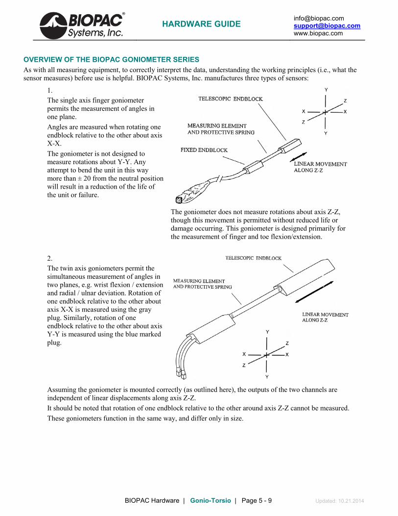
[email protected] [email protected] www.biopac.com
BIOPAC Hardware | Gonio-Torsio | Page 5 - 9 Updated: 10.21.2014
OVERVIEW OF THE BIOPAC GONIOMETER SERIES As with all measuring equipment, to correctly interpret the data, understanding the working principles (i.e., what the sensor measures) before use is helpful. BIOPAC Systems, Inc. manufactures three types of sensors:
1. The single axis finger goniometer permits the measurement of angles in one plane. Angles are measured when rotating one endblock relative to the other about axis X-X. The goniometer is not designed to measure rotations about Y-Y. Any attempt to bend the unit in this way more than ± 20 from the neutral position will result in a reduction of the life of the unit or failure.
The goniometer does not measure rotations about axis Z-Z, though this movement is permitted without reduced life or damage occurring. This goniometer is designed primarily for the measurement of finger and toe flexion/extension.
2. The twin axis goniometers permit the simultaneous measurement of angles in two planes, e.g. wrist flexion / extension and radial / ulnar deviation. Rotation of one endblock relative to the other about axis X-X is measured using the gray plug. Similarly, rotation of one endblock relative to the other about axis Y-Y is measured using the blue marked plug.
Assuming the goniometer is mounted correctly (as outlined here), the outputs of the two channels are independent of linear displacements along axis Z-Z. It should be noted that rotation of one endblock relative to the other around axis Z-Z cannot be measured. These goniometers function in the same way, and differ only in size.
HARDWARE GUIDE

[email protected] [email protected] www.biopac.com
BIOPAC Hardware | Gonio-Torsio | Page 6 - 9 Updated: 10.21.2014
3. The single axis torsiometers permit the measurement of rotation in one plane, e.g. forearm pronation/supination. Axial rotation of one endblock relative to the other along axis Z-Z is measured from the gray plug. If the torsiometer is bent in planes X-X or Y-Y, the output remains constant. All torsiometers function in the same way, and difference only in size.
WARNING! Torsiometers measure rotations about ZZ in the range ± 90°. Exceeding the range may result in a reduction of the life of the unit or failure.
The working mechanism is the same for all three types of sensors. There is a composite wire between the two endblocks that has a series of strain inside the protective spring gauges mounted around the circumference. As the angle between the two ends changes, the change in strain along the length of the wire is measured and this is equated to an angle. The design is such that only angular displacements are measured. If the two ends move linearly relative to each other, within the limits of telescopic endblock, without changing the relative angles between them, then the outputs remain constant.
The amount of strain induced in the gauges is inversely proportional to the bend radius that the beam is bent around. If the stated minimum permissible bend radius is exceeded then unit life will be reduced or, in severe cases, failure may result.
HARDWARE GUIDE

[email protected] [email protected] www.biopac.com
BIOPAC Hardware | Gonio-Torsio | Page 7 - 9 Updated: 10.21.2014
SIGN CONVENTIONS The sign convention for certain joints will differ, depending which side of the body the sensor is attached to. The following figures show sign conventions for the most common joints.
HARDWARE GUIDE

[email protected] [email protected] www.biopac.com
BIOPAC Hardware | Gonio-Torsio | Page 8 - 9 Updated: 10.21.2014
WRIST – Goniometer TSD130A/SS20L/SS20/BN-GON-110-XDCR Attach the telescopic endblock to the back of the hand, with the center axis of the hand and endblock coincident (top of figure — viewed in the frontal plane). While fully flexing the wrist (middle and bottom of figure), extend the goniometer to Position 2 (as shown on page 2) and attach the fixed endblock to the forearm so that when viewed from the dorsal plane, the axes of the forearm and endblock are coincident. The wrist may now be flexed or extended, abducted or adducted, with the goniometer freely sliding between Positions 1 and 2. Measurement of flexion/extension is obtained from the gray plug, and abduction/adduction is obtained from the blue plug.
ARTICULAR COMPLEX OF THE FOOT – Goniometer TSD130A/SS20L/SS20/BN-GON-110-XDCR Attach the telescopic endblock to the back of the heel. Extend the ankle to the maximum extension anticipated during measurement, and attach the fixed endblock to the posterior of the leg, with the goniometer in Position 1 (maximum length, as shown on page 2) so that the axes of the leg endblock are coincident. Flexion/extension of the ankle may now be monitored using the gray plug and pronation/supination using the blue marked plug.
ELBOW – Goniometer TSD130B/SS21L/SS21/BN-GON-150-XDCR Attach the telescopic endblock to the forearm with the center axis of the endblock coincident with the center axis of the forearm. With the elbow fully extended, move the goniometer to Position 2 (maximum length, as shown on page 2) and attach the fixed endblocks to the upper arm, with the center of the endblock and the center axis of the upper arm coincident. Now the elbow may be fully extended with the telescopic endblock freely sliding between Positions 1 and 2. Measurement of flexion/extension is obtained from the blue marked plug, and the gray plug is redundant. Note that the telescopic endblock is mounted on the half of the forearm nearest to the elbow joint. Movements of pronation and supination may be made and will affect the measurement of flexion/extension by a small amount.
HIP – Goniometer TSD130B/SS21L/SS21//BN-GON-150-XDCR Attach the fixed endblock to the side of the trunk in the pelvic region. With the limb in the position of reference, extend the goniometer to Position 2 (maximum length, as shown on page 2) and attach the telescopic endblock to the thigh, so that axes of the thigh and endblock coincide (when viewed in the sagittal plane, as shown). The thigh may now be flexed or extended, abducted or adducted, with the goniometer sliding freely between Positions 1 and 2. Measurements of flexion/extension are obtained from the blue marked, and abduction/adduction from the gray plug.
HARDWARE GUIDE

[email protected] [email protected] www.biopac.com
BIOPAC Hardware | Gonio-Torsio | Page 9 - 9 Updated: 10.21.2014
KNEE – Goniometer TSD130B/SS21L/SS21/BN-GON-150-XDCR Mount the telescopic endblock laterally on the leg so the axes of the leg and endblock coincide, when viewed in the sagittal plane. With the leg fully extended in the position of reference, extend the goniometer to Position 2 (maximum length, as shown on page 2) and attach the fixed endblock to the thigh so the axes of the thigh and endblock coincide. The knee may now be flexed or extended with the goniometer freely sliding between Positions 1 and 2. Measurements of flexion/extension may be monitored using the blue marked plug and varus/valgus may be monitored using the gray plug.
FOREARM PRONATION /SUPINATION – Torsiometer TSD130C/SS22L/SS22/BN-TOR-110-XDCR or TSD130D/SS23L/SS23/BN-TOR-150-XDCR Attach the two endblocks of the torsiometer to the forearm, with the slider mechanism approximately midway between the two extremes. Measurements of pronation/supination may now be made from the gray plug. Movements of wrist flexion/extension or radial/ulnar deviation will not affect the output.
FINGERS AND TOES –Goniometer TSD130E/SS24L/SS24/BN-GON-F-XDCR The single axis goniometer is intended for use on fingers and toes. Angles are measured by rotating one endblock relative to the other about axis X-X (as shown on page 2).
The goniometer is not designed to measure rotations about Y-Y. Any attempt to bend the unit in this way more than +/-20° from the neutral position will result in reduced unit life or failure. The goniometer does not measure rotations about the axis Z-Z. The unit is designed to fit over the joint to be measured and has extremely high flexibility to ensure the instrument does not interfere with normal joint movement. One endblock is attached either side of the joint. Unlike other BIOPAC Goniometers and Torisometers, and “Z” series sensors, an “oxbow” shape is permitted in the measuring element. This is not detrimental to the results and does not reduce life of sensor. Care should be taken, however, that the minimum bend radius is not exceeded.
Panel cutout for 9 pin DSUB MRIRFIF or existing DSUB 9
HARDWARE GUIDE

[email protected] [email protected] www.biopac.com
BIOPAC Hardware | TSD160 Series | Page 1 - 1 Updated: 6.5.2014
TSD160 SERIES – HIGH SENSITIVITY DIFFERENTIAL PRESSURE TRANSDUCERS
The TSD160 series differential pressure transducers are designed for low range pressure monitoring. The transducers plug directly into the DA100C general-purpose differential amplifier. The differential pressure ports are located on the front of the transducers and are easily connected to breathing circuits, pneumotachs or plethysmograph boxes. These transducers are very useful for interfacing a variety of small animal pneumotachs or plethysmographs to the MP System. The transducers are extremely sensitive and come in three ranges to suit a number of different applications. RX137 heads connect to the TSD160A differential pressure transducer via standard 3 mm or 4 mm ID tubing.
TSD160 SERIES SPECIFICATIONS Part TSD160A TSD160B TSD160C TSD160D TSD160E TSD160F
Operational Pressure: ±2.5 cm H2O
±12.5 cm H2O
±25 cm H2O
±75 cm H2O
±350 cm H2O
±1,000 cm H2O
Overpressure (max):
±250 cm H2O
±380 cm H2O
±380 cm H2O
±700 cm H2O
±700 cm H2O
±4,200 cm H2O
Voltage Output (normalized to 1 v
excitation
327.5 µV/cm H2O
131 µV/cm H2O
65.5 µV/cm H2O
21.9 µV/cm H2O
14.22 µV/cm H2O
7.11 µV/cm H2O
Warm-up Drift: ±50µV Stability: ±100µV Operating Temperature: 0°C to +50°C (compensated) Storage Temperature: -40°C to +125°C Combined Linearity and Hysteresis Error: ±0.05% Dynamic Response: 100 Hz Connection Ports: Accepts 3 mm to 4.5 mm ID tubing Dimensions: 8.3 cm (high) x 3.8 cm (wide) x 3.2 cm (deep) Weight: 76 g Interface: DA100C
TSD160 SERIES CALIBRATION See also: DA100C Calibration options.
HARDWARE GUIDE

[email protected] [email protected] www.biopac.com
BIOPAC Hardware | VMG Systems | Page 1 - 2 Updated: 10.8.2014
VIBROMYOGRAPHY SYSTEMS & TRANSDUCERS Complete VMG System (WSW Windows, WS Mac) Everything required to record and analyze VMG Data VMG System with MP150 System with MP36R System
2-chan nel VMG102WSW or WS VMG36R2WSW or WS 4-chan nel VMG104WSW or WS VMG36R4WSW or WS
VMG Transducer only Stand-alone VMG transducers to extend existing systems
Large muscle TSD25 0 Facial muscle TSD251
VMG Transducer & License Pack (-W Win, -M Mac) Add VMG to an existing MP Research System
For MP150 VMG150PACK-W or -M For MP36R VMG36RPACK-W or -M
BIOPAC Vibromygraphy (VMG) solutions allow researchers to study muscle performance and strength balance using precision microelectromechanical (MEMS) accelerometers, about the size of a quarter, and advanced signal analysis algorithms to monitor muscle vibration. The transducer and software algorithm are optimized for assessing voluntary muscle effort (Type IIb muscle fiber activity).
Transducers are secured over the muscle belly and record the small vibrations that occur when the muscle is activated. The transducer includes band-pass filtering to eliminate most motion artifacts including physiologic tremor. AcqKnowledge software automated VMG Analysis uses wavelet packet analysis to simplify the analysis process and extract the vibrational components that correlate with the effort generated by the muscle being studied.
VMG Benefits Ability to perform muscle balance assessments Improved reproducibility between muscles and individuals Convenient setup Reduced setup time
Improved subject comfort No electrodes No skin preparation
VMG provides extremely reproducible results. The single sensor solution and the lack of skin preparation improve the reliability and reproducibility of muscle effort recordings between muscles and across subjects. One major benefit of being able to compare results between muscles and between subjects is the ability to perform muscle balance assessments.
See videos, Application Notes, and Publications at www.biopac.com/vibromyography-vmg-muscle-activity.
Vibromyography Transducers
Vibromyography sensors incorporate a sensitive MEMS accelerometer and are intended for use with a BIOPAC Vibromyography System. Transducers are available as a stand-alone item or to augment an existing VMG system.
TSD250 is a larger sensor (3.8 cm dia) for measuring absolute muscle force from substantial muscle groups, such as leg muscles.
TSD251 is a smaller sensor (1.8 cm dia) sensor that reliably permits measurement from absolute muscle force from small, superficial muscles, such as facial muscles.
The VMG transducer integrates a low noise accelerometer with low and high pass filtering and pre-amplification. The transducer operates in differential mode in order to achieve superior noise reduction, delivering two channels of vibration data along a three meter cable to a converter unit which both converts the signal to single-ended mode and adapts the VMG signal appropriately for use with the BIOPAC Research platform.
VMG transducers are compatible with both the MP150 and MP36R systems and include dual output connectors to connect to the HLT100C for MP150 Systems or directly to an MP36R System. Up to 16 VMG transducers can be attached per MP150 System and up to four VMG transducers can be connected per MP36R System.
HARDWARE GUIDE
[email protected] [email protected] www.biopac.com
BIOPAC Hardware | VMG Systems | Page 2 - 2 Updated: 10.8.2014
Optimal results are achieved by holding the transducer against the skin with an elastic or athletic wrap using moderate pressure. Either surface of the transducer can be placed against the skin surface; the convex surface may facilitate use on a concave surface. Transducer can be secured with a variety of attachment methods (not included), such as double-sided adhesive, Ace® bandages and Nylatex® wraps (6 cm - 10 cm width suggested).
Do not use excessive pressure in securing the transducers—snug enough not to move is adequate.
VMG Specifications
Complete System Components Data Acquisition System Choose MP150 System and HLT100C High Level Transfer Interface or MP36R System (no transducer interface required, direct connection) VMG Transducers Choose TSD250 or TSD251 - two for 2-channel, four for 4-channel VMG License AcqKnowledge VMG License Key
VMG Transducer Specifications Sensor TSD250 TSD251 Type: Sonostics VMG BPS-II Sonostics VMG BPS-IIm Dimensions: 38 mm (dia) x 20 mm (high) 18 mm octagon (dia) x 8.5 mm (high) Weight: 15 grams 2 grams Inline-amplifier/converter Dimensions (L x W x H): 88 mm x 41 mm x 20 mm Weig ht 35 grams Operational Frequency Range: 20-200 Hz Output: MP150: ±10 V MP36R: ±0.2 V Gain Constant: MP150: 50 V/g MP36R: 1 V/g Voltage Noise Floor: MP150: 16 mV (rms) MP36R: 0.32 mV (rms) Sensitivity: 0.32 mg (rms) Temperature Range: 0 - 50° C Maximum Shock: 2000 g Cables: Sensor to conditioning module: 30 cm, flat
Conditioning module to BIOPAC platform: 3 m, round, shielded Termination (dual connectors): RJ-25 M (6-pin) to HLT100C and DSUB9 M 9-pin to MP36R Interface: MP150: via HLT100C MP36R: direct connection to CH analog input Minimum sampling rate: Sample acquisition rate must be set to 2000 Hz for proper operation of
the VMG algorithm.
VMG License
Ac qKnowledge VMG License Key VMG functionality is available in AcqKnowledge 4.1.1 or above via License Key Activation. The VMG License must be authorized to access VMG functionality. The VMG License: adds “Vibromyography” Calculation channel Preset with required
scaling and calibration adds “Vibromyography Filter” option under the Analysis menu includes graph template QuickStart Q45 Vibromyography (.gtl)
Transducer & License Pack Components Adds VMG Measurement & Analysis to existing MP Systems
VMG Transducer (1) TSD250 or TSD251 as specified Ac qKnowledge VMG License Key VMG License Authorization; requires AcqKnowledge 4.1.1 or above
HARDWARE GUIDE

[email protected] [email protected] www.biopac.com
BIOPAC Hardware | TCI Series | Page 1 - 7 Updated: 6.11.2014
TCI SERIES TRANSDUCER CONNECTOR INTERFACES
TCI interface options TCI to DA100C Connection The transducer connector interfaces (TCIs) adapt a variety of transducer types to the DA100C module. The front of the TCI contains the appropriate connector while the rear has seven 2 mm pin jacks which plug directly into the DA100C. Probes and transducers normally used with Grass, Beckman, World Precision Instruments and Lafayette Instrument’s equipment can be used directly with the DA100C when used with the appropriate transducer connector interface.
The TCIs match the DA100C to the transducer brands listed below. If no existing connector matches the required equipment, BIOPAC will build a special TCI for users, or users can use the TCIKIT to build their own. Please call or write BIOPAC with specific needs.
TCI100 Grass/Astromed transducers – 6 pin
TCI101 Beckman transducers – 5 pin
TCI102 World Precision Instrument transducers – 8 pin
TCI103 Lafayette Instrument transducers – 9 pin
TCI104 Honeywell transducers – 6 pin
TCI105 Modular phone jack connector – 4 pin (also used to interface NIBP100A and NIBP100D) TCI106 Beckman transducers – 12 pin
TCI107 Nihon Koden transducers – 5 pin
TCI108 Narco transducers – 7 pin
TCI109 Fukuda transducers – 8 pin
TCI110 Gould transducers – 12 pin: Discontinued use Fogg Cable and an available BIOPAC TCI
TCI111A Liquid metal transducers – 1.5 mm Touchproof male plugs (two)
TCI112 Hokanson transducers – 4 pin
TCI113 Hugo-Sachs/Harvard Apparatus – 6 pin
TCI114 BIOPAC SS Series Transducers – 9 pin
TCI115 Interface XLR Microphone
TCIPPG1 PPG100C amplifier to Geer Photo-electric (IR) plethysmogram transducer – 7 pin
TCIKIT/C Build a customized adapter
HARDWARE GUIDE

[email protected] [email protected] www.biopac.com
BIOPAC Hardware | TCI Series | Page 2 - 7 Updated: 6.11.2014
TCI100 GRASS TRANSDUCER INTERFACE
Pin Signal 1 VREF2 (Set to -1 V)
2 VIN-
3 VIN+
4 VREF1 (Set to +1 V)
6 GND
Connector ITT Cannon WK-F-32S
Typical VREF ±1 V
TCI101 BECKMAN TRANSDUCER INTERFACE
Pin Signal A VIN-
B VIN+
C VREF1 (Set to +1 V)
D VREF2 (Set to -1 V)
E GND
Connector ITT Cannon CA-3102-E-14S-5S
Typical VREF ±1 V
TCI102 WPI TRANSDUCER INTERFACE
Pin Signal 1 VREF1 (Set to +5 V)
2 VIN+
3 VIN-
4 VREF2 (Set to -5 V)
Connector CUI Stack SDS-80J
Typical VREF ±5 V
HARDWARE GUIDE

[email protected] [email protected] www.biopac.com
BIOPAC Hardware | TCI Series | Page 3 - 7 Updated: 6.11.2014
TCI103 LAFAYETTE TRANSDUCER INTERFACE
Pin Signal C VREF2 (Set to -5 V)
E GROUND
H VIN+
K VREF1 (Set to +5 V)
Connector Amphenol 12F-013
Typical VREF ± 5 V
TCI104 HONEYWELL TRANSDUCER INTERFACE
Pin Signal 1 VREF2 (Set to -1 V)
2 VIN-
3 VIN+
4 VREF1 (Set to +1 V)
5 GND
Connector ITT Cannon WK-F-32S
Typical VREF ±1 V
TCI105 PHONE PLUG (RJ-11) TRANSDUCER INTERFACE
Pin Signal 1 VREF1 (Set to +3 V)
2 VIN +
3 VIN –
4 VREF2 (Set to -3 V)
Connector RJ-11 Phone plug
Typical VREF ±2 V DC
HARDWARE GUIDE

[email protected] [email protected] www.biopac.com
BIOPAC Hardware | TCI Series | Page 4 - 7 Updated: 6.11.2014
TCI106 BECKMAN (12-PIN) TRANSDUCER INTERFACE
AB
DC
EFHL K J
N M
AB
DC
EFHL K J
N M
Pin Signal A VIN + B VIN – C VREF2 (-1 V) D VREF1 (+1 V) E Ground Connector Amphenol 165-12 Typical VREF ±1 V
TCI107 NIHON KOHDEN TRANSDUCER INTERFACE
Pin Signal 2 VIN+
3 VREF1 (+1 V)
4 VREF2 (-1 V)
5 VIN –
Connector JAE SRC-02A13-5S
Typical VREF ±1 V
TCI108 NARCO (7-PIN) TRANSDUCER INTERFACE
Pin Signal 1 VIN+
2 VIN –
4 GND
5 (connect 1,600-ohm resistor between pins 5 and 7)
6 VREF1 (+1 V)
7 VREF2 (-1 V)
Connector Amphenol 703-91T-3478-009
Typical VREF ±1 V
HARDWARE GUIDE

[email protected] [email protected] www.biopac.com
BIOPAC Hardware | TCI Series | Page 5 - 7 Updated: 6.11.2014
TCI109 FUKUDA TRANSDUCER INTERFACE
Pin Signal 1 VIN+
3 VIN-
6 VREF2 (-1 V)
7 VREF1 (+1 V)
Connector Hirshmann MAS 8100
Typical VREF ±1 V
TCI110 GOULD TRANSDUCER INTERFACE Discontinued – see options online
TCI111A LIQUID METAL TRANSDUCER INTERFACE
Connector: Signal A (top) XDCR
B (bottom) XDCR
Connector Type: 1.5 mm Touchproof male plugs (accepts 1.5 mm Touchproof female socket XDCRs)
The TCI111A comes with an attached 3 meter cable that terminates in two Touchproof 1.5 mm male plugs for connecting to two 1.5 mm Touchproof 1.5 mm female sockets for Mercury (old style) or Indium Gallium liquid metal strain gauges.
TCI112 HOKANSON TRANSDUCER INTERFACE
1 2 3 4
Pin Signal 1 Iex +
2 VIN +
3 VIN –
4 Iex –
Connector RJ-11 Phone plug
Typical Iex: 5 mA
HARDWARE GUIDE

[email protected] [email protected] www.biopac.com
BIOPAC Hardware | TCI Series | Page 6 - 7 Updated: 6.11.2014
TCI113 HUGO SACHS/HARVARD APPARATUS INTERFACE
Six-pin female:
TCI114 BIOPAC SS SERIES INTERFACE
TCI115 INTERFACE XLR MICROPHONE
TCIPPG1 PPG—GEER TRANSDUCER INTERFACE
Pin Signal A not used
B not used
C not used
D Ground
E VIN +
F +5 Vex
G not used
Connector Amphenol 7-pin
HARDWARE GUIDE

[email protected] [email protected] www.biopac.com
BIOPAC Hardware | TCI Series | Page 7 - 7 Updated: 6.11.2014
TCIKIT AND TCIKITC CUSTOM INTERFACE KITS
Build custom transducer connector interfaces for DA100C amplifier modules.
TCIKIT do-it-yourself kit includes housing, PC board with 7 attached PIN plugs (2 mm) and instructions. The kit comes partially assembled. Mount a connector to the housing and solder wires to the pins.
TCIKITC is used to connect non-BIOPAC electrodes and transducers directly to BIOPAC biopotential or transducer amplifier modules.
The TCI case has two connector holes on the front, 0.44” and 0.75” in diameter. These sizes should accommodate most connectors. The aluminum label is intended to cover up the unused hole. Color-coded wires have been soldered to each of the seven DA100C input pins. They are connected as shown above.
ADAPTING THE TCI The following instructions are for adapting the TCI for any particular connection. A “Bulkhead Mount” connector is the best type of connector to use.
1. Remove four screws from back of TCI so that the TCI PC board and case are separate.
2. Remove four connector-mounting screws from TCI case and set aside.
3. Check to see that the connector fits the TCI case. If not, the smaller (0.44”) hole can be enlarged using a hole enlarging drill bit.
4. Clip off unused wires from the TCI PC board. Be very careful not to clip the ones that will be used.
5. Note that most connectors must be mounted from the outside of the case. This means that the wires should first be routed through the appropriate hole, and then soldered to the connector.
6. Solder the appropriate wires to the connector.
CAUTION! When soldering wires or components on the TCI PC board, be very careful not to desolder the pre-aligned pin plugs—albeit might not be possible to get them straight if they are inadvertently desoldered.
7. Bolt the connector to the case using the supplied 4-40 screws and nuts.
8. Bolt the TCI PC board to the TCI case.
9. Cover unused hole with supplied label.
HARDWARE GUIDE

[email protected] [email protected] www.biopac.com
BIOPAC Hardware | Amplifier Modules | Page 1 - 2 Updated: 11.19.2013
BIOPAC AMPLIFIER OVERVIEW
BIOPAC Amplifier Modules
The 100C series biopotential/transducer amplifier modules are single channel, differential input, linear amplifiers with adjustable offset and gain. These modules are used to amplify smaller voltage signals coming from raw electrodes and transducers (typically less than ±0.01 volt). In addition to amplifying signals, most of the 100C series modules include selectable signal conditioning ability so that data may be filtered or transformed as it is being collected.
• Biopotential modules: ECG100C, EEG100C, EGG100C, EMG100C, EOG100C, ERS100C • Transducer modules: EDA100C; PPG100C; RSP100C; SKT100C • MRI Smart modules—advanced signal processing circuitry removes spurious MRI artifact from the
source physiological data: ECG100C-MRI; EDA100C-MRI; EEG100C-MRI; EMG100C-MRI; PPG100C-MRI.
Modules can be cascaded by snapping the modules together. Up to sixteen 100C series modules can be connected to the MP System at any one time.
IMPORTANT When cascading modules, it is important to remember that no two amplifiers may be set to the same channel. If two connected amplifier modules are left on the same channel, then contention will result and both amplifier outputs will give erroneous readings.
AMPLIFIER GLOSSARY Amplifier offset Set by the zero adjust control trim potentiometer near the top of the module.
The offset control can be used to adjust the zero point or “baseline” of a signal. Gain Switch The four-position slide Gain switch controls sensitivity. Lower gain settings will amplify the
signal to a lesser extent than higher gain settings. If the signal plotted on the screen appears to be very small for a given channel, increase the Gain for that particular channel. Conversely, if the signal seems to be “cropped” at +10 Volts or −10 Volts, decrease the Gain.
Connections Transducers and electrodes connect to the amplifiers using Touchproof connectors.
HARDWARE GUIDE

[email protected] [email protected] www.biopac.com
BIOPAC Hardware | Amplifier Modules | Page 2 - 2 Updated: 11.19.2013
Electrodes The biopotential amplifier modules use a three-electrode arrangement (VIN+, GND, VIN−). Although certain applications may require different arrangements of electrodes and/or transducers, some generalizations about electrode and transducer connections can be made. Electrodes measure the electrical activity at the surface of the skin, and since electricity flows from – to +, measuring the flow of a signal requires that there be (at least) one “-” electrode and (at least) one “+” electrode. An additional electrode, a “ground” (or earth) electrode is used to control for the general level of electrical activity in the body.
Leads Typically, electrode leads are used to connect individual electrodes to the xxx100C amplifier. Most electrode leads are shielded, which means they introduce less noise than an unshielded lead. A shielded electrode lead has an extra jack on one end that plugs into the SHIELD input on the amplifier modules. A standard electrode lead configuration consists of two LEAD110S electrode leads (one connected to the VIN + input and one to the VIN – input on the amplifier) and a single LEAD110 (connected to the GND input on a biopotential amplifier).
Transducers Transducers, on the other hand, are not designed to measure electrical activity directly and usually involve simpler connections. The transducers discussed in this manual translate physical changes (in temperature, for instance) into electrical signals. Connections for individual transducers are discussed in each section.
Channel The active channel is selected using the channel select switch on the top of the module. The channel select switch can direct the amplifier output to one of sixteen possible MP System input channels. Remember to make sure that each amplifier module is set to a unique channel.
Zero Adjust On input signals, a limited range in baseline level (DC offset) can be “zeroed out” using the zero adjust potentiometer. Typically, the zero adjust will not have to be used (as it is preset at the factory). However, some of the 100C series modules can measure DC signals and, in certain circumstances, signal “zeroing” may be required.
Setup All 100C Series biopotential or transducer amplifiers incorporate specific gain, coupling and filtering options that are appropriate for the biopotential type or transducer signal that requires measurement. Generally, when an electrode or transducer is inserted into the corresponding 100C series module, the amplifier will immediately produce a useful output, with no user adjustments necessary.
Certain functionality is added to each module to optimize its performance with its intended signal measurement. For example, all 100C series biopotential amplifiers incorporate a selectable interference filter. When the interference filter is on, 50/60 Hz interfering signals are suppressed.
Filters All 100C series amplifiers are constructed with filters that have a high degree of phase linearity. This means the 100C series modules will filter signals with as little distortion as possible. These modules also incorporate protection circuitry to limit input current in the event of input signal overload. Notch and bandstop filters have the potential to cause distortion, especially in the form of "ringing" in the data stream; biopotential hardware notch filters are implemented in conjunction with LP or HP functions to minimize distortion.
Line Freq Line Frequency is set using the recessed switch boxes on the back of the amplifier module (50 Hz = all switches down, 60 Hz = all switches up). It is important to select the correct line frequency for your geographical region. Typically, U.S. line frequency is 60 Hz; Europe and China 50 Hz. Contact BIOPAC for additional line frequency information. All MP biopotential amplifier modules which contain a 50/60 Hz notch filter only engage the filter when the pass filter is also ON:
• ECG100C, EEG100C, EOG100C amplifiers: the 50/60 Hz notch is only engaged when the 35 Hz LPN low pass notch filter switch is set to ON.
• EMG100C, ERS100C amplifiers: the 50/60 HZ notch is only engaged when the 100 Hz HPN high pass notch filter switch is set to ON.
See individual module sections for details.
HARDWARE GUIDE

[email protected] [email protected] www.biopac.com
BIOPAC Hardware | ECG100C | Page 1 - 3 Updated: 6.25.2014
ECG100C – ELECTROCARDIOGRAM AMPLIFIER MODULE The electrocardiogram amplifier module (ECG100C) is a single channel, high gain, differential input, biopotential amplifier designed specifically for monitoring the heart’s electrical activity, and for use in the following applications:
Conventional electrocardiogram (12-lead ECG) Einthoven’s triangle potential measurement (3-lead ECG) Transverse-plane ECG measurement (V1 through V6) Vectorcardiogram measurement
Chaos investigations (heart rate variability) Heart arrhythmia analysis Exercise physiology studies
The ECG100C will connect directly to any of BIOPAC Systems, Inc.’s series of Ag-AgCl lead electrodes. The best choice for electrodes depends on the application, but typically the EL500 series (i.e., EL501, EL502, EL503) of adhesive/disposable snap electrodes are used in conjunction with the LEAD110/LEAD110S pinch lead. If reusable electrodes are required, the EL258 is typically used; when using EL258 electrodes, adhesive disks (ADD208) and electrode gel (GEL100) are also needed. Use two shielded electrodes (EL258S) for the signal inputs and one unshielded electrode (EL258S) for the ground. The ECG100C has built in drive capability for use with shielded electrode leads. If high bandwidth (resolution) ECG measurements are required, then shielded electrode leads are recommended. When the interference filter is switched on, shielded leads are typically not necessary. The ECG100C is designed to pass the ECG signal (P, Q, R, S, T waves) with minimal distortion. R-WAVE DETECTOR FUNCTION The ECG100C has an additional R-wave detector function. When enabled, the output signal will produce a smoothed positive peak every time the R-wave is detected. This graph illustrates ECG data recorded with the ECG100C. The top waveform is a raw ECG wave, and the bottom waveform is the same signal processed using the R-wave detector in the ECG100C module. This function is extremely useful for rate calculations when a well-defined peak is desired. Enabling the R-wave detector is useful for calculating BPM and IBI, as it tends to remove any components of the waveform that might be mistaken for peaks. The R-wave detector circuitry consists of: 17 Hz band pass filter with Q = 5 Full wave rectifier 10.0 Hz, three pole, low pass filter with Q = 0.707
These settings are optimized for ECG data sampled at 250 Hz or faster. For data sampled at less than 250 Hz, the low pass filter might be set to 5 Hz. RECORDING A 12-LEAD ECG For full, simultaneous, 12-lead ECG recording, eight ECG100C amplifiers are required, along with a
WT100C Wilson Terminal. Two of the ECG100C are used to simultaneous record Leads I, II, III, aVR, aVL and aVF, while the remaining six ECG100C are used to generate the six precordial leads.
To perform a standard 12-lead ECG recording using only three ECG100C amplifiers, use the TSD155C. The TSD155C multi-lead ECG cable is 3 meters long and incorporates a built-in Wilson Terminal for simultaneous recording of Leads I, II, III, aVR, aVL, aVF and one (movable) precordial lead [V1, V2, V3, V4, V5 or V6].
HARDWARE GUIDE

[email protected] [email protected] www.biopac.com
BIOPAC Hardware | ECG100C | Page 2 - 3 Updated: 6.25.2014
CONNECTIONS This figure shows the electrode connections to the ECG100C for the measurement of Lead I. Signals from this electrode montage can be used to calculate BPM (or IBI) and general-purpose ECG applications.
ZEROADJ
GAIN500100020005000
ONFILTEROFF
SHIELD
VIN+
SHIELD
VIN-
GND
R WAV
NORM
ONHIPASSOFF
ECG100
LEAD100S
EL503
LEAD100
RIGHT LEFT
This figure shows the electrode connections to two ECG100C modules for recording a standard two lead ECG (Lead I and Lead III). Although only two channels are directly acquired, Lead II can be computed (either on-line or after the fact) by summing Lead I and Lead III. For this setup, the GND input on Lead I is internally connected to the GND input on Lead III, and the VIN+ on Lead I is connected to the VIN- on Lead III via a JUMP100C jumper lead.
ZEROADJ
GAIN500100020005000
ONFILTEROFF
SHIELD
VIN+
SHIELD
VIN-
GND
R WAV
NORM
ONHIPASSOFF
ECG100
LEAD100S
EL503
ZEROADJ
GAIN500100020005000
ONFILTEROFF
SHIELD
VIN+
SHIELD
VIN-
GND
R WAV
NORM
ONHIPASSOFF
ECG100
LEAD100JUMP100
RIGHT LEFT
FREQUENCY RESPONSE CHARACTERISTICS The ECG100C includes a high pass filter that is used to stabilize the ECG baseline. When the HP switch is set to 0.5 Hz, P and T wave amplitudes will be reduced somewhat, but the QRS wave will be virtually unchanged. The HP switch is usually ON when using the ECG100C for rate measurements only or when monitoring the ECG of an active subject. The 0.05 Hz and 0.5 Hz lower frequency response high pass filter settings are single pole roll-off filters. Modules can be set for 50 Hz or 60 Hz notch options to match the wall-power line frequency of the destination country. The proper setting reduces noise from interfering signals when the notch filter is engaged. Generally, wall-power line frequency is 60 Hz in the United States and 50 Hz in most of Europe and China; if necessary contact BIOPAC to determine the correct line frequency. To reset the line frequency setting, adjust the bank of switches on the back of the amplifier module. The 50/60 Hz notch is only engaged when the 35 Hz LPN filter switch on the ECG100C amplifer is set to ON.
HARDWARE GUIDE

[email protected] [email protected] www.biopac.com
BIOPAC Hardware | ECG100C | Page 3 - 3 Updated: 6.25.2014
Line Frequency switch bank is on the back of the amplifier 50 Hz 60 Hz
Both switches
DOWN
Both switches
UP
See also: Sample frequency response plots: 35 Hz LPN option (with 50 Hz notch enabled), 150 Hz LP option, and 35 Hz LPN option (with 60 Hz notch enabled) ECG100C CALIBRATION The ECG100C is factory set and does not require calibration. To confirm the accuracy of the device, use the CBLCALC. ECG100C SPECIFICATIONS
Gain: 500, 1000, 2000, 5000 Output Selection: Normal, R-wave indicator Output Range: ±10 V (analog) Frequency Response Maximum bandwidth (.05 Hz – 150 Hz) Low Pass Filter: 35 Hz, 150 Hz High Pass Filter: 0.05 Hz, 1.0 Hz Notch Filter: 50 dB rejection @ 50 Hz or 60 Hz Noise Voltage: 0.1 µV rms – (0.05-35 Hz) Signal Source: Electrodes (three electrode leads required) Z (input) Differential: 2 MΩ
Common mode: 1000 MΩ CMRR: 110 dB min (50/60 Hz); see also: Shield Drive Operation CMIV–referenced to Amplifier ground: ±10 V Mains ground: ±1500 VDC Input Voltage Range: Gain Vin (mV)
500 20 1000 ±10 2000 ±5 5000 ±2 Weight: 350 grams Dimensions: 4 cm (wide) x 11 cm (deep) x 19 cm (high) Input Connectors: Five 1.5 mm male Touchproof sockets (Vin+, Ground, Vin-, 2 of shield)
See also: JUMP100C and MEC series
HARDWARE GUIDE

[email protected] [email protected] www.biopac.com
BIOPAC Hardware | TSD155C | Page 1 - 1 Updated: 4.18.2013
TSD155C MULTI-LEAD ECG CABLE To record 12-lead ECG with a movable chest lead, use the TSD155C The TSD155C multi-lead ECG cable is 3 meters long and incorporates a built-in Wilson Terminal for simultaneous recording of Leads I, II, III, aVR, aVL, aVF and one (movable) precordial lead [V1, V2, V3, V4, V5 or V6].
The TSD155C is used for performing a standard 12-lead ECG recording using only 3 ECG100C amplifiers.
See also: TEL100 Compatibility: SS29
HARDWARE GUIDE

[email protected] [email protected] www.biopac.com
MP Research System | WT100C | Page 1 - 1 Updated: 7.13.2012
WT100C WILSON TERMINAL FOR THE ECG100C The WT100C is used to create a virtual reference electrode when measuring the transverse plane (i.e., precordial) ECG components [V1, V2, V3, V4, V5, and V6]. The virtual reference is created by the summation of the Right Arm (RA), Left Arm (LA) and Left Leg (LL) electrode leads. To measure all six transverse plane components, six ECG100C amplifiers are required. Use five of the JUMP100C jumper connectors to tie together the reference (Vin-) inputs of these amplifiers. This common reference connects to the virtual reference created by the WT100C.
HARDWARE GUIDE

[email protected] [email protected] www.biopac.com
BIOPAC Hardware | EEG100C | Page 1 - 2 Updated: 8.12.2014
EEG100C – ELECTROENCEPHALOGRAM AMPLIFIER MODULE The electroencephalogram amplifier module (EEG100C) is a single-channel, high-gain, differential input, biopotential amplifier designed specifically for monitoring the neuronal activity of the brain. The EEG100C is designed for use in the following applications:
Conventional EEG (16 channel, unipolar or bipolar) Sleep studies Epilepsy investigations Evoked responses Tumor pathology studies Cognition studies
The EEG100C will connect directly to any of BIOPAC Systems, Inc.’s series of Ag-AgCl lead electrodes. Typically, EL503 electrodes are recommended for evoked response measurements. Use two shielded electrodes (LEAD110S) for the signal inputs and one unshielded electrode (LEAD110) for ground. If hair is present, disposable electrodes don’t work very well for scalp attachment—add electrode gel (GEL100) and tape the electrode lightly in place or use a conductive adhesive paste (like Ten20® or Collodion HV®). The EEG100C has built-in drive capability for use with shielded electrode leads. If high bandwidth (resolution) EEG measurements are required, then shielded electrode leads are recommended. When the interference filter is switched on, shielded leads are typically not necessary. This module is designed to pass the EEG signal ranges (Delta, Theta, Alpha, Beta, and Gamma) with minimal distortion. In addition, the EEG100C has a built-in Alpha wave detector. When enabled, the output signal will produce a smoothed wave with peaks that indicate points of maximum Alpha activity. The Alpha wave detector consists of a highly selective, six pole, 8-13 Hz bandpass filter, followed by a full wave rectifier, followed by a 6Hz, three pole, low pass filter. The EEG100C is capable of measuring Slow Cortical Potentials, down to 0.005 Hz in frequency (32 second time constant).
BIPOLAR EEG ELECTRODE PLACEMENT
ZEROADJ
GAIN5000100002000050000
ONFILTEROFF
SHIELD
VIN+
SHIELD
VIN-
GND
ALPHA
NORM
EEG100
Bipolar connection to the occipital lobe
EEG waveform with eyes closed then opened
The illustration above shows a bipolar connection to the occipital lobe; to make a unipolar connection, relocate the VIN- electrode to the earlobe (where GND is attached). The graph indicates the change in the occipital EEG when eyes are closed and opened. The data is shown compressed, but can easily be expanded to show waveform differences in greater detail.
FREQUENCY RESPONSE CHARACTERISTICS The 0.005 Hz high pass and 0.5 Hz high pass lower frequency response settings are single pole, roll-off filters.
Modules can be set for 50 Hz or 60 Hz notch options to match the wall-power line frequency of the destination country. The proper setting reduces noise from interfering signals when the notch filter is engaged. Generally, wall-power line frequency is 60 Hz in the United States and 50 Hz in most of Europe and China; if necessary contact BIOPAC to determine the appropriate line frequency. To reset the line frequency setting, adjust the bank of switches on the back of the amplifier module (as shown on the next page). The 50/60 Hz notch is only engaged when the 35 Hz LPN filter switch on the EEG100C amplifier is set to ON.
HARDWARE GUIDE

[email protected] [email protected] www.biopac.com
BIOPAC Hardware | EEG100C | Page 2 - 2 Updated: 8.12.2014
FREQUENCY RESPONSE, CONT’D See also: Frequency response Plots
35 Hz LPN (with 50 Hz notch enabled)
35 Hz LPN (with 60 Hz notch)
100 Hz LP option
Line Frequency switch bank is on the back of the amplifier 50 Hz 60 Hz
Both switches
DOWN
Both switches
UP
EEG100C CALIBRATION The EEG100C is factory set and does not require calibration. To confirm the accuracy of the device, use the CBLCALC. Hardware settings are based on line frequency, which varies by country. To confirm that line frequency is set correctly for the country, check the switches on the back panel of the amplifier.
EEG100C SPECIFICATIONS Gain: 5000, 10000, 20000, 50000 Output Selection: Normal, Alpha Wave indicator Output Range: ±10 V (analog) Frequency Response Maximum bandwidth (0.005 Hz – 100 Hz) Low Pass Filter: 35 Hz, 100 Hz High Pass Filter: 0.005 Hz, 0.5 Hz Notch Filter: 50 dB rejection @ 50 Hz or 60 Hz Noise Voltage: 0.1 µV rms – (0.005–35 Hz) Signal Source: Electrodes (three electrode leads required) Z (input) Differential: 2 MΩ Common mode: 1000 MΩ CMRR: 110 dB min (50/60 Hz); see also: Shield Drive Operation CMIV—referenced to Amplifier ground: ±10 V Mains ground: ±1500 VDC Input Voltage Range: Gain Vin (mV) Gain
5000 ±2 20000 ±0.5 Vin (mV)
10000 ±1 50000 ±0.2 Weight: 350 grams Dimensions: 4 cm (wide) x 11 cm (deep) x 19 cm (high)
Input Connectors: Five 1.5 mm male Touchproof sockets (Vin+, Ground, Vin-, 2 of shield)
See also: JUMP100C and MEC series
HARDWARE GUIDE

[email protected] [email protected] www.biopac.com
BIOPAC Hardware | EEG CAPS | Page 1 - 2 Updated: 10.8.2014
EEG ELECTRODE CAP SYSTEMS AND CAPS Systems Cap Only BN-EEGCAP-SYS BioNomadix Wireless EEG Cap System CAP-INFANT CAP100C Electrode Cap System (Touchproof) BN-CAP-SMALL CAP-SMALL BN-CAP-MEDIUM CAP-MEDIUM BN-CAP-LARGE CAP-LARGE
Pz
Cz
O1 O2
Fp1 Fp2
F7FzF3
C3
P3 P4
C4
F4
T5
T3
F8
T4
T6
A2
A1
Electrode Cap System International 10-20 electrode montage Cap only (CAP100C shown) (CAP-MEDIUM shown)
EEG CAP SYSTEMS EEG Cap Systems include a medium EEG cap with accessories, plus mating cable to interface an EEG amplifier or MP36R/36R unit. The medium electrode cap fits most subjects over age five; infant, small, and large caps are also available; Systems ship with one medium cap (no substitutions).
The fabric cap has recessed tin electrodes attached to the Lycra-type fabric. The electrodes are pre-positioned in the International 10-20 montage (shown above). Since leads are available for all electrodes, unipolar or bipolar montage recordings can be obtained. The electrode cap comes with two ground electrodes, and can also be used for evoked potential investigations (such as ABR). When the electrode cap is in place, EEG recording gel is injected into each electrode (via a central gel access hole) with a blunt-tipped syringe.
Leads from the electrode cap terminate in Touchproof sockets, which connect to inputs on
EEG100C electroencephalogram amplifier
o To connect to older model EEG100A or EEG100B, add connection cable CBL201.
BN-EEG2 BioNomadix Wireless EEG transmitter/receiver set
o See BioNomadix Product Sheet for more information on BioNomadix hardware.
MP3X data acquisition unit via shielded electrode interface cable SS1LA
EEG CAP ONLY Lycra-type fabric cap with recessed tin electrodes pre-positioned in the International 10-20 montage (shown above). Additional or replacement caps are available in a variety of sizes. Caps include a ribbon cable for connection to a cap system.
HARDWARE GUIDE

[email protected] [email protected] www.biopac.com
BIOPAC Hardware | EEG CAPS | Page 2 - 2 Updated: 10.8.2014
CAP SYSTEM SPECIFICATIONS Components: 1 x medium cap with 19-pin ribbon cable (see CAP-SIZE Specs) 1 x mating cable with Touchproof connectors 2 x earclip reference electrodes 1 x blunt-tipped syringe 1 x EEG recording gel 1 x chest harness (holds cap in place) 1 x liquid soap (to wash cap after use) Interface: EEG100C (add CBL201 adapter for older EEG100A or EEG100B) BN-EEG2 MP36/36R system via SS1LA adapter
CAP SIZE SPECIFICATIONS Sizes: CAP-INFANT 45-50 cm BN-CAP-SMALL CAP-SMALL 50-54 cm BN-CAP-ME DIUM CAP-MEDIUM 54-58 cm BN-CAP-LA RGE CAP-LARGE 58-62 cm Material: Lycra Cable: Ribbon cable from cap to 19 Touchproof sockets
Length: BN-CAP-SIZE 25 cm or CAP-SIZE 100 cm
100 cm
WHITE TIP
WIRE COLOR RED TIP
Fp1 Brown Fp2
F3 Red F4
C3 Orange C4
P3 Yellow P4
01 Green 02
F7 Blue F8
T3 Violet T4
T5 Gray T6
Gnd White Cz
Fz Black Pz
Interface: Cap System BN-EEGCAP-SYS or CAP100C
HARDWARE GUIDE

[email protected] [email protected] www.biopac.com
BIOPAC Hardware | EGG100C | Page 1 - 1 Updated: 6.24.2014
EGG100C – ELECTROGASTROGRAM AMPLIFIER MODULE
The EGG100C amplifies the electrical signal resulting from stomach and intestinal smooth muscle activity. The amplifier monitors the DC potential on the skin surrounding, or surface of, the intestine and stomach, which is indicative of the degree of slow wave contraction. The amplifier permits DC coupling to electrodes for signal amplification and presentation without discernible decay. The EGG100C also has built-in drive capability for use with shielded electrode leads. The gastric slow wave (ECA) originates in the proximal stomach and propagates distally towards the pylorus. For recording, place multiple surface electrodes on the abdomen along the gastric axis and connect them to respective EGG100C amplifiers that have a common reference electrode placed near the xiphoid process. For consistent electrode-to-electrode spacing, use the EL500 dual electrodes with LEAD110 leads. For extremely tight electrode-to-electrode spacing, use the EL254 or EL258 reusable Ag-AgCl lead electrodes. The signals amplified at each electrode will be displayed on consecutive channels in AcqKnowledge.
FREQUENCY RESPONSE CHARACTERISTICS Modules can be set for 50 or 60 Hz notch options, depending on the destination country. Generally, wall-power line frequency is 60 Hz in the United States and 50 Hz in most of Europe and China; if necessary contact BIOPAC to determine the appropriate line frequency. The 0.005 Hz high pass lower frequency response setting is a single pole, roll-off filter. See also: Frequency Response Plots: 05 Hz HP, 0.1 Hz LP, 1 Hz LP.
EGG100C CALIBRATION The EGG100C is factory set and does not require calibration. To confirm the accuracy of the device, use the CBLCALC.
EGG100C SPECIFICATIONS Gain & Input Voltage: Gain Vin (mV) 500 ±20 1000 ±10 2000 ±5 5000 ±2 Output Range: ±10 V (analog) Frequency Response Maximum bandwidth (DC – 1 Hz) Low Pass Filter: 0.1Hz, 1Hz High Pass Filter: DC, 0.005 Hz, 0.05 Hz Notch Filter: 50 dB rejection @ 50 Hz or 60 Hz Noise Voltage: 0.1µV rms – (0.005-1.0 Hz) Signal Source: Electrodes (three electrode leads required) Z (input) Differential: 2 MΩ Common mode: 1000 MΩ CMRR: 110 dB min (50/60 Hz); see also: Shield Drive Operation CMIV—referenced to Amplifier ground: ±10 V Mains ground: ±1500 VDC Weight: 350 grams Dimensions: 4 cm (wide) x 11 cm (deep) x 19 cm (high) Input Connectors: Five 1.5 mm male Touchproof sockets (Vin+, Ground, Vin-, 2 of shield)
HARDWARE GUIDE

[email protected] [email protected] www.biopac.com
BIOPAC Hardware | EMG100C | Page 1 - 2 Updated: 6.25.2014
EMG100C – ELECTROMYOGRAM AMPLIFIER MODULE The electromyogram amplifier module (EMG100C) is a single-channel, high-gain, differential input, biopotential amplifier designed specifically for monitoring muscle and nerve response activity. The EMG100C is designed for use in the following applications:
Conventional bipolar EMG measurement Muscular reflex studies Biomechanics Motor unit potential measurement Nerve conduction measurement
The EMG100C will connect directly to any of BIOPAC Systems, Inc.’s series of Ag-AgCl lead electrodes. The best choice for electrodes depends on the application, but typically, the EL503 adhesive/disposable snap electrodes are used in conjunction with the LEAD110S pinch lead. If reusable electrodes are required, the EL508S is typically used; when using EL508S electrodes, adhesive disks (ADD208) and electrode gel (GEL100) are also required. Use two shielded electrodes (LEAD110S/EL503 or EL508S) for the signal inputs and one unshielded electrode (LEAD110/EL503 or EL508) for ground. The EMG100C has built-in drive capability for use with shielded electrode leads. Shielded leads are typically required, as the EMG100C has a frequency response that extends through the 50/60 Hz interference bands. The EMG100C is designed to pass EMG signals and signals associated with nerve responses. The EMG100C incorporates a variety of filtering options to optimize the amplifier performance when recording from either surface or needle electrodes, and when recording from either muscle or nerves. For instance, when recording EMG (muscle) from surface electrodes, the 10 Hz to 500 Hz bandwidth setting could be used, but when recording nerve propagation times, the 100 Hz to 5,000 Hz bandwidth setting could be used.
ZEROADJ
GAIN500100020005000
ONFILTEROFF
SHIELD
VIN+
SHIELD
VIN-
GND
INTEG
NORM
EL503
LEAD1
EMG100
00S
LEAD100
Electrode connections to the EMG1EMG100C to measure EMG activity from the arm biceps
This graph shows a typical raw EMG recording. Waveform peaks indicate points of peak muscle activity.
This graph shows raw EMG and integrated EMG.
To integrate EMG in real-time, set up a calculation channel in AcqKnowledge using the Integrate function with Rectify checked ON. In this case, this waveform would be augmented by a smoothed curve following the positive envelope of the EMG signal.
HARDWARE GUIDE

[email protected] [email protected] www.biopac.com
BIOPAC Hardware | EMG100C | Page 2 - 2 Updated: 6.25.2014
FREQUENCY RESPONSE CHARACTERISTICS The 1 Hz high pass and 10 Hz high pass lower frequency response settings are single pole roll-off filters. Modules can be set for 50 Hz or 60 Hz notch options to match the wall-power line frequency of the destination country. The proper setting reduces noise from interfering signals when the notch filter is engaged. Generally, wall-power line frequency is 60 Hz in the United States and 50 Hz in most of Europe and China; if necessary, contact BIOPAC to determine the appropriate line frequency. To reset the line frequency setting, adjust the bank of switches on the back of the amplifier module. The 50/60 Hz notch is only engaged when the 100 Hz HPN filter switch on the EMG100C amplifer is set to ON.
Line Frequency switch bank is on the back of the amplifier 50 Hz 60 Hz
Both switches
DOWN
Both switches
UP
See also: Sample frequency response plots
100 Hz HPN option (with 50 Hz notch enabled) 500 Hz LP option
100 Hz HPN option (with 60 Hz notch enabled) 5000 Hz LP
EMG100C CALIBRATION The EMG100C is factory set and does not require calibration. To confirm the accuracy of the device, use the CBLCAL. EMG100C SPECIFICATIONS
Gain: 500, 1000, 2000, 5000 Output Range: ±10 V (analog) Frequency Response Maximum bandwidth (1.0 Hz – 5,000 Hz) Low Pass Filter: 500 Hz, 5000 Hz High Pass Filter: 1.0 Hz, 10 Hz, 100 Hz Notch Filter: 50 dB rejection @ 50 Hz or 60 Hz Noise Voltage: 0.2µV rms – (10-500 Hz) Signal Source: Electrodes (three electrode leads required) Z (input) Differential: 2 MΩ Common mode: 1000 MΩ CMRR: 110 dB min (50/60 Hz) CMIV–referenced to Amplifier ground: ±10 V Mains ground: ± 1500 VDC Input Voltage Range Gain Vin (mV) 500 ±20 1000 ±10 2000 ±5 5000 ±2 Weight: 350 grams Dimensions: 4 cm (wide) x 11 cm (deep) x 19 cm (high) Input Connectors: Five 1.5 mm male Touchproof sockets (Vin+, Ground, Vin-, 2 of shield)
See also: JUMP100C, MEC series
HARDWARE GUIDE

[email protected] [email protected] www.biopac.com
BIOPAC Hardware | EOG100C | Page 1 - 2 Updated: 8.28.2014
EOG100C – ELECTROOCULOGRAM AMPLIFIER MODULE The electrooculogram amplifier module (EOG100C) is a single-channel, high-gain, differential input, biopotential amplifier designed for tracking eye movement. The EOG100C is designed for use in the following applications: Sleep studies Nystagmus testing Vertigo investigations Eye motion and tracking REM activity analysis Vestibular function studies The EOG100C senses the corneal-retinal potential inherent in the eyeball. As the eyes move in the horizontal and vertical planes, these potentials are superimposed to generate a DC voltage variation in the region immediately surrounding the eye sockets. The EOG100C will connect directly to any of BIOPAC’s Ag-AgCl series lead electrodes. For most EOG applications, EL503 electrodes are used. Use two shielded electrode leads (LEAD110S) for the signal inputs and one unshielded electrode lead (LEAD110) for ground. The EOG100C has built-in drive capability for use with shielded electrode leads. If high bandwidth (resolution) EOG measurements are required, then shielded electrode leads are recommended. When the interference filter is switched on, shielded leads are typically not necessary. The EOG100C is designed to pass the EOG signal to accommodate a large velocity range with minimal distortion. This module includes an HP selection switch, which permits either absolute (DC) or relative (AC: 0.05 Hz HP) eye motion measurements. When performing absolute eye motion measurement, the eye position signal will still decay, but the time constant will be significantly longer than when performing relative eye motion measurement. The EOG100C also has an EOG derivative function. When enabled, the output signal will produce a wave that will be directly proportional to the velocity of eye movement. Eye velocity measurement is useful for performing Nystagmus testing. The derivative function is obtained through the use of a specially designed bandpass filter (center frequency of 30 Hz, Q=0.8).
ZEROADJ
GAIN500100020005000
ONFILTEROFF
SHIELD
VIN+
SHIELD
VIN-
GND
DERIV
NORM
AC
DC
LEAD100S
EOG100
LEAD100
LEAD100S
EL503EL503
Setup to record horizontal eye movement
ZEROADJ
GAIN500100020005000
ONFILTEROFF
SHIELD
VIN+
SHIELD
VIN-
GND
DERIV
NORM
AC
DC
ZEROADJ
GAIN500100020005000
EOG100
ONFILTEROFF
SHIELD
VIN+
SHIELD
VIN-
GND
DERIV
NORM
AC
DC
EOG100
Setup for two EOG100C modules to record vertical and
horizontal eye movement
To increase accuracy, use electrodes above and below each eye and parallel them with JUMP100C Jumper leads when connecting to the vertical track EOG100C module.
This graph shows a horizontal eye movement recording. The positive peaks indicate eyes looking left. The negative peaks indicate eyes looking right. The derivative of this waveform would indicate the speed of eye motion during this time.
Typical EOG signal
HARDWARE GUIDE

[email protected] [email protected] www.biopac.com
BIOPAC Hardware | EOG100C | Page 2 - 2 Updated: 8.28.2014
FREQUENCY RESPONSE CHARACTERISTICS The 0.05 Hz high pass lower frequency response setting is a single pole roll-off filter. Modules can be set for 50 Hz or 60 Hz notch options to match the wall-power line frequency of the destination country. The proper setting reduces noise from interfering signals when the notch filter is engaged. Generally, wall-power line frequency is 60 Hz in the United States and 50 Hz in most of Europe and China; if necessary, contact BIOPAC to determine the appropriate line frequency. To reset the line frequency setting, adjust the bank of switches on the back of the amplifier module. The 50/60 Hz notch is only engaged when the 35 Hz LPN filter switch on the EOG100C amplifer is set to ON.
Line Frequency switch bank is on the back of the amplifier 50 Hz 60 Hz
Both switches
DOWN
Both switches
UP
See also: Sample frequency response plots. 35 Hz LPN (with 50 Hz notch) 100 Hz LP
35 Hz LPN (with 60 Hz notch)
EOG100C CALIBRATION The EOG100C is factory set and does not require calibration. To confirm the accuracy of the device, use the CBLCALC.
EOG100C SPECIFICATIONS Gain: 500, 1000, 2000, 5000 Output Selection: Normal, Derivative output Output Range: ±10 V (analog) Frequency Response Maximum bandwidth (DC – 100 Hz) Low Pass Filter: 35 Hz, 100 Hz High Pass Filter: DC, 0.05 Hz Notch Filter: 50 dB rejection @ 50/60 Hz Noise Voltage: 0.1µV rms – (0.05-35 Hz) Signal Source: Electrodes (three electrode leads required) Z (input) Differential: 2 MΩ Common mode: 1000 MΩ CMRR: 110 dB min (50/60 Hz); see also: Shield Drive Operation CMIV–referenced to Amplifier ground: ±10 V Mains ground: ±1500 VDC Input Voltage Range Gain Vin (mV) 500 ±20 1000 ±10 2000 ±5 5000 ±2 Weight: 350 grams Dimensions (WxDxH): 4 cm x 11 cm x 19 cm Input Connectors: Five 1.5 mm male Touchproof sockets (Vin+, Ground, Vin-, 2 of shield)
See also: JUMP100C and MEC series
HARDWARE GUIDE

[email protected] [email protected] www.biopac.com
BIOPAC Hardware | ERS100C | Page 1 - 5 Updated: 11.26.2014
ERS100C – EVOKED RESPONSE AMPLIFIER MODULE The evoked response amplifier module (ERS100C) is a single channel, high gain, extremely low noise, differential input, biopotential amplifier designed to accurately amplify the very small potentials (< 200 nV) associated with evoked response measurement. The ERS100C is designed for use in the following applications:
Auditory brainstem response (ABR) testing Visual evoked response testing
Nerve conduction velocity and latency recording Somatosensory response testing
The ERS100C will connect directly to any of BIOPAC Systems, Inc.’s Ag-AgCl series of lead electrodes. Typically, the EL503 electrodes are recommended for evoked response measurements. Use two shielded electrodes (LEAD110S) for the signal inputs and one unshielded electrode (LEAD110) for the ground. If hair is present, disposable electrodes don’t work very well for scalp attachment—use electrode gel (GEL100) and tape the electrode lightly in place or use a conductive adhesive paste (like Ten20® or Collodion HV®). The ERS100C has built-in drive capability for use with shielded electrode leads. Shielded leads are typically required, as the ERS100C has a frequency response that extends through the 50/60 Hz interference bands. Furthermore, the ERS100C is used to amplify extremely low level signals that can be easily corrupted by interfering signals. The ERS100C incorporates selectable gain and bandwidth options to perform a variety of evoked response testing. The ERS100C is typically used with two shielded electrodes for signal input and one unshielded electrode for ground. In nearly all cases of stimulus response testing, the ERS100C will be used in conjunction with the STM100C and the MP System.
• The STM100C is a general-purpose stimulator that can be used to present auditory, visual or mechanical stimulus signals.
For most types of evoked response testing, the MP System will be operating in averaging mode. Typically, the stimulus output (usually a pulse) will be output through one of the analog channels (Out 0 or Out 1) or I/0 15 just prior to the data collection pass. Stimuli output on analog channels typically consists of pulses or tones, and stimulus output waveforms can easily be created and modified using the stimulator setup window, described in the AcqKnowledge Software Guide. Auditory evoked potentials
The ERS100C can record auditory evoked potentials, like the ABR. Use the STM100C to present an auditory pulse or “click” to the auditory stimulator, such as the ER-3A Tubephone. Present the acoustical signal to the active ear using a calibrated auditory earphone like the OUT101 Tubephone.
To record the ABR: 1) Place the active (VIN-) electrode at the
earlobe or mastoid. 2) Place the reference (VIN+) electrode at the
vertex. 3) Place the ground electrode at the forehead.
HARDWARE GUIDE

[email protected] [email protected] www.biopac.com
BIOPAC Hardware | ERS100C | Page 2 - 5 Updated: 11.26.2014
The MP System collected the data in the “Averaging” mode.
2000 trial ABR test performed using the ERS100C with the STM100C and OUT101 (Tubephone)
Somatosensory response
Somatosensory tests are used to characterize the perception of touch. Active electrodes are usually placed on an earlobe, and passive electrodes are placed on the contralateral earlobe. The ground electrode is placed on the forehead. In somatosensory response tests, the stimulation source is usually an electrical pulse or mechanical impulse applied at some point along the leg or arm.
General nerve conduction velocity
The ERS100C can also be used for general nerve conduction velocity tests, and will perform exceptionally well since the ultra low noise characteristics of the ERS100C are not required to obtain the best results and these tests don’t require the extensive averaging required for auditory or visual evoked response measurements.
FREQUENCY RESPONSE CHARACTERISTICS The 1 Hz high pass or 20 Hz high pass lower frequency response settings are single pole roll-off filters.
Modules can be set for 50 Hz or 60 Hz notch options to match the wall-power line frequency of the destination country. The proper setting reduces noise from interfering signals when the notch filter is engaged. Generally, wall-power line frequency is 60 Hz in the United States and 50 Hz in most of Europe and China; if necessary, contact BIOPAC to determine the appropriate line frequency. To reset the line frequency setting, adjust the bank of switches on the back of the amplifier module.
The 50/60 Hz notch is only engaged when the 100 Hz HPN filter switch on the ERS100C amplifer is set to ON. Line Frequency switch bank is on the back of the amplifier 50 Hz 60 Hz
Both switches
DOWN
Both switches
UP
See also: Sample frequency response plots 100 Hz HPN (with 50 Hz notch) 100 Hz HPN (with 60 Hz notch) 3,000 Hz LP 10 kHz LP
HARDWARE GUIDE

[email protected] [email protected] www.biopac.com
BIOPAC Hardware | ERS100C | Page 3 - 5 Updated: 11.26.2014
ERS100C CALIBRATION The ERS100C is factory set and does not require calibration. To confirm the accuracy of the device, use the CBLCALC.
ERS100C SPECIFICATIONS Gain: 5000, 10000, 20000, 50000 Output Range: ±10 V (analog) Frequency Response Maximum bandwidth (1.0 Hz – 10 kHz) Low Pass Filter: 3 kHz, 10 kHz High Pass Filter: 1.0 Hz, 20 Hz, 100 Hz Notch Filter: 50 dB rejection @ 50 Hz or 60 Hz Noise Voltage: 0.5µV rms – (100-3000 Hz) Signal Source: Electrodes (three electrode leads required) Z (input) Differential: 2 MΩ Common mode: 1000 MΩ CMRR: 110 dB min (50/60 Hz); see also: Shield Drive Operation CMIV–referenced to Amplifier ground: ±10 V Mains ground ±1500 VDC Input Voltage Range Gain
5000 ±2 Vin (mV)
10000 ±1 20000 ±0.5 50000 ±0.2 Weight: 350 grams Dimensions: 4 cm (wide) x 11 cm (deep) x 19 cm (high) Input Connectors: Five 1.5 mm male Touchproof sockets (Vin+, Ground, Vin-, 2 of shield)
HARDWARE GUIDE

[email protected] [email protected] www.biopac.com
BIOPAC Hardware | JUMP100/C | Page 1 - 1 Updated: 3.26.2013
JUMP100/C JUMPER CONNECTORS FOR BIOPOTENTIAL AMPLIFIERS
JUMP100 — for all connections between all 100B-series Biopotential amplifiers
JUMP100C — for all connections between all 100C-series Biopotential amplifiers
These jumper connectors (10 cm long) are used to create a common reference between Biopotential amplifier modules. Link one reference electrode to multiple amplifier inputs using one jumper connector per amplifier. Jumper connectors are required when connecting the same reference electrode lead to two or more amplifiers, as in multi-lead ECG or unipolar EEG measurements.
HARDWARE GUIDE

[email protected] [email protected] www.biopac.com
BIOPAC Hardware | EDA100C | Page 1 - 3 Updated: 8.29.2014
TRANSDUCER MODULE EDA100C NOTE TO GSR100C USERS:
• The term “Galvanic Skin Response” (GSR) has been superseded by “Electrodermal Activity” (EDA).
• GSR units (µmho/V) have been superseded by modern EDA units of µS/V (microsiemens).
• There is no hardware or operational differences between the older GSR100C and the newer EDA100C amplifiers referred to in this document.
The EDA100C electrodermal activity amplifier module is a single-channel, high-gain, differential amplifier designed to measure skin conductance via the constant voltage technique. The EDA100C is designed for use in the following applications: General eccrine activity measurement Vestibular function analysis Vertigo and motion sickness studies Psychophysiological investigations The EDA100C includes a selection switch for lower frequency response.
• DC—For absolute measures (e.g. skin conductance level) • 0.05 Hz—For relative measures (e.g. skin conductance response)
---------------------------------------------------IMPORTANT--------------------------------------------------GROUNDING: When using the EDA100C amplifier with other biopotential amplifiers attached to the same subject, it’s not necessary to attach the ground lead from the biopotential amplifier(s) to the subject. The subject is already appropriately referenced (grounded) to the system via the attachment to the EDA100C. If a biopotential ground is attached to the subject, then currents sourced from the EDA100C will be split to the biopotential amplifier ground lead, potentially resulting in measurement errors.
---------------------------------------------------IMPORTANT--------------------------------------------------- The EDA100C is typically used with TSD203 Ag-AgCl finger electrodes.
Skin conductance measurement using EDA100C and TSD203
The following graph shows the relationship between respiration rate and the electrodermal activity response (galvanic skin response). The left half of the graph marks the onset and completion of fast breathing (panting), and the subject begins to breathe normally at the time index corresponding to 12 seconds.
Electrodermal activity response, respiration
and respiration rate waveforms
HARDWARE GUIDE

[email protected] [email protected] www.biopac.com
BIOPAC Hardware | EDA100C | Page 2 - 3 Updated: 8.29.2014
FREQUENCY RESPONSE CHARACTERISTICS The 0.05 Hz high pass lower frequency response setting is a single pole roll-off filter.
Modules can be set for 50 or 60 Hz notch options, depending on the destination country. Generally, wall-power line frequency is 60 Hz in the United States and 50 Hz in most of Europe and China; if necessary contact BIOPAC to determine the appropriate line frequency. See also: Sample frequency response plots. 1 Hz LP 10 Hz LP
EDA100C CALIBRATION Note that the EDA100C has scale setting in units of “µS per volt.” This is identical to the respective scale setting of µmho or micromho per volt. Namely, 1 µS = 1 µmho.
SETUP INSTRUCTIONS Lower frequency response at DC
In the scaling window, set the input voltages so they map to the DC conductance ranges indicated by the sensitivity setting. For example, if the EDA100C is set to a Gain of 5µS/V, then 0 V will map to 0 µS or infinite resistance, and 1 V will map to 5 µS or 200 kohm.
:
Lower frequency response at 0.05 Hz
In the scaling window, set the input voltages so they map to the “0.05 Hz” conductance ranges indicated by the sensitivity setting. For example if the EDA100C is set to a Gain of 5 µS/V, then 0 V will map to X µSs and 1 V will map to (X+5) µS. Where “X” is the mean conductance being recorded.
:
To verify the Gain setting of the EDA100C:
1. Calibrate AcqKnowledge as detailed above for lower frequency response at DC. 2. Place the lower frequency response to DC. 3. Set the Gain switch on the EDA100C to 5µS/V. 4. Perform measurement with electrodes disconnected.
• AcqKnowledge should produce a reading of 0 µS. 5. Insulate a 100 kohm resistor and place it from electrode pad to electrode pad (resistor must be insulated
from fingers). 6. Perform measurement with electrode-resistor setup.
• AcqKnowledge should produce a reading of 10 µS.
HARDWARE GUIDE

[email protected] [email protected] www.biopac.com
BIOPAC Hardware | EDA100C | Page 3 - 3 Updated: 8.29.2014
EDA100C SPECIFICATIONS Unit Note—BIOPAC software calculates SCL/SCR in microsiemens. The traditional unit of conductance, Micromho (µmho)
is interchangeable with the more current microsiemen (µS). To use Ohm, the traditional measure of resistance, convert as 1 µS equals 1,000,000 ohms.
Gain: 20, 10, 5, 2 micro-siemens/volt (i.e., micro-umhos/volt)
Input conductance range DC 0.05 Hz Minimum Resistance Sensitivity
0 to 200 µS/V ±200 µS/V 5,000 Ω 20 µS/V
0 to 100 µS/V ±100 µS/V 10,000 Ω 10 µS/V
0 to 50 µS/V ±50 µS/V 20,000 Ω 5 µS/V
0 to 20 µS/V ±20 µS/V 50,000 Ω 2 µS/V
Note: Normal human range is 1-50 µS Output Range: 0-10 V nominal, ±10 V full (analog) Frequency Response Low Pass Filter: 1 Hz, 10 Hz High Pass Filter: DC, 0.05 Hz, 0.5 Hz Sensitivity: 0.7 nano-mhos – with MP System Excitation: Vex = 0.5 VDC (Constant Voltage) Signal Source: TSD203 Weight: 350 grams Dimensions: 4 cm (wide) x 11 cm (deep) x 19 cm (high) Input Connectors: Three 1.5 mm male Touchproof sockets (VIN+, Ground, VIN-)
HARDWARE GUIDE

[email protected] [email protected] www.biopac.com
BIOPAC Hardware | PPG100C | Page 1 - 2 Updated: 9.4.2014
PPG100C – PHOTOPLETHYSMOGRAM AMPLIFIER MODULE The photoplethysmogram amplifier module (PPG100C) is a single channel amplifier designed for indirect measurement of blood pressure or density. The PPG100C is designed for use in the following applications:
• General pulse rate determination • Blood pressure analysis
• Exercise physiology studies • Psychophysiological investigations
The PPG100C works with the TSD200 photoplethysmogram transducer. The peak measurement recorded by the PPG100C indicates the point of maximal blood density in the respective location. Indications of blood pressure can be inferred by comparing the point of R-wave onset in the ECG to the point of maximum blood density recorded by the PPG100C. The PPG100C includes lower frequency response selection switches, which permits either absolute (DC) or relative (via 0.05 or 0.5 Hz highpass filters) blood density measurements.
FREQUENCY RESPONSE CHARACTERISTICS The 0.05 Hz high pass and 0.5 Hz high pass lower frequency response settings are single pole roll-off filters. Modules can be set for 50 Hz or 60 Hz notch options, depending on the destination country. Generally, wall-power line frequency is 60 Hz in the United States and 50 Hz in most of Europe and China; if necessary contact BIOPAC to determine the appropriate line frequency. See also: Sample frequency response plots. 10 Hz LP
PPG100C CALIBRATION None required.
PPG100C SPECIFICATIONS Gain: 10, 20, 50, 100 Output Range: ±10 V (analog) Low Pass Filter: 3 Hz, 10 Hz High Pass Filter: DC, 0.05 Hz, 0.5 Hz Noise Voltage: 0.5 µV rms – amplifier contribution Excitation: 6 V Signal Source: TSD200 Pulse Transducer Weight: 350 grams Dimensions: 4 cm (wide) x 11 cm (deep) x 19 cm (high) Upper Frequency Response 10 Hz Lower Frequency Response DC or 0.05 Hz or 0.5 Hz Noise Voltage 0.5 µV (rms) – amplifier contribution Gain Settings Input Signal Range (pk-pk) Gain 2000 mV x 10 1000 mV x 20 400 mV x 50 200 mV x 100 Input Connectors: Three 1.5 mm male Touchproof sockets (Vsup, Ground, Input)
HARDWARE GUIDE

[email protected] [email protected] www.biopac.com
BIOPAC Hardware | PPG100C | Page 2 - 2 Updated: 9.4.2014
This illustration shows the proper connections to use the TSD200 with the PPG100C. The TSD200 can be placed on other body locations by employing ADD208 adhesive disks to hold the TSD200 in place. The TSD200 connects to the PPG100C as follows:
TSD200 Lead Red lead +VSUP
PPG100C
Black lead GND Purple or Blue lead INPUT
Finger pulse measurement using
the PPG100C and TSD200
This graph illustrates photoplethysmogram data indicating blood density with respect to the acquired ECG. The distance between peaks on the two channels can provide indications of blood pressure, vascular resistance and compliance.
Pulse plethysmograph and ECG waveforms
.
HARDWARE GUIDE
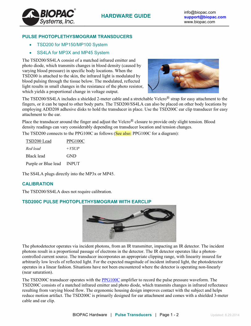
[email protected] [email protected] www.biopac.com
BIOPAC Hardware | Pulse Transducers | Page 1 - 2 Updated: 8.29.2014
PULSE PHOTOPLETHYSMOGRAM TRANSDUCERS
• TSD200 for MP150/MP100 System
• SS4LA for MP3X and MP45 System The TSD200/SS4LA consist of a matched infrared emitter and photo diode, which transmits changes in blood density (caused by varying blood pressure) in specific body locations. When the TSD200 is attached to the skin, the infrared light is modulated by blood pulsing through the tissue below. The modulated, reflected light results in small changes in the resistance of the photo resistor, which yields a proportional change in voltage output. The TSD200/SS4LA includes a shielded 2-meter cable and a stretchable Velcro® strap for easy attachment to the fingers, or it can be taped to other body parts. The TSD200/SS4LA can also be placed on other body locations by employing ADD208 adhesive disks to hold the transducer in place. Use the TSD200C ear clip transducer for easy attachment to the ear. Place the transducer around the finger and adjust the Velcro® closure to provide only slight tension. Blood density readings can vary considerably depending on transducer location and tension changes. The TSD200 connects to the PPG100C as follows (See also: PPG100C for a diagram):
TSD200 Lead PPG100C Red lead +VSUP
Black lead GND
Purple or Blue lead INPUT
The SS4LA plugs directly into the MP3x or MP45.
CALIBRATION The TSD200/SS4LA does not require calibration.
TSD200C PULSE PHOTOPLETHYSMOGRAM WITH EARCLIP
The photodetector operates via incident photons, from an IR transmitter, impacting an IR detector. The incident photons result in a proportional passage of electrons in the detector. The IR detector operates like a photon-controlled current source. The transducer incorporates an appropriate clipping range, with linearity insured for arbitrarily low levels of reflected light. For the expected magnitude of incident infrared light, the photodetector operates in a linear fashion. Situations have not been encountered where the detector is operating non-linearly (near saturation).
The TSD200C transducer operates with the PPG100C amplifier to record the pulse pressure waveform. The TSD200C consists of a matched infrared emitter and photo diode, which transmits changes in infrared reflectance resulting from varying blood flow. The ergonomic housing design improves contact with the subject and helps reduce motion artifact. The TSD200C is primarily designed for ear attachment and comes with a shielded 3-meter cable and ear clip.
HARDWARE GUIDE
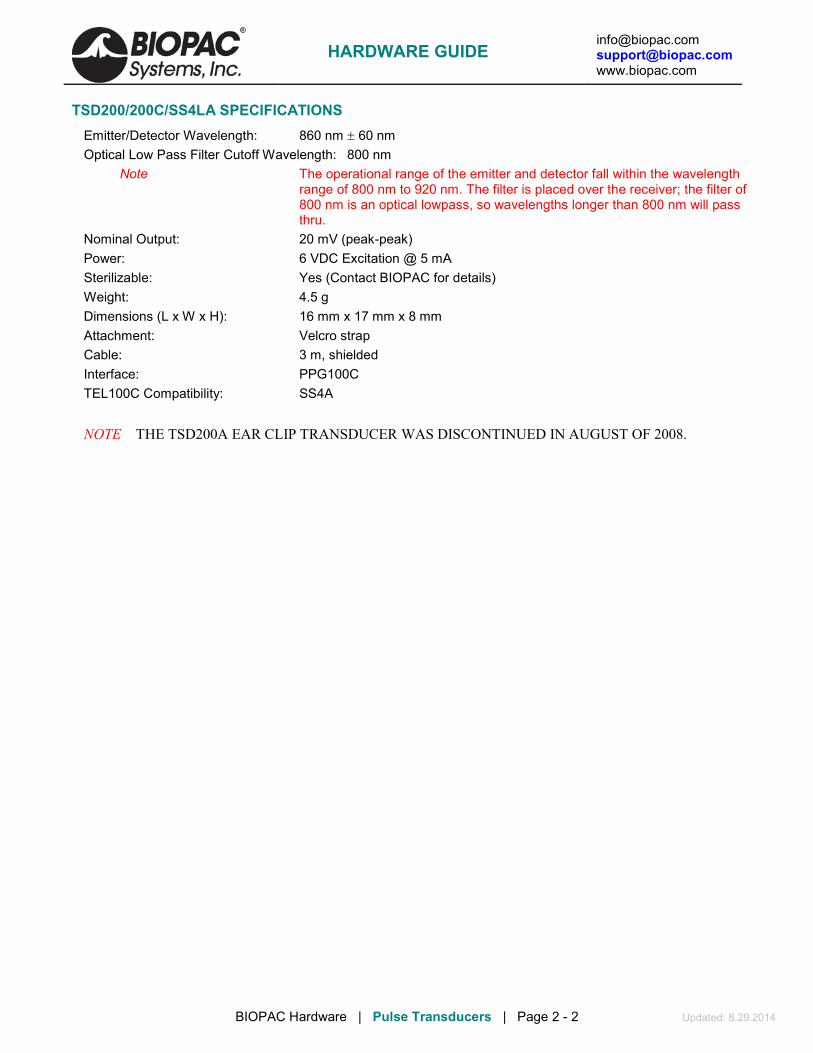
[email protected] [email protected] www.biopac.com
BIOPAC Hardware | Pulse Transducers | Page 2 - 2 Updated: 8.29.2014
TSD200/200C/SS4LA SPECIFICATIONS Emitter/Detector Wavelength: 860 nm ± 60 nm Optical Low Pass Filter Cutoff Wavelength: 800 nm
Note The operational range of the emitter and detector fall within the wavelength range of 800 nm to 920 nm. The filter is placed over the receiver; the filter of 800 nm is an optical lowpass, so wavelengths longer than 800 nm will pass thru.
Nominal Output: 20 mV (peak-peak) Power: 6 VDC Excitation @ 5 mA Sterilizable: Yes (Contact BIOPAC for details) Weight: 4.5 g Dimensions (L x W x H): 16 mm x 17 mm x 8 mm Attachment: Velcro strap Cable: 3 m, shielded Interface: PPG100C TEL100C Compatibility: SS4A NOTE THE TSD200A EAR CLIP TRANSDUCER WAS DISCONTINUED IN AUGUST OF 2008.
HARDWARE GUIDE

[email protected] [email protected] www.biopac.com
BIOPAC Hardware | TSD203 | Page 1 - 1 Updated: 3.25.2014
TSD203 – ELECTRODERMAL RESPONSE TRANSDUCER The TSD203 is a set of two Ag-AgCl electrodes, which incorporate molded housings designed for finger attachment. The TSD203 is used when measuring the electrodermal response. Each transducer includes a stretchable Velcro® strap for easy attachment.
Connectors: Blue shrink tubing = Vin+ & Vin-, unmarked = GND
When the TSD203 is used to measure electrodermal response, the choice of electrolyte is extremely important. A higher impedance electrolyte using hyposaturated electrolyte concentrations of Cl- (on the order of physiological levels) is necessary for effective monitoring of local eccrine activity.
Use GEL101 as an isotonic, hyposaturated, conductant with the TSD203 EDR transducer. Trace conductive parts (metal parts) do not make contact to the subject. TSD203 is not recommended for MRI use.
Storing and Cleaning
1. Store the transducer in a clean, dry area. 2. After use, clean the transducer with cold to tepid water.
a) DO NOT use hot water. b) Cotton swabs are suggested. c) Let the transducer dry completely before storing it.
3. DO NOT allow transducers to come in contact with each other during storage (adverse reaction could occur).
4. Transducers may form a brown coating if they have not been used regularly. To remove the coating, gently polish the surface of the transducer element with non-metallic material or wipe it with mild ammonium hydroxide. Rinse with water and store the transducer in a clean, dry container.
TSD203 SPECIFICATIONS Electrode Type: Ag-AgCl (unpolarizable) Attachment: integral Velcro strap Contact area: 6 mm (dia) Sterilizable: Yes, contact BIOPAC Cable length: 3 m Interface: EDA100C Dimensions (LxWxH each): 16 mm x 17 mm x 8 mm TEL100C compatibility: SS3A
TSD203 CALIBRATION See the EDA100C transducer module.
HARDWARE GUIDE

[email protected] [email protected] www.biopac.com
BIOPAC Hardware | RSP100C | Page 1 - 3 Updated: 8.29.2014
RSP100C – RESPIRATION PNEUMOGRAM AMPLIFIER MODULE The RSP100C respiration pneumogram amplifier module is a single channel, differential amplifier designed specifically for recording respiration effort. The RSP100C is designed for use in the following applications: Allergic responses analysis Exercise physiology studies Psychophysiological investigations Respiration rate determination Sleep studies The RSP100C works with the TSD201 respiration transducer to measure abdominal or thoracic expansion and contraction. The RSP100C includes a lower frequency response selection switch that permits either absolute (DC) or relative (via a 0.05 high pass filter) respiratory effort measurements. The following illustration shows the placement and connections for recording thoracic respiration effort using the RSP100C and the TSD201 respiration transducer.
RSP100C AMPLIFIER MODULE SETTINGS The RSP100C has three built-in filters and a number of different gain settings for the different uses of the transducer.
Type of Use Gain Setting Low Pass Filter .5 Hz Filter .05 Hz Filter
General 10 10 Hz DC DC
Exercise Physiology 10 1 Hz .5 Hz .05 Hz
Small Animal 20+ 10 Hz .5 Hz .05 Hz
General For most measurements with little or no subject movement. The most common setting is with all three filters at their bottom settings (10 Hz, DC, and DC) and the gain set at 10. This allows any signals slower than 10 Hz (cyclic rate) to pass, and is usually good for most measurements with little or no subject movement.
Exercise physiology The transducer produces the best signal at the lowest gain and with all three filter settings at their top position (1 Hz, .5 Hz, and .05 Hz). This setting will allow only a signal between .5 Hz and 1 Hz to be transmitted, filtering out most of the signal interference due to extraneous chest and abdominal movement resulting from limb motion.
Smaller animals For measurements with very small changes in thoracic circumference, increase the gain to magnify the signal. Increase the gain until a clear signal is obtained, but not so much that the signal is clipped.
HARDWARE GUIDE

[email protected] [email protected] www.biopac.com
BIOPAC Hardware | RSP100C | Page 2 - 3 Updated: 8.29.2014
PLACEMENT AND CONNECTIONS This illustration shows the placement and connections to record thoracic and abdominal respiration effort using two RSP100C amplifier modules and two TSD201 respiration transducers.
Connections for Thoracic and Abdominal
Respiratory Effort Measurement
This graph shows the relationship between abdominal and thoracic expansion and contraction.
Calculate the peak-to-peak values for both abdominal and thoracic respiration effort were calculated with AcqKnowledge, and then the two peak-to-peak values were compared in the lowest channel. When abdominal breathing effort changes with respect to thoracic breathing effort, the lowest channel will quantify the extent of the change.
Thoracic vs. Abdominal respiration effort data
FREQUENCY RESPONSE CHARACTERISTICS The 0.05 Hz high pass lower frequency response setting is a single pole roll-off filter. The 0.5 Hz high pass lower frequency response setting is a two pole roll-off filter.
Modules can be set for 50 or 60 Hz notch options, depending on the destination country. Generally, wall-power line frequency is 60 Hz in the United States and 50 Hz in most of Europe and China; if necessary contact BIOPAC to determine the appropriate line frequency. See also: Sample frequency response plots: 1 Hz LP
10 Hz LP
RSP100C CALIBRATION None required.
HARDWARE GUIDE

[email protected] [email protected] www.biopac.com
BIOPAC Hardware | RSP100C | Page 3 - 3 Updated: 8.29.2014
RSP100C SPECIFICATIONS Gain: 10, 20, 50, 100 Output Range: ±10 V (analog) Frequency Response Low Pass Filter: 1 Hz, 10 Hz High Pass Filter: DC, 0.05 Hz, 0.5 Hz Excitation Voltage ±0.5 V Noise Voltage: 0.2 µV rms – amplifier contribution Signal Source: TSD201 Weight: 350 g Dimensions: 4 cm (wide) x 11 cm (deep) x 19 cm (high) Input Connectors: Three 1.5 mm male Touchproof sockets (VIN+, Ground, VIN-)
HARDWARE GUIDE

[email protected] [email protected] www.biopac.com
BIOPAC Hardware | TSD200-MRI | Page 1 - 1 Updated: 1.13.2015
TSD200-MRI PHOTOPLETHYSMOGRAM TRANSDUCER
The TSD200-MRI photoplethysmogram (PPG) transducer operates with the PPG100C-MRI to record the blood volume pulse waveform via optical (photoplethysmogram) methods. The TSD200-MRI consists of a matched infrared emitter and photo diode detector, which transmits changes in infrared reflectance resulting from varying blood flow. Blood is highly reflective of near infrared light wavelengths, due to the heme subunit of hemoglobin. When the PPG transducer is placed on the skin, in proximity to capillaries, the reflectance of the infrared light from the emitter to the detector will change in accordance to capillary blood volume. The PPG waveform peaks when capillary blood volume is maximized.
The transducer optics are designed to sense diffuse surfaces, including the skin surfaces of finger or toe. The transducer is sensitive to Blood Volume Pulse (BVP) via photo-plethysmographic methods.
The Diode and Phototransistor are mounted side by side on parallel axis in a black polyurethane housing. The Phototransistor is encased in a dark epoxy package which filters out visible ambient light. The transducer has a shielded 3-meter cable.
The ergonomic housing design improves contact with the subject and helps reduce motion artifact. Trace conductive (metal) parts of transducer do not make contact to the subject.
The TSD200-MRI only operates with the PPG100C-MRI amplifier.
MRI Use: MR Conditional to 3T Note: Conductive parts of transducer are electrically and thermally isolated from subject. Components: Polyvinyl chloride (PVC) Plastic, Polymer thick film device (rigid substrate, printed semi- conductor), Copper clad fiberglass lamination (PCB material), Tinned copper wire, Silicone elastomer
CONNECTIONS For MRI applications: Use the MECMRI-TRANS Cable/Filter to connect the TSD200-MRI to the PPG100C-MRI. See BIOPAC Application Notes regarding the proper installation of MECMRI cables for recording in an MRI environment.
For non-MRI applications: Connect the TSD200-MRI directly to the PPG100C-MRI.
HARDWARE GUIDE

[email protected] [email protected] www.biopac.com
BIOPAC Hardware | TSD201 | Page 1 - 2 Updated: 12.8.2014
TSD201 – RESPIRATION TRANSDUCER
Sample Data for Subject at Rest
MRI Usage: MR Conditional to 7T Tested in a variety of gradient conditions to 7T. Note: Conductive parts of transducer are electrically and thermally isolated from subject. Components: Nylon/Velcro® Chest Strap, Mylar, Polyvinyl Chloride (PVC) Plastic, Acrylonitrile Butadiene Styrene (ABS) Thermo-molded Plastic, Polymer thick-film device (flexible substrate printed semi-conductor), Copper clad fiberglass lamination (PCB material), Tinned copper wire, Silicone elastomer
The TSD201 is a strain gauge transducer designed to measure respiratory-induced changes in thoracic or abdominal circumference, and can therefore be used to record respiratory effort. The TSD201 is essentially a resistive transducer and responds in a linear fashion to changes in elongation through its length, with resistance increasing as length increases. The transducer is ideal for a variety of applications because it presents minimal resistance to movement and is extremely unobtrusive. Due to its unique construction, the TSD201 can measure extremely slow respiration patterns with no loss in signal amplitude while maintaining excellent linearity and minimal hysteresis. The TSD201 plugs directly into the RSP100C amplifier module. It includes a fully adjustable nylon strap to accommodate a large range of circumferences (9 cm to 130 cm). To attach the nylon belt to the respiration transducer, thread the nylon strap through the corresponding slots so the strap clamps into place when tightened. Place the transducer around the body at the level of maximum respiratory expansion. This location will vary from the erect to supine positions (generally about 5 cm below the armpits). Correct tension adjustment of the respiration transducer is important. For best sensitivity, the transducer must be just slightly tight at the point of minimum circumference (maximum expiration). To obtain proper tension, stretch the belt around the body and have the subject exhale. At maximum expiration, adjust the nylon strap so there is slight tension to hold the strap around the chest. For proper operation, there must always be at least a small amount of tension on the transducer. The transducer has three 1.5 mm Touchproof connectors to connect to the amplifier. Insert the two blue lead transducer pin plugs into the two RSP100C inputs labeled XDCR. Either blue lead can be connected to either XDCR input. Insert the single black transducer lead into the GND input of the RSP100C. The respiration transducer is ready for measurement. Trace conductive parts (metallic parts) do not make contact to the subject.
HARDWARE GUIDE

[email protected] [email protected] www.biopac.com
BIOPAC Hardware | TSD201 | Page 2 - 2 Updated: 12.8.2014
PLACEMENT AND CONNECTIONS
using one TSD201 respiration transducer
using two TSD201 respiration transducers
Placement and Connections for Thoracic and Abdominal Respiratory Effort Measurement
TSD201 CALIBRATION The TSD201 does not require calibration.
TSD201 SPECIFICATIONS True DC Response: Yes Variable Resistance Output: 5-125 KΩ (increases as length increases) Circumference Range: 15 cm x 150 cm (can be increased with a longer strap) Attachment: Velcro® strap (adjustable length) Sterilizable: Yes (contact BIOPAC for details) Sensor Weight: 18 g Sensor Dimensions: 66 mm (long), 40 mm (wide), 15 mm (thick) Cable Length: 3 meters Interface: RSP100C TEL100C compatibility: SS5B Frequency Response: DC-500 Hz Operating Humidity Range: 0-95% non-condensing Operating Temperature Range: -20° C to +80° C
Sensitivity: Monotonic analog output. Sufficiently sensitive to detect heart motion in thoracic cavity, in addition to thoracic/abdominal expansion and contraction.
HARDWARE GUIDE

[email protected] [email protected] www.biopac.com
BIOPAC Hardware | TSD221-MRI | Page 1 - 2 Updated: 10.21.2014
TSD221-MRI – RESPIRATION TRANSDUCER This MR Safe fully pneumatic respiration transducer measures subject respiration (thoracic or abdominal) in the MRI. The extremely unobtrusive design presents minimal resistance to movement and can measure arbitrarily slow to very fast respiration patterns with no loss in signal amplitude, while maintaining excellent linearity and minimal hysteresis. The TSD221-MRI incorporates a bellows-based design. As the subject breathes, a minimum and
maximum circumference for respiratory measurement is established, and the tension and relaxation of the bellows changes the associated bellows pressure. The bellows’ behavior will be a tendency to come to physical equilibrium at the mean (average) circumference. This behavior results in effective high pass filtering of a very low value (~0.001 Hz). The TSD221-MRI includes the respiration sensor in a mesh strap with self-adhering adjustable chest band (70 cm), a pressure transducer (±2.5 cm H2O TSD160A), and three cascadable segments of tubing for up to 15.8 m (AFT30-XL 10 m, AFT30-L 4 m, and AFT30 1.8 m). TSD221-MRI has no ferrous metals or conductive parts. The TSD221-MRI connects to the DA100C and an MP150 system (and does not require the MECMRI-DA or MECMRI-TRANS cable sets).
MRI Use: MR Safe Components: Respiration sensor in compliant mesh sleeving, adjustable flexible chest band: TSD160A
transducer, tubing for up to 15.8 meters (AFT30XL + AFT30L + AFT30).
Placement and Connections Place the transducer around the body at the level of maximum respiratory expansion, generally about 5 cm below the armpits but location will vary from the erect to supine positions. Correct tension adjustment of the respiration transducer is important. For best sensitivity, the transducer must be just slightly tight at the point of minimum circumference (maximum expiration). To obtain proper tension, stretch the belt around the body and have the subject exhale. At maximum expiration, adjust the nylon strap so there is slight tension to hold the strap around the chest. To use the TSD221-MRI, place sensing band around subject’s chest and attach pneumatic tubing to the band. Then route tubing from the MRI table/bore through an available wave guide to location of MP System with DA100C and TSD160A pressure transducer, and attach tubing to the pressure transducer port. Be careful to check all tubing junctions, as the transducer will fail to operate optimally if any leaks are present.
HARDWARE GUIDE

[email protected] [email protected] www.biopac.com
BIOPAC Hardware | TSD221-MRI | Page 2 - 2 Updated: 10.21.2014
TSD221-MRI Specifications Sensor Construction: MR Safe materials True DC Response: Yes Pneumatic Design: Attaches to TSD160A/DA100C Sensitivity: Linear Analog Output. Sufficiently sensitive to detect heart motion in thoracic
cavity, in addition to thoracic/abdominal expansion and contraction. Circumference Range: 50 cm x 120 cm (can be increased with a longer strap) Attachment: Velcro® strap (adjustable length) Sterilizable: Yes (contact BIOPAC for details) Sensor Weight: 67 grams Sensor Dimensions: 45 cm (long), 3.8 cm (wide), 1.1 cm (thick) Tubing: AFT30XL, 10 m, AFT30L, 4 m, AFT30, 1.8 m TSD160A Operational Pressure ±2.5 cm H2O Voltage Output: 327.5 µV/cm H2O (normalized to 1 V excitation) Click for detailed transducer specs Interface: DA100C Frequency Response: 0.001 – 100 Hz* Sensor Operating Humidity Range: 0-100% (can be used under water) Operating Temperature Range: 0° C to 50° C (compensated) Respiration Measurement Options: TSD201 for MP150 System (MR Conditional for 7T) SS5LB for MP36 or MP36R System SS5B for TEL100C Telemetry System
*NOTE: With any pressure based system, minute leaks are possible. Air leaks will contribute to a high pass
filtering of respiration data. As long as leaks are minute, associated high pass filtering action will not materially affect the quality of the respiration data. To largely circumvent high pass filtering effects of leaks on respiration data, simply record data with the 0.05 Hz HP filter selected on the associated module.
HARDWARE GUIDE

[email protected] [email protected] www.biopac.com
BIOPAC Hardware | SKT100C | Page 1 - 3 Updated: 1.8.2014
SKT100C – SKIN TEMPERATURE AMPLIFIER MODULE The SKT100C skin temperature amplifier module is a single channel, differential amplifier designed especially for skin and core temperature and respiration flow (rate) monitoring. The SKT100C is designed for use in the following applications:
General temperature measurement Respiration rate determination Psychophysiological investigations Sleep studies
The SKT100C employs any of the BIOPAC TSD202 series thermistor transducers to measure temperature. The SKT100C includes a lower frequency response selection switch that permits either absolute (DC) or relative (via a 0.05 Hz or 0.5 Hz high pass filter) temperature measurements.
Connections and placement for measuring respiration flow using the SKT100C and the TSD202A fast-response surface temperature thermistor.
Respiration flow measurement using SKT100C and TSD202B
Connections and placement for measuring index fingertip temperature using the SKT100C and the TSD202D digit surface temperature probe. The probe is secured to the finger using the Velcro strap on the transducer.
Index finger temperature measurement with TSD202D
This graph shows the relationship between fingertip skin temperature, skin conductance and heart rate. This configuration of physiological measurements can be useful for psychological testing and evaluation.
SKT versus EDA versus Heart Rate Waveforms
HARDWARE GUIDE

[email protected] [email protected] www.biopac.com
BIOPAC Hardware | SKT100C | Page 2 - 3 Updated: 1.8.2014
FREQUENCY RESPONSE CHARACTERISTICS The 0.05 Hz high pass lower frequency response setting is a single pole roll-off filter.
Modules can be set for 50 Hz or 60 Hz notch options, depending on the destination country. Generally, wall-power line frequency is 60 Hz in the United States and 50 Hz in most of Europe and China; if necessary contact BIOPAC to determine the appropriate line frequency.
See also: Sample frequency response plots: 1 Hz LP and 10 Hz LP
SKT100C CALIBRATION Temperature Measurements
To measure absolute temperature, set the lower frequency response to DC.
To measure relative temperature changes, set the lower frequency response to 0.05 Hz or 0.5 Hz.
To set up AcqKnowledge to record temperature directly, perform the following:
A. Lower frequency response at DC: In the scaling window, set the input voltages so they map to the respective temperature ranges indicated by the sensitivity setting. In this case, 0 V will always map to 90° F.
B. Lower frequency response at 0.05 Hz or 0.5 Hz: In the scaling window, set the input voltages so they map to the respective temperature ranges indicated by the sensitivity setting. In this case, 0 V will map to the mean (average) temperature during the recording. Use this setting when temperature delta measurement is important, as when monitoring airflow (respiration rate).
Skin Temperature Measurements To measure absolute skin temperature, place the lower frequency response to DC.
To measure relative skin temperature changes or respiration rate (airflow), place the lower frequency response to 0.05 Hz or 0.5 Hz.
To set up AcqKnowledge to record temperature directly, perform the following:
A. Lower frequency response to DC: In the scaling window, set the input voltages so they map to the “DC on” temperature ranges indicated by the sensitivity setting. In this case, 0 V will always map to 90° F.
Scaling setup window set to correspond to
5°/V setting on SKT100C
B. Lower frequency response to 0.05 Hz or 0.5 Hz.: In the scaling window, set the input voltages so they map to the respective temperature ranges indicated by the sensitivity setting. In this case, 0 V will map to the mean (average) temperature measured during the recording and 1 V will map to one-half the “delta range” values, which corresponds to the chosen Gain setting.
HARDWARE GUIDE
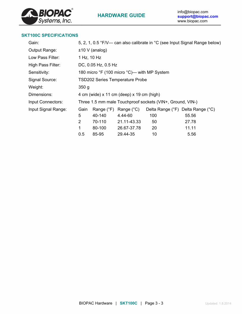
[email protected] [email protected] www.biopac.com
BIOPAC Hardware | SKT100C | Page 3 - 3 Updated: 1.8.2014
SKT100C SPECIFICATIONS Gain: 5, 2, 1, 0.5 °F/V— can also calibrate in °C (see Input Signal Range below)
Output Range: ±10 V (analog)
Low Pass Filter: 1 Hz, 10 Hz
High Pass Filter: DC, 0.05 Hz, 0.5 Hz
Sensitivity: 180 micro °F (100 micro °C)— with MP System
Signal Source: TSD202 Series Temperature Probe
Weight: 350 g
Dimensions: 4 cm (wide) x 11 cm (deep) x 19 cm (high)
Input Connectors: Three 1.5 mm male Touchproof sockets (VIN+, Ground, VIN-)
Input Signal Range: Gain Range (°F) Range (°C) Delta Range (°F) Delta Range (°C) 5 40-140 4.44-60 100 55.56 2 70-110 21.11-43.33 50 27.78 1 80-100 26.67-37.78 20 11.11 0.5 85-95 29.44-35 10 5.56
HARDWARE GUIDE

[email protected] [email protected] www.biopac.com
BIOPAC Hardware | TSD202 Series | Page 1 - 2 Updated: 1.10.2014
TSD202 SERIES TEMPERATURE TRANSDUCERS
MRI Usage: MR Conditional (TSD202A and TSD202E only) Condition: Tested to 3T. TSD202A and TSD202E Components: Silicon semiconductor, copper wire, polyvinyl chloride (PVC) plastic
TSD202A The TSD202A employs a fast response thermistor, and is appropriate for use in locations where temperature changes rapidly, as with the temperature changes of inspired/expired breath. The TSD202A is useful for measuring skin temperature (in small areas) or airflow rate resulting from respiration, and is not designed for liquid immersion. For measuring skin (surface) temperature, simply tape the TSD202A to the location of interest. For measuring respiration rates, by monitoring airflow, place the TSD202A next to the mouth or nose so that inspired or exhaled air will intercept the tip of the TSD202A transducer. Trace conductive parts (metallic parts) do not make contact to the subject.
RX202A Replacement Fast-response Temperature Sensor
TSD202B The TSD202B is a “Banjo” style surface probe useful for measuring surface temperature. The “Banjo” design allows efficient skin temperature measurements on a variety of body locations. The TSD202B is not designed for liquid immersion. For measuring skin (surface) temperature, simply tape the TSD202B to the location of interest.
TSD202C The TSD202C encases the internal thermistor in a stainless steel, waterproof housing, and is designed for liquid immersion and other temperature measurement applications where ruggedness is required and fast response is not critical.
TSD202D The TSD202D is a modified TSD202B, with a housing that conforms to curved skin surfaces and includes a stretchy Velcro® strap for easy attachment to the fingers or toes. The “Banjo” design allows efficient skin temperature measurements. The TSD202D is not designed for liquid immersion. For measuring skin (surface) temperature, simply tape the TSD202D to the location of interest. Insert the two blue lead transducer pin plugs into the two SKT100C inputs labeled XDCR. Either blue lead can be connected to either XDCR input.
TSD202E The TSD202E is a general-purpose waterproof thermistor. Trace conductive parts (metallic parts) do not make contact to the subject.
TSD202F The TSD202F is a small, flexible waterproof thermistor.
HARDWARE GUIDE

[email protected] [email protected] www.biopac.com
BIOPAC Hardware | TSD202 Series | Page 2 - 2 Updated: 1.10.2014
TSD202 SERIES SPECIFICATIONS Response Time TSD202A: 0.6 sec TSD202B: 1.1 sec TSD202C: 3.6 sec TSD202D: 1.1 sec TSD202E: 0.9 sec TSD202F: 1.1 sec Size with housing TSD202A: 1.7 mm (diameter) x 5 mm (long) TSD202B: 9.8 mm (diameter) x 3.3 mm (high) TSD202C: 4 mm (diameter) x 115 mm (long) TSD202D: 16 mm (long) x 17 mm (wide) x 8 mm (high) (TSD202D – sensor only: 10 mm sensing diameter, 1.4 mm sensor thickness) TSD202E: 9.8 mm (long) x 3.3 mm (diameter) TSD202F: 9.8 mm (long) x 3.3 mm (diameter) Sensor only: 10 mm sensing diameter, 1.4 mm sensor thickness Interface: SKT100C Nominal Resistance: 2252 Ω at 25° C Maximum operating temperature: 60° C (when used with SKT100C) Accuracy and Interchangability 0.2° C Cable length: 3 meters Compatibility: YSI series 400 temperature probes Sterilizable: Yes (contact BIOPAC for details) TEL100 Compatibility: SS6
HARDWARE GUIDE

[email protected] [email protected] www.biopac.com
BIOPAC Hardware | EL120 | Page 1 - 1 Updated: 2.28.2013
ELECTRODES In selecting the application site for any style of electrode, care should be taken that:
1) Electrode site is dry and free of excessive hair.
2) Electrode is not placed over scar tissue or on an area of established erythema or with a lesion of any kind.
3) Skin is properly prepared. (Prepare the skin at the electrode site. Use the ELPAD to lightly abrade the skin surface. Use a brisk dry rub to prepare the application site. Avoid excessive abrasion of the skin surface.)
EL120 The EL120 electrode has contact posts designed to improve contact through fur or hair. The 12 posts create a 10 mm contact area. The posts are 2mm deep to push through fur/hair to provide good contact with the skin surface.
Shipped in packs of 10.
Silver-silver chloride (Ag-AgCl) electrodes provide accurate and clear transmission of surface biopotentials and are useful for recording all surface biopotentials on animals and human EEG.
Notes:
It is not necessary to use an EL120 for the ground; a generic electrode can be used for ground.
Requires one LEAD120 per electrode.
HARDWARE GUIDE

[email protected] [email protected] www.biopac.com
BIOPAC Hardware | EL160 Series | Page 1 - 1 Updated: 6.10.2014
ELECTRODES In selecting the application site for any style of electrode, care should be taken that: 1) Electrode site is dry and free of excessive hair. 2) Electrode is not placed over scar tissue or on an area of established erythema or with a lesion of any kind. 3) Skin is properly prepared. (Prepare the skin at the electrode site. Use the ELPAD to lightly abrade the skin
surface. Use a brisk dry rub to prepare the application site. Avoid excessive abrasion of the skin surface.)
EL160 Gold Cup Reusable gold cup electrode with 10 mm cup diameter and 1.2 m cable. One electrode per package.
• EL160 with black cable • EL160-R with red cable • EL160-W with white cable
The leadwire terminates in a standard Touchproof connector. Use with MEC Series Module Extension Cables for MP150 Systems or SS1LA Touchproof Electrode Lead Adapter for MP3X Systems.
EL160-Ear – Ear Clip Electrodes This pair of gold-plated ear clip electrodes has 1.2 meter Teflon-insulated leadwires ending in standard Touchproof connectors. Use with MEC Series Module Extension Cables for MP Research Systems or SS1LA Touchproof Electrode Lead Adapter for BSL Systems. Before use, check the electrode for damage and excessive wear. If in doubt, replace it.
Also available as individual standard gold cup electrodes: EL160 with green cable, EL160-R with red cable, and EL160-W with white cable. Please do not use these electrodes unless you have been trained in the proper use and placement of these devices.
Cleaning Earclips and Surface Electrodes After each use clean with warm water and a mild detergent. Use a soft cloth or Q-tip. Then disinfect with 70% alcohol or a water based disinfectant. Do not soak in water for prolonged periods, it causes deterioration of the electrode.
EL160-Ear Specifications Electrodes: two
Material: Au Cup (gold plated discs)
Style: Ear Clip Electrodes
Leadwires: 1.2 meter Teflon-insulated leadwires
Connector: leadwires terminate in standard Touchproof connectors
Non-sterile
Reusable
HARDWARE GUIDE

[email protected] [email protected] www.biopac.com
BIOPAC Hardware | EL250 SERIES | Page 1 - 2 Updated: 1.12.2015
ELECTRODES
In selecting the application site for any style of electrode, care should be taken that:
1) Electrode site is dry and free of excessive hair.
2) Electrode is not placed over scar tissue or on an area of established erythema or with a lesion of any kind.
3) Skin is properly prepared. (Prepare the skin at the electrode site. Use the ELPAD to lightly abrade the skin surface. Use a brisk dry rub to prepare the application site. Avoid excessive abrasion of the skin surface.)
EL250 Series Reusable Ag-AgCI Electrodes EL250 Series reusable electrodes incorporate a variety of features which improve biopotential recordings.
Non-polarizable
Sintered to increase electrode/electrolyte contact area
Does not require chloriding
Reusable via resurfacing
High stability recordings, to DC, when used with chloride salt gel electrolyte
Electrolyte gel cavity reduces artifact due to electrolyte/electrode motion and minimizes electrolyte dissipation/drying over long term recordings
Surface biopotentials can be accurately and clearly transmitted with silver-silver chloride electrodes. EL250 Series reusable electrodes are permanently connected to 1-meter leads and terminate in standard 1.5 mm female Touchproof sockets for direct connection to the SS1L shielded electrode lead adapter. Use shielded electrode leads for minimal interference. The unshielded electrode leads work best as ground electrodes. Typically, one biopotential input requires two shielded electrodes for signal inputs and one unshielded electrode for ground.
EL254 Ag-AgCl Unshielded Electrode, 7.2 mm diameter housing, 4 mm contact area, includes 1 m lead terminated with a 1.5 mm female Touchproof socket for connection to the SS1L.
EL254S Ag-AgCl Shielded Electrode, 7.2 mm diameter housing, 4 mm contact area, includes 1 meter lead terminated with two 1.5 mm female Touchproof sockets for connection to the SS1L. The gray lead plug is for the electrode contact; the black lead pin plug is for the lead shield.
EL258 Ag-AgCl Unshielded Electrode, 12.5 mm diameter housing, 8 mm contact area, includes 1 meter lead terminated with a 1.5 mm female Touchproof socket for connection to the SS1L.
EL258S Ag-AgCl Shielded Electrode, 12.5 mm diameter housing, 8 mm contact area, includes 1 meter lead terminated with two 1.5 mm female Touchproof sockets for connection to the SS1L. The gray lead plug is for the electrode contact; the black lead pin plug is for the lead shield.
EL258H Features a 2 mm gel injection hole, useful for EEG monitoring; use as both recording and reference electrodes. 12.5 mm diameter housing, 8 mm contact area, 1 m lead terminated with 1.5 mm female Touchproof socket for connection to the SS1L.
EL250 Series Radiotranslucent Ag-AgCI Recording Electrodes (Animals Only) MRI Use: MR Conditional (tested to 9T)
Condition: For use with animals only, due to possible heating hazards associated with incomplete filling of gel reservoir with electrode gel.
EL254RT/258RT Components:
Electrode: Ag/AgCl Lead wire: Carbon
Enclosure: Epoxy Wire insulation: PVC
HARDWARE GUIDE

[email protected] [email protected] www.biopac.com
BIOPAC Hardware | EL250 SERIES | Page 2 - 2 Updated: 1.12.2015
EL254RT Silver-silver chloride (Ag-AgC1) electrodes provide accurate and clear transmission of surface biopotentials. Reusable electrodes are permanently connected to robust and pliable leadwires. The leadwires terminate in standard Touchproof connectors for interfacing to 100C series Biopotential modules or extension cables. 7.2 mm diameter housing, 4 mm contact area, includes 1.5 m lead terminated with a 1.5 mm female Touchproof socket for connection to the SS1L.
EL258RT As described above for EL254RT but with larger dimensions. 12.5 mm diameter housing, 8 mm contact area, includes 1.5 m lead terminated with 1.5 mm female Touchproof socket for connection to the SS1L.
All EL250 Series electrodes require adhesive disks (ADD200 series) and recording gel (GEL1 or the preferred recording gel). See the Electrode Accessories section for further description.
Instructions for EL250 Series Electrodes 1) Store electrodes in clean, dry area.
2) After use, clean electrode with cold to tepid water
a) DO NOT use hot water.
b) Cotton swabs are suggested.
3) The electrodes should be completely dry before returning to storage.
4) DO NOT allow the electrodes to come in contact with each other during storage (adverse reaction could take place).
Electrodes may form a brown coating if they have not been used regularly. This should be removed by gently polishing the surface of the electrode element with non-metallic material. Wiping with mild ammonium hydroxide will also remove this coating. Rinse with water and store the electrode in a clean, dry container.
5) Remove an appropriate size electrode washer (ADD204, ADD208, or ADD212) from its waxed paper strip and carefully apply the washer to the electrode so the center hole of the washer is directly over the electrode cavity.
6) Fill the cavity with electrode gel (GEL100). No air bubbles should be present in the cavity.
7) Remove the white backing from the washer to expose the second adhesive side.
8) Place electrode on prepared skin area and smooth the washer into place.
9) Apply a few drops of electrode gel to fingertip and rub the exposed side of the adhesive washer (around the electrode) to rid its surface of adhesive quality.
HARDWARE GUIDE

[email protected] [email protected] www.biopac.com
BIOPAC Hardware | EL350 SERIES | Page 1 - 1 Updated: 8.29.2014
ELECTRODES In selecting the application site for any style of electrode, care should be taken that: 1) Electrode site is dry and free of excessive hair. 2) Electrode is not placed over scar tissue or on an area of established erythema or with a lesion of any kind. 3) Skin is properly prepared. (Prepare the skin at the electrode site. Use the ELPAD to lightly abrade the skin
surface. Use a brisk dry rub to prepare the application site. Avoid excessive abrasion of the skin surface.)
EL350 SERIES BAR LEAD ELECTRODES
Bar lead electrodes are recommended when applying a stimulus during nerve conduction, somatosensory or muscle twitch recordings with human subjects. Two concave tin electrode disks are placed 30mm apart in a watertight acrylic bar. EL350 unshielded bar lead electrode for use with the STMISO. EL350S shielded bar lead electrode for biopotential recordings. EL351 convex bar lead electrode for stimulating
EL350 SPECIFICATIONS Electrode space: 30 mm Lead length: 61 cm Connector type: BNC Interface: BSLSTM Stimulator or SS58L Low Voltage Stimulator
HARDWARE GUIDE

[email protected] [email protected] www.biopac.com
BIOPAC Hardware | EL450 SERIES | Page 1 - 1 Updated: 8.29.2014
ELECTRODES In selecting the application site for any style of electrode, care should be taken that: 1) Electrode site is dry and free of excessive hair. 2) Electrode is not placed over scar tissue or on an area of established erythema or with a lesion of any kind. 3) Skin is properly prepared. (Prepare the skin at the electrode site. Use the ELPAD to lightly abrade the skin
surface. Use a brisk dry rub to prepare the application site. Avoid excessive abrasion of the skin surface.)
EL450 SERIES NEEDLE ELECTRODES
Use for stimulation or recording in animal subjects and tissue preparations. The 28-gauge stainless steel needles are Teflon-coated, with flexible cable terminating in 1.5 mm Touchproof connectors. The coating prevents the needle from making contact with the subject except at the very tip of the needle, which is exposed. For applications that require better contact between the electrode and the subject to record a good signal, abrade the needle to remove the Teflon coating. Needle electrodes are shipped non-sterile, so pre-sterilization is required. EL450 Unipolar: 2.5 cm (long) x 300 µm (dia); 61 cm lead
A pair of EL450 electrodes is suitable for either recording or stimulation. EL451 Bipolar: 3.0 cm (long) x 460 µm (dia); 91 cm lead
Use when recording from a single site, as in studies of single muscle fibers. EL452 Unipolar, uncoated: 1.5 cm (long) x 300 µm (dia); 61 cm lead
HARDWARE GUIDE

[email protected] [email protected] www.biopac.com
BIOPAC Hardware | EL500 SERIES | Page 1 - 6 Updated: 1.2.2015
EL500 SERIES – DISPOSABLE ELECTRODES
EL504
EL50 8
The EL500 Series disposable, Ag/AgCl snap electrodes provide the same signal transmission as BIOPAC’s reusable electrodes, with added convenience and hygiene. Each peel-and-stick electrode is pre-gelled and designed for one time use only.
Use the EL500 series electrodes with a wide range of BIOPAC electrode leads and cables, such as SS1L, SS1LA, SS2L, SS2LA, SS2LB, LEAD108 series, Lead 110 series, Lead 110S series or any BIOPAC lead or electrode lead cable assembly indicated for use with snap electrodes.
Electrode Properties – Electrolyte Gel and Chloride Salt Concentration For electrode gels (electrolytes), the higher the chloride salt content, the more conductive the electrode. Higher salt content, pre-gelled, surface electrodes are useful for making fast, high quality measurements of biopotentials, once the electrodes are applied to the skin surface. In addition, wet (liquid) gels further accelerate this process because the electrolyte migrates into the skin surface layers more easily and rapidly. High conductivity electrodes generally have reduced artifact, due to the low generated impedance between electrode and skin surface.
As the chloride salt content of the electrolyte drops, the less conductive the electrode. As the chloride content drops to 10% or less, then the electrode can be increasingly employed for long-term recording (greater than 2 hours), with reduced chance for skin irritation. In addition, hydrogels are gentler on the skin than wet (liquid) gels of the same salt concentration. Hydrogel based electrolytes will not migrate into the skin surface as easily or rapidly as with wet gels.
For Electrodermal activity measurements it’s important to use an electrode with similar (isotonic) chloride salt content as per the skin surface, so as not to hypersaturate or hyposaturate the eccrine glands.
The impedance of the electrode/skin junction is highly dependent on the electrolyte type and the chloride salt concentration. For example, a hydrogel electrode with 4% chloride concentration will have about 10x higher impedance than a wet liquid gel electrode with 10% chloride concentration, after first application to the skin.
Electrode Properties – Backing Adhesive The 500 series disposable electrodes come with a range of adhesive qualities. All electrodes are designed to adhere well to skin surfaces, but the adhesion characteristics can be grouped depending on the application.
The three adhesive groups are identified as follows:
Group 1: strong adhesive
Group 2: moderate adhesive, high tack
Group 3: moderate adhesive, low tack
EL510
EL509
HARDWARE GUIDE

[email protected] [email protected] www.biopac.com
BIOPAC Hardware | EL500 SERIES | Page 2 - 6 Updated: 1.2.2015
Strong adhesive electrodes are best for biopotential measurements when the subject is moving. Moderate adhesive electrodes are optimal for long-term recordings. Lower tack electrodes can be repositioned and are best suited for delicate skin surfaces.
Usage Descriptions - 500 Series Disposable Ag/AgCl electrodes: EL500: Dual high adhesion, high conductivity, low artifact, biopotential electrodes
EL501: High adhesion, high conductivity, low artifact, biopotential electrode
EL502: Long-term recording, high adhesion, low artifact, biopotential electrode
EL503: General purpose, economical, high conductivity, biopotential electrode
EL504: Long-term recording, moderate adhesion, high compliance, low artifact, gentle, biopotential electrode
EL506: Bioimpedance, cardiac output use, strip electrode to establish equipotential lines on skin surface
EL507: Electrodermal activity measurement electrode
EL508: MRI conditional electrode for general-purpose use – use only with LEAD108 series leads
EL509: MRI conditional electrode for electrodermal activity measurement – use only with LEAD108 series leads
EL510: MRI conditional electrode and lead set for general-purpose use
Skin Preparation For highest electrode to skin conductivity, the skin should be lightly abraded with a gentle abrasive wipe, such as BIOPAC’s ELPAD. An alcohol wipe is not recommended, to improve conductivity, as this will only serve to dry out the skin surface. Lightly abrading the top layer of the epidermis will effectively remove dead skin cells and prepare the skin site to establish a high conductivity path, once the gelled electrode is applied.
After application, the electrode can be verified for robust galvanic connection to the skin via impedance checking. BIOPAC’s EL-CHECK can be used to measure the impedance between any two applied surface electrodes. Because each electrode/electrolyte junction forms a half-cell, impedance measurements are more accurately measured at some frequency resident in the band of biopotentials. EL-CHECK operates by injecting a 3.5 uA rms constant current of 25 Hz through the electrodes undergoing impedance check. The complete series impedance loop, including both electrodes/skin junction and coupling body impedance, is reported. Ideally, the reading should be 10,000 ohms or less (approximately 5000 ohms per electrode). In practice, BIOPAC biopotential amplifiers are very tolerant of electrode/skin impedances, even higher than 50,000 ohms. However, the highest quality recordings will always be accompanied by electrode/skin impedance junctions of 10,000 ohms or less.
HARDWARE GUIDE
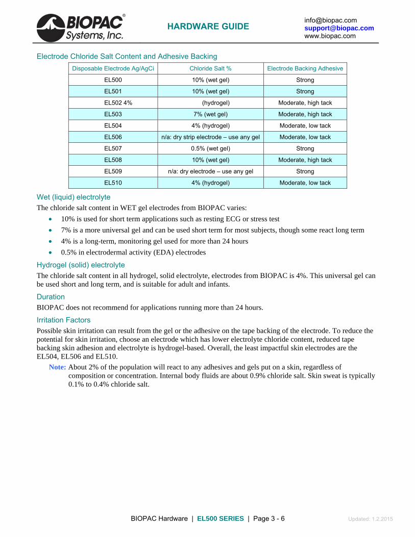
[email protected] [email protected] www.biopac.com
BIOPAC Hardware | EL500 SERIES | Page 3 - 6 Updated: 1.2.2015
Electrode Chloride Salt Content and Adhesive Backing Disposable Electrode Ag/AgCi Chloride Salt % Electrode Backing Adhesive
EL500 10% (wet gel) Strong
EL501 10% (wet gel) Strong
EL502 4% (hydrogel) Moderate, high tack
EL503 7% (wet gel) Moderate, high tack
EL504 4% (hydrogel) Moderate, low tack
EL506 n/a: dry strip electrode – use any gel Moderate, low tack
EL507 0.5% (wet gel) Strong
EL508 10% (wet gel) Moderate, high tack
EL509 n/a: dry electrode – use any gel Strong
EL510 4% (hydrogel) Moderate, low tack
Wet (liquid) electrolyte The chloride salt content in WET gel electrodes from BIOPAC varies:
10% is used for short term applications such as resting ECG or stress test
7% is a more universal gel and can be used short term for most subjects, though some react long term
4% is a long-term, monitoring gel used for more than 24 hours
0.5% in electrodermal activity (EDA) electrodes
Hydrogel (solid) electrolyte The chloride salt content in all hydrogel, solid electrolyte, electrodes from BIOPAC is 4%. This universal gel can be used short and long term, and is suitable for adult and infants.
Duration BIOPAC does not recommend for applications running more than 24 hours.
Irritation Factors Possible skin irritation can result from the gel or the adhesive on the tape backing of the electrode. To reduce the potential for skin irritation, choose an electrode which has lower electrolyte chloride content, reduced tape backing skin adhesion and electrolyte is hydrogel-based. Overall, the least impactful skin electrodes are the EL504, EL506 and EL510.
Note: About 2% of the population will react to any adhesives and gels put on a skin, regardless of composition or concentration. Internal body fluids are about 0.9% chloride salt. Skin sweat is typically 0.1% to 0.4% chloride salt.
HARDWARE GUIDE

[email protected] [email protected] www.biopac.com
BIOPAC Hardware | EL500 SERIES | Page 4 - 6 Updated: 1.2.2015
Part Ag/AgCl Adhesive/Disposable Electrode Type
EL500
Dual Electrodes
Paired, pre-gelled, electrodes: The fixed spacing between the contacts of these dual electrodes are useful for general-purpose EMG measurements, electrical stimulation, bioimpedance and cardiac output studies. Hypo-allergenic, wet liquid gel electrolyte (10% chloride salt).
These electrodes incorporate a gel cavity (16 mm diameter, 1.5 mm deep) situated between electrode and skin surfaces that helps reduce motion artifact.
Dual Ag/AgCl electrode conductors: 11 mm diameter, 95 mm2 conductive contact area, 41 mm spacing (center to center) mounted on 41 mm x 82 mm, moisture resistant, latex free, 1.5 mm thick foam tape with strong adhesive.
EL501
Stress Test Electrodes
Small stress test, pre-gelled, electrodes: Use for short-term recordings where the subject may be in motion or when electrodes should be closely placed, as for multi-channel ECG, EGG, EMG or EOG. Hypo-allergenic wet liquid gel electrolyte (10% chloride salt). These electrodes incorporate a gel cavity (16 mm diameter, 1.5 mm deep) situated between electrode and skin surfaces that helps reduce motion artifact.
Single Ag/AgCl electrode conductor: 11 mm diameter, 95 mm2 conductive contact area, mounted on 40 mm diameter, moisture resistant, latex free, 1.5 mm thick foam tape with strong adhesive.
EL502
Long-term Recording Electrodes
Small, pre-gelled, electrodes. Most appropriate for long-term ( > 2 hours ) biopotential measurements. Hypo-allergenic, hydrogel, solid, electrolyte (4% chloride salt) that adheres well to skin, but leaves no residue when removed.
Single Ag/AgCl electrode conductor: 11 mm diameter, 95 mm2 conductive contact area mounted on 41 mm diameter, moisture resistant, latex free, vinyl backing tape (0.12 mm thick) with moderately strong adhesive. The hydrogel base also lends these electrodes to electrical stimulation studies, such as for nerve conduction velocity or tDCS.
EL503
General-purpose electrode
Small, pre-gelled, electrodes: These economical electrodes are most suitable for general purpose, short-term recordings. The small diameter permits relatively closely-spaced biopotential recording. Hypo-allergenic wet liquid gel electrolyte (7% chloride salt).
Single Ag/AgCl electrode conductor: 11 mm diameter, 95 mm2 conductive contact area mounted on 35 mm diameter, moisture resistant, latex free, vinyl backing tape (0.12 mm thick) with moderately strong adhesive.
EL504
High Flexibility Electrodes
Small, pre-gelled, electrodes. Most appropriate for long-term (greater than 2 hours) biopotential measurements. Hypo-allergenic, hydrogel, solid, electrolyte (4% chloride salt) that adheres well to skin, but leaves no residue when removed.
Single Ag/AgCl electrode conductor: 11 mm diameter, 95 mm2 conductive contact area mounted on a cloth-based, 2.5 cm x 2.5 cm porous, latex free, backing fabric tape (0.2 mm thick). Particularly useful for applications on non-conforming surfaces, such as the face for EMG or fingers for nerve conduction studies.
The electrodes are very comfortable and conform easily to a great variety of skin surfaces. These are optimal electrodes for facial EMG recording, due to gentle adhesion, high flexibility, cloth base and low potential for skin irritation. These electrodes are useful for general ECG, EMG and sleep studies. The hydrogel base also lends these electrodes to electrical stimulation studies, such as for nerve conduction velocity or tDCS. These latex-free, hypo-allergenic, electrodes adhere well to the skin, can be repositioned and are suitable for long term use with minimal irritation.
HARDWARE GUIDE

[email protected] [email protected] www.biopac.com
BIOPAC Hardware | EL500 SERIES | Page 5 - 6 Updated: 1.2.2015
Part Ag/AgCl Adhesive/Disposable Electrode Type
EL506 Alternative for band electrodes
This unique disposable strip electrode is designed for bioimpedance applications. The electrode is silver laminated on medical grade porous cloth, with industry-standard medical grade adhesive, medium tackiness. The silver/silver chloride (Ag/AgCl) electrode provides accurate and clear transmission of surface biopotentials and is latex free. The Ag/AgCl center, strip conductor is free of electrode gel and is designed for direct connection to the skin surface. If desired, a thin bead of electrode gel (GEL 100) can be added to the surface of the center conductor before application to the skin surface.
Strip length: 250 mm, Conductive element width: 6.5 mm, Adhesive width: 2 x 9 mm (9 mm strip on either side of conductive strip,) Cloth backing width: 24.5 mm
Advantages of the Strip Electrode:
Combines the convenience of standard snap (spot) electrodes with the signal to noise, equipotential and current diffusion performance of band electrodes
Less obtrusive than band electrodes - easier for subjects to move and breathe
Ergonomic advantages of snap (spot) electrodes
Diffuses currents similarly to band electrodes (reduces current density)
Provides voltage measurements through a well-defined equipotential plane
Adjustable size - cut the 250 mm strip to the desired size for optimal fit
Snap lead connection
Latex free
Peel-and-stick convenience
Disposable
EL507
EDA Electrodes
Designed for electrodermal activity (EDA) measurements and are pre-gelled with isotonic gel. Isotonic gel is recommended for EDA measurements to establish physiological ionic equivalency to the skin surface. The electrodes conform and adhere well to a variety of skin surfaces. Typically, they are applied around fingers to create a firm bond. Also, these electrodes are very suitable for attachment to the palm of hand, wrist, toes or sole of foot. These electrodes incorporate a gel cavity (16 mm diameter, 1.5 mm deep) situated between electrode and skin surfaces that helps to stabilize measurements and reduce motion artifact.
Wet Gel: 0.5% chloride salt (isotonic,) Electrode Contact Diameter: 11 mm, Electrode Contact Area: 95 mm2, Size: 27 mm x 36 mm, Backing: 1.5 mm thick foam, latex free
EL508
MRI General-Purpose Electrodes
These disposable, radio-translucent electrodes are pre-gelled. Use with LEAD108.
MRI Use: MR Conditional
Condition: Up to 7T, any scanning sequence. Up to 9T on animals. Use with LEAD108 series only.
Electrode contact type: Ag/AgCl laminated on carbon composition plastic snap, Wet Gel: 10% chloride salt, Electrode Contact Diameter: 11 mm, Electrode Contact Area: 95 mm2, Vinyl Tape Backing: 41 mm diameter, 0.12 mm thick, latex free
EL508 Components: Substrate: Tape with medical grade adhesive, Label: Bi-Oriented Polypropylene (BOPP) or Vinyl, Stud: 40% Carbon-filled ABS plastic, Eyelet: 20% glass-filled ABS plastic coated with Ag/AgCl, Reticulated foam: Polyester-polyurethane, Gel: 10% chloride salt wet liquid gel electrolyte
HARDWARE GUIDE

[email protected] [email protected] www.biopac.com
BIOPAC Hardware | EL500 SERIES | Page 6 - 6 Updated: 1.2.2015
EL509
MRI EDA Electrodes
These disposable, radio-translucent, dry electrodes have a very long shelf-life and are ideal for electrodermal activity (EDA) measurements. They are content and dimensionally equivalent to the EL507 series electrodes, but with carbon composition snap and gel-free. Use with LEAD108 and isotonic electrode gel - GEL101 recommended for EDA.
Isotonic gel is recommended for EDA measurements to establish physiological ionic equivalency to the skin surface. The electrodes conform and adhere well to a variety of skin surfaces. Typically, they are applied around fingers to create a firm bond. Also, these electrodes are very suitable for attachment to the palm of hand, wrist, toes or sole of foot. These electrodes incorporate a gel cavity (16 mm diameter, 1.5 mm deep) situated between electrode and skin surfaces that helps to stabilize measurements and reduce motion artifact.
MRI Use: MR Conditional
Condition: Up to 7T, any scanning sequence. Up to 9T on animals. Use with LEAD108 series only.
Electrode contact type: Ag/AgCl laminated on carbon composition plastic snap, Electrode Contact Diameter: 11 mm, Electrode Contact Area: 95 mm2, Size: 27 mm x 36 mm, Backing: 1.5 mm thick foam, latex free
To add gel:
1. Fill back cavity (adhesive side) with gel.
2. Add a drop of gel to the sponge pad.
3. Place the sponge pad into the cavity.
4. Press firmly to clear air pockets.
EL509 Components: Substrate: Tape with medical grade adhesive, Label: Bi-Oriented Polypropylene (BOPP) or Vinyl, Stud: 40% Carbon-filled ABS plastic, Eyelet: 20% glass-filled ABS plastic coated with Ag/AgCl, Reticulated foam: Polyester-polyurethane, Gel: none; add BIOPAC GEL101 at time of application.
EL510
MRI X-ray Electrodes
EL510 is a disposable, radio-translucent, set of three electrodes with hydrogel (4% chloride salt) electrolyte centers and hydrocolloid ends that terminate in Touchproof leads. Each box includes 20 sets of 3 electrodes. Electrodes are 25 mm x 10 mm with a 10 mm x 10 mm, gelled, contact area. The thin, flexible, carbon composition leads are 58 cm long.
MRI Use: MR Conditional
Condition: Tested up to 3T, any scanning sequence, radiolucent head
Pre-wired, carbon composition leads
Ag/AgCl contact type
Safely secures to limbs without a strap that could reduce circulation.
Gentle hydrogel centers and hydrocolloid ends adhesives
Long lasting and easy to use, even under high humidity
Radio-translucent materials allow for X-ray passage
Latex, phthalate/DEHP, BPA free
HARDWARE GUIDE

[email protected] [email protected] www.biopac.com
BIOPAC Hardware | EL650 SERIES | Page 1 - 1 Updated: 1.12.2015
ELECTRODES
In selecting the application site for any style of electrode, care should be taken that:
1) Electrode site is dry and free of excessive hair.
2) Electrode is not placed over scar tissue or on an area of established erythema or with a lesion of any kind.
3) Skin is properly prepared. (Prepare the skin at the electrode site. Use the ELPAD to lightly abrade the skin surface. Use a brisk dry rub to prepare the application site. Avoid excessive abrasion of the skin surface.)
EL650 SERIES REUSABLE SNAP ELECTRODES
EL650 Series reusable snap electrodes incorporate a variety of features which improve biopotential recordings.
Non-polarizable
Sintered to increase electrode/electrolyte contact area
Does not require chloriding
Reusable via resurfacing
High stability recordings, to DC, when used with chloride salt gel electrolyte
Electrolyte gel cavity reduces artifact due to electrolyte/electrode motion and minimizes electrolyte dissipation/drying over long term recordings
EL654 This is a reusable Ag-AgCl snap electrode with a 4 mm diameter.
EL658 This is a reusable Ag-AgCl snap electrode with a 8 mm diameter. Use with ADD204 adhesive collars and interface with LEAD110S Series snap electrode leads or
BioNomadix electrode lead sets.
EL654/658 SPECIFICATIONS Sensor diameter: 4 mm Ag-AgCl (EL654,) 8 mm Ag-AgCl (EL658) Housing diameter: 13 mm Overall height: 6 mm (EL654,) 8 mm (EL658) Gel cavity: 2 mm deep Snap: 1 mm thick Ag-AgCl sintered sensor element mounted in an epoxy housing; all parts are firmly encapsulated with epoxy, resulting in a tough, durable waterproof assembly
How to Clean Reusable Electrodes 1. Do not leave GEL in the cavity after use. If GEL is left in cavity, the Ag-AgCl electrode disk could degrade
quickly with time because the electrode surface is somewhat porous to promote good conductivity to the GEL.
2. To clean the reusable electrode, use a cotton swab or toothbrush with tap water. 3. Use any lab cleaner with pumice (such as Ajax) with cotton swab or toothbrush to remove any dark
residue from electrode surface. 4. Use Hydrogen Peroxide solution (2-3%) to brighten electrode surface (optional) or to sterilize electrode.
Do not place the electrode in solution, but simply clean the electrode surface using a cotton swab. 5. Dry electrode off completely before storage.
HARDWARE GUIDE

[email protected] [email protected] www.biopac.com
BIOPAC Hardware | EL-CHECK | Page 1 - 1 Updated: 7.22.2013
EL-CHECK – ELECTRODE IMPEDANCE CHECKER
BIOPAC EL-CHECK video tutorial!
Use EL-CHECK to determine electrode/surface contact impedances. Measurements are selectable to a standard three-point contact (Vin+ to GND, Vin- to GND and Vin+ to Vin-). Electrode impedance range from < 5 k to > 50 k is indicated in seven levels. EL-CHECK accepts standard Touchproof and BioNomadix connectors. EL-CHECK will support over 50,000 10-second measurements with a single 9-volt battery.
The EL-CHECK is suitable for measuring electrode contact impedance for all surface biopotential measurements, including ECG, EEG, EGG, EMG, EOG, Bioimpedance and Impedance Cardiography. The EL-CHECK permits simultaneous connection of up to three electrode leads, for quick impedance checking between any two electrodes in the three connected leads (Active or Vin+) and (Reference or Vin-) and GND.
To test the impedance between any two electrode leads:
1. Insert the leads into the appropriate connectors on the front panel of the EL-CHECK.
2. Switch the selector knob to the corresponding position, and then press and hold the “Test” button.
Green, Yellow, Orange and/or Red LEDs will illuminate to indicate the measured electrode impedance. The EL-CHECK is only active when the “Test” button is pressed.
For best biopotential measurement results, the impedance between any two electrode leads should be less than 5 k. To obtain electrode lead-to-lead impedances of less than 5 k, it’s advisable to lightly abrade the skin with an abrasive pad, such as BIOPAC’s ELPAD, and then apply a well-gelled (not dry) surface electrode. Dried-out surface electrodes can sometimes be rejuvenated by applying a small amount of BIOPAC’s electrode gel to the contact pad of the electrode.
Specifications Test Frequency: 25 Hz Test Current: 3.5 µA rms (10 µA peak-peak: constant current) Electrode Impedance < 5 k, 5k-10 k,10 to 20 k, 20k-30 k, 30k-40 k, 40-50 k, > 50 k Range Indicators: Lead Compatibility: Standard female touchproof (1.5mm) electrode leads, all BIOPAC electrodes and leads that terminate in female touchproof sockets, all BN- EL and BN-Adapt series. Testing Configurations Active (Vin+) to Reference (Vin-), Active (Vin+) to Ground (GND), Switch Selectable: Reference (Vin-) to Ground (GND) Power: One 9 V Alkaline battery, ~50,000 impedance tests possible per battery Dimensions: 14 cm long x 8 cm wide x 2.2 cm high Weight: 132 grams
HARDWARE GUIDE

[email protected] [email protected] www.biopac.com
BIOPAC Hardware | Electrode Accessories | Page 1 - 3 Updated: 1.2.2015
ELECTRODE ACCESSORIES & GELS
Abrasive Pads Before applying electrodes, abrade the skin lightly with an ELPAD to remove non-conductive skin cells and sensitize skin for optimal adhesion. Each ELPAD package contains 10 abrasive pads.
Adhesive Use adhesive tape for attaching Active Electrodes and other devices. Use the preferred tape or BIOPAC’s adhesive tape: TAPE1 single-sided; TAPE2 double-sided.
MRI Use: MR Safe
TAPE1 Components:
3M hypoallergenic surgical tape – Acrylic adhesive
Adhesive Disks ADD200 series double-sided adhesive collars are used to hold reusable electrodes (EL254/8RT) firmly on the skin surface.
ADD204 19 mm outside diameter, use with EL254 and EL254S
ADD208 22 mm outside diameter, use with EL258 and EL258S
MRI Use: MR Safe
ADD204/208 Adhesive Disks Components: Disks: 3M hypoallergenic medical tape – Acrylic polymer
Electrode Gels GEL1 & Non-irritating, hypo-allergenic gel used as a conductant with the EL250 series reusable GEL100 electrodes. GEL1 = 50 g; GEL100 = 250 g. 5% NaCl (salt) content. 0.85 molar NaCl
MRI Use: MR Conditional
Condition: Max MR field strength 7T
MRI Notes When using with EL250 series electrodes, it’s important to completely fill the EL250 series gel reservoir. Incomplete filling of reservoir may result in localized heating of gel at the electrode site.
GEL100 Components:
Water, Sodium Chloride, Propylene Glycol, Mineral Oil, Glyceryl MonostearatePolyoxyethelene Stearate, Stearyl Alcohol, Calcium Chloride, Potassium Chloride, Methylparaben, Butylparaben, Propyl Paraben
GEL101 Non-irritating, isotonic gel is primarily used as a conductant for the TSD203 electrodermal response electrodes. Each tube contains 114 g (~4 ounces).
Consists of 0.5% Saline in a neutral base and is the appropriate GEL to use for GSR, EDA, EDR, SCR, and SCL. This electrode paste has an approximate molarity of 0.05M NaCl and is 0.5% Saline; the Saline concentration is adjusted to obtain a final paste molarity of 0.05M NaCl. This particular molarity is recommended by Fowles (1981). Psychophysiology, 18, 232-239
MRI Use: MR Conditional
Condition: Max MR field strength 7T
GEL101 Components:
Cetyl Alcohol #697313, Glycerol Monostearate, Lanolin, USP Anhydrous, Dimenthicon Silicone TBF9-1000, Water, purified USP Sodium Chloride, Sodium Lauryl Sulfate, Sorbitol, 70 USP, Methylparaben, Propylparaben, Quaternium-15
HARDWARE GUIDE

[email protected] [email protected] www.biopac.com
BIOPAC Hardware | Electrode Accessories | Page 2 - 3 Updated: 1.2.2015
GEL102 Ten20 Conductive Gel 114 g (~4 ounces). Ten20 is a conductive and adhesive paste specifically formulated for use with reusable (non-disposable) electrodes. Ten20 contains the right balance of adhesiveness and conductivity, enabling electrodes to remain in place while allowing the transmittance of electrical signals. Ten20 is a uniquely washable and non-drying formula.
Do not use too much paste—the size of the area of the paste becomes the effective size of the electrode; this can reduce interelectrode distances and potential differences measured. Wash skin promptly after use. 12.5% NaCl content, 2.15 molar NaCl
GEL103 Tensive Adhesive Gel, 33 ml. Conductive adhesive gel. This safe, non-flammable, odorless gel is recommended for TENs or ECG to adhere non-adhesive electrodes to the skin.
Eliminates tape and tape irritation
Conductive immediately, no need to wait
Non-flammable, no solvent odor
Best adhesive gel available
Hypoallergenic, bacteriostatic, non-irritating
Water soluble, easily removed with water
GEL104 Electrode Gel - salt free - 250 g (8.5 oz). SPECTRA 360® electrode gel. The only salt-free and chloride-free electrically conductive gel, recommended for many biopotential measurements. Salt-free characteristics make it particularly suitable for electrical stimulation and long-term applications. However, it is not recommended for DC measures, such as EDA, ECG, EOG or slow potentials. Spectra 360 differs significantly from all other electrically conductive media...it works by wetting the skin, thereby reducing skin resistance.
Salt-free, no sodium ion transfer
Non-irritating, hypoallergenic, bacteriostatic
Can be used with carbon compositing flexible electrodes
Can be used for ECG and TENS
Non-gritty STAY-WET® formula allows for prolonged use without re-application
MRI Use: MR Conditional
Condition: Max MR field strength 7T
GEL104 Salt-Free Components:
Water, Propylene Glycol, Mineral Oil, Glyceryl Monostearate, Polyoxyethelene Stearate, Stearyl Alcohol, Methylparaben, Butylparaben, Propyl Paraben
ELPREP Skin Preparation Gel 114 grams (~4 oz). Designed for EEG, ECG, EMG, EOG, Cardiac Output and Bioimpedance measurements. This gel is abrasive and should be used with care not to overabrade the skin. It is not recommended for use with electrodes attached to conventional electrical stimulation equipment, such as voltage or current stimulators. Not to be used on subjects with a history of skin allergies to cosmetics and lotions. Topical use only.
Prepare skin and apply small amount to appropriate electrode site by squeezing near tube opening. Gently rub gel into the skin surface. Apply small amount to disc electrode and press into the paste that has been applied to the scalp or other skin surface. Clean with warm water.
HARDWARE GUIDE

[email protected] [email protected] www.biopac.com
BIOPAC Hardware | Electrode Accessories | Page 3 - 3 Updated: 1.2.2015
Coban Wrap Self-adhesive Coban™ wrap can be used to hold electrodes, VMG transducers and fNIR sensors on a subject.
4 inch x 5 yard (fully stretched) (100 mm x 4.5 m)
Latex free self-adherent wrap
Nonsterile
Tan
BSL-ACCPACK Make students accountable for their own lab equipment and reduce the burden on department budgets.
The BSL Accessory Pack includes the consumable items to run 16 BSL Lessons. School bookstores can purchase the BSL Accessory Packs and sell them to students. Includes:
60 x EL503 Disposable Electrodes
10 x EL507 Disposable EDA (GSR) Electrodes (ten electrodes total)
1 x AFT1 Disposable Bacterial Filter
1 x AFT2 Disposable Mouthpiece
1 x AFT3 Noseclip
8 x ELPAD Abrasive Pads
HARDWARE GUIDE
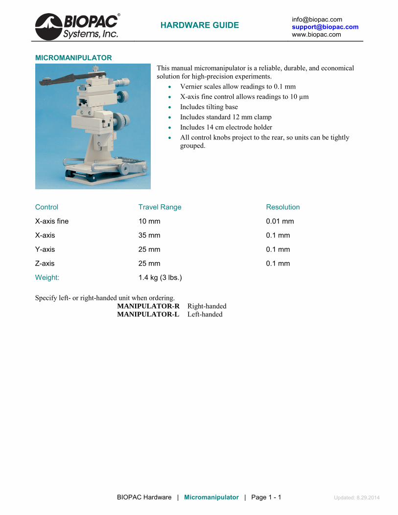
[email protected] [email protected] www.biopac.com
BIOPAC Hardware | Micromanipulator | Page 1 - 1 Updated: 8.29.2014
MICROMANIPULATOR This manual micromanipulator is a reliable, durable, and economical solution for high-precision experiments.
• Vernier scales allow readings to 0.1 mm • X-axis fine control allows readings to 10 µm • Includes tilting base • Includes standard 12 mm clamp • Includes 14 cm electrode holder • All control knobs project to the rear, so units can be tightly
grouped.
Control Travel Range Resolution
X-axis fine 10 mm 0.01 mm
X-axis 35 mm 0.1 mm
Y-axis 25 mm 0.1 mm
Z-axis 25 mm 0.1 mm
Weight: 1.4 kg (3 lbs.)
Specify left- or right-handed unit when ordering.
MANIPULATOR-R Right-handed MANIPULATOR-L Left-handed
HARDWARE GUIDE

[email protected] [email protected] www.biopac.com
BIOPAC Hardware | Nerve Chambers | Page 1 - 2 Updated: 8.29.2014
NERVE CHAMBERS: NERVE1 AND NERVE2 These acrylic, desktop Nerve Chambers have 15 stainless steel pins for recording and stimulating a variety of different nerve preparations. Each stainless steel pin is spaced 5mm apart to provide a variety of recording and stimulating configurations. The sockets accept 2 mm pin plugs. NERVE1 and NERVE2 Comparison
Feature NERVE1 NERVE2
Deep Reservoir (35 mL)—contain Ringers or other solutions x x
Drain—facilitate extended viability of the preparation. x x
Agent Well — add compounds (ether, dry ice, etc.) 1.4 cm x 2 cm x 2 cm (h x w x l) x x
Lid—enclose the preparation. 50 mm thick x --
Valve & hose—flush and drain options x --
NERVE1 – WITH AGENT WELL AND LID
NERVE1 chamber includes:
• Deep Reservoir (35 mL) for containing Ringers or other solutions • Drain (with valve & hose) to facilitate extended viability of the preparation • Agent Well for adding compounds (such as ether or dry ice) • Lid to enclose the preparation when the protocol requires it.
NERVE2 – STANDARD NERVE CHAMBER NERVE1 chamber includes: • Deep Reservoir (35 mL) for containing Ringers or other solutions. • Drain (with valve & hose) to facilitate extended viability of your
preparation.
NERVE CHAMBER SPECIFICATIONS (NERVE1/NERVE2) Pins: 15, stainless steel Spacing: 5 mm Sockets: accepts 2 mm pin plugs Reservoir: holds 35 mL (or use drain/valve) Dimensions: 4.5 cm x 7 cm x 14 cm (H x W x L) Agent well: (NERVE1 only) 1.4 cm x 2 cm x 2 cm (H x W x L) Lid: (NERVE1 only) 50 mm thick
Related components: • STM100C Stimulator Module • STMISO Series Stimulator Modules • MCE100C Micro-electrode Amplifier • ERS100C Evoked Response Amplifier • EMG100C Electromyogram Amplifier
NERVE2
HARDWARE GUIDE

[email protected] [email protected] www.biopac.com
BIOPAC Hardware | Nerve Chambers | Page 2 - 2 Updated: 8.29.2014
NERVE CHAMBER CONNECTIONS
To connect the Nerve Chamber to MP-series Biopotential amplifiers (MCE100C, ERS100C, or EMG100C), use three JUMP100 connectors and three CBL200 adapter cables. Optionally, for additional lead length, use one MEC110C extension cable.
1. Plug the three JUMP100s into the desired points of the Nerve Chamber. 2. Connect the free ends of the JUMP100s to the mating ends of the CBL200s. 3. Then connect the free ends of the CBL200s to the Biopotential amplifier inputs. For additional lead
length, plug the MEC110C into the Biopotential amplifier and plug the free ends of the CBL200s into the free end of the MEC110C.
To connect the Nerve Chamber to the STM100C Stimulator, use one CBL106 and one CBL102. 1. Plug the red and black leads (2 mm pins) of the CBL106 into the desired points of the Nerve Chamber. 2. Connect the free end (Female BNC) of the CBL106 to the mating end (Male BNC) of the CBL102. 3. Then insert the free end of the CBL102 (3.5 mm phone plug) into the 50 Ohm output of the STM100C.
Note: If the STM100C Stimulator is used with a Biopotential amplifier on the same nerve—which is nearly always the case—make sure that the black lead of the CBL106 (stimulation negative) is connected to the same pin as the ground lead going to the Biopotential amplifier. This is easy to do because the design of the JUMP100 allows stacking connections.
HARDWARE GUIDE

[email protected] [email protected] www.biopac.com
BIOPAC Hardware | ELECTRODE LEADS | Page 1 - 2 Updated: 1.13.2015
ELECTRODE LEADS LEAD108 SERIES — MRI-CONDITIONAL/RADIOTRANSLUCENT LEADS FOR EL508/EL509 Use the LEAD108 series with EL508 MRI-conditional, radiotranslucent electrodes and EL509 disposable radiotranslucent dry electrodes. All LEAD108 Series terminate in 1.5 mm female Touchproof sockets.
MRI Usage: MR Conditional to 9T Condition: Up to 9T, any scanning sequence, use with EL508
or EL509 MRI/RT electrodes only. Lead108 Components: Polyvinyl chloride (PVC) plastic, carbon fiber leadwire, tinned copper connectors (Touchproof socket), electrode clip (carbon filled ABS plastic)
SPECIFICATIONS Construction: Carbon fiber leadwire and electrode snap Leadwire Diameter: 1.5 mm Leadwire Resistance: 156 Ohms/meter Leadwire Length: LEAD108 1.8 m, LEAD108A 3.6 m, LEAD108B 15 cm, LEAD108C 30cm
LEAD110 SERIES — ELECTRODE LEADS The LEAD110 Series, for use with disposable and other snap connector electrodes, are pinch leads for easy connection between the EL500-series snap electrodes and any BIOPAC biopotential amplifier or the GND terminal on the back of the UIM100C. Leads are 1.9 mm in diameter and terminate in standard 1.5 mm Touchproof connector and connect to BIOPAC modules or to a Modular Extension Cable (MEC series).
LEAD TYPE LENGTH USAGE NOTE LEAD110 Unshielded 1 m Works best as a ground electrode LEAD110A Unshielded 3 m Works best with ground or reference electrodes LEAD110S-R Shielded; red 1 m Use with recording electrodes for minimal noise interference. White lead
plug is for electrode contact; black lead pin plug is for lead shield. LEAD110S-W Shielded; white 1 m Use with recording electrodes for minimal noise interference. White lead
plug is for electrode contact; black lead pin plug is for lead shield.
See also: TSD155C Multi-lead ECG Cable
WT100C Wilson Terminal (virtual reference)
LEAD120 LEAD FOR EL120 This 1-meter lead with Touchproof connector works exclusively with the reusable EL120 electrode. Snap the electrode into place and then plug the lead in with the Touchproof connector. White—LEAD120-W Red—LEAD120-R
LEAD130 SHIELDED LEAD ASSEMBLY LEAD130 Shielded Lead Assembly is for use with the EBI100C Electrical Bioimpedance Module or the NICO100C Noninvasive Cardiac Output Module. The shielded lead assembly terminates with an adapter that plugs into the front of the amplifier module and includes four leads:
White = I+ Red = Vin+ Green = Vin- Black = I- (GND)
HARDWARE GUIDE

[email protected] [email protected] www.biopac.com
BIOPAC Hardware | ELECTRODE LEADS | Page 2 - 2 Updated: 1.13.2015
Important Usage Notes: • If using multiple biopotential modules, do not connect the ground (GND) for the other modules — establish
one ground per subject. • If using a GSR100C Electrodermal Response Amplifier with the EBI100C or the NICO100C, please note
that the black I- (GND) connection will shunt current from the GSR100C excitation source. Accordingly, GSR100C measurement values will be shifted somewhat higher in absolute conductance, and should be used for relative measures only.
See also: EBI100C Electrical Bioimpedance Module
NICO100C Noninvasive Cardiac Output Module
EL506 Bioimpedance Strip Electrode and EL500 Series Disposable Electrodes
Application Note 215 - Noninvasive Cardiac Ouput - NICO100C and LEAD130.
LEAD140 SERIES CLIP LEADS
LEAD140 Series clip leads have a 1 m black cable and a Touchproof connector, and require the SS1LA interface. LEAD140 Alligator clip with teeth, 40 mm: Use this fully-insulated, unshielded lead to connect fine wire
electrodes, including irregular surfaces. There is ferrous metal in the clip. LEAD141 Alligator clip with smooth (flat) clamp, 40 mm: Use this fully-insulated, unshielded lead to connect to
fine wire electrodes without damage, including arbitrarily small electrode wires. There is ferrous metal in the clip.
LEAD142 Retractable clip lead with copper extension contacts, 3.5 mm: Use this unshielded lead to connect to fine wire electrodes up to 1 mm diameter. There is non-ferrous copper alloy in the clip.
MRI Usage: MR Conditional Condition: Tested 3T-9T (LEAD142 only)
HARDWARE GUIDE

[email protected] [email protected] www.biopac.com
BIOPAC Hardware | MRI Definitions | Page 1 - 1 Updated: 11.7.2013
MRI, RADIOTRANSLUCENT, AND RADIO-OPAQUE COMPATIBILITY Biopac Definitions Radiotranslucent products as products that have no metal at all in the applied part. These are best suited for MRI applications.
MR Safe - an item that poses no known hazards in all MRI environments. Using the terminology, “MR Safe” items are non-conducting, non-metallic, and non-magnetic items such as a plastic Petri dish. An item may be determined to be MR Safe by providing a scientifically based rationale rather than test data.
MR Conditional - an item that has been demonstrated to pose no known hazards in a specified MR environment with specified conditions of use. “Field” conditions that define the MR environment include static magnetic field strength, spatial gradient magnetic field, dB/dt (time rate of change of the magnetic field), radio frequency (RF) fields, and specific absorption rate (SAR). Additional conditions, including specific configurations of the item (e.g., the routing of leads used for a neurostimulation system), may be required.
X-ray notes: MRI Safe or Conditional does not refer to the capability of an applied part to be used in an x-ray machine. Radio-opaque implies that the applied part is easily visible in an x-ray machine so it can be manipulated via the x-ray viewer. Radiotranslucent in this context implies that the applied part is only partially or not visible in the x-ray viewer.
Caution is required whenever employing electrode leads and electrodes in an MRI environment.
IMPORTANT! See Safety Guidelines for recording biopotential measurements in the MRI environment.
Under certain conditions, single fault and otherwise, low impedance conduction through the subject represents a potential hazard due to currents that may be induced in loops placed in the time-varying MRI field gradients and RF fields, and due to body movement in the static MRI field. Low impedance conduction can result in significant heating at the electrode/skin junction, because this point is often the part of the signal path with the highest impedance. Sufficient heating at the electrode/skin junction could result in burns.
For more information:
Read the Associated Application Notes listed below.
See the "Magnetic Resonance Imaging" section of a BIOPAC Hardware Guide (available at Support > Manuals, or under the software Help menu, or on the software CD).
Read Methodological Issues in EEG-correlated Functional MRI Experiments (Lemieux L, Allen PJ, Krakow K, Symms MR, Fish DR; International Journal of Bioelectromagnetism 1999; 1: 87-95).
Associated Application Notes: 223 - Physiological Measurement in Magnetic Resonance Imaging Systems,
230 - Connections for Physiological Signals in an MRI
HARDWARE GUIDE

[email protected] [email protected] www.biopac.com
BIOPAC Hardware | MRI Smart Modules | Page 1 - 3 Updated: 9.12.2014
MRI SMART MODULES The MRI smart amplifiers incorporate advanced signal processing circuitry which removes spurious MRI artifact from the source physiological data. Signal processors are able to distinguish between physiological signal and MRI artifact as manifested by gradient switching during MRI sequences, such as Shim or EPI.
Because MRI-related transient artifact is removed at the source, the MRI version amplifier can be sampled at the same rate as during normal (non-MRI) physiological recording. There is no longer any requirement to over-sample the amplifier output to capture every nuance of MRI artifact to train secondary computer-based processing steps to remove such artifact.
In every aspect, data recording is easier and the final results are cleaner when using the MRI version amplifiers to record physiological data in the fMRI or MRI.
FEATURES
• Less sensitivity to electrode and transducer lead placement • Improved gain selectability • No missing spectra in physiological signal frequency band • No requirement for acquisition oversampling • No need for computer-based real-time or post-processing signal processing • Clean data available as real-time analog output
Safety Guidelines for Recording Biopotential Measurements in the MRI Environment
1. Place electrodes on the subject according to these guidelines:
A) Prepare the subject's skin surface with ELPAD to create low contact source impedance at the electrode attachment site. Be careful to wipe away any excess electrode gel form the surface of the subject's skin.
B) Attach the EL508 or EL509 electrodes as close to each other as possible (on the subject's skin) for the measurement.
C) Place electrodes in as straight of a line as possible which is perpendicular to the magnet's axis.
D) Place electrodes between 3-5 cm apart, if possible; the larger the area between the electrodes, the stronger the MRI gradient artifact.
2. Connect the electrode lead set to the electrodes according to these guidelines:
A) Make sure that the electrode leads do not loop in a "circle", "S" or "U" shape. Also, do not twist or braid the electrode leads.
Looped, braided or twisted leads pick up RF energy, resulting in current induction and increased localized heating.
B) Run the leads out of the chamber bore in the simplest (straightest) manner possible.
C) Do not allow the electrode leads to touch the subject's bare skin. Electrode leads may heat up in the MRI. - Use a thermal insulator (such as a blanket or towel) between the electrode lead and the subject's skin. - It's also possible to use thermally-insulating foam jacket, similar to those used for insulating copper tubing, for placing the electrode leads to keep them away from the subject's skin.
HARDWARE GUIDE

[email protected] [email protected] www.biopac.com
BIOPAC Hardware | MRI Smart Modules | Page 2 - 3 Updated: 9.12.2014
See also Safety Awareness Notes for Cables and Electrodes During MRI
ECG100C-MRI Gain: 500, 1000, 2000, 5000 Output selection: Normal, R wave indicator Frequency Response Maximum Bandwidth (.05 Hz - 150 Hz) can be customized at BIOPAC Low Pass Filter: 35 Hz, 150 Hz High Pass Filter: 0.05 Hz, 1.0 Hz Notch Interference Filter: 50 dB rejection @ 50 or 60 Hz Noise Voltage (0.05-35 Hz): 0.1 µV (rms) Zin: 2M ohm (Differential), 1000M ohm (Common mode) CMRR: 110 dB min (50/60 Hz) Common Mode Input Voltage Range: ±10 V (referenced to amplifier ground) ±1500 VDC (referenced to mains ground) Output Range: ±10 V (analog) Input Voltage Range: Gain
500 ±20 Vin (mV)
1000 ±10 2000 ±5 5000 ±2
Input Connectors: Five 1.5 mm male Touchproof sockets (VIN+, Gnd, VIN-, 2 of shield)
EDA100C-MRI Gain: 20, 10, 5, 2 µsiemens/volt (i.e. µmhos/volt) Low Pass Filter: 1 Hz, 10 Hz High Pass Filter: DC, 0.05 Hz, 0.5 Hz Sensitivity: 0.7 nano-siemens (with MP System) Constant Voltage Excitation: Vex = 0.5 VDC Output Range: ±10 V full range (analog); 0-10 V nominal range Input Signal Range: Gain 20 0-200
Range (µmho)
10 0-100 5 0-50 2 0-20 Input Connectors: Three 1.5 male Touchproof sockets (VIN+, Gnd, VIN-) Note: Normal human range is 1-50 µmho.
Unit Note—BIOPAC software calculates SCL/SCR in µmho, the traditional unit of conductance. Micromho (µmho) is interchangeable with the alternative microsiemen (µS). To use Ohm, the traditional measure of resistance, convert as 1 µmho equals 1,000,000 ohm.
HARDWARE GUIDE

[email protected] [email protected] www.biopac.com
BIOPAC Hardware | MRI Smart Modules | Page 3 - 3 Updated: 9.12.2014
EEG100C-MRI Gain: 5000, 10000, 20000, 50000 Output selection: Normal, Alpha wave indicator Low Pass Filter: 35 Hz, 100 Hz High Pass Filter: 0.1 Hz, 1.0 Hz Notch Interference Filter: 50 dB rejection @ 50/60 Hz Noise Voltage (0.1-35 Hz): 0.1 µV (rms) Zin: 2 Mohm (Differential)
1000 Mohm (Common mode) CMRR: 110 dB min (50/60 Hz) Common Mode Input Voltage Range: ±10 V (referenced to amplifier ground)
±1500 VDC (referenced to mains ground) Output Range: ±10 V (analog) Input Voltage Range: Gain 5000 ±2 mV
Vin
10000 ±1 mV 20000 ±0.5 mV 50000 ±0.2 mV
Input Connectors: Five 1.5 mm male Touchproof sockets (VIN+, Gnd, VIN-, 2 of shield)
EMG100C-MRI Gain: 500, 1000, 2000, 5000 Low Pass Filter: 500 Hz, 5000 Hz High Pass Filter: 1.0 Hz, 10 Hz, 100 Hz Notch Interference Filter: 50 dB rejection @ 50/60 Hz Noise Voltage (10-500 Hz): 0.2 µV (rms) Zin: 2M ohm (Differential), 1000 Mohm (Common mode) CMRR: 110 dB min (50/60 Hz) Common Mode Input Voltage Range: ±10 V (referenced to amplifier ground)
±1500 VDC (referenced to mains ground) Output Range ±10 V (analog) Input Voltage Range Gain
500 ±20 Vin (mV)
1000 ±10 2000 ±5 5000 ±2
Input Connectors: Five 1.5 mm male Touchproof sockets (VIN+, Gnd, VIN-, 2 of shield)
PPG100C-MRI Gain: 10, 20, 50, 100 Low Pass Filter: 3 Hz, 10Hz High Pass Filter: DC, 0.05 Hz, 0.5 Hz Noise Voltage: 0.5 µV (RMS); amplifier contribution Output Range: ±10 V (analog) Input Signal Source: TSD200 Excitation: 6 V Input Connectors: Three 1.5 mm male Touchproof sockets (Vsup, Gnd, Input)
HARDWARE GUIDE

[email protected] [email protected] www.biopac.com
BIOPAC Hardware | NICO100C-MRI | Page 1 - 2 Updated: 10.7.2014
NICO100C-MRI
The NICO100C-MRI noninvasive cardiac output amplifier records the parameters associated with cardiac output measurements while subjects are undergoing fMRI or MRI scanning procedures. The NICO100C-MRI incorporates a precision high frequency current source, which injects a small (4 ma rms) measurement current through the thoracic volume defined by the placement of a set of current source electrodes. A separate set of monitoring electrodes then measures the voltage developed across the thorax volume. Because the current is constant, the voltage measured is proportional to the impedance characteristics of the thorax.
The NICO100C-MRI simultaneously measures impedance magnitude (Zo; labeled “Z” on the module) and derivative (dZ/dt; labeled “DZ” on the module). Zo and dZ/dt are recorded at a stimulation frequency of 50 kHz.
For operation, the NICO100C-MRI typically connects to the MECMRI-NICO Cable/Filter set. This set incorporates a shorter (2 meter), control room, cable (MECMRI-2) that connects the NICO100C-MRI to the patch-panel-attached MRIRFIF-3 Pi filter. The other side of this filter pokes through the patch panel to the chamber room where a longer (8 meter), chamber room, cable (MECMRI-1) connects between the patch panel filter and the subject electrode leads (four CBL204 “Y” electrode lead adapters that connect to eight LEAD108B and/or LEAD108C carbon composition unshielded electrode leads terminating in Touchproof sockets).
The NICO100C-MRI is typically used with EL508 disposable carbon composition (MRI conditional to 7T) electrodes, but can function with other electrode types too.
For injecting current and averaging voltage at four paired-electrode sites (often required for cardiac output measurements), use four CBL204 Touchproof “Y” electrode lead adapters and eight LEAD108B and/or LEAD108C electrode leads with each NICO100C-MRI. One electrode lead is attached to each 508 electrode, with electrode lead pairs coupled together using the CBL204 Touchproof “Y” electrode lead adapter.
IMPORTANT: BIOPAC recommends that the shortest electrode leads possible are used for fMRI or MRI.
In this situation, due to the anatomical shape of the thorax, the best placement for all eight electrodes is along the frontal plane (wider dimension). When directed through the thorax, the measurement current seeks the shortest and most conducting pathway. Consequently, the measurement current flows through the thoracic aorta and vena cava superior and inferior.
Use the CH SELECT switch bank to assign NICO100C-MRI output (Zo and dZ/dt) channels as follows: Bank Magnitude (Zo) Derivative (dZ/dt)
If the particular NICO100C-MRI output is not used, the respective assigned channel cannot be used for another module’s output; users should simply not record on the unwanted, but assigned channel.
1 Channel 1 Channel 9 2 Channel 2 Channel 10 3 Channel 3 Channel 11 4 Channel 4 Channel 12
MRI Cabling When using NICO100C-MRI the MECMRI-NICO Cable/Filter Set is recommended. This cable set is identical to MECMRI-BIOP, but incorporates a different five-line Pi filter set (MRIRFIF-3).
Grounding
When using the NICO100C-MRI amplifier with other biopotential amplifiers attached to the same subject, it’s not necessary to attach the ground lead from the biopotential amplifier(s) to the subject. The subject is already appropriately referenced to the subject via the attachment to the NICO100C-MRI. If a biopotential ground is attached to the subject, then currents sourced from the NICO100C-MRI will be split to the biopotential amplifier ground lead, potentially resulting in measurement errors.
HARDWARE GUIDE

[email protected] [email protected] www.biopac.com
BIOPAC Hardware | NICO100C-MRI | Page 2 - 2 Updated: 10.7.2014
Derivative Polarity – NICO100C vs. EBI100C
The NICO100C-MRI module incorporates an internal, hardware-based, derivative function, which outputs dZ/dt simultaneously with Zo (impedance magnitude).
When used with AcqKnowledge, this internal derivative function outputs the inverted mathematically accurate dZ/dt signal so that it displays a positive-going peak, coincident with negative slopes indicated in Zo, as per academic research convention. The dZ/dt polarity can be inverted to record as a negative-going pulse, if required, by simply inverting the scaling in the associated analog input channel DZ in AcqKnowledge.
The EBI100C does not include an internal, hardware-based, derivative function for the Z (impedance magnitude) channel. An AcqKnowledge calculation channel can be used to determine dZ/dt, if required. Channel scaling can be employed to specify the dZ/dt polarity desired.
NICO100C-MRI Specifications
Number of Channels: 2 – Magnitude (Zo) and dZ/dt
Operational Frequencies: 50 kHz
Current Output: 4 mA (rms)—constant sinusoidal current
Outputs: MAG of Impedance: 0-100 Ω
dZ/dt of Impedance: 2 (Ω/sec)/V
Output Range: ±10 V (analog)
CMIV, referenced to: Amplifier ground: ±10 V
Mains ground: ±1500 VDC
Signal Source: Electrodes (requires 8 LEAD108B and/or LEAD108C electrode leads)
Gain Range: MAG: 10, 5, 2, 1 Ω/V
dZ/dt: 2 (Ω/sec)/v constant (independent of MAG Gain)
LP Filter: MAG: 10 Hz, 100 Hz
dZ/dt: 100 Hz
HP Filter: MAG: DC, 0.05 Hz
dZ/dt: DC coupled
Sensitivity: MAG: 0.0025 (Ω) rms @ 10 Hz bandwidth
dZ/dt: 0.005 (Ω/sec) rms @ 10 Hz bandwidth
Weight: 370 g
Dimensions: 4 cm (wide) x 11 cm (deep) x 19 cm (high)
HARDWARE GUIDE

[email protected] [email protected] www.biopac.com
BIOPAC Hardware | TSD114-MRI | Page 1 - 1 Updated: 10.3.2013
TSD114-MRI RESPONSE/HAND FORCE TRANSDUCER FOR MRI
The TSD114-MRI consists of a pump bulb (RXPUMPBULB), pressure transducer (TSD104A equivalent, terminated in DSUB9), and tubing (AFT30-XL). Subjects can squeeze the bulb by hand or apply pressure via foot, thigh, etc. to indicate a response while in the MRI.
The output of the TSD114-MRI device is ultimately voltage. The device provides a output voltage which moves in a variably linear fashion with respect to applied pressure in the squeeze bulb. To obtain usable voltage output, the device requires amplification via BIOPAC's DA100C.
The device has high accuracy for pressure measurements, on the order of ±1%. It's based on pneumatic principles of operation. It comes equipped with a 10 meter polyethylene tube; additional polyethylene tube extensions are available from BIOPAC.
To use the TSD114-MRI with a third-party A/D converter, use DA100C and IPS100C.
DA100C amplifies and conditions the mV level signal coming from TSD114-MRI
IPS100C will supply isolated power to DA100C
High level output voltage (anywhere in the range of ±10 V, such as 0-5 V) can be obtained via the front panel of IPS100C, via 3.5 mm phono plug. This signal can be directed straight to the third-party A/D converter.
MRI Use: MR Safe
TSD114-MRI Components: Bulb: Polyvinyl Chloride, Tubing: Polyethylene (polymerized urethane), Connection barb: Nylon
TSD114-MRI Specifications Pump Bulb: Rubber bulb with endcap for connection to the pressure transducer Transducer: Equivalent to TSD104A Sensitivity: 5 µV per mmHg (for 1V excitation)
o Used with the DA100C with factory CAL 2 V excitation, sensitivity is 10 µV per mmHg o Set for DA100C at Av =1000, sensitivity at MP150 is 10 mV per mmHg o The MP150 can resolve to 300 µV, so the system can resolve (.3 mV)/(10 mV/mmHg)
or 0.03 mmHg o To increase sensitivity, increase the excitation voltage up to 10 V (contact BIOPAC)
Tubing: See AFT30-XL
HARDWARE GUIDE

[email protected] [email protected] www.biopac.com
BIOPAC Hardware | TSD121B-MRI | Page 1 - 1 Updated: 1.13.2015
TSD121B-MRI HAND DYNAMOMETER FOR MRI
• Terminates in DSUB9 and requires MECMRI-DA for proper operation.
Use to measure clench force in the MRI. The lightweight, ergonomically designed transducer provides direct readings in kilograms or pounds. Use in isolation or combine with EMG recordings for in-depth studies of muscular activity. The isometric design improves experiment repeatability and accuracy. The TSD121B-MRI has an 8 meter cable terminated for connection to the MECMRI-DA. Trace conductive parts (metallic parts) of transducer do not make contact to the subject. MRI Use: MR Conditional to 3T Note: Conductive parts of transducer are electrically and thermally isolated from subject. This
transducer has been employed repeatedly in 3T Siemens fMRI, running standard EPI (gradient echo) sequences, typically with 18.5 Hz gradient shift rate.
Components: Transducer Body: Delrin®, Polyvinyl chloride (PVC) Plastic, Acrylonitrile Butadiene Styrene (ABS) Thermo-molded, Plastic, Polymer thick film device (rigid substrate, printed semi-conductor), Copper clad fiberglass lamination (PCB material), Stainless steel machine screws/nuts, Tinned copper wire, Silicone elastomer, PVDF (Kynar®) Heat Shrink Tubing
TSD121B-MRI SPECIFICATIONS Isometric Range: 0-90 kg Nominal Output: 782 µV/kg (assumes DA100C VREF1 is set to +1 volt, the factory default) Latency: no material latency; any latency encountered will be a function of the DA100C filters
used—the higher the lowpass selected, the smaller the delay Weight: 323 g Dimensions: 17.78 cm x 5.59 cm x 2.54 cm Cable Length: 8 m Interface: MECMRI-DA to DA100C in control room
TSD121B-MRI CALIBRATION Sample calibration values shown are for Gain 200 (per switch on the DA100C) and Range 20 kg
1. Multiply Gain by Nominal Output: 200 * 782 µV/kg = 0.1564 V/kg.
2. Multiply the result by the Range: 0.1564 V * 20 kg = 3.128 V per 20 kg range.
3. Plug the TSD121B-MRI into the cabling system/amplifier.
4. For CAL1: remove all weight from the TSD121B-MRI, press CAL1 to get the Input Value, and then enter 0 for Map (Scale) Value.
5. For CAL2: add 3.128 V (the result from step 2) to the CAL1 Input Value and enter it in the CAL2 Input Value, and then enter 20 kg for the Map (Scale) Value.
6. Click OK.
HARDWARE GUIDE

[email protected] [email protected] www.biopac.com
BIOPAC Hardware | TSD131-MRI | Page 1 - 1 Updated: 1.13.2015
TSD131-MRI FINGER TWITCH TRANSDUCER FOR MRI The TSD131-MRI transducers record finger twitch responses from human subjects in the MRI. The transducer conforms to the shape of the finger and attaches via Velcro straps. Trace conductive parts (metallic parts) do not make contact to the subject.
Palmar attachment recommended, with “UP” label facing out:
If a protocol requires posterior (dorsal) attachment, “UP” label must be placed toward skin for optimum response.
MRI Use: MR Conditional to 3T Note: Conductive parts of transducer are electrically and thermally isolated from subject. Components: Polymer thick film device (flexible insulating substrate, printed conductor), Tinned copper wire, Silicone elastomer, PVDF (Kynar®) Heat Shrink Tubing TSD131-MRI SPECIFICATIONS
Weight: 7 g Dimensions (l x w): 14.6 cm x 0.50 cm Cable Length: 8 m Interface: MECMRI-HLT to HLT100C
HARDWARE GUIDE

[email protected] [email protected] www.biopac.com
BIOPAC Hardware | MRI Cables/Cable Sets | Page 1 - 4 Updated:1.13.2015
MRI CABLES MECMRI-1 This is a Biopotential or Transducer cable for use inside the MRI chamber room. It supports one to five subject or transducer electrical connections and is 8 meters long. The cable incorporates a plastic housed DSUB9 Male connector to panel mount with the chamber room exposed DSUB9 female connector of the MRIRFIF. MRI Use: MR Conditional to 7T Note: To collect physiological data, the MECMRI-1 cable DSUB-9 connector must be connected to the
MRIRFIF filter on the patch panel. Electrode leads/electrodes employed should be carbon composition BIOPAC LEAD108/EL508 series. Transducers employed should be BIOPAC certified MRI conditional or safe.
MECMRI-2 This is a Biopotential cable for use inside the MRI control room. It supports one to five subject electrical connections and is 2 meters long. The cable incorporates a plastic housed DSUB9 Male connector to panel mount with the control room exposed DSUB9 female connector of the MRIRFIF. This cable connects directly to any of the following biopotential amplifiers: ECG100C-MRI, EGG100C, EMG100C-MRI, EOG100C, EEG100C-MRI. MECMRI-3
Transducer cable for use inside the MRI control room. It supports one to three-subject transducer connections and is 2 meters long. The cable incorporates a plastic housed DSUB9 Male connector to panel mount with the control room exposed DSUB9 female connector of the MRIRFIF. This cable connects directly to any of the following transducer amplifiers: PPG100C-MRI, RSP100C, SKT100C, EDA100C-MRI. MECMRI-4 This cable is used inside the MRI control room. It supports one channel of subject stimulator connection and is 2 meters long. The cable incorporates a plastic housed DSUB9 Male connector to panel mount with the control room exposed DSUB9 female connector of the MRIRFIF interference filter. This cable connects directly to any of the following stim isolation adapters: STMISOC, STMISOD, or STMISOE.
Note—One MECMRI-4 comes with the MECMRI-STIMISO setup kit. MECMRI-5 This 2-meter cable is used inside the MRI control room. It supports one channel of general-purpose transducer output and connects directly to the DA100C high-level transducer module and the MRIRFIF interference filter. Cable incorporates a plastic housed DSUB9 male connector to panel mount with the control room exposed DSUB9 female connector of the MRIRFIF interference filter.
Note—One MECMRI-5 is included with the MECMRI-DA setup kit. MECMRI-6 This cable is used inside the MRI control room. It supports one channel of high-level transducer output and is 2 meters long. The cable incorporates a plastic housed DSUB9 Male connector to panel mount with the control room exposed DSUB9 female connector of the MRIRFIF interference filter. This cable connects directly to the HLT100C high level transducer module.
Note—One MECMRI-6 is included with the MECMRI-HLT setup kit. OXY-MRI The OXY-MRI SpO2 amplifier is placed inside the MRI control room, the associated 9 meter fiber-optic sensor cable is passed through a waveguide (connecting control room to chamber room), and the finger sensor is attached to the subject in the MRI chamber room. No patch panel MRIRFIF connections are required because of the fiber-optic construction of the sensor cable. MECMRI-OXY Discontinued product. Available by request for existing OXY100C users. MRI Cable/Filter set for OXY100C.
HARDWARE GUIDE

[email protected] [email protected] www.biopac.com
BIOPAC Hardware | MRI Cables/Cable Sets | Page 2 - 4 Updated:1.13.2015
MRIRFIF (COMBINATION FILTER) MRIRFIF is a five-line Pi filter set, designed for interfacing between the MECMRI-1 chamber room cable and any of the MRI control room cables (MECMRI-2 to MECMRI-6).
See also: App Note 223 Physiological Measurements in Magnetic Resonance Imaging Systems Using BIOPAC Equipment.
1. MRIRFIF: -3 dB point = 100 kHz
2. MRIRFIF-2: -3 dB point = 1 MHz
3. MRIRFIF-3: -3 dB point = 500 kHz
4. MRIRFIF + MRIRFIF-2 = -3 dB point = 70 kHz
• attenuation is -60 db from 7 MHz to 1000 MHz
• attenuation slope from 70 kHz to 7 Mhz is 30 dB per decade
5. MRIRFIF-3 + MRIRFIF-2 = -3 dB point = 400 kHz
• attenuation is -60 db from 7 MHz to 1000 MHz
• attenuation slope from 400 kHz to 7 Mhz is 30 dB per decade
This Pi filter set has a dielectric withstand voltage of 1500 VDC and conforms to IEC 60601-1 requirements. The Pi filter set is designed to shunt RF energy from the MRI control or chamber room to EARTH GROUND without sacrificing CMRR performance for the recording of small valued biopotential or transducer signals.
The MRIRFIF’s symmetrical construction, with dual 9-pin female connectors, results in a pin swap for pins 1, 2, 3, 4, 5, regarding signal flow as illustrated above right:
Accordingly, if the MRIRFIF and associated cable assemblies (such as MECMRI-#) are used with any existing patch panel connectors, the existing connector must be a male/female 9-pin straight-through DSUB patch or filter connector. The male side of the existing connector must be on the Control room side to successfully connect the MRIRFIF to this connector. Best performance is obtained by robustly attaching the GROUND of the MRIRFIF (metal enclosure) to EARTH GROUND at the junction panel. Mounting the MRIRFIF to the junction panel via the included L-bracket establishes an excellent ground to the panel. EARTH GROUND must be robust and held to the same potential as MAINS GROUND.
LEAKAGE CURRENTS 1. MRIRFIF: The IEC 60601-1 standard specifies a leakage current of 5 ma assuming double fault
conditions. 265 VAC at 60 Hz will source 5ma into a reactance of 53 K. This reactance is equivalent to an effective subject capacitance to equipment ground of 0.05uF. The BIOPAC MP unit establishes a subject to ground capacitance of 0.005 uF. The Pi filter (MRIRFIF) incorporates a 0.002uF subject capacitance to ground (2 of 0.001 uF caps). Accordingly, even with 16 MECMRI cables (with 16 MRIRFIFs) this results in a capacitance of .037 uF, which is 74% of the IEC 60601-1 limit, assuming mains is 265 VAC at 60 Hz.
2. MRIRFIF-2: This filter has a dielectric withstand voltage of 1500 VDC and is compatible with IEC60601-1 requirements. The filter is designed to shunt RF energy from the MRI or control room chambers to EARTH GROUND without sacrificing CMRR performance for the recording of small valued signals.
o MRIRFIF-2: -3 dB point = 1 MHz The MRIRFIF-2 (nine-line Pi filter) is normally attached to the MRIRFIF to create a cascaded Pi filter for superior EMI rejection. The MRIRFIF-2 is also designed for interfacing between MRI chamber room specialty cable (such as with NICO100C-MRI) and the MRI control room cable.
HARDWARE GUIDE

[email protected] [email protected] www.biopac.com
BIOPAC Hardware | MRI Cables/Cable Sets | Page 3 - 4 Updated:1.13.2015
If the specialty cable set is used with an existing patch panel connector, the MRIRFIF-2 should be plugged into the Control Room side of the patch panel connector, which must be a male/female 9-pin straight-through DSUB patch or filter connector. The male side of the existing connector must be on the Control room side to successfully connect to the MRIRFIF-2 and specialty cable.
Best performance is obtained by robustly attaching the GROUND of the MRIRFIF-2 (metal enclosure) to EARTH GROUND at the junction panel. Mounting the MRIRFIF-2 to the junction panel establishes an excellent ground to the panel. EARTH GROUND must be robust and held to the same potential as MAINS GROUND.
The IEC 60601-1 standard specifies a leakage current of 5 ma assuming double fault conditions. 265 VAC at 60 Hz will source 5 ma into a reactance of 53 K. This reactance is equivalent to an effective subject capacitance to equipment ground of 0.05 uF. The BIOPAC MP unit establishes a subject to ground capacitance of 0.005 uF, and the Pi filter (MRIRFIF-2) incorporates a 0.001 uF subject capacitance to ground. Accordingly, even with 16 MECMRI cables with 16 MRIRFIFs, this results in a capacitance of 0.021 uF, which is 42% of the IEC 60601-1 limit, assuming mains is 265 VAC at 60 Hz.
3. MRIRFIF + MRIRFIF-2 & MRIRFIF-3 + MRIRFIF-2: The IEC 60601-1 standard specifies a leakage current of 5 ma assuming double fault conditions. 265 VAC at 60 Hz will source 5 ma into a reactance of 53 K. This reactance is equivalent to an effective subject capacitance to equipment ground of 0.05 uF. The BIOPAC MP unit establishes a subject to ground capacitance of 0.005 uF. The Pi filter set (MRIRFIF + MRIRFIF-2) incorporates a 0.003 uF subject capacitance to ground. Accordingly, even with 15 MECMRI cables—with 15 MRIRFIFs—this results in a capacitance of .05 uF, which is 100% of the IEC 60601-1 limit, assuming mains is 265 VAC at 60 Hz.
MRI CABLE SETS MECMRI-xxxx cable systems for MRI applications. Cables must be attached to the MRI patch panel according to BIOPAC’s instructions; see web for diagrams. These cable sets include a five line Pi filter set, designed for interfacing between the MECMRI-1 chamber room cable and any of the MRI Control room cables (MECMRI-2 to MECMRI-6).
MRI Use: MR Conditional to 7T Note: The MRIRFIF + MRIRFIF-2 Pi filter must be on the control room side of the patch
panel. Conductive parts of cable are electrically and thermally isolated from subject. MECMRI-xxx components—MRI chamber room cable only: Tinned copper wire (99.99% pure copper), Polyvinyl chloride (PVC) plastic, Acrylonitrile Butadiene Styrene (ABS) Thermo-molded, Plastic, Solder (63% tin and 37% lead) – trace amounts, Copper clad fiberglass lamination (PCB material), Tinned copper connectors
HARDWARE GUIDE

[email protected] [email protected] www.biopac.com
BIOPAC Hardware | MRI Cables/Cable Sets | Page 4 - 4 Updated:1.13.2015
MRI CABLE/FILTER SETS TABLE The following table illustrates the components of each cable/filter set. See table for full descriptions of each included cable and filter.
CABLE/FILTER SETS MR
IRFI
F
MR
IRFI
F-2
MR
IRFI
F-3
ME
CM
RI-
1
ME
CM
RI-
2
ME
CM
RI-
3
ME
CM
RI-
4
ME
CM
RI-
5
ME
CM
RI-
6
MECMRI-DA — For recordings with a transducer in the MRI chamber room and the DA100C in the MRI control room. Use to connect directly to the following transducers: Medium Flow Pneumotach (TSD117-MRI,) Hand clench dynamometer (TSD121B-MRI,) or arterial pressure TSD104A-MRI.
X
X
MECMRI-HLT — For recordings in the MRI with the HLT100C. Use to connect directly to the following transducers: TSD115-MRI or TSD131-MRI.
X
X
MECMRI-OXY — Use to connect to the OXY100C Pulse Oximeter and TSD123A/B Oximetry transducers for MRI applications. (Discontinued)
X
MECMRI-STMISO — Use to connect directly to the following stim isolation adapters: STMISOC, STMISOD, or STMISOE. X
X
X
MECMRI-TRANS — For Transducer recordings in the MRI. Use to connect directly to the following transducer amplifiers: PPG100C-MRI, RSP100C*, SKT100C*, or EDA100C-MRI. Connection Sequence: Subject to transducer to MECMRI-1 to MRIRFIF to MECMRI-3 to transducer module. *These amplifiers can be used for MRI measurements.
X
X X
MECMRI-BIOP — Component set for Biopotential recordings in the MRI. Use to connect directly to any of the following biopotential amplifiers: ECG100C-MRI, EGG100C*, EMG-100C-MRI or EOG100C*. Connection Sequence: Subject to electrodes to leads to MECMRI-1 to MRIRFIF to MECMRI-2 to Biopotential Module. *BIOPAC can customize these amplifiers for use in MRI.
X
X X
MECMRI-NICO — Component (Cable/Filter) set for noninvasive cardiac output recordings in the fMRI and MRI. Use to connect directly to the NICO100C-MRI amplifier. Connection Sequence: Subject to electrodes to leads to MECMRI-NICO to NICO100C-MRI.
X X X X
PNEUMATIC LINES — No electrical MRI Cable/Filter required – use DA100C. TSD110-MRI, TSD114-MRI, TSD137 series, TSD221-MRI, TSD237 series (for animal.)
HARDWARE GUIDE

[email protected] [email protected] www.biopac.com
BIOPAC Hardware | DTU100 | Page 1 - 2 Updated: 8.29.2014
DTU100 DIGITAL TRIGGER UNIT Digital Trigger (MRI Trigger)
Use the DTU100 Digital Trigger Unit to trigger an MRI System with the occurrence of the R-wave present in animal (high frequency) ECG data. The DTU100 provides high-level (3000 V) isolation between the MP System and external equipment; the DTU100 is always used with the HLT100C module. This isolation is very important to maintain both subject safety and high quality signal recording. This external hardware module can accept data from any analog output associated with an MP System and convert that analog signal into a TTL compatible trigger suitable for synchronizing with external devices.
For the DTU100, “Analog output” means:
1) Analog output associated with any MP module (DA100C, ECG100C, etc) that is sending data to an MP System on Analog Input channels 1–16.
2) Analog output coming from the MP system via one of its D/A converters on Analog Output channel 0–1.
SYNCHRONIZATION To synchronize an MRI System with the occurrence of the R-wave, record animal (high frequency) ECG data on an ECG100C amplifier and direct the output to an analog input channel on the MP100/150 Unit.
a) Connect the DTU100 RJ11 cable to the HLT100C channel that is sourcing the ECG analog signal. For example, if acquiring ECG waveform on Channel 2, connect DTU100 RJ11 to channel 2 on the HLT100C.
b) Use CBL100 cables to connect the Threshold, Trigger and/or Signal View to unused analog channel inputs on the UIM100C to monitor signals in AcqKnowledge.
c) Connect the Trigger Out (TTL) line to the MRI system requiring synchronization to the R-wave of the ECG.
d) If the R-Wave is a clearly defined peak, run the DTU100 in Normal mode. If the R-wave is not always predominant, consider operating the DTU100 in Auto Level mode, or change the location of ECG leads on the subject to obtain a better-defined R-wave peak.
e) Adjust the Trigger Level potentiometer to obtain a Trigger Signal. Change the Trigger Out polarity to Positive or Negative as required for the MRI equipment. Verify proper operation by noting the periodic lighting of the green Trigger LED. This LED should light briefly whenever the R-wave is detected.
HARDWARE GUIDE

[email protected] [email protected] www.biopac.com
BIOPAC Hardware | DTU100 | Page 2 - 2 Updated: 8.29.2014
DTU100 CONTROLS HLT100C The DTU100 is always used with the HLT100C module. Use the RJ-11 straight
through cable provided by BIOPAC to plug the DTU100 into the HLT100C.
Feedback Views The DTU100 incorporates three feedback outputs that can be monitored on the MP System to properly set the threshold (trigger) level and required Trigger Out polarity for any type of analog input. Use a 3.5 mm mono phono cable (CBL100) to connect the respective line to an unused MP system input channel.
Threshold View Shows the Threshold (Trigger) Level
Trigger View Shows the Trigger Output as sent to the external equipment.
Signal View Shows the analog input signal as sent to the DTU100.
Trigger Out Connect a TTL line with BNC female connector between the DTU100 and the trigger device.
Normal/Auto Level The DTU100 incorporates an optional Automatic Level control circuit. The Automatic Level control circuit will expand or compress the analog input signal to fit inside of a ±5 V range.
• Normal — use if the analog input signal is clearly defined.
• Auto Level — use if the analog input signal has a widely varying baseline or significant change in amplitude from one desired trigger point to the next; or to try to improve signal definition.
Trigger The Trigger LED (green) lights up whenever the Trigger Out signal goes high.
Positive/Negative If analog data is above the threshold setting the DTU100 output can be set to either high (+5 V) or low (0.0 V). When analog data drops below the threshold value the output will be the opposite level.
Trigger Level Select a trigger level (or threshold) that will fire when analog data reaches that threshold.
See also: DTU200/300 Systems
HARDWARE GUIDE

[email protected] [email protected] www.biopac.com
BIOPAC Hardware | MRI Gating Systems | Page 1 - 1 Updated: 1.10.2014
ECG-GATE-CARDRESP-E/EL: COMPLETE DUAL CHANNEL GATING SYSTEMS ECG-GATE-CARDRESP-E with DTU200 ECG-GATE-CARDRESP-EL with DTU300
This system provides the cardiac trigger via an electrocardiogram amplifier and includes an MP150 data acquisition & analysis system, dual channel cardiac respiratory gating system, and appropriate amplifiers, transducers, cables, electrodes, and leads.
The MRI Smart Electrocardiogram Amplifier (ECG100C-MRI) records electrical activity generated by the heart and will reliably record ECG from humans or animals. The amplifier output can be switched between normal ECG output and R-wave detection. The R-wave mode outputs a smoothed pulse with the occurrence of each R-wave. The exact timing of the R-wave is detected even under conditions of extreme signal artifact.
The Respiration Transducer (TSD110-MRI) requires no electrical connections inside the chamber and works on a number of body locations. The multipurpose assembly can be used to noninvasively measure pulse, respiration—from a small mouse to a human, small pressing forces (like pinching fingers together) for Parkinson’s evaluations, human facial expressions (smiling, frowning, etc.), spacing and pressure between teeth coming together, or startle blink response.
The dual channel gating system (DTU200 in -E or DTU300 in -EL) works for small animal and human MRI applications. It sends cardiac trigger pulses to the MRI when a respiration signal is in the quiet phase. Additional filters and gain controls further refine the quality of the signal and ensure reliable triggering.
AcqKnowledge includes automation tools for artifact frequency removal, artifact projection removal, median filter artifact removal, and signal blanking.
System includes: • MP150 Data Acquisition & Analysis System with AcqKnowledge software (for Windows or Mac) • ECG100C-MRI Electrocardiogram Amplifier • MECMRI-BIOP MRI Cable/Filter Set to Biopotential Amplifiers • LEAD108B (x 3) Radiotranslucent Clip Lead—unshielded, 15 cm • EL508 (100/pk) Disposable Radiotranslucent Electrodes (Human) or • EL510 (20/pk) Disposable Radiotranslucent Electrodes (Animal) • TSD110-MRI Respiration Transducer • DA100C General-purpose Transducer Amplifier • Dual Channel Cardiac Respiratory Gating System
- DTU200 with GATE-CARDRESp-E - DTU300 with GATE-CARDRESP-EL
HARDWARE GUIDE

[email protected] [email protected] www.biopac.com
BIOPAC Hardware | DTU200-300 | Page 1 - 2 Updated: 1.10.2014
DTU200/300 DUAL CHANNEL GATING SYSTEMS DTU200 for small animal
DTU200 and DTU300 dual channel gating systems for MRI applications send cardiac trigger pulses to the MRI when a respiration signal is in the quiet phase. Pre-processing filters and gain controls further refine the quality of the signal and ensure reliable triggering. The system requires two analog input signals:
1. Cardiac signal – ECG, BP or Pulse from Electrocardiogram Amplifier (ECG100C/ECG100C-MRI), Micro Pressure Measurement System MPMS200 + TSD283), or Pulse Oximetry System (OXY300-MRI).
2. Respiration signal – small animal respiration pad (TSD110-MRI + DA100C General Purpose Transducer Amp) or human respiration transducer (TSD201 + RSP100C + MECMRI-TRANS).
Cardiac phase • Threshold: The ECG or Blood pressure signal passes through a user selectable threshold that creates a square
wave (0-5 volt) cardiac trigger signal. o R-wave or BP signal crosses the threshold in both directions to initiate the MRI trigger signal pulse.
• Hold-Off: A delay control allows precise timing of the trigger signal pulse relative to the rising or falling edge of the ECG R-wave (DTU200: 1-50 msec; DTU300 5-250 msec).
• Blanking: A blanking control, initiated on the falling edge of the first accepted ECG in the quiet period, provides a time discriminator (DTU200: 50-300 msec; DTU300: 250-1,500 msec) that prevents the DTU system from falsely triggering on an MRI-corrupted ECG signal.
• Monitoring: cardiac trigger channel is available for monitoring purposes using a BNC to 3.5 mm cable (CBL102, included). BIOPAC recommends monitoring this signal with the MP150 data acquisition and analysis system.
Respiration • Threshold: The respiratory system also passes through a similar threshold to create a square wave when the signal
crosses the threshold in both directions. The quiet period is user-selectable to be the interval between rising and falling edges or falling and rising edges of the RSP signal.
• Monitoring: This signal is available for monitoring purposes using a BNC to 3.5 mm cable (included) CBL102. BIOPAC recommends monitoring this signal with the MP150 data acquisition and analysis system.
Signal Conditioning • Cardiac Gain: 1-10 Low Pass Filter: 10-100 Hz High Pass Filter: 0.1-1 Hz • Respiration Gain: 1-10 Low Pass Filter: 1-10 Hz High Pass Filter: 0.05-0.5 Hz
DTU300 for human/large animal
HARDWARE GUIDE

[email protected] [email protected] www.biopac.com
BIOPAC Hardware | DTU200-300 | Page 2 - 2 Updated: 1.10.2014
Output Controls The MRI trigger channel only outputs a cardiac trigger when the respiration trigger channel goes into the quiet period, which occurs when the animal is between breaths and still. The system will output a precise number of cardiac triggers between each respiratory period by adjusting the trigger count control (1-8). Cardiac cycles are only considered if they occur >100 msec after the respiration trigger goes into the quiet period. If there isn’t enough time to complete the required number of triggers, the unit will stop and wait for the next quiet period before starting a new count. For example, if the counter is set to output 5 triggers, but there is only enough time to send 4, the unit will ignore the fifth trigger and wait for the next quiet period before starting the count again.
Signal Monitoring There are outputs for the cardiac and respiration conditioned signals (available at BNC ports: Buffered ECG/BP and Buffered RSP) and the respective triggers. The conditioned signals are in the ±10 volt level range and trigger outputs are 0-5 volts. Seven BNC to 3.5 mm monitoring cables (CBL102) are included.
Compatibility The unit will interface with either a BIOPAC MP100 or MP150 system. It will also work with third-party amplifiers and data acquisition systems that operate in the ±10 volt range.
DTU200/300 Specifications Inputs ECG/BP ECG /BP Trigger Buffered ECG/BP RSP RSP Trigger Buffered RSP Signal Controls ECG/BP HP high-pass filter LP low-pass filter
MRI Trigger Pulse width 500 µsec, active low
Threshold .10 - 1.0 Hz -6 - +6 V (infinitely variable) Gain Range 10 - 100 Hz 1 - 10 (infinitely variable) RSP HP high-pass filter LP low-pass filter Threshold 05 - 0.5 Hz 1 - 10 Hz Polarity ECG/BP + (pos, up) or - (neg, down)
Gain Range -6 - +6 V (infinitely variable) 1 - 10 V (infinitely variable)
ECG/BP Delays Hold-Off DTU200: 1 - 50 ms, DTU300: 5-250 ms (infinitely variable)
RSP + (pos, up) or - (neg, down)
Blanking DTU200: 50 -300 ms, DTU300: 250-1,500 ms (infinitely variable) Status LED Trigger ECG/BP red RSP red
Trigger Count 1 – 8
MRI Trigger Out green Power Switch ON (up), OFF (down)
Power yellow
Supply 12 V DC 1 A
Blood Pressure Gating—Complete Systems • Provide the cardiac trigger via a micro pressure measurement system
GATE-CARDRESP-E for small animal (DTU200) GATE-CARDRESP-EL for human or large animal (DTU300) Includes:
o Dual Channel Cardiac Respiratory Gating System: DTU200 (-E) DTU300 (-EL) o MP150 Data Acquisition & Analysis System with AcqKnowledge software (for Windows or Mac) o TSD110-MRI Respiration Transducer (transducer, sensor, and tubing) o DA100C General-purpose transducer amplifier o Electrocardiography Amplifier ECG100C-MRI with leads and electrodes
HARDWARE GUIDE

[email protected] [email protected] www.biopac.com
BIOPAC Hardware | NIBP-MRI | Page 1 - 2 Updated: 1.10.2014
NIBP-MRI NONINVASIVE BLOOD PRESSURE SYSTEM
MRI Use: MR Conditional Condition: The NIBP-MRI wireless amplifier module must remain in the MRI Control Room.
Only the sensor and tubing is MR Safe and can be placed inside the MRI Chamber Room. Tubing should be passed through the waveguide back to the control room to connect to the wireless amplifier.
Sensor MRI Chamber Room Components only: Sensor, tubing and Velcro®: Polyurethane The NIBP-MRI is a wireless and noninvasive physiological monitoring system that tracks blood pressure, using Pulse-Decomposition Analysis (PDA) technology, as well as heart rate.
NIBP-MRI operates passively at a low constant coupling pressure of 40 mmHg. After being provided a calibrated blood pressure reading, the device tracks blood pressure by analyzing the timing and amplitudes of the primary left ventricular ejection pulse as well as the arterial pulse reflections while attached to the thumb (recommended), middle flange of the middle finger, wrist or upper arm.
The system provides relative, real-time, beat-to-beat pressure measurement values during magnetic resonance imaging. The system includes NIBP-MRI Amplifier and Transducer (with 8mm tubing,) Bluetooth Dongle, USB DAQ Device (A/D or D/A Converter) and Cables, INISO Optically Isolated Input Adapter and Automatic Blood Pressure Calibration Unit. The system runs on a computer using Windows 7. The DAQ Device sends analog signals back to a BIOPAC MP Device; add an HLT100C to interface the INISO Optically Isolated Input Adapter to the MP150—this combination provides optimal isolation for improved subject safety.
The NIBP-MRI device is controlled from and streams data to the software running on a PC computer. Communication is wireless via Bluetooth transmission protocol. The device weighs ~114 grams and runs for about 12-hours on a single battery charge. Since the device tracks pulse reflections that stem from the central arteries, it is capable of tracking central blood pressure. Recent experiments furthermore suggest that the technology is particularly suitable as a hemorrhage detector. This is due to the fact that PDA is particularly adept at tracking pulse pressure, which is a sensitive and specific marker for central hypovolemia.
The digital sensor features a miniaturized design based on a piezo-electric sensor and proprietary pulsation-exteriorization as well as electronic filtering and amplification techniques.
The device’s signal quality is sufficiently high as to allow detailed contour analysis of the radial or digital pulse shape, which is influenced by factors such as systolic and diastolic blood pressure, arterial distensibility and the pressure impedance effects of artery/arteriole interfaces. Specifically, it makes the resolution of the component pulse structure of the radial/digital pulse envelope possible.
NOTE: NIBP-MRI is NOT FDA approved for clinical use.
HARDWARE GUIDE

[email protected] [email protected] www.biopac.com
BIOPAC Hardware | NIBP-MRI | Page 2 - 2 Updated: 1.10.2014
NIBP-MRI Specifications
Includes: NIBP-MRI Amplifier and Transducer with 8 m tubing, Bluetooth Dongle, USB D/A Converter and Cables, INISO Optically Isolated Input Adapter, Automatic Blood Pressure Calibration Unit
Device Dimensions: 78 x 55 x 27 mm Weight: 114 Grams Operating Temp: 0 to 40 °C Operating Humidity: 0 to 95% non-condensing Latency: Two seconds for beat-by-beat blood pressure and other analysis; real time for pulse signal Charge Time: Two hours; works on charger whether charged or not Charger Operating Voltages:
Input: 100-240 VAC, 50-60 Hz, 0.6 A Output: 5 V, 3.2 A (switch mode power supply)
Charge Life: Operates 12 hours after full charge Tubing Length: 8 Meters Measurement Technique: Pulse-Decomposition Analysis
Software Compatibility: Windows 7
NOTE: The HLT100C high-level transducer module is required to interface the INISO Optically Isolated Input Adapter to the MP150 data acquisition unit. This combination provides optimal isolation for improved subject safety.
Splint Stabilizer for NIBP-MRI – NIBP-MRI-SPLINT This is an acrylic splint to stabilize the arm for blood pressure measurements using the NIBP-MRI noninvasive BP monitoring system. This item can be used to add or replace splints. If it becomes necessary to use the wrist or upper arm placement, NIBP-MRI splint can be used to hold the arm in optimal position. Splint is 7.6 cm x 61 cm with two straps, 26 cm for attachment at wrist and 50 cm for attachment at elbow. MRI Use: MRI Safe Components: Splint: Acrylic NOTE: The thumb is the preferred placement site for the blood pressure sensor. The wrist or elbow splint
should only be used if a good signal can’t be acquired using the thumb.
SYNCHRONIZATION
To synchronize an MRI System with the occurrence of the R-wave, record animal (high frequency) ECG data on an ECG100C-MRI amplifier and direct the output to an analog input channel on the MP100/150 Unit.
a) Connect the DTU100 RJ11 cable to the HLT100C channel that is sourcing the ECG analog signal. For example, if acquiring ECG waveform on Channel 2, connect DTU100 RJ11 to channel 2 on the HLT100C.
b) Use CBL100 cables to connect the Threshold, Trigger and/or Signal View to unused analog channel inputs on the UIM100C to monitor signals in AcqKnowledge.
c) Connect the Trigger Out (TTL) line to the MRI system requiring synchronization to the R-wave of the ECG.
d) If the R-Wave is a clearly defined peak, run the DTU100 in Normal mode. If the R-wave is not always predominant, consider operating the DTU100 in Auto Level mode, or change the location of ECG leads on the subject to obtain a better-defined R-wave peak.
e) Adjust the Trigger Level potentiometer to obtain a Trigger Signal. Change the Trigger Out polarity to Positive or Negative as required for the MRI equipment. Verify proper operation by noting the periodic lighting of the green Trigger LED. This LED should light briefly whenever the R-wave is detected.
HARDWARE GUIDE

[email protected] [email protected] www.biopac.com
BIOPAC Hardware | OXY-MRI | Page 1 - 4 Updated: 12.9.2014
OXY-MRI – SPO2 MODULE WITH SENSOR FOR HUMAN MRI
MRI Use: MR Conditional
Condition: Must use MR finger sensor and max MR field strength 3T; module stays in control room.
OXY-MRI is a stand-alone system for adult human pulse oximetry (SpO2) in the MRI; it can also be used with a BIOPAC MP150 Research System.
The system includes a SpO2 amplifier and a fiber-optic oximetry sensor for the finger, plus a signal isolation adapter INISO and interface cables to connect to an existing BIOPAC HLT100C (high level transducer interface module) for MP Research Systems. Additional finger sensors are available as OXY-MRI-SENSOR.
The SpO2 amplifier is used in the MRI control room, the 9 m fiber-optic sensor cable is passed through the wave guide, and the finger sensor is attached to the subject in the MRI chamber room. MRI-rated to 3.0 Tesla.
! OXY-MRI is not intended for animal use.
SYSTEM COMPONENTS
System includes: SpO2 amplifier and pulse oximetry sensor for stand-alone use, plus INISO signal isolator and dSUB9 cable to connect SpO2 amp analog out to INISO for use with a BIOPAC Research System.
Note: When simultaneously recording biopotential signals from a subject, or for safety in cases when the system is electrically connected to the subject (for recording or stimulation,) a BIOPAC HLT100C (not included) is required in order to connect the INISO to the MP150 unit. If more than one OXY-MRI signal is to be recorded using the HLT100C, an additional INISO can be obtained by contacting BIOPAC. (Only one INISO is included in the OXY-MRI system.)
If not recording biopotential signals, the OXY-MRI cable can be connected directly to the UIM100C.
HARDWARE GUIDE
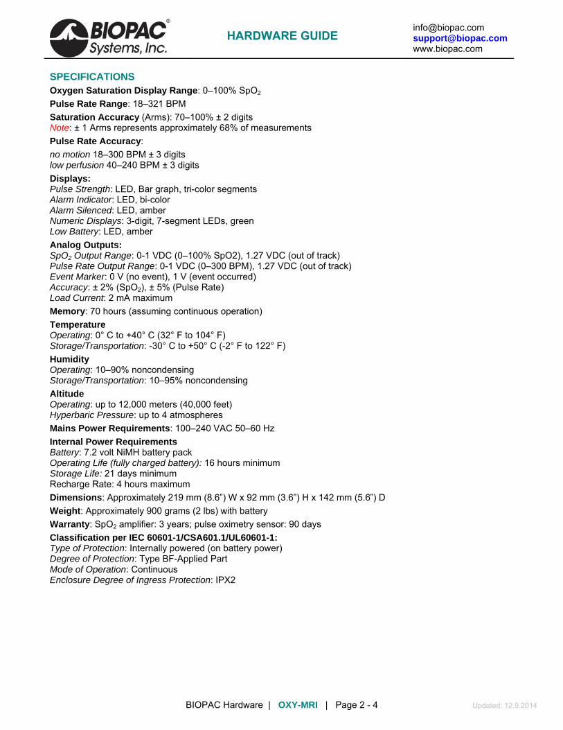
[email protected] [email protected] www.biopac.com
BIOPAC Hardware | OXY-MRI | Page 2 - 4 Updated: 12.9.2014
SPECIFICATIONS Oxygen Saturation Display Range: 0–100% SpO2 Pulse Rate Range: 18–321 BPM Saturation Accuracy (Arms): 70–100% ± 2 digits Note: ± 1 Arms represents approximately 68% of measurements Pulse Rate Accuracy: no motion 18–300 BPM ± 3 digits low perfusion 40–240 BPM ± 3 digits Displays: Pulse Strength: LED, Bar graph, tri-color segments Alarm Indicator: LED, bi-color Alarm Silenced: LED, amber Numeric Displays: 3-digit, 7-segment LEDs, green Low Battery: LED, amber Analog Outputs: SpO2 Output Range: 0-1 VDC (0–100% SpO2), 1.27 VDC (out of track) Pulse Rate Output Range: 0-1 VDC (0–300 BPM), 1.27 VDC (out of track) Event Marker: 0 V (no event), 1 V (event occurred) Accuracy: ± 2% (SpO2), ± 5% (Pulse Rate) Load Current: 2 mA maximum Memory: 70 hours (assuming continuous operation) Temperature Operating: 0° C to +40° C (32° F to 104° F) Storage/Transportation: -30° C to +50° C (-2° F to 122° F) Humidity Operating: 10–90% noncondensing Storage/Transportation: 10–95% noncondensing Altitude Operating: up to 12,000 meters (40,000 feet) Hyperbaric Pressure: up to 4 atmospheres Mains Power Requirements: 100–240 VAC 50–60 Hz Internal Power Requirements Battery: 7.2 volt NiMH battery pack Operating Life (fully charged battery): 16 hours minimum Storage Life: 21 days minimum Recharge Rate: 4 hours maximum Dimensions: Approximately 219 mm (8.6”) W x 92 mm (3.6”) H x 142 mm (5.6”) D Weight: Approximately 900 grams (2 lbs) with battery Warranty: SpO2 amplifier: 3 years; pulse oximetry sensor: 90 days Classification per IEC 60601-1/CSA601.1/UL60601-1: Type of Protection: Internally powered (on battery power) Degree of Protection: Type BF-Applied Part Mode of Operation: Continuous Enclosure Degree of Ingress Protection: IPX2
HARDWARE GUIDE

[email protected] [email protected] www.biopac.com
BIOPAC Hardware | OXY-MRI | Page 3 - 4 Updated: 12.9.2014
ACQKNOWLEDGE CALIBRATION (HLT100C)
1. Launch AcqKnowledge. The “Add new module” dialog should appear. If it does not, choose “MP150 > Set Up Data Acquisition > Channels.”
2. Choose “HLT100C-A1” from the module list and choose “Add.”
3. Select “OXY-MRI SPO2 Module Human-SPO2” from the “Transducer” list and click OK.
4. Choose “Add new module” and choose “HLT100C-A2” from the module list and click “Add.”
5. Select "OXY-MRI SPO2 Module Human-Pulse Rate" from the “Transducer” and click OK.
Using the above method of HLT100C module setup, no further calibration or scaling is necessary.
HARDWARE GUIDE

[email protected] [email protected] www.biopac.com
BIOPAC Hardware | OXY-MRI | Page 4 - 4 Updated: 12.9.2014
ACQKNOWLEDGE CALIBRATION (UIM100C)
1. Launch AcqKnowledge. The “Add new module” dialog should appear. If it does not, choose “MP150 > Set Up Data Acquisition > Channels.”
2. Choose “UIM100C-A1” from the module list and choose “Add.”
3. Choose “Custom” from the “Transducer” list and click OK to open the Scaling dialog.
4. Enter Cal 1, Cal 2, and Units Label as shown below and click OK.
5. Choose “Add new module” and choose “UIM100C-A2” from the module list, and click “Add.”
6. Choose “Custom” from the “Transducer” list and click OK to open the Scaling dialog.
7. Enter Cal 1, Cal 2, and Units Label as shown below and click OK.
HARDWARE GUIDE

[email protected] [email protected] www.biopac.com
BIOPAC Hardware | OXY300-MRI | Page 1 - 4 Updated: 8.29.2014
OXY300-MRI – SMALL ANIMAL NON-INVASIVE VITAL SIGNS MONITOR
MRI Usage: MR Conditional Condition: Must use MR sensor clip and max MR field strength 3T; modules stay in control room.
OXY300-MRI is a complete system for collecting small animal SpO2 measurements in an MRI environment.
• Works on conscious or anesthetized subjects • Patented sensor supports heart rates in the range of 90-900 BPM • Works with neonatal mice up to 500 gram rats • MRI sensor works in closed, small and large bore MRI machines
o regularly used in 9T magnets and has been successfully used in a 12T magnet o contact BIOPAC to discuss specific magnet strengths up to 19T
• Analog outputs interface cables included to interface with BIOPAC MP150 System via the UIM100C • Immediate access to Vital Signs for pre-,intra- and post-operative measurements • Arterial Oxygen Saturation
o comprehensive health indicator o indicates lung efficiency, not just airflow
• Heart Rate • Pulse Distention
o indicates signal quality
SYSTEM COMPONENTS Includes: Small Animal Vital Signs Monitor - MouseOx® Plus Monitor MRI sensor Analog output data unit Interface Cables (2 x CBL102)
OXY300-MRI REFERENCES OXY300-MRI User Manual OXY300-MRI Publications
HARDWARE GUIDE

[email protected] [email protected] www.biopac.com
BIOPAC Hardware | OXY300-MRI | Page 2 - 4 Updated: 8.29.2014
SPECIFICATIONS Oxygen Saturation (%) Measurement Range (pulse rate 90 to 900 bpm) 0 to 100% Arterial Blood Oxygen Saturation Measurement Resolution (pulse rate 210 to 900 bpm) Resolution = 1.5%, across entire range Measurement Response Time SpO2 is reported to the user after each heartbeat Heart Rate (bpm) Measurement Range 90 to 900 bpm Measurement Resolution (heart rate 210 to 900 bpm) Rate (bpm) Resolution (bpm) Rate (bpm) 210 2.4 600 19.4
Resolution (bpm)
300 4.9 700 26.2 400 8.7 800 34.0 500 13.5 900 42.9 Measurement Response Time Heart rate is reported to the user after each heartbeat. Pulse Distention (µm) Measurement Range (pulse rate 90 to 900 bpm) 0 to 800 µm Measurement Resolution = 2.4% of measurement Measurement Response Time Pulse distention is reported to the user after each heartbeat Respiration Respiration may be available as a derived signal but is not suitable for use with gating systems
Warning: No part of the OXY300-MRI MouseOx® Plus system other than the fiber optic cable and the sensor should go into an MRI machine.
Analog output interface 2 x CBL102 (included) to UIM100C module for BIOPAC MP150 System Delay Fixed (0.7-1.4 seconds) Small Animal Vital Signs Monitor MouseOx® Plus Control Box (Starr Life Sciences) BNC output range: ±5 V Screen refreshes every 0.72 seconds to update measurement values 12 VAC Power Supply (you will have one or the other of the following)
• US and Canada: Standard External Plug-in Power Supply • International: Power Transformer and Power Cord to fit your wall receptacle
12-foot 2.0 USB Cable CD with MouseOx® Plus Electronic User Manual Universal Cable Computer and Electrical Requirements for MouseOx Plus:
• Processor- PC with Pentium-class processor (Pentium 1 GHz or higher recommended) • Computer Hardware • VGA or higher resolution monitor (Super VGA recommended) • 2.0 USB port
HARDWARE GUIDE

[email protected] [email protected] www.biopac.com
BIOPAC Hardware | OXY300-MRI | Page 3 - 4 Updated: 8.29.2014
Operating System Windows® XP, Vista, 7 or newer, compatible with Apple® computers when using a Windows® emulator Memory: 1 GB RAM; 5 MB Hard-Drive Space for program (does not include data files) Minimum Screen Resolution: 1024 by 768 pixels The MouseOx® Plus has the following power requirements: Operating Wall Voltage: 100-240 VAC @ 50-60 Hz - you must use ONLY the provided power supply! Device Operating Voltage: 12 VAC Max Operating Analog Current: 200 mA Max Operating USB Current: 85 mA - MouseOx® Plus; 180 mA – STARR-Link™ (When using more than one of these devices, you must not operate the computer on batteries.)
HARDWARE GUIDE

[email protected] [email protected] www.biopac.com
BIOPAC Hardware | OXY300-MRI | Page 4 - 4 Updated: 8.29.2014
OXY300-MRI SENSOR: SMALL-BORE MRI SENSOR INSTRUCTION SHEET Small-Bore MRI Sensor Schematic
Usage Instructions:
1. Connect the DB9 Connector (9-pin connector) on the end of the thin black cable to the MouseOx® Control Box. Be sure that the MouseOx® software is not running when you do this.
2. Connect a disposable sensor clip to the fiber-optic cable. You MUST USE a Mouse Thigh Clip for mice and a Rat Foot Clip for rats. Place the protrusion on the end of the fiber-optic cable labeled “LED” into the hole on the clip half marked “LED,” then do the same for the side marked “PD.” Make sure that the fiber-optic cable is oriented so that it aligns over the handle as shown.
3. Connect the sensor clip to the animal:
a. Mouse Thigh – Place the clip on the thigh of a mouse as shown. For non-white fur, you MUST shave both locations of the sensor site. On white fur, shaving is not necessary, but will improve signal strength.
b. Rat Foot – Place the clip over the toes and locate it so that light shines through the CENTER of the foot. Support the clip/cable so that the animal’s foot is NOT TWISTED relative to its position before attaching the clip. The clip half marked “PD” should be on the bottom side of the foot.
4. After locating the clip on the animal, distribute the dual black fiber-optic cable such that it proceeds
straight from the animal and that it DOES NOT twist the animal’s foot. Try to lay the sensor clip so that both the LED and PD cables are lying on the table.
5. Run the MouseOx® software (Rev 6.0 or higher). To get to the Monitor Subject screen, choose “Anesthetized Measurements” then “Mouse Thigh” or “Rat Foot” depending on your application.
Other recommended guidelines: - Keep the body (rectal) temperature of the animal above 36° C. - Make sure that Pulse Distention exceeds 20 m when operating the system. If Pulse Distention is less than 20 m, try to relocate the sensor clip to improve it or warm the animal. - If you are having trouble getting a good signal, try shaving the sensor location if applicable. - The non-ferrous spring will weaken with multiple uses. An unreasonably low oxygen saturation measurement (a healthy subject with a sat of 88% or less) is a clear sign of an over-used spring. To prevent this, and to promote infection control, replace the clip before each MRI session.
CAUTION: Converter box contains trace amounts of ferrous material. Keep it away from the magnet bore.
HARDWARE GUIDE

[email protected] [email protected] www.biopac.com
BIOPAC Hardware | O2100C-CO2100C | Page 1 - 5 Updated: 12.9.2013
O2100C AND CO2100C GAS CONCENTRATION MEASUREMENT MODULES
O2100C and CO2100C
BIOPAC offers two fast-response analyzers for gas analysis. Each module measures partial pressure (of O2 or CO2, respectively) and thus module output is proportional to the pressure in the sample cell. Gas sampled must be free of liquids or any condensable vapors and should be filtered to 5 microns or better.
O2100C Records quickly varying oxygen concentration levels.
Ideal for monitoring time-averaged O2 levels using mixing chambers or real-time O2 levels for breath-by-breath measurements.
Employs an analysis technique based on the parametric oxygen measurement principle.
CO2100C Records quickly varying carbon dioxide concentration levels.
Ideal for monitoring time-averaged CO2 levels using mixing chambers or real-time CO2 levels for breath-by-breath measurements.
Employs a single beam infrared, single wavelength, measurement technique.
Both modules are equipped with a variable speed pump to adjust the flow over a wide range of sampling conditions. Sampling line connections for input and output flow are readily accessible on the front panel of either module.
Each module can interface with the AFT15A and AFT15B mixing chambers (via the AFT20 or AFT35-MRI gas sampling interface kit), the AFT21 and AFT22 non-rebreathing T valves or the AFT25 mask with integral non-rebreathing T valve.
HARDWARE GUIDE

[email protected] [email protected] www.biopac.com
BIOPAC Hardware | O2100C-CO2100C | Page 2 - 5 Updated: 12.9.2013
TECHNICAL USE NOTES 1. Snap the module together with the UIM100C (or other BIOPAC modules).
2. Select an unused channel on the channel selector switch on top of the module.
If two or more BIOPAC modules are set to the same channel, the outputs will conflict, resulting in erroneous readings.
3. Turn the MP150/MP100 unit on and start the AcqKnowledge software.
Please consult the “AcqKnowledge Software Guide” for information about AcqKnowledge.
4. Plug the adapter into the main power and insert the adapter plug into the back of the module.
The module is supplied with a 12 vdc @ 1 amp wall adapter—do not use other wall adapters with a gas analysis module.
The green POWER LED should light up. If it doesn’t, check the adapter main power and the connection to the O2100C module and then, if necessary, check the FUSE on the back of the O2100C/CO2100C module. [The FUSE ratings are: Instrumentation Type, Fast Blow @ 2 amps.]
The O2100C module has a warm-up time of approximately 1 minute. The CO2100C module has a warm-up time of approximately 5 minutes. Output readings during this warm-up period may be erratic.
5. Check for pump operation by turning the PUMP switch ON (after the green POWER LED comes on).
The module should emit a hum, indicating that the pump is working. Generally, the PUMP SPEED control will not have to be adjusted. However, it may be helpful to control sampling flow in the range of 50 to 200 ml/min depending upon measurement requirements.
The PUMP will start fast, then slow down and stabilize on a speed after a few seconds. This is a perfectly normal process, designed to overcome the pump’s initial mechanical hysteresis.
If the pump does not come on or comes on for a brief period and then shuts off, the PUMP SPEED control is set to a very low value (i.e., close to zero speed). To change the pump speed, keep the PUMP switch in the ON position and use a small straight blade screwdriver to turn the recessed potentiometer in the PUMP SPEED control. Turn trim POT clockwise to increase PUMP speed or counter-clockwise to decrease PUMP speed
6. Adjust the GAIN switch on the front of the module after proper startup.
Module Gain 1V output = % gas concentration Voltage output range
O2 100% / V 100% O2 0 to 1 volt
O2 50% / V 50% O2 0 to 2 volts
O2 20% / V 20% O2 0 to 5 volts
O2 10% / V 10% O2 0 to 10 volts
CO2 10% / V 10% CO2 0 to 1 volt
CO2 5% / V 5% CO2 0 to 2 volts
CO2 2% / V 2% CO2 0 to 5 volts
CO2 1% / V 1% CO2 0 to 10 volts
HARDWARE GUIDE

[email protected] [email protected] www.biopac.com
BIOPAC Hardware | O2100C-CO2100C | Page 3 - 5 Updated: 12.9.2013
O2 example: If the 100% / V setting is used, then 20.93% oxygen (atmospheric level) will be output as 0.2093 volts or 209.3 mV. Generally, GAIN can be left at the setting of 10% oxygen per volt (bottom position).
CO2 example: If the 10% / V setting is used, then 4% carbon dioxide (approximate concentration in expired breath) will be output as 0.40 V or 400 mV. Generally, GAIN can be left at the setting of 1% carbon dioxide per volt (bottom position).
GAS SAMPLING SETUP 1. Stabilize the measurement setup prior to sampling any gases.
Pump speed, filters and sampling lines all affect the oxygen measurement of the module. Everything should be stable prior to attempting module calibration.
2. Attach a 5 micron filter (or better) on the sample input port prior to sampling any gases. The sample input port is a male Luer fitting on the front of the module. The module incorporates an internal particulate filter, however the addition of this external filter will extend the life of the internal filter and otherwise improve the long-term performance of the module. Always use a 5 micron hydrophobic sampling filter (or better) at the sampling input of the module. One is included with each module and each Gas Sampling Interface Kit (AFT20 or AFT35-MRI). The 5-micron hydrophobic filter will help to protect the module from airborne particulate matter and other contaminants.
3. If required, screw a 10/32 threaded Luer adapter into the sample output port bulkhead fitting and attach the venting line to the Luer adapter to vent undesirable gases away from the site of the module. The sample output port is adjacent to the sample input port (on the right, facing the front panel of the module) and is a bulkhead fitting with a 10/32 internal thread.
Important
Sample dry gases only. All excess water vapor above ambient levels should be removed from the sampling stream prior to being monitored by the module. To dry the sampling stream, use water vapor permeable tubing (i.e., NAFION®). The AFT20 or AFT35-MRI Gas Sampling Interface Kit includes all the items necessary (including NAFION® tubing) to efficiently connect the module to a variety of setups, including BIOPAC mixing chambers, facemasks and non-rebreathing T-valves..
CALIBRATION Each gas concentration module comes factory-calibrated to ± 1% concentration accuracy. Depending upon sampling line configuration and pump speed (flow rate,) the calibration may veer further from ±1% accuracy. Generally, a gas calibration should be performed prior to all exacting measurements. This may also be required when running at increased pump speeds and thus increased flow rate. Initial (Factory) oxygen accuracy calibration is usually inadequate for varying setup protocols. Proper calibration of the module should be performed after the specific measurement setup is in place.
The CO2100C and O2100C gas sampling modules are designed so that the gas sensors are held at ambient pressure, due to construction design which directs exhaust sampling direct to the ambient environment. In this regard, the modules are relatively insensitive to variations in sampling line pressure. However, it remains good practice to use setup configurations which will minimize any pressure variation in the sampling line.
Choose the calibration gases to bracket the expected measurements. For example:
When performing End Tidal O2 measurements, normal air can be used as the first calibration gas because the oxygen concentration is known as 20.93%. For the second gas, it might be best to use a calibration gas of 16% oxygen, 4% carbon dioxide and 80% nitrogen (such as BIOPAC’s GASCAL). In this case, the measurements will be most accurate for the range of 16.00% to 20.93% oxygen.
When performing End Tidal CO2 measurements, normal air can be used as the first calibration gas because the carbon dioxide concentration is known as 0.04%. For the second gas, it might be best to use a calibration gas of 4% carbon dioxide, 16% oxygen and 80% nitrogen. In this case, the measurements will be most accurate for the range of 0.04% to 4% carbon dioxide.
HARDWARE GUIDE

[email protected] [email protected] www.biopac.com
BIOPAC Hardware | O2100C-CO2100C | Page 4 - 5 Updated: 12.9.2013
Exact calibration is typically performed in AcqKnowledge, using the Scaling function under Setup Channels, once the measurement setup is in place.
1. Set up the measurement so that all gas sampling lines are in place between the module and the sampling chamber.
2. Adjust the PUMP SPEED control (if required) on the module.
3. Run the module and click on the CAL1 button when the first calibration gas is introduced into the sampling chamber.
4. Introduce a second calibration gas into the chamber and click on CAL2 when the second calibration gas is introduced into the sampling chamber.
Note Do not change the pump speed, the sampling filter or the sampling line length/configuration during or after a calibration. Changing any of these elements may reduce the accuracy of the calibration.
PUMP SPEED CONTROL The pump speed is factory preset to result in a sampling flow rate of approximately 100 ml/min, when used with the AFT20 or AFT35-MRI Gas Sampling Interface Kit. The time delay between change of oxygen concentration at the sampling end of the Gas Sampling Interface Kit (AFT20 or AFT35-MRI)) to measurement at the module is approximately 2.4 seconds. This is because the pump will move 100 ml/min and the internal volume of the Gas Sampling Interface Kit is about 4.0 ml.
Volume in ml = () • (radius in cm)2 • (length in cm)
The Gas Sampling Interface Kit volume is calculated using:
PVC Sample Line: 72" long at 0.060" D Volume = 3.336 ml
NAFION® Dryer: 12" long at 0.050" D Volume = 0.386 ml
Misc. Tubing/Junctions: 6" long at 0.060" D Volume = 0.278 ml
If the sample rate is 100 ml/min, then the pump will pull 4 ml in 2.4 seconds:
(60 sec/min) • (4 ml) / (100 ml/min) = 2.4 sec
To check the flow rate, expire into the free end of the sampling line (30 cm Naflon tubing + 1.8 meters polyethylene tubing from AFT20 or AFT35-MRI Gas Sampling Kit) and simultaneously mark the recording (using the marker function in AcqKnowledge). The measured gas concentration level should show a change at approximately 2.5 seconds.
HARDWARE GUIDE

[email protected] [email protected] www.biopac.com
BIOPAC Hardware | O2100C-CO2100C | Page 5 - 5 Updated: 12.9.2013
SPECIFICATIONS O2100C Module measures the partial pressure of O2. CO2100C Module measures the partial pressure of CO2. Thus the module output is proportional to the pressure in the sample cell. Gas sampled must be free of any liquid or condensable vapors. Gas should be filtered to 5 microns or better.
O2100C CO2100C Range: 0-100% O2 0-10% CO2 Repeatability: ±0.1% O2 0.03% CO2 Resolution: ±0.1% O2 0.1% CO2 Linearity: ±0.2% O2 0.1% CO2 Zero Stability: ±0.01% O2/hr 0.1% CO2/24 hours Response Time: Fact ory Preset:
200 msec (T20-T80) @ 200 ml/min 500 msec (T20-T80) @ 100 ml/min 1000 msec (T20-T80) @ 50 ml/min
150 msec (T20-T80) @ 200 ml/min 250 msec (T20-T80) @ 100 ml/min 350 msec (T20-T80) @ 50 ml/min
Delay: (at 4 ml sampling line volume)
Flow (ml/min) = 240/Delay (sec) Example: If Delay is 2 sec; Flow = 120 ml/min
Gain: 10, 20, 50, 100 (%O2/Volt) 1, 2, 5, 10 (%CO2/Volt) Output Range: 0-10 volts Flow Range: 5-200 ml/min (50/150 ml/min recommended, increasing flow rate increases
response time) Temp Range: 5-50 C 10-45 C Zero Drift: ±0.05% O2/C ±0.01% CO2/C Span Drift: ±0.25% O2/C ±0.02% CO2/C Warm Up Time: About 1 minute About 5 minutes Humidity Range: (non-condensing) 0-95% 0-90% Sampling Input Port: Male Luer Sampling Output Port: Bulkhead fitting, 10/32 internal thread Weight: 990 grams 740 grams Dimensions: 7 cm (wide) x 11 cm (deep) x 19 cm (high) Power Source: 12 VDC @ 1 amp (uses AC100A transformer, included)
Gas sampled must be free of liquids or any condensable vapors. Gas sampled should be filtered to 5 microns or better. The module measures the partial pressure of O2 and thus the module output is proportional to the partial
pressure of O2 in the sample cell. For example, the partial pressure of 21% concentration of O2 at sea level (760 torr) is: 760 torr * 0.21 = 159.60 torr So at 700 torr and 21% O2, the module output will be: (700 torr / 760 torr) * 159.6 torr = 147 torr Accordingly, when operating at an ambient pressure of 700 torr, the module scaling needs to be multiplied by a factor of (700/760) or 0.921 * (original scaling).
See also: AFT Series Airflow & Gas Analysis Accessories
Application Note # AH149 — O2100C Module Setup Application Note # AH151 — CO2100C Module Setup
HARDWARE GUIDE

[email protected] [email protected] www.biopac.com
BIOPAC Hardware | GASSYS2 | Page 1 - 4 Updated: 8.7.2013
GASSYS2-EA/EB AND GASSYS2-RA/RB O2 & CO2 GAS ANALYSIS SYSTEM
GASSYS2 modules measure expired O2 and CO2 concentrations. When the subject inspires, air is drawn into the GASSYS2 through an airflow transducer. The SS11 (GASSYS2 EA/EB) or TSD107B (GASSYS2 RA/RB) airflow transducer is placed on the inspiration side to eliminate any effects associated with expired air humidity. When the subject expires, air is directed to the GASSYS2 module. The GASSYS2 is designed to work with saturated expired air.
Modular assembly makes complete cleaning easy!
See the AFT series of accessories for airflow
and gas analysis.
Obtain real-time Oxygen Consumption (VO2) and Respiratory Exchange Ratio (RER) measurements using the MP System with a GASSYS2 module and some airflow accessories. The GASSYS2 connects directly to the MP36 System (GASSYS EA/EB) or via the UIM100C (GASSYS RA/RB) and requires two channels.
The non-rebreathing T-valve directs only expired air to the GASSYS2. Because only expired air is directed to the module, the system acts to average respiratory outflows. This averaging effect causes the CO2 and O2 concentrations to vary in accordance to the mean values resident in a few expired breaths.
Two chamber sizes are available for the GASSYS2. Each chamber assembly includes the chamber casing and rod. The chambers work exactly the same way and are interchangeable on the module base. Use the smaller chamber size for small children/medium sized animals.
5-liter chamber — included in the GASSYS2-EA/RA; order chamber only as RX-GASA
1.7-liter chamber — included in the GASSYS2-EB/RB; order chamber only as RX-GASB
The GASSYS2 also includes AFT7 tubing, AFT11E Coupler, AFT22 Non-rebreathing T-Valve, and a power supply.
GASSYS2 Specs O2 sensor: Warm-up: 10 minutes. Response time 10-90%: 30 sec. Accuracy: ±1% FSR*.
Zirconia solid electrolyte with a 0.1-25% sensing range. It runs hot, which helps burn off humidity. *FSR = Full Scale Reading
Expected O2 sensor lifespan (in years):
[5,256/(number of hours used per year)]*5 If used for 10 hours per week or 520 total hours in a year, O2 sensor lifespan would
be [5,256/520]* 5 = 50.5 years
CO2 sensor: Warm-up: 2 minutes. Response time: < 120 seconds for a 90% step change. Uses a humidity-repellant (hydrophobic) membrane and has a sensing range of 0-5%. It uses non-dispersive infrared diffusion with single-beam IR and a self-calibrating algorithm. It also runs hot, which burns off humidity.
Calibration: GASSYS2 sensors are factory calibrated prior to shipping.
Power Supply: 12 V DC @ 1 amp (AC300A) wall adapter for serial numbers ending 200 or older.
HARDWARE GUIDE

[email protected] [email protected] www.biopac.com
BIOPAC Hardware | GASSYS2 | Page 2 - 4 Updated: 8.7.2013
Dimensions/Weight 1.7-liter chamber 5-liter chamber
Length: 22 cm 55 cm
Height: 18 cm 18 cm
Width: 14 cm 14 cm
Weight: 1.38 kg 1.96 kg
GASSYS2 Software Scaling Defaults
AcqKnowledge Software
Default %O2 Scaling
Default %CO2 Scaling
BSL PRO Software
Default %O2 Scaling
Default %CO2 Scaling
Calibration Procedure The GASSYS2 scaling parameters are factory-set to a “ballpark” default, but in order to achieve accurate measurements, these values must be re-calibrated in the AcqKnowledge or BSL PRO software using the following steps.
1. Flood the mixing chamber with fresh (ambient) air. (20.93% O2, 0.04% CO2) This can be accomplished by attaching the calibration syringe to the mouthpiece and cycling fresh air into the mixing chamber.
2. Monitor the gas concentration levels using AcqKnowledge or BSL PRO software. When the levels appear stabilized at ambient, obtain the first calibration point. (CAL 1)
3. Flood the chamber with the gas mixture using BIOPAC’s GASCAL and GASREG. The recommended concentration is 16% O2, 4% CO2 and 80% nitrogen (N2).
4. When the levels appear stabilized, obtain the second calibration point. (CAL 2)
HARDWARE GUIDE

[email protected] [email protected] www.biopac.com
BIOPAC Hardware | GASSYS2 | Page 3 - 4 Updated: 8.7.2013
Cleaning the BIOPAC GASSYS2
Note: Never clean the sensor base of the device. The two sensors, a screen and a copper-colored gas detector, are highly sensitive.
1) Unscrew the top knob attachment.
2) Remove the plastic lid from the flow chamber.
3) Gently pull the clear cylinder off the sensor base.
4) Detach the metal standing rod and its lower base attachment by holding the third of the standing rod nearest the base of the module and unscrewing the rod in a counter-clockwise motion.
a. Depress the rod by applying pressure at the base – this unlocks the rod’s position and allows movement.
b. Unscrew the rod in a counter-clockwise motion.
HARDWARE GUIDE

[email protected] [email protected] www.biopac.com
BIOPAC Hardware | GASSYS2 | Page 4 - 4 Updated: 8.7.2013
5) Remove the chamber stand (gently pull back the chamber stand from the electronics base).
6) Clean the flow chamber with one of two methods:
a. Use a soft cloth and Cidex Plus Sterilizing and Disinfecting Solution cleanser. Spray a light mist of Cidex cleanser on the parts of the device to be cleaned, and wipe the pieces with a dry rag. It is important never to get Cidex near the sensors of the device.
Other cleansers should not be substituted for Cidex – non-Cidex cleansers might damage or abrade the flow chamber pieces.
b. Heating the components in an autoclave sterilizing oven.
7) After cleaning reattach the platformed-standing rod to the electronics base.
a. Align the exhaust tube at the bottom of the rod stand with the exhaust port on the electronics base and insert securely.
b. Gently ease the rod stand back into its appropriate position on the electronics base. The sensors are very delicate—slowly lower the plastic base of the standing rod to the electronics base to make sure that the openings in the standing rod base correspond with the appropriate sensors.
8) Locate the latch opening for the security screw and align it with the screw, and then press the base of the standing rod to the sensor base.
a. Revolve the rod until the lower screw drops into its opening. When the screw meets its opening, it should drop into the hole.
b. Depress the rod by applying pressure on the lower third of the piece and rotate it in a clockwise motion until it locks into position.
9) Ease the clear cylinder back onto the device and lay its lower edge in the track on the electronics base.
10) Re-attach the plastic top to the clear cylinder.
11) Lock the plastic top into place by screwing in the security knob.
HARDWARE GUIDE
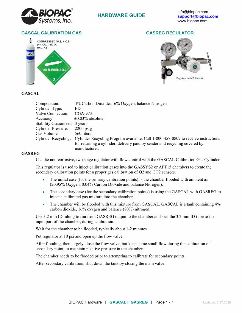
[email protected] [email protected] www.biopac.com
BIOPAC Hardware | GASCAL ï GASREG | Page 1 - 1 Updated: 2.17.2015
GASCAL CALIBRATION GAS GASREG REGULATOR
GASCAL
Composition: 4% Carbon Dioxide, 16% Oxygen, balance Nitrogen Cylinder Type: ED Valve Connection: CGA-973 Accuracy: ±0.03% absolute Stability Guaranteed: 3 years Cylinder Pressure: 2200 psig Gas Volume: 560 liters Cylinder Recycling: Cylinder Recycling Program available. Call 1-800-457-0809 to receive instructions
for returning a cylinder; delivery paid by sender and recycling covered by manufacturer.
GASREG Use the non-corrosive, two stage regulator with flow control with the GASCAL Calibration Gas Cylinder.
This regulator is used to inject calibration gases into the GASSYS2 or AFT15 chambers to create the secondary calibration points for a proper gas calibration of O2 and CO2 sensors.
The initial case (for the primary calibration points) is the chamber flooded with ambient air (20.95% Oxygen, 0.04% Carbon Dioxide and balance Nitrogen).
The secondary case (for the secondary calibration points) is using the GASCAL with GASREG to inject a calibrated gas mixture into the chamber.
The chamber will be flooded with this mixture from GASCAL. GASCAL is a tank containing 4% carbon dioxide, 16% oxygen and balance (80%) nitrogen.
Use 3.2 mm ID tubing to run from GASREG output to the chamber and seal the 3.2 mm ID tube to the input port of the chamber, during calibration.
Wait for the chamber to be flooded, typically about 1-2 minutes.
Put regulator at 10 psi and open up the flow valve.
After flooding, then largely close the flow valve, but keep some small flow during the calibration of secondary point, to maintain positive pressure in the chamber.
The chamber needs to be flooded prior to attempting to calibrate for secondary points.
After secondary calibration, shut down the tank by closing the main valve.
HARDWARE GUIDE

HARDWARE GUIDE
[email protected] [email protected] www.biopac.com
BIOPAC Hardware | AFT Series | Page 1 - 8 Updated: 9.5.2014
See also: Student Accessory Pack BSL-ACCPACK
AFT SERIES AIRFLOW & GAS ANALYSIS ACCESSORIES Includes the following airflow accessories:
Bacterial Filters Mouthpieces Calibration Syringes Airflow Tubing Facemasks & Accessories Noseclip
AFT1 AFT4 AFT13
AFT2 ATF8 AFT9
AFT6A AFT26
AFT7 AFT7L AFT12
AFT10 AFT10S AFT25
AFT3
Gas Sampling Kits AFT T-valves Head Support Gas Tubing Mixing Chamber Couplers
AFT20 AFT31-MRI AFT35-MRI
AFT21 AFT22 AFT23
AFT24 AFT30 AFT15 AFT11A AFT11B AFT11C AFT11D AFT11E AFT11F AFT11H AFT11I
DISPOSABLE BACTERIAL FILTERS MRI Use: MR Safe AFT1/4/13 Bacterial Filter Components: Polycarbonate Clear Plastic AFT1 Disposable Bacterial Filter Available in Packs of 10 or 250
Designed to remove airborne bacteria. Pore Size: Virus Filtration Efficiency (VFE): 3.1 micron; Bacterial Filtration Efficiency (BFE): 2.8 micron. Use between the SS11LA or TSD117 and the AFT2. 22 mm ID/OD.
AFT4 Disposable Bacterial Filter Designed to remove airborne bacteria; for use with the TSD107B, AFT4, or other 35 mm breathing circuits, connects between the AFT7 and the AFT9. (35 mm ID/35 mm OD)

HARDWARE GUIDE
[email protected] [email protected] www.biopac.com
BIOPAC Hardware | AFT Series | Page 2 - 8 Updated: 9.5.2014
AFT13 Disposable Pulmonary Function Filter and Mouthpiece Available in packs of 10 or 250 Eliminate cross-contamination concerns with this bacteriological filter with disposable plastic-coated paper mouthpiece to protect subjects and equipment. These exceed all recommended performance standards with 99.9% bacterial filtration efficiency and 99.9% viral filtration efficiency. They feature low resistance and minimal dead space (45 ml when measured without tube fittings). These surpass published ATS recommendations for flow resistance in pulmonary function instrumentation, which suggest resistance should be below 1.5 cm H2O/L/sec at flow rates less than 12 liters/sec. Port: 30 mm OD.
MOUTHPIECES MRI Use: MR Safe AFT Mouthpiece Components: Polyethylene EVA Copolymer, Thermoplastic Rubber,
Polycarbonate Plastic AFT2 Disposable Mouthpiece Available in Packs of 10 or 250
22 mm OD; connects to the SS11LA or TSD117 via the AFT1. AFT8 Autoclavable Mouthpiece Available in Packs of 1 or 10
30 mm ID; interfaces with the SS11LA or TSD117 and reduces the cost of disposable parts. • RX117 Replacement Sterilizable Airflow Head: 22 mm ID/30 mm OD; autoclavable transducer
head for the TSD117; can be used with the AFT8 to reduce the cost of disposable items. AFT9 Reusable Mouthpiece Available in Packs of 1 or 10
35 mm ID; designed to connect to the TSD107B or other 35 mm breathing circuits with the AFT7 via the AFT4. (Also connects to the AFT21 Non-rebreathing T Valve.)
NOSECLIP MRI Use: MR Safe AFT Noseclip Components: Thermoplastic Rubber, Polyvinyl Chloride (PVC) Plastic,
Polyurethane Foam Plastic AFT3 Disposable Noseclip Available in Packs of 10 or 250
Gently squeezes the nostrils shut while using the SS11LA or TSD117 Airflow Transducer.
CALIBRATION SYRINGES AFT6A Calibration Syringe
0.6 liter calibration syringe. See also: AFT26 2.0 liter Calibration Syringe AFT26 Calibration Syringe (2.0 liter)
The AFT26 is a 2.0 Liter Calibration Syringe for the SS11LA or TSD117 Airflow Transducer. The AFT26 Calibration Syringe is certified to have a 2-liter volume that meets or exceeds an accuracy ± 1% of the total displacement volume. The increased size and accuracy of this 2.0 liter calibration syringe provide a wider calibration
range than the AFT6A for advanced studies. A coupler is included and can be reordered as AFT11I if it is inadvertently discarded when an airflow accessory is removed.
TUBING FOR AIRFLOW MRI Use: MR Safe AFT7/7L/12 Tubing Components: Polyethylene EVA Copolymer AFT7 Smooth Bore Tubing
1 m length, 35 mm ID; connects to the TSD107B, AFT4, or other 35 mm breathing circuits. See also: AFT part guide for additional applications.

HARDWARE GUIDE
[email protected] [email protected] www.biopac.com
BIOPAC Hardware | AFT Series | Page 3 - 8 Updated: 9.5.2014
AFT7L Smooth Bore Tubing 3 m length, 35 mm ID; connects to the TSD107B, AFT4, or other 35 mm breathing circuits. See also: AFT part guide for additional applications.
AFT12 Tubing (22 mm) Smooth bore tubing for use in 22 mm breathing circuits. (1.8 meter length, 22 mm ID)
FACEMASKS, FACEMASK ACCESSORIES AFT10 Disposable Adult Facemask These mouthpieces connect to 22 mm breathing circuits. Connects directly to the AFT1, AFT22 non-
rebreathing T-valve, or SS11LA/TSD117 airflow transducer (via AFT11B coupler). Includes hook-ring to secure AFT10S adjustable head strap. (22 mm ID/25 mm OD)
MRI Use: MR Safe AFT10 Facemask Components: Thermoplastic Elastomer, Polyvinyl Chloride (PVC) Plastic AFT10S Adjustable Head Strap This fully adjustable latex head strap holds the AFT10 disposable facemask securely to the subject’s
head. Use one or more straps to securely fasten the mask. MRI Use: MR Safe AFT10S Head Strap Components: Latex Rubber AFT25 Facemask with Valve
This adult facemask with integral non-rebreathing T valve is a high performance, very low dead space, low airflow resistance mask and valve; suitable for high airflow applications (e.g. exercise physiology). The AFT25 incorporates two gas sampling ports (female Luer) for interfacing with the AFT20 Gas Sampling Kit. All ports are 35 mm OD, 28 mm ID
MRI Use: MR Safe AFT25 Facemask Components: Mask: Thermoplastic Elastomer, Valve:
Acetal Plastic, Acrylic Plastic,, Aluminum (nickel plated silver,) Elastomer, Nylon, Thermoplastic Polyester, Polycarbonate Plastic, Silicone Rubber, Stainless Steel, Polysulfone Plastic
Headgear: Fabric with Velcro straps
COUPLERS MRI Use: MR Safe AFT11 Series Coupler Components: Thermoplastic Rubber, Polyvinyl Chloride (PVC) Plastic,
Polycarbonate Clear Plastic, Acrylonitrile Butadiene Styrene (ABS) Thermo-molded, Plastic
AFT11A Flexible AFT11D Flexible AFT11H Flexible AFT11B Rigid AFT11E Flexible AFT11I Flexible (for AFT26) AFT11C Rigid AFT11F Rigid
These couplers are very useful for connecting up a variety of airflow port IDs and ODs to transducers, tubing and calibration syringes. Pick an AFT11 Series coupler that matches the port sizes to be interfaced.
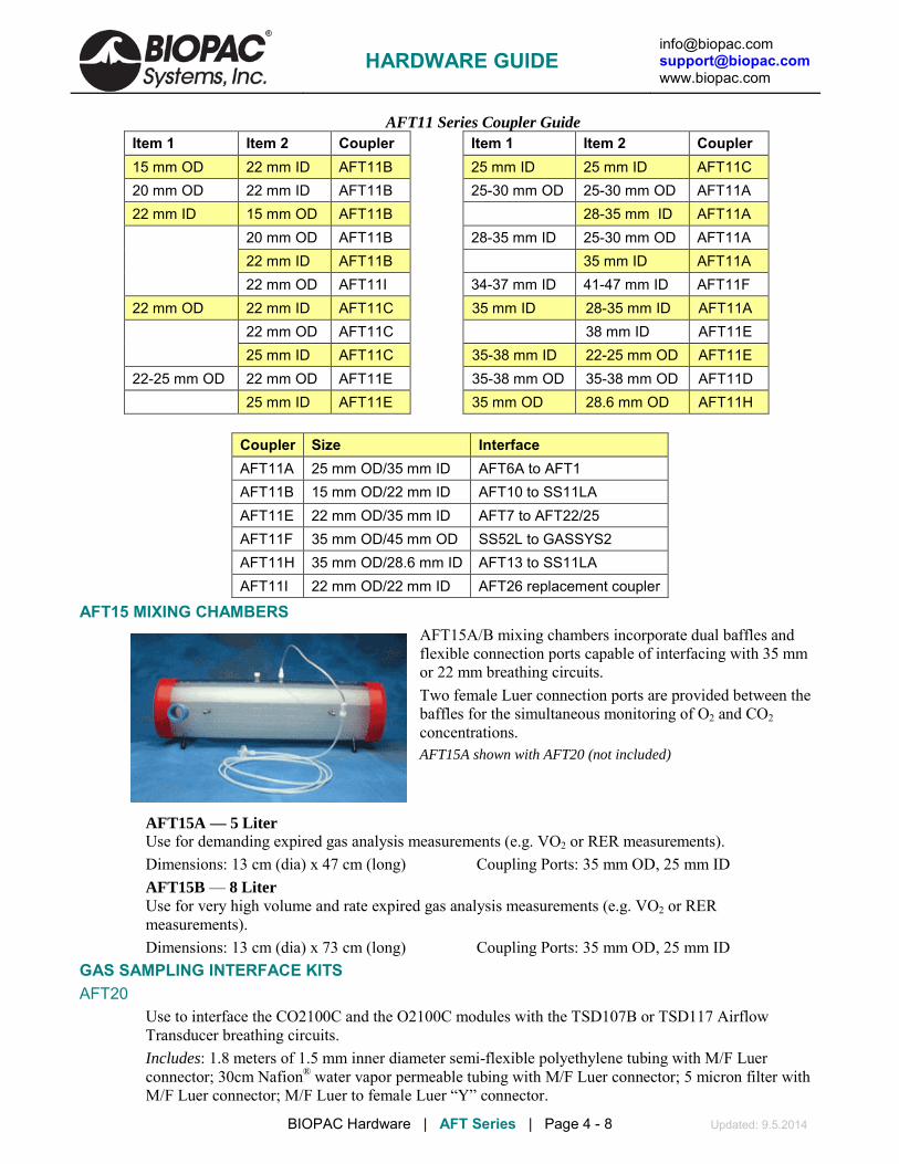
HARDWARE GUIDE
[email protected] [email protected] www.biopac.com
BIOPAC Hardware | AFT Series | Page 4 - 8 Updated: 9.5.2014
AFT11 Series Coupler Guide Item 1 Item 2 Coupler Item 1 Item 2 Coupler 15 mm OD 22 mm ID AFT11B 25 mm ID 25 mm ID AFT11C 20 mm OD 22 mm ID AFT11B 25-30 mm OD 25-30 mm OD AFT11A 22 mm ID 15 mm OD AFT11B 28-35 mm ID AFT11A 20 mm OD AFT11B 28-35 mm ID 25-30 mm OD AFT11A 22 mm ID AFT11B 35 mm ID AFT11A 22 mm OD AFT11I 34-37 mm ID 41-47 mm ID AFT11F 22 mm OD 22 mm ID AFT11C 35 mm ID 28-35 mm ID AFT11A 22 mm OD AFT11C 38 mm ID AFT11E 25 mm ID AFT11C 35-38 mm ID 22-25 mm OD AFT11E 22-25 mm OD 22 mm OD AFT11E 35-38 mm OD 35-38 mm OD AFT11D 25 mm ID AFT11E 35 mm OD 28.6 mm OD AFT11H
Coupler Size Interface AFT11A 25 mm OD/35 mm ID AFT6A to AFT1 AFT11B 15 mm OD/22 mm ID AFT10 to SS11LA AFT11E 22 mm OD/35 mm ID AFT7 to AFT22/25 AFT11F 35 mm OD/45 mm OD SS52L to GASSYS2 AFT11H 35 mm OD/28.6 mm ID AFT13 to SS11LA AFT11I 22 mm OD/22 mm ID AFT26 replacement coupler
AFT15 MIXING CHAMBERS AFT15A/B mixing chambers incorporate dual baffles and flexible connection ports capable of interfacing with 35 mm or 22 mm breathing circuits. Two female Luer connection ports are provided between the baffles for the simultaneous monitoring of O2 and CO2 concentrations. AFT15A shown with AFT20 (not included)
AFT15A — 5 Liter Use for demanding expired gas analysis measurements (e.g. VO2 or RER measurements).
Dimensions: 13 cm (dia) x 47 cm (long) Coupling Ports: 35 mm OD, 25 mm ID AFT15B — 8 Liter
Use for very high volume and rate expired gas analysis measurements (e.g. VO2 or RER measurements).
Dimensions: 13 cm (dia) x 73 cm (long) Coupling Ports: 35 mm OD, 25 mm ID GAS SAMPLING INTERFACE KITS AFT20 Use to interface the CO2100C and the O2100C modules with the TSD107B or TSD117 Airflow
Transducer breathing circuits. Includes: 1.8 meters of 1.5 mm inner diameter semi-flexible polyethylene tubing with M/F Luer
connector; 30cm Nafion® water vapor permeable tubing with M/F Luer connector; 5 micron filter with M/F Luer connector; M/F Luer to female Luer “Y” connector.

HARDWARE GUIDE
[email protected] [email protected] www.biopac.com
BIOPAC Hardware | AFT Series | Page 5 - 8 Updated: 9.5.2014
The AFT20 connects the CO2100C or O2100C directly to the sampling port of a mixing chamber. The AFT20 also permits sampling connections to the Non-rebreathing “T” Valves (AFT21 or AFT22).
MRI Use: MR Safe AFT20 Gas Sampling Kit Components: Tubing: 1.8 m of 1.5 mm diameter polyethylene tubing with
M/F Luer; Tubing: 30 cm Nafion water vapor permeable tubing with M/F Luer connector; Y-connector: Acrylonitrile butadiene styrene (ABS) polycarbonate
AFT31-MRI This 3.175 mm ID tubing is 10 meters long with male and female Luer lock and "Y" connector interfaces to the AFT21 T-valve, AFT25 facemask, or AFT15 mixing chamber gas sampling ports to connect them to the CO2100C module and/or the O2100C module. To use both CO2100C and O2100C modules simultaneously, a “Y” connector gas sampling interface adapter is included.
MRI Use: MR Safe AFT31-MRI Gas Sampling Kit Components: Polyethylene, Polyvinyl Chloride Plastic,
Polycarbonate Clear Plastic ID/OD: 3.175 mm (1/8") / 6.35 mm (1/4") Type: Crack-Resistant Polyethylene Tubing Maximum Pressure: 358 psi @ 70º F Material: Linear Low Density Polyethylene Operating Temperature Range: -100° to +175° F Wall Thickness: 1.588 (1/16") “Y” connector: 1 x male to 2 x female Bend Radius: 2" Length: 10 m Durometer: 95A (Firm)
AFT35-MRI The AFT35-MRI is a low profile mouthpiece and non-rebreathing T-valve assembly specifically
designed to fit inside an fMRI head coil. Use the AFT35-MRI to perform the following airflow and lung volume tests:
• End Tidal CO2 • VO2 max • Breath-by-breath Air Flow
• Breath-by-breath Volume • Metabolic Studies
The assembly includes a Luer lock port for easy interface to AFT31-MRI gas sampling tubing for CO2
and O2 gas analysis. The assembly interfaces with AFT7/7-L tubing, via the AFT11A coupler, for operation with the TSD117-MRI ±300 L/min airflow transducer. Extra mouthpiece included.
Low clearance – only 25 mm between subject and coil Dimensions: 25 mm breathing port height (excluding mouthpiece) x 35 mm outlet port diameter x 83
mm wide x 115 mm long Deadspace: 88 ml Sterilization: Cidex recommended

HARDWARE GUIDE
[email protected] [email protected] www.biopac.com
BIOPAC Hardware | AFT Series | Page 6 - 8 Updated: 9.5.2014
AFT35-MRI Sample Setups Perform a variety of tests. Place transducer outside the bore in the MRI Chamber Room and run tubing to connect to the subject and breathing accessories; place amp in Control Room. • End Tidal CO2: C02100C amp + AFT31-MRI tubing + AFT35-MRI airflow interface • Airflow & Lung Volume: DA100C amp + MECMRI-DA cable/filter set + TSD117-MRI
transducer + AFT11A coupler + AFT7-L tubing + AFT35-MRI • Airflow & Lung Volume with End Tidal CO2: DA100C + MECMRI-DA + TSD117-MRI +
AFT11A + AFT7-L + AFT35-MRI + AFT31-MRI + CO2100C • Metabolic: DA100C + MECMRI-DA + TSD117-MRI + 2 x AFT11A + 2 x AFT7-L + AFT35-
MRI + AFT31-MRI + AFT15A/B + C02100C and/or O2100C MRI Use: MR Safe AFT35-MRI Components: Polyvinyl Chloride (PVC) plastic, Polyethylene EVA Copolymer,
Thermoplastic Rubber, Polycarbonate Plastic, Acrylic Plastic, Elasotomer, Paper, Latex Rubber, Polyurethane Foam Plastic, Acrylonitrile Butadiene Styrene (ABS) Thermo-molded
AFT T-VALVES AFT21 Non-Rebreathing “T” Valve: Female, 35 mm High performance, very low dead space, low airflow
resistance valve, suitable for high airflow applications (e.g. exercise physiology). The non-rebreathing “T” valve incorporates a Female Luer connector gas sampling port for interfacing with the AFT20. All ports are 35 mm OD, 30 mm ID.
Includes: 35 mm OD coupler Requires: AFT4, AFT7, and AFT9 for proper operation. AFT22 (top left), AFT21 (top right)
AFT20 (bottom) AFT22 Non-Rebreathing “T” Valve: Male, 22 mm
Very low dead space valve, suitable for low to medium airflow applications. The non-rebreathing “T” valve incorporates a Male Luer connector gas sampling port for interfacing with the AFT20. Coupler ports are 22 mm OD fittings. Common port incorporates a 15 mm ID connection. Dead space 20 cc. Resistance: 0.29 cmH2O at 5 liter per minute flow, 0.65 cmH2O at 10 liter per minute. Single subject disposable item – do not autoclave. Includes: 22 mm OD coupler Requires: AFT1 and AFT2 for proper operation.
Includes: 22 mm OD coupler Requires: AFT1 and AFT2 for proper operation. MRI Use: MR Safe AFT21/22 T-Valve Components: Acrylic Plastic, Elasotomer, Polycarbonate Clear Plastic AFT23 Non-Rebreathing T-Valve, 35 mm
The AFT23 is a disposable paper mouthpiece featuring a one-way valve for pulmonary function measurements (expiratory only). It provides low air resistance, adds cross-contamination protection, and is strong and durable. It ships with eight extra valves. Mouthpiece OD: 35 mm. Fits AFT13 pulmonary function filter & mouthpiece set.
MRI Use: MR Safe AFT23 T-Valve Components: Acrylic Plastic, Elasotomer, Paper

HARDWARE GUIDE
[email protected] [email protected] www.biopac.com
BIOPAC Hardware | AFT Series | Page 7 - 8 Updated: 9.5.2014
AFT24 Head Support
The AFT24 head support is used when breathing directly into the AFT21 non-rebreathing T valve for exercise physiology measurements. The AFT21 is secured directly in front of the subject and minimizes the strain associated with the weight of valves and tubing.
TUBING FOR GAS SAMPLING AFT30 Series Tubing and M/F Luer Locks
Use this semi-flexible 1.5 mm tubing with male and female Luer locks to interface with the RX110 self-inflating pressure pad, TSD114 response/hand force pump bulb, or gas sampling ports on AFT15 mixing chambers, CO2100C module, or O2100C module. See AFT31-MRI for gas sampling in the MRI. AFT30: 1.8 m AFT30-L: 4 m AFT30-XL: 10 m The length of tubing will add a delay of less than 50 msec to the sensing of the waveform peak.
MRI Use: MR Safe AFT30 Series Gas Sampling Kit Components: 1.5 mm diameter polyethylene tubing with M/F Luer Part Summary for Typical Airflow / Gas Analysis Applications Pulmonary Function High Flow Med. Flow Low Flow Very Low Flow Part #
Exercising human
Resting human Child, Pig, Dog Small Animals
AFT2 Mouthpiece X AFT3 Noseclip X X AFT6A Calibration Syringe X X X AFT7/7L Tubing X (2) AFT9 Mouthpiece X AFT21 T Valve X AFT24 Head Support X (optional) AC137 In-line Transformer DA100C Amplifier X (2) X X X TSD107B Pneumotach (High) X (2) X TSD117 Pneumotach (Med.) X TSD127 Pneumotach (Low) X TSD137 A-E Pneumotachs (Very Low) X (by size)
Part Options: AFT25 = AFT21 + AFT9 + AFT3 + optional AFT24 AFT2 + AFT3 = AFT0 + AFT11B

HARDWARE GUIDE
[email protected] [email protected] www.biopac.com
BIOPAC Hardware | AFT Series | Page 8 - 8 Updated: 9.5.2014
Exercise Physiology Mixed Expiratory Gases Breath-by-Breath High Flow Med. Flow High Flow Med. Flow Low Flow Part #
Exercising human
Resting human
Exercising human
Resting human Dog
AFT6A Calibration Syringe X X X X X AFT7 Tubing X (2) X AFT10 Facemask X X AFT10S Head Strap X X AFT11 Series Couplers X (3)* X X (2)** AFT12 Tubing X (2) X AFT15A Mixing Chamber X X AFT20 Interface Kit X (2) X (2) X (2) X X (2) AFT22 T Valve X X X AFT25 Facemask w/Valve X X DA100C Amplifier X X X X X CO2100C CO2 Module X X X X X O2100C O2 Module X X X X X TSD107B Pneumotach (High) X X TSD117 Pneumotach (Med.) X X TSD127 Pneumotach (Low) X
Part Options: AFT25 = AFT21 + AFT9 + AFT3 + optional AFT24 * use 2 AFT11B and 1 AFT11C AFT10 + AFT10S = AFT2 + AFT3 + AFT11C ** use 1 AFT11B and 1 AFT11C
See also: AFT coupler guide for additional applications.

[email protected] [email protected] www.biopac.com
BIOPAC Hardware | PULSE OXIMETRY | Page 1 - 5 Updated: 8.29.2014
PULSE OXIMETRY OXY100E Module (18-321 BPM) OXY200 Module (for veterinary use only, 18-450 BPM) TSD124 Series SPO2 Transducers for OXY100E TSD270 Series SPO2 Transducers for OXY200 These modules measure beat-by-beat, blood oxygen saturation (SpO2) level in a noninvasive fashion. The OXY100E outputs four signals simultaneously:
A: SpO2 value (Ch 1, 2, 3, or 4)
B: Pulse Plethysmogram (Ch 5, 6, 7, or 8)
C: Heart pulse rate (Ch 9, 10, 11, or 12)
D: Module Status (Ch 13, 14, 15, or 16)
These signals are directed to switchable blocks of different MP input channels. Up to four OXY modules can be used with a single MP System. The modules have built-in calibration for a simplified setup procedure. Each OXY module requires one of the TSD124 series SpO2 transducers.
The modules operate in accordance to principles outlined by the Lambert-Beer law; this is an empirical relationship that relates the absorption of light to the properties of the material through which the light is traveling.
The OXY modules are noninvasive instruments that measure blood-oxygen percentage levels. The module probe incorporates light-emitting diodes (LEDs) which face photodiodes through a translucent part of the subject's body, usually a fingertip or an earlobe. One LED is red, with wavelength of 660 nm, and the other is infrared (approximately 910 nm). Light absorption at these wavelengths is different between oxyhemoglobin and its deoxygenated form. The oxyhemoglobin/deoxyhemoglobin ratio can be calculated via the ratio of the absorption of the
red and infrared light. In particular, the OXY modules output (as a proportional voltage) the percentage of arterial hemoglobin in the oxyhemoglobin state.
HARDWARE GUIDE

[email protected] [email protected] www.biopac.com
BIOPAC Hardware | PULSE OXIMETRY | Page 2 - 5 Updated: 8.29.2014
OXY100E/200 Series Specifications Outputs: SpO2, Pulse Rate, Pulse Waveform & Module Status Pulse Rate Range: OXY100E: 18-321 BPM, OXY200: 18-450 BPM SpO2 Range: 0-100% SpO2 Accuracy: 70-100% ±2% Measurement Wavelengths Red: 660 nanometers @ 0.8 mW maximum average and Output Power: Infared: 910 nanometers @ 12 mW maximum average Operating Temperature Range: 0-50 degrees C Operating Humidity Range: 10-90% (non-condensing) Beat to Beat (un-averaged, non-slew limited, beat-to-beat value) Fast (non-slew limited, 4 beat average) Standard (4 beat average, slew limited) Extended (8 beat average, slew limited) Pulse Rate Output Options*: Standard (4 beat average, slew limited) Extended (8 beat average, slew limited). Compatible Sensors: BIOPAC TSD124 series Principle of Operation: Lambert-Beer law employing dual wavelengths
*for un-averaged, Beat-to-Beat Pulse Rate: use AcqKnowledge Rate detector on Pulse Waveform Output
TSD124 Series SpO2 Transducers For OXY100E
TSD124 Series TSD124A Finger TSD124C Flex Wrap The TSD124 series human oximetry transducers are reliable and simple to use on a wide range of subjects for both short-term and continuous noninvasive monitoring. The transducers incorporate Nonin’s PureLight® sensors and are backed by a six-month warranty. Use with the OXY100E oximetry amplifier.
Available Types: TSD124A Finger Clip Transducer
Subject Range: > 30 kg (66 lbs) Preferred application: Index, middle or ring fingers Length: 1 m
TSD124B Ear Clip SpO2 Transducer Subject Range: > 40 kg (88 lbs) Length: 1 m
TSD124C Flex Wrap SpO2 Transducer (Ships with 25 RX124C adhesive wrap guides)
Length: 1 m
HARDWARE GUIDE

[email protected] [email protected] www.biopac.com
BIOPAC Hardware | PULSE OXIMETRY | Page 3 - 5 Updated: 8.29.2014
RX124C Disposable FlexiWrap® adhesive guides for use with the reusable TSD124C Flex Sensor. Sized for adults (> 20 Kg or 44 lbs) Apply to index, middle or ring finger. Qty 25 per pack
Also available: OXY100E-200 EXT Pulse Oximeter extension cable – 3m
TSD270 Series SpO2 Transducers For OXY200
The TSD270 series veterinary oximetry transducers are reliable and simple to use on a wide range of animals for both short-term and continuous noninvasive monitoring. The transducers incorporate Nonin’s PureLight® sensors and are backed by a six-month warranty. Use with the OXY200 Veterinary oximetry amplifier.
TSD270A Transflectance Transducer The Transflectance Sensor, the smallest probe, is ideally suited for continuous monitoring from the paw, tail, or other vascularized part of the animal. It can be conveniently placed on the underside, base of the tail or other well-perfused surfaces. It is an excellent option during dental procedures.
TSD270A
TSD270B Small Animal Wrap Transducer The flexible wrap sensor can be placed on a small, well-perfused appendage. This sensor is easily secured making it ideal for continuous monitoring during long surgical or other procedures. It is most often used on rodents or other very small animals.
TSD270B
HARDWARE GUIDE

[email protected] [email protected] www.biopac.com
BIOPAC Hardware | PULSE OXIMETRY | Page 4 - 5 Updated: 8.29.2014
Pulse Oximeter Calibration OXY100E/OXY200 Modules will operate with default values unless an exact calibration is performed using the recessed “Cal” button on the OXY module and AcqKnowledge scaling.
To access the “Scaling analog channel” dialog, click MP menu > Set Up Channels and then click “View by Channels,” click “Setup…” and click “Yes” when prompted.
On the OXY module, use a paperclip or pen tip to press and hold the recessed “Cal” button. “Press and hold” the “Cal” button for ~1.5 seconds to switch between modes, as indicated by the Status LED states.
“Normal” Status LEDS = GREEN OFF and YELLOW OFF (YELLOW may occasionally flicker due to background processing)
“Calibration Low” Status LEDs = CONSTANT GREEN ON and YELLOW OFF
“Calibration High” Status LEDs = GREEN OFF and CONSTANT YELLOW ON
Release the “Cal” button as soon as the mode switches—continuously holding the button in the depressed state will not lead to another mode change. Modes cycle from normal to low, then to high, then back to normal.
“Press and hold” the “Cal” button for ~1.5 seconds to switch to “Calibration Low” mode and then click the “Cal2” button in the software for any of the OXY module analog channels that are enabled.
“Press and hold” the “Cal” button again for ~1.5 seconds to switch to “Calibration High” mode and then click the “Cal1” button in the software for any of the OXY module analog channels that are enabled.
“Press and hold” the “Cal” button again for ~1.5 seconds to return to “Normal” mode.
It’s best to calibrate the OXY module once, then Save As > Graph Template to save the respective scale values.
HARDWARE GUIDE

[email protected] [email protected] www.biopac.com
BIOPAC Hardware | PULSE OXIMETRY | Page 5 - 5 Updated: 8.29.2014
OXY100E and OXY200 Status Output Values Event Weight Out of Track/No sensor
0/16*10 V (~ 0 V)
Artifact 1/16*10 V (~ 0.625 V)
Sensor Alarm 2 /16*10 V (~ 1.25 V)
Green Perfusion 16/16*10 V (~10 V)
Yellow Perfusion 14 /16*10 V (~8.75 V)
Red Perfusion 13 /16*10 V (~8.125 V)
OXY100E and OXY200 Switches The switch bank on the back panel can be used to control output for the SpO2 and HR channels. Use ‘Calibration’ for exact output levels. Output is ~10 V if the sensor is ‘out of track.’
Switch Channel Output details
1 2 3 SpO2 Range is 0 V (0%) to ~7.9 V (100%) OFF OFF OFF 0-127 BPM 4-beat average values in standard1 mode Factory setting OFF ON ON 0-127 BPM 4-beat average values in standard1 mode ON ON ON 0-127 BPM 4-beat average values in standard1 mode ON OFF OFF 0-127 BPM 4-beat average displayed values in display2 mode OFF OFF ON 0-127 BPM 8-beat average values in standard1 mode ON OFF ON 0-127 BPM 8-beat average displayed values in display2 mode OFF ON OFF 0-127 BPM Non-slew limited saturation with 4-beat averaging in standard1 mode ON ON OFF 0-127 BPM Non-slew limited, not averaged, beat to beat value in standard1 mode
4 5 HR Range is 0 V (0 BPM) to ~6.27 V (321 BPM) for human OXY100E 0 V (0 BPM) to ~8.86 V (450 BPM) for veterinary OXY200
OFF OFF 0-max3 BPM 4-beat average values in standard1 mode Factory setting
ON OFF 0-max BPM 4- beat average displayed values in display2 mode
OFF ON 0-max BPM 8-beat average values in standard1 mode
ON ON 0-max BPM 8-beat average displayed values in display2 mode
1 Standard SpO2 and Pulse rate updated on every pulse beat. SpO2 and Heart Rate values are set to missing data values and out of track indicated.
2 Display SpO2 and Pulse rate updated every 1.5 seconds. Last in track values transmitted for ten seconds and out of track indicated; after ten seconds, values are set to missing data values.
3 511 BPM Output of 511 BPM (+10 V) indicates that sensor is not connected or signal is bad (out of track or sensor is not secured on the finger). The module never outputs BPM between range max (321 or 450) and 511.
HARDWARE GUIDE

[email protected] [email protected] www.biopac.com
MP Research System | OXY100C | Page 1 - 4 Updated: 12.5.2012
OXY100C PULSE OXIMETER MODULE Note: Effective August 2010, the OXY100E replaced the OXY100C
The OXY100C Pulse Oximeter Module is primarily used to measure beat-by-beat blood oxygen saturation (SpO2) in a noninvasive fashion. The OXY100C probe incorporates light-emitting diodes (LEDs) which face photodiodes through a translucent part of the patient's body, usually a fingertip or an earlobe. One LED is red, with wavelength of 660 nm, and the other is infrared (approximately 910 nm). Light absorption at these wavelengths is different between oxyhemoglobin and its deoxygenated form. The oxyhemoglobin/deoxyhemoglobin ratio can be calculated via the ratio of the absorption of the red and infrared light. In particular, the OXY100C outputs (as a proportional voltage) the percentage of arterial hemoglobin in the oxyhemoglobin state.This ratio is expressed as the O2 Saturation Level and will vary between 0% and 100%.
The OXY100C operates in accordance to the principles outlined by the Lambert-Beer law. This is an empirical relationship that relates the absorption of light to the properties of the material through which the light is traveling.
The Pulse Oximeter Module connects directly to the MP150 via the UIM100C. Up to four OXY100C modules can be used with a single MP System. The Pulse Oximeter Transducer (TSD123) connects to the OXY100C via a 3-meter extension cable (included with the OXY100C).
The OXY100C outputs four signals simultaneously. Output signals can be optionally directed to a number of different MP System input channels as determined with the BANK SELECT:
CH SIGNAL Bank 1 Bank 2 Bank 3 Bank 4
A O2 Saturation Channel 1 Channel 2 Channel 3 Channel 4 B Pulse Waveform Channel 5 Channel 6 Channel 7 Channel 8 C Pulse Rate Channel 9 Channel 10 Channel 11 Channel 12 D Module Status Channel 13 Channel 14 Channel 15 Channel 16
There is an ON/OFF switch for each signal output channel on the OXY100C. Set the switch for each signal output channel to sample all, some or none of the signals. When any Signal Channel Enable switch is OFF (bottom position), the corresponding MP150 channel can be used by another input device.
The OXY100C includes Calibration features that permit easy scaling of all these signals when using the OXY100C with the MP System.
The graph on the following page shows sample output.
O2 Saturation (beat-by-beat, CH 1)
Pulse Waveform (beat-by-beat, CH 5)
Pulse Rate (continuous, CH 9)
Module Status (dynamic, CH13)
HARDWARE GUIDE

[email protected] [email protected] www.biopac.com
MP Research System | OXY100C | Page 2 - 4 Updated: 12.5.2012
OXY100C CALIBRATION Initial setup— OXY100C with an MP System:
1. Snap the OXY100C into the side of the UIM100C.
2. Connect the Analog cables directly from the MP150 to the OXY100C Analog mating connectors.
3. Connect the Digital cables directly from the MP150 to the OXY100C Digital mating connectors.
4. When the cable connections are secure, power up the MP150.
5. On the OXY100C module, place the four-position Bank Select switch to the first bank (top position). In this position, the OXY100C output signals will be directed as follows:
O2 Saturation Channel 1 Pulse Rate Channel 9
Pulse Waveform Channel 5 Module Status Channel 13
If using multiple OXY100C modules with a single MP System, be sure to place additional OXY100C modules on unique banks. Furthermore, please check that any OXY100C output does not reside on the same channel used by any other amplifier module.
6. On the OXY100C module, slide the four-position Calibration switch to the OFF position (bottom).
7. On the OXY100C module, set all the Signal Channel Enables to ON (top position).
8. Using the Input Channels Setup in AcqKnowledge, label the OXY100C signal outputs as follows:
Channel Label
A5 Pulse
A9 Rate (BPM)
A13 Status (status reports a voltage, after calibration the stat
9. It’s best to calibrate the OXY100C once, then Save As > Graph Template to save the respective scale values.
SCALE SETTING 1. Determine the highest frequency component of all the waveforms sampled. To properly sample the
signals from the OXY100C, the sample rate of the MP150 (set from AcqKnowledge) will need to be double the rate of the highest frequency component resident in the input data.
If just the OXY100C is being used, the maximum sampling rate will normally be 50 Hz or less.
If the Pulse Waveform signal is not being sampled, the maximum sampling rate drops to double what the expected pulse rate maximum would be.
The fastest pulse rate detectable by the OXY100C is 250 BPM, so the safe sampling rate minimum would be: 2 x [250 BPM] / [60 sec/min] or 8.33 Hz
2. Establish the Calibration Scaling for each channel
O2 Saturation (Channel 1) scaling
HARDWARE GUIDE

[email protected] [email protected] www.biopac.com
MP Research System | OXY100C | Page 3 - 4 Updated: 12.5.2012
a) Slide the OXY100C Calibration switch on the OXY100C module to the CAL LO position. b) Click on the Cal2 button in the Channel A1 scaling dialog box. c) Slide the OXY100C Calibration switch to the CAL HI position. d) Click on the Cal1 button in the Channel A1 scaling dialog box. e) Enter the Map values: Cal1 = 100.00, Cal2 = 0.00 f) Enter the Units label: %O2 SAT
Ideally, the nominal Cal1/Input volts value should be exactly 3.200. The nominal Cal2/Input volts value should be exactly 0.00. In practice, there will be very slight deviations from these expected values. The minimum O2 Saturation level detectable by the OXY100C is 0.00%. The maximum O2 Saturation level detectable is 100%. In the range from 80% to 100% the O2 Saturation level is ±2% accurate. From 0% to 79%, the O2 Saturation level is unspecified.
Pulse Waveform (Channel 5) scaling
a) Slide the OXY100C Calibration switch on the OXY100C module to the CAL LO position. b) Click on the Cal2 button in the Channel A5 scaling dialog box. c) Slide the OXY100C Calibration switch to the CAL HI position. d) Click on the Cal1 button in the Channel A5 scaling dialog box. e) Enter the Map values: Cal1 = 10.00, Cal2 = -10.00. f) Enter the Units label: Pulse
Ideally, the nominal Cal1/Input volts value should be exactly 4.064. The nominal Cal2/Input volts value should be exactly 0.00. In practice, there will be very slight deviations from these expected values. The Pulse Waveform output from the OXY100C is functionally equivalent to a standard plethysmographic waveform, such as obtained with the PPG100C and TSD200.
Pulse Rate (Channel 9) scaling
a) Slide the OXY100C Calibration switch on the OXY100C module to the CAL LO position. b) Click on the Cal2 button in the Channel A9 scaling dialog box. c) Slide the OXY100C Calibration switch to the CAL HI position. d) Click on the Cal1 button in the Channel A9 scaling dialog box. e) Enter the Map values: Cal1 = 250.00, Cal2 = 0.00. f) Enter the Units label: BPM.
HARDWARE GUIDE

[email protected] [email protected] www.biopac.com
MP Research System | OXY100C | Page 4 - 4 Updated: 12.5.2012
Ideally, the nominal Cal1/Input volts value should be exactly 4.00. The nominal Cal2/Input volts value should be exactly 0.00. In practice, there will be very slight deviations from these expected values.
The minimum BPM detectable by the OXY100C is 30. The maximum BPM detectable is 250. The BPM accuracy in the range of 30-250 BPM is ±1%. The BPM settles to ±1% of the final reading less than 15 seconds after the sensor is properly applied.
Module Status (Channel 13) scaling
a) Slide the OXY100C Calibration switch on the OXY100C module to the CAL LO position. b) Click on the Cal2 button in the Channel A13 scaling dialog box. c) Slide the OXY100C Calibration switch to the CAL HI position. d) Click on the Cal1 button in the Channel A13 scaling dialog box. e) Enter the Map values: Cal1 = 16.00, Cal2 = 0.00. f) Enter the Units label: Status.
Ideally, the nominal Cal1/Input volts value should be exactly 2.048. The nominal Cal2/Input volts value should be exactly 0.00. In practice, there will be very slight deviations from these expected values.
MODULE STATUS LEVELS: 0 – no status errors, all is well 9 – probe error 2, sensor’s IR led has failed
1 – probe fell off subject, outputs at full scale 10 – connect probe, probe not connected to OXY100C
2 – unused 11 – incorrect probe, incompatible probe connected
3 – insufficient light, mean path is to low for valid readings 12 – front end initializing
4 – light interference, ambient noise detected on front end 13 – unused
5 – pulse out of range, pulse rate exceeds 250 BPM 14 – unused
6 – low signal strength, AC signal too low 15 – unidentified probe, can’t determine if probe is correct
7 – monitor error 1, front end fatal error 16 – probe failure, general
8 – probe error 1, sensor’s red led has failed
HARDWARE GUIDE

[email protected] [email protected] www.biopac.com
BIOPAC Hardware | TSD123 Series | Page 1 - 1 Updated: 8.29.2014
TSD123 SERIES SPO2 TRANSDUCERS FOR OXY100C
TSD123A TSD123B
Note: TSD123 series is for existing OXY100C users only! New users should see SpO2 Pulse Oximeter Amplifier - OXY100E and TSD124 series transducers.
TSD123A SPO2 FINGER TRANSDUCER The TSD123A Blood Oxygen Saturation Finger transducer connects to the OXY100C Pulse Oximeter module and is ideal for short term SpO2 monitoring. The transducer, with the OXY100C, provides continuous readings for SpO2, pulse rate, Pulse Waveform, and Module Status. The transducer comes with a 1-meter cable, which plugs into the (3 m) extension cable included with the OXY100C.
TSD123B UNIVERSAL ADHESIVE SPO2 TRANSDUCER The Universal Adhesive TSD123B Blood Oxygen Saturation Transducer connects to the OXY100C Pulse Oximeter module, and comes with a 1-meter cable, which plugs into the (3 m) extension cable included with the OXY100C. Adhesive patches can be used to connect to the TSD123B to fingers, ears, and toes. The transducer fits into a special window cut into the adhesive patch, which allows the transducer to be located on almost any part of the body and is ideal for long-term monitoring.
The TSD123B, with the OXY100C, provides continuous readings for SpO2, Pulse rate, Pulse Waveform, and Module Status.
TSD123A/B CALIBRATION See also: the OXY100 transducer.
TSD123 SERIES SPECIFICATIONS Optical Transmission: Red (660 nm) and IR (940 nm) Weight: TSD123A: 23 grams, TSD123B: 6 grams Dimensions: TSD123A: 62 mm (long) x 23 mm (wide) x 26 mm (high) TSD123B: 12 mm (long) x 12 mm (wide) x 12 mm (high) Sterilizable: Yes (contact BIOPAC for details) Cable Length: 1 meter Interface: OXY100C
HARDWARE GUIDE

[email protected] [email protected] www.biopac.com
BIOPAC Hardware | EBI100C | Page 1 - 4 Updated: 2.10.2014
EBI100C ELECTRICAL BIOMPEDANCE AMPLIFIER See also
Application Note #AH-196 Cardiac Output Measurement
www.biopac.com and
Applications (Appendix) in the “AcqKnowledge
Software Guide”
The EBI100C records the parameters associated with cardiac output measurements, thoracic impedance changes as a function of respiration or any kind of biological impedance monitoring.
The EBI100C incorporates a precision high frequency current source, which injects a very small (400 µA) current through the measurement tissue volume defined by the placement of a set of current source electrodes. A separate set of monitoring electrodes then measures the voltage developed across the tissue volume. Because the current is constant, the voltage measured is proportional to the characteristics of the biological impedance of the tissue volume.
The EBI100C simultaneously measures impedance magnitude and phase. Impedance can be recorded at four different measurement frequencies, from 12.5 kHz to 100 kHz; cardiac output measurements are usually performed at a measurement frequency of 50 kHz.
For operation, the EBI100C connects to four unshielded electrode leads terminating in Touchproof sockets. The EBI100C is typically used with EL500 paired disposable electrodes, but can function with spot or ring electrodes, reusable electrodes, or needle electrodes.
The CH SELECT switch has four bank settings, which assign EBI100C output (i.e., Magnitude or Phase) channels as follows:
Bank Magnitude (MAG) Phase (PHS)
1 Channel 1 Channel 9
2 Channel 2 Channel 10
3 Channel 3 Channel 11
4 Channel 4 Channel 12
If the particular EBI100C output is not used, the respective assigned channel cannot be used for another module’s output; users should simply not record on the unwanted, but assigned channel.
Typical Configuration for Cardiac Output Measurements
For injecting current and averaging voltage at four paired-electrode sites (required for cardiac output measurements), use four CBL204 Touchproof “Y” electrode lead adapters and eight LEAD110 electrode leads with each EBI100C.
Grounding
When using the EBI100C amplifier with other biopotential amplifiers attached to the same subject, it’s not necessary to attach the ground lead from the biopotential amplifier(s) to the subject. The subject is already appropriately referenced to the subject via the attachment to the EBI100C. If a biopotential ground is attached to the subject, then currents sourced from the EBI100C will be split to the biopotential amplifier ground lead, potentially resulting in measurement errors.
HARDWARE GUIDE

[email protected] [email protected] www.biopac.com
BIOPAC Hardware | EBI100C | Page 2 - 4 Updated: 2.10.2014
Derivative Polarity – EBI100C vs. NICO100C The EBI100C does not include an internal, hardware-based, derivative function for the Z (impedance magnitude) channel. An AcqKnowledge calculation channel can be used to determine dZ/dt, if required. Channel scaling can be employed to specify the dZ/dt polarity desired.
The NICO100C module incorporates an internal, hardware-based, derivative function, which outputs dZ/dt simultaneously with Z (impedance magnitude). This internal derivative function also inverts the polarity of the dZ/dt signal so that it displays a positive-going peak, coincident with negative slopes indicated in Z, as per academic research convention.
Sample Data
Note that dZ/dt maximum is determined on a cycle-by-cycle basis from the raw dZ/dt waveform.
Similarly, the heart rate in BPM is derived from the raw ECG waveform in Channel 1.
This graph illustrates the procedure for measuring Left Ventricular Ejection Time (T).
The AcqKnowledge cursor was swept to bridge from peak to peak in the filtered (40-60 Hz) Heart Sounds channel.
The Delta T (0.379 seconds) indicates the time from aortic valve opening to closing.
HARDWARE GUIDE

[email protected] [email protected] www.biopac.com
BIOPAC Hardware | EBI100C | Page 3 - 4 Updated: 2.10.2014
Applications Cardiac Output
Cardiac Output can be determined noninvasively by employing electrical bioimpedance measurement techniques. Electrical bioimpedance is simply the characteristic impedance of a volume of tissue and fluid. In the case of Cardiac Output measures, the relevant tissue includes the heart and the immediate surrounding volume of the thorax, and the relevant fluid is blood. The electrical impedance of the thorax can be thought of as composed of two impedance types:
1. Zo (the base impedance) corresponds to non-time varying tissues, such as muscle, bone and fat.
2. dZ/dt is the magnitude of the largest impedance change during systole ( Ω /sec).
BIOPAC Application Note #AH-196 Cardiac Output Measurements, implements the following equation, but other equations/modifications can be incorporated:
SV = r · (L²/Zo²) · T · dZ/dt Where: SV = Stroke volume (ml)
r = Resistivity of blood (Ω · cm)
L = Length between inner band electrodes (cm)
Water Content Measurement and Adiposity
Please see the NIH reference site for a discussion of BIA Technology in the Estimation of Total Body Water, Fat-Free Mass, and Adiposity: http://www.ncbi.nlm.nih.gov/books/bv.fcgi?rid=hstat4.section.26000 This is an area of active research and so specific methods of performing total body water (TBW) measurements using BIA may change. The following formula is sometimes used:
TBW = A * (H**2/R) + C Where: A = a proportionality constant specific for a given subject population
H = subject's height R = resistance obtained by single-frequency BIA (usually 50 kHz) C = a constant
It may also be possible to obtain additional specificity in TBW measurements by performing BIA at multiple frequencies.
Frequency Response Plots
The 0.05 Hz lower frequency response setting is a single pole roll-off filter.
See also: Sample frequency response plots, 10 Hz LP, 100 Hz LP
EBI100C Calibration
The EBI100C can be calibrated using external loads. BIOPAC factory calibration is performed with 20, 200 and 900 Ohm loads. The EBI100C can measure from zero phase to 90 degree phase at the limits. Measurements of zero phase (using resistors) may not mean the output voltage of the phase signal is exactly zero. The user will need to scale the output voltage to 0 degrees phase when calibrating. Typically, a couple of tenths of volts are possible to obtain (at zero phase), depending on frequency of excitation.
For Cardiac Output Measurements
1. Set the EBI100C to a Frequency of 50 kHz and a Magnitude Gain range of 5 ohms/volt.
2. Introduce a 20 ohm resistor between the I Out / Vin+ combination terminal to the I In / Vin- combination terminal.
3. Press the Cal1 button…
4. Introduce a 40 ohm resistor between the I Out / Vin+ combination terminal to the I In / Vin- combination terminal.
5. Press the Cal2 button…
HARDWARE GUIDE

[email protected] [email protected] www.biopac.com
BIOPAC Hardware | EBI100C | Page 4 - 4 Updated: 2.10.2014
EBI100C SPECIFICATIONS Number of Channels: 2 – Magnitude (MAG) and Phase (PHS)
Operational Frequencies: 12.5, 25, 50, 100 kHz
Current Output: 400µA (rms)—constant sinusoidal current
Outputs: MAG of Impedance (0-1000 )*
PHS of Impedance (0-90°)*
Output Range: ±10 V (analog)
Operational Resistance: The resistance range is 10 Ohms to 1,000 ohms; the minimum operational resistance is around 10 Ohms. A delta of 0.1 ohms is quite simple to measure with the correct EBI100C settings (assuming the data acquisition system used provides sufficient resolution.)
MAG Gain Range: 100, 20, 5, 1 Ω/volt
MAG LP Filter: 10 Hz, 100 Hz
MAG HP Filter: DC, 0.05 Hz
MAG Sensitivity: 0.0015 Ω rms @ 10 Hz bandwidth
PHS Gain: 90°/10 volts
PHS LP Filter: 100 Hz
PHS HP Filter: DC coupled
PHS Sensitivity: 0.0025 degrees @ 10 Hz bandwidth
CMIV – referenced to
Amplifier ground: ±10 V
Mains ground: ±1500 VDC
Signal Source: Electrodes (four electrode leads required)
Weight: 370 grams
Dimensions: 4 cm (wide) x 11 cm (deep) x 19 cm (high)
*The EBI100C and NICO100C amplifiers are specifically designed to measure complex impedances that have a magnitude between 10 Ω and 1000 Ω and phases between 0° and 90° degrees; they are not designed to measure any arbitrary impedance.
*Since these amplifiers require at least some small leakage path of DC current from I+ to I-, 89.9° degrees is the maximum measurement; they can't measure exactly to 90°.
Note—If a series capacitor is placed in the measurement circuit, then a large valued parallel resistor (10 K-100 K) should be placed across the capacitor to permit a small DC current to flow.
HARDWARE GUIDE

[email protected] [email protected] www.biopac.com
BIOPAC Hardware | NICO100C | Page 1 - 2 Updated: 10.7.2014
NICO100C
The NICO100C noninvasive cardiac output amplifier records the parameters associated with cardiac output measurements. It incorporates a precision high frequency current source, which injects a very small (400 µA) measurement current through the thoracic volume defined by the placement of a set of current source electrodes. A separate set of monitoring electrodes then measures the voltage developed across the thorax volume. Because the current is constant, the voltage measured is proportional to the impedance characteristics of the thorax.
The NICO100C simultaneously measures impedance magnitude (Zo; labeled “Z” on the module) and derivative (dZ/dt; labeled “DZ” on the module). Zo and dZ/dt can be recorded at four different measurement frequencies, from 12.5 kHz to 100 kHz; cardiac output measurements are usually performed at a measurement frequency of 50 kHz.
For operation, the NICO100C connects to four unshielded electrode leads terminating in Touchproof sockets.
The NICO100C is typically used with EL500 paired disposable electrodes, but can function with spot or ring (tape) electrodes, reusable electrodes, or needle electrodes.
For injecting current and averaging voltage at four paired-electrode sites (often required for cardiac output measurements), use four CBL204 Touchproof “Y” electrode lead adapters and eight LEAD110 electrode leads with each NICO100C. In this situation, due to the anatomical shape of the thorax, the best placement for all eight electrodes is along the frontal plane (wider dimension). When directed through the thorax, the measurement current seeks the shortest and most conducting pathway. Consequently, the measurement current flows through the thoracic aorta and vena cava superior and inferior.
Use the CH SELECT switch bank to assign NICO100C output (Zo and dZ/dt) channels as follows: Bank Magnitude (Zo) Derivative (dZ/dt)
If the particular NICO100C output is not used, the respective assigned channel cannot be used for another module’s output; users should simply not record on the unwanted, but assigned channel.
1 Channel 1 Channel 9 2 Channel 2 Channel 10 3 Channel 3 Channel 11 4 Channel 4 Channel 12
GROUNDING
When using the NICO100C amplifier with other biopotential amplifiers attached to the same subject, it’s not necessary to attach the ground lead from the biopotential amplifier(s) to the subject. The subject is already appropriately referenced to the subject via the attachment to the NICO100C. If a biopotential ground is attached to the subject, then currents sourced from the NICO100C will be split to the biopotential amplifier ground lead, potentially resulting in measurement errors.
Derivative Polarity – NICO100C vs. EBI100C
The NICO100C module incorporates an internal, hardware-based, derivative function, which outputs dZ/dt simultaneously with Z (impedance magnitude). When used with AcqKnowledge, this internal derivative function also inverts the polarity of the dZ/dt signal so that it displays a positive-going peak, coincident with negative slopes indicated in Z, as per academic research convention.
The EBI100C does not include an internal, hardware-based, derivative function for the Z (impedance magnitude) channel. An AcqKnowledge calculation channel can be used to determine dZ/dt, if required. Channel scaling can be employed to specify the dZ/dt polarity desired.
HARDWARE GUIDE

[email protected] [email protected] www.biopac.com
BIOPAC Hardware | NICO100C | Page 2 - 2 Updated: 10.7.2014
NICO100C SPECIFICATIONS
Number of Channels: 2 – Magnitude (Zo) and dZ/dt
Operational Frequencies:
12.5, 25, 50, 100 kHz
Current Output: 400µA (rms)—constant sinusoidal current
Outputs: MAG of Impedance: 0-100 Ω dZ/dt of Impedance: 2 (Ω/sec)/v
Output Range: ±10 V (analog)
CMIV, referenced to… Amplifier ground: ±10 V Mains ground: ±1500 VDC
Signal Source: Electrodes (requires 4 electrode leads)
Gain Range: MAG: 10, 5, 2, 1 Ω/V dZ/dt: 2 (Ω/sec)/v constant (independent of MAG Gain)
LP Filter: MAG: 10 Hz, 100 Hz dZ/dt: 100 Hz
HP Filter: MAG: DC, 0.05 Hz dZ/dt: DC coupled
Sensitivity: MAG: 0.0015 Ω rms @ 10 Hz bandwidth
dZ/dt: 0.002 (Ω/sec) rms @ 10 Hz bandwidth
Weight: 370 g
Dimensions: 4 cm (wide) x 11 cm (deep) x 19 cm (high)
HARDWARE GUIDE
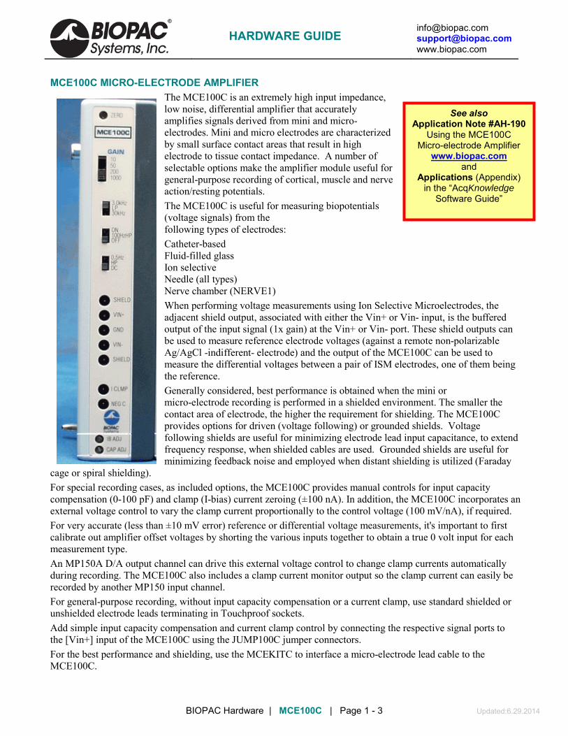
[email protected] [email protected] www.biopac.com
BIOPAC Hardware | MCE100C | Page 1 - 3 Updated:6.29.2014
See also Application Note #AH-190
Using the MCE100C Micro-electrode Amplifier
www.biopac.com and
Applications (Appendix) in the “AcqKnowledge
Software Guide”
MCE100C MICRO-ELECTRODE AMPLIFIER The MCE100C is an extremely high input impedance, low noise, differential amplifier that accurately amplifies signals derived from mini and micro-electrodes. Mini and micro electrodes are characterized by small surface contact areas that result in high electrode to tissue contact impedance. A number of selectable options make the amplifier module useful for general-purpose recording of cortical, muscle and nerve action/resting potentials. The MCE100C is useful for measuring biopotentials (voltage signals) from the following types of electrodes: Catheter-based Fluid-filled glass Ion selective Needle (all types) Nerve chamber (NERVE1) When performing voltage measurements using Ion Selective Microelectrodes, the adjacent shield output, associated with either the Vin+ or Vin- input, is the buffered output of the input signal (1x gain) at the Vin+ or Vin- port. These shield outputs can be used to measure reference electrode voltages (against a remote non-polarizable Ag/AgCl -indifferent- electrode) and the output of the MCE100C can be used to measure the differential voltages between a pair of ISM electrodes, one of them being the reference. Generally considered, best performance is obtained when the mini or micro-electrode recording is performed in a shielded environment. The smaller the contact area of electrode, the higher the requirement for shielding. The MCE100C provides options for driven (voltage following) or grounded shields. Voltage following shields are useful for minimizing electrode lead input capacitance, to extend frequency response, when shielded cables are used. Grounded shields are useful for minimizing feedback noise and employed when distant shielding is utilized (Faraday
cage or spiral shielding). For special recording cases, as included options, the MCE100C provides manual controls for input capacity compensation (0-100 pF) and clamp (I-bias) current zeroing (±100 nA). In addition, the MCE100C incorporates an external voltage control to vary the clamp current proportionally to the control voltage (100 mV/nA), if required. For very accurate (less than ±10 mV error) reference or differential voltage measurements, it's important to first calibrate out amplifier offset voltages by shorting the various inputs together to obtain a true 0 volt input for each measurement type. An MP150A D/A output channel can drive this external voltage control to change clamp currents automatically during recording. The MCE100C also includes a clamp current monitor output so the clamp current can easily be recorded by another MP150 input channel. For general-purpose recording, without input capacity compensation or a current clamp, use standard shielded or unshielded electrode leads terminating in Touchproof sockets. Add simple input capacity compensation and current clamp control by connecting the respective signal ports to the [Vin+] input of the MCE100C using the JUMP100C jumper connectors. For the best performance and shielding, use the MCEKITC to interface a micro-electrode lead cable to the MCE100C.
HARDWARE GUIDE

[email protected] [email protected] www.biopac.com
BIOPAC Hardware | MCE100C | Page 2 - 3 Updated:6.29.2014
Current Clamping can be enabled/disabled, by connecting/disconnecting the "I CLMP" port to either differential input of the MCE100C. Negative Capacity Compensation can be enabled/disabled, by connecting/disconnecting the "NEG C" port to either differential input of the MCE100C.
• See Application Note 190 for details: http://www.biopac.com/Manuals/app_pdf/app190.pdf
IMPORTANT USAGE NOTE Although the MCE100C will function with the MP100 System, the MP150 system is recommended due to the module’s wide operational bandwidth. Contact BIOPAC for details.
FREQUENCY RESPONSE PLOTS The 0.5 Hz high pass lower frequency response setting is a single pole roll-off filter.
Modules can be set for 50 Hz or 60 Hz notch options to match the wall-power line frequency of the destination country. The proper setting reduces noise from interfering signals when the notch filter is engaged. Generally, wall-power line frequency is 60 Hz in the United States and 50 Hz in most of Europe; if necessary, contact BIOPAC to determine the correct line frequency, adjust the bank of switches on the back of the amplifier module.
• The 50/60 Hz notch on the MCE100C is only engaged when the 100 Hz HPN high pass notch filter switch is set to ON—see Amplifer Filtering for details.
Line Frequency switch bank is on the back of the amplifier 50 Hz 60 Hz
Both switches
DOWN
Both switches
UP
See also: Sample frequency response plots 100 Hz HPN (with 50 Hz notch) 100 Hz HPN (with 60 Hz notch) 3 kHz LP 30 kHz LP
MCE100C CALIBRATION No calibration required. Use the CBLCALC to verify accuracy.
HARDWARE GUIDE

[email protected] [email protected] www.biopac.com
BIOPAC Hardware | MCE100C | Page 3 - 3 Updated:6.29.2014
MCE100C SPECIFICATIONS Gain & Input Voltage: Gain 10 ±1000
Vin (mV)
50 ±200 200 ±50 1000 ±10 Output Range: ±10 V (analog) Offset Voltage (DI): Differential Input: ±5 mV maximum (Vin+ to Vin-) Offset Voltage (SE): Driven Shield to Input: ±15 mV typical (Vin+ or Vin- to Adjacent Shield) Low Pass Filter: 3 kHz, 30 kHz High Pass Filter: DC, 0.5 Hz, 100 Hz CMRR: 92 dB typical; see Shield Drive Operation CMIV – referenced to: Isolated ground: ±10 V Mains ground: ±1500 VDC Notch Filter: 50 dB rejection (50/60 Hz) Noise Voltage: 2.1 µV rms – (DC-3000 Hz) Noise Current: 0.1 fA/√Hz Input Bias Current: ±3 fA (typical), ±100 fA (maximum) Note: Current Clamping and Negative Capacity Compensation Disabled Z (input) Differential: 10 E15 Ω Common mode: 10 E15 Ω Capacit. Comp (Neg): Input capacitance compensation (0-100 pF) – manual control I Clamp (I CLMP port): Adjustable (±100 nA) - voltage control I Clamp Control: Input 3.5 mm phone jack (100 mV/nA) I Clamp Monitor: Output 3.5 mm phone jack (100 mV/nA) Signal Source: Micro-electrodes Weight: 350 grams Dimensions: 4 cm (wide) x 11 cm (deep) x 19 cm (high) Input Connectors (front panel): Seven 1.5 mm Touchproof sockets (Vin+, Gnd, Vin-, 2 of shield, I-clmp, neg C)
HARDWARE GUIDE

[email protected] [email protected] www.biopac.com
BIOPAC Hardware | MCEKITC | Page 1 - 3 Updated: 4.4.2013
MCEKITC CONNECTOR KIT FOR MCE100C MICRO-ELECTRODE AMPLIFIER
Build a customized adapter to a micro-electrode shielded cable. Cable shields can be tied to voltage follower drive or simply grounded. Input capacity compensation and clamp current options can be independently added to or removed from a cable configuration. The MCEKITC comes with seven attached Touchproof sockets (1.5 mm) and instructions.
The MCEKITC is a junction box assembly that plugs directly into the front panel of the MCE100C amplifier. The MCEKITC comes equipped with an assortment of wire and coaxial cable to customize the MCE100C for a variety of micro-electrode lead connectors. The MCEKITC construction allows the appropriate interface connector to be mounted to the housing and the respective socket pin wires to be soldered.
The MCEKITC is required when either of the last two MCE100C operational modes (5, 6) are used with micro-electrodes. The following table illustrates the configuration desired. The amplifier configuration is determined via the MCEKITC. The MCEKITC connects to the MCE100C and modifies the MCE100C appropriately. See the respective figure to determine the correct MCEKITC configuration for the application.
INPUT TYPE SHIELD
CURRENT CLAMP
NEGATIVE CAPACITY
MCEKITC FIGURE
Differential Grounded No No A Differential Driven No No B Single-ended Grounded No No C Single-ended Grounded No Yes D Single-ended Grounded Yes Yes E Single-ended Driven Yes Yes F
HARDWARE GUIDE

[email protected] [email protected] www.biopac.com
BIOPAC Hardware | MCEKITC | Page 2 - 3 Updated: 4.4.2013
MCEKITC KIT LEGEND
MCEKITC CONFIGURATIONS
FIGURE A
FIGURE B
HARDWARE GUIDE
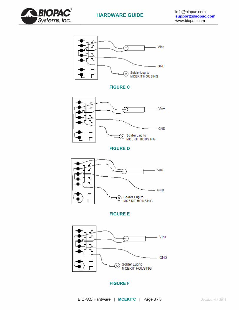
[email protected] [email protected] www.biopac.com
BIOPAC Hardware | MCEKITC | Page 3 - 3 Updated: 4.4.2013
FIGURE C
FIGURE D
FIGURE E
FIGURE F
HARDWARE GUIDE

[email protected] [email protected] www.biopac.com
BIOPAC Hardware | Laser Doppler Flowmetry | Page 1 - 19 Updated: 9.4.2014
LASER DOPPLER FLOWMETRY (LDF) - click page number to jump to section LDF100C Laser Doppler Flowmetry Module: Controls & Specifications - page 2 TSD140 Series Laser Doppler Probes, Options, Handling, Applying, Quick Setup, Intro - page 4 LDFCAL Calibration Kit - page 6 LDF Calibration Procedure - page 7 LDF Setup (module & probes) - page 9 LDF Safety & Warnings, Storage, Maintenance & Cleaning - page 12 Troubleshooting - page 14 LDF – Basic Principles - page 17
Sample blood perfusion data acquired with the LDF100C
Laser Doppler Flowmetry (or simply “LDF”) is an established and reliable method for the measurement of blood perfusion in microvascular research. Most LDF applications are concerned with monitoring the competence of regional (microvascular) blood supply following trauma, degenerative and pathological disease, surgical intervention and drug therapy.
LDF measurements are performed with the Laser Doppler Flowmetry module (LDF100C) and a wide range of fiber-optic based probes (TSD140 series) in order to access the tissue. Probes include small and lightweight probes for (non-invasive) skin and tissue surface measurements and needle type probes for direct (invasive) measurements within tissue, such as muscle and organ. Double-sided adhesive rings (ADD200 series) can be used to attach surface type probes to tissue; one size of ring fits both standard and miniature surface probes
LDF Calibration requires a calibration kit (LDFCAL), which includes a motility standard and positioning device to hold a probe in the solution during calibration. The motility standard comprises a carefully controlled solution of microspheres undergoing Brownian motion, which provides a standard calibration value of 1000 BPU ±5% at 21° C.
Unpacking LDF Components
IMPORTANT: It is essential that the Warnings and Cautions are fully understood before the LDF100C is used.
1. Inspect the packaging for damage before unpacking
• If the outer packaging or carton is wet or damaged in any way, immediately notify the shipping agent and file a claim. It is the receiver’s duty to notify the specific carrier’s local office. In the event of any damage, please save the shipping carton as evidence.
the component(s).
2. Unpack the component(s) and check the part(s) against the enclosed packing slip.
3. Remove the packaging and check for signs of obvious damage or defect either to the main body of the LDF100C module or the TSD140 series laser Doppler probes.
• Contact BIOPAC Systems, Inc. for replacement of any damaged component.
HARDWARE GUIDE

[email protected] [email protected] www.biopac.com
BIOPAC Hardware | Laser Doppler Flowmetry | Page 2 - 19 Updated: 9.4.2014
LDF100C Laser Doppler Flowmetry Module The LDF100C is a laser Doppler microvascular perfusion module that is capable of monitoring red blood cell (erythrocyte) perfusion in the microcirculation of a tissue. This module uses a Laser Doppler Flowmetry technique.
• Microvascular blood perfusion is indicated on the AcqKnowledge software display in relative units called Blood Perfusion Units (BPU).
• In common with all LDF devices, quantitative measurements of tissue blood perfusion in absolute units (e.g. ml/min/g of tissue) are not possible with the LDF100C.
The LDF100C laser Doppler microvascular perfusion module works by illuminating tissue with low power laser light using a probe (TSD140 series) containing optical fiber light guides. Laser light from one fiber is scattered within the tissue and some is scattered back to the probe. Another optical fiber collects the backscattered light from the tissue and returns it to the module. Most of the light is scattered by tissue that is not moving but a small percentage of the returned light is scattered by moving red blood cells. The light returned to the module undergoes signal processing to extract the signal related to the moving red blood cells.
The LDF100C is not
Flow/flux/perfusion has the SAME meaning—this manual and the module uses the term “flow.”
a medical device. It is not designed for the diagnosis, mitigation or treatment of disease in humans.
Controls, Indicators and Symbols
Interface: Connect the LDF100 directly to the UIM100C as part of an MP system for data acquisition.
Channel Select Switch:
Choose a channel setting that will not conflict with other modules to display Flow and Backscatter as follows:
Flow
CH 1 CH 5
Backscatter
CH 2 CH 6
CH 3 CH 7
CH 4 CH 8
If the particular output (i.e., Flow or Backscatter) is not used, the respective assigned channel cannot be used for another module’s output. Do not record on the unwanted, but assigned channel.
Cal Button: For calibrating new or existing probes (intentionally recessed).
Status LED: Red laser is powered; i.e., probe is connected Green software is running correctly and no probe or defective
probe is connected; or calibration status Amber software is running correctly and a recognized or
unrecognized probe is connected
Analog Indicators:
Warning Backscatter (BS) Perfusion (LDF) Calibrate probe 0 V 0 V No probe 0 V 0 V BS low 0 V 0 V LDF over range Data 5 V
Probe Connector:
Combined fiber optic and electrical connector. Use only TSD140 series probes.
Power plug: Mini-Din socket on the back panel; use to connect the AC101 DC power adapter that is included with each LDF100C module.
HARDWARE GUIDE

[email protected] [email protected] www.biopac.com
BIOPAC Hardware | Laser Doppler Flowmetry | Page 3 - 19 Updated: 9.4.2014
LDF100C Specifications PERFORMANCE
Measurements Primary Measure: Microvascular blood flow (Relative RBC flow Units: 0 – 5,000 BPU (blood perfusion units); 0 – 100% BS (backscatter)
Range (linearity) Up to 0.35% moving scatterers by volume
Stability of reading 5%
Probe identification TSD140 Series Laser Doppler Probes use Smart Probe Technology. Calibration coefficients are automatically selected for previously calibrated probes
Probe calibration
Flow: User set via LDFCAL motility standard of 1000 BPU ±5% @ 21° C Factory set using a motility standard (i.e., known concentration solution of
latex spheres undergoing Brownian motion) Factory or user calibration using LDF CAL calibration solution.
Zeroing Automatic, controlled (unplug probe to check the zero level of the backscatter output)
LASER
Type Temperature stabilized semi-conductor laser diode
Mode of operation Continuous
Wavelength 830±10 nm
Class Class 1 (EN 60825-1 and 21 CFR 1040.10)
Power at probe < 0.5 mW from the probe
ENVIRONMENTAL
Operating temp 10° C – 35° C
Storage temp 5° C – 50° C
Operating humidity 0 – 70% (non-condensing)
ELECTRICAL
Power supply unit (PSU)
Ships with ±12, +5 VDC @ 2 amp (AC101A DC power adapter) PSU spec affects warm-up time and operating range. The LDF100C heats and cools the laser. At 3 A at +5 V, the laser is at the correct temperature after about 30 seconds.
DATA OUTPUTS
Analog 2 analog outputs
Signals
Type Units Range Resolution Time
Constant (filtering)
Output voltage
Blood perfusion (BPU) LDF
0-5000 BPU
0 -5 V < 2.5 BPU 200 ms
0 to +5 V Scaling: 1 BPU
corresponds to 1 mV
Backscatter (BS) tissue remittance
0-100% 0 -5 V ≤ 0.05% 200 ms 0 to +5 V Scaling:
1% corresponds
to 50 mV
General Technology: Oxford Optronix, Ltd. technology for LDF signal processing Weight: 790 g Dimensions: 19 cm x 7 cm x 11 cm (H × W × D)
HARDWARE GUIDE

[email protected] [email protected] www.biopac.com
BIOPAC Hardware | Laser Doppler Flowmetry | Page 4 - 19 Updated: 9.4.2014
TSD140 Series Probes
The TSD140 series offers a wide range of laser Doppler probes that interface with the LDF100C module. Probes are designed to allow the local monitoring of blood perfusion from almost any tissue type. All probes contain optical fibers, which are used to direct low power laser light to and from the tissue. Three types of probes (surface, needle, and disposable) and a driver are stocked for the LDF100C; other probes styles are available. Standard cable length for all probes is 3 m. Single fiber probes have an overall length of 30-100 cm and require the use of TSD148; they can be cut to any length with a sharp scalpel.
Probe cable lengths between 1 m and 8 m and needle and needle probes with shaft lengths of between 10 mm to 70 mm may be custom ordered. Contact BIOPAC Systems, Inc. for more information.
Probe Options SURFACE
TSD140 Cutaneous blood flow anywhere on the skin surface.
Designed for skin and exposed tissue blood flow monitoring. Ideal for noninvasive measurements from skin or organ surfaces. The signal delivery fiber intersects the probe body at a right angle, making the probes easy to secure to the skin or tissue surface. Made from Tempalux.
TSD142 Micro-vascular skin blood flow in the digits.
TSD143 Small animal work, including post-operative monitoring, i.e., reconstructive surgery (suturable).
TSD146 Small animal work and general tissue surface monitoring (this is a non-suturable version of the TSD143).
NEEDLE
TSD144 Microvascular blood flow measurements. Typically positioned using a micromanipulator clamp over soft tissues such as brain and muscle.
Designed for invasive and endoscopic blood flow monitoring of tissue. Needle probes can be used both for noninvasive monitoring from the surface of tissues (by positioning the tip in contact/close proximity to the tissue) or for invasive placement and monitoring from regions within tissues. The signal delivery fiber terminates flush with the top of the needle, making the probes easy to insert into tissue. Made from medical grade stainless steel.
TSD145 Micro-vessel or micro-vascular blood flow within skin, muscle, tumor and organ tissues. Fine probe diameters facilitate blood flow measurements from only a small number of capillaries.
DISPOSABLE
TSD147A/AL Blood flow measurements under the skin (use a standard 22G ID cannula to insert directly into tissue). TSD147A is 30 cm long, TSD147AL is 100 cm long.
Designed for safe, continuous, invasive microvascular blood flow monitoring. Composed of a polymethyl methacrylate core and a tough fluorinated polymer cladding. Incorporate a coupling bead to interface with the TSD148 single fiber driver for connection to the LDF100C module.
MRI Use: MR Safe
TSD147A/AL Components – MRI chamber room; cable only: Fiber Optic Cable: Polymethyl methacrylate core & tough fluorinated polymer cladding
HARDWARE GUIDE

[email protected] [email protected] www.biopac.com
BIOPAC Hardware | Laser Doppler Flowmetry | Page 5 - 19 Updated: 9.4.2014
DRIVER
TSD148 This is a precision-machined coupling system for interfacing the TSD147 series single fiber probes to the LDF100C. The TSD148 consists of a compact laser driver housed in a non-metallic Tempalux housing, terminated with a 2-meter cable for connection to the LDF100C module.
Handling TSD140 Series Probes
TSD140 series probes must be handled with care. Failure to do this may result in breakage of the internal optical fibers, scratching the polished probe ends or separation of the cable from the probe ends or connectors.
Do not use a worn or damaged probe.
The optical fibers used in the TSD140 series probes are glass and have a diameter of 125 μm. The fibers are flexible and can be bent; however, it is recommended that they are not subjected to bends with a radius less than 30 mm.
The connectors on TSD140 series probes must be kept clean and free from dust. Connectors should be inspected before each use. Dust can be removed from the connectors using a good quality ‘air-duster.’
Check the integrity of TSD140 series probes by holding the probe end to a source of bright diffuse light (e.g. a lamp) and inspecting the connector end. Two bright spots of light of equal intensity should be visible from the pins within the connector.
Applying Probes to Tissue Surface Surface probes may be attached to tissue using double-sided adhesive rings (such as ADD204 or
ADD208). Alternatively, the miniature suturable probe can be sutured directly into position.
Needle Needle probes can be secured in a micromanipulator assembly or stand and placed above the tissue. Depending on the tissue, fine needle probes may be introduced directly into tissue after first ensuring an appropriate superficial incision has been made. Alternatively, a suitable introducer or catheter should be used. All needle style probes can optionally be secured in a micromanipulator assembly or stand.
• Bear in mind that all needle probes have a blunt end and may cause some degree of tissue trauma when inserted directly into tissue without using a suitable introducer.
Single fiber The insertable probe can be inserted into tissue using a standard 2G ID cannula. These probes can be cut to the desired length with a sharp scalpel. The single fiber probes require the TSD148 driver.
It is important to control the relative movements of the tissue (induced by breathing, etc.) with respect to the probe to reduce artifact in the perfusion signal. Allowing the supported probe to lightly come into contact with the surface of the tissue can reduce these artifacts. Under some conditions it may be best to hold the probe in position by hand.
It is essential to ensure that the pressure on the tissue is minimal, otherwise local occlusion of the microvasculature may result.
Avoid direct illumination of the measurement site from external lighting sources and direct sunlight. Excessive ambient lighting at the probe site can disturb the blood perfusion reading. If erroneous readings due to excessive ambient lighting levels are suspected, cover the attached probe and measurement area with a light piece of opaque material.
Place the LDF100C module on a flat surface close to the point of measurement; note that the standard probe cable length is 3 m.
The probe can be placed in or on tissue at any stage, either prior to or following connection to the LDF100C. Allow the module to warm up with a probe attached before taking any measurements.
The probe can be exchanged for another at any stage without the need to first switch off the LDF100C.
HARDWARE GUIDE

[email protected] [email protected] www.biopac.com
BIOPAC Hardware | Laser Doppler Flowmetry | Page 6 - 19 Updated: 9.4.2014
The probe does not need to be disconnected from the LDF100C prior to turning off the LDF100C.
Quick Set up and Use Guide Place the LDF100C module on a flat surface close to the point of measurement.
Connect the AC100A to the LDF100C and plug the AC101 into a properly grounded AC Mains socket.
When the module is powered (immediately after the double beep) the analog outputs both go to 0 V (half scale) for 3 sec and then to 0 V for a further 3 sec before outputting data.
Allow the instrument to warm up for 5 minutes before making any measurements.
Select a probe to make measurements with and connect it respecting the correct orientation. If no probe is connected to the LDF100C module, the Flow analog output will be held at 0 V and the Backscatter output at 0 volts. The status LED will be green when no probe is connected.
Introduction to Probe Calibration The LDF100C system incorporates proprietary Smart Sensor technology that enables the module to recognize a previously calibrated probe and to automatically apply the necessary probe calibration coefficients. This alleviates the need to re-calibrate a probe every time a different probe is plugged in to the module. The module ‘recognizes’ a specific probe every time the probe is plugged in.
When probes are ordered at the same time as the LDF100C, BIOPAC will calibrate the LDF100C to the ordered probes with a “motility standard” before shipping the items. If a probe has previously been calibrated then there is generally no need to re-calibrate that probe. However, when probes are purchased separately they will require calibrating before use using an LAF CAL calibration kit. When the calibration procedure ends, the calibration data is automatically stored in the module. The calibration data is automatically retrieved every time that particular probe is connected to the module.
LDFCAL Calibration Kit
Contents:
• The motility standard is a colloidal solution of suspended latex spheres. The size and concentration of spheres are carefully controlled so that calibration values are always reproducible. The LDFCAL provides a standard calibration value of 1000 BPU 5% @ 21° C.
Motility standard and positioning device
• The size and relative density of the latex spheres is such that the artifact due to settling and aggregation is negligible during the calibration process.
Intended use:
IMPORTANT! Please read the information contained in this section before using the calibration standard. Pay
particular attention to the warnings and cautions.
Use the calibration standard with the LDF100C blood flow monitor and probes when required. Probes require calibration if they are purchased separately from a monitor and for routine calibration purposes.
Manufacturer: Oxford Optronix Ltd.
HARDWARE GUIDE

[email protected] [email protected] www.biopac.com
BIOPAC Hardware | Laser Doppler Flowmetry | Page 7 - 19 Updated: 9.4.2014
Probe Calibration Procedure—TSD140-TSD47 To calibrate the single fiber driver adapter (TSD148), refer to the next section.
To perform a new probe calibration, a Calibration Kit (LDFCAL) is required, which contains a motility standard and a positioning device. The parameters are automatically stored and recalled when that particular probe is subsequently connected.
Every probe is supplied with a probe identification number (Probe ID) on the probe box label. The number is between 5 and 36 and must be unique for the probes used; using two probes with the same ID will result in invalid calibration data being used.
Calibration errors may occur if probes with the same probe identification number are used. Contact BIOPAC for advice if multiple probes have the same ID number.
The motility standard has a 3-month shelf life, so it’s best to order only when required. The expiration date is indicated on the label. The solution must not be used beyond this date, as it will produce misleading values due to the aggregation of the latex spheres.
Do not use the motility standard in ambient temperatures below 15° C or above 25° C.
Store the motility standard within the temperature range 3 – 25° C. Do not freeze the solution.
Never attempt to re-fill the bottle with spilt solution. Errors may arise as a result of contamination.
Do not dilute the motility standard.
It is essential that the calibration procedure be performed on a stable and vibration-free surface. This is very important, any movement or vibration during the calibration procedure, however slight, is likely to result in erroneous calibration data.
1. Connect the probe to the front panel of the blood flow monitor.
2. Gently swirl the bottle to disperse the contents.
3. Open the bottle and allow the contents to settle for one minute before proceeding.
4. Carefully position the probe in the solution. This is best achieved by holding the probe cable within the jaws of the clamp and carefully lowering the active area of the probe into the center of the solution.
IMPORTANT! Keep the active surface of the probe as far as possible from the edge of the bottle. The probe should be supported in such a way that it does not swing or move while it is in the solution.
Read through all the instructions first before proceeding.
5. Press the CAL button on the front panel of the LDF100C once and then press the CAL button again within 10 seconds to confirm calibration. To end calibration at this point, wait 10 seconds and the calibration process will time out and stop. If proceeding, there will be one long beep.
IMPORTANT! Any vibration or movement during this period will invalidate the calibration procedure.
6. An audible double beep indicates a successful calibration.
HARDWARE GUIDE

[email protected] [email protected] www.biopac.com
BIOPAC Hardware | Laser Doppler Flowmetry | Page 8 - 19 Updated: 9.4.2014
• A series of audible beeps (long beep followed by a pause and then a number of rapid beeps) indicates a failed calibration. The number of rapid beeps equates to the error code—refer to Troubleshooting for more information on the error codes.
Driver Calibration Procedure— TSD148 To calibrate a probe (TSD140-TSD147), refer to the preceding section.
1. IMPORTANT! Read the following information before attempting to calibrate the single fiber probe connecting adapter. Refer to calibration standard instructions for precautions to be taken.
2. Unscrew Part A.
3. Pull off Part B. (Note: This is a tight fit and may need to be twisted while it is pulled.)
4. Connect the single fiber adapter into the front panel of the blood flow monitor.
5. Gently swirl the bottle to disperse the contents before use. Open the bottle and allow the contents to settle for one minute before proceeding.
6. Carefully position Part C of the adapter in the solution. This is best achieved by holding the adapter cable within the jaws of the clamp and carefully lowering Part C into the center of the solution.
IMPORTANT! Keep the active surface of the probe as far as possible from the edge of the bottle. The adapter cable should be supported in such a way that it does not swing or move while in the solution. Follow the calibration procedure detailed in the preceding section.
7. Clean Part C to remove residual calibration solution by washing and wiping using water or 70% IMS or IPA. Allow Part C to dry before reassembling the adapter by pushing Part B onto Part C and then attaching Part A.
HARDWARE GUIDE
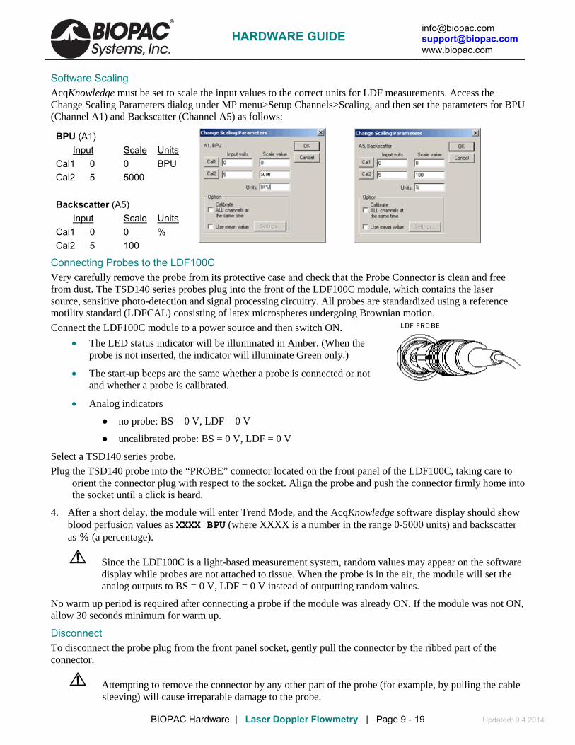
[email protected] [email protected] www.biopac.com
BIOPAC Hardware | Laser Doppler Flowmetry | Page 9 - 19 Updated: 9.4.2014
Software Scaling AcqKnowledge must be set to scale the input values to the correct units for LDF measurements. Access the Change Scaling Parameters dialog under MP menu>Setup Channels>Scaling, and then set the parameters for BPU (Channel A1) and Backscatter (Channel A5) as follows:
BPU (A1) Input Scale Cal1 0 0 BPU
Units
Cal2 5 5000 Backscatter (A5) Input Scale Cal1 0 0 %
Units
Cal2 5 100
Connecting Probes to the LDF100C Very carefully remove the probe from its protective case and check that the Probe Connector is clean and free from dust. The TSD140 series probes plug into the front of the LDF100C module, which contains the laser source, sensitive photo-detection and signal processing circuitry. All probes are standardized using a reference motility standard (LDFCAL) consisting of latex microspheres undergoing Brownian motion.
Connect the LDF100C module to a power source and then switch ON.
• The LED status indicator will be illuminated in Amber. (When the probe is not inserted, the indicator will illuminate Green only.)
• The start-up beeps are the same whether a probe is connected or not and whether a probe is calibrated.
• Analog indicators
no probe: BS = 0 V, LDF = 0 V
uncalibrated probe: BS = 0 V, LDF = 0 V
Select a TSD140 series probe.
Plug the TSD140 probe into the “PROBE” connector located on the front panel of the LDF100C, taking care to orient the connector plug with respect to the socket. Align the probe and push the connector firmly home into the socket until a click is heard.
4. After a short delay, the module will enter Trend Mode, and the AcqKnowledge software display should show blood perfusion values as XXXX BPU (where XXXX is a number in the range 0-5000 units) and backscatter as % (a percentage).
Since the LDF100C is a light-based measurement system, random values may appear on the software display while probes are not attached to tissue. When the probe is in the air, the module will set the analog outputs to BS = 0 V, LDF = 0 V instead of outputting random values.
No warm up period is required after connecting a probe if the module was already ON. If the module was not ON, allow 30 seconds minimum for warm up.
Disconnect To disconnect the probe plug from the front panel socket, gently pull the connector by the ribbed part of the connector.
Attempting to remove the connector by any other part of the probe (for example, by pulling the cable sleeving) will cause irreparable damage to the probe.
HARDWARE GUIDE

[email protected] [email protected] www.biopac.com
BIOPAC Hardware | Laser Doppler Flowmetry | Page 10 - 19 Updated: 9.4.2014
TSD140 Series Probes Storage & Cleaning When not in use, TSD140 series probes for the LDF100C should be stored in the probe box with the optical fiber coiled neatly. Following sterilization, probes should be stored unopened in the packaging in which they were sterilized.
Cleaning Probes are cleaned prior to packing and shipment. It is recommended that the probe end on all new probes be wiped with a soft cloth, preferably one that does not shed fibers, dampened with a solution of 70% alcohol in water.
Probes should be cleaned immediately after use as it is easier to remove soiling and particulate matter before it dries onto surfaces.
Visually inspect the probe end, cable and connector.
• If there is no visible soiling, wipe the probe end and cable with a soft cloth dampened with a solution of 70% alcohol in water. Allow the alcohol to dry completely before using the probe.
• If there is visible soiling, clean the probe with warm water containing a mild detergent. To ensure that all soiling and particulate matter is removed, keep the probe beneath the surface of the cleaning solution and rub it carefully with a soft cloth or brush. Avoid immersing the probe connector in the cleaning solution. Rinse the probe end and cable in clean water. Wipe the probe end and cable with an absorbent cloth and leave the probe to dry completely.
Disinfection To disinfect TSD140 series probes, immerse the probe end and cable (for the disinfectant manufacturer’s recommended immersion times) in:
• 2% glutaraldehyde (Cidex)
• 70% alcohol in water
Sterilization Some of the TSD140 series dedicated perfusion probes may be sterilized by moist heat (steam). They are capable of withstanding an autoclave cycle of 134° C for 3 minutes. With care a TSD140 series probe can be expected to survive between 10 – 20 sterilization cycles.
TSD140 series probes must be cleaned prior to sterilization.
It is the responsibility of the user to validate the sterility of TSD140 series probes after sterilization.
The TSD140 series probe should be packaged to maintain sterility after processing. The packaging material used should be appropriate for sterilization by steam, e.g. a tray within a pouch. The dimensions of the base of the tray should not be smaller than 15 cm x10 cm for a standard length probe.
1. Place the probe in the tray in a neat coil.
• Starting at the connector end, tape the connector to the base of the tray using autoclave tape. Coil the probe onto the tray and lay the probe end in the center of the coil. Autoclave tape may be used to secure the cable to the tray. Do not use tape on the probe end. Do not rest the connector on the cable as it is heavy and may distort the cable.
2. Seal the tray into a pouch designed to withstand sterilization by steam.
3. Use only a validated autoclave to sterilize the TSD140 series probes.
• Probes can be immersed in a non-corrosive sterilizing solution, such as 2% Glutaraldehyde (Cidex) or in a low-temperature, ethylene-oxide gas sterilization chamber. The maximum temperature to which older style probes can be exposed is 60° C.
HARDWARE GUIDE

[email protected] [email protected] www.biopac.com
BIOPAC Hardware | Laser Doppler Flowmetry | Page 11 - 19 Updated: 9.4.2014
Probe Identification The LDF100C system incorporates proprietary Smart Sensor technology that enables the module to recognize a previously calibrated probe and to automatically apply the necessary probe calibration coefficients. This alleviates the need to re-calibrate a probe every time a different probe is plugged in to the module. The module ‘recognizes’ a specific probe every time the probe is plugged in.
New Probe If a new (previously uncalibrated) probe is connected to the LDF100C module, then the module’s Flow and Backscatter outputs will be at 0 V. To take measurements, the probe must be calibrated (see following section on calibrating probes) or removed and replaced by a recognized probe. The status LED will be amber when a probe, recognized or unrecognized, is connected to the LDF100C.
Temperature Out of Range (Single beep every 16 seconds) This warning will sound if the laser temperature is below the minimum or above the maximum for stable operation. It may occur during the warm-up period if the ambient temperature is low—this is normal and not a cause for concern. If this occurs during operation, the instrument should be moved to a cooler or warmer environment depending on the ambient temperature. With the temperature out of range, output signals will continue to be generated but may no longer be within the calibrated tolerance of the system and should be interpreted with caution. If the environmental temperature is below 25° C and this message occurs repeatedly soon after power-on, then a fault may have occurred; please contact BIOPAC Systems, Inc. for further advice.
TSD140 Series Probe Specifications Part # Style Suturable Body
Dimensions Angle of Laser
Delivery & Collection
Skin & Tissue Monitoring
TSD140 Standard surface. Reusable, may be
autoclaved.
no 8 mm (high) x 17 mm (dia)
Right angle to probe body
yes
TSD142 Digit surface. Reusable, may be
autoclaved.
no 10 mm (high) x 17 mm (dia)
Right angle to probe body
yes
TSD143 Suturable Miniature surface. Reusable, may be autoclaved.
yes 5 mm (high) x 12 mm (dia)
Right angle to probe body
yes
TSD144 Needle. Reusable, may be autoclaved.
no 25 mm (long) x 1 mm (dia)
Straight Invasive and endoscopic
TSD145 Fine needle. Reusable, may be autoclaved.
no 25 mm (long) x 0.5 mm (dia)
Straight Invasive and endoscopic
TSD146 Miniature surface. Reusable, may be
autoclaved.
no 5 mm (high) x 12 mm (dia)
Right angle to probe body
yes
TSD147A* Disposable, insertable single fiber. Single-use
recommended.
no 30 cm (long) x 0.5 mm (dia)
Straight Insert via 22G ID cannula
TSD147AL*
Disposable, insertable single fiber. Single-use
recommended.
no 100 cm (long) x 0.5 mm (dia)
Straight Insert via 22G ID cannula
Part # Style Used with Body
Dimensions Connection Type Cable Length
TSD148 Single fiber Driver TSD147A TSD147AL
28 mm (long) x 8 mm (dia)
In-line single fiber connector
3 meters
*Requires the TSD148 Single Fiber Driver for operation with the LDF100C.
HARDWARE GUIDE

[email protected] [email protected] www.biopac.com
BIOPAC Hardware | Laser Doppler Flowmetry | Page 12 - 19 Updated: 9.4.2014
LDF Safety This section contains important safety information related to the general use of the LDF100C laser Doppler perfusion module. Important safety information also appears throughout the LDF100C and TSD140 series sections as Warnings and Cautions.
! Warning A warning indicates the possibility of injury to the operator.
A caution indicates a condition that may lead to equipment damage and/or malfunction.
LDF100C incorporates semiconductor laser diode devices operating in continuous mode and emitting invisible laser radiation at a nominal operating wavelength of 830 nm. The maximum output power at the probe tip is less than 0.5 mW. Laser light emitted from the optical fiber is highly divergent. Although the characteristics of the laser radiation place the LDF100C device within the “Class 1” classification users should avoid directing the laser radiation onto the eye. Applying the probe to any tissue OTHER THAN THE EYE is harmless, even over prolonged time periods.
Warnings ! Warning Never apply an LDF100C probe directly to the eye. The laser beam may cause permanent
damage to the retina.
! Warning Do not attempt to use the LDF100C if it is damaged or does not operate as described in this manual. There is a risk of electrical shock or other injury. The module must be returned to BIOPAC for repair.
Cautions for the Module
Do not attempt to operate the LDF100C in the vicinity of imaging or therapeutic equipment that emits ionizing radiation or produces a strong magnetic field as the performance of the module may be affected. Extra long probes are available that allow the LDF100C module to be operated at a safe distance from such equipment.
Do not attempt to autoclave, pressure sterilize, or expose to radiation, any part of the module.
Do not attempt repairs to the LDF100C module or TSD140 series probes. Only BIOPAC trained personnel should undertake repairs.
Do not use the LDF100C in the presence of strong or changing ambient lighting levels as this may result in erroneous measurements and artifacts.
Do not use probes, cables and other accessories unless supplied by BIOPAC, otherwise serious damage may result.
Do not mishandle the module; use extreme care at all times.
Do not use the module in the presence of flammable anesthetics, which represent an explosive hazard.
HARDWARE GUIDE

[email protected] [email protected] www.biopac.com
BIOPAC Hardware | Laser Doppler Flowmetry | Page 13 - 19 Updated: 9.4.2014
Cautions for the Probes
Do not drop, pull, stretch or apply mechanical shock to a TSD140 series probe. Permanent damage to the probe may result.
Do not apply tension to the probe cable. Permanent damage to the probe may result.
Do not soak or immerse the probe in any corrosive liquid solution. Permanent damage to the probe may result.
Do not mishandle. Handle the probes with great care to avoid breaking the optical fibers, scratching the polished ends or separating the probe ends or connectors from the fibers.
Maintenance User Responsibility
Never use a defective product. Replace parts that are missing, broken, worn or damaged in any way immediately. This product (or its components) should be repaired only by BIOPAC Systems, Inc. trained engineers. Any exceptions to this recommendation must be made using written instructions supplied by BIOPAC Systems, Inc. If service is not provided by BIOPAC Systems, Inc. (or its appointed agents) then the user of this product will have the sole responsibility for any losses incurred as a result of unauthorized maintenance, improper repair, alterations or damage.
LDF100C ! Warning Only BIOPAC technical staff should remove the cover of the LDF100C module. There are no
user-serviceable parts inside.
Inspect the module regularly for signs of wear and tear.
Checking TSD140 Series Probes Inspect TSD140 series probes regularly to check the integrity of the internal optical fibers.
• A simple check is to hold the probe end to a source of bright diffuse light (e.g. a lamp) while visually inspecting the connector end. Two bright spots of light of equal intensity should be visible from the two large pins within the connector.
LDF100C Storage & Cleaning When not in use, the LDF100C module should ideally be stored at room temperature, although it may be stored between 5° C to 50° C. When returning from extremes of temperature, it is important to allow the module to stabilize at room temperature before use.
To clean the surface of the module: wipe lightly with a dry, lint-free cloth. Or wipe lightly with a soft cloth dampened with a commercial, nonabrasive cleaner, or use a low-pressure air line to blow dust free, or carefully clean with a suitable vacuum cleaner.
To disinfect the module, wipe the surface with a soft cloth dampened with a solution of 70% alcohol in water.
! Warning Do not spray, pour or spill any liquid on the LDF100C module, its accessories, connectors, switches or openings.
HARDWARE GUIDE

[email protected] [email protected] www.biopac.com
BIOPAC Hardware | Laser Doppler Flowmetry | Page 14 - 19 Updated: 9.4.2014
Troubleshooting ! Warning Only BIOPAC technical staff should remove the cover of the LDF100C module. There are no
user-serviceable parts inside.
Use of controls or adjustments or performance of procedures other than those specified herein may result in hazardous radiation exposure.
Contact [email protected] for problems using the LDF100C.
Beep & Led Guide Beep LED Indication Two beeps Off Initializing with no probe. Two beeps Red Initializing with a probe connected. — Green Instrument ready for use; no probe connected. — Amber Instrument operating correctly with probe connected. Single beep every 16 seconds
Amber or green Laser temperature out of range (too hot or too cold).
Double beeps
Alternating amber/red, synchronized with beeps
Calibration button was pressed, awaiting confirmation. Note If the calibration button was pressed in error, wait
10 seconds for normal operation to resume. To confirm calibration, press the calibration button again during that 10-second period.
Long beep Alternating amber/red
Calibration in progress.
Double beep Amber Calibration successful. Long beep followed by a number of short beeps indicating the error.
Alternating red/amber, synchronized with error code beeps
Calibration failed. Error: 1, 2, 3, 4, 7 Incorrect probe position or malfunctioning probe.
Reposition probe in motility standard and repeat calibration procedure.
Error: 5, 6 Vibration or movement of probe or cable. Ensure LDFCAL motility standard is on a vibration-free surface and eliminate probe and cable movement; repeat calibration procedure.
Single beep Amber Calibration aborted (probe removed or calibration button pressed).
HARDWARE GUIDE

[email protected] [email protected] www.biopac.com
BIOPAC Hardware | Laser Doppler Flowmetry | Page 15 - 19 Updated: 9.4.2014
Reducing Signal Artifact
Certain environmental conditions and probe application and positioning errors can affect laser Doppler blood perfusion readings.
Irrespective of the probe used, it is important to reduce the possibility of signal artifact, noise and signal dropout in the blood perfusion reading. The presence of motion artifact noise in the blood perfusion signal is often due to relative movements of the tissue (e.g. induced by breathing) with respect to the probe and/or probe cable movements. To minimize artifact, allow the probe to come into contact with the tissue such that the probe and tissue ‘move together’ and ensure that the cables do not move. It may be helpful to secure the probe cable to the table with adhesive tape at intervals.
It is also essential to ensure that undue probe pressure is not applied to the tissue, otherwise local occlusion of the microvasculature may result in a corresponding reduced blood perfusion reading.
Excessive ambient lighting at the probe measurement site can also disturb the blood perfusion reading. Avoid direct illumination of the measurement site from external lighting sources and direct sunlight. If erroneous readings due to excessive ambient lighting levels are suspected, cover the attached probe and measurement area with a light piece of opaque material.
In summary, avoid the following situations:
• Probe movement relative to the tissue.
• Movement of the probe cables.
• Strong ambient lighting sources such as surgical lights, fluorescent lights and direct sunlight.
• Changing ambient lighting.
Loss of signal due to excessive tissue occlusion could occur for the following reasons:
• Excessive probe pressure on the tissue.
• The formation of a hematoma (blood clot) within the tissue.
Electro-Magnetic Interference
With the proliferation of radio-frequency transmitting equipment and other sources of electrical noise in research environments (e.g. mobile phones, electrical appliances), high levels of such interference due to close proximity or strength of a source may result in disruption of performance of this device.
Erratic readings, cessation of operation or other incorrect functioning may indicate electro-magnetic interference to the module. If this occurs, survey the location of use to determine the source of the disruption and take actions to eliminate it:
• Turn equipment off in the vicinity of the module to isolate the equipment generating the electromagnetic interference.
• Relocate the other device(s).
• Increase the separation between the interfering equipment and the LDF100C module.
For further information and assistance contact BIOPAC.
HARDWARE GUIDE

[email protected] [email protected] www.biopac.com
BIOPAC Hardware | Laser Doppler Flowmetry | Page 16 - 19 Updated: 9.4.2014
Possible Errors & Suggestions
A. There is no response to the Power On button and the Power On LED indicator fails to light green.
The power adapter may not be properly connected to the LDF100C or to the Mains outlet, or it may not be functioning. Check all connections. If possible, try another adapter with the same specification; the adapter must have the same specification to maintain electrical safety.
B. There is no double beep upon power on and/or the initial beep does not occur.
If the power on indicator is not lit, the power supply may not be working. Notify institution service personnel to check and if necessary, replace with the same type and rating of adapter. If the power on indicator is lit, the module has failed the power on self-test. Do not use the module. Contact BIOPAC.
C. There is a continuous sound upon power on.
The module has failed the power-on self-test. Do not use the module. Contact BIOPAC.
D. The Temp. Out of Range beep sequence is emitted (an audible beep every 16 seconds).
This is normal during the warm-up period and not indicative of a fault.
Warning sounds if the laser temperature is above or below the range for stable operation. If this occurs, the instrument should be moved to warmer or cooler environment for proper operation. Output signals (analog voltage outputs and serial data) will be generated but should be interpreted with caution.
If the environmental ambient temperature is below 25° C and this error occurs repeatedly soon after power-on, then a fault may have occurred—contact BIOPAC for further advice.
E. The status LED remains green even though there is a probe connected.
This is likely a problem with the probe. If a spare probe is available, replace the probe connected to the module with the spare probe. It may be possible to determine which probe is faulty.
If the problem can’t be resolved, contact BIOPAC.
F. The analog outputs are both 0 V.
This might occur a) when the probe is connected to the LDF100C; b) due to a low backscatter signal; and c) because probe calibration is required. Follow the instructions for probe calibration given in section 4.12.
G. Pressing the CAL button for probe calibration does not emit a double beep to indicate a probe calibration is under way.
The calibration process has failed to start. Try pressing the CAL button again. If there is still no response, contact BIOPAC.
H. The Error beep sequence (varying number of beeps) is emitted.
Probe calibration has failed. There are 7 series of error beeps used to indicate the reason for calibration failure. Beep sequences are explained below:
Error: 1, 2, 3, 4, 7 Incorrect probe position or malfunctioning probe.
Reposition probe in motility standard and repeat calibration procedure.
Error: 5, 6 Vibration or movement of probe or cable.
Ensure LDFCAL motility standard is on a vibration-free surface and eliminate probe and cable movement; repeat calibration procedure.
I. The BPU values are erratic.
The probe may have become detached, check and replace if required. Tissue movement may be excessive. The probe cable may be moving; re-route the cable and/or secure that cable at intervals using adhesive tape. There may be local electro-magnetic interference —see previous page.
HARDWARE GUIDE

[email protected] [email protected] www.biopac.com
BIOPAC Hardware | Laser Doppler Flowmetry | Page 17 - 19 Updated: 9.4.2014
J. The analog output signal is zero.
There may be a cable problem. Check that the cable attached to the analog output connector(s) is correctly configured. Notify institution service personnel and request that they check that i) the cable is correct and ii) the output signal(s) are available on the pins of the connector(s).
If the problem cannot be resolved, contact BIOPAC.
Obtaining Technical Assistance For technical information and assistance or to order additional probes and accessories, please contact BIOPAC. When calling BIOPAC for technical support, it is helpful to have the serial number of the LDF100C module and/or TSD140 series probes and the version of AcqKnowledge software.
• The serial number of the LDF100C module can be found on the back panel.
• Probe serial numbers can be found on the cable label and Probe ID numbers are on the probe box.
• The AcqKnowledge software version appears under the About menu in the software.
Returning LDF Components Contact BIOPAC for shipping instructions including a Returned Materials Authorization (RMA) number and a RMA Declaration (including decontamination of equipment) form.
Pack the module in its original shipping carton. If the original carton is not available, wrap the module securely using bubble wrap and pack it in a strong box surrounded by polystyrene chips and/or suitable foam inserts.
A probe should be returned in the probe storage box. If returning a probe on its own, wrap the probe storage box in bubble wrap and pack it in a strong box.
Use a recognized courier company for the return of the module and probes.
Warranty BIOPAC warrants that this device is free from defects in both materials and workmanship.
THE ABOVE WARRANTIES ARE IN LIEU OF ALL WARRANTIES, EITHER EXPRESS OR IMPLIED, INCLUDING ANY WARRANTY OF MERCHANTABILITY OR FITNESS FOR A PARTICULAR PURPOSE.
The user shall determine suitability for use of this device for any procedure. BIOPAC shall not be liable for incidental or consequential loss or damages of any kind.
Principles of Laser Doppler Flowmetry What does the LDF100C measure?
The LDF100C is a laser Doppler blood flow (perfusion) module whose primary purpose is to measure real-time microvascular red blood cell (or erythrocyte) flow (perfusion) in tissue. Perfusion is sometimes also referred to as red blood cell flux. Laser Doppler signals from the tissue are recorded in BPU (Blood Perfusion Units) which is a relative units scale defined using a carefully controlled motility standard comprising a suspension of latex spheres undergoing Brownian motion.
The LDF100C laser Doppler flow module employs a technique called laser Doppler Flowmetry (LDF) and works by illuminating the tissue under observation with low power laser light from a probe containing optical fiber light guides. Laser light from one fiber is scattered within the tissue and some is scattered back to the probe. Another optical fiber collects the backscattered light from the tissue and returns it to the monitor. Most of the light is scattered by tissue that is not moving but a small percentage of the returned light is scattered by moving red blood cells. The light returned to the monitor undergoes signal processing to extract the signal related to the moving red blood cells. Microvascular blood flow (perfusion) is indicated in the AcqKnowledge software display in relative units called Blood Perfusion Units (BPU).
The LDF technique offers substantial advantages over other methods in the measurement of microvascular blood perfusion.
HARDWARE GUIDE

[email protected] [email protected] www.biopac.com
BIOPAC Hardware | Laser Doppler Flowmetry | Page 18 - 19 Updated: 9.4.2014
• Studies have shown that it is both highly sensitive and responsive to local blood perfusion and is also versatile and easy to use for continuous monitoring.
• The LDF100C is potentially noninvasive (since the TSD140 series probe is not actually required to touch the surface of the tissue) and in no way harms or disturbs the normal physiological state of the microcirculation.
• The small probe dimensions enable it to be employed in experimental environments not readily accessible using other techniques.
Measurements obtained by LDF are intrinsically of a relative nature. Although such measurements are proportional to flow, the factor of proportionality will be different for different tissues.
Blood Perfusion Signal and the BPU. The primary function of the LDF100C is to produce a blood perfusion output signal that is proportional to the red blood cell flow (perfusion). This represents the transport of blood cells through microvasculature and is defined as:
Microvascular Flow (Red Blood Cell Flux) = Number of blood cells moving in
the tissue sampling volume x Mean velocity of these cells
Microvascular blood perfusion therefore, is the product of mean blood cell velocity and mean blood cell number concentration present in the small measuring volume of tissue under illumination from the probe. For the LDF100C, microvascular blood perfusion is indicated in the AcqKnowledge software display in relative units called Blood Perfusion Units (BPU). All LDF100C devices have been calibrated with a constant, known motility standard so that, for a given perfusion situation, all LDF100C probes will read the same value of blood perfusion expressed in blood perfusion units (BPU).
The standard Blood Perfusion output on the LDF100C has been optimally filtered with a time constant of 200 ms to give a clean and smooth looking signal while being able to respond to dynamic changes and pulsatile blood flow. This output is available as a continuous analog voltage for recording purposes via the MP system.
Backscatter Signal (BS)
The LDF100C also produces a signal, which is proportional to the total light remitted or backscattered from the tissue. This is called the Backscatter Signal (BS) and is available as an analog voltage output for recording purposes via the MP system. The backscatter is expressed as a percentage fraction of the laser light remitted from the tissue from the percentage of the maximum analog output possible for the backscatter signal. For example, in highly perfused tissues, the BS will be low due to increased photon absorption. Situations where the BS signal is close to zero may indicate that the probe has come into contact with whole blood. This could cause the BPU reading to saturate since the system is no longer monitoring microvascular perfusion.
What is the Meaning of Zero and Negative BPU?
The zero (0.00 V) reading of the LDF100C has been obtained by calibrating the system against a special static scattering material where no movements occur. In such cases the back-scattered light processed by the LDF100C contains no Doppler shifted frequency components and a true zero is obtained. In a true physical sense, ‘noise’ around zero can be both positive and negative, thus it is possible that a small negative reading (of up to –10 BPU) can be observed in conditions of zero perfusion.
A zero reading indicates zero motion both in the measuring volume under examination and artifactual motion arising from relative movements between the probe and the measuring volume. During in vivo measurements, rarely is an absolute zero obtained. Even during total occlusion of tissue blood perfusion, there is often some small, residual motion of blood cells trapped in the vessels, as well as some small muscle and tissue movement in the measuring volume. Even after surgical removal of tissue, localized cell movement and Brownian motion may still occur in the severed blood vessels.
HARDWARE GUIDE

[email protected] [email protected] www.biopac.com
BIOPAC Hardware | Laser Doppler Flowmetry | Page 19 - 19 Updated: 9.4.2014
What volume of tissue does the LDF100C measure?
LDF defines a flow (perfusion) parameter from information contained in the optical spectrum of light remitted from the tissue. The actual measurement sampling volume or depth can only be determined by identifying precisely which blood vessels and erythrocytes have interacted with the remitted light, which in turn, is principally dependant on two parameters; namely the optical scattering and optical absorption coefficients of the tissue under observation. Since both of these coefficients are entirely dependent on the site of observation and perfusion of the microvasculature at the time of measurement, it is impossible to determine the actual sampling volume/depth at any tissue site. Generally speaking, for well-perfused tissue such as muscle, the mean sampling depth has been estimated to be in the region 0.5-1.0 mm with a concomitant sampling volume in the region 0.3-0.5 mm3. For cutaneous measurements, the sampling depth is likely to be in the range 1.0 – 1.5 mm. These estimates have been obtained heuristically through many years of experience and are based on both in vitro observations and mathematical modeling of photon diffusion through “imaginary tissues” using Monte-Carlo techniques.
HARDWARE GUIDE

[email protected] [email protected] www.biopac.com
BIOPAC Hardware | NIBP100D | Page 1 - 3 Updated: 9.3.2014
NIBP100D NONINVASIVE BLOOD PRESSURE MONITORING SYSTEM
The NIBP100D Noninvasive Blood Pressure Monitoring System is suitable for small children (~4-5 years) to large adults
Accurate noninvasive blood pressure values Comfortable for subjects to wear Real-time, continuous, noninvasive blood pressure Easy to use
The NIBP100D noninvasive blood pressure system provides a continuous, beat-to-beat, blood pressure signal recorded from the fingers of a subject. The system outputs a continuous blood pressure waveform that is similar to a direct arterial pressure waveform. The monitor displays values for systolic, diastolic, mean blood pressure, and heart rate. The noninvasive blood pressure (NIBP) monitoring system uses a double finger cuff that is comfortable for the subject to wear and easy to place on the hand. The cuffs (included with system) come in three sizes to accommodate children through large adults. The NIBP100D interfaces with an MP150 data acquisition system (or third-party data acquisition system), via a DA100C and TCI105 Interface Connector. The AcqKnowledge software displays the blood pressure signal, plus systolic, diastolic, mean blood pressure and heart rate. It will also provide a detailed beat-to-beat analysis of the blood pressure signal. The NIBP100D is calibrated using a standard blood pressure cuff that is placed around the subject’s upper arm. The unit automatically takes a blood pressure measurement from the subject and uses the value for calibration purposes. During the calibration process the system locates the pulse at the finger and performs a partial occlusion. It will switch from one finger to the next during the course of the recording to relieve the pressure from the occluded finger. The interval between finger rotations is user-selectable and can be as long as 60 minutes. During the rotation, the system takes another calibration reading to ensure that values are accurate. The system is very user friendly and the initial setup and calibration period takes less than three minutes—that time includes placing the cuff around the upper arm and the sensor on the fingers. Placing the finger sensor is as simple as sliding the subject’s fingers through the two cuffs. The system employs a vascular unloading technique to measure blood pressure at the fingers. A refined version of the Penáz' principle is used to deliver a continuous noninvasive blood pressure signal. The method is based on concentrically interlocking control loops for accurate long-term readings of finger blood pressure.
HARDWARE GUIDE

[email protected] [email protected] www.biopac.com
BIOPAC Hardware | NIBP100D | Page 2 - 3 Updated: 9.3.2014
HYPERBARIC/HYPOBARIC CHAMBER SETUP 1. Cuff controller and CNAP monitor must be in the same chamber with the same"pressure" environment as
both are equipped with pressure sensor for surrounding pressure. 2. Pressure must be increased / decreased continuously rather than abruptly. 3. Hypobaric: take measures against overheating of the device as conventional cooling is limited (dim
CNAP display low; do not restrict airflow through case). 4. No draught on cuff. 5. Hand on heart level in steady position.
SPECIFICATIONS For complete specifications, see the NIBP100D User Manual online under the product page “Resource” tab.
Components Double-Cuff Finger Sensors – one each size
o L 24 - 28 mm dark red, M 18 - 24 mm Dark blue, S 10 - 18 mm Light blue
o Finger cuff sensors are a consumable item and typically last ~12 months based on 3-4 hours/week.
Blood Pressure Cuffs — one each size, latex-free o Child (12 – 19 cm), Small Adult (17 – 25 cm),
Adult (23 – 33 cm), Large Adult (31 – 40 cm) NIBP100D Monitor
o Dimensions 280 x 270 x 250 mm (11 x 10.6 x 9.8 in.) o Weight 7.5 Kg (16.6 lbs) including components and accessories necessary for operability of
device o Battery Sealed lead gel, operating time = 2 hrs (fully charged battery, normal conditions)
Electrical properties Nominal voltage: 18 VDC ±10% Nominal current: 3 A Operability: No time-limit if powered by external mains adapter, at least 2 hrs if on battery-operation (fully
charged battery)
NIBP100D continuous noninvasive arterial pressure
Parameter classification o Sys, Dia, Mean [mmHg] o Pulse [bpm]
Measuring range o Sys: 40 - 250 mmHg (5.3 – 33.3 kPa) o Dia: 30 - 210 mmHg (4 - 28 kPa) o Mean: 35 - 230 mmHg (4 – 30.6 kPa) o Heart rate indication range 20-200 bpm o Accuracy ±5 mmHg (0.6 kPa)
Inflation pressure o Typ.: 120 mmHg (16 kPa) o Min.: 30 mmHg (4 kPa) o Max.: 300 ±10 mmHg (41.3 kPa ±1.3 kPa)
Excess pressure limit o 300 ±10 mmHg (40 kPa ±1.3 kPa) o Response time: < 3 sec. o Deflation time: < 15 sec o Protection against electric shock: Type BF
Display resolution 1 mmHg (0.1 kPa)
HARDWARE GUIDE

[email protected] [email protected] www.biopac.com
BIOPAC Hardware | NIBP100D | Page 3 - 3 Updated: 9.3.2014
Output
Sensor bridge voltage: 2 – 10 V (external monitor)
Sensitivity: 5 µV/V/mmHg BP Wave Out: CNAP™ transducer cable 0.3 m;
connector RJ11 6P4C (e.g. Abbott IBP catheter)
Max delay of analog out signal: 80 msec (means the BP waveform may be delayed with respect to other waveforms acquired by the MP150 unit, such as ECG, by max 80 msec)
Interface
To DA100C via TCI105 (sold separately) External mains adapter
Nominal voltage: 100 – 240 VAC Power frequency: ~50/60 Hz Power output: 18 V, 3.3 A
Safety class: Class II with functional earth Earth leakage current: < 500 µA
Standards EN 60601-1+A1+A2+A12+A13: 1996 EN 60601-1-2: 2003 EN 60601-1-4:1996 +A1: 1999 EN 60601-1-6: 2004 EN 60601-1-8:2004+A1: 2006
EN 60601-2-30: 2000 EN 1060-1: 1995 EN 1060-3:1997+A1: 2005 ANSI/AAMI SP10: 2002
Note: Electric and magnetic fields may interfere with the functional reliability of the device, so avoid using the NIBP100D CNAP™ Monitor 500 close to devices emitting powerful electromagnetic fields, e.g. x-ray equipment, diathermy applications or magnetic resonance tomographs.
HARDWARE GUIDE

[email protected] [email protected] www.biopac.com
BIOPAC Hardware | NIBP100D O-Ring Kit | Page 1 - 3 Updated: 6.24.2013
O-RING KIT FOR NIBP100D – RXNIBP100D-KIT This O-ring repair kit for the NIBP100D Noninvasive Blood Pressure Monitor (CNAP® Monitor 500) allows the user to replace the O-rings on the main unit, sensor cable and sensor.
Kit includes 50+ O-rings, a repair tool, and lubricant.
1. O-RING LUBRICATION O-rings are used for leak-proof distribution of air throughout the CNAP® hardware. The O-ring bushings of the CNAP® finger cuff and the CNAP®
cable (Figure 1) need to be lubricated regularly (every 12 months) in order to assure a free moving connection and avoid air leakage.
CNAP™ Error Codes associated with air leakage: CNAP Fault Initial Pressure. Technical description: Self-Test Manifold Pump Does Not Reach Minimum Pressure Threshold CNAP Fault Pump/Tubing/Valve Leaky. Technical description: Self-Test Manifold Pump/Tubing/Inlet Valve Leakage
Figure 1
Lubricate the O-ring bushings (air connectors) of CNAP® Monitor 500 with O-lube.
a. Apply a small amount of O-lube to a Q-tip. (Figures 2-4). Avoid applying too much O-lube on the Q-tip (as in Figure 2) by distributing excess lube on the back of your hand (Figure 3). Figure 4 depicts the proper amount of lube.
Figure 2
Figure 3
Figure 4
HARDWARE GUIDE

[email protected] [email protected] www.biopac.com
BIOPAC Hardware | NIBP100D O-Ring Kit | Page 2 - 3 Updated: 6.24.2013
b. Apply O-lube into each of the two bushings (lateral holes used for air supply) of the CNAP® finger cuff and the CNAP® cable (both ends) as shown in Figures 5 and 6.
IMPORTANT: The electrical connections in the middle of the connector must not come in contact with the O-lube.
Figure 5
Figure 6 c. Start the NIBP100D CNAP® Monitor and CNAP® hardware (CNAP® controller, CNAP®
finger cuff and CNAP® cable). If the status message “CNAP initializing” is displayed upon startup, the connection is working properly. Otherwise, repeat Steps b and c.
2. O-RING INSTALLATION O-rings are used in the CNAP® controller (four O-rings) and CNAP® cable port (two O-rings) to distribute leak-proof air throughout the CNAP® hardware.
How to change the O-rings (air connectors) on the NIBP100D CNAP® Monitor 500
a. Remove the four red O-rings from the CNAP® controller. (Two O-rings for each connector, see Figures 7 and 8.)
Figure 7
Figure 8
HARDWARE GUIDE

[email protected] [email protected] www.biopac.com
BIOPAC Hardware | NIBP100D O-Ring Kit | Page 3 - 3 Updated: 6.24.2013
b. Slide/roll O-ring onto the provided O-ring mounting tool (O-ring at the end of the conus, as shown in Figures 9 and 10).
Figure 9
Figure 10
c. Attach the O-ring mounting tool to one of the O-ring carriers (as shown in Figure 11). Then use the green O-ring plug socket to slide the O-ring onto the O-ring carrier (Figure 12). Make sure that the O-ring sits in position on the O-ring carrier.
Figure 11
Figure 12
d. Remove the O-ring plug socket and O-ring mounting tool.
e. Repeat Steps a-d for all four O-rings of the CNAP® controller and the two O-rings of the cable port on the NIBP100D CNAP® Monitor 500.
f. Lubricate all O-ring bushings as described in Section 1.
HARDWARE GUIDE

[email protected] [email protected] www.biopac.com
BIOPAC Hardware | NIBP Systems | Page 1 - 8 Updated: 9.4.2014
NON-INVASIVE SMALL ANIMAL TAIL BLOOD PRESSURE SYSTEMS NIBP250 Blood Pressure Amplifier NIBP200A Blood Pressure System
NIBP Amplifiers with built-in pump automatically inflate the tail cuff to occlude the vessel in the tail of a rat or similar small animal, and then slowly deflate the cuff when the inflation point is reached, providing a linear drop in pressure. A single control starts both the inflation and deflation cycles, making the system very operator-friendly. Amplifiers have two analog outputs for pressure and pulse waveforms, plus gain adjustment to amplify or attenuate the pulse signal. Systolic, diastolic, and mean BP values.
• NIBP250 Touchscreen LCD controls and displays data for local analysis and storage. Use as a stand-alone system or interface to BIOPAC or third-party A/D hardware. USB 1.1 compatible flash memory port and SD card slot.
• NIBP200A Amplifier for use with Tail Cuff Sensor
Systems include:
• Amplifier order NIBP250 or NIBP200A
• One tail cuff sensor (request size):
RXTCUFSENSOR9.5 = 9.5 mm, 100-220 g
RXTCUFSENSOR11 = 11 mm, 200-280 g
RXTCUFSENSOR13 = 13 mm, 250-350 g
• One small animal restrainer:
RXRESTRAINER-MICE, 10-25 g (mice)
RXRESTRAINER-S, 70-150 g (small rat)
RXRESTRAINER-M, 150-200 g (medium rat)
RXRESTRAINER-L, 250-350 g (large rat)
• Optional MRI-conditional sensors available – add to an existing NIBP200A system
RXCUFSEN9.5-MRI = 9.5 mm, 100-220 g
RXCUFSEN11-MRI = 11 mm, 200-280 g
RXCUFSEN13-MRI = 13 mm, 250-350 g
MRI Use: MR Conditional
Condition: Animal use only; tested to MR field strength 3T
RXTCUFSENSOR 9.5/11/13 Components—MRI chamber room components only: Sensor Housing: Delrin®
SensorType: Infrared
Sensor Tubing: Latex
Cable: Dual Fiber Optical Cable
Air Line: Tygon® Tubing
HARDWARE GUIDE

[email protected] [email protected] www.biopac.com
BIOPAC Hardware | NIBP Systems | Page 2 - 8 Updated: 9.4.2014
• Analog outputs: pressure 0-3 V DC, Pulse 0-4 V DC
• Output cables: pressure cable and pulse cable
• Interface cables: to BIOPAC or third-party A/D hardware
• User’s Manual
Optional Tail Heater: TAILHEATA 110 V or TAILHEATB 220 V
SPECIFICATIONS Cut-off Pressure Range: 100 – 300 mmHg (adjustable by 1mmHg steps) Pressure Accuracy: 300 mmHg Full Scale 1% Pressure Sensitivity: 0.1 mmHg Pressure Signal output: 300 mmHg/3 Volt DC Pulse Gain Levels: x1, x2, x4, x5, x8, x16, x32 (adjustable) Pulse Signal Output: 0- 4 Volt DC Pulse Display: Pulse intensity is displayed on A2, derived from plethysmographic measure The tail sensor detects blood flow and pulse intensity is increased or decreased, depending on the flow ratio. LCD Display: 7” 800 x 480 TFT (NIBP250) User Interface: Resistive Touch Panel (NIBP250) Analog outputs: Two BNC connectors for uncalibrated pressure and pulse signals Triggers: Two BNC connectors for TTL Compatible trigger in and out signals Power Supply: 12 Volt 2 Amp – External
NIBP200A/NIBP250 SYSTEM CONNECTIONS
NIBP200A Front Panel NIBP200A Rear Panel
1. Connect the CBL150-Pre cable
a. BNC to the PRESSURE output on the back panel of the unit.
b. Other end to A1 on the front of the UIM100C unit
2. Connect the CBL150-Pls cable
a. BNC to the PULSE output on the back panel of the unit.
b. Other end to A2 on the front of the UIM100C unit.
3. Connect the IRSENSOR
a. Black cord to the sensor input on the front panel of the NIBP200A (back panel on NIBP250).
b. Tubing in the cuff on the front panel of the NIBP200A (back panel on NIBP250).
4. Connect the power
a. AC300 adapter to the 12V DC input on the back panel of the NIBP200A.
b. AC300 to Mains power.
5. Switch the POWER on.
HARDWARE GUIDE

[email protected] [email protected] www.biopac.com
BIOPAC Hardware | NIBP Systems | Page 3 - 8 Updated: 9.4.2014
ANIMAL PREPARATION
Optional Heating Chamber Restrainer Animal Holders Tail Cuff/Sensor
1. Turn the Animal Heating Chamber on.
2. Set the temperature value (press and hold P.Set and then press the up or down arrow to reach the desired value).
• For accurate noninvasive blood pressure measurement, the animal or its tail should be warmed to 32° C.
3. Press the Heater button to start heating to the selected temperature value.
4. Place the animal inside the RESTRAINER “Animal Holder” (select the suitable size for the animal volume).
• Leave the tail outside.
• Adjust the length to obtain a position where the animal has limited movement.
5. Place the RESTRAINER (with the animal) in the heating section of the Animal Heating Chamber.
6. Wait approximately 30 minutes for the animal to reach the selected temperature.
7. Remove the RESTRAINER from the Animal Heating Chamber.
8. Connect the IRSENSOR to the tail of the animal inside the RESTRAINER.
9. Check if the sensor just fits to the tail. The sensor should be between the mid point of tail and tail end (spinal column). To achieve this, a suitable sensor should be selected.
10. Wait for the animal to relax and become inactive before starting measurements.
TIP Before starting the experiment, to condition the animal, put the animal inside the holder several times a day and repeat the heating each time.
HARDWARE GUIDE

[email protected] [email protected] www.biopac.com
BIOPAC Hardware | NIBP Systems | Page 4 - 8 Updated: 9.4.2014
SOFTWARE SETUP (AcqKnowledge 4.1 and higher) 1. Launch AcqKnowledge
2. Select the “Create/Record a new experiment” option.
3. Select MP150 > Set Up Channels > “Add New Module...”
a. From the new module list, select UIM100C-A1 (or whichever channel CBL150-PRE pressure cable is connected to) and click “Add.”
b. From the UIM100C Transducer list, select “NIBP200A – Small Animal Tail BP, Pressure” or “NIBP250 – Small Animal Tail BP, Pressure” and click OK.
c. Click “Calibrate” in the resulting Calibration dialog.
4. Repeat “Add New Module…” portion of Step 3.
a. From the new module list, select UIM100C-A2 (or whichever channel CBL150-PLS pulse cable is connected to) and click “Add.”
b. From the UIM100C Transducer list, select “NIBP200A – Small Animal Tail BP, Pulse” or “NIBP250 – Small Animal Tail, Pulse” and click OK.
SOFTWARE SETUP (AcqKnowledge 4.0 and earlier) 1. Launch the BIOPAC software.
2. Choose MP menu > Set up Channels.
or
3. Enable analog inputs A1 and A2 to Acquire Data, Plot on Screen and Enable Value Display.
• If desired, enter channel Labels: A1 Pressure and A2 Pulse
4. Calibrate for the pressure measurement of IRSENSOR.
a. Select A1 (Pressure) and click Setup and establish these settings:
HARDWARE GUIDE

[email protected] [email protected] www.biopac.com
BIOPAC Hardware | NIBP Systems | Page 5 - 8 Updated: 9.4.2014
Input volts Scale (Map) value
Cal 1 0 0
Cal 2 1 100
Units Label: mmHg
The scaling must be adjusted as the cut-off pressure switch settings are changed. If the pressure switch is set to 300 mmHg, then the settings should be:
Input volts Scale (Map) value
Cal 1 0 0
Cal 2 3 300
Units Label: mmHg
b. Click OK as needed to close out of A1 setup.
5. Calibrate for the pulse measurement of IRSENSOR.
a. Ensure that the tail is not inside the IRSENSOR and it is empty, and the sensor resides freely.
b. Select A2 (Pulse) and click Setup and establish these settings:
Input volts Scale (Map) value
Cal 1 0 0
Cal 2 1 4
Units Label: Volts
c. Click OK as needed to close out of A2 setup and the Setup Channels dialog.
6. Choose MP menu > Set up Acquisition and establish the following settings.
Mode = Record and Append to Memory
Sample Rate = 200 samples/second
Total Length = 24 seconds
Repeat = every 3 seconds for 10 times
7. Close out of Set up Acquisition.
8. Choose MP menu > Setup Trigger and establish the following settings.
HARDWARE GUIDE

[email protected] [email protected] www.biopac.com
BIOPAC Hardware | NIBP Systems | Page 6 - 8 Updated: 9.4.2014
Source = CH 1
Pos Edge
Trigger Level = 0.33 (based on 1 V ≈ 100 mmHg) Delay = 0
9. Close out of Set up Triggering.
RECORDING 1. Confirm that the animal is ready and that the
IRSENSOR is attached to the tail.
2. Click “Start” in the BIOPAC software window.
3. Press START button on the front panel of NIBP200A.
• IRSENSOR will pump up the Cuff automatically.
• When the Cuff Pressure on A1 reaches 30 mmHg, the cuff pressure and tail pulse signals will be generated.
• The recording will stop automatically after 24 seconds.
4. Press START to continue with the next measurement and repeat as necessary.
5. Choose File > Save or Save as when done.
TIP A generally accepted application is that for each animal, 10 measurements are recorded and mean values are calculated. In the append mode, 10 consecutive measurements can be made in the same file.
NIBP200A ANALYSIS Calculation of Systolic, Diastolic and Mean.
1. Click the Calculation Label.
2. Select from the list Max , Min, Mean for three different Labels.
3. Select Channel 1 as channel option.
4. Select cursor ‘I’ from the cursor option on the bottom right of the screen.
HARDWARE GUIDE

[email protected] [email protected] www.biopac.com
BIOPAC Hardware | NIBP Systems | Page 7 - 8 Updated: 9.4.2014
5. On the graphical display, starting from the point of first pulse, select an area to the maximum.
6. Review the results for Max (Systolic), Min (Diastolic), and Mean measurements.
Calculation of BPM Heart
1. Set a measurement for BPM.
2. Use the I-beam cursor to select the maximum points of the peaks of the CH2 pulse waveform.
3. Review the results for BPM (Heart Rate value) for each peak.
NIBP250 QUICK GUIDE PREPARE - With unit turned off, attach the sensor and cuff connectors.
- Turn on unit and wait for the Main Screen to appear.
- Prepare the animal and attach sensor-cuff to tail.
ACQUIRE - When preparation is complete: Press the “Start” button on the Main Screen. The button label changes to “Stop” and you can halt the acquisition at any time. - When the acquisition starts, the unit automatically closes the leakage valve and begins inflating the cuff.
- After pressure reaches the maximum level, the pump stops and opens the leakage valve to release the pressure.
- After the pressure is fully released, the acquisition stops.
NIBP250 ANALYSIS
The NIBP250’s automated peak detection system marks the peak of each pulse with a white cross, and is enabled by selecting the "Peak by peak" option on the Main Screen. This feature makes it easier to identify the individual pulses. To determine the systolic and diastolic values:
1. Select the "Peak by peak" box on the main screen.
2. Use the right (or left) cursor button to locate the first pulse's white cross and press the "Systolic" button. (You may also place the cursor using the touch screen.) The system will record and display the systolic blood pressure value.
3. Use the cursor button (or touch screen) to move to the pulse with the highest peak and then press the "Diastolic" button. The system will record and display the diastolic blood pressure value..
You may change your cursor peak positions at anytime during the analysis.
After measurement is complete, press the Save button under “Results.” An automatically generated result code will be displayed at the top of the results section.
For analysis in BIOPAC AcqKnowledge or BSL PRO software, see previous page for NIBP200A.
HARDWARE GUIDE

[email protected] [email protected] www.biopac.com
BIOPAC Hardware | NIBP Systems | Page 8 - 8 Updated: 9.4.2014
SAVE RESULTS - Previously saved results can be displayed by pressing the “Load” button under “Results.”
- Placing the cursor on a desired measurement and pressing OK will load the recorded pressure, pulse curves and previously calculated results.
- After loading is complete, you can easily evaluate the results and re-analyze any measurements.
TURN OFF - Before turning off the unit, be sure that the current measurement was saved. - Power off the unit by switching the power button on the back
TROUBLESHOOTING Tail Pulse signals are not regular.
• The animal may be under stress, resulting in excessive tail movement. Remove the animal from the RESTRAINER holder until it calms down before continuing with the experiment.
• The tail may not be sufficiently warmed or cooled down. Put the animal in the Tail Heater Chamber and repeat the heating process. Make sure the tail temperature is 32° C.
• Tail Cuff sizing may be incorrect. Check Table 5 on the following page for sizing descriptions.
• Tail Cuff Sensor position may be incorrect. Try re-attaching the sensor in a different location on the tail. The optimal location is between the mid-point of tail and base of tail (spinal column).
Compressor is working continuously.
• Immediately turn off the NIBP system.
• Remove the Tubing from the Cuff connector on the panel of NIBP system
• Turn the system back on.
• Close the air outlet by pressing the finger on the Cuff output and press the “Start” button. The compressor will work for a few seconds and stop (please inform BIOPAC if the Compressor does not stop). The pressure chart should be viewable on the screen.
• If the Compressor stops automatically, it means that the system is working normally.
There is leakage in the tubing connections and Cuff of the IRSENSOR. • Make sure the tubing is securely attached.
HARDWARE GUIDE

[email protected] [email protected] www.biopac.com
MP Research System | NIBP TAILHEAT | Page 1 - 1 Updated: 7.12.2012
TAILHEAT HEATER FOR SMALL ANIMAL TAIL BP
TAILHEATA Tail heating unit, 110 V / 60 Hz TAILHEATB Tail heating unit, 220 V / 50 Hz
See also: NIBP200A for setup and usage guidelines.

[email protected] [email protected] www.biopac.com
BIOPAC Hardware | fNIR SYSTEMS | Page 1 - 5 Updated: 9.25.2014
fNIR OPTICAL BRAIN IMAGING SYSTEMS fNIR functional near infrared optical imaging systems measure oxygen level changes in the prefrontal cortex of human subjects. Each fNIR system provides real-time monitoring of tissue oxygenation in the brain as subjects take tests, perform tasks, or receive stimulation and allows researchers to quantitatively assess brain functions—such as attention, memory, planning, and problem solving—while individuals perform cognitive tasks. The fNIR device provides relative change in hemoglobin levels, calculated using a modified Beer-Lambert law.
Subject's wear an fNIR sensor (four IR light sources and ten detectors mounted in a flexible band) on the forehead that detects oxygen levels in the prefrontal cortex and provides real-time values for oxy-hemoglobin and deoxygenated hemoglobin. It provides a continuous and real-time display of the oxygen changes as the subject performs different tasks. The subject can sit in front of a computer and take a test or perform mobile tasks. It integrates with stimulus presentation systems and BIOPAC's virtual reality products.
The powerful fNIR spectroscopy imaging tool measures NIR light absorbance in blood of hemoglobin with and without oxygen and provides information about ongoing brain activity similar to functional MRI studies. It eliminates many of the drawbacks of fMRI and provides a safe, affordable, noninvasive solution for cognitive function assessment. The technology empowers researchers by providing greater flexibility for study design, including working within complex lab environments and operating in non-traditional lab locations for field studies.
The fNIR device can produce digital TTL output signal through the BNC output port to synchronize any external device with data acquisition events.
fNIR systems are suitable for a wide range of applications.
Human Performance Assessment
Depth of Anesthesia Monitoring
Pain Assessment
Brain Computer Interface
Virtual Reality
Neurorehabilitation
Autism
Credibility Assessment (lie detection)
fNIR100A Functional Near Infrared Brain Imaging System
The fNIR100A is a stand-alone functional brain imaging system that includes a control unit and sensor for continuous fNIR spectroscopy (NIRS). The device provides 16 channels of information through 4 sources and 10 detectors. The fNIR100A System includes software to view the data in real time and save it for post acquisition analysis.
The fNIR data combines with other physiological variables such as ECG, respiration, cardiac output, blood pressure, electrodermal activity and stimulus response markers. AcqKnowledge software provides automated analysis tools for event related potentials and ensemble averaging. Combining the fNIR data with the other physiological signals provides researchers with a detailed subject assessment.
HARDWARE GUIDE

[email protected] [email protected] www.biopac.com
BIOPAC Hardware | fNIR SYSTEMS | Page 2 - 5 Updated: 9.25.2014
fNIR100W Wireless Optical Brain Imaging System
The wireless fNIR100W is a stand-alone 2-channel functional brain imaging system that includes a control unit and sensor* for continuous fNIR spectroscopy (NIRS), plus COBI control unit software and fNIRSOFT Standard analysis software to view the data in real time and perform post acquisition analysis. The device provides 2 channels of information through one light source and two detectors.
*The wireless fNIR unit works with the 2-CH Pediatric Sensor (RXFNIR-PED) or the 4-CH Adult Sensor (RXFNIR4) – system includes one sensor, specify preference when ordering.
fNIR200A Data Collection Solution
fNIR 200A System fNIR 300A System
fNIR200A is a complete data collection solution for functional near infrared (fNIR) studies; fNIR optical imaging technology measures hemodynamic response and neural activity in the prefrontal cortex.
The fNIR200A System includes a control device and 16-channel sensor transducer for continuous NIR spectroscopy (NIRS), all-in-one computer, pre-loaded COBI control device software, fNIRSOFT (fS) Standard Edition analysis software, and a caddy that supports the system.
fNIR300A Data & Stimulation System The fNIR300 optical brain imaging data collection and stimulation solution includes an fNIR control device and 16-channel sensor transducer for continuous NIR spectroscopy (NIRS), two all-in-one computers, pre-loaded COBI control device software, fNIRSOFT (fS) Standard Edition analysis software, and a presentation cart that supports all components. Use one computer for running the fNIR100 system and the other computer as the subject monitor for the stimulus presentation system.
fNIR400 Optical Brain Imaging Station The fNIR400 data collection and stimulation solution includes the functional brain imaging device, 16-channel sensor and Phantom sensor, COBI control device software and fNIRSOFT Professional Edition analysis software plus two 19" zero footprint all-in-one computers and a presentation pole cart that suports both computers, the fNIR Control Device, and the Isolation Transformer. Use one computer for running the fNIR100 system and the other computer as the subject monitor for a stimulus presentation system.
HARDWARE GUIDE

[email protected] [email protected] www.biopac.com
BIOPAC Hardware | fNIR SYSTEMS | Page 3 - 5 Updated: 9.25.2014
fNIRSOFT-STD – fNIR Software Standard Edition fNIRSOFT (fS) is a stand-alone software package designed to process, analyze and visualize functional near infrared (fNIR) spectroscopy signals through a graphical user interface and/or scripting (for automation).
fNIR Software Standard Edition offers the following functionality:
Temporal visualization of fNIR Data
Customizable display graphs by data type (voxel/channel/wavelength), sensor geometry, time period and multiple color palettes
User interface for time series data analysis
Inspect and manage optodes/channels/time periods visually
Automated and user-selectable co-registration of all event marker information
Event related and epoch analysis with customizable block definitions through easy to use GUI
Customizable hemodynamic response calculation applying Modified Beer Lambert Law (MBLL) for oxy-Hb, deoxy-Hb, oxy and total Hb
Basic Noise reduction, pre-processing (Finite Impulse Response Filter Design and application) through GUI
Spatial visualization of fNIR Data
Through a wizard style tool, select and export time-series data in various formats
Save/Send data in native binary format
Through a wizard style tool, esaily customizible template, import various types of text data
Load/share data in native binary format
fS Scripting Language (functional and data-oriented)
Editor with syntax highlighting and quick access tools for command list and run toolbar
History of commands and log operations in command pane (can save for future reference)
Store procedures in script files (re-apply procedures to previously saved data blocks)
fNIRSOFT-PRO – fNIR Software Professional Edition fNIRSOFT (fS) Professional Edition analysis software includes all of the Standard Edition analysis tools plus extended functionality with these features:
Automated signal quality inspection for elimination of saturated and problematic channels through GUI
Advanced signal processing algorithms for feature extraction
Motion artifact removal algorithms
Left/right/dorsal view with thresholding, animation (temporal changes) or group/subject/condition average
Export visualization (time-based for animation, or threshold based for evaluation)
Spatial visualization of fNIR Data
Apply Temporal and Spatial Processing actions (Averaging/Feature Extraction/Signal Conditioning) through GUI
Apply Cell-by-cell Processing actions (Averaging/Signal Conditioning) through GUI
Apply common statistical comparison and correlation through GUI
Apply advanced Modified Beer Lambert Law (MBLL) oxygenation calculation through GUI
fNIRSOFT Professional Edition is included in fNIR400 Systems and can be added to other fNIR Systems.
To upgrade installed fNIRSOFT Standard Edition software to Professional Edition, see fNIRSOFT-PRO-U.
HARDWARE GUIDE

[email protected] [email protected] www.biopac.com
BIOPAC Hardware | fNIR SYSTEMS | Page 4 - 5 Updated: 9.25.2014
fNIR Sensors fNIR-Phantom Sensor This is a phantom for the 16-channel fNIR sensor used with the fNIR 1100 imager. The phantom sensor material mimics optical properties of brain tissue, and it is used to test the system to make sure that the fNIR sensor is detecting correctly.
The phantom is included with the fNIR400 System and can be added to fNIR100A, fNIR200A, or fNIR300A Systems.
See the fNIR COBI Manual for details on how to run a Self-Check to test signal levels at each channel and generate a report that indicates performance on each channel.
RXfNIR Sensor Replacement This functional near infrared optical brain imaging sensor is designed for the fNIR 1100 Imager.
16-channel forehead sensor
10 photo-detectors: silicon photodiode with integrated trans-impedance preamp
4 photo-emitters: 730 nm/850 nm dual wave-length LED
inter-optode distance: 25 mm
comfortable to wear for prolonged periods
silicone rubber over-molded
cables: two lightweight, flexible cables, 3 m length
included in fNIR100A, fNIR200A, fNIR300A, and fNIR400 Systems
RXfNIR-PED Pediatric Sensor Add-On This pediataric-sized functional near infrared optical brain imaging sensor can be used with the fNIR Imager 1100 or fNIR Imager 1100W.
2 photo-detectors: silicon photodiode with integrated trans-impedance preamp
1 photo-emitters: 730 nm/850 nm dual wave-length LED
inter-optode distance: 20 mm
silicone rubber over-molded
comfortable to wear for prolonged periods
included in fNIR100W Wireless 2-CH fNIR System
compatible with all BIOPAC fNIR Systems
RXfNIR-4 Adult 4-Channel Sensor This adult fNIR optical imaging sensor provides four channels split into two pieces; each piece contains two channels (2 detectors, 1 emitter, 25 mm inter-optode distance).
The sensor is compatible with the wireless imager (fNIR1100W) or the 16-channel imager (fNIR1100) and can be added to any BIOPAC fNIR system.
Sensor Cleaning Instructions for RXfNIR, RXfNIR-PED and RXfNIR-4: Use an alcohol swab to gently wipe the surface of the fNIR sensor.
HARDWARE GUIDE

[email protected] [email protected] www.biopac.com
BIOPAC Hardware | fNIR SYSTEMS | Page 5 - 5 Updated: 9.25.2014
fNIR System Options
System Components fNIR100A fNIR100W fNIR200A fNIR300A fNIR400 Image Control Device 1100 1100W 1100 1100 1100 Supported Channels 16 4 16 16 16
Supplied Sensor 16 CH 2 CH* 16 CH 16 CH 16 CH and Phantom**
Wireless no yes no no no COBI Control Device
Software yes yes yes pre-loaded
yes pre-loaded
yes pre-loaded
fNIRSoft Analysis Software Standard Standard Standard
pre-loaded Standard
pre-loaded Pro
pre-loaded
Computer(s) --- --- All-in-one computer
2 x All-in-one computer
2 x All-in-one computer
Isolation Transformer yes n/a yes yes yes
System Stand --- --- Caddy Pole cart with shelf
Pole cart with shelf
Sensor Extension cables --- --- 2 2 2
* 2 channel sensor is also compatible with larger 1100 Systems – order as RXFNIR-PED ** Phantom sensor is compatible with all imager 1100 Systems – order as fNIR-PHANTOM fNIR Computer Requirements CPU: 2 GHz or better processor, recommended quad-core. Memory: Minimum system RAM of 1 GB, recommended 2 GB or more. Operating Systems: Windows XP, Windows Vista, Windows 7 and Windows 8 For fNIR hardware interface: USB 2.0 ports National Instrument NIDAQmx driver For Network interface: Wireless or LAN Network adapter Warranty: Sensors: 3-month limited Unit: 12-month
HARDWARE GUIDE

[email protected] [email protected] www.biopac.com
BIOPAC Hardware | B-Alert | Page 1 - 4 Updated: 9.4.2014
B-ALERT WIRELESS EEG HEADSET SYSTEMS B-Alert Wireless EEG 9-Channel System – B-ALERT110-W B-Alert Wireless EEG with AcqKnowledge plus Cognitive State Software – B-Alert110-CS-W B-Alert Cognitive State Software – B-ALERT-SFT-W (add-on software) B-Alert Accessories, see page 3
B-ALERT WIRELESS EEG 9-CHANNEL SYSTEM
This complete system includes the B-Alert X10 for wireless acquisition of 9 channels of high fidelity EEG plus ECG, head movement & position, AcqKnowledge software with powerful analysis tools, including automated scoring and reporting options, and B-Alert Cognitive State software.
• Set up in less than 5 minutes
• Comfortable and nonintrusive—low profile fits comfortably under headgear
• Data quality monitoring and feedback simplifies acquisition for non-technical personnel
• Cognitive state classification for engagement, confusion/distraction, drowsiness, workload and stress
• Patented real-time artifact decontamination
Standard Signals
9 mono-polar EEG with impedance 2-lead ECG Heart rate Head movement PSD by channel
Optional signals
Differential signals for B-Alert and workload
B-ALERT X10 WIRELESS SYSTEMS The B-Alert X10 mobile-wireless EEG system delivers real-time measurements for a variety of research and engineering applications, including closed-loop performance monitoring and simulation training; HCI design assessment; situational awareness and team dynamics monitoring; tools for productivity and training enhancement; and fatigue management.
B-ALERT X10 SETUP OVERVIEW • For step-by-step direction, request B-Alert X10 User Training Videos from [email protected].
HARDWARE GUIDE
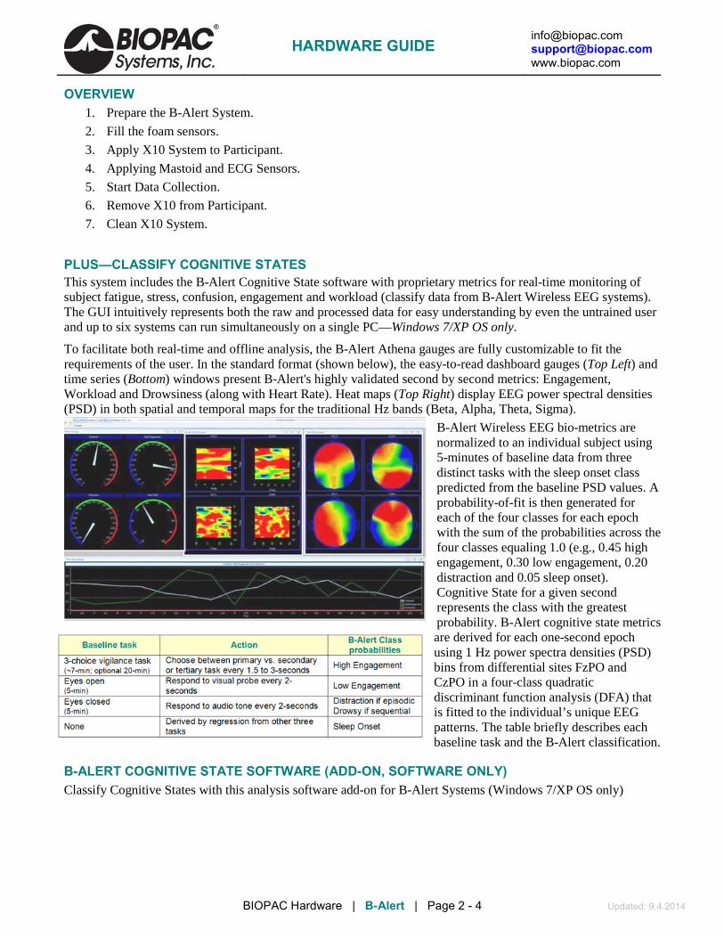
[email protected] [email protected] www.biopac.com
BIOPAC Hardware | B-Alert | Page 2 - 4 Updated: 9.4.2014
OVERVIEW 1. Prepare the B-Alert System.
2. Fill the foam sensors.
3. Apply X10 System to Participant.
4. Applying Mastoid and ECG Sensors.
5. Start Data Collection.
6. Remove X10 from Participant.
7. Clean X10 System.
PLUS—CLASSIFY COGNITIVE STATES This system includes the B-Alert Cognitive State software with proprietary metrics for real-time monitoring of subject fatigue, stress, confusion, engagement and workload (classify data from B-Alert Wireless EEG systems). The GUI intuitively represents both the raw and processed data for easy understanding by even the untrained user and up to six systems can run simultaneously on a single PC—Windows 7/XP OS only.
To facilitate both real-time and offline analysis, the B-Alert Athena gauges are fully customizable to fit the requirements of the user. In the standard format (shown below), the easy-to-read dashboard gauges (Top Left) and time series (Bottom) windows present B-Alert's highly validated second by second metrics: Engagement, Workload and Drowsiness (along with Heart Rate). Heat maps (Top Right) display EEG power spectral densities (PSD) in both spatial and temporal maps for the traditional Hz bands (Beta, Alpha, Theta, Sigma).
B-Alert Wireless EEG bio-metrics are normalized to an individual subject using 5-minutes of baseline data from three distinct tasks with the sleep onset class predicted from the baseline PSD values. A probability-of-fit is then generated for each of the four classes for each epoch with the sum of the probabilities across the four classes equaling 1.0 (e.g., 0.45 high engagement, 0.30 low engagement, 0.20 distraction and 0.05 sleep onset). Cognitive State for a given second represents the class with the greatest probability. B-Alert cognitive state metrics are derived for each one-second epoch using 1 Hz power spectra densities (PSD) bins from differential sites FzPO and CzPO in a four-class quadratic discriminant function analysis (DFA) that is fitted to the individual’s unique EEG patterns. The table briefly describes each baseline task and the B-Alert classification.
B-ALERT COGNITIVE STATE SOFTWARE (ADD-ON, SOFTWARE ONLY) Classify Cognitive States with this analysis software add-on for B-Alert Systems (Windows 7/XP OS only)
HARDWARE GUIDE

[email protected] [email protected] www.biopac.com
BIOPAC Hardware | B-Alert | Page 3 - 4 Updated: 9.4.2014
HARDWARE SPECIFICATIONS: Channels: 9 EEG with fixed gain referenced to linked mastoids; 1 auxiliary differential channel
with programmable gain
Sampling rate: 256 samples/second
Dynamic range: Fixed gain ± 1,000 µV
Resolution: 16 bit, CMRR 105 dB
Bandpass characteristics: 0.1 Hz and 65Hz (at 3dB attenuation)
Noise: ~ +1.5 µV @ 10 Hz and 50 kO impedance
Head movement/position: Angles obtained with 3D 12-bit accelerometer
RF Band: 2.4 to 2.48 GHz (ISM band)
Transmission mode: Bi-Directional with B-Alert BT – USB dongle
Data transmission range: ~ 10 meters, line of sight with onboard antenna
Transmission power: ~ 1 mW
System power consumption:
~ 40 mA @ 3.7 V
Battery capacity: Standard 2 x Li-ION batteries - 500 mAH, 12-hours of continuous use
Optional 4 x Li-ION batteries:
1000 mAH, 24-hours of continuous use
Battery charging: Internally charged with custom cable and USB wall charger
On-line impedance monitoring:
Initiated by host computer using bi-directional link
Head unit dimensions: Size 13 cm (L) x 6 cm (W) x 2.5 cm (H); Weight 110 g with standard battery
User control: On/Off
Indicator LEDs: Green - wireless synced, Red – on but not synced
Software Compatibility: Windows 7 and XP, PC with 2.0 GHz or higher processor 1 GB of RAM
Sensor Headset & Accessories Sensor sites Fz, F3, F4, Cz, C3, C4, POz, P3, P4 Sensor strips Streamline – medium; Standard – small, medium and large Medium = Nasium to Inion ~36 cm Electrode cream” Highly conductive, electrolytes and preservatives in non-ionic, hypoallergenic base, buffered to skin pH Windows 7 or XP OS only.
B-ALERT ACCESSORIES X10 Sensor Strips Sensors are sized for placement between Nasium and Inion. Sensor strips are typically good for 40 recordings, depending on care during use and cleaning. Worn out strips should be replaced to ensure good data quality. Strip warranty is 180 days.
X10-SENSOR-S small 32.0-34.5 cm (approx. 12.6-13.6") Strip 9 Sensor & replacement Neoprene
X10 SENSOR-M medium > 34.5 cm Note: Small and Medium sensors should cover 99% of subjects, but a large is available by request in
the very rare cases it is needed.
HARDWARE GUIDE

[email protected] [email protected] www.biopac.com
BIOPAC Hardware | B-Alert | Page 4 - 4 Updated: 9.4.2014
Disposable Study Kits This disposable study kit for the B-Alert X10 Wireless EEG System contains:
• one sensor strip
• one Neoprene sensor strap with Velcro
• gel and pads for 25 studies
• disposable electrodes (for mastoid) for 25 studies
RXB-ALERT-KIT-S small 32.0-34.5 cm (approx. 12.6-13.6”)
RXB-ALERT-KIT-M medium > 34.5 cm
HARDWARE GUIDE

[email protected] [email protected] www.biopac.com
BIOPAC Hardware | CBLX10 | Page 1 - 1 Updated: 2.13.2015
CBLX10 – B-ALERT X10 TO UIM100C ANALOG OUT
Use the CBLX10 to connect the analog output of the UIM100C for MP150 Systems to the ECG input of an ABM B-Alert X10 headset. The cable allows for the injection of signals that may be used to align data recordings between the two independent units. CBLX10 provides both signal attenuation and isolation between the MP150 unit and the B-Alert headset.
This cable is required in order to use the B-Alert X10 with the “Master Sync Device” mode available in AcqKnowledge 4.3 or above.
Cable length is 2 m from case to UIM100C connection and 2 m from case to B-Alert connection.
To connect the CBLX10:
1. Plug the black connector into an Analog Output on the UIM100C module connected to the MP150.
2. Plug the blue connector into the 2-pin (ECG) input on the top of the B-Alert unit.
3. In AcqKnowledge, choose “MP150 > Set Up Data Acquisition > Set Up Linked Acquisitions” and select “Use the master synchronization” as the synchronization method to pair and synchronize data obtained during linked MP150 and B-Alert X10 acquisitions. This is the only configuration where the “Master Sync Device” radio button is active.
IMPORTANT: About 10-12 seconds after starting a linked MP150/B-Alert X10 acquisition, disconnect the CBLX10 from the B-Alert headset to avoid introducing extraneous noise into the B-Alert signal being plotted on the screen.
See the AcqKnowledge 4 Software Guide and the Tutorial video for a detailed explanation of Linked Acquisitions.
HARDWARE GUIDE

[email protected] [email protected] www.biopac.com
BIOPAC Hardware | EPOCH Systems | Page 1 - 2 Updated: 2.25.2015
EPOCH SYSTEMS EPOCH-MSE-SYS 2-Channel Wireless EEG System for Mouse
EPOCH-RAT-SYS 2-Channel Wireless EEG System for Rat
These wireless EEG systems for mice and rats collect two channels of long-term wireless EEG/neural signals. To record, the animal's cage is simply placed on top of the receiver tray with the implanted animal inside of the cage. EEG data from the sensor is telemetered to the receiving tray and then sent to the data acquisition system.
Complete system includes a receiver tray, two 2-channel implantable EEG sensor transmitters, and interface cables (2 x CBL102) to collect data from a mouse or rat housed in an industry standard home cage. The Epoch EEG Transmitter amplifies and transmits two channels of high-fidelity EEG data. Implants are small enough to be implanted into mice as young as P21. The receiver tray has BNC connections that easily connect to a BIOPAC MP150 data acquisition system (via the UIM100C) or third-party devices capable of accepting signals within the ±5 V range.
Sensors are shipped with the default transmitter Gain setting; other Gain settings are available if requested before order is placed. AcqKnowledge software includes the scale settings for each transmitter Gain option.
Neural Implant Options Typical Use Gain Settings EEG, ECoG, LFP - default 2000x ±1.0 mV range, 2.0 mVpp in = 4 V out Status-Epilepticus 800x ±2.5 mV range, 5.0 mVpp in = 4 V out LFP, EEG in rat or mouse pups 4000x ±0.5 mV range, 1.0 mVpp in = 4 V out
When used with an MP Research System, use the power of AcqKnowledge software’s automation and scoring tools to identify seizures, predefine and control recording protocols, or set triggers based on external events (dosing, light changes, etc.). After recording, use automated EEG analysis routines to quickly score multiple channels of EEG data simultaneously. Derive frequency bands, complete a Frequency analysis, look at Alpha RMS, etc., all with guided automated routines.
For more options, add SleepSign (SSA100W) for complete sleep data analysis or use Camera Systems (CAMSYS4 or 8) to monitor and record protocols and animal behavior. Recorded video will be time synchronized to the physiological signals in AcqKnowledge for easy investigation of key areas of interest.
Implantable EEG sensors
Sensors require an EPOCH-MSE-SYS or EPOCH-RAT-SYS to operate. Battery options can each be used for rat or mouse if footprint and weight dimensions suit the animal; mouse should typically be larger than P21. Teflon insulated platinum electrode wires are shipped at 10 cm and can be truncated to desired length.
EPOCH-T2 Two-channel transmitter with 2 month battery life EPOCH-T6 Two-channel transmitter with 6 month battery
EPOCH-ACTI Epoch Sensor Activation Utility
This is an activation and test utility for Epoch EEG sensors. The sensors are typically shipped from the factory with the battery running. The utility allows users to start the battery when they are ready to use the sensor
HARDWARE GUIDE

[email protected] [email protected] www.biopac.com
BIOPAC Hardware | EPOCH Systems | Page 2 - 2 Updated: 2.25.2015
Specifications
Implant Weight: 2 month: 2.3 g 6 month: 4 g
EEG Sensor Footprint: 2 month: 7 mm x 9 mm 6 month: 7 mm x 12 mm
Volume: 2 month: 0.756 cubic cm 6 month: 1.344 cubic cm
Electrode Wire Length: Default 10 cm (truncate to desired length; custom longer lengths available upon request)
Electrode Wire Material: Teflon insulated platinum material
Implant Material: Medical Grade Epoxy
Gain and Max Signal Inputs: 10x = 15 mV
20x = 7.5 mV
50x = 3 mV
100x = 1.5 mV
EEG Bandwidth: 0.1 – 100 Hz per channel
Input: 5 MΩ impedance
Operating Temperature: 30 – 45° C
Maximum Tray Dimensions Mouse: 345 mm x 210 mm x 21 mm (13.6” x 8.25” x 1”)
Rat: 429 mm x 216 mm x 21 mm (16.9” x 8.5” x 1”)
Maximum Animal Size: 1 kg
Maximum Output: 4 V peak-to-peak
HARDWARE GUIDE

[email protected] [email protected] www.biopac.com
BIOPAC Hardware | FOTS100 System | Page 1 - 2 Updated: 9.4.2014
FOTS100 FIBER OPTIC TEMPERATURE SYSTEM FOTS100 Control Unit TSD180/182/181 Fiber Optic Temperature Probes This is a stand alone system, but it can also be interfaced to MP150 or MP100 Systems via CBL101. Use with
high-accuracy, MRI-conditional fiber optic temperature probes TSD180, TSD182 or TSD181.
FOTS100 includes control unit with RS-232 port, ± 5 V analog output, and rubber boot; power via 9 V battery or wall power.
The analog output parameters comprise the scale factor and the offset. The scale factor corresponds to the physical unit per Volt (unit/V) outputted by the system, while the offset corresponds to the physical value at which the user wants the analog output to be at zero volt.
For example, with a scale factor set to 10° C / V and the offset set to 5° C, the temperature as a function of the analog output voltage is given by:
Temperature = [Voltage output] x 10° C / V + 5° C. The default value of the scale factor is 50° C / V (or its equivalent in °F) and the default
value of the offset is 0° C (or its equivalent in °F). During a No Signal condition, the analog output and the serial ports output constant values as follow:
Output Analog 0 Volt
No Signal condition output value
RS-232 65 536.0 For more details, please see the complete FOTS100 User Manual, available online.
FOTS100 Specifications Output interface: Display, ±5 Volts Analog output, and RS-232 standard
BIOPAC interface for MP1X0: add CBL101 (RCA to 3.5 mm cable)
Channels: One
Compatibility: TSD180, TSD182 and TSD181 high accuracy fiber-optic temperature sensors
Accuracy: ±0.3° C (Total accuracy - includes both signal conditioner and transducer errors)
Temperature range: 20° C to 60° C (higher range also available)
Resolution: 0.1° C
Sampling rate: 50 Hz (20 ms)
Communication protocol: SCPI (default)
Input power: 9 to 24 VDC (AC/DC wall-transformer adapter included)
Consumption: 1.8 Watts typical
Battery: 9 V
Enclosure: Plastic casing with a removable rubber boot protection
Dimensions (without rubber boot protection):
45 mm (H) x 105 mm (W) x 165 mm (L)
Storage temperature: -40° C to 65° C
Operating temperature: 0° C to 45° C
Humidity: 95% non condensing
Light source life span: > 150,000 hours (> 17 years) MTBF
HARDWARE GUIDE

[email protected] [email protected] www.biopac.com
BIOPAC Hardware | FOTS100 System | Page 2 - 2 Updated: 9.4.2014
TSD180 & TSD182 RECTAL TEMP PROBE: 420 µm OD Polyimide tubing, 8 m (TSD180), 3 m (TSD182)
MRI Use: MR Conditional
Condition: Max MR field strength 3T; FOTS100 module stays in the control room.
• The Polyimide round tubing protects the sensing element its flexibility and rigidity provide excellent pushability.
TSD181 SURFACE TEMP PROBE: Sensor 1 mm OD, PFA tubing 0.9 mm OD, 8 m
• Cable sheath rated up to 85° C. TSD180, TSD182 and TSD181 Specifications
SPECS TSD180 and TSD182 TSD181
Temperature range: 0° C to +85° C (other ranges AUR)
Response Time: 250 ms and better 1.5 sec. typical
Temperature operating & calibrated range:
20° C to 45° C (other ranges AUR)
Accuracy: ±0.2° C (Total accuracy over the calibrated range including both signal
conditioner and sensor errors)
±0.3° C (Total accuracy over the calibrated range including both signal
conditioner and sensor errors)
Resolution: 0.05° C
Operating humidity range:
0-100%
MRI/EMI/RFI susceptibility:
Complete immunity
Calibration: NIST traceable
Optical connector: ST standard
Cable sheathing: 420 µm OD of Polyimide tubing; 900 µm OD tight buffer PVC
3 mm OD Kevlar reinforced PVC cable
Cable length: 8 m (TSD180/181) 3 m (TSD182)
Signal conditioner compatibility:
FOTS100 system
Interface: FOTS100 is a stand alone Fiber Optic Temperature System
Optional interface: MP150 or MP100 System via FOTS100 and CBL101
HARDWARE GUIDE

[email protected] [email protected] www.biopac.com
BIOPAC Hardware | VPG HARDWARE | Page 1 - 1 Updated: 6.13.2014
VPG HARDWARE TSD204 – Vaginal Plethysmograph Transducer The TSD204 VPG vaginal plethysmography transducer measures vaginal pulse amplitude (VPA) and vaginal blood volume (VBV).
TSD204
TCIPPG2
BSL-TCI24
TCIPPG2 – Interface VPG Transducer to PPG100C for MP150 Plethysmograph interface for VPG transducer (TSD204) to PPG100C for MP150 System.
BSL-TCI24 – Interface VPG Transducer to dSub9 input for MP36R Plethysmograph interface for VPG transducer (TSD204) to MP36R System analog input (dSub9).
TSDVPG – Vaginal Plethysmograph Transducer + One Interface This TSDVPG kit includes one VPG Transducer (TSD204) and choice of one interface: TCIPPG2 to PPG100C for MP150 System or BSL-TCI24 to dSub9 for MP36R analog CH input.
VPG Transducer Specifications Electronics Photodiode: Photodiode with integrated amplifier 340-950 nm response 80 mV / mW / cm2
Typical output voltage 3 V LED: 3 mm Red/Orange LED (Visible red probe) 90 med @ 20 mA, peak wavelength 620 mm View angle 60º Used at 4.50 mA (approx. 25 med) Resistor: 680 ohm, 1% metal film (visible RED probe) Sterilization: Cidex™ OPA Solution (20-45 minutes) Materials Probe: PLEXIGLAS SG-10, FDA section 21 CFR 177.1010; suited for internal use Connecting cable: Silicone Sheeting Quality 7480/061 – Compliant with the FDA Regulation meeting the requirements of the 3-A Sanitary Standard, Class III FDA section CFR 177.2600 Placement device: Silicone Sheeting Quality 7480/061 – Compliant with the FDA Regulation meeting the requirements of the 3-A Sanitary Standard, Class III FDA section CFR 177.2600
HARDWARE GUIDE

[email protected] [email protected] www.biopac.com
BIOPAC Hardware | PNPG HARDWARE | Page 1 - 1 Updated: 7.10.2014
PNPG HARDWARE TSD205 Series – Penile Pulse Plethysmography Transducer (PNPG) The TSD205-size series penile plethysmography transducer is an easy-to-use liquid metal (Indium Gallium) strain gauge. The transducer is available in a variety of sizes ranging from 6.0 cm to 12.5 cm. The gauge is designed for single use or same client only and is sold in 0.5 cm size increments.
TSD205
TCI111A
BSL-TCI18
TSD205 Series Available Sizes Transducer Circumference Transducer Circumference
TSD205-6.0 6.0 cm TSD205-9.5 9.5 cm
TSD205-6.5 6.5 cm TSD205-10 10.0 cm
TSD205-7.0 7.0 cm TSD205-10.5 10.5 cm
TSD205-7.5 7.5 cm TSD205-11 11.0 cm
TSD205-8.0 8.0 cm TSD205-11.5 11.5 cm
TSD205-8.5 8.5 cm TSD205-12 12 cm
TSD205-9.0 9.0 cm TSD205-12.5 12.5 cm
TCI111A – Interface PNPG Transducer to DA100C for MP150 Plethysmograph interface for PNPG transducer (TSD205) to DA100C for MP150 System.
BSL-TCI18 – Interface 2 mm HG Strain to 2 x CBL201 for MP36R Plethysmograph interface for PNPG transducer (TSD205) to MP36R System analog CH input.
TSDPNPG – Penile Plethysmography Transducer + One Interface This TSDPNPG kit includes one PNPG Transducer (TSD205) and choice of one interface: TCI111A to DA100C for MP150 System or BSL-TCI18 to 2 x CBL201 for MP36R analog CH input.
HARDWARE GUIDE

[email protected] [email protected] www.biopac.com
BIOPAC Hardware | Micro Pressure | Page 1 - 2 Updated: 9.3.2014
MICRO PRESSURE MEASUREMENT SYSTEM MPMS200 Micro Pressure System TSD280 - MPMS Sensor, 5 cm 2 m TSD281 - MPMS MRI Sensor, 5 cm 2 m TSD282 - MPMS Sensor, 15 cm 2 m TSD283 - MPMS MRI Sensor, 15 cm 2 m MPMS200 - EXT MPMS MRI Sensor Extension, 8 m
The MPMS200 is a single-channel, hand-held fiber optic micro pressure measurement system for physiological pressure monitoring: intra vascular blood pressure; Urodynamic; Intra cranial pressure; Intra uterine pressure; Intra ocular; Cardiac assist applications; etc.
Use with TSD280 Series sensors—tip diameter 0.30 mm (1 French)
Compact and rugged design
High resolution and precision
Easily interfaces with BIOPAC or 3rd-party DAQs
MR-safe sensors available
Automatic atmospheric pressure correction
The amplifier unit provides an analog output signal in the ±5 V range and has a 250 Hz frequency range. The system includes a CBL101 cable to interface directly with the UIM100C for Research Systems. The unit includes a mains power transformer.
MPMS200 Physical Connections 1. Connect the CBL101 cable (included) between the MPMS200 and the UIM100C module.
2. Launch AcqKnowledge and select Set Up Data Acquisition from the Hardware menu.
3. Add a new channel, select UIM100C, and choose the MPMS200 option from the transducer list.
AcqKnowledge will automatically calibrate the signal to mmHg and display the correct units when recording data. See the Opsens LifeSens Manual for further information about the amplifier and sensor.
Specifications Number of channels: One Compatibility: TSD280 Series fiber optic pressure sensors (other sensors upon request) Full scale*: -50 mmHg to 300 mmHg relative to atm. (wider range also available) Resolution*: 0.5 mmHg (no averaging) Precision*: 1% FS or 1 mmHg (whichever is greater) Sampling rate: 250 Hz standard Connector compatibility: SC connector (SCPROM connector compatible) Internal manometer: Included for automatic atmospheric pressure correction Analog Output: ±5 V (1 V/100 mmHg) Input power and consumption: 9 to 24 VDC - 1.8 W (wall-transformer adapter included) Dimensions - (without rubber boot protection): 45 mm (H) x 105 mm (W) x 165 mm (L) Display: lar ge LCD Storage temperature: -40° C to 70° C Operating temperature: 0° C to 45° C Humidity: 95% non-condensing Light source life span: 40000 hours MTBF
* Specifications include the effect of both the signal conditioner errors and the sensor errors.
HARDWARE GUIDE

[email protected] [email protected] www.biopac.com
BIOPAC Hardware | Micro Pressure | Page 2 - 2 Updated: 9.3.2014
The Micro Pressure Measurement System utilizes Opsens technology and benefits from Opsens’ White Light Polarization Interferometry (WLPI) technology (Patent# 7,259,862).
TSD280 Series Micro Pressure Sensors for MPMS200 System The MPMS200 system is used with TSD280 series fiber optic sensors that have an optional extension cable for MRI applications. The probes are suitable for work on small animals (up to the frequency response 250 Hz limit; contact BIOPAC for higher frequency response options).
TSD280 - MPMS Sensor 5 cm 2 m
TSD281 - MPMS MRI Sensor 5 cm 2 m
TSD282 - MPMS Sensor 15 cm 2 m
TSD283 - MPMS MRI Sensor 15 cm 2 cm
The TSD280 and TSD282 are micro pressure sensors that connect directly to the MPMS200 unit. The TSD281 and TSD283 are MR-safe micro pressure sensors that connect to the MPMS200 unit via the MPMS EXT extension cable for MRI applications.
TSD280 Series Specifications TSD280 TSD281 TSD282 TSD283 Sensor tip diameter: 0.30 mm OD (1.0 French) Sensor tip material: PIT 3 tube Sensor tip material length:
50 mm 50 mm 150 mm 150 mm
Connector: SC connector F2.5 ferrule connector
SC connector F2.5 ferrule connector
Cable length: 2.0 meter Cable sheath: PTFE Operating range: Operating range: P1 (-50 mmHg to +300 mmHg (relative to atmospheric pressure)
MPMS200 EXT - MPMS MRI Sensor Extension 8 M This MR-safe extension cable can be used to connect the MPMS200 Micro Pressure Measurement unit in the MRI control room to a TSD281 or TSD283 micro pressure sensor in the MRI chamber room.
Cable: 3 mm OD Kevlar reinforced PVC optical cable
Fiber core: 62.5 μm core
Cable length: 8.0 meters
Sensor end connector: F2.5 to TSD281 or TSD283
System end connector: SC to MPMS200
HARDWARE GUIDE

[email protected] [email protected] www.biopac.com
BIOPAC Hardware | Tissue Bath Stations | Page 1 - 2 Updated: 3.22.2013
TISSUE BATH 1, 2, 4, 8 TISSUE BATH STATIONS
The Tissue Bath Station is completely modular, and can be purchased in multiples of one unit. The System includes all of the glassware, tubing, reservoir, tissue hooks and mounting accessories, force transducer and micrometer tension adjuster. The ergonomic design of the station allows the tissue bath to be lowered away from the tissue holder so that mounting of the tissue preparation is very easy. The taps for filling and draining the bath are mounted on the tubing to avoid the risk of accidental bath breakage. The entire station is mounted on a convenient base stand, which creates a sturdy platform for the experiment. The unique design makes it easy to add or remove stations to provide the optimal solution for the requirements. When a system is ordered, the size of the tissue bath and heating coil must be specified. Each Tissue Bath station includes:
1 Reservoir 1 Reservoir Holder 1 Transducer Holder 1 Warming Coil Holder 1 Warming Coil (specify 5 ml, 10 ml, 20 ml, or 30 ml
size) 1 Tissue Holder (glass; left) 1 Tissue Holder (stainless steel; right) 2 Triangle Tissue Holder (stainless steel) 2 Tissue Clip (stainless steel) 1 Bath Holder 1 Tissue Bath (specify 5 ml, 10 ml, 20 ml size) 1 Oxygen Filter (glass) 1 Micro meter Assembly 1 Mount Accessories Kit 1 Base Station with Support Rods 1 TSD125 Force Transducer (specify TSD125 model
C, D, E or F)
See also: BIOPAC Circulators, or use an existing system.
HARDWARE GUIDE

[email protected] [email protected] www.biopac.com
BIOPAC Hardware | Tissue Bath Stations | Page 2 - 2 Updated: 3.22.2013
TISSUE BATH ACCESSORIES / REORDER PARTS Tissue Holders Tissue Clips Warming Coil Oxygen Filter
Tissue Bath Reservoir Mount Accessories Field Stimulation Electrode
RXHOLDER-S Tissue Holder (stainless steel) RXHOLDER-G Tissue Holder (glass) RXHOLDER-TR Triangle Tissue Holder (stainless) RXCLIP Tissue Clip (stainless steel) RXCLIP-TRI Triangle Tissue Clip for Rings
(stainless steel) RXWARMING Replacement Warming Reservoir
400 ml
RXCOIL Wa rming Coil RXO2FILTER Oxygen Filter (glass) RXBATH Tissue Bath (5 ml, 10 ml, 20 ml) RXRESERVOIR Re servoir 1000ml RXMOUNT Mount Accessories Kit STIMHOLDER Field Stimulation Electrode for use with STM100C BSLSTIMHLD Field Stimulation Electrode with BNC cable termination for use with BSL Stimulator
TISSUE BATH ACCESSORIES SPECIFICATIONS
1 x Tissue Holder—stainless steel; 15 mm high x 9 mm wide; reorder as RXHOLDER-TR 1 x Tissue Holder—glass; 67.46 mm high x 57.85 mm wide; reorder as RXHOLDER-G; 1 x Tissue Holder —stainless steel; 77.34 mm high x 55.06 mm wide; reorder as RXHOLDER-S 2 x Tissue Clip—stainless steel; 15 mm high x 5 mm wide: reorder as RXCLIP 2 x Triangle Tissue Clip—stainless steel; 15 mm high x 12 mm wide; reorder as RXCLIP-TRI 1 x Replacement Warming Reservoir 400 ml: reorder as RXWARMING 1 x Integrated heater—1,600 ml volume, programmable temp. 20° - 44° C 1 x Circulator pump—15 W; 500 ml/min
1 x Warming Coil; reorder as RXCOIL 1 x Oxygen Filter; reorder as RX02FILTER 1 x Bath —reorder as RXBATH5 (5 ml,) RXBATH10 (10 ml,) RXBATH20 (20 ml) 1 x Reservoir—1000 ml; reorder as RXRESERVOIR Mount Accessories Kit; reorder as RXMOUNT Field Stimulation Electrode; reorder as STIMHOLDER for STM100C, BSLSTIMHLD for BSL Stimulator 1 x Micrometer-transducer assembly 1 x 3 way Rotary Valve 1 x Power Supply – 110V/60 Hz or 220V/50 Hz
HARDWARE GUIDE

[email protected] [email protected] www.biopac.com
BIOPAC Hardware | Circulator | Page 1 - 3 Updated: 9.3.2014
CIRCULATOR A/B HEATING CIRCULATORS Heating circulators are used with Tissue Bath Stations and include a digital temperature display and the following controls:
Preset Temperature Power Heater Circulation
Inlet and Outlet ports are on the back, along with the power cord. Circulator A: 110 V, 60 Hz Circulator B: 220 V, 50 Hz
CIRCULATOR SETUP AND USAGE GUIDE
BIOPAC Heating Circulators will maintain water temperature at a preset value in the range 30 C to 45 C and circulate the water through tissue baths.
Heating circulators include a digital temperature display and the following controls:
Preset Temperature Power Heater Circulation
CALIBRATION Although the offset value for the temperature sensor is factory-calibrated, the user can calibrate the controller’s internal temperature sensor. To calibrate the sensor:
1. Install a calibrated reference thermometer in the bath.
2. Adjust the offset value to zero. 3. Adjust the preset value to an appropriate
temperature. 4. Once the bath reaches the preset value and
stabilizes, calculate the offset value by noting the difference between the reference thermometer value and the preset value.
5. Enter this value as an offset.
ERROR CODES Display Indication Lo Water in the bath is not enough or
the bath is empty.
Sen Microprocessor cannot communicate with the temperature sensor.
HARDWARE GUIDE

[email protected] [email protected] www.biopac.com
BIOPAC Hardware | Circulator | Page 2 - 3 Updated: 9.3.2014
CIRCULATOR SETUP & USAGE GUIDELINES 1. Connect a hose from the INLET on the back of the circulator to the tissue bath OUTPUT.
For more than one tissue bath, connect the tissue baths serially.
2. Connect a hose from the OUTLET on the back of the circulator to the tissue bath INPUT.
3. Fill the stainless steel water bath with 4.5 liters of water.
A buzzer sound warning will be emitted if there is not enough water in the bath when the Circulator is powered on. See Error Codes above.
4. Place the glass lid on the bath to close.
5. Plug the power cord from the back of the Circulator to a power source.
6. Press the POWER key to turn on the circulator.
7. To see the preset temperature value, press the P.SET key.
To change the preset temperature value, hold down the P.SET key and, at the same time, repeatedly press the UP or DOWN arrow keys to increase or decrease the preset value.
8. To see the acceleration value of the Circulator, press the ACC key.
To change the preset acceleration value, hold down the ACC key and, at the same time, repeatedly press the UP or DOWN arrow keys to increase or decrease the preset value. The higher values for acceleration indicate more rapid heating.
9. To see the offset temperature value, press the ACC and P.SET keys at the same time.
This is a factory-calibrated value. To calibrate the temperature sensor, see Calibration above. All preset values are written to non-volatile memory.
10. Press the PUMP ON/OFF key to start the circulation pump.
Check that the blue Pump Status LED is ON. The pump should begin circulating water.
11. Check that the water goes out of the circulator and flows through the waterway of the tissue bath(s).
With initial setup, some air may remain in the circulator pump. See Troubleshooting below.
12. Press the P.SET button and confirm the set value of the desired temperature.
13. Press the HEATER ON/OFF key to turn on the heater.
Check that the red Heater Status LED is ON.
Check that the Heater Display LED is on to confirm that the heater inside the bath is working.
Circulator will maintain the preset temperature of water in the bath; variations of +/-0.2 C are acceptable.
14. Check the water level periodically and add water to the bath if the level drops below 4 liters.
Caution: Over time, the water level inside the bath may decrease. Do not operate the circulator with less than 4 liters of water in the bath.
15. To turn the PUMP and HEATER on and off individually, press their respective ON/OFF keys.
16. To stop operation, press ON/OFF keys.
Power down equipment in the following order: PUMP, HEATER, POWER.
HARDWARE GUIDE

[email protected] [email protected] www.biopac.com
BIOPAC Hardware | Circulator | Page 3 - 3 Updated: 9.3.2014
TROUBLESHOOTING
There is no water circulation or very little. 1. Check the hose connections and be sure they are connected to the correct positions.
2. Check that the hoses are not bent or twisted (which might impede the flow of water).
3. Confirm that there is at least 4 liters of water in the bath.
There is some air in the waterway.
To remove the air:
1. Press the PUMP ON/OFF key to OFF stop the circulator pump.
2. Disconnect the hose from the INPUT of tissue bath. (Leave other end connected to the Circulator OUTLET.)
3. Put the end of the hose in a bucket to catch the water flow.
4. Press the PUMP ON/OFF to ON to start the circulator pump.
5. Operate the circulator pump for a few 1-2 second cycles.
6. Press the PUMP ON/OFF key to OFF stop the circulator pump.
7. Reconnect the hose to the INPUT of the tissue bath.
8. Press the PUMP ON/OFF to ON to start the circulator pump and continue with normal operation.
TECHNICAL SPECIFICATIONS Temperature Range: 30 C to 44 C Reading Sensitivity: 0.1 C Display: 3 digit (LED Display) Water Bath Volume: 4.5 liters (Stainless Steel) Circulation Flow: 2 liter/min. Heater Resistance: 1000 Watt Circulation Pump: 110 V 100 W Plastic Head Supply Voltage: CIRCULATA: 110 Volt 60 Hz (1000 Watt) CIRCULATB: 220 V 50 Hz (1100 Watt) Inlet/Outlet OD 8.5 mm, ID 6.3 mm Tubing Temperature Offset Range: 0 C to 1.2 C Acceleration Levels: 0 to 5
HARDWARE GUIDE
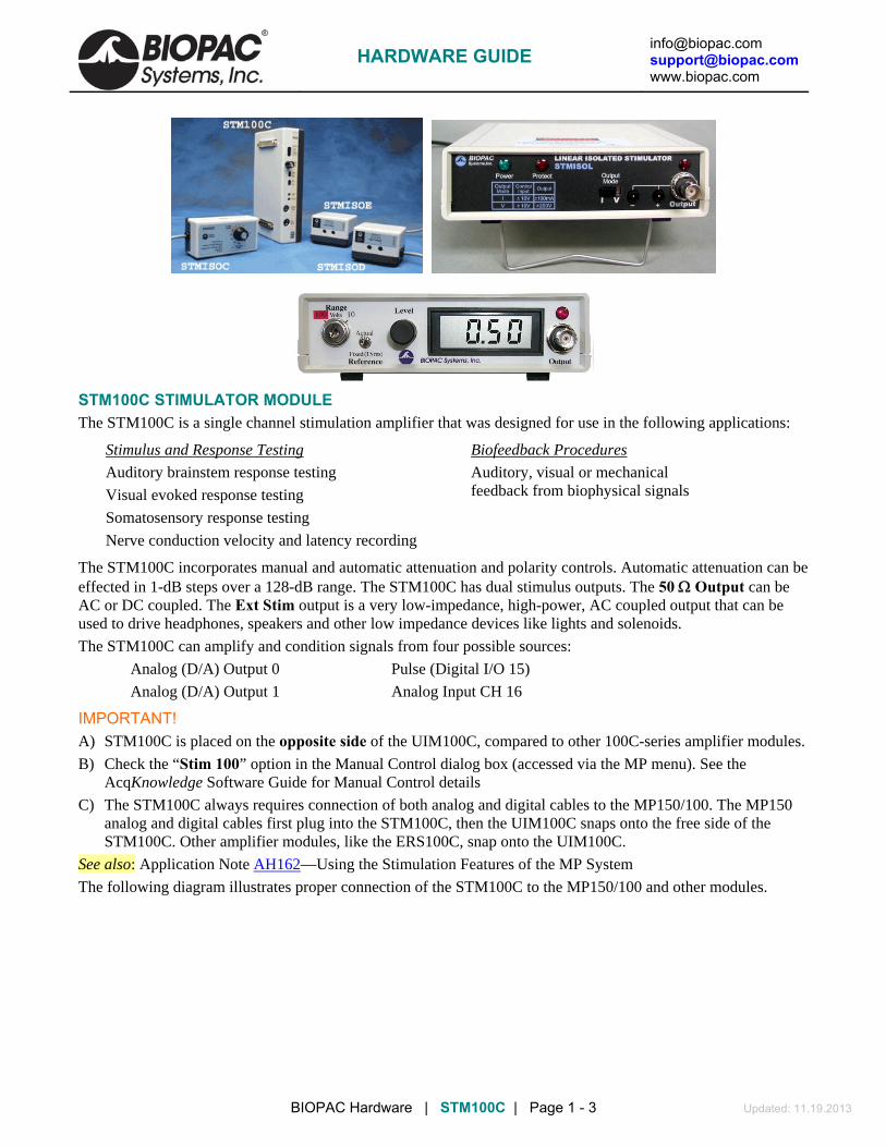
[email protected] [email protected] www.biopac.com
BIOPAC Hardware | STM100C | Page 1 - 3 Updated: 11.19.2013
STM100C STIMULATOR MODULE The STM100C is a single channel stimulation amplifier that was designed for use in the following applications:
Stimulus and Response Testing
Auditory brainstem response testing
Visual evoked response testing
Somatosensory response testing
Nerve conduction velocity and latency recording
Biofeedback Procedures
Auditory, visual or mechanical feedback from biophysical signals
The STM100C incorporates manual and automatic attenuation and polarity controls. Automatic attenuation can be effected in 1-dB steps over a 128-dB range. The STM100C has dual stimulus outputs. The 50 Output can be AC or DC coupled. The Ext Stim output is a very low-impedance, high-power, AC coupled output that can be used to drive headphones, speakers and other low impedance devices like lights and solenoids.
The STM100C can amplify and condition signals from four possible sources:
Analog (D/A) Output 0 Pulse (Digital I/O 15)
Analog (D/A) Output 1 Analog Input CH 16
IMPORTANT! A) STM100C is placed on the opposite side of the UIM100C, compared to other 100C-series amplifier modules.
B) Check the “Stim 100” option in the Manual Control dialog box (accessed via the MP menu). See the AcqKnowledge Software Guide for Manual Control details
C) The STM100C always requires connection of both analog and digital cables to the MP150/100. The MP150 analog and digital cables first plug into the STM100C, then the UIM100C snaps onto the free side of the STM100C. Other amplifier modules, like the ERS100C, snap onto the UIM100C.
See also: Application Note AH162—Using the Stimulation Features of the MP System
The following diagram illustrates proper connection of the STM100C to the MP150/100 and other modules.
HARDWARE GUIDE

[email protected] [email protected] www.biopac.com
BIOPAC Hardware | STM100C | Page 2 - 3 Updated: 11.19.2013
STIMULUS RESPONSE TESTING In nearly all cases of stimulus response testing, the STM100C will be used in conjunction with the ERS100C and the MP System. The ERS100C is a very low noise biopotential amplifier, with sufficient bandwidth ranges to accommodate the variety of evoked potential testing.
For most types of evoked response testing, the MP150/100 will be operating in averaging mode. Typically, the stimulus output waveform is generated in the stimulator setup window and ported through either analog output 0 or analog output 1, and the output device (such as the OUT101 Tubephone) is connected to the external stimulus jack on the STM100C. This allows for complex pulses, tones, ramp waves and arbitrary shaped analog waveforms to be used as stimulus signals.
POWER BUSY
ZEROADJ
SOURCEOUT0OUT1PULSECH15
POS
NEG
LIMIT
PULSE
-100%LEVEL-0%
DC
AC
STM100
EXT STIM
OUTPUT50
1
2
3
4
5
6
7
8
9
10
12
13
14
15
16
11
0
1
BISy
ZEROADJ
OPACstems
GAIN5000100002000050000
ONFILTEROFF
SHIELD
VIN+
SHIELD
VIN-
GND
10HzHIPASS1Hz
ERS100
STM100C connection to MP device, UIM100C and ERS100C
See the AcqKnowledge Software Guide for details.
Alternatively, a single variable-length digital pulse can be output on I/O 15. The analog output options offer greater flexibility and are generally easier to use, but I/O 15 allows for greater resolution (1 sec vs. 22 sec for analog output options). In either case, the stimulus signal is output just prior to each data collection pass in the averaging sequence.
IMPORTANT! Make sure that the settings on the STM100C match those in the stimulator setup windows (i.e., the output channel in the stimulator window matches the output channel selected on the STM100C).
AUDITORY EVOKED POTENTIALS Auditory evoked potentials, like the ABR can be implemented using the STM100C. The STM100C is used to present the auditory pulse or “click” to an auditory stimulator, like the Tubephone (OUT101). The OUT101 or headphones (OUT100) plug directly into the EXT STIM jack on the STM100C. “Clicks” can be either rarefaction or condensation (positive or negative pulses). “Click” attenuation can be controlled manually or via the computer in 1-dB steps over a 128-dB range.
SOMATOSENSORY RESPONSE TESTS These tests are very similar to ABR and VEP tests, except the stimulation source is usually an electrical pulse or mechanical impulse applied at some point along the leg or arm. Somatosensory tests are used to characterize the perception of touch. By connecting a solenoid to the EXT STIM output of the STM100C, a mechanical pulse can be generated for peripheral nervous system stimulation.
GENERAL NERVE CONDUCTION VELOCITY TESTS General nerve conduction velocity tests are evoked potential tests, but they generally do not require extensive signal averaging like the ABR or EP tests. The STM100C can perform this type of test, however the STM100C output is limited to a 20-Volt pk-pk signal. In the case of in vitro or in vivo experimentation, the 20-Volt range of the STM100C is typically adequate. For surface electrode stimulators, higher voltage is often required.
For higher voltage outputs, use the STMISOD or STMISOE (with the STM100C) to boost the voltage stimulus signal to 100 V or 200 V, respectively.
HARDWARE GUIDE
[email protected] [email protected] www.biopac.com
BIOPAC Hardware | STM100C | Page 3 - 3 Updated: 11.19.2013
BIOFEEDBACK PROCEDURES The STM100C can be used to condition and amplify the signals coming from any biopotential or transducer amplifier. The source amplifier must have its output switched to CH 16 (last channel), and the STM100C SOURCE switch needs to be placed on CH 16 as well. With the headphones or speaker plugged into the EXT STIM jack, biopotential signals like EMG can be heard directly. The EXT STIM output can also be used to drive visual indicators directly, so rhythmic or pulsatile signals (like ECG or respiration) can be easily observed. Mechanical actuators like relays and solenoids can be directly connected to the STM100C.
CALIBRATION: None required STM100C SPECIFICATIONS
Stimulus Output Voltage: 20 Volts (p-p) maximum. Voltages of up to 200 V are possible by connecting STMISO Series to the Ext Stim output on the STM100C. Current Output Drives: 50 Output: ±200 mA (3.5 mm phone jack) Ext. Stim. Output: ±1.0 amp (6.35 mm [¼"] phono jack) Ext. Stim Z (out): Less than 0.1 Input Sources: D/A0, D/A1, PULSE (DIG I/O 15), CH 16 (Analog) Polarity Control: Manual or digital control (DIG I/O 7, H-POS, L-NEG) Attenuation Control: Manual or digital control Attenuation Control Range: 128 dB (Digital I/O 0-6, LSB-MSB) Attenuation Step Resolution: 1 dB LED Indicators: Pulse, Current Limit Uniphasic Pulse Width: 10 µs (min) with 5 µs resolution Biphasic Pulse Width: MP150: 20 µs (min) MP100: 50 µs (min) Biphasic Pulse Resolution: MP150: 10 µs MP100: 25 µs Arbitrary Wave Resolution: MP150: 10 µs MP100: 25 µs Weight: 380 grams Dimensions: 4 cm (wide) x 11 cm (deep) x 19 cm (high)
HARDWARE GUIDE
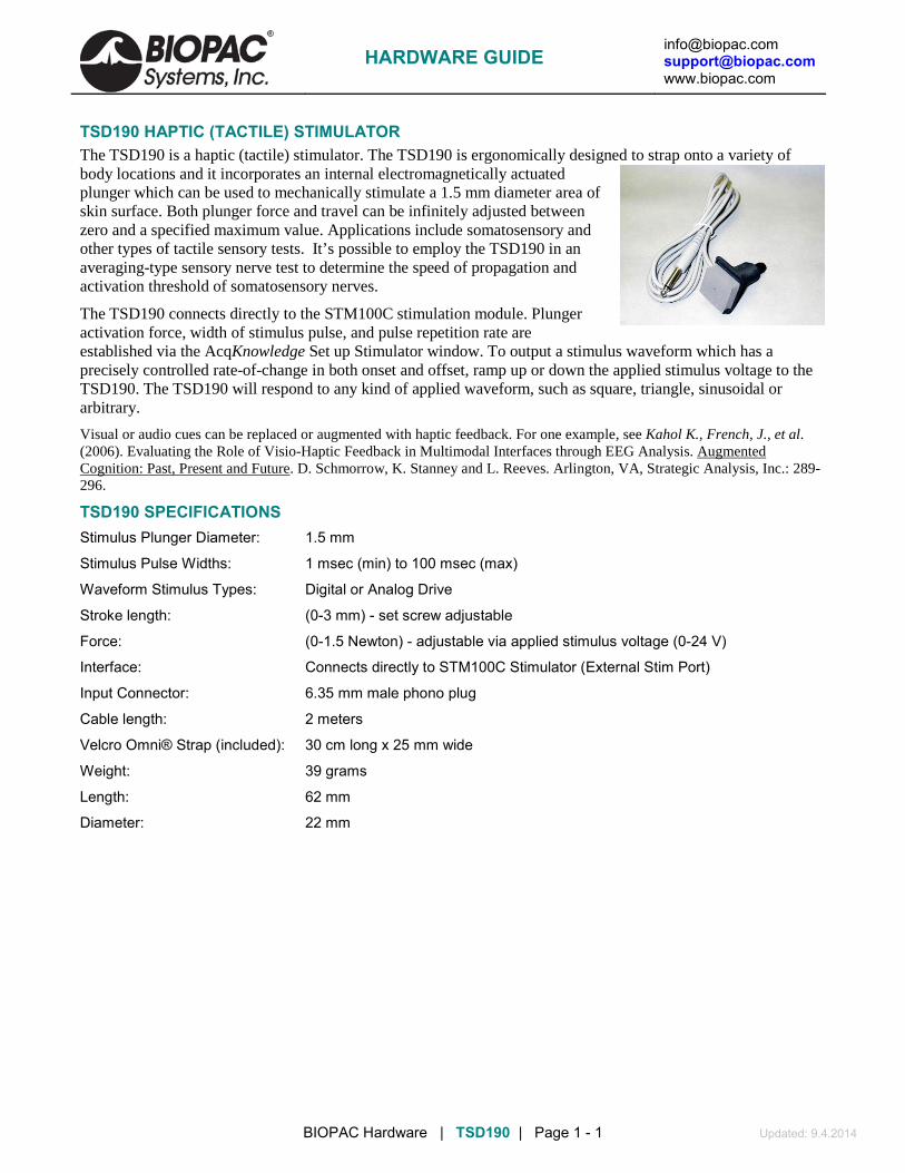
[email protected] [email protected] www.biopac.com
BIOPAC Hardware | TSD190 | Page 1 - 1 Updated: 9.4.2014
TSD190 HAPTIC (TACTILE) STIMULATOR The TSD190 is a haptic (tactile) stimulator. The TSD190 is ergonomically designed to strap onto a variety of body locations and it incorporates an internal electromagnetically actuated plunger which can be used to mechanically stimulate a 1.5 mm diameter area of skin surface. Both plunger force and travel can be infinitely adjusted between zero and a specified maximum value. Applications include somatosensory and other types of tactile sensory tests. It’s possible to employ the TSD190 in an averaging-type sensory nerve test to determine the speed of propagation and activation threshold of somatosensory nerves.
The TSD190 connects directly to the STM100C stimulation module. Plunger activation force, width of stimulus pulse, and pulse repetition rate are established via the AcqKnowledge Set up Stimulator window. To output a stimulus waveform which has a precisely controlled rate-of-change in both onset and offset, ramp up or down the applied stimulus voltage to the TSD190. The TSD190 will respond to any kind of applied waveform, such as square, triangle, sinusoidal or arbitrary.
Visual or audio cues can be replaced or augmented with haptic feedback. For one example, see Kahol K., French, J., et al. (2006). Evaluating the Role of Visio-Haptic Feedback in Multimodal Interfaces through EEG Analysis. Augmented Cognition: Past, Present and Future
TSD190 SPECIFICATIONS
. D. Schmorrow, K. Stanney and L. Reeves. Arlington, VA, Strategic Analysis, Inc.: 289-296.
Stimulus Plunger Diameter: 1.5 mm
Stimulus Pulse Widths: 1 msec (min) to 100 msec (max)
Waveform Stimulus Types: Digital or Analog Drive
Stroke length: (0-3 mm) - set screw adjustable
Force: (0-1.5 Newton) - adjustable via applied stimulus voltage (0-24 V)
Interface: Connects directly to STM100C Stimulator (External Stim Port)
Input Connector: 6.35 mm male phono plug
Cable length: 2 meters
Velcro Omni® Strap (included): 30 cm long x 25 mm wide
Weight: 39 grams
Length: 62 mm
Diameter: 22 mm
HARDWARE GUIDE

[email protected] [email protected] www.biopac.com
BIOPAC Hardware | STM200 | Page 1 - 3 Updated: 3.5.2014
STM200 CONSTANT VOLTAGE STIMULATOR – UNIPOLAR PULSE The STM200 can be used to stimulate any preparation or subject, including
Pain and stress studies that require lower voltages and wider pulse widths
Trigger the stimulator from a visual presentation system such as Superlab®, E-prime®, DirectRT®, MediaLab®, Inquisit®, and other visual presentation programs
Tissue baths (range 0-100 V at 0.1-200 ms pulse width)
Nerve or muscle stimulation that requires higher energy than a STMISOC/D/E can deliver
Controls & Connections Front Panel
Range Establishes the stimulus pulse output level range in Volts (0-10 Volts or 0-100 Volts).
Turn right to select a range of 0-10 Volts.
Turn left to select a range of 0-100 Volts.
Remove the key for added safety and control.
If the Range is changed before recording begins, the scaling must also be changed (MP menu > Set Up Channels) to maintain direct Level recordings.
If the Range is changed during recording, the user should manually enter a software marker to note the change (Esc). The pulse Level could then be determined by (mentally) moving the decimal place to the right or left, depending on how the Range was changed.
Reference Refers to the pulse width of the signal on the Reference Output (on the back panel).
Actual reflects the actual output width.
Fixed (15 ms) establishes a pulse width of 15 ms, regardless of the actual pulse width.
The Reference control only affects the pulse width; in either case, the pulse level reflects the actual output level.
Level Level is used in conjunction with Range to set the stimulus pulse output level. Turn the Level control (right to increase, left to decrease) to establish the desired Level, as indicated on the digital display.
Output Standard BNC connector to output the stimulus pulse to external electrodes or other devices.
LCD light The red LCD is activated when the DC adapter is plugged in and the power switch on the back panel is turned ON, and flashes when the stimulus pulse is active.
HARDWARE GUIDE

[email protected] [email protected] www.biopac.com
BIOPAC Hardware | STM200 | Page 2 - 3 Updated: 3.5.2014
Back Panel
Power Rocker switch for turning the STM200 power ON and OFF.
Fuse If the fuse blows and must be replaced, use a screwdriver to open (counterclockwise) and close (clockwise) the fuse cap.
DC Input Socket for DC adapter (AC300A or equivalent).
Trigger This cable terminates in a 3.5 mm mono plug for connection to the UIM100C Analog Output 0 or the STM100C 50 ohm output.
Manual Test Used to diagnose problems with the STM200 stimulator unit. When the Trigger and Reference Output cables are disconnected, press the Manual Test button to initiate a stimulus with a fixed pulse width of 2.5 milliseconds.
Reference Out This output cable terminates in an RJ-11 plug for connection to the HLT100C. The cable reports the stimulator marker pulse to the MP System, via the channel it is connected to. A marker pulse will be generated each time the stimulator generates a pulse. The front panel Reference switch determines the marker amplitude:
Actual varies between 0-1 V and maps to 0-100 V or 0-10 V
Fixed is 15 ms
Stand-Alone Setup To use the STM200 as a stand-alone stimulator from the MP System, the user must supply
a) TTL high pulse to the tip of the mono phone plug connector, with respect to the plug shield.
b) Power (+5 V and GND)
c) Signal conditioning to the output to observe results.
The report signal can be observed via the RJ-11 cable. The Reference Output cable does not need to be used for STM200 operation, because the front panel LCD panel indicator will show the pulse height output and the pulse width will simply be the pulse directed to the STM200.
HARDWARE GUIDE

[email protected] [email protected]
.com www.biopac
BIOPAC Hardware | STM200 | Page 3 - 3 Updated: 3.5.2014
Software Setup
The stimulation waveform must be created using stimulator setup (MP menu > Set Up Stimulator or MP Menu > Set Up Channels > Stimulator). The output waveform should be designed so that it has
One or more pulses
Baseline of 0 V
Pulse amplitude of 5 V
Pulse length from 0.1 ms to 200 ms
Related pulse duty cycle should not normally exceed 10%; higher duty cycles are supportable in certain circumstances.
Calibration The “Reference Output” signal should be calibrated to optimize results.
1. With the STM200 connected and ON, turn the Level control counter-clockwise until the display reads 0 (or as close to 0 as possible).
2. MP menu > Set Up Channels > View by Channels and click the Setup button for the stimulator channel.
3. Press Cal1 to get the signal representing 0 V out of the stimulator.
4. Add the Input value found with Cal 1 to the Input Value displayed for Cal2.
For example, if “Cal 1” is pressed and returns an Input Value of .255 V, .255 V should be added to the existing 50 V and manually entered as the total value of 50.255 V for Cal 2 Input Value.
Note Even if the Cal 1 Input Value is negative, it must still be “added” to the number for Cal 2 (which essentially subtracts it) to arrive at the proper value.
5. Click OK to close out of the Scaling window.
Optional: Click Save as Graph Template to save these new scale settings. As long as neither the MP unit nor stimulator changes, the calibration should not need to be repeated.
6. Close out of the Setup window.
HARDWARE GUIDE

[email protected] [email protected] www.biopac.com
BIOPAC Hardware | STMISOLA | Page 1 - 4 Updated: 2.2.2015
STMISOLA LINEAR ISOLATED STIMULATOR
The Constant Current and Constant Voltage Isolated Linear Stimulator (STMISOLA) will connect to any analog output signal drive (±10 V input) and provides considerable flexibility in stimulation protocols:
Voltage and current stimulator (unipolar or bipolar)—
The STMISOLA connects directly to the STM100C (50 output port) or the UIM100C (Analog Output 0 or 1 port) associated with the MP150 system. The STMISOLA can also connect directly to an MP36.
Linear stimulator—the STMISOLA can be used to generate stimulation signals that can have arbitrary waveshape. Typically, stimulators can only generate simple unipolar or bipolar pulses. The STMISOLA, however, can output unipolar or bipolar arbitrary waves such as pulse (single or train), square, sine, triangle, exponentially decaying, modulated envelopes, and fully user-specified types.
The STMISOLA can output either voltage or current waveforms.
Voltage (V) mode—the STMISOLA multiplies the Control Input Voltage by a factor of 20, to present that amplified signal at the STMISOLA output.
o In the case of a maximum ±10 V input control signal, the STMISOLA will output a ±200 V signal, with an output of either 100 ohms or 1 K ohms. These output impedance settings will act to limit the available output current.
Current (I) mode—two settings.
The STMISOLA provides two options for output current mode.
1) High current mode (Zout switch set to 100 ohms), provides a gain factor of 10 ma/volt.
2) Low current mode (Zout switch set to 1K ohms), provides a gain factor of 1 ma/volt. Low current mode permits much improved control for currents less than 10 ma.
The STMISOLA multiplies the Control Voltage by the factor indicated (K in ma/V) to present that associated output current at the STMISOLA output.
In the case of a maximum ±10 V Control Input Voltage, for:
Zout = 100 ohms, K=10 ma/V: the STMISOLA will output ±100 ma
Zout = 1000 ohms, K=1 ma/V: the STMISOLA will output ±10 ma
In both cases, the voltage compliance is ±200 V.
There are two basic stimulation modes for the STMISOLA:
Voltage
Current
In voltage mode, the STMISOLA has two different output impedance (Zout) settings (100 ohms and 1 kohm). Depending on the setting, the output voltage (Vout) on the electrode impedance load (Ze) will be subject to the following formula:
Vout = [Ze/(Ze+Zout)] * Vc * 20
Where: Vc is the input control voltage
In current mode, electrode load impedance does not impact STMISOLA gain accuracy. The STMISOLA will simply output the specified current (subject to the applied control voltage), despite the electrode load impedance, up to the point of maximum voltage compliance (+/- 200 volts).
Isolation characteristics—The STMISOLA isolates the Control Input Voltage from the stimulus output to 1500 VDC HiPot and approximately 1000 pF of coupling capacitance.
This very high degree of input/output isolation helps ensure subject safety and helps to substantially reduce, or eliminate, stimulus artifact.
HARDWARE GUIDE

[email protected] [email protected] www.biopac.com
BIOPAC Hardware | STMISOLA | Page 2 - 4 Updated: 2.2.2015
Stimulus artifact results when some percentage of electrical current from the stimulation site is directed to the recording site due to electrical leakage paths intrinsic to the stimulation/recording equipment. In the case of the STMISOLA, the leakage conductance and capacitance that permit this artifact to occur are reduced to very small values.
Power ON Safety—when you Power ON the STMISOLA, you must also hold Reset for at least 3 seconds. This forces the unit into an "operational but no output state" and protects the subject if accidentally connected to electrodes on power up.
Operating Details
Review Important Notes and Safety Notes before operating the STMISOLA
Important Notes
A) In Current (I) Mode stimulation, if the output has a load (typically high impedance) that induces railing for the specific output current, then the STMISOLA will immediately go into “Protect” mode. In the case of an unloaded output, this state will happen as soon as the STMISOLA is placed into Current (I) Mode stimulation. This happens because an “unloaded” STMISOLA output simply means that an arbitrarily high resistance load is attached to the STMISOLA. To correctly operate in Current (I) Mode stimulation, the proper load must be placed between stimulation electrodes and then “Reset” pushbutton must be pressed to 3 seconds to activate the unit.
B) In either stimulation mode (V or I), the output level (OL) will directly be a function of the applied Control Input Voltage (CIV). The conversion ratios are as follows:
Voltage (V) Mode: CIV (volts)*20 (volts/volts) = OL (volts) Current (I) Modes: Zout = 100 ohms: CIV (volts)*10 (ma/volts) = OL (ma) Zout = 1K ohms: CIV (volts)*1 (ma/volts) = OL (ma)
C) When an output waveform is present, the output waveform indicator—red LED just above BNC output connector —will glow. Waveform output level indication can be observed as an increasing intensity of this red LED. This output waveform indicator is designed to provide a visual indication of output, even if the wave duration is extremely short, so it may be possible that this indicator shows a waveform output for some brief period of time after the output wave has already passed.
Safety Notes
1. Never place the stimulation electrodes so that it’s possible for stimulation current to pass through the subject’s heart. This can happen if electrodes are placed so that the leads “straddle” to the left and right sides of the subject’s body. Place the stimulation electrodes close together on the SAME (left or right) side of the subject’s body appendage. Only place stimulation electrodes so they are on the appendage of interest. For example, for left leg stimulation, only place stimulation electrodes on the left leg and on NO other location on the body.
2. Do not power ON or OFF the STMISOLA unit while electrodes attached to the subject. Always be sure to place the STMISOLA in VOLTAGE mode, with zero volts applied to input, before attaching/removing electrodes to/from the subject. Zero volts is automatically applied to the STMISOLA input if the STMISOLA input cable is unplugged from any signal source.
3. It is ideal to use the STM100C for stimulation control, because it permits manual control of the stimulation level. To use the STM100C:
Plug the Control Input Voltage line for the STMISOLA into the 50 ohm output of the STM100C.
Before stimulation begins, turn the Output Level Control knob to 0%.
Initiate stimulation in the AcqKnowledge software (see Application Note AH162).
After stimulation is initiated, slowly turn the STM100C Output Level Control to the desired level.
When the stimulation session is ended, turn the STM100C Output Level Control back to 0%.
4. Do not remove electrodes while in current (I) mode; it’s possible for subjects to receive a shock if they remove electrodes while the STMISOLA is in current (I) mode because the STMISOLA responds to the impedance increase and causes the current source to swing to a positive or negative rail.
HARDWARE GUIDE

[email protected] [email protected] www.biopac.com
BIOPAC Hardware | STMISOLA | Page 3 - 4 Updated: 2.2.2015
Operating Procedure
Review Important Notes and Safety Notes before operating the STMISOLA
The included 3.5 mm mono splitter (3.5 mm male mono phone plug to two 3.5 mm female mono sockets) and one CBL100 (3.5 mm mono male to 3.5 mm mono male cable) permit the analog drive signal to be directed to two locations. The drive signal – usually from DA0 or DA1 – is typically directed to the splitter cable. One socket output of the splitter cable is directed to the STMISOLA input. The other socket output of the splitter cable is looped back to drive an available MP input, via CBL100, through the UIM100C. In this manner, during acquisition, the stimulus level and timing will be indicated on the recording.
1. Plug AC300 into back of STMISOLA unit.
2. Connect Control Input (3.5 mm male phono plug) to output: UIM100C (Analog Out 0 or 1) or STM100C (50 ohms) or MP36 headphone output or external signal generator.
3. Before powering ON the STMISOLA (turning from OFF to ON), make sure that stimulation electrodes are not attached to the subject.
4. Power ON STMISOLA.
Note that “Protect” red LED on front panel is ON, when STMISOLA is powered ON.
5. Set “Output Mode” switch to V for Voltage stimulation.
6. Press “Reset” pushbutton switch for 3 seconds to enable STMISOLA.
7. Make sure that STMISOLA input voltage is Zero volts.
8. Connect electrodes to subject and then to STMISOLA output.
9. Place STMISOLA in Current (I) mode, if desired.
Note that if output is unloaded and if STMISOLA is in Current (I) Mode, then the “Protect” light will stay ON, thus activating shutdown protection (see Important Note A).
10. Send Control Voltage (STMISOLA input) to affect desired wave output (see AcqKnowledge Software Guide or BIOPAC Application Notes AH162 and AS200).
11. When stimulation session is ended, place STMISOLA in Voltage (V) Mode and make sure that STMISOLA unit input control voltage is Zero volts.
12. Before powering OFF the STMISOLA (turning from ON to OFF), remove stimulation leads and/or electrodes from subject.
WARNING: Do not remove electrodes while in current (I) mode; it's possible for subjects to receive a shock if they remove electrodes while the STMISOLA is in current (I) mode because the STMISOLA responds to the impedance increase and causes the current source to swing to a positive or negative rail.
13. Power OFF STMISOLA after making sure that stimulation electrodes are not attached to the subject.
STMISOLA Specifications
THE STMISOLA is a linear, isolated, constant voltage or constant current stimulator. The STMISOLA has one output voltage mode and two output current modes. The output voltage mode multiplies the input control voltage (±10 V) by a factor of 20 to the output. When operating in output current mode, there are two options: Low current mode (Zout=1K ohm) and High current mode (Zout = 100 ohms). In Low current mode there is a 1:1 relationship between the input control voltage (in volts) and output current (in ma). In High current mode there is a 1:10 relationship between the input control voltage (in volts) and output current (in ma). The Zout selector switch determines the output impedance of the STMISOLA is voltage mode (100 ohms or 1 K ohms). The Zout selector switch determines the output current range (±100 ma for Zout = 100 ohms) or (±10 ma for Zout = 1 K ohms). The Zout switch has different operation, depending on output mode of STMISOLA. In Voltage output mode, the Zout setting simply specifies the output impedance of the STMISOLA. In Current output mode, the Zout setting determines the gain factor (K) which sets the desired current range, either +/- 100 ma or +/-10 ma.
The STMISOLA is also well-suited for transcranial direct current stimulation (tDCS). tDCS is a form of neuro-stimulation which employs the use of low level (typically under 10 ma) constant, unipolar, direct current. The STMISOLA will support arbitrarily long, constant, non-varying, direct output currents, so long as the associated
HARDWARE GUIDE
[email protected] [email protected] www.biopac.com
BIOPAC Hardware | STMISOLA | Page 4 - 4 Updated: 2.2.2015
voltage compliance is 100 VDC or less. The tDCS level is adjusted by holding a stable voltage to the control voltage input of the STMISOLA. This control voltage can be set in AcqKnowledge, to be output to STMISOLA via analog output, or can be provided by any 3rd party power supply or signal generator. Control Voltage Input: ±10 V maximum input Control Voltage Input Interface: Male 3.5 mm mono phone plug Isolation: Control Voltage Ground to Isolated Output Ground: 1000 pF at 1500 VDC HiPot Isolated Output Ground to Mains Ground: 2000 pF at 1500 VDC HiPot OUTPUT: Stimulation Voltage (V) Mode: ±200 V with:
Zout = 100 ohms: ±100 ma compliance; Output Impedance = 100 ohms Zout = 1Kohm: ±10 ma compliance; Output Impedance = 1000 ohms
Current (I) Mode: ±200 V compliance; Output Impedance - 1 Gohm Zout = 100 ohms: ±100 ma Zout = 1K ohm: ±10 ma
Input to Output Ratio: Voltage (V) Mode: ±10 V DC input creates output of ±200 VDC (1:20 ratio - V/V) for Zout either 100 ohms or 1K ohms Current (I) Mode: ±10 V DC input creates output of:
Zout = 100 ohms ±100 mA (1:10 ratio - V/ma) Zout = 1K ohms ±10 mA (1:1 ratio - V/ma)
Timing: Voltage Rise time: 200 V in 9.5 µsec (T10-T90) Current Rise Time: 100 ma in 9.5 µsec (T10-T90) Max output pulse width: Less than 100 VDC (voltage output or compliance level) – arbitrarily long More than 100 VDC (voltage output or compliance level) – 100 ms typical Max sine frequency: 30 kHz (-3 dB) Input Control Voltage: ±10 V max Physical Interface: 3.5 mm male mono phone plug Compatibility: MP: UIM100C (Analog Out 0 or 1), STM100C (50 ohm output), Generic signal generator with ±10 V output range Voltage or Current output noise (rms) — nominally +/-0.02% of Full Scale Range (FSR) Accuracy: Voltage or Current output (Zout is 100 ohms or 1K ohms): ± 1% Linearity: ± 0.1% Output Pulse Duration: Output or current compliance voltage (Vout < 100 V) - fully arbitrary, no limit to wave (pulse) duration, subject to user-supplied control voltage signal drive Output or current compliance voltage (Vout > 100 V) - 100 msec typical and limiting to 20 ms at 100 ma current output Current Limiting: ±350 ma (short circuit) Voltage Limiting: ±210 V (nominal) Reset Push Button: Required with each power ON – push in for 3 seconds to Reset Manual Test Voltage Output Pulse: 100 V for 2 msec Current Output Pulse:
Zout = 100 ohms: 50 ma for 2 msec Zout = 1K ohms: 5 ma for 2 msec
Full Scale Range: Voltage mode: ±200 V (Zout = 100 ohms or 1K ohms) Current mode: ±100ma (Zout = 100 ohms) ±10ma (Zout – 1K ohms)
Output Indicator: ON for P-P amplitudes > 1% FSR Fuse: 2 amp fast blow Power Adapter: 12 VDC at 1 amp (AC300A)
HARDWARE GUIDE

[email protected] [email protected] www.biopac.com
BIOPAC Hardware | CBLEPM | Page 1 - 1 Updated: 4.5.2013
CBLEPM Measurement Computing 4-Channel D/A To STMISOL/A
The CBLEPM connects the STMISOLA/L to a Measurement Computing 4-channel D/A unit. 3.5 mm phone jack connects to STMISOLA/L phone plug trigger and two tinned wires connect to the D/A unit screw terminals.
SPECIFICATIONS 3.5 mm phone plug (female) to 2 x tinned wires
See also: STMISOLA Stimulator and STMEPM E-Prime System
HARDWARE GUIDE
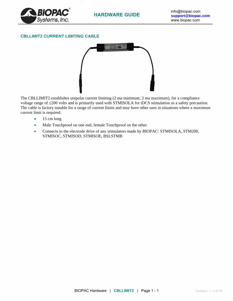
[email protected] [email protected] www.biopac.com
BIOPAC Hardware | CBLLIMIT2 | Page 1 - 1 Updated: 1.14.2015
CBLLIMIT2 CURRENT LIMITING CABLE
The CBLLIMIT2 establishes unipolar current limiting (2 ma minimum, 3 ma maximum), for a compliance voltage range of ±200 volts and is primarily used with STMISOLA for tDCS stimulation as a safety precaution. The cable is factory tunable for a range of current limits and may have other uses in situations where a maximum current limit is required.
15 cm long
Male Touchproof on one end, female Touchproof on the other
Connects to the electrode drive of any stimulators made by BIOPAC: STMISOLA, STM200, STMISOC, STMISOD, STMISOE, BSLSTMB
HARDWARE GUIDE

[email protected] [email protected] www.biopac.com
BIOPAC Hardware | STMISO | Page 1 - 6 Updated: 9.3.2014
STMISO STIMULUS ISOLATION ADAPTERS See also: Stimulator Setup notes in AcqKnowledge Software Guide
BIOPAC offers three stimulus isolation adapters: STMISOC constant current or constant voltage (5X / 10X) stimulation
STMISOD multiplies STM100C voltage by 5
STMISOE multiplies STM100C voltage by 10
IMPORTANT SAFETY NOTES!
When using the STMISOC, STMISOD, or STMISOE, it is possible to generate voltages as high as 200 v p-p. These voltages are potentially dangerous, especially if the stimulator’s high voltage outputs are connected across the subject’s heart. Across the heart means that the heart is potentially in the electrical path from lead to lead. This situation occurs when the stimulation electrodes are placed on opposite sides of the subject’s body.
NEVER PLACE STIMULATION ELECTRODES ON OPPPOSITE SIDES OF THE SUBJECT’S BODY!
Always use the stimulator with the leads placed in relatively close proximity to each other and relatively far from the heart, and with the leads placed only on the SAME side of the body. The figure to the right illustrates correct connection techniques when using the STMISOC/D/E.
Example of correct stimulation electrode placement:
EL500 recordingelectrodes
EL500 s timulatingelectrodes
Left
STMISO SAFETY The harmonized, international regulatory standard relating to the safety of nerve and muscle stimulators is IEC 601-2-10. Certain stimulation equipment is excluded from this standard, such as stimulators intended for cardiac defibrillation; however, for the purposes of defining relevant safety metrics for STMISOC, STMISOD, or STMISOE stimulation units, this standard is quite relevant.
STMISOC, STMISOD, and STMISOE stimulation units are designed in such a manner that the power available to stimulate the subject is limited. This limitation of power is achieved through the use of stimulus isolation transformers which have physical constraints (due to their size and construction) which absolutely —in accordance to known physical laws — constrain the maximum transferable power to be no more than a specific level.
Section 51.104 of the IEC 601-2-10 standard clearly specifies the limitation of output power for a variety of wave types.
* For stimulus pulse outputs, the maximum energy per pulse shall not exceed 300mJ, when applied to a load resistance of 500 ohms,
* For stimulus pulse outputs, the maximum output voltage shall not exceed a peak value of 500 V, when measured under open circuit conditions.
STMISOC, STMISOD, and STMISOE units employ stimulus isolation transformers that limit the output pulse width to 2 ms maximum, under 500 ohm load conditions. In addition, the highest available output voltage is 200 V pk-pk (STMISOC or STMISOE) under open circuit conditions.
HARDWARE GUIDE

[email protected] [email protected] www.biopac.com
BIOPAC Hardware | STMISO | Page 2 - 6 Updated: 9.3.2014
For the pulse energy calculation for STMISOC and STMISOE:
Joules = Watts x Seconds Watts (instantaneous maximum) = (200 V x 200 V) / 500 ohms = 80 Joules = 80 W x 0.002 seconds = 0.16 Joules = 160 mJ
Accordingly, the highest possible energy output using the STMISOC or STMISOE is 160 mJ.
The remaining stimulus isolation unit, STMISOD, has a maximum voltage output of 100 V. In this case, the maximum energy output is:
Watts (instantaneous maximum) = (100 V x 100 V) / 500 ohms = 20 Joules = 20 W x 0.002 seconds = 0.04 Joules = 40 mJ
In all cases the maximum available energy, from the STMISO series stimulus isolation units, is limited to be considerably less than the 300 mJ maximum as specified by IEC 601-2-10.
CAUTIONS FOR USE! Even the safest stimulation units, if used incorrectly, can cause serious harm. The following points illustrate fundamental rules for using stimulus isolation units to stimulate subjects.
1) NEVER APPLY THE STIMULUS SIGNAL IN SUCH A MANNER AS TO CAUSE CURRENT TO FLOW THROUGH THE HEART.
Primarily considered, this rule implies that stimulation leads should never be split apart so as to be able to touch opposing sides of the body surrounding the heart.
For example: NEVER CONNECT THE STIMULUS ISOLATION UNIT SO THAT ONE LEAD TOUCHES THE LEFT ARM AND THE OTHER LEAD TOUCHES THE RIGHT ARM.
Both stimulus leads [(+) and (-)], should be applied to the SAME side (left or right) of the subject's body. Furthermore, always stimulate AWAY from the heart. Stimulation probes (such as BIOPAC's EL350 or the EL351), which constrain the distance from the positive stimulation output to the negative stimulation output, should always be used for skin surface stimulation of nerve or muscle.
The EL350 or the EL351 stimulation probes fix the distance between stimulation outputs to 35mm. It is not recommended that this distance be increased for skin surface stimulation of nerve or muscle. An increase in this distance simply allows stimulation currents to circulate over a larger area, which is usually not necessary for nerve or muscle stimulation scenarios.
2) Always start the stimulation process with the stimulator control set the LOWEST possible level. The control for the STMISO series stimulus isolation units is located on the STM100C stimulation module. Set the control knob to the 0% level, prior to the onset of the stimulation protocol. During the protocol, increase the stimulus intensity by SLOWLY turning the control knob towards the 100% level. Stop increasing the intensity at the first sign of subject discomfort.
IMPORTANT NOTES! A) It takes as little as 15 micro-amps directed across the heart to instigate ventricular fibrillation.
This situation can be readily achieved by using sub-surface stimulation needle electrodes that insert directly into the heart. It is considerably more difficult to achieve ventricular fibrillation on the same heart using surface electrodes, but it is possible to do so, evidenced by the performance of cardiac defibrillation units used in hospitals or by paramedics.
B) Qualified experienced professionals should supervise any protocols where electrical stimulation is applied to human subjects. Electrical stimulation protocols are not simple. Please contact BIOPAC Systems for any questions regarding the use of BIOPAC’s stimulation units or accessories.
HARDWARE GUIDE

[email protected] [email protected] www.biopac.com
BIOPAC Hardware | STMISO | Page 3 - 6 Updated: 9.3.2014
STMISOC CONSTANT VOLTAGE OR CONSTANT CURRENT STIMULUS ISOLATION ADAPTER
50
20
10 mA
1 2
5
0.5
0.2
0.1
0.05
0.020.01
Voltage Monitor
Voltage(1:5) 100V max
Voltage(1:10) 200V max
Off
Current (mA)
STMISOC
+ -High Voltage Output
Current Control
MODE SELECT SWITCH
VOLTAGE OR CURRENT STIMULUS OUTPUT
VOLTAGE MONITOR
CONSTANT CURRENT CONTROL
To use the STMISOC, an MP System with (minimally) one STM100C Stimulator module is required.
Plug the STMISOC directly into the EXT STIM jack on the STM100C module.
Use two LEAD110 electrode leads to connect the stimulus output to the subject. The LEAD110 electrode leads are required because they have the proper plug type for the new safety lead standard used on the STMISOC module. (1.6 mm pin connectors)
In the Voltage mode, the STMISOC can be used with bipolar stimulation and with different waveform types (square, sine, triangle).
See also: Safety Notes
STMISOC Mode Signal output if LEVEL control is set to 100%
OFF No signal will be output from the STMISOC.
Voltage (1:5) 100 V Max
Signal output will be 5x the values shown in the Stimulator Setup dialog (acts like a STMISOD).
Voltage (1:10) 200 V Max
Signal output will be 10x the values shown in the Stimulator Setup dialog (acts like a STMISOE).
Current Signal output will be positive constant current output; set signal value with the Current Control rotary switch.
It’s important to output positive pulses only. Pulses should have a height of at least 10 V because pulse height output determines the voltage compliance of the current stimulation signal. The compliance of the current stimulation signal is determined by multiplying the pulse voltage amplitude by 10. For a 10 V pulse, the compliance would be 100 V. This means that the STMISOC can output a current of up to 100 V/R load. If R load = 5 k ohms, in this case the maximum output current would be 100 V/5 k = 20 ma. The maximum pulse height can be as much as 20 V, so it’s possible to have a compliance as high as 200 V.
HARDWARE GUIDE

[email protected] [email protected] www.biopac.com
BIOPAC Hardware | STMISO | Page 4 - 6 Updated: 9.3.2014
STMISOC SPECIFICATIONS
Stimulus Pulse Width: 50 µsec to 2 msec (voltage and current) Stimulus Sine Wave Range: 100 Hz to 5kHz (voltage only) Step Up Voltage Ratio: Selectable: (1:5) or (1:10) Maximum Output Voltage: (1:5) mode 100 V (p-p); (1:10) mode 200 V (p-p) into 5 k ± load Constant Current Range: 0.01, 0.02, 0.05, 0.1, 0.2, 0.5, 1.0, 2.0, 5.0, 10.0, 20.0, 50.0 ma (unipolar only) Current Source Compliance: 200 V maximum
Current stimulation mode: Positive current only Isolation Capacitance: 150 pf Isolation Voltage: 1500 VDC (from amplifier ground) Cable Length: 1.8 meters Weight: 190 grams Dimensions: 10 cm (wide) x 5 cm (deep) x 4.5 cm (high) Interface: STM100C
Off mode: Turns off Voltage or Current stimulation to subject. Voltage Monitor output: Output via 3.5 mm mono phono jack (1:5) mode 1:10 of stimulation voltage (1:10) mode 1:20 of stimulation voltage Current mode disabled
OFF Reports a signal of approximately 50% of the voltage indicated in the stimulator setup window
HARDWARE GUIDE

[email protected] [email protected] www.biopac.com
BIOPAC Hardware | STMISO | Page 5 - 6 Updated: 9.3.2014
STMISOD (5X VOLTAGE) STMISOE (10X VOLTAGE)
See Safety Notes
STMISOD/E setup for EL500 electrodes
The STMISOD/E plugs into the STM100C external stimulus output to provide an isolated voltage stimulus for response studies requiring a voltage stimulus (nerve conduction, somatosensory, etc.).
STMISOD adapter boosts the voltage of the STM100C by a multiple of 5x to provide a stimulus of up to ±50 V (or 100 V pk-pk).
STMISOE adapter boosts the voltage of the STM100C by a multiple of 10x to provide a stimulus of up to ±100 V (or 200 V pk-pk).
The front of the STMISOD/E has two 1.6 mm pin plugs that accept any of BIOPAC’s “safe lead” electrode leads, including bar electrodes, needle electrodes, and reusable electrodes.
The STMISOD/E has 1.6 mm “safe lead” pin plug outputs to accept most needle or stimulating electrodes. For voltage stimulus applications, the EL500 bar electrode or the EL500 electrodes with two of the LEAD110 electrode leads are recommended.
The STMISOD/E comes with an attached 2-meter cable that has a 1/4” phone plug on the end that connects to the EXT STIM output on the STM100C.
STMISOD/E CALIBRATION To use the STMISOD/E, simply set up the stimulator in the software, and hook the STMISOD/E adapter as shown in the previous figure. Then, hook the stimulating electrodes of the choice to the two 1.6 mm “safe lead” pin plugs.
The STMISOD/E provides an additional barrier of galvanic isolation between the MP150 and the stimulating electrodes. When using the STMISOD/E to create a pulsed voltage stimulus output, the pulse width must be between 50 µsec and 2 msec.
If the pulse is narrower than 10 µsec, the STMISOD/E will not reproduce the pulse well, due to rise-time constraints.
If the pulse is greater than 2 msec, the pulse output will sag due to lower frequency response limits. The pulse may sag before 2 msec, depending on load and drive levels.
When using the STMISOD/E for voltage stimulus applications, turn the level control to 0% on the STM100C, then, after stimulation has begun, turn the level control up slowly. This approach will help to determine the appropriate voltage level for stimulating the subject.
HARDWARE GUIDE

[email protected] [email protected] www.biopac.com
BIOPAC Hardware | STMISO | Page 6 - 6 Updated: 9.3.2014
STMISOD/E SPECIFICATIONS Stimulus Pulse Width: 50 µsec to 2 msec (voltage only) Stimulus Sine Wave Range: 100 Hz to 5 kHz (voltage only) Step Up Voltage Ratio: STMISOD (1:5) STMISOE (1:10) Maximum Output Voltage: STMISOD 100 V (p-p) into 5 k ohm load STMISOE 200 V (p-p) into 5 k ohm load Isolation Capacitance: 120 pf Isolation Voltage: 1500 VDC (from amplifier ground) Cable Length: 1.8 meters Weight: 140 grams Dimensions (WxDxH): 6.5 cm x 5 cm x 4.8 cm Interface: STM100C
HARDWARE GUIDE

[email protected] [email protected] www.biopac.com
BIOPAC Hardware | STMEPM | Page 1 - 1 Updated: 10.22.2014
STMEPM PROGRAMMABLE STIMULATOR FOR E-PRIME The STMEPM Programmable Stimulation System for E-Prime allows a user to interface the STMISOLA Stimulator with E-Prime to control the stimulus frequency and stimulus intensity for real-time stimulus delivery changes based on a subject's responses.
The system includes
STMISOLA Constant Current and Constant Voltage Linear Isolated Stimulator
USB 4-ch D/A Unit
Software Utility (STMISOLA<--> E-Prime) with sample E-Prime experiment
Interface cables
The sample E-Prime experiment provides the necessary interface commands to communicate with the D/A unit. The D/A unit provides the STMISOLA with the appropriate voltage levels to stimulate a subject. The system supports up to four STMISOLA (and includes one).
SPECIFICATIONS STMISOLA: see Constant Current and Constant Voltage Linear Isolated Stimulator specs CBLEPM connection cable x 4: 3.5 mm to 2 x tinned wire (STMISOLA to D/A card) D/A Unit: High-speed multifunction module with eight 13-bit, 1 MS/s analog inputs and four 12-bit, 1 MS/s analog outputs
Four 12-bit, ±10 V analog outputs with 1 MS/s update rate USB-bus powered (type: 2.0 high speed; compatibility: 1.1 or 2.0) 8 single-ended/4 differential analog inputs 13-bit resolution 1 MS/s sample rate Single-ended ranges: ±10 V, ±5 V, ±2.5 V or 0 to10 V Differential ranges: ±20 V, ±10 V, or ±5 V 16 digital I/O lines Two 32-bit counters One 32-bit PWM timer output
MRI COMPATIBILITY For electrical stimulation requirements in MRI or fMRI, use STMEPM-MRI.
HARDWARE GUIDE
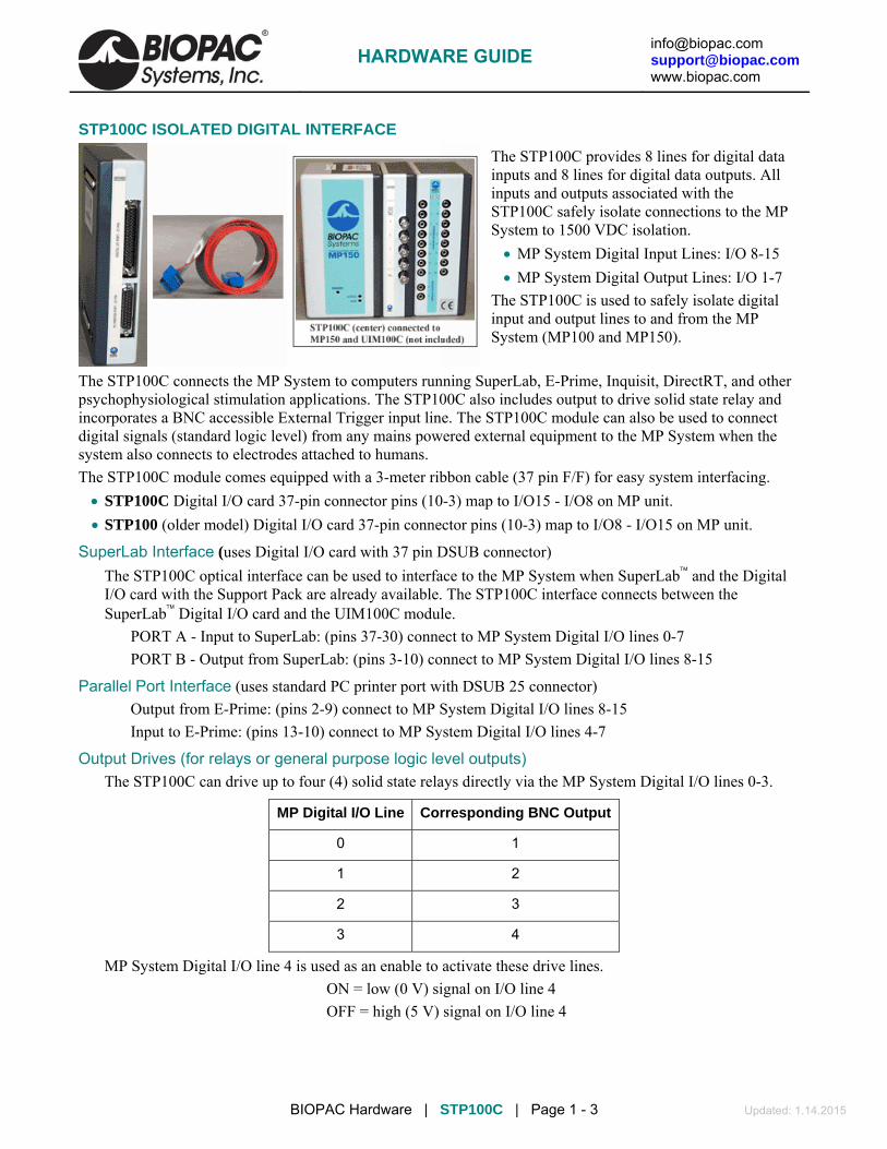
[email protected] [email protected] www.biopac.com
BIOPAC Hardware | STP100C | Page 1 - 3 Updated: 1.14.2015
STP100C ISOLATED DIGITAL INTERFACE
The STP100C provides 8 lines for digital data inputs and 8 lines for digital data outputs. All inputs and outputs associated with the STP100C safely isolate connections to the MP System to 1500 VDC isolation.
MP System Digital Input Lines: I/O 8-15
MP System Digital Output Lines: I/O 1-7
The STP100C is used to safely isolate digital input and output lines to and from the MP System (MP100 and MP150).
The STP100C connects the MP System to computers running SuperLab, E-Prime, Inquisit, DirectRT, and other psychophysiological stimulation applications. The STP100C also includes output to drive solid state relay and incorporates a BNC accessible External Trigger input line. The STP100C module can also be used to connect digital signals (standard logic level) from any mains powered external equipment to the MP System when the system also connects to electrodes attached to humans.
The STP100C module comes equipped with a 3-meter ribbon cable (37 pin F/F) for easy system interfacing.
STP100C Digital I/O card 37-pin connector pins (10-3) map to I/O15 - I/O8 on MP unit.
STP100 (older model) Digital I/O card 37-pin connector pins (10-3) map to I/O8 - I/O15 on MP unit.
SuperLab Interface (uses Digital I/O card with 37 pin DSUB connector)
The STP100C optical interface can be used to interface to the MP System when SuperLab and the Digital I/O card with the Support Pack are already available. The STP100C interface connects between the SuperLab Digital I/O card and the UIM100C module.
PORT A - Input to SuperLab: (pins 37-30) connect to MP System Digital I/O lines 0-7
PORT B - Output from SuperLab: (pins 3-10) connect to MP System Digital I/O lines 8-15
Parallel Port Interface (uses standard PC printer port with DSUB 25 connector)
Output from E-Prime: (pins 2-9) connect to MP System Digital I/O lines 8-15
Input to E-Prime: (pins 13-10) connect to MP System Digital I/O lines 4-7
Output Drives (for relays or general purpose logic level outputs) The STP100C can drive up to four (4) solid state relays directly via the MP System Digital I/O lines 0-3.
MP Digital I/O Line Corresponding BNC Output
0 1
1 2
2 3
3 4
MP System Digital I/O line 4 is used as an enable to activate these drive lines.
ON = low (0 V) signal on I/O line 4
OFF = high (5 V) signal on I/O line 4
HARDWARE GUIDE
[email protected] [email protected] www.biopac.com
BIOPAC Hardware | STP100C | Page 2 - 3 Updated: 1.14.2015
The output drives (for relays or general purpose logic level outputs) have 0 to 5 V output voltages and are current limited with 200 resistors. This means that for solid state relay drive requirements, output current will be limited to approximately 20 mA, assuming an optically isolated solid state relay input diode drop of 1.2 V. Nearly all solid state relays can operate with as little as 5 mA of current drive.
Digital Inputs
The STP100C is designed to work with digital inputs in the range of 0-3.0 V, 0-3.3 V and 0-5.0 V. The STP100C Digital inputs pull high and require current sinking ability of 4 ma to drive low. Digital high inputs must be greater than 2.5 V and Digital low input voltage must be less than 0.5 V.
Isolated External Trigger Input The optically isolated external trigger input is standard logic level compatible. This line is accessible via a BNC female connector (labeled TRIG on the front of the STP100C) and connects to the MP unit External Trigger input via optical isolation, compliant to 1500 VDC. The voltage range for this drive can support digital triggers in the range of 0-3.0 V, 0-3.3 V and 0-5.0 V.
When the STP100C trigger is unused, it is pulled to a high state (+5 V) via an internal 100 kΩ resistor. To properly drive this line, connect a standard logic level driver to this port. For non-logic level type drivers, the low voltage applied to a trigger should ideally be between 0 and 1.0 V. The high voltage applied to the trigger should ideally be between 3.5 and 5 V. The maximum recommended source impedance of the driver should not exceed 1 kΩ. The trigger will accommodate logic levels anywhere in ±10 V range, but low level should be less than 1.0 V and high level should be greater than 3.5 V.
The pulse width to the STP100C trigger input should be greater than 40 msec, and can be high going or low going. The MP system can be set up via AcqKnowledge to trigger on positive or negative edges.
Additionally, to use the STP100C external trigger in a manual mode, the input can be pulled low with an external switch connected between the trigger input and ground.
To externally trigger MP Unit acquisition, send a logic level signal to the External Trigger of the STP100C (TRIG). This line connects to the MP Unit External Trigger via optical isolation.
To use an MP System line normally dedicated to an I/O input (lines 8-15) to sample the External Trigger drive, use a JUMP100 jumper wire to connect that line directly to External Trigger (EXT T) on the back of the UIM100C. To increase the speed of the trigger response, place a 500 Ω resistor from TRIG to 5 V on the back of the UIM100C with STP100C connected. This will allow the STP100C to process pulse widths as narrow as 1 msec.
Note The older model STP100 tied the MP System External Trigger directly to MP System I/O 8.
STP100C Instructions 1. Snap the STP100C module DSUB I/0 connectors on the left side of the UIM100C module. 2. Use the 3-meter ribbon cable to connect the STP100C module (computer I/O 37-pin connector) to the
digital I/O card in the PC. Connects Port A (inputs; pins 30-37) on the digital I/O card to digital I/O lines 0-7 on the MP unit. Connects Port B (outputs; pins 3-10) on the digital I/O card to digital I/O lines 8-15 on the MP unit.
3. For debugging purposes, ground pins are: 37-pin digital I/O cable (CBL110A): pins 19 and 21 are GND; pin 20 is +5 V. 25-pin printer port cable (CBL110C): pins 18 and 25 are GND.
HARDWARE GUIDE

[email protected] [email protected] www.biopac.com
BIOPAC Hardware | STP100C | Page 3 - 3 Updated: 1.14.2015
Application example — P300 visual evoked response test
To set up the STP100W with an MP System to perform a P300 visual evoked response test:
1. C onnect two SuperLab outputs to the respective MP System digital inputs.
These SuperLab outputs are assigned to respective images that will be presented to the subject during the recording session. Typically, image presentation occurs within a statistical framework, i.e., Image 1 is presented 20% of the time and Image 2 is presented 80%. The SuperLab outputs will be tightly (1 ms) synchronized to the respective image presentation.
2. Set the MP System up to record EEG and the two SuperLab outputs, which should be directed to the MP System digital inputs.
3. After the recording session has been completed, use AcqKnowledge to perform specific averaging on the collected EEG data.
a) Use the digital input corresponding to SuperLab output 1 as a “Control Channel” in the Find Peak Averaging Setup; all the responses resulting from Image 1 presentation will be averaged together to create the composite response for Image 1 presentation.
b) Repeat the above procedure with the “Control Channel” assigned to SuperLab Output 2 to create the composite response for Image 2 presentation.
For more information on setting up the Find Cycle (Cycle Detector) Off-line Averaging for this kind of measurement, see the AcqKnowledge Software Guide.pdf.
HARDWARE GUIDE

[email protected] [email protected] www.biopac.com
BIOPAC Hardware | OUT SERIES | Page 1 - 5 Updated: 2.2.2015
OUT SERIES
Headphones OUT2 BNC Output Adapter OUT1 High Fidelity Headphones
OUT1A Ultra-Wide Frequency Response Headphones OUT3 see Stimulators OUT100 Monaural Headphone 40HP Monaural Headphones OUT101 Tubephone OUT01E Foam Ear Inserts:
LED OUT101R Plastic Tubes OUT4 Visual Stimulus: Controllable LED OUT103 LED Cable OUT102 Piezo Audio Transducer
OUT1 HIGH-FIDELITY HEADPHONES
These wide response high-fidelity headphones are used for auditory stimulus (short tones or clicks) or to listen to physiological signals (like EMG) directly. The Headphones are comfortable and lightweight (3 ounces) and include a 2 meter cable so the Subject can be seated a comfortable distance from the acquisition unit.
Unlike other Smart Sensors that connect to the MP3X, the OUT1 connects to the “Analog out” port on the back panel of the MP3X.
OUT1 SPECIFICATIONS Cable Length: 2 meters Connector Type: 9 Pin DIN (female)
OUT1A WIDE-FREQUENCY RESPONSE HEADPHONES
These ultra-wide frequency response headphones connect directly to the headphone port on the MP36 or MP36R data acquisition unit.
Features of these multi-purpose headphones include:
High dynamic range
High-resolution capsule
1/8" connector plus 1/4" adapter included
Single-sided cord
Oval-shaped ear cups
Comfortable headband
High-quality components and exceptionally rugged construction
OUT1A SPECIFICATIONS Connector: 1/8" TRS connector plus 1/4" TRS adapter Interface: MP36 or MP36R (not compatible with other MP units) Frequency response: 20 Hz - 20 kHz Max. power handling: 100 mW Impedance: 32 Ohm Sensitivity: 105 dB @ 1 kHz Cord length: 2 meters Dimensions: 11-3/4" x 9-3/4" x 8-1/4"
HARDWARE GUIDE

[email protected] [email protected] www.biopac.com
BIOPAC Hardware | OUT SERIES | Page 2 - 5 Updated: 2.2.2015
OUT100 MONAURAL HEADPHONES
These monaural headphones can be used with the STM100C stimulator module to deliver a tone signal while recording data for startle response or other stimulus-response studies. The headphones can also be used to listen to raw signals (such as EMG), piped through the STM100C from an amplifier output. The OUT100 is a wide response, high efficiency headphone, weighing 85 grams and is equipped with a 1.8 meter cord terminated in a 6.3 mm (1/4") phone plug.
OUT100 SPECIFICATIONS Weight: 85 grams Connector Type: 6.3 mm (1/4") Cable length: 1.8 meters Speaker: 28 mm dia 32 ohm dynamic Mylaar Impedance: 16 Ohm @ 1.0 kHz Power Handling: 100 mW max Frequency response: 20 Hz - 20 kHz Average SPL: 108 dB ± 4 dB Adapter (included): 1/4" mono adapter plug
40HP MONAURAL HEADPHONES
These monaural headphones are used with Biopac Science Lab MP40 and Biopac Student Lab MP45 for stimulus response experiments and to listen to EMG signals. The 40HP is a wide-response, high-efficiency headphone.
40HP SPECIFICATIONS Cable Length: 5 meters Connector Type: 3.5 mm phone plug
OUT2 BNC (M) OUTPUT ADAPTER
This BNC adapter is designed to output signals from the MP3X unit to other devices (such as external amplified speakers and scopes). This 2-meter adapter cable terminates in a male BNC for easy connections.
See also: SS9LA BNC Input Adapter
OUT2 SPECIFICATIONS Cable Length: 2 meters Connector Type: BNC (male)
OUT4 VISUAL STIMULUS: CONTROLLABLE LED
The OUT4 is a controllable high-brightness LED output device mounted on an angled stand intended to provide a good viewing angle for subjects. Use OUT4 for visual stimulus presentation in Biopac Student Lab Lesson 11A Reaction Time - Visual Stimulus, Visual Evoked Potential experiments, and more. Set LED intensity via Use MP Menu > Output Control > Visual Stim Controllable LED - OUT4; set flash rate/sequence via MP Menu > Output Control > Pulse Sequence.
OUT4 SPECIFICATIONS LED: White, Relative Luminous Intensity up to ~5000 mcd, adjustable Interface: MP36 or MP35 “Analog Out” port* (Pulse Out 0-5 V) Cable: 2 meters
HARDWARE GUIDE

[email protected] [email protected] www.biopac.com
BIOPAC Hardware | OUT SERIES | Page 3 - 5 Updated: 2.2.2015
* OUT4 is not compatible with a) Research System MP36R at this time because AcqKnowledge 4.4 and below does not include the required output control, b) with MP45, c) with MP30 except if used in place of SS10L in BSL Lesson 11.
OUT101 TUBEPHONE
OUT101E Replacement Foam Ear Inserts: pkg. of 50
OUT101T Replacement Plastic Tubes: pkg. of 4
OUT101 Components: one Tubephone, plastic tube and 50 foam ear inserts
Use the OUT101 tubephone to deliver clicks and tones in auditory evoked response applications (i.e. ABR).
The tubephone design consists of a monaural acoustic transducer attached to a short, flexible, plastic tube, which fits into the subject’s ear with the aid of a foam tip.
Use of the tubephone reduces ambient noise and bone conduction problems, which can interfere with auditory response recordings. Furthermore, because the Tubephone provides a 1 msec acoustic signal delay (due to plastic tube), it automatically separates true response from electromagnetic artifact resulting from speaker activation.
MP36 and MP36R interface options:
• BSL System stimulator (model BSLSTM): use BSLCBL6 and Radio Shack P/N 274-047 ¼" to 1/8" phono adapter
• BSL MP36 data acquisition unit Analog Out port: use OUT3 plus BSLCBL6 and Radio Shack P/N 274-047 ¼" to 1/8" phono adapter
• MP36 headphone port: use Radio Shack P/N 274-047 ¼" to 1/8" phono adapter; note—volume may not reach the same levels as the Analog Out port
Calibration for Auditory Brainstem Response Studies
To calibrate the OUT101 Tubephone, use an Etymotic ER-7C Probe Microphone—this microphone provides a calibrated output voltage which is a function of applied Sound Pressure Level (SPL). The sensitivity is 50 mV/Pascal (-46 dB re: 1 V/uBar): 0 dB SPL = 0 dBuV. Place the Probe Microphone insert tube in the auditory canal prior to the insertion of the OUT101 foam tip.
The OUT101 Tubephone sound delivery tube and the Probe Microphone sound input tube will then be exposed to the same auditory chamber. Accordingly, the SPL is recorded, via the Probe Microphone, simultaneously with applied auditory stimulus from the OUT101 Tubephone.
OUT101 SPECIFICATIONS Response: Compares to TDH-39, 49 or 50 audiometric headphones
Acoustic signal delay: 1 msec
Dimensions: 3.8 cm (wide) x 5 cm (high) x 1 cm (thick)
Cable termination: 6.3 mm (1/4") phone plug
Cable length: 1.8 meters
Cable clip: Yes; clip attaches to fabric or fixtures
HARDWARE GUIDE

[email protected] [email protected] www.biopac.com
BIOPAC Hardware | OUT SERIES | Page 4 - 5 Updated: 2.2.2015
OUT102 PIEZO AUDIO TRANSDUCER
The OUT102 Piezo transducer is typically connected directly to the STM100C stimulator module. When the stimulator module output rises above 1.5 volts, the Piezo indicator will emit a constant audible signal (3.0 kHz @ 80 dB). Accordingly, the device is very useful for providing an audible stimulus, or alarm, when a physiological signal passes a certain threshold. As such, the OUT102 makes an excellent audible BPM indicator for ECG, blood pressure or respiration signals. The device can also be used to indicate when temperature or other slowly moving variable (e.g. electrodermal response) passes a certain threshold. The threshold for the OUT102 is determined by adjusting the amplitude control on the STM100C module. The specific Biopotential or Transducer amplifier signal monitored can be recorded while simultaneously directed through the STM100C module. The OUT102 also connects directly to the UIM100C digital I/O ports for operation with Control Channel outputs. The OUT102 measures 2.5 cm (dia) x 1 cm (high) and comes equipped with a 1.8 m cable terminated in a 3.5 mm phone plug. An adapter is included for connecting the OUT102 to the UIM100C digital I/O ports.
The included 3.5 mm mono splitter (3.5 mm male mono phone plug to two 3.5 mm female mono sockets) and one CBL100 (3.5 mm mono male to 3.5 mm mono male cable) permit the analog drive signal to be directed to two locations. The drive signal – usually from DA0 or DA1 – is typically directed to the splitter cable. One socket output of the splitter cable is directed to the OUT102 input. The other socket output of the splitter cable is looped back to drive an available MP input, via CBL100, through the UIM100C. In this manner, during acquisition, the stimulus level and timing will be indicated on the recording.
OUT102 SPECIFICATIONS Dimensions: 2.5 cm (dia) x 1 cm (high) Cable Length: 1.8 meters Connector Type: 3.5 mm phone plug + adapter for the UIM100C digital I/O ports
OUT103 LED CABLE
Use this LED cable to synchronize a light flash. The 3 meter cable makes it easy to use the LED for a variety of protocols. Terminates for connection to Analog OUT 0/1 and includes adapter for connection to Digital I/O. Media synchronization - Windows only - AcqKnowledge 4.1 and above.
The included 3.5 mm mono splitter (3.5 mm male mono phone plug to two 3.5 mm female mono sockets) and one CBL100 (3.5 mm mono male to 3.5 mm mono male cable) permit the analog drive signal to be directed to two locations. The drive signal – usually from DA0 or DA1 – is typically directed to the splitter cable. One socket output of the splitter cable is directed to the OUT103 input. The other socket output of the splitter cable is looped back to drive an available MP input, via CBL100, through the UIM100C. In this manner, during acquisition, the stimulus level and timing will be indicated on the recording.
Option 1: MP150 and UIM100C setup using an Analog Output
a. Connect the OUT103's 3.5 mm phone plug from the LED to one of the arms of the included Y-cable.
b. Connect the included CBL100 to the other arm of the Y-cable.
c. Connect the stem of the Y-cable to one of the two Analog Output connections near the bottom of the front face of the UIM100C.
d. Connect the other end of the CBL100 to an otherwise unused Analog Channel also on the front face of the UIM100C.
e. Use "MP150 > Set Up Channels..." (in AcqKnowledge 4.4, choose "Channels" in the left pane after choosing "MP150 > Set Up Data Acquisition...") and acquire and plot the analog channel to which the CBL100 is connected.
f. Use "MP150 > Set Up Stimulator..." (in AcqKnowledge 4.4, choose "Stimulator" in the left pane after choosing "MP150 > Set Up Data Acquisition...") to send 5 volt pulses through the Analog Output.
HARDWARE GUIDE

[email protected] [email protected] www.biopac.com
BIOPAC Hardware | OUT SERIES | Page 5 - 5 Updated: 2.2.2015
Option 2: MP150 and UIM100C setup using a Digital I/O Channel
a. Connect the OUT103 2 mm pin adapter to the 3.5 mm plug on the OUT103 cable.
b. Connect the red OUT103 2 mm pin to a Digital I/O channel on the rear of the UIM100C and the black pin to GND D on the rear of the UIM100C.
c. Use MP150 > Set Up Channels to acquire and plot the Digital I/O channel the OUT103 is connected to.
d. Set MP150 > Show Manual Control
Set for ‘Output.’ Enable the 'Set immediately' option. Click the Digital I/O channel the OUT103 was connected to toggle between 0 and 1.
If necessary, click the 'Set' button to update the manual control and output a digital pulse.
MP36R setup - additional items required
a. Connect an OUT3 (BNC adapter) to the 'Analog Out' port on the rear of the MP36R.
b. Connect a BSLCBL6 (interface cable: BNC to 3.5 mm) to the OUT3.
c. Connect the OUT103 3.5 mm plug to the BSLCBL6 3.5 mm socket.
d. Set MP36 > Output Control 'Low Voltage Stim' option
Set Pulse width to 100 msec. Set Pulse level to 5 volts – set Reference Channel to any digital channel. Click the D’ON’ button to output a digital pulse.
Calibration
The OUT series does not require calibration.
HARDWARE GUIDE

[email protected] [email protected] www.biopac.com
BIOPAC Systems | E-Prime Options | Page 1 - 1 Updated: 9.3.2014
EPM100W/WP STIMULUS PRESENTATION SYSTEMS WITH E-PRIME 2 These stimulus presentation packages include E-Prime experiment generator and an isolated digital interface (STP100C) with parallel port cable (CBL100C).
E-Prime provides experiment generation and millisecond precision data collection through data handling and processing. E-Prime is a powerful suite of applications combining precise millisecond timing, a user-friendly environment, and the flexibility to create simple to complex experiments for both advanced and novice users.
EPM100W includes E-Prime 2.0
EMP100WP includes E-Prime 2.0 Professional
EPM100 – E-Prime 2.0 software only
EPM100P – E-Prime 2.0 Professional software only
Use the AcqKnowledge Digital inputs to stim events tool to automatically score and label digital event marks from the E-Prime presentation. The digital channels are interpreted as a binary number. Each stimulus event placed into the graph has the corresponding number included with its label. This allows further analysis to distinguish between different types of stimulus events for automated event related analysis.
SPECIFICATIONS See also: STP100C, STMEPM
E-Prime: Requires Intel PCs with Windows® XP/Vista/7
Minimum - Pentium Processor 1 GHz - 512 MB RAM - PCI DirectXTM video card with 32 MB RAM - PCI DirectXTM sound card - CD-ROM - USB Port - Serial Port*
Recommended - Pentium Processor 2 GHz or higher - 1024 MB RAM or higher - 8X AGP Video or PCI Express DirectXTM video card with 128 MB RAM or higher - Sound Blaster AudigyTM sound card - CD-ROM - USB Port - Serial Port* - Internet Connection
E-Prime Device Drivers are not supported for Windows® XP 64 and Windows® Vista 64 at this time. Windows® 7/Vista requires installing the E-Prime Device Drivers separately.
HARDWARE GUIDE

[email protected] [email protected] www.biopac.com
BIOPAC Hardware | STK100 | Page 1 - 2 Updated: 3.28.2014
STK100 Standalone StimTracker Universal Marker Interface
STK100M/W StimTracker Universal Marker Interface with SuperLab and STP100C Isolated Digital Interface
STK100
The new StimTracker interfaces with the existing SuperLab software to provide digital trigger marks. Requires a USB port and works with Windows and Mac. This hardware includes two (2) photocells for precise event marking (one black and one white).
Deliver markers via USB from the stimulus presentation computer and deliver markers from voice key, audio channels/speakers (2), TTL input lines (6) or photocells (up to 4).
An STP100C with the parallel port cable option (CBL110C) should be used with this device; STP100C sold separately.
• For complete packages—StimTracker, SuperLab (current release,) and cables— see STK100W (Windows) and STK100M (Mac).
INCLUDES - Universal marker Interface module
- Photocells x 2 (8 by 14 mm)
- USB
HARDWARE GUIDE

[email protected] [email protected] www.biopac.com
BIOPAC Hardware | STK100 | Page 2 - 2 Updated: 3.28.2014
STK100M/W STIMTRACKER UNIVERSAL MARKER INTERFACE WITH SUPERLAB These stimulus presentation packages include SuperLab stimulus presentation software (current release) and the new StimTracker universal marker interface to provide digital trigger information from SuperLab. SuperLab offers a host of powerful features, including
• Playing movies • Stimulus lists • Support for JPEG, GIF, PNG, and TIFF files • Built-in support for RSVP and self-paced reading • Improved support for fMRI and EEG/ERP • Trial variables • Conditional branching (if/then/else) • Multiple input devices in the same experiment • Unicode application that handles Japanese, Chinese, and other international fonts just as easily as it
handles English fonts. The package includes two (2) photocells for precise event marking and the STP100C Isolated Digital Interface with the parallel port cable option (CBL110C); if additional photocells are required, please contact BIOPAC. See also: Product description and specs for SKT100, STP100C, and CBL110C.
HARDWARE GUIDE

[email protected] [email protected] www.biopac.com
MP Research System | STP100W | Page 1 - 2 Updated:11.13.2012
STP100W STIMULUS PRESENTATION SYSTEM (SUPERLAB) The STP100W system includes:
SuperLab Pro Software (Windows)
STP100C Optical Interface (w/3-meter ribbon cable)
Measures physiological responses to stimuli
Permits up to eight synchronization signals (input or output) between the STP100W and the MP System
Digital I/O Card (PCI slot required)
Support Pack for Digital I/O Card (Windows)
Pushbutton Keycap Color Change Kit
Six Pushbutton Response Box
Performs accurate (1 ms resolution) reaction time measurements
The STP100W is a stand-alone system that measures subject responses to visual or auditory stimuli. It can present visual stimuli on a computer screen, or auditory stimuli via headphones or speakers, and simultaneously (1ms resolution) send trigger signals to an MP System on a different computer for data synchronization and collection purposes.
The SuperLab Pro software can change the placement of visual stimuli on the screen or change the screen’s background color. It offers a variety of input and timing options, and will provide feedback based on the subject’s response or reaction time. Different trigger channels can be paired to different visual or auditory stimuli to perform sophisticated evoked response averaging tests (e.g. P300).
Second PC required— The synchronization signal(s) coming from the STP100W can be directed to an MP System running on a Mac or PC, but it’s not possible to run the STP100W on the same computer as the MP System. The STP100W requires that the SuperLab software and a Digital I/O card be placed on a PC.
HARDWARE GUIDE

[email protected] [email protected] www.biopac.com
MP Research System | STP100W | Page 2 - 2 Updated:11.13.2012
SUPERLAB SET UP 1. Connect the SuperLab output card via the STP100C to the UIM100C and the BIOPAC MP100 or MP150
System.
2. Create the presentation using the appropriate digital outputs from the SuperLab PC to the MP150.
See the SuperLab Manual for instructions on how to create the presentation.
3. Setup digital channels 8-15 (as used in the presentation) using the MP150>Setup Channels>Digital dialog.
The SuperLab stimulus output synchronization signals will be output on digital lines 8 through 15. In order to record the changes and use the stimulus for analysis purposes, the appropriate channels must have “Acquire” enabled.
SuperLab employs a digital I/O PCI card that uses Port A for input and Port B for output (Port C is unused). For input, lines must be “pulled low” (connected to ground by a resistor). The diagram illustrates how this is done for line A0 (pin 37). The same diagram applies for lines A1 to A7. The resistor’s value may range from 2.2 kilo-ohm to 5 kilo-ohm.
Cedrus highly recommends that all lines on Port A are pulled low even if all 8 input lines will not be used. Better yet: connect unused lines directly to ground.
To add other digital inputs and outputs to the system, simply remove the 2 mm pin plugs from the STP100C Interface Module. The 2 mm pins are screwed in and can be removed and added to mirror the particular application.
HARDWARE GUIDE

[email protected] [email protected] www.biopac.com
BIOPAC Hardware | SUPERLAB for MP3X | Page 1 - 2 Updated: 9.10.2014
STIMULUS PRESENTATION STP35W SUPERLAB SYSTEM FOR MP36R/MP36/MP35 See STP30W to use with a BSL MP30
STP35W Components SuperLab Software
Digital I/O Card
STP35 Interface Cable
Support Pack for Digital I/O Card
Six-button Response Box
Pushbutton Keycap Color Kit
The STP35W is a stand-alone system that measures subject responses to visual or auditory stimuli. It can present visual stimuli on a computer screen, or auditory stimuli via headphones or speakers, and simultaneously (1ms resolution) send trigger signals to an MP36R/MP36/MP35 System for data synchronization and collection purposes.
For performing accurate (1 ms resolution) reaction time measurements, the STP35W includes a six-pushbutton response box. For measuring physiological responses to stimuli, the STP35W includes an optically isolated interface, permitting up to three synchronization signals (input) between the STP35W and the MP36R/MP36/MP35 System.
The SuperLab software can be used to change the placement of visual stimuli on the screen, change the screen's background color, choose from a variety of input and timing options, and provide feedback to subjects based on either response or reaction time. Different trigger channels can be paired to different visual or auditory stimuli to perform sophisticated evoked response averaging tests (e.g. P300).
See BSL PRO Lesson H30 Stroop Effect for details of the classic psychology experiment and a sample of how SuperLab works with the BSL System.
NOTE: Second PC required. The synchronization signal(s) coming from the STP35W can be directed to an MP36R/MP36/MP35 System running on a PC or a Macintosh, but it's not possible to run the STP35W on the same computer as the MP36R/MP36/MP35 System. The STP35W requires that the SuperLab software and a Digital I/O card (PCI slot required) be placed on a second computer.
STP35 MP36R/MP36/MP35 TO SUPERLAB
For users who already have SuperLab and an MP3X unit, the STP35 Interface Cable can be used to connect the two systems. The STP35 cable interfaces with the I/O port of the rear of the MP36R/MP36/MP35 unit.
STP35A MP36R/MP36/MP35 TO PARALLEL
MP36R/MP36 or MP35 to E-Prime, Direct RT, MediaLab, Inquisit, and other systems that connect via the parallel port.
HARDWARE GUIDE

[email protected] [email protected] www.biopac.com
BIOPAC Hardware | TSD122 Series | Page 1 - 1 Updated: 9.3.2014
TSD122 SERIES STROBOSCOPE
The TSD122 Stroboscope connects directly to the UIM100C or STM100C for Visual Evoked Response applications. This battery-operated device will provide 360,000 flashes between charges. The unit will go from zero to a maximum of 12,000 flashes per minute. It has external TTL synchronization and Trigger facilities for interfacing with the MP System and other equipment.
The TSD122 can also be used to trigger the MP System, via the External Trigger terminal block (on the back of the UIM100C).
TSD122A Stroboscope 120 V/60Hz
To use the TSD122 Stroboscope with a BSL or MP36R unit, order as TSD122C (includes BSLCBL5); see BSL PRO Lesson H22 Visual Evoked Potentials for setup guidelines.
TSD122C Stroboscope 120 V/60Hz
TSD122 SPECIFICATIONS Display: Digital LCD Battery: Built-in, rechargeable Battery Life: 60 hours at 100 strobes/sec (360,000 strobes between charges) Flash duration: 30 µsec Flash energy: 180 mJoule External TTL: Sync/Trigger Weight: 1.1 kg Body Dimensions: 9.3 cm (wide) 9 cm (high) x 23 cm (long) Reflector Housing: 12.2 cm (dia) Handle: 10.8 cm (long) I/O Ports: TTL (Sync input and output)—3.5 mm phone jacks Cables: CBL102 and CBL106 or BSLCBL5 Interface: UIM100C or MP36R STM100C (triggered)
HARDWARE GUIDE

[email protected] [email protected] www.biopac.com
BIOPAC Hardware | TEL100C | Page 1 - 6 Updated: 9.4.2014
TEL100C REMOTE MONITORING SYSTEM
The TEL100C is a remote monitoring system designed for use with an existing MP System. In addition, the TEL100C System can be used with existing BIOPAC amplifiers (e.g., ECG100C, RSP100C) and/or other TEL100C Systems. Up to four TEL100C Systems can be connected to a single MP System, and a single TEL100C System can be used with as many as 15 existing amplifiers or direct analog inputs.
Each TEL100C System consists of four major components (as shown above):
• transmitter with 4 channel inputs (TEL100M-C)
• receiver (TEL100D-C)
• cable to connect transmitter to receiver (CBL117)
• up to four “Simple Sensor” electrode/transducer assemblies (which must be purchased separately).
The TEL100C is intended for biophysical ambulatory measurements (ECG, EMG, joint angle, acceleration, respiration, finger twitch, heel/toe strike, PPG, EDA/GSR, temperature, etc.). The system is not designed for high-accuracy, precision measurements (force, pressure, strain, etc.). Any slowly moving signal that must be measured to high accuracy and precision should be recorded with the respective amplifier module (typically DA100C or SKT100C).
TEL100D-C The TEL100D-C is a four-channel receiver module that is compatible with all other MP150/100 modules. The TEL100D-C includes filtering and channel select controls.
• Select the bank (A, B, C and D) to assign channels to. Make sure no other 100C series amplifiers are assigned to those same channels.
• If certain channels in a particular bank are already being used (and can’t be moved), then turn the telemetry channel off, via the “Enable ON/OFF” switch on the front panel of the TEL100D-C.
Up to four TEL100D-C units can be connected to a single MP150, allowing for up to 16 channels of transmitted data originating from up to four separate TEL100M-C units. For every TEL100M-C, a TEL100D-C must be available to receive its data signals.
TEL100M-C Each TEL100M-C is a miniature four-channel remote amplifier/transmitter that connects directly to the TEL100D-C via a lightweight coaxial transmission cable. The TEL100M-C does the work of four 100C series amplifiers and includes filtering, offset and gain control for each of its four channels.
All BIOPAC SS series transducers and electrodes will function directly with the TEL100M-C. Excitation voltages are available on each channel input to provide power for “Simple Sensor” transducer assemblies (such as RSP, GSR, PPG and SKT).
The TEL100M-C requires one 9 V alkaline battery for operation. A low battery indicator light will flash when the battery requires replacing. Expected battery life is approximately 12 hours of continuous operation.
HARDWARE GUIDE

[email protected] [email protected] www.biopac.com
BIOPAC Hardware | TEL100C | Page 2 - 6 Updated: 9.4.2014
The TEL100C module set is a modulation/demodulation system.
• The modulation process occurs in the TEL100M-C.
• The demodulation process occurs in the TEL100D-C.
The TEL100M-C amplifies and filters the four input channels. After amplification the channel signals are time division multiplexed (TDM) into a single transmission channel and are sent through the CBL117 (coaxial cable) to the TEL100D-C. The TDM process intrinsically samples the four input channels at a rate of 2000 Hz / per channel. This sampling process occurs in the TEL100M-C module and is independent of the MP System.
Prior to the TDM process, the four input channels are low-pass filtered to 500 Hz. The TDM process always samples at 2000 Hz for each channel and each channel’s maximum bandwidth is 500 Hz. Accordingly, the sampling process does not affect the user or the rate at which the MP150 samples data. The TEL100M-C transmits an analog signal.
The TEL100D-C demodulates the transmission from the TEL100M-C and incorporates user-selectable 35 Hz LPN or 500 Hz LP filters for removing noise and/or 50/60 Hz interference from any of the four input channels. Filters (35 Hz LPN or 500 Hz LP) can be independently assigned on or off for each channel.
• Use of the 35 Hz LPN filter automatically engages the notch filter (50 Hz or 60 Hz).
• Use of the 500 Hz LP filter disables the notch filter.
The TEL100D-C produces a ±10 volt range analog output for each channel, and then these analog outputs are sampled by the MP150.
• Analog outputs are also available via the front panel of the UIM100C to direct the outputs to an alternate recording system in conjunction with the MP System.
The TEL100C module set has an upper frequency limit of 500 Hz for each channel. The TEL100C is not recommended for physiological measurements requiring higher frequency measurements (e.g. certain evoked response applications). However, a wide range of physiological activity can be monitored with the TEL100C, including ECG, EOG, EEG, GSR, SKT, PPG, RSP and surface EMG.
• Specialized signal processing of physiologic variables (like RMS filtered EMG, or QRS detection) are performed on the computer via calculation channels.
Up to four TEL100C module sets can be connected to a single MP System, providing a maximum of 16 transmitted channels. The TEL100C module set behaves the same as four alternate 100 series modules.
The 2000 Hz sampling rate of the TEL100C module set is independent of the MP System sampling rate.
• If a TEL100C channel is low-pass filtered at 35 Hz LPN, it would be appropriate for the MP System to sample that channel at 100 Hz or greater.
The TEL100C module set can be used independently from the MP System and, instead, with a different data acquisition system. The recommended configuration requires the IPS100C in addition to the TEL100C. Up to four TEL100C units can be used with a single IPS100C. The TEL100C channel outputs are then accessed via the front panel of the IPS100C using CBL102 3.5 mm phone plug to BNC male cables.
For studies that employ surface electrodes (e.g., ECG, EMG), gain settings from 500 to 5000 are typically appropriate. Similar settings are also appropriate for measurements with the RSP and PPG Simple Sensors. Moreover, non-electrode measurements (temperature, pulse, respiration and so forth) are typically performed with the hipass switch on the TEL100M-C set to DC (or 0.05 Hz to remove baseline drift), and the filter switch on the TEL100D-C in the ON position.
No special software is required to use the TEL100C module set. The TEL100C operates on the same AcqKnowledge software platform as the MP150. The TEL100C module set behaves equivalently to any four 100 series modules. All the surface electrode measurements (ECG, EEG, EMG and EOG) terminate in an SS2 Simple Sensor shielded electrode lead assembly. See the section on Simple Sensors for information about the termination of other physiological variables.
HARDWARE GUIDE

[email protected] [email protected] www.biopac.com
BIOPAC Hardware | TEL100C | Page 3 - 6 Updated: 9.4.2014
POWER BUSY
1 2 3 4 5 6 7 8
9 10
12 13 14 15 16
11
0 1
BIOPAC ZERO ADJ
SHIELD VIN+
SHIELD VIN- GND
INPUT
1 2 3 4
5 6 7 8
Enable Filter Enable Filter Enable Filter Enable Filter
A
B
C
D
50K 20K 10K
5K 2K 1K
500 200 100
50
Zero Zero Zero
On Off
Zero
. DC
.05Hz
.5Hz
50K 20K 10K
5K 2K 1K
500 200 100
50
50K 20K 10K
5K 2K 1K
500 200 100
50
Filter
CBL117 or CBL118
TEL100M-C
TEL100D-C
Variable gain settings (50x to 50,000x - 10 positions)
MP100
Smart Sensor Electrodes and Transducers
Baseline (offset) adjustment
. DC
.05Hz
.5Hz . DC .05Hz .5Hz
CH A Gain CH B
Gain CH C Gain CH D
Gain
GAIN 500 1000 2000 5000
ON FILTER OFF
A B C D 9 10 11 12
13 14 15 16
ECG 100A
TEL100C—MP System setup
CBL117 This 10-meter cable connects the TEL100D-C receiver to the TEL100M-C transmitter and is included in the TEL100C remote monitoring module set. The lightweight coaxial cable minimizes hindrance caused by multiple heavy cables. For increased operating distance, use CBL118.
CBL118 This 60-meter cable connects the TEL100D-C receiver to the TEL100M-C transmitter and is designed as an extension option for the TEL100C remote monitoring module set. The lightweight coaxial cable minimizes hindrance caused by multiple heavy cables.
HARDWARE GUIDE

[email protected] [email protected] www.biopac.com
BIOPAC Hardware | TEL100C | Page 4 - 6 Updated: 9.4.2014
TEL100C CALIBRATION To begin using the TEL100C system:
1. Plug the TEL100D-C into the side of the UIM100C
2. Select a bank to assign the channels to (A, B, C and D). Make sure no other 100C series amplifiers are assigned to those same channels. If certain channels in a particular bank are already being used (and can’t be moved), then turn the telemetry channel off, via the “Enable” switch on the front panel of the TEL100D-C.
3. Plug the CBL117 into the TEL100M-C and the TEL100D-C.
4. When recording in AcqKnowledge, turn on the TEL100M-C, by flipping the power switch from right to left. The LED on the TEL100M-C should blink once then stay off. If the LED continues to blink, the 9 V battery needs to be replaced (use 9 Volt alkaline batteries).
5. If bank 1 is selected on the TEL100D-C, then TEL100 Channels A, B, C and D will be assigned to MP150/100 channels 1, 5, 9 and 13 respectively. When using AcqKnowledge, select these channels when viewing data assigned to bank 1. The following documentation assumes that bank 1 is the selected bank.
6. To determine correct operation, rotate the zero balance for channel A on the TEL100M-C. Channel 1 in AcqKnowledge should indicate a moving baseline that changes as the zero is adjusted. Set the zero balance for channels A, B, C and D, so that the AcqKnowledge screen trace is centered. Plug the desired Simple Sensor into the TEL100M-C.
For EDA/GSR measurements, the following Gain settings correspond to µmhos per Volt. Similarly, for temperature measurements, the Gain settings listed correspond to °F per Volt. Using the scaling or rescaling features in AcqKnowledge, these settings can be used to calibrate the signal.
The equipment calibrations for TEL100C and EDA (GSR) are:
10 micro-mhos = 1 mV, so for a gain of 1000, this translates to 10 micro-mhos per 1 volt. A gain of 5000 on TEL100M would put the translation as 2 micro-mhos for 1 volt output.
Gain EDA/GSR (SS3A) µmhos/V
SKT (SS6) ºF/V
50 200 100 100 100 50 200 50 25 500 20 10
1,000 10 5 2,000 5 2.5 5,000 2 1
10,000 1 0.5 20,000 .5 0.25 50,000 .2 0.1
As with the SKT100C amplifier, temperature data collected with the TEL100C is centered around 90° F assuming the SKT100C is set to “DC.” Supposing data was acquired using a gain setting of 500, a reading of 0 Volts would correspond to 90° F, whereas a signal of +2 Volts (read on the MP150) would correlate to a temperature of 110° F. These values could then be used to rescale the incoming signal from raw voltages to degrees Fahrenheit.
Modules can be set for 50 Hz or 60 Hz notch options to match the wall-power line frequency of the destination country. The proper setting reduces noise from interfering signals when the notch filter is engaged. Generally, wall-power line frequency is 60 Hz in the United States and 50 Hz in most of Europe; if necessary contact BIOPAC to determine the correct line frequency. To reset the line frequency setting, adjust the bank of switches on the back of the amplifier module.
HARDWARE GUIDE

[email protected] [email protected] www.biopac.com
BIOPAC Hardware | TEL100C | Page 5 - 6 Updated: 9.4.2014
Line Frequency switch bank is on the back of the amplifier
(The TEL100 has an 8-switch bank vs. 2-switch bank shown)
50 Hz = All 8 switches DOWN 60 Hz = All 8 switches UP
TEL100C SYSTEM SPECIFICATIONS Number of Channels: 4 Sampling Rate: 2000 Hz (per channel) [Transparent to user] Frequency response (independent bandwidth settings per channel) Low Pass Filters: 35 Hz LPN, 500 Hz LP High Pass Filters: DC, 0.05 Hz and 0.5 Hz Channel Gain Control: x50, x100, x200, x500, x1000, x2000, x5000, x10000, x20000, x50000 Output Range: ±9 V (analog) Offset Control: Yes Input Signal Level: Max: ±50 mV Input Impedance: 2 MΩ (differential) CMRR (1 kΩ source imbalance):110 dB min (50/60 Hz); see Shield Drive Operation CMII: 11 MΩ (DC), >1000 MΩ (50/60 Hz) CMIV: ±7 V (referenced to amplifier ground) ±1500 VDC (referenced to mains ground) Noise Voltage: 0.1µV rms (0.05-30 Hz) Transducer Excitation: ±5 V (10 V pk) @ 20 ma (total max current from four channels) Signal/Crosstalk Ratio: (0.05-500 Hz) 65 dB min Signal/Noise Ratio: (0.05-30 Hz) 75 dB min, (0.05-500 Hz) 65dB min Encoding: TDM-DSB/LC Signal transmission range: ≤ 60 meters via coaxial cable TEL100M Power Source: 9 V alkaline battery (24 hrs nominal)
Dimensions Size
TEL100D-C: 4 cm x 11 cm x 19 cm 400 g
Weight
TEL100M-C: 9 cm x 15 cm x 3.3 cm 308 g
Pin-outs TEL100M-C: Female DSUB 9 connector pin 1: Shield Drive pin 2: Vin+ pin 3: Ground pin 4: Vin- pin 5: Shield Drive pin 6: Vref+ (+5 V excitation at 5 mA nominal) pin 7: no connection pin 8: no connection pin 9: Vref- (-5 V excitation at 5 mA nominal)
NOTE: TEL100C-RF is discontinued. Contact BIOPAC for info/options.
HARDWARE GUIDE

[email protected] [email protected] www.biopac.com
BIOPAC Hardware | TEL100C | Page 6 - 6 Updated: 9.4.2014
SIMPLE SENSOR (SS) ELECTRODES AND TRANSDUCERS FOR THE TEL100C Simple Sensor (SS) electrodes and transducers are explicitly designed to connect to the TEL100M-C transmitter, and most come with a 1.2 meter cable. SS assemblies include specific circuitry to adapt various physiological variables to the TEL100M-C.
Any SS electrode or transducer can be plugged into any TEL100M-C input. The “smart” configuration of each electrode and transducer assembly communicates its specific signal type. Certain transducers (such as SS26 and SS27 Accelerometers) will reduce the overall recording life of the 9 V battery, but it is generally possible to record biopotentials and other signals for up to 12 hours.
Simple Sensors take the place of BIOPAC’s traditional electrodes and transducers in that they are only compatible with the TEL100M-C amplifier. All the surface electrode measurements (ECG, EEG, EGG, EMG and EOG) terminate in an SS2 (Simple Sensor shielded electrode lead assembly).
The Simple Sensor connector varies from the transducer connector, but functionality is the same. The following physiological variables terminate as shown—see the corresponding transducer section for information about each Simple Sensor.
SS # Description
SS1A Unshielded Touchproof Electrode Adapter (10 cm)
Corresponding Transducer
SS2 Shielded Electrode Lead Assembly (1 meter) SS3A Electrodermal Response Transducer see TSD203 SS4A Pulse Plethysmogram Transducer see TSD200 SS5B Respiratory Effort Transducer see TSD201 SS6 Fast Response Temperature Probe see TSD202A SS7 Skin Surface Temperature Probe see TSD202B SS10 Hand Switch see TSD116A SS11LA Airflow Transducer (medium) see TSD117 SS17 Physiological Sounds Microphone see TSD108 SS18 Skin Surface Temperature Probe see TSD202D SS20 Twin-Axis Goniometer (110 mm) — requires 2 channels see TSD130A SS21 Twin-Axis Goniometer (180 mm) — requires 2 channels see TSD130B SS22 Single Axis Torsiometer (110 mm) see TSD130C SS23 Single Axis Torsiometer (180 mm) see TSD130D SS24 Finger Goniometer (35 mm) see TSD130E SS25 Hand Dynamometer see TSD121C SS26LB Tri-Axial Accelerometer (5 G) — requires 3 channels see TSD109C SS27L Tri-Axial Accelerometer (50 G) — requires 3 channels see TSD109F SS28A Heel/Toe Strike Transducer see TSD111A SS29 Multi-lead ECG Cable — requires 3 channels see TSD155C
SIMPLE SENSOR CALIBRATION Refer to the corresponding transducer section.
HARDWARE GUIDE

[email protected] [email protected] www.biopac.com
BIOPAC Hardware | BioHarness | Page 1 - 2 Updated: 9.4.2014
BIOHARNESS WITH ACQKNOWLEDGE BioHarness Data Logger and Telemetry Physiology Monitoring System BioHarness-5 Data Logger and Telemetry Physiology Monitoring System (five-system package)
BioHarness™ with AcqKnowledge® software is a state-of-the-art lightweight portable biological data logger and telemetry system. It monitors, analyzes and records a variety of physiological parameters including ECG, respiration, temperature, posture, and acceleration. The BioHarness operates in RF (Radio Frequency) transmitting mode for live viewing of data or data logging mode. In the data logging mode, the BioHarness logs the data for later download to the AcqKnowledge software using the USB docking and charging cradle that comes with the system. BioHarness applications include physiology, psychology, psychophysiology, exercise physiology, ergonomics, human factors, and more.
BioHarness-5 This five-system BioHarness solution is ideal for small group studies.
BioHarness Data Channels
• ECG – Raw
• Breathing
• RR Interval
• Heart Rate
• Respiration Rate
• Posture
• Vector Magnitude
• Peak Acceleration
• Breathing Wave Amplitude
• X axis acceleration min
• X axis acceleration peak
• Y axis acceleration min
• Y axis acceleration peak
• Z axis acceleration peak
• Z axis acceleration min
Live data viewing features include a variety of selectable waveforms and trend data including:
• ECG
• Heart Rate
• RR values
• Respiration
• Tri-axial accelermeter (X, Y & Z)
• Activity level
• Posture (attitude of device in degrees from vertical)
BioHarness™ is a trademark of Zephyr Technology Limited.
• Go to www.biopac.com for a video of BioHarness in use • Complete BioHarness Users Guide is online
HARDWARE GUIDE

[email protected] [email protected] www.biopac.com
BIOPAC Hardware | BioHarness | Page 2 - 2 Updated: 9.4.2014
Specifications Acceleration Highpass 0; Low pass limited to 10.5 Hz, and sampled at 18 Hz. The maximum and minimum
measured in each second are reported. Temperature Stabilizes to a new reading, following a step change, in 900 ms; the reporting rate is 1 Hz. Posture Highpass 0. Based on the accelerometer with a 6.5 Hz low pass filter to limit the noise resulting
from movement and provide a stable reading. Activity Requires the magnitude of the AC components of each axis; uses a digital 0.1 Hz highpass filter
and a 10.5 Hz lowpass hardware filter. Sampled at 18 Hz and accumulated for 1 second reporting.
Respiration Detect breathing rates from 3 BPM to 70 BPM (0.05 Hz to 1.166 Hz) ECG In hardware, the signal is filtered with a highpass filter at 15 Hz and a low pass filter at 78 Hz. The
low end filter cut-off enables heart rate measurement under vigorous activity (high resistance to motion artifact). The sample frequency is 250 Hz.
Smart Fabric Strap Chest Strap: Adjustable, Velcro® fastening Material: Elasticized webbing incorporating Zephyr Smart Fabric sensors Width: 50 mm Weight: 50 grams Size: BioHarness ships with a small-to-medium strap
Additional straps are available: RXBHSTRAP-S-M (small to medium size frames, 69-84 cm; 27-33”) RXBHSTRAP-M-XL (medium to extra-large size frames, 84-104 cm; 33-41”)
BioHarness Transmitter/Logger BioHarness or BioHarness 5 (five bundled systems for small group studies) Frequency: Bluetooth 2.4 to 2.835 GHz Sample Rate: 250 Hz Max. Memory Capacity: ~480 hours Transmit Range: Up to 100m, environment and antenna dependent Weight: 18 grams Size: 28 mm (diameter) x 7 mm
Battery Life ~ 12-28 hours transmitting ~ 35 hours logging Charging is intelligent - the device cannot be overcharged
o Quick Charge (90%): 1 hour from fully discharged o Full charge (100%): 3 hours from fully discharged
Operating System Windows® 7, Vista or XP
Connectivity USB (either built-in chip or USB Bluetooth dongle)
Compliance This device complies with Part 15 of the FCC Rules. Operation is subject to the following two conditions:
1. This device may not cause harmful interference. 2. This device must accept any interference received, including interference that may cause
undesired operation.
HARDWARE GUIDE

[email protected] [email protected] www.biopac.com
BIOPAC Hardware | TEAM Systems | Page 1 - 2 Updated: 10.7.2014
BIOHARNESS TEAM SYSTEMS TEAMSYSTEM-1A – Team System Physiology Monitoring for 1 Subject TEAMSYSTEM-4A – Team System Physiology Monitoring for 4 Subjects
TEAMSYSTEM-1A TEAMSystem-1 is an RF telemetry physiology monitoring system for one person. The TEAM System can be expanded to simultaneously monitor multiple people in real time, anywhere in a stadium, field or other wide-area setting. Each subject wears a BioHarness system that telemeters heart rate, respiration rate, temperature, posture, activity, and acceleration back to a central TEAM central recording station. A single TEAM recording station can receive data from multiple subjects.
Key TEAM BioHarness™ sensors
– heart rate – breathing rate (patented) – activity – posture
• Radio built in and memory for 24 days • Works under extreme activity • Fabric-based, dry contacts—no skin break down • Comfortable over long periods, washable • Unobtrusive, light and small • No wires • Logging or Radio
• Detect ventilatory (anaerobic) threshold • Fitness and fatigue using well known methods – Heart Rate reduction at end of activity – Anaerobic threshold detection • Biomechanical markers give context (at rest vs. active)
• Individually configurable thresholds and bio alarm algorithms for prioritization
TEAMSYSTEM-4A TEAMSYSTEM-4A is an RF telemetry physiology monitoring system with the same functionality as TEAMSYSTEM-1A but expanded for 4 people. Includes x 4 BioHarness units, 4-unit charger and any size combination of 4 straps.
HARDWARE GUIDE

[email protected] [email protected] www.biopac.com
BIOPAC Hardware | TEAM Systems | Page 2 - 2 Updated: 10.7.2014
TEAMSYSTEM-1 and TEAMSYSTEM-4 Components
BioHarness Unit x 1 (Unit x 4 for TEAMSYSTEM-4A) BioHarness Charger (holds 4 units in TEAMSYSTEM-4A) Smart Fabric™ strap - specify size when ordering: Small fits 71-97 cm (28-38 inches) or Large fits 91-122 cm (36-48 inches) (TEAMSYSTEM-4A – specify any combination of four straps) USB Power 5 m USB ext cable 1 m USB A to miniB cable Support Docs (Quick Guide, Install Guide, User Guide) Team System CD
System Case (TEAMSYSTEM-4A)
Antenna with stand and case (TEAMSYSTEM-4A)
TEAM ECHO-L – Team BioHarness Device with Large Strap TEAM BioHarness device with large strap for use with TEAM System station. Large strap holds BioHarness device and fits 91-122 cm (36-48").
TEAM ECHO-S – Team BioHarness Device with Small Strap TEAM BioHarness device with small strap for use with TEAM System station. Small strap holds BioHarness device and fits 71-97 cm (28-38").
See also: BioHarness Data Logger and Telemetry System
Note: BioHarness requires a computer with integrated Bluetooth or an external USB Bluetooth dongle (not included with system purchase).
HARDWARE GUIDE

[email protected] [email protected] www.biopac.com
BIOPAC Hardware | In-line Power Supplies | Page 1 - 1 Updated: 12.19.2013
IN-LINE POWER SUPPLIES
AC150A Power Supply AC137A Power Supply
All AC series in-line power supplies are CE marked for the EC Low Voltage Directive and EMC Directive, and all have UL and TUV approval. The units have standard IEC power input plugs and operate over mains power ratings of 100-240 VAC, 50-60 Hz. Each includes a USA or EURO power cord. (ACCORD US/EURO, ACCORD-HUS Hospital Grade)
AC101A ±12 volt, +5 volt, 1 amp Connects the LDF100C to the AC mains wall outlet. One supply is included with each LDF100C module.
AC137A +6 volt, 1.5 amp Powers the heating element for any of the TSD137 series pneumotachs.
AC150A +12 volt, 4.17 amp Connects the MP150 System to the AC mains wall outlet. One supply is included with each MP150 Starter system.
AC300A +12 volt, 1.25 amp Connects the MP or GASSYSTEM2 to mains wall outlet. One supply is included with MP36/35 system, MP100 or GASSYSTEM2.
See also: IPS100C Isolated Power Supply
HARDWARE GUIDE
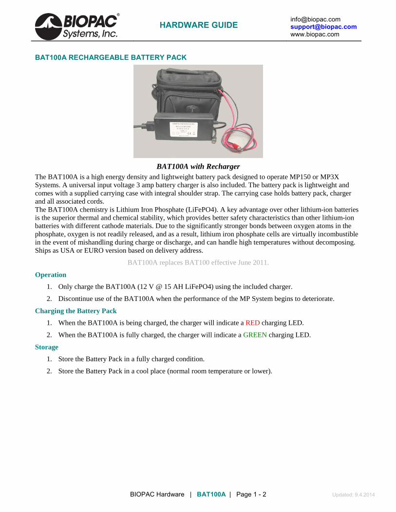
[email protected] [email protected] www.biopac.com
BIOPAC Hardware | BAT100A | Page 1 - 2 Updated: 9.4.2014
BAT100A RECHARGEABLE BATTERY PACK
BAT100A with Recharger The BAT100A is a high energy density and lightweight battery pack designed to operate MP150 or MP3X Systems. A universal input voltage 3 amp battery charger is also included. The battery pack is lightweight and comes with a supplied carrying case with integral shoulder strap. The carrying case holds battery pack, charger and all associated cords. The BAT100A chemistry is Lithium Iron Phosphate (LiFePO4). A key advantage over other lithium-ion batteries is the superior thermal and chemical stability, which provides better safety characteristics than other lithium-ion batteries with different cathode materials. Due to the significantly stronger bonds between oxygen atoms in the phosphate, oxygen is not readily released, and as a result, lithium iron phosphate cells are virtually incombustible in the event of mishandling during charge or discharge, and can handle high temperatures without decomposing. Ships as USA or EURO version based on delivery address.
BAT100A replaces BAT100 effective June 2011.
Operation
1. Only charge the BAT100A (12 V @ 15 AH LiFePO4) using the included charger.
2. Discontinue use of the BAT100A when the performance of the MP System begins to deteriorate.
Charging the Battery Pack
1. When the BAT100A is being charged, the charger will indicate a RED charging LED.
2. When the BAT100A is fully charged, the charger will indicate a GREEN charging LED.
Storage
1. Store the Battery Pack in a fully charged condition.
2. Store the Battery Pack in a cool place (normal room temperature or lower).
HARDWARE GUIDE

[email protected] [email protected] www.biopac.com
BIOPAC Hardware | BAT100A | Page 2 - 2 Updated: 9.4.2014
BAT100A BATTERY PACK SPECIFICATIONS Battery
Chemistry: LiFePO4 (Lithium Iron Phosphate) Output Capacity: 12 V @ 15 amp-hours Working Output Voltage Range: 13.2 V – 12 V Output Connector: DC Barrel Plug (5.5 mm OD, 2.1 mm ID – Center positive) Operating Time: MP3X with 4 sensors: 26 hours nominal MP150 with 4 modules: 16 hours nominal Charge Time: 5 hours (nominal) Recharge Cycles: (number of cycles to 80% of original capacity): 1500 (typical minimum) Operating Temperature Range: 0° C to 45° C Storage Temperature Range: -20° C to 60° C Weight: 2.45 kg Dimensions: (includes carrying case) 14 cm (high) x 19 cm (wide) x 14 cm (deep)
Battery Charger (For BAT100A only) Maximum Nominal Charge Voltage: 14.4 V @ 3.0 amps (Charges at 3 amps to 14.4 V, then potentiostatic at
14.4 V until current is less than 0.5 amps) Input: 120/240 VAC @ 50/60 Hz (USA or EURO power cord) Output Connector: DC Barrel Socket (5.5 mm OD, 2.1 mm ID – Center positive) Operating Temperature Range: 0° C to 45° C Storage Temperature Range: -20° C to 60° C Weight: 285 grams Dimensions: 3.8 cm (high) x 6.4 cm (wide) x 15 cm (long)
HARDWARE GUIDE

[email protected] [email protected] www.biopac.com
BIOPAC Hardware | CBL100 Series | Page 1 - 2 Updated: 11.4.2013
CBL100 SERIES ANALOG CONNECTION CABLES
CBL100 series
The CBL100 Series analog connection cables are used to connect the stand-alone equipment to the MP System. Analog outputs (from chart recorders, force plates, pre-amplifiers, oscilloscopes, etc.) can be connected to the UIM100C module or other MP System modules. Select the cable number with the plug corresponding to the output jack of the equipment. Use one cable per recording channel.
CBL100 2 meter; 3.5 mm mono phone plug to 3.5 mm mono phone plug
CBL101 2 meter; 3.5 mm mono phone plug to male RCA
CBL102 2 meter; 3.5 mm mono phone plug to male BNC
CBL105 2 meter; 3.5 mm mono phone plug to 6.35 mm (¼”) mono phone plug
CBL106 10 cm; 2 mm pin plugs to female BNC
The CBL106 is a multi-purpose adapter that can be used to:
Connect BNC terminated equipment to the DA100C
Connect a BNC cable to the digital I/O lines on the UIM100C
Connect the STM100C to nerve conduction chambers (via the CBL101)
CBL107 10 meter, 3.5 mm mono plug to 3.5 mm mono phone plug
CBL108 60 meter, 3.5 mm mono plug to 3.5 mm mono phone plug
CBL110A DB37 F/F Ribbon Cable. Use this 3-meter ribbon cable to interface a SuperLab presentation system with the STP100C Isolated Digital Interface for an MP150 or MP100 System. Pins 19 and 21 are GND; pin 20 is +5 V.
CBL110C DB25 M/F Ribbon Cable. Use this 3-meter ribbon cable to send digital I/O info to the STP100C Isolated Digital Interface to interface visual presentation systems that use a computer's parallel printer port (E-Prime, DirectRT, MediaLab, Inquisit, etc.) with an MP150 or MP100 System. Pins 18 and 25 are GND.
CBL110C-Y This Y-adapter for the CBL110C parallel port cable allows users to interface the output from a parallel port with two devices, the STP100C and another piece of hardware. DB25 parallel male/dual female Y-splitter; 20 cm (8”).
CBL117 10 meter RCA male plug to RCA male R/A plug for TEL100C
CBL118 60 meter RCA male plug to RCA male R/A plug for TEL100C
CBL121 This cable will connect Biodex System 4 or System 3 devices to a BIOPAC MP150 System to report Torque, Velocity, Position, and Sync values. One end of the 3 m cable terminates with a dSub15 male connector to interface the Biodex device and the other end terminates with four 3.5 mm phone inputs to connect to the MP150 via UIM100C or INISO.
HARDWARE GUIDE

[email protected] [email protected] www.biopac.com
BIOPAC Hardware | CBL100 Series | Page 2 - 2 Updated: 11.4.2013
EXTERNAL DEVICE INTERFACES TO AN MP SYSTEM USING UIM100C If a different interface is required, contact BIOPAC to discuss custom options. All brand or product names are the trademarks or registered trademarks of their respective holders.
Custom cables are available from BIOPAC for connectors not listed.
Company Device Connector Type BIOPAC cable
AMTI MSA-6: Force Plate Amp (Use AMTI cable 5405C) MCA: Force Plate Amp (Use AMTI cable 5405C)
BNC female CBL102
Axon All Amplifiers BNC female CBL102 Buxco MAX II 3.5 mm mini-phone jack CBL100 Data Sciences International
Physio Tel Receiver with ART Analog Adapter BNC female CBL102
Gould 6600 Series BNC female CBL102 Grass Model 7 (J6) 3.5 mm mini-phone jack CBL100 P55, P122, and P511 Series BNC female CBL102 Harvard HSE PLUGSYS
AH 69-0026 Dissolved Oxygen Meter BNC female CBL102
AH 60-2994-2999 Research Grade Isometric Transducers AH 6-03000/3001 Research Grade Isotonic Transducers
4 mm double banana jack
CBL102 with CBL106
Kent TRN(001-012) Amplifiers BNC female CBL102 Kissler Force Plates BNC female CBL102 Millar TCB600: Transducer Control Unit ¼" phone jack CBL105 TC-510 (Specify Grass Cable interface #850-3028) 6-pin TCI100 (to
DA100C) Sonometrics Sonomicrometer Systems with Optional Adapter BNC female CBL102 Transonic T106, T206, T106U, T206U: Animal Research Flowmeters
T110: Lab Tubing Flowmeter BLF21D/21: Laser Doppler Meters
BNC female CBL102
Triton CBI System System 6
¼” phone jack CBL105
Tucker Davis All Digital BioAmp Systems BNC female CBL102 WPI 705: Electro 705 Electrometer
721: Cyto 721 Electrometer 767: Intra 767 Electrometer 773: Duo 773 Electrometer DAM50: Bio-amplifier DBA Series Digital Biological Amps DVC-1000: Voltage Current Clamp EVC-4000-(1-4): Voltage Clamp FD223: Dual Electrometer ISO2: Dissolved Oxygen Meter & Electrode ISODAM: Low Noise Preamplifier ISO-DAM8A-(1-8): Bio-amplifier System NOMK2: ISO-NO Mark II Nitric Oxide Meter TRN001, TRN002, TRN011, TRN012: Isometric Transducers VF-4: 4-Channel Buffer Amplifier
BNC female CBL102
DAM60, DAM70, DAM80: Bio-amplifiers 3.5 mm mini-phone jack CBL100 Biodex System 3
System 4 3.5 mm mini-phone jack CBL121
HARDWARE GUIDE

[email protected] [email protected] www.biopac.com
BIOPAC Hardware | CBL200 Series | Page 1 - 2 Updated: 12.17.2013
CBL200 SERIES LEAD CONNECTOR CONVERSION CABLES See also: Guide to External Device Interfaces for connections to common devices
CBL200 CBL200 consists of a 2 mm female socket leading to a 1.5 mm female Touchproof socket. This 10
cm extension is required when converting an old-style 2mm pin electrode or transducer lead to a 1.5mm Touchproof socket for connection to any of the 100C-series Biopotential or Transducer amplifiers or STMISO series modules. One CBL200 is required for each old-style 2mm pin.
CBL201 CBL201 is a 2 mm male pin leading to a 1.5 mm male Touchproof pin and is 10 cm long. Use CBL201 to:
• Connect a female socket 1.5 mm Touchproof electrode lead to the DA100C amplifier. • Connect a ground electrode lead (e.g. LEAD110A) to the UIM100C module—required
when using the TSD150 active electrodes. • Convert a Touchproof 1.5 mm female socket electrode or transducer lead to an old-style 2
mm pin, for connection to any of the 100B-series Biopotential or Transducer amplifier modules.
One CBL201 is required for each Touchproof socket. For MP36/35/45 Systems CBL201 is used to update older model SS1L Shielded Lead Adapters.
CBL202 CBL202 consists of a female mono 6.3 mm (¼") phone socket leading to two 2 mm male pins. This multi-purpose adapter is 10 cm long and can be used to:
• Connect a 6.3 mm male mono phone cable to the digital I/O lines on the UIM100C. • Connect microphones or signal sources that terminate in a 6.3 mm male mono phone plug to
the DA100C. • Connect the STM100C to nerve conduction chambers (CBL105 required).
CBL203 CBL203 consists of a female mono 6.3 mm (1/4") phone socket leading to two female 1.5 mm Touchproof sockets and is 10 cm long. CBL203 is primarily designed to connect YSI 400 series biomedical temperature probes to the SKT100C temperature amplifier, but it can also be used to connect certain male mono 6.3 mm (1/4") phone plug terminated cables or transducers to 100C-series Biopotential or Transducer amplifiers.
CBL204 CBL204 consists of a single female 1.5 mm Touchproof socket leading to two male 1.5 mm Touchproof pins and is 25 cm long. The CBL204 plugs into any 100C series Biopotential amplifier input or STMISO series stimulator output and provides two sockets to connect to electrode leads terminating in a Touchproof "Y" electrode lead adapter. This Touchproof "Y" electrode lead adapter is required when multiple electrode sites are to be connected to a single amplifier input or stimulator output. Multiple CBL204s can be plugged together to reference three or more electrode leads to the same input or output.
HARDWARE GUIDE

[email protected] [email protected] www.biopac.com
BIOPAC Hardware | CBL200 Series | Page 2 - 2 Updated: 12.17.2013
CBL205 CBL205 is a Touchproof male to female
1.5 mm AC-coupled electrode lead adapter and is 10 cm long. One end of the adapter plugs into the ground on the biopotential amplifier and the other end accepts the electrode lead. Use CBL205 when more than one ground is required while recording electrodermal activity (a.k.a. galvanic skin response). To record GSR (EDA) with other biopotential signals (ECG, EEG, EOG, EGG, EMG, ERS), BIOPAC recommends using CBL205 connected to one ground on any of the biopotential amplifiers. The subject will be grounded through the Vin- of the GSR electrodes, but in some cases it is necessary to have more than one ground; in such cases, use an AC-coupled lead adapter (CBL205) to prevent galvanic ground loops. For example, if—while recording a biopotential and GSR—the GSR electrode is removed during a stage of the experiment, you will want to maintain ground for the biopotential. To always have a ground and no ground loops: connect the Vin- lead of the GSR as ground and connect an AC-coupled ground to the biopotential amplifier GND. Safety Note—If using any two GSR100C, EBI100C or NICO100C modules at the same time on the same MP System, ground loops can be a problem due to non-isolation between module excitation currents. A possible solution is to record with one module connected to a separate IPS100C and HLT100C, and the remaining module to the MP System. Use OUTISO signal isolators to connect the first module outputs (via HLT100C) to the UIM100C on the MP System side.
CBL206 Lead junction TPF to 4X TPM. Reference four electrodes from one. Connect via the MEC110C to the NICO100C and EBI100C cardiac output amplifier modules.
CBL207 1 m, BNC (m) to 2 x 1.5 mm TP (m). Use with:
• Touchproof (f) electrodes
• STM200 Unipolar Pulse Stimulator Module
• MECMRI-STIMISO cable/filter system to connect to the STM200 in the MRI control room
HARDWARE GUIDE

[email protected] [email protected] www.biopac.com
BIOPAC Hardware | MEC Series | Page 1 - 1 Updated: 9.4.2014
MEC SERIES MODULE EXTENSION CABLES
MEC100C and MEC110C
These module extension cables are used to increase the distance between subject and recording system, allowing increased subject movement and comfort. Each extension cable attaches to one amplifier; electrodes and transducers plug into the extension cable’s molded plastic input plug. The 3-meter extension includes a clip for attaching to a subject’s belt loop or clothing.
The MEC series extension cables contain no ferrous parts (less the removable clothing clip). The MEC100C is designed for Transducer amplifiers. The MEC110C and MEC111C are designed for Biopotential amplifiers. Use the MEC100C or MEC110C to increase the lead length to the amplifier.
The MEC111C is required for the protection of a system and Biopotential amplifiers when electrocautery or defibrillation equipment is used while recording data.
IMPORTANT SAFETY NOTES
1. MEC series cables are not to be used on humans when they are undergoing electrosurgery or defibrillation. In fact, no BIOPAC equipment should be connected to human subjects during the course of defibrillation or electrosurgery.
2. When MEC series cables are used, be careful to preserve the isolation of MP system during defibrillation. No external lab equipment should be connected directly to the UIM100C, IPS100C or any included amplifier module. To preserve MP system isolation, all connections of this type should be made using INISO or OUTISO with the HLT100C. To verify that the isolation of the recording system is intact, use a multimeter to measure resistance from subject ground (on biopotential amplifier) to mains ground; there should be no DC conductivity.
3. Do not connect the electrode leads attached to the MEC series cables directly to defibrillator paddles. When using MEC cables, electrode leads should be connected to the subject directly and not via the defibrillator paddles.
COMMON EXTENSIONS MEC100C 100C-series Transducer amplifiers to 1.5 mm male Touchproof pins
MEC110C 100C-series Biopotential amplifiers to 1.5 mm male Touchproof pins
MEC111C 100C-series Biopotential amplifiers to 1.5 mm male Touchproof pins—Protected
LESS COMMON EXTENSIONS MEC100 DA100C or 100B-series Biopotential or Transducer amplifiers to 2 mm socket inputs
MEC101 100B-Series Biopotential amplifiers to 2 mm socket inputs – Protected
MEC110 100B-series Biopotential or Transducer amplifiers to Touchproof inputs
MEC111 100B-series Biopotential amplifiers to Touchproof inputs—Protected
HARDWARE GUIDE
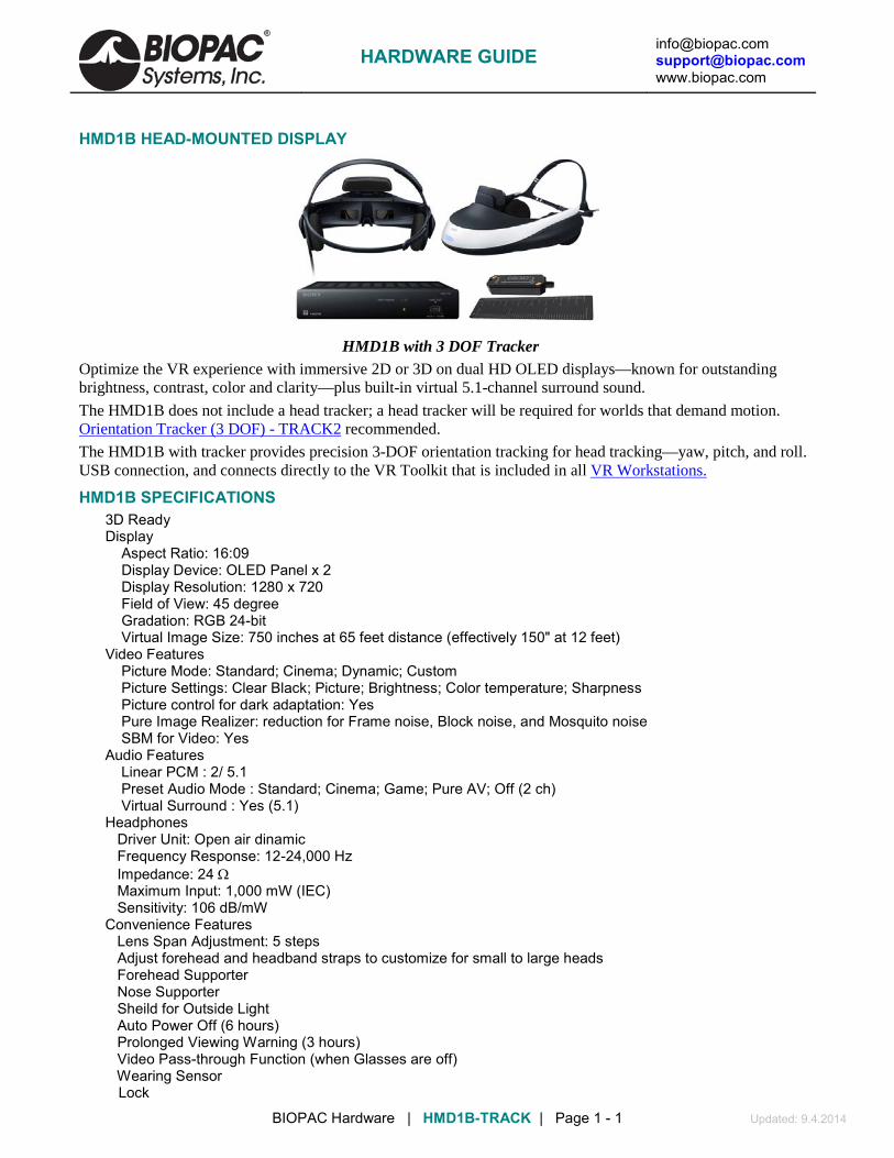
[email protected] [email protected] www.biopac.com
BIOPAC Hardware | HMD1B-TRACK | Page 1 - 1 Updated: 9.4.2014
HMD1B HEAD-MOUNTED DISPLAY
HMD1B with 3 DOF Tracker Optimize the VR experience with immersive 2D or 3D on dual HD OLED displays—known for outstanding brightness, contrast, color and clarity—plus built-in virtual 5.1-channel surround sound.
The HMD1B does not include a head tracker; a head tracker will be required for worlds that demand motion. Orientation Tracker (3 DOF) - TRACK2 recommended.
The HMD1B with tracker provides precision 3-DOF orientation tracking for head tracking—yaw, pitch, and roll. USB connection, and connects directly to the VR Toolkit that is included in all
HMD1B SPECIFICATIONS VR Workstations.
3D Ready Display Aspect Ratio: 16:09 Display Device: OLED Panel x 2 Display Resolution: 1280 x 720 Field of View: 45 degree Gradation: RGB 24-bit Virtual Image Size: 750 inches at 65 feet distance (effectively 150" at 12 feet) Video Features Picture Mode: Standard; Cinema; Dynamic; Custom Picture Settings: Clear Black; Picture; Brightness; Color temperature; Sharpness Picture control for dark adaptation: Yes Pure Image Realizer: reduction for Frame noise, Block noise, and Mosquito noise SBM for Video: Yes Audio Features Linear PCM : 2/ 5.1 Preset Audio Mode : Standard; Cinema; Game; Pure AV; Off (2 ch) Virtual Surround : Yes (5.1) Headphones Driver Unit: Open air dinamic Frequency Response: 12-24,000 Hz Impedance: 24 Ω Maximum Input: 1,000 mW (IEC) Sensitivity: 106 dB/mW Convenience Features Lens Span Adjustment: 5 steps Adjust forehead and headband straps to customize for small to large heads Forehead Supporter Nose Supporter Sheild for Outside Light Auto Power Off (6 hours) Prolonged Viewing Warning (3 hours) Video Pass-through Function (when Glasses are off) Wearing Sensor Lock
HARDWARE GUIDE

[email protected] [email protected] www.biopac.com
BIOPAC Hardware | HMD2A | Page 1 - 1 Updated: 1.21.2015
HMD2A HEAD-MOUNTED DISPLAY—HIGH RES
The HMD2A* offers virtual and augmented reality developers and users a high-fidelity head-mounted display with unprecedented visual clarity and acuity at an affordable price.
The HMD2A is built around a high-contrast Organic Light Emitting Diode (OLED) microdisplay. The microdisplay provides 1280 x 1024 pixels per eye in a low-power, compact design. The patent-pending eyepieces display the image across a 50° diagonal field-of-view with <2% distortion, making the see-through compatible optics ideal for professional augmented reality applications that require precision alignment between real and virtual environments. The HMD2A works equally well as a see-through or fully immersive display. A removable cover can be quickly applied to allow users the flexibility to develop both virtual and augmented reality applications using the same HMD. And the HMD2A supports standard motion tracking devices from InterSense, Ascension, Polhemus, and others via a tracker platform mounted on the back of the HMD.
The simplicity and performance of this HMD is at the forefront of immersive display technology and development. Unsurpassed visual fidelity is designed into a lightweight, ergonomically friendly device that is both easy to use and comfortable to wear. HDMI cables from the HMD plug directly into the image source with no additional video processing electronics. Stereo headphones, built-in microphone, and programmable buttons compliment the high-resolution visuals to provide the rich, immersive experience required in the most demanding training and simulation applications.
HMD2A SPECIFICATIONS Optical FOV Vertical 32° FOV Horizontal 40° FOV Binocular (diagonal) 50° See-Thru Transmission 44% Pupil Size 10, Non-Real mm Eye Relief 23 mm Geometric Distortion -2% Maximum (Barrel) Brightness (MAX) 23 fL Contrast 10000:1 Image Defect Criteria available on request Spatial Resolution 1.88 arcmn/pxl Microdisplay Display Technology Organic Light-Emitting Diode (OLED) Resolution SXGA 1280 x 1024 Color Depth 24-BIT (8 bits per R,G,B) Video Video Input Format SXGA 1280 x 1024 @ 60 Hz Video Interface DVI over HDMI Latency < 0.002 ms Audio Headphone Response 15-25,000 Hz Headphone Impedance 60 Ohms Microphone Standard Integrated, Shell-mounted Microphone Mic Transducer Principle Electret Controls Interpupillary Distance (IPD) Range: 53-73 (Independent left and right) mm Power Power Supply Input: 100-240 VAC, 0.3A 50-60 Hz. Output: +5 V DC, 2 A min Physical Size (envelope) 14.2 L x 9.0 W x 8.6 H max in Mass 1050 g Compliancy CE Compliance CE Compliant RoHS Compliance RoHS Compliant Mfg Warranty Included: one year additional 1-year warranty add-ons available up to 3 years max
*nVIS nVisor ST50 Specifications are subject to change without notice
HARDWARE GUIDE

[email protected] [email protected] www.biopac.com
BIOPAC Hardware | HMD2 | Page 1 - 1 Updated: 1.21.2015
HMD2 HEAD-MOUNTED DISPLAY—HIGH RES
HMD2 is a state-of-the-art head-mounted display (HMD) for advanced virtual reality applications. It incorporates high-resolution color microdisplays with custom engineered optics to deliver unsurpassed visual acuity in a wide field-of-view format.
HMD2 SPECIFICATIONS Monocular FOV: 60° Overlap : 100% Brightness: 25 fL max (adjustable) Arc Minute Per Pixel: < 2.2 Display Technology: LCOS Reflective (CRL Opto) Video Formats: 1280 x 1024 60 Hz (analog or DVI) Color: 24 Bit Stereo Dual channel support Mechanical IPD Adjustment: 55-73 mm Eye Relief: 23 mm to 30 mm Weight: ~ 1 kg Power Input: AC 100 V - 240 V Display Control Brightness
NOTE: The HMD2 was discontinued in January of 2015. The HMD2A is the current product offering.
HARDWARE GUIDE

[email protected] [email protected] www.biopac.com
BIOPAC Hardware | TRACK2 | Page 1 - 1 Updated: 9.4.2014
TRACK2 ORIENTATION TRACKER (3 DOF)
This multi-purpose subminiature 3D orientation sensor is designed for use in real-time orientation tracking applications. It includes three types of sensing elements (tri-axial MEMS gyros, tri-axial MEMS accelerometers, and tri-axial magneto-resistive magnetometers) and comes equipped with an onboard processor and embedded orientation algorithms allowing for direct integration into systems without interfacing a PC. For PC-based integrations, the system comes with a set of libraries that allow users to modify algorithm and/or sensor parameters on-the-fly to suit individual protocols.
TRACK2 interfaces via USB and connects directly to the VR Toolkit included in all VR Workstations; intro, advanced, and ultimate Workstations include one TRACK2.
Also available pre-mounted to high-res head mounted display—see HMD1B-TRACK.
Use additional sensors to track limb movement.
SPECIFICATIONS Output data: Quaternion, Euler angles, Raw data (angular rate, acceleration, magnetic field strength) Internal update rate: 500 Hz Start-up time: < 1 sec Range (pitch, roll, yaw): full 3D Angular Resolution: = 0.01 deg Static Accuracy: yaw = 1 deg; pitch, roll = 0.2 deg Repeatability Accuracy (yaw): < 0.5 deg Gyro Range: ±1200 deg/sec Accelerometer range: ±2 or 6 g Magnetometer range: ±2 gauss Operating temperature: -40° to +85° C Storage temperature: -40° to +85° C Electrical Supply voltage: 3.5 to 5.7 V Power consumption: < 300 mW Interface Standard: TIA/EIA-485A (half-duplex) Baud Rate: 1,000,000 bps Byte Size: 8 bits Stop Bites: 1 bits Parity: No Dimensions: 50.7 × 14.5 × 9.2 mm
HARDWARE GUIDE

[email protected] [email protected] www.biopac.com
MP Research System | VR HDS100 | Page 1 - 1 Updated: 7.13.2012
HDS100 HAPTIC DELIVERY SYSTEM
The HDS100 haptic delivery system provides tactile feedback during virtual reality experiments. The system includes:
audio amplifier that connects to a computer sound card
interface cables (3): HDS100 to an existing sound card (3.5 mm stereo phone plug to dual RCA Y); HDS100 to actuators (18 gauge, 7.3 m); and signal to HDS100 and speakers (stereo splitter, 13.5 mm)
actuators & isolators that vibrate based on the sound from the sound card
Actuators are placed under chair legs or on a platform and deliver vibrations based on the VR environment (e.g. movement of elevators).
The system is compatible with SuperLab, E-Prime, Vizard VR Toolkit, and other presentation systems that interface the computer’s sound card.
HDS100 SPECIFICATIONS
Includes:
1 amplifier
o Features remote control and and rear-mounted IR Input o Bass management, filter and gain control for limitless personalization o Drives up to four linear actuators with two channels 150 W each RMS (6 ohm) o Rack mountable with optional ears o Variable Low Pass Filter (20-600 Hz) o Three inputs (Left, Right, LFE) o Signal sense auto on/off o Ultraquiet variable speed fan o Size 2U (43 cm x 9 cm x 36 cm) or (48 cm x 9 cm x 36 cm with optional Rackmount Adapters)
2 linear actuators—These electromagnetic motors deliver low-frequency motion to a wide range of furnishings.
2 motion isolators—The motion isolators reduce the amount of tactile motion transmitted to the floor and surrounding environment, effectively isolating the tactile sensation to the couch or chair.
Interface cables o HDS100 to an existing sound card: 3.5 mm
stereo phone plug to dual RCA Y (CBL120) o HDS100 to actuators: 18 gauge, 7.3 m o signal to HDS100 and speakers: stereo
splitter, 13.5 mm
Replacement actuators/isolators available as RXHDS.
HARDWARE GUIDE

[email protected] [email protected] www.biopac.com
BIOPAC Hardware | SDS100 | Page 1 - 1 Updated: 12.6.2013
SDS100 SCENT DELIVERY SYSTEM
Self contained scent dispersal system—no compressor needed! Compact, computer-controlled (USB), eight-cartridge scent* machine uses compressed air to project different scents on cue for a predetermined time followed by a burst of unscented air to clear for the next scent.
System includes software to control the delivery and duration of scents from the SDS100 unit. Scents can be triggered from a virtual reality environment. Dispersed scent covers approximately 3-6 meters in front of unit, depending on how many fans are used. *Scent cartridges not included; order as SCENT—over 100 scent options available.
SDS100 SPECIFICATIONS Scent receptacles: 8 Scent dispersement*: 3 m - 6 m Scent control: See App Note 238 - Software options for controlling the SDS100 Scent Delivery System Output: 1/4" NPT male output
Power: Description Wall Mount AC Adapter (2-prong flat blade) Input 100-240 V, 0.7 amps, 47-63 Hz Output 12 V, 2.1 amps Shipping Weight: 5.44 kg (12 lbs.) Product Dimensions (LxWxH): 41.9 cm x 25.4 cm x 14 cm (16-1/2" x 10" x 5-1/2")
HARDWARE GUIDE
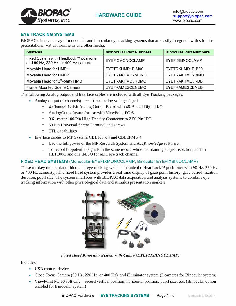
[email protected] [email protected] www.biopac.com
BIOPAC Hardware | EYE TRACKING SYSTEMS | Page 1 - 5 Updated: 3.19.2014
EYE TRACKING SYSTEMS BIOPAC offers an array of monocular and binocular eye tracking systems that are easily integrated with stimulus presentations, VR environments and other media.
Systems Monocular Part Numbers Binocular Part Numbers Fixed System with HeadLock™ positioner and 90 Hz, 220 Hz, or 400 Hz camera EYEFIXMONOCLAMP EYEFIXBINOCLAMP
Movable Head for HMD1 EYETRKHMD1B-M90 EYETRKHMD1B-B90 Movable Head for HMD2 EYETRAKHMD2MONO EYETRAKHMD2BINO Movable Head for 3rd-party HMD EYETRAKHMD3RDMO EYETRAKHMD3RDBI Frame Mounted Scene Camera EYEFRAMESCENEMO EYEFRAMESCENEBI
The following Analog output and Interface cables are included with all Eye Tracking packages:
Analog output (4 channels)—real-time analog voltage signals
o 4-Channel 12-Bit Analog Output Board with 48-Bits of Digital I/O
o AnalogOut software for use with ViewPoint PC-6
o 0.61 meter 100 Pin High Density Connector to 2 50 Pin IDC
o 50 Pin Universal Screw Terminal and screws
o TTL capabilities
Interface cables to MP System: CBL100 x 4 and CBLEPM x 4
o Use the full power of the MP Research System and AcqKnowledge software.
o To record biopotential signals in the same record while maintaining subject isolation, add an HLT100C and one INISO for each eye track channel
FIXED HEAD SYSTEMS (Monocular-EYEFIXMONOCLAMP, Binocular-EYEFIXBINOCLAMP) These turnkey monocular or binocular eye tracking systems include the HeadLock™ positioner with 90 Hz, 220 Hz, or 400 Hz camera(s). The fixed head system provides a real-time display of gaze point history, gaze period, fixation duration, pupil size. The system interfaces with BIOPAC data acquisition and analysis systems to combine eye tracking information with other physiological data and stimulus presentation markers.
Fixed Head Binocular System with Clamp (EYEFIXBINOCLAMP)
Includes:
USB capture device
Close Focus Camera (90 Hz, 220 Hz, or 400 Hz) and illuminator system (2 cameras for Binocular system)
ViewPoint PC-60 software—record vertical position, horizontal position, pupil size, etc. (Binocular option enabled for Binocular system)
HARDWARE GUIDE

[email protected] [email protected] www.biopac.com
BIOPAC Hardware | EYE TRACKING SYSTEMS | Page 2 - 5 Updated: 3.19.2014
MOVABLE HEAD SYSTEMS (Monocular- EYETRKHMD1B-M90, Binocular- EYETRKHMD1B-B90)
These turnkey systems include everything you need for monocular or binocular HMD eye tracking—including the Sony HMZ-1 head mounted display with eye tracking cameras and illuminator systems installed.
Monocular Movable Head System
Includes:
Sony HMZ-1 (HMD1B)
USB capture device
ViewPoint PC-60 software—record vertical position, horizontal position, pupil size, etc.
One eye camera and illuminator system (x 2 cameras and illuminator systems for Binocular system)
o 90 Hz USB 2.0 camera
o Eye camera(s) and illuminator system(s) include either a color 70º horizontal field of view scene camera or a black and white 60º horizontal field of view scene camera
Universal power supply with country-specific adapter and 10 m video and power cable
Waist pack cable holder (not shown)
Additional hardware specs as shown
MOVABLE HEAD - HMD2 (Monocular-EYETRAKHMD2MONO, Binocular-EYETRAKHMD2BINO) This turnkey system provides everything required to add monocular/binocular HMD eye tracking to an nVis SX HMD, including hardware, software, and professional mounting to the HMD at the factory. The system can be added to a new nVis SX purchased from BIOPAC (HMD2) or to an existing nVis SX HMD; if the system is being added to an existing nVis SX, the unit must be returned to BIOPAC for modification.
Part numbers:
MOVABLE HEAD - FOR 3RD PARTY HMD (Monocular-EYETRAKHMD3RDMO, Binocular-EYETRAKHMD3RDBI) This system includes everything you need to mount monocular HMD eye tracking to existing third-party HMD.
HARDWARE GUIDE

[email protected] [email protected] www.biopac.com
BIOPAC Hardware | EYE TRACKING SYSTEMS | Page 3 - 5 Updated: 3.19.2014
SCENE CAMERA (Monocular-EYEFRAMESCENEMO, Binocular-EYEFRAMESCENEBI)
Monocular & Binocular Viewpoint PC-60 Scene Camera Versions with EyeFrame hardware.
Binocular Scene Camera System Includes:
USB capture device
ViewPoint PC-60 software scene camera version—record vertical position, horizontal position, pupil size, etc. (Binocular version enabled for Binocular system)
Eye camera(s) and illuminator system(s) mounted to the EyeFrame hardware
o EyeFrame hardware includes eye camera and illuminator system and either a color 70º horizontal field of view scene camera or a black and white 60º horizontal field of view scene camera
Universal power supply with country specific adaptor and 10 M video and power cable.
Waist pack cable holder (not shown)
Additional hardware specs as shown
HARDWARE GUIDE

[email protected] [email protected] www.biopac.com
BIOPAC Hardware | EYE TRACKING SYSTEMS | Page 4 - 5 Updated: 3.19.2014
EYE TRACKING SYSTEM SPECIFICATIONS Real-time display Gaze point history, gaze trace, fixation duration, pupil size and ROIs, can be graphically
displayed over stimulus image. Visible to the user and / or the subject for fixed and HMD options.
Real-time pen plots of X and Y position of gaze, velocity, ocular torsion, pupil width and pupil aspect ratio.
Allowable head movement
Fixed and HMD options: Small movements allowed. Subject's pupil and corneal reflection must remain within the camera image.
Scene camera options: unlimited
Tracking Method Infrared video. Monocular or binocular options. Pupil tracking—Fixed and HMD options = bright or dark pupil; scene camera options = dark pupil.
Visual range Fixed options: Horizontal ±44° of visual arc, Vertical± 20° of visual arc
HMD options: tracking will depend on the field of view of the HMD.
Scene camera options, included with the system either: Color 70º horizontal field of view or B&W 60º horizontal field of view.
Measurement principle
The user can select between three methods: Pupil only, corneal reflection only, or both together (both provides greater tolerance to head movements for the fixed and HMD options).
Accuracy* Approximately 0.25° - 1.0° visual arc
Spatial resolution*
Approximately 0.15° visual arc
Temporal resolution
between 60 Hz and 30 Hz, user-selectable
Blink suppression
Automatic blink detection and suppression
Pupil size resolution
Measures pupil height and width to better than 0.03 mm instantaneous (no averaging).
Auto threshold The program scans over the video image for the pupil and / or for the corneal reflection. Little or no manual adjustment required.
luminance threshold can be adjusted
auto threshold feature provides good threshold levels automatically
Real-time communication
Same computer: Software Developers Kit (SDK) supplies everything required for seamless interface between ViewPoint and the program. This includes: DLL with shared memory, .h and .lib files plus sample source code written in C Language.
Serial port: Sends eye data packets and asynchronous packets equivalent to information in ASCII data files at rates of up to 56K. Receive real time data from other programs and store it asynchronously into data files.
AnalogOut option: Selectable unipolar or bipolar voltage ranges: +/- 10, 5, 2.5. Selectable data items: position of gaze (x,y), pupil (h,w), velocity (dx,dy), and raw pupil, glint or vector data. TTL capabilities. 2 or 4 channel options.
TTL in/out option: Eight TTL input channels are interfaced to place marker codes into the ViewPoint data file. Eight TTL output channels that indicate when the position of gaze is inside ViewPoint region of interest areas ROI-0 to ROI-7.
Ethernet: full real-time synchronization across machines via the Ethernet.
HARDWARE GUIDE

[email protected] [email protected] www.biopac.com
BIOPAC Hardware | EYE TRACKING SYSTEMS | Page 5 - 5 Updated: 3.19.2014
Stimulus Presentation
Pictures and movies can be displayed in full stimulus windows or in user specified ROIs. Auditory cues can be integrated. Gaze contingent stimulus presentation via state logic.
Data recorded Data is stored in ASCII files.
Eye data: X, Y position of gaze, pupil height and width, ocular torsion, delta time, total time, and regions of interest (ROI).
Asynchronous records include: State transition markers, key presses, data from other programs.
Calibration Fixed and HMD options: ViewPoint starts in a roughly calibrated state that is adequate for determining screen quadrants or other relative movement measurement such as objective preference-of-looking tasks.
Scene camera options: Calibration is performed relative to the pixels of the CCD array, not the image content. This is analogous to calibrating relative to the CRT screen and not the image displayed on it.
New subject setup time between 1-5 minutes. For accurate position of gaze, calibration is required only once per subject—settings can be stored and reused each time a subject returns.
Easy Slip Correction feature and re-presentation of stray calibration points.
System requirements:
OS: Windows 7/Vista or XP
Machine: Fixed and HMD options—Pentium compatible
Scene camera options—2.8 GHz Pentium or higher, or
Athlon XP 2800+ or higher
Fee-based consulting for integration can be provided.
These eye tracking systems use Arrington Research® technology and include cables required to interface to a BIOPAC MP system—MP150 or MP100 data acquisition unit and AcqKnowledge software.
HARDWARE GUIDE

HARDWARE GUIDE
[email protected] [email protected] www.biopac.com
BIOPAC Hardware | CAMERA SYSTEMS | Page 1 - 4 Updated: 10.21.2014
CAMERA SYSTEMS - MULTI-SUBJECT VIDEO MONITORING Multi-Subject Video Monitoring Systems are available with Four or Eight Cameras
Camera System 4 (CAMSYS4) and Camera System 8 (CAMSYS8) include everything needed to record 4-8 channels of video data for integration with existing MP150 System and AcqKnowledge software.*
The Camera Systems record multiple subjects or camera angles and AcqKnowledge media functionality synchronizes the video to any physiological data being recorded with the MP150 Research System. The cameras work well in low-light conditions, making them very well-suited for long-term recordings, sleep studies, animal studies, and more.
View the video capture window and physiology in AcqKnowledge in real-time during recording—and scroll through the linked data in either the AcqKnowledge graph file or video playback viewer for review and analysis. Scrolling through one file will automatically advance the linked file to the same location.
During recording, the video capture window is capable of displaying all camera views at once in a stacked display. The included multiplexer allows the user to toggle between cameras, or cycle through all views. This allows the researcher to focus on a particular camera view during recording when necessary, and then easily revert back to the stacked camera view.
*Camera Systems work with AcqKnowledge Version 4.1 or above, Windows Operating System only.
NOTE: A FireWire connection is required to use all CAMSYS Packages
.
CAMSYS4
Four Camera System CAMSYS8
Eight Camera System CAMSYSUPG
System Upgrade
Components Cameras 4 8 4 Tripods 4 8 4 Gooseneck Adapter 4 8 4 Camera Power Splitter 1 to 4 splitter 1 to 8 splitter 1 to 8 splitter General Power Splitter 1 to 2 splitter 1 to 2 splitter — 8 Channel Multiplexer included included — A/D Converter included included — FireWire Cable Options included included —
For a video demo/tutorial of Camera System setup and operation, click here.
NEW CAMSYS Video Monitoring Packages from BIOPAC interface to the
MP150 Research System with AcqKnowledge!
Upgrade a CAMSYS4 four camera system to
a CAMSYS8 eight camera system.

HARDWARE GUIDE
[email protected] [email protected] www.biopac.com
BIOPAC Hardware | CAMERA SYSTEMS | Page 2 - 4 Updated: 10.21.2014
VIDEO MONITORING APPLICATIONS Exercise Physiology
Examine ventilation, oxygen uptake, carbon dioxide production, biopotentials, temp., and biomechanical signals simultaneously. Record wirelessly with BioNomadix.
Psychophysiology Record BP, ECG, EDA, EMG, EEG, EOG, RSP, etc. Interface to stimulus presentation programs and use automated analysis routines to easily score and analyze data.
Remote Monitoring BioNomadix modules provide high quality, full-bandwidth data for a variety of signals—ECG, EEG, EGG, EMG, EOG, PPG, RSP, SKT, Accelerometry, Cardiac Output and Gyro.
Sleep Studies Long term recordings with up to 16 channels of data. Record EEG, EOG, EMG, respiration, temp., sound, limb position and more. Filter out EEG frequencies to score sleep stages.
Virtual Reality Synchronize events from a virtual world with physiological data from an MP150 system. Use feedback loops for greater control and automation—change the VR world in real time. For tips on synchronizing video data, see Application Note 270
.
CAMERA SYSTEM UPGRADE - CAMSYSUPG The CAMSYSUPG package comes with four additional cameras, tripod stands, gooseneck adapters, and required cables to upgrade a CAMSYS4 package to the equivalent of a CAMSYS8 package.
CAMSYSUPG Package
CAMSYSUPG Upgrade from 4 to 8 Camera System Contains: • 4 x Cameras (see additional camera specs below) • 4 Tripod stands (1-2 meter range) • 4 x 19" black gooseneck adapters for tripod stands • Power Splitter (1 female to 8 male 5.5 mm x 2.1 mm)

HARDWARE GUIDE
[email protected] [email protected] www.biopac.com
BIOPAC Hardware | CAMERA SYSTEMS | Page 3 - 4 Updated: 10.21.2014
ADDITIONAL CAMERA SPECIFICATIONS 1/4" Color CMOS Image Sensor Cable Length: 60' 420 TV Lines, Horizontal 6 mm Lens Signal: NTSC Night Vision Min. Light: 0 Lux (IR On) IR Irradiation Distance: up to 30' Operation Temperature: -5° F ~ 120° F Power: 12 V DC Power Supply: 12 V 1500 mA 4 Port
ADDITIONAL MULTIPLEXER SPECIFICATIONS Supported Resolution NTSC: 720 (H) x 480 (V) 8 channel video signal input, 1 Vp-p, 75 Ohms Video Output Audio Input 4 channel audio input (RCA) Audio Output 1 channel audio output (RCA) Power Consumption 5 W (400 mA) Operation Temperature -10 to 60 Operational Humidity within 85% RH Power Supply: DC 12 V Dimension 210 mm (L) x 130 mm (W) x 40 mm (H)

HARDWARE GUIDE
[email protected] [email protected] www.biopac.com
BIOPAC Hardware | CAMERA SYSTEMS | Page 4 - 4 Updated: 10.21.2014
End #2
MULTIPLEXER (back panel)
1. 2. Tripod Assembly (for each tripod) 3. Cable Connections (for each camera) Computer Connections
A. Attach Gooseneck to Tripod A. Connect End #1 of 18 m Cable to Camera A. Connect Multiplexer to Computer
End #1
GOOSENECK ADAPTER
Attach Camera to screw on end of
Gooseneck adapter
Attach Gooseneck Adapter to Top of
Tripod Stand
CAMERA
18 METER CAMERA CABLE
To Power Splitter
To Multiplexer (C)
Connect to Power Cable for Multiplexer
Connect to AC150A
Power Supply and Outlet
Connect Plugs from Camera
Cable End #2 to Power Splitter
MULTIPLEXER (back panel)
Connect Video Out cable (BNC to RCA) from Multiplexer to
A/D Converter
Choose appropriate FireWire cable for connection between A/D converter and your computer. • 6 pin to 4 pin
cable requires included AC Adapter.
• 6 pin to 6 pin - no AC adapter needed.
• 6 pin to 9 pin - no AC adapter needed
**Once Camera System connections are completed, select cameras from the Media Menu in AcqKnowledge. Next, synchronize the cameras with the MP150 System using OUT103 LED light. For more information on synchronization, see Application Note 270 available on BIOPAC online Support page.
Connect cable from End #2 of each camera cable to back of Multiplexer.
CAMERA
TRIPOD B. Connect Camera and Multiplexer to Power Splitters
C. Connect End #2 of 18 m Cable to Multiplexer
Connect Power Splitters
End #2
End #2
CBL216
CBL217
A/D CONVERTER
B. Attach Camera to Gooseneck

[email protected] [email protected] www.biopac.com
BIOPAC Hardware | CAM-HFR-A | Page 1 - 5 Updated: 9.4.2014
CAM-HFR-A HIGH FRAME RATE CAMERA Tightly synchronize high frame rate video—up to 100 FPS—with physiological data recorded with a BIOPAC MP150 Research System.
Included Components • High Frame Rate Camera (CAM-HFR-A) • Camera Lens, 6 mm (LENS-CAM-A) • GigE Network Interface Card (ETHCARD3) • CAT6 Ethernet Cable (CBLETH3) • AC Power Supply, cord and Trigger Cable (AC300A and CBLHFR) • Camera Tripod Kit with Mount (TRIPOD-KIT-CAM)
Requires Windows-based computer and AcqKnowledge 4.3.1 or above for Windows to support GigE camera; does not require auxiliary synchronization methods.
Use the High Frame Rate Camera System to capture precise movement activity at 100 frames-per-second (640 x 480 resolution) in conjunction with other recorded physiological variables.
With CAM-HFR-A and AcqKnowledge media tools, it’s possible to obtain synchronization within 1 video frame (10 ms) between physiological data and video data, running at a rate of 100 frames per second, up to the computer’s memory capacity. This very high performance video recording option incorporates automatic synchronizing between the video data and the physiological data, so no external synchronization marker is required. Furthermore, the high speed camera in CAM-HFR-A can be controlled from AcqKnowledge for exposure times as short as 1 ms, running at 100 frames per second. This combination of high frame rate, automatic synchronization, and precise control over camera exposure times results in the ability to precisely characterize physical activity in relation to simultaneously recorded physiological data, such as EMG, Acceleration, Goniometry, Respiration, and more.
Media functionality allows users to capture and playback video and synchronize it with physiological information from an MP device. The key functionality is the strong link between the video and data cursor when physiological data graphs and associated video are reviewed in post-acquisition mode; changing the selection in the graph window will automatically jump the video to the time corresponding to the cursor position in the physiological data graph. The reverse connection is also in place where scrolling through the video will move the data cursor to the corresponding point in the physiological data graph.
Data streams from the video digitizer and the MP unit are automatically synchronized. In this manner—there is no requirement that the user create a visible synchronization marker to align physiological data with video. The combined CAM-HFR-A and AcqKnowledge System is very simple to use!
HARDWARE GUIDE

[email protected] [email protected] www.biopac.com
BIOPAC Hardware | CAM-HFR-A | Page 2 - 5 Updated: 9.4.2014
AcqKnowledge 4.3.1 and above automatically recognizes the HFR camera and simplifies setup for tight synchronization
The video capture field is a function of the lens placed on the high-speed camera. BIOPAC has included a high quality Navitar lens, suitable for nearly all sports science and exercise physiology applications. The provided C-mount lens will permit a 1.8 meter high x 2.4 meter wide field of view at a camera distance of 2.5 meters.
To perform close-up videos of heads, hands or feet, simply pull the camera in towards the subject. To capture movement of many subjects at once, just pull the camera away from the subjects. For exotic measurements, as when videoing a distant subject or performing an extreme close-up, simply switch out the provided lens for the appropriate C-mount lens.
The camera iris control can be adjusted to accommodate a range of ambient lighting conditions. Furthermore, the camera exposure time can be controlled from the AcqKnowledge software to allow for the sharpest imaging possible under fast subject movement conditions. When using short exposure times, video frames will hold very crisp images to allow for precise identification of subject position as a function of simultaneously collected physiological data.
System Requirements Recommended Minimum
Core i7 Quad Core or Xeon E3/E5 processor, 2.40 GHz Core 2 Duo processor, 2.13 GHz
8 GB DDR2 memory, dedicated card for video capture 4 GB DDR2 memory
RAID0/RAID10 with enterprise grade “RAID Edition” hard disks, or Non-RAID 10,000 RPM (such as VelociRaptor,) or 15,000 RPM, (such as Seagate Cheetah) > 125 MB/s sequential write speed
SAS/SATA III, 6 GB/s, 7200 RPM > 90 MB/s sequential write speed
• Windows AcqKnowledge 4.3.1 or above is required for high frame rate camera support. • To insure stable 100 fps frame rate, use the provided GigE Network Interface Card.
HARDWARE GUIDE
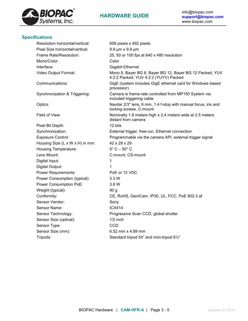
[email protected] [email protected] www.biopac.com
BIOPAC Hardware | CAM-HFR-A | Page 3 - 5 Updated: 9.4.2014
Specifications Resolution horizontal/vertical: 658 pixels x 492 pixels Pixel Size horizontal/vertical: 9.9 µm x 9.9 µm Frame Rate/Resolution: 25, 50 or 100 fps at 640 x 480 resolution Mono/Color: Color Interface: Gigabit Ethernet Video Output Format: Mono 8, Bayer BG 8, Bayer BG 12, Bayer BG 12 Packed, YUV
4:2:2 Packed, YUV 4:2:2 (YUYV) Packed Communications: GigE (system includes GigE ethernet card for Windows based
processor) Synchronization & Triggering: Camera is frame-rate controlled from MP150 System via
included triggering cable Optics: Navitar 2/3" lens, 6 mm, 1.4 f-stop with manual focus, iris and
locking screws, C-mount Field of View: Nominally 1.8 meters high x 2.4 meters wide at 2.5 meters
distant from camera Pixel Bit Depth: 12 bits Synchronization: External trigger, free-run, Ethernet connection Exposure Control: Programmable via the camera API, external trigger signal Housing Size (L x W x H) in mm: 42 x 29 x 29 Housing Temperature: 0° C – 50° C Lens Mount: C-mount, CS-mount Digital Input: 1 Digital Output: 1 Power Requirements: PoE or 12 VDC Power Consumption (typical): 3.3 W Power Consumption PoE: 3.6 W Weight (typical): 90 g Conformity: CE, RoHS, GenICam, IP30, UL, FCC, PoE 802.3 af Sensor Vendor: Sony Sensor Name: ICX414 Sensor Technology: Progressive Scan CCD, global shutter Sensor Size (optical): 1/2 inch Sensor Type: CCD Sensor Size (mm): 6.52 mm x 4.89 mm Tripods: Standard tripod 54” and mini-tripod 6¼”
HARDWARE GUIDE

[email protected] [email protected] www.biopac.com
BIOPAC Hardware | CAM-HFR-A | Page 4 - 5 Updated: 9.4.2014
Connecting Camera Hardware:
Before you begin:
1. Connect the CBLHFR 6-pin-connector to the camera input.
Make sure the camera drivers and the provided ETHCARD3 Network Interface Card are installed.
2. Connect the female end of the CBLHFR connector to the AC300A power supply adapter cable.
3. Plug the AC300A power supply cord into wall socket.
4. Connect the Ethernet cable between the camera’s Ethernet port and the ETHCARD3 network interface card supplied with your system. Attach the 6 mm lens to camera (included as LENS-CAM-A).
Launch the pylon IP Configuration Tool from the Desktop shortcut to verify camera/network connection. If successful, the camera’s network settings will appear in the IP configuration window as shown below. (Make sure the IP configuration is set to DHCP.)
NOTE: If the camera’s network settings don’t appear in the pylon IP Tool Configuration window, click the
“Refresh” button and highlight the camera device from the list at the top of the Configuration Tool. If the camera’s network settings still don’t appear, or appear in the pylon IP Configuration Tool window as “unreachable”, reset the IP configuration to Static IP.
HARDWARE GUIDE

[email protected] [email protected] www.biopac.com
BIOPAC Hardware | CAM-HFR-A | Page 5 - 5 Updated: 9.4.2014
Set Up Camera Configuration in AcqKnowledge Software:
1. Launch AcqKnowledge and select Media > Set Up. The Basler camera should appear as selected in the “Video” list.
2. Check the “Video” option (and “Audio” if sound is to be recorded).
3. Click the “Output” tab and type in a media file name.
4. Click “Browse” and choose a format (*.wmv or *.avi) and directory for the new media file.
5. Click “Save”.
6. Click “OK” to bring up the Video Capture Viewer. This is useful for determining proper camera positioning, lighting, etc…
7. To access the “Video” properties (Exposure or Gain controls,) go to Media > Set Up and click the “Configure” button.
NOTE: The “Configure” button is not active until the Media > Set Up dialog is dismissed with “OK” and reopened.
8. Click the “HW Trigger” tab to:
• Use the MP150 Stimulator to trigger and synchronize the camera recording with AcqKnowledge.
• Set the camera frame rate. (25, 50, or 100 fps.)
For Support contact: [email protected] or visit the Support page at www.biopac.com
HARDWARE GUIDE

[email protected] [email protected] www.biopac.com
BIOPAC Hardware | Shield Drive Operation | Page 1 - 1 Updated: 9.4.2014
APPENDIX SHIELD DRIVE OPERATION
ECG100C EGG100C EOG100C MCE100C*
EEG100C EMG100C ERS100C TEL100C
The shield drive for BIOPAC biopotential front-end differential amplifiers is developed as the arithmetic mean of the voltages sensed on the positive and negative differential inputs with respect to Ground. Given that interfering noise sources (usually 50 Hz / 60 Hz) nearly always appear as high level voltage signals of similar value on the positive and negative differential inputs, creating a shield drive for the positive and negative input leads will act to increase the amplifier’s Common Mode Rejection Ratio (CMRR) via capacitance reduction of the differential input to its respective shield. Because the shield drive is introduced identically to the differential inputs, additive noise from the shield drive will have a tendency to cancel out due to the operation of the differential amplifier front end.
Generally, it’s helpful to have an active shield drive for interfering noise reduction. However, in special cases, it may be worthwhile to ground the cable shields connecting to the amplifier’s differential inputs or to dispense with shielding altogether. Any BIOPAC biopotential front-end differential amplifier can be user-adapted to satisfy these special cases; please contact BIOPAC Systems, Inc. for details.
* The MCE100C shield drive is independent for both (Vin+) and (Vin-) inputs.
HARDWARE GUIDE

[email protected] [email protected] www.biopac.com
BIOPAC Hardware | Frequency Response Characteristics | Page 1 - 6 Updated: 9.4.2014
APPENDIX AMPLIFIER FREQUENCY RESPONSE CHARACTERISTICS The following frequency response plots illustrate the frequency response selections available on the indicated amplifier modules. LP is low pass, HP is high pass, and the N suffix indicates the notch setting. Modules (except for the DA100C) can be set for 50 or 60 Hz notch options, depending on the destination country.
0.1 Hz LP EGG100C
Setting Modules
1 Hz LP EGG100C, GSR100C, SKT100C
3Hz LP PPG100C, RSP100C
10 Hz LP DA100C, EBI100C, GSR100C, PPG100C, RSP100C, SKT100C
35 Hz LPN (with 50 Hz notch) ECG100C, EEG100C, EOG100C, TEL100C
35 Hz LPN (with 60 Hz notch) ECG100C, EEG100C, EOG100C, TEL100C
100 Hz LP EBI100C, EEG100C, EOG100C
150 Hz LP ECG100C
100 Hz HPN (with 50 Hz notch) EMG100C, ERS100C, MCE100C
100 Hz HPN (with 60 Hz notch) EMG100C, ERS100C, MCE100C
300 Hz LP DA100C
500 Hz LP EMG100C, TEL100C
3,000 Hz LP ERS100C, MCE100C
5000 Hz LP DA100C, EMG100C
10 kHz LP ERS100C
30 kHz LP MCE100C
See also: Sample Plots
HARDWARE GUIDE

[email protected] [email protected] www.biopac.com
BIOPAC Hardware | Frequency Response Characteristics | Page 2 - 6 Updated: 9.4.2014
100C SERIES
100C Series Amplifers - Sample Frequency Response Plots
0.1 Hz LP
EGG100C
1 Hz LP
EGG100C GSR100C SKT100C
3 Hz LP
PPG100C
RSP100C
HARDWARE GUIDE

[email protected] [email protected] www.biopac.com
BIOPAC Hardware | Frequency Response Characteristics | Page 3 - 6 Updated: 9.4.2014
100C Series Amplifers - Sample Frequency Response Plots
10 Hz LP
DA100C EBI100C GSR100C PPG100C RSP100C SKT100C
35 Hz LPN (with 50 Hz notch enabled) ECG100C
EEG100C
EOG100C
TEL100C
35 Hz LPN (with 60 Hz notch enabled)
ECG100C
EEG100C
EOG100C
TEL100C
HARDWARE GUIDE

[email protected] [email protected] www.biopac.com
BIOPAC Hardware | Frequency Response Characteristics | Page 4 - 6 Updated: 9.4.2014
100C Series Amplifers - Sample Frequency Response Plots
100 Hz LP
EBI100C
EEG100C
EOG100C
NICO100C
150 Hz LP
ECG100C
100 Hz HPN (with 50 Hz notch enabled)
EMG100C
ERS100C
MCE100C
HARDWARE GUIDE
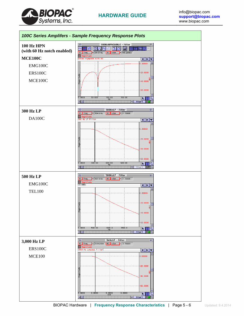
[email protected] [email protected] www.biopac.com
BIOPAC Hardware | Frequency Response Characteristics | Page 5 - 6 Updated: 9.4.2014
100C Series Amplifers - Sample Frequency Response Plots
100 Hz HPN (with 60 Hz notch enabled)
MCE100C
EMG100C
ERS100C
MCE100C
300 Hz LP
DA100C
500 Hz LP
EMG100C
TEL100
3,000 Hz LP
ERS100C
MCE100
HARDWARE GUIDE

[email protected] [email protected] www.biopac.com
BIOPAC Hardware | Frequency Response Characteristics | Page 6 - 6 Updated: 9.4.2014
100C Series Amplifers - Sample Frequency Response Plots
5000 Hz LP
DA100C
EMG100C
10 kHz LP
ERS100C
30 kHz LP
MCE100C
HARDWARE GUIDE

[email protected] [email protected] www.biopac.com
MP Research System | Amplifier Module Response Times | Page 1 - 2 Updated:11.15.2012
APPENDIX AMPLIFIER MODULE FILTER RESPONSE TIMES The MP series amplifier modules incorporate a variety of filtering options. The low pass filtering options have an effect on the signal response time, which is sometimes referred to as signal delay.
Signal delay is often plotted as the function “group delay” versus frequency. This type of plot shows the typical delay the filter will have for a wide range of frequencies. The group delay plot is the derivative of the filter phase plot with respect to frequency. If the filter is perfectly linear phase, the group delay plot will be a straight horizontal line, because the derivative of a constant (linear) slope is a constant.
In practice it’s often difficult to utilize a group delay plot to get a quick and simple handle on essential filter signal delay, unless one is experienced in reading such plots. Instead, it’s typically better to show the filter response to a well-understood input signal, such as a step function.
The following plots illustrate the delay times for a variety of low pass filter settings.
10 Hz Low Pass Filter – 4 pole Besselworth
35 Hz Low Pass Notch Filter – 4 pole Besselworth – Notch at 60 Hz
HARDWARE GUIDE

[email protected] [email protected] www.biopac.com
MP Research System | Amplifier Module Response Times | Page 2 - 2 Updated:11.15.2012
100 Hz Low Pass Filter – 4 pole Besselworth
500 Hz Low Pass Filter – 4 pole Besselworth
Note that signal delay is proportional to the cut-off frequency for any particular 4 pole low pass Besselworth filter. The one minor exception is the 35 Hz LPN filter, because it consists of a 4 pole Besselworth filter and a 60 Hz Notch (band reject) filter. This additional filter adds a small additional delay.
Step Response Signal Delay (approximate)
Filter Type: 10 Hz LP 35 Hz LP 100 Hz LP 500 Hz LP Delay at 50% (approximate): 30 ms 11 ms 3 ms 0.6 ms
HARDWARE GUIDE

[email protected] [email protected] www.biopac.com
MP Research System | BioNomadix Sample Plots | Page 1 - 3 Updated: 7.11.2012
BioNomadix Transmitter-Receiver Modules - Sample Frequency Response Plots
Note BioNomadix frequency responses are identified either by -3 dB or -6 dB inflection points, which are representative of 0.707 or 0.5 respectively of the mid band gain.
BN-ECG2
1 Hz HP
35 Hz LP
0.05 Hz HP
150 Hz LP
BN-EOG2
0.005 Hz HP
35 Hz LP
0.005 Hz HP
100 Hz LP
HARDWARE GUIDE
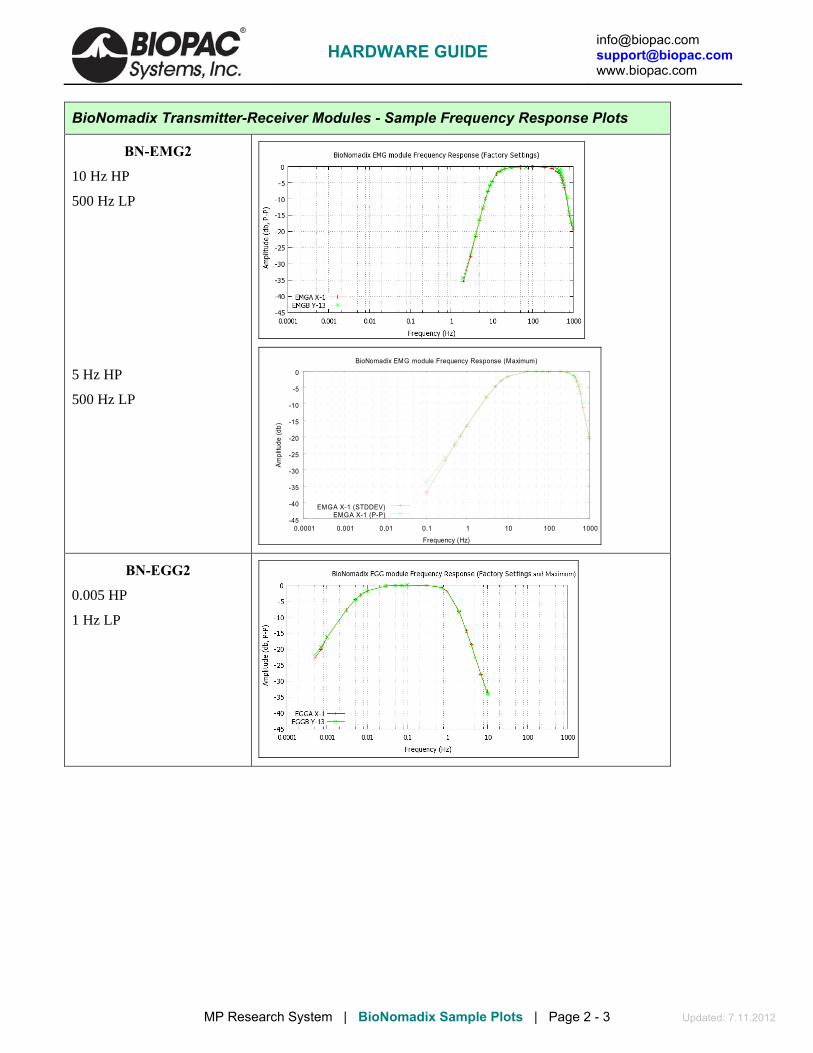
[email protected] [email protected] www.biopac.com
MP Research System | BioNomadix Sample Plots | Page 2 - 3 Updated: 7.11.2012
BioNomadix Transmitter-Receiver Modules - Sample Frequency Response Plots
BN-EMG2
10 Hz HP
500 Hz LP
5 Hz HP
500 Hz LP
-45
-40
-35
-30
-25
-20
-15
-10
-5
0
0.0001 0.001 0.01 0.1 1 10 100 1000
Ampl
itude
(db)
Frequency (Hz)
BioNomadix EMG module Frequency Response (Maximum)
EMGA X-1 (STDDEV)EMGA X-1 (P-P)
BN-EGG2
0.005 HP
1 Hz LP
HARDWARE GUIDE

[email protected] [email protected] www.biopac.com
MP Research System | BioNomadix Sample Plots | Page 3 - 3 Updated: 7.11.2012
BioNomadix Transmitter-Receiver Modules - Sample Frequency Response Plots
BN-EEG2
0.5 HP
35 Hz LP
0.1 HP
100 Hz LP
-45
-40
-35
-30
-25
-20
-15
-10
-5
0
0.0001 0.001 0.01 0.1 1 10 100 1000
Am
plitu
de (d
b)
Frequency (Hz)
BioNomadix EEG module Frequency Response (Factory Settings)
EEGA X-1 (stddev)EEGA X-1 (P-P)
-45
-40
-35
-30
-25
-20
-15
-10
-5
0
0.0001 0.001 0.01 0.1 1 10 100 1000
Ampl
itude
(db,
P-P
)
Frequency (Hz)
BioNomadix EEG module Frequency Response (Maximum)
EEGA X-1EEGB Y-13
EEGA X-1 STDDEV
HARDWARE GUIDE